Hierarchical amorphous nanofibers for transparent inherently super-hydrophilic coatings
Upload
khangminh22Category
view
0download
0
SYMPOSIUM SERIES NO 163 HAZARDS 28 © 2018 IChemE
1
Inherently Safer Design (ISD) in Sour Gas Processing Facilities
Bello, J., HSE Engineer
Haris, N., HSE Engineer
Venables, J., HSE Engineering Manager
Amott, N., Process Director
*Fluor, 140 Pinehurst Road, Farnborough, Hampshire, United Kingdom
For correspondence email [email protected]
An estimated 40% of the world's remaining oil and gas reserves are sour; H2S is highly toxic, flammable,
explosive and corrosive. Engineering companies develop designs to separate oil/gas/water from well fluids. The oil is stabilized, de-sulfurized and desalted; and the sour gas may be treated or compressed and re-injected back
into producing, depleted or non-producing reservoirs; to give improved well pressure and performance through
miscible flood and as a means of sour gas disposal. With the development of tried, tested and proven process technology; compression and re-injection is taking place at increasingly higher pressures and H2S
concentrations. Given the relative cost effectiveness and importance of engineering in reducing the potential for
major accident hazards associated with H2S over the life-cycle of the facility; effective application of the principles of Inherently Safer Design (ISD) in sour service gas processing facilities is paramount. Successful
application of the principles of ISD can improve Health, Safety and Environment (HSE) performance during
construction, commissioning, operation and decommissioning phases. This paper discusses the application of ISD in sour service gas processing facilities including: safeguarding strategies, separation and segregation of
layout, material selection and various Process, Pipeline and Piping design solutions. It also outlines tools and
techniques that organizations can utilize to achieve inherent safety in design and uses examples drawn from
projects in the sour gas arena.
Sour Gas, Inherent, Safer, Injection Compressor
INTRODUCTION
The practical application of Inherently Safer Design (ISD) in engineering can be a challenge. Engineering disciplines are
often restrained in their work output by standards, codes, contract requirements and Clients wishing to reduce Capital
Expenditure (CAPEX). The Process Safety Engineer may be seen as the one who champions, coordinates and secures ISD
however in reality the entire team is working to the same constraints. Engineers should not view Health, Safety and
Environment (HSE) as the domain of the Process Safety Engineer; all engineering decisions are HSE decisions. All
Engineers require a sound theoretical knowledge and a structured approach to HSE in engineering and this should be
integrated with an understanding of legal context, Project/Client philosophy, risk analysis and the broader
Project/Engineering objectives; as well as constraints such as codes, standards, contract and CAPEX.
Figure 1. The Effectiveness of Risk Reduction Activities as the Design Progresses
CONCEPT FEED OPERATIONS
Eff
ecti
ven
ess
of
Ris
k R
ed
ucti
on
Eff
ort
EPC
Inherently Safer Design
(ISD)Add-On Safety
Operator & Maintenance
Includes concept selection,
layout and structural
optimisationIncludes safety
instrumented functions
& safety critical elements
SYMPOSIUM SERIES NO 163 HAZARDS 28 © 2018 IChemE
2
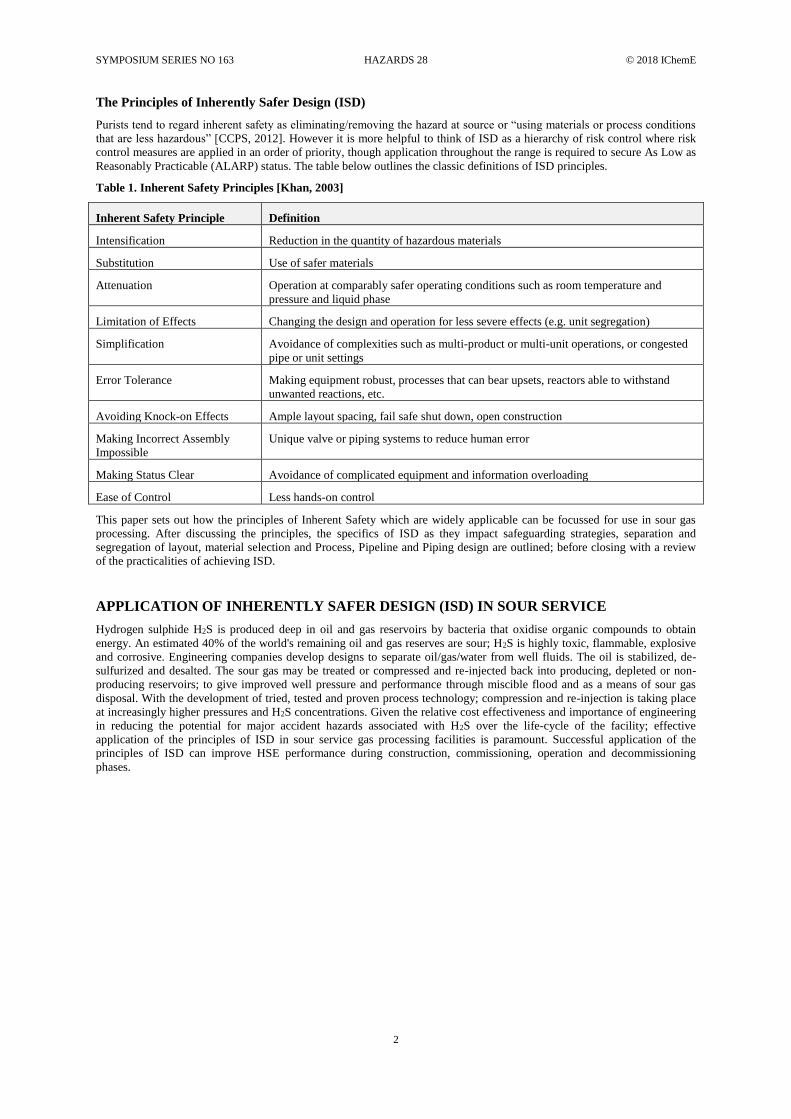
The Principles of Inherently Safer Design (ISD)
Purists tend to regard inherent safety as eliminating/removing the hazard at source or “using materials or process conditions
that are less hazardous” [CCPS, 2012]. However it is more helpful to think of ISD as a hierarchy of risk control where risk
control measures are applied in an order of priority, though application throughout the range is required to secure As Low as
Reasonably Practicable (ALARP) status. The table below outlines the classic definitions of ISD principles.
Table 1. Inherent Safety Principles [Khan, 2003]
Inherent Safety Principle Definition
Intensification Reduction in the quantity of hazardous materials
Substitution Use of safer materials
Attenuation Operation at comparably safer operating conditions such as room temperature and
pressure and liquid phase
Limitation of Effects Changing the design and operation for less severe effects (e.g. unit segregation)
Simplification Avoidance of complexities such as multi-product or multi-unit operations, or congested
pipe or unit settings
Error Tolerance Making equipment robust, processes that can bear upsets, reactors able to withstand
unwanted reactions, etc.
Avoiding Knock-on Effects Ample layout spacing, fail safe shut down, open construction
Making Incorrect Assembly
Impossible
Unique valve or piping systems to reduce human error
Making Status Clear Avoidance of complicated equipment and information overloading
Ease of Control Less hands-on control
This paper sets out how the principles of Inherent Safety which are widely applicable can be focussed for use in sour gas
processing. After discussing the principles, the specifics of ISD as they impact safeguarding strategies, separation and
segregation of layout, material selection and Process, Pipeline and Piping design are outlined; before closing with a review
of the practicalities of achieving ISD.
APPLICATION OF INHERENTLY SAFER DESIGN (ISD) IN SOUR SERVICE
Hydrogen sulphide H2S is produced deep in oil and gas reservoirs by bacteria that oxidise organic compounds to obtain
energy. An estimated 40% of the world's remaining oil and gas reserves are sour; H2S is highly toxic, flammable, explosive
and corrosive. Engineering companies develop designs to separate oil/gas/water from well fluids. The oil is stabilized, de-
sulfurized and desalted. The sour gas may be treated or compressed and re-injected back into producing, depleted or non-
producing reservoirs; to give improved well pressure and performance through miscible flood and as a means of sour gas
disposal. With the development of tried, tested and proven process technology; compression and re-injection is taking place
at increasingly higher pressures and H2S concentrations. Given the relative cost effectiveness and importance of engineering
in reducing the potential for major accident hazards associated with H2S over the life-cycle of the facility; effective
application of the principles of ISD in sour service gas processing facilities is paramount. Successful application of the
principles of ISD can improve HSE performance during construction, commissioning, operation and decommissioning
phases.
SYMPOSIUM SERIES NO 163 HAZARDS 28 © 2018 IChemE
3
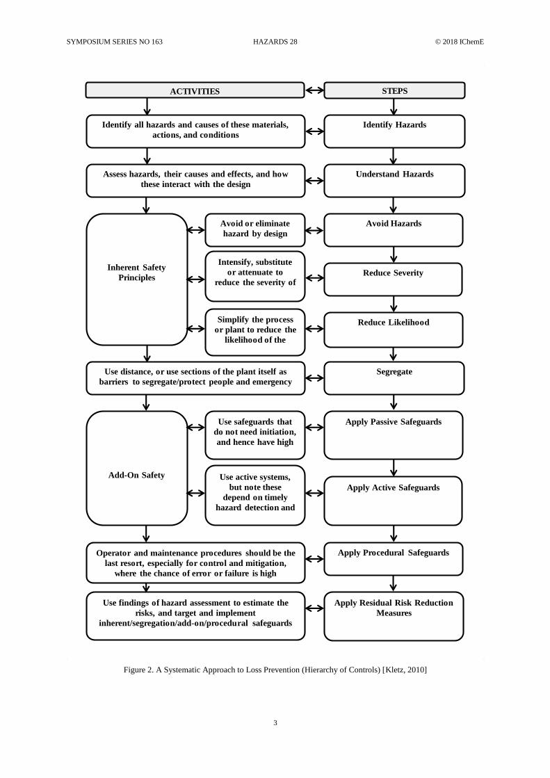
Figure 2. A Systematic Approach to Loss Prevention (Hierarchy of Controls) [Kletz, 2010]
ACTIVITIES STEPS
Identify all hazards and causes of these materials,
actions, and conditions
Assess hazards, their causes and effects, and how
these interact with the design
Inherent Safety
Principles
Avoid or eliminate
hazard by design
Intensify, substitute
or attenuate to
reduce the severity of
Simplify the process
or plant to reduce the
likelihood of the
Use distance, or use sections of the plant itself as
barriers to segregate/protect people and emergency
Add-On Safety
Use safeguards that
do not need initiation,
and hence have high
Use active systems,
but note these
depend on timely
hazard detection and
Operator and maintenance procedures should be the
last resort, especially for control and mitigation,
where the chance of error or failure is high
Use findings of hazard assessment to estimate the
risks, and target and implement
inherent/segregation/add-on/procedural safeguards
Identify Hazards
Understand Hazards
Avoid Hazards
Reduce Severity
Reduce Likelihood
Segregate
Apply Passive Safeguards
Apply Active Safeguards
Apply Procedural Safeguards
Apply Residual Risk Reduction
Measures
SYMPOSIUM SERIES NO 163 HAZARDS 28 © 2018 IChemE
4
SAFEGUARDING STRATEGIES
The process of concentrating sour material, and increasing the pressure and temperature is in direct opposition of the concept
of inherent safety, that is to say “limiting the hazard by using materials and process conditions that are more benign” (CCPS,
2012). However this does not prohibit effective risk reduction and management through safeguarding strategies. The
strategies for reducing risk whether directed towards reducing the likelihood or the severity can be classified into; Inherent,
Passive, Active or Procedural (CCPS, 2012). Safeguarding Strategies, or engineered solutions, for sour service focus on the
passive, active and procedural aspects of eliminating or reducing identified risk in a system. Passive solutions represent
features that are present at all times and require little human intervention to ensure they work. Active solutions include for
example safety instrumented functions and safety critical elements; they require an active system to operate and intervene, or
an actively managed regime of integrity checks and maintenance to ensure they remain effective. Procedural solutions are
those that are applied by the actions of operations and maintenance personnel and they may require some engineered features
to facilitate procedure application. The passive, active and procedural safeguards highlighted in this paper are not exhaustive.
The intention is to highlight unique or novel technologies that can be applied alongside conventional safeguarding
techniques focussing on gaining improvement in ISD in sour gas facilities.
SEPARATION AND SEGREGATION OF LAYOUT (PASSIVE)
The Global Asset Protection Services (GAPS) standard [Global Asset Protection Services, 2015] used by insurers usually
sets the minimum separation distances to be applied in facilities. The driver here is minimizing equipment damage,
escalation of the incident (involving more equipment damage) and therefore insurer liability. GAPS sets out the minimum
separation distance taking into account pool fire and heat radiation and specifies that the owner must undertake calculations
for explosion. The GAPS standard is conducive to iterative design development. The initial plot layout and separation
utilizes the inter-unit spacing table that enables the designer to set the overall plot plan showing unit blocks in early Front
End Engineering Design (FEED). This is augmented by a coarse Quantified Risk Assessment (QRA) or consequence
modelling for explosion or escalation events such as potential jet fire impingement on large hydrocarbon inventories. As the
design progresses the intra-unit spacing table is used to place items within the unit plot plans. Towards the mid to late stage
of FEED the QRA is developed that allows further plot optimization on the basis of risk.
The overall plot layout can lead to some interesting challenges and dichotomies. Minimum separation distance is required to
satisfy the insurer, additional separation is required as per risk assessment to prevent escalation of Major Accident Hazards
(MAH). Increased separation distance directly equals increased cost. The CAPEX motivation is always to shrink the plot.
However the objective of the process safety group is to not only ensure sufficient spacing, to prevent escalation, but also to
minimize the pipe runs because from the point of view of inherent safety we want to minimize the available inventory to leak
between two isolatable points in the event of loss of containment.
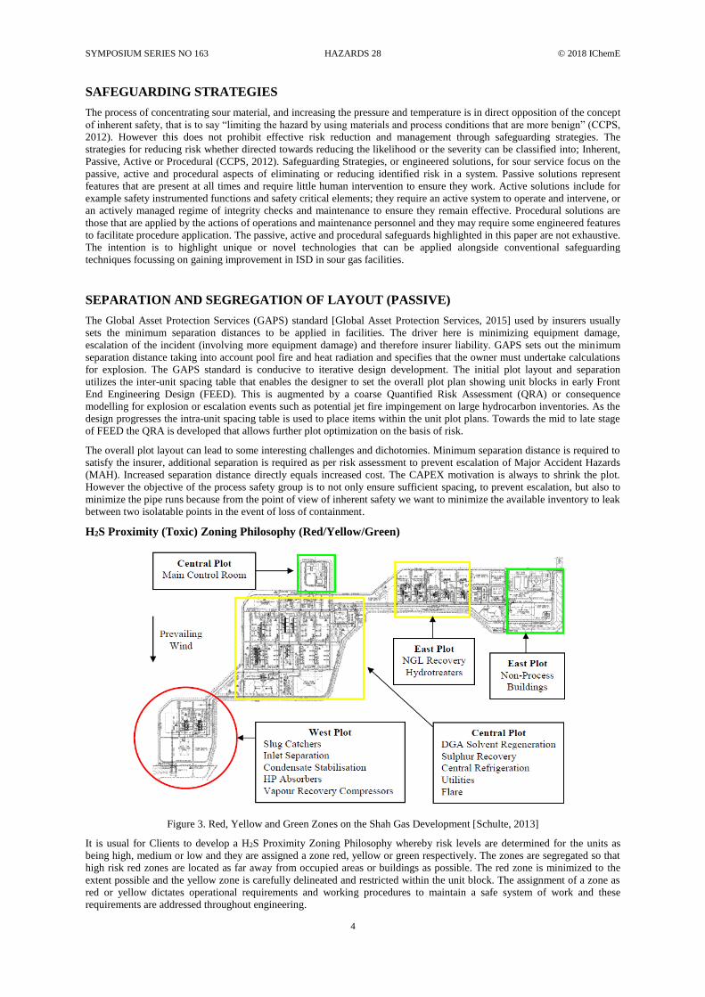
H2S Proximity (Toxic) Zoning Philosophy (Red/Yellow/Green)
Figure 3. Red, Yellow and Green Zones on the Shah Gas Development [Schulte, 2013]
It is usual for Clients to develop a H2S Proximity Zoning Philosophy whereby risk levels are determined for the units as
being high, medium or low and they are assigned a zone red, yellow or green respectively. The zones are segregated so that
high risk red zones are located as far away from occupied areas or buildings as possible. The red zone is minimized to the
extent possible and the yellow zone is carefully delineated and restricted within the unit block. The assignment of a zone as
red or yellow dictates operational requirements and working procedures to maintain a safe system of work and these
requirements are addressed throughout engineering.
SYMPOSIUM SERIES NO 163 HAZARDS 28 © 2018 IChemE
5
Red Zone
The Red Zone threshold is set at a level where serious acute toxic effects on the human body may result in a fatal injury
within a short time frame (i.e. immediately). Red Zone work areas are strictly controlled. Non-intrusive work such as
security or visual inspection may be conducted with mandatory requirement for personnel to carry functioning H2S detector
and emergency escape mini-filter breathing apparatus. Intrusive maintenance work may be conducted with mandatory
requirement for personnel to wear Self-Contained Breathing Apparatus (SCBA) or equivalent. Personal H2S detectors are
worn at all times. Red zone shall make use of strict access control to monitor personnel location. A high level of H2S training
and competency attainment is required for red zone entry.
From a design perspective the primary objective is to apply the principles of ISD in removing and minimising red zones to
the extent that is reasonably practicable. The design, where possible, shall avoid the requirement for foreseeable maintenance
in red zone areas and facilitate escape when wearing SCBA e.g. stair access/egress and two means of egress. The design
allows simple delineation of red zones for the purposes of operational site management. Red zones are segregated to the
maximum extent possible from occupied buildings or areas where people may be present.
The FEED design assesses where prolonged work in red zones may be required. No major maintenance in Red Zone is
allowed and so provisions are made to enable the Unit to shut-down and depressurise to perform major maintenance;
particularly where SCBA may introduce other hazards such as heat stress. Wearing of SCBA sets can narrow the field of
vision, increase body temperature (exacerbated by ambient climate conditions), reduce manoeuvrability/coordination and
cause general discomfort. The overall impact is on productivity and coordination which can result in the potential to make
errors or accidentally damage equipment e.g. valves/instrument connections. It is thus required to minimize the use of SCBA
sets.
Simultaneous Operations (SIMOPs)
H2S is highly toxic, flammable, and explosive so the operators concern for separation and segregation is the health, safety
and lives of their personnel. SIMOPs are where you have large workforce numbers undertaking work, for example campaign
maintenance or compressor repair, in close proximity to live plant. An operator may desire three gas compression and
conditioning trains, to ensure the requisite availability and production output of the facility. Where it is known upfront that
there is a requirement to be able to work on one positively isolated gas compression and conditioning train whilst the others
are live, the owner will require a SIMOPs philosophy and increased separation distance in design to support the operational
requirements for a safe working environment.
The SIMOPs Zone threshold is set at a level where serious acute toxic effects on the human body may result in fatal injury
within a prolonged time frame (e.g. a few hours if untreated). The objective of the separation distance is that workers should
not be exposed to immediately fatal concentrations of H2S and that the separation distance gives them time to hear the alarm,
recognize the emergency action required, don an emergency escape mini-filter breathing apparatus and escape the hazard to
a temporary refuge. SIMOPs Zone work areas are strictly controlled. Within a SIMOPs H2S Proximity Zone there is a
requirement to eliminate and minimize large numbers of people undertaking maintenance work whilst adjacent plant is live.
The safe systems of work and design requirements are very much the same as for Red zone working. Following the
provision of adequate separation distance, SIMOPs work activities are managed through the facility specific H2S HSE
Management System, which incorporates the requisite Permit to Work and other requirements as needed to manage the
residual risk to ALARP on an ongoing basis through the life of the facility. Incorporation of SIMOPs requirements into
design is a relatively new concept; with increasing H2S concentrations and higher injection pressures it is a welcome
development.
Escalation of Events
Quantified Risk Assessment (QRA) and Fire and Explosion Risk Assessment (FERA) enables the designer to determine the
credible escalation events e.g. sustained jet fire impingement on large inventory of volatile liquid hydrocarbons; which can
escalate to a Boiling Liquid, Expanding Vapour Cloud Explosion (BLEVE) with associated fireball and missiles/projectiles.
The studies also enable the determination of the extent of the hazard. This information is used to increase plot separation
distances as an inherently safer approach in the first instance. It is important to remember the escalation events must be
credible.
Where a credible risk of BLEVE exists, bullet tanks are oriented so that the end caps are not directed towards occupied
buildings/or areas. It is very difficult to predict with any confidence the trajectory of missiles though there have been studies
showing the end caps generally travel in the direction of orientation, so plot layout accounts for the line of sight of the end
caps.
Plot Layout
H2S is toxic and acutely hazardous to health therefore the overall Plot layout must take into consideration a number of key
HSE issues relating to the prevailing wind condition:
• It is important that any temporary or permanently occupied buildings, e.g. construction compounds or
administration buildings are placed upwind of any large credible loss of containment events. This is inherently
safer.
SYMPOSIUM SERIES NO 163 HAZARDS 28 © 2018 IChemE
6
• When a flare is operating as per design the combustion products from a sour flare contain CO2, CO, NO, NO2 and
SO2 which are hazardous to human health. Under abnormal conditions a flare may fail to ignite causing ‘flame out’
whereby sour material is dispersed into the atmosphere from the flare stack. It is important that flares are placed
downwind of any permanent occupied buildings and with due consideration to any pre-existing or planned
permanent occupied buildings whether industrial or public. This is inherently safer.
• With regards to emergency escape to a temporary refuge; emergency escape mini filter breathing apparatus
generally has a 15 minute usage limit. Whilst theoretically the industrial filter medium can withstand 15 minutes
exposure it is not good practice to push the limits. These constraints, coupled with a sound HSE philosophy, enable
systematic development of plot layout. For example, you must be able to reach a temporary refuge within 15
minutes from any location on the plot. Sensible assumptions about walking speed wearing breathing apparatus,
where breathing is laboured, allow the calculation of how many temporary refuges are required and optimization
of location; taking into consideration physical access barriers e.g. security fencing, pipe track or sleeper way. The
plot should be orientated to allow the escapee to travel crosswind and upwind, so that they are not continually
travelling through a toxic plume.
Ultimately the prevailing wind direction can dictate the orientation of the overall plot plan; particularly when considering the
existing infrastructure.
MATERIAL SELECTION (PASSIVE)
In sour gas injection facilities, there are areas where careful material selection is required due to the presence of high H2S
content and extreme operating pressures and temperature conditions. Establishing an integrated material selection and testing
programme ensures the safe operation of equipment when installed in high sour and extreme process services, to prevent
against the dangers of possible corrosion, fatigue, leaks or ruptures etc.
Where sour gas plants are located in regions with extreme cold weather conditions, there is the challenge of contending with
low ambient temperatures when the injection pipelines are being depressurised. For instance, at sub-zero design temperatures
in cold winter periods, it has been established from similar sour gas plants that injection lines subjected to ultra-high
pressures are susceptible to brittle failures. Whilst the risk is greatest in extreme cold environments, rigorous assessment is
required for all ambient conditions, even in arid desert locations.
An integrated material selection process for different materials to be used in the construction of the above ground gas
injection lines and plant equipment can be studied for non-heat traced operating conditions at the respective minimum and
maximum design conditions. The study should also establish for each material the ease of welding, availability, economics
and attainability of the required properties. This paper does not cover details of different material selection and their
respective testing, since there are many references already available.
• Where injection pipelines are above ground, pipelines constructed from carbon steel based material are susceptible
to embrittlement as carbon steel is known to have a low temperature coefficient for heat conduction. An alloy rich
material such as F-22 low-alloy steel could be considered ideal for above ground injection pipelines since it is able
to retain good toughness when subjected to varying temperatures.
• Selecting materials with an excellent resistance to reducing and oxidizing fluids, such as sour gas, is important for
equipment as the injection compressor suction drums or gas injectors which are in constant operation with sour gas
fluids. Alloy materials like Alloy 825, a nickel-iron-chromium alloy can be selected for cladding the internal walls
of the drums to meet design conditions and prevent localised corrosion in the drums. Also, material such as
Inconel 625 can be used for certain components.
• Where air coolers are employed in continuous mode, there is a possibility of overcooling of stagnant process sour
gas which can eventually lead to liquid formation in the air coolers especially in cold climates. The cooling tubes
may be subjected to condensation which can gradually lead to corrosion; hence, employing an alloy based material
such as Alloy 825 as the construction material can help reduce the risk of possible corrosion in the cooling tubes
[Block, 2005].
PROCESS, PIPELINE AND PIPING DESIGN (PASSIVE, ACTIVE AND PROCEDURAL)
There are many difficulties and dangers associated with working in sour fields, such as toxicity of the sour gases, hydrate
blockage formation, and corrosion of equipment, that have prevented these resources from being used in the past. The main
aim of process design is to create a process that is cost-effective, safe, and environmentally friendly throughout the whole
lifetime of the plant.
Compressor System (Passive)
The sour gas compressor plant is the core of the sour gas injection process. In some cases compression can operate at
pressures above 600 barg and with H2S levels exceeding 25 mol%. The need to select the right manufacturers with proven
compressor design experience in high pressure and sour gas application is important, as working closely with a carefully
selected compressor manufacturer will offer the opportunity to enhance the design to meet the project requirements. The
SYMPOSIUM SERIES NO 163 HAZARDS 28 © 2018 IChemE
7
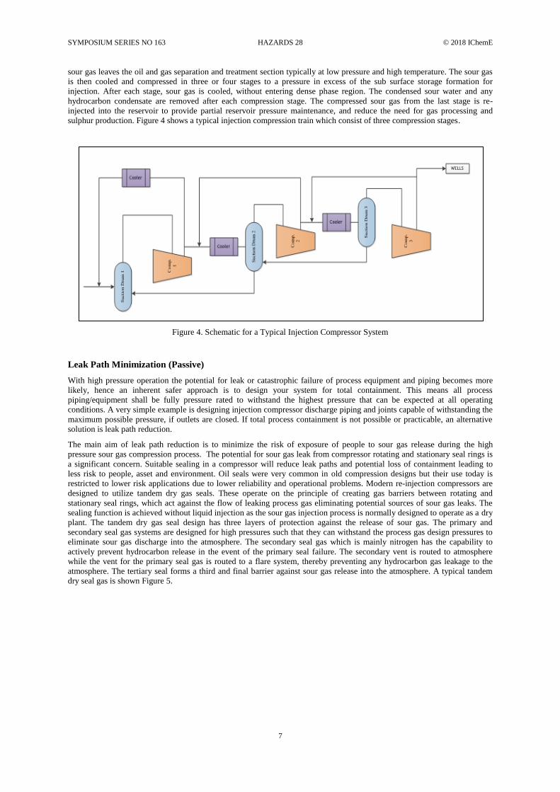
sour gas leaves the oil and gas separation and treatment section typically at low pressure and high temperature. The sour gas
is then cooled and compressed in three or four stages to a pressure in excess of the sub surface storage formation for
injection. After each stage, sour gas is cooled, without entering dense phase region. The condensed sour water and any
hydrocarbon condensate are removed after each compression stage. The compressed sour gas from the last stage is re-
injected into the reservoir to provide partial reservoir pressure maintenance, and reduce the need for gas processing and
sulphur production. Figure 4 shows a typical injection compression train which consist of three compression stages.
Figure 4. Schematic for a Typical Injection Compressor System
Leak Path Minimization (Passive)
With high pressure operation the potential for leak or catastrophic failure of process equipment and piping becomes more
likely, hence an inherent safer approach is to design your system for total containment. This means all process
piping/equipment shall be fully pressure rated to withstand the highest pressure that can be expected at all operating
conditions. A very simple example is designing injection compressor discharge piping and joints capable of withstanding the
maximum possible pressure, if outlets are closed. If total process containment is not possible or practicable, an alternative
solution is leak path reduction.
The main aim of leak path reduction is to minimize the risk of exposure of people to sour gas release during the high
pressure sour gas compression process. The potential for sour gas leak from compressor rotating and stationary seal rings is
a significant concern. Suitable sealing in a compressor will reduce leak paths and potential loss of containment leading to
less risk to people, asset and environment. Oil seals were very common in old compression designs but their use today is
restricted to lower risk applications due to lower reliability and operational problems. Modern re-injection compressors are
designed to utilize tandem dry gas seals. These operate on the principle of creating gas barriers between rotating and
stationary seal rings, which act against the flow of leaking process gas eliminating potential sources of sour gas leaks. The
sealing function is achieved without liquid injection as the sour gas injection process is normally designed to operate as a dry
plant. The tandem dry gas seal design has three layers of protection against the release of sour gas. The primary and
secondary seal gas systems are designed for high pressures such that they can withstand the process gas design pressures to
eliminate sour gas discharge into the atmosphere. The secondary seal gas which is mainly nitrogen has the capability to
actively prevent hydrocarbon release in the event of the primary seal failure. The secondary vent is routed to atmosphere
while the vent for the primary seal gas is routed to a flare system, thereby preventing any hydrocarbon gas leakage to the
atmosphere. The tertiary seal forms a third and final barrier against sour gas release into the atmosphere. A typical tandem
dry seal gas is shown Figure 5.

SYMPOSIUM SERIES NO 163 HAZARDS 28 © 2018 IChemE
8
Figure 5. Typical Tandem Dry Seal Arrangement (Block, 2005)
Flange joints are another vulnerable point of pressurized systems. A bolted flange joint leaks when the material contained in
the system escapes through the gasket pores or around the gasket and the flange face. This occurs when the load on the
gasket has fallen below its minimum seal pressure. The main factors which cause a bolted flange to leak are gasket creep,
bolt creep, vibration, elastic interaction and differential thermal expansion (George, 2010). Use of fit for purpose gasket and
bolt selection followed by correct placement of gasket and proper tightening of bolts can reduce likelihood of failure of
flanged joints. An inherent safer approach will be use of welded pipe and butt welded valves with special stem sealing
wherever possible, minimise the use of flanges and eliminate threaded connections. By eliminating the likelihood of sour gas
leaking to atmosphere this leads to lower risk of fire, explosion and toxic gas release to people, asset and environment.
Other leak sources relate to piping systems and the majority of these are vibration induced failures of small bore piping. The
vibration issue is not properly address via piping design code, and the negative effect of vibration might be incorrectly
ignored in design stage. In injection compressor plant this vibration can be noticed on small branch connection which
includes relief lines, instrumentation ports, nozzles, drains and valves etc. Figure 6 shows the different factors which
contribute to vibration in the compressor and associated piping systems. The piping vibration can be mitigated if a proper
design philosophy is applied and vibration assessment is performed during design stage. The inherent safety approach is to
avoid small bore piping where possible. Unfortunately, avoidance is not always practical and the best solution is to design
them such that they are less subjected to vibration i.e. by reducing the level of vibration to which piping system is exposed or
provide adequate support so that it can withstand any vibration. In addition appropriate vibration detection and trip systems
can also be installed for a compressor which can trip the system and thereby avoid any vibration induced failure.
Last but not least care should be taken to ensure the compressor safeguarding system has a fail-safe design. This means that
failure of the controls or associated systems will result in the system going to the operational mode that has been pre-
determined as safest (DNV, 2010). Examples related to the injection compressor include anti-surge valve will ‘fail to open’
positon, shutdown valves will ‘fail to close’ position and depressurisation valves ‘fail to open’ position.
Figure 6. Vibration Risk Zones for Compressor and Associated Piping System

SYMPOSIUM SERIES NO 163 HAZARDS 28 © 2018 IChemE
9
Unrestrained Pipeline (Passive)
The expansive or mechanical behaviour of buried pipelines under pressure and temperature depends primarily on the
interaction between the pipes and surrounding soil, and even more so with sour gas injection pipelines subjected to high
pressures and high temperature (HPHT) conditions. Tests have shown that designing gas injection pipelines as conventional
restrained pipelines at high design temperatures may introduce expansion stress and possible rupture. To reduce such risk,
HPHT pipelines may be designed as unrestrained heavy wall pipelines, with expansion loops buried in engineered
backfill/padding to achieve the required fatigue life. With such design, the HPHT pipelines will expand and relieve any force
without damage. Further control of such forces is achieved with the use of relatively small anchor blocks on the pipeline. A
typical representation of pipeline expansion loops and anchor block arrangement is shown in Figure 7.
Expansion Loop
Anchor Block
Loop Spacing
Figure 7. Typical Pipeline Expansion Loop Schematic
This strategy to safeguard the pipeline from the risk of rupture and sour gas release is considered a “walk away” design
solution, robust enough to last the plant’s life cycle without the need for high levels of maintenance. However, this should
not stop designers utilising some form of monitoring to ensure the HPHT pipelines are behaving as designed.
Isolation (Passive)
Injection lines and equipment in sour gas service should be designed to have double block and bleed to maintain positive
isolation regardless of pressure rating. This approach for sour service lines establishes a double barrier of isolation between
the injection lines and wells. In the event of an upset this will help limit inventories to be flared, or in the event of a leak it
will limit the size of a loss of containment event, and allow for the removal and/or reinstatement of piping connecting a well
head in a safe manner without having to shut-down or flare a much larger volume.
Hard-Pipe Venting (Passive)
The application of hard-piping to closed hydrocarbon drains or flare in sour gas service is an ISD compared to using flexible
hose connections for draining through a bleed. Having all low point drains including low point pockets from injection lines
hard-piped to a closed drain header with the drain lines design to slope, will ensure fluids are freely drained. This can help
eliminate the venting of sour fluids to the atmosphere when bleeds are opened, thus reducing the risk of having operators use
temporary flexible hoses to connect bleed valves to a safe location or drain.
Flaring and Emission (Passive)
Flare systems are designed to safely dispose any unwanted gas generated in sour gas processing facility during both normal
operation and emergency scenarios (e.g. during an external fire impinging on a process vessel or due a compressor failure
etc.). In an emergency situation, a large inventory of high velocity sour gas must be flared and this creates significant safety
(thermal radiation, noise) and environment impact (NOx, SOx, CO and CO2 emissions). These challenges can be overcome
by use of flare gas reduction and recovery process. An example related to sour gas compressor plant is recycling inventory to
a second train and thereby reducing any sour gas flaring inventory.
In cases where planned maintenance shut-down activities are scheduled in a sour gas facility, sweet gas can be employed to
purge the sour gas injection plant and pipelines to avoid non-emergency sour gas flaring thereby reducing any Sulphur
Dioxide (SO2) emissions and environmental impact. Consideration can be given to designing the process of sweet gas
purging in an automatic mode, as this will minimise human intervention during sweet gas purging operation. Technology
exists for graphical displays and software programming that can be built specifically for sweet gas purging automation.
Overpressure Protection (Active)
System overpressure conditions are very likely scenarios to occur in sour gas injection plants if not adequately controlled
through safer and reliable overpressure protection design. Since these facilities are characterised by HPHT conditions
requiring high capacity injection compressors to operate within these process parameters, safeguarding and controlling
against overpressure scenarios is important. The use of High Integrity Pressure Protection Systems (HIPPS), often as the last
line of defence for protecting downstream operation from over pressurisation is becoming increasingly popular. HIPPS are
independently instrumented protective devices, a type of Safety Instrumented Systems (SIS) designed with higher integrity
to take a process to a safe state when predetermined conditions are met. Each Safety Instrumented Function (SIF) within a
SIS is designed to have a Safety Integrity Level (SIL) rating which may vary from one system to the other depending on the
process to be controlled. Due to their high-integrity performance, HIPPS can sometimes be considered a better design

SYMPOSIUM SERIES NO 163 HAZARDS 28 © 2018 IChemE
10
alternative to traditional mechanical relief devices for overpressure protection of production wells and injection flowlines,
rather than relying upon numerous Pressure Safety Valves which can present hazards such as leaks or are simply not
feasible, particularly in some gathering systems.
Hydrate and/or Corrosion (Active)
Water condensation and/or hydrate formation are serious design/operation issue within sour gas injection facilities; and
represent a significant risk to process safety as it can result in the plugging of both pipes and safety critical instrumentations.
Hydrates typically form in a process where light hydrocarbon, H2S, water vapour and low temperatures or high pressures are
present. A better solution to ensure safety and efficiency of plant is preventing the hydrate formation (Neutrium, 2015).
Even if hydrate formation is avoided by maintaining the compression temperature above the hydrate formation temperature
or by use of a specific dew point monitoring or moisture analysing device, any excess water accelerates corrosion of
equipment and piping in contact with sour gas, this is the main reason why dehydration of sour gas is required ideally before
being fed to sour gas compression. The dehydration facilities help in reducing the quantity of water vapour in a sour gas and
this will lower the dew point and therefore lower the likelihood of hydrate formation. There are several dehydration
technologies available; Molecular sieves and Glycol dehydration are commonly used.
Enhanced Smart-Pig for Pipeline Inspection (Procedural)
The use of full inspection on pipeline is a technology that is readily available with varying capabilities. Smart pigs can be
used to inspect pipelines for defects but current technology is limited to inspecting up to 40mm pipe wall thickness. Working
with recognised pigging specialists can prove to be valuable, as this limitation can be improved for gas injection pipeline
thickness ranging up to say 55mm. The enhanced smart-pig tool gives engineers the flexibility of designing HPHT injection
pipelines beyond the typical thickness of 40mm.
Moisture Analysers for Wet Upset Conditions (Procedural)
Sour gas injection plant designed to operate in a water dry environment may be subjected to wet sour service under upset
conditions. A wet sour service environment introduces the potential for wet H2S cracking, corrosion and accelerated fatigue
of associated piping and pipelines. The impact of wet upset condition is long term considering this phenomenon can go
undetected before they manifest in the form of corrosion which can lead to leak, rupture and/or possible loss of containment.
The provision of moisture analyser alarms on inlet lines to the injection compressor systems helps gives clarity for
operations personnel required to intervene upon wet upset conditions. The analysers can be programmed to trip at variable
thresholds (minimum concentration of moisture) depending on the ambient temperature.
Breathing Air System (Procedural)
A well designed and robust breathing air system can be implemented at sour gas facilities especially in areas where
personnel are expected to be under air at all times. Such design may include a series of multiple outlet manifolds that can be
installed at risk areas to supply breathing air to personnel via personal airline hoses. The portable retractable airline hose
reels can be used over longer distances, and they make for good housekeeping when not in use, as they keep work areas tidy
and safe. They are a much safer replacement for SCBA packs which can create hazard particularly when working at heights.
It is important for engineers to design the air line connections to be incompatible with all other fittings for non-breathable air
or gases. Careful consideration should also be given to the valve connection on the “person side” to prevent ingress of
gases/dirt when not connected to the breathing air supply mains.
PRACTICALITIES OF ACHIEVING INHERENTLY SAFER DESIGN (ISD)
ISD is a relative concept and does not provide absolute yes/no answers. You can never guarantee a 100% safe design. One
option may be inherently safer than another; one option may be safer than another taking into consideration the planned
mode of operation; two options may present the same risk level but one risk may be easier to manage. Applying the
principles of ISD only means something when you are comparing one option against another.
A sound strategy for effective application will make use of a range of tools and techniques owing to the associated
advantages and disadvantages of each, which could include: Procedures, Checklists, Workshops, Hazard Indices e.g. Dow
FEI and CEI, Engagement Surveys, ISD Training, Competence or Traditional Risk Studies. The selection of tools and
techniques will depend on the organizations policy or attitude towards ISD, existing HSE management system framework,
available resources, baseline competence and any constraints given by legal, contractual or standard requirements.
The below table outlines a range of tools and techniques for implementing ISD; used by organizations in the oil and gas
industry. The table highlights advantages and disadvantages of each.
SYMPOSIUM SERIES NO 163 HAZARDS 28 © 2018 IChemE
11
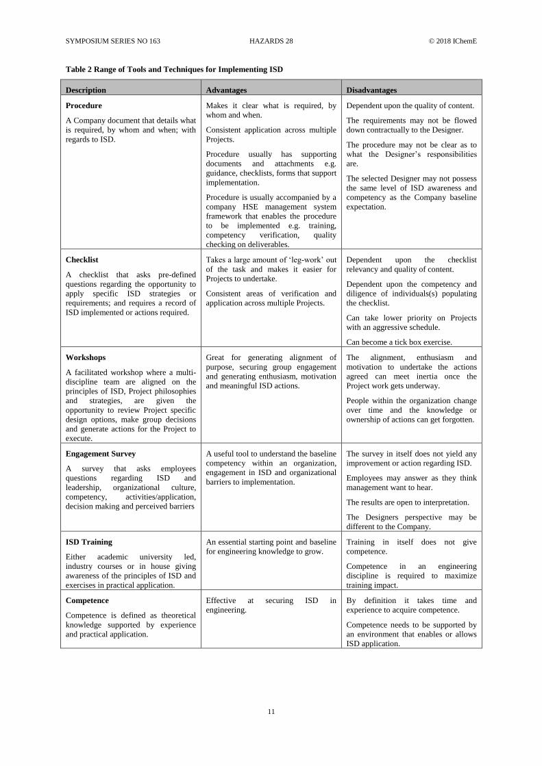
Table 2 Range of Tools and Techniques for Implementing ISD
Description Advantages Disadvantages
Procedure
A Company document that details what
is required, by whom and when; with
regards to ISD.
Makes it clear what is required, by
whom and when.
Consistent application across multiple
Projects.
Procedure usually has supporting
documents and attachments e.g.
guidance, checklists, forms that support
implementation.
Procedure is usually accompanied by a
company HSE management system
framework that enables the procedure
to be implemented e.g. training,
competency verification, quality
checking on deliverables.
Dependent upon the quality of content.
The requirements may not be flowed
down contractually to the Designer.
The procedure may not be clear as to
what the Designer’s responsibilities
are.
The selected Designer may not possess
the same level of ISD awareness and
competency as the Company baseline
expectation.
Checklist
A checklist that asks pre-defined
questions regarding the opportunity to
apply specific ISD strategies or
requirements; and requires a record of
ISD implemented or actions required.
Takes a large amount of ‘leg-work’ out
of the task and makes it easier for
Projects to undertake.
Consistent areas of verification and
application across multiple Projects.
Dependent upon the checklist
relevancy and quality of content.
Dependent upon the competency and
diligence of individuals(s) populating
the checklist.
Can take lower priority on Projects
with an aggressive schedule.
Can become a tick box exercise.
Workshops
A facilitated workshop where a multi-
discipline team are aligned on the
principles of ISD, Project philosophies
and strategies, are given the
opportunity to review Project specific
design options, make group decisions
and generate actions for the Project to
execute.
Great for generating alignment of
purpose, securing group engagement
and generating enthusiasm, motivation
and meaningful ISD actions.
The alignment, enthusiasm and
motivation to undertake the actions
agreed can meet inertia once the
Project work gets underway.
People within the organization change
over time and the knowledge or
ownership of actions can get forgotten.
Engagement Survey
A survey that asks employees
questions regarding ISD and
leadership, organizational culture,
competency, activities/application,
decision making and perceived barriers
A useful tool to understand the baseline
competency within an organization,
engagement in ISD and organizational
barriers to implementation.
The survey in itself does not yield any
improvement or action regarding ISD.
Employees may answer as they think
management want to hear.
The results are open to interpretation.
The Designers perspective may be
different to the Company.
ISD Training
Either academic university led,
industry courses or in house giving
awareness of the principles of ISD and
exercises in practical application.
An essential starting point and baseline
for engineering knowledge to grow.
Training in itself does not give
competence.
Competence in an engineering
discipline is required to maximize
training impact.
Competence
Competence is defined as theoretical
knowledge supported by experience
and practical application.
Effective at securing ISD in
engineering.
By definition it takes time and
experience to acquire competence.
Competence needs to be supported by
an environment that enables or allows
ISD application.
SYMPOSIUM SERIES NO 163 HAZARDS 28 © 2018 IChemE
12
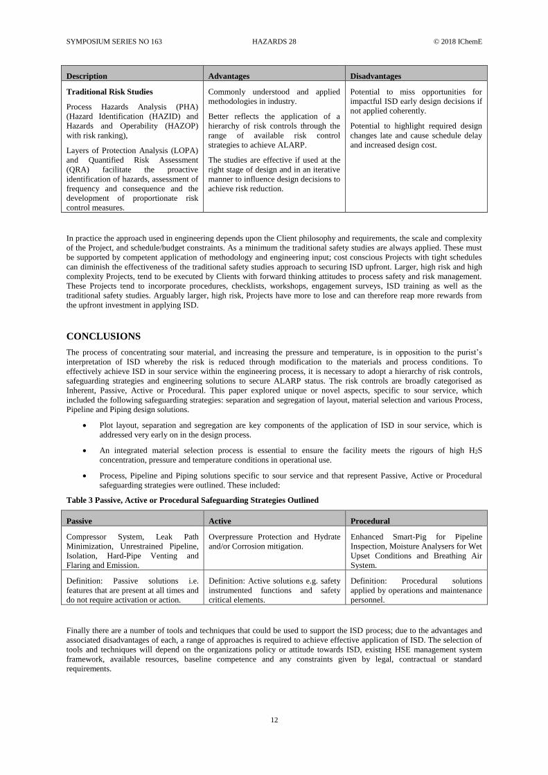
Description Advantages Disadvantages
Traditional Risk Studies
Process Hazards Analysis (PHA)
(Hazard Identification (HAZID) and
Hazards and Operability (HAZOP)
with risk ranking),
Layers of Protection Analysis (LOPA)
and Quantified Risk Assessment
(QRA) facilitate the proactive
identification of hazards, assessment of
frequency and consequence and the
development of proportionate risk
control measures.
Commonly understood and applied
methodologies in industry.
Better reflects the application of a
hierarchy of risk controls through the
range of available risk control
strategies to achieve ALARP.
The studies are effective if used at the
right stage of design and in an iterative
manner to influence design decisions to
achieve risk reduction.
Potential to miss opportunities for
impactful ISD early design decisions if
not applied coherently.
Potential to highlight required design
changes late and cause schedule delay
and increased design cost.
In practice the approach used in engineering depends upon the Client philosophy and requirements, the scale and complexity
of the Project, and schedule/budget constraints. As a minimum the traditional safety studies are always applied. These must
be supported by competent application of methodology and engineering input; cost conscious Projects with tight schedules
can diminish the effectiveness of the traditional safety studies approach to securing ISD upfront. Larger, high risk and high
complexity Projects, tend to be executed by Clients with forward thinking attitudes to process safety and risk management.
These Projects tend to incorporate procedures, checklists, workshops, engagement surveys, ISD training as well as the
traditional safety studies. Arguably larger, high risk, Projects have more to lose and can therefore reap more rewards from
the upfront investment in applying ISD.
CONCLUSIONS
The process of concentrating sour material, and increasing the pressure and temperature, is in opposition to the purist’s
interpretation of ISD whereby the risk is reduced through modification to the materials and process conditions. To
effectively achieve ISD in sour service within the engineering process, it is necessary to adopt a hierarchy of risk controls,
safeguarding strategies and engineering solutions to secure ALARP status. The risk controls are broadly categorised as
Inherent, Passive, Active or Procedural. This paper explored unique or novel aspects, specific to sour service, which
included the following safeguarding strategies: separation and segregation of layout, material selection and various Process,
Pipeline and Piping design solutions.
• Plot layout, separation and segregation are key components of the application of ISD in sour service, which is
addressed very early on in the design process.
• An integrated material selection process is essential to ensure the facility meets the rigours of high H2S
concentration, pressure and temperature conditions in operational use.
• Process, Pipeline and Piping solutions specific to sour service and that represent Passive, Active or Procedural
safeguarding strategies were outlined. These included:
Table 3 Passive, Active or Procedural Safeguarding Strategies Outlined
Passive Active Procedural
Compressor System, Leak Path
Minimization, Unrestrained Pipeline,
Isolation, Hard-Pipe Venting and
Flaring and Emission.
Overpressure Protection and Hydrate
and/or Corrosion mitigation.
Enhanced Smart-Pig for Pipeline
Inspection, Moisture Analysers for Wet
Upset Conditions and Breathing Air
System.
Definition: Passive solutions i.e.
features that are present at all times and
do not require activation or action.
Definition: Active solutions e.g. safety
instrumented functions and safety
critical elements.
Definition: Procedural solutions
applied by operations and maintenance
personnel.
Finally there are a number of tools and techniques that could be used to support the ISD process; due to the advantages and
associated disadvantages of each, a range of approaches is required to achieve effective application of ISD. The selection of
tools and techniques will depend on the organizations policy or attitude towards ISD, existing HSE management system
framework, available resources, baseline competence and any constraints given by legal, contractual or standard
requirements.

SYMPOSIUM SERIES NO 163 HAZARDS 28 © 2018 IChemE
13
ACKNOWLEDGEMENT
Obasi, N., Department of Mechanical/Metallurgy Engineering, Fluor, United Kingdom
REFERENCES
Block, M., Amott, N. and Lanterman, J., 2005, Sour Gas Injection Design Extends the Envelope in Kazakhstan
Center for Chemical Process Safety/AIChE, 2012, Guidelines for Engineering Design for Process Safety
Det Norske Veritas, DNV-OS-E 201, 2010, Oil and Gas Processing System
George, D., 2010 Preventing Leaks from Bolted Flange Joints, Retrieved from https://www.solonmfg.com/why-do-gasketed-
joints-leak-i-50
Global Asset Protection Services LLC, 2015, GAPS Guidelines - GAP.2.5.2 - Oil and Chemical Plant Spacing
Harper C. B., AIV and FIV in Pipelines, Plants and Facilities, IPC2016-64651
Jamaluddin, A.K.M., Bennion, D.B., Thomas, F.B. and Clark, M.A., 1998 “Acid/Sour Gas Management in Petroleum
Industry” SPE 49522
Khan, F.I. and Amyotte, P.R., 2003, How to Make Inherent Safety Practice a Reality
Kletz, T. and Amyotte, P., 2010, Process Plants - A Handbook for Inherently Safer Design
Neutrium, 2015, Hydrate Formation in Gas System, Retrieved from https://neutrium.net/general_engineering/hydrate-
formation-in-gas-systems/
Piping Vibration and Integrity Assessment Retrieved from http://www.betamachinery.com/services/piping-vibration-and-
integrity-assessment
Schulte, D., Mangas, R., Almuhairi, H A., Sahoon, T. and Ross, I., 2013, The Shah Gas Development Project - A Systematic
HSE Approach to Sour Gas Processing
The Energy Institute, 2014, Guidance on Applying Inherent Safety in Design
The Energy Institute, 2008 Guidelines for the Avoidance of Vibration Induced Fatigue Failure in Process Pipework, 2nd
edition
The Health and Safety Executive, 2001, Reducing Risks, Protecting People (R2P2)
The Health and Safety Executive, 1999, The Management of Health and Safety at Work Regulations
The Health and Safety Executive UK, 2006, Offshore Information Sheet No. 2/2006 - Offshore Installations (Safety Case)
Regulations 2005 Regulation 12 Demonstrating compliance with the relevant statutory provisions
Venables, J. and Amott, N., 2017, Effective Achievement of Inherently Safer Design (GPA Europe)
Copyright © 2022 FDOKUMEN