Racetrack SAFER barrier on temporary concrete barriers
14
This article was downloaded by: [University of Nebraska, Lincoln] On: 16 August 2013, At: 13:30 Publisher: Taylor & Francis Informa Ltd Registered in England and Wales Registered Number: 1072954 Registered office: Mortimer House, 37-41 Mortimer Street, London W1T 3JH, UK International Journal of Crashworthiness Publication details, including instructions for authors and subscription information: http://www.tandfonline.com/loi/tcrs20 Racetrack SAFER barrier on temporary concrete barriers John D. Reid a , Robert W. Bielenberg a , Ronald K. Faller a , Karla A. Lechtenberg a & Dean L. Sicking a a Midwest Roadside Safety Facility , University of Nebraska–Lincoln , Lincoln , USA Published online: 07 May 2013. To cite this article: John D. Reid , Robert W. Bielenberg , Ronald K. Faller , Karla A. Lechtenberg & Dean L. Sicking (2013) Racetrack SAFER barrier on temporary concrete barriers, International Journal of Crashworthiness, 18:4, 343-355, DOI: 10.1080/13588265.2013.794321 To link to this article: http://dx.doi.org/10.1080/13588265.2013.794321 PLEASE SCROLL DOWN FOR ARTICLE Taylor & Francis makes every effort to ensure the accuracy of all the information (the “Content”) contained in the publications on our platform. However, Taylor & Francis, our agents, and our licensors make no representations or warranties whatsoever as to the accuracy, completeness, or suitability for any purpose of the Content. Any opinions and views expressed in this publication are the opinions and views of the authors, and are not the views of or endorsed by Taylor & Francis. The accuracy of the Content should not be relied upon and should be independently verified with primary sources of information. Taylor and Francis shall not be liable for any losses, actions, claims, proceedings, demands, costs, expenses, damages, and other liabilities whatsoever or howsoever caused arising directly or indirectly in connection with, in relation to or arising out of the use of the Content. This article may be used for research, teaching, and private study purposes. Any substantial or systematic reproduction, redistribution, reselling, loan, sub-licensing, systematic supply, or distribution in any form to anyone is expressly forbidden. Terms & Conditions of access and use can be found at http:// www.tandfonline.com/page/terms-and-conditions
-
Upload
un-lincoln -
Category
Documents
-
view
2 -
download
0
Transcript of Racetrack SAFER barrier on temporary concrete barriers

This article was downloaded by: [University of Nebraska, Lincoln]On: 16 August 2013, At: 13:30Publisher: Taylor & FrancisInforma Ltd Registered in England and Wales Registered Number: 1072954 Registered office: Mortimer House,37-41 Mortimer Street, London W1T 3JH, UK
International Journal of CrashworthinessPublication details, including instructions for authors and subscription information:http://www.tandfonline.com/loi/tcrs20
Racetrack SAFER barrier on temporary concretebarriersJohn D. Reid a , Robert W. Bielenberg a , Ronald K. Faller a , Karla A. Lechtenberg a & DeanL. Sicking aa Midwest Roadside Safety Facility , University of Nebraska–Lincoln , Lincoln , USAPublished online: 07 May 2013.
To cite this article: John D. Reid , Robert W. Bielenberg , Ronald K. Faller , Karla A. Lechtenberg & Dean L. Sicking (2013)Racetrack SAFER barrier on temporary concrete barriers, International Journal of Crashworthiness, 18:4, 343-355, DOI:10.1080/13588265.2013.794321
To link to this article: http://dx.doi.org/10.1080/13588265.2013.794321
PLEASE SCROLL DOWN FOR ARTICLE
Taylor & Francis makes every effort to ensure the accuracy of all the information (the “Content”) containedin the publications on our platform. However, Taylor & Francis, our agents, and our licensors make norepresentations or warranties whatsoever as to the accuracy, completeness, or suitability for any purpose of theContent. Any opinions and views expressed in this publication are the opinions and views of the authors, andare not the views of or endorsed by Taylor & Francis. The accuracy of the Content should not be relied upon andshould be independently verified with primary sources of information. Taylor and Francis shall not be liable forany losses, actions, claims, proceedings, demands, costs, expenses, damages, and other liabilities whatsoeveror howsoever caused arising directly or indirectly in connection with, in relation to or arising out of the use ofthe Content.
This article may be used for research, teaching, and private study purposes. Any substantial or systematicreproduction, redistribution, reselling, loan, sub-licensing, systematic supply, or distribution in anyform to anyone is expressly forbidden. Terms & Conditions of access and use can be found at http://www.tandfonline.com/page/terms-and-conditions

International Journal of Crashworthiness, 2013Vol. 18, No. 4, 343–355, http://dx.doi.org/10.1080/13588265.2013.794321
Racetrack SAFER barrier on temporary concrete barriers
John D. Reid∗, Robert W. Bielenberg, Ronald K. Faller, Karla A. Lechtenberg and Dean L. Sicking
Midwest Roadside Safety Facility, University of Nebraska–Lincoln, Lincoln, USA
(Received 24 August 2012; final version received 6 April 2013)
Previously, the Steel and Foam Energy Reduction (SAFER) barrier system was successfully developed and crash tested foruse in high-speed racetrack applications for the purpose of reducing the severity of racecar crashes into permanent, rigid,concrete containment walls. The SAFER barrier has been implemented at all high-speed oval race tracks that host eventsfrom NASCAR’s top three race series and IRL’s top series. However, there are a number of racetrack facilities in the UnitedStates that use temporary concrete barriers as a portion of the track layout during races. These barriers are typically usedon race tracks to shield openings or protect portions of the infield. Some of these temporary barrier installations are inareas where current safety guidance would recommend treatment with the SAFER barrier. Thus, a system was successfullydesigned, tested, and evaluated for a system targeted towards the most pressing need in the US motorsports industry, a systemfor spanning openings between rigid concrete parapets on the inner walls of various race tracks.
Keywords: racetrack safety; SAFER barrier; temporary concrete barriers
1. Introduction
In the early 2000s, the Steel and Foam Energy Reduction(SAFER) barrier system was successfully developed andcrash tested for use in high-speed racetrack applications forthe purpose of reducing the severity of racecar crashes intopermanent, rigid, concrete containment walls [2,6]. Thusfar, the SAFER barrier has been implemented at all high-speed oval race tracks that host events from NASCAR’s topthree race series and IRL’s top series.
However, there are a number of racetrack facilities in theUnited States that use temporary concrete barriers (TCBs)as a portion of the track layout during races. These bar-riers are typically used on race tracks to shield openingsor protect portions of the infield. Some of these tempo-rary barrier installations are in areas where current safetyguidance would recommend treatment with the SAFERbarrier. At the onset of this project, no shielding methodhad been developed that could effectively cover the open-ings for racing events while still being removable at othertimes.
Thus, the objective of the research effort describedherein was to design and evaluate a system for installingSAFER barrier on TCB segments that offers race tracksthe flexibility to install the barrier wherever TCBs maybe employed. This research included design, simulation,and analysis of the new system over a range of poten-tial installation types, as well as design of the necessaryTCB and anchorage hardware required for such a sys-tem. Full-scale crash testing was used to evaluate the finaldesign.
∗Corresponding author. Email: [email protected]
TCB systems redirect errant vehicles through a com-bination of various forces and mechanisms, including in-ertial resistance developed by the acceleration of severalbarrier segments, lateral friction loads, and the tensileloads developed from the mass and friction of the bar-rier segments upstream and downstream of the impactedregion [3].
The SAFER barrier system consists of a vertical-face,steel impact panel that is spaced away from a rigid parapetwith discrete, energy-absorbing foam cartridges [4]. Thesteel impact panel is fabricated with five steel tubes stitch-welded to one another, thus forming a stiff, load distributorbeam. The stiff impact panel is utilised to keep the faceof the barrier parallel to the track and prevent permanentdeformation of the impact surface. Dynamic crush of thefoam cartridges dissipates the impacting vehicle’s kineticenergy.
2. Design and analysis
Development of a new system for the installation of theSAFER barrier on TCB systems required a considerabledesign and analysis effort, including: (1) selection of theTCB design for use in the system; (2) development of con-cepts for the SAFER barrier installed on TCB; (3) finiteelement analysis using LS-DYNA R© [5] on various con-cepts to evaluate performance, loading, and critical areas;(4) selection of test installation; (5) simulation to designthe system to be tested; and (6) development of anchoragehardware for the ends of the system.
C© 2013 Taylor & Francis
Dow
nloa
ded
by [
Uni
vers
ity o
f N
ebra
ska,
Lin
coln
] at
13:
30 1
6 A
ugus
t 201
3

344 J.D. Reid et al.
2.1. Selection of TCB design
It was deemed advantageous to select a single TCB designfor the SAFER barrier system installed on TCB in orderto make installations consistent from track to track and toprevent the use of incompatible TCB systems. Review ofthe TCB designs used at various tracks identified a varietyof barrier configurations, including variations in length,barrier reinforcement, and connection design.
The Midwest Roadside Safety Facility (MwRSF) hadrecently worked with the Iowa Speedway to develop a TCBfor use on the track, as shown in Figure 1. The TCB de-veloped for the Iowa Speedway consisted of a 2.44 m longbarrier segment with a vertical front face. The segmentswere connected with a pin and loop connection with threesets of double shear loops and a 31.75 mm diameter, A36steel drop pin. This new design was fabricated and put touse at the Iowa Speedway, and it possessed several advan-tages over the other TCB systems. First, it featured a robustconnection and a significant quantity of reinforcing steel.These features increased the overall load capacity of thebarrier segment. Second, the barrier used a relatively short
length (2.44 m), which allowed it to be easily placed aroundthe curves, and added to its installation flexibility. Based onthese advantages, the Iowa Speedway TCB was chosen asthe standard TCB design for use with the SAFER barrier.
2.2. Initial design concept
With the design of the supporting TCB segment chosen,the next step of the research effort was to reconfigure theSAFER barrier for installation on the temporary barrier.A design concept was developed to facilitate the connec-tions required between the temporary barrier segments andthe SAFER. The barrier design concept was configured forattachment to the 2.44 m long TCB segments using a re-vised, 7.3 m length for the steel SAFER panels. Similarly,the spacing of the foam energy absorbers was increasedby 152 mm as compared to the original design in order tofacilitate the installation on the TCB segments. The spac-ing of retention straps and strap mounting hardware on theSAFER barrier were modified to allow for strap mountingplates to be installed at the midpoint of each TCB segmentfor ease of installation.
Figure 1. Temporary concrete barrier design for Iowa Speedway.
Dow
nloa
ded
by [
Uni
vers
ity o
f N
ebra
ska,
Lin
coln
] at
13:
30 1
6 A
ugus
t 201
3

International Journal of Crashworthiness 345
This initial design concept was used as the basis for thecomputer simulation models. It was realised that the resultsfrom the simulations would have the potential to changethe design. For example, additional rows of temporary bar-riers or anchoring hardware at each barrier segment mightbe necessary to prevent excessive deflection of the system.However, it was desired to make the preliminary evalua-tion of the design without additional barrier segments oranchorages. In addition, the original design concept didnot include any anchoring of the ends of the TCB system.These end anchorages would be added as needed during thesimulation analysis.
2.3. Concept simulation
2.3.1. Simulation model
A finite element model was developed for the prototype,freestanding SAFER barrier and TCB system. The systemmodel consisted of seven panels mounted in front of 21TCB segments. All of the major components of the SAFERbarrier installed on TCB were incorporated. The TCB seg-ments were modelled as rigid bodies with a deformable pinand loop connection. The TCB models were defined withappropriate mass and inertial properties as well as properbarrier-ground friction. This approach for TCB modellinghas been used with good success in previous MwRSF re-search projects involving TCB in highway work zones. TheSAFER barrier panels, splice connections, and retaining-strap brackets were all modelled with shell elements and de-fined with the appropriate steel material properties. Modelsof the retention straps and the foam energy absorbers werealso incorporated. The majority of the simulation modelcomponents were derived from or improved upon previousmodels used in the original development of the SAFER bar-rier system. Thus, there was a large degree of confidence intheir ability to predict the performance.
The barrier model was impacted in all of the simulationswith a surrogate, foam-block vehicle model. The foam-block model had similar mass, inertial, and crush propertiesto a NASCAR stock car vehicle. However, its simplicityallowed it to be computationally very efficient and stable.Use of the surrogate vehicle model allowed the researchersto focus the simulation effort on the barrier details whilestill providing the proper impact dynamics for a crash event.
2.3.2. SAFER barrier on freestanding TCB
The base model was modified to conduct a series of sim-ulations to quantify the performance of the system wheninstalled on freestanding TCB segments. Simulations onthe length of need were conducted with different end con-straints on both the TCBs and the SAFER barrier to bracketthe performance of the system. All models were impactednear the midspan of the system. The results from these
simulations were analysed to provide insight on critical an-chorage requirements as well as guidance on the criticalinstallation for full-scale crash testing. The end constraintson the system were varied to include the following:
(1) TCB segments with unconstrained or free ends andSAFER barrier panels with tension provided on up-stream and downstream ends (Case 1).
(2) TCB segments with axially constrained or pinned endsand SAFER barrier panels with tension provided onupstream and downstream ends (Case 2).
(3) TCB segments with unconstrained or free ends andSAFER barrier panels with unconstrained or free ends(Case 3).
In addition to varying the end conditions, simulationswere conducted with reduced friction coefficient betweenthe TCB segments and the ground to represent an upperbound for potential barrier deflections.
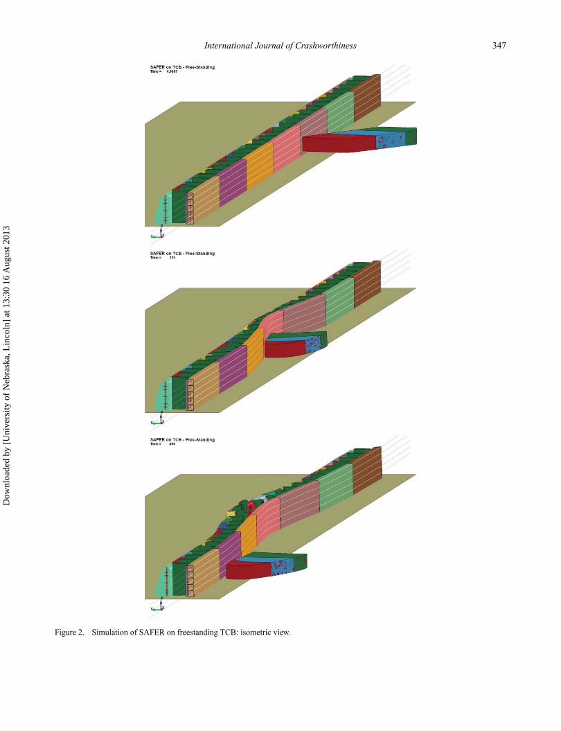
A summary of the simulation results is shown inTable 1. For comparison, included in Table 1 are resultsfrom the SAFER on a fixed concrete wall simulation. Typ-ical simulation results are shown in Figure 2. In these sim-ulations, the overall behaviour of the barrier system waspositive. The surrogate vehicle was smoothly redirected bythe barrier system regardless of the constraints applied tothe system, and with no concern for vehicle pocketing.There was some deformation of the SAFER barrier pan-els, but no plastic hinging of the panels was observed. Inaddition, the bending moments in the SAFER panels wereconsistently more than 20% lower than those found in sim-ulation of the SAFER barrier installed on a fixed concretewall.
The main concern observed in the simulations was thelarge system deflections. Even with the upstream and down-stream ends constrained, the maximum lateral-system de-flections were approximately 0.66 m. These deflections in-creased to approximately 1.04 m when end conditions wereunconstrained. Simulations with reduced TCB segment toground-friction values demonstrated even higher systemdeflections. Lateral deflection is undesirable for the rac-ing circuits due to safety concerns related to personnel andequipment located behind the barriers, and the time andeffort that would be required to reset the system after aserious-impact event.
Additional simulations were conducted to investigatethe benefit of using two rows of TCB segments in lieuof a single row in order to limit lateral-barrier deflections.Results predicted that the use of two rows of TCB segmentscould reduce deflections by approximately 40%.
2.3.3. SAFER barrier on TCB approach transition
A second series of simulations was conducted to inves-tigate the effects of transitioning the SAFER barrier on
Dow
nloa
ded
by [
Uni
vers
ity o
f N
ebra
ska,
Lin
coln
] at
13:
30 1
6 A
ugus
t 201
3

346 J.D. Reid et al.
Table 1. SAFER barrier on freestanding TCB – simulation comparisons.
Model description
Maximumlateral TCB CGdeflection (mm)
Maximum relativedisplacement of
SAFER to TCB (mm)
MaximumSAFER panel
deflection (mm)
Maximum lateraldisplacement ofTCB end (mm)
Maximumlongitudinal
displacement ofTCB end (mm)
SAFER on concrete wall NA 465 465 NA NACase 1 (SAFER on TCB with
longitudinal constraint of SAFERpanels
829 508 777 28 52
Case 2 (SAFER on TCB withlongitudinal constraint of SAFERpanels and pinned TCB ends)
653 508 722 0 0
Case 3 (No constraint on SAFERpanels or TCB)
1049 508 1018 61 115
Repeat of Case 1 with 12 friction 973 508 917 65 113
freestanding TCBs to a rigid concrete parapet. For thissimulation series, the impacting vehicle was configured tostrike at varying impact locations as it approached the rigidbarrier in order to determine the potential hazards of thistype of installation. The main concerns for impacts nearthe rigid barrier were pocketing, excessive loading of thebarrier system, and bottoming out the SAFER barrier onthe rigid barrier.
The results from the transition models found that pock-eting and excessive loading was not an issue. However, therewas some potential for bottoming of the panels at the endof the rigid barrier. The extent of the bottom out is difficultto gauge due to the simplicity of the foam impactor usedto represent the NASCAR vehicle in the simulation. Thus,it was difficult to accurately determine the performance ofthe approach transition with the current vehicle model.
Bottoming of the SAFER barrier at the end of the rigidbarrier was undesirable because it would tend to generateincreased lateral forces on the barrier and increased impactloading on the vehicle occupant. Several options existedfor stiffening the approach transition, including the use ofa second row of TCB segments or using beams or platesacross the end connection to stiffen it.
2.4. Selection of test installation
Following the initial simulation studies, results were dis-cussed with the project sponsors to determine the appropri-ate system for full-scale crash testing. Only one full-scaletest was budgeted for the project, and there existed a need toselect a design that best served the motorsports communityand provided a viable solution to meet the most pressingneed.
There were two basic options for the full-scale crashtest:
(1) The first option was to test a basic length of need setup.Test setup would consist of a long system length with
no end constraints. This would simplify system param-eters to inertia, friction, and foam crush. This optionwould provide the basic information needed to fine tunethe simulation models such that they could be used tofurther develop viable guidelines for various alterna-tive installations. The premise behind this option wasproviding a simple test of the system in order to gainunderstanding and add complexity from there forward.However, it was anticipated that additional analysis andtesting would be required to fully develop the SAFERinstalled on TCB for a wide range of applications.
(2) The second option was to test a system specifically tar-geted towards the most pressing need in the motorsportsindustry in the US, using a single critical test. Discus-sions with MST, IRL, and NASCAR identified spanopenings between rigid concrete barriers on the trackas the most critical need. As such, this option wouldproceed with evaluation of a critical opening configu-ration, design of a system to address that installation,and development of a test setup to evaluate its perfor-mance. This type of option would give the sponsorsa single answer for using the SAFER barrier installedon TCB, but would yield only limited information onpotential alternative installations.
The second option was chosen and researchers pro-ceeded to shift its modelling and design effort to addressthe revised focus.
2.5. Simulation of SAFER on TCB acrossopenings
New LS-DYNA models were developed for spanning anopening between two rigid, concrete parapets. The motor-sports groups provided input regarding the length and con-figuration of the opening. It was determined that the maxi-mum opening size currently used on the tracks of 33 m wasthe critical opening size for consideration. This length was
Dow
nloa
ded
by [
Uni
vers
ity o
f N
ebra
ska,
Lin
coln
] at
13:
30 1
6 A
ugus
t 201
3
International Journal of Crashworthiness 347
Figure 2. Simulation of SAFER on freestanding TCB: isometric view.
Dow
nloa
ded
by [
Uni
vers
ity o
f N
ebra
ska,
Lin
coln
] at
13:
30 1
6 A
ugus
t 201
3
348 J.D. Reid et al.
considered as critical because the larger opening would tendto maximise the lateral deflections as well as increase theloads imparted to the end anchorage hardware. Ultimately,an opening size of 35 m was chosen for simulation, design,and testing because that allowed for an even number of2.44 m long TCB segments to be used. It was believed thatthe performance of the system on smaller openings couldbe determined based on the selected opening size.
The new LS-DYNA models focused on two areas. First,models were simulated to examine the impact of a vehi-cle near the connection between the TCB segments and therigid barrier in order to determine critical anchor loads, lookfor potential pocketing of the system, and investigate thepotential bottoming of the SAFER panels on the rigid bar-rier. Second, simulations were conducted near the midspanof the system to estimate maximum deflections.
Initial models were made with a single row of TCBsegments supporting the SAFER barrier. These TCB seg-ments were anchored to the rigid walls on the upstreamand downstream ends of the system. Results from the im-pact near the transition to the rigid barrier showed that thesystem successfully redirected the impacting vehicle, butthere was potential for the SAFER barrier to bottom out onthe rigid, concrete barrier. In addition, the maximum lateraldeflection of the TCB segments was found to be 0.40 m.Simulation of an impact into the midspan of the systemshowed that the system successfully redirected the vehiclewith an estimated maximum lateral system deflection ofover 0.64 m.
The results from these models led to concerns thatthe overall system deflections were higher than desired,and that there was potential for significant bottoming ofthe panels on the rigid barrier end. In order to alleviatethese issues, a second series of models was developed us-ing a second row of TCB segments behind the originalrow spanning the opening. The second row of TCB seg-ments was also anchored to the rigid concrete wall oneach end with cable tension anchors. Simulation resultsfor these models, when impacted near the transition to therigid barrier and the midspan of the system, are shown inFigures 3 and 4.
Results from the models with the additional row of TCBsegments showed significant improvement over the previ-ous design. For an impact near the transition to the rigidwall, the maximum lateral deflection of the first row ofTCB segments was reduced to 0.23 m, and the maximumlateral deflection of the second row of TCB segments was0.40 m. These deflections represent a significant reductionin overall barrier displacement. In addition, the simulationindicated a significantly reduced potential for bottoming outthe SAFER panels against the rigid barrier. Results fromthe simulation of impact near the midspan of the systemshowed similar improvement. Maximum lateral deflectionsof the first and second row of TCB segments were foundto be 0.36 m and 0.51 m, respectively. Both impact condi-
tions indicated that the system would successfully redirecta vehicle impacting at 217 km/h and an angle of 25◦.
Based on the improved performance with a second rowof TCB segments, the system design proceeded with theSAFER barrier mounted on a double row of TCB segmentswith each row of TCBs anchored to the ends of the concretebarrier. Review of the simulation results also demonstratedthat an impact 3.66 m upstream of the end of the concreteparapet produced the highest anchorage loads, the highestbarrier loads, and demonstrated some potential for bottom-ing the SAFER barrier panels on the concrete wall. Thus,MwRSF proposed to run the single full-scale crash test asan impact of a NASCAR vehicle 3.66 m upstream of thedownstream concrete parapet end at a speed of 217 km/hand an angle of 25◦.
2.6. Anchorage design
In order for the TCB segments to safely support the SAFERbarrier, the end segments in each row were anchored to theupstream and downstream concrete parapets. Anchoringthe temporary barriers provided for reduced barrier deflec-tion and helped prevent pocketing and bottom out of theSAFER panels near the transition to the rigid parapet. Sep-arate anchorages were required for each row of the TCBsegments. The upstream and downstream end anchoragesfor both rows of TCB segments were designed based on theloads estimated by the simulation effort.
The end anchorage hardware for the first row consistedof a 19 mm thick, ‘L’ shaped A572 Grade 50 steel plateanchored to the end of the concrete parapet (see Figure 5).The ‘L’-shaped steel anchor plate was attached to the end ofthe parapet with four 22 mm (diameter) by 330 mm (length)A193 Grade B7 threaded rods that were epoxied in the bar-rier to a depth of 254 mm. The front side of the ‘L’-shapedsteel anchor plate was anchored to the front side of theparapet with five 19 mm Hilti HIS-N threaded sleeves with19 mm (diameter) A325 heavy hex bolts. The end of the‘L’-shaped steel anchor plate had a series of 19 mm thickA572 Grade 50 steel plates welded to it with holes for theend-pin connection. These plates were spaced to match thespacing of the connection loops on the TCB segment. Con-nection of the ‘L’-shaped steel anchor plate to the end TCBsegment was completed by passing an oversized 38 mm(diameter) A36 steel pin through the loops of the end TCBsegment and the pin plates.
The ‘L’-shaped steel anchor plate design was chosenbecause it allowed anchorage of the TCB segments for wallsof varying widths and had sufficient capacity to keep theTCB segments anchored during a high-energy impact. Inaddition, it was believed that the ‘L’-shaped steel anchorplate could be adjusted upto 19 mm by the addition ofspacers under the plates to address small variations in thefit up of the anchor plate holes with the TCB segment loops.
Dow
nloa
ded
by [
Uni
vers
ity o
f N
ebra
ska,
Lin
coln
] at
13:
30 1
6 A
ugus
t 201
3

International Journal of Crashworthiness 349
Figure 3. System across opening, double row of PCBs, impact near rigid barrier end.
Dow
nloa
ded
by [
Uni
vers
ity o
f N
ebra
ska,
Lin
coln
] at
13:
30 1
6 A
ugus
t 201
3

350 J.D. Reid et al.
Figure 4. System across opening, double row of PCBs, impact near midspan.
Anchorage of the second row of TCB segments wasaccomplished with a pair of cable anchors that attached toanchor brackets mounted on the concrete parapet on one endand an oversized 38 mm (diameter) A36 steel pin throughthe loops of the end TCB segment on the other end (seeFigure 5). The cable assemblies were comprised of 19 mm(diameter) 6 × 19 IWRC IPS wire rope, with a thimbleassembly on one end and a Grade 5 threaded stud on theother end. The anchor bracket on the concrete parapet wasmade of gusseted 13 mm thick A36 steel plate and wasanchored to the parapet using four 19 mm (diameter) by152 mm long Powers Fasteners wedge bolts. Pipe sleevespacers were used to keep the cable assemblies attached ata consistent height to the end pin of the TCB segment. Thecable anchor assemblies were made taught prior to crashtesting by tightening the nut on the threaded stud.
3. Design detailsPhotographs of the installation are shown in Figure 6. Thebasic system configuration consisted of a 35 m long, simu-lated track opening formed by a 37 m long concrete parapeton the downstream end of the system and a 3 m long con-crete parapet on the upstream end. One row of 14 TCBsegments was installed flush with the traffic side face of theconcrete parapets and anchored directly to the end of theupstream and downstream concrete parapets. A second rowof 15 TCB segments was installed behind the first row witha half TCB segment length offset such that the midspan ofeach TCB in the second row aligned with the connectionjoint between two TCB segments in the first row. The sec-ond row of TCB segments was anchored to the backsideof the concrete parapets. Eight SAFER barrier panels weremounted across the opening.
Dow
nloa
ded
by [
Uni
vers
ity o
f N
ebra
ska,
Lin
coln
] at
13:
30 1
6 A
ugus
t 201
3

International Journal of Crashworthiness 351
Figure 5. Anchor designs.
The SAFER barrier system was modified slightly fromprevious designs to account for installation on the TCB sec-tions across the opening. First, the panel length was short-ened from the original 8.5 m to 7.4 m in order to match thelength of three 2.44 m long TCB segments. The foam spac-ing in the system was increased slightly from the original1.7 m to 1.9 m to allow for an even spacing of four blocksper panel section while placing the blocks securely on theTCB segments rather than across a TCB joint. Similarly,the retention-strap anchors were moved to facilitate place-ment on the TCB segments. Two retention-strap anchorswere used for each SAFER panel section and located at themidspan of the TCB segments. This modification allowedfor easy SAFER placement on the TCB segments whilestill allowing for sufficient retention straps to constrain theSAFER barrier to the TCB segments. The retention strapsand mounting hardware were unchanged from the originalSAFER barrier – Version 2. No other changes were madeto the original SAFER barrier design. Ends of the SAFERpanels were anchored to the concrete parapets to provide
Figure 6. SPCB-1: pre-test.
the anchorage necessary to simulate a continuous SAFERbarrier installation.
The TCB segments were based on a portable concrete-barrier design developed for use at the Iowa Speedway.Each TCB consisted of a 2.44 m long by 457 mm wideby 914 mm tall reinforced concrete-barrier section witha vertical front face and a sloped back face. The barriersection was configured with concrete having a compressionstrength of 34.5 MPa. The barrier segments were connectedby a pin and loop style connection, with three sets of doubleshear loops. The rebar loops were comprised of no. 6 A706Grade 60 steel and were slightly recessed within a circularcutout at the ends to reduce the gap between the barriersegments. A 32 mm (diameter) A36 steel pin was passedthrough the loops to complete the connection.
4. Full-scale crash test no. SPCB-1
4.1. Test description
On 18 November 2011, a 1701 kg NASCAR stock car vehi-cle was impacted into the SAFER barrier installed on TCBacross an opening at a speed of 240 km/h and at a trajectory
Dow
nloa
ded
by [
Uni
vers
ity o
f N
ebra
ska,
Lin
coln
] at
13:
30 1
6 A
ugus
t 201
3
352 J.D. Reid et al.
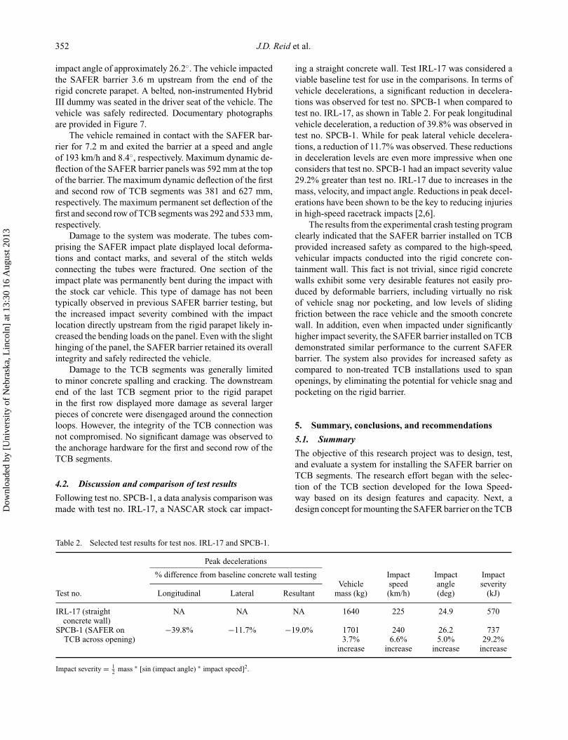
impact angle of approximately 26.2◦. The vehicle impactedthe SAFER barrier 3.6 m upstream from the end of therigid concrete parapet. A belted, non-instrumented HybridIII dummy was seated in the driver seat of the vehicle. Thevehicle was safely redirected. Documentary photographsare provided in Figure 7.
The vehicle remained in contact with the SAFER bar-rier for 7.2 m and exited the barrier at a speed and angleof 193 km/h and 8.4◦, respectively. Maximum dynamic de-flection of the SAFER barrier panels was 592 mm at the topof the barrier. The maximum dynamic deflection of the firstand second row of TCB segments was 381 and 627 mm,respectively. The maximum permanent set deflection of thefirst and second row of TCB segments was 292 and 533 mm,respectively.
Damage to the system was moderate. The tubes com-prising the SAFER impact plate displayed local deforma-tions and contact marks, and several of the stitch weldsconnecting the tubes were fractured. One section of theimpact plate was permanently bent during the impact withthe stock car vehicle. This type of damage has not beentypically observed in previous SAFER barrier testing, butthe increased impact severity combined with the impactlocation directly upstream from the rigid parapet likely in-creased the bending loads on the panel. Even with the slighthinging of the panel, the SAFER barrier retained its overallintegrity and safely redirected the vehicle.
Damage to the TCB segments was generally limitedto minor concrete spalling and cracking. The downstreamend of the last TCB segment prior to the rigid parapetin the first row displayed more damage as several largerpieces of concrete were disengaged around the connectionloops. However, the integrity of the TCB connection wasnot compromised. No significant damage was observed tothe anchorage hardware for the first and second row of theTCB segments.
4.2. Discussion and comparison of test results
Following test no. SPCB-1, a data analysis comparison wasmade with test no. IRL-17, a NASCAR stock car impact-
ing a straight concrete wall. Test IRL-17 was considered aviable baseline test for use in the comparisons. In terms ofvehicle decelerations, a significant reduction in decelera-tions was observed for test no. SPCB-1 when compared totest no. IRL-17, as shown in Table 2. For peak longitudinalvehicle deceleration, a reduction of 39.8% was observed intest no. SPCB-1. While for peak lateral vehicle decelera-tions, a reduction of 11.7% was observed. These reductionsin deceleration levels are even more impressive when oneconsiders that test no. SPCB-1 had an impact severity value29.2% greater than test no. IRL-17 due to increases in themass, velocity, and impact angle. Reductions in peak decel-erations have been shown to be the key to reducing injuriesin high-speed racetrack impacts [2,6].
The results from the experimental crash testing programclearly indicated that the SAFER barrier installed on TCBprovided increased safety as compared to the high-speed,vehicular impacts conducted into the rigid concrete con-tainment wall. This fact is not trivial, since rigid concretewalls exhibit some very desirable features not easily pro-duced by deformable barriers, including virtually no riskof vehicle snag nor pocketing, and low levels of slidingfriction between the race vehicle and the smooth concretewall. In addition, even when impacted under significantlyhigher impact severity, the SAFER barrier installed on TCBdemonstrated similar performance to the current SAFERbarrier. The system also provides for increased safety ascompared to non-treated TCB installations used to spanopenings, by eliminating the potential for vehicle snag andpocketing on the rigid barrier.
5. Summary, conclusions, and recommendations
5.1. Summary
The objective of this research project was to design, test,and evaluate a system for installing the SAFER barrier onTCB segments. The research effort began with the selec-tion of the TCB section developed for the Iowa Speed-way based on its design features and capacity. Next, adesign concept for mounting the SAFER barrier on the TCB
Table 2. Selected test results for test nos. IRL-17 and SPCB-1.
Peak decelerations
% difference from baseline concrete wall testing Impact Impact ImpactVehicle speed angle severity
Test no. Longitudinal Lateral Resultant mass (kg) (km/h) (deg) (kJ)
IRL-17 (straightconcrete wall)
NA NA NA 1640 225 24.9 570
SPCB-1 (SAFER on −39.8% −11.7% −19.0% 1701 240 26.2 737TCB across opening) 3.7%
increase6.6%
increase5.0%
increase29.2%
increase
Impact severity = 12 mass ∗ [sin (impact angle) ∗ impact speed]2.
Dow
nloa
ded
by [
Uni
vers
ity o
f N
ebra
ska,
Lin
coln
] at
13:
30 1
6 A
ugus
t 201
3

International Journal of Crashworthiness 353
Figure 7. SPCB-1: post-test.
Dow
nloa
ded
by [
Uni
vers
ity o
f N
ebra
ska,
Lin
coln
] at
13:
30 1
6 A
ugus
t 201
3

354 J.D. Reid et al.
section was developed. The design concept focused on lim-iting changes to the SAFER barrier hardware while stillproviding a method of mounting the system on TCB seg-ments. After a basic design concept was chosen, simula-tion using LS-DYNA was used to investigate the perfor-mance of the proposed system, determine the loads onvarious system components, and to identify critical im-pact points. The initial simulations found that the relativelylarge system deflections were associated with installing theSAFER barrier on a single row of freestanding TCB seg-ments. Further investigation demonstrated that two rows ofTCB segments could reduce deflections by approximately40%.
Following the initial simulation effort, feedback fromthe sponsors was sought regarding the direction of the re-search. Two research options were considered. The optionchosen involved specific development of a SAFER barrierinstalled on TCB system targeted towards the most pressingneed in the US motorsports industry – a system for spanningopenings between rigid concrete parapets on the inner wallsof various racetracks. This research effort would give thesponsors a single answer for using the SAFER barrier in-stalled on TCB, but it would yield only limited informationon potential alternative installations.
Simulation was used to finalise the design concept, de-termine the load requirements for the anchorage of the endTCB segments, and determine the critical impact point onthe system. Subsequently, one full-scale crash test was con-ducted to evaluate the new system. A slightly modifiedversion of the SAFER barrier was installed on two rowsof TCBs used to span a 35 m long, simulated track open-ing. The test conditions consisted of a 1701 kg NASCARvehicle impacting at a speed of 240 km/h and at a tra-jectory impact angle of approximately 26.2◦. The vehicleimpacted the SAFER barrier 3.6 m upstream of the end ofthe rigid concrete parapet and was safely redirected. Anal-ysis of the test data found that the new system providedimproved safety over rigid concrete parapets and standardTCB installations.
In addition, the performance of the new system wasfound to be very similar to that of the SAFER barrier cur-rently implemented on racetracks around the country. Itshould also be noted that similar safety benefits are expectedwhen the system is impacted with IRL open wheel cars.Based on the successful full-scale crash test, the SAFERbarrier installed on TCB was deemed acceptable for use onracetracks hosting IRL and NASCAR racing events.
5.2. Conclusions
The new system addressed the need to adapt the SAFERsystem to TCBs and focused on a specific application ofrigid wall openings. Specific conclusions include: (1) spe-cial attention is needed for anchorage of such a system inorder to limit system deflections and improve transition be-
haviour; (2) an additional row of barriers improves systemdeflections; (3) the critical impact point was located at thetransition between the movable TCBs and the fixed walls,and (4) this system provided similar safety improvement asthe original SAFER system, including reduced deflectionsand risk for occupant injury.
5.3. Installation guidance
As with any piece of safety hardware, the SAFER barrierinstalled on TCB across an opening system has certain in-stallation parameters and recommendations pertaining toits use as well as pertaining to repair and/or resetting fol-lowing an impact event. Two such examples are providedhere; a detailed list of such is provided in [1].
(1) The SAFER barrier installed on TCB across an open-ing system was designed and tested using a 35 m longopening. This opening size represented the largest an-ticipated opening size currently in use on NASCARand IRL track facilities. The system can also be usedon smaller openings without any modifications.
(2) The SAFER barrier installed on TCB across an open-ing system was tested at a critical impact location nearthe transition to the rigid concrete parapet. While thisimpact was most critical in terms of the safety perfor-mance of the system, it does not represent the maximumlateral deflection of the system. Simulation of impactsnear the mid-span of the system at speeds of 217 km/hand an angle of 25◦ indicated that lateral deflection ofthe first and second rows of TCB segments could be ashigh as 381 mm and 533 mm, respectively. Based onthese expected deflection levels under severe impacts, aminimum 0.6 m lateral clear area should be maintainedbehind the second row of TCB segments to allow forbarrier motion and prevent interaction of the barriersystem with the people and equipment it is designedto shield. The clear area should be clearly delineatedto discourage traffic or items from being placed in thearea. This clear area should also be paved with asphaltor concrete paving in order to provide a consistent sur-face for the barriers to slide on during an impact event.Gravel or soil deflection areas for the barrier are notrecommended as they may cause the base of the TCBsegments to snag on the ground as they deflect and tripbackward.
5.4. Future research
The successful design, testing, and evaluation effort for theSAFER barrier installed on TCB demonstrated the poten-tial to use this system in other motorsports applications,such as road or street courses. However, there are certainareas that need further research before the design can beadapted for use in such applications. For example, the geom-etry, potential impact conditions, boundary conditions, and
Dow
nloa
ded
by [
Uni
vers
ity o
f N
ebra
ska,
Lin
coln
] at
13:
30 1
6 A
ugus
t 201
3

International Journal of Crashworthiness 355
installation parameters for road courses may be significantlydifferent from those parameters considered for oval tracks,requiring a detailed design and testing program.
AcknowledgementsThe authors wish to acknowledge several sources that made acontribution to this project: (1) MST, NASCAR, and IRL; (2)Southern Bleacher Company, GT Grandstands, Inc., and NUSSLI(US) LLC for donation of the SAFER wall sections and materials;(3) Tom Gideon and John Patalak with the NASCAR Research &Development Center for their assistance in conducting the crashtesting; (4) Jody Swartz and Hilti USA for donation of adhesivematerials and concrete anchors; (5) Hendrick Motorsports; (6)MwRSF staff and students; and (7) Livermore Software Technol-ogy Corporation. The simulation work performed for this projectwas completed utilising the Holland Computing Center of theUniversity of Nebraska–Lincoln.
References[1] R.W. Bielenberg, R.K. Faller, D.L. Sicking, J.D. Reid, and
K.A. Lechtenberg, Design and Evaluation of the SAFERBarrier Installed on Portable Concrete Barrier, MwRSF
Research Report No. TRP-03-257-11, Midwest RoadsideSafety Facility, University of Nebraska, Lincoln, NE, 2011.
[2] R.W. Bielenberg, R.K. Faller, D.L. Sicking, J.R. Rohde, J.D.Reid, K.A. Polivka, and J. Holloway, Initial In-Service Per-formance Evaluation of the SAFER Racetrack Barrier, Pro-ceedings of the 2004 Motorsports Engineering Conferenceand Exhibition, SAE P-392, Paper 2004-01-3526, SAE Inter-national, Warrendale, PA, 2004.
[3] R.W. Bielenberg, J.D. Reid, R.K. Faller, J.R. Rohde, and D.L.Sicking, Tie-Downs and Transitions for Temporary ConcreteBarriers, Transportation Research Record 1984, TRB, Na-tional Research Council, Washington, DC, 2006, pp. 31–46.
[4] R.K. Faller, R.W. Bielenberg, D.L. Sicking, J.R. Rohde, andJ.D. Reid, Development and Testing of the SAFER Barrier –Version 2, SAFER Barrier Gate, and Alternative BackupStructure, Proceedings of the 2006 Motorsports EngineeringConference and Exhibition, SAE Paper 06MSEC-16, SAEInternational, Warrendale, PA, 2006.
[5] J.O. Hallquist, LS-DYNA Keyword User’s Manual Version971, Livermore Software Technology Corporation, Liver-more, CA, 2007.
[6] J.D. Reid, R.K. Faller, J.C. Holloway, J.R. Rohde, and D.L.Sicking, New Energy-Absorbing High-Speed Safety Barrier,Transportation Research Record 1851, TRB, National Re-search Council, Washington, DC, 2003, pp. 53–64.
Dow
nloa
ded
by [
Uni
vers
ity o
f N
ebra
ska,
Lin
coln
] at
13:
30 1
6 A
ugus
t 201
3