Informatica Cloud Data Integration - May 2022 - Mappings
115
Informatica ® Cloud Data Integration May 2022 Mappings
-
Upload
khangminh22 -
Category
Documents
-
view
6 -
download
0
Transcript of Informatica Cloud Data Integration - May 2022 - Mappings
Informatica® Cloud Data IntegrationMay 2022
Mappings

Informatica Cloud Data Integration MappingsMay 2022
© Copyright Informatica LLC 2006, 2022
This software and documentation are provided only under a separate license agreement containing restrictions on use and disclosure. No part of this document may be reproduced or transmitted in any form, by any means (electronic, photocopying, recording or otherwise) without prior consent of Informatica LLC.
U.S. GOVERNMENT RIGHTS Programs, software, databases, and related documentation and technical data delivered to U.S. Government customers are "commercial computer software" or "commercial technical data" pursuant to the applicable Federal Acquisition Regulation and agency-specific supplemental regulations. As such, the use, duplication, disclosure, modification, and adaptation is subject to the restrictions and license terms set forth in the applicable Government contract, and, to the extent applicable by the terms of the Government contract, the additional rights set forth in FAR 52.227-19, Commercial Computer Software License.
Informatica, Informatica Cloud, Informatica Intelligent Cloud Services, PowerCenter, PowerExchange, and the Informatica logo are trademarks or registered trademarks of Informatica LLC in the United States and many jurisdictions throughout the world. A current list of Informatica trademarks is available on the web at https://www.informatica.com/trademarks.html. Other company and product names may be trade names or trademarks of their respective owners.
Portions of this software and/or documentation are subject to copyright held by third parties. Required third party notices are included with the product.
The information in this documentation is subject to change without notice. If you find any problems in this documentation, report them to us at [email protected].
Informatica products are warranted according to the terms and conditions of the agreements under which they are provided. INFORMATICA PROVIDES THE INFORMATION IN THIS DOCUMENT "AS IS" WITHOUT WARRANTY OF ANY KIND, EXPRESS OR IMPLIED, INCLUDING WITHOUT ANY WARRANTIES OF MERCHANTABILITY, FITNESS FOR A PARTICULAR PURPOSE AND ANY WARRANTY OR CONDITION OF NON-INFRINGEMENT.
Publication Date: 2022-05-05
Table of Contents
Preface . . . . . . . . . . . . . . . . . . . . . . . . . . . . . . . . . . . . . . . . . . . . . . . . . . . . . . . . . . . . . . . . . . . . . . 6Informatica Resources. . . . . . . . . . . . . . . . . . . . . . . . . . . . . . . . . . . . . . . . . . . . . . . . . . . 6
Informatica Documentation. . . . . . . . . . . . . . . . . . . . . . . . . . . . . . . . . . . . . . . . . . . . . 6
Informatica Intelligent Cloud Services web site. . . . . . . . . . . . . . . . . . . . . . . . . . . . . . . . 6
Informatica Intelligent Cloud Services Communities. . . . . . . . . . . . . . . . . . . . . . . . . . . . . 6
Informatica Intelligent Cloud Services Marketplace. . . . . . . . . . . . . . . . . . . . . . . . . . . . . . 6
Data Integration connector documentation. . . . . . . . . . . . . . . . . . . . . . . . . . . . . . . . . . . 7
Informatica Knowledge Base. . . . . . . . . . . . . . . . . . . . . . . . . . . . . . . . . . . . . . . . . . . . 7
Informatica Intelligent Cloud Services Trust Center. . . . . . . . . . . . . . . . . . . . . . . . . . . . . . 7
Informatica Global Customer Support. . . . . . . . . . . . . . . . . . . . . . . . . . . . . . . . . . . . . . 7
Chapter 1: Mappings. . . . . . . . . . . . . . . . . . . . . . . . . . . . . . . . . . . . . . . . . . . . . . . . . . . . . . . . . 8Mapping Designer. . . . . . . . . . . . . . . . . . . . . . . . . . . . . . . . . . . . . . . . . . . . . . . . . . . . . . 9
Mapping templates. . . . . . . . . . . . . . . . . . . . . . . . . . . . . . . . . . . . . . . . . . . . . . . . . . . . 11
Mapping configuration. . . . . . . . . . . . . . . . . . . . . . . . . . . . . . . . . . . . . . . . . . . . . . . . . . 13
Defining a mapping. . . . . . . . . . . . . . . . . . . . . . . . . . . . . . . . . . . . . . . . . . . . . . . . . 14
Configuring the source. . . . . . . . . . . . . . . . . . . . . . . . . . . . . . . . . . . . . . . . . . . . . . . 14
Configuring the data flow. . . . . . . . . . . . . . . . . . . . . . . . . . . . . . . . . . . . . . . . . . . . . 15
Configuring the target. . . . . . . . . . . . . . . . . . . . . . . . . . . . . . . . . . . . . . . . . . . . . . . . 16
Rules and guidelines for mapping configuration. . . . . . . . . . . . . . . . . . . . . . . . . . . . . . . 16
Rules and guidelines for mappings on GPU-enabled clusters. . . . . . . . . . . . . . . . . . . . . . . 17
Data flow run order. . . . . . . . . . . . . . . . . . . . . . . . . . . . . . . . . . . . . . . . . . . . . . . . . 17
Mapping validation. . . . . . . . . . . . . . . . . . . . . . . . . . . . . . . . . . . . . . . . . . . . . . . . . . . . . 19
Validating a mapping. . . . . . . . . . . . . . . . . . . . . . . . . . . . . . . . . . . . . . . . . . . . . . . . 20
Data preview for a mapping. . . . . . . . . . . . . . . . . . . . . . . . . . . . . . . . . . . . . . . . . . . . . . . 20
Preview behavior for a mapping. . . . . . . . . . . . . . . . . . . . . . . . . . . . . . . . . . . . . . . . . 21
Running a preview job for a mapping. . . . . . . . . . . . . . . . . . . . . . . . . . . . . . . . . . . . . . 22
Viewing preview results for a mapping. . . . . . . . . . . . . . . . . . . . . . . . . . . . . . . . . . . . . 22
Data preview for an elastic mapping. . . . . . . . . . . . . . . . . . . . . . . . . . . . . . . . . . . . . . . . . . 24
Preview behavior for an elastic mapping. . . . . . . . . . . . . . . . . . . . . . . . . . . . . . . . . . . . 25
Running a preview for an elastic mapping. . . . . . . . . . . . . . . . . . . . . . . . . . . . . . . . . . . 25
Viewing preview results for an elastic mapping. . . . . . . . . . . . . . . . . . . . . . . . . . . . . . . . 26
Pushdown optimization preview. . . . . . . . . . . . . . . . . . . . . . . . . . . . . . . . . . . . . . . . . . . . 27
Running a pushdown preview job. . . . . . . . . . . . . . . . . . . . . . . . . . . . . . . . . . . . . . . . . 28
Pushdown optimization preview results files. . . . . . . . . . . . . . . . . . . . . . . . . . . . . . . . . 29
Testing a mapping. . . . . . . . . . . . . . . . . . . . . . . . . . . . . . . . . . . . . . . . . . . . . . . . . . . . . 29
Mapping tutorial. . . . . . . . . . . . . . . . . . . . . . . . . . . . . . . . . . . . . . . . . . . . . . . . . . . . . . 29
Preparing for the mapping tutorial. . . . . . . . . . . . . . . . . . . . . . . . . . . . . . . . . . . . . . . . 30
Step 1. Create a mapping. . . . . . . . . . . . . . . . . . . . . . . . . . . . . . . . . . . . . . . . . . . . . . 31
Step 2. Configure a source. . . . . . . . . . . . . . . . . . . . . . . . . . . . . . . . . . . . . . . . . . . . . 32
Table of Contents 3

Step 3. Create a Filter transformation. . . . . . . . . . . . . . . . . . . . . . . . . . . . . . . . . . . . . . 33
Step 4. Configure a target. . . . . . . . . . . . . . . . . . . . . . . . . . . . . . . . . . . . . . . . . . . . . 35
Step 5. Validate and test the mapping. . . . . . . . . . . . . . . . . . . . . . . . . . . . . . . . . . . . . 35
Step 6. Create a mapping task. . . . . . . . . . . . . . . . . . . . . . . . . . . . . . . . . . . . . . . . . . 38
Mapping maintenance. . . . . . . . . . . . . . . . . . . . . . . . . . . . . . . . . . . . . . . . . . . . . . . . . . 39
Mapping revisions and mapping tasks. . . . . . . . . . . . . . . . . . . . . . . . . . . . . . . . . . . . . . . . 40
Bigint data conversion. . . . . . . . . . . . . . . . . . . . . . . . . . . . . . . . . . . . . . . . . . . . . . . . . . 40
Chapter 2: Parameters. . . . . . . . . . . . . . . . . . . . . . . . . . . . . . . . . . . . . . . . . . . . . . . . . . . . . . 41Input parameters. . . . . . . . . . . . . . . . . . . . . . . . . . . . . . . . . . . . . . . . . . . . . . . . . . . . . . 41
Input parameter types. . . . . . . . . . . . . . . . . . . . . . . . . . . . . . . . . . . . . . . . . . . . . . . . 44
Input parameter configuration. . . . . . . . . . . . . . . . . . . . . . . . . . . . . . . . . . . . . . . . . . 46
Partial parameterization with input parameters. . . . . . . . . . . . . . . . . . . . . . . . . . . . . . . . 47
Using parameters in a mapping. . . . . . . . . . . . . . . . . . . . . . . . . . . . . . . . . . . . . . . . . . 48
In-out parameters. . . . . . . . . . . . . . . . . . . . . . . . . . . . . . . . . . . . . . . . . . . . . . . . . . . . . 49
Aggregation types. . . . . . . . . . . . . . . . . . . . . . . . . . . . . . . . . . . . . . . . . . . . . . . . . . 50
Variable functions. . . . . . . . . . . . . . . . . . . . . . . . . . . . . . . . . . . . . . . . . . . . . . . . . . 51
In-out parameter properties. . . . . . . . . . . . . . . . . . . . . . . . . . . . . . . . . . . . . . . . . . . . 52
In-out parameter values. . . . . . . . . . . . . . . . . . . . . . . . . . . . . . . . . . . . . . . . . . . . . . . 53
Rules and guidelines for in-out parameters. . . . . . . . . . . . . . . . . . . . . . . . . . . . . . . . . . 53
Creating an in-out parameter. . . . . . . . . . . . . . . . . . . . . . . . . . . . . . . . . . . . . . . . . . . 54
Editing in-out parameters in a mapping task. . . . . . . . . . . . . . . . . . . . . . . . . . . . . . . . . 54
In-out parameter example. . . . . . . . . . . . . . . . . . . . . . . . . . . . . . . . . . . . . . . . . . . . . 56
In-out parameter example for elastic mappings. . . . . . . . . . . . . . . . . . . . . . . . . . . . . . . 58
Using in-out parameters as expression variables. . . . . . . . . . . . . . . . . . . . . . . . . . . . . . . 61
Parameter files. . . . . . . . . . . . . . . . . . . . . . . . . . . . . . . . . . . . . . . . . . . . . . . . . . . . . . . 61
Parameter file requirements. . . . . . . . . . . . . . . . . . . . . . . . . . . . . . . . . . . . . . . . . . . . 62
Parameter scope. . . . . . . . . . . . . . . . . . . . . . . . . . . . . . . . . . . . . . . . . . . . . . . . . . . 63
Sample parameter file. . . . . . . . . . . . . . . . . . . . . . . . . . . . . . . . . . . . . . . . . . . . . . . . 64
Parameter file location. . . . . . . . . . . . . . . . . . . . . . . . . . . . . . . . . . . . . . . . . . . . . . . 65
Rules and guidelines for parameter files. . . . . . . . . . . . . . . . . . . . . . . . . . . . . . . . . . . . 67
Parameter file templates. . . . . . . . . . . . . . . . . . . . . . . . . . . . . . . . . . . . . . . . . . . . . . 67
Overriding connections with parameter files. . . . . . . . . . . . . . . . . . . . . . . . . . . . . . . . . 68
Overriding data objects with parameter files. . . . . . . . . . . . . . . . . . . . . . . . . . . . . . . . . 69
Overriding source queries. . . . . . . . . . . . . . . . . . . . . . . . . . . . . . . . . . . . . . . . . . . . . 69
Creating target objects at run time with parameter files. . . . . . . . . . . . . . . . . . . . . . . . . . 70
Chapter 3: CLAIRE recommendations. . . . . . . . . . . . . . . . . . . . . . . . . . . . . . . . . . . . . . . . 71Transformation type recommendations. . . . . . . . . . . . . . . . . . . . . . . . . . . . . . . . . . . . . . . 72
Source recommendations. . . . . . . . . . . . . . . . . . . . . . . . . . . . . . . . . . . . . . . . . . . . . . . . 72
Join recommendations. . . . . . . . . . . . . . . . . . . . . . . . . . . . . . . . . . . . . . . . . . . . . . . 73
Union recommendations. . . . . . . . . . . . . . . . . . . . . . . . . . . . . . . . . . . . . . . . . . . . . . 73
Mapping inventory recommendations. . . . . . . . . . . . . . . . . . . . . . . . . . . . . . . . . . . . . . . . . 74
4 Table of Contents

Chapter 4: Data catalog discovery. . . . . . . . . . . . . . . . . . . . . . . . . . . . . . . . . . . . . . . . . . . 75Performing data catalog discovery. . . . . . . . . . . . . . . . . . . . . . . . . . . . . . . . . . . . . . . . . . 76
Mapping inventory. . . . . . . . . . . . . . . . . . . . . . . . . . . . . . . . . . . . . . . . . . . . . . . . . . 77
Catalog search. . . . . . . . . . . . . . . . . . . . . . . . . . . . . . . . . . . . . . . . . . . . . . . . . . . . . . . 78
Discovering and selecting a catalog object. . . . . . . . . . . . . . . . . . . . . . . . . . . . . . . . . . . . . 79
Data catalog discovery example. . . . . . . . . . . . . . . . . . . . . . . . . . . . . . . . . . . . . . . . . . . . 80
Chapter 5: Visio templates. . . . . . . . . . . . . . . . . . . . . . . . . . . . . . . . . . . . . . . . . . . . . . . . . . 81Prerequisites. . . . . . . . . . . . . . . . . . . . . . . . . . . . . . . . . . . . . . . . . . . . . . . . . . . . . . . . 81
Configuring a Visio template. . . . . . . . . . . . . . . . . . . . . . . . . . . . . . . . . . . . . . . . . . . . . . 82
Creating a Visio template. . . . . . . . . . . . . . . . . . . . . . . . . . . . . . . . . . . . . . . . . . . . . . 82
Visio template information in tasks. . . . . . . . . . . . . . . . . . . . . . . . . . . . . . . . . . . . . . . 83
Template parameters. . . . . . . . . . . . . . . . . . . . . . . . . . . . . . . . . . . . . . . . . . . . . . . . 84
Expression macros in Visio templates. . . . . . . . . . . . . . . . . . . . . . . . . . . . . . . . . . . . . 85
Parameter files and user-defined parameters. . . . . . . . . . . . . . . . . . . . . . . . . . . . . . . . . 88
Object-level session properties. . . . . . . . . . . . . . . . . . . . . . . . . . . . . . . . . . . . . . . . . . 89
Optional objects. . . . . . . . . . . . . . . . . . . . . . . . . . . . . . . . . . . . . . . . . . . . . . . . . . . 89
Rules and guidelines for configuring a Visio template. . . . . . . . . . . . . . . . . . . . . . . . . . . 90
Publishing a Visio template. . . . . . . . . . . . . . . . . . . . . . . . . . . . . . . . . . . . . . . . . . . . . . . 93
Uploading a Visio template. . . . . . . . . . . . . . . . . . . . . . . . . . . . . . . . . . . . . . . . . . . . . . . 94
Logical connections. . . . . . . . . . . . . . . . . . . . . . . . . . . . . . . . . . . . . . . . . . . . . . . . . 94
Input control options. . . . . . . . . . . . . . . . . . . . . . . . . . . . . . . . . . . . . . . . . . . . . . . . 94
Parameter display customization. . . . . . . . . . . . . . . . . . . . . . . . . . . . . . . . . . . . . . . . 95
Advanced session properties. . . . . . . . . . . . . . . . . . . . . . . . . . . . . . . . . . . . . . . . . . . 96
Pushdown optimization. . . . . . . . . . . . . . . . . . . . . . . . . . . . . . . . . . . . . . . . . . . . . . 102
Uploading a Visio template and configuring parameter properties. . . . . . . . . . . . . . . . . . . 104
Visio template revisions. . . . . . . . . . . . . . . . . . . . . . . . . . . . . . . . . . . . . . . . . . . . . 107
Creating a mapping task from a Visio template. . . . . . . . . . . . . . . . . . . . . . . . . . . . . . . . . . 108
Downloading a template XML file. . . . . . . . . . . . . . . . . . . . . . . . . . . . . . . . . . . . . . . . . . . 108
Deleting a Visio template. . . . . . . . . . . . . . . . . . . . . . . . . . . . . . . . . . . . . . . . . . . . . . . . 108
Visio template example. . . . . . . . . . . . . . . . . . . . . . . . . . . . . . . . . . . . . . . . . . . . . . . . . 108
Step 1. Configure the Date to String template. . . . . . . . . . . . . . . . . . . . . . . . . . . . . . . . 109
Step 2. Upload the Visio template. . . . . . . . . . . . . . . . . . . . . . . . . . . . . . . . . . . . . . . 111
Step 3. Create the mapping task. . . . . . . . . . . . . . . . . . . . . . . . . . . . . . . . . . . . . . . . 113
Index. . . . . . . . . . . . . . . . . . . . . . . . . . . . . . . . . . . . . . . . . . . . . . . . . . . . . . . . . . . 114
Table of Contents 5

PrefaceUse Mappings to learn how to create and use mappings in Informatica Cloud® Data Integration to define the flow of data from sources to targets. Mappings also contains information about finding and using objects in your data catalog and information about creating and using parameters.
Informatica ResourcesInformatica provides you with a range of product resources through the Informatica Network and other online portals. Use the resources to get the most from your Informatica products and solutions and to learn from other Informatica users and subject matter experts.
Informatica DocumentationUse the Informatica Documentation Portal to explore an extensive library of documentation for current and recent product releases. To explore the Documentation Portal, visit https://docs.informatica.com.
If you have questions, comments, or ideas about the product documentation, contact the Informatica Documentation team at [email protected].
Informatica Intelligent Cloud Services web siteYou can access the Informatica Intelligent Cloud Services web site at http://www.informatica.com/cloud. This site contains information about Informatica Cloud integration services.
Informatica Intelligent Cloud Services CommunitiesUse the Informatica Intelligent Cloud Services Community to discuss and resolve technical issues. You can also find technical tips, documentation updates, and answers to frequently asked questions.
Access the Informatica Intelligent Cloud Services Community at:
https://network.informatica.com/community/informatica-network/products/cloud-integration
Developers can learn more and share tips at the Cloud Developer community:
https://network.informatica.com/community/informatica-network/products/cloud-integration/cloud-developers
Informatica Intelligent Cloud Services MarketplaceVisit the Informatica Marketplace to try and buy Data Integration Connectors, templates, and mapplets:
6

https://marketplace.informatica.com/
Data Integration connector documentationYou can access documentation for Data Integration Connectors at the Documentation Portal. To explore the Documentation Portal, visit https://docs.informatica.com.
Informatica Knowledge BaseUse the Informatica Knowledge Base to find product resources such as how-to articles, best practices, video tutorials, and answers to frequently asked questions.
To search the Knowledge Base, visit https://search.informatica.com. If you have questions, comments, or ideas about the Knowledge Base, contact the Informatica Knowledge Base team at [email protected].
Informatica Intelligent Cloud Services Trust CenterThe Informatica Intelligent Cloud Services Trust Center provides information about Informatica security policies and real-time system availability.
You can access the trust center at https://www.informatica.com/trust-center.html.
Subscribe to the Informatica Intelligent Cloud Services Trust Center to receive upgrade, maintenance, and incident notifications. The Informatica Intelligent Cloud Services Status page displays the production status of all the Informatica cloud products. All maintenance updates are posted to this page, and during an outage, it will have the most current information. To ensure you are notified of updates and outages, you can subscribe to receive updates for a single component or all Informatica Intelligent Cloud Services components. Subscribing to all components is the best way to be certain you never miss an update.
To subscribe, go to https://status.informatica.com/ and click SUBSCRIBE TO UPDATES. You can then choose to receive notifications sent as emails, SMS text messages, webhooks, RSS feeds, or any combination of the four.
Informatica Global Customer SupportYou can contact a Customer Support Center by telephone or online.
For online support, click Submit Support Request in Informatica Intelligent Cloud Services. You can also use Online Support to log a case. Online Support requires a login. You can request a login at https://network.informatica.com/welcome.
The telephone numbers for Informatica Global Customer Support are available from the Informatica web site at https://www.informatica.com/services-and-training/support-services/contact-us.html.
Preface 7
C h a p t e r 1
MappingsA mapping defines reusable data flow logic that you can use in mapping tasks. Use a mapping to define data flow logic that is not available in synchronization tasks, such as specific ordering of logic or joining sources from different systems.
You can create the following types of mappings:
Mapping
Use a mapping to deploy small to medium data integration solutions that are processed directly by a Secure Agent group using the infrastructure that you provide, or by the Hosted Agent.
Elastic Mapping
Use an elastic mapping to deploy data integration logic that is processed on an elastic cluster that scales automatically and intelligently.
Use the Data Integration Mapping Designer to configure mappings. When you configure a mapping, you describe the flow of data from source and target. You can add transformations to transform data, such as an Expression transformation for row-level calculations or a Filter transformation to remove data from the data flow. A transformation includes field rules to define incoming fields. Links visually represent how data moves through the data flow.
You can configure parameters to enable additional flexibility in how you can use the mapping. Parameters act as placeholders for information that you define in the mapping task. For example, you can use a parameter for a source connection in a mapping, and then define the source connection when you configure the task.
You can use components such as mapplets, business services, and hierarchical schema definitions in mappings. Components are assets that support mappings. Some components are required for certain transformations while others are optional. For example, a business services asset is required for a mapping that includes a Web Service transformation. Conversely, a saved query component is useful when you want to reuse a custom query in multiple mappings, but a saved query is not required.
To use mappings and components, your organization must have the appropriate licenses.
8
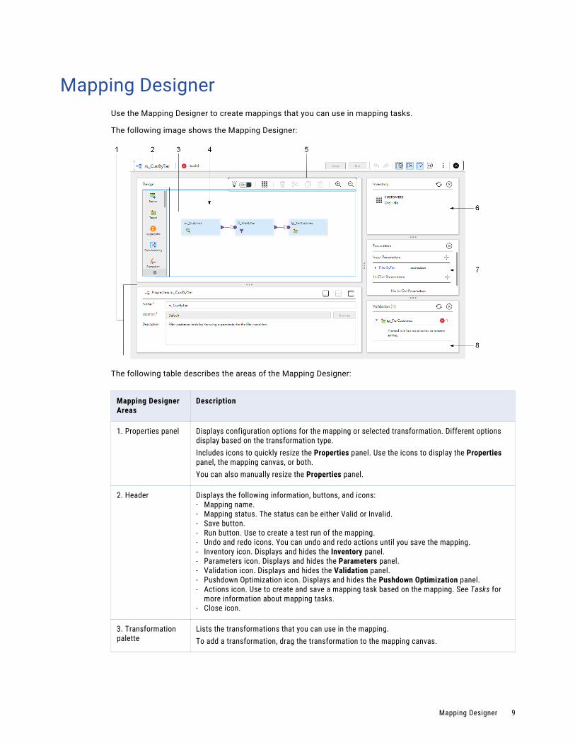
Mapping DesignerUse the Mapping Designer to create mappings that you can use in mapping tasks.
The following image shows the Mapping Designer:
The following table describes the areas of the Mapping Designer:
Mapping Designer Areas
Description
1. Properties panel Displays configuration options for the mapping or selected transformation. Different options display based on the transformation type.Includes icons to quickly resize the Properties panel. Use the icons to display the Properties panel, the mapping canvas, or both.You can also manually resize the Properties panel.
2. Header Displays the following information, buttons, and icons:- Mapping name.- Mapping status. The status can be either Valid or Invalid.- Save button.- Run button. Use to create a test run of the mapping.- Undo and redo icons. You can undo and redo actions until you save the mapping.- Inventory icon. Displays and hides the Inventory panel.- Parameters icon. Displays and hides the Parameters panel.- Validation icon. Displays and hides the Validation panel.- Pushdown Optimization icon. Displays and hides the Pushdown Optimization panel.- Actions icon. Use to create and save a mapping task based on the mapping. See Tasks for
more information about mapping tasks.- Close icon.
3. Transformation palette
Lists the transformations that you can use in the mapping.To add a transformation, drag the transformation to the mapping canvas.
Mapping Designer 9

Mapping Designer Areas
Description
4. Mapping canvas The canvas where you configure a mapping. When you create a mapping, a Source transformation and a Target transformation are already on the canvas for you to configure.
5. Toolbar Displays the following icons and buttons:- Recommendation toggle. Turns CLAIRE™ recommendations on or off.
Shown when organization CLAIRE recommendation preferences are enabled.- Arrange All icon. Arranges the mapping.- Delete icon. Deletes the selected transformation or link.- Cut.- Copy.- Paste.- Zoom In icon. Increases the size of the mapping.- Zoom Out icon. Decreases the size of mapping.
6. Inventory panel Lists Enterprise Data Catalog objects that you can add to the mapping as sources, targets, or lookup objects.Note: Your organization must have the appropriate licenses in order for you to see the Inventory panel.Objects appear in the inventory when you search for objects on the Data Catalog page, select them in the search results, and add them to the mapping. To delete an object from the inventory, click "X" in the row that contains the object.Displays when you click Inventory. To hide the panel, click Inventory again.
7. Parameters panel Lists the parameters in the mapping. You can create, edit, and delete parameters, and see where the mapping uses parameters.Displays when you click Parameters. To hide the panel, click Parameters again.
8. Validation panel Lists the transformations in the mapping and displays details about mapping errors. Use to find and correct mapping errors.Displays when you click Validation. To hide the panel, click Validation again.
10 Chapter 1: Mappings

Mapping templatesYou can use a mapping template instead of creating a mapping from scratch.
Mapping templates are divided into the categories: Integration, Cleansing, and Warehousing.
When you select a mapping template in the New Asset dialog box, you create a mapping that uses a copy of the mapping template. The created mapping is not an elastic mapping, and you cannot run it on an elastic cluster.
The mapping contains pre-populated transformations. Click on each of the transformations in the mapping to see the purpose of the transformation, how the transformation is configured, and which parameters are used.
Mapping templates 11

The following image shows the Augment data with Lookup template with the Source transformation selected. The Description field shows how the Source transformation is configured:
You can use a mapping template as is or you can reconfigure the mapping. For example, the Augment data with Lookup template uses the p_scr_conn parameter for the source connection. You can use the parameter to specify a different connection each time you run the mapping task that uses this mapping. You might want
12 Chapter 1: Mappings

to use the same source connection every time you run the mapping task. You can replace the parameter p_scr_conn with a specific connection, as shown in the following image:
When you save the mapping, you save a copy of the template. You do not modify the template itself.
Mapping configurationUse the Mapping Designer to configure a mapping.
To configure a mapping, perform the following tasks:
1. Define the mapping.
2. Configure the source.
3. Configure the data flow. Add, and configure transformations, and draw links to represent the flow of data.
Tip: You can copy and paste transformations within or between open mappings.
4. Configure the target.
5. Optionally, create parameters to be defined in the mapping task.
6. Save and validate the mapping.
Mapping configuration 13
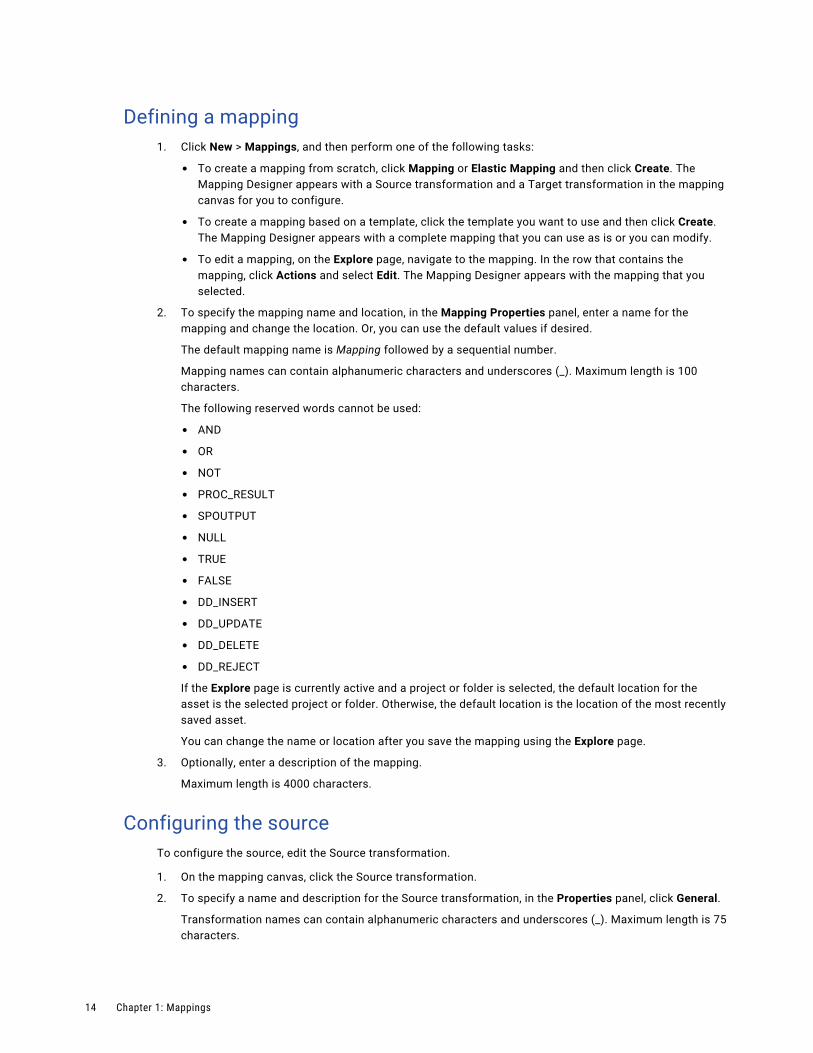
Defining a mapping1. Click New > Mappings, and then perform one of the following tasks:
• To create a mapping from scratch, click Mapping or Elastic Mapping and then click Create. The Mapping Designer appears with a Source transformation and a Target transformation in the mapping canvas for you to configure.
• To create a mapping based on a template, click the template you want to use and then click Create. The Mapping Designer appears with a complete mapping that you can use as is or you can modify.
• To edit a mapping, on the Explore page, navigate to the mapping. In the row that contains the mapping, click Actions and select Edit. The Mapping Designer appears with the mapping that you selected.
2. To specify the mapping name and location, in the Mapping Properties panel, enter a name for the mapping and change the location. Or, you can use the default values if desired.
The default mapping name is Mapping followed by a sequential number.
Mapping names can contain alphanumeric characters and underscores (_). Maximum length is 100 characters.
The following reserved words cannot be used:
• AND
• OR
• NOT
• PROC_RESULT
• SPOUTPUT
• NULL
• TRUE
• FALSE
• DD_INSERT
• DD_UPDATE
• DD_DELETE
• DD_REJECT
If the Explore page is currently active and a project or folder is selected, the default location for the asset is the selected project or folder. Otherwise, the default location is the location of the most recently saved asset.
You can change the name or location after you save the mapping using the Explore page.
3. Optionally, enter a description of the mapping.
Maximum length is 4000 characters.
Configuring the sourceTo configure the source, edit the Source transformation.
1. On the mapping canvas, click the Source transformation.
2. To specify a name and description for the Source transformation, in the Properties panel, click General.
Transformation names can contain alphanumeric characters and underscores (_). Maximum length is 75 characters.
14 Chapter 1: Mappings

The following reserved words cannot be used:
• AND
• OR
• NOT
• PROC_RESULT
• SPOUTPUT
• NULL
• TRUE
• FALSE
• DD_INSERT
• DD_UPDATE
• DD_DELETE
• DD_REJECT
You can enter a description if desired.
Maximum length is 4000 characters.
3. Click the Source tab and configure source details, query options, and advanced properties.
Source details, query options, and advanced properties vary based on the connection type. For more information, see Transformations.
In the source details, select the source connection and source object. For some connection types, you can select multiple source objects. If your organization administrator has configured Enterprise Data Catalog integration properties, and you have added objects to the mapping from the Data Catalog page, you can select the source object from the Inventory panel. You can also configure parameters for the source connection and source object.
If you are configuring an elastic mapping, and you select an Amazon S3 or a Microsoft Azure Data Lake connection, you can add an intelligent structure model to the Source transformation for some source types. You must create the model before you can add it to the mapping. For more information about intelligent structure models, see Components.
To configure a source filter or sort options, expand Query Options. Click Configure to configure a filter or sort option.
4. Click the Fields tab to add or remove source fields, to update field metadata, or to synchronize fields with the source.
5. To save your changes and continue, click Save.
Configuring the data flowTo configure the data flow, optionally add transformations to the mapping.
1. To add a transformation, perform either of the following actions:
• On the transformation palette, drag the transformation onto the mapping canvas. If you drop the transformation between two transformations that are connected, the Mapping Designer automatically connects the new transformation to the two transformations.
• On the mapping canvas, hover over the link between transformations or select an unconnected transformation and click the Add Transformation icon. Then select a transformation from the menu.
2. On the General tab, enter a name and description for the transformation.
Mapping configuration 15

3. Link the new transformation to appropriate transformations on the canvas.
When you link transformations, the downstream transformation inherits the incoming fields from the previous transformation.
For a Joiner transformation, draw a master link and a detail link.
4. To preview fields, configure the field rules, or rename fields, click Incoming Fields.
5. Configure additional transformation properties, as needed.
The properties that you configure vary based on the type of transformation you create. For more information about transformations and transformation properties, see Transformations.
6. To save your changes and continue, click Save.
7. To add another transformation, repeat these steps.
Configuring the targetTo configure the target, edit the Target transformation.
1. On the mapping canvas, click the Target transformation.
2. Link the Target transformation to the appropriate upstream transformation.
3. On the General tab, enter the target name and optional description.
4. Click the Incoming Fields tab to preview incoming fields, configure field rules, or rename fields.
5. Click the Target tab and configure target details and advanced properties.
Target details and advanced target properties vary based on the connection type. For more information, see Transformations.
In the target details, select the target connection, target object, and target operation. If your organization administrator has configured Enterprise Data Catalog integration properties, and you have added objects to the mapping from the Data Catalog page, you can select the target object from the Inventory panel. You can also configure parameters for the target connection and target object.
6. Click Field Mapping and map the fields that you want to write to the target.
Rules and guidelines for mapping configurationUse the following rules and guidelines when you configure a mapping:
• A mapping does not need a Source transformation if it includes a Mapplet transformation and the mapplet includes a source.
• You can configure multiple branches within the data flow. If you create more than one data flow, configure the flow run order.
• Connect all transformations to the data flow.
• You can merge multiple upstream branches through a passive transformation only when all transformations in the branches are passive.
• When you rename fields, update conditions and expressions that use the fields. Conditions and expressions, such as a Lookup condition or expression in an Expression transformation, do not inherit field name changes.
• To use a connection parameter and a specific object, use a connection and object in the mapping. When the mapping is complete, you can replace the connection with a parameter.
• When you use a parameter for an object, use parameters for all conditions or field mappings in the data flow that use fields from the object.
16 Chapter 1: Mappings

• You can copy and paste multiple transformations at once between the following open assets:
- Between mappings
- Between elastic mappings
- Between mapplets
- From a mapping or elastic mapping to a mapplet
When you paste a transformation into another asset, all transformation attributes except parameter values are copied to the asset.
Rules and guidelines for mappings on GPU-enabled clustersUse the following rules and guidelines when you configure a mapping that runs on a GPU-enabled elastic cluster:
• The size of a partition file must be smaller than the GPU memory size. To check the GPU memory size, refer to the AWS documentation for the selected worker instance type.
• The mapping cannot read from an Amazon Redshift source or a source based on an intelligent structure model.
• The mapping cannot write to a CSV file.
• If the mapping includes NaN values, the output is unpredictable.
• The mapping cannot process timestamp data types from a Parquet source.
• If you need to process decimal data from a CSV file, read the data as a string and then convert it to a float.
• When the mapping uses an Expression transformation, you can use only scientific functions and the following numeric functions:
- ABS
- CEIL
- FLOOR
- LN
- LOG
- POWER
- SQRT
To learn how to configure a GPU-enabled cluster, refer to Data Integration Elastic Administration in the Administrator help.
Data flow run orderYou can specify the order in which Data Integration runs the individual data flows in a mapping. Specify the flow run order when you want Data Integration to load the targets in the mapping in a particular order. For example, you might want to specify the flow run order when inserting, deleting, or updating tables with primary or foreign key constraints.
A flow is all connected sources, targets, and transformations in a mapping. You can have multiple flows in a mapping but not in an elastic mapping.
You can specify the flow run order for data flows with any target type.
Mapping configuration 17

You might want to specify the flow run order to maintain referential integrity when updating tables that have primary or foreign key constraints. Or, you might want to specify the flow run order when you are processing staged data.
If a flow contains multiple targets, you cannot configure the load order of the targets within the flow.
The following image shows a mapping with two data flows:
In the this example, the top flow contains two pipelines and the bottom flow contains one pipeline. A pipeline is a source and all the transformations and targets that receive data from that source. When you configure the flow run order, you cannot configure the run order of the pipelines within a data flow.
The following image shows the flow run order for the mapping:
In this example, Data Integration runs the top flow first, and loads Target3 before running the second flow. When Data Integration runs the second flow, it loads Target1 and Target2 concurrently.
If you add another data flow to the mapping after you configure the flow run order, the new flow is added to the end of the flow run order by default.
If the mapping contains a mapplet, Data Integration uses the data flows in the last version of the mapplet that was synchronized. If you synchronize a mapplet and the new version adds a data flow to the mapping,
18 Chapter 1: Mappings

the new flow is added to the end of the flow run order by default. You cannot specify the flow run order in mapplets.
Note: You can also specify the run order of data flows in separate mapping tasks with taskflows. Configure the taskflow to run the tasks in a specific order. For more information about taskflows, see Taskflows.
Configuring the data flow run orderConfigure the order in which Data Integration runs the data flows in a mapping.
1. In the Mapping Designer, click Actions and select Flow Run Order.
2. In the Flow Run Order dialog box, select a data flow and use the arrows to move it up or down.
3. Click Save.
Mapping validationEach time you save a mapping, the Mapping Designer validates the mapping.
When you save a mapping, check the status to see if the mapping is valid. Mapping status displays in the header of the Mapping Designer.
If the mapping is not valid, you can use the Validation panel to view the location and details of mapping errors. The Validation panel displays a list of the transformations in the mapping. Error icons display by the transformations that include errors.
In the following example, the Accounts_By_State Target transformation contains one error:
Tip: If you click a transformation name in the Validation panel, the transformation is selected in the Mapping Designer.
Due to processing differences, the Validation panel shows additional validation errors for some transformations in elastic mappings. The validation errors result from validation criteria on the Serverless Spark engine.
Mapping validation 19
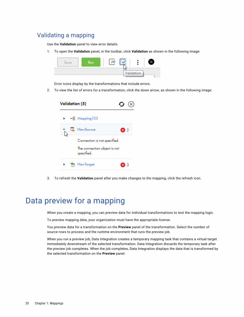
Validating a mappingUse the Validation panel to view error details.
1. To open the Validation panel, in the toolbar, click Validation as shown in the following image:
Error icons display by the transformations that include errors.
2. To view the list of errors for a transformation, click the down arrow, as shown in the following image:
3. To refresh the Validation panel after you make changes to the mapping, click the refresh icon.
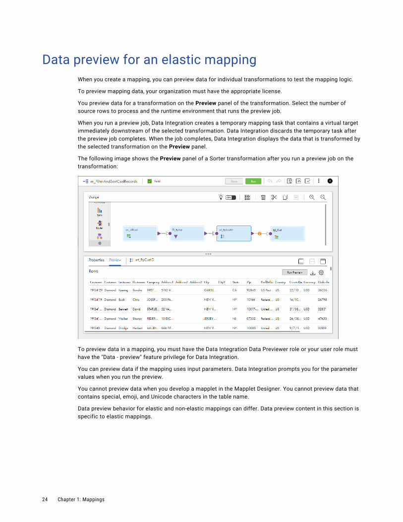
Data preview for a mappingWhen you create a mapping, you can preview data for individual transformations to test the mapping logic.
To preview mapping data, your organization must have the appropriate license.
You preview data for a transformation on the Preview panel of the transformation. Select the number of source rows to process and the runtime environment that runs the preview job.
When you run a preview job, Data Integration creates a temporary mapping task that contains a virtual target immediately downstream of the selected transformation. Data Integration discards the temporary task after the preview job completes. When the job completes, Data Integration displays the data that is transformed by the selected transformation on the Preview panel.
20 Chapter 1: Mappings

The following image shows the Preview panel of a Sorter transformation after you run a preview job on the transformation:
To preview data in a mapping, you must have the Data Integration Data Previewer role or your user role must have the "Data - preview" feature privilege for Data Integration.
You can preview data if the mapping uses input parameters. Data Integration prompts you for the parameter values when you run the preview.
You cannot preview data when you develop a mapplet in the Mapplet Designer. You cannot preview data that contains special, emoji, and Unicode characters in the table name.
Data preview behavior for elastic and non-elastic mappings can differ. Data preview content in this section is specific to non-elastic mappings.
Preview behavior for a mappingYou can preview data for a transformation if there are no mapping validation errors in the selected transformation or any upstream transformations. Data Integration displays mapping results for the selected transformation. It also generates results for the upstream transformations.
You can preview data for any transformation except for the following transformations:
• Data Masking
• Hierarchy Builder
• Sequence Generator
• Velocity
• Web Services
• Target
Data preview for a mapping 21

Running a preview job for a mappingRun a data preview job on the Preview panel of the selected transformation.
Before you run a data preview job for a non-elastic mapping, verify that the following conditions are true:
• Verify that a Secure Agent is available to run the job. You cannot run a preview job using the Hosted Agent.
• Verify that the Secure Agent machine has enough disk space to store the preview data.
• Verify that there are no mapping validation errors in the selected transformation or any upstream transformation.
To run a data preview job:
1. In the Mapping Designer, select a transformation.
2. Open the Preview panel.
3. Click Run Preview.
4. In the Run Preview wizard, enter the number of source rows to preview and the runtime environment to run the preview job.
The number that you enter applies to each source in the mapping. For example, if you select 10 rows and the mapping contains multiple sources, the preview job processes the first 10 rows in each source.
You can select up to 999,999,999 rows.
Warning: Selecting a large number of source rows can cause storage or performance issues on the Secure Agent machine.
5. If the part of the mapping that you are previewing uses input parameters, click Next and enter the parameter values.
6. Click Run Preview.
Data Integration displays the results in the Preview panel for the selected transformation.
You can monitor preview jobs on the My Jobs page in Data Integration and on the All Jobs and Running Jobs pages in Monitor. Data Integration names the preview job <mapping name>-<instance number>, for example, MyMapping_1. You can download the session log for a data preview job.
To restart a preview job, run the job again on the Preview panel. You cannot restart a data preview job on the My Jobs or All Jobs pages.
Viewing preview results for a mappingData Integration generates preview results for the selected transformation and the upstream transformations in the mapping. Data Integration stores preview results in CSV files on the Secure Agent machine.
Data Integration displays preview results on the Preview panel of the selected transformation and each upstream transformation. Data Integration does not display preview results for downstream transformations.
If a transformation has multiple output groups and you want to preview results for a different output group, select the output group from the Output Groups menu at the top of the Preview panel.
To download preview results, click Download on the Preview panel.
Data Integration stores preview results in CSV files on the Secure Agent machine. When you run a preview, Data Integration creates one CSV file for the selected transformation and one CSV file for every upstream transformation in the mapping. If a transformation has multiple output groups, Data Integration creates one CSV file for each output group. If you run the same preview multiple times, Data Integration overwrites the CSV files.
22 Chapter 1: Mappings

By default, the files are stored in the following directory:
<Secure Agent installation directory>/apps/Data_Integration_Server/data/cache/preview
The CSV files are stored in this directory unless an organization administrator changes the value of the $PMCacheDir property for the Data Integration Server service that runs on the Secure Agent. For more information about Secure Agent services, see the Administrator help.
Note: Ensure that the Secure Agent machine has enough disk space to store preview data for all users that might run a data preview using the Secure Agent.
Data Integration purges the preview directory once every 24 hours. During the purge, Data Integration deletes files that are more than 24 hours old.
Customizing preview resultsYou can choose which columns to display on the Preview panel. You can also reorder the columns. Customize the Preview panel on the Settings dialog.
The following image shows the Settings dialog:
To open the Settings dialog, click the settings icon on the Preview panel. Columns in the Selected Columns area appear on the Preview panel. To hide a column from the Preview panel, select it and move it to the Available Columns area. To reorder the columns in the Preview panel, select a column name in the Selected Columns area and move it up or down.
Data preview for a mapping 23
Data preview for an elastic mappingWhen you create a mapping, you can preview data for individual transformations to test the mapping logic.
To preview mapping data, your organization must have the appropriate license.
You preview data for a transformation on the Preview panel of the transformation. Select the number of source rows to process and the runtime environment that runs the preview job.
When you run a preview job, Data Integration creates a temporary mapping task that contains a virtual target immediately downstream of the selected transformation. Data Integration discards the temporary task after the preview job completes. When the job completes, Data Integration displays the data that is transformed by the selected transformation on the Preview panel.
The following image shows the Preview panel of a Sorter transformation after you run a preview job on the transformation:
To preview data in a mapping, you must have the Data Integration Data Previewer role or your user role must have the "Data - preview" feature privilege for Data Integration.
You can preview data if the mapping uses input parameters. Data Integration prompts you for the parameter values when you run the preview.
You cannot preview data when you develop a mapplet in the Mapplet Designer. You cannot preview data that contains special, emoji, and Unicode characters in the table name.
Data preview behavior for elastic and non-elastic mappings can differ. Data preview content in this section is specific to elastic mappings.
24 Chapter 1: Mappings

Preview behavior for an elastic mappingYou can preview data if there are no mapping validation errors in the selected transformation. An elastic mapping shows preview data for the selected transformation. You can preview data for hierarchical data types.
You can preview data for any transformation except for the following transformations:
• Normalizer
• Router
• Hierarchy Processor with multiple output groups
• Target
You can preview data for sources except for sources meeting the following conditions:
• Parameterized sources
• Sources with binary fields
Data preview is available in AWS and Azure environments.
A preview job runs on the same cluster as other elastic jobs. If the cluster is saturated with other jobs, the preview job can take longer to run and return data.
Running a preview for an elastic mappingRun a data preview job on the Preview panel of the selected transformation. Data preview jobs run on AWS on-demand instances.
Before you run a data preview job for a elastic mapping, verify that there are no mapping validation errors in the selected transformation.
To run a preview job:
1. In the Mapping Designer, select a transformation.
2. Open the Preview panel.
3. Click Run Preview.
4. In the Run Preview wizard, enter the number of source rows to preview and the runtime environment to run the preview job.
The number that you enter applies to each source in the mapping. For example, if you select 10 rows and the mapping contains multiple sources, the preview job processes the first 10 rows in each source.
You can select up to 999,999,999 rows.
Warning: Selecting a large number of source rows can cause storage or performance issues on the Secure Agent machine.
5. Select the Read Entire Source option if you're sure you want Data Integration to read all source data. Preview data may be slow to display if you have a large source data set. Target data will be limited based on the value entered in the Rows to Preview field.
6. The Enable Upstream Preview option allows you to preview data for the selected transformation and upstream transformations. This option is enabled by default. Preview data may be slow to display if you have many upstream transformations.**
7. Click Run Preview.
Data Integration displays the results in the Preview panel for the selected transformation.
Data preview for an elastic mapping 25

You can monitor preview jobs on the My Jobs page in Data Integration and on the All Jobs and Running Jobs pages in Monitor. Data Integration names the preview job <mapping name>-<instance number>, for example, MyMapping_1. You can download the session log for a data preview job.
To restart a preview job, run the job again on the Preview panel. You cannot restart a data preview job on the My Jobs or All Jobs pages.
Viewing preview results for an elastic mappingData Integration Elastic generates preview results for the selected transformation in the elastic mapping. Data Integration Elastic stores preview results in JSON files in the staging location configured in the elastic configuration.
Data Integration Elastic shows complex data cells as hyperlinks on the Preview page. When you click a hyperlink, the preview data displays in a separate panel.
The following limitations apply to the preview results:
• Job name, start time, end time, and job status columns show null values.
• Preview results for the Sequence Generator transformation may not be consistent from one preview run to the next. For example when you set the initial value in the transformation to 1, you may get a result of 1, 2, 3, 4 the first time you run a preview. The second time you run a preview, you may get 2001, 2002, 2003, 2004.
Data Integration Elastic purges the preview data once every 30 minutes to delete these data files. Data Integration Elastic also deletes preview data when a Secure Agent stops a cluster.
26 Chapter 1: Mappings
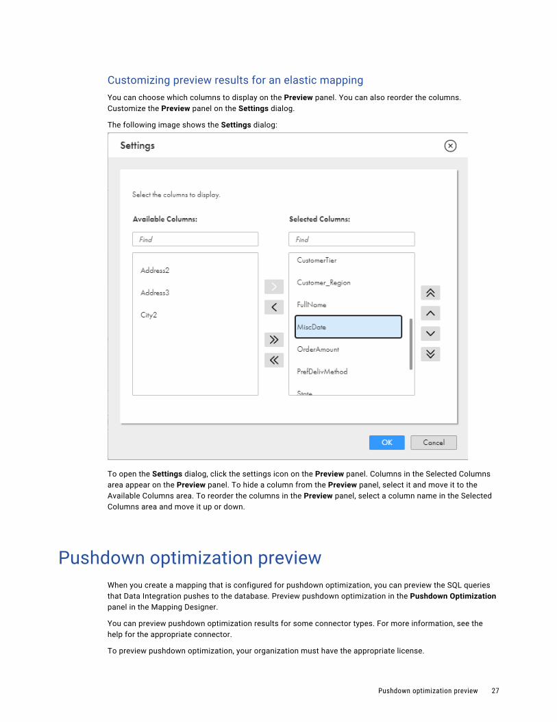
Customizing preview results for an elastic mappingYou can choose which columns to display on the Preview panel. You can also reorder the columns. Customize the Preview panel on the Settings dialog.
The following image shows the Settings dialog:
To open the Settings dialog, click the settings icon on the Preview panel. Columns in the Selected Columns area appear on the Preview panel. To hide a column from the Preview panel, select it and move it to the Available Columns area. To reorder the columns in the Preview panel, select a column name in the Selected Columns area and move it up or down.
Pushdown optimization previewWhen you create a mapping that is configured for pushdown optimization, you can preview the SQL queries that Data Integration pushes to the database. Preview pushdown optimization in the Pushdown Optimization panel in the Mapping Designer.
You can preview pushdown optimization results for some connector types. For more information, see the help for the appropriate connector.
To preview pushdown optimization, your organization must have the appropriate license.
Pushdown optimization preview 27

When you preview pushdown optimization, Data Integration creates and runs a temporary pushdown preview mapping task. When the job completes, Data Integration displays the SQL to be executed and any warnings in the Pushdown Optimization panel.
The following image shows the Pushdown Optimization panel:
If the pushdown optimization type that you select is not available, Data Integration lists the SQL queries, if any, that can be executed. For example, if you select Full pushdown optimization, but the target does not support pushdown, Data Integration displays the SQL queries that will be pushed to the source.
You cannot preview pushdown optimization in an elastic mapping.
Running a pushdown preview jobPreview the SQL queries that Data Integration pushes to the database on the Pushdown Optimization panel.
Before you run pushdown optimization preview, verify that the following conditions are true:
• In-out parameters have a default value. You cannot provide values for in-out parameters when you configure the preview job.
• The mapping is valid.
To run a pushdown optimization job:
1. Open the Pushdown Optimization panel.
2. Click Preview Pushdown.
3. In the Pushdown Preview wizard, select the runtime environment and then click Next.
4. If the mapping contains input parameters, enter the parameter values and then click Next.
5. Configure pushdown optimization options.
6. Click Pushdown Preview.
Data Integration displays the SQL queries and any warnings in the Pushdown Optimization panel. If pushdown optimization fails, Data Integration lists any queries generated up to the point of failure.
You can monitor preview jobs on the My Jobs, Running Jobs, or All Jobs pages. Data Integration names the job <mapping name>_pdo_preview-<instance number>, for example, Mapping1_pdo_preview-2. You can download the session log for the preview job.
To restart a preview job, run it again from the Pushdown Optimization panel. You cannot restart the job from the My Jobs, Running Jobs, or All Jobs pages.
28 Chapter 1: Mappings
Pushdown optimization preview results filesData Integration stores preview results in a JSON file on the Secure Agent machine.
If you run the preview more than once, Data Integration overwrites the JSON file.
By default, files are stored in the following directory:
<Secure Agent installation directory>/apps/Data_Integration_Server/data/cache/pdo_previewFiles are stored in this directory unless the organization administrator changes the $PMCacheDir property for the Data Integration Server service on the Secure Agent. For more information about Secure Agent services, see the Administrator help.
Data Integration purges the directory once every 24 hours. During the purge, Data Integration deletes files that are more than 24 hours old.
Testing a mappingAfter you complete a mapping and you confirm that the mapping is valid, you can perform a test run to verify the results of the mapping. Perform a test run of a valid mapping to verify the results of the mapping before you create a mapping task.
When you perform a test run, you run a temporary mapping task. The task reads source data, writes target data, and performs all calculations in the data flow. Data Integration discards the temporary task after the test run.
You can perform a test run from the Mapping Designer or from the Explore page.
To test run a mapping from the Mapping Designer, perform the following steps:
1. After you save the mapping, click Run.
2. Select the runtime environment and specify values for parameters, if any parameters are in mapping.
3. Click Run.
To test run a mapping from the Explore page, perform the following steps:
1. Navigate to the mapping and in the row that contains the mapping, click Actions and select Run.
2. Select the runtime environment and then click Run.
Note that if you select New Mapping Task instead of Run, Data Integration creates a mapping task and saves it in the location you specify. For more information about mapping tasks, see Tasks.
Mapping tutorialThe following tutorial describes how to create a simple mapping, save and validate the mapping, and create a mapping task.
For this tutorial, you have a file that contains U.S. customer account information. You want to create a file that contains customer account information for a specific state.
In the mapping, you define the following components:
• Source transformation. Represents the source file that contains account information.
Testing a mapping 29

• Filter transformation. Transformation that filters out all account information except for a specific state.
• Target transformation. Represents the target file that contains account information for a specific state.
You create parameters in the mapping so that you can use the same mapping task to create files for each state. You create the following parameters:
• In the Filter transformation, you create a parameter to hold the state value so that you can use the mapping to create multiple tasks. You can specify a different state value for each task.
• In the Target transformation, you create a parameter for the target object so that you have separate target files for each state.
After you define the mapping, you create a mapping task that is based on the mapping. When you run the mapping task, you specify values for the target object parameter and the filter parameter. The mapping task then writes the data to the specified target based on the specified state.
The mapping tutorial includes the following steps:
1. Create a mapping.
2. Configure a source. Specify the name of the source object and the connection to use.
3. Create a Filter transformation. Create a parameter in the Filter transformation to hold the state value.
4. Configure a target. Specify the connection to use and create a parameter for the target object.
5. Validate the mapping to be sure there are no errors. The mapping must be valid before you can run a task based on the mapping.
6. Create a task based on the mapping. The task includes parameters for the target object and state value, which you specify when you run the task.
Preparing for the mapping tutorialBefore you start the mapping tutorial, you need to download a sample file and set up a connection.
1. Download the sample Account source file from the Informatica Cloud Community and save the file in a directory local to the Secure Agent. You can download the file from the following link:
Sample Source File for the Mapping Tutorial
2. Create a flat file connection for the directory that contains the saved sample Account source file.
3. On the Explore page, create a project and name the project AccountsByState, and then create a folder in the project and name the folder Mappings.
30 Chapter 1: Mappings

Step 1. Create a mappingIn the following procedure, you create a mapping in the Mapping Designer to specify the source, filter, and target.
1. To create a mapping, click New and then in the New Asset dialog box, click Mapping.
The following image shows the New Asset dialog box with Mapping selected:
2. Click Create. The Mapping Designer appears with a new mapping displayed in the mapping canvas.
The following image shows a new mapping in the Mapping Designer:
3. In the Properties panel, enter m_Accounts_by_State for the mapping name.
You can use underscores in mapping and transformation names, but do not use other special characters.
Mapping tutorial 31
Tip: Informatica recommends that you use a standard naming convention for objects. For example, begin all object names with an abbreviation of the object type so that mapping names begin with m_, Source transformation names begin with src_, parameter names begin with p_, and so on. Also, use names that explain the purpose of the object, for example, flt_Filter_by_State. A standard naming convention is particularly helpful when you are working with large, complex mappings so that you can easily identify the type and purpose of each object.
4. To select a location for the mapping, browse to the folder you want the mapping to reside in, or use the default location.
If the Explore page is currently active and a project or folder is selected, the default location for the asset is the selected project or folder. Otherwise, the default location is the location of the most recently saved asset.
Step 2. Configure a sourceIn the following procedure, you create a Source transformation to specify the source object.
When you design a mapping, the first transformation you configure is the Source transformation. You specify the source object in the Source transformation. The source object represents the source of the data that you want to use in the mapping. You add the source object at the beginning of mapping design because the source properties can affect the downstream data. For example, you might filter data at the source, which affects the data that enters downstream transformations.
Configure the sample Account flat file as the source object.
1. On the mapping canvas, click the Source transformation to select it.
2. In the Properties panel, click General and enter src_FF_Account for the Source transformation name.
3. Specify which connection to use based on the source object. In this case, the source object is a flat file so the connection needs to be a flat file connection.
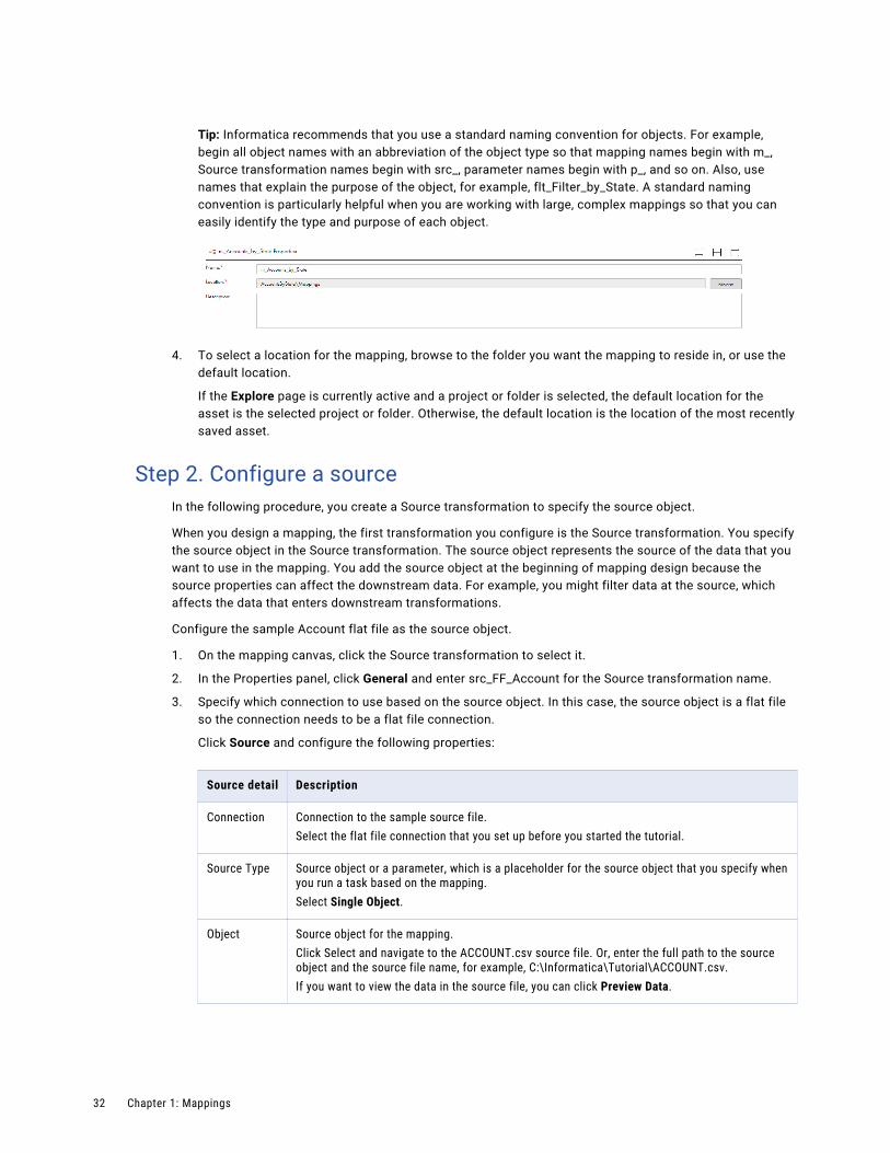
Click Source and configure the following properties:
Source detail Description
Connection Connection to the sample source file.Select the flat file connection that you set up before you started the tutorial.
Source Type Source object or a parameter, which is a placeholder for the source object that you specify when you run a task based on the mapping.Select Single Object.
Object Source object for the mapping.Click Select and navigate to the ACCOUNT.csv source file. Or, enter the full path to the source object and the source file name, for example, C:\Informatica\Tutorial\ACCOUNT.csv.If you want to view the data in the source file, you can click Preview Data.
32 Chapter 1: Mappings
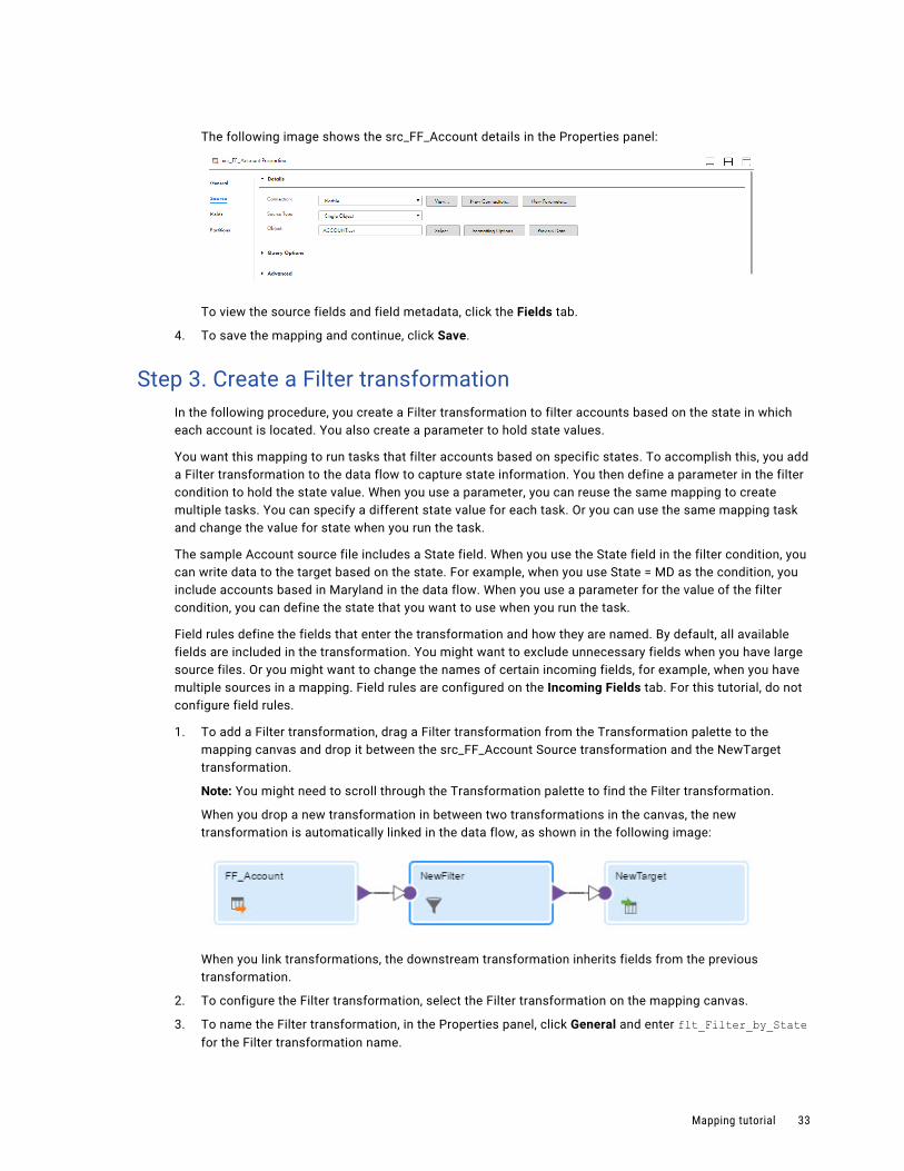
The following image shows the src_FF_Account details in the Properties panel:
To view the source fields and field metadata, click the Fields tab.
4. To save the mapping and continue, click Save.
Step 3. Create a Filter transformationIn the following procedure, you create a Filter transformation to filter accounts based on the state in which each account is located. You also create a parameter to hold state values.
You want this mapping to run tasks that filter accounts based on specific states. To accomplish this, you add a Filter transformation to the data flow to capture state information. You then define a parameter in the filter condition to hold the state value. When you use a parameter, you can reuse the same mapping to create multiple tasks. You can specify a different state value for each task. Or you can use the same mapping task and change the value for state when you run the task.
The sample Account source file includes a State field. When you use the State field in the filter condition, you can write data to the target based on the state. For example, when you use State = MD as the condition, you include accounts based in Maryland in the data flow. When you use a parameter for the value of the filter condition, you can define the state that you want to use when you run the task.
Field rules define the fields that enter the transformation and how they are named. By default, all available fields are included in the transformation. You might want to exclude unnecessary fields when you have large source files. Or you might want to change the names of certain incoming fields, for example, when you have multiple sources in a mapping. Field rules are configured on the Incoming Fields tab. For this tutorial, do not configure field rules.
1. To add a Filter transformation, drag a Filter transformation from the Transformation palette to the mapping canvas and drop it between the src_FF_Account Source transformation and the NewTarget transformation.
Note: You might need to scroll through the Transformation palette to find the Filter transformation.
When you drop a new transformation in between two transformations in the canvas, the new transformation is automatically linked in the data flow, as shown in the following image:
When you link transformations, the downstream transformation inherits fields from the previous transformation.
2. To configure the Filter transformation, select the Filter transformation on the mapping canvas.
3. To name the Filter transformation, in the Properties panel, click General and enter flt_Filter_by_State for the Filter transformation name.
Mapping tutorial 33
4. To create a simple filter with a parameter for the value, click Filter. For the Filter Condition, select Simple.
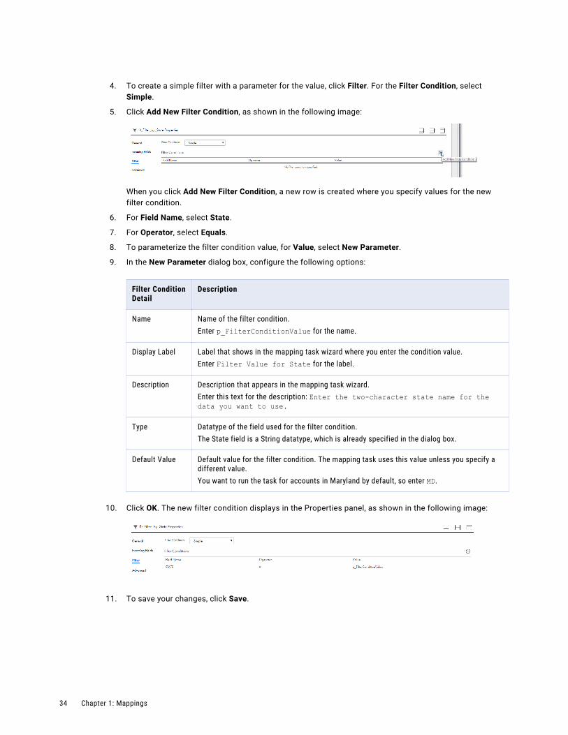
5. Click Add New Filter Condition, as shown in the following image:
When you click Add New Filter Condition, a new row is created where you specify values for the new filter condition.
6. For Field Name, select State.
7. For Operator, select Equals.
8. To parameterize the filter condition value, for Value, select New Parameter.
9. In the New Parameter dialog box, configure the following options:
Filter Condition Detail
Description
Name Name of the filter condition.Enter p_FilterConditionValue for the name.
Display Label Label that shows in the mapping task wizard where you enter the condition value.Enter Filter Value for State for the label.
Description Description that appears in the mapping task wizard.Enter this text for the description: Enter the two-character state name for the data you want to use.
Type Datatype of the field used for the filter condition.The State field is a String datatype, which is already specified in the dialog box.
Default Value Default value for the filter condition. The mapping task uses this value unless you specify a different value.You want to run the task for accounts in Maryland by default, so enter MD.
10. Click OK. The new filter condition displays in the Properties panel, as shown in the following image:
11. To save your changes, click Save.
34 Chapter 1: Mappings
Step 4. Configure a targetIn the following procedure, you create a parameter for the target object so that each time you run the mapping task, you can select a different target.
For example, you might want files that only include data for the states you specify in the filter parameter when you run the mapping task. When you run the task, if you filter for accounts in California, you can select the file that contains data for California accounts as the target.
1. On the mapping canvas, click the Target transformation to select it.
2. To name the Target transformation, in the Properties panel, click General and enter tgt_Accounts_by_State for the Target transformation name.
3. Click Target and configure the following properties:
Target detail Description
Connection Connection to the target file.You want the target object to be a flat file and you want the target object to reside in the same location as the source file. You can use the same connection that you used for the source because the source is a flat file as well.
Target Type Target object or parameter.You want to parameterize the target object so that you can have separate files for each state, so select Parameter.
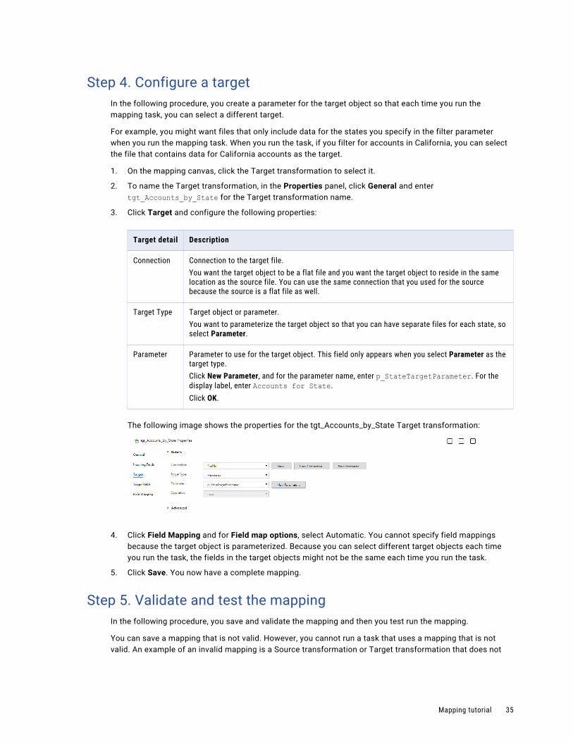
Parameter Parameter to use for the target object. This field only appears when you select Parameter as the target type.Click New Parameter, and for the parameter name, enter p_StateTargetParameter. For the display label, enter Accounts for State.Click OK.
The following image shows the properties for the tgt_Accounts_by_State Target transformation:
4. Click Field Mapping and for Field map options, select Automatic. You cannot specify field mappings because the target object is parameterized. Because you can select different target objects each time you run the task, the fields in the target objects might not be the same each time you run the task.
5. Click Save. You now have a complete mapping.
Step 5. Validate and test the mappingIn the following procedure, you save and validate the mapping and then you test run the mapping.
You can save a mapping that is not valid. However, you cannot run a task that uses a mapping that is not valid. An example of an invalid mapping is a Source transformation or Target transformation that does not
Mapping tutorial 35

have a specified connection, or a mapping that does not have a Source transformation and a Target transformation.
1. To validate the mapping, click Save.
Whenever you save the mapping, the Mapping Designer validates the mapping. The status of the mapping displays in the header next to the mapping name. The mapping status can be Valid or Invalid.
2. If the mapping is not valid, perform the following steps:
a. In the header, click the Validation icon to open the Validation panel.
The Validation panel lists the mapping and the transformations used in the mapping and shows where the errors occur. For example, in the following image, the tgt_Accounts_by_State Target transformation has an error:
b. After you correct the errors, save the mapping and then in the Validation panel, click Refresh. The Validation panel updates to list any errors that might still be present.
3. To test the mapping, click Run.
36 Chapter 1: Mappings
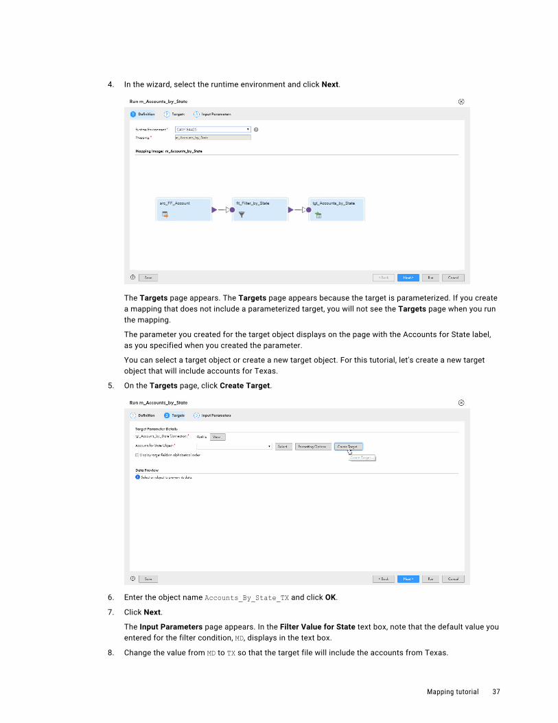
4. In the wizard, select the runtime environment and click Next.
The Targets page appears. The Targets page appears because the target is parameterized. If you create a mapping that does not include a parameterized target, you will not see the Targets page when you run the mapping.
The parameter you created for the target object displays on the page with the Accounts for State label, as you specified when you created the parameter.
You can select a target object or create a new target object. For this tutorial, let's create a new target object that will include accounts for Texas.
5. On the Targets page, click Create Target.
6. Enter the object name Accounts_By_State_TX and click OK.
7. Click Next.
The Input Parameters page appears. In the Filter Value for State text box, note that the default value you entered for the filter condition, MD, displays in the text box.
8. Change the value from MD to TX so that the target file will include the accounts from Texas.
Mapping tutorial 37

9. Click Run.
The mapping task runs and then returns you to the Mapping Designer.
10. In the navigation bar, click My Jobs. The My Jobs page lists all of the jobs that you have run. At the top, you should see the mapping task that was created when you ran the mapping, as shown in the following diagram:
The My Jobs page shows that there were three accounts from Texas, which are now in your tgt_Accounts_By_State_TX target file.
Step 6. Create a mapping taskIn the following procedure, you create a mapping task that uses the mapping that you just designed.
Now that you have a valid mapping, you can use the mapping task wizard to create tasks based on the mapping. Because you used parameters in the mapping, each time you run the task, you can change the parameter values. After the task runs, you have a target file that contains account information for the state that you specify in the filter condition parameter.
1. To create a mapping task based on the mapping, while still in the Mapping Designer, click Actions and select New Mapping Task, as shown in the following image:
The mapping task wizard appears.
2. On the Definition page, enter mt_Accounts_by_State_task for the name of the task.
3. Select the runtime environment to use to run this task. It should be the same runtime environment that you used to create and test the mapping.
38 Chapter 1: Mappings
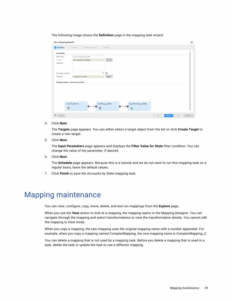
The following image shows the Definition page in the mapping task wizard:
4. Click Next.
The Targets page appears. You can either select a target object from the list or click Create Target to create a new target.
5. Click Next.
The Input Parameters page appears and displays the Filter Value for State filter condition. You can change the value of the parameter, if desired.
6. Click Next.
The Schedule page appears. Because this is a tutorial and we do not want to run this mapping task on a regular basis, leave the default values.
7. Click Finish to save the Accounts by State mapping task.
Mapping maintenanceYou can view, configure, copy, move, delete, and test run mappings from the Explore page.
When you use the View action to look at a mapping, the mapping opens in the Mapping Designer. You can navigate through the mapping and select transformations to view the transformation details. You cannot edit the mapping in View mode.
When you copy a mapping, the new mapping uses the original mapping name with a number appended. For example, when you copy a mapping named ComplexMapping, the new mapping name is ComplexMapping_2.
You can delete a mapping that is not used by a mapping task. Before you delete a mapping that is used in a task, delete the task or update the task to use a different mapping.
Mapping maintenance 39

Mapping revisions and mapping tasksYou might need to update a mapping that is used in a mapping task.
When you update a mapping used in a mapping task, the mapping task uses the revised mapping. If you change the mapping so that the mapping task is incompatible with the mapping, an error occurs when you run the mapping task.
For example, you add a parameter to a mapping after the mapping task was created and you do not update the mapping task to specify a value for the parameter. When you run the mapping task, an error occurs.
If you do not want your updates to affect the mapping task, you can make a copy of the mapping, give the new mapping a different name, and then apply your updates to the new mapping.
Bigint data conversionIn mappings created before the Spring 2020 September release, Data Integration converts Bigint data from a parameterized source to Int data in database targets created at runtime. To write Bigint data to the target without conversion, edit the mapping in the Mapping Designer. Click Actions > Advanced Properties and enable the option in the mapping advanced properties.
Data Integration does not convert Bigint data in mappings created after the Spring 2020 September release.
40 Chapter 1: Mappings

C h a p t e r 2
ParametersParameters are placeholders that represent values in a mapping or mapplet. Use parameters to hold values that you want to define at run-time such as a source connection, a target object, or the join condition for a Joiner transformation. You can also use parameters to hold values that change between task runs such as a time stamp that is incremented each time a mapping runs.
You can create the following kinds of parameters in a mapping or mapplet:
Input Parameters
An input parameter is a placeholder for a value or values in a mapping or mapplet. Input parameters help you control the logical aspects of a data flow or to set other variables that you can use to manage different targets.
When you define an input parameter in a mapping, you set the value of the parameter when you configure a mapping task.
In-Out Parameters
An in-out parameter holds a variable value that can change each time a task runs, to handle things like incremental data loading. When you define an in-out parameter, you can set a default value in the mapping but you typically set the value at run time using an Expression transformation. You can also change the value in the mapping task.
You cannot use an in-out parameter in an elastic mapping.
Input parametersAn input parameter is a placeholder for a value or values in a mapping. You define the value of the parameter when you configure the mapping task.
You can create an input parameter for logical aspects of a data flow. For example, you might use a parameter in a filter condition and a parameter for the target object. Then, you can create multiple tasks based on the mapping and write different sets of data to different targets. You could also use an input parameter for the target connection to write target data to different Salesforce accounts.
41

The following table describes the input parameters that you can create in each transformation:
Transformation Input parameter use in mappings and tasks
Source You can use an input parameter for the following parts of the Source transformation:- Source connection. You can configure the connection type for the parameter or allow any
connection type. In the task, you select the connection to use.- Source object. In the task, you select the source object to use. For relational and Salesforce
connections, you can specify a custom query for a source object.- Filter. In the task, you configure the filter expression to use. To use a filter for a parameterized
source, you must use a parameter for the filter.- Sort. In the task, you select the fields and type of sorting to use. To sort data for a
parameterized source, you must use a parameter for the sort options.
Target You can use an input parameter for the following parts of the Target transformation:- Target connection. You can configure the connection type for the parameter or allow any
connection type. In the task, you select the connection to use.- Target object. In the task, you select the target object to use.- Completely parameterized field mapping. In the task, you configure the entire field mapping for
the task.- Partially parameterized field mapping. Based on how you configure the parameter, you can use
the partial field mapping parameter as follows:- Configure links in the mapping and display unmapped fields in the task.- Configure links in the mapping and display all fields in the task. Allows you to edit links
configured in the mapping.
All transformations with incoming fields
You can use an input parameter for the following parts of the Incoming Fields tab of any transformation:- Field rule: Named field. You can use a parameter when you use the Named Fields field
selection criteria for a field rule. In the task, you select the field to use in the field rule.- Renaming fields: Pattern. You can use a parameter to rename fields in bulk with the pattern
option. In the task, you enter the regular expression to use.
Aggregator You can use an input parameter for the following parts of the Aggregator transformation:- Group by: Field name. In the task, you select the incoming field to use.- Aggregate expression: Additional aggregate fields. In the task, you specify the fields to use.- Aggregate expression: Expression for aggregate field. In the task, you specify the expression
to use for each aggregate field.
Data Masking You can use an input parameter for masking techniques in the Data Masking transformation.In the task, you select and configure the masking techniques.
Expression You can use an input parameter for an expression in the Expression transformation.In the task, you create the entire expression.
Filter You can use an input parameter for the following parts of the Filter transformation:- Completely parameterized filter condition. In the task, you enter the incoming field and value,
or you enter an advanced data filter.- Simple or advanced filter condition: Field name. In the task, you select the incoming field to
use.- Simple or advanced filter condition: Value. In the task, you select the value to use.
Joiner You can use an input parameter for the following parts of the Joiner transformation:- Join condition. In the task, you define the entire join condition.- Join condition: Master field. In the task, you select the field in the master source to use.- Join condition: Detail field. In the task, you select the field in the detail source to use.
42 Chapter 2: Parameters

Transformation Input parameter use in mappings and tasks
Lookup You can use an input parameter for the following parts of the Lookup transformation:- Lookup connection. You can configure the connection type for the parameter or allow any
connection type. In the task, you select the connection to use.- Lookup object. In the task, you select the lookup object to use.- Lookup condition: Lookup field. In the task, you select the field in the lookup object to use.- Lookup condition: Incoming field. In the task, you select the field in the data flow to use.
Mapplet You can use an input parameter for the following parts of the Mapplet transformation:- Connection. If the mapplet uses connections, you can configure the connection type for the
parameter or allow any connection type. In the task, you select the connection to use.- Completely parameterized field mapping. In the task, you configure the entire field mapping for
the task.- Partially parameterized field mapping. Based on how you configure the parameter, you can use
the partial field mapping parameter as follows:- Configure links in the mapping that you want to enforce, and display unmapped fields in the
task.- Configure links in the mapping, and allow all fields and links to appear in the task for
configuration.You can configure input parameters separately for each input group.
Rank You can use an input parameter for the number of rows to include in each rank group.In the task, you enter the number of rows.
Router You can use an input parameter for the following parts of the Router transformation:- Completely parameterized group filter condition. In the task, you enter the expression for the
group filter condition.- Simple or advanced group filter condition: Field name. In the task, you select the incoming
field to use.- Simple or advanced group filter condition: Value. In the task, you select the value to use.
Sorter You can use an input parameter for the following parts of the Sorter transformation:- Sort condition: Sort field. In the task, you select the field to sort.- Sort condition: Sort Order. In the task, you select either ascending or descending sort order.
SQL You can use an input parameter for the following parts of the SQL transformation:- Connection: In the Mapping Designer, select the stored procedure or function before you
parameterize the connection. Use the Oracle or SQL Server connection type. In the task, you select the connection to use.
- User-entered query: You can use string parameters to define the query. In the task, you enter the query.
Structure Parser You can use an input parameter for the following parts of the Structure Parser transformation:- Completely parameterized field mapping. In the task, you configure the entire field mapping for
the task.- Partially parameterized field mapping. Based on how you configure the parameter, you can use
the partial field mapping parameter as follows:- Configure links in the mapping that you want to enforce, and display unmapped fields in the
task.- Configure links in the mapping, and allow all fields and links to appear in the task for
configuration.
Input parameters 43

Transformation Input parameter use in mappings and tasks
Transaction Control
You can use an input parameter for the following parts of the Transaction Control transformation:- Transaction Control condition: In the task, you specify the expression to use as the transaction
control condition.- Advanced transaction control condition: Expression. In the task, you specify the string or field
to use in the expression.
Union You can use an input parameter for the following parts of the Union transformation:- Completely parameterized field mapping. In the task, you configure the entire field mapping for
the task.- Partially parameterized field mapping. Based on how you configure the parameter, you can use
the partial field mapping parameter as follows:- Configure links in the mapping that you want to enforce, and display unmapped fields in the
task.- Configure links in the mapping, and allow all fields and links to appear in the task for
configuration.You can configure input parameters separately for each input group.
Input parameter typesYou can create different types of input parameters. The type of parameter indicates how and where you can use the parameter.
For example, when you create a connection parameter, you can use it as a source, target, or lookup connection. An expression parameter can represent an entire expression in the Expression transformation or the join condition in the Joiner transformation. In a transformation, only input parameters of the appropriate type display for selection.
You can create the following types of input parameters:
string
Represents a string value to be used as entered.
In the task, the string parameter displays as a text box in most instances. A Named Fields string parameter displays a list of fields from which you can select a field.
You can use string parameters in the following locations:
• All transformations: Field rule bulk rename by pattern
• All transformations: Field name for the Named Fields field selection criteria
• Filter condition value in the Filter transformation
• Joiner condition value in the Joiner transformation
• User-entered query in the SQL transformation
• Advanced transaction control condition in the Transaction Control transformation
connection
Represents a connection. You can specify the connection type for the parameter or allow any connection type.
In the task, the connection parameter displays a list of connections.
You can use connection parameters in the following locations:
• Source connection
44 Chapter 2: Parameters

• Lookup connection
• Mapplet connection
• Database connection in the SQL transformation
• Target connection
expression
Represents an expression.
In the task, displays the Field Expression dialog box to configure an expression.
You can use expression parameters in the following locations:
• Full expression in the Expression transformation
• Full join condition in the Joiner transformation
• Full lookup condition in the Lookup transformation
• Transaction control condition in the Transaction Control transformation
data object
Represents a data object, such as a source table or source file.
In the task, appears as a list of available objects from the selected connection.
You can use data object parameters in the following locations:
• Source object
• Lookup object
• Target object
field
Represents a field.
In the task, displays as a list of available fields from the selected object.
You can use field parameters in the following locations:
• Field in a filter condition in the Filter transformation
• Field in a join condition in the Joiner transformation
• Field in a lookup condition in the Lookup transformation
• Advanced transaction control condition in the Transaction Control transformation
field mapping
Represents field mappings for the task. You can create a full or partial field mapping.
Use a full field mapping parameter to configure all field mappings in the task. In the task, a full field mapping parameter displays all fields for configuration.
Use a partial field mapping to configure field mappings in the mapping and in the task.
You can use a partial field mapping parameter as follows:
• Preserve links configured in the mapping. Link fields in the mapping that must be used in the task.In the task, the parameter displays the unmapped fields.
• Allow changes to the links configured in the mapping. Link fields in the mapping that can be changed in the task.In the task, the parameter displays all fields and the links configured in the mapping. You can create links and change existing links.
Input parameters 45
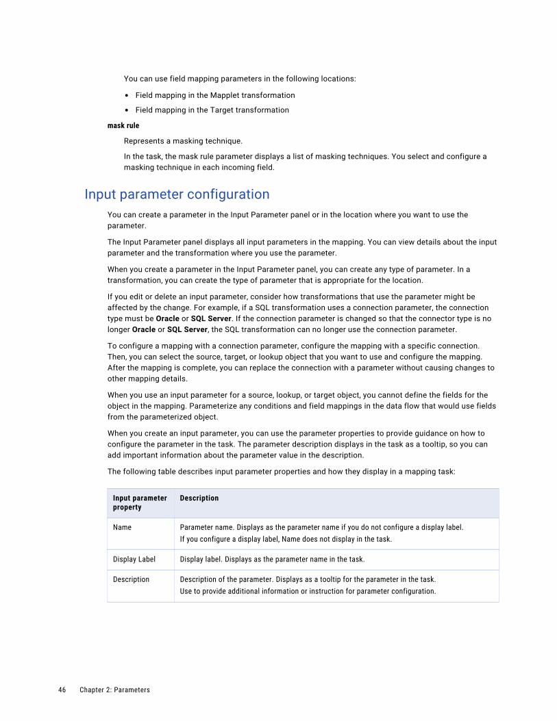
You can use field mapping parameters in the following locations:
• Field mapping in the Mapplet transformation
• Field mapping in the Target transformation
mask rule
Represents a masking technique.
In the task, the mask rule parameter displays a list of masking techniques. You select and configure a masking technique in each incoming field.
Input parameter configurationYou can create a parameter in the Input Parameter panel or in the location where you want to use the parameter.
The Input Parameter panel displays all input parameters in the mapping. You can view details about the input parameter and the transformation where you use the parameter.
When you create a parameter in the Input Parameter panel, you can create any type of parameter. In a transformation, you can create the type of parameter that is appropriate for the location.
If you edit or delete an input parameter, consider how transformations that use the parameter might be affected by the change. For example, if a SQL transformation uses a connection parameter, the connection type must be Oracle or SQL Server. If the connection parameter is changed so that the connector type is no longer Oracle or SQL Server, the SQL transformation can no longer use the connection parameter.
To configure a mapping with a connection parameter, configure the mapping with a specific connection. Then, you can select the source, target, or lookup object that you want to use and configure the mapping. After the mapping is complete, you can replace the connection with a parameter without causing changes to other mapping details.
When you use an input parameter for a source, lookup, or target object, you cannot define the fields for the object in the mapping. Parameterize any conditions and field mappings in the data flow that would use fields from the parameterized object.
When you create an input parameter, you can use the parameter properties to provide guidance on how to configure the parameter in the task. The parameter description displays in the task as a tooltip, so you can add important information about the parameter value in the description.
The following table describes input parameter properties and how they display in a mapping task:
Input parameter property
Description
Name Parameter name. Displays as the parameter name if you do not configure a display label.If you configure a display label, Name does not display in the task.
Display Label Display label. Displays as the parameter name in the task.
Description Description of the parameter. Displays as a tooltip for the parameter in the task.Use to provide additional information or instruction for parameter configuration.
46 Chapter 2: Parameters

Input parameter property
Description
Type Parameter type. Determines where you can use the parameter. Also determines how the parameter displays in a mapping task:- String. Displays a textbox. For the Named Fields selection criteria, displays a list of fields.- Connection. Displays a list of connections.- Expression. Displays a Field Expression dialog box so you can create an expression.- Data object. Displays a list of available objects from the configured connection.- Field. Displays a list of fields from the selected object.- Field mapping. Displays field mapping tables allowing you to map fields from the data flow to
the target object.
Connection Type Determines the type of connection to use in the task. Applicable when the parameter type is Connection.For example, you select Oracle. Only Oracle connections are available in the task.
Allow parameter to be overridden at run time
Determines whether parameter values can be changed with a parameter file when the task runs. When you configure the task, you specify a default value for the parameter. You define the parameter value to use in the task in the parameter file.Applicable for data objects and connections with certain connection types. To see if a connector supports runtime override of source and target connections and objects, see the help for the appropriate connector.
Default Value Default value. Displays as the default value for the parameter, when available.For example, if you enter a connection name for a default value and the connection name does not exist in the organization, no default value displays.
Allow partial mapping override
Determines whether field mappings specified during mapping configuration can be changed in the task.Applicable when parameter type is Field mapping.Do not select Allow Partial Mapping Override if you want to enforce the links you configure in the mapping.
Partial parameterization with input parametersTo allow users to select one of the fields based on an input parameter at run time, you can implement partial parameterization in a mapping. Use partial parameterization to create templates for incremental data loads and other solutions.
For example, if you completely parameterize the source filter, you must include a query similar to the following example:
lastmodified_date > $$myvar
To partially parameterize the filter, you can specify the field as a variable, as shown in this example:
$field$ > $$myvar
In this case, the user can select the required field in the mapping task.
To implement partial parameterization, you must use a database connection and a Source transformation advanced filter or a Filter, Expression, Router, or Aggregator transformation. You can create an input parameter for one of the fields so that the user can select a specific field in the mapping task instead of writing a complete query. "String" and "field" are the only valid types.
Note: You can use the same parameter in all the supported transformations.
Input parameters 47
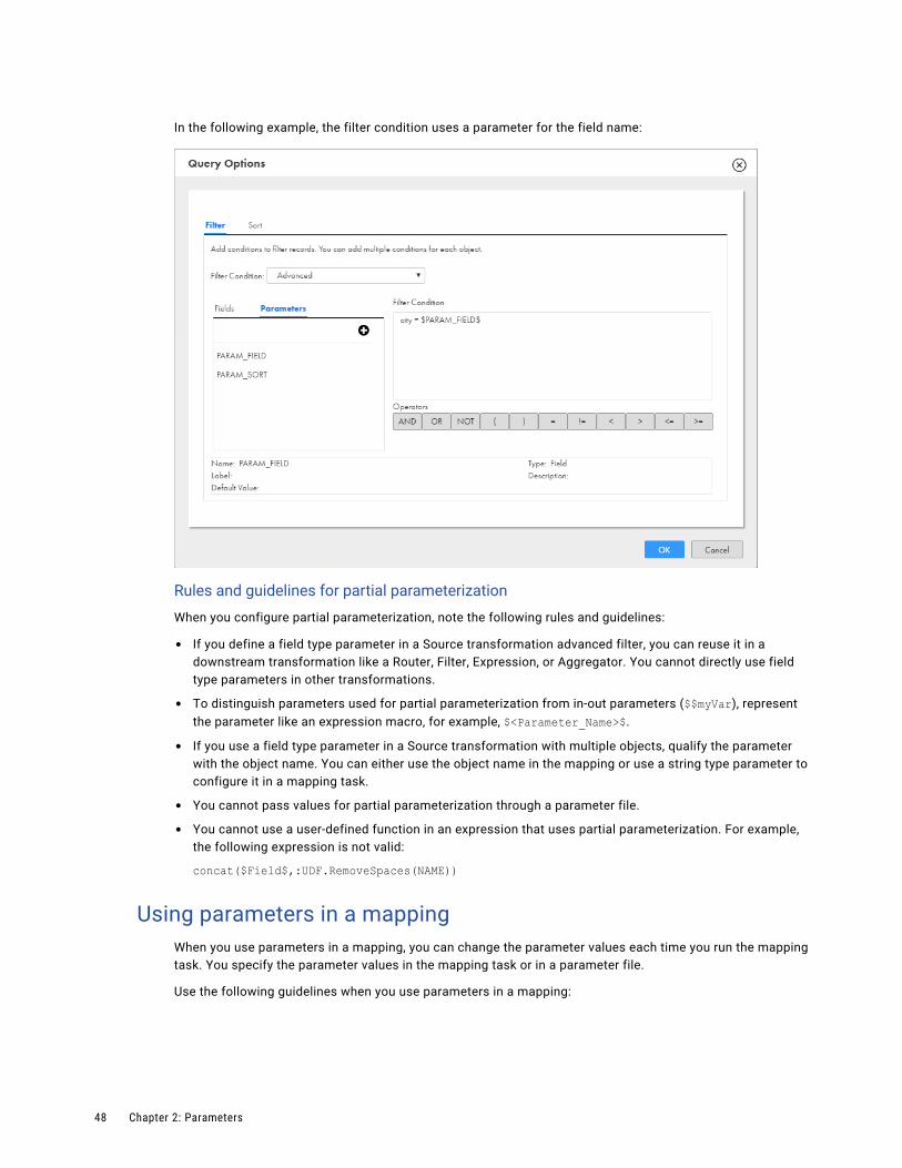
In the following example, the filter condition uses a parameter for the field name:
Rules and guidelines for partial parameterization
When you configure partial parameterization, note the following rules and guidelines:
• If you define a field type parameter in a Source transformation advanced filter, you can reuse it in a downstream transformation like a Router, Filter, Expression, or Aggregator. You cannot directly use field type parameters in other transformations.
• To distinguish parameters used for partial parameterization from in-out parameters ($$myVar), represent the parameter like an expression macro, for example, $<Parameter_Name>$.
• If you use a field type parameter in a Source transformation with multiple objects, qualify the parameter with the object name. You can either use the object name in the mapping or use a string type parameter to configure it in a mapping task.
• You cannot pass values for partial parameterization through a parameter file.
• You cannot use a user-defined function in an expression that uses partial parameterization. For example, the following expression is not valid:
concat($Field$,:UDF.RemoveSpaces(NAME))
Using parameters in a mappingWhen you use parameters in a mapping, you can change the parameter values each time you run the mapping task. You specify the parameter values in the mapping task or in a parameter file.
Use the following guidelines when you use parameters in a mapping:
48 Chapter 2: Parameters

When you create a mapping that includes source parameters, add the parameters after you configure the mapping.
For example, you have multiple customer account tables in different databases, and you want to run a monthly report to see customers for a specific state. When you create the mapping, you want to use parameters for the source connection, source object, and state. You update the parameter values to use at runtime when you configure the task.
To configure the mapping, you perform the following steps:
1. In the mapping, select the Source transformation.
2. On the Source tab, select a connection that contains one of the objects that you want to use, and then select the source object.You replace the source connection and object with parameters after the mapping is configured. You cannot select a source object if the source connection is a parameter. Add a source object so that you can configure the downstream data.
3. Add a Filter transformation.
4. On the Filter tab, add a filter condition. Select State for the field name, and create a new string parameter for the value. You resolve the parameter when you configure the task.
5. Configure the Target transformation.
6. Select the Source transformation.
7. On the Source tab, replace the source connection and the source object with parameters.
When you create a mapping with a parameterized target that you want to create at runtime, set the target field mapping to automatic.
If you create a mapping with a parameterized target object and you want to create the target at runtime, you must set the target field mapping to Automatic on the Target transformation Field Mapping tab. Automatic field mapping automatically links fields with the same name. You cannot map fields manually when you parameterize a target object.
In-out parametersAn in-out parameter is a placeholder for a value that stores a counter or task stage. Data Integration evaluates the parameter at run time based on your configuration.
In-out parameters act as persistent task variables. The parameter values are updated during task execution. The parameter might store a date value for the last record loaded from a data warehouse or help you manage the update process for a slowly changing dimension table.
For example, you might use an in-out parameter in one of the following ways:
Update values after each task execution.
You can use the SetVariable, SetMaxVariable, SetMinVariable, or SetCountVariable function in an Expression transformation to update parameter values each time you run a task.
To view the parameter values after the task completes, open the job details from the All Jobs or My Jobs page. You can also get these values when you work in the Mapping Designer or through the REST API.
In-out parameters 49

Handle incremental data loading for a data warehouse.
In this case, you set a filter condition to select records from the source that meet the load criteria. When the task runs, you include an expression to increment the load process. You might choose to define the load process based on one of the following criteria:
• A range of records configured in an expression to capture the maximum value of the record ID to process in a session.
• A time interval, using parameters in an expression to capture the maximum date/time values, after which the session ends. You might want to evaluate and load transactions daily.
Parameterize an expression.
You might want to parameterize an expression and update it when the task runs. Create a string or text parameter and enable Is expression variable. Use the parameter in place of an expression and resolve the parameter at run time in a parameter file.
For example, you create the expression field parameter $$param and override the parameter value with the following values in a parameter file:
$$param=CONCAT(NAME,$$year)$$year=2020
When the task runs, Data Integration concatenates the NAME field with 2020.
Note: Using in-out parameters in simultaneous mapping task runs can cause unexpected results.
You can use in-out parameters in the following transformations:
• Source
• Target
• Aggregator, but not in expression macros
• Expression, but not in expression macros
• Filter
• Router
• SQL, but not in elastic mappings
• Transaction Control, but not in elastic mappings
For each in-out parameter you configure the variable name, datatype, default value, aggregation type, and retention policy. You can also use a parameter file that contains the value to be applied at run time. For a specific task run, you can change the value in the mapping task.
Unlike input parameters, an in-out parameter can change each time a task runs. The latest value of the parameter is displayed in the job details when the task completes successfully. The next time the task runs, the mapping task compares the in-out parameter to the saved value.
You can also reset the in-out parameters in a mapping task, and then view the saved values in the job details.
Aggregation typesThe aggregation type of an in-out parameter determines the final current value of the parameter when the task runs. You can use variable functions with a corresponding aggregation type to set the parameter value at run time.
You can select one of the following aggregation types for each parameter:
• Count
• Max
50 Chapter 2: Parameters
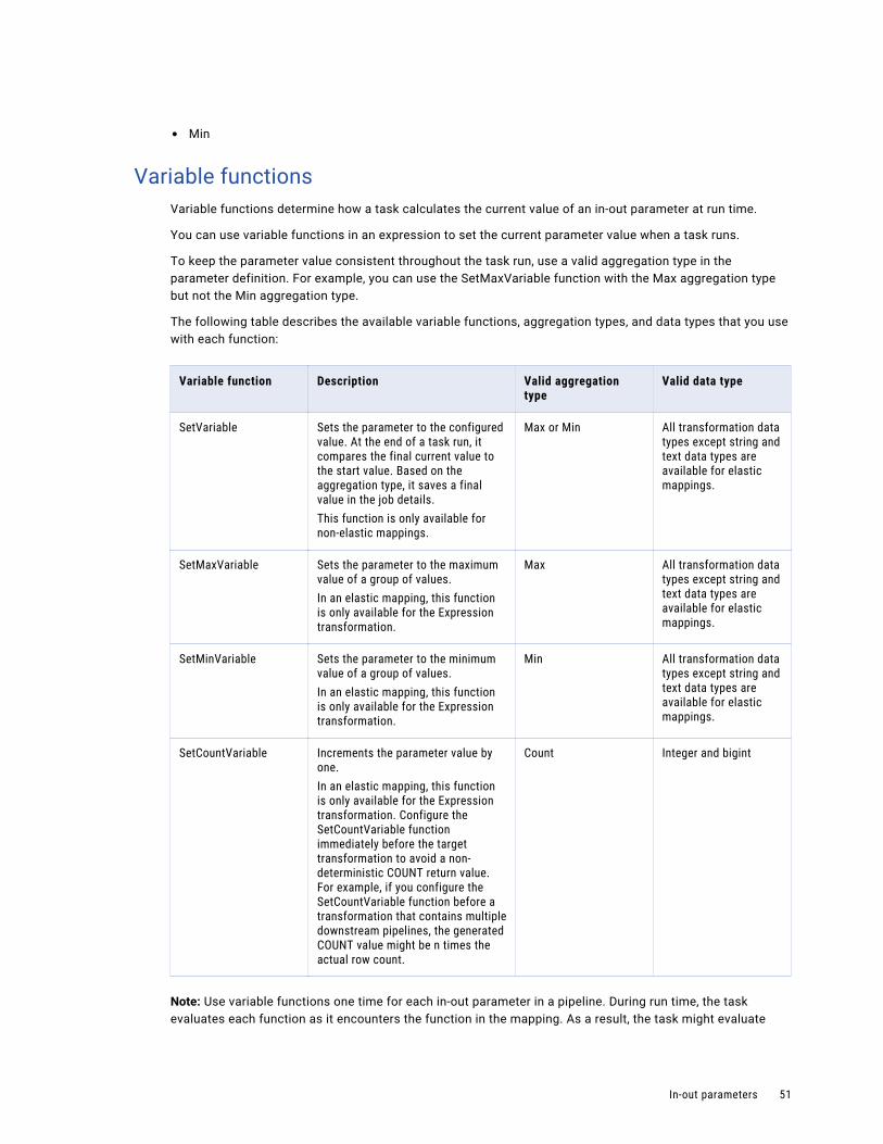
• Min
Variable functionsVariable functions determine how a task calculates the current value of an in-out parameter at run time.
You can use variable functions in an expression to set the current parameter value when a task runs.
To keep the parameter value consistent throughout the task run, use a valid aggregation type in the parameter definition. For example, you can use the SetMaxVariable function with the Max aggregation type but not the Min aggregation type.
The following table describes the available variable functions, aggregation types, and data types that you use with each function:
Variable function Description Valid aggregation type
Valid data type
SetVariable Sets the parameter to the configured value. At the end of a task run, it compares the final current value to the start value. Based on the aggregation type, it saves a final value in the job details.This function is only available for non-elastic mappings.
Max or Min All transformation data types except string and text data types are available for elastic mappings.
SetMaxVariable Sets the parameter to the maximum value of a group of values.In an elastic mapping, this function is only available for the Expression transformation.
Max All transformation data types except string and text data types are available for elastic mappings.
SetMinVariable Sets the parameter to the minimum value of a group of values.In an elastic mapping, this function is only available for the Expression transformation.
Min All transformation data types except string and text data types are available for elastic mappings.
SetCountVariable Increments the parameter value by one.In an elastic mapping, this function is only available for the Expression transformation. Configure the SetCountVariable function immediately before the target transformation to avoid a non-deterministic COUNT return value. For example, if you configure the SetCountVariable function before a transformation that contains multiple downstream pipelines, the generated COUNT value might be n times the actual row count.
Count Integer and bigint
Note: Use variable functions one time for each in-out parameter in a pipeline. During run time, the task evaluates each function as it encounters the function in the mapping. As a result, the task might evaluate
In-out parameters 51

functions in a different order each time the task runs. This might cause inconsistent results if you use the same variable function multiple times in a mapping.
In-out parameter propertiesSpecify the parameter properties for each in-out parameter that you define.
The following table describes the in-out parameter properties:
In-out parameter property
Description
Name Required. Name of the parameter.The parameter name cannot contain the text strings CurrentTaskName, CurrentTime, LastRunDate, or LastRunTime.
Description Optional. Description that is displayed with the parameter in the job details and the mapping task.Maximum length is 255 characters.
Data Type Required. Data type of the parameter.Note: Select a compatible aggregation type. For example, if you select string, you cannot configure it with the Count aggregation type.
Precision Required. Precision of the parameter.
Scale Optional. Scale of the parameter.
Is expression variable
Optional. Controls whether Data Integration resolves the parameter value as an expression.Disable to resolve the parameter as a literal string.Applicable when the data type is String or Text.Not available for elastic mapping.Default is disabled.
Default Value Optional. Default value for the parameter, which might be the initial value when the mapping first runs.Use the following format for default values for datetime variables: MM/DD/YYYY HH24:MI:SS.US.
Retention Policy Required. Determines when the mapping task retains the current value, based on the task completion status and the retention policy.Select one of the following options:- On success or warning (available for non-elastic mappings)- On success- On warning (available for non-elastic mappings)- Never
Aggregation Type Required. Aggregation type of the variable. Determines the type of calculation you can perform and the available variable functions.Select one of the following options:- Count to count number of rows read from source.- Max to determine a maximum value from a group of values.- Min to determine a minimum value from a group of values.
52 Chapter 2: Parameters
In-out parameter valuesAn in-out parameter is a placeholder for a value or values that the task applies at run time. You define the value of the in-out parameter in the mapping and you can edit the value when you configure the mapping task.
A mapping task uses the following values to evaluate the in-out parameter at run time:
• Default Value. The value specified in the in-out parameter configuration.
• Value. The current value of the parameter as the task progresses. When a task starts, the value is the same as the default value. As the task progresses, the task calculates the value using a function that you set for the parameter. The task evaluates the value as each row passes through the mapping. Unlike the default value, the value can change. The task saves the final value in the job details after the task runs.
Note:
• If the task does not use a function to calculate the value of an in-out parameter, the task saves the default value of the parameter as the initial current value.
• An in-out parameter value cannot exceed 4000 characters.
At run time, the mapping task looks for the value in one of these locations, in the following order:
1. Value in the parameter file
2. Value saved from the previous task run
3. Default value in the mapping
4. Default value for the data type
If you want to override a saved value, define a value for the in-out parameter in a parameter file. The task uses the value in the parameter file.
Rules and guidelines for in-out parametersConsider the following rules and guidelines:
• When you write expressions that use in-out parameters, you do not need string identifiers for string variables.
• When you use a parameter in a transformation, enclose string parameters in string identifiers, such as single quotation marks, to indicate the parameter is a string.
• When you use in-out parameter in a source filter of type date/time, you must enclose the in-out parameter in single quotes because the value received after Informatica Intelligent Cloud Services resolves the in-out parameter can contain spaces.
• When required, change the format of a date/time parameter to match the format in the source.
• If you copy, import, or export a mapping task, the session values of the in-out parameters are included.
• You cannot use in-out parameters in a link rule or as part of a field name in a mapping.
• You cannot use in-out parameters in an expression macro, because they rely on column names.
• When you use an in-out parameter in an expression or parameter file, precede the parameter name with two dollar signs ($$).
• An in-out parameter value cannot exceed 4000 characters.
• For elastic mappings, you cannot use an in-out parameter as a placeholder for an expression.
In-out parameters 53
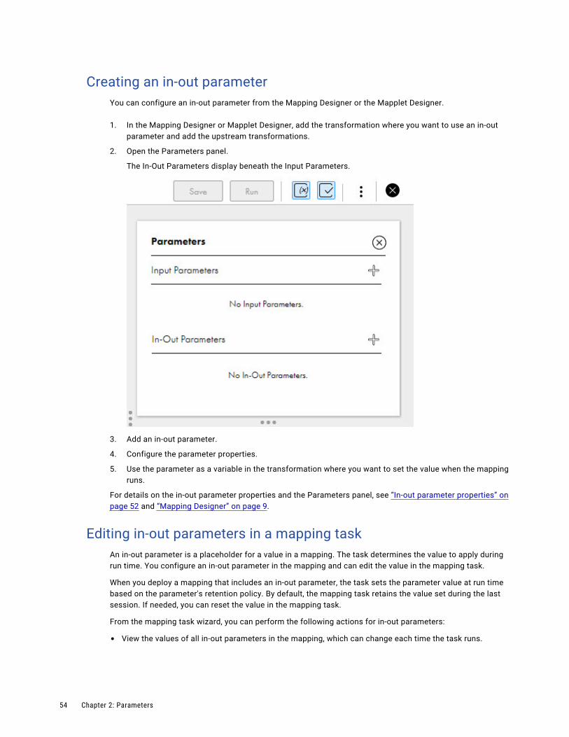
Creating an in-out parameterYou can configure an in-out parameter from the Mapping Designer or the Mapplet Designer.
1. In the Mapping Designer or Mapplet Designer, add the transformation where you want to use an in-out parameter and add the upstream transformations.
2. Open the Parameters panel.
The In-Out Parameters display beneath the Input Parameters.
3. Add an in-out parameter.
4. Configure the parameter properties.
5. Use the parameter as a variable in the transformation where you want to set the value when the mapping runs.
For details on the in-out parameter properties and the Parameters panel, see “In-out parameter properties” on page 52 and “Mapping Designer” on page 9.
Editing in-out parameters in a mapping taskAn in-out parameter is a placeholder for a value in a mapping. The task determines the value to apply during run time. You configure an in-out parameter in the mapping and can edit the value in the mapping task.
When you deploy a mapping that includes an in-out parameter, the task sets the parameter value at run time based on the parameter's retention policy. By default, the mapping task retains the value set during the last session. If needed, you can reset the value in the mapping task.
From the mapping task wizard, you can perform the following actions for in-out parameters:
• View the values of all in-out parameters in the mapping, which can change each time the task runs.
54 Chapter 2: Parameters

• Reset the configuration to the default values. Click Refresh to reset a single parameter. Click Refresh All to reset all the parameters.
• Edit or change specific configuration details. Click Edit.
For example, the following image shows configuration details of the "Timestamp" parameter and the value at the end of the last session:
View in-out parameters in the job details
To find the value of an in-out parameter after a task runs, view the job details. To view job details, open Monitor and select All Jobs or open Data Integration and select My Jobs. Then click the job name.
The following image shows an example of the available details, including the current value of the specified parameter, set during the last run of a mapping task:
The in-out parameters appear in the job details based on the retention policy that you set for each parameter.
In-out parameters 55
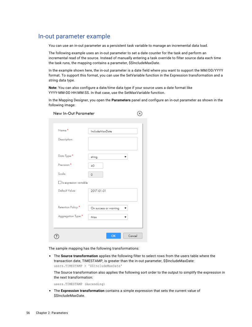
In-out parameter exampleYou can use an in-out parameter as a persistent task variable to manage an incremental data load.
The following example uses an in-out parameter to set a date counter for the task and perform an incremental read of the source. Instead of manually entering a task override to filter source data each time the task runs, the mapping contains a parameter, $$IncludeMaxDate.
In the example shown here, the in-out parameter is a date field where you want to support the MM/DD/YYYY format. To support this format, you can use the SetVariable function in the Expression transformation and a string data type.
Note: You can also configure a date/time data type if your source uses a date format like YYYY-MM-DD HH:MM:SS. In that case, use the SetMaxVariable function.
In the Mapping Designer, you open the Parameters panel and configure an in-out parameter as shown in the following image:
The sample mapping has the following transformations:
• The Source transformation applies the following filter to select rows from the users table where the transaction date, TIMESTAMP, is greater than the in-out parameter, $$IncludeMaxDate:users.TIMESTAMP > '$$IncludeMaxDate' The Source transformation also applies the following sort order to the output to simplify the expression in the next transformation:
users.TIMESTAMP (Ascending)• The Expression transformation contains a simple expression that sets the current value of
$$IncludeMaxDate.
56 Chapter 2: Parameters

The Expression output field, OutMaxDate, is a string type that enables you to map the expression output to the target.
The SetVariable function sets the current parameter value each time the session runs. For example, if you set the default value of $$IncludeMaxDate to 2016-04-04, the task reads rows dated through 2016-04-04 the first time it runs. The task sets $$IncludeMaxDate to 2016-04-04 when the session is complete. The next time the session runs, the task reads rows with a date greater than 2016-04-04 based on the source filter.
In-out parameters 57
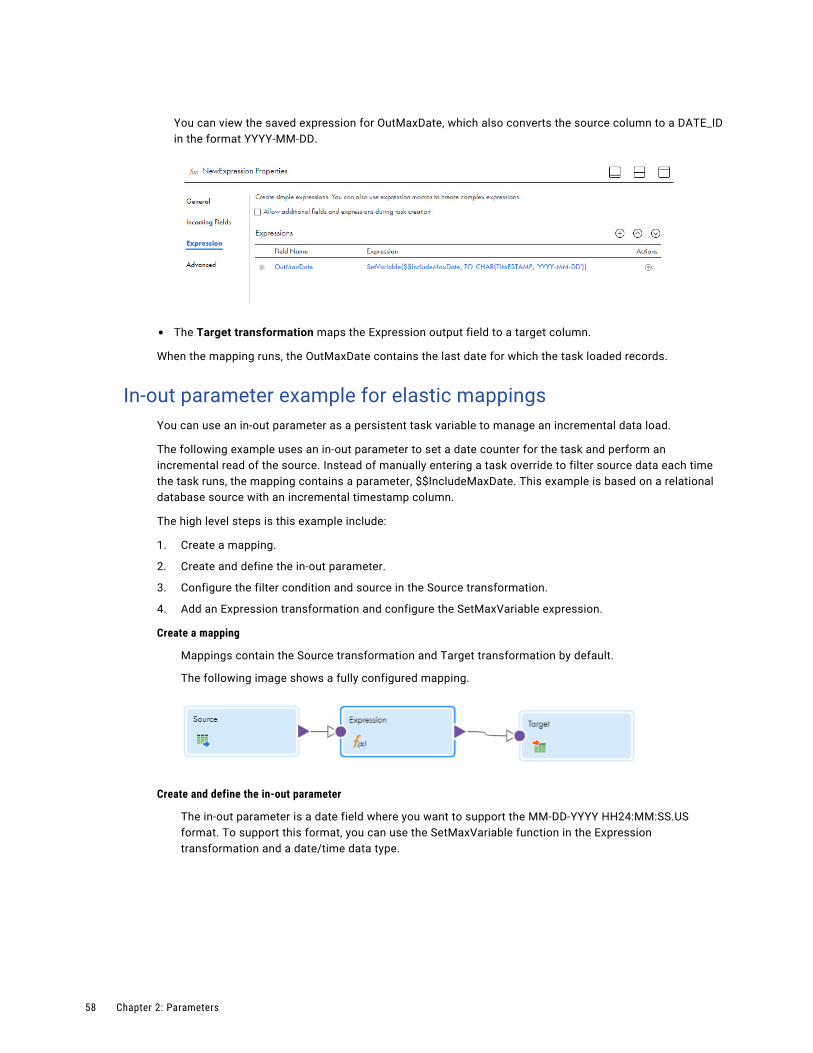
You can view the saved expression for OutMaxDate, which also converts the source column to a DATE_ID in the format YYYY-MM-DD.
• The Target transformation maps the Expression output field to a target column.
When the mapping runs, the OutMaxDate contains the last date for which the task loaded records.
In-out parameter example for elastic mappingsYou can use an in-out parameter as a persistent task variable to manage an incremental data load.
The following example uses an in-out parameter to set a date counter for the task and perform an incremental read of the source. Instead of manually entering a task override to filter source data each time the task runs, the mapping contains a parameter, $$IncludeMaxDate. This example is based on a relational database source with an incremental timestamp column.
The high level steps is this example include:
1. Create a mapping.
2. Create and define the in-out parameter.
3. Configure the filter condition and source in the Source transformation.
4. Add an Expression transformation and configure the SetMaxVariable expression.
Create a mapping
Mappings contain the Source transformation and Target transformation by default.
The following image shows a fully configured mapping.
Create and define the in-out parameter
The in-out parameter is a date field where you want to support the MM-DD-YYYY HH24:MM:SS.US format. To support this format, you can use the SetMaxVariable function in the Expression transformation and a date/time data type.
58 Chapter 2: Parameters

In the Mapping Designer, open the Parameters panel and configure an in-out parameter as shown in the following image:
Configure the filter condition and source in the Source transformation
Use the Source filtering options in the Source transformation to apply the following filter to select rows from the users table where the transaction date, TIMESTAMP, is greater than the in-out parameter, $$IncludeMaxDate:
users.TIMESTAMP > '$$IncludeMaxDate'
Add an Expression transformation and configure the SetMaxVariable expression
The Expression transformation contains a simple expression that sets the current value of $$IncludeMaxDate.
In-out parameters 59

The New Field dialog box shows the Field Type as Variable Field, Name as VariableMaxDate, Type as date/time, and Precision as 29.
The SetMaxVariable function sets the current parameter value each time the task runs. For example, if you set the default value of $$IncludeMaxDate to 04-04-2020 10:00:00, the task reads rows dated through 04-04-2020 the first time it runs. For the first task run, you specify the start date based on your needs. The task sets $$IncludeMaxDate to 11-04-2020 10:00:00 when the session is complete. The next time the task runs, it reads rows with a date/time value greater than 11-04-2020 10:00:00 based on your configuration of the Source filtering options.
60 Chapter 2: Parameters
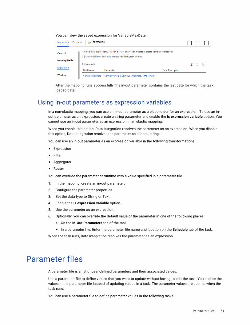
You can view the saved expression for VariableMaxDate.
After the mapping runs successfully, the in-out parameter contains the last date for which the task loaded data.
Using in-out parameters as expression variablesIn a non-elastic mapping, you can use an in-out parameter as a placeholder for an expression. To use an in-out parameter as an expression, create a string parameter and enable the Is expression variable option. You cannot use an in-out parameter as an expression in an elastic mapping.
When you enable this option, Data Integration resolves the parameter as an expression. When you disable this option, Data Integration resolves the parameter as a literal string.
You can use an in-out parameter as an expression variable in the following transformations:
• Expression
• Filter
• Aggregator
• Router
You can override the parameter at runtime with a value specified in a parameter file.
1. In the mapping, create an in-out parameter.
2. Configure the parameter properties.
3. Set the data type to String or Text.
4. Enable the Is expression variable option.
5. Use the parameter as an expression.
6. Optionally, you can override the default value of the parameter in one of the following places:
• On the In-Out Parameters tab of the task.
• In a parameter file. Enter the parameter file name and location on the Schedule tab of the task.
When the task runs, Data Integration resolves the parameter as an expression.
Parameter filesA parameter file is a list of user-defined parameters and their associated values.
Use a parameter file to define values that you want to update without having to edit the task. You update the values in the parameter file instead of updating values in a task. The parameter values are applied when the task runs.
You can use a parameter file to define parameter values in the following tasks:
Parameter files 61

Mapping tasks
Define parameter values for connections in the following transformations:
• Source
• Target
• Lookup
• SQL
Define parameter values for objects in the following transformations:
• Source
• Target
• Lookup
Also, define values for parameters in data filters, expressions, and lookup expressions.
Note: Not all connectors support parameter files. To see if a connector supports runtime override of connections and data objects, see the help for the appropriate connector.
Synchronization tasks
Define values for parameters in data filters, expressions, and lookup expressions.
PowerCenter tasks
Define values for parameters and variables in data filters, expressions, and lookup expressions.
You cannot use a parameter file if the mapping task is based on an elastic mapping.
You enter the parameter file name and location when you configure the task.
Parameter file requirementsYou can reuse parameter files across assets such as mapping tasks, taskflows, and linear taskflows. To reuse a parameter file, define local and global parameters within a parameter file.
You group parameters in different sections of the parameter file. Each section is preceded by a heading that identifies the project, folder, and asset to which you want to apply the parameter values. You define parameters directly below the heading, entering each parameter on a new line.
The following table describes the headings that define each section in the parameter file and the scope of the parameters that you define in each section:
Heading Description
#USE_SECTIONS Tells Data Integration that the parameter file contains asset-specific parameters. Use this heading as the first line of a parameter file that contains sections. Otherwise Data Integration reads only the first global section and ignores all other sections.
[Global] Defines parameters for all projects, folders, tasks, taskflows, and linear taskflows.
[project name].[folder name].[taskflow name]-or-[project name].[taskflow name]
Defines parameters for tasks in the named taskflow only.If a parameter is defined in a taskflow section and in a global section, the value in the taskflow section overrides the global value.
62 Chapter 2: Parameters

Heading Description
[project name].[folder name].[linear taskflow name]-or-[project name].[linear taskflow name]
Defines parameters for tasks in the named linear taskflow only.If a parameter is defined in a linear taskflow section and in a global section, the value in the linear taskflow section overrides the global value.
[project name].[folder name].[task name]-or-[project name].[task name]
Defines parameters for the named task only.If a parameter is defined in a task section and in a global section, the value in the task section overrides the global value.If a parameter is defined in a task section and in a taskflow or linear taskflow section and the taskflow uses the task, the value in the task section overrides the value in the taskflow section.
If the parameter file does not contain sections, Data Integration reads all parameters as global.
Precede the parameter name with two dollar signs, as follows: $$<parameter>. Define parameter values as follows:
$$<parameter>=value$$<parameter2>=value2
For example, you have the parameters SalesQuota and Region. In the parameter file, you define each parameter in the following format:
$$SalesQuota=1000$$Region=NW
The parameter value includes any characters after the equals sign (=), including leading or trailing spaces. Parameter values are treated as String values.
Parameter scopeWhen you define values for the same parameter in multiple sections in a parameter file, the parameter with the smallest scope takes precedence over parameters with larger scope.
In this case, Data Integration gives precedence to parameter values in the following order:
1. Values defined in a task section.
2. Values defined in a taskflow or linear taskflow section.
3. Values defined in the #USE_SECTIONS section.
4. Values defined in a global section.
For example, a parameter file contains the following parameter values:
[GLOBAL]$$connection=ff5[Project1].[Folder1].[monthly_sales]$$connection=ff_jd
For the task "monthly_sales" in Folder1 inside Project1, the value for parameter $$connection is "ff_jd." In all other tasks, the value for $$connection is "ff5."
If you define a parameter in a task section and in a taskflow or linear taskflow section and the taskflow uses the task, Data Integration uses the parameter value defined in the task section.
Parameter files 63

For example, you define the following parameter values in a parameter file:
#USE_SECTIONS$$source=customer_table[GLOBAL]$$location=USA$$sourceConnection=Oracle[Default].[Sales].[Task1]$$source=Leads_table[Default].[Sales].[Taskflow2]$$source=Revenue$$sourceconnection=ODBC_1[Default].[Taskflow3]$$source=Revenue$$sourceconnection=Oracle_DB
Task1 contains the $$location, $$source, and $$sourceconnection parameters. Taskflow2 and Taskflow3 contain Task1.
When you run Taskflow2, Data Integration uses the following parameter values:
Parameter Section Value
$$source [Default].[Sales].[Task1] Leads_table
$$sourceconnection [Default].[Sales].[Taskflow2] ODBC_1
$$location [GLOBAL] USA
When you run Taskflow3, Data Integration uses the following parameter values:
Parameter Section Value
$$source [Default].[Sales].[Task1] Leads_table
$$sourceconnection [Default].[Taskflow3] Oracle_DB
$$location [GLOBAL] USA
When you run Task1, Data Integration uses the following parameter values:
Parameter Section Value
$$source [Default].[Sales].[Task1] Leads_table
$$sourceconnection [GLOBAL] Oracle
$$location [GLOBAL] USA
For all other tasks that contain the $$source parameter, Data Integration uses the value customer_table.
Sample parameter fileThe following example shows a sample parameter file entry:
#USE_SECTIONS$$oracleConn=Oracle_SK$$city=SF
64 Chapter 2: Parameters

[Global]$$ff_conn=FF_ja_con$$st=CA[Default].[Accounts].[April]$$QParam=SELECT * from con.ACCOUNT where city=LAX$$city=LAX$$tarOb=accounts.csv$$oracleConn=Oracle_Src
Parameter file locationWhen you use a parameter file, save the parameter file on a local machine or in a cloud-hosted directory based on the task type. You enter details about the parameter file on the Schedule tab when you create the task.
By default, Data Integration uses the following parameter file directory on the Secure Agent machine:
<Secure Agent installation directory>/apps/Data_Integration_Server/data/userparameters
When you use a parameter file in a synchronization task, save the parameter file in the default directory.
For mapping tasks, you can also save the parameter file in one of the following locations:
A local machine
Save the file in a location that is accessible by the Secure Agent.
You enter the file name and directory on the Schedule tab when you create the task. Enter the absolute file path. Alternatively, enter a path relative to a $PM system variable, for example, $PMRootDir/ParameterFiles.
The following table lists the system variables that you can use:
System variable Description
$PMRootDir Root directory for the Data Integration Server Secure Agent service.Default is <Secure Agent installation directory>/apps/Data_Integration_Server/data.
$PMBadFileDir Directory for row error logs and reject files.Default is $PMRootDir/error.
$PMCacheDir Directory for index and data cache files.Default is $PMRootDir/cache.
$PMExtProcDir Directory for external procedures.Default is $PMRootDir.
$PMLookupFileDir Directory for lookup files.Default is $PMRootDir.
$PMSessionLogDir Directory for session logs.Default is $PMRootDir/../logs.
$PMSourceFileDir Directory for source files.Default is $PMRootDir.
Parameter files 65

System variable Description
$PMStorageDir Directory for files related to the state of operation of internal processes such as session and workflow recovery files.Default is $PMRootDir.
$PMTargetFileDir Directory for target files.Default is $PMRootDir.
$PMTempDir Directory for temporary files.Default is $PMRootDir/temp.
$PMWorkflowLogDir Directory for workflow logs.Default is $PMRootDir/../logs.
To find the configured path of a system variable, see the pmrdtm.cfg file located at the following directory:
<Secure Agent installation directory>\apps\Data_Integration_Server\<Data Integration Server version>\ICS\main\bin\rdtm
You can also find the configured path of any variable except $PMRootDir in the Data Integration Server system configuration details in Administrator.
If you do not enter a location, Data Integration uses the default parameter file directory.
A cloud platform
You can use a connection stored with Informatica Intelligent Cloud Services. The following table shows the connection types that you can use and the configuration requirements for each connection type:
Connection type Requirements
Amazon S3 V2 You can use a connection that was created with the following credentials:- Access Key- Secret Key- RegionThe S3 bucket must be public.
Azure Data Lake Store Gen2 You can use a connection that was created with the following credentials:- Account Name- ClientID- Client Secret- Tenant ID- File System Name- Directory PathThe storage point must be public.
Google Storage V2 You can use a connection that was created with the following credentials:- Service Account ID- Service Account Key- Project IDThe storage bucket must be public.
Create the connection before you configure the task. You select the connection and file object to use on the Schedule tab when you create the task.
66 Chapter 2: Parameters

Data Integration displays the location of the parameter file and the value of each parameter in the job details after you run the task.
Rules and guidelines for parameter filesData Integration uses the following rules to process parameter files:
• If a parameter is not defined in the parameter file, Data Integration uses the value defined in the task.
• Data Integration processes the file top-down.
• If a parameter value is defined more than once in the same section, Data Integration uses the first value. For example, a parameter file contains the following task section:
[MyProject].[Folder1].[mapping_task1]$$sourceconn=Oracle$$filtervariable=ID$$sourceObject=customer_table$$targetconn=salesforce$$sourceconn=ff_2
When mapping_task1 runs, the value of the sourceconn parameter is Oracle.
• If a parameter value is another parameter defined in the file, precede the parameter name with one dollar sign ($). Data Integration uses the first value of the variable in the most specific scope. For example, a parameter file contains the following parameter values:
[GLOBAL]$$ffconnection=my_ff_conn$$var2=California$var5=North[Default].[folder5].[sales_accounts]$$var2=$var5$var5=south
In the task "sales_accounts," the value of "var5" is "south." Since var2 is defined as var5, var2 is also "south."
• If a task is defined more than once, Data Integration combines the sections.
• If a parameter is defined in multiple sections for the same task, Data Integration uses the first value. For example, a parameter file contains the following task sections:
[Default].[Folder1].[MapTask2]$$sourceparam=Oracle_Cust [Default].[Folder1].[MapTask2]$$sourceparam=Cust_table$$targetparam=Sales
When you run MapTask2, Data Integration uses the following parameter values:
- $$sourceparam=Oracle_Cust
- $$targetparam=Sales
• The value of a parameter is global unless it is present in a section.
• Data Integration ignores sections with syntax errors.
Parameter file templatesYou can generate and download a parameter file template that contains mapping parameters and their default values. The parameter file template includes input and in-out parameters that can be overridden at
Parameter files 67

runtime. Save the parameter file template and use it to apply parameter values when you run the task, or copy the mapping parameters to another parameter file.
When you generate a parameter file template, the file contains the default parameter values from the mapping on which the task is based. If you do not specify a default value when you create the parameter, the value for the parameter in the template is blank.
The parameter file template does not contain the following elements:
• Runtime values that you specify in the mapping task
• Partial parameters
• Advanced session properties
• System defined variables
If you add, edit, or delete parameters in the mapping, download a new parameter file template.
Downloading a parameter file template
1. On the Schedule tab in the mapping task, click Download Parameter File Template.
The file name is <mapping task name>.param.
2. If you want to use the file in subsequent task runs, save the parameter file in a location that is accessible by the Secure Agent.
Enter the file name and directory on the Schedule tab when you configure the task.
Overriding connections with parameter filesIf you use a connection parameter in a mapping, you can override the connection defined in the mapping task at runtime with values specified in a parameter file.
When you define a connection value in a parameter file, the connection type must be the same as the default connection type in the mapping task. For example, you create a Flat File connection parameter and use it as the source connection in a mapping. In the mapping task, you provide a flat file default connection. In the parameter file, you can only override the connection with another flat file connection.
When you override an FTP connection using a parameter, the file local directory must the same.
You cannot use a parameter file to override a lookup with an FTP/SFTP connection.
Note: Some connectors support only cached lookups. To see which type of lookup a connector supports, see the help for the appropriate connector.
1. In the mapping, create an input parameter:
a. Select connection for the parameter type .
b. Select Allow parameter to be overridden at runtime.
2. In the mapping, use the parameter as the connection that you want to override.
3. In the mapping task, define the parameter details:
a. Select a default connection.
b. On the Schedule tab, enter the parameter file directory and parameter file name.
4. In the parameter file, define the connection parameter with the value that you want to use at runtime.
68 Chapter 2: Parameters

Precede the parameter name with two dollar signs ($$). For example, you have a parameter with the name ConParam and you want to override it with the connection OracleCon1. You define the runtime value with the following format:
$$ConParam=OracleCon15. If you want to change the connection, update the parameter value in the parameter file.
Overriding data objects with parameter filesIf you use a data object parameter in a mapping, you can override the object defined in the mapping task at runtime with values specified in a parameter file.
Note: You cannot override source objects when you read from multiple relational objects or from a file list. You cannot override target objects if you create a target at run time.
When you define an object parameter in the parameter file, the parameter in the file must have the same metadata as the default parameter in the mapping task. For example, if you override the source object ACCOUNT with EMEA_ACCOUNT, both objects must contain the same fields and the same data types for each field.
1. In the mapping, create an input parameter:
a. Select data object for the parameter type.
b. Select Allow parameter to be overridden at runtime.
2. In the mapping, use the object parameter at the object that you want to override.
3. In the mapping task, define the parameter details:
a. Set the type to Single.
b. Select a default data object.
c. On the Schedule tab, enter the parameter file directory and file name.
4. In the parameter file, specify the object to use at runtime.
Precede the parameter name with two dollar signs ($$). For example, you have a parameter with the name ObjParam1 and you want to override it with the data object SourceTable. You define the runtime value with the following format:
$$ObjParam1=SourceTable
5. If you want to change the object, update the parameter value in the parameter file.
Overriding source queriesIf you use a source query or filter condition in a mapping, you can override the value specified in the mapping task with values specified in a parameter file. You can override source queries for relational and ODBC database connections.
When you define an SQL query, the fields in the overridden query must be the same as the fields in the default query. The task fails if the query in the parameter file contains fewer fields or is invalid.
If a filter condition parameter is not resolved in the parameter file, Data Integration will use the parameter as the filter value and the task returns zero rows.
1. In the mapping, create a data object parameter.
2. Select Allow parameter to be overridden at runtime.
3. Use the parameter as the source object.
Parameter files 69

4. In the mapping task, on the Sources tab, select Query as the source type.
5. Enter a default custom query.
6. On the Schedule tab, provide the parameter file name and location.
7. In the parameter file, enter the values to use when the task runs.
8. If you want to change the query, update the parameter value in the parameter file.
Creating target objects at run time with parameter filesIf you use a target object parameter in a mapping, you can create a target at run time using a parameter file.
You include the target object parameter and the name that you want to use in a parameter file. If the target name in the parameter file doesn't exist, Data Integration creates the target at run time. In subsequent runs, Data Integration uses the existing target.
To create a target at run time using a parameter file, the following conditions must be true:
• The mapping uses a flat file, relational, or file storage-based connection.
• The mapping is used in a mapping task, dynamic mapping task, or taskflow.
For file storage-based connections, the parameter value in the parameter file can include both the path and file name. If the path is not specified, the target is created in the default path specified in the connection.
1. In the mapping, create an input parameter:
a. Select data object for the parameter type.
b. Select Allow parameter to be overridden at runtime.
2. In the mapping, use the parameter as the target object.
3. In the task, define the parameter details:
a. Set the type to Single.
b. Select a default data object.
c. On the Schedule tab, enter the parameter file directory and file name.
4. In the parameter file, specify the name of the target object that you want to create.
Precede the parameter name with two dollar signs ($$). For example, you have a parameter with the name TargetObjParam and you want to create a target object with the name MyTarget. You define the runtime value with the following format:
$$TargetObjParam=MyTarget
For file storage-based connector types, include the path in the object name. If you don't include a path, the target is created in the default path specified in the connection.
5. If you want to change the object, update the parameter value in the parameter file.
70 Chapter 2: Parameters

C h a p t e r 3
CLAIRE recommendationsIf your organization has enabled CLAIRE recommendations, you can receive recommendations during mapping design. CLAIRE, Informatica's AI engine, uses machine learning to make recommendations based on the current flow of the mapping and metadata from prior mappings across Informatica Intelligent Cloud Services organizations.
When your organization opts in to receive CLAIRE-based recommendations, anonymous metadata from your organization's mappings is analyzed and leveraged to offer design recommendations.
To disable recommendations for the current mapping, use the recommendation toggle. You can enable recommendations again at any time.
When you create a new mapping, recommendations are enabled by default. If you edit an existing mapping, recommendations are disabled by default.
CLAIRE can make the following types of recommendations during mapping design:
• Recommend transformation types to include in the mapping.
• Recommend additional sources based on primary key and foreign key relationships.
• Recommend joining or unioning additional sources.
• Make recommendations for objects in a mapping inventory.
71
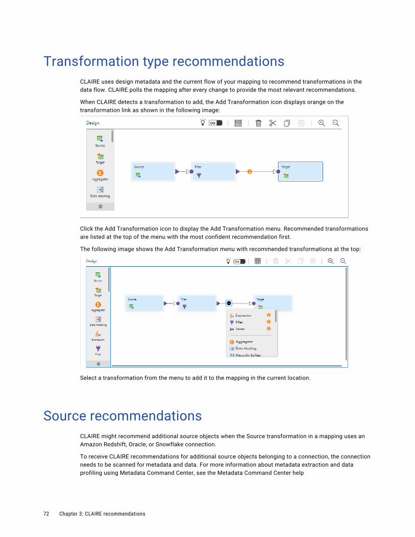
Transformation type recommendationsCLAIRE uses design metadata and the current flow of your mapping to recommend transformations in the data flow. CLAIRE polls the mapping after every change to provide the most relevant recommendations.
When CLAIRE detects a transformation to add, the Add Transformation icon displays orange on the transformation link as shown in the following image:
Click the Add Transformation icon to display the Add Transformation menu. Recommended transformations are listed at the top of the menu with the most confident recommendation first.
The following image shows the Add Transformation menu with recommended transformations at the top:
Select a transformation from the menu to add it to the mapping in the current location.
Source recommendationsCLAIRE might recommend additional source objects when the Source transformation in a mapping uses an Amazon Redshift, Oracle, or Snowflake connection.
To receive CLAIRE recommendations for additional source objects belonging to a connection, the connection needs to be scanned for metadata and data. For more information about metadata extraction and data profiling using Metadata Command Center, see the Metadata Command Center help
72 Chapter 3: CLAIRE recommendations

CLAIRE makes recommendations for additional source objects based on primary key and foreign key relationships. The recommendations can be helpful when you want to use multiple source objects and you have many tables on the data source to search through.
For example, you want to find a list of customers together with the type of car each customer has ordered. For the Source transformation in your mapping, you use a connection to an Oracle database that contains hundreds of tables. You select a customer table for the source object. In the CLAIRE Recommendations tab, CLAIRE suggests several tables that can be joined to the customer table. One of the tables contains customer order data. You add the table to the mapping as an additional Source transformation.
When a recommendation is available, Data Integration highlights the Recommendations tab. Select the Recommendations tab to see the recommendations.
In the list of recommendations, click the Show Me icon for the source that you want to investigate. A Source transformation with the recommended source object appears on the mapping canvas. The following image shows the Show Me icon for a recommended source:
Open the Source transformation and click the Fields tab to review the source fields in the source object.
If you want to use the source, in the Recommendations tab, click the Accept icon. In the mapping canvas, connect the Source transformation to the data flow.
If you don't want to use the recommended source, click Decline. Data Integration removes the recommended Source transformation from the mapping canvas.
Join recommendationsWhen CLAIRE recommends an additional source object, it might also recommend joining the new source and the original source with a Joiner transformation if it detects a join relationship between the two objects.
Data Integration automatically joins the sources with a normal join based on the recommended join condition. By default, when Data Integration joins the sources, it links the recommended source to the Master group and the original source to the Detail group. To avoid field name conflicts, Data Integration prefixes field names in the recommended source.
To review the recommended join condition, in the Recommendations tab, select Show with Joiner for the source that you want to review, and then click the Show Me icon. In the mapping canvas, open the Joiner transformation and click the Join Condition tab.
If you want to use the source with the Joiner transformation, in the Recommendations tab, click the Accept icon. In the mapping canvas, connect the Joiner transformation to the data flow.
Union recommendationsWhen CLAIRE recommends an additional source object, it might also recommend a Union transformation if it detects a union relationship between the two sources. If you accept the recommendation, Data Integration automatically unions the sources.
By default, Data Integration adds the original source as Input Group 1 and maps the original source fields to the Union transformation output fields.
Source recommendations 73

To review the recommended source and Union transformation, in the Recommendations tab, select Show with Union for the source that you want to review, and then click the Show Me icon. If you want to use the source with the Union transformation, in the Recommendations tab, click the Accept icon. In the mapping canvas, connect the Union transformation to the data flow.
Mapping inventory recommendationsIf your organization uses Enterprise Data Catalog and you use a catalog object from the inventory as a source, target, or lookup object in a mapping, CLAIRE might make recommendations for the object.
For example, CLAIRE might recommend that you add a Data Masking transformation to the mapping to mask sensitive data.
For more information about using catalog objects in mappings, see Chapter 4, “Data catalog discovery” on page 75.
74 Chapter 3: CLAIRE recommendations
C h a p t e r 4
Data catalog discoveryIf your organization uses Enterprise Data Catalog and you have the appropriate license, you can perform a search against the data catalog and discover catalog assets. You can use the assets that you discover as sources, targets, and lookup objects in mappings and as sources in synchronization and file ingestion tasks.
Use data catalog discovery to find objects in the catalog that you can use in the following types of Data Integration assets:
• Mappings. Discover tables, views, and delimited flat files to use as sources, targets, or lookup objects in new mappings or in mappings that you currently have open in Data Integration.
• Elastic mappings. If you have the appropriate license, you can discover Amazon S3 and Amazon Redshift objects to use as sources, targets, and lookup objects in new elastic mappings or in elastic mappings that you currently have open in Data Integration.
• Synchronization tasks. Discover tables, views, and delimited flat files to use as sources in new synchronization tasks.
• File ingestion tasks. You can discover Amazon S3, Microsoft Azure Blob Storage, and Hadoop Files objects to use as sources in file ingestion tasks.
Note: Before you can use data catalog discovery, your organization administrator must configure the Enterprise Data Catalog integration properties on the Organization page in Administrator. For more information about configuring Enterprise Data Catalog integration properties, see the Administrator help.
75

Performing data catalog discoveryPerform data catalog discovery on the Data Catalog page.
The following image shows the Data Catalog page:
The page displays a Search field and the total number of table, view, and flat file assets in the catalog.
In the Search field, enter a phrase that might occur in the object name, description, or other metadata such as the data domain or associated business glossary term. When you select an object from the search results, Data Integration asks you where you want to use the object. Data Integration also imports the connection if it does not exist in your organization.
You can use the object in the following places:
• In a new mapping. If you select this option, Data Integration creates a new mapping and adds the object to the mapping inventory. You can then add the object to the mapping as a source, target, or lookup object.
• In an open mapping. If you select this option, Data Integration asks you to select the mapping and adds the object to the mapping inventory. You can then add the object to the mapping as a source, target, or lookup object.
• In a new synchronization task. If you select this option, Data Integration creates a new synchronization task and adds the object as the source object.
• In a new file ingestion task. If you select this option, Data Integration creates a new file ingestion task and adds the object as the source object.
76 Chapter 4: Data catalog discovery

Mapping inventoryIf you select an object from the search results and add it to a mapping, Data Integration adds the object to the mapping inventory. Select an object from the inventory, and add it to the mapping as a source, target, or lookup object.
The following image shows the mapping inventory:
1. Inventory icon. Shows and hides the Inventory panel.2. "Select an object from the inventory" icon in the transformation Properties panel. Selects an object from the
inventory as the source, target, or lookup object.
Each mapping has its own inventory. Each object that you add to the mapping inventory stays in the inventory until you delete it.
To add an object from the inventory as a source, target, or lookup object, select the Source, Target, or Lookup transformation and click Select an object from the inventory on the tab where you configure the connection. Then select the object from the inventory.
If you enable CLAIRE recommendations in the Mapping Designer, Data Integration highlights the Recommendations tab when there is a new recommendation for objects in the inventory. For example, if an object in the inventory contains sensitive data such as credit card numbers, and you add it to the mapping as a source, target, or lookup object, Data Integration highlights the Recommendations tab. When you open the recommendations, CLAIRE might recommend that you add a Data Masking transformation to the mapping to mask the sensitive data.
Performing data catalog discovery 77

Catalog searchUse the search on the Data Catalog page to find an Enterprise Data Catalog object. Enter the object name, part of the name, or keywords associated with the object in the Search field, and then click the search icon. Data Integration returns all tables, views, and flat files in the catalog that match the search criteria.
You can use the * and ? wildcard characters in the search phrase. For example, to find objects that start with the string "Cust", enter Cust* in the Search field.
You can also enter keyword searches. For example, if you enter tables with order in the Search field, Data Integration returns tables with "order" in the name or description, tables that have the associated business term "order," and tables that contain columns for which the "order" data domain is inferred or assigned.
For more information about Enterprise Data Catalog searches and search results, see the Enterprise Data Catalog documentation.
The following image shows an example of search results when you enter "tables with order" as the search phrase:
1. Filter search results.2. Show or hide object details.3. Sort search results.4. Apply or remove all filters.5. Use the selected object in a mapping, a synchronization task, or a file ingestion task.
You can perform the following actions on the search results page:
Filter search results.
Use the filters to filter search results by asset type, resource type, resource name, number of rows, data domains, and date last updated.
Show details.
To display details about the object, click Show Details.
78 Chapter 4: Data catalog discovery
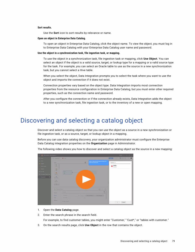
Sort results.
Use the Sort icon to sort results by relevance or name.
Open an object in Enterprise Data Catalog.
To open an object in Enterprise Data Catalog, click the object name. To view the object, you must log in to Enterprise Data Catalog with your Enterprise Data Catalog user name and password.
Use the object in a synchronization task, file ingestion task, or mapping.
To use the object in a synchronization task, file ingestion task or mapping, click Use Object. You can select an object if the object is a valid source, target, or lookup type for a mapping or a valid source type for the task. For example, you can select an Oracle table to use as the source in a new synchronization task, but you cannot select a Hive table.
When you select the object, Data Integration prompts you to select the task where you want to use the object and imports the connection if it does not exist.
Connection properties vary based on the object type. Data Integration imports most connection properties from the resource configuration in Enterprise Data Catalog, but you must enter other required properties, such as the connection name and password.
After you configure the connection or if the connection already exists, Data Integration adds the object to a new synchronization task, file ingestion task, or to the inventory of a new or open mapping.
Discovering and selecting a catalog objectDiscover and select a catalog object so that you can use the object as a source in a new synchronization or file ingestion task, or as a source, target, or lookup object in a mapping.
Before you can use data catalog discovery, your organization administrator must configure the Enterprise Data Catalog integration properties on the Organization page in Administrator.
The following video shows you how to discover and select a catalog object as the source in a new mapping:
1. Open the Data Catalog page.
2. Enter the search phrase in the search field.
For example, to find customer tables, you might enter "Customer," "Cust*," or "tables with customer."
3. On the search results page, click Use Object in the row that contains the object.
Discovering and selecting a catalog object 79

You can select one object at a time.
Data Integration prompts you to select where to use the object.
4. Select one of the following options:
• To add the object to a new synchronization task, click New Synchronization Task.
• To add the object to a new file ingestion task, click New File Ingestion Task.
• To add the object to a new mapping, click New Mapping.
• To add the object to an open mapping, click Add to an open asset, and then select the mapping.
5. Click OK.
If the connection does not exist in your organization, Data Integration prompts you to import the connection. Enter the missing connection properties such as the connection name and password.
If you use the object in a synchronization or file ingestion task, Data Integration creates the task with the object as the source. Configure other task properties such as the target, data filters, field mapping, and scheduling information.
6. If you use the object in a mapping, Data Integration adds the object to the mapping inventory. Select the object as the source, target or lookup object.
To select the object:
a. Open the Inventory panel.
b. Select the Source, Target, or Lookup transformation.
c. In the Properties panel, select the tab where you configure the connection:
- In the Source transformation, click the Source tab.
- In the Target transformation, click the Target tab.
- In the Lookup transformation, click the Lookup Object tab.
d. Click Select an object from the inventory.
e. Select the object from the inventory and click OK.
Data Integration adds the object to the mapping as the source, target, or lookup object.
Data catalog discovery exampleYou need to create a mapping that reads data from an orders table. You know that the table is in an Oracle database, but you cannot remember the exact table name or which connection the object is associated with.
You open the Data Catalog page and enter "tables with order" in the search field. The search returns a list of tables and views that contain “order” in the name or description, tables that have the associated business term "order," and tables that contain columns for which the "order" data domain is inferred or assigned. The search results also show details about each object.
You select the table that you were looking for and add it to a new mapping. You then open the Source transformation in the mapping, click the Source tab, and click Select an object from the inventory. You select the table from the mapping inventory and click OK. The table becomes the source object.
80 Chapter 4: Data catalog discovery
C h a p t e r 5
Visio templatesA Visio template defines parameterized data flow logic that you can use in mapping tasks.
Visio templates are a legacy feature known as integration templates in Informatica Cloud. Visio templates are not supported in Data Integration by default. If you require the Visio template feature, contact Informatica Global Customer Support.
As an alternative to Visio templates, Informatica recommends that you take advantage of the mapping and mapping task templates that are included in Data Integration. These templates include pre-built logic that you can use for data integration, cleansing, and warehousing tasks. The templates can be used as is or as a head start in creating a mapping or mapping task to suit your business needs. You can choose the template that you want to use for a new mapping or mapping task on the New Asset page.
If you use Visio templates, you must complete the following tasks:
1. Configure a Visio template using the Cloud Integration Template Designer, which is a Data Integration plug-in for Microsoft Visio. Use the Informatica toolbar and Informatica stencil to configure the template.You can create a new file in the Cloud Integration Template Designer, use a mapping XML file exported from PowerCenter, or use a synchronization task mapping XML file exported from Data Integration.
When you configure the Visio template, you define the general data flow and configure template parameters to enable flexibility in how the Visio template can be used.
2. Publish the Visio template using the Cloud Integration Template Designer.
3. Upload the Visio template to your Data Integration organization.When you upload the Visio template, you define template parameter properties, such as default values and display properties.
4. Create a mapping task based on the template.When you configure the mapping task, you define the template parameter values for the Visio template. You can reuse the logic of an uploaded Visio template by creating multiple mapping tasks and defining template parameter values differently in each task.
PrerequisitesWorking with Visio templates requires the following prerequisites:
• Microsoft Visio 2010.
• The Informatica Data Integration plug-in, the Cloud Integration Template Designer.
• Some understanding of PowerCenter mappings and transformation objects.
81

Configuring a Visio templateConfigure a Visio template in the Cloud Integration Template Designer to define flexible, reusable data flow logic for use in mapping tasks.
A Visio template includes at least one source definition, source qualifier, target definition, and links that define how data moves between objects. A Visio template can include other Informatica objects, such as a Lookup object to define lookups or a Joiner object to join heterogeneous sources.
A pipeline consists of a source qualifier and all the objects and targets that receive data from the source qualifier. You can include one or more pipelines in a Visio template.
When you configure a Visio template, you can configure template parameters. Template parameters are values that you can define in mapping tasks.
In a Visio template, sources, targets, and lookups are always template parameters. You can create additional template parameters for other data flow logic, such as filter or join conditions or other expressions.
You can use expression macros in Expression and Aggregator objects. Expression macros allow you to define dynamic expression logic.
You can also use user-defined parameters in Visio templates and mapping tasks. User-defined parameters are values that you define in a parameter file. You can update user-defined parameter values without editing the Visio template or the mapping task. You associate a parameter file with a mapping task.
When you configure a Visio template, you can configure the following:
• Source and target objects to be used in the task.
• Data flow logic. To perform data transformation add the appropriate objects, such as an Expression object to configure expressions.
• Links and rules. Create links between objects and link rules to define how data moves between objects.
• Template parameters. Use template parameters for values that you want to define later in the process. Sources, targets, and lookups are always template parameters. Create additional template parameters as necessary.
• Expression macros. (Optional.) If your data flow includes Expression or Aggregator objects, you can use expression macros to enable flexible expression logic.
• User-defined parameters. Configure user-defined parameters for values that you define outside of the Visio template or mapping task.
Creating a Visio templateThough you use the Cloud Integration Template Designer to configure Visio templates, you can use several methods to create the initial Visio template XML file.
82 Chapter 5: Visio templates
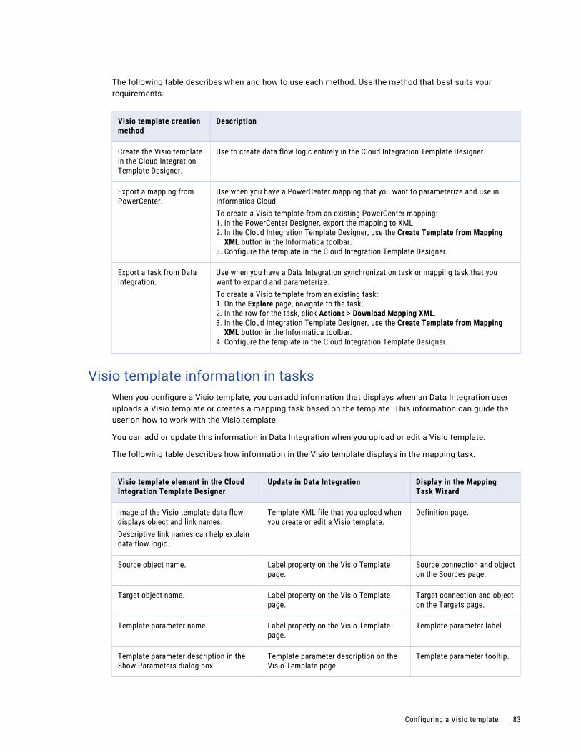
The following table describes when and how to use each method. Use the method that best suits your requirements.
Visio template creation method
Description
Create the Visio template in the Cloud Integration Template Designer.
Use to create data flow logic entirely in the Cloud Integration Template Designer.
Export a mapping from PowerCenter.
Use when you have a PowerCenter mapping that you want to parameterize and use in Informatica Cloud.To create a Visio template from an existing PowerCenter mapping:1. In the PowerCenter Designer, export the mapping to XML.2. In the Cloud Integration Template Designer, use the Create Template from Mapping
XML button in the Informatica toolbar.3. Configure the template in the Cloud Integration Template Designer.
Export a task from Data Integration.
Use when you have a Data Integration synchronization task or mapping task that you want to expand and parameterize.To create a Visio template from an existing task:1. On the Explore page, navigate to the task.2. In the row for the task, click Actions > Download Mapping XML.3. In the Cloud Integration Template Designer, use the Create Template from Mapping
XML button in the Informatica toolbar.4. Configure the template in the Cloud Integration Template Designer.
Visio template information in tasksWhen you configure a Visio template, you can add information that displays when an Data Integration user uploads a Visio template or creates a mapping task based on the template. This information can guide the user on how to work with the Visio template.
You can add or update this information in Data Integration when you upload or edit a Visio template.
The following table describes how information in the Visio template displays in the mapping task:
Visio template element in the Cloud Integration Template Designer
Update in Data Integration Display in the Mapping Task Wizard
Image of the Visio template data flow displays object and link names.Descriptive link names can help explain data flow logic.
Template XML file that you upload when you create or edit a Visio template.
Definition page.
Source object name. Label property on the Visio Template page.
Source connection and object on the Sources page.
Target object name. Label property on the Visio Template page.
Target connection and object on the Targets page.
Template parameter name. Label property on the Visio Template page.
Template parameter label.
Template parameter description in the Show Parameters dialog box.
Template parameter description on the Visio Template page.
Template parameter tooltip.
Configuring a Visio template 83

Template parametersA template parameter is a placeholder for a value or values in a Visio template. You configure template parameters when you configure Informatica objects in the Visio template data flow.
You can define the value of the template parameter when you upload the Visio template to your Data Integration organization or when you create a mapping task based on the Visio template.
You can create a template parameter for any logical aspect of a data flow. Sources, targets, and lookups are always template parameters. You can create additional template parameters for other aspects of the data flow logic. Some template parameters you might want to create include the following:
• Source filter in a source qualifier
• Filter condition in a Filter object
• Join condition in a Joiner object
• Update strategy condition in an Update Strategy object
• Expression in an Expression object
• Expression in an Aggregator object
• Link rule for a link
For example, if you have regional lookup data in different lookup tables, you might create a $lookuptable$ template parameter in the Lookup object that represents the lookup table. When you configure the mapping task, you select the lookup connection and table that you want to use. You configure a different mapping task for each regional lookup table.
To create a template parameter in a Visio template, surround the template parameter name with dollar signs as follows: $<template_parameter_name>$. Template parameter names are case sensitive.
By default, the template parameter name displays as the template parameter label in the mapping task wizard. However, you can also configure a template parameter label in the template or after you upload the template.
You can use the Show Parameters button on the Informatica toolbar to see the template parameters defined using the $<template_parameter_name>$ syntax. If you do not use the template parameter name syntax to configure source, target, or lookup template parameters, they do not display in the Show Parameters dialog box.
Template parameter usageVisio template parameters are flexible placeholders that you can use in many different ways. Some examples:
• Output field. You can use a template parameter to define a field.In the following example, $fullname$ is an output field that merges first and last name data from the source:
$fullname$ = CONCAT(fname,lname) • Expression clause. You can use a template parameter as part of a larger expression.
For example, you might use the following in a WHERE clause:
fullname=$nameexpr$Or, in the following example, the unit price template parameter and quantity template parameter define the TOTAL output field.
TOTAL=$unitpricefield$*$quantityfield$
84 Chapter 5: Visio templates

You might create a template parameter for a filter condition as follows:
$filter$ Or, use a template parameter to represent a field in a filter condition:
NOT ISNULL($id$)You might create a lookup condition using two template parameters as follows:
$lookupID$=$sourceID$You could use a template parameter in a link rule as follows:
$custid$ (to) CUST_ID• Expressions. If you configure a template parameter to use the field mapping input control, you can
configure an entire expression or sets of expressions. With the field mapping input control, you can use any input field in expressions.
Expression macros in Visio templatesExpression macros are macros that can help create flexible expressions in Visio templates. You can use expression macros in Expression and Aggregator objects.
Use an expression macro to specify repetitive expression statements or complex expressions. Expression macros apply a common expression pattern across a set of fields, such as adding all or a set of fields together, checking if fields contain null values, or converting dates to a different format.
You can use an expression macro to generate output fields and variable fields.
An expression macro consists of several parts:
• Macro variable declaration. When you declare the macro variable, you declare the macro variable name and the fields to be used in the macro expression. Use the link rule format to declare the fields. As with link rules, you can list actual field names or use a link rule, such as All Ports or Pattern.Use the following syntax for the macro variable declaration:
Macro variable declaration element
Description Syntax
Macro variable name
Macro variable name. Use a logical name. Declare_%<macro variable name>%
Macro variable fields
Fields to be used in the macro expression.You can list field names, create an expression to define the field names, or use a link rule.For example, you can use the following syntax to apply a macro across all fields in the object:
{"port":"All Ports"}When listing field names, use a comma delimited list.You can create more than one set of variable fields as follows:
{"<variable1>"}:"value1, value2..."}, "<variable2>":"value1, value2..."}When you use a variable in an expression, enclose the variable name in percent signs, as follows:
%<macro variable field name>%
{"<macro variable field name>":"<macro variable field list, expression, or rule>" }
Configuring a Visio template 85

• Macro statement. When you define the macro statement, you define the names of the macro output field names and the macro expression.
Macro statement element
Description
Output field names Expression that defines the field names for the output fields generated by the expression macro.You can use variables and rules to help define output field names, such as <%field%>_out.
Macro expression Expression to be used.
For example, you might use the following expression macro to check if any of the address fields that start with "addr" are null. The ISNULL output port will be set to a value 1 or higher if one or more fields are null:
Macro variable name: Declare_%addressports%Macro variable fields: {"addrport":"Pattern:^addr"}Output field names: ISNULLMacro expression: %OPR_SUM[IIF(ISNULL(%addrport%),1,0)]%
Template parameters in expression macrosYou can use template parameters in expression macros.
For example, you might use a template parameter in the following macro variable declaration to define the fields to be used in the expression macro:
Macro variable name: Declare_%input%Macro variable fields: {"inputfields":"$salesdata$"}
When you configure the mapping task, $salesdata$ displays as a template parameter. The fields that you define for the template parameter are expanded where you use the %inputfields% variable in the Expression object.
Patterns in expression macrosYou can use Mapping Architect for Visio patterns in expression macros.
For example, if you know that you want to use all fields that begin with SALES_, you might declare the macro variable fields as follows:
Macro variable name: Declare_%salesfields%Macro variable fields: {"SalesFields":"Pattern:^SALES_"}
Or, if you know that you want to use all input fields, you might use the following expression:
Macro variable name: Declare_%salesfields%Macro variable fields: {"SalesFields":"All Ports"}
For more information about patterns, see the Mapping Architect for Visio documentation.
Horizontal and vertical expansionAn expression macro can expand vertically or horizontally. You can use both horizontal and vertical expansion in an expression macro.
A vertical expansion performs the same calculation on multiple fields by generating multiple expressions. To use a vertical expansion, configure a macro input field that represents multiple incoming fields. When the task runs, the application performs the same calculations on each field that the macro input field represents.
86 Chapter 5: Visio templates

For example, the following expression trims leading and trailing spaces from the address ports defined by the %addr% variable and writes the results to output fields with a suffix of _o:
%addr%_o = LTRIM(RTRIM(%addr%))This results in the following expressions in the following output fields:
address1_o = LTRIM(RTRIM(address1))address2_o = LTRIM(RTRIM(address2))city_o = LTRIM(RTRIM(city))state_o = LTRIM(RTRIM(state))zipcode_o = LTRIM(RTRIM(zipcode))
Horizontal expansion performs a calculation across multiple fields while expanding a single expression. To use a horizontal expansion, configure a macro input field that represents a set of incoming fields or a set of constants. When the task runs, the task expands the macro input field and then uses the fields or constants to calculate a complex expression.
You can use the following horizontal expansion functions:%OPR_CONCAT%
Uses the CONCAT function and expands an expression in an expression macro to concatenate multiple fields. %OPR_CONCAT% creates calculations similar to the following expression:
FieldA || FieldB || FieldC...%OPR_CONCATDELIM%
Uses the CONCAT function and expands an expression in an expression macro to concatenate multiple fields, and adds a comma delimiter. %OPR_CONCATDELIM% creates calculations similar to the following expression:
FieldA || ", " || FieldB || ", " || FieldC...%OPR_IIF%
Uses the IIF function and expands an expression in an expression macro to evaluate a set of IIF statements. %OPR_IIF% creates calculations similar to the following expression:
IIF(<field> >= <constantA>, <constant1>, IIF(<field> >= <constantB>, <constant2>, IIF(<field> >= <constantC>, <constant3>, 'out of range')))
%OPR_SUM%
Uses the SUM function and expands an expression in an expression macro to return the sum of all fields. %OPR_SUM% creates calculations similar to the following expression:
FieldA + FieldB + FieldC...For example, the following expression checks if any of the fields are null. If a field is null, it sets the Isnull field to a positive number:
Isnull=%OPR_SUM{IIF(ISNULL(%fields%),1,0]%When expanded, the expression macro generates the following expression, and expands the expression to include all fields defined by the %fields% variable.
Isnull=IIF(ISNULL (fieldA, 1,0) + IIF(ISNULL(fieldB, 1, 0)...
Configuring a Visio template 87

Expression macro configurationConfigure an expression macro on the Configuration tab of the Expression or Aggregator object properties dialog box.
When you configure an expression macro, use one row for the macro variable declaration and another for the macro statement. Enter expression macro elements in the Port Name and Expression columns as follows. Data type and port type information is not relevant:
Expression macro part Port name Expression
Macro variable declaration Macro variable name.For example:
Declare_%addressports%
Macro variable fields.For example:
{"addrport":"Pattern:^addr"}
Macro statement Output field names.For example:
ISNULL
Macro expression.
%OPR_SUM[IIF(ISNULL(%addrport%),1,0)]%
Parameter files and user-defined parametersA parameter file is a list of user-defined parameters and their associated values. You can use user-defined parameters in Visio templates and mapping tasks.
Use a parameter file to define values that you want to update without having to edit the Visio template or the mapping task. For example, you might use a user-defined parameter for a sales quota that changes quarterly. Or, you might configure a task to update user-defined parameter values in the parameter file at the end of the job, so the next time the job runs, it uses the new values.
You can include user-defined parameters for multiple Visio templates or mapping tasks in a single parameter file. You can also use multiple parameter files for different Visio templates or tasks. The mapping task reads the parameter file before a task runs to determine the start values for the user-defined parameters used in the task.
User-defined parameter values are treated as String values. When you use a user-defined parameter in an expression, use the appropriate function to convert the value to the necessary datatype. For example, you might use the following expression to define a quarterly bonus for employees:
IIF((EMP_SALES < TO_INTEGER($$SalesQuota), 200, 0)To use a parameter file, perform the following steps:
1. Use a user-defined parameter in a Visio template or mapping task.
• Use two dollar signs to name the parameter, as follows: $$<user-defined_parameter>.
• When you use the user-defined parameter in an expression, convert the String parameter value to the appropriate datatype as necessary.
• If you use a user-defined parameter in a filter, start the filter with the user-defined parameter.
2. Use the following format for the parameter file:
[Global]$$<user-defined_parameter>=value$$<user-defined_parameter2>=value2
88 Chapter 5: Visio templates
For example:
[Global]$$SalesQuota=1000$$Region=NW
Note: The value of a user-defined parameter includes any characters after the equals sign (=), including leading or trailing spaces. User-defined parameter names are case-sensitive.
You can save the file as several different formats, such as *.txt, *.doc, or *.param.
3. Save the parameter file to a directory local to the Secure Agent to run the task.Use the following directory:
<Secure Agent installation directory>/apps/Data_Integration_Server/data/userparameters4. Enter the parameter file name on the Schedule page of the mapping task wizard.
Object-level session propertiesObject-level session properties are advanced properties based on PowerCenter session properties for transformation objects. You can configure object-level session properties for source qualifier and target objects.
For source qualifier objects, you can configure object-level session properties such as a SQL query override or pipeline partitioning attributes. Target objects allow different object-level session properties based on target type, such as null characters or delimiters for flat file targets or target load type for database targets.
Configure object-level session properties in the Session Properties field on the Properties tab of a source qualfier or target object. Use XML to configure the session properties that you want to use. Use the following syntax:
<attribute name="<session property name>" value="<value>"/>For example, you can use the following XML to define target properties in a target object:
<attribute name ="Append if Exists" value ="YES"/> <attribute name ="Create Directory if Not Exists" value ="YES"/> <attribute name ="Header Options" value ="No Header"/>
To define partition properties, use a slightly different format. For example, to define read partitions for a database table, you could enter the following XML in the the source qualifier object Session Properties field:
<partition name="Partition1"/><partition name="Partition2"/><partition name="Partition3"/><partitionPoint type="KEY_RANGE"> <ppField name="field1"> <range min="10" max="20" /> <range min="21" max="30" /> <range min="31" max="40" /> </ppField></partitionPoint>
Note: XML is case sensitive. Also, unlike in PowerCenter, use an underscore for the KEY_RANGE option.
Visit the Informatica Cloud Community for additional details and examples. You can browse or search for "session properties".
Optional objectsYou can configure objects in a Visio template data flow as optional. When data is not passed to an optional object in a mapping task, the object is not included in the final data flow for the task.
You can configure any object as optional except source or source qualifier objects.
Configuring a Visio template 89
For example, you might have an optional Expression object that updates the date format of date data routed from the source. The updated data is routed back to the main data flow. If the source selected for the task does not include date data or a date field that is routed to the Expression object, IData Integration omits the optional Expression object from the final data flow used for the task.
When you use an optional object, make sure the data flow is still valid if the object is not included. If the data flow is not valid without the optional object, errors can occur when the task runs.
To configure an object as optional, on the Properties page of the object details dialog box, set the Optional property to True.
Rules and guidelines for configuring a Visio templateUse the following general rules and guidelines for configuring a Visio template:
• Use the Source Definition object for all source types.
• For database and flat file sources, use the Source Qualifier object. For all other source types, use the Application Source Qualifier object.
• You can use any target object to represent different target types.
• The following objects are not supported at this time:
- Unconnected Salesforce lookups
- Unconnected stored procedure
- Related Salesforce sources
• When naming a link, use a name that describes the rules associated with the link. This allows you to understand a data flow without having to read the rules for each link.
• Do not create a Mapplet object in the Cloud Integration Template Designer. You can use a Mapplet object in a Visio template if you can create the mapplet as part of a PowerCenter task and export the PowerCenter mapping XML to be used as a Visio template.
• When you configure a data flow that contains expression macros and template parameters to use the field mapping input control, keep them in different Expression objects. Use one Expression object for the expression macros, and another for the field mapping template parameters.
• Use the Data Integration transformation language to define expressions.
• For a Normalizer object, generated key values are reset with each job. For a Sequence Generator object, generated key sequence values are also reset with each job.
• When you configure multiple group by ports for an Aggregator object, use a semicolon to separate field names. If you create a template parameter for group by ports, you might add a template parameter description when you upload the Visio template.
• You can use connected stored procedures and stored functions in a mapplet or in the data flow. Use the following guidelines when using stored procedure objects:
- Define the stored procedure in the Expression Text property by stating the stored procedure name, input fields, and output fields:
<Stored Procedure Name>(<inputfield1 datatype>(<precision>,<scale>) IN <inputfield1>, <inputfield2 datatype>(<precision>,<scale>) IN <inputfield2>... <outputfield1 datatype>(<precision>,<scale>) OUT <outputfield1>, <outputfield1 datatype>(<precision>,<scale>) OUT <outputfield2>...)
- Match the order of the fields with the order of the template parameters defined in the stored procedure.
- Connect all fields in a stored procedure object.
90 Chapter 5: Visio templates

- When a stored procedure is used in the data flow, you can parameterize the expression text to reuse same template with different stored procedures. In this case, the input and output link rules for the stored procedure object also needs to be parameterized and link rules mapping should maintain the order of the stored procedure template parameters.
- To use a stored function, enter the following syntax in the Expression Text property:
<return value datatype>(<precision>,<scale>)<Stored Function Name>(<inputfield1 datatype>(<precision>,<scale>) IN <inputfield1>, <inputfield2 datatype>(<precision>,<scale>) IN <inputfield2>... <outputfield1 datatype>(<precision>,<scale>) OUT <outputfield1>, <outputfield1 datatype>(<precision>,<scale>) OUT <outputfield2>...)
- If issues with string datatypes occur, use the NSTRING datatype for string values.
• The field mapping input control appends "_OUT" to the field mapping output field names. When you plan to use a field mapping input control for a template parameter, use a link rule to move output fields with the _OUT suffix to the next object in the data flow.
• When you plan to use a field mapping input control to write data to multiple targets with matching field names and matching datatypes, precision, and scale, connecting one field in one target results in writing data to matching fields in both targets. If the target fields have the same name, but different datatypes, precision, or scale, you can map one of the target fields.
• Avoid using Mapplet objects or multiple targets to a data flow after a field mapping input control.
• When you use multiple instances of the same source object, use a unique table name for each instance of the source. Similarly, when you use more than one instance of a target object, use a unique table name for each instance of the target. And when you use more than one instance of a lookup, use a unique table name for each instance of the lookup.
• You can use the %ALL% expression macro in an expression to represent all field names in a transformation. For more information, see "Using the %ALL% Keyword in an Expression" in the Informatica PowerCenter Mapping Architect for Visio Guide.
• Use an Update Strategy object only when the target table has keys defined.
• In Custom Transformation objects, do not configure a field as both an input and output field and do not include all input fields in the OUTPUT group.
• To include the fields from a Custom Transformation in field mappings, set the Fixed Ports property to YES.
Tips for working with the Cloud Integration Template Designer
Use the following tips when working with the Cloud Integration Template Designer:
• Enable macros in Microsoft Visio to enable full functionality for the Cloud Integration Template Designer.
• For Mapping Architect for Visio 2010, the Informatica toolbar displays on the Add-Ins tab.
• Use the Show Parameters icon on the Informatica toolbar to see the template parameters declared in a Visio templates that use the $<template_parameter_name>$ syntax.
• Use the Validate Mapping Template icon on the Informatica toolbar to perform basic validation.
• You can cut and paste objects within a Visio template. However, you might encounter errors if you try to copy and paste across different Visio templates.
• When you configure a link, Mapping Architect for Visio indicates that the link is connected to an object by highlighting the object. Connect both sides of the link.
• The Mapping Architect for Visio Dictionary link rule is not supported at this time.
• For general information about using Mapping Architect for Visio, see the Mapping Architect for Visio documentation. The Mapping Architect for Visio documentation is available in the Informatica Cloud Developer Community: https://network.informatica.com/docs/DOC-15318.
Configuring a Visio template 91
The following Mapping Architect for Visio functionality is not relevant to creating Visio templates for Data Integration:
• The Declare Mapping Parameters and Variables icon on the Informatica toolbar.
• The <template_name>_<param>.xml file created when you publish a template. Do not use this file.
Template parameter rules and guidelines
Use the following rules and guidelines when configuring template parameters in a template:
• To avoid confusion when defining values for a template parameter, use a logical name for each template parameter and use a unique name for each template parameter in a template.
• When you parameterize a user-defined join, use the fully-qualified name in the parameter value.
• You can use the Show Parameters icon on the Informatica toolbar to view all template parameters in the file.
• Template parameter names and values are case-sensitive unless otherwise noted.
Tips for PowerCenter mapping XML templates
Use the following tips for Visio templates created from PowerCenter mapping XML files:
• Rename sources, targets, lookups, and link rules in the Visio template to provide meaningful names. Sources, targets, and lookups become template parameters automatically in an uploaded Visio template.
• You can include the following PowerCenter objects in a Visio template:
- Aggregator
- Application Source Qualifier
- BAPI/RFC transformation
- Expression
- Joiner
- Lookup
- Mapplets
- Normalizer
- Rank
- Router
- SAP/ALE IDoc Prepare
- Sequence Generator (connected only)
- Source
- Source Qualifier
- Sorter
- Stored Procedure (connected only)
- Target
- Transaction Control
- Union
- Update Strategy
- Web Services transformation
- XML transformation
92 Chapter 5: Visio templates

• You can use the following PowerCenter objects in a Visio template only when included in a mapplet:
- HTTP transformation
- Java transformation
- SQL transformation
- Unstructured Data transformation
• Do not create a Mapplet object in the Cloud Integration Template Designer. You can use a Mapplet object in a Visio template if you can create the mapplet as part of a PowerCenter task and export the PowerCenter mapping XML to be used as a Visio template.
• Do not rename mapplets in Visio templates. Keep mapplet names as exported from PowerCenter.
• Do not use the same mapplet more than once in a Visio template.
• Use only one connection type in a mapplet.
• Do not use PowerCenter mapping parameters and variables in Visio templates. PowerCenter mapping parameters and variables are not supported.
• Do not use the PowerCenter $Source or $Target variables in mapplets.
• When joining two sources with a single source qualifier, configure a user-defined join in the source qualifier. Query overrides are not supported.
Tips for Data Integration workflow XML templates
Use the following tips for Visio templates created from Data Integration workflow XML files:
• Rename sources, targets, lookups, and link rules in the Visio template to provide meaningful names. Sources, targets, and lookups become template parameters automatically in an uploaded Visio template.
Publishing a Visio templatePublish a Visio template when you are ready to use the Visio template in Data Integration.
When you publish a Visio template, the Cloud Integration Template Designer creates a Visio template XML file that you can upload to Data Integration.
Before you publish a Visio template, you can perform the following optional tasks:
• Validate the template. You can use the Validate Mapping Template icon on the Informatica toolbar to perform basic validation.
• Create an image file. You can save the template as .JPG or .PNG to create an image file. You can use the image file to represent the template data flow when you upload the Visio template to your organization.
To publish a Visio template:
1. On the Informatica toolbar, click the Publish icon.
2. Navigate to the directory you want to use, and click Save.
The Cloud Integration Template Designer generates a Visio template XML file in the directory that you select. The Visio template XML file uses the following naming convention:
<Visio template name>.XML When you publish a Visio template, the Cloud Integration Template Designer also creates a parameter file name <Visio template name>_param.XML. This file contains information related to user-defined parameters. Unless you want to use this file as a basis for a user-defined parameter file, you do not need to use this file.
Publishing a Visio template 93

Uploading a Visio templateUpload a Visio template when you want to use it in your organization. After you upload a Visio template, you can use it in mapping tasks.
Logical connectionsA logical connection is a name used to represent a shared connection.
Use a logical connection when you want to use the same connection for more than one connection template parameter in a Visio template. To use a logical connection, enter the same logical connection name for all template parameters that you want to use the same connection.
When you use logical connections for connections that display on a single page of the mapping task wizard, the wizard displays a single connection for the user to select.
For example, you might use a logical connection when a Visio template includes two sources that should reside in the same source system. To ensure that the task developer selects a single connection for both sources, when you upload the Visio template, you can enter "Sources" as the logical connection name for both source template parameters. When you create a mapping task, the mapping task wizard displays one source connection template parameter named Sources and two source object template parameters.
When you use a logical connections for connections that display on different pages of the mapping task wizard, the wizard uses the logical connection name for the connection template parameters. If a logical connection appears on the Other Parameters page, it displays in the Shared Connection Details section. Since the requirement to use the same connection for all logical connections is less obvious, you might configure a lookup to display on the same wizard page as the other logical connection, or use descriptions for each logical template parameter to create tooltips to guide the task developer.
You can use any string value for the logical connection name.
Input control optionsInput control options define how the task developer configures template parameters in a mapping task. You can configure template parameter input control options when you upload or edit a Visio template.
When you configure an input control option for a template parameter, select a logical input control option for the template parameter type.
For example, for a filter template parameter, you could use a condition, expression, or text box input control, but the condition input control would best indicate the type of information that the template parameter requires. The field or field mapping input controls would not allow the task developer to enter the appropriate information for a filter template parameter.
94 Chapter 5: Visio templates

The following table describes the input control options that you can use:
Input control type
Description Recommended usage
Text Box Use for any information.Displays an empty text box.Requires an understanding of the type of information to enter. If the information is not obvious, use a template parameter description to create a tooltip.Default for string template parameters.
Expressions or partial expressions. Data values and other template parameters that do not fit in the other input control types.
Condition Use to create a boolean condition that resolves to True or False.Displays a Data Filter dialog box that allows you to create a simple or advanced data filter.
Filter expressions defined in a Filter object, conditions used in a Router object, and other boolean expressions.
Expression Use to create simple or complex expressions.Displays a Field Expression dialog box with a list of source fields, functions, and operators.
Expressions in the Expression and Aggregator objects.
Field Use to select a single source or lookup field.Displays a list of fields and allows you to select a single field.
Field selection for a lookup condition or other expressions. Or for a link rule to propagate specific fields.
Field Mapping
Use to map more than one field.Displays a field mapping input control like on the Field Mapping page of the synchronization task wizard.Allows you to map available fields from upstream sources, lookups, and mapplets to downstream mapplets or targets.Defines whether you can use aggregate functions in expressions.
Define a set of field level mappings between sources, lookups, mapplets, and targets.To allow aggregate functions in expressions, enable the Aggregate Functions option.
Custom Dropdown
Use to provide a list of options.Displays a drop down menu with options that you configure when you upload the Visio template.When you define the options, you create a display label and a value for the label. In the mapping task wizard, the label displays. The value does not display.
Define a set of options for possible selection. Does not display the values that the options represent.
Parameter display customizationYou can add one or more steps or pages to the mapping task wizard to customize the order in which a task developer configures template parameters. You can configure the parameter display order when you upload or edit a Visio template.
When you upload a Visio template, the defined source and target parameters appear on the Sources or Targets steps by default. You can move other connection template parameters to these steps. All other template parameters appear in the Other Parameters step by default.
You can create steps in the mapping task wizard to group similar parameters together. For example, you can group the field mapping parameters into one step, and the filter parameters into another step.
You can also create steps in the mapping task wizard to order logically dependent parameters. The task developer must then configure parameters in a certain order. For example, a Visio template includes a parameterized mapplet and a field mapping. Configure the mapplet parameter to appear on a step before the
Uploading a Visio template 95
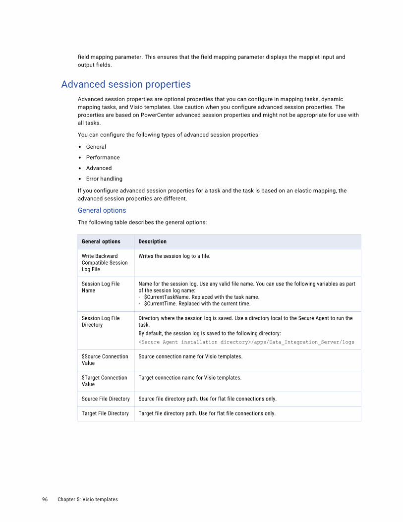
field mapping parameter. This ensures that the field mapping parameter displays the mapplet input and output fields.
Advanced session propertiesAdvanced session properties are optional properties that you can configure in mapping tasks, dynamic mapping tasks, and Visio templates. Use caution when you configure advanced session properties. The properties are based on PowerCenter advanced session properties and might not be appropriate for use with all tasks.
You can configure the following types of advanced session properties:
• General
• Performance
• Advanced
• Error handling
If you configure advanced session properties for a task and the task is based on an elastic mapping, the advanced session properties are different.
General options
The following table describes the general options:
General options Description
Write Backward Compatible Session Log File
Writes the session log to a file.
Session Log File Name
Name for the session log. Use any valid file name. You can use the following variables as part of the session log name:- $CurrentTaskName. Replaced with the task name.- $CurrentTime. Replaced with the current time.
Session Log File Directory
Directory where the session log is saved. Use a directory local to the Secure Agent to run the task.By default, the session log is saved to the following directory:<Secure Agent installation directory>/apps/Data_Integration_Server/logs
$Source Connection Value
Source connection name for Visio templates.
$Target Connection Value
Target connection name for Visio templates.
Source File Directory Source file directory path. Use for flat file connections only.
Target File Directory Target file directory path. Use for flat file connections only.
96 Chapter 5: Visio templates

General options Description
Treat Source Rows as
When the task reads source data, it marks each row with an indicator that specifies the target operation to perform when the row reaches the target. Use one of the following options:- Insert. All rows are marked for insert into the target.- Update. All rows are marked for update in the target.- Delete. All rows are marked for delete from the target.- Data Driven. The task uses the Update Strategy object in the data flow to mark the
operation for each source row.
Commit Type Commit type to use. Use one of the following options.- Source. The task performs commits based on the number of source rows.- Target. The task performs commits based on the number of target rows.- User Defined. The task performs commits based on the commit logic defined in the Visio
template.When you do not configure a commit type, the task performs a target commit.
Commit Interval Interval in rows between commits.When you do not configure a commit interval, the task commits every 10,000 rows.
Commit on End of File
Commits data at the end of the file.
Rollback Transactions on Errors
Rolls back the transaction at the next commit point when the task encounters a non-fatal error.When the task encounters a transformation error, it rolls back the transaction if the error occurs after the effective transaction generator for the target.
Java Classpath Java classpath to use.The Java classpath is added to the beginning of the system classpath when the task runs.Use this option when you use third-party Java packages, built-in Java packages, or custom Java packages in a Java transformation.
Uploading a Visio template 97

Performance settings
The following table describes the performance settings:
Performance settings
Description
DTM Buffer Size Amount of memory allocated to the task from the DTM process.By default, a minimum of 12 MB is allocated to the buffer at run time.Use one of the following options:- Auto. Enter Auto to use automatic memory settings. When you use Auto, configure Maximum
Memory Allowed for Auto Memory Attributes.- A numeric value. Enter the numeric value that you want to use. The default unit of measure
is bytes. Append KB, MB, or GB to the value to specify a different unit of measure. For example, 512MB.
You might increase the DTM buffer size in the following circumstances:- When a task contains large amounts of character data, increase the DTM buffer size to 24
MB.- When a task contains n partitions, increase the DTM buffer size to at least n times the value
for the task with one partition.- When a source contains a large binary object with a precision larger than the allocated DTM
buffer size, increase the DTM buffer size so that the task does not fail.
Incremental Aggregation
Performs incremental aggregation for tasks based on Visio templates.
Reinitialize Aggregate Cache
Overwrites existing aggregate files for a task that performs incremental aggregation.
Enable High Precision
Processes the Decimal data type to a precision of 28.
Session Retry on Deadlock
The task retries a write on the target when a deadlock occurs.
Pushdown Optimization
Type of pushdown optimization. Use one of the following options:- None. The task processes all transformation logic for the task.- To Source. The task pushes as much of the transformation logic to the source database as
possible.- To Target. The task pushes as much of the transformation logic to the target database as
possible.- Full. The task pushes as much of the transformation logic to the source and target
databases as possible. The task processes any transformation logic that it cannot push to a database.
- $$PushdownConfig. The task uses the pushdown optimization type specified in the user-defined parameter file for the task.When you use $$PushdownConfig, ensure that the user-defined parameter is configured in the parameter file.
When you use pushdown optimization, do not use the Error Log Type property.For more information, see the help for the appropriate connector.The pushdown optimization functionality varies depending on the support available for the connector. For more information, see the help for the appropriate connector.
98 Chapter 5: Visio templates
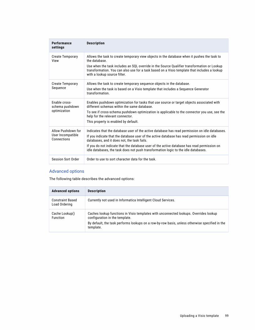
Performance settings
Description
Create Temporary View
Allows the task to create temporary view objects in the database when it pushes the task to the database.Use when the task includes an SQL override in the Source Qualifier transformation or Lookup transformation. You can also use for a task based on a Visio template that includes a lookup with a lookup source filter.
Create Temporary Sequence
Allows the task to create temporary sequence objects in the database.Use when the task is based on a Visio template that includes a Sequence Generator transformation.
Enable cross-schema pushdown optimization
Enables pushdown optimization for tasks that use source or target objects associated with different schemas within the same database.To see if cross-schema pushdown optimization is applicable to the connector you use, see the help for the relevant connector.This property is enabled by default.
Allow Pushdown for User Incompatible Connections
Indicates that the database user of the active database has read permission on idle databases.If you indicate that the database user of the active database has read permission on idle databases, and it does not, the task fails.If you do not indicate that the database user of the active database has read permission on idle databases, the task does not push transformation logic to the idle databases.
Session Sort Order Order to use to sort character data for the task.
Advanced options
The following table describes the advanced options:
Advanced options Description
Constraint Based Load Ordering
Currently not used in Informatica Intelligent Cloud Services.
Cache Lookup() Function
Caches lookup functions in Visio templates with unconnected lookups. Overrides lookup configuration in the template.By default, the task performs lookups on a row-by-row basis, unless otherwise specified in the template.
Uploading a Visio template 99

Advanced options Description
Default Buffer Block Size
Size of buffer blocks used to move data and index caches from sources to targets. By default, the task determines this value at run time.Use one of the following options:- Auto. Enter Auto to use automatic memory settings. When you use Auto, configure
Maximum Memory Allowed for Auto Memory Attributes.- A numeric value. Enter the numeric value that you want to use. The default unit of measure
is bytes. Append KB, MB, or GB to the value to specify a different unit of measure. For example, 512MB.
The task must have enough buffer blocks to initialize. The minimum number of buffer blocks must be greater than the total number of Source Qualifiers, Normalizers for COBOL sources, and targets.The number of buffer blocks in a task = DTM Buffer Size / Buffer Block Size. Default settings create enough buffer blocks for 83 sources and targets. If the task contains more than 83, you might need to increase DTM Buffer Size or decrease Default Buffer Block Size.
Line Sequential Buffer Length
Number of bytes that the task reads for each line. Increase this setting from the default of 1024 bytes if source flat file records are larger than 1024 bytes.
Maximum Memory Allowed for Auto Memory Attributes
Maximum memory allocated for automatic cache when you configure the task to determine the cache size at run time.You enable automatic memory settings by configuring a value for this attribute. Enter a numeric value. The default unit is bytes. Append KB, MB, or GB to the value to specify a different unit of measure. For example, 512MB.If the value is set to zero, the task uses default values for memory attributes that you set to auto.
Maximum Percentage of Total Memory Allowed for Auto Memory Attributes
Maximum percentage of memory allocated for automatic cache when you configure the task to determine the cache size at run time. If the value is set to zero, the task uses default values for memory attributes that you set to auto.
Additional Concurrent Pipelines for Lookup Cache Creation
Restricts the number of pipelines that the task can create concurrently to pre-build lookup caches. You can configure this property when the Pre-build Lookup Cache property is enabled for a task or transformation.When the Pre-build Lookup Cache property is enabled, the task creates a lookup cache before the Lookup receives the data. If the task has multiple Lookups, the task creates an additional pipeline for each lookup cache that it builds.To configure the number of pipelines that the task can create concurrently, select one of the following options:- Auto. The task determines the number of pipelines it can create at run time.- Numeric value. The task can create the specified number of pipelines to create lookup
caches.
Custom Properties Configure custom properties for the task. You can override the custom properties that the task uses after the job has started. The task also writes the override value of the property to the session log.
100 Chapter 5: Visio templates
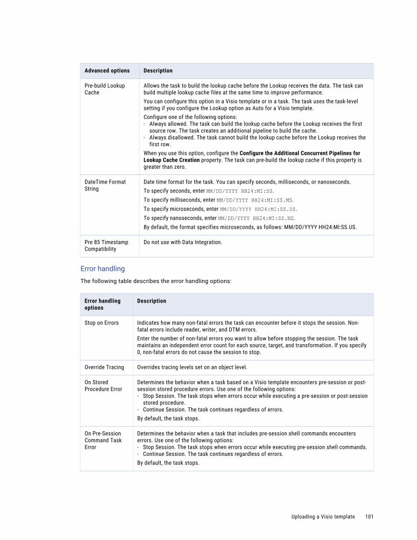
Advanced options Description
Pre-build Lookup Cache
Allows the task to build the lookup cache before the Lookup receives the data. The task can build multiple lookup cache files at the same time to improve performance.You can configure this option in a Visio template or in a task. The task uses the task-level setting if you configure the Lookup option as Auto for a Visio template.Configure one of the following options:- Always allowed. The task can build the lookup cache before the Lookup receives the first
source row. The task creates an additional pipeline to build the cache.- Always disallowed. The task cannot build the lookup cache before the Lookup receives the
first row.When you use this option, configure the Configure the Additional Concurrent Pipelines for Lookup Cache Creation property. The task can pre-build the lookup cache if this property is greater than zero.
DateTime Format String
Date time format for the task. You can specify seconds, milliseconds, or nanoseconds.To specify seconds, enter MM/DD/YYYY HH24:MI:SS.To specify milliseconds, enter MM/DD/YYYY HH24:MI:SS.MS.To specify microseconds, enter MM/DD/YYYY HH24:MI:SS.US.To specify nanoseconds, enter MM/DD/YYYY HH24:MI:SS.NS.By default, the format specifies microseconds, as follows: MM/DD/YYYY HH24:MI:SS.US.
Pre 85 Timestamp Compatibility
Do not use with Data Integration.
Error handling
The following table describes the error handling options:
Error handling options
Description
Stop on Errors Indicates how many non-fatal errors the task can encounter before it stops the session. Non-fatal errors include reader, writer, and DTM errors.Enter the number of non-fatal errors you want to allow before stopping the session. The task maintains an independent error count for each source, target, and transformation. If you specify 0, non-fatal errors do not cause the session to stop.
Override Tracing Overrides tracing levels set on an object level.
On Stored Procedure Error
Determines the behavior when a task based on a Visio template encounters pre-session or post-session stored procedure errors. Use one of the following options:- Stop Session. The task stops when errors occur while executing a pre-session or post-session
stored procedure.- Continue Session. The task continues regardless of errors.By default, the task stops.
On Pre-Session Command Task Error
Determines the behavior when a task that includes pre-session shell commands encounters errors. Use one of the following options:- Stop Session. The task stops when errors occur while executing pre-session shell commands.- Continue Session. The task continues regardless of errors.By default, the task stops.
Uploading a Visio template 101

Error handling options
Description
On Pre-Post SQL Error
Determines the behavior when a task that includes pre-session or post-session SQL encounters errors:- Stop Session. The task stops when errors occur while executing pre-session or post-session
SQL.- Continue. The task continues regardless of errors.By default, the task stops.
Error Log Type Specifies the type of error log to create. You can specify flat file or no log. Default is none.You cannot log row errors from XML file sources. You can view the XML source errors in the session log.Do not use this property when you use the Pushdown Optimization property.
Error Log File Directory
Specifies the directory where errors are logged. By default, the error log file directory is $PMBadFilesDir\.
Error Log File Name
Specifies error log file name. By default, the error log file name is PMError.log.
Log Row Data Specifies whether or not to log transformation row data. When you enable error logging, the task logs transformation row data by default. If you disable this property, n/a or -1 appears in transformation row data fields.
Log Source Row Data
Specifies whether or not to log source row data. By default, the check box is clear and source row data is not logged.
Data Column Delimiter
Delimiter for string type source row data and transformation group row data. By default, the task uses a pipe ( | ) delimiter.Tip: Verify that you do not use the same delimiter for the row data as the error logging columns. If you use the same delimiter, you may find it difficult to read the error log file.
Pushdown optimizationYou can use pushdown optimization to push transformation logic to source databases or target databases for execution. Use pushdown optimization when using database resources can improve task performance.
When you run a task configured for pushdown optimization, the task converts the transformation logic to an SQL query. The task sends the query to the database, and the database executes the query.
The amount of transformation logic that you can push to the database depends on the database, transformation logic, and task configuration. The task processes all transformation logic that it cannot push to a database.
Use the Pushdown Optimization advanced session property to configure pushdown optimization for a task.
You cannot configure pushdown optimization for a mapping task that is based on an elastic mapping.
The pushdown optimization functionality varies depending on the support available for the connector. For more information, see the help for the appropriate connector.
Pushdown optimization typesYou can use the following pushdown optimization types:
102 Chapter 5: Visio templates

Source pushdown optimization
The task analyzes the mapping from source to target until it reaches transformation logic that it cannot push to the source database.
The task generates and executes a Select statement based on the transformation logic for each transformation that it can push to the database. Then, the task reads the results of the SQL query and processes the remaining transformations.
Target pushdown optimization
The task analyzes the mapping from target to source or until it reaches transformation logic that it cannot push to the target database.
The task generates an Insert, Delete, or Update statement based on the transformation logic for each transformation that it can push to the target database. The task processes the transformation logic up to the point where it can push the transformation logic to the database. Then, the task executes the generated SQL on the target database.
Full pushdown optimization
The task analyzes the mapping from source to target or until it reaches transformation logic that it cannot push to the target database.
The task generates and executes SQL statements against the source or target based on the transformation logic that it can push to the database.
You can use full pushdown optimization when the source and target databases are in the same relational database management system.
When you run a task with large quantities of data and full pushdown optimization, the database server must run a long transaction. Consider the following database performance issues when you generate a long transaction:
• A long transaction uses more database resources.
• A long transaction locks the database for longer periods of time, which can reduce database concurrency and increase the likelihood of deadlock.
• A long transaction increases the likelihood of an unexpected event.
To minimize database performance issues for long transactions, consider using source or target pushdown optimization.
Pushdown optimization user-defined parametersYou can use a pushdown optimization user-defined parameter to perform pushdown optimization based on the parameter value defined in a parameter file. Use a pushdown optimization user-defined parameter when you want to perform different pushdown optimization options at different times.
For example, you might use source or target pushdown optimization during the peak hours of the day, but use full pushdown optimization from midnight until 2 a.m. when database activity is low.
To use the pushdown optimization user-defined parameter, perform the following steps:
1. Configure a parameter file to use the $$PushdownConfig user-defined parameter. Save the file to a directory local the Secure Agent to run the task.Use the following format to define the parameter:
$$PushdownConfig=<pushdown optimization type>For example: $$PushdownConfig=Source.
Configure a different parameter file of the same name for each pushdown type that you want to use.
2. In the task, add the Pushdown Optimization property and select the $$PushdownConfig option.
Uploading a Visio template 103

3. Configure the task to use the parameter file.
4. Replace the parameter file version as needed.
Uploading a Visio template and configuring parameter propertiesUpload a Visio template for use in your organization. When you upload a Visio template, you can define template parameter properties, such as template parameter descriptions and display properties. You can also select a template image to visually represent the template data flow.
Display properties determine where and how a template parameter displays in the mapping task wizard.
After you upload a Visio template, you can edit the template. If you select a different template XML file, you can choose between the following options:
• Reuse the existing mapplet and template parameter customizations.Data Integration uses the existing customization for mapplets and template parameters with names that match those from the previous file.
• Discard the existing mapplet and template parameter customizations.Data Integration clears the existing customizations.
With both options, mapplets and template parameters that are not used in the new file are deleted. New mapplets and template parameters display in the task wizard.
1. To upload a new Visio template, click New > Components > Visio Templates and then click Create.
To edit a Visio template, on the Explore page, navigate to the Visio template. In the row that contains the Visio template, click Actions and select Edit.
2. Complete the following template details:
Template details property
Description
Template Name Name of the template.
Location Project folder in which the Visio template resides.If the Explore page is currently active and a project or folder is selected, the default location for the asset is the selected project or folder. Otherwise, the default location is the location of the most recently saved asset.
Description Optional. Description of the Visio template.
Template XML File
Visio template XML file to upload. Perform the following steps to upload a Visio template XML file:1. Click Select.2. Browse to locate and select the file you want to use, and then click OK.
Template Image File
Image file associated with the Visio template.Optionally, upload an image file. Use a JPG or PNG file that is less than 1 MB in size and 1024 x 768 pixels or smaller.Perform the following steps to upload an image file:1. Click Select.2. Browse to locate and select the file you want to use, and then click OK.To remove the selected template image file, click Clear.
3. If the Visio template includes a mapplet template parameter, click Select to select a mapplet.
104 Chapter 5: Visio templates
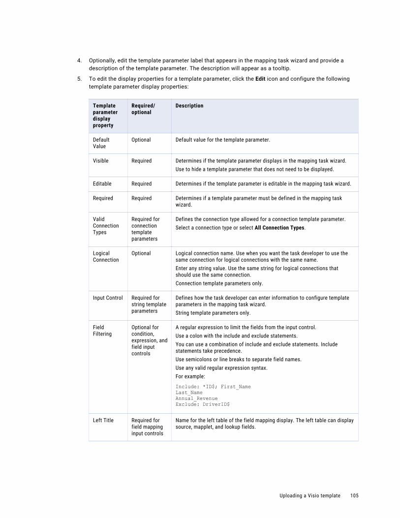
4. Optionally, edit the template parameter label that appears in the mapping task wizard and provide a description of the template parameter. The description will appear as a tooltip.
5. To edit the display properties for a template parameter, click the Edit icon and configure the following template parameter display properties:
Template parameter display property
Required/optional
Description
Default Value
Optional Default value for the template parameter.
Visible Required Determines if the template parameter displays in the mapping task wizard.Use to hide a template parameter that does not need to be displayed.
Editable Required Determines if the template parameter is editable in the mapping task wizard.
Required Required Determines if a template parameter must be defined in the mapping task wizard.
Valid Connection Types
Required for connection template parameters
Defines the connection type allowed for a connection template parameter.Select a connection type or select All Connection Types.
Logical Connection
Optional Logical connection name. Use when you want the task developer to use the same connection for logical connections with the same name.Enter any string value. Use the same string for logical connections that should use the same connection.Connection template parameters only.
Input Control Required for string template parameters
Defines how the task developer can enter information to configure template parameters in the mapping task wizard.String template parameters only.
Field Filtering
Optional for condition, expression, and field input controls
A regular expression to limit the fields from the input control.Use a colon with the include and exclude statements.You can use a combination of include and exclude statements. Include statements take precedence.Use semicolons or line breaks to separate field names.Use any valid regular expression syntax.For example:
Include: *ID$; First_NameLast_NameAnnual_RevenueExclude: DriverID$
Left Title Required for field mapping input controls
Name for the left table of the field mapping display. The left table can display source, mapplet, and lookup fields.
Uploading a Visio template 105

Template parameter display property
Required/optional
Description
Left Field Filtering
Optional for field mapping input controls
Regular expression to limit the fields that display in the left table of the field mapping display.Use a colon with the include and exclude statements.You can use a combination of include and exclude statements. Include statements take precedence.Use semicolons or line breaks to separate field names.Use any valid regular expression syntax.For example:
Include: *ID$; First_NameLast_NameAnnual_RevenueExclude: DriverID$
Right Title Required for field mapping input controls
Name for the right table of the field mapping display. The right table can display target, mapplet, and lookup fields.
Right Data Provider
Required for field mapping input controls
Set of fields to display in the right table of the field mapping display:- All objects. Shows all fields from all possible right table objects.- <object name>. Individual object names. You can select a single object for
the right table fields to display.- Static. A specified set of fields. Allows you to define the fields to display.
Fields Declaration
Required for field mapping input controls
List of fields to display on the right table of the field mapping display.List field names and associated datatypes separated by a line break or semicolon (;) as follows:
<datatype>(<precision>,<scale>)<field name1>; <field name2>;...or
<datatype>(<precision>,<scale>)<field name1><field name2><datatype>(<precision>,<scale>)<field name3>If you omit the datatype, Data Integration assumes a datatype of String(255).Available when Static is selected for the Right Data Provider.
Right Field Filtering
Optional for field mapping input controls
Regular expression to limit the fields that display in the right table of the field mapping display.Use a colon with the include and exclude statements.You can use a combination of include and exclude statements. Include statements take precedence.Use semicolons or line breaks to separate field names.Use any valid regular expression syntax.For example:
Include: *ID$; First_NameLast_NameAnnual_RevenueExclude: DriverID$
106 Chapter 5: Visio templates

Template parameter display property
Required/optional
Description
Aggregate Functions
Required for expression and field mapping input controls
Enables the display and use of aggregate functions in the Field Expression dialog box in the mapping task wizard.
Label Required for custom dropdown input controls
Label for an option to display in a custom dropdown.Click Add to add additional options. Click Remove to remove any configured options.
Value Required for custom dropdown input controls
Value for an option to display in a custom dropdown.Click Add to add additional options. Click Remove to remove any configured options.
6. To add another step to the mapping task wizard, click New Step.
You can name the step and rename the Parameters step.
7. To order template parameters, use the Move Up and Move Down icons.
You can use the icons to move connection template parameters to the Sources or Targets steps.
You can use the icons to move template parameters from the Parameters step to any new steps.
8. If you want to add advanced session properties, click Add, select the property that you want to use, and configure the session property value.
9. Click OK.
Visio template revisionsYou can revise a Visio template that is used by a mapping task.
If you edit a Visio template that is already used by a mapping task, Data Integration performs the following actions based on the changes that you make:
• When you change the template XML file, Data Integration lists the mapping tasks that use the Visio template and offers to keep or delete the tasks.
Note: If you choose to delete the tasks, Data Integration deletes all listed tasks immediately. You cannot undo this action.
• When you change other elements of the Visio template, such as the input control or default value for a template parameter, Data Integration applies the changes to existing tasks that use the template.If you have tasks that already use the Visio template, review the listed tasks after making uploadant changes to the template. If the changes are not compatible with an existing task configuration, the task may fail at run time.
Note: If you want to make signification changes to the Visio template and already have tasks that use the existing template, you might want to upload the template again and configure the changes with the newly-uploaded template.
Uploading a Visio template 107
Creating a mapping task from a Visio templateWhen you create a mapping task from a Visio template, the mapping task wizard opens with the Visio template already selected for the task.
1. On the Explore page, navigate to the Visio template.
2. In the row that contains the Visio template, click Actions and select New Mapping Task.
The mapping task wizard appears.Alternatively, you can create a new mapping task from the New Asset page and then select the Visio template in the wizard.
Downloading a template XML fileYou can download a template XML file for a Visio template. You might download a template XML file to upload the template into the Cloud Integration Template Designer.
1. On the Explore page, navigate to the Visio template.
2. In the row that contains the Visio template, click Actions and select Download Template XML.
Deleting a Visio templateDelete a Visio template when you no longer want to use the uploaded Visio template and customizations.
You cannot delete a Visio template that is used in a mapping task. Before you delete the Visio template, delete the task or replace the Visio template in the task.
1. On the Explore page, navigate to the Visio template.
2. In the row that contains the Visio template, click Actions and select Delete.
Visio template exampleThis example describes how to create the Date to String Visio template and use it in a mapping task. The Date to String template converts date values in a database source to string values for a file or database target.
The example includes the following tasks:
1. Configure the Date to String template in the Cloud Integration Template Designer.
2. Upload the Date to String template to Data Integration.
3. Create a mapping task that is based on the Date to String template.
108 Chapter 5: Visio templates

Step 1. Configure the Date to String templateUse the Cloud Integration Template Designer to configure and publish the Date to String Visio template.
Use objects in the Informatica stencil to create the data flow in a Visio template. Add and configure objects and links. When the template is complete, validate and publish the template. Then create an image file. You will use the image file when you upload the Visio template to your Data Integration organization.
1. To create a new template, click File > New > Custom Visio Template > Create.
2. To save and name the file, click File > Save. Select a local directory and name the file: DateToString.vsd.
VSD is the default file type for the Cloud Integration Template Designer.
3. From the Informatica stencil, add a Source Definition object to the template. Double-click the Source Definition icon.
4. In the Source Definition Details dialog box, configure the following source definition properties.
To configure a property, select the property you want to configure. In the Property area, enter the value you want to use, and click Apply.
Source Definition property Value
Transformation Name $DBsrc$
Source Table $DBsrc$
For sources, use the same template parameter name for the transformation name and source table. Sources are always template parameters, regardless of whether you enclose the name in dollar signs, but use dollar signs to clearly indicate it is a template parameter to other users.
5. Add a Source Qualifier object to the data flow, and configure the following property:
Source Qualifier property Value
Transformation Name SQ
6. Add a Link object between the Source Definition to the Source Qualifier. Double-click the link to configure link rules.
7. To name the link, in the Link Rules dialog box, in the Rule Set Name field, enter All.
8. To configure a link rule that moves all data from the source to the source qualifier, click New Rule. In the Define Link Rule dialog box, click Include, click All Ports, and click OK.
9. To save your changes and close the Link Rules dialog box, click OK.
10. To configure the expressions to convert dates to strings, add an Expression object to the data flow. On the Property tab of the Expression Details dialog box, configure the following property:
Expression Details Value
Transformation Name EXP_DateConversion
11. On the Configuration tab, click New Expression, then configure the following details and click Apply.
Visio template example 109
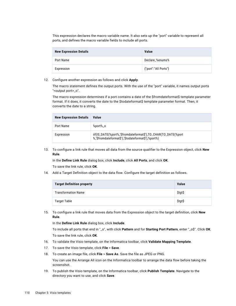
This expression declares the macro variable name. It also sets up the "port" variable to represent all ports, and defines the macro variable fields to include all ports.
New Expression Details Value
Port Name Declare_%enums%
Expression {"port":"All Ports"}
12. Configure another expression as follows and click Apply.
The macro statement defines the output ports. With the use of the "port" variable, it names output ports "<output port>_o".
The macro expression determines if a port contains a date of the $fromdateformat$ template parameter format. If it does, it converts the date to the $todateformat$ template parameter format. Then, it converts the date to a string.
New Expression Details Value
Port Name %port%_o
Expression iif(IS_DATE(%port%,'$fromdateformat$'),TO_CHAR(TO_DATE(%port%,'$fromdateformat$'),'$todateformat$'),%port%)
13. To configure a link rule that moves all data from the source qualifier to the Expression object, click New Rule.
In the Define Link Rule dialog box, click Include, click All Ports, and click OK.
To save the link rule, click OK.
14. Add a Target Definition object to the data flow. Configure the target definition as follows.
Target Definition property Value
Transformation Name $tgt$
Target Table $tgt$
15. To configure a link rule that moves data from the Expression object to the target definition, click New Rule.
In the Define Link Rule dialog box, click Include.
To include all ports that end in "_o", with click Pattern and for Starting Port Pattern, enter "_o$". Click OK.
To save the link rule, click OK.
16. To validate the Visio template, on the Informatica toolbar, click Validate Mapping Template.
17. To save the Visio template, click File > Save.
18. To create an image file, click File > Save As. Save the file as JPEG or PNG.
You can use the Arrange All icon on the Informatica toolbar to arrange the data flow before taking the screenshot.
19. To publish the Visio template, on the Informatica toolbar, click Publish Template. Navigate to the directory you want to use, and click Save.
110 Chapter 5: Visio templates

The Cloud Integration Template Designer creates the template XML file.
20. Save and close the Visio template.
Step 2. Upload the Visio templateUpload the Date to String Visio template to use it in your organization.
When you upload the Visio template, you can define template parameter descriptions, defaults, and display options. You can also upload an image file to visually represent the data flow.
1. Click New > Components > Visio Templates and then click Create.
2. On the Visio Template page, configure the following information.
Template details property
Value
Template Name Date to String
Template XML File Select the DateToString.xml Visio template file.After you select the file, the template parameters in the file display in the Parameters table.
Template Image File Select the JPG file that you created.After you select the file, the template image file displays.
3. To configure the display properties for the $DBsrc$ template parameter, click Edit.
4. In the Edit Parameters Properties dialog box, configure the following options and click OK.
Edit display properties
Value
Default Value Do not configure a default value.
Visible Select Yes to display the template parameter in the Contact Validation task.
Editable Select Yes to allow the task developer to configure the source connection in the Contact Validation task.
Required Select Yes to require this template parameter to be set.
Valid Connection Type Determines the connection type allowed for the source. You can select a connection type that exists in your organization or select All Connection Types.Select Relational Database.
Logical Connection Do not configure.
Visio template example 111
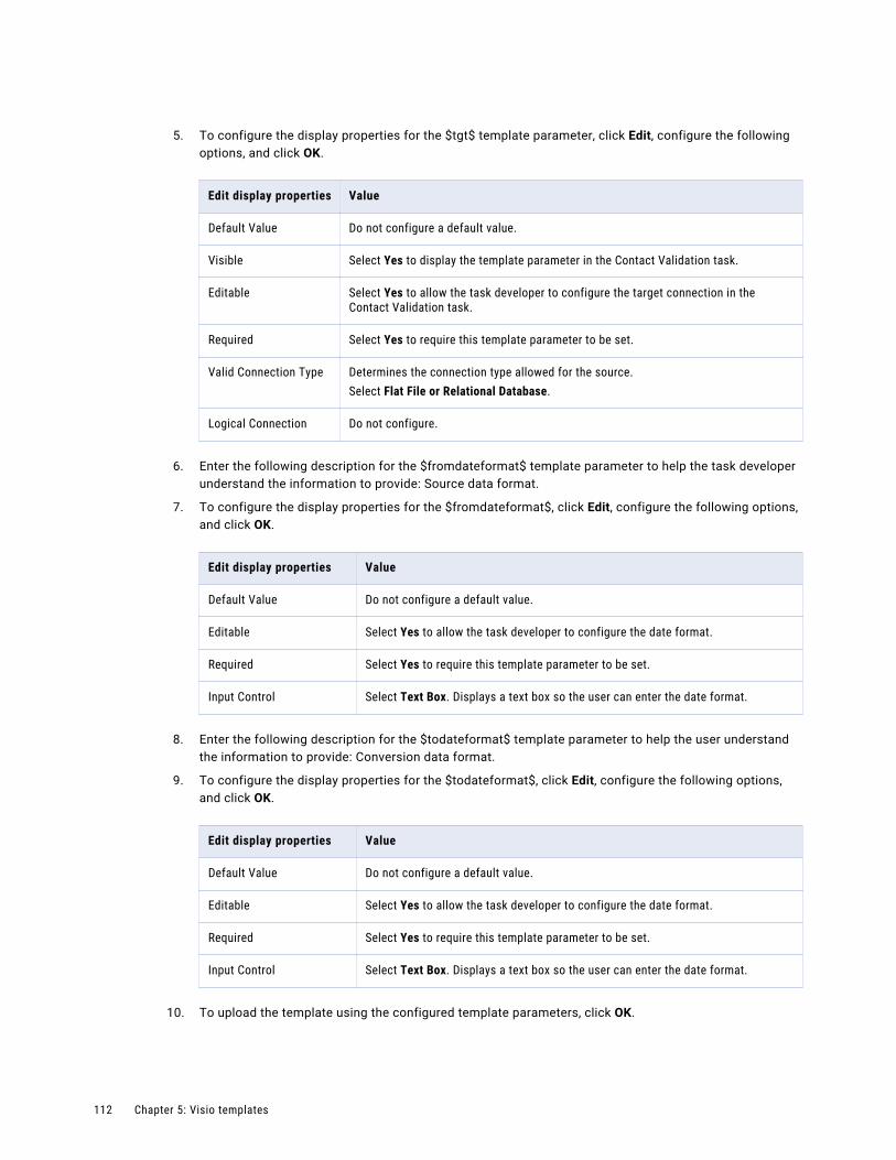
5. To configure the display properties for the $tgt$ template parameter, click Edit, configure the following options, and click OK.
Edit display properties Value
Default Value Do not configure a default value.
Visible Select Yes to display the template parameter in the Contact Validation task.
Editable Select Yes to allow the task developer to configure the target connection in the Contact Validation task.
Required Select Yes to require this template parameter to be set.
Valid Connection Type Determines the connection type allowed for the source.Select Flat File or Relational Database.
Logical Connection Do not configure.
6. Enter the following description for the $fromdateformat$ template parameter to help the task developer understand the information to provide: Source data format.
7. To configure the display properties for the $fromdateformat$, click Edit, configure the following options, and click OK.
Edit display properties Value
Default Value Do not configure a default value.
Editable Select Yes to allow the task developer to configure the date format.
Required Select Yes to require this template parameter to be set.
Input Control Select Text Box. Displays a text box so the user can enter the date format.
8. Enter the following description for the $todateformat$ template parameter to help the user understand the information to provide: Conversion data format.
9. To configure the display properties for the $todateformat$, click Edit, configure the following options, and click OK.
Edit display properties Value
Default Value Do not configure a default value.
Editable Select Yes to allow the task developer to configure the date format.
Required Select Yes to require this template parameter to be set.
Input Control Select Text Box. Displays a text box so the user can enter the date format.
10. To upload the template using the configured template parameters, click OK.
112 Chapter 5: Visio templates

Step 3. Create the mapping taskTo process data using the Date to String Visio template, create a mapping task.
1. Click New > Tasks > Mapping Task. and click OK.
2. Configure the task details as follows and click Next.
Task detail Value
Task Name Date to String
Location Browse to the folder where you want to store the Date to String mapping task or use the default location.
Runtime Environment Select the runtime environment that contains the Secure Agent to use to run the task.
Mapping Click Select and browse to the Visio template, and then click Select.After you select the template, the template image displays.
3. On the Sources page, select a source connection and source object, and click Next.
Based on the template parameter properties, the wizard displays only database connections.
4. On the Targets page, select a target connection and target object, and click Next.
Based on the template parameter properties, the wizard displays file and database connections.
5. On the Input Parameters page, enter the date format that you want to use for $fromdateformat$.
For example: yyyy-mm-dd.
6. Enter the date format that you want to use for $todateformat$ and click Next.
For example: mm-dd-yyyy.
7. On the Schedule page, select schedule details, email notification options, advanced options, and click Save.
When you run the task, the Secure Agent reads data from the source, converts dates to the new format, and writes data to the selected target.
Visio template example 113
I n d e x
$$PushdownConfig user-defined parameter 103
Aadvanced session properties
in Visio templates 104
CCLAIRE recommendations
mapping design 71Cloud Application Integration community
URL 6Cloud Developer community
URL 6components
Visio templates 81
Ddata catalog discovery
discovering and selecting objects 79example 80mapping inventory 77overview 75performing 76searching for objects 78
Data flow run order 17Data Integration community
URL 6data preview
monitoring preview jobs 22previewing mapping data 20steps for previewing data 22viewing results 22
EEnterprise Data Catalog
discovering and selecting objects 79integration with Data Integration 75searching for objects 78
expression macros in Visio templates 85
Fflow run order
configuring 19
Iin-out parameters
configuration 54overview 49properties 52values 53variable functions 51
Informatica Global Customer Support contact information 7
Informatica Intelligent Cloud Services web site 6
input control options for template parameters 94uploading a Visio template 94
input parameters in mappings 41using in mappings 48
integration templates see Visio templates 81
Llogical connections
understanding 94
Mmaintenance outages 7Mapping Designer 9mapping tasks
advanced session properties for mappings 96advanced session properties for Visio templates 96configuring template parameter properties 94creating from a Visio template 108effect of mapping revisions 40parameter files and user-defined parameters 88parameters,in-out 54pushdown optimization 102using parameter files 61
mapping templates 11mappings
configuration 13configuring rules and guidelines 16data preview 20data preview results 22in-out parameter values 53in-out parameters 49input parameters 41inventory panel 77maintenance 39Mapping Designer overview 9mapping revisions and mapping tasks 40overview 8
114

mappings (continued)parameters 41parameters,aggregation type 50parameters,in-out 53, 56, 58steps for previewing data 22testing 19tutorial 29using parameters 48validating 19variable functions for in-out parameters 51
Masking tasks using parameter files 61
Oobject-level session properties
in Visio templates 89optional objects
Visio templates 89
Pparameter file templates
downloading 68Parameter file templates 68parameter files
creating target object at run time 70overview 61with Visio templates and mapping tasks 88
parameters aggregation type 50configuration 46guidelines 53in mapping tasks 54in mappings 41in-out 49in-out parameter properties 52in-out parameter values 53in-out parameters 56, 58parameter types 44partial 47user defined 61variable functions 51
PowerCenter mapping XML tips for creating Visio templates from 90
pushdown optimization mapping tasks 102types 102user-defined parameter 103
Pushdown optimization preview 27
pushdown optimization preview results file 29running a job 28
Pushdown optimization preview 27
Ssession properties
object level for Visio templates 89status
Informatica Intelligent Cloud Services 7
synchronization tasks using parameter files 61
system status 7
Ttemplate parameters
in Visio templates, rules and guidelines 90input control options 94ordering in the mapping task wizard 95overview 84
template XML downloading for Visio templates 108
templates mapping 11
testing mappings 19transformations
data preview 20data preview results 22steps for previewing data 22
trust site description 7
Uupgrade notifications 7user parameters 61user-defined parameters
in Visio templates and mapping tasks 88
Vvalidating mappings 19Visio templates
configuring logical connections 94configuring overview 82creating a mapping task from a Visio template 108deleting 108display in mapping tasks 83downloading template XML 108example 108example:configure and publish the Visio template 109example:uploading the Visio template 111input control options 94methods to create 82optional objects 89overview 81parameter display customization 95parameter files and user-defined parameters 88prerequisites 81publishing 93revising 107rules and guidelines for configuring 90steps to upload 104template parameter usage 84uploading, configuring template parameter properties 94
Wweb site 6
Index 115


![1195252577 manual-informatica basica[1]](https://static.fdokumen.com/doc/165x107/6319e808bb40f9952b01c47b/1195252577-manual-informatica-basica1.jpg)