
InfoPrint 75 and InfoPrint 100 - Ricoh
244
InfoPrint 75 and InfoPrint 100 IPDS Technical Reference S550-1193-01
-
Upload
khangminh22 -
Category
Documents
-
view
0 -
download
0
Transcript of InfoPrint 75 and InfoPrint 100 - Ricoh

InfoPrint 75 and InfoPrint 100IPDS Technical Reference
S550-1193-01


InfoPrint 75 and InfoPrint 100IPDS Technical Reference
S550-1193-01

This edition applies to the InfoPrint 75, the InfoPrint 100, and to all subsequent releases and modifications untilotherwise indicated in new editions.
InternetVisit our home page: http://www.infoprint.com
You can send comments by e-mail to [email protected] or by mail to:
InfoPrint Solutions Company6300 Diagonal Hwy 002JBoulder, CO 80301-9270U.S.A.
This product is or contains commercial computer software and commercial computer software documentationdeveloped exclusively at private expense. As specified in Federal Acquisition Regulation 12.212 in the case of civilianagencies and Defense Federal Acquisition Regulation Supplement 227.7202 in the case of military agencies, use,duplication and disclosure by agencies of the U.S. Government shall solely be in accordance with the accompanyingInternational Program License Agreement in case of software products and in accordance with the licensing termsspecified in the product’s documentation in the case of hardware products.
© Copyright InfoPrint Solutions Company 2008, 2009.

Introduction
This manual contains detailed instructions and notes on the operation and use of this machine. For your safety and benefit, read this manual carefully before using the machine. Keep this manual in a handy place for quick reference.
Important
Contents of this manual are subject to change without prior notice. In no event will the company be liable for direct, indirect, special, incidental, or consequential damages as a result of handling or operating the machine.
Notes
This manual covers all models, and therefore contains functions and settings that may not be available for your model.Functions and supported operating systems may differ from those of your model.
Trademarks
Adobe® Reader®, Adobe® Acrobat® Reader, and PostScript® are either registered trademarks or trademarks of Adobe Systems Incorporated in the United States and/or other countries.PCL is a registered trademark of Hewlett-Packard Company.AIX®, Application System/400®, AS/400®, IBM®, OS/390®, OS/400®, Print Services Facility, PS/2®, PSF, System i and z/OS® are trademarks of International Business Machines Corporation in the United States, other countries, or both. InfoPrint, InfoPrint and Ricoh are trademarks or registered trademarks of Ricoh Co., Ltd., in the United States, other coun-tries, or both. IBM and the IBM logo are registered trademarks of International Business Machines Corporation in the United States, other countries, or both.IPDS and Intelligent Printer Data Stream are trademarks owned by Ricoh Company, Ltd.Windows® is either registered trademarks or trademarks of Microsoft Corporation in the United States and/or other coun-tries.Other product names used herein are for identification purposes only and might be trademarks of their respective compa-nies. We disclaim any and all rights to those marks.


Revision Table for manual
Rev. for manual
Machine Rev.
Page No.(Contents) Date
00 - First Edition Oct. 2008
01 - 62(01): Modified reply value of Sense Type and Model.
Mar. 2009


TABLE OF CONTENTSManuals for the IPDS...........................................................................................................5How to Read This Manual ...................................................................................................6
Symbols ....................................................................................................................................6About This Book...................................................................................................................7
Audience ...................................................................................................................................7Terminology .............................................................................................................................7
About IPDS ...........................................................................................................................8Capabilities of IPDS .............................................................................................................9Printing a Letter .................................................................................................................10Using Overlays....................................................................................................................12Using Page Segments..........................................................................................................13Using Images and Graphics...............................................................................................14
IM and IO Images...................................................................................................................14Graphics..................................................................................................................................14
Using Bar Codes .................................................................................................................15
1. IPDS Overview
About the IPDS Feature.....................................................................................................17IPDS Operating States .......................................................................................................18
Home State..............................................................................................................................18Overlay State ..........................................................................................................................18Font State ................................................................................................................................18
IPDS Command Format ....................................................................................................19Reserved Bytes .......................................................................................................................21Flag Byte.................................................................................................................................21Correlation ID (CID) ..............................................................................................................21Error Processing......................................................................................................................22Page and Copy Counters.........................................................................................................23
Data Types...........................................................................................................................24Text .........................................................................................................................................24Image ......................................................................................................................................24Graphics..................................................................................................................................24Bar Code .................................................................................................................................25
Coordinate System .............................................................................................................26Xm, Ym Coordinate System (Medium Presentation Space) ..................................................26Xp, Yp Coordinate System (Logical Page Presentation Space) .............................................26I, B Coordinates System (Text) ..............................................................................................26Other Text Positioning Terms ................................................................................................27Notation Conventions .............................................................................................................28
Color Simulation.................................................................................................................29Simulation Modes Supported .................................................................................................29Color Simulation Processes and Algorithms ..........................................................................30Logical Page and Object Area Coloring.................................................................................32Presentation Space Reset Mixing ...........................................................................................34
2. Summary of IPDS Commands
IPDS Initialization Defaults...............................................................................................35Page Printer Initialization Sequence ................................................................................38
1OG L 00

3. Device Control Command Set
About Device Control Command Set ...............................................................................39Acknowledgement Reply ...................................................................................................40Activate Resource ...............................................................................................................42
Resource ID example with RIDF = GRID .............................................................................44Resource ID example with RIDF = MVS Host Unalterable Remote Font Environment.......45Resource ID example with RIDF = Coded Font ....................................................................46
Begin Page ...........................................................................................................................47Deactivate Font ...................................................................................................................48End.......................................................................................................................................49End Page..............................................................................................................................50Load Copy Control.............................................................................................................51Load Font Equivalence ......................................................................................................53Logical Page Descriptor.....................................................................................................56Logical Page Position .........................................................................................................59Presentation Fidelity Control ............................................................................................60
Text Fidelity Control ..............................................................................................................60Finishing Fidelity Control.......................................................................................................61
Sense Type and Model .......................................................................................................62Execute Order Any State (XOA) ......................................................................................68
XOA Mark Form ....................................................................................................................68XOA Exception Handling Control .........................................................................................69XOA Request Resource List...................................................................................................70XOA Control Edge Mark (CEM) ...........................................................................................73
Execute Order Home State (XOH) ...................................................................................74XOH Obtain Printer Characteristics .......................................................................................74Printable Area Self-Defining Field.........................................................................................74XOH Select Input Media Source ............................................................................................83XOH Set Media Origin...........................................................................................................84XOH Set Media Size ..............................................................................................................84XOH Page Counter Control....................................................................................................85XOH Define Group Boundary................................................................................................85XOH Specify Group Operation ..............................................................................................87
4. Presentation Text Command Set
Presentation Text Commands ...........................................................................................89Load Equivalence ...................................................................................................................89Write Text...............................................................................................................................90Temporary Baseline Move ...................................................................................................103
2OG L 00

5. IM Image Command Set
IM Image Commands ......................................................................................................105Write Image Control ........................................................................................................106Write Image ......................................................................................................................108
6. IO Image Command Set
IO Image Commands .......................................................................................................109Write Image Control 2 ..........................................................................................................110Image Output Control ...........................................................................................................111Image Data Descriptor ..........................................................................................................113Write Image 2 .......................................................................................................................115
7. Graphics Command Set
Graphics Commands........................................................................................................119Write Graphics Control.........................................................................................................119
Write Graphics .................................................................................................................125Write Graphics Defaults .......................................................................................................125Begin Segment Introducer ....................................................................................................126Set Process Color..................................................................................................................133Drawing Order Summary .....................................................................................................135
8. Bar Code Command Set
Bar Code Commands .......................................................................................................137Write Bar Code Control ..................................................................................................138
Bar Code Area Position ........................................................................................................138Bar Code Output Control......................................................................................................139Bar Code Data Descriptor.....................................................................................................140
Write Bar Code.................................................................................................................146
9. Overlay Command Set
Overlay Function Set Commands ...................................................................................147
10.Page Segment Command Set
Page Segment Function Set Commands.........................................................................149
11.Loaded Font Command Set
Loaded Font Function Set Commands...........................................................................151Load Code Page....................................................................................................................151Load Code Page Control.......................................................................................................152Load Font..............................................................................................................................153Load Font Character Set Control ..........................................................................................156Load Font Control.................................................................................................................157
Load Font Index ...............................................................................................................159
3OG L 00

12.Exception Reporting, Sense Data, and Recovery
About Exception Reporting, Sense Data, and Recovery...............................................161General Reply Rules .............................................................................................................161Exception-Handling Control (EHC) .....................................................................................162Classes of Data Stream Exceptions ......................................................................................163Sense Byte Information ........................................................................................................164Exception-Reporting Codes..................................................................................................166TCP/IP Sense Data ...............................................................................................................169IPDS Exceptions Reported ...................................................................................................170Page Counter Adjustments ...................................................................................................182Page and Copy Counter Adjustments for Data-Stream Exceptions .....................................185
13.Code Page and Font Identification
About Code Page and Font Identification......................................................................187RRL RT’06’ Code Page (CPGID)........................................................................................187RRL RT’12’ Specific Code Pages (GCSGID/CPGID) ........................................................187RRL RT’11’ Graphic Character Sets (GCSGID SUB/SUPERSETS) .................................187RRL RT’07’ Font Character Sets (GCSGID/FGID/FW) .....................................................188RRL RT’01’/’03’/’10’ RIDF’03’ (GCSGID/CPGID/FGID/FW = GRID) ..........................189
14.Fonts
IBM Font Structure..........................................................................................................191Coded Font............................................................................................................................191Character Set.........................................................................................................................192Code Page .............................................................................................................................192Operating System/400 Terms ...............................................................................................194Font Terms............................................................................................................................195Font and Code Page Selection ..............................................................................................196
Resident IPDS Fonts ........................................................................................................197Resident Font Activation Methods .......................................................................................197IBM Core Interchange Resident Scalable Font Set (IPDS only)..........................................198IBM Core Interchange Resident Code Page Set...................................................................210
4028 Compatibility Resident Font Set ............................................................................2184028 Compatibility Resident Code Page Set........................................................................221IBM Coordinated Font Set (IPDS) .......................................................................................222IBM Coordinated Font Set Code Page Set ...........................................................................223
IPDS Default Font ............................................................................................................224Factory Setting......................................................................................................................224
Selectable IPDS Default Font ..........................................................................................225Selectable Code Pages ..........................................................................................................225Selectable Fonts ....................................................................................................................2284028 Selectable Fonts ...........................................................................................................229Selectable Font Widths .........................................................................................................230IPDS Bar Code Printing........................................................................................................230IPDS Font Bolding ...............................................................................................................231
INDEX...................................................................................................................233
4OG L 00

Manuals for the IPDS
Refer to the manuals that are relevant to what you want to do with the IPDS.
Important• Adobe Acrobat Reader/Adobe Reader must be installed in order to view the manuals as PDF
files.
* IPDS Printing Configuration Guide for InfoPrint 75/100 - (550-1194-00 pn:55Y6983) *English OnlyExplains about environment necessary for connecting the mainframe to the machine, and performing IPDS printing.
* IPDS Technical Reference for InfoPrint 75/100 - (S550-1193-00 pn:55Y6982) *English OnlyExplains about commands necessary for IPDS printing.
* InfoPrint 75/100 User’s Guide Explains about how to configure the IPDS for the InfoPrint 75/100, and about items selecta-ble from the Web browser and the printer’s operator control panel.
Note• For details about the necessary environment, and installation of the IPDS and machine, con-
sult your sales or service representative.
5OG L 00

How to Read This Manual
SymbolsThis manual uses the following symbols:
Indicates important safety notes.Ignoring these notes could result in serious injury or death. Be sure to read these notes. They can be found in the “Safety Information” section of About This Machine.
Indicates important safety notes.Ignoring these notes could result in moderate or minor injury, or damage to the machine or to property. Be sure to read these notes. They can be found in the “Safety Information” section of About This Machine.
Indicates points to pay attention to when using the machine, and explanations of likely causes of paper misfeeds, damage to originals, or loss of data. Be sure to read these explanations.
Indicates supplementary explanations of the machine’s functions, and instructions on resolving user errors.
This symbol is located at the end of sections. It indicates where you can find further relevant information.[ ]Indicates the names of keys that appear on the machine’s display panel.{ }Indicates the names of keys on the machine’s control panel.
6OG L 00

About This Book
This book provides technical reference information about how printers support the IPDS data stream.
AudienceThis publication is intended for the system programmers, application programmers, and sys-tems engineers who are familiar with data streams and are writing or modifying programs to operate your printer with the IPDS data stream.
Terminology
Paper Input and Output Receptacles
Input receptacles are called trays. Output receptacles are called stackers or bins.
Related Publications
This book refers to the following:• PostScript Language Reference Manual, second edition, by Adobe Systems, Inc.• PCL 5 Printer Language Technical Reference Manual by Hewlett-Packard, Inc.• PCL 5 Comparison Guide by Hewlett-Packard, Inc.• Printer Job Language Technical Reference Manual by Hewlett-Packard, Inc.• Presentation Text Object Content Architecture (PTOCA) Reference, by IBM• Graphic Object Content Architecture (GOCA) Reference, by IBM• Image Object Content Architecture (IOCA) Reference, by IBM• Bar Code Object Content Architecture (BCOCA) Reference, by IBM• Font Object Content Architecture (FOCA) Reference, by IBM• Intelligent Printer Data Stream Reference, by IBM
7OG L 00

About IPDS
This chapter introduces the Intelligent Printer Data Stream (IPDS) and describes some of the capabilities of IPDS.IPDS lets you print pages containing an unlimited mix of different types of data: high-quality text, images, vector graphics, and bar codes.You can send IPDS data to printers attached to the IBM Application System/400 (AS/400) in-telligent work stations, local area networks, IBM 3270-family controllers, Ethernet, and spooled systems. In some of these environments, you can create applications to directly control IPDS printers such as this printer. For more information about IPDS as a component of printing subsystems, refer to Intelligent Printer Data Stream Reference.IBM provides a variety of host software products with components that generate IPDS com-mands for this printer or other IPDS printers. These software products vary in their use of IPDS functions. Some of the software products available are:• Graphical Data Display Manager (GDDM) Release 2.3 or higher• OS/400 Version 5.1 or higher• Print Service Facility (PSF/VM) Release 2.1.1 or higher• Print Service Facility (PSF for z/OS Release 4.1 or higher• Print Service Facility (PSF/VSE) Release 2.2 or higher• Print Service Facility (PSF/400) Release 5.3 or higher• InfoPrint Manager for AIX Release 4.3 PU1 or higher• InfoPrint Manager for Windows Release 2.3 PU1 or higher• InfoPrint ProcessDirector for Linux Release 1.3.1 or higher• Business Graphics Unit (BGU)• Control Language (CL) and Data Description Specifications (DDS)• OS/400 Graphics• AFP Utilities/400 Version 2.2 or higherThese software utilities accept a variety of input data streams from a wide assortment of applica-tions and transform this data to IPDS. Examples of such applications are:• DisplayWrite System 370 (DW/370) Version 2• Document Composition Facility (DCF), including GML/Script, in the VM and MVS envi-
ronments.• Overlay Generation Language (VM and MVS)• Print Services Access Facility (VM and MVS)• Page Printer Formatting Aid (VM and MVS).
Note• The capabilities of the printer depend on the host software and the IPDS functions that the
software enables.
8OG L 00

Capabilities of IPDS
A printer controlled by IPDS has a number of advantages over conventional printers. With IPDS you can:• Use the printer’s all-points-addressable printing to print text, graphics, images, or bar codes at
any point on a page or that is within the printers printable area.• Print text in a variety of type styles and switch fonts within a printed page.• Use both images and vector graphics (explained later in this chapter) to print line drawings,
pie charts, bar charts, graphics, logos, tables, and signatures.• Combine text with images and graphics on the same page (creating what is known as a com-
posite document).• Electronically store and later print forms and letterheads that are always printed in the same
predetermined type style.• Electronically store and later print text where the type style printed is the same as that used in
the rest of the text.• Print any of 16 different kinds of bar codes in many sizes and with a number of variations.• Print either portrait (upright, letter orientation) or landscape (printing “on the side”, with the
page wider than it is tall).
9OG L 00

Printing a Letter
IPDS lets you print a letter in just one step. In conventional printing, you must load letterhead pa-per into your printer, print the text of your letter, and then manually sign the letter.
c0ni1101
Using IPDS, you can temporarily store your letterhead and signature in the printer’s memory and then merge the letterhead, text, and signature with additional data to form a complete letter. You can also include graphics, such as a line chart or bar chart, in your letter, creating a com-posite document.
10OG L 00

An IPDS-driven printer offers flexibility. For example, you can highlight a list of items by printing the list in a different type style from the rest of the text; or you can print your letterhead in one font and your text in another font.You can electronically store your letterhead so it is always printed in the same type style. This printing concept is discussed in p.12 "Using Overlays".You can store your printed signature block so it is printed in the type style used in the rest of the letter or memo. That way the signature block’s type style matches the letter in which it ap-pears, no matter how many different fonts you use for different kinds of letters. This printing concept is discussed in p.13 "Using Page Segments".You can include bar charts or line graphs in your letter. Such graphic material can be generated through either the Image function or the Graphics function. See p.14 "Using Images and Graph-ics".
11OG L 00

Using Overlays
Overlays are stored constructs (text, graphics, images, and bar codes), often in complex config-urations, with all the instructions needed to print. An overlay always prints in the type style used when it was stored and can be positioned anywhere on the page.Overlays are useful for letterheads and for forms, as shown below.
12OG L 00

Using Page Segments
Page segments are similar to overlays, except that the construct is stored without specific in-structions for type styles and position on the page. Page segments are printed in the type style in use at print time. You can place a page segment anywhere on the page.One way to use a page segment is as text under a signature, as shown below.
13OG L 00

Using Images and Graphics
Graphic material - charts, engineering drawings, and line drawings - can be sent to the printer as IM Images, IO Images, or Graphics. In all-points-addressable printing by the printer, a page can consist of 300 points per inch, 7.8 million printable points, each one of which is individu-ally addressable. These addressable points are called picture elements or pixels.
IM and IO ImagesImages are figures on the page created by explicitly specifying each pixel in the figure. There is one bit of image data per pixel, so a large quantity of data is needed to create an image.IM images are uncompressed raster data images. A raster pattern is composed of a series of pix-els arranged in scan lines.IO images are compressed or uncompressed raster data images. Compression generally reduces the amount of data sent to the printer and should significantly save transmission time. IO im-ages may be arbitrarily scaled and corrected for resolution differences between the scanner and the printer.
GraphicsGraphics are line drawings created from separate lines, arcs, and markers. With vector graphics, only control information such as the end points of a line are sent to the printer. This process lets you create complex figures with a minimum of data.For details on graphics commands, see IBM Data Stream and Object Architectures Graphics Object Content Architecture (GOCA) Reference, SC31-6804. For details on IO image com-mands, see IBM Data Stream and Object Architectures Image Object Content Architecture (IO-CA) Reference, SC31-6805.
14OG L 00

Using Bar Codes
Bar code data is encoded information that is recognized by optical scanning devices. The print-er can print the bar code types as shown below in many sizes and variations, such as with or without the human-readable characters.
15OG L 00

16OG L 00

1. IPDS Overview
About the IPDS Feature
The Intelligent Printer Data Stream (IPDS) is a structured field data stream designed to manage and control All Points Addressable (APA) printers. APA is a printing concept that allows users to position text, images, graphics, and overlays at any defined point on a printed page.IPDS allows both data and commands to be streamed to the printer via channels, controllers or any type of networking link which supports the transparent transmission of data to print proc-esses that are resident in the device.Commands within the data stream also allow the “Host” process to control the media handling capabilities of the device, select source drawers, jog output and other operations dealing with paper. In addition, the commands provide the means for managing the down-loading of fonts and other stored resources such as overlays and page segments that are required at presentation time to construct the printed page. Finally, the commands provide the means for returning error information and performing recovery actions. The source IPDS architecture document is the In-telligent Printer Data Stream Reference.InfoPrint75/100 supports the following IPDS Architecture command sets.• Device Control (DC1)• Text (TX1 with PTOCA PT1 and PTOCA PT2)• IM Image (IM1 with IMD1)• IO Image (IO1 with IOCA FS10 + 8-bit Grayscale via halftoning)• Graphics (GR1 with GOCA DR/2V0)• Page Segments (PS1)• Overlay (OL1)• Loaded Font (LF1 and LF3)• Bar Code (BC1 with BCD1)
17OG L 00

IPDS Operating States
If the host sends a command inappropriate for the printer state, the printer returns an error code identifying the error and follows Exception Handling Control processing.
Home StateThe following actions can force the printer to home state, regardless of the current state of the printer:1 The Set Home State (SHS) command2 The Execute Order Anystate--Discard Buffered Data (XOA/DBD) command3 The printer’s transmission of a NACK to the host4 The Arctic link-level Clear command5 Any non-IPDS print order in NDS (New Display System)6 An NDS Reset order7 An NDS System Status Available No Mode orderAll these actions will also force the printer to an IPDS command boundary if it is not already on one. To interpret SHS or XOA/DBD, the printer and the host must already be in agreement as to where the IPDS command boundaries are.Deactivation of fonts with the DF command occurs in Home State.
Overlay StateOverlays can be nested to a depth of 6 as indicated in the STM Overlay Command-Set Vector, see p.147 "Overlay Command Set".
Font StateAn operating state for downloading single-byte Coded Font patterns, Font Character Sets, and Code Pages.
18OG L 00

IPDS Command Format
All IPDS commands are encoded in the following pattern:
Data Area Value Description Error Code
Byte 0-1 X’0005’ - LENGTH X’0202..02’
X’7FFF’
Byte 2-3 COMMAND X’8001..00’
X’D601’ Manage IPDS Dialog
X’D603’ No Operation
X’D60F’ Load Font Index
X’D619’ Load Font Character Set Control
X’D61A’ Load Code Page Control
X’D61B’ Load Code Page
X’D61D’ Load Equivalence
X’D61F’ Load Font Control
X’D62D’ Write Text
X’D62E’ Activate Resource
X’D62F’ Load Font
X’D633’ Execute Order Anystate
X’D63D’ Write Image Control
X’D63E’ Write Image Control 2
X’D63F’ Load Font Equivalence
X’D64D’ Write Image
X’D64E’ Write Image 2
X’D64F’ Deactivate Font
X’D65D’ End
X’D65F’ Begin Page Segment
X’D66D’ Logical Page Position
X’D66F’ Deactivate Page Segment
X’D67D’ Include Overlay
X’D67F’ Include Page Segment
X’D680’ Write Bar Code Control
X’D681’ Write Bar Code
X’D684’ Write Graphics Control
X’D685’ Write Graphics
X’D68F’ Execute Order Homestate
19OG L 00

Byte 2-3 X’D697’ Set Home State
X’D69F’ Load Copy Control
X’D6AF’ Begin Page
X’D6BF’ End Page
X’D6CF’ Logical Page Descriptor
X’D6DF’ Begin Overlay
X’D6E4’ Sense Type and Model
X’D6EF’ Deactivate Overlay
Byte 4 FLAGS (Active when Bit value = 1) X’0204..02’
Bit 0 0/1 Acknowledgement Required (ARQ)
Bit 1 0/1 Correlation Number Present
Bit 2 0/1 Acknowledgement Continuation
Bit 3-6 000 Reserved
Bit 7 0/1 Persistent NACK (DSC non-SNA ONLY) Other-wise Reserved)
Byte 5-6 X’0000’-X’FFFF’ CORRELATION ID
Byte 7 DATA - The specific operands,
parameters and/or data fields as appropriate for the given command.
Data Area Value Description Error Code
20OG L 00
Reserved BytesThroughout the command descriptions in the following chapters, some data fields, bytes, and bits are specified as reserved.When the description for a reserved field, byte, or bit specifies “should be zero,” the printer does not check the contents of the bytes or bits. The reserved data should be set to zero, because they could be defined in future changes to the printer. However, non zero values do not cause an error and are ignored by the printer.When the description for a reserved field, byte, or bit specifies it “must be zero,” the printer checks the contents of the bytes or bits and will return error status to the host if the field contains a non zero value.
Flag ByteBit 7 is the Persistent NACK bit for 3270 Non-SNA DSC (Data Stream Compatability) Mode NACKs. This bit has no meaning in other attachment environments. Valid values for the Ac-knowledge Reply Flag byte are described in the Intelligent Printer Data Stream Reference.
Correlation ID (CID)The correlation ID (CID) is an identifier of a specific instance of an IPDS command. It is used to correlate errors with the command that generated them.It is not possible to correlate all errors with particular IPDS commands. Mechanism errors (for example, out of paper position checks and unpopulated character positions in resident fonts) are never correlated.Therefore, it is possible for some NACKs to be returned without correlation numbers even if all downstream commands had correlation numbers.
21OG L 00

Error ProcessingInfoPrint75/100 supports Page Continuation Action error processing. See Intelligent Printer Data Stream Reference for details.The printer stops if there is a probability that it is not parsing commands correctly. This means that, regardless of the setting of the Exception Handling Control (EHC) the printer will stop processing, send a NACK, and enter home state immediately if one of the following conditions occurs:1 The command length is less than 5 (No correlation number present).2 The command length is less than 7 (Correlation number present).3 The command length is greater than 32767.4 The command does not have X’D6’ as the first byte of the command code.5 The command does have X’D6’ as the first byte but is otherwise unrecognized.6 A resource download is interrupted, resulting in a purge of the partial resource object.The maximum numbers of queued asynchronous and synchronous errors are as followed.• One for ARCTIC and NDS DSC mode• Seven for NDS LU1 mode• Seven for TCP/IP modeIntervention required and equipment check exception types will be reported for NDS and TCP/IP interface type.
Exception Highlight Support
If a position exception occurs and the “position-check highlight” flag (XOA-EHC byte 2, bit 6) is on (B’1’), or if a Page Continuation Action (PCA) is taken for a position check, the approximate location of each unique occurrence of the position check will be highlighted with a Print-Error-Marker (PEM). Other exceptions detected in page state, or a derivative of page state, or when print-ing a medium overlay, which have a PCA defined, are also indicated by a PEM when the PCA is taken.A PEM is a distinguishing mark which is placed in close proximity to the area on the page where the exception has occurred.• The PEM for Position Check processing is a solid rectangular mark, placed in close prox-
imity to the area on the page where the exception occurred. For the exception detected, the associated code (08C100) will be located at the top of the logical page, starting in the left hand corner.
• The PEM for PCA processing is a hollow rectangular mark enclosing a +, placed in close proximity to the area on the page where the exception has occurred, if the location can be accurately specified. For the exception detected, the associated code (040B00) will be located at the top of the logical page, starting in the left hand corner.
• Multiple exception code highlighting is limited to only the codes that will fit across the top of the logical page (10).
• PEM Size: 600 Pixel (80 by 80)If error exception handling is set to allow printing of an undefined character, the undefined character will appear as:• A Space if it is unprintable.• The Character itself if printable.
22OG L 00

Page and Copy CountersPage and Copy Counter information is reported using the 18-byte counter format described in In-telligent Printer Data Stream Reference, section “Acknowledge Reply”. The following counters are supported:• Received Page• Committed Page• Committed Copy• Operator Viewing Page• Operator Viewing Copy• Jam Recovery Page• Jam Recovery Copy• Stacked Page• Stacked CopyFor Action Code 22, counters are adjusted as follows:• Received Page - Actual Received Count• Committed Page - Mapped to Stacked Page• Committed Copy - Mapped to Stacked Copy• Operator Viewing Page Counter - Mapped to Stacked Page Counter• Operator Viewing Copy Counter - Mapped to Stacked Copy Counter• Jam Recovery Page Counter - Mapped to Stacked Page Counter• Jam Recovery Copy Counter - Mapped to Stacked Copy Counter• Stacked Page Counter - Last value• Stacked Copy Counter - Last Value
23OG L 00

Data Types
InfoPrint75/100 supports four different types of data that may be used to create an output page. These are: text, graphics, images, and bar codes. The printed page can include any combination of these data types.Blocks of graphics, bar code or image data are presented as a single unit to the printer. The printer enters the appropriate “ Block” State (graphics block, image block, bar code block) to create the entire data group for that block of data.Page segments and Overlays are any combinations of text, graphics, bar codes and images. The printer can store these segments and overlays for later use as the page is created.
TextPresentation Text is the data type used to present lines of character information on a logical page.The information to be presented is represented as a string of graphic character IDs and X’2B’ control sequences that are sent to the printer in the Write Text command (See p.90 "Write Text"). The initial conditions governing the presentation of the data are established via control parameters that are sent to the printer in the Logical Page Description command (See p.56 "Log-ical Page Descriptor").The source architecture document for Text is Presentation Text Object Content Architecture Reference.
ImageImage is the data type used to present rectangular arrays of raster data in an Image block area on a page.This data may have been created originally by a scanning process or generated by a computer program. InfoPrint75/100 supports the IM Image Function Set (see p.105 "IM Image Com-mand Set"). and the IO Image Function Set (See p.109 "IO Image Command Set")The IM Image Function Set has a syntax and functional content that is based on AFPDS image arrays and cells. The IO Image Function Set has a syntax and functional content based on the IOCA architecture for image data (see Image Object Content Architecture Reference).The raster data to be presented is represented as a sequence of scan lines ‘m’ lines deep by ‘n’ picture elements (pixels) wide. In IO image data, there may be more than one bit per pixel if the image data is grayscale encoded. The format of the data and the recording algorithms used to encode the image array are sent to the printer as control parameters of the Write Image Con-trol 2 command that prepares the printer for processing image data. The data itself is sent in the Write Image 2 command.
GraphicsGraphics is the data type used to present line art picture drawings in a graphics block area on a page.
24OG L 00

The information to be presented is represented by a sequence of primitive drawing orders that are used by the device to construct arcs, lines, fillets, character strings, markers and other ele-ments that define the drawing. These primitive orders, in turn, are grouped into one or more drawing segments that are executed to present the picture.The Write Graphics Control command (See p.119 "Graphics Command Set") is sent to the printer to establish the clipping window control parameters and initial drawing conditions to be used in presenting the picture data. The picture segments are sent to the printer as data in zero or more Write Graphics commands of the architecture.The graphics drawing orders are summarized in p.127 "Drawing Orders". The source architec-ture document for graphics data is the Graphics Object Content Architecture Reference.
Bar CodeBar Code is the data type used to present machine-scannable bar code symbols in a bar code block area on a page.The Write Bar Code Control command (See p.137 "Bar Code Command Set") is sent to the printer to establish the bar code pattern parameters to be used in presentation. Data for the bar code symbols is sent to the printer in zero or more Write Bar Code commands.
25OG L 00

Coordinate System
Xm, Ym Coordinate System (Medium Presentation Space)The Xm, Ym coordinate system is the medium presentation space coordinate system. The ori-gin of this system (Xm=0, Ym=0) can be set by the IPDS XOH Set Media Origin command to any of the four corners of the media. If this command is not sent to the printer the origin is the top-left corner (viewed from the center). In this case, positive Xm values begin at the origin and increase along the top edge from left to right. Positive Ym values begin at the origin and in-crease along the left side from top to bottom. Top is defined as the short edge which leads into the printer. See Intelligent Printer Data Stream Reference for a description of the Xm, Ym Co-ordinate System and default media origin for envelopes.
Xp, Yp Coordinate System (Logical Page Presentation Space)
Identifying the Size of the Logical Page or Overlay
The size of the logical page or overlay presentation space is set during a printer initialization using the p.35 "IPDS Initialization Defaults" on page 21 or by the host program when it sends a Logical Page Descriptor command.Overlays are logical pages and are handled as such by the printer with the following special con-siderations:1 Overlays are positioned in relationship to the logical page presentation space origin (Xp=0,
Yp=0) when they are merged with the Include Overlay command.2 Overlays are positioned in relationship to the origin of the medium presentation space
(Xm=0, Ym=0) when they are merged with the Merge Overlay keyword in a copy control record.
I, B Coordinates System (Text)The +I and +B directions for the logical page or overlay are specified in degrees of rotation in relationship to the +Xp direction on the logical page.The printer sets the +I and +B directions during the initialization through the p.35 "IPDS Initial-ization Defaults" on page 21. The host program can change the +I and +B directions through the Logical Page Descriptor command (See Intelligent Printer Data Stream Reference).The host program can also change the +I and +B directions as it builds a page or overlay through text controls in the print data sent by a Write Text command (See p.90 "Write Text").
Note• Setting the orientations of the +I and +B axes also implicitly sets their origins as one of the
four corners of the logical page or overlay.
26OG L 00

Other Text Positioning TermsSome other terms that relate to text positioning and fonts include:
Text Orientation
The combination of the inline sequence direction (the direction which characters are added to a line) and the baseline sequence direction (the direction which lines are added to a page or overlay) identify the text orientation for a page. The inline sequence direction can be 0, 90, 180 or 270 degrees. InfoPrint75/100 supports baseline sequence directions that are always rotated plus or minus 90 degrees from the inline sequence direction. Therefore, there are eight text ori-entations for printing pages or overlays.
Printing Baseline
An imaginary line that extends across the page or overlay in the positive inline sequence direc-tion (+I), between pixels, and beginning from the baseline sequence printing coordinate (Bc). (Sometimes shown as baseline as in the font terms baseline offset and baseline extent.)In languages with a right to left or left to right reading order (for example, English), the printing baseline is the imaginary line on which the main body of the character appears to rest. Descenders (the “tails” of lower case g, j, p, q, and y characters) usually extend below the printing baseline.In languages with a top to bottom reading order (for example, Kanji), the printing baseline is an imaginary vertical line that passes through the center of the character.Each font index record contains a Font Inline Sequence field. The field value specifies a rela-tionship between the inline sequence direction and the font rotation (the character pattern rota-tion for the font). The printer uses the font index record to identify how to place characters on the printing baseline for a page or overlay. The characters are placed in the combination of the inline sequence direction (the printing direction) and the font rotation.The Baseline Offset value is another field in the font index record. This value locates the printing baseline relationship to a specified character box reference edge.
27OG L 00

Notation ConventionsSome field values (or ranges of values) are specified assuming a unit of measure of 14400 L-units per 10 inches (5670 L-units per 10 centimeters). To determine supported values for a unit of measure of 2400 L-units per 10 inches (945 L-units per 10 centimeters) use the following steps.1 Convert the specified value from hex (2’s complement) to decimal.2 Divide the + or - decimal number by 63 Round to the nearest integer4 Convert the + or - decimal value back to hex (2’s complement).For example, if the specified value is X’8000’ the following steps would be performed.1 8000(H) = -32768(D)2 -32768/6 = -5461.3333 -5461(D) = EAAB(H)
28OG L 00

Color Simulation
This printer provides ″limited color simulation″ by either simulating with generated grayscales or substituting ″black″ in special cases.• Data objects whose colors are simulated with ″grayscale″:
• PTOCA (characters, underscores, overscores, text rules)• GOCA (characters, lines, arcs, image, solid-area fill, pattern fill)• IM1/IOCA (bi-level image)• Object Areas (Pages, Overlays, BCOCA and IOCA)
• Data objects whose colors are simulated with ″black″:• GOCA Markers• BCOCA Bar Code Symbols and HRI
• Full Color Image is not supported on this printer since the transformation to grayscale would be very costly from a performance perspective. Host utilities are available to convert full color images to bi-level images for printing on monochrome printers.
• Grayscale Image (8 bits/pixel) is supported on this printer, however for very large images unacceptable performance degradation may result, due to the dithering process to produce bi-level image.
Simulation Modes SupportedThere are two color simulation modes that may be supported:• Legacy Mode (Substituting ″black″ or Pattern Creation)• Fidelity Mode (Simulation with Grayscale)InfoPrint75/100 supports both the Legacy Mode and the Fidelity Mode of color simulation.The Legacy Mode is provided to support customer legacy applications where simulation with grayscale would produce unacceptable results. There are console configuration menus to allow customers to select what level of color simulation best meets their needs. There are also console configuration menus to allow customers to select whether or not Color PTOCA (text) Objects should be simulated with grayscale or rendered with black. Rendering all PTOCA objects with black may be desirable, especially when small fonts are utilized.
29OG L 00

Color Simulation Processes and AlgorithmsTo allow printing of documents containing color specifications, the specified colors in the document should be simulated in a consistent and predictable manner.Color simulation occurs independently at the object level.• Named Colors
Convert Named Color to RGB Process Color using the following table.This table defines the valid color values used to specify named colors in PTOCA, GOCA, BCOCA, IOCA and IM objects. The table also specifies the RGB values for each named color, assuming that each component is specified with 8 bits and that the component intensity range 0 to 1 is mapped to the binary value range 0 to 255. For a definition of the supported colors for individual objects refer to the appropriate OCA specifications, since some objects only support a subset of the colors.
Value Named Color Red (R) Green (G) Blue (B)
X’0000’ or X’FF00’ Printer Default (Black) 0 0 0
X’0001’ or X’FF01’ Blue 0 0 255
X’0002’ or X’FF02’ Red 255 0 0
X’0003’ or X’FF03’ Pink (magenta) 255 0 255
X’0004’ or X’FF04’ Green 0 255
X’0005’ or X’FF05’ Turquise (cyan) 0 255 255
X’0006’ or X’FF06’ Yellow 255 255 0
X’0007’ White 255 255 255
X’0008’ Black 0 0 0
X’0009’ Dark Blue 0 0 170
X’000A Orange 255 128 0
X’000B’ Purple 170 0 170
X’000C’ Dark Green 0 146 0
X’000D’ Dark Turquoise 0 146 170
X’000E’ Mustard 196 160 32
X’000F’ Gray 131 131 131
X’0010’ Brown 144 48 0
X’FF07’ Printer Default (Black) 0 0 0
X’FF08’ Color of Medium (Reset)
– Simulate RGB Process Color with Grayscale• Full-process Colors. To maintain output consistency across different printer families, proc-
ess colors to be simulated are converted to grayscale intensities based on color “luminance” (Y). A luminance of 0 is defined to be black and a luminance of 1 is defined to be white. CIE luminance (Y) is derived using the following “architected“ equations:
30OG L 00

* RGB Color Space:Where Y=0 is black, Y=1 is white Y = 0.212(R) + 0.701(G) + 0.087(B) assuming 0 R,G,B 1Where R, G and B represent the non-gamma-corrected (linear) red, green and blue com-ponents.
* CIELab Color SpaceCIELab space is the exception where the current implementation directly utilizes Light-ness (L).L = L assuming 0 L 100
* CMYK Color Space;Where Y=0 is black, Y=1 is white Y = 1 - min(1,(0.212C+0.701M+0.087Y+K)) assuming 0 C,M,Y,K 1Where the function min(a,b) selects the smaller of (a,b).
• Highlight ColorsColor Mapping Tables (CMT) are not supported, therefore mapping to Process Color is not pro-vided.• Highlight colors are mapped to black with the % coverage applied to produce a gray level.
31OG L 00

Logical Page and Object Area Coloring
Color Specification
The Color Specification triplet is used to specify to foreground color of the logical page or object area before any object data is placed on the logical page or object area.
Data Area Value Description Error Code
Byte 0 X’0E’-X’10’ TRIPLET LENGTH X’020E..01’
Byte 1 X’4E’ COLOR SPECIFICATION TRIPLET
Byte 2 X’00’ RESERVED
Byte 3 COLOR SPACE (Note 1) X’020E..02’
X’01’ RGB - Limited Simulated Color Support
X’04’ CMYK - Limited Simulated Color Support
X’06’ Highlight - Limited Simulated Color Support
X’08’ CIELAB - Limited Simulated Color Support
X’40’ Standard OCA - Limited Simulated Color Support
Bytes 4-7 X’00000000’ RESERVED
Byte 8 1ST COLOR COMPONENT BITS X’020E..05’
X’01’ - X’08’ (RGB, CMYK, CIELAB)
X’10’ (Standard OCA, Highlight)
Byte 9 2ND COLOR COMPONENT BITS X’020E..05’
X’00’ - X’08’ (RGB, CMYK, Highlight, CIELAB)
Byte 10 3RD COLOR COMPONENT BITS X’020E..05’
X’00’ - X’08’ (RGB, CMYK, CIELAB)
Byte 11 4TH COLOR COMPONENT BITS X’020E..05’
X’00’ - X’08’ (CMYK)
Bytes 12-15 COLOR VALUE X’020E..03’
RGB Color Space X’020E..04’
X’nn’ Red Intensity
X’nn’ Green Intensity
X’nn’ Blue Intensity
CMYK Color Space
X’nn’ Cyan Intensity
X’nn’ Magenta Intensity
X’nn’ Yellow Intensity
X’nn’ Black Intensity
32OG L 00

Bytes 12-15 Highlight Color Space
X’nnnn’ Highlight Color Number
X’nn’ Percent Coverage
X’nn’ Percent Shading
CIELAB Color Space
X’nn’ Luminance (L)
X’nn’ Chrominance Difference (a)
X’nn’ Chrominance Difference (b)
Standard OCA Color Space
X’0000’ or X’FF00’ Printer Default (Black)
X’0001’ or X’FF01’ Blue
X’0002’ or X’FF02’ Red
X’0003’ or X’FF03’ Pink
X’0004’ or X’FF04’ Green
X’0005’ or X’FF05’ Turquoise
X’0006’ or X’FF06’ Yellow
X’0007’ White - Color of Medium (Reset)
X’0008’ Black
X’0009’ Dark Blue
X’000A’ Orange
X’000B’ Purple
X’000C’ Dark Green
X’000D’ Dark Turquoise
X’000E’ Mustard
X’000F’ Gray
X’0010’ Brown
X’FF07’ Printer Default (Black)
X’FF08’ Color of Medium (Reset)
Data Area Value Description Error Code
33OG L 00

Presentation Space Reset MixingThe Presentation Space Reset Mixing triplet is used to specify whether or not a logical page or object area is reset to the color of medium before any object data is placed on the logical page or object area.
Data Area Value Description Error Code
Byte 0 X’03’ TRIPLET LENGTH X’020E..01’
Byte 1 X’70’ PRESENTATION SPACE RESET MIXING TRIPLET
Byte 2 Bit 0 0 MIXING FLAGSDo not reset to color of the logical page to color of medium.
Bit 0 1 Reset to color of the logical page to color of medium.
Bits 1-7 0000000 Reserved
34OG L 00

2. Summary of IPDS Commands
IPDS Initialization Defaults
This chapter lists the IPDS commands that can be used with the printer. For more information about how to use these commands, see the Intelligent Printer Data Stream ReferencePrinter commands listed on the following pages are the valid values as identified in Intelligent Printer Data Stream Reference unless otherwise noted. Where the IPDS architecture allows choic-es, those choices are indicated.When you set the printer power switch to the On position, various IPDS data stream parameters are set to their initialization default values. These values are used for control parameters when:• The command stream specifies that the printer default should be used,• No explicit values are specified in the command stream sent to the printer, or• Previously transmitted values are lost and initial machine settings are reestablished at POR
time.These values remain in effect until overridden by specific data stream commands from the host application program. The following list of values remain in effect until explicitly overridden by the following IPDS commands:• Load Copy Control• Load Font Equivalence• Logical Page Descriptor• Logical Page Position• XOA Exception Handling Control• XOH Select Input Media Source• XOH Set Media Origin• XOH Set Media Size• Text Control Sequences (STO, SIM, SIA, SBI, SCFL, STC, DIR, and DBR)
35OG L 00
The following table shows the initialization defaults:
Description Default Value
L-Units Base Value X'00' (10 inches)
L-Units per Base X'3840' (14400 per 10 inches)
Input Media Source Determined by the printer's control panel, Forms Device Setting
Media Origin X'00' (top-left)
Width of the Physical Page Derived from X-Extent of Medium Presentation Space
Length of the Physical Page Derived from Y-Extent of Medium Presentation Space
Width of the Logical Page in L-Units (X p-Extent)
Derived from X-Extent of Medium Presentation Space
Length of the Logical Page in L-Units (Y p-Extent)
Derived from Y-Extent of Medium Presentation Space
Ordered Data Flags X'00' (Unordered page, block, and text flags)
Inline Sequence X'0000' (0 degrees)
Baseline Sequence X'2D00' (90 degrees)
Initial I Print Coordinate X'0000'
Initial B Print Coordinate X'00C0'(192 L-Units below the logical page origin)
Note• Text printing on the first line requires the Current B Text Posi-
tion to be large enough to accommodate the height of the cur-rent font.
Xm-Coordinate page origin X'000000' Logical page X-displacement from the physical page ori-gin (0 in)
Ym-Coordinate page origin X'000000' Logical page Y-displacement from the physical page ori-gin (0 in)
Initial Inline Margin in L-Units X'0000'
Inter-character Adjustment X'0000'
Baseline Increment X'00F0' (240 L-Units)
Text Color Black
Code Page ID From configuration settings.
Font Type Font selection from configuration settings.
Note• The default font may be changed to another font which supports the
selected Code Page. For printer generated bar codes with human readable information (HRI), the default font is OCR-B (UPC and EAN bar code types) or OCR-A (other bar code types with HRI).
Exception Handling Control X'C10101' Report undefined characters, position checks, and all other exceptions. Do not take Alternate Exception Action. Termi-nate, print page, and go to home state. No highlighting of position checks.
Number of Copy Groups X'01'
36OG L 00

X-Extent of Medium Presentation Space Determined by Configuration
Y-Extent of Medium Presentation Space Determined by Configuration
X Coordinate (logical page origin) X'0000'
Y Coordinate (logical page origin) X'0000'
Xp-Extent of Logical Page Derived from X-Extent of Medium Presentation Space
Yp-Extent of Logical Page Derived from Y-Extent of Medium Presentation Space
Code Page Global ID (CPGID) Determined by Configuration
Font Global ID (FGID) Determined by Configuration
Font Width (FW) Determined by Configuration
Copy Group Definition Length X'04' (The Default Copy Group definition is four bytes long.)
Number of Identical Copies X'01' (The printer prints one copy of each page.)
Keyword Entry X'C100' (The printer prints simplex, no text suppression, no over-lays.)
Description Default Value
37OG L 00

Page Printer Initialization Sequence
Before printing begins, the host may determine characteristics of the printer and its resources and may specify certain parameters related to subsequent printing. Following is a typical se-quence of initialization commands.• Sense Type and Model (STM) with ARQ• XOH Obtain Printer Characteristics (OPC) with ARQ• Set Home State (SHS)• Logical Page Descriptor (LPD)• Logical Page Position (LPP)• Load Copy Control (LCC)• Load Font Equivalence (LFE) with ARQ
38OG L 00
3. Device Control Command Set
About Device Control Command Set
Device Control commands control basic device operations, error reporting and recovery, and construction of logical pages on the physical medium.Before the host program sends the Begin Page command to begin defining a page to be printed, it should establish the printing environment in which the page is to be printed.The following Device Control commands are described in this section:• p.40 "Acknowledgement Reply"• p.42 "Activate Resource"• p.47 "Begin Page"• p.48 "Deactivate Font"• p.49 "End"• p.50 "End Page"• p.51 "Load Copy Control"• p.53 "Load Font Equivalence"• p.56 "Logical Page Descriptor"• p.59 "Logical Page Position"• p.60 "Presentation Fidelity Control"• p.62 "Sense Type and Model"• p.68 "Execute Order Any State (XOA)"• p.68 "XOA Mark Form"• p.69 "XOA Exception Handling Control"• p.70 "XOA Request Resource List"• p.73 "XOA Control Edge Mark (CEM)"“• p.74 "Execute Order Home State (XOH)"• p.74 "XOH Obtain Printer Characteristics"• p.83 "XOH Select Input Media Source"• p.84 "XOH Set Media Origin"• p.84 "XOH Set Media Size"• p.85 "XOH Page Counter Control"• p.85 "XOH Define Group Boundary"• p.87 "XOH Specify Group Operation"
39OG L 00
Acknowledgement Reply
The Acknowledge Reply returns device status, sense data, and other information the host program requests. The printer sends an acknowledgement when it finds either of the following:• A datastream or device error that requires the printer to return a negative acknowledgement
(NACK).• The Acknowledgement Required (ARQ) flag bit in the command the printer receives is set
to 1.The Acknowledge Reply is returned to the host in the standard IPDS command format although it goes from the printer to the host. See Intelligent Printer Data Stream Reference for details.The following table lists Bit Codes for IPDS command stream flags for Acknowledgement Re-ply
Bit Code Meaning
Bit 0 Reserved
Bit 1 Correlation Number Present
Bit 2 Acknowledgement Continuation
Bits 3-6 Reserved
Bit 7 The Persistent NACK bit is for Non-SNA DSC Mode NACKs only. This bit has no meaning in other attachment environments.
Note• When a command is received with Bit 1 set, the Acknowledgement Reply will be returned
with this bit set, indicating that a two byte “Correlation Number” follows.• The Correlation Number, a two byte identifier, is returned if available for:
• Synchronous NACKs• Response to information request commands• Acknowledgement requested (Flag byte bit 0 = 1)
• The Special Data area of the Acknowledgement Reply contains:• Error sense bytes when reporting an exception.• Response to the following information request commands:
• Sense Type and Model• XOH Obtain Printer Characteristics• XOA Request Resource List
40OG L 00

Data Area Value Description Error Code
Byte 0 ACKNOWLEDGEMENT TYPE:A one byte field that identifies the type of acknowledge-ment record and contents (if any) of the Special Data ar-ea.
X’40’ None
X’41’ Sense Type and Model
X’44’ Request Resource List
X’46’ Obtain Printer Characteristics
X’C0’ Sense Bytes
Bytes 1-2 X’0000’ - X’FFFF’
Received Page Counter*
*Incremented when the End Page processing is complet-ed.
Bytes 3-4 X’0000’-X’FFFF’ Committed Page Counter*
*Incremented by the number of pages on a sheet when the last copy of the sheet is printed.
Bytes 5-6 X’0000’-X’FFFF’ Committed Copy Counter*
*Incremented by the number of pages on a sheet when the sheet is printed.
Bytes 7-8 X’0000’-X’FFFF’ Operator Viewing Page Counter*
*Incremented by the number of pages on a sheet when the last copy of the sheet is stacked.
Bytes 9-10 X’0000’-X’FFFF’ Operator Viewing Copy Counter*
*Incremented by the number of pages on a sheet when the sheet is stacked.
Bytes 11-12 X’0000’-X’FFFF’ Jam Recovery Page Counter*
*Incremented by the number of pages on a sheet when the last copy of the sheet is stacked.
Bytes 13-14 X’0000’-X’FFFF’ Jam Recovery Copy Counter*
*Incremented by the number of pages on a sheet when the sheet is stacked.
Bytes 15-16 X’0000’-X’FFFF’ Stacked Page Counter*
*Incremented by the number of pages on a sheet when the last copy of the sheet is stacked.
Bytes 17-18 X’0000’-X’FFFF’ Stacked Copy counter*
*Incremented by the number of pages on a sheet when the sheet is stacked.
Bytes 19-n SPECIAL DATA AREA: This area contains zero or more bytes of additional data as requested by the host program defined by the Acknowledgement Type.
41OG L 00

Activate Resource
This command maps a 6-byte Host Assigned Resource ID (HAID/FIS/Section) to a resident Re-source ID of the format specified in the Resource ID Format parameter (Byte 6). The Resource ID formats which are supported may be determined using the XOH OPC command (See p.74 "XOH Obtain Printer Characteristics".An AR mapping (HAID to Resource ID mapping) remains in effect until:• an XOH Erase Residual Font Data command or Deactivate Font (See p.48 "Deactivate Font")
command is received (the mapping is removed and font deactivated)• the printer performs an IML (the mapping is removed)If a Deactivate Font command is received for a single byte font, the font identified by the HAID is deactivated (made unavailable for use by the host), but all other current font mappings remain in effect until one of the actions described in the preceding paragraph occurs. If a Deactivate Font command is received which specifies all single byte fonts, all font mappings are removed as those fonts are deactivated.The maximum of Activate Resource ID mappings that may be received is limited only by the available memory.
Note• IPDS architecture describes the mapping and activation of resident resources as two conceptually
separate processes. The printer, however, implements mapping and activation as one inseparable process. Un-map and de-activate are also inseparable operations. Thus, a Deactivate Font com-mand directed at a mapped and activated resident font, both un-maps and de-activates the spec-ified font(s).
Data Area Value Description Error Code
Bytes 0-1 ENTRY LENGTH X’028F..01’
X’0002’ Null entry
X’000C’ Specifying without an equivalence
X’000E’ Valid for RT=X’06’ with RIDF=X’03’
X’0010’ Valid for RT=X’06’ or X’07’ with RIDF=X’03’
X’0014’ Valid for RT=X’01’, X’08’, X’09’, X’10’ with RIDF=X’03’
X’001E’ Valid for RT=X’01’, X’08’, X’09’, X’10’ with RIDF=X’07’
X’00B8’ Valid for RT=X’01’ or X’08’ with RIDF=X’06’
42OG L 00

Note• Zero or more additional entries, analogous to bytes 0 - n above
Byte 2 RESOURCE TYPE (RT) X’028F..01’
X’01’ Single byte LF1 coded font
X’03’ Double-byte LF1-type coded-font section
X’06’ Code Page
X’07’ Font Character Set
X’08’ Single byte font index
X’09’ Double-byte coded-font index
X’10’ Coded Font
Bytes 3-4 X’0001’-X’7EFF’ HOST ASSIGNED ID X’028F..01’
Byte 5 X’41’-X’FE’ Ignored for RT=X’01’, X’06’, X’07’, X’08’ and X’10’
Byte 6 RESOURCE ID FORMAT (RIDF) X’028F..01’
X’03’ IBM Registered Global Resource ID parts
X’06’ MVS host unalterable remote font environment
X’07’ Coded font
Bytes 7 - 8 FONT INLINE SEQUENCE X’028F..01’
X’0000’ 0 Degrees
X’2D00’ 90 Degrees
X’5A00’ 180 Degrees
X’8700’ 270 Degrees
Note• That the Font Inline Sequence is ignored for RT=X’06’
and X’07’. For outline fonts with RT=X’10’, FIS is used to select the character metrics for a specific writ-ing mode.
Bytes 9 - 10 X’0000’ Reserved
Byte 11 RESOURCE CLASS FLAGS
Bit 0 0/1 Public/Private (Resource Capture)
Bit 1 0 Retired
Bit 2 0/1 Ignored (Reset)
Bit 3 0/1 AR NACK Enabled
Bit 4 0/1 Outline Font Substitution
Bits 5-7 0 Reserved
Bytes 12 - n RESOURCE ID and triplets X’028F..01’
Data Area Value Description Error Code
43OG L 00

Resource ID example with RIDF = GRID
Data Area Value Description Error Code
Bytes 12-13 GRAPHIC CHARACTER SET GLOBAL ID X’028F..02’
X’0000’ No value supplied
X’0001’ - X’FFFE’
GCSGID
X’FFFF’ All characters with assigned code points in the associated code page
Bytes 14-15 CODE PAGE GLOBAL ID X’028F..02’
X’0000’ No value supplied
X’0001’ - X’FFFE’
CPGID
X’FFFF’ Default Code Page (Configuration Settings)
Bytes 16-17 FONT GLOBAL ID X’028F..02’
X’0000’ No value supplied
X’0001’ - X’FFFE’
FGID
X’FFFF’ Default FGID (Configuration Settings)
Bytes 18-19 FONT WIDTH X’028F..02’
X’0000’ No value supplied
X’0001’ - X’FFFE’
FW
X’FFFF’ Default FW (Configuration Settings)
44OG L 00

Resource ID example with RIDF = MVS Host Unalterable Remote Font Environment
Data Area Value Description Error Code
Bytes 12-13 CRC
Bytes 14-21 Ignored (MVS Host System ID)
Bytes 22-27 Ignored (VOLSER of Host library)
Bytes 28-71 Ignored (DSNAME of Host library)
Bytes 72-77 Date Stamp
Bytes 78-85 Time Stamp
Bytes 86-93 Ignored (Host Library Member Name)
Bytes 94-95 GRAPHIC CHARACTER SET GLOBAL ID X’028F..02’
X’0000’ No value supplied
X’0001’ - X’FFFE’
GCSGID
X’FFFF’ All characters with assigned code points in the asso-ciated code page
Bytes 96-97 CODE PAGE GLOBAL ID X’028F..02’
X’0000’ No value supplied
X’0001’ - X’FFFE’
CPGID
X’FFFF’ Default Code Page (Configuration Settings)
Bytes 98-99 CRC
Bytes 100-107 Ignored (MVS Host System ID)
Bytes 108-113 Ignored (VOLSER of Host library)
Bytes 114-157 Ignored (DSNAME of Host library)
Bytes 158-163 Date Stamp
Bytes 164-171 Time Stamp
Bytes 172-179 Ignored (Host Library Member Name)
Bytes 180-181 FONT GLOBAL ID X’028F..02’
X’0000’ No value supplied
X’0001’ - X’FFFE’
FGID
X’FFFF’ Default FGID (Configuration Settings)
Bytes 182-183 FONT WIDTH X’028F..02’
X’0000’ No value supplied
X’0001’ - X’FFFE’
FW
X’FFFF’ Default FW (Configuration Settings)
45OG L 00

Resource ID example with RIDF = Coded Font
Data Area Value Description Error Code
Bytes 12-13 FONT CHARACTER SET HAID
X’0000’ No Value supplied
X’0001’ - X’7FFF’ FCS HAID
Bytes 14-15 CODE PAGE HAID
X’0000’ No Value supplied
X’0001’ - X’7FFF’ CP HAID
Bytes 16-17 GRAPHIC CHARACTER SET GLOBAL ID
X’0000’ No value supplied
X’0001’ - X’FFFE’ GCSGID
X’FFFF’ All characters that with assigned code points
Bytes 18-19 CODE PAGE GLOBAL ID
X’0000’ No value supplied
X’0001’ - X’FFFE’ CPGID
X’FFFF’ Default Code Page (Configuration Settings)
Bytes 20-21 FONT GLOBAL ID
X’0000’ No value supplied
X’0001’ - X’FFFE’ FGID
X’FFFF’ Default FGID (Configuration Settings)
Bytes 22-23 FONT WIDTH
X’0000’ No value supplied
X’0001’ - X’FFFE’ FW
X’FFFF’ Default FW (Configuration Settings)
Byte 24 PATTERN TECHNOLOGY ID
X’00’ No value supplied
X’1E’ Composite technology
X’1F’ Adobe Type-1 PFB
Byte 25 Reserved
Bytes 26-27 VERTICAL SCALE FACTOR
X’0000’ No Value supplied
X’0001’ - X’7FFF’ VSF in 1440th of an inch
Bytes 28-29 HORIZONTAL SCALE FACTOR
X’0000’ No Value supplied
X’0001’ - X’7FFF’ HSF in 1440th of an inch
46OG L 00

Begin Page
This command is only valid in home state and causes the printer to enter page state. See the Intelligent Printer Data Stream Reference for details.
Note• At Begin Page processing time a test for media source and destination compatibility will be
performed. If it is determined that the processing of this page with the media source and me-dia destination specified is incompatible an exception X’0237..04’ will be reported.
47OG L 00

Deactivate Font
The Deactivate Font command carries one to six bytes of data used by the host to deactivate one or more coded fonts, coded font indexes, font character sets, or code pages.
Data Area Value Description Error Code
Byte 0 DEACTIVATION TYPE X’0217..02’X’02C5..01’X’02C6..01’
X’11’ Deactivate one single-byte LF1 Coded Font and related indexes
X’12’ Deactivate one single-byte font index
X’1E’ Deactivate all single-byte LF1 Coded Fonts and all in-dexes
X’1F’ Deactivate all single-byte LF1 Coded Fonts and all in-dexes (same as above)
X’20’ Double-byte LF1-type coded font section and all indexes
X’21’ Double-byte LF1-type coded font section, all higher sec-tions, and all indexes
X’22’ Font Index for a double-byte LF1-type coded font section
X’2F’ ALL double-byte LF1-type coded fonts and all indexes
X’30’ Deactivate one Code Page
X’3F’ Deactivate all Code Pages
X’40’ Deactivate one Font Character Set
X’4F’ Deactivate all Font Character Sets
X’50’ Deactivate one LF1 or LF3 Coded Font
X’51’ Deactivate one LF1 or LF3 Coded Font and all associated components
X’5D’ Deactivate all resident Coded Fonts and all associated components
X’5E’ Deactivate all Coded Fonts
X’5F’ Deactivate all Coded Fonts and all associated compo-nents
Bytes 1-2 X’0001’ - X’7EFF’ HOST ASSIGNED ID (Deactivation Types X’11’, X’12’, X’20’, X’21’, X’22’, X’30’, X’40’, X’50’ and X’51’
X’0214..02’X’0215..02’X’02C5..01’X’02C6..01’
Byte 3 SECTION ID
X’00’ Single-byte font
Bytes 4-5 FONT INLINE SEQUENCE X’0240..02’
(Deactivation Type X’12’ and X’22’)
X’0000’ 0 deg.
X’2D00’ 90 deg.
X’5A00’ 180 deg.
X’8700’ 270 deg.
48OG L 00
End
The End command is the ending control for a series of Write Image, Write Image 2, Write Graphics, Write Bar Code, Load Code Page, or Load Font commands. This command marks either the end of an image object, a graphics object, a bar code object, or the end of a down-loaded font sequence. See the Intelligent Printer Data Stream Reference, S544-3417, for more details.
49OG L 00

End Page
The End Page (EP) command causes the printer to return to home state from page state, page segment state, or overlay state and thus marks the end of a page, a page segment, or an overlay. The EP command is an implicit command to schedule that page for printing if the command is being used to exit page state; all data for that page is available to the printer. Zero or more data bytes can be transmitted but are ignored. See the Intelligent Printer Data Stream Reference, S544-3417, for more details.
50OG L 00

Load Copy Control
A copy control record 2 to 32760 bytes long specifies how the printer is to modify and print logical pages in one or more copy subgroup definitions. Each copy subgroup definition can be from 2 to 254 bytes long (divisible by 2). The maximum number of key-words that the host pro-gram can specify in a copy subgroup definition is:• X’80nn’ specify 1 time• X’90nn’ specify 1 time• X’91nn’ specify 1 time• X’C1nn’ specify 1 time• X’C2nn’ specify 1 time• X’D1nn’ specify 1 to 126 times• X’E1nn’ specify 1 to 126 times• X’E4nn’ specify 1 to 63 times• X’E5nn’ specify 1 to 63 times
Note• Actual tray capacity is determined by media weight.
Table of InfoPrint75/100
Data Area Value Description Error Code
Byte 0 X’02’ - X’FE’ COPY SUBGROUP DEFINITION LENGTH
Byte 1 X’01’ - X’FF’ NUMBER OF IDENTICAL COPIES X’0231..01’
Bytes 2-n COPY MODIFICATION KEYWORDS X’0232..01’
X’8000’ Media Source X’02C2..02’
Tray 1
X’9000’ Media Destination (Byte Pairs) X’0236..01’
High Order Byte is Always 00 X’0237..03’
X’9101’ Output Tray X’0237..04’X’02C1..01’X’02C3..01’
X’C100’ Simplex Printing X’02C0..01’
X’02C2..01’
X’C201’ 1-up Partitioning X’0237..01’
X’C202’ 2-up Partitioning X’02C0..02’
X’C203’ 3-up Partitioning X’02C0..03’
51OG L 00

Bytes 2-n X’C204’ 4-up Partitioning X’02C0..04’
X’02C0..05’
X’D101’ - X’D1FF’ Suppression X’0290..01’
X’0238..01’
X’E101’ - X’E1FE’ Medium Overlay ID X’0292..01’
X’E400’ - X’E47E’ Extended Medium Overlay ID (High-order) X’0238..03’
X’E500’ - X’E5FF’ Extended Medium Overlay ID (Low-order) X’0290..01’
Table of InfoPrint75/100
Data Area Value Description Error Code
52OG L 00

Load Font Equivalence
The font equivalence record is a list of 0 to 254 font equivalence entries (each entry is 16 bytes). The font equivalence record permits the host program to equate a Local-Font ID (specified in text control p.96 "Set Coded Font Local", graphics order p.192 "Character Set" or p.140 "Bar Code Data Descriptor" p.138 "Write Bar Code Control") with:• Font Host Assigned ID (HAID)• The Font Inline Sequence or character rotation table to be used when processing characters• Global Resource ID (GRID) for resident fonts. The GRID is made up of the following com-
ponents:• GCSGID Graphic Character Set Global ID• CPGID Code Page Global ID• FGID Font Global ID• FW Font width in 1/1440 inch units.
If a GRID is specified in bytes 5-12, the entry is requesting the activation of a coded font and assigning a HAID to it. The printer uses the information provided in the GRID to locate the component parts of the coded font. First, the GCSGID and FGID values are used to find the font character set, and GCSGID and CPGID are used to find the code page. In some cases, the printer will locate the code page using just the CPGID value. If the character set and code page are not found in the above manner, information in the GRID will be used together with the Font Inline Sequence value (Bytes 3-4) to locate a single-byte fully described font and font index.The set of supported GCSGID/CPGID/FGID/FW (GRID) combinations is described in p.187 "Code Page and Font Identification" and is available to the host PSF by means of the XOA-RRL command. For typographic and scalable fonts, a Font Width (FW) must be specified in order to uniquely select a point size, unless FW=0 or X’FFFF’, in which case the printer's con-trol panel [Characters Per Inch] setting is used ([Characters Per Inch] on the IPDS Menu).Exception X’021D..02’ is reported back if a non-zero GRID is requested with parts that are not supported in the printer, except in the case of GCSGID subset substitution or LFE Bold At-tribute substitution.For outline coded fonts, the FW value is used to derive a scale factor as follows:• For typographic and proportionally spaced fonts, both horizontal and vertical scale factors
are 3 (FW).• For fixed pitch, uniform character increment fonts, both horizontal and vertical scale factors are
derived using the following algorithm (fractions are truncated):V_Scale = H_Scale = 1000 *1 FW/SPACEWhere SPACE is the value of the Space Character increment in relative units.
*1 4028-type font substitution is provided as the printer's control panel feature. It is independent of the Device emulation mode setting (native or 4028). Default is No Font Substitution.
Data Area Value Description Error Code
Byte 0 X’00’ - X’FE’ LOCAL-FONT ID X’0219..02’
X’FF’ Reserved X’0218..02’
53OG L 00

Bytes 1-2 X’0001’ - X’7EFF’
FONT HOST ASSIGNED ID X’0218..02’
X’021F..02’
Bytes 3 - 4 FONT INLINE SEQUENCE X’0247..02’
X’0000’ 0 Degrees
X’2D00’ 90 Degrees
X’5A00’ 180 Degrees
X’8700’ 270 Degrees
Bytes 5 - 6 GCSGID
X’0000’ No value assigned (Note 2)
X’0001’ - X’FFFE’
Graphic Character Set Global ID
X’FFFF’ All characters with assigned code points in the associat-ed code page
Bytes 7 - 8 CPGID X’021D..02’
X’0000’ No value assigned (Note 2)
X’0001’ - X’FFFE’
Code Page Global ID
X’FFFF’ Printer Default (Configuration Setting)
Bytes 9 - 10 FGID X’021D..02’
X’0000’ No value assigned (Note 2)
X’0001’ - X’FFFE’
Font Global ID
X’FFFF’ Printer Default (Configuration Setting)
Bytes 11 - 12 FW
X’0000’ No value assigned (Note 2)
X’0001’ - X’7FFF’
Font Width (Ignored for Fixed Pitch Fonts)
X’FFFF’ Printer Default as specified by Configuration Settings
Byte 13 X’00’ Reserved
Byte 14 FONT ATTRIBUTES (Note 3)
Bit 0 0/1 Ignored (Symbol Sets)
Bits 1-2 00 Reserved
Bit 3 0/1 Ignored (Double High)
Bit 4 0/1 Ignored (Italics)
Bit 5 0/1 Ignored (Double Strike)
Bit 6 0/1 Bold = 1
Bit 7 0/1 Ignored (Double Wide)
Data Area Value Description Error Code
54OG L 00

Note• For LF1 coded fonts, FIS specifies the font index table for character rotation. For LF3 coded
fonts, FIS is used to select the metrics for a specific writing mode.• Global Resource IDs (bytes 5-12) apply to printer resident fonts only. If these fields are all
X’0000’, then an activation is not done. If GCSGID and/or FW are 0 or X’FFFF’:• CPGID (non-zero) defines the CPGID/GCSGID• FGID (non-zero) defines the FGID/FW (Non-Typographic)• FGID (non-zero) and the printer's control panel CPI defines the FGID/FW (Typographic)
• When the chosen font and attribute combination is restricted by a licensing agreement the font attributes may be executed by substitution or other means. If an appropriate font is not available, the attribute may not occur. Also, with font substitution, the available character-istics may change. Combinations of attributes may not be available. Font attributes will not be applied to host downloaded fonts.
Byte 15 X’00’ Reserved
Bytes 16-n Additional LFE ENTRIES X’023A..02’
Data Area Value Description Error Code
55OG L 00

Logical Page Descriptor
Before the printer can present a page of data it must know the following:• the units in which distances have been measured• the boundaries of the logical page• initialization values for control parameters (Margins, Line spacing...)The controls established in a Logical Page Descriptor command remain in effect until the next Logical Page Descriptor is received unless superseded by explicit controls in other commands (see p.90 "Write Text"). In any case, the latest LPD control values are restored with each Begin Page or Begin Overlay command.The LPD command is valid with 24, 28, 34, 36, 38, 40, 41 or 43 bytes. The printer accepts the LPD command using any of these valid lengths.
Data Area Value Description Error Code
Byte 0 UNIT-BASE (Measurement Units) X’0264..02’
X’00’ 10 in.
X’01’ 10 centimeters
Byte 1 Reserved
Bytes 2-3 Xp AND I L-units PER UNIT-BASE X’0260..02’
X’3840’ 14400 L-units per 10 in.
X’1626’ 5670 L-units per 10 centimeters
X’0960’ 2400 L-units per 10 in.
X’03B1’ 945 L-units per 10 centimeters
Bytes 4-5 Yp AND B L-units PER UNIT-BASE X’0261..02’
X’3840’ 14400 L-units per 10 in.
X’1626’ 5670 L-units per 10 centimeters
X’0960’ 2400 L-units per 10 in.
X’03B1’ 945 L-Units per 10 centimeters
Byte 6 Reserved
Bytes 7-9 X’000001’ - X’007FFF’ Xp-EXTENT OF LOGICAL PAGE (Width) See p.28 "Notation Conventions"
X’0262..02’
Byte 10 Reserved
Bytes 11-13 X’000001’ - X’007FFF’ Yp-EXTENT OF LOGICAL PAGE (Height) See p.28 "Notation Conventions"
X’0263..02’
Byte 14 Reserved
Byte 15 Ignored (Ordered Data)
Bytes 16-23 Reserved
Bytes 24-25 I-AXIS ORIENTATION X’0268..02’
56OG L 00

Bytes 24-25 X’0000’ 0 Degrees
X’2D00’ 90 Degrees
X’5A00’ 180 Degrees
X’8700’ 270 Degrees
X’FFFF’ Printer Default
Bytes 26-27 B-AXIS ORIENTATION X’0269..02’
X’0000’ 0 Degrees
X’2D00’ 90 Degrees
X’5A00’ 180 Degrees
X’8700’ 270 Degrees
X’FFFF’ Printer Default
Note• See p.101 "Set Text Orientation" for valid
combinations of I-axis and B-axis orienta-tions.
Bytes 28-29 X’0000’ - X’7FFF’ INITIAL I PRINT COORDINATE See p.28 "No-tation Conventions"
X’026A..02’
Bytes 30-31 X’0000’ - X’7FFF’ INITIAL B PRINT COORDINATE See p.28 "Notation Conventions"
X’026B..02’
Bytes 32-33 X’0000’ - X’7FFF’ INLINE MARGIN X’0210..01’
See p.28 "Notation Conventions"
X’FFFF’ Printer Default
Bytes 34-35 X’0000’ - X’7FFF’ INTERCHARACTER ADJUSTMENT (+) X’0212..01’
See p.28 "Notation Conventions"
X’FFFF’ Printer Default
Bytes 36-37 Reserved
Bytes 38-39 X’0000’ - X’7FFF’ BASELINE INCREMENT X’0211..01’
See p.28 "Notation Conventions"
X’FFFF’ Printer Default
Byte 40 X’00’ - X’FE’ LOCAL FONT ID
X’FF’ Printer Default
Data Area Value Description Error Code
57OG L 00

Bytes 41-42 TEXT COLOR X’0258..03’
X’0000’ or X’FF00’ Printer Default (Black)
X’0001’ or X’FF01’ Blue - Limited Simulated Color Support
X’0002’ or X’FF02’ Red - Limited Simulated Color Support
X’0003’ or X’FF03’ Pink - Limited Simulated Color Support
X’0004’ or X’FF04’ Green - Limited Simulated Color Support
X’0005’ or X’FF05’ Turquoise - Limited Simulated Color Support
X’0006’ or X’FF06’ Yellow - Limited Simulated Color Support
X’0008’ Black
X’0010’ Brown - Limited Simulated Color Support
X’FF07’ Printer Default (Black)
X’FF08’ Color of Medium (Reset)
X’FFFF’ Printer Default (Black)
Bytes 43-end LPD Triplets• Color Specification Triplet. This optional tri-
plet can be placed at the end of the LPD com-mand to specify the foreground color of the object area, before any object data is placed on the object area. Any number of LPD triplets can be received, they are processed in the or-der received and the resulting color of the ob-ject area depends on the last instance of the triplet received. See p.32 "Color Specifica-tion" for details.
• Presentation Space Reset Mixing Triplet. This optional triplet can be placed at the end of the LPD command to specify whether or not an object area is reset to the color of medium be-fore any object data is placed on the object ar-ea. Any number of LPD triplets can be received, they are processed in the order re-ceived and the resulting color of the object area depends on the last instance of the triplet received. See p.34 "Presentation Space Reset Mixing" for details.
Data Area Value Description Error Code
58OG L 00

Logical Page Position
This command defines the position on the physical sheet of paper where the logical page is to be placed.
Data Area Value Description Error Code
Byte 0 X’00’ RESERVED
Bytes 1-3 X’FF8000’ - X’007FFF’
Xm OFFSET of the LOGICAL PAGE ORIGIN in L-Units See p.28 "Notation Conventions".
X’02A4..01’X’02AD..01’
Byte 4 PAGE PLACEMENT
X’00’ Default placement
X’10’ Partition 1, front side
X’20’ Partition 2, front side
X’30’ Partition 3, front side
X’40’ Partition 4, front side
Bytes 5-7 X’FF8000’ - X’007FFF’
Ym OFFSET of the LOGICAL PAGE ORIGIN in L-Units See p.28 "Notation Conventions".
X’02A5..01’X’02AD..01’
Bytes 8-9 PAGE ORIENTATION
X’0000’ 0 Degrees
X’2D00’ 90 Degrees
X’5A00’ 180 Degrees
X’8700’ 270 Degrees
• Explicit placement is supported.Note
59OG L 00

Presentation Fidelity Control
The Presentation Fidelity Control (PFC) command is only valid in home state and specifies the fidelity re-quirements for certain presentation functions. The desired fidelity for each supported presentation function can be specified with a triplet on the PFC command. The activate flag can be used to reset all fidelity controls to their default settings before activating the settings specified in the PFC triplets. A PFC command with no triplets and with the activate flag set to B’0’ resets all fidelity controls to their default settings.Data Area Value Description Error Code
Byte 0 X’00’ RESERVED
Byte 1 FLAGS
Bit 0 ACTIVATE
0 Reset to default fidelity controls and activate PFC triplets
1 Just activate PFC triplets
Bits 1-7 Reserved
00000000000000
Byte 2-3 X’0000’ Reserved
Bytes 4-n Triplets (Zero or more optional PFC triplets) X’0254..05’
X’86’ Text Fidelity Control
X’88’ Finishing Fidelity Control
Text Fidelity ControlThe Text Fidelity triplet specifies the exception continuation and reporting rules when an un-recognized or unsupported text control sequence is encountered.Data Area Value Description Error Code
Byte 0 X’07’ LENGTH X’0254..51’
Byte 1 X’86’ Text Fidelity Triplet ID
Byte 2 CONTINUE X’0254..52’
X’01’ Stop on Exception ID X’0200..01’
X’02’ Continue Processing Write Text Data
Byte 3 X’00’ Reserved
Byte 4 REPORT X’0254..53’
X’01’ Report X’0200..01’ Exception
X’02’ Do Not Report X’0200..01’ Exception
Byte 5-6 X’0000’ Reserved
Note• The Presentation Fidelity Controls for Text Fidelity is only supported on the
InfoPrint75/100 printer.
60OG L 00
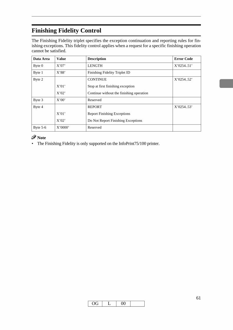
Finishing Fidelity ControlThe Finishing Fidelity triplet specifies the exception continuation and reporting rules for fin-ishing exceptions. This fidelity control applies when a request for a specific finishing operation cannot be satisfied.
Data Area Value Description Error Code
Byte 0 X’07’ LENGTH X’0254..51’
Byte 1 X’88’ Finishing Fidelity Triplet ID
Byte 2 CONTINUE X’0254..52’
X’01’ Stop at first finishing exception
X’02’ Continue without the finishing operation
Byte 3 X’00’ Reserved
Byte 4 REPORT X’0254..53’
X’01’ Report Finishing Exceptions
X’02’ Do Not Report Finishing Exceptions
Byte 5-6 X’0000’ Reserved
Note• The Finishing Fidelity is only supported on the InfoPrint75/100 printer.
61OG L 00

Sense Type and Model
Causes the printer to place into the Special Data Area of the Acknowledge Reply (See p.40 "Ac-knowledgement Reply") a record containing type and model information and the functions the printer supports.This command is effectively a NOP if the ARQ bit is NOT ON in the command header.
* Sense Type and Model X’D6E4’
Special Data Area Value Description
Byte 0 X’FF’ Convention
Bytes 1-2 Product Code
X’4370’ InfoPrint75/100
X’4028’ 4028 Emulation (4028)
Byte 3 Model
X’00’ 4028 Emulation (Simplex)InfoPrint75/100 reports this value.
Bytes 4-5 X’0000’ Reserved
* Device-Control Command Set
Special Data Area Value Description
Bytes 0-1 X’nnnn’ VECTOR LENGTH
Bytes 2-3 X’C4C3’ DEVICE CONTROL Command-Set ID
Bytes 4-5 X’FF10’ DC1 Subset ID
Bytes 6-7 X’6001’ MULTIPLE COPY and COPY-SUBGROUP support in LCC
Bytes 8-9 X’6002’ Media-source-selection support in LCC
Bytes 10-11 X’6003’ Media-destination_selection support in LCC
Bytes 12-13 X’6101’ Explicit Page Placement and Orientation Support
Bytes 14-15 X’6201’ LOGICAL PAGE AND OBJECT AREA COLORING support
Bytes 16-17 X’7001’ MANAGE IPDS DIALOG (MID) Command support
Bytes 18-19 X’702E’ ACTIVATE RESOURCE Command support
Bytes 20-21 X’7034’ PRESENTATION FIDELITY Command support
Bytes 22-23 X’8008’ XOA Order MARK FORM
Bytes 24-25 X'800C’ XOA Order Control Edge Mark
Bytes 26-27 X’80F2’ XOA Order DISCARD BUFFERED DATA
Bytes 28-29 X’80F4’ XOA Order REQUEST RESOURCE LIST
Bytes 30-31 X’80F6’ XOA Order EXCEPTION HANDLING CONTROL
Bytes 32-33 X’80F8’ XOA Order PRINT QUALITY CONTROL
Bytes 34-35 X’9001’ XOH Order PRINT BUFFERED DATA
Bytes 36-37 X’9003’ XOH Order SPECIFY GROUP OPERATION
62OG L 00OG L 01
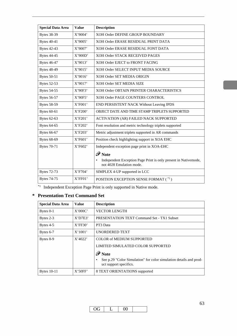
*1 Independent Exception Page Print is only supported in Native mode.
* Presentation Text Command Set
Special Data Area Value Description
Bytes 0-1 X’000C’ VECTOR LENGTH
Bytes 2-3 X’D7E3’ PRESENTATION TEXT Command Set - TX1 Subset
Bytes 4-5 X’FF30’ PT3 Data
Bytes 6-7 X’1001’ UNORDERED TEXT
Bytes 8-9 X’4022’ COLOR of MEDIUM SUPPORTED
LIMITED SIMULATED COLOR SUPPORTED
• See p.29 "Color Simulation" for color simulation details and prod-uct support specifics.
Bytes 10-11 X’50FF’ 8 TEXT ORIENTATIONS supported
Bytes 38-39 X’9004’ XOH Order DEFINE GROUP BOUNDARY
Bytes 40-41 X’9005’ XOH Order ERASE RESIDUAL PRINT DATA
Bytes 42-43 X’9007’ XOH Order ERASE RESIDUAL FONT DATA
Bytes 44-45 X’900D’ XOH Order STACK RECEIVED PAGES
Bytes 46-47 X’9013’ XOH Order EJECT to FRONT FACING
Bytes 48-49 X’9015’ XOH Order SELECT INPUT MEDIA SOURCE
Bytes 50-51 X’9016’ XOH Order SET MEDIA ORIGIN
Bytes 52-53 X’9017’ XOH Order SET MEDIA SIZE
Bytes 54-55 X’90F3’ XOH Order OBTAIN PRINTER CHARACTERISTICS
Bytes 56-57 X’90F5’ XOH Order PAGE COUNTERS CONTROL
Bytes 58-59 X’F001’ END PERSISTENT NACK Without Leaving IPDS
Bytes 60-61 X’F200’ OBJECT DATE AND TIME STAMP TRIPLETS SUPPORTED
Bytes 62-63 X’F201’ ACTIVATION (AR) FAILED NACK SUPPORTED
Bytes 64-65 X’F202’ Font resolution and metric technology triplets supported
Bytes 66-67 X’F203’ Metric adjustment triplets supported in AR commands
Bytes 68-69 X’F601’ Position check highlighting support in XOA EHC
Bytes 70-71 X’F602’ Independent exception page print in XOA-EHC
Note• Independent Exception Page Print is only present in Nativemode,
not 4028 Emulation mode.
Bytes 72-73 X’F704’ SIMPLEX 4-UP supported in LCC
Bytes 74-75 X’FF01’ POSITION EXCEPTION SENSE FORMAT ( *1 )
Note
Special Data Area Value Description
63OG L 00

* IM Image Command Set
Special Data Area Value Description
Bytes 0-1 X’000C’ VECTOR LENGTH
Bytes 2-3 X’C9D4’ IM IMAGE Command Set - IM1 Subset
Bytes 4-5 X’FF10’ IMD1 Data
Bytes 6-7 X’1001’ UNORDERED IMAGE BLOCKS
Bytes 8-9 X’4022’ COLOR of MEDIUM SUPPORTED LIMITED SIMULATED COLOR SUPPORTED
• See p.29 "Color Simulation" for color simulation details and prod-uct support specifics.
Bytes 10-11 X’A004’ ALL 4 ORIENTATIONS Supported
Note
64OG L 00

* IO Image Command SetSpecial Data Area Value Description
Bytes 0-1 X’001A’ VECTOR LENGTH
Bytes 2-3 X’C9D6’ IO Image Command Set
Bytes 4-5 X’FF10’ IO/1 Level
Bytes 6-7 X’1001’ Unordered Image Blocks
Bytes 8-9 X’4022’ COLOR of MEDIUM SUPPORTED LIMITED SIMULATED COLOR SUPPORTED
• p.29 "Color Simulation" for color simulation details and product support specifics.
Bytes 10-11 X’5001’ MMR Compression algorithm supported
Bytes 12-13 X’5003’ Uncompressed Image supported
Bytes 14-15 X’5006’ RL4 Compression supported
Bytes 16-17 X’5081’ G3 Facsimile Coding Scheme (CCITT G3MR)
Bytes 18-19 X’5082’ G4 Facsimile Coding Scheme (CCITT G4MMR)
Bytes 20-21 X’5101’ Bit ordering supported
Bytes 22-23 X’A004’ All four orientations supported
Bytes 24-25 X’F300’ Replicate and Trim mapping supported
Note• The Replicate and Trim Mapping Control Option is not supported when IPDS Print
Mode = STD (Standard 300 dpi).* Graphics Command Set
Special Data Area Value Description
Bytes 0-1 X’0012’ VECTOR LENGTH
Bytes 2-3 X’E5C7’ GRAPHICS Command Set - GR1 Subset
Bytes 4-5 X’FF20’ DR/2V0 Data
Bytes 6-7 X’1001’ UNORDERED GRAPHICS BLOCKS
Bytes 8-9 X’4022’ COLOR of MEDIUM SUPPORTED LIMITED SIMULATED COLOR SUPPORTED
• See p.29 "Color Simulation" for color simulation details and prod-uct support specifics.
Bytes 10-11 X’4100’ Set Process Color Supported
Bytes 12-13 X’4101’ GOCA Box Drawing Supported
Bytes 14-15 X’4102’ Partial Arc Drawing Supported
Bytes 16-17 X’4106’ Set Fractional Line Width Supported
Note
Note
65OG L 00

* Page Segment Command SetSpecial Data Area Value Description
Bytes 0-1 X’0008’ VECTOR LENGTH
Bytes 2-3 X’D7E2’ PAGE SEGMENT Command Set
Bytes 4-5 X’FF10’ PS1 Subset
Bytes 6-7 X’1101’ EXTENDED PAGE SEGMENT SUPPORT (32K)
* Overlay Command SetSpecial Data Area Value Description
Bytes 0-1 X’000A’ VECTOR LENGTH
Bytes 2-3 X’D6D3’ OVERLAY Command Set
Bytes 4-5 X’FF10’ OL1 Subset
Bytes 6-7 X’1506’ OVERLAY NESTING = 6 Levels
Bytes 8-9 X’1102’ EXTENDED OVERLAY SUPPORT (32K)
* Loaded Font Command Set (LF1)Special Data Area Value Description
Bytes 0-1 X’0012’ VECTOR LENGTH
Bytes 2-3 X’C3C6’ LOADED FONT Command Set
Bytes 4-5 X’FF10’ LF1 subset - fully described font + font index
Bytes 6-7 X’A004’ 4 CHARACTER ROTATIONS (LFI command)
Bytes 8-9 X’B001’ Double-byte coded fonts supported
Bytes 10-11 X’B002’ LFI UNDERSCORE Width and Position USED
Bytes 12-13 X’C005’ BOUNDED BOX RASTER FONT TECHNOLOGY
Bytes 14-15 X’C100’ FIXED METRICS
Bytes 16-17 X’C101’ RELATIVE METRICS
* Loaded Font Command Set (LF3)Special Data Area Value Description
Bytes 0-1 X’0016’ VECTOR LENGTH
Bytes 2-3 X’C3C6’ LOADED FONT Command Set
Bytes 4-5 X’FF30’ LF3 subset - code page + font character set
Bytes 6-7 X’A004’ 4 CHARACTER ROTATIONS (LFI command)
Bytes 8-9 X’B001’ Double-byte coded fonts supported
Bytes 10-11 X’B002’ LF1 UNDERSCORE Width and Position USED
Bytes 12-13 X’B005’ BOUNDED BOX RASTER FONT TECHNOLOGY
Bytes 14-15 X’C100’ FIXED METRICS
Bytes 16-17 X’C01E’ ADOBE CID-keyed OUTLINE FONT TECHNOLOGY
Bytes 18-19 X’C01F’ ADOBE TYPE-1 PFB OUTLINE FONT TECHNOLOGY
Bytes 20-21 X’C101’ RELATIVE METRICS
66OG L 00

* Bar Code Command Set
Special Data Area Value Description
Bytes 0-1 X’000C’ VECTOR LENGTH
Bytes 2-3 X’C2C3’ BAR CODE Command Set - BC1 Subset
Bytes 4-5 X’FF10’ BCD1 Data
Bytes 6-7 X’1001’ UNORDERED BAR CODE BLOCKS
Bytes 8-9 X’4022’ COLOR of MEDIUM SUPPORTED LIMITED SIMULATED COLOR SUPPORTED
• See p.29 "Color Simulation" for color simulation details and prod-uct support specifics.
Bytes 10-11 X’A004’ All four orientations supported
Note• See p.142 "Bar Code Type and Modifier Description and Values" for a list of supported
Bar Code Types.
Note
67OG L 00

Execute Order Any State (XOA)
This command identifies a set of subcommands which take effect immediately, regardless of the current printer operating state.Each Execute Order Any state command consists of a two-byte order code followed by zero or more bytes of parameters.
XOA Mark FormThe MF order causes the printer to place two rectangular blocks of job separation marks on the current or the next sheet. One block is printed on the leading edge of the sheet and one block is printed on the trailing edge of the sheet.If the MF order is included in a page that is part of a Load Copy Control copy group (See p.51 "Load Copy Control") all the copies of the page will have a job separator mark included.
Data Area Value Description Error Code
Bytes 0-1 X’0800’ MARK FORM
68OG L 00

XOA Exception Handling ControlThe Exception-Handling Control command allows the host to control how the printer reports and processes exceptions. A data-stream exception exists when the printer detects an invalid or un-supported command, control, or parameter value.
Data Area Value Description Error Code
Bytes 0-1 X’F600’ EXCEPTION HANDLING CONTROL (EHC)
Byte 2 EXCEPTION REPORTING
Bit 0: 0 Do not Report Undefined Character Check
Bit 0: 1 Report Undefined Character Check
Bit 1: 0 Do not Report Page Position Check
Bit 1: 1 Report Page Position Check
Bits 2-5: 00 Reserved
Bit 6: 0 Do not Highlight Position Checks
Bit 6: 1 Highlight Position Checks (08C1..00 and 0411..00)
Bit 7: 0 Do not Report All other Exceptions with AEA’s
Bit 7: 1 Report All other Exceptions with AEA’s
Byte 3 ALTERNATE EXCEPTION ACTIONS
Bits 0-6: 0 Reserved
Bit 7: 0 Take AEA (if defined)
Bit 7: 1 Don’t take AEA
Byte 4 EXCEPTION PRESENTATION PROCESSING
Bits 0-5: 0 Reserved
Bit 6: 0 No Page Continuation
Bit 6: 1 Page Continuation Action (Independent Exception Page Print Supported)
Discard Page
Bit 7: 0 Print to point of Exception
Bit 7: 1 (Process limits may apply)
• Independent Exception Page Print is only present in Native mode, not 4028 Emulation mode.
Note
69OG L 00

XOA Request Resource ListThis order causes the Resource List (see “Resource List Reply”) to be placed in the Special Data Area of the Acknowledge Reply (see p.40 "Acknowledgement Reply") requested with this order. If the ARQ flag was not set for this XOA subcommand, it is treated as a NOP.A Resource List Reply may consist of multiple entries. If the Resource List Reply contains an entry that does not fit in the space available in the Special Data Area of Acknowledge Reply, the printer will follow either the acknowledge continuation method or the RRL-continuation method, depending on the host, as described in Intelligent Printer Data Stream Reference.
Data Area Value Description Error Code
Bytes 0-1 X’F400’ REQUEST RESOURCE LIST (RRL)
Byte 2 QUERY TYPE X’0291..02’
X’05’ Resource Activation Status
X’00’ or X’FF’ General Resource Status
Bytes 3-4 X’0000’-X’FFFF’
ENTRY CONTINUATION Indicator
Byte 5 X’03’-X’xx’ ENTRY LENGTH
• Multiple-entry queries are not supported. Byte 5 indi-cates the length of the command.
X’0291..02’
Byte 6 RESOURCE TYPE X’0291..02’
X’01’ Single Byte Coded Fonts
X’02’ Double-byte LF1-type coded fonts
X’03’ Double-byte LF1-type coded font sections
X’04’ Page Segments
X’05’ Overlays
X’06’ Device Version Code Pages
X’07’ Font Character Sets
X’08’ Single-byte coded-font indexes
X’09’ Double-byte LF1-type coded font section indexes
X’10’ Coded Fonts (treated as RT 01)
X’11’ Graphic Character Sets supported in a font character set
X’12’ Specific Code Pages
X’FF’ All Resources
Byte 7 RESOURCE ID FORMAT X’0291..02’
X’00’ Host-Assigned Resource ID
X’03’ IBM Registered Global Resource ID parts
Bytes 8-n RESOURCE IDENTIFIER
Note
70OG L 00

• Multiple-entry queries are not supported. Byte 5 indicates the length of the entry.• If the entire resource list does not fit in the Special Data area of the Acknowledge Reply, contin-
uation is necessary. The printer indicates continuation using the acknowledgement continuation bit in the flag byte of the Acknowledge Reply. If the host requests Acknowledgement continua-tion by sending a command with ARQ bit and the Continuation bit set, the printer will complete the RRL reply using Acknowledgement continuation. If the host requests RRL continuation (by sending an RRL command with non-zero value in bytes 3 and 4) the printer will use conventional RRL continuation to finish the reply. If the host requests both RRL and ACK continuation, the printer will default to RRL continuation.
• Bytes 8 and 9 are ignored when the resource type is ALL.• Exception ID 0291..02 in bytes 6 and 7 are for invalid values. If either value is unsupported,
then the query is not understood and the reply is a single entry that sets the resource type to zero, echoes other values, and sets the resource size to zero (not present).
71OG L 00

* Resource List Reply
Data Area Value Description Error Code
Byte 0 X’FF UNORDERED LIST
Byte 1 X’01’ END of LIST
X’04’ - X’nn’ LENGTH of this ENTRY
Byte 2 RESOURCE TYPE
X’00’ Resource Size=0. The queried Resource Type,
ID Format, or ID is unknown, unsupported, or inconsistent
X’01’ Single Byte Coded Font
X’04’ Page Segment
X’05’ Overlay
X’06’ Device Version Code Pages
X’07’ Font Character Sets
X’08’ Single Byte Coded Font Index
X’11’ Graphic Character Sets supported in a font character set
X’12’ Specific Code Pages
X’FF’ All Resources
Byte 3 RESOURCE ID FORMAT
X’00’ Host-Assigned Resource ID
X’03’ IBM Registered Global Resource ID parts
Byte 4 RESOURCE SIZE Indicator
X’00’ Resource not present
X’01’ Resource present
Byte 5-6 X’xxxx’ Resource ID
• Bytes 2-6 repeat for each resource type.• A query for a HARID that maps to a GCSGID/CPGID/FGID/FW combination which is
not supported in the current configuration will result in a negative response (Reply Byte 4 = 0).
• See p.187 "Code Page and Font Identification" for a description of the supported GCS-GID/CPGID/FGID/FW combinations.
72OG L 00

XOA Control Edge Mark (CEM)The CEM order causes the printer to mark the current or next sheet with edge marks. Edge marks consist of one, two or three narrow bars as defined by the printer. These bars are printed perpendicular to the media perforation and entirely within the left carrier strip ending at the trailing edge of the specified page. A corresponding number of edge marks are also printed per-pendicular to the media perforation and entirely within the left carrier strip beginning at the leading edge of the next page.
Data Area Value Description Error Code
Byte 0-1 X’0C00’ Control Edge Mark (CEM)
Byte 2 X’00’ Inhibit (default)
X’01’ Continue
X’F1’ One edge mark
X’F2’ Two edge marks
X’F3’ Three edge mark
X’FE’ Alternate
73OG L 00

Execute Order Home State (XOH)
Each Execute Order Homestate command consists of a two-byte order code followed by zero or more bytes of parameters.
XOH Obtain Printer CharacteristicsThis order causes a set of device self-defined fields describing printer characteristics to be placed in the Special Data Area of the requested Acknowledgement Reply and is identified with an acknowledgement type of X’46’. If the ARQ flag was not set on the XOH command containing this order, then this order is equivalent to a No Operation.
Data Area Value Description Error Code
Bytes 0-1 X’F300’ OPC Order Code
Printable Area Self-Defining Field• The printer provides two modes that determine the specification of the Xm Offset, Ym Off-
set, Xm Extent and Ym Extent of the Printable Area.• Restricted (No Print Border) (Guaranteed Print Legibility) (Default)• Unrestricted (Edge-to-Edge Addressability)
• The Xm Extent and Ym Extent of the Printable Area parameters documented in the follow-ing table are representative of the standard printer source media configuration. These extents can be modified as a result of receiving a XOH-SMO command, as described in p.84 "XOH Set Media Origin".
• Actual tray capacities are determined media weight. The capacities in the following table are the maximum allowable.
Special Data Area Value Description
Bytes 0-1 LENGTH of this Self-Defining Field
X’0024’ or InfoPrint75/100 with Single Media OID
X’nnnn’ InfoPrint75/100 with Media Name
Bytes 2-3 X’0001’ PRINTABLE AREA Self-Defining Field ID
Byte 4 INPUT MEDIA SOURCE
X’00’ Tray 0 Refer to the section of Load Copy Control command.
Byte 5 X’00’ Reserved
Byte 6 X’00’ UNIT BASE 10 in.
Byte 7 X’00’ Reserved
Bytes 8-9 X’3840’ L-units per UNIT BASE
Bytes 10-11 X’0001’ - X’xxxx’
WIDTH of the Medium Presentation Space in L-units (determined by configuration)
74OG L 00

Bytes 12-13 X’0001’ - X’xxxx’
LENGTH of the Medium Presentation Space in L-units (determined by configuration)
Bytes 14-15 Xm OFFSET of the Printable Area in L-Units
X’00E3’ Restricted (4mm)
X’0000’ Unrestricted (0mm)
Bytes 16-17 Ym OFFSET of the Printable Area in L-units
X’00E3’ Restricted (4mm)
X’0000’ Unrestricted (0mm)
Bytes 18-19 X’1EF0’ -X’5FA0’
Xm EXTENT of the Printable Area in L-units
Bytes 20-21 X’21C0’ -X’4EC0’
Ym EXTENT of the Printable Area in L-units
Bytes 22-23 INPUT MEDIA SOURCE CHARACTERISTICS
Bit 0: 0 0 = No Duplex
Bits 1-2: 01 01 = Continuous Form Media
Bit 3: 1 0 = Tray Not Available; 1 = Tray Available
Bit 4: 0 0 = Reserved
Bit 5: 0/1 0 = No Envelopes; 1 = Auto or Manual Envelope Feature
Bit 6: 0/1 0 = Auto Media Feed; 1 = Manual Media Feed
Bytes 22-23 Bit 7: 0 0 = No Computer Output on Microfilm (COM)
Bit 8: 0 0 = No Carrier Strips (Ignored for Cut Sheet Media)
Bit 9: 0/1 0 = Not an Inserter Bin; 1=Inserter Bin
Bits 10-15:all 0 Reserved
Bytes 24-25 Input Media ID LENGTH (Note 3)
X’000C’ or InfoPrint75/100 with Single OID byte
X’000D’ or InfoPrint75/100 with Double OID bytes
X’000E’ or InfoPrint75/100 with Triple OID bytes
X’000F’ InfoPrint75/100 with Quadruple OID bytes
Byte 26 INPUT MEDIA ID Type
X’10’ MO:DCA Input Media Type OID
Byte 27 X’06’ OID Encoding
Byte 28 OID LENGTH
X’07’ or InfoPrint75/100 with Single OID byte
X’08’ or InfoPrint75/100 with Double OID bytes
X’09’ or InfoPrint75/100 with Triple OID bytes
X’0A’ InfoPrint75/100 with Quadruple OID bytes
Bytes 29-34 X’2B1200040301’
Input Media ID (Common Part)
Bytes 35-36 X’nn’ The value specified OCP.
Special Data Area Value Description
75OG L 00

• Input Media ID type X’06’ - Media OID is only returned if a particular media has a regis-tered MO:DCA Media Type OID.
• Input Media ID type X’00’ - User Defined Name is only returned if the user defines a Form, assigns a Form Name to the Form and associates that Form with a given Input Media Source tray.
Image and Coded Font Resolution Self-Defining Field
Special Data Area Value Description
Bytes 0-1 X’000A’ LENGTH of this Self-Defining Field
Bytes 2-3 X’0003’ IMAGE and CODED FONT RESOLUTION Self-Defining Field
Byte 4 X’00’ UNIT BASE 10 inches
Byte 5 FONT RESOLUTIONS
X’00’ Resolution Acceptance Mode (Only value in bytes 6-9)
X’FF’ Resolution Independence Mode (Bytes 6-9 specify highest resolution) (240 DPI or 300 DPI or 600 DPI)
Bytes 6-7 X PIXELS per Unit Base
X’0960’ 2400 pixels/10 inches
X’0BB8’ 3000 pixels/10 inches
X’1770’ 6000 pixels/10 inches
Bytes 8-9 Y PIXELS per Unit Base
X’0960’ 2400 pixels/10 inches
X’0BB8’ 3000 pixels/10 inches
X’1770’
6000 pixels/10 inches
• Value for byte 5 is controlled by the [Resolution] setting in the IPDS menu. Byte 5 will in-dicate Resolution Acceptance mode X’00’ if the IPDS Resolution setting is 240, 300 or 600 DPI. Byte 5 will indicate Resolution Independence mode X’FF’ if the IPDS Resolution set-ting is Auto.
• Values for bytes 6-9 are controlled by the setting of byte 5 (Font Resolutions). If byte 5 in-dicates Resolution Acceptance mode X’00’, bytes 6-9 reflect the [Resolution] setting in the IPDS menu. If byte 5 indicates Resolution Independence mode X’FF’, bytes 6-9 reflect the [Print Mode] setting in the IPDS menu. Note that the resolutions specified also apply to GOCA image if the image resolution specified in the GDD command is X’0000’, indicating that no explicit GOCA image resolution was specified.
Bytes 37-38 X’0004’ - X’0013’
Input Media ID LENGTH (Note 4)
Byte 39 Input Media ID TYPE
X’00’ User Defined Name
Bytes 40-end Input Media ID (Form Name)
X’4C6574746572’ (ie. Letter)
(1 to 16 Byte Form Name)
Special Data Area Value Description
76OG L 00

• If the [Print Mode] = STD (Standard 300 DPI), then the [Resolution] setting is ignored. Byte 5 will indicate Resolution Acceptance mode X’00’ and bytes 6-9 will reflect the IPDS Print Mode setting (300 DPI).
• For the printer to specify IPDS Resolution support of 240, 600, or AUTO, The IPDS Print Mode must be set to Enhanced (PRINT MODE = ENH on the IPDS Menu). In enhanced print mode, complex (full page) image jobs may not yield optimal print performance due to the increased print fidelity required to accurately render 240 and 600 DPI print objects.
Storage Pools Self-Defining Field
Special Data Area Value Description
Bytes 0-1 X’0039’ LENGTH of this Self-Defining Field
Bytes 2-3 X’0004’ STORAGE POOLS Self-Defining Field
Byte 4 X’2F’ LENGTH of each Storage Pool Self-Defining Field
Byte 5 X’01’ Triplet ID
Byte 6 X’00’ STORAGE POOL ID
Bytes 7-10 X’nnnnnnnn’ Storage pool varies based on installed memory and features
Bytes 11-14 X’00000000’ Reserved
Bytes 15-16 X’0011’ PAGE GRAPHICS Data
Bytes 17-18 X’0012’ PAGE IMAGE Data
Bytes 19-20 X’0013’ PAGE TEXT Data
Bytes 21-22 X’0014’ PAGE BAR CODE Data
Bytes 23-24 X’0021’ OVERLAY GRAPHICS Data
Bytes 25-26 X’0022’ OVERLAY IMAGE Data
Bytes 27-28 X’0023’ OVERLAY TEXT Data
Bytes 29-30 X’0024’ OVERLAY BAR CODE Data
Bytes 31-32 X’0031’ PAGE SEGMENT GRAPHICS Data
Bytes 33-34 X’0032’ PAGE SEGMENT IMAGE Data
Bytes 35-36 X’0033’ PAGE SEGMENT TEXT Data
Bytes 37-38 X’0034’ PAGE SEGMENT BAR CODE Data
Bytes 39-40 X’0040’ Single-Byte CODED FONT Index Tables
Bytes 41-42 X’0041’ Single-Byte CODED FONT Descriptors
Bytes 43-44 X’0042’ Single-Byte CODED FONT Patterns
Bytes 45-46 X’0048’ Double-Byte CODED FONT Index tables
Bytes 47-48 X’0049’ Double-Byte CODED FONT Descriptions
Bytes 49-50 X’004A’ Double-Byte CODED FONT Patterns
Bytes 51-52 X’0050’ CODE PAGES
Bytes 53-54 X’0060’ FONT CHARACTER SETS
Bytes 55-56 X’0070’ CODED FONTS
77OG L 00

Color Support Self-Defining Field
Special Data Area Value Description
Bytes 0-1 X’0006’ LENGTH of this Self-Defining Field
Bytes 2-3 X’0005’ COLOR SUPPORT Self-Defining Field
Bytes 4-5 X’0008’ BLACK
Installed Features Self-Defining Field
Since printers are capable of supporting multiple features, multiple configuration combinations are possible. All installable features are described below.
Special Data Area Value Description
Bytes 0-1 X’0006’ LENGTH of this Self Defining Field
Bytes 2-3 X’0006’ INSTALLED FEATURE Self Definition Field
Bytes 4-5 X’0B00’ Continuous Form
Available Features Self-Defining Field
Since printers are capable of supporting multiple features, multiple configuration combinations are possible. All available features are described below.
Special Data Area Value Description
Bytes 0-1 X’0006’ LENGTH of this Self Defining Field
Bytes 2-3 X’0006’ INSTALLED FEATURE Self Definition Field
Bytes 4-5 X’0B00’ Continuous Form
78OG L 00

RRL Resource Type and ID Format Self-Defining Field
Special Data Area Value Description
Bytes 0-1 X’002A’ LENGTH of this Self-Defining Field
Bytes 2-3 X’000A’ RRL RESOURCE TYPE Self
• RRL query combinations that receive a non-zero Resource Type reply (See p.70 "XOA Request Resource List"
Bytes 4-5 X’0100’ Single-Byte Coded Fonts as Host Assigned Resource ID
Bytes 6-7 X’0103’ Single-Byte Coded Fonts as IBM Global Resource ID
Bytes 8-9 X’0400’ Page Segments as Host Assigned Resource ID
Bytes 10-11 X’0500’ Overlays as Host Assigned Resource ID
Bytes 12-13 X’0600 Device Version Code Pages as Host Assigned Resource ID
Bytes 14-15 X’0603’ Device Version Code Pages as IBM Global Resource ID
Bytes 16-17 X’0700’ Font Character Set as Host Assigned Resource ID
Bytes 18-19 X’0703’ Font Character Set as IBM Global Resource ID
Bytes 20-21 X’0800’ Single-Byte Coded Font Index as Host Assigned Resource ID
Bytes 22-23 X’1000’ Coded Fonts as Host Assigned Resource ID (treated as X’0100’)
Bytes 24-25 X’1003’ Coded Fonts as IBM Global Resource ID (treated as X’0103’)
Bytes 26-27 X’1103’ Graphic Character Sets/Subsets as IBM Global Resource ID
Bytes 28-29 X’1200’ Specific Code Pages as Host Assigned Resource ID
Bytes 30-31 X’1203’ Specific Code Pages as IBM Global Resource ID
Bytes 32-33 X’2000’ Double-Byte LF1-typeCoded Font as Host Assigned Resource ID
Bytes 34-35 X’2003’ Double-Byte LF1-typeCoded Font as IBM Global Resource ID
Bytes 36-37 X’3000’ Double-Byte LF1-typeCoded Font sections as Host Assigned Re-source ID
Bytes 38-39 X’9000’ Double-Byte Coded Font section indexes as Host Assigned Resource ID
Bytes 40-41 X’FF00’ All Resources as Host Assigned Resource ID
Note
79OG L 00

Activate Resource RT and ID Format Self-Defining Field
Special Data Area Value Description
Bytes 0-1 X’001C’ LENGTH of this Self Defining Field
Bytes 2-3 X’000B’ RRL RESOURCE TYPE Self
• RRL query combinations that receive a non-zero Resource Type reply (See p.70 "XOA Request Resource List")
Bytes 4-5 X’0103’ Single-Byte LF1 Coded Fonts with IBM Global Resource IDs
Bytes 6-7 X’0106’ Single-Byte LF1 Coded Fonts with MVS Host Unalterable Remote Font Environment
Bytes 8-9 X’0603’ Code Pages with IBM Global Resource IDs
Bytes 10-11 X’0703’ Font Character Sets with IBM Global Resource IDs
Bytes 12-13 X’0803’ Device Version Code Pages as Host Assigned Resource ID
Bytes 14-15 X’0806’ Single-Byte LF1 Coded Fonts Index with MVS Host Unalterable
Bytes 16-17 X’1003’ Remote Font Environment
Bytes 18-19 X’1007’ Single-Byte Coded Fonts with IBM Global Resource ID
Bytes 20-21 X’0303’ Double-Byte LF1-type Coded Font Sections with IBM Global Re-source IDs
Bytes 22-23 X’0306’ Double-Byte LF1-type Coded Font Sections with MVS Host Unalter-able format
Bytes 24-25 X’0903’ Double-Byte LF1-type Coded Font Section Indexes with IBM Global Resource IDs
Bytes 26-27 X’0906’ Double-Byte LF1-type Coded Font Section Indexes with MVS Host Unalterable format
Note
80OG L 00
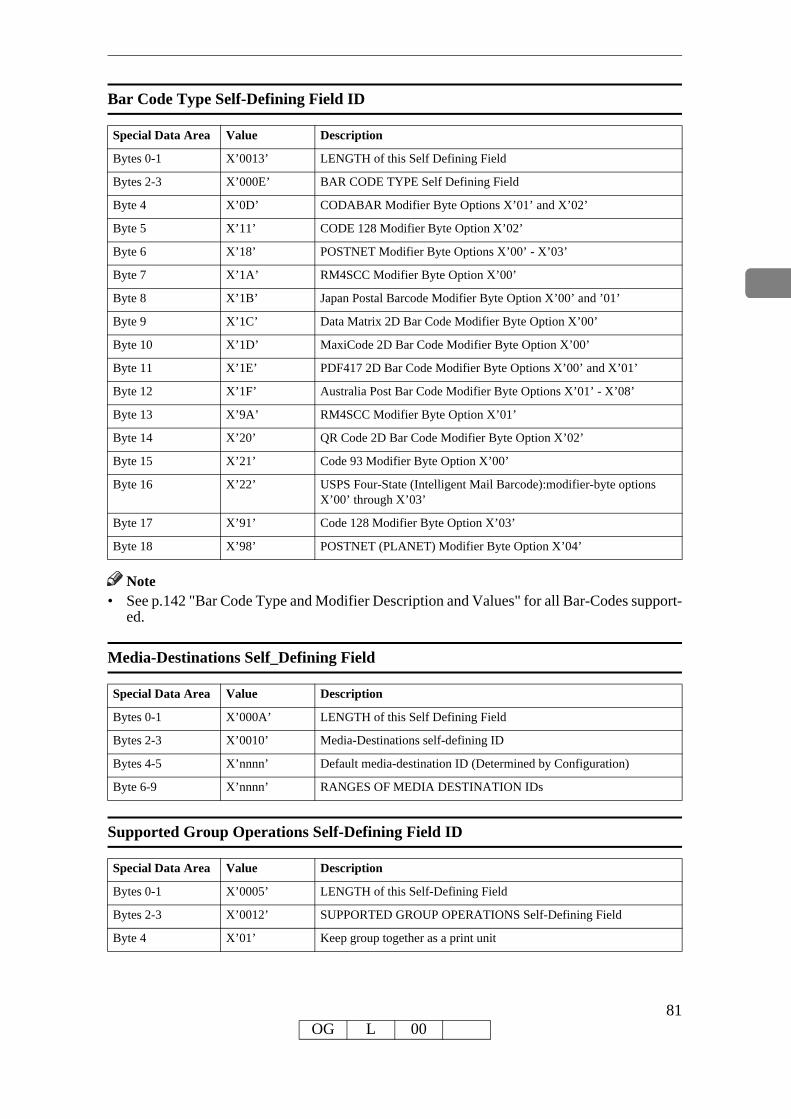
Bar Code Type Self-Defining Field ID
Special Data Area Value Description
Bytes 0-1 X’0013’ LENGTH of this Self Defining Field
Bytes 2-3 X’000E’ BAR CODE TYPE Self Defining Field
Byte 4 X’0D’ CODABAR Modifier Byte Options X’01’ and X’02’
Byte 5 X’11’ CODE 128 Modifier Byte Option X’02’
Byte 6 X’18’ POSTNET Modifier Byte Options X’00’ - X’03’
Byte 7 X’1A’ RM4SCC Modifier Byte Option X’00’
Byte 8 X’1B’ Japan Postal Barcode Modifier Byte Option X’00’ and ’01’
Byte 9 X’1C’ Data Matrix 2D Bar Code Modifier Byte Option X’00’
Byte 10 X’1D’ MaxiCode 2D Bar Code Modifier Byte Option X’00’
Byte 11 X’1E’ PDF417 2D Bar Code Modifier Byte Options X’00’ and X’01’
Byte 12 X’1F’ Australia Post Bar Code Modifier Byte Options X’01’ - X’08’
Byte 13 X’9A’ RM4SCC Modifier Byte Option X’01’
Byte 14 X’20’ QR Code 2D Bar Code Modifier Byte Option X’02’
Byte 15 X’21’ Code 93 Modifier Byte Option X’00’
Byte 16 X’22’ USPS Four-State (Intelligent Mail Barcode):modifier-byte options X’00’ through X’03’
Byte 17 X’91’ Code 128 Modifier Byte Option X’03’
Byte 18 X’98’ POSTNET (PLANET) Modifier Byte Option X’04’
Note• See p.142 "Bar Code Type and Modifier Description and Values" for all Bar-Codes support-
ed.
Media-Destinations Self_Defining Field
Special Data Area Value Description
Bytes 0-1 X’000A’ LENGTH of this Self Defining Field
Bytes 2-3 X’0010’ Media-Destinations self-defining ID
Bytes 4-5 X’nnnn’ Default media-destination ID (Determined by Configuration)
Byte 6-9 X’nnnn’ RANGES OF MEDIA DESTINATION IDs
Supported Group Operations Self-Defining Field ID
Special Data Area Value Description
Bytes 0-1 X’0005’ LENGTH of this Self-Defining Field
Bytes 2-3 X’0012’ SUPPORTED GROUP OPERATIONS Self-Defining Field
Byte 4 X’01’ Keep group together as a print unit
81OG L 00
Product Identifier Self-Defining Field ID
Special Data Area Value Description
Bytes 0-1 X’0053’ LENGTH of this Self Defining Field
Bytes 2-3 X’0013’ PRODUCT IDENTIFIER Self Defining Field ID
Byte 4 X’38’ LENGTH of Self Defining Product ID Parameter
Bytes 5-6 X’0001’ UNIQUE PRODUCT IDENTIFIER Parameter ID
Bytes 7-12 X’F0F0F2F7F0F7’ DEVICE TYPE
InfoPrint 75/100
Bytes 13-15 X'F0F0F1' InfoPrint 75
X'F0F0F2' InfoPrint 100
Bytes 16-18 X'D9D7E2'(RPS) MANUFACTURER
Bytes 19-20 X’0000’ PLANT
Bytes 21-32 SEQUENCE NUMBER (Serial number)
X’F0F0F0F0F0F0F2F9F6F5F3F8’ (ie. 296538)
EBCDIC) (12 bytes)
Bytes 33-34 X’0000’ TAG
Bytes 35-43 IPDS CODE LEVEL
X’F0F0F0F0F44BF6F2F8’ (4.628)
(EBCDIC) (9 bytes)
Bytes 44-59 CONTROLLER CODE LEVEL
(EBCDIC) (16 bytes)
Byte 60 X’17’ LENGTH of Self Defining Product ID Parameter
Bytes 61-62 X’0003’ PRINTER NAME Parameter ID
Bytes 63-82 X’nnnnnnnnnnnnnnnnnnnnnnnnnnnnnnnnnnnnnnnn’
PRINTER NAME
PFC Triplets Supported Self Defining Field ID
Special Data Area Value Description
Bytes 0-1 X’0006’ LENGTH of this Self Defining Field
Bytes 2-3 X’0016’ PFC Triplets Supported Self Defining Field
Byte 4 X’86’ Text Fidelity Triplet
Byte 5 X’88’ Finishing Fidelity Triplet
82OG L 00
XOH Select Input Media SourceThis order selects the input media source and, indirectly, the input media, for subsequent phys-ical sheets.The set of valid values differs according to which forms module configuration is installed and selected by the operator. Since printers are capable of supporting multiple installed input bins, multiple configuration combinations are possible. All input media sources are described below.• Actual tray capacities are determined by media weight. The capacities indicated in the table
are the maximum allowable.
Default settings of InfoPrint75/100
Data Area Value Description Error Code
Byte 0-1 X’1500’SELECT INPUT MEDIA SOURCE
Byte 2 INPUT MEDIA SOURCE X’02C8..01’
X’00’ Tray 1
83OG L 00

XOH Set Media OriginThe XOH Set Media Origin (SMO) command specifies the origin of the media. This order takes ef-fect on the next-received page. The media origin will not change until either another XOH-SMO command is processed or the printer is reinitialized.
Data Area Value Description Error Code
Byte 0-1 X’1600’ SET MEDIA ORIGIN
Byte 2 MEDIA ORIGIN X’026F..02’
X’00’ Top-left corner
X’01’ Top-right corner
(Bottom-left corner if back side of duplex sheet)
X’02’ Bottom-right corner
X’03’ Bottom-left corner
(Top-right corner if back side of duplex sheet)
XOH Set Media SizeThis order specifies SIZE of the physical medium.
Data Area Value Description Error Code
Byte 0-1 X’1700’
Byte 2 UNIT BASE (Measurement Units) X’0274..02’
X’00’ 10 in.
X’01’ 10 centimeters
Bytes 3-4 L-Units per UNIT BASE X’0270..02’
X’3840’ 14400 L-Units/10 inches
X’1626’ 5670 L-Units/10 centimeters
X’0960’ 2400 L-Units/10 inches
X’03B1’ 945 L-Units/10 centimeters
Bytes 5-6 X’0001’ - X’7FFF’ Xm EXTENT of MEDIUM X’0272..02’
See p.28 "Notation Conventions"
X’FFFF’ Printer Default (Printer's control panel setting or Tray sensors)
Bytes 7-8 X’0001’ - X’7FFF’ Ym EXTENT of MEDIUM X’0273..02’
See p.28 "Notation Conventions"
X’FFFF’ Printer Default (Printer's control panel setting or Tray sensors)
84OG L 00

XOH Page Counter ControlThe XOH Page Counter Control (PCC) command provides a counter synchronization function that should only be used to recover from an exception or after a XOA Discard Buffer Data com-mand.
Data Area Value Description Error Code
Bytes 0-1 X’F500’ OPC Order Code
Byte 2 X’00’ Do Nothing (default)
X’01’ Synchronize Counters
XOH Define Group BoundaryThis order initiates or terminates a grouping of pages. When a grouping of pages is initiated the page that next increments the received page counter is the first sheet in the designated group.
Data Area Value Description Error Code
Bytes 0-1 X’0400’ Define Group Boundary X’018F..00’
X’0277..01’
X’0278..01’
X’027A..01’
X’027B..01’
Byte 2 X’00’ Initiate Group
X’01’ Terminate Group
Byte 3 X’00’ - X’FF’ Group Level
Bytes 4-end of command
See specific triplet de-scription.
X’00’ Group ID triplet
X’6E’ Group information triplet X’027C..01’
X’85’ Finishing Operation triplet X’027C..02’
85OG L 00

Group ID Triplet
The Group ID triplet specifies host specific print-data formats for print job identification. The printer utilizes this information to provide IPDS print job identification on the printer console display.
Data Area Value Description Error Code
Byte 0 X’02’-X’FF’ LENGTH X’027A..01’
X’027B..02’
Byte 1 X’01’ Group ID Triplet
Byte 2 HOST FORMAT
X’01’ MVS and VSE print-data
X’02’ VM print-data
X’03’ OS/400 print-data (4 char spool file #)
X’06’ AIX and NT print-data
X’13’ OS/400 print-data (6 char spool file #)
Bytes 4-11 MVS and VSE ID DATA
X’C2E4C4C7C5E3F0F1’ (i.e. BUDGET01)
Job Name (EBCDIC) (8 bytes)
Bytes 4-11 VM ID DATA
X’C2E4C4C7C5E3F0F1’ (i.e. BUDGET01)
Filename (EBCDIC) (8 bytes)
Bytes 23-32 OS/400 ID DATA
x’C2E4C4C7C5E3F2F0F0F1’ Filename (EBCDIC) (10 bytes)
(i.e. BUDGET2000)
Bytes 3-End AIX and NT ID DATA
X’4445505442554447455432303030’ (i.e. DEPTBUDGET2000)
Name (ASCII) (1-251 bytes)
Group Information Triplet
The Group Information is accepted, although no specific processing will occur.
86OG L 00

XOH Specify Group OperationThis order indicates to an attached printer, pre-processor, or post-processor that the specified processing option is to be performed upon subsequent boundary groups of the group level iden-tified in this command.
Data Area Value Description Error Code
Byte 0-1 X’0300’ Define Group Boundary
Byte 2 X’00’-X’FF’ Operation Identifier
X’01’ Keep group together as a print unit
X’04’ Finish
Bytes 3 X’00’-X’FF’ Group Level
Note• For SGO Identifier (Byte 2), X’01’ and X’04’ are the only supported operations. All other
identifiers are accepted, although no specific processing will occur.
87OG L 00

88OG L 00

4. Presentation Text Command Set
Presentation Text Commands
Name Command Sub-command Where to Look
Load Equivalence X’D61D’ p.89 "Load Equivalence"
Write Text X’D62D’ p.90 "Write Text"
Load EquivalenceThis command permits text-suppression values imbedded in text data stored within the printer to be referenced externally using different values. For example, the Internal Suppression value of X’02’ may be referenced externally on a Load Copy Control as a X’06’ provided that an ap-propriate Load Equivalence command was previously received.If more than 127 LE entries are specified, exception X’0202..02’ is reported.
Data Area Value Description Error Code
Bytes 0-1 X’0100’ MAPPING TYPE X02C6..02’
Suppression Mapping
Bytes 2-3 X’0001’ - X’00FF’ INTERNAL VALUE from BS..ES Pair X’02C1..02’
X’02C8..02’
Bytes 4-5 X’0001’ - X’007F’ EXTERNAL VALUE from LCC X’02C8..02’
Bytes 6-509 Zero or more additional entries analogous to Bytes 2-5
89OG L 00

Write TextIn this Write Text description, references made to pages also apply to overlays and page seg-ments.The print data is a string of 1-byte code points. To determine the character raster pattern, the printer uses the code point to identify the character metrics obtained from:• Load Font Index (See p.159 "Load Font Index")• Load Font Control (See p.157 "Load Font Control")• Font Local ID (See p.53 "Load Font Equivalence") or• Resident Font DataWhen the printer processes a Begin Page, it uses the values from the existing Logical Page De-scriptor (See p.56 "Logical Page Descriptor") or Initialization Default (See p.35 "IPDS Initial-ization Defaults") until it processes one of the following text control sequences• Draw B-Axis Rule• Draw I-Axis Rule• Set Baseline Increment• Set Coded Font Local• Set Extended Text Color• Set Inline Margin• Set Intercharacter Adjustment• Set Text Color• Set Text Orientation• Set Variable Space Character Increment• Temporary Baseline MoveThe text control sequence value supersedes the Logical Page Descriptor or Initialization De-fault value and it remains in effect until it is changed by another text control sequence, or End Page is received.For a complete description of the following text control sequences see the Presentation Text Object Content Architecture Reference and the Intelligent Printer Data Stream Reference .
Absolute Move Baseline
Absolute Move Baseline Control Sequence moves the baseline coordinate relative to the I-axis of the Presentation Text Space.
Data Area Value Description Error Code
Bytes 0-1 X’2BD3’ TEXT CONTROL Sequence
Byte 2 X’04’ LENGTH X’021E..01’
Byte 3 ABSOLUTE MOVE BASELINE
X’D2’ Unchained
X’D3’ Chained
Bytes 4-5 X’0000’ - X’7FFF’ DISPLACEMENT (Bc) See p.28 "Notation Con-ventions"
X’0213..01’
90OG L 00
Absolute Move Inline
Absolute Move Inline Control Sequence moves an inline coordinate position relative to the B-axis of the Presentation Text Space.
Data Area Value Description Error Code
Bytes 0-1 X’2BD3’ TEXT CONTROL Escape Sequence
Byte 2 X’04’ LENGTH X’021E..01’
Byte 3 ABSOLUTE MOVE INLINE
X’C6’ Unchained
X’C7’ Chained
Bytes 4-5 X’0000’ - X’7FFF’ DISPLACEMENT (Ic) See p.28 "Notation Conven-tions"
X’0214..01’
Begin Line
Begin Line Control Sequence begins a new line.
Data Area Value Description Error Code
Bytes 0-1 X’2BD3’ TEXT CONTROL Escape Sequence
Byte 2 X’02’ LENGTH X’021E..01’
Byte 3 BEGIN LINE
X’D8’ Unchained
X’D9’ Chained
Begin Suppression
Begin Suppression Control Sequence marks the beginning of a string of presentation text that may be suppressed from the visible output.
Data Area Value Description Error Code
Bytes 0-1 X’2BD3’ TEXT CONTROL Escape Sequence
Byte 2 X’03’ LENGTH X’021E..01’
Byte 3 BEGIN SUPPRESSION
X’F2’ Unchained
X’F3’ Chained
Byte 4 X’01’ - X’FF’ SUPPRESSION ID X’0298..01’
91OG L 00

Draw B-Axis Rule
Draw B-axis Rule Control Sequence draws a rule in the b-direction.
Data Area Value Description Error Code
Bytes 0-1 X’2BD3’ TEXT CONTROL Escape Sequence
Byte 2 X’04’ or X’07’ LENGTH X’021E..01’
Byte 3 DRAW B-AXIS RULE
X’E6’ Unchained
X’E7’ Chained
Bytes 4-5 X’8000’ - X’7FFF’ LENGTH (Bl) See p.28 “Notation Conventions”
Bytes 6-7 WIDTH (Bw)
X’8000’ - X’7FFF’ Printer Default 24/1440 inch
X’FFFF’
Byte 8 IGNORED
Draw I-Axis Rule
Draw I-axis Rule Control Sequence draws a rule in the i-direction.Table 70. Draw I-Axis Rule
Data Area Value Description Error Code
Bytes 0-1 X’2BD3’ TEXT CONTROL Escape Sequence
Byte 2 X’04’ or X’07’ LENGTH X’021E..01’
Byte 3 DRAW I-AXIS RULE
X’E4’ Unchained
X’E5’ Chained
Bytes 4-5 X’8000’ - X’7FFF’ LENGTH (Il) See p.28 “Notation Conventions”
Bytes 6-7 WIDTH (Iw)
X’8000’ - X’7FFF’ Printer Default 24/1440 inch
X’FFFF’
Byte 8 IGNORED
92OG L 00

End Suppression
End Suppression Control Sequence marks the end of a string of presentation text that may be suppressed from the visible output.
Data Area Value Description Error Code
Bytes 0-1 X’2BD3’ TEXT CONTROL Escape Sequence
Byte 2 X’03’ LENGTH X’021E..01’
Byte 3 END SUPPRESSION
X’F4’ Unchained
X’F5’ Chained
Byte 4 X’01’ - X’FF’ SUPPRESSION ID X’0202..01’
X’0204..01’
X’0298..01’
No Operation
No Operation Control Sequence has no effect on presentation.
Data Area Value Description Error Code
Bytes 0-1 X’2BD3’ TEXT CONTROL Escape Sequence
Byte 2 X’02’ - X’FF’ LENGTH X’021E..01’
Byte 3 NO OPERATION
X’F8’ Unchained
X’F9’ Chained
Bytes 4-255 DATA (Ignored)
93OG L 00

Overstrike
The Overstrike control identifies text that is to be overstruck with a specified character.
Data Area Value Description Error Code
Bytes 0-1 X’2BD3’ TEXT CONTROL Escape Sequence
Byte 2 X’05’ LENGTH X’021E..01’
Byte 3 OVERSTRIKE
X’72’ Unchained
X’73’ Chained
Byte 4 BYPASS IDENTIFIERS
Bits 0-3 Reserved
Bit 4: 0 Overstrike white space from RMI
Bit 4: 1 Bypass white space from RMI
Bit 5: 0 Overstrike white space from AMI
Bit 5: 1 Bypass white space from AMI
Bit 6: 0 Overstrike white space from Space or Variable Space Character
Bit 6: 1 Bypass white space from Space or Variable Space Character
Bit 7: 0 BYPASS Treat Bits 0-6 according to their set values
Bit 7: 1 NO BYPASS Treat Bits 0-6 as if their values are set to zero
Byte 5 IGNORED
Byte 6 X’00’ - X’FF’ OVERSTRIKE CHARACTER
Relative Move Baseline
Relative Move Baseline Control Sequence moves a baseline coordinate relative to the current baseline coordinate position.
Data Area Value Description Error Code
Bytes 0-1 X’2BD3’ TEXT CONTROL Escape Sequence
Byte 2 X’04’ LENGTH X’021E..01’
Byte 3 RELATIVE MOVE BASELINE
X’D4’ Unchained
X’D5’ Chained
Bytes 4-5 X’8000’ - X’7FFF’ INCREMENT (Br) See p.28 “Notation Conven-tions”
94OG L 00

Relative Move Inline
Relative Move Inline Control Sequence moves the inline coordinate of the presentation posi-tion relative to the current inline position.
Data Area Value Description Error Code
Bytes 0-1 X’2BD3’ TEXT CONTROL Sequence
Byte 2 X’04’ LENGTH X’021E..01’
Byte 3 RELATIVE MOVE INLINE
X’C8’ Unchained
X’C9’ Chained
Bytes 4-5 X’8000’ - X’7FFF’ INCREMENT (Ir) See p.28 “Notation Conven-tions”
Repeat String
Repeat String Control Sequence contains a string of coded graphic characters that is repeated on the current line.
Data Area Value Description Error Code
Bytes 0-1 X’2BD3’ TEXT CONTROL Sequence
Byte 2 X’04’ - X’FF’ LENGTH X’021E..01’
Byte 3 REPEAT STRING
X’EE’ Unchained
X’EF’ Chained
Bytes 4-5 X’0000’ - X’7FFF’ REPEAT LENGTH (RL) X0219..01’
Bytes 6-n REPEAT DATA X021F..01’
Set Baseline Increment
Set Baseline Increment Control Sequence specifies the distance to be added to the current base-line coordinate when a Begin Line control sequence is executed.
Data Area Value Description Error Code
Bytes 0-1 X’2BD3’ TEXT CONTROL Sequence
Byte 2 X’04’ LENGTH X’021E..01’
Byte 3 SET BASELINE INCREMENT
X’D0’ Unchained
X’D1’ Chained
Bytes 4-5 X’8000’ - X’7FFF’ INCREMENT (Bi)
See p.28 “Notation Conventions”
X’FFFF’ Use LPD value. If no LPD is received, use printer default
95OG L 00

Set Coded Font Local
Set Coded Font Local Control Sequence specifies the character attributes to be used and in-vokes a coded font.
Data Area Value Description Error Code
Bytes 0-1 X’2BD3’ TEXT CONTROL Sequence
Byte 2 X’03’ LENGTH X’021E..01’
Byte 3 SET CODED FONT LOCAL
X’F0’ Unchained
X’F1’ Chained
Byte 4 LOCAL FONT ID
X’01’ - X’FE’ Use LPD value. If no LPD is received, use printer default
X’0218..02’
X’FF’ X’023F..02’
96OG L 00
Set Extended Text Color
The Set Text Color control specifies the color value and defines the color space and encoding for that value. The specified color value is applied to foreground areas of the presentation text space. Foreground areas consist of the following:• The stroked and filled areas of solid text characters, including overstrike characters. With
hollow characters, only the stroked portion of the character is considered foreground.• The stroked area of a rule.• The stroked area of an underscore.
Data Area Value Description Error Code
Bytes 0-1 X’2BD3’ TEXT CONTROL Sequence
Byte 2 X’14’ - X’16’ LENGTH X’021E..01’
Byte 3 SET EXTENDED TEXT COLOR
X’80’ Unchained
X’81’ Chained
Byte 4 X’00’ RESERVED
Bytes 5 COLOR SPACE X’020E..02’
X’01’ RGB - Limited Simulated Color Support
X’04’ CMYK - Limited Simulated Color Support
X’06’ HCS - Limited Simulated Color Support
X’08’ CIELAB - Limited Simulated Color Support
X’40’ Standard OCA - Limited Simulated Color Support
Bytes 6-9 X’00000000’ RESERVED
Byte 10 1ST COLOR COMPONENT BITS X’020E..05’
X’01’ - X’08’ (RGB, CMYK, CIELAB)
X’10’ (Standard OCA, Highlight)
Byte 11 2ND COLOR COMPONENT BITS X’020E..06’
X’00’ - X’08’ (RGB, CMYK, Highlight, CIELAB)
Byte 12 3RD COLOR COMPONENT BITS X’020E..07’
X’00’ - X’08’ (RGB, CMYK, CIELAB)
Byte 13 4TH COLOR COMPONENT BITS X’020E..08’
X’00’ - X’08’ (CMYK)
Bytes 14-17 COLOR VALUE X’020E..03’
RGB Color Space X’020E..04’
X’nn’ Red Intensity
X’nn’ Green Intensity
X’nn’ Blue Intensity
97OG L 00

Bytes 14-17
CMYK Color Space
X’nn’ Cyan Intensity
X’nn’ Magenta Intensity
X’nn’ Yellow Intensity
X’nn’ Black Intensity
Highlight Color Space
X’nnnn’ Highlight Color Number
X’nn’ Percent Coverage
X’nn’ Percent Shading
CIELAB Color Space
X’nn’ Luminance (L)
X’nn’ Chrominance Difference (a)
X’nn’ Chrominance Difference (b)
Standard OCA Color Space
X’0000’ or X’FF00’
Printer Default (Black)
X’0001’ or X’FF01’
Blue
X’0002’ or X’FF02 Red
X’0003’ or X’FF03’
Pink
X’0004’ or X’FF04’
Green
X’0005’ or X’FF05’
Turquoise
X’0006’ or X’FF06’
Yellow
X’0007’ White - Color of Medium (Reset)
X’0008’ Black
X’0010’ Brown
X’FF07’ Printer Default (Black)
X’FF08’ Color of Medium (Reset)
Data Area Value Description Error Code
98OG L 00

Set Inline Margin
Set Inline Margin Control Sequence specifies position of an inline margin.
Data Area Value Description Error Code
Bytes 0-1 X’2BD3’ TEXT CONTROL Sequence
Byte 2 X’04’ LENGTH X’021E..01’
Byte 3 SET INLINE MARGIN
X’C0’ Unchained
X’C1’ Chained
Bytes 4-5 X’0000’ - X’7FFF’ DISPLACEMENT (Ia) X’0210..01’
See p.28 “Notation Conventions”
X’FFFF’ Use LPD value. If no LPD is received, use printer default
Set Intercharacter Adjustment
Set Intercharacter Adjustment Control Sequence specifies additional increment or decrement between graphic characters.
Data Area Value Description Error Code
Bytes 0-1 X’2BD3’ TEXT CONTROL Sequence
Byte 2 X’04’ or X’05’ LENGTH X’021E..01’
Byte 3 SET INTERCHARACTER ADJUSTMENT
X’C2’ Unchained
X’C3’ Chained
Bytes 4-5 X’0000’ - X’7FFF’ ADJUSTMENT (ica) X’0212..01’
See p.28 “Notation Conventions”
X’FFFF’ Use LPD value. If no LPD is received, use printer default
Byte 6 DIRECTION X’0212..01’
X’00’ Increment Direction
X’01’ Decrement Direction
X’FF’ Same as X’00’
99OG L 00

Set Text Color
The Set Text Color control specifies the foreground color attribute that selects the color for sub-sequent text characters.
Data Area Value Description Error Code
Bytes 0-1 X’2BD3’ TEXT CONTROL Sequence
Byte 2 X’04’ or X’05’ LENGTH X’021E..01’
Byte 3 SET TEXT COLOR
X’74’ Unchained
X’75’ Chained
Bytes 4-5 COLOR X’0258..03’
X’0000’ or X’FF00’ Printer Default (Black)
X’0001’ or X’FF01’ Blue - Limited Simulated Color Support
X’0002’ or X’FF02’ Red - Limited Simulated Color Support
X’0003’ or X’FF03’ Pink - Limited Simulated Color Support
X’0004’ or X’FF04’ Green - Limited Simulated Color Support
X’0005’ or X’FF05’ Turquoise - Limited Simulated Color Support
X’0006’ or X’FF06’ Yellow - Limited Simulated Color Support
X’0007’ White - Color of Medium (Reset)
X’0008’ Black
X’0010’ Brown - Limited Simulated Color Support
X’FF07’ Printer Default (Black)
X’FF08’ Color of Medium (Reset)
X’FFFF’ Use LPD color value
r See p.29 “Color Simulation” for color simula-tion details and product support specifics.
Byte 6 X’00’ - X’01’ PRECISION X’0258..03’
X’FF’ Same as X’00’
Note
100OG L 00

Set Text Orientation
Set Text Orientation Control Sequence establishes i-direction and b-direction for the following presentation text.
Data Area Value Description Error Code
Bytes 0-1 X’2BD3’ TEXT CONTROL Sequence
Byte 2 X’06’ LENGTH X’021E..01’
Byte 3 SET TEXT ORIENTATION
X’F6’ Unchained
X’F7’ Chained
Bytes 4-5 I-AXIS ORIENTATION X’020F..01’
X’0000’ 0 Degree (+X direction)
X’2D00’ 90 Degree (+Y direction)
X’5A00’ 180 Degree (-X direction)
X’8700’ 270 Degree (-Y direction)
X’FFFF’ Use LPD value. If no LPD is received, use printer default
Byte 6 B-AXIS ORIENTATION X’020F..01’
X’0000’ 0 Degree (+X direction)
X’2D00’ 90 Degree (+Y direction)
X’5A00’ 180 Degree (-X direction)
X’8700’ 270 Degree (-Y direction)
X’FFFF’’ Use LPD value. If no LPD is received, use printer default
The permitted combinations are those where the difference between the I-axis orientation and the B-axis orientation are 90 deg.INLINE-DIRECTION BASELINE-DIRECTION 0 deg. rotation 90 deg. rotation 0 deg. rotation 270 deg. rotation 90 deg. rotation 180 deg. rotation 90 deg. rotation 0 deg. rotation 180 deg. rotation 270 deg. rotation 180 deg. rotation 90 deg. rotation 270 deg. rotation 180 deg. rotation 270 deg. rotation 0 deg. rotation
101OG L 00

Set Variable Space Character Increment
Set Variable Space Character Increment Control Sequence specifies the increment of a Variable Space Character.
Data Area Value Description Error Code
Bytes 0-1 X’2BD3’ TEXT CONTROL Sequence
Byte 2 X’04’ LENGTH X’021E..01’
Byte 3 SET VARIABLE SPACE CHARACTER INCREMENT
X’C4’ Unchained
X’C5’ Chained
Bytes 4-5 X’0000’ - X’7FFF’
INCREMENT (vsi) X’0217..01’
See p.28 “Notation Conventions”
X’FFFF’ Default Variable Space Increment for Current Font
102OG L 00

Temporary Baseline MoveThe Temporary Baseline Move Control Sequence is used to change the position of the sequen-tial baseline without change to the established baseline.
Data Area Value Description Error Code
Bytes 0-1 X’2BD3’ TEXT CONTROL Sequence
Byte 2 X’03’ or X’06’ LENGTH X’021E..01’
Byte 3 TEMPORARY MOVE BASELINE
X’78’ Unchained
X’79’ Chained
Byte 4 DIRECTION X’0298..03’
X’00’ Baseline is Unchanged
X’01’ Return to Established Baseline
X’02’ Shift Baseline away from I-axis (Subscript)
X’03’ Shift Baseline toward I-axis (Superscript)
X’FF’ Same as X’00’
Byte 5 PRECISION X’0298..03
X’00’ Accurate placement and character representation is re-quired using the current font.
X’01’ A substitute font with characteristics identical to the cur-rent font may be used to simulate baseline shift (super-script/subscript). The printer accepts this value but treats it as X’00’.
X’FF’ Same as X’00’
Bytes 6-7 X’0000’ - X’7FFF’
TEMPORARY BASELINE INCREMENT X’0298..03’
See p.28 “Notation Conventions”
X’FFFF’ Half the current baseline increment
Transparent Data
Transparent Data Control Sequence contains a sequence of coded characters that are presented without a scan for embedded control sequences.
Data Area Value Description Error Code
Bytes 0-1 X’2BD3’ TEXT CONTROL Sequence
Byte 2 X’02’ - X’FF’ LENGTH X’021E..01’
Byte 3 TRANSPARENT DATA
X’DA’ Unchained
X’DB’ Chained
Bytes 4-255 CHARACTER STRING
103OG L 00
Underscore
The Underscore control sequence identifies text that is to be underscored.
Data Area Value Description Error Code
Bytes 0-1 X’2BD3’ TEXT CONTROL Sequence
Byte 2 X’03’ LENGTH X’021E..01’
Byte 3 UNDERSCORE
X’76’ Unchained
X’77’ Chained
Byte 4 BYPASS IDENTIFIERS
Bits 0-3 Reserved
Bit 4: 0 Underscore white space from Relative Move Inline
Bit 4: 1 Bypass white space from Relative Move Inline
Bit 5: 0 Underscore white space from Absolute Move Inline
Bit 5: 1 Bypass white space from Absolute Move Inline
Bit 6: 0 Underscore white space from Space or Variable Space Char-acter
Bit 6: 1 Bypass white space from Space or Variable Space Character
Bit 7: 0 BYPASS Treat Bits 0-6 according to their set values
Bit 7: 1 NO BYPASS Treat Bits 0-6 as if their values are set to zero
X’FF’ NO BYPASS in EFFECT
104OG L 00

5. IM Image Command Set
IM Image Commands
Name Command Sub-command Where to Look
Write Image Control X’D63D’ p.106 "Write Image Control"
Write Image X’D64D’ p.108 "Write Image"
105OG L 00

Write Image Control
The Write Image Control command is the first command in the sequence to send raster image data to the printer. The command contains fields to define the input, scale, and image placement parameters. Several Write Image commands may be required to a complete raster image.
Data Area Value Description Error Code
Bytes 0-1 X’0001’ - X’7FFF’ Pixels per scan line in the output image X’0242..01’
X’0243..01’
Bytes 2-3 X’0001’ - X’7FFF’ Number of scan lines in the output image X’0244..01’
X’0245..01’
Bytes 4-5 X’0001’ - X’7FFF’ Pixels per scan line in the input image X’0242..01’
X’0243..01’
Bytes 6-7 X’0001’ - X’7FFF’ Number of scan lines in the input image X’0244..01’
X’0245..01’
Byte 8 X’00’ Uncompressed input image X’0246..01’
Byte 9 X’00’ One bit per pixel in the input image format X’0246..01’
Byte 10 PIXEL MAGNIFICATION FACTOR X’0247..01’
X’01’ No Magnification Factor
X’02’ Magnification Factor of 2
Byte 11 SCAN LINE MAGNIFICATION FACTOR X’0247..01’
X’01’ No Magnification Factor
X’02’ Magnification Factor of 2
Bytes 12-13 SCAN LINE DIRECTION X’0248..01’
X’0000’ 0 Degrees
X’2D00’ 90 Degrees
X’5A00’ 180 Degrees
X’8700’ 270 Degrees
Bytes 14-15 SCAN LINE SEQUENCE DIRECTION X’0249..01’
X’0000’ 0 Degrees
X’2D00’ 90 Degrees
X’5A00’ 180 Degrees
X’8700’ 270 Degrees
Byte 16 REFERENCE COORDINATE SYSTEM X’024A..01’
X’00’ Absolute I, Absolute B
X’20’ Absolute I, Relative B
X’40’ Relative I, Absolute B
106OG L 00

Byte 16 X’60’ Relative I, Relative B
X’A0’ Xp, Yp
Bytes 17-19 X’FF8000’ - X’007FFF’
Xp, I or I offset coordinate of the IM image block or-igin
X’024A..01’
Bytes 20 X’00’ Reserved
Bytes 21-23 X’FF8000’ - X’007FFF’
Yp, B or B offset coordinate of the IM image block origin
X’024A..01’
Bytes 24-25 IMAGE COLOR (Named Color) X’0253..01’
X’0000’ or X’FF00’ Printer Default (Black)
X’0001’ or X’FF01’ Blue - Limited Simulated Color Support
X’0002’ or X’FF02’ Red - Limited Simulated Color Support
X’0003’ or X’FF03’ Pink - Limited Simulated Color Support
X’0004’ or X’FF04’ Green - Limited Simulated Color Support
X’0005’ or X’FF05’ Turquoise - Limited Simulated Color Support
X’0006’ or X’FF06’ Yellow - Limited Simulated Color Support
X’0007’ White - Color of Medium (Reset)
X’0008’ Black
X’0009’ Dark Blue - Limited Simulated Color Support
X’000A’ Orange - Limited Simulated Color Support
X’000B’ Purple - Limited Simulated Color Support
X’000C’ Dark Green - Limited Simulated Color Support
X’000D’ Dark Turquoise - Limited Simulated Color Support
X’000E’ Mustard - Limited Simulated Color Support
X’000F’ Gray - Limited Simulated Color Support
X’0010’ Brown - Limited Simulated Color Support
X’FF07’ Printer Default (Black)
X’FF08’ Color of Medium (Reset)
Note• See p.29 “Color Simulation” on page 16 for
color simulation details and product support specifics.
Data Area Value Description Error Code
107OG L 00
Write Image
The data is a binary representation of the raster image. In the binary data, a 1-bit represents a colored pixel and a 0-bit represents a pixel left unchanged in the page map. In other words, if a pixel is set black by another block on the page (for example, text), it will not be reset to white if it is written with a 0-bit in the image block. Several Write Image commands may be required to a complete raster image.An error occurs if the host program sends the End command and the total number of bytes of image data is a different number than specified in the image control record.
Data Area Value Description Error Code
Bytes 0-End Binary RASTER IMAGE X’026A..01’
X’026B..01’
X’0264..01’
108OG L 00

6. IO Image Command Set
IO Image Commands
Name Command Sub-command Where to Look
Write Image Control 2 X’D63E’ p.110 "Write Image Control 2"
Image Area Position X’AC6B’ p.110 "Image Area Position"
Image Output Control X’A66B’ p.111 "Image Output Control"
Image Data Descriptor X’A6FB’ p.113 "Image Data Descriptor"
Write Image 2 X’D64E’ p.115 "Write Image 2"
Begin Segment X’70’ p.115 "Begin Segment"
Begin Image Content X’91’ p.115 "Begin Image Content"
Image Size Parameter X’94’ p.116 "Image Size Parameter"
Image Encoding Parameter X’95’ p.116 "Image Encoding Parameter"
Image Data Element Size Parameter
X’96’ p.117 "Image Data Element Size Parame-ter"
Image Look Up Table ID Parameter
X’97’ p.117 "Image Look-up Table ID Parame-ter"
Image Data X’FE92’ p.117 "Image Data"
End Image Content X’93’ p.117 "End Image Content"
End Segment X’71’ Image Object Content Architecture Ref-erence
109OG L 00

Write Image Control 2The Write Image Control 2 data consists of three consecutive structured fields:• Image Area Position Control (IAP)• Image Output Control (IOC)• Image Data Descriptor (IDD)The Write Image Control 2 command and the command sequence that follows defines the im-age presentation block area on the current page. The parameters of this command define the size, placement and orientation of the image block and establish the parameters required to in-terpret the image segments.Positive acknowledgement of image commands in Overlay State or Page Segment State means that the command or command sequence has been accepted for processing, but does not imply that its parameters have been checked in any way.
Image Area Position
This data structured field specifies the position and orientation of the image output area relative to a reference coordinate system. It is a REQUIRED data field in the Write Image Control 2 command.
Data Area Value Description Error Code
Bytes 0-1 X’000B’ - X’xxxx’ LENGTH of Image Area Position X’0202..05’
Bytes 2-3 X’AC6B’ STRUCTURED FIELD ID X’020B..05’
Bytes 4-5 X’8000’ - X’7FFF’ Image Object Area Origin Xp, I, or I-offset Coordi-nate Position
See p.28 "Notation Conventions"
Bytes 6-7 X’8000 - X’7FFF’ Image Object Area Origin Yp, B, or B-offset Coor-dinate Position
See p.28 "Notation Conventions"
Bytes 8-9 ORIENTATION OF IMAGE BLOCK X’0203..05’
X’0000’ 0 degrees
X’2D00’ 90 degrees
X’5A00’ 180 degrees
X’8700’ 270 degrees
Byte 10 COORDINATE REFERENCE SYSTEM X’0204..05’
X’00’ Absolute I, absolute B
X’20’ Absolute I, relative B
X’40’ Relative I, absolute B
X’60’ Relative I, relative B
X’A0’ Page Xp, Yp
Bytes 11-n Ignored
110OG L 00

Image Output ControlThis data structured field specifies the mapping option for the image object. It is an ELECTIVE data field in the Write Image Control 2 command. If this field is omitted, the printer will use the following default values:Mapping option = X’30’ (Position and Trim)X, Y Offset = 0.X, Y Extent = Image Presentation Space extent defined by the Image Data Descriptor structured field.
Data Area Value Description Error Code
Bytes 0-1 X’0010’ - X’xxxx’ LENGTH of Image Output Control X’0202..05’
Bytes 2-3 X’A66B’ Structured Field ID X’020B..05’
Byte 4 UNIT BASE (Measurement Units) X’0205..05’
X’00’ 10 Inches
X’01’ 10 Centimeters
Bytes 5-6 X’0001’-X’7FFF’ L-units per UNIT BASE X’0206..05’
Bytes 7-8 X’0001’-X’7FFF’ X extent of IO image block in L-units for Page, Overlay and Page Segment (see p.28 "Notation Conventions"
X’0207..05’
X’FFFF’ Use Load Page Descriptor Value
Bytes 9-10 X’0001’-X’7FFF’ Y extent of IO image block in L-units for Page, Overlay and Page (see p.28 "Notation Conventions"
X’0207..05’
X’FFFF’ Use Load Page Descriptor Value
Byte 11 MAPPING CONTROL OPTION X’0208..05’
X’10’ Scale to fit
X’20’ Center and trim
X’30’ Position and trim
X’41’ Point to pixel
X’42’ Point to pixel with double dot
X’50’ Replicate and Trim
Bytes 12-13 X’8000’-X’7FFF’ X OFFSET L-units X’0209..05’
See p.28 "Notation Conventions"
Bytes 14-15 X’8000’-X’7FFF’ Y OFFSET L-units
See p.28 "Notation Conventions" X’0209..05’
111OG L 00

Data Area Value Description Error Code
Bytes 16-n IOC Triplets
• Color Specification Triplet. This optional triplet can be placed at the end of the IOC command to specify the foreground color of the object area, before any object data is placed on the object ar-ea. Any number of IOC triplets can be received, they are processed in the order received and the resulting color of the object area depends on the last instance of the triplet received. See p.32 "Color Specification" for details.
• Presentation Space Reset Mixing Triplet. This optional triplet can be placed at the end of the IOC command to specify whether or not an ob-ject area is reset to the color of medium before any object data is placed on the object area. Any number of IOC triplets can be received, they are processed in the order received and the resulting color of the object area depends on the last in-stance of the triplet received. See p.34 "Presen-tation Space Reset Mixing" for details.
Note• The Replicate and Trim Mapping Control option is supported only when the IPDS Menu
PRINT MODE item is set to ENH (Enhanced 600 dpi).
112OG L 00

Image Data DescriptorThis is a REQUIRED data structured field in the Write Image Control 2 command. It specifies pa-rameters that define the image presentation space size and resolution.
Data Area Value Description Error Code
Bytes 0-1 X’000F’ - X’xxxx’ LENGTH of Image Data Descriptor X’0202..05’
Bytes 2-3 X’A6FB’ STRUCTURED FIELD ID X’020B..05’
Bytes 4-5 X’0000’ Reserved
Byte 6 UNIT BASE (Measurement Units) X’0205..05’
X’00’ 10 Inches
X’01’ 10 Centimeters
Bytes 7-8 X’0001’-X’7FFF’ X image points per unit base X’0206..05’
Bytes 9-10 X’0001’-X’7FFF’ Y image points per unit base X’0206..05’
Bytes 11-12 X’0001’-X’7FFF’ X EXTENT of image presentation space (in im-age points)
X’0207..05’
See p.28 "Notation Conventions"
Bytes 13-14 X’0001’-X’7FFF’ Y EXTENT of image presentation space (in im-age points)
X’0207..05’
See p.28 "Notation Conventions"
Bytes 15-end of IDD IOCA SDFs
Byte 0 X’F6’ Set Bilevel Image Color SDF *1
Byte 1 X’04’ LENGTH
Byte 2 X’00’ AREA
Byte 3 X’00’ Reserved
Bytes 4-5 Named Color
X’0000’ or X’FF00’
Printer Default (Black)
X’0001’ or X’FF01’
Blue - Limited Simulated Color Support
X’0002’ or X’FF02’
Red - Limited Simulated Color Support
X’0003’ or X’FF03’
Pink - Limited Simulated Color Support
X’0004’ or X’FF04’
Green - Limited Simulated Color Support
X’0005’ or X’FF05’
Turquoise - Limited Simulated Color Support
X’0006’ or X’FF06’
Yellow - Limited Simulated Color Support
X’0007’ White - Color of Medium (Reset)
113OG L 00

*1 Refer to the Intelligent Printer Data Stream Reference and the Image Object Content Architecture Reference for specifics on the Set Bilevel Image Color SDF format.
X’0008’ Black
X’0009’ Dark Blue - Limited Simulated Color Support
Bytes 4-5 X’000A’ Orange - Limited Simulated Color Support
X’000B’ Purple - Limited Simulated Color Support
X’000C’ Dark Green - Limited Simulated Color Support
X’000D’ Dark Turquoise - Limited Simulated Color Sup-port
X’000E’ Mustard - Limited Simulated Color Support
X’000F’ Gray - Limited Simulated Color Support
X’0010’ Brown - Limited Simulated Color Support
X’FF07’ Printer Default (Black)
X’FF08’ Color of Medium (Reset)
Data Area Value Description Error Code
114OG L 00

Write Image 2The image segment is processed as it is received by the printer and is not retained or stored as a named image segment.Write Image 2 command carries the IO image data within a hierarchical sequence of self-defining fields. See the Intelligent Printer Data Stream Reference and the Image Object Content Architec-ture Reference.
Begin Segment
Data Area Value Description Error Code
Byte 0 X’70’ Begin Segment X’0570..0F’
Byte 1 X’00’-X’FF’ Length
Begin Image Content
Data Area Value Description Error Code
Byte 0 X’91’ Begin Image Content X’0591..0F’
Byte 1 X’01’-X’FF’ Length X’0500..03’
Byte 2 X’FF’ Format Specification X’0500..04’
115OG L 00

Image Size Parameter
The Image Size Parameter specifies the size of the image defined within the image segment. Map-ping of the image into the image presentation space (See p.113 "Image Data Descriptor") is on a 1 image point to 1 image point basis (one image point of an IO-Image segment is mapped to one image point of the image presentation space).Data Area Value Description Error Code
Byte 0 X’94’ IMAGE SIZE X’0594..0F’
Byte 1 X’09’-X’FF’ LENGTH of the following bytes X’0500..03’
Byte 2 UNIT BASE (Measurement Units)
X’00’ 10 Inches
X’01’ 10 Centimeters
X’02’ Logical (resolution ratio)
Bytes 3-4 X’0000’ - X’7FFF’ X image points per unit base
Bytes 5-6 X’0000’ - X’7FFF’ Y image points per unit base
Bytes 7-8 X’0000’-X’7FFF’ X extent of the image in image points X’0500..04’
X’0594..11’
X’0595..11’
X’05A9..02’
Bytes 9-10 X’0000’-X’7FFF’ Y extent of the image in image points X’0500..04’
X’05A9..02’
Image Encoding Parameter
Data Area Value Description Error Code
Byte 0 X’95’ IMAGE ENCODING X’0595..0F’
Byte 1 X’02’-X’FF’ LENGTH of the following bytes X’0500..03’
Byte 2 COMPRESSION ALGORITHM X’0595..10’
X’01’ IBM MMR compression X’0595..11’
X’03’ No compression
X’06’ RL4 compression
X’81’ G3 MR (CCITT T.4 G3 facsimile 2-D)
X’82’ G4 MMR (CCITT T.6 G4 facsimile 2-D)
Byte 3 RECORDING ALGORITHM X’0595..10’
X’01’ RIDIC (Recording Image Data Inline Code) Unpad-ded RIDIC
Byte 4 BIT ORDER within each image data byte
X’00’ Left-to-Right
X’01’ Right-to-Left
116OG L 00

Image Data Element Size Parameter
Data Area Value Description Error Code
Byte 0 X’96’ IMAGE DATA ELEMENT SIZE X’0596..0F’
Byte 1 X’01’-X’FF’ LENGTH of the following bytes X’0500..03’
Byte 2 NUMBER of BITS per PIXEL X’0596..10’
X’01’ 1 bit per pixel X’0500..04’
X’08’ 8 bits per pixel X’0596..11’
If 1 is specified, the image is binary, with 1-bits representing black pixels and 0-bits represent-ing pixels unchanged in the page map. If the image is uncompressed, each raster scan in the image data must be padded so that it is an integral number of bytes.If 8 is specified, the image is gray scale. Each image byte is considered to be a value 0 to 255, where 0 is maximum black, 255 is no black at all, and the values in between are shades of gray.The printer implements 8 bit per pixel images by halftoning. Halftoning significantly degrades image detail. For that reason, resolutions of gray scale data greater than 120 pixels per inch are not recommended except for draft printing purposes.If 8 is specified, the Image Compression, if specified with the Image Encoding command, must be uncompressed. This error is detected when the first Image Data command is received.
Image Look-up Table ID Parameter
Data Area Value Description Error Code
Byte 0 X’97’ Image Look-up Table ID Parameter X’0597..0F’
Byte 1 X’01’-X’FF’ LENGTH of the following bytes X’0500..03’
Byte 2 X’00’ Look up table ID X’0597..10’
Image Data
Data Area Value Description Error Code
Bytes 0-1 X’FE92’ Image Data X’0592..0F’
Bytes 2-3 X’0001’-X’FFFF’ Length X’0500..03’’
X’0594..01’
Bytes 4-end X’x...x’ Image Data X’0597..10’
End Image Content
Data Area Value Description Error Code
Byte 0 X’93’ End Image Content X’0593..0F’
Byte 1 X’00’-X’FF’ Length
117OG L 00

End Segment
Data Area Value Description Error Code
X’71’ X’93’ End Segment X’0571..0F’
Byte 1 X’00’-X’FF’ Length
118OG L 00

7. Graphics Command Set
Graphics Commands
The base reference for graphic drawing orders is the Graphics Object Content Architecture Ref-erence.Name Command Sub-command Where to Look
Write Graphics Control X’D684’ Graphics Area Position p.119 "Write Graphics Control"
Graphics Area Position X’AC6B’ p.119 "Graphics Area Position"
Graphics Output Control X’A66B’ p.120 "Graphics Output Control"
Graphics Data Descriptor X’A6BB’ p.122 "Graphics Data Descriptor"
Write Graphics X’D685’ p.119 "Write Graphics Control"
Begin Segment Introducer X’70’ p.126 "Begin Segment Introducer"
Write Graphics Control
Graphics Area Position
Data Area Value Description Error Code
Bytes 0-1 X’000B’-X’xxxx’ LENGTH of Graphics Area Position X’0202..05’
Bytes 2-3 X’AC6B’ Structured Field ID. X’020B..05’
Bytes 4-5 X’8000’-X’7FFF’ GRAPHICS BLOCK ORIGIN Xp, I, or I-offset Coordi-nate Position. See p.28 "Notation Conventions"
Byte 6-7 X’8000’-X’7FFF’ GRAPHICS BLOCK ORIGIN Yp, B, or B-offset Coordi-nate Position. See p.28 "Notation Conventions"
Bytes 8-9 ORIENTATION of Graphic Block X’0203..05’
X’0000’ 0 Degrees
X’2D00’ 90 Degrees
X’5A00’ 180 Degrees
X’8700’ 270 Degrees
119OG L 00

Graphics Output Control
Byte 10 COORDINATE REFERENCE SYSTEM X’0204..05’
X’00’ Absolute I, Absolute B
X’20’ Absolute I, Relative B
X’40’ Relative I, Absolute B
X’60’ Relative I, Relative B
X’A0’ Page Xp, Yp
Byte 11-n
Data Area Value Description Error Code
Byte 0-1 X’0010’-X’xxxx’ LENGTH of Graphics Output Control (GOC) X’0202..05’
Byte 2-3 X’A66B’ STRUCTURED FIELD ID X’020B..05’
Byte 4 UNIT BASE (Measurement Units) X’0205..05’
X’00’ 10 Inches
X’01’ 10 Centimeters
Byte 5-6 X’0001’ - X’7FFF’ L-Units per UNIT BASE X’0206..05’
Byte 7-8 X’0001’ - X’7FFF’ X EXTENT of GRAPHICS BLOCK in L-units See p.28 "Notation Conventions"
X’0207..05’
X’FFFF’ Use Load Page Descriptor Value
Byte 9-10 X’0001’ - X’7FFF’ Y EXTENT of GRAPHICS BLOCK in L-units See p.28 "Notation Conventions"
X’0207..05’
X’FFFF’ Use Load Page Descriptor Value
Byte 11 MAPPING Control Option X’0208..05’
X’10’ Scale to Fit
X’20’ Center and Trim
X’30’ Position and Trim
Byte 12-13 X’8000’ - X’7FFF’ X OFFSET L-units. See p.28 "Notation Conventions" X’0209..05’
Byte 14-15 X’8000’ - X’7FFF’ Y OFFSET L-units. See p.28 "Notation Conventions" X’0209..05’
Data Area Value Description Error Code
120OG L 00

Note• The Graphics Output Control Self Defining Field is optional and may be omitted from the WGC
command. If the GOC is omitted, the printer uses the following:• Mapping Control Option X’30’ (Position and Trim)• X Offset = 0• Y Offset = 0• Graphics Block size equals the Graphics Presentation Space Window size which is de-
fined in the Graphics Data Descriptor (GDD) Self Defining Field (See p.122 "Graphics Data Descriptor").
Byte 16-n GOC Triplets
• Color Specification Triplet. This optional triplet can be placed at the end of the GOC command to specify the foreground color of the object area, be-fore any object data is placed on the object area. Any number of GOC triplets can be received, they are processed in the order received and the resulting color of the object area depends on the last instance of the triplet received. See p.32 "Color Specifica-tion" for details.
• Presentation Space Reset Mixing Triplet. This op-tional triplet can be placed at the end of the GOC command to specify whether or not an object area is reset to the color of medium before any object data is placed on the object area. Any number of GOC triplets can be received, they are processed in the order received and the resulting color of the ob-ject area depends on the last instance of the triplet received. See p.34 "Presentation Space Reset Mix-ing" .
Data Area Value Description Error Code
121OG L 00

Graphics Data Descriptor
Data Area Value Description Error Code
Bytes 0-1 X’001C’-X’xxxx’ LENGTH of Graphics Data Descriptor (GDD) X’0202..05’
Bytes 2-3 X’A6BB’ STRUCTURED FIELD ID X’020B..05’
Byte 4 UNIT BASE (Measurement Units) X’0205..05’
X’00’ 10 Inches
X’01’ 10 Centimeters
Byte 5 X’00’ Reserved
Bytes 6-7 X’0001’ - X’7FFF’ Xg UNITS per UNIT BASE X’0206..05’
Bytes 8-9 X’0001’ - X’7FFF’ Yg UNITS per UNIT BASE Yg = Xg X’0206..05’
Bytes 10-13 X’00000000’ Reserved
Bytes 14-15 X’8000’-X’7FFF’ Xg LEFT LIMIT of Graphic Presentation Space Win-dow. See p.28 "Notation Conventions"
Bytes 16-17 X’8000’-X’7FFF’ Xg RIGHT LIMIT of Graphic Presentation Space Win-dow. See p.28 "Notation Conventions"
Bytes 18-19 X’8000’-X’7FFF’ Yg TOP LIMIT of Graphic Presentation Space Win-dow. See p.28 "Notation Conventions"
Bytes 20-21 X’8000’-X’7FFF’ Yg BOTTOM LIMIT of Graphic Presentation Space Window. See p.28 "Notation Conventions"
Bytes 22-27 X’000000000000’ Reserved
Bytes 28-n INITIAL GRAPHICS DEFAULTS. See “GDD Initial Graphics Defaults Self Describing Instructions”
If the image resolution specified in the GDD is X’0000’ (indicating that no explicit resolution is specified), then the resolution used is the resolution specified in the OPC’s Image and Coded Font Resolution Self-Defining Field.
122OG L 00

* GDD Initial Graphics Defaults Self Describing Instructions
Data Area Value Description Error Code
Byte 0 X’21’ SET CURRENT DEFAULTS X’0300..21’
Byte 1 X’04’-X’FF’ LENGTH of Data X’0300..03’
Byte 2 SET Byte X’0300..02’
X’00’ Drawing Attributes
X’01’ Line Attributes
X’02’ Character Attributes
X’03’ Marker Attributes
X’04’ Pattern Attributes
X’0B’ Arc Parameters
Byte 3-4 MASK Bytes. See p.124 "Graphics Drawing Order Defaults and Masks"
X’0300..03’
Byte 5 DEFAULT Byte X’0300..02’
X’0F’ Use Standard Default X’0300..03’
X’8F’ Use the following Data Bytes
Byte 6-n Data bytes X’0300..21’
Note• See p.127 "Drawing Orders" for valid drawing order defaults.
123OG L 00

* Graphics Drawing Order Defaults and Masks
Set Byte Mask Bit Description
X’00’ DRAWING ATTRIBUTES
0 Color (Named Color)
1 Foreground Mix
2 Background Mix
3-15 Reserved
X’01’ LINE ATTRIBUTES
0 Line Type
1 Line Width
2-15 Reserved
X’02’ CHARACTER ATTRIBUTES
0 Angle X, Y
1 Character Cell Size CW, CH
2 Direction
3 Precision
4 Character Set
5 Shear X, Y
6-15 Reserved
X’03’ MARKER ATTRIBUTES
0-2 Reserved
3 Precision
4 Marker Set
5-6 Reserved
7 Marker Symbol
8-15 Reserved
X’04’ PATTERN ATTRIBUTES
0-6 Reserved
7 Pattern Symbol
8-15 Reserved
X’0B’ ARC PARAMETERS
0 P Value
1 R Value
2 Q Value
3 S Value
4-15 Reserved
124OG L 00

Write Graphics
Write Graphics DefaultsThe following defaults will be used if not previously defined by p.124 "Graphics Drawing Or-der Defaults and Masks". The current value of an attribute is taken into account when the draw-ing order is received.
Description Value
Color Black
Line Type Solid
Line Width Normal (4 pixel)
Character Cell 10 CPI
Character Set Courier 10
Character Angle No Rotation
Character Direction Left to Right
Marker Symbol Cross
Pattern Symbol Solid Shading
Current Position X,Y = 0,0
Arc Parameters P=Q=1; R=S=0
Foreground Mix Overpaint
Background Mix Leave Alone
Character Precision Character Precision
Marker Precision Character Precision
Marker Symbol Set Resident Set in Printer
125OG L 00

Begin Segment Introducer
Data Area Value Description Error Code
Byte 0 X’70’ BEGIN SEGMENT code
Byte 1 X’0C’ LENGTH of the following parameters X’0370..C1’
Byte 2-5 SEGMENT ID (Ignored)
Byte 6 X’00’ Reserved
Byte 7 FLAGS X’0370..01’
Bits 0-2: 00 Reserved X’0370..82’
Bit 3: 0/1 No Prolog (0); Prolog (1)
Bit 4: 0 Reserved
Bits 5-6: 00/11 New Segment (reinitialize graphics defaults)/Append Seg-ment (do not reinitialize defaults)
Bit 7: 0 Reserved
Byte 8-9 X’0000’-X’FFFF’ Length of this segment (SEGLEN)
Byte 10-13 X’00000000’ Reserved
Byte 14-n See p.127 "Drawing Orders"
126OG L 00

Drawing Orders
InfoPrint75/100 supports all DR2 Drawing Orders and valid data values as defined in the Intel-ligent Printer Data Stream Reference. The following are those Drawing Orders which define specific data values.
* Set Background Mix:
Data Area Value Description Error Code
Byte 0 X’0D’ Order code
Byte 1 BACKGROUND MIX ATTRIBUTE X’0300..04’
X’00’ Drawing default X’0300..0E’
X’05’ Leave Alone
* Set Character Angle:
Data Area Value Description Error Code
Byte 0 X’34’ Order code
Byte 1 X’04’ Length X’0300..03’
Byte 2-3 X’8000’ - X’7FFF’ Xg COORDINATE X’0334..00’
Byte 4-5 X’8000’ - X’7FFF’ Yg COORDINATE X’0334..00’
• If Xg = 0 and Yg = 0 then the character angle is 0 degrees (default)• If Xg > 0 and Yg = 0 then the character angle is 0 degrees• If Xg = 0 and Yg > 0 then the character angle is 90 degrees• If Xg < 0 and Yg = 0 then the character angle is 180 degrees• If Xg = 0 and Yg < 0 then the character angle is 270 degrees
Note• Exception X’0334..00’ applies when both Xg and Yg are non-zero values.
* Set Character Precision:
Data Area Value Description Error Code
Byte 0 X’39’ Order code
Byte 1 PRECISION TYPE X’0300..04’
X’00’ Current default X’0300..0E’
X’01’ String Precision
X’02’ Character Precision
127OG L 00

* Set Character Set:
Data Area Value Description Error Code
Byte 0 X’38’ Order code
Byte 1 LOCAL CHARACTER SET ID X’03C3..00’
X’00’ Current default
X’01’ - X’FE’ Local ID for Character Set
X’FF’ Printer Default
* Set Color:
Data Area Value Description Error Code
Byte 0 X’0A’ Order code
Byte 1 COLOR X’0300..04’
X’00’ Printer Default (Black)
X’01’ Blue - Limited Simulated Color Support
X’02’ Red - Limited Simulated Color Support
X’03’ Pink - Limited Simulated Color Support
X’04’ Green - Limited Simulated Color Support
X’05’ Turquoise - Limited Simulated Color Sup-port
X’06’ Yellow - Limited Simulated Color Support
X’07’ Black
X’08’ Color of Medium (Reset)
• See p.29 "Color Simulation" for color simulation details and product support specifics.
Note
128OG L 00

* Set Extended Color:
Data Area Value Description Error Code
Byte 0 X’26’ Order code
Byte 1 X’02’ Length X’0300..03’
Bytes 2-3 EXTENDED COLOR X’0300..04’
X’0000’ or X’FF00’ Printer Default (Black)
X’0001’ or X’FF01’ Blue - Limited Simulated Color Support
X’0002’ or X’FF02’ Red - Limited Simulated Color Support
X’0003’ or X’FF03’ Pink - Limited Simulated Color Support
X’0004’ or X’FF04’ Green - Limited Simulated Color Support
X’0005’ or X’FF05’ Turquoise - Limited Simulated Color Sup-port
X’0006’ or X’FF06’ Yellow - Limited Simulated Color Support
X’0007’ White - Color of Medium (Reset)
X’0008’ Black
X’0009’ Dark Blue - Limited Simulated Color Sup-port
X’000A’ Orange - Limited Simulated Color Support
X’000B’ Purple - Limited Simulated Color Support
X’000C’ Dark Green - Limited Simulated Color Support
X’000D’ Dark Turquoise - Limited Simulated Color Support
X’000E’ Mustard - Limited Simulated Color Sup-port
X’000F’ Gray - Limited Simulated Color Support
X’0010’ Brown - Limited Simulated Color Support
X’FF07’ Printer Default (Black)
X’FF08’ Color of Medium (Reset)
r See p.29 "Color Simulation" for color simulation details and product support specifics.
* Set Line Type:
Note
Data Area Value Description Error Code
Byte 0 X’18’ Order code
129OG L 00
* Set Fractional Line Width (4028 Emulation Mode):
Data Area Value Description Error Code
Byte 0 X’11’ Order code
Byte 1 X’02’ Length X’0300..03’
Bytes 2-3 FRACTIONAL LINE WIDTH X’0300..04’
X’0000’ Current default X’0300..0E’
X’0001’ - X’00FF’ 2 Pixel Wide
X’0100’ - X’017F’ 4 Pixels Wide
X’0180’ - X’01FF’ 6 Pixels Wide
X’0200’ - X’0F7F’ G8-60 Pixels Wide
X’0F80’ - X’FFFF’ 62 Pixels Wide
Byte 1 LINE TYPE X’0300..04’
X’00’ Current default X’0300..0E’
X’01’ Dotted Line
X’02’ Short Dashed Line
X’03’ Dashed and Dotted Line
X’04’ Double Dotted Line
X’05’ Long Dashed Line
X’06’ Dashed Double Dotted Line
X’07’ Solid Line
X’08’ Invisible Line
Data Area Value Description Error Code
130OG L 00

* Set Fractional Line Width (Native Mode):Data Area Value Description Error Code
Byte 0 X’11’ Order code
Byte 1 X’02’ Length X’0300..03’
Bytes 2-3 FRACTIONAL LINE WIDTH X’0300..04’
X’0000’ Current default X’0300..0E’
X’0001’ - X’007F’ 1 Pixel Wide
X’0080’ - X’00BF’ 2 Pixels Wide
X’00C0’ - X’00FF’ 3 Pixels Wide
X’0100’ - X’013F’ 4 Pixel Wide
X’013F’ - X’017F’ 5 Pixels Wide
X’0180’ - X’01BF’ 6 Pixels Wide
X’01C0’ - X’01FF’ 7 Pixels Wide
X’0200’ - X’0F7F’ 8-60 Pixels Wide
X’0F80’ - X’FFFF’ 62 Pixels Wide
* Set Line Width:Data Area Value Description Error Code
Byte 0 X’19’ Order code
Byte 1 LINE WIDTH X’0300..04’
X’00’ Current default X’0300..0E’
X’01’ - X’0F’ 2-58 Pixels Wide (4 pixel increments)
X’10’ - X’FF’ 62 Pixels Wide
* Set Marker Precision:Data Area Value Description Error Code
Byte 0 X’3B’ Order code
Byte 1 MARKER PRECISION X’0300..04’
X’00’ Drawing default X’0300..0E’
X’01’ Character Precision
X’02’ Stroke Precision
131OG L 00

* Set Mix:Data Area Value Description Error Code
Byte 0 X’0C’ Order code
Byte 1 MIX ATTRIBUTE X’0300..04’
X’00’ Drawing default X’0300..0E’
X’02’ Overpaint
* Set Pattern Set:
Data Area Value Description Error Code
Byte 0 X’08’ Order code
Byte 1 X’00’ PATTERN SET ID X’0368..03’
* Set Pattern Symbol:
Data Area Value Description Error Code
Byte 0 X’28’ Order code
Byte 1 PATTERN SYMBOL ID X’0368..04’
X’00’ Use Current default
X’01’ - X’08’ Decreasing Density
X’09’ Vertical Lines
X’0A’ Horizontal Lines
X’0B’ Diagonal Lines 1 (Bot L/Top R)
X’0C’ Diagonal Lines 2 (Bot L/Top R)
X’0D’ Diagonal Lines 1 (Top L/Bot R)
X’0E’ Diagonal Lines 2 (Top L/Bot R)
X’0F’ No Shading
X’10’ Solid Shading
X’40’ Blank
132OG L 00

Set Process ColorThe Set Process Color control specifies a process color, highlights color or named color that sets the following color attributes to the same value:• Character color• Image color• Line color• Marker color• Pattern color
Data Area Value Description Error Code
Byte 0 X’B2’ Order Code
Byte 1 X’12’ - X’14’ LENGTH X’0300..03’
Byte 2 X’00’ RESERVED
Byte 3 COLOR SPACE X’020E..02’
X’01’ RGB - Limited Simulated Color Support
X’04’ CMYK - Limited Simulated Color Support
X’06’ HCS - Limited Simulated Color Support
X’08’ CIELAB - Limited Simulated Color Support
X’40’ Standard OCA - Limited Simulated Color Support
Bytes 4-7 X’00000000’ RESERVED
Byte 8 1ST COLOR COMPONENT BITS X’020E..05’
X’01’ - X’08’ (RGB, CMYK, CIELAB)
X’10’ Standard OCA Color Space
Byte 9 2ND COLOR COMPONENT BITS X’020E..05’
X’00’ - X’08’ (RGB, CMYK, Highlight, CIELAB)
Byte 10 3RD COLOR COMPONENT BITS X’020E..05’
X’00’ - X’08’ (RGB, CMYK, CIELAB)
Byte 11 4TH COLOR COMPONENT BITS X’020E..05’
X’00’ - X’08’ (CMYK)
Bytes 12-15 COLOR VALUE X’020E..03’
RGB Color Space X’020E..04’
X’nn’ Red Intensity
X’nn’ Green Intensity
X’nn’ Blue Intensity
CMYK Color Space
133OG L 00

Bytes 12-15 X’nn’ Cyan Intensity
X’nn’ Magenta Intensity
X’nn’ Yellow Intensity
X’nn’ Black Intensity
Highlight Color Space
X’nnnn’ Highlight Color Number
X’nn’ Percent Coverage
X’nn’ Percent Shading
CIELAB Color Space
X’nn’ Luminance (L)
X’nn’ Chrominance Difference (a)
X’nn’ Chrominance Difference (b)
Standard OCA Color Space
X’0000’ or X’FF00’ Printer Default (Black)
X’0001’ or X’FF01’ Blue
X’0002’ or X’FF02’ Red
X’0003’ or X’FF03’ Pink
X’0004’ or X’FF04’ Green
X’0005’ or X’FF05’ Turquoise
X’0006’ or X’FF06’ Yellow
X’0007’ White - Color of Medium (Reset)
X’0008’ Black
X’0010’ Brown
X’FF07’ Printer Default (Black)
X’FF08’ Color of Medium (Reset)
Data Area Value Description Error Code
134OG L 00

Drawing Order SummaryZero or more drawing orders follow each Begin Segment Introducer. These drawing orders either specify graphics to be printed or assign drawing attributes.Given below is a list of the supported drawing orders. Please refer to the AFP GOCA Reference, S544-5498, for complete descriptions of all GOCA drawing orders.
Code Drawing Order
X'68' Begin Area
X'D1' Begin Image
X'91' Begin Image at Current Position
X'C0' Box
X'80' Box at Current Position
X'C3' Character String
X'83' Character String at Current Position
X'01' Comment
X'60' End Area
X'93' End Image
X'3E' End Prolog
X'71' End Segment (treated like a No Operation command)
X'C5' Fillet
X'85' Fillet at Current Position
X'C7' Full Arc
X'87' Full Arc at Current Position
X'92' Image Data
X'C1' Line
X'81' Line at Current Position
X'C2' Marker
X'82' Marker at Current Position
X'00' No Operation
X'E1' Relative Line
X'E3' Partial Arc
X'A3' Partial Arc at Current Position
X'A1' Relative Line at Current Position
X'04' Segment Characteristics (treated like a No Operation command)
X'22' Set Arc Parameters
X'OD' Set Background Mix
X'34' Set Character Angle
135OG L 00

X'33' Set Character Cell
X'3A' Set Character Direction
X'39' Set Character Precision
X'38' Set Character Set
X'35' Set Character Shear
X'0A' Set Color
X'21' Set Current Position
X'26' Set Extended Color
X'11' Set Fractional Line Width
X'18' Set Line Type
X'19' Set Line Width
X'37' Set Marker Cell
X'3B' Set Marker Precision
X'3C' Set Marker Set
X'29' Set Marker Symbol
X'0C' Set Mix
X'08' Set Pattern Set
X'28' Set Pattern Symbol
X'43' Set Pick Identifier (treated like a No Operation command)
X'B2' Set Process Color
Code Drawing Order
136OG L 00

8. Bar Code Command Set
The base reference for Bar Code commands is the Bar Code Object Content Architecture Ref-erence.
Bar Code Commands
Name Command Sub-command Where to Look
Write Bar Code Control X’D680’ p.138 "Write Bar Code Control"
Bar Code Area Position X’AC6B’ p.138 "Bar Code Area Position"
Bar Code Output Control X’A66B’ p.139 "Bar Code Output Control"
Bar Code Data Descriptor X’A6EB’ p.140 "Bar Code Data Descriptor"
Write Bar Code X’D681’ p.146 "Write Bar Code"
137OG L 00

Write Bar Code Control
Bar Code Area Position
Data Area Value Description Error Code
Byte 0-1 X’000B’-X’xxxx’ LENGTH of Bar Code Area Position (BCAP) X’0202..05’
Byte 2-3 X’AC6B’ STRUCTURED FIELD ID X’020B..05’
Byte 4-5 X’8000’-X’7FFF’ Bar Code BLOCK ORIGIN Xp, I, or I-OFFSET coordinate position (in 1440ths)
X’0411..00’
Byte 6-7 X’8000’-X’7FFF’ Bar Code BLOCK ORIGIN Yp, B, or B-OFFSET coordinate position (in 1440ths)
X’0411..00’
Byte 8-9X’0000’X’2D00’X’5A00’X’8700’
ORIENTATION OF Bar Code BLOCK0 degrees90 degrees180 degrees270 degrees
X’0203..05’
Byte 10X’00’X’20’X’40’X’60’X’A0’
COORDINATE REFERENCE SYSTEMAbsolute I, Absolute BAbsolute I, Relative BRelative I, Absolute BRelative I, Relative BPage Xp, Yp
X’0204..05’
Byte 11-n :c
138OG L 00

Bar Code Output Control
Data Area Value Description Error Code
Byte 0-1 X’0010’-X’xxxx’ LENGTH of Bar Code Output Control (BCOC) X’0202..05’
Byte 2-3 X’A66B’ STRUCTURED FIELD ID X’020B..05’
Byte 4X’00’X’01’
UNIT BASE (Measurement Units)10 Inches10 Centimeters
X’0205..05’
Byte 5-6 X’0001’ - X’7FFF’ L-Units per UNIT BASE X’0206..05’
Byte 7-8 X’0001’ - X’7FFF’
X’FFFF’
X EXTENT of Bar Code BLOCK in L-units See p.28 "Notation Conventions"Use Load Page Descriptor Value
X’0207..05’
Byte 9-10 X’0001’ - X’7FFF’
X’FFFF’
Y EXTENT of Bar Code BLOCK in L-units See p.28 "Notation Conventions"Use Load Page Descriptor Value
X’0207..05’
Byte 11 X’30’ MAPPING CONTROL OPTION (Position) X’0208..05’
Byte 12-13 X’8000’ - X’7FFF’ X OFFSET L-units See p.28 "Notation Conven-tions"
X’0209..05’
Byte 14-15 X’8000’ - X’7FFF’ Y OFFSET L-units See p.28 "Notation Conven-tions"
X’0209..05’
Byte 16-n Triplets• Color Specification Triplet. This optional tri-
plet can be placed at the end of the BCOC command to specify the foreground color of the object area, before any object data is placed on the object area. Any number of BCOC tri-plets can be received, they are processed in the order received and the resulting color of the object area depends on the last instance of the triplet received. See p.32 "Color Specifica-tion" for details.
• Presentation Space Reset Mixing Triplet. This optional triplet can be placed at the end of the BCOC command to specify whether or not an object area is reset to the color of medium be-fore any object data is placed on the object ar-ea. Any number of BCOC triplets can be received, they are processed in the order re-ceived and the resulting color of the object area depends on the last instance of the triplet re-ceived. See p.34 "Presentation Space Reset Mixing" for details.
139OG L 00

Bar Code Data Descriptor
Data Area Value Description Error Code
Byte 0-1 X’001B’-X’xxxx’ LENGTH of Bar Code Data Descriptor (BCDD) X’0202..05’
Byte 2-3 X’A6EB’ STRUCTURED FIELD ID X’020B..05’
Byte 4X’00’X’01’
UNIT BASE (Measurement Units)10 Inches10 Centimeters
X’0205..05’
Byte 5 X’00’ Reserved
Byte 6-7 X’0001’ - X’7FFF’ Xbc Units per UNIT BASE X’0206..05’
Byte 8-9 X’0001’ - X’7FFF’ Ybc Units per UNIT BASE X’0206..05’
Byte 10-11 X’0001’ - X’7FFF’
X’FFFF’
X EXTENT of Bar Code Presentation Space in L-units. See p.28 "Notation Conventions" Use BCOC X EXTENT
X’0207..05’
Byte 12-13 X’0001’ - X’7FFF’
X’FFFF’
Y EXTENT of Bar Code Presentation Space in L-units. See p.28 "Notation Conventions"Use BCOC Y EXTENT
X’0207..05’
Bytes 14-15 X’0000’ Reserved
Byte 16 BAR CODE TYPE See p.142 "Bar Code Type and Modifier Description and Values"
X’0403..00’
Byte 17 BAR CODE MODIFIER See p.142 "Bar Code Type and Modifier Description and Values"
X’040B..00’
Byte 18 X’01’ - X’FE’X’FF’
FONT LOCAL IDDefault Font Local ID (Note 1)
X’0404..00’
Bytes 19-20X’0000’ or X’FF00’X’0001’ or X’FF01’X’0002’ or X’FF02’X’0003’ or X’FF03’X’0004’ or X’FF04’X’0005’ or X’FF05’X’0006’ or X’FF06’X’0007’X’0008’X’0009’X’000A’X’000B’X’000C’X’000D’X’000E’X’000F’X’0010’X’FF07’X’FF08’X’FFFF’
COLOR (Named Color)Printer Default (Black)Blue - Limited Simulated Color SupportRed - Limited Simulated Color SupportPink - Limited Simulated Color SupportGreen - Limited Simulated Color SupportTurquoise - Limited Simulated Color SupportYellow - Limited Simulated Color SupportWhite - Color of Medium (Reset)BlackDark Blue - Limited Simulated Color SupportOrange - Limited Simulated Color SupportPurple - Limited Simulated Color SupportDark Green - Limited Simulated Color SupportDark Turquoise - Limited Simulated Color SupportMustard - Limited Simulated Color SupportGray - Limited Simulated Color SupportBrown - Limited Simulated Color SupportPrinter Default (Black)Color of Medium (Reset)Printer Default (Black)
X’0405..00’
140OG L 00

• The Font Local ID specified in BCDD Byte 18 should be OCR-A, OCR-B or Code 128 de-pendent on the Bar Code Type specified in BCDD Byte 16. The default Font Local ID and Bar Code Type relationships are as follows:
OCR-A OCR-B
Code 128Code 3 of 9MSI2 of 5 Industrial2 of 5 Matrix2 of 5 InterleavedCodabar
UPC-AUPC-EUPC 2-Digit Add-onUPC 5-Digit Add-onEAN-8EAN-13EAN 2-Digit Add-on EAN 5-Digit Add-on
• Wide-to-Narrow Ratio (BCDD Bytes 25-26) is only valid for the following Bar Code Types:X’01’ 3 of 9X’02’ MSIX’0A’ 2 of 5 IndustrialX’0B’ 2 of 5 MatrixX’0C’ Interleaved 2 of 5X’0D’ Codabar
• Default wide-to-narrow ratio for Codabar, Code 3 of 9, and the 2-of-5 types is dictated by the lowest unit module width that results in a readable bar code. The default wide-to-narrow ratio for MSI is 2:1 unless it can’t be printed with the selected unit module width.
Byte 21 X’07’ - X’36’X’FF’
UNIT MODULE WIDTHPrinter DefaultRange and Printer Default are specified by Bar Code Type in Byte 16 (especially 2D bar codes)
X’0406..00’
Byte 22-23 X’0001’ - X’7FFF’
X’FFFF’
ELEMENT HEIGHT in L-units See p.28 "Nota-tion Conventions"Printer Default as specified by Bar Code Type in Byte 16
X’0407..00’
Byte 24 X’01’-X’FF’ Height multiplier X’0408..00’
Bytes 25-26X’0000’X’0002’X’0003’X’0014’ to X’001E’X’00C8’ to X’012C’X’FFFF’
WIDE-TO-NARROW RATIO (WE|NE)Not Applicable Note 22: 13: 12.0: 1 - 3.0: 12.00: 1 - 3.00: 1Printer Default as specified by Bar Code Type (Byte 16)
X’0409..00’
Byte 27-end Ignored
Data Area Value Description Error Code
141OG L 00

Bar Code Type and Modifier Description and Values
Bar Code Type (Byte
16)
Bar Code Description Unit Mod-ule Width
Default (mils)
Unit Mod-ule Width
Range (mils)
Element Height De-fault (mils)
Element Height Range (mils)
Wide-to-Narrow Ratio
X’01’ 3 of 9 Code AIM USS-39 14 7-54 234 234-14000 7.3
X’02’ MSI 14 7-54 300 300-14000
X’03’ UPC/CGPC Version A 14 7-54 1020 250-14000
X’05’ UPC/CGPC Version E 14 7-54 1020 250-14000
X’06’ UPC 2 Character Supple-mental (Periodicals)
14 7-54 1020 250-14000
X’07’ UPC 5 Character Supple-mental (Paperbacks)
14 7-54 1020 250-14000
X’08’ EAN-8 (JAN Short) 14 7-54 840 250-14000
X’09’ EAN-13 (JAN Standard) 14 7-54 1020 250-14000
X’0A’ Industrial 2 of 5 14 7-54 234 234-14000 8:02
X’0B’ Matrix 2 of 5 14 7-54 234 234-14000 4:02
X’0C’ Interleaved 2 of 5 AIM USS-I 2/5
14 7-54 234 234-14000 3:02
X’0D’ Codabar 2 of 7 Code AIM USS-Codabar
14 7-54 234 234-14000 4:02
X’11’ Code 128 AIM USS-128 14 7-54 250 250-14000
X’16’ EAN 2 Digit Add-on 14 7-54 1020 250-14000
X’17’ EAN 5 Digit Add-on 14 7-54 1020 250-14000
X’18’ POSTNET (Include PLANET)
14 7-54 1000 250-14000
X’1A’ RM4SCC Royal Mail (Inc. Dutch KIX)
14 7-54 1000 250-14000
X’1B’ Japan Postal 14 7-54 1000 250-14000
X’1C’ Data Matrix 2D 21 12-254 21 12-254
X’1D’ MaxiCode 2D
X’1E’ PDF417 2D 14 7-254 15% of width or 0.2 in.
4*width - 524287
X’1F’ Australia Post 14 7-54 1000 250-14000
X’20’ QR Code 2D 14 7-254 21 12-254
X’21’ Code 93 14 7-54 234 234-14000 7:03
X’22’ USPS Four-State (Intelli-gent Mail Barcode)
20 15-25 145 125-165
142OG L 00

• Bar Code Type and Modifier Description and Values
Byte 12 Value
Bar Code Type Byte 13 Value
Description
X’01’ 3 of 9 Code, AIM USS-39
X’01’
X’02’
Print Bar Code with no Printer-Generated Check Charac-terGenerate Check Character and Print with Bar Code
X’02’ MSI X’01’ Print Bar Code with no Printer-Generated Check Charac-ter
X’02’ Print Bar Code with IBM Modulus 10 Check Digit Gen-erated by Printer and Put at End of Data
X’03’ First check digit IBM Modulus 10
X’04’ First check digit NCR Modulus 11. Check digit equals re-mainder. Check digit of 10 equals error.
X’05’ First check digit IBM Modulus 11. Check digit equals re-mainder. Check digit of 10 equals error.
X’06’ First check digit NCR Modulus 11. Check digit equals 11 mi-nus remainder. Check digit of 10 equals zero.
X’07’ First check digit IBM Modulus 11. Check digit equals 11 mi-nus remainder. Check digit of 10 equals error.
X’08’ First check digit NCR Modulus 11. Check digit equals 11 mi-nus remainder. Check digit of 10 equals error.
X’09’ First check digit IBM Modulus 11. Check digit equals 11 mi-nus remainder. Check digit of 10 equals error.
X’03’ UPC/CGPC Version A
X’00’ Generate check digit and Print standard symbol
X’05’ UPC/CGPC Version E
X’00’ Print bar code. Six digits are encoded.
X’06’ UPC 2-Character Supplemental (Peri-odicals)
X’00’ Print the 2 supplemental digits (bar/space pattern and HRI)
X’07’ UPC 5-Character Supplemental (Paper-backs)
X’00’ Print the 5 supplemental digits (bar/space pattern and HRI)
X’08’ EAN-8 (JAN Short) X’00’ Print bar code symbol. Input variable data is 7 digits (2 flag and 5 article ID digits).
X’09’ EAN-13 (JAN Stand-ard)
X’00’ Print bar code symbol. Input variable data is 12 digits (2 flag and 10 article ID digits).
X’0A’ 2 of 5 Industrial X’01’
X’02’
Print bar code with no printer-generated check characterGenerate check character and print with bar code
X’0B’ 2 of 5 Matrix X’01’
X’02’
Print bar code with no printer-generated check characterGenerate check character and print with bar code
143OG L 00

X’0C’ Interleaved 2 of 5, AIM USS-I 2/5
X’01’
X’02’
Print bar code with no printer-generated check characterGenerate check character and print with bar code
X’0D’ Codabar, 2 of 7 Code, AIM USS-Codabar
X’01’
X’02’
Print bar code with no printer-generated check characterGenerate check character and print with bar code (Check character appears in HRI)
X’11’ Code 128, AIM USS-128
X’02’X’03’
Generate check character and print with bar codeGenerate check character and print with bar code that sup-ports UCC/EAN 128
X’16’ EAN 2 Digit Add-on X’00’ Print the 2 digit add-on (bar/space pattern and HRI)
X’17’ EAN 5 Digit Add-on X’00’ Print the 5 digit add-on (bar/space pattern and HRI)
X’18’ POSTNET USPS Specification
X’00’ Print 5 digit POSTNET ’Zip Code’ bar code with leading frame bar and trailing correction digit and frame.
X’01’ Print 9 digit POSTNET ’Zip + 4’ bar code with leading frame bar and trailing correction digit and frame.
X’02’ Print 11 digit POSTNET ’ABC’ bar code with leading frame bar and trailing correction digit and frame.
X’03’ Print variable length data POSTNET bar code with leading frame bar and trailing correction digit and frame.Data length checking is not performed with modifier X’03’.
X’04’ Print PLANET bar code symbology
X’1A’ RM4SCC (Royal Mail 4 State Custom-er Code)
X’00’ Variable Length Data. Printer will generate Start bit, Checksum Character and Stop bit. Checksum algorithm is performed on the data characters only. User is responsible for 2 mm quiet zone (all around) and proper sequencing of the Postal Code data (including International Prefix, Outward Code, Inward Code and Delivery Point Suffix).
X’1A’ RM4SCC (Dutch KIX Postal Bar Code)
X’01’ Present s RM4SCC bar code symbol with NO Start bit, NO Checksum Character and NO Stop bit. Checksum algo-rithm is performed on the data characters only. User is re-sponsible for 2 mm quiet zone (all around) and proper sequencing of the Postal Code data (including International Prefix, Outward Code, Inward Code and Delivery Point Suffix).
X’1B’ Japan Postal Bar Code
X’00’X’01’
Present a Japan Postal Bar Code symbol with a generated start character, checksum character and stop character.Present a Japan Postal Bar Code symbol directly from the bar code data.
X’1C’ Data Matrix 2D X’00’ Present a Data Matrix Bar Code symbol.
X’1D’ MaxiCode 2D X’00’ Present a MaxiCode Bar Code symbol.
X’1E’ PDF417 2D X’00’X’01’
Present a “full” PDF417 Bar Code symbol.Present a “truncated” PDF417 Bar Code symbol.
Byte 12 Value
Bar Code Type Byte 13 Value
Description
144OG L 00

X’1F’ Australia Post X’01’ Standard Customer Bar Code (Format Code 11) - An 8 digit number representing the Sorting Code.
X’02’ Customer Bar Code 2 using Table N (Format Code 59) An 8 digit number representing the Sorting Code, fol-lowed by up to 8 numeric digits representing the Custom-er Information.
X’03’ Customer Bar Code 2 using Table C (Format Code 59) An 8 digit number representing the Sorting Code, followed by up to 5 characters (A-Z, a-z, 0-9, space, #) representing the Customer Information.
X’04’ Customer Bar Code 2 using proprietary encoding (Format Code 59) - An 8 digit number representing the Sorting Code, followed by up to 16 numeric digits (0-3) represent-ing the Customer Information. Each of the 16 digits specify one of the 4 types of bar.
X’05’ Customer Bar Code 3 using Table N (Format Code 62) An 8 digit number representing the Sorting Code, fol-lowed by up to 15 numeric digits representing the Cus-tomer Information.
X’06’ Customer Bar Code 3 using Table C (Format Code 62) An 8 digit number representing the Sorting Code, followed by up to 10 characters (A-Z, a-z, 0-9, space, #) representing the Customer Information.
X’07’ Customer Bar Code 3 using proprietary encoding (Format Code 62) - An 8 digit number representing the Sorting Code, followed by up to 31 numeric digits (0-3) represent-ing the Customer Information. Each of the 31 digits specify one of the 4 types of bar.
X’08’ Reply Paid Bar Code (Format Code 45) - An 8 digit number representing the Sorting Code.
X’20’ QR Code 2D X’02’ Present a model 2 QR Code bar code symbol.
X’21’ Code 93 X’02’ Present a Code 93 bar code symbol.
X’22’ USPS Four-State (Intelligent Mail Barcode)
X’00’ Present a USPS Four-State (Intelligent Mail Barcode) bar code symbol with no Routing ZIP Code. The input data for this bar code symbol must be 20 numeric digits.
X’01’ Present a USPS Four-State (Intelligent Mail Barcode) bar code symbol with a 5-digit Routing ZIP Code. The input data for this bar code symbol must be 25 numer-ic digits; the valid values for the Routing ZIP Code are 00000-99999.
X’02’ Present a USPS Four-State (Intelligent Mail Barcode) bar code symbol with a 9-digit Routing ZIP Code. The input data for this bar code symbol must be 29 numer-ic digits; the valid values for the Routing ZIP Code are 000000000-999999999.
X’03’ Present a USPS Four-State (Intelligent Mail Barcode) bar code symbol with a 11-digit Routing ZIP Code. The input data for this bar code symbol must be 31 numer-ic digits; the valid values for the Routing ZIP Code are 00000000000-99999999999.
Byte 12 Value
Bar Code Type Byte 13 Value
Description
145OG L 00

Write Bar Code
Data Area Value Description Error Code
Byte 0 FLAGS
Bit 0
01
HRI PRINTING (Not supported for postal bar code types)Print HRINo HRI
X’0410..00’
Bits 1-20001
10
HRI LOCATIONPrinter Default (Below symbol)Below symbol (Except UPC/EAN with 2 or 5 digit add-on)Above symbol (UPC/EAN with 2 or 5 digit add-on on-ly)
Bit 301
START/STOP HRI for 3 of 9 Code (Asterisk)Do not print HRI for 3 of 9 Start/Stop patternPrint HRI for 3 of 9 Start/Stop pattern
Bits 4 CODE PAGE TYPE (Ignore)
Bits 501
BAR CODE SUPRESSIONPresent the bar code symbolSupress presentation of the bar code symbol
Bits 6
Bits 7
Bytes 1-2 X’0001’ - X’7FFF’ X COORDINATE of the symbol ORIGIN See p.28 "Notation Conventions"
X’040A..00’
Bytes 3-4 X’0001’ - X’7FFF’ Y COORDINATE of the symbol ORIGIN See p.28 "Notation Conventions"
X’040A..00’
Bytes 5-End DATA to be bar encoded X’040C..00’
146OG L 00

9. Overlay Command Set
Overlay Function Set Commands
Name Command Sub-command Where to Look
Begin Overlay X’D6DF’ Intelligent Printer Data Stream Reference
Deactivate Overlay X’D6EF’ Intelligent Printer Data Stream Reference
Include Overlay X’D67D’ Intelligent Printer Data Stream Reference
Note• InfoPrint75/100 does not support Secure Overlay (value X’01’ in byte 2 of Include Overlay
is not supported).• See p.28 "Notation Conventions" regarding the notation convention for Include Overlay
bytes 3-5 and 7-9.
147OG L 00

148OG L 00

10. Page Segment Command Set
Page Segment Function Set Commands
Name Command Sub-command Where to Look
Begin Page Segment X’D65F’ Intelligent Printer Data Stream Ref-erence
Deactivate Page Segment X’D66F’ Intelligent Printer Data Stream Ref-erence
Include Page Segment X’D67F’ Intelligent Printer Data Stream Ref-erence
149OG L 00

150OG L 00

11. Loaded Font Command Set
Loaded Font Function Set Commands
Name Command Sub-command Where to Look
Load Code Page X’D61B’ p.151 "Load Code Page"
Load Code Page Control X’D61A’ p.152 "Load Code Page Control"
Load Font X’D62F’ p.153 "Load Font"
Load Font Character Set Control
X’D619’ p.155 "Object type specific informa-tion"
Load Font Control X’D61F’ p.157 "Load Font Control"
Load Font Index X’D60F’ p.159 "Load Font Index"
Load Code PageThis command assigns each code point of a code page to a specific Graphic Character Global ID (GCGID). One or more Load Code Page (LCP) commands follow the Load Code Page Con-trol command.A sequence of LCP commands are used to transmit the entire code page. This sequence is ini-tiated by the first LCP command that contains data and terminates with an End command. En-tries may be split across LPC commands on any byte boundary and are restricted in size by the standard IPDS 32767 byte command length limit.
Data Area Value Description Error Code
Bytes 0-7 (8 Bytes) GRAPHIC CHARACTER GLOBAL ID
Byte 8 Bit 0: 0/1Bit 1: 0/1Bit 2: 0/1Bits 3-7
PROCESSING FLAGSDefined/UndefinedDefined/UndefinedIncrementing/NonincrementingReserved
Bytes 9-n CODE POINT X’02B0..07’
151OG L 00

Load Code Page ControlThis command describes a code page resource which will be used to carry code page data. The Load Code Page Control (LCPC) command is followed by one or more Load Code Page (LCP) commands that specify the code page data.The LCPC command is valid only in Home State and causes a transition to Code Page State. Code Page State ends when the printer receives the End command following receipt of at least one LCP command.
Data Area Value Description Error Code
Bytes 0-1 X’0001’ - X’7EFF’ CODE PAGE HOST ASSIGNED ID X’02B0..00’ X’02B0..01’
Bytes 2-3Bits 0-3: 0000Bits 4-7: 0001
0010Bits 8-15: 00000000
NUMBER OF BYTES INDICATORReservedFixed single byteFixed double byteReserved
X’02B0..02’
Bytes 4-7 X’0000000A’- X’FFFFFFFF’
BYTE COUNT for subsequent LCP commands X’02B0..04’ X’02B0..05’
Bytes 8-9 X’0000’ Reserved
Bytes 10-nnX’nn’X’nnnn’
VARIABLE SPACE CODE POINTSBCSDBCS
Bytes n+1 to n+2 X’0000’ X’0001’ - X’FFFE’ X’FFFF’
GCSGIDNo Value SuppliedSpecific GCSGID Use Default
Bytes n+3 to n+4 X’0001’ - X’FFFE’ CPGIDSpecific CPGID
Bytes n+5 to n+12 X’nnnnnnnnnnnnnnnn’ GCGIDDefault GCGID
Bytes n+13 Bit 0: 0/1Bit 1: 0/1Bit 2: 0/1Bit 3: 0Bit 4: 0/1Bits5-7: 0/1
GCGIDDefault GCGID
Note• If the code point specified in VARIABLE SPACE CODE POINT is not contained in the as-
sociated font character set, the printer will use a character increment of 333 relative units for typographic and proportionally spaced fonts and 600 relative units for fixed pitch, uniform character increment fonts.
• GCSGID/CPGID will be used for CMAP matching (DBCS), in all other instances they will be ignored.
152OG L 00
Load Font
LF1 Format
When downloading a fully described font (LF1 format), the Load Font (LF) carries a series of character raster pattern bit strings. Consecutive Load Font commands are supported for down-loading the LF1 font character patterns.
Data Area Value Description Error Code
Bytes 0-n Any Value in conformance with LFC Font Byte Count
FONT DATA in LF1 FORMAT (Character Patterns)
X’022E..02’X’0232..02’
LF3 Format
When downloading a font character set (LF3 format), the LF consists of a character ID map fol-lowed by zero or more (technology specific) Adobe Type-1 PFB objects. Consecutive LF com-mands are supported for downloading the LF3 font data.
* Character ID MapData Area Value Description Error Code
Byte 0 X’02’ IBM CHARACTER ID FORMAT (IBM Registered EBCDIC GCGID)
Byte 1X’03’
X’05’
TECHNOLOGY SPOACIFIC CHARACTER IDFORMAY Font-specific ASCII Character name used with Type-1 PFB fonts ASCII numeric Glyph ID (used with Adobe Composite fonts)CMAP binary code point, used with CID-keyed fonts
Zero of more entries in the following format
Bytes +0-7 IBM CHARACTER ID (GCGID) X’02B1..04’
Bytes +8-11 OFFSET into the following list of Adobe Type-1Character ID entries (each GCGID maps to exactly one Adobe Type-1 Character ID)
Zero or more Adobe Type-1 Character ID entries in the following
Byte ++0 X’02’-X’80’ LENGTH of Adobe Type-1 Character ID entry (in-cluding this field)
X’02B1..03’
Bytes +1-n ADOBE Type-1 CHARACTER ID
153OG L 00

* Technology Specific Font ObjectsThe technology specific LF3 font object supported is a form of Adobe Type-1 PFB file or CID-keyed files.Each PFB or CID-keyed object contains the following information.
Data Area Value Description Error Code
Bytes 0-3 X’0000000A’ - X’FFFFFFFF’
LENGTH of Adobe Type-1 PFB file or CID-keyed files(including this field)
X’02B1..08’
Bytes 4-7 CHECKSUM X’02B1..09’
Bytes 8-9 X’0002’ - X’FFFF’
LENGTH of Adobe PFB or CID-Keyed object NAME
X’02B1..0A
Bytes 10-n Adobe PFB or CID-Keyed Object NAME
Bytes n+1 to m are only present for CID-keyed fontsThese bytes are omitted for Type1 PFB fonts
Bytes n+1 to n+2
X’0002’ - X’FFFF’
LENGTH of the CID-Keyed files descriptor(bytes N+1 to m)
Byte n+3X’00’X’01’X’05’X’06’X’07’X’08’
OBJECT TypeNo object type specifiedCMap fileCID filePFB fileAFM fileFilename Map file
Bytes n+4 to m See note Object type specific information
Bytes m+1 to z OBJECT DATA for Adobe Type-1 PFB fonts or CID-keyed fonts
154OG L 00

* Object type specific informationThe content of this field depends on the object type, as follows:
-For types X’00’ and X’06’-X’08’, this field is not defined by architecture and is ignored.-For type X’01’, five fields in the following sequence
Data Area Value Description
n+4 X’00’X’01’
PrimaryAuxiliary
n+5 X’00’X’01’
Character ID map linkedNot character ID map linked
n+6 X’00’X’01’X’02’X’03’
No writing direction specifiedHorizontalVerticalBoth horizontal and vertical
n+7 to n+8 X’0000’
X’0001’-X’FFFF’
X’FFFF’
No value supplied
Graphic Character Set Global ID
Use default value
n+9 to n+10 X’0000’
X’0001’-X’FFFF’
X’FFFF’
No value supplied
Code Page Global ID
Use default value
155OG L 00

Load Font Character Set ControlThis command provides control information for each font character set that the host downloads to the printer. The command is only used for LF-3 type coded fonts. The LFCSC command is followed by one or more Load Font commands that contain the actual font character set infor-mation. This command is valid only in home state and causes a transition to font state. Font state ends when the printer receives the End command following receipt of at least one LF com-mand.
Data Area Value Description Error Code
Bytes 0-1 X’0001’ - X’7EFF’ FONT CHARACTER SET HAID X’02B0..0A’X’02B0..0B’
Bytes 2-3 X’0000’ Reserved
Byte 4X’1E’X’1F’
PATTERN TECHNOLOGY IDCID-keyedType 1 PFB
Byte 5 X’0’ Adobe PFB Object NAME
Byte 6Bit 0: 0/1Bit 1: 0/1Bits 2-7: 000000
INTENDED USE FLAGSNot intended for MICR printing/Intended for MICR printing (ignored)This is NOT a FCS extension/This IS a FCS exten-sionReserved
X’02B2..04’X’02B2..01’X’02B2..02’
Bytes 7-10 X’00000002’ - X’FFFFFFFF’
NUMBER of BYTES in the LOAD FONT COM-MANDS
X’022E..02’X’0232..02’X’02B0..0E’
Bytes 11-14 X’00000002’ - X’FFFFFFFF’
NUMBER of BYTES in the CHARACTER ID MAP
X’02B0..0F’
Bytes 15-16 NUMBER of GCGIDs in the CHARACTER ID MAP
Bytes 17 to 18X’0000’X’0001’ - X’FFFE’X’FFFF’
GCSGIDNo Value SuppliedSpecific GCSGIDUse Default
Bytes 19 to 20X’0001’ - X’FFFE’
FGIDSpecific FGID
156OG L 00

Load Font ControlThis command is 40 + (8 × n) bytes long, where n (4090 max) is the number of font characters that have associated raster patterns. The command contains font id, overall font characteristics, and the information needed to parse the font raster patterns. There is only one Load Font Control command for each font or font section. This command can only be issued in Home State and causes a transition to Font State.
Data Area Value Description Error Code
Bytes 0-1 X’0001’-X’7EFF’ FONT HOST ASSIGNED ID X’0218..02’X’0239..02’
Byte 2X’00’
SECTION IDSingle-byte fonts
X’0243..02’
Byte 3 X’00’ Reserved (Font-index Format) X’0221..02’
Byte 4 X’05’ Pattern Data Format (bounded box) X’0222..02’
Byte 5Bits 0-1: 00Bits 2-3: 01
10Bits 4-5: 00Bit 6: 1/0
Bit 7: 0
FONT TYPE BITSReservedFONT TYPE: Single byte
Double byteReservedCHARACTER BOX SIZE: Uniform size (see bytes 6-7)/Individual size (see bytes 40-End)Reserved
X’0223..02’
Bytes 6-7 X’0001’ - X’7FFF’ UNIFORM or MAXIMUM CHARACTER BOX X SIZE
X’0226..02’
Bytes 8-9 X’0001’ - X’7FFF’ UNIFORM or MAXIMUM CHARACTER BOX Y SIZE
X’0227..02’
Byte 10X’00’X’02’
UNIT BASE for L-unitsTen in. (fixed metric technology)Relative units (relative metric technology)
X’021B..02’
Byte 11 X’00’ X’00’Reserved
Bytes 12-13
X’03E8’
X’0960’ X’0BB8’X’1770’
L-units per UNIT BASE in the X directionByte 10 = X’02’ 1000 Byte 10 = X’00’2400 (240 DPI)3000 (300 DPI)6000 (600 DPI)
X’022A..02’
Bytes 14-15
X’03E8’
X’0960’X’0BB8’X’1770’
L-units per UNIT BASE in the Y directionByte 10 = X’02’1000Byte 10 = X’00’2400 (240 DPI)3000 (300 DPI)6000 (600 DPI)
X’022B..02’
157OG L 00

Bytes 16-17 X’0000’ Reserved
Bytes 18-20 X’000001’ - X’7FFFFF’
FONT BYTE COUNT X’021C..02’
Byte 21X’01’X’04’X’08’
CHARACTER DATA ALIGNMENTStarting address 1 byte alignedStarting address 4 byte alignedStarting address 8 byte aligned
X’022D..02’
Bytes 22-23 X’nnnn’ GCSGID (ignored)
Bytes 24-25 X’nnnn’ CPGID (ignored)
Byte 26X’00’
UNIT BASE for PIXEL-UnitsTen in.
X’0287..02’
Byte 27 X’00’ Reserved
Bytes 28-29
X’0960’X’0BB8’X’1770’
PIXEL-Units per UNIT BASE in the X direction (only applicable if byte 10 = x’02’2400 Units per 10 in. (240 dpi)3000 Units per 10 in. (300 dpi)6000 Units per 10 in. (600 dpi)
X’0288..02’
Bytes 30-31
X’0960’X’0BB8’X’1770’
PIXEL-Units per UNIT BASE in the Y direction only applicable if byte 10 = x’02’2400 Units per 10 in. (240 dpi)3000 Units per 10 in. (300 dpi)6000 Units per 10 in. (600 dpi)
X’0289..02’
Bytes 32-33 X’0001’ - X’7FFF’ RELATIVE METRIC MULTIPLYING FACTOR X’028A..02’
Bytes 34-35 X’nnnn’ FGID (ignored)
Byte 36X’01’
STAGEABILITYFont is not stageable (retired)
X’0220..02’
Byte 37 Bit 0: 0/1Bits 1-7: 0000000
INTENDED USE FLAGS: Not intended for MICR printing/Intended for MICR printing(ignored)Reserved
Bytes 38-39 X’nnnn’ Font width (ignored)
Bytes 40-n Zero or more CHARACTER PATTERN DE-SCRIPTORS in the following format
+ 0-1 bytes+ 2-3 bytes+ 4-7 bytes
X’0000’ - X’7FFF’X’0000’ - X’7FFF’X’00000000’ - X’007FFFFE’
CHARACTER BOX X SIZECHARACTER BOX Y SIZECHARACTER PATTERN ADDRESS
X’0226..02’X’0227..02’X’023E..02’
Data Area Value Description Error Code
158OG L 00

Load Font Index
This command is 32 + (256 × 16) (the (256 × 16) byte field is not always required) bytes long. It contains general information needed to print the patterns and a description of the character-istics of each of the 256 possible code points. Each font can have from one to four associated font indices.Each index is loaded by a separate Load Font Index command. This command can only be is-sued in Home State.
Data Area Value Description Error Code
Bytes 0-1 X’0001’-X’7EFF’ FONT HOST ASSIGNED ID (HAID) X’0218..02’
Byte 2X’00’X’41’-X’FE’
SECTION IDSingle byteDouble byte section
X’0243..02’
Byte 3Bit 0: 0/1Bits 1-7: 0000000
FLAGSVARIABLE SPACE: Disabled/EnabledReserved
Bytes 4-5X’0000’X’2D00’X’5A00’X’8700’
FONT INLINE SEQUENCE0 deg.90 deg.180 deg.270 deg.
X’0240..02’X’0246..02’
Byte 6-7 X’0000’ Reserved
Byte 8-9 X’8000’ - X’7FFF’ UNIFORM or MAXIMUM BASELINE OFFSET X’023C..02’
Byte 10-11 X’8000’ - X’7FFF’ UNIFORM or MAXIMUM CHARACTER IN-CREMENT
X’023C..02’
Byte 12-13 X’0000’ Reserved
Byte 14-15 X’0000’ - X’7FFF’ MAXIMUM BASELINE EXTENT
Byte 16 ORIENTATION FLAGS
Bits 0-4: 00000 Reserved
Bit 5: 1/0 UNIFORM A-SPACE: Bytes 18, 19 specify uni-form value/Bytes 18, 19 specify minimum valueA-space for each character is in the character index entry
Bit 6: 1/0 UNIFORM BASELINE OFFSET: Bytes 8, 9 speci-fy uniform baseline offset/Bytes 8, 9 specify mini-mum baseline offset(Baseline offset for each character is in the character index entry)
Bit 7: 1/0 UNIFORM CHARACTER INCREMENT: Bytes 10, 11 specify uniform character increment/Bytes 10, 11 specify minimum character increment(Character in-crement for each character is in the character index en-try)
Byte 17 X’00’ Reserved
Bytes 18-19 X’8000’ - X’7FFF’ UNIFORM or MINIMUM A-SPACE X’023C..02’
159OG L 00

Bytes 20-21 X’0000’ - X’FFFF’
Bytes 22-23 X’8000’ - X’7FFF’
Bytes 24-25X’0000’X’0001’ - X’7FFF’
RECOMMENDED UNDERSCORE WIDTHNo recommendationUnderscore width in L-units
X’023C..02’
Bytes 26-27 X’8000’ - X’7FFF’ RECOMMENDED UNDERSCORE POSITION (L-units)
Bytes 28-31 X’00000000’ Reserved
Bytes 32-4127
+ 0-1 bytes
+ 2-3 bytes+ 4-5 bytes+ 6-7 bytes+ 8-13 bytes + 14-15 bytes
X’0000’X’2000’X’4000’X’6000’X’8000’X’A000’X’C000’X’E000’X’0000’ - X’xxxx’X’8000’ - X’7FFF’X’8000’ - X’7FFF’X’000000000000’X’8000’ - X’7FFF’
CHARACTER FLAGSDefined, printing, incrementingDefined, printing, non-incrementingDefined, non-printing, incrementingDefined, non-printing, non-incrementingUndefined, printing, incrementingUndefined, printing, non-incrementingUndefined, non-printing, incrementingUndefined, non-printing, non-incrementingPATTERN INDEXCHARACTER INCREMENTA-SPACE ReservedBASELINE OFFSET
X’023C..02’X’023C..02’
X’023C..02’
Data Area Value Description Error Code
160OG L 00

12. Exception Reporting, Sense Data, and Recovery
About Exception Reporting, Sense Data, and Recovery
This chapter supplies information about Acknowledge Reply, which the IPDS uses for excep-tion reporting.The chapter begins with general information followed by tables of the exception-reporting codes for the printer. The tables contain details about the specific exceptions. The chapter con-cludes with a section on printer counter adjustments.
Note• When you have questions about codes from the printer, use this chapter instead of the ex-
ception-reporting chapter in the Intelligent Printer Data Stream Reference. Although the two chapters are similar, this chapter contains only those exception codes that the printer returns.
General Reply RulesIPDS uses the Acknowledge Reply command to return both positive and negative replies to the host.Positive messages are Acknowledge Replies. The negative messages (exception messages) are NACKs and are sent as sense-byte information in the special data area. For more information about Acknowledge Replies, see p.39 "Device Control Command Set".The following general rules apply to printer replies:• The printer reports a data-stream exception with a NACK. Only one exception can be re-
turned in each NACK.• The printer sends an ACK or a NACK in response to an Acknowledgement Required (ARQ)
flag. If there is an exception, the printer sends a NACK without receiving an ARQ.• If the printer receives a command requesting an acknowledgement, it expects the host to
wait for the acknowledgement before sending more commands.• Any data received after an exception is reported is discarded until all queued NACKs have
been either sent to the host or cleared by an appropriate link-level command.An exception on a command can be reported before receiving the entire command data. When an Alternate Exception Action (AEA) or Page Continuation Action (PCA) is not to be taken, the next data received should be part of a new command. Otherwise, an 8001..00 exception may result. The printer might not discard the remaining bytes in a command with an error when reported. Therefore, the next data received should be the start of a new command. As a result, begin the host data re-transmission only after a synchronizing command (such as XOH Print Buffered Data or XOA Discard Buffered Data) is successfully acknowledged.
161OG L 00

A terminating condition causes the first NACK to be reported. The next NACK is reported when the next five bytes of data are received. This is usually an IPDS command header. Re-porting a NACK discards all data currently received. The process of receiving five bytes and sending a NACK repeats until the NACK queue is exhausted or cleared by the appropriate link-level command.
• An ACK indicates that the data stream was checked and that commands were transformed into the printer’s internal command language, with the following exceptions:– Asynchronous-position exceptions and undefined character exceptions are not detected until print time.– The data stream is not checked when IPDS is being saved for future use, as in overlays and page segments, and when more than one copy group is specified in a Load Copy Control (LCC) command.An exception in an overlay or page segment is reported synchronously with the End Page (EP) command on the page it is used. An exception in a saved copy group is reported syn-chronously after the EP command; that is, in the next command after the EP.
• The XOA Exception-Handling Control (EHC) order tells the printer how to handle excep-tions. More information about the EHC order follows.
Exception-Handling Control (EHC)The EHC order lets you control the three exception-handling functions listed below. Brief de-scriptions of the functions follow this listing.• Exception Reporting. You can record three types of exception conditions and related exception in-
formation and have them reported at specified times using NACKs.• Alternate Exception Actions (AEA). You can specify whether the printer is to take Alternate
Exception Actions (AEAs), which prescribe actions to take when the printer is given an IPDS command or parameters it does not support.
• Exception-Presentation Processing. The exception-presentation processing function has two parts:• Page Continuation Actions (PCA). You can specify whether to end or continue process-
ing a page that has an exception.• Exception Page Print. You can specify whether the printer is to print or discard a page
that was terminated.
Exception Reporting
Use the exception-reporting bits in the Exception-Handling Control (EHC) record to control the recording and reporting of three classes of exceptions:• Undefined characters• Position exceptions• All other exceptions that have AEAs.When you instruct the printer to record a given class of exception, it always records exceptions that fit in that class. If you instruct the printer not to record a given class of exception, the printer still records such exceptions if the printer was told not to take the AEA.
162OG L 00

Classes of Data Stream ExceptionsAll printer data stream exceptions are returned in 24 bytes of detailed sense information in the special data area of the NACK. The exception-code identifier consists of three bytes: 0, 1, and 19. Byte 0 specifies the exception class; bytes 1 and 19 identify the particular exception.The six classes of data-stream exceptions are:• Command Reject• Intervention Required• Equipment Check• Data Check• Specification Check
• IO Images• Bar Codes• Graphics• General
• Conditions Requiring Host Notification.See p.167 "Exception Classes" for more information.
163OG L 00

Sense Byte InformationThe following list gives details of the information in each sense byte.
Byte(s) Description
0 Defines the exception class for the specific exception, It is the first byte of each 3-byte ex-ception ID.
1 Together with sense byte 19, byte 1 defines the specific exception within an exception class. It is the second byte of each 3-byte exception ID.
2 Contains exception-recovery action codes that specify the required actions for the exception conditions. For more information, see p.165 "Action Codes in Sense Byte 2".
3 Reserved
4 through 18 Describe the specific cause in three separate formats:• Format 0
Provides details about all data stream exceptions other than data check positioning ex-ceptions.
• Format 2Provides details about device exceptions, including intervention-required exceptions, equip-ment-check exceptions, and conditions requiring host notification.
• Format 7Provides details about data check positioning exceptions.
For more information about formats, see “p.165 "Formats 0, 1, and 2 for Sense Bytes 4-18 and 20-23".
19 Together with sense byte 1, byte 19 defines the specific exception within an exception class. It is the third byte of each 3-byte exception ID.
20 through 23 Contain additional information about the state of the printer when it senses an exception.
Reference
164OG L 00

Action Codes in Sense Byte 2
The action codes in sense byte 2 classify the exception to assist host-exception recovery and allow printing to continue. The action codes listed are the only ones returned by the printer.
Action Code (in hex) Exception-Recovery Action
01 Data Stream Exception ”A syntax error exists in the IPDS data stream. The specific recovery ac-tions depend on the specific exception (sense bytes 0, 1, and 19 in the ta-bles of printer exception codes) and host support requirements. Data stream exceptions occur on the page or resource just before the received page counter.”
08 Paper Jam The printer detects a paper jam. Retransmit all pages and associated re-sources (overlays, page segments, and fonts) that have not passed the print-er-defined jam recovery point.
09 Data-Related Print Exception A sheet cannot be printed because of something within the data stream. The data might be too complex, too dense, or the media source selected might be incompatible with the media destination selected. The printer has discarded all buffered pages and modified the page and copy counters.
0C Resource Storage Exception The printer cannot accept a page or resource (overlay, page segment, or font) because the storage area is full. Delete all resources not necessary to continue printing and retransmit the page in progress. If this action fails, the recovery action depends on host-support requirements.
15 Cancel The printer operator requests that the current job be canceled. Cancel the job containing the page at the host-defined canceling point.
1A Re-drive Buffered Pages The printer may not be in Ready State, may need paper or toner, or may have a full exit tray. Take the appropriate recovery action for the exception code and retransmit all pages and associated resources that have not been committed for printing, if any.
1D Printer Characteristics Changed At least one of the printer characteristics that is reported in the reply to an XOH OPC command has changed. The host should issue an XOH OPC command to obtain the new printer characteristics.
1E Asynchronous Out-of-Storage Exception
A resource or a page that is not currently being received at the Received Page ID caused an out-of-storage exception. The printer has discarded all buffered pages and reset the page and copy counters. The page on which this exception was discovered will not print. The host must issue an XOH PBD to ensure that the page and copy counters are accurately adjusted. Af-ter the XOH PBD has returned an ACK, the page in error is the page just before the Committed Page Counter. Cancel the printed data containing the page just before the Committed Page ID.
22 Printer Communications Inoper-ative
A printer condition exists from which the printer cannot recover without operator intervention. End the communication and the session.
Formats 0, 1, and 2 for Sense Bytes 4-18 and 20-23
Sense bytes 4 through 18 and 20 through 23 describe the cause of each exception condition. (Sense byte 19 is byte 3 of the exception code.) These descriptions are presented in three sep-arate formats, which are explained below.
165OG L 00

* Format 0Format 0 provides detailed information for all data stream exceptions except data check positioning excep-tions. This format applies to all data check, specification-check, and command-reject exceptions, except for exceptions X'08C1..00', X'020A..05', and X'0411..00'.
Byte Description
4 Data exception, X'DE'
5 Format Identifier, X'00'
6,7 Count of occurrences of the exception (the printer provides an approximate count of occurrences of some exceptions)
8,9 ID of overlay that has an exception
10,11 ID of page segment that has an exception
12,13 Command in process when exception found
14,15 Object Identifier (other than overlay or page segment that has an exception, such as a font exception)
16,17 Identifies a part within an object that has the exception, such as “ font”
18 Reserved
20-23 Page Identifier for the page that has the exception
* Format 1Format 1 provides detailed information for both data check positioning exceptions. This format applies only to data check exceptions X'08C1..00', X'020A..05', and X'0411..00'.
Byte Description
4 Data exception, X'DE'
5 Format Identifier, X'01'
6, 7 Count of occurrences of the exception (the printer provides an approximate count of occurrences of some exceptions)
8, 18 Reserved
20-23 Page Identifier for the page that has the exception
* Format 2Format 2 provides detailed information for all device exceptions. This format applies to all intervention-required and equipment-check exceptions and for conditions requiring host no-tification.
Byte Description
4 System Reference Code, X'BF'
5 Format Identifier, X'02'
6-23 Format Identifier, X'02'
Exception-Reporting CodesThe following tables describe all printer exception codes that are returned to the host in the spe-cial data area of a NACK.
166OG L 00

Each exception code is identified by three bytes: byte 0, byte 1, and byte 19. The first table lists the names of the exception classes which are returned in byte 0. The subsequent tables give de-tailed information about each of the groups listed in the first table.
Note• The printer provides an approximate count of occurrences for some exceptions.
Exception Classes
Sense Byte 0 Exception Class and Description
X'80' Command Reject—the printer cannot recognize a received command.
X'50' Equipment Check with Intervention Required—the printer detects a condition caused by hardware failure or hardware limitations, and manual intervention at the printer is re-quired.
X'40' Intervention Required—the printer detects a condition that requires manual intervention, such as “out of paper.”
X'20' Reserved
X'10' Equipment Check—the printer detects an equipment malfunction or hardware error.
X'08' Data Check—the printer detects a position exception or an undefined character excep-tion.
X'05' Specification Check - IO Images—the printer detects an invalid or unsupported data val-ue in an IO image command.
X'04' Specification Check - Bar Codes—the printer detects an invalid or unsupported data val-ue in a bar code command.
X'03' Specification Check - Graphics—the printer detects an invalid or unsupported data value in a graphics command.
X'02' Specification Check - General—the printer detects an invalid or unsupported data value in a received command.
X'01' Conditions Requiring Host Notification—the printer detects a condition that requires ac-tion by the host.
167OG L 00

Tables of Printer Exception Codes
The following tables list specific exception classes and are arranged in three columns. The first column lists the 3-byte ID given in sense bytes 0, 1, and 19. The second column gives a descrip-tion of each exception. The third column lists the action code given in sense byte 2.Typically, when an exception has a defined AEA, the PCA is the AEA. Also, no PCA is taken when the command is received in Home state or Font state.In each table, the exceptions are listed in ascending numeric order.
Note• The term architecturally valid refers to the range of values permitted by the IPDS architec-
ture. An “invalid” value denotes one outside the range defined by the architecture. “ Sup-ported” values are those that the printer accepts. Therefore, “ unsupported” values may be valid by architecture but not in the printer implementation.• InfoPrint75/100 supports 24 Byte Sense data (See p.62 "Sense Type and Model").• InfoPrint75/100 supports AEA and PCA error processing. See Intelligent Printer Data
Stream Reference for details on Sense byte information and error processing.• The maximum number of queued asynchronous and synchronous errors is 1 for Twinax and
Coax DSC mode and 7 for Coax LU1 mode and TCP/IP mode).• The cause of the exception and the Alternate Exception Action (AEA) are the same as spec-
ified in Intelligent Printer Data Stream Reference unless otherwise noted.
168OG L 00

TCP/IP Sense Data
Intervention Required Sense Data
Exception ID Description Action Code
X’4000..00’ Printer not ready 3
X’4001..00’ Out of paper 3
X’4002..00’ Output bin full 3
X’4004..00’ Out of toner 3
X’4031..00’ Paper Length Check 3
X’4033..00’ Paper Width Check 3
X’40E6..00’ Cover open 3
169OG L 00
IPDS Exceptions Reported
Command Reject Exceptions
Exception ID Description Action Code
X’8001..00’ Invalid IPDS command code 01
X’8002..00’ Invalid IPDS command sequence 01
X’8004..00’ Data received after ARQ 01
X’80E0..00’ Invalid IPDS command length 01
Equipment Check with Intervention Required
Exception ID Description Action Code
50F8..00 Media Source X’nn’ is not available (has been disabled). 01
170OG L 00

Intervention Required Exceptions
Exception ID Description Action Code
X’4000..00’ Printer is not ready:• The printer is in a not-ready state.• Alternate Exception Action: none.• Page Continuation Action: none.
1A
X’4001..00’ Printer is out of paper:• The printer is out of paper, and paper was not added within
specified amount of time.• Alternate Exception Action: none.• Page Continuation Action: none.
1A
X’4002..00’ The printer’s exit tray is full:• The printer’s exit tray is full and it was not emptied within a
specified amount of time.• Alternate Exception Action: none.• Page Continuation Action: none.
1A
X’4004..00’ Printer is out of toner:• The printer is out of toner, and toner was not added within a
specified amount of time.• Alternate Exception Action: none.• Page Continuation Action: none.
1A
X’4031..00’ Paper Length Check• The printer has detected a paper-length check, and it has not
been corrected by the operator after a specified amount of time.• Alternate Exception Action: none.• Page Continuation Action: none.
1A
X’4033..00’ Paper Width Check• The printer has detected a paper-width check, and it has not
been corrected by the operator after a specified amount of time.• Alternate Exception Action: none.• Page Continuation Action: none.
1A
X’40E5..00’ Paper jam recovery needed:• A paper jam has occurred and has not been cleared within a
specified amount of time. Any lost pages must be resent.• Alternate Exception Action: none.• Page Continuation Action: none.
08
X’40E6..00’ Cover open 03
X’40E8..nn’ Supported but not installed media source ID 1A
171OG L 00

Equipment Check Exceptions
Exception Description Action Code
X’10F1..00’ Permanent hardware exception:• A permanent hardware failure exists.• The microcode detected either a logic exception from which the printer
could not recover or a condition that should not have occurred.• Alternate Exception Action: none.• Page Continuation Action: none.
22
Data Check Exceptions
Exception ID Description Description
X’0821..00’ Undefined character 01
X’0860..00’ Numeric representation precision check 01
X’08C1..00’ Numeric representation precision check 01
IO-Image Specification Exceptions
Exception ID Description Action Code
X’0500..01’ Invalid or unsupported IO Image SDF code 01
X’0500..03’ Invalid or unsupported IO Image SDF 01
X’0500..04’ Invalid IO Image SDF value 01
X’0570..0F’ IO Image Begin Segment out of sequence 01
X’0571..0F’ IO Image End Segment out of sequence 01
X’0591..0F’ IO Image Begin Image Content out of sequence 01
X’0592..0F’ IO Image Data SDF out of sequence 01
X’0593..0F’ IO Image End Image Content out of sequence 01
X’0594..01’ Inconsistent Image Size Parameter value and Image data 01
X’0594..0F’ IO Image Size Parameter missing or out of sequence 01
X’0594..11’ IO Image Size cannot be determined 01
X’0595..0F’ IO Image Encoding Parameter out of sequence 01
X’0595..10’ IO Image Encoding Parameter unsupported value 01
X’0595..11’ IO Image Decompression error 01
X’0596..0F’ IO Image Data Element Size Parameter out of sequence 01
X’0596..10’ IO Image Data Element Size Parameter unsupported value 01
X’0596..11’ IO Image Data Element Size Parameter and Image Encoding Pa-rameter inconsistent
01
X’0597..0F’ IO Image Look Up Table ID Parameter out of sequence 01
X’0597..10’ IO Image Look Up Table ID Parameter unsupported value 01
X’05A9..02’ IO Image data outside the Image Presentation Space 01
172OG L 00

Bar Code Specification Exceptions
Exception ID Description Action Code
X’0403..00’ Invalid or unsupported bar code type 01
X’0404..00’ Unsupported local-font ID or font not available 01
X’0405..00’ Invalid or unsupported bar code color 01
X’0406..00’ Invalid or unsupported module width 01
X’0407..00’ Invalid or unsupported element height 01
X’0408..00’ Invalid or unsupported height multiplier 01
X’0409..00’ Invalid or unsupported wide-to-narrow ratio 01
X’040A..00’ Invalid or unsupported symbol origin 01
X’040B..00’ Invalid or unsupported bar code modifier 01
X’040C..00’ Invalid or unsupported bar code data length 01
X’040E..00’ Check-digit calculation exception 01
X’040F..00’ Unsupported 2D bar code size 01
X’040F..01’ Invalid structured append sequence indicator 01
X’040F..02’ Structured append sequence indicator too large 01
X’040F..03’ Mismatched structured append information 01
X’040F..04’ Invalid number of structured append symbols 01
X’040F..05’ Invalid symbol mode value 01
X’040F..06’ Invalid data symbol characters per row value 01
X’040F..07’ Invalid desired number of row values 01
X’040F..08’ Too much data for a PDF417 bar code 01
X’040F..09’ Invalid security level value 01
X’040F..0A’ Incompatible combination of Data Matrix parameters 01
X’040F..0B’ Invalid structured append file identification value 01
X’040F..0C’ Invalid Macro PDF417 Control Block length value 01
X’040F..0D’ Invalid Macro PDF417 Control Block data 01
X’040F..0E’ Invalid QR Code EBCDIC Code Page value 01
X’040F..0F’ Invalid QR Code Version value 01
X’040F..10’ Invalid QR Code Error Correction-level value 01
X’040F..11’ Incompatible combination of QR Code Special-function flags 01
X’0410..00’ Invalid or unsupported human-readable interpretation location 01
X’0411..00’ Attempt to print portion of symbol outside block or VPA 01
173OG L 00

Graphics Specification Exceptions
Exception ID Description Action Code
X’0300..01’ Unallocated or unsupported graphics order or command code 01
X’0300..02’ Reserved byte exception or invalid attribute set 01
X’0300..03’ Incorrect drawing order length 01
X’0300..04’ Invalid attribute value 01
X’0300..08’ Truncated order exception 01
X’0300..0C’ Segment prolog exception 01
X’0300..0E’ Unsupported attribute value 01
X’0300..21’ Invalid or unsupported default 01
X’0334..00’ Character angle value not supported 01
X’033E..00’ Invalid End Prolog 01
X’0360..00’ Area bracket exception 01
X’0368..00’ Begin Area received incorrectly 01
X’0368..01’ Area truncated exception 01
X’0368..02’ Supported order invalid in area 01
X’0368..03’ Pattern Symbol Set not supported 01
X’0368..04’ Undefined pattern symbol 01
X’0370..01’ Unsupported Begin Segment Introducer segment flag 01
X’0370..82’ Invalid Begin Segment Introducer segment flag 01
X’0370..C1’ Invalid Begin Segment Introducer length 01
X’0370..C5’ Insufficient Segment Data 01
X’0392..00’ Graphics image order sequence exception 01
X’0392..01’ Image data discrepancy 01
X’0393..00’ Graphics image bracket exception 01
X’0393..01’ Incorrect number of Image Data drawing orders 01
X’03C2..00’ Marker Symbol Set not supported 01
X’03C2..01’ Undefined marker code 01
X’03C3..00’ Font not available 01
X’03C3..01’ Undefined graphics character code 01
X’03C6..01’ Arc drawing check 01
X’03D1..00’ Truncated graphics image exception 01
X’03D1..01’ Invalid order in graphics image 01
X’03D1..02’ Graphics image format not supported 01
X’03D1..03’ Image width greater than maximum supported 01
X’03D1..04’ Image height greater than maximum supported 01
X’03E1..00’ Relative line outside coordinate space 01
174OG L 00

General Specification Exceptions
Exception ID Description Action Code
X’0200..01’ Embedded Control Sequence Code Exception 01
X’0202..01’ End Suppression (ESU) text-control exception 01
X’0202..02’ Invalid or unsupported IPDS command length 01
X’0202..05’ Invalid data self-defining-field length 01
X’0203..02’ IPDS Command Header Length too small 01
X’0203..05’ Invalid or unsupported block orientation 01
X’0204..01’ EP command encountered 01
X’0204..02’ Invalid use of Acknowledgement Continuation Bit 01
X’0204..05’ Invalid or unsupported area-position reference system 01
X’0205..01’ Invalid spanning sequence 01
X’0205..05’ Invalid or unsupported self-defining-field unit base 01
X’0206..01’ Invalid Begin Suppression (BSU) 01
X’0206..05’ Invalid or unsupported self-defining field L-units 01
X’0207..05’ Invalid or unsupported self-defining-field extents or Graphic Win-dow values inconsistent
01
X’0208..05’ Invalid or unsupported mapping option 01
X’0209..05’ Invalid or unsupported axis offsets 01
X’020B..05’ Invalid self-defining-field identifier 01
X’020E..02’ Invalid or unsupported Color Space 01
X’020E..03’ Invalid or unsupported Color value 01
X’020E..05’ Invalid or unsupported number of bits for a color component 01
X’020F..01’ Invalid or unsupported Set Text Orientation (STO) 01
X’0210..01’ Invalid or unsupported Set Inline Margin (SIM) 01
X’0211..01’ Invalid or unsupported Set Baseline increment (SBI) 01
X’0212..01’ Invalid or unsupported inter-character adjustment 01
X’0213..01’ Invalid or unsupported Absolute Move Baseline (AMB) 01
X’0214..01’ Invalid or unsupported Absolute Move Inline (AMI) 01
X’0214..02’ The font resource to be deactivated is not found 01
X’0215..01’ Invalid or unsupported Relative Move Inline (RMI) 01
X’0215..02’ Invalid or unsupported DF command font or font-section ID 01
X’0216..01’ Invalid or unsupported Relative Move Baseline (RMB) 01
X’0217..01’ Invalid or unsupported Set Variable-Space Increment (SVI) 01
X’0217..02’ Invalid or unsupported DF command deletion type 01
X’0218..02’ Invalid, unsupported, or unavailable font ID 01
X’0219..01’ Invalid or Unsupported value for Repeat String (RPS) repeat length 01
175OG L 00

X’0219..02’ Multiple occurrences of the same LFE font-equivalence number 01
X’021A..01’ Repeat String (RPS) or Transparent Data (TRN) exception 01
X’021B..01’ Repeat String (RPS) target-string length exception 01
X’021B..02’ Invalid or unsupported Load Font Control unit base for L-units 01
X’021C..01’ Invalid escape sequence 01
X’021C..02’ Invalid LFC command byte-count value 01
X’021D..02’ Invalid or unsupported the Load Font Equivalence global font ID 01
X’021E..01’ Invalid WT text-control length 01
X’021F..01’ Repeat String (RPS) length exception 01
X’021F..02’ Mismatch of LFE command font Host-Assigned IDs 01
X’0220..02’ Invalid Load Font Control (Byte 36 value) 01
X’0221..02’ Invalid or unsupported Load Font Control font-index format 01
X’0222..02’ Invalid or unsupported Load Font Control data pattern format 01
X’0223..02’ Invalid or unsupported Load Font Control font-type bits 01
X’0226..02’ Invalid or unsupported LSS or LFC X-box size 01
X’0227..02’ Invalid or unsupported LSS or LFC Y-box size 01
X’022A..02’ Invalid or unsupported Load Font Control L-Units per unit base in the X-direction
01
X’022B..02’ Invalid or unsupported Load Font Control L-Units per unit base in the Y-direction
01
X’022D..02’ Invalid or unsupported Load Font Control character-data alignment 01
X’022E..02’ Insufficient font data received 01
X’0231..01’ Invalid or unsupported Load Copy Control number of copies 01
X’0232..01’ Invalid or unsupported Load Copy Control Keyword in copy-group entry
01
X’0232..02’ Excess font data received 01
X’0234..01’ Invalid or unsupported Load Copy Control entry-byte count 01
X’0236..01’ Invalid or unsupported Load Copy Control simplex/duplex param-eter
01
X’0237..01’ Invalid or Unsupported LCC N-up Parameter 01
X’0237..03’ Invalid or Unsupported LCC Media Destination Parameter 01
X’0237..04’ Incompatible Media Source and Media Destination 09
X’0237..05’ Mixture of Media Source or Destination IDs in a duplex copy-sub-group pair
01
X’0238..01’ Maximum supported number of Overlays per LCC copy-group ex-ceeded
01
X’0239..01’ Maximum supported number of Suppressions per LCC copy-group exceeded
01
Exception ID Description Action Code
176OG L 00

X’0239..02’ Load Font Control font Host-Assigned ID already assigned 01
X’023A..02’ Maximum number of Fonts allowed by printer exceeded 01
X’023C..02’ Invalid or unsupported value within Load Font Index command 01
X’023E..02’ Invalid Load Font Control character-pattern address 01
X’023F..02’ STO-SCFL-LFE mismatch 01
X’0240..02’ Invalid or unsupported value for Font Inline Sequence 01
X’0242..01’ WIC pixel count is less than the minimum required 01
X’0243..01’ WIC command pixel count is greater than the maximum supported value
01
X’0243..02’ Invalid double-byte font-section identifier 01
X’0244..01’ WIC command scan count is less than the minimum required 01
X’0245..01’ WIC command scan count is greater than the maximum supported value
01
X’0246..01’ Invalid WIC source image format 01
X’0246..02’ Invalid parameter for the Load Font Index command 01
X’0247..01’ Invalid or unsupported Write Image Control magnification factor 01
X’0247..02’ Invalid or unsupported Load Font Equivalence font-inline sequence 01
X’0248..01’ Invalid or unsupported Write Image Control scan-line direction 01
X’0249..01’ Invalid scan-line-sequence direction in the WIC command 01
X’024A..01’ Invalid or unsupported Write Image Control image block location 01
X’0253..01’ Invalid or unsupported Write Image Control image color 01
X’0254..41’ Invalid Finishing Fidelity Triplet Length 01
X’0254..42’ Invalid Finishing Fidelity Triplet Continue value 01
X’0254..43’ Invalid Finishing Fidelity Triplet Report value 01
X’0254..51’ Invalid Text Fidelity Triplet Length 01
X’0254..52’ Invalid Text Fidelity Triplet Continue value 01
X’0254..53’ Invalid Text Fidelity Triplet Report value 01
X’0258..03’ Invalid or unsupported text color 01
X’0260..02’ Invalid or unsupported Load Page Descriptor Xp and I L-units per unit base
01
X’0261..02’ Invalid L-Units (Yp) Value in the LPD command 01
X’0262..02’ Invalid or unsupported Load Page Descriptor Xp-extent 01
X’0263..02’ Invalid or unsupported Load Page Descriptor Yp-extent 01
X’0264..02’ Invalid or unsupported Load Page Descriptor unit base 01
X’0268..02’ Invalid or unsupported Load page Descriptor 01
X’0269..02’ Invalid baseline-sequence direction in the LPD command 01
X’026A..01’ Insufficient source image data 01
Exception ID Description Action Code
177OG L 00

X’026A..02’ Invalid or unsupported LPD initial I print coordinate 01
X’026B..01’ Excess source image data received 01
X’026B..02’ Invalid or unsupported LPD initial B print coordinate 01
X’026F..02’ Invalid XOH-SMO Media Origin 01
X’0270..02’ Invalid or unsupported XOH Set Media Size L-units per unit base 01
X’0272..02’ Invalid or unsupported XOH Set Media Size Xm-extent 01
X’0273..02’ Invalid or unsupported XOH Set Media Size Ym-extent 01
X’0274..02’ Invalid or unsupported XOH Set Media Size unit base 01
X’0277..01’ Group Termination Exception 01
X’027A..01’ Invalid triplet length value in a group triplet 01
X’027B..01’ Incorrect number of triplet data bytes in a group triplet 01
X’027C..01’ Incompatible finishing operations 01
X’027C..02’ Too many or too few sheets for a finishing operation 01
X’027C..03’ Invalid or unsupported finishing operation type 01
X’027C..04’ Invalid or unsupported finishing operation reference corner and edge
01
X’027C..05’ Unsupported finishing operation count 01
X’027C..06’ Invalid or unsupported finishing operation axis offset 01
X’027C..07’ Invalid or unsupported number of finishing positions 01
X’027C..09’ Finishing operation incompatible with physical media or media destination
06
X’027C..0A’ Incompatible media destination change in a group to be finished 06
X’0280..02’ Invalid or unsupported rule width 06
X’0282..02’ Invalid or unsupported rule length 01
X’0285..01’ Invalid or unsupported Delete Overlay command overlay ID 01
X’0287..02’ Invalid or unsupported Load Font Control unit base for Pixel-units 01
X’0288..02’ Invalid or unsupported Load Font Control Pixel-units per unit base in the X-direction
01
X’0289..02’ Invalid or unsupported Load Font Control Pixel-units per unit base in the Y-direction
01
X’028A..01’ Invalid or unsupported Delete Page Segment command page seg-ment Host-Assigned ID
01
X’028A..02’ Invalid or unsupported Load Font Control Relative-Metric Multi-plying Factor
01
X’028F..01’ Invalid or unsupported AR command parameter values 01
X’028F..02’ AR activation command failed 01
X’028F..03’ Invalid Resource ID triplet length 01
X’028F..04’ Invalid or unsupported resolution or metric-technology value 01
Exception ID Description Action Code
178OG L 00
X’028F..10’ Invalid or unsupported value in a Metric Adjustment triplet 01
X’028F..11’ Baseline adjustment value too large or too small 01
X’0290..01’ Invalid or unsupported Overlay ID 01
X’0291..01’ BO overlay ID already loaded 01
X’0291..02’ Invalid or unsupported XOA Request Resource list entry 01
X’0292..01’ Overlay ID not loaded 01
X’0293..01’ Recursive overlay invocation 01
X’0294..01’ Invalid or unsupported page segment Host-Assigned ID 01
X’0295..01’ Page segment Host-Assigned ID already loaded 01
X’0295..02’ Invalid or unsupported XOH Page Counters Control page-counter update
01
X’0296..01’ Page segment Host-Assigned ID not loaded 01
X’0297..01’ Overlay nesting limit exceeded 01
X’0298..01’ Invalid or unsupported suppression number 01
X’0298..03’ Invalid or unsupported Temporary Baseline Move text control 01
X’029A..01’ Invalid overstrike character increment 01
X’02A4..01’ Page boundary in the X-direction cannot be presented by the printer 01
X’02A5..01’ Page boundary in the Y-direction cannot be presented by the printer 01
X’02AC..01’ Insufficient Main Storage to print the Sheet 09
X’02AD..01’ Invalid or unsupported Load Page Position command 01
X’02AE..01’ Invalid or unsupported parameter in an IO command 01
X’02AF..01’ Insufficient storage to print the sheet 0C
X’02AF..01’ Asynchronous Insufficient storage to print the sheet 1E
X’02B0..00’ LCPC Code Page HAID already in use 01
X’02B0..01’ Invalid LCPC Code Page HAID 01
X’02B0..02’ Invalid or Unsupported LCPC Encoding Scheme 01
X’02B0..04’ Too much or too little code page data 01
X’02B0..05’ Invalid or Unsupported LCPC Byte count 01
X’02B0..07’ Code points out of order in LCP command 01
X’02B0..0A’ LFCSC HAID already assigned 01
X’02B0..0B’ Invalid LFCSC HAID 01
X’02B0..0C’ Invalid or Unsupported LFCSC pattern technology ID 01
X’02B0..0E’ Invalid or Unsupported LFCSC Byte count 01
X’02B0..0F’ Invalid or Unsupported LFCSC Map size 01
X’02B1..01’ Invalid or Unsupported LF Character ID format 01
X’02B1..02’ Invalid LF technology specific ID offset 01
Exception ID Description Action Code
179OG L 00

Host Notification Exceptions
X’02B1..03’ Invalid LF technology specific ID length 01
X’02B1..04’ GCGIDs out of order in a Font Character Set 01
X’02B1..08’ Invalid LF technology specific object length 01
X’02B1..09’ LF checksum mismatch 01
X’02B1..0A’ Invalid Name Length in LF3 technology specific object 01
X’02B1..0B’ Invalid data within a LF3 technology specific object 01
X’02B2..01’ Parent character set not activated 01
X’02B2..02’ Font character set extension not valid with pattern technology 01
X’02B2..03’ Mismatched character ID format in a LF command 01
X’02B2..04’ Mismatched MICR printing flag in a LFCSC command 01
X’02C0..01’ Mixture of Xm-axis duplex and Ym-axis duplex copy groups 01
X’02C0..02’ Mixture of N-up copy subgroups in a LCC command 01
X’02C0..03’ More than one N-up keyword specified in a copy subgroup 01
X’02C0..04’ Duplexing and N-up not supported together 01
X’02C0..05’ N-up partitioning not supported with envelope media 01
X’02C1..01’ Maximum number of simplex or duplex keywords in an LCC com-mand
01
X’02C1..02’ Internal value not unique in an LE command 01
X’02C2..01’ Odd number of duplex copy groups in an LCC command 01
X’02C2..02’ More than one Media Source or Destination Keyword specified in a copy subgroup.
01
X’02C3..01’ Mixture of simplex and duplex parameters in an LCC command 01
X’02C4..01’ Unequal copy counts in an LCC command 01
X’02C5..01’ Unable to delete resource (needed on duplex side) 01
X’02C5..02’ Physical media not compatible with duplex printing 01
X’02C6..01’ Unable to deactivate a component of an activated coded font 01
X’02C6..02’ Invalid mapping type in an LE command 01
X’02C8..01’ An unsupported Input Media Source ID was specified 01
X’02C8..02’ Invalid or unsupported internal value or external value in an Load Equivalence command
01
X’02FF..02’ Exceptions detected but not queued 01
Exception ID Description Action Code
X’0100..00’ Normal Printer Restart (Printer IMLed or IPDS Dialog Resources Deleted)
0D
X’0101..00’ Media Size or Input Media Source ID Changed 1D
Exception ID Description Action Code
180OG L 00

X’0180..00’ Request to end IPDS Dialog 05
X’018F..00’ Error Printer Restart (Printer IMLed) 0D
X’01E4..00’ Cancel Key Pressed 15
Exception ID Description Action Code
181OG L 00

Page Counter AdjustmentsTo identify which page or pages to send to the printer after an exception occurs, the host pro-gram must determine the position of the sheets in the paper path.Count fields in the ACK command identify the state of a virtual paper path that includes a count of the number of pages received, the number of pages past the jam-recovery point, and the number of pages stacked.The printer tracks the following:• Received Page Counter• Committed Page Counter• Committed Copy Counter• Stacked Page Counter• Stacked Copy CounterAll other counters are mapped to the Stacked Page Counter (for pages) and the Stacked Copy Counter (for copies).The following rules define how the counters are updated:• After power is switched on, all counter values equal X'0000'.• When a counter containing X'FFFF' increments, the counter wraps to X'0000'.• The counters are updated as shown in the following table as each condition is detected.• The Copy Counters are incremented when more than one copy of a page is printed. When
all copies have passed a station, the Copy Counter is then reset to zero and the Page Counter is incremented.
The Copy Counters are not reset to zero during exception recovery.
Condition (in hex) Counters Counter Adjustments
Action Codes0822
Received Page CounterCommitted Page CounterCommitted Copy CounterOperator Viewing Page CounterOperator Viewing Copy CounterJam Recovery Page CounterJam Recovery Copy CounterStacked Page CounterStacked Copy Counter
Set to Jam Recovery Page CounterSet to Jam Recovery Page CounterSet to Jam Recovery Page CounterSet to Jam Recovery Page CounterSet to Jam Recovery Page CounterNo changeNo changeSet to Jam Recovery Page CounterSet to Jam Recovery Copy Counter
Action Codes151A1D
Received Page CounterCommitted Page CounterCommitted Copy CounterOperator Viewing Page CounterOperator Viewing Copy CounterJam Recovery Page CounterJam Recovery Copy CounterStacked Page CounterStacked Copy Counter
Set to Committed Page CounterNo changeNo changeNo changeNo changeNo changeNo changeNo changeNo change
182OG L 00

Action Code0C
Received Page CounterCommitted Page CounterCommitted Copy CounterOperator Viewing Page CounterOperator Viewing Copy CounterJam Recovery Page CounterJam Recovery Copy CounterStacked Page CounterStacked Copy Counter
No changeNo changeNo changeNo changeNo changeNo changeNo changeNo changeNo change
Action Code01
Received Page CounterCommitted Page CounterCommitted Copy CounterOperator Viewing Page CounterOperator Viewing Copy CounterJam Recovery Page CounterJam Recovery Copy CounterStacked Page CounterStacked Copy Counter
No changeNo changeNo changeNo changeNo changeNo changeNo changeNo changeNo change
Action Code1E
Received Page CounterCommitted Page Counter Committed Copy CounterOperator Viewing Page Counter Operator Viewing Copy CounterJam Recovery Page Counter Jam Recovery Copy CounterStacked Page Counter Stacked Copy Counter
Set to Committed Page CounterNo changeNo changeNo changeNo changeNo changeNo changeNo changeNo change
All other action codes Received Page CounterCommitted Page Counter Committed Copy CounterOperator Viewing Page Counter Operator Viewing Copy CounterJam Recovery Page Counter Jam Recovery Copy CounterStacked Page Counter Stacked Copy Counter
No changeNo changeNo changeNo changeNo changeNo changeNo changeNo changeNo change
Command XOA -Discard Buffered Data
Received Page CounterCommitted Page Counter Committed Copy CounterOperator Viewing Page Counter Operator Viewing Copy CounterJam Recovery Page Counter Jam Recovery Copy CounterStacked Page Counter Stacked Copy Counter
Set to Committed Page CounterNo changeNo changeNo changeNo changeNo changeNo changeNo changeNo change
Condition (in hex) Counters Counter Adjustments
183OG L 00

Note• Should not be incremented for page in error (that is, any partial page is discarded).• The Received Page Counter should be incremented if a partial or complete page is printed.• For Action Code X'1E', the host should issue an XOH Print Buffered Data command with
the ARQ bit on and a unique correlation ID (to ensure that the Acknowledge Reply matches the Print Buffer Data [PBD] command) to cause the Committed Page/Copy Counter to re-flect the page in error.
Normal Counter Wrap (on a Per-Counter Ba-sis)
Received Page CounterCommitted Page Counter Committed Copy CounterOperator Viewing Page Counter Operator Viewing Copy CounterJam Recovery Page Counter Jam Recovery Copy CounterStacked Page Counter Stacked Copy Counter
Reset to 0Reset to 0Reset to 0Reset to 0Reset to 0Reset to 0Reset to 0Reset to 0Reset to 0
Command XOH -Page Counters Control
Received Page CounterCommitted Page Counter Committed Copy CounterOperator Viewing Page Counter Operator Viewing Copy CounterJam Recovery Page Counter Jam Recovery Copy CounterStacked Page Counter Stacked Copy Counter
For datails about XOH PCC command, see p.39 "Device Control Command Set".
Condition (in hex) Counters Counter Adjustments
184OG L 00

Page and Copy Counter Adjustments for Data-Stream ExceptionsThe following are counter adjustments for simplex copy groups.
Condition (in hex) Counters Counter Adjustments
Action Code01and the page is printed
Received Page CounterCommitted Page CounterCommitted Copy CounterOperator Viewing Page CounterOperator Viewing Copy CounterJam Recovery Page CounterJam Recovery Copy CounterStacked Page Counter Stacked Copy Counter
Does not reflect the page in which the er-ror occurs.No changeReflects any committed copies resulting from prior error-free copy groups.No changeNo changeNo changeNo changeNo changeNo change
Action Code01and the page is not printed
Received Page CounterCommitted Page CounterCommitted Copy CounterOperator Viewing Page CounterOperator Viewing Copy CounterJam Recovery Page CounterJam Recovery Copy CounterStacked Page CounterStacked Copy Counter
Reflects the page in which the error oc-curs, only if the error occurred on the last copy group.No changeReflects any committed copies resulting from prior error-free copy groups or from the copy group in error.No changeNo changeNo changeNo changeNo changeNo change
185OG L 00

186OG L 00

13. Code Page and Font Identification
About Code Page and Font Identification
InfoPrint75/100 supports both raster and outline technology fonts: single byte. The resident sin-gle-byte LF1 ″raster″ fonts are generated using outline font technology (IBM AFP Font Collec-tion): the IBM Core Interchange Font Set, the IBM Coordinated Font Set and the 4028 Com-patibility Font Set.The va l id combina t ions o f GCSGID/CPGID, GCSGID/FGID/FW, or GCS-GID/CPGID/FGID/FW are too numerous to list here. They can be obtained by the host using the Any state command p.70 "XOA Request Resource List" with the appropriate Resource Type and RIDF.They can also be determined by using the information under p.197 "Resident IPDS Fonts" with the criteria described in the following sections:
Note• InfoPrint75/100 supports Download and Capture of Font Resources. There is Date/Time
stamp information to help identify versions of font resources. p.197 "Resident IPDS Fonts"includes the Date/Time stamps for the resident fonts.
RRL RT’06’ Code Page (CPGID)Values are listed in p.210 "IBM Core Interchange Resident Code Page Set", p.221 "4028 Com-patibility Resident Code Page Set", and p.223 "IBM Coordinated Font Set Code Page Set", and will be reported via XOA-RRL RT 06 RIDF 03.
RRL RT’12’ Specific Code Pages (GCSGID/CPGID)Valid combinations are listed in p.210 "IBM Core Interchange Resident Code Page Set", p.221 "4028 Compatibility Resident Code Page Set", and p.223 "IBM Coordinated Font Set Code Page Set", and will be reported via XOA-RRL RT 12 RIDF 03.
RRL RT’11’ Graphic Character Sets (GCSGID SUB/SUPERSETS)Valid combinations are listed in p.223 "GCSGID Subsets for the Strategic Font Set 2" and will be reported via XOA-RRL RT 11 RIDF 03.
187OG L 00

RRL RT’07’ Font Character Sets (GCSGID/FGID/FW)• Valid combinations for the IBM Core Interchange Set are listed in p.198 "IBM Core Inter-
change Resident Scalable Font Set", and will be reported via XOA-RRL RT 07 RIDF 03.• Scalable Font Width (FW) will be reported as 0 to the host PSF. This indicates that any
width/scale-factor is valid.• p.209 "GCSGID Subsets for IBM Core Interchange Fonts" shows the subset GCSGIDs
for each of the listed superset GCSGIDs in p.198 "IBM Core Interchange Resident Scal-able Font Set". These subset GCSGIDs are valid combinations for the associated superset GCSGIDs in the GCSGID/FGID/FW, but will not be added to the RRL 0703 response unless required by the host PSF’s.
• Valid combinations for the IBM Coordinated Set are listed in p.222 "Resident PSC Strategic Scalable Font Set 2" and will be reported via XOA-RRL RT 07 RIDF 03.• Scalable Font Width (FW) will be reported as 0 to the host PSF. This indicates that any
width/scale-factor is valid.• p.223 "GCSGID Subsets for the Strategic Font Set 2" shows the subset GCSGIDs for
each of the listed superset GCSGIDs in p.222 "Resident PSC Strategic Scalable Font Set 2". These subset GCSGIDs are valid combination entries for the associated superset GCSGIDs in the GCSGID/FGID/FW, but will not be added to the RRL 0703 response unless required by the host PSF’s.
• Valid combinations for the 4028 Compatibility Set require p.219 "4028 Compatibility Res-ident Font Set"(FGID/FW) and p.221 "4028 Compatibility Resident Code Page Set" (GCS-GID), and will be reported via XOA-RRL RT 07 RIDF 03.• The FW’s for these fonts are non-zero, because they represent fixed-width fonts.• The Alternate FGIDs are valid values for GCSGID/FGID/FW combinations.• Native Mode - These fonts (which are representing 4028 raster fonts) don’t have a GCS-
GID of their own, so the GCSGID used is from the associated Code Pages (CPGIDs).The GCSGIDs are obtained by finding the Code Page(s) in p.221 "4028 Compatibility Resident Code Page Set" that matches the Code Page(s) listed for a given FGID/FW en-try in p.219 "4028 Compatibility Resident Font Set". The GCSGID for each of the Code Pages listed with an FGID is a valid combination entry.Since these fonts don’t have a superset GCSGID, there is no subset condition. So each of these unique GCSGID/FGID/FW combinations will be added to the XOA-RRL 0703 re-port to the host PSF.
• 4028 Emulation Mode - These fonts (which are representing 4028 raster fonts) don’t have a GCSGID of their own, so the GCSGID used is 0.
188OG L 00

RRL RT’01’/’03’/’10’ RIDF’03’ (GCSGID/CPGID/FGID/FW = GRID)• Valid combinations for the IBM Core Interchange Set require p.198 "IBM Core Interchange
Resident Scalable Font Set" (superset GCSGID/FGID/FW), p.209 "GCSGID Subsets for IBM Core Interchange Fonts" (GCSGID subsets) and p.210 "IBM Core Interchange Resi-dent Code Page Set" (GCSGID/CPGID), and will be reported via XOA-RRL RT 01 RIDF 03 (also RT 10 RIDF 03). In all GRIDs, the GCSGID chosen will belong to the Code Page, as this is almost always the subset of the outline font GCSGID.• Scalable Font Width (FW) will be reported as 0 to the host PSF. This indicates that any
width/scale-factor is valid.• CPGIDs and GCSGIDs are listed in p.210 "IBM Core Interchange Resident Code Page
Set". For each pair, determine which FGIDs in p.198 "IBM Core Interchange Resident Scalable Font Set" can combine with them. This is done by finding the superset GCSGID in p.209 "GCSGID Subsets for IBM Core Interchange Fonts" which contains the p.210 "IBM Core Interchange Resident Code Page Set" GCSGID as a subset. An example is that there would be 51 GRID combinations for the Times New Roman Medium font...FGID is always 2308, FW is always 0, and there are 51 unique CPGID/GCSGID pairs in Table p.210 "IBM Core Interchange Resident Code Page Set" which are subsets of the superset GCSGID 1269.
• Valid combinations for the IBM Coordinated Set require p.222 "Resident PSC Strategic Scalable Font Set 2" (superset GCSGID/FGID/FW), p.223 "GCSGID Subsets for the Stra-tegic Font Set 2" (GCSGID subsets) and p.224 “IBM Core Interchange Resident Code Page Set” and p.223 "IBM Coordinated Font Set Code Page Set" (GCSGID/CPGID), and will be reported via XOA-RRL RT 01 RIDF 03 (also RT 10 RIDF 03). In all GRIDs, the GCSGID chosen will belong to the Code Page, as this is almost always the subset of the outline font GCSGID.• Scalable Font Width (FW) will be reported as 0 to the host PSF. This indicates that any
width/scale-factor is valid.• CPGIDs and GCSGIDs are listed in p.210 "IBM Core Interchange Resident Code Page
Set" and p.223 "IBM Coordinated Font Set Code Page Set". For each pair, determine which FGIDs in p.222 "Resident PSC Strategic Scalable Font Set 2" can combine with them. This is done by finding the superset GCSGID in p.223 "GCSGID Subsets for the Strategic Font Set 2" which contains the p.210 "IBM Core Interchange Resident Code Page Set" GCSGID as a subset. An example is that there would be 41 GRID combina-tions for the Letter Gothic font...FGID is always 400, FW is always 0, and there are 41 unique CPGID/GCSGID pairs in p.210 "IBM Core Interchange Resident Code Page Set"and p.223 "IBM Coordinated Font Set Code Page Set". which are subsets of the superset GCSGID 2039.
189OG L 00

• Valid combinations for the 4028 Compatibility Set require p.218 "4028 Compatibility Res-ident Font Set" (FGID/FW) and p.221 "4028 Compatibility Resident Code Page Set" (GCS-GID/CPGID), and will be reported via XOA-RRL RT 01 RIDF 03. In all GRIDs, the GCSGID chosen will belong to the Code Page, as this is almost always the subset of the out-line font GCSGID.• The FW’s for these fonts are non-zero, because they represent fixed-width fonts.• The Alternate FGIDs are valid values for FGID/FW combinations.• The GCSGID/CPGID pairs for each font are obtained by finding the Code Page(s) in
p.221 "4028 Compatibility Resident Code Page Set" that match the Code Page(s) listed for a given FGID/FW pair in p.218 "4028 Compatibility Resident Font Set".
190OG L 00

14. Fonts
IBM Font Structure
In IBM AFP terminology, a font has three components. They are:• Coded font• Character set• Code page
Note• These terms have different meanings in Operating System/400 (OS/400). See P.194 "Oper-
ating System/400 Terms" for what these terms mean in OS/400.
Coded FontIn IBM font structure, a coded font translates your request for type (for example, text you pre-viously entered at a computer terminal) into characters for printing. A coded font consists of two parts:• References to specific character sets• References to specific code pagesA character must be included in the specified character set and listed on the specified code page before it can be printed.A coded font associates a specific code page with a specific character set. A coded font contains one code-page and one character-set pair.
191OG L 00

Character SetIn IBM font structure, a character set corresponds to the definition of a font; it contains the char-acters of a single type family, typeface, and type size. In addition, a character set specifies char-acter properties and printing attributes.
• charactersCharacters are the letters, numerals, punctuation marks, or other symbols of a font.
• character propertiesCharacter properties detail how a character is positioned relative to the characters around it. Some character properties include the following:• The baseline of a character, showing its general alignment• The dimensions of space in which the character is printed• The position of the character within that space• The identifier of the character (the character ID)One of the character properties is the character ID (or graphic character ID). Each character is assigned a character ID; for example, the character A (uppercase A) is assigned the char-acter ID LA020000.The purpose of a character ID is to distinguish the character from similar characters. For ex-ample, the following characters look similar; however, they are different and are assigned different character IDs:Minus sign (-): Character ID SA000000Hyphen (-): Character ID SP100000Em dash (—): Character ID SM900000For a list of character IDs and the graphic character each represents, refer to “ABOUT TYPE: IBM’s Technical Reference for Core Interchange Digitized Type”.
• printing attributesThe printing attributes define how the character set will be printed. Some printing attributes include rotation of characters, maximum ascender, and point size.
Code PageA code page is a set of symbols that can be printed by your printer. These symbols can be letters, num-bers, or graphic elements such as lines or patterns. The symbols may be grouped to be specific to a country, language, or special symbol set. By supporting different code pages, the printer can support different language requirements.
192OG L 00

No particular typeface is assumed for any particular code page. The typeface is defined as a font by the assignment of size, weight, and posture.
Character IDs and Code Points
In IBM font structure, a code page maps each character of text to the characters in a character set. The following figure shows how a code page maps text to the characters in a character set. As you enter your text at a computer terminal, each keyboard character is translated into a code point. When the text is printed, each code point is matched to a character ID on the code page you specified. The character ID then is matched to the image (raster pattern) of the character in the character set you specified. The image in the character set is the image that is printed in your text. To be a valid code page for a particular character set, all character IDs in the code page must be included in that character set.
Every code page has 256 positions, or code points, that represent potential characters. Each of the code points is normally identified by its bit configuration in hexadecimal, with two hex characters per byte. The range of values is hex 00 through hex FF, or 256 values. The code page determines which character prints for each of the printable code points.A character ID is an 8-byte standard identifier for a character regardless of its type family. For example, all uppercase “A” have the same character ID (LA020000). Character IDs also are called graphic character identifiers (GCIDs).Binary: 11000001Decimal: 193Hexadecimal: C1
193OG L 00

The following figure shows an example of a part of a code page. When the printer receives hex-adecimal code point C1 for the code page shown (code page 00037 Version 1), it prints an up-percase A (character ID LA020000). Baselines for each character on the example code page show the general alignment of characters.
Different Code Pages
Code pages accommodate various national languages by using characters and special symbols appropriate to the language. Code pages can have identical character IDs assigned to different code points.For example, the character é (lowercase e accent acute, character ID LE110000) has the follow-ing code point assignment in two different code pages:• Hexadecimal code point 51 in code page 00037 Version 1• Hexadecimal code point 5A in code page 00280 Version 1
Operating System/400 TermsTable 158 lists the IBM AFP font terminology and describes how it is used with the OS/400 printing interfaces.
AFP Term OS/400 AFP Implementation OS/400 Print File Term
Coded font *FNTRSC object with CDEFNT attribute Coded font
Character set *FNTRSC object with FNTCHRSET attribute Font
Code page *FNTRSC object with CDEPAG attribute Character ID (CHRID)
Note• This is not the character ID that identifies individual characters within an AFP character set.
This is a control object that identifies a code page by two numbers representing a character set ID and a code page ID.
194OG L 00

Font TermsA font is a complete set of characters in a particular typeface, type size, and code page.The following terms help define a font:
* Character SetA set of numeric, alphabetic, or graphic characters with their assigned code points.
* Code PageA table of alphanumeric characters and graphic characters each of which is assigned a 1-byte value (a code point). These values define which characters will print.
* Code Page Global ID (CPGID)Identifies a specific set of code points assigned to a specific list of graphic character IDs.
* Font Global ID (FGID)Specifies a value for selecting a font. IBM fonts have a preassigned FGID value.
* Graphic Character Set Global ID (GCSGID)Identifies the list of graphic character IDs included in the code page.
* SpacingAlso called font width or escapement. Spacing is the distance from the start of a character to the start of the next character. Font spacing can be defined by spacing type:• Fixed-pitch fonts – All characters in a fixed-pitch font have the same spacing, which is
specified as the number of characters per inch.• Typographic fonts – Typographic fonts are identified as Typo.Most documents are easier to read if the widths of the characters vary, that is, if a W is print-ed wider than an I. Typographic fonts have this variability. These fonts are sized by height, not width.Seventy-two points equals approximately one inch. Therefore, a 10-point font is 10/72 inch high. Type height includes some white space above and below the printed character for adequate minimum spacing between the lines of type.Text is most readable when character spacing ranges from 8 to 12 points. For example, the text in this document is 10 point.
Note• For typographic fonts, it is recommended that the first and last print positions on each
line be left blank.• Proportionally spaced machine (PSM) fonts – Proportionally spaced machine fonts are iden-
tified by PSM or PS. PSM fonts are a compromise between the variability of typographic siz-es and the simple uniformity of fixed pitch. With PSM fonts, the widths of the characters vary. For example, a lowercase “i“ has a different width than an uppercase W. However, a specific character in one font will be the same width in another font. For example, a W in one PSM font is the same width as the W in every other PSM font. Therefore, it is possible to have only one character-width table that applies to every PSM font.
* PostureRefers to a character’s incline, or tilt. Roman posture is upright. Italic posture is inclined to the right.
195OG L 00

* Type SizeAlso called point size. Specifies the overall height of the font, measured in printer’s points. A point is 1/72 inch. For example, a 12-point font is 1/6 inch high.
* TypefaceAlso called type style. Specifies the shape and design of each letter of the alphabet. A com-plete alphabet of letter designs makes up one typeface.
* WeightRefers to the thickness of the strokes that make up the characters of a font, as in a bold font weight.
Font and Code Page SelectionPrinters with an IPDS feature receive IPDS commands to specify fonts. The IPDS command set can select any font or code page supported by the printer. See the printer User’s Guide for a list of the IPDS fonts supported. However, host software may restrict the actual fonts or code pages that can be selected. This includes typographic and nontypographic fonts in all pitches, point sizes, and widths. The information provided to the printer to select a font is called a GRID (Global Resource Identifier). The GRID consists of the following (see P.195 "Font Terms" for a description of these terms):• FGID (Font Global Identifier)• GCSGID (Graphic Character Set Global Identifier)• CPGID (Code Page Global Identifier)• Font WidthFor typographic fonts with the same FGID, specify the FONT WIDTH parameter to the printer. The printer needs the font width parameter to identify the font in order to specify the point size. The FONT WIDTH parameter is described in detail in the IPDS section.You can select the code page and code page version from a configuration setting. Refer to your printer’s User’s Guide for instructions on changing code page and code page version configu-ration settings. Some system software does not allow you to change code pages by software and uses the printer default code page for printing. The printer factory default character set is 0697 and the code page is 00037 version 1.This may require you to change the printer code page to match the system software.
Note• When using an application that does not allow selection of font width, use the alternate
FGID when available to access typographic fonts.
196OG L 00

Resident IPDS Fonts
Printer will support outline fonts from the IBM Core Interchange Font Sets, IBM DBCS Core Font Sets and IBM Coordinated Font Set as resident fonts. Set as resident fonts. In addition, selections of these fonts are grouped into the 4028 Compatibility Font set. This set is used to represent the 4028 base internal raster fonts for limited compatibility. The font technologies used in the printer are:IBM Core Interchange - Type 1 OutlinesIBM DBCS Core Font Sets - CID-Keyed outlineIBM Coordinated - Type 1 Outlines4028 Compatibility - Type 1 Outlines3820 ROM Font Compatibility - Raster
Resident Font Activation MethodsFonts resident within the Printer may be activated using the following IPDS commands. Note that some fonts have restrictions on allowable font activation methods.
Load Font Equivalence
The Load Font Equivalence (LFE) command maps font local identifiers, specified within text, graphics or bar code data, to font Host Assigned IDs (HAIDs) and Global Resource IDs (GRIDs).If the GRID specified in the LFE command matches a GRID contained in the printer, the font is activated.
Activate Resource (Load Resource Equivalence)
The Activate Resource (AR) command (previously known as Load Resource Equivalence) maps Host Assigned IDs to global names of another format. The format for the global name is identified by a resource type and resource ID combination.If the Printer has a resource that matches the global name in the AR command, that resource is activated.The following combinations of Resource Type and Resource ID Format are supported by the Printer.Resource Type RT Hex Resource ID Format RIDF Hex
Single Byte Coded Raster Font X’01’ IBM GRID X’03’
Single Byte Coded Raster Font X’01’ MVS Host Unalterable X’06’
Code Page X’06’ IBM GRID X’03’
Font Character Set X’07’ IBM GRID X’03’
Single Byte Coded Font Index X’08’ IBM GRID X’03’
Single Byte Coded Font Index X’08’ MVS Host Unalterable X’06’
Coded Font X’10’ IBM GRID X’03’
Coded Font X’10’ Coded Font Format X’07’
197OG L 00

IBM Core Interchange Resident Scalable Font Set (IPDS only)The IBM Core Interchange fonts as shown in p.202 will be supported as resident fonts in the following language groups:• Latin 1/2/3/4/5• Symbols• APL2• Arabic• Cyrillic Greek• Hebrew• Thai• Lao• KatakanaP.198 "IBM Core Interchange Resident Scalable Font Set" lists the typefaces resident in the Printer and includes the valid FGID and code pages for each font. The Date Stamp on the char-acter sets with GCSGIDs of 1269, 1275, 1300, 1264, and 1265 is 94350, and the Time Stamp used is 00:00:00.00. The Date Stamp on the character sets with a GCSGID of 1355 is 98152 and the Time Stamp used is 00:00:00.00. The Date Stamp used on the remaining character sets is 02185, and the Time Stamp used is 00:00:01.00.P.203 "IBM DBCS Core Font Sets" provides a mapping of the valid subsets of the GCSGIDs listed for the IBM Core Interchange fonts.
XOA-RRL Replies for Font Character Sets
The resident set as shown in p.202 will support a font character set of any valid font width when queried as an individual font character set.When queried for a list of font character sets, the resident character sets will be reported with a font width of zero. A font width of zero indicates that the font is scalable.Valid combinations of the CPGIDs, GCSGIDs, FGIDs and Font Widths for the resident fonts are defined in P.187 "Code Page and Font Identification".
* IBM Core Interchange Resident Scalable Font Set
Typeface FGID GCSGID Font Width Code Pages
Latin 1/2/3/4/5 with Euro and Vietnamese
Times New Roman Medium
2308 1503 Scalable See P.210 "IBM Core Interchange Resident Code Page Set".
Times New Roman Bold
2309 1503 Scalable See P.210 "IBM Core Interchange Resident Code Page Set".
Times New Roman Italic Medium
2310 1503 Scalable See P.210 "IBM Core Interchange Resident Code Page Set".
Times New Roman Italic Bold
2311 1503 Scalable See P.210 "IBM Core Interchange Resident Code Page Set".
198OG L 00

Helvetica Roman Medium
2304 1503 Scalable See P.210 "IBM Core Interchange Resident Code Page Set".
Helvetica Roman Bold
2305 1503 Scalable See P.210 "IBM Core Interchange Resident Code Page Set".
Helvetica Italic Me-dium
2306 1503 Scalable See P.210 "IBM Core Interchange Resident Code Page Set".
Helvetica Italic Bold 2307 1503 Scalable See P.210 "IBM Core Interchange Resident Code Page Set".
Courier Roman Me-dium
416 1503 Scalable See P.210 "IBM Core Interchange Resident Code Page Set".
Courier Roman Bold 420 1503 Scalable See P.210 "IBM Core Interchange Resident Code Page Set".
Courier Italic Medi-um
424 1503 Scalable See P.210 "IBM Core Interchange Resident Code Page Set".
Courier Italic Bold 428 1503 Scalable See P.210 "IBM Core Interchange Resident Code Page Set".
Symbols with Euro
Times New Roman Medium
2308 1191 Scalable See P.210 "IBM Core Interchange Resident Code Page Set".
Times New Roman Bold
2309 1191 Scalable See P.210 "IBM Core Interchange Resident Code Page Set".
Helvetica Roman Medium
2304 1191 Scalable See P.210 "IBM Core Interchange Resident Code Page Set".
Helvetica Roman Bold
2305 1191 Scalable See P.210 "IBM Core Interchange Resident Code Page Set".
Courier Roman Me-dium
416 1191 Scalable See P.210 "IBM Core Interchange Resident Code Page Set".
Courier Roman Bold 420 1191 Scalable See P.210 "IBM Core Interchange Resident Code Page Set".
APL2
APL2 307 1364 Scalable 293, 310, 910
APL2 Bold 322 1364 Scalable 293, 310, 910
Cyrillic Greek with Euro
Times New Roman Medium
2308 1504 Scalable See P.210 "IBM Core Interchange Resident Code Page Set".
Times New Roman Bold
2309 1504 Scalable See P.210 "IBM Core Interchange Resident Code Page Set".
Times New Roman Italic Medium
2310 1504 Scalable See P.210 "IBM Core Interchange Resident Code Page Set".
Times New Roman Italic Bold
2311 1504 Scalable See P.210 "IBM Core Interchange Resident Code Page Set".
Helvetica Roman Medium
2304 1504 Scalable See P.210 "IBM Core Interchange Resident Code Page Set".
Typeface FGID GCSGID Font Width Code Pages
199OG L 00

Helvetica Roman Bold
2305 1504 Scalable See P.210 "IBM Core Interchange Resident Code Page Set".
Helvetica Italic Me-dium
2306 1504 Scalable See P.210 "IBM Core Interchange Resident Code Page Set".
Helvetica Italic Bold 2307 1504 Scalable See P.210 "IBM Core Interchange Resident Code Page Set".
Courier Roman Me-dium
416 1504 Scalable See P.210 "IBM Core Interchange Resident Code Page Set".
Courier Roman Bold 420 1504 Scalable See P.210 "IBM Core Interchange Resident Code Page Set".
Courier Italic Medi-um
424 1504 Scalable See P.210 "IBM Core Interchange Resident Code Page Set".
Courier Italic Bold 428 1504 Scalable See P.210 "IBM Core Interchange Resident Code Page Set".
Arabic with Euro
ITC Boutros Setting Medium
2308 1506 Scalable See P.210 "IBM Core Interchange Resident Code Page Set".
ITC Boutros Setting Bold
2309 1506 Scalable See P.210 "IBM Core Interchange Resident Code Page Set".
ITC Boutros Setting Italic Medium
2310 1506 Scalable See P.210 "IBM Core Interchange Resident Code Page Set".
ITC Boutros Setting Italic Bold
2311 1506 Scalable See P.210 "IBM Core Interchange Resident Code Page Set".
ITC Boutros Modern Rokaa Medium
2304 1506 Scalable See P.210 "IBM Core Interchange Resident Code Page Set".
ITC Boutros Modern Rokaa Bold
2305 1506 Scalable See P.210 "IBM Core Interchange Resident Code Page Set".
ITC Boutros Modern Rokaa Italic Medium
2306 1506 Scalable See P.210 "IBM Core Interchange Resident Code Page Set".
ITC Boutros Modern Rokaa Italic Bold
2307 1506 Scalable See P.210 "IBM Core Interchange Resident Code Page Set".
Boutros Typing Me-dium
416 1506 Scalable See P.210 "IBM Core Interchange Resident Code Page Set".
Boutros Typing Bold 420 1506 Scalable See P.210 "IBM Core Interchange Resident Code Page Set".
Boutros Typing Ital-ic Medium
424 1506 Scalable See P.210 "IBM Core Interchange Resident Code Page Set".
Boutros Typing Ital-ic Bold
428 1506 Scalable See P.210 "IBM Core Interchange Resident Code Page Set".
Hebrew with Euro
Narkissim Medium 2308 1362 Scalable See P.210 "IBM Core Interchange Resident Code Page Set".
Typeface FGID GCSGID Font Width Code Pages
200OG L 00

Narkissim Bold 2309 1362 Scalable See P.210 "IBM Core Interchange Resident Code Page Set".
Narkissim Italic Me-dium
2310 1362 Scalable See P.210 "IBM Core Interchange Resident Code Page Set".
Narkissim Italic Bold
2311 1362 Scalable See P.210 "IBM Core Interchange Resident Code Page Set".
Narkiss Tam Medi-um
2304 1362 Scalable See P.210 "IBM Core Interchange Resident Code Page Set".
Narkiss Tam Bold 2305 1362 Scalable See P.210 "IBM Core Interchange Resident Code Page Set".
Narkiss Tam Italic Medium
2306 1362 Scalable See P.210 "IBM Core Interchange Resident Code Page Set".
Narkiss Tam Italic Bold
2307 1362 Scalable See P.210 "IBM Core Interchange Resident Code Page Set".
Shalom Medium 416 1362 Scalable See P.210 "IBM Core Interchange Resident Code Page Set".
Shalom Bold 420 1362 Scalable See P.210 "IBM Core Interchange Resident Code Page Set".
Shalom Italic Medi-um
424 1362 Scalable See P.210 "IBM Core Interchange Resident Code Page Set".
Shalom Italic Bold 428 1362 Scalable See P.210 "IBM Core Interchange Resident Code Page Set".
Thai
Burirum Medium 2308 1505 Scalable See P.210 "IBM Core Interchange Resident Code Page Set".
Burirum Bold 2309 1505 Scalable See P.210 "IBM Core Interchange Resident Code Page Set".
Burirum Italic Medi-um
2310 1505 Scalable See P.210 "IBM Core Interchange Resident Code Page Set".
Burirum Italic Bold 2311 1505 Scalable See P.210 "IBM Core Interchange Resident Code Page Set".
Thonburi Medium 2304 1505 Scalable See P.210 "IBM Core Interchange Resident Code Page Set".
Thonburi Bold 2305 1505 Scalable See P.210 "IBM Core Interchange Resident Code Page Set".
Thonburi Italic Me-dium
2306 1505 Scalable See P.210 "IBM Core Interchange Resident Code Page Set".
Thonburi Italic Bold 2307 1505 Scalable See P.210 "IBM Core Interchange Resident Code Page Set".
Courier Thai Medi-um
416 1505 Scalable See P.210 "IBM Core Interchange Resident Code Page Set".
Courier Thai Bold 420 1505 Scalable See P.210 "IBM Core Interchange Resident Code Page Set".
Typeface FGID GCSGID Font Width Code Pages
201OG L 00

Courier Thai Italic Medium
424 1505 Scalable See P.210 "IBM Core Interchange Resident Code Page Set".
Courier Thai Italic Bold
428 1505 Scalable See P.210 "IBM Core Interchange Resident Code Page Set".
Lao
Kaewfah Medium 2308 1341 Scalable See P.210 "IBM Core Interchange Resident Code Page Set".
Kaewfah Bold 2309 1341 Scalable See P.210 "IBM Core Interchange Resident Code Page Set".
Kaewfah Italic Me-dium
2310 1341 Scalable See P.210 "IBM Core Interchange Resident Code Page Set".
Kaewfah Italic Bold 2311 1341 Scalable See P.210 "IBM Core Interchange Resident Code Page Set".
Pusuwan Medium 2304 1341 Scalable See P.210 "IBM Core Interchange Resident Code Page Set".
Pusuwan Bold 2305 1341 Scalable See P.210 "IBM Core Interchange Resident Code Page Set".
Pusuwan Italic Me-dium
2306 1341 Scalable See P.210 "IBM Core Interchange Resident Code Page Set".
Pusuwan Italic Bold 2307 1341 Scalable See P.210 "IBM Core Interchange Resident Code Page Set".
Courier Lao Medium 416 1341 Scalable See P.210 "IBM Core Interchange Resident Code Page Set".
Courier Lao Bold 420 1341 Scalable See P.210 "IBM Core Interchange Resident Code Page Set".
Courier Lao Italic Medium
424 1341 Scalable See P.210 "IBM Core Interchange Resident Code Page Set".
Courier Lao Italic Bold
428 1341 Scalable See P.210 "IBM Core Interchange Resident Code Page Set".
Katakana
Katakana Gothic 304 1306 Scalable 290, 897, 1027, 1041, 1139
Typeface FGID GCSGID Font Width Code Pages
202OG L 00

IBM DBCS Core Font Sets
The IBM DBCS Core Font Sets as shown on p.203 will be supported as resident fonts in the following language groups:
• Japanese• Japanese Heisei Kaku Gothic• Japanese Heisei Maru Gothic• Japanese Heisei Mincho
• Korean• Korean Gothic• Korean Myengjo
• Simplified Chinese• Fang Song (GB)• Hei (GB18030)• Kai (GB)• Song (GB18030)
• Traditional Chinese• Kai• Sung
P.206 "DBCS Resident Scalable Outline Font Set" and P.207 "DBCS Resident Raster Font Set"lists the typeface resident in the Printer and includes the valid FGID and code pages for each font.
* IBM DBCS Core Font Sets
Typeface FGID GCSGID Font Width Code Pages
Japanese Heisei Mincho
Heisei Mincho 53248 2093 Full T10300
1132 Half T1H01002
1187 Half T1H011041
1398 Half T1H00290
1398 Half T1H01027
1363 Half T1H01031
1363 Half T1H01030
Japanese Heisei Mincho (JIS X 0213:2004)
Heisei Mincho 530248 2093 Full T1K300
Japanese Heisei Kaku Gothic
203OG L 00

Heisei Kaku Gothic 53249 2093 Full T10300
1132 Half T1H01002
1187 Half T1H01041
1398 Half T1H00290
1398 Half T1H01027
1363 Half T1H01031
1363 Half T1H01030
Japanese Heisei Kaku Gothic (JIS X 0213:2004)
Heisei Kaku Gothic 53249 2093 Full T1K300
Japanese Heisei Maru Gothic
Heisei Maru Gothic 53250 2093 Full T10300
1132 Half T1H01002
1187 Half T1H011041
1398 Half T1H00290
1398 Half T1H01027
1363 Half T1H01031
1363 Half T1H01030
Japanese Heisei Maru Gothic (JIS X 0213:2004)
Heisei Maru Gothic 53249 2093 Full T1K300
Korean Gothic
Gothic 53816 1010 Full T10834
1098 Full T1K834
1173 Half T1H00833
1267 Half T1H01126
1365 Half T1H01150
Korean Myengjo
Myengjo 53560 1010 Full T10834
1098 Full T1K834
1173 Half T1H00833
1267 Half T1H01126
1365 Half T1H01150
Simplified Chinese-GB Fang Song
Fang Song 54566 1020 Full T10837
1174 Half T1H00836
1240 Half T1H01115
1366 Half T1H01151
Typeface FGID GCSGID Font Width Code Pages
204OG L 00

Simplified Chinese-GB 18030 Hei
Hei 54565 1020 Full T10837
2103 Full T1K837
1174 Half T1H00836
1240 Half T1H01115
0103 Half T1H01252
1366 Half T1H01151
Simplified Chinese-GB Fang Song
Kai 54568 1020 Full T10837
1174 Half T1H00836
1240 Half T1H01115
1366 Half T1H01151
Simplified Chinese-GB 18030 Song
Song 54567 1020 Full T10837
2103 Full T1K837
1174 Half T1H00836
1240 Half T1H01115
0103 Half T1H01252
1366 Half T1H01151
Traditional Chinese Kai
Kai 54568 2074 Full T10835
1175 Half T1K00037
1189 Half T1H01043
1500 Half T1H01114
1399 Half T1H01159
1367 Half T1H01152
Traditional Chinese Sung
Sung 54563 2074 Full T10835
1175 Half T1K00037
1189 Half T1H01043
1500 Half T1H01114
1399 Half T1H01159
1367 Half T1H01152
Typeface FGID GCSGID Font Width Code Pages
205OG L 00

* DBCS Resident Scalable Outline Font Set
Typeface FGID Code Page Chracter Set GCGID
Japanese
Heisei Mincho 53248 300 1067
Heisei Kaku Gothic 53249 300 1067
Heisei Mincho 53248 300 2094
Heisei Kaku Gothic 53249 300 2094
Heisei Maru Gothic 53250 300 2094
Traditional Chinese
Sung 54563 835 2070
Kai 54568 835 2070
Sung 54563 835 2077
Kai 54568 835 2077
Simplified Chinese
Fang Song 54566 837 1082
Hei 54565 837 1082
Kai 54568 837 1082
Song 54567 837 1082
Fang Song 54566 837 2088
Hei (GB18030) 54565 837 2100
Kai 54568 837 2088
Song (GB18030) 54567 837 2100
Korean
Myengjo 53560 834 1091
Gothic 53816 834 1091
Myengjo 53560 834 2061
Gothic 53816 834 2061
206OG L 00

* DBCS Resident Raster Font Set
Typeface Box Size Point Size Font Width
GCSGID CPGID FGID
Japanese Font Set
Mincho M16F 16×16 4.8 96 370 300 53559
Mincho M24F 24×24 7.0 140 370 300 53559
Mincho Z24F 24×24 7.2 144 370 300 53559
Mincho M26F 26×26 7.8 156 370 300 53559
Mincho M32F 32×32 10.0 180 370 300 53559
Mincho M36F 36×36 10.8 216 370 300 53559
Mincho M40F 40×40 12.0 240 370 300 53559
Mincho M44F 44×44 13.2 264 370 300 53559
Mincho M48F 48×48 14.4 288 370 300 53559
Mincho M52F 52×52 15.6 312 370 300 53559
Mincho M64F 64×64 19.2 384 370 300 53559
Gothic G16F 16×16 5.0 100 370 300 53815
Gothic G20F 20×24 7.2 144 370 300 53815
Gothic G24F 24×30 7.0 140 370 300 53815
Gothic G32F 32×32 9.6 192 370 300 53815
Gothic G36F 36×36 10.8 216 370 300 53815
Gothic G40F 40×40 12.0 240 370 300 53815
Gothic G48F 48×48 14.4 288 370 300 53815
Gothic G64F 64×64 19.2 384 370 300 53815
R-Gothic R36F 36×36 10.8 216 370 300 54071
R-Gothic R40F 40×40 12.0 240 370 300 54071
R-Gothic R48F 48×48 14.4 288 370 300 54071
R-Gothic R64F 64×64 19.2 384 370 300 54071
Korean Font Set
Mincho M24K 24×24 7.2 144 934 834 53559
Mincho M32K 32×32 9.6 192 934 834 53559
Mincho M36K 36×36 10.8 216 934 834 53559
Mincho M40K 40×40 12.0 240 934 834 53559
Mincho M48K 48×48 14.4 288 934 834 53559
Mincho M64K 64×64 19.2 384 934 834 53559
Gothic G16K 16×16 4.8 96 934 834 53815
Gothic G24K 24×30 9.0 180 934 834 53815
207OG L 00

Traditional Chinese Font Set
Ming M24T 24×24 7.2 144 935 835 54583
Ming M32T 32×32 9.6 192 935 835 54583
Ming M40T 40×40 12.0 240 935 835 54583
Gothic G16T 16×16 4.8 96 935 835 53815
Simplified Chinese Font Set
Song S26P 26×26 7.8 144 937 837 54327
Song S32P 32×32 9.6 192 937 837 54327
Song S40P 40×40 12.0 240 937 837 54327
Gothic G16P 16×16 4.8 96 937 837 53815
Thai Font Set
Official O40F 24×40 12.0 240 939 839 57655
Official O60F 24×60 18.0 360 939 839 57655
Italics I60F 24×60 18.0 360 939 839 58039
Typeface Box Size Point Size Font Width
GCSGID CPGID FGID
208OG L 00

GCSGID Subsets
The following table provides a mapping of the valid subsets of the GCSGIDs listed for the IBM Core Interchange fonts.
* GCSGID Subsets for IBM Core Interchange Fonts
GCSGID Valid GCSGID Subsets
1269 0101, 0103, 0119, 0251, 0265, 0269, 0273, 0277, 0281, 0285, 0288, 0289, 0293, 0297, 0301, 0305, 0309, 0313, 0317, 0321, 0325, 0329, 0337, 0341, 0611, 0697, 0919, 0959, 0965, 0980, 0982, 0983, 0987, 0990, 0991, 0993, 0995, 1111, 1132, 1133, 1145, 1146, 1149, 1152, 1166, 1167, 1174, 1188, 1189, 1198, 1220, 1232, 1233, 1237, 1256, 1258, 1259, 1260, 1261, 1268, 1286, 1301, 1302, 2039
1355 1269, 2041
2041 0695, 0988, 1243, 1353, 1412, 2039
1275 0340, 0630, 0909, 1191, 1257
1264 0235, 0994, 1154, 1162, 1177, 1244
1265 0941, 0687, 0986, 0992, 1147, 1199, 1217, 1218
1300 0218, 0925, 0960, 0981, 0985, 0996, 0998, 1150, 1190, 1231, 1235, 1249, 1251, 1276, 1401
1279 1102, 1395, 1396
1304 380, 963, 1113
1306 332, 1122, 1164, 1172, 1187
1364 1304, 1330, 1340
1362 1265, 1356, 1357, 1358, 1360
1502 969
1503 1305, 1336, 1346, 1347, 1355, 1375, 1377, 1378, 1380, 1391, 1392, 1393, 1394, 1397, 1410, 1414, 1418, 1421
1504 1300, 1331, 1338, 1371, 1373, 1381, 1383, 1385, 1387, 1388, 1390, 1411, 1413, 1441
1505 1279
1506 1264, 1461, 1463, 1464, 1465
209OG L 00

IBM Core Interchange Resident Code Page SetThe following lists the code pages used with the IBM Core Interchange Resident Fonts. Not all code pages apply to each font; this is determined by the character set. Please correlate the GCSGIDs found in the following lists with the correct IBM Core Interchange Font GCSGID superset in P.209 "GCSGID Subsets for IBM Core Interchange Fonts" to determine which code pages apply to a par-ticular font family.
* IBM Core Interchange Resident Code Page Set
Code Page Global ID (CPGID)
Graphic Character Set ID (GCSGID)
Language Supported
Latin 1 Country Extended Code Pages
37 697 US English, Canadian English, Canadian French, Dutch, Bra-zilian Portuguese, Portuguese
273 697 Austrian, German
274 697 Belgian
275 697 Brazilian
277 697 Danish, Norwegian
278 697 Finnish, Swedish
280 697 Italian
281 697 Japanese
282 697 Portuguese
284 697 Castillian Spanish, Latin American Spanish
285 697 UK English
297 697 French, Catalan
500 697 Multinational, Belgium French, Belgium Dutch, Swiss French, Swiss German, Swiss Italian
871 697 Icelandic
1140 695 US English, Canadian English, Canadian French, Dutch, Bra-zilian Portuguese, Portuguese ECECP
1141 695 Austrian, German ECECP
1142 695 Danish, Norwegian ECECP
1143 695 Finnish, Swedish ECECP
1144 695 Italian ECECP
1145 695 Castillian Spanish, Latin American Spanish ECECP
1146 695 UK English ECECP
1147 695 French, Catalan ECECP
1148 695 Multinational ECECP, Belgium French, Belgium Dutch, Swiss French, Swiss German, Swiss Italian
1149 695 Icelandic ECECP
210OG L 00

Latin 1 EBCDIC Publishing Code Pages
361 1145 Multinational, Belgium French, Belgium Dutch, Swiss French, Swiss German, Swiss Italian
382 1145 German
383 1145 Belgian
384 1145 Brazilian Portuguese
385 1145 Canadian French
386 1145 Danish, Norwegian
387 1145 Finnish, Swedish
388 1145 French, Catalan
389 1145 Italian
390 1145 Japanese
391 1145 Portuguese
392 1145 Castillian Spanish
393 1145 Latin American Spanish
394 1145 UK English
395 1145 US English, Canadian English
Latin 1 ASCII Code Pages
437 919 Multinational, US English, UK English, Dutch, German, Finnish, French, Italian, Spanish, Swedish
850 980 Multinational PC
858 988 Multinational PC with Euro
860 990 Portugese (Primary = 850)
861 991 Icelandic (Primary = 850)
863 993 Canadian French (Primary = 850)
865 995 Nordic (Primary = 850)
1004 1146 IBM PC Desktop Publishing
819 697 ISO Latin 1
1252 1412 Windows Latin 1
1112 1305 Baltic, Multi EBCDIC
1257 1421 Windows, Baltic Rim
Latin 2/3/4/5 EBCDIC and ASCII Code Pages
852 982 Croatian, Czech, East German, Hungarian, Polish, Romanian, Slovak, Slovenian
852 1377 Croatian, Czech, East German, Hungarian, Polish, Romanian, Slovak, Slovenian with Euro
870 959 Latin 2 Multilingual
Code Page Global ID (CPGID)
Graphic Character Set ID (GCSGID)
Language Supported
211OG L 00

912 959 Latin 2 ISO/ ANSI 8 Bit
1153 1375 Latin 2 Multi with Euro
1250 1410 Windows Latin 2
853 983 Latin 3 Multilingual PC
905 1286 Latin 3 Multilingual
913 1286 Latin 3 Multilingual
1069 1256 Latin 4 EBCDIC
914 1256 Latin 4 ISO/ASCII
857 987 Latin 5 Turkey PC
857 1380 Latin 5 Turkey PC with Euro
1155 1378 EBCDIC Turkey with Euro
857 987 Latin 5 PC
920 1152 Latin 5 ISO/ANSI 8 Bit
1026 1152 Latin 5
1254 1414 Windows, Turkish
1157 1391 EBCDIC Estonia with Euro
922 1347 Estonia, PC
902 1392 8-bit Estonia with Euro
1156 1393 EBCDIC Baltic Multi with Euro
921 1346 PC Baltic Multi
901 1394 PC Baltic Multi with Euro
Latin 9 EBCDIC and ASCII Code Pages
923 1353 Latin 9
924 1353 Latin 9 EBCDIC
Vietnamese
1130 1336 Vietnamese EBCDIC
1164 1397 Vietnamese EBCDIC with Euro
1129 1336 Vietnamese ISO-8
1163 1397 Vietnamese ISO-8 with Euro
1258 1418 Windows Vietnamese
Thailand
838 1279 Thailand
889 1102 Thailand
874 1279 Thailand, PC
1160 1395 Thailand, EBCDIC with Euro
Code Page Global ID (CPGID)
Graphic Character Set ID (GCSGID)
Language Supported
212OG L 00
1161 1395 Thailand, PC with Euro
1162 1396 Windows Thailand
Lao
1132 1341 Lao EBCDIC
1133 1341 Lao ISO-8
Latin EBCDIC DCF Code Pages
1002 1132 DCF Release 2 Compatibility
1003 1133 US Text Subset
1068 1259 Text with Numeric Spacing
1039 1258 GML List Symbols
Cyrillic and Greek EBCDIC and ASCII Code Pages
880 960 Cyrillic Multilingual (Primary = 1025)
915 1150 Cyrillic ISO/ASCII 8 Bit
855 985 Cyrillic PC
866 996 Cyrillic #2 PC
1025 1150 Cyrillic Multilingual
1251 1411 Windows, Cyrillic
423 218 Greek 183 (Primary = 875)
813 925 Greek ISO/ASCII 8 Bit
813 1371 Greek ISO/ASCII 8 Bit with Euro
851 981 Greek PC (Primary = 869)
869 998 Greek PC
869 1373 Greek PC with Euro
875 925 Greek
875 1371 Greek with Euro
1039 1258 GML List Symbols
1253 1413 Windows, Greek
1253 1381 EBCDIC Cyrillic Multi. with Euro
808 1385 PC, Cyrillic, Russian with Euro
1131 1338 PC, Cyrillic, Belo Russian
849 1387 PC, Cyrillic, Belo Russian with Euro
808 1385 PC, Cyrillic, Russian with Euro
1158 1388 EBCDIC Cyrillic, Ukraine with Euro
1125 1331 PC, Cyrillic, Ukrainian
848 1390 PC, Cyrillic, Ukrainian with Euro
Code Page Global ID (CPGID)
Graphic Character Set ID (GCSGID)
Language Supported
213OG L 00
872 1383 Cyrillic PC with Euro
1166 1441 EBCDIC Cyrillic Multi. with Euro
Arabic EBCDIC and ASCII Code Pages
420 235 Arabic Bilingual
420 1461 Arabic Bilingual with Euro
864 994 Arabic PC
864 1463 Arabic PC with Euro
1008 1162 Arabic ISO/ASCII 8 Bit
1008 1464 Arabic ISO/ASCII 8 Bit with Euro
1029 1154 Arabic Extended ISO/ASCII 8 Bit
1046 1177 Arabic Extended ISO/ASCII 8 Bit
1046 1465 Arabic Extended ISO/ASCII 8 Bit with Euro
1039 1258 GML List Symbols
Hebrew EBCDIC and ASCII Code Pages
916 941 Hebrew ISO/ASCII 8 Bit
1028 941 Hebrew Publishing
424 941 Hebrew
424 1356 Hebrew with Euro
803 1147 Hebrew Character Set A (Primary = 424)
803 1357 Hebrew Character Set A (Primary = 424) with Euro
856 986 Hebrew PC (Primary = 862)
856 1358 Hebrew PC (Primary = 862) with Euro
862 992 Hebrew PC
867 1360 Israel with Euro
1039 1258 GML List Symbols
Symbols
259 340 Symbols, Set 7
899 340 Symbols, Set 7 ASCII
1087 1257 Symbols, Adobe
1038 1257 Symbols, Adobe ASCII
1091 1191 Symbols, Modified Set 7
1092 1191 Symbols, Modified Set 7 ASCII
363 630 Symbols, Set 8
829 909 Math Symbols
1039 1258 GML List Symbols
Code Page Global ID (CPGID)
Graphic Character Set ID (GCSGID)
Language Supported
214OG L 00

* DBCS Resident Code Page Set
Katakana
1027 1172 Japanese Latin Extended
290 332 Japan Katakana
290 1172 Host/PC Japanese Katakana Extended
897 1164 Japan PC #1
1041 1187 Japanese Extended PC
1139 1122 Japan Alphanumeric Katakana
APL2
293 1340 APL USA
310 963 Graphic Escape APL/TN
910 1330 APL ASCII
Code Page Global ID (CPGID)
Graphic Character Set ID (GCSGID)
Language Supported
Japanese Code Pages
290 1398 Japanese Host Katakana Extended with Euro
300 1000 Japanese Host DBCS
300 1001 Japanese Host DBCS with UDC
300 2093 Extended Japanese Host DBCS for JIS X 0213
1027 1398 Japanese Host Latin Extended with Euro
1030 1363 Japanese Host Katakana Extended with Box Drawings
1031 1363 Japanese Host Latin Extended with Box Drawings
65280 2093 Extended Japanese Host DBCS for JIS X 0213
65281 2093 Extended Japanese Host DBCS for JIS X 0213
65282 2093 Extended Japanese Host DBCS for JIS X 0213
Simplified Chinese Code Pages
836 1174 Simplified Chinese Host
837 1020 Simplified Chinese Host DBCS GB
837 937 Simplified Chinese Host DBCS GB with UDC
837 2103 Simplified Chinese Host DBCS GBK (GB18030)
1115 1240 Simplified Chinese PC
1151 1366 Simplified Chinese Latin with Box Drawings
65284 1020 Chinese Host DBCS GB
Traditional Chinese Code Pages
37 1175 Traditional Chinese Host
Code Page Global ID (CPGID)
Graphic Character Set ID (GCSGID)
Language Supported
215OG L 00

* GCSGID Subsets for DBCS Resident Scalable Outline Font Set
835 1030 Traditional Chinese Host DBCS
835 935 Traditional Chinese Host DBCS with UDC
835 2074 Traditional Chinese Host DBCS with Euro
1114 1238 Traditional Chinese PC
1114 1500 Traditional Chinese PC with Euro
1152 1367 Traditional Chinese Host with Box Drawings
1159 1399 Traditional Chinese Host with Euro
Korean Code Pages
833 1173 Korean Host
834 1010 Korean Host DBCS KS
834 934 Korean Host DBCS KS with UDC
834 1098 Korean Host DBCS Full Hangul & Registered Mark with Euro
1088 1327 Korean PC
1126 1267 Korean PC
1150 1365 Korean Host Latin Extended with Box Drawings
65283 1010 Korean Host DBCS KS
GCSGID Valid GCSGID Subsets
934 1010
935 1030
937 1020
1001 1000
1021 1020
1067 1000,1132,1172,1187
1068 1001,1067
1082 1020,1174,1240
1083 937,1082
1086 1085
1087 1082,1085,1366
1088 1086,1087
1089 1082,1366
1091 1010,1173,1327
1092 934,1091
1095 1091,1094,1365
1096 1095,1097
Code Page Global ID (CPGID)
Graphic Character Set ID (GCSGID)
Language Supported
216OG L 00

1097 1094
2051 1067,1363
2052 1001,2051
2058 2057
2061 1095,1098,1267
2062 2061,2063
2063 1097
2070 1030,1175,1189,1238
2071 935,2070
2072 1367,1500,2070
2073 935,2072
2077 1399,2072,2074
2078 2077,2079
2079 2074
2080 1089,937
2088 1020,1089
2089 1021,2088
2090 2058,2091
2091 1398,2051,2057
2092 2093
2094 2091,2093
2095 2092,2094
2100 103,1087,2103
2101 2100,2102
2102 2103
GCSGID Valid GCSGID Subsets
217OG L 00

4028 Compatibility Resident Font Set
The following lists the typefaces resident in the Printer and includes the valid FGID and code pages for each font. The Date Stamp on most of these character sets is 94350, and the Time Stamp used is 00000000.The Date Stamp on FGIDs 76 and 159(20224) is 96036. The Date Stamp on FGID 164 is 96039 with a Time Stamp 08225100 for all GCSGIDs except 695, where the Data Stamp is 98124 and the Time Stamp is 13491500. The Date Stamp on FGID 701 is 96309 with a Time Stamp of 08230800 for all GCSGIDs except 695, where the Date Stamp is 98124 and the Time Stamp is 13492000. Fonts listed with an “Alt FGID”, are used as a substitute for the requested “Alt FGID”.The Printer will substitute Times New Roman (from the IBM Core Interchange Set) for the Times Roman fonts listed in table p.198 "*IBM Core Interchange Resident Scalable Font Set in p.198". The Courier fonts will also come from the IBM Core Interchange Set. All the remain-ing listed fonts will be from the IBM Coordinated Font Set (see P.222 "Resident PSC Strategic Scalable Font Set 2").See P.221 "4028 Compatibility Resident Code Page Set" for an explanation of the groups used in the “Code Pages” column.
Note• Prestige fonts used with code pages with a CPGID of 259 are mapped to the Courier Roman
Medium Symbols font (FGID 416 GCSGID 1275). When the printer is in Box-Draw mode, any font which does not indicate CPGID 259 support will print with the Roman Medium Symbols font in a point size of 10 (12 pitch) when used with CPGID 259. This emulates 4028 behavior.
• Courier FGIDs 11 and 85 and Prestige FGIDs 12 and 86 now support Code Page 259 (when Box-Draw mode is on) to the extent these were supported in the 4028. In this mode, CPGID 1091 is substituted for CPGID 259 in order to print box-draw characters that line up with each other. The registered CPGID 259 does not have such characters, and is used when not in Box-Draw mode.
• To match the 4028 and 3116 printed font sizes, the FGIDs 254, 256, 281, and 290 are scaled anamorphically (internal to the Printer) as follows:
FGID Vertical x Horizontal Scale Factors (points)
254 7.8 vpt × 7.0 hpt
256 7.8 vpt × 7.0 hpt
281 7.0 vpt × 6.0 hpt
290 5.0 vpt × 4.5 hpt
218OG L 00

* 4028 Compatibility Resident Font Set
Typeface FGID Alt FGID
Pitch Point Size
Font width
Code Pages
APL 76 12 10 120 310
Boldface 159 Proportional 12 120 A, B
Prestige PSM Roman Medium
164 Proportional 12 120 A, B
Courier 11 10 12 144 259, A, B
Courier 85 12 10 120 259, A, B
Courier 223 15 8 96 A, B
Courier Ultra Ex-panded
244 5 12 288 A, B
Courier.17 252 17.1 11 84 A, B
Courier.17ss 254 17.1 7.8 84 A, B
Courier Bold 46 10 12 144 A, B
Courier Bold 108 12 10 120 A, B
Courier Italic 18 10 12 144 A, B
Courier Italic 92 12 10 120 A, B
Letter Gothic 281 20 7 72 A, B
OCR A 19 10 12 144 892
OCR B 3 10 12 144 893
Prestige Pica 12 10 12 144 259, A, B
Prestige Elite 86 12 10 120 259, A, B
Prestige 221 15 7.8 96 A, B
Prestige 256 17.1 8.5 84 A, B
Prestige PSM 164 Proportional 12 120 A, B
Prestige PSM Roman Bold
701 Proportional 12 120 A, B
Prestige Pica Bold 60 10 12 144 A, B
Prestige Elite Bold 111 12 10 120 A, B
Prestige Elite Italic 112 12 10 120 A, B
Times Roman 5687 760 Typo 6 40 A
Times Roman 5687 751 Typo 8 53 A
Times Roman 5687 1051 Typo 10 67 A
Times Roman 5687 1351 Typo 12 80 A
Times Roman Bold 5707 1053 Typo 10 67 A
Times Roman Bold 5707 761 Typo 12 80 A
Times Roman Bold 5707 762 Typo 14 93 A
219OG L 00

Times Roman Bold 5707 1803 Typo 18 120 A
Times Roman Bold 5707 2103 Typo 24 160 A
Times Roman Italic 5815 1056 Typo 10 67 A
Times Roman Italic 5815 763 Typo 12 80 A
Times Roman Bold Italic
5835 764 Typo 10 67 A
Times Roman Bold Italic
5835 765 Typo 12 80 A
Gothic Text (311x) 203 13.3 9 108 A, B
Gothic Text (311x) 283 20 6 72 A, B
Gothic Text (311x) 290 26.7 5 54 A, B
Typeface FGID Alt FGID
Pitch Point Size
Font width
Code Pages
220OG L 00
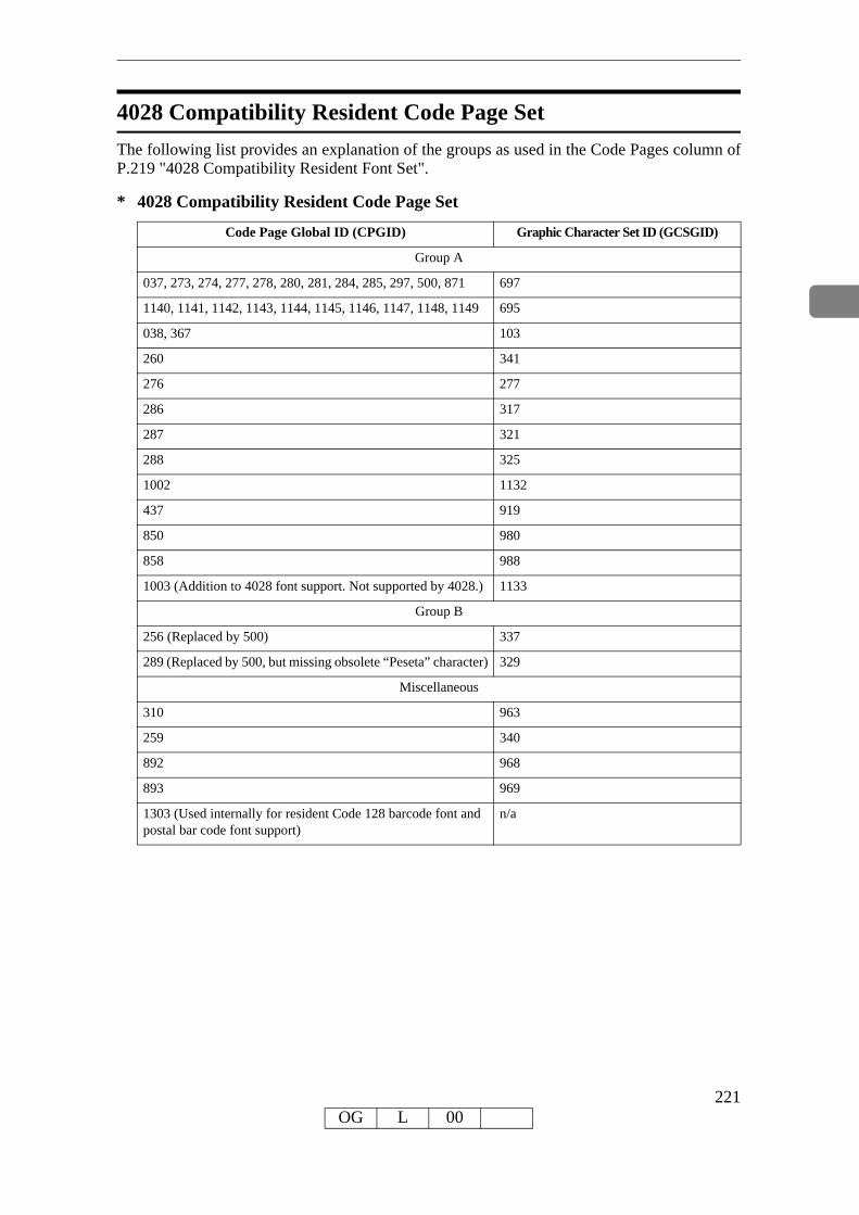
4028 Compatibility Resident Code Page SetThe following list provides an explanation of the groups as used in the Code Pages column of P.219 "4028 Compatibility Resident Font Set".
* 4028 Compatibility Resident Code Page Set
Code Page Global ID (CPGID) Graphic Character Set ID (GCSGID)
Group A
037, 273, 274, 277, 278, 280, 281, 284, 285, 297, 500, 871 697
1140, 1141, 1142, 1143, 1144, 1145, 1146, 1147, 1148, 1149 695
038, 367 103
260 341
276 277
286 317
287 321
288 325
1002 1132
437 919
850 980
858 988
1003 (Addition to 4028 font support. Not supported by 4028.) 1133
Group B
256 (Replaced by 500) 337
289 (Replaced by 500, but missing obsolete “Peseta” character) 329
Miscellaneous
310 963
259 340
892 968
893 969
1303 (Used internally for resident Code 128 barcode font and postal bar code font support)
n/a
221OG L 00

IBM Coordinated Font Set (IPDS)P.222 "Resident PSC Strategic Scalable Font Set 2" lists the scalable IBM Coordinated font set typefaces resident in the Printer and includes the valid FGID and code pages for each font.Where the IBM Core Interchange code pages are referenced in P.210 "IBM Core Interchange Resident Code Page Set", only the Latin 1 Country Extended, Latin 1 EBCDIC Publishing, Lat-in 1 ASCII and Latin EBCDIC DCF code pages are supported.
GCSGID Subsets
The following lists provides an a mapping of the valid subsets of the GCSGIDs listed for the PSC Strategic Font Set 2.
* Resident PSC Strategic Scalable Font Set 2
Typeface FGID GCSGID Font width Code Pages
APL 307 1304 Scalable 293, 310, 910
APL Bold 322 1304 Scalable 293, 310, 910
Boldface 20224 2041 Scalable See P.210 "IBM Core Inter-change Resident Code Page Set"
Gothic Text 304 2041 Scalable See P.210 "IBM Core Inter-change Resident Code Page Set"
Letter Gothic 400 2041 Scalable See P.210 "IBM Core Inter-change Resident Code Page Set"
Letter Gothic Bold 404 2041 Scalable See P.210 "IBM Core Inter-change Resident Code Page Set"
OCR A 305 968 Scalable 876, 892
OCR B 306 969 Scalable 877, 893
OCR B (with Euro) 306 1502 Scalable 877, 893
Prestige 432 2041 Scalable See P.210 "IBM Core Inter-change Resident Code Page Set"
Prestige Bold 318 2041 Scalable See P.210 "IBM Core Inter-change Resident Code Page Set"
Prestige Italic 319 2041 Scalable See P.210 "IBM Core Inter-change Resident Code Page Set"
Katakana Gothic 304 1306 Scalable 290, 897, 1027, 1041
222OG L 00

IBM Coordinated Font Set Code Page SetThe following list provide the GCSGIDs and CPGIDs for the individual code pages listed in the Code Pages column of P.222 "Resident PSC Strategic Scalable Font Set 2".
* IBM Coordinated Font Set Code Page Set
Code Page Global ID (CPGID) Graphic Character Set ID (GCSGID)
293 380
310 963
910 1113
876, 892 968
877, 893 969
877, 893 1502
290, 1027 1172
897 1164
1041 1187
* GCSGID Subsets for the Strategic Font Set 2
GCSGID Valid GCSGID Subsets
1304 0380, 0963, 1113
2039 0101, 0103, 0119, 0251, 0265, 0269, 0273, 0277, 0281, 0285, 0288, 0289, 0293, 0297, 0301, 0305, 0309, 0313, 0317, 0321, 0325, 0329, 0337, 0341, 0611, 0697, 0919, 0980, 0990, 0991, 0993, 0995, 1132, 1133, 1145, 1146, 1149, 1198, 1220, 1258, 1259, 1260
1306 0332, 1164, 1172, 1187
2041 0695, 0988, 1243, 1353, 1412, 2039
223OG L 00

IPDS Default Font
Factory SettingThe factory setting for the default font is Courier Roman Medium 10 pitch (12 point) using code page 037, version 1. The GRID for the default font is: FGID=416, GCSGID=697, CPGID=037, FontWidth=144 (CPI setting is 10.0). The default font may be changed by the op-erator using the printer's Web Utilities.The default font can be set for single byte fonts. It does not contain double byte font character set code pages.
224OG L 00

Selectable IPDS Default Font
To change the default font requires the use of the printer's Web Utilities. The printer's Web Util-ities will present menu choices for selecting the various parts of the font.The operator may select the default font using any or all of the Code Page (CPGID), Font (FGID), and Characters Per Inch (CPI) parameters. The available parameters will be listed in Groups to help identify valid/invalid combinations. An invalid combination will be resolved in-side the printer because the printer must have a valid default font. However, the parameter ad-justment will not be visible at the printer's Web Utilities. Detailed information listing the valid combinations and how to select them will be available with the printer.The selection is based upon a hierarchy: Code Page is highest, Font is next, and Characters Per Inch (CPI) is the lowest. Should an invalid combination be selected, the Code Page will over-ride Font and CPI, and Font will override CPI.There are 5 Groups, A-E, into which all the fonts, code pages, and widths fall. All combinations defined within a Group are valid. When internal modification is necessary, the following rules apply:• An invalid/unsupported CPGID becomes Code Page 037 (Group A).• An invalid/unsupported Characters Per Inch (CPI) becomes 10.0 CPI (which will translate
to 12 points).• For a Group A CPGID, an invalid/unsupported FGID becomes 416 Courier Roman Medi-
um.• For a Group B CPGID, the FGID is automatically 304 Gothic Katakana.• For a Group C CPGID, the FGID is automatically 305 OCR A. Characters Per Inch is 10.0
CPI.• For a Group D CPGID, the FGID is automatically 306 OCR B. Characters Per Inch is 10.0
CPI.• For a Group E CPGID, an invalid/unsupported FGID becomes 416 Courier Roman Medium.
Note• The 4028 compatibility fonts are a new addition to the printer's control panel selection.
This is necessary because some of these FGIDs are anamorphically scaled, and therefore cannot be correctly reproduced with just an AFP FGID and a CPI value.
These fonts are handled specially in that all of these FGIDs (except 5687, 5707, 5815, 5835) ignore the printer's control panel CPI value, because the FGID fully describes the font. In the case of the 4 typographic FGIDs, there are valid discreet sizes associated with them. If the cor-rect CPI values are not used, the printer will default to the nearest discrete size value. Tie goes to the smaller value.
Selectable Code PagesThe following code pages are selectable by the operator:
Code-Page/Group Code Page Description
500 A Belgium, Switzerland / International
037 A US, Canada, Netherlands, Portugal
038 A US English ASCII
225OG L 00

260 A Canadian French
273 A Austrian / German
274 A Belgium
276 A Canadian French (94 character set)
277 A Danish / Norwegian
278 A Finnish / Swedish
280 A Italian
281 A Japanese
284 A Spanish
285 A UK English
286 A Austrian / German (alternate)
287 A Danish / Norwegian (Alternate)
288 A Finnish / Swedish (Alternate)
297 A French
871 A Icelandic
1140 A US, Canada, Netherlands, Portugal (Euro)
1141 A Austrian, German (Euro)
1142 A Danish Norwegian (Euro)
1143 A Finnish, Swedish (Euro)
1144 A Italian (Euro)
1145 A Spanish (Euro)
1146 A UK English (Euro)
1147 A Catalan French (Euro)
1148 A Multinational (Euro)
1149 A Icelandic (Euro)
290 B Japanese / Katakana
892 C OCR - A
893 D OCR - B
420 E Arabic
423 E Greek
424 E Hebrew
870 E Latin 2 Multilingual
875 E Greek
880 E Cyrillic
905 E Turkish
1025 E Cyrillic (primary)
Code-Page/Group Code Page Description
226OG L 00
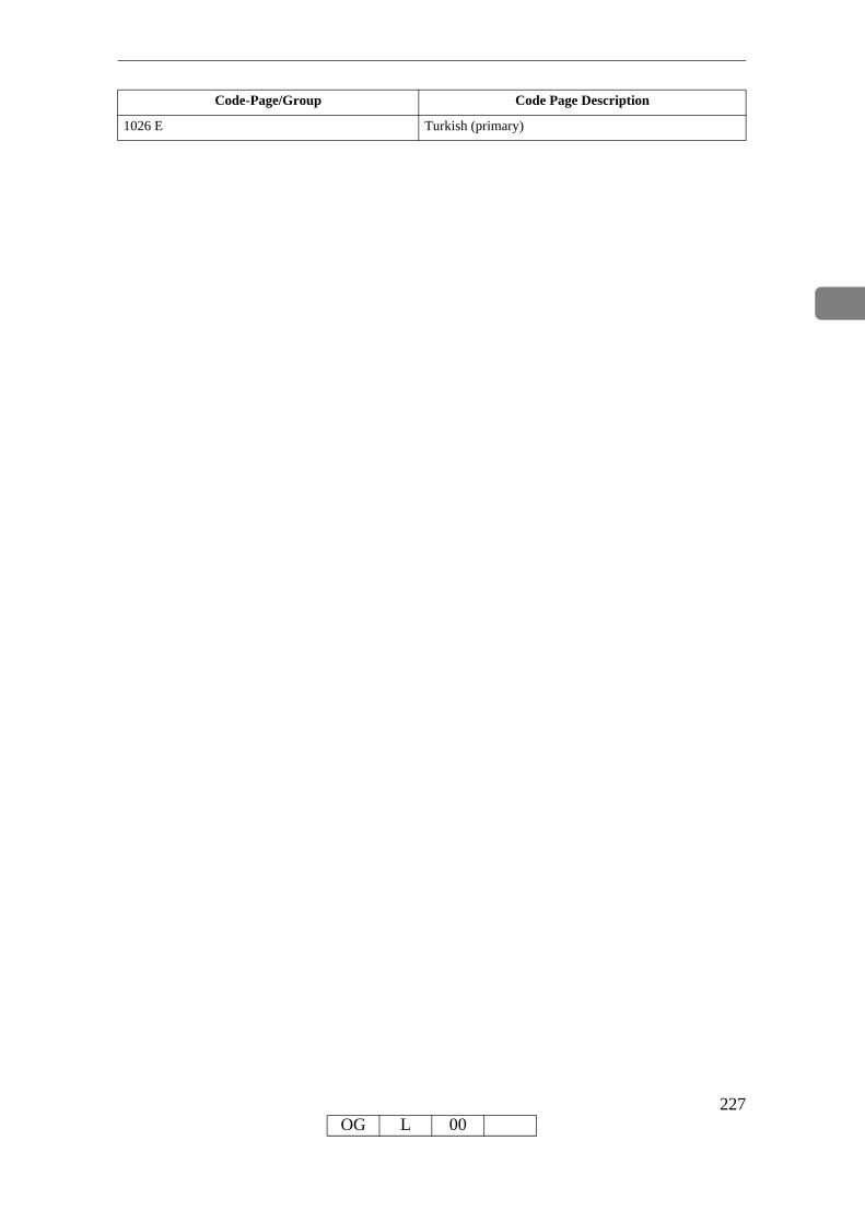
1026 E Turkish (primary)
Code-Page/Group Code Page Description
227OG L 00

Selectable FontsThe following fonts (FGID) are selectable by the operator:
FGID/Group FGID Description
2304 A, E Helvetica Roman/ITC Boutros Modern Rokaa/Narkiss Tam - Medium
2305 A, E Helvetica Roman/ITC Boutros Modern Rokaa/Narkiss Tam - Bold
2306 A, E Helvetica Roman/ITC Boutros Modern Rokaa/Narkiss Tam - Italic Medium
2307 A, E Helvetica Roman/ITC Boutros Modern Rokaa/Narkiss Tam - Italic Bold
2308 A, E Times New Roman/ITC Boutros Setting Rokaa/Narkissim - Medium
2309 A, E Times New Roman/ITC Boutros Setting Rokaa/Narkissim - Bold
2310 A, E Times New Roman/ITC Boutros Setting Rokaa/Narkissim - Italic Medium
2311 A, E Times New Roman/ITC Boutros Setting Rokaa/Narkissim - Italic Bold
416 A, E Courier Roman/Boutros Typing/Shalom - Medium
420 A, E Courier Roman/Boutros Typing/Shalom - Bold
424 A, E Courier Roman/Boutros Typing/Shalom - Italic Medium
428 A, E Courier Roman/Boutros Typing/Shalom - Italic Bold
20224 A Boldface
304 A Gothic Text
400 A Letter Gothic
404 A Letter Gothic Bold
432 A Prestige
318 A Prestige Bold
319 A Prestige Italic
304 B Katakana Gothic
305 C OCR A
306 D OCR B
228OG L 00

4028 Selectable FontsThe following 4028 fonts (FGID) are also selectable by the operator:
FGID/Group FGID Description
159 A Boldface (Proportional Space 12 pt., based on 10 CPI)
11 A Courier 10.0 CPI
85 A Courier 12.0 CPI
223 A Courier 15.0 CPI
254 A Courier 17.1 CPI
46 A Courier Bold 10.0 CPI
18 A Courier Italic 10.0 CPI
92 A Courier Italic 12.0 CPI
203 A Gothic Text 13.3 CPI
283 A Gothic Text 20.0 CPI
290 A Gothic Text 26.7 CPI
281 A Letter Gothic 20 CPI
19 C OCR A
03 D OCR B
12 A Prestige Pica 10.0 CPI
86 A Prestige Elite 12.0 CPI
221 A Prestige Elite 15.0 CPI
256 A Prestige Elite 17.1 CPI
111 A Prestige Elite Bold 12.0 CPI
112 A Prestige Elite Italic 12.0 CPI
5687 A Times Roman Typographic 6, 8, 10, 12, pt
5707 A Times Roman Typographic Bold 10, 12, 14, 18, 24 pt
5815 A Times Roman Typographic Italic 10, 12, pt
5835 A Times Roman Typographic Bold Italic 10, 12, pt
229OG L 00

Selectable Font WidthsThe following Font Widths (CPI) are selectable by the operator:
Group Range in characters per inch
A, B, E 5.0 CPI - 30.0 CPI, in increments of 0.1 CPI.
C, D 10.0 CPI.
4028 Fixed Width Ignored. Handled internally because the FGID defines the size.
5687 6 pt 20.0 CPI
5687 8 pt 15.1 CPI
5687 10 pt 11.9 CPI
5687 12 pt 10.0 CPI
5707 10 pt 11.9 CPI
5707 12 pt 10.0 CPI
5707 14 pt 8.6 CPI
5707 18 pt 6.7 CPI
5707 24 pt 5.0 CPI
5815 10 pt 11.9 CPI
5815 12 pt 10.0 CPI
5835 10 pt 11.9 CPI
5835 12 pt 10.0 CPI
Normally, IPDS Font Width is in terms of 1440ths of an inch (for example, 144, 120). However, printer's control panel Font Width selection is more easily understood (and more universally used) as Characters Per Inch. So the values will range from 5.0 cpi (Font Width 288) to 30.0 cpi (Font Width 48) in increments of 0.1 cpi.The resulting cpi will be translated internally to the nearest integer font width value. Since CPI is inherently a reciprocal, 0.1 cpi increments will be a non-linear font width progression. This should not prove a serious problem since default fonts for IPDS are not the primary selection path.An extra note is that font widths for fixed width fonts are calculated differently than for typo-graphic fonts.The vertical point size is the real common ground. So to get a 12 point size, a fixed width font will use a font width of 144; 10 cpi. A typographic font will use a font width of 80. To keep compatible sizes this is also translated from 10 cpi. The FGID defines which range to use. For further detail, refer to the LFE and/or AR command sections of the IPDS architecture spec.
IPDS Bar Code PrintingTo support the BCOCA tower for printing of bar codes, the OCR-A and OCR-B fonts and their corresponding code pages (892 and 893) must be resident in the printer. These are supported as shown in P.219 "4028 Compatibility Resident Font Set".Code page 1303 is also resident to be used for printing code 128 bar codes.
230OG L 00

IPDS Font BoldingThe Printer will accept the IPDS Load Font Equivalence command and support the bold and double strike bits for both resident Type 1 and loaded raster fonts. No other bits within the LFE flags byte are supported.The bold/double strike attributes are handled the same way within the printer. The function is provided by printing a text block multiple times, each time shifted an appropriate amount. Since the attributes are tied to the font LID and not the font resource, the font resource is not affected.
231OG L 00

232OG L 00

INDEXA
action codes, 165, 182applications
bar codes, 15graphics, 14images, 14IPDS, 8letter printing, 10overlays, 12page segments, 13
attributesprinting, 192
B
bar codesusing, 15
C
character IDsdefinition, 192
character image, 192character properties, 192Character set, 192character sets
definition, 192Coded font, 191coded fonts
definition, 191Code page, 192code page global identifier (CPGID)
definition, 195code pages, 192, 193
definion, 192printer configuration, 196selecting, 196
code points, 193code tables
exception, 168commands, 35
device control (DC/1), 39initialization defaults, 35initialization sequence, 38
CPGID, 195
D
data stream classes, 163data stream commands, 196
font selection, 196IPDS, 196
definitionscharacter IDs, 192character set, 191coded font, 191code page, 191font, 191GCSGID, 195
device control (DC/1), 39
E
error reporting and recovery, 39exception code tables, 168
page and copy counter adjustment, 185page counter adjustment, 182
exception (error)action codes, 165alternate actions, 162classes, 167code tables, 168data stream, 163handling control, 162presentation processing, 162reporting, 162reporting codes, 166rules, 161sense byte, 165
233OG L 00

F
fixed-pitch fonts, 195font definitions
code page, 195font global ID (FGID), 195font width, 196point size, 196posture, 195spacing, 195spacing fixed-pitch, 195spacing proportionally
spaced machine fonts, 195spacing typographic, 195typeface, 196typeface, 196weight, 196
font global ID (FGID), 195fonts
appearance, 193fixed-pitch, 195height, 195pitch, 195points, 196proportionally spaced machine (PSM) pitch,
195selection, 196typographic, 195
font selection, 196general information, 159IPDS, 197
font structure, 191font values (see metrics), 192
G
GCSGID,definition, 195
GDDM, 8global identifiers
CPGID, 195global identifiers (continued)
GCSGID, 195graphic character set global identifier (GCSGID)
definition, 195graphics, 14
H
hex values, 193How to Read This Manual, 6
I
imagecharacter, 193
images, 14initialization defaults, 35initialization sequence, 38IPDS, 8
capabilities, 8introduction, 8software, 8
IPDS font selection, 196
L
language code pages, 194letter
preparation, 10printing, 10
N
national language, 194national language code pages, 194
O
OS/400 font terminology, 194overlays, 12
234OG L 00
P
page and copy counter adjexceptions, 185
page counter adjexceptions, 185
page counter adjustment, 182page segments, 13pitch, 195points, 196printable characters, 193printer configuration
code pages, 196printing attributes, 192printing letters, 10properties
character, 192proportionally spaced machine (PSM) fonts, 195
R
reporting, 161reporting and recovery
error, 161rules, 161
S
segmentspage, 13
sense byte information, 169software
IPDS, 8SSP, 8System i font terminology, 194
T
type size, 196typographic fonts, 195
235OG L 00

Part Number: 55Y6982
Printed in USA
S550-1193-01
(1P)
P/N:
55Y6
982