Influence of tool geometry and numerical parameters when modeling orthogonal cutting of LFRP...
12
Influence of tool geometry and numerical parameters when modeling orthogonal cutting of LFRP composites X. Soldani a , C. Santiuste b , A. Muñoz-Sánchez a , M.H. Miguélez a,⇑ a Department of Mechanical Engineering, Universidad Carlos III de Madrid, Avda. de la Universidad 30, 28911 Leganés, Madrid, Spain b Department of Continuum Mechanics and Structural Analysis, Universidad Carlos III de Madrid, Avda. de la Universidad 30, 28911 Leganés, Madrid, Spain Keywords: Glass LFRP C. Finite element analysis (FEA) C. Numerical analysis E. Cutting A. Glass fibers The first objective of this paper is to analyze the influence of mesh size and shape in finite element mod- eling of composite cutting. Also the influence of the level of energy needed to reach complete breakage of the element is considered. The statement of this level of energy is crucial to simulate the material behav- ior. On the other hand geometrical characteristics of the tool have significant influence on machining pro- cesses. The second objective of the present work is to advance in the knowledge concerning tool geometry and its effect in composite cutting. A two-dimensional finite element model of orthogonal cutting has been developed and validated for Glass LFRP composite, comparing with experimental results presented in scientific literature. It was dem- onstrated that both numerical parameters and tool geometry influence the predicted chip morphology and machining induced damage. 1. Introduction Long Fiber Reinforced Polymer (LFRP) composites are suitable for a wide range of applications in aeronautical, automotive, mar- ine and sporting industries. Their attractive physical and mechan- ical properties lead to increasing application fields of this materials family. The components based on LFRP composites are usually made to the final size of the desired product; however, some machining operations are commonly needed to achieve work-piece requirements. Machining operations on LFRP composites in industry involves considerable difficulties due to the presence of long fibers and the risk of inducing damage during the cutting process [1]. Experimental research in the field of composite cutting is not only expensive in terms of time and cost. Also the health hazards associated to the presence of fibers in the chip removed reduces the possibility to carry out extensive experimental research on machining of LFRP composites. The interpretation of results is also difficult due to the complex- ity of the cutting process itself and because of the anisotropy of the composite. Industrial machining processes involves oblique cut- ting, however, orthogonal cutting is commonly the objective of simulations in machining numerical studies, due to its simplicity and utility to obtain information about difficult to measure vari- ables. Despite of its limitations it is possible to obtain interesting information concerning, for instance, chip morphology, subsurface damage, influence of fiber orientation and the role of tool geome- try. On the other hand the development of complex models for ob- lique cutting requires the use of three dimensional approaches involving elevated computational cost. It is necessary to advance in the knowledge of simplified cutting process prior to develop three dimensional approaches. The necessity to simplify the process in order to understand the basic phenomena involved in the cutting operation, has motivated the development of several works focused on the study of orthog- onal cutting of LFRP composites [2–12]. Experimental works presented in [2–4] have studied the effect of fiber orientation, depth of cut, rake angle and cutting edge ra- dius. Experimental results obtained in these works have been widely used to validate numerical models in scientific literature. Also Finite Element (FE) has been used to analyze orthogonal cutting of LFRP composites using macro and micro mechanical ap- proaches [5–13]. Combined micro–macro approach was applied to analyze orthogonal cutting of composite in [5,6], obtaining good prediction of cutting forces. Micro mechanical modeling of both glass and car- bon fiber reinforced polymer composite has been developed re- cently in [7]. De-cohesion phenomena in matrix–fiber interface was analyzed and it was demonstrated the influence of the fiber orientation on the failure mechanisms. Macro-mechanical approaches have used to model the compos- ite as an anisotropic homogeneous material. Two dimensional ap- proaches commonly involve the hypothesis of unidirectional fiber orientation. The earliest study of orthogonal cutting of unidirec- tional composites based on finite element was presented by Arola ⇑ Corresponding author. Tel.: +34 91 624 94 02; fax: +34 91 624 94 30. E-mail address: [email protected] (M.H. Miguélez). 1
Transcript of Influence of tool geometry and numerical parameters when modeling orthogonal cutting of LFRP...

Influence of tool geometry and numerical parameters when modelingorthogonal cutting of LFRP composites
X. Soldani a, C. Santiuste b, A. Muñoz-Sánchez a, M.H. Miguélez a,⇑a Department of Mechanical Engineering, Universidad Carlos III de Madrid, Avda. de la Universidad 30, 28911 Leganés, Madrid, Spainb Department of Continuum Mechanics and Structural Analysis, Universidad Carlos III de Madrid, Avda. de la Universidad 30, 28911 Leganés, Madrid, Spain
Keywords:Glass LFRP
The first objective of this paper is to analyze the influence of mesh size and shape in finite element mod-eling of composite cutting. Also the influence of the level of energy needed to reach complete breakage ofthe element is considered. The statement of this level of energy is crucial to simulate the material behav-ior. On the other hand geometrical characteristics of the tool have significant influence on machining pro-cesses. The second objective of the present work is to advance in the knowledge concerning toolgeometry and its effect in composite cutting.
A two-dimensional finite element model of orthogonal cutting has been developed and validated for
FRP) ceronauractivelicationLFRP composites are usually The necessity to simplify the process in order to understand the
C. Finite element analysis (FEA)C. Numerical analysisE. CuttingA. Glass fibers
1. Introduction
Long Fiber Reinforced Polymer (Lfor a wide range of applications in aine and sporting industries. Their attical properties lead to increasing appfamily. The components based on
Glass LFRP composite, comparing with experimental results presented in scientific literature. It was dem-onstrated that both numerical parameters and tool geometry influence the predicted chip morphologyand machining induced damage.
omposites are suitabletical, automotive, mar-physical and mechan-fields of this materials
damage, influence of fiber orientation and the role of tool geome-try. On the other hand the development of complex models for ob-lique cutting requires the use of three dimensional approachesinvolving elevated computational cost. It is necessary to advancein the knowledge of simplified cutting process prior to developthree dimensional approaches.
made to the final size of the desired product; however, somemachining operations are commonly needed to achieve work-piece
basic phenomena involved in the cutting operation, has motivatedthe development of several works focused on the study of orthog-
requirements.Machining operations on LFRP composites in industry involves
considerable difficulties due to the presence of long fibers andthe risk of inducing damage during the cutting process [1].
Experimental research in the field of composite cutting is notonly expensive in terms of time and cost. Also the health hazardsassociated to the presence of fibers in the chip removed reducesthe possibility to carry out extensive experimental research onmachining of LFRP composites.
The interpretation of results is also difficult due to the complex-ity of the cutting process itself and because of the anisotropy of thecomposite. Industrial machining processes involves oblique cut-ting, however, orthogonal cutting is commonly the objective ofsimulations in machining numerical studies, due to its simplicityand utility to obtain information about difficult to measure vari-ables. Despite of its limitations it is possible to obtain interestinginformation concerning, for instance, chip morphology, subsurface
⇑ Corresponding author. Tel.: +34 91 624 94 02; fax: +34 91 624 94 30.E-mail address: [email protected] (M.H. Miguélez).
1
onal cutting of LFRP composites [2–12].Experimental works presented in [2–4] have studied the effect
of fiber orientation, depth of cut, rake angle and cutting edge ra-dius. Experimental results obtained in these works have beenwidely used to validate numerical models in scientific literature.
Also Finite Element (FE) has been used to analyze orthogonalcutting of LFRP composites using macro and micro mechanical ap-proaches [5–13].
Combined micro–macro approach was applied to analyzeorthogonal cutting of composite in [5,6], obtaining good predictionof cutting forces. Micro mechanical modeling of both glass and car-bon fiber reinforced polymer composite has been developed re-cently in [7]. De-cohesion phenomena in matrix–fiber interfacewas analyzed and it was demonstrated the influence of the fiberorientation on the failure mechanisms.
Macro-mechanical approaches have used to model the compos-ite as an anisotropic homogeneous material. Two dimensional ap-proaches commonly involve the hypothesis of unidirectional fiberorientation. The earliest study of orthogonal cutting of unidirec-tional composites based on finite element was presented by Arola
Cita bibliográfica
Published in: Composites Part A: Applied Science and Manufacturing, 42(9), 2011, 1205-1216
and Ramulu [8]. Failure mechanism based on fiber–matrix crackingwas implemented and the influence of fiber orientation for differ-ent LFRP composites was analyzed by Ramesh et al. [9]. It wasfound that the load needed to induce failure depended on the fiberorientation. Both two-dimensional (2D) and three-dimensional(3D) approaches were used by Mahdi and Zhang [10,11] to simu-late composite cutting. 2D analysis reproduced an equivalenthomogeneous material predicting cutting forces of LFRP compositedepending on the fiber orientation. 3D approach simulated a com-posite cell based on perfectly bonded constituents (fiber and ma-trix). The influence of tool geometry on cutting forces andsubsurface damage was analyzed by Arola et al. [12] focusing onorthogonal machining of unidirectional LFRPs. In general thesestudies showed good approximation to experimental cutting forceshowever, thrust forces were poorly predicted. In a recent numeri-cal work developed by the authors [13], the mechanism of chip for-mation of both glass and carbon LFRP composites have beencompared.
A new approach of modeling of orthogonal cutting of carbonLFRP using discrete element method (DEM) has been presentedin [14]. The observation of the chip formation using a high speedvideo camera made possible to validate qualitatively the resultsof numerical simulation by discrete elements. A recent work [15]has focused on the development of the analytical foundation fororthogonal cutting of FRP laminates. The study focused on theunderstanding of the implications of the subsurface stresses andassociated damage during machining, provided a framework forstudying the subsurface stress fields during edge trimming of FRPs.
The influence of numerical parameters of the model (such asmesh size and shape) has been extensively analyzed in differentworks focusing on metal cutting (see for instance Refs. [16–18]).Although macroscopic results such as cutting forces are not consid-erably affected by these parameters, the local results depending onlocalization phenomena are strongly dependent on mesh size andshape. For instance, the prediction of segmentation during cuttingof thermo-resistant alloys can be achieved with Lagrangian formu-lation when an appropriate mesh is designed [18,19].
Despite of the interest to properly define size and mesh of thenumerical model, it is not easy to found works analyzing the effectof numerical parameters when simulating composite cutting. Thefirst objective of this paper is to study the influence of mesh sizeand shape in cutting forces, chip morphology and damage. Alsothe influence of the level of energy needed to reach completebreakage of the element is considered. The statement of this levelof energy is crucial to simulate the material behavior: when low le-vel of energy is implemented the element is eroded just after thedamage onset, while high level of energy allows high deformationof the element before total breakage. Thus it is possible to distin-guish between ductile composite materials, showing progressivefailure; and brittle composite materials, presenting sudden break-age, not only in machining processes, also when experiencing otherdynamic loads [13]. Although it could not be considered a purelynumerical parameter, since it is representative of mechanicalbehavior of the composite, it is difficult to find precise informationabout its value, and thus it is sometimes used as a tuning parame-ter for modeling process.
On the other hand geometrical characteristics of the tool havesignificant influence on machining processes. The rake angle is re-lated with the robustness of the tool and also with the surfacequality of the workpiece. Tool geometry was found to have signif-icant influence on the frequency characteristics of measured forcesignal in orthogonal cutting of glass fiber reinforced composites[20]. The cutting edge radius, always larger than zero even in thecase of a sharp new tool, also influences the cutting processes.The rounding of the tool nose has been observed during orthogonalcutting of unidirectional glass–reinforced plastics when the cutting
2
speed was very low [21]. The influence of cutting edge radius isespecially important when small values of the feed are consideredand has been extensively studied in metal cutting. The secondobjective of the present work is to advance in the knowledge con-cerning tool geometry and its influence in composite cutting.
The work is focused on orthogonal cutting of LFRP. A two-dimensional finite element model has been developed. The modelwas validated for Glass LFRP comparing with experimental resultspresented in scientific literature [3]. The description of the modeland the study of the results sensitivity with the mesh size are pre-sented in Section 2. Numerical results concerning the influence ofmesh orientation, breakage energy and tool geometry are summa-rized and discussed in Section 3. Conclusions of the work are pre-sented in Section 4.
2. Numerical modeling
2.1. Description of the basic model: geometry, contact, meshing andanalysis
The basic model is described in detail in [13] and it is brieflysummarized in this section. The plane stress model was developedusing the commercial finite element code ABAQUS/Explicit. Dy-namic explicit analysis was performed with plane stress, quadrilat-eral, linearly interpolated, elements, with reduced integration andautomatic hourglass control (CPS4R in ABAQUS/Explicit notation[22]).
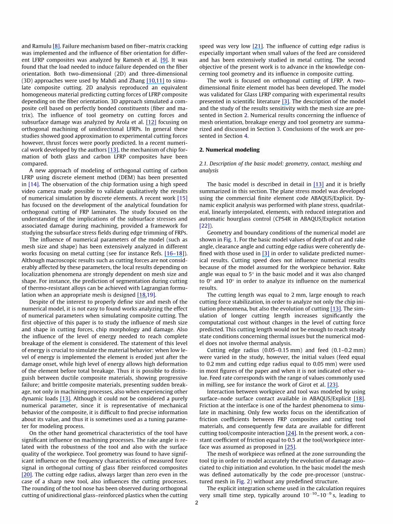
Geometry and boundary conditions of the numerical model areshown in Fig. 1. For the basic model values of depth of cut and rakeangle, clearance angle and cutting edge radius were coherently de-fined with those used in [3] in order to validate predicted numer-ical results. Cutting speed does not influence numerical resultsbecause of the model assumed for the workpiece behavior. Rakeangle was equal to 5� in the basic model and it was also changedto 0� and 10� in order to analyze its influence on the numericalresults.
The cutting length was equal to 2 mm, large enough to reachcutting force stabilization, in order to analyze not only the chip ini-tiation phenomena, but also the evolution of cutting [13]. The sim-ulation of longer cutting length increases significantly thecomputational cost without changes in the level of cutting forcepredicted. This cutting length would not be enough to reach steadystate conditions concerning thermal issues but the numerical mod-el does not involve thermal analysis.
Cutting edge radius (0.05–0.15 mm) and feed (0.1–0.2 mm)were varied in the study, however, the initial values (feed equalto 0.2 mm and cutting edge radius equal to 0.05 mm) were usedin most figures of the paper and when it is not indicated other va-lue. Feed rate corresponds with the range of values commonly usedin milling, see for instance the work of Girot et al. [23].
Interaction between workpiece and tool was modeled by usingsurface–node surface contact available in ABAQUS/Explicit [18].Friction at the interface is one of the hardest phenomena to simu-late in machining. Only few works focus on the identification offriction coefficients between FRP composites and cutting toolmaterials, and consequently few data are available for differentcutting tool/composite interaction [24]. In the present work, a con-stant coefficient of friction equal to 0.5 at the tool/workpiece inter-face was assumed as proposed in [25].
The mesh of workpiece was refined at the zone surrounding thetool tip in order to model accurately the evolution of damage asso-ciated to chip initiation and evolution. In the basic model the meshwas defined automatically by the code pre-processor (unstruc-tured mesh in Fig. 2) without any predefined structure.
The explicit integration scheme used in the calculation requiresvery small time step, typically around 10�10–10�9 s, leading to
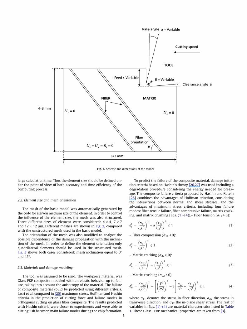
Fig. 1. Scheme and dimensions of the model.
large calculation time. Thus the element size should be defined un-der the point of view of both accuracy and time efficiency of thecomputing process.
2.2. Element size and mesh orientation
The mesh of the basic model was automatically generated bythe code for a given medium size of the element. In order to controlthe influence of the element size, the mesh was also structured.Three different sizes of element were considered: 4 � 4, 7 � 7and 12 � 12 lm. Different meshes are shown in Fig. 2, comparedwith the unstructured mesh used in the basic model.
The orientation of the mesh was also modified to analyze thepossible dependence of the damage propagation with the inclina-tion of the mesh. In order to define the element orientation onlyquadrilateral elements should be used in the structured mesh.Fig. 3 shows both cases considered: mesh inclination equal to 0�and 45�.
2.3. Materials and damage modeling
The tool was assumed to be rigid. The workpiece material wasGlass FRP composite modeled with an elastic behavior up to fail-ure, taking into account the anisotropy of the material. The failureof composite material could be predicted using different criteria.Lasri et al. compared in [25] maximum stress, Hoffman and Hashincriteria in the prediction of cutting force and failure modes inorthogonal cutting on glass fiber composite. The results predictedwith Hashin criteria were closer to experiments and were able todistinguish between main failure modes during the chip formation.
3
To predict the failure of the composite material, damage initia-tion criteria based on Hashin’s theory [26,27] was used including adegradation procedure considering the energy needed for break-age. The composite failure criteria proposed by Hashin and Rotem[26] combines the advantages of Hoffman criterion, consideringthe interactions between normal and shear stresses, and theadvantages of maximum stress criteria, including four failuremodes: fiber tensile failure, fiber compressive failure, matrix crack-ing, and matrix crushing (Eqs. (1)–(4)).– Fiber tension (r11 > 0):
dtf ¼
r11
XT
� �2
þ as12
SL
� �2
6 1 ð1Þ
– Fiber compression (r11 < 0):
dcf ¼
r11
XC
� �2
6 1 ð2Þ
– Matrix cracking (r22 > 0):
dtm ¼
r22
YT
� �2
þ s12
SL
� �2
6 1 ð3Þ
– Matrix crushing (r22 < 0):
dcm ¼
r22
2ST
� �2
þ YC
2ST
!2
� 1
24
35r22
YC þs12
SL
� �2
6 1 ð4Þ
where r11 denotes the stress in fiber direction, r22 the stress intransverse direction, and r12 the in-plane shear stress. The rest ofvariables in Eqs. (1)–(4) are material characteristics listed in Table1. These Glass LFRP mechanical properties are taken from [3].
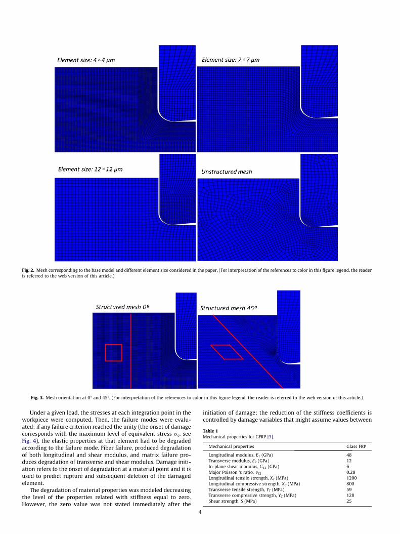
Fig. 2. Mesh corresponding to the base model and different element size considered in the paper. (For interpretation of the references to color in this figure legend, the readeris referred to the web version of this article.)
Fig. 3. Mesh orientation at 0� and 45�. (For interpretation of the references to color in this figure legend, the reader is referred to the web version of this article.)
Table 1Mechanical properties for GFRP [3].
Mechanical properties Glass FRP
Longitudinal modulus, E1 (GPa) 48Transverse modulus, E2 (GPa) 12In-plane shear modulus, G12 (GPa) 6Major Poisson ’s ratio, v12 0.28Longitudinal tensile strength, XT (MPa) 1200Longitudinal compressive strength, XC (MPa) 800Transverse tensile strength, YT (MPa) 59Transverse compressive strength, YC (MPa) 128Shear strength, S (MPa) 25
Under a given load, the stresses at each integration point in theworkpiece were computed. Then, the failure modes were evalu-ated; if any failure criterion reached the unity (the onset of damagecorresponds with the maximum level of equivalent stress rc, seeFig. 4), the elastic properties at that element had to be degradedaccording to the failure mode. Fiber failure, produced degradationof both longitudinal and shear modulus, and matrix failure pro-duces degradation of transverse and shear modulus. Damage initi-ation refers to the onset of degradation at a material point and it isused to predict rupture and subsequent deletion of the damagedelement.
The degradation of material properties was modeled decreasingthe level of the properties related with stiffness equal to zero.However, the zero value was not stated immediately after the
4
initiation of damage; the reduction of the stiffness coefficients iscontrolled by damage variables that might assume values between
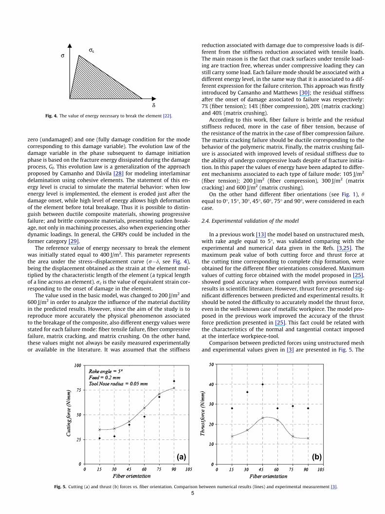
Fig. 4. The value of energy necessary to break the element [22].
zero (undamaged) and one (fully damage condition for the modecorresponding to this damage variable). The evolution law of thedamage variable in the phase subsequent to damage initiationphase is based on the fracture energy dissipated during the damageprocess, GI. This evolution law is a generalization of the approachproposed by Camanho and Dávila [28] for modeling interlaminardelamination using cohesive elements. The statement of this en-ergy level is crucial to simulate the material behavior: when lowenergy level is implemented, the element is eroded just after thedamage onset, while high level of energy allows high deformationof the element before total breakage. Thus it is possible to distin-guish between ductile composite materials, showing progressivefailure; and brittle composite materials, presenting sudden break-age, not only in machining processes, also when experiencing otherdynamic loadings. In general, the GFRPs could be included in theformer category [29].
The reference value of energy necessary to break the elementwas initially stated equal to 400 J/m2. This parameter representsthe area under the stress–displacement curve (r�d, see Fig. 4),being the displacement obtained as the strain at the element mul-tiplied by the characteristic length of the element (a typical lengthof a line across an element). rc is the value of equivalent strain cor-responding to the onset of damage in the element.
The value used in the basic model, was changed to 200 J/m2 and600 J/m2 in order to analyze the influence of the material ductilityin the predicted results. However, since the aim of the study is toreproduce more accurately the physical phenomenon associatedto the breakage of the composite, also different energy values werestated for each failure mode: fiber tensile failure, fiber compressivefailure, matrix cracking, and matrix crushing. On the other hand,these values might not always be easily measured experimentallyor available in the literature. It was assumed that the stiffness
Fig. 5. Cutting (a) and thrust (b) forces vs. fiber orientation. Comparison b
5
reduction associated with damage due to compressive loads is dif-ferent from the stiffness reduction associated with tensile loads.The main reason is the fact that crack surfaces under tensile load-ing are traction free, whereas under compressive loading they canstill carry some load. Each failure mode should be associated with adifferent energy level, in the same way that it is associated to a dif-ferent expression for the failure criterion. This approach was firstlyintroduced by Camanho and Matthews [30]; the residual stiffnessafter the onset of damage associated to failure was respectively:7% (fiber tension); 14% (fiber compression), 20% (matrix cracking)and 40% (matrix crushing).
According to this work, fiber failure is brittle and the residualstiffness reduced, more in the case of fiber tension, because ofthe resistance of the matrix in the case of fiber compression failure.The matrix cracking failure should be ductile corresponding to thebehavior of the polymeric matrix. Finally, the matrix crushing fail-ure is associated with improved levels of residual stiffness due tothe ability of undergo compressive loads despite of fracture initia-tion. In this paper the values of energy have been adapted to differ-ent mechanisms associated to each type of failure mode: 105 J/m2
(fiber tension); 200 J/m2 (fiber compression), 300 J/m2 (matrixcracking) and 600 J/m2 (matrix crushing).
On the other hand different fiber orientations (see Fig. 1), hequal to 0�, 15�, 30�, 45�, 60�, 75� and 90�, were considered in eachcase.
2.4. Experimental validation of the model
In a previous work [13] the model based on unstructured mesh,with rake angle equal to 5�, was validated comparing with theexperimental and numerical data given in the Refs. [3,25]. Themaximum peak value of both cutting force and thrust force atthe cutting time corresponding to complete chip formation, wereobtained for the different fiber orientations considered. Maximumvalues of cutting force obtained with the model proposed in [25],showed good accuracy when compared with previous numericalresults in scientific literature. However, thrust force presented sig-nificant differences between predicted and experimental results. Itshould be noted the difficulty to accurately model the thrust force,even in the well-known case of metallic workpiece. The model pro-posed in the previous work improved the accuracy of the thrustforce prediction presented in [25]. This fact could be related withthe characteristics of the normal and tangential contact imposedat the interface workpiece-tool.
Comparison between predicted forces using unstructured meshand experimental values given in [3] are presented in Fig. 5. The
etween numerical results (lines) and experimental measurement [3].
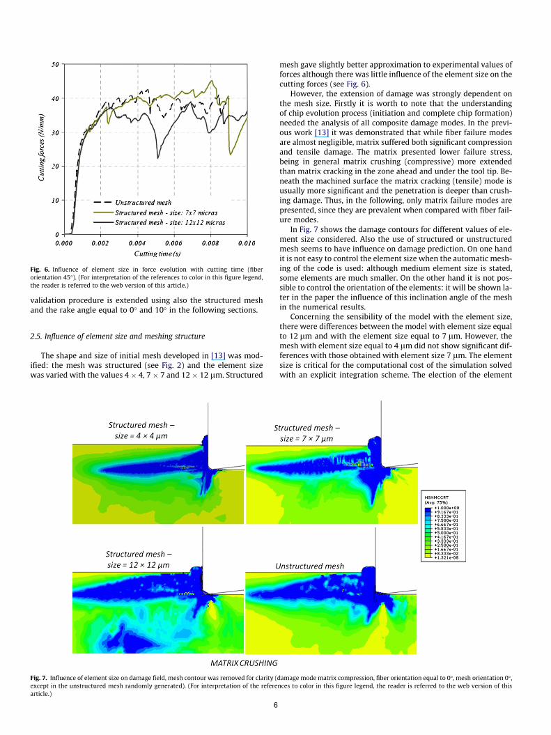
Fig. 6. Influence of element size in force evolution with cutting time (fiberorientation 45�). (For interpretation of the references to color in this figure legend,the reader is referred to the web version of this article.)
validation procedure is extended using also the structured meshand the rake angle equal to 0� and 10� in the following sections.
2.5. Influence of element size and meshing structure
The shape and size of initial mesh developed in [13] was mod-ified: the mesh was structured (see Fig. 2) and the element sizewas varied with the values 4 � 4, 7 � 7 and 12 � 12 lm. Structured
Fig. 7. Influence of element size on damage field, mesh contour was removed for clarity (except in the unstructured mesh randomly generated). (For interpretation of the referearticle.)
6
mesh gave slightly better approximation to experimental values offorces although there was little influence of the element size on thecutting forces (see Fig. 6).
However, the extension of damage was strongly dependent onthe mesh size. Firstly it is worth to note that the understandingof chip evolution process (initiation and complete chip formation)needed the analysis of all composite damage modes. In the previ-ous work [13] it was demonstrated that while fiber failure modesare almost negligible, matrix suffered both significant compressionand tensile damage. The matrix presented lower failure stress,being in general matrix crushing (compressive) more extendedthan matrix cracking in the zone ahead and under the tool tip. Be-neath the machined surface the matrix cracking (tensile) mode isusually more significant and the penetration is deeper than crush-ing damage. Thus, in the following, only matrix failure modes arepresented, since they are prevalent when compared with fiber fail-ure modes.
In Fig. 7 shows the damage contours for different values of ele-ment size considered. Also the use of structured or unstructuredmesh seems to have influence on damage prediction. On one handit is not easy to control the element size when the automatic mesh-ing of the code is used: although medium element size is stated,some elements are much smaller. On the other hand it is not pos-sible to control the orientation of the elements: it will be shown la-ter in the paper the influence of this inclination angle of the meshin the numerical results.
Concerning the sensibility of the model with the element size,there were differences between the model with element size equalto 12 lm and with the element size equal to 7 lm. However, themesh with element size equal to 4 lm did not show significant dif-ferences with those obtained with element size 7 lm. The elementsize is critical for the computational cost of the simulation solvedwith an explicit integration scheme. The election of the element
damage mode matrix compression, fiber orientation equal to 0�, mesh orientation 0�,nces to color in this figure legend, the reader is referred to the web version of this

Fig. 8. Cutting (a) and thrust force (b) vs. fiber orientation predicted width unstructured and structured mesh (7 mm, mesh orientation 0�) and experimental values given in[3] for rake angle equal to 5�.
size should be stated ensuring equilibrium between computationalefficiency and precision of the model.
In the following, all calculations are based on element size equalto 7 � 7 lm and structured mesh, just to ensure the comparabilitybetween the obtained results: influence of orientation, energy andgeometrical parameters of the tool.
2.6. Extension of validation
Numerical results obtained with the modified mesh were com-pared with those given by Nayak et al. [3]. The rake angle was sta-ted equal to 5�, both unstructured and structured with elementsize equal to 7 � 7 lm meshing were considered. Firstly the cut-ting and thrust forces were compared in Fig. 8. Both models basedon unstructured and structured mesh showed reasonably accuracyin the prediction of cutting and trust forces. The use of a structuredmesh improved slightly the predictions in the case of fiber orienta-tion lying in the range 15�–60�.
3. Numerical results and discussion
3.1. Mesh orientation
With the objective of analyzing the effect of mesh inclination onthe numerical results, the mesh structured horizontally (size7 � 7 lm), was modified giving an inclination angle equal to 45�(see Fig. 3). This configuration of the mesh has been used in simu-lation of metal cutting for the analysis of segmentation [18,19]. Inthat case, the best configuration for modeling localization is impos-ing an angle of inclination of the mesh close to the shear angle. Nostudy of the influence of mesh configuration has been found con-cerning macroscopic modeling of composite cutting. However, itis well known that the damage distribution is strongly influencedby the fiber orientation and tends to extend along the fiber. Itseems to be interesting to link the fiber angle and the mesh incli-nation, thus simulations with fiber angle equal to 0�, 45� and 90�,were performed with horizontal and mesh inclined to 45�.
As was explained in Section 2 concerning model development,plane stress, quadrilateral, linearly interpolated, elements, with re-duced integration and automatic hourglass control (CPS4R) wereused in the analysis. The reduced integration scheme is based onthe uniform strain formulation [31]. In this method, the elementstrain is assumed to be given by the average strain over the ele-ment. Since the elements involved are constant-strain elements,they are unable to resolve the corresponding strain gradient in
7
their interiors. Hashin failure criteria (Eqs. (1)–(4)) are formulatedin local axis coincident with fiber orientation (direction 1) andorthogonal (direction 2). The failure criterion depends on the strainthrough the stresses and thus, the damage prediction is influencedby the orientation of the element. It should be noticed that whenunstructured mesh is considered and the elements are randomlyoriented the damage propagation along fiber direction is more dif-ficult. In contrast, the strain field can vary from one to the nextacross the element boundary, facilitating the resolution of straingradients associated with damage propagation in the case of paral-lel mesh. In consequence the predicted damage is affected whenthe orientation of the mesh is coincident with the orientation ofthe fiber (see damage fields in Fig. 9) and tends to extend furtherin both directions: the fiber and orthogonal.
3.2. Influence of energy needed for breakage
As was explained before, the energy needed to complete break-age of one element, being a parameter characterizing the ductilityof the composite, was varied from 200, 400 and 600 J/m2 and alsoenergy variable with the damage mode was implemented.
The forces are not clearly dependent on the level of energy. Forfiber angle equal to 0� and 45�, the cutting forces showed approx-imately the same value irrespective of the energy value. For the fi-ber angle equal to 90� the cutting force was slightly increased withthe energy value.
However, both the crushing and cracking damages increasedwith the increment of energy required for breakage causing subse-quent enhancement of the material ductility (see Fig. 10). Whenthe onset of damage is induced in an element, it is deformed upto the level of energy allowed. Thus the lower the value of energy(brittle composite), the greater the trend to originate catastrophicfailure with no progression of the damage: the elements do notsuffer significant deformation, thus they break just after the dam-age onset, restraining the damage extension on the workpiece [28].Under the point of view of damage extension, it is more favorablethe brittle behavior, since enhanced ductility of the material is re-lated with increased level of damage.
The mechanism of chip formation is also highly sensitive to thecritical level of energy. The lower value of energy (200 J/m2) origi-nates a small chip and the deformation of the mesh is concentratedin a narrow area around the primary zone (approximately parallelto the fiber orientation). Similar chip morphology can be observedin [14] in the orthogonal cutting of CFRP, it is worth to note thatcarbon composite exhibits brittle behavior that should be
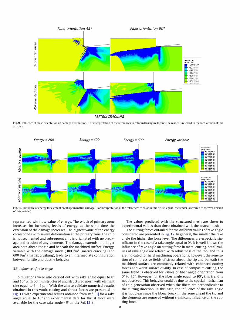
Fig. 9. Influence of mesh orientation on damage distribution. (For interpretation of the references to color in this figure legend, the reader is referred to the web version of thisarticle.)
Fig. 10. Influence of energy for element breakage in matrix damage. (For interpretation of the references to color in this figure legend, the reader is referred to the web versionof this article.)
represented with low value of energy. The width of primary zoneincreases for increasing levels of energy, at the same time theextension of the damage increases. The highest value of the energycorresponds with severe deformation at the primary zone, the chipis not segmented and subsequent chip is originated with no break-age and erosion of any elements. The damage extends in a largerarea both ahead the tip and beneath the machined surface. Energy,variable with the damage mode (300 J/m2 (matrix cracking) and600 J/m2 (matrix crushing), leads to an intermediate configurationbetween brittle and ductile behavior.
3.3. Influence of rake angle
Simulations were also carried out with rake angle equal to 0�and 10� with both unstructured and structured mesh with elementsize equal to 7 � 7 lm. With the aim to validate numerical resultsobtained in this work, cutting and thrust forces are presented inFig. 11 with experimental results obtained from Ref. [3] for a rakeangle equal to 10� (no experimental data for thrust force wereavailable for the case rake angle = 0� in the Ref. [3]).
8
The values predicted with the structured mesh are closer toexperimental values than those obtained with the coarse mesh.
The cutting forces obtained for the different values of rake angleconsidered are presented in Fig. 12. In general, the smaller the rakeangle the higher the force level. The differences are especially sig-nificant in the case of a rake angle equal to 0�. It is well known theinfluence of rake angle on cutting force in metal cutting. Small val-ues of rake angle are related with robustness of the tool and thusare indicated for hard machining operations, however, the genera-tion of compressive fields of stress ahead the tip and beneath themachined surface are commonly related with enhanced cuttingforces and worst surface quality. In case of composite cutting, thesame trend is observed for values of fiber angle orientation from0� to 75�. However, for the fiber angle equal to 90�, this trend isnot observed. This behavior could be due to the special mechanismof chip generation observed when the fibers are perpendicular tothe cutting direction. In this case, the influence of the rake angleit is not clear since the fibers break in the zone ahead the tip andthe elements are removed without significant influence on the cut-ting force.
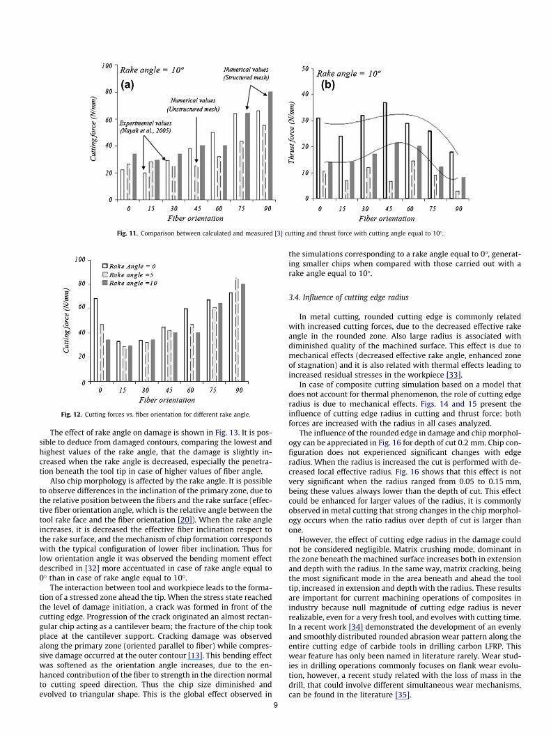
Fig. 11. Comparison between calculated and measured [3] cutting and thrust force with cutting angle equal to 10�.
Fig. 12. Cutting forces vs. fiber orientation for different rake angle.
The effect of rake angle on damage is shown in Fig. 13. It is pos-sible to deduce from damaged contours, comparing the lowest andhighest values of the rake angle, that the damage is slightly in-creased when the rake angle is decreased, especially the penetra-tion beneath the tool tip in case of higher values of fiber angle.
Also chip morphology is affected by the rake angle. It is possibleto observe differences in the inclination of the primary zone, due tothe relative position between the fibers and the rake surface (effec-tive fiber orientation angle, which is the relative angle between thetool rake face and the fiber orientation [20]). When the rake angleincreases, it is decreased the effective fiber inclination respect tothe rake surface, and the mechanism of chip formation correspondswith the typical configuration of lower fiber inclination. Thus forlow orientation angle it was observed the bending moment effectdescribed in [32] more accentuated in case of rake angle equal to0� than in case of rake angle equal to 10�.
The interaction between tool and workpiece leads to the forma-tion of a stressed zone ahead the tip. When the stress state reachedthe level of damage initiation, a crack was formed in front of thecutting edge. Progression of the crack originated an almost rectan-gular chip acting as a cantilever beam; the fracture of the chip tookplace at the cantilever support. Cracking damage was observedalong the primary zone (oriented parallel to fiber) while compres-sive damage occurred at the outer contour [13]. This bending effectwas softened as the orientation angle increases, due to the en-hanced contribution of the fiber to strength in the direction normalto cutting speed direction. Thus the chip size diminished andevolved to triangular shape. This is the global effect observed in
9
the simulations corresponding to a rake angle equal to 0�, generat-ing smaller chips when compared with those carried out with arake angle equal to 10�.
3.4. Influence of cutting edge radius
In metal cutting, rounded cutting edge is commonly relatedwith increased cutting forces, due to the decreased effective rakeangle in the rounded zone. Also large radius is associated withdiminished quality of the machined surface. This effect is due tomechanical effects (decreased effective rake angle, enhanced zoneof stagnation) and it is also related with thermal effects leading toincreased residual stresses in the workpiece [33].
In case of composite cutting simulation based on a model thatdoes not account for thermal phenomenon, the role of cutting edgeradius is due to mechanical effects. Figs. 14 and 15 present theinfluence of cutting edge radius in cutting and thrust force: bothforces are increased with the radius in all cases analyzed.
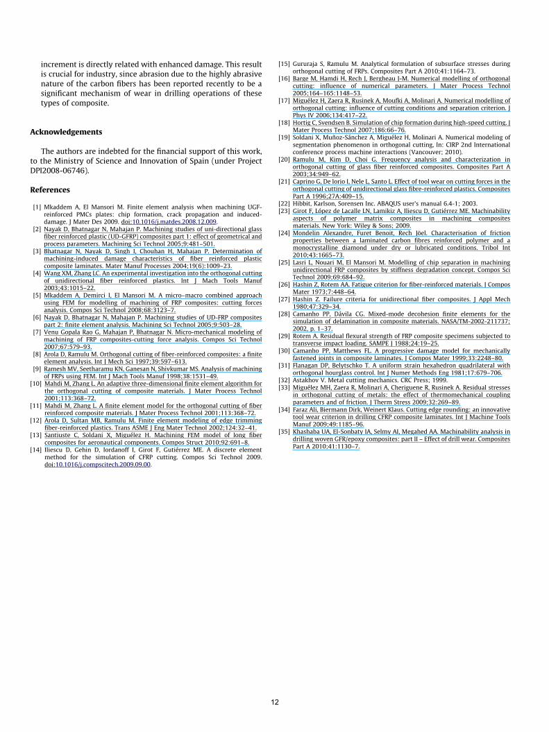
The influence of the rounded edge in damage and chip morphol-ogy can be appreciated in Fig. 16 for depth of cut 0.2 mm. Chip con-figuration does not experienced significant changes with edgeradius. When the radius is increased the cut is performed with de-creased local effective radius. Fig. 16 shows that this effect is notvery significant when the radius ranged from 0.05 to 0.15 mm,being these values always lower than the depth of cut. This effectcould be enhanced for larger values of the radius, it is commonlyobserved in metal cutting that strong changes in the chip morphol-ogy occurs when the ratio radius over depth of cut is larger thanone.
However, the effect of cutting edge radius in the damage couldnot be considered negligible. Matrix crushing mode, dominant inthe zone beneath the machined surface increases both in extensionand depth with the radius. In the same way, matrix cracking, beingthe most significant mode in the area beneath and ahead the tooltip, increased in extension and depth with the radius. These resultsare important for current machining operations of composites inindustry because null magnitude of cutting edge radius is neverrealizable, even for a very fresh tool, and evolves with cutting time.In a recent work [34] demonstrated the development of an evenlyand smoothly distributed rounded abrasion wear pattern along theentire cutting edge of carbide tools in drilling carbon LFRP. Thiswear feature has only been named in literature rarely. Wear stud-ies in drilling operations commonly focuses on flank wear evolu-tion, however, a recent study related with the loss of mass in thedrill, that could involve different simultaneous wear mechanisms,can be found in the literature [35].
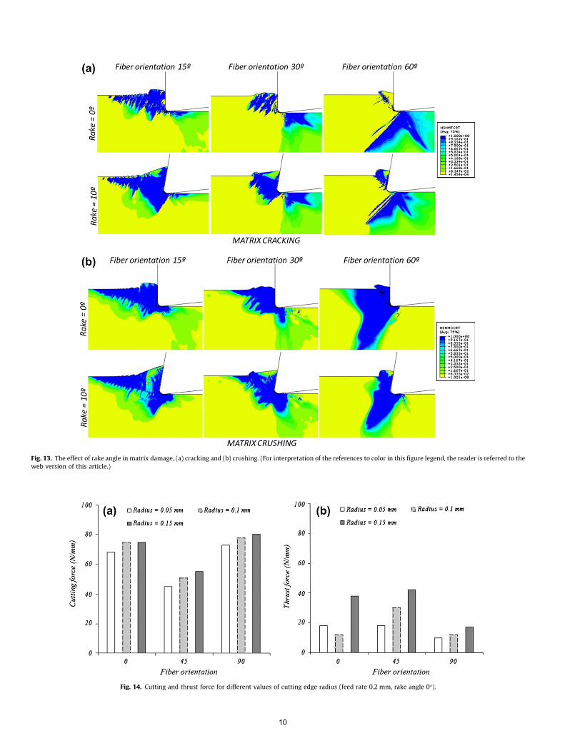
Fig. 13. The effect of rake angle in matrix damage, (a) cracking and (b) crushing. (For interpretation of the references to color in this figure legend, the reader is referred to theweb version of this article.)
Fig. 14. Cutting and thrust force for different values of cutting edge radius (feed rate 0.2 mm, rake angle 0�).
10
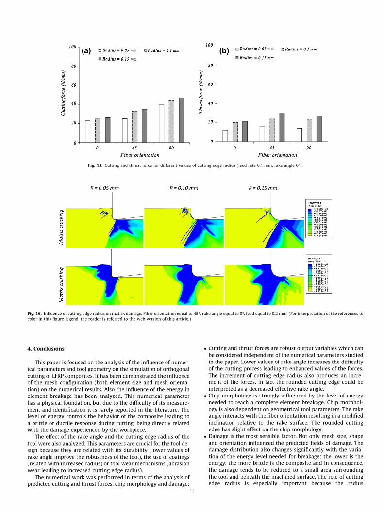
Fig. 15. Cutting and thrust force for different values of cutting edge radius (feed rate 0.1 mm, rake angle 0�).
Fig. 16. Influence of cutting edge radius on matrix damage. Fiber orientation equal to 45�, rake angle equal to 0�, feed equal to 0.2 mm. (For interpretation of the references tocolor in this figure legend, the reader is referred to the web version of this article.)
4. Conclusions
This paper is focused on the analysis of the influence of numer-ical parameters and tool geometry on the simulation of orthogonalcutting of LFRP composites. It has been demonstrated the influenceof the mesh configuration (both element size and mesh orienta-tion) on the numerical results. Also the influence of the energy inelement breakage has been analyzed. This numerical parameterhas a physical foundation, but due to the difficulty of its measure-ment and identification it is rarely reported in the literature. Thelevel of energy controls the behavior of the composite leading toa brittle or ductile response during cutting, being directly relatedwith the damage experienced by the workpiece.
The effect of the rake angle and the cutting edge radius of thetool were also analyzed. This parameters are crucial for the tool de-sign because they are related with its durability (lower values ofrake angle improve the robustness of the tool), the use of coatings(related with increased radius) or tool wear mechanisms (abrasionwear leading to increased cutting edge radius).
The numerical work was performed in terms of the analysis ofpredicted cutting and thrust forces, chip morphology and damage:
11
� Cutting and thrust forces are robust output variables which canbe considered independent of the numerical parameters studiedin the paper. Lower values of rake angle increases the difficultyof the cutting process leading to enhanced values of the forces.The increment of cutting edge radius also produces an incre-ment of the forces. In fact the rounded cutting edge could beinterpreted as a decreased effective rake angle.� Chip morphology is strongly influenced by the level of energy
needed to reach a complete element breakage. Chip morphol-ogy is also dependent on geometrical tool parameters. The rakeangle interacts with the fiber orientation resulting in a modifiedinclination relative to the rake surface. The rounded cuttingedge has slight effect on the chip morphology.� Damage is the most sensible factor. Not only mesh size, shape
and orientation influenced the predicted fields of damage. Thedamage distribution also changes significantly with the varia-tion of the energy level needed for breakage: the lower is theenergy, the more brittle is the composite and in consequence,the damage tends to be reduced to a small area surroundingthe tool and beneath the machined surface. The role of cuttingedge radius is especially important because the radius
increment is directly related with enhanced damage. This resultis crucial for industry, since abrasion due to the highly abrasivenature of the carbon fibers has been reported recently to be asignificant mechanism of wear in drilling operations of thesetypes of composite.
Acknowledgements
The authors are indebted for the financial support of this work,to the Ministry of Science and Innovation of Spain (under ProjectDPI2008-06746).
References
[1] Mkaddem A, El Mansori M. Finite element analysis when machining UGF-reinforced PMCs plates: chip formation, crack propagation and induced-damage. J Mater Des 2009. doi:10.1016/j.matdes.2008.12.009.
[2] Nayak D, Bhatnagar N, Mahajan P. Machining studies of uni-directional glassfiber reinforced plastic (UD-GFRP) composites part 1: effect of geometrical andprocess parameters. Machining Sci Technol 2005;9:481–501.
[3] Bhatnagar N, Nayak D, Singh I, Chouhan H, Mahajan P. Determination ofmachining-induced damage characteristics of fiber reinforced plasticcomposite laminates. Mater Manuf Processes 2004;19(6):1009–23.
[4] Wang XM, Zhang LC. An experimental investigation into the orthogonal cuttingof unidirectional fiber reinforced plastics. Int J Mach Tools Manuf2003;43:1015–22.
[5] Mkaddem A, Demirci I, El Mansori M. A micro–macro combined approachusing FEM for modelling of machining of FRP composites: cutting forcesanalysis. Compos Sci Technol 2008;68:3123–7.
[6] Nayak D, Bhatnagar N, Mahajan P. Machining studies of UD-FRP compositespart 2: finite element analysis. Machining Sci Technol 2005;9:503–28.
[7] Venu Gopala Rao G, Mahajan P, Bhatnagar N. Micro-mechanical modeling ofmachining of FRP composites-cutting force analysis. Compos Sci Technol2007;67:579–93.
[8] Arola D, Ramulu M. Orthogonal cutting of fiber-reinforced composites: a finiteelement analysis. Int J Mech Sci 1997;39:597–613.
[9] Ramesh MV, Seetharamu KN, Ganesan N, Shivkumar MS. Analysis of machiningof FRPs using FEM. Int J Mach Tools Manuf 1998;38:1531–49.
[10] Mahdi M, Zhang L. An adaptive three-dimensional finite element algorithm forthe orthogonal cutting of composite materials. J Mater Process Technol2001;113:368–72.
[11] Mahdi M, Zhang L. A finite element model for the orthogonal cutting of fiberreinforced composite materials. J Mater Process Technol 2001;113:368–72.
[12] Arola D, Sultan MB, Ramulu M. Finite element modeling of edge trimmingfiber-reinforced plastics. Trans ASME J Eng Mater Technol 2002;124:32–41.
[13] Santiuste C, Soldani X, Miguélez H. Machining FEM model of long fibercomposites for aeronautical components. Compos Struct 2010;92:691–8.
[14] Iliescu D, Gehin D, Iordanoff I, Girot F, Gutiérrez ME. A discrete elementmethod for the simulation of CFRP cutting. Compos Sci Technol 2009.doi:10.1016/j.compscitech.2009.09.00.
12
[15] Gururaja S, Ramulu M. Analytical formulation of subsurface stresses duringorthogonal cutting of FRPs. Composites Part A 2010;41:1164–73.
[16] Barge M, Hamdi H, Rech J, Bergheau J-M. Numerical modelling of orthogonalcutting: influence of numerical parameters. J Mater Process Technol2005;164–165:1148–53.
[17] Miguélez H, Zaera R, Rusinek A, Moufki A, Molinari A. Numerical modelling oforthogonal cutting: influence of cutting conditions and separation criterion. JPhys IV 2006;134:417–22.
[18] Hortig C, Svendsen B. Simulation of chip formation during high-speed cutting. JMater Process Technol 2007;186:66–76.
[19] Soldani X, Muñoz-Sánchez A, Miguélez H, Molinari A. Numerical modeling ofsegmentation phenomenon in orthogonal cutting, In: CIRP 2nd Internationalconference process machine interactions (Vancouver; 2010).
[20] Ramulu M, Kim D, Choi G. Frequency analysis and characterization inorthogonal cutting of glass fiber reinforced composites. Composites Part A2003;34:949–62.
[21] Caprino G, De lorio I, Nele L, Santo L. Effect of tool wear on cutting forces in theorthogonal cutting of unidirectional glass fibre-reinforced plastics. CompositesPart A 1996;27A:409–15.
[22] Hibbit, Karlson, Sorensen Inc. ABAQUS user’s manual 6.4-1; 2003.[23] Girot F, López de Lacalle LN, Lamikiz A, Iliescu D, Gutiérrez ME. Machinability
aspects of polymer matrix composites in machining compositesmaterials. New York: Wiley & Sons; 2009.
[24] Mondelin Alexandre, Furet Benoit, Rech Jöel. Characterisation of frictionproperties between a laminated carbon fibres reinforced polymer and amonocrystalline diamond under dry or lubricated conditions. Tribol Int2010;43:1665–73.
[25] Lasri L, Nouari M, El Mansori M. Modelling of chip separation in machiningunidirectional FRP composites by stiffness degradation concept. Compos SciTechnol 2009;69:684–92.
[26] Hashin Z, Rotem AA. Fatigue criterion for fiber-reinforced materials. J ComposMater 1973;7:448–64.
[27] Hashin Z. Failure criteria for unidirectional fiber composites. J Appl Mech1980;47:329–34.
[28] Camanho PP, Dávila CG. Mixed-mode decohesion finite elements for thesimulation of delamination in composite materials. NASA/TM-2002-211737;2002, p. 1–37.
[29] Rotem A. Residual flexural strength of FRP composite specimens subjected totransverse impact loading. SAMPE J 1988;24:19–25.
[30] Camanho PP, Matthews FL. A progressive damage model for mechanicallyfastened joints in composite laminates. J Compos Mater 1999;33:2248–80.
[31] Flanagan DP, Belytschko T. A uniform strain hexahedron quadrilateral withorthogonal hourglass control. Int J Numer Methods Eng 1981;17:679–706.
[32] Astakhov V. Metal cutting mechanics. CRC Press; 1999.[33] Miguélez MH, Zaera R, Molinari A, Cheriguene R, Rusinek A. Residual stresses
in orthogonal cutting of metals: the effect of thermomechanical couplingparameters and of friction. J Therm Stress 2009;32:269–89.
[34] Faraz Ali, Biermann Dirk, Weinert Klaus. Cutting edge rounding: an innovativetool wear criterion in drilling CFRP composite laminates. Int J Machine ToolsManuf 2009;49:1185–96.
[35] Khashaba UA, El-Sonbaty IA, Selmy AI, Megahed AA. Machinability analysis indrilling woven GFR/epoxy composites: part II – Effect of drill wear. CompositesPart A 2010;41:1130–7.