Influence of particle-particle interactions and particles rotational motion in traveling wave...
13
Nadine Aubry Pushpendra Singh Department of Mechanical Engineering, New Jersey Institute of Technology, Newark, NJ, USA Received August 18, 2005 Revised October 10, 2005 Accepted October 13, 2005 Research Article Influence of particle-particle interactions and particles rotational motion in traveling wave dielectrophoresis Traveling wave dielectrophoresis provides an interesting method for the controlled movement of microsized particles in suspended mixtures, and as such is a promising tool in microfluidic technology. In this case, the electrostatic force acting on the parti- cles has two components: one due to the spatially varying magnitude of the electric field and the other due to the spatially varying phase. The actual movement of the particle is determined by the combined effect of these two forces and corresponding torques, the viscous drag exerted by the fluid on the particle, and the electrostatic and hydrodynamic particle-particle interactions. This paper presents the first numerical simulations of the motion of particles subjected to all previous forces and torques. Our technique is based on a finite-element scheme in which the particles are moved using a direct simulation scheme respecting the fundamental equations of motion for both the fluid and the solid particles. The fluid-particle motion is resolved by the method of distributed Lagrange multipliers and the electrostatic forces are computed using the point-dipole approximation. Our simulations show that the particle behavior strongly depends on the mismatch of the dielectric properties between the particles and the fluid, and that the particle-particle interaction force as well as particles rotation speeds play crucial roles in the various regimes. Keywords: Direct numerical simulation / Microfluidic device / Traveling wave dielec- trophoresis DOI 10.1002/elps.200500606 1 Introduction In recent years, there has been an increased interest in dielectrophoresis (DEP) [1, 2] for the manipulation, separation, and analysis of micro- and nanosized parti- cles such as latex spheres, cells, bacteria, viruses, DNA molecules, and proteins (see, e.g., [3–8]). The technique is based on the motion of particles arising from the interac- tion of a nonuniform electric field with the dipole induced within the particles. In conventional dielectrophoresis (cDEP) [1], the dielec- trophoretic force acting on an isolated, spherical particle in a direct current (DC) electric field is proportional to the field nonuniformity, as given by the gradient of the square of the electric field. In an alternating current (AC) electric field, this statement remains valid if the dielectric force considered is the time-averaged force and the electric field is replaced by the root mean square (rms) of the electric field. The force is also proportional to the real part of the Clausius–Mossotti factor b (a function of the electric-field frequency in the case of an AC field), which quantifies the mismatch be- tween the dielectric properties of the particle and its sus- pending medium. Depending on the sign of the real part of b, particles move either toward the regions of highest electric-field strength (positive DEP) or away from them toward the regions of lowest electric-field strength (negative DEP), and so particles with different b(o) curves can be separated in a suitable frequency range. In many applications, it is advantageous to combine the separation of particles with their transport along a chan- nel. One way to accomplish this is by using traveling wave dielectrophoresis (twDEP) [9–12] based on a traveling AC electric field generated by a periodic series of appro- priately phased electrodes. In this case, the time-aver- Correspondence: Professor Nadine Aubry, Department of Mechan- ical Engineering, New Jersey Institute of Technology, Newark, NJ 07102, USA E-mail: [email protected] Fax: 11-973-642-7268 Abbreviations: cDEP , conventional dielectrophoresis; DEP , dielec- trophoresis; DLM, distributed Lagrange multiplier; PD, point-dipole; twDEP , traveling wave dielectrophoresis Electrophoresis 2006, 27, 703–715 703 © 2006 WILEY-VCH Verlag GmbH & Co. KGaA, Weinheim www.electrophoresis-journal.com
-
Upload
independent -
Category
Documents
-
view
0 -
download
0
Transcript of Influence of particle-particle interactions and particles rotational motion in traveling wave...

Nadine AubryPushpendra Singh
Department of MechanicalEngineering, New Jersey Instituteof Technology,Newark, NJ, USA
Received August 18, 2005Revised October 10, 2005Accepted October 13, 2005
Research Article
Influence of particle-particle interactions andparticles rotational motion in traveling wavedielectrophoresis
Traveling wave dielectrophoresis provides an interesting method for the controlledmovement of microsized particles in suspended mixtures, and as such is a promisingtool in microfluidic technology. In this case, the electrostatic force acting on the parti-cles has two components: one due to the spatially varying magnitude of the electricfield and the other due to the spatially varying phase. The actual movement of theparticle is determined by the combined effect of these two forces and correspondingtorques, the viscous drag exerted by the fluid on the particle, and the electrostatic andhydrodynamic particle-particle interactions. This paper presents the first numericalsimulations of the motion of particles subjected to all previous forces and torques. Ourtechnique is based on a finite-element scheme in which the particles are moved usinga direct simulation scheme respecting the fundamental equations of motion for boththe fluid and the solid particles. The fluid-particle motion is resolved by the method ofdistributed Lagrange multipliers and the electrostatic forces are computed using thepoint-dipole approximation. Our simulations show that the particle behavior stronglydepends on the mismatch of the dielectric properties between the particles and thefluid, and that the particle-particle interaction force as well as particles rotation speedsplay crucial roles in the various regimes.
Keywords: Direct numerical simulation / Microfluidic device / Traveling wave dielec-trophoresis DOI 10.1002/elps.200500606
1 Introduction
In recent years, there has been an increased interest indielectrophoresis (DEP) [1, 2] for the manipulation,separation, and analysis of micro- and nanosized parti-cles such as latex spheres, cells, bacteria, viruses, DNAmolecules, and proteins (see, e.g., [3–8]). The technique isbased on the motion of particles arising from the interac-tion of a nonuniform electric field with the dipole inducedwithin the particles.
In conventional dielectrophoresis (cDEP) [1], the dielec-trophoretic force acting on an isolated, spherical particle ina direct current (DC) electric field is proportional to the field
nonuniformity, as given by the gradient of the square of theelectric field. In an alternating current (AC) electric field, thisstatement remains valid if the dielectric force considered isthe time-averaged force and the electric field is replacedby the root mean square (rms) of the electric field. The forceis also proportional to the real part of the Clausius–Mossottifactor b (a function of the electric-field frequency in thecase of an AC field), which quantifies the mismatch be-tween the dielectric properties of the particle and its sus-pending medium. Depending on the sign of the real partof b, particles move either toward the regions of highestelectric-field strength (positive DEP) or away from themtoward the regions of lowest electric-field strength(negative DEP), and so particles with different b(o) curvescan be separated in a suitable frequency range.
In many applications, it is advantageous to combine theseparation of particles with their transport along a chan-nel. One way to accomplish this is by using traveling wavedielectrophoresis (twDEP) [9–12] based on a traveling ACelectric field generated by a periodic series of appro-priately phased electrodes. In this case, the time-aver-
Correspondence: Professor Nadine Aubry, Department of Mechan-ical Engineering, New Jersey Institute of Technology, Newark, NJ07102, USAE-mail: [email protected]: 11-973-642-7268
Abbreviations: cDEP, conventional dielectrophoresis; DEP, dielec-trophoresis; DLM, distributed Lagrange multiplier; PD, point-dipole;twDEP, traveling wave dielectrophoresis
Electrophoresis 2006, 27, 703–715 703
© 2006 WILEY-VCH Verlag GmbH & Co. KGaA, Weinheim www.electrophoresis-journal.com
704 N. Aubry and P. Singh Electrophoresis 2006, 27, 703–715
aged force acting on an isolated, spherical particle hastwo origins, the first one being the nonuniformity in theelectric-field magnitude, and the second one being thespatial variation of the electric-field phase. While the firstphenomenon gives rise to a time-averaged force similarto the conventional dielectrophoretic force, which de-pends on the real part of the Clausius–Mossotti factor andthe nonuniformity in the spatial distribution of the squareof the electric-field magnitude, the second one generateson average a translational force proportional to the imag-inary part of the Clausius–Mossotti factor and the non-uniformity in the cross product of the two out-of-phasecomponents of the electric field. This translational motioncan propel the particles along the channel upstream ordownstream (depending on the sign of Im(b)), thus avoid-ing the need to pump the fluid itself. It is thus clear thatparticle separation can be achieved based on the signs ofthe real and imaginary parts of b. Further separation cap-ability is based on the fact that the translational particlevelocity is a function of the size of the particles and therelative polarizability of the particles versus that of thefluid, and therefore the technique has the potential toseparate particles according to their size and/or dielectricproperties [13, 14] in practical applications.
Most studies of the phenomenon of cDEP and twDEP havebeen somewhat qualitative in the past as DEP in general israther easy to realize in practice. However, the precise con-trol of particle motion requires more quantitative ap-proaches. The latter, so far, have been based on the calcu-lation of the electric-field and DEP force distribution eitherthrough analytical approximations using series expansions[9, 13, 14] or computational techniques [15–19]. The actualmovement of the particle, however, is determined by notonly the combined effect of the above two DEPs, but alsothe viscous drag exerted by the fluid on the particle and theelectrostatic and hydrodynamic particle-particle interac-tions. Accounting for the latter should be useful in under-standing and predicting the chaining and/or repelling be-tween particles as well as the existence of various regimes(as described in [20]), which may affect the separation/transport capability of the device, as well as its efficiency.
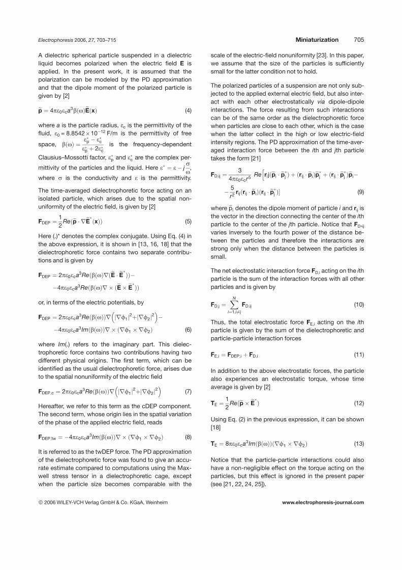
In this paper, we present the first computations of themotion of particles subjected to all previous forces intwDEP. The particular geometry we simulate is that of achannel whose bottom contains an array of planar elec-trodes (see Fig. 1), as is the case of many microfluidic de-vices. The electrodes are connected so that the electricpotentials of two adjacent electrodes are 907 out-of-phaseof each other. This periodic array, whose period containsfour electrodes, generates an electric field with a spatiallyvarying phase, and therefore a four-phase twDEP. Ournumerical technique is based on a finite-element schemeconsisting of moving the particles using a direct simulation
Figure 1. Schematic of the domain used in the simula-tions. Electrodes, shown as gray strips, are mounted inthe bottom of the device. Phase of the voltage applied tothe electrodes is shown. Phase difference (f) for thedarker colored electrodes differs by 6/2 from those forthe lighter colored electrodes. Domain is periodic in thez-direction. Notice that the one-half of the first electrodeappears at the other end of the domain. Gravity is in thenegative x-direction.
scheme in which the fundamental equations of motion forboth the fluid and the solid particles are solved. The latterequations are resolved by the method of distributedLagrange multiplier (DLM) while the electrostatic forces arecomputed using the point-dipole (PD) approximation. Ourtechnique is an expansion of that presented in [21, 22] forthe simulation of the motion of particles subjected to cDEP.As in [21, 22], we neglect here electrically driven fluid flowphenomena even though the latter have been observed tobe important in experiments for certain parameter values.
2 Theory
2.1 Electrostatic forces
In twDEP, the phase of the electric potential varies inspace and thus the electric potential oscillating with fre-quency o is represented using the phasor notation
fðx; tÞ ¼ ReðefðxÞejotÞ (1)
where j =ffiffiffiffiffiffiffi1p
, efðxÞ ¼ f1 þ jf2 and Re refers to the realpart of a complex variable. Here f1 and f2 are two com-ponents of the electric potential with a p/2 phase differ-ence with respect to one another. The electric field is thengiven by
E ¼ rf ¼ ReðeEejotÞ, where eEðxÞ ¼ ðrf1 þ jrf2Þ (2)
In experiments, an electric field with a spatially varyingphase is generated by applying voltages with differentphases to various electrodes, as shown in Fig. 1. The twocomponents of the electric potential, f1 and f2, can beobtained by solving Laplace’s equation
r2fi ¼ 0; i ¼ 1;2 (3)
subjected to the appropriate boundary conditions.
© 2006 WILEY-VCH Verlag GmbH & Co. KGaA, Weinheim www.electrophoresis-journal.com
Electrophoresis 2006, 27, 703–715 Miniaturization 705
A dielectric spherical particle suspended in a dielectricliquid becomes polarized when the electric field E isapplied. In the present work, it is assumed that thepolarization can be modeled by the PD approximationand that the dipole moment of the polarized particle isgiven by [2]
ep ¼ 4pe0eca3bðoÞeEðxÞ (4)
where a is the particle radius, ec is the permittivity of thefluid, e0 = 8.8542610212 F/m is the permittivity of free
space, bðoÞ ¼ep ecep þ 2ec
is the frequency-dependent
Clausius–Mossotti factor, ep and ec are the complex per-
mittivity of the particles and the liquid. Here e ¼ e jso
,
where s is the conductivity and e is the permittivity.
The time-averaged dielectrophoretic force acting on anisolated particle, which arises due to the spatial non-uniformity of the electric field, is given by [2]
FDEP ¼12
Reðep reEðxÞÞ (5)
Here (.)* denotes the complex conjugate. Using Eq. (4) inthe above expression, it is shown in [13, 16, 18] that thedielectrophoretic force contains two separate contribu-tions and is given by
FDEP ¼ 2pe0eca3ReðbðoÞrðeE eEÞÞ4pe0eca3ReðbðoÞr ðeE eEÞÞ
or, in terms of the electric potentials, by
FDEP ¼ 2pe0eca3ReðbðoÞÞr rf1j j2þ rf2j j2
4pe0eca3ImðbðoÞÞr ðrf1 rf2Þ (6)
where Im(.) refers to the imaginary part. This dielec-trophoretic force contains two contributions having twodifferent physical origins. The first term, which can beidentified as the usual dielectrophoretic force, arises dueto the spatial nonuniformity of the electric field
FDEP;c ¼ 2pe0eca3ReðbðoÞÞr rf1j j2þ rf2j j2
(7)
Hereafter, we refer to this term as the cDEP component.The second term, whose origin lies in the spatial variationof the phase of the applied electric field, reads
FDEP;tw ¼ 4pe0eca3ImðbðoÞÞr ðrf1 rf2Þ (8)
It is referred to as the twDEP force. The PD approximationof the dielectrophoretic force was found to give an accu-rate estimate compared to computations using the Max-well stress tensor in a dielectrophoretic cage, exceptwhen the particle size becomes comparable with the
scale of the electric-field nonuniformity [23]. In this paper,we assume that the size of the particles is sufficientlysmall for the latter condition not to hold.
The polarized particles of a suspension are not only sub-jected to the applied external electric field, but also inter-act with each other electrostatically via dipole-dipoleinteractions. The force resulting from such interactionscan be of the same order as the dielectrophoretic forcewhen particles are close to each other, which is the casewhen the latter collect in the high or low electric-fieldintensity regions. The PD approximation of the time-aver-aged interaction force between the ith and jth particletakes the form [21]
FD;ij ¼3
4pe0ecr5 Re rijðepi epj Þ þ ðrij epiÞepj þ ðrij epj Þepih
5r2 rijðrij epiÞðrij epj Þ (9)
where epi denotes the dipole moment of particle i and rij isthe vector in the direction connecting the center of the ithparticle to the center of the jth particle. Notice that FD,ijvaries inversely to the fourth power of the distance be-tween the particles and therefore the interactions arestrong only when the distance between the particles issmall.
The net electrostatic interaction force FD,i acting on the ithparticle is the sum of the interaction forces with all otherparticles and is given by
FD;j ¼XN
i¼1;i 6¼j
FD;ij (10)
Thus, the total electrostatic force FE,i acting on the ithparticle is given by the sum of the dielectrophoretic andparticle-particle interaction forces
FE;i ¼ FDEP;i þ FD;i (11)
In addition to the above electrostatic forces, the particlealso experiences an electrostatic torque, whose timeaverage is given by [2]
TE ¼12
Reðep eEÞ (12)
Using Eq. (2) in the previous expression, it can be shown[18]
TE ¼ 8pe0eca3ImðbðoÞÞðrf1 rf2Þ (13)
Notice that the particle-particle interactions could alsohave a non-negligible effect on the torque acting on theparticles, but this effect is ignored in the present paper(see [21, 22, 24, 25]).
© 2006 WILEY-VCH Verlag GmbH & Co. KGaA, Weinheim www.electrophoresis-journal.com
706 N. Aubry and P. Singh Electrophoresis 2006, 27, 703–715
2.2 Governing equations for fluid and particles
The governing equations for the motion of the fluid andparticles are presented in this section, and then theseequations are nondimensionalized to obtain the dimen-sionless parameters relevant to our problem.
Let us denote the domain containing a Newtonian fluidand N solid spherical particles by O, the interior of the ithparticle by Pi(t), and the domain boundary by G. The gov-erning equations for the fluid-particle system are
rLquqtþ u ru
¼ rpþr ð2ZDÞ in Ω\ PðtÞ
r u ¼ 0 in Ω\ PðtÞ (14)
u ¼ uL on G
u ¼ Ui þ oi ri on qPiðtÞ, i = 1, ..., N (15)
Here, u is the fluid velocity, p is the pressure, Z is the dy-namic viscosity of the fluid, rL is the density of the fluid, Dis the symmetric part of the velocity gradient tensor, andUi and oi are the linear and angular velocities of the ithparticle. The above equations are solved using the initialcondition ujt¼0 ¼ u0, where u0 is the known initial value ofthe velocity.
The linear velocity Ui and the angular velocity oi of the ithparticle are governed by
midUi
dt¼ Fi þ FE;i þ FB;i
Iidoi
dt¼Iðx XiÞ ½ðpIþ sÞ n dAþ TE;i (16)
Uijt¼0 ¼ Ui;0
oijt¼0 ¼ oi;0 (17)
where FB, i is the buoyant weight of the ith particle and mi
and Ii are the mass and moment of inertia of the ith particle,
Xi denotes the center of the particle, Fi =IðpIþ sÞ nds
and Ti =Iðx XiÞ ½ðpIþ sÞ nds are the hydro-
dynamic force and torque acting on the ith particle,FE,i = FDEP,i 1 FD,i is the net electrostatic force acting on theith particle, s ¼ 2ZD, and TE,i is the electric torque actingon the ith particle.
In this work, we restrict ourselves to the case where theparticles are spherical, and therefore we do not need tokeep track of the particle orientation. The particle posi-tions are obtained from
dXi
dt¼ Ui (18)
Xijt¼0 ¼ Xi;0 (19)
where Xi,0 is the position of the ith particle at time t = 0. Wealso assume that all particles are homogeneous and havethe same density rp, and since they have the same radius,they also have the same mass, m.
2.2.1 Dimensionless equations and parameters
The equations of motion are nondimensionalized byassuming that the characteristic length, velocity, time,stress, angular velocity, and electric-field scales are a, U,a/U, ZU/a, U/a, and E0, respectively. The gradient of theelectric field is assumed to scale as E0/L, where L is thedistance between the electrodes, which is the same asthe domain width. The dimensionless equations, afterusing the same symbols for the dimensionless variables,are
Requqtþ u ru
¼ rpþr s in Ω\ PðtÞ
r u ¼ 0 in Ω\ PðtÞ (20)
dUdt¼ 6pZa2
mU
Z pIþ s6p
nds
þ2pa4e0ecReðbÞjE0j2
mU2Lr rf1j j2þ rf2j j2
þ4pa4e0ecjE0j2ImðbðoÞÞmU2L
r ðrf1 rf2Þ
þ3pe0eca3 bj j2jE0j2
4mU2jr ijj4ðFDÞ (21)
I0pdodt¼ Za2
mU
Zðx XÞ½ðpIþ sÞ ndsþ
þ8pa3e0ecImðbðoÞÞjE0j2
mU2 ðrf1 rf2Þ (22)
Notice that a factor of 6p has been introduced in the firstterm on the right-hand side of Eq. (21) to ensure that in theStokes flow limit the quantity inside the integral, for anisolated particle, is equal to one. The particle moment ofinertia is IP = M I0pD2, where I0p is the dimensionlessmoment of inertia.
The above equations contain the following dimensionless
parameters: Re ¼ rLUaZ
, P1 ¼6pZa2
mU,
P2 ¼3pe0ec bj j2a3jE0j2
4mU2 , P3 ¼2pa4e0ecReðbÞjE0j2
mU2L,
P5 ¼4pa4e0ecjE0j2ImðbðoÞÞ
mU2L, P6 ¼
8pa3e0ecImðbðoÞÞjE0j2
mU2 ,
and h0 ¼ La. Here, Re is the Reynolds number, which
determines the relative importance of the fluid inertia andviscous forces, P1 is the ratio of the viscous and inertia
© 2006 WILEY-VCH Verlag GmbH & Co. KGaA, Weinheim www.electrophoresis-journal.com

Electrophoresis 2006, 27, 703–715 Miniaturization 707
forces, P2 is the ratio of the electrostatic particle-particleinteraction and inertia forces, P3 is the ratio of the dielec-trophoretic and inertia forces, P5 is the ratio of the travelingwave dielectrophoretic and inertia forces, and P6 is the ratioof the traveling wave torque and rotational inertia. Anotherimportant parameter, which does not appear directly in theabove equations, is the solids fraction. Furthermore, inorder to investigate the relative importance of the electro-static particle-particle and dielectrophoretic forces, we
define another parameter P4 ¼P2
P3¼ 3L bj j2
8aReðbÞ. Notice that
P4 depends on the ratio of the domain size and the particleradius, as the spatial gradient of the electric field dependson the domain size and the particle-particle interactionforce depends on the distance between the particles. Fornanosized particles, another parameter involving the mag-nitude of the Brownian force needs to be introduced as in[26], but in this paper we assume that the size of the parti-cles is sufficiently large for this force to be negligible com-pared to the electrostatic forces. The importance of the pa-rameter P4 with respect to particle chaining in cDEP hasbeen shown numerically in [22] and experimentally [27]while manipulating yeast cells.
2.2.2 Finite-element method
The numerical scheme is a generalization of the DLMfinite-element scheme described in [28, 29]. The compu-tational scheme used here is described in detail in [21]. Inthe DLM scheme, the fluid flow equations are solved onthe combined fluid-solid domain, and the motion withinthe particle boundaries is forced to be rigid-body motionusing a distribution of Lagrange multipliers. The fluid andparticle equations of motion are combined into a singlecombined weak equation of motion, eliminating thehydrodynamic forces and torques, which helps ensure thestability of the time integration. The time integration isperformed using the Marchuk–Yanenko operator splittingmethod, which is first-order accurate. The electrostaticforce and torque are given by Eqs. (11) and (13), based onthe PD approximation.
3 Problem set-up
Figure 2 shows a typical domain with the coordinate sys-tem used in our simulations and an initial arrangement of105 yeast particles. The dimensions of the box-shapeddomain are 726486192 mm in the x-, y-, and z-direc-tions. The length scale used for nondimensionalization inthis paper is the average cross-sectional dimension of60 mm, i.e., all lengths shown are nondimensionalizedwith respect to this length. The liquid velocity is assumed
Figure 2. Initial positions of the particles inside the de-vice. There are 105 particles placed on a cubic lattice nearthe device entrance.
to be zero on the sidewalls of the domain and periodica-long the z-direction. The electric field is also assumed tobe periodic in the z-direction. The electrostatic andhydrodynamic forces include contributions from the peri-odic images in the z-direction. The imposed fluid velocityand the pressure gradient in the z-direction are assumedto be zero.
The nonuniform electric field with a spatially varyingphase is generated by placing four electrodes at the bot-tom of the channel, as displayed in Fig. 1. The four elec-trodes are subjected to AC voltages. The phase differ-ence is 6p between the first and third electrodes and be-tween the second and fourth electrodes, and 6p/2between the first and second electrodes and between thefirst and fourth electrodes. The electric field due to thefirst and third electrodes is denoted by =f1 and that dueto the second and fourth electrodes by =f2.
Throughout this paper, we assume that the dynamicfluid viscosity Z = 0.01 Poise, the fluid density rL = 1.0 g/cm3, and the gravity is along the negative x-direction.The domain is discretized using a regular pseudo P2-P1tetrahedral mesh and the number of nodes used is208 065.
© 2006 WILEY-VCH Verlag GmbH & Co. KGaA, Weinheim www.electrophoresis-journal.com
708 N. Aubry and P. Singh Electrophoresis 2006, 27, 703–715
The particles are assumed to be rigid, with propertiesidentical to those of the viable yeast cells reported in [20].The particles diameter and density are 6.0 mm and 1.01 g/cm3, respectively. In [30] the electric properties of theyeast cells are modeled using a two-shell model. Theconductivity and permittivity values assumed here are:the dielectric constants of the cell wall, membrane, cyto-plasm, and medium are 10, 6, 50, and 78; the con-ductivities of the cell wall, membrane, cytoplasm, andmedium are 50 mS/m, 0.25 mS/m, 0.5 S/m, and 40 mS/m.The cell wall thickness is 0.22 mm. We have used thismodel to compute the effective Clausius–Mossotti factorsfor the particles for the following four frequencies investi-gated: 3000 Hz, 0.4, 3, and 5 MHz. The correspond-ing effective Clausius–Mossotti factors are20.473 1 0.00092j, 20.454 1 0.1196j, 20.02 1 0.31j,and 0.1233 1 0.3357j. The dimensionless parametersbased on the maximum particle velocity and the particleradius for the four cases are: (i) Re = 7.6561022,P1 = 58.24, P2 = 367.6, P3 = 103.62, P4 = 3.54, P5 = 0.40,and P6 = 16.12; (ii) Re = 0.122, P1 = 36.37, P2 = 141.23,P3 = 38.78, P4 = 3.64, P5 = 20.43, and P6 = 817.45; (iii)Re = 0.393, P1 = 11.33, P2 = 6.0, P3 = 0.166, P4 = 36.18,P5 = 5.14, and P6 = 205.86; (iv) Re = 0.41, P1 = 10.68,P2 = 7.07, P3 = 0.90, P4 = 7.77, P5 = 4.95, and P6 = 198.0.
In the first three cases, it is clear that the cDEP force willrepel particles away from the electrodes’ edges and inthe fourth case its effect will be to attract the particles to
the electrodes’ edges. In the first case, since the imag-inary part of the Clausius–Mossotti factor is rathersmall, the twDEP force and torque are expected to berelatively small. Furthermore, as the effective PD modelis used to capture the particles’ electrical response, onlythe effective Clausius–Mossotti factor of the yeast parti-cles is relevant to the fluid-dynamics problem.
4 Results and discussion
In this section, we report our numerical results depictingthe configuration of the electric field and the motion ofparticles, first in the case of two particles and second inthe case of 105 particles.
4.1 Configuration of the electric field
Since the electrodes cover the entire length of the domainin the y-direction, the electric field is 2-D in the sense thatit does not vary with y. The electric-field distributionsdescribed below are therefore shown on a plane parallelto the xz-plane and passing through the center of the de-vice.
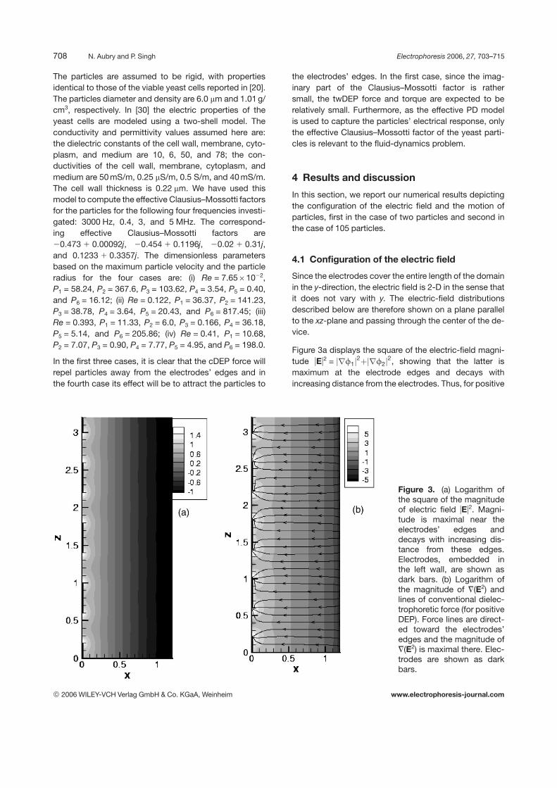
Figure 3a displays the square of the electric-field magni-tude uEu2 = rf1j j2þ rf2j j2, showing that the latter ismaximum at the electrode edges and decays withincreasing distance from the electrodes. Thus, for positive
Figure 3. (a) Logarithm ofthe square of the magnitudeof electric field uEu2. Magni-tude is maximal near theelectrodes’ edges anddecays with increasing dis-tance from these edges.Electrodes, embedded inthe left wall, are shown asdark bars. (b) Logarithm ofthe magnitude of =(E2) andlines of conventional dielec-trophoretic force (for positiveDEP). Force lines are direct-ed toward the electrodes’edges and the magnitude of=(E2) is maximal there. Elec-trodes are shown as darkbars.
© 2006 WILEY-VCH Verlag GmbH & Co. KGaA, Weinheim www.electrophoresis-journal.com
Electrophoresis 2006, 27, 703–715 Miniaturization 709
DEP, we expect particles to collect at the electrodes’edges. This can be also observed from Fig. 3b where thegradient of the previous quantity, =(E2), which determinesthe magnitude of the cDEP force, is shown together withthe lines of that force. It is clear that the magnitude of thiscomponent of the dielectrophoretic force is maximal atthe electrodes edges and that it decreases with increas-ing distance from the electrodes. The direction of thedielectrophoretic force is toward the electrodes edges.
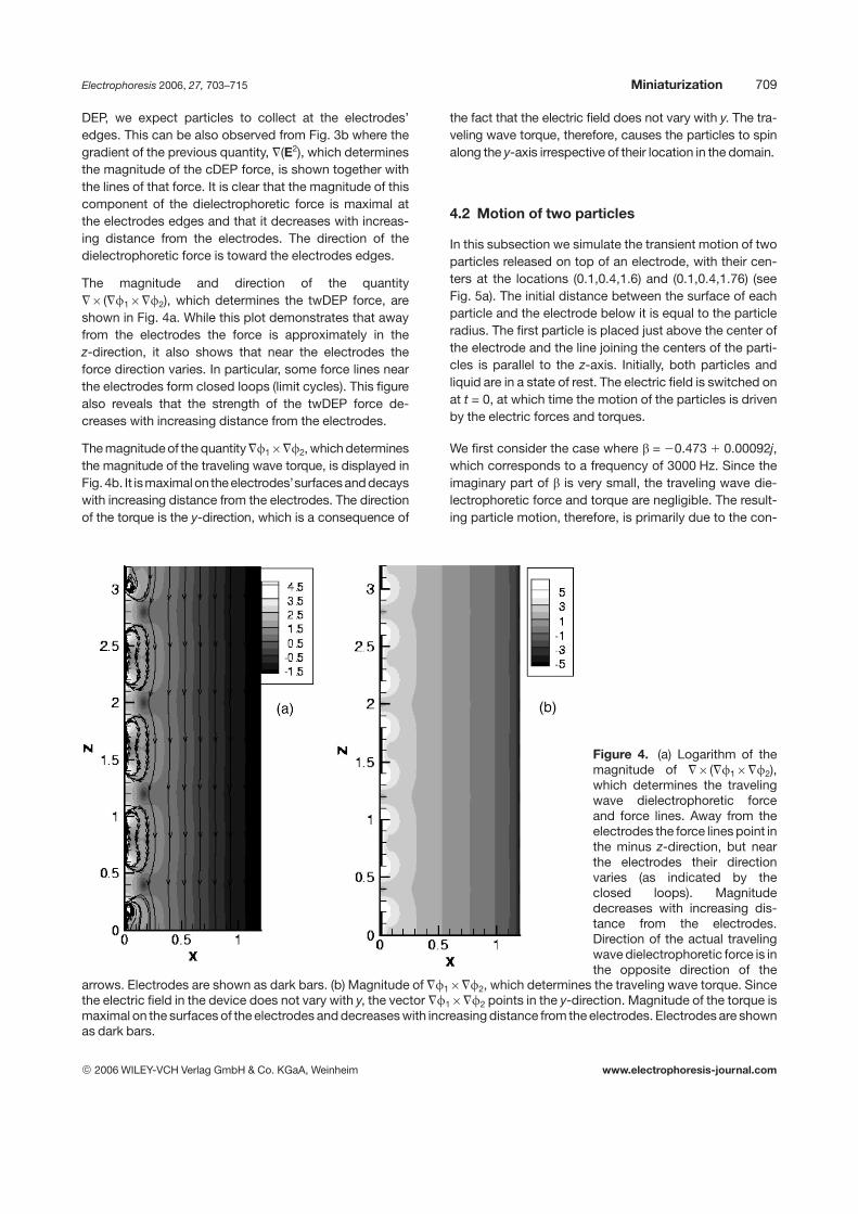
The magnitude and direction of the quantity=6(=f16=f2), which determines the twDEP force, areshown in Fig. 4a. While this plot demonstrates that awayfrom the electrodes the force is approximately in thez-direction, it also shows that near the electrodes theforce direction varies. In particular, some force lines nearthe electrodes form closed loops (limit cycles). This figurealso reveals that the strength of the twDEP force de-creases with increasing distance from the electrodes.
The magnitude of the quantity =f16=f2, which determinesthe magnitude of the traveling wave torque, is displayed inFig. 4b. It ismaximalon the electrodes’surfacesand decayswith increasing distance from the electrodes. The directionof the torque is the y-direction, which is a consequence of
the fact that the electric field does not vary with y. The tra-veling wave torque, therefore, causes the particles to spinalong the y-axis irrespective of their location in the domain.
4.2 Motion of two particles
In this subsection we simulate the transient motion of twoparticles released on top of an electrode, with their cen-ters at the locations (0.1,0.4,1.6) and (0.1,0.4,1.76) (seeFig. 5a). The initial distance between the surface of eachparticle and the electrode below it is equal to the particleradius. The first particle is placed just above the center ofthe electrode and the line joining the centers of the parti-cles is parallel to the z-axis. Initially, both particles andliquid are in a state of rest. The electric field is switched onat t = 0, at which time the motion of the particles is drivenby the electric forces and torques.
We first consider the case where b = 20.473 1 0.00092j,which corresponds to a frequency of 3000 Hz. Since theimaginary part of b is very small, the traveling wave die-lectrophoretic force and torque are negligible. The result-ing particle motion, therefore, is primarily due to the con-
Figure 4. (a) Logarithm of themagnitude of =6(=f16=f2),which determines the travelingwave dielectrophoretic forceand force lines. Away from theelectrodes the force lines point inthe minus z-direction, but nearthe electrodes their directionvaries (as indicated by theclosed loops). Magnitudedecreases with increasing dis-tance from the electrodes.Direction of the actual travelingwave dielectrophoretic force is inthe opposite direction of the
arrows. Electrodes are shown as dark bars. (b) Magnitude of =f16=f2, which determines the traveling wave torque. Sincethe electric field in the device does not vary with y, the vector =f16=f2 points in the y-direction. Magnitude of the torque ismaximal on the surfaces of the electrodes and decreases with increasing distance from the electrodes. Electrodes are shownas dark bars.
© 2006 WILEY-VCH Verlag GmbH & Co. KGaA, Weinheim www.electrophoresis-journal.com

710 N. Aubry and P. Singh Electrophoresis 2006, 27, 703–715
Figure 5. Particles positions and velocity fields around them are shown for four different frequencies. Particles positions atthe same time are connected by a segment. To identify each individual particle, the segment starts from the center of the“first” particle and end at the surface of the “second” particle, i.e., does not extend to the second particle’s center. In thismanner, each particle can be identified at later times. (a) Positions of the two particles at t = 0, 0.049, and 0.45 for a fre-quency of 3000 Hz. (b) Particles positions at t = 0.081, 0.325, 0.813, and 2.22 (left) and velocity field around them at t = 1.3(right) for a frequency of 0.4 MHz. Particles are spinning about their respective axis and, in addition, the line joining theircenters is rotating in the xz-plane. (c) Particles positions at t = 0.008 and 0.19 (left) and velocity field around them at t = 0.19(right) for a frequency of 3 MHz. Particles are trapped at the electrodes’ edges, but continue to spin in the clockwisedirection about their respective axis. (d) Positions of the two particles at t = 0, 0.02, 0.04, and 0.13 for a frequency of 5 MHz.
ventional dielectrophoretic force. While both particles riseagainst gravity, the lower particle rises more slowly as itexperiences a slightly smaller dielectrophoretic force (seeFigs. 3b, 5a). Both levitate to a height where their buoyantweights are equal to their respective dielectrophoretic
forces and then float with their velocities becoming ap-proximately zero [31]. This is in agreement with the resultsreported in [20] at this frequency (despite the difference indevice geometry). The particles also move toward eachother due to the attractive electrostatic particle-particle
© 2006 WILEY-VCH Verlag GmbH & Co. KGaA, Weinheim www.electrophoresis-journal.com
Electrophoresis 2006, 27, 703–715 Miniaturization 711
interaction forces. The rotational speeds of particlesbeing negligible, the lubrication-like effect describedbelow is absent and the particles are able to come inclose contact with each other.
We next consider b = 20.454 1 0.1196j which corre-sponds to a frequency of 0.4 MHz. The positions of theparticles at t = 0.081, 0.325, 0.813, and 2.22 are shown inFig. 5b. In this case, since both real and imaginary parts ofb are relatively large, both the conventional dielec-trophoretic and traveling wave components of thedielectrophoretic forces are important. The particles areforced away from the electrodes by the first component ofthe force since it is repulsive as Re(b) is negative. Theparticles then levitate, reaching a height above the elec-trodes such that the dielectrophoretic force is balancedby the particles’ buoyant weight. While rising, the parti-cles spin in the clockwise direction (about the y-axis). Forthe phase differences of the electrodes shown in Fig. 1,the torque on all particles is in the clockwise direction (seeFigs. 4b, 6), and hence the sense of rotation of both par-ticles is clockwise. This spinning of particles squeezesliquid into the gap between two nearby particles, thuscreating lubrication forces that prevent the particles fromtouching each other.
Another interesting feature of the particle motion is thatparticles also rotate such that the line joining their centersrotates in the xz-plane. The distance between their cen-ters remains approximately constant (see Fig. 5b). Inother words, in addition to spinning about the y-axis, theyrotate together as if their centers were connected by arigid rod, forming a dumbbell. Furthermore, after movingaway from the electrodes, they slowly move along the
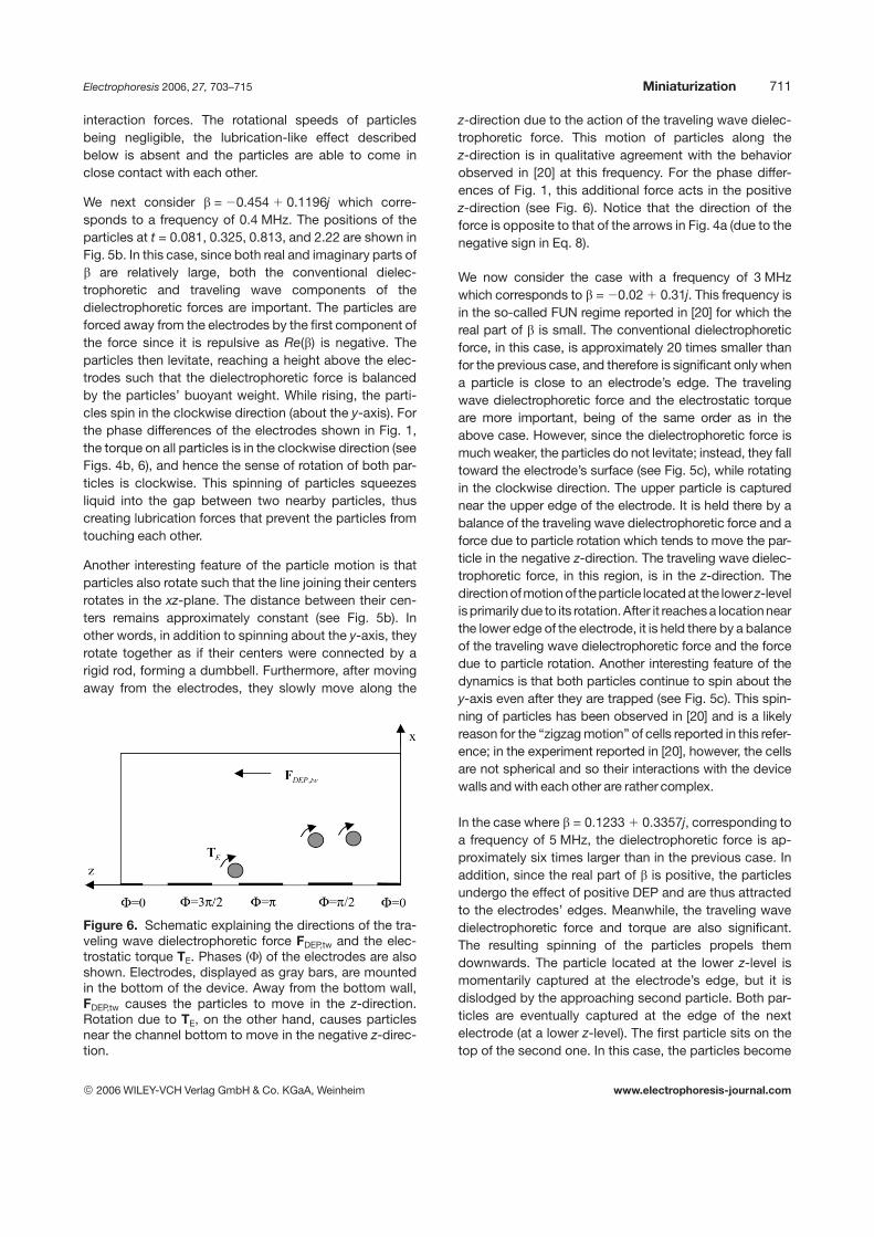
Figure 6. Schematic explaining the directions of the tra-veling wave dielectrophoretic force FDEP,tw and the elec-trostatic torque TE. Phases (F) of the electrodes are alsoshown. Electrodes, displayed as gray bars, are mountedin the bottom of the device. Away from the bottom wall,FDEP,tw causes the particles to move in the z-direction.Rotation due to TE, on the other hand, causes particlesnear the channel bottom to move in the negative z-direc-tion.
z-direction due to the action of the traveling wave dielec-trophoretic force. This motion of particles along thez-direction is in qualitative agreement with the behaviorobserved in [20] at this frequency. For the phase differ-ences of Fig. 1, this additional force acts in the positivez-direction (see Fig. 6). Notice that the direction of theforce is opposite to that of the arrows in Fig. 4a (due to thenegative sign in Eq. 8).
We now consider the case with a frequency of 3 MHzwhich corresponds to b = 20.02 1 0.31j. This frequency isin the so-called FUN regime reported in [20] for which thereal part of b is small. The conventional dielectrophoreticforce, in this case, is approximately 20 times smaller thanfor the previous case, and therefore is significant only whena particle is close to an electrode’s edge. The travelingwave dielectrophoretic force and the electrostatic torqueare more important, being of the same order as in theabove case. However, since the dielectrophoretic force ismuch weaker, the particles do not levitate; instead, they falltoward the electrode’s surface (see Fig. 5c), while rotatingin the clockwise direction. The upper particle is capturednear the upper edge of the electrode. It is held there by abalance of the traveling wave dielectrophoretic force and aforce due to particle rotation which tends to move the par-ticle in the negative z-direction. The traveling wave dielec-trophoretic force, in this region, is in the z-direction. Thedirectionofmotion of the particle located at the lower z-levelisprimarily due to its rotation. After it reaches a locationnearthe lower edge of the electrode, it is held there by a balanceof the traveling wave dielectrophoretic force and the forcedue to particle rotation. Another interesting feature of thedynamics is that both particles continue to spin about they-axis even after they are trapped (see Fig. 5c). This spin-ning of particles has been observed in [20] and is a likelyreason for the “zigzag motion” of cells reported in this refer-ence; in the experiment reported in [20], however, the cellsare not spherical and so their interactions with the devicewalls and with each other are rather complex.
In the case where b = 0.1233 1 0.3357j, corresponding toa frequency of 5 MHz, the dielectrophoretic force is ap-proximately six times larger than in the previous case. Inaddition, since the real part of b is positive, the particlesundergo the effect of positive DEP and are thus attractedto the electrodes’ edges. Meanwhile, the traveling wavedielectrophoretic force and torque are also significant.The resulting spinning of the particles propels themdownwards. The particle located at the lower z-level ismomentarily captured at the electrode’s edge, but it isdislodged by the approaching second particle. Both par-ticles are eventually captured at the edge of the nextelectrode (at a lower z-level). The first particle sits on thetop of the second one. In this case, the particles become
© 2006 WILEY-VCH Verlag GmbH & Co. KGaA, Weinheim www.electrophoresis-journal.com
712 N. Aubry and P. Singh Electrophoresis 2006, 27, 703–715
attached to an electrode’s edge in a region where thetraveling wave torque is relatively small and thus theyrotate rather slowly.
4.3 Motion of 105 particles
We next describe the transient motion of 105 particlesreleased at the channel entrance near the bottom wall, asshown in Fig. 2. The particles are placed on a simple cubiclattice. As in the case of two particles, the initial distancebetween the electrodes and the closest particles surfacesis equal to the particle radius. We now describe theirmotion for the four frequencies considered in Section 4.2.
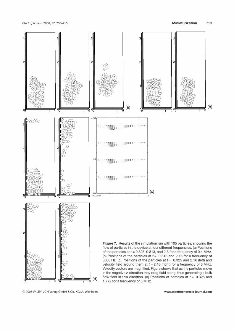
For the frequency of 0.4 MHz, the positions of particles att = 0.325, 0.813, and 2.3 are shown in Fig. 7a. As was thecase for two particles at this frequency, the particles levi-tate after the electric field is switched on. For the timeinterval during which the gap between the particles andthe channel bottom is small, the particles move in thenegative z-direction. This motion of particles is a result ofthe clockwise rotation of the particles near the bottom ofthe channel, as well as the orientation of the twDEP forcein this region. As the particles move away from the bot-tom, both their rotation speeds and velocity componentsin the negative z-direction decrease. Particles stop risingafter they reach a height above the electrodes at whichthe dielectrophoretic force is balanced by their buoyantweights. In addition, when the gap between the channelbottom and the particles is sufficiently large, the force dueto the rotation of the particles becomes negligible. ThetwDEP force becomes dominant, causing particles tomove in the z-direction.
The behavior of particles at the frequency of 3000 Hz(shown in Fig. 7b) is less complex, the primary force, inthis case, being the (negative) cDEP force which causesthe particles to levitate. Particles rise to a height wheretheir buoyant weight is equal to the dielectrophoreticforce, while also coming close to each other under theaction of particle-particle interaction forces. Indeed, inthis case, the rotation speeds of the particles are not largeenough to generate sufficiently large lubrication forces tokeep them apart.
The direction of motion of the particles at the frequency of3 MHz is rather unexpected, as they collectively move inthe negative z-direction (see Fig. 7c). The conventionaldielectrophoretic force is still repulsive, but not sufficientlylarge to levitate particles. Therefore, instead of rising, theparticles fall to the bottom surface of the device. As thedistance between them and the channel bottom de-creases, their rotation speeds increase. The particlesrotating in the clockwise direction near the bottom sur-
face are propelled in the negative z-direction. Further-more, since the particles near the channel bottom movefaster than those on the top, they spread over a largerarea. Another interesting feature of the dynamics is theestablishment of an average flow in the negative z-direc-tion due to the fact that the particles moving in thatdirection drag the liquid along (see Fig. 7c). Unlike in thetwo-particle case, the particles here do not get trapped atthe electrodes’ edges because they interact with eachother hydrodynamically and the established average fluidflow drags them in the negative z-direction. It is worthnoting that this flow drags even particles away from theelectrodes in the negative z-direction as it overcomes thetraveling wave dielectrophoretic force.
The qualitative motion of the particles at the frequency of5 MHz is similar to that observed in the previous case.The rotation speeds of the particles are, however, slightlylarger as the imaginary part of b is larger. Consequently,the particles’ velocities in the negative z-direction are alsolarger. The dielectrophoretic force, in this case, is attrac-tive, thus making the particles migrate toward the elec-trodes’ edges. However, due to the proximity of otherparticles and the induced liquid flow generated by themotion of particles in the negative z-direction, the parti-cles do not get trapped at the edges. Finally, we note thatit is reported in [20] that “. . . the twDEP regime occurredat frequencies where negative rather than positive DEPforces were operative.” Our simulations show that in thepositive DEP regime the particles remain close to theelectrodes embedded in the solid walls and thus theirmotion is primarily due to their spinning which arises dueto the traveling wave torque; this could also be the casefor the experiments reported in [20].
4.4 Discussion
In this paper, we have presented numerical simulations ofthe phenomenon of twDEP, in which polarized particlesare subjected to a nonuniform traveling electric field.Simulations were conducted in a plane microfluidic de-vice (for which electrodes are located in the bottom wall ofthe channel) with spherical particles having the propertiesof yeast cells. As in experiments on yeast cells (see, e.g.,[20]), the electrokinetics of the particles were found to bequite complex and strongly dependent on the variousparameters involved. Four values of the Clausius–Mossottifactor b (corresponding to four frequencies in the case ofan AC field) were investigated.
The motion of two particles initially located close to thebottom wall was quite revealing. In the case where boththe real and imaginary parts of b were relatively large, with
© 2006 WILEY-VCH Verlag GmbH & Co. KGaA, Weinheim www.electrophoresis-journal.com
Electrophoresis 2006, 27, 703–715 Miniaturization 713
Figure 7. Results of the simulation run with 105 particles, showing theflow of particles in the device at four different frequencies. (a) Positionsof the particles at t = 0.325, 0.813, and 2.3 for a frequency of 0.4 MHz.(b) Positions of the particles at t = 0.813 and 2.16 for a frequency of3000 Hz. (c) Positions of the particles at t = 0.325 and 2.16 (left) andvelocity field around them at t = 2.16 (right) for a frequency of 3 MHz.Velocity vectors are magnified. Figure shows that as the particles movein the negative z-direction they drag fluid along, thus generating a bulkflow field in this direction. (d) Positions of particles at t = 0.325 and1.772 for a frequency of 5 MHz.
© 2006 WILEY-VCH Verlag GmbH & Co. KGaA, Weinheim www.electrophoresis-journal.com
714 N. Aubry and P. Singh Electrophoresis 2006, 27, 703–715
a negative real part, the particles were observed to levi-tate from the effect of negative cDEP and then movealong the channel under the action of twDEP. The particle-particle interactions, however, were found to play a cru-cial role in two ways: (i) while electrostatic interactionsbrought particles together, hydrodynamic interactions(due to their spinning) prevented them to become tooclose, (ii) while particles spinned about their centers indi-vidually, they also formed a dumbbell as they approachedeach other, with the line joining their centers rotatingabout the y-axis. In the case where the real part of b waslarge and negative but the imaginary part of b was small,particles levitated under negative cDEP but neithertranslated along the channel nor rotated. In this case,electrostatic particle-particle interactions acted aloneand particles got close to each other to form chains. In thecase where the real part of b was small and negative, andthe imaginary part was important, particles did not levi-tate and thus did not reach the region where twDEP aloneis important. In this case, particles spinned and thereforemoved along the channel in the direction opposite to thatof the traveling wave dielectrophoretic force. In the casewhere the real and imaginary parts of b were important,with a positive real part, particles underwent positivecDEP and were thus attracted toward the electrodes’edges. Simultaneously, they also spinned due to thetorque action. This spinning motion propelled them alongthe channel wall in the direction opposite to that of thetraveling wave dielectrophoretic force.
While the simulated electrokinetics of 105 particlesreflected the basic features described above, somedynamics exclusively originating in the particle-particleinteractions of a large number of particles could also beobserved. The most interesting of such phenomena arosein the third case where the real part of b was small andnegative, and the imaginary part was important. Asexplained above, particles here propelled close to thewall in the direction opposite to that of the traveling wavedielectrophoretic force. The additional feature, however,was that this global motion of particles interacting witheach other hydrodynamically induced a flow in thatdirection.
Finally, we would like to emphasize on the importance ofparticle-particle interactions in almost all regimes studiedhere, indicating that investigations exclusively based onthe structure of the electric field, electrostatic force lines,and viscous Stokes drag (acting on one particle only) forma good starting point but exclude many features presentin the electrokinetic behavior of particles. In addition toparticle chaining, known to be due to electrostatic parti-cle-particle interactions, this paper has highlighted somecrucial hydrodynamic interactions between particles.
We gratefully acknowledge the support of the New JerseyCommission on Science and Technology through theNew-Jersey Center for Micro-Flow Control under AwardNumber 01–2042–007–25, and the W.M. Keck Foundationfor providing support for the establishment of the NJITKeck Laboratory for Electrohydrodynamics of Suspen-sions.
5 References
[1] Pohl, H. A., Dielectrophoresis, Cambridge University Press,Cambridge 1978.
[2] Jones, T. B., Electromechanics of Particles, Cambridge Uni-versity Press, Cambridge 1995.
[3] Green, N. G., Morgan, H., J. Phys. Chem. B 1999, 103, 41–50.
[4] Hughes, M. P., Morgan, H., Biotechnol. Prog. 1999, 15, 245–249.
[5] Washizu, M., Kurosawa, O., Arai, I., Suzuki, S., et al., IEEETrans. Indust. Appl. 1995, 30, 835–843.
[6] Hughes, M. P., Morgan, H., Rixon, J. F., Biochim. Biophys.Acta 2002, 1571, 1.
[7] Markx, G. H., Dyda, P. A., Pethig, R., J. Biotechnol. 1996, 51,175–180.
[8] Becker, F. F., Wang, X.-B., Huang, Y., Pethig, R., et al., J.Phys. D: Appl. Phys. 1994, 27, 2659–2662.
[9] Masuda, S., Washizu, M., Iwadare, M., IEEE Trans. Ind. Appl.1987, 23, 474–480.
[10] Hagedorn, R., Fuhr, G., Muller, T., Gimsa, J., Electrophoresis1992, 13, 49–54.
[11] Huang, Y., Pethig, R., Tame, J., Pethig, R., J. Phys. D 1993,26, 312–322.
[12] Hughes, M. P., Pethig, R., Wang, X. B., J. Phys. D 1996, 29,474–482.
[13] Wang, X. J., Wang, X. B., Becker, F. F., Gascoyne, P. R. C., J.Phys. D 1996, 29, 1649–1660.
[14] Morgan, H., Izquierdo, A. G., Bakewell, D., Green, N. G.,Ramos, A., J. Phys. D 2001, 34, 1553–1561.
[15] Schnelle, T., Hagedorn, R., Fuhr, G., Fiedler, S., Muller, T.,Biochim. Biophys. Acta 1993, 1157, 127–140.
[16] Wang, X. B., Huang, Y., Burt, J. P. H., Markx, G. H., Pethig,R., J. Phys. D 1993, 26, 1278–1285.
[17] Hughes, M. P., Pethig, R., Wang, X. B., J. Phys. D 1995, 28,474.
[18] Green, N. G., Ramos, A., Morgan, H., J. Electrostat. 2002,56, 235–254.
[19] Chen, D. F., Du, H., Li, W. H., Shu, C., J. Micromech. Micro-eng. 2005, 15, 1040–1048.
[20] Huang, Y., Wang, X. B., Tame, J. A., Pethig, R., J. Phys. D1993, 26, 1528–1535.
[21] Kadaksham, J., Singh, P., Aubry, N., J. Fluids Eng. 2004,120, 170.
[22] Kadaksham, J., Singh, P., Aubry, N., Mech. Res. Commun.2006, 33, 108–122.
[23] Singh, P., Aubry, N., Phys. Rev. E 2005, 72, DOI 016602.
[24] Bonnecaze, R. T., Brady, J. F., J. Chem. Phys. 1992, 96,2183–2204.
© 2006 WILEY-VCH Verlag GmbH & Co. KGaA, Weinheim www.electrophoresis-journal.com

Electrophoresis 2006, 27, 703–715 Miniaturization 715
[25] Klingenberg, D. J., van Swol, S., Zukoski, C. F., J. Chem.Phys. 1989, 91, 7888–7895.
[26] Kadaksham, J., Singh, P., Aubry, N., Electrophoresis 2004,25, 3625–3632.
[27] Kadaksham, J., Singh, P., Aubry, N., Electrophoresis 2005,26, 3738–3744.
[28] Glowinski, R. T., Pan, W., Hesla, T. I., Joseph, D. D., Int. J.Multiphase Flows 1998, 25, 755–794.
[29] Singh, P., Joseph, D. D., Hesla, T. L., Glowinski, R. T., Pan,W., J. Non-Newtonian Fluid Mech. 2000, 91, 165–188.
[30] Huang, Y., Holzel, R., Pethig, R., Wang, X. B., Phys. Med.Biol. 1992, 37, 1499–1517.
[31] Kadaksham, J., Batton, J., Singh, P., Aubry, N., Dielec-trophoretic manipulation of micro- and nanoscale particlesin microchannels, Nanotechnology World Forum 2003 Pro-ceedings, Marlborough, Massachusetts, June 23–25, 2003.
© 2006 WILEY-VCH Verlag GmbH & Co. KGaA, Weinheim www.electrophoresis-journal.com