Industrial enhanced-safety radio remote controls UDSeries
79
Ref.doc. : 319472N - EN Installation and user technical manual (Translated from French original version 319472M-FR) Industrial enhanced-safety radio remote controls UD Series EN UDE UDB2 - UWB UDR URR UCR UxCU
-
Upload
khangminh22 -
Category
Documents
-
view
3 -
download
0
Transcript of Industrial enhanced-safety radio remote controls UDSeries

Ref.doc. :
319472N - EN
Installation and user technical manual(Translated from French original version 319472M-FR)
Industrial enhanced-safety radio remote controls
UD Series
EN
UDE
UDB2 - UWB
UDR
URR
UCR
UxCU

- 2 - UD - 319472NFR DEEN
Table of contents1 - General safety rules and precautions .....................................................................p. 62 - Description and operating principle ........................................................................p. 73 - Unpacking the elements ...........................................................................................p. 84 - Description of elements..........................................................................................p. 10
4.1 Transmitter UDE ...........................................................................................................................p. 104.1.1 Labeling the transmitter function buttons ............................................................................................p. 11
4.2 Chargers and batteries .................................................................................................................p. 124.2.1 Battery storage precaution and general information .......................................................................... p. 124.2.2 Precaution when inserting battery pack in transmitter unit ................................................................. p. 124.2.3 Indication of remaining battery level ................................................................................................... p. 13
4.3 Electronic key ...............................................................................................................................p. 144.4 Receiver URR ..............................................................................................................................p. 164.5 Receiver UCR ..............................................................................................................................p. 174.6 Receiver UDR ..............................................................................................................................p. 18
5 - Delivery configuration ............................................................................................p. 206 - Installation ...............................................................................................................p. 21
6.1 Installation recommendations ......................................................................................................p. 216.2 Dimension and implementation of elements ................................................................................p. 21
6.2.1 Receiver URR .................................................................................................................................... p. 216.2.2 Receiver UCR .................................................................................................................................... p. 226.2.3 Receiver UDR .................................................................................................................................... p. 226.2.4 Infrared module UDF .......................................................................................................................... p. 236.2.5 Wall Bracket UDC1 for transmitter and battery .................................................................................. p. 236.2.6 Transmitter UDE................................................................................................................................. p. 246.2.7 Charger, voltage adapter and connector ............................................................................................ p. 24
6.3 Receiver position ..........................................................................................................................p. 256.4 UDF infrared module position (option) .........................................................................................p. 266.5 Marking the Controlled Equipment ...............................................................................................p. 266.6 Auxiliary control ............................................................................................................................p. 266.7 Wiring the radio receiver ..............................................................................................................p. 27
6.7.1 Instructions for electrical connection of the receiver .......................................................................... p. 276.7.2 Conductor wire sections to be observed ............................................................................................ p. 286.7.3 Opening the connection terminal strips on receivers URR and UCR ................................................. p. 286.7.4 Opening the connection terminal strips on receiver UDR .................................................................. p. 286.7.5 Wiring the power supply ..................................................................................................................... p. 296.7.6 Use of safety relays RS1 and RS2 ..................................................................................................... p. 306.7.7 Interference suppression of the installation and protection of relay outputs ...................................... p. 306.7.8 Protection of the power supply ........................................................................................................... p. 30
6.8 Wiring diagrams and assignment of buttons/relays for standard assemblies ..............................p. 316.8.1 Standard unit using receiver URR ...................................................................................................... p. 316.8.2 Standard units using receiver UCR .................................................................................................... p. 326.8.3 Standard units using receiver UDR .................................................................................................... p. 35
6.9 Choice of operating radio frequency ............................................................................................p. 396.9.1 Table of possible radio channels following the receiver used ............................................................ p. 396.9.2 Radio frequency tables ...................................................................................................................... p. 40
7 - Configuration and Parameterization .....................................................................p. 417.1 Procedure: «Locking-unlocking» the electronic key .....................................................................p. 427.2 Procedure: programming the radio frequency ..............................................................................p. 437.3 Procedure: time delay for the «Standby mode» function .............................................................p. 447.4 Procedure: Recopying the electronic key identity code ...............................................................p. 457.5 Receiverconfiguration .................................................................................................................p. 46
8 - Commissioning and use .........................................................................................p. 478.1 Precautions to be observed before commissioning .....................................................................p. 478.2 Starting the radio control ..............................................................................................................p. 48

UD - 319472N - 3 -DE FREN
8.3 Operating chronogram .................................................................................................................p. 498.4 Transmitter UDE indicator lights functions ...................................................................................p. 508.5 Receiver URR, UCR and UDR indicator lights functions .............................................................p. 528.6 Infrared module UDF indicator light .............................................................................................p. 54
9 - Functions .................................................................................................................p. 559.1 «Standby mode» function ............................................................................................................p. 55
10 - Options ...................................................................................................................p. 5610.1 «start-up by IR validation» option .................................................................................................p. 5610.2 «Transmitter/Receiver association on start-up» option ................................................................p. 57
11 - «Plug-in antenna» kit OWR02...............................................................................p. 5811.1 Description of the kit OWR02 .......................................................................................................p. 5811.2 Installation on URR or UCR receiver ...........................................................................................p. 58
12 - Technical data ........................................................................................................p. 5912.1 Transmitter UDE ...........................................................................................................................p. 59
12.1.1 Technical characteristics .................................................................................................................... p. 5912.1.2 Function button interlockings ............................................................................................................. p. 60
12.3 Standard battery UDB2 ................................................................................................................p. 6112.4 Fast charge battery UWB .............................................................................................................p. 6112.5 Receiver URR ..............................................................................................................................p. 62
12.5.1 Receiver URR technical characteristics ............................................................................................. p. 6212.5.2 Fuse characteristics on receiver URR ................................................................................................ p. 63
12.6 Receiver UCR ..............................................................................................................................p. 6412.6.1 Receiver UCR technical characteristics ............................................................................................. p. 6412.6.2 Fuse characteristics on receiver UCR ................................................................................................ p. 65
12.7 Receiver UDR ..............................................................................................................................p. 6612.7.1 Receiver UDR technical characteristics ............................................................................................. p. 6612.7.2 Fuse characteristics on receiver UDR ................................................................................................ p. 67
12.8 BNC plug-in antennas - use in 433-434MHz bands .....................................................................p. 6812.9 BNC plug-in antennas - use in 869MHz and 911-918MHz bands ................................................p. 69
13 - Servicing ................................................................................................................p. 7013.1 Servicing the UDE transmitter ......................................................................................................p. 7013.2 Servicing the receiver URR/UCR/UDR ........................................................................................p. 70
14 - FCC compliance ....................................................................................................p. 7115 - Warranty .................................................................................................................p. 7116 - Waste recycling and management .....................................................................p. 7217 - Product references...............................................................................................p. 7218 - Warning, avoid any mutual disturbance .............................................................p. 7219 - Manufacturer information .....................................................................................p. 7220 - CE Declaration of conformity ...............................................................................p. 73
20.1 Transmitter UDE ...........................................................................................................................p. 7320.2 Receiver URR ..............................................................................................................................p. 7420.3 Receiver UCR ..............................................................................................................................p. 7520.4 Receiver UDR ..............................................................................................................................p. 76
21 - FFC USA Certification documents .......................................................................p. 7721.1 Transmitter UDEE ........................................................................................................................p. 7721.2 Receiver UDRE ............................................................................................................................p. 78

- 4 - UD - 319472NFR DEEN
UD - 319472N - 5 -DE FREN
We thank you for your choice. You have just acquired the JAY Electronique UD Series radio control system, which offers you a configuration adapted to your application, easy to use and maintain, and with a high safety level.
The various components forming your JAY Electronique radio control system are designed to meet the safety requirements of the currently applicable and draft standards, and are compliant with the European directives (see section «CE Declaration of conformity», page 73 ).
For all questions concerning installation or use of your radio control system, contact our «Customer Service» :
service: Monday to Friday
Tel : + 33 (0)4.76.41.44.00
Email : [email protected]
The JAY Electronique UD Series radio control system is intended to control industrial equipment, vehicles and lifting devices, previously operated by pendant control box or control panel.
The use of the radio control system enables the operator to better focus on his work as it allows him to choose his observation position which is only limited by safety considerations (example: no one should be standing under a load).
The radio remote control does not remove, but completes and enhances the classic safety circuits (emergency stop circuits).

- 6 - UD - 319472NFR DEEN
1 - General safety rules and precautions
IMPORTANT :A radio control system is considered as a machine control device and as a safety component usedtostopamachineasspecifiedbytheEECMachineryDirective.All applicable rules must therefore be observed to ensure safe, correct operation of such devices.
Theoperatormustbeappropriatelytrainedandcertifiedtooperatemachinesbyradiocontrol.
The operator must have uninterrupted visibility of the manoeuvre which he is performing. When the operator’s direct field of view is inadequate, the liftingmachinerymust beequipped with auxiliary devices to improve visibility.
Whenseveralmachinesarebeingmovedsimultaneously,theequipmentmustbefittedout to limit to consequences of a possible collision.
To avoid any risks of electrocution, don’t open the receiver housing when powered. The opening of the housing must be done by ensuring that the power supply cables and control cables are out of voltage.
Never leave the transmitter unattended in any haphazard location, even though it is equipped with a “Standby Mode” function which automatically cuts out the system, see section ««Standby mode» function», page 55
Never leave the radio control transmitter on the ground. If doing so becomes indispensable, press the stop palmswitch on the radio control.
Never leave the transmitter to sunlight (eg vehicle windscreens), or near a heat source.
Ifseveralradiocontrolsareusedatthesamesite,differentradiofrequenciesshouldbeused, spaced by at least two channels (for example, channels 5, 7, 9,….). The more space there is between the chosen radio channels, the less the risks of disturbance are, see section «Choice of operating radio frequency», page 39
In the event of a malfunction, immediately shut down the installation by pressing thestop palmswitch on the transmitter, remove the electronic key and the battery.
For safety reasons, remove the electronic key when not in use. Store it in a safe and tracked down place.
The stop palmswitch button on transmitter should be manipulated to check if it is functional at minimum once a year.
Service your equipment and perform all the periodic checks as may be required by the intensity with which your equipment is used. Follow necessarily the instructions of cleaning described in the chapter «Servicing», page 69

UD - 319472N - 7 -DE FREN
2 - Description and operating principle
A radio control assembly is formed by two components :
a transmitter (UDE) + a receiver (for example : « UDR » type).
The transmitter transmits the commands to the receiver which operates its relay outputs according toapredefinedbutton/relayassignment.
The type of the radio link between the transmitter and the receiver is unidirectional.
This link between the two elements is ensured and secured by means of an «identity code» (uniqueandfixedcodeforeachproduct).
M
Radio transmitter
Radio receiver
- 8 - UD - 319472NFR DEEN
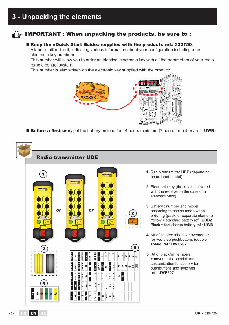
� Keep the «Quick Start Guide» supplied with the products ref.: 332750. Alabelisaffixedtoit,indicatingvariousinformationaboutyourconfigurationincluding«theelectronic key number». This number will allow you to order an identical electronic key with all the parameters of your radio remote control system. This number is also written on the electronic key supplied with the product:
� Before a first use, put the battery on load for 14 hours minimum (7 hours for battery ref.: UWB)
3 - Unpacking the elements
IMPORTANT : When unpacking the products, be sure to :
Radio transmitter UDE
UP
DOWN
EVERSE
RORWARD
F
NORTH
SOUTH
WEST
EAST
NORD
SUD
OUEST
EST
LEFT
RIGHT
•
12
•
1
•
12
12
3
34
3+4
12
1+2
1 2 3GATE
ON
OFF
SHUNT
+RPM
-RPM
12
1+2
4
7 8 9
4 5 6
•
2
•
3
•
34
43
•
3+4
3
électronique
électronique
électronique
or or
1
4
5
1. Radio transmitter UDE (depending on ordered model)
2. Electronic key (the key is delivered with the receiver in the case of a standard pack)
3. Battery : number and model according to choice made when ordering (pack, or separate element) Yellow = standard battery ref.: UDB2 Black = fast charge battery ref.: UWB
4. Kit of colored labels «movements» for two-step pushbuttons (double speed) ref.: UWE202
5. Kit of black/white labels «movements, special and customization functions» for pushbuttons and switches ref.: UWE207
3
2

UD - 319472N - 9 -DE FREN
Radio receiver URR / UCR / UDR
Battery charger (according choice made when ordering, standard pack or separate element)
Infrared module Only for an option requiring the use of an infrared signal.
(3 - Unpacking the elements)
or
or
or
or
1
42 3
1. Radio receiver URR or UCR or UDR (depending on ordered model)
2. Self-adhesive directional colored arrows, to be stuck onto controlled equipment (e.g. travelling crane) ref.: UWE002
3. Common wiring accessory ref.: UDWR12
4. In the case of a standard pack, the electronic key is delivered with the receiver.
1. Infrared module ref.: UDF1, delivered with M16 cable gland and mounting bracket.
1. Charger UBCU for battery UDB2 (110-230 VAC / 12VDC) or Charger UCCU for battery UWB (110-230 VAC / 5VDC)
2. Connector UBC1 for battery UDB2, to be connected to a stabilized power supply or car battery, 10 to 30VDC Black/white wire : +
3. Charger UCC1 Voltage adapter on vehicle socket, to charge battery UWB
URR UCR UDR
2
3
11
- 10 - UD - 319472NFR DEEN
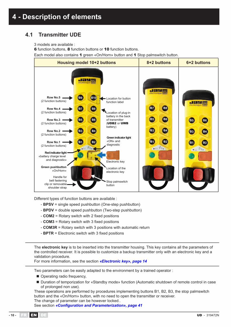
4.1 Transmitter UDE3 models are available :6 function buttons, 8 function buttons or 10 function buttons.Each model also contains 1 green «On/Horn» button and 1 Stop palmswitch button.
Housing model 10+2 buttons 8+2 buttons 6+2 buttons
Row No.5(2 function buttons)
Row No.4(2 function buttons)
Row No.3(2 function buttons)
Row No.2(2 function buttons)
Row No.1(2 function buttons)
Red indicator light«battery charge level
and diagnostic»
Green pushbutton«On/Horn»
Handle forbelt fastening
clip or removableshoulder strap
Stop palmswitchbutton
Location of theelectronic key
Electronic key
Green indicator light«ON» anddiagnostic
B1 B2
B3 B4
B5 B6
B7 B8
B9 B10 Location for buttonfunction label
Location of plug-inbattery in the backof transmitter(UDB2 or UWBbattery)
B1 B2
B3 B4
B5 B6
B7 B8
B1 B2
B3 B4
B5 B6
Differenttypesoffunctionbuttonsareavailable:- BPSV = single speed pushbutton (One-step pushbutton)- BPDV = double speed pushbutton (Two-step pushbutton)- COM2=Rotaryswitchwith2fixedpositions- COM3=Rotaryswitchwith3fixedpositions- COM3R = Rotary switch with 3 positions with automatic return- BPTR=Electronicswitchwith3fixedpositions
The electronic key is to be inserted into the transmitter housing. This key contains all the parameters of the controlled receiver. It is possible to customize a backup transmitter only with an electronic key and a validation procedure.For more information, see the section «Electronic key», page 14
Two parameters can be easily adapted to the environment by a trained operator : � Operating radio frequency, � Duration of temporization for «Standby mode» function (Automatic shutdown of remote control in case of prolonged non use).
These operations are performed by procedures implementing buttons B1, B2, B3, the stop palmswitch button and the «On/Horn» button, with no need to open the transmitter or receiver.The change of parameter can be however locked..See section «Configuration and Parameterization», page 41
4 - Description of elements

UD - 319472N - 11 -DE FREN
(4 - Description of elements)4.1.1 Labeling the transmitter function buttons
Thevariousbuttonfunctionsareidentifiedbymeansofadhesivelabels,tobestuckontothetransmitter housing, at each button location.
The labels are delivered in the form of boards to be used depending on the application.6,
4 m
m
22 mm
Reference : UWE202 (supplied as standard with the transmitter UDE)
Reference : UWE205
Kit of 90 black/white labels «movements, special and customizationfunctions» for pushbuttons and switches
Kit of 6 colored labels «movements» for two-step pushbuttons (double speed)
Kit of 48 blank labels (white) + 48 transparent labels for personalized labeling
UP
DOWN
EVERSE
RORWARD
F
NORTH
SOUTH
WEST
EAST
NORD
SUD
OUEST
EST
LEFT
RIGHT
•
12
•
1
•
12
12
3
34
3+4
12
1+2
1 2 3GATE
ON
OFF
SHUNT
+RPM
-RPM
12
1+2
4
7 8 9
4 5 6
•
2
•
3
•
34
43
•
3+4
3
6,4 mm22 m
m
UP
DOWN
EVERSE
RORWARD
F
NORTH
SOUTH
WEST
EAST
NORD
SUD
OUEST
EST
LEFT
RIGHT
•
12
•
1
•
12
12
3
34
3+4
12
1+2
1 2 3GATE
ON
OFF
SHUNT
+RPM
-RPM
12
1+2
4
7 8 9
4 5 6
•
2
•
3
•
34
43
•
3+4
3
6,4 mm
22 mm
B6 B4B1 B2button
B3 B5
Recommended standard labeling for buttons B1 to B6
6,4 mm
22 mm
black(down)
white(up)
brown(left)
green(right)
blue(backward)
yellow(forward)
Other label sheets available:
Reference : UWE207 (supplied as standard with the transmitter UDE)

- 12 - UD - 319472NFR DEEN
4.2 Chargers and batteries
2 battery types can be used with the transmitter: UDE :
BatteriesDedicated chargers
(important: only the JAY Electronics chargers listed below are suitable for recharging the batteries)
Battery indicator light
(back view)
Battery ref.: UDB2Standard batteryPower supply 10 to 30VDC(full charge in 14h)
Charger UBCUInput : 110-230VACOutput : 12VDC RED indicator light
«in charge» (This indicator light does not show the charge level)
Connector UBC1to be connected to a stabilized power supply or car battery, 10 to 30VDCBlack/white wire : +
Battery ref.: UWBFast charge batteryPower supply 5VDC (full charge in 7h)
Charger UCCUInput : 110-230VACOutput : 5VDC
ORANGE indicator light (fast charge) this light turns GREEN for the holding charge (the battery has been recharged at + 60%)
Charger UCC1On vehicle socketInput : 12 to 24VDCOutput : 5VDC
4.2.1 Battery storage precaution and general informationThebatterymustbestoredinaclean,dryplaceatthetemperaturesspecifiedinthetableunder section «Standard battery UDB2», page 61.
Self-dischargeisestimatedat15%thefirstmonthandthenlow(itismandatorytorechargethe battery pack every 6 months mini.). The number of full charge cycles is 500 minimum for battery UDB2 and 300 minimum for battery UWB (without damaging the battery capacity).
4.2.2 Precaution when inserting battery pack in transmitter unitAfter any change, check that the battery is correctly held in the location provided on the back of the transmitter.
If not, a 5-blink error message caused by micro-power failures may occur (according to fault list generated by the transmitter)
(4 - Description of elements)

UD - 319472N - 13 -DE FREN
4.2.3 Indication of remaining battery level
électronique
Two battery charge status display functions are provided on the transmitter:
1. When the remote control is powered up (stop palmswitch button out), the red indicator light on the transmitter shows the remaining battery level:
Status of the RED indicator light Battery charge status
Redindicatorlightoff Battery charge > 90%
RedindicatorlightflashesslowlyBattery charge between 90% and 10%
Redindicatorlightflashesquickly Battery charge < 10%The battery pack must absolutely be charged
2. During operation of the remote control (radio transmission), a LOW BATT (battery lowlevel,charge<10%)indicationisgivenbytheredindicatorlightwhichflashesquickly. This indication is used to inform the operator that the remote control will soon be unavailable (within around 15 minutes).
(4 - Description of elements)

- 14 - UD - 319472NFR DEEN
4.3 Electronic key
The electronic key used on the UD radio remote control system has a dual function :
� It enables start-up of the transmitter by limiting access to the remote control to trained and authorized persons only.
� It contains all the information required for operation of the product, including:
◊ the system identity code
◊ the last programmed frequency *
◊ the «Standby Mode» function duration *
◊ thetransmitterbuttonconfigurationandthetypeofbuttonused(pushorrotary type)
◊ and the option register
When the key is removed, it prevents unauthorized use of the transmitter. For this reason, it should be removed (like the battery) when the remote control is put away.
Preferably, the electronic key should be removed after pressing the stop palmswitch button. Removal of the key before the stop palmswitch button is pressed will result in a fault indication (2 flashes)andpassiveshutdownofthereceiver.
If necessary, it can be used to stop the system.
* = reprogrammable by a trained operator, see section «Configuration and Parameterization», page 41
The transmitter UDE also has an internal memory containing an identity code.
� If identity code of the electronic key matches the identity code stored in the UDE, the transmitter can be started up.
� If the identity code of the electronic key and that of the UDE do not match, the transmitterindicatestheproblembyitstwoindicatorlights(3flashes).Inthiscase,perform the programming procedure described in section «Procedure : Recopying the electronic key identity code», page 45
The transmitter cannot be started up without its electronic key
Identity code containedin electronic key
Identity code containedin transmitter UDE
Transmitter UDE can be started up provided :
Transmitter identity code=
Electronic key identity code
électronique
électronique
électronique
(4 - Description of elements)

UD - 319472N - 15 -DE FREN
In the event of a transmitter failure :Youcanrecovertheelectronickeyandconnectitonabackuptransmitter(buttonconfigurationshouldbethesameasthatofthefailedtransmitter,otherwise,buttonsthataredifferentwillbeineffective).
To perform this operation, you must reprogram the key identity code in the new transmitter UDE, as described in the procedure in section «Procedure : Recopying the electronic key identity code», page 45
if your electronic key is lost :You can order another electronic key (ref.: UDWE23) making sure to specify the following information when ordering :
� Unique 6-digit number of the old key (information indicated on the label stuck onto the «Quick Start Guide»).
or, if you do not have key number :
� the associated receiver identity code (on receiver descriptive label)
and
� thetransmitterbuttonconfigurationUDE.
This information will allow you to receive an electronic key identical to the old one containing all the parameters indicated above for your radio remote control.
(4 - Description of elements)

- 16 - UD - 319472NFR DEEN
V1V2
V3
R6 R5 R4 R3 R2 R1 RK RS2 RS1
222324
1 2 3 4 5 6 7 8 9 10 11 12 13 14 15 16 17 18 19 20 21
F1
F2
V4
V5VR
(4 - Description of elements)
4.4 Receiver URRThe receiver is formed by a basic PCB comprising 6 control relays.The basic board systematically comprises :
• 1 «Horn» relay (active when the transmitter «On/Horn» button is pressed, not auto-maintained)• 2 safety relays (active when the transmitter «On/Horn» button is pressed, auto-maintained until passive or active stop)
- 1 infrared module ref.: UDF can be connected to the receiver for the option ««start-up by IR validation» option», page 56- 3 models depending on power supply : 12-24 VDC, 24-48 VAC or 115-230 VAC-1standardrelayconfiguration(seesection»Standard unit using receiver URR», page 31)
Function relays terminal stripsV5 : Red indicator light «state of Horn (RK) relay»
Power supply terminal strips
Function relays
Cable gland «Control»
IR module terminal strips UDF(for the option ««start-up by IR validation» option», page 56) V1 : Green indicator light «Power ON»
V2 : Red indicator light «Wrong identity code + diagnostic»V3 : Green indicator light «Radio link established + diagnostic»
VR : red indicator lights «state of function relays»
Fixed antenna (possibility of using a BNC plug-in antenna with kit ref.: OWR02, see section ««Plug-in antenna» kit OWR02», page 58)
Cover«Power supply
and IRmodule UDF
(option)» passageway
Fuses «Power»
Terminal number Function
1 Neutral or 0 V (depending power supply version, see section «Installation»)2 115 VAC or 24 VAC or 24 VDC (depending power supply version, see section «Installation»)3 230 VAC or 48 VAC or 12 VDC (depending power supply version, see section «Installation»)4 - 5 Function relay R66 - 7 Function relay R58 - 9 Function relay R410 - 11 Function relay R312 - 13 Function relay R214 - 15 Function relay R116 - 17 «Horn» relay RK (controlled by the green button of the transmitter UDE)18 - 19 Safety relay No.2 RS220 - 21 Safety relay No.1 RS122 Terminal block for option «start-up by IR», Infrared module UDF - White wire23 Terminal block for option «start-up by IR», Infrared module UDF - Brown or Blue wire24 Terminal block for option «start-up by IR», Infrared module UDF - Black wire
Connector for serial link board (accessory, DialogUD software option)
Radio tuner
Safety relay No.1
V4 : Red indicator light «state of safety relays»
Safety relay No.2
Horn relay

UD - 319472N - 17 -DE FREN
V1
RK
RS2 RS1
R1
F1F2
7 6 5 4 3 2 1
8 9 10 11 12 13 14 15 16 17 18 19 20 21 22 23 24 25 26 27 28 29 30 31 32 33
R2 R3 R4 R5 R6 R7 R8 R9 R10 R11 R12
V2V3
V4
V5
VR
(4 - Description of elements)
4.5 Receiver UCRThe receiver is formed by a basic PCB comprising 12 control relays.The basic board systematically comprises :
• 1 «Horn» relay (active when the transmitter «On/Horn» button is pressed, not auto-maintained)• 2 safety relays (active when the transmitter «On/Horn» button is pressed, auto-maintained until passive or active stop)
- 2 models depending on power supply : 12-24 VDC, 48-230 VAC-4typesofrelayconfigurationdependingonthetransmittertowhichthereceiverisassociated(seechapter «Standard units using receiver UCR», page 32)
Fixed antenna (possibility of using a BNC plug-in antenna with kit ref.: OWR02, see section ««Plug-in antenna» kit OWR02», page 58)
Function relays terminal strips
(R1 to R12) Function relays
«Horn» RK relay
Fuses «Power»
Power supply terminal strips
Safety relays RS1 and RS2 terminal strips
Safety relays RS1 and RS2
Cover«Power supply»passageway
Cable gland «Control»
«Horn» RK relay terminal strips
V1 : Green indicator light «Power ON»V2 : Red indicator light «Wrong identity code + diagnostic»V3 : Green indicator light «Radio link established + diagnostic»
Radio tuner
Connector for serial link board (accessory, DialogUD software option)
Terminal number Function
1 Neutral or 0 V (depending power supply version, see section «Installation»)2 48 VAC or 12 VDC (depending power supply version, see section «Installation»)3 230 VAC or 24 VDC (depending power supply version, see section «Installation»)4 - 5 Safety relay No.1 RS16 - 7 Safety relay No.2 RS28 - 9 «Horn» RK relay (controlled by the green button of the transmitter UDE)10 - 11 Function relay R112 - 13 Function relay R214 - 15 Function relay R316 - 17 Function relay R418 - 19 Function relay R520 - 21 Function relay R622 - 23 Function relay R724 - 25 Function relay R826 - 27 Function relay R928 - 29 Function relay R1030 - 31 Function relay R1132 - 33 Function relay R12

- 18 - UD - 319472NFR DEEN
4.6 Receiver UDRThe receiver is formed by a basic board on which the following components can be connected :• 2 to 3 boards with 6 control relays• 1 RS232 serial link board for diagnostic and programming purposes (option and accessory)
The basic board systematically comprises :• 1 «Horn» relay (active when the transmitter «On/Horn» button is pressed, not auto-maintained)• 2 safety relays (active when the transmitter «On/Horn» button is pressed, auto-maintained until passive or active stop)
- Up to 3 infrared modules ref .: UDF can be connected to the receiver for option using an infrared signal.- 3 models depending on power supply : 12-24 VDC, 24-48 VAC or 115-230 VAC-4typesofrelayconfigurationdependingonthetransmittertowhichthereceiverisassociated(seechapter «Standard units using receiver UDR», page 35)
RK
RS1
RS2
F1F2
A B C
2021
2223
272625242928
30 31 32 33 34 35 36 37 38
V1
V2
V3
V4V5
VR
UDF IR module terminal strips (for IR options «Options», page 56)
BNC antenna connector
V1 : RED indicator light«power indicator»
V3 : Green indicator light «Radio link established + diagnostic»
V2 : Red indicator light «Wrong identity code + diagnostic»
Safety relay No.2
Safety relay No.1
V4 : Red indicator light «state of safety
relays»Connector for serial link board (accessory, DialogUD software option)
V5 : Red indicator light «state of Horn (RK) relay»
«Horn»RK relay
VR : red indicator lights «state of function relays»
Connectors of control relay boards
(3 boards of 6 relays can be connected)
«Control»cable gland
«Horn» RK relay terminal stripsSafety relay No.1 terminal stripsSafety relay No.2 terminal strips
«power supply» passagewayPower terminal strips
Passageways for IR modules ref.:UDF (for IR options «Options», page 56)
Fuses«Power supply»
(4 - Description of elements)
Radio tuner

UD - 319472N - 19 -DE FREN
Terminal number Function
3 x 1 to 12 Function relay boards (A, B, C Locations)21 Neutral or 0 V (depending power supply version, see section «Installation»)22 230 VAC or 48 VAC or 24 VDC (depending power supply version, see section «Installation»)23 115 VAC or 24 VAC or 12 VDC (depending power supply version, see section «Installation»)24 - 25 Safety relay No.1 RS126 - 27 Safety relay No.2 RS228 - 29 «Horn» RK relay (controlled by the green button of the transmitter UDE)30 (IR Option) infrared module UDF No.1 - white wire31 (IR Option) infrared module UDF No.1 - brown or blue wire32 (IR Option) infrared module UDF No.1 - black wire33 (IR Option) infrared module UDF No.2 - white wire34 (IR Option) infrared module UDF No.2 - brown or blue wire35 (IR Option) infrared module UDF No.2 - black wire36 (IR Option) infrared module UDF No.3 - white wire37 (IR Option) infrared module UDF No.3 - brown or blue wire38 (IR Option) infrared module UDF No.3 - black wire
(4 - Description of elements)

- 20 - UD - 319472NFR DEEN
5 - Delivery configuration
Radio channel number :- For standard packs, the pre-programmed radio channel is 01 (see chapter «Radio
frequency tables», page 40)-Forseparatedelements,theradiochannelconformstothedefinitionofthehardwarewhen
ordering (transmitter sale reference)
Duration of the temporization for the «Standby mode» function (automatic shutdown of remote control in case of prolonged non-use) :
- Programmed for 4mn
Button / relay configuration and button interlocking :- For standard packs, see section «Wiring diagrams and assignment of buttons/relays
for standard assemblies», page 31-Forseparatedelements,theseconfigurationsconformtothedefinitionofthehardware
when ordering, standard or special (customization sheet).
Locking of the UDE transmitter electronic key (access to UDE transmitter programming) :- The electronic key is delivered «unlocked», the following parameters can be directly
programmed by a trained and authorized operator (see operating procedures in chapter «Configuration and Parameterization», page 41) :
�Radio frequency (number of the radio channel), �Duration of the temporization for the «Standby mode» function

UD - 319472N - 21 -DE FREN
6 - Installation
6.1 Installation recommendations
Experienceshowsthatthefunctionalefficiencyofthesystembasicallydependsonthequality of the installation :
� Implementation of elements, � Marking of the controlled equipment, � Wiring quality of receiver and UDF infrared module (for options using an infrared signal),
� Interference suppression, � Electrical power supply protection, � Minimum and maximum current of relay outputs, � Choice of operating radio frequency.
The following symbol indicates essential information for the mounting holes.
6.2 Dimension and implementation of elements
6.2.1 Receiver URR
120
mm
75 m
m
200 mm 150 mm
40 m
m75
mm 35
mm
188 mm
90 m
m
40 m
m
30 mm
4xØ5 mm
30 mm
15 mm

- 22 - UD - 319472NFR DEEN
6.2.2 Receiver UCR
6.2.3 Receiver UDR
(6 - Installation)
100
mm
120
mm
170 mm240 mm30 mm
48 mm
47 mm
35mm
90 mm
229 mm
27mm
66 m
m
4 x Ø4 mm
250 mm160 mm
33252525
238 mm
130mm
4 x Ø 4 mm
80mm
15mm
120 mm
160mm
30mm
50 mm

UD - 319472N - 23 -DE FREN
6.2.4 Infrared module UDF
6.2.5 Wall Bracket UDC1 for transmitter and battery
(6 - Installation)
UDF module
Mounting bracket
(supplied)Ø6
Ø5
mm
mm
mm
mm
mm
mmmm
mmmm
mm
mm
électronique
127 mm
41 mm 56 mm
22 m
m
Ø4 mm
200mmmin.
BatteryUDB2 or UWB
Transmitter UDE
To charger or power supply connector

- 24 - UD - 319472NFR DEEN
6.2.6 Transmitter UDE
6.2.7 Charger, voltage adapter and connector(to charge battery UDB2 or UWB)
(6 - Installation)
électronique
électronique
82 mm 64 mm
électronique
232mm
251mm
288mm
~ 1,80 m
25 mm
80 mm
68 mm
56 mm
To charge battery UDB2 110-230 VAC / 12VDC, with EU, UK and US plugs
To charge battery UWB 110-230 VAC / 5VDC, with EU, UK and US plugs
UBCU
UCCU
UBC1
UCC1
To charge battery UDB2Connector to be connected to a stabilized power supply or a car battery, 10 to 30 VDC
To charge battery UWBVoltage adapter on vehicle socket.12-24VDC / 5VDC
white wire : +
~ 1,70 m
40 mm
60mm
28 mm~ 1,80 m
EU
UK
US
6+2 button model 8+2 button model 10+2 button model

UD - 319472N - 25 -DE FREN
(6 - Installation)
6.3 Receiver position
The remote control receiver should be mounted as close as possible to the control cabinet, vertical with respect to the machine structure. The receiver should be sheltered from shocks and weather.The antenna should be as far as possible from the class 3 cables and power components (power supply, motor, variable speed drive, etc.) while remaining within an area favorable to radio reception (and connection of the UDF infrared module(s), if the remote control is equipped with an IR option).
� The antenna should be located at a height, above the operator using the transmitter. No metal object which could create a screen should be located between the operator and the antenna.
� The antenna must be directed toward the transmitter working areas (downward with a hoist).
� Thecorrectorientationoftheantennaisshowninthefigurebelow:
* For the URR and UCR receivers, it is possible to use a removable antenna BNC and extension antenna thanks to kit ref. : OWR02. See chapter ««Plug-in antenna» kit OWR02», page 58
ME
TAL
RECEIVER
**
METAL METAL METAL
ME
TAL
ME
TAL
OK OK
OK

- 26 - UD - 319472NFR DEEN
6.4 UDF infrared module position (option)
See chapter «Options», page 56 for the description, installation and use of options using an infrared signal.
6.5 Marking the Controlled Equipment
Ifthereareseveralequipmentfittedwithsimilarradioremotecontrolsystemsworkinginthe same neighbourhood (e.g. in a plant), each transmitter and each electronic key shall carry a clear indication which tells the equipment driver which equipment is controlled by the transmitter in question.In this respect, signalling arrows are available as an accessory.Placethedifferentarrowsontheequipmenttobecontrolledsothateacharrowcolourcorresponds to that on the associated transmitter control button.The direction of movement of control buttons shall whenever possible be consistent with equipmentmotion.Symbolsshallbefixedinsuchpositionsthatthereisaclearandunambiguous relationship between the action on buttons in the control station and the corresponding direction of motion.
6.6 Auxiliary controlMeasures should be taken to ensure, that when the radio control is not in service, another control system can be used to ensure the safety of the operator and the manipulated load.
Reference : UWE002 (label sheet supplied as standard with the receiver)
4 Self-adhesive directional colored arrows
180mm
490 mm
Brown Green Blue Yellow
(6 - Installation)

UD - 319472N - 27 -DE FREN
6.7 Wiring the radio receiver
(6 - Installation)
6.7.1 Instructions for electrical connection of the receiver
To avoid any risks of electrocution, don’t open the receiver housing when powered. The opening of the housing must be done by ensuring that the power supply cables and control cables are out of voltage.
� The receiver power supply circuit must be directly related to the power supply circuit of the radio-controlled equipment.
� The receiver power supply circuit must have appropriate separation means (fuse(s) or circuitbreaker)orbenefitfromthepowersupplycircuitofradio-controlledequipment.
� When the receiver is supplied with 230 VAC, the power cable shall be separated from the «control» cable. In the case of use of EEC-type electrical plug, the color of the plug shall be “BLUE”.
� In cable path, power cables should be separated from the control cables, by observing a minimum spacing (20 cm) between the various classes : - Class 1 : Radio, analog signals - Class 2 : Mains for supply of various components, - Class 3 : Power control of motors, variable speed drives, etc... Ifonlyonecablepathisavailable,thecablesofdifferentclassesshouldbeseparatedas much as possible
� To maintain the reinforced insulation inside the receiver housing, it is mandatory to increase the insulation of cables carrying high voltages with insulating sleeves.
� Besurenottoexceedtheminimumandmaximumcharacteristicsspecifiedinchapter«Technical data», page 59, by installing, if necessary, an additional load or intermediate relays (auxiliary contacts in electrical control cabinet for power control, for example).
� Whenflexiblemulti-strandwiresareused,wireendferrulesmustbeusedtoavoidfalsecontacts and short-circuits.
0,25mm² 0,35mm² 0,50mm² 0,75mm² 1 mm² 1,5 mm²
1,5 mm²

- 28 - UD - 319472NFR DEEN
6.7.2 Conductor wire sections to be observed
Be sure to observe the min. /max. wire sections listed below for electrical connection of the receiver :
- Receiver power supply circuit- Connection to function relays- Connection to safety relays
0,5mm² to 1,5mm²
6.7.4 Opening the connection terminal strips on receiver UDR
To open the connection terminal strips :1. Insert a screwdriver vertically (flat blade 1.5 to
3 mm wide) into the slot on the lever,2. Exercise a moderated pressure up to opening
the terminal,3. Insert the wire,4. Remove the screwdriver. UDR
6.7.3 Opening the connection terminal strips on receivers URR and UCR
To open the connection terminal strips :1. Insert a screwdriver vertically (flat blade 1.5 to
3 mm wide) into the slot on the terminal block,2. Exercise a moderated pressure up to opening
the terminal,3. Insert the wire,4. Remove the screwdriver.
URRUCR
(6 - Installation)

UD - 319472N - 29 -DE FREN
6.7.5 Wiring the power supply
Attention: The electrical connection of the power supply must be made in such a way that when the main switch is deactivated, the receiver of the radio control unit is also deactivated.
(6 - Installation)
V1V2
V3
R6
R5
R4
R3
R2
R1
RK
RS2
RS1
222324
12
34
56
78
910
1112
1314
1516
1718
1920
21
F1 F2
V4
V5VR
V1
RK
RS2
RS1R
1 F1F2
76
54
32
1
89
1011
1213
1415
1617
1819
2021
2223
2425
2627
2829
3031
3233
R2
R3
R4
R5
R6
R7
R8
R9
R10
R11
R12
V2V3
V4
V5
VRRK
RS1
RS2
F1 F2
A
B
C
20212223
2726
2524
2928
303132333435
363738
V1
V2 V3
V4V5
VRRK
RS1
RS2
F1F2
ABC
2021
2223
27 26 25 24 29 28
303132333435363738
V1
V2
V3
V4 V5
VR
Receiver URR Receiver UCR Receiver UDR
Receiver reference
123
0 V+ 24 VDC+ 12 VDC
URR*C4*-B 12/24 VDC
123
N24 VAC48 VAC
URR*CA*-B 24/48 VAC
123
N115 VAC230 VAC
URR*CB*-B 115/230 VAC
123230 VAC
48 VACN
UCR**M* 48/230 VAC
123
UCR**4* 12/24 VDC
12 VDC0 v
24 VDC
12 VDC
0 v24 VDC
UDR**40* 12/24 VDC
2223 21 20
24 VAC
N48 VAC
UDR**A0* 24/48 VAC
2223 21 20
115 VAC
N230 VAC
UDR**B0* 115/230 VAC
2223 21 20

- 30 - UD - 319472NFR DEEN
6.7.7 Interference suppression of the installation and protection of relay outputsIn the event of inductive loads on the Transceiver relay outputs (contactor coils, solenoid valves or electro-brakes), interference suppression devices such as capacitors, RC circuits, diodes, etc. must be placed directly at the terminals of the controlled components using the shortest possible connections.
A pull-up resistor should also be used on the PLC controller inputs..
Examples of protection system to be used :
6.7.6 Use of safety relays RS1 and RS2The safety relays RS1 and RS2 are used to interrupt the common control line of the radio-controlled equipment :
K1 and K2 are guided contact contactors, to be integrated in the safety circuit of the system controlled.
The 2 safety relays RS1 and RS2 are activated when radio communication is set up between the transmitter and the receiver, and are automatically maintained up to the moment of active or passive shutdown (action on stop palmswitch button, loss of radio link, battery discharged, “Standby mode” function activated …).
* = The use of overvoltage limiting circuits will increase the service life of the relay contacts (ex: RC circuits with AC, diodes + Zener with DC, etc...).
6.7.8 Protection of the power supplyProtection against overcurrents (EN60204-1 §7.2) resulting from overvoltages.
A fuse or other protection device should be provided in the power supply circuit of the receiver (seewiringdiagramforstandardassemblies, itemF•nextpages)Theassignedcurrent isdefinedinchapter«Technical data», page 59.
AC
PLC input(pull-up resistor R=Vdc/Imin(10mA))
Output relay in AC(RC circuit)
Receiver Relay Output Terminal Block
Output relay in DC(Freewheel diode)
DC+-
DCR
++- -External
wiring
(6 - Installation)
L1 L2N2N1
K1
K1
RS1 RS2 R1 R2 R3
K2 Ra1 Ra2 Ra3
K2
S1 S2 S3 S4
RECEIVER
Externalwiring
* * * * *

UD - 319472N - 31 -DE FREN
6.8.1 Standard unit using receiver URRSafety relays RS1 and RS2 are switched on by the green pushbutton «On/Horn» of UDE transmitter, and hold in position until the transmitter stop palmswitch button «STOP» is pressed (active shutdown) or until the loss of the radio transmission (passive shutdown).
(6 - Installation)
6.8 Wiring diagrams and assignment of buttons/relays for standard assemblies
Unit ref: UD1R14•••
(a)= The power supply connection depends on the type of receiver and the power supply required: terminals 2 - 1 for power supplies 24 VDC, 24 VAC or 115 VAC terminals 3 - 1 for power supplies 12 VDC, 48 VAC or 230 VAC.
(b)= Relay life is increased by the use of surge limiters (ex.RC network for AC, Zener + diodes for DC, etc...)(c)= K1 and K2 contactors must have guided contacts(d)= Elementswhichindicatestartofremotecontrolledmachines(ex.:horn,rotaring/flashinglight,etc...)
RS1
K1 K2
K2
K1
K2
K1
L
F1Ua
+
F2 F3
NLN
RS2 RK R1 R2 R3 R4 R5 R6
211(a)
(b) (c) (d)
20 19 18 17 16 15 14 13 12 11 10 9 8 7 6 5 4
Receiverrelays
Externalwiringexample
Receiverpower supply
Externaldriven loads
Receiver URR
ACTIVATED relay of the receiver URR
RK R1 R2 R3 R4 R5 R6
OPERATED button of the transmitter
UDE
Green button«On/Horn» X
B1 X
B2 X
B3 X
B4 X
B5 X
B6 X
électronique
B1 B2
B3 B4
B5 B6
Transmitter with 6 one-step pushbuttons

- 32 - UD - 319472NFR DEEN
(6 - Installation)
6.8.2 Standard units using receiver UCRSafety relays RS1 and RS2 are switched on by the green pushbutton «On/Horn» of UDE transmitter, and hold in position until the transmitter stop palmswitch button «STOP» is pressed (active shutdown) or until the loss of the radio transmission (passive shutdown).
Unit ref: UD2C140C•ACTIVATED relay of the receiver UCR
(With dedicated second speed relay)
RK R1 R2 R3 R4 R5 R6 R7 R8 R9 R10 R11 R12
OPERATED button of the transmitter
UDE
Green button«On/Horn» X
B11st step X
2nd step X X
B21st step X
2nd step X X
B31st step X
2nd step X X
B41st step X
2nd step X X
B51st step X
2nd step X X
B61st step X
2nd step X X
(a)= The power supply connection depends on the type of receiver and the power supply required: terminals 2 - 1 for power supplies 48 VAC or 12 VDC terminals 3 - 1 for power supplies 230 VAC or 24 VDC
(b)= Relay life is increased by the use of surge limiters (ex.RC network for AC, Zener + diodes for DC, etc...)(c)= K1 and K2 contactors must have guided contacts(d)= Elementswhichindicatestartofremotecontrolledmachines(ex.:horn,rotaring/flashinglight,etc...)
Receiver UCR
RS1
K1 K2
K2
K1
K2
K1
L
F1Ua
+
F2 F3
NLN
RS2 RK R1 R2 R3 R4 R5 R6 R7 R8 R9 R10 R11 R12
51(a)
(b) (c) (d)
4 7 6 8 9 10 11 12 13 14 15 16 17 18 19 20 21 22 23 24 25 26 27 28 29 30 31 32 33
Receiverrelays
Externalwiringexample
Receiverpower supply
Externaldriven loads
électronique
B1 B2
B3 B4
B5 B6
Transmitter with 6 two-step pushbuttons

UD - 319472N - 33 -DE FREN
(6 - Installation)Units ref: UD2C240•• and UD3C240••
ACTIVATED relay of the receiver UCR (With common second speed relay)
RK R1 R2 R3 R4 R5 R6 R7 R8 R9 R10 R11 R12
OPERATED button of the transmitter
UDE
Green button«On/Horn» X
B11st step X
2nd step X X
B21st step X
2nd step X X
B31st step X
2nd step X X
B41st step X
2nd step X X
B51st step X
2nd step X X
B61st step X
2nd step X X
B71st step X
2nd step X X
B81st step X
2nd step X X
électronique
B1 B2
B3 B4
B5 B6
électronique
B1 B2
B3 B4
B5 B6
B7 B8
UD2C240••Transmitter with 6 two-step
pushbuttons
UD3C240••Transmitter with 8 two-step
pushbuttons
Transmitter with 10 one-step pushbuttons
Unit ref: UD5C240••
ACTIVATED relay of the receiver UCR
RK R1 R2 R3 R4 R5 R6 R7 R8 R9 R10 R11 R12
OPERATED button of the transmitter
UDE
Green button«On/Horn» X
B1 X
B2 X
B3 X
B4 X
B5 X
B6 X
B7 X
B8 X
B9 X
B10 X
électronique
B1 B2
B3 B4
B5 B6
B7 B8
B9 B10

- 34 - UD - 319472NFR DEEN
Unit ref: UD4C240••
ACTIVATED relay of the receiver UCR
RK R1 R2 R3 R4 R5 R6 R7 R8 R9 R10 R11 R12
OPERATED button of the transmitter
UDE
Green button«On/Horn» X
B11st step X
2nd step X X
B21st step X
2nd step X X
B31st step X
2nd step X X
B41st step X
2nd step X X
B51st step X
2nd step X X
B61st step X
2nd step X X
B7 X
B8
électronique
B1 B2
B3 B4
B5 B6
B7 B8 X électronique
B1 B2
B3 B4
B5 B6
B7 B8 X électronique
B1 B2
B3 B4
B5 B6
B7 B8 X X
électronique
B1 B2
B3 B4
B5 B6
B7 B8
Transmitter with 6 two-step pushbuttons
+ 1 one-step pushbutton+ 1 electronic switch with 3
positions
(6 - Installation)

UD - 319472N - 35 -DE FREN
6.8.3 Standard units using receiver UDRSafety relays RS1 and RS2 are switched on by the green pushbutton «On/Horn» of UDE transmitter, and hold in position until the transmitter stop palmswitch button «STOP» is pressed (active shutdown) or until the loss of the radio transmission (passive shutdown).
(6 - Installation)
Receiver UDR relay board A For standard units:UD5D3, UD6D3 and UD7D3
Externalwiringexample
RS1
K1 K2
K2
K1
K2
K1
L
F1Ua
+
F2 F3
NLN
LN
LN
RS2 RK Ra1 Ra2 Ra3 Ra4 Ra5 Ra6
2521(a)
(b) (c) (d)
24 27 26 29 28 1a 2a 3a 4a 5a 6a 7a 8a 9a 10a 11a 12a 1b 2b 3b 4b 5b 6b 7b 8b 9b 10b 11b 12b 1c 2c 3c 4c 5c 6c 7c 8c 9c 10c 11c 12c
Receiverpower supply
Receiverrelays
Externaldriven loads
K2
K1
F4
Rb1 Rb2 Rb3 Rb4 Rb5 Rb6
K2
K1
F5
Rc1 Rc2 Rc3 Rc4 Rc5 Rc6
relay board B relay board C
(a)= The power supply connection depends on the type of receiver and the power supply required: terminals 23 - 21 for power supplies 12 VDC, 24 VAC or 115 VAC terminals 22 - 21 for power supplies 24 VDC, 48 VAC or 230 VAC
(b)= Relay life is increased by the use of surge limiters (ex.RC network for AC, Zener + diodes for DC, etc...)(c)= K1 and K2 contactors must have guided contacts(d)= Elementswhichindicatestartofremotecontrolledmachines(ex.:horn,rotaring/flashinglight,etc...)
Unit ref: UD4D2••••
électronique
B1 B2
B3 B4
B5 B6
B7 B8
Transmitter with 6two-step pushbuttons
+ 1 one-step pushbutton+ 1 electronic switch with 3
positions
ACTIVATED relay of the receiver UDR
RK Ra1 Ra2 Ra3 Ra4 Ra5 Ra6 Rb1 Rb2 Rb3 Rb4 Rb5 Rb6
OPERATED button of the transmitter
UDE
Green button«On/Horn» X
B11st step X
2nd step X X
B21st step X
2nd step X X
B31st step X
2nd step X X
B41st step X
2nd step X X
B51st step X
2nd step X X
B61st step X
2nd step X X
B7 X
B8
électronique
B1 B2
B3 B4
B5 B6
B7 B8 X électronique
B1 B2
B3 B4
B5 B6
B7 B8 X électronique
B1 B2
B3 B4
B5 B6
B7 B8 X X

- 36 - UD - 319472NFR DEEN
(6 - Installation)
Units ref: UD2D2••••, UD3D2•••• and UD6D3••••ACTIVATED relay of the receiver UDR (With common second speed relay)
RK Ra1 Ra2 Ra3 Ra4 Ra5 Ra6 Rb1 Rb2 Rb3 Rb4 Rb5 Rb6 Rc1 Rc2 Rc3 Rc4 Rc5 Rc6
OPERATED button of the transmitter
UDE
Green button«On/Horn» X
B11st step X2nd step X X
B21st step X2nd step X X
B31st step X2nd step X X
B41st step X2nd step X X
B51st step X2nd step X X
B61st step X2nd step X X
B71st step X2nd step X X
B81st step X2nd step X X
B91st step X2nd step X X
B101st step X2nd step X X
électronique
B1 B2
B3 B4
B5 B6
électronique
B1 B2
B3 B4
B5 B6
B7 B8
électronique
B1 B2
B3 B4
B5 B6
B7 B8
B9 B10
UD2D2••••Transmitter with
6 two-step pushbuttonsReceiver with 12 relays
UD3D2••••Transmitter with
8 two-step pushbuttonsReceiver with 12 relays
UD6D3••••Transmitter with
10 two-step pushbuttonsReceiver with 18 relays

UD - 319472N - 37 -DE FREN
Units ref: UD1D29••• and UD5D3••••
ACTIVATED relay of the receiver UDR
RK Ra1 Ra2 Ra3 Ra4 Ra5 Ra6 Rb1 Rb2 Rb3 Rb4 Rb5 Rb6 Rc1 Rc2 Rc3 Rc4 Rc5 Rc6
OPERATED button of the transmitter
UDE
Green button«On/Horn» X
B1 X
B2 X
B3 X
B4 X
B5 X
B6 X
B7 X
B8 X
B9 X
B10 X
électronique
B1 B2
B3 B4
B5 B6
électronique
B1 B2
B3 B4
B5 B6
B7 B8
B9 B10
UD1D29•••Transmitter with
6 one-step pushbuttonsReceiver with 12 relays
UD5D3••••Transmitter with
10 one-step pushbuttonsReceiver with 18 relays
(6 - Installation)

- 38 - UD - 319472NFR DEEN
Unit ref: UD7D3••••ACTIVATED relay of the receiver UDR (With common second speed relay)
RK Ra1 Ra2 Ra3 Ra4 Ra5 Ra6 Rb1 Rb2 Rb3 Rb4 Rb5 Rb6 Rc1 Rc2 Rc3 Rc4 Rc5 Rc6
OPERATED button of the transmitter
UDE
Green button«On/Horn» X
B1 1st step X2nd step X X
B2 1st step X2nd step X X
B3 1st step X2nd step X X
B4 1st step X2nd step X X
B5 1st step X2nd step X X
B6 1st step X2nd step X X
B7 X
B8 X
B9
électronique
1+2
21
1+2
12
B10B9
B1 B2
B3 B4
B5 B6
B8B7
X électronique
1+2
21
1+2
12
B10B9
B1 B2
B3 B4
B5 B6
B8B7
X électronique
1+2
21
1+2
12
B10B9
B1 B2
B3 B4
B5 B6
B8B7
X X
B10
électronique
1+2
21
1+2
12
B10B9
B1 B2
B3 B4
B5 B6
B8B7
X électronique
1+2
21
1+2
12
B9 B10
B1 B2
B3 B4
B5 B6
B8B7
X électronique
1+2
21
1+2
12
B10B9
B1 B2
B3 B4
B5 B6
B8B7
X X
électronique
1+2
21
1+2
12
B10B9
B1 B2
B3 B4
B5 B6
B8B7
électronique
1+2
21
1+2
12
B10B9
B1 B2
B3 B4
B5 B6
B8B7
Transmitter with6 two-step pushbuttons
+ 2 one-step pushbuttons+ 2 rotary switches with 3
fixed positions
(6 - Installation)

UD - 319472N - 39 -DE FREN
See on the following page, all tables of the programmable radio channels according to frequency bands.
(6 - Installation)
6.9.1 Table of possible radio channels following the receiver used
URR UCR UDR
64 frequencies in 433-434MHz bands YES YES YES
12 frequencies in 869MHz band NO YES YES
64 frequencies in 911-918MHz NO NO YES
6.9 Choice of operating radio frequencyTo ensure good operating quality, it is important that the radio channel used be free (as well as the preceding and the following one) throughout the area in which the equipment will be controlled.If several radio remote controls operate on the same site, frequencies should be used at intervals of at least two channels (for example: No.5, No.7, No.9... the more spaced the channels chosen, less there will be the risk of mutual disturbance), and if necessary, a radio frequency plan must be drawn up for identifying the various controlled equipment and their working radio frequency.The programming of the radio channel is detailed in chapter «Procedure: programming the radio frequency», page 43

- 40 - UD - 319472NFR DEEN
(1)= list of available frequencies for Denmark(2)= list of available frequencies for Singapore(3)= list of available frequencies for the U.S.
6.9.2 Radio frequency tables
433-434 MHz bands 911-918 MHz bands 869 MHz band
Channel Nb.
Frequency MHz
Channel Nb.
Frequency MHz
Channel Nb.
Frequency MHz
Channel Nb.
Frequency MHz
Channel Nb.
Frequency MHz
01 433,100 33 433,900 (2) 01 911,800 (3) 33 915,100 (3) 01 869,9875
02 433,125 34 433,925 (1) (2) 02 911,900 (3) 34 915,200 (3) 02 869,9625
03 433,150 35 433,950 (2) 03 912,000 (3) 35 915,300 (3) 03 869,9375
04 433,175 36 433,975 (1) (2) 04 912,100 (3) 36 915,400 (3) 04 869,9125
05 433,200 37 434,000 (2) 05 912,200 (3) 37 915,500 (3) 05 869,8875
06 433,225 38 434,025 (1) (2) 06 912,300 (3) 38 915,600 (3) 06 869,8625
07 433,250 39 434,050 (2) 07 912,400 (3) 39 915,700 (3) 07 869,8375
08 433,275 40 434,075 (2) 08 912,500 (3) 40 915,800 (3) 08 869,8125
09 433,300 41 434,100 (2) 09 912,600 (3) 41 915,900 (3) 09 869,7875
10 433,325 42 434,125 (2) 10 912,700 (3) 42 916,000 (3) 10 869,7625
11 433,350 43 434,150 (2) 11 912,800 (3) 43 916,100 (3) 11 869,7375
12 433,375 44 434,175 (2) 12 912,900 (3) 44 916,200 (3) 12 869,7125
13 433,400 45 434,200 (2) 13 913,000 (3) 45 916,300 (3)
14 433,425 46 434,225 (2) 14 913,100 (3) 46 916,400 (3)
15 433,450 47 434,250 (2) 15 913,200 (3) 47 916,500 (3)
16 433,475 48 434,275 (2) 16 913,300 (3) 48 916,600 (3)
17 433,500 49 434,300 (2) 17 913,400 (3) 49 916,700 (3)
18 433,525 50 434,325 (2) 18 913,500 (3) 50 916,800 (3)
19 433,550 51 434,350 (2) 19 913,600 (3) 51 916,900 (3)
20 433,575 (1) 52 434,375 (2) 20 913,700 (3) 52 917,000 (3)
21 433,600 53 434,400 (2) 21 913,800 (3) 53 917,100 (3)
22 433,625 (1) 54 434,425 (2) 22 913,900 (3) 54 917,200 (3)
23 433,650 55 434,450 (2) 23 914,000 (3) 55 917,300 (3)
24 433,675 (1) 56 434,475 (2) 24 914,100 (3) 56 917,400 (3)
25 433,700 57 434,500 (2) 25 914,300 (3) 57 917,500 (3)
26 433,725 (1) 58 434,525 (2) 26 914,400 (3) 58 917,600 (3)
27 433,750 59 434,550 (2) 27 914,500 (3) 59 917,700 (3)
28 433,775 (1) 60 434,575 (2) 28 914,600 (3) 60 917,800 (3)
29 433,800 (2) 61 434,600 (2) 29 914,700 (3) 61 917,900 (3)
30 433,825 (1) (2) 62 434,625 (2) 30 914,800 (3) 62 918,000 (3)
31 433,850 (2) 63 434,650 (2) 31 914,900 (3) 63 918,100 (3)
32 433,875 (1) (2) 64 434,675 (2) 32 915,000 (3) 64 918,200 (3)
(6 - Installation)
UD - 319472N - 41 -DE FREN
7 - Configuration and Parameterization
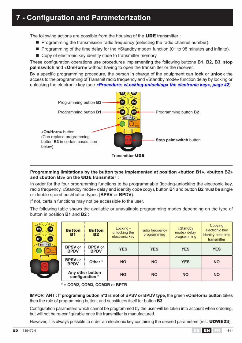
The following actions are possible from the housing of the UDE transmitter : � Programming the transmission radio frequency (selecting the radio channel number). � Programmingofthetimedelayforthe«Standbymode»function(01to98minutesandinfinite). � Copy of electronic key identity code to transmitter memory.
TheseconfigurationoperationsuseproceduresimplementingthefollowingbuttonsB1, B2, B3, stop palmswitch and «On/Horn» without having to open the transmitter or the receiver.Byaspecificprogrammingprocedure,thepersoninchargeoftheequipmentcanlock or unlock the access to the programming of Transmit radio frequency and «Standby mode» function delay by locking or unlocking the electronic key (see «Procedure: «Locking-unlocking» the electronic key», page 42).
Programming limitations by the button type implemented at position «button B1», «button B2» and «button B3» on the UDE transmitter :In order for the four programming functions to be programmable (locking-unlocking the electronic key, radio frequency, «Standby mode» delay and identity code copy), button B1 and button B2 must be single or double speed pushbutton types (BPSV or BPDV).If not, certain functions may not be accessible to the user.
The following table shows the available or unavailable programming modes depending on the type of button in position B1 and B2 :
IMPORTANT : If programing button n°3 is not of BPSV or BPDV type, the green «On/Horn» button takes then the role of programming button, and substitutes itself for button B3.Configurationparameterswhichcannotbeprogrammedbytheuserwillbetakenintoaccountwhenordering,butwillnotbere-configurableoncethetransmitterismanufactured.
However, it is always possible to order an electronic key containing the desired parameters (ref.: UDWE23).
Programming button B3
Programming button B1
Transmitter UDE
Programming button B2
Stop palmswitch button
«On/Horn» button(Can replace programmingbutton B3 in certain cases, seebelow)
électronique
B1 B2
B3 B4
B5 B6
électronique
B1 B2
B3 B4
B5 B6
Button B1
Button B2
Locking - unlocking the electronic key
radio frequency programming
«Standby mode» delay programming
Copyingelectronic key
identity code intotransmitter
BPSV or BPDV
BPSV or BPDV YES YES YES YES
BPSV or BPDV Other * NO NO YES NO
Any other button configuration * NO NO NO NO
* = COM2, COM3, COM3R or BPTR

- 42 - UD - 319472NFR DEEN
(7 - Configuration and Parameterization)
7.1 Procedure: «Locking-unlocking» the electronic keyThe transmit radio frequency and the «Standby mode» function delay are saved into the electronic key memory. Procedure below enables authorization (electronic key unlocked) or prohibition(electronickeylocked)ofanymodificationofthese2parameters.
Remark: if an operator attempts to program the radio frequency or the «Standby mode» function time delay when the electronic key is locked, the transmitter will indicate an «electronic key locked»error(alternatingflashesofits2indicatorlights).
1 Switch OFF the receiver.OFF
2 Press the transmitter stop palmswitch button and insert the electronic key into the transmitter housing.
électronique
3 While holding buttons B1, B2 and B3 * pressed, unlock the stop palmswitch button.
électronique
4Release the buttons.Indicator light statuses: :
� Electronic key locked : red indicator light on, green indicatorlightoff.
� Electronic key unlocked : red and green indicator lights on.
électronique électronique
5 Select «locked» or «unlocked» by pressing button B2: the selected mode is shown by the indicator lights.
électronique électronique
6 Validate the selected mode by pressing the green «On/Horn» button.
électronique
7 The information «locked electronic key» or «unlocked electronic key»isstoredintheelectronickey,theindicatorlightsturnoff. /
DATA
8 Exittheconfigurationmodebypressingthestop palmswitch button.
électronique
* = If the button B3 is not BPSV or BPDV type, use then the green «On/Horn» button.

UD - 319472N - 43 -DE FREN
(7 - Configuration and Parameterization)
7.2 Procedure: programming the radio frequencySee the radio frequency tables in the chapter «Installation», page 21 to select a radio channel number from those proposed in the frequency band used by the radio control.
1 Switch ON the receiver. ON
2 Press the transmitter stop palmswitch button and insert the electronic key into the transmitter housing.
électronique
3
While holding buttons B1 and B2 pressed, unlock the stop palmswitch button..If transmitter red and green indictor lights flash in alternation :The electronic key is locked. Press the stop palmswitch button and follow procedure described on chapter «Procedure: «Locking-unlocking» the electronic key», page 42 to unlock the electronic key. Then repeat this procedure from point 3.
électronique
4
The display of the current radio channel number is done by the flashingofthetransmitterindicatorlights:the red light represents the tens (0, 10, 20......60)andthe green light represents the units (0, 1, 2, 3......9)
Example : Theredlightflashes2timesandgreenlightflashes4 times = the radio channel number is No.24 (frequency: 433,675MHz on 433-434MHz bands)
électronique
+ -
Ex:
n°24 (433,675 MHz)
20
4
6050403020100
9876543210
5
Select the new radio channel using buttons B1 and B2.Press button B1 to increment the tens and button B2 to increment the units.During these operations, the newly selected channel is displayedbythe2indicatorlightsonthetransmitterwhichflashaccordingly.
électronique électronique
+1+10
6
Once the desired channel is selected (between 01 and 64 for 433-434MHZ/911-918MHz bands or 01 to 12 for 869MHz band), press the green «On/Horn» button to validate the selection.
� Briefly pressing «On/Horn» button : the transmitter sends the selected radio channel number to the receiver and saves its new working radio channel.
� By pressing and holding the «On/Horn» button (3 seconds approx) : the transmitter sends the selected channel number to the receiver (on each of the radio link channels between 01 to 64 for 433-434MHZ/911-918MHz bands or 01 to 12 for 869MHz band) and saves its new working channel. Wait until thetransmitterindicatorlightsnolongerflash(around30seconds) (this longer procedure is preferable and should be performed when you are not familiar with the initial working channel of the receiver).
électronique
DATA
7 Exittheconfigurationmodebypressingthestop palmswitch button.
électronique
8 Check that the receiver has changed the radio channel by performing the startup procedure

- 44 - UD - 319472NFR DEEN
(7 - Configuration and Parameterization)
7.3 Procedure: time delay for the «Standby mode» functionThe «Standby mode» function is described in chapter ««Standby mode» function».
1 Switch OFF the receiver.OFF
2 Press the transmitter stop palmswitch button and insert the electronic key into the transmitter housing.
électronique
3
While holding buttons B1 and B3 * pressed, unlock the stop palmswitch button.If transmitter red and green indictor lights flash in alternation :The electronic key is locked. Press the stop palmswitch button and follow procedure described on chapter «Procedure: «Locking-unlocking» the electronic key», page 42 to unlock the electronic key. Then repeat this procedure from point 3.
électronique
4
Thedisplayofthecurrenttimedelayisdonebytheflashingofthe transmitter indicator lights:the red indicator light represents the tens (0, 10, 20......90)andthe green indicator light represents the minutes (0, 1, 2, 3......9)Example : theredindicatorlightflashes1timeandthegreenindicatorlightflashes3times:thetimedelayis13mnbeforethe system comes to «Standby mode».
électronique
+ -
Ex:
13 min.
10
3
908070605040302010
0
9876543210
5Select the new time delay using buttons B1 and B2.Press button B1 to increment by ten minutes and button B2 to increment by one minute.During these operations, the new time selected is displayed by the two indicator lights on the transmitter.
électronique électronique
+1min
+10min
6
Once the desired «dead man» time have been selected (between 01 and 99), press the green «On/Horn» button to validate the selection.
Attention : 99 minutes duration corresponds to an infinite time delay for the «Standby mode» function.This function is then deactivated, if the user forgets to stop the transmitter (by pressing the stop palmswitch button), it remains in radio transmission until the battery is completely discharged.
électronique
7 The information «time delay for Standby mode function» is storedintheelectronickey,theindicatorlightsturnoff.
DATA. . min
8 Exittheconfigurationmodebypressingthestop palmswitch button.
électronique
* = If the button B3 is not BPSV or BPDV type, use then the green «On/Horn» button.
UD - 319472N - 45 -DE FREN
(7 - Configuration and Parameterization)
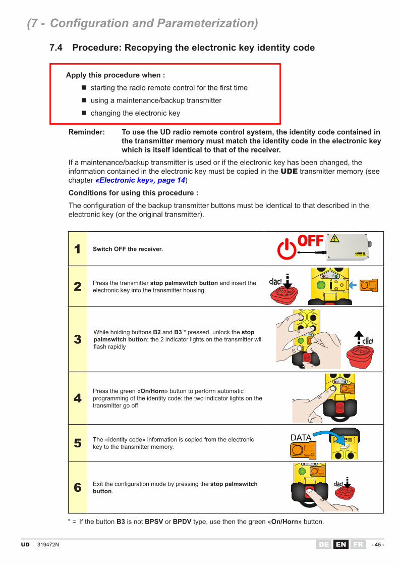
7.4 Procedure: Recopying the electronic key identity code
Apply this procedure when : � startingtheradioremotecontrolforthefirsttime
� using a maintenance/backup transmitter
� changing the electronic key
Reminder: To use the UD radio remote control system, the identity code contained in the transmitter memory must match the identity code in the electronic key which is itself identical to that of the receiver.
If a maintenance/backup transmitter is used or if the electronic key has been changed, the information contained in the electronic key must be copied in the UDE transmitter memory (see chapter «Electronic key», page 14)
Conditions for using this procedure :Theconfigurationofthebackuptransmitterbuttonsmustbeidenticaltothatdescribedintheelectronic key (or the original transmitter).
1 Switch OFF the receiver.OFF
2 Press the transmitter stop palmswitch button and insert the electronic key into the transmitter housing.
électronique
3While holding buttons B2 and B3 * pressed, unlock the stop palmswitch button: the 2 indicator lights on the transmitter will flashrapidly
électronique
4Press the green «On/Horn» button to perform automatic programming of the identity code: the two indicator lights on the transmittergooff
électronique
5 The «identity code» information is copied from the electronic key to the transmitter memory.
électroniqueDATA
6 Exittheconfigurationmodebypressingthestop palmswitch button.
électronique
* = If the button B3 is not BPSV or BPDV type, use then the green «On/Horn» button.

- 46 - UD - 319472NFR DEEN
(7 - Configuration and Parameterization)
7.5 Receiver configuration
Thefollowingparameterscanbeconfiguredonthereceiver:
� Interlocking controls : FactoryconfiguredorusingaPCviaseriallinkoptionref.:UDWR32 and programming software DialogUD ref.:UDWR37.
� Transmitter buttons / receiver function relays correspondence : FactoryconfiguredorusingaPCviaseriallinkoptionref.:UDWR32 and programming software DialogUD ref.:UDWR37.
� The receiving radio frequency : The radio reception frequency (channel No.) can be programmed in two ways :
◊ By the transmitter matched to the receiver implementing the transmitter frequency programming procedure, see chapter «Procedure: programming the radio frequency», page 43.
◊ By using a PC via serial link option ref.: UDWR32 and programming software DialogUD ref.:UDWR37.

UD - 319472N - 47 -DE FREN
8 - Commissioning and use
8.1 Precautions to be observed before commissioning
� Check that the electronic key matches the radio receiver (the identity code written ontheidentificationlabeloftheelectronickeymustbeidenticaltotheidentitycodewritten on the receiver’s label).
� Check that the selected radio channel number matches the frequency plan established on the site.
� PerformafinalchecktoverifythatthedesiredButton-Relaycorrespondenceisin place. During the previous check, the installer must check that when the green «On/Horn» button is pressed on startup, only the safety relays and function relays assigned to rotary switch selections are activated.
� Verify the priority general shutdown mode (remote control in operation and radio link established) :
◊ Active stop : Pressing the transmitter’s stop plamswitch button instantaneously deactivates the receiver safety relays (RS1 and RS2).
◊ Passive stop : Remove the electronic key (or battery) from the transmitter, the safety relays (RS1 and RS2) on the receiver must be deactivated within 2 seconds.
� Time delay for «Standby mode» function :Checktheeffectivetimedelayofthe«Standbymode»function(timedelaybeforeautomatic shutdown of transmitter) :Start up the remote control and leave it without activating any control. Note the time after which the safety relays (RS1 and RS2) of the receiver are deactivated and check whether this duration corresponds to that delivered in standard (4mn) or to the duration after a change by a trained and authorized operator (by following the procedure described in paragraph ««Standby mode» function», page 55.).
� Radio range limits and infrared range limit if the system is equipped with an IR option :
Evaluate the range limit of the transmitter/receiver assembly (by moving up to the range limit).Make sure of the good infrared area covering by the IR module(s).

- 48 - UD - 319472NFR DEEN
8.2 Starting the radio control
(8 - Commissioning and use)
1 Switch ON the receiver. ON
2 Take care that UDB2 or UWB battery is charged and is well connected to transmitter back.
3a Insert the electronic key into the transmitter housing.
électronique
3b
This step is to be followed only during the first start of the radio control :The information contained in the electronic key supplied with your remote control must be «copied» into the internal memory of the radio transmitter.For this, please follow the procedure described in the chapter «Procedure : Recopying the electronic key identity code», page 45
électroniqueDATA
4 Unlock the transmitter stop palmswitch button.
électronique
5
Press the green «On / Horn» button on the transmitter until the receiver is activated (activation of the RS1 and RS2 safety relays).
If the UD system is equipped with the «start with infrared validation» or «Transmitter/Receiver association on start-up» option:with the transmitter, aim for the UDF infrared module (s) delimiting the start zone while pressing the green «On / Horn» button.
électronique
60°
UDF
UDR / URR
20°
6 Use the radio remote control to control the equipment.
7To stop the radio control:Press the transmitter stop palmswitch button.The safety relays as well as the function relays of the receiver are deactivated.
électronique
If this procedure is not followed, the transmitter reports an error with its green and red indicator lights:
� «3 flashes»errortype(thegreenandredindicatorlightsofthetransmitterflash3times,pause,thenflash3times, etc...) : repeat the identity code copying procedure described in the chapter «Procedure : Recopying the electronic key identity code», page 45.
� «5 flashes»errortype(thegreenandredindicatorlightsofthetransmitterflash5times,pause,thenflash5times, etc...) : stop or start error (make sure that the battery is correctly inserted in the transmitter housing and resume the radio remote control startup procedure).

UD - 319472N - 49 -DE FREN
8.3 Operating chronogram
(8 - Commissioning and use)
Unlocking the transmitter's stop palmswitch button (switching ON the UDE transmitter)
3 states of the UDE
transmitter
Active
Standby
OFF
Activa
ted
Deacti
vated
Status of the RS1 and
RS2 safety relays of the
receiver
Status of the green
indicator light of
transmitter UDE
3 states of the red
indicator light of the
transmitter UDE
(battery charge state)
Battery charge > 90%
90% > Battery charge > 10%
90% > Battery charge > 10% Battery charge < 10%
Battery charge < 10%
Battery charge < 10%
Passive stop caused by discharged battery
Press the green "On / Horn" button (if using
an infrared option, place the transmitter in the IR start zone and aim at an IR module)
USING THE REMOTE
CONTROL SYSTEM
Last action on one of the
push buttons of the UDE transmitter
Time delay for «Standby mode»
function
Activestop
Passivestop
Stop of the remote control, caused by:
Active stop (press the transmitter stop
palmswitch button)
Passive stop («Standby mode» function activated, battery discharged,
electronic key removed from the transmitter
housing, radio disturbance etc...)
T
+ -
électronique
M

- 50 - UD - 319472NFR DEEN
(8 - Commissioning and use)
8.4 Transmitter UDE indicator lights functions
électronique
Error messages
Transmitter state (The transmitter stop
palmswitch is unlocked)
RED indicator
light + -
GREEN indicator
light Possible causes of failure Possible remedies
Before or after «On/horn» button is
pressedcontinuously OFF
- Battery is discharged or disconnected- Internal electronic failure
- Check battery chargeor- Contact the technical manager
Before or after «On/horn» button is
pressedcontinuously ON
- Electronic key is not connected totransmitter - Bad connection of the electronic key - Electronic key failure - Internal electronic failure
- Install electronic key on tranmitter before powering up the transmitteror- Contact the technical manager
Before or after «On/horn» button is
pressed
flash in a alternative way
- Access to the transmitter programming is prohibited (the electronic key is locked)
- If the radio frequency or «Standby mode» function time delay must be changed, the electronic key must be unlocked. Follow procedure described in «Configuration and Parameterization»or- Contact the technical manager
Before or after «On/horn» button is
pressed2 flashes - Electronic key contact fault
- Check the correct insertion of the electronic key into the transmitter housingor- Contact the technical manager
Before «On/horn» button is pressed 3 flashes
- The transmitter identity code is differentfromthatcontainedintheelectronic key- Internal electronic failure
- Apply the programming procedure: copy the identity code described in the chapter «Configuration and Parameterization»or- Contact the technical manager
Before or after «On/horn» button is
pressed4 flashes
-Thebuttonconfigurationisdifferentfrom that contained in the electronic andthephysicalconfigurationonthetransmitter- One or several function buttons aredefective- Internal electronic failure
- Contact the technical manager
Before «On/horn» button is pressed 5 flashes
- Micro power cuts due to a bad battery pack connection- Internal electronic failure
- Check that battery pack is correctly inserted in transmitter housingor- Contact the technical manager
Before «On/horn» button is pressed 6 flashes - Internal electronic failure - Contact the technical manager
Before «On/horn» button is pressed 7 flashes - Internal electronic failure - Contact the technical manager
Before «On/horn» button is pressed 8 flashes - Internal electronic failure - Contact the technical manager

UD - 319472N - 51 -DE FREN
(8 - Commissioning and use)
State of the battery charge level
Transmitter state (The transmitter stop
palmswitch is unlocked)
RED indicator light + -
GREEN indicator light
Corresponding function or message
Before «On/horn»button is pressed OFF continuously
ON Battery charge level > 90%
Before «On/horn»button is pressed
Slow flashing
continuously ON 90% > Battery charge level > LOW BATT* level
Before «On/horn»button is pressed fast flashing continuously
ON Battery charge level < or = LOW BATT* level
After «On/horn»button is pressed OFF Flashes Radio transmission
Battery charge level > 10%
After «On/horn»button is pressed fast flashing Flashes Radio transmission
Battery charge level < or = LOW BATT* level
* «LOW BATT level» = low battery (battery charge level lower than 10%), the battery must be recharged.

- 52 - UD - 319472NFR DEEN
(8 - Commissioning and use)
8.5 Receiver URR, UCR and UDR indicator lights functions
Receiver URR
Receiver UCR
Receiver UDR
V1V2
V3
R6 R5 R4 R3 R2 R1 RK RS2 RS1
222324
1 2 3 4 5 6 7 8 9 10 11 12 13 14 15 16 17 18 19 20 21
F1
F2
V4
V5VR
V1
RK
RS2 RS1
R1
F1F2
7 6 5 4 3 2 1
8 9 10 11 12 13 14 15 16 17 18 19 20 21 22 23 24 25 26 27 28 29 30 31 32 33
R2 R3 R4 R5 R6 R7 R8 R9 R10 R11 R12
V2V3
V4
V5
VR
RK
RS1
RS2
F1F2
A B C
2021
2223
272625242928
30 31 32 33 34 35 36 37 38
V1
V2
V3
V4V5
VR

UD - 319472N - 53 -DE FREN
(8 - Commissioning and use)
Indicator light name and color Mode Indication State Message
V1Power supply
GREEN (except for UDR :
RED)
All Receiver power supplyON The receiver is powered
OFF The receiver is not powered
V2Microprocessor No.1
RED
Normal Indicates validityof identity code
OFF No message reception
OFF Message reception with correct identity code
Regular flashes
Message reception with wrong identity code
Serial link RS232 Mode ON The receiver programming is in progress
V3Microprocessor No.2
GREEN
Normal Indicates radioreception quality
OFF No radio message reception
flashes Poor radio reception quality
ON Good radio reception quality
Serial link RS232 Mode OFF nothing to report
V4RS1 and RS2 safety
relays RED
All State of the safety relaysON Relays activated
(contacts are closed)
OFF Relays deactivated (contacts are open)
V5«Horn» RK relay
REDAll State of the «Horn» RK relay
ON Relay activated (closed contact)
OFF Relay deactivated (open contact)
VRfunction relays R1 to R6/R12/
R18 depending of receiver model
RED
All Indicates each function relays state
ON Relay activated (closed contact)
OFF Relay deactivated (open contact)
Error messagesIndicator light V2Microprocessor
No.1RED
Indicator light V3Microprocessor
No.2GREEN
Possible causes of failure Possible remedies
OFF (Mainboard power supplied but power supply red indicator light V1 remains
OFF)
- Melted fuses- Wrong power supply wiring- Internal electronic failure
- Check fuse state and calibre- Check power supply wiring diagram according to receiver modelor- Contact the technical manager
2 flashes 3 flashes 4 flashes 5 flashes 6 flashes 7 flashes
- Internal electronic failure - Contact the technical manager
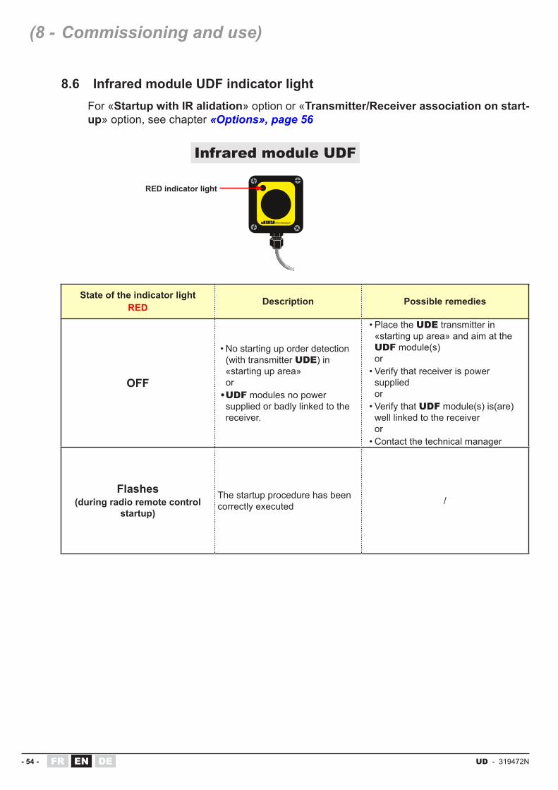
- 54 - UD - 319472NFR DEEN
(8 - Commissioning and use)
8.6 Infrared module UDF indicator lightFor «Startup with IR alidation» option or «Transmitter/Receiver association on start-up» option, see chapter «Options», page 56
RED indicator light
Infrared module UDF
State of the indicator lightRED Description Possible remedies
OFF
•No starting up order detection (with transmitter UDE) in «starting up area» or
• UDF modules no power supplied or badly linked to the receiver.
•Place the UDE transmitter in «starting up area» and aim at the UDF module(s) or•Verify that receiver is power
supplied or•Verify that UDF module(s) is(are)
well linked to the receiver or•Contact the technical manager
Flashes(during radio remote control
startup)
The startup procedure has been correctly executed /

UD - 319472N - 55 -DE FREN
9 - Functions
9.1 «Standby mode» functionThe safety function called «Standby mode» allows the automatic deactivation of the transmitter UDE (cut-off of the radio transmission)when the pushbuttons * (BPSV or BPDV type, and «On / Horn») are not actuated for a period of N minutes.
This shutdown of the radio transmission causes a safety state of the receiver by passive stop (deactivation of the RS1 and RS2 safety relays as well as function relays).
Restart after activation of the «Standby mode» function :
1. Press the stop palmswitch button on the transmitter.
2. Follow startup procedure described in chapter «Starting the radio control», page 48
Changing the time delay of «Standby mode» function :
The duration Nofthedelaycanbemodifiedbyatrainedandauthorizedoperator,followthe procedure described in the chapter «Procedure: time delay for the «Standby mode» function», page 44
Parameter N can take values from 01 to 98 minutes.
If the Nvalueconfiguredis99minutes,thetransmitterconsidersthatthetimedelayisinfinite(untilthebatteryisentirelydischarged).
Ondelivery,thedurationisdefinedfor4minutes.
* = Rotary switches COM2, COM3, COM3R and BPTR do not act on the «Standby mode» function. The manipulation of these types of buttons does not rearm the temporization.
If the operator has to use switches during a long period, the temporization must be lengthened or removed by programming, or the operator will have to rearm the temporization by pressing regularly on the «On/Horn» button or another pushbutton type

- 56 - UD - 319472NFR DEEN
10.1 «start-up by IR validation» optionSafety feature requiring IR validation to start up a remote controlled equipment can be used.
his option is available on URR and UDR receivers.
� To start the unit, the operator is required to point the transmitter toward the IR module UDF installed on the equipment to be controlled (see positioning below). This ensures an error-free match-up between the transmitter and the equipment to be controlled.
� TheIRstart-upfieldofactionhasarangeof0to25m(seeFig.A).
� 1 infrared module UDF can be connected to the receiver URR.
� 1 to 3 infrared modules UDF can be connected to the receiver UDR.
IMPORTANT : the wiring of the IR module(s) UDF must be separate from the power cables and all other sources which may generate interference (power regulator, for example).
Positioning of infrared modules UDF and IR range :
10 - Options
Start-up area(active infrared area)
Ran
ge (m
)
Max.rangerecommended
Fig. AIRfieldwidth (m)
Transmitter UDE
60°
UDF
UDR / URR UDR
UDRUDR / URR
60°
UDF
60°
UDF UDF
60°
UDF UDF
20° 20°
20°
20°
Zone1 Zone2
Max. rangeseefig.A
Max. rangeseefig.A
Max. rangeseefig.A
Max. rangeseefig.A
25
20
15
10
5
20°

UD - 319472N - 57 -DE FREN
10.2 «Transmitter/Receiver association on start-up» optionThis option allows the operator to select the receiver(s) to be controlled.
During the start-up phase (transmitter switched on), an encoded infrared message is transmitted to the receiver(s) pointed to by the operator. This option thus enables several transmitters (withdifference idcodeand frequency) tosuccessively takecontrolof thereceiver(s).
This is particularly useful when several receivers are implemented and you wish to operate any receiver with any transmitter with no mutual interference. This feature also allows you to select two receivers with one transmitter and have them operate simultaneously.
The infrared aiming characteristics are the same as those of the «start-up by infrared validation» option.
This option is only available on the receiver UDR.
� To start the unit, the operator is required to point the transmitter toward the IR module UDF installed on the equipment to be controlled (see positioning below). This ensures an error-free match-up between the transmitter and the equipment to be controlled.
� To «release» previously used equipment and to be able to work with other receivers, the operator must operate the stop palmswitch button of the transmitter UDE.
� TheIRstart-upfieldofactionhasarangeof0to25m(seeFig.Aonpreviouspage).
� 1 to 3 infrared modules UDF can be connected to the receiver UDR.
IMPORTANT : the wiring of the IR module(s) UDF must be separate from the power cables and all other sources which may generate interference (power regulator, for example).
(10 - Options)
A B C A B C A B C A B C D
électronique
B1 B2
B3 B4
B5 B6
électronique
B1 B2
B3 B4
B5 B6
Equipment selection(aim transmitter at receiver +
«On/Horn» button)Use of equipment
End of use (press emergency stop
button)
Conveyor moves> return to sequence No.1
Synoptic of operation: example for an overhead conveyor

- 58 - UD - 319472NFR DEEN
CAUTION
To avoid any risks of electrocution, don’t open the receiver housing when powered. The opening of the housing must be done by ensuring that the power supply cables and control cables are out of voltage.
11.1 Description of the kit OWR02The «plug-in antenna» kit is intended for URR and UCRreceiverswhichbothhaveafixedantenna.
This kit adds a BNC plug-in antenna connector instead ofthefixedantennaoutput.
11.2 Installation on URR or UCR receiver
11 - «Plug-in antenna» kit OWR02
1 Open the receiver housing.
2Removethefixedantennabydisconnectingthe antenna wire from the Tuner and unscrewingthefixedantennaconnectorfrom the receiver housing.
3Place the BNC connector (A).Connect the antenna wire and the ground wire to the pins shown opposite.
A
4 Place the serrated washer (B) and tighten thenut(C)withaflatwrench.
A B C
17mm 16mm
5Close the receiver housing.A BNC antenna or BNC extension can be installed now.
Kit OWR02
A B
C
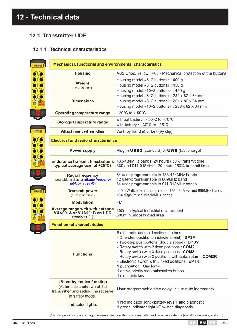
UD - 319472N - 59 -DE FREN
12 - Technical data
12.1 Transmitter UDE
12.1.1 Technical characteristics
Mechanical, functional and environmental characteristics
Housing ABS Choc, Yellow, IP65 - Mechanical protection of the buttons
Weight (with battery)
Housing model «6+2 buttons» : 400 gHousing model «8+2 buttons» : 450 gHousing model «10+2 buttons» : 490 g
Dimensions Housing model «6+2 buttons» : 232 x 82 x 64 mmHousing model «8+2 buttons» : 251 x 82 x 64 mmHousing model «10+2 buttons» : 288 x 82 x 64 mm
Operating temperature range - 20°C to + 50°C
Storage temperature range without battery : - 30°C to +70°Cwith battery : - 30°C to +35°C
Attachment when idles Wall (by handle) or belt (by clip)
Electrical and radio characteristics
Power supply Plug-in UDB2 (standard) or UWB (fast charge)
Endurance transmit time/buttons typical average use (at +25°C)
433-434MHz bands: 24 hours / 50% transmit time869 and 911-918MHz : 20 hours / 50% transmit time
Radio frequency (see table in chapter «Radio frequency
tables», page 40)
64 user-programmable in 433-434MHz bands12 user-programmable in 869MHz band64 user-programmable in 911-918MHz bands
Transmit power (built-in antenna)
<10 mW (license not required) in 433-434MHz and 869MHz bands<94 dBµV/m in 911-918MHz bands
Modulation FMAverage range with with antenna VUA001A or VUA001B on UDR
receiver (1)100m in typical industrial environment300m in unobstructed area
Functionnal characteristics
Functions
6differentskindsoffonctionsbuttons:- One-step pushbutton (single speed) : BPSV- Two-step pushbuttons (double speed) : BPDV-Rotaryswitchwith2fixedpositions:COM2-Rotaryswitchwith3fixedpositions:COM3- Rotary switch with 3 positions with auto. return : COM3R-Electronicswitchwith3fixedpositions:BPTR1 pushbutton «On/Horn»1 active priority stop palmswitch button1 electronic key
«Standby mode» function (Automatic shutdown of the
transmitter and setting the receiver in safety mode)
User-programmable time delay, in 1 minute increments
Indicator lights 1 red indicator light «battery level» and diagnostic1 green indicator light «On» and diagnostic
(1)= Range will vary according to environment conditions of transmitter and reception antenna (metal frameworks, walls… ).
électronique
électronique
électronique

- 60 - UD - 319472NFR DEEN
12.1.2 Function button interlockingsThefollowingfunctionbuttoninterlockingconfigurationsarepossible:
électronique
B1 B2
B3 B4
B5 B6
B7
B9 B10
B8
1st button ofinterlocked pair
2nd button ofinterlocked pair Acronym
Button No.1 Button No.2 B1-B2*
Button No.1 Button No.3 B1-B3
Button No.1 Button No.4 B1-B4
Button No.2 Button No.3 B2-B3
Button No.2 Button No.4 B2-B4
Button No.3 Button No.4 B3-B4*
Button No.3 Button No.5 B3-B5
Button No.4 Button No.6 B4-B6
Button No.5 Button No.6 B5-B6*
Button No.7 Button No.8 B7-B8
Button No.7 Button No.10 B7-B10
Button No.8 Button No.9 B8-B9
Button No.9 Button No.10 B9-B10
*= Standardinterlockingconfigurationsdefinedinsalesreference for UDR receiver (if choosing a unit in separate elements, see ref .: E330 sales documentation).
Foreachofthedesiredinterlockingconfigurations,simultaneousactiononthetwobuttonswillresultinthreeoperatingmodeswhichdependontheprogramsdefined:
� program «1» : By pressing the 2 button pair, the two commands are deactivated (cor-responding relays set to OFF).
� program «2» :Thefirstbuttonoftheinterlockedpairhaspriority (ex.: button No.1 and button No.2 interlocked: when these two buttons are pressed simultaneously, only button No.1 is acknowledged)
� program «3» : The 2nd button of the interlocked pair has priority (ex.: button No.2 and button No.4 interlocked: when these two buttons are pressed simultaneously, only button No.4 is acknowledged)
� program «X» : special (according to a customization data sheet).
(12 - Technical data)

UD - 319472N - 61 -DE FREN
(12 - Technical data)
12.3 Standard battery UDB2
Mechanical, functional and environmental characteristics
Housing ABS Choc, YellowIP40
Technology NiMH
Dimensions 40 x 96 x 23 mm
Storage temperature range -30°C to +35°C
Charging temperature 0°C to +45°C
Complete charging time 14 Hours
Indicator lights
Charging :1 red light indicator on the batteryCharge status :1 red light indicator on transmitter (low battery charge level)
Power supply by charger UBCU (110-230VAC / 12VDC)by connector UBC1 (10 to 30VDC)
Mechanical, functional and environmental characteristics
Housing ABS Choc, BlackIP40
Technology NiMH
Dimensions 40 x 96 x 23 mm
Storage temperature range -20°C to +35°C
Charging temperature 0°C to +35°C
Complete charging time 7 Hours
Partial charge time (at 20°C)
10 mn of charge get approx. 1 hour of autonomy1 hour of charge gets approx. 8 hours of autonomy6 hours of charge get approx. 12 hours of autonomy
Indicator lights
Charging :1 «2-color» indicator light on the battery pack: Orange = fast charge Green = slow charge and up-keep chargeCharge status :1 red light indicator on transmitter (low battery charge level)
Power supply By charger UCCU (110-230VAC / 5VDC)By voltage adapter UCC1 (6V)
12.4 Fast charge battery UWB
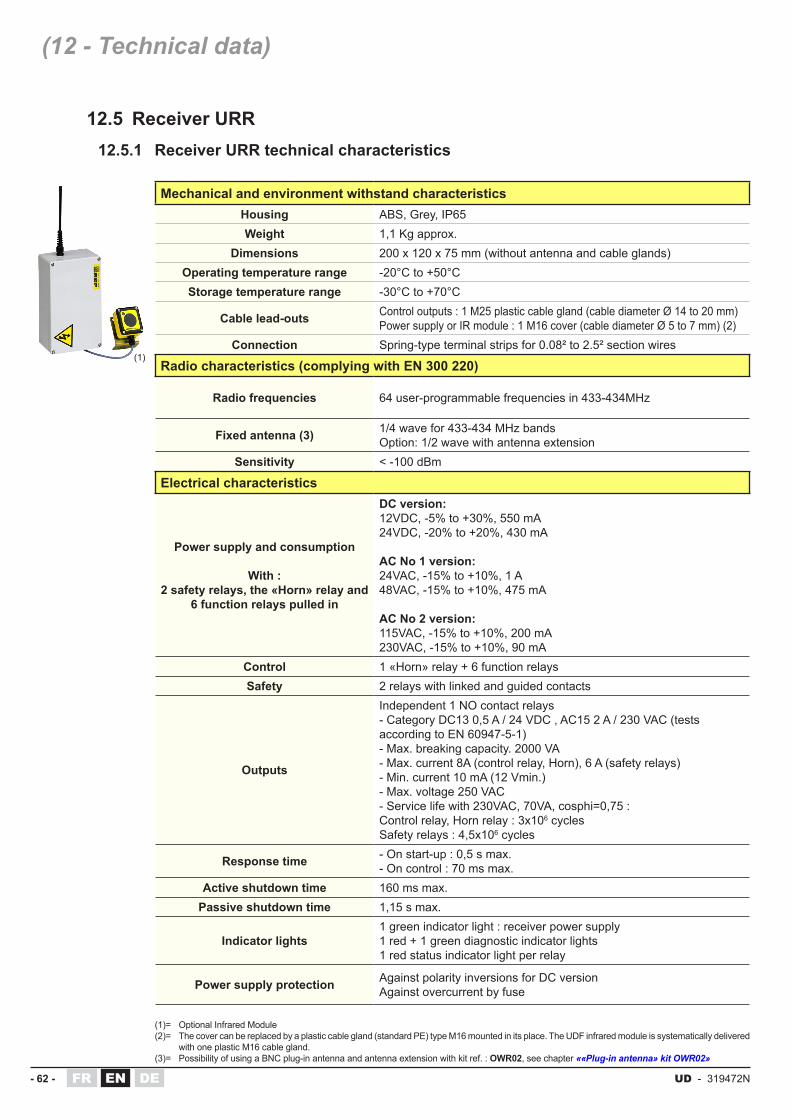
- 62 - UD - 319472NFR DEEN
12.5 Receiver URR
Mechanical and environment withstand characteristicsHousing ABS, Grey, IP65Weight 1,1 Kg approx.
Dimensions 200 x 120 x 75 mm (without antenna and cable glands)Operating temperature range -20°C to +50°CStorage temperature range -30°C to +70°C
Cable lead-outs Control outputs : 1 M25 plastic cable gland (cable diameter Ø 14 to 20 mm)Power supply or IR module : 1 M16 cover (cable diameter Ø 5 to 7 mm) (2)
Connection Spring-type terminal strips for 0.08² to 2.5² section wires
Radio characteristics (complying with EN 300 220)
Radio frequencies 64 user-programmable frequencies in 433-434MHz
Fixed antenna (3) 1/4 wave for 433-434 MHz bandsOption: 1/2 wave with antenna extension
Sensitivity < -100 dBm
Electrical characteristics
Power supply and consumption
With :2 safety relays, the «Horn» relay and
6 function relays pulled in
DC version:12VDC, -5% to +30%, 550 mA24VDC, -20% to +20%, 430 mA
AC No 1 version:24VAC, -15% to +10%, 1 A48VAC, -15% to +10%, 475 mA
AC No 2 version:115VAC, -15% to +10%, 200 mA230VAC, -15% to +10%, 90 mA
Control 1 «Horn» relay + 6 function relaysSafety 2 relays with linked and guided contacts
Outputs
Independent 1 NO contact relays- Category DC13 0,5 A / 24 VDC , AC15 2 A / 230 VAC (tests according to EN 60947-5-1)- Max. breaking capacity. 2000 VA- Max. current 8A (control relay, Horn), 6 A (safety relays)- Min. current 10 mA (12 Vmin.)- Max. voltage 250 VAC- Service life with 230VAC, 70VA, cosphi=0,75 :Control relay, Horn relay : 3x10⁶ cyclesSafety relays : 4,5x10⁶ cycles
Response time - On start-up : 0,5 s max.- On control : 70 ms max.
Active shutdown time 160 ms max.Passive shutdown time 1,15 s max.
Indicator lights1 green indicator light : receiver power supply1 red + 1 green diagnostic indicator lights1 red status indicator light per relay
Power supply protection Against polarity inversions for DC versionAgainst overcurrent by fuse
(1)= Optional Infrared Module(2)= The cover can be replaced by a plastic cable gland (standard PE) type M16 mounted in its place. The UDF infrared module is systematically delivered
with one plastic M16 cable gland.(3)= Possibility of using a BNC plug-in antenna and antenna extension with kit ref. : OWR02, see chapter ««Plug-in antenna» kit OWR02»
(1)
12.5.1 Receiver URR technical characteristics
(12 - Technical data)

UD - 319472N - 63 -DE FREN
12.5.2 Fuse characteristics on receiver URR
V1V2
V3
R6 R5 R4 R3 R2 R1 RK RS2 RS1
222324
1 2 3 4 5 6 7 8 9 10 11 12 13 14 15 16 17 18 19 20 21
F1
F2
V4
V5VR
Receiver power supply
CAUTION : Depending on receiver model ! Fuse characteristics (5x20)
Location of fuse tobe used
Receiver supplied with 12 VDC 1 A / 250 VAC / T F1
Receiver supplied with 24VDC 1 A / 250 VAC / T F2
Receiver supplied with 24VAC 1.6 A / 250 VAC / T F2
Receiver supplied with 48VAC 800 mA / 250 VAC / T F1
Receiver supplied with 115VAC 315 mA /250 VAC / T F2
Receiver supplied with 230VAC 160 mA / 250 VAC / T F1
(12 - Technical data)

- 64 - UD - 319472NFR DEEN
12.6 Receiver UCR
Mechanical and environment withstand characteristicsHousing ABS, Grey, IP65Weight 1,2 Kg approx.
Dimensions 120 x 240 x 100 mm (without antenna and cable glands)Operating temperature range -20°C to +50°CStorage temperature range -30°C to +70°C
Cable lead-outsControl outputs : 1 M32 plastic cable gland (for cable diameter Ø 20 à 26 mm)Power supply : 1 M16 cover (for cable diameter Ø 5 to 7 mm) (1)
Connection Spring-type terminal strips for 0.08² to 2.5² section wires
Radio characteristics (complying with EN 300 220)
Radio frequencies 64 user-programmable frequ. in 433-434MHz bands12 user-programmable frequ. in 869 MHz band
Fixed antenna (2) 1/4 wave for 433-434 MHz and 869 MHz bandsOption: 1/2 wave with antenna extension
Sensitivity Better than -100 dBm
Electrical characteristics
Power supply and consumption
With :2 safety relays, the «Horn» relay and
5 function relays pulled in
DC version:12VDC, 0 to +25%, 675mA and 188mA idle24VDC, -15% to +20%, 675mA and 188mA idleAC version:48 VAC, -15% to +10%, 550 mA230 VAC, -15% to +10%, 70 mA
Control 12 relays + 1 «Horn» relaySafety 2 relays with linked and guided contacts
Number of output relays simultaneously controllable 8 (including «RS1-RS2» safety relays and the «horn» relay)
Outputs
Independent 1 NO relays- Category DC13 0,5 A / 24 VDC , AC15 2 A / 230 VAC (tests according to EN 60947-5-1)- Max. breaking capacity: 2000 VA- Max. current: 8A (control relays and «Horn» relay), 6 A («Safety» relays)- Min. current: 10 mA (12 Vmin.), 100 mA recommended- Max. voltage: 250 VAC- Service life with 230 VAC, 70 VA, cosphi=0,75 : Control relay, Horn relay : 3x10⁶ cyclesSafety relays : 4,5x10⁶ cycles
Response time - On start-up : 0,5 s max.- On control : 70 ms max.
Active shutdown time 160 ms max.
Passive shutdown time 1,15 s max.
Indicator lights1 green indicator light : receiver power supply1 red + 1 green diagnostic indicator lights1 red status indicator light per relay
Power supply protection - Against overcurrent by fuse
12.6.1 Receiver UCR technical characteristics
(12 - Technical data)
(1)= The cover can be replaced by a plastic cable gland (standard PE) type M16 mounted in its place.(2)= Possibility of using a BNC plug-in antenna and antenna extension with kit ref. : OWR02, see chapter ««Plug-in antenna» kit OWR02»

UD - 319472N - 65 -DE FREN
V1
RK
RS2 RS1
R1
F1F2
7 6 5 4 3 2 1
8 9 10 11 12 13 14 15 16 17 18 19 20 21 22 23 24 25 26 27 28 29 30 31 32 33
R2 R3 R4 R5 R6 R7 R8 R9 R10 R11 R12
V2V3
V4
V5
VR
12.6.2 Fuse characteristics on receiver UCR
V1
RK
RS2 RS1
R1
F1F2
7 6 5 4 3 2 1
8 9 10 11 12 13 14 15 16 17 18 19 20 21 22 23 24 25 26 27 28 29 30 31 32 33
R2 R3 R4 R5 R6 R7 R8 R9 R10 R11 R12
V2V3
V4
V5
VR
Receiver power supply
CAUTION : Depending on receiver model ! Fuse characteristics (5x20)
Location of fuse tobe used
Receiver supplied with 12 VDC 1 A / 250 VAC / T F1
Receiver supplied with 24VDC 1 A / 250 VAC / T F2
Receiver supplied with 48VAC 800 mA / 250 VAC / T F2
Receiver supplied with 230VAC 160 mA / 250 VAC / T F1
(12 - Technical data)

- 66 - UD - 319472NFR DEEN
(12 - Technical data)
12.7 Receiver UDR
Mechanical and environment withstand characteristicsHousing ABS, Grey, IP65Weight 2 Kg approx.
Dimensions 160 x 250 x 120 mm (without antenna and cable glands)Operating temperature range -20°C to +50°CStorage temperature range -30°C to +70°C
Cable lead-outsControl: 1 plastic cable gland M32 (Ø 20 to 26 mm cables)IR Modules: 3 cover M16 (Ø 5 to 7 mm cables) (2)Power supply: 1 cover M16 (Ø 5 à 7 mm cables) (2)
Connection Spring-type terminal strips for 0.08² to 2.5² section wires
Radio characteristics (complying with EN 300 220)
Radio frequencies64 user-programmable frequ. in 433-434MHz bands12 user-programmable frequ. in 869 MHz band64 user-programmable frequ. in 911-918MHz bands
Antennas 1/4 wave for 433-434, or 869, or 911-918 MHz bands.Option 1/2 wave with antenna extension
Sensitivity < -100 dBm
Electrical characteristics
Power supply and consumption (3)
With :2 safety relays,
8 function relays pulled in, and 3 IR UDF modules connected to
receiver
DC version:12VDC, 0 to +25%, 675mA and 188mA idle24VDC, -15% to +20%, 675mA and 188mA idleAC No 1 version:24VAC, -15% to +10%, 850 mA48VAC, -15% to +10%, 400 mAAC No 2 version:115VAC, -15% to +10%, 180 mA230VAC, -15% to +10%, 85 mA
Control 1 «Horn» relay + 12 or 18 function relaysSafety 2 relays with linked and guided contacts
Outputs
Independent 1 NO relays- Category DC13 0,5 A / 24 VDC , AC15 2 A / 230 VAC- Max. breaking capacity: 2000 VA- Max. current: 8A (control relays and «Horn» relay), 6 A («Safety» relays)- Min. current: 10 mA (12 Vmin.), 100 mA recommended- Max. voltage: 250 VAC- Service life with 230 VAC, 70 VA, cosphi=0,75 : Control relay, Horn relay : 3x10⁶ cyclesSafety relays : 4,5x10⁶ cycles
Response time - On start-up : 0,5 s max.- On control : 55 ms max.
Active shutdown time 145 ms max.Passive shutdown time 1,1 s max.
Indicator lights- 1 red «power on» indicator light- 1 red indicator light + 1 green diagnostic indicator light- 1 red status indicator light per relay
Power supply protection - Against polarity inversions for DC versions- Against overcurrents by fuse
12.7.1 Receiver UDR technical characteristics
(1)
(1)= Optional Infrared Modules(2)= The cover can be replaced by a plastic cable gland (standard PE) type M16 mounted in its place. The UDF infrared module is systematically
delivered with one plastic M16 cable gland.(3)= The number of function relays controlled simultaneously is limited to 10 relays with 1 UDF module connected to UDR receiver, or to 9 relays
with 2 UDF modules connected, or to 8 relays with 3 UDF modules connected.

UD - 319472N - 67 -DE FREN
(12 - Technical data)
RK
RS1
RS2
F1F2
A B C
2021
2223
272625242928
30 31 32 33 34 35 36 37 38
V1
V2
V3
V4V5
VR
12.7.2 Fuse characteristics on receiver UDR
Receiver power supply
CAUTION : Depending on receiver model ! Fuse characteristics (5x20)
Location of fuse tobe used
Receiver supplied with 12 VDC 1 A / 250 VAC / T F2
Receiver supplied with 24VDC 1 A / 250 VAC / T F1
Receiver supplied with 24VAC 1,6 A / 250 VAC / T F2
Receiver supplied with 48VAC 800 mA / 250 VAC / T F1
Receiver supplied with 115VAC 315 mA / 250 VAC / T F2
Receiver supplied with 230VAC 160 mA / 250 VAC / T F1

- 68 - UD - 319472NFR DEEN
(12 - Technical data)
12.8 BNC plug-in antennas - use in 433-434MHz bands

UD - 319472N - 69 -DE FREN
12.9 BNC plug-in antennas - use in 869MHz and 911-918MHz bandsAntenna reference: VUA001BBrand name: EBDSFrequency Range: 890-960 MHzAntenna gain: 1.5 dBi (need grounded 16x16cm)Type: straight, 1/4 wave, BNC connectionApproximate length: 180mm
Antenna supplied as standard with the Transceiver UDR
Antenna reference: VUA002BBrand name: PROCOMFrequency Range: 890-960 MHzAntenna gain: 5 dB (compared to 1/4 wave)Type: straight, 1/2 wave, BNC connectionApproximate length: 250mm
Antennas references: •VUA100BH (with 0,5m cable)•VUA102BH (with 2m cable)•VUA105BH (with 5m cable)•VUA110BH (with 10m cable)
Brand name: ASTELFrequency Range: 860-960 MHzAntenna gain: 4 dBiType: through insulated remote, 1/2 wave, BNC connectionApproximate length: 190mmRequired drill hole: 15mm
Antennas references:•VUA103BM (with 3m cable)•VUA105BM (with 5m cable)
Brand name: ASTELFrequency Range: 806-870 MHzAntenna gain: 5 dBi (need grounded 60x60cm)Type: insulated magnetic remote, tuned, BNC connectionApproximate length: 320mm
Antennas references:•VUA103BV (with 3m cable)•VUA105BV (with 5m cable)
Brand name: ASTELFrequency Range: 900-920 MHzAntenna gain: 2 dBiType: through uninsulated remote, 1/4 wave, BNC connectionApproximate length: 100mmRequired drill hole: 12mm or 19mm (ring 2 diameters supplied)

- 70 - UD - 319472NFR DEEN
13 - Servicing
13.1 Servicing the UDE transmitter
13.2 Servicing the receiver URR/UCR/UDR
BEFORE STARTING ANY SERVICING OPERATION, SWITCH OFF THE MAIN POWER SUPPLY FOR THE SYSTEM CONTROLLED
� Housing of the UDE transmitter must not be opened. The UDE transmitter can be dismanteldonlybeatrainedstaff,inasuitableenvironment,sparepartscanbechangedonly by identical and original parts.
� If one of the membranes of the function buttons or the seal of the transmitter is damaged, the transmitter must not be any more used until replacement of these tightness spare parts. In opposite case, any liquid, any dust or any foreign body can damage the transmitter.
� The attention of the user is attracted to the risks of the use of the remote control in an environment containing solvents of polymers or glues which can degrade the good functioning of transmiiter mechanical components.
� Verify regularly the good state of the transmitter, paying a special attention to the function button membranes, to the electronic key connector and to the battery connector.
� Clean the transmitter by eliminating any foreign body. Use only non-aggressive cleansers based on soapy solution.
� Check the following points:
◊ The electrical connection of the receiver to the equipment to be controlled.
◊ Contacts of function relays.
◊ Correct operation of stop circuits, active and passive.
◊ Condition of cover seal, tightening of screws and cable glands and tightness of antenna (check that it is clean and if BNC connector is present, check that it is not oxidized).
� Clean the receiver by eliminating any foreign body. Use only non-aggressive cleansers based on soapy solution.
� To check operation of the active stop function (UD system started up) : simply press the stop palmswitch button on the transmitter. The safety relays of the receiver must then be deactivated immediately.
� To check operation of the passive stop function (UD system started up) : simply remove the electronic key or remove the battery from the transmitter or wait until «Standby mode» function is activated (automatic shutdown of the transmitter), the safety relays of the receiver must then be deactivated within 2 seconds

UD - 319472N - 71 -DE FREN
14 - FCC compliance
15 - Warranty
UDEE / UDRE complies with Part 15 of the FCC Rules. Operation is subject to the following two conditions:(1) this device may not cause harmful interference,and(2) this device must accept any interference received, including interference that may cause undesired operation.Theuser thatchangesormodificationsnotexpresslyapprovedby thepartyresponsible forcompliance could void the user’s authority to operate the equipment.This equipment has been tested and found to comply with the limits for a Class B digital device, pursuant to Part 15 of the FCC Rules. These limits are designed to provide reasonable protection against harmful interference in a residential installation. This equipment generates, uses and can radiate radio frequency energy and, if not installed and used in accordance with the instructions, may cause harmful interference to radio communications. However, there is no guarantee that interference will not occur in a particular installation. If this equipment does cause harmful interference to radio or television reception, which can be determined by turning theequipmentoffandon,theuserisencouragedtotrytocorrecttheinterferencebyoneormore of the following measures:- Reorient or relocate the receiving antenna.- Increase the separation between the equipment and receiver.-Connecttheequipmentintoanoutletonacircuitdifferentfromthattowhichthereceiverisconnected.- Consult the dealer or an experienced radio/TV technician for help.
All our products are guaranteed two years as of date of product manufacture (indicated on product), excluding wear parts. For the battery, the warranty period is limited to 1 year. Repair, modification or replacement of a device during the warranty period may not have the effect of extending the warranty period.
Limits of warranty:The warranty does not cover defects resulting from : •transport •falsemanoeuverornon-observanceofconnectiondiagramswhensettingtheequipment
into service •insufficientsupervisionorservicing,utilizationnotcomplyingwiththespecificationsdetailed
in the technical manual and, as a general rule, storage, operation or environment conditions (atmospheric, chemical, electrical or other conditions).
•Conditionsnotspecifiedonorderoftheequipment
Thewarrantyshallnotapplysubsequent toanymodificationsoradditionsto theequipmentperformed by the customer without written approval by JAY Electronique.

- 72 - UD - 319472NFR DEEN
16 - Waste recycling and management
When the unit has reached the end of its service life, be sure to dispose of it appropriately.Theunitcanbedisposedofinaspecificwastecollectioncentreasorganised by the local authorities, or it can be turned over to a distributor who will handle proper disposal of the unit.Electronic waste sorting will prevent possible negative impact on the environment resulting from inappropriate elimination of electronic waste and will allow proper processingandrecyclingofthematerialsformingtheunit,representingsignificantsavings in terms of energy and resources.
17 - Product references
18 - Warning, avoid any mutual disturbance
19 - Manufacturer information
See product sales documentation ref.: E330 «UD Series»
Be certain that the UD System doesn’t disturb other systems and that it is not being disturbed itself by other Systems.
Usedifferentradiofrequenciesifseveralradiocontrolsystemsareusedonthesamesite.
Manufacturer and plant:JAY électroniqueZAC la Bâtie, rue ChamprondF38330 SAINT ISMIERTel: +33 (0)4 76 41 44 00www.jay-electronique.com
The JAY Electronique responsability during the warranty period is limited to material and construction defects. This warranty comprises repair in the JAY workshops or replacement, free of charge, of parts recognized to be defective following expert inspection by the Jay Technical Department.The warranty shall not give rise to any compensation for damage claims.Any disputes relative to a supply or settlement thereof shall be ruled by the COURT OF COMMERCE OF GRENOBLE, solely competent, even in the event of an Appeal or a plurality of defendants

UD - 319472N - 73 -DE FREN
20 - CE Declaration of conformity
320642C_UDE 320642C_UDE_Declaration_de_conformite_FR-EN-DE-IT-ES.docx
Translated from French
DECLARATION OF CONFORMITY The manufacturer :
JAY Electronique ZAC la Bâtie, rue Champrond 38334 ST ISMIER Cedex FRANCE
Declares that the transmitter described in the user manual and mentioned here below:
UDE Complies: � With the requirements specified for the machines defined in Appendix I of the Directive 2006/42/EC concerning alignment of the
legislation of the member states relative to machinery on the basis of compliance with the following standards :
� EN ISO 13849-1 :2015 Requirements for performance level PL d (Category 3) � EN 62061 :2005 + AC :2010+A1 :2013+ A2 :2015 Requirements for SIL 2 � IEC 61508 Parts 1 to 3 :2010 Requirements for SIL 2 � EN ISO 13850 (2015) Clause 4.14 Stop category 0 � EN 60204-1 :2006+ A1 :2009 + AC :2010, Paragraph 9.2.2 category 0. � EN 60947-5-1 :2004 + AC :2005 + A1 :2009 � EN 13557+A2 :2008 Paragraphs 5.1 ; 5.2.3 and Annex C.
This equipment can be used in applications up to Category 3 (PL d) according to EN ISO 13849-1 and SIL 2 according to EN 62061 and EN 61508. For its safety stop, when combined with the appropriate receiver. � With the requirements of the European Directive 2014/53/EU of the Council of Europe of April 16th 2014, concerning the alignment of
the legislations of the member states, relative to radio equipment and telecommunication terminals with special reference to:
- article 3.1 a, concerning the protection requirements of the health and safety of people and domestic animals, and the protection of property with Directive 2014/35/EU according to the following standards : EN 60950-1 :2006 + A11 :2009 + A1 :2010 + A12:2011 + AC :2011 + A2 : 2013 et EN 62479 :2010
- l'article 3.1 b, covering the requirements relative to protection as concerns electromagnetic compatibility, with Directive 2014/30/EU.
- l'article 3.2, covering the requirements relative to proper use of the radio-frequency spectrum. To this end, the notified body n°0573:
AEMC Lab 19, rue François Blumet ZI de l’Argentière 38330 SASSENAGE FRANCE
Conducted testing of the above transmitter unit for Electromagnetic Compatibility (3.1b) and for compliance with the spectrum (3.2), according to following standards:
� EN 301 489-3 V1.6.1 � EN 301 489-1 V1.9.2 � EN 61000-6-2 : 2005 � EN 300 220-2 V3.1.1 � EN 62479 :2010 � EN 62061 Annex E :2005
included in the reports : nb.R1412371R2-E-A1, and nb.R1412371C2-E.
� With the requirements of the European Directive of the Council of Europe dated June 8, 2011, relative to the limitation of use of certain dangerous substances in electrical and electronic equipment (RoHS), (2011/65/EU).
� With the requirements of the European Directive of the Council of Europe dated July 4, 2012, relative to electrical and electronic equipment waste (WEEE), (2012/19/EU).
Signatory: Responsible person authorized to compile the technical file (2006/42 Annex II § 2), and empowered to draw up the declaration on behalf of the manufacturer (2006/42 Annex II § 10). This declaration of conformity is issued under the sole responsibility of the manufacturer: Name: Pascal De Boissieu; Function: Technical Manager. Place and Date: JAY Electronique ZAC Bâtie Street Champrond 38334 St Ismier France on 24/10/2017. Signature: signed on original
20.1 Transmitter UDE

- 74 - UD - 319472NFR DEEN
20.2 Receiver URR
(20 - CE Declaration of conformity)

UD - 319472N - 75 -DE FREN
20.3 Receiver UCR
(20 - CE Declaration of conformity)

- 76 - UD - 319472NFR DEEN
20.4 Receiver UDR
(20 - CE Declaration of conformity)

UD - 319472N - 77 -DE FREN
21 - FFC USA Certification documents
21.1 Transmitter UDEE
TCB GRANT OF EQUIPMENT AUTHORIZATION TCB
Certi f icationIssued Under the Authori ty of the
Federal Communications CommissionBy:
Nemko Canada Inc. 303 River Road Ottawa, Ontario, K1V 1H2 Canada
Date of Grant: 10/30/2009
Appl ication Dated: 10/29/2009
Jay ElectroniqueZAC la bâtie, rue champrondSaint Ismier, F38334 France
Attention: Normand Ol iv ier , Chairman
NOT TRANSFERABLEEQUIPMENT AUTHORIZATION is hereby issued to the named GRANTEE, and is VALID ONLY for the equipment identified hereon for use under the Commission's Rules and Regulations listed below.
FCC IDENTIFIER: OQMUDName of Grantee: Jay ElectroniqueEquipment Class: Part 15 Low Power Communication Device
TransmitterNotes: Industrial Enhanced Safety Radio Controls
transmitter
Grant Notes FCC Rule PartsFrequency
Range (MHZ)OutputWatts
FrequencyTolerance
EmissionDesignator
15C 911.8 - 918.2

- 78 - UD - 319472NFR DEEN
21.2 Receiver UDRE
TCB GRANT OF EQUIPMENT AUTHORIZATION TCB
Certi f icationIssued Under the Authori ty of the
Federal Communications CommissionBy:
Nemko Canada Inc. 303 River Road Ottawa, Ontario, K1V 1H2 Canada
Date of Grant: 10/30/2009
Appl ication Dated: 10/29/2009
Jay ElectroniqueZAC la bâtie, rue champrondSaint Ismier, F38334 France
Attention: Normand Ol iv ier , Chairman
NOT TRANSFERABLEEQUIPMENT AUTHORIZATION is hereby issued to the named GRANTEE, and is VALID ONLY for the equipment identified hereon for use under the Commission's Rules and Regulations listed below.
FCC IDENTIFIER: OQMUDRName of Grantee: Jay ElectroniqueEquipment Class: Communications Receiver used w/Pt 15
TransmitterNotes: Industrial Enhanced Safety Radio Controls
receiver
Grant Notes FCC Rule PartsFrequency
Range (MHZ)OutputWatts
FrequencyTolerance
EmissionDesignator
15B 911.8 - 918.2
(21 - FFC USA Certification documents)

ZAC la Bâtie, rue ChamprondF38330 SAINT ISMIER
Tel : +33 (0)4 76 41 44 00
www.jay-electronique.com
Rea
lisat
ion
JAY
Elec
troni
que
- 319
472L
-EN
_UD
_Ser
ies_
Use
r_te
chni
cal_
man
ual_
1011
2017
.indd
- E.
D. /
d.A