Industrial Automation Guide 2006
406
Industrial products & systems ...for the best machines. Industrial Automation Guide 2006
-
Upload
khangminh22 -
Category
Documents
-
view
0 -
download
0
Transcript of Industrial Automation Guide 2006
Industrial products & systems
...for the best machines.
Industrial Automation Guide 2006
Industrial Automation Guide 2006

Note: Although we do strive for perfection, Omron Europe BV and/or its subsidiary and affiliated companies do not warrant or make any representations regarding the correctness or completeness of information described in this catalogue. Product information in this catalogue is provided ‚as is‘ without warranty of any kind, either express or implied, including, but not limited to, the implied warranties of merchantability, fitness for a particular purpose, or non-infringement. In a jurisdiction where the exclusion of implied warranties is not valid, the exclusion shall be deemed to be replaced by such valid exclusion, which most closely matches the intent and purpose of the original exclusion. Omron Europe BV and/or its subsidiary and affiliated companies reserve the right to make any changes to the products, their specifications, data at its sole discretion at any time without prior notice. The material contained in this catalogue may be out of date and Omron Europe BV and/or its subsidiary and affiliated companies make no commitment to update such material.
Industrial Automation Guide 2006
www.omron-industrial.com

Welcome to Omron’s world of advanced industrial automation.
The INDUSTRIAL AUTOMATION GUIDE is your essential tool
to select best in class devices for your automation system. It
highlights our core competences in sensing, control, visualisation,
motion and panel components.
Of course Omron offers a much larger range of products that you
can find in the attached CD-ROM. For more information on
services and company competence please visit our web site at
www.omron-industrial.com.
Industrial Automation Guide 2006
50 years of innovation in industrial business
Content
Automation SystemsProgrammable logical controllers (PLC)
Remote I/O
Human machine interface (HMI)
278
302
Control componentsTemperature controllersPower suppliesTimersCountersProgrammable relaysDigital panel indicators
220234244254264268
Switching componentsElectromechanical relaysSolid state relaysLow voltage switch gearsMonitoring productsLimit switchesPushbutton switches
148158166180196212
SafetySafety networks and units
Safety sensors
Safety components
108
118
130
SensingPhotoelectric sensorsRotary encodersInductive sensorsFibre optic amplifiersDisplacement / measurement sensorsVision sensors & systems
83338648296
Motion & DrivesMotion controllers
Servo systems
Inverters
Index
308
314
326
366
401

Omron – a global corporation
...right on your doorstep
• 50 years in industrial auto mation
• Over 24,000 employees
• Support in every European country
• Over 1,800 employees in 18 European countries
• 8% of turnover invested in R&D
• More than 200,000 products
• More than 6,950 patents registered to date
NORTH AND SOUTH AMERICA
EUROPE AND AFRICA
ASIA/PACIFIC
CHINA JAPAN
Omron Corporation
Omron Industrial Automation is a leading manufacturer of technologically advanced
industrial automation pro ducts and worldwide supplier of application expertise. It is
part of the global Omron Corporation, which has been anticipating and filling social
needs since 1933. With pioneering technology Omron has developed into a $ 5 billion
global manufacturing company in sensing and control.
Omron continues to make significant contributions in a wide variety of fields such
as industrial automation, electronic and automotive components, and healthcare.
Omron Industrial Automation technologies can be found in factories and machines
all over the world. Our solutions continue to be flexible and innovative, but our
standards remain rigid: never stop, never fail, just create!
Omron Industrial Automation Europe
In Europe we have maintained a leading position in machine and industrial automation
for over 30 years. Our infrastructure is designed to think globally while acting locally.
From sales, application knowledge and support to R&D and customised production,
we can support your needs wherever you are located, and through every step of your
manufacturing process.
You’ll find Omron’s expertise in control systems, motion & drives, sensing, safety and
control components.

Application supportApplication support
As an Omron customer you have unprecedented support from our As an Omron customer you have unprecedented support from our As an Omron customer you have unprecedented support from our
application engineers, who can advise you on-site anywhere in Europe. application engineers, who can advise you on-site anywhere in Europe. application engineers, who can advise you on-site anywhere in Europe.
We can carry out tests on your design on-site or demonstrate a new We can carry out tests on your design on-site or demonstrate a new We can carry out tests on your design on-site or demonstrate a new
product without disturbing or halting your production process.product without disturbing or halting your production process.product without disturbing or halting your production process.
European manufacturing Omron has manufacturing sites in s‘Hertogenbosch, the Netherlands and Nufringen, Omron has manufacturing sites in s‘Hertogenbosch, the Netherlands and Nufringen, Omron has manufacturing sites in s‘Hertogenbosch, the Netherlands and Nufringen, Omron has manufacturing sites in s‘Hertogenbosch, the Netherlands and Nufringen,
Germany where, in addition to our standard product offering, we can provide fast and flexi-Germany where, in addition to our standard product offering, we can provide fast and flexi-Germany where, in addition to our standard product offering, we can provide fast and flexi-ble customised solutions using on-site R&D facilities and expertise. Both factories meet ble customised solutions using on-site R&D facilities and expertise. Both factories meet ble customised solutions using on-site R&D facilities and expertise. Both factories meet very strict quality assurance standards, and are the forefront of meeting global environmen-very strict quality assurance standards, and are the forefront of meeting global environmen-very strict quality assurance standards, and are the forefront of meeting global environmen-tal standards. Omron actively welcomes people to come and visit these facilities. tal standards. Omron actively welcomes people to come and visit these facilities. tal standards. Omron actively welcomes people to come and visit these facilities.
Online support Omron’s web-site is designed to provide fast, no-nonsense support, enabling you to quickly Omron’s web-site is designed to provide fast, no-nonsense support, enabling you to quickly Omron’s web-site is designed to provide fast, no-nonsense support, enabling you to quickly
find the latest information on manuals, data sheets and brochures, read about our latest find the latest information on manuals, data sheets and brochures, read about our latest find the latest information on manuals, data sheets and brochures, read about our latest product releases, and check out the most frequently asked questions. You can also down-product releases, and check out the most frequently asked questions. You can also down-product releases, and check out the most frequently asked questions. You can also down-load our latest software versions or patch upgrades along with 2-D and 3-D CAD drawings. load our latest software versions or patch upgrades along with 2-D and 3-D CAD drawings. load our latest software versions or patch upgrades along with 2-D and 3-D CAD drawings. All the support you need is available on www.omron-industrial.com.All the support you need is available on www.omron-industrial.com.
European Repair Centre Omron has set up a special repair service with DHL that enables your product to be picked Omron has set up a special repair service with DHL that enables your product to be picked
up, repaired and returned within 5 days. This repair service is totally free for products up, repaired and returned within 5 days. This repair service is totally free for products under Omron’s warranty conditions, and includes a direct pick up and delivery at your site. under Omron’s warranty conditions, and includes a direct pick up and delivery at your site. You can get more information on this service at www.repair.europe.omron.com.You can get more information on this service at www.repair.europe.omron.com.
“From the moment you contact Omron you get direct access to our application expertise, wherever and whenever you need it….”

Total machine integration with the robustness offered by
PLCs and the flexibility of the IPC. What was a dream in
the eighties, a vision in the nineties is now materialising
into reality.
Enabling complete machine and plant automation from
one single platform without having to worry about fieldbuses,
integration of various software and above all without being
locked with one dominant supplier. FDT/DTM, messaging
across networks and Internet are the main contributors.
Our aim is to minimize the time and effort you spend in
automation and focus your resources in creativity. Hence
our motto JUST CREATE!
One software – One connection – One minute
Smart Platform
Easy programming and configuration with Omron’s CX-One software.
For a demonstration and to order your 30 days’ trial version for free please visit www.smartplatform.info
The Smart Platform concept is built around three major
advantages for the user:
• One software
• One connection
• One minute
Sensor ActuatorSwitching & Regulation
Motion & Drives Cx-One Software

Why Smart Platform?Smart Platform can help you increase the fl exibility and effi ciency of your machines or production lines. It provides:
• A single software environment for your machine covering sensing, regulation, control, motion, and visualisation.
• Easy drag & drop object-based programming and confi guration of the complete system.
• Communications and architecture that is network independent.
• Distributed intelligent devices that are self-reporting and self-maintaining to reduce downtime and identify the source of production problems.
... just create
One minuteDrag & drop, plug and work in minutes to control, visualise and maintain your machine.
One connectionNo matter what device, what fi eldbus and what task you are performing, one connection is all you need to give you full access to your machine.
One softwareCX-one allows you to control, visualise, position, detect and regulate from one automation suite.

Product selection table
Safety
Page 108
Safety networks and units
Safety sensors
Safety components
Switching Components
Page 148
Electromechanical relays
Solid state relays
Low voltage switch gears
Monitoring products
Limit switches
Pushbutton switches
Sensing
Page 8
Photoelectric sensors
Rotary encoders
Inductive sensors
Fibre optic amplifi ers
Displacement / measurement sensors
Vision sensors & systems

Control Components
Page 220
Temperature controllers
Power supplies
Timers
Counters
Programmable relays
Digital panel indicators
Motion & Drives
Page 314
Motion controllers
Servo systems
Inverters
Automation Systems
Page 278
Programmable logical controllers (PLC)
Remote I/O
Human machine interface (HMI)

Photoelectric sensors
Reliability and accuracy confirmed by millions... every day
8

Tested reliability for demanding conditions
9
Table of contentsSelection table 10
Miniature compact E3T 12
E3Z 13
E3S-C 15
E3S-CL 16
E3F2 standard 17
Long distance E3G 18
E3NT 19
E3F2 long distance 20
Bottle detection E3Z-B 21
E3S-CR62/67 22
Laser LED E3Z-Laser 23
Preventive maintance E3Z-@G, E3Z-@J 24
AC power supply E3F2-@Z 25
E3G-M 26
E3JK 27
Mark sensor E3M-V 28
E3S-G 29
PCB detection E3S-LS3 30
Precision positioning E3C-LDA 31
Cylindrical 90° optics E3F2-@41 32

10
Selection table
Format Square
Model E3T E3Z E3ZM E3S-C E3G
Type Miniature Compact Long distance
Material PBT PBT SUS Zinc, diecast PBT
Max
. sen
sin
g d
ista
nce
Through-beam 1 m 30 m 15 m 30 m
Retroreflective 200 mm
Retroreflectivepolarizing
4 m 4 m 3 m 10 m
Diffuse reflective(energetic)
30 mm 1 m 1 m 2 m 2 m
Diffuse reflective(backgroundsuppression)
200 mm 150 mm 500 mm 1.2 m
LE
D Infrared
Red
Op
erat
ion Light-ON
Dark-ON
Selectable
Vo
ltag
e 10 - 24 VDC
10 - 30 VDC
24 - 240 VAC
IP
IP67
IP69k
Co
nn
ecti
on PVC cable
M8 connector
M12 connector
Page 12 13 Please contact your OMRON representative
15 18
Format Square Cylindrical
Model E3NT E32-@C200 E3F2 E3F2
Type Long distance Miniature Compact Long distance
Material Al die cast Polyethylene ABS, brass, SUS ABS, brass
Max
. sen
sin
g d
ista
nce
Through-beam 3 m 7 m 10 m
Retroreflective 2 m
Retroreflectivepolarizing
16 m 2 m 4 m
Diffuse reflective(energetic)
150 mm 300 mm 1 m
Diffuse reflective(backgroundsuppression)
3 m 100 mm
LE
D Infrared
Red
Op
erat
ion Light-ON
Dark-ON
Selectable
Vo
ltag
e 10 - 24 VDC
10 - 30 VDC
24 - 240 VAC
IP
IP67
IP69k
Co
nn
ecti
on PVC cable
M8 connector
M12 connector
Page 19 Please contact your OMRON representative
17 20

Photoelectric sensors
11
Special models
Application Building installations Doors and building installations Filling and bottle conveying
Model E3F2-@Z E3JK E3G-M E3S-CR62/67 E3Z-B
Type Cylindrical AC voltage sensor
Compact AC&DC voltage sensor
Long distance AC&DC voltage sensor
Transparent bottle sensor PET bottle sensor
Key features 24-240 VAC power supply voltage
12-240 VDC or 24-240 VAC power supply voltage
Special optical design for reliable detection of glass bottles compen-sating 'double-detection-effect'
Inner view optical sys-tem for PET bottle de-tection
BGS
D
R
T
Page 25 27 26 22 21
Application Mark detection on laminated objects
Mark detection on transparent objects
Precision positioning and counting PCB detection
Object detection and sensor condition
monitoring
Model E3M-V E3S-G E3Z Laser E3S-LS3 E3Z-@G, E3Z-@J
Type Mark sensor Mark sensor in forked housing LASER sensor Wide beam models Preventive
maintenance
Key features Coaxial optical system for reliable mark detec-tion
Forked shaped housing for simple installation
Visible LASER light Wide beam for detection of structured objects (e.g. with holes)
'machine stop' or 'defect' alarm active sensor
checking detection of dirt on lens
BGS
D
R
T
Page 28 29 23 30 24
Application Conveying applications High precision positioning
Model E3Z-@H F3C-AA E3F2-@41 E3C-LDA
Type Tampering protection Conveyor sensor Cylindrical sensors with 90° optics
High precision LASER sensor
Key features Without adjuster to prevent misalignment
special housing shape fitting between conveyor segments
radial (90°) optics for simple installation and adjustment
up to 10 µm accuracy
BGS
D
R
T
Page Please contact your OMRON representative 32 31
Standard Available No / not available

For full specifications and additional models please refer to the (attached) CD or www.europe.omron.comPhotoelectric sensors - Cat.-No. E12E-EN-0112
E3T Photoelectric sensors
Miniature size sensors in plastic housingSmall sized square photoelectric sensors with high performance pin-point LED for demanding mounting conditions.
• Ultra small size with high power pinpoint LED where space is crucial • 3.5 mm thin flat shape or 7 mm wide side view shape • IP67
Ordering information
Specifications
Sensor type Shape Connection method
Sensing distance Output form NPN output *1
*1 The robot cable type is available. Its type ends with "R". (Example: E3T-ST11R)
PNP output
Through-beam Side-view Pre-wired 1 m(Red light)
Light ON E3T-ST11 E3T-ST13*2
*2 preferred stock item
Dark ON E3T-ST12 E3T-ST14*2
Flat 500 mm(Red light)
Light ON E3T-FT11 E3T-FT13*2
Dark ON E3T-FT12 E3T-FT14*
Retroreflective Side-view 200 mm (10 mm)*3
(Red light)
*3 Values in parenthese indicate the minimum required distance between the sensor and the reflector.
Light ON E3T-SR11 E3T-SR13*2
Dark ON E3T-SR12 E3T-SR14*2
Diffuse reflective Flat 5 to 30 mm(Red light)
Light ON E3T-FD11 E3T-FD13*2
Dark ON E3T-FD12 E3T-FD14*2
Limited reflective Side-view 5 to 30 mm(Red light)
Light ON E3T-SL21 E3T-SL23*2
Dark ON E3T-SL22 E3T-SL24*2
Item Through-beam Retroreflective Limited reflective Diffuse reflective
Side-view Flat Side-view Flat
NPN PNP NPN PNP NPN PNP NPN PNP NPN PNP
Light-ON -ST11 -ST13 -FT11 -FT13 -SR11 -SR13 -SL21 -SL23 -FD11 -FD13
Dark-ON -ST12 -ST14 -FT12 -FT14 -SR12 -SR14 -SL22 -SL24 -FD12 -FD14
Sensing distance 1 m (Sensitivity adjustment Unit is available)
500 mm 200 mm (10 mm) with the E39-R4
5 to 30 mm (50x50 mm white paper)
5 to 30 mm (50x50 mm white paper)
Directional angle Emitter: 3° to 10°Receiver: 3 to 70°
Emitter: 3° to 13°Receiver: 3 to 70°
Emitter: 2° to 5° ---
Light source (wave length)
Red LED ("Pin-point" LED) (λ=650 nm)
Power supply voltage
12 to 24 VDC ±10%, ripple (p-p) 10% max. 24 VDC ±10%
Control output Open collector, load current: 50 mA max. at 24 VDC, residual voltage: 1 V max., operation mode: Light ON or Dark ON (separate models)
Protective circuits Protection from reversed power supply connection and output short-circuit
Protection from reversed power supply connection, output short-circuit, and mutual interference
Response time 1 ms max. each for operation and release
Ambient temperature
Operating: -25 °C to 55 °CStorage: -40 °C to 70 °C (with no icing or condensation)
Vibration resistance Destruction: 10 to 2,000 Hz, 1.5 mm double amplitude or 300 m/s² (approx. 30 G) for 0.5 hrs each in X, Y, and Z directions
Shock resistance Destruction: 1,000 m/s² (approx. 100 G) 3 times each in X, Y, and Z directions
Degree of protection IEC60529: IP67
Connection method Prewired (standard length: 2 m)
Materials Case: PBTLens and cover: Polycarbonate

For full specifications and additional models please refer to the (attached) CD or www.europe.omron.comPhotoelectric sensors - Cat.-No. E701-E2-01-X 13
E3Z Photoelectric sensors
General purpose sensors in compact plastic housingCompact housing size and high-power LED for excellent performance-size ratio and best value-performance ratio for standard applications.
• Compact housing size and high power LED for excellent performance-size ratio
• IP67 and IP69k for highest protection in wet environment • Intensive shielding for highest noise immunity (EMC) • Tough PBT housing for high mechanical resistance
Ordering information
Specifications
Sensor type Connection method Sensing distance NPN output PNP output
Through-beam Pre-wired models (2 m)*1
*1 Models provided with a 0.5-m cable are available. When ordering, specify the cable length by adding the code "0.5M" to the model number (e.g., E3Z-T61 0.5M).
30 m(Infrared light)
E3Z-T62 E3Z-T82
E3Z-T62-60 E3Z-T82-60
Connector type E3Z-T67 E3Z-T87
E3Z-T67-60 E3Z-T87-60
Pre-wired models (2 m)*1 10 m(Red light)
E3Z-T61A E3Z-T81A
Connector type E3Z-T66A E3Z-T86A
Retroreflective model (with M.S.R. function)
Pre-wired (2 m)*1 4 m (100 mm)*2
(Red light)
*2 The sensing distance specified is possible when the E39-R1S used. Figure in parentheses indicate the minimum required distance between the sensor and reflector.
E3Z-R61 E3Z-R81
Connector type E3Z-R66 E3Z-R86
Diffuse-reflective Pre-wired models (2 m)*1, *3
*3 The connector joint type is available M12. Its model ends with -M1. (Example: E3Z-T61-M1J)
1 m(Infrared light)
E3Z-D62 E3Z-D82
Connector type E3Z-D67 E3Z-D87
Distance-settable Pre-wired models (2 m)*1
(Red light)
E3Z-LS61 E3Z-LS81
Connector type E3Z-LS66 E3Z-LS86
Output Through-beam Retroreflective model (with M.S.R. function)
Diffuse-reflective Distance-settable
Item NPN E3Z-T62/T67 E3Z-T61A/T66A E3Z-R61/R66 E3Z-D62/D67 E3Z-LS61/66
PNP E3Z-T82/T87 E3Z-T81A/T86A E3Z-R81/R86 E3Z-D82/D87 E3Z-LS81/86
Sensing distance 30 m 10 m 4 m (100 mm) *1 (When using the E39-R1S)
1 m (White paper 300x300 mm)
BGS: White or black paper (100x100 mm): 20 mm to set distanceFGS: White paper (100x100 mm): Set distance to 200 mm min.Black paper (100x100 mm): Set distance to 160 mm min.
Directional angle Both emitter and receiver: 3° to 15°
2° to 10° ---
Light source (wave length)
Infrared LED (870 nm)
Red LED (700 nm)
Red LED (680 nm)
Infrared LED (860 nm)
Red LED (680 nm)
Power supply voltage 12 to 24 VDC ±10%, ripple (p-p) : 10% max.
Control output Load power supply voltage 26.4 VDC max., load current 100 mA max. (residual voltage 2 V max.) Open collector output type (depends on the NPN/PNP output format) Light-ON/Dark-ON switch selectable
40 mm20 mm 200 mm
BGS (at min. setting)BGS (at max. setting)
FGS (at max. setting)
FGS (at min. setting)
Incident light level
threshold (fixed)

E3Z Photoelectric sensors
14
Protective circuits Reverse polarity protec-tion, output short-circuit protection, mutual interfer-ence prevention, output re-verse protection
Protection from load short-circuit and reversed power supply connection
Reverse polarity protection, output short-circuit protec-tion, mutual interference prevention, output reverse pro-tection
Reverse polarity protec-tion, output short-circuit protection, mutual interfer-ence prevention
Response time Operation or reset: 2 ms max.
Operation or reset: 1 ms max.
Ambient temperature Operating: -25 °C to 55 °C, Storage: -40 °C to 70 °C (with no icing or condensation)
Vibration resistance 10 to 55 Hz, 1.5 mm or 300 m/s2 double amplitude for 2 hours each in X, Y, and Z directions
Shock resistance Destruction: 500 m/s2 for 3 times each in X, Y, and Z directions
Degree of protection IEC 60529 IP67, IP69k after DIN 40050 part 9
Connection method Pre-wired (standard length: 2 m / 500 mm) / M8 connector
Material Case PBT (polybutylene terephthalate)
Lens Denatured polyacrylate resin
Methacylate resin Denaturated polyallylate
*1 Values in parentheses indicate the minimum required distance between the sensor and reflector.
Output Through-beam Retroreflective model (with M.S.R. function)
Diffuse-reflective Distance-settable
Item NPN E3Z-T62/T67 E3Z-T61A/T66A E3Z-R61/R66 E3Z-D62/D67 E3Z-LS61/66
PNP E3Z-T82/T87 E3Z-T81A/T86A E3Z-R81/R86 E3Z-D82/D87 E3Z-LS81/86

For full specifications and additional models please refer to the (attached) CD or www.europe.omron.comPhotoelectric sensors - Cat.-No. E229-E2-04-X 15
E3S-C Photoelectric sensors
Oil-resistant, compact photoelectric sensor in metal housingHigh oil resistance built into a compact housing shape.
• High functional reserve for highest reliability in dirty environments
Ordering information
Note: All pre-wired models are also available as M12 -junction connector type- M1J.
Specifications
Sensor type Shape Connection method Sensing distance Model
Through-beam Horizontal model Pre-wired 30 m(Infrared light)
E3S-CT11
M12 connector E3S-CT16
Vertical model Pre-wired E3S-CT61
M12 connector E3S-CT66
Retroreflective Models Horizontal model Pre-wired 3 m(Red light)
E3S-CR11
M12 connector E3S-CR16
Vertical model Pre-wired E3S-CR61
M12 connector E3S-CR66
Diffuse-reflective Horizontal model Pre-wired 2 m(Infrared light)
E3S-CD12
M12 connector E3S-CD17
Vertical model Pre-wired 2 m(Infrared light)
E3S-CD62
M12 connector E3S-CD67
Item Through-beam Retroreflective model (with M.S.R. function)
Diffuse-reflective
Horizontal E3S-CT11 (-M1J) Horizontal E3S-CR11 (-M1J) Horizontal E3S-CD12 (-M1J)
Vertical E3S-CT61 (-M1J) Vertical E3S-CR61 (-M1J) Vertical E3S-CD62 (-M1J)
Sensing distance 30 m 3 m (When using the E39-R1) 2 m (White paper 300x300 mm)
Light source (wave length)
Infrared LED (880 nm) Red LED (700 nm) Infrared LED (880 nm)
Supply voltage
10 to 30 VDC [ripple (p-p) 10% included]
Protective circuits Reverse polarity protection, output short-cir-cuit protection
Reverse polarity protection, output short-circuit protection, mutual interference prevention
Response time Operation or reset: 1 ms max. Operation/reset: 2 ms max. each
Ambient temperature Operating: -25 °C to 55 °C, Storage: -40 °C to 70 °C (with no icing or condensation)
Vibration resistance 10 to 2,000 Hz double amplitude 1.5 mm or 300 m/s2 for 0.5 h in each of X, Y, Z directions
Shock resistance 1000 m/s2 (approx.- l00 G) 3 times each in X, Y, and Z directions
Protective structure IEC Standard IP67, NEMA 6P (limited to indoors use)*1
*1 NEMA (National Electrical Manufacturers Association) standards
Connection method Pre-wired (standard length: 2 m)
Junction connector (standard length: 300 mm)
M12 Connector
Materials Case Zinc diecast
Operation panel cover
Polyethyl sulfon
Lens Acrylics
Size in mm 20Hx57Wx23D

For full specifications and additional models please refer to the (attached) CD or www.europe.omron.comPhotoelectric sensors - Cat.-No. E237-E2-02A-X16
E3S-CL Photoelectric sensors
Distance setting photoelectric sensor in metal housing• High water, oil and detergent resistance• Minimal black / white error for highest reliability detecting different
colored objects (E3S-CL1)
Ordering information
Specifications
Sensing/Setting range Model
E3S-CL1
E3S-CL2
Item E3S-CL1 E3S-CL2
Sensing distance 5 to 200 mm (White paper 200x200 mm) (Setting distance 200 mm)
5 to 500 mm (White paper 200x200 mm) (Setting distance 500 mm)
Light source (wave length)
Red LED (700 nm) Infrared LED (860 nm)
Power supply voltage 10 to 30 VDC [ripple (p-p) 10% included]
Protective circuits Reverse polarity protection, output short-circuit protection, mutual interference prevention
Response time Operation or reset: 1 ms max. Operation or reset: 2 ms max.
Ambient temperature Operating/Storage: -25 °C to 55 °C (with no icing or condensation)
Vibration resistance 10 to 55 Hz, 1.5 mm double amplitude for 2 hours each in X, Y, and Z directions
Shock resistance Destruction: 500 m/s2 for 3 times each in X, Y, and Z directions
Degree of protection IEC standard IP67, NEMA 6P (limited to indoor use) *1
*1 NEMA (National Electrical Manufacturers Association) standards
Connection method Pre-wired models (standard length: 2 m)
Reflectivity characteristics (black / white error)*2
*2 Sensing distance difference between standard white paper (reflectivity 90%) and standard black paper (reflectivity 5%)
2% max. 10% max.
Materials Case Zinc diecast
Operation panel cover
Polyethyl sulfon
Lens Acrylics
Size in mm 15.4Hx40Wx42D
Red light Green light
Setting range40 to 200 mm
Max. setting
5 40mm
Detecting range 200mm5
5 to 200 mm
Min. setting
5 50mmSetting range50 to 500 mmMax. setting
Detecting range 500mm55 to 500 mm
Min. setting

For full specifications and additional models please refer to the (attached) CD or www.europe.omron.comPhotoelectric sensors - Cat.-No. E224-E2-03-X 17
E3F2 Photoelectric sensors
Standard cylindrical M18 photoelectric sensorThe cylindrical M18 size family offers a large standard portfolio in plastic, brass or stainless steel housings for through-beam, retro-reflective, diffuse-reflective and background-suppression models. For excellent price-performance for your standard applications.
• Plastic, brass or stainless steel housings • IP67, IP69k for highest water resistance • Special beam and LED models available
Ordering information
Specifications
Sensor type Appearance Connection method Sensing distance Housing NPN output PNP output
Through-beam Multi purpose Pre-wired 7 m(Infrared LED)
Plastic E3F2-7C4 E3F2-7B4
Brass E3F2-7C4-M E3F2-7B4-M
Stainless steel E3F2-7C4-S E3F2-7B4-S
M12 connector Plastic E3F2-7C4-P1 E3F2-7B4-P1
Brass E3F2-7C4-M1-M E3F2-7B4-M1-M
Stainless steel E3F2-7C4-M1-S E3F2-7B4-M1-S
Retro-reflective*1
*1 Retroreflective models incl. reflectors E39-R1 or E39-R1S are also available
Non-polarizing (with-out MSR function)
Pre-wired 0.1 - 2 m*2
(Infrared LED)
*2 With reflector E39-R1S
Plastic E3F2-R2C4-E E3F2-R2B4-E
M12 connector Plastic E3F2-R2C4-P1-E E3F2-R2B4-P1-E
Polarizing (with MSR function)
Pre-wired 0.1 - 2 m(Red LED)
Brass E3F2-R2C4-M-E E3F2-R2B4-M-E
Stainless steel E3F2-R2C4-S-E E3F2-R2B4-S-E
M12 connector Brass E3F2-R2C4-M1-M-E E3F2-R2B4-M1-M-E
Stainless steel E3F2-R2C4-M1-S-E E3F2-R2B4-M1-S-E
Diffuse reflective Adjustable sensitivity Pre-wired 0.3 m Plastic E3F2-DS30C4 E3F2-DS30B4
Brass E3F2-DS30C4-M E3F2-DS30B4-M
Stainless steel E3F2-DS30C4-S E3F2-DS30B4-S
M12 connector Plastic E3F2-DS30C4-P1 E3F2-DS30B4-P1
Brass E3F2-DS30C4-M1-M E3F2-DS30B4-M1-M
Stainless steel E3F2-DS30C4-M1-S E3F2-DS30B4-M1-S
Background suppression
Fixed sensing distance
Pre-wired 10 cm Plastic E3F2-LS10C4 E3F2-LS10B4
Brass E3F2-LS10C4-M E3F2-LS10B4-M
Stainless steel E3F2-L210C4-S E3F2-L210B4-S
M12 connector Plastic E3F2-LS10C4-P1 E3F2-LS10B4-P1
Brass E3F2-LS10C4-M1-M E3F2-LS10B4-M1-M
Stainless steel E3F2-LS10C4-M1-S E3F2-LS10B4-M1-S
Item E3F2-7@ E3F2-R2@4-@ E3F2-R2R@ E3F2-DS30@ E3F2-LS10@4-@Sensing distance type Through-beam Retroreflective Diffuse reflective
multi purpose Non-polarizing Polarizing Adjustable sensing distance
Background suppression
Light source (wave length) Infrared LED (880 nm / 850 nm) Red LED (660 nm) Infrared LED (880 nm) Red LED (660 nm)
Power supply voltage 10 to 30 V DC
Protective circuits Output short-circuit and power supply reverse polarity
Response time ≤ 2.5 ms
Ambient temperature Operating: -25 to 55 °C / Storage: -30 to 70 °C (with no icing or condensation)
Vibration resistance 10 to 55 Hz, 1.5 mm double amplitude for 2 hrs each direction (X, Y, Z)
Shock resistance Destruction: 500 m/s2 each direction (X, Y, Z)
Degree of protection IP67 *1; NEMA 1, 2, 4; IP69k after DIN 40050 part 9
*1 The enclosure rating IP67 of OMRON internal standards correspond to stricter test requirements than the standard IEC 60529 (refer to chapter “Precautions”)
Connection method 2 m, 5 m pre-wired cable (PVC, dia. 4 mm (18 / 0.12) *2) or
M12-connector
*2 For other cable materials (e.g. PUR) please contact your OMRON sales representative.
Material Plastic (case: ABS; lens: PMMA)
Nickel brass – Nickel brass Nickel brass Nickel brass
Stainless steel *3
*3 Material-specification for stainless steel housing case: 1.4305 (W.-No.), 303 (AISI), 2346 (SS). For other stainless steel materials please contact your OMRONsales representative.
– Stainless steel*3 Stainless steel*3 Stainless steel*3

For full specifications and additional models please refer to the (attached) CD or www.europe.omron.comPhotoelectric sensors - Cat.-No. E278-E2-04-X18
E3G Photoelectric sensors
Long distance sensors in plastic housingLong distance retro-reflective and diffuse reflective sensors in plastic housing.
• Diffuse reflective model with • M12 rotary connector or pre-wired models
Ordering information
Specifications
Sensor type Shape Size in mm(HxWxD)
Connection method
Sensing distance
NPN/PNP selector
Retroreflective models (with M.S.R. function)
45x17.8x21 Pre-wired 10 m (500 mm) *1
(Red light)
*1 Values in parentheses indicate the minimum required distance between the sensor and reflector.
E3G-R13-G
43x67.8x21 Connector type E3G-R17-G
Distance setting 45x67.8x21 Pre-wired 0.2 to 2 mWhite paper 300 x 300 mm(Infrared light)
E3G-L73
43x67.8x21 Connector type E3G-L77
Item Retroreflective models (M.S.R. function) Distance-setting
E3G-R13-G E3G-R17-G E3G-L73 E3G-L77
Sensing distance 10 m (500 mm) *1 (When using the E39-R2)
*1 Values in parentheses indicate the minimum required distance between the sensor and reflector.
0.2 to 2 m (White paper 300x300 mm)(setting distance 0.5 to 1.2 m)
Light source (wave length)
Red LED (700 nm) Infrared LED (860 nm)
Power supply voltage 10 to 30 VDC(Ripple (p-p) 10% included)
10 to 30 VDC(Ripple (p-p) 10% included)
Protective circuits Reverse polarity protection, output short-circuit protection, mutual interference prevention
Reverse polarity protection, output short-circuit protection, mutual interference prevention
Response time Operation / reset: 1 ms each Operation/reset: 5 ms each
Ambient temperature Operating: -25 °C to 55 °C, Storage: -30 °C to 70 °C (with no icing or condensation)
Vibration resistance Destruction: 10 to 55 Hz, 1.5 mm double amplitude for 2 hours each in X, Y, and Z directions
Shock resistance 500 m/s2 3 times in each of X, Y and Z directions
Degree of protection IEC 60529 IP67 (with Protective Cover attached)
Connection method
Pre-wired (standard length: 2 m)
M12 connector
Pre-wired (standard length: 2 m)
M12 connector
Materials Case PBT (polybutylene terephthalate)
Lens Acrylics (PMMA)
Mounting brackets
Stainless steel (SUS304)

For full specifications and additional models please refer to the (attached) CD or www.europe.omron.comPhotoelectric sensors - Cat.-No. E332-E2-02 19
E3NT Photoelectric sensors
Harsh environment long-distance photoelectric sensorHarsh environment long-distance retro-reflective and diffuse-reflective photoelectric sensors in rugged aluminium die cast housing.
• 4 Diffuse reflective E3NT-L application optimized models (long distance, window heating, analog output, fast response)
• Retro-reflective E3NT-R models with sensing distance of up to 16 m • Two programmable outputs for 'window teaching' • Double triangulation for stable detection of shiny objects • IP67 and IP69k for highest resistance in wet environments
Ordering information
Specifications
Sensing method Type Connectorappearance
Connection method Sensing / Setting distance Model
Distance setting (BGS / FGS)
Long distance horizontal M12 connector (5-pole)
0.2 m .. 3.0 m (90% remission)0.2 m .. 2.7 m (6% remission)
E3NT-L17-20
vertical E3NT-L37-20
Fast response horizontal 0.2 m .. 2.0 m E3NT-L17
vertical E3NT-L37
Window heating horizontal E3NT-LH17
vertical E3NT-LH37
Analog and digital output
horizontal E3NT-L27
vertical E3NT-L47
Retro reflective (with MSR-polarisation)
Long distance horizontal 0.2 m .. 16.0 m (with E39-R8) E3NT-R17
vertical E3NT-R37
Item E3NT-L17E3NT-L37
E3NT-L27E3NT-L47
E3NT-LH17E3NT-LH37
E3NT-L17-20E3NT-L37-20
E3NT-R
Sensing distance 2 m 3 m 16 m
Light source(wave length)
Infrared LED 850-880 nm Red LED 660 nm
Power supply voltage 12 to 24 VDC (10 to 30 VDC)
12 to 24 VDC (11 to 30 VDC)
12 to 24 VDC (10 to 30 VDC)
Protective circuits Reversed power supply, overload, short-circuit (pulsed)
Response time ≤ 2.5 ms ≤ 5 ms ≤ 2.5 ms ≤ 20 ms ≤ 2.0 ms
Ambient temperature - 25 °C ... + 55 °C - 10 °C ... + 55 °C (analog output)
- 40 °C ... + 55 °C - 25 °C ... + 55 °C
Vibration resistance (to IEC 68-2-6)
± 1.5 mm, 1 h , 10 - 70 Hz
Shock resistance (to IEC 68-2-27)
300 m/s²
Degree of protection IP67 (after IEC 60529), IP69k (after DIN 40050 part 9)
Connection method M12 connector, 5-pole (piercing)
Materials Housing Powder-coated aluminum, 231 GD AlSi12 (Cu)
Front pane Glas
Size in mm 65.1Hx88.7Wx27D

For full specifications and additional models please refer to the (attached) CD or www.europe.omron.comPhotoelectric sensors - Cat.-No. E224-E2-02-X20
E3F2 Photoelectric sensors
Long distance cylindrical M18 photoelectric sensorsThe long distance types within the E3F2 family provide enhanced sens-ing distances and functional reserve for enhanced reliability in dirty en-vironments.
• High-power LED for enhanced sensing distance
Ordering information
Specifications
Sensor type Appearance Connectionmethod
Sensingdistance
Housing NPN output PNP output
Through-beam Precision positioningTest input
Pre-wired 10 m Plastic E3F2-10C4 E3F2-10B4
Brass E3F2-10C4-M E3F2-10B4-M
M12 connector Plastic E3F2-10C4-P1 E3F2-10B4-P1
Brass E3F2-10C4-M1-M E3F2-10B4-M1-M
Retro-reflective*1
*1 Retroreflective models incl. reflectors E39-R1 or E39-R1S are also available
Polarizing (Adjustable sensitivity)
Pre-wired 0.1 - 4 m*2
*2 with reflector E39-R1S
Brass E3F2-R4RC4-M-E E3F2-R4RB4-M-E
M12 connector Brass E3F2-R4RC4-M1-M-E E3F2-R4RB4-M1-M-E
Diffuse reflective Adjustable sensitivity Pre-wired 1 m Plastic E3F2-D1C4 E3F2-D1B4
Brass E3F2-D1C4-M E3F2-D1B4-M
M12 connector Plastic E3F2-D1C4-P1 E3F2-D1B4-P1
Brass E3F2-D1C4-M1-M E3F2-D1B4-M1-M
Item E3F2-10# E3F2-R4# E3F2-DS1#
Type Through-beam Retroreflective Diffuse reflective
multi purpose Polarizing Adjustable sensing distance
Light source (wave length)
Infrared LED (880 nm) Red LED (660 nm) Infrared LED (880 nm)
Power supply voltage 10 to 30 V DC
Protective circuits Output short-circuit and power supply reverse polarity
Ambient temperature Operating: -25 to 55 °C / Storage: -30 to 70 °C (with no icing or condensation)
Vibration resistance 10 to 55 Hz, 1.5 mm double amplitude for 2 hrs each direction (X, Y, Z)
Shock resistance Destruction: 500 m/s2 each direction (X, Y, Z)
Degree of protection IP67 *1; NEMA 1, 2, 4; IP69k after DIN 40050 part 9
*1 The enclosure rating IP67 of OMRON internal standards correspond to stricter test requirements than the standard IEC 60529 (refer to chapter “Precautions”)
Connection method 2 m, 5 m pre-wired cable (PVC, dia. 4 mm (18 / 0.12) *2) or
M12-connector
*2 For other cable materials (e.g. PUR) please contact your OMRON sales representative.
Material Plastic (case: ABS; lens: PMMA)
Nickel brass Nickel brass Nickel brass
For full specifications and additional models please refer to the (attached) CD or www.europe.omron.comPhotoelectric sensors - Cat.-No. E701-E2-01-X 21
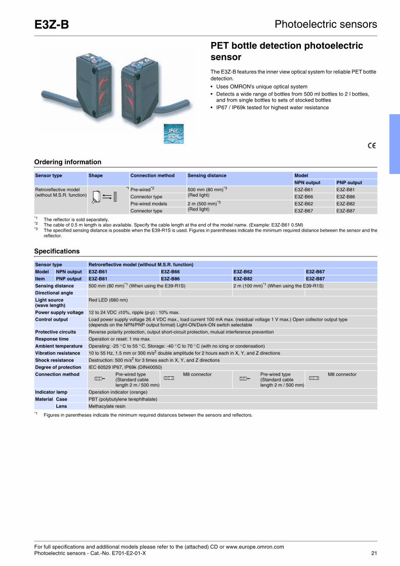
E3Z-B Photoelectric sensors
PET bottle detection photoelectric sensorThe E3Z-B features the inner view optical system for reliable PET bottle detection.
• Uses OMRON's unique optical system • Detects a wide range of bottles from 500 ml bottles to 2 l bottles,
and from single bottles to sets of stocked bottles • IP67 / IP69k tested for highest water resistance
Ordering information
Specifications
Sensor type Shape Connection method Sensing distance Model
NPN output PNP output
Retroreflective model (without M.S.R. function)
*1
*1 The reflector is sold separately.
Pre-wired*2
*2 The cable of 0.5 m length is also available. Specify the cable length at the end of the model name. (Example: E3Z-B61 0.5M)
500 mm (80 mm)*3
(Red light)
*3 The specified sensing distance is possible when the E39-R1S is used. Figures in parentheses indicate the minimum required distance between the sensor and thereflector.
E3Z-B61 E3Z-B81
Connector type E3Z-B66 E3Z-B86
Pre-wired models 2 m (500 mm)*3
(Red light)E3Z-B62 E3Z-B82
Connector type E3Z-B67 E3Z-B87
Sensor type Retroreflective model (without M.S.R. function)
Model NPN output E3Z-B61 E3Z-B66 E3Z-B62 E3Z-B67
Item PNP output E3Z-B81 E3Z-B86 E3Z-B82 E3Z-B87
Sensing distance 500 mm (80 mm)*1 (When using the E39-R1S)
*1 Figures in parentheses indicate the minimum required distances between the sensors and reflectors.
2 m (100 mm)*1 (When using the E39-R1S)
Directional angle
Light source (wave length)
Red LED (680 nm)
Power supply voltage 12 to 24 VDC ±10%, ripple (p-p) : 10% max.
Control output Load power supply voltage 26.4 VDC max., load current 100 mA max. (residual voltage 1 V max.) Open collector output type (depends on the NPN/PNP output format) Light-ON/Dark-ON switch selectable
Protective circuits Reverse polarity protection, output short-circuit protection, mutual interference prevention
Response time Operation or reset: 1 ms max.
Ambient temperature Operating: -25 ° C to 55 ° C, Storage: -40 ° C to 70 ° C (with no icing or condensation)
Vibration resistance 10 to 55 Hz, 1.5 mm or 300 m/s2 double amplitude for 2 hours each in X, Y, and Z directions
Shock resistance Destruction: 500 m/s2 for 3 times each in X, Y, and Z directions
Degree of protection IEC 60529 IP67, IP69k (DIN40050)
Connection method Pre-wired type (Standard cable length 2 m / 500 mm)
M8 connector Pre-wired type (Standard cable length 2 m / 500 mm)
M8 connector
Indicator lamp Operation indicator (orange)
Material Case PBT (polybutylene terephthalate)
Lens Methacylate resin

For full specifications and additional models please refer to the (attached) CD or www.europe.omron.comPhotoelectric sensors - Cat.-No. E268-E2-01-X22
E3S-CR62/67 Photoelectric sensors
Transparent bottle sensorThe special optical design of the E3S-CR62/67 ensures reliable detection of glass bottles compensating the often noticed 'double-detection-effect' when using other sensors.
• Special optical system for reliable bottle detection preventing 'lens effect'
• Thin beam for reliable bottle counting
Ordering information
Specifications
Sensor type Shape Connection method Sensing distance Model
Reflector E39-R6 Reflector E39-R1
Retroreflective models Pre-wired type 250 mm(Red light)
1 m (250 mm)(Red light) *1
*1 Values in parentheses indicate the minimum required distance between the sensor and reflector.
E3S-CR62-C
Connector type E3S-CR67-C
Item E3S-CR62-C E3S-CR67-C
Sensing distance 250 mm (When using the E39-R6), 1 m (250 mm)*1 (When using the E39-R1)
*1 Values in parentheses indicate the minimum required distance between the sensor and reflector.
Light source (wave length)
Red LED (660 nm)
Power supply voltage 10 to 30 VDC, ripple (p-p) : 10 % max.
Protective circuits Load short protection, reverse connection protection, mutual interference protection function
Response time Operation or reset: 1 ms max.
Ambient temperature Operating: -25 °C to 55 °C, Storage: -40 °C to 70 °C (with no icing or condensation)
Vibration resistance Destruction: 10 to 2,000 Hz, 1.5 mm double amplitude or 300 m/s2 (approx. 30 G) for 0.5 hrs each in x, y, and Z directions
Shock resistance 1000 m/s2 (approx. l00 G) 3 times each in X, Y, and Z directions
Degree of protection IEC Standard IP67; NEMA 6P (restricted to indoor use) IEC Standard IP67 NEMA 6P (restricted to indoor use)
Connection method Pre-wired models (standard length: 2 m) Connector type
Materials Case Zinc diecast
Lens Acrylics
Display operation panel
Polyethyl sulfon
Size in mm 20Hx57Wx23D

For full specifications and additional models please refer to the (attached) CD or www.europe.omron.comPhotoelectric sensors - Cat.-No. E368-E2-01-X 23
E3Z-Laser Photoelectric sensors
LASER sensor in compact size housingThe E3Z LASER sensor in compact plastic housing features visible LASER light for precision positioning and detection applications.
• Visible LASER light for precision positioning and small object detection
• High power LED for high functional reserve
Ordering information
Specifications
Sensing method Connection method Response time Sensing distance Model
NPN output PNP output
Through-beam Pre-wired (2 m) 1 ms 60 m E3Z-LT61 E3Z-LT81
Standard M8 connector E3Z-LT66 E3Z-LT86
Retroreflective withM.S.R. function
Pre-wired (2 m) 15 m (300 mm), (Using E39-R1)7 m (200 mm), (Using E39-R12)7 m (200 mm), (Using E39-R6)
E3Z-LR61 E3Z-LR81
Standard M8 connector E3Z-LR66 E3Z-LR86
Distance-settable(BGS-Models)
Pre-wired (2 m) 20 to 40 mm (Min. distance)20 to 300 mm (Max. distance)
E3Z-LL61 E3Z-LL81
Standard M8 connector E3Z-LL66 E3Z-LL86
Pre-wired (2 m) 0.5 ms 25 to 40 mm (Min. distance)25 to 300 mm (Max. distance)
E3Z-LL63 E3Z-LL83
Standard M8 connector E3Z-LL68 E3Z-LL88
Sensing method Through-beam Retro-reflective with M.S.R. function
Diffuse-reflective
Response Standard response High-speed response
Model
Item
NPN output E3Z-LT61/-LT66 E3Z-LR61/-LR66 E3Z-LL61/-LL66 E3Z-LL63/-LL68
PNP output E3Z-LT81/-LT86 E3Z-LR81/-LR86 E3Z-LL81/-LL86 E3Z-LL83/-LL88
Sensing distance 60 m 0.3 to 15 m(when using E39-R1S)0.2 to 7 m(when using E39-R12)0.2 to 7 m(when using E39-R6)
White paper(100x100 mm)20 to 300 mmBlack paper(100x100 mm)20 to 160 mm
White paper(100x100 mm)25 to 300 mmBlack paper(100x100 mm)25 to 100 mm
Light source (wavelength) Red LED (655 nm), JIS Class 1, IEC Class 1, FDA Class II
Power supply voltage 12 to 24 VDC ±10%, ripple (p-p): 10% max.
Ambient temperature range Operating: -10 °C to 55 °C, Storage: -25 °C to 70 °C (with no icing or condensation)
Vibration resistance Destruction: 10 to 55 Hz, 1.5 mm double amplitude for 2 hours each in X, Y, and Z directions
Shock resistance Destruction: 500 m/s2 3 times each in X, Y, and Z directions
Degree of protection IP67 (IEC 60529)
Connection method Pre-wired cable (standard length: 2 m): E3Z-L 1/-L 3Standard M8 connector: E3Z-L 1/-L 3
Material Case PBT (polybutylene terephthalate)
Lens Modified polyacrylate resin Methacrylic resin Modified polyacrylate resin

For full specifications and additional models please refer to the (attached) CD or www.europe.omron.comPhotoelectric sensors - Cat.-No. E39E-EN-0124
E3Z-@G, E3Z-@J Photoelectric sensors
Compact size photoelectric sensors for condition monitoring and preventive maintenanceThe E3Z 'Preventive maintenance' family features active or passive sensor function checking capabilities detecting misalignments, dirt covers, defective sensors, jammed products, etc.
• E3Z-@-J0: 'Machine stop' or 'Sensor defect' alarm output if beam interruption is too long
• E3Z-@-G0: Active sensor functionality check by test input forcing state change at receiver
• E3Z-@-G2: Detection of dirt cover by power reduction
Ordering information
Specifications
Sensor type Sensing distance
Output specifications
Preventive maintenance function
anti-tampering self diagnosis emission stop light intensivity switching
Through-beam 15 m NPN E3Z-T61H E3Z-T61-J0SHW E3Z-T61-G0SHW E3Z-T61-G2SHW
PNP E3Z-T81H E3Z-T81-J0SHW E3Z-T81-G0SHW E3Z-T81-G2SHW
Retroreflective 4 m NPN E3Z-R61H E3Z-R61-J0SHW E3Z-R61-G0SHW E3Z-R61-G2SHW
PNP E3Z-R81H E3Z-R81-J0SHW E3Z-R81-G0SHW E3Z-R81-G2SHW
Diffuse-reflective 1 m NPN E3Z-D62H E3Z-D62-J0SHW E3Z-D62-G0SHW E3Z-D62-G2SHW
PNP E3Z-D82H E3Z-D82-J0SHW E3Z-D82-G0SHW E3Z-D82-G2SHW
E3Z-T@ E3Z-R@ E3Z-D@Sensing distance 15 m 4 m 1 m
Light source Infrared LED (870 nm) Red LED (660 nm) Infrared LED (860 nm)
Power supply voltage 12 to 24 VDC ±10%
Ambient temperature Operating: -25 °C to 55 °C, Storage: -40 °C to 70 °C (with no icing or condensation)
Vibration resistance 10 to 55 Hz, 1.5 mm or 300 m/s2 double amplitude for 2 hours each in X, Y, and Z directions
Degree of protection IP67, IP69k
Material PBT

For full specifications and additional models please refer to the (attached) CD or www.europe.omron.comPhotoelectric sensors - Cat.-No. E43E-EN-01 25
E3F2-@Z Photoelectric sensors
AC voltage sensor in cylindrical M18 housingThe E3F2 family of cylindrical M18 sized photoelectric sensors features models for direct AC voltage switching.
• 24 to 240 VAC power supply • UL and CSA approved
Ordering information
Note: Standard cable length is 2 m. Models provided with a 5 m long cable are available. When ordering, specify the cable length by adding the length of the cable (e.g. E3F2-R2Z1 2M or E3F2-R2Z1 5M). For other cable length please contact your OMRON sales representative.
Specifications
Sensing method Appearance Connection method
Sensing distance Model
Light-ON Dark-ON
Through-beam pre-wired 3 m E3F2-3Z1 E3F2-3Z2
Retro-reflective Non-polarizing(without MSR function)
pre-wired 0.1 - 2 m (with reflector E39-R1)
E3F2-R2Z1-E E3F2-R2Z2-E
Diffuse reflective Fixed sensing distancewide-beam characteristics
pre-wired 0.1 m E3F2-DS10Z1-N E3F2-DS10Z2-N
Item E3F2-3Z1E3F2-3Z2
E3F2-R2Z1E3F2-R2Z2
E3F2-DS10Z1E3F2-DS10Z2
Type Through-beam Non-polarizing Retroreflective Diffuse reflective (wide-beam characteristic)
Power supply voltage 24 to 240 VAC ±10 %, 50 / 60 Hz
Rated sensing distance *1
*1 For stable sensing distance in detail, please refer to 'Engineering data'
3 m 0.1 - 2 m(with reflector E39-R1)
0.1 m (5 x 5 cm white mat paper)
Ambient temperature Operating: -25 to 55 °C / Storage: -30 to 70 °C (with no icing or condensation)
Vibration resistance 10 to 55 Hz, 1.5 mm double amplitude for 2 hrs each direction (X, Y, Z)
Shock resistance 500 m/sqr (approx. 50 g) for each direction (X, Y, Z)
Enclosure rating IP67 *2; NEMA 1, 2, 4; IP69k after DIN 40050 part 9
*2 The enclosure rating IP67 of OMRON internal standards correspond to stricter test requirements than the standard IEC 60529 (refer to chapter “Precautions”)
Light source Infrared LED (880 nm)
Connection method 2 m, 5 m pre-wired cable (PVC dia. 4 mm (14 / 0.15) *3)
*3 For other cable materials (e.g. PUR) please contact your OMRON sales representative.
Housing materials Plastic (case: ABS; lens: PMMA)

For full specifications and additional models please refer to the (attached) CD or www.europe.omron.comPhotoelectric sensors - Cat.-No. E278-E2-04-X26
E3G-M Photoelectric sensors
Long distance all voltage photoelectric sensor in plastic housingThe E3G-M series offers the long sensing distance of the E3G family for all voltage (AC and DC) installations.
• 12 to 240 VDC and 24 to 240 VAC power supply • Terminal block connection
Ordering information
Specifications
Sensor type Shape Connection method
Sensing distance
Timer function Relay contact output
Retroreflective models (with M.S.R. function)
Terminal block 10 m (500 mm) *1
(Red light)
*1 Values in parentheses indicate the minimum required distance between the sensor and reflector.
--- E3G-MR19-G
ON or OFF delay 0 to 5 s (adjustable) E3G-MR19T-G
Distance setting 0.2 to 2 mWhite paper 300x300 mm(Infrared light)
--- E3G-ML79-G
ON or OFF delay 0 to 5 s (adjustable) E3G-ML79T-G
Sensor type Retroreflective models (M.S.R. function) Distance-setting
Item Model E3G-MR19-G E3G-MR19T-G E3G-ML79-G E3G-ML79T-G
Sensing distance 10 m (500 mm) *1 (When using the E39-R2)
*1 Values in parentheses indicate the minimum required distance between the sensor and reflector.
0.2 to 2 m (White paper 300 x 300 mm)
Light source (wave length)
Red LED (700 nm) Infrared LED (860 nm)
Power supply voltage 12 to 240 VDC ±10% ripple (p-p) : 10% max. 24 to 240 VAC ±10% 50/60 Hz
12 to 240 VDC ±10% ripple (p-p) : 10% max. 24 to 240 VAC ±10% 50/60 Hz
Control output Relay output: switch-over contact 250 VAC 3A (cosφ= 1) max. 30 VDC 3A max. L-ON/D-ON switch selectable
Relay output: switch-over contact 250 VAC 3A (cosφ= 1) max. 30 VDC 3A max. L-ON/D-ON switch selectable
Response time Operation/reset: 30 ms each Operation/reset: 30 ms each
Timer function --- ON delay/OFF delay 0 to 5 s(Adjuster variable system)
--- ON delay/OFF delay 0 to 5 s(Adjuster variable system)
Ambient temperature Operating: -25 °C to 55 °C, Storage: -30 °C to 70 °C (with no icing or condensation)
Vibration resistance Destruction: 10 to 55 Hz, 1.5 mm double amplitude for 2 hours each in X, Y, and Z directions
Shock resistance 500 m/s2 3 times in each of X, Y and Z directions
Protective structure IEC 60529 IP67 (with protective cover attached)

For full specifications and additional models please refer to the (attached) CD or www.europe.omron.comPhotoelectric sensors - Cat.-No. E027-E2-09-X 27
E3JK Photoelectric sensors
AC&DC voltage sensor in compact size housingThe compact sized E3JK family provides 12-240 VDC and 24-240 VAC power supply voltage and is ideally suited to AC installations. The wide voltage range also reduces the product variety needed for different voltage requirements.
• Built-in amplifier accepts wide supply voltage range • Compact, space-saving construction 50Hx50Wx17.4D mm • Relay outputs with long life expectancy and high switching capacity
(3 A, 250 VAC)
Ordering information
Note: The UL-listed model ends with '-US'. (Example: E3JK-5M1-US). Note that the DC transistor type of the E3JK is UL-unlisted.
Specifications
Sensor type Shape Connection method
Sensing distance
Output form Output Model
NPN PNP
Through-beam Pre-wired 5 m(Infrared light)
Light ON Relay output E3JK-5M1
Dark ON E3JK-5M2
Light ON/ Dark ON(selectable)
DC transistor output E3JK-5S3
Retroreflective model (with M.S.R. function)
2.5 m (3 m)*1
(Red light)
*1 The value within the parentheses indicates the sensing distance applied when the E39-R2 reflector is used.
Light ON Relay output E3JK-R2M1
Dark ON E3JK-R2M2
Light ON/Dark ON(selectable)
DC transistor output E3JK-R2S3 E3JK-R2R3
Retroreflective model (without M.S.R. function)
4 m (5 m)*1
(Red light)Light ON Relay output E3JK-R4M1
Dark ON E3JK-R4M2
Light ON/Dark ON(selectable)
DC transistor output E3JK-R4S3
Diffuse-reflective 300 mm(Infrared light)
Light ON Relay output E3JK-DS30M1
Dark ON E3JK-DS30M2
Light ON/Dark ON(selectable)
DC transistor output E3JK-DS30S3
Item Through-beam Retroflective model (with M.S.R. function)
Retroflective model (without M.S.R. function)
Diffuse-reflective
E3JK-5M# E3JK-5S3 E3JK-R2M# E3JK-R2#3 E3JK-R4M# E3JK-R4S3 E3JK-DS30M# E3JK-DS30S3
Sensing distance 5 m 2.5 m (When using the E39-R1)
4 m (When using the E39-R1)
300 mm (White paper 100x100 mm)
Light source (wave length)
Infrared LED (950 nm) Red LED (660 nm) Infrared LED (950 nm)
Power supply voltage 12 to 240 VDC ±10% ripple (p-p) : 10% max. 24 to 240 VAC ±10% 50/60 Hz
Response time ≤ 30 ms ≤ 10 ms ≤ 30 ms ≤ 5 ms ≤ 30 ms ≤ 5 ms ≤ 30 ms ≤ 5 ms
Ambient temperature Operating: -25 °C to 55 °C, Storage: -30 °C to 70 °C (with no icing or condensation)
Vibration resistance 10 to 55 Hz, 1.5 mm double amplitude for 2 hours each in X, Y, and Z directions
Shock resistance Destruction: 500 m/s2 for 3 times each in X, Y, and Z directions
Degree of protection IEC60529 IP64
Connection method Pre-wired models (standard length: 2 m)
Material Case ABS
Size in mm 50Hx50Wx22D

For full specifications and additional models please refer to the (attached) CD or www.europe.omron.comPhotoelectric sensors - Cat.-No. E280-E2-01A-X28
E3M-V Photoelectric sensors
Photoelectric sensor for mark detectionThe coaxial optical system of the E3M-V provides reliable mark detection on laminated objects
• Detects laminated or light-dispersing objects in stable operation without being influenced by mirror reflection
• Automatically sets to the optimum threshold level by auto-teaching • Green LED
Ordering information
Specifications
Connection method Setting distance Spot diameter Model
NPN output PNP output
Connector type*1
*1 Possible to switch between vertical or horizontal connection using the M12 rotary connector
10+3 mm 1x4 mm E3M-VG11 E3M-VG16
4x1 mm E3M-VG21 E3M-VG26
Pre-wired 1x4 mm E3M-VG12 E3M-VG17
4x1 mm E3M-VG22 E3M-VG27
Item E3M-VG11 E3M-VG12 E3M-VG21 E3M-VG22 E3M-VG16 E3M-VG17 E3M-VG26 E3M-VG27
Sensing distance 10±3 mm
Spot size (HxW) 4x1 mm 1x4 mm 4x1 mm 1x4 mm
Light source (wavelength)
Green LED (525 nm)
Power supply voltage 10 to 30 VDC, ripple (p-p) 10% max.
Control output Load power supply voltage:30 VDC max.Load current: 100 mA max.(Residual voltage: 1.2 V max.)NPN open collector output type
Load power supply voltage:30 VDC max.Load current: 100 ma max.(Residual voltage: 2 V max.)PNP open collector output type
Response time ON: 50 µs max.OFF: 70 µs max.
Ambient illumination (on receiver lens)
Incandescent lamp:3,000 lx max.Sunlight: 10,000 lx max.
Ambient temperature Operating: -20 °C to 55 °C / Storage: -30 °C to 70 °C (with no icing)
Vibration resistance*1
*1 The sensor withstands 0.75 mm double amplitude or 100 m/s² if the mounting bracket is attached to the sensor
Destruction: 10 to 55 Hz, 1-mm double amplitude or 150 m/s2 for 2 hrs each in X, Y, and Z directions
Shock resistance*2
*2 The sensor withstands 300 m/s² if the mounting bracket is attached to the sensor.
Destruction: 500 m/s2, 3 times each in X, Y, and Z directions
Degree of protection IEC60529 IP67 (with protective cover)
Connection method Connector Pre-wired Connector Pre-wired Connector Pre-wired Connector Pre-wired
Material Case: Polybutylene terephthalateLens: Acrylic (PMMA)

For full specifications and additional models please refer to the (attached) CD or www.europe.omron.comPhotoelectric sensors - Cat.-No. E036-E1-02 29
E3S-G Photoelectric sensors
Groove-type photoelectric sensor for mark detectionThe pre-aligned emitter and receiver of this 1 cm groove-type simplifies the installation and reduces the possibility for misalignment for detect-ing marks on transparent film.
• Green or red LED • IP65 • Fork opening: 10x35 mm
Ordering information
Specifications
Type LED Groove width Model
NPN output PNP output
Adjustable sensitivity green 1 cm E3S-GS1E4 E3S-GS1B4
10-cycle trimmer red E3S-GS1RE4 E3S-GS1RB4
green E3S-GS1GE4 E3S-GS1GB4
Item E3S-GS1E4/E3S-GS1B4
E3S-GS1RE4A/E3S-GS1RB4A
E3S-GS1GE4A/E3S-GS1GB4A
Power supply voltage 12 to 24 VDC, ripple (p-p): 10% max.
Current consumption 40 mA max.
Sensing distance 1 cm
Standard objects Transparent (2x3 mm)
Control output
DC solid-state
Load Models with suffix -E4: 80 mA max.Models with suffix -B4: 100 mA max.
Voltage output
2 V max.
Response time (ON, OFF) 1 ms max.
Sensitivity Adjustable 10-cycle trimmer
Operation mode Wire-selectable (refer to 'output circuit.')
Indicators Light indicator (red), stability indicator (green)
Enclosure rating IEC 144 IP65 IP65
NEMA 1, 2, 12 1, 2, 12
Housing material Plastic
Light source Green LED Red LED Green LED
Ambient temperature Operating: -25 to 55 °C

For full specifications and additional models please refer to the (attached) CD or www.europe.omron.comPhotoelectric sensors - Cat.-No. E223-E2-01-X30
E3S-LS3 Photoelectric sensors
Photoelectric sensor for structured object detectionThe special wide beam optics of the E3S-LS3 ensures reliable detection of structured objects (with holes or different heights) and is therefore ideally suited to detect printed circuit boards (PCBs), for example.
• Wide beam for reliable detection of structured and irregular shaped objects
Ordering information
Specifications
Sensor type Connection method Detection distance Timer function Model Output
Limited reflective Pre-wired (2 m) 20 to 35 mm(Red light)
No E3S-LS3N NPN Light ON
10 to 60 mm(Red light)
E3S-LS3NW
Pre-wired (2 m) 20 to 35 mm(Red light)
No E3S-LS3P PNP Light ON
Yes E3S-LS3PT
Pre-wired M8 3-pin connector (0.3 m)
No E3S-LS3P-M5J
Yes E3S-LS3PT-M5J
Pre-wired M8 4-pin connector (0.3 m)
No E3S-LS3P-M3J
Yes E3S-LS3PT-M3J
Pre-wired (2 m) 10 to 60 mm(Red light)
No E3S-LS3PW
Yes E3S-LS3PWT
Pre-wired M8 3-pin connector (0.3 m)
No E3S-LS3PW-M5J
Yes E3S-LS3PWT-M5J
Pre-wired M8 4-pin connector (0.3 m)
No E3S-LS3PW-M3J
Yes E3S-LS3PWT-M3J
Item E3S-LS3@ E3S-LS3PT E3S-LS3@W E3S-LS3PWT
Sensing White paper * 20 to 35 mm 10 to 60 mm
Black paper * 20 to 30 mm 15 to 50 mm
Light source (wave length)
Red LED (660 nm)
Power supply voltage 12 to 24 VDC ±10%, ripple (p-p) 10% max.
Response time 1 ms max. for operation and reset respectively
Timer function Available with E3S-LS3P(W)T models only. Time range: 0.1 to 1.0 s (adjustable)
Ambient temperature Operating: -10 to 55 °C (with no icing or condensation)Storage: -25 to 70 °C (with no icing or condensation)
Vibration resistance 10 to 55 Hz with a 1.5-mm double amplitude for 2 hrs each in X, Y and Z directions
Shock resistance 500 m/s2, 3 times each in X, Y and Z directions
Degree of protection IEC60529 IP40
Connection method Pre-wired (standard length: 2 m) / Pre-wired
M8 connector (standard length: 0.3 m)
Material Case ABS
Lens Acrylic

For full specifications and additional models please refer to the (attached) CD or www.europe.omron.comPhotoelectric sensors - Cat.-No. E13E-EN-01 31
E3C-LDA Photoelectric sensors
High precision LASER sensorThe separate amplifier high-precision photoelectric sensors feature a large variety of different LASER sensing heads for highest precision positioning and application detection.
• Up to 10 µm accuracy • Easy installation due to adjustable focus point and optical axis • Wide range sensor head portfolio with different laser beam shapes • Stable detection of transparent objects such as plastic or glass
materials • Controller functions with easy wiring concept and power tuning
function
Ordering information
Sensor heads
Amplifier units
Specifications
Sensor heads
Sensing method Focus Model number Remarks
Diffuse reflective Spot E3C-LD11 Mounting a beam unit (sold separately) allows the use of line and area beams.
Line E3C-LD21 This model number is for the set consisting of the E39-P11 mounted to the E3C-LD11.
Area E3C-LD31 This model number is for the set consisting of the E39-P21 mounted to the E3C-LD11.
Coaxial retroreflective Spot (variable) E3C-LR11 *1
*1 Select a reflector (sold separately) according to the application.
Mounting a beam unit (sold separately) allows the use of line and area beams.
Spot (2.0-mm fixed dia.) E3C-LR12 *1 ---
Item Functions pre-wired with connector
NPN output PNP output NPN output PNP output
Advanced models Twin-output models Area output, self-diagnosis, differential operation
E3C-LDA11 E3C-LDA41 E3C-LDA6 E3C-LDA8
External-input models Remote setting, counter, differential operation
E3C-LDA21 E3C-LDA51 E3C-LDA7 E3C-LDA9
Item Diffuse reflective Coaxial retroreflective
E3C-LD11 E3C-LD21 E3C-LD31 E3C-LR11 E3C-LR11 + E39-P31
E3C-LR11 + E39-P41
E3C-LR12
Light source (emission wavelength)
Red semiconductor laser diode (650 nm), 2.5 mW max. (JIS standard: Class 2, FDA standard: Class II) 1 mW max. (JIS standard Class 1)
Sensing distance High-resolution mode: 30 to 1,000 mmStandard mode: 30 to 700 mmSuper-high-speed mode: 30 to 250 mm
7 m5 m2 m
1,700 mm,1,300 mm700 mm
900 mm700 mm400 mm
7 m5 m2 m
Beam size 0.8 mm max. (at distances up to 300 mm)
33 mm (at 150 mm)
33x15 mm (at 150 mm)
0.8 mm max. (at distances up to 1,000 mm)
28 mm (at 150 mm)
28x16 mm (at 150 mm)
2.0 mm dia. (at distances up to 1,000 mm)
Functions Variable focal point mechanism (beam size adjustment) , optical axis adjustment mechanism (axis adjustment)
Indicators LDON indicator: Green; Operation indicator: Orange

For full specifications and additional models please refer to the (attached) CD or www.europe.omron.comPhotoelectric sensors - Cat.-No. E224-E2-03-X32
E3F2-@41 Photoelectric sensors
Radial cylindrical M18 photoelectric sensorRadial (angled) optics for easy mounting, installation and adjustment
• Diffuse reflective and retro-reflective models • IP67 and IP69k
Ordering information
Specifications
Sensor type Appearance Connectionmethod
Sensingdistance
Housing NPN output PNP output
Retro-reflective*1
*1 Retroreflective models incl. reflectors E39-R1 or E39-R1S are also available.
Polarizing (Adjustable sensitivity)
Pre-wired 0.1 - 2 m*2
*2 With reflector E39-R1S.
Plastic E3F2-R2RC41-E E3F2-R2RB41-E
Brass E3F2-R2RC41-E E3F2-R2B41-E
M12 connector Plastic E3F2-R2RC41-1-E E3F2-R2RB41-1-E
Brass E3F2-R2RC41-M1-M-E E3F2-R2RB41-M1-M-E
Diffuse reflective Adjustable sensitivity Pre-wired 0.3 m Plastic E3F2-DS30C41 E3F2-DS30B41
Brass E3F2-DS30C41-M E3F2-DS30B41-M
M12 connector Plastic E3F2-DS30C41-P1 E3F2-DS30B41-P1
Brass E3F2-DS30C41-M1-M E3F2-DS30B41-M1-M
Item E3F2-R2R#41-# E3F2-DS30#41-#
Sensing distance type Retroreflective Diffuse reflective
Polarizing, adjustable sensing distance Adjustable sensing distance
Light source (wave length)
Red LED (660 nm) Infrared LED (880 nm)
Power supply voltage 10 to 30 V DC
Protective circuits Output short-circuit and power supply reverse polarity
Response time ≤ 2.5 ms
Ambient temperature Operating: -25 °C to 55 °C / Storage: -30 °C to 70 °C (with no icing or condensation)
Vibration resistance 10 to 55 Hz, 1.5 mm double amplitude for 2 hrs each direction (X, Y, Z)
Shock resistance Destruction: 500 m/s2 each direction (X, Y, Z)
Enclosure ratings IP67 *1; NEMA 1, 2, 4; IP69k after DIN 40050 part 9
*1 The enclosure rating IP67 of OMRON internal standards correspond to stricter test requirements than the standard IEC 60529 (refer to chapter “Precautions”).
Connection method 2 m, 5 m pre-wired cable (PVC, dia. 4 mm (18 / 0.12) *2) or
M12-connector
*2 For other cable materials (e.g. PUR) please contact your OMRON sales representative.
Material Nickel brass Nickel brass
Stainless steel Stainless steel

Selection table Encoder
33
Output Incremental
Model E6A2-C E6B2-C E6C2-C E6C3-C E6F-C
Type Miniature Compact Water resistant Rugged housing
Resolutionrange
Min 10 100
Max 500 2,000 3,600 1,000
Output NPN
PNP
Size 25 mm 40 mm 50 mm 50 mm 60 mm
Maxforce
radial 10 30 50 80 120
axial 5 20 30 50 50
IPrating
IP50
IP64
IP65
Max. rotation frequency 5,000 6,000 5,000
Page 34 35
Output Incremental Absolute
Model E6H-C E6C-N E6C3-A E6F-A
Type Hollow shaft Multiturn Water resistant Rugged housing
ResolutionRange
Min 300 500 6 256
Max 3,600 500 1,024
Output NPN
PNP
Size 40 mm (hollow) 50 mm (full and hollow) 50 mm 60 mm
Maxforce
radial 29.4 30 80 120
axial 4.9 20 50 50
IPrating
IP50
IP64
IP65 Standard
Max. rotation frequency 10,000 1,500 5,000 5,000
Page 36 37 No / not available

For full specifications and additional models please refer to the (attached) CD or www.europe.omron.comRotary encoders - Incremental - Cat.-No. Q018-E2-03-X / Q085-E2-03-X34
E6A2-C Rotary encoders - Incremental
Miniature size rotary encoderThe E6A family of rotary encoders features a small sized dia 25 mm housing.
• Small sized dia 25 mm housing
Ordering information
E6B2-CCompact size rotary encoderThe E6B family of incremental rotary encoders features a housing size dia 40 mm.
• Line driver output models available
Ordering information
Size in mm Output phase Power supply voltage Output form Resolution (pulse/rotation) Model
Ø 20 A 5 to 12 VDC NPN voltage output 10, 60, 100, 200, 300, 360, 500 E6A2-CS3E
NPN open collector 10, 60, 100, 200, 300, 360, 500 E6A2-CS3C
12 to 24VDC 10, 60, 100, 200, 300, 360, 500 E6A2-CS5C
A, B 5 to 12 VDC NPN voltage output 100, 200, 360, 500 E6A2-CW3E
NPN open collector 100, 200, 360, 500 E6A2-CW3C
12 to 24VDC 100, 200, 360, 500 E6A2-CW5C
A, B, Z 5 to 12 VDC NPN voltage output 100, 200, 360, 500 E6A2-CWZ3E
NPN open collector 100, 200, 360, 500 E6A2-CWZ3C
12 to 24VDC 100, 200, 360, 500 E6A2-CWZ5C
Size in mm Power supply voltage Output form Resolution (pulse/rotation) Model
Ø 40 5 to 24 VDC NPN open collector output 10, 20, 30, 40, 50, 60, 100, 200, 300, 360, 400, 500, 600, 720, 800, 1,000, 1,024, 1,200, 1,500 1,800, 2,000
E6B2-CWZ6C
12 to 24VDC PNP open collector output 100, 200, 360, 500, 600, 1,000, 2,000 E6B2-CWZ5B
5 to 12 VDC NPN voltage output 10, 20, 30, 40, 50, 60, 100, 200, 300, 360, 400, 500, 600, 1,000, 1,200, 1,500 1,800, 2,000
E6B2-CWZ3E
5 VDC Line driver output 10, 20, 30, 40, 50, 60, 100, 200, 300, 360, 400, 500, 600, 1,000, 1,024, 1,200, 1,500 1,800, 2,000
E6B2-CWZ1X
For full specifications and additional models please refer to the (attached) CD or www.europe.omron.comRotary encoders - Incremental - Cat.-No. F01E-EN-01 / E284-E2-02-X 35
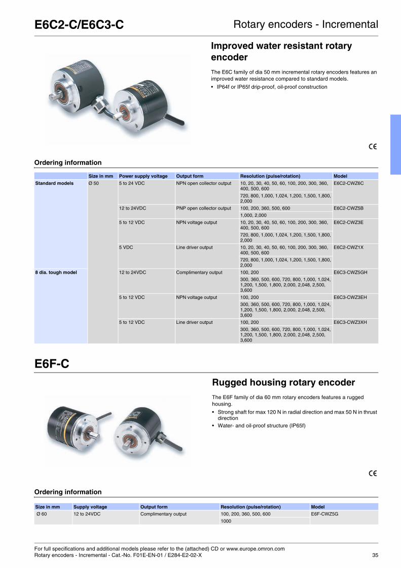
E6C2-C/E6C3-C Rotary encoders - Incremental
Improved water resistant rotary encoderThe E6C family of dia 50 mm incremental rotary encoders features an improved water resistance compared to standard models.
• IP64f or IP65f drip-proof, oil-proof construction
Ordering information
E6F-CRugged housing rotary encoderThe E6F family of dia 60 mm rotary encoders features a rugged housing.
• Strong shaft for max 120 N in radial direction and max 50 N in thrust direction
• Water- and oil-proof structure (IP65f)
Ordering information
Size in mm Power supply voltage Output form Resolution (pulse/rotation) Model
Standard models Ø 50 5 to 24 VDC NPN open collector output 10, 20, 30, 40, 50, 60, 100, 200, 300, 360, 400, 500, 600
E6C2-CWZ6C
720, 800, 1,000, 1,024, 1,200, 1,500, 1,800, 2,000
12 to 24VDC PNP open collector output 100, 200, 360, 500, 600 E6C2-CWZ5B
1,000, 2,000
5 to 12 VDC NPN voltage output 10, 20, 30, 40, 50, 60, 100, 200, 300, 360, 400, 500, 600
E6C2-CWZ3E
720, 800, 1,000, 1,024, 1,200, 1,500, 1,800, 2,000
5 VDC Line driver output 10, 20, 30, 40, 50, 60, 100, 200, 300, 360, 400, 500, 600
E6C2-CWZ1X
720, 800, 1,000, 1,024, 1,200, 1,500, 1,800, 2,000
8 dia. tough model 12 to 24VDC Complimentary output 100, 200 E6C3-CWZ5GH
300, 360, 500, 600, 720, 800, 1,000, 1,024, 1,200, 1,500, 1,800, 2,000, 2,048, 2,500, 3,600
5 to 12 VDC NPN voltage output 100, 200 E6C3-CWZ3EH
300, 360, 500, 600, 720, 800, 1,000, 1,024, 1,200, 1,500, 1,800, 2,000, 2,048, 2,500, 3,600
5 to 12 VDC Line driver output 100, 200 E6C3-CWZ3XH
300, 360, 500, 600, 720, 800, 1,000, 1,024, 1,200, 1,500, 1,800, 2,000, 2,048, 2,500, 3,600
Size in mm Supply voltage Output form Resolution (pulse/rotation) Model
Ø 60 12 to 24VDC Complimentary output 100, 200, 360, 500, 600 E6F-CWZ5G
1000

For full specifications and additional models please refer to the (attached) CD or www.europe.omron.comRotary encoders - Incremental - Cat.-No. Q101-E2-01-X / Q084-E2-03-X36
E6H-C Rotary encoders - Incremental
Hollow shaft rotary encoderThe E6H family of incremental encoders features a dia 40 mm hollow shaft.
• Wide operating voltage range from 5 to 24 VDC. • Line drive output available (100 m max.)
Ordering information
E6C-N Rotary encoders- Absolut
Multiturn rotary encoderThe E6C-N rotary encoder provides a multiturn function for applica-tions with rotations over 360°.
• Multiturn function
Ordering information
Size in mm Supply voltage Output form Resolution (pulse/rotation) Model
Ø 40 5 to 24 VDC Open collector output 300, 360, 500, 600, 720, 800, 1,000, 1,024 E6H-CWZ6C
1,200, 1,500, 1,800, 2,000, 2,048
2,500, 3,600
5 to 12 VDC Voltage output 300, 360, 500, 600, 720, 800, 1,000, 1,024 E6H-CWZ3E
1,200, 1,500, 1,800, 2,000, 2,048
2,500, 3,600
5 to 12 VDC Line drive output 300, 360, 500, 600, 720, 800, 1,000, 1,024 E6H-CWZ3X
1,200, 1,500, 1,800, 2,000, 2,048
2,500, 3,600
Size Name Model
Ø 50 Shaft model with cable E6C-NN5C
Hollow-shaft model with cable E6C-NN5CA
Shaft model with connector E6C-NN5C-C
Hollow-shaft model with connector E6C-NN5CA-C

For full specifications and additional models please refer to the (attached) CD or www.europe.omron.comRotary encoders - Absolut - Cat.-No. F058-E2-01-X / E284-E2-02-X 37
E6C3-A Rotary encoders - Absolut
Improved water resistant rotary encoderThe E6C family of dia 50 mm incremental rotary encoders features an improved water resistance compared to standard models.
• IP65f drip-proof, oil-proof construction
Ordering information
E6F-ARugged housing rotary encoder
The E6F family of dia 60 mm rotary encoders features a rugged housing.
• Stronger shaft and higher durability (120 N in radial direction and 50 N in thrust direction) than previous E6F encoders
• Drip-proof construction meets IP64f standards • High-resolution models (1,024 pulses max. per revolution) • Faster response for high-speed control applications
(grey code: 20 kHz).
Ordering information
Size in mm Supply voltage Output form Output code Resolution (pulse/rotation)
Connection method Model
Ø 50 12 to 24VDC NPN open collector output Gray code 256 Connector type E6C3-AG5C-C
256, 360, 720, 1,024 Pre-wired type E6C3-AG5C
Binary 32, 40 E6C3-AN5C
BCD 6, 8, 12 E6C3-AB5C
PNP open collector output Gray code 256, 360, 720, 1,024 E6C3-AG5B
Binary 32, 40 E6C3-AN5B
BCD 6, 8, 12 E6C3-AB5B
5 VDC NPN voltage output Binary 256 E6C3-AN1E
12 VDC E6C3-AN2E
Size in mm Supply voltage Output form Output code Resolution (pulses/revolution)
Connection method Model
Ø 60 12 to 24 VDC NPN open collector BCD 360 Pre-wired E6F-AB5C
Connector type E6F-AB5C-C
PNP open collector Pre-wired E6F-AB5B
Gray code 256, 360, 720, 1,024 Pre-wired E6F-AG5B

Inductive sensors
Reliability and accuracy confirmed by millions... every day
38

Tested reliability for demanding conditions
39
Table of contentsSelection table 40
Subminiature E2EC 42
Miniature E2E 43
Compact - metal E2A 44
Compact - plastic E2F 46
Long distance E2A3 47
Miniature - square E2S 48
Compact - square TL-W 49
TL-T 50
Long distance - square E2Q2 51
E2Q4 52
Mobile usage E2AU 53
Explosive environments E2AX 54
Anti-microbial E2F-D 56
High frequency E2EL 57
Spatter resistant E2EQ 58
AC power supply E2E-@Y / E2F-@Y 59
Metal chip immune E2EZ 60
Chemical resistant E2FQ 61
Oil resistant E2E 62
Precision positioning E2C-EDA 63

40
Selection table
Special models
Format Cylindrical
Model E2EC E2E small diameter E2A E2F E2A3
Type Subminiature Miniature Compact Long distance
Material Brass Brass Brass, SUS Polyarylate Brass
Max
. sen
sin
g d
ista
nce
dia 3 0.8 mm
dia 4 0.8 mm
M5 1 mm
dia 5.4 1.5 mm 1 mm
M8 4 mm 1.5 mm 3 mm
M12 4 mm 8 mm 2 mm 6 mm
M18 16 mm 5 mm 11 mm
M30 30 mm 10 mm 20 mm
19x6x6
22x8x6
26x40x12
31x18x10
53x40x23
67x40x40
Mo
un
t. Shielded
Non-shielded
Op
er.
mo
de NO
NC
NO + NC
Wir
ing
DC 2-wire
DC 3-wire
DC 4-wire
AC 2-wire
Vo
ltag
e 10-30 VDC
10-60 VDC
12-240 VAC
IPra
tin
g IP67
IP69k
Page 42 43 44 46 47
Type AC power supply Vehicle usage certified ATEX 3D certified Oil resistant Increased frequency
Model E2@-Y E2AU E2AX E2E E2EL
Application • building installations • utility vehicles• mobile construction
equipment• RCVs (refuse
collecting vehicles)• mobile agricultural
equipment
• powder handling and packaging
• wood cutting/ wood chip handling
• automotive manufacturing lines
• counting• rotation speed control
Key features • 24-240 VAC direct switching
• e1 mark• high EMC immunity
(additional test up to 100V/m)
• ATEX certification Group II category 3D (94/9/EG Appendix VIII)
• typically for explo-sive areas zone 22 with non-leading dust
• tested oil resistance on commonly used lubricants
• up to 5 kHz response (switching) frequency
3 mm
5.4 mm
6.5 mm
M8
M12
M18
M30
Page 59 53 54 62 57

Inductive sensors
41
Special models
Format Square
Model E2S TL-W TL-T E2Q2 / E2Q4
Type Miniature Compact Compact Long distance
Material Polyarylate ABS PBT PBT
Max
. sen
sin
g d
ista
nce
dia 3
dia 4
M5
dia 5.4
M8
M12
M18
M30
19x6x6 1.6 mm
22x8x6 2.5 mm 1.5 mm
26x40x12 4 mm
31x18x10 5 mm
53x40x23 20 mm
67x40x40 40 mm
Mo
un
t. Shielded
Non-shielded
Op
er.
mo
de NO
NC
NO + NC
Wir
ing
DC 2-wire
DC 3-wire
DC 4-wire
AC 2-wire
Vo
ltag
e 10-30 VDC
10-60 VDC
12-240 VAC
IPra
tin
g IP67
IP69k
Page 48 49 50 51 / 52
Standard No / not available
Spatter resistant Metal chip immune Anti-microbial housing Chemical resistant High precision positioning
SMART inductive sensor
E2EQ E2EZ E2F-D E2FQ E2C-EDA ZX-E
• welding applications • metal cutting in machine tool industry
• meat and dairy products processing
• pharmaceutical packaging"
• applications with aggressive chemicals (etching, cleaning, water treatment
• precision positioning • high precision distance measurement
• PTFE coating preventing the attachment of spatters
• immune to aluminium and cast iron chips on sensing surface
• anti-microbial housing material inhibiting and reducing bacteria and microbe growth
• PTFE housing • repeat accuracy 1 µm • 1 µm measurement resolution
58 60 56 61 63 90

For full specifications and additional models please refer to the (attached) CD or www.europe.omron.comInductive sensors - Cat.-No. D09E-EN-0142
E2EC Inductive sensors
Sub-miniature sensor for demanding mounting conditionsThe E2EC family features the smallest sensor heads for reliable sens-ing in areas where mounting space is crucial. The miniature sizes of the sensing heads are achieved by separating the sensing part from the amplifier. In contrast to standard separate amplifier models the E2EC family simplifies the installation as the amplifier is built into the cable.
• 3 mm diameter sensing head for the most demanding mounting conditions
• 18 mm long ultra short M12 size housing
Ordering information
DC 2-wire
Specifications
Note: The response frequencies for DC switching are average values measured on condition that the distance between each sensing object is twice as large as the size of the sensing object and the sensing distance set is half of the maximum sensing distance.
Size Shape Sensing distance Operating status
NO NC
3-mm dia. *1
*1 A different frequency type is available. (E2EC-@@5; e.g.E2EC-CR8D15)
Shielded 0.8 mm E2EC-CR8D1 E2EC-CR8D2
5.4-mm dia.*1 1.5 mm E2EC-C1R5D1 E2EC-C1R5D2
8-mm dia. *1 3 mm E2EC-C3D1 E2EC-C3D2
M12*1 4 mm E2EC-X4D1 E2EC-X4D2
Item E2EC-CR8D@ E2EC-C1R5D@ E2EC-C3D@ E2EC-X4D@Sensing distance 0.8 mm ±15% 1.5 mm ±10% 3 mm ±10% 4 mm ±10%
Response frequency 1.5 kHz 1 kHz
Power supply voltage(Operating voltage)
12 to 24 VDC (10 to 30 VDC) ripple (p-p): 10% max.
Protective circuit Surge absorber, short-circuit protection
Ambient temperature Operating / Storage: -25 ° C to 70 ° C (with no icing or condensation)
Vibration resistance 10 to 55 Hz, 1.5-mm double amplitude for 2 hours each in X, Y, and Z directions
Shock resistance Destruction: 1,000 m/s2 for 10 times each in X, Y, and Z directions
Degree of protection IEC60529 IP67
Material Case Brass
Sensing surface
ABS

For full specifications and additional models please refer to the (attached) CD or www.europe.omron.comInductive sensors - Cat.-No. D11E-EN-02 43
E2E Inductive sensors
Miniature inductive proximity sensorThe E2E small diameter line with housing sizes dia 4 mm, M5 or dia 5.4 mm is part of the E2E family and is the ideal solution for tight mounting spaces.
• Miniature housing sizes dia 4 mm, M5 or dia 5.4 mm • IP67
Ordering information
Specifications
Size Shape Sensing distance Connection Housing material Output Operation mode NO
Operation mode NC
dia 4 mm Shielded 0.8 mm Pre-wired brass PNP E2E-CR8C1 E2E-CR8C2
NPN E2E-CR8C1 E2E-CR8C2
M8 connector PNP E2E-CR8C1-M5 E2E-CR8C2-M5
NPN E2E-CR8C1-M5 E2E-CR8C2-M5
M5 1 mm Pre-wired PNP E2E-X1B1 E2E-X1B2
NPN E2E-X1C1 E2E-X1C2
M8 connector PNP E2E-X1B1-M5 E2E-X1B2-M5
NPN E2E-X1C1-M5 E2E-X1C2-M5
dia 5.4 mm Pre-wired PNP E2E-C1B1 E2E-C1B2
NPN E2E-C1C1 E2E-C1C2
Item 4 dia. M5 5.4 dia.
E2E-CR8C@/B@ E2E-X1C@/B@ E2E-C1C@/B@Sensing distance 0.8 mm ±15% 1 mm ±15%
Response frequency*1
*1 The response speed is an average value. Measurement conditions are as follows: standard sensing object, a distance of twice the standard sensing object, and aset distance of half the sensing distance.
3 kHz
Power supply voltage (operating voltage)
12 to 24 VDC (10 to 30 VDC), ripple (p-p): 10% max.
Protective circuit Power supply reverse polarity protection, surge suppressor
Ambient temperature Operating/Storage: –25 ° C to 70 ° C (with no icing or condensation)
Vibration resistance 10 to 55 Hz, 1.5-mm double amplitude for 2 hours each in X, Y, and Z directions
Shock resistance 500 m/s2 10 times each in X, Y, and Z directions
Degree of protection IEC 60529 IP67
Material Case Stainless steel (SUS303) Brass-nickel plated
Sensing surface
Heat-resistant ABS

For full specifications and additional models please refer to the (attached) CD or www.europe.omron.comInductive sensors - Cat.-No. D03E-EN-0244
E2A Inductive sensors
Cylindrical inductive sensor in brass and stainless steel housingThe modular E2A family of inductive sensors is designed and tested for extra long life with maximum quality consistency in manufacturing. The modular design provides the basis for an unmatched portfolio flexibility.
• Standard (single) or extended (double) sensing distance • IP67 and IP69k for highest protection in wet environments • Continuously high quality level through specialized manufacturing
process • DC 3-wire (NO, NC), DC 4-wire (NO+NC) and DC 2-wire models • Wide portfolio range through modular concept
Ordering information
(Exemplary for pre-wired. For connector versions, different cable materials and lengths or special connectors, please refer to complete datasheet.)
Model number legend
(please contact your OMRON representative for all available combinations)
Example: E2A-M12LS04-M1-B1 Standard, M12, long barrel, shielded, Sn=4 mm, M12 connector, PNP-NOE2A-S08KN04-WP-B1 5M Standard, M8 stainless steel, short barrel, non-shielded, Sn=4 mm, pre-wired PVC cable, PNP-NO,
cable length=5 m
1. Basic nameE2A
2. Sensing technologyBlank: Standard double distance3: Extended (triple) distanceU: for mobile machines (vehicles)X: for explosive enviroments
3. Housing shape and materialM: Cylindrical, metric threaded, brassS: Cylindrical, metric threaded, stainless steel
4. Housing size08: 8 mm12: 12 mm18: 18 mm30: 30 mm
5. Barrel lengthK: Standard lengthL: Long body
6. ShieldS: ShieldedN: Non-shielded
7. Sensing distanceNumeral: Sensing distance: e.g. 02=2 mm, 16=16 mm
8. Kind of connectionWP: pre-wired, PVC, dia 4mm (standard)WS: pre-wired, PVC, dia 6mmWR: pre-wired, PVC, robotic cable, dia 4mmWA: pre-wired, PUR/PVC (PUR jacket), dia 4mmWB: pre-wired, PUR/PVC (PUR jacket), dia 6mm
M1: M12 connector (4 pin) 1M3: M8 connector (4 pin)M5: M8 connector (3 pin)
M1J pre-wired with M12 cable end connector (4 pin)M3J pre-wired with M8 cable end connector (4 pin)M5J pre-wired with M8 cable end connector (3 pin)
9. Power source and outputB: DC, 3-wire, PNP open collectorC: DC, 3-wire, NPN open collectorD: DC, 2-wireE: DC, 3-wire, NPN voltage outputF: DC, 3-wire, PNP voltage output
10. Operation mode1: Normally open (NO)2: Normally closed (NC)3: Antivalent (NO+NC)
11. Specials (e.g., cable material, oscillating frequency)
12. Cable lengthBlank: Connector typeNumeral: Cable length
Size Shape Sensing distance
Thread length (overall length)
Output configuration
Operation mode NO Operation mode NC Operation mode NO + NC
M8 Shielded 2.0 mm 27 (40) *1
*1 Longer housing models are available.
PNP *2
*2 NPN models are also available.
E2A-S08KS02-WP-B1 2M E2A-S08KS02-WP-B2 2M
Non-shielded
4.0 mm 27 (40) *1 PNP *2 E2A-S08KN04-WP-B1 2M E2A-S08KN04-WP-B2 2M
M12 Shielded 4.0 mm 34 (50) *1 PNP *2 E2A-M12KS04-WP-B1 2M E2A-M12KS04-WP-B2 2M E2A-M12KS04-WP-B3 2M
Non-shielded
8.0 mm 34 (50) *1 PNP *2 E2A-M12KN08-WP-B1 2M E2A-M12KN08-WP-B2 2M E2A-M12KN08-WP-B3 2M
M18 Shielded 8.0 mm 39 (59) *1 PNP *2 E2A-M18KS08-WP-B1 2M E2A-M18KS08-WP-B2 2M E2A-M18KS08-WP-B3 2M
Non-shielded
16.0 mm 39 (59) *1 PNP *2 E2A-M18KN16-WP-B1 2M E2A-M18KN16-WP-B2 2M E2A-M18KN16-WP-B3 2M
M30 Shielded 15.0 mm 44 (64) *1 PNP *2 E2A-M30KS15-WP-B1 2M E2A-M30KS15-WP-B2 2M E2A-M30KS15-WP-B3 2M
Non-shielded
20.0 mm 44 (64) *1 PNP *2 E2A-M30KN20-WP-B1 2M E2A-M30KN20-WP-B2 2M E2A-M30KN20-WP-B3 2M
2 3 4 5 6 7 8 9 10 111 12E2A@-@@@@@-@-@@-@@
1. In case of DC 2-wire models the M12 connector identifier is '-M1G'

E2A Inductive sensors
45
Specifications
Type M8 M12 M18 M30
Item E2A-S08 E2A-M12 E2A-M18 E2A-M30
Sensing distance 2 mm ±10% 4 mm ±10% 8 mm±10% 15 mm±10%
Response frequency 1,500 Hz 1,000 Hz 500 Hz 250 Hz
Power supply voltage (operating voltage)
12 to 24 VDC. Ripple (p-p): 10% max. (10 to 32 VDC)
Protective circuit Power source circuit reverse polarity protection, Surge suppres-sor, Short-circuit protection
Output reverse polarity protection, Power source circuit reverse polarity protection, Surge suppressor, Short-circuit protection
Ambient temperature Operating: −40 ° C to 70 ° C, Storage: −40 ° C to 85 ° C (with no icing or condensation)
Vibration resistance 10 to 55 Hz, 1.5-mm double amplitude for 2 hours each in X, Y and Z directions
Shock resistance 500 m/s2, 10 times each in X, Y and Z directions
1,000 m/s2, 10 times each in X, Y and Z directions
Standard and listings(Degree of protection)
IP67 after IEC 60529IP69k after DIN 40050EMC after EN60947-5-2UL (CSA) E196555
Material Case Stainless steel Brass-nickel plated or stainless steel
Sensing surface
PBT

For full specifications and additional models please refer to the (attached) CD or www.europe.omron.comInductive sensors - Cat.-No. D07E-EN-0146
E2F Inductive sensors
Cylindrical inductive sensor in compact plastic housingThe general purpose E2F family features a full body plastic housing for high water and light chemical resistance.
• High quality full body plastic housing for high waterproof requirements
• Light chemical resistance
Ordering information
Specifications
Size Shape Sensing distance Output specifications Operating status
NO NC
M8 Shielded 1.5 mm NPN E2F-X1R5E1 E2F-X1R5E2
M12 2 mm NPN E2F-X2E1*1
*1 A different frequency type is available. (E2F-X@@5; e.g.E2F-X5E15)
E2F-X2E2*1
M18 5 mm NPN E2F-X5E1*1 E2F-X5E2*1
M30 10 mm NPN E2F-X10E1*1 E2F-X10E2*1
Item E2F-X1R5E@ E2F-X2E@ E2F-X5E@ E2F-X10E@Sensing distance 1.5 mm ±10% 2 mm ±10% 5 mm ±10% 10 mm ±10%
Response frequency*1
*1 The response frequencies are average values measured on condition that the distance between each sensing object is twice as large as the size of the sensingobject and the sensing distance set is half of the maximum sensing distance.
2 kHz 1.5 kHz 600 Hz 400 Hz
Power supply voltage (operating voltage)
12 to 24 VDC (10 to 30 VDC), ripple (p-p): 10% max.
Protective circuits Reverse connection protection, load short-circuit protection, surge absorber
Ambient temperature Operating/Storage: -25 ° C to 70 ° C (with no icing or condensation)
Vibration resistance 10 to 55 Hz, 1.5-mm double amplitude for 2 hours each in X, Y, and Z directions
Shock resistance Destruction: 1,000 m/s2 for 10 times each in X, Y, and Z directions
Degree of protection IEC IP67
Material Case Polyarylate
Sensing surface

For full specifications and additional models please refer to the (attached) CD or www.europe.omron.comInductive sensors - Cat.-No. D102-E2-01-X 47
E2A3 Inductive sensors
Long (triple) distance inductive sensorThe E2A3 family features an optimised sensing performance to achieve triple sensing distance for flush mounting requirements. The E2A3 is based on the modular concept of the E2A family.
• Triple distance for demanding sensing requirements and enhanced sensor protection
• IP67 and IP69k
Ordering information
Specifications
Diameter Thread length Type Sensing distance
Connection Output Operation mode: NO Operation mode: NC
M8 27 (40) mm Shielded 3.0mm Pre-wired PNP E2A3-S08KS03-WP-B1 2M E2A3-S08KS03-WP-B2 2M
NPN E2A3-S08KS03-WP-C1 2M E2A3-S08KS03-WP-C2 2M
27 (44) mm M12 Connector PNP E2A3-S08KS03-M1-B1 E2A3-S08KS03-M1-B2
NPN E2A3-S08KS03-M1-C1 E2A3-S08KS03-M1-C2
27 (40) mm M8 Connector (3-pin) PNP E2A3-S08KS03-M5-B1 E2A3-S08KS03-M5-B2
NPN E2A3-S08KS03-M5-C1 E2A3-S08KS03-M5-C2
M12 34 (50) mm Shielded 6.0 mm Pre-wired PNP E2A3-M12KS06-WP-B1 2M E2A3-M12KS06-WP-B2 2M
NPN E2A3-M12KS06-WP-C1 2M E2A3-M12KS06-WP-C2 2M
34 (49) mm M12 Connector PNP E2A3-M12KS06-M1-B1 E2A3-M12KS06-M1-B2
NPN E2A3-M12KS06-M1-C1 E2A3-M12KS06-M1-C2
M18 39 (60) mm Shielded 11.0 mm Pre-wired PNP E2A3-M18KS11-WP-B1 2M E2A3-M18KS11-WP-B2 2M
NPN E2A3-M18KS11-WP-C1 2M E2A3-M18KS11-WP-C2 2M
39 (54) mm M12 Connector PNP E2A3-M18KS11-M1-B1 E2A3-M18KS11-M1-B2
NPN E2A3-M18KS11-M1-C1 E2A3-M18KS11-M1-C2
M30 44 (65) mm Shielded 20.0 mm Pre-wired PNP E2A3-M30KS20-WP-B1 2M E2A3-M30KS20-WP-B2 2M
NPN E2A3-M30KS20-WP-C1 2M E2A3-M30KS20-WP-C2 2M
44 (59) mm M12 Connector PNP E2A3-M30KS20-M1-B1 E2A3-M30KS20-M1-B2
NPN E2A3-M30KS20-M1-C1 E2A3-M30KS20-M1-C2
Item M8 M12 M18 M30
E2A3-S08KS03-@@-B@E2A3-S08KS03-@@-C@
E2A3-M12KS06-@@-B@E2A3-M12KS06-@@-C@
E2A3-M18KS11-@@-B@E2A3-M18KS11-@@-C@
E2A3-M30KS20-@@-B@E2A3-M30KS20-@@-C@
Sensing distance 3 mm ±10% 6 mm ±10% 11 mm ±10% 20 mm ±10%
Response frequency *1
*1 The response frequency is an average value. Measurement conditions are as follows: standard sensing object, a distance of twice the standard sensing objectlength between sensing objects, and a set distance of half the sensing distance.
700 Hz 350 Hz 250 Hz 80 Hz
Power supply voltage (operating voltage)
12 to 24 VDC. Ripple (p-p): 10% max. (10 to 32 VDC)
Protection circuit Power source circuit reverse polarity protection, Surge suppres-sor, Short-circuit protection
Output reverse polarity protection, Power source circuit reverse polarity protection, Surge suppressor, Short-circuit protection
Ambient temperature Operating: -25 °C to 70 °C, Storage: -25 °C to 70 °C
Vibration resistance 10 to 55 Hz, 1.5 mm double amplitude for 2 hours each in X, Y, and Z directions
Shock resistance 500 m/s2, 10 times each in X, Y, and Z directions
1,000 m/s2, 10 times each in X, Y and Z directions
Standards and listings IP67 after IEC 60529IP69K after DIN 40050EMC after EN60947-5-2UL (CSA) E196555 *2
*2 UL (CSA) [E196555]: Use class 2 circuit only.
Material Case Stainless steel*3
*3 Material specifications for stainless steel housing case: 1.4305 (W.-No.), SUS303 (AISI), 2346 (SS).
Brass-nickel plated
Sensing surface
PBT
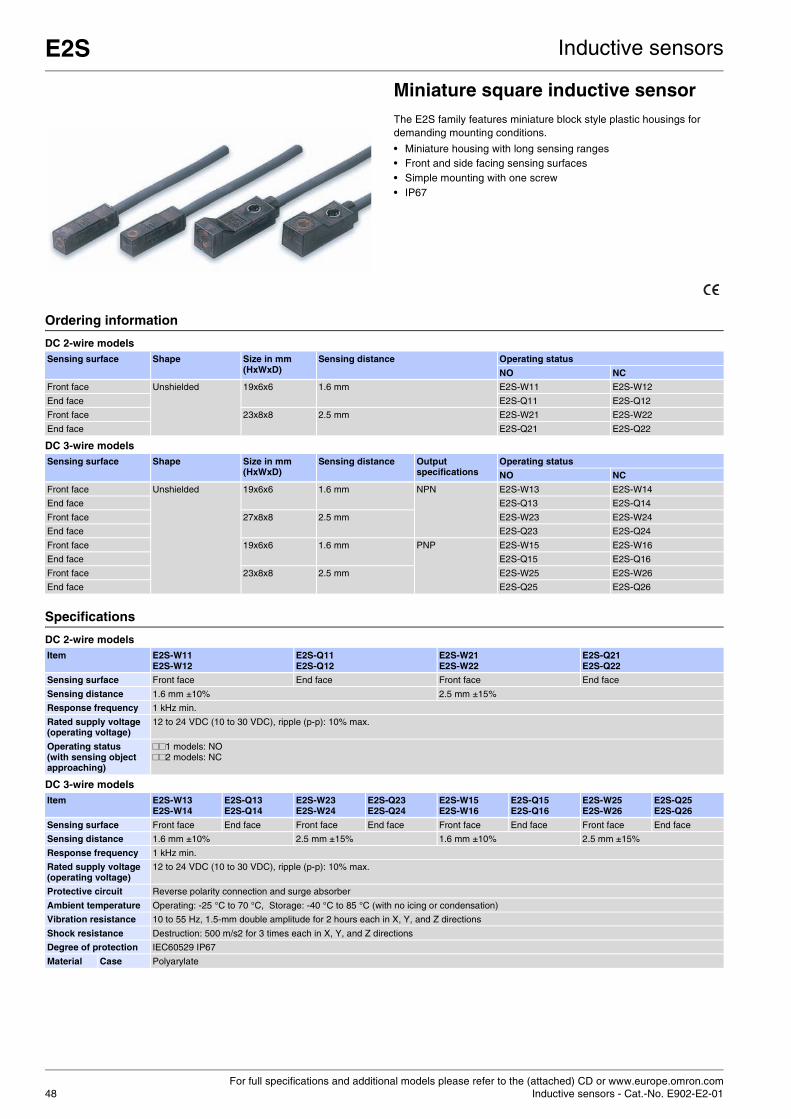
For full specifications and additional models please refer to the (attached) CD or www.europe.omron.comInductive sensors - Cat.-No. E902-E2-0148
E2S Inductive sensors
Miniature square inductive sensorThe E2S family features miniature block style plastic housings for demanding mounting conditions.
• Miniature housing with long sensing ranges • Front and side facing sensing surfaces • Simple mounting with one screw • IP67
Ordering information
DC 2-wire models
DC 3-wire models
Specifications
DC 2-wire models
DC 3-wire models
Sensing surface Shape Size in mm(HxWxD)
Sensing distance Operating status
NO NC
Front face Unshielded 19x6x6 1.6 mm E2S-W11 E2S-W12
End face E2S-Q11 E2S-Q12
Front face 23x8x8 2.5 mm E2S-W21 E2S-W22
End face E2S-Q21 E2S-Q22
Sensing surface Shape Size in mm(HxWxD)
Sensing distance Output specifications
Operating status
NO NC
Front face Unshielded 19x6x6 1.6 mm NPN E2S-W13 E2S-W14
End face E2S-Q13 E2S-Q14
Front face 27x8x8 2.5 mm E2S-W23 E2S-W24
End face E2S-Q23 E2S-Q24
Front face 19x6x6 1.6 mm PNP E2S-W15 E2S-W16
End face E2S-Q15 E2S-Q16
Front face 23x8x8 2.5 mm E2S-W25 E2S-W26
End face E2S-Q25 E2S-Q26
Item E2S-W11E2S-W12
E2S-Q11E2S-Q12
E2S-W21E2S-W22
E2S-Q21E2S-Q22
Sensing surface Front face End face Front face End face
Sensing distance 1.6 mm ±10% 2.5 mm ±15%
Response frequency 1 kHz min.
Rated supply voltage (operating voltage)
12 to 24 VDC (10 to 30 VDC), ripple (p-p): 10% max.
Operating status (with sensing object approaching)
##1 models: NO##2 models: NC
Item E2S-W13E2S-W14
E2S-Q13E2S-Q14
E2S-W23E2S-W24
E2S-Q23E2S-Q24
E2S-W15E2S-W16
E2S-Q15E2S-Q16
E2S-W25E2S-W26
E2S-Q25E2S-Q26
Sensing surface Front face End face Front face End face Front face End face Front face End face
Sensing distance 1.6 mm ±10% 2.5 mm ±15% 1.6 mm ±10% 2.5 mm ±15%
Response frequency 1 kHz min.
Rated supply voltage (operating voltage)
12 to 24 VDC (10 to 30 VDC), ripple (p-p): 10% max.
Protective circuit Reverse polarity connection and surge absorber
Ambient temperature Operating: -25 °C to 70 °C, Storage: -40 °C to 85 °C (with no icing or condensation)
Vibration resistance 10 to 55 Hz, 1.5-mm double amplitude for 2 hours each in X, Y, and Z directions
Shock resistance Destruction: 500 m/s2 for 3 times each in X, Y, and Z directions
Degree of protection IEC60529 IP67
Material Case Polyarylate

For full specifications and additional models please refer to the (attached) CD or www.europe.omron.comInductive sensors - Cat.-No. E221-E2-03-X 49
TL-W Inductive sensors
Compact square (flat shape) inductive sensorThe TL-W family offers a wide range of block style inductive sensors featuring different housing sizes for all standard applications.
• Front and side facing surface • IP67 • DC 2-wire and DC 3-wire models
Ordering information
DC 2-wire models
DC 3-wire models
Specifications
Shape Sensing distance Output and operating status
NO NC
Non-Shielded 5 mm TL-W5MD1*1
*1 Models with different response frequency are available. These model numbers take the form TL-W5MD#5 (e.g., TL-W5MD15)
TL-W5MD2*1
Shape Size in mm(HxWxD)
Sensing distance
Outputspecifications
Output and operating status
PNP-NO PNP-NC NPN-NO NPN-NC
Non-Shielded 25x8x5 1.5 mm
DC 3-wire
TL-W1R5MB1 --- TL-W1R5MC1*1
*1 Models with different response frequency are available. These model numbers take the form TL-W5MD#5 (e.g., TL-W5MD15)
---
22x8x6 3 mm TL-W3MB1 TL-W3MB2 TL-W3MC1*1 TL-W3MC2
31x18x10 5 mm TL-W5MB1 TL-W5MB2 TL-W5MC1*1 TL-W5MC2
53x40x23 20 mm --- --- TL-W20ME1*1 TL-W20ME2*1
Shielded 31x18x10 5 mm DC 3-wire TL-W5F1 TL-W5F2 TL-W5E1 TL-W5E2
Item TL-W5MD# TL-W1R5M#1 TL-W3M## TL-W5M## TL-W5E#/F# TL-W20ME#
Sensing distance 5 mm ±10% 1.5 mm ±10% 3 mm ±10% 5 mm ±10% 20 mm ±10%
Response frequency 0.5 kHz 1 kHz min. 600 Hz min. 500 Hz min. 300 Hz min. 40 Hz min.
Power supply voltage(operating voltage)
12 to 24 VDC (10 to 30 VDC) ripple (p-p): 10% max. 10 to 30 VDC with a ripple (p-p) of 20% max.
12 to 24 VDC (10 to 30 VDC) ripple (p-p): 10% max.
Ambient temperature Operating/Storage: -25 °C to 70 °C (with no icing or condensation)
Vibration resistance 10 to 55 Hz, 1.5 mm double amplitude for 2 hours each in X, Y, and Z directions
Shock resistance Destruction: 500 m/s2 for 3 times each in X, Y, and Z directions Destruction: 500 m/s2 for 10 times each in X, Y, and Z directions
Degree of protection IEC60529 IP67
Material Case Heat-resistant ABS resin Diecast aluminum Heat-resistant ABS resin
Sensing surface
Heat-resistant ABS resin

For full specifications and additional models please refer to the (attached) CD or www.europe.omron.comInductive sensors - Cat.-No. E38E-EN-0150
TL-T Inductive sensors
Compact square (thin shape) inductive sensorThe TL-T features a 12 mm thin housing for space saving direct wall mounting.
• 12 mm thin housing • Direct side wall mounting for bracket-less installation
Ordering information
DC 3-wire models
DC 4-wire models (NO + NC)
Specifications
Mounting Sensing distance Connection Output configuration Operation status mode NO
Operation status mode NC
Shielded 2.0 mm Pre-wired NPN TL-T2E1-E TL-T2E2-E
PNP TL-T2F1-E TL-T2F2-E
M8 connector (3-pin) NPN TL-T2E1-M5-E TL-T2E2-M5-E
PNP TL-T2F1-M5-E TL-T2F2-M5-E
Non-shielded 4.0 mm Pre-wired NPN TL-T4ME1-E TL-T4ME2-E
PNP TL-T4MF1-E TL-T4MF2-E
M8 connector (3-pin) NPN TL-T4ME1-M5-E TL-T4ME2-M5-E
PNP TL-T4MF1-M5-E TL-T4MF2-M5-E
Mounting Sensing distance Connection Output configuration Operation status mode antivalent (NO + NC)
Shielded 2.0 mm Pre-wired NPN TL-T2E3-E
PNP TL-T2F3-E
Non-shielded 4.0 mm Pre-wired NPN TL-T4ME3-E
PNP TL-T4MF3-E
Item Shielded Non-shielded
TL-T2 TL-T4
Sensing distance 2 mm ±10% 4 mm ±10%
Response frequency *1
*1 The response frequency is an average value. Measurement conditions are as follows: standard target, a distance of twice the standard target distance betweentargets, and a setting distance of half the sensing distance.
3000 Hz 1500 Hz
Power supply voltage (operating voltage)
24 VDC. Ripple (p-p): 10% max. (10 to 35 VDC)
Protective circuit Output reverse polarity protection, power source circuit reverse polarity protection, surge suppressor, short-circuit protection
Ambient temperature Operating/Storage: -25 °C to 70 °C
Vibration resistance 0 to 55 Hz with 30 min. dwell time at resonance frequency or 55 Hz each in X, Y, and Z directions55 to 2000 Hz, 150 m/s2, double amplitude for 2 hours each in X, Y, and Z directions
Shock resistance 300 m/s2 6 times each in X, Y, and Z directions
Degree of protection in accordance with IEC 60529:Pre-wired models: IP67M8 Connector models: IP65
Material Case PBT
Cable PVC
Size in mm 26Hx40Wx12D
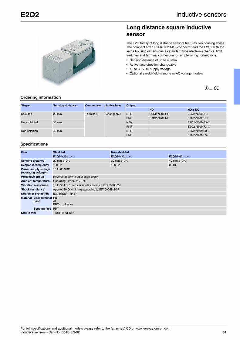
For full specifications and additional models please refer to the (attached) CD or www.europe.omron.comInductive sensors - Cat.-No. D01E-EN-02 51
E2Q2 Inductive sensors
Long distance square inductive sensorThe E2Q family of long distance sensors features two housing styles. The compact sized E2Q4 with M12 connector and the E2Q2 with the same housing dimensions as standard type electromechanical limit switches and terminal connection for simple wiring connections.
• Sensing distance of up to 40 mm • Active face direction changeable • 10 to 60 VDC supply voltage • Optionally weld-field-immune or AC voltage models
Ordering information
Specifications
Shape Sensing distance Connection Active face Output
NO NO + NC
Shielded 20 mm Terminals Changeable NPN E2Q2-N20E1-H E2Q2-N20E3-#
PNP E2Q2-N20F1-H E2Q2-N20F3-#
Non-shielded 30 mm NPN E2Q2-N30ME3-#
PNP E2Q2-N30MF3-#
Non-shielded 40 mm NPN E2Q2-N40ME3-#
PNP E2Q2-N40MF3-#
Item Shielded Non-shielded
E2Q2-N20##-# E2Q2-N30##-# E2Q2-N40## -#
Sensing distance 20 mm ±10% 30 mm ±10% 40 mm ±10%
Response frequency 150 Hz 100 Hz 30 Hz
Power supply voltage(operating voltage)
10 to 60 VDC
Protective circuit Reverse polarity, output short circuit
Ambient temperature Operating: -25 °C to 70 °C
Vibration resistance 10 to 55 Hz, 1 mm amplitude according IEC 60068-2-6
Shock resistance Approx. 30 G for 11 ms according to IEC 60068-2-27
Degree of protection IEC 60529 IP 67
Material Case terminal base
PBTAlPBT (...-H type)
Sensing face PBT
Size in mm 118Hx40Wx40D
LISTED

For full specifications and additional models please refer to the (attached) CD or www.europe.omron.comInductive sensors - Cat.-No. D02E-EN-01A52
E2Q4 Inductive sensors
Long distance square inductive proximity sensor
• Compact size for long distance requirements• M12 Plug-in connection• Active face positioning: Y-axis 15°, X-axis 90° increments
Ordering information
Specifications
Shape Sensingdistance
Connection Active face Operating status
NO NO + NC
Shielded 20 mm Plug-inconnector
Changable NPN E2Q4-N20E1-M1 E2Q4-N20E3-M1
PNP E2Q4-N20F1-M1 E2Q4-N20F3-M1
Non-shielded 30 mm NPN E2Q4-N30ME1-M1 E2Q4-N30ME3-M1
PNP E2Q4-N30MF1-M1 E2Q4-N30MF3-M1
Non-shielded 40 mm NPN E2Q4-N40ME3-M1
PNP E2Q4-N40MF3-M1
Item Shielded Non-shielded
E2Q4-N20## -M1 E2Q4-N30M## -M1 E2Q4-N40M#3-M1
Sensing distance Sn 20 mm ± 10% 30 mm ± 10% 40 mm ± 10%
Switching frequency 150 Hz
Power supply voltage (operating voltage
10 to 30 VDC
Protective circuit Reverse polarity, output short circuit
Ambient temperature Operating: -25 °C to 70 °C
Vibration resistance 10 to 55 Hz, 1 mm amplitude according IEC 60068-2-6
Shock resistance Approx. 30 G for 11 ms according to IEC 60068-2-27
Degree of protection IEC 60529 IP 67
Material Case PBT
Sensing face
PBT
Size in mm 67Hx40Wx40D
LISTEDCERIFIED

For full specifications and additional models please refer to the (attached) CD or www.europe.omron.comInductive sensors - Cat.-No. D10E-EN-01 53
E2AU Inductive sensors
Cylindrical inductive sensor for mobile usageDesigned and tested to keep your machines moving.
• IP69k tested and certified for highest water resistance • e1 type approval (according to automotive directive 95/54/EC) • EMC noise tested up to 100 V/m (ISO 11452-2) • Cable breakage protection
Ordering information
Specifications
Size Length Type Sensing distance Connection Output configuration
Operation mode NO
M12 34 (50) Shielded 4.0 mm Pre-wired PNP E2AU-M12KS04-WP-B1 2M
56 (72) PNP E2AU-M12LS04-WP-B1 2M
34 (48) M12 connector PNP E2AU-M12KS04-M1-B1
56 (70) PNP E2AU-M12LS04-M1-B1
M18 39 (59) Shielded 8.0 mm Pre-wired PNP E2AU-M18KS08-WP-B1 2M
61 (81) PNP E2AU-M18LS08-WP-B1 2M
39 (53) M12 connector PNP E2AU-M18KS08-M1-B1
61 (75) PNP E2AU-M18LS08-M1-B1
M30 44 (64) Shielded 15.0 mm Pre-wired PNP E2AU-M30KS15-WP-B1 2M
66 (86) PNP E2AU-M30LS15-WP-B1 2M
44 (58) M12 connector PNP E2AU-M30KS15-M1-B1
66 (80) PNP E2AU-M30LS15-M1-B1
Item M12 M18 M30
E2AU-M12@S04-@@-B1 E2AU-M18@S08-@@-B1 E2AU-M30@S15-@@-B1
Sensing distance 4 mm ±10% 8 mm ±10% 15 mm ±10%
Response frequency*1
*1 The response frequency is an average value. Measurement conditions are as follows: standard target, a distance of twice the standard target distance betweentargets, and a setting distance of half the sensing distance.
1,000 Hz 500 Hz 250 Hz
Power supply voltage (operating voltage)
12 to 24 VDC. Ripple (p-p): 10% max.(10 to 32 VDC)
Protective circuit Output reverse polarity protection, power source circuit reverse polarity protection, surge suppressor, short-circuit protection
Ambient temperature Operating: -40 °C to 70 °C, Storage: -40 °C to 85 °C (with no icing or condensation)
Vibration resistance 10 to 55 Hz, 1.5 mm double amplitude for 2 hours each in X, Y and Z directions
Shock resistance 1,000 m/s2, 10 times each in X, Y and Z directions
Degree of protection IP67 after IEC 60529IP69k after DIN 40050
Standard and listings EMC after EN60947-5-2UL (CSA) E196555 *2
EMC after 95/94/ECEMC after ISO11452-2
*2 UL (CSA) [E196555]: Use class 2 circuit only.
Material Case Brass-nickel plated
Sensing surface
PBT

For full specifications and additional models please refer to the (attached) CD or www.europe.omron.comInductive sensors - Cat.-No. E37E-EN-0154
E2AX Inductive sensors
Cylindrical inductive sensor for explosive environmentsThe high-reliability and robustness of the E2A family is now also available for explosive environments. The protective structure of the E2A family (based on EN50014 and EN50281-1-1/2) allows the ATEX certification group II category 3D (94/9/EC appendix VIII) typically for explosive areas zone 22 with non-leading dust.
• Protective connector cover to avoid disconnection under power • Certified ATEX group II category 3D (94/9/EC appendix VIII) • Rugged housing construction based on EN50014 and
EN50281-1-1/2
Ordering information
DC 3-wire models (NO + NC: DC 4-wire) *1
*1 Please contact your OMRON representative for DC 2-wire models.*2 Stainless steel models are also available. Please contact your OMRON representative.*3 M30 non-shielded models with double sensing distance and short barrels cannot be mounted due to the necessary separation distance from the surrounding
metal. Standard sensing models are thus available.
Size Sensing distance
Connection Body material
Thread length (overall length)
Output configuration
Operation mode NO Operation mode NC Operation mode NO + NC
M12 Shielded 4.0 mm M12 connector
Brass*2 34 (48) PNP E2AX-M12KS04-M1-B1 E2AX-M12KS04-M1-B2 E2AX-M12KS04-M1-B3
NPN E2AX-M12KS04-M1-C1 E2AX-M12KS04-M1-C2 E2AX-M12KS04-M1-C3
56 (70) PNP E2AX-M12LS04-M1-B1 E2AX-M12LS04-M1-B2 E2AX-M12LS04-M1-B3
NPN E2AX-M12LS04-M1-C1 E2AX-M12LS04-M1-C2 E2AX-M12LS04-M1-C3
Non-shielded 8.0 mm M12 connector
Brass*2 34 (48) PNP E2AX-M12KN08-M1-B1 E2AX-M12KN08-M1-B2 E2AX-M12KN08-M1-B3
NPN E2AX-M12KN08-M1-C1 E2AX-M12KN08-M1-C2 E2AX-M12KS08-M1-C3
56 (70) PNP E2AX-M12LN08-M1-B1 E2AX-M12LN08-M1-B2 E2AX-M12LS08-M1-B3
NPN E2AX-M12LN08-M1-C1 E2AX-M12LN08-M1-C2 E2AX-M12LS08-M1-C3
M18 Shielded 8.0 mm M12 connector
Brass*2 39 (53) PNP E2AX-M18KS08-M1-B1 E2AX-M18KS08-M1-B2 E2AX-M18KS08-M1-B3
NPN E2AX-M18KS08-M1-C1 E2AX-M18KS08-M1-C2 E2AX-M18KS08-M1-C3
61 (75) PNP E2AX-M18LS08-M1-B1 E2AX-M18LS08-M1-B2 E2AX-M18LS08-M1-B3
NPN E2AX-M18LS08-M1-C1 E2AX-M18LS08-M1-C2 E2AX-M18LS08-M1-C3
Non-shielded 16.0 mm M12 connector
Brass*2 39 (53) PNP E2AX-M18KN16-M1-B1 E2AX-M18KN16-M1-B2 E2AX-M18KN16-M1-B3
NPN E2AX-M18KN16-M1-C1 E2AX-M18KN16-M1-C2 E2AX-M18KS16-M1-C3
61 (75) PNP E2AX-M18LN16-M1-B1 E2AX-M18LN16-M1-B2 E2AX-M18LS16-M1-B3
NPN E2AX-M18LN16-M1-C1 E2AX-M18LN16-M1-C2 E2AX-M18LS16-M1-C3
M30 Shielded 15.0 mm M12 connector
Brass*2 44 (58) PNP E2AX-M30KS15-M1-B1 E2AX-M30KS15-M1-B2 E2AX-M30KS15-M1-B3
NPN E2AX-M30KS15-M1-C1 E2AX-M30KS15-M1-C2 E2AX-M30KS15-M1-C3
66 (80) PNP E2AX-M30LS15-M1-B1 E2AX-M30LS15-M1-B2 E2AX-M30LS15-M1-B3
NPN E2AX-M30LS15-M1-C1 E2AX-M30LS15-M1-C2 E2AX-M30LS15-M1-C3
Non-shielded 20.0 mm M12 connector
Brass*2 44 (58) *3 PNP E2AX-M30KN20-M1-B1 E2AX-M30KN20-M1-B2 E2AX-M30KN20-M1-B3
NPN E2AX-M30KN20-M1-C1 E2AX-M30KN20-M1-C2 E2AX-M30KN20-M1-C3
30.0 mm 66 (80) PNP E2AX-M30LN30-M1-B1 E2AX-M30LN30-M1-B2 E2AX-M30LN30-M1-B3
NPN E2AX-M30LN30-M1-C1 E2AX-M30LN30-M1-C2 E2AX-M30LN30-M1-C3

E2AX Inductive sensors
55
Specifications
Size M12 M18 M30
Type Shielded Non-shielded Shielded Non-shielded Shielded Non-shielded Non-shielded
Item E2AX-M12@S04-@@-B@E2AX-M12@S04-@@-C@E2AX-S12@S04-@@-B@E2AX-S12@S04-@@-C@
E2AX-M12@N08-@@-B@E2AX-M12@N08-@@-C@E2AX-S12@N08-@@-B@E2AX-S12@N08-@@-C@
E2AX-M18@S08-M1-B@E2AX-M18@S08-M1-C@E2AX-S18@S08-M1-B@E2AX-S18@S08-M1-C@
E2AX-M18@N16-M1-B@E2AX-M18@N16-M1-C@E2AX-S18@N16-M1-B@E2AX-S18@N16-M1-C@
E2AX-M30@S15-M1-B@E2AX-M30@S15-M1-C@E2AX-S30@S15-M1-B@E2AX-S30@S15-M1-C@
E2AX-M30KN20-M1-B@E2AX-M30KN20-M1-C@E2AX-S30KN20-M1-B@E2AX-S30KN20-M1-C@
E2AX-M30LN30-M1-B@E2AX-M30LN30-M1-C@E2AX-S30LN30-M1-B@E2AX-S30LN30-M1-C@
Sensing distance 4 mm ±10% 8 mm ±10% 8 mm ±10% 16 mm ±10% 15 mm ±10% 20 mm ±10% 30 mm ±10%
Response frequency *1
*1 The response frequency is an average value. Measurement conditions are as follows: standard target, a distance of twice the standard target distance betweentargets, and a setting distance of half the sensing distance.
1,000 Hz 800 Hz 500 Hz 400 Hz 250 Hz 100 Hz 100 Hz
Power supply voltage (operating voltage range)
12 to 24 VDC. Ripple (p-p): 10% max.(10 to 32 VDC)
Protection circuit Output reverse polarity protection, power source circuit reverse polarity protection, surge suppressor, short-circuit protection
Ambient air temperature Operating: -40 °C to 70 °C, Storage: -40 °C to 85 °C (with no icing or condensation)
Vibration resistance 10 to 55 Hz, 1.5 mm double amplitude for 2 hours each in X, Y and Z directions
Shock resistance 1,000 m/s2, 10 times each in X, Y and Z directions
Standard and listings IP65EMC after EN60947-5-2UL (CSA) E196555 *2
ATEX after EN50014EN50281-1-1/2
*2 UL (CSA) [E196555]: Use class 2 circuit only
Material Case Brass-nickel plated or stainless steel
Sensing surface PBT
Clamping nut Brass-nickel plated for brass models stainless steel for steel models

For full specifications and additional models please refer to the (attached) CD or www.europe.omron.comInductive sensors - Cat.-No. D15E-EN-0156
E2F-D Inductive sensors
Anti-microbial inductive sensor in cylindrical plastic housingThe E2F-D features a FDA approved anti-microbial housing reducing the risk of food contamination.
• Anti-microbial housing material reducing bacteria growth • IP67 and IP69k for highest water resistance • Tested detergent resistance
Ordering information
Specifications
Size Shape Sensing distance Output specifications Operating status
NO NC
M12 non-shielded 4 mm NPN E2F-DX4E1 E2F-DX4E2
PNP E2F-DX4F1 E2F-DX4F2
M18 8 mm NPN E2F-DX8E1 E2F-DX8E2
PNP E2F-DX8F1 E2F-DX8F2
Item E2F-DX4@ E2F-DX8@Sensing distance 4 mm ±10% 8 mm ±10%
Response frequency 1 kHz 500 Hz
Power supply voltage 10 to 35 VDC
Ambient temperature Operating/Storage: -25 °C to 70 °C (with no icing or condensation)
Vibration resistance 10 to 55 Hz, 1.5 mm double amplitude for 2 hours each in X, Y, and Z directions
Degree of protection IP67, IP69k
Material PBT with anti-microbial SAN additive based on silver ions

For full specifications and additional models please refer to the (attached) CD or www.europe.omron.comInductive sensors - Cat.-No. D06E-EN-01 57
E2EL Inductive sensors
Increased switching frequency inductive sensorThe E2EL family features an increased response frequency for high-speed applications such as counting applications.
• Max 5 kHz, switching frequency • M8 or dia 6.5 mm housing • Brass or stainless steel housing
Ordering information
Exemplary for pre-wired types. Please refer to complete datasheet for connector versions.
Brass housing
Stainless steel housing
Specifications
Size Length Shape Sensing distance
Operating status
NPN / NO NPN / NC PNP / NO PNP / NC
Ø 6,5 30 mm Shielded 1,5 mm E2EL-C1R5E1 2M E2EL-C1R5E2 2M E2EL-C1R5F1 2M E2EL-C1R5F2 2M
32 mm Non-shielded 2,0 mm E2EL-C2ME1 2M E2EL-C2ME2 2M E2EL-C2MF1 2M E2EL-C2MF2 2M
45 mm Shielded 1,5 mm E2EL-C1R5E1-L 2M E2EL-C1R5E2-L 2M E2EL-C1R5F1-L 2M E2EL-C1R5F2-L 2M
47 mm Non-shielded 2,0 mm E2EL-C2ME1-L 2M E2EL-C2ME2-L 2M E2EL-C2MF1-L 2M E2EL-C2MF2-L 2M
M8 30 mm Shielded 1,5 mm E2EL-X1R5E1 2M E2EL-X1R5E2 2M E2EL-X1R5F1 2M E2EL-X1R5F2 2M
32 mm Non-shielded 2,0 mm E2EL-X2ME1 2M E2EL-X2ME2 2M E2EL-X2MF1 2M E2EL-X2MF2 2M
45 mm Shielded 1,5 mm E2EL-X1R5E1-L 2M E2EL-X1R5E2-L 2M E2EL-X1R5F1-L 2M E2EL-X1R5F2-L 2M
47 mm Non-shielded 2,0 mm E2EL-X2ME1-L 2M E2EL-X2ME2-L 2M E2EL-X2MF1-L 2M E2EL-X2MF2-L 2M
Size Length Mounting Sensing distance
Operating status
NPN / NO NPN / NC PNP / NO PNP / NC
Ø 6,5 30 mm Shielded 2,0 mm E2EL-C2E1-DS 2M E2EL-C2E2-DS 2M E2EL-C2F1-DS 2M E2EL-C2F2-DS 2M
45 mm Shielded 2,0 mm E2EL-C2E1-DSL 2M E2EL-C2E2-DSL 2M E2EL-C2F1-DSL 2M E2EL-C2F2-DSL 2M
M8 30 mm Shielded 2,0 mm E2EL-X2E1-DS 2M E2EL-X2E2-DS 2M E2EL-X2F1-DS 2M E2EL-X2F2-DS 2M
45 mm Shielded 2,0 mm E2EL-X2E1-DSL 2M E2EL-X2E2-DSL 2M E2EL-X2F1-DSL 2M E2EL-X2F2-DSL 2M
Type Ø 6,5 M8
Response frequency 5,0 kHz
Power supply voltage(operating voltage)
24 VDC
Protective circuit Reverse polarity, output short-circuit
Operating voltage 10 to 35 VDC
Mounting Shielded Non-shielded Shielded Non-shielded
Operating distance 1,5 mm 2,0 mm 1,5 mm 2,0 mm
Ambient temperature Operating: -25 °C to 70 °C
Vibration resistance Destruction: 10 to 70 Hz, 1,5 mm double amplitude for 1 hour each in X, Y and Z directions
Shock resistance Destruction: 300 m/s² (approx. 30 G) for 6 times each in X, Y and Z directions
Enclosure rating IP 67 (EN 60947-1)
Material Case Brass, stainless steel 1.4305/AIS/303
Sensing face
PBT

For full specifications and additional models please refer to the (attached) CD or www.europe.omron.comInductive sensors - Cat.-No. D055-E2-03-X58
E2EQ Inductive sensors
Spatter resistant inductive sensorsThe E2EQ family features a PTFE coated brass housing preventing the attachment of sputters in welding applications.
• PTFE coated brass housing • DC 2-wire models
Ordering information
Specifications
Size Shape Sensing distance Output specifications Operating status Model
M12 Shielded 4 mm DC 2-wire NO E2EQ-X4X1
M18 8 mm E2EQ-X8X1
M30 15 mm E2EQ-X15X1
Item E2EQ-X4X1E2EQ-X4X1-M1J
E2EQ-X8X1E2EQ-X8X1-M1J
E2EQ-X15X1E2EQ-X15X1-M1J
Sensing distance 4 mm ±10% 8 mm ±10% 15 mm ±10%
Response frequency*1
*1 The response frequencies for DC switching are average values.
1 kHz 0.5 kHz 0.25 kHz
Power supply voltage(operating voltage)
12 - 24 VDC (10 to 30 VDC), ripple (p-p) 10% max.
Protective circuits Surge absorber, load short-circuit protection
Ambient temperature Operating: -25 °C to 70 °C, Storage: -40 °C to 85 °C (with no icing or condensation)
Shock resistance Destruction: 1,000 m/s2 for 10 times each in X, Y, and Z directions
Degree of protection IP67 (IEC 60529)
Material Case Teflon resin coating (brass base)
Sensing surface
PTFE resin

For full specifications and additional models please refer to the (attached) CD or www.europe.omron.comInductive sensors - Cat.-No. D14E-EN-01 59
E2E-@Y / E2F-@Y Inductive sensors
Inductive sensor line for AC power supplyThe E2E-@Y and E2F-@Y models offer the same functionality and protection as the standard E2E (brass housing) and E2F (plastic housing) families but can be connected to an AC power supply.
• 24-240 VAC direct switching • IP67 • Brass or plastic housing
Ordering information
AC 2-wire / Pre-wired models
Specifications (exemplary)
Metal housing (E2E)
Size Sensing distance
Operation mode
Metal housing Plastic housing
Pre-wired Connector Pre-wired
Shielded M8 1.5 mm NO E2E-X1R5Y1 E2F-X1R5Y1
NC E2E-X1R5Y2 E2F-X1R5Y2
M12 2 mm NO E2E-X2Y1 E2E-X2Y1-M1 E2F-X2Y1
NC E2E-X2Y2 E2E-X2Y2-M1 E2F-X2Y2
M18 5 mm NO E2E-X5Y1 E2E-X5Y1-M1 E2F-X5Y1
NC E2E-X5Y2 E2E-X5Y2-M1 E2F-X5Y2
M30 10 mm NO E2E-X10Y1 E2E-X10Y1-M1 E2F-X10Y1
NC E2E-X10Y2 E2E-X10Y2-M1 E2F-X10Y2
Unshielded M8 2 mm NO E2E-X2MY1
NC E2E-X2MY2
M12 5 mm NO E2E-X5MY1 E2E-X5MY1-M1
NC E2E-X5MY2 E2E-X5MY2-M1
M18 10 mm NO E2E-X10MY1 E2E-X10MY1-M1
NC E2E-X10MY2 E2E-X10MY2-M1
M30 18 mm NO E2E-X18MY1 E2E-X18MY1-M1
NC E2E-X18MY2 E2E-X18MY2-M1
Size M8 M12 M18 M30
Type Shielded Unshielded Shielded Unshielded Shielded Unshielded Shielded Unshielded
Item E2E-X1R5Y@ E2E-X2MY@ E2E-X2Y@ E2E-X5MY@ E2E-X5Y@ E2E-X10MY@ E2E-X10Y@ E2E-X18MY@Sensing distance 1.5 mm ±10% 2 mm ±10% 2 mm ±10% 5 mm ±10% 5 mm ±10% 10 mm ±10% 10 mm ±10% 18 mm ±10%
Response speed 25 Hz
Power supply voltage (operating voltage range) *1
*1 When supplying 24 VAC to any of the above models, make sure that the operating ambient temperature range is over –25 °C.
24 to 240 VAC, 50/60 Hz (20 to 264 VAC)
Operation mode (with sensing object approaching)
Y1 Models: NOY2 Models: NCFor details, refer to Timing charts.
Ambient temperature *1 *2
*2 When using an M18- or M30-sized E2E within an ambient temperature of 70 °C to 85 °C, make sure that the E2E has a control output of 5 to 200 mA max.
Operating/Storage: -25 °C to 70 °C (with no icing or condensation)
Operating/Storage: -40 °C to 85 °C (with no icing or condensation)
Vibration resistance 10 to 55 Hz, 1.5 mm double amplitude for 2 hours each in X, Y, and Z directions
Shock resistance 500 m/s2 10 times each in X, Y, and Z directions
1,000 m/s2 10 times each in X, Y, and Z directions
Degree of protection IEC 60529 IP67 (Pre-wired models: JEM standard IP67g (waterproof, oil-proof))
Connection method Pre-wired models (standard length 2 m), connector models
Material Case Stainless steel (SUS303) Brass-nickel plated
Sensing surface
PBT (polybutylene terephthalate)
Clamping nuts
Brass-nickel plated
Toothed washer
Iron-zinc plated

For full specifications and additional models please refer to the (attached) CD or www.europe.omron.comInductive sensors - Cat.-No. D028-E1-04-X60
E2EZ Inductive sensors
Aluminium and cast iron chip immune inductive sensorThe E2EZ family features a specialized sensing method providing reliable metal object detection even when covered with small chips of Aluminium or cast iron (e.g. in metal cutting applications).
• Aluminium and Cast Iron chip immune • DC 2-wire or DC 3-wire
Ordering information
Specifications
Size Shape Sensing distance Output specifications Operating status
NO NC
M12 Shielded 2 mm DC 2-wire E2EZ-X2D1-N E2EZ-X2D2-N
M18 4 mm DC 3-wire NPN E2EZ-X4C1 ---
DC 2-wire E2EZ-X4D1-N E2EZ-X4D2-N
M30 6 mm DC 3-wire NPN E2EZ-X8C1 ---
DC 2-wire E2EZ-X8D1-N E2EZ-X8D2-N
Item E2EZ-X4C1 E2EZ-X8C1 E2EZ-X2 E2EZ-X4D@-NE2EZ-X4D@-M1JE2EZ-X4D@-M1GJ
E2EZ-X8D@-NE2EZ-X8D@-M1JE2EZ-X8D@-M1GJ
Sensing distance 4 mm ±10% 8 mm ±10% 2 mm ±10% 4 mm ±10% 8 mm ±10%
Response frequency*1
*1 The response frequencies for DC switching are average values measured on condition that the distance between each sensing object is twice as large as the sizeof the sensing object and the sensing distance set is half of the maximum sensing distance.
12 Hz 8 Hz 200 Hz 100 Hz 30 Hz
Power supply voltage (operating voltage)
C models: 12 to 24 VDC, ripple (p-p) : 10% max., (10 to 30 VDC)
12 to 24 VDC (10 to 30 VDC) ripple (p-p): 10% max.
Protective circuits C models: Reverse connection protection, load short-circuit protection, surge absorber
Surge absorber, short-circuit protection
Ambient temperature Operating / Storage: 0 ° C to 50 ° C (with no icing or condensation)
Vibration resistance 10 to 55 Hz, 1.5 mm double amplitude for 2 hours each in X, Y, and Z directions
Shock resistance Destruction: 1,000 m/s2 for 10 times each in X, Y, and Z directions
Degree of protection IEC60529 IP67
Material Case BrassSensing face: Heat-resistant ABS resin
Screw BrassMounting nut: Steel
v
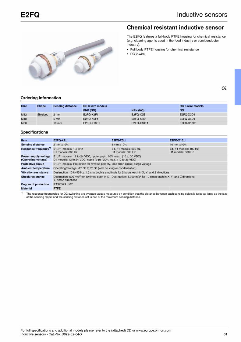
For full specifications and additional models please refer to the (attached) CD or www.europe.omron.comInductive sensors - Cat.-No. D029-E2-04-X 61
E2FQ Inductive sensors
Chemical resistant inductive sensorThe E2FQ features a full-body PTFE housing for chemical resistance (e.g. cleaning agents used in the food industry or semiconductor industry).
• Full body PTFE housing for chemical resistance • DC 2-wire
Ordering information
Specifications
Size Shape Sensing distance DC 3-wire models DC 2-wire models
PNP (NO) NPN (NO) NO
M12 Shielded 2 mm E2FQ-X2F1 E2FQ-X2E1 E2FQ-X2D1
M18 5 mm E2FQ-X5F1 E2FQ-X5E1 E2FQ-X5D1
M30 10 mm E2FQ-X10F1 E2FQ-X10E1 E2FQ-X10D1
Item E2FQ-X2@ E2FQ-X5@ E2FQ-X10@Sensing distance 2 mm ±10% 5 mm ±10% 10 mm ±10%
Response frequency*1
*1 The response frequencies for DC switching are average values measured on condition that the distance between each sensing object is twice as large as the sizeof the sensing object and the sensing distance set is half of the maximum sensing distance.
E1, F1 models: 1.5 kHzD1 models: 800 Hz
E1, F1 models: 600 Hz,D1 models: 500 Hz
E1, F1 models: 400 Hz, D1 models: 300 Hz
Power supply voltage(Operating voltage)
E1, F1 models: 12 to 24 VDC, ripple (p-p) : 10% max., (10 to 30 VDC)D1 models: 12 to 24 VDC, ripple (p-p) : 20% max., (10 to 36 VDC)
Protective circuit E1, F1 models: Protection for reverse polarity, load short circuit, surge voltage
Ambient temperature Operating/Storage: -25 °C to 70 °C (with no icing or condensation)
Vibration resistance Destruction: 10 to 55 Hz, 1.5 mm double amplitude for 2 hours each in X, Y, and Z directions
Shock resistance Destruction: 500 m/s2 for 10 times each in X, Y, and Z directions
Destruction: 1,000 m/s2 for 10 times each in X, Y, and Z directions
Degree of protection IEC60529 IP67
Material PTFE

For full specifications and additional models please refer to the (attached) CD or www.europe.omron.comInductive sensors - Cat.-No. D058-E2-02-X62
E2E Inductive sensors
Oil resistant inductive sensor familyThe standard E2E family offers tested oil resistance on commonly used oils in the automotive industry for reliable long-life operation in automotive assembly lines.
• DC 3-wire and DC 2-wire models • M8, M12, M18 and M30 standard sizes • IP67g (water and oil resistance)
Ordering information
Specifications
Size Sensing distance Self-diagnostic output function
Model
NO NC
M12 Shielded 3 mm Yes E2E-X3D1S*1
*1 In addition to the above models, E2E-X@@15 models (e.g., E2E-X3D15-N), which are different in frequency from the above models, are available.
---
M18 7 mm E2E-X7D1S *1 ---
M30 10 mm E2E-X10D1S *1 ---
M12 Unshielded 8 mm E2E-X8MD1S *1 ---
M18 14 mm E2E-X14MD1S *1 ---
M30 20 mm E2E-X20MD1S *1 ---
M8 Shielded 2 mm No E2E-X2D1-N *2 *3
*2 E2E models with a robotics cable are available as well. The model number of a model with a robotics cable has the suffix '-R' (e.g., E2E-X3D1-R).
E2E-X2D2-N *3
M12 3 mm E2E-X3D1-N *1 *2 *3 E2E-X3D2-N *3
M18 7 mm E2E-X7D1-N *1 *2 *3 E2E-X7D2-N *3
*3 Cables with a length of 5 m are also available. Specify the cable length at the end of the model number (e.g., E2E-X3D1-N 5M).
M30 10 mm E2E-X10D1-N *1 *2 *3 E2E-X10D2-N
M8 Unshielded 4 mm E2E-X4MD1 *2 *3 E2E-X4MD2
M12 8 mm E2E-X8MD1 *1 *2 *3 E2E-X8MD2
M18 14 mm E2E-X14MD1 *1 *2 *3 E2E-X14MD2
M30 20 mm E2E-X20MD1 *1 *2 *3 E2E-X20MD2
Item M8 M12 M18 M30
E2E-X2D@ E2E-X4MD@ E2E-X3D@ E2E-X8MD@ E2E-X7D@ E2E-X14MD@ E2E-X10D@ E2E-X20MD@Sensing distance 2 mm ±10% 4 mm ±10% 3 mm ±10% 8 mm ±10% 7 mm ±10% 14 mm ±10% 10 mm ±10% 20 mm ±10%
Response frequency *1
*1 The response speed is an average value. Measurement conditions are as follows: standard sensing object, a distance of twice the standard sensing object, and aset distance of half the sensing distance.
1.5 kHz 1.0 kHz 1.0 kHz 0.8 kHz 0.5 kHz 0.4 kHz 0.4 kHz 0.1 kHz
Power supply voltage (operating voltage)
12 to 24 VDC (10 to 30 VDC), ripple (p-p): 10% max.
Protective circuit Surge suppressor, output load short-circuit protection (for control and diagnostic output)
Ambient temperature Operating: -25 ° C to 70 ° C, Storage: -40 ° C to 85 ° C (with no icing or condensation)
Vibration resistance 10 to 55 Hz, 1.5-mm double amplitude for 2 hours each in X, Y, and Z directions
Shock resistance 500 m/s2 10 times each in X, Y, and Z directions
1,000 m/s2 10 times each in X, Y, and Z directions
Degree of protection IEC 60529 IP67 (Pre-wired models, pre-wired connector models: JEM standard IP67g (waterproof and oil-proof))
Material Case Stainless steel (SUS303) Brass-nickel plated
Sensing surface
PBT (polybutylene terephthalate)

For full specifications and additional models please refer to the (attached) CD or www.europe.omron.comInductive sensors - Cat.-No. D101-E2-01A-X 63
E2C-EDA Inductive sensors
High precision positioning inductive proximity sensorThe separate amplifier inductive sensor family E2C-EDA offers high precision distance positioning and detection. The teach-in function allows simple installation, and with the window function (2 outputs) production tolerance checks can easily be set up and modified.
• 1 µm repeat accuracy • Precision distance teaching • Window function (2 outputs) for production tolerance checks
Ordering information
Sensor heads
Amplifier units with cables Amplifier units with connectors
Specifications
Sensor heads
Type Appearance Size in mm (HxWxD) Sensing distance Repeat accuracy Model
Shielded 3 dia.× 18 0.6 mm 1 µm E2C-EDR6-F
5.4 dia.× 18 1 mm 1 µm E2C-ED01-@
8 dia.× 22 2 mm 2 µm E2C-ED02-@
M10× 22 2 mm 2 µm E2C-EM02-@
30× 14× 4.8 5 mm 2 µm E2C-EV05-@
Unshielded M18× 46.3 7 mm 5 µm E2C-EM07M-@
Heat-resistant M12× 22 2 mm 2 µm E2C-EM02H
Cylindrical
Screw
Flat
Screw
Screw
Item Functions NPN output PNP output
Twin-output models
Area output, open circuit detection, differential operation
E2C-EDA11 E2C-EDA41
External-input models
Remote setting, differential operation
E2C-EDA21 E2C-EDA51
Item Functions NPN output PNP output
Twin-output models
Area output, open circuit detection, differential operation
E2C-EDA6 E2C-EDA8
External-input models
Remote setting, differential operation
E2C-EDA7 E2C-EDA9
Item E2C-EDR6-F E2C-ED01(-@) E2C-ED02(-@) E2C-EM02-@) E2C-EM07(-@) E2C-EV05(-@) E2C-EM02H
3 dia.× 18 mm 5.4 dia.× 18 mm 8 dia.× 22 mm M10× 22 mm M18× 46.3 mm 30× 14× 4.8 mm M12× 22 mm
Sensing distance 0.6 mm 1 mm 2 mm 7 mm 5 mm 2 mm
Ambient temperature *1
*1 A sudden temperature rise even within the rated temperature range may degrade characteristics.
operating -10 ° C to 60 ° C (with no icing or condensation) -10 ° C to 200 ° C*2
*2 For the Sensor Head only without the preamplifier ( 10 to 60° C). With no icing or condensation.
storage -10 ° C to 60 ° C (with no icing or condensation)
-20 ° C to 70 ° C (with no icing or condensation)
Vibration resistance Destruction: 10 to 55 Hz, 1.5-mm double amplitude for 2 hours each in X, Y, and Z directions
Shock resistance Destruction: 500 m/s2 for 3 times each in X, Y, and Z directionsDegree of protection IEC60529 IP67 IEC60529 IP60 *3
*3 Do not operate in areas exposed to water vapor because the enclosure is not waterproof.
Material
Sensor Head
Case Brass Stainless steel Brass Zinc Brass
Sensing surface
Heat-resistant ABS PEEK

Fibre optic amplifiers
The best solution package for powerful digital amplifi ers and fi bre sensors
E3X-DA-S – the new best-in-class fibre optic amplifiers
64

65
Table of contentsSelection table 66
Fiber optic amplifiers E3X-DA-N 71
E3X-NA 73
E3X-DA-S 75
E3X-MDA 77
E3X-DA-SE-S 79
E3X-DA-AT-S 80
E3X-DA-AN-S 81

66
Selection table
Category Basic line - cost effective
Industrial line -manual adjustor
High end -one for all
High end -2 in 1
Model E3X-DA-N E3X-NA E3X-DA-S E3X-MDA
Sensingadjustment
Teach button
Manual adjustment
Specialfeatures
Power tuning
Auto power control APC
Active threshold ATC
Networkconnectivity
Communication
Module E3X-DRT21
Communication
Module E3X-DRT21-S
Communication with mobile console E3X-MC11 / -SV2 E3X-MC11 / -SV2 E3X-MC11 / -SV2
Display Digital single (S) /dual (D) display
S D D
LED bargraph
Light sourcestypes
Red LED
Green LED
Blue LED
Infrared
Voltage range 12 VDC - 24 VDC 12 VDC - 24 VDC 12 VDC - 24 VDC 12 VDC - 24 VDC
Powerconsumption
(at 24 VDC, without load) <40 mA <35 mA <45 mA <45 mA
Controloutput / input
PNP
NPN
Twin output / 2 Chn.
Alarm / error output
Analogue output
Monitor output 1 V - 5 V
Remote input
Mode selection Dark on / Light on / switch
Response time (min.) 250 µs 20 µs 48 µs 130 µs
Connection Cable type (prewired)
Connector type
Enclosure rating IP50 / IP66 IP50 / IP60 IP50 IP50
Ambient temperature -25 °C - 55 °C -25 °C - 55 °C -25 °C - 55 °C -25 °C - 55 °C
Housingmaterial
Case PBT PBT PBT PBT
Cover PC / PES PC / PES PC PC
ROHS conformity (in prep.) (in prep.) (in prep.) (in prep.)
Page 71 73 75 77

Fiber optic amplifiers
67
Category High end -teach and go
High end -active threshold
High end -analogue output
Model E3X-DA-SE-S E3X-DA-AT-S E3X-DA-AN-S
Sensingadjustment
Teach button
Manual adjustment
Specialfeatures
Power tuning
Auto power control APC
Active threshold ATC
Networkconnectivity
Communication
Module E3X-DRT21
Communication
Module E3X-DRT21-S
Communication with mobile console E3X-MC11 / -SV2 E3X-MC11 / -SV2
Display Digital single (S) /dual (D) display
D D D
LED bargraph
Light sourcestypes
Red LED
Green LED
Blue LED
Infrared
Voltage range 12 VDC - 24 VDC 12 VDC - 24 VDC 12 VDC - 24 VDC
Powerconsumption
(at 24 VDC, without load) <40 mA <45 mA <45 mA
Controloutput / input
PNP Control output
NPN Control output
Twin output
Alarm / error output Error output
Analogue output Analogue Output
Monitor output 1 V - 5 V
Remote input
Mode selection Dark on / Light on
Response time (min.) 1 ms 80 µs 80 µs
Connection Cable type (prewired)
Connector type
Enclosure rating IP50 IP50 IP50
Ambient temperature -25 °C - 55 °C -25 °C - 55 °C -25 °C - 55 °C
Housingmaterial
Case PBT PBT PBT
Cover PC PC PC
ROHS conformity (in prep.) (in prep.) (in prep.)
Page 79 80 81
Standard Available No / not available

68
Selection table
General purpose
Category Standard Long distance
Type name E32-DC200E32-TC200
E32-D16 E32-D11LE32-T11L
E32-D22LE32-T22L
E32-D12RE32-T12R
E32-ED11RE32-ET11R
Ambientoperating temperature
-40 °C - 70 °C
IP rating IP67 IP40 IP67
Ambient humidity 38% - 85%
Fiber material / coating Plastic / PE Plastic / PVC
Min. bending radius / mm 25 4 25 10 1 1
Freecut (Y/N) Y
Max. sensing distance [mm]diffuse- / through beam type
500/1,000 1,000 650/1,700 210/540 300/700 300/700
D = Diffuse typeT = Through beam type
R = Retro reflective
D/T D D/T D/T D/T D/T
General purpose
Category Flexible / R-type
Type name E32-T1@R E32-D1@R E32-T2@R E32-ET@R E32-ED@R E32-D2@R
Ambientoperating temperature
-40 °C - 70 °C
IP rating IP67
Ambient humidity 38% - 85%
Fiber material / coating Plastic / PVC Plastic / PE
Min. bending radius / mm 1
Freecut (Y/N) Y
Max. sensing distance [mm]diffuse- / through beam type
4,000 (+ E39-F1) 300 160 3,000 Area sensor (High res. mode)
100 50
D = Diffuse typeT = Through beam type
R = Retro reflective
T D T D
Special function fibers
Category Wafer mapping Small spot Ultracompact ultrafine sleeve Coaxial small spot
Type name E32-A03E32-A04
E32-D32 +E39-F3A
E32-EC41 +E39F3B
E32-EC31+E39-EF51
E32-T223R E32-EC31 + EF51E32-EC31 + E39F3CE32-EC41 + E39F3B
Ambientoperating temperature
-40 °C - 70 °C
IP rating IP50
Ambient humidity 38% - 85%
Fiber material / coating Plastic / PE Plastic / PVC PO *3 Plastic / PE
Min. bending radius / mm 1/10 25 1 25
Freecut (Y/N) Y N Y
Max. sensing distance [mm]diffuse- / through beam type
1,150/460 6 - 15 spot dia.: 0,2 mm at 17 mm sensing distance
spot dia.: 0,5 mm at 17 mm sensing distance
160
D = Diffuse typeT = Through beam type
R = Retro reflective
T D D/T D
Special function fibers
Category Narow vision field (fine beam) Area sensing
Type name E32-T22SE32-T24S
E32-ED36-1/-2 E32-D36P1 E32-T16 E32-T16W[R] E32-ET16WR-1,E32-ET16WR-2
Ambientoperating temperature
-40 °C - 70 °C -15 °C - 70 °C -40 °C - 70 °C -25 °C - 55 °C
IP rating IP67 IP67 / IP65 IP50 IP67 IP50 IP54
Ambient humidity 38% - 85%
Fiber material / coating Plastic / PVC Plastic / PE Plastic / PVC Plastic / PE
Min. bending radius / mm 10 25 4 25 10 [1] 1
Freecut (Y/N) Y
Max. sensing distance [mm]diffuse- / through beam type
2,500/1,750 10Sensing area: 10 mm
250 3,700 1,700 2,400 / 2,200
D = Diffuse typeT = Through beam type
R = Retro reflective
T D T
For full specifications and additional models please refer to the (attached) CD or www.europe.omron.comFiber Optic Sensors - Cat.-No. E21E-EN-01

Fiber optic sensors
69
*1. For continuous operation between -40 °C to 130 °C.*2. Max. temperature resisitivity depends on location - refer to dimension diagrams for details*3. PO= = Polyolefine*4. FR = Fluororesin
Note: - Achievable sensing distances are according to E3X-DA-S Fiber Optic Amplifiers and can vary if using other types.
Special function fibers
Category Retro reflective Limited refelctive
Type name E32-R21 E32-R16 E32-L25L E32-L24L E32-L24S E32-L16
Ambientoperating temperature
-40 °C - 70 °C -25 °C - 55 °C -40 °C - 105 °C *1 - -
IP rating IP67 IP66 IP50 IP50 IP40
Ambient humidity 38% - 85%
Fiber material / coating Plastic / PE
Min. bending radius / mm 10 25 10 25
Freecut (Y/N) Y
Max. sensing distance [mm]diffuse- / through beam type
250 1,500 9 6 4 15
D = Diffuse typeT = Through beam type
R = Retro reflective
R D
Special function fibers
Category Limited reflective Liquid level det.
Type name E32-L86 E32-A01 E32-ED36-1 / -2 E32-A02 E32-D82F E32-L25T
Ambientoperating temperature
-40 °C - 200 °C *2 -40 °C - 70 °C -15 °C - 70 °C -40 °C - 70 °C -40 °C - 200 °C *1 -40 °C - 70 °C
IP rating IP40 IP50 IP67 IP50 IP68 IP50
Ambient humidity 38% - 85%
Fiber material / coating Glass / SUS Plastic / FR *4 Plastic / PE Plastic / FR *4 Plastic / PTFE cover Plastic / PE
Min. bending radius / mm 25 4 25 4 40 10
Freecut (Y/N) N Y
Max. sensing distance [mm]diffuse- / through beam type
10 - - - - -
D = Diffuse typeT = Through beam type
R = Retro reflective
D
Special shape
Category Side view
Type name E32-T14LR E32-D14LR E32-ETS14R E32-D25YR E32-D14L E32-D15Y
Ambientoperating temperature
-40 °C - 70 °C
IP rating IP67
Ambient humidity 38% - 85%
Fiber material / coating Plastic / PE
Min. bending radius / mm 1 25
Freecut (Y/N) Y
Max. sensing distance [mm]diffuse- / through beam type
700 80 360 14 200 170
D = Diffuse typeT = Through beam type
R = Retro reflective
T D T D
Special shape Special environment
Category Square heads Heat resistant
Type name E32-ETS20R E32-T15XR E32-D25XR E32-ETS10R E32-T5@ E32-D5@Ambient
operating temperature-40 °C - 70 °C -40 °C - 150 °C *1
IP rating IP67
Ambient humidity 38% - 85%
Fiber material / coating Plastic / PE Plastic / FR
Min. bending radius / mm 1 353
Freecut (Y/N) Y
Max. sensing distance [mm]diffuse- / through beam type
250 700 50 720 1,000 400
D = Diffuse typeT = Through beam type
R = Retro reflective
T D T D

70
Selection table Fiber optic sensors
*1. For continuous operation between -40 °C to 130 °C.*2. Max. temperature resisitivity depends on location - refer to dimension diagrams for details*3. PO= = Polyolefine*4. FR = Fluororesin
Note: - Achievable sensing distances are according to E3X-DA-S Fiber Optic Amplifiers and can vary if using other types.
Special environment
Category Heat resistant
Type name E32-T8@R-S E32-D8@R-S E32-T84S-S E32-T6@-S E32-D6@-S E32-D73-S
Ambientoperating temperature
-40 °C - 200 °C *1 -60 °C - 350 °C *1 -40 °C - 400 °C *2
IP rating IP67
Ambient humidity 38% - 85%
Fiber material / coating Glass / FR Glass / SUS spiral
Min. bending radius / mm 10 25
Freecut (Y/N) N
Max. sensing distance [mm]diffuse- / through beam type
360 150 1,750 4,000 150 100
D = Diffuse typeT = Through beam type
R = Retro reflective
T D T D
Special environment
Category Fluorine coating / U-type Vacuum resistant Robotic break resistant / B-type
Type name E32-D11U E32-T11U E32-T51V E32-T84SV E32-D11E32-T11
E32-D21E32-T21
Ambientoperating temperature
-40 °C - 70 °C -25 °C - 120 °C -25 °C - 200 °C -40 °C - 70 °C
IP rating IP67 IP67 IP67
Ambient humidity 38% - 85%
Fiber material / coating Glass / FR *4 Glass / SUS spiral Plastic / PVC
Min. bending radius / mm 4 4 30 25 4 4
Freecut (Y/N) Y Y N Y
Max. sensing distance [mm]diffuse- / through beam type
300 900 260 630 300/900 50/240
D = Diffuse typeT = Through beam type
R = Retro reflective
D T D/T
For full specifications and additional models please refer to the (attached) CD or www.europe.omron.com

For full specifications and additional models please refer to the (attached) CD or www.europe.omron.comFiber optic sensors - Cat.-No. E22E-EN-01 71
E3X-DA-N Fiber optic sensors
Digital fibre amplifier with remote teaching for a reasonable priceE3X-DA-N is your best choice for basic entry into our digital fibre ampli-fier line-up. APC function, network connectivity via DeviceNet or CompoBus/S and remote control over mobile consule (group teaching) are convincing arguments for purchasing this cost effective amplifier.
• Simple teaching for one or multiple amplifiers using the same settings• Digital displays show light incident levels, percentage and analog
levels • Optical communication between amps. for copy / paste + storage of
settings • Group mounting of up to 16 sensors avoiding mutual interferences • Versatile models in the line-up for specific applications
Ordering information
Prewired
Connector type
Amplifier units connectors (order separately)Note: Stickers for connectors are included as accessories.
Mobile console (order separately)
Specifications
Prewired
Item Control output Size in mm (HxWxD) Model
NPN output PNP output
Standard models ON/OFF output 31,5x64,3x10 E3X-DA11-N E3X-DA41-N
Monitor-output models ·ON/OFF output·Monitor output
E3X-DA21-N E3X-DA51-N
Mark-detecting models (Blue LED) ON/OFF output E3X-DAB11-N E3X-DAB41-N
Mark-detecting models (Green LED) E3X-DAG11-N E3X-DAG41-N
Infrared models E3X-DAH11-N E3X-DAH41-N
Differential output type E3X-DA11D ---
Water-resistant models 33x81.5x12 E3X-DA11V E3X-DA41V
Twin-output models 31,5x64,3x10 E3X-DA11TW E3X-DA41TW
Item Applicable connector (order separately)
Control output Model
NPN output PNP output
Standard models Master E3X-CN11 ON / OFF output E3X-DA6 E3X-DA8
Slave E3X-CN12
Monitor-output models Master E3X-CN21 ·ON / OFF output·Monitor-output
E3X-DA7 E3X-DA9
Slave E3X-CN22
Mark-detecting models (Blue LED) Master E3X-CN11 ON / OFF output E3X-DAB6 E3X-DAB8
Slave E3X-CN12
Mark-detecting models (Green LED) Master E3X-CN11 E3X-DAG6 E3X-DAG8
Slave E3X-CN12
Infrared models Master E3X-CN11 E3X-DAH6 E3X-DAH8
Slave E3X-CN12
Differential output type Master E3X-CN11 E3X-DA6D ---
Slave E3X-CN12
Water-resistant models (M8 Connector) XS3F-M421-40#-AXS3F-M422-40#-A
E3X-DA14V E3X-DA44V
Twin-output models Master E3X-CN21 E3X-DA6TW E3X-DA8TW
Slave E3X-CN22
Item Cable length No. of conductors Model
Master connector 2 m 3 E3X-CN11
4 E3X-CN21
Slave connector 1 E3X-CN12
2 E3X-CN22
Model Remarks
(Set form)E3X-MC11
Mobile console with head, cable, and AC adapter provided as accessories. Power supply provided by chargeable battery
E3X-MC11-C1 Mobile console
E3X-MC11-H1 Head
E39-Z12-1 Cable (1.5 m)
Type Standard models
Monitor-output models
Mark-detecting models Infrared models Water-resistant models
Twin-output models
Model NPN output
E3X-DA11-N E3X-DA21-N E3X-DAB11-N E3X-DAG11-N E3X-DAH11-N E3X-DA11V E3X-DA11TW
Item PNP output
E3X-DA41-N E3X-DA51-N E3X-DAB41-N E3X-DAG41-N E3X-DAH41-N E3X-DA41V E3X-DA41TW
Light source (wave length)
Red LED (660 nm) Blue LED (470 nm)
Green LED (525 nm)
Infrared LED (870 nm)
Red LED (660 nm)
Power supply voltage 12 to 24 VDC ±10%, ripple (p-p) : 10% max.
Power consumption Normal operation < 40 mA / < 30 mA ECO mode

E3X-DA-N Fiber optic sensors
72
Digital fiber amplifier• Differential output digital fiber amplifier (E3X-DA11D/E3X-DA6D)Through-beam model
Note: Refer to E3X-DA-N for the note of the fiber unit.
Control output
ON / OFF output Load current 50 mA (residual voltage NPN/PNP: 1 V max. each) Open collector output type (depends on the NPN/PNP output format) Light-ON/Dark-ON, switch selectable
Monitor output --- 1 to 5 VDC, load 10 k min.
---
Protective circuits Reverse polarity protection, output short-circuit protection, mutual interference prevention (possible for up to 10 amplifiers)
Response time
Super-high-speed mode
0.25 ms for operation and reset respectively 0.5 ms *1
Standard mode Operation / reset: 1 ms each 2 ms *1
Super-long-distance mode
4 ms for operation and reset respectively 7 ms *1
Sensitivity setting Teaching or manual method
Functions Timer functions OFF delay 0 to 200 ms (1 to 20: 1 ms increments, 20 to 200 ms: 5 ms increments), when the mobile control is used, select either OFF delay, ON delay or one shot.
Automatic power control (APC)
Fiber-optic current digital control --- Fiber-optic current digital control
Zero reset Yes (negative indication possible)
Initial reset Yes (setting conditions initialized)
Monitor focus --- Setting of upper /lower limit values
---
Indicator lamp Operation indicator (orange), 7-segment digital incident level display (red), 7-segment digital incident level percent display (red), incident level & threshold value double-bar display (green, red), 7-segment digital threshold value display (red)
Ambient temperature Operating: Groups of 1 to 3 amplifiers: -25 to +55°C, groups of 4 to 11 amplifiers: -25 to +50°C, Groups of 12 to 16 amplifiers: -25 to +45°C Storage: -30 to +70°C (with no icing and condensation)
Ambient humidity Operating / Storage: 35% to 85% RH (with no condensation)
Degree of protection IEC 60529 IP50 (with Protective Cover attached) IEC 60529 IP66 *2 IEC 60529 IP *2
Connection method Prewired models (standard length: 2 m)
Accessories Instruction manual
*1 Operation and reset respectively *2 With protective cover attached
Type Standard models
Monitor-output models
Mark-detecting models Infrared models Water-resistant models
Twin-output models
Model NPN output
E3X-DA11-N E3X-DA21-N E3X-DAB11-N E3X-DAG11-N E3X-DAH11-N E3X-DA11V E3X-DA11TW
Item PNP output
E3X-DA41-N E3X-DA51-N E3X-DAB41-N E3X-DAG41-N E3X-DAH41-N E3X-DA41V E3X-DA41TW
Sensing distance (mm) (Values in parentheses: When using the E39-F1 lens unit) Standard object (mm) *1 Minimum sensing object *2 (Opaque object) default
*1 Standard object (mm) / Sensing object is operating Minimum sensing object (resp. time is set to 3-11)*2 Value applied when the response time is set to 3-11.
Sensitivity switching HIGH LOW
11 steps can be set 1 2 3-11 1 2 3-11
Fiber type Response time
270 or 570µs 0.5 or 1 ms 1 to 200 ms or 2 to 400 ms
270 or 570µs 0.5 or 1 ms 1 to 200 ms or 2 to 400 ms
E32-ET11R 240 (1680) 280 (1960) 370 (2590) 140(980) 180(1260) 240 (1680) 1 mm dia. (0.01 mm dia.)
E32-ET21R 50 60 80 30 40 50
E32-T16WR 580 690 910 350 450 580 (0.3 mm dia.)*3
*3 Digital value is 1000.Refer to the E3X-DA-N for the note of the fiber unit.
Reflective model
E32-T16PR 380 450 600 230 290 380 (0.2 mm dia.)
Sensing distance (mm) / white paper Standard object (mm) *1 Minimum sensing object *2 (Opaque object) default
*1 The sensing object is operating.*2 Value applied when the response time is set to 3-11. The value can be detected if the temperature varies within the operating ambient temperature.
Sensitivity switching HIGH LOW
11 steps can be set 1 2 3-11 1 2 3-11
Fiber type Response time
270 or 570µs 0.5 or 1 ms 1 to 200 ms or 2 to 400 ms
270 or 570µs 0.5 or 1 ms 1 to 200 ms or 2 to 400 ms
E32-ED11R 80 90 120 45 60 80 150x150 (0.01 mm dia.)
E32-ED21R 13 15 20 7 10 13 25x25 (0.01 mm dia.)

For full specifications and additional models please refer to the (attached) CD or www.europe.omron.comFiber optic sensors - Cat.-No. E23E-EN-01 73
E3X-NA Fiber optic sensors
Cost effective fibre optic amplifierwith bar graph displayE3X-NA belongs to the most cost-effective fibre optical amplifiers with manual adjustment and LED bar graph display. Group alignment of max. 16 sensors with mutual interference suppression and useful functional models prove high performance for a very reasonable price.
• Easy adjustment with potentiometer • Short response time of only 20 µs • Very cost-effective basic-line amplifier • Mutual interference suppression • Water-resistant models and green or red light types are available
Ordering information
Pre-wired
Connector type
Specifications
Item Control output Model
NPN output PNP output
Standard models ON / OFF output E3X-NA11 E3X-NA41
High-speed detection models E3X-NA11F E3X-NA41F
Mark-detecting models E3X-NAG11 E3X-NAG41
Water-resistant models E3X-NA11V E3X-NA41V
Item Applicable connector (order separately)
Control output Model
NPN output PNP output
Standard models Master E3X-CN11 ON/OFF output E3X-NA6 E3X-NA8
Slave E3X-CN12
Water-resistant models (M8 connector)
XS3F-M421-40#-AXS3F-M422-40#-A
E3X-NA14V E3X-NA44V
Pre-wired Connector type
Type Standard models High-speed detection models
Mark-detecting models
Water-resistant models
Standard models Water-resistant models (M8 connector)
Model NPN output E3X-NA11 E3X-NA11F E3X-NAG11 E3X-NA11V E3X-NA6 E3X-NA14V
Item PNP output E3X-NA41 E3X-NA41F E3X-NAG41 E3X-NA41V E3X-NA8 E3X-NA44V
Light source (wave length) Red LED (680 nm)
Green LED (520 nm)
Red LED (680 nm)
Power supply voltage 12 to 24 VDC ±10%, ripple (p-p): 10% max.
Current consumption 35 mA max. 35 mA max. (at power supply voltage 24 VDC)
35 mA max.
Control output Load current 50 mA (residual voltage 1 V max. each) Open collector output type (depends on the NPN / PNP output format) Light-ON / Dark-ON switch selectable
Response time Operation or reset: 200 µs max.*1
Operating: 20 µs max. Reset: 30 µs max.
200 µs max. for operation and reset respectively*1
Sensitivity adjustment 8-turn endless adjuster (with indicator)
Protective circuits Reverse polarity protection, output short-circuit protec-tion, mutual inter-ference prevention (optically synchronized)
Reverse polarity protection, output short-circuit protection
Reverse polarity protection, output short-circuit protection, mutual interference prevention (optically synchronized)
Timer function OFF-delay timer: 40 ms (fixed)
Ambient illuminance Incandescent lamp: 10,000 lux max. Sunlight: 20,000 lux max.
Ambient temperature Operating: Groups of 1 to 3 amplifiers: -25 to +55°C, Groups of 4 to 11 amplifiers: -25 to +50°C, Groups of 12 to 16 amplifiers: -25 to +45°C Storage: -30 to +70°C (with no icing and condensation)
Ambient humidity Operating / Storage: 35% to 85% RH (with no condensation)
Insulation resistance 20 M Ω min. at 500 VDC
Dielectric strength 1,000 VAC at 50/60 Hz for 1 minute 500 VAC at 50/60 Hz for 1 minute
Vibration resistance 10 to 55 Hz with a 1.5 mm double amplitude for 2 hrs each in X, Y and Z directions
Shock resistance Destruction: 500 m/s2 for 3 times each in X, Y, and Z directions
Protective structure IEC 60529 IP50 (with protective cover attached) IEC 60529 IP66 (with protective cover attached)
IEC 60529 IP50 (with protective cover attached)
IEC 60529 IP66 (with protective cover attached)

E3X-NA Fiber optic sensors
74
Amplifier unit connectors
Connection method Pre-wired models (standard length: 2 m) Connector type M8 connector
Weight (Packed state) Approx. 100 g Approx. 110 g Approx. 55 g 65 g
Material Case PBT (polybutylene terephthalate)
Cover Polycarbonate Polyethersulfone (PES)
Polycarbonate Polyethersulfone (PES)
Accessories Instruction manual
Size in mm 64,3Hx31,5Wx10D 81,5Hx33Wx12D 64,3Hx31,5Wx10D 81,5Hx33Wx12D
*1 If 8 or more Units are installed side-by-side, the response time will be 350 s max.
Item Model E3X-CN11 E3X-CN12
Rated current 2.5 A
Rated voltage 50 V
Contact resistance 20 mΩ max. (20 mVDC max., 100 mA max.) [By connection with amplifier unit and connection with adjacent connector (except conductor resistance of cable)]
No. of insertions 50 times (By connection with amplifier unit and connection with adjacent connector)
Material Housing PBT (polybutylene terephthalate)
Contacts Phosphor bronze / gold-plated nickel
Weight (packed state) Approx. 55 g Approx. 25 g
Pre-wired Connector type
Type Standard models High-speed detection models
Mark-detecting models
Water-resistant models
Standard models Water-resistant models (M8 connector)
Model NPN output E3X-NA11 E3X-NA11F E3X-NAG11 E3X-NA11V E3X-NA6 E3X-NA14V
Item PNP output E3X-NA41 E3X-NA41F E3X-NAG41 E3X-NA41V E3X-NA8 E3X-NA44V

For full specifications and additional models please refer to the (attached) CD or www.europe.omron.comFiber optic sensors - Cat.-No. E10E-EN-02 75
E3X-DA-S Fiber optic sensors
High accuracy double display digital fibre amplifierSuperior digital fibre optic amplifier allowing easy user setting with power tuning. Two large displays are in favour of excellent visibility even from a distance. A convincing range of advanced and useful functions help you solve almost every sensing task.
• User-friendly power-tuning function allows easy sensor settings • High resolution for long sensing distances and accurate settings • Short response time of only 50 µs for fast sensing processes • 4 element LED and auto power control for high and long-term
stability • Mutual interference suppression for simultaneous sensor operations
Ordering information
Amplifier units with cables
Amplifier units with connectors
Amplifier unit connectors (order separately)
Combining amplifier units and connectorsAmplifier units and connectors are sold separately. Refer to the following tables when placing an order.
When using 5 amplifier units
Item Functions Model
NPN output PNP output
Standard models --- E3X-DA11-S E3X-DA41-S
Mark-detecting models
Green LED --- E3X-DAG11-S E3X-DAG41-S
Blue LED --- E3X-DAB11-S E3X-DAB41-S
Infrared LED --- E3X-DAH11-S E3X-DAH41-S
Advanced models
Twin-output models Area output, self-diagnosis, differential operation
E3X-DA11TW-S E3X-DA41TW-S
External-input models
Remote setting, counter, differential operation
E3X-DA11RM-S E3X-DA41RM-S
Item Functions Model
NPN output PNP output
Standard models --- E3X-DA6-S E3X-DA8-S
Mark-detecting models
Green LED --- E3X-DAG6-S E3X-DAG8-S
Blue LED --- E3X-DAB6-S E3X-DAB8-S
Advanced models
Twin-output models Area output, self-diagnosis, differential operation
E3X-DA6TW-S E3X-DA8TW-S
External-input models
Remote setting, counter, differential operation
E3X-DA6RM-S E3X-DA8RM-S
Item Cable length No. of conductors
Model
Master connector 2 m 3 E3X-CN11
4 E3X-CN21
Slave connector 1 E3X-CN12
2 E3X-CN22
Amplifier unit Applicable connector (order separately)
Model NPN output PNP output Master connector Slave connector
Standard models E3X-DA6-S E3X-DA8-S E3X-CN11 (3-wire) E3X-CN12 (1-wire)
Mark-detecting models E3X-DAG6-S E3X-DAG8-S +E3X-DAB6-S E3X-DAB8-S
Advanced models E3X-DA6TW-S E3X-DA8TW-S E3X-CN21 (4-wire) E3X-CN22 (2-wire)
E3X-DA6RM-S E3X-DA8RM-S
Amplifier units (5 Units) + 1 Master connector + 4 Slave connectors

E3X-DA-S Fiber optic sensors
76
Specifications
Amplifier units with cablesType Standard models Mark-detecting models Advanced, twin-
output modelsAdvanced, external-input models
Model NPN output E3X-DA11-S E3X-DAG11-S E3X-DAB11-S E3X-DAH11-S E3X-DA11TW-S E3X-DA11RM-S
Item PNP output E3X-DA41-S E3X-DAG41-S E3X-DAB41-S E3X-DAH41-S E3X-DA41TW-S E3X-DA41RM-S
Light source (wavelength) Red LED (650 nm)
Green LED (525 nm)
Blue LED (470 nm)
Infrared LED Red LED (650 nm)
Supply voltage 12 to 24 VDC ±10%, ripple (p-p) 10% max.
Power consumption 960 mW max. (current consumption: 40 mA max. at power supply voltage of 24 VDC)
1,080 mW max. (current consumption: 45 mA max. at power supply voltage of 24 VDC)
Control output Load power supply voltage: 26.4 VDC; NPN / PNP open collector; load current: 50 mA max.; residual voltage: 1 V max.
Circuit protection Reverse polarity for power supply connection, output short-circuit
Response time
Super-high-speed mode
NPN 48 µs for operation and 50 µs for reset
80 µs for operation and resetrespectively
48 µs for operation and 50 µs for reset*1
*1 When counter is enabled: 80 µs for operation and reset respectively.
PNP 53 µs for operation and 55 µs for reset
53 µs for operation and 55 µs for reset*1
Standard mode 1 ms for operation and reset respectively
High-resolution mode 4 ms for operation and reset respectively
Sensitivity setting Teaching or manual method
Functions Power tuning Light emission power and reception gain, digital control method
Differential detection --- Switchable between single edge and double edge detection modeSingle edge: Can be set to 250 µs, 500 µs, 1 ms, 10 ms, or 100 ms.Double edge: Can be set to 500 µs, 1 ms, 2 ms, 20 ms, or 200 ms.
Timer function Select from OFF-delay, ON-delay, or one-shot timer.1 ms to 5 s (1 to 20 ms set in 1-ms increments, 20 to 200 ms set in 10-ms increments, 200 ms to 1 s set in 100-ms increments, and 1 to 5 s set in 1 s-increments)
Automatic power control (APC)
High-speed control method for emission current
Zero-reset Display can be reset to zero when required (negative values can be displayed).
Initial reset Settings can be returned to defaults as required.
Mutual interference prevention
Possible for up to 10 Units*2, *3
*2 Communications are disabled if the detection mode is selected during super-high-speed mode, and the communications functions for mutual interference preven-tion and the mobile console will not function.
*3 Mutual interference prevention can be used for only up to 6 units if power tuning is enabled.
Counter --- Switchable between up counter and down counter.Set count: 0 to 9,999,999
I/O settings --- Output setting (Select from chan-nel 2 output, area output, or self-diag-nosis.)
External input set-ting (Select from teaching, power tuning, zero reset, light OFF, or counter reset.)
Display Operation indicator (orange), Power tuning indicator (orange) Operation indicator for channel 1 (orange), Operation indicator for channel 2 (orange)
Operation indicator (orange), Power Tuning indicator (orange)
Digital display Select from the following: Incident level + threshold, incident level percentage + threshold, incident light peak level + no incident light bottom level, minimum incident light peak level + maximum no incident light bottom level, long bar display, incident level + peak hold, incident level + channel
Select from same displays as given at the left or a counter display.
Size in mm 70Hx32Wx10D

For full specifications and additional models please refer to the (attached) CD or www.europe.omron.comFiber optic sensors - Cat.-No. E11E-EN-02 77
E3X-MDA Fiber optic sensors
2- in -1 digital double-head advanced photoelectric amplifierE3X-MDA is the innovative consequence incorporating 2 digital fibre amplifiers in one slim-line housing. Many sensing applications require a signal to detect the presence of the object and another to check some part of that object which has been realized by this fibre optic amplifier.
• Two digital amplifiers in one slime-line housing • Short response time of 130 µs • Power tune function for easy and accurate setting • Parallel display of light intensity and switch point value • Twin output models - on / off or area (between two values)
Ordering information
Amplifier units with cables
Amplifier units with connectors
Amplifier unit connectors (order separately)
Combining amplifier units and connectorsAmplifier units and connectors are sold separately. Refer to the following tables when placing an order.
When using 5 amplifier units
Specifications
Item Functions Model
NPN output PNP output
2-channel models AND / OR output E3X-MDA11 E3X-MDA41
Item Functions Model
NPN output PNP output
2-channel models AND / OR output E3X-MDA6 E3X-MDA8
Item Cable length No. of conductors
Model
Master connector 2 m 3 E3X-CN11
4 E3X-CN21
Slave connector 1 E3X-CN12
2 E3X-CN22
Amplifier unit Applicable connector (order separately)
Model NPN output PNP output Master connector Slave connector
2-channel models E3X-MDA6 E3X-MDA8 E3X-CN21 (4-wire) E3X-CN22 (2-wire)
Amplifier units (5 units) + 1 Master connector + 4 Slave connectors
Type 2-channel models
Model NPN output E3X-MDA11 E3X-MDA6
Item PNP output E3X-MDA41 E3X-MDA8
Light source (wavelength) Red LED (650 nm)
Supply voltage 12 to 24 VDC ±10%, ripple (p-p) 10% max.
Power consumption 1,080 mW max. (current consumption: 45 mA max. at power supply voltage of 24 VDC)
Control output Load power supply voltage: 26.4 VDC; open collector; load current: 50 mA max.; residual voltage: 1 V max.
Circuit protection Reverse polarity for power supply connection, output short-circuit
Response time
Super-high-speed mode
NPN 130 µs*1 for operation and reset respectively
PNP
Standard mode 1 ms for operation and reset respectively
High-resolution mode 4 ms for operation and reset respectively
Sensitivity setting Teaching or manual method
Functions Power tuning Light emission power and reception gain, digital control method
Timer function Select from OFF-delay, ON-delay, or one-shot timer.1 ms to 5 s (1 to 20 ms set in 1-ms increments, 20 to 200 ms set in 10-ms increments, 200 ms to 1 s set in 100-ms increments, and 1 to 5 s set in 1 s-increments)
Automatic power control (APC)
High-speed control method for emission current
Zero-reset Display can be reset to zero when required (negative values can be displayed).
Initial reset Settings can be returned to defaults as required.
Mutual interference prevention
Possible for up to 9 Units (18 channels)*2, *3
I/O settings Output setting (select from channel 2 output, AND, OR, leading edge sync, falling edge sync, or differential output)

E3X-MDA Fiber optic sensors
78
Display Operation indicator for channel 1 (orange), Operation indicator for channel 2 (orange)
Digital display Select from the following: Incident level for channel 1 + incident level for channel 2, Incident level + threshold, incident level percentage + threshold, incident light peak level + no incident light bottom level, minimum incident light peak level + maximum no incident light bottom level, long bar display, incident level + peak hold, incident level + channel
Display orientation Switching between normal/reversed display is possible.
Ambient illumination (receiver side)
Incandescent lamp: 10,000 lux max.Sunlight: 20,000 lux max.
Insulation resistance 20 MΩ min. (at 500 VDC)
Dielectric strength 1,000 VAC at 50/60 Hz for 1 minute
Vibration resistance (destruction) 10 to 55 Hz with a 1.5-mm double amplitude for 2 hrs each in X, Y and Z directions
Shock resistance (destruction) 500 m/s2, for 3 times each in X, Y and Z directions
Enclosure rating IEC 60529 IP50 (with Protective Cover attached)
Connection method Prewired cable Standard connector
Weight (packed state) Approx. 100 g Approx. 55 g
Materials Case Polybutylene terephthalate (PBT)
Cover Polycarbonate (PC)
Accessories Instruction sheet
Size in mm 70Hx32Wx10D
*1 When differential output is selected for the output setting, the second channel output is 200 µs for operation and reset respectively.*2 Communications are disabled if the detection mode is selected during super-high-speed mode, and the communications functions for mutual interference
prevention and the mobile console will not function.*3 Mutual interference prevention can be used for up to 5 units (10 channels) if power tuning is enabled.
Type 2-channel models
Model NPN output E3X-MDA11 E3X-MDA6
Item PNP output E3X-MDA41 E3X-MDA8

For full specifications and additional models please refer to the (attached) CD or www.europe.omron.comFiber optic sensors - Cat.-No. E357-E2-01-X 79
E3X-DA-SE-S Fiber optic sensors
Digital fibre optic amplifier with easy teach & go functionalityE3X-DA-SE-S is the right answer for a simple one key setting of an advanced fibre optical amplifier incorporating almost all the same beneficial features as its big brother 'E3X-DA-S'.
• Easy operation with one key teaching or manually • Digital double display for incident level and threshold • High-resolution 12 bit A/D converter (4000 resolution) • Mutual interference protection for alignment of 10 fibre amplifiers • Low power consumption - 10 amplifiers only need 0.4 A current
supply
Ordering information
Specifications
Note: Basic performance is the same as the E3X-DA-S Series. Refer to the E3X-DA-S Datasheet (E336) for details.
Type Model
NPN output PNP output
Pre-wired models E3X-DA11SE-S E3X-DA41SE-S
Connector models E3X-DA6SE-S E3X-DA8SE-S
Type Model Digital fiber sensor
NPN output E3X-DA11SE-S E3X-DA6SE-S
Item PNP output E3X-DA41SE-S E3X-DA8SE-S
Light source (wave length) Red LED (650 nm)
Power supply voltage 12 to 24 VDC ±10%, ripple (p-p): 10% max.
Power consumption 960 mW max. (Power supply: 24 V, current consumption: 40 mA max.)
Control output Load power supply: 26.4 VDC max., open-collector output, Load current: 50 mA max. (residual voltage: 1 V max.)
Protective circuits Power supply reverse polarity protection, output short-circuit protection
Response time Operate or reset: 1 ms
Sensitivity setting Teaching or manual adjustment
Functions Auto power control
High-speed control method for emission current
Mutual interference prevention
Optical communications sync, possible for up to 10 Units
Indicators Operation indicator (orange)
Digital displays Twin digital displays (incident level + threshold)
Size in mm 70Hx32Wx10D

For full specifications and additional models please refer to the (attached) CD or www.europe.omron.comFiber optic sensors - Cat.-No. E356-E2-01-X80
E3X-DA-AT-S Fiber optic sensors
Digital fibre amplifier with active threshold for dust and dirt compensationThe active threshold E3X-DA-AT-S digital fibre amplifier ignores a certain level of dirt or pollution and makes readjustments of thresholds unnecessary. Combined with APC function you can always be assured of stable sensing characteristics.
• Active threshold control for high stability • High resolution 12 bit A/D converter (res. = 4.000) • APC compensation for LED derating • Short response time of only 80 µs (super-high-speed mode) • Alarm output for maintenance warning
Ordering information
Digital fiber sensor
Seperate digital amplifier laser sensors
Specifications
Note: Basic performance is the same as the advanced twin-output sensors. Refer to E3C-LDA datasheet (E338) and E3X-DA-S datasheet (E336) for details.Only differences from the advanced twin-output sensors have been given above.
Type Functions Model
NPN output PNP output
Pre-wired models ATCATC error outputAlarm output
E3X-DA11AT-S E3X-DA41AT-S
Connector models E3X-DA6AT-S E3X-DA8AT-S
Type Functions
Pre-wired models ATCATC error outputAlarm output
Connector models
Type Model Digital fiber sensor
NPN output E3X-DA11AT-S E3X-DA6AT-S
Item PNP output E3X-DA41AT-S E3X-DA8AT-S
Response time
Super-high-speed mode
Operate or Reset: 80 µs
High-speed mode Operate or reset: 250 µs
Standard mode Operate or reset: 1 ms
High-resolution mode
Operate or reset: 4 ms
Functions ATC Active threshold control (used for output 1)
I/O settings The signal that is output can be selected (used for output 2): ATC error output
Startup operation The operation when power is turned ON can be selected: No operation, PT, or PT + ATC
Size in mm 70Hx 32Wx 10D

For full specifications and additional models please refer to the (attached) CD or www.europe.omron.comFiber optic sensors - Cat.-No. E358-E2-01-X 81
E3X-DA-AN-S Fiber optic sensors
Fibre optic amplifier with analog output and short response timeE3X-DA-AN-S is the perfect solution provider in terms of position-detection of objects. A high speed output with only 80 µs response time, low temperature drift and high repeat accuracy are in favour of an excellent sensing characteristic.
• Analog output with high stability and accuracy • Power tuning for easy setting • Dual digital display for level and threshold indication • High-speed mode with 80 µs response time • APC for compensation of LED derating
Ordering information
Digital fiber amplifier
Photoelectric sensor with separate digital amplifier (laser-type)
Specifications
Note: - The power tuning function cannot be used in super-high-speed mode.- Other performance items and functions are the same as those of general-purpose models.
For details, refer to the data sheet for the E3X-DA-S (Cat. No. E336) and the E3L-LDA (Cat. No. E338).
Type Functions Model
NPN output PNP output
Pre-wired models Analog output E3X-DA11AN-S E3X-DA41AN-S
Type Functions Model
NPN output PNP output
Pre-wired models Analog output E3C-LDA11AN E3C-LDA41AN
Type Model Digital fiber amplifier
NPN output E3X-DA11AN-S
Item PNP output E3X-DA41AN-S
Analog output
Control output Voltage output 1 to 5 VDC (with connected load of 10 kΩ min.)
Repeat accuracy Super-high-speed mode: 1.5% F.S.High-speed mode: 1.5% F.S.Standard mode: 1% F.S.High-resolution mode: 0.75% F.S.
Temperature characteristics
0.3% F.S./°C
Response time
Super-high-speed mode
Operate or reset: 80 µs
High-speed mode Operate or reset: 250 µs
Standard mode Operate or reset: 1 ms
High-resolution mode
Operate or reset: 4 ms
Size in mm 70Hx32Wx10D
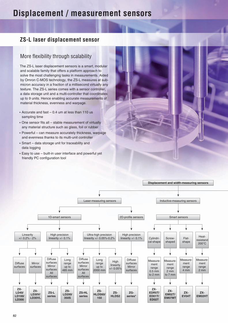
Displacement / measurement sensors
ZS-L laser displacement sensor
More fl exibility through scalability
82

83
Table of contentsSelection table 84
Laser measuring sensors ZX-LD 86
ZS-L 88
Inductive measuring sensors ZX-E 90
Contact measuring sensor ZX-T 92
Width measuring sensors ZX-LT 95

84
Selection table
1D smart laser measuring sensors
Sel
ecti
on
cri
teri
a
Model ZX-LD ZS-L ZS-HL
Measurement range Z Min. ±2 mm ±1 mm ±0.5 mm
Max. ±200 mm ±135 mm ±500 mm
Measurement range X Min.
Max.
Center distance Min. 30 mm 6.3 mm 10 mm
Max. 300 mm 350 mm 1,500 mm*1 Resolution Z
*1 Depends on the sensor head and measurment range
0.25 µm 0.25 µm 0.1 µm
*1 Resolution X*1 Linearity (± % of full scale) 0.2% 0.1 % 0.05%
Response time 150 µs 110 µs 110 µs
Spot beam
Line beam
IP-rating head IP50 IP67 IP64 - IP67
IP-rating controler IP40 IP40 IP40
Ambient oper. temperature 0 - 50 °C 0 - 50 °C 0 - 50 °C
Number of connectable sensors 5 9
Fea
ture
s
Thickness measurement
Excentricity
Step
Height
Distance
Evenness
Warpage
Edge
Position
Width
Peak
Peak to peak
Bottom
Self-trigger
Multi-point-calculation
Mutual interference prevention
Signal scaling
PC-software
Plug & play technology
Ap
plic
atio
n
Diffuse reflection
Optical method (reflection) Diffuse / Regular
Mirror
Glass
Metal
Plastic
Black rubber
Liquid
Su
pp
ly
volt
age 12 - 24 VDC
21.6 - 26.4 VDC
Co
ntr
ol I
/O
4 - 20 mA
1 - 5 VDC
±5 VDC
±4 VDC
±10 VDC
Judgement output High/Pass/Low
Trigger
Co
mm
u-
nic
atio
n RS-232C
USB2.0
Page 86 88 Please contact your OMRON representative

Displacement / measurement sensors
85
Inductive measuring sensors Contact measuring sensors Width measuring sensors
Sel
ecti
on
cri
teri
a
Model ZX-E ZX-T ZX-LT
Measurement range Z Min. 0.5 mm 1 mm 1 mm
Max. 7 mm 10 mm 30 mm
Measurement range X Min.
Max.
Center distance Min.
Max.*1 Resolution Z
*1 Depends on the sensor head and measurment range
1 µm 0.1 µm 4 µm
*1 Resolution X*1 Linearity (± % of full scale) 0.5% 0.3% 1%
Response time 150 µs 1 ms 150 µs
Spot beam
Line beam
IP-rating head IP67 IP67 IP40
IP-rating controler IP40 IP40 IP40
Ambient oper. temperature 0 - 50 °C 0 - 50 °C 0 - 50 °C
Number of connectable sensors 5 7 5
Fea
ture
s
Thickness measurement
Excentricity
Step
Height
Distance
Evenness
Warpage
Edge
Position
Width
Peak
Peak to peak
Bottom
Self-trigger
Multi-point-calculation
Mutual interference prevention
Signal scaling
PC-software
Plug & play technology
Ap
plic
atio
n
Diffuse reflection
Optical method (reflection)
Mirror
Glass
Metal
Plastic
Black rubber
Liquid
Su
pp
ly
volt
age 12 - 24 VDC
21.6 - 26.4 VDC
Co
ntr
ol I
/O
4 - 20 mA
1 - 5 VDC
±5 VDC
±4 VDC
±10 VDC
Judgement output High/Pass/Low
Trigger
Co
mm
u-
nic
atio
n RS-232C
USB2.0
Page 90 92 95
Standard No / not available

For full specifications and additional models please refer to the (attached) CD or www.europe.omron.comDisplacement / measurement sensors - Cat.-No. Q15E-EN-0186
ZX-LD Displacement / measurement sensors
Smart, fast and accurate laser measurement sensorSmart ZX-L offers plug & measure technology for applications where high resolution and fast response time is required. A wide range of interchangeable sensor heads provides greater flexibility in solving most demanding applications.
• Small and light sensor heads for easy integration • High speed response time of 150 µs • Easy sensor head replacement • Scalability through a modular platform concept • Multipoint measurement with up to 5 sensors
Ordering information
Sensor head (reflection type)
Amplifier units
Note: Compatible with sensor head connection.
Specifications
Sensor head (reflection type)
Note: When an object has a high reflectance, detection errors are possible outside the measurement range.
Optical method Beam shape Sensing distance Resolution *1
*1 At average count of 4,096 times
Size in mm (HxWxD) Model
Diffuse-reflective Spot beam 40 ± 10 mm 2 µm 39x33x17 ZX-LD40
100 ± 40 mm 16 µm ZX-LD100
300 ± 200 mm 300 µm ZX-LD300
Line beam 40 ± 10 mm 2 µm ZX-LD40L
100 ± 40 mm 16 µm ZX-LD100L
300 ± 200 mm 300 µm ZX-LD300L
Regular reflection type Spot beam 30 ± 2 mm 0.25 µm 45x55x25 ZX-LD30V
Line beam ZX-LD30VL
Power supply Output specifications Model
DC NPN output ZX-LDA11-N
PNP output ZX-LDA41-N
Item Model ZX-LD40 ZX-LD100 ZX-LD300 ZX-LD30V ZX-LD40L ZX-LD100L ZX-LD300L ZX-LD30VL
Optical method Diffuse reflection Regular reflection
Diffuse reflection Regular reflection
Light source (wave length) Visible-light semiconductor laser (wavelength 650 nm, 1 mW or less, Class 2)
Measurement center distance 40 mm 100 mm 300 mm 30 mm 40 mm 100 mm 300 mm 30 mm
Measurement range ±10 mm ±40 mm ±200 mm ±2 mm ±10 mm ±40 mm ±200 mm ±2 mm
Beam shape Spot Line
Beam diameter *1
*1 Beam diameter: This is the value of the measurement center distance (actual value), and is defined at 1/e2 (13.5%) of the central light intensity. If there is straylight outside, the defined area and the area around the object has a higher reflectance than the object,
50 mm dia. 100 mm dia. 300 mm dia. 75 mm dia. 75 m x 2mm 150 µm x 2 mm
450 µm x 2 mm
100 µm x 1.8 mm
Resolution*2
*2 Resolution: Indicates the amount of fluctuation (±3 ) in the linear output when connected to the ZX-LDA. (The measured value when the average count of the ZX-LDA is set to 4,096 and our standard object (white ceramic) is used for the central distance.) This indicates the repeatability precision when the work is in a staticstate, and does indicate the distance precision. The resolution performance may not be satisfactory in a strong electromagnetic field.
2 µm 16 µm 300 µm 0.25 µm 2 µm 16 µm 300 m 0.25 µm
Linearity*3
*3 Linearity: This indicates the error with respect to the ideal straight line of the displacement output when measuring our standard object.
±0.2% F.S. (entire range)
±0.2% F.S. (80 to 121 mm)
±2% F.S. (200 to 401 mm)
±0.2% F.S. (entire range)
±0.2% F.S.(32 to 49 mm)
±0.2% F.S. (80 to 121 mm)
±2% F.S. (200 to 401 mm)
±0.2% F.S. (entire range)
Protective structure IEC 60529 IP50 IEC Standard IP40
IEC 60529 IP50 IEC Standard IP40
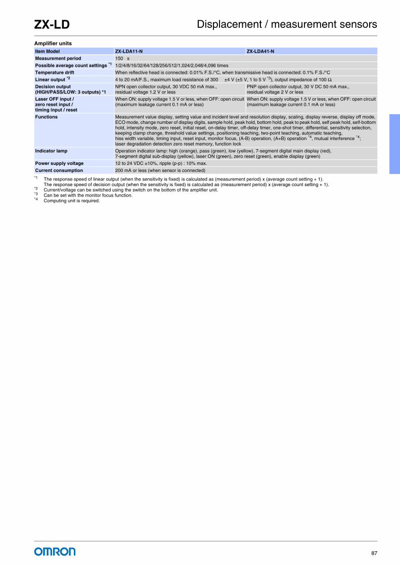
ZX-LD Displacement / measurement sensors
87
Amplifier unitsItem Model ZX-LDA11-N ZX-LDA41-N
Measurement period 150 s
Possible average count settings *1
*1 The response speed of linear output (when the sensitivity is fixed) is calculated as (measurement period) x (average count setting + 1). The response speed of decision output (when the sensitivity is fixed) is calculated as (measurement period) x (average count setting + 1).
1/2/4/8/16/32/64/128/256/512/1,024/2,048/4,096 times
Temperature drift When reflective head is connected: 0.01% F.S./°C, when transmissive head is connected: 0.1% F.S./°C
Linear output *2
*2 Current/voltage can be switched using the switch on the bottom of the amplifier unit.
4 to 20 mA/F.S., maximum load resistance of 300 ±4 V (±5 V, 1 to 5 V *3), output impedance of 100 Ω.
*3 Can be set with the monitor focus function.
Decision output (HIGH/PASS/LOW: 3 outputs) *1
NPN open collector output, 30 VDC 50 mA max., residual voltage 1.2 V or less
PNP open collector output, 30 V DC 50 mA max., residual voltage 2 V or less
Laser OFF input / zero reset input / timing input / reset
When ON: supply voltage 1.5 V or less, when OFF: open circuit (maximum leakage current 0.1 mA or less)
When ON: supply voltage 1.5 V or less, when OFF: open circuit (maximum leakage current 0.1 mA or less)
Functions Measurement value display, setting value and incident level and resolution display, scaling, display reverse, display off mode, ECO mode, change number of display digits, sample hold, peak hold, bottom hold, peak to peak hold, self peak hold, self-bottom hold, intensity mode, zero reset, initial reset, on-delay timer, off-delay timer, one-shot timer, differential, sensitivity selection, keeping clamp change, threshold value settings, positioning teaching, two-point teaching, automatic teaching, hiss width variable, timing input, reset input, monitor focus, (A-B) operation, (A+B) operation *4, mutual interference *4;laser degradation detection zero reset memory, function lock
*4 Computing unit is required.
Indicator lamp Operation indicator lamp: high (orange), pass (green), low (yellow), 7-segment digital main display (red), 7-segment digital sub-display (yellow), laser ON (green), zero reset (green), enable display (green)
Power supply voltage 12 to 24 VDC ±10%, ripple (p-p) : 10% max.
Current consumption 200 mA or less (when sensor is connected)

For full specifications and additional models please refer to the (attached) CD or www.europe.omron.comDisplacement / measurement sensors - Cat.-No. Z215-E2-01A-X88
ZS-L Displacement / measurement sensors
The scalable high precision laser measurement sensorSmart ZS-L sensor offers superb dynamic sensing range for all surfaces from black rubber to glass and mirror surfaces by simply scaling it to your needs.
• High dynamic sensing range for all surfaces • High resolution of 0.25 µm • Modular and scalable platform concept for up to 9 sensors • Easy to use, install and maintain for all user levels • Fast response time of 110 µs
Features
The scalable platform for more flexibility• Connect and expand up to 9 controllers• Connect multi-calculation controller for advanced calculations like
evenness or flatness• Connect data storage module for process-data logging• Connect PC software for easy system set up and signal monitoring• Sensor head with 2D-CMOS technology with high dynamic sensing
range for measuring black rubber, plastic, shiny, glass and mirror surfaces
• Advanced application settings• Easy reconfiguration and teaching
Measurement tools:• Hight measurement• Step measurement• Thickness measurement• Flatness measurement• Average measurement• Excentricity• Warpage / Evenness
Ordering information
Sensor heads
Sensor controllers
Multi controllers
Data storage units
Optical system Sensing distance Beam diameter Resolution*1
*1 This is the peak-to-peak displacement conversion value in the displacement output at the measuring center distance in high-precision mode when the number ofsamples to average is set to 128 and the measuring mode is set to the high-resolution mode. The standard workpiece is white aluminum ceramics in diffuse re-flection mode and glass in the regular reflection mode.
Size in mm (HxWxD) Model
Diffuse reflection 50 ± 5 mm 900 x 60 µm 0.8 µm 65mmx65mmx35mm ZS-LD50
80 ± 15 mm 900 x 60 µm 2 µm ZS-LD80
130 ± 15 mm 600 x 70 µm 3 µm ZS-LD130
200 ± 50 mm 900 x 100 µm 5 µm ZS-LD200
350 ± 135 mm dia. 240 µm 20 µm ZS-LD350S
Regular reflection 20 ± 1 mm 900 x 25 µm 0.25 µm ZS-LD20T
40 ± 2.5 mm 2,000 x 35 µm 0.4 µm ZS-LD40T
Supply voltage Control outputs Model
24 VDC NPN outputs ZS-LDC11
PNP outputs ZS-LDC41
Supply voltage Control outputs Model
24 VDC NPN outputs ZS-MDC11
PNP outputs ZS-MDC41
Supply voltage Control outputs Model
24 VDC NPN outputs ZS-DSU11
PNP outputs ZS-DSU41

ZS-L Displacement / measurement sensors
89
Specifications
Sensor heads
Sensor controllers
Item Model ZS-LD20T ZS-LD40T ZS-LD50 ZS-LD80 ZS-LD130 ZS-LD200 ZS-LD350S
Applicable controllers
ZS-LDC Series
Optical system Regularreflection
Diffusereflection
Regularreflection
Diffusereflection
Diffusereflection
Regularreflection
Diffusereflection
Regularreflection
Regular reflection
Diffuse reflection
Diffusereflection
Regularreflection
Diffusereflection
Measuring center distance
20 mm 6.3 mm 40 mm 30 mm 50 mm 47 mm 80 mm 78 mm 130 mm 130 mm 200 mm 200 mm 350 mm
Measuring range ±1 mm ±1 mm ±2.5 mm ±2 mm ±5 mm ±4 mm ±15 mm ±14 mm ±15 mm ±12 mm ±50 mm ±48 mm ±135 mm
Light source Visible semiconductor laser (wavelength: 650 nm, 1 mW max., Class 2)
Beam diameter
900 x 25 µm 2,000 x 35 µm 900 x 60 µm 900 x 60 µm 600 x 70 µm 900 x 100 µm dia. 240 µm
Linearity ±0.1% F.S. ±0.25% F.S. ±0.1% F.S.
±0.25% F.S.
±0.1% F.S.
Resolution 0.25 µm 0.4 µm 0.8 µm 2 µm 3 µm 5 µm 20 µm
Temperature characteristic
0.04% F.S./°C 0.02% F.S./°C 0.02% F.S./°C 0.01% F.S./°C 0.02% F.S./°C 0.02% F.S./°C 0.04% F.S./°C
Sampling cycle 110 µs
Degree of protection
Cable length 0.5 m: IP66, cable length 2 m: IP67
Item ZS-LDC11 ZS-LDC41
No. of samples to average 1, 2, 4, 8, 16, 32, 64, 128, 256, 512, 1024, 2048, or 4096
Number of mounted sensors 1 per sensor controller
External interface
Connection method Serial I/O: connector, Other: pre-wired (standard cable length: 2 m)
Serial I/O USB 2.0 1 port, full speed (12 Mbps), MINI-B
RS-232C 1 port, 115,200 bps max.
Outputs Judgement outputs 3 outputs: HIGH, PASS, and LOWNPN open-collector, 30 VDC, 50 mA max., residual voltage: 1.2 V max.
3 outputs: HIGH, PASS, and LOWPNP open-collector, 50 mA max., residual voltage: 1.2 V max.
Linear outputs Selectable from 2 types of output, voltage or current (selected by slide switch on base).Voltage output: –10 to 10 V, output impedance: 40 .Current output: 4 to 20 mA, maximum load resistance: 300 .
Inputs Laser OFF, ZERO reset timing, RESET
ON: Short-circuited with 0V terminal or 1.5 V or lessOFF: Open (leakage current: 0.1 mA max.)
ON: Short-circuited to supply voltage or within 1.5 V of supply voltageOFF: Open (leakage current: 0.1 mA max.)
Functions Display: Measured value, threshold value, voltage/current, received light amount, and resolutionSensing: Mode, gain, measurement object, head installationFilter: Smooth, average, and differentiationOutputs: Scaling, various hold values, and zero resetI/O settings: Linear (focus/correction), judgements (hysteresis and timer), non-measurement, and bank
(switching and clear)System: Save, initialization, measurement information display, communications settings, key lock,
language, and data load
Status indicators HIGH (orange), PASS (green), LOW (orange), LDON (green), ZERO (orange), and ENABLE (green)
Segment display Main display 8-segment red LED, 6 digits
Sub-display 8-segment green LED, 6 digits
LCD 16 digits x 2 rows, Color of characters: green, Resolution per character: 5 x 8 pixel matrix
Setting inputs Setting keys Direction keys (UP, DOWN, LEFT, and RIGHT), SET key, ESC key, MENU key, and function keys (1 to 4)
Slide switch Threshold switch (2 states: High/Low), mode switch (3 states: FUN, TEACH, and RUN)
Power supply voltage 21.6 V to 26.4 VDC (including ripple)

For full specifications and additional models please refer to the (attached) CD or www.europe.omron.comDisplacement / measurement sensors - Cat.-No. Q16E-EN-0190
ZX-E Displacement / measurement sensors
Smart inductive measurement sensorZX-E offers the best solution for the accurate measurement of metallic objects. It is highly recommended in harsh environments such as automotive and metal working machines.
• High resolution of 1 µm • High-speed response time of 150 µs • Easy sensor head replacement • Modular platform concept for different sensing technologies • Easy linearity adjustment for any metal
Ordering information
Sensor heads
Amplifier units
Note: Compatible connection with the sensor head.
Specifications
Sensor heads
Shape Dimensions Sensing distance Accuracy *1
*1 For an average count of 4,096.
Model
Cylindrical 3 dia. x 18 mm 0.5 mm 1 µm ZX-EDR5T
5.4 dia. x 18 mm 1 mm ZX-ED01T *2
*2 Models with protective spiral tubes are also available. Add a suffix of “-S” to the above model numbers when ordering. (Example: ZX-ED01T-S)
8 dia. x 22 mm 2 mm ZX-ED02T *2
Screw-shaped M10 x 22 mm 2 mm ZX-EM02T *2
M18 x 46.3 mm 7 mm ZX-EM07MT *2
Flat 30 x 14 x 4.8 mm 4 mm ZX-EV04T
Heat-resistant, cylindrical M12 x 22 mm 2 mm ZX-EM02HT
Power supply Output type Model
DC NPN ZX-EDA11
PNP ZX-EDA41
Model ZX-EDR5T ZX-ED01T ZX-ED02T/EM02T ZX-EM07MT ZX-EV04T ZX-EM02HT
Measurement range 0 to 0.5 mm 0 to 1 mm 0 to 2 mm 0 to 7 mm 0 to 4 mm 0 to 2 mm
Sensing object Magnetic metals (Measurement ranges and linearities are different for non-magnetic metals. Refer to Engineering Data on B-67.)
Standard reference object 18× 18× 3 mm 30× 30× 3 mm 60× 60× 3 mm 45x45x3 mm
Material: ferrous (S50C)
Accuracy *1
*1 Accuracy: The resolution is the deviation (±3σ) in the linear output when connected to the ZX-EDA amplifier unit. The above values indicate the deviations observed30 minutes after the power is turned ON.(The resolution is measured with OMRON's standard reference object at 1/2 of the measurement range with the ZX-EDA set for the maximum average count of4,096 per period.) The resolution is given at the repeat accuracy for a stationary workpiece, and is not an indication of the distance accuracy. The resolution may be adversely affectedunder strong electromagnetic fields.
1 µm
Linearity *2
*2 Linearity: The linearity is given as the error in an ideal straight line displacement output when measuring the standard reference object. The linearity and measure-ment values vary with the object being measured.
±0.5% F.S. ±1% F.S.
Linear output range Same as measurement range.
Shock resistance (destruction) 500 m/s2, 3 times each in X, Y, and Z directions
Degree of protection (Sensor head) IEC60529, IP65 IEC60529, IP67 IEC60529, IP60
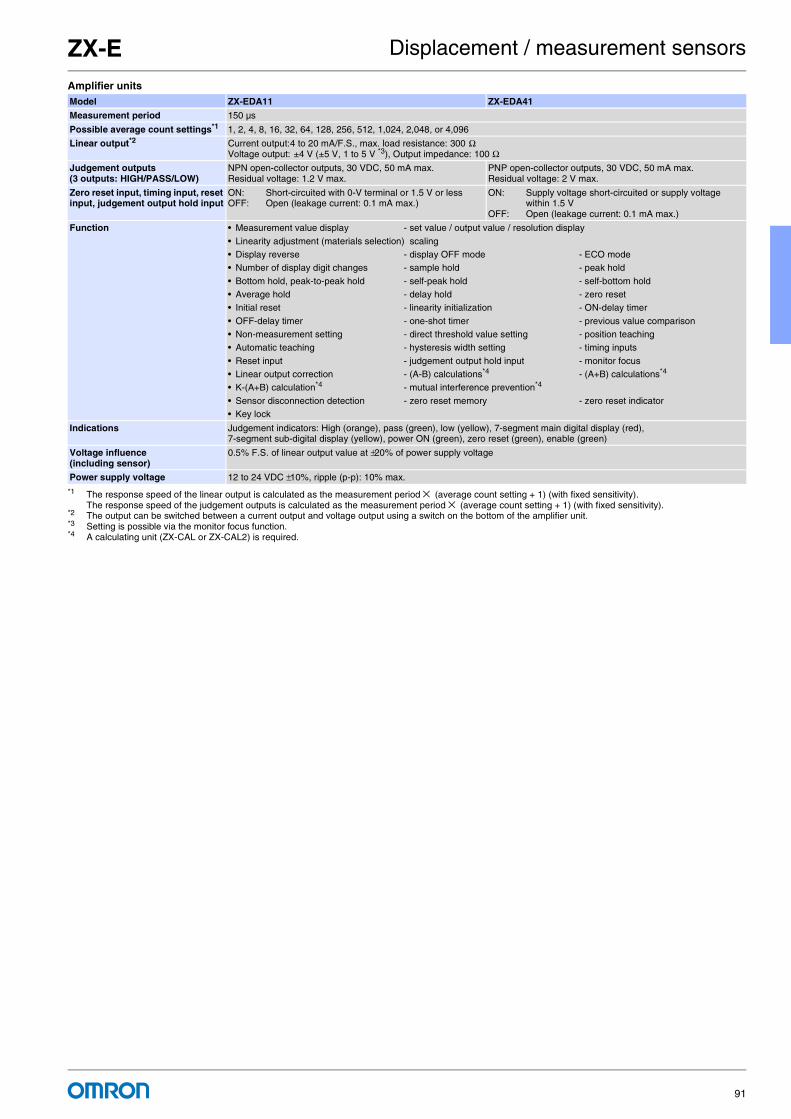
ZX-E Displacement / measurement sensors
91
Amplifier unitsModel ZX-EDA11 ZX-EDA41
Measurement period 150 µs
Possible average count settings*1
*1 The response speed of the linear output is calculated as the measurement period × (average count setting + 1) (with fixed sensitivity). The response speed of the judgement outputs is calculated as the measurement period × (average count setting + 1) (with fixed sensitivity).
1, 2, 4, 8, 16, 32, 64, 128, 256, 512, 1,024, 2,048, or 4,096
Linear output*2
*2 The output can be switched between a current output and voltage output using a switch on the bottom of the amplifier unit.
Current output:4 to 20 mA/F.S., max. load resistance: 300 ΩVoltage output: ±4 V (±5 V, 1 to 5 V *3), Output impedance: 100 Ω
*3 Setting is possible via the monitor focus function.
Judgement outputs (3 outputs: HIGH/PASS/LOW)
NPN open-collector outputs, 30 VDC, 50 mA max.Residual voltage: 1.2 V max.
PNP open-collector outputs, 30 VDC, 50 mA max.Residual voltage: 2 V max.
Zero reset input, timing input, reset input, judgement output hold input
ON: Short-circuited with 0-V terminal or 1.5 V or lessOFF: Open (leakage current: 0.1 mA max.)
ON: Supply voltage short-circuited or supply voltage within 1.5 V
OFF: Open (leakage current: 0.1 mA max.)
Function • Measurement value display - set value / output value / resolution display
• Linearity adjustment (materials selection) scaling • Display reverse - display OFF mode - ECO mode • Number of display digit changes - sample hold - peak hold
• Bottom hold, peak-to-peak hold - self-peak hold - self-bottom hold • Average hold - delay hold - zero reset• Initial reset - linearity initialization - ON-delay timer
• OFF-delay timer - one-shot timer - previous value comparison • Non-measurement setting - direct threshold value setting - position teaching • Automatic teaching - hysteresis width setting - timing inputs
• Reset input - judgement output hold input - monitor focus• Linear output correction - (A-B) calculations*4 - (A+B) calculations*4 • K-(A+B) calculation*4 - mutual interference prevention*4
• Sensor disconnection detection - zero reset memory - zero reset indicator• Key lock
*4 A calculating unit (ZX-CAL or ZX-CAL2) is required.
Indications Judgement indicators: High (orange), pass (green), low (yellow), 7-segment main digital display (red), 7-segment sub-digital display (yellow), power ON (green), zero reset (green), enable (green)
Voltage influence (including sensor)
0.5% F.S. of linear output value at ±20% of power supply voltage
Power supply voltage 12 to 24 VDC ±10%, ripple (p-p): 10% max.
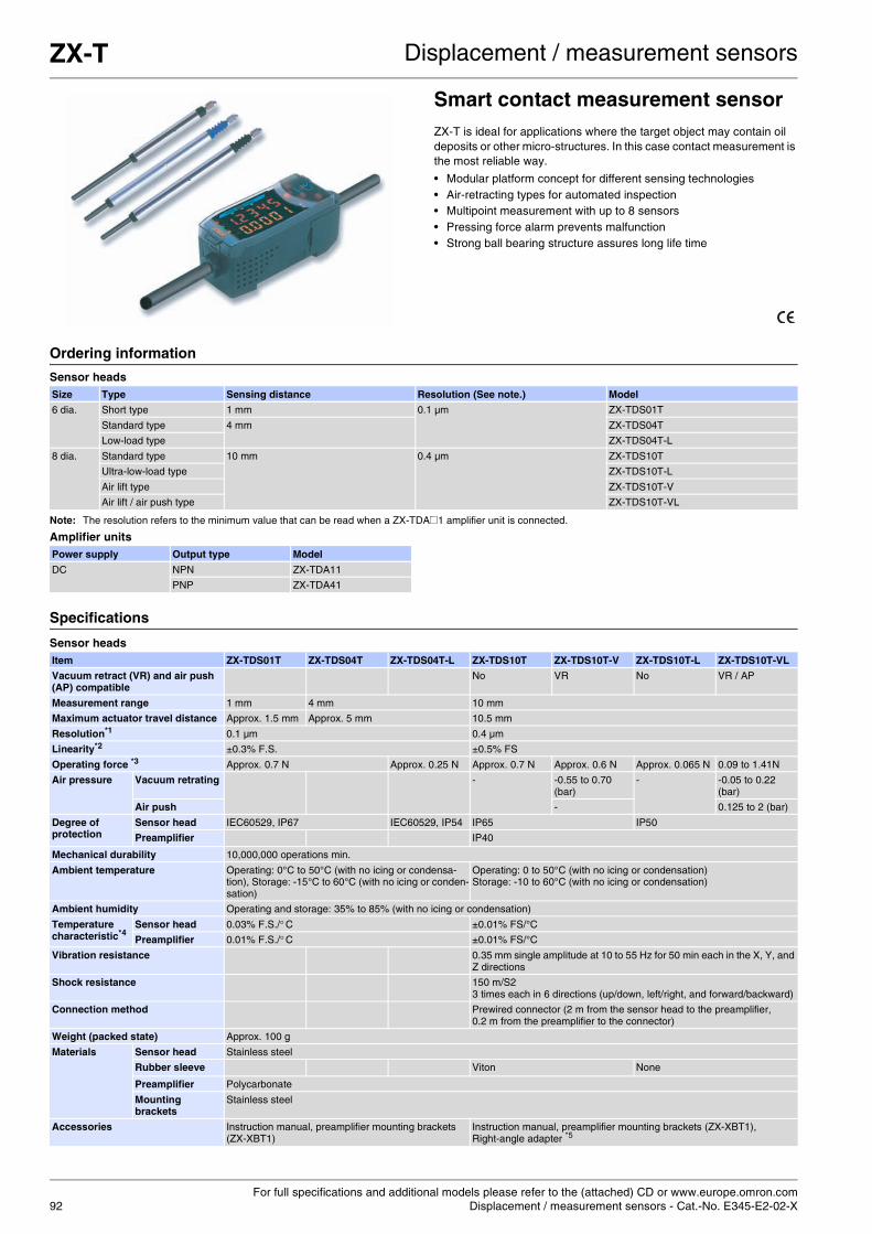
For full specifications and additional models please refer to the (attached) CD or www.europe.omron.comDisplacement / measurement sensors - Cat.-No. E345-E2-02-X92
ZX-T Displacement / measurement sensors
Smart contact measurement sensorZX-T is ideal for applications where the target object may contain oil deposits or other micro-structures. In this case contact measurement is the most reliable way.
• Modular platform concept for different sensing technologies • Air-retracting types for automated inspection • Multipoint measurement with up to 8 sensors • Pressing force alarm prevents malfunction • Strong ball bearing structure assures long life time
Ordering information
Sensor heads
Note: The resolution refers to the minimum value that can be read when a ZX-TDA@1 amplifier unit is connected.
Amplifier units
Specifications
Sensor heads
Size Type Sensing distance Resolution (See note.) Model
6 dia. Short type 1 mm 0.1 µm ZX-TDS01T
Standard type 4 mm ZX-TDS04T
Low-load type ZX-TDS04T-L
8 dia. Standard type 10 mm 0.4 µm ZX-TDS10T
Ultra-low-load type ZX-TDS10T-L
Air lift type ZX-TDS10T-V
Air lift / air push type ZX-TDS10T-VL
Power supply Output type Model
DC NPN ZX-TDA11
PNP ZX-TDA41
Item ZX-TDS01T ZX-TDS04T ZX-TDS04T-L ZX-TDS10T ZX-TDS10T-V ZX-TDS10T-L ZX-TDS10T-VL
Vacuum retract (VR) and air push (AP) compatible
No VR No VR / AP
Measurement range 1 mm 4 mm 10 mm
Maximum actuator travel distance Approx. 1.5 mm Approx. 5 mm 10.5 mm
Resolution*1 0.1 µm 0.4 µm
Linearity*2 ±0.3% F.S. ±0.5% FS
Operating force *3 Approx. 0.7 N Approx. 0.25 N Approx. 0.7 N Approx. 0.6 N Approx. 0.065 N 0.09 to 1.41N
Air pressure Vacuum retrating - -0.55 to 0.70 (bar)
- -0.05 to 0.22 (bar)
Air push - 0.125 to 2 (bar)
Degree of protection
Sensor head IEC60529, IP67 IEC60529, IP54 IP65 IP50
Preamplifier IP40
Mechanical durability 10,000,000 operations min.
Ambient temperature Operating: 0°C to 50°C (with no icing or condensa-tion), Storage: -15°C to 60°C (with no icing or conden-sation)
Operating: 0 to 50°C (with no icing or condensation)Storage: -10 to 60°C (with no icing or condensation)
Ambient humidity Operating and storage: 35% to 85% (with no icing or condensation)
Temperature characteristic*4
Sensor head 0.03% F.S./° C ±0.01% FS/°C
Preamplifier 0.01% F.S./° C ±0.01% FS/°C
Vibration resistance 0.35 mm single amplitude at 10 to 55 Hz for 50 min each in the X, Y, and Z directions
Shock resistance 150 m/S23 times each in 6 directions (up/down, left/right, and forward/backward)
Connection method Prewired connector (2 m from the sensor head to the preamplifier, 0.2 m from the preamplifier to the connector)
Weight (packed state) Approx. 100 g
Materials Sensor head Stainless steel
Rubber sleeve Viton None
Preamplifier Polycarbonate
Mounting brackets
Stainless steel
Accessories Instruction manual, preamplifier mounting brackets (ZX-XBT1)
Instruction manual, preamplifier mounting brackets (ZX-XBT1), Right-angle adapter *5

ZX-T Displacement / measurement sensors
93
Amplifier units
*1 The resolution is given as the minimum value that can be read when a ZX-TDA@1 amplifier unit is connected. This value is taken 15 minutes after turning ON the power with the average number of operations set to 256.
*2 The linearity is given as the error in an ideal straight line displacement output.*3 These figures are representative values that apply for the measurement mid-point, and are for when the provided actuator is used, with the actuator moving
downwards. If the actuator moves horizontally or upwards, the operating force will be reduced. Also, if an actuator other than the standard one is used, the operating force will vary with the weight of the actuator itself.
*4 These figures are representative values that apply for the mid-point of the measurement range.*5 The ZX-TDS10@ comes with a right-angle adapter.
Item ZX-TDA11 ZX-TDA41
Measurement period 1 ms
Possible average count settings *1
*1 The response speed of the linear output is calculated as the measurement period × (average count setting + 1). The response speed of the judgement outputs is calculated as the measurement period × (average count setting + 1).
1, 16, 32, 64, 128, 256, 512, or 1,024
Linear output *2
*2 The output can be switched between a current output and voltage output using a switch on the bottom of the amplifier unit.
Current output: 4 to 20 mA/F.S., Max. load resistance: 300 ΩVoltage output: ±4 V (±5 V, 1 to 5 V*3), Output impedance: 100 Ω
*3 Setting is possible via the monitor focus function.
Judgement outputs (3 outputs: HIGH/PASS/LOW)
NPN open-collector outputs, 30 VDC, 30 mA max.Residual voltage: 1.2 V max.
PNP open-collector outputs, 30 VDC, 30 mA max.Residual voltage: 2 V max.
Zero reset input, timing input, reset input, judgement output hold input
ON: Short-circuited with 0-V terminal or 1.5 V or lessOFF: Open (leakage current: 0.1 mA max.)
ON: Supply voltage short-circuited or supply voltage of 1.5 V or lessOFF: Open (leakage current: 0.1 mA max.)
Function • Measurement value display - present value/set value/output value display • Display reverse - ECO mode - number of display digit changes
• Sample hold - peak hold - bottom hold, peak-to-peak hold• Self-peak hold - self-bottom hold - zero reset• Initial reset - direct threshold value setting - position teaching
• Hysteresis width setting - timing inputs - reset input• Judgement output hold input - monitor focus - (A-B) calculations*4
• (A+B) calculations (See note 4.) - sensor disconnection detection
• Zero reset memory - function lock - non-measurement setting• Clamp value setting - scale inversion - zero reset indicator• Span adjustment - warming-up display - pressing force alarm
*4 A calculating unit (ZX-CAL2) is required.
Indicators Judgement indicators: High (orange), pass (green), low (yellow), 7-segment main digital display (red), 7-segment sub-digital display (yellow), power ON (green), zero reset (green), enable (green)
Power supply voltage 12 to 24 VDC ±10%, Ripple (p-p): 10% max.
Current consumption 140 mA max. (with Sensor connected), For 24-VDC power supply voltage: 140 mA max. (with Sensor connected)
Ambient temperature Operating and storage: 0 to 50° C (with no icing or condensation)
Temperature characteristic 0.03% F.S./° C
Connection method Prewired (standard cable length: 2 m)
Weight (packed state) Approx. 350 g
Materials Case: PBT (polybutylene terephthalate), Cover: Polycarbonate

ZX-T Displacement / measurement sensors
94
Options (actuators)
Note: Replacement possible Conversion Adapter required
Model Type (material) Screw section Appearance Application Applicable sensor (see note.)
ZX-TDS@T
D5SN- TB1 Ball type (steel) Female screwM2.5 x 0.45
Measuring ordinary flat surfaces (standard actuator supplied with the ZX-TDS series)
TB2 Ball type (carbide steel)
Female screwM2.5 x 0.45
Measurements where abrasion resistance is criticalMeasured objects: carbide (HR90) or lower.
TB3 Ball type (ruby) Female screwM2.5 x 0.45
Measurements where abrasion resistance is criticalMeasured objects: carbide (HR90) or higher.
TN1 Needle type (carbide steel)
Male screwM2.5 x 0.45
Measuring the bottom of grooves and holes
TF1 Flat (carbide steel)
Male screwM2.5 x 0.45
Measuring spherical objects
TA Conversion adapter (stainless steel)
Through-hole female screwM2.5 x 0.45
Mounting D5SN-TN1/-TF1 or commercially available actuators on ZX-TDS-series sensors

For full specifications and additional models please refer to the (attached) CD or www.europe.omron.comDisplacement / measurement sensors - Cat.-No. Q15E-EN-01 95
ZX-LT Displacement / measurement sensors
Smart parallel laser through beam sensorZX-LT parallel laser through beam sensor is recommended for precise object sensing such as width, diameter size or edge control.
• Small and light sensor heads for easy integration • High-speed response time of 150 µs for more stable detection • Plug & play technology saves installation time • Modular platform concept for different sensing technologies • Wide range of sensor heads offering laser beam width from 1 mm to
30 mm
Ordering information
Sensor head
Amplifier units
Note: Compatible with sensor head connection.
Specifications
Sensor head (transmissive type)
Amplifier units
Optical method Measurement width Sensing distance Resolution *1
*1 At average count of 64 times
Size in mm (HxWxD) Model
Transmitter Receiver
Through-beam 1 mm dia. 0 to 2,000 mm 4 µm 15x15x34 15x15x19 ZX-LT001
5 mm 0 to 500 mm ZX-LT005
10 mm 20x20x42 20x20x25 ZX-LT010
30 mm 12 µm 64.25x70x22.6 64.25x54x22.6 ZX-LT030
Power supply Output specifications Model
DC NPN output ZX-LDA11-N
PNP output ZX-LDA41-N
Item model ZX-LT001 ZX-LT005 ZX-LT010 ZX-LT030
Optical method Through-beam
Light source (wave length) Visible-light semiconductor laser (wavelength 650 nm, 1 mW or less, Class 1)
Measurement width 1 mm dia. 1 to 2.5 mm dia. 5 mm 10 mm 30 mm
Sensing distance 0 to 500 mm 500 to 2,000 mm 0 to 500 mm
Min. sensing object 8 mm dia. opaque object 8 to 50 µm opaque object opaque: 0.05 mm dia. opaque: 0.1 mm dia. opaque: 0.3 mm dia.
Resolution*1
*1 The amount of fluctuation (±3 δ) of the linear output when connected to an amplifier unit, converted to a detection span.
4 µm*2
*2 When the average count is 64.5 µm when the count is 32. The value when the smallest detection object shades the vicinity of the center of the 1 mm dia. detection span.
--- 4 µm*3
*3 When the average count is 64.5 µm when the count is 32.
12 µm
Protective structure IEC 60529 IP40 IP 40
Item model ZX-LDA11-N ZX-LDA41-N
Measurement period 150 s
Possible average count settings *1
*1 The response speed of linear output (when the sensitivity is fixed) is calculated as (measurement period) x (average count setting + 1). The response speed of decision output (when the sensitivity is fixed) is calculated as (measurement period) x (average count setting + 1).
1/2/4/8/16/32/64/128/256/512/1,024/2,048/4,096 times
Temperature drift When reflective head is connected: 0.01% F.S./°C, when transmissive head is connected: 0.1% F.S./°C
Linear output *2
*2 Current/voltage can be switched using the switch on the bottom of the amplifier unit.
4 to 20 mA/F.S., maximum load resistance of 300 ±4 V (±5 V, 1 to 5 V *3), output impedance of 100 .
*3 Can be set with the monitor focus function.
Decision output (HIGH/PASS/LOW: 3 outputs) *1
NPN open collector output, 30 VDC 50 mA max., residual voltage 1.2 V or less
PNP open collector output, 30 V DC 50 mA max., residual voltage 2 V or less
Laser OFF input / zero reset input / timing input / reset
When ON: supply voltage 1.5 V or less, when OFF: open circuit (maximum leakage current 0.1 mA or less)
When ON: supply voltage 1.5 V or less, when OFF: open circuit (maximum leakage current 0.1 mA or less)
Functions Measurement value display, setting value and incident level and resolution display, scaling, display reverse, display off mode, ECO mode, change number of display digits, sample hold, peak hold, bottom hold, peak to peak hold, self peak hold, self-bottom hold, intensity mode, zero reset, initial reset, on-delay timer, off-delay timer, one-shot timer, differential, sensitivity selection, keeping clamp change, threshold value settings, positioning teaching, two-point teaching, automatic teaching, hiss width variable, timing input, reset input, monitor focus, (A-B) operation, (A+B) operation *4, mutual interference *4, laser degradation detection zero reset memory, function lock
*4 Computing unit is required.
Indicator lamp Operation indicator lamp: high (orange), pass (green), low (yellow), 7-segment digital main display (red), 7-segment digital sub-display (yellow), laser ON (green), zero reset (green), enable display (green)
Power supply voltage 12 to 24 VDC ±10%, ripple (p-p) : 10% max.
Current consumption 200 mA or less (when sensor is connected)

Vision sensors & systems
ZFV smart vision sensor
Easy vision – teach & go
96

97
Table of contentsSelection table 98
Vision sensors ZFV 100
F150 102
F160 103
Vision systems F210 104
F250 105
F500 / F210 ETN 106
2D code reader V530-R160 107

98
Selection table
Vision sensors Vision systems
Sel
ecti
on
cri
teri
a
Model ZFV F150 F160 F210
Number of connectablecameras
1 1 (2 with optional extension)
2 2
Camera type Digital black&white Analogue black&white
Resolution (usable) 468 x 432 512 x 484 512 x 484 512 x 484
Working distance mmMin.
34 depends on selected lens
Max. 194
Field of view mmMin.
5 depends on selected lens
Max. 50
Number of storableconfigurations
8 16 32 (expandable using CF card)
Number of tools/configuration
1 16 32 limited only by memory space / depends on type of
Cycle time app. 4-25 ms depending on setup
Depends on setup and used tools
IP-Rating camera head IP65 n/a
Supply voltage 24 VDC
Fea
ture
s
Image processing tools Up to seven (area, brightness, width, position, character, count, pattern)
App. 30 processing tools for object or defect recognition, measurements, calculations, input / output and more
App. 50 processing tools for object or defect recognition, measurements, calculations, input / output and more, including character recogni-tion tool
App. 70 processing tools for object or defect recognition, measurements, calculations, input / output, display and more. Includes also character recognition and high precision edge code inspection tools.
Image preprocessing Smoothing, edge enhance-ment, edge extraction, back-ground suppression
Smoothing, edge enhance-ment, edge extraction, erosion, dilation, median, background suppression
Smoothing, edge enhance-ment, edge extraction, erosion, dilation, median, background suppression - multiple passes, configurable
Optional macroprogramming interface
User interface on board 'teach&go' point to point GUI
Optional PC configurationsoftware
Yes, via serial interface
Security tools
Co
mm
un
icat
ion RS-232 Optional via ZS-DSU
USB
Ethernet
Number of digital I/O 5 in / 3 out 11 in / 21 out 13 in / 22 out 13 in / 22 out
Page 100 102 103 104

Vision sensors & systems
99
Vision systems 2D code reader
Sel
ecti
on
cri
teri
a
Model F250 F210ETN / F500ETN V530-R160
Number of connectablecameras
4 2 2
Camera type Analogue black&white Digital black&white Analogue black&white
Resolution (usable) 512x484 512x484 F210 ETN 1K x 1K F500 ETN
512x484
Working distance mmMin.
depends on selected lens
Max.
Field of view mmMin.
depends on selected lens
Max.
Number of storableconfigurations
32 (expandable using CF card) 10
Number of tools/configuration
limited only by memory space / depends on type of tools n/a
Cycle time Depends on setup and used tools Depends on code size, type and orientation
IP-Rating camera head n/a
Supply voltage 24 VDC
Fea
ture
s
Image processing tools App. 70 processing tools for object or defect recognition, measurements, calculations, input/output, display and more. Includes also character recog-nition and high precision edge code inspection tools. Hardware support fast object location
App. 80 processing tools for object or defect recognition, measurements, calculations, input/output, display and more. Includes also character recog-nition and high precision edge code inspection tools. Enhanced image and data log-ging functions
Data matrix ECC200: 10 × 10 to 64 × 64, 8 × 18, 8 × 32, 12 × 26, 12 × 36, 16 × 36, 16 × 48 Data matrix ECC000, ECC050, ECC080, ECC100, ECC140: 9 × 9 to 25 × 25 QR code (Model 1, 2): 21 × 21 to 41 × 41 (Version 1 to 6)
Image preprocessing Smoothing, edge enhance-ment, edge extraction, erosion, dilation, median, background suppression - multiple passes, configurable
Smoothing, edge enhance-ment, edge extraction, erosion, dilation, median, background suppression - multiple passes, configurable
n/a
Optional macroprogramming interface
User interface point to point GUI
Optional PC configurationsoftware
Yes, via Ethernet
Security tools Yes, user log in, 3 user levels, change history log, etc., via optional PC software
Co
mm
un
icat
ion RS-232
USB
Ethernet 10 Base T 10/100 Base T/TX
Number of digital I/O 21 in / 46 out 11 in / 21 out 5 in / 6 out
Page 105 106 107
Standard No / not available

For full specifications and additional models please refer to the (attached) CD or www.europe.omron.comVision sensors & systems - Cat.-No. Z205-E2-02-X100
ZFV Vision sensors & systems
Easy vision - teach & goThe ZFV proves that vision sensors can be 'teach&go'. Parameter settings are available at the touch of a button. A smart user interface allows intuitive configuration using a built-in colour monitor. In Run-mode, the display gives live feedback showing results and images in real time.
• Intuitive - 'teach&go' user interface • Live - LCD display for setup and live inspection feedback • Versatile - up to seven inspection tools included • Scalable - add controllers to add functionality • Flexible - adjustable working distance and area
Ordering information
Sets of sensor head and amplifier unit
Sensor heads
Amplifier units
Specifications
Sensor heads
Amplifier units
Type NPN PNP
Narrow view / Single function ZFV-R1010 ZFV-R1015
Narrow view / Standard ZFV-R1020 ZFV-R1025
Wide view / Single function ZFV-R5010 ZFV-R5015
Wide view / Standard ZFV-R5020 ZFV-R5025
Type Working length Sensing area Model
Narrow view 34 to 49 mm (variable) 5x4.6 mm (HxV) to 9x8.3 mm (HxV)
ZFV-SR10
Wide view 38 to 194 mm (variable) 10x9.2 mm (HxV) to 50x46 mm (HxV)
ZFV-SR50
Type Power supply Output type Model
Single function
24 VDC ±10% NPN ZFV-A10
PNP ZFV-A15
Standard NPN ZFV-A20
PNP ZFV-A25
Item ZFV-SR10 (Narrow view) ZFV-SR50 (Wide view)
Setting distance (L) 34 to 49 mm 38 to 194 mm
Detection range (H× V) 5x4.6 mm to 9x8.3 mm 10x9.2 mm to 50x46 mm
Guide light Provided (center, sensing area)
Built-in lens Focus: f15.65 Focus: f13.47
Object lighting method Pulse lighting
Object light source Eight red LEDs
Sensing element 1/3-inch CCD, partial scan
Shutter Electronic shutter, shutter time: 1/1,000 to 1/4,000
Degree of protection IEC60529, IP65
Item Single function models Multi function models
ZFV-A10 ZFV-A15 ZFV-A20 ZFV-A25
Output method NPN PNP NPN PNP
Inspection items Pattern (PTRN), Brightness (BRGT) Patterns (PTRN), Brightness (BRGT), Area (AREA), Width (WID), Position (POSI), Count (CNT), Characters (CHAR)
Teaching area Rectangular, one area
Teaching area size • Pattern (PTRN), Brightness (BRGT): Any rectangular area (256x256 max.)• Area (AREA), Width (WID), Position (POSI), Count (CNT), Characters (CHAR):
Any rectangular area (full screen max.)
Sensing area Full screen
Resolution 468Hx432V max.
Bank selection Supported for 8 banks.
Response time Pattern (PTRN), Brightness (BRGT): High-speed: 4 ms, Standard: 8 ms, High-precision: 12 ms (not using partial scan)Area (AREA), Width (WID), Position (POSI), Count (CNT), Characters (CHAR): 128 x 128: 15 ms max.
Other functions Control output switching: ON for OK or ON for NGON delay / OFF delay, One-shot output, 'ECO' mode
Output signals (1) Control output (OUTPUT), (2) Enable output (ENABLE), (3) Error output (ERROR)
Input signals (1) Simultaneous measurement input (TRIG) or continuous measurement input (TRIG), switched by using menu. (2) Bank selection inputs (BANK1 to BANK3)(3) Workpiece still teaching (TEACH) or workpiece moving teaching (TEACH), switched by using menu.

ZFV Vision sensors & systems
101
Connecting to ZS-DSU Image logging trigger Stores NG images or all images.
Sampling rate ZFV measurement cycle *1
Number of logged image Logs up to 128 images in series
Number of connected 15 max. (ZFV: 5 Units max., ZS-LDC: 9 Units max., ZS-MDC *2: 1 Unit max.)
External bank function Amplifier unit setting data can be saved to the memory card as bank data. Reading bank data enables bank switching.
Sensor head interface Digital interface
Image display Compact TFT 1.8-inch LCD (Display dots: 557x234)
Indicators • Judgement result indicator (OUTPUT) • Inspection mode indicator (RUN)
Operation interface • Cursor keys (up, down, left, right) • Setting key (SET) • Escape key (ESC)• Operating mode switching (slide switch) • Menu switching (slide switch)• Teaching / Display switching key (TEACH/VIEW)
Power supply voltage 20.4 to 26.4 VDC (including ripple)
Current consumption 600 mA max. (with sensor head connected)
*1 This is the sampling rate when logging images. To log measurement data only, use the ZS-DSU settings.*2 Image logging is not possible when the ZS-MDC is connected.
Item Single function models Multi function models
ZFV-A10 ZFV-A15 ZFV-A20 ZFV-A25

For full specifications and additional models please refer to the (attached) CD or www.europe.omron.comVision sensors & systems - Cat.-No. Q09E-EN-01102
F150 Vision sensors & systems
Easy to use and highly efficientThe F150 offers the diverse measurement options of an image processing system but with the added benefits of fast start-up, easy operation via a graphical interface and an excellent price / value ratio. Easy-to-use on-screen dropdown menus allow fast and flexible parameter changes.
• Easy configuration with built in graphical user interface • Variety of inspection tools: defect, pattern, rotation, edge, etc. • 16 configurations can be stored in non-volatile memory • One camera connection (two-camera option using two-camera unit)• DeviceNet and PROFIBUS-DP models also available
Ordering information
Specifications
Controller: F150-C10E-3/15E-3 and F150-C10E-3-DRT/-C15E-3-PRT
Name Model Remarks
Controller Serial version F150-C10E-3 NPN input / output
Serial version F150-C15E-3 PNP input / output
CompoBus/D version F150-C10E-3-DRT NPN input / output
PROFIBUS version F150-C15E-3-PRT PNP input / output
Camera Camera with intelligent lighting
F150-SLC20 Field of view 20 mm , adjustable
F150-SLC50 Field of view 50 mm , adjustable
Camera with light F150-SL20A Field of view 20 mm
F150-SL50A Field of view 50 mm
Camera only F150-S1A 659Hx494V pixel
Extension unit F150-A20 2 camera extension unit
Monitor F150-M05L 5.5" color TFT LCD
Console F150-KP Standard console
Camera cable F150-VS Cable length 3m *1
*1 Other length on request
Monitor cable F150-VM Cable length 2m *1
Number of connected cameras 1 unit / 2 units (using the F150-A20)
Processing resolution 512Hx484V
Number of scenes 16 scenes (can be saved to a computer through the RS-232C)
Image memory function Up to 23 images can be saved
Processing method Grey Levels (256) / Binary
Image pre-processing Smoothing, edge enhancement, edge extraction, background cut-off
Binary levels 256 levels (per measurement area)
Position correction function Correction directions: X, Y, θ Detection modes: binary center of gravity / main axis angle, model position: middle point, edge position
Number of measurement areas 16 areas/scene
Measured data Area center of gravity, main axis angle, dark-light correlation value, dark-light search position, defect degree, edge position, edge number, density average, relative position
Calculation functions Four arithmetic operations, distance, maximum value / minimum value, absolute value, others
Result output Overall decision, computation result (decision) per measurement area, measurement / computation data (RS-232C and parallel output possible)
Monitor 1 ch (supports pin jack and over-scan monitor)
RS-232C 1 ch (Dsub 9-pin, female)
CompoBus/D 1 ch (F150-C10E-3-DRT)
PROFIBUS-DP 1 ch (F150-C15E-3-PRT)
Parallel input / output F150-C10E-3 and F150-C15E-3: Inputs: 11 points, outputs: 21 points F150-C10E-3-DRT/-C15E-3-PRT: Inputs: 1 point, outputs: 5 points (including control inputs / outputs)
Power supply voltage 20.4 to 26.4 VDC

For full specifications and additional models please refer to the (attached) CD or www.europe.omron.comVision sensors & systems - Cat.-No. Q04E-EN-02 103
F160 Vision sensors & systems
Intelligent sensor with high speed image processingThe F160 offers all features of the F150, including quick start-up, simple operation and an excellent price / value ratio. The main difference is that image capture and processing are accelerated many times. New functions include OCR, rotation search, customizable display and many more.
• Two camera connections - high-speed image acquisition • Accelerated processing algorithms for all inspection tools • Optical character recognition / verification tool • Compact flash slot for storage of data and images • Configurable user interface and monitor output
Ordering information
Specifications
Controller: F160-C10E-2/-C15E-2
Name Model Remarks
Controller F160-C10E-2 NPN input / output
F160-C15E-2 PNP input / output
Double-speed camera
Camera with intelligent lighting
F160-SLC20 Field of view 20 mm , adjustable
F160-SLC50 Field of view 50 mm , adjustable
Camera only F160-S1 659x494 pixel (HxV)
F160-S2 With partial scan function.
Compatible F150 cameras
Camera with intelligent lighting
F150-SLC20 Field of view 20 mm , adjustable
F150-SLC50 Field of view 50 mm , adjustable
Camera with light F150-SL20A Field of view 20 mm
F150-SL50A Field of view 50 mm
Camera only F150-S1A 659Hx494V pixel
Console F160-KP Console with additional function keys
F150-KP Standard console
Color LCD monitor F150-M05L 5.5" color TFT LCD
Memory card F160-N64S(S) Memory capacity 64 MB
Camera cable F150-VS For double-speed camera and compatible F150 cameras.Cable length: 3 m *1
*1 Other length on request
Monitor cable F150-VM Cable length: 2 m *1
Parallel cable F160-VP Loose-wire cable for parallel I/O connectors. Cable length: 2 m
Connectable cameras F150-S1A/SL20A/SL50A/SLC20/SLC50, F160-S1/S2/SLC20/SLC50, etc.
Number of cameras connectable 1 2
Number of pixels 512Hx484V
Number of scenes 32 scenes (Expansion possible using memory card)
Image storage function Maximum of 35 images stored
Filtering Smoothing (strong / weak), edge enhancement, edge extraction (horizontal, vertical, both horizontal and vertical), dilation, erosion, median, background suppression
Position displacement compensation Compensation directions: X, Y, and θ (360°)directionsDetection methods: Binary center of gravity, axis angle, labeling, rotation search, gray search, edge position
Number of measurement regions 32 regions per scene
Measurement data Gravity and area, gravity and axis, gray search, precise search, rotation search, flexible search, relative search, defect, area (variable box), defect (variable box), edge position, edge pitch, edge width, density average, labeling, OCR for 1 character, classification
Data operation functions (expressions)
Number: 32 expressions can be set for judgements, data, and variables used in other expressions.Operations: Arithmetic operations, square root, absolute value, remainder, distance, angle, maximum, minimum, SIN, COS,
ATAN, AND, OR, NOT
Functions for customizing operations Menu masking , password setting, shortcut keys
Functions for customizing screens Display items: Character strings (measured values, judgement results, times, user-specified characters, measurement region names)
Specified parameters: Display color, position, size
Number of slots for memory cards 1
Monitor interface 1 channel (color, monochrome)
Serial communications RS-232C/22A 1 channel
13 inputs and 22 outputs including control I/O points
Power supply voltage 20.4 to 26.4 VDC

For full specifications and additional models please refer to the (attached) CD or www.europe.omron.comVision sensors & systems - Cat.-No. Q05E-EN-02104
F210 Vision sensors & systems
Compact hardware, high end softwareThe F210 contains powerful algorithms such as Edge Code, Fine Matching and OCR / OCV. Inspection tasks can be configured easily via the user-friendly GUI. A Macro Function for OEMs and system integrators allows customization through which nearly every system function can be manipulated.
• Enhanced flexibility using branching and conditional operations • Two camera connections • Fine Matching tool-for-print quality inspection • Edge Code (EC) technology for high-precision inspections • High-speed Character Recognition / Verification tool
Ordering information
Specifications
Controller: F210-C10/-15
Name Model Remarks
Controller F210-C10 NPN input / output
F210-C15 PNP input / output
Double-speed camera
Camera with intelligent lighting
F160-SLC20 Field of view 20 mm , adjustable
F160-SLC50 Field of view 50 mm , adjustable
Camera only F160-S1 659Hx494V pixel
F160-S2 With partial scan function.
Compatible F150 cameras
Camera with intelligent lighting
F150-SLC20 Field of view 20 mm , adjustable
F150-SLC50 Field of view 50 mm , adjustable
Camera with light F150-SL20A Field of view 20 mm
F150-SL50A Field of view 50 mm
Camera only F150-S1A 659Hx494V pixel
Console F160-KP Console with additional function keys
F150-KP Standard Console
Color LCD monitor F150-M05L 5.5" color TFT LCD
Memory card F160-N64S(S) Memory capacity 64 MB
Camera cable F150-VS For double-speed camera and compatible F150 Cameras.Cable length: 3 m*1
*1 Other length on request.
Monitor cable F150-VM Cable length: 2 m*1
Parallel cable F160-VP Loose-wire cable for parallel I/O connectors. Cable length: 2 m
Application software F500-UM3ME with macro function
F500-UM3FE without macro function
Connectable cameras F150-S1A/-SL20A/-SL50A/-SLC20/-SLC50, F160-S1/-S2/-SLC20/-SLC50, F300-S2R/-S3DR, etc.
Number of cameras connectable 2
Number of pixels 512Hx484V
Number of scenes 32 (Expansion possible using memory cards.)
Image storage function Maximum of 35 images stored
Filtering Smoothing (strong, weak), edge enhancement, edge extraction (horizontal, vertical, both), dilation, erosion, median, background suppression
Operation and settings Installing measurement items using application software, and combining and setting measurement items by menu operations
Trend monitor function Supported
Memory card slots 1
Monitor interface 1 channel
Serial communications RS-232C/22A: 1 channel
Parallel I/O 13 inputs and 22 outputs
Strobe interface 2 channels (included in parallel outputs)
Power supply voltage 20.4 to 26.4 VDC

For full specifications and additional models please refer to the (attached) CD or www.europe.omron.comVision sensors & systems - Cat.-No. Q11E-EN-01 105
F250 Vision sensors & systems
Speed, flexibility, accuracyThe F250 offers all inspection tools such as the F210, and in addition to that a hardware accelerated, ultra fast object location. 4 camera ports allow multiple inspection stations within one system. With an Ethernet interface, the F250 can communicate with almost every company computer system.
• Hardware accelerated inspection tools for extreme speed applications
• Four camera connections, Real-time object location tools • Enhanced flexibility using branching and conditional operations • 2 CF slots for data storage and logging • Ethernet interface, 67 digital I/Os, RS-232C
Ordering information
Specifications
Controller: F250-C50/55
Name Model Remarks
Controller F250-C50 NPN Input/Output
F250-C55 PNP Input/Output
Double-speed camera
Camera with intelligent lighting
F160-SLC20 Field of view 20 mm , adjustable
F160-SLC50 Field of view 50 mm , adjustable
Camera only F160-S1 659x494 pixel (HxV)
F160-S2 Includes Partial Scan functionality
F150Compatible cameras
Camera with intelligent lighting
F150-SLC20 Field of view 20 mm , adjustable
F150-SLC50 Field of view 50 mm , adjustable
Camera with lighting F150-SL20A Field of view 20 mm
F150-SL50A Field of view 50 mm
Camera only F150-S1A 659Hx494V pixel
Console F160-KP Console with additional function keys
F150-KP Standard console
LCD monitor F150-M05L 5.5" color TFT LCD
Memory card F160-N64S(S) Memory capacity 64 MB
Application software F500-UM3ME with Macro function
F500-UM3FE without Macro function
Camera cable F150-VS Length of cable for double-speed camera and F150 common camera: 3 m *1
*1 Other length on request.
Monitor cable F150-VM Cable length: 2 m *1
Parallel cable F160-VP Length of pigtail cable for parallel input / output connector: 2 m
Connected camera F150-S1A/SL20A/SL50A/SLC20/SLC50, F160-S1/S2/SLC20/SLC50
Number of connectable cameras 4
Processing resolution 512Hx484V
Number of scenes 32 scenes (expansion possible using memory card)
Image storage function Maximum 35 images
Image pre-processing Smoothing (strong / weak), edge enhancement, edge extraction (horizontal, vertical, both), erosion, dilation, median, background deletion
Operation and settings Install measurement routines from a software application, combine and establish settings for measurement routines from menus.
Operation customization function Password function, short-cut key function
Screen customization function Display items: Character strings (measured values, decisions, time, any character string, measurement area names), graphics (straight lines, rectangles, circles, cross-hair cursors)Parameters specified: display color, postion, size
Trend monitor function Yes
Memory card slot 2 slots
Monitor Composite video output: 1 CH, S-video output: 1 CH
Ethernet 10Base-T 1CH
Serial communication RS-232C/22A 1CH
Parallel input / output Inputs: 21 points, outputs: 46 points
Strobe 4 CH (included in parallel outputs)
Power supply voltage 20.4 to 26.4 VDC

For full specifications and additional models please refer to the (attached) CD or www.europe.omron.comVision sensors & systems - Cat.-No. Q143-E2-01-X106
F500 / F210 ETN Vision sensors & systems
Ultimate power - high resolution, network - ready vision systemThe F500 / F210ETN are network ready, digital vision systems. The optional software VisionComposerNET allows configuration and maintenance of a vision network from a central PC. For documentation or later audits, the system provides tools for logging images and results for later analysis.
• Two digital camera ports, high resolution (1 K x 1 K) with F500 ETN • Advanced real time data logging and storage functions • 10/100 Base TX Ethernet Port, USB, RS-232C/-422, 33 digital I/O • Optional VisionComposerNET for remote configuration / maintenance • Security tools, audit trail creation in security sensitive environment
Ordering information
Specifications
System requirements for F500-CD3E Vision composer net
Name Model Remarks
Controller Standard resolution F210-C10-ETN NPN input / output
Standard resolution F210-C15-ETN PNP input / output
High resolution F500-C10-ETN NPN input / output
High resolution F500-C15-ETN PNP input / output
Camera 250 K Pixel F210-S1 For F210ETN only
1 M Pixel F500-S1 For F500ETN only
Monitor F150-M05L 5.5" color TFT LCD
F150-M10L 10.4" color TFT LCD
Console F150-KP Standard console
F-160-KP Console with additional function keys
Memory cards F160-N64S(S) Memory capacity 64 MB
F160-N256S Memory capacity 256 MB
PC-Software F500-CD Optional remote configuration software (via ETN)
Application software F500-UM3ME With macro function
F500-UM3FE Without macro function
High precision lenses F500-LE16 focal length 16 mm
F500-LE25 focal length 25 mm
F500-LE50 focal length 50 mm
Camera cable F500-VS2 Available lenght 2 m, 5 m, 10 m
Monitor cable F500-VM Cable length 2 m
Parallel cable F160-VP Loose-wire cable for parallel I/O connectors. Cable length
Model F210-C10-ETN/-C15-ETN F500-C10-ETN/-C15-ETN
Connected camera F210-S1 F500-S1
No. of connectable cameras 2 2
Processing resolution 512Hx484V 1024Hx1024V
No. of scenes 32 (can be increased using Memory Cards.)
Image memory function 35 images max.
Storage 64 MB non-volatile memory 256 MB non-volatile memory
Operation and settings Measurement items installed using Applications Software. Menu operations used to combine measurement items.Vision Composer Net can be used for operation and settings.
Serial communications USB series B: 1 channel, RS-232C/22: 1 channel
Network communications Ethernet 100Base-TX/10Base-T
Parallel I/O 11 inputs, 22 outputs
Monitor interface Composite video output: 1 channel, S-VIDEO output: 1 channel
Memory card interface Compact Flash card slot, 1 channel
Power supply voltage 20.4 to 26.4 V DC
CPU Pentium III 600 MHz min.(Pentium III 1 GHz min. recommended)
OS Windows 2000 Professional, Service Pack 4 or higherWindows XP Home Edition, Service Pack 2 or higherWindows XP Professional, Service Pack 2 or higher
Memory 192 MB min. (256 MB min. recommended)
Hard disk 300 MB min. available space
Monitor Resolution: 1,024x768 min. Display colors: High Color (16-bit) min. (True Color (32-bit) min. recommended)
Network 10BaseT-compliant network(100Base-TX recommended)
Vision sensor
Controller F210-C10-ETN/F210-C15-ETN, F500-C10-ETN/F500-C15-ETN
Applications software F500-UM Version 3.00 or later

For full specifications and additional models please refer to the (attached) CD or www.europe.omron.comVision sensors & systems - Cat.-No. Q13E-EN-01 107
V530-R160 Vision sensors & systems
Fixed type reader solution for highly degraded codesThe V530-R160 2D-code reader is designed especially for reading direct marked codes on surfaces such as metal, plastic and glass. Its newly developed advanced algorithms allow reliable reading of codes made from dots (pin stamped), laser edged or ink jet.
• Reads direct marked Data Matrix and QR code • Can read codes in all directions (360°) • Trend monitoring, statistics functions for quality feedback • Communication via RS-232C/-422 and 11 digital I/Os • 2 camera connection
Ordering information
Specifications
Name Model No. Remarks
Controller V530-R160E Controller NPN input / output
V530-R160EP Controller PNP input / output
Console F150-KP Standard console
Camera F150-S1A 659Hx494V pixel
Camera cable F150-VS 3 m cable
Monitor cable F150-VM 2 m cable
Liquid crystal monitor F150-M05L Monitor 5.5" color TFT LCD
Parallel cable F160-VP Cable with loose wires for parallel I/O connector (2 m cable)
Memory card F160-N64S(S) Card capacity: 64 MB
RS-232C cable XW2Z-200S-V For IBM PC/AT or compatible computer (2 m cable)
XW2Z-200T For SYSMAC PLC (2 m cable)
Item V530-R160E V530-R160EP
Input / output type NPN PNP
Applicable codes Data Matrix ECC200: 10 × 10 to 64 × 64, 8 × 18, 8 × 32, 12 × 26, 12 × 36, 16 × 36, 16 × 48Data Matrix ECC000, ECC050, ECC080, ECC100, ECC140: 9 × 9 to 25 × 25QR Code (Model 1, 2): 21 × 21 to 41 × 41 (Version 1 to 6)
Readable direction 360°Number of pixels (resolution) 512Hx484V
Number of connectable cameras 2 max.
Image memory function Maximum of 35 images stored (internal memory in controller).
Operation method Selected from menu.
Processing method Gray
Memory card slot 1
Monitor interface 1 channel (color / monochrome)
Serial communications RS-232C/22A, 1 channel
Parallel I/O 5 inputs: TRIG-A, TRIG-B, TRIG-C, TRIG-D, and RESET6 outputs: RUN, ERROR, OK/NG, BUSY, GATE, and ALARM
Power supply voltage 20.4 to 26.4 VDC

108

109
Table of contentsSelection table 111
Safety controller NE1A-SCPU01 112
Safety I/O DST1-ID/MD/MRD 113
Flexible safety unit G9SX 115
Expandable relay unit G9SA 116
Slim size safety unit G9SB 117

110
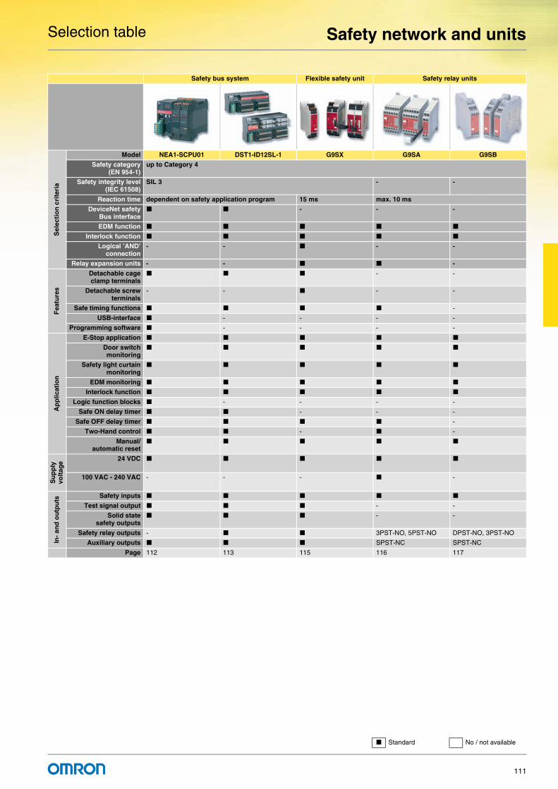
Selection table Safety network and units
111
Safety bus system Flexible safety unit Safety relay units
Sel
ecti
on
cri
teri
a
Model NEA1-SCPU01 DST1-ID12SL-1 G9SX G9SA G9SB
Safety category(EN 954-1)
up to Category 4
Safety integrity level(IEC 61508)
SIL 3 - -
Reaction time dependent on safety application program 15 ms max. 10 ms
DeviceNet safetyBus interface
- - -
EDM function
Interlock function
Logical ’AND’connection
- - - -
Relay expansion units - - -
Fea
ture
s
Detachable cageclamp terminals
- -
Detachable screwterminals
- - - -
Safe timing functions -
USB-interface - - - -
Programming software - - - -
Ap
plic
atio
n
E-Stop application
Door switchmonitoring
Safety light curtainmonitoring
EDM monitoring
Interlock function
Logic function blocks - - - -
Safe ON delay timer - - -
Safe OFF delay timer -
Two-Hand control - -
Manual/automatic reset
Su
pp
ly
volt
age
24 VDC
100 VAC - 240 VAC - - - -
In-
and
ou
tpu
ts Safety inputs
Test signal output - -
Solid statesafety outputs
- -
Safety relay outputs - 3PST-NO, 5PST-NO DPST-NO, 3PST-NO
Auxiliary outputs SPST-NC SPST-NC
Page 112 113 115 116 117
Standard No / not available

For full specifications and additional models please refer to the (attached) CD or www.europe.omron.comSafety network and units - Cat.-No. Z907-E2-01-X112
NE1A-SCPU01 Safety network and units
Safety network controller NE1AThe NE1A hosts the safety application program. All local and DeviceNet safety-based in- and outputs are monitored and controlled by the NE1A. It manages up to 16 DeviceNet safety slaves and can be seamlessly integrated in a standard DeviceNet system.
• Removable cage-clamp terminals for easy installation • Predefined and certified function blocks for easy programming • LED display and status LEDs for advanced diagnostics • System status on DeviceNet for easy troubleshooting and predictive
maintenance • Easy scalability through the addition of DeviceNet safety devices
Ordering information
Stand-alone programmable controllerProgrammable safety circuits
Using DeviceNet safety offers benefits far before the need for a safety network is obvious. The safety network controller uses predefined logical function blocks to set up the programmable safety system. Modifications of the safety system in the life cycle of a machine are done without tedious wiring.
Software
Note: For further information please refer to chapter software.
Specifications
General specifications Safety input specifications
Safety output specifications
Test output specifications
Software:
Safety network
configurator
Safety door switch
ContactorEmergency stop
NE1A-SCPU01
Safety network
controller
Motor
USB
Appearance Appearance description Part number
Safety network controler
16 PNP inputs8 PNP outputs4 test outputs128 function block programmingremovable cage clamp terminals
NE1A-SCPU01
Appearance Appearance description Part number
Safety network configurator
Installation disk (CD-ROM)IBM PC/AT compatibleWindows 2000 or XP
WS02-CFSC1-E(English version)
DeviceNet communications power supply voltage
11 to 25 VDC (supplied from communications connector)
Unit power supply voltage 20.4 to 26.4 VDC (24 VDC -15% +10%)
I/O power supply voltage
Consumption current
Communications power supply
24 VDC, 15 mA
Internal circuit power supply
24 VDC, 230 mA
Mounting method 35-mm DIN track
Ambient operating temperature
-10 °C +55 °C
Ambient storagetemperature
-40 °C +70 °C
Degree of protection IP20 (IEC 60529)
Input type Sinking inputs (PNP)
ON voltage 11 VDC min. between each input terminal and G1
OFF voltage 5 VDC max. between each input terminal and G1
OFF current 1 mA max.
Input current 4.5 mA
Output type Sourcing outputs (PNP)
Rated output current 0.5 A max. per output
Residual voltage 1.2 V max. between each output terminal and V2
Output type Sourcing outputs (PNP)
Rated output current 0.7 A max. per output (see note.)
Residual voltage 1.2 V max. between each output terminal and V1
LISTEDLISTED

For full specifications and additional models please refer to the (attached) CD or www.europe.omron.comSafety network and units - Cat.-No. Z907-E2-01-X 113
DST1-ID/DST1-MRD Safety network and units
DeviceNet safety I/O terminal block family• Removable cage clamp terminals for easy installation• up to 12 Inputs for safety signals• 4 test pulse outputs to ensure crosstalk and short circuit detection• up to 8 safety outputs (solid state or relay)• Status LEDs for advanced diagnostics• Mixed mode operation (safety and standard) for all in- and outputs
Ordering information
Safety networkExpand safety I/O through networks
Safety components distributed over many different installation locations required long and complicated wiring.Replacing the wiring with a network between safety components greatly improves productivity.
Appearance Appearance description Model
Input terminal 12 PNP inputs4 Test outputsRemovable cage clamp terminals
DST1-ID12SL-1
Mixed I/O terminal 8 PNP inputs8 PNP outputs4 Test outputsRemovable cage clamp terminals
DST1-MD16SL-1
Mixed I/O terminal 4 PNP inputs4 relay outputs (4 x 2-single pole)4 Test outputsRemovable cage clamp terminals
DST1-MRD08SL-1
DeviceNet
CJ1 series PLC
DeviceNet master
NE1A-SCPU01
Safety network
controller
Machine control Safety control
Analog I/O terminal
DeviceNet slave
Remote I/O terminal
DeviceNet slave
DST1-ID12SL-1
Safety I/O terminal
DeviceNet slave
DST1-ID12SL-1
Safety I/O terminal
DeviceNet slave
DST1-MRD08SL-1
Safety I/O terminal
DeviceNet slave
Safety light curtain
Safety door switch
Contactor ContactorEmergency stop
NE1A-SCPU01
Safety network
controller
LISTEDLISTED

DST1-ID/DST1-MRD Safety network and units
114
Specifications
General specifications
Safety input specifications
Safety output specifications
Test output specifications
Safety output specifications for relay outputs
Safety I/O terminalsDST1-ID12SL-1
DST1-MD16SL-1
DST1-MRD08SL-1
DeviceNet communications power supply voltage
11 to 25 VDC (supplied from communications connector)
Unit power supply voltage 20.4 to 26.4 VDC (24 VDC -15% +10%)
I/O power supply voltage
Consumption current
Communications power supply
DST1-ID12SL-1/MD16SL-1: 100 mADST1-MRD08SL-1: 110 mA
Mounting method 35-mm DIN track
Ambient operating temperature -10 °C +55 °CAmbient storage temperature -40 °C +70 °CDegree of protection IP20 (IEC 60529)
Weight DST1-ID12SL-1/MD16SL-1: 420 gDST1-MRD08SL-1: 600 g
Input type Sinking inputs (PNP)
ON voltage 11 VDC min. between each input terminal and G1
OFF voltage 5 VDC max. between each input terminal and G1
OFF current 1 mA max.
Input current 6 mA
Output type Sourcing outputs (PNP)
Rated output current 0.5 A max. per output
Residual voltage 1.2 V max. between each output terminal and V1
Output type Sourcing outputs (PNP)
Rated output current 0.7 A max. per point
Residual voltage 1.2 V max. between each output terminal and V0
Relays G7SA-2A2B, EN 50205 class A
Minimum applicable load 1 mA at 5 VDC
Rated load for a resistive load
240 VAC: 2 A, 30 VDC: 2 A
Rated load for an inductive load
2 A at 240 VAC (cosφ= 0.3),1 A at 24 VDC
Mechanical life expectancy 5,000,000 operations min. (switching frequency of 7,200 operations/h)
Electrical life expectancy 100,000 operations min. (at rated load and switching frequency of 1,800 operations/h)
V+
CAN H
DRAIN
CAN L
V−
G G T0 T1 T0 T1 T0 T1 T0 T1 T0 T1 T0 T1 G G G G G G11 12 13 14 15 16 17 18 19 20 31 32 33 34 35 36 37 38 39 40
V
Physical layer
Input power supply circuits Safety input circuits Test output circuits
DC-DC converter (non-isolated)
V IN0 IN1 IN2 IN3 IN4 IN5 IN6 IN7 IN8 IN9 IN10 IN11 T2 T2 T2 T3 T3 T31 2 3 4 5 6 7 8 9 10 21 22 23 24 25 26 27 28 29 30
Internal circuits
V+
CAN H
DRAIN
CAN L
V−
G0 G0 T0 T1 T0 T1 T0 T1 T2 T3 G1 G1 G1 G1 G1 G1 G1 G1 G1 G111 12 13 14 15 16 17 18 19 20 31 32 33 34 35 36 37 38 39 40
V0
Physical layer
Input power supply circuits
Test output circuits
Output power supply circuits
Safety input circuits Safety output circuits
DC-DC converter (non-isolated)
V0 IN0 IN1 IN2 IN3 IN4 IN5 IN6 IN7 V1 V1 OUT0 OUT1 OUT2 OUT3 OUT4 OUT5 OUT6 OUT71 2 3 4 5 6 7 8 9 10 21 22 23 24 25 26 27 28 29 30
Internal circuits
V+
CAN H
DRAIN
CAN L
V−
G0 G0 T0 T1 T0 T1 G0 G0 G0 G0 G1 G1 C0 C0e C1
Ry0 Ry1 Ry2 Ry2
C1e C2 C2e C3 C3e11 12 13 14 15 16 17 18 19 20 31 32 33 34 35 36 37 38 39 40
V0
Safety input circuits
V0 IN0 IN1 IN2 IN3 T2 T2 T3 T3 V1 V1 OUT0 OUT0 OUT1 OUT1 OUT2 OUT2 OUT3 OUT31 2 3 4 5 6 7 8 9 10 21 22 23 24 25 26 27 28 29 30
Internal circuits
Physical layer
DC-DC converter (non-isolated)
Output power supply circuits
Test output circuits
Input power supply circuits

For full specifications and additional models please refer to the (attached) CD or www.europe.omron.comSafety network and units - Cat.-No. J150-E2-01A-X 115
G9SX Safety network and units
Flexible safety unitG9SX-family modules can be connected by a logical "AND" function to implement partial/global stopping of a machine. Solid-state outputs, detailed LED diagnosis and clever feedback signals help to keep maintenance easy. The line-up is completed by expansion units with safe timing functions.
• Clear and transparent segmentation of safety functions by use of unique "AND" connection
• Solid-state outputs for long life and relay outputs in extension box available
• Detailed LED indications enable easy diagnosis • Clever feedback signals for easy maintenance • Category-4 according to EN954-1 and SIL 3 according to EN 61508
Ordering information
Advanced unit
Basic unit
Expansion unit
Specifications
Power input Inputs
Outputs
Expansion unit
Characteristics
Safety outputs Auxiliary outputs No. of input channels
Max. OFF-delay time *1
*1 The OFF-delay time can be set in 16 steps as follows: T15: 0/0.2/0.3/0.4/0.5/0.6/0.7/1/1.5/2/3/4/5/7/10/15 s
Rated voltage
Terminal block type Model
Instantaneous OFF-delayed
P channel MOS-FET transistor output
P channel MOS FET transistor outputs
PNP transistor outputs
1 or 2 channels 0 to 15 in 16 steps
24 VDC Screw terminals G9SX-AD322-T15-RT
Cage clamp terminals G9SX-AD322-T15-RC
Safety outputs Auxiliary outputs No. of input channels
Rated voltage Terminal block type Model
Instantaneous OFF-delayed
P channel MOS FET transistor output
--- PNP transistor output 1 or 2 channels 24 VDC Screw terminals G9SX-BC202-RT
Cage clamp terminals G9SX-BC202-RC
Safety outputs Auxiliary outputs OFF-delay time Rated voltage Terminal block type Model
Instantaneous OFF-delayed
4 PST-NO (contact) --- 1 (solid state) PNP transistor output
--- 24 VDC Screw terminals G9SX-EX401-RT
Cage clamp terminals G9SX-EX401-RC
--- 4 PST-NO (contact) Synchronized with G9S-X-AD - unit
Screw terminals G9SX-EX041-T-RT
Cage clamp terminals G9SX-EX041-T-RC
Item G9SX-AD322-@ G9SX-BC202-@ G9SX-EX-@Rated supply voltage 20.4 to 26.4 VDC (24 VDC -15% +10%)
Item G9SX-AD322-@ G9SX-BC202-@Safety input Operating voltage: 20.4 VDC to 26.4 VDC,
internal impedance: approx. 2.8 kΩFeedback/reset input
Item G9SX-AD322-@ G9SX-BC202-@Instantaneous safety outputOFF-delayed safety output
P channel MOS FET transistor outputLoad current: Using 2 outputs or less: 1 A DC max.
Using 3 outputs or more: 0.8 A DC max.
P channel MOS FET transistor outputLoad current: Using 1 output: 1 A DC max.
Using 2 outputs: 0.8 A DC max.
Auxiliary output PNP transistor outputLoad current: 100 mA max.
Item G9SX-EX-@Rated load 250 VAC, 3A / 30 VDC, 3A
(resistive load)
Rated carry current 3 A
Maximum switching voltage 250 VAC, 125 VDC
Item G9SX-AD322-@ G9SX-BC202-@ G9SX-EX-@Operating time (OFF to ON state) 50 ms max. (Safety input: ON)
100 ms max. (Logical AND connection input: ON)
50 ms max. (Safety input: ON) 30 ms max.
Response time (ON to OFF state) 15 ms max. 10 ms max.
Durability Electrical --- 100,000 cycles min.
Mechanical --- 5,000,000 cycles min.
Ambient temperature -10 °C +55 °C (with no icing or condensation)
LISTED

For full specifications and additional models please refer to the (attached) CD or www.europe.omron.comSafety network and units - Cat.-No. J121-E2-03A-X116
G9SA Safety network and units
Expandable safety relay unitG9SA-family offers a complete line-up of compact and expandable safety relay units. Modules with safe OFF-delay timing are available as well as a two-hand controller. Simple multiplication of safety contacts is possible by using the connection on the front.
• 45 m-wide housing, expansion units are 17.5 m wide • Safe OFF-delay timer • Simple expansion connection • Certification up to category 4 according to EN954-1 depending on
the application
Ordering information
Emergency-stop units
Emergency-stop OFF-delay units
Two-hand controller
Expansion unitThe expansion unit connects to a G9SA-301, G9SA-501, G9SA-321, or G9SA-TH301.
Expansion units with OFF-delay outputsThe expansion unit connects to a G9SA-301, G9SA-501, G9SA-321, or G9SA-TH301.
Specifications
Power input Inputs
Contacts
Characteristics
Main contacts Auxiliary contact Number of input channels Rated voltage Model Category
3PST-NO SPST-NC 1 channel or 2 channels possible 24 VAC / VDC G9SA-301 4
100 to 240 VAC
5PST-NO SPST-NC 1 channel or 2 channels possible 24 VAC / VDC G9SA-501
100 to 240 VAC
Main contacts OFF-delay contacts
Auxiliary contact
Number of input channels
OFF-delay time Rated voltage Model Category
3PST-NO DPST-NO SPST-NC 1 channel or 2 channels possible
7.5 s 24 VAC / VDC G9SA-321-T075 Main contacts: 4OFF-delay contacts: 3100 to 240 VAC
15 s 24 VAC / VDC G9SA-321-T15
100 to 240 VAC
30 s 24 VAC / VDC G9SA-321-T30
100 to 240 VAC
Main contacts Auxiliary contact Number of input channels Rated voltage Model Category
3PST-NO SPST-NC 2 channels 24 VAC / VDC G9SA-TH301 4 (IIIc, EN574)
100 to 240 VAC
Main contacts Auxiliary contact Model Category
3PST-NO SPST-NC G9SA-EX301 4
Main contact form
Auxiliary contact
OFF-delay time
Model Category
3PST-NO SPST-NC 7.5 s G9SA-EX031-T075 3
15 s G9SA-EX031-T15
30 s G9SA-EX031-T30
Item G9SA-301/TH301
G9SA-501 G9SA-321-T#
Power supply voltage 24 VAC/VDC:24 VAC, 50/60 Hz, or 24 VDC100 to 240 VAC:100 to 240 VAC, 50/60 Hz
Operating voltage range 85% to 110% of rated power supply voltage
Item G9SA-301/321-T#/TH301 G9SA-501
Input current 40 mA max. 60 mA max.
Item G9SA-301/501/321-T#/TH301/EX301/EX031-T#
Resistive load (cosφ= 1)
Rated load 250 VAC, 5 A
Rated carry current 5 A
Item G9SA-301/TH301 G9SA-501/321-T# G9SA-EX301/EX031-T#
Operating time 30 ms max. (not including bounce time)
Response time *1
*1 The response time is the time it takes for the main contact to open after the input is turned OFF.
10 ms max. (not including bounce time)
Durability Mechanical 5,000,000 operations min. (at approx. 7,200 operations/hr)
Electrical 100,000 operations min. (at approx. 1,800 operations/hr)
Minimum permissible load (reference value)
5 VDC, 1 mA
Ambient temperature Operating: -25°C to 55°C (with no icing or condensation)Storage: -25°C to 85°C (with no icing or condensation)

For full specifications and additional models please refer to the (attached) CD or www.europe.omron.comSafety network and units - Cat.-No. J130-E2-01-X 117
G9SB Safety network and units
Slim-size safety unitG9SB is a family of slender safety relay units, providing two safety contacts in a 17.5 m- and three safety contacts in a 22.5 m-wide housing.
• 17.5 m- and 22.5 m-wide housing • 1- and 2-input channel units • Manual and automatic reset units • Certification up to category 4 according to EN954-1 depending on
the application
Ordering information
Specifications
Power input
Inputs
Note: Indicates the current between terminals A1 and A2.
Contacts
Characteristics
Main contacts Auxiliary contact
Number of input channels
Reset mode Input type Rated voltage Model Category(EN954-1)
Size
DPST-NO2 safety contacts
None 2 channels Auto-reset Inverse 24 VAC / VDC G9SB-2002-A 4 17.5 mm
1 channel or 2 channels
+ common G9SB-200-B
2 channels Manual-reset Inverse G9SB-2002-C
1 channel or 2 channels
+ common G9SB-200-D
3PST-NO3 safety contacts
SPST-NC None (direct breaking)
Auto-reset --- 24 VDC G9SB-3010 3 17.5 mm
2 channels Inverse 24 VAC / VDC G9SB-3012-A 4 22.5 mm
1 channel or 2 channels
+ common G9SB-301-B
2 channels Manual-reset Inverse G9SB-3012-C
1 channel or 2 channels
+ common G9SB-301-D
Item G9SB-200#-# G9SB-3010 G9SB-301#-#
Power supply voltage 24 VAC / VDC: 24 VAC, 50/60 Hz, or 24VDC24 VDC: 24 VDC
Operating voltage range 85% to 110% of rated power supply voltage
Power consumption 1.4 VA / 1.4 W max. 1.7 W max. 1.7 VA / 1.7 W max.
Item G9SB-200#-# G9SB-3010 G9SB-301#-#
Input current 25 mA max. 60 mA max. (See note.) 30 mA max.
Item G9SB-200#-# G9SB-3010 G9SB-301#-#
Resistive load (cosφ= 1)
Rated load 250 VAC, 5 A
Rated carry current 5 A
Item G9SB-200#-# G9SB-3010 G9SB-301#-#
Response time *1
*1 The response time is the time it takes for the main contact to open after the input is turned OFF.
10 ms max.
Durability Mechanical 5,000,000 operations min. (at approx. 7,200 operations/hr)
Electrical 100,000 operations min. (at approx. 1,800 operations/hr)
Minimum permissable load (reference value) 5 VDC, 1 mA
Ambient operating temperature -25 °C +55 °C (with no icing or condensation)

118

119
Table of contentsSelection table 120
Safety light curtain F3SN-A / F3SH-A 123
F3S-B 125
F3SL 126
F3S-TGR 127
Safety single beam E3FS 128
Muting controller F3SP-U4P 129

120
Selection table
Category 4 Category 2 Category 4
Sel
ecti
on
cri
teri
a
Model F3SN-A F3S-B F3SL F3SH-A
Safety category Category 4 Category 2 Category 4
Operating distance 0.2 - 7 m / 0.2 - 10 m 0.3 - 5 m 0.3 - 20 m 0.2 - 10 m
Protective height 189 - 1,822 mm 300 - 1,650 mm 351 - 2,095 mm 900 mm
Resolution 14, 25, 40, 70 mm 30, 55, 80 mm 30 mm -
Beam pitch 9, 15, 30, 60 mm 25, 50, 70 mm 22 mm 300 mm
Reaction time 10 - 19.5 ms 20 - 45 ms 20 - 35 ms 10 ms
Temperature range -10 °C - 55 °C
Size of housing 30x30 mm 30x40 mm 35x50 mm 30x30 mm
Fea
ture
s
Blanking function internal option internal -
Muting function - - - -
EDM function internal
Interlock function internal
Series connection option option - option
Mounting kits option
Parameter setting option (Console) option (PC) internal DIP switch Option (Console)
External control unit - - - -
Optical heating - - - -
Ap
plic
atio
n
Finger protection - - -
Hand protection -
Arm protection -
Body protection
Presence detection - -
Muting application -
Blanking application -
Su
pp
ly
volt
age 24 VDC
In-
and
Ou
tpu
ts
Safety outputs 2 PNP OSSD transistor outputs
Auxiliary output 2 PNP (non safety) 1 PNP (non safety) 1 PNP (non safety) 2 PNP (non safety)
Test input -
EDM input
Reset input
Muting sensor input - - - -
Page 123 125 126 123

Safety sensors
121
Category 2 and 4 Category 4 Category 2
Sel
ecti
on
cri
teri
a
Model F3S-TGR F3SS E3FS + F3SP-U3P/U5P F3SP-U4P
Safety category Category 4 Category 2 Category 2 Category 2
Operating distance 0.5 - 6 m (active / passive)0.5 - 5 m (active / passive)
0.3 - 60 m 0 - 10 m -
Protective height 500 - 900 m - - -
Resolution - - - -
Beam pitch 300 mm, 400 mm, 500 mm - - -
Reaction time 16 ms 35 ms 32 ms 30 ms
Temperature range -10 °C - 55 °C 0 °C - 55 °C -10 °C - 55 °C -10 °C - 55 °C
Size of housing 30x30 mm 50x115x90 mm Sensor: M18 housingControl unit: 22,5/45 mm wide
45 mm wide
Fea
ture
s
Blanking function - - - -
Muting function internal -
EDM function - - - -
Interlock function internal
Series connection - - - -
Mounting kits -
Parameter setting - - - -
External control unit - -
Optical heating - - -
Ap
plic
atio
n
Finger protection - - - -
Hand protection - - - -
Arm protection - - - -
Body protection -
Presence detection - - - -
Muting application
Blanking application - - - -
Su
pp
ly
volt
age 24 VDC
In-
and
Ou
tpu
ts
Safety outputs 2 PNP OSSD transistor outputs 2 NO relay outputs 2 NO relay outputs
Auxiliary output - - - -
Test input
EDM input - - - -
Reset input
Muting sensor input -
Page 127 Please contact your OMRON representative
128 129
Standard No / not available

122
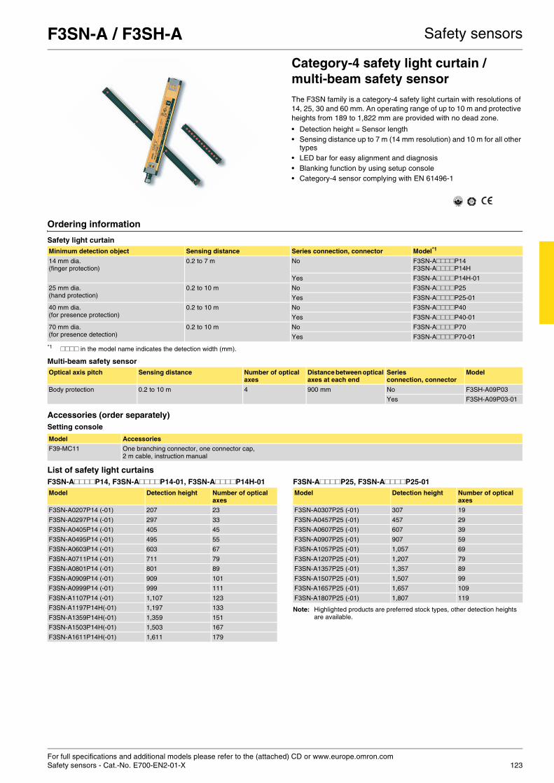
For full specifications and additional models please refer to the (attached) CD or www.europe.omron.comSafety sensors - Cat.-No. E700-EN2-01-X 123
F3SN-A / F3SH-A Safety sensors
Category-4 safety light curtain / multi-beam safety sensorThe F3SN family is a category-4 safety light curtain with resolutions of 14, 25, 30 and 60 mm. An operating range of up to 10 m and protective heights from 189 to 1,822 mm are provided with no dead zone.
• Detection height = Sensor length • Sensing distance up to 7 m (14 mm resolution) and 10 m for all other
types • LED bar for easy alignment and diagnosis • Blanking function by using setup console • Category-4 sensor complying with EN 61496-1
Ordering information
Safety light curtain
Multi-beam safety sensor
Accessories (order separately)Setting console
List of safety light curtainsF3SN-A####P14, F3SN-A####P14-01, F3SN-A####P14H-01 F3SN-A####P25, F3SN-A####P25-01
Note: Highlighted products are preferred stock types, other detection heights are available.
Minimum detection object Sensing distance Series connection, connector Model*1
*1 #### in the model name indicates the detection width (mm).
14 mm dia. (finger protection)
0.2 to 7 m No F3SN-A####P14F3SN-A####P14H
Yes F3SN-A####P14H-01
25 mm dia. (hand protection)
0.2 to 10 m No F3SN-A####P25
Yes F3SN-A####P25-01
40 mm dia.(for presence protection)
0.2 to 10 m No F3SN-A####P40
Yes F3SN-A####P40-01
70 mm dia.(for presence detection)
0.2 to 10 m No F3SN-A####P70
Yes F3SN-A####P70-01
Optical axis pitch Sensing distance Number of optical axes
Distance between optical axes at each end
Series connection, connector
Model
Body protection 0.2 to 10 m 4 900 mm No F3SH-A09P03
Yes F3SH-A09P03-01
Model Accessories
F39-MC11 One branching connector, one connector cap, 2 m cable, instruction manual
Model Detection height Number of optical axes
F3SN-A0207P14 (-01) 207 23
F3SN-A0297P14 (-01) 297 33
F3SN-A0405P14 (-01) 405 45
F3SN-A0495P14 (-01) 495 55
F3SN-A0603P14 (-01) 603 67
F3SN-A0711P14 (-01) 711 79
F3SN-A0801P14 (-01) 801 89
F3SN-A0909P14 (-01) 909 101
F3SN-A0999P14 (-01) 999 111
F3SN-A1107P14 (-01) 1,107 123
F3SN-A1197P14H(-01) 1,197 133
F3SN-A1359P14H(-01) 1,359 151
F3SN-A1503P14H(-01) 1,503 167
F3SN-A1611P14H(-01) 1,611 179
Model Detection height Number of optical axes
F3SN-A0307P25 (-01) 307 19
F3SN-A0457P25 (-01) 457 29
F3SN-A0607P25 (-01) 607 39
F3SN-A0907P25 (-01) 907 59
F3SN-A1057P25 (-01) 1,057 69
F3SN-A1207P25 (-01) 1,207 79
F3SN-A1357P25 (-01) 1,357 89
F3SN-A1507P25 (-01) 1,507 99
F3SN-A1657P25 (-01) 1,657 109
F3SN-A1807P25 (-01) 1,807 119

F3SN-A / F3SH-A Safety sensors
124
Specifications
Connection
Model Stand-alone F3SN-A@@@@P14 *1 *3 F3SN-A@@@@P25 *1 F3SN-A@@@@P40 *1 F3SN-A@@@@P70 *1 F3SH-A09P03
Item Series connection F3SN-A@@@@P14-01 *1 *2 *3
*1 The 4 digits in @@@@ in the model number represent the protective height. Use the formula given in the information on protective height specifications to calculatethe height. For example, if the beam gap is 9 mm, and the No. of beams is 21, the protective height will be 9×21 = 189 mm. The model with this protective height is F3SN-A0189P14.
*2 F3SN-A@@@@P14-01 is a customized model. Consult with your OMRON representative when ordering this model.*3 For sizes above 1,125 mm add „H“ after P14, e.g. F3SN-A1143P14H. Ask for supplemental manual.
F3SN-A@@@@P25-01 *1 F3SN-A@@@@P40-01 *1 F3SN-A@@@@P70-01*1 F3SH-A09P03-01
Sensor type Type 4 Safety Light Curtain
Operating range 0.2 to 7 m 0.2 to 10 m
Beam pitch (P) 9 mm 15 mm 30 mm 60 mm 300 mm
Protective height (PH) 189 to 1611 mm PH = n × P
217 to 1822 mm PH = (n – 1) × P + 37
217 to 1807 mm PH = (n – 1) × P + 37
277 to 1777 mm PH = (n – 1) × P + 37
-
Outermost beam gap - 900 mm
Detection capability Non-transparent: 14 mm in diameter
Non-transparent: 25 mm in diameter
Non-transparent: 40 mm in diameter
Non-transparent: 70 mm in diameter
-
Effective aperture angle (EAA)
Within ±2.5° for the emitter and receiver at a detection distance of at least 3 m according to IEC 61496-2
Light source Infrared LED (870 nm)
Supply voltage (Vs) 24 VDC ±10% (ripple p-p 10% max.)
OSSD Two PNP transistor outputs, load current 300 mA max.
Auxiliary output (non-safety output)
One PNP transistor output, load current 50 mA max.
External indicator output (non-safety output) *4
*4 Models ending in -01 only.
One PNP transistor output, load current 40 mA max.
Output operation mode OSSD output: Light-ON Auxiliary output: Dark-ON (can be changed by the F39-MC11)External indicator output: Light-ON (can be changed by the F39-MC11) *4
Input voltage For test input, interlock selection input, reset input, and external relay monitor input voltages; ON voltage: 9 to 24 V (with a sink current of 3 mA max.), OFF voltage: 0 to 1.5 V or open
Test functions Self-test (after power ON, and during operation, one cycle during response time)External test (light emission stop function by test input)
Safety-related functions Auto reset/manual reset (interlock) *5
EDM (external device monitoring)Fixed blanking *6
Floating blanking *6
*5 For the factory setting, the manual reset mode is set to the “start / restart” interlock. Using the F39-MC11 can select either the start interlock or the restart interlock.
*6 For the factory setting, the function is not set. It can be enabled with the F39-MC11.
Auto reset mode/manual reset mode (interlock) *5
EDM (external device monitoring)
Response time ON to OFF: 10 to 15.5 ms max., 19,5 ms max. for 179 beams ON to OFF: 10 ms max.
Ambient light intensity Incandescent lamp: 3000 Ix max. (light intensity on the receiver surface)Sunlight: 10000 Ix max. (light intensity on the receiver surface)
Ambient temperature Operating: -10 °C +55 °C, storage: -30 °C +70 °C (with no icing or condensation)
Degree of protection IP65 (IEC60529)
Connection method M12 connector (8 pins)
Materials Case: Aluminum, cap: Zinc die-cast, optical cover: PMMA (acrylic resin)
Size (cross section) 30x30 mm
S1 S3
+24
V (
brow
n)
+24
V (
brow
n)
Inte
r lo
ck s
elec
tion
inpu
t (w
hite
)
Res
et in
put (
yello
w)
Tes
t inp
ut (
gree
n)
0V (
blue
)
Shi
elde
d
(Red
)
Aux
iliar
y (y
ello
w)
ED
M in
put (
red)
RS-485(A) (gray)
Receiver cableF39-JC#A-D
Emitter cableF39-JC#A-L
RS-485(B) (pink)
DC24V
K2K1K3
K1
K2
ReceiverEmitter Emitter
When using a auto reset functionUsing a manual reset function and an external device monitoring function
Ope
n
+24
V (
brow
n)
Inte
r lo
ck s
elec
tion
inpu
t (w
hite
)
Res
et in
put
Tes
t inp
ut (
gree
n)
0V (
blue
)
Shi
elde
d
(Red
)
DC24V
Ope
n
S1 S2
Ope
n
OS
SD
(w
hite
)
OS
SD
(gr
een)
0V (
blue
)
shie
ld
S1: External test switchS2: Interlock / lockout reset switchS3: Lock-out reset switch (if the switch is not needed, connect to 24 V DC)K1, K2: Relays for control of dangerous parts of machine.K3: Load, PLC, etc. (for monitor)
Note: If you do not intend to use the external relay monitor, connect the auxiliary output that is set for dark: ON operation to the external relay monitor input, or useF39-MC11 to disable the external relay monitor function.
("1:1:11935")
("1:1:11936")
("1:1:11937")
("1:1:11938")
("1:1:21091")
("1:1:28360")
("1:1:28360")

For full specifications and additional models please refer to the (attached) CD or www.europe.omron.comSafety sensors - Cat.-No. E503-E2-01-X 125
F3S-B Safety sensors
Category-2 safety light curtainThe F3S-B is a category-2 safety light curtain with resolutions of 30, 55 and 80 mm. An operating range of up to 5 m and protective heights from 300 mm to 1,650 mm are provided with a very small dead zone.
• Sensing distance up to 5 m • LEDs for easy alignment and diagnosis • Series connection of two sensors is possible • Category-2 sensor complying with EN 61496-1
Ordering information
Specifications
Stand-alone Optical resolution
No. of optical axes
Protective height
F3S-B122P 30 mm 12 300 mm
F3S-B182P 18 450 mm
F3S-B242P 24 600 mm
F3S-B302P 30 750 mm
F3S-B362P 36 900 mm
F3S-B422P 42 1,050 mm
F3S-B482P 48 1,200 mm
F3S-B542P 54 1,350 mm
F3S-B602P 60 1,500 mm
F3S-B662P 66 1,650 mm
F3S-B065P 55 mm 6 300 mm
F3S-B095P 9 450 mm
F3S-B125P 12 600 mm
F3S-B155P 15 750 mm
F3S-B185P 18 900 mm
Stand-alone Optical resolution
No. of optical axes
Protective height
F3S-B215P 55 mm 21 1,050 mm
F3S-B245P 24 1,200 mm
F3S-B275P 27 1,350 mm
F3S-B305P 30 1,500 mm
F3S-B335P 33 1,650 mm
F3S-B047P 80 mm 4 300 mm
F3S-B067P 6 450 mm
F3S-B087P 8 600 mm
F3S-B107P 10 750 mm
F3S-B127P 12 900 mm
F3S-B147P 14 1,050 mm
F3S-B167P 80 mm 16 1,200 mm
F3S-B187P 18 1,350 mm
F3S-B207P 20 1,500 mm
F3S-B227P 22 1,650 mm
Type F3S-B###P *1
Stand-alone
*1 For detailed type names and optical specifications, see „Type Naming Rule“
F3S-BM###P## *1
Master unit for series connectionF3S-BS### *1
Slave unit for series connection
Sensor type Type 2 Safety Light Curtain
Optical-axis pitch 25 mm 50 mm 75 mm 25 mm 50 mm 75 mm 25 mm 50 mm 75 mm
Optical resolution(Detection capability)
Non-transparent: in diameter
30 mm 55 mm 80 mm 30 mm 55 mm 80 mm 30 mm 55 mm 80 mm
Protective height 300 / 450 / 600 / 750 / 900 / 1,050 / 1,200 / 1,350 / 1,500 / 1,650 mm 300 / 450 / 600 / 750 mm
Detection distance 0.3 to 5.0 m
Response time ON to OFF 20 ms to 45ms (stand-alone)ON to OFF 20 ms to 65ms (series connection)
Supply voltage (Vs) 24 VDC ±20% (including 5 Vp-p ripple)
Current consumption 400 mA max. (under no-load conditions)
Light source Infrared LED (880 nm wavelength).
Effective aperture angle Within ±5° for the emitter and receiver at a detection distance of at least 3 m according to IEC 61496-2
Control output Two PNP transistor outputs, load current 200 mA max.
Instability output PNP transistor output (non safety output)
Protection circuit Output short-circuit protection, power supply reverse connection protection
External test function Mode selection by connecting ”External test input” line to: Active: 17 VDC to Vs, 10 mA max. duration time at least 15 msInactive: No connection or 0 to 2.5 VDC, 2 mA max.
Relay monitoring function (optional) Default inactive, selectable with F39-U1E
Start interlock function (optional) Default inactive, selectable with F39-U1E
Blanking function (optional) Default inactive, selectable with F39-U1E
Connection method For extension cable: 8 pins, M12 connectorFor series connection cable: 6 pins, M12 connector
Ambient temperature Operating: -10 °C +55 °C (with no icing or condensation)
Degree of protection IP65 (IEC60529)
Size (cross section) 30x40 mm

For full specifications and additional models please refer to the (attached) CD or www.europe.omron.comSafety sensors - Cat.-No. E15E-EN-01126
F3SL Safety sensors
Category-4 safety light curtain for long-distance detectionThe F3SL category-4 safety light curtain is ideal for applications where long operating ranges of up to 20 m are needed. A resolution of 30 mm ensures hand detection even in large machines and conveyor lines.
• Sensing distance up to 20 m • LEDs for easy alignment and diagnosis • Blanking function included • EDM function included • Category-4 sensor complying with EN 61496-1
Ordering information
Specifications
Sensor type Sensing distance Detection width (mm) Model
Through-beam 0.3 to 20 m 351 F3SL-A0351P30
523 F3SL-A0523P30
700 F3SL-A0700P30
871 F3SL-A0871P30
1,046 F3SL-A1046P30
1,219 F3SL-A1219P30
1,394 F3SL-A1394P30
1,570 F3SL-A1570P30
1,746 F3SL-A1746P30
1,920 F3SL-A1920P30
2,095 F3SL-A2095P30
Item Model F3SL-A0351 P30
F3SL-A0523 P30
F3SL-A0700 P30
F3SL-A0871 P30
F3SL-A1046 P30
F3SL-A1219 P30
F3SL-A1394 P30
F3SL-A1570 P30
F3SL-A1746 P30
F3SL-A1920 P30
F3SL-A2095P 30
Sensing distance 0.3 to 20 m
Optical axis pitch 22 mm
Number of optical axes
16 24 32 40 48 56 64 72 80 88 96
Protective height 351 mm 523 mm 700 mm 871 mm 1,046 mm 1,219 mm 1,394 mm 1,570 mm 1,746 mm 1,920 mm 2,095 mm
Min. sensing object Opaque object, 30-mm dia. or greater (52-mm or 74-mm dia. when using floating blanking)
Effective aperture angle
Emitter / receiver: ±2.5° or less each (based on IEC61496-2 at detection distance of 3 m or greater)
Light source Infrared LED (850 nm)
Supply voltage (Vs) 24 VDC ±20% including 5% ripple (p-p)
Current consumption Emitter: 285 mA or less, receiver: 1.4 A or less (including load output current)
Control output PNP transistor outputs x 2, load current 500 mA or less, Light ON
Auxiliary output Same signal as control output: PNP transistor outputs x 1 output (non-safety output), load current 100 mA or less
Protective circuits Output load short circuit protection, reverse power connection protection
Safety functions Start/restart interlock function (select enable/disable with DIP switch)
• Blanking functions A Channel select (fixed blanking) B Floating blanking C No blanking (initial setting)Select A, B, or C with DIP switch.The optical axes for A fixed blanking are set by a teach button.
Diagnosis functions • Self diagnosis functions when the power is turned on
• External relay (MPCE) monitor function (connect external relay monitor input wire to contact b of external relay, 50 mA 24 VDC)
Response time ON to OFF 20 ms max. ON to OFF 25 ms max. ON to OFF 30 ms max. ON to OFF 35 ms max.
Ambient temperature Operating / Storage: 0 °C to 55 °C (with no icing or condensation)
Degree of protection IP65 (IEC 60529)
Connection method M12 Connector
Accessories Test rod, mounting brackets (upper/lower), operation manual, special hex wrench for program button access, test load resistors (1 kΩ, 2 resistors), surge protector (2)
Size (cross section) 35x50 mm

For full specifications and additional models please refer to the (attached) CD or www.europe.omron.comSafety sensors - Cat.-No. E19E-EN-01 127
F3S-TGR Safety sensors
Safety sensor for perimetrical guardingThe F3S-TGR perimetrical guards are available in category 2 and category 4 with integrated muting function. They are available as 2-, 3- and 4-beam guards with an operation range of up to 50 m.
• Sensing distance up to 50 m • Muting function included (no additional controller needed) • Two muting actuator shapes for easy muting applications • Automatic and manual restart function included • Category-2 and -4 sensor complying with EN 61496-1
Ordering information
Safety multi beam sensorsF3S-TGR-SB2-K@C mirror reflection type (type 2) F3S-TGR-SB4-K@C mirror reflection type (type 4)
Flexible muting connector box
Specifications
Safety sensors
Muting connection box
Number of optical axes
Sensing distance
Beam pitch
Model
2 0.5 to 6 m 500 F3S-TGR-SB2-K2C-500(MTL)*1
*1 For muting applications with transport in only one direction, please add theMTL behind the model name. Ex. F3S-TGR-SB4-K2C-500MTL.
3 0.5 to 5 m 400 F3S-TGR-SB2-K3C-800(MTL)*1
4 300 F3S-TGR-SB2-K4C-900(MTL)*1
Number of optical axes
Sensing distance
Beam pitch
Model
2 0.5 to 6 m 500 F3S-TGR-SB4-K2C-500(MTL)*1
*1 For muting applications with transport in only one direction, please add theMTL behind the model name. Ex. F3S-TGR-SB4-K2C-500MTL.
3 0.5 to 5 m 400 F3S-TGR-SB4-K3C-800(MTL)*1
4 300 F3S-TGR-SB4-K4C-900(MTL)*1
SLC connection type Other connection Model
M12 8pin connector without cable 4 x muting sensor connection (4pin)1 x muting lamp M12 (4pin)1 x override / Test input M12 (4pin)1 x cabinet connection M12 (8pin)
F39-TGR-SB-CMB1
M12 8pin connector with 100 mm cable F39-TGR-SB-CMB2
F3S-TGR-SB4-K@C-@@@(MTL) F3S-TGR-SB2-K@C-@@@(MTL)
Sensor type Type 4 Type 2
Operating range F3S-TGR-SB@-K2C 0.5 - 6 mF3S-TGR-SB@-K3C/K4C 0.5 - 5 m
Beam pitch and number of beam F3S-TGR-SB@-K2C 500 mm 2 beam with mirrorF3S-TGR-SB@-K3C 400 mm 3 beam with mirrorF3S-TGR-SB@-K4C 300 mm 4 beam with mirror
Effective aperture angle (EAA) Within ±2.5° Within ±5°
Light source Infrared LED (880 nm)
Supply voltage (Vs) 24 VDC ±20%
OSSD Two PNP transistor outputs, load current 500 mA max
Output operation mode Light - ON
Test functions Self-test (after power ON and during operation, one cycle during response time)
Protection Output short-circuit protection
Response time ON to OFF 16 ms max
Ambient temperature Operating: -10 °C +55 °C (with no icing or condensation)
Degree of protection IP65 (IEC 60529)
Size (cross section) 38x48 mm
Supply voltage (Vs) 24 VDC ±20%
Ambient temperature Operating: -10 to +55 °C (with no icing or condensation)
Safety light curtain connector M12 8 pins female
Cabinet connector M12 8 pins male
Sensor connector 4 x M12 4 pins female
Muting sensor connector M12 4 pins female
Test / override connectors M12 4 pins female
Degree of protection IP65 (IEC60529)

For full specifications and additional models please refer to the (attached) CD or www.europe.omron.comSafety sensors - Cat.-No. E25E-EN-02128
E3FS Safety sensors
Single-beam safety sensor in compact housingThe slender M18-sized E3FS is a category-2 safety single beam with an operating range of up to 10m. Plastic and metal housing, cable and M12-connector offer flexibility in application together with a control unit such as F3SP-U3P, F3SP-U4P or F3SP-U5P.
• Sensing distance up to 10m • LEDs for easy alignment and diagnosis • Cable and M12 plug categories • Plastic and metal housing • Category-2 sensor complying with EN 61496-1
Ordering information
Safety single beam sensors (Type 2) Controller for safety single beam sensors
Specifications
Sensors
Controllers
Case material Operation distance Model
Plastic 0 to 10 m Cable type E3FS-10B4
Plug type E3FS-10B4-P1
Nickel Brass Cable type E3FS-10B4-M
Plug type E3FS-10B4-M1-M
Sensors Output contacts Width Model
1 to 2Safety single beam sensors
2 NO 2.5 A 22.5 mm F3SP-U3P-TGR
1 to 4Safety single beam sensors
45 mm F3SP-U5P-TGR
Sensing method Through-beam
Controller F3SP-U3P-TGR, F3SP-U5P-TGR
Supply voltage (Vs) 24 VDC ± 10% (ripple p-p 10% max.)
Effective aperture angle (EAA) ±5° (at 3 m)
Current consumption Emitter: 50 mA max.Receiver: 25 mA max.
Sensing distance 10 m
Standard sensing object Opaque object: 11 mm min. in diameter
Response time 2.0 ms (E3FS only)
Control output PNP transistor output, load current: 100 mA max.
Test input (emitter) 21.5 to 24 VDC: emitter OFF (source current: 3 mA max.)Open or 0 to 2.5 V: emitter ON (leakage current: 0.1 mA max.)
Ambient light intensity Incandescent lamp: 3.000 lx max. (light intensity on the receiver surface)Sunlight: 10,000 lx max. (light intensity on the receiver surface)
Ambient temperature Operating: -10 °C +55 °C, storage: -30 °C +70 °C (with no icing or condensation)
Degree of protection IP67 (IEC 60529)
Light source Infrared LED
Protection Output short-circuit protection, reverse polarity protection
F3SP-U3P F3SP-U5P
Number of sensors 1 to 2 safety single beam sensor 1 to 4 safety single beam sensor
Width 22.5 mm 45 mm
Muting input 2 Inputs 4 Inputs
Safety related function Override functionMuting lamp ConnectionInterlock system (automatic and manual reset)
Power supply voltage 24 VDC ±10%
Power consumption 420 mA max.
Output contacts 2 NO 2.5 A (protected by fuse), 115 VAC max. 2 NO 2.5 A (protected by fuse), 250 VAC max.
Indicators 6 LED for status and diagnostics
Degree of protection IP20 (IEC 60529)
Terminal 16 screw terminals, detachable blocks with ’4pin’
32 screw terminals, detachable blocks with ’4pin’
Response time ≤ 30 ms
Ambient temperature Operation: -10 °C +55 °C
Housing material Plastic; DIN rail mounting

For full specifications and additional models please refer to the (attached) CD or www.europe.omron.comSafety sensors - Cat.-No. E28E-EN-01 129
F3SP-U4P Safety sensors
Safety light curtain controller with integrated muting functionThe F3SP-U4P muting controller can handle up to two safety light curtains. It has a 45 mm-wide housing, two safety relay outputs with up to 2.5 A and additional functions such as muting-lamp monitoring and override function.
• Two independent muting functions with override • Slim housing: 45 mm • LEDs for status and diagnosis • Detachable terminals • Fully certified according to EN 61496-1
Ordering information
Specifications
Wiring example
Control unit F3SP-U4P-TGR in a mixed configuration that allows the use of several OMRON safety light curtains and perimetrical guards.
Description Model
Muting controller for safety light curtain F3S-B, F3SN and F3SH F3SP-U4P-TGR
F3SP-U4P-TGR
Power supply voltage 24 VDC ±10%
Power consumption 420 mA max. (excl. SLC power consumption)
Output contacts 2 NO 2.5 A (protected by fuse)
Indicators 6 LEDs for status and diagnostics.
Degree of protection IP20 (IEC 60529)
Terminal 32 screw terminals (1.5 mm²), detachable blocks with 4 screws each
Response time ≤ 30 ms
Ambient temperature Operating: -10 °C + 55 °C
Housing material Plastic, DIN rail mounting
17 18 19 20 21 22 23 24 25 26 27 28 29 30 31 32
1 2 3 4 5 6 7 8 9 10 11 12 13 14 15 16
F3SP-U4P-TGR control unit
first Safety sensor F3SN, F3SH, F3S-B, F3SL F3S-TGR-SB
second Safety sensor F3SN, F3SH, F3S-B, F3SL F3S-TGR-SB
+Vcc
0 V 0 V
+Vcc
0 V
Out 1
0 V
+Vcc Out 1
Out 2 Out 2
Safety out number 1
Safety out number 1
Muting sensor contact N.O.
MAIN SUPPLIER
24 VDC
GND MutingA B
MutingD C
+Vcc
StartN.A.
Test N.C.
LMC

130
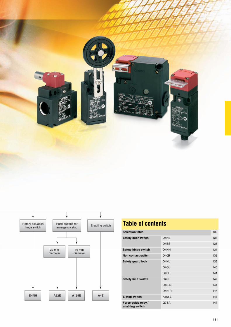
131
Table of contentsSelection table 132
Safety door switch D4NS 135
D4BS 136
Safety hinge switch D4NH 137
Non contact switch D40B 138
Safety guard lock D4NL 139
D4GL 140
D4BL 141
Safety limit switch D4N 142
D4B-N 144
D4N-R 145
E-stop switch A165E 146
Force guide relay / enabling switch
G7SA 147

132
Selection table
Safety door switches Non-contact safety door
switches
Safety door-lock switches
Sel
ecti
on
cri
teri
a
Model D4NS D4BS D4NH D40B D4NL D4GL D4BL
Housing Plastic Metal Plastic Plastic Plastic Plastic Metal
Connector type M12 - - - - -
Head mounting 4 directions 4 directions - - 4 directions 4 directions 4 directions
Actuation Straight Straight Hinge - Straight Straight Straight
Key holding force - - - - 1,300 N 1,000 N 700 N
Protection class IP67
Conformity EN50047, EN1088 EN1088
Fea
ture
s
Conduit size PG13.5 -
Conduit size M20 -
Conduit size G1/2 -
Conduit size 1/2-14NPT - - - -
Cable length 3 , 5 , 10 m - - - - - -
Gold clad contacts
Operation key adjustable -
Mechanical lock /24 VDC solenoid release
- - - -
Mechanical lock /110 VAC solenoid release
- - - - -
Mechanical lock /230 VAC solenoid release
- - - - - -
24 VDC solenoid lock /mechanical release
- - - -
110 VAC solenoid lockmechanical release
- - - - - -
240 VAC solenoid lock,mechanical release
- - - - - -
Shaft actuator - - - - - -
Arm lever actuator - - - - - -
High temperature sensor - - - - - -
Ap
plic
atio
n Door monitoring
Door locking - - - -
Co
nta
ct c
on
fig
ura
tio
n
1NC / 1NO SL - - - -
2NC SL - - - -
2NC / 1NO - - - - - - -
2NC / 1NO SL - - - - -
3NC SL - - - - -
1NC / 1NO (MBB contact) - - - - -
2NC / 1NO (MBB contact) - - - - -
1NO / 1NC - - - - - -
2NO / 1NC - - - - - -
1NC / 1NO SL+ 1NC / 1NO SL
- - - - -
1NC / 1NO SL + 2NC SL - - - - -
1NC / 1NO SL + 1NC SL - - - - - -
2NC SL + 1NC / 1NO SL - - - - -
2NC / 1NO SL+ 1NC / 1NO SL
- - - - - -
2NC/1NO SL + 2NC SL - - - - -
2NC SL + 2NC SL - - - - -
2NC SL + 1NC SL - - - - - -
3NC SL + 1NC / 1NO SL - - - - -
3NC SL + 2NC SL - - - - -
Page 135 136 137 138 139 140 141

Safety components
133
Standard No / not available
Safety limit switches E-stop switches Safety relay and enabling
switches
Sel
ecti
on
cri
teri
a
Model D4N D4B-N D4N-R A22E A165E G7SA
Housing Plastic Metal Plastic
M12 Plug connector - - - - -
Protection class IP67 IP65 -
Operating temperaturerange
-30 °C - 70 °C -40 °C - 80 °C -30 °C - 70 °C -20 °C - 70 °C -10 °C - 55 °C -40 °C - 85 °C
Head size - - - 30 mm, 40 mm, 60 mm 30 mm, 40 mm -
Number of poles - - - - - 4pole and 6pole
Flux tight - - - - -
Conformity EN50047, EN1088 EN 60947-5-1 EN50205
Fea
ture
s
Conduit size PG13.5 - - -
Conduit size M20 - - -
Conduit size G1/2 - - -
Conduit size 1/2-14NPT - - -
Gold clad contacts - -
Actuators
Resin roller, resin lever - - - - -
Resin roller, metal lever - - -
Metal roller, metal lever - - - - -
Bearing lever, metal lever - - - - -
Adj. resin roller,metal lever
- - -
Adj. rubber roller,metal lever
- - - -
Adj. rod lever - - - -
Top plunger - - -
Top roller plunger - - -
Roller arm lever - - - - -
Cat whisker - - - - -
Plastic rod - - -
Fork lever lock - - - - -
Lighted head - - - -
Push lock - pull reset - - - - -
Push lock, turn reset - - - -
Push lock, lock key reset - - - - -
Relay socket - - - - -
Ap
plic
atio
n Position monitoring - - -
E-stop application - - - -
General safetyapplication
- - - - -
Co
nta
ct c
on
fig
ura
tio
n
1NC/1NO snap action - - -
2NC snap action - - - - -
1NC/1NO slow action - - -
2NC slow action - - -
2NC/1NO slow action - - - - -
3NC slow action - - - - -
1NC / 1NO(MBB slow action)
- - - - -
2NC / 1NO(MBB slow action)
- - - - -
Co
nta
ct c
on
fig
ura
tio
n
SPST (NC) - - - -
DPST (NC) - - - -
SPST (NO) + SPST (NC) - - - - -
TPST (NC) - - - - -
4PST-NO + DPST-NC - - - - -
3PST-NO + 3PST-NC - - - - -
3PST-NO + SPST-NC - - - - -
DPST-NO + DPST-NC - - - - -
5PST-NO + SPST-NC - - - - -
Page 142 144 145 Please contact your OMRON representative
146 147

134

For full specifications and additional models please refer to the (attached) CD or www.europe.omron.comSafety components - Cat.-No. C128-E2-03-X 135
D4NS Safety components
Safety door switch with plastic housingThe D4NS line-up includes three-contact models with 2NC / 1NC and 3NC contact forms in addition to the previous contact forms, 1NC / 1NO and 2NC. Models with M12 connectors and conduit opening, such as M20, are also available.
• Line-up with three contacts: 2NC / 1NC and 3NC contact forms • Line-up with two contacts 1NC / 1NO and 2NC • M12 connector types available • Standardised gold-clad contacts for high contact reliability • Applicable for standard loads and micro loads
Ordering information
Switches
Note: Additionally conduit sizes G1/2, 1/2-14NPT and Pg13,5 are available.
Operation keys (order separately)
Specifications
Note: - The above values are initial values.
Type Contact configuration Conduit opening/connector Model
1-conduit Slow-action 1NC / 1NO M20 D4NS-4AF
2NC M20 D4NS-4BF
2NC / 1NO M20 D4NS-4CF
3NC M20 D4NS-4DF
Slow-action MBB contact 1NC / 1NO M20 D4NS-4EF
2NC / 1NO M20 D4NS-4FF
2-conduit Slow-action 1NC / 1NO M20 D4NS-8AF
2NC M20 D4NS-8BF
2NC / 1NO M20 D4NS-8CF
Slow-action MBB contact 1NC / 1NO M20 D4NS-8EF
Slow-action MBB contact 2NC / 1NO M20 D4NS-8FF
1-conduit, with connector
Slow-action 1NC / 1NO M12 connector D4NS-9AF
2NC M12 connector D4NS-9BF
Slow-action MBB contact 1NC / 1NO M12 connector D4NS-9EF
: Models with approved direct opening contacts.
Type Model
Horizontal mounting D4DS-K1
Vertical mounting D4DS-K2
Type Model
Adjustable mounting (horizontal) D4DS-K3
Adjustable mounting(horizontal/vertical)
D4DS-K5
Degree of protection IP67 (EN60947-5-1) (This applies for the switch only. The degree of protection for the key hole is IP00.)
Durability *1
*1 The durability is for an ambient temperature of 5° C to 35° C and an ambient humidity of 40% to 70%. For more details, consult your OMRON representative.
Mechanical 1,000,000 operations min.
Electrical 500,000 operations min. for a resistive load of 3 A at 250 VAC300,000 operations min. for a resistive load of 10 A at 250 VAC
Operating speed 0.05 to 0.5 m/s
Operating frequency 30 operations/minute max.
Direct opening force *2
*2 These figures are minimum requirements for safe operation.
60 N min.
Direct opening travel *2 10 mm min.
Minimum applicable load Resistive load of 1 mA at 5 VDC (N-level reference value)
Protection against electric shock Class II (double insulation)
Pollution degree (operating environment) 3 (EN60947-5-1)
Contact gap 2 x 2 mm min
Conditional short-circuit current 100 A (EN60947-5-1)
Rated open thermal current (Ith) 10 A (EN60947-5-1)
Ambient temperature Operating: -30° C to 70° C with no icing

For full specifications and additional models please refer to the (attached) CD or www.europe.omron.comSafety components - Cat.-No. C094-E2-04A-X136
D4BS Safety components
Safety door switch with metal housingThe D4BS line-up includes two-contact models with 1NC/1NO and 2NC in a robust metal housing. Models with M12 connectors and conduit opening, such as M20, are also available.
• Robust metal housing • Line-up with two contacts: 1NC / 1NO and 2NC • M12 connector types available • Standardised gold-clad contacts for high contact reliability • Applicable for standard loads and micro loads
Ordering information
Operation keys (order separately)
Specifications
Note: The above values are initial values.
Type Mounting direction Conduit size 1NC/1NO (slow-action) 2NC (slow-action)
1-conduit Front-side mounting
Pg13.5 D4BS-15FS D4BS-1AFS
M20 D4BS-45FS D4BS-4AFS
3-conduit Pg13.5 D4BS-55FS D4BS-5AFS
M20 D4BS-85FS D4BS-8AFS
Type Model
Horizontal mounting D4BS-K1
Vertical mounting D4BS-K2
Adjustable mounting (horizontal)
D4BS-K3
Degree of protection*1
*1 Although the switch box is protected from dust, oil, or water penetration, do not use the D4BS in places where dust, oil, water, or chemicals may penetrate throughthe key hole on the head, otherwise switch damage or malfunctioning may occur.
IP67 (EN60947-5-1)
Durability*2
*2 The durability is for an ambient temperature of 5° C to 35° C and an ambient humidity of 40% to 70%. Contact your OMRON sales representative for more detailedinformation on other operating environments.
Mechanical: 1,000,000 operations min.Electrical: 500,000 operations min. (10 A at 250 VAC, resistive load)
Operating speed 0.1 m/s to 0.5 m/s
Operating frequency 30 operations/min max.
Rated frequency 50/60 Hz
Contact gap 2 x 2 mm min.
Direct opening force*3
*3 These figures are minimum requirements for safe operation.
19.61 N min. (EN60947-5-1)
Direct opening travel*3 20 mm min. (EN60947-5-1)
Full stroke 23 mm min.
Conventional enclosed thermal current (Ith)
20 A (EN60947-5-1)
Conditional short-circuit current
100 A (EN60947-5-1)
Pollution degree (operating environment)
3 (EN60947-5-1)
Protection against electric shock
Class I (with ground terminal)
Ambient temperature Operating: -40°C to 80°C (with no icing)

For full specifications and additional models please refer to the (attached) CD or www.europe.omron.comSafety components - Cat.-No. C131-E2-01A-X 137
D4NH Safety components
Safety door hinge switchD4NH safety-door hinge switches are available with one or two built-in contacts, shaft or arm lever actuator and various conduit types, e.g. M20.
• Direct opening mechanism • Shaft or arm lever actuator • Wide temperature range • Metric conduit types available
Ordering information
Note: Conduit types with G1/2, 1/2-14NPT and Pg13,5 are also available. bold = Preferred stock item
Specifications
Actuator Conduit size Built-in switch mechanism
1NC / 1NO (slow-action) 2NC (slow-action) 2NC / 1NO (slow-action)
Shaft 1-conduit M20 D4NH-4AAS D4NH-4BAS D4NH-4CAS
M12 connector D4NH-9AAS D4NH-9BAS ---
2-conduit M20 D4NH-8AAS D4NH-8BAS D4NH-8CAS
Arm lever 1-conduit M20 D4NH-4ABC D4NH-4BBC D4NH-4CBC
M12 connector D4NH-9ABC D4NH-9BBC ---
2-conduit M20 D4NH-8ABC D4NH-8BBC D4NH-8CBC
Actuator Conduit size Built-in switch mechanism
3NC (slow-action) 1NC / 1NO MBB (slow-action) 2NC / 1NO MBB (slow-action)
Shaft 1-conduit M20 D4NH-4DAS D4NH-4EAS D4NH-4FAS
M12 connector --- D4NH-9EAS ---
Arm lever 1-conduit M20 D4NH-4DBC D4NH-4EBC D4NH-4FBC
M12 connector --- D4NH-9EBC ---
Degree of protection IP67 (EN60947-5-1)
Durability Mechanical 1,000,000 operations min.
Electrical 500,000 operations min. for a resistive load of 3 A at 250 VAC300,000 operations min. for a resistive load of 10 A at 250 VAC
Operating speed 2 to 360° /s
Operating frequency 30 operations/minute max.
Protection against electric shock Class II (double insulation)
Pollution degree (operating environment) 3 (EN60947-5-1)
Contact gap Snap-action: 2x9.5 mm minSlow-action: 2x2 mm min
Conditional short-circuit current 100 A (EN60947-5-1)
Rated open thermal current (Ith) 10 A (EN60947-5-1)
Ambient temperature Operating: -30° C to 70° C with no icing

For full specifications and additional models please refer to the (attached) CD or www.europe.omron.comSafety components - Cat.-No. C127-E2-02-X138
D40B Safety components
Compact non-contact door switchThree types of sensors and two control units present the D40B family. Standard sensors are available with 3 m and 10 m cabling. The high temperature sensor (up to +125 °C) is equipped with a 5 m cable. If requested, all sensor types are available with an auxiliary output.
• Contact-free detection of the closing/opening of a door • Non contact=no abrasion=no particles • Washable actuator • Easy cleaning - there is no key hole • Good coverage of mechanical tolerances
Ordering information
Sensors (switches/actuators)
Note: A sensor used in combination with a controller is classified category 3.
Controllers
Specifications
Sensor (switch/actuator)
Controller
Classification Shape Auxiliary output Cable length Model
Standard sensor None 3 m / 10 m D40B-1B3 / D40B-1B10
1 NC 3 m / 10 m D40B-1D3 / D40B-1D10
Elongated sensor None 3 m / 10 m D40B-2B3 / D40B-2B10
1 NC 3 m / 10 m D40B-2D3 / D40B-2D10
High-temperature type sensor 1 NC 5 m D40B-3D5C
1 NO D40B-3E5C
Safety contacts Auxiliary contacts/output *1
*1 Non-safety output.
Rated voltage Model
1 NO 1 NC 24 VAC/VDC D40B-J1
2 NO 1 NC 24 VAC/VDC110/230 VAC
D40B-J2
Item Type Standard sensor High-temperature type sensor
Switching distance (nominal value) OFF -> ON: 5 mmON -> OFF: 15 mm
OFF -> ON: 9 mmON -> OFF: 17 mm
Operating temperature -10 °C +55 °C -25 °C +125 °C
Degree of protection IP67 (IEC 60947-5-1)
Material ABS Stainless steel
Item Type D40B-J1 D40B-J2
Power supply voltage 24 VAC / VDC 24 VAC / VDC or 110/230 VAC (selectable)
Allowable voltage range Power supply voltage ±15%
Rated load Safety contacts 250 VAC, 4 A, cosφ= 1, 30 VDC, 2 A, cosφ = 1
Auxiliary contacts / output*1
*1 D40B-J1: MOS output; D40B-J2: contact output.
230 VAC, 100 mA, cosφ = 1, 24 VDC, 100 mA, cosφ = 1 250 VAC, 4 A, cosφ = 1, 30 VDC, 2 A, cosφ = 1
Response time 25 ms max.
Operating temperature -10 °C +55 °C

For full specifications and additional models please refer to the (attached) CD or www.europe.omron.comSafety components - Cat.-No. C126-E2-01-X 139
D4NL Safety components
Guard-lock safety door switchThe D4NL guard-lock safety-door switches are available with four or five built-in contacts. When locked, they have a key holding force of up to 1300 N. Mechanical lock/solenoid release types and vice versa set up the complete range in combination with various conduit types, e.g. M20.
• Safety-door switch with electromagnetic lock or unlock mechanism • Models with four or five built-in contacts • Strong key holding force: 1300 N • For standard loads and micro loads • Keys are compatible with D4GL and D4NS
Ordering information
For 110V and 230V version ask your local OMRON representative
Note: - Conduit sizes of G1/2 and Pg 13,5 are also available.- Solenoid: 24 VDC, Orange LED: 10 to 115 VAC/VDC
Operation keys
Specifications
Note: The above values are initial values.
: Models with approved direct opening contacts.
Lock and release types
Contact configuration Conduit opening
Model
Mechanical locksolenoid release
1NC / 1NO + 1NC / 1NO M20 D4NL-4AFA-B
1NC / 1NO + 2NC M20 D4NL-4BFA-B
2NC + 1NC / 1NO M20 D4NL-4CFA-B
2NC + 2NC M20 D4NL-4DFA-B
2NC / 1NO + 1NC / 1NO M20 D4NL-4EFA-B
2NC / 1NO + 2NC M20 D4NL-4FFA-B
3NC + 1NC / 1NO M20 D4NL-4GFA-B
3NC + 2NC M20 D4NL-4HFA-B
Lock and release types
Contact configuration Conduit opening
Model
Solenoid lockmechanicalrelease
1NC / 1NO + 1NC / 1NO M20 D4NL-4AFG-B
1NC / 1NO + 2NC M20 D4NL-4BFG-B
2NC + 1NC / 1NO M20 D4NL-4CFG-B
2NC + 2NC M20 D4NL-4DFG-B
2NC / 1NO + 1NC / 1NO M20 D4NL-4EFG-B
2NC / 1NO + 2NC M20 D4NL-4FFG-B
3NC + 1NC / 1NO M20 D4NL-4GFG-B
3NC + 2NC M20 D4NL-4HFG-B
Type Model
Horizontal mounting D4DS-K1
Vertical mounting D4DS-K2
Type Model
Adjustable mounting(horizontal)
D4DS-K3
Adjustable mounting(horizontal / vertical)
D4DS-K5
Degree of protection IP67 (EN60947-5-1) (This applies for the switch only. The degree of protection for the key hole is IP00.)
Durability*1
*1 The durability is for an ambient temperature of 5° C to 35° C and an ambient humidity of 40% to 70%. For more details, consult your OMRON representative.
Mechanical 1,000,000 operations min.
Electrical 500,000 operations min. for a resistive load of 3 A at 250 VAC
Operating speed 0.05 to 0.5 m/s
Operating frequency 30 operations/minute max.
Rated frequency 50/60 Hz
Contact gap 2x2 mm min
Direct opening force *2
*2 These figures are minimum requirements for safe operation.
60 N min. (EN60947-5-1)
Direct opening travel *2 10 mm min. (EN60947-5-1)
Holding force 1,300 N min.
Minimum applicable load Resistive load of 1 mA at 5 VDC (N-level reference value)
Thermal current (Ith) 10 A (EN60947-5-1)
Conditional short-circuit current
100 A (EN60947-5-1)
Pollution degree (operating environment)
3 (EN60947-5-1)
Protection against electric shock
Class II (double insulation)
Ambient temperature Operating: -10° C to 55° C (with no icing or condensation)

For full specifications and additional models please refer to the (attached) CD or www.europe.omron.comSafety components - Cat.-No. C125-E2-01-X140
D4GL Safety components
Guard-lock safety door switchThe D4GL guard-lock safety-door switches are available with four or five built-in contacts. When locked, they have a key holding force of up to 1000 N. Mechanical lock/solenoid release types and vice versa set up the complete range in combination with various conduit types, e.g. M20.
• Slim safety-door switch with electromagnetic lock or unlock mechanism
• Models with four or five built-in contacts • Strong key holding force: 1000 N • For standard loads and micro loads • Keys are compatible with D4NL and D4NS
Ordering information
Note: - conduit sizes of G1/2 and Pg13,5 are also available.- solenoid: 24 VDC, orange/green LED: 24 VDC
Operation keys (order separately)
Specifications
Note: The above values are initial values.
: Models with approved direct opening contacts.
Lock and release types
Contact configuration Conduit size
Model
Mechanical locksolenoid release
1NC / 1NO + 1NC / 1NO M20 D4GL-4AFA-A
1NC / 1NO + 2NC M20 D4GL-4BFA-A
2NC + 1NC / 1NO M20 D4GL-4CFA-A
2NC + 2NC M20 D4GL-4DFA-A
2NC / 1NO + 1NC / 1NO M20 D4GL-4EFA-A
2NC / 1NO + 2NC M20 D4GL-4FFA-A
3NC + 1NC / 1NO M20 D4GL-4GFA-A
3NC + 2NC M20 D4GL-4HFA-A
Lock and release types
Contact configuration Conduit size
Model
Solenoid lockmechanical release
1NC / 1NO + 1NC / 1NO M20 D4GL-4AFG-A
1NC / 1NO + 2NC M20 D4GL-4BFG-A
2NC + 1NC / 1NO M20 D4GL-4CFG-A
2NC + 2NC M20 D4GL-4DFG-A
2NC / 1NO + 1NC / 1NO M20 D4GL-4EFG-A
2NC / 1NO + 2NC M20 D4GL-4FFG-A
3NC + 1NC / 1NO M20 D4GL-4GFG-A
3NC + 2NC M20 D4GL-4HFG-A
Type Model
Horizontal mounting D4DS-K1
Vertical mounting D4DS-K2
Type Model
Adjustable mounting(horizontal)
D4DS-K3
Adjustable mounting(horizontal / vertical)
D4DS-K5
Degree of protection IP67 (EN60947-5-1)(This applies for the switch only. The degree of protection for the key hole is IP00.)
Durability *1
*1 The durability is for an ambient temperature of 5° C to 35° C and an ambient humidity of 40% to 70%. For more details, consult your OMRON representative.
Mechanical 1,000,000 operations min.
Electrical 500,000 operations min. for a resistive load of 4 mA at 24 VDC;150,000 operations min. for a resistive load of 1 A at 125 VAC in 2 circuits and 4 mA at 24 VDC in 2 circuits
Operating speed 0.05 to 0.5 m/s
Operating frequency 30 operations/minute max.
Rated frequency 50/60 Hz
Contact gap 2x2 mm min.
Direct opening force *2
*2 These figures are minimum requirements for safe operation.
60 N min. (EN60947-5-1)
Direct opening travel *3
*3 These figures are minimum requirements for safe operation.
10 mm min. (EN60947-5-1)
Holding force 1,000 N min.
Minimum applicable load Resistive load of 4 mA at 24 VDC (N-level reference value)
Thermal current (Ith) 2.5 A (EN60947-5-1)
Conditional short-circuit current
100 A (EN60947-5-1)
Pollution degree (operating environment)
3 (EN60947-5-1)
Protection against electric shock
Class II (double insulation)
Ambient temperature Operating: -10° C to 55° C with no icing

For full specifications and additional models please refer to the (attached) CD or www.europe.omron.comSafety components - Cat.-No. C100-E2-03A-X 141
D4BL Safety components
Guard-lock safety door switch with metal housingThe D4BL guard-lock safety-door switches are available with three built-in contacts. They are mechanically locked when the key is inserted and have a solenoid release. An auxiliary release key ensures easy maintenance and unlocks the door in case of power failure.
• Automatically mechanical lock• Auxiliary release key for easy maintenance• Tough aluminium die-cast body• Horizontal and vertical conduit opening• Head direction can easily be changed
Ordering information
Operation keys (order separately)
Specifications
Note: The above values are initial values.
Solenoid coil characteristics
Indicator characteristics
Lock method
Conduit size
Voltage for solenoid
Without indicator1NC/1NO+ 1NC(slow-action)
With LED indicator1NC/1NO+ 1NC(slow-action)
Without indicator2NC+ 1NC(slow-action)
With LED indicator2NC+ 1NC(slow-action)
Mechanical lock
PG13.5 24 VDC D4BL-1CRA D4BL-1CRA-A D4BL-1DRA D4BL-1DRA-A
110 VAC D4BL-1CRB D4BL-1CRB-A D4BL-1DRB D4BL-1DRB-A
M20 24 VDC D4BL-4CRA D4BL-4CRA-A D4BL-4DRA D4BL-4DRA-A
110 VAC D4BL-4CRB D4BL-4CRB-A
Solenoid lock Pg 13.5 24 VDC D4BL-1CRG D4BL-1CRG-A D4BL-1DRG D4BL-1DRG-A
M20 24 VDC D4BL-4CRG-A
Type Model
Horizontal mounting D4BL-K1
Vertical mounting D4BL-K2
Type Model
Adjustable mounting (horizontal)
D4BL-K3
Degree of protection IP67 (EN60947-5-1)
Durability*1
*1 The durability is for an ambient temperature of 5°C to 35°C and an ambient humidity of 40% to 70%.
Mechanical: 1,000,000 operations min.Electrical: 500,000 operations min. (10 A resistive load at 250 VAC)
Operating speed 0.05 to 0.5 m/s
Operating frequency 30 operations/min max.
Rated frequency 50/60 Hz
Operating characteristics Direct opening force: 19.61 N min. (EN60947-5-1)Direct opening travel: 20 mm min. (EN60947-5-1) All stroke: 23 mm min.
Holding force 700 N min. (GS-ET-19)
Thermal current (Ith) 10 A (EN60947-5-1)
Pollution degree (operating environment)
3 (EN60947-5-1)
Protection against electric shock Class I (with ground terminal)
Ambient temperature Operating: -10°C to 55°C (with no icing)
Item 24 VDC mechanical lock models 110 VAC mechanical lock models 24 VAC solenoid lock models
Rated operating voltage 24 VDC +10%/-15% (100% ED) 110 VAC ±10% (50/60 Hz) 24 VDC +10%/-15% (100% ED)
Current consumption Approx. 300 mA Approx. 98 mA Approx. 300 mA
Item LED
Rated voltage 10 to 115 VAC/VDC
Current leakage Approx. 1 mA
Color (LED) Orange, green

For full specifications and additional models please refer to the (attached) CD or www.europe.omron.comSafety components - Cat.-No. C130-E2-01-X142
D4N Safety components
Safety-limit switch with plastic housingThe D4N-family is a complete line-up of safety-limit switches. They are available with one, two or three built-in contacts and a wide range of head and actuator types. To set up easy installation and maintenance, various conduit types, e.g. M20 and M12 connector types, are provided.
• Direct opening mechanism • Various actuators • Double insulation • Gold-plated contacts for handling micro loads • Metric conduit types available
Ordering information
Note: Conduit sizes 1/2-14NPT, G1/2 and Pg13,5 are also available. Bold = preferred stock item
Switches with two contacts and MBB contacts
Note: Conduit sizes 1/2-14NPT, G1/2 and Pg13,5 are also available. Bold = preferred stock item
Actuator Conduit size Built-in switch mechanism
1NC / 1NO (snap-action) 1NC / 1NO (slow-action) 2NC (slow-action)
Direct opening
Model Direct opening
Model Direct opening
Model
Roller lever (resin lever, resin roller)
1-conduit M20 D4N-4120 D4N-4A20 D4N-4B20
M12 connector D4N-9120 D4N-9A20 D4N-9B20
Plunger 1-conduit M20 D4N-4131 D4N-4A31 D4N-4B31
M12 connector D4N-9131 D4N-9A31 D4N-9B31
2-conduit M20 D4N-8131 D4N-8A31 D4N-8B31
Roller plunger 1-conduit M20 D4N-4132 D4N-4A32 D4N-4B32
M12 connector D4N-9132 D4N-9A32 D4N-9B32
2-conduit M20 D4N-8132 D4N-8A32 D4N-8B32
One-way roller arm lever (horizontal) 1-conduit M20 D4N-4162 D4N-4A62 D4N-4B62
M12 connector D4N-9162 D4N-9A62 D4N-9B62
2-conduit M20 D4N-8162 D4N-8A62 D4N-8B62
One-way roller arm lever (vertical) 1-conduit M20 D4N-4172 D4N-4A72 D4N-4B72
Adjustable roller lever, form lock (metal lever, resin roller)
1-conduit M20 D4N-412G D4N-4A2G D4N-4B2G
M12 connector D4N-912G D4N-9A2G D4N-9B2G
Adjustable roller lever, form lock (metal lever, rubber roller)
1-conduit M20 D4N-412H D4N-4A2H D4N-4B2H
M12 connector D4N-912H D4N-9A2H D4N-9B2H
Actuator Conduit size Built-in switch mechanism
1NC / 1NO (snap-action) 1NC / 1NO (slow-action) 2NC (slow-action)
Direct opening
Model Direct opening
Model Direct opening
Model
Roller lever (resin lever, resin roller)
1-conduit M20 D4N-4C20 D4N-4E20 D4N-4F20
M12 connector --- D4N-9E20 ---
2-conduit M20 D4N-8C20 D4N-8E20 D4N-8F20
Roller plunger 1-conduit M20 D4N-4C32 D4N-4E32 D4N-4F32
M12 connector --- D4N-9E32 ---
2-conduit M20 D4N-8C32 D4N-8E32 D4N-8F32
One-way roller arm lever (horizontal) 1-conduit M20 D4N-4C62 D4N-4E62 D4N-4F62
M12 connector --- D4N-9E62 ----
2-conduit M20 D4N-8C62 D4N-8E62 D4N-8F62

D4N Safety components
143
General-purpose switches with two contacts
Note: Conduit sizes 1/2-14NPT, G1/2 and Pg13,5 are also available. Bold = preferred stock item
Specifications
Note: - The above values are initial values.
Actuator Conduit size Built-in switch mechanism
1NC / 1NO (snap-action) 2NC (snap-action) 1NC / 1NO (slow-action) 2NC (slow-action)
Direct opening
Model Direct opening
Model Direct opening
Model Direct opening
Model
Cat whisker 1-conduit M20 --- D4N-4180 --- D4N-4280 --- --- --- D4N-4B80
Plastic rod 1-conduit M20 --- D4N-4187 --- D4N-4287 --- --- D4N-4B87
Degree of protection IP67 (EN60947-5-1)
Durability *1
*1 The durability is for an ambient temperature of 5° C to 35° C and an ambient humidity of 40% to 70%. For more details, consult your OMRON representative.
Mechanical 15,000,000 operations min. / Fork lever 10,000,000 operations min.
Electrical 500,000 operations min. for a resistive load of 3 A at 250 VAC300,000 operations min. for a resistive load of 10 A at 250 VAC
Operating speed 1 mm/s to 0.5 m/s (D4-1120)
Operating frequency 30 operations/minute max.
Minimum applicable load Resistive load of 1 mA at 5 VDC (N-level reference value)
Protection against electric shock Class II (double insulation)
Pollution degree (operating environment) 3 (EN60947-5-1)
Contact gap Snap-action: 2x0.5 mm minSlow-action: 2x2 mm min
Conditional short-circuit current 100 A (EN60947-5-1)
Rated open thermal current (Ith) 10 A (EN60947-5-1)
Ambient temperature Operating: -30° C to 70° C with no icing

For full specifications and additional models please refer to the (attached) CD or www.europe.omron.comSafety components - Cat.-No. C005-E2-09A-X144
D4B-@N Safety components
Safety-limit switch with metal housingThe D4BN family is a complete line-up of safety-limit switches in metal housing. They are available with one or two built-in contacts and a wide range of head and actuator types. To set up easy installation and maintenance, various conduit types, e.g. M20, are provided.
• Direct opening mechanism • Various actuators • Robust metal housing • Gold-plated contacts for handling micro loads • Metric conduit types available
Ordering information
Switches (EN50041)
Note: Conduit sizes G1/2 and Pg 13,5 are also available
3-conduit Switch
Specifications
1NC / 1NO (snap-action)
1NC / 1NO (slow-action)
2NC (slow-action)
Side rotary
Roller lever (form A)
D4B-4111N D4B-4511N D4B-4A11N
Adjustableroller lever
D4B-4116N D4B-4516N D4B-4A16N
Adjustable rod lever (form D)
D4B-4117N D4B-4517N D4B-4A17N
Top plunger
Plain(form B)
D4B-4170N D4B-4570N D4B-4A70N
Roller (form C)
D4B-4171N D4B-4571N D4B-4A71N
Wobble lever
Coil spring D4B-4181N ---
Plastic rod D4B-4187N ---
1NC / 1NO (snap-action)
1NC / 1NO (slow-action)
2NC (slow-action)
Side rotary
Roller lever (form A)
D4B-8111N --- ---
Adjustable roller lever
D4B-8116N --- ---
Adjustable rod lever (form D)
D4B-8117N --- ---
Top plunger
Plain(form B)
--- --- ---
Roller (form C)
D4B-8171N --- D4B-8A71N
Wobble lever
Coil spring --- --- ---
Plastic rod --- --- ---
italic = safety limit switch, mechanical form lock
Item Snap-action Slow-action
Durability *1
*1 The durability is for an ambient temperature of 5 °C to 35 °C and ambient humidity of 40% to 70%. For further conditions, consult your OMRON sales representative.
Mechanical 30,000,000 operations min. 10,000,000 operations min.
Electrical 500,000 operations min. (at a 250 VAC, 10 A resistive load)
Operating speed 1 mm/s to 0.5 m/s
Operating frequency Mechanical: 120 operations/minElectrical: 30 operations/min
Rated frequency 50/60 Hz
Contact resistance 25 mΩ max. (initial value)
Pollution degree (operating environment)
3 (EN60947-5-1)
Conditional short-circuit current 100 A (EN60947-5-1)
Conventional enclosed thermal current (Ith)
20 A (EN60947-5-1)
Protection against electric shock Class I (with ground terminal)
Ambient temperature Operating: -40 °C to 80 °C (with no icing) *2
*2 -25 °C to 80 °C for the flexible-rod type.
Degree of protection IP67 (EN60947-5-1)

For full specifications and additional models please refer to the (attached) CD or www.europe.omron.comSafety components - Cat.-No. C132-E2-01-X 145
D4N-@R Safety components
Safety-limit switch with manual resetThe D4NR family is a complete line-up of safety-limit switches with manual reset. They are available with one, two or three built-in contacts and a wide range of actuator types. To set up easy installation and maintenance, various conduit types, e.g. M20 and M12 connector types, are provided.
• Direct opening mechanism • Various actuators • Pull-reset switches • Gold-plated contacts for handling micro loads • Metric conduit types available
Ordering information
Note: Conduit types with G1/2, 1/2-14NPT and Pg13,5 are also available. Bold = preferred stock item
Specifications
Actuator Conduit size Built-in switch mechanism
1NC / 1NO (slow-action)
2NC / 1NO (slow-action)
Roller lever (resin lever, resin roller)
1-conduit M20 D4N-4A20R D4N-4C20R
M12 connector D4N-9A20R ---
2-conduit M20 D4N-8A20R D4N-8C20R
Adjustable roller lever, form lock (metal lever, rubber roller)
1-conduit M20 D4N-4A2HR D4N-4C2HR
M12 connector D4N-9A2HR ---
2-conduit M20 D4N-8A2HR D4N-8C2HR
Plunger 1-conduit M20 D4N-4A31R D4N-4C31R
M12 connector D4N-9A31R ---
2-conduit M20 D4N-8A31R D4N-8C31R
Roller plunger 1-conduit M20 D4N-4A32R D4N-4C32R
M12 connector D4N-9A32R ---
2-conduit M20 D4N-8A32R D4N-8C32R
Degree of protection IP67 (EN60947-5-1)
Durability Mechanical 1,000,000 operations min.
Electrical 500,000 operations min. for a resistive load of 3 A at 250 VAC300,000 operations min. for a resistive load of 10 A at 250 VAC
Operating speed 1 mm/s to 0.5 m/s (D4N-1A20R)
Operating frequency 30 operations/minute max.
Protection against electric shock Class II (double insulation)
Pollution degree (operating environment) 3 (EN60947-5-1)
Contact gap Snap-action: 2 x 0.5 mm minSlow-action: 2 x 2 mm min
Rated open thermal current (Ith) 10 A (EN60947-5-1)
Ambient temperature Operating: -30° C to 70° C with no icing

For full specifications and additional models please refer to the (attached) CD or www.europe.omron.comSafety components - Cat.-No. A120-E2-03A-X146
A165E Safety components
Emergency stop switchThe A165E line-up offers E-stop switches with various head types. For flexible application, a wide range of accessories is provided. To set up easy installation and maintenance, various contact combinations are available.
• Direct opening mechanism with minimum contact separation of 3 mm • Safety lock mechanism prevents misuse • Short mounting depth • Modular construction; easy installation using snap-in switch
Ordering information
Note: The above models have a surface indication of “RESET.” Models with “STOP” indication are also available. For further information, contact your OMRON rep-resentative.
Accessories (order separately)
Specifications
Illumination Rated voltage Pushbutton color Pushbutton size Terminal Contact Standard load (125 VAC at 5 A, 250 VAC at 3 A, 30 VDC at 3 A)
LED 24 VDC Red 30 dia. Solder terminal SPST-NC A165E-LS-24D-01
DPST-NC A165E-LS-24D-02
None --- SPST-NC A165E-S-01
DPST-NC A165E-S-02
TPST-NC A165E-S-03U
LED 24 VDC 40 dia. SPST-NC A165E-LM-24D-01
DPST-NC A165E-LM-24D-02
None --- SPST-NC A165E-M-01
DPST-NC A165E-M-02
TPST-NC A165E-M-03U
Item Type Model Precautions
Yellow plate Yellow, 45 dia. A16Z-5070 Use this as an emergency stop nameplate.
Panel plug Rectangular A16ZJ-3003 Used for covering the panel cutouts for future panel expansion.
Square A16ZA-3003
Round A16ZT-3003
Tightening tool --- A16Z-3004 Useful for repetitive mounting. Be careful not to tighten excessively.
Extractor --- A16Z-5080 Convenient for extracting the switch and lamp.
Rated voltage Resistive load
A165E series A165E#-U series
125 VAC 5 A 1 A
250 VAC 3 A 0.5 A
30 VDC 3 A 1 A
Minimum applicable load 150 mA at 5 VDC 1 mA at 5 VDC
Features Characteristics
Operating force (OF) max. 14.7 N
Releasing force (RF) min. 0.1 N·m
Pretravel (PT) 3.5±0.5 mm (3±0.5 mm In case of A165E#U series)
Item Emergency stop switch
Allowable operating frequency
Mechanical 20 operations/minute max.
Electrical 10 operations/minute max.
Insulation resistance 100 MΩ min. (at 500 VDC)
Dielectric strength 1,000 VAC, 50/60 Hz for 1 min between terminals of same polarity2,000 VAC, 50/60 Hz for 1 min between terminals of different polarity and also between each terminal and ground1,000 VAC, 50/60 Hz for 1 min between lamp terminals *1
*1 LED not mounted. Test them with the LED removed.
Durability Mechanical 100,000 operations min.
Electrical 100,000 operations min.
Ambient temperature Operating: -10°C to 55°C (with no icing or condensation)Storage: -25°C to 65°C (with no icing or condensation)
Protection against electric shock Class II

For full specifications and additional models please refer to the (attached) CD or www.europe.omron.comSafety components - Cat.-No. J120-E2-02A-X 147
G7SA Safety components
Relays with forcibly guided contactsThe slim G7SA relay family with forcibly guided contacts is available as a four- or six-pole type in various contact combinations and offers reinforced insulation. Terminals are arranged for easy PCB layout. It can be soldered directly to a PCB or used together with the P7SA sockets.
• Forcibly guided contacts • Conforms to EN 50205 • 6 A at 240 VAC and 6 A at 24 VDC for resistive loads • Reinforced insulation between inputs and outputs and poles • 4- and 6-pole relays available
Ordering information
Relays with forcibly guided contacts Sockets
Specifications
Coil
Note: Refer to datasheet for details
Contacts
Relays with forcibly guided contacts
Note: The values listed above are initial values.
Type Sealing Poles Contacts Rated voltage
Model
Standard Flux-tight 4 poles 3PST-NO, SPST-NC
24 VDC*1
*1 12 VDC, 21 VDC, 48 VDC are available on request.
G7SA-3A1B
DPST-NO, DPST-NC
G7SA-2A2B
6 poles 5PST-NO, SPST-NC
G7SA-5A1B
4PST-NO, DPST-NC
G7SA-4A2B
3PST-NO, 3PST-NC
G7SA-3A3B
Type LED indicator
Poles Rated voltage
Model
Track-mounting
Track mounting and screw mounting possible
Yes 4 poles 24 VDC P7SA-10F-ND
6 poles P7SA-14F-ND
Back-mounting
PCB terminals No 4 poles --- P7SA-10P
6 poles P7SA-14P
Rated voltage Rated current Coil resistance Must-operate voltage Must-release voltage Max. voltage Power consumption
24 VDC 4 poles: 15 mA6 poles: 20.8 mA
4 poles: 1,600 Ω6 poles: 1,152 Ω
75% max. (V) 10% min. (V) 110% (V) 4 poles: approx. 360 mW6 poles: approx. 500 mW
Load Resistive load (cosφ = 1)
Rated load 6 A at 250 VAC, 6 A at 30 VDC
Rated carry current 6 A
Max. switching voltage 250 VAC, 125 VDC
Load Resistive load (cosφ = 1)
Max. switching current 6 A
Max. switching capacity (reference value)
1,500 VA, 180 W
Contact resistance 100 mΩ max. (The contact resistance was measured with 1 A at 5 VDC using the voltage-drop method.)
Operating time *1
*1 These times were measured at the rated voltage and an ambient temperature of 23°C. Contact bounce time is not included.
20 ms max.
Response time *1 10 ms max. (The response time is the time it takes for the normally open contacts to open after the coil voltage is turned OFF.)
Release time *1 20 ms max.
Insulation resistance 100 MΩ min. (at 500 VDC)(The insulation resistance was measured with a 500 VDC megger at the same places that the dielectric strength was measured.)
Dielectric strength *2 *3
*2 Pole 3 refers to terminals 31-32 or 33-34, pole 4 refers to terminals 43-44, pole 5 refers to terminals 53-54, and pole 6 refers to terminals 63-64.*3 When using a P7SA socket, the dielectric strength between coil contacts/different poles is 2,500 VAC, 50/60 Hz for 1 min.
Between coil contacts/different poles: 4,000 VAC, 50/60 Hz for 1 min(2,500 VAC between poles 3-4 in 4-pole Relays or poles 3-5, 4-6, and 5-6 in 6-pole Relays.)Between contacts of same polarity: 1,500 VAC, 50/60 Hz for 1 min
Durability Mechanical 10,000,000 operations min. (at approx. 36,000 operations/hr)
Electrical 100,000 operations min. (at the rated load and approx. 1,800 operations/hr)
Min. permissible load*4
*4 Min. permissible load is for a switching frequency of 300 operations/min.
5 VDC, 1 mA (reference value)
Ambient temperature *5
*5 When operating at a temperature between 70°C and 85°C, reduce the rated carry current (6 A at 70°C or less) by 0.1 A for each degree above 70°C.
Operating: -40°C to 85°C (with no icing or condensation)
Ambient humidity Operating: 35% to 85%
Approved standards EN61810-1 (IEC61810-1), EN50205, UL508, CSA22.2 No. 14

148

149
Table of contentsSelection table 150
General purpose relays G2RS 152
MY 153
LY 155
MK-I-S 156
G7J 157
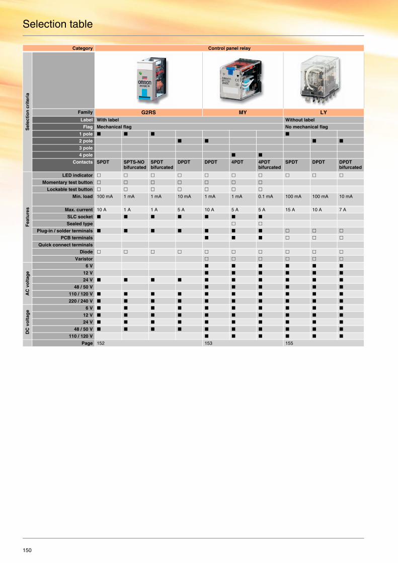
150
Selection table
Category Control panel relay
Sel
ecti
on
cri
teri
a
Family G2RS MY LYLabel With label Without label
Flag Mechanical flag No mechanical flag
1 pole
2 pole
3 pole
4 pole
Contacts SPDT SPTS-NO bifurcated
SPDT bifurcated
DPDT DPDT 4PDT 4PDT bifurcated
SPDT DPDT DPDT bifurcated
Fea
ture
s
LED indicator
Momentary test button
Lockable test button
Min. load 100 mA 1 mA 1 mA 10 mA 1 mA 1 mA 0.1 mA 100 mA 100 mA 10 mA
Max. current 10 A 1 A 1 A 5 A 10 A 5 A 5 A 15 A 10 A 7 A
SLC socket
Sealed type
Plug-in / solder terminals
PCB terminals
Quick connect terminals
Diode
Varistor
AC
vo
ltag
e
6 V
12 V
24 V
48 / 50 V
110 / 120 V
220 / 240 V
DC
vo
ltag
e
6 V
12 V
24 V
48 / 50 V
110 / 120 V
Page 152 153 155

Electromechanical relays
151
Category Control panel relay
Sel
ecti
on
cri
teri
a
Family LY MK-I MK-S G7JLabel Without label Without label
Flag No mechanical flag Mechanical flag
1 pole
2 pole
3 pole
4 pole
Contacts 3PDT 4PDT DPDT 3PDT DPDT 3PDT SPST-NC DPST-NO / -NC
3PDT-NO 4PST-NO
Fea
ture
s
LED indicator
Momentary test button
Lockable test button
Min. load 100 mA 100 mA 10 mA 10 mA 10 mA 10 mA 100 mA 10 mA
100 mA 100 mA 10 mA
100 mA 10 mA
Max. current 10 A 10 A 10 A 10 A 10 A 10 A 8 A 25 A 25 A 25 A
SLC socket
Sealed type
Plug-in / solder terminals
PCB terminals
Quick connect terminals
Diode
Varistor
AC
vo
ltag
e
6 V
12 V
24 V
48 / 50 V
110 / 120 V
220 / 240 V
DC
vo
ltag
e
6 V
12 V
24 V
48 / 50 V
110 / 120 V
Page 155 156 157
Standard Available No / not available

For full specifications and additional models please refer to the (attached) CD or www.europe.omron.comElectromechanical relays - Cat.-No. J140-E2-01152
G2RS Electromechanical relays
Plug-in relays with enhanced features for even more applicationsThe G2RS relay sets new standards in feature design and reliability. These slimline interface relays give enhanced features and flexibility for more user-friendly installation, commissioning and operation. G2RS comes with standard nameplate and mechanical indicator.
• Space saving - 16 mm with socket • SPDT type 10 A, DPDT type 5 A • LED indicator, colour coded green for DC versions, red for AC
versions • Test button, momentary and lockable, blue for DC, red for AC
versions • Screwless clamp-terminal sockets available
Ordering information
Accessories
Specifications
Coil ratings
Technical data
Contact ratings
Contact Form Diode LED indicator Test button Gold Clad 3 um Model(@@@ = Coil Voltage + AC/DC)
Common Coil Voltages *1
*1 Other coil voltages available. Please see specifications
DC AC
SPDT (1 pole) no no no no G2R-1-S@@@(S) 24 230
no yes no no G2R-1-SN@@@(S) 12, 24 24, 110, 230
no yes yes no G2R-1-SNI@@@(S) 24 12, 24, 110, 230
no yes yes yes G2R-1-SNI-AP3@@@(S) 230
yes no no no G2R-1-SD@@@(S) 24
yes yes no no G2R-1-SND@@@(S) 12, 24
yes yes yes no G2R-1-SNDI@@@(S) 24
yes yes yes yes G2R-1-SNDI-AP3@@@(S) 24
DPDT (2 pole) no no no no G2R-2-S@@@(S) 24 24, 110, 240
no yes no no G2R-2-SN@@@(S) 12, 24, 48 24, 110, 230
no yes yes no G2R-2-SNI@@@(S) 12, 24 12, 24, 110, 230
no yes yes yes G2R-2-SNI-AP3@@@(S) 230
yes no no no G2R-2-SD@@@(S) 12, 24
yes yes no no G2R-2-SND@@@(S) 12, 24
yes yes yes no G2R-2-SNDI@@@(S) 12, 24
yes yes yes yes G2R-2-SNDI-AP3@@@(S) 24
Contact form Surface-mounting socket DIN-rail Back-mounting socket
Screw-less clamp terminal Clip for screw-less clamp terminal Screw terminal PCB terminals
SPDT (1 pole) P2RF-05S (R99-11name plate (option)) P2CM-S (option) P2RF-05-E P2R-05P
DPDT (2 pole) P2RF-08S (R99-11name plate (option)) P2CM-S (option) P2RF-08-E P2R-08P
Rated voltage Must operate voltage Must release voltage Max. voltage Power consumption (approx.)% of rated voltage
AC 24 V, 110 V, 120 V,230 V, 240 V 80% max. 30% max. 110% 0.9 VA (60 Hz)
DC 6 V, 12 V, 24 V, 48 V 70% max. 15% max. 110% 0.53 W
Item 1-pole 2-pole
Operating time 15 ms max. 15 ms max.
Release time AC: 10 ms max., DC: 5 ms max. AC: 15 ms max., DC: 10 ms max.
Dielectric strength 5,000 VAC (coil-contact) 5,000 VAC (coil-contact)
Ambient temperature Operating: -40 °C to 70 °C (no icing or condensation)
Size in mm 35.5Hx13Wx29D
Number of poles 1-pole 2-pole
Load Resistive load Inductive load Resistive load Inductive load
Rated load 10 A at 250 VAC10 A at 30 VDC
7.5 A at 250 VAC5 A at 30 VDC
5 A at 250 VAC5 A at 30 VDC
2 A at 250 VAC3 A at 30 VDC
Rated carry current 10 A 5 A
Max. switching voltage 440 VAC, 125 VDC 380 VAC, 125 VDC
Max. switching current 10 A 5 A
Max. switching power 2,500 VA, 300 W 1,875 VA, 150 W 1,250 VA, 150 W 500 VA, 90 W
Failure rate (reference value) 100 mA at 5 VDC 10 mA at 5 VDC
Mechanical life AC: 10,000,000 operations min., DC: 20,000,000 operations min.
Electrical life 100,000 operations min.
LR

For full specifications and additional models please refer to the (attached) CD or www.europe.omron.comElectromechanical relays - Cat.-No. J03-EN-01B 153
MY Electromechanical relays
Versatile plug-in relay that sets the standardSince they were first introduced, over 500 million of these mini power relays have rolled off the production line. This truly versatile relay has become the standard, bringing enhanced features and flexibility for more user-friendly installation, commissioning and operation.
• 10 A (DPDT) and 5 A (4PDT) contact types, gold-clad contacts (MY4)
• Mechanical and LED indication • Push-to-test button - momentary and lockable • Labelling facility • Hermetically sealed (MYH) and latching (MY2K) and PCB types
available
Ordering information
Note: - MY4 also available with bifurcated contacts => example MY4Z- MY2 and MY4 AC 110/120, 220/240 types also available with suppression => example MY4N-CR
Accessories
Contact Form Diode LED indicator
Lockable test button
Model(@@@ = Coil Voltage + AC/DC)
Common Coil Voltages *1
*1 Other coil voltages available. Please see specification.
Standard Coil Polarity Reversed Coil Polarity DC AC
DPDT no no no MY2@@@(S) 12, 24 12, 24, 110/120, 220/240
yes MY2N@@@(S) 24 24, 220/240
yes MY2IN@@@(S) 12,24 24, 110/120, 220/240
yes no MY2N-D2@@@(S) 24
yes MY2IN-D2@@@(S 24
no MY2IN1@@@(S) 24
4PDT no no MY4@@@(S) 12, 24, 48 100/110 12, 24, 48/50, 110/120, 220/240
yes MY4N@@@(S) 12, 24, 100/110 24, 110/120, 220/240
yes MY4IN@@@(S) 12, 24 12, 24, 48/50, 110/120, 220/240
MY4IN1@@@(S) 24
yes no MY4N-D2@@@(S) 12, 24
yes MY4IN-D2@@@(S) 24
MY4IN1-D2@@@(S) 24, 48
Contact form Front Mounting SocketDIN-rail Screwless Clamp
Clip for Screw-lessclamp terminal
Label Socket bridge
DPDT (2 pole) PYF08S PYCM08S R99-11 name plate (option) PYDM-08SR / SB
4DPDT (4 pole) PYF14S PYCM14S R99-11 name plate (option) PYDM-14SR / SB
Contact form Front Mounting SocketDIN-rail / Screw mounting
Metal Spring Clip Plastic Holding Clip Label
Input Common / NO-NC Out- / input separated
DPDT (2 Pole) PYF14-ESN PYF14-ESS PYC-0 PYC-35 PYC TR1
4PDT (4 pole) PYF14-ESN PYF14-ESS PYC-0 PYC-35 PYC TR1
DPDT (2 Pole) PYF08A-E / PYF08A-N *1
4PDT (4 pole) PYF14A-E / PYF14A-N *1
*1 Clip PYC-A1 (option), except MY2IN type, these use clip PYC-E1 (option).
LRS

MY Electromechanical relays
154
Specifications
Coil ratings
Contact ratings
Technical data
Rated voltage Must operate voltage Must release voltage Max. voltage Power consumption (approx.)
% of rated voltage
AC 6 V, 12 V, 24 V, 48 / 50 V 80% max 30% min. 110% 1.0 to 1.2 VA (60 Hz)
110 / 120 V, 220 / 240 V 0.9 to 1.1 VA (60 Hz)
DC 6 V, 12 V, 24 V, 48 V, 100 / 110 V 10% min. 0.9 W
Item 2-pole 4-pole 4-pole (bifurcated)
Resistive load Inductive load Resistive load Inductive load Resistive load Inductive load
Rated load 5 A at 250 VAC 2 A at 250 VAC 3 A at 250 VAC 0.8 A at 250 VAC 3 A at 250 VAC 0.8 A at 250 VAC
5 A at 30 VDC 2 A at 30 VDC 3 A at 30 VDC 1.5 A at 30 VDC 3 A at 30 VDC 1.5 A at 30 VDC
Rated carry current 10 A 5 A
Max. switching voltage 250 VAC, 125 VDC 250 VAC, 125 VDC
Max. switching current 10 A 5 A
Max. switching power 2,500 VA, 300 W 1,250 VA, 300 W 1,250 VA, 150 W 500 VA, 150 W 1,250 VA, 150 W 500 VA, 150 W
Failure rate (reference value) 5 VDC at 1 mA 1 VDC at 1 mA 1 VDC at 100 µA
Mechanical life AC: 50,000,000 operations min., DC: 100,000,000 operations min. 20,000,000 operations min.
Electrical life 500,000 operations min. 200,000 operations min. 100,000 operations min.
Operating time 20 ms max.
Release time 20 ms max.
Dielectric strength 2,000 VAC
Ambient temperature Operating: -55 °C to 70 °C (no icing)
Size in mm 28Hx21.5Wx36D

For full specifications and additional models please refer to the (attached) CD or www.europe.omron.comElectromechanical relays - Cat.-No. J002-E2-10 155
LY Electromechanical relays
A miniature power relayThe LY series is equipped with arc barrier and built-in diode. LY comes in single-, double-, three- and four-pole models. The available mounting types are DIN-rail by socket, PCB & flange mounting.
• SPDT, DPDT, 3PDT and 4PDT contact types• DIN-rail by socket, PCB and flange mounting types available • 10 A rated load
Ordering information
Accessories
Specifications
Contact ratings
Contact form LED indicator
Diode Terminals Model *1
(@@@ = Coil Voltage + AC/DC)
*1 For other options like CR suppression please see specifications.
Common Coil Voltages*2
*2 Other coil voltages available. Please see specification.
Plug-in / Solder
PCB Upper-MountingPlug-in/solder
DC AC
DPDT (2 Pole) no no no yes no LY2-0@@@ 24
yes no LY2@@@ 12, 24 12, 24, 48, 100/110, 110/120, 220/240
no yes LY2F@@@ 220/240
yes yes no LY2N@@@ 24
yes LY2N-D2@@@ 24
3PDT (3 Pole) no no LY3@@@ 24
4PDT (4 Pole) LY4@@@ 12, 24, 100/110, 125 24, 100/110, 230
yes yes LY4N-D2@@@ 24 n/a
Contact form Model
Front-connecting socket for DIN-rail / Screw terminals
Clip Back Connecting socket
Plug-in/solder terminals PCB Terminals
SPDT / DPDT (1, 2 Pole) PTF08A-E PYC-A1 PT08 PT08-0
3PDT (3 Pole) PTF11-A PYC-A1 PT11 PT11-0
4PDT (4 Pole) PTF14A-E PYC-A1 PT14 PT14-0
Relay Single contact 1-pole Single contact 2-,3- or 4-pole Bifurcated contacts 2-pole
Load Resistive load Inductive load Resistive load Inductive load Resistive load Inductive load
Rated load 110 VAC at 15 A 110 VAC at 10 A 110 VAC at 10 A 110 VAC at 7.5 A 110 VAC at 5 A 110 VAC at 4 A
24 VDC at 15 A 24 VDC at 7 A 24 VDC at 10 A 24 VDC at 5 A 24 VDC at 5 A 24 VDC at 4 A
Rated carry current 15 A 10 A 7 A
Max. switching voltage 250 VAC, 125 VDC 250 VAC, 125 VDC 250 VAC, 125 VDC
Max. switching current 15 A 10 A 7 A
Max. switching power 1,700 VA 1,100 VA 1,100 VA 825 VA 550 VA 440 VA
360 W 170 W 240 W 120 W 120 W 100 W
10 mA at 5 VDC
Failure rate (reference value) 100 mA at 5 VDC
Mechanical life AC: 50,000,000 operations min., DC: 100,000,000 operations min.
1-, 2-, 4-pole: 200,000 operations min., 2-pole: 500,000 operations min.
Coil ratingsPoles Rated voltage Must
operate voltage
Must release voltage
Max. voltage
Power consumption (approx.)
% of rated voltage
1 or 2 AC 6 V, 12 V, 24 V, 50 V 80% max.
30% min. 110% 1.0 to 1.2 VA (60 Hz)
100 / 110 V, 110 / 120 V, 200 / 220 V, 220 / 240 V 0.9 to 1 VA (60 Hz)
DC 6 V, 12 V, 24 V, 48 V, 100 / 110 V 10% min. 0.9 W
3 AC 6 V, 12 V, 24 V, 50 V, 100 / 110 V, 200 / 220 V 80% max.
30% min. 110% 1.6 to 2.0 VA (60 Hz)
DC 6 V, 12 V, 24 V, 48 V, 100 / 110 V 10% min 1.4 W
4 AC 6 V, 12 V, 24 V, 50 V, 100 / 110 V, 200 / 220 V 80% max.
30% min. 110% 1.95 to 2.5 VA (60 Hz)
DC 6 V, 12 V, 24 V, 48 V, 100 / 110 V 10% min 1.5 W
Technical dataOperating time 25 ms max.
Release time 25 ms max.
Dielectric strength 1,000 VAC
Ambient temperature *1
*1 See datasheet for more details.
-25 °C to 70 °C
S LR

For full specifications and additional models please refer to the (attached) CD or www.europe.omron.comElectromechanical relays - Cat.-No. J011-E2-06156
MK-I-S Electromechanical relays
Exceptionally reliable general-purpose relayThe MK relay breaks relatively large load currents despite its small size. The silver contacts ensure a long life (min. 100,000 operations). Standard models are UL, CSA, SEV, DEMKO, NEMKO, SEMKO, TÜV (IEC) and VDE and conform to CENELEC standards.
• 8-pin DPDT and 11-pin 3PDT contact types • Mechanical indicator and LED indicators • Push-to-test button • Diode and varistor surge suppression • 10 A rated load
Ordering information
Accessories
Specifications
Coil ratings
Contact ratings Technical data
Contact Form Mechanical Indicator & Push to Test Button & Dust Cover
LED Indicator Diode Model *1
(@@@ = Coil Voltage + AC/DC)
*1 Many various terminal arrangements possible please see specifications.
Common Coil Voltages *2
*2 Other coil voltages available. Please see specifications.
DC AC
DPDT (2 Pole) yes no no MK2P-S@@@ 12, 24, 110, 24, 110, 230
yes MK2PN-S@@@ 24 24, 230
3PDT (3 Pole) no MK3P5-S@@@ 12, 24, 48, 110 12, 24, 110, 230
yes MK3PD-5-S@@@ 24
yes no MK3PN-5-S@@@ 12, 24 24, 110, 230
yes MK3PND-5-S@@@ 24
Contact Form Surface Mounting Socket for DIN-rail / Screw mounting Clip
DPDT (2 Pole) PF083A-E PFC-A1
3PDT (3 Pole) PF113A-E PFC-A1
Rated voltage Must operate voltage Must release voltage Max. voltage Power consumption (approx.)% of rated voltage
AC 6 V, 12 V, 24 V, 50 V, 100 V, 110 V 80% max. 30% min. 90% to 110% 2.3 VA (60 Hz)
120 V, 200 V, 220 V, 230 V, 240 V 2.7 VA (50 Hz)
DC 6 V, 12 V, 24 V, 48 V, 100 V, 110 V 15% min. 1.5 W
Load 2- or 3-pole
Resistive load Inductive load
Contact material Ag
Rated load 10 A at 250 VAC 7 A at 250 VAC
10 A at 28 VDC
Rated carry current 10 A
Max. switching voltage 250 VAC, 250 VDC
Max. switching current 10 A
Max. switching power 2,500 VA, 280 W 1,750 VA
Mechanical life 10,000,000 operations min.
Operating time AC: 20 ms max., DC: 30 ms max.
Release time 20 ms max.
Dielectric strength 2,500 VAC (coil-contact)
Ambient temperature Operating: -10 °C to 40 °C (no icing or condensation)
Size in mm 34.5Hx34.5Wx52.5D

For full specifications and additional models please refer to the (attached) CD or www.europe.omron.comElectromechanical relays - Cat.-No. J088-E2-03 157
G7J Electromechanical relays
A high-capacity multi-pole relay used like a contactorWith a rated load current of 25 A due to the miniature hinge for maximum switching power, the G7J can switch both motor loads as well as resistive and inductive loads. G7J has no contact chattering for momentary voltage drops up to 50% of its rated voltage.
• 4PST-NO, 3PST-NO/SPST-NC or DPST-NO/DPST-NC contact types
• Quick-connect, PCB or screw terminals • 25 A rated load • Compatible with momentary voltage drops • Can be used like a contactor
Ordering information
Accessories
Specifications
Coil ratings
Contact ratings Technical data
Contact form Mounting Terminal *1
*1 Quick-connect also available for W-Bracket mounting upon request.
Model *2 (@@@= Coil Voltage + AC/DC)
*2 For other options like Bifurcated Contacts please see specifications.
Common Coil Voltages *3
*3 Other coil voltages available. Please see specifications.
PCB W-bracket mounting
PCB Screw DC AC
4PST-NO yes no yes no G7J-4A-P@@@ 24 200/240
no yes no yes G7J-4A-B@@@ 24
3PST-NO / SPST-NC yes no yes no G7J-3A1B-P@@@ 24
no yes no yes G7J-3A1B-B@@@ 24
DPST-NO / DPST-NC yes no yes no G7J-2A2B-P@@@ 24
Name Model Applicable relay
W-bracket R99-04 for G5F G7J4-A-B, G7J-3A1B-B, G7J-4A-T,G7J-3A1B-T, G7J-2A2B-T
Rated voltage Must operate voltage Must release voltage Max. voltage Power consumption (approx.)% of rated voltage
AC 24, 50, 100 to 120, 200 to 240 75% max. 15% min. 110% 1.8 to 2.6 VA
DC 6, 12, 24, 48, 100 10% min. 2.0 W
Item 4-pole
Resistive load Inductive load Resistive load
Contact material Ag alloy
Rated load NO: 25 A at 220 VAC (24 A at 230 VAC)NC: 8 A at 220 VAC (7.5 A at 230 VAC)
NO: 25 A at 30 VDCNC: 8 A at 30 VDC
Rated carry current NO: 25 A (1 A), NC: 8 A (1 A)
Max. switching voltage 250 VAC 125 VDC
Max. switching current NO: 25 A (1 A), NC: 8 A (1 A)
Mechanical life 1,000,000 operations min.
Electrical life 100,000 operations min.
Operating time 50 ms max.
Release time 50 ms max.
Dielectric strength 4,000 VAC
Ambient temperature Operating: -25 °C to 60 °C (no icing)

158
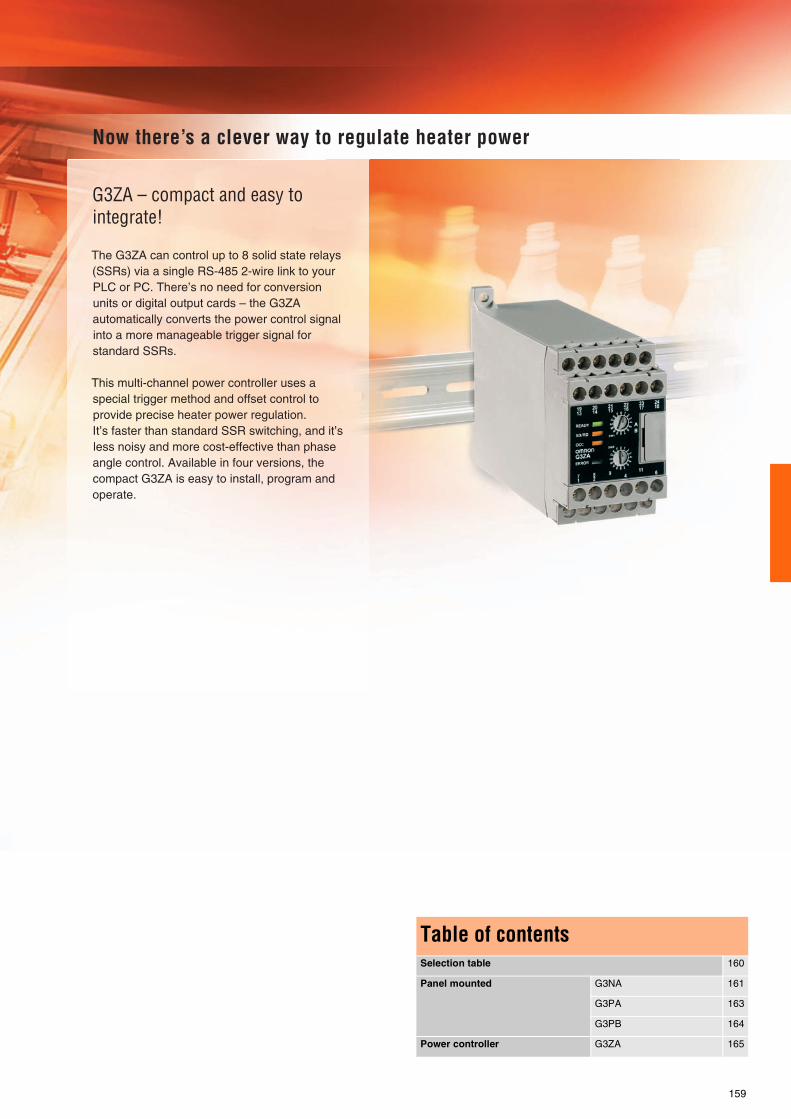
159
Table of contentsSelection table 160
Panel mounted G3NA 161
G3PA 163
G3PB 164
Power controller G3ZA 165

160
Category Control panel mounting type Power regulator
Sel
ecti
on
cri
teri
a
Model G3NA G3PA G3PB G3PB G3ZAType of load Normal resistors
Middle and long wave IR heaterTransformers and inductors
Normal resistorsMiddle and long wave IR heater
Normal resistors Depends on the SSR usedDistributes loop / control output levels (mV%) to SSRs
1-phase control Depends on the SSR used
2-phase control Depends on the SSR used
3-phase control Depends on the SSR used
Function Heater control, motor control
Heater control Heater control Heater control Intelligent power control
Max. current rating 50 A 60 A 45 A 45 A Depends on the SSR used
Lo
ad v
olt
age
/ cu
rren
t [V
AC
] 24 to 240
100 to 240
200 to 480 400 to 480
Lo
ad v
olt
age
/ cu
rren
t [V
DC
] 5 to 200
Inp
ut v
olt
ages
[V
DC
or
VA
C] 5 to 24 VDC
12 to 24 VDC
24 VAC
100 to 120 VAC
200 to 240 VAC
Fea
ture
s
Built-in heat sink
Zero-cross
Built-in varistor
LED operation indicator
Protective cover
3-phase loads via3 single-phase SSRs
Replaceablepower cartridge
Alarm output
Built-in failure detection
SSR open circuitsdetection
SSR short circuitsdetection
Mo
un
tin
g DIN-rail
Screw
Page 161 163 164 165
Standard Available No / not available
Selection table Solid state relays

For full specifications and additional models please refer to the (attached) CD or www.europe.omron.comSolid state relays - Cat.-No. J146-E2-01 161
G3NA Solid state relays
A wide range of models with 5 to 90 A output currentsAll models feature the same compact dimensions to provide a uniform mounting pitch. A built-in varistor effectively absorbs external surges. The operation indicator enables monitoring operation.
• 5 - 90 A output current • 24 - 480 VAC / 5 - 200 VDC output voltages • Built-in varistor • Operation indicator (red LED) • Protective cover for greater safety
Ordering information
Accessories
Applicable output load
Zero cross function
Isolation Rated input voltage
Must operate voltage
Must release voltage
Load current with / without heatsink at 40 °C
Model
24 to 240 VAC 5 A Yes Phototriac 5 to 24 VDC 4 VDC max. 1 VDC min. 0.1 - 5 A / 0.1 - 3 A G3NA-205B-UTU DC5-24
Photocoupler 100 to 120 VAC 75 VAC max. 20 VAC min. G3NA-205B-UTU AC100-120
200 to 240 VAC 150 VAC max. 40 VAC min. G3NA-205B-UTU AC200-240
10 A Phototriac 5 to 24 VDC 4 VDC max. 1 VDC min. 0.1 - 10 A / 0.1 - 4 A G3NA-210B-UTU DC5-24
Photocoupler 100 to 120 VAC 75 VAC max. 20 VAC min. G3NA-210B-UTU AC100-120
200 to 240 VAC 150 VAC max. 40 VAC min. G3NA-210B-UTU AC200-240
20 A Phototriac 5 to 24 VDC 4 VDC max. 1 VDC min. 0.1 - 20 A / 0.1 - 4 A G3NA-220B-UTU DC5-24
Photocoupler 100 to 120 VAC 75 VAC max. 20 VAC min. G3NA-220B-UTU AC100-120
200 to 240 VAC 150 VAC max. 40 VAC min. G3NA-220B-UTU AC200-240
40 A Phototriac 5 to 24 VDC 4 VDC max. 1 VDC min. 0.1 - 40 A / 0.1 - 6 A G3NA-240B-UTU DC5-24
Photocoupler 100 to 120 VAC 75 VAC max. 20 VAC min. G3NA-240B-UTU AC100-120
200 to 240 VAC 150 VAC max. 40 VAC min. G3NA-240B-UTU AC200-240
75 A Phototriac 5 to 24 VDC 4 VDC max. 1 VDC min. 1 - 75 A / 1 - 7 A G3NA-275B-UTU DC5-24
Photocoupler 100 to 240 VAC G3NA-275B-UTU AC100-240
90 A Phototriac 5 to 24 VDC 1 - 90 A / 1 - 7 A G3NA-290B-UTU DC5-24
Photocoupler 100 to 240 VAC G3NA-290B-UTU AC100-240
5 to 200 VDC 10 A No Photocoupler 5 to 24 VDC 4 VDC max. 1 VDC min. 0.1 - 10 A / 0.1 - 4 A G3NA-D210B-UTU DC5-24
100 to 240 VAC 75 VAC max. 20 VAC min. G3NA-D210B-UTU AC100-240
200 to 480 VAC 10 A Yes 5 to 24 VDC 4 VDC max. 1 VDC min. 0.2 - 10 A / 0.2 - 4 A G3NA-410B DC5-24
100 to 240 VAC 75 VAC max. 20 VAC min. G3NA-410B AC100-240
20 A 5 to 24 VDC 4 VDC max. 1 VDC min. 0.2 - 20 A / 0.2 - 4 A G3NA-420B DC5-24
100 to 240 VAC 75 VAC max. 20 VAC min. G3NA-420B AC100-240
40 A 5 to 24 VDC 4 VDC max. 1 VDC min. 0.2 - 40 A / 0.2 - 6 A G3NA-440B DC5-24
100 to 240 VAC 75 VAC max. 20 VAC min. G3NA-440B AC100-240
50 A 5 to 24 VDC 4 VDC max. 1 VDC min. 0.2 - 50 A / 0.2 - 6 A G3NA-450B DC5-24
75 A 5 to 24 VDC 75 VAC max. 20 VAC min. 1 - 75 A / 1 - 7 A G3NA-475B-UTU DC5-24
100 to 240 VAC G3NA-475B-UTU AC100-240
90 A 5 to 24 VDC 1 - 90 A / 1 - 7 A G3NA-490B-UTU DC5-24
100 to 240 VAC G3NA-490B-UTU AC100-240
Bold = preferred stock item
Name Model Applicable SSRs
One-touch mounting plates R99-12 FOR G3NA
Mounting bracket R99-11 FOR G3NA G3NA-240B, G3NA-440B
Slim models enabling DIN-rail mounting Y92B-N50 G3NA-205B, G3NA-210B, G3NA-D210B, G3NA-410B
Y92B-N100 G3NA-220B, G3NA-420B
Y92B-N150 G3NA-240B, G3NA-440B
Slim models enabling DIN-rail mounting Y92B-P250 G3NA-450B
Y92B-P250NF G3NA-275B-UTU, G3NA-290B-UTU, G3NA-475B-UTU, G3NA-490B-UTU
Low-cost models Y92B-A100 G3NA-205B, G3NA-210B, G3NA-D210B, G3NA-220B, G3NA-410B, G3NA-420B
Y92B-A150N G3NA-240B, G3NA-440B
Y92B-A250 G3NA-440B
Bold = preferred stock item

G3NA Solid state relays
162
Specifications
Operating voltage range 5 to 24 VDC: 4 to 32 VDC100 to 120 VAC: 75 to 132 VAC200 to 240 VAC: 150 to 264 VAC
Output ON voltage drop G3NA-2: 1.6 V (RMS) max.G3NA-4: 1.8 V (RMS) max.G3NA-D2: 1.5 V max.
Leakage current 5 mA (100 V) / 10 mA (200 V)G3NA-D2: 5 mA max. (200 VDC)
Load voltage range 200 to 480 VAC: 180 to 528 VAC24 to 240 VAC: 19 to 264 VAC5 to 200 VDC: 4 to 220 VDC
Ambient temperature Operating: -30 to 80 °C
Operate & release time 1/2 of load power source cycle + 1 ms max. (DC input)1/2 of load power source cycle + 1 ms max. (DC input)
G3NA-D2 1 ms max. (DC input; release 5 ms), 30 ms max. (AC input)
Size in mm 58Hx43Wx27D

For full specifications and additional models please refer to the (attached) CD or www.europe.omron.comSolid state relays - Cat.-No. K094-E2-06 163
G3PA Solid state relays
Extremely thin relays with integrated heat sinksOptimum design of the heat sink has contributed to the downsizing of this product. The power element cartridges of G3PA are easily replace-able for easy maintenance. G3PA can be mounted on a DIN-rail or us-ing screws.
• 10 - 50 A output current • 240 - 480 VAC output voltages • Applicable with 3-phase loads • Replaceable power element cartridges • All features can be delivered with or without heat sink
Ordering information
Accessories
Specifications
Rated output load Zero cross function
Rated input voltage
Rated voltage
Operating voltage range
Input current impedance
Voltage level Size in mm (HxWxD)
Model
Must operate voltage
Must release voltage
24 to 240 VAC 10 A Yes 5 to 24 VDC 5 to 24 VDC 4 to 30 VDC 7 mA max. 4 VDC max. 1 VDC min. 100x27x100 G3PA-210B-VD DC5-24
20 A 100x37x100 G3PA-220B-VD DC5-24
40 A 100x47x100 G3PA-240B-VD DC5-24
60 A 100x110x100 G3PA-260B-VD DC5-24
10 A 24 VAC 24 VAC 19.2 to 26.4 VAC
1.4 kΩ ±20% 19.2 VAC max. 4.8 VAC min. 100x27x100 G3PA-210B-VD AC24
20 A 100x37x100 G3PA-220B-VD AC24
40 A 100x47x100 G3PA-240B-VD AC24
60 A 100x110x100 G3PA-260B-VD AC24
180 to 400 VAC 20 A 12 to 24 VDC 12 to 24 VDC 9.6 to 30 VDC
7 mA max. 9.2 VDC max. 1 VDC min. 100x37x100 G3PA-420B-VD DC12-24
30 A 100x47x100 G3PA-430B-VD DC12-24
200 to 480 VAC 20 A 100x37x100 G3PA-420B-VD-2 DC12-24
30 A 100x47x100 G3PA-430B-VD-2 DC12-24
50 A 100x110x100 G3PA-450B-VD-2 DC12-24
Bold = preferred stock item
Replacement parts: power device cartridges
Carry current
Load voltage range
Model Applicable SSR
10 A 19 to 264 VAC G32A-A10-VD DC5-24 G3PA-210B-VD DC5-24
G32A-A10-VD AC24 G3PA-210B-VD AC24
20 A G32A-A20-VD DC5-24 G3PA-220B-VD DC5-24
G32A-A20-VD AC24 G3PA-220B-VD AC24
40 A G32A-A40-VD DC5-24 G3PA-240B-VD DC5-24
G32A-A40-VD AC24 G3PA-240B-VD AC24
60 A G32A-A60-VD DC5-24 G3PA-260B-VD DC5-24
G32A-A60-VD AC24 G3PA-260B-VD AC24
Replacement parts: power device cartridges
Carry current
Load voltage range
Model Applicable SSR
20 A 150 to 440 VAC
G32A-A420-VD DC12-24 G3PA-420B-VD DC12-24
30 A G32A-A430-VD DC12-24 G3PA-430B-VD DC12-24
20 A 180 to 528 VAC
G32A-A420-VD-2 DC12-24 G3PA-420B-VD-2 DC12-24
30 A G32A-A430-VD-2 DC12-24 G3PA-430B-VD-2 DC12-24
50 A G32A-A450-VD-2 DC12-24 G3PA-450B-VD-2 DC12-24
Bold = preferred stock item
Current flow Model Applicable SSR
10 A G32A-D20 G3PA-210B-VD, G3PA-210BL-VD, G3PA-220B-VD, G3PA-220BL-VD, G3PA-420B-VD, G3PA-420B-VD-2
20 A
30 A G32A-D40 G3PA-430B-VD, G3PA-430B-VD-2, G3PA-240B-VD, G3PA-240BL-VD40 A
Isolation Phototriac coupler
Indicator Yes
Ambient temperature Operating: -30 °C to 80 °C
Load voltage range 200 - 480 VAC: 180 to 528 VAC24 - 240 VAC: 19 to 264 VAC180 to 400 VAC: 150 to 440 VAC
Output ON drop 1.6 V (RMS) max.
Operate time 0.5 of load power source cycle + 1 ms max. (DC input, -B models)1.5 of load power source cycle + 1 ms max. (AC input) 1 ms max. (-BL models)
Release time 0.5 of load power source cycle + 1 ms max. (DC input)1.5 of load power source cycle + 1 ms max. (AC input)

For full specifications and additional models please refer to the (attached) CD or www.europe.omron.comSolid state relays - Cat.-No. J152-E2-01A164
G3PB Solid state relays
Compact, slim-profile SSR with heat sink for heater controlThe compact design of G3PB has been achieved by optimising the shape of the heat sink. The G3PB range provides you with a choice between DIN-rail mounting and screw mounting.
• Single and three phase, 15 - 45 A output current • 100 - 480 VAC output voltages • Applicable with 1-, 2- and 3-phase loads • All features can be delivered with or without heat sink • Conforms to CE marking, EN (VDE approval), CSA
and VDE standards
Ordering information
Specifications
Phases Main circuit voltage Rated output load
Applicable load current (at 40 °C)
Permissible I2t (half 60 Hz wave)
Applicable heater capacity (with class -1 AC resistive load)
Size in mm (HxWxD)
Number of poles
Model number
1 100 to 240 VAC 15 A 0.1 - 15 A 128 A2s 6 kW max. 100x22.5x100 G3PB-215B-VD DC12-24
25 A 0.1 - 25 A 1,350 A2s 10 kW max. G3PB-225B-VD DC12-24
35 A 0.5 - 35 A 14 kW max. 100x44.5x100 G3PB-235B-VD DC12-24
45 A 0.5 - 45 A 18 kW max. G3PB-245B-VD DC12-24
200 to 480 VAC 15 A 0.1 - 15 A 128 A2s 6 kW max. 100x22.5x100 G3PB-515B-VD DC12-24
25 A 0.1 - 25 A 1,350 A2s 10 kW max. G3PB-525B-VD DC12-24
35 A 0.5 - 35 A 14 kW max. 100x44.5x100 G3PB-535B-VD DC12-24
45 A 0.5 - 45 A 18 kW max. G3PB-545B-VD DC12-24
3 100 to 240 VAC 15 A 0.2 - 15 A 260 A2s 5.1 kW max. 150.5x80x150.5 3 G3PB-215B-3N-VD DC12-24
2 G3PB-215B-2N-VD DC12-24
25 A 0.2 - 25 A 2,660 A2s 8.6 kW max. 150.5x80x150.5 3 G3PB-225B-3N-VD DC12-24
2 G3PB-225B-2N-VD DC12-24
35 A 0.5 - 35 A 12.1 kW max. 150.5x80x150.5 3 G3PB-235B-3N-VD DC12-24
2 G3PB-235B-2N-VD DC12-24
45 A 0.5 - 45 A 15.5 kW max. 150.5x110x150.5 3 G3PB-245B-3N-VD DC12-24
150.5x80x150.5 2 G3PB-245B-2N-VD DC12-24
200 to 480 VAC 15 A 0.5 - 15 A 260 A2s 12.5 kW max. 150.5x80x150.5 3 G3PB-515B-3N-VD DC12-24
2 G3PB-515B-2N-VD DC12-24
25 A 0.5 - 25 A 1,040 A2s 20.7 kW max. 150.5x80x150.5 3 G3PB-525B-3N-VD DC12-24
2 G3PB-525B-2N-VD DC12-24
35 A 0.5 - 35 A 29.0 kW max. 150.5x80x150.5 3 G3PB-535B-3N-VD DC12-24
2 G3PB-535B-2N-VD DC12-24
45 A 0.5 - 45 A 37.4 kW max. 150.5x110x150.5 3 G3PB-545B-3N-VD DC12-24
150.5x80x150.5 2 G3PB-545B-2N-VD DC12-24
Bold = preferred stock item
Rated input voltage 12 to 24 VDC
Operating voltage range 9.6 to 30 VDC
Rated input current (impedance) 10 mA max. (at 24 VDC)
Zero cross function Yes
Must operate voltage 9.6 VDC max.
Must release voltage 1 VDC min.
Isolation method Phototriac coupler
Operation indicator Yes (yellow)
Load voltage range 200 to 480 VAC models: 180 to 528 VAC100 to 240 VAC models: 75 to 264 VAC
Operate time 1/2 of load power source cycle +1 ms max.
Release time 1/2 of load power source cycle +1 ms max.
Leakage current 10 mA (at 200 VAC)
Ambient temperature Operating: -30 °C to 80 °C

For full specifications and additional models please refer to the (attached) CD or www.europe.omron.comSolid state relays - Cat.-No. J147-E2-01A 165
G3ZA Solid state relays
Multi-channel power controller = smarter SSR usageThe G3ZA receives manipulated variables generated by control loops or manual settings via a simple-to-wire RS-485. It regulates the heater power with high precision by driving up to eight standard SSRs. Moreover, the offset control reduces peak power in the supply net.
• Multi-channel power controller • Controls up to eight standard solid state relays • Easy integration with PLC • Compact size • Available with heater alarms (four channels)
or without (eight channels)
Ordering information
Accessories
Specifications
Optimum cycle control
• Optimum cycle control is performed by driving SSRs according to load power detection and trigger signals. (Zero-cross SSRs are used.)• Noise is suppressed while ensure high-speed response by turning outputs ON and OFF each half cycle to achieve high-precision temperature
control.
Name Number of control channels Heater burnout detection Load power supply voltage Model
Multi-channel power controller 4 Supported 100 to 240 VAC G3ZA-4H203-FLK-UTU
400 to 480 VAC G3ZA-4H403-FLK-UTU
8 Not supported 100 to 240 VAC G3ZA-8A203-FLK-UTU
400 to 480 VAC G3ZA-8A403-FLK-UTU
Name Hole diameter Model
Current transformer (CT) 5.8 dia. E54-CT1
12.0 dia. E54-CT3
Bold = preferred stock item
Item Load power supply voltage range
100 to 240 VAC 400 to 480 VAC
Power supply voltage 100 to 240 VAC (50 / 60 Hz)
Operating voltage range 85 to 264 VAC
Power consumption 16 VA max.
Load power supply voltage 100 to 240 VAC 400 to 480 VAC
Load power supply voltage range 75 to 264 VAC 340 to 528 VAC
Manipulated variable input 0.0% to 100.0% (via RS-485 communications)
Current transformer input Single-phase AC, 0 to 50 A (primary current of CT)
Trigger output One voltage output for each channel, 12 VDC ±15%, max. load current: 21 mA (with built-in short-circuit protection circuit)
Alarm output NPN open collector, one outputMax. applicable voltage: 30 VDC Max. load current: 50 mAResidual voltage: 1.5 V max.Leakage current: 0.4 mA max.
Indications LED indicators
Ambient operating temperature -10 °C to 55 °C (with no icing or condensation)
Ambient operating humidity 25% to 85%
Storage temperature -25 °C to 65 °C (with no icing or condensation)
Performance
Current indication accuracy ±3 A (for models with heater burnout detection)
Insulation resistance 100 MΩ min. (at 500 VDC) between primary and secondary
Dielectric strength 2,000 VAC, 50 / 60 Hz for 1 min between primary and secondary
Vibration resistance Vibration frequency: 10 to 55 Hz, acceleration: 50 m/s2 in X, Y, and Z directions
Shock resistance 300 m/s2 three times each in six directions along three axes
Weight Approx. 200 g (including terminal cover)
Degree of protection IP20
Memory protection EEPROM (non-volatile memory) (number of writes: 100,000)
Installation environment Overvoltage category III, pollution degree 2 (according to IEC 60664-1)
Approved standards UL508 (Listing), CSA22.2 No. 14EN50178EN61000-6-4 (EN55011: 1998, A1: 1999 Class A, Group 1) EN61000-6-2: 2001
Size in mm 76Hx45Wx111D
SW2
SW1
ERROR
OCC
SD/RD
READY
G3ZA-8 SSR SSR SSR SSR
8 total
Programmable Controller
RS-485 commands
Serial Communications Unit (RS-485)
Multi-channelPower Controller
1/5th ON (20%)
Manipulatedvariable: 20%

166
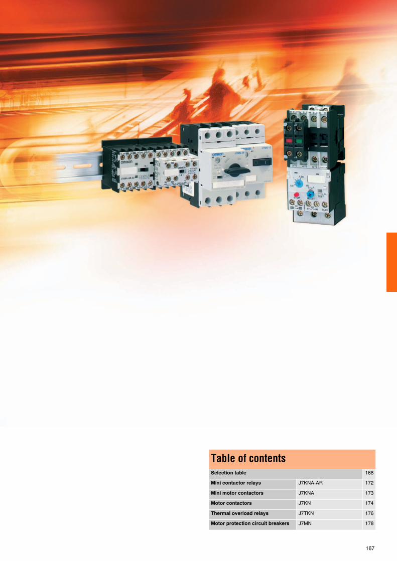
167
Table of contentsSelection table 168
Mini contactor relays J7KNA-AR 172
Mini motor contactors J7KNA 173
Motor contactors J7KN 174
Thermal overload relays J7TKN 176
Motor protection circuit breakers J7MN 178

168
Selection table
Category Mini contactor relay
Sel
ecti
on
cri
teri
a
Model J7KNA-AR-40 J7KNA-AR-31 J7KNA-AR-22Mounting 35 mm DIN-rail or base
Distinction numberaccording to EN 50011
40E 31E 22E
AC15 230 V [A] 3 3 3AC15 400 V [A] 2 2 2
Thermal rated current Ie [A] 10 10 10Thermal overload relay
Au
xilia
ry
con
tact
s Integrated auxiliary contacts 4 NO 3 NO + 1 NC 2 NO + 2 NCAdditional auxiliary
contacts blockJ73-KN-A-11 (1 NO + 1 NC)J73-KN-A-02 (2 NC)J73-KN-A-40 (4 NO)
AC
po
wer
co
nsu
mp
-ti
on
of c
oils
Inrush [VA] 25 25 25
Sealed [VA] 4 - 5 4 - 5 4 - 5
DC
po
wer
co
nsu
mp
-ti
on
of c
oils
Inrush [W] 2.5 2.5 2.5
Sealed [W] 2.5 2.5 2.5
Cab
le
cro
ss-
sect
ion Solid or stranded [mm2] 0.75 – 2.5 0.75 – 2.5 0.75 – 2.5
Flexible [mm2] 0.75 – 2.5 0.75 – 2.5 0.75 – 2.5
Cables per clamp 2 2 2
Au
xilia
ry
con
tact
Ith 10 A 10 A 10 A
AC15 at 230 V 3 A 3 A 3 A
Fea
ture
s
Rated insulation voltage Ui 690 VAC 690 VAC 690 VACAC operatedDC operated
4 pole versionShort circuit protection 20 A 20 A 20 A
Page 172
Category Mini motor contactor Motor contactors
Sel
ecti
on
cri
teri
a
Model J7KNA-09 J7KNA-12 J7KN-10 J7KN-14 J7KN-18 J7KN-22 J7KN-24 J7KN-32 J7KN-40Mounting 35 mm DIN-rail or base
AC1 up to 690 V [A] 20 25 32 50 65 80Motor AC3 up to 400 V [A] 9 12 10 14 18 22 24 32 40
Motor AC3 380 - 415 V [kW] 4 5.5 4 5.5 7.5 11 11 15 18.5Motor AC3 660 - 690 V [kW] 4 5.5 5.5 7.5 10 10 15 18.5 18.5
Thermal overload relay J7TKN-A J7TKN-B J7TKN-C
Au
xilia
ry
con
tact
s
Integrated auxiliary contacts 1 NO / 1 NC 1 NO / 1 NC 1 NO / 1 NC
1 NO / 1 NC
1 NO / 1 NC
1 NO / 1 NC
Additional auxiliarycontacts block
J73KN-AM-11 (1 NO + 1 NC)J73KN-AM-02 (2 NC)J73KN-AM-22 (2 NO + 2 NC)
J73KN-B-10 (1 NO)J73KN-B-01 (1 NC)
J73KN-B-10 (1 NO)J73KN-B-01 (1 NC)J73KN-C-11S (1 NO + 1 NC)
AC
po
wer
co
nsu
mp
-ti
on
of c
oils
Inrush [VA] 25 25 33 – 45 33 – 45 33 – 45 33 – 45 90 – 115 90 – 115 90 – 115
Sealed [VA] 4 – 5 4 – 5 7 – 10 7 – 10 7 – 10 7 – 10 9 – 13 9 – 13 9 – 13
DC
po
wer
co
nsu
mp
-ti
on
of c
oils
Inrush [W] 2.5 2.5 75 75 75 75 140 140 140
Sealed [W] 2.5 2.5 2 2 2 2 2 2 2
Cab
le
cro
ss-
sect
ion Solid or stranded [mm2] 0.75 – 2.5 0.75 – 2.5 0.75 – 6 0.75 – 6 0.75 – 6 0.75 – 6 1.5 – 25 1.5 – 25 1.5 – 25
Flexible [mm2] 0.75 – 2.5 0.75 – 2.5 1 – 4 1 – 4 1 – 4 1 – 4 2.5 – 16 2.5 – 16 2.5 – 16
Cables per clamp 2 2 2 2 2 2 1 1 1
Au
xilia
ry
con
tact
Ith 10 A 10 A 16 A 16 A 16 A 16 A
AC15 at 230 V 3 A 3 A 12 A 12 A 12 A 12 A
Fea
ture
s
Rated insulation voltage Ui 690 VAC 690 VAC 690 VAC 690 VAC 690 VAC 690 VAC 690 VAC 690 VAC 690 VACAC operatedDC operated
4 pole versionShort circuit protection 20 A 20 A 25 A 25 A 25 A 25 A
Page 173 174

Low voltage switch gear
169
Category Motor contactorsS
elec
tio
n c
rite
ria
Model J7KN-50 J7KN-62 J7KN-74 J7KN-85 J7KN-110 J7KN-150 J7KN-175 J7KN-200Mounting 35 mm DIN-rail or base Base
AC1 up to 690 V [A] 110 120 130 150 170 200 250 350Motor AC3 up to 400 V [A] 50 62 74 85 110 150 175 200
Motor AC3 380 - 415 V [kW] 22 30 37 45 55 75 90 110Motor AC3 660 - 690 V [kW] 30 37 45 55 55 75 110 132
Thermal overload relay J7TKN-D J7TKN-E J7TKN-F
Au
xilia
ry
con
tact
s
Integrated auxiliary contacts 2 NO + 2 NC 2 NO + 2 NC 1 NO / 1 NC 1 NO / 1 NC 2 NO + 2 NC
Additional auxiliarycontacts block
J73KN-B-10 (1 NO)J73KN-B-01 (1 NC)J73KN-C-11S (1 NO + 1 NC)
AC
po
wer
co
nsu
mp
-ti
on
of c
oils
Inrush [VA] 140 – 165 140 – 165 140 – 165 280 – 350 350 – 420 550 550 1100
Sealed [VA] 13 – 18 13 – 18 13 – 18 16 – 23 23 – 29 130 130 66
DC
po
wer
co
nsu
mp
-ti
on
of c
oils
Inrush [W] 200 200 200 170 320 160 160 530
Sealed [W] 6 6 6 2 4 5 5 21
Cab
le
cro
ss-
sect
ion Solid or stranded [mm2] 4 – 50 4 – 50 4 – 50 10 – 70 10 – 70 95 120 185
Flexible [mm2] 10 – 35 10 – 35 10 – 35 6 – 50 16 – 50 Screw Screw Screw
Cables per clamp 1 1 1 1 1 1 1 1
Au
xilia
ry
con
tact
Ith 16 A 16 A 16 A 16 A 10 A 10 A 10 A
AC15 at 230 V 12 A 12 A 12 A 12 A 3 A 3 A 3 A
Fea
ture
s
Rated insulation voltage Ui 690 VAC 690 VAC 690 VAC 690 VAC 690 VAC 690 VAC 690 VAC 690 VACAC operatedDC operated
4 pole versionShort circuit protection 25 A 25 A 10 A 10 A 10 A
Page 174
Standard Available No / not available

170
Selection table
Category Motor protection circuit breaker
Sel
ecti
on
cri
teri
a
Model J7MN-12-E16
J7MN-12-E2
J7MN-12-E25
J7MN-12-E32
J7MN-12-E4
J7MN-12-E5
J7MN-12-E63
J7MN-12-E8
J7MN-12-1
J7MN-12-1E25
J7MN-12-1E6
J7MN-12-2
J7MN-12-2E5
J7MN-12-3E2
J7MN-12-4
J7MN-12-5
J7MN-12-6E3
J7MN-12-8
J7MN-12-10
J7MN-12-12
J7MN-25-E16
J7MN-25-E2
J7MN-25-E25
J7MN-25-E32
Family J7MN-12 J7MN-25
Type Switch type Rotary typeCurrent range 0.11 - 12 A 0.16 - 25 A
Rated current [A] 0.16 0.2 0.25 0.32 0.4 0.5 0.63 0.8 1 1.25 1.6 2 2.5 3.2 4 5 6.3 8 10 12 0.16 0.2 0.25 0.32Suitable for motors
3 ~ 400 V [kW]0.06 0.09 0.12 0.18 0.25 0.37 0.55 0.75 1.1 1.5 2.2 3 4 5.5 0.06 0.09
Current thermaloverload release [A]
0.11 – 0.16
0.14 – 0.2
0.18 – 0.25
0.22 – 0.32
0.28 – 0.4
0.35 – 0.5
0.45 – 0.63
0.55 – 0.8
0.7 – 1
0.9 – 1.25
1.1 – 1.6
1.4 –2
1.8 – 2.5
2.2 – 3.2
2.8 – 4
3.5 – 5
4.5 – 6.3
5.5 – 8
7 – 10
9 – 12
0.11 – 0.16
0.14 – 0.2
0.18 – 0.25
0.22 – 0.32
Setting rangeinstantaneous
short-circuit release[A]
2.1 2.6 3.3 4.2 5.2 6.5 8.2 10 13 16 21 26 33 42 52 65 82 104 130 156 2.1 2.6 3.3 4.2
Short-circuitbreaking capacity at
3 ~ 400V [kA]
100 50 100
Acc
esso
ries
Transverseauxiliary contact
block
J73MN-11F
Auxiliary contactblock for left hand
side mounting
J73MN-11S
Signalling switchfor left hand side
mounting
J73MN-T-11S
Undervoltagerelease
J74MN-U-N1
Shunt release J74MN-S-N2
Moulded plasticenclosures (IP55)
J74MN-PF12 J74MN-PF25
Moulded plastic front plates (IP55)
J74MN-P12 J74MN-P25
Holder forfront plate
J74MN-PH
Door-couplingrotary mechanisms
(black and red /yellow)
J74MN-DC-B
Emergency-stopdoor-coupling
rotary mechanisms(red / yellow)
J74MN-DC-RY
Three-phasebusbar system
up to 5 MPCB
J74MN-L3-1/2, J74MN-L3-1/3J74MN-L3-1/4J74MN-L3-1/5
Line side terminal J74MN-TC12 J74MN-TC25
Shroud J74MN-DS
Adapter formechanical fixing
of MPCB andcontactor
J74MN-HU
Link module J74KN-VD-12 J74KN-VD-25
Terminal block J74MN-TB25
Page 178

Low voltage switch gear
171
Motor protection circuit breaker
J7MN-25-E4
J7MN-25-E5
J7MN-25-E63
J7MN-25-E8
J7MN-25-1
J7MN-25-1E25
J7MN-25-1E6
J7MN-25-2
J7MN-25-2E
J7MN-25-3E
J7MN-25-4
J7MN-25-5
J7MN-25-6E3
J7MN-25-8
J7MN-25-10
J7MN-25-12E5
J7MN-25-16
J7MN-25-20
J7MN-25-22
J7MN-25-25
J7MN-50-25
J7MN-50-32
J7MN-50-40
J7MN-50-45
J7MN-50-50
J7MN-100-63
J7MN-100-75
J7MN-100-90
J7MN-100-100
J7MN-25 J7MN-50 J7MN-100
Rotary type0.16 - 25 A 32 - 50 A 45 - 100 A0.4 0.5 0.63 0.8 1 1.25 1.6 2 2.5 3.2 4 5 6.3 8 10 12.5 16 20 22 25 25 32 40 45 50 63 75 90 100
0.12 0.18 0.25 0.37 0.55 0.75 1.1 1.5 2.2 3 4 5.5 7.5 11 11 15 18.5 18.5 22 30 37 37 45
0.28 – 0.4
0.35 – 0.5
0.45 – 0.63
0.55 – 0.8
0.7 – 1
0.9 – 1.25
1.1 – 1.6
1.4 – 2
1.8 – 2.5
2.2 – 3.2
2.8 – 4
3.5 – 5
4.5 – 6.3
5.5 – 8
7 – 10
9 – 12.5
11 – 16
14 – 20
17 – 22
20 – 25
18 – 25
22 – 32
28 – 40
36 – 45
40– 50
45 – 63
57 – 75
70 – 90
80 – 100
5.2 6.5 8.2 10 13 16 21 26 33 42 52 65 82 104 130 163 208 260 286 325 325 416 520 585 650 819 975 1170 1235
100 50 100
J73MN-11F
J73MN-11S
J73MN-T-11S
J74MN-U-N1
J74MN-S-N2
J74MN-PF25
J74MN-P25
J74MN-PH
J74MN-DC-B
J74MN-DC-RY
J74MN-L3-1/2 J74MN-L3-1/3J74MN-L3-1/4J74MN-L3-1/5
J74MN-TC25
J74MN-DS
J74MN-HU
J74KN-VD-25
J74MN-TB25
178
Standard Available No / not available

For full specifications and additional models please refer to the (attached) CD or www.europe.omron.comLow voltage switch gear - Cat.-No. J04E-EN-01172
J7KNA-AR Low voltage switch gear
Main mini contactor relay, 4-poleThree basic units can be combined with different additional auxiliary contacts. 4-pole, 6-pole and 8-pole versions in different configurations are possible as well as different coil voltages (AC and DC). Accessories such as suppressors are available.
• Mirror contacts • Screw fixing and snap fitting (35 mm DIN-rail) • Rated current = 10 A (Ith) • Suitable for electronic devices (DIN 19240) • Finger proof (BGV A2)
Ordering information
Accessories
Specifications
Operation Contacts Distinctive number according to DIN EN 50011
Ratings Thermal rated current
Model Coil voltage *1, replace with:
*1 Other coil voltages available on request Bold = preferred stock item
AC15230 VA
400 VA
NO NC Ith, A
4-pole, with screw terminals VAC VDC
AC 4 0 40 E 3 2 10 J7KNA-AR-40 24 110 230
3 1 31 E 3 2 10 J7KNA-AR-31 24 110 230
2 2 22 E 3 2 10 J7KNA-AR-22 24 110 230
DC solenoid 4 0 40 E 3 2 10 J7KNA-AR-40 24D 110D
3 1 31 E 3 2 10 J7KNA-AR-31 24D 110D
2 2 22 E 3 2 10 J7KNA-AR-22 24D 110D
DC solenoid with diode
4 0 40 E 3 2 10 J7KNA-AR-40 24VS
3 1 31 E 3 2 10 J7KNA-AR-31 24VS
2 2 22 E 3 2 10 J7KNA-AR-22 24VS
Contacts Ratings Thermal rated current Model
AC15230 VA
400 VA
NO NC Ith, A
1 1 3 2 10 J73KN-A-11
0 2 3 2 10 J73KN-A-02
4 0 3 2 10 J73KN-A-40
2 2 3 2 10 J73KN-A-22
Bold = preferred stock item
Suffix to contactor type e.g. J7KNA-09-10-24
Voltage marking at the coil for
Rated control voltage Usrange for
50 Hz 60 Hz 50 Hz 60 Hz
V V min. V max. V min. V max. V
24 24 24 22 24 24 24
110 110 - 115 120 - 125 110 115 120 125
230 220 - 230 240 220 230 240 250
Size in mm 57.5Hx45Wx49D

For full specifications and additional models please refer to the (attached) CD or www.europe.omron.comLow voltage switch gear - Cat.-No. J05E-EN-01 173
J7KNA Low voltage switch gear
Motor contactors from 4 - 5.5 kW for normal duty switchingThis modular system consists of main contactors and additional contact blocks. The basic units can be combined with auxiliary contacts (top mounting). Reversed versions, including integrated mechanical inter-lock, are available as well as 3-main-pole and 4-main-pole versions.
• 4 kW and 5.5 kW versions are available • Different coil voltages (AC and DC) • Mini and normal-size versions are available • The contactors can be mounted with screw fixing and snap fitting on
a DIN-rail • All components are finger proof
Ordering information
Accessories
Specifications
Operation Poles Rating AC2, AC3 Rated current Auxiliary contact
Overload relay
Size in mm (HxWxD)
Model Coil voltage *1 ,replace with:
*1 Other coil voltages available on request Bold = preferred stock item
380 V 400 V 415 V kW
500 V kW
660 V 690 V kW
AC3 AC1
400 VA
690 VA NO NC VAC VDC
AC / DC solenoid
3 4 4 4 9 20 1 0 J7TKN-A 57.5x45x49 J7KNA-09-10 24 110 230 400 24D
0 1 J7TKN-A J7KNA-09-01 24 110 230 400 24D
5.5 5.5 5.5 12 20 1 0 J7TKN-A J7KNA-12-10 24 110 230 400 24D
0 1 J7TKN-A J7KNA-12-01 24 110 230 400 24D
4 4 4 4 9 20 0 0 J7TKN-A J7KNA-09-4 24 110 230 400 24D
DC solenoid with diode
3 4 4 4 9 20 1 0 J7TKN-A J7KNA-09-10 24VS
0 1 J7TKN-A J7KNA-09-01 24VS
5.5 5.5 5.5 12 20 1 0 J7TKN-A J7KNA-12-10 24VS
0 1 J7TKN-A J7KNA-12-01 24VS
AC / DC solenoid
3reversing contactors
4 4 4 9 20 0 1 J7TKN-A 57.5x94.5x50 J7KNA-09-01 W 24 110 230 400 24D
5.5 5.5 5.5 12 20 0 1 J7TKN-A J7KNA-12-01 W 24 110 230 400 24D
DC solenoid with diode
4 4 4 9 20 0 1 J7TKN-A J7KNA-09-01 W 24VS
5.5 5.5 5.5 12 20 0 1 J7TKN-A J7KNA-12-01 W 24VS
Auxiliary contacts
Contacts Rated current Model
AC15230 V 400 VNO NC
1 1 3 A 2 A J73KN-AM-11
0 2 3 A 2 A J73KN-AM-02
2 2 3 A 2 A J73KN-AM-22
Auxiliary contacts for reversing contactors
1 1 3 A 2 A J73KN-AM-11V
1 1 3 A 2 A J73KN-AM-11X
Link modules between MPCB & contactors
For MPCB J7MN12 / J7MN25 J74MN-VK1 12-25
Insulated wiring system for J7KNA
Reversing or parallel contactors J75-WK11
Star-delta combination J75-WK12
Bold = preferred stock item
Suffix to contactor type e.g. J7KNA-09-10-24
Voltage markingat the coil for
Rated control voltage Usrange for
50 Hz 60 Hz 50 Hz 60 Hz
V V min. V max. V min. V max. V
24 24 24 22 24 24 24
110 110 - 115
120 - 125
110 115 120 125
230 220 - 230
240 220 230 240 250
Main contacts J7KNA-09- J7KNA-12-
Rated insulation voltage Ui 690 VAC 690 VAC
Making capacity Ieff at Ue = 690 VAC 165 A 165 A
Breaking capacity Ieffcosφ = 0,65
400 VAC 100 A 100 A
500 VAC 90 A 90 A
690 VAC 80 A 80 A
Mechanical life AC operated 5 x 10⁶ 5 x 10⁶
DC operated 15 x 106 15 x 106
Short time current 10 s current 96 A 120 A
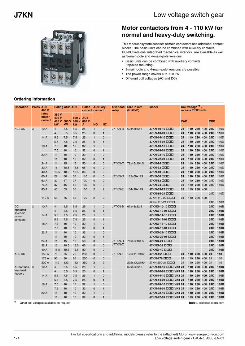
For full specifications and additional models please refer to the (attached) CD or www.europe.omron.comLow voltage switch gear - Cat.-No. J06E-EN-01174
J7KN Low voltage switch gear
Motor contactors from 4 - 110 kW for normal and heavy-duty switching.This modular system consists of main contactors and additional contact blocks. The basic units can be combined with auxiliary contacts. DC-DC versions, integrated mechanical interlock, are available as well as 3-main-pole and 4-main-pole versions.
• Basic units can be combined with auxiliary contacts (top/side mounting)
• 3-main-pole and 4-main-pole versions are possible • The power range covers 4 to 110 kW • Different coil voltages (AC and DC)
Ordering information
Operation Poles AC3 400 V rated motor current
Rating AC2, AC3 Rated current
Auxiliary contact
Overload relay
Size in mm (HxWxD)
Model Coil voltage *1 , replace with:
*1 Other coil voltages available on request Bold = preferred stock item
380 V 400 V 415 V kW
500 V kW
660 V 690 V kW
AC1690 VA NO NC
VAC VDC
AC / DC 3 10 A 4 5.5 5.5 25 1 0 J7TKN-B 67x45x82.5 J7KN-10-10 24 110 230 400 24D 110D
4 5.5 5.5 25 0 1 J7KN-10-01 24 110 230 400 24D 110D
14 A 5.5 7.5 7.5 25 1 0 J7KN-14-10 24 110 230 400 24D 110D
5.5 7.5 7.5 25 0 1 J7KN-14-01 24 110 230 400 24D 110D
18 A 7.5 10 10 32 1 0 J7KN-18-10 24 110 230 400 24D 110D
7.5 10 10 32 0 1 J7KN-18-01 24 110 230 400 24D 110D
22 A 11 10 10 32 1 0 J7KN-22-10 24 110 230 400 24D 110D
11 10 10 32 0 1 J7KN-22-01 24 110 230 400 24D 110D
24 A 11 15 15 50 0 0 J7TKN-C 78x45x104.5 J7KN-24 24 110 230 400 24D 110D
32 A 15 18.5 18.5 65 0 0 J7KN-32 24 110 230 400 24D 110D
40 A 18.5 18.5 18.5 80 0 0 J7KN-40 24 110 230 400 24D 110D
60 A 22 30 30 110 0 0 J7TKN-D 112x60x113 J7KN-50 24 110 230 400 24D 110D
62 A 30 37 37 120 0 0 J7KN-62 24 110 230 400 24D 110D
74 A 37 45 45 130 0 0 J7KN-74 24 110 230 400 24D 110D
85 A 45 55 55 150 2 2 J7TKN-E 134x90x119 J7KN-85-22 24 110 230 400
J7KN-85-21 24D 110D
110 A 55 75 55 170 2 2 J7KN-110-22 24 110 230 400
J7KN-110-21 24D 110D
DC operated solenoid motor contactor
3 10 A 4 5.5 5.5 25 1 0 J7TKN-B 67x45x82.5 J7KNG-10-10 24D 110D
4 5.5 5.5 25 0 1 J7KNG-10-01 24D 110D
14 A 5.5 7.5 7.5 25 1 0 J7KNG-14-10 24D 110D
5.5 7.5 7.5 25 0 1 J7KNG-14-01 24D 110D
18 A 7.5 10 10 32 1 0 J7KNG-18-10 24D 110D
7.5 10 10 32 0 1 J7KNG-18-01 24D 110D
22 A 11 10 10 32 1 0 J7KNG-22-10 24D 110D
11 10 10 32 0 1 J7KNG-22-01 24D 110D
24 A 11 15 15 50 0 0 J7TKN-BJ7TKN-C
78x45x104.5 J7KNG-24 24D 110D
32 A 15 18.5 18.5 65 0 0 J7KNG-32 24D 110D
40 A 18.5 18.5 18.5 80 0 0 J7KNG-40 24D 110D
AC / DC 150 A 75 75 75 230 0 0 J7TKN-F 170x110x162 J7KN-151 24 110 230 400 24 110
175 A 90 90 90 250 0 0 J7KN-176 24 110 230 400 24 110
200 A 110 132 132 350 2 2 202x130x190 J7KN-200-21 24 110 230 400 24 110
AC for fuse-less load feeders
3 10 A 4 5.5 5.5 25 1 0 67x45x82.5 J7KN-10-10 VK3 24 110 230 400 24D 110D
4 5.5 5.5 25 0 1 J7KN-10-01 VK3 24 110 230 400 24D 110D
14 A 5.5 7.5 7.5 25 1 0 J7KN-14-10 VK3 24 110 230 400 24D 110D
5.5 7.5 7.5 25 0 1 J7KN-14-01 VK3 24 110 230 400 24D 110D
18 A 7.5 10 10 32 1 0 J7KN-18-10 VK3 24 110 230 400 24D 110D
7.5 10 10 32 0 1 J7KN-18-01 VK3 24 110 230 400 24D 110D
22 A 11 10 10 32 1 0 J7KN-22-10 VK3 24 110 230 400 24D 110D
11 10 10 32 0 1 J7KN-22-01 VK3 24 110 230 400 24D 110D

J7KN Low voltage switch gear
175
Accessories
Specifications
Operation Poles AC3 400 V rated motor current
Rating AC2, AC3 Rated current
Auxiliary contact
Overload relay
Size in mm (HxWxD)
Model Coil voltage *1 , replace with:
*1 Other coil voltages available on requestBold = preferred stock item
380 V 400 V 415 V kW
AC1400 VkW
AC1690 VA NO NC
VAC VDC
AC 4 10 A 4 17.5 25 0 0 67x45x82.5 J7KN-10-4 24 110 230 400
14 A 5.5 17.5 25 0 0 J7KN-14-4 24 110 230 400
18 A 7.5 22 32 0 0 J7KN-18-4 24 110 230 400
22 A 11 22 32 0 0 J7KN-22-4 24 110 230 400
DCsolenoid mo-tor contactor
4 10 A 4 17.5 25 0 0 67x45x82.5 J7KNG-10-4 24D 110D
14 A 5.5 17.5 25 0 0 J7KNG-14-4 24D 110D
18 A 7.5 22 32 0 0 J7KNG-18-4 24D 110D
22 A 11 22 32 0 0 J7KNG-22-4 24D 110D
AC / DC 150 A 75 159 230 0 0 170x110x162 J7KN-151-4 24 110 230 400 24 110
175 A 90 173 250 0 0 J7KN-176-4 24 110 230 400 24 110
Auxiliary contact blocks
Rated operational current Contacts Model
Suitable for: AC15 230 VA
AC15 400 VA
AC1 690 VA
NO NC
J7KN-10… to -74…
3 2 10 1 - J73KN-B-10
3 2 10 - 1 J73KN-B-01
3 2 10 - - J73KN-B-10U
3 2 10 - - J73KN-B-01U
6 4 25 1 - J73KN-B-10A
6 4 25 - 1 J73KN-B-01A
J7KN-151… to -176…
3 2 10 1 1 J73KN-D-11F
3 2 10 2 2 J73KN-D-22F
3 2 10 1 1 J73KN-D-11S
J7KN-24…to KN-110 andJ7KN-200
3 2 10 1 1 J73KN-C-11S
3 2 10 2 2 J73KN-E-22
Pneumatic timers
Function Time range
Contacts Model
Suitable for: NO NC
J7KN-10...to -40…
ON-delay 0.1 - 40 s 1 - J74KN-B-TP40DA
ON-delay 10 - 180 s 1 - J74KN-B-TP180DA
OFF-delay 0.1 - 40 s - 1 J74KN-B-TP40IA
OFF-delay 10 - 180 s - 1 J74KN-B-TP180IA
Mechanicalinterlocks
Interlocks contactor with contactor Model
Mounting Model + Model
Horizontal J7KN-10 to -40 + J7KN-10 to - 40 J74KN-B-ML
J7KN-24 to -74 + J7KN-24 to -74 J74KN-C-ML
J7KN-85 to -110 + J7KN-85 to -110 J74KN-D-ML
J7KN-151 to -176 + J7KN-151 to -176 J74KN-E-ML
Suppressor units
Type Applicable coil voltage
Model
Suitable for contactors
J7KNA AC / DC Varistor snap-on coil terminals
110 - 230 V J74KN-A-VG230
J7KN10-J7KN22 AC / DC 250 - 415 V J74KN-A-VG400
J7KN10-J7KN74 AC / DC Varistor snap-on top of contactor
110 - 230 V J74KN-B-VG230
AC / DC 250 - 415 V J74KN-B-VG400
J7KNA AC / DC RC-unit snap-on contactor
12 - 48 V J74KN-D-RC24
AC / DC 48 - 127 V J74KN-D-RC110
AC / DC 110 - 230 V J74KN-D-RC230
J7KN10-J7KN74 AC / DC RC-unit snap-on contactor
12 - 48 V J74KN-C-RC24
AC / DC 48 - 127 V J74KN-C-RC110
AC / DC 110 - 230 V J74KN-C-RC230
J7KN85-J7KN110
AC / DC RC-unit to fix viafixing band or adhesive strip with contactor
12 - 24 V J74KN-B-RC48
AC / DC 110 - 250 V J74KN-B-RC230
AC / DC 250 - 415 V J74KN-B-RC400
Additional terminals single pole
Suitable for contactors
Cable cross-sectionsto clamp (mm2)
Model
Solid or stranded
Flexible Flexible with multi-core cable end
J7KN50 - KN74 4 - 35 6 - 25 4 - 25 J74KN-LG-9030
J7KN151 - KN176 16 - 120 16 - 95 J74KN-LG-11224
Terminal covers Specification Model
Suitable for contactors
J7KN151 - KN176 One unit J74KN-LG-10404
Marking systems Specification Model
Description
Marking plate 2-section without marking, divisible
J74KN-P487-1
Marking plate 4-section without marking, divisible
J74KN-P245-1
Coil voltages Suffix to contactor type:
Contactor type 20 24 48 90 110 180 230 400 500
J7KN-10 to J7KN-74 yes yes yes yes yes yes yes
J7KN-85 to J7KN-110 yes yes yes yes yes yes yes yes yes
J7KN-151 to J7KN-200 yes yes yes yes yes
Bold = standard coil voltages

For full specifications and additional models please refer to the (attached) CD or www.europe.omron.comLow voltage switch gear - Cat.-No. J07E-EN-01176
J7TKN Low voltage switch gear
Thermal overload relays for J7 contactorsJ7TKN relays protect motors against thermal overload. They can be mounted on the contactor or separately. The relays comply with IEC 947 (single-phase sensitivity).
• Series of overload relays covering a setting range from 0.24 A to 220 A
• All components are finger proof
Ordering information
Accessories
Applicable contactors Setting range Size in mm (HxWxD) Model
D.O.L. (A) Star-delta (A)
J7KNA-09…, J7KNA-12… 0.12 - 0.18 38.8x48.5x77 J7TKN-A-E18
0.18 - 0.27 J7TKN-A-E27
0.27 - 0.4 J7TKN-A-E4
0.4 - 0.6 J7TKN-A-E6
0.6 - 0.9 J7TKN-A-E9
0.8 - 1.2 J7TKN-A-1E2
1.2 - 1.8 J7TKN-A-1E8
1.8 - 2.7 J7TKN-A-2E7
2.7- 4 J7TKN-A-4
4 - 6 7 - 10.5 J7TKN-A-6
6 - 9 10.5 - 15.5 J7TKN-A-9
8 - 11 14 - 19 J7TKN-A-11
10- 14 18 - 24 J7TKN-A-14
J7KN-10… to J7KN-40… 0.12 - 0.18 63.5x45x70 J7TKN-B-E18
0.18 - 0.27 J7TKN-B-E27
0.27 - 0.4 J7TKN-B-E4
0.4 - 0.6 J7TKN-B-E6
0.6 - 0.9 J7TKN-B-E9
0.8 - 1.2 J7TKN-B-1E2
1.2 - 1.8 J7TKN-B-1E8
1.8 - 2.7 J7TKN-B-2E7
2.7 - 4 J7TKN-B-4
4 - 6 7 - 10.5 J7TKN-B-6
6 - 9 10.5 - 15.5 J7TKN-B-9
8 - 11 14 - 19 J7TKN-B-11
10 - 14 18 - 24 J7TKN-B-14
13 - 18 23 - 31 J7TKN-B-18
17 - 24 30 - 41 J7TKN-B-24
23 - 32 40 - 55 J7TKN-B-32
J7KN-24… to J7KN-40… 28 - 42 48 - 73 47x67x90 J7TKN-C-42
J7KN-50… to J7KN-74… 40 - 52 70 - 90 57x69x93 J7TKN-D-52
52 - 65 90 - 112 J7TKN-D-65
60 - 74 104 - 128 J7TKN-D-74
J7KN-85… to J7KN-150… 60 - 90 104 - 156 101x107x102 J7TKN-E-90
80 - 120 140 - 207 J7TKN-E-120
J7KN-175… to J7KN-200… 100 - 150 175 - 260 113x190x176 J7TKN-F-150
140 - 220 240 - 380 J7TKN-F-210
Bold = preferred stock item
Busbar sets
For overload relays For contactors Model
J7TKN-F-150 J7KN-151, J7KN-176 J74TK-SU-176
J7TKN-F-210 J7KN-200 J74TK-SU-200
Sets for single mounting
For overload relays
Cable cross-section to clamp (mm2) Model
Solid or stranded
Flexible Flexible with multi-core cable
J7TKN-A 0.75 - 6 0.75 - 4 0.5 - 4 J74TK-M
J7TKN-B 0.75 - 6 0.75 - 4 0.5 - 4 J74TK-SM
Bold = preferred stock item

J7TKN Low voltage switch gear
177
Specifications
Type J7TKN-A J7TKN-B J7TKN-C J7TKN-D J7TKN-E J7TKN-F
Rated insulation voltage Ui 690 VAC
Permissible ambient temperature
Operation -25 to 60 °C
Storage -50 to 70 °C
Trip class according to IEC 947-4-1 10 A 20 A
Cable cross-sectionMain connector
Solid or stranded mm2 0.75 - 60.75 - 2.5
0.75 - 6 0.75 - 10 4 - 35
Flexible mm2 0.75 - 40.5 - 2.5
1 - 4 0.75 - 6 6 - 25
Flexible with multi-core cable end mm2
0.5 - 2.50.5 - 1.5
0.75 - 4 0.75 - 6 4 - 25
Cables per clamp Number 1 + 1 2 2 1
Auxiliary connector Solid mm2 0.75 - 2.5
Flexible mm2 0.5 - 2.5
Flexible with multi-core cable end mm2
0.5 - 1.5
Cables per clamp Number 2
Auxiliary contacts
Rated insulation voltage Ui same potential 690 VAC
different potential 440 VAC 250 VAC 440 VAC
Rated operational current Ie Utilization category AC15
24 V 5 A 3 A 4 A 5 A
230 V 3 A 2 A 2.5 A 2.5 A 3 A 3 A
400 V 2 A 1 A 1.5 A 1.5 A 2 A 2 A
690 V 0.6 A 0.5 A 0.6 A
Rated operational current IeUtilization category DC13
24 V 1.2 A 1 A 1.2 A
110 V 0.15 A
220 V 0.1 A
Short circuit protection (without welding 1 kA)
Highest fuse rating gL (gG)
6 A 4 A 6 A
Setting range to 23 A All 28 - 42 A 52 - 65 A All
Power loss per current path (max.)
Minimum setting value 1.1 W 1.1 W 1.3 W 2.9 W 1.1 W
Maximum setting value 2.3 W 2.3 W 3.3 W 4.5 W 2.5 W

For full specifications and additional models please refer to the (attached) CD or www.europe.omron.comLow voltage switch gear - Cat.-No. J08E-EN-01178
J7MN Low voltage switch gear
J7MN is a range of motor-protection circuit breakers from 0.11 - 100 AJ7MN starters protect motors against thermal overload and short circuit. Additional auxiliary contacts (standard and trip indicating) are available, optional are: undervoltage and shunt release; insulated enclosures for surface and flush mounting; lockable rotary handles and 3-phase common links.
• Available rated operational currents of 12 A, 25 A, 50 A and 100 A • Switching capacity is 50 kA / 415 V for all versions • OMRON offers four different-sized versions • MPCBs can be mounted with screw fixing and snap fitting
on a DIN-rail • All components are finger proof
Ordering information
Rated current In A
Suitable for motors 3 ~ 400 V kW
Current setting range Short-circuit breaking capacity at 3 ~ 400 V kA
Size in mm (HxWxD) Model
Thermal overload release A
Instanteneous short-circuit release A
0.16 - 0.11 - 0.16 2.1 100 90x45x76 J7MN-12-E16
0.2 - 0.14 - 0.2 2.6 100 J7MN-12-E2
0.25 0.06 0.18 - 0.25 3.3 100 J7MN-12-E25
0.32 0.09 0.22 - 0.32 4.2 100 J7MN-12-E32
0.4 - 0.28 - 0.4 5.2 100 J7MN-12-E4
0.5 0.12 0.35 - 0.5 6.5 100 J7MN-12-E5
0.63 0.18 0.45 - 0.63 8.2 100 J7MN-12-E63
0.8 - 0.55 - 0.8 10 100 J7MN-12-E8
1 0.25 0.7 - 11 13 100 J7MN-12-1
1.25 0.37 0.9 - 1.25 16 100 J7MN-12-1E25
1.6 0.55 1.1 - 1.6 21 100 J7MN-12-1E6
2 0.75 1.4 - 22 26 100 J7MN-12-2
2.5 - 1.8 - 2.5 33 100 J7MN-12-2E5
3.2 1.1 2.2 - 3.2 42 100 J7MN-12-3E2
4 1.5 2.8 - 4 52 100 J7MN-12-4
5 - 3.5 - 5 65 100 J7MN-12-5
6.3 2.2 4.5 - 6.3 82 100 J7MN-12-6E3
8 3 5.5 - 8 104 50 J7MN-12-8
10 4 7 - 10 130 50 J7MN-12-10
12 5.5 9 - 12 156 50 J7MN-12-12
0.16 - 0.11 - 0.16 2.1 100 97x45x91 J7MN-25-E16
0.2 - 0.14 - 0.2 2.6 100 J7MN-25-E2
0.25 0.06 0.18 - 0.25 3.3 100 J7MN-25-E25
0.32 0.09 0.22 - 0.32 4.2 100 J7MN-25-E32
0.4 - 0.28 - 0.4 5.2 100 J7MN-25-E4
0.5 0.12 0.35 - 0.5 6.5 100 J7MN-25-E5
0.63 0.18 0.45 - 0.63 8.2 100 J7MN-25-E63
0.8 - 0.55 - 0.8 10 100 J7MN-25-E8
1 0.25 0.7 - 1 13 100 J7MN-25-1
1.25 0.37 0.9 - 1.25 16 100 J7MN-25-1E25
1.6 0.55 1.1 - 1.6 21 100 J7MN-25-1E6
2 0.75 1.4 - 2 26 100 J7MN-25-2
2.5 - 1.8 - 2.5 33 100 J7MN-25-2E5
3.2 1.1 2.2 - 3.2 42 100 J7MN-25-3E2
4 1.5 2.8 - 4 52 100 J7MN-25-4
5 - 3.5 - 5 65 100 J7MN-25-5
6.3 2.2 4.5 - 6.3 82 100 J7MN-25-6E3
8 3 5.5 - 8 104 100 J7MN-25-8
10 4 7 - 10 130 100 J7MN-25-10
12.5 5.5 9 - 12.5 163 100 J7MN-25-12E5
16 7.5 11 - 16 208 50 J7MN-25-16
20 - 14 - 20 260 50 J7MN-25-20
22 - 17 - 22 286 50 J7MN-25-22
25 11 20 - 25 325 50 J7MN-25-25
Bold = preferred stock item

J7MN Low voltage switch gear
179
Accessories
Note: For enclosures & front plates, insulated 3-phase busbar systems and components Bold = preferred stock item& mounting parts for fuseless load feeders, please refer to the datasheet.
Specifications
25 11 18 - 25 325 50 140x55x144 J7MN-50-25
32 15 22 - 32 416 50 J7MN-50-32
40 18.5 28 - 40 520 50 J7MN-50-40
45 - 36 - 45 585 50 J7MN-50-45
50 22 40 - 50 650 50 J7MN-50-50
63 30 45 - 63 819 50 165x70x169 J7MN-100-63
75 37 57 - 75 975 50 J7MN-100-75
90 - 70 - 90 1,170 50 J7MN-100-90
100 45 80 - 100 1,235 50 J7MN-100-100
Description Version For circuit breaker Type
Transverse auxiliary contact block
Contact block 1 NO + 1 NC All J73MN-11F
Auxiliary contact block for left hand side mounting (max. 1 pc. per circuit breaker)
Contact block 1 NO + 1 NC 9 mm All J73MN-11S
Signalling switch for left hand side mounting (max. 1 pc. per circuit breaker)
Signalling switch 1 NO + 1 NC eachIndividual tripped and short-circuit signalling
J7MN-25J7MN-50
J73MN-T-11S
Auxiliary releases for right hand side mounting (max 1 pc. per circuit breaker)
Undervoltage release. Trips the circuit breaker when the voltage is interrupted. Prevents the motor from being restarted accidentally when the voltage is restored, suitable for EMERGENCY STOP according to VDE 0113
AC 50 Hz AC 60 Hz
110 V 120 V All J74MN-U-N3
230 V 240 V All J74MN-U-N1
400 V 400 V All J74MN-U-N4
Shunt release. Trips the circuit breaker when the release coil is energized
50 / 60 Hz100% ON
50 / 60 Hz, DC5 s ON
210 - 240 V 190 - 330 V All J74MN-S-N2
Terminal block
Terminal block Up to 600 V according to UL 489 not for transverse auxiliary contact block
J7MN-25 J74MN-TB25
J7MN-100 J74MN-TB100
Type J7MN-12 J7MN-25 J7MN-50 J7MN-100
Number of poles 3 3 3 3
Max. rated current Inmax (= max. rated operational current Ie)
A 12 25 50 100
Permissible ambient temperature Storage / transport -50 °C to 80 °C
Operation -20 °C to 70 °C
Rated operational voltage Ue V 690
Rated frequemcy Hz 50 / 60
Rated insulation voltage Ui V 690
Rated impulse withstand voltage Uimp kV 6
Utilization category IEC 60 947-2 (circuit breaker) A
IEC 60 947-4-1 (motor starter) AC-3
Class According to IEC 60 947-4-1 10
DC short-circuit breaking capacity (time constant t = 5 ms)
1 conducting path DC 150 V 10 kA
2 conducting paths in series DC 300 V
10 kA
3 conducting paths in series DC 450 V
10 kA
Degree of protection According to IEC 60 529 IP20 IP20 IP20 IP20
Phase failure sensitivity According to IEC 60 947-4-1 Yes
Explosion protection According to EC Directive 94191EC Yes
Isolator characteristics According to IEC 60 947-3 Yes
Main and EM. STOP switch characteristics According to IEC 60 204-1 (VDE113) Yes
Safe isolation between main and auxiliary circuitsAccording to DIN VDE 0106 Part 101
Up to 400 V + 10% Yes
Up to 415 V + 5% Yes
Mechanical endurance Operating cycles 100,000 100,000 50,000 50,000
Electrical endurance 100,000 100,000 25,000 25,000
Max. operating frequency per hour (motor starts)
1 / h 15 15 15 15
Permissible mounting position Any, according to IEC 60 447 start command "I" right-hand side or top
Rated current In A
Suitable for motors 3 ~ 400 V kW
Current setting range Short-circuit breaking capacity at 3 ~ 400 V kA
Size in mm (HxWxD) Model
Thermal overload release A
Instanteneous short-circuit release A
Bold = preferred stock item

180

181
Table of contentsSelection table 182
1 phase control K8AB-AS 184
K8AB-VS 185
K8AB-VW 186
3 phase control K8AB-PH 187
K8AB-PM 188
K8AB-PA 189
K8AB-PW 190
Conductive level controller 61F-GP-N8 191
61F-GPN-BT / BC 193
61F-D21T 194
Leakage controller K7L 195

182
Selection table
Category 1-phase current 1-phase voltage Phase-sequence phase-loss
3-phase phase-sequence phase-
loss
3-phase asymmetry and phase-sequence
phase-loss
Sel
ecti
on
cri
teri
a
Model K8AB-AS K8AB-VS K8AB-VW K8AB-PH K8AB-PM K8AB-PADetection method Conductive
Specialty Ideal for current monitoring for industrial heaters and motors.
Ideal for voltage monitoring for industrial facilities and equipment.
Ideal for voltage monitoring for industrial facilities and equipment.
Ideal for phase-sequence and phase-loss monitoring for industrial facilities and equipment.
Ideal for monitoring 3-phase power supplies for industrial facilities and equipment.
Ideal for 3-phase voltage asymmetry monitoring for industrial facilities and equipment.
Sensing range(configurable)
20 mA to 10 A, current transformer: 100 / 200 A
60 mV to 600 V 60 mV to 600 V Same as supply voltage
Su
pp
ly v
olt
age
AC
24 VAC
100 VAC
110 VAC
115 VAC
120 VAC
200 VAC
220 VAC
230 VAC
240 VAC
200 - 500 VAC
200 - 240 VAC (-PM1, 3-wire) (-PA1, 3-wire)
115 - 138 VAC (-PM1, 4-wire) (-PA1, 4-wire)
380 - 480 VAC (-PM2, 3-wire) (-PA2, 3-wire)
220 - 277 VAC (-PM2, 4-wire) (-PA2, 4-wire)
Su
pp
ly
volt
age
DC 24 VDC
12 .. 24 VDC
Co
ntr
ol
ou
tpu
t Transistor NPN
Transistor PNP
Relay (1 SPDT) (1 SPDT) (2 SPDT) (1 SPDT) (2 SPDT) (1 SPDT)
Fea
ture
s LED operation indicator
Adjustable sensitivity
Electrode types
Page 184 185 186 187 188 189

Monitoring products
183
3-phase voltage Conductive level controller Liquid leakage sensor amplifier
K8AB-PW 61F-GP-N8 61F-GPN-BT 61F-GPN-BC 61F-D21T K7L-AT50 K7L-AT50DConductive
Ideal for monitoring 3-phase power supplies for industrial facilities and equipment.
Single or two-point AC sine wave between electrodes for stable detection with no electrolysis
AC sine wave between electrodes for stable detection with no electrolysis
Ideal for level control for industrial facilities and equipment
Sensor amplifier, AC sine wave between electrodes for stable detection with no electrolysis
Sensor amplifier with disconnection detection function
Same as supply voltage
4 to 50 kΩ 0 to 100 kΩ 1 to 100 kΩ 10 to 100 kΩ 0 to 50 MΩ 1 to 50 MΩ
(-PW1, 3-wire)
(-PW1, 4-wire)
(-PW2, 3-wire)
(-PW2, 4-wire)
(2 SPDT)
Electrode holder: PS- S, PS-31, BF-1 and BS-1 Liquid leakage sensor band F03-16PE
190 191 193 194 195
Standard Available No / not available

For full specifications and additional models please refer to the (attached) CD or www.europe.omron.comMonitoring products - Cat.-No. N142-E2-01184
K8AB-AS Monitoring products
Single-phase current relayThese single-phase current relays monitor over- and undercurrents. Manual resetting and automatic resetting are supported by one relay. The start-up lock and operating time can be set separately. The relay warning status is easily monitored with the LED indicator.
• Single-phase current relay • In 22.5 mm wide industrial housing • Under or over control • Supply voltages: 24 VAC / 24 VDC / 115 VAC / 230 VAC • Easy wiring with ferrules
Ordering information
Bold = preferred stock itemAccessories
Note: The K8AB-AS3 is designed to be used in combination with the K8AC-CT200L (direct input not possible)
Specifications
Measuring current Supply voltage Model
2 to 20 mA AC / DC, 10 to 100 mA AC / DC, 50 to 500 mA AC / DC
24 VDC K8AB-AS1 24 VDC
24 VAC K8AB-AS1 24 VAC
100-115 VAC K8AB-AS1 100-115 VAC
200-230 VAC K8AB-AS1 200-230 VAC
0.1 to 1 A AC / DC, 0.5 to 5 A AC / DC, 0.8 to 8 A AC / DC
24 VDC K8AB-AS2 24 VDC
24 VAC K8AB-AS2 24 VAC
100-115 VAC K8AB-AS2 100-115 VAC
200-230 VAC K8AB-AS2 200-230 VAC
10 to 100 A AC, 20 to 200 A AC 24 VDC K8AB-AS3 24 VDC
24 VAC K8AB-AS3 24 VAC
100-115 VAC K8AB-AS3 100-115 VAC
200-230 VAC K8AB-AS3 200-230 VAC
Current transformer Input range Applicable relay Model
10 to 100 A AC, 20 to 200 A AC K8AB-AS3 K8AC-CT200L
Ambient temperature Operating: -20 °C to 60 °C (with no condensation or icing), storage: -40 °C to 70 °C (with no condensation or icing)
Operating voltage range 85% to 110% of rated operating voltage
Rated power supply frequency 50 / 60 Hz ±5 Hz (AC power supply)
Output relays (SPDT)
Resistive load 6 A at 250 VAC (cosφ = 1), 6 A at 30 VDC (L / R = 0 ms)
Inductive load 1 A at 250 VAC (cosφ = 0.4), 1 A at 30 VDC (L / R = 7 ms)
Minimum load 10 mA at 5 VDC
Maximum contact voltage 250 VAC
Maximum contact current 6 A AC
Maximum switching capacity 1,500 VA
Life expectancy Mechanical: 10,000,000 operations, electrical: make: 50,000 times, break: 30,000 times
Crimp terminals Two solid wires of 2.5 mm2, two crimp terminals of 1.5 mm2 with insulation sleeves, can be tightened together
Degree of protection Terminal section: IP20, rear case: IP40
Case material ABS resin (self-extinguishing resin) UL94-V0
Weight 200 g
Operating power Non-isolated power supply 24 VDC (1 W)
Isolated power supply 24 VAC (3 VA), 100 to 115 VAC (4 VA), 200 to 230 VAC (5 VA)
Operate (SV) Operating value setting range 10% to 100% of maximum rated input value
Operating value 100% operation at set value
Reset (HYS.) Hysteresis 5% to 50% of operating value
Resetting method Manual reset / automatic reset (switchable)Manual reset: turn OFF operating power for 1 s or longer
Operating time (T) 0.1 to 30 s (value when input rapidly changes from 0% to 120%)
Operating power ON lock (LOCK) 0 to 30 s (value when input rapidly changes from 0% to 120%, lock timer starts upon input 30% of SV)
Setting accuracy ±10% of full scale
Time error ±10% of set value (minimum error: 50 ms)
Input frequency K8AB-AS1 / -AS2: DC input, 45 to 65 Hz; K8AB-AS3: 45 to 60 Hz
Continuous input K8AB-AS1 / -AS2 Continuous input: 115% of maximum input, 10 s max.: 125% of maximum input
K8AB-AS3 Continuous input: 240 A, 30 s max.: 400 A, 1 s max.: 1,200 A
Indicators Power (PWR): green LED, relay output (RY): yellow LED, alarm outputs (ALM): red LED
Size in mm 90Hx22.5Wx100D

For full specifications and additional models please refer to the (attached) CD or www.europe.omron.comMonitoring products - Cat.-No. N143-E2-01 185
K8AB-VS Monitoring products
Single-phase voltage relayThese single-phase voltage relays are for monitoring over- and undervoltages. Manual resetting and automatic resetting are supported by one relay. Relay warning status can easily be monitored using the LED indicator.
• Single-phase voltage relay • In 22.5 mm-wide industrial housing • Under or over control • Supply voltages: 24 VAC / 24 VDC / 115 VAC / 230 VAC • Easy wiring with ferrules
Ordering information
Specifications
Measuring voltage Supply voltage Model
6 to 60 mV AC / DC, 10 to 100 mV AC / DC, 30 to 300 mV AC / DC
24 VDC K8AB-VS1 24 VDC
24 VAC K8AB-VS1 24 VAC
100-115 VAC K8AB-VS1 100-115 VAC
200-230 VAC K8AB-VS1 200-230 VAC
1 to 10 VAC / VDC, 3 to 30 VAC / VDC, 15 to 150 VAC / VDC
24 VDC K8AB-VS2 24 VDC
24 VAC K8AB-VS2 24 VAC
100-115 VAC K8AB-VS2 100-115 VAC
200-230 VAC K8AB-VS2 200-230 VAC
20 to 200 VAC / VDC, 30 to 300 VAC / VDC, 60 to 600 VAC / VDC
24 VDC K8AB-VS3 24 VDC
24 VAC K8AB-VS3 24 VAC
100-115 VAC K8AB-VS3 100-115 VAC
200-230 VAC K8AB-VS3 200-230 VAC
Bold = preferred stock item
Ambient operating temperature -20 °C to 60 °C (with no condensation or icing)
Storage temperature -40 °C to 70 °C (with no condensation or icing)
Operating voltage range 85% to 110% of rated operating voltage
Rated power supply frequency 50 / 60 Hz ±5 Hz (AC power supply)
Output relays Resistive load 6 A at 250 VAC (cosφ = 1), 6 A at 30 VDC (L / R = 0 ms)
Inductive load 1 A at 250 VAC (cosφ = 0.4), 1 A at 30 VDC (L / R = 7 ms)
Minimum load 10 mA at 5 VDC
Maximum contact voltage 250 VAC
Maximum contact current 6 A AC
Maximum switching capacity 1,500 VA
Mechanical life 10,000,000 operations
Electrical life Make: 50,000 times, break: 30,000 times
Crimp terminals Two solid wires of 2.5 mm2, two crimp terminals of 1.5 mm2 with insulation sleeves, can be tightened together
Degree of protection Terminal section: IP20, rear case: IP40
Case color Munsell 5Y8/1 (ivory)
Case material ABS resin (self-extinguishing resin) UL94-V0
Weight 200 g
Mounting Mounted to DIN-rail or via M4 screws
Operating power Non-isolated power supply 24 VDC (1 W)
Isolated power supply 24 VAC (4 VA), 100 to 115 VAC (4 VA), 200 to 230 VAC (5 VA)
Operate (SV) Operating value setting range 10% to 100% of maximum rated input value
Operating value 100% operation at set value
Reset (HYS.) Hysteresis 5% to 50% of operating value
Resetting method Manual reset / automatic reset (switchable) Manual reset: turn OFF operating power for 1 s or longer
Operating time (T) 0.1 to 30 s (value when input rapidly changes from 0% to 120%)
Power ON lock (LOCK) 1 s or 5 s error ±0.5 s(value when input rapidly changes from 0% to 100%. The operating time is the shortest at this point)
Setting accuracy ±10% of full scale
Time error ±10% of set value (minimum error: 50 ms)
Input frequency 40 to 500 Hz
Input impedance K8AB-VS1: 9 kΩ min., K8AB-VS2: 100 kΩ min., K8AB-VS3: 1 MΩ min.
Indicators LED power (PWR): green LED, relay output (RY): yellow LED, alarm output (ALM): red LED
Output relays One SPDT relay (6 A at 250 VAC, resistive load)
Size in mm 90Hx22.5Wx100D

For full specifications and additional models please refer to the (attached) CD or www.europe.omron.comMonitoring products - Cat.-No. N144-E2-01186
K8AB-VW Monitoring products
Single-phase voltage relay, window typeFor monitoring over- and undervoltages simultaneously. Manual resetting and automatic resetting are supported by one relay. Separate settings and outputs are supported for over- and undervoltages. Relay warning status can easily be monitored with the LED indicator.
• Single-phase voltage window relay • In 22.5 mm-wide industrial housing • Under and over, low / low or high / high control • Supply voltages: 24 VAC / 24 VDC / 115 VAC / 230 VAC • Easy wiring with ferrules
Ordering information
Specifications
Measuring voltage Supply voltage Model
6 to 60 mV AC / DC, 10 to 100 mV AC / DC, 30 to 300 mV AC / DC
24 VDC K8AB-VW1 24 VDC
24 VAC K8AB-VW1 24 VAC
100-115 VAC K8AB-VW1 100-115 VAC
200-230 VAC K8AB-VW1 200-230 VAC
1 to 10 V AC / DC, 3 to 30 V AC / DC, 15 to 150 V AC / DC
24 VDC K8AB-VW2 24 VDC
24 VAC K8AB-VW2 24 VAC
100-115 VAC K8AB-VW2 100-115 VAC
200-230 VAC K8AB-VW2 200-230 VAC
20 to 200 V AC / DC, 30 to 300 V AC / DC, 60 to 600 V AC / DC
24 VDC K8AB-VW3 24 VDC
24 VAC K8AB-VW3 24 VAC
100-115 VAC K8AB-VW3 100-115 VAC
200-230 VAC K8AB-VW3 200-230 VAC
Bold = preferred stock item
Ambient operating temperature -20 °C to 60 °C (with no condensation or icing)
Storage temperature -40 °C to 70 °C (with no condensation or icing)
Operating voltage range 85% to 110% of rated operating voltage
Rated power supply frequency 50 / 60 Hz ±5 Hz (AC power supply)
Output relays (SPDT) Resistive load 6 A at 250 VAC (cosφ = 1), 6 A at 30 VDC (L / R = 0 ms)
Inductive load 1 A at 250 VAC (cosφ = 0.4), 1 A at 30 VDC (L / R = 7 ms)
Minimum load 10 mA at 5 VDC
Maximum contact voltage 250 VAC
Maximum contact current 6 A AC
Maximum switching capacity 1,500 VA
Mechanical life 10,000,000 operations
Electrical life Make: 50,000 times, break: 30,000 times
Crimp terminals Two solid wires of 2.5 mm2, two crimp terminals of 1.5 mm2 with insulation sleeves, can be tightened together
Degree of protection Terminal section: IP20, rear case: IP40
Case color Munsell 5Y8/1 (ivory)
Case material ABS resin (self-extinguishing resin) UL94-V0
Weight 200 g
Mounting Mounted to DIN-rail or via M4 screws
Operating power Non-isolated power supply 24 VDC (1 W)
Isolated power supply 24 VAC (4 VA), 100 to 115 VAC (4 VA), 200 to 230 VAC (5 VA)
Operation (AL1 and AL2)
Operating value setting range 10% to 100% of maximum rated input value
Operating value 100% operation at set value
Reset (HYS.) Hysteresis 5% of operating value (fixed)
Resetting method Manual reset / automatic reset (switchable) Manual reset: turn OFF operating power for 1 s or longer
Operating time (T) 0.1 to 30 s (value when input rapidly changes from 0% to 120%)
Power ON lock (LOCK) 1 s or 5 s error ±0.5 s (value when input rapidly changes from 0% to 100%)
Setting accuracy ±10% of full scale
Time error ±10% of set value (minimum error: 50 ms)
Input frequency 40 to 500 Hz
Input impedance K8AB-VW1: 9 kΩ min., K8AB-VW2: 100 kΩ min., K8AB-VW3: 1 MΩ min.
Indicators Power (PWR): green LED, relay output (RY): yellow LED, alarm outputs (ALM 1 / 2): red LED
Output relays Two SPDT relays (6 A at 250 VAC, resistive load), normally closed operation (normally ON)
Size in mm 90Hx22.5Wx100D

For full specifications and additional models please refer to the (attached) CD or www.europe.omron.comMonitoring products - Cat.-No. N145-E2-01 187
K8AB-PH Monitoring products
3-phase sequence, phase-loss relayK8AB-PH simultaneously monitors phase sequence and phase loss for 3-phase 3-wire power supplies. The relay warning status can easily be monitored using the LED indicator. Suitable for industrial facilities and equipment.
• 3-phase sequence, phase-loss relay • Monitors both functions at once • Measuring range: 200 to 500 VAC • Power supply voltage is the same as measuring voltage • Operation reaction time: 0.1 s maximum
Ordering information
Specifications
Rated input voltage Model
200 to 500 VAC K8AB-PH1
Bold = preferred stock item
Ambient operating temperature -20 °C to 60 °C (with no condensation or icing)
Storage temperature -40 °C to 70 °C (with no condensation or icing)
Altitude 2,000 m max.
Voltage fluctuation range 85% to 110% of rated input voltage
Input frequency 50 / 60 Hz ±5 Hz (AC power supply)
Output relays Resistive load 6 A at 250 VAC (cosφ = 1), 6 A at 30 VDC (L / R = 0 ms)
Inductive load 1 A at 250 VAC (cosφ = 0.4), 1 A at 30 VDC (L / R = 7 ms)
Minimum load 10 mA at 5 VDC
Maximum contact voltage 250 VAC
Maximum contact current 6 A AC
Maximum switching capacity 1,500 VA
Mechanical life 10,000,000 operations
Electrical life Make: 50,000 times, break: 30,000 times
Terminal screw tightening torque 1.2 Nm
Degree of protection Terminal section: IP20, rear case: IP40
Case color Munsell 5Y8/1 (ivory)
Case material ABS resin (self-extinguishing resin) UL94-V0
Weight 200 g
Mounting Mounted to DIN-rail or via M4 screws
Rated input voltage Non-isolated 200 to 500 VAC (15 VA)
Phase-sequence, phase-loss operating time 0.1 s max. (value when rated operating voltage changes quickly from 0% to 100%) (relays are normally ON and turn OFF for phase-sequence or loss phase errors)
Resetting method Automatic reset
Input frequency 45 to 65 Hz
Input impedance 100 kΩ min.
Indicators Power (PWR): green LED, relay output (RY): yellow LED
Output relays One SPDT relay (6 A at 250 VAC, resistive load)
Size in mm 90Hx22.5Wx100D

For full specifications and additional models please refer to the (attached) CD or www.europe.omron.comMonitoring products - Cat.-No. N146-E2-01188
K8AB-PM Monitoring products
3-phase voltage, phase-sequence, phase-loss relayK8AB-PM monitors overvoltages, undervoltages, phase sequence and phase loss for 3-phase, 3-wire or 4-wire power supplies, in one unit. This relay features a switch setting for 3-phase, 3-wire or 3-phase, 4-wire power supply.
• Worldwide power specifications supported by one unit • Phase sequence, phase loss: operation reaction time 0.1 s maximum• Overvoltages or undervoltages: operation time setting from 0.1 to 30 s• Relay warning status can easily be monitored using the LED indicator• Easy wiring with ferrules
Ordering information
Specifications
Rated input Model
3-phase 3-wire mode 200, 220, 230, 240 VAC K8AB-PM1
3-phase 4-wire mode 115, 127, 133, 138 VAC
3-phase 3-wire mode 380, 400, 415, 480 VAC K8AB-PM2
3-phase 4-wire mode 220, 230, 240, 277 VAC
Bold = preferred stock item
Ambient operating temperature -20 °C to 60 °C (with no condensation or icing)
Ambient operating humidity 25% to 85%
Voltage fluctuation range 85% to 110% of rated input voltage
Input frequency 50 / 60 Hz ±5 Hz (AC power supply)
Output relays Resistive load 6 A at 250 VAC (cosφ = 1), 6 A at 30 VDC (L / R = 0 ms)
Inductive load 1 A at 250 VAC (cosφ = 0.4), 1 A at 30 VDC (L / R = 7 ms)
Minimum load 10 mA at 5 VDC
Maximum contact voltage 250 VAC
Maximum contact current 6 A AC
Maximum switching capacity 1,500 VA
Mechanical life 10,000,000 operations
Electrical life Make: 50,000 times, break: 30,000 times
Crimp terminals Two solid wires of 2.5 mm2, two crimp terminals of 1.5 mm2 with insulation sleeves, can be tightened together
Degree of protection Terminal section: IP20, rear case: IP40
Case color Munsell 5Y8/1 (ivory)
Case material ABS resin (self-extinguishing resin) UL94-V0
Weight 200 g
Mounting Mounted to DIN-rail or via M4 screws
Rated input voltage K8AB-PM1 3-phase, 3-wire mode: 200, 220, 230, 240 VAC, 3-phase, 4-wire mode: 115, 127, 133, 138 VAC
K8AB-PM2 3-phase, 3-wire mode: 380, 400, 415, 480 VAC, 3-phase, 4-wire mode: 220, 230, 240, 277 VAC
Operation (overvoltage or undervoltage)
Operating value setting range Overvoltage = -30% to 25% of maximum rated input voltage *1
Undervoltage = -30% to 25% of maximum rated input voltage *1
*1 The rated input voltage is switched with a switch
Operating value 100% operation at set value
Reset (HYS.) Hysteresis 5% of operating value (fixed)
Resetting method Automatic reset
Operating time (T) Overvoltage / undervoltage 0.1 to 30 s (value when input rapidly changes from 0% to 120%)
Phase-sequence, phase-loss 0.1 s max. (value when input rapidly changes from 0% to 100%)
Power ON lock (LOCK) 1 s or 5 s error ±0.5 s(value when input rapidly changes from 0% to 100%. The operating time is the shortest at this point)
Setting accuracy ±10% of full scale
Time error ±10% of set value (minimum error: 50 ms)
Input frequency 45 to 65 Hz
Input impedance 100 kΩ min.
Indicators Power (PWR): green LED, relay output (RY): yellow LED, alarm outputs (ALM 1 / 2): red LED
Output relays Two SPDT relays (6 A at 250 VAC, resistive load), normally closed operation (normally ON) (separate outputs possible for overvoltages and undervoltages)
Size in mm 90Hx22.5Wx100D

For full specifications and additional models please refer to the (attached) CD or www.europe.omron.comMonitoring products - Cat.-No. N147-E2-01 189
K8AB-PA Monitoring products
3-phase asymmetry, phase-sequence, phase-loss relayMonitors voltage asymmetry, phase sequence and phase loss for 3-phase 3-wire or 4-wire power supplies, in one unit.
• Worldwide power specifications supported by one unit • Phase sequence, phase loss: operation reaction time 0.1 s maximum• Asymmetry: operation time setting from 0.1 to 30 s• Reset method: automatic• Power ON lock: 1 s or 5 s
Ordering information
Specifications
Rated input Model
3-phase 3-wire mode 200, 220, 230, 240 VAC K8AB-PA1
3-phase 4-wire mode 115, 127, 133, 138 VAC
3-phase 3-wire mode 380, 400, 415, 480 VAC K8AB-PA2
3-phase 4-wire mode 220, 230, 240, 277 VAC
Bold = preferred stock item
Ambient operating temperature -20 °C to 60 °C (with no condensation or icing)
Storage temperature -40 °C to 70 °C (with no condensation or icing)
Altitude 2,000 m max.
Voltage fluctuation range 85% to 110% of rated input voltage
Input frequency 50 / 60 Hz ±5 Hz (AC power supply)
Output relays Resistive load 6 A at 250 VAC (cosφ = 1), 6 A at 30 VDC (L / R = 0 ms)
Inductive load 1 A at 250 VAC (cosφ = 0.4), 1 A at 30 VDC (L / R = 7 ms)
Minimum load 10 mA at 5 VDC
Maximum contact voltage 250 VAC
Maximum contact current 6 A AC
Maximum switching capacity 1,500 VA
Mechanical life 10,000,000 operations
Electrical life Make: 50,000 times, break: 30,000 times
Crimp terminals Two solid wires of 2.5 mm2, two crimp terminals of 1.5 mm2 with insulation sleeves, can be tightened together
Degree of protection Terminal section: IP20, rear case: IP40
Case color Munsell 5Y8/1 (ivory)
Case material ABS resin (self-extinguishing resin) UL94-V0
Weight 200 g
Rated input voltage K8AB-PA1 3-phase, 3-wire mode: 200, 220, 230, 240 VAC, 3-phase, 4-wire mode: 115, 127, 133, 138 VAC
K8AB-PA2 3-phase, 3-wire mode: 380, 400, 415, 480 VAC, 3-phase, 4-wire mode: 220, 230, 240, 277 VAC
Asymmetry operation (ASY.)
Operating value setting range Asymmetry rate: 2% to 22%
Operating value 100% operation at set valueAsymmetry operating value = rated input voltage x asymmetry set value [%] The asymmetry operation will function when the difference between the highest and lowest voltage phases equals or exceeds the asymmetry operating value
Reset (HYS.) Hysteresis 5% of operating value (fixed)
Resetting method Automatic reset
Operating time (T) Asymmetry 0.1 s to 30 s (value when input rapidly changes from 0% to 120%)
Phase-sequence, phase-loss 0.1 s max. (value when input rapidly changes from 0% to 100%)
Power ON lock (LOCK) 1 s or 5 s (value when input rapidly changes from 0% to 100%. The operating time is the shortest at this point)
Setting accuracy ±10% of full scale
Time error ±10% of set value (minimum error: 50 ms)
Input frequency 45 to 65 Hz
Input impedance 100 kΩ min.
Indicators Power (PWR): green LED, relay output (RY): yellow LED, alarm outputs (ALM 1 / 2): red LED
Output relays One SPDT relay (6 A at 250 VAC, resistive load), normally closed operation (normally ON)
Size in mm 90Hx22.5Wx100D

For full specifications and additional models please refer to the (attached) CD or www.europe.omron.comMonitoring products - Cat.-No. N148-E2-01190
K8AB-PW Monitoring products
3-phase voltage relayMonitors overvoltages and undervoltages for 3-phase 3-wire or 4-wire power supplies, in one unit. Switch setting for 3-phase 3-wire or 3-phase 4-wire power supply.
• Overvoltages or undervoltages: operation time setting from 0.1 to 30 s• Relay warning status can easily be monitored using the LED indicator• Separate outputs possible for overvoltages and undervoltages • Reset method: automatic • Power ON lock: 1 s or 5 s
Ordering information
Specifications
Rated input Model
3-phase 3-wire mode 200, 220, 230, 240 VAC K8AB-PW1
3-phase 4-wire mode 115, 127, 133, 138 VAC
3-phase 3-wire mode 380, 400, 415, 480 VAC K8AB-PW2
3-phase 4-wire mode 220, 230, 240, 277 VAC
Bold = preferred stock item
Ambient operating temperature -20 °C to 60 °C (with no condensation or icing)
Storage temperature -40 °C to 70 °C (with no condensation or icing)
Altitude 2,000 m max.
Voltage fluctuation rang 85% to 110% of rated input voltage
Input frequency 50 / 60 Hz ±5 Hz (AC power supply)
Output relays Resistive load 6 A at 250 VAC (cosφ = 1), 6 A at 30 VDC (L / R = 0 ms)
Inductive load 1 A at 250 VAC (cosφ = 0.4), 1 A at 30 VDC (L / R = 7 ms)
Minimum load 10 mA at 5 VDC
Maximum contact voltage 250 VAC
Maximum contact current 6 A AC
Maximum switching capacity 1,500 VA
Mechanical life 10,000,000 operations
Electrical life Make: 50,000 times, break: 30,000 times
Crimp terminals Two solid wires of 2.5 mm2, two crimp terminals of 1.5 mm2 with insulation sleeves, can be tightened together
Degree of protection Terminal section: IP20, rear case: IP40
Case color Munsell 5Y8/1 (ivory)
Case material ABS resin (self-extinguishing resin) UL94-V0
Weight 200 g
Rated input voltage K8AB-PW1 3-phase, 3-wire mode: 200, 220, 230, 240 VAC, 3-phase, 4-wire mode: 115, 127, 133, 138 VAC
K8AB-PW2 3-phase, 3-wire mode: 380, 400, 415, 480 VAC, 3-phase, 4-wire mode: 220, 230, 240, 277 VAC
Operation (overvoltage and undervoltage)
Operating value setting range Overvoltage = -30% to 25% of maximum rated input voltage *1
Undervoltage = -30% to 25% of maximum rated input voltage *1
*1 The rated input voltage is switched with a switch
Operating value 100% operation at set value
Reset (HYS.) Hysteresis 5% of operating value (fixed)
Resetting method Automatic reset
Operating time (T) Overvoltage / undervoltage 0.1 to 30 s (value when input rapidly changes from 0% to 120%)
Power ON lock (LOCK) 1 s or 5 s (value when input rapidly changes from 0% to 100%. The operating time is the shortest at this point)
Setting accuracy ±10% of full scale
Time error ±10% of set value (minimum error: 50 ms)
Input frequency 45 to 65 Hz
Input impedance 100 kΩ min.
Indicators Power (PWR): green LED, relay output (RY): yellow LED, alarm outputs (ALM 1 / 2): red LED
Output relays Two SPDT relays (6 A at 250 VAC, resistive load), normally closed operation (normally ON) (separate outputs possible for overvoltages and undervoltages)
Size in mm 90Hx22.5Wx100D

For full specifications and additional models please refer to the (attached) CD or www.europe.omron.comMonitoring products - Cat.-No. F043-E2-02 191
61F-GP-N8 Monitoring products
Compact plug-in (8-pin) level controllerThe 61F-GP-N8 can be used for single- or two-point level control of conductive materials, both liquids and solids. These products are equipped with a red LED operation indicator.
• Low-voltage (AC) electrodes (8 VAC or 24 VAC) • Operation range: 4 - 15 kΩ, 70 - 300 kΩ • Detection method: conductive • Probes need to be ordered separately • Conforms to EMC and LVD directives, UL / CSA approved
Ordering information
Bold = preferred stock item
Accessories
Bold = preferred stock item
Application Type Model number
Ordinary purified water or sewage water General purpose type 61F-GP-N8 24AC
61F-GP-N8 110AC
61F-GP-N8 230AC
Ordinary purified water, where the distance between sewage pumps and water tanks or between receiver tanks and supply tanks is long or where remote control is required
Long-distance type 2 km 61F-GP-N8L 24AC 2KM
61F-GP-N8L 110AC 2KM
61F-GP-N8L 230AC 2KM
4 km 61F-GP-N8L 24AC 4KM
61F-GP-N8L 110AC 4KM
61F-GP-N8L 230AC 4KM
Liquids with high specific resistance such as distilled water High sensitivity type 61F-GP-N8H 24AC
61F-GP-N8H 110AC
61F-GP-N8H 230AC
Liquids with low specific resistance such as salt water, sewage water, acid chemicals, alkali chemicals
Low sensitivity type 61F-GP-N8D 24AC
61F-GP-N8D 110AC
61F-GP-N8D 230AC
Ordinary purified or sewage water, with two-wired-type electrode holder (incorporating a resistor of 6.8 kΩ)
Two-wired type 61F-GP-N8R 24AC
61F-GP-N8R 110AC
61F-GP-N8R 230AC
Electrode holders
Applications Mounting style
Insulator material
Max. temperature Number of electrodes
Model
For city water and other general use. Easy-to-replace separate versions for maintenance.
Flange Phenol resin 70 °C 3 PS-3S
When mounting space is limited. Special 3-pole holder of small size and light weight.
Screw Phenol resin 3, 300 mm3, 1,000 mm
PS-31-300MMPS-31-1000MM
Use for sewage, sea water, etc., having a low specific resistance.
Flange Ceramics 150 °C (without water drips or vapor on the electrode holder surface)
1 BF-1
For resistance to high pressure. Use in tanks with high temperature or pressure.
Screw PTFE 250 °C (without water drips or vapor on the surface of the electrode holder)
1 BS-1
Electrode separators Number of electrodes
Model
1 F03-14 1P
3 F03-14 3P
Electrodes, connecting, and lock nuts
Applicable liquids Material Component Indication mark Inscription Model
Purified city water, industrial water, sewage Equivalent to SUS 304 (AISI-304)
Electrode (1 m long) 1 line F03-01 SUS201
Connecting nut F03-02 SUS201
Lock nut F03-03 SUS201
Purified city water, industrial water, sewage,dilute alkaline solution
SUS316 (AISI-316)
Electrode (1 m long) 2 lines F03-01 SUS316
Connecting nut 6 F03-02 SUS316
Lock nut 316 F03-03 SUS316

61F-GP-N8 Monitoring products
192
Specifications
Model 61F-GP-N8 61F-GP-N8L 61F-GP-N8H 61F-GP-N8D 61F-GP-N8R
Supply voltage 24, 100, 110, 120, 200, 220, 230 or 240 VAC; 50 / 60 Hz
Operating voltage range 85% to 110% of rated voltage
Interelectrode voltage 8 VAC 24 VAC 8 VAC
Interelectrode current Approx. 1 mA AC max. Approx. 0.4 mA AC max. Approx. 1 mA AC max.
Power consumption Approx. 3.5 VA max.
Response time Operate: 80 ms max., release: 160 ms max.
Cable length 1 km max. 2 km max. 4 km max. 50 m max. 1 km max. 800 m max.
Control output 1 A, 250 VAC (inductive load: cosφ = 0.4), 3 A, 250 VAC (resistive load)
Ambient temperature Operating: -10 °C to 55 °C
Life expectancy Electrical: 100,000 operations min., mechanical: 5,000,000 operations min
Size in mm 49.4Hx38Wx84D

For full specifications and additional models please refer to the (attached) CD or www.europe.omron.comMonitoring products - Cat.-No. F053-E2-02 193
61F-GPN-BT / BC Monitoring products
Compact plug-in (11-pin) level controller (DC supply)This controller is for single- or two-point level control. 24 VDC supply allows for usage in locations without AC power supply. Relay contact chattering usually caused by waves has been eliminated by using open collector output, reducing contact wear.
• Adjustable sensitivity: operation range: 0 - 100 kΩ • Red LED for operation indicator • Conforms to EMC and LVD directives • UL / CSA approved • Probes need to be ordered separately
Ordering information
Accessories
Specifications
Product name Output Model
Conductive level controller Open collector (NPN) 61F-GPN-BT 24VDC
Relay contact (SPST-NO) 61F-GPN-BC 24VDC
Front socket PF113A-E
Bold = preferred stock item
Electrode holders
Applications Mounting style
Insulator material
Max. temperature Number of electrodes
Model
For city water and other general use. Easy-to-replace separate versions for maintenance.
Flange Phenol resin 70 °C 3 PS-3S
When mounting space is limited. Special 3-pole holder of small size and light weight.
Screw Phenol resin 3, 300 mm3, 1000 mm
PS-31-300MMPS-31-1000MM
Use for sewage, sea water, etc., having a low specific resistance.
Flange Ceramics 150 °C (without water drips or vapor on the electrode holder surface)
1 BF-1
For resistance to high pressure. Use in tanks with high temperature or pressure.
Screw PTFE 250 °C (without water drips or vapor on the surface of the electrode holder)
1 BS-1
Electrode separators Number of electrodes
Model
1 F03-14 1P
3 F03-14 3P
Electrodes, connecting, and lock nuts
Applicable liquids Material Component Indication mark Inscription Model
Purified city water, industrial water, sewage Equivalent to SUS 304 (AISI-304)
Electrode (1 m long) 1 line F03-01 SUS201
Connecting nut F03-02 SUS201
Lock nut F03-03 SUS201
Purified city water, industrial water, sewage,dilute alkaline solution
SUS316 (AISI-316)
Electrode (1 m long) 2 lines F03-01 SUS316
Connecting nut 6 F03-02 SUS316
Lock nut 316 F03-03 SUS316
Bold = preferred stock item
Model 61F-GPN-BT 61 F-GPN-BC
Rated voltage 24 VDC
Allowable voltage range 85% to 110% of the rated voltage
Interelectrode voltage 5 VAC max.
Error For scale of 0: +10 kΩ, for scale of 100: ±10 kΩRelease resistance 200% max. of the operation resistance
Switching between supply and drainage Terminals 7 and 8 open: automatic drainage operation; terminals 7 and 8 shorted: automatic supply operation
Output specifications Open collector (NPN) 30 VDC, 100 mA max. SPST-NO; 5 A, 240 VAC (resistive load) 2 A, 240 VAC (inductive load: cosφ = 0.4)
Life expectancy Electrical: 100,000 operations min. Mechanical: 20,000,000 operations min.
Wiring distance 100 m max.
Ambient operating temperature -10 °C to 55 °C
Response time Operating: 1.5 s max., releasing: 3.0 s max.
Size in mm 49.4Hx38Wx84D

For full specifications and additional models please refer to the (attached) CD or www.europe.omron.comMonitoring products - Cat.-No. N149-E2-01194
61F-D21T Monitoring products
22.5 mm wide conductive level controller• The 61F-D21T is a conductive level controller in a 22.5 mm wide
industrial housing. Via DIP switches its function (supply or drainage) can be selected. This product is for single- or two-point level control.
• Time delay function up to 10 s • Supply voltages: 24 VAC / 115 VAC / 220 to 230 VAC • Control output: relay 6 A at 250 VAC resistive load • Probes cable length: max. 100 m from controller • LED indicator: green for power ON, yellow for output relay
Ordering information
Accessories
Specifications
Supply voltage Model
24 VAC 61F-D21T-V1 24 VAC
115 VAC 61F-D21T-V1 115 VAC
220 to 230 VAC 61F-D21T-V1 220 to 230 VAC
Bold = preferred stock item
Electrode holders
Applications Mounting style Insulator material Max. temperature Number of electrodes
Model
For city water and other general use. Easy-to-replace separate versions for maintenance.
Flange Phenol resin 70 °C 3 PS-3S
When mounting space is limited. Special 3-pole holder of small size and light weight.
Screw Phenol resin 3, 300 mm3, 1000 mm
PS-31-300MMPS-31-1000MM
Use for sewage, sea water, etc., having a low specific resistance.
Flange Ceramics 150 °C (without water drips or vapor on the electrode holder surface)
1 BF-1
For resistance to high pressure. Use in tanks with high temperature or pressure.
Screw PTFE 250 °C (without water drips or vapor on the surface of the electrode holder)
1 BS-1
Electrode separators Number of electrodes
Model
1 F03-14 1P
3 F03-14 3P
Electrodes, connecting, and lock nuts
Applicable liquids Material Component Indication mark Inscription Model
Purified city water, industrial water, sewage Equivalent to SUS 304 (AISI-304)
Electrode (1 m long) 1 line F03-01 SUS201
Connecting nut F03-02 SUS201
Lock nut F03-03 SUS201
Purified city water, industrial water, sewage,dilute alkaline solution
SUS316 (AISI-316)
Electrode (1 m long) 2 lines F03-01 SUS316
Connecting nut 6 F03-02 SUS316
Lock nut 316 F03-03 SUS316
Bold = preferred stock item
Rated voltage 24 VAC, 115 VAC, 220 to 230 VAC
Operating voltage range 85% to 110% of rated voltage
Voltage between electrodes 6 VAC p-p (approx. 20 Hz)
Power consumption 5 VA max.
Operating resistance 10 kΩ to 100 kΩ (variable)
Reset resistance 250 kΩ max.
Response time Approx. 0.1 to 10 s (variable)
Cable length 100 m max. with completely insulated (600 V) cabtire cable with 3 conductors (0.75 mm2)
Control output 6 A at 250 VAC for resistive load at 20 °C, 1 A at 250 VAC for inductive load cosφ = 0.4 at 20 °C
Indicators Green LED: power, yellow LED: control output
Ambient temperature Operating: -20 °C to 60 °C, storage: -30 °C to 70 °C (with no condensation or icing)
Size in mm 90Hx22.5Wx100D

For full specifications and additional models please refer to the (attached) CD or www.europe.omron.comMonitoring products - Cat.-No. F049-E2-06 195
K7L Monitoring products
Ultra-miniature liquid leakage sensor amplifierThis very compact plug-in leakage controller fits into OMRON's G2R 8-pin sockets (P2RF-08-E). K7L detects a wide variety of liquids, ranging from water to liquid chemicals with low conductivity.
• Operation range: up to 50 MΩ • Four sensing ranges available • Detection method: conductive • Two LEDs: green for power supplied, red for output indication • Conforms to EMC and LVD Directives, UL / CSA approved
Ordering information
Accessories
Specifications
Product name Characteristics Model number
Liquid leakage sensor amplifier
Standard K7L-AT50
With disconnection function set K7L-AT50D
With disconnection function set sensor amplifier only
K7L-AT50D-S
Bold = preferred stock item
Product name Characteristics Model number
Sensors Sensing band
Standard model (material polyethylene) F03-16PE 5M
For temperature and chemical resistance (material polyethylene PTFE)
F03-16PT 5M
For flexibility and superior workability (material; plastic fiber braided cable)
F03-16SF 5M
For flexibility and visual confirmation of leakage (material; plastic fiber braided cable)
F03-16SFC 5M
Point sensor
Easier to wipe off than the band type F03-16PS
Electrodes have PTFE coating to resist chemicals
F03-16PS-F
Bold = preferred stock item
Product name Characteristics Model number
Terminal blocks (10 pcs) F03-20
DIN-rail mounted socket
With finger protection P2RF-08-E
Without finger protection P2RF-08
Bold = preferred stock item
Product name Characteristics Model number
Mountingbrackets and stickers
Sensing band stickers
Used for F03-16SF(C) F03-25
Used for F03-16PE (adhesive tape)
F03-26PES
Used for F03-16PE (screws) (30 pcs)
F03-26PEN
Used for F03-16PT (screws) F03-26PTN
Point sensor mounting brackets
Used for F03-16PS F03-26PS
Bold = preferred stock item
Rated power supply voltage 12 to 24 VDC (allowable voltage fluctuation range: 10 to 30 VDC)
Operate resistance 0 Ω to 50 MΩ, variableRange 0: 0 to 250 kΩRange 1: 0 to 600 kΩRange 2: 0 to 5 MΩRange 3: 0 to 50 MΩ
Release resistance 105% min. of operate resistance
Output configuration NPN open-collector transistor output with 100 mA at 30 VDC max.
Wiring distance Connecting cable: 50 m max. Sensing band length: 10 m max.
Ambient temperature Operating: -10 °C to 55 °C
Power consumption 1 W max.
Response time Operate: 800 ms max., release: 800 ms max.
Weight Approx. 14 g
Disconnection detection function (K7L-AT50D & K7L-AT50D-S only)
Detection signal: 10 VDC max., 200 ms, detection time: 10 s max.Release: by resetting the power supply
Size in mm 28.8Hx12.8Wx46D

196

197
Table of contentsSelection table 198
Standard switches HL5000 201
WL 202
Miniature switches D4C 203
D4CC 204
Enclosed switches D4E-_N 205
D4MC 206
SHL 207
ZC-55 208
General purpose Z-size DZ 209
X 210
Z 211

198
Selection table
TypeGeneral
purpose basic switch
Two circuit limit switch
Enclosed switch
Miniature limit switch
Small sealed switch
Enclosed switch
Sel
ecti
on
cri
teri
a
Model HL-5000 WL D4C D4CC D4E-N D4MCCategory General pur-
pose switchesSpecial purpose switches
Degree of protection IEC IP65 IP67 IP67JIS Jet-proof Immersion-proof
Rated current [A] 5 VDC12 to 24 VDC
30 VDC 5 4 1 1 6125 / 250 VDC
24 VAC115 VAC 0.5125 VAC 5 10 5 1 5 10
100 to 240 VAC250 VAC 5 10 5 10480 VAC 10 3500 VAC 10
Fea
-tu
res Microload type 0.1 A 0.1 A 0.1 A 0.1 A
Operation indicator
Act
uat
ors
Adjustable rod leverAdjustable roller lever
Bevel plungerCenter roller lever
Coil springCross roller plunger
Fork lever lockHinge lever
Hinge roller leverHinge cross roller lever
Horizontal plungerHorizontal roller plunger
Horizontal ball plungerLeaf spring
Long hinge leverLow force hinge lever
Low force wire hinge leverOne-way action hinge roller lever
One-way action short hinge roller leverOne-way action roller lever
Panel mount plungerPanel mount pin plunger
Panel mount roller plungerPanel mount cross roller plunger
Pin plungerPlastic rod
Reverse hinge leverReverse hinge roller lever
Reverse short hinge roller leverRoller leaf spring
Roller leverRoller lever
Roller plungerSealed cross roller plunger
Sealed plungerSealed plunger roller
Short hinge cross roller leverShort hinge lever
Short hinge roller leverShort spring plunger
Side plungerSide roller plunger horizontal
Side roller plunger verticalSlim spring plunger
Spring plungerTop ball plunger
Top plungerUnidirectional short hinge roller lever
Variable rod leverVariable roller lever
Page 201 202 203 204 205 206

Limit switches
199
Type Enclosed switchSpecial
purpose basic switch
General purpose basic switch
Sel
ecti
on
cri
teri
a
Model SHL55 ZC-55 DZ X - 10 Z - 1..Category Special purpose switches General purpose switches
Degree of protection IEC IP67 IP00 IP00 / IP62 (drip-proof)JIS Immersion-proof
Rated current [A] 5 VDC12 to 24 VDC
30 VDC 5 6125 / 250 VDC 10 / 3 A
24 VAC115 VAC 0.4 0.5 0.5125 VAC 10 10 10 15
100 to 240 VAC250 VAC 10 10 10 15480 VAC 2 2 0.1500 VAC
Fea
-tu
res Microload type 0.1 A 0.1 A
Operation indicator
Act
uat
ors
Adjustable rod leverAdjustable roller lever
Bevel plungerCenter roller lever
Coil springCross roller plunger
Fork lever lockHinge lever
Hinge roller leverHinge cross roller lever
Horizontal plungerHorizontal roller plunger
Horizontal ball plungerLeaf spring
Long hinge leverLow force hinge lever
Low force wire hinge leverOne-way action hinge roller lever
One-way action short hinge roller leverOne-way action roller lever
Panel mount plungerPanel mount pin plunger
Panel mount roller plungerPanel mount cross roller plunger
Pin plungerPlastic rod
Reverse hinge leverReverse hinge roller lever
Reverse short hinge roller leverRoller leaf spring
Roller leverRoller lever
Roller plungerSealed cross roller plunger
Sealed plungerSealed plunger roller
Short hinge cross roller leverShort hinge lever
Short hinge roller leverShort spring plunger
Side plungerSide roller plunger horizontal
Side roller plunger verticalSlim spring plunger
Spring plungerTop ball plunger
Top plungerUnidirectional short hinge roller lever
Variable rod leverVariable roller lever
Page 207 208 209 210 211
Standard Available No / not available

200
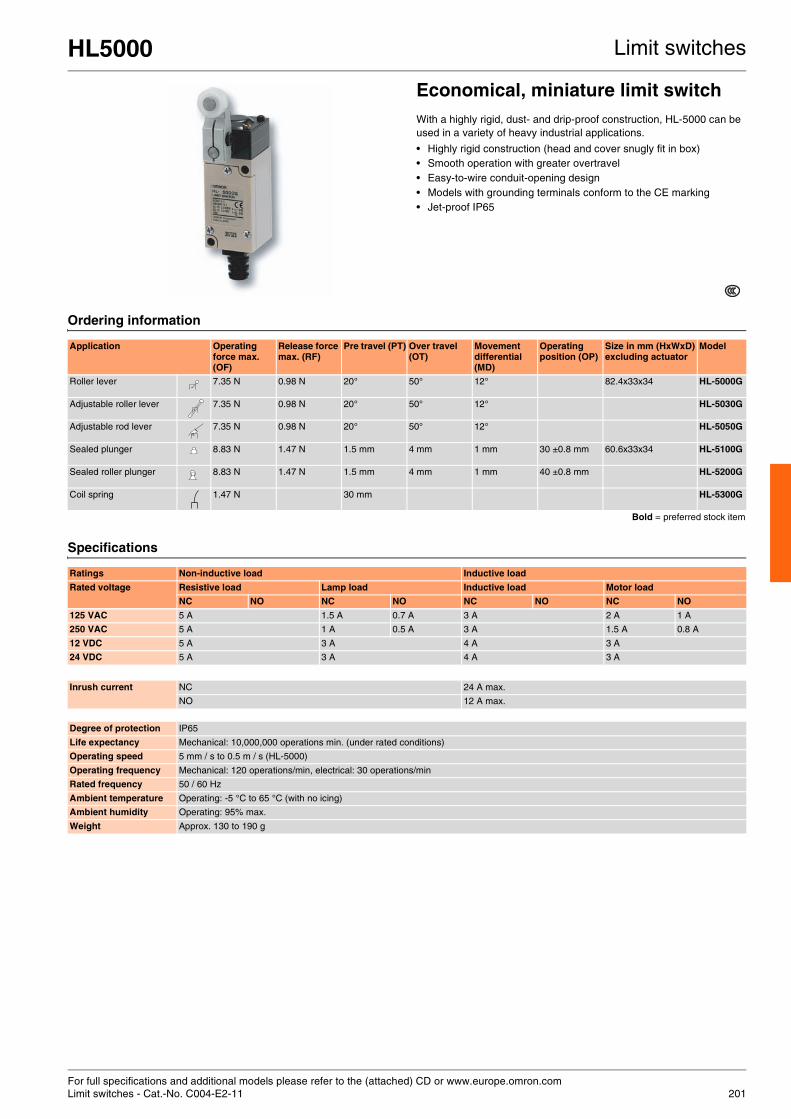
For full specifications and additional models please refer to the (attached) CD or www.europe.omron.comLimit switches - Cat.-No. C004-E2-11 201
HL5000 Limit switches
Economical, miniature limit switchWith a highly rigid, dust- and drip-proof construction, HL-5000 can be used in a variety of heavy industrial applications.
• Highly rigid construction (head and cover snugly fit in box) • Smooth operation with greater overtravel • Easy-to-wire conduit-opening design • Models with grounding terminals conform to the CE marking • Jet-proof IP65
Ordering information
Specifications
Application Operating force max. (OF)
Release force max. (RF)
Pre travel (PT) Over travel (OT)
Movement differential (MD)
Operating position (OP)
Size in mm (HxWxD)excluding actuator
Model
Roller lever 7.35 N 0.98 N 20° 50° 12° 82.4x33x34 HL-5000G
Adjustable roller lever 7.35 N 0.98 N 20° 50° 12° HL-5030G
Adjustable rod lever 7.35 N 0.98 N 20° 50° 12° HL-5050G
Sealed plunger 8.83 N 1.47 N 1.5 mm 4 mm 1 mm 30 ±0.8 mm 60.6x33x34 HL-5100G
Sealed roller plunger 8.83 N 1.47 N 1.5 mm 4 mm 1 mm 40 ±0.8 mm HL-5200G
Coil spring 1.47 N 30 mm HL-5300G
Bold = preferred stock item
Ratings Non-inductive load Inductive load
Rated voltage Resistive load Lamp load Inductive load Motor load
NC NO NC NO NC NO NC NO
125 VAC 5 A 1.5 A 0.7 A 3 A 2 A 1 A
250 VAC 5 A 1 A 0.5 A 3 A 1.5 A 0.8 A
12 VDC 5 A 3 A 4 A 3 A
24 VDC 5 A 3 A 4 A 3 A
Inrush current NC 24 A max.
NO 12 A max.
Degree of protection IP65
Life expectancy Mechanical: 10,000,000 operations min. (under rated conditions)
Operating speed 5 mm / s to 0.5 m / s (HL-5000)
Operating frequency Mechanical: 120 operations/min, electrical: 30 operations/min
Rated frequency 50 / 60 Hz
Ambient temperature Operating: -5 °C to 65 °C (with no icing)
Ambient humidity Operating: 95% max.
Weight Approx. 130 to 190 g

For full specifications and additional models please refer to the (attached) CD or www.europe.omron.comLimit switches - Cat.-No. C001-E2-13202
WL Limit switches
Wide selection of two-circuit limit switchesA wide selection of models is available, including overtravel models with greater OT, lamp-equipped models for checking operation, low-temperature and heat-resistant models and micro-load models. Various plungers and levers are also available.
• Two-circuit limit switch • Direct and pre-wiring • Metal housing, immersion-proof IP67 • Ground terminal models are approved by EN and IEC and bear the
CE marking • UL, CSA
Ordering information
Note: For other model please refer to the datasheet Bold = preferred stock item
Specifications
Actuator Ground terminal
No Yes
Adjustable roller lever: standard WLCA12 WLCA12-G
Adjustable roller lever: standard WLCA12-2 WLCA12-2G
Adjustable roller lever: overtravel 90° WLCA12-2N WLCA12-2NG
Roller lever: standard model (R38) WLCA2 WLCA2-2G
Rod lever: standard WLCA2-2 WLCA2-G
Rod lever: overtravel 90° WLCA2-2N WLCA2-2NG
Roller lever: standard, standard model (R50) WLCA2-7 WLCA2-7G
Roller lever: standard, standard model (R63) WLCA2-8 WLCA2-8G
Fork lever lock: protective, WL-5A100 WLCA32-41 WLCA32-41G
Fork lever lock: protective, WL-5A104 WLCA32-43 WLCA32-43G
Adjustable rod lever: standard WLCL WLCL-G
Adjustable rod lever: overtravel 90°, 25 to 140 mm WLCL-2N WLCL-2NG
Plunger: top plunger WLD WLDG
Plunger: top roller plunger WLD2 WLD2-G
Plunger: top ball plunger WLD3 WLD3-G
Adjustable rod lever: overtravel, high sensitivity, 80°, 350 to 380 mm WLGL WLGL-G
Flexible rod: coil spring WLNJ WLNJ-G
Flexible rod: coil spring, resin rod WLNJ-2 WLNJ-2G
Flexible rod: coil spring, multi-wire WLNJ-30 WLNJ-30G
Flexible rod: steel wire WLNJ-S2 WLNJ-S2-G
Plunger: horizontal roller plunger WLSD2 WLSD2-G
Plunger: horizontal ball plunger WLSD3 WLSD3-G
Plunger: horizontal plunger WLSD WLSD-G
Rated voltage Carry current
Current Volt-amperes
Make Break Make Break
120 VAC 10 A 60 A 6 A 7,200 VA 720 VA
240 VAC 30 A 3 A
480 VAC 15 A 1.5 A
600 VAC 12 A 1.2 A
Agency Standard File No.
UL UL508 E76675
CSA CSA C22.2 No. 14 LR45746
TÜV Rheinland EN60947-5-1 R9551016
Size in mm 68.7Hx40Wx42D (excluding the actuator)
Type Rated voltage
Non-inductive load Inductive load
Resistive load Lamp load Inductive load Motor load
NC NO NC NO NC NO NC NO
Standard, overtravel (except high-sensitivity models), and high-precision models.
125 VAC 10 A 3 A 1.5 A 10 A 5 A 2.5 A
250 VAC 10 A 2 A 1 A 10 A 3 A 1.5 A
500 VAC 10 A 1.5 A 0.8 A 3 A 1.5 A 0.8 A
8 VDC 10 A 6 A 3 A 10 A 6 A
14 VD 10 A 6 A 3 A 10 A 6 A
30 VDC 6 A 4 A 3 A 6 A 4 A
125 VD 0.8 A 0.2 A 0.2 A 0.8 A 0.2 A
250 VDC 0.4 A 0.1 A 0.1 A 0.4 A 0.1 A
Overtravel (high-sensitivity models)
125 VAC 5 A
250 VAC 5 A
125 VDC 0.4 A
250 VD 0.2 A
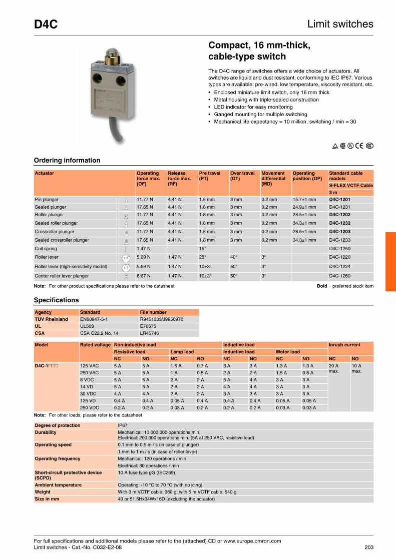
For full specifications and additional models please refer to the (attached) CD or www.europe.omron.comLimit switches - Cat.-No. C032-E2-08 203
D4C Limit switches
Compact, 16 mm-thick, cable-type switchThe D4C range of switches offers a wide choice of actuators. All switches are liquid and dust resistant, conforming to IEC IP67. Various types are available: pre-wired, low temperature, viscosity resistant, etc.
• Enclosed miniature limit switch, only 16 mm thick • Metal housing with triple-sealed construction • LED indicator for easy monitoring • Ganged mounting for multiple switching • Mechanical life expectancy = 10 million, switching / min = 30
Ordering information
Note: For other product specifications please refer to the datasheet Bold = preferred stock item
Specifications
Note: For other loads, please refer to the datasheet
Actuator Operating force max. (OF)
Release force max. (RF)
Pre travel (PT)
Over travel (OT)
Movement differential (MD)
Operating position (OP)
Standard cable models
S-FLEX VCTF Cable
3 m
Pin plunger 11.77 N 4.41 N 1.8 mm 3 mm 0.2 mm 15.7±1 mm D4C-1201
Sealed plunger 17.65 N 4.41 N 1.8 mm 3 mm 0.2 mm 24.9±1 mm D4C-1231
Roller plunger 11.77 N 4.41 N 1.8 mm 3 mm 0.2 mm 28.5±1 mm D4C-1202
Sealed roller plunger 17.65 N 4.41 N 1.8 mm 3 mm 0.2 mm 34.3±1 mm D4C-1232
Crossroller plunger 11.77 N 4.41 N 1.8 mm 3 mm 0.2 mm 28.5±1 mm D4C-1203
Sealed crossroller plunger 17.65 N 4.41 N 1.8 mm 3 mm 0.2 mm 34.3±1 mm D4C-1233
Coil spring 1.47 N 15° D4C-1250
Roller lever 5.69 N 1.47 N 25° 40° 3° D4C-1220
Roller lever (high-sensitivity model) 5.69 N 1.47 N 10±3° 50° 3° D4C-1224
Center roller lever plunger 6.67 N 1.47 N 10±3° 50° 3° D4C-1260
Agency Standard File number
TÜV Rheinland EN60947-5-1 R9451333/J9950970
UL UL508 E76675
CSA CSA C22.2 No. 14 LR45746
Model Rated voltage Non-inductive load Inductive load Inrush current
Resistive load Lamp load Inductive load Motor load
NC NO NC NO NC NO NC NO NC NO
D4C-1### 125 VAC 5 A 5 A 1.5 A 0.7 A 3 A 3 A 1.3 A 1.3 A 20 Amax.
10 Amax.250 VAC 5 A 5 A 1 A 0.5 A 2 A 2 A 1.5 A 0.8 A
8 VDC 5 A 5 A 2 A 2 A 5 A 4 A 3 A 3 A
14 VD 5 A 5 A 2 A 2 A 4 A 4 A 3 A 3 A
30 VDC 4 A 4 A 2 A 2 A 3 A 3 A 3 A 3 A
125 VD 0.4 A 0.4 A 0.05 A 0.4 A 0.4 A 0.4 A 0.05 A 0.05 A
250 VDC 0.2 A 0.2 A 0.03 A 0.2 A 0.2 A 0.2 A 0.03 A 0.03 A
Degree of protection IP67
Durability Mechanical: 10,000,000 operations min.Electrical: 200,000 operations min. (5A at 250 VAC, resistive load)
Operating speed 0.1 mm to 0.5 m / s (in case of plunger)
1 mm to 1 m / s (in case of roller lever)
Operating frequency Mechanical: 120 operations / min
Electrical: 30 operations / min
Short-circuit protective device (SCPD)
10 A fuse type gG (IEC269)
Ambient temperature Operating: -10 °C to 70 °C (with no icing)
Weight With 3 m VCTF cable: 360 g; with 5 m VCTF cable: 540 g
Size in mm 49 or 51.5Hx34Wx16D (excluding the actuator)

For full specifications and additional models please refer to the (attached) CD or www.europe.omron.comLimit switches - Cat.-No. C116-E2-02204
D4CC Limit switches
Compact, 16 mm thick connector-type switchThe D4CC family of limit switches comes as standard with a triple-seal construction (IP67), cable connectors for easy switch replacement and an operation indicator for easy monitoring.
• Miniature limit switch • Various models including roller lever • Switches are only 16 mm thick with connector • Cable connectors for easy switch replacement • Immersion proof; IEC IP67, UL and CSA (type 3, 4 and 13)
Ordering information
Accessories
Specifications
Actuator Operating force max. (OF)
Release force max. (RF)
Pre travel (PT)
Over travel (OT)
Movement differential (MD)
Operating position (OP)
1 A at 125 VAC 1 A at 30 VDC
Without indicator Without indicator
Pin plunger 11.77 N 4.41 N 1.8 mm 3 mm 0.2 mm 15.7 ±1 mm D4CC-1001 D4CC-3001
Roller plunger 11.77 N 4.41 N 1.8 mm 3 mm 0.2 mm 28.5 ±1 mm D4CC-1002 D4CC-3002
Crossroller plunger 11.77 N 4.41 N 1.8 mm 3 mm 0.2 mm 28.5 ±1 mm D4CC-1003 D4CC-3003
High-sensitivity roller lever 5.69 N 1.47 N 10 ±3° 50° 3° D4CC-1024 D4CC-3024
Sealed pin plunger 17.65 N 4.41 N 1.8 mm 3 mm 0.2 mm 24.9 ±1 mm D4CC-1031 D4CC-3031
Sealed roller plunger 17.65 N 4.41 N 1.8 mm 3 mm 0.2 mm 34.3 ±1 mm D4CC-1032 D4CC-3032
Sealed crossroller plunger 17.65 N 4.41 N 1.8 mm 3 mm 0.2 mm 34.3 ±1 mm D4CC-1033 D4CC-3033
Plastic rod 1.47 N 15° D4CC-1050 D4CC-3050
Center roller lever 6.67 N 1.47 N 10 ±3° 50° 3° D4CC-1060 D4CC-3060
Type Appearance Number of conductors Cable length Model
VAC Straight 4 2 m XS2F-A421-D90-A
5 m XS2F-A421-G90-A
10 m XS2F-A421-J90-A
VDC 2 m XS2F-D421-D80-A
5 m XS2F-D421-G80-A
10 m XS2F-D421-J80-A
Bold = preferred stock item
Rated voltage Carry current Current Volt-amperes
Make Break Make Break
120 VAC 1.0 A 3.6 A 3.6 A 432 VA 72 VA
Agency Standard File number
UL UL508 E76675
CSA CSA C22.2 No. 14 LR45746
Rated voltage Non-inductive load Inductive load
Resistive load Lamp load Inductive load Motor load
NC NO NC NO NC NO NC NO
125 VAC 1 A 1 A 1 A 0.7 A 1 A 1 A 1 A 1 A
30 VDC 1 A 1 A 1 A 1 A 1 A 1 A 1 A 1 A
Degree of protection IP67
Durability Mechanical: 10,000,000 operations min., electrical: 200,000 operations min. (1 A at 125 VAC, resistive load)
Operating speed Plunger: 0.1 mm to 0.5 m / s, roller lever: 1 mm to 1 m / s
Operating frequency Mechanical: 120 operations/min, electrical: 30 operations/min
Ambient temperature Operating: -10 °C to 70 °C (with no icing)
Weight Approx. 120 g (in the case of D4CC-1002)
Size in mm 57 or 59.5Hx34Wx16D (excluding the actuator)
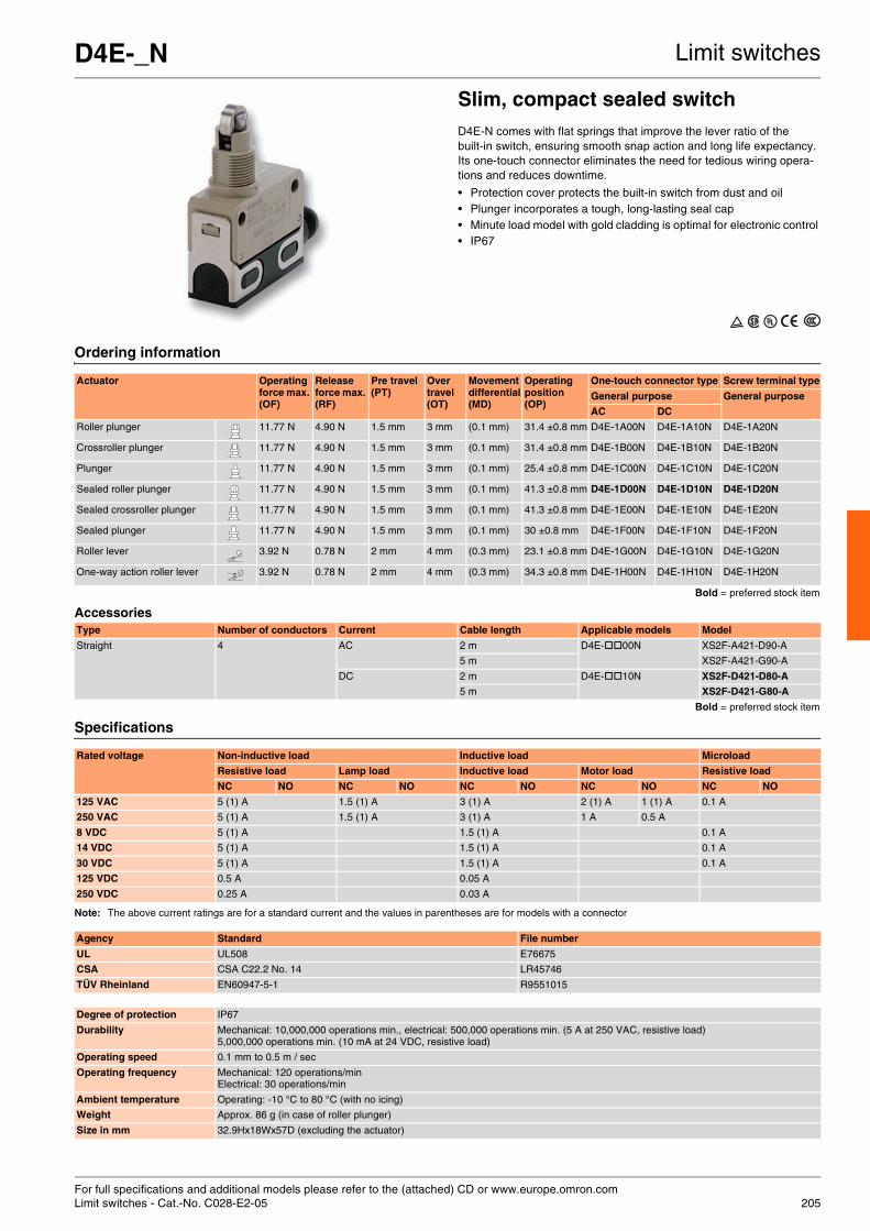
For full specifications and additional models please refer to the (attached) CD or www.europe.omron.comLimit switches - Cat.-No. C028-E2-05 205
D4E-_N Limit switches
Slim, compact sealed switchD4E-N comes with flat springs that improve the lever ratio of the built-in switch, ensuring smooth snap action and long life expectancy. Its one-touch connector eliminates the need for tedious wiring opera-tions and reduces downtime.
• Protection cover protects the built-in switch from dust and oil • Plunger incorporates a tough, long-lasting seal cap • Minute load model with gold cladding is optimal for electronic control • IP67
Ordering information
Accessories
Specifications
Note: The above current ratings are for a standard current and the values in parentheses are for models with a connector
Actuator Operating force max. (OF)
Release force max. (RF)
Pre travel (PT)
Over travel (OT)
Movement differential (MD)
Operating position (OP)
One-touch connector type Screw terminal type
General purpose General purpose
AC DC
Roller plunger 11.77 N 4.90 N 1.5 mm 3 mm (0.1 mm) 31.4 ±0.8 mm D4E-1A00N D4E-1A10N D4E-1A20N
Crossroller plunger 11.77 N 4.90 N 1.5 mm 3 mm (0.1 mm) 31.4 ±0.8 mm D4E-1B00N D4E-1B10N D4E-1B20N
Plunger 11.77 N 4.90 N 1.5 mm 3 mm (0.1 mm) 25.4 ±0.8 mm D4E-1C00N D4E-1C10N D4E-1C20N
Sealed roller plunger 11.77 N 4.90 N 1.5 mm 3 mm (0.1 mm) 41.3 ±0.8 mm D4E-1D00N D4E-1D10N D4E-1D20N
Sealed crossroller plunger 11.77 N 4.90 N 1.5 mm 3 mm (0.1 mm) 41.3 ±0.8 mm D4E-1E00N D4E-1E10N D4E-1E20N
Sealed plunger 11.77 N 4.90 N 1.5 mm 3 mm (0.1 mm) 30 ±0.8 mm D4E-1F00N D4E-1F10N D4E-1F20N
Roller lever 3.92 N 0.78 N 2 mm 4 mm (0.3 mm) 23.1 ±0.8 mm D4E-1G00N D4E-1G10N D4E-1G20N
One-way action roller lever 3.92 N 0.78 N 2 mm 4 mm (0.3 mm) 34.3 ±0.8 mm D4E-1H00N D4E-1H10N D4E-1H20N
Bold = preferred stock item
Type Number of conductors Current Cable length Applicable models Model
Straight 4 AC 2 m D4E- 00N XS2F-A421-D90-A
5 m XS2F-A421-G90-A
DC 2 m D4E- 10N XS2F-D421-D80-A
5 m XS2F-D421-G80-A
Bold = preferred stock item
Rated voltage Non-inductive load Inductive load Microload
Resistive load Lamp load Inductive load Motor load Resistive load
NC NO NC NO NC NO NC NO NC NO
125 VAC 5 (1) A 1.5 (1) A 3 (1) A 2 (1) A 1 (1) A 0.1 A
250 VAC 5 (1) A 1.5 (1) A 3 (1) A 1 A 0.5 A
8 VDC 5 (1) A 1.5 (1) A 0.1 A
14 VDC 5 (1) A 1.5 (1) A 0.1 A
30 VDC 5 (1) A 1.5 (1) A 0.1 A
125 VDC 0.5 A 0.05 A
250 VDC 0.25 A 0.03 A
Agency Standard File number
UL UL508 E76675
CSA CSA C22.2 No. 14 LR45746
TÜV Rheinland EN60947-5-1 R9551015
Degree of protection IP67
Durability Mechanical: 10,000,000 operations min., electrical: 500,000 operations min. (5 A at 250 VAC, resistive load)5,000,000 operations min. (10 mA at 24 VDC, resistive load)
Operating speed 0.1 mm to 0.5 m / sec
Operating frequency Mechanical: 120 operations/minElectrical: 30 operations/min
Ambient temperature Operating: -10 °C to 80 °C (with no icing)
Weight Approx. 86 g (in case of roller plunger)
Size in mm 32.9Hx18Wx57D (excluding the actuator)

For full specifications and additional models please refer to the (attached) CD or www.europe.omron.comLimit switches - Cat.-No. C027-E2-09206
D4MC Limit switches
Economical, high-utility enclosed switchD4MC provides users with high precision and a long life (10,000,000 mechanical operations). It is sealed with a gasket diaphragm without use of any adhesive or pin, making it suitable for applications demand-ing higher mechanical strength and for dust-proof and drip-proof appli-cations.
• Various models, plungers and levers available • Panel-mount versions have the same operating position
as the Z basic switch • IP67, UL, CSA
Ordering information
Note: Use molded terminal models when using the switch under one of the following conditions: Bold = preferred stock itemdusty, high amount of dripping oil or high humidity
Specifications
Actuator Operating force max. (OF)
Release force max. (RF)
Pre travel (PT) Over travel (OT)
Movement differential (MD)
Operating position (OP)
Model
Panel mount plunger 5.88 N 0.98 N 1.6 mm 5 mm 0.2 mm 21.8 ±1.2 mm D4MC-5000
Panel mount roller 5.88 N 0.98 N 1.6 mm 5 mm 0.2 mm 33.4 ±1.2 mm D4MC-5020
Panel mount crossroller 5.88 N 0.98 N 1.6 mm 5 mm 0.2 mm 33.4 ±1.2 mm D4MC-5040
Short hinge lever 2.55 N 0.34 N --- 2.5 mm 1.7 mm 25 ±1 mm D4MC-1020
Hinge lever 1.67 N 0.25 N --- 4 mm 3 mm 25 ±1 mm D4MC-1000
Hinge roller lever 1.96 N 0.39 N --- 5 mm 3 mm 40 ±1 mm D4MC-2000
Short hinge roller 2.94 N 0.39 N --- 2 mm 1.5 mm 40 ±1 mm D4MC-2020
One-way action short hinge roller 2.94 N 0.39 N --- 2 mm 1.5 mm 50 ±1 mm D4MC-3030
Rated voltage Non-inductive load Inductive load
Resistive load Lamp load Inductive load Motor load
NC NO NC NO NC NO NC NO
125 VAC 10 A 3 A 1.5 A 10 A 5 A 2.5 A
250 VAC 10 A 2.5 A 1.25 A 10 A 3 A 1.5 A
480 VAC 3 A 1.5 A 0.75 A 2.5 A 1.5 A 0.75 A
8 VDC 10 A 3 A 1.5 A 6 A 5 A 2.5 A
14VDC 10 A 3 A 1.5 A 6 A0.75 5 A 2.5 A
30 VDC 6 A 3 A 1.5 A 5 A 5 A 2.5 A
125VDC 0.5 A 0.4 A 0.05 A 0.05 A
250 VDC 0.25 A 0.2 A 0.03 A 0.03 A
Rated voltage Carry current Current
Make Break
120 VAC 10 A 60 A 6 A
240 VAC 30 A 3 A
Degree of protection IP67 (NEMA250: 6.6P)
Life expectancy Mechanical: 10,000,000 operations min., electrical: 500,000 operations min.
Operating speed 0.05 mm / s to 0.5 m / s (at panel mount plunger)
Operating frequency Mechanical: 120 operations/min, electrical: 20 operations / min
Pollution degree (operating environment) 3 (IEC947-5-1)
Protection against electric shock Class II
PTI (tracking characteristics) 175
Switch category D (IEC335)
Rated operating current (Ie) 10 A
Rated operating voltage (Ue) 250 VAC
Ambient temperature Operating: -10 °C to 80 °C (with no icing)
Weight Approx. 71 g (at panel mount plunger)
Size in mm 45Hx21.7Wx55D (excluding the actuator)
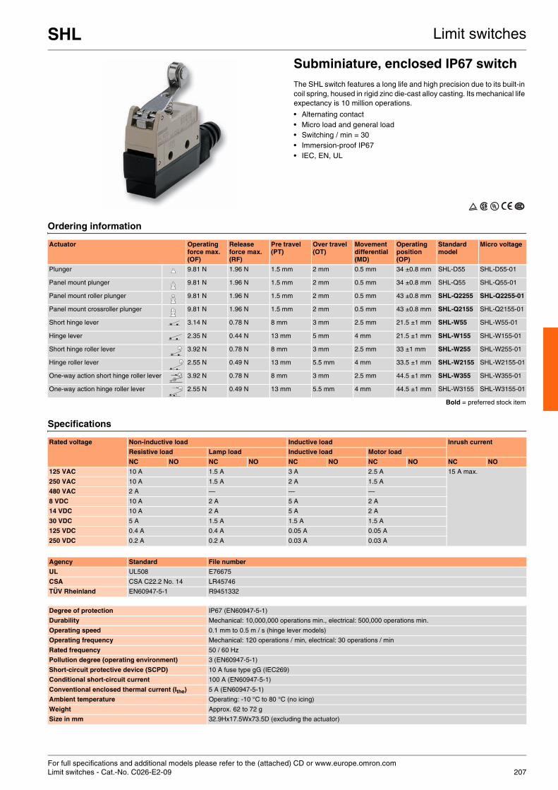
For full specifications and additional models please refer to the (attached) CD or www.europe.omron.comLimit switches - Cat.-No. C026-E2-09 207
SHL Limit switches
Subminiature, enclosed IP67 switchThe SHL switch features a long life and high precision due to its built-in coil spring, housed in rigid zinc die-cast alloy casting. Its mechanical life expectancy is 10 million operations.
• Alternating contact • Micro load and general load • Switching / min = 30 • Immersion-proof IP67 • IEC, EN, UL
Ordering information
Specifications
Actuator Operating force max. (OF)
Release force max. (RF)
Pre travel (PT)
Over travel (OT)
Movement differential (MD)
Operating position (OP)
Standard model
Micro voltage
Plunger 9.81 N 1.96 N 1.5 mm 2 mm 0.5 mm 34 ±0.8 mm SHL-D55 SHL-D55-01
Panel mount plunger 9.81 N 1.96 N 1.5 mm 2 mm 0.5 mm 34 ±0.8 mm SHL-Q55 SHL-Q55-01
Panel mount roller plunger 9.81 N 1.96 N 1.5 mm 2 mm 0.5 mm 43 ±0.8 mm SHL-Q2255 SHL-Q2255-01
Panel mount crossroller plunger 9.81 N 1.96 N 1.5 mm 2 mm 0.5 mm 43 ±0.8 mm SHL-Q2155 SHL-Q2155-01
Short hinge lever 3.14 N 0.78 N 8 mm 3 mm 2.5 mm 21.5 ±1 mm SHL-W55 SHL-W55-01
Hinge lever 2.35 N 0.44 N 13 mm 5 mm 4 mm 21.5 ±1 mm SHL-W155 SHL-W155-01
Short hinge roller lever 3.92 N 0.78 N 8 mm 3 mm 2.5 mm 33 ±1 mm SHL-W255 SHL-W255-01
Hinge roller lever 2.55 N 0.49 N 13 mm 5.5 mm 4 mm 33.5 ±1 mm SHL-W2155 SHL-W2155-01
One-way action short hinge roller lever 3.92 N 0.78 N 8 mm 3 mm 2.5 mm 44.5 ±1 mm SHL-W355 SHL-W355-01
One-way action hinge roller lever 2.55 N 0.49 N 13 mm 5.5 mm 4 mm 44.5 ±1 mm SHL-W3155 SHL-W3155-01
Bold = preferred stock item
Rated voltage Non-inductive load Inductive load Inrush current
Resistive load Lamp load Inductive load Motor load
NC NO NC NO NC NO NC NO NC NO
125 VAC 10 A 1.5 A 3 A 2.5 A 15 A max.
250 VAC 10 A 1.5 A 2 A 1.5 A
480 VAC 2 A — — —
8 VDC 10 A 2 A 5 A 2 A
14 VDC 10 A 2 A 5 A 2 A
30 VDC 5 A 1.5 A 1.5 A 1.5 A
125 VDC 0.4 A 0.4 A 0.05 A 0.05 A
250 VDC 0.2 A 0.2 A 0.03 A 0.03 A
Agency Standard File number
UL UL508 E76675
CSA CSA C22.2 No. 14 LR45746
TÜV Rheinland EN60947-5-1 R9451332
Degree of protection IP67 (EN60947-5-1)
Durability Mechanical: 10,000,000 operations min., electrical: 500,000 operations min.
Operating speed 0.1 mm to 0.5 m / s (hinge lever models)
Operating frequency Mechanical: 120 operations / min, electrical: 30 operations / min
Rated frequency 50 / 60 Hz
Pollution degree (operating environment) 3 (EN60947-5-1)
Short-circuit protective device (SCPD) 10 A fuse type gG (IEC269)
Conditional short-circuit current 100 A (EN60947-5-1)
Conventional enclosed thermal current (Ithe) 5 A (EN60947-5-1)
Ambient temperature Operating: -10 °C to 80 °C (no icing)
Weight Approx. 62 to 72 g
Size in mm 32.9Hx17.5Wx73.5D (excluding the actuator)

For full specifications and additional models please refer to the (attached) CD or www.europe.omron.comLimit switches - Cat.-No. C025-E2-09208
ZC-55 Limit switches
Small, high-precision enclosed switchThe ZC-55 switch is a modified version of the Z basic switch as a built-in switch. The mounting pitch is the same. It requires less operating force than conventional limit switches. ZC-55 is economical and has a long life expectancy.
• Metal housing • Alternating contact • Switching / min = 20 • Immersion-proof IP67 • UL, CSA and EN
Ordering information
Specifications
Actuator Operating force max. (OF)
Release force max. (RF)
Pre travel (PT) Over travel (OT)
Movement differential (MD)
Operating position (OP)
Model
Plunger 11.8 N 4.90 N 1.5 mm 2.4 mm 0.2 mm 32.4 ±0.8 mm ZC-D55
Panel mount plunger 11.8 N 4.90 N 1.5 mm 3 mm 0.2 mm 32.2 ±0.8 mm ZC-Q55
Panel mount roller plunger 11.8 N 4.90 N 1.5 mm 4 mm 0.2 mm 32.2 ±0.8 mm ZC-Q2255
Panel mount crossroller plunger 11.8 N 4.90 N 1.5 mm 5 mm 0.2 mm 32.2 ±0.8 mm ZC-Q2155
Sealed roller plunger 6.86 N 1.67 N 1.5 mm 2.5 mm 0.2 mm 47.4 ±0.8 mm ZC-N2255
Sealed crossroller plunger 6.86 N 1.67 N 1.5 mm 2.5 mm 0.2 mm 47.4 ±0.8 mm ZC-N2155
Short hinge lever 3.92 N 0.78 N 6 mm 1 mm 28.5±1.2 mm 34.7 mm ZC-W55
Hinge lever 2.75 N 0.59 N 8.4 mm 1.4 mm 28.5±1.2 mm 36.7 mm ZC-W155
Short hinge roller lever 3.92 N 0.78 N 6 mm 1 mm 43±1.2 mm 49.2 mm ZC-W255
Hinge roller lever 2.75 N 0.59 N 8.4 mm 1.4 mm 43±1.2 mm 51.3 mm ZC-W2155
One-way action short hinge roller lever 3.92 N 0.78 N 6 mm 1 mm 53±1.2 mm 59.2 mm ZC-W355
One-way action hinge roller lever 2.75 N 0.59 N 8.4 mm 1.4 mm 53±1.2 mm 61.2 mm ZC-W3155
Bold = preferred stock item
Rated voltage Non-inductive load Inductive load
Resistive load Lamp load Inductive load Motor load
NC NO NC NO NC NO NC NO
125 VAC 10 A 3 A 1.5 A 10 A 5 A 2.5 A
250 VAC 10 A 2.5 A 1.25 A 10 A 3 A 1.5 A
8 VDC 10 A 3 A 1.5 A 6 A 5 A 2.5 A
14 VDC 10 A 3 A 1.5 A 6 A 5 A 2.5 A
30 VDC 6 A 3 A 1.5 A 5 A 5 A 2.5 A
125 VDC 0.5 A 0.4 A 0.4 A 0.05 A 0.05 A 0.05 A
250 VDC 0.25 A 0.2 A 0.2 A 0.03 A 0.03 A 0.03 A
Agency Standard File number
UL UL508 E76675
CSA CSA C22.2 No. 14 LR45258
TÜV Rheinland EN60947-1, EN60947-5-1 J9650089
Degree of protection IP67
Durability Mechanical:10,000,000 operations min., electrical: 500,000 operations min.
Operating speed 0.05 mm to 0.5 m / s (at pin plunger)
Operating frequency Mechanical:120 operations/min, electrical: 20 operations/min
Pollution degree (operating environment)
3 (IEC947-5-1)
PT1 (tracking characteristics) 175
Rated operating current (Ie) 10 A
Rated operating voltage (Ue) 250 VAC
Ambient temperature Operating: -10 °C to 80 °C (with no icing)
Weight Approx. 92 g (in case of ZC-Q22(21)55)
Size in mm 41Hx21.7Wx55D (excluding the actuator)
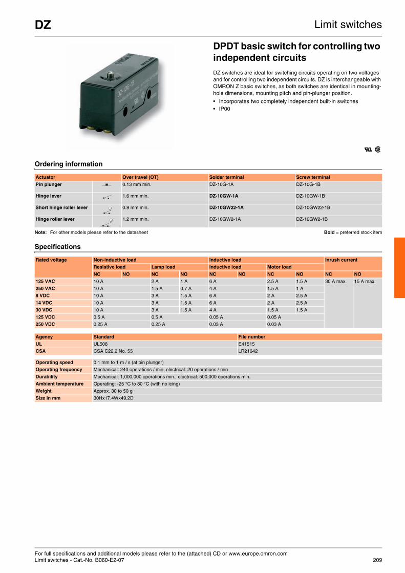
For full specifications and additional models please refer to the (attached) CD or www.europe.omron.comLimit switches - Cat.-No. B060-E2-07 209
DZ Limit switches
DPDT basic switch for controlling two independent circuitsDZ switches are ideal for switching circuits operating on two voltages and for controlling two independent circuits. DZ is interchangeable with OMRON Z basic switches, as both switches are identical in mounting-hole dimensions, mounting pitch and pin-plunger position.
• Incorporates two completely independent built-in switches • IP00
Ordering information
Note: For other models please refer to the datasheet Bold = preferred stock item
Specifications
Actuator Over travel (OT) Solder terminal Screw terminal
Pin plunger 0.13 mm min. DZ-10G-1A DZ-10G-1B
Hinge lever 1.6 mm min. DZ-10GW-1A DZ-10GW-1B
Short hinge roller lever 0.9 mm min. DZ-10GW22-1A DZ-10GW22-1B
Hinge roller lever 1.2 mm min. DZ-10GW2-1A DZ-10GW2-1B
Rated voltage Non-inductive load Inductive load Inrush current
Resistive load Lamp load Inductive load Motor load
NC NO NC NO NC NO NC NO NC NO
125 VAC 10 A 2 A 1 A 6 A 2.5 A 1.5 A 30 A max. 15 A max.
250 VAC 10 A 1.5 A 0.7 A 4 A 1.5 A 1 A
8 VDC 10 A 3 A 1.5 A 6 A 2 A 2.5 A
14 VDC 10 A 3 A 1.5 A 6 A 2 A 2.5 A
30 VDC 10 A 3 A 1.5 A 4 A 1.5 A 1.5 A
125 VDC 0.5 A 0.5 A 0.05 A 0.05 A
250 VDC 0.25 A 0.25 A 0.03 A 0.03 A
Agency Standard File number
UL UL508 E41515
CSA CSA C22.2 No. 55 LR21642
Operating speed 0.1 mm to 1 m / s (at pin plunger)
Operating frequency Mechanical: 240 operations / min, electrical: 20 operations / min
Durability Mechanical: 1,000,000 operations min., electrical: 500,000 operations min.
Ambient temperature Operating: -25 °C to 80 °C (with no icing)
Weight Approx. 30 to 50 g
Size in mm 30Hx17.4Wx49.2D

For full specifications and additional models please refer to the (attached) CD or www.europe.omron.comLimit switches - Cat.-No. B003-E2-08210
X Limit switches
Direct-current switch with built-in magnetic blow-outX switches incorporate a small permanent magnet in the contact mechanism to deflect the arc to effectively extinguish it. These switches have the same shape and mounting procedure as the Z basic switches.
• General-purpose basic switch • Direct-current switch with built-in magnetic blow-out • IP00
Ordering information
Specifications
Actuator Solder Screw
Pin plunger X-10G X-10G-B
Slim spring X-10GS X-10GS-B
Short spring X-10GD X-10GD-B
Panel mount X-10GQ X-10GQ-B
Panel mount X-10GQ22 X-10GQ22-B
Panel mount cross X-10GQ21 X-10GQ21-B
Leaf spring X-10GL X-10GL-B
Short hinge lever X-10GW21 X-10GW21-B
Hinge lever X-10GW X-10GW-B
Low-force hinge X-10GW4 X-10GW4-B
Short hinge roller X-10GW22 X-10GW22-B
Hinge roller lever X-10GW2 X-10GW2-B
Reverse hinge X-10GM X-10GM-B
Reverse short X-10GM22 X-10GM22-B
Reverse hinge X-10GM2 X-10GM2-B
Bold = preferred stock item
Rated voltage Non-inductive load Inductive load
Resistive load Lamp load Inductive load Motor load
NC NO NC NO NC NO NC NO
8 VDC 10 A 3 A 1.5 A 10 A 10 A 5 A 2.5 A
14 VDC 10 A 3 A 1.5 A 10 A 10 A 5 A 2.5 A
30 VDC 10 A 3 A 1.5 A 10 A 10 A 5 A 2.5 A
125 VDC 10 A 3 A 1.5 A 7.5 A 6 A 5 A 2.5 A
250 VDC 3 A 1.5 A 075 A 2 A 1.5 A 2 A 1.5 A
Agency Standard File number
UL UL508 E41515
CSA CSA C22.2 No. 55 LR21642
Operating speed 0.1 mm to 1 m / s
Operating frequency Mechanical: 240 operations/min, electrical: 20 operations/min
Durability Mechanical: 1,000,000 operations min., electrical: 100,000 operations min.
Degree of protection IP00
Degree of protection against electric shock Class I
Proof tracking index (PTI) 175
Ambient temperature Operating: -25 °C to 80 °C (with no icing)
Weight Approx. 27 to 63 g
Size in mm 24.2Hx49.2Wx17.5D (excluding the actuator)

For full specifications and additional models please refer to the (attached) CD or www.europe.omron.comLimit switches - Cat.-No. B001-E2-12 211
Z Limit switches
Standard high-precision switchZ basic switches provide a large switching capacity of 15 A with very high repeat accuracy. They come in a wide range of variations in contact form for your selection: basic, split-contact, maintained-contact and adjustable-contact gap types.
• General-purpose basic switch • A series of standard models for micro loads is available • High-precision switching • A wide range of variations in contact • Drip-proof IP00 / IP62
Ordering information
Note: Many other types are also available, please refer to the full datasheet. Bold = preferred stock item
Specifications
Ratings Contact gap Actuator Model
Solder terminal Screw terminal
15 A 0.5 mm Pin plunger Z-15G Z-15G-B
Short spring plunger Z-15GD Z-15GD-B
Leaf spring (high OF) Z-15GL Z-15GL-B
Roller leaf spring Z-15GL2 Z-15GL2-B
Reverse hinge lever Z-15GM Z-15GM-B
Reverse hinge roller lever Z-15GM2 Z-15GM2-B
Reverse hinge short roller lever Z-15GM22 Z-15GM22-B
Panel mount plunger (medium OP) Z-15GQ Z-15GQ-B
Panel mount plunger (low OP) Z-15GQ3 Z-15GQ3-B
Panel mount plunger (high OP) Z-15GQ8 Z-15GQ8-B
Panel mount cross roller plunger Z-15GQ21 Z-15GQ21-B
Panel mount roller plunger Z-15GQ22 Z-15GQ22-B
Slim spring plunger Z-15GS Z-15GS-B
Hinge lever (low OF) Z-15GW Z-15GW-B
Hinge roller lever Z-15GW2 Z-15GW2-B
Short hinge lever Z-15GW21 Z-15GW21-B
Short hinge roller lever Z-15GW22 Z-15GW22-B
Unidirectional short hinge roller lever (low OF) Z-15GW2277 Z-15GW2277-B
Hinge roller lever (large roller) Z-15GW25 Z-15GW25-B
Hinge lever (medium OF) Z-15GW3 Z-15GW3-B
Low-force hinger lever Z-15GW4 Z-15GW4-B
Hinge lever (high OF) Z-15GW32 Z-15GW32-B
Short hinge cross roller lever Z-15GW49 Z-15GW49-B
Hinge cross roller lever Z-15GW54 Z-15GW54-B
Agency Standard File number
UL UL508 E41515
CSA CSA C22.2 No. 55 LR21642
TÜV Rheinland EN61058-1 R9451585
Degree of protection General purpose: IP00, drip-proof: IP62
Degree of protection against electric shock Class I
Proof tracking index (PTI) 175
Switch category D (IEC335-1)
Ambient operating temperature General purpose: -25 °C to 80 °C (with no icing)Drip-proof: -15 °C to 80 °C (with no icing)
Size in mm 24.2Hx49.2Wx17.5D (excluding the actuator)

212
Table of contentsSelection table 213
Pushbutton switches A16 214
A22 216
Indicators M16 218
M22 219

Pushbutton switches
213
Selection table
Category Pushbutton switch IndicatorS
elec
tio
n c
rite
ria
Model A16 A22 M16 M22Mounting Nut-mounting
Size 16 mm 22 mm 16 mm 22 mm
Shape
Pu
shb
utt
on
co
lou
r
Inca
nd
esce
nt
lam
p-l
igh
ted
Red
Yellow
Pure yellow
Green
White
Blue
LE
D-l
igh
ted
Red
Yellow
Pure yellow
Green
White
Blue
No
n-l
igh
ted
Red
Yellow
Green
White
Blue
Black
Fea
ture
s
Momentary operation
Self-holding
Number of contacts 2 6
IP rating IP40 / IP65 IP65 IP40 / IP65 IP65
Legend plate
Sw
itch
rat
ing
s [A
] 125 VAC 5 10
250 VAC 3 6
30 VDC 3 10
Rated load 5 A at 125 VAC, 3 A at 250 VAC, 3 A at 30 VDC
10 A at 110 VAC, 6 A at 220 VAC
Ter
min
als Solder
PCB
Screw-less Clamp
Op
erat
ing
vo
ltag
e
5 VDC
12 VDC
24 VDC
Fo
rm
SPDT
DPDT
SPST-NO
SPST-NC
SPST-NO + SPST-NC
DPST-NO
DPST-NC
Page 214 216 218 219
Standard Available No / not available

For full specifications and additional models please refer to the (attached) CD or www.europe.omron.comPushbutton switches - Cat.-No. A124-E2-02214
A16 Pushbutton switches
16 mm pushbutton switchThese subassembled pushbutton switches have a modular construction: pushbutton + case + lamp (if applicable) + switch. A16 is a nut-mounted pushbutton switch with a short mounting depth of less than 28.5 mm below panel.
• Wide variety of control and signal devices: lighted, non-lighted and buzzer
• Quick and easy assembly, snap-in switch • Wide range of switching capacity from standard load to micro load • High reliability, IP65 • UL, cUL, CSA and VDE approved, conforms to EN60947-5-1 and
IEC947-5-1
Ordering information
Cases
Switches Switches with reduced voltage lighting
Lamps
Type Colour Degree of protection
IP40 Oil-resistant IP65
Rectangular Square Round Rectangular Square Round
Non-lightedLEDIncandescent lamp
Red A16L-JR A16L-AR A16L-TR A165L-JR A165L-AR A165L-TR
Yellow A16L-JY A16L-AY A16L-TY A165L-JY A165L-AY A165L-TY
Pure yellow A16L-JPY A16L-APY A16L-TPY A165L-JPY A165L-APY A165L-TPY
White A16L-JW A16L-AW A16L-TW A165L-JW A165L-AW A165L-TW
Blue A16L-JA A16L-AA A16L-TA A165L-JA A165L-AA A165L-TA
Non-lighted Black A16L-JB A16L-AB A16L-TB A165L-JB A165L-AB A165L-TB
LED Green A16L-JGY A16L-AGY A16L-TGY A165L-TGY A165L-AGY A165L-TGY
Non-lighted / incandescent lamp
Green A16L-JG A16L-AG A16L-TG A165L-JG A165L-AG A165L-TG
Bold = preferred stock item
Appearance Classification Model
IP40 Oil-resistant IP65
IP40 Momentary operation Rectangular (2-way guard) A16-CJM A165-CJM
Square A16-CAM A165-CAM
Round A16-CTM A165-CTM
Alternate operation Rectangular (2-way guard) A16-CJA A165-CJA
Square A16-CAA A165-CAA
Round A16-CTA A165-CTA
Appearance Classification Model
Lighted / non-lighted (common use)
Standard load / microload (common use)
SPDT Solder terminal A16-1
DPDT A16-2
SPDT PCB terminal A16-1P
DPDT A16-2P
DPDT Screw-less clamp
A16-2S
Appearance Classification Model
100 V Standard load /microload (common use)
SPDT Solder terminal A16-T1-1
DPDT A16-T1-2
100 V DPDT Screw-less clamp A16-T1-2S
200 V A16-T2-2S
Type Colour 5 VDC 12 VDC 24 VDC
LED Red A16-5DSR A16-12DSR A16-24DSR
Yellow A16-5DSY A16-12DSY A16-24DSY
Green A16-5DSG A16-12DSG A16-24DSG
White *1
*1 Use the white LED together with white or pure yellow pushbuttons.
A16-5DSW A16-12DSW A16-24DSW
Blue A16-5DA A16-12DA A16-24DA
Type 5 VAC / VDC 12 VAC / VDC 24 VAC / VDC
Incandescent lamp A16-5 A16-12 A16-24
Bold = preferred stock item

A16 Pushbutton switches
215
Accessories
Specifications
Name Appearance Classification Remarks Model
Switch guards For rectangular models Cannot be used with the dust cover A16ZJ-5050
For square and round models A16ZA-5050
Dust covers For rectangular models Cannot be used with the switch guard A16ZJ-5060
For round models A16ZA-5060
For round models A16ZT-5060
Panel plugs For rectangular models Used for covering the panel cutouts for future panel expansion A16ZJ-3003
For square models A16ZA-3003
For round models A16ZT-3003
Bold = preferred stock item
Allowable operating frequency
Mechanical Momentary operation: 120 operations / minute max.Alternate operation: 60 operations / minute max.
Electrical 20 operations / minute max.
Durability Mechanical Momentary operation: 2,000,000 operations min. Alternate operation: 200,000 operations min.
Electrical 100,000 operations min.
Ambient temperature Operating: -10 °C to 55 °C (with no icing or condensation)Storage: -25 °C to 65 °C (with no icing or condensation)
Weight Approx. 10 g (in the case of a lighted DPDT switch with solder terminals)
Size in mm Round / square:18Hx18Wx28.5Drectangular: 18Hx24Wx28.5D
Operating characteristics Pushbutton switch
IP40 Oil-resistant IP65
SPDT DPDT SPDT DPDT
Operating force (OF) max. 2.45 N 4.41 N 2.94 N 4.91 N
Releasing force (RF) min. 0.29 N
Total travel (TT) Approx. 3 mm
Pretravel (PT) max. 2.5 mm
Lock stroke (LTA) min. 0.5 mm
Item Screw-less clamp
Recommended wire size 0.5 mm2 twisted wire or 0.8 mm dia. solid wire
Usable wires and tensile strength
Twisted wire 0.3 mm2 0.5 mm2 0.75 mm2 1.25 mm2
Solid wire 0.5 mm dia. 0.8 mm dia. 1.0 mm dia.
Tensile strength
10 N 20 N 30 N 40 N
Length of exposed wire 10 ±1 mm

For full specifications and additional models please refer to the (attached) CD or www.europe.omron.comPushbutton switches - Cat.-No. A128-E2-02216
A22 Pushbutton switches
22 mm pushbutton switchA22 comes in a wide variety of shapes and colours and is installable in 22-dia. or 25-dia. panel cutouts. The switch unit can easily be mounted. A22 is mounted using either open-type (fork-type) or closed-type (round-type) crimp terminals.
• Finger-protection mechanism on switch unit provided as standard feature
• Increased wiring efficiency with three-row mounting of switch blocks • IP65 oil-resistant (non-lighted models), IP65 (lighted models) • Lighted and non-lighted, flat, projection and half- and full-guard
versions • EN60947-5-1, UL and cUL approved
Ordering information
Pushbutton
Switches
Switch blocks
Lamp - LED
Lamp - incandescent lamp
Illumination Colour Flat type Projection type Full-guard type Half-guard type Square / projection type
Square / full-guard type
Round / mushroom type (30-dia. head)
Round / mushroom type (40-dia. head)
Non-lighted Red A22-FR A22-TR A22-GR A22-HR A22-CR A22-DR A22-SR A22-MR
Green A22-FG A22-TG A22-TG A22-HG A22-CG A22-DG A22-SG A22-MG
Yellow A22-FY A22-TY A22-GY A22-HY A22-CY A22-DY A22-SY A22-MY
White A22-FW A22-TW A22-GW A22-HW A22-CW A22-DW A22-SW A22-MW
Blue A22-FA A22-TA A22-GA A22-HA A22-CA A22-DA A22-SA A22-MA
Black A22-FB A22-TB A22-GB A22-HB A22-CB A22-DB A22-SB A22-MB
Lighted Red A22L-TR A22L-GR A22L-HR A22L-CR A22L-DR
Green A22L-TG A22L-GG A22L-HG A22L-CG A22L-DG
Yellow A22L-TY A22L-GY A22L-HY A22L-CY A22L-DY
White A22L-TW A22L-GW A22L-HW A22L-CW A22L-DW
Blue A22L-TA A22L-GA A22L-HA A22L-CA A22L-DA
Buttonsize in mm 29.7 dia. x 12D 29.7 dia. x 19D 29.7 dia. x 19D 29.7 dia. x 12/18.5D 29.8 mm2 x 18D 29.8 mm2 x 18D 30 dia. x 32D 40 dia. x 32D
Bold = preferred stock item
Switch operation
Contacts Non-lighted models
Lighted models
With voltage reduction unit
With voltage reduction unit
110 VAC 220 VAC
Momentary SPST-NO A22-10M A22L-10M A22L-10M-T1 A22L-10M-T2
SPST-NC A22-01M A22L-01M A22L-01M-T1 A22L-01M-T2
SPST-NO + SPST-NC
A22-11M A22L-11M A22L-11M-T1 A22L-11M-T2
DPST-NO A22-20M A22L-20M A22L-20M-T1 A22L-20M-T2
DPST-NC A22-02M A22L-02M A22L-02M-T1 A22L-02M-T2
Alternate SPST-NO A22-10A A22L-10A A22L-10A-T1 A22L-10A-T2
SPST-NC A22-01A A22L-01A A22L-01A-T1 A22L-01A-T2
SPST-NO + SPST-NC
A22-11A A22L-11A A22L-11A-T1 A22L-11A-T2
DPST-NO A22-20A A22L-20A A22L-20A-T1 A22L-20A-T2
DPST-NC A22-02A A22L-02A A22L-02A-T1 A22L-02A-T2
Standard load Model
Switch blocks SPST-NO A22-10
SPST-NC A22-01
DPST-NO A22-20
DPST-NC A22-02
Bold = preferred stock item
AC / DC LED light Operating voltage
6 V 12 V 24 V 24 V superbright
DC Red A22-6DR
Green A22-6DG
Yellow *1
*1 Used when the pushbutton colour is yellow or white
A22-6DY
Blue A22-6DA
AC Red A22-6AR
Green A22-6AG
Yellow *1 A22-6AY
Blue A22-6AA
AC and DC
Red A22-12AR A22-24AR A22-24ASR
Green A22-12AG A22-24AG A22-24ASG
Yellow *1 A22-12AY A22-24AY A22-24ASY
Blue A22-12AA A22-24AA A22-24ASA
Operating voltage
5 VAC / VDC 12 VAC / VDC 24 VAC / VDC
A22-5 A22-12 A22-24
Bold = preferred stock item

A22 Pushbutton switches
217
Accessories
Specifications
Contact ratings (standard load)
Contacts (microload)
LED indicators without voltage reduction unit
Super-bright LED indicator
Incandescent lamp
Voltage-reduction lighting
Remarks Model
Lamp sockets Direct lighting Used when changing the lighting method (LED only) A22-TN
Voltage-reduction lighting 220 VAC A22-T2
Mounting latches
For momentary models Order mounting latches only when mounting switch blocks or lamp sockets are purchased individually
A22-3200
Legend plate frames
Large size With snap-in legend plate, without text, black Snap-in legend plate is acrylic A22Z-3333
Without snap-in legend plate A22Z-3330
Sealing caps For projection models Used to prevent dust or water from entering the operation unit (pushbutton, etc.), color: opaque, material: silicon
A22Z-3600T
Three-throw spacer Used when mounting three non-lighted switches A22Z-3003
Control boxes(enclosures)
Exclusively for A22 One hole Do not use DPST-NO or DPST-NC switches, material: polycarbonate resin
A22Z-B101
Two holes A22Z-B102
Three holes A22Z-B103
Snap-in legend plates
Standard size Without text White Attached to the standard-size legend plate frame, material: acryclic
A22Z-3443W
Transparent A22Z-3443C
White text on black background ON A22Z-3443B-5
OFF A22Z-3443B-6
DOWN A22Z-3443B-8
POWER ON A22Z-3443B-9
Large size Without text White Attached to the large-size legend plate frame, material: acrylic
A22Z-3453W
Transparent A22Z-3453C
For emergency stop switch
60-dia. round plate with black letters on a yellow background “EMERGENCY STOP” is engraved on the plate. Used as an emergency stop switch legend plate
A22Z-3466-1
90-dia. round plate with black letters on a yellow background A22Z-3476-1
Lamp extractor Rubber tool used to easily replace lamps A22Z-3901
Tightening wrench Tool used to tighten nuts from the back of the panel A22Z-3905
Bold = preferred stock item
Recognized organization Standards File number
UL, cUL UL508 E41515
— EN60947-5-1 —
Rated carry current (A)
Rated voltage
Rated current (A)
AC15 (inductive load)
AC12 (resistive load)
DC13 (inductive load)
DC12 (resistive load)
10 24 VAC 10 10
110 VAC 5 10
220 VAC 3 6
380 VAC 2 3
440 VAC 1 2
24 VDC 1,5 10
110 VDC 0,5 2
220 VDC 0,2 0,6
380 VDC 0,1 0,2
Rated applicable load Minimum applicable load
50 mA at 5 VDC (resistive load) 1 mA at 5 VDC
Rated voltage Rated current Operating voltage
6 VDC 60 mA (20 mA) 6 VDC ±5%
6 VAC 60 mA (20 mA) 6 VAC / VDC ±5%
12 VAC / VDC 30 mA (10 mA) 12 VAC / VDC ±5%
24 VAC / VDC 15 mA (10 mA) 24 VAC / VDC ±5%
Rated voltage Rated current Operating voltage
24 VAC / VDC 15 mA 24 VAC / VDC ±5%
Rated voltage Rated current Operating voltage
6 VAC / VDC 200 mA 5 VAC / VDC
14 VAC / VDC 80 mA 12 VAC / VDC
28 VAC / VDC 40 mA 24 VAC / VDC
130 VAC / VDC 20 mA 100 VAC / VDC
Rated voltage Operating voltage Applicable lamp (BA8S/13 gold)
110 VAC 95 to 115 VAC LED Lamp (A22-24A )
220 VAC 190 to 230 VAC
Pushbutton switches Emergency stop switches Knob-type selector switches Key-type selector switch
Non-lighted Lighted Non-lighted Lighted Non-lighted Lighted Non-lighted
Allowable operating frequency
Mechanical Momentary operation:60 operations / minute max.
30 operations/minute max. Manual release: 30 operations / minute max., automatic release: 30 operations / minute max.
Electrical 30 operations / minute max. 30 operationsp/minute max.
Durability (number of operations min.)
Mechanical Momentary operation: 5,000,000 Momentary operation: 300,000 500,000 100,000 500,000
Electrical 500,000 300,000 500,000 100,000 500,000
Ambient temperature
Operating -20 °C to 70 °C -20 °C to 55 °C -20 °C to 70 °C -20 °C to 55 °C -20 °C to 70 °C -20 °C to 55 °C -20 °C to 70 °C
Storage -40 °C to 70 °C -40 °C to 70 °C -40 °C to 70 °C -40 °C to 70 °C -40 °C to 70 °C -40 °C to 70 °C -40 °C to 70 °C
Degree of protection IP65 (oil-resistant) IP65 IP65 (oil-resistant) IP65 IP65 (oil-resistant) IP65 IP65 (oil-resistant)
Size in mm (in-panel only) 34Hx34Wx54.7D, 34Hx34Wx72.7D for DPST switches
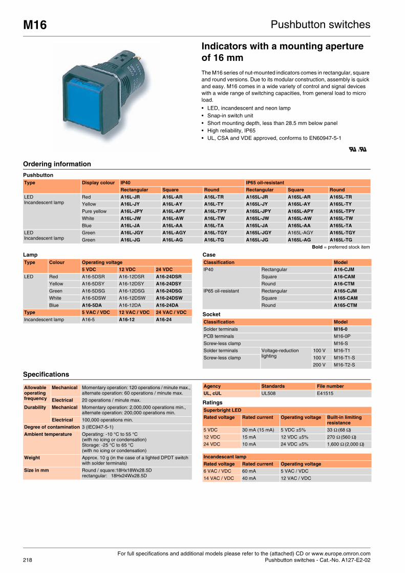
For full specifications and additional models please refer to the (attached) CD or www.europe.omron.comPushbutton switches - Cat.-No. A127-E2-02218
M16 Pushbutton switches
Indicators with a mounting aperture of 16 mmThe M16 series of nut-mounted indicators comes in rectangular, square and round versions. Due to its modular construction, assembly is quick and easy. M16 comes in a wide variety of control and signal devices with a wide range of switching capacities, from general load to micro load.
• LED, incandescent and neon lamp • Snap-in switch unit • Short mounting depth, less than 28.5 mm below panel • High reliability, IP65 • UL, CSA and VDE approved, conforms to EN60947-5-1
Ordering information
Pushbutton
Lamp Case
Socket
Specifications
Ratings
Type Display colour IP40 IP65 oil-resistant
Rectangular Square Round Rectangular Square Round
LEDIncandescent lamp
Red A16L-JR A16L-AR A16L-TR A165L-JR A165L-AR A165L-TR
Yellow A16L-JY A16L-AY A16L-TY A165L-JY A165L-AY A165L-TY
Pure yellow A16L-JPY A16L-APY A16L-TPY A165L-JPY A165L-APY A165L-TPY
White A16L-JW A16L-AW A16L-TW A165L-JW A165L-AW A165L-TW
Blue A16L-JA A16L-AA A16L-TA A165L-JA A165L-AA A165L-TA
LEDIncandescent lamp
Green A16L-JGY A16L-AGY A16L-TGY A165L-JGY A165L-AGY A165L-TGY
Green A16L-JG A16L-AG A16L-TG A165L-JG A165L-AG A165L-TG
Bold = preferred stock item
Type Colour Operating voltage
5 VDC 12 VDC 24 VDC
LED Red A16-5DSR A16-12DSR A16-24DSR
Yellow A16-5DSY A16-12DSY A16-24DSY
Green A16-5DSG A16-12DSG A16-24DSG
White A16-5DSW A16-12DSW A16-24DSW
Blue A16-5DA A16-12DA A16-24DA
Type 5 VAC / VDC 12 VAC / VDC 24 VAC / VDC
Incandescent lamp A16-5 A16-12 A16-24
Classification Model
IP40 Rectangular A16-CJM
Square A16-CAM
Round A16-CTM
IP65 oil-resistant Rectangular A165-CJM
Square A165-CAM
Round A165-CTM
Classification Model
Solder terminals M16-0
PCB terminals M16-0P
Screw-less clamp M16-S
Solder terminals Voltage-reduction lighting
100 V M16-T1
Screw-less clamp 100 V M16-T1-S
200 V M16-T2-S
Allowable operating frequency
Mechanical Momentary operation: 120 operations / minute max., alternate operation: 60 operations / minute max.
Electrical 20 operations / minute max.
Durability Mechanical Momentary operation: 2,000,000 operations min., alternate operation: 200,000 operations min.
Electrical 100,000 operations min.
Degree of contamination 3 (IEC947-5-1)
Ambient temperature Operating: -10 °C to 55 °C (with no icing or condensation)Storage: -25 °C to 65 °C (with no icing or condensation)
Weight Approx. 10 g (in the case of a lighted DPDT switch with solder terminals)
Size in mm Round / square:18Hx18Wx28.5D rectangular: 18Hx24Wx28.5D
Agency Standards File number
UL, cUL UL508 E41515
Superbright LED
Rated voltage Rated current Operating voltage Built-in limiting resistance
5 VDC 30 mA (15 mA) 5 VDC ±5% 33 Ω (68 Ω)
12 VDC 15 mA 12 VDC ±5% 270 Ω (560 Ω)
24 VDC 10 mA 24 VDC ±5% 1,600 Ω (2,000 Ω)
Incandescant lamp
Rated voltage Rated current Operating voltage
6 VAC / VDC 60 mA 5 VAC / VDC
14 VAC / VDC 40 mA 12 VAC / VDC

For full specifications and additional models please refer to the (attached) CD or www.europe.omron.comPushbutton switches - Cat.-No. A131-E2-02 219
M22 Pushbutton switches
Nut-mounted, 22 mm indicator, with high-visibility, illuminated buttonsThe M22 series of indicators comes in 22 or 25 mm-diameter round versions. They can easily be mounted and removal of the socket unit is also easy. The finger-protection mechanism on the lamp is provided as a standard feature. M22 indicators can be equipped with an LED or incandescent lamp.
• Available in 5 colours • Super-bright LEDs for all versions • Lamp sockets with or without transformers • UL and cUL approved
Ordering information
Display
Socket unit
Lamp
Bold = preferred stock item
AccessoriesM22 uses the same accessories as A22. Please refer to the relevant information in the corresponding section for the A22.
Specifications
LED lamp
Incandescent lamp
Superbright LED indicator
Voltage-reduction lighting
Appearance IP65 oil-resistant
Colour of display Model
Round / flat Red M22-FR
Green M22-FG
Yellow M22-FY
White M22-FW
Blue M22-FA
Square / projection Red M22-CR
Green M22-CG
Yellow M22-CY
White M22-CW
Blue M22-CA
Voltage-reduction circuits
Without voltage reduction unit With voltage reduction unit (220 VAC)
M22-00 M22-00-T2
AC / DC LED light Operating voltage
6 V 12 V 24 V 24 V superbright
AC Red A22-6DR
Green A22-6DG
Yellow A22-6DY
Blue A22-6DA
DC Red A22-6AR
Green A22-6AG
Yellow A22-6AY
Blue A22-6AA
AC and DC Red A22-12AR A22-24AR A22-24ASR
Green A22-12AG A22-24AG A22-24ASG
Yellow A22-12AY A22-24AY A22-24ASY
Blue A22-12AA A22-24AA A22-24ASA
Incandescent lamp 6 VAC / VDC 12 VAC / VDC 24 VAC / VDC 100 VAC / VDC
A22-5 A22-12 A22-24 A22-H1
Recognized organization Standards File number
UL, cUL UL508 E41515
Rated voltage Rated current Operating voltage
6 VDC 60 mA (20 mA) 6 VDC ±5%
6 VAC 60 mA (20 mA) 6 VAC ±5%
12 VAC / VDC 30 mA (10 mA) 12 VAC / VDC ±5%
24 VAC / VDC 15 mA (10 mA) 24 VAC / VDC ±5%
Rated voltage Rated current Operating voltage
6 VAC / VDC 200 mA 5 V
14 VAC / VDC 80 mA 12 V
28 VAC / VDC 40 mA 24 V
130 VAC / VDC 20 mA 100 V
Rated voltage Rated current Operating voltage
24 VAC / VDC 15 mA 24 VAC / VDC ±5%
Rated voltage Rated current Operating voltage
110 VAC 95 to 115 VAC LED lamp (A22-24 )
220 VAC 190 to 230 VAC
Ambient temperature Operating: -20 °C to 55 °C, storage: -40 °C to 70 °C
Degree of protection IP65
Electric shock protection class Class II
PTI (tracking characteristic) 175
Degree of contamination 3 (IEC947-5-1)
Size in mm Button: 29.7 dia.x16D, switch: 34Hx34Wx54.7D

What type of output? What type of output?
How many loops are required?
What type of control is needed?
Temperature controllers
Temperature uniformity made easy
With E5ZN temperature controllers, all temperatures are equal
220

What type of mounting is required?
Now available in a choice of dimensions!
The E5_N series – evolution in temperature control
221
Table of contentsSelection table 222
Basic temperature controller K8AB-TH 224
E5C2 225
E5CSV 226
General purpose controller E5@N 227
E5ZN 229
Advanced controller E5@K / E5@K-T 230
E5@R 231
Auxiliaries PRT1-SCU11 233

222
Selection table
*7 Fuzzy PID available
Category Alarm controller
Analogue temperature
controller
Compact digital temperature
controllerDigital temperature controller
Sel
ecti
on
cri
teri
a
Model K8AB-TH E5C2 E5CSV E5AN E5EN E5CN E5GNType Basic General purpose
Panel In-panel type In- & on-panel type On-panel type
Loops Single loop
Size 22.5 mm wide 1/16 DIN 1/16 DIN 1/4 DIN 1/8 DIN 1/16 DIN 1/32 DIN
Co
ntr
ol m
od
e ON / OFF
PID *1
*1 P only
2-PID *2
*2 2-PID is OMRON´s unique high-performance PID control
Operation *3
*3 H = heat, H / C = heat or cool, H & C = heat and cool
H H / C H & C H & C H & C H & C
Position proportional *4
*4 Position proportional = valve control (relay up & down)
Fea
ture
s
Accuracy ±2% ±0.5% ±0.5% ±0.5% ±0.5% ±0.5%
Auto-tuning
Self-tuning
Transfer output
Remote input
Number of alarms 1 2 3 3 3 1
Heater burnout *5
*5 Heater alarm = heater burnout & SSR failure detection
IP rating front panel IP20 IP40 IP65 IP66 IP66 IP66 IP66
Display Rotary switch SV dial Single 3.5 digit Dual 4 digit colour change
Dual 4 digit colour change
Dual 4 digit colour change
Dual 4 digit
Su
pp
ly
volt
age 110 / 220 VAC 100 to 240 100 to 240
24 VAC / VDC
Co
mm
s *6
*6 PROFIBUS-DP communication option via gateway for E5_N, E5_R, E5ZN, ask your local OMRON representative.
RS-232
RS-485
Event IP
QLP port
DeviceNet
Co
ntr
ol
ou
tpu
t
Relay
SSR
Voltage (pulse)
Linear voltage
Linear current
Inp
ut
typ
e -
lin
ear mA
mV
V
Inp
ut
typ
e -
ther
mo
cou
ple
K
J
T
E
L
U
N
R
S
B
W
PLII
Inp
ut
typ
e -
RT
D
Pt100
JPt100
THE
Page 224 225 226 227

Temperature controllers
223
Digital temperature
controllerDigital process controller
E5ZN E5AK E5EK E5CK E5AK-T E5EK-T E5CK-T E5AR E5ERModular Universal Universal / programmer Advanced
In-panel type On-panel type
Multi-loop Single loop Multi-loop
22.5 x 130 mm 1/4 DIN 1/8 DIN 1/16 DIN 1/4 DIN 1/8 DIN 1/16 DIN 1/4 DIN 1/8 DIN
H & C H & C H & C H & C H & C H & C H & C H & C H & C
±0.5% ±0.3% ±0.3% ±0.3% ±0.3% ±0.3% ±0.3% ±0.1% ±0.1%
2 3 3 3 3 3 3 4 4
Loop burnout Loop burnout
IP66 IP66 IP66 IP66 IP66 IP66 IP66 IP66
Dual 4 digit Dual 4 digit Dual 4 digit Dual 4 digit Dual 4 digit Dual 4 digit Dual 4 digit Triple 5 digit Triple 5 digit
229 230 231
Standard Available No / not available

For full specifications and additional models please refer to the (attached) CD or www.europe.omron.comTemperature controllers - Cat.-No. N150-E2-01224
K8AB-TH Temperature controllers
Affordable and compact temperature alarm unitThis temperature monitoring relay was designed specially for monitor-ing abnormal temperatures to prevent excessive temperature increase and to protect equipment. K8AB-TH provides temperature monitoring in slim design with a width of just 22.5 mm.
• Simple function settings using DIP switch • Selectable alarm latch and SV setting protection • Multi-input support for thermocouple or Pt100 sensor input • Changeover relay: fail-safe selectable • Alarm status identification with LED
Ordering information
Specifications
Input type Temperature setting range Setting unit Supply voltage Size in mm (HxWxD) Model
Thermocouple / Pt100
0 to 399 °C / F 1 °C / F 100 to 240 VAC 90x22.5x100 K8AB-TH11S 100-240
24 VAC / VDC K8AB-TH11S 24
Thermocouple 0 to 1,800 °C0 to 3,200 °F
10 °C / F *1
*1 Setting range depending on sensor type selected
100 to 240 VAC K8AB-TH12S 100-240
24 VAC / VDC K8AB-TH12S 24
100 to 240 VAC 50 / 60 Hz 24 VAC 50 / 60 Hz or 24 VDC
Allowable voltage range 85% to 110% of power supply voltage
Power consumption 5 VA max. 2 W max. (24 VDC), 4 VA max. (24 VAC)
Sensor inputs K8AB-TH11S Thermocouple: K, J, T, E; platinum-resistance thermometer: Pt100
K8AB-TH12S Thermocouple: K, J, T, E, B, R, S, PLII
Output relay One SPDT relay (3 A at 250 VAC, resistive load)
External inputs(for latch setting)
Contact input ON: 1 kΩ 2 max., OFF: 100 kΩ 2 min.
Non-contact input ON residual voltage: 1.5 V max., OFF leakage current: 0.1 mA max.
Leakage current: approx. 10 mA
Setting method Rotary switch setting (set of three switches)
Indicators Power (PWR): green LED, relay output (ALM): red LED
Other functions Alarm mode (upper limit / lower limit), output normally ON / OFF selection, output latch, setting protection, temperature unit °C / °F
Ambient operating temperature -10 °C to 55 °C (with no condensation or icing); for 3-year guarantee: -10 °C to 50 °C
Storage temperature -25 °C to 65 °C (with no condensation or icing)
Setting accuracy ±2% of full scale
Hysteresis width 2 °C
Output relay Resistive load 3 A at 250 VAC (cosφ = 1), 3 A at 30 VDC (L / R = 0 ms)
Inductive load 1 A at 250 VAC (cosφ= 0.4), 1 A at 30 VDC (L / R = 7 ms)
Minimum load 10 mA at 5 VDC
Maximum contact voltage 250 VAC
Maximum contact current 3 A AC
Maximum switching capacity 1,500 VA
Mechanical life 10,000,000 operations
Electrical life Make: 50,000 times, break: 30,000 times
Sampling cycle 500 ms
Weight 130 g
Degree of protection IP20
Memory protection Non-volatile memory (number or writes: 200,000)
Safety standards Approved standards EN 61010-1
Application standards EN 61326 and EN 61010-1 (pollution level 2, overvoltage category II)
Crimp terminals Two solid wires of 2.5 mm2 or two ferrules of 1.5 mm2 with insulation sleeves can be tightened together
Case color Munsell 5Y8/1 (ivory)
Case material ABS resin (self-extinguishing resin)
Mounting Mounted to DIN-rail or with M4 screws
Size in mm 90Hx22.5Wx100D

For full specifications and additional models please refer to the (attached) CD or www.europe.omron.comTemperature controllers - Cat.-No. H081-E2-02 225
E5C2 Temperature controllers
Easy-to-use, basic temperature controller with analogue dial settingOMRON's basic ON / OFF or PD controller features an analogue set-ting dial. This compact, low-cost controller has a setting accuracy of 2% of full scale. It incorporates a plug-in socket allowing for DIN-rail or flush mounting.
• Compact, cost-effective controller • Control mode: ON / OFF or PD • Control output: relay • Power supply: 100 - 120 / 200 - 240 VAC • Thermocouple K: 0 to 1200°C, L: 0 to 400°C, Pt100: -50 to 200°C
Ordering information
Accessories
Specifications
Setting method Indication method
Control mode Output Model Voltage
Thermocouple Platinum resistance thermometer Pt100
Thermistor THE
K (CA) chromel vs. alumel
L (IC) iron vs. constantan
Analogue setting No indication ON / OFF Relay E5C2-R20K E5C2-R20L-D E5C2-R20P-D E5C2-R20G 100/110/120 VAC
P Relay E5C2-R40K E5C2-R40L-D E5C2-R40P-D 200/220/240 VAC
Input ranges Thermocouple *1
*1 Values in ( ) are the minimum unit. Bold = preferred stock item *3
Platinum resistance thermometer Thermistor *2
*2 Values in ( ) are the thermistor resistive value.*3 Preferred stock items are R20. Types + 200-240 AC
K (CA) chromel vs. alumel L (IC) iron vs. constantan Pt100 THE
°C 0 to 200 (5),0 to 300 (10),0 to 400 (10),0 to 600 (20),0 to 800 (20),0 to 1,000 (25),0 to 1,200 (25)
0 to 200 (5),0 to 300 (10),0 to 400 (10)5 to 450 (10)
-50 to 50 (2),-20 to 80 (2),0 to 50 (1),0 to 100 (2),0 to 200 (5),0 to 300 (10),0 to 400 (10)
-50 to 50 (2) (6 kΩ at 0 °C),0 to 100 (2) (6 kΩ at 0 °C),50 to 150 (2) (30 kΩ at 0 °C)
°F 32 to 392 (10),32 to 572 (20),32 to 752 (20),32 to 1,112 (40),32 to 1,472 (50),32 to 1,832 (50),32 to 2,192 (50)
32 to 392 (10),32 to 572 (20),32 to 752 (20)
32 to 212 (5),32 to 392 (10)
Functions Model
Front connecting socket with finger protection P2CF-08-E
Back connecting socket (for flush mounting) P3G-08
Finger protection cover (for P3G-08) Y92A-48G
Protective front cover (IP66) Y92A-48B
Thermocouple input type K, L (with sensor break detection)
RTD input type Pt100, THE
Control mode ON / OFF or P control
Setting method Analogue setting
Output Relay, SPDT, 3 A at 250 VAC
Life expectancy Electrical: 100,000 operations min.
Setting accuracy ±2% FS max.
Hysteresis Approx. 0.5% FS (fixed)
Proportional band 3% FS (fixed)
Reset range 5 ±1% FS min.
Control period 20 s
IP Rating front panel IP40 (IP66 cover available)
IP rating terminals IP00
Ambient temperature -10 °C to 55 °C
Size in mm 48Hx48Wx96D

For full specifications and additional models please refer to the (attached) CD or www.europe.omron.comTemperature controllers - Cat.-No. H138-E2-01-X226
E5CSV Temperature controllers
Easy setting using DIP switch and simple functions within DIN 48x48 mmThis multi-range 1/16 DIN controller with alarm function offers field-selectable PID control or ON / OFF control. The large, single display shows process value, direction of deviation from set point, output and alarm status.
• All setting field configurable with switches • Multi-input (thermocouple / Pt100) • Clearly visible 3.5-digit display with character height of 13.5 mm • Control output: relay, voltage (for driving SSR) • ON / OFF or 2-PID control with auto-tuning and self-tuning
Ordering information
Note: Other models are available on request. Bold = preferred stock item
Specifications
Size in mm Power supply voltage Number of alarm points
Control output TC/Pt universal input case color: black
1/16 DIN48Hx48Wx78D
100 to 240 VAC 1 Relay E5CSV-R1T-500 AC100-240
Voltage (for driving SSR) E5CSV-Q1T-500 AC100-240
24 VAC / VDC 1 Relay E5CSV-R1TD-500 AC/DC24
Voltage (for driving SSR) E5CSV-Q1TD-500 AC/DC24
Supply voltage 100 to 240 VAC, 50 / 60 Hz or 24 VAC / VDC (depending on model)
Operating voltage range 85% to 110% of rated supply voltage
Power consumption 5 VA
Sensor input Multi-input (thermocouple / platinum resistance thermometer): K, J, L, T, U, N, R, Pt100, JPt100
Control output Relay output SPST-NO, 250 VAC, 3A (resistive load)
Voltage output (for driving SSR) 12 VDC, 21 mA (with short-circuit protection circuit)
Control method ON / OFF or 2-PID (with auto-tune and self-tune)
Alarm output SPST-NO, 250 VAC, 1 A (resistive load)
Setting method Digital setting using front panel keys (functionality set-up with DIP switch)
Indication 7-segment digital display (character height: 13.5 mm) and deviation indicators
Ambient temperature -10 °C to 55 °C (with no condensation or icing)
Setting / indication accuracy ±0.5% of indication value or ±1 °C, whichever is greater ±1 digit max.
Hysteresis (for ON / OFF control) 0.2% FS (0.1% FS for multi-input (thermocouple / platinum resistance thermometer) models)
Proportional band (P) 1 to 999 °C (automatic adjustment using AT / ST)
Integral time (I) 0 to 1,999 s (automatic adjustment using AT / ST)
Derivative time (D) 0 to 1,999 s (automatic adjustment using AT / ST)
Control period 2 / 20 s
Sampling period 500 ms
Electrical life expectancy 100,000 operations min. (relay output models)
Weight Approx. 120 g (controller only)
Degree of protection Front panel: equivalent to IP66; rear case: IP20; terminals: IP00
Memory protection EEPROM (non-volatile memory) (number of writes: 1,000,000)
Size in mm 48Hx48Wx78D

For full specifications and additional models please refer to the (attached) CD or www.europe.omron.comTemperature controllers - Cat.-No. H136-E2-01 227
E5@N Temperature controllers
Compact and intelligent general-purpose controllersThe E5@N general-purpose line of temperature controllers is available in 4 standard DIN formats. They all feature a high-intensity dual LCD display with a wide viewing angle. Except for the E5GN, the series features 3-colour PV change for easy status recognition.
• Control mode: ON / OFF or 2-PID • Control output: relay, hybrid relay, voltage (SSR) or linear current • Power supply: 100 / 240 VAC or 24 VDC / VAC • Easy PC connection for parameter cloning, setting and tuning • Easy set-up and operation
Ordering information
Note: - Output relay: 3 A / 250 VAC, electrical life: 100,000 operations Bold = preferred stock item- Output voltage (pulse): 12 V, 21 mA- Hybrid relay (long life relay) electrical life 1,000,000 operations- Linear current: 0(4) - 20 mA- Heater alarm = heater burnout + SSR short detection- Voltage: specify the power supply specifications (voltage) when ordering
Type Input Output Fixed option Alarms 48x24 mm model Voltage
Thermocouple Pt100, JPt100
On-panel relay 1 E5GN-R1TC E5GN-R1P AC100-240 or DC/AC 24
voltage (pulse) E5GN-Q1TC E5GN-Q1P AC100-240 or DC/AC 24
relay RS-485 communication
0 E5GN-R03TC-FLK E5GN-R03P-FLK AC100-240 or DC/AC 24
voltage (pulse) E5GN-Q03TC-FLK E5GN-Q03P-FLK AC100-240 or DC/AC 24
Type Input Output Fixed option Alarms 48x48 mm model Voltage
On-panel temperature(TC / Pt / mV)
relay 2 E5CN-R2MT-500 AC100-240 or DC/AC 24
voltage (pulse) E5CN-Q2MT-500 AC100-240 or DC/AC 24
linear current E5CN-C2MT-500 AC100-240 or DC/AC 24
hybrid relay E5CN-Y2MT-500 AC100-240
analogue(mA / V)
relay E5CN-R2ML-500 AC100-240 or DC/AC 24
voltage (pulse) E5CN-Q2ML-500 AC100-240 or DC/AC 24
linear current E5CN-C2ML-500 AC100-240 or DC/AC 24
hybrid relay E5CN-Y2ML-500 AC100-240
In-panel temperature(TC / Pt / mV)
relay 2 E5CN-R2TU AC100-240 or DC/AC 24
voltage (pulse) E5CN-Q2TU AC100-240 or DC/AC 24
Type Input Output Fixed option Alarms 48x96 mm model 96x96 mm model Voltage
On-panel temperature(TC / Pt / mV)
linear current 3 E5EN-C3MT-500 E5AN-C3MT-500 AC100-240 or DC/AC 24
hybrid relay 3 E5EN-C3YMT-500 E5AN-C3YMT-500 AC100-240
voltage (pulse) E5EN-C3QMT-500 E5AN-C3QMT-500 AC100-240
voltage (pulse) 3 E5EN-Q3MT-500 E5AN-Q3MT-500 AC100-240 or DC/AC 24
hybrid relay E5EN-Q3YMT-500 E5AN-Q3YMT-500 AC100-240
voltage (pulse) 3 E5EN-Q3QMT-500 E5AN-Q3QMT-500 AC100-240
heater alarm E5EN-Q3HMT-500 E5AN-Q3HMT-500 AC100-240 or DC/AC 24
3-phase HA E5EN-Q3HHMT-500 E5AN-Q3HHMT-500 AC100-240
power supply E5EN-Q3PMT-500 AC100-240
relay 3 E5EN-R3MT-500 E5AN-R3MT-500 AC100-240 or DC/AC 24
voltage (pulse) E5EN-R3QMT-500 E5AN-R3QMT-500 AC100-240
heater alarm E5EN-R3HMT-500 E5AN-R3HMT-500 AC100-240 or DC/AC 24
3-phase HA E5EN-R3HHMT-500 E5AN-R3HHMT-500 AC100-240
power supply E5EN-R3PMT-500 AC100-240
analogue(mA / V)
linear current 3 E5EN-C3ML-500 AC100-240
voltage (pulse) 3 E5EN-Q3ML-500 AC100-240
hybrid relay E5EN-Q3YML-500 AC100-240
heater alarm E5EN-Q3HML-500 E5AN-Q3HML-500 AC100-240
relay 3 E5EN-R3ML-500 AC100-240
heater alarm E5EN-R3HML-500 E5AN-R3HML-500 AC100-240

E5@N Temperature controllers
228
AccessoriesE5CN option boards(do no fit in E5CN-U types; one slot available in each instrument)
E5AN / -EN option boards(one slot available in each instrument)
E5_N series optional tools
Specifications
Model Option
E53-CNH03N RS-485 heater alarm
E53-CN03N RS-485
E53-CNHBN heater alarm event input
E53-CNBN event input
E53-CNHH03N RS-485 3-phase HA
E53-CNQ03N RS-485 voltage (pulse)
E53-CNQHN heater alarm voltage (pulse)
E53-CNPBN event input power supply 12 VDC / 20 mA
E53-CNPHN heater alarm power supply 12 VDC / 20 mA
Model Option
E53-EN01 RS-232 communications (Compoway-F / Modbus)
E53-EN03 RS-485 communications (Compoway-F / Modbus)
E53-AKB event input
Model Option
E58-CIFQ1 USB PC based configuration cable
CX-Thermo PC based configuration and tuning software
ThermoMini PC based parameter cloning software (free)
P2CF-08-E Standard 8 pin socket for E5CN-@@@U type
Heater alarm yes, optional; 1 + 3-phase option
Thermocouple input type K, J, T, E, L, U, N, R, S, B
RTD input type Pt100, JPt100
Linear input type mV, mA (optional), V (not for -GN)
Control mode ON / OFF, 2-PID, heat and / or cool
Accuracy ±0.5% of indicated value
Auto-tuning yes
Self-tuning yes
RS-232 -AN / -EN: optional
RS-485 optional
Event input optional (not for -GN)
QLP port (USB connection PC) yes (not for -GN)
Ambient temperature -10 °C to 55 °C
IP Rating front panel IP66
Sampling period 500 ms for -GN, 250 ms for -CN, -EN, -AN

For full specifications and additional models please refer to the (attached) CD or www.europe.omron.comTemperature controllers - Cat.-No. H116-E2-02A 229
E5ZN Temperature controllers
In-panel, DIN-rail mounted modular multi-loop temperature controllersThis modular temperature controller consists of 22.5 mm wide modules with 2 channels per module. Via RS-485 one can build up to a maximum of 32 control loops. The modularity of E5ZN enables easy exchange and replacement of the individual modules.
• Output: SSR, transistor, current, transfer outputs and event in- and outputs
• Alarms and load-fail detection, LED indicators for status • Control mode: ON / OFF and 2-PID • Easy connection to PLC and HMI or PC • Configuration by separate setting unit (E5ZN-SDL) and tool software
Ordering information
Note: Terminal units are required for wiring. Purchase separately.
AccessoriesTerminal unit (includes bus system without backplane)
Current transformer
Setting display unit
Sockets for E5ZN-SDL
DeviceNet gateway
Specifications
Functions Control output Auxiliary output Input type *1
*1 Thermocouple models provide analogue input and input for infrared temperature sensors (ES1B). Bold = preferred stock item
Model
Heating or heat / cool control *2
Event input: 1 point per unit
*2 When using heating and cooling control functionality, the auxiliary output will be either heating control output or cooling control output.
Heater burnout alarm *3
*3 When using the heater burnout alarm, purchase a current transformer (CT) separately.
Voltage (pulse) output
Transistor output: 2 pts (sinking)
Thermocouple E5ZN-2QNH03TC-FLKDC24
Platinum resistance thermometer E5ZN-2QNH03P-FLKDC24
Transistor output: 2 pts (sourcing)
Thermocouple E5ZN-2QPH03TC-FLKDC24
Platinum resistance thermometer E5ZN-2QPH03P-FLKDC24
Transistor output Transistor output: 2 pts (sinking)
Thermocouple E5ZN-2TNH03TC-FLKDC24
Platinum resistance thermometer E5ZN-2TNH03P-FLKDC24
Transistor output: 2 pts (sourcing)
Thermocouple E5ZN-2TPH03TC-FLKDC24
Platinum resistance thermometer E5ZN-2TPH03P-FLKDC24
Transfer output *4
*4 When connecting the load of the controlled system, heat control output or cool control output can be allocated to the control output or auxiliary output. When connecting a recording device or digital panel meter, transfer output (volt) can be allocated to control output or auxiliary output 3 or 4 of analogue output models.
Analogue output (current output)*4
Transistor output: 2 pts (sinking)
Thermocouple E5ZN-2CNF03TC-FLKDC24
Platinum resistance thermometer E5ZN-2CNF03P-FLKDC24
Transistor output: 2 pts (sourcing)
Thermocouple E5ZN-2CPF03TC-FLKDC24
Platinum resistance thermometer E5ZN-2CPF03P-FLKDC24
no. of terminals Functions Model
24 Master socket, equipped with terminals for power supply, communications and display unit
E5ZN-SCT24S-500
18 Extension socket E5ZN-SCT18S-500
Diameter Model
5.8 dia. E54-CT1
12.0 dia. E54-CT3
Power Supply Model
24 VDC E5ZN-SDL
Type Model
Front-connecting socket (with finger protection) P2CF-11-E
Back-connecting socket (for control panel mounting) P3GA-11
Terminal cover for finger protection Y92A-48G
Functions Model
Connects up to 16 E5ZN modules to DeviceNet (fits into master socket), 24 VDC supply voltage
E5ZN-DRT
Bold = preferred stock item
Heater burnout yes
Thermocouple input type K, J, T, E, L, U, N, R, S, B
RTD input type Pt100, JPt100
Linear input type mA, 0-50 mV
Control mode 2-PID or ON / OFF Control
Accuracy 0.5% FS
Auto-tuning yes
RS-485 yes
Event input yes
DeviceNet optional
Ambient temperature -10 °C to 55 °C
Sampling period 500 ms
Size in mm 130Hx22.5Wx112D

For full specifications and additional models please refer to the (attached) CD or www.europe.omron.comTemperature controllers - Cat.-No. E5@K: H084-E2-04, E5@K-T: H087-E2-03230
E5@K / E5@K-T Temperature controllers
Advanced compact digital process controllersThe E5@K series of advanced controllers provides standard models and models with programmer functionality. The modular structure of the series makes it very versatile. A number of tuning functions are provid-ed, including auto-tuning, self-tuning and fuzzy self-tuning.
• 96Hx48Wx100D / 53Hx53Wx100D / 96Hx96Wx100D mm • Control mode: ON / OFF or PID • Control output: relay, SSR, voltage or current • Universal inputs (Pt100 / thermocouple / volt / milliampere)• Supported by ThermoTools PC Software
Ordering information
Note: A single output unit and option unit can be mounted to each E5CK base unit.
Option Units
Specifications
Specification Alarms Standard model Programmer model 48x48 mm Voltage
Base unit 1 E5CK-AA1 E5CK-TAA1 AC100-240 or DC/AC 24 Base unit with terminal cover E5CK-AA1-500 E5CK-TAA1-500
Specification Alarms Standard model Programmer model 48x96 mm Voltage
Standard model 2 E5EK-AA2 E5EK-TAA2 AC100-240 or DC/AC 24 Standard model with terminal cover E5EK-AA2-500 E5EK-TAA2-500
Position-proportional model E5EK-PRR2 E5EK-TPRR2
Position-proportional model with terminal cover E5EK-PRR2-500 E5EK-TPRR2-500
Standard mode with terminal cover and DeviceNet E5EK-AA2-DRT-500 AC100-240
Specification Alarms Standard model Programmer model 96x96 mm Voltage
Standard model 2 E5AK-AA2 E5AK-TAA2 AC100-240 or DC/AC 24 Standard model with terminal cover E5AK-AA2-500 E5AK-TAA2-500
Position-proportional model E5AK-PRR2 E5AK-TPRR2
Position-proportional model with terminal cover E5AK-PRR2-500 E5AK-TPRR2-500
Model Name Model Specification
E5CK Output units E53-R4R4 Relay / relay
E53-Q4R4 Pulse (NPN) / relay
E53-Q4HR4 Pulse (PNP) / relay
E53-C4R4 Linear (4 to 20 mA) / relay
E53-C4DR4 Linear (0 to 20 mA) / relay
E53-V44R4 Linear (0 to 10 V) / relay
E53-Q4Q4 Pulse (NPN) / pulse (NPN)
E53-Q4HQ4H Pulse (PNP) / pulse (PNP)
Option units E53-CK01 RS-232C
E53-CK03 RS-485
E53-CKB Event input: 1 point
E53-CKF Transfer output (4 to 20 mA)
Model Name Model Specification
E5AKE5EK
Output units E53-R Relay
E53-S SSR
E53-Q Pulse (NPN) 12 VDC
E53-Q3 Pulse (NPN) 24 VDC
E53-Q4 Pulse (PNP) 24 VDC
E53-C3 Linear (4 to 20 mA)
E53-C3D Linear (0 to 20 mA)
E53-V34 Linear (0 to 10 V)
E53-V35 Linear (0 to 5 V)
Option units E53-AKB Event input
E53-EN01 Communication (RS-232C)
E53-EN02 Communication (RS-422)
E53-EN03 Communication (RS-485)
E53-AKF Transfer output
Bold = preferred stock item
Heater burnout Optional, CK: loop burnout
Thermocouple input type K, J, T, E, L, U, N, R, S, B, W, PLII
RTD input type Pt100, JPt100
Linear input type mA, 0 to 50 mV
Control mode 2-PID or ON / OFF control
Accuracy 0.3% FS, 1 digit max.
Self-tuning yes
Auto-tuning yes
RS-485 optional
Event input optional
Ambient temperature -10 °C to 55 °C
IP rating front panel IP66
Sampling period Temperature input: 250 msLinear input: 100 ms

For full specifications and additional models please refer to the (attached) CD or www.europe.omron.comTemperature controllers - Cat.-No. H122-E2-02 231
E5@R Temperature controllers
Digital process controllers with high speed and precision, multiple I/OThe E5_R series provides you with high-accuracy inputs (0.01°C for Pt100) and a 50ms sample and control cycle for all four loops. Its unique disturbance overshoot reduction adjustment ensures solid, robust control.
• 96Hx48Wx110D / 96Hx96Wx110D mm • Control mode: ON / OFF or 2-PID • Control output: voltage (puls), linear (mA) and relay valve positioning • Power supply: 100 - 240 VAC or 24 VAC / VDC • Supported by CX-Thermo PC software
Ordering information
Note: - Voltage: specify the power supply specifications (voltage) when ordering. Bold = preferred stock item- standard = heat and / or cool PID control, valve = valve positioning (relay up / down) (PRR)- max 2 = 2 loops heat and / or cool or 1 loop cascade, ratio or remote SP- max 4 = 4 loops heat and / or cool- 1, 2 or 4 = number of analogue universal input 1 + pot = 1 universal and 1 slide wire feedback from valve- QC = voltage (pulse) or current (switch), Q = voltage (pulse), C = current, 4R = 4 two pole relay, 2T = two transistor output NPN
Functions Loops Input Output Comms 48x96 mm model Voltage
Analogue Event Control Alarm
standard 1 1 2 2 QC+Q 4R - E5ER-Q4B AC100-240 or DC/AC 24
standard 1 1 2 2 QC+Q 4R RS-485 E5ER-Q43B-FLK AC100-240
standard 1 1 2 4 QC+Q+C+C 4R RS-485 E5ER-QC43B-FLK AC100-240 or DC/AC 24
standard 1 1 6 2 QC+Q 2T RS-485 E5ER-QT3DB-FLK AC100-240
standard max 2 2 4 2 QC+Q 2T RS-485 E5ER-QT3DW-FLK AC100-240 or DC/AC 24
standard 1 1 2 2 C+C 4R - E5ER-C4B AC100-240 or DC/AC 24
standard 1 1 2 2 C+C 4R RS-485 E5ER-C43B-FLK AC100-240
standard 1 1 6 2 C+C 2T RS-485 E5ER-CT3DB-FLK AC100-240
standard max 2 2 4 2 C+C 2T RS-485 E5ER-CT3DW-FLK AC100-240 or DC/AC 24
valve 1 1 + pot 4 2 R+R 2T - E5ER-PRTDF AC100-240 or DC/AC 24
valve 1 1 + pot - 4 R+R+QC+Q 4R RS-485 E5ER-PRQ43F-FLK AC100-240 or DC/AC 24
standard 1 1 2 2 QC+Q 2T DeviceNet E5ER-QTB-DRT AC100-240 or DC/AC 24
standard max 2 2 - 2 QC+Q 2T DeviceNet E5ER-QTW-DRT AC100-240 or DC/AC 24
standard 1 1 2 2 C+C 2T DeviceNet E5ER-CTB-DRT AC100-240 or DC/AC 24
standard max 2 2 - 2 C+C 2T DeviceNet E5ER-CTW-DRT AC100-240 or DC/AC 24
valve 1 1 + pot - 2 R+R 2T DeviceNet E5ER-PRTF-DRT AC100-240 or DC/AC 24
Functions Loops Input Output Comms 96x96 mm Model Voltage
Analogue Event Control Alarm
standard 1 1 2 2 QC+Q 4R - E5AR-Q4B AC100-240 or DC/AC 24
standard 1 1 2 2 QC+Q 4R RS-485 E5AR-Q43B-FLK AC100-240
standard 1 1 6 2 QC+Q 4R RS-485 E5AR-Q43DB-FLK AC100-240
standard 1 1 6 4 QC+Q+C+C 4R RS-485 E5AR-QC43DB-FLK AC100-240 or DC/AC 24
standard max 2 2 4 2 QC+Q 4R RS-485 E5AR-Q43DW-FLK AC100-240
standard max 2 2 4 4 QC+Q+QC+Q 4R RS-485 E5AR-QQ43DW-FLK AC100-240 or DC/AC 24
standard max 4 4 4 4 QC+Q+QC+Q 4R RS-485 E5AR-QQ43DWW-FLK AC100-240
standard 1 1 2 2 C+C 4R - E5AR-C4B AC100-240 or DC/AC 24
standard 1 1 2 2 C+C 4R RS-485 E5AR-C43B-FLK AC100-240
standard 1 1 6 2 C+C 4R RS-485 E5AR-C43DB-FLK AC100-240
standard max 2 2 4 2 C+C 4R RS-485 E5AR-C43DW-FLK AC100-240
standard max 4 4 4 4 C+C+C+C 4R RS-485 E5AR-CC43DWW-FLK AC100-240 or DC/AC 24
valve 1 1 + pot 4 2 R+R 4R - E5AR-PR4DF AC100-240 or DC/AC 24
valve 1 1 + pot 4 4 R+R+QC+Q 4R RS-485 E5AR-PRQ43DF-FLK AC100-240 or DC/AC 24
standard 1 1 2 2 QC+Q 4R DeviceNet E5AR-Q4B-DRT AC100-240 or DC/AC 24
standard 1 1 2 4 QC+Q+C+C 4R DeviceNet E5AR-QC4B-DRT AC100-240 or DC/AC 24
standard max 2 2 - 4 QC+Q+QC+Q 4R DeviceNet E5AR-QQ4W-DRT AC100-240 or DC/AC 24
standard 1 1 2 2 C+C 4R DeviceNet E5AR-C4B-DRT AC100-240 or DC/AC 24
standard max 4 4 - 4 C+C+C+C 4R DeviceNet E5AR-CC4WW-DRT AC100-240 or DC/AC 24
valve 1 1 + pot - 2 R+R 4R DeviceNet E5AR-PR4F-DRT AC100-240 or DC/AC 24
valve 1 1 + pot - 4 R+R+QC+Q 4R DeviceNet E5AR-PRQ4F-DRT AC100-240 or DC/AC 24
Terminal cover for E5AR E53-COV14
Terminal cover for E5ER E53-COV15

E5@R Temperature controllers
232
Specifications
Thermocouple input type K, J, T, E, L, U, N, R, S, B, W
RTD input type Pt100
Linear input type mA, V
Control mode 2-PID or ON / OFF control
Accuracy ±0.1% FS
Auto-tuning yes
RS-485 optional
Event input optional
Ambient temperature -10 °C to 55 °C
IP rating front panel IP66
Sampling period 50 ms
Size in mm E5ER: 96Hx48Wx110DE5AR: 96Hx96Wx110D

For full specifications and additional models please refer to the (attached) CD or www.europe.omron.comTemperature controllers - Cat.-No. PRT-SCU11: P05E-EN-01, ES1B: H127-E2-01 233
PRT1-SCU11 Temperature controllers
OMRON's intelligent PROFIBUS-DP and Compoway/F gatewayThis gateway supports all Compoway/F equipped products, including temperature controllers, digital panel indicators, etc. It can also be used for connecting MCW151-E and E5_K series.
• Cost-effectively integrates basic instruments into a PROFIBUS-DP network
• Requires no complex protocol conversion writing • Has function blocks for drag-and-drop configuration • Connects up to 15 instruments to a single PROFIBUS point
Ordering information Specifications
ES1BAchieve low-cost measurements with an infrared thermosensorThis infrared thermosensor provides an accurate, stable and cost-ef-fective way to measure the temperature of objects. It behaves just like a standard K-type thermocouple, which enables it to operate with any temperature controller or alarm unit.
• Cost-effective infrared thermosensor • Contactless, meaning no deterioration, unlike thermocouples • 4 temperature ranges available: 10-70°C, 60-120°C, 115-165°C and
140-260°C • Response speed 300 ms
Ordering information
Dimensions (unit: mm)
Specifications
Name Model
PROFIBUS remote terminal serial communications unit PRT1-SCU11
Storage temperature -20 °C to +75 °C
Ambient temperature 0 °C to 55 °C
Ambient humidity 10 to 90% (non-condensing)
EMC compliance EN 50081-2, EN 61131-2
Power supply +24 VDC (+10% / -15%)Current consumption 80 mA (typical)
Weight 125 g (typical)
Communication interface RS-485 based PROFIBUS-DPRS-422A Host linkRS-485 CompoWay/FRS-232C PeripheralPort supporting connection to thermotools
Size in mm 90Hx40Wx65D
Appearance and sensing characteristics
Specification Model
10 to 70 °C ES1B 10-70C
60 to 120 °C ES1B 115-165C
155 to 165 °C ES1B 140-260C
140 to 260 °C ES1B 60-120C2 dia. 20 dia.
2 mm 20 mm 40 mm 60 mm
40 dia. 60 dia.
14.2 dia.
36.5
17.8
15
6.5
44.5 3,000ABS resin
PVC-covered(−25°C to 70°C)
Polyolefin tube
Screw M18×1.0
Green, output +White, output −
Orange, power +Shield, power −
Item ES1B
Power supply voltage 12 / 24 VDC
Current consumption 20 mA max.
Accuracy ±5 °C ±2% PV or ±2 °C, whichever is larger
±10 °C ±4% PV or ±4 °C, whichever is larger
±30 °C ±6% PV or ±6 °C, whichever is larger
±40 °C ±8% PV or ±8 °C, whichever is larger
Reproducibility ±1% PV or ±1 °C, whichever is larger
Temperature drift 0.4 °C / °C max.
Receiver element Thermopile
Response speed Approximately 300 ms at response rate of 63%
Operating temperature -25 °C to 70 °C (with no icing or condensation)
Allowable ambient humidity 35% to 85%
Degree of protection IP65
Size in mm head: 17.8 dia. x 44.5 (screw M18 x 1.0), cable 3,000

What type of network supply is it?
Which type of system is required?
What type is required?
Power supplies
With the S8VS Micro size IS everything!
Powerful performance in compact design
234

The power supplies that alert you!
S8VM power supplies
235
Table of contentsSelection table 236
Single-phase S8VS 238
S8VM 239
S8TS 240
S8T-DCBU-01/-02 241
S82K 242
Three-phase S8PE 243

236
Selection table
Category Industrial standard
With status monitor Modular Back-up
Sel
ecti
on
cri
teri
a
ModelS8VS S8VS-Bx /
-Ax S8VM S8TS
Phases Single-phase
Rated voltage 100 to 240 VAC
Voltage 24 V 24 V 5 V 12 V 15 V 24 V 5 V 12 V 24 V 24 V
Po
wer
[W
]
3 W
7.5 W
10 W
15 W 3 A 1.3 A 1 A 0.65 A
25 W 5 A
30 W 6 A 2.5 A 2 A 1.3 A 2.5 A
50 W 10 A 4.3 A 3.5 A 2.2 A
60 W 2.5 A 2.5 A 5 A 2.5 A 2.5 A
90 W 3.75 A 3.75 A 7.5 A
100 W 20 A 8.5 A 7 A 4.5 A
120 W 5 A 5 A 10 A 5 A
150 W 27 A 12.5 A 10 A 6.5 A
180 W 7.5 A 7.5 A 7.5 A
240 W 10 A 10 A 10 A
300 W
480 W
600 W
960 W
Fea
ture
s
Conforms toEN61000-3-2 A14 with PFC with PFC
with PFC
with PFC
with PFC
with PFC with PFC with PFC with PFC
DC back-up
Capacitor back-up
Undervoltage alarm
Overvoltage protection
Overload protection
DIN-rail mounting
Screw mounting(with bracket)
EMI Class B
UL Class 2 only 60 W only 60 W
N+1 redundancy
Parallel operation
Series operation
Page 238 239 240

Power supplies
237
Category Industrial standard High power
Sel
ecti
on
cri
teri
a
ModelS82K S8PE
Phases Single-phase 3-phase
Rated voltage 100 / 200 VAC or 100 to 240 VAC 400 - 480 VAC or 200 - 230 VAC
Voltage 5 V 12 V 15 V 24 V 24 V
Po
wer
[W
]
3 W 0.6 A 0.25 A 0.2 A 0.13 A
7.5 W 1.5 A 0.6 A 0.5 A 0.3 A
10 W
15 W 2.5 A 1.2 A 0.6 A
25 W
30 W 5 A 2.5 A 1.3 A
50 W 2.1 A
60 W
90 W 3.75 A
100 W 4.2 A
120 W 5 A
150 W
180 W
240 W 10 A
300 W
480 W 20 A
600 W
960 W 40 A
Fea
ture
s
Conforms toEN61000-3-2 A14
DC back-up
Capacitor back-up
Undervoltage alarm
Overvoltage protection except 40 A
Overload protection
DIN-rail mounting except 40 A
Screw mounting(with bracket)
only 40 A
EMI Class B
UL Class 2 except dual output
N+1 redundancy
Parallel operation only 100 W
Series operation only 90 /100 W
Page 242 243
Standard Available No / not available
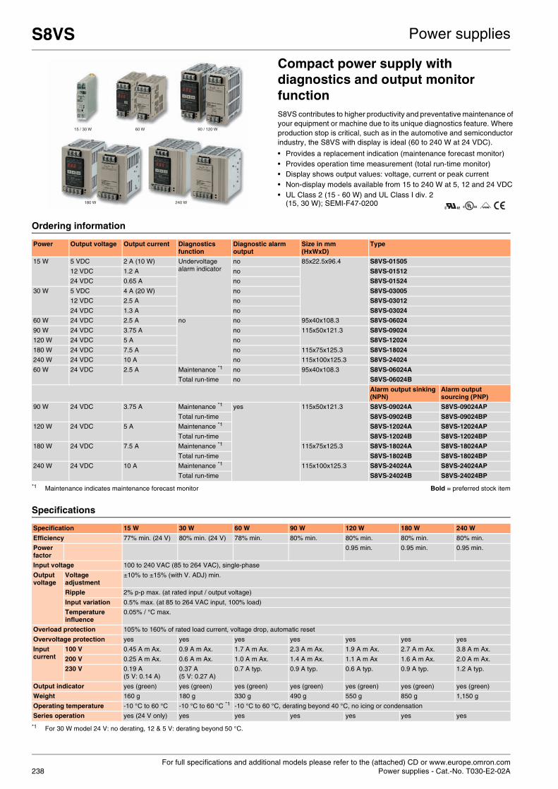
For full specifications and additional models please refer to the (attached) CD or www.europe.omron.comPower supplies - Cat.-No. T030-E2-02A238
S8VS Power supplies
Compact power supply with diagnostics and output monitor functionS8VS contributes to higher productivity and preventative maintenance of your equipment or machine due to its unique diagnostics feature. Where production stop is critical, such as in the automotive and semiconductor industry, the S8VS with display is ideal (60 to 240 W at 24 VDC).
• Provides a replacement indication (maintenance forecast monitor) • Provides operation time measurement (total run-time monitor) • Display shows output values: voltage, current or peak current • Non-display models available from 15 to 240 W at 5, 12 and 24 VDC • UL Class 2 (15 - 60 W) and UL Class I div. 2
(15, 30 W); SEMI-F47-0200
Ordering information
Specifications
Power Output voltage Output current Diagnostics function
Diagnostic alarm output
Size in mm (HxWxD)
Type
15 W 5 VDC 2 A (10 W) Undervoltage alarm indicator
no 85x22.5x96.4 S8VS-01505
12 VDC 1.2 A no S8VS-01512
24 VDC 0.65 A no S8VS-01524
30 W 5 VDC 4 A (20 W) no S8VS-03005
12 VDC 2.5 A no S8VS-03012
24 VDC 1.3 A no S8VS-03024
60 W 24 VDC 2.5 A no no 95x40x108.3 S8VS-06024
90 W 24 VDC 3.75 A no 115x50x121.3 S8VS-09024
120 W 24 VDC 5 A no S8VS-12024
180 W 24 VDC 7.5 A no 115x75x125.3 S8VS-18024
240 W 24 VDC 10 A no 115x100x125.3 S8VS-24024
60 W 24 VDC 2.5 A Maintenance *1
*1 Maintenance indicates maintenance forecast monitor Bold = preferred stock item
no 95x40x108.3 S8VS-06024A
Total run-time no S8VS-06024B
Alarm output sinking (NPN)
Alarm output sourcing (PNP)
90 W 24 VDC 3.75 A Maintenance *1 yes 115x50x121.3 S8VS-09024A S8VS-09024AP
Total run-time S8VS-09024B S8VS-09024BP
120 W 24 VDC 5 A Maintenance *1 S8VS-12024A S8VS-12024AP
Total run-time S8VS-12024B S8VS-12024BP
180 W 24 VDC 7.5 A Maintenance *1 115x75x125.3 S8VS-18024A S8VS-18024AP
Total run-time S8VS-18024B S8VS-18024BP
240 W 24 VDC 10 A Maintenance *1 115x100x125.3 S8VS-24024A S8VS-24024AP
Total run-time S8VS-24024B S8VS-24024BP
Specification 15 W 30 W 60 W 90 W 120 W 180 W 240 W
Efficiency 77% min. (24 V) 80% min. (24 V) 78% min. 80% min. 80% min. 80% min. 80% min.
Power factor
0.95 min. 0.95 min. 0.95 min.
Input voltage 100 to 240 VAC (85 to 264 VAC), single-phase
Output voltage
Voltage adjustment
±10% to ±15% (with V. ADJ) min.
Ripple 2% p-p max. (at rated input / output voltage)
Input variation 0.5% max. (at 85 to 264 VAC input, 100% load)
Temperature influence
0.05% / °C max.
Overload protection 105% to 160% of rated load current, voltage drop, automatic reset
Overvoltage protection yes yes yes yes yes yes yes
Input current
100 V 0.45 A m Ax. 0.9 A m Ax. 1.7 A m Ax. 2.3 A m Ax. 1.9 A m Ax. 2.7 A m Ax. 3.8 A m Ax.
200 V 0.25 A m Ax. 0.6 A m Ax. 1.0 A m Ax. 1.4 A m Ax. 1.1 A m Ax 1.6 A m Ax. 2.0 A m Ax.
230 V 0.19 A (5 V: 0.14 A)
0.37 A (5 V: 0.27 A)
0.7 A typ. 0.9 A typ. 0.6 A typ. 0.9 A typ. 1.2 A typ.
Output indicator yes (green) yes (green) yes (green) yes (green) yes (green) yes (green) yes (green)
Weight 160 g 180 g 330 g 490 g 550 g 850 g 1,150 g
Operating temperature -10 °C to 60 °C -10 °C to 60 °C *1
*1 For 30 W model 24 V: no derating, 12 & 5 V: derating beyond 50 °C.
-10 °C to 60 °C, derating beyond 40 °C, no icing or condensation
Series operation yes (24 V only) yes yes yes yes yes yes
15 / 30 W 60 W 90 / 120 W
180 W 240 W

For full specifications and additional models please refer to the (attached) CD or www.europe.omron.comPower supplies - Cat.-No. T033-E2-01 239
S8VM Power supplies
General-purpose, slim power supply with DC output status monitorThe S8VM is available in a slim housing from 15 to 150 W at 5, 12, 15 and 24 VDC in various configurations. S8VM gives a warning when abnormalities occur, such as input power failure, overload and under-voltage, by watching the DC output behaviour to help you to quickly determine the cause of failure.
• Indicates abnormalities on the load side (undervoltage alarm) • Indicates input power failure (undervoltage alarm) • Consistent height in the family for easy cabinet design • 300 to 1,500 W models to be released soon
(see S8PS / S82J until then) • EMI Class B, UL Class 1 division 2,
SEMI-F47-0200 (pending)
Ordering information
Note: The indicated sizes are for DIN-rail mounting covered types. Other types will have slightly different dimensions.
Specifications
Power ratings
Output voltage
Output current
Size in mm(HxWxD)
Open-frame type
Covered type
DIN-rail mounting *1
*1 For open-frame type with front-mounting, remove the 'D' from the ordering number.. Bold = preferred stock item
Front-mounting DIN-rail mounting
Standard type Standard type Undervoltage alarm type Standard type Undervoltage alarm type
Sinking (NPN) Sourcing (PNP) Sinking (NPN) Sourcing (PNP)
15 W 5 V 3 A 84.5x35.1x94.4 S8VM-01505D S8VM-01505C S8VM-01505CD
12 V 1.3 A S8VM-01512D S8VM-01512C S8VM-01512CD
15 V 1 A S8VM-01515D S8VM-01515C S8VM-01515CD
24 V 0.65 A S8VM-01524D S8VM-01524C S8VM-01524A *2
*2 No output built-in.
S8VM-01524CD S8VM-01524AD *2
30 W 5 V 6 A 84.5x35.1x109.4 S8VM-03005D S8VM-03005C S8VM-03005CD
12 V 2.5 A S8VM-03012D S8VM-03012C S8VM-03012CD
15 V 2 A S8VM-03015D S8VM-03015C S8VM-03015CD
24 V 1.3 A S8VM-03024D S8VM-03024C S8VM-03024A *2 S8VM-03024CD S8VM-03024AD *2
50 W 5 V 10 A 84.5x35.1x124.5 S8VM-05005D S8VM-05005C S8VM-05005CD
12 V 4.3 A S8VM-05012D S8VM-05012C S8VM-05012CD
15 V 3.5 A S8VM-05015D S8VM-05015C S8VM-05015CD
24 V 2.2 A S8VM-05024D S8VM-05024C S8VM-05024A S8VM-05024P S8VM-05024CD S8VM-05024AD S8VM-05024PD
100 W 5 V 20 A 84.5x36.6x164.5 S8VM-10005D S8VM-10005C S8VM-10005CD
12 V 8.5 A S8VM-10012D S8VM-10012C S8VM-10012CD
15 V 7 A S8VM-10015D S8VM-10015C S8VM-10015CD
24 V 4.5 A S8VM-10024D S8VM-10024C S8VM-10024A S8VM-10024P S8VM-10024CD S8VM-10024AD S8VM-10024PD
150 W 5 V 27 A (135 W)
84.5x45.6x164.5 S8VM-15005D S8VM-15005C S8VM-15005CD
12 V 12.5 A S8VM-15012D S8VM-15012C S8VM-15012CD
15 V 10 A S8VM-15015D S8VM-15015C S8VM-15015CD
24 V 6.5 A S8VM-15024D S8VM-15024C S8VM-15024A S8VM-15024P S8VM-15024CD S8VM-15024AD S8VM-15024PD
15 W 30 W 50 W 100 W 150 W
Efficiency 5 V models 75% min. 75% min. 80% min. 81% min. 81% min.
12 V models 78% min. 79% min. 79% min. 81% min. 81% min.
15 V models 78% min. 79% min. 79% min. 81% min. 81% min.
24 V models 80% min. 81% min. 80% min. 82% min. 83% min.
Input voltage 100 to 240 VAC, (85 to 264 VAC), single phase
Output Voltage adjustment ±20% with V. ADJ min. (S8VM-@@@24A@ / P@: -10% to 20%)
Ripple 5 V models 3.2% (p-p) max. 3.2% (p-p) max.
12 V models 1.5% (p-p) max. 1.5% (p-p) max.
15 V models 1.2% (p-p) max. 1.2% (p-p) max.
24 V models 1.0% (p-p) max. 0.75% (p-p) max.
Input variation 0.4% max.
Temperature influence 0.02% / °C max.
Overload protection 105% to 160% of rated load current, voltage drop, automatic reset
Overvoltage protection yes
Output indicator yes (green)
Weight 180 g max. 220 g max. 290 g max. 460 g max. 530 g max.
Series operation yes
Remote sensing function no no no yes yes
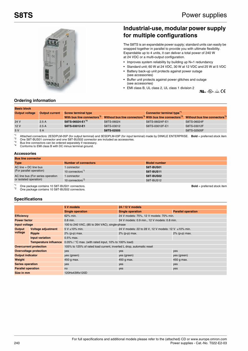
For full specifications and additional models please refer to the (attached) CD or www.europe.omron.comPower supplies - Cat.-No. T022-E2-03240
S8TS Power supplies
Industrial-use, modular power supply for multiple configurationsThe S8TS is an expandable power supply; standard units can easily be snapped together in parallel to provide you with ultimate flexibility. Expandable up to 4 units, it can deliver a total power of 240 W at 24 VDC or a multi-output configuration.
• Improves system reliability by building up N+1 redundancy • Standard unit; 60 W at 24 VDC, 30 W at 12 VDC and 25 W at 5 VDC • Battery back-up unit protects against power outage
(see accessories) • Buffer unit protects against power glitches and outage
(see accessories) • EMI class B, UL class 2, UL class 1 division 2
Ordering information
Accessories
Specifications
Basic block
Output voltage Output current Screw terminal type Connector terminal type*1
*1 Attached connectors: 2ESDPLM-05P (for output terminal) and 3ESDPLM-03P (for input terminal) made by DINKLE ENTERPRISE. Bold = preferred stock item
With bus line connectors*2
*2 One S8T-BUS01 connector and one S8T-BUS02 connector are included as accessories.
Without bus line connectors*3
*3 Bus line connectors can be ordered separately if necessary.
With bus line connectors*2 Without bus line connectors*3
24 V 2.5 A S8TS-06024-E1*4
*4 Conforms to EMI class B with DC minus terminal ground.
S8TS-06024 S8TS-06024F-E1 S8TS-06024F
12 V 2.5 A S8TS-03012-E1 S8TS-03012 S8TS-03012F-E1 S8TS-03012F
5 V 5 A S8TS-02505 S8TS-02505F
Bus line connector
Type Number of connectors Model number
AC line + DC line bus(For parallel operation)
1 connector S8T-BUS01
10 connectors*1
*1 One package contains 10 S8T-BUS01 connectors. Bold = preferred stock item
S8T-BUS11
AC line bus (For series operation or isolated operation)
1 connector S8T-BUS02
10 connectors*2
*2 One package contains 10 S8T-BUS02 connectors.
S8T-BUS12
5 V models 24 / 12 V models
Single operation Single operation Parallel operation
Efficiency 62% min. 24 V models: 75%, 12 V models: 70% min.
Power factor 0.8 min. 24 V models: 0.9 min., 12 V models: 0.8 min.
Input voltage 100 to 240 VAC, (85 to 264 VAC), single-phase
Output voltage
Voltage adjustment 5 V ±10% min. 24 V models: 22 to 28 V, 12 V models: 12 V ±10% min.
Ripple 2% (p-p) max. 2% (p-p) max. 2% (p-p) max.
Input variation 0.5% max.
Temperature influence 0.05% / °C max. (with rated input, 10% to 100% load)
Overcurrent protection 105% to 125% of rated load current, inverted L drop, automatic reset
Overvoltage protection yes yes yes
Output indicator yes (green) yes (green) yes (green)
Weight 450 g max. 450 g max. 450 g max.
Series operation yes yes yes
Parallel operation no yes yes
Size in mm 120Hx43Wx120D

For full specifications and additional models please refer to the (attached) CD or www.europe.omron.comPower supplies - Cat.-No. S8T-DCBU-01: T027-E2-02, S8T-DCBU-02: T029-E2-01A 241
S8T-DCBU-01/-02 Power supplies
S8T-DCBU-01The S8T-DCBU-01 battery backup block supplies 24 VDC for a fixed period of time during AC input outages to considerably improve system reliability.
Ordering information
Note: The S8TS DC back-up block is for S8TS power supplies only. Bold = preferred stock item
Specifications
Product Input voltage Output voltage Output current Model number
DC back-up block 24 to 28 VDC 24 V 3.7 A / 8 A S8T-DCBU-01
Battery holder S82Y-TS01
Product Input voltage Output voltage Output current Type Model number
Basic block (use together with the DC back-up block)
100 to 240 VAC 24 V 2.5 A Screw terminal type
With bus line connectors S8TS-06024-E1
Without bus line connectors S8TS-06024
Connector terminal type
With bus line connectors S8TS-06024F-E1
Without bus line connectors S8TS-06024F
Product Back-up time Overcurrent protection operating point selector
Model number
Battery 8 min. / 3.7 A 5.7 A (typ.) LC-R122R2PG
4 min. / 8.0 A 5.7 A (typ.) 11.7 A (typ.) LC-R123R4PG
Size in mm
S8TS-DCBU-01 120Hx43Wx130D
Battery holder 82Hx185.7Wx222.25D
S8T-DCBU-02Prevents equipment stoppage, data loss and other problems resulting from momentary power failures. One S8TS-DCBU-02 buffer block pro-vides a back-up time of 500 ms at an output current of 2.5 A. Can be wired to the 24 VDC output from any switch mode power supply.
Ordering information
Accessories
Specifications
Input voltage Output voltage (during back-up operation) Output current Model number
24 VDC (24 to 28 VDC) 22.5 V 2.5 A S8T-DCBU-02
Type Number of connectors Model number
DC bus line connector (for use with S8TS only) 1 connector S8T-BUS03
10 connectors S8T-BUS13
Size in mm
S8TS-DCBU-02 120Hx43Wx120D

For full specifications and additional models please refer to the (attached) CD or www.europe.omron.comPower supplies - Cat.-No. T035-E2-01242
S82K Power supplies
All-purpose, industrial use power supplyThe S82K has set an industrial standard in power supply history. Available from 3 to 100 W at 5, 12, 15 and 24 VDC.
• Indicates abnormalities on the load side (undervoltage alarm) • Parallel operation (100 W models) • ±12 and ±15 VDC output with 7.5 W available • UL Class 2 (90 W), EMI class B
Ordering information
Note: Complies to EN61000-3-2 A14 for all models
Specifications
Power ratings Output voltage Output current Function configuration Size in mm (HxWxD)
Models
Output Undervoltage alarm indicator
Undervoltage alarm output
3 W 5 V 0.6 A Single output yes no 75x37.5x65 S82K-00305
12 V 0.25 A S82K-00312
15 V 0.2 A S82K-00315
24 V 0.13 A S82K-00324
7.5 W 5 V 1.5 A Single output yes no S82K-00705
12 V 0.6 A S82K-00712
15 V 0.5 A S82K-00715
24 V 0.3 A S82K-00724
+V12 / -V12 0.3 A / 0.2 A Dual output S82K-00727
+V15 / -V15 0.2 A / 0.2 A S82K-00728
15 W 5 V 2.5 A Single output yes no 75x45x91 S82K-01505
12 V 1.2 A S82K-01512
24 V 0.6 A S82K-01524
30 W 5 V 5.0 A (25 W) Single output yes no 75x90x91 S82K-03005
12 V 2.5 A S82K-03012
24 V 1.3 A S82K-03024
50 W 24 V 2.1 A Single output yes no 75x145x91 S82K-05024
90 W 24 V 3.75 A yes S82K-09024
S82K-09024-500 *1
*1 Conforms to EMI class B with DC minus terminal ground Bold = preferred stock item
100 W 4.2 A *2
*2 The output current during parallel operation is 3.78 A.
S82K-10024
Specification Models without PFC Models with PFC
Single output Dual output Single output Single output
3 W 7.5 W 7.5 W 15 W 30 W 50 W 90 W 100 W 90 W 100 W
Efficiency 60% to 80% (varies depending on specification)
Power factor
100 V 0.95 min.
200 V 0.7 min. 0.95 min.
Input voltage 100 to 240 VAC, single-phase
Output voltage
Voltage adjustment
±10% (V. ADJ) not applicable
±10% (V.ADJ), -10% to 15% for S82K-030012 / -03024 / -05024
Ripple 2% (p-p max.)
Input variation 0.5% max.
Temperature influence
0.5% / °C max.
Overload protection 105% to 160% of rated load current, inverted L drop, automatic reset *1
*1 For 7.5 W Dual output 105% to 250% and for 90 W models 101% to 111%
Input current max.
100 V 0.15 A 0.25 A 0.45 A 0.9 A 1.3 A 2.5 A 2.5 A
200 V 0.25 A 0.6 A 0.8 A 1.5 A 1.0 A
Output indicator Yes (green)
Weight 150 g 260 g 260 g 380 g 400 g 600 g 1,000 g
Operating temperature -10 °C to 60 °C with derating from 50 °C, 100 W models: -10 °C to 50 °C, 90 W model derating from 30 °C
Series operation yes yes yes yes
Parallel operation yes yes
Models with PFC
S82K-P09024
S82K-P10024

For full specifications and additional models please refer to the (attached) CD or www.europe.omron.comPower supplies - Cat.-No. M044-E2-04 243
S8PE Power supplies
Slim, 3-phase input power supplyS8PE provides all you need for control panel design. From 5 to 40 A available.
• 3-phase input (340 - 576 VAC) • 5, 10, 20 and 40 A; 24 VDC output • 50 mm wide with 240 W model • UL60950 (CSA22.2-60950), UL508 listing (CSA22.2-14) and CE • Conforms to EN61000-3-2
Ordering information
Specifications
Power ratings Output voltage Output current Size in mm (HxWxD) With front-mounting bracket With DIN-rail mounting bracket
120 W 24 V 5 A 125x50x140 S8PE-F12024CD
240 W 24 V 10 A 170x50x140 S8PE-F24024CD
480 W 24 V 20 A 133x256x80 S8PE-F48024CD
960 W 24 V 40 A 275x246x80 S8PE-F96024C
Bold = preferred stock item
5 A 10 A 20 A 40 A
Efficiency Vin= 400 VAC 85 % 88 % 87 % 90 %
Vin= 480 VAC 84 % 88 % 87 % 90 %
Voltage range 340 to 766 VAC, 3-phase
Output voltage
Voltage adjustment
22.5 to 26.4 VDC min.
Ripple 200 mV max.
Input variation
±0.5% max.
Temperature influence
±0.01% / °C
Overload protection yes
Overvoltage protection yes
Output indicator yes (green) yes (green) yes (green) yes (green)
Weight 750 g 1.0 kg 2.65 kg 4.75 kg
Series operation yes (for 2 units)
Parallel operation yes (for 2 units)
LISTED

Which size is required?
Which mounting method is required?
Which type of timer is needed?
Timers
244

Which size is required?
H5CX series – designed to your specifications
245
Table of contentsSelection table 246
Analogue solid state timers H3DS 248
H3DE 249
H3YN 250
H3CR 251
Digital timers H5CX 252
Motor timers H2C 253

246
Selection table
Category Analogue solid state timer
Sel
ecti
on
cri
teri
a
Model H3DS-M H3DS-S H3DS-A H3DS-F H3DS-G H3DS-X H3DE-M H3DE-S H3DE-F H3DE-G H3DE-HMounting DIN-rail
Size 17.5 mm 22.5 mm
Type Multi-functional Twin timer
Star-delta Two-wired
Multi-functional Twin timer
Star-delta
Power OFF-delay
Co
nta
ct c
on
fig
ura
tio
n
Time limit
Instantaneous
Programmablecontacts
14 pins
11 pins
8 pins
Screw terminals
Screw-less clampterminals
Screw-less clampsockets
Inp
uts Voltage input
Ou
tpu
ts
Transistor
Relay
SCR
Relayoutput
type
SPDT (2X)
SPST-NO (2X)
DPDT
4PDT
Fea
ture
s
Timerange
Total timerange
0.1 s to 120 h
1 s to 120 h
2 s to 120 h
0.1 s to 120 h
1 s to 120 h
0.1 s to 120 h
0.1 s to 120 h
0.1 s to 120 h
0.1 s to 120 h
1 s to 120 h
0.1 s to 120 h
Number ofsub
ranges
7 7 7 6 2 7 8 8 8 2 2 (model dependent)
Supply voltage 24 to 230 VAC or 24 to 48 VDC
24 to 230 VAC or 24 to 48 VDC
24 to 230 VAC or 24 to 48 VDC
24 to 230 VAC or 24 to 48 VDC
24 to 230 VAC or 24 to 48 VDC
24 to 230 VAC or 24 to 48 VDC
24 to 230 VAC or 12 VDC
24 to 230 VAC / DC or 12 VDC
24 to 230 VAC / DC
24 to 230 VAC / DC
100 to 120 VAC, 200 to 230 VAC, 24 VAC / DC, 48 VAC / DC
Number ofoperating modes
8 4 1 2 1 1 8 4 1 1 1
Fu
nct
ion
s
ON-delay
Flicker OFF start
Flicker ON start
SignalON- / OFF-delay
Signal OFF-delay
Interval (signal orpower start)
One-shot output(ON-delay)
ON-delay (fixed)
IndependentON / OFF time
Star-delta
Re-
mar
ks Transistor
Page 248 249

Timers
247
Category Analogue solid state timer Digital timer Motor timer
Sel
ecti
on
cri
teri
a
Model H3YN H3CR-A H3CR-F H3CR-G H3CR-H H5CX H8GN H2CMounting Socket / on panel
Size 21.5 mm 1/16 DIN 1/32 DIN 1/16 DIN
Type Miniature Multi-functional
Twin timer Star-delta Power OFF-delay
Multi-functional
Preset counter / timer
Motor timer
Co
nta
ct c
on
fig
ura
tio
n
Time limit
Instantaneous
Programmablecontacts
14 pins
11 pins
8 pins
Screw terminals
Screw-less clampterminals
Screw-less clampsockets
Inp
uts Voltage input
Ou
tpu
ts
Transistor
Relay
SCR
Relayoutput
type
SPDT
SPST-NO (2X)
DPDT
4PDT
Fea
ture
s
Timerange
Total timerange
0.1 s to 10 h (model dependent)
0.05 s to
300 h, 0.1 s to 600 h (model dependent)
0.05 s to 30 h or 1.2 s to 300 h (model dependent)
0.5 s to 120 s 0.05 s to 12 s, 1.2 s to 12 min
0.001 s to 9999 h (configurable)
0.000 s to 9999 h (configurable)
0.2 s to 30 h
Number ofsub
ranges
2 9 14 4 4 10 9 15
Supply voltage 24, 100 to 120, 200 to 230 VAC, 12, 23, 48, 100 to 110, 125 VDC
100 to 240 VAC, 100 to 125 VDC, 24 to 48 VAC, 12 to 48 VDC
100 to 240 VAC, 12 VDC, 24 VAC / DC, 48 to 125 VDC
100 to 120 VAC, 200 to 240 VAC
100 to 120 VAC, 200 to 240 VAC, 24 VAC / DC, 48 VDC, 100 to 125 VDC
100 to 240 VAC, 24 VAC, 12 to 24 VDC
24 VDC 24, 48, 100, 110, 115, 120, 200, 220, 240 VAC
Number ofoperating modes
4 6 (model dependent)
2 1 12 6 2
Fu
nct
ion
s
ON-delay
Flicker OFF start
Flicker ON start
SignalON- / OFF-delay
Signal OFF-delay
Interval (signal orpower start)
One-shot output(ON-delay)
ON-delay (fixed)
IndependentON / OFF time
Star-delta
Re-
mar
ks Transistor
Page 250 251 252 261 253
Standard Available No / not available

For full specifications and additional models please refer to the (attached) CD or www.europe.omron.comTimers - Cat.-No. L098-E2-05248
H3DS Timers
DIN-rail mounted, standard 17.5 mm width solid state timer rangeThis broad range of timers includes many functionalities and has a wide AC / DC power supply range. Models with screwless clamp connection available.
• 17.5 mm width, modular 45 mm • DIN-rail mounting • 24 - 48 VDC and 24 - 230 VAC • 0.1 s to 120 h, 7 ranges
Ordering information
Specifications
Type Supply voltage Control output Time setting range
Operating modes Model
Screwterminal type
Screw-less clamp type
Multi-functional timer 24 to 230 VAC (50 / 60 Hz) / 24 to 48 VDC
SPDT 0.1 s -120 h ON-delay, flicker OFF start, flicker ON start, signal ON / OFF-delay, signal OFF-delay, interval, signal ON / OFF-delay, one-shot
H3DS-ML H3DS-MLC
Standard timer ON-delay, flicker ON start, interval, one-shot H3DS-SL H3DS-SLC
Single function timer ON-delay H3DS-AL H3DS-ALC
Twin timer Relay SPDT 0.1 s - 12 h Flicker OFF start, flicker ON start H3DS-FL H3DS-FLC
Star-delta timer 2x Relay SPST-NO 1 s - 120 s Star-delta H3DS-GL H3DS-GLC
Two-wired timer 24 to 230 VAC / VDC (50 / 60 Hz)
SCR output 0.1 s - 120 h ON-delay H3DS-XL H3DS-XLC
Bold = preferred stock item
Terminal block Screw terminal type: clamps two 2.5 mm2 max. bar terminals without sleevesScrew-less clamp type: clamps two 1.5 mm2 max. bar terminals without sleeves
Mounting method DIN-rail mounting
Operating voltage range 85% to 110% of rated supply voltage
Power reset Minimum power-off time: 0.1 s, 0.5 s for H3DS-G
Reset voltage 2.4 VAC / VDC max., 1.0 VAC / VDC max. for H3DS-X
Voltage input Max. permissible capacitance between input lines (terminals B1 and A2): 2,000 pF
Load connectable in parallel with inputs (terminals B1 and A1)
H-level: 20.4 to 253 VAC / 20.4 to 52.8 VDC
L-level: 0 to 2.4 VAC / VDC
Control output Contact output: 5 A at 250 VAC with resistive load (cosφ = 1)
5 A at 30 VDC with resistive load (cosφ = 1)
Ambient temperature Operating: -10 °C to 55 °C (with no icing)
Storage: -25 °C to 65 °C (with no icing)
Accuracy of operating time ±1% max. of FS (±1% ±10 ms max. at 1.2 s range)
Setting error ±10% ±50 ms max. of FS
Influence of voltage ±0.7% max. of FS (±0.7% ±10 ms max. at 1.2 s range)
Influence of temperature ±5% max. of FS (±5% ±10 ms max. at 1.2 s range)
Life expectancy (not H3DS-X) Mechanical: 10 million operations min. (under no load at 1,800 operations / h)
Electrical: 100,000 operations min. (5 A at 250 VAC, resistive load at 360 operations / h)
Size in mm 80Hx17.5Wx73D

For full specifications and additional models please refer to the (attached) CD or www.europe.omron.comTimers - Cat.-No. L092-E2-05 249
H3DE Timers
DIN-rail mounted, standard 22.5 mm width solid state timer rangeThe H3DE series of timers provides a wide AC / DC power supply and time range to reduce the number of items.
• 79Hx22.5Wx100D mm • DIN-rail mounting • 24 - 230 VAC / VDC (except -H) • Wide time setting range: 0.10 s - 120 h (except -H and -G), 8 ranges
Ordering information
Specifications
Type Supply voltage Control output Time setting range Operating modes Model
Multi-functional standard timers
12 VDC DPDT 0.1 s - 120 h ON-delay, flicker OFF start, flicker ON start, signal ON / OFF-delay, signal OFF-delay, interval, signal ON / OFF-delay, one-shot
H3DE-M2 DC12 *1
*1 One output can be set to instantaneous. Bold = preferred stock item
24 to 230 VAC / VDC SPDT H3DE-M1 AC/DC24-230
DPDT H3DE-M2 AC/DC24-230 *1
SPDT ON-delay, flicker ON start, interval, one-shot
H3DE-S1 AC/DC24-230
DPDT H3DE-S2 AC/DC24-230 *1
Twin timer SPDT 0.1 s - 12 h Flicker OFF start, flicker ON start H3DE-F AC/DC24-230
Star-delta timer 2x SPDT 1 - 20 m Star-delta H3DE-G AC/DC24-230
Power OFF-delay timer
24 VAC / VDC SPDT 1 - 120 s Signal OFF-delay H3DE-H AC/DC24 L
0.1 - 12 s H3DE-H AC/DC24 S
48 VAC / VDC 1 - 120 s H3DE-H AC/DC48 L
0.1 - 12 s H3DE-H AC/DC48 S
100 to 120 VAC 1 - 120 s H3DE-H AC100-120 L
0.1 - 12 s H3DE-H AC100-120 S
200 to 230 VAC 1 - 120 s H3DE-H AC200-230 L
0.1 - 12 s H3DE-H AC200-230 S
Terminal block Clamps two 2.5 mm2 max. bar terminals without sleeves
Mounting method DIN-rail mounting
Operating voltage range 85% to 110% of rated supply voltage
Power reset Minimum power-off time: H3DE-M/S, H3DE-F: 0.1 s, H3DE-G: 0.5 s
Reset voltage 2.4 VAC / VDC max. (not for H3DE-H)
Voltage input (H3DE-M / -S) Max. permissible capacitance between input lines (terminals B1 and A2): 2,000 pF
Load connectable in parallel with inputs (terminals B1 and A2)
H-level: 20.4 to 253 VAC / VDC, L-level: 0 to 2.4 VAC / VDC
Control output Contact output: 5 A at 250 VAC with resistive load (cosφ = 1), 5 A at 30 VDC with resistive load (cosφ = 1)
Ambient temperature Operating: -10 °C to 55 °C (with no icing), storage: -25 °C to 65 °C (with no icing)
Accuracy of operating time ±1% max. of FS (±1% ±10 ms max. at 1.2 s range)
Setting error ±10% ±0.05 s max. of FS
Signal input time 50 ms min.
Influence of voltage ±0.5% max. of FS
Influence of temperature ±2% max. of FS
Contact material AGNi+gold plating
Life expectancy Mechanical: 10 million operations min. (under no load at 1,800 operations / h)
Electrical: 100,000 operations min. (5 A at 250 VAC, resistive load at 360 operations / h)
Degree of protection IP30 (terminal block: IP20)
Size in mm 79Hx22.5Wx100D

For full specifications and additional models please refer to the (attached) CD or www.europe.omron.comTimers - Cat.-No. L089-E2-03250
H3YN Timers
Miniature timer with multiple time ranges and multiple operating modesH3YN features 4 multi-operating modes: ON-delay, interval, flicker ON start and flicker OFF start.
• 28Hx21.5Wx52.6D mm • Plug-in • All supply voltages available • 0.1 s to 10 h • DPDT (5 A) or 4PDT (3 A)
Ordering information
AccessoriesConnecting socket Hold-down clips
Specifications
Supply voltage Functions Time-limit contact Short-time range model (0.1 s to 10 min) Long-time range model (0.1 min to 10 h)
12 VDC ON-delayIntervalFlicker ONFlicker OFF
DPDT H3YN-2 12DC H3YN-21 12DC
24 VAC H3YN-2 24AC H3YN-21 24AC
24 VDC H3YN-2 24DC H3YN-21 24DC
100 - 120 VAC H3YN-2 100-120AC H3YN-21 100-120AC
200 - 230 VAC H3YN-2 200-230AC H3YN-21 200-230AC
12 VDC 4PDT H3YN-4 12DC H3YN-41 12DC
24 VAC H3YN-4 24AC H3YN-41 24AC
24 VDC H3YN-4 24DC H3YN-41 24DC
100 - 120 VAC H3YN-4 100-120AC H3YN-41 100-120AC
200 - 230 VAC H3YN-4 200-230AC H3YN-41 200-230AC
Bold = preferred stock item
Timer DIN-rail mounting / front-connecting socket
Back-connecting socket
PCB terminal
H3YN-2 / -21 PYF08A, PYF08A-N, PYF08A-E PY08-02
H3YN-4 / -41 PYF14A, PYF14A-N, PYF14A-E PY14-02
Applicable socket Model
PYF08A, PYF08A-N, PYF08A-E, PYF14A, PYF14A-N, PYF14A-E
Y92H-3 (pair)
PY08, PY08-02, PY14-02 Y92H-4
Bold = preferred stock item
Item H3YN-2 / -4 H3YN-21 / -41
Time ranges 0.1 s to 10 min (1 s, 10 s, 1 min, or 10 min max. selectable) 0.1 min to 10 h (1 min, 10 min, 1 h, or 10 h max. selectable)
Rated supply voltage 24, 100 to 120, 200 to 230 VAC (50 / 60 Hz) 12, 24, 48, 100 to 110, 125 VDC
Pin type Plug-in
Operating mode ON-delay, interval, flicker OFF start, or flicker ON start (selectable with DIP switch)
Operating voltage range 85% to 110% of rated supply voltage (12 VDC: 90% to 110% of rated supply voltage)
Reset voltage 10% min. of rated supply voltage
Control outputs DPDT: 5 A at 250 VAC, resistive load (cosφ = 1), 4PDT: 3 A at 250 VAC, resistive load (cosφ = 1)
Accuracy of operating time ±1% FS max. (1 s range: ±1% ±10 ms max.)
Setting error ±10% ±50 ms FS max.
Reset time Min. power-opening time: 0.1 s max. (including halfway reset)
Influence of voltage ±2% FS max.
Influence of temperature ±2% FS max.
Ambient temperature Operating: -10 °C to 50 °C (with no icing), storage: -25 °C to 65 °C (with no icing)
Degree of protection IP40
Size in mm 28Hx21.5Wx52.6D

For full specifications and additional models please refer to the (attached) CD or www.europe.omron.comTimers - Cat.-No. L084-E2-06 251
H3CR Timers
DIN 48x48 mm multi-functional timer seriesThis elaborate range of solid state timers provides you with a multi-functional timer, twin timer, star-delta timer and a power OFF-delay timer.
• 48x48 mm front-panel / plug-in • High- / low-voltage models (except -H and -G) • 0.05 s to 300 h (except -H and -G) • DPDT, 5 A at 250 VAC • Transistor 100 mA at 30 VDC
Ordering information
Accessories
Specifications
Output Number of pins Supply voltage Time range Operating mode Model
Relay DPDT 11 100 to 240 VAC / 100 to 125 VDC 0.05 s to 300 h ON-delay, flicker OFF start, flicker ON start, signal ON / OFF-delay, signal OFF-delay, interval
H3CR-A 100-240AC/100-125DC
24 to 48 VAC / 12 to 48 VDC H3CR-A 24-48AC/12-48DC
Transistor 24 to 48 VAC / 12 to 48 VDC 0.05 s to 300 h H3CR-AS 24-48AC/12-48DC
Relay DPDT 8 100 to 240 VAC / 100 to 125 VDC 0.05 s to 300 h ON-delay, flicker ON start,interval, one-shot
H3CR-A8 100-240AC/100-125DC
24 to 48 VAC / 12 to 48 VDC H3CR-A8 24-48AC/12-48DC
Transistor 24 to 48 VAC / 12 to 48 VDC 0.05 s to 300 h H3CR-A8S 24-48AC/12-48DC
Relay SPDT 100 to 240 VAC / 100 to 125 VDC H3CR-A8E 100-240AC/100-125DC
24 to 48 VAC / 12 to 48 VDC H3CR-A8E 24-48AC/DC
Relay DPDT 11 100 to 240 VAC 0.05 s to 30 h Flicker OFF start H3CR-F 100-240AC
24 VAC / VDC H3CR-F 24AC/DC
8 100 to 240 VAC H3CR-F8 100-240AC
24 VAC / VDC H3CR-F8 24AC/DC
11 100 to 240 VAC 0.05 s to 30 h Flicker ON start H3CR-FN 100-240AC
24 VAC / VDC H3CR-FN 24AC/DC
8 100 to 240 VAC H3CR-F8N 100-240AC
24 VAC / VDC H3CR-F8N 24AC/DC
Time-limit contact and instantaneous contact
100 to 120 VAC H3CR-G8EL 100-120AC
200 to 240 VAC H3CR-G8EL 200-240AC
DPDT 8 100 to 120 VAC 0.05 to 12 s Signal OFF-delay H3CR-H8LS 100-120AC
200 to 240 VAC H3CR-H8LS 200-240AC
24 VAC / VDC H3CR-H8LS 24AC/DC
100 to 120 VAC 0.05 to 12 m H3CR-H8LM 100-120AC
200 to 240 VAC H3CR-H8LM 200-240AC
24 VAC / VDC H3CR-H8LM 24AC/DC
Bold = preferred stock item
Name / specifications Model
Flush-mounting adapter Y92F-30
Protective cover Y92A-48B
Front connecting socket 8-pin, finger-safe type, DIN-rail P2CF-08-E
11-pin, finger-safe type P2CF-11-E
Back connecting socket 8-pin P3G-08
11-pin P3GA-11
Name / specifications Model
Time setting ring Setting a specific time Y92S-27
Limiting the setting range Y92S-28
Panel cover Light grey (5Y7/1) Y92P-48GL
Black (N1.5) Y92P-48GB
Bold = preferred stock item
Accuracy of operating time ±0.2% FS max. (±0.2% ±10 ms max. in a range of 1.2 s)
Influence of voltage ±0.2% FS max.(±0.2% ±10 ms max. in a range of 1.2 s)
Influence of temperature ±1% FS max. (±1% ±10 ms max. in a range of 1.2 s)
Ambient temperature Operating: -10 °C to 55 °C (with no icing), storage: -25 °C to 65 °C (with no icing)
Life expectancy Mechanical: 20,000,000 operations min.(under no load at 1,800 operations / h)
Electrical: 100,000 operations min. (5 A at 250 VAC, resistive load at 1,800 operations / h)
Size in mm 48Hx48Wx66.6D (H3CR-A, -F), 48Hx48Wx78D (H3CR-G, -H)
Setting error ±5% FS ±50 ms
Degree of protection IP40 (panel surface)
Weight Approx. 90 g

For full specifications and additional models please refer to the (attached) CD or www.europe.omron.comTimers - Cat.-No. L101-E2-04252
H5CX Timers
The most complete digital standard timer on the marketH5CX offers you the most complete series of products on the market today. Based on extensive customer research, these new timers have been designed with added-value features that users both need and appreciate.
• 48Hx48Wx64D to 100 mm • Two-colour display value, red or green • Front-mounting/plug-in • 0.001 s to 9999 h, 10 ranges • Input NPN, PNP and contact
Ordering information
Accessories
Specifications
Output type Supply voltage Functions External connection Size in mm (HxWxD)
Socket depth (mm)
Model
Contact output 100 to 240 VAC A: Signal ON-delay
A-1: Signal ON-delay 2
A-2: Power ON-delay 1
A-3: Power ON-delay 2
b: Repeat cycle 1
b-1: Repeat cycle 2
d: Signal OFF-delay
E: Interval
F: Cumulative
Z: ON / OFF-duty adjustable flicker
toff: Twin timer OFF start
ton: Twin timer ON start
Screw terminals 48x48x100 0 H5CX-A
12 to 24 VDC / 24 VAC 48x48x64 H5CX-AD
Transistor output 100 to 240 VAC 48x48x100 H5CX-AS
12 to 24 VDC / 24 VAC 48x48x64 H5CX-ASD
Contact output 100 to 240 VAC 11-pin socket 48x48x72.5 14.4 H5CX-A11
12 to 24 VDC / 24 VAC 48x48x63.7 H5CX-A11D
Transistor output 100 to 240 VAC 48x48x72.5 H5CX-A11S
12 to 24 VDC / 24 VAC 48x48x63.7 H5CX-A11SD
Contact output 100 to 240 VAC 8-pin socket 48x48x63.7 14.3 H5CX-L8
12 to 24 VDC / 24 VAC H5CX-L8D
Transistor output 100 to 240 VAC H5CX-L8S
12 to 24 VDC / 24 VAC H5CX-L8SD
Bold = preferred stock item
Name Model
Flush-mounting adapter Y92F-30
Waterproof packing Y92S-29
Front-connecting socket 8-pin, finger safe type P2CF-08-E
11-pin, finger safe type P2CF-11-E
Back-connecting socket 8-pin P3G-08
11-pin P3GA-11
Hard cover Y92A-48
Soft cover Y92A-48F1
Bold = preferred stock item
Item H5CX-A H5CX-A11 H5CX-L8
Display 7-segment, negative transmissive LCD
Present value: 11.5 mm-high characters
red or green (programmable) red
Set value: 6-mm-high characters, green
Digits 4 digits
Total time range 0.001 s to 9,999 h (configurable)
Timer mode Elapsed time (Up), remaining time (Down) (selectable)
Input signals Signal, reset, gate Signal, reset
Key protection Yes
Memory backup EEPROM (overwrites: 100,000 times min.) that can store data for 10 years min.
Ambient temperature Operating: -10 °C to 55 °C (no icing or condensation), side-by-side mounting: -10 °C to 50 °C
Case color Black (N1.5)

For full specifications and additional models please refer to the (attached) CD or www.europe.omron.comTimers - Cat.-No. L007-E2-10 253
H2C Timers
DIN-sized (48x48 mm) motor timer with variable time rangesThis motor timer series provides you with many features, such as ON-delay, time indicator, moving pointer and synchronous motor. Moreover, the LED indicator shows the time operation, time range and the rated voltage.
• DIN-sized 48x48 mm • Front-panel / plug-in / DIN-rail • All supply voltages available • 0.2 s to 30 h • SPDT, 6A at 250 VAC
Ordering information
Note: Other voltages available on request Bold = preferred stock item
Accessories
Specifications
Operation / resetting system Internal connection Terminal Time-limit contact Instantaneous contact Time range code Model
Time-limit operation / electric resetting
Separate motor and clutch connection
11-pin socket SPDT SPDT 1.25 s - 30 h in 5 ranges
H2C-RSA 110AC
H2C-RSA 220AC
H2C-RSA 24AC
0.2 s - 6 hin 5 ranges
H2C-RSB 110AC
H2C-RSB 220AC
H2C-RSB 24AC
0.5 s - 12 hin 5 ranges
H2C-RSC 110AC
H2C-RSC 220AC
H2C-RSC 24AC
Time-limit operation / self-resetting
Separate motor and clutch connection
11-pin socket SPDT SPDT 1.25 s - 30 hin 5 ranges
H2C-SA 110AC
H2C-SA 220AC
H2C-SA 24AC
0.2 s - 6 hin 5 ranges
H2C-SB 110AC
H2C-SB 220AC
H2C-SB 24AC
0.5 s - 12 hin 5 ranges
H2C-SC 110AC
H2C-SC 220AC
H2C-SC 24AC
Name / specifications Model
DIN-rail mounting / front-connecting socket
8-pin, finger safe type P2CF-08-E
11-pin, finger safe type P2CF-11-E
Back-connecting socket 8-pin, screw terminal P3G-08
11-pin P3GA-11
Name / specifications Model
Hold-down clip (pair) For PL08 and PL11 sockets Y92H-1
For PF085A socket Y92H-2
Flush mounting adapter Y92F-30
Time setting ring Y92A-Y1
Bold = preferred stock item
Operating voltage range 85% to 110% of rated supply voltage
Reset voltage 10% max. of rated supply voltage
Reset time Min. power-opening time: 0.5 s, min. pulse width: 0.5 s
Control outputs 6 A at 250 VAC, resistive load (cosφ = 1)
Mounting method Flush mounting (except for H2C-F / -FR models), surface-mounting, DIN-rail mounting
Life expectancy Mechanical: 10,000,000 operations min.
Electrical: 500,000 operations min.
Motor life expectancy 20,000 h
Accuracy of operating time
±0.5% FS max. (±1% max. at 0.2 to 6 s for the time range code B or at 0.5 to 12 s for the time range code C)
Setting error ±2% FS max.
Reset time 0.5 s max.
Influence of voltage ±1% FS max.
Influence of temperature
±2% FS max.
Ambient temperature Operating: -10 °C to 50 °C
Case color Light grey (Munsell 5Y7/1)
Degree of protection IP40 (panel surface)
Size in mm 48Hx48Wx77.5D

Which size is required?
Which type of application?
What is the type of counting application?
Which size is required?
Counters
254

Which size is required?
H7CX series – multi-functional pre-set counter
255
Table of contentsSelection table 256
Totalisers H7EC 258
H7ET 259
H7ER 260
Pre-set counters H8GN 261
H7CX 262
Cam positioners H8PS 263

256
Selection table
Category Self-powered total Self-powered timer Self-powered tachometer
Sel
ecti
on
cri
teri
a
Model H7EC H7ET H7ERDisplay LCD
Size 1/32 DIN
Ou
tpu
ts
Control outputs
2 stage
Total
Time
Preset
Batch
Dual
Tachometer
Inp
uts Control inputs No-voltage, PNP / NPN, DC-voltage,
AC / DC multi-voltageNo-voltage, PNP / NPN, DC-voltage, AC / DC multi-voltage
No-voltage, PNP / NPN
Fea
ture
s
Dual operation
Number of digits 8 7 4 or 5
NPN / PNP switch
Back-lit
External reset
Manual reset
Number of banks
Built-in sensor power supply
IP rating IP66 IP66 IP66
Ter
min
als Screw terminals
PCB terminals
11-pin socket
Su
pp
ly
volt
age 100 to 240 VAC
12 to 24 VDC
24 VDC
Comms
Fu
nct
ion
s
Up
Down
Up / down
Reversible
Speed 0 to 30 Hz or 0 to 1 kHz 1 or 10 kHz
Counting range 0 to 99999999 0.0 h to 999999.9 h <--> 0.0 h to 3999 d 23.9 h or 0 s to 999 h 59 min 59 s <--> 0.0 min to 9999 h 59.9 min
1000 s-1 or 1000 min-1; 1000 s-1 or 1000 min-1 <--> 10000 min-1
Co
lou
r Beige
Black
Page 258 259 260

Counters
257
Counter type Pre-set counter / timer Pre-set counter Cam positioner
Sel
ecti
on
cri
teri
a
Model H8GN H7CX H8PSDisplay LCD negative transmissive LCD
Size 1/32 DIN 1/16 DIN 1/4 DIN
Ou
tpu
ts
Control outputs 1 relay (SPDT) 1 relay (SPDT), transistor NPN or PNP, cam outputs (8 lines), run out, tachometer
5 stage
Total
Time
Preset
Batch
Dual
Tachometer
Inp
uts Control inputs No-voltage No-voltage,
PNP / NPNEncoder
Fea
ture
s
Dual operation
Number of digits PV: 4, SV: 4 PV: 4, SV: 4or PV: 6, SV: 6
7
NPN / PNP switch
Back-lit
External reset
Manual reset
Number of banks 4
Built-in sensor power supply
IP rating IP66 IP66 IP50
Ter
min
als Screw terminals
PCB terminals
11-pin socket
Su
pp
ly
volt
age 100 to 240 VAC
12 to 24 VDC
24 VDC
Comms
Fu
nct
ion
s
Up
Down
Up / down
Reversible
Speed 0 to 30 Hz or 0 to 5 kHz 0 to 30 Hz or 0 to 5 kHz
Counting range -1999 to 9999 -999 to 9999 or -99999 to 999999
Co
lou
r Beige
Black
Page 261 262 263
Standard Available No / not available

For full specifications and additional models please refer to the (attached) CD or www.europe.omron.comCounters - Cat.-No. M064-E2-03258
H7EC Counters
Self-powered LCD totaliserThe H7E series is available with large display with 8.6 mm character height. It includes models with backlight for improved visibility in dimly lit places. The H7E family includes total counters, time counters, tachometers and PCB-mounted counters.
• 24Hx48Wx48.5D mm • 8 digits, 8.6 mm character height • Black or light-grey housing • Dual input speed: 30 Hz <-> 1 kHz • Short body: all models have a depth of 48.5 mm
Ordering information
Specifications
Count input Max. counting speed Display Model
Light grey body Black body
No-voltage 30 Hz <-> 1 kHz (switchable) 7-segment LCD H7EC-N H7EC-N-B
PNP / NPN universal DC voltage input
30 Hz <-> 1 kHz (switchable) 7-segment LCD H7EC-NV H7EC-NV-B
7-segment LCD with backlight H7EC-NV-H H7EC-NV-BH
AC / DC multi-voltage input 20 Hz 7-segment LCD H7EC-NFV H7EC-NFV-B
Bold = preferred stock item
Item H7EC-NV- / H7EC-NV- H H7EC-NFV- H7EC-N-
Operating mode Up type
Mounting method Flush mounting
External connections Screw terminals, optional wire-wrap terminals
Number of digits 8
Display 7-segment LCD with or without backlight, zero suppression (character height: 8.6 mm)
Max. counting speed 30 Hz / 1 kHz 20 Hz 30 Hz / 1 kHz
Case color Light grey or black (-B models)
Attachment Waterproof packing, flush mounting bracket
Supply voltage Backlight model: 24 VDC (0.3 W max.) (only for backlight)No-backlight model: not required(powered by built-in battery)
Not required (powered by built-in battery)
Count input High (logic) level: 4.5 to 30 VDCLow (logic) level: 0 to 2 VDC(input impedance: approx. 4.7 kΩ)
High (logic) level: 24 to 240 VAC / VDC, 50 / 60 Hz Low (logic) level: 0 to 2.4 VAC / VDC, 50 / 60 Hz
No voltage input Maximum short-circuit impedance: 10 kΩ max. Short-circuit residual voltage: 0.5 V max. Minimum open impedance: 750 kΩ min.Reset input No voltage input
Maximum short-circuit impedance: 10 kΩ max. Short-circuit residual voltage: 0.5 V max. Minimum open impedance: 750 kΩ min.
Minimum signal width 20 Hz: 25 ms, 30 Hz: 16.7 ms, 1 KHz: 0.5 ms
Reset system External reset and manual reset: minimum signal width of 20 ms
Ambient temperature Operating: -10 °C to 55 °C (with no condensation or icing), storage: -25 °C to 65 °C (with no condensation or icing)
Degree of protection Front-panel: IP66, NEMA4, terminal block: IP20
Battery life (reference) 7 years min. with continuous input at 25 °C (lithium battery)
Size in mm 24Hx48Wx48.5D

For full specifications and additional models please refer to the (attached) CD or www.europe.omron.comCounters - Cat.-No. M064-E2-03 259
H7ET Counters
Self-powered time counterThe H7E series is available with large display with 8.6 mm character height. It includes models with backlight for improved visibility in dimly lit places. The H7E family includes total counters, time counters, tachometers and PCB-mounted counters.
• 24Hx48Wx48.5D mm • 7 digits, 8.6 mm character height • Black or light-grey housing • Dual time range 999999.9h <-> 3999d23.9h or
999h59m59s <-> 9999h59.9m
Ordering information
Specifications
Timer input Display Time range
999999.9h <-> 3999d23.9h (switchable) 999999.9h <-> 3999d23.9h (switchable)
Light grey body Black body Light grey body Black body
No-voltage input 7-segment LCD H7ET-N H7ET-N-B H7ET-N1 H7ET-N1-B
PNP / NPN universal DC voltage input
7-segment LCD H7ET-NV H7ET-NV-B H7ET-NV1 H7ET-NV1-B
7-segment LCD with backlight H7ET-NV-H H7ET-NV-BH H7ET-NV1-H H7ET-NV1-BH
AC / DC multi-voltage input 7-segment LCD H7ET-NFV H7ET-NFV-B H7ET-NFV1 H7ET-NFV1-B
Bold = preferred stock item
Item H7ET-NV - / H7ET-NV - H H7ET-NFV - H7ET-N -
Operating mode Accumulating
Mounting method Flush mounting
External connections Screw terminals
Display 7-segment LCD with or without backlight, zero suppression (character height: 8.6 mm)
Number of digits 7
Case color Light grey or black (-B models)
Attachment Waterproof packing, flush mounting bracket, time unit labels
Supply voltage Backlight model: 24 VDC (0.3 W max.) (for backlight) No-backlight model: not required(powered by built-in battery)
Not required (powered by built-in battery)
Timer input High (logic) level: 4.5 to 30 VDCLow (logic) level: 0 to 2 VDC (Input impedance: approx. 4.7 kΩ)
High (logic) level: 24 to 240 VAC / VDC, 50 / 60 Hz Low (logic) level: 0 to 2.4 VAC / VDC, 50 / 60 Hz
No voltage input Maximum short-circuit impedance: 10 kΩ max. Short-circuit residual voltage: 0.5 V max. Minimum open impedance: 750 kΩ min.Reset input No voltage input
Maximum short-circuit impedance: 10 kΩ max. Short-circuit residual voltage: 0.5 V max. Minimum open impedance: 750 kΩ min.
Minimum pulse width 1 s
Reset system External reset and manual reset: minimum signal width of 20 ms
Ambient temperature Operating: -10 °C to 55 °C (with no condensation or icing), storage: -25 °C to 65 °C (with no condensation or icing)
Time accuracy ±100 ppm (25 °C)
Degree of protection Front-panel: IP66, NEMA4 with waterproof packing, terminal block: IP20
Battery life (reference) 10 years min. with continuous input at 25 °C (lithium battery)
Size in mm 24Hx48Wx48.5D

For full specifications and additional models please refer to the (attached) CD or www.europe.omron.comCounters - Cat.-No. M064-E2-03260
H7ER Counters
Self-powered tachometerThe H7E series is available with large display with 8.6 mm character height. It includes models with backlight for improved visibility in dimly lit places. The H7E family includes total counters, time counters, tachometers and PCB-mounted counters.
• 24Hx48Wx48.5D mm • 5 digits, 8.6 mm character height • Black or light-grey housing • Dual revolution display
Ordering information
Specifications
Count input Display Max. revolutions displayed (applicable encoder resolution)
1,000 s-1 (1 pulse / rev.)1,000 min-1 (60 pulse / rev.)
1,000.0 s-1 (10 pulse / rev)1,000.0 min-1 (600 pulse / rev) <-> 10,000 min-1 (60 pulse / rev) (switchable)
Light grey body Black body Light grey body Black body
No-voltage input 7-segment LCD H7ER-N H7ER-N-B
PNP / NPN universal DC voltage input
7-segment LCD H7ER-NV H7ER-NV-B H7ER-NV1 H7ER-NV1-B
7-segment LCD with backlight H7ER-NV-H H7ER-NV-BH H7ER-NV1-H H7ER-NV1-BH
Bold = preferred stock item
Item H7ER-NV1- / H7ER-NV1- H H7ER-NV- H7ER-NV- H H7ER-N-
Operating mode Up type
Mounting method Flush mounting
External connections Screw terminals, wire-wrap terminals
Display 7-segment LCD with or without backlight, zero suppression (character height: 8.6 mm)
Number of digits 5 4
Max. revolutions displayed 1,000.0 s-1 (when encoder resolution of 10 pulse / rev is used) 1,000.0 min-1 (when encoder resolution of 600 pulse / rev is used) <-> 10,000 min-1 (when encoder resolution of 60 pulse / rev is used) (switchable with switch)
1,000 s-1 (when encoder resolution of 1 pulse / rev is used)1,000 min-1 (when encoder resolution of 60 pulse / rev is used)
Attachment Waterproof packing, flush mounting bracket, revolution unit labels
Supply voltage Backlight model: 24 VDC (0.3 W max.) (for backlight lit) No-backlight model: not required (powered by built-in battery)
Not required (powered by built-in battery)
Count input High (logic) level: 4.5 to 30 VDCLow (logic) level: 0 to 2 VDC (Input impedance: approx. 4.7 kΩ)
No voltage input Maximum short-circuit impedance: 10 kΩ max.Short-circuit residual voltage: 0.5 V max. Minimum open impedance: 750 kΩ min.
Max. counting speed 10 kHz 1 kHz
Minimum signal width 10 kHz: 0.05 ms, 1 kHz: 0.5 ms
Ambient temperature Operating: -10 °C to 55 °C (with no condensation or icing), storage: -25 °C to 65 °C (with no condensation or icing)
Degree of protection Front-panel: IP66, NEMA4 with waterproof packing, terminal block: IP20
Battery life (reference) 7 years min. with continuous input at 25 °C (lithium battery)
Size in mm 24Hx48Wx48.5D

For full specifications and additional models please refer to the (attached) CD or www.europe.omron.comCounters - Cat.-No. M065-E2-02 261
H8GN Counters
World's smallest compact preset counter / timerThe H8GN is a 1/32 DIN timer and counter in one. It is simple to switch between the timer and counter functions. During operation it is also possible to switch the display to monitor the totalising count value in 8 digits. Many sophisticated functions come standard with H8GN.
• 24Hx48Wx83D mm • 8-digit display, 4 value and 4 set value • Front mounting • 0.001 s to 9999 h (configurable) • 24 VDC
Ordering information
Specifications
Functions Supply voltage
Output Communications
Counter Timer No communications RS-485
Counter: up / down / reversible, 4 digits, N, F, C or K output modesTotal counter: 8 digits
A: ON-delay B: FlickerD: Signal OFF-delay E: IntervalF: AccumulativeZ: ON / OFF-duty adjustable flicker
24 VDC Contact output (SPDT) H8GN-AD H8GN-AD-FLK
Bold = preferred stock item
Rated supply voltage 24 VDC
Operating voltage range 85% to 110% of rated supply voltage
Power consumption 1.5 W max. (for max. DC load) (inrush current: 15 A max.)
Mounting method Flush-mounting
External connections Screw terminals (M3 screws)
Terminal screw tightening torque 0.5 Nm max.
Attachment Waterproof packing, flush-mounting bracket
Display 7-segment, negative transmissive LCD; time display (h, min, s); CMW, OUT, RST, TOTALPresent value (red, 7 mm high characters); set value (green, 3.4 mm high characters)
Digits PV: 4 digits, SV: 4 digits, when total count value is displayed: 8 digits (zeros suppressed)
Memory backup EEPROM (non-volatile memory) (number of writes: 100,000 times)
Counter Maximum counting speed 30 Hz or 5 kHz
Counting range -999 to 9,999
Input modes Increment, decrement, individual, quadrature inputs
Timer Timer modes Elapsed time (up), remaining time (down)
Inputs Input signals For counter: CP1, CP2, and resetFor timer: start, gate, and reset
Input method No-voltage input (contact short-circuit and open input)Short-circuit (ON) impedance: 1 kΩ max. (approx. 2 mA runoff current at 0 Ω) Short-circuit (ON) residual voltage: 2 VDC max. Open (OFF) impedance: 100 kΩ min.Applied voltage: 30 VDC max.
Start, reset, gate Minimum input signal width: 1 or 20 ms (selectable)
Power reset Minimum power-opening time: 0.5 s
Control output SPDT contact output: 3 A at 250 VAC / 30 VDC, resistive load (cosφ = 1)
Minimum applied load 10 mA at 5 VDC (failure level: P, reference value)
Reset system External, manual, and power supply resets (for timer in A, B, D, E, or Z modes)
Sensor waiting time 260 ms max. (inputs cannot be received during sensor wait time if control outputs are turned OFF)
Timer function Accuracy of operating time and setting error (including temperature and voltage effects)
Signal start: ±0.03% ±30 ms max. Power-ON start: ±0.03% ±50 ms max.
Ambient temperature
Operating storage -10 °C to 55 °C (with no icing or condensation)
-25 °C to 65 °C (with no icing or condensation)
Case color Rear section: grey smoke; front section: N1.5 (black)
Degree of protection Panel surface: IP66 and NEMA Type 4X (indoors); rear case: IP20, terminal block: IP20
Size in mm 24Hx48Wx83D

For full specifications and additional models please refer to the (attached) CD or www.europe.omron.comCounters - Cat.-No. M070-E2-03262
H7CX Counters
The most complete digital standard timer on the marketH7CX offers you the most complete series of products on the market today. Based on extensive customer research, these new counters have been designed with added-value features that users both need and appreciate.
• 48Hx48Wx64D to 100 mm • Two-colour display value, red or green • Front-mounting / plug-in • 6-digit model -99999 to 999999, set value -99999 to 999999 • Input contact, NPN or PNP
Ordering information
Accessories
Specifications
Type External connection
Sensor power supply
Supply voltage Output type Digits Size in mm (HxWxD)
Model
1-stage counter1-stage counter with total counter2-stage counter1-stage counter with batch counterDual counter (addition/subtraction)Tachometer
Screw terminal 12 VDC 100 to 240 VAC Contact and transistor output
6 48x48x100 H7CX-AU
12 to 24 VDC / 24 VAC H7CX-AUD1
Transistor output (2x) H7CX-AUSD1
100 to 240 VAC Contact output (2x) H7CX-AW
12 to 24 VDC / 24 VAC H7CX-AWD1
1-stage counter1-stage counter with total counter
11-pin socket 12 VDC 100 to 240 VAC Contact output 48x48x72.5 H7CX-A11
12 to 24 VDC / 24 VAC H7CX-A11D1
100 to 240 VAC Transistor output H7CX-A11S
12 to 24 VDC / 24 VAC H7CX-A11SD1
Screw terminal 100 to 240 VAC Contact output 48x48x100 H7CX-A
100 to 240 VAC Transistor output H7CX-AS
Bold = preferred stock item
Name Model
Flush-mounting adapter Y92F-30
Waterproof packing Y92S-29
DIN-rail mounting / front-connecting socket 11-pin, finger safe type P2CF-11-E
Back-connecting socket 11-pin P3GA-11
Finger safe terminal cover for P3GA-11 Y92A-48G
Hard cover Y92A-48
Soft cover Y92A-48F1
Bold = preferred stock item
Display 7-segment, negative transmissive LCD
Digits 6-digits: -99,999 to 999,999, SV range: 0 to 9,999
Max. counting speed 30 Hz or 5 kHz (selectable, ON / OFF ratio 1:1)
Input modes Increment, decrement, command, individual, and quadrature
Control output Contact output: 3 A at 250 VAC / 30 VDC, resistive load (cosφ = 1)Minimum applied load: 10 mA at 5 VDCTransistor output: NPN open collector, 100 mA at 30 VDC
Residual voltage: 1.5 VDC max. (approx. 1V)Leakage current: 0.1 mA max.
NEMA B300 Pilot Duty, 1/4 HP 3 A resistive load at 120 VAC, 1/3 HP 3 A resistive load at 240 VAC
Key protection Yes
Decimal point adjustment Yes (rightmost 3 digits)
Sensor waiting time 250 ms max.
Memory backup EEPROM (overwrites: 100,000 times min.) stores data 10 years min.
Ambient temperature Operating: -10 to 55 °C (-10 to 50 °C when mounted side by side)
Case color Black (N1.5), light grey (Munsell 5Y7/1, produced upon request)
Life expectancy Mechanical: 10,000,000 operations min.
Electrical: 100,000 operations min. (3 A at 250 VAC, resistive load)
Degree of protection Panel surface: IP66, NEMA 4 (indoors)

For full specifications and additional models please refer to the (attached) CD or www.europe.omron.comCounters - Cat.-No. M075-E2-02 263
H8PS Counters
Compact, easy-to-use cam positionerThe H8PS provides high-speed operation at 1,600 r/min and high-pre-cision settings to 0.5° ensuring widespread application. H8PS features a highly visible display with back-lit negative transmissive LCD. Advance angle compensation function compensates for output delays.
• 96Hx96Wx65D mm • Front-panel/DIN-rail • 24 VDC • 8-, 16- and 32-outputs • NPN / PNP 100 mA at 30 VDC
Ordering information
Accessories
Encoder accessories
Specifications
Number of outputs Mounting method Output configuration Bank function Size in mm (HxWxD) Model
8-outputs Flush-mounting NPN transistor output No 96x96x67.5 H8PS-8B
PNP transistor output H8PS-8BP
Surface-mounting / DIN-rail mounting NPN transistor output 96x96x60.6 H8PS-8BF
PNP transistor output H8PS-8BFP
16-outputs Flush-mounting NPN transistor output Yes 96x96x67.5 H8PS-16B
PNP transistor output H8PS-16BP
Surface-mounting / DIN-rail mounting NPN transistor output 96x96x60.6 H8PS-16BF
PNP transistor output H8PS-16BFP
32-outputs Flush-mounting NPN transistor output 96x96x67.5 H8PS-32B
PNP transistor output H8PS-32BP
Surface-mounting / DIN-rail mounting NPN transistor output 96x96x60.6 H8PS-32BF
PNP transistor output H8PS-32BFP
Bold = preferred stock item
Type Resolution Cable length Model
Economy 256 2 m E6CP-AG5C-C 256 2M
Standard 256 1 m E6C3-AG5C-C 256 1M
2 m E6C3-AG5C-C 256 2M
360 E6C3-AG5C-C 360 2M
720 E6C3-AG5C-C 720 2M
Rigid 256 2 m E6F-AG5C-C 256 2M
360 E6F-AG5C-C 360 2M
720 E6F-AG5C-C 720 2M
Bold = preferred stock item
Name Specification Model
Discrete wire output cable 2 m Y92S-41-200
Connector-type output cable 2 m E5ZE-CBL200
Support software CD-ROM H8PS-SOFT-V1
USB cable A miniB, 2 m Y92S-40
Parallel input adapter Two units can operate in parallel
Y92C-30
Protective cover Y92A-96B
Watertight cover Y92A-96N
DIN-rail mounting base Y92F-91
Name Specification Model
Shaft coupling for the E6CP Axis: 6 mm dia. E69-C06B
Shaft coupling for the E6C3 Axis: 8 mm dia. E69-C08B
Shaft coupling for the E6F Axis: 10 mm dia. E69-C10B
Extension cable 5 m (same for E6CP, E6C3, and E6F)
E69-DF5
Bold = preferred stock item
Rated supply voltage 24 VDC
Inputs Encoder input 8-output models: none; 16-/32-output models: bank inputs 1/2/4, origin input, start input
External inputs Input signals 8-output models: none; 16-/32-output models: bank inputs 1/2/4, origin input, start input
Input type No voltage inputs: ON impedance: 1 kΩ max. (leakage current: approx. 2 mA at 0 Ω) ON residual voltage: 2 V max., OFF impedance: 100 kΩ min., applied voltage: 30 VDC max.Minimum input signal width: 20 ms
Number of banks 8 banks (for 16-/32-output models only)
Display method 7-segment, negative transmissive LCD (main display: 11 mm (red), sub-display: 5.5 mm (green))
Memory backup method EEPROM (overwrites: 100,000 times min.) that can store data for 10 years min.
Ambient operating temperature -10 °C to 55 °C (with no icing or condensation)
Storage temperature -25 °C to 65 °C (with no icing or condensation)
Ambient humidity 25% to 85%
Degree of protection Panel surface: IP40, rear case: IP20
Case color Light grey (Munsell 5Y7/1)

How many I/O points?
What functionality is required?
How many I/O points? How many extra I/O points?
Programmable relays
ZEN – the logical automatic tools for small-scale flexible control
264

Programmable relays
265
Selection table
Category CPU units
Sel
ecti
on
cri
teri
a
Model ZEN-10C1AR-A-V1
ZEN-10C2AR-A-V1
ZEN-10C1DR-D-V1
ZEN-10C2DR-D-V1
ZEN-10C1DT-D-V1
ZEN-10C2DT-D-V1
ZEN-20C1AR-A-V1
ZEN-20C2AR-A-V1
ZEN-20C1DR-D-V1
ZEN-20C2DR-D-V1
ZEN-20C1DT-D-V1
ZEN-20C2DT-D-V1
Type LCD LED LCD LED LCD LED LCD LED LCD LED LCD LED
Number of I/O points 10 expandable up to 34 I/O 20 expandable up to 44 I/O
Inputs 6 6 6 12 12 12
Inputs / power supply 100 to 240 VAC 24 VDC 24 VDC 100 to 240 VAC 24 VDC 24 VDC
Outputs 4 4 4 8 8 8
Relays Relays Transistors Relays Relays Transistors
Fea
ture
s
LCD, buttons,calendar and clock
Analogue input (PNP)
Timers 16
Holding timers 8
Counters 16
Weekly timers 16 16 16 16 16 16
Calendar timers 16 16 16 16 16 16
Displays 16 16 16 16 16 16
Work bits 16
Holding bits 16
Analogue comparators(PNP) 4 4
Comparators 16
Page 267
Standard Available No / not available
Accessories and options EEPROM (for data security and copying) ZEN-ME01 Enables programs and parameter settings to be saved or copied to another ZEN
Battery (keeps time, date and bit values for 10 years at 25 °C)
ZEN-BAT01 10 year min. battery life (at 25 °C)
Connecting cable for the programming software, RS-232C cable, 9-way 'D' connector for PC
ZEN-CIF01 2 m RS-232C (9-pin D-sub connector)
Support software for Windows ZEN-SOFT01-V3
Runs on Windows 95, 98, 2000, ME, XP, or NT 4.0
PS unit 24 VDC, 1.3 A (30 W) ZEN-PA03024 ZEN power supply unit
ZEN kit - with LCD display AC version ZEN-KIT01-EV3 Set containing CPU unit (ZEN-10C1AR-A-V1), support software connecting cable, ZEN support software and manual
ZEN kit - with LCD Display DC version ZEN-KIT02-EV3 Set containing CPU unit (ZEN-10C1DR-D-V1), support software connecting cable, ZEN support software and manual

266
Programmable relaysSelection table
Category Expansion I/O units
Sel
ecti
on
cri
teri
a
ModelZEN-8EAR
ZEN-8EDR ZEN-8EDT ZEN-4EA ZEN-4ED ZEN-4ER
Type
Number of I/O points 8 4
Inputs 4 4 4 4 4
Inputs / power supply 100 to 240 VAC
24 VDC 24 VDC 100 to 240 VAC
24 VDC 24 VDC
Outputs 4 4 4 4
Relays Relays Transistors Relays
Fea
ture
s
LCD, buttons,calendar and clock
Analogue input (PNP)
Timers
Holding timers
Counters
Weekly timers
Calendar timers
Displays
Work bits
Holding bits
Analogue comparators(PNP)
Comparators
Page 267
Standard Available No / not available

For full specifications and additional models please refer to the (attached) CD or www.europe.omron.comProgrammable relays - Cat.-No. L01E-EN-01 267
ZEN Programmable relays
Flexible automationWithin OMRON's ZEN range there are up to 44 I/O to control. Our basic unit is either a 10 I/O or a 20 I/O version. These basic units are available with a realtime clock, an LCD screen and buttons, or with LED indication and no buttons. Each CPU can be handle up to 3 expansion units
• 10 I/O models with 6 inputs and 4 outputs, expandable up to 34 I/O• 20 I/O models with 12 inputs and 8 outputs, expandable up to 44 I/O• With LCD screen, including calendar & clock function or LED
indicator• DC power supply units have analogue input• Expansion units for 10 & 20 I/O versions with relay output or
transistor
Ordering information
Bold = preferred stock item
Accessories and options
Bold = preferred stock item
Specifications
Name Numberof I/O points
Inputs Inputs / power supply
Outputs Type LCD, buttons, calendar and clock
Ana-logue input
Timers, counters, weekly timers, calendar timers, displays, work bits, hol-ding bits, comparators
Analogue compara-tors
Holding timers
Size in mm (HxWxD)
Model number
CPU units
10Expand-able up to 34 I/O
6 100 to 240 VAC 4 Relays LCD yes 16 4 8 90x70x56 ZEN-10C1AR-A-V1
LED ZEN-10C2AR-A-V1
6 24 VDC 4 Relays LCD yes yes ZEN-10C1DR-D-V1
LED yes ZEN-10C2DR-D-V1
6 24 VDC 4 Transistors LCD yes yes ZEN-10C1DT-D-V1
LED yes ZEN-10C2DT-D-V1
20Expand-ableup to 44 I/O
12 100 to 240 VAC 8 Relays LCD yes 90x122.5x56 ZEN-20C1AR-A-V1
LED ZEN-20C2AR-A-V1
12 24 VDC 8 Relays LCD yes yes ZEN-20C1DR-D-V1
LED yes ZEN-20C2DR-D-V1
12 24 VDC 8 Transistors LCD yes yes ZEN-20C1DT-D-V1
LED yes ZEN-20C2DT-D-V1
Expan-sionI/O units
8 4 100 to 240 VAC 4 Relays 90x70x56 ZEN-8EAR
4 24 VDC 4 Relays ZEN-8EDR
4 24 VDC 4 Transistors ZEN-8EDT
4 4 100 to 240 VAC ZEN-4EA
4 24 VDC ZEN-4ED
4 Relays ZEN-4ER
EEPROM (for data security and copying) ZEN-ME01
Battery (keeps time, date and bit values for 10 years at 25 °C) ZEN-BAT01
For the programming software, RS-232C cable, 9-way ‘D’ connector for PC ZEN-CIF01
Support software for Windows ZEN-SOFT01-V3
PS unit 24 VDC, 1.3 A (30 W) ZEN-PA03024
ZEN kit - CPU unit ZEN-10C1AR-A-V1, support software and RS-232C cable ZEN-KIT01-EV3
ZEN kit - CPU unit ZEN-10C1DR-D-V1, support software and RS-232C cable ZEN-KIT02-EV3
Item Specification
ZEN- 0C AR-A-V1 ZEN- 0C D -D-V1
Power supply voltage 100 to 240 VAC 24 VDC
Rated power supply voltage 85 to 264 VAC 20.4 to 26.4 VDC
Power consumption 30 V max. (with 3 expansion units connected) 6.5 W max. (with 3 expansion units connected)
Ambient temperature LCD-type CPU unit (operation panel and calendar / clock function): 0 °C to 55 °C
LED-type CPU unit (no operation panel or calendar / clock function): -25 °C to 55 °C
Ambient storage temperature LCD-type CPU unit: -20 °C to 75 °C, LED-type CPU unit: -40 °C to 75 °C
Control method Stored program control
I/O control method Cyclic scan
Programming language Ladder diagram
Program capacity 96 lines (3 input conditions and 1 output per line)
LCD display 12 characters x 4 lines, with backlight (LCD-type CPU unit only)
Operation keys 8 (4 cursor keys and 4 operation keys) (LCD-type CPU unit only)
Super-capacitor holding time 2 days min. (25 °C)
Battery life (ZEN-BAT01) 10 years min. (25 °C)
Time function (RTC) ZEN 0C1 - - only, accuracy: 1 to 2 min / month (at 25 °C)

Which size is required?
Which application is required? Which application is required?
Digital panel indicators
268

K3HB – Omron’s new panel indicator
269
Table of contentsSelection table 270
1/32 DIN multi-function K3GN 272
1/8 DIN standard indicators K3MA-J, -L, -F 273
1/8 DIN advanced indicators - analogue input
K3HB-X, -H, -V, -S 274
1/8 DIN advanced indicators - digital input
K3HB-R, -P, -C 276

270
Selection table
Panel indicator typeMultifunctional
digital panel indicator
Process indicator Temperature indicator
Frequency / rate indicator Process indicator
Sel
ecti
on
cri
teri
a
Model K3GN K3MA-J K3MA-L K3MA-F K3HB-XSize 1/32 DIN 1/8 DIN
Fea
ture
s
Colour change display
Number of digits 5 5 4 5 5
Leading zero suppression
Forced zero function
Min. / max. hold function
Average processing
User selectable inputs
Start-up compensating time
Key protection
Decimal point positionsetting
Accuracy ±0.1% of full scale ±0.1% of full scale ±0.1% of full scale ±0.1% of full scale ±0.1% of full scale (DC voltage & DC current), ±0.5% of full scale (AC voltage & AC current)
Input range 0 to 20 mA, 4 to 20 mA or 0 to 5 V, 1 to 5 V, -5 to 5 V, -10 to 10 V or 0 to 30 Hz or 0 to 5 kHz
0 to 20 mA, 4 to 20 mA or 0 to 5 V, 1 to 5 V, -5 to 5 V, -10 to 10 V
Pt100, JPt100 or thermocouple K, J, T, E, L, U, N, R, S, B
0 to 30 Hz or 0 to 5 kHz 0.000 to 10.000 A, 0.0000 to 19.999 mA, -199.99 to 199.99 mA, 4.000 to 20.000 mA, 0.0 to 400.0 V, 0.0000
Sample rate 4 Hz 4 Hz 0 to 30 Hz or 0 to 5 kHz 0 to 30 Hz or 0 to 5 kHz 50 Hz
Features Remote / local processing, parameter initialisation, programmable output configuration, process value hold
Teaching, comparative output pattern selection, parameter initialisation, programmable output configuration, process value hold
Programmable output configuration, process value hold
Teaching, comparative output pattern selection, programmable output configuration, process value hold
Scaling, teaching, averaging, output hysteresis, output OFF-delay, output test, bank selection, reset, comparative output
Sensor power supply
Fro
nt
pro
tect
ion IP rating IP66 IP66 IP66 IP66 IP66
Supply voltage 24 VDC 24 VAC / VDC or 100 to 240 VAC
24 VAC / VDC or 100 to 240 VAC
24 VAC / VDC or 100 to 240 VAC
100 to 240 VAC or24 VAC / VDC
Inp
uts
NPN
PNP
Temperature
Contact
Voltage pulse
Load cell
DC voltage
DC current
AC voltage
AC current
Ou
tpu
ts
Relay
NPN
PNP
Linear
BCD
Comms
Page 272 273 274

Digital panel indicators
271
Temperature indicator Weighing indicator Linear sensor indicator Rotary pulse indicator Time interval indicator Up / down counting pulse indicator
K3HB-H K3HB-V K3HB-S K3HB-R K3HB-P K3HB-C1/8 DIN
5 5 5 5 5 5
Thermocouple: ±0.3% of full scale, Pt-100: ±0.2% of full scale
±0.1% of full scale One input: ±0.1% of full scale, two inputs: ±0.2% of full scale
±0.006% rgd ±1 digit±0.02% rgd ±1 digit
±0.08% rgd ±1 digit
Pt100, thermocouple K, J, T, E, L, U, N, R, S, B, W
0.00 to 199.99 mV, 0.000 to 19.999 mV, 100.00 mV, 199.99 mV
0 to 20 mA, 4 to 20 mA, 0 to 5 V, -5 to 5 V, -10 to 10 V
No voltage contact: 30 Hz, voltage pulse: 50 kHz, open collector: 50 kHz
No voltage contact: 30 Hz, voltage pulse: 50 kHz, open collector: 50 kHz
No voltage contact: 30 Hz, voltage pulse: 50 kHz, open collector: 50 kHz
50 Hz 50 Hz 2000 Hz 50 Hz 50 Hz 50 Hz
Scaling, teaching, averaging, output hysteresis, outputOFF-delay, output test, bank selection, reset, comparative output
Scaling, teaching, averaging, output hysteresis, outputOFF-delay, output test, bank selection, reset, comparative output
Scaling, 2-input calculation, teaching, averaging, output hysteresis, output OFF-delay, output test, bank selection, reset, comparative output
Scaling, measurement operation selection, averaging, previous average value comparison, output hysteresis, output OFF-delay, output test, teaching, display value selection, display colour selection, key protection, bank selection, display refresh period, maximum / minimum hold, reset
Scaling, measurement operation selection, output hysteresis, output OFF-delay, output test, teaching, display value selection, display colour selection, key protection, bank selection, display refresh period, maximum / minimum hold, reset
Scaling, measurement operation selection, output hysteresis, output OFF-delay, output test, display value selection, display colour selection, key protection, bank selection, display refresh period, maximum / minimum hold, reset
IP66 IP66 IP66 IP66 IP66 IP66
100 to 240 VAC or 24 VAC / VDC
100 to 240 VAC or 24 VAC / VDC
100 to 240 VAC or 24 VAC / VDC
100 to 240 VAC or 24 VAC / VDC
100 to 240 VAC or24 VAC / VDC
100 to 240 VAC or 24 VAC / VDC
274 276
Standard Available No / not available
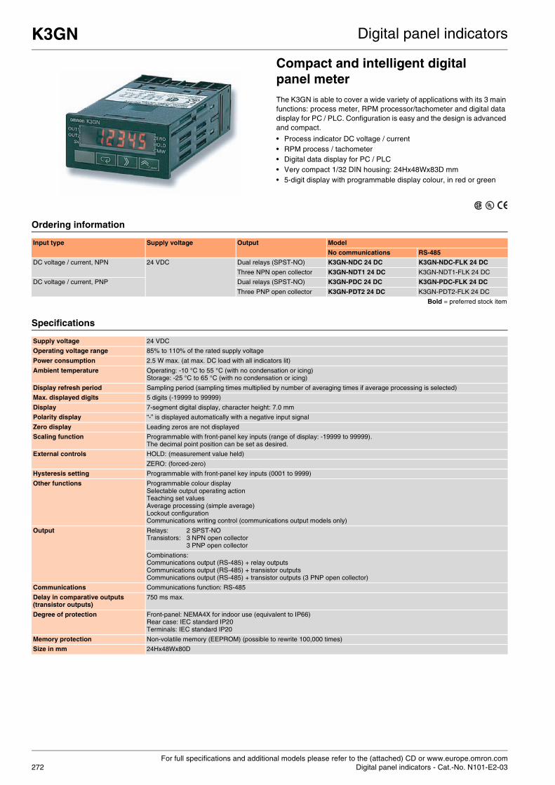
For full specifications and additional models please refer to the (attached) CD or www.europe.omron.comDigital panel indicators - Cat.-No. N101-E2-03272
K3GN Digital panel indicators
Compact and intelligent digital panel meterThe K3GN is able to cover a wide variety of applications with its 3 main functions: process meter, RPM processor/tachometer and digital data display for PC / PLC. Configuration is easy and the design is advanced and compact.
• Process indicator DC voltage / current • RPM process / tachometer • Digital data display for PC / PLC • Very compact 1/32 DIN housing: 24Hx48Wx83D mm • 5-digit display with programmable display colour, in red or green
Ordering information
Specifications
Input type Supply voltage Output Model
No communications RS-485
DC voltage / current, NPN 24 VDC Dual relays (SPST-NO) K3GN-NDC 24 DC K3GN-NDC-FLK 24 DC
Three NPN open collector K3GN-NDT1 24 DC K3GN-NDT1-FLK 24 DC
DC voltage / current, PNP Dual relays (SPST-NO) K3GN-PDC 24 DC K3GN-PDC-FLK 24 DC
Three PNP open collector K3GN-PDT2 24 DC K3GN-PDT2-FLK 24 DC
Bold = preferred stock item
Supply voltage 24 VDC
Operating voltage range 85% to 110% of the rated supply voltage
Power consumption 2.5 W max. (at max. DC load with all indicators lit)
Ambient temperature Operating: -10 °C to 55 °C (with no condensation or icing)Storage: -25 °C to 65 °C (with no condensation or icing)
Display refresh period Sampling period (sampling times multiplied by number of averaging times if average processing is selected)
Max. displayed digits 5 digits (-19999 to 99999)
Display 7-segment digital display, character height: 7.0 mm
Polarity display “-” is displayed automatically with a negative input signal
Zero display Leading zeros are not displayed
Scaling function Programmable with front-panel key inputs (range of display: -19999 to 99999). The decimal point position can be set as desired.
External controls HOLD: (measurement value held)
ZERO: (forced-zero)
Hysteresis setting Programmable with front-panel key inputs (0001 to 9999)
Other functions Programmable colour displaySelectable output operating actionTeaching set valuesAverage processing (simple average)Lockout configurationCommunications writing control (communications output models only)
Output Relays: 2 SPST-NOTransistors: 3 NPN open collector
3 PNP open collector
Combinations:Communications output (RS-485) + relay outputsCommunications output (RS-485) + transistor outputsCommunications output (RS-485) + transistor outputs (3 PNP open collector)
Communications Communications function: RS-485
Delay in comparative outputs (transistor outputs)
750 ms max.
Degree of protection Front-panel: NEMA4X for indoor use (equivalent to IP66)Rear case: IEC standard IP20Terminals: IEC standard IP20
Memory protection Non-volatile memory (EEPROM) (possible to rewrite 100,000 times)
Size in mm 24Hx48Wx80D

For full specifications and additional models please refer to the (attached) CD or www.europe.omron.comDigital panel indicators - Cat.-No. K3MA-J: N108-E2-04A, K3MA-L: N109-E2-04, K3MA-F: N107-E2-03A, 273
K3MA-J, -L, -F Digital panel indicators
Highly visible LCD display with 2-colour (red and green) LEDsThe K3MA series comes with a process meter, a frequency / rate meter and a temperature meter of either 100 to 240 VAC or 24 VAC / VDC. All are equipped with the same quality display and have the same short depth of 80 mm.
• DIN-size of 48Hx96W mm • Highly visible, negative transmissive backlit LCD display• 14.2 mm high characters • 5 digits (-19,999 to 99,999), K3MA-L: 4 digits• Front-panel IP66
Ordering information
Accessories
Specifications
Indicator Input type & ranges Supply voltage Output Model
Process meter DC voltage: 0 to 5 V, 1 to 5 V, -5 to 5 V, -10 to 10 VDC current: 0 to 20 mA, 4 to 20 mA
100 to 240 VAC 2 relay contact outputs (SPST-NO) K3MA-J-A2 100-240VAC
24 VAC / VDC 2 relay contact outputs (SPST-NO) K3MA-J-A2 24VAC/VDC
Temperature meter Platinum-resistance thermometer: Pt100, JPt100 or thermocouple K, J, T, E, L, U, N, R, S, B
100 to 240 VAC 1 relay contact output (SPDT) K3MA-L-C 100-240VAC
24 VAC / VDC 1 relay contact output (SPDT) K3MA-L-C 24VAC/VDC
Frequency / rate meter Rotary pulse: no voltage: 0.05 to 30.00 Hz; open collector: 0.1 to 5000.0 Hz
100 to 240 VAC 2 relay contact outputs (SPST-NO) K3MA-F-A2 100-240VAC
24 VAC / VDC 2 relay contact outputs (SPST-NO) K3MA-F-A2 24VAC/VDC
Bold = preferred stock item
Name Model
Splash-proof soft cover K32-49SC
Hard cover K32-49HC
Bold = preferred stock item
Item 100-240 VAC models 24 VAC / VDC models
Supply voltage 100 to 240 VAC 24 VAC (50 / 60 Hz), 24 VDC
Operating voltage range 85% to 110% of the rated supply voltage
Power consumption (under maximum load) 6 VA max. 4.5 VA max. (24 VAC) 4.5 W max. (24 VDC)
Ambient temperature Operating: -10 °C to 55 °C (with no condensation or icing) Storage: -25 °C to 65 °C (with no condensation or icing)
Weight Approx. 200 g
Display 7-segment digital display, character height: 14.2 mm
Polarity display "-" is displayed automatically with a negative input signal
Zero display Leading zeros are not displayed
Hold function Max. hold (maximum value), min. hold (minimum value)
Hysteresis setting Programmable with front-panel key inputs (0001 to 9,999)
Delay in comparative outputs 1 s max.
Degree of protection Front-panel: NEMA4X for indoor use (equivalent to IP66) Rear case: IEC standard IP20 Terminals: IEC standard IP00 + finger protection (VDE 0106 / 100)
Memory protection Non-volatile memory (EEPROM) (possible to rewrite 100,000 times)
Size in mm 48Hx96Wx80D

For full specifications and additional models please refer to the (attached) CD or www.europe.omron.comDigital panel indicators - Cat.-No. N131-E2-03274
K3HB-X, -H, -V, -S Digital panel indicators
Process, temperature, weighing and linear sensor indicatorsThese indicators with analogue input feature a clear and easy-to-use colour change display. All models are equipped with an IP66 housing. K3HB series is high-speed, with a sample rate of 50 Hz, and even 2,000 Hz for K3HB-S
• Position meter indication for easy monitoring• Optional DeviceNet, RS-232C, RS-485• Double display, with 5 digits, in two colours• Dimensions: 48Hx96Wx100D mm
Ordering information
Option boardsSensor power supply / output boards
Relay / transistor output boards
Event input boards
*1 CPA / CPB can be combined with relay outputs only. Bold = preferred stock item*2 Only one of the following can be used by each digital indicator: RS-232C / RS-485 communications, a linear output, or DeviceNet communications.
K3HB has got three slots for option boards: slot B, slot C and slot D.
Type of indicator Input sensor type and range Supply voltage Base unit model
Process indicatorK3HB-X
AC current input, from 0.000 to 10.000 A, 0.0000 to 19.999 mA 100 - 240 VAC K3HB-XAA 100-240VAC
24 VAC / VDC K3HB-XAA 24VAC/VDC
DC current input, from ±199.99 mA, to 4.000 to 20.000 mA 100 - 240 VAC K3HB-XAD 100-240VAC
24 VAC / VDC K3HB-XAD 24VAC/VDC
AC voltage input, from 0.0 to 400.0 V to 0.0000 to 1.999 V 100 - 240 VAC K3HB-XVA 100-240VAC
24 VAC / VDC K3HB-XVA 24VAC/VDC
DC voltage input, from ±199.99 V to 1.0000 to 5.0000 V 100 - 240 VAC K3HB-XVD 100-240VAC
24 VAC / VDC K3HB-XVD 24VAC/VDC
Temperature indicatorK3HB-H
Temperature input Pt100, thermocouple K, J, T, E, L, U, N, R, S, B, W 100 - 240 VAC K3HB-HTA 100-240VAC
24 VAC / VDC K3HB-HTA 24VAC/VDC
Weighing indicatorK3HB-V
Load cell input (DC low voltage input), 0.00 to 199.99 mV, 0.000 to 19.999 mV, 100.00 mV, 199.999 mV
100 - 240 VAC K3HB-VLC 100-240 VAC
24 VAC / VDC K3HB-VLC 24VAC/VDC
Linear sensor indicatorK3HB-S
DC process input, 0 to 5 V, 1 to 5 V, -5 to 5 V, -10 to 10 V, 0 to 20 mA, 4 to 20 mA 24 VAC / VDC K3HB-SSD AC/DC24
100 - 240 VAC K3HB-SSD AC100-240
Bold = preferred stock item
Slot Output Sensor power supply Communications Model Applicable indicator types
B Relay PASS: SPDT 12 VDC ±10%, 80 mA K33-CPA *1 K3HB-X, -H, -S
Linear current DC0(4) - 20 mA K33-L1 A *2 K3HB-X, -H, -S
Linear voltage DC0(1) - 5 V, 0 to 10 V K33-L2A *2 K3HB-X, -H, -S
K33-A *2 K3HB-X, -H, -S
RS-232C K33-FLK1 A *2 K3HB-X, -H, -S
RS-485 K33-FLK3A *2 K3HB-X, -H, -S
Relay PASS: SPDT 10 VDC ±5%, 100 mA K33-CPB *1 K3HB-V
Linear current DC0(4) - 20 mA K33-L1B *2 K3HB-V
Linear voltage DC0(1) - 5 V, 0 to 10 V K33-L2B *2 K3HB-V
K33-B *2 K3HB-V
RS-232C K33-FLK1B *2 K3HB-V
RS-485 K33-FLK3B *2 K3HB-V
Slot Output Communications Model
C Relay H / L: SPDT each K34-C1
HH / H / LL / L: SPST-NO each K34-C2
Transistor NPN open collector: HH / H / PASS / L / LL K34-T1
PNP open collector: HH / H / PASS / L / LL K34-T2
DeviceNet K34-DRT *2
Slot Input type Number of points Communications Model
D NPN open collector 5 M3 terminal blocks K35-1
8 10-pin MIL connector K35-2
PNP open collector 5 M3 terminal blocks K35-3
8 10-pin MIL connector K35-4

K3HB-X, -H, -V, -S Digital panel indicators
275
Accessories
Specifications
Special cable (for event inputs with 8-pin connector) K32-DICN
Bold = preferred stock item
Power supply voltage 100 to 240 VAC (50 / 60 Hz), 24 VAC / VDC, DeviceNet power supply: 24 VDC
Allowable power supply voltage range 85% to 110% of the rated power supply voltage, DeviceNet power supply: 11 to 25 VDC
Power consumption 100 to 240 V: 18 VA max. (max. load), 24 VAC / DC: 11 VA / 7 W max. (max. load)
Display method Negative LCD (backlit LED) display 7-segment digital display (character height: PV: 14.2 mm (green / red); SV: 4.9 mm (green))
Ambient operating temperature -10 °C to 55 °C (with no icing or condensation)
Display range -19,999 to 99,999
Weight Approx. 300 g (base unit only)
Degree of protection Front-panel Conforms to NEMA 4X for indoor use (equivalent to IP66)
Rear case IP20
Terminals IP00 + finger protection (VDE0106 / 100)
Memory protection EEPROM (non-volatile memory), number of rewrites: 100,000
Event input ratings Contact ON: 1 kΩ max., OFF: 100 kΩ min.
No-contact ON residual voltage: 2 V max., OFF leakage current: 0.1 mA max., load current: 4 mA max.Maximum applied voltage: 30 VDC max.
Output ratings Transistor output Maximum load voltage 24 VDC
Maximum load current 50 mA
Leakage current 100 µA max.
Contact output(resistive load)
Rated load 5 A at 250 VAC, 5 A at 30 VDC
Rated through current 5 A
Mechanical life expectancy 5,000,000 operations
Electrical life expectancy 100,000 operations
Linear output Allowable load impedance 500 Ω max. (mA); 5 kΩ min. (V)
Resolution Approx. 10,000
Output error ±0.5% FS
Size in mm 48Hx96Wx100D

For full specifications and additional models please refer to the (attached) CD or www.europe.omron.comDigital panel indicators - Cat.-No. N135-E2-02276
K3HB-R, -P, -C Digital panel indicators
Rotary pulse, timer interval and up- / down-counting pulse indicatorsThese indicators with analogue input feature a clear and easy-to-use colour change display. All models are equipped with an IP66 housing. K3HB-R and -C are high-speed, with a sample rate up to 50 kHz.
• Position meter indication for easy monitoring• Optional DeviceNet, RS-232C, RS-485• Double display, with 5 digits, in two colours• Dimensions: 48Hx96Wx100D mm
Ordering information
Option boardsSensor power supply / output boards
Relay / transistor output boards
Event input boards
*1 CPA can be combined with relay outputs only. Bold = preferred stock item*2 Only one of the following can be used by each digital indicator: RS-232C / RS-485 communications, a linear output, or DeviceNet communications.
K3HB has got three slots for option boards: slot B, slot C and slot D.
Accessories
Type of indicator Input ranges Supply voltage Input sensor Base unit model
Rotary pulse indicator K3HB-R No voltage contact: 30 Hz max.Voltage pulse: 50 kHz max. Open collector: 50 kHz max.
100 - 240 VAC NPN input / voltage pulse K3HB-RNB 100-240VAC
24 VAC / VDC K3HB-RNB 24VAC/VDC
100 - 240 VAC PNP input K3HB-RPB 100-240VAC
24 VAC / VDC K3HB-RPB 24VAC/VDC
100 - 240 VAC K3HB-PNB 100-240VAC
100 - 240 VAC K3HB-PPB 100-240VAC
Timer interval indicator K3HB-P 24 VAC / VDC K3HB-PPB 24VAC/VDC
100 - 240 VAC K3HB-CNB 100-240VAC
Up / down counting pulse indicator K3HB-C 24 VAC / VDC K3HB-CNB 24VAC/VDC
24 VAC / VDC K3HB-CPB 24VAC/VDC
Bold = preferred stock item
Slot Output Sensor power supply Communications Model
B Relay PASS: SPDT 12 VDC ±10%, 80 mA K33-CPA *1
Linear current DC0(4) - 20 mA K33-L1 A *2
Linear voltage DC0(1) - 5 V, 0 to 10 V K33-L2A *2
K33-A *2
RS-232C K33-FLK1 A *2
RS-485 K33-FLK3A *2
Slot Output Communications Model
C Relay H / L: SPDT each K34-C1
HH / H / LL / L: SPST-NO each K34-C2
Transistor NPN open collector: HH / H / PASS / L / LL K34-T1
PNP open collector: HH / H / PASS / L / LL K34-T2
DeviceNet K34-DRT *2
BCD + transistor NPN open collector: HH / H / PASS / L / LL K34-BCD
Bold = preferred stock item
Slot Input type Number of points Communications Model
D NPN open collector 5 M3 terminal blocks K35-1
8 10-pin MIL connector K35-2
PNP open collector 5 M3 terminal blocks K35-3
8 10-pin MIL connector K35-4
Special cable (for event inputs with 8-pin connector) K32-DICN
Special BCD output cable K32-BCD
Bold = preferred stock item

K3HB-R, -P, -C Digital panel indicators
277
Specifications
Power supply voltage 100 to 240 VAC (50 / 60 Hz), 24 VAC / VDC, DeviceNet power supply: 24 VDC
Allowable power supply voltage range 85% to 110% of the rated power supply voltage, DeviceNet power supply: 11 to 25 VDC
Power consumption 100 to 240 V: 18 VA max. (max. load), 24 VAC / DC: 11 VA / 7 W max. (max. load)
Display method Negative LCD (backlit LED) display 7-segment digital display (character height: PV: 14.2 mm (green / red); SV: 4.9 mm (green))
Ambient operating temperature -10 °C to 55 °C (with no icing or condensation)
Display range -19,999 to 99,999
Weight Approx. 300 g (base unit only)
Degree of protection Front-panel Conforms to NEMA 4X for indoor use (equivalent to IP66)
Rear case IP20
Terminals IP00 + finger protection (VDE0106 / 100)
Memory protection EEPROM (non-volatile memory), number of rewrites: 100,000
Event input ratings Contact ON: 1 kΩ max., OFF: 100 kΩ min.
No-contact ON residual voltage: 2 V max., OFF leakage current: 0.1 mA max., load current: 4 mA max.Maximum applied voltage: 30 VDC max.
Output ratings Transistor output Maximum load voltage 24 VDC
Maximum load current 50 mA
Leakage current 100 µA max.
Contact output(resistive load)
Rated load 5 A at 250 VAC, 5 A at 30 VDC
Rated through current 5 A
Mechanical life expectancy 5,000,000 operations
Electrical life expectancy 100,000 operations
Linear output Allowable load impedance 500 Ω max. (mA); 5 kΩ min. (V)
Resolution Approx. 10,000
Output error ±0.5% FS
Size in mm 48Hx96Wx100D

Programmable logical controllers (PLC)
CX-One – one software for all your automation needs
278

CP1H – the all-in-one PLC
279
Table of contentsCompact PLC CPM1A CPU units 282
CPM2A CPU units 283
CPM2C CPU units 284
CP1H CPU units 285
CPM1A expansion units 286
CPM2C expansion units 287
Modular PLC CJ1 CPU units 288
CJ1 power supplies, expansions 289
CJ1 digital I/O units 290
CJ1 analog I/O and control units 291
CJ1 position control units 293
CJ1 communication units 294
Rack PLC CS1 CPU units 295
CS1 power supplies, backplanes 296
CS1 digital I/O units 297
CS1 analog and process I/O units 298
CS1 position / motion control units 300
CS1 communication units 301

280
Selection table
Compact PLC series
Model CPM1A CPM2A CPM2C CP1HBuilt-in Digital I/O 10 - 40 20 - 60 10 - 32 40
Interrupt inputs 2 - 4 2 - 4 2 - 4 8
Counter inputs 1 (5 kHz) 1 (20 kHz) + 2 to 4 (2 kHz) 4 (100 kHz)
Pulse outputs 1 (2 kHz) 2 (10 kHz) 2 (100 kHz) + 2 (30 kHz)
CPU features /option boards
Built-in AC or DC power supply2 analog settings
Built-in AC or DC power supply2 analog settingsRemovable terminal blocks Standard 2nd serial port
DC power supply2nd serial port via converter unit
Built-in AC or DC power supply4 analog in / 2 analog out (XA model)2 serial communication board plug-ins1 simple analog input1 analog settingRemovable terminal blocksUSB programming port
Max. digital I/O points 10 - 100 80 - 120 106 - 192 320
Execution time(bit instruction)
0.72 - 1.72 µs 0.26 - 0.64 µs 0.1 µs
Program memory 2 kWords 4 kWords 20 kSteps
Data memory 1 kWords 2 kWords 32 kWords
CompactFlash memory n.a.
Analog I/O Up to 6 inputs and 3 outputs8-bit, 12-bit resolutionU, I, TC, Pt100
Up to 4 x (2 in + 1 out)12-bit resolutionU, I, TC, Pt100
Up to approx. 30 inputs / outputs(8, 13, 14-bit resolution U, I, TC, PT100)
Special function units n.a. Temperature controlProtocol macroRFID sensor unit
Industrial networks Serial communications Ethernet (100 BASE-Tx)Controller linkSerial communications
Fieldbus master n.a. CompoBus/S DeviceNetCANPROFIBUS-DPCompoBus/S
Fieldbus I/O link DeviceNetCompoBusSPROFIBUS-DP
DeviceNetCompoBus/S
DeviceNetPROFIBUS-DPCAN
Page 282 283 284 285

Control system
281
Modular PLC series Rack PLC series
Model CJ1M CJ1G/H CS1G/H CS1DBuilt-in Digital I/O 16 n.a.
Interrupt inputs 4 n.a.
Counter inputs 2 (100 kHz) n.a.
Pulse outputs 2 (100 kHz) n.a.
CPU features /option boards
Choice of models with and without built-in I/OEthernet CPU (3 models)
Loop control CPU (4 models)
2 serial portsLoop control board
Loop control board
Duplex CPU,Power supply and communications
Max. digital I/O points 160 - 640 960 - 2560 960 - 5120 960 - 5,120
Execution time(bit instruction)
0.1 µs 0.04/0.02 µs 0.04/0.02 µs 0.04/0.02 µs
Program memory 5 - 20 kSteps 10 - 250 kSteps 10 - 250 kSteps 10 - 250 kSteps
Data memory 32 kWords 64 - 448 kWords 64 - 448 kWords 64 - 448 kWords
CompactFlash memory Up to 64 MB Up to 64 MB
Analog I/O Up to 20 x 8 points12 bit resolutionU, I15 bit resolutionTC, Pt100, Pt1000 inputs
Up to 36 x 8 points13-bit resolutionU, I,15-bit resolutionTC, Pt100, PT1000 inputs
Up to 80 x 8 points, 13 bit resolution or 80 x 4 points, 16 bit resolutionU, I, TC, Pt100, process I/O
Up to 75 x 8 points, 13 bit resolution or 75 x 4 points, 16 bit resolutionU, I, TC, Pt100, process I/O
Special function units Temperature controlHigh-speed counters (500 kHz)SSI encoder inputPosition controlProtocol macroRFID sensor unit
Temperature controlSSI encoder inputHigh-speed counters (500 kHz)Position controlMotion controlProcess controlProtocol macroRFID sensor unit
Industrial networks Ethernet (100 BASE-Tx)Controller linkSerial communications
Ethernet (100 BASE-Tx)Controller linkSerial communications
Fieldbus master DeviceNetCANPROFIBUS-DPCompoBus/S
DeviceNetPROFIBUS-DPCAN / CANopenCompoBus/S
Fieldbus I/O link DeviceNetPROFIBUS-DPCAN
DeviceNetPROFIBUS-DPCAN / CANopen
Page 288 295

For full specifications and additional models please refer to the (attached) CD or www.europe.omron.comCompact PLC - Cat.-No. P06E-EN-03282
CPM1A CPU units Compact PLC
CPUs with 10 to 40 I/O built-inSetting a standard for micro PLCs, the CPM1A packs all basic functions into a compact size. Four CPU sizes are available, each with a choice of AC or DC power, relay or transistor outputs. Select any combination of power supply, output, and the number of I/O points to meet your needs.
Ordering information
Input points
Output points
Program capacity
Data memory capacity
Logic execution speed
Expandability Size in mm(HxWxD)
Power supply
Output method Built-in functions Model
6 points 4 points 2 kWords 1 kWords 0.72 µs to 1.72 µs
Not possible 90x66x70 85 to264 VAC
Relay 1 Encoder input (5 kHz) CPM1A-10CDR-A-V1
Transistor (sink type)
1 Encoder input (5 kHz)1 Pulse output (2 kHz)
CPM1A-10CDT-A-V1
Transistor (source type)
CPM1A-10CDT1-A-V1
90x66x50 20.4 to26.4 VDC
Relay 1 Encoder input (5 kHz) CPM1A-10CDR-D-V1
Transistor (sink type)
1 Encoder input (5 kHz)1 Pulse output (2 kHz)
CPM1A-10CDT-D-V1
Transistor (source type)
CPM1A-10CDT1-D-V1
12 points
8 points 2 kWords 1 kWords 0.72 µs to 1.72 µs
Not possible 90x86x70 85 to264 VAC
Relay 1 Encoder input (5 kHz) CPM1A-20CDR-A-V1
Transistor (sink type)
1 Encoder input (5 kHz)1 Pulse output (2 kHz)
CPM1A-20CDT-A-V1
Transistor (source type)
CPM1A-20CDT1-A-V1
90x86x50 20.4 to26.4 VDC
Relay 1 Encoder input (5 kHz) CPM1A-20CDR-D-V1
Transistor (sink type)
1 Encoder input (5 kHz)1 Pulse output (2 kHz)
CPM1A-20CDT-D-V1
Transistor (source type)
CPM1A-20CDT1-D-V1
18 points
12 points 2 kWords 1 kWords 0.72 µs to 1.72 µs
Up to 3 expansions
90x130x70 85 to264 VAC
Relay 1 Encoder input (5 kHz) CPM1A-30CDR-A-V1
Transistor (sink type)
1 Encoder input (5 kHz)1 Pulse output (2 kHz)
CPM1A-30CDT-A-V1
Transistor (source type)
CPM1A-30CDT1-A-V1
90x130x50 20.4 to26.4 VDC
Relay 1 Encoder input (5 kHz) CPM1A-30CDR-D-V1
Transistor (sink type)
1 Encoder input (5 kHz)1 Pulse output (2 kHz)
CPM1A-30CDT-D-V1
Transistor (source type)
CPM1A-30CDT1-D-V1
24 points
16 points 2 kWords 1 kWords 0.72 µs to 1.72 µs
Up to 3 expansions
90x150x70 85 to264 VAC
Relay 1 Encoder input (5 kHz) CPM1A-40CDR-A-V1
Transistor (sink type)
1 Encoder input (5 kHz)1 Pulse output (2 kHz)
CPM1A-40CDT-A-V1
Transistor (source type)
CPM1A-40CDT1-A-V1
90x150x50 20.4 to26.4 VDC
Relay 1 Encoder input (5 kHz) CPM1A-40CDR-D-V1
Transistor (sink type)
1 Encoder input (5 kHz)1 Pulse output (2 kHz)
CPM1A-40CDT-D-V1
Transistor (source type)
CPM1A-40CDT1-D-V1

For full specifications and additional models please refer to the (attached) CD or www.europe.omron.comCompact PLC - Cat.-No. P06E-EN-03 283
CPM2A CPU units Compact PLC
CPUs with 20 to 60 I/O built-inAdvanced functions and high performance in a compact shape. Ideal for automation of packaging and conveyor systems. Provides in-creased performance and added value to any compact machine.
Ordering information
Input points
Output points
Program capacity
Data memory capacity
Logic execution speed
Expandability Size in mm(HxWxD)
Power supply
Output method Built-in functions Model
12 points 8 points 4 kWords 2 kWords 0.26 µs to 0.64 µs
Up to 3 expansions*1
*1 Consult operation manual for details.
90x130x90 85 to264 VAC
Relay 1 Encoder input (20 kHz) CPM2A-20CDR-A
90x130x55 20.4 to26.4 VDC
Relay 1 Encoder input (20 kHz) CPM2A-20CDR-D
Transistor (sink type)
1 Encoder input (20 kHz)2 Pulse output (10 kHz)
CPM2A-20CDT-D
Transistor output (source type)
1 Encoder input (20 kHz)2 Pulse output (10 kHz)
CPM2A-20CDT1-D
18 points 12 points 4 kWords 2 kWords 0.26 µs to 0.64 µs
Up to 3 expansions*1
90x130x90 85 to264 VAC
Relay 1 Encoder input (20 kHz) CPM2A-30CDR-A
90x130x55 20.4 to26.4 VDC
Relay 1 Encoder input (20 kHz) CPM2A-30CDR-D
Transistor (sink type)
1 Encoder input (20 kHz)2 Pulse output (10 kHz)
CPM2A-30CDT-D
Transistor (source type)
1 Encoder input (20 kHz)2 Pulse output (10 kHz)
CPM2A-30CDT1-D
24 points 16 points 4 kWords 2 kWords 0.26 µs to 0.64 µs
Up to 3 expansions*1
90x150x90 85 to264 VAC
Relay 1 Encoder input (20 kHz) CPM2A-40CDR-A
90x150x55 20.4 to26.4 VDC
Relay 1 Encoder input (20 kHz) CPM2A-40CDR-D
Transistor (sink type)
1 Encoder input (20 kHz)2 Pulse output (10 kHz)
CPM2A-40CDT-D
Transistor (source type)
1 Encoder input (20 kHz)2 Pulse output (10 kHz)
CPM2A-40CDT1-D
36 points 24 points 4 kWords 2 kWords 0.26 µs to 0.64 µs
Up to 3 expansions*1
90x195x90 85 to264 VAC
Relay 1 Encoder input (20 kHz) CPM2A-60CDR-A
90x195x55 20.4 to26.4 VDC
Relay 1 Encoder input (20 kHz) CPM2A-60CDR-D
Transistor (sink type)
1 Encoder input (20 kHz)2 Pulse output (10 kHz)
CPM2A-60CDT-D
Transistor (source type)
1 Encoder input (20 kHz)2 Pulse output (10 kHz)
CPM2A-60CDT1-D

For full specifications and additional models please refer to the (attached) CD or www.europe.omron.comCompact PLC - Cat.-No. P06E-EN-03284
CPM2C CPU units Compact PLC
Compact CPUs with 10 to 32 I/O built-inAn extensive range of models assures efficient machine control in an ultracompact package. CPU units are available with relay or transistor output, terminal block or various connector options, and an optional real-time clock function.
Ordering information
Note: All CPU's are available only with DC supply voltage (CPM2C-PA201 can be used as power supply).CPU's with sourcing transistor outputs are also available with sinking transistor outputs.MIL = connector according to MIL-C-83503 (compatible with DIN 41651 / IEC 60603-1).
Input points
Output points
Program capacity
Data memory capacity
Logic execution speed
Size in mm(HxWxD)
I/O Connectors
Output method Built-in functions Real time clock
Model
6 points 4 points 4 kWords 2 kWords 0.64 µs 90x33x65 2 Terminal blocks
Relay 1 Encoder input (20 kHz) - CPM2C-10CDR-D
Yes CPM2C-10C1DR-D
2 Fujitsu (24 pt) Transistor (source type)
1 Encoder input (20 kHz)2 Pulse output (10 kHz)
- CPM2C-10CDT1C-D
Yes CPM2C-10C1DT1C-D
2 MIL (20 pt) Transistor (source type)
1 Encoder input (20 kHz)2 Pulse output (10 kHz)
- CPM2C-10CDT1M-D
Yes CPM2C-10C1DT1M-D
12 points 8 points 4 kWords 2 kWords 0.64 µs 90x33x65 2 Terminal blocks
Relay 1 Encoder input (20 kHz) - CPM2C-20CDR-D
Yes CPM2C-20C1DR-D
2 Fujitsu (24 pt) Transistor (source type)
1 Encoder input (20 kHz)2 Pulse output (10 kHz)
- CPM2C-20CDT1C-D
Yes CPM2C-20C1DT1C-D
2 MIL (20 pt) Transistor (source type)
1 Encoder input (20 kHz)2 Pulse output (10 kHz)
- CPM2C-20CDT1M-D
Yes CPM2C-20C1DT1M-D
16 points 16 points 4 kWords 2 kWords 0.64 µs 90x33x65 2 Fujitsu (24 pt) Transistor (source type)
1 Encoder input (20 kHz)2 Pulse output (10 kHz)
- CPM2C-32CDT1C-D
2 MIL (20 pt) Transistor (source type)
1 Encoder input (20 kHz)2 Pulse output (10 kHz)
- CPM2C-32CDT1M-D
6 points 4 points 4 kWords 2 kWords 0.64 µs 90x40x65 1 Fujitsu (24 pt) Transistor (source type)
1 Encoder input (20 kHz)2 Pulse output (10 kHz)Programmable Slave with DeviceNet slave and CompoBus/S Master
Yes CPM2C-S110C-DRT
6 points 4 points 4 kWords 2 kWords 0.64 µs 90x40x65 1 Fujitsu (24 pt) Transistor (source type)
1 Encoder input (20 kHz)2 Pulse output (10 kHz)CompoBus/S Master
Yes CPM2C-S110C

For full specifications and additional models please refer to the (attached) CD or www.europe.omron.comCompact PLC - Cat.-No. P06E-EN-02 285
CP1H CPU units Compact PLC
Powerful compact PLC with 40 I/O built-inThe CP1H is the advanced high speed all-in-one compact PLC. It com-bines all the strong points from the CPM2A and CJ1 series PLCs. Built-in functions like Digital I/O, High-speed counters, Pulse outputs, and analog Input / Outputs offer huge flexibility. Integrated communica-tion gateway functions make CP1H the first compact PLC in OMRON's Smart Platform concept. All OMRON devices connected to CP1H by Ethernet, DeviceNet, MECHATROLINK-II or Serial link can be config-ured, programmed and monitored through a single connection, using the CX-One software suite.
Ordering information
CP1H option modules
Input points
Output points
Expandable up to(digital I/O)*1
*1 CP1H CPU series can be expanded with CPM1A expansion units and CJ1 Special I/O units.
Program capacity
Data memory capacity
Logic execution speed
Power supply
Output method Built-in functions Model
24 points 16 points 320 points 20 kSteps 32 kWords 100 ns 85 to264 VAC
Relay 4 Encoder inputs (100 kHz)8 Interrupts / counters
- CP1H-X40DR-A
20.4 to26.4 VDC
Transistor (sink type)
4 Encoder input (100 kHz)4 Pulse output (2 x 100 kHz + 2 x 30 kHz)8 Interrupts / counters
CP1H-X40DT-D
Transistor (source type)
CP1H-X40DT1-D
24 points 16 points 320 points 20 kSteps 32 kWords 100 ns 85 to264 VAC
Relay 4 Encoder inputs (100 kHz)8 Interrupts / counters
4 Analog in2 Analog out(res: 1/12000)
CP1H-XA40DR-A
20.4 to26.4 VDC
Transistor (sink type)
4 Encoder input (100 kHz)4 Pulse output (2 x 100 kHz + 2 x 30 kHz)8 Interrupts / counters
CP1H-XA40DT-D
Transistor (source type)
CP1H-XA40DT1-D
Type Remarks Model
RS-232C option board Plug-in board (D-Sub, 9 pins, female) CP1W-CIF01
RS-422A/485 option board Plug-in board (Terminal block) CP1W-CIF11
Memory cassette 512 kWords (upload/download program) CP1W-ME05M
Expansion I/O connecting cable 80 cm cable to connect CPM1A I/O CP1W-CN811
CJ1 expansion unit adapter Unit to connect CJ1 Special I/O units CP1W-EXT01

For full specifications and additional models please refer to the (attached) CD or www.europe.omron.comCompact PLC - Cat.-No. P06E-EN-03286
CPM1A expansion units Compact PLC
Expand the capacity of your compact PLCA wide variety of expansion units such as Digital I/O, Analog I/O and Remote I/O are available to create the control system you need for your application. These CPM1A expansion units can be used for CPM1A and also for CPM2A and CP1H PLC series.
Ordering information
Unit Size in mm(HxWxD)
Output type Inputs Outputs Model
Expansion I/O units 90x66x50 - 8 - CPM1A-8ED
Relay - 8 CPM1A-8ER
Transistor (sinking) CPM1A-8ET
Transistor (sourcing) CPM1A-8ET1
90x86x50 Relay 12 8 CPM1A-20EDR1
Transistor (sinking) CPM1A-20EDT
Transistor (sourcing) CPM1A-20EDT1
90x150x50 Relay 24 16 CPM1A-40EDR
Transistor (sinking) CPM1A-40EDT
Transistor (sourcing) CPM1A-40EDT1
Analog I/O units 90x66x50 Analog (resolution 1/256) 2 1 CPM1A-MAD01
90x86x50 Analog (resolution 1/6000) 2 1 CPM1A-MAD11
90x86x50 Analog (resolution 1/6000) 4 - CPM1A-AD041
90x86x50 Analog (resolution 1/6000) - 4 CPM1A-DA041
Temperature sensor units 90x86x50 Thermocouple input 2 - CPM1A-TS001
Thermocouple input 4 - CPM1A-TS002
Platinum resistance input 2 - CPM1A-TS101
Platinum resistance input 4 - CPM1A-TS102
Platinum resistance input and voltage / current output
2 1 CPM1A-TS101-DA
DeviceNet I/O link unit 90x66x50 - I/O link of 32 input bits and 32 output bits CPM1A-DRT21
PROFIBUS-DP I/O link unit 90x66x50 - I/O link of 16 input bits and 16 output bits CPM1A-PRT21
CompoBus/S I/O link unit 90x66x50 - I/O link of 8 input bits and 8 output bits CPM1A-SRT21

For full specifications and additional models please refer to the (attached) CD or www.europe.omron.comCompact PLC - Cat.-No. P06E-EN-03 287
CPM2C expansion units Compact PLC
Expand the capacity of your CPM2C PLCExpansion I/O units with 8 to 32 I/O points make it possible to configure a control system with a maximum of 192 I/O points
Ordering information
Note: Expansion I/O units with sourcing transistor outputs are also available with sinking transistor outputs.MIL = connector according to MIL-C-83503 (compatible with DIN 41651 / IEC 60603-1).
Unit Output type I/O Connectors Inputs Outputs Model
Expansion I/O units - 1 Fujitsu (24 pt) 8 - CPM2C-8EDC
1 MIL (20 pt) CPM2C-8EDM
- 1 Fujitsu (24 pt) 16 - CPM2C-16EDC
1 MIL (20 pt) CPM2C-16EDM
Relay 1 Terminal block - 8 CPM2C-8ER
Transistor output (source type) 1 Fujitsu (24 pt) CPM2C-8ET1C
1 MIL (20 pt) CPM2C-8ET1M
Transistor output (source type) 1 Fujitsu (24 pt) - 16 CPM2C-16ET1C
1 MIL (20 pt) CPM2C-16ET1M
Relay 2 Terminal blocks 6 4 CPM2C-10EDR
Relay 2 Terminal blocks 12 8 CPM2C-20EDR
Transistor output (source type) 2 Fujitsu (24 pt) 16 8 CPM2C-24EDT1C
2 MIL (20 pt) CPM2C-24EDT1M
Transistor output (source type) 2 Fujitsu (24 pt) 16 16 CPM2C-32EDT1C
2 MIL (20 pt) CPM2C-32EDT1M
Analog I/O units Analog (resolution 1/6000) 2 Terminal blocks 2 1 CPM2C-MAD11
Temperature sensor units Thermocouple input 1 Terminal block 2 - CPM2C-TS001
Platinum resistance input 1 Terminal block 2 - CPM2C-TS101
CompoBus/S I/O link unit - 1 Terminal block I/O link of 8 input bits and 8 output bits CPM2C-SRT21
RS232C and RS422 adapter units - 1 D-sub 9-pin RS232C CPM2C-CIF01-V1
1 Terminal block and 1 D-sub 9-pin
RS232C and RS422 CPM2C-CIF11

For full specifications and additional models please refer to the (attached) CD or www.europe.omron.comModular PLC - Cat.-No. P04E-EN-03288
CJ1 CPU units Modular PLC
Fast and powerful CPUs for any taskOMRON's CS1-series CPUs are available in two processor speeds, each in various memory capacities. Besides the basic CPU models, versions are available for dual-redundant operation, supporting I/O hot-swapping. All CPUs have one dedicated board slot with a direct CPU-bus connection, in which a serial communication board or a loop control board can be mounted. All CPU Units support IEC61131-3 Structured text and ladder language.
OMRON's extensive function block library helps to reduce your pro-gramming effort, while you can create your own function blocks to suit your specific needs.
Ordering information
Note: - MIL = connector according to MIL-C-83503 (compatible with DIN 41651 / IEC 60603-1).- Models with sinking outputs (NPN type) are available as well.
Accessories
Max. digital I/O points
Program capacity
Data memory capacity
Logic execution speed
Max. I/O Units
Width 5 V current consumption
Built-in functions Model
2,560 250 kSteps 448 kWords 20 ns 40 62 mm 990 mA CJ1H-CPU67H
2,560 120 kSteps 256 kWords 20 ns 40 62 mm 990 mA CJ1H-CPU66H
2,560 60 kSteps 128 kWords 20 ns 40 62 mm 990 mA CJ1H-CPU65H
1,280 60 kSteps 128 kWords 40 ns 40 69 mm 1,060 mA Loop control engine (300 blocks) CJ1G-CPU45P
62 mm 910 mA CJ1G-CPU45H
1,280 30 kSteps 64 kWords 40 ns 40 69 mm 1,060 mA Loop control engine (300 blocks) CJ1G-CPU44P
62 mm 910 mA CJ1G-CPU44H
960 20 kSteps 64 kWords 40 ns 30 69 mm 1,060 mA Loop control engine (300 blocks) CJ1G-CPU43P
62 mm 910 mA CJ1G-CPU43H
960 10 kSteps 64 kWords 40 ns 30 69 mm 1,060 mA Loop control engine (50 blocks) CJ1G-CPU42P
62 mm 910 mA CJ1G-CPU42H
640 30 kSteps 32 kWords 100 ns 20 49 mm 640 mA 2 Encoder inputs (100 kHz)2 Pulse outputs (100 kHz)4 interrupt / counter inputs
CJ1M-CPU23
320 10 kSteps 32 kWords 100 ns 10 49 mm 640 mA 2 Encoder inputs (100 kHz)2 Pulse outputs (100 kHz)4 interrupt / counter inputs
CJ1M-CPU22
160 5 kSteps 32 kWords 100 ns 10 49 mm 640 mA 2 Encoder inputs (100 kHz)2 Pulse outputs (100 kHz)4 interrupt / counter inputs
CJ1M-CPU21
640 20 kSteps 32 kWords 100 ns 19 62 mm 950 mA 100 base-Tx Ethernet port CJ1G-CPU13-ETN
20 31 mm 580 mA CJ1G-CPU13
320 10 kSteps 32 kWords 100 ns 9 62 mm 950 mA 100 base-Tx Ethernet port CJ1G-CPU12-ETN
10 31 mm 580 mA CJ1G-CPU12
160 5 kSteps 32 kWords 100 ns 9 62 mm 950 mA 100 base-Tx Ethernet port CJ1G-CPU11-ETN
10 31 mm 580 mA CJ1G-CPU11
Model
CompactFlash memory card, 30 MB, for all models (not required for operation) Industrial grade HMC-EF372
CompactFlash memory card, 64 MB, for all models (not required for operation) Industrial grade HMC-EF672
CompactFlash PC-Card adapter HMC-AP001
I/O terminal block (40 x M3 screw) for CJ1M-CPU2x MIL (40 pt) XW2D-40G6
Servo unit terminal block for 1 axis XW2B-20J6-8A
Servo unit terminal block for 2 axes XW2B-40J6-9A
Connection cable between I/O terminal block and CJ1M-CPU2x (@@@ = length in cm) MIL (40 pt) XW2Z-@@@K
SMARTSTEP cable for CJ1M CPU2x, cable length: 1 m XW2Z-100J-A26
W-series servo cable for CJ1M CPU2x, cable length: 1 m XW2Z-100J-A27
CX-One, integrated software for programming and configuration of all OMRON control system components CX-ONE-AL C-E
Connection cable, D-Sub 9-pin PC serial port to PLC peripheral port (length: 2.0 m) CS1W-CN226
Connection cable, D-Sub 9-pin PC serial port to PLC peripheral port (length: 6.0 m) CS1W-CN626
USB to serial conversion cable CS1W-CIF31

For full specifications and additional models please refer to the (attached) CD or www.europe.omron.comModular PLC - Cat.-No. P04E-EN-03 289
CJ1 power supplies, expansions Modular PLC
Power and flexibilityCJ1 systems can operate on 24 VDC power supply, or on 100 - 240 VAC mains. For small-scale systems with mainly digital I/O a low-cost small-capacity power supply can be used. For systems with many analog I/Os and control/communication units, it may be neces-sary to use a larger power supply Unit.
Depending on the CPU type, up to 3 expansions can be connected to the CPU 'rack', giving a total capacity of 40 I/O units. The total length of the expansion cables of one system may be up to 12 m.
Ordering information
Power supply
I/O expansion
Input range Power consumption
Output capacity @ 5 VDC
Output capacity @ 24 VDC
Max. output power
Features Width Model
21.6 to 26.4 VDC 35 W max. 2.0 A 0.4 A 16.6 W No galvanic isolation 27 mm CJ1W-PD022
19.2 to 28.8 VDC 50 W max. 5.0 A 0.8 A 25 W 60 mm CJ1W-PD025
85 to 264 VAC47 to 63 Hz
50 VA max. 2.8 A 0.4 A 14 W 45 mm CJ1W-PA202
100 VA max. 5.0 A 0.8 A 25 W Run output (SPST relay) 80 mm CJ1W-PA205R
Maintenance status display 80 mm CJ1W-PA205C
Type Description Width, Length
Model
I/O control unit Required unit on CPU 'rack' to connect I/O expansions 20 mm CJ1W-IC101
I/O interface unit Start unit for each I/O expansion 'rack'. Requires a power supply unit. 31 mm CJ1W-II101
I/O expansion cable Connects CJ1W-IC101 or -II101 to the next expansion rack's -II101 0.3 m CS1W-CN313
0.7 m CS1W-CN713
2.0 m CS1W-CN223
3.0 m CS1W-CN323
5.0 m CS1W-CN523
10 m CS1W-CN133
12 m CS1W-CN133-B2

For full specifications and additional models please refer to the (attached) CD or www.europe.omron.comModular PLC - Cat.-No. P04E-EN-03290
CJ1 digital I/O units Modular PLC
8 to 64 points per unit - input, output or mixedDigital I/O units serve as the PLC's interface to achieve fast, reliable se-quence control. A full range of units, from high-speed DC inputs to relay outputs, let you adapt CJ1 to your needs.
CJ1 units are available with various I/O densities and connection tech-nologies. Up to 16 I/O points can be wired to units with detachable M3 screw terminals or screwless clamp terminals. High-density 32- and 64- point I/O units are equipped with standard 40-pin 'flatcable'-connectors. Prefabricated cables and wiring terminals are available for easy inter-facing to high-density I/O units.
Ordering information
Accessories
Type Points Type Rated voltage Rated current
Width I/O bus current consumption
Remarks Connection type*1
*1 MIL = connector according to MIL-C-83503 (compatible with DIN 41651 / IEC 60603-1).
Model
input 8 AC in 240 VAC 7 mA 31 mm 80 mA M3 CJ1W-IA201
input 8 DC in 24 VDC 10 mA 31 mm 80 mA M3 CJ1W-ID201
input 16 DC in 24 VDC 7 mA 31 mm 80 mA M3Screwless
CJ1W-ID211CJ1W-ID211(SL)
input 16 DC in 24 VDC 7 mA 31 mm 80 mA Inputs start interrupt tasks in PLC program
M3 CJ1W-INT01
input 16 DC in 24 VDC 7 mA 31 mm 80 mA Latches pulses down to 50 ms pulse width
M3 CJ1W-IDP01
input 32 DC in 24 VDC 4.1 mA 20 mm 90 mA 1 x MIL*1 (40 pt) CJ1W-ID232
input 64 DC in 24 VDC 4.1 mA 31 mm 90 mA 2 x MIL*1 (40 pt) CJ1W-ID262
output 8 Triac out 250 VAC 0.6 mA 31 mm 220 mA M3 CJ1W-OA201
output 8 Relay out 250 VAC 2 mA 31 mm 80 mA M3Screwless
CJ1W-OC201CJ1W-OC201(SL)
output 16 Relay out 250 VAC 2 mA 31 mm 110 mA M3Screwless
CJ1W-OC211CJ1W-OC211(SL)
output 8 DC out (source)*2
*2 Models with sinking outputs (NPN type) are available as well.
24 VDC 2 mA 31 mm 110 mA With short-circuit protection, alarm
M3 CJ1W-OD202
output 8 DC out (source)*2 24 VDC 0.5 mA 31 mm 100 mA With short-circuit protection, alarm
M3 CJ1W-OD204
output 16 DC out (source)*2 24 VDC 0.5 mA 31 mm 100 mA With short-circuit protection, alarm
M3Screwless
CJ1W-OC212CJ1W-OC212(SL)
output 32 DC out (source)*2 24 VDC 0.3 mA 20 mm 150 mA With short-circuit protection, alarm
1 x MIL*1 (40 pt) CJ1W-OD232
output 64 DC out (source)*2 24 VDC 0.3 mA 31 mm 170 mA 2 x MIL*1 (40 pt) CJ1W-OD262
In + out 16 +16 DC in/out (source)*2 24 VDC 0.5 mA 31 mm 130 mA 2 x MIL (20 pt) CJ1W-OD232
In + out 32 +32 DC in/out (sink) 24 VDC 0.3 mA 31 mm 140 mA 2 x MIL*1 (40 pt) CJ1W-OD263
In + out 32 +32 DC in/out (TLL) 5 VDC 35 mA 31 mm 190 mA 2 x MIL*1 (40 pt) CJ1W-OD563
Model
Replacement 18-point screwless terminal blocks for I/O Units, pack of 5 pcs. Screwless CJ-WM01-18P-5
I/O terminal block (40 x M3 screw) for XW2Z-@@@K MIL (40pt) XW2D-40G6
Connection cable between I/O terminal block and I/O unit (@@@ = length in cm) MIL (40pt) XW2Z-@@@K

For full specifications and additional models please refer to the (attached) CD or www.europe.omron.comModular PLC - Cat.-No. P04E-EN-03 291
CJ1 analog I/O and control units Modular PLC
From basic analog I/O to advanced temperature controlCJ1 offers a wide choice of analog input units, fit for any application, from low-speed, multi-channel temperature measurement to high-speed, high-accuracy data acquisition. Analog outputs can be used for accurate control or external indication.
Advanced units with built-in scaling, filtering and alarm functions reduce the need for complex PLC programming. High-accuracy process I/O units support an extensive range of sensors, for fast and accurate data acquisition. Temperature control units relieve the PLC CPU of PID cal-culations and alarm monitoring. These functions are handled autono-mously by the unit, offering control performance and autotuning functions similar to stand-alone temperature controllers.
Ordering information
Points Type Ranges Resolution Accuracy *1 Conversion time
Width I/O bus current consump-tion
Remarks Connection type
Model
4 Analog input 0 to 5 V, 0 to 10 V,
-10 to 10 V, 1 to 5 V, 4 to 20 mA
1/8,000 V: 0.2% of PVI: 0.4% of PV
250 µs/point 31 mm 420 mA Offset / gain adjustment, peak hold, moving average, alarms
M3 CJ1W-AD041-V1
Screwless CJ1W-AD041-V1 (SL)
8 Analog input 1 to 5 V, 0 to 10 V,
-10 to 10 V, 1 to 5 V, 4 to 20 mA
1/8,000 V: 0.2% of PVI: 0.4% of PV
250 µs/point 31 mm 420 mA Offset / gain adjustment, peak hold, moving average,alarms
M3 CJ1W-AD081-V1
Screwless CJ1W-AD081-V1 (SL)
2 Analog output 0 to 5 V, 0 to 10 V,
-10 to 10 V, 1 to 5 V, 4 to 20 mA
1/4,000 V: 0.3% of PVI: 0.5% of PV
1 ms/point 31 mm 120 mA Offset / gain adjustment, output hold
M3 CJ1W-DA021
Screwless CJ1W-DA021 (SL)
4 Analog output 1 to 5 V, 0 to 10 V,
-10 to 10 V, 1 to 5 V, 4 to 20 mA
1/4,000 V: 0.3% of PVI: 0.5% of PV
1 ms/point 31 mm 120 mA Offset / gain adjustment, output hold
M3 CJ1W-DA041
Screwless CJ1W-DA041 (SL)
8 Voltage output 0 to 5 V, 0 to 10 V,
-10 to 10 V, 1 to 5 V
1/8,000 0.3% of PV 250 µs/point 31 mm 140 mA Offset / gain adjustment, output hold
M3 CJ1W-DA08V
Screwless CJ1W-DA08V (SL)
8 Current output 4 to 20 mA 1/8,000 0.5% of PV 250 µs/point 31 mm 140 mA Offset / gain adjustment, output hold
M3 CJ1W-DA08C
Screwless CJ1W-DA08C (SL)
4 + 2 Analog in + output
1 to 5 V, 0 to 10 V,
-10 to 10 V, 1 to 5 V, 4 to 20 mA
1/8,000 in: 0.2% of PVout:0.3% of PV
1 ms/point 31 mm 580 mA Offset / gain adjustment, scaling, peak hold, moving average, alarms, output hold
M3 CJ1W-MAD042
Screwless CJ1W-MAD042 (SL)
2 Process input 4 to 20 mA0 to 20 mA0 to 10 V,
-10 to 10 V, 0 to 5 V,
-5 to 5 V, 1 to 5 V, 0 to1.25 V,
1.25 to1.25 V
1/64,000 0.05% of PV 5 ms/point 31 mm 180 mA Configurable alarms, maintenance functions, user-defined scaling
M3 CJ1W-PDC15

CJ1 analog I/O and control units Modular PLC
292
Note: all Analog I/O units are designated as special I/O Units, except TS561/TS562, which are basic I/O units
Accessories
2 Thermocouple input
B, E, J, K, L, N, R, S, T, U, WRe5-26, PLII, -100 to 100 mV
1 / 64,000 0.05% of PV 5 ms/point 31 mm 180 mA Configurable alarms, maintenance functions
M3 CJ1W-PTS15
2 Resistance thermometer input
Pt50, Pt100, JPt100, Ni508.4
1 / 64,000 0.05% of PV 5 ms/point 31 mm 180 mA Configurable alarms, maintenance functions
M3 CJ1W-PTS16
4 Thermocouple Input
B, J, K, L, R, S, T
0.1 °C 0.3% of PV 62.5 ms/point 31 mm 250 mA 4 configurable alarm outputs
M3 CJ1W-PTS51
4 Resistance thermometer input
Pt100, JPt100 0.1 °C 0.3% of PV 62.5 ms/point 31 mm 250 mA 4 configurable alarm outputs
M3 CJ1W-PTS52
6 Thermocouple input
K-type(-200 to 1,300 °C)J-Type (-100 to 850 °C)
0.1 °C 0.5% of PV 40 ms/point 31 mm 220 mA Basic I/O Unit, setup by DIPswitches,adjustable filtering 10/50/60 Hz
M3 CJ1W-TS561
Screwless CJ1W-TS561 (SL)
6 Resistance thermometer input
Pt100 (-200 to 650 °C)Pt1000 (-200 to 650 °C)
0.1 °C 0.5% of PV 40 ms/point 31 mm 250 mA Basic I/O Unit, setup by DIPswitches,adjustable filtering 10/50/60 Hz
M3 CJ1W-TS562
Screwless CJ1W-TS562 (SL)
4 Temperature control loops, Thermocouple
B, J, K, L, R, S, T
0.1 °C 0.3% of PV 500 ms total 31 mm 250 mA 4 control outputs: PNP open collector*2, 100 mA max.
M3 CJ1W-TC002
2 Temperature control loops, Thermocouple
B, J, K, L, R, S, T
0.1 °C 0.3% of PV 500 ms total 31 mm 250 mA 2 control outputs: PNP open collector*2, 100 mA max., 2 current transformerinputs for heater burnout detection.
M3 CJ1W-TC004
4 Temperature control loops, RTD
Pt100, JPt100 0.1 °C 0.3% of PV 500 ms total 31 mm 250 mA 4 control outputs: PNP open collector*2, 100 mA max.
M3 CJ1W-TC102
2 Temperature control loops, RTD
Pt100, JPt100 0.1 °C 0.3% of PV 500 ms total 31 mm 250 mA 2 control outputs: PNP open collector*2, 100 mA max., 2 current transformerinputs for heater burnout detection.
M3 CJ1W-TC104
*1 Typical value at 25 °C ambient temperature. Consult the operation manual for details.*2 NPN open collector outputs are available as well.
Connection type
Model
Replacement 18-point screwless terminal blocks for I/O units, pack of 5 pcs. Screwless CJ-WM01-18P-5
Points Type Ranges Resolution Accuracy *1 Conversion time
Width I/O bus current consump-tion
Remarks Connection type
Model

For full specifications and additional models please refer to the (attached) CD or www.europe.omron.comModular PLC - Cat.-No. P04E-EN-03 293
CJ1 position control units Modular PLC
Add motion control to any CJ1 PLCFrom simple position measurement to multi-axis synchronised motion control, CJ1 offers a full range of units:
• Counter Units gather position information from SSI- or incremental encoders. Actual positions are compared with internally stored target values.
• Position Control Units are used for point-to-point positioning with servo drives or stepper motors. Target data and accelleration/deceleration curves can be adjusted on-the-fly.
• Position- and Motion Control Units equipped with MECHATROLINK-II interface can control multiple drives through a single high-speed link. Message routing through mutliple communication layers allows the attached drives to be configured from any point in the control network.
Ordering information
Accessories
Channels/Axes
Type Signal type Unit class Width I/O bus current consumption
Remarks Connection type Model
2 SSI inputs (absolute position data)
Synchronous serial protocol
Special I/O Unit 31 mm 300 mA Baud rate, encoding type, data length, etc. can be set per channel
M3 screw CJ1W-CTS21-E
2 500 kHz Counter
24 V, line driver Special I/O Unit 31 mm 280 mA 2 configurable digital inputs + outputs 1 x Fujitsu (40 pt) CJ1W-CT021
4 100 kHz Counter
Line driver, 24 V via terminal block
Special I/O Unit 31 mm 320 mA Target values trigger interrupt to CPU 1 x MIL (40 pt) CJ1W-CTL41-E
1 Position Control Unit
24 V open collector
Special I/O Unit 31 mm 250 mA 500 kpps pulse outputs, inputs for origin, limit switches, stop, interrupt
1 x Fujitsu (40 pt) CJ1W-NC113
2 Position Control Unit
24 V opencollector
Special I/O Unit 31 mm 250 mA 500 kpps pulse outputs, inputs for origin, limit switches, stop, interrupt
1 x Fujitsu (40 pt) CJ1W-NC213
4 Position Control Unit
24 V opencollector
Special I/O Unit 31 mm 360 mA 500 kpps pulse outputs, inputs for origin, limit switches, stop, interrupt
2 x Fujitsu (40 pt) CJ1W-NC413
1 PositionControl Unit
Line driver Special I/O Unit 31 mm 250 mA 500 kpps pulse outputs, inputs for origin, limit switches, stop, interrupt
1 x Fujitsu (40 pt) CJ1W-NC133
2 Position Control Unit
Line driver Special I/O Unit 31 mm 250 mA 500 kpps pulse outputs, inputs for origin, limit switches, stop, interrupt
1 x Fujitsu (40 pt) CJ1W-NC233
4 Position Control Unit
Line driver Special I/O Unit 31 mm 360 mA 500 kpps pulse outputs, inputs for origin, limit switches, stop, interrupt
2 x Fujitsu (40 pt) CJ1W-NC433
16 Position Control Unit
MECHA-TROLINK-II
CPU bus Unit 31 mm 360 mA Position, speed and torque control. Access to all drive parameters
ML-II CJ1W-NCF71
32 Motion Control Unit
MECHA-TROLINK-II
CPU bus Unit 80 mm 600 mA Electronic CAM profiles and axis synchronisation. Registration inputs. Access to all drive parameters.
ML-II CJ1W-MCH71
Description Connection type Model
General purpose I/O terminal block (40 x M3 screw) MIL (40 pt) XW2D-40G6
Screwless terminal block for connecting 24 V or Line driver encoders to CJ1W-CTL41-E MIL (40 pt.) to 32 pt. screwless clamp
XW2G-40G7-E
Servo interface block for 2- or 4-Axis position control unit (without communications support) XW2B-40J6-2B
Servo interface block for 2- or 4-Axis position control unit (with communications support) XW2B-40J6-4B
General purpose I/O connection cable for I/O units with 40-pt. Fujitsu connector (@@@ = length in cm) Fujitsu (40 pt.) to MIL (40 pt.)
XW2Z-@@@B
General purpose I/O connection cable for I/O Units with 40-pt. MIL connector (@@@ = length in cm) 2 x MIL (40 pt) XW2Z-@@@K
Cable connecting CJ1W-NC113 to W Series, cable length: 1.0 m XW2Z-100J-A14
Cable connecting CJ1W-NC213/413 to W series, cable length: 1.0 m XW2Z-100J-A15
Cable connecting CJ1W-NC113 to SmartStep, cable length: 1.0 m XW2Z-100J-A16
Cable connecting CJ1W-NC213/413 to SmartStep, cable length: 1.0 m XW2Z-100J-A17
Cable connecting CJ1W-NC133 to W series, cable length: 1.0 m XW2Z-100J-A18
Cable connecting CJ1W-NC233/433 to W series, cable length: 1.0 m XW2Z-100J-A19
Cable connecting CJ1W-NC133 to SmartStep, cable length: 1.0 m XW2Z-100J-A20
Cable connecting CJ1W-NC233/433 to SmartStep, cable length: 1.0 m XW2Z-100J-A21

For full specifications and additional models please refer to the (attached) CD or www.europe.omron.comModular PLC - Cat.-No. P04E-EN-03294
CJ1 communication units Modular PLC
Open to any communicationCJ1 provides both standardised open networks interfaces, and cost-ef-ficient high-speed proprietary network links. Datalinks between PLCs, or to higher-level information systems can be made using serial or Eth-ernet links, or the easy-to-use controller link network.
OMRON supports the 2 major field networks, DeviceNet and PROFIBUS-DP. For high-speed field I/O, OMRON's own CompoBus/S offers an unsurpassed ease of installation. Fully user-configurable serial and CAN-based communication can be used to emulate a variety of application-specific protocols.
Ordering information
Accessories
Type Ports Protocols Unit class Width I/O bus current consumption
Connection type Model
Serial 2 x RS-232C CompoWay-F, Host link, NT link, Modbus, User-defined
CPU bus Unit 31 mm 280 mA 9-pin D-Sub CJ1W-SCU21-V1
Serial 1 x RS-232C +1 x RS-422/RS-485
CompoWay-F, Host link, NT link, Modbus, User-defined
CPU bus Unit 31 mm 380 mA 9-pin D-Sub CJ1W-SCU41-V1
Ethernet 1 x 100 Base-Tx UDP, TCP/IP, FTP server,SMTP (e-mail), SNTP (time adjust), FINS routing
CPU bus Unit 31 mm 380 mA RJ45 CJ1W-ETN21
Controller link 2-wire twisted pair OMRON proprietary CPU bus Unit 31 mm 350 mA 2-wire screw + GND CJ1W-CLK21
DeviceNet 1 x CAN DeviceNet CPU bus Unit 31 mm 330 mA 5-p detachable CJ1W-DRM21
PROFIBUS-DP 1 x RS-485 (Master) DP, DPV1 CPU bus Unit 31 mm 400 mA 9-pin D-Sub CJ1W-PRM21
PROFIBUS-DP 1 x RS-485 (Slave) DP Special I/O Unit 31 mm 400 mA 9-pin D-Sub CJ1W-PRT21
CAN 1 x CAN User-defined CPU bus Unit 31 mm 330 mA 5-p detachable CJ1W-CORT21
CompoBus/S 2-wire (Master) OMRON proprietary Special I/O Unit 20 mm 150 mA 2-wire screw + 2-wire power
CJ1W-SRM21
Description Connection type Model
RS-232C to RS-422/RS-485 signal converter. Mounts directly on serial port. 9-pin D-sub to screw clamp terminals
CJ1W-CIF11
Controller link PCI board with support software PCI, wired CLK 3G8F7-CLK21-EV1
Controller link repeater unit (wire to wire) Screw - Screw CS1W-RPT01
Controller link repeater unit (wire to HPCF fiber ) Screw - HPCFconnector
CS1W-RPT02
Controller link repeater unit (wire to graded-index glass fiber) Screw - ST connector CS1W-RPT03

For full specifications and additional models please refer to the (attached) CD or www.europe.omron.comRack PLC - Cat.-No. P08E-EN-03 295
CS1 CPU units Rack PLC
Fast and powerful CPUs for any taskOMRON's CS1-series CPUs are available in two processor speeds, each in various memory capacities. Besides the basic CPU models, versions are available for dual-redundant operation, supporting I/O hot-swapping. All CPUs have one dedicated board slot with a direct CPU-bus connection, in which a serial communication board or a loop control board can be mounted. All CPU units support IEC61131-3 structured text and ladder language.
OMRON's extensive function block library helps to reduce your pro-gramming effort, while you can create your own function blocks to suit your specific needs.
Ordering information
Accessories
Max. Digital I/O points
Program capacity
Data memory capacity
Logic execution speed
Max. I/O Units
I/O bus current consumption (5 V)
Additional functions Model
5120 250 kSteps 448 kWords 20 ns 80 820 mA CS1H-CPU67H
71 Supports duplex power supply andI/O hot-swapping
CS1D-CPU67S
68 CPU for full dual-redundancy CS1D-CPU67H
1,040 mA CPU for full dual-redundancy, with loop control board
CS1D-CPU67P
120 kSteps 256 kWords 80 820 mA CS1H-CPU66H
60 kSteps 128 kWords 80 CS1H-CPU65H
71 Supports duplex power supply andI/O hot-swapping
CS1D-CPU65S
68 CPU for full dual-redundancy CS1D-CPU65H
1,040 mA CPU for full dual-redundancy, with loop control board
CS1D-CPU65P
30 kSteps 64 kWords 80 820 mA CS1H-CPU64H
20 kSteps CS1H-CPU63H
60 kSteps 40 ns 780 mA CS1G-CPU45H
1280 30 kSteps 40 CS1G-CPU44H
35 Supports duplex power supply and I/O hot-swapping
CS1D-CPU44S
960 20 kSteps 30 CS1G-CPU43H
10 kSteps CS1G-CPU42H
26 Supports duplex power supply andI/O hot-swapping
CS1D-CPU42S
Description I/O bus current consumption (5V)
Data memory capacity
Duplex Unit, required for CS1D-CPU6 H systems See CS1D-BC052 backplane
CS1D-DPL01
Serial communication option board, 2 x RS-232C 280 mA CS1W-SCB21-V1
Serial communication option board, 1 x RS-232C + 1 x RS422/RS-485 360 mA CS1W-SCB41-V1
Loop control option board, 50 control blocks max. 220 mA CS1W-LCB01
Loop control option board, 300 control blocks max. 220 mA CS1W-LCB05
Replacement battery set, for all CS1 CPUs CS1W-BAT01
Industrial grade CompactFlash memory card, 30 MB, for all models (not required for operation) HMC-EF372
Industrial grade CompactFlash memory card, 64 MB, for all models (not required for operation) HMC-EF672
CompactFlash PC-Card adapter HMC-AP001
CX-One, integrated software for programming and configuration of all OMRON control system components CX-ONE-AL C-E
Connection cable, D-Sub 9-pin PC serial port to PLC peripheral port (length: 2.0 m) CS1W-CN226
Connection cable, D-Sub 9-pin PC serial port to PLC peripheral port (length: 6.0 m) CS1W-CN626
USB to serial conversion cable CS1W-CIF31

For full specifications and additional models please refer to the (attached) CD or www.europe.omron.comRack PLC - Cat.-No. P08E-EN-03296
CS1 power supplies, backplanes Rack PLC
Expand with up to 7 racksCS1 systems can operate on 24 VDC power supply, or on 100-240 VAC mains. For small-scale systems with mainly digital I/O a low-cost small-capacity power supply can be used. For systems with many ana-log I/Os and control / communication units, it may be necessary to use a larger power supply unit.
PLC racks are available in several sizes, from 2 to 10 slots wide. Spe-cial backplanes are required for duplex systems. Depending on the CPU type, up to 7 expansions can be connected to the CPU rack, giving a total capacity of 80 I/O units. The total length of the expansion cables of one system may be up to 12 m.
Ordering information
Power supplies
Specifications
Input range Power consumption
Output capacity @ 5 VDC
Output capacity @ 26 VDC
Max. output Power
Extra functions Model
19.2 to 28.8 V DC 40 W max. 6.6 A 0.62 A 30 W n.a. C200HW-PD024
4.3 A 0.56 A 28 W Power supply for dual-redundant system
CS1D-PD024
55 VA max. 5.3 A 1.3 A 40 W n.a. C200HW-PD025
Power supply for dual-redundant system
CD1D-PD025
85 to 264 V AC50/60 Hz
120 VA max. 4.6 A 0.62 A 30 W Maintenance status display C200HW-PA204C
85 to 132 V AC,170 to 264 V AC,50/60 Hz
n.a. C200HW-PA204
Service output 24 V DC, 0.8 A C200HW-PA204S
Run status output (SPST relay) C200HW-PA204R
180 VA max. 9.0 A 1.3 A 45 W Run status output (SPST relay) C200HW-PA209R
150 VA max. 7.0 A 1.3 A 35 W Power supply for dual-redundant system
CS1D-PA207R
Type Slots 5 V current consumption Expansion connector Width Special functions Model
CPU backplane 2 110 mA No 200 mm CS1W-BC023
CPU backplane 3 110 mA Yes 260 mm CS1W-BC033
CPU backplane 5 110 mA Yes 330 mm CS1W-BC053
CPU backplane 8 110 mA Yes 435 mm CS1W-BC083
CPU backplane 10 110 mA Yes 505 mm CS1W-BC103
Expansion backplane 3 230 mA Yes 260 mm CS1W-BI033
Expansion backplane 5 230 mA Yes 330 mm CS1W-BI053
Expansion backplane 8 230 mA Yes 435 mm CS1W-BI083
Expansion backplane 10 230 mA Yes 505 mm CS1W-BI103
CPU backplane 5 550 mA(including CS1D-DPL01)
Yes 505 mm For Duplex CPU + Power supplies CS1D-BC052
CPU backplane 8 170 mA Yes 505 mm For Duplex Power supplies CS1D-BC082S
Expansion backplane 9 280 mA Yes 505 mm For Duplex Power supplies CS1D-BI092
Type Description Length Model
I/O Expansion cable Connects CS1 CPU backplane or Expansion backplane to next Expansion backplane. 0.3 m CS1W-CN313
0.7 m CS1W-CN713
2.0 m CS1W-CN223
3.0 m CS1W-CN323
5.0 m CS1W-CN523
10.0 m CS1W-CN133
12.0 m CS1W-CN133-B2

For full specifications and additional models please refer to the (attached) CD or www.europe.omron.comRack PLC - Cat.-No. P08E-EN-03 297
CS1 digital I/O units Rack PLC
Up to 96 I/O points per unit - input, output or mixedDigital I/O units serve as the PLC's interface to achieve fast, reliable se-quence control. A full range of units, from high-speed DC inputs to relay outputs, let you adapt CS1 to your needs.
CS1 units are available with various I/O densities and connection tech-nologies. Up to 16 I/O points can be wired to units with detachable M3 screw terminals directly. High-density 32- and 64- point I/O units are equipped with standard 40-pin connectors. Prefabricated cables and wiring terminals are available for easy interfacing to high-density I/O units.
Ordering information
Note: All digital I/O units are designated as basic I/O units
Points Type Rated voltage Rated current
I/O bus current consumption (5V)
I/O bus current consumption(26V)
Remarks Connection type Model *1
*1 C200H I/O units can also be mounted, except on CS1D systems.
16 AC input 240 VAC 10 mA 100 mA M3 CS1W-IA211
16 DC input 24 VDC 7 mA 100 mA M3 CS1W-ID211
16 DC input 24 VDC 7 mA 100 mA Inputs start interrupt tasks in PLC program
M3 CS1W-INT01
16 DC input 24 VDC 7 mA 100 mA Latches pulses down to 50 µs pulse width
M3 CS1W-IDP01
32 DC input 24 VDC 6 mA 150 mA 1 x 40 pt Fujitsu CS1W-ID231
64 DC input 24 VDC 6 mA 150 mA 2 x 40 pt Fujitsu CS1W-ID261
96 DC input 24 VDC 5 mA 200 mA 2 x 56 pt Fujitsu CS1W-ID291
8 Triac output 250 VAC 1.2 A max. 230 mA M3 CS1W-OA201
16 Triac output 250 VAC 0.5 A max. 200 mA M3 CS1W-OA211
8 Relay output 250 VAC 2.0 A 100 mA max. 48 mA M3 CS1W-OC201
16 Relay output 250 VAC 2.0 A 130 mA max. 96 mA M3 CS1W-OC211
16 DC output (source)*2
*2 Models with sinking outputs (NPN type) are available as well.
24 VDC 0.5 A 170 mA With short-circuit protection, alarm M3 CS1W-OD212
32 DC output (source)*2 24 VDC 0.5 A 270 mA With short-circuit protection, alarm 1 x 40 pt Fujitsu CS1W-OD232
64 DC output (source)*2 24 VDC 0.3 A 390 mA With short-circuit protection, alarm 2 x 40 pt Fujitsu CS1W-OD262
96 DC output (source)*2 24 VDC 0.1 A 480 mA 2 x 56 pt Fujitsu CS1W-OD292
16+16 DC in+out (TTL) 5 VDC 35 mA 270 mA 2 x 40 pt Fujitsu CS1W-MD561
32+32 DC in+out (source)*2 24 VDC 0.3 A 270 mA With short-circuit protection, alarm 2 x 40 pt Fujitsu CS1W-MD262
48+48 DC in+out (source)*2 24 VDC 0.1 A 350 mA 2 x 56 pt Fujitsu CS1W-MD292

For full specifications and additional models please refer to the (attached) CD or www.europe.omron.comRack PLC - Cat.-No. P08E-EN-03298
CS1 analog and process I/O units Rack PLC
From basic analog I/O to process controlCS1 offers a wide choice of analog input units, fit for any application, from low-speed, multi-channel temperature measurement to high-speed, high-accuracy data acquisition. Analog outputs can be used for accurate control or external indication.
Advanced units with built-in scaling, filtering and alarm functions reduce the need for complex PLC programming. High-accuracy process I/O units support an extensive range of sensors, for fast and accurate data acquisition. All process and temperature I/O units provide isolation be-tween all individual channels.
Ordering information
Points Type Ranges Reso-lution
Accuracy*1 Conversion time
I/O bus current consump-tion (5 V)
I/O bus current consump-tion (26 V)
Remarks Connection type
Model
4 Analog input 0 to 5 V, 0 to 10 V,
-10 to 10 V, 1 to 5 V, 4 to 20 mA
1/8,000 V: 0.2% of PVI: 0.4% of PV
250 µs/point 130 mA 90 mA Offset / gainadjustment, peak hold, moving average, alarms
M3 CS1W-AD041-V1
8 Analog input M3 CS1W-AD081-V1
18 Analog input 0.2% of PV 150 mA 60 mA 2 x MIL (34p.)
CS1W-AD161
4 Analog output 0 to 5 V, 0 to 10 V,
-10 to 10 V, 1 to 5 V, 4 to 20 mA
1/4,000 V: 0.3% of PVI: 0.5% of PV
1 ms/point 130 mA 180 mA Offset / gain adjustment M3 CS1W-DA041
8 Voltage output 0 to 5 V, 0 to 10 V,
-10 to 10 V, 1 to 5 V
0.3% of PV 180 mA Offset / gain adjustment, output hold
M3 CS1W-DA08V
8 Current output 4 to 20 mA 0.5% of PV 250 mA M3 CS1W-DA08C
4 + 4 Analogin + output
0 to 5 V,0 to 10 V,
-10 to 10 V,1 to 5 V
(4 to 20 mA input)
1/8,000 V in: 0.2% of PVI in: 0.4% of PVout: 0.3% of PV
1 ms/point 200 mA 200 mA Offset / gain adjustment, scaling, peak hold, moving average, alarms, output hold
M3 CS1W-MAD44
4 Process input 4 to 20 mA,0 to 20 mA,0 to 10 V,
-10 to 10 V,0 to 5 V,
-5 to 5 V,1 to 5 V,1 to 1.25 V,
-1.25 to 1.25 V
1/64,000 0.05% of PV 5 ms/point 120 mA 120 mA Configurable alarms, maintenance functions, user-defined scaling, zero / span adjustment, square root, totaliser.
M3 CS1W-PDC11
8 Process input -10 to 10 V,0 to 5 V,1 to 5 V,4 to 20 mA
1/16,000 0.3% of PV 62.5 ms/point 180 mA 60 mA Configurable alarms, zero / span adjustment, square root
M3 CS1W-PDC55
4 Thermocouple input
B, E, J, K, L, N, R, S, T, U, WRe5-26, PLII, -100 to 100 mV
1/64,000 0.05% of PV 5 ms/point 120 mA 80 mA Configurable alarms (absolute + rate-of-change), peak hold, maintenance functions
M3 CS1W-PTS11
4 Resistance thermometer input
Pt50, Pt100 JPt100, Ni508.4
1/64,000 0.05% of PV 5 ms/point 120 mA 70 mA Configurable alarms (absolute + rate-of-change), peak hold, maintenance functions
M3 CS1W-PTS12
4 Thermocouple input
B, J, K, L, R, S, T
0.1 °C 0.3% of PV 62.5 ms/point 250 mA --- 4 configurable alarm outputs
M3 CS1W-PTS51
4 Resistance thermometer input
Pt100, JPt100 0.1 °C 0.3% of PV 62.5 ms/point 250 mA --- 4 configurable alarm outputs
M3 CS1W-PTS52
8 Thermocouple input
B, J, K, L, R,S, T
0.1 °C 0.3% of PV 31.2 ms/point 180 mA 60 mA Configurable alarms per channel
M3 CS1W-PTS55
8 Resistance thermometer input
Pt100, JPt100 0.1 °C 0.3% of PV 31.2 ms/point 180 mA 60 mA Configurable alarms per channel
M3 CS1W-PTS56
4 2-Wire transmitter input
1 to 5 V,4 to 20 mA
1/4,096 0.2% of FS 25 ms/point 150 mA 160 mA Built-in power supply for transmitter, configurable alarms, square root, rate-of-change, etc.
M3 CS1W-PTW01
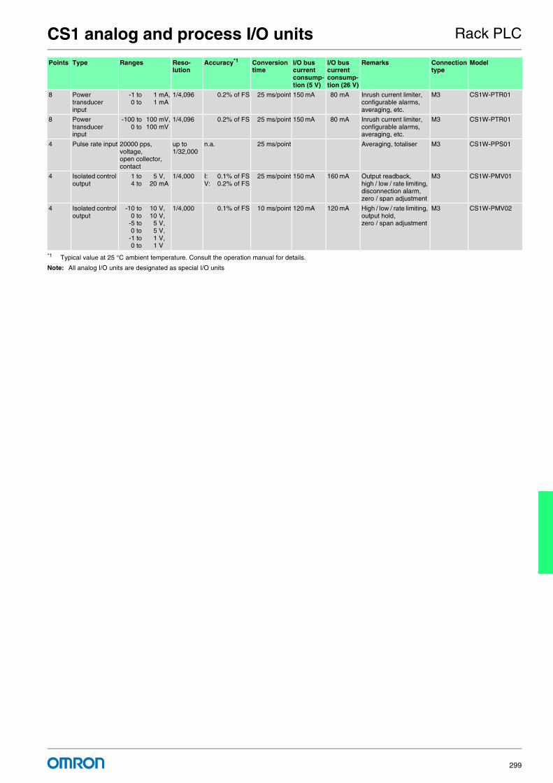
CS1 analog and process I/O units Rack PLC
299
Note: All analog I/O units are designated as special I/O units
8 Power transducer input
-1 to 1 mA,0 to 1 mA
1/4,096 0.2% of FS 25 ms/point 150 mA 80 mA Inrush current limiter, configurable alarms, averaging, etc.
M3 CS1W-PTR01
8 Power transducer input
-100 to 100 mV,0 to 100 mV
1/4,096 0.2% of FS 25 ms/point 150 mA 80 mA Inrush current limiter, configurable alarms, averaging, etc.
M3 CS1W-PTR01
4 Pulse rate input 20000 pps, voltage, open collector, contact
up to 1/32,000
n.a. 25 ms/point Averaging, totaliser M3 CS1W-PPS01
4 Isolated control output
1 to 5 V, 4 to 20 mA
1/4,000 I: 0.1% of FSV: 0.2% of FS
25 ms/point 150 mA 160 mA Output readback, high / low / rate limiting, disconnection alarm, zero / span adjustment
M3 CS1W-PMV01
4 Isolated control output
-10 to 10 V, 0 to 10 V,
-5 to 5 V, 0 to 5 V,
-1 to 1 V, 0 to 1 V
1/4,000 0.1% of FS 10 ms/point 120 mA 120 mA High / low / rate limiting, output hold, zero / span adjustment
M3 CS1W-PMV02
*1 Typical value at 25 °C ambient temperature. Consult the operation manual for details.
Points Type Ranges Reso-lution
Accuracy*1 Conversion time
I/O bus current consump-tion (5 V)
I/O bus current consump-tion (26 V)
Remarks Connection type
Model

For full specifications and additional models please refer to the (attached) CD or www.europe.omron.comRack PLC - Cat.-No. P08E-EN-03300
CS1 position / motion control units Rack PLC
Add motion control to any CS1 PLCFrom simple position measurement to multi-axis synchronised motion control, CS1 offers a full range of units:
• Counter Units gather position information from SSI- or incremental encoders. Actual positions are compared with internally stored target values.
• Position control units are used for point-to-point positioning with servo drives or stepper motors. Target data and acceleration /deceleration curves can be adjusted on-the-fly.
• Position- and motion control units equipped with MECHATROLINK-II interface can control multiple drives through a single high-speed link. Message routing through mutliple communication layers allows the attached drives to be configured from any point in the control network.
Ordering information
Accessories
Channels/Axes
Type Signal type Unit class I/O bus current consumption
Remarks Connection type Model
2 SSI inputs (absoluteposition data)
Synchronous serial protocol
Special I/O unit 320 mA Baud rate, encoding type, data length, etc. can be set per channel2 digital outputs, NPN/PNP selectable.
M3 screw CS1W-CTS21
2 500 kHz Counter
24 V, 12V, line driver
Special I/O unit 360 mA 4 configurable digital inputs +4 configurable digital outputsTarget values trigger interrupt to CPU
1 x Fujitsu (40 pt) CS1W-CT021
4 450 mA 2 x Fujitsu (40 pt) CS1W-CT041
1 Position control unit
24V open collector Special I/O unit 250 mA 500 kpps pulse outputs, inputs for origin, limit switches, stop, interrupt
1 x Fujitsu (40 pt) CS1W-NC113
2 Position control unit
24V open collector Special I/O unit 250 mA 500 kpps pulse outputs, inputs for origin, limit switches, stop, interrupt
1 x Fujitsu (40 pt) CS1W-NC213
4 Position control unit
24V open collector Special I/O unit 250 mA 500 kpps pulse outputs, inputs for origin, limit switches, stop, interrupt
2 x Fujitsu (40 pt) CS1W-NC413
1 Position control unit
Line driver Special I/O unit 250 mA 500 kpps pulse outputs, inputs for origin, limit switches, stop, interrupt
1 x Fujitsu (40 pt) CS1W-NC133
2 Position control unit
Line driver Special I/O unit 360 mA 500 kpps pulse outputs, inputs for origin, limit switches, stop, interrupt
1 x Fujitsu (40 pt) CS1W-NC233
4 Position control unit
Line driver Special I/O unit 360 mA 500 kpps pulse outputs, inputs for origin, limit switches, stop, interrupt
2 x Fujitsu (40 pt) CS1W-NC433
32 Motion control unit
MECHA-TROLINK-II
CPU bus unit 800 mA Electronic cam profiles and axis synchronisation. Registration inputs. Access to all drive parameters.
ML-II CS1W-MCH71
Description Connection type Model
General purpose I/O terminal block (40 x M3 screw) MIL (40 pt) XW2D-40G6
General purpose I/O connection cable for I/O Units with 40-pt. Fujitsu connector (@@@ = length in cm) Fujitsu (40 pt.) to MIL (40 pt.) XW2Z-@@@B
Servo interface block for 2- or 4-Axis position control unit (without communications support) XW2B-40J6-2B
Servo interface block for 2- or 4-Axis position control unit (with communications support) XW2B-40J6-4B
Cable connecting CS1W-NC113 to W Series, cable length: 1.0 m XW2Z-100J-A14
Cable connecting CS1W-NC213/413 to W Series, cable length: 1.0 m XW2Z-100J-A15
Cable connecting CS1W-NC113 to SmartStep, cable length: 1.0 m XW2Z-100J-A16
Cable connecting CS1W-NC213/413 to SmartStep, cable length: 1.0 m XW2Z-100J-A17
Cable connecting CS1W-NC133 to W Series, cable length: 1.0 m XW2Z-100J-A18
Cable connecting CS1W-NC233/433 to W series, cable length: 1.0 m XW2Z-100J-A19
Cable connecting CS1W-NC133 to SmartStep, cable length: 1.0 m XW2Z-100J-A20
Cable connecting CS1W-NC233/433 to SmartStep, cable length: 1.0 m XW2Z-100J-A21

For full specifications and additional models please refer to the (attached) CD or www.europe.omron.comRack PLC - Cat.-No. P08E-EN-03 301
CS1 communication units Rack PLC
Open to any communication, standard or user-definedCS1 provides both standardised open networks interfaces, and cost-ef-ficient high-speed proprietary network links. Datalinks between PLCs, or to higher-level information systems can be made using Serial or Eth-ernet links, or the easy-to-use Controller Link network.
OMRON supports the 2 major field networks, DeviceNet and PROFIBUS-DP. For high-speed field I/O, OMRON's own CompoBus/S offers an unsurpassed ease of installation. Fully user-configurable se-rial and CAN-based communication can be used to emulate a variety of application-specific protocols.
Ordering information
Accessories
Type Ports Protocols Unit class I/O bus current consumption
Remarks Connection type Model
Serial 2 x RS-232C CompoWay-F, Host Link, NT link, Modbus, User-defined
CPU bus unit 290 mA 9-pin D-Sub CS1W-SCU21-V1
Serial 2 x RS-232C CompoWay-F, Host Link, NT link, Modbus, User-defined
CPU option board
280 mA 9-pin D-Sub CS1W-SCB21-V1
Serial 1 x RS-232C +1 x RS-422/RS-485
CompoWay-F, Host Link, NT link, Modbus, User-defined
CPU option board
360 mA 9-pin D-Sub CS1W-SCB41-V1
GP-IB Master / Slave selectable GP-IB instrument communication
Special I/O unit 260 mA GP-IB CS1W-GPI01
Ethernet 1 x 100 Base-Tx UDP, TCP/IP, FTP server, SMTP (e-mail), SNTP (time adjust), FINS routing
CPU bus unit 400 mA RJ45 CS1W-ETN21
Controller link 2-wire twisted pair OMRON proprietary CPU bus unit 330 mA 2-wire screw + GND CS1W-CLK21
Optical HPCF 520 mA 2 x HPCF connector CS1W-CLK12
Optical graded-index fiber 650 mA 4 x ST connector CS1W-CLK52
DeviceNet 1 x CAN DeviceNet CPU bus unit 290 mA 5-p detachable CS1W-DRM21
PROFIBUS-DP 1 x RS-485 (Master) DP, DPV1 CPU bus unit 400 mA 9-pin D-Sub CS1W-PRM21
PROFIBUS-DP 1 x RS-485 (Slave) DP C200H special I/O unit
250 mA C200H units can-not be used on CS1D systems
9-pin D-Sub C200HW-PRT21
CAN 1 x CAN CANopen, User-defined C200H special I/O unit
250 mA 5-p detachable C200HW-CORT21-V1
CompoBus/S 2-wire (Master) OMRON proprietary C200H special I/O unit
150 mA 2-wire screw + 2-wire power
C200HW-SRM21-V1
Description Connection type Model
RS-232C to RS-422/RS-485 signal converter. Mounts directly on serial port. 9-pin D-sub to screw clamp terminals
CJ1W-CIF11
Controller link PCI board with support software PCI, wired CLK 3G8F7-CLK21-EV1
Controller link PCI board with support software PCI, HPCF connectors
3G8F7-CLK12-EV1
Controller link PCI board with support software PCI, ST connectors 3G8F7-CLK52-EV1
Controller link repeater unit (wire to wire) Screw - Screw CS1W-RPT01
Controller link repeater unit (wire to HPCF fiber ) Screw - HPCF connector
CS1W-RPT02
Controller link repeater unit (wire to graded-index glass fiber) Screw - ST connector
CS1W-RPT03

Remote I/O
Smart functions you can rely on
302

Smart design for all-round benefits
303
Table of contentsRemote I/O SmartSlice I/O system 304
Compact I/O DRT2 305
Compact I/O SRT2 306
Field I/O DRT2/SRT2 307
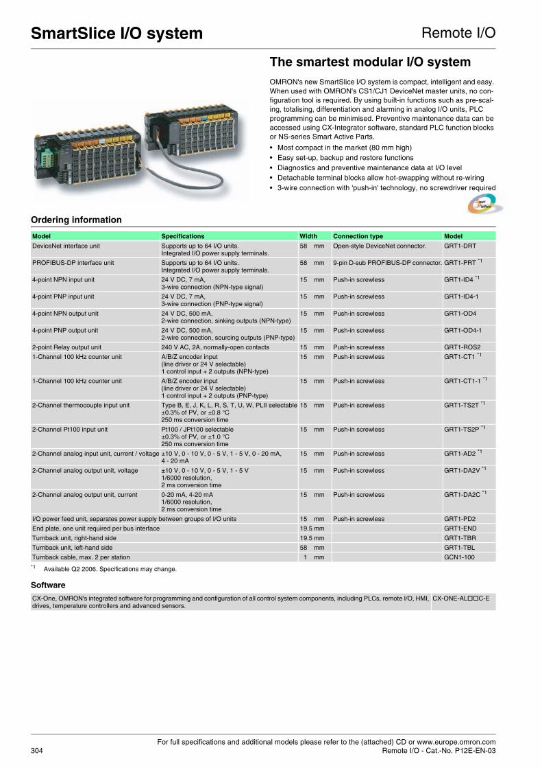
For full specifications and additional models please refer to the (attached) CD or www.europe.omron.comRemote I/O - Cat.-No. P12E-EN-03304
SmartSlice I/O system Remote I/O
The smartest modular I/O systemOMRON's new SmartSlice I/O system is compact, intelligent and easy. When used with OMRON's CS1/CJ1 DeviceNet master units, no con-figuration tool is required. By using built-in functions such as pre-scal-ing, totalising, differentiation and alarming in analog I/O units, PLC programming can be minimised. Preventive maintenance data can be accessed using CX-Integrator software, standard PLC function blocks or NS-series Smart Active Parts.
• Most compact in the market (80 mm high) • Easy set-up, backup and restore functions • Diagnostics and preventive maintenance data at I/O level • Detachable terminal blocks allow hot-swapping without re-wiring • 3-wire connection with 'push-in' technology, no screwdriver required
Ordering information
Software
Model Specifications Width Connection type Model
DeviceNet interface unit Supports up to 64 I/O units.Integrated I/O power supply terminals.
58 mm Open-style DeviceNet connector. GRT1-DRT
PROFIBUS-DP interface unit Supports up to 64 I/O units.Integrated I/O power supply terminals.
58 mm 9-pin D-sub PROFIBUS-DP connector. GRT1-PRT *1
*1 Available Q2 2006. Specifications may change.
4-point NPN input unit 24 V DC, 7 mA, 3-wire connection (NPN-type signal)
15 mm Push-in screwless GRT1-ID4 *1
4-point PNP input unit 24 V DC, 7 mA, 3-wire connection (PNP-type signal)
15 mm Push-in screwless GRT1-ID4-1
4-point NPN output unit 24 V DC, 500 mA, 2-wire connection, sinking outputs (NPN-type)
15 mm Push-in screwless GRT1-OD4
4-point PNP output unit 24 V DC, 500 mA, 2-wire connection, sourcing outputs (PNP-type)
15 mm Push-in screwless GRT1-OD4-1
2-point Relay output unit 240 V AC, 2A, normally-open contacts 15 mm Push-in screwless GRT1-ROS2
1-Channel 100 kHz counter unit A/B/Z encoder input (line driver or 24 V selectable)1 control input + 2 outputs (NPN-type)
15 mm Push-in screwless GRT1-CT1 *1
1-Channel 100 kHz counter unit A/B/Z encoder input (line driver or 24 V selectable)1 control input + 2 outputs (PNP-type)
15 mm Push-in screwless GRT1-CT1-1 *1
2-Channel thermocouple input unit Type B, E, J, K, L, R, S, T, U, W, PLII selectable±0.3% of PV, or ±0.8 °C250 ms conversion time
15 mm Push-in screwless GRT1-TS2T *1
2-Channel Pt100 input unit Pt100 / JPt100 selectable±0.3% of PV, or ±1.0 °C250 ms conversion time
15 mm Push-in screwless GRT1-TS2P *1
2-Channel analog input unit, current / voltage ±10 V, 0 - 10 V, 0 - 5 V, 1 - 5 V, 0 - 20 mA, 4 - 20 mA
15 mm Push-in screwless GRT1-AD2 *1
2-Channel analog output unit, voltage ±10 V, 0 - 10 V, 0 - 5 V, 1 - 5 V1/6000 resolution,2 ms conversion time
15 mm Push-in screwless GRT1-DA2V *1
2-Channel analog output unit, current 0-20 mA, 4-20 mA1/6000 resolution,2 ms conversion time
15 mm Push-in screwless GRT1-DA2C *1
I/O power feed unit, separates power supply between groups of I/O units 15 mm Push-in screwless GRT1-PD2
End plate, one unit required per bus interface 19.5 mm GRT1-END
Turnback unit, right-hand side 19.5 mm GRT1-TBR
Turnback unit, left-hand side 58 mm GRT1-TBL
Turnback cable, max. 2 per station 1 mm GCN1-100
CX-One, OMRON's integrated software for programming and configuration of all control system components, including PLCs, remote I/O, HMI, drives, temperature controllers and advanced sensors.
CX-ONE-AL C-E

For full specifications and additional models please refer to the (attached) CD or www.europe.omron.comRemote I/O - Cat.-No. P12E-EN-03 305
Compact I/O DRT2 Remote I/O
Smart DeviceNet I/OThese units feature internal diagnostic and data collection over the net-work. Power supply status, I/O response times, operation counters and on-time monitor data are continuously recorded and checked against user-defined limits. Hence any deviation is immediately flagged. Smart DeviceNet I/Os are supported by Smart Active Parts, allowing program-less visualisation and monitoring from the NS terminals.
• Compact size IP20 housing • Expandable digital I/Os • Built-in diagnostics and preventive maintenance functions • Detachable I/O terminal blocks • Analog I/O with data pre-processing and alarm functions
Ordering information
Note: - MIL = connector according to MIL-C-83503 (compatible with DIN 41651 / IEC 60603-1).- Models with sinking outputs (NPN type) are available as well.
I/O points Size in mm (HxWxD) Current Name Remarks Model
16 input points (PNP) 115x50x49.7 Input current 6.0 mA max./point (for 24 V DC)
Remote I/O terminals with transistors
Can be extended with XWT expansion unit.
DRT2-ID16-1
16 output points (PNP) 115x50x49.7 Output current 0.5 A/point, 4.0 A/common
Remote I/O terminals with transistors
Can be extended with XWT expansion unit.
DRT2-OD16-1
16 output points 125x50x51.8 Load 2 A, 8A / common Remote I/O terminal with relay outputs
Relay outputs. Can be extended with XWT expansion unit.
DRT2-ROS16
8 input points (PNP) 66x50x49.7 Input current 6.0 mA max./point (for 24 V DC)
Remote I/O terminalexpansion units with transistors
Expansion unit for increasing inputs of the basic units
XWT-ID08-1
16 input points (PNP) 94x50x49.7 Input current 6.0 mA max./point (for 24 V DC)
Remote I/O terminalexpansion units with transistors
Expansion unit for increasing inputs of the basic units
XWT-ID16-1
8 output points (PNP) 66x50x49.7 Output current 0.5 A/point, 2.0 A/common
Remote I/O terminalexpansion units with transistors
Expansion unit for increasing outputs of the basic units
XWT-OD08-1
16 output points (PNP) 94x50x49.7 Output Current 0.5 A/point, 4.0 A/common
Remote I/O terminalexpansion units with transistors
Expansion unit for increasing outputs of the basic units
XWT-OD16-1
16 input points (PNP) 180x50x58 Input current 6.0 mA max./point at 24 V DC
Remote I/O terminals with 3-tier terminal blocks and transistors
Wiring locations easy to find (wiring to the same terminal not required).Cannot be expanded with an XWT expansion unit.
DRT2-ID16TA-1
16 output points (PNP) 180x50x58 Output current 0.5 A/point Remote I/O terminals with 3-tier terminal blocks and transistors
Wiring locations easy to find (wiring to the same terminal not required).Cannot be expanded with an XWT expansion unit.
DRT2-OD16TA-1
8 input points /8 output points (PNP)
180x50x58 Input current 6.0 mA max./point at 24 V DC. Output Current 0.5 A/point
Remote I/O terminals with 3-tier terminal blocks and transistors
Wiring locations easy to find (wiring to the same terminal not required).Cannot be expanded with an XWT expansion unit.
DRT2-MD16TA-1
16 input points (PNP) 95x50x33.3 Input current 11 mA max./point (for 24 VDC)
Sensor connectorterminals with transistors
Uses E-con industry standard sensor connectors.
DRT2-ID16-S
32 input points (PNP) 80x35x60 Input Current 6.0 mA max./point at 24 V DC.
MIL connector terminals with transistors
Connects to relay terminal using MIL cable
DRT2-ID32ML-1
32 output points (PNP) 80x35x60 Output current 0.3 A/point, 4 A/common.
MIL connector terminals with transistors
Connects to relay terminal using MIL cable
DRT2-OD32ML-1
16 input points /16 output points (PNP)
80x35x60 Input current 6.0 mA max./point at 24 V DC. Output current 0.3 A/point, 2 A/common
MIL connector terminals with transistors
Connects to relay terminal using MIL cable
DRT2-MD32ML-1
4 input points (0 to 5 V, 1 to 5 V, 0 to 10 V, -10 to 10 V, 0 to 20 mA, 4 to 20 mA)
115x50x49.7 Current consumption from communications power supply 90 mA max.
Analog input terminals Resolution 1/6000 (full scale) Conver-sion cycle depends on number of ac-tive points, 4points: 4ms max.
DRT2-AD04
2 output points (0 to 5 V, 1 to 5 V, 0 to 10 V, -10 to 10 V, 0 to 20 mA, 4 to 20 mA)
115x50x49.7 Current consumption from communications power supply 120 mA max.
Analog output terminals Conversion time 2 ms/2 points DRT2-DA02
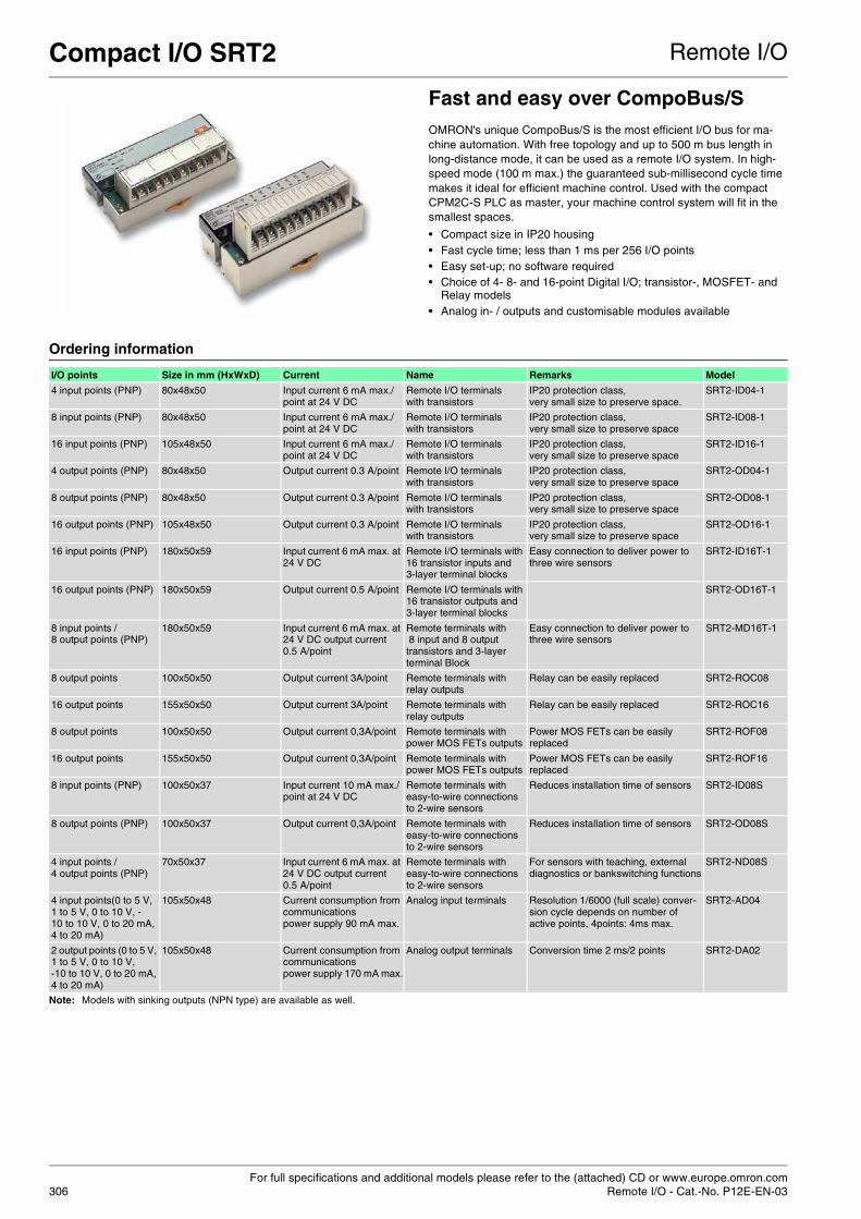
For full specifications and additional models please refer to the (attached) CD or www.europe.omron.comRemote I/O - Cat.-No. P12E-EN-03306
Compact I/O SRT2 Remote I/O
Fast and easy over CompoBus/SOMRON's unique CompoBus/S is the most efficient I/O bus for ma-chine automation. With free topology and up to 500 m bus length in long-distance mode, it can be used as a remote I/O system. In high-speed mode (100 m max.) the guaranteed sub-millisecond cycle time makes it ideal for efficient machine control. Used with the compact CPM2C-S PLC as master, your machine control system will fit in the smallest spaces.
• Compact size in IP20 housing • Fast cycle time; less than 1 ms per 256 I/O points • Easy set-up; no software required • Choice of 4- 8- and 16-point Digital I/O; transistor-, MOSFET- and
Relay models • Analog in- / outputs and customisable modules available
Ordering information
Note: Models with sinking outputs (NPN type) are available as well.
I/O points Size in mm (HxWxD) Current Name Remarks Model
4 input points (PNP) 80x48x50 Input current 6 mA max./point at 24 V DC
Remote I/O terminals with transistors
IP20 protection class, very small size to preserve space.
SRT2-ID04-1
8 input points (PNP) 80x48x50 Input current 6 mA max./point at 24 V DC
Remote I/O terminals with transistors
IP20 protection class, very small size to preserve space
SRT2-ID08-1
16 input points (PNP) 105x48x50 Input current 6 mA max./point at 24 V DC
Remote I/O terminals with transistors
IP20 protection class, very small size to preserve space
SRT2-ID16-1
4 output points (PNP) 80x48x50 Output current 0.3 A/point Remote I/O terminals with transistors
IP20 protection class, very small size to preserve space
SRT2-OD04-1
8 output points (PNP) 80x48x50 Output current 0.3 A/point Remote I/O terminals with transistors
IP20 protection class, very small size to preserve space
SRT2-OD08-1
16 output points (PNP) 105x48x50 Output current 0.3 A/point Remote I/O terminals with transistors
IP20 protection class, very small size to preserve space
SRT2-OD16-1
16 input points (PNP) 180x50x59 Input current 6 mA max. at 24 V DC
Remote I/O terminals with 16 transistor inputs and 3-layer terminal blocks
Easy connection to deliver power to three wire sensors
SRT2-ID16T-1
16 output points (PNP) 180x50x59 Output current 0.5 A/point Remote I/O terminals with 16 transistor outputs and 3-layer terminal blocks
SRT2-OD16T-1
8 input points /8 output points (PNP)
180x50x59 Input current 6 mA max. at 24 V DC output current 0.5 A/point
Remote terminals with 8 input and 8 output transistors and 3-layer terminal Block
Easy connection to deliver power to three wire sensors
SRT2-MD16T-1
8 output points 100x50x50 Output current 3A/point Remote terminals with relay outputs
Relay can be easily replaced SRT2-ROC08
16 output points 155x50x50 Output current 3A/point Remote terminals with relay outputs
Relay can be easily replaced SRT2-ROC16
8 output points 100x50x50 Output current 0,3A/point Remote terminals with power MOS FETs outputs
Power MOS FETs can be easily replaced
SRT2-ROF08
16 output points 155x50x50 Output current 0,3A/point Remote terminals with power MOS FETs outputs
Power MOS FETs can be easily replaced
SRT2-ROF16
8 input points (PNP) 100x50x37 Input current 10 mA max./point at 24 V DC
Remote terminals with easy-to-wire connections to 2-wire sensors
Reduces installation time of sensors SRT2-ID08S
8 output points (PNP) 100x50x37 Output current 0,3A/point Remote terminals with easy-to-wire connections to 2-wire sensors
Reduces installation time of sensors SRT2-OD08S
4 input points /4 output points (PNP)
70x50x37 Input current 6 mA max. at 24 V DC output current 0.5 A/point
Remote terminals with easy-to-wire connections to 2-wire sensors
For sensors with teaching, external diagnostics or bankswitching functions
SRT2-ND08S
4 input points(0 to 5 V, 1 to 5 V, 0 to 10 V, -10 to 10 V, 0 to 20 mA, 4 to 20 mA)
105x50x48 Current consumption from communications power supply 90 mA max.
Analog input terminals Resolution 1/6000 (full scale) conver-sion cycle depends on number of active points, 4points: 4ms max.
SRT2-AD04
2 output points (0 to 5 V, 1 to 5 V, 0 to 10 V, -10 to 10 V, 0 to 20 mA, 4 to 20 mA)
105x50x48 Current consumption from communications power supply 170 mA max.
Analog output terminals Conversion time 2 ms/2 points SRT2-DA02

For full specifications and additional models please refer to the (attached) CD or www.europe.omron.comRemote I/O - Cat.-No. P12E-EN-03 307
Field I/O DRT2 Remote I/O
IP67 DeviceNet I/ORugged I/O units for field mounting. The DRT2 slave units feature inter-nal diagnostic and maintenance data collection, which can be accessed over the network. Power supply status, I/O response times, operation counters and on-time monitor data is available at all times. Mainte-nance warnings will be generated when limits are exceeded. Using CX-One or NS-series HMI with Smart Active Parts, this allows more effi-cient system setup, commissioning and troubleshooting.
• IP67 protection, DRT2 versions are also oil- and welding-spatter proof
• Internal circuits powered by DeviceNet; fewer connections means less installation errors.
• Smart Slave functions for diagnostics and preventive maintenance
• Indication of broken wire and short-circuit in I/O signals • M12 connectors for fast installation.
Ordering information
Note: Models with sinking outputs (NPN type) are available as well.
Field I/O SRT2IP67 CompoBus/SRugged I/O units for field mounting. OMRON's unique CompoBus/S is the most efficient I/O bus for machine automation. With free topology and up to 500 m bus length in long-distance mode, it can be used as a remote I/O system. In high-speed mode (100 m max.) the guaranteed sub-millisecond cycle time makes it ideal for efficient machine control. With IP67 slave modules distributed throughout the machine, the need for protective enclosures is minimised.
• IP67 protection against dust and water • Fast cycle time; less than 1 ms for 256 I/O points • Easy setup; no software required. • Choice of 4- and 8-point digital I/O • M12 connectors for easy field wiring
Ordering information
Note: Models with sinking outputs (NPN type) are available as well.
I/O points Size in mm (HxWxD) Current Name Remarks Model
8 input points (PNP) 1 input / connection.
60x175x37.7 Input current 11.0 mA max./point (for 24 VDC)
Environment-resistive terminals
Waterproof, oil-proof, and spatter-proof construction (IP67). With short-circuit protection and open wire detection.
DRT2-ID08C-1
16 input points (PNP) 2 inputs / connection.
60x175x37.7 Input current 11.0 mA max./point (for 24 VDC)
Environment-resistive terminals
Waterproof, oil-proof, and spatter-proof construction (IP67). With short-circuit protection and open wire detection.
DRT2-HD16C-1
8 output points (PNP) 60x175x43.9 Output current 1.5 A/point, 8.0 A/common
Environment-resistive terminals
Waterproof, oil-proof, and spatter-proof construction (IP67). With short-circuit protection and open wire detection.
DRT2-OD08C-1
I/O points Size in mm (HxWxD) Current Name Remarks Model
4 input points (PNP) 54x114x45 Input current 6.0 mA max./point (for 24 V DC)
Water-resistant terminals Small size with easy connection SRT2-ID04CL-1
8 input points (PNP) 84x160x45 Input current 6.0 mA max./point (for 24 V DC)
Water-resistant terminals Small size with easy connection SRT2-ID08CL-1
4 output points (PNP) 54x114x45 Output current 0.5 /point, 2.0 A/common
Water-resistant terminals Small size with easy connection SRT2-OD04CL-1
8 output points (PNP) 84x140x45 Output current 0.5 A/point, 2.4 A/common
Water-resistant terminals Small size with easy connection SRT2-OD08CL-1

Human machine interface (HMI)
Less colour, same performance
308

Smart Active Parts can make a difference
309
Table of contentsHMI-NT NT21S-ST121(B) 310
NT11–SF121(B)
NT2S-SF12..B-E(V2)
NT3S-ST12@B-E
HMI-NS NS12 312
NS10
NS8
NS5-T
NS5-S / NSH5-S
NS5-M
NSJ5
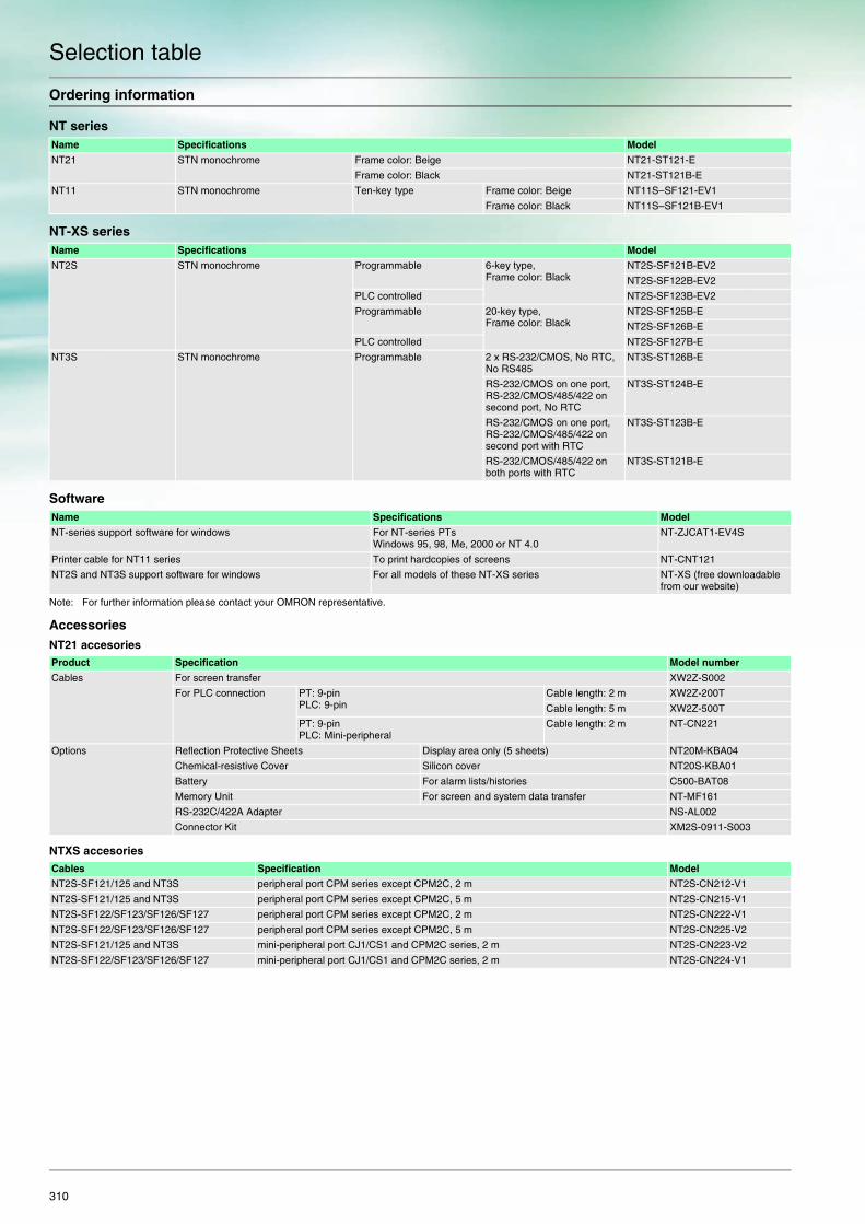
310
Selection table
Ordering information
NT series
NT-XS series
Software
Note: For further information please contact your OMRON representative.
AccessoriesNT21 accesories
NTXS accesories
Name Specifications Model
NT21 STN monochrome Frame color: Beige NT21-ST121-E
Frame color: Black NT21-ST121B-E
NT11 STN monochrome Ten-key type Frame color: Beige NT11S–SF121-EV1
Frame color: Black NT11S–SF121B-EV1
Name Specifications Model
NT2S STN monochrome Programmable 6-key type, Frame color: Black
NT2S-SF121B-EV2
NT2S-SF122B-EV2
PLC controlled NT2S-SF123B-EV2
Programmable 20-key type, Frame color: Black
NT2S-SF125B-E
NT2S-SF126B-E
PLC controlled NT2S-SF127B-E
NT3S STN monochrome Programmable 2 x RS-232/CMOS, No RTC, No RS485
NT3S-ST126B-E
RS-232/CMOS on one port, RS-232/CMOS/485/422 on second port, No RTC
NT3S-ST124B-E
RS-232/CMOS on one port, RS-232/CMOS/485/422 on second port with RTC
NT3S-ST123B-E
RS-232/CMOS/485/422 on both ports with RTC
NT3S-ST121B-E
Name Specifications Model
NT-series support software for windows For NT-series PTsWindows 95, 98, Me, 2000 or NT 4.0
NT-ZJCAT1-EV4S
Printer cable for NT11 series To print hardcopies of screens NT-CNT121
NT2S and NT3S support software for windows For all models of these NT-XS series NT-XS (free downloadable from our website)
Product Specification Model number
Cables For screen transfer XW2Z-S002
For PLC connection PT: 9-pinPLC: 9-pin
Cable length: 2 m XW2Z-200T
Cable length: 5 m XW2Z-500T
PT: 9-pinPLC: Mini-peripheral
Cable length: 2 m NT-CN221
Options Reflection Protective Sheets Display area only (5 sheets) NT20M-KBA04
Chemical-resistive Cover Silicon cover NT20S-KBA01
Battery For alarm lists/histories C500-BAT08
Memory Unit For screen and system data transfer NT-MF161
RS-232C/422A Adapter NS-AL002
Connector Kit XM2S-0911-S003
Cables Specification Model
NT2S-SF121/125 and NT3S peripheral port CPM series except CPM2C, 2 m NT2S-CN212-V1
NT2S-SF121/125 and NT3S peripheral port CPM series except CPM2C, 5 m NT2S-CN215-V1
NT2S-SF122/SF123/SF126/SF127 peripheral port CPM series except CPM2C, 2 m NT2S-CN222-V1
NT2S-SF122/SF123/SF126/SF127 peripheral port CPM series except CPM2C, 5 m NT2S-CN225-V2
NT2S-SF121/125 and NT3S mini-peripheral port CJ1/CS1 and CPM2C series, 2 m NT2S-CN223-V2
NT2S-SF122/SF123/SF126/SF127 mini-peripheral port CJ1/CS1 and CPM2C series, 2 m NT2S-CN224-V1

HMI - NT
311
Specification
Model NT21S-ST121(B)*1 NT11–SF121(B)*1 NT2S-SF12 B-E(V2) NT3S-ST12 B-E
Size in mm (HxWxD) 110x190x58 113x218x38.2 60x108x43 77x140x35
Effective display area 117x63 mm (260x140 dots)
160x64 mm 56x11 mm 98x35 mm (192 x 64 pixels, 4.1 inch)
Type with ethernet 24 VDC +10%/-15% 24 VDC ±15% 24 VDC ±10% (when applicable)
24 VDC ±15%
I/O Function keys - 22 keys 6 to 20 keys depending on model
-
Touch panel 7 vertical x 13 horizontal --- --- Analog Resistive
Obtained standards UL, CSA, EC Directives,NEMA equivalent
CE, cULus CE, cULus CE, cULus
Display graphics Straight lines, rectangles, polygons, circles, ovals, sector, bitmaps
Rectangle, rounded rectangle, circle, oval, line, bitmaps
No. of display characters(standard characters)
16 characters x 8 lines 20 characters x 4 lines 16 characters x 2 lines 32 characters x 8 lines
No. of registered screens 3,999 screens max.(depending on screen contents)
250 250 65,000 max.(limited by memory capacity)
Screen data capacity (standard) 512 KB 32 KB 24 KB 120 KB
Expansion memory --- --- --- ---
Memory card interface NT-MF261 memory unit for screen transfer can be used.
--- --- ---
Expansion interface --- --- --- ---
Ethernet --- --- --- ---
Internal memory Numeral memory table: 2,000 entries max., Character memorytable: 2,000 entries max.
- 1 kWords data,1 kWords retentative memory
1 kWords data,1 kWords retentative,64 words system memory
Ladder monitor --- --- --- ---
Programming Console function Supported --- --- ---
Device monitor --- --- --- ---
Barcode reader connection Supported --- --- ---
Printer connection --- Supported Supported Supported
Multivendor support Supports most third party PLCs. *2
--- Supports most third party PLCs *2
Supports most third party PLCs *2
Backlight life 50,000 hours average 50,000 hours average LED, min. 50,000 hours LED, min. 50,000 hours
*1 Model numbers with ’B’ have a black frame and without a beige frame.*2 Please contact your local OMRON representative for a list of available drivers.

312
Selection table
Ordering information
Software
Note: For further information please contact your OMRON representative.
NS series accessories
Name Specifications Model
NS12 TFT, 12'', 800 x 600 pixels Without ethernet Frame color: Beige NS12-TS00-V2
Frame color: Black NS12-TS00B-V2
With ethernet Frame color: Beige NS12-TS01-V2
Frame color: Black NS12-TS01B-V2
NS10 TFT, 10'', 640 x 480 pixels Without ethernet Frame color: Beige NS10-TV00-V2
Frame color: Black NS10-TV00B-V2
With ethernet Frame color: Beige NS10-TV01-V2
Frame color: Black NS10-TV01B-V2
NS8 TFT, 8.4'', 640 x 480 pixels Without ethernet Frame color: Beige NS8-TV00-V2
Frame color: Black NS8-TV00B-V2
With ethernet Frame color: Beige NS8-TV01-V2
Frame color: Black NS8-TV01B-V2
NS5-T TFT, 5.7'', 320 x 240 pixels Without ethernet Frame color: Beige NS5-TQ00-V2
Frame color: Black NS5-TQ00B-V2
With ethernet Frame color: Beige NS5-TQ01-V2
Frame color: Black NS5-TQ01B-V2
NS5-S STN, 5.7'', 320 x 240 pixels Without ethernet Frame color: Beige NS5-SQ00-V2
Frame color: Black NS5-SQ00B-V2
With ethernet Frame color: Beige NS5-SQ01-V2
Frame color: Black NS5-SQ01B-V2
NS5-M STN, Monochrome 5.7'', 320 x 240 pixels
Without ethernet Frame color: Beige NS5-MQ00-V2
Frame color: Black NS5-MQ00B-V2
With ethernet Frame color: Beige NS5-MQ01-V2
Frame color: Black NS5-MQ01B-V2
NSH5 STN, 5.7", 320 x 240 pixels Without Ethernet Frame color: Black NSH5-SQR00B-V2
Name Specifications Model
NS-series screen design software for windows For NS-series Windows 95, 98, Me, 2000, XP, NT 4.0 or XP
CX-Designer, included in CX-ONE
Specifications Model
Cable *1 Screen transfer cable for DOS/V XW2Z-S002
USB Host Cable, cable length: 5 m NS-US52 (5 m)
USB Host Cable, cable length: 2 m NS-US22 (2 m)
PT-to-PLCConnecting Cable
PT connection: 9 pinsPLC connection:9 pins
Length: 2 m XW2Z-200T
Length: 5 m XW2Z-500T
Accessories Video input Inputs: 4 channels NTSC / PAL NS-CA001
Inputs: 2 channels NTSC b/ PAL, 1 channel RGB NS-CA002
Special cable for the console F150-VKP (2 m)
F150-VKP (5 m)
Controller link interface unit NS-CLK21
RS-422A adapter (50 m) CJ1W-CIF11
RS-422A adapter (500 m) NS-AL002
Anti-reflection sheets (5 surface sheets) NS12/10 NS12-KBA04
NS8 NS7-KBA04
NS5 NT30-KBA04
Protective anti-reflection covers (5 pack) NS12/10 NS12-KBA05
NS8 NS7-KBA05
NS5 NT31C-KBA05
Transparent protective covers (5 pack) NS12/10 NS12-KBA05N
NS8 NS7-KBA05N
NS5 NT31C-KBA05N
Chemical-resistant cover (1 cover) NS5 NT30-KBA01
Memory card 15 MB HMC-EF172
30 MB HMC-EF372
64 MB HMC-EF672
Attachment adapter (NT625C/631/631C series to NS12 series) NS12-ATT01
(NT625C/631/631C series to NS12 series) NS12-ATT01B
(NT620S/620C/600S series to NS8 series) NS8-ATT01
(NT600M/600G/610G/612G series to NS8 series) NS8-ATT02
Memory card adapter for pc HMC-AP001
Battery CJ1W-BAT01
Barcode reader (refer to the catalog for details) V520-RH21-6
*1 Be sure to use cables made by OMRON when connecting NS hardware to a printer. No guarantee of proper operation if other cables are used.
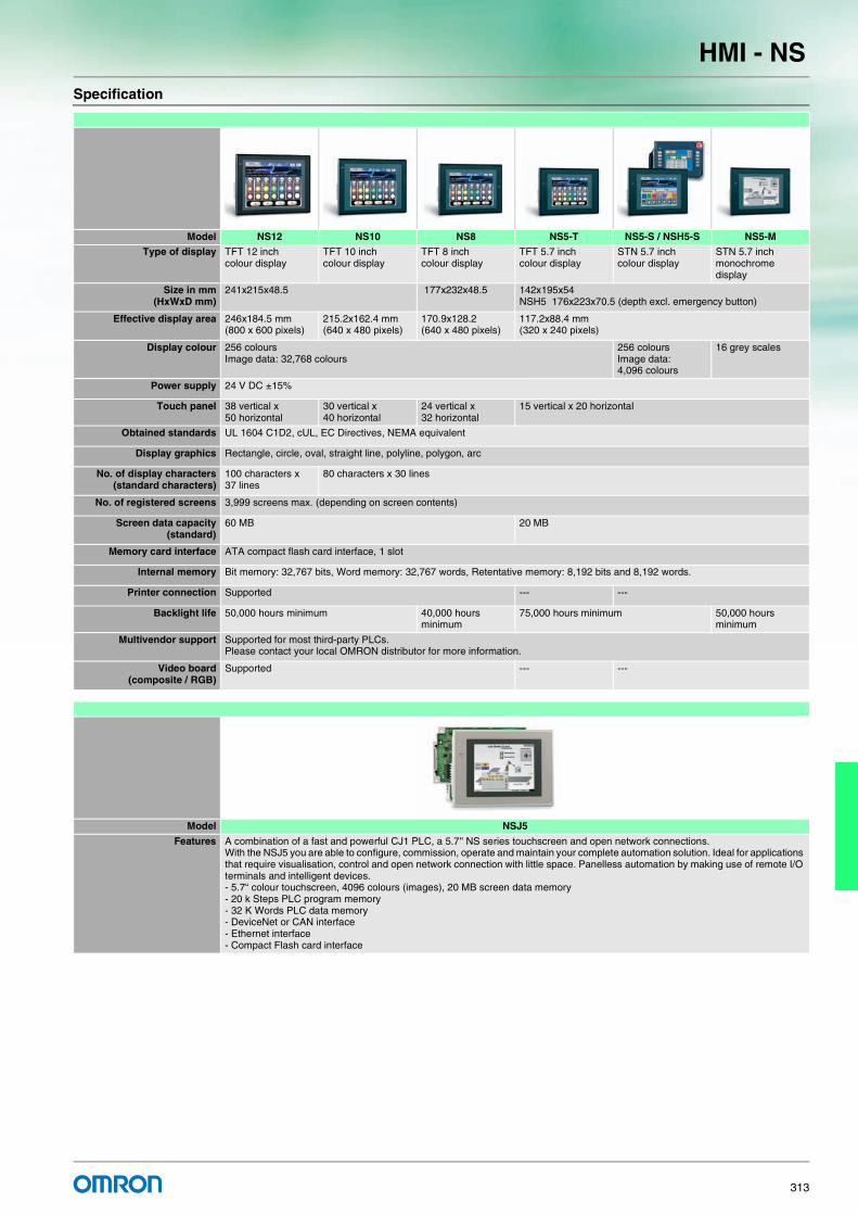
HMI - NS
313
Specification
Model NS12 NS10 NS8 NS5-T NS5-S / NSH5-S NS5-M
Type of display TFT 12 inchcolour display
TFT 10 inchcolour display
TFT 8 inchcolour display
TFT 5.7 inchcolour display
STN 5.7 inchcolour display
STN 5.7 inch monochrome display
Size in mm(HxWxD mm)
241x215x48.5 177x232x48.5 142x195x54NSH5 176x223x70.5 (depth excl. emergency button)
Effective display area 246x184.5 mm(800 x 600 pixels)
215.2x162.4 mm(640 x 480 pixels)
170.9x128.2(640 x 480 pixels)
117.2x88.4 mm(320 x 240 pixels)
Display colour 256 coloursImage data: 32,768 colours
256 coloursImage data: 4,096 colours
16 grey scales
Power supply 24 V DC ±15%
Touch panel 38 vertical x 50 horizontal
30 vertical x 40 horizontal
24 vertical x 32 horizontal
15 vertical x 20 horizontal
Obtained standards UL 1604 C1D2, cUL, EC Directives, NEMA equivalent
Display graphics Rectangle, circle, oval, straight line, polyline, polygon, arc
No. of display characters(standard characters)
100 characters x 37 lines
80 characters x 30 lines
No. of registered screens 3,999 screens max. (depending on screen contents)
Screen data capacity(standard)
60 MB 20 MB
Memory card interface ATA compact flash card interface, 1 slot
Internal memory Bit memory: 32,767 bits, Word memory: 32,767 words, Retentative memory: 8,192 bits and 8,192 words.
Printer connection Supported --- ---
Backlight life 50,000 hours minimum 40,000 hours minimum
75,000 hours minimum 50,000 hours minimum
Multivendor support Supported for most third-party PLCs. Please contact your local OMRON distributor for more information.
Video board(composite / RGB)
Supported --- ---
Model NSJ5
Features A combination of a fast and powerful CJ1 PLC, a 5.7'' NS series touchscreen and open network connections. With the NSJ5 you are able to configure, commission, operate and maintain your complete automation solution. Ideal for applications that require visualisation, control and open network connection with little space. Panelless automation by making use of remote I/O terminals and intelligent devices. - 5.7“ colour touchscreen, 4096 colours (images), 20 MB screen data memory - 20 k Steps PLC program memory - 32 K Words PLC data memory - DeviceNet or CAN interface - Ethernet interface - Compact Flash card interface

314
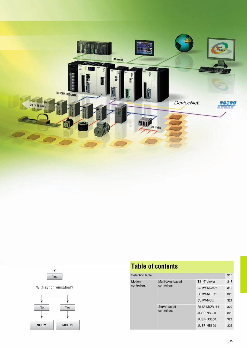
315
Table of contentsSelection table 316
Motion controllers
Multi-axes basedcontrollers
TJ1-Trajexia 317
CJ1W-MCH71 319
CJ1W-NCF71 320
CJ1W-NC@ 321
Servo-based controllers
R88A-MCW151 322
JUSP-NS300 323
JUSP-NS500 324
JUSP-NS600 325

316
Selection table Motion controllers
Multi-axes motion controllers
Model Trajexia CJ1W-MCH71 CJ1W-NCF71 CJ1W-NC@Flexible concept of advanced motion control over MECHATROLINK-II motion bus and traditional interfaces
Advanced motion controller over MECHATROLINK-II motion bus
Point-to-point positioning controller over MECHATROLINK-II motion bus
Point-to-point positioning controller
Axes control method MECHATROLINK-II motion bus, analogue output and pulse-train
MECHATROLINK-II motion bus
MECHATROLINK-II motion bus
Pulse train output
Number of axes 16 servos + 8 inverters 30 real and 2 virtual axes 16 1, 2, 4
Applicable servo drive Sigma II Sigma II Sigma II SmartStep, Sigma II
Application Advanced motion, e-cam, e-gearbox, phase shift, registration
Advanced motion, e-cam, ELS, phase shift, registration
From simple PTP to multi axis PTP coordinated systems.
Point to point applications
Servo control mode Position, speed and torque Position, speed and torque Position, speed and torque Open loop position with linear interpolation
PLC series Stand alone motion solution. Ethernet, PROFIBUS-DP and DeviceNet connectivity
CJ1 and CS1 PLCs CJ1 and CS1 PLCs CJ1 and CS1 PLCs
Page 317 319 320 321
Servo based motion controllers
Model R88A-MCW151 XtraDrive JUSP-NS300 JUSP-NS500 JUSP-NS600
Advanced motion in a compact package
All in one! Servo drive and motion controller integrated
Position controller over DeviceNet
Position controller over PROFIBUS-DP
Position controller over serial link
Axes control method Direct connection to servo drive
Integrated into the servo drive
Direct connection to servo drive
Direct connection to servo drive
Direct connection to servo drive
Connectivity DeviceNet, PROFIBUS, Hostlink
PROFIBUS DeviceNet PROFIBUS RS-485/RS-422
Digital I/O 8 DI, 6 DO, 2 registration inputs, 1 encoder in 1 pulse out + servo I/Os
Servo inputs + expansion available
Uses the servo I/O and adds 2 additional DO and 1 DI
Uses the servo I/O and adds 2 additional DO and 1 DI
Uses the servo I/O and adds 8 additional DI and 6 DO
Application Advanced motion, e-cam, ELS, phase shift, registration
Advanced motion Point to point with registration capability
Point to point with registration capability
Point to point with registration capability
Servo control mode Position, speed and torque. Open loop for additional axis
Position, speed and torque.
Position and speed
Applicable servo drive Sigma II XtraDrive Sigma II
Page 322 330 323 324 325

For full specifications and additional models please refer to the (attached) CD or www.europe.omron.comMotion controllers - Cat.-No. I53E-EN-01 317
TJ1-Trajexia Motion controllers
The advanced motion controller that puts you in controlTrajexia is OMRON's new motion platform that offers you the performance of a dedicated motion system, the ease of use you get from an automation specialist and the peace of mind you have from a global player.
• 16 axes advanced motion coordination over a robust motion link • Each axis can run complex interpolation moves, eCAMs and eGEAR• Advanced debugging tools including trace and oscilloscope • Multi-tasking - capable of running up to 14 tasks simultaneously • Open - Ethernet built-in, PROFIBUS-DP and DeviceNet as options
System configuration
M
CX-One
Trajexia tool
NS-series
HMI
JUSP-NS115
MECHATROLINK-II
unit
Sigma-II series
linearmotors
16 axes max. Total lenght: 50 m
I/O module
PROFIBUS-DP
PROFIBUS-DP
Terminator
Sigma-II series
servomotors
Sigma-II series
servodrive
Input
Motion controller
CJ-series PLC
Digital I/Os
Host-link
Fast registration input, home
Ethernet
MECHATROLINK-II
Frequency
inverter

TJ1-Trajexia Motion controllers
318
Ordering information
Trajexia motion controller
Trajexia - axes control modules
Trajexia - communication modules
MECHATROLINK-II - related devices
I/O Cables
Servo systemNote: Refer to servo systems section for detailed information.
Frequency invertersNote: Refer to frequency inverters section for detailed information.
Computer software
Name Model
Trajexia motion controller unit. Controls up to16 servos and 8 inverters, Ethernet port build-in. TJ1-MC16
Power supply for Trajexia controller 100-240 VAC CJ1W-PA202
Power supply for Trajexia controller 24 VDC CJ1W-PD022
Name Model
Trajexia MECHATROLINK-II master unit (up to 16 axes) TJ1-ML16
Trajexia flexible axes unit (for 2 axes) TJ1-FL02
Name Model
Trajexia PROFIBUS-DP slave unit TJ1-PRT
Name Remarks Model
Distributed I/O modules 64-point input and 64-point output JEPMC-IO2310
Analog input: -10 V to +10 V, 4 channels JEPMC-AN2900
Analog output: -10 V to +10 V, 2 channels JEPMC-AN2910
MECHATROLINK-II cables 0.5 meter JEPMC-W6003-A5
1 meter JEPMC-W6003-01
3 meters JEPMC-W6003-03
5 meters JEPMC-W6003-05
10 meters JEPMC-W6003-10
20 meters JEPMC-W6003-20
30 meters JEPMC-W6003-30
MECHATROLINK-II terminator Terminating resistor JEPMC-W6022
MECHATROLINK-II interface unit For Sigma-II series servo drives. (Firmware version 38 or later) JUSP-NS115
For Varispeed V7 inverter (For inverter’s version supported contact your OMRON sales office) SI-T/V7
For Varispeed F7, G7 inverter (For inverter’s version supported contact your OMRON sales office)
SI-T
Remarks Length m Model
I/O cable for JEPMC-IO2310 With connector on the IO2310 side 0.5 JEPMC-W5410-05
1.0 JEPMC-W5410-10
3.0 JEPMC-W5410-30
Specifications Model
Trajexia motion perfect and CX-Drive V1.2 or higher TJ1-Tools

For full specifications and additional models please refer to the (attached) CD or www.europe.omron.comMotion control unit - Cat.-No. I33E-EN-01 319
CJ1W-MCH71 Motion control unit
30-axes advanced motion controller over MECHATROLINK-II motion busThe MCH is a compact module that enables the development of advanced applications. It supports 30 real axes and 2 virtual axes. Its advanced motion includes e-cam, ELS and registration.
• Simplified wiring• Simple basic programming• One hardware registration per axis• Real multi-tasking• Access to complete system from 1 point
Ordering information
Motion controller
MECHATROLINK-II - Related devices
I/O Cables
Servo systemNote: Refer to servo systems section for detailed information
Frequency invertersNote: Refer to frequency inverters section for detailed information
Computer software
NS115
SW1
SW2
A
R
CN6A
CN6B
CN4
CHARGE POWER
SERVOPACK
SGDH-
200VVer.
CN3
CN1
CN2
NS115
SW1
SW2
A
R
CN6A
CN6B
CN4
CHARGE POWER
SERVOPACK
SGDH-
200VVer.
CN3
CN1
CN2
CHARGE POWER
SERVOPACK
SGDH-
200VVer.
CN3
CN1
CN2
NS115
SW1
SW2
A
R
CN6A
CN6B
CN4
CHARGE POWER
SERVOPACK
SGDH-
200VVer.
CN3
CN1
CN2
NS115
SW1
SW2
A
R
CN6A
CN6B
CN4
CN1
CN2
RUN TX 1 2 3 4 5 6 7 8 120 DDI 343 30
Sigma-II series
servo drive
JUSP-NS115
MECHATROLINK-II
unit
Sigma-II series
servo motor
CJ1 series
motion control unit
CJ1W-MCH71
Sigma-II series
linear motor
Terminator
Personal computer
software: CX-one
MECHATROLINK-II 30 axes max. Total length: 50 m
Limit switches contact sensors
Input
I/O module
Name Model
MECHATROLINK-II motion control unit CJ1W-MCH71
Name Remarks Model
Distributed I/O Modules 64-point input and 64-point output JEPMC-IO2310
Reversible counter: 2 channels JEPMC-PL2900
Pulse output: 2 channels JEPMC-PL2910
MECHATROLINK-IIcables
0.5 meter JEPMC-W6003-A5
1 meter JEPMC-W6003-01
3 meters JEPMC-W6003-03
5 meters JEPMC-W6003-05
10 meters JEPMC-W6003-10
20 meters JEPMC-W6003-20
MECHATROLINKcables
30 meters JEPMC-W6003-30
MECHATROLINK-II terminator
Terminating resistor JEPMC-W6022
MECHATROLINK-II interface units
For Sigma-II series servo drives. (Firmware version 38 or later)
JUSP-NS115
For Varispeed V7 inverter (For inverter version support contact your OMRON sales office)
SI-T/V7
For Varispeed F7, G7 inverter (For inverter version support contact your OMRON sales office)
SI-T
MECHATROLINK-II repeater
When 17 or more axes are connected to the MECHATROLINK-II the repeater is required
JEPMC-REP2000
Remarks Length m
Model
I/O Cable for IO2310 With connector on the IO2310 side
0.5 JEPMC-W5410-05
1.0 JEPMC-W5410-10
3.0 JEPMC-W5410-30
Specifications Model
CX-One version 1.1 or higher CX-ONE
Name Remarks Model

For full specifications and additional models please refer to the (attached) CD or www.europe.omron.comPosition control unit - Cat.-No. I09E-EN-01320
CJ1W-NCF71 Position control unit
16-axis point-to-point positioning controller over MECHATROLINK-IINCF is a powerful controller for point-to-point applications. It is based on MECHATROLINK-II motion bus, which reduces programming and development and maintenance costs. Supports PLC open function blocks.
• Simplified wiring. Data routing to all servo drives (MECHATROLINK) • Integration into OMRON Smart Platform: FBs, SAPs, CX-One • Servo drives full control and parameter access via MECHATROLINK• Easy, fast, reliable, optimised for positioning applications • Advanced PTP: 8-axis (4 dim.+ 4 dim.) interpolator
Ordering information
Position controller unit
MECHATROLINK-II related devices
Servo systemNote: Refer to servo systems section for more information
Computer software
NS115
SW1
SW2
A
R
CN6A
CN6B
CN4
CHARGE POWER
SERVOPACK
SGDH-
200VVer.
CN3
CN1
CN2
NS115
SW1
SW2
A
R
CN6A
CN6B
CN4
CHARGE POWER
SERVOPACK
SGDH-
200VVer.
CN3
CN1
CN2
CHARGE POWER
SERVOPACK
SGDH-
200VVer.
CN3
CN1
CN2
NS115
SW1
SW2
A
R
CN6A
CN6B
CN4
CHARGE POWER
SERVOPACK
SGDH-
200VVer.
CN3
CN1
CN2
NS115
SW1
SW2
A
R
CN6A
CN6B
CN4
Sigma-II
series
servo drive
JUSP-NS115
MECHATROLINK-II
unit
Sigma-II series
servo motor
CJ1 series
position control unit
CJ1W-NCF71
Sigma-II series
linear motor
Terminator
Personal computer
software: CX-One
MECHATROLINK-II16 Axes max.
Limit switches contact sensors
Input
Name Model
MECHATROLINK-II position controller unit CJ1W-NCF71
Name Remarks Model
MECHATROLINK-II interface unit
For Sigma-II series servo drives.(Firmware version 38 or later)
JUSP-NS115
MECHATROLINK-II terminator
Terminating resistor JEPMC-W6022
MECHATROLINK-II cables
0.5 meter JEPMC-W6003-A5
1 meter JEPMC-W6003-01
3 meters JEPMC-W6003-03
5 meters JEPMC-W6003-05
10 meters JEPMC-W6003-10
20 meters JEPMC-W6003-20
30 meters JEPMC-W6003-30
Specifications Model
CX-One version 1.1 or higher CX-ONE

For full specifications and additional models please refer to the (attached) CD or www.europe.omron.comPosition control unit - Cat.-No. I04E-EN-02 321
CJ1W-NC@ Position control unit
4-axis point-to-point positioning controller with pulse train outputThe NC motion controllers support positioning control via pulse-train outputs. Positioning is performed using trapezoidal or S-curve acceler-ation and deceleration. Ideal for controlling simple positioning in step-per motors and servos with pulse-train input.
• Positioning can be carried out by direct ladder commands• Positioning using trapezoidal and S curve• Interrupt feeding function• Positioning points are saved in internal flash memory• Origin search and backlash compensation functions
Ordering information
Position control unit Servo drive cablesNote: Refer the selected servo systems section for cable and servo relay units
information.
Computer software
CHARGEPOWER
SGDH-
200VVer.
CN3
CN1
CN2
CJ1 series
position control unit
CJ1W-NC_
Limit switches contact sensors
SmartStep
servo drive
SmartStep
servo motor
Personal computer
software: CX-Position
Input
Servo
relay unit
Sigma-II series
servo drive
Sigma-II series
linear motor
Name Model
1 axis position control unit. Open-collector output CJ1W-NC113
2 axes position control unit. Open-collector output CJ1W-NC213
4 axes position control unit. Open-collector output CJ1W-NC413
1 axis position control unit. Line-driver output CJ1W-NC133
2 axes position control unit. Line-driver output CJ1W-NC233
4 axes position control unit. Line-driver output CJ1W-NC433
Specifications Model
CX-One version 1.1 or higher CX-ONE

For full specifications and additional models please refer to the (attached) CD or www.europe.omron.com1.5 axis motion controller - Cat.-No. I14E-EN-01322
R88A-MCW151 1.5 axis motion controller
Motion pure in a compact packageThe MCW151 is a powerful servo-based controller. Complex motions such as cams, gears, linked axes and interpolation are made easy with a comprehensive BASIC command set.
• Controls 1 real axis, 1 virtual axis and a configurable third axis• One pulse-train output to control an additional axis• User-friendly and intuitive BASIC motion programming• Multi-tasking programming• 2 fast-registration inputs
Ordering information
Motion controller unit
PROFIBUS connectivity
Serial cables (for Port 0, 1)
Connectors
Note: For a complete view of DeviceNet network accesories, refer to Automation systems catalogue or contact your OMRON representative.
Computer software
Servo SystemNote: Refer to the servo systems section for more information
PO
RT
0,1,1
RUN STS
I/O/O
+24V24V
0V0V
2525
1
2626
2
000000000000
RD SD
MCW151
PO
RT
2
CHARGE POWER
SERVOPACK
SGDH-
200VVer.
CN3
CN1
CN2
CHARGE POWER
SERVOPACK
SGDH-
200VVer.
CN3
CN1
CN2
PO
RT
0,1,1
RUN STS
I/O/O
+24V24V
0V0V
2525
1
2626
2
000000000000
RD SD
MCW151
PO
RT
2
Sigma-II series
servo drive
R88A-MCW151_
Motion controller unit
Sigma-II series
servo motor
Sigma-II
series
servo drive
R88A-MCW151
Motion controller unit
(Port 0) Computer connecting cable
(I/O) External I/O
(Port 2) HostLink or DeviceNet network
Limit switches contact sensors
(CN10)
Cable connection
Input
External
encoder
- Host link network
- DeviceNet network
- PROFIBUS-DP network
Fast
registration
input
Rotary
cutter
NS/NT terminals
Name Model
1.5 axis advanced motion controller with host link interface
R88A-MCW151-E
1.5 axis advanced motion controller with DeviceNet interface
R88A-MCW151-DRT-E
Name Model
PROFIBUS-DP module interface for R88A-MCW151-E motion controllers
PRT1-SCU11
Name Model
Programing cable, 2 m. (Port 0) R88A-CCM002P4-E
Spliter cable, 1 m (Port 0 & 1). Combined with R88A-CCM002P4-E cable allows using motion perfect and a general purpose application.(e.g. terminal)
R88A-CCM001P5-E
Specification Model
I/O connector (Included in package) B2L 3.5/26 SN SW (Weidmüler)
Power connector (Included in package) MSTB 2.5/3-ST-5.08 (Phoenix)
Port 2 connector (Included in package) MSTB 2.5/5-ST-5.08 (Phoenix)
Specifications Model
Motion perfect MOTION TOOLS CD
EDS file
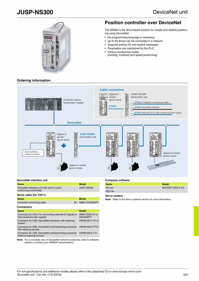
For full specifications and additional models please refer to the (attached) CD or www.europe.omron.comDeviceNet unit - Cat.-No. I11E-EN-02 323
JUSP-NS300 DeviceNet unit
Position controller over DeviceNetThe NS300 is the drive-based solution for simple and reliable position-ing using DeviceNet.
• No programming language is necessary• Up to 63 drives can be connected in a network• Supports polling I/O and explicit messages• Parameters are maintained by the PLC• Various positioning modes
(homing, multistep and speed positioning)
Ordering information
DeviceNet interface unit
Serial cable (for CN11)
Connectors
Note: For a complete view of DeviceNet network accesories, refer to networks section or contact your OMRON representative.
Computer software
Servo systemNote: Refer to the Servo systems section for more information.
CHARGE POWER
SERVOPACK
SGDH-
200VVer.
CN3
CN1
CN2
54
0 9
6
12
7 8
3
3
54
0 9
6
12
7 8
NS300
54
0 9
6
12
7 8
3
X10
X1
DR
CN11
MS
NS
CHARGE POWER
SERVOPACK
SGDH-
200VVer.
CN3
CN1
CN2
54
0 9
6
12
7 8
3
3
54
0 9
6
12
7 8
NS300
54
0 9
6
12
7 8
3
X10
X1
DR
CN11
MS
NS
CHARGE POWER
SERVOPACK
SGDH-
200VVer.
CN3
CN1
CN2
54
0 96
12
7 8
3
3
54
0 9
6
12
7 8
NS300
54
0 9
6
12
7 8
3
X10
X1
DR
CN11
MS
NS
CHARGE POWER
SERVOPACK
SGDH-
200VVer.
CN3
CN1
CN2
54
0 9
6
12
7 8
3
3
54
0 9
6
12
7 8
NS300
54
0 9
6
12
7 8
3
X10
X1
DR
CN11
MS
NS
CHARGE POWER
SERVOPACK
SGDH-
200VVer.
CN3
CN1
CN2
54
0 9
6
12
7 8
3
3
54
0 9
6
12
7 8
NS300
54
0 9
6
12
7 8
3
X10
X1
DR
CN11
MS
NS
Sigma-II
series
servo drive
JUSP-NS300
DeviceNet unit
DeviceNet
Sigma-II series
servo motor
CJ1/CS1 series
DeviceNet master
Sigma-II series
linear motor
Sigma-II
series
servo drive
JUSP-NS300
DeviceNet unit
(CN10)
(CN11) Computer connecting cable
(CN4) External I/O or fully-closed encoder signal
(CN6) DeviceNet network
Limit switches contact sensors
Cable connection
Name Model
DeviceNet Interface unit with point to point positioning functionality
JUSP-NS300
Name Model
Computer connecting cable 2m R88A-CCW002P4
Name Model
Connector for CN4. For connecting external I/O signals or fully-closed encoder signals
R88A-CNU01R orDE9406973
Connector for CN6. DeviceNet connector with retaining screws
XW4B-05C1-H1-D
Connector for CN6. DeviceNet multi-branching connector with retaining screws
XW4B-05C4-TF-D
Connector for CN6. DeviceNet multi-branching connector (without retaining screws)
XW4B-05C4-T-D
Name Model
NS tool MOTION TOOLS CD
ESD file

For full specifications and additional models please refer to the (attached) CD or www.europe.omron.comPROFIBUS-DP unit - Cat.-No. I12E-EN-02324
JUSP-NS500 PROFIBUS-DP unit
Position controller over PROFIBUS-DPThe NS500 is a flexible and simple distributed control over PROFIBUS-DP. It connects directly to the Sigma-II and has several positioning modes, making it simple to configure.
• No programming language is necessary• Various positioning modes (homing, multistep and speed
positioning)• Connects directly to Sigma-II drives• Up to 125 servos can be connected• Fully closed control loop
Ordering information
PROFIBUS-DP interface unit
Serial cable (for CN11)
Connectors
Computer software
Servo systemNote: Refer to the Servo systems section for more information.
6
NS500
6
NS500
6
NS500
6
NS500
6
NS500
CHARGE POWER
SERVOPACK
SGDH-
200VVer.
CN3
CN1
CN2
CHARGE POWER
SERVOPACK
SGDH-
200VVer.
CN3
CN1
CN2
CHARGE POWER
SERVOPACK
SGDH-
200VVer.
CN3
CN1
CN2
CHARGE POWER
SERVOPACK
SGDH-
200VVer.
CN3
CN1
CN2
CHARGE POWER
SERVOPACK
SGDH-
200VVer.
CN3
CN1
CN2
Sigma-II
series
servo drive
JUSP-NS500
PROFIBUS-DP
unit
PROFIBUS-DP
Sigma-II series
servo motor
CJ1 series
PROFIBUS-DP
master
Sigma-II series
linear motor
Sigma-II
series
servo drive
JUSP-NS500
PROFIBUS-DP
(CN11) Computer connecting cable
(CN4) External I/O or fully-closed encoder signal
(CN6) PROFIBUS-DP network
Limit switches contact sensors
(CN10)
Cable connection
Name Model
PROFIBUS-DP interface unit with point to point positioning functionality
JUSP-NS500
Name Model
Computer connecting cable 2 m R88A-CCW002P4
Name Model
Conector for CN4. For connecting external I/O signals or fully-closed encoder signals
R88A-CNU01R orDE9406973
Name Model
NS tool MOTION TOOLS CD
GSD file

For full specifications and additional models please refer to the (attached) CD or www.europe.omron.comIndexer unit - Cat.-No. I13E-EN-02 325
JUSP-NS600 Indexer unit
Position controller over serial linkThe NS600 provides flexible and simple distributed control. lt connects directly to the Sigma-II and has several positioning modes, making it simple to configure. It supports a standard RS-485/-422 and discreteI/O control
• Direct connection to servo drive• No programming language is necessary• Discrete I/O positioning control• Up to 16 servos can be connected via network• Parameters are maintained by the PLC
Ordering information
Indexer option unit
Serial options (for CN7)
Control cables (for CN4)
Serial cables (for CN6)
Connectors
Computer software
Servo systemNote: Refer to the Servo systems section for more information.
NS600
CHARGE POWER
SERVOPACK
SGDH-
200VVer.
CN3
CN1
CN2
CHARGE POWER
SERVOPACK
SGDH-
200VVer.
CN3
CN1
CN2
CHARGE POWER
SERVOPACK
SGDH-
200VVer.
CN3
CN1
CN2
CHARGE POWER
SERVOPACK
SGDH-
200VVer.
CN3
CN1
CN2
NS600 NS600 NS600
Limit switchescontact sensors
Sigma-II
series
servo drive
JUSP-NS600
Indexer unit
Controls 16 axes through RS-485/RS-422
Sigma-II series
servo motor
CJ1/CS1 series
host controller
Sigma-II
series
linear motor
Using serial communications Using digital I/O
Name Model
Indexer unit. Versatile point to point positioning JUSP-NS600
Name Model
Computer connecting cable 2 m R88A-CCW002P2or JZSP-CMS02
Parameter unit with 1m cable 2 m JUSP-OP02A-2or R88A-PR02W
Name Model
Relay terminal block XW2B-40F5-P
Relay terminal block cables 1 m R88A-CTU001N
2 m R88A-CTU002N
General purpose I/O cable (with open end) 1 m FND-CCX001S
2 m FND-CCX002S
Name Model
Computer connecting cable 2 m R88A-CCW002P2or JZSP-CMS02
Specification Model
Conector for CN4 R88A-CNU01C
Conector for CN6 and CN7 R7A-CNA01R
Specifications Model
SigmaWin+ MOTION TOOLS CD

326

327
Table of contentsSelection table 328
Servo drive XtraDrive 330
Sigma-II servo drive 334
SmartStep drive 339
Rotary servo motors Sigma-II rotary motors 342
SmartStep rotary motors 353
Linear servo motors Sigma linear motors 357

328
Selection table
Servo drives
XtraDrive Sigma-II SmartStep
All in one! Servo drive and motion controller
Designed with ZERO compromise Servo capability with stepper simplicity
Ratings 230 V single-phase 30 W to 1,500 W 30 W to 1,500 W 30 W to 800 W
Ratings 400 V single-phase 0.5 kW to 5 kW 0.5 kW to 55 kW N/A
Motors applicable Sigma linear motors, rotary Sigma-II and SmartStep motors
Rotary Sigma-II and Sigma linear motors SmartStep motors
Positioning control Internal program, pulse train input or via PROFIBUS-DP
Pulse train input or via option unit Pulse train input
Speed control Internal program, analogue ±10 V or via PROFIBUS-DP
Analogue ±10 V or via option unit N/A
Torque control Internal program, analogue ±10 V or via PROFIBUS-DP
Analogue ±10 V or via option unit N/A
Page 330 334 339
Rotary servo motors
SGMAH SGMPH SGMGH
Sigma-II rotary motors (6 diferent motor families to cover all application needs)
Low-inertia design for high dynamics Medium inertia design with flat profile High torque servo motors
Rated speed 3,000 rpm 3,000 rpm 1,500 rpm
Max speed 5,000 rpm 5,000 rpm 3,000 rpm
Rated torque 0.095 Nm to 2.39 Nm 0.318 Nm to 4.77 Nm 2.84 Nm to 95.4 Nm
Sizes 30 to 800 W 100 to 1500 W 0.45 to 15 kW
Drives applicable Sigma-II and XtraDrive Sigma-II and XtraDrive Sigma-II and XtraDrive
Encoder resolution 13 bits-incremental / 16 bits-absolute
13 bits-incremental / 16 bits-absolute
17 bits-incremental and absolute
IP rating IP55 IP55 (optional IP67) IP67
Page 342
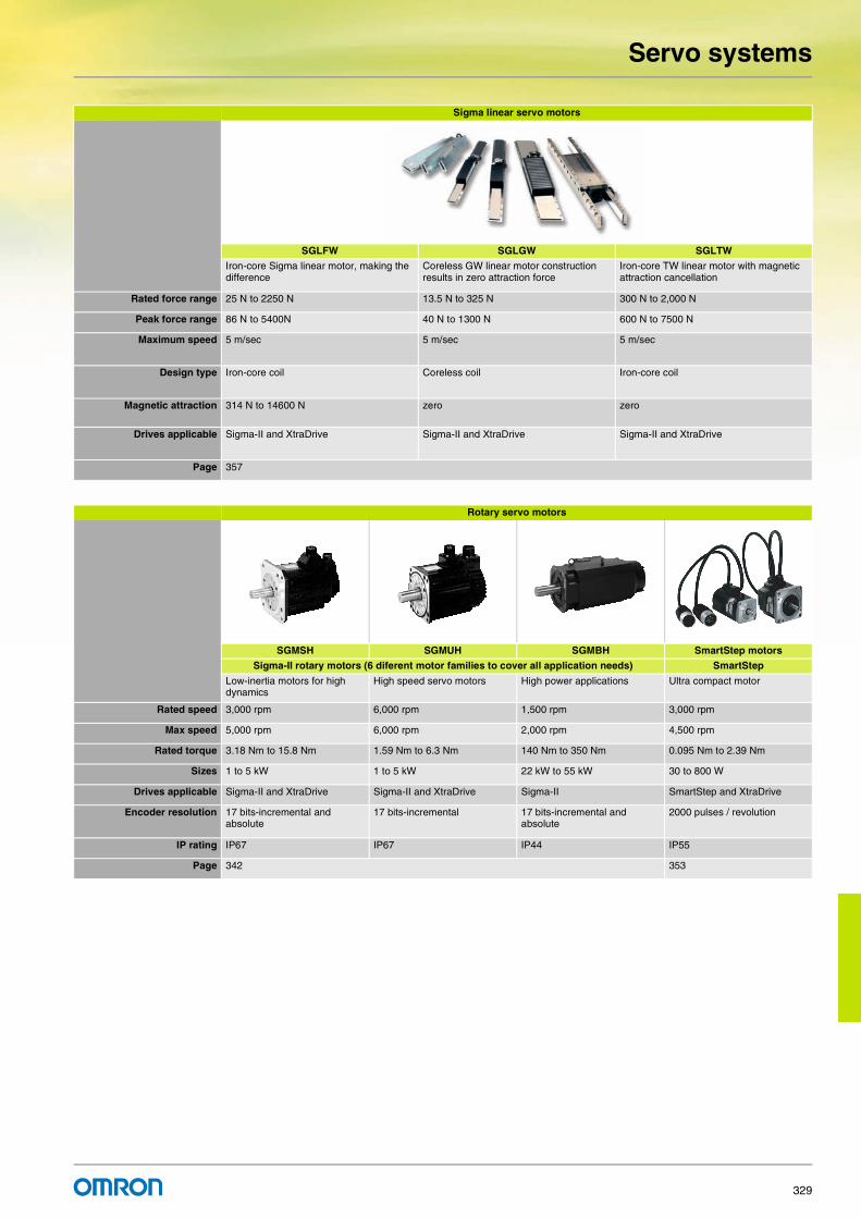
Servo systems
329
Sigma linear servo motors
SGLFW SGLGW SGLTW
Iron-core Sigma linear motor, making the difference
Coreless GW linear motor construction results in zero attraction force
Iron-core TW linear motor with magnetic attraction cancellation
Rated force range 25 N to 2250 N 13.5 N to 325 N 300 N to 2,000 N
Peak force range 86 N to 5400N 40 N to 1300 N 600 N to 7500 N
Maximum speed 5 m/sec 5 m/sec 5 m/sec
Design type Iron-core coil Coreless coil Iron-core coil
Magnetic attraction 314 N to 14600 N zero zero
Drives applicable Sigma-II and XtraDrive Sigma-II and XtraDrive Sigma-II and XtraDrive
Page 357
Rotary servo motors
SGMSH SGMUH SGMBH SmartStep motors
Sigma-II rotary motors (6 diferent motor families to cover all application needs) SmartStep
Low-inertia motors for high dynamics
High speed servo motors High power applications Ultra compact motor
Rated speed 3,000 rpm 6,000 rpm 1,500 rpm 3,000 rpm
Max speed 5,000 rpm 6,000 rpm 2,000 rpm 4,500 rpm
Rated torque 3.18 Nm to 15.8 Nm 1.59 Nm to 6.3 Nm 140 Nm to 350 Nm 0.095 Nm to 2.39 Nm
Sizes 1 to 5 kW 1 to 5 kW 22 kW to 55 kW 30 to 800 W
Drives applicable Sigma-II and XtraDrive Sigma-II and XtraDrive Sigma-II SmartStep and XtraDrive
Encoder resolution 17 bits-incremental and absolute
17 bits-incremental 17 bits-incremental and absolute
2000 pulses / revolution
IP rating IP67 IP67 IP44 IP55
Page 342 353

For full specifications and additional models please refer to the (attached) CD or www.europe.omron.comServo systems - Cat.-No. I18E-EN-02330
XtraDrive Servo systems
All-in-one servo drive and motion controller integratedIf your application demands the highest accuracy, the shortest cycle time in the most compact size and the ability to connect to PROFIBUS-DP or CAN, then look no further than XtraDrive. Complex motions such as cams, gears and linked axes are also available.
• Patented non-linear technique for tight control• Very low tracking error with no overshoot and zero settling time• The ideal drive for linear-motor control• Supports various servo-motor encoder types• PROFIBUS-DP embedded
Ordering information
System configuration
Note: The symbols ABCDE... show the recommended sequence to select the components for a servo system.
Servo motors, power & encoder cablesNote: AB Refer to the Servo motors chapter for detailed motor specifications and selection.
Servo drivesSymbol Specifications XtraDrive XtraDrive-E
with electronic CAM
XtraDrive-DPwith PROFIBUS
XtraDrive-DP-E with PROFIBUS and electronic CAM
Compatible servo motors A
Sigma-II rotary SmartStep Sigma linear motors
C 1 phase 200 VAC
30 W XD-P3-MN01 XD-P3-MN01-E - - SGMAH-A3A@ R7M-A03030-@ -
50 W XD-P5-MN01 XD-P5-MN01-E - - SGMAH-A5D@ R7M-A05030-@ SGLGW-30A050@100 W XD-01-MN01 XD-01-MN01-E XD-01-MSD0 XD-01-MSD0-E SGMAH-01A@,
SGMPH-01A@R7M-A10030-@, R7M-AP10030-@
SGLGW-30A080@, SGLGW-40A140@
200 W XD-02-MN01 XD-02-MN01-E XD-02-MSD0 XD-02-MSD0-E SGMAH-02A@, SGMPH-02A@
R7M-A20030-@, R7M-AP20030-@
SGLFW-20A@, SGLFW-35A120@,SGLGW-40A253A@,SGLGW-60A140@
400 W XD-04-MN01 XD-04-MN01-E XD-04-MSD0 XD-04-MSD0-E SGMAH-04A@, SGMPH-04A@
R7M-A40030-@, R7M-AP40030-@
SGLGW-40A365A@, SGLGW-60A253A@
750 W XD-08-MN XD-08-MN01-E XD-08-MSD0 XD-08-MSD0-E SGMAH-08A@, SGMPH-08A@
R7M-A75030-@, R7M-AP75030-@
SGLFW-35A230@, SGLFW-50A200@,SGLGW-60A365A@
CablesCables
A
F
H
J
I
E G
C
B
A A
B
A A
CHARGE
PO
WE
R
CN3
CN1
CN2
B
A
K
D
SGMGH, SGMUH, SGMSH, SGMBH servo motor
(Refer to chapter Sigma-II linear motors)
SGMAH, SGMPHservo motor
Position controlunit
Terminal block
General purpose cable
Motion control unit
Human machine interface
Personal computer
Option unit
Analog monitor cable
Filter
XtraDrive
servo drives
SGLT_ linear servo motor
SGLG_ linear servo motor
SGLF_ linear servo motor
(Refer to chapter
Sigma-II rotary motors)
(Refer to chapter
SmartStep servo motors)
R7M servo motor
PROFIBUS network(XtraDrive models with embedded PROFIBUS)
Cables
NS115
SW1
SW2
AR
CN6A
CN6B
CN4
L
M

XtraDrive Servo systems
331
Note: SGLGW-@ linear motor combination is made considering the use of standard magnets. Refer to the linear motors chapter for details.
Control cables (for CN1)
Cable (for CN5)
Options (for CN3)
Human machine interface
Option units (for CN10)
Filters
C 1 Phase 200 VAC
1.5 kW XD-15-MN XD-15-MN00-E - - SGMPH-15A@ - SGLFW-50A380@, SGLFW-1ZA200@,SGLGW-90A200A@
3 Phase 400 VAC
0.5 kW XD-05-TN XD-05-TN00-E XD-05-TSD0 XD-05-TSD0-E SGMGH-05D@, SGMAH-03D@, SGMPH-02D@/04D@
- SGLFW-35D@
1.0 kW XD-10-TN XD-10-TN00-E XD-10-TSD0 XD-10-TSD0-E SGMGH-09D@, SGMSH/UH-10D@, SGMAH-07D@, SGMPH-08D@
- SGLFW-50D200@, SGLTW-35D170@, SGLTW-50D170@
1.5 kW XD-15-TN XD-15-TN00-E XD-15-TSD0 XD-15-TSD0-E SGMGH-13D@,SGMSH/UH-15D@, SGMPH-15D@
- SGLFW-50D380@, SGLFW-1ZD200@
2.0 kW XD-20-TN XD-20-TN00-E XD-20-TSD0 XD-20-TSD0-E SGMGH-20D@, SGMSH-20D@
- SGLTW-35D320@, SGLTW-50D320@
3.0 kW XD-30-TN XD-30-TN00-E XD-30-TSD0 XD-30-TSD0-E SGMGH-30D@, SGMSH/UH-30D@
- SGLFW-1ZD380@, SGLTW-40D400@
5.0 kW XD-50-TN XD-50-TN00-E - - SGMGH-44D@,SGMSH/UH-40D@, SGMSH-50D@
- SGLTW-40D600@, SGLTW-80D400@
Symbol Specifications XtraDrive XtraDrive-E with electronic CAM
XtraDrive-DPwith PROFIBUS
XtraDrive-DP-E with PROFIBUS and electronic CAM
Compatible servo motors A
Sigma-II rotary SmartStep Sigma linear motors
Symbol Description Connect to Len Model
D Control cable(1 axis)
Motion control units CS1W-MC221CS1W-MC421C200H-MC221
1 m R88A-CPW001M1
2 m R88A-CPW002M1
3 m R88A-CPW003M1
5 m R88A-CPW005M1
Control cable(2 axis)
Motion control units CS1W-MC221CS1W-MC421C200H-MC221
1 m R88A-CPW001M2
2 m R88A-CPW002M2
3 m R88A-CPW003M2
5 m R88A-CPW005M2
Terminal block (4 axes)
Motion control unit C200HW-MC402-E
- R88A-TC04-E
Servo drive con-necting cable (1 axis)
1 m R88A-CMUK001J3-E2
PLC unit control cables (4 axes)
1 m R88A-CMX001S-E
1 m R88A-CMX001J1-E
E Servo relay unit CS1W-NC1@3, CJ1W-NC1@3, or C200HW-NC113 Position control unit
XW2B-20J6-1B (1 axis)
CS1W-NC2@3/4@3, CJ1W-NC2@3/4@3, or C200HW-NC213/413 Position control unit
XW2B-40J6-2B (2 axes)
CQM1H-PLB21CQM1-CPU43
XW2B-20J6-3B (1 axis)
CJ1M-CPU22/23 XW2B-20J6-8A (1 axis)XW2B-40J6-9A (2 axes)
F Cable to servo drive
Servo relay units XW2B-@0J6-@B
1 m XW2Z-100J-B4
2 m XW2Z-200J-B4
G Position control unit connecting cable
C200H-NC112 0.5 m XW2Z-050J-A1
1 m XW2Z-100J-A1
C200H-NC211 0.5 m XW2Z-050J-A2
1 m XW2Z-100J-A2
CQM1-CPU43-V1 and CQM1H-PLB21
0.5 m XW2Z-050J-A3
1 m XW2Z-100J-A3
CS1W-NC113 and C200HW-NC113
0.5 m XW2Z-050J-A6
1 m XW2Z-100J-A6
CS1W-NC213/413 and C200HW-NC213/413
0.5 m XW2Z-050J-A7
1 m XW2Z-100J-A7
CS1W-NC133 0.5 m XW2Z-050J-A10
1 m XW2Z-100J-A10
CS1W-NC233/433 0.5 m XW2Z-050J-A11
1 m XW2Z-100J-A11
G Position control unit connecting cable
CJ1W-NC113 0.5 m XW2Z-050J-A14
1 m XW2Z-100J-A14
CJ1W-NC213/413 0.5 m XW2Z-050J-A15
1 m XW2Z-100J-A15
CJ1W-NC133 0.5 m XW2Z-050J-A18
1 m XW2Z-100J-A18
CJ1W-NC233/433 0.5 m XW2Z-050J-A19
1 m XW2Z-100J-A19
CJ1M-CPU22/23 0.5 m XW2Z-050J-A27
1 m XW2Z-100J-A27
H Control cable For general purpose controllers
1 m R88A-CPW001Sor JZSP-CKI01-1
2 m R88A-CPW002Sor JZSP-CKI01-2
I Relay terminal block cable
General-purpose controller
1 m R88A-CTW001N
2 m R88A-CTW002N
Relay terminal block
- XW2B-50G5
Symbol Name Model
J Analog monitor cable R88A-CMW001Sor DE9404559
Symbol Name Model
K Computer connecting cable R88A-CCW002P2or JZSP-CMS02
Symbol Name Model
L 4.1“ HMI monochrome NT3S-ST126B-E
Symbol Name Model
M IO card, 8 inputs / 8 outputs XDIO-08
Symbol Applicable servo drive Filter model Rated current
Rated voltage
N XD-P3-M@, XD-P5-M@, XD-01-M@, XD-02-M@
R88A-FIW104-SE 4 A 250 VACsingle-phaseXD-04-M@ R88A-FIW107-SE 7A
XD-08-M@ R88A-FIW115-SE 15 A
XD-15-M@ R88A-FIW125-SE 25 A
XD-05-T@, XD-10-T@, XD-15-T@
R88A-FIW4006-SE 6 A 400 VACthree-phaseXD-20-T@, XD-30-T@ R88A-FIW4010-SE 10 A
XD-50-T@ R88A-FIW4020-SE 20 A
Symbol Description Connect to Len Model

XtraDrive Servo systems
332
Battery backup for absolute encoder
Connectors
Computer software
Specifications
Single-phase, 230 V
Three-phase, 400 V
Name Model
Battery (required for servo motors with absolute encoder)
JZSP-BA01ER6VC3 (3.6V)
Specification Model
Control I/O connector (For CN1) R88A-CNU11Cor JZSP-CKI9
XtraDrive 200V connector kit. (For 200V motors SGMAH/PH-@@A@@@D-OY and R7M-A@-D)
Connectors included XD-CN200K-DE
DE9406973 SPOC-17H-FRON169SPOC-06K-FSDN169
XtraDrive 400V connector kit. (For 400V motors SGMAH/PH-@@D@@@D-OY)
Connectors included XD-CN400K-DE
DE9406973 SPOC-17H-FRON169LPRA-06B-FRBN170
Sigma-II Drive encoder connector (For CN2) DE9406973 or R88A-CNU01R
Hypertac encoder connector IP67(For motors SGMAH/PH-@@@@@@@D-OY and R7M-A@-D)
SPOC-17H-FRON169
Hypertac power connector IP67, 200V.(For 200V motors SGMAH/PH-@@A@@@@D-OY and R7M-A@-D)
SPOC-06K-FSDN169
Hypertac power connector IP67, 400V.(For 400V motors SGMAH/PH-@@D@@@@D-OY)
LPRA-06B-FRBN170
Military encoder connector IP67(For motors SGMGH-@, SGMSH-@, SGMUH-@)
MS3108E20-29S
Military power connector IP67(For 400V motors SGMGH-(05/10/13)D@, SGMSH-(10/15/20)D@ , SGMUH-(10/15)D@)
MS3108E18-10S
Military power connector IP67(For 400V motors SGMGH-(20/30/44)D@, SGMSH-(30/40/50)D@, SGMUH-(30/40)D@)
MS3108E22-22S
Military brake connector IP67 (For 400V servo motors SGMGH-@, SGMSH-@, SGMUH-@)
MS3108E10SL-3S
Specifications Model
XtraWare MOTION TOOLS
Specification Model
Servo drive type XD-P3-M@ XD-P5-M@ XD-01-M@ XD-02-M@ XD-04-M@ XD-08-M@ XD-15-M@
Applicable servo motor
SGMAH-@ A3A@ A5A@ 01A@ 02A@ 04A@ 08A@ 15A@SGMPH-@ - - 01A@ 02A@ 04A@ 08A@ -
R7M-@ A03030-@ A05030-@ A10030-@ A20030-@ A40030-@ A75030-@ -
R7M-@ - - AP10030-@ AP20030-@ AP40030-@ AP75030-@ -
Bas
ic s
peci
ficat
ions
Max. applicable motor capacity W 30 50 100 200 400 750 1500
Continuous output current A(rms) 0.44 0.64 0.91 2.1 2.8 5.7 11.6
Max. output current A(rms) 1.3 2.0 2.8 6.5 8.5 13.9 28
Input power Main circuit For single-phase, 200 to 230 VAC +10 to -15%
Supply Control circuit For single-phase, 200 to 230 VAC +10 to -15%
Control method Single phase full-wave rectification / IGBT / PWM / sine-wave current drive method
Feedback Serial encoder ( incremental / absolute value )
Con
ditio
ns Usage / storage temperature 0 to +55 °C / -20 to 85 °C
Usage / storage humidity 90% RH or less (non-condensing)
Altitude 1000 m or less above sea level
Vibration / shock resistance 4.9 m/s2 / 19.6 m/s2
Configuration Base mounted
Approx. weight kg 0.8 1.1 1.7 3.8
Servo drive type XD-05-T@ XD-10-T@ XD-15-T@ XD-20-T@ XD-30-T@ XD-50-T@Applicable servo motor
SGMAH-@ 03D@ 07D@ - - - -
SGMPH-@ 02D@, 04D@ 08D@ 15D@ - - -
SGMGH-@ 05D@ 09D@ 13D@ 20D@ 30D@ 44D@SGMSH-@ - 10D@ 15D@ 20D@ 30D@ 40D@/50D@SGMUH-@ - 10D@ 15D@ - 30D@ 40D@
Bas
ic s
peci
ficat
ions
Max. applicable motor capacity kW 0.45 1.0 1.5 2.0 3.0 5.0
Continuous output current A(rms) 1.9 3.5 5.4 8.4 11.9 16.5
Max. output current A(rms) 5.5 8.5 14 20 28 40.5
Input power Main circuit For three-phase, 380 to 480 VAC + 10 to -15% (50/60Hz)
Supply Control circuit 24VDC+ 15%
Control method Three phase full-wave rectification / IGBT / PWM / sine-wave current drive method
Feedback Serial encoder (incremental / absolute value)
Con
ditio
ns Usage / storage temperature 0 to +55 °C / -20 to +85 °C
Usage / storage humidity 90% RH or less (non-condensing)
Altitude 1000 m or less above sea level
Vibration / shock resistance 4.9 m/s2 / 19.6 m/s2
Configuration Base mounted
Approx. weight kg 2.8 3.8 5.5

XtraDrive Servo systems
333
Dimensions
Servo drives
Specifications Drive model H W D
1-phase 200 VAC 30 W XD-P3-M@ 160 55 130
50 W XD-P5-M@100 W XD-01-M@200 W XD-02-M@400 W XD-04-M@ 160 75 130
750 W XD-08-M@ 160 90 180
1.5 kW XD-15-M@ 250 110 180
3-phase 400 VAC 0.5 kW XD-05-T@ 160 110 180
1.0 kW [email protected] kW [email protected] kW XD-20-T@ 250 110 180
3.0 kW [email protected] kW XD-50-T@ 250 125 230
H
WD

For full specifications and additional models please refer to the (attached) CD or www.europe.omron.comServo systems - Cat.-No. I48E-EN-01334
Sigma-II servo drive Servo systems
Designed with ZERO compromiseThe Sigma II servo series was designed with ZERO compromise on quality, reliability or performance. The servo amplifiers are ultra-compact with pulse and analogue inputs as standard, plus an auto-tuning function. Plug-in option cards offer enhanced functionality such as indexing and complex motions such as cams, gears and linked axes.
• 300% peak current for 3 seconds• Automatic motor recognition with auto-tuning function• Analogue and pulse inputs for speed, torque and position control• Option units for field buses, MECHATROLINK-II, servos and motion
controller and indexers• Trace function allowing oscilloscope function
Ordering information
Note: The symbols ABCDE... show the recommended sequence to select the components in a Sigma-II servo system
Servo motors, power & encoder cablesNote: AB Refer to the servo motors chapter for detailed motor specifications and selection
Servo drivesSymbol Specifications Model Compatible rotary servo motors A Compatible linear motors A
C 1 Phase 200 V AC 30 W SGDH-A3AE-OY SGMAH-A3A@ -
50 W SGDH-A5AE-OY SGMAH-A5D@ SGLGW-30A050@100 W SGDH-01AE-OY SGMAH-01A@, SGMPH-01A@ SGLGW-30A080@, SGLGW-40A140@200 W SGDH-02AE-OY SGMAH-02A@, SGMPH-02A@ SGLFW-20A@, SGLFW-35A120@,
SGLGW-40A253A@,SGLGW-60A140@400 W SGDH-04AE-OY SGMAH-04A@, SGMPH-04A@ SGLGW-40A365A@, SGLGW-60A253A@750 W SGDH-08AE-S-OY SGMAH-08A@, SGMPH-08A@ SGLFW-35A230@, SGLFW-50A200@,
SGLGW-60A365A@1500 W SGDH-15AE-S-OY SGMPH-15A@ SGLFW-50A380@, SGLFW-1ZA200@,
SGLGW-90A200A@
M
L
Q
O
P
Cables Cables
A
CHARGE POWER
SERVOPACK
SGDH-
200VVer.
CN3
CN1
CN2
F H
J
I
E
G
D C
B
A A
B
A A
K
SGMGH, SGMUH, SGMSH, SGMBH servo motor
(Refer to chapter Sigma-II linear motors)
SGMAH, SGMPHservo motor
Position controlunit
Terminal block position control
General purpose cable
Motion control unit
Digital operator
Option unit- 1 MECHATROLINK I/II- 2 DeviceNet- 3 PROFIBUS- 4 Motion controller- 5 Indexer
Battery for absolute encoder
Analog monitor cable
Filter
For higher drive size
External regenerative resistorDynamic brake resistor
Sigma-II series
servo drives
SGLT_ linearservo motor
SGLG_ linearservo motor
SGLF_ linear servo motor
(Refer to chapter Sigma-II rotary motors)
Personal computer
NS115
SW1
SW2
AR
CN6A
CN6B
CN4

Sigma-II servo drive Servo systems
335
Option units (for CN10)
Note: D Refer to the servo drive option unit chapter for detailed specifications and selection
Control cables (for CN1)
C 3 Phase 400 V AC 0.5 kW SGDH-05DE-OY SGMGH-05D@, SGMAH-03D@, SGMPH-02D@/04D@ [email protected] kW SGDH-10DE-OY SGMGH-09D@, SGMSH/UH-10D@, SGMAH-07D@,
SGMPH-08D@SGLFW-50D200@, SGLTW-35D170@, SGLTW-50D170@
1.5 kW SGDH-15DE-OY SGMGH-13D@, SGMSH/UH-15D@, SGMPH-15D@ SGLFW-50D380@, SGLFW-1ZD200@2 kW SGDH-20DE-OY SGMGH-20D@, SGMSH-20D@ SGLTW-35D320@, SGLTW-50D320@3 kW SGDH-30DE-OY SGMGH-30D@, SGMSH/UH-30D@ SGLFW-1ZD380@, SGLTW-40D400@5 kW SGDH-50DE-OY SGMGH-44D@, SGMSH/UH-40D@, SGMSH-50D@ SGLTW-40D60@, SGLTW-80D400@6 kW SGDH-60DE-OY SGMGH-55D@ -
7.5 kW SGDH-75DE-OY SGMGH-75D@ SGLTW-80D600@11 kW SGDH-1ADE-OY SGMGH-1AD@ -
15 kW SGDH-1EDE-OY SGMGH-1ED@ -
22 kW SGDH-2BDE SGMBH-2BD@ -
30 kW SGDH-3ZDE SGMBH-3ZD@ -
37 kW SGDH-3GDE SGMBH-3GD@ -
45 kW SGDH-4EDE SGMBH-4ED@ -
55 kW SGDH-5EDE SGMBH-5ED@ -
Symbol Name Model
D 1.5 axis advanced motion controller with host link interface R88A-MCW151-E
1.5 axis advanced motion controller with DeviceNet interface R88A-MCW151-DRT-E
MECHATROLINK-I interface unit JUSP-NS100
MECHATROLINK-II interface unit JUSP-NS115
DeviceNet interface unit with positioning fuctionality JUSP-NS300
PROFIBUS-DP interface unit with positioning fuctionality JUSP-NS500
Indexer unit. versatile point to point positioning JUSP-NS600
Symbol Description Connect to Model
E Control cable(1 axis)
Motion control units CS1W-MC221CS1W-MC421C200H-MC221
1 m R88A-CPW001M1
2 m R88A-CPW002M1
3 m R88A-CPW003M1
5 m R88A-CPW005M1
Control cable(2 axes)
Motion control units CS1W-MC221CS1W-MC421C200H-MC221
1 m R88A-CPW001M2
2 m R88A-CPW002M2
3 m R88A-CPW003M2
5 m R88A-CPW005M2
Terminal block (4 axes)
Motion control unit C200HW-MC402-E
- R88A-TC04-E
Servo drive connecting cable (1 axis)
1 m R88A-CMUK001J3-E2
PLC unit control cables (4 axes)
1 m R88A-CMX001S-E
1 m R88A-CMX001J1-E
F Servo relay unit CS1W-NC1@3, CJ1W-NC1@3, or C200HW-NC113 position control unit
XW2B-20J6-1B (1 axis)
CS1W-NC2@3/4@3, CJ1W-NC2@3/4@3, or C200HW-NC213/413 position control unit
XW2B-40J6-2B (2 axes)
CQM1H-PLB21CQM1-CPU43
XW2B-20J6-3B (1 axis)
CJ1M-CPU22/23 XW2B-20J6-8A (1 axis)XW2B-40J6-9A (2 axes)
G Cable to servo drive Servo relay units XW2B-@0J6-@B 1 m XW2Z-100J-B4
2 m XW2Z-200J-B4
H Position control unit connecting cable
C200H-NC112 0.5 m XW2Z-050J-A1
1 m XW2Z-100J-A1
C200H-NC211 0.5 m XW2Z-050J-A2
1 m XW2Z-100J-A2
CQM1-CPU43-V1 and CQM1H-PLB21 0.5 m XW2Z-050J-A3
1 m XW2Z-100J-A3
CS1W-NC113 and C200HW-NC113 0.5 m XW2Z-050J-A6
1 m XW2Z-100J-A6
CS1W-NC213/413 and C200HW-NC213/413
0.5 m XW2Z-050J-A7
1 m XW2Z-100J-A7
CS1W-NC133 0.5 m XW2Z-050J-A10
1 m XW2Z-100J-A10
CS1W-NC233/433 0.5 m XW2Z-050J-A11
1 m XW2Z-100J-A11
Symbol Specifications Model Compatible rotary servo motors A Compatible linear motors A

Sigma-II servo drive Servo systems
336
Battery backup for absolute encoder (for CN8)
Cable (for CN5)
Options (for CN3)
Filters
External regenerative resistor DB resitor units
Connectors
Computer software
H Position control unit connecting cable
CJ1W-NC113 0.5 m XW2Z-050J-A14
1 m XW2Z-100J-A14
CJ1W-NC213/413 0.5 m XW2Z-050J-A15
1 m XW2Z-100J-A15
CJ1W-NC133 0.5 m XW2Z-050J-A18
1 m XW2Z-100J-A18
CJ1W-NC233/433 0.5 m XW2Z-050J-A19
1 m XW2Z-100J-A19
CJ1M-CPU22/23 0.5 m XW2Z-050J-A27
1 m XW2Z-100J-A27
I Control cable For general purpose controllers 1 m R88A-CPW001S
JZSP-CKI01-1
2 m R88A-CPW002S
JZSP-CKI01-1
J Relay terminal block cable General purpose controller 1 m R88A-CTW001N
2 m R88A-CTW002N
Relay terminal block - XW2B-50G5
Symbol Description Connect to Model
Symbol Name Model
K Battery for 30 W to 5 kW drives JZSP-BA01
Battery for 6 kW to 15 kW drives JZSP-BA01-1
Symbol Name Model
L Analog monitor cable R88A-CMW001Sor DE9404559
Symbol Name Model
M Parameter unit with cable JUSP-OP02A-2or R88A-PR02W
N Computer connecting cable R88A-CCW002P2or JZSP-CMS02
Symbol Applicable servo drive Filter model Rated current Rated voltage
O SGDH-A3AE-OY,SGDH-A5AE-OY, SGDH-01AE-OY, SGDH-02AE-OY
R88A-FIW104-SE 4 A 250 VACsingle-phase
SGDH-04AE-OY R88A-FIW107-SE 7A
SGDH-08AE-S-OY R88A-FIW115-SE 15 A
SGDH-15AE-S-OY R88A-FIW125-SE 25 A
SGDH-05DE-OY, SGDH-10DE-OY,SGDH-15DE-OY
R88A-FIW4006-SE 6 A 400 VACthree-phase
SGDH-20DE-OY, SGDH-30DE-OY R88A-FIW4010-SE 10 A
SGDH-50DE-OY R88A-FIW4020-SE 20 A
SGDH-60DE-OY, SGDH-75DE-OY R88A-FIW4030-SE 30 A
SGDH-1ADE-OY, SGDH-1EDE-OY R88A-FIW4055-SE 55 A
SGDH-2BDE, SGDH-3ZDE, SGDH-3GDE FN258-180-07 180 A
SGDH-4EDE, SGDH-5EDE FN359-250-99 250 A
Symbol Applicable servo drive Regenerative resistor unit model
Specifications
P SGDH-60DE-OY to -75DE-OY
JUSP-RA18 18 Ω , 880 W
SGDH-1ADE-OY to -1EDE-OY
JUSP-RA19 14.25 Ω , 1760 W
SGDH-2BDE JUSP-RA12 9 Ω, 3600 W
SGDH-3ZDE JUSP-RA13 6.7 Ω, 3600 W
SGDH-3GDE JUSP-RA14 5 Ω, 4800 W
SGDH-4EDE JUSP-RA15 4 Ω, 6000 W
SGDH-5EDE JUSP-RA16 3.8 Ω, 7200 W
Symbol Servo drive model Regenerative resistor unit model
Specifications. star wiring
Q SGDH-2BDE, SGDH-3ZDE JUSP-DB03 180 W, 0.8 ΩSGDH-3GDE JUSP-DB04 180 W, 0.8 ΩSGDH-4EDE JUSP-DB05 180 W, 0.8 ΩSGDH-5EDE JUSP-DB06 300 W, 0.8 Ω
Specification Model
Control I/O connector (For CN1) R88A-CNU11Cor JZSP-CKI9
Sigma-II drive encoder connector (For CN2) JZSP-CMP9-1
Communications connector (For CN3) R7A-CNA01R
Specifications Model
Configuration and monitoring software tool for servo drives and inverters. (CX-Drive version 1.11 or higher) CX-DRIVE
Complete OMRON software package including CX-Drive (CX-One version 1.1 or higher) CX-ONE

Sigma-II servo drive Servo systems
337
Specifications
Single-phase, 230 V
Three-phase, 400 V (up to 15 kW)
Three-phase, 400 V (from 22 kW to 55 kW)
Servo drive type SGDH- @ A3AE-OY A5AE-OY 01AE-OY 02AE-OY 04AE-OY 08AE-S-OY 15AE-S-OY
Applicable servo motor SGMAH-@ A3A@ A5A@ 01A@ 02A@ 04A@ 08A@ -
SGMPH-@ - - 01A@ 02A@ 04A@ 08A@ 15A@
Bas
ic s
pec
ific
atio
ns
Max. applicable motor capacity W 30 50 100 200 400 750 1500
Continuous output current A(rms) 0.44 0.64 0.91 2.1 2.8 5.7 11.6
Max. output current A(rms) 1.3 2.0 2.8 6.5 8.5 13.9 28
Input power Main circuit For single-phase, 200 to 230 VAC + 10 to -15% 220 to 230 VAC+10 to -15% (50/60 Hz)Supply Control circuit For single-phase, 200 to 230 VAC + 10 to -15%
Control method Single phase full-wave rectification / IGBT / PWM / sine-wave current drive method
Feedback Serial encoder (incremental / absolute value)
Co
nd
itio
ns Usage / storage temperature 0 to +55 °C / -20 to 85 °C
Usage / storage humidity 90% RH or less (non-condensing)
Altitude 1000 m or less above sea level
Vibration / shock resistance 4.9 m/s2 / 19.6 m/s2
Configuration Base mounted
Approx. weight kg 0.8 1.1 1.7 3.8
Servo drive type SGDH-@ 05DE-OY 10DE-OY 15DE-OY 20DE-OY 30DE-OY 50DE-OY 60DE-OY 75DE-OY 1ADE-OY 1EDE-OY
Applicable servo motor SGMGH-@ 05D@ 09D@ 13D@ 20D@ 30D@ 44D@ 55D@ 75D@ 1AD@ 1ED@SGMSH-@ - 10D@ 15D@ 20D@ 30D@ 40D@/
50D@- - - -
SGMUH-@ - 10D@ 15D@ - 30D@ 40D@ - - - -
Bas
ic s
pec
ific
atio
ns
Max. applicable motor capacity kW 0.45 1.0 1.5 2.0 3.0 5.0 6.0 7.5 11 15
Continuous output current A(rms) 1.9 3.5 5.4 8.4 11.9 16.5 20.8 25.4 28.1 37.2
Max. output current A(rms) 5.5 8.5 14 20 28 40.5 55 65 70 85
Input power Main circuit For three-phase, 380 to 480 VAC + 10 to -15% (50/60 Hz)
Supply Control circuit 24 VDC + 15%
Control method Three phase full-wave rectification / IGBT / PWM / sine-wave current drive method
Feedback Serial encoder ( incremental / absolute)
Co
nd
itio
ns Usage / storage temperature 0 to +55 °C / -20 to +85 °C
Usage / storage humidity 90% RH or less (non-condensing)
Altitude 1000 m or less above sea level
Vibration / shock resistance 4.9 m/s2 / 19.6 m/s2
Configuration Base mounted
Approx. weight kg 2.8 3.8 5.5 15 22
Servo drive type SGDH-@ 2BDE 3ZDE 3GDE 4EDE 5EDE
Applicable servo motor SGMBH-# 2BD#A 3ZD#A 3GD#A 4ED#A 5ED#A
Bas
ic s
pec
ific
atio
ns
Max. applicable motor capacity kW 22 30 37 45 55
Continuous output current A(rms) 58 80 100 127 150
Max. output current A(rms) 120 170 210 260 310
Input power Main circuit For three-phase, 380 to 480 VAC + 10 to -15% (50/60 Hz)
Supply Control circuit 24 VDC+ 15%
Control method Three phase full-wave rectification / IGBT / PWM / sine-wave current drive method
Feedback Serial encoder (incremental / absolute)
Co
nd
itio
ns Usage / storage temperature 0 to +55 °C / -20 to +85 °C
Usage / storage humidity 90% RH or less (non-condensing)
Altitude 1000 m or less above sea level
Vibration / shock resistance 4.9 m/s2 / 19.6 m/s2
Configuration Base mounted
Approx. weight kg 40 60 65

Sigma-II servo drive Servo systems
338
Dimensions
Servo drives
Specifications Drive model H W D
1-phase 200 VAC 30 W SGDH-A3AE-OY 160 55 130
50 W SGDH-A5AE-OY100 W SGDH-01AE-OY200 W SGDH-02AE-OY400 W SGDH-04AE-OY 160 75 130
750 W SGDH-08AE-S-OY 160 90 180
1.5 kW SGDH-15AE-S-OY 250 110 180
3-phase 400 VAC 0.5 kW SGDH-05DE-OY 160 110 180
1.0 kW SGDH-10-DE-OY1.5 kW SGDH-15AE-OY2.0 kW SGDH-20DE-OY 250 110 180
3.0 kW SGDH-30DE-OY5.0 kW SGDH-50DE-OY 250 125 230
6.0 kW SGDH-60DE-OY 350 230 235
7.5 kW SGDH-75DE-OY11 kW SGDH-1ADE-OY 450 260 285
15 kW SGDH-1EDE-OY22 kW SGDH-2BDE 500 370 348
30 kW SGDH-3ZDE37 kW SGDH-3GDE 475 500 348
45 kW SGDH-4EDE 475 550 348
55 kW SGDH-5EDE
H
WD

For full specifications and additional models please refer to the (attached) CD or www.europe.omron.comServo systems - Cat.-No. I46E-EN-01 339
Servo systemsSmartStep drive
Servo capability with stepper simplicitySmartStep is designed and engineered to provide you with an easy way to migrate from steppers to servos in minutes. It accepts pulse-train input, can be configured quickly via simple dip switches and has an online auto-tuning function. Thus, the SmartStep offers all the simplicity and cost-effectiveness of a stepper with the added advantages of the servo drive capability.
• Output range from 30 W to 750 W• 300% peak current over nominal• Control via pulse train (speed and position)• Position resolution of 8,000 steps per revolution• On-line auto-tuning with 10 levels of rigidity
Ordering information
Note: The symbols ABCDE... show the recommended sequence to select the components in a SmartStep servo system
Servo motors, power & encoder cablesNote: AB Refer to the SmartStep servo motor chapter for detailed motor specifications and selection
Servo drives
Control cables (For CN1)
Symbol Specifications SmartStep drive model
Compatible servo motors ACylindrical type Flat type
C 200 VAC 30 W R7D-APA3H R7M-A03030-@ -
50 W R7D-APA5H R7M-A05030-@ -
100 W R7D-AP01H R7M-A10030-@ R7M-AP10030-@200 W R7D-AP02H R7M-A20030-@ R7M-AP20030-@400 W R7D-AP04H R7M-A40030-@ R7M-AP40030-@750 W R7D-AP08H R7M-A75030-@ R7M-AP75030-@
Symbol Name Compatible units Model Available lengths
D Servo relay unit Use with position control units(does not support communications functions.)Units: CS1W-NC113/133, CJ1W-NC113/133, C200HW-NC113, and C200H-NC112
XW2B-20J6-1B(1 axis)
---
Use with position control units (does not support communications functions.)Units: CS1W-NC213/233/413/433, CJ1W-NC213/233/413/433, C200HW-NC213/413, C500-NC113/211, and C200H-NC211
XW2B-40J6-2B(2 axes)
Use with position control units (does not support communications functions.)Units: CQM1H-PLB21, and CQM1-CPU43-V1
XW2B-20J6-3B(1 axis)
Use with position control units (supports communications functions.)Units: CS1W-NC213/233/413/433, CJ1W-NC213/233/413/433
XW2B-40J6-4A(2 axes)
Use with CJ1M-CPU22/23(does not support communications functions.)
XW2B-20J6-8A (1 axis)XW2B-40J6-9A (2 axes)
E Cable to servo drive Does not support communications functions. (for the XW2B-@@J6-@B) XW2Z-@@@J-B5 1 m or 2 m(The cable length goes in the empty boxes.)
Supports communications functions. (for the XW2B-@@J6-4B) XW2Z-@@@J-B7
C
B
A
F
H
J
I
E
G
D
K
H
SmartStep
servo drive
SmartStep
servo motor
(Refer to chapter SmartStep servo motors)
Connector terminal block
General purpose controller
(with pulse output)
Position control
unit
Personal computer

SmartStep drive Servo systems
340
Cable for CN3 Cable for CN4
Filters
Connectors
External regeneration resistor
Parameter unit & computer software
F Cable to position control unit
CQM1H-PLB21 and CQM1-CPU43-V1 XW2Z-@@@J-A3 0.5 m or 1 m(The cable length goes in the empty boxes.)
C200H-NC112 XW2Z-@@@J-A4
C200H-NC211 and C500-NC113/211 XW2Z-@@@J-A5
CS1W-NC113 and C200HW-NC113 XW2Z-@@@J-A8
CS1W-NC213/413 and C200HW-NC213/413 XW2Z-@@@J-A9
CS1W-NC133 XW2Z-@@@J-A12
CS1W-NC233/433 XW2Z-@@@J-A13
CJ1W-NC113 XW2Z-@@@J-A16
CJ1W-NC213/413 XW2Z-@@@J-A17
CJ1W-NC133 XW2Z-@@@J-A20
CS1W-NC233/433 XW2Z-@@@J-A21
CJ1M-CPU22/23 XW2Z-@@@J-A26
G Control cable For general-purpose controllers R88A-CPU@@@S 1 m or 2 m(The cable length goes in the empty boxes.)
H Connector terminal block cable
For general-purpose controllers R88A-CTU@@@N
Connector terminal block XW2B-40F5-P ---
Symbol Name Compatible units Model Available lengths
Symbol Name Model
I Computer monitor cable R7A-CCA002P2
Symbol Name Model
J Analog monitor cable R88A-CMW001S
Symbol Applicable servo drive Filter model Rated current Rated voltage
K R7D-APA3H, R7D-APA5H, R7D-AP01H, R7D-AP02H R88A-FIW104-E 4 A 250 VACSingle phaseR7D-AP04H R88A-FIW107-E 7 A
R7D-AP08H R88A-FIW115-E 15 A
Specifications Model
Control I/O connector (For CN1) R88A-CNU01C
SmartStep connectors kit Models included in kit R7A-CNA00K-DE
SmartStep encoder connector (For CN2) R7A-CNA01R
Hypertac power connectors female SPOC-06K-FSDN169
Hypertac encoder connectors female SPOC-17H-FRON169
Specification Model
220 W, 47 Ω R88A-RR22047S
Specifications Model
Parameter copy unit (with cable) R7A-PR02A
Configuration and monitoring software tool forservo drives and inverters. (CX-Drive version 1.11 or higher)
CX-DRIVE
Complete OMRON software package including CX-Drive (CX-One version 1.1 or higher)
CX-ONE

SmartStep drive Servo systems
341
Specifications
General specifications
Performance specifications
Dimensions
Servo drives
Item Specification
Ambient operating temperature 0 to 55 °C
Ambient operating humidity 90% max. (with no condensation)
Ambient storage temperature -20 to 85 °C
Ambient storage humidity 90% max. (with no condensation)
Storage / operating atmosphere No corrosive gases.
Vibration resistance 10 to 55 Hz in X, Y, and Z directions with 0.1-mm double amplitude or acceleration of 4.9 m/s2 max., whichever is smaller
Impact resistance Acceleration 19.6 m/s2 max., in X, Y, and Z directions, three times
Insulation resistance Between power line terminals and case: 0.5 MΩ min. (at 500 V DC)
Dielectric strength Between power line terminals and case: 1,500 VAC for 1 min at 50/60 HzBetween each control signal and case: 500 VAC for 1 min
Protective structure Built into panel (IP10).
International standards Approval obtained for UL, cUL, and EN (EMC directive and low-voltage directive)
Item 200 VAC input type
30 W 50 W 100 W 200 W 400 W 750 W
R7D-APA3H R7D-APA5H R7D-AP01H R7D-AP02H R7D-AP04H R7D-AP08H
Continuous output current (rms) 0.42 0.6 0.89 2.0 2.6 4.4
Momentary maximum output current (rms) 1.3 1.9 2.8 6.0 8.0 13.9
Control power supply Single-phase 200/230 VAC (170 to 253 V) 50/60 Hz
Main-circuit power supply Single-phase 200/230 VAC (170 to 253 V) 50/60 Hz (Three-phase 200/230 VAC can be used with the 750 W model.)
Control method All-digital servo
Speed feedback 2,000 pulses / revolution incremental encoder
Inverter method PWM method based on IGBT
PWM frequency 11.7 kHz
Weight 0.8 0.8 0.8 0.8 1.1 1.7
Compatible motor voltage 200 V
Compatible motor capacity 30 W 50 W 100 W 200 W 400 W 750 W
Command pulse response 250 kHz
Applicable servo motor(R7M-)
A03030 A05030 A10030AP10030
A20030AP20030
A40030AP40030
A75030AP75030
Main dimensions
Specifications Drive model H W D
1-phase 200 VAC 30 W R7D-APA3H 160 55 130
50 W R7D-APA5H
100 W R7D-AP01H
200 W R7D-AP02H
400 W R7D-AP04H 160 75 130
750 W R7D-AP08H 160 90 180
H
WD

For full specifications and additional models please refer to the (attached) CD or www.europe.omron.comServo systems - Cat.-No. I47E-EN-01342
Sigma-II rotary servo motors Servo systems
The ideal servo family for motion control. Fast response, high speed, and high accuracy• 6 different designs provide a complete range of servo motors to meet
the power, speed and performance required for each application.• Peak torque 300% of nominal during 3 seconds• Automatic motor recognition by servo drive• IP67 and shaft oil seal available• High resolution encoders
Ordering information
Note: The symbols ABC... show the recommended sequence to select the servo motor and cables
Servo motor
A A select motor from families SGMAH, SGMPH, SGMGH, SGMUH, SGMSH, SGMBH using motor tables in next pages
Servo driveNote: Choosing Sigma-II drive or XtraDrive affects to the encoder cable needed
B Refer to Sigma-II servo drive or XtraDrive chapter for detailed drive specifications and selection of drive accessories
B
B CHARGE POWER
SERVOPACK
SGDH-
200VVer.
CN3
CN1
CN2
CHARGE
PO
WE
R
CN3
CN1
CN2
C C
DD
E
AA A A A A
Intelligent
servo drive
XtraDrive
Servo drive with option
boards for flexible
system configuration
Sigma-II
servo drive Drive options
(Refer to servo drive chapter)
SGMAH servo motor3000 rpm (30-750 W)
SGMPH servo motor3000 rpm (100-1500 W)
SGMGH servo motor1500 rpm (450W-15 kW)
SGMBH servo motor1500 rpm (22 kW-55 kW)
SGMUHservo motor3000 rpm (1-5 kW)
SGMSHservo motor6000 rpm (1-4 kW)
Enc
oder
cab
le
Pow
er c
able
Pow
er c
able
Enc
oder
cab
le
Bra
ke c
able
Power and
encoder cables
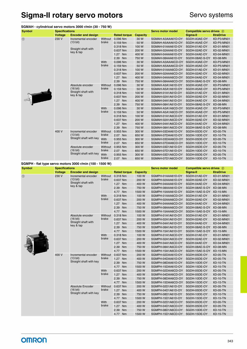
Sigma-II rotary servo motors Servo systems
343
SGMAH - cylindrical servo motors 3000 r/min (30 - 750 W)
SGMPH - flat type servo motors 3000 r/min (100 - 1500 W)
Symbol Specifications Servo motor model Compatible servo drives BVoltage Encoder and design Rated torque Capacity Sigma-II XtraDrive
A 230 V Incremental encoder (13 bit)
Straight shaft with key & tap
Without brake
0.096 Nm 30 W SGMAH-A3AAA61D-OY SGDH-A3AE-OY XD-P3-MN010.159 Nm 50 W SGMAH-A5AAA61D-OY SGDH-A5AE-OY XD-P5-MN010.318 Nm 100 W SGMAH-01AAA61D-OY SGDH-01AE-OY XD-01-MN010.637 Nm 200 W SGMAH-02AAA61D-OY SGDH-02AE-OY XD-02-MN011.27 Nm 400 W SGMAH-04AAA61D-OY SGDH-04AE-OY XD-04-MN012.39 Nm 750 W SGMAH-08AAA61D-OY SGDH-08AE-S-OY XD-08-MN
With brake
0.096 Nm 30 W SGMAH-A3AAA6CD-OY SGDH-A3AE-OY XD-P3-MN010.159 Nm 50 W SGMAH-A5AAA6CD-OY SGDH-A5AE-OY XD-P5-MN010.318 Nm 100 W SGMAH-01AAA6CD-OY SGDH-01AE-OY XD-01-MN010.637 Nm 200 W SGMAH-02AAA6CD-OY SGDH-02AE-OY XD-02-MN011.27 Nm 400 W SGMAH-04AAA6CD-OY SGDH-04AE-OY XD-04-MN012.39 Nm 750 W SGMAH-08AAA6CD-OY SGDH-08AE-S-OY XD-08-MN
Absolute encoder (16 bit)Straight shaft with key & tap
Without brake
0.096 Nm 30 W SGMAH-A3A1A61D-OY SGDH-A3AE-OY XD-P3-MN010.159 Nm 50 W SGMAH-A5A1A61D-OY SGDH-A5AE-OY XD-P5-MN010.318 Nm 100 W SGMAH-01A1A61D-OY SGDH-01AE-OY XD-01-MN010.637 Nm 200 W SGMAH-02A1A61D-OY SGDH-02AE-OY XD-02-MN011.27 Nm 400 W SGMAH-04A1A61D-OY SGDH-04AE-OY XD-04-MN012.39 Nm 750 W SGMAH-08A1A61D-OY SGDH-08AE-S-OY XD-08-MN
With brake
0.096 Nm 30 W SGMAH-A3A1A6CD-OY SGDH-A3AE-OY XD-P3-MN010.159 Nm 50 W SGMAH-A5A1A6CD-OY SGDH-A5AE-OY XD-P5-MN010.318 Nm 100 W SGMAH-01A1A6CD-OY SGDH-01AE-OY XD-01-MN010.637 Nm 200 W SGMAH-02A1A6CD-OY SGDH-02AE-OY XD-02-MN011.27 Nm 400 W SGMAH-04A1A6CD-OY SGDH-04AE-OY XD-04-MN012.39 Nm 750 W SGMAH-08A1A6CD-OY SGDH-08AE-S-OY XD-08-MN
400 V Incremental encoder (13 bit)Straight shaft with key
Without brake
0.955 Nm 300 W SGMAH-03DAA61D-OY SGDH-05DE-OY XD-05-TN2.07 Nm 650 W SGMAH-07DAA61D-OY SGDH-10DE-OY XD-10-TN
With brake
0.955 Nm 300 W SGMAH-03DAA6CD-OY SGDH-05DE-OY XD-05-TN2.07 Nm 650 W SGMAH-07DAA6CD-OY SGDH-10DE-OY XD-10-TN
Absolute encoder (16 bit)Straight shaft with key
Without brake
0.955 Nm 300 W SGMAH-03D1A61D-OY SGDH-05DE-OY XD-05-TN2.07 Nm 650 W SGMAH-07D1A61D-OY SGDH-10DE-OY XD-10-TN
With brake
0.955 Nm 300 W SGMAH-03D1A6CD-OY SGDH-05DE-OY XD-05-TN2.07 Nm 650 W SGMAH-07D1A6CD-OY SGDH-10DE-OY XD-10-TN
Symbol Specifications Servo motor model Compatible servo drives BVoltage Encoder and design Rated torque Capacity Sigma-II XtraDrive
A 230 V Incremental encoder (13 bit)Straight shaft with key & tap
Without brake
0.318 Nm 100 W SGMPH-01AAA61D-OY SGDH-01AE-OY XD-01-MN010.637 Nm 200 W SGMPH-02AAA61D-OY SGDH-02AE-OY XD-02-MN011.27 Nm 400 W SGMPH-04AAA61D-OY SGDH-04AE-OY XD-04-MN012.39 Nm 750 W SGMPH-08AAA61D-OY SGDH-08AE-S-OY XD-08-MN4.77 Nm 1500 W SGMPH-15AAA61D-OY SGDH-15AE-S-OY XD-15-MN
With brake
0.318 Nm 100 W SGMPH-01AAA6CD-OY SGDH-01AE-OY XD-01-MN010.637 Nm 200 W SGMPH-02AAA6CD-OY SGDH-02AE-OY XD-02-MN011.27 Nm 400 W SGMPH-04AAA6CD-OY SGDH-04AE-OY XD-04-MN012.39 Nm 750 W SGMPH-08AAA6CD-OY SGDH-08AE-S-OY XD-08-MN4.77 Nm 1500 W SGMPH-15AAA6CD-OY SGDH-15AE-S-OY XD-15-MN
Absolute encoder (16 bit)Straight shaft with key & tap
Without brake
0.318 Nm 100 W SGMPH-01A1A61D-OY SGDH-01AE-OY XD-01-MN010.637 Nm 200 W SGMPH-02A1A61D-OY SGDH-02AE-OY XD-02-MN011.27 Nm 400 W SGMPH-04A1A61D-OY SGDH-04AE-OY XD-04-MN012.39 Nm 750 W SGMPH-08A1A61D-OY SGDH-08AE-S-OY XD-08-MN4.77 Nm 1500 W SGMPH-15A1A61D-OY SGDH-15AE-S-OY XD-15-MN
With brake
0.318 Nm 100 W SGMPH-01A1A6CD-OY SGDH-01AE-OY XD-01-MN010.637 Nm 200 W SGMPH-02A1A6CD-OY SGDH-02AE-OY XD-02-MN011.27 Nm 400 W SGMPH-04A1A6CD-OY SGDH-04AE-OY XD-04-MN012.39 Nm 750 W SGMPH-08A1A6CD-OY SGDH-08AE-S-OY XD-08-MN4.77 Nm 1500 W SGMPH-15A1A6CD-OY SGDH-15AE-S-OY XD-15-MN
400 V Incremental encoder (13 bit)Straight shaft with key
Without brake
0.637 Nm 200 W SGMPH-02DAA61D-OY SGDH-05DE-OY XD-05-TN1.27 Nm 400 W SGMPH-04DAA61D-OY SGDH-05DE-OY XD-05-TN2.39 Nm 750 W SGMPH-08DAA61D-OY SGDH-10DE-OY XD-10-TN4.77 Nm 1500 W SGMPH-15DAA61D-OY SGDH-15DE-OY XD-15-TN
With brake
0.637 Nm 200 W SGMPH-02DAA6CD-OY SGDH-05DE-OY XD-05-TN1.27 Nm 400 W SGMPH-04DAA6CD-OY SGDH-05DE-OY XD-05-TN2.39 Nm 750 W SGMPH-08DAA6CD-OY SGDH-10DE-OY XD-10-TN4.77 Nm 1500 W SGMPH-15DAA6CD-OY SGDH-15DE-OY XD-15-TN
Absolute Encoder (16 bit)Straight shaft with key
Without brake
0.637 Nm 200 W SGMPH-02D1A61D-OY SGDH-05DE-OY XD-05-TN1.27 Nm 400 W SGMPH-04D1A61D-OY SGDH-05DE-OY XD-05-TN2.39 Nm 750 W SGMPH-08D1A61D-OY SGDH-10DE-OY XD-10-TN4.77 Nm 1500 W SGMPH-15D1A61D-OY SGDH-15DE-OY XD-15-TN
With brake
0.637 Nm 200 W SGMPH-02D1A6CD-OY SGDH-05DE-OY XD-05-TN1.27 Nm 400 W SGMPH-04D1A6CD-OY SGDH-05DE-OY XD-05-TN2.39 Nm 750 W SGMPH-08D1A6CD-OY SGDH-10DE-OY XD-10-TN4.77 Nm 1500 W SGMPH-15D1A6CD-OY SGDH-15DE-OY XD-15-TN

Sigma-II rotary servo motors Servo systems
Servo systemsCat.-No. I47E-EN-01344
SGMGH - servo motors 1500 r/min (0.45 - 15 kW)
SGMSH - servo motors 3000 r/min (1 - 5 KW)
Symbol Specifications Servo motor model Compatible servo drives BVoltage Encoder and design Rated torque Capacity Sigma-II XtraDrive
A 400 V Incremental encoder (17 bit)Straight shaft with key & tap
Without brake
2.84 Nm 0.45 kW SGMGH-05DCA6F-OY SGDH-05DE-OY XD-05-TN5.39 Nm 0.85 kW SGMGH-09DCA6F-OY SGDH-10DE-OY XD-10-TN8.34 Nm 1.3 kW SGMGH-13DCA6F-OY SGDH-15DE-OY XD-15-TN
11.5 Nm 1.8 kW SGMGH-20DCA6F-OY SGDH-20DE-OY XD-20-TN18.6 Nm 2.9 kW SGMGH-30DCA6F-OY SGDH-30DE-OY XD-30-TN28.4 Nm 4.4 kW SGMGH-44DCA6F-OY SGDH-50DE-OY XD-50-TN35.0 Nm 5.5 kW SGMGH-55DCA6F-OY SGDH-60DE-OY -48.0 Nm 7.5 kW SGMGH-75DCA6F-OY SGDH-75DE-OY -70.0 Nm 11.5 kW SGMGH-1ADCA6F-OY SGDH-1ADE-OY -95.4 Nm 15.0 kW SGMGH-1EDCA6F-OY SGDH-1EDE-OY -
With brake
2.84 Nm 0.45 kW SGMGH-05DCA6H-OY SGDH-05DE-OY XD-05-TN5.39 Nm 0.85 kW SGMGH-09DCA6H-OY SGDH-10DE-OY XD-10-TN8.34 Nm 1.3 kW SGMGH-13DCA6H-OY SGDH-15DE-OY XD-15-TN
11.5 Nm 1.8 kW SGMGH-20DCA6H-OY SGDH-20DE-OY XD-20-TN18.6 Nm 2.9 kW SGMGH-30DCA6H-OY SGDH-30DE-OY XD-30-TN28.4 Nm 4.4 kW SGMGH-44DCA6H-OY SGDH-50DE-OY XD-50-TN35.0 Nm 5.5 kW SGMGH-55DCA6H-OY SGDH-60DE-OY -48.0 Nm 7.5 kW SGMGH-75DCA6H-OY SGDH-75DE-OY -70.0 Nm 11.5 kW SGMGH-1ADCA6H-OY SGDH-1ADE-OY -95.4 Nm 15.0 kW SGMGH-1EDCA6H-OY SGDH-1EDE-OY -
Absolute encoder (17 bit)Straight shaft with key & tap
Without brake
2.84 Nm 0.45 kW SGMGH-05D2A6F-OY SGDH-05DE-OY XD-05-TN5.39 Nm 0.85 kW SGMGH-09D2A6F-OY SGDH-10DE-OY XD-10-TN8.34 Nm 1.3 kW SGMGH-13D2A6F-OY SGDH-15DE-OY XD-15-TN
11.5 Nm 1.8 kW SGMGH-20D2A6F-OY SGDH-20DE-OY XD-20-TN18.6 Nm 2.9 kW SGMGH-30D2A6F-OY SGDH-30DE-OY XD-30-TN28.4 Nm 4.4 kW SGMGH-44D2A6F-OY SGDH-50DE-OY XD-50-TN35.0 Nm 5.5 kW SGMGH-55D2A6F-OY SGDH-60DE-OY -48.0 Nm 7.5 kW SGMGH-75D2A6F-OY SGDH-75DE-OY -70.0 Nm 11.5 kW SGMGH-1AD2A6F-OY SGDH-1ADE-OY -95.4 Nm 15.0 kW SGMGH-1ED2A6F-OY SGDH-1EDE-OY -
With brake
2.84 Nm 0.45 kW SGMGH-05D2A6H-OY SGDH-05DE-OY XD-05-TN5.39 Nm 0.85 kW SGMGH-09D2A6H-OY SGDH-10DE-OY XD-10-TN8.34 Nm 1.3 kW SGMGH-13D2A6H-OY SGDH-15DE-OY XD-15-TN
11.5 Nm 1.8 kW SGMGH-20D2A6H-OY SGDH-20DE-OY XD-20-TN18.6 Nm 2.9 kW SGMGH-30D2A6H-OY SGDH-30DE-OY XD-30-TN28.4 Nm 4.4 kW SGMGH-44D2A6H-OY SGDH-50DE-OY XD-50-TN35.0 Nm 5.5 kW SGMGH-55D2A6H-OY SGDH-60DE-OY -48.0 Nm 7.5 kW SGMGH-75D2A6H-OY SGDH-75DE-OY -70.0 Nm 11.5 kW SGMGH-1AD2A6H-OY SGDH-1ADE-OY -95.4 Nm 15.0 kW SGMGH-1ED2A6H-OY SGDH-1EDE-OY -
Symbol Specifications Servo motor model Compatible servo drives BVoltage Encoder and design Rated torque Capacity Sigma-II XtraDrive
A 400 V Incremental encoder (17 bit)Straight shaft with key & tap
Without brake
3.18 Nm 1.0 kW SGMSH-10DCA6F-OY SGDH-10DE-OY XD-10-TN
4.9 Nm 1.5 kW SGMSH-15DCA6F-OY SGDH-15DE-OY XD-15-TN
6.36 Nm 2.0 kW SGMSH-20DCA6F-OY SGDH-20DE-OY XD-20-TN
9.8 Nm 3.0 kW SGMSH-30DCA6F-OY SGDH-30DE-OY XD-30-TN
12.6 Nm 4.0 kW SGMSH-40DCA6F-OY SGDH-50DE-OY XD-50-TN
15.8 Nm 5.0 kW SGMSH-50DCA6F-OY SGDH-50DE-OY XD-50-TN
With brake
3.18 Nm 1.0 kW SGMSH-10DCA6H-OY SGDH-10DE-OY XD-10-TN
4.9 Nm 1.5 kW SGMSH-15DCA6H-OY SGDH-15DE-OY XD-15-TN
6.36 Nm 2.0 kW SGMSH-20DCA6H-OY SGDH-20DE-OY XD-20-TN
9.8 Nm 3.0 kW SGMSH-30DCA6H-OY SGDH-30DE-OY XD-30-TN
12.6 Nm 4.0 kW SGMSH-40DCA6H-OY SGDH-50DE-OY XD-50-TN
15.8 Nm 5.0 kW SGMSH-50DCA6H-OY SGDH-50DE-OY XD-50-TN
Absolute encoder (17 bit)Straight shaft with key & tap
Without brake
3.18 Nm 1.0 kW SGMSH-10D2A6F-OY SGDH-10DE-OY XD-10-TN
4.9 Nm 1.5 kW SGMSH-15D2A6F-OY SGDH-15DE-OY XD-15-TN
6.36 Nm 2.0 kW SGMSH-20D2A6F-OY SGDH-20DE-OY XD-20-TN
9.8 Nm 3.0 kW SGMSH-30D2A6F-OY SGDH-30DE-OY XD-30-TN
12.6 Nm 4.0 kW SGMSH-40D2A6F-OY SGDH-50DE-OY XD-50-TN
15.8 Nm 5.0 kW SGMSH-50D2A6F-OY SGDH-50DE-OY XD-50-TN
With brake
3.18 Nm 1.0 kW SGMSH-10D2A6H-OY SGDH-10DE-OY XD-10-TN
4.9 Nm 1.5 kW SGMSH-15D2A6H-OY SGDH-15DE-OY XD-15-TN
6.36 Nm 2.0 kW SGMSH-20D2A6H-OY SGDH-20DE-OY XD-20-TN
9.8 Nm 3.0 kW SGMSH-30D2A6H-OY SGDH-30DE-OY XD-30-TN
12.6 Nm 4.0 kW SGMSH-40D2A6H-OY SGDH-50DE-OY XD-50-TN
15.8 Nm 5.0 kW SGMSH-50D2A6H-OY SGDH-50DE-OY XD-50-TN

Sigma-II rotary servo motors Servo systems
345
SGMUH - servo motors 6000 r/min (1 - 4 kW)
SGMBH - servo motors 1500 r/min (22 - 55 kW)
Encoder cables for Sigma-II servo drive
for XtraDrive servo drive
Symbol Specifications Servo motor model Compatible servo drives BVoltage Encoder and design Rated torque Capacity Sigma-II XtraDrive
A 400 V Incremental encoder (17 bit)Straight shaft with key
Without brake
1.59 Nm 1.0 kW SGMUH-10DCA61-OY SGDH-10DE-OY XD-10-TN
2.45 Nm 1.5 kW SGMUH-15DCA61-OY SGDH-15DE-OY XD-15-TN
4.9 Nm 3.0 kW SGMUH-30DCA61OY SGDH-30DE-OY XD-30-TN
6.3 Nm 4.0 kW SGMUH-40DCA61-OY SGDH-50DE-OY XD-50-TN
With brake
1.59 Nm 1.0 kW SGMUH-10DCA6C-OY SGDH-10DE-OY XD-10-TN
2.45 Nm 1.5 kW SGMUH-15DCA6C-OY SGDH-15DE-OY XD-15-TN
4.9 Nm 3.0 kW SGMUH-30DCA6C-OY SGDH-30DE-OY XD-30-TN
6.3 Nm 4.0 kW SGMUH-40DCA6C-OY SGDH-50DE-OY XD-50-TN
Symbol Specifications Servo motor model Compatible drives B
Voltage Encoder and design Rated torque Capacity Sigma-II
A 400 V Incremental encoder (17 bit)Straight shaft with key & tap
Without brakeflange mount
140 Nm 22 kW SGMBH-2BDCA61 SGDH-2BDE
191 Nm 30 kW SGMBH-3ZDCA61 SGDH-3ZDE
236 Nm 37 kW SGMBH-3GDCA61 SGDH-3GDE
286 Nm 45 kW SGMBH-4EDCA61 SGDH-4EDE
Without brakefoot mount
236 Nm 37 kW SGMBH-3GDCAL1 SGDH-3GDE
286 Nm 45 kW SGMBH-4EDCAL1 SGDH-4EDE
350 Nm 55 kW SGMBH-5EDCAL1 SGDH-5EDE
With brakeflange mount
140 Nm 22 kW SGMBH-2BDCA6C SGDH-2BDE
191 Nm 30 kW SGMBH-3ZDCA6C SGDH-3ZDE
With brakefoot mount
236 Nm 37 kW SGMBH-3GDCALC SGDH-3GDE
286 Nm 45 kW SGMBH-4EDCALC SGDH-4EDE
Absolute encoder (17 bit)Straight shaft with key & tap
Without brakeflange mount
140 Nm 22 kW SGMBH-2BD2A61 SGDH-2BDE
191 Nm 30 kW SGMBH-3ZD2A61 SGDH-3ZDE
236 Nm 37 kW SGMBH-3GD2A61 SGDH-3GDE
286 Nm 45 kW SGMBH-4ED2A61 SGDH-4EDE
Without brakefoot mount
236 Nm 37 kW SGMBH-3GD2AL1 SGDH-3GDE
286 Nm 45 kW SGMBH-4ED2AL1 SGDH-4EDE
350 Nm 55 kW SGMBH-5ED2AL1 SGDH-5EDE
With brakeflange mount
140 Nm 22 kW SGMBH-2BD2A6C SGDH-2BDE
191 Nm 30 kW SGMBH-3ZD2A6C SGDH-3ZDE
With brakefoot mount
236 Nm 37 kW SGMBH-3GD2ALC SGDH-3GDE
286 Nm 45 kW SGMBH-4ED2ALC SGDH-4EDE
Symbol Specifications Model Appearance
C Sigma-II encoder cable for SGMAH/PH servo motors SGMAH-@@@@@@@D-OYSGMPH-@@@@@@@D-OY
3 m R88A-CRWA003C-DE
5 m R88A-CRWA005C-DE
10 m R88A-CRWA010C-DE
15 m R88A-CRWA015C-DE
20 m R88A-CRWA020C-DE
Sigma-II encoder cable for SGMGH/SH/UHservo motors SGMGH-@SGMSH-@SGMUH-@, SGMBH-@
3 m R88A-CRWB003N-E
5 m R88A-CRWB005N-E
10 m R88A-CRWB010N-E
15 m R88A-CRWB015N-E
20 m R88A-CRWB020N-E
Symbol Specifications Model Appearance
C XtraDrive encoder cable for Sigma-II (SGMAH/PH) servo motors SGMAH-@@@@@@@D-OYSGMPH-@@@@@@@D-OY
3 m XD-CRWA003-DE
5 m XD-CRWA005-DE
10 m XD-CRWA010-DE
15 m XD-CRWA015-DE
20 m XD-CRWA020-DE
XtraDrive encoder cable for Sigma-II (SGMGH/SH/UH/BH) servo motors SGMGH-@SGMSH-@SGMUH-@
3 m XD-CRWB003N-E
5 m XD-CRWB005N-E
10 m XD-CRWB010N-E
15 m XD-CRWB015N-E
20 m XD-CRWB020N-E

Sigma-II rotary servo motors Servo systems
Servo systemsCat.-No. I47E-EN-01346
Power cables
Brake cable (For SGMGH/SH/UH motors)
Symbol Specifications Model Appearance
D For 200 V servo motors without brakeSGMAH-@@A@@@1D-OYSGMPH-(01/02/04/08)A@@41D-OY
3 m R88A-CAWA003S-DE
5 m R88A-CAWA005S-DE
10 m R88A-CAWA010S-DE
15 m R88A-CAWA015S-DE
20 m R88A-CAWA020S-DE
For 200 V servo motors with brakeSGMAH-@@A@@@CD-OYSGMPH-(01/02/04/08)A@@4CD-OY
3 m R88A-CAWA003B-DE
5 m R88A-CAWA005B-DE
10 m R88A-CAWA010B-DE
15 m R88A-CAWA015B-DE
20 m R88A-CAWA020B-DE
For 200 V servo motors without brakeSGMPH-15A@@@1D-OY
3 m R88A-CAWB003S-DE
5 m R88A-CAWB005S-DE
10 m R88A-CAWB010S-DE
15 m R88A-CAWB015S-DE
20 m R88A-CAWB020S-DE
For 200 V servo motors with brakeSGMPH-15A@@@CD-OY
3 m R88A-CAWB003B-DE
5 m R88A-CAWB005B-DE
10 m R88A-CAWB010B-DE
15 m R88A-CAWB015B-DE
20 m R88A-CAWB020B-DE
For 400 V servo motors without brakeSGMAH-@@D@@@1D-OYSGMPH-@@D@@@1D-OY
3 m R88A-CAWK003S-DE
5 m R88A-CAWK005S-DE
10 m R88A-CAWK010S-DE
15 m R88A-CAWK015S-DE
20 m R88A-CAWK020S-DE
For 400 V servo motors with brakeSGMAH-@@D@@@CD-OYSGMPH-@@D@@@CD-OY
3 m R88A-CAWK003B-DE
5 m R88A-CAWK005B-DE
10 m R88A-CAWK010B-DE
15 m R88A-CAWK015B-DE
20 m R88A-CAWK020B-DE
For 400 V servo motorsSGMGH-(05/09/13)D@SGMSH-(10/15/20)D@SGMUH-(10/15)D@For servo motors with brake a separate cable (R88A-CAWC0@@B-E) is needed
3 m R88A-CAWC003S-E
5 m R88A-CAWC005S-E
10 m R88A-CAWC010S-E
15 m R88A-CAWC015S-E
20 m R88A-CAWC020S-E
For 400 V servo motorsSGMGH-(20/30)D@SGMSH-(30/40/50)D@SGMUH-(30/40)D@For servo motors with brake a separate cable (R88A-CAWC0@@B-E) is needed
3 m R88A-CAWD003S-E
5 m R88A-CAWD005S-E
10 m R88A-CAWD010S-E
15 m R88A-CAWD015S-E
20 m R88A-CAWD020S-E
For 400 V servo motorsSGMGH-44D@For servo motors with brake a separate cable (R88A-CAWC0@@B-E) is needed
3 m R88A-CAWG003S-E
5 m R88A-CAWG005S-E
10 m R88A-CAWG010S-E
15 m R88A-CAWG015S-E
20 m R88A-CAWG020S-E
For 400 V servo motorsSGMGH-55D@For servo motors with brake a separate cable (R88A-CAWC0@@B-E) is needed
3 m R88A-CAWF003S-E
5 m R88A-CAWF005S-E
10 m R88A-CAWF010S-E
15 m R88A-CAWF015S-E
20 m R88A-CAWF020S-E
For 400 V servo motorsSGMGH-(75/1A)D@For servo motors with brake a separate cable (R88A-CAWC0@@B-E) is needed
3 m R88A-CAWH003S-E
5 m R88A-CAWH005S-E
10 m R88A-CAWH010S-E
15 m R88A-CAWH015S-E
20 m R88A-CAWH020S-E
For 400 V servo motorsSGMGH-1ED@For servo motors with brake a separate cable (R88A-CAWC0@@B-E) is needed
3 m R88A-CAWJ003S-E
5 m R88A-CAWJ005S-E
10 m R88A-CAWJ010S-E
15 m R88A-CAWJ015S-E
20 m R88A-CAWJ020S-E
Symbol Specifications Model Appearance
E Brake cable only. For 400 V servo motors with brakeSGMGH-@@D@SGMSH-@@D@SGMUH-@@D@
3 m R88A-CAWC003B-E
5 m R88A-CAWC005B-E
10 m R88A-CAWC010B-E
15 m R88A-CAWC015B-E
20 m R88A-CAWC020B-E

Sigma-II rotary servo motors Servo systems
347
Connectors
Specifications
Type SGMAH, 230V/400 VRatings and specifications
Type SGMPH, 230V/400 VRatings and specifications
Specification Model
Hypertac power connector IP67 (for 200 V motors SGMAH/PH-@@A@@@@D-OY) SPOC-06K-FSDN169
Hypertac power connector IP67 (for 400 V motors SGMAH/PH-@@D@@@@D-OY) LPRA-06B-FRBN170
Hypertac encoder connector IP67 (for motors SGMAH/PH-@@@@@@@D-OY) SPOC-17H-FRON169
Military power connector IP67 (for 400 V motors SGMGH-(05/10/13)D@, SGMSH-(10/15/20)D@ , SGMUH-(10/15)D@) )(for SGMBH-@ fan) MS3108E18-10S
Military power connector IP67 (for 400 V motors SGMGH-(20/30/44)D@, SGMSH-(30/40/50)D@, SGMUH-(30/40)D@) MS3108E22-22S
Military power connector IP67 (for 400 V motors SGMGH-(55/75/1A/1E)D@) MS3108E32-17S
Military brake connector IP67 (for 400 V servo motors SGMGH-@, SGMSH-@, SGMUH-@) MS3108E10SL-3S
Military encoder connector IP67 (for motors SGMGH-@, SGMSH-@, SGMUH-@, SGMBH-@) MS3108E20-29S
Applied voltage 230 V 400 V
Servo motor model SGMAH- @ A3A@ A5A@ 01A@ 02A@ 04A@ 08A@ 03D@ 07D@Rated output W 30 50 100 200 400 750 300 650
Rated torque Nm 0.096 0.159 0.318 0.637 1.27 2.39 0.955 2.07
Instantaneous peak torque Nm 0.286 0.477 0.955 1.91 3.82 7.16 3.82 7.16
Rated current A (rms) 0.44 0.64 0.91 2.1 2.8 4.4 1.3 2.2
Instantaneous max. current A (rms) 1.3 2.0 2.8 6.5 8.5 13.4 5.1 7.7
Rated speed min-1 3000
Max. speed min-1 5000
Torque constant Nm/A (rms) 0.238 0.268 0.378 0.327 0.498 0.590 0.837 1.02
Rotor moment of inertia (JM) kg·m2x10-4 0.017 0.022 0.036 0.106 0.173 0.672 0.173 0.672
Alowable load moment of inertia (JL) Multiple of (JM) 30 20
Rated power rate kW/s 5.49 11.5 27.8 38.2 93.7 84.8 52.9 63.8
Rated angular acceleration rad/s2 57,500 72,300 87,400 60,100 73,600 35,500 55,300 30,800
Aplicable encoder Standard Incremental encoder (13 bits: 2048P/R)
Option Incremental / absolute encoder (16 bits: 16384P/R)
Holding brake moment of inertia J kg·m2x10-4 0.0085 0.058 0.14 0.058 0.14
Bas
ic s
pec
ific
atio
ns Time rating Continuous
Insulation class Class B
Ambient temperature 0 to +40 °C
Ambient humidity 20 to 80% (non-condensing)
Vibration class 15 µm or below
Enclosure Totally-enclosed, self-cooled, IP55 (excluding shaft opening)
Vibration resistance Vibration acceleration 49 m/s2
Mounting Flange-mounted
Applied voltage 230 V 400 V
Servo motor model SGMPH- @ 01A@ 02A@ 04A@ 08A@ 15A@ 02D@ 04D@ 08D@ 15D@Rated output W 100 200 400 750 1500 200 400 750 1500
Rated torque Nm 0.318 0.637 1.27 2.39 4.77 0.637 1.27 2.39 4.77
Instantaneous peak torque Nm 0.955 1.91 3.82 7.16 14.3 1.91 3.82 7.16 14.3
Rated current A (rms) 0.89 2.0 2.6 4.1 7.5 1.4 1.4 2.6 4.5
Instantaneous max. current A (rms) 2.8 6.0 8.0 13.9 23.0 4.6 4.4 7.8 13.7
Rated speed min-1 3000
Max. speed min-1 5000
Torque constant Nm/A (rms) 0.392 0.349 0.535 0.641 0.687 0.481 0.963 0.994 1.14
Rotor moment of inertia (JM) kg·m2x10-4 0.0491 0.193 0.331 2.10 4.02 0.193 0.331 2.10 4.02
Alowable load moment of inertia (JL) Multiple of (JM) 25 15 7 5 15 7 5
Rated power rate kW/s 20.6 21.0 49.0 27.1 56.7 21.0 49.0 27.1 56.7
Rated angular acceleration rad/s2 64,800 33,000 38,500 11,400 11,900 33,000 38,500 11,400 11,900
Aplicable encoder Standard Incremental encoder (13 bits: 2048P/R)
Option Incremental / absolute encoder (16 bits: 16384P/R)
Holding brake moment of inertia J kg·m2x10-4 0.029 0.109 0.875 0.109 0.875
Bas
ic s
pec
ific
atio
ns Time rating Continuous
Insulation class Class B
Ambient temperature 0 to +40 °C
Ambient humidity 20 to 80% (non-condensing)
Vibration class 15 µm or below
Enclosure Totally-enclosed, self-cooled, IP55 (excluding shaft opening)
Vibration resistance Vibration acceleration 49 m/s2
Mounting Flange-mounted

Sigma-II rotary servo motors Servo systems
Servo systemsCat.-No. I47E-EN-01348
Type SGMGH, 400 VRatings and specifications
Type SGMSH, 400 VRatings and specifications
Applied voltage 400 V
Servo motor model SGMGH- @ 05D@ 09D@ 13D@ 20D@ 30D@ 44D@ 55D@ 75D@ 1AD@ 1ED@Rated output kW 0.45 0.85 1.3 1.8 2.9 4.4 5.5 7.5 11 15
Rated torque Nm 2.84 5.39 8.34 11.5 18.6 28.4 35.0 48.0 70.0 95.4
Instantaneous peak torque Nm 8.92 13.8 23.3 28.7 45.1 71.1 90.7 123 175 221
Rated current A (rms) 1.9 3.5 5.4 8.4 11.9 16.5 20.8 25.4 28.1 37.2
Instantaneous max. current A (rms) 5.5 8.5 14 20 28 40.5 55 65 70 85
Rated speed min-1 1500
Max. speed min-1 3000 2,000
Torque constant Nm/A (rms) 1.64 1.65 1.68 1.46 1.66 1.82 1.74 2.0 2.56 2.64
Rotor moment of inertia (JM) kg·m2x10-4 7.24 13.9 20.5 31.7 46.0 67.5 89.0 125 281 315
Alowable load moment of inertia (JL) Multiple of (JM) 5
Rated power rate kW/s 11.2 20.9 33.8 41.5 75.3 120 137 184 174 289
Rated angular acceleration rad/s2 3,930 3,880 4,060 3,620 4,050 4,210 3,930 3,850 2,490 3,030
Aplicable encoder Standard Incremental encoder (17 bits: 16384P/R)
Option Absolute encoder (17 bits: 16384P/R)
Holding brake moment of inertia J kg·m2x10-4 2.10 8.50 18.8 37.5
Bas
ic s
pec
ific
atio
ns Time rating Continuous
Insulation class Class F
Ambient temperature 0 to +40 °C
Ambient humidity 20 to 80% (non-condensing)
Vibration class 15 µm or below
Enclosure Totally-enclosed, self-cooled, IP67 (excluding shaft opening)
Vibration resistance Vibration acceleration 24.5 m/s2
Mounting Flange-mounted
Applied voltage 400 V
Servo motor model SGMSH- @ 10D@ 15D@ 20D@ 30D@ 40D@ 50D@Rated output kW 1.0 1.5 2.0 3.0 4.0 5.0
Rated torque Nm 3.18 4.9 6.36 9.8 12.6 15.8
Instantaneous peak torque Nm 9.54 14.7 19.1 29.4 37.8 47.6
Rated current A (rms) 2.8 4.7 6.2 8.9 12.5 13.8
Instantaneous max. current A (rms) 8.5 14 19.5 28 38 42
Rated speed min-1 3,000
Max. speed min-1 5,000
Torque constant Nm/A (rms) 1.27 1.15 1.12 1.19 1.07 1.24
Rotor moment of inertia (JM) kg·m2x10-4 1.74 2.47 3.19 7.0 9.60 12.3
Alowable load moment of inertia (JL) Multiple of (JM) 5
Rated power rate kW/s 57.9 97.2 127 137 166 202
Rated angular acceleration rad/s2 18,250 19,840 19,970 14,000 13,160 12,780
Aplicable encoder Standard Incremental encoder (17 bits: 16384P/R)
Option Absolute encoder (17 bits: 16384P/R)
Holding brake moment of inertia J kg·m2x10-4 0.325 2.10
Bas
ic s
pec
ific
atio
ns Time rating Continuous
Insulation class Class F
Ambient temperature 0 to +40 °C
Ambient humidity 20 to 80% (non-condensing)
Vibration class 15 µm or below
Enclosure Totally-enclosed, self-cooled, IP67 (excluding shaft opening)
Vibration resistance Vibration acceleration 24.5 m/s2
Mounting Flange-mounted

Sigma-II rotary servo motors Servo systems
349
Type SGMUH, 400 VRatings and specifications
Type SGMBH, 400 VRatings and specifications
Applied voltage 400 V
Servo motor model SGMUH- @ 10D@ 15D@ 30D@ 40D@Rated output kW 1.0 1.5 3.0 4.0
Rated torque Nm 1.59 2.45 4.9 6.3
Instantaneous peak torque Nm 6.5 11 21.5 29
Rated current A (rms) 2.7 4.1 8.1 9.6
Instantaneous max. current A (rms) 8.5 14 28 38.5
Rated speed min-1 6000
Max. speed min-1 6000
Torque constant Nm/A (rms) 0.81 0.83 0.81 0.80
Rotor moment of inertia (JM) kg·m2x10-4 1.74 2.47 7.0 9.6
Alowable load moment of inertia (JL) Multiple of (JM) 5
Rated power rate kW/s 14.5 24.3 34.3 41.3
Rated angular acceleration rad/s2 9130 9910 7000 6550
Aplicable encoder Standard Incremental Encoder (17 bits: 16384P/R)
Option -
Holding brake moment of inertia J kg·m2x10-4 0.25 2.10
Bas
ic s
pec
ific
atio
ns Time rating Continuous
Insulation class Class F
Ambient temperature 0 to +40 °C
Ambient humidity 20 to 80% (non-condensing)
Vibration class 15 µm or below
Enclosure Totally-enclosed, self-cooled, IP67 (excluding shaft opening)
Vibration resistance Vibration acceleration 24.5 m/s2
Mounting Flange-mounted
Type SGMBH-@ 2BD@A 3ZD@A 3GD@A 4ED@A 5ED@A
Per
form
ance
Rated output kW 22 30 37 45 55
Rated torque Nm 140 191 236 286 350
Stalling torque Nm 140 191 236 286 350
Instantaneous peak torque
Nm 280 382 471 572 700
Rated current A(rms) 58 80 100 127 150
Innstantaneous max. current
A(rms) 120 170 210 260 310
Rated / max. speed min-1 1500/2000
Rotor inertia kg·m2 0.0592 0.0773 0.139 0.151 0.197
Str
uct
ure Protective enclosure IP44
Mounting method Flange Flange foot mount *1
*1 37 kW and 45 kW motors with brakes are foot mount type
Foot mount
Encoder Standard Incremental, absolute: 17 bits 16384P/R or equivalent *2
*2 The number of output pulses of servo drive is 16384P/R for both 17-bit and 20-bit encoders (no dividing).
Option Absolute: 20 bits 16384P/R or equivalent
Usage temperature 0 to 40 °C
Usage humidity 20 to 80% (non-condensing)

Sigma-II rotary servo motors Servo systems
Servo systemsCat.-No. I47E-EN-01350
Dimensions
Servo motors Type SGMAH (230/400 V)
Type SGMPH (230/400 V)
Dimensions (mm) Without brake With brake LR Flange surface Shaft end
Model L LL L LL LA LB LC LE LG LZ S QK W T U Tap × DepthSGMAH-A3A@A6@D-OY 94.5 69.5 126 101 25 46 30h7 40 2.5 5 4.3 6h6 14 2 2 1.2 M2.5 x 5L
SGMAH-A5A@A6@D-OY 102.0 77 133.5 108.5
SGMAH-01A@A6@D-OY 119.5 94.5 160 135 8h6 3 3 1.8 M3 x 6L
SGMAH-02A@A6@D-OY 126.5 96.5 166 136 30 70 50h7 60 3 6 5.5 14h6 20 5 5 3 M5 x8L
SGMAH-03D@A6@D-OY 154.5 124.5 194 164
SGMAH-04A@A6@D-OY
SGMAH-07D@A6@D-OY 185 145 229.5 189.5 40 90 70h7 80 3 8 7 16h6 30
SGMAH-08A@A6@D-OY
Dimensions (mm) Without brake With brake LR Flange surface Shaft end
Model L LL L LL LA LB LC LE LG LZ S QK W T U Tap × DepthSGMPH-01@@@6@D-OY 87 62 116 91 25 70 50h7 60 3 6 5.5 8h6 14 3 3 1.8 M3x6L
SGMPH-02@@@6@D-OY 97 67 128.5 98.5 30 90 70h7 80 3 8 7 14h6 16 5 5 3 M5x8L
SGMPH-04@@@6@D-OY 117 87 148.5 118.5
SGMPH-08@@@6@D-OY 126.5 86.5 160 120 40 145 110h7 120 3.5 10 10 16h6 22
SGMPH-15@@@6@D-OY 154.5 114.5 188 148 19h6 6 6 3.5 M6x10L
φLA
Tap × Depth4-φLZ
T
U
W
L
LL LR
LELG
QK
φS
300 ±30
300 ±30
Shaft end
φLA
Tap × Depth
φLB
300 ±30
300 ±30
Holding brake
φLB
QK φS
L
LL LR
LG LE
SGMAH-A3,-A5,-01
2-φLZLCLC
Models with brakeModels without brakeSGMAH-02 to -08
φLA
Tap × Depth4-φLZ
300±30
300±30
φS
φLB
QK
LLL
LG
LR
LE
300±30
φS
φLB
QK
LLL
LG
LR
LE
LC
Holding brake
Models with brakeModels without brake
T
U
W
Shaft end

Sigma-II rotary servo motors Servo systems
351
Type SGMGH (400 V)
Type SGMSH (400 V)
Dimensions (mm) Without brake With brake LR LT KB1 KL1 Flange surface Shaft end
Model L LL KB2 L LL KB2 KB3 KL3 LA LB LC LE LG LH LZ S Q QK W T U PSGMGH-05D@A6@-OY 196 138 117 234 176 154 109 98 58 46 65 109 145 110 130 6 12 165 9 19 40 25 5 5 3 M5x12L
SGMGH-09D@A6@-OY 219 161 140 257 199 177 132 88
SGMGH-13D@A6@-OY 243 185 164 281 223 201 156 112 22 6 6 3.5
SGMGH-20D@A6@-OY 245 166 144 296 217 195 137 123 79 47 89 140 200 114.3 180 3.2 18 230 13.5 35 76 60 10 8 5 M12x25L
SGMGH-30D@A6@-OY 271 192 170 322 243 221 163 115
SGMGH-44D@A6@-OY 305 226 204 356 277 255 197 149
SGMGH-55D@A6@-OY 373 260 238 424 311 289 231 113 174 150 42 110 90 12 M16x32L
SGMGH-75D@A6@-OY 447 334 312 498 385 363 305 248
SGMGH-1AD@A6@-OY 454 338 316 499 383 362 315 142 116 47 251 168 235 200 220 4 18 270 13.5 42 110 90 12 8 5 M16x32L
SGMGH-1ED@A6@-OY 573 457 435 635 519 497 415 48 343 20 55 16 10 6 M20x40L
Dimensions (mm) Without brake With brake LR LT KB1 KL1 Flange surface Shaft end
Model L LL KB2 L LL KB2 KB3 KL3 LA LB LC LE LG LH LZ S Q QK W T U PSGMSH-10D@A6@-OY 194 149 128 238 193 171 120 85 45 46 76 96 115 95h7 100 3 10 130 7 24h6 40 32 8 7 4 M8x16L
SGMSH-15D@A6@-OY 220 175 154 264 219 197 146 102
SGMSH-20D@A6@-OY 243 198 177 287 242 220 169 125
SGMSH-30D@A6@-OY 262 199 178 300 237 216 170 98 63 124 114 145 110h7 130 6 12 165 9 28h6 55 50
SGMSH-40D@A6@-OY 299 236 215 337 274 253 207 161
SGMSH-50D@A6@-OY 339 276 255 377 314 293 247 201
KB1
KB2
KB3
L
φS
KL
3 88 φL
B
LRLL
KL
1
Shaft endLR
Q
QKU P
T
W
φS
LE
LC
4-φLZ Mounting holes
φLAφLH
KB1
KB2
L
φS
1
00
KL
1 88
φLB
LR
LELG
LTLL
1
00
LT
LE
Models with brakeModels without brake
LG
φSφL
B
Q
LRLL
L
KB1
KB2
KL1
88
LC
φLA
φLH
KB2
88
KL1
KL3
φSφL
B1
00
KB3
KB1
LL LR
LG
LT4-φLZ Mounting
holes
Shaft endLR
Q
QK
U P
T
W
φS
LE
L
LTLG
Q
Models with brakeModels without brake

Sigma-II rotary servo motors Servo systems
Servo systemsCat.-No. I47E-EN-01352
Type SGMUH (400 V)
Type SGMBH (400 V)
Dimensions (mm) Without brake With brake LR LT KB1 KL1 Flange surface Shaft end
Model L LL KB2 L LL KB2 KB3 KL3 LA LB LC LE LG LH LZ S Q QK W T U PSGMUH-10D@A6@-OY 194 149 128 238 193 171 120 85 45 46 76 96 130 110 116 3.5 10 150 9 24h6 40 32 8 7 4 M8x16L
SGMUH-15D@A6@-OY 220 175 154 264 219 197 146 102
SGMUH-30D@A6@-OY 262 202 181 300 237 219 173 98 60 127 114 165 130 155 12 190 11 28h6 55 50
SGMUH-40D@A6@-OY 327 269 245 362 302 281 210 71 164
φSφL
B
Q
LRLL
L
KB1
KB2
KL1
88
LC
φLA
φLH
KB2
88
KL1
KL3
φSφL
B100
KB3
KB1
LL LR
LG
LT4-φLZ Mounting
holes
Shaft endLR
Q
QK
U P
T
W
φS
LE
L
LTLG
Q
Models with brakeModels without brake
A
NPT
´S R
BM
DK
EJFH
G
CL
*1 Connector for encoder
Receptacle: 97F-3102E20-29PPlug IP67 (L-shape): MS3108E20-29S
D
C
A
B
*2 Connector for fan
Receptacle: CE05-2A18-10PD-BPlug IP67 (L-shape): MS3108E18-10S
Approx. weight: 120 kg (22 kW) 140 kg (30 kW)
Type: SGMBH-2BD A/-3ZD A (22/30 kW)
Approx. weight: 230 kg (37 kW) 250 kg (45 kW)
Type: SGMBH-3GD A /-4E A37/45 kW
Approx. weight: 350 kg
Type: SGMBH-5ED A (55 kW)
601 (22 kW), 670 (30kW) 140
5
*1 Connector for encoder
*2 Connector for fan
60+0
.011
DIA
.
230-
0.04
60
+0.0
30
DIA
.
4-13.5 DIA.
258
*3
#30
030
0 D
IA.
#280 (Flange)
265
DIA
.
140
5
DIA
.
70+0
.011
DIA
.
25
0-0
.046
0
+0.0
30
676 (37 kW), 717 (45 kW)
4-17.5 DIA.
*1 Connector for encoder
*2 Connector for fan
406 121
802 170*1 Connector for encoder*2 Connector for fan
80+
0.01
1D
IA.
+0.
030
330
139.5 139.5
4-24 DIA.
324
#300
#28
0
260
*3
180
-0.50
22*3
220
#250 (Flange)

For full specifications and additional models please refer to the (attached) CD or www.europe.omron.comServo systems - Cat.-No. I45E-EN-01 353
SmartStep motors Servo systems
Ultra-compact motorThe SmartStep motors offer the simplicity and cost-effectiveness of a stepper with the added advantages of a servo system.
• Sizes 30 W to 800 W, rated speed 3,000 rpm• Cylindrical and flat servo motor types are available• Peak torque up to three times continuous torque during 3 seconds• Easy to install with prebuilt cables• Motors with brake are available
Ordering information
Note: The symbols ABC... show the recommended sequence to select the servo motor and cables
Servo motorCylindrical servo motors (3,000-r/min)Symbol Specifications Servo motor model Compatible servo drives B
Design Rated torque Capacity SmartStep XtraDrive
A Cylindrical servo motors (3,000-r/min)
Straight shaft with key
Without brake 0.095 Nm 30 W R7M-A03030-S1-D R7D-APA3H XD-P3-MN01
0.159 Nm 50 W R7M-A05030-S1-D R7D-APA5H XD-P5-MN01
0.318 Nm 100 W R7M-A10030-S1-D R7D-AP01H XD-01-MN01
0.637 Nm 200 W R7M-A20030-S1-D R7D-AP02H XD-02-MN01
1.27 Nm 400 W R7M-A40030-S1-D R7D-AP04H XD-04-MN01
2.39 Nm 750 W R7M-A75030-S1-D R7D-AP08H XD-08-MN
With brake 0.095 Nm 30 W R7M-A03030-BS1-D R7D-APA3H XD-P3-MN01
0.159 Nm 50 W R7M-A05030-BS1-D R7D-APA5H XD-P5-MN01
0.318 Nm 100 W R7M-A10030-BS1-D R7D-AP01H XD-01-MN01
0.637 Nm 200 W R7M-A20030-BS1-D R7D-AP02H XD-02-MN01
1.27 Nm 400 W R7M-A40030-BS1-D R7D-AP04H XD-04-MN01
2.39 Nm 750 W R7M-A75030-BS1-D R7D-AP08H XD-08-MN
B CHARGE
PO
WE
R
CN3
CN1
CN2
B
C
A A
Intelligent
servo drive
XtraDrive
Servodrive controlled
by pulses
SmartStep
servo drive
Power and encoder cables
R7M-AP (flat type)
servo motor
3,000 rpm
(100-750 W)
R7M-A (cylindrical type)
servo motor
3,000 rpm
(30-750 W)
Drive options
(Refer to servo drive chapter)

Digital ControllerSmartStep motors
Servo systemsCat.-No. I45E-EN-01354
Flat servo motors (3,000-r/min)
Servo driveNote: Choosing SmartStep drive or XtraDrive affects to the encoder cable needed
B Refer to SmartStep servo drive or XtraDrive chapter for detailed drive specifications and selection of drive accessories
Servo motor cables for SmartStep drive Standard cable (power + encoder)
Flexible cables (power + encoder)
Servo motor cables for XtraDrive driveFlexible cables (power + encoder)
Connectors
Symbol Specifications Servo motor model Compatible servo drives BDesign Rated torque Capacity SmartStep XtraDrive
A Flat servo motors (3,000-r/min)
Straight shaft with key
Without brake 0.318 Nm 100 W R7M-AP10030-S1-D R7D-AP01H XD-01-MN01
0.637 Nm 200 W R7M-AP20030-S1-D R7D-AP02H XD-02-MN01
1.27 Nm 400 W R7M-AP40030-S1-D R7D-AP04H XD-04-MN01
2.39 Nm 750 W R7M-AP75030-S1-D R7D-AP08H XD-08-MN
With brake 0.318 Nm 100 W R7M-AP10030-BS1-D R7D-AP01H XD-01-MN01
0.637 Nm 200 W R7M-AP20030-BS1-D R7D-AP02H XD-02-MN01
1.27 Nm 400 W R7M-AP40030-BS1-D R7D-AP04H XD-04-MN01
2.39 Nm 750 W R7M-AP75030-BS1-D R7D-AP08H XD-08-MN
Symbol Drive Specifications Power cable model Encoder cable model Appearance
C SmartStep For servo motors without brakeR7M-A(P)@@@30-S1-D
3 m R7A-CEA003S-DE
5 m R7A-CEA005S-DE
10 m R7A-CEA010S-DE
15 m R7A-CEA015S-DE
20 m R7A-CEA020S-DE
For servo motors with brakeR7M-A(P)@@@30-BS1-D
3 m R7A-CEA003B-DE
5 m R7A-CEA005B-DE
10 m R7A-CEA010B-DE
15 m R7A-CEA015B-DE
20 m R7A-CEA020B-DE
Symbol Drive Specifications Power cable model Encoder cable model Appearance
C SmartStep For servo motors without brakeR7M-A(P)@@@30-S1-D
3 m R88A-CAWA003S-DE R7A-CRA003-FDE
5 m R88A-CAWA005S-DE R7A-CRA005-FDE
10 m R88A-CAWA010S-DE R7A-CRA010-FDE
15 m R88A-CAWA015S-DE R7A-CRA015-FDE
20 m R88A-CAWA020S-DE R7A-CRA020-FDE
For servo motors with brakeR7M-A(P)@@@30-BS1-D
3 m R88A-CAWA003B-DE R7A-CRA003-FDE
5 m R88A-CAWA005B-DE R7A-CRA005-FDE
10 m R88A-CAWA010B-DE R7A-CRA010-FDE
15 m R88A-CAWA015B-DE R7A-CRA015-FDE
20 m R88A-CAWA020B-DE R7A-CRA020-FDE
Symbol Drive Specifications Power cable model Encoder cable model Appearance
C XtraDrive For servo motors without brakeR7M-A(P)@@@30-S1-D
3 m R88A-CAWA003S-DE XD-CRA003-DE
5 m R88A-CAWA005S-DE XD-CRA005-DE
10 m R88A-CAWA010S-DE XD-CRA010-DE
15 m R88A-CAWA015S-DE XD-CRA015-DE
20 m R88A-CAWA020S-DE XD-CRA020-DE
For servo motors with brakeR7M-A(P)@@@30-BS1-D
3 m R88A-CAWA003B-DE XD-CRA003-DE
5 m R88A-CAWA005B-DE XD-CRA005-DE
10 m R88A-CAWA010B-DE XD-CRA010-DE
15 m R88A-CAWA015B-DE XD-CRA015-DE
20 m R88A-CAWA020B-DE XD-CRA020-DE
Specifications Model
SmartStep connectors kit. Models included in kit R7A-CNA00K-DE
SmartStep encoder connector (for CN2) R7A-CNA01R
Hypertac power connector female SPOC-06K-FSDN169
Hypertac encoder connector female SPOC-17H-FRON169
R7A-CEA0___-DE
Only for brake models
R88A-CAWA0___-DE
R7A-CRA0___-FDE
Only for brake models
R88A-CAWA0___-DE
XD-CRA0___-DE
Only for brake models
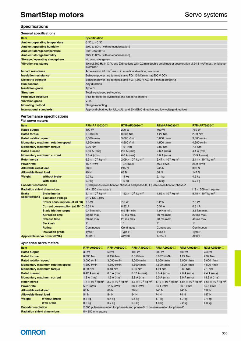
SmartStep motors Servo systems
355
Specifications
General specifications
Performance specificationsFlat servo motors
Cylindrical servo motors
Item Specification
Ambient operating temperature 0 °C to 40 °C
Ambient operating humidity 20% to 80% (with no condensation)
Ambient storage temperature -20 °C to 60 °C
Ambient storage humidity 20% to 80% (with no condensation)
Storage / operating atmosphere No corrosive gases.
Vibration resistance 10 to 2,500 Hz in X, Y, and Z directions with 0.2 mm double amplitude or acceleration of 24.5 m/s2 max., whichever is smaller
Impact resistance Acceleration 98 m/s2 max., in a vertical direction, two times
Insulation resistance Between power line terminals and FG: 10 MΩ min. (at 500 V DC)
Dielectric strength Between power line terminals and FG: 1,500 V AC for 1 min at 50/60 Hz
Run position Any direction
Insulation grade Type B
Structure Totally-enclosed self-cooling
Protective structure IP55 for both the cylindrical and flat servo motors
Vibration grade V-15
Mounting method Flange-mounting
International standards Approval obtained for UL, cUL, and EN (EMC directive and low-voltage directive)
Item R7M-AP10030-@ R7M-AP20030-@ R7M-AP40030-@ R7M-AP75030-@Rated output 100 W 200 W 400 W 750 W
Rated torque 0.318 Nm 0.637 Nm 1.27 Nm 2.39 Nm
Rated rotation speed 3,000 r/min 3,000 r/min 3,000 r/min 3,000 r/min
Momentary maximum rotation speed 4,500 r/min 4,500 r/min 4,500 r/min 4,500 r/min
Momentary maximum torque 0.96 Nm 1.91 Nm 3.82 Nm 7.1 Nm
Rated current 0.89 A (rms) 2.0 A (rms) 2.6 A (rms) 4.1 A (rms)
Momentary maximum current 2.8 A (rms) 6.0 A (rms) 8.0 A (rms) 13.9 A (rms)
Rotor inertia 6.5 × 10⁻⁶ kg·m2 2.09 × 10⁻⁵ kg·m2 3.47 × 10⁻⁵ kg·m2 2.11 × 10⁻⁴ kg·m2
Power rate 15.7 kW/s 19.4 kW/s 46.8 kW/s 26.9 kW/s
Allowable radial load 78 N 245 N 245 N 392 N
Allowable thrust load 49 N 68 N 68 N 147 N
Weight Without brake 0.7 kg 1.4 kg 2.1 kg 4.2 kg
With brake 0.9 kg 1.9 kg 2.6 kg 5.7 kg
Encoder resolution 2,000 pulses/revolution for phase-A and phase-B, 1 pulse/revolution for phase-Z
Radiation shield dimensions t6 × 250 mm square t12 × 300 mm square
Brake specifications
Brake inertia 3.1 × 10⁻⁶ kg·m2 1.52 × 10⁻⁵ kg·m2 1.52 × 10⁻⁵ kg·m2 8.75 × 10⁻⁵ kg·m2
Excitation voltage 24 V DC ±10%
Power consumption (at 20 °C) 7.5 W 7.6 W 8.2 W 7.5 W
Current consumption (at 20 °C) 0.31 A 0.32 A 0.34 A 0.31 A
Static friction torque 0.4 Nm min. 0.9 Nm min. 1.9 Nm min. 3.5 Nm min.
Attraction time 60 ms max. 40 ms max. 60 ms max. 20 ms max.
Release time 20 ms max. 20 ms max. 20 ms max. 40 ms max.
Backlash 1° 1° 1° 1°
Rating Continuous Continuous Continuous Continuous
Insulation grade Type F Type F Type F Type F
Applicable servo driver (R7D-) AP01H AP02H AP04H AP08H
Item R7M-A03030-@ R7M-A05030-@ R7M-A10030-@ R7M-A20030-@ R7M-A40030-@ R7M-A75030-@Rated output 30 W 50 W 100 W 200 W 400 W 750 W
Rated torque 0.095 Nm 0.159 Nm 0.318 Nm 0.637 NmNm 1.27 Nm 2.39 Nm
Rated rotation speed 3,000 r/min 3,000 r/min 3,000 r/min 3,000 r/min 3,000 r/min 3,000 r/min
Momentary maximum rotation speed 4,500 r/min 4,500 r/min 4,500 r/min 4,500 r/min 4,500 r/min 4,500 r/min
Momentary maximum torque 0.29 Nm 0.48 Nm 0.96 Nm 1.91 Nm 3.82 Nm 7.1 Nm
Rated current 0.42 A (rms) 0.6 A (rms) 0.87 A (rms) 2.0 A (rms) 2.6 A (rms) 4.4 A (rms)
Momentary maximum current 1.3 A (rms) 1.9 A (rms) 2.8 A (rms) 6.0 A (rms) 8.0 A (rms) 13.9 A (rms)
Rotor inertia 1.7 × 10⁻⁶ kg·m2 2.2 × 10⁻⁶ kg·m2 3.6 × 10⁻⁶ kg·m2 1.19 × 10⁻⁵ kg·m2 1.87 × 10⁻⁵ kg·m2 6.67 × 10⁻⁵ kg·m2
Power rate 5.31 kW/s 11.5 kW/s 28.1 kW/s 34.1 kW/s 86.3 kW/s 85.6 kW/s
Allowable radial load 68 N 68 N 78 N 245 N 245 N 392 N
Allowable thrust load 54 N 54 N 54 N 74 N 74 N 147 N
Weight Without brake 0.3 kg 0.4 kg 0.5 kg 1.1 kg 1.7 kg 3.4 kg
With brake 0.6 kg 0.7 kg 0.8 kg 1.6 kg 2.2 kg 4.3 kg
Encoder resolution 2,000 pulses/revolution for phase-A and phase-B, 1 pulse/revolution for phase-Z
Radiation shield dimensions t6× 250 mm square

Digital ControllerSmartStep motors
Servo systemsCat.-No. I45E-EN-01356
Dimensions
Cylindrical servo motors (3,000 r/min)200 V AC: 30 W/50 W / 100 W / 200 W / 400 W / 750 WWithout brake: R7M-A03030-S1-D/A05030-S1-D/A10030-S1-D/A20030-S1-D/A40030-S1-D/A75030-S1-DWith brake: R7M-A03030-BS1-D/A05030-BS1-D/A10030-BS1-D/A20030-BS1-D/A40030-BS1-D/A75030-BS1-D
Flat servo motors (3,000 r/min)200 V AC: 100 W / 200 W / 400 W / 750 WWithout brake: R7M-AP10030-S1-D/AP20030-S1-D/AP40030-S1-D/AP75030-S1-DWith brake: R7M-AP10030-BS1-D/AP20030-BS1-D/AP40030-BS1-D/AP75030-BS1-D
Brake specifications
Brake inertia 0.85 × 10⁻⁶ kg·m2 0.85 × 10⁻⁶ kg·m2 0.85 × 10⁻⁶ kg·m2 6.4 × 10⁻⁶ kg·m2 6.4 × 10⁻⁶ kg·m2 1.7 × 10⁻⁵ kg·m2
Excitation voltage 24 V DC ±10% V
Power consumption (at 20 °C) 6 W 6 W 6 W 7 W 7 W 7.7 W
Current consumption(at 20 °C)
0.25 A 0.25 A 0.25 A 0.29 A 0.29 A 0.32 A
Static friction torque 0.2 Nm min. 0.2 Nm min. 0.34 Nm min. 1.47 Nm min. 1.47 Nm min. 2.45 Nm min.
Attraction time 30 ms max. 30 ms max. 30 ms max. 60 ms max. 60 ms max. 60 ms max.
Release time 60 ms max. 60 ms max. 60 ms max. 20 ms max. 20 ms max. 20 ms max.
Backlash 1° 1° 1° 1° 1° 1°
Rating Continuous Continuous Continuous Continuous Continuous Continuous
Insulation grade Type F Type F Type F Type F Type F Type F
Applicable servo driver (R7D-) APA3H APA5H AP01H AP02H AP04H AP08H
Model Dimensions (mm)
LL LR Flange surface Axis end
Without brake With brake C D1 D2 F G Z S QK b h t1
R7M-A03030@ 69.5 101 25 40 46 30h7 2.5 5 Two, 4.3 dia. 6h6 14 2 2 1.2
R7M-A05030@ 77 108.5
R7M-A10030@ 94.5 135 8h6 3 3 1.8
R7M-A20030@ 96.5 136 30 60 70 50h7 3 6 Four, 5.5 dia. 14h6 20 5 5 3
R7M-A40030@ 124.5 164
R7M-A75030@ 145 189.5 40 80 90 70h7 3 8 Four, 7 dia. 16h6 30
Item R7M-A03030-@ R7M-A05030-@ R7M-A10030-@ R7M-A20030-@ R7M-A40030-@ R7M-A75030-@
Model Dimensions (mm)
LL LR Flange surface Axis end
Without brake With brake C D1 D2 F G Z S QK b h t1
R7M-AP10030@ 62 91 25 60 70 50h7 3 6 5.5 8h6 14 3 3 1.8
R7M-AP20030@ 67 98.5 30 80 90 70h7 3 8 7 14h6 16 5 5 3
R7M-AP40030@ 87 118.5
R7M-AP75030@ 86.5 120 40 120 145 110h7 3.5 10 10 16h6 22
D2 dia.S dia.
300
300
QK*
LL LR
G F
C
D1 dia.
C
D2 dia.S dia.
QK*
LL LR
G F
300
300
b
t1
h
Axis end dimensions
Hole with “Z” mark
R7M-A@@@30-S1-D (without brake) R7M-A@@@30-BS1-D (with brake)
b
t1
h
C
C
D1 dia.
D2 dia.S dia.
LL LR
G F
QK*
300
300
LL LR
G F
D2 dia.S dia.
QK*
300
300
R7M-AP@@@30-S1-D (without brake) R7M-AP@@@30-BS1-D (with brake) Axis end dimensions
Four, Z-dia. mounting holes
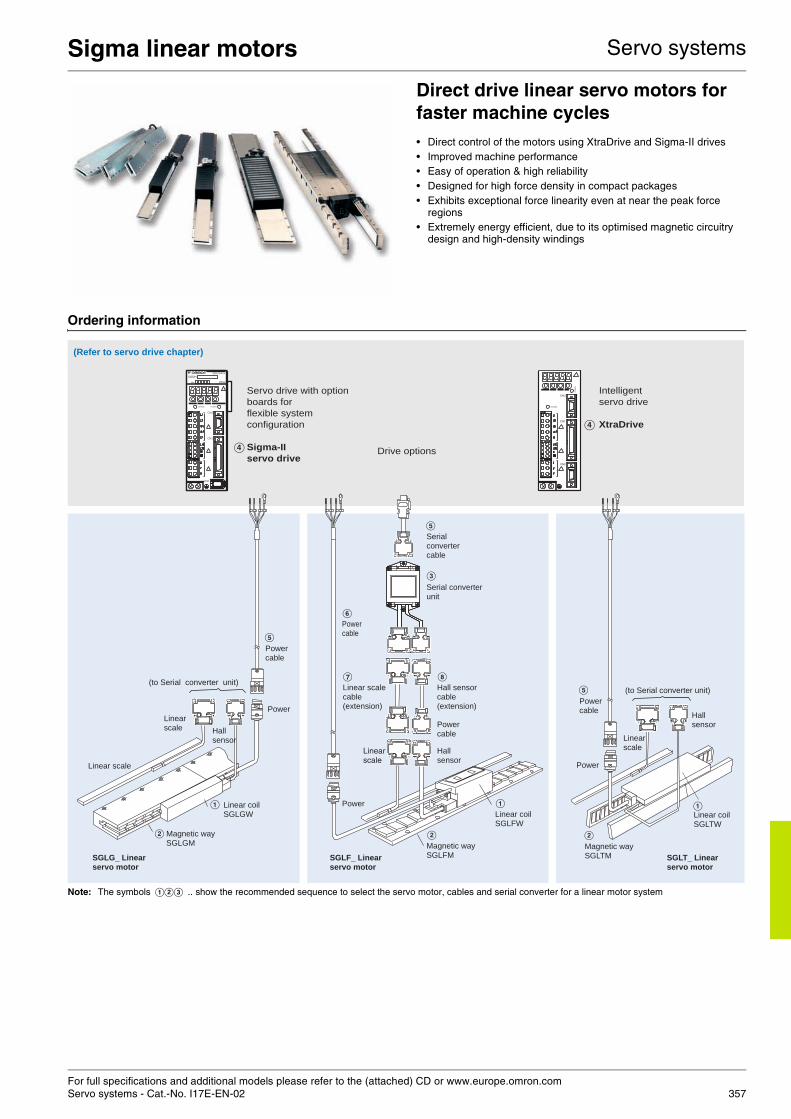
For full specifications and additional models please refer to the (attached) CD or www.europe.omron.comServo systems - Cat.-No. I17E-EN-02 357
Sigma linear motors Servo systems
Direct drive linear servo motors for faster machine cycles• Direct control of the motors using XtraDrive and Sigma-II drives• Improved machine performance• Easy of operation & high reliability• Designed for high force density in compact packages • Exhibits exceptional force linearity even at near the peak force
regions• Extremely energy efficient, due to its optimised magnetic circuitry
design and high-density windings
Ordering information
Note: The symbols ABC .. show the recommended sequence to select the servo motor, cables and serial converter for a linear motor system
CHARGE POWER
SERVOPACK
SGDH-
200VVer.
CN3
CN1
CN2
CHARGE
PO
WE
R
CN3
CN1
CN2
A
B
E
A
B
E
C
G H
A
B
E
F
D
D
Intelligent
servo drive
XtraDrive
Servo drive with option
boards for
flexible system
configuration
Sigma-II
servo drive
(Refer to servo drive chapter)
Linear coilSGLTW
Magnetic waySGLTM
Linear scale
Hall sensor
Power cable
(to Serial converter unit)
Power
SGLT_ Linear servo motor
Linear scale
Linear coilSGLGW
SGLG_ Linear servo motor
Magnetic waySGLGM
Hall sensor
Linear scale
Power cable
(to Serial converter unit)
Power
Power cable
Serial converter unit
Linear coilSGLFW
Magnetic waySGLFMSGLF_ Linear
servo motor
Linear scale
Hall sensor cable(extension)
Linear scale cable(extension)
Hall sensor
Power
Serialconvertercable
Power cable
Drive options
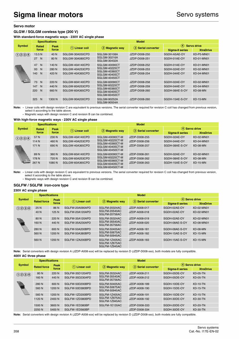
Sigma linear motors Servo systems
Servo systemsCat.-No. I17E-EN-02358
Servo motor
GLGW / SGLGM coreless type (200 V)With standard-force magnetic ways - 230V AC single phase
Note: - Linear coils with design revision C are equivalent to previous versions. The serial converter required for revision C coil has changed from previous version, select it according to the table above.
- Magnetic ways with design revision C and revision B can be combined.
With high-force magnetic ways - 230V AC single phase
Note: - Linear coils with design revision C are equivalent to previous versions. The serial converter required for revision C coil has changed from previous version, select it according to the table above.
- Magnetic ways with design revision C and revision B can be combined.
SGLFW / SGLFM iron-core type230V AC single phase
Note: Serial converters with design revision A (JZDP-A008-xxx) will be replaced by revision D (JZDP-D008-xxx), both models are fully compatible.
400V AC three phase
Note: Serial converters with design revision A (JZDP-A008-xxx) will be replaced by revision D (JZDP-D008-xxx), both models are fully compatible.
Symbol
Specifications Model
Rated force
Peak force A Linear coil B Magnetic way C Serial converter
D Servo drive
Sigma-II series XtraDrive
ABCD 13.5 N 40 N SGLGW-30A050CPD SGLGM-30108ASGLGM-30216ASGLGM-30432A
JZDP-D008-250 SGDH-A5AE-OY XD-P5-MN01
27 N 80 N SGLGW-30A080CPD JZDP-D008-251 SGDH-01AE-OY XD-01-MN01
47 N 140 N SGLGW-40A140CPD SGLGM-40090CTSGLGM-40225CTSGLGM-40360CTSGLGM-40405CTSGLGM-40450CT
JZDP-D008-252 SGDH-01AE-OY XD-01-MN01
93 N 280 N SGLGW-40A253CPD JZDP-D008-253 SGDH-02AE-OY XD-02-MN01
140 N 420 N SGLGW-40A365CPD JZDP-D008-254 SGDH-04AE-OY XD-04-MN01
73 N 220 N SGLGW-60A140CPD SGLGM-60090CTSGLGM-60225CTSGLGM-60360CTSGLGM-60405CTSGLGM-60450CT
JZDP-D008-258 SGDH-02AE-OY XD-02-MN01
147 N 440 N SGLGW-60A253CPD JZDP-D008-259 SGDH-04AE-OY XD-04-MN01
220 N 660 N SGLGW-60A365CPD JZDP-D008-260 SGDH-08AE-S-OY XD-08-MN
325 N 1300 N SGLGW-90A200CPD SGLGM-90252ASGLGM-90504A
JZDP-D008-260 SGDH-15AE-S-OY XD-15-MN
Symbol
Specifications Model
Rated force
Peak force A Linear coil B Magnetic way C Serial converter
D Servo drive
Sigma-II series XtraDrive
ABCD 57 N 230 N SGLGW-40A140CPD SGLGM-40090CT-MSGLGM-40225CT-MSGLGM-40360CT-MSGLGM-40405CT-MSGLGM-40450CT-M
JZDP-D008-255 SGDH-02AE-OY XD-02-MN01
114 N 460 N SGLGW-40A253CPD JZDP-D008-256 SGDH-04AE-OY XD-04-MN01
171 N 690 N SGLGW-40A365CPD JZDP-D008-257 SGDH-08AE-S-OY XD-08-MN
89 N 360 N SGLGW-60A140CPD SGLGM-60090CT-MSGLGM-60225CT-MSGLGM-60360CT-MSGLGM-60405CT-MSGLGM-60450CT-M
JZDP-D008-261 SGDH-02AE-OY XD-02-MN01
178 N 720 N SGLGW-60A253CPD JZDP-D008-262 SGDH-08AE-S-OY XD-08-MN
267 N 1080 N SGLGW-60A365CPD JZDP-D008-263 SGDH-15AE-S-OY XD-15-MN
Symbol
Specifications Model
Rated force Peak force A Linear coil B Magnetic way C Serial converter
D Servo drive
Sigma-II series XtraDrive
ABCD 25 N 86 N SGLFW-20A090APD SGLFM-20324ACSGLFM-20540ACSGLFM-20756AC
JZDP-A008-017 SGDH-02AE-OY XD-02-MN01
40 N 125 N SGLFW-20A120APD JZDP-A008-018 SGDH-02AE-OY XD-02-MN01
80 N 220 N SGLFW-35A120APD SGLFM-35324ACSGLFM-35540ACSGLFM-35756AC
JZDP-A008-019 SGDH-02AE-OY XD-02-MN01
160 N 440 N SGLFW-35A230APD JZDP-A008-020 SGDH-08AE-S-OY XD-08-MN01
280 N 600 N SGLFW-50A200BPD SGLFM-50405ACSGLFM-50675ACSGLFM-50945AC
JZDP-A008-181 SGDH-08AE-S-OY XD-08-MN
560 N 1200 N SGLFW-50A380BPD JZDP-A008-182 SGDH-15AE-S-OY XD-15-MN
560 N 1200 N SGLFW-1ZA200BPD SGLFM-1Z405ACSGLFM-1Z675ACSGLFM-1Z945AC
JZDP-A008-183 SGDH-15AE-S-OY XD-15-MN
Symbol
Specifications Model
Rated force Peak force A Linear coil B Magnetic way C Serial converter
D Servo drive
Sigma-II series XtraDrive
ABCD 80 N 220 N SGLFW-35D120APD SGLFM-35324ACSGLFM-35540ACSGLFM-35756AC
JZDP-A008-211 SGDH-05DE-OY XD-05-TN
160 N 440 N SGLFW-35D230APD JZDP-A008-212 SGDH-05DE-OY XD-05-TN
280 N 600 N SGLFW-50D200BPD SGLFM-50405ACSGLFM-50675ACSGLFM-50945AC
JZDP-A008-189 SGDH-10DE-OY XD-10-TN
560 N 1200 N SGLFW-50D380BPD JZDP-A008-190 SGDH-15DE-OY XD-15-TN
560 N 1200 N SGLFW-1ZD200BPD SGLFM-1Z405ACSGLFM-1Z675ACSGLFM-1Z945AC
JZDP-A008-191 SGDH-15DE-OY XD-15-TN
1120 N 2400 N SGLFW-1ZD380BPD JZDP-A008-192 SGDH-30DE-OY XD-30-TN
1500 N 3600 N SGLFW-1ED380BP SGLFM-1E135AC JZDP-D008-333 SGDH-20DE-OY XD-20-TN
2250 N 5400 N SGLFW-1ED560BP JZDP-D008-334 SGDH-30DE-OY XD-30-TN

Sigma linear motors Servo systems
359
SGLTW / SGLTM iron-core type400V AC three phase
Note: Serial converters with design revision A (JZDP-A008-xxx) will be replaced by revision D (JZDP-D008-xxx), both models are fully compatible.
Servo driveNote: Choosing Sigma-II drive or XtraDrive affects to the serial converter cable needed.
D Refer to Sigma-II servo drive or XtraDrive chapter for detailed drive specifications and selection of drive accessories.
Serial converter cable to servo drive
Power cables
Symbol
Specifications Model
Rated force Peak force A Linear coil B Magnetic way C Serial converter
D Servo drive
Sigma-II series XtraDrive
ABCD 300 N 600 N SGLTW-35D170HPD SGLTM-35324HCSGLTM-35540HCSGLTM-35756HC
JZDP-A008-193 SGDH-10DE-OY XD-10-TN
600 N 1200 N SGLTW-35D320HPD JZDP-A008-194 SGDH-20DE-OY XD-20-TN
450 N 900 N SGLTW-50D170HPD SGLTM-50324HCSGLTM-50540HCSGLTM-50756HC
JZDP-A008-195 SGDH-10DE-OY XD-10-TN
900 N 1800 N SGLTW-50D320HPD JZDP-A008-196 SGDH-20DE-OY XD-20-TN
670 N 2600 N SGLTW-40D400BP SGLTM-40405ACSGLTM-40675ACSGLTM-40945AC
JZDP-A008-197 SGDH-30DE-OY XD-30-TN
1000 N 4000 N SGLTW-40D600BP JZDP-A008-198 SGDH-50DE-OY XD-50-TN
1300 N 5000 N SGLTW-80D400BP SGLTM-80405ACSGLTM-80675ACSGLTM-80945AC
JZDP-A008-199 SGDH-50DE-OY XD-50-TN
2000 N 7500 N SGLTW-80D600BP JZDP-A008-200 SGDH-75DE-OY -
Symbol Specifications Model Appearance
E Sigma-II drive to serial converter cable
3 m JZSP-CLP70-03-E
5 m JZSP-CLP70-05-E
10 m JZSP-CLP70-10-E
15 m JZSP-CLP70-15-E
20 m JZSP-CLP70-20-E
XtraDrive drive to serial converter cable
3 m XD-CLP70-03-E
5 m XD-CLP70-05-E
10 m XD-CLP70-10-E
15 m XD-CLP70-15-E
20 m XD-CLP70-20-E
Symbol Specifications Model Appearance
F For 200 V servo motors SGLGW-30A@@@@@DSGLGW-40A@@@@@DSGLGW-60A@@@@@DSGLFW-20A@@@A@DSGLFW-35A@@@A@D
3 m R88A-CAWA003S-DE
5 m R88A-CAWA005S-DE
10 m R88A-CAWA010S-DE
15 m R88A-CAWA015S-DE
20 m R88A-CAWA020S-DE
For 200 V servo motors SGLGW-90A200@@DSGLFW-50A@@@B@DSGLFW-1ZA200B@D
3 m R88A-CAWB003S-DE
5 m R88A-CAWB005S-DE
10 m R88A-CAWB010S-DE
15 m R88A-CAWB015S-DE
20 m R88A-CAWB020S-DE
For 400 V servo motors SGLFW-35D@@@A@DSGLFW-50D200@DSGLTW-35D170H@DSGLTW-50D170H@D
3 m R88A-CAWK003S-DE
5 m R88A-CAWK005S-DE
10 m R88A-CAWK010S-DE
15 m R88A-CAWK015S-DE
20 m R88A-CAWK020S-DE
For 400 V servo motorsSGLFW-50D380@DSGLFW-1ZD@@@B@DSGLTW-35D320H@DSGLTW-50D320H@D
3 m R88A-CAWL003S-DE
5 m R88A-CAWL005S-DE
10 m R88A-CAWL010S-DE
15 m R88A-CAWL015S-DE
20 m R88A-CAWL020S-DE
For 400 V servo motorsSGLFW-1ED@@@B@SGLTW-40D@@@B@SGLTW-80D@@@B@
3 m R88A-CAWD003S-E
5 m R88A-CAWD005S-E
10 m R88A-CAWD010S-E
15 m R88A-CAWD015S-E
20 m R88A-CAWD020S-E

Sigma linear motors Servo systems
Servo systemsCat.-No. I17E-EN-02360
Linear scale cable to serial converter
Hall sensor cable to serial converter
Connectors
Dimensioning software
Servo motor specifications
Coreless SGLGW/SGLGM - (with standard-force magnetic ways)
Note: - The items marked with an * and “force and speed characteristics” are the values at a motor winding temperature of 100 ° C during operation in combination with a servo drive. The others are at 20 ° C (68 ° F).
- The above specifications show the values under the cooling condition when a heat sink (aluminium board) listed in the following table is mounted on the coil assembly.
Symbol Specifications Model Appearance
G Extension cable for Renishaw linear scale to serial converter. (connector DB-15) (the extension cable is optional)
1 m JZSP-CLL00-01-E
3 m JZSP-CLL00-03-E
5 m JZSP-CLL00-05-E
10 m JZSP-CLL00-10-E
15 m JZSP-CLL00-15-E
Extension cable for Heidenhain linear scale to serial converter(connector DB-15 ) (when a Heidenhain scale is used the ex-tension cable is required)
1 m JZSP-CLL20-01-E
3 m JZSP-CLL20-03-E
5 m JZSP-CLL20-05-E
10 m JZSP-CLL20-10-E
15 m JZSP-CLL20-15-E
Symbol Specifications Model Appearance
H Extension cable for linear scale to serial converter(the extension cable is optional)
1 m JZSP-CLL10-01-E
3 m JZSP-CLL10-03-E
5 m JZSP-CLL10-05-E
10 m JZSP-CLL10-10-E
15 m JZSP-CLL10-15-E
Specification Model
Hypertac power connector IP67 (for 200V motor coils SGL@W-@@A@@@@@D) SPOC-06K-FSDN169
Hypertac power connector IP67 (for 400V motor coils SGL@W-@@D@@@@@D) LPRA-06B-FRBN170
Military power connector IP67 (for motor coils SGLTW-40@/80@ and SGLFW-1ED@) MS3108E22-22S
Specifications Model
SigmaSize MOTION TOOLS CD
Voltage 230 V
Linear servo motor model SGLGW- 30A 40A 60A 90A
050C 080C 140C 253C 365C 140C 253C 365C 200C
Rated force∗ N 12.5 25 47 93 140 70 140 210 325
Rated current∗ A(rms) 0,51 0,79 0.8 1.6 2.4 1,16 2,2 3,3 4.4
Instantaneous peak force∗ N 40 80 140 280 420 220 440 660 1300
Instantaneous peak current∗ A(rms) 1.62 2.53 2.4 4.9 7.3 3.5 7.0 10.5 17.6
Coil assembly mass kg 0.10 0.15 0.34 0.60 0.87 0.42 0.76 1.10 2.15
Force constant N / A(rms) 26.4 33.9 61.5 61.5 61.5 66.6 66.6 66.6 78
BEMF constant V / (m / s) 8.8 11.3 20.5 20.5 20.5 22.2 22.2 22.2 26.0
Motor constant 3.7 5.6 7.8 11.0 13.5 11.1 15.7 19.2 26.0
Electrical time constant ms 0.2 0.4 0.4 0.4 0.4 0.5 0.5 0.5 1.4
Mechanical time constant ms 7.30 4.78 5.59 4.96 4.77 3.41 3.08 2.98 3.18
Thermal resistance (with heat sink) K / W 5,19 3,11 1,67 0,87 0,58 1,56 0,77 0,51 0,39
Thermal resistance (without heat sink) K / W - - 3,02 1,80 1,23 2,59 1,48 1,15 -
Magnetic attraction N 0 0 0 0 0 0 0 0 0
Head sink size mm 200x300x12 300x400x12 400x500x12 200x300x12 300x400x12 400x500x12 800x900x12
Bas
ic s
peci
ficat
ions
Time rating Continuous
Insulation class Class B
Ambient temperature 0 to +40 °C
Ambient humidity 20 to 80% (non-condensing)
Insulation resistance 500 VDC, 10 MΩ min.
Excitation Permanent magnet
Dielectric strength 1500 VAC for 1 minute
Protection methods Self-cooled, air-cooling
Allowable winding temperature 130 °C
N / w

Sigma linear motors Servo systems
361
Coreless SGLGW/SGLGM - (with high-force magnetic ways)
Note: - The item servo drive. The others are at 20 ° C (68 ° F).- The above specifications show the values under the cooling condition when a heat sink (aluminium board) listed in the following table is mounted on the coil
assembly.
Iron-core SGLFW/SGLFM (200V)
Note: - The items marked with an * and “Force and speed characteristics” are the values at a motor winding temperature of 100 ° C during operation in combination with a servo drive. The others are at 20 ° C (68 ° F).
- The above specifications show the values under the cooling condition when a heat sink (aluminium board) listed in the following table is mounted on the coil assembly.
Voltage 230 V
Linear servo motor model SGLGW- 40A 60A
140C 253C 365C 140C 253C 365C
Rated force∗ N 57 114 171 85 170 255
Rated current∗ A(rms) 0.8 1.6 2.4 1.2 2.2 3.3
Instantaneous peak force∗ N 230 460 690 360 720 1080
Instantaneous peak current∗ A(rms) 3.2 6.5 9.7 5.0 10.0 14.9
Coil assembly mass kg 0.34 0.60 0.87 0.42 0.76 1.10
Force constant N / A(rms) 76.0 76.0 76.0 77.4 77.4 77.4
BEMF constant V / (m / s) 25.3 25.3 25.3 25.8 25.8 25.8
Motor constant 9.6 13.6 16.7 12.9 18.2 22.3
Electrical time constant ms 0.4 0.4 0.4 0.5 0.5 0.5
Mechanical time constant ms 3.69 3.24 3.12 2.52 2.29 2.21
Thermal resistance (with heat sink) K / W 1.67 0.87 0.58 1.56 0.77 0.51
Thermal resistance (without heat sink) K / W 3.02 1.80 1.23 2.59 1.48 1.15
Magnetic attraction N 0 0 0 0 0 0
Head sink size mm 200x300x12 300x400x12 400x500x12 200x300x12 300x400x12 400x500x12
Bas
ic s
peci
ficat
ions
Time rating Continuous
Insulation class Class B
Ambient temperature 0 to +40 °C
Ambienthumidity 20 to 80% (non-condensing)
Insulation resistance 500 VDC, 10 MΩ min.
Excitation Permanent magnet
Dielectric strength 1500 VAC for 1 minute
Protection methods Self-cooled, air-cooling
Allowable winding temperature 130 °C
Voltage 230 V
Linear servo motor model SGLFW- 20A 35A 50A 1ZA
090A 120A 120A 230A 200B 380B 200B
Rated force∗ N 25 40 80 160 280 560 560
Rated current∗ A(rms) 0.7 0.8 1.4 2.8 5.0 10.0 8.7
Instantaneous peak force∗ N 86 125 220 440 600 1200 1200
Instantaneous peak current∗ A(rms) 3.0 2.9 4.4 8.8 12.4 25.0 21.6
Coil assembly mass kg 0.7 0.9 1.3 2.3 3.5 6.9 6.4
Force constant N / A(rms) 36.0 54.0 62.4 62.4 60.2 60.2 69.0
BEMF constant V / (m / s) 12.0 18.0 20.8 20.8 20.1 20.1 23.0
Motor constant 7.9 9.8 14.4 20.4 34.3 48.5 52.4
Electrical time constant ms 3.2 3.3 3.6 3.6 15.9 15.8 18.3
Mechanical time constant ms 11.0 9.3 6.2 5.5 3.0 2.9 2.3
Thermal resistance (with heat sink) K / W 4.35 3.19 1.57 0.96 0.82 0.32 0.6
Thermal resistance (without heat sink) K / W 7.69 5.02 4.10 1.94 1.48 0.74 0.92
Magnetic attraction N 314 462 809 1586 1650 3260 3300
Head sink size mm 125x125x13 254x254x25 400x500x40 254x254x25
Bas
ic s
peci
ficat
ions
Time rating Continuous
Insulation class Class B
Ambient temperature 0 to +40 °C
Ambient humidity 20 to 80% (non-condensing)
Insulation resistance 500 VDC, 10 MΩ min.
Excitation Permanent magnet
Dielectric strength 1500 VAC for 1 minute
Protection methods Self-cooled
Allowable winding temperature 130 °C
N / w
N / w

Sigma linear motors Servo systems
Servo systemsCat.-No. I17E-EN-02362
Iron-core SGLFW/SGLFM (400V)
Note: - The items marked with an * and “force and speed characteristics” are the values at a motor winding temperature of 100 ° C during operation in combination with a servo drive. The others are at 20 ° C (68 ° F).
- The above specifications show the values under the cooling condition when a heat sink (aluminium board) listed in the following table is mounted on the coil assembly.
Iron-core SGLTW/SGLTM (400 V)
*1. The unbalanced magnetic gap resulting from the coil assembly installation condition causes a magnetic attraction of the coil assembly. *2. The value indicates the magnetic attraction generated on one side of the magnetic way.
Note: - The items marked with an * and “force and speed characteristics” are the values at a motor winding temperature of 100 °C during operation in combination with a servo drive. The others are at 20 °C (68 °F).
- The above specifications show the values under the cooling condition when a heat sink (aluminium board) listed in the following table is mounted on the coil assembly.
Voltage 400 V
Linear servo motor model SGLFW- 35D 50D 1ZD 1ED
120A 230A 200B 380B 200B 380B 380B 560B
Rated force∗ N 80 160 280 560 560 1,120 1,500 2,250
Rated current∗ A(rms) 0.7 1.4 2.3 4.5 4.9 9.8 6.4 9.6
Instantaneous peak force∗ N 220 440 600 1,200 1,200 2,400 3,600 5,400
Instantaneous peak current∗ A(rms) 2.3 4.6 5.6 11.0 12.3 24.6 18.1 27.2
Coil assembly mass kg 1.3 2.3 3.5 6.9 6.4 11.5 22.0 33.0
Force constant N / A(rms) 120.2 120.2 134.7 134.7 122.6 122.6 250 250
BEMF constant V / (m / s) 40.1 40.1 44.9 44.9 40.9 40.9 83.2 83.2
Motor constant 13.8 19.5 33.4 47.2 51.0 72.1 95.4 117
Electrical time constant ms 3.5 3.5 15.0 15.0 17.4 17.2 19.7 19.6
Mechanical time constant ms 5.5 5.5 3.2 3.2 2.5 2.2 1.8 1.8
Thermal resistance (with heat sink) K / W 1.57 0.96 0.82 0.32 0.6 0.28 0.21 0.13
Thermal resistance (without heat sink) K / W 4.1 1.94 1.48 0.74 0.92 0.55 0.50 0.35
Magnetic attraction N 810 1,590 1,650 3,260 3,300 6,520 9,780 14,600
Head sink size mm 254x254x25 400x500x40 254x254x25 400x500x40 609x762x50 762x1270x64
Bas
ic s
peci
ficat
ions
Time rating Continuous
Insulation class Class B
Ambient temperature 0 to +40 °C
Ambient humidity 20 to 80% (non-condensing)
Insulation resistance 500 VDC, 10 MΩ min.
Excitation Permanent magnet
Dielectric strength 1500 VAC for 1 minute
Protection methods Self-cooled
Allowable winding temperature 130 °C
Voltage 400 V
Linear servo motor model SGLTW- 35D 50D 40D 80D
170H 320H 170H 320H 400B 600B 400B 600B
Rated force∗ N 300 600 450 900 670 1,000 1,300 2,000
Rated current∗ A(rms) 3.2 6.5 3.2 6.3 3.7 5.5 7.2 11.1
Instantaneous peak force∗ N 600 1,200 900 1,800 2,600 4,000 5,000 7,500
Instantaneous peak current∗ A(rms) 7.5 15.1 7.3 14.6 20.7 30.6 37.6 56.4
Coil assembly mass kg 4.7 8.8 6 11 15 23 25 36
Force constant N / A(rms) 99.6 99.6 153.3 153.3 196.1 196.1 194.4 194.4
BEMF constant V / (m / s) 33.2 33.2 51.1 51.1 65.4 65.4 64.8 64.8
Motor constant 36.3 51.4 48.9 69.1 59.6 73 85.9 105.2
Electrical time constant ms 14.3 14.3 15.6 15.6 14.4 14.4 15.4 15.4
Mechanical time constant ms 3.5 3.5 2.5 2.5 4.2 4.2 3.2 3.2
Thermal resistance (with heat sink) K / W 0.76 0.4 0.61 0.3 0.24 0.2 0.22 0.18
Thermal resistance (without heat sink) K / W 1.26 0.83 0.97 0.8 0.57 0.4 0.47 0.33
Magnetic attraction∗1 N 0 0 0 0 0 0 0 0
Magnetic attraction∗2 N 1,400 2,780 2,000 3,980 3,950 5,890 7,650 11,400
Head sink size mm 400x500x40 609x762x50
Bas
ic s
peci
ficat
ions
Time rating Continuous
Insulation class Class B
Ambient temperature 0 to +40 °C
Ambient humidity 20 to 80% (non-condensing)
Insulation resistance 500 VDC, 10 MW min.
Excitation Permanent magnet
Dielectric strength 1500 VAC for 1 minute
Protection methods Self-cooled
Allowable winding temperature 130 °C
N / w
N / w

Sigma linear motors Servo systems
363
Dimensions
Coreless SGLG@-@Coil assembly: SGLGW-@
Magnetic way: SGLGM-@
Coil assembly model SGLGW-
L1 L2 L3 L4 D1 D2 W Approx. weight kg
30A050 D 50 48 30 15 48.5 57 22 0.14
30A080 D 80 72 50 15 48.5 57 22 0.19
40A140 D 140 125 90 30 63 78 25.4 0.40
40A253 D 252.5 237.5 180 37.5 63 78 25.4 0.66
40A365 D 365 350 315 30 63 78 25.4 0.93
60A140 D 140 125 90 30 83 98 25.4 0.48
60A253 D 252.5 237.5 180 37.5 83 98 25.4 0.82
60A365 D 365 350 315 30 83 98 25.4 1.16
90A200 D 199 189 130 40 121 138 49 2.2
Magnetic way model SGLGM-
L1 D Standard-force magnetic way High-force magnetic way
W Approx. weight kg W Approx. weight kg
30108A 108 44 24 0.6 - -
30216A 216 44 24 1.1 - -
30432A 432 44 24 2.3 - -
40090C 90 62 25.4 0.8 31.8 1.0
40225C 225 62 25.4 2.0 31.8 2.6
40360C 360 62 25.4 3.1 31.8 4.1
40405C 405 62 25.4 3.5 31.8 4.6
40450C 450 62 25.4 3.9 31.8 5.1
60090C 90 82 25.4 1.1 31.8 1.3
60225C 225 82 25.4 2.6 31.8 3.3
60360C 360 82 25.4 4.1 31.8 5.2
60405C 405 82 25.4 4.6 31.8 5.9
60450C 450 82 25.4 5.1 31.8 6.6
90252A 252 110 50.8 7.3 - -
90504A 504 110 50.8 14.7 - -
W
D1
500
50
L4L1L3
L2
500
50
D2
N Ins.AW
Units: mm
The coil assembly moves in the direction indicated by the arrow in the order of phase U, V, and W.
WARNING away.
May cause injury.Keep magnetic materials
YASKAWA ELECTRIC CORPORATION JAPAN
W A
Ins.
CORELESS LINEAR SERVO MOTOR
N
D
WL1 (1 unit)0.10.3
Units: mm

Sigma linear motors Servo systems
Servo systemsCat.-No. I17E-EN-02364
Iron-core SGLF@-@Coil assembly: SGLFW-@
Magnetic way: SGLFM-@
Coil assembly model SGLFW-
L1 D1 D2 W Approx. weight kg
20A090A 91 34 45 40 0.7
20A120A 127 34 45 40 0.9
35 120A D 127 34 45 55 1.3
35 230A D 235 34 45 55 2.3
50 200B D 215 43 58 71.5 3.5
50 380B D 395 43 58 71.5 6.9
1Z 200B D 215 43 58 119 6.4
1ZD380B D 395 43 58 119 11.5
1ED380B 395 61 76 175 22
1ED560B 605 61 76 175 33
Magnetic way model SGLFM-
L1 -0.1 -0.3
(L3) D W Approx. weight kg
20324A 324 (331.6) 10 44 0.9
20540A 540 (547.6) 10 44 1.4
20756A 756 (763.6) 10 44 2
35324A 324 (334.4) 10 60 1.2
35540A 540 (550.4) 10 60 2
35756A 756 (766.4) 10 60 2.9
50405A 405 (416.3) 14 75 2.8
50675A 675 (686.3) 14 75 4.6
50945A 945 (956.3) 14 75 6.5
1Z405A 405 (423.9) 14 125 7.3
1Z675A 675 (693.9) 14 125 12
1Z945A 945 (963.9) 14 125 17
1E135A 135 (145.5) 14.2 200 2.4
L1Magnetic way
The coil assembly moves in the direction indicated by the arrow when current flows in the order of phase U, V, and W.
WD
2Magnetic way D1
Coil assembly
S SSNS NNN
TYPE:YASKAWA
TYPE:YASKAWA
D
W
L1
L3
-0.3-0.1
S/NO/N
MADE IN JAPAN DATE
Units: mm

Sigma linear motors Servo systems
365
Iron-core SGLT@-@Coil assembly: SGLTW-@
Magnetic way: SGLTM-@ Note: - Two magnetic ways for both ends of coil assembly make one set. Spacers are mounted on magnetic ways for safety during transporta-tion. Do not remove the spacers until the coil assembly is mounted on a machine.
- The magnetic way may affect pacemakers. Keep a minimum distance of 200 mm from the magnetic way.
- Two magnetic ways in a set can be connected to each other.- The dimensions marked with an * are the dimensions between the
magnetic ways. Be sure to follow exactly the dimensions specified in the figure above. Mount magnetic ways as shown in assembly dimen-sions. The values with an * are the dimensions at preshipment.
- Use socket headed screws of strength class 10.9 minimum for mag-netic way mounting screws. Do not use stainless steel screws
Coil assembly model SGLTW-
L1 D W Approx. weight kg
35D320H D 315 66 120 8.8
50D170H D 170 81 120 6
50D320H D 315 81 120 11
40D400B 395 78 150 15
40D600B 585 78 150 23
80D400B 395 115 150 25
80D600B 585 115 150 36
TY
PE
YASKAWA ELECTRIC
MADE IN JAPAN
WAV
O/N
S/N
DA
TE ins.
Linear SERVO M
OTO
R
m/s
N W
L1
D
Hall sensor
Magnetic way
The coil assembly moves in the directionindicated by the arrow when current flowsin the order of phase U, V, and W.
Units: mm
Magnetic way model SGLTM-
L1 -0.1 -0.3
D W1 W2 W3 Approx. weight kg
35324H 324 55 15 90 107 4.8
35540H 540 55 15 90 107 8
35756H 756 55 15 90 107 11
50324H 324 70 19.1 90 112 8
50540H 540 70 19.1 90 112 13
50756H 756 70 19.1 90 112 18
40405A 405 63 19.1 111.8 131 9
40675A 675 63 19.1 111.8 131 15
40945A 945 63 19.1 111.8 131 21
80405A 405 100 19.1 111.8 131 14
80675A 675 100 19.1 111.8 131 24
80945A 945 100 19.1 111.8 131 34
W1
W1
O/N
S/N
MADE IN JAPANDATE
YASKAWATYPE:
YASKAWATYPE:
O/N
S/N
MADE IN JAPAN DATE
L1 -0.1-0.3
D
W3
Coil assembly Spacer: Do not remove them until the coil assemby is mounted on the machine.
W2

366

367
Table of contentsSelection table 368
Standard inverter G7 370
F7 375
L7 380
E7 384
V7 388
J7 392
Inverter PLCs G7/F7/L7/E7 Inverter PLC 394
V7 Inverter PLC 396
Inverter application software Case 398

368
Selection table
Model G7 F7 L7
Type World´s first three level inverter architecture
The industrial workhorse Made to drive lifts
400 V Three-phase200 V Three-phase200 V Single-phase
0.4 kW to 300 kW0.4 kW to 110 kWN/A
0.4 kW to 300 kW0.4 kW to 110 kWN/A
4.0 kW to 55 kW3.7 kW to 55 kWN/A
Application High performance, long cable lines General and high-end applications Lift control with asynchronous or synchronous motors
Control method Open and close loop for vector and V/F control.
Open and close loop for vector and V/F control.
Open and close loop for vector and V/F control.
Torque features 150% at 0.0 Hz (CLV)150% at 0.3 Hz (OLV)
150% at zero speed (CLV)150% at 0.5 Hz (OLV)
150% at zero speed (CLV)150% at 0.5 Hz (OLV)
Connectivity MemobusDeviceNetPROFIBUS-DPCANopenLONWorksEthernet
MemobusDeviceNetPROFIBUS-DPCANopenLONWorksEthernetMECHATROLINK-II
MemobusDeviceNetPROFIBUS-DPCANopenLONWorksEthernet
Customisation options - PLC option board- Inverter application software
- PLC option board- Inverter application software
- PLC option board- Inverter application software
Page 370 375 380
Model E7 V7 J7
Type Drive your energy cost down Sensorless flux vector in a pocket sized inverter
Small, simple and smart
400V Three-Phase200V Three-Phase200V Single-Phase
0.4 kW to 300 kW0.4 kW to 110 kWN/A
0.2 kW to 7.5 kW0.1 kW to 7.5 kW0.1 kW to 4.0 kW
0.2 kW to 4.0 kW0.1 kW to 4.0 kW0.1 kW to 1.5 kW
Application Pumps and fans (variable torque) Compact general purpose Simple speed control
Control method V/F control Sensorless vector and V/F control V/F control
Torque features 120% at 0.5 Hz. 100% at 0.5 Hz. 150% at 3 Hz.
Connectivity MemobusMetasys N2L&S Apogee LONWorksDeviceNetPROFIBUS-DPCANopen
MemobusDeviceNetPROFIBUS-DPCANopenMECHATROLINK-II
Memobus
Customisation options - PLC option board- Inverter application software- IP54 enclosure
- PLC option board- Inverter application software- IP65 enclosure
N/A
Page 384 388 392
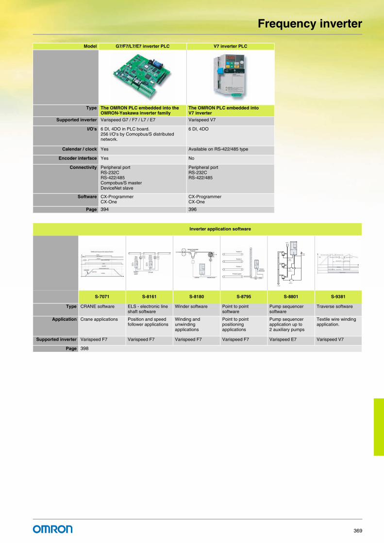
Frequency inverter
369
Model G7/F7/L7/E7 inverter PLC V7 inverter PLC
Type The OMRON PLC embedded into the OMRON-Yaskawa inverter family
The OMRON PLC embedded into V7 inverter
Supported inverter Varispeed G7 / F7 / L7 / E7 Varispeed V7
I/O's 6 DI, 4DO in PLC board.256 I/O's by Comopbus/S distributed network.
6 DI, 4DO
Calendar / clock Yes Available on RS-422/485 type
Encoder interface Yes No
Connectivity Peripheral portRS-232CRS-422/485Compobus/S masterDeviceNet slave
Peripheral portRS-232CRS-422/485
Software CX-ProgrammerCX-One
CX-ProgrammerCX-One
Page 394 396
Inverter application software
S-7071 S-8161 S-8180 S-8795 S-8801 S-9381
Type CRANE software ELS - electronic line shaft software
Winder software Point to point software
Pump sequencer software
Traverse software
Application Crane applications Position and speed follower applications
Winding and unwinding applications
Point to point positioning applications
Pump sequencer application up to 2 auxiliary pumps
Textile wire winding application.
Supported inverter Varispeed F7 Varispeed F7 Varispeed F7 Varispeed F7 Varispeed E7 Varispeed V7
Page 398
Power
Supply
Main
Pump
Aux.
Pump 1
Aux.
Pump 2
Water
Water

For full specifications and additional models please refer to the (attached) CD or www.europe.omron.comInverters - Cat.-No. I37E-EN-02370
G7 Inverters
World´s first three level inverterThe G7 has the world's first 400V 3-level inverter architecture that eliminates or minimises the installation problems associated with IGBT switching and protects the entire motor-drive system.
• 3-level control reduces voltage peaks on motor windings by up to 50%. There is no need for an AC reactor on long motor cables.
• Flux-vector control. Excellent performance in open-loop mode with 150% torque at 0.3Hz
• Silent operation. No current de-rating in silent mode • Wide selection of option cards • Programming software: CX-Drive for parameter configuration.
DriveWorkEZ for object-orientated programming.
Ordering information
C22
R52C24PE
C16
U11
U8
R6C26
C28
JP3
U6
U7
T1
U9++
R15
R15R25
R15R20R30
R7
R5C5
R21
U14
C17R14
R28
RR11
JP1
C1
U10
C3
R5R1 R2
R36R3C2
1
R35
R70
R120
R75
R78
R114C2
2+
+
U1+
C35
R99U12
R95
R39
R40
R57
R56
D6
R6
U15
R54
R55
R8
TR2
11 R11
R110
R107
R113
TR1
C13
U13
C10
SI-N
CODE No.
U17
73600-C0210
JP5 JP6
RT4
R10R10 R10
5
R102 C12
C11
R94R97
R96
C20
R95
C39
R131
Y1
U10
C33
R
S
T
ED C B
A
F
GGGGG
H
Communication
option cards
Monitor option card
3G3IV-PCN329-E
Inverter to PC cable
3G3IV-PCN126/326
Digital operator
extension cable
JVOP-161-OY
Digital operator
(LED display)
JVOP-160 OY
Digital operator
(LCD display)
CX-Drive
DriveWorkEZ
Line filter Braking accessories
Feedback speed
control card
PLC option card
Power supply Varispeed
G7
Reference
option cards

G7 Inverters
371
Varispeed G7200 V 400 V
A Line filters200 V 400 V
B Monitor option cards
Specifications Model
IP20 0.4 kW 3.2 A CIMR-G7C20P41
0.75 kW 6.0 A CIMR-G7C20P71
1.5 kW 8.0 A CIMR-G7C21P51
2.2 kW 12 A CIMR-G7C22P21
3.7 kW 18 A CIMR-G7C23P71
5.5 kW 27 A CIMR-G7C25P51
7.5 kW 34 A CIMR-G7C27P51
11 kW 49 A CIMR-G7C20111
15 kW 66 A CIMR-G7C20151
18.5 kW 80 A CIMR-G7C20181
IP00 22 kW 96 A CIMR-G7C20220
30 kW 130 A CIMR-G7C20300
37 kW 160 A CIMR-G7C20370
45 kW 183 A CIMR-G7C20450
55 kW 224 A CIMR-G7C20550
75 kW 300 A CIMR-G7C20750
90 kW 358 A CIMR-G7C20900
110 kW 415 A CIMR-G7C21100
Specifications Model
IP20 0.4 kW 1.8 A CIMR-G7C40P41
0.75 kW 3.4 A CIMR-G7C40P71
1.5 kW 4.8 A CIMR-G7C41P51
2.2 kW 6.2 A CIMR-G7C42P21
3.7 kW 9 A CIMR-G7C43P71
5.5 kW 15 A CIMR-G7C45P51
7.5 kW 21 A CIMR-G7C47P51
11 kW 27 A CIMR-G7C40111
15 kW 34 A CIMR-G7C40151
18.5 kW 42 A CIMR-G7C40181
IP00 22 kW 52 A CIMR-G7C40220
30 kW 65 A CIMR-G7C40300
37 kW 80 A CIMR-G7C40370
45 kW 97 A CIMR-G7C40450
55 kW 128 A CIMR-G7C40550
75 kW 165 A CIMR-G7C40750
90 kW 195 A CIMR-G7C40900
110 kW 240 A CIMR-G7C41100
132 kW 270 A CIMR-G7C41320
160 kW 235 A CIMR-G7C41600
185 kW 370 A CIMR-G7C41850
220 kW 450 A CIMR-G7C42200
300 kW 605 A CIMR-G7C43000
Inverter model Line filters
Varispeed G7 Type EN55011 class
Current(A)
Weight(kg)
CIMR-G7C20P4 3G3RV-PFI3010-SE B, 25 mA, 100 m
10 1.1
CIMR-G7C20P7
CIMR-G7C21P5
CIMR-G7C22P2 3G3RV-PFI3018-SE B, 25 mA, 100 m
18 1.3
CIMR-G7C23P7 3G3RV-PFI2035-SE B, 25 mA, 100 m
35 1.4
CIMR-G7C25P5
CIMR-G7C27P5 3G3RV-PFI2060-SE B, 25 mA, 100 m
60 3
CIMR-G7C2011
CIMR-G7C2015 3G3RV-PFI2100-SE B, 25 mA, 100 m
100 4.9
CIMR-G7C2018
CIMR-G7C2022 3G3RV-PFI2130-SE A, 100 m 130 4.3
CIMR-G7C2030
CIMR-G7C2037 3G3RV-PFI2160-SE A, 100 m 160 6.0
CIMR-G7C2045 3G3RV-PFI2200-SE A, 100 m 200 11.0
CIMR-G7C2055
CIMR-G7C2075 3G3RV-PFI3400-SE A, 100 m 400 18.5
CIMR-G7C2090
CIMR-G7C2110 3G3RV-PFI3600-SE A, 100 m 600 11.0
Inverter model Line filters
Varispeed G7 Model EN 55011 class
Current(A)
Weight(kg)
CIMR-G7C40P4 3G3RV-PFI3010-SE B, 25 mA, 100 m
10 1.1
CIMR-G7C40P7
CIMR-G7C41P5
CIMR-G7C42P2
CIMR-G7C43P7 3G3RV-PFI3018-SE B, 25 mA, 100 m
18 1.3
CIMR-G7C44P0
CIMR-G7C45P5
CIMR-G7C47P5 3G3RV-PFI3035-SE B, 25 mA, 100 m
35 2.1
CIMR-G7C4011
CIMR-G7C4015 3G3RV-PFI3060-SE B, 25 mA, 100 m
60 4.0
CIMR-G7C4018
CIMR-G7C4022 3G3RV-PFI3070-SE A, 100 m 70 3.4
CIMR-G7C4030
CIMR-G7C4037 3G3RV-PFI3130-SE A, 100 m 130 4.7
CIMR-G7C4045
CIMR-G7C4055
CIMR-G7C4075 3G3RV-PFI3170-SE A, 100 m 170 6.0
CIMR-G7C4090 3G3RV-PFI3200-SE A, 100 m 250 11
CIMR-G7C4110
CIMR-G7C4132 3G3RV-PFI3400-SE A, 100 m 400 18.5
CIMR-G7C4160
CIMR-G7C4185 3G3RV-PFI3600-SE A, 100 m 600 11,0
CIMR-G7C4220
CIMR-G7C4300 3G3RV-PFI3800-SE A, 100 m 800 31.0
Type Model Description Function
Mon
itor
optio
n ca
rd
AO-08 / 3G3IV-PAO08 Analog monitor card Outputs analog signal for monitoring inverter output state (output freq., output current etc.) after absolute value conversion.Output resolution: 8 bits (1/256)Output voltage: 0 to 10 V (non isolated) Output channel: 2 channels
AO-12 / 3G3IV-PAO12 Outputs analog signal for monitoring inverter output state (output freq., output current etc.)Output resolution: 11 bits (1/2048) + codeOutput voltage: 0 to 10 V (non isolated) Output channel: 2 channels
DO-08 / 3G3IV-PDO08 Digital output card Outputs isolated type digital signal for monitoring inverter run state (alarm signal, zero speed detection etc.).Output channel: Photo coupler 6 channels (48 V, 50 mA or less)Relay contact output 2 channels (250 VAC, 1 A or less 30 VDC, 1 A or less)
DO-02C / 3G3IV-PDO02C 2C-relay output card Two multi-function contact outputs (2C-relay) can be used other than those of the inverter proper unit.

G7 Inverters
372
C Feedback speed control cards
D Communication option cards
E Reference option Cards
F PLC option boards
G Accessories
G Software
H Braking Unit, braking resistor unitNote: For braking units specifications and models refer to the G7 datasheet Cat-No: I37E-EN-02
Type Model Description Function
Fee
dbac
k sp
eed
cont
rol c
ard
PG-A2 / 3G3FV-PPGA2 PG speed controller card (used for V/f control with PG or flux vector)
Phase A pulse (single pulse) inputs (voltage, complementary, open collector input)PG frequency range: approx. 30 kHz max. [Power supply output for PG: +12 V, max. current 200 mA]Pulse monitor output: +12 V, 20 mA
PG-B2 / 3G3FV-PPGB2 Phase A and B pulse inputs (exclusively for complementary input)PG frequency range: approx. 30 kHz max. [Power supply output for PG: +12 V, Max. current 200 mA]Pulse monitor output: Open collector, +24 V, Max. current 30 mA
PG-D2 / 3G3FV-PPGD2 Phase A pulse (differential pulse) input for V/f control (RS-422 input)PG frequency range: approx. 300 kHz max. [Power supply output for PG: +5 V or +12 V, Max. current 200 mA]Pulse monitor output: RS-422
PG-X2 / 3G3FV-PPGX2 Phase A, B and Z pulse (differential pulse) inputs (RS-422 input)PG frequency range: approx. 300 kHz max. [Power supply output for PG: +5 V or +12 V, Max. current 200 mA]Pulse monitor output: RS-422
Type Model Description Function
Com
mun
icat
ion
optio
n ca
rd
SI-N1 DeviceNet option card Used for running or stopping the inverter, setting or referencing parameters, and monitoring output frequency, output current, or similar items through DeviceNet communication with the host controller.
SI-P1 PROFIBUS-DP option card Used for running or stopping the inverter, setting or referencing parameters, and monitoring output frequency, output current, or similar items through PROFIBUS-DP communication with the host controller.
SI-S1 CANopen option card Used for running or stopping the inverter, setting or referencing parameters, and monitoring output frequency, output current, or similar items through CANopen communication with the host controller.
SI-J LONWORKS option card Used for HVAC control, running or stopping the inverter, setting or referencing parameters, and monitoring output current, watt-hours, or similar items through LONWORKS communications with peripheral devices.
CM090 Ethernet option card Modbus TCP/IP Ethernet interface unit
SI-T MECHATROLINK-II option board
High speed motion bus.Used for running or stopping the inverter, setting or referencing parameters, and monitoring output frequency, output current, or similar items through MECHATROLINK-II communication with the host controller.Host controller : Trajexia, MCH or MP Series *1
*1 Please refer to Trajexia, MCH or MP Series section for host controllers detailed information.
Type Model Description Function
Ref
eren
ce o
ptio
n ca
rd
AI-14U / 3G3IV-PAI14U Analog input card 2 channel high resolution analog input cardChannel 1: 0 to 10 V (20KΩ)Channel 2: 4 to 20 mA (250Ω)Resolution 14 bit
AI-14B / 3G3IV-PAI14B 3 Channel high resolution analog input cardSignal level: -10 to +10V (20 KΩ)4 to 20 mA (250 Ω)Resolution: 13 bit + sign
DI-08 / 3G3IV-PDI08 Digital reference card 8 bit digital speed reference input card
DI-16H2 / 3G3IV-PDI16H2 16 bit digital speed reference input card
Type Model Description Function
PLC
opt
ion 3G3RV-P10ST8-E PLC option Full PLC features, wireless installation and seamless access to the inverter parameters and
analogue / digital inputs and outputs. Embedded Compubus/S fieldbusStandard OMRON tools can be used for programming
3G3RV-P10ST8-DRT-E PLC option with DeviceNet Same features than standard models with DeviceNet support.
Type Model Description Function
Digital operator
JVOP-160-OY 5 lines LCD digital operator7 language support
Configuration and monitoring device.
JVOP-161-OY 7 segment LED digital operator
Accesories 3G3IV-PCN1263G3IV-PCN326
Digital operator extension cable1 meter3 meters
Cable to connect the inverter and the digital operator when it's not plugged into the inverter.
3G3IV-PCN329-E PC configuration cable Cable to connect inverter and PC
Model Description Function
CX-DRIVE Computer software Configuration and monitoring software tool for drives. (Version 1.1 or higher)
CX-ONE Computer software Complete automation software including CX-Drive

G7 Inverters
373
Specifications
200 V
400 V
Model CIMR-G7C 20P4 20P7 21P5 22P2 23P7 25P5 27P5 2011 2015 2018 2022 2030 2037 2045 2055 2075 2090 2110
Max. applicable motor output *1
*1 Standard 4-pole motors are used for max. applicable motor output. Choose the inverter model whose rated current is allowable within the motor rated current range.
kW 0.4 0.75 1.5 2.2 3.7 5.5 7.5 11 15 18.5 22 30 37 45 55 75 90 110
Ou
tpu
t ch
arac
teri
stic
s Inverter capacity kVA 1.2 2.3 3.0 4.6 6.9 10 13 19 25 30 37 50 61 70 85 110 140 160
Rated current A 3.2 6 8 12 18 27 34 49 66 80 96 130 160 183 224 300 358 415
Max. voltage 3-phase, 200/208/220/230/240 V (proportional to input voltage)
Max. output frequency 400 Hz (programmable)
Po
wer
su
pp
ly
Rated input voltage and frequency
3-phase 200/208/220/230/240 V, 50/60 Hz*2
*2 When using the inverter of 200 V class 30 kW or more with a cooling fan of three-phase 230 V 50 Hz or 240 V 50/60 Hz power supply, a transformer for the coolingfan is required.
Allowable voltage fluctuation
+10%, -15%
Allowable frequency fluctuation
±5%
Harmonic wave prevention
DC reactor Option Provided
12-Pulse input Not available Available *3
*3 A 3-wired transformer is required at 12-pulse input.
Model CIMR-G7C 40P4 40P7 41P5 42P2 43P7 45P5 47P5 4011 4015 4018 4022 4030 4037 4045 4055 4075 4090 4110 4132 4160 4185 4220 4300Max. applicable motor output *1
*1 Standard 4-pole motors are used for max. applicable motor output. Choose the inverter model whose rated current is allowable within the motor rated current range.
kW 0.4 0.75 1.5 2.2 3.7 5.5 7.5 11 15 18.5 22 30 37 45 55 75 90 110 132 160 185 220 300
Ou
tpu
t ch
arac
teri
stic
s Inverter capacity kV 1.4 2.6 3.7 4.7 6.9 11 16 21 26 32 40 50 61 74 98 130 150 180 210 250 280 340 460
Rated current A 1.8 3.4 4.8 6.2 9 15 21 27 34 42 52 65 80 97 128 165 195 240 270 325 370 450 605
Max. voltage 3-phase, 380/400/415/440/460/480 V (proportional to input voltage)
Max. output frequency
400 Hz (programmable)
Po
wer
su
pp
ly
Rated input voltage and frequency
3-phase 380/400/415/440/460/480 V, 50/60 Hz
Allowable voltage fluctuation
+10%, -15%
Allowable frequency fluctuation
±5%
Harmonic wave prevention
DC reactor Option Provided
12-Pulse input Not available Available *2
*2 A 3-wired transformer is required at 12-pulse input.

G7 Inverters
374
Dimensions
Specifications Drive model H W D3 phase 200 VAC 0.4 kW CIMR-G7C20P41 140 280 157
0.75 kW CIMR-G7C20P711.5 kW CIMR-G7C21P512.2 kW CIMR-G7C22P21 1773.7 kW CIMR-G7C23P715.5 kW CIMR-G7C25P51 200 300 1977.5 kW CIMR-G7C27P51
11 kW CIMR-G7C20111 240 350 20715 kW CIMR-G7C2015118.5 kW CIMR-G7C20181 250 400 25822 kW CIMR-G7C20220 275 450 25830 kW CIMR-G7C20300 375 600 29837 kW CIMR-G7C20370 32845 kW CIMR-G7C20450 450 725 34855 kW CIMR-G7C2055075 kW CIMR-G7C20750 500 850 35890 kW CIMR-G7C20900 575 885 378
110 kW CIMR-G7C211003 phase 400 VAC 0.4 kW CIMR-G7C40P41 140 280 157
0.75 kW CIMR-G7C40P711.5 kW CIMR-G7C41P51 1772.2 kW CIMR-G7C42P213.7 kW CIMR-G7C43P715.5 kW CIMR-G7C45P51 200 300 1977.5 kW CIMR-G7C47P51
11 kW CIMR-G7C40111 240 350 20715 kW CIMR-G7C4015118.5 kW CIMR-G7C40181 275 450 25822 kW CIMR-G7C4022030 kW CIMR-G7C40300 325 550 28337 kW CIMR-G7C4037045 kW CIMR-G7C4045055 kW CIMR-G7C40550 450 725 34875 kW CIMR-G7C4075090 kW CIMR-G7C40900 500 850 358
110 kW CIMR-G7C41100132 kW CIMR-G7C41320 575 916 378160 kW CIMR-G7C41600185 kW CIMR-G7C41850 710 1305 415220 kW CIMR-G7C42200300 kW CIMR-G7C43000 916 1475
H
WD

For full specifications and additional models please refer to the (attached) CD or www.europe.omron.comInverters - Cat.-No. I23E-EN-02 375
F7 Inverters
The industrial workhorse The F7 drive is the industrial workhorse of adjustable frequency drives. It is intended to handle every conventional drive application found in a typical industrial manufacturing plant from simple variable torque pumping to sophisticated networked material handling
• Flux vector control. Excellent performance in open-loop mode with 150% torque at 0.5 Hz
• Silent operation. No current de-rating in silent mode• Wide selection of option cards • Programming software: CX-Drive for parameter configuration • CASE (inverter application software) and PLC option board
Ordering information
C22
R52C24PE
C16
U11
U8
R6C26
C28
JP3
U6
U7
T1
U9++
R15
R15R25
R15R20R30
R7
R5C5
R21
U14
C17R14
R28
RR11
JP1
C1
U10
C3
R5R1 R2
R36R3C2
1
R35
R70
R120
R75
R78
R114C2
2+
+
U1+
C35
R99U12
R95
R39
R40
R57
R56
D6
R6
U15
R54
R55
R8
TR2
11 R11
R110
R107
R113
TR1
C13
U13
C10
SI-N
CODE No.
U17
73600-C0210
JP5 JP6
RT4
R10R10 R10
5
R102 C12
C11
R94R97
R96
C20
R95
C39
R131
Y1
U10
C33
R
S
T
F
E
G
D C B
A
F F F F
Communication option cards Reference option card
3G3IV-PCN329-EInverter to PC cable
3G3IV-PCN126/326Digital operatorextension cable
JVOP-161-OYDigital operator(LED display)
JVOP-160 OYDigital operator(LCD display)
CX-Drive
Line filter Braking accessories
Feedback speed option card PLC option card
Power supply VarispeedF7
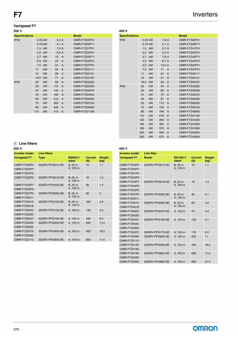
F7 Inverters
376
Varispeed F7200 V 400 V
A Line filters200 V 400 V
Specifications Model
IP20 0.55 kW 3.2 A CIMR-F7Z20P41
0.75 kW 4.1 A CIMR-F7Z20P71
1.5 kW 7.0 A CIMR-F7Z21P51
2.2 kW 9.6 A CIMR-F7Z22P21
3.7 kW 15 A CIMR-F7Z23P71
5.5 kW 23 A CIMR-F7Z25P51
7.5 kW 31 A CIMR-F7Z27P51
11 kW 45 A CIMR-F7Z20111
15 kW 58 A CIMR-F7Z20151
18.5 kW 71 A CIMR-F7Z20181
IP00 22 kW 85 A CIMR-F7Z20220
30 kW 115 A CIMR-F7Z20300
37 kW 145 A CIMR-F7Z20370
45 kW 180 A CIMR-F7Z20450
55 kW 215 A CIMR-F7Z20550
75 kW 283 A CIMR-F7Z20750
90 kW 346 A CIMR-F7Z20900
110 kW 415 A CIMR-F7Z21100
Specifications Model
IP20 0.55 kW 1.8 A CIMR-F7Z40P41
0.75 kW 2.1 A CIMR-F7Z40P71
1.5 kW 3.7 A CIMR-F7Z41P51
2.2 kW 5.3 A CIMR-F7Z42P21
3.7 kW 7.6 A CIMR-F7Z43P71
4.0 kW 8.7 A CIMR-F7Z44P01
5.5 kW 12.5 A CIMR-F7Z45P51
7.5 kW 17 A CIMR-F7Z47P51
11 kW 24 A CIMR-F7Z40111
15 kW 31 A CIMR-F7Z40151
18.5 kW 39 A CIMR-F7Z40181
IP00 22 kW 45 A CIMR-F7Z40220
30 kW 60 A CIMR-F7Z40300
37 kW 75 A CIMR-F7Z40370
45 kW 91 A CIMR-F7Z40450
55 kW 112 A CIMR-F7Z40550
75 kW 150 A CIMR-F7Z40750
90 kW 180 A CIMR-F7Z40900
110 kW 216 A CIMR-F7Z41100
132 kW 260 A CIMR-F7Z41320
160 kW 304 A CIMR-F7Z41600
185 kW 370 A CIMR-F7Z41850
220 kW 506 A CIMR-F7Z42200
300 kW 675 A CIMR-F7Z43000
Inverter model Line filters
Varispeed F7 Type EN55011 class
Current(A)
Weight(kg)
CIMR-F7Z20P4 3G3RV-PFI3010-SE B, 25 mA, 100 m
10 1.1
CIMR-F7Z20P7
CIMR-F7Z21P5
CIMR-F7Z22P2 3G3RV-PFI3018-SE B, 25 mA, 100 m
18 1.3
CIMR-F7Z23P7 3G3RV-PFI2035-SE B, 25 mA, 100 m
35 1.4
CIMR-F7Z25P5
CIMR-F7Z27P5 3G3RV-PFI2060-SE B, 25 mA, 100 m
60 3
CIMR-F7Z2011
CIMR-F7Z2015 3G3RV-PFI2100-SE B, 25 mA, 100 m
100 4.9
CIMR-F7Z2018
CIMR-F7Z2022 3G3RV-PFI2130-SE A, 100 m 130 4.3
CIMR-F7Z2030
CIMR-F7Z2037 3G3RV-PFI2160-SE A, 100 m 160 6.0
CIMR-F7Z2045 3G3RV-PFI2200-SE A, 100 m 200 11.0
CIMR-F7Z2055
CIMR-F7Z2075 3G3RV-PFI3400-SE A, 100 m 400 18.5
CIMR-F7Z2090
CIMR-F7Z2110 3G3RV-PFI3600-SE A, 100 m 600 11.0
Inverter model Line filter
Varispeed F7 Model EN 55011 class*
Current(A)
Weight(kg)
CIMR-F7Z40P4 3G3RV-PFI3010-SE B, 25 mA, 100 m
10 1.1
CIMR-F7Z40P7
CIMR-F7Z41P5
CIMR-F7Z42P2
CIMR-F7Z43P7 3G3RV-PFI3018-SE B, 25 mA, 100 m
18 1.3
CIMR-F7Z44P0
CIMR-F7Z45P5
CIMR-F7Z47P5 3G3RV-PFI3035-SE B, 25 mA, 100 m
35 2.1
CIMR-F7Z4011
CIMR-F7Z4015 3G3RV-PFI3060-SE B, 25 mA, 100 m
60 4.0
CIMR-F7Z4018
CIMR-F7Z4022 3G3RV-PFI3070-SE A, 100 m 70 3.4
CIMR-F7Z4030
CIMR-F7Z4037 3G3RV-PFI3130-SE A, 100 m 130 4.7
CIMR-F7Z4045
CIMR-F7Z4055
CIMR-F7Z4075 3G3RV-PFI3170-SE A, 100 m 170 6.0
CIMR-F7Z4090 3G3RV-PFI3200-SE A, 100 m 250 11
CIMR-F7Z4110
CIMR-F7Z4132 3G3RV-PFI3400-SE A, 100 m 400 18.5
CIMR-F7Z4160
CIMR-F7Z4185 3G3RV-PFI3600-SE A, 100 m 600 11,0
CIMR-F7Z4220
CIMR-F7Z4300 3G3RV-PFI3800-SE A, 100 m 800 31.0

F7 Inverters
377
B Feedback speed control cards
C Communication option cards
D Reference option cards
E PLC option cards
F Accessories
Type Model Description Function
Fee
dbac
k sp
eed
cont
rol c
ard
PG-A2 / 3G3FV-PPGA2 PG speed controller card(Used for V/f control with PG or flux vector)
Phase A pulse (single pulse) inputs (voltage, complementary, open collector input)PG frequency range: approx. 30 kHz max. [Power supply output for PG: +12 V, max. current 200 mA]Pulse monitor output: +12 V, 20 mA
PG-B2 / 3G3FV-PPGB2 Phase A and B pulse inputs (exclusively for complementary input)PG frequency range: approx. 30 kHz max. [Power supply output for PG: +12 V, Max. current 200 mA]Pulse monitor output: Open collector, +24 V, Max. current 30 mA
PG-D2 / 3G3FV-PPGD2 Phase A pulse (differential pulse) input for V/f control (RS-422 input)PG frequency range: approx. 300 kHz max. [Power supply output for PG: +5 V or +12 V, Max. current 200 mA]Pulse monitor output: RS-422
PG-X2 / 3G3FV-PPGX2 Phase A, B and Z pulse (differential pulse) inputs (RS-422 input)PG frequency range: approx. 300 kHz max. [Power supply output for PG: +5 V or +12 V, Max. current 200 mA]Pulse monitor output: RS-422
PG-Z2 Phase A, B and Z pulse (differential pulse) inputs (RS-422 input)PG frequency range: approx. 300 kHz max. [Power supply output for PG: +5 V or +12 V, Max. current 200 mA]Pulse monitor output: RS-422Dual channel encoder: 1st channel A, B, Z / 2nd channel A, B, Z or open collector
Type Model Description Function
Com
mun
icat
ion
optio
n ca
rd
3G3RV-PDRT2 DeviceNet option card Used for running or stopping the inverter, setting or referencing parameters, and monitoring output frequency, output current, or similar items through DeviceNet communication with the host controller.
SI-P1 PROFIBUS-DP option card Used for running or stopping the inverter, setting or referencing parameters, and monitoring output frequency, output current, or similar items through PROFIBUS-DP communication with the host controller.
SI-S1 CANopen option card Used for running or stopping the inverter, setting or referencing parameters, and monitoring output frequency, output current, or similar items through CANopen communication with the host controller.
SI-J LONWORKS option card Used for HVAC control, running or stopping the inverter, setting or referencing parameters, and monitoring output current, watt-hours, or similar items through LONWORKS communications with peripheral devices.
CM090 Ethernet option card MODBUS TCP/IP Ethernet interface unit.
SI-T MECHATROLINK-II option board
High speed motion bus.Used for running or stopping the inverter, setting or referencing parameters, and monitoring output frequency, output current, or similar items through MECHATROLINK-II communication with the host controller.Host controller : Trajexia, MCH or MP Series *1
*1 Please refer to Trajexia, MCH or MP Series section for host controllers detailed information.
Type Model Description Function
Ref
eren
ce o
ptio
n ca
rd
AI-14U / 3G3IV-PAI14U Analog input card 2 channel high resolution analog input cardChannel 1: 0 to 10 V (20KΩ)Channel 2: 4 to 20 mA (250Ω)Resolution 14 bit
AI-14B / 3G3IV-PAI14B 3 Channel high resolution analog input cardSignal level: -10 to +10V (20 KΩ)4 to 20 mA (250 Ω)Resolution: 13 bit + sign
DI-08 / 3G3IV-PDI08 Digital reference card 8 bit digital speed reference input card
DI-16H2 / 3G3IV-PDI16H2 16 bit digital speed reference input card
Type Model Description Function
PLC
opt
ion
card
3G3RV-P10ST8-E PLC option Full PLC featrues, wireless installation and seamless access to the inverter parameters and analogue/digital inputs and outputs.Embedded Compubus/S fieldbusStandard OMRON tools can be used for programming
3G3RV-P10ST8-DRT-E PLC option with DeviceNet Same features than standard model with DeviceNet support.
Type Model Description Function
Dig
ital
oper
ator JVOP-160-OY 5 lines LCD digital operator
7 Language supportConfiguration and monitoring device
JVOP-161-OY 7 segment LED digital operator
Acc
esso
ries
3G3IV-PCN1263G3IV-PCN326
Digital operator extension cable1 meters3 meters
Cable to connect the inverter and the digital operator when it's not plugged into the inverter
3G3IV-PCN329-E PC configuration cable Cable to connect inverter and PC
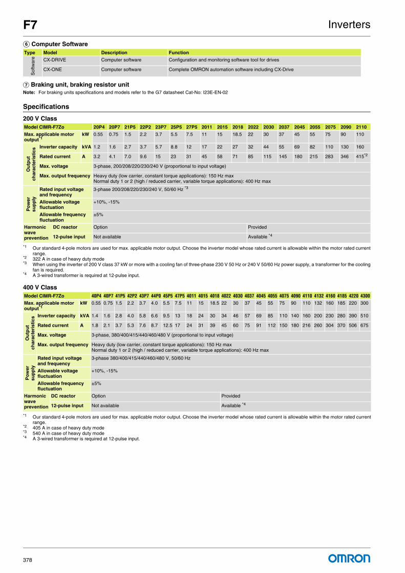
F7 Inverters
378
F Computer Software
G Braking unit, braking resistor unitNote: For braking units specifications and models refer to the G7 datasheet Cat-No: I23E-EN-02
Specifications
200 V Class
400 V Class
Type Model Description Function
Sof
twar
e CX-DRIVE Computer software Configuration and monitoring software tool for drives
CX-ONE Computer software Complete OMRON automation software including CX-Drive
Model CIMR-F7Zo 20P4 20P7 21P5 22P2 23P7 25P5 27P5 2011 2015 2018 2022 2030 2037 2045 2055 2075 2090 2110
Max. applicable motor output*1
*1 Our standard 4-pole motors are used for max. applicable motor output. Choose the inverter model whose rated current is allowable within the motor rated currentrange.
kW 0.55 0.75 1.5 2.2 3.7 5.5 7.5 11 15 18.5 22 30 37 45 55 75 90 110
Ou
tpu
t ch
arac
teri
stic
s Inverter capacity kVA 1.2 1.6 2.7 3.7 5.7 8.8 12 17 22 27 32 44 55 69 82 110 130 160
Rated current A 3.2 4.1 7.0 9.6 15 23 31 45 58 71 85 115 145 180 215 283 346 415*2
*2 322 A in case of heavy duty mode
Max. voltage 3-phase, 200/208/220/230/240 V (proportional to input voltage)
Max. output frequency Heavy duty (low carrier, constant torque applications): 150 Hz maxNormal duty 1 or 2 (high / reduced carrier, variable torque applications): 400 Hz max
Po
wer
su
pp
ly
Rated input voltage and frequency
3-phase 200/208/220/230/240 V, 50/60 Hz *3
*3 When using the inverter of 200 V class 37 kW or more with a cooling fan of three-phase 230 V 50 Hz or 240 V 50/60 Hz power supply, a transformer for the coolingfan is required.
Allowable voltage fluctuation
+10%, -15%
Allowable frequency fluctuation
±5%
Harmonic wave prevention
DC reactor Option Provided
12-pulse input Not available Available *4
*4 A 3-wired transformer is required at 12-pulse input.
Model CIMR-F7Zo 40P4 40P7 41P5 42P2 43P7 44P0 45P5 47P5 4011 4015 4018 4022 4030 4037 4045 4055 4075 4090 4110 4132 4160 4185 4220 4300Max. applicable motor output*1
*1 Our standard 4-pole motors are used for max. applicable motor output. Choose the inverter model whose rated current is allowable within the motor rated currentrange.
kW 0.55 0.75 1.5 2.2 3.7 4.0 5.5 7.5 11 15 18.5 22 30 37 45 55 75 90 110 132 160 185 220 300
Ou
tpu
t ch
arac
teri
stic
s Inverter capacity kVA 1.4 1.6 2.8 4.0 5.8 6.6 9.5 13 18 24 30 34 46 57 69 85 110 140 160 200 230 280 390 510
Rated current A 1.8 2.1 3.7 5.3 7.6 8.7 12.5 17 24 31 39 45 60 75 91 112 150 180 216 260 304 370 506
*2 405 A in case of heavy duty mode
675
*3 540 A in case of heavy duty mode
Max. voltage 3-phase, 380/400/415/440/460/480 V (proportional to input voltage)
Max. output frequency Heavy duty (low carrier, constant torque applications): 150 Hz maxNormal duty 1 or 2 (high / reduced carrier, variable torque applications): 400 Hz max
Po
wer
su
pp
ly
Rated input voltage and frequency
3-phase 380/400/415/440/460/480 V, 50/60 Hz
Allowable voltage fluctuation
+10%, -15%
Allowable frequency fluctuation
±5%
Harmonic wave prevention
DC reactor Option Provided
12-pulse input Not available Available *4
*4 A 3-wired transformer is required at 12-pulse input.

F7 Inverters
379
Dimensions
Specifications Drive model H W D
3 phase 200 VAC 0.55 kW CIMR-F7Z20P41 140 280 157
0.75 kW CIMR-F7Z20P71
1.5 kW CIMR-F7Z21P51
2.2 kW CIMR-F7Z22P21
3.7 kW CIMR-F7Z23P71 177
5.5 kW CIMR-F7Z25P51
7.5 kW CIMR-F7Z27P51 200 300 197
11 kW CIMR-F7Z20111 310
15 kW CIMR-F7Z20151 240 350 207
18.5 kW CIMR-F7Z20181 380
22 kW CIMR-F7Z20220 250 400 258
30 kW CIMR-F7Z20300 275 450
37 kW CIMR-F7Z20370 375 600 298
45 kW CIMR-F7Z20450 328
55 kW CIMR-F7Z20550 450 725 348
75 kW CIMR-F7Z20750
90 kW CIMR-F7Z20900 500 850 358
110 kW CIMR-F7Z21100 575 885 378
3 phase 400 VAC 0.55 kW CIMR-F7Z40P41 140 280 157
0.75 kW CIMR-F7Z40P71
1.5 kW CIMR-F7Z41P51
2.2 kW CIMR-F7Z42P21 177
3.7 kW CIMR-F7Z43P71
4.0 kW CIMR-F7Z44P71
5.5 kW CIMR-F7Z45P51
7.5 kW CIMR-F7Z47P51 200 300 197
11 kW CIMR-F7Z40111
15 kW CIMR-F7Z40151 240 350 207
18.5 kW CIMR-F7Z40181
22 kW CIMR-F7Z40220 275 450 258
30 kW CIMR-F7Z40330
37 kW CIMR-F7Z40370 325 550 283
45 kW CIMR-F7Z40450
55 kW CIMR-F7Z40550
75 kW CIMR-F7Z40750 450 725 348
90 kW CIMR-F7Z40900
110 kW CIMR-F7Z41100 500 850 358
132 kW CIMR-F7Z41320
160 kW CIMR-F7Z41600 575 916 378
185 kW CIMR-F7Z41850 710 1305 413
220 kW CIMR-F7Z42200
300 kW CIMR-F7Z43000 916 1475 413
H
WD

For full specifications and additional models please refer to the (attached) CD or www.europe.omron.comInverters - Cat.-No. I22E-EN-02380
L7 Inverters
Made to drive liftsThe L7 is the ultimate drive for lift applications up to 3 m/s. High starting torque, silent operation, lift-specific operator interface and operation with both AC and PM motors are standard features of the L7 inverter.
• One model to control AC and PM motors• Silent operation with no current de-rating• Safety Cat 3 stop. Cat.0 embedded as standard.• UPS or battery operation for emergency rescue.• Motor auto-tuning at standstill and at RUN• Programming software: CX-Drive for parameter configuration
Ordering information
Varispeed L7200 V 400 V
C22
R52C24PE
C16
U11
U8
R6C26
C28
JP3
U6
U7
T1
U9++
R15
R15R25
R15R20R30
R7
R5C5
R21
U14
C17R14
R28
RR11
JP1
C1
U10
C3
R5R1 R2
R36R3C2
1
R35
R70
R120
R75
R78
R114C2
2+
+
U1+
C35
R99U12
R95
R39
R40
R57
R56
D6
R6
U15
R54
R55
R8
TR2
11 R11
R110
R107
R113
TR1
C13
U13
C10
SI-N
CODE No.
U17
73600-C0210
JP5 JP6
RT4
R10R10 R10
5
R102 C12
C11
R94R97
R96
C20
R95
C39
R131
Y1
U10
C33
R
S
T
ED C B
A
F
GGGGG
H
Communication
option cards
Monitor option card
3G3IV-PCN329-E
Inverter to PC cable
3G3IV-PCN126/326
Digital operator
extension cable
JVOP-161-OY
Digital operator
(LED display)
JVOP-160 OY
Digital operator
(LCD display)
CX-Drive
Line filter Braking accessories
Feedback speed
control card
PLC option card
Varispeed
L7
Reference
option cards
Specifications Model
3 x 200 V 3.7 kW 17.5 A CIMR-L7Z23P7
5.5 kW 25 A CIMR-L7Z25P5
7.5 kW 33 A CIMR-L7Z27P5
11 kW 49 A CIMR-L7Z2011
15 kW 64 A CIMR-L7Z2015
18.5 kW 80 A CIMR-L7Z2018
22 kW 96 A CIMR-L7Z2022
30 kW 130 A CIMR-L7Z2030
37 kW 160 A CIMR-L7Z2037
45 kW 183 A CIMR-L7Z2045
55 kW 224 A CIMR-L7Z2055
Specifications Model
3 x 400 V 4.0 kW 11 A CIMR-L7Z44P0
5.5 kW 14 A CIMR-L7Z45P5
7.5 kW 18 A CIMR-L7Z47P5
11 kW 27 A CIMR-L7Z4011
15 kW 34 A CIMR-L7Z4015
18.5 kW 41 A CIMR-L7Z4018
22 kW 48 A CIMR-L7Z4022
30 kW 65 A CIMR-L7Z4030
37 kW 80 A CIMR-L7Z4037
45 kW 96 A CIMR-L7Z4045
55 kW 128 A CIMR-L7Z4055

L7 Inverters
381
A Line filters200 V 400 V
A Line filters
B Monitor option cards
C Feedback speed control cards
D Communication option cards
Inverter model Line filters
Varispeed L7 Type EN55011 class
Current(A)
Weight(kg)
CIMR-L7Z23P7 3G3RV-PFI2035-SE B, 25 mA 100 m
35 1.4
CIMR-L7Z25P5
CIMR-L7Z27P5 3G3RV-PFI2060-SE B, 25 mA 100 m
60 3
CIMR-L7Z2011
CIMR-L7Z2015 3G3RV-PFI2100-SE B, 25 mA 100 m
100 4.9
CIMR-L7Z2018
CIMR-L7Z2022 3G3RV-PFI2130-SE A, 100 m 130 4.3
CIMR-L7Z2030
CIMR-L7Z2037 3G3RV-PFI2160-SE A, 100 m 160 6.0
CIMR-L7Z2045 3G3RV-PFI2200-SE A, 100 m 200 11.0
CIMR-L7Z2055
Inverter model Line filters
Varispeed L7 Type EN55011 class
Current(A)
Weight(kg)
CIMR-L7Z44P0 3G3RV-PFI3018-SE B, 25 mA 100 m
18 1.3
CIMR-L7Z45P5
CIMR-L7Z47P5 3G3RV-PFI3035-SE B, 25 mA 100 m
35 2.1
CIMR-L7Z4011
CIMR-L7Z4015 3G3RV-PFI3060-SE B, 25 mA 100 m
60 4.0
CIMR-L7Z4018
CIMR-L7Z4022 3G3RV-PFI3070-SE A, 100 m 70 3.4
CIMR-L7Z4030
CIMR-L7Z4037 3G3RV-PFI3130-SE A, 100 m 130 4.7
CIMR-L7Z4045
CIMR-L7Z4055
Inverter model Line filters
Varispeed L7 Type EN55011 class
Current(A)
Weight(kg)
CIMR-L7Z44P0 3G3RV-PFI3018B-SE B, 25 mA 100 m
18 1,0
CIMR-L7Z45P5
CIMR-L7Z47P5 3G3RV-PFI3035B-SE B, 25 mA 100 m
35 1,5
CIMR-L7Z4011
CIMR-L7Z4015 3G3RV-PFI3060B-SE B, 25 mA 100 m
60 2,2
CIMR-L7Z4018
Type Model Description Function
Mon
itor
optio
n ca
rd
DO-08 / 3G3IV-PDO08 Digital output card Outputs isolated type digital signal for monitoring inverter run state (alarm signal, zero speed detection etc.) .Output channel: photo coupler 6 channels (48 V, 50 mA or less)Relay contact output 2 channels (250 VAC, 1 A or less, 30 VDC, 1 A or less)
DO-02C / 3G3IV-PDO02C 2C-relay output card Two multi-function contact outputs (2C-relay) can be used other than those of the inverter proper unit.
Type Model Description Function
Fee
dbac
k sp
eed
cont
rol c
ard
PG-A2 / 3G3FV-PPGA2 PG speed controller card(Used for V/f control with PG or Flux Vector)
Phase A pulse (single pulse) inputs (voltage, complementary, open collector input)PG frequency range: Approx. 30 kHz max. [Power supply output for PG: +12 V, max. current 200 mA]Pulse monitor output: +12 V, 20 mA
PG-B2 / 3G3FV-PPGB2 Phase A and B pulse inputs (exclusively for complementary input)PG frequency range: Approx. 30 kHz max. [Power supply output for PG: +12 V, Max. current 200 mA]Pulse monitor output: Open collector, +24 V, Max. current 30 mA
PG-D2 / 3G3FV-PPGD2 Phase A pulse (differential pulse) input for V/f control (RS-422 input)PG frequency range: Approx. 300 kHz max. [Power supply output for PG: +5 V or +12 V, Max. current 200 mA]Pulse monitor output: RS-422
PG-X2 / 3G3FV-PPGX2 Phase A, B and Z pulse (differential pulse) inputs (RS-422 input)PG frequency range: Approx. 300 kHz max. [Power supply output for PG: +5 V or +12 V, Max. current 200 mA]Pulse monitor output: RS-422
PG-F2 Hiperface and endat encoder option.
Type Model Description Function
Com
mun
icat
ion
optio
n ca
rd
SI-N1 DeviceNet option card Used for running or stopping the inverter, setting or referencing parameters, and monitoring output frequency, output current, or similar items through DeviceNet communication with the host controller.
SI-P1 PROFIBUS-DP option card Used for running or stopping the inverter, setting or referencing parameters,and monitoring output frequency, output current, or similar items through PROFIBUS-DP communication with the host controller.
SI-S1 CANopen option card Used for running or stopping the inverter, setting or referencing parameters, and monitoring output frequency, output current, or similar items through CANopen communication with the host controller.It supports DSP402 CANOpen standard protocol for drives control in speed control.
SI-J LONWORKS option card Used for HVAC control, running or stopping the inverter, setting or referencing parameters, and monitoring output current, watt-hours, or similar items through LONWORKS communications with peripheral devices.

L7 Inverters
382
E Reference option cards
F PLC option boards
G Accessories
G Software
H Braking unit, braking resistor unitNote: For braking units specifications and models refer to the G7 datasheet Cat-No: I22E-EN-02
Specifications
200 V class
Model Description Function
AI-14U / 3G3IV-PAI14U Analog input card 2 channel high resolution analog input cardChannel 1: 0 to 10 V (20 kΩ)Channel 2: 4 to 20 mA (250 Ω)Resolution 14 bit
AI-14B / 3G3IV-PAI14B 3 channel high resolution analog input cardSignal level: -10 to +10 V (20 kΩ)4 to 20 mA (250 Ω)Resolution: 13 bit + sign
DI-08 / 3G3IV-PDI08 Digital reference card 8 bit digital speed reference input card
DI-16H2 / 3G3IV-PDI16H2 16 bit digital speed reference input card
Model Description Function
3G3RV-P10ST8-E PLC option Full PLC features, wireless installation and seamless access to the inverter parameters and analogue / digital inputs and outputs. Embedded Compubus/S fieldbusStandard OMRON tools can be used for programming
3G3RV-P10ST8-DRT-E PLC option with DeviceNet Same features than standard models with DeviceNet support.
Type Model Description Function
Digital operator
JVOP-160-OY 5 lines LCD digital operator7 language support
Configuration and monitoring device.
JVOP-161-OY 7 segment LED digital operator
Accesories 3G3IV-PCN1263G3IV-PCN326
Digital operator extension cable1 meter3 meters
Cable to concect the inverter and the digital operator when it's not plugged into the inverter.
3G3IV-PCN329-E PC configuration cable Cable to connect inverter and PC.
Model Description Installation
CX-DRIVE Computer software Configuration and monitoring software tool for Drives
CX-ONE Computer software Complete OMRON automation software including CX-Drive
Model CIMR-L7ZZ 23P7 25P5 27P5 2011 2015 2018 2022 2030 2037 2045 2055
Max. applicable motor output*1
*1 The maximum applicable motor output is given for a standard 4-pole Yaskawa motor. When selecting the actual motor and Inverter, be sure that the inverter ratedcurrent is applicable for the motor’s rated current.
Note: A transformer with dual star-delta secondary is required on the power supply for 12-pulse rectification.
kW 3.7 5.5 7.5 11 15 18.5 22 30 37 45 55
Ou
tpu
t ch
arac
teri
stic
s Inverter capacity kVA 7 10 14 20 27 33 40 54 67 76 93
Rated current A 17.5 25 33 49 64 80 96 130 160 183 224
Max. voltage 3-phase; 200, 208, 220, 230, or 240 VAC (proportional to input voltage.)
Max. outputfrequency Up to 120Hz available by programing.
Po
wer
su
pp
ly
Rated input voltage and frequency
3-phase, 200/208/220/230/240 VAC, 50/60 Hz
Rated input current A 21 25 40 52 68 96 115 156 176 220 269
Allowable voltage fluctuation
+ 10%, - 15%
Allowable frequency fluctuation
±5%
Harmonic wave prevention
DC reactor Optional Built in
12-pulse input Not possible Possible

L7 Inverters
383
400 V class
Dimensions
Model CIMR-L7ZZ 44P0 45P5 47P5 4011 4015 4018 4022 4030 4037 4045 4055
Max. applicable motor output*1
*1 The maximum applicable motor output is given for a standard 4-pole Yaskawa motor. When selecting the actual motor and inverter, be sure that the inverter’s ratedcurrent is applicable for the motor’s rated current.
Note: A transformer with dual star-delta secondary is required on the power supply for 12-pulse rectification.
kW 4.0 5.5 7.5 11 15 18.5 22 30 37 45 55
Ou
tpu
t ch
arac
teri
stic
s Inverter capacity kVA 9 12 15 22 28 34 40 54 67 80 106
Rated current A 11 14 18 27 34 41 48 65 80 96 128
Max. voltage 3-phase; 380, 400, 415, 440, 460, or 480 VAC (proportional to input voltage.)
Max. output frequency 120 Hz max.
Po
wer
su
pp
ly
Rated input voltage and frequency
3-phase, 380, 400, 415, 440, 460 or 480 VAC, 50/60 Hz
Rated input current A 13.2 17 22 32 41 49 58 78 96 115 154
Allowable voltagefluctuation
+ 10%, - 15%
Allowablefrequency fluctuation
±5%
Harmonic wave prevention
DC reactor Optional Built in
12-pulse input Not possible Possible
Specifications Drive model H W D
3-phase 200 VAC 3.7 kW CIMR-L7Z23P77 140 280 177
5.5 kW CIMR-L7Z25P57
7.5 kW CIMR-L7Z27P57 200 300 197
11 kW CIMR-L7Z20117 310
15 kW CIMR-L7Z20157 240 350 207
18.5 kW CIMR-L7Z20187 380
22 kW CIMR-L7Z20227 254 464 258
30 kW CIMR-L7Z20300 275 450 258
37 kW CIMR-L7Z20370 375 600 298
45 kW CIMR-L7Z20450 328
55 kW CIMR-L7Z20550 450 725 348
3-phase 400 VAC 4.0 kW CIMR-L7Z44P77 140 280 177
5.5 kW CIMR-L7Z45P57
7.5 kW CIMR-L7Z47P57 200 300 197
11 kW CIMR-L7Z40117
15 kW CIMR-L7Z40157 240 350 207
18.5 kW CIMR-L7Z40187
22 kW CIMR-L7Z40227 275 535 258
30 kW CIMR-L7Z40307
37 kW CIMR-L7Z40377 325 715 283
45 kW CIMR-L7Z40457
55 kW CIMR-L7Z40557
H
WD

For full specifications and additional models please refer to the (attached) CD or www.europe.omron.comInverters - Cat.-No. I21E-EN-02384
E7 Inverters
Drive your energy costs downThe E7 is designed for variable torque applications such as fans and centrifugal pumps. It is supplied with V/f control and normal duty over-load rating of 110% for one minute. A unique feature of the E7 is the energy-saving algorithm, which allows an extra saving of up to 20%.
• E7 IP54 solution with robust metal chassis and built-in RFI filter • Adaptive energy-saving algorithm • Silent operation • 12-pulse configuration for low-current harmonics • Programming software: CX-Drive for parameter configuration
Ordering information
Varispeed E7200 V 400 V
C22
R52C24PE
C16
U11
U8
R6C26
C28
JP3
U6
U7
T1
U9++
R15
R15R25
R15R20R30
R7
R5C5
R21
U14
C17R14
R28
RR11
JP1
C1
U10
C3
R5R1 R2
R36R3C2
1
R35
R70
R120
R75
R78
R114C2
2+
+
U1+
C35
R99U12
R95
R39
R40
R57
R56
D6
R6
U15
R54
R55
R8
TR2
11 R11
R110
R107
R113
TR1
C13
U13
C10
SI-N
CODE No.
U17
73600-C0210
JP5 JP6
RT4
R10R10 R10
5
R102 C12
C11
R94R97
R96
C20
R95
C39
R131
Y1
U10
C33
R
S
T
E
D
C B
A
D D D D
Communication card PLC option card
3G3IV-PCN329-E
Inverter to PC cable
3G3IV-PCN126/326
Digital operator
extension cable
JVOP-161-OY
Digital operator
(LED display)
JVOP-160 OY
Digital operator
(LCD display)
CX-Drive
Line Filter
3G3RV-PFI_
Input noise filter
LKEB_ braking
resistor unit
CDBR_B
braking unit
Braking accessories
Varispeed E7
Power supply
* E7 IP54 types are built-in filter inverters.
* see note
Specifications Model
IP20 0.55 kW 3.2 A CIMR-E7Z20P41
0.75 kW 4.1 A CIMR-E7Z20P71
1.5 kW 7.0 A CIMR-E7Z21P51
2.2 kW 9.6 A CIMR-E7Z22P21
3.7 kW 15 A CIMR-E7Z23P71
5.5 kW 23 A CIMR-E7Z25P51
7.5 kW 31 A CIMR-E7Z27P51
11 kW 45 A CIMR-E7Z20111
15 kW 58 A CIMR-E7Z20151
18.5 kW 71 A CIMR-E7Z20181
IP00 22 kW 85 A CIMR-E7Z20220
30 kW 115 A CIMR-E7Z20300
37 kW 145 A CIMR-E7Z20370
45 kW 180 A CIMR-E7Z20450
55 kW 215 A CIMR-E7Z20550
75 kW 283 A CIMR-E7Z20750
90 kW 345 A CIMR-E7Z20900
110 kW 415 A CIMR-E7Z21100
Specifications Model
IP20 0.55 kW 1.8 A CIMR-E7Z40P41
0.75 kW 2.1 A CIMR-E7Z40P71
1.5 kW 3.7 A CIMR-E7Z41P51
2.2 kW 5.3 A CIMR-E7Z42P21
3.7 kW 7.6 A CIMR-E7Z43P71
4.0 kW 8.7 A CIMR-E7Z44P01
5.5 kW 12.5 A CIMR-E7Z45P51
7.5 kW 17 A CIMR-E7Z47P51
11 kW 24 A CIMR-E7Z40111
15 kW 31 A CIMR-E7Z40151
18.5 kW 39 A CIMR-E7Z40181

E7 Inverters
385
Varispeed E7 IP54400 V
A Line filters *1
200 V
*1. E7 IP54 types are built-in filter inverters.
400 V
B Communication cards
C PLC Option card
IP00 22 kW 45 A CIMR-E7Z40220
30 kW 60 A CIMR-E7Z40300
37 kW 75 A CIMR-E7Z40370
45 kW 91 A CIMR-E7Z40450
55 kW 112 A CIMR-E7Z40550
75 kW 150 A CIMR-E7Z40750
90 kW 180 A CIMR-E7Z40900
110 kW 216 A CIMR-E7Z41100
132 kW 260 A CIMR-E7Z41320
160 kW 304 A CIMR-E7Z41600
185 kW 370 A CIMR-E7Z41850
220 kW 506 A CIMR-E7Z42200
300 kW 675 A CIMR-E7Z43000
Specifications Model
Specifications Model
IP54 7.5 kW 17 A CIMR-E7Z47P52
11 kW 24 A CIMR-E7Z40112
15 kW 31 A CIMR-E7Z40152
18.5 kW 39 A CIMR-E7Z40182
22 kW 45 A CIMR-E7Z40222
30 kW 60 A CIMR-E7Z40302
37 kW 75 A CIMR-E7Z40372
45 kW 91 A CIMR-E7Z40452
55 kW 112 A CIMR-E7Z40552
Inverter model Line filters
Varispeed E7 Type EN55011 Class
Current(A)
Weight(kg)
CIMR-E7Z20P4 3G3RV-PFI3010-SE B, 25 mA, 100 m
10 1.1
CIMR-E7Z20P7
CIMR-E7Z21P5
CIMR-E7Z22P2 3G3RV-PFI3018-SE B, 25 mA, 100 m
18 1.3
CIMR-E7Z23P7 3G3RV-PFI2035-SE B, 25 mA, 100 m
35 1.4
CIMR-E7Z25P5
CIMR-E7Z27P5 3G3RV-PFI2060E-SE B, 25 mA, 100 m
60 3
CIMR-E7Z2011
CIMR-E7Z2015 3G3RV-PFI2100-SE B, 25 mA, 100 m
100 4.9
CIMR-E7Z2018
CIMR-E7Z2022 3G3RV-PFI2130-SE A, 100 m 130 4.3
CIMR-E7Z2030
CIMR-E7Z2037 3G3RV-PFI2160-SE A, 100 m 160 6.0
CIMR-E7Z2045 3G3RV-PFI2200-SE A, 100 m 200 11.0
CIMR-E7Z2055
CIMR-E7Z2075 3G3RV-PFI3400-SE A, 100 m 400 18.5
CIMR-E7Z2090
CIMR-E7Z2110 3G3RV-PFI3600-SE A, 100 m 600 11.0
Inverter model Line filter
Varispeed E7 Model EN 55011 class
Current(A)
Weight(kg)
CIMR-E7Z40P4 3G3RV-PFI3010-SE B, 25 mA, 100 m
10 1.1
CIMR-E7Z40P7
CIMR-E7Z41P5
CIMR-E7Z42P2
CIMR-E7Z43P7 3G3RV-PFI3018-SE B, 25 mA, 100 m
18 1.3
CIMR-E7Z44P0
CIMR-E7Z45P5
CIMR-E7Z47P5 3G3RV-PFI3035-SE B, 25 mA, 100 m
35 2.1
CIMR-E7Z4011
CIMR-E7Z4015 3G3RV-PFI3060-SE B, 25 mA, 100 m
60 4.0
CIMR-E7Z4018
CIMR-E7Z4022 3G3RV-PFI3070-SE A, 100 m 70 3.4
CIMR-E7Z4030
CIMR-E7Z4037 3G3RV-PFI3130-SE A, 100 m 130 4.7
CIMR-E7Z4045
CIMR-E7Z4055
CIMR-E7Z4075 3G3RV-PFI3170-SE A, 100 m 170 6.0
CIMR-E7Z4090 3G3RV-PFI3200-SE A, 100 m 250 11
CIMR-E7Z4110
CIMR-E7Z4132 3G3RV-PFI3400-SE A, 100 m 400 18.5
CIMR-E7Z4160
CIMR-E7Z4185 3G3RV-PFI3600-SE A, 100 m 600 11,0
CIMR-E7Z4220
CIMR-E7Z4300 3G3RV-PFI3800-SE A, 100 m 800 31.0
Type Model Description Function
Com
mun
icat
ion
optio
n ca
rds
3G3RV-PDRT2 DeviceNet option card Used for running or stopping the inverter, setting or referencing parameters, and monitoring output frequency, output current, or similar items through DeviceNet communication with the host controller.
SI-P1 PROFIBUS-DP option card Used for running or stopping the inverter, setting or referencing parameters, and monitoring output frequency, output current, or similar items through PROFIBUS-DP communication with the host controller.
SI-S1 CANopen option card Used for running or stopping the inverter, setting or referencing parameters, and monitoring output frequency, output current, or similar items through CANopen communication with the host controller.
CM090 Ethernet option card MODBUS TCP/IP Ethernet interface unit.
SI-J1 LONWORKS option card Used for HVAC control, running or stopping the inverter, setting or referencing parameters, and monitoring output current, watt-hours, or similar items through LONWORKS communications with peripheral devices.
Type Model Description Function
PLC
opt
ion
card
s
3G3RV-P10CDT-E PLC option Full features, wireless installation and seamless access to the inverter parameters and analogue / digital inputs and outputsEmbedded Compobus/S fieldbusStandard OMRON tools can be used for programming
3G3-P10CDT-E-DRT PLC option with DeviceNet Same features than standard models with DeviceNet support

E7 Inverters
386
D Accessories
D Computer software
E Braking unit, braking resistor unitNote: For braking units specifications and models refer to the G7 datasheet Cat-No: I21E-EN-02
Specifications
200 V class
400 V class
Type Model Description Function
Dig
ital
oper
ator
s JVOP-160-OY 5 lines LCD digital operator *1
*1 LCD digital operator is the standard in IP54 types
Configuration and monitoring device.
JVOP-161-OY 7 segment LED digital operator
JVOP-162 Hand-Off auto operator
Acc
esor
ies
3G3IV-PCN1263G3IV-PCN326
Digital operator extension cable1 meter3 meters
Cable to connect the inverter and the digital operator when it's not plugged into the inverter.
3G3IV-PCN329-E PC configuration cable Cable to connect inverter and PC
Type Model Description Function
Sof
twar
e CX-DRIVE Computer software Configuration and monitoring software tool for drives
CX-ONE Computer software Complete OMRON automation software including CX-Drive
Model CIMR-E7Z 20P4 20P7 21P5 22P2 23P7 25P5 27P5 2011 2015 2018 2022 2030 2037 2045 2055 2075 2090 2110
Max. applicable motor output*1
*1 Standard 4-pole motors are used for max. applicable motor output. Choose the inverter model whose rated current is allowable within the motor rated current range.
kW 0.55 0.75 1.5 2.2 3.7 5.5 7.5 11 15 18.5 22 30 37 45 55 75 90 110
Ou
tpu
t ch
arac
teri
stic
s Inverter kVA 1.2 1.6 2.7 3.7 5.7 8.8 12 17 22 27 32 44 55 69 82 110 130 160
Rated current A 3.2 4.1 7.0 9.6 15 23 31 45 58 71 85 115 145 180 215 283 346 415
Max. voltage 3-phase; 200, 220, 230, or 240 VAC (Proportional to input voltage.)
Max. output frequency 200.0
Po
wer
su
pp
ly
Rated input voltage and frequency
3-phase, 200/208/220/230/240 VAC, 50/60 Hz
Allowable voltagefluctuation
+ 10%, - 15%
Allowable frequency fluctuation
±5%
Harmonic wave prevention
DC reactor Optional Built in
12-pulse input Not possible Possible *2
*2 A 3-wire transformer is required on the power supply for 12-phase rectification
Model CIMR-E7ZZ4 0P4 0P7 1P5 2P2 3P7 4P0 5P5 7P5 011 015 018 022 030 037 045 055 075 090 110 132 160 185 220 300IP54 model: CIMR-E7Z4 --- --- --- --- --- --- --- 7P52 0112 0152 0182 0222 0302 0372 0452 0552 --- --- --- --- --- --- --- ---Max. applicable motor output*1
*1 Standard 4-pole motors are used for max. applicable motor output. Choose the inverter model whose rated current is allowable within the motor rated current range.
kW 0.55 0.75 1.5 2.2 3.7 4.0 5.5 7.5 11 15 18.5 22 30 37 45 55 75 90 110 132 160 185 220 300
Ou
tpu
t ch
arac
teri
stic
s Inverter kVA 1.4 1.6 2.8 4.0 5.8 6.6 9.5 13 18 24 30 34 46 57 69 85 110 140 160 200 230 280 390 510
Rated current A 1.8 2.1 3.7 5.3 7.6 8.7 12.5 17 24 31 39 45 60 75 91 112 150 180 216 260 304 370 506 675
Max. voltage 3-phase; 380, 400, 415, 440, 460, or 480 VAC (Proportional to input voltage.)
Max. output frequency 200.0
Po
wer
su
pp
ly
Rated input voltage and frequency
3-phase, 380, 400, 415, 440, 460 or 480 VAC, 50/60 Hz
Allowable voltage fluctuation
+ 10%, - 15%
Allowable frequency fluctuation
±5%
Harmonic wave prevention
DC reactor Optional Built in
12-pulse input Not possible Possible **2
*2 A 3-wire transformer is required on the power supply for 12-phase rectificationTo agg 400V class
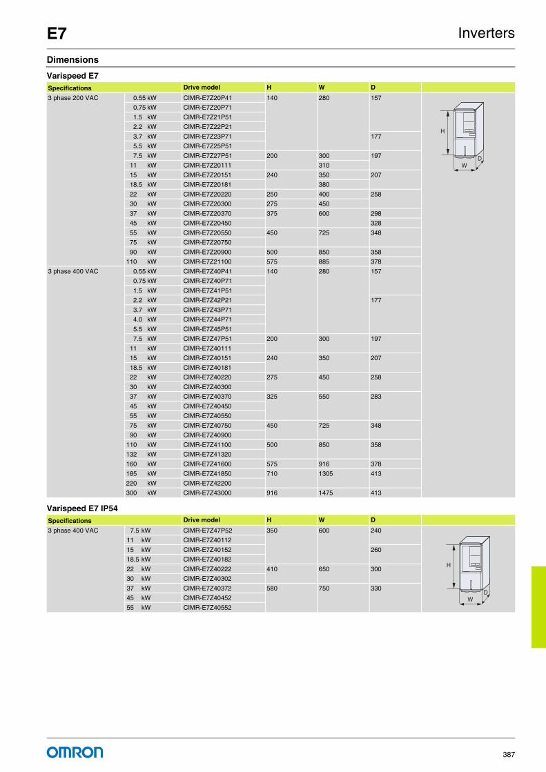
E7 Inverters
387
Dimensions
Varispeed E7
Varispeed E7 IP54
Specifications Drive model H W D
3 phase 200 VAC 0.55 kW CIMR-E7Z20P41 140 280 157
0.75 kW CIMR-E7Z20P71
1.5 kW CIMR-E7Z21P51
2.2 kW CIMR-E7Z22P21
3.7 kW CIMR-E7Z23P71 177
5.5 kW CIMR-E7Z25P51
7.5 kW CIMR-E7Z27P51 200 300 197
11 kW CIMR-E7Z20111 310
15 kW CIMR-E7Z20151 240 350 207
18.5 kW CIMR-E7Z20181 380
22 kW CIMR-E7Z20220 250 400 258
30 kW CIMR-E7Z20300 275 450
37 kW CIMR-E7Z20370 375 600 298
45 kW CIMR-E7Z20450 328
55 kW CIMR-E7Z20550 450 725 348
75 kW CIMR-E7Z20750
90 kW CIMR-E7Z20900 500 850 358
110 kW CIMR-E7Z21100 575 885 378
3 phase 400 VAC 0.55 kW CIMR-E7Z40P41 140 280 157
0.75 kW CIMR-E7Z40P71
1.5 kW CIMR-E7Z41P51
2.2 kW CIMR-E7Z42P21 177
3.7 kW CIMR-E7Z43P71
4.0 kW CIMR-E7Z44P71
5.5 kW CIMR-E7Z45P51
7.5 kW CIMR-E7Z47P51 200 300 197
11 kW CIMR-E7Z40111
15 kW CIMR-E7Z40151 240 350 207
18.5 kW CIMR-E7Z40181
22 kW CIMR-E7Z40220 275 450 258
30 kW CIMR-E7Z40300
37 kW CIMR-E7Z40370 325 550 283
45 kW CIMR-E7Z40450
55 kW CIMR-E7Z40550
75 kW CIMR-E7Z40750 450 725 348
90 kW CIMR-E7Z40900
110 kW CIMR-E7Z41100 500 850 358
132 kW CIMR-E7Z41320
160 kW CIMR-E7Z41600 575 916 378
185 kW CIMR-E7Z41850 710 1305 413
220 kW CIMR-E7Z42200
300 kW CIMR-E7Z43000 916 1475 413
Specifications Drive model H W D
3 phase 400 VAC 7.5 kW CIMR-E7Z47P52 350 600 240
11 kW CIMR-E7Z40112
15 kW CIMR-E7Z40152 260
18.5 kW CIMR-E7Z40182
22 kW CIMR-E7Z40222 410 650 300
30 kW CIMR-E7Z40302
37 kW CIMR-E7Z40372 580 750 330
45 kW CIMR-E7Z40452
55 kW CIMR-E7Z40552
H
WD
H
WD

For full specifications and additional models please refer to the (attached) CD or www.europe.omron.comInverters - Cat.-No. I20E-EN-02388
V7 Inverters
Sensorless vector control inverterThe Varispeed V7 is the perfect drive for standard industrial applica-tions such as conveyors, cranes, grinders, etc. It delivers an amazing 100% torque at 0.5 Hz, ensuring a very stable motor speed. It is also extremely compact and silent. It can interface to all popular field buses as an option. You can turn the V7 into a decentralised control station by adding a PLC option board.
• Sensorless vector control ensures 100% at 0.5 Hz• Compact size available in IP20 or IP65• Silent operation with no current de-rating• Programming software: CX-Drive for parameter configuration• CASE (inverter application software) and PLC option board
Ordering information
Varispeed V7
200 V 400 V
*See note *See note
* Option frames are needed for V7 IP65 type.
R
S
T
C B
A E
D D D D D D
Communication unit
3G3IV-PCN329-E
Inverter to PC cable
3G3IV-PCN126/326
Digital operator
extension cable
CX-Drive
Braking accessories
PLC option unit
Varispeed
V7
Line filter
3G3MV-PFI_
Input noise filter
3G3IV-PEZZ8122_
DIN attachment
JVOP-144
Remote digital oper.
with potentiometer
JVOP-146
Remote digital oper.
with potentiometer
LKEB_ ERF150WJ_CDBR_B
Power supply
* V7 IP65 typer are built-in filter inverters.
*See note
Specifications Model
1 x 200 V 0.12 kW 0.8 A CIMR-V7AZB0P10
0.25 kW 1.6 A CIMR-V7AZB0P20
0.55 kW 3.0 A CIMR-V7AZB0P40
1.1 kW 5.0 A CIMR-V7AZB0P70
1.5 kW 8.0 A CIMR-V7AZB1P50
2.2 kW 11.0 A CIMR-V7AZB2P20
4.0 kW 17.5 A CIMR-V7AZB4P00
3 x 200 V 0.12 kW 0.8 A CIMR-V7AZ20P10
0.25 kW 1.6 A CIMR-V7AZ20P20
0.55 kW 3.0 A CIMR-V7AZ20P40
1.1 kW 5.0 A CIMR-V7AZ20P70
1.5 kW 8.0 A CIMR-V7AZ21P50
2.2 kW 11.0 A CIMR-V7AZ22P20
4.0 kW 17.5 A CIMR-V7AZ24P00
5.5 kW 25.0 A CIMR-V7AZ25P51
7.5 kW 33.0 A CIMR-V7AZ27P51
Specifications Model
3 x 400 V 0.37 kW 1.2 A CIMR-V7AZ40P20
0.55 kW 1.8 A CIMR-V7AZ40P40
1.1 kW 3.4 A CIMR-V7AZ40P70
1.5 kW 4.8 A CIMR-V7AZ41P50
2.2 kW 5.5 A CIMR-V7AZ42P20
3.0 kW 7.2 A CIMR-V7AZ43P00
4.0 kW 9.2 A CIMR-V7AZ44P00
5.5 kW 14.8 A CIMR-V7AZ45P51
7.5 kW 18.0 A CIMR-V7AZ47P51

V7 Inverters
389
Varispeed V7 IP65200 V 400 V
A Line filters*1
*1. V7 IP65 types are built-in filter inverters.
B Communication cards
C PLC option card
D Accessories
Specifications Model
1 x 200 V 0.55 kW 3.0 A CIMR-V7TZB0P405
1.1 kW 5.0 A CIMR-V7TZB0P705
1.5 kW 8.0 A CIMR-V7TZB1P505
2.2 kW 11.0 A CIMR-V7TZB2P205
Specifications Model
3 x 400 V 0.55 kW 1.8 A CIMR-V7TZ40P405
1.1 kW 3.4 A CIMR-V7TZ40P705
1.5 kW 4.8 A CIMR-V7TZ41P505
2.2 kW 5.5 A CIMR-V7TZ42P205
3.0 kW 7.2 A CIMR-V7TZ43P005
4.0 kW 9.2 A CIMR-V7TZ44P005
Inverter Line filter
Voltage Model CIMR-V7AZ Schaffner Rasmi Rated current (A) Weight (kg)
3-phase 200 VAC 20P1 / 20P2 / 20P4 / 20P7 3G3MV-PFI2010-SE 3G3MV-PFI2010-E 10 0.8
21P5 / 22P2 3G3MV-PFI2020-SE 3G3MV-PFI2020-E 20 1.0
24P0 3G3MV-PFI2030-SE 3G3MV-PFI2030-E 30 1.1
25P5 / 27P5 - 3G3MV-PFI2050-E 50 2.3
Single-phase 200 VAC B0P1 / B0P2 / B0P4 3G3MV-PFI1010-SE 3G3MV-PFI1010-E 10 0.6
B0P7 / B1P5 3G3MV-PFI1020-SE 3G3MV-PFI1020-E 20 1.0
B2P2 3G3MV-PFI1030-SE 3G3MV-PFI1030-E 30 1.1
B4P0 3G3MV-PFI1040-SE 3G3MV-PFI1040-E 40 1.2
3-phase 400 VAC 40P2 / 40P4 3G3MV-PFI3005-SE 3G3MV-PFI3005-E 5 1.0
40P7 / 41P5 / 42P2 3G3MV-PFI3010-SE 3G3MV-PFI3010-E 10 1.0
40P4 3G3MV-PFI3020-SE 3G3MV-PFI3020-E 15 1.1
45P5 / 47P5 3G3MV-PFI3030-SE 3G3MV-PFI3030-E 30 2.3
Type Model Description Function
Com
mun
icat
ion
optio
n bo
ard
3G3MV-PDRT2*1
*1 Option frames are needed for V7 IP65 type. Please refer to motion and drive catalogue or contact your OMRON representative.
DeviceNet option card Used for running or stopping the inverter, setting or referencing parameters, and monitoring output frequency, output current, or similar items through DeviceNet communication with the host controller.
SI-P1/V7*1 PROFIBUS-DP option card Used for running or stopping the inverter, setting or referencing parameters, and monitoring output frequency, output current, or similar items through PROFIBUS-DP communication with the host controller.
SI-S1/V7*1 Can open option card Used for running or stopping the inverter, setting or referencing parameters, and monitoring output frequency, output current, or similar items through CANopen communication with the host controller.
3G3MV-PCORT21*1 Can open gateway Used for running or stopping the inverter, setting or referencing parameters, and monitoring output frequency, output current, or similar items through CANopen communication with the host controller.
SI-T1/V7*1 MECHATROLINK-II option card Used for running or stopping the inverter, setting or referencing parameters, and monitoring output frequency, output current, or similar items through MECHATROLINK-IIcommunication with the host controller.High speed motion bus.Host controller: Trajexia, MCH or MP Series.*2
*2 Please refer to Trajexia, MCH or MP series section for host controllers detailed information.
Type Model Description Function
PLC
opt
ion
card
3G3MV-P10CDT-E *1
*1 Option frames are needed for V7 IP65 type. Please refer to motion and drive catalogue or contact your OMRON representative.
PLC option Full PLC featrues, wireless installation and seamless access to the inverter parameters and analogue/digital inputs and outputs.Standard OMRON tools can be used for programmingCalendar / clock
3G3MV-P10CDT3-E *1 PLC option with RS 422/485 Same features than standard models with RS 422/485 support.
Types Model Description Funtions
Digital operator JVOP-146 Remote digital operator without potentiometer
Configuration and monitoring device
JVOP-144 Remote digital operatorwith potentiometer
Configuration and monitoring device
72606-CVS31060 Blank cover -----
3G3IV-PEZZ0838BA Digital operator case -----
Accessories3G3IV-PCN1263G3IV-PCN326
Digital operator extension cable1 meters3 meters
Cable to connect the inverter and the digital operator when it's not plugged into the inverter
3G3IV-PCN329-E PC configuration cable Cable to connect inverter and PC

V7 Inverters
390
D Computer software
E Braking unit, braking resistor unitNote: For braking units specifications and models refer to the V7 datasheet Cat-No: I20E-EN-02
Specifications
200 V class
400 V class
Types Model Description Installation
Software CX - DRIVE Computer software Configuration and monitoring software tool for drives. (Version 1.1 or higher)
CX - ONE Computer software Complete automation software including CX-Drive
IP20 single-phase: CIMR-V7AZ B0P1 B0P2 B0P4 B0P7 B1P5 B2P2 B4P0
IP65 single-phase: CIMR-V7TZ --- --- B0P405 B0P705 B1P505 B2P205 ---
Three-phase CIMR-V7AZ 20P1 20P2 20P4 20P7 21P5 22P2 24P0
Maximum permissible motor output kW *1
*1 Based on a standard 4-pole motor for maximum applicable motor output. Select the inverter model within the allowable motor rated current
0.12 0.25 0.55 1.1 1.5 2.2 4.0
Ou
tpu
t ch
arac
teri
stic
s Inverter capacity kVA 0.3 0.6 1.1 1.9 3.0 4.2 6.7
Rated output current A 0.8 1.6 3.0 5.0 8.0 11.0 17.5
Max. output voltage Proportional to input voltage: 0..240 V
Max. output frequency 400 Hz
Po
wer
sup
ply
Rated input voltage and frequency 3-phase 200..230V 50/60 HzSingle-phase 200..240V 50/60 Hz
Allowable voltage fluctuation -15%..+10%
Allowable frequency fluctuation +5%
IP20 three-phase: CIMR-V7AZ 40P2 40P4 40P7 41P5 42P2 43P0 44P0 44P5 47P5
IP65 three-phase: CIMR-V7TZ --- 40P405 40P705 41P505 42P205 43P005 44P005 --- ---
Maximum permissible motor output kW *1
*1 Based on a standard 4-pole motor for maximum applicable motor output. Select the inverter model within the allowable motor rated current
0.37 0.55 1.1 1.5 2.2 3.0 4.0 5.5 7.5
Ou
tpu
t ch
arac
teri
stic
s Inverter capacity kVA 0.9 1.4 2.6 3.7 4.2 5.5 7.0 11.0 14.0
Rated output current A 1.2 1.8 3.4 4.8 5.5 7.2 9.2 14.8 18.0
Max. output voltage Proportional to input voltage: 0..400 V
Max. output frequency 400 Hz
Po
wer
sup
ply Rated input voltage and frequency 3-phase 380..460 VAC, 50/60 Hz
Allowable voltage fluctuation -15%..+10%
Allowable frequency fluctuation +5%

V7 Inverters
391
Dimensions
Varispeed V7
Varispeed V7 IP65
Note: For option frames sizes needed for V7 option boards please refer to motion and drive catalogue or contact your OMRON representative.
Specifications Drive model H W D
1-phase 200 VAC 0.12 kW CIMR-V7AZB0P10 68 128 76
0.25 kW CIMR-V7AZB0P20
0.55 kW CIMR-V7AZB0P40 131
1.1 kW CIMR-V7AZB0P70 108 140
1.5 kW CIMR-V7AZB1P50 156
2.2 kW CIMR-V7AZB2P20 140 163
4.0 kW CIMR-V7AZB4P00 170 180
3-phase 200 VAC 0.12 kW CIMR-V7AZ20P10 68 128 76
0.25 kW CIMR-V7AZ20P20
0.55 kW CIMR-V7AZ20P40 108
1.1 kW CIMR-V7AZ20P70 128
1.5 kW CIMR-V7AZ21P50 108 131
2.2 kW CIMR-V7AZ22P20 140
4.0 kW CIMR-V7AZ24P00 140 143
5.5 kW CIMR-V7AZ25P51 180 170
7.5 kW CIMR-V7AZ27P51
3-phase 400 VAC 0.37 kW CIMR-V7AZ40P20 108 128 92
0.55 kW CIMR-V7AZ40P40 110
1.1 kW CIMR-V7AZ40P70 140
1.5 kW CIMR-V7AZ41P50 156
2.2 kW CIMR-V7AZ42P20
3.0 kW CIMR-V7AZ43P00 140 143
4.0 kW CIMR-V7AZ44P00
5.5 kW CIMR-V7AZ45P51 180 260 170
7.5 kW CIMR-V7AZ47P51
Specifications Drive model H W D
1-phase 200 VAC 0.55 kW CIMR-V7TZB0P405 260 275 150.3
1.1 kW CIMR-V7TZB0P705
1.5 kW CIMR-V7TZB1P505
2.2 kW CIMR-V7TZB2P205
3-phase 200 VAC 0.55 kW CIMR-V7TZ40P405 260 275 150.3
1.1 kW CIMR-V7TZ40P705
1.5 kW CIMR-V7TZ41P505
2.2 kW CIMR-V7TZ42P205
3.0 kW CIMR-V7TZ43P005
4.0 kW CIMR-V7TZ44P005
H
WD
H
WD

For full specifications and additional models please refer to the (attached) CD or www.europe.omron.comInverters - Cat.-No. I19E-EN-02392
J7 Inverters
Small, simple and smartWith simplicity and cost-effectiveness in mind, the J7 was designed to meet low-end simple applications such as conveyors, fans and pumps in small power applications. With on-line torque compensation the J7 can deliver 100% torque down to 1.5 Hz. For quick installation and set-up the J7 is fitted as standard with a digital operator and speed volume.
• Easy to use. Just WIRE and RUN.• Good torque performance: 100% torque at 1.5 Hz, 150% at 3 Hz• Compact size• RS-485 and RS-232C option unit• Programming software: CX-Drive for parameter configuration
Ordering information
Varispeed J7200 V 400 V
A Line filters
R
S
TA
B
B
SI-232/J7
SI-232/J7C
SI-485/J7
3G3IV-PCN329-E
Inverter to PC cable
3G3IV-PCN126/326
Digital operator
extension cable
3G3IV-PEZZ8122_
DIN attachment
JVOP-144
Remote digital oper.
with potentiometer
CX-Drive
Line filter
3G3MV-PFI_
Input noise filter
Power supply
Varispeed
J7
JVOP-146
Remote digital oper.
with potentiometer
Specifications Model
1 x 200 V 0.12 kW 0.8 A CIMR-J7AZB0P10
0.25 kW 1.6 A CIMR-J7AZB0P20
0.55 kW 3.0 A CIMR-J7AZB0P40
1.1 kW 5.0 A CIMR-J7AZB0P70
1.5 kW 8.0 A CIMR-J7AZB1P50
3 x 200 V 0.12 kW 0.8 A CIMR-J7AZ20P10
0.25 kW 1.6 A CIMR-J7AZ20P20
0.55 kW 3.0 A CIMR-J7AZ20P40
1.1 kW 5.0 A CIMR-J7AZ20P70
1.5 kW 8.0 A CIMR-J7AZ21P50
2.2 kW 11.0 A CIMR-J7AZ22P20
4.0 kW 17.5 A CIMR-J7AZ24P00
Specifications Model
3 x 400 V 0.37 kW 1.2 A CIMR-J7AZ40P20
0.55 kW 1.8 A CIMR-J7AZ40P40
1.1 kW 3.4 A CIMR-J7AZ40P70
1.5 kW 4.8 A CIMR-J7AZ41P50
2.2 kW 5.5 A CIMR-J7AZ42P20
3.0 kW 7.2 A CIMR-J7AZ43P00
4.0 kW 9.2 A CIMR-J7AZ44P00
Inverter Line filter
Voltage Model CIMR-J7AZ Schaffner Rasmi Rated current (A) Weight (kg)
3-phase 200 VAC 20P1 / 20P2 / 20P4 / 20P7 3G3JV-PFI2010-SE 3G3JV-PFI2010-E 10 0.68
21P5 / 22P2 3G3JV-PFI2020-SE 3G3JV-PFI2020-E 16 0.84
24P0 --- 3G3JV-PFI2030-E 26 1.0
Single-phase 200 VAC B0P1 / B0P2 / B0P4 3G3JV-PFI1010-SE 3G3JV-PFI1010-E 10 0.45
B0P7 / B1P5 3G3JV-PFI1020-SE 3G3JV-PFI1020-E 20 0.68
3-phase 400 VAC 40P2 / 40P4 3G3JV-PFI3005-SE 3G3JV-PFI3005-E 5 0.57
40P7 / 41P5 / 42P2 3G3JV-PFI3010-SE 3G3JV-PFI3010-E 10 0.67
43P0 / 44P0 3G3JV-PFI3020-SE 3G3JV-PFI3020-E 20 / 15 1.0

J7 Inverters
393
B Accessories
B Accessories
Specifications
Dimensions
Type Model Description Funtions
Digital operator JVOP-146 Remote digital operator without potentiometer Configuration and monitoring device
JVOP-144 Remote digital operator with potentiometer
Interface units SI-232/J7 (3G3JV-PSI232J) RS232 adapter Another option SI-232/J7C (3G3JV-PSI232JC) is available, the only difference is that this one is removable.
SI-485/J7 (3G3JV-PSI485J) RS485 adapter
Accessories3G3IV-PCN1263G3IV-PCN326
Digital operator extension cable1 meters3 meters
SI232/J7 is necessary to connect
3G3IV-PCN329-E PC configuration cable SI232/J7 is necessary to connect
Type Model Description Installation
Software CX-DRIVE Computer software Configuration and monitoring software tool for drives
CX-ONE Computer software Complete OMRON automation software including CX-Drive
Voltage class 200V Single / three-phase 400V three-phase
Model CIMR-J7AZ# Three-phase 20P1 20P2 20P4 20P7 21P5 22P2 24P0 40P2 40P4 40P7 41P5 42P2 43P0 44P0
Single-phase*1
*1 Single-phase series inverter output is three-phase (for three-phase motors)
B0P1 B0P2 B0P4 B0P7 B1P5 – – – – – – – – –
Max. applicablemotor output kW (HP) *2
*2 Based on a standard 4-pole motor for max. applicable motor output. Select the inverter model whose rated current is larger than motor rated current
0.12 0.25 0.55 1.1 1.5 2.2 4.0 0.37 0.55 1.1 1.5 2.2 3.0 4.0
Ou
tpu
t C
har
acte
rist
ics Inverter capacity kVA 0.3 0.6 1.1 1.9 3.0 4.2 6.7 0.9 1.4 2.6 3.7 4.2 5.5 7.0
Rated output current A 0.8 1.6 3 5 8 11 17.5 1.2 1.8 3.4 4.8 5.5 7.2 9.2
Max. output voltage V 3-phase, 200 to 230 V (proportional to input voltage)Single-phase, 200 to 240 V (proportional to input voltage)
3-phase, 380 to 460 V (proportional to input voltage)
Max. output frequency 400 Hz (programmable)
Po
wer
su
pp
ly
Rated input voltage and frequency
3-phase, 200 to 230 V, 50/60HzSingle-phase, 200 to 240 V, 50/60Hz
3-phase, 380 to 460 V, 50/60Hz
Allowable voltage function
-15 to +10%
Allowable frequency function
±5%
Specifications Drive model H W D
1 phase 200 VAC 0.12 kW CIMR-J7AZB0P10 68 128 70
0.25 kW CIMR-J7AZB0P20
0.55 kW CIMR-J7AZB0P40 112
1.1 kW CIMR-J7AZB0P70 108 129
1.5 kW CIMR-J7AZB1P50 154
3 phase 200 VAC 0.12 kW CIMR-J7AZ20P10 68 128 70
0.25 kW CIMR-J7AZ20P20
0.55 kW CIMR-J7AZ20P40 102
1.1 kW CIMR-J7AZ20P70 122
1.5 kW CIMR-J7AZ21P50 108 129
2.2 kW CIMR-J7AZ22P20 154
4.0 kW CIMR-J7AZ24P00 140 161
3 phase 400 VAC 0.37 kW CIMR-J7AZ40P20 108 128 81
0.55 kW CIMR-J7AZ40P40 99
1.1 kW CIMR-J7AZ40P70 129
1.5 kW CIMR-J7AZ41P50 154
2.2 kW CIMR-J7AZ42P20
3.0 kW CIMR-J7AZ43P00 140 161
4.0 kW CIMR-J7AZ44P00
H
WD

For full specifications and additional models please refer to the (attached) CD or www.europe.omron.comInverters - Cat.-No. I25E-EN-02394
G7/F7/L7/E7 Inverter PLC Inverters
The OMRON PLC embedded into the OMRON-Yaskawa inverter familyBringing PLC functionality to the drive. You will be able to access the inverter parameters, analogue / digital I/Os, control up to 256 I/Os and DeviceNet connectivity. Ideal for applications such as winding /unwinding, HVAC installations, smart lifts and water treatment.
• Fully featured OMRON PLC embedded into the inverter• Interrupt inputs, counter inputs, encoder inputs and pulse outputs• Mechatronics functions (PWM, pulse and sync.)• Memory backup• Programmed using standard OMRON PLC software
Ordering information
Inverter PLC
A Inverters
Note: For detailed information please refer to inverter section.
B Compobus/S slave
C Cables
C Computer software
Specifications Model
Inputs Ouptuts RTC Compobus/S master RS422 port DeviceNet slave
6 4 Yes Yes Yes No 3G3RV-P10ST8-E
6 4 Yes Yes NO Yes 3G3RV-P10ST8-DRT-E
Specifications Model
3 level control method inverter Varispeed G7
Flux vector control inverter Varispeed F7
Lift inverter Varispeed L7
Pumps & fans inverter Varispeed E7
Specifications Model
Compobus/S slaves SRT2-XX*1
*1 For detailed information please refers to network I/O section
Specifications Model
Computer connecting cable 3G3IV-PCN329-E
Programmable console cable 3G3IV-PCN126/326
Specifications Model
PLC programming software: CX-Programmer CX-ONE
Inverter configurator software: CX-Drive
B A
C C C
3G3IV-PCN329-E
Inverter to PC cable
3G3IV-PCN126/326
Digital operator
extension cable
CX-One
G7/F7/L7/E7
Inverter PLC
Varispeed CompoBus/S
slaves SRT2-ID
SRT2-OD
SRT2-ROC
SRT2-ROF
SRT2-ID_CL
SRT2-OD_CL
SRT2-AD
SRT2-DA

G7/F7/L7/E7 Inverter PLC Inverters
395
Specifications
Specifications by product
General specifications
Item 3G3RV-P10ST8-E 3G3RV-P10ST8-DRT-E
PLC core CPM2C-S CPM2C-S
Inputs 6 24 VDC inputs 6 24 VDC inputs
Outputs 4 sourcing / PNP transistor outputs 4 sourcing / PNP transistor outputs
Peripheral port Yes Yes
RS-232C port Yes Yes
RS-422 port No Yes
Calendar / clock Yes Yes
Memory backup Flash memory and battery Flash memory and battery
Compobus/S master interface Yes Yes
Encoder interface Yes Yes
DeviceNet slave interface No Yes
Item Specifications
3G3RV-P10ST8-E 3G3RV-P10ST8-DRT-E
Rated power supply voltage 24 VDC +10%/-15% (external power supply for I/O)
Communications power supply voltage --- 11 to 25 VDC (supplied by communications connector)
Vibration resistance 10 to 20 Hz, 9.8 m/s2 max.20 to 50 Hz, 2 m/s2 max
Ambient operating temperature -10 to 45 °C
Ambient operating relative humidity 10% to 90% (no condensation)
Ambient storage temperature -20 to 70 °C
Atmosphere Must be free from corrosive gas
I/O control method Cyclic scan method
Programming language Ladder chart method
Processing speed
Basic instructions 0.64 µs (LD)
Special instructions 7.8 µs (MOV)
Program capacity 4,096 words
Inverter interface Direct interface with inverter throughIR-memory, DM-memory, Transfer command
CompoBus/S master functions Remote I/O devices can be allocated up to 256 I/O points (128 inputs and 128 outputs)
DeviceNet slave functions Up to 64 words (32 input words and 32 output words) can be allocated to the DeviceNet Master's I/O.
Interrupts Interrupt inputs: 2 inputsResponse time: 50 µs
Interval timer interrupts: 1 inputSet value: 0.5 to 319,968 msPrecision: 0.1 ms
Scheduled interrupts
One-shot interrupt
High-speed counters
High-speed counter 1 input No interrupt
Differential phase mode (5 kHz)Pulse plus direction input mode (20 kHz)Up / down input mode (20 kHz)Increment mode (20 kHz)
Count-check interrupt(an interrupt can be generated when the count equals the set value or the count lies within a preset range.)
Interrupt inputs (counter mode)2 inputsIncrementing counter (2 kHz)Decrementing counter (2 kHz)
No interrupt
Count-up interrupt
Encoder interface 3 input modes: Differential-phase (up / down)Pulse plus directionUp / down pulse
Maximum input frequency 50 kHzMaximum counter range 4,294,967,295 (232-1)Two capture registers, 3 selectable registration inputsOne comparison valueCounter reset through software or Z-phaseInterrupt function
Pulse outputs 2 outputs: Single-phase pulse output without acceleration / deceleration 10 Hz to 10 kHz2 outputs: Variable duty ratio pulse output 0.1 to 999.9 Hz, duty ratio 0 to 100%1 output: Pulse output with trapezoidal acceleration / deceleration
Pulse plus direction output, up / down pulse output, 10 Hz to 10 kHz
Synchronized pulse control 1 point Input frequency range: 10 to 500 Hz, 20 Hz to 1 kHz, or 300 Hz to 20 kHzOutput frequency range: 10 Hz to 10 kHz
Pulse catch inputs 2 bitsMinimum pulse input: 50 µs max.Used in common by input interrupts and input interrupt counter mode.
Clock / calendar function Shows the current year, month, day of the week, day of the month, hour, minute, and second.
Communication function Port 1 = Peripheral and RS-422: Host link, peripheral bus, no-protocol, programming consolePort 2 = RS-232C port: Host link, no-protocol, 1:1 PLC link, 1:1 NT link
Power-interruption hold function Holds the contents of HR, AR, CNT, and DM Areas.
Memory backup Flash memory: Program, read-only DM area, and PC setupMemory backup: The read / write DM area, HR area, AR area, and counter values are backed up. (The battery has a 5-year lifetime at 25 °C and it is replaceable.)
Self-diagnostic function CPU errors, memory errors, communications errors, setting errors, battery errors

For full specifications and additional models please refer to the (attached) CD or www.europe.omron.comInverters - Cat.-No. I24E-EN-02396
V7 Inverter PLC Inverters
The OMRON PLC embedded into the sensorless vector control inverterThis inverter-based architecture provides wireless installation and seamless access to the V7 parameters and analogue / digital I/Os. Ideal for applications such as door control, pump sequencing, intelligent conveyor, vertical-axis control and general positioning
• Fully featured OMRON PLC embedded into the inverter• Interrupt inputs, counter inputs and pulse outputs• Mechatronics functions (PWM, pulse and sync.)• Memory backup• Programmed using standard OMRON PLC software
Ordering information
Inverter PLC
A Inverters
B Cables
B Software
Specifications Model
Inputs Outputs RS422 port RTC
6 4 No No 3G3MV-P10CDT-E
6 4 Yes Yes 3G3MV-P10CDT3-E
Specifications Model
Sensorless vector control inverter Varispeed V7 *1
*1 For detailed information please refer to Varispeed V7 section.
Specifications Model
Computer connecting cable CS1W-CN226
Programmable console cable CS1W-CN224
Specifications Model
PLC programming software: CX-Programmer CX-ONE
Inverter configurator software: CX-Drive
B
A
B
3G3IV-PCN329-E
Inverter to PC cable
CX-Drive
V7 Inverter
PLC
Varispeed V7
B B
CS1W-CN226
PLC to PC cable
CX-One
Varispeed V7 + V7
Inverter PLC
=

V7 Inverter PLC Inverters
397
Specifications
Specifications by product
General specifications
Item 3G3MV-P10CDT-E 3G3MV-P10CDT5-E 3G3MV-P10CDT3-E
PLC core CPM2C-S CPM2C-S CPM2C-S
Inputs 6 24 VDC inputs 6 24 VDC inputs 6 24 VDC inputs
Outputs 3 sinking / NPN transistor outputs 3 sinking / PNP transistor outputs 3 sinking / NPN transistor outputs
1 relay output 1 relay output 1 relay output
Peripheral port Yes Yes Yes
RS-232C port Yes Yes Yes
RS-422/485 port No No Yes
Calendar / clock No No Yes
Memory backup Flash memory and capacitor Flash memory and capacitor Flash memory and battery
Item Specifications
Rated power supply voltage 24 VDC +10%/-15% (External power supply for I/O)
Vibration resistance 0.15 mm (10-57 Hz)9.8 m/s2 (57-150 Hz)9.8 m/s2 (57-150 Hz)In all directions (X, Y, Z)
Ambient operating temperature -10 to 45 °C
Ambient operating relative humidity 10% to 90% (no condensation)
Ambient storage temperature -20 to 70 °C
Atmosphere Must be free from corrosive gas
I/O control method Cyclic scan method
Programming language Ladder chart method
Processing speed Basic instructions 0.64 µs (LD)
Special instructions 7.8 µs (MOV)
Program capacity 4,096 words
Output bits 01000 to 01003 (4 physical outputs)
Inverter interface Direct interface with V7 inverter throughIR-memoryDM-memoryTransfer command
Quick-response input 2 inputs (minimum input signal width: 50 µs)
Interrupt processing External interrupts 2 bits (used in common for input interrupt counter mode and high-speed inputs.)
Scheduled interrupts 1 bit (scheduled interrupts or one-shot interrupts)
Interrupts Interrupt inputs: 2 inputsResponse time: 50 µs
Interval timer interrupts: 1 inputSet value: 0.5 to 319,968 msPrecision: 0.1 ms
Scheduled interrupts
One-shot interrupt
High-speed counters High-speed counter1 inputDifferential phase mode (5 kHz)Pulse plus direction input mode (20 kHz)Up / down input mode (20 kHz)Increment mode (20 kHz)
No interrupt
Count-check interrupt (an interrupt can be generated when the count equals the set value or the count lies within a preset range.)
Interrupt inputs (counter mode)2 inputsIncrementing counter (2 kHz)Decrementing counter (2 kHz)
No interrupt
Count-up interrupt
Pulse outputs 2 outputs: Single-phase pulse output without acceleration / deceleration 10 Hz to 10 kHz
2 outputs: Variable duty ratio pulse output 0.1 to 999.9 Hz, duty ratio 0 to 100%
1 output: Pulse output with trapezoidal acceleration / deceleration Pulse plus direction output, up / down pulse output, 10 Hz to 10 kHz
Synchronized pulse control 1 point Input frequency range: 10 to 500 Hz, 20 Hz to 1 kHz, or 300 Hz to 20 kHzOutput frequency range: 10 Hz to 10 kHz
Clock / calendar function Yes. Shows the current year, month, day of the week, day of the month, hour, minute, and second.
Communication function Port 1 = Peripheral and RS-422: Host link, peripheral bus, no-protocol, programming consolePort 2 = RS-232C port: Host link, no-protocol, 1:1 PLC link, 1:1 NT link
Power-interruption hold function Holds the contents of HR, AR, CNT, and DM areas.
Memory backup Non-volatile memory, user program, DM (read only), PLC setup
Fixed internal lithium battery (5 years, not replaceable by the user) or capacitor DM (read / write), HR, SR and CNT areas
Self-diagnostic function CPU errors, memory errors, communications errors, setting errors, battery errors

For full specifications and additional models please refer to the (attached) CD or www.europe.omron.comInverters - Cat.-No. I44E-EN-01398
Case Inverters
Customised software to meet your specific application requirementsThe customised application software gives to a standard inverter the features of a dedicated solution
• The CASE software is a special software file that can be downloaded into a standard inverter providing additional functionality.
• Logic functions can be added.• I/O´s settings can be set for special functionality.• Specific paremeters, monitors and alarms can be added with
application units.
Ordering information
Note: The symbols AB show the recommended sequence to build the item name with CASE software.
Power
Supply
Main
Pump
Aux.
Pump 1
Aux.
Pump 2
Water
Water
ELS software S-8161 Winder software S-8180Pump sequencer software S-8801
Point to point software S-8795 Traverse software S-9381Crane software S-7071
A
A A
A A
A
Varispeed
E7
Varispeed
F7
Varispeed
V7
Varispeed
G7
B
/ X
/
X
X +
(Main speed)
Frequency ref.
0.00 to 10.00%
Diameter
0.00 to 10.00%
Tension ref.
0.00 to 10.00%
Torque ref.
w/o comp.
U1-80 (r20H)
(for A, B, C, see fig. 3.2.2.)
C
B
A
U1-81 (r21H)
Buit Ratio
P1-01 (600H)
1 to 10
Diameter
10%
U1-94 (r24H)
Dyn. comp.
P1-03 (603H)
0.00 to 100
Dynamic comp.
U1-93 (r23H)
10%
100%
10% 100%

Case Inverters
399
A CASE software
Note: - For other CASE sofware examples and ordering information, please contact your standard OMRON YASKAWA supplier.- To request new CASE software customised to meet application specific functionality, please contact your standard OMROM YASKAWA supplier.
B Inverters
Note: Refer to the inverters G7 / F7 / E7 / V7 series chapter for detailed inverter specifications and selection.
Type CASE software Description Application
CIMR-F7Z-S 7071 Dedicated software for crane applications Cranes
8161 Dedicated software for position and speed follower applications Synchronized movements
8180 Dedicated software for rewinding and unwinding applications Rewinding & unwinding
8795 Dedicated software for point to point position applications Point to point movement applications
7061 Dedicated software for 1.000 Hz output frequency High speed
8091 Dedicated software for position deceleration Positioning at stopping.
8600 Dedicated softeware for local / remote smooth changover Local / remote control
CIMR-E7Z-S 8801 Dedicated software for pump squencer applications Water supply, building HVAC.
8810 Dedicated software for dynamic current limitation Industrial pumping
CIMR-V7AZ-S 9381 Dedicated software for textile wire winding applications Textile winding
5502 Dedicated software for kinetic energy backup Control under power loss conditions
9640 Dedicated software for dinamic PID change Variable load
9646 Dedicated software for modification on main frequency from F.R. Fine speed adjustments
9662 Dedicated software for valve cleaner sequences for filter units Valves
9666 Dedicated software for ceramics customised functionality Ceramics
9676 Dedicated software for textile customised functionality Textile
9683 Dedicated software for textile customised functionality Textile
Specifications Model
3 level control method inverter Varispeed G7
Flux vector control inverter Varispeed F7
Pumps & fans inverter Varispeed E7
Sensorless vector control inverter Varispeed V7

400

Index 401
Index61F-D21T . . . . . . . . . . . . . . . . 19461F-GP-N8 . . . . . . . . . . . . . . . 19161F-GPN-BT / BC. . . . . . . . . . . . 193A16 . . . . . . . . . . . . . . . . . . . 214A165E. . . . . . . . . . . . . . . . . . 146A22 . . . . . . . . . . . . . . . . . . . 216Case . . . . . . . . . . . . . . . . . . 398CJ1 analog I/O and control units . . . . 291CJ1 communication units . . . . . . . . 294CJ1 CPU units . . . . . . . . . . . . . 288CJ1 digital I/O units . . . . . . . . . . . 290CJ1 position control units . . . . . . . . 293CJ1 power supplies, expansions . . . . 289CJ1W-MCH71 . . . . . . . . . . . . . 319CJ1W-NC@ . . . . . . . . . . . . . . . 321CJ1W-NCF71 . . . . . . . . . . . . . . 320Compact I/O DRT2 . . . . . . . . . . . 305Compact I/O SRT2 . . . . . . . . . . . 306CP1H CPU units . . . . . . . . . . . . 285CPM1A CPU units . . . . . . . . . . . 282CPM1A expansion units . . . . . . . . 286CPM2A CPU units . . . . . . . . . . . 283CPM2C CPU units . . . . . . . . . . . 284CPM2C expansion units . . . . . . . . 287CS1 analog and process I/O units . . . 298CS1 communication units. . . . . . . . 301CS1 CPU units . . . . . . . . . . . . . 295CS1 digital I/O units. . . . . . . . . . . 297CS1 position / motion control units . . . 300CS1 power supplies, backplanes . . . . 296D40B . . . . . . . . . . . . . . . . . . 138D4B-@N. . . . . . . . . . . . . . . . . 144D4BL . . . . . . . . . . . . . . . . . . 141D4BS . . . . . . . . . . . . . . . . . . 136D4C . . . . . . . . . . . . . . . . . . . 203D4CC . . . . . . . . . . . . . . . . . . 204D4E-_N . . . . . . . . . . . . . . . . . 205D4GL . . . . . . . . . . . . . . . . . . 140D4MC . . . . . . . . . . . . . . . . . . 206D4N . . . . . . . . . . . . . . . . . . . 142D4N-@R. . . . . . . . . . . . . . . . . 145D4NH . . . . . . . . . . . . . . . . . . 137D4NL . . . . . . . . . . . . . . . . . . 139D4NS . . . . . . . . . . . . . . . . . . 135DST1-ID/DST1-MRD . . . . . . . . . . 113DZ. . . . . . . . . . . . . . . . . . . . 209E2A . . . . . . . . . . . . . . . . . . . . 44E2A3 . . . . . . . . . . . . . . . . . . . 47E2AU . . . . . . . . . . . . . . . . . . . 53E2AX . . . . . . . . . . . . . . . . . . . 54E2C-EDA . . . . . . . . . . . . . . . . . 63E2E . . . . . . . . . . . . . . . . . . . . 43E2E . . . . . . . . . . . . . . . . . . . . 62E2E-@Y / E2F-@Y . . . . . . . . . . . . 59E2EC . . . . . . . . . . . . . . . . . . . 42E2EL . . . . . . . . . . . . . . . . . . . 57E2EQ . . . . . . . . . . . . . . . . . . . 58E2EZ . . . . . . . . . . . . . . . . . . . 60E2F . . . . . . . . . . . . . . . . . . . . 46E2F-D . . . . . . . . . . . . . . . . . . . 56E2FQ . . . . . . . . . . . . . . . . . . . 61E2Q2 . . . . . . . . . . . . . . . . . . . 51E2Q4 . . . . . . . . . . . . . . . . . . . 52E2S . . . . . . . . . . . . . . . . . . . . 48E3C-LDA . . . . . . . . . . . . . . . . . 31E3F2 . . . . . . . . . . . . . . . . . . . 17E3F2 . . . . . . . . . . . . . . . . . . . 20E3F2-@41. . . . . . . . . . . . . . . . . 32E3F2-@Z . . . . . . . . . . . . . . . . . 25E3FS . . . . . . . . . . . . . . . . . . 128E3G . . . . . . . . . . . . . . . . . . . . 18
E3G-M . . . . . . . . . . . . . . . . . . 26E3JK . . . . . . . . . . . . . . . . . . . 27E3M-V . . . . . . . . . . . . . . . . . . 28E3NT . . . . . . . . . . . . . . . . . . . 19E3S-C . . . . . . . . . . . . . . . . . . 15E3S-CL. . . . . . . . . . . . . . . . . . 16E3S-CR62/67 . . . . . . . . . . . . . . 22E3S-G . . . . . . . . . . . . . . . . . . 29E3S-LS3 . . . . . . . . . . . . . . . . . 30E3T . . . . . . . . . . . . . . . . . . . . 12E3X-DA-AN-S . . . . . . . . . . . . . . 81E3X-DA-AT-S . . . . . . . . . . . . . . 80E3X-DA-N . . . . . . . . . . . . . . . . 71E3X-DA-S . . . . . . . . . . . . . . . . 75E3X-DA-SE-S . . . . . . . . . . . . . . 79E3X-MDA . . . . . . . . . . . . . . . . 77E3X-NA . . . . . . . . . . . . . . . . . 73E3Z . . . . . . . . . . . . . . . . . . . . 13E3Z-@G, E3Z-@J. . . . . . . . . . . . . 24E3Z-B . . . . . . . . . . . . . . . . . . 21E3Z-Laser . . . . . . . . . . . . . . . . 23E5@K / E5@K-T . . . . . . . . . . . . .230E5@N. . . . . . . . . . . . . . . . . . .227E5@R. . . . . . . . . . . . . . . . . . .231E5C2 . . . . . . . . . . . . . . . . . . .225E5CSV . . . . . . . . . . . . . . . . . .226E5ZN . . . . . . . . . . . . . . . . . . .229E6A2-C. . . . . . . . . . . . . . . . . . 34E6C2-C/E6C3-C . . . . . . . . . . . . . 35E6C3-A . . . . . . . . . . . . . . . . . . 37E6H-C . . . . . . . . . . . . . . . . . . 36E7 . . . . . . . . . . . . . . . . . . . .384F150 . . . . . . . . . . . . . . . . . . .102F160 . . . . . . . . . . . . . . . . . . .103F210 . . . . . . . . . . . . . . . . . . .104F250 . . . . . . . . . . . . . . . . . . .105F3S-B . . . . . . . . . . . . . . . . . .125F3SL . . . . . . . . . . . . . . . . . . .126F3SN-A / F3SH-A . . . . . . . . . . . .123F3SP-U4P . . . . . . . . . . . . . . . . 129F3S-TGR . . . . . . . . . . . . . . . . . 127F500 / F210 ETN. . . . . . . . . . . . .106F7 . . . . . . . . . . . . . . . . . . . .375Fiber optic sensors . . . . . . . . . . . . 70Field I/O DRT2 . . . . . . . . . . . . . .307G2RS. . . . . . . . . . . . . . . . . . .152G3NA. . . . . . . . . . . . . . . . . . .161G3PA. . . . . . . . . . . . . . . . . . .163G3PB. . . . . . . . . . . . . . . . . . .164G3ZA . . . . . . . . . . . . . . . . . . .165G7 . . . . . . . . . . . . . . . . . . . .370G7/F7/L7/E7 Inverter PLC . . . . . . . .394G7SA. . . . . . . . . . . . . . . . . . .147G9SA. . . . . . . . . . . . . . . . . . .116G9SB. . . . . . . . . . . . . . . . . . .117G9SX. . . . . . . . . . . . . . . . . . .115H2C . . . . . . . . . . . . . . . . . . .253H3CR. . . . . . . . . . . . . . . . . . .251H3DE. . . . . . . . . . . . . . . . . . .249H3DS. . . . . . . . . . . . . . . . . . .248H3YN. . . . . . . . . . . . . . . . . . .250H5CX. . . . . . . . . . . . . . . . . . .252H7CX. . . . . . . . . . . . . . . . . . .262H7EC. . . . . . . . . . . . . . . . . . .258H7ER. . . . . . . . . . . . . . . . . . .260H7ET . . . . . . . . . . . . . . . . . . .259H8GN . . . . . . . . . . . . . . . . . .261H8PS . . . . . . . . . . . . . . . . . . .263HL5000 . . . . . . . . . . . . . . . . . .201J7. . . . . . . . . . . . . . . . . . . . .392J7KN . . . . . . . . . . . . . . . . . . .174
J7KNA . . . . . . . . . . . . . . . . . . 173J7KNA-AR . . . . . . . . . . . . . . . . 172J7MN . . . . . . . . . . . . . . . . . . 178J7TKN . . . . . . . . . . . . . . . . . . 176JUSP-NS300 . . . . . . . . . . . . . . 323JUSP-NS500 . . . . . . . . . . . . . . 324JUSP-NS600 . . . . . . . . . . . . . . 325K3GN . . . . . . . . . . . . . . . . . . 272K3HB-R, -P, -C . . . . . . . . . . . . . 276K3HB-X, -H, -V, -S . . . . . . . . . . . 274K3MA-J, -L, -F . . . . . . . . . . . . . . 273K7L . . . . . . . . . . . . . . . . . . . 195K8AB-AS . . . . . . . . . . . . . . . . 184K8AB-PA . . . . . . . . . . . . . . . . 189K8AB-PH . . . . . . . . . . . . . . . . 187K8AB-PM . . . . . . . . . . . . . . . . 188K8AB-TH . . . . . . . . . . . . . . . . 224K8AB-VS . . . . . . . . . . . . . . . . 185K8AB-VW . . . . . . . . . . . . . . . . 186L7 . . . . . . . . . . . . . . . . . . . . 380LY . . . . . . . . . . . . . . . . . . . . 155M16 . . . . . . . . . . . . . . . . . . . 218M22 . . . . . . . . . . . . . . . . . . . 219MK-I-S . . . . . . . . . . . . . . . . . . 156Motion controllers . . . . . . . . . . . . 316MY . . . . . . . . . . . . . . . . . . . . 153NE1A-SCPU01 . . . . . . . . . . . . . 112PRT1-SCU11 . . . . . . . . . . . . . . 233R88A-MCW151 . . . . . . . . . . . . . 322S82K. . . . . . . . . . . . . . . . . . . 242S8PE . . . . . . . . . . . . . . . . . . 243S8T-DCBU-01/-02 . . . . . . . . . . . . 241S8TS . . . . . . . . . . . . . . . . . . 240S8VM . . . . . . . . . . . . . . . . . . 239S8VS . . . . . . . . . . . . . . . . . . 238SHL . . . . . . . . . . . . . . . . . . . 207Sigma linear motors . . . . . . . . . . . 357Sigma-II rotary servo motors . . . . . . 342Sigma-II servo drive . . . . . . . . . . . 334SmartSlice I/O system. . . . . . . . . . 304SmartStep drive . . . . . . . . . . . . . 339SmartStep motors . . . . . . . . . . . . 353Solid state relays . . . . . . . . . . . . 160TJ1-Trajexia . . . . . . . . . . . . . . . 317TL-T . . . . . . . . . . . . . . . . . . . . 50TL-W. . . . . . . . . . . . . . . . . . . . 49V530-R160 . . . . . . . . . . . . . . . 107V7 Inverter PLC . . . . . . . . . . . . . 396V7 . . . . . . . . . . . . . . . . . . . . 388WL . . . . . . . . . . . . . . . . . . . . 202X . . . . . . . . . . . . . . . . . . . . . 210XtraDrive . . . . . . . . . . . . . . . . 330Z . . . . . . . . . . . . . . . . . . . . . 211ZC-55 . . . . . . . . . . . . . . . . . . 208ZEN . . . . . . . . . . . . . . . . . . . 267ZFV . . . . . . . . . . . . . . . . . . . 100ZS-L . . . . . . . . . . . . . . . . . . . . 88ZX-E . . . . . . . . . . . . . . . . . . . . 90ZX-LT . . . . . . . . . . . . . . . . . . . 95ZX-T . . . . . . . . . . . . . . . . . . . . 92


Cat. No. Y205-EN2-01 Guidebook
OMRON EUROPE B.V. Wegalaan 67-69, NL-2132 JD, Hoofddorp, The Netherlands. Tel: +31 (0) 23 568 13 00 Fax: +31 (0) 23 568 13 88 www.omron-industrial.com
Austria Tel: +43 (0) 1 80 19 00 www.omron.at
Belgium Tel: +32 (0) 2 466 24 80 www.omron.be
Czech Republic Tel: +420 234 602 602 www.omron.cz
Denmark Tel: +45 43 44 00 11 www.omron.dk
Finland Tel: +358 (0) 207 464 200 www.omron.fi
France Tel: +33 (0) 1 56 63 70 00 www.omron.fr
Germany Tel: +49 (0) 2173 680 00 www.omron.de
Hungary Tel: +36 (0) 1 399 30 50 www.omron.hu
Italy Tel: +39 02 32 681 www.omron.it
Netherlands Tel: +31 (0) 23 568 11 00 www.omron.nl
Norway Tel: +47 (0) 22 65 75 00 www.omron.no
Poland Tel: +48 (0) 22 645 78 60 www.omron.com.pl
Portugal Tel: +351 21 942 94 00 www.omron.pt
Russia Tel: +7 095 745 26 64 www.omron.ru
Spain Tel: +34 913 777 900 www.omron.es
Sweden Tel: +46 (0) 8 632 35 00 www.omron.se
Switzerland Tel: +41 (0) 41 748 13 13 www.omron.ch
Turkey Tel: +90 (0) 216 474 00 40 www.omron.com.tr
United Kingdom Tel: +44 (0) 870 752 08 61 www.omron.co.uk
Middle East & Africa Tel: +31 (0) 23 568 11 00 www.omron-industrial.com
More Omron representatives www.omron-industrial.com
Authorised Distributor: