INDUSTRIAL APPLICATIONS - ProTek Devices
16
Advanced circuit protection devices for overvoltage transient events INDUSTRIAL APPLICATIONS
-
Upload
khangminh22 -
Category
Documents
-
view
1 -
download
0
Transcript of INDUSTRIAL APPLICATIONS - ProTek Devices

Advanced circuit protection devices for overvoltage transient events
INDUSTRIAL APPLICATIONS

Today’s industrial applications are as diverse as ever. They include point of sale (PoS) systems that have card readers, modems and serial ports. They also include resi-dential and commercial energy meters and smart meters; industrial displays; appliances; general control systems; instrumentation; photovoltaic systems; LED lighting and many more. Industrial system failures in the field due to improper circuit protection can be costly exercises in terms of time and money. In addition, system downtime can often result in damage to a company’s image or quality reputation – both that of the user and the system provider. Any of these industrial applications are at risk to external threats that can include electrostatic discharges (ESD), electrical fast transients (EFT), surges, lightning or improper wiring.
Communications systems are at the heart of many industrial applications, such as the use of RS-485, CAN Bus, LIN Bus, USB2.0, ProfiNet or ProfiBus. To provide circuit protection, traditionally, a high capacitor was used to ensure overvoltage protection. However, due to the high speed requirements in today’s communication ports, the capacitance per line must be significantly reduced. If not, transmission speed will be substantially negatively impacted. And, capacitance reduction must be done while still providing enough overvoltage protection against elec-trical threats. The capacitance of the protection device becomes a particular issue for data lines where higher baud rates are being designed. Here, what’s required are circuit protection components where the load capacitance creates a first order filter to slow the rise and falling edge.
Power supplies are also obviously critical to industrial systems and they can be easily susceptible to various electrical threats. But, power supplies are generally im-mune to ESD conditions. This is due to the use of passive components such as capacitors and inductors that are
www.protekdevices.com
inherently robust. Ferrite beads are commonly used in power supplies to add inductance that limits the impulse amplitudes under fast transients. While this traditional solution often provides adequate protection, it does use passive components that can strain other components. Thus, energy can then be diverted into the system power rail, causing electrical damage into other areas of the system. For this reason, overvoltage protection solutions with a fast response time that divert or shunt the energy to ground should be considered.
In addition, it is important that industrial application designers understand that their solutions are likely to be exposed to external ESD, EFT, surges, lightning or im-proper wiring during installation. This includes ESD levels per IEC 61000-4-2 and EFT levels per IEC 61000-6-4. Critical systems and integrated circuits (IC) will be ex-posed to such elements and designers should remember that devices may not be resettable and may be damaged beyond repair.
For surge protection per IEC 61000-4-5, it is critical for the design engineer to understand what installation clas-sification is required for a system. They include:
• Class 0: Well-protected electrical environment, often within a special room.
• Class 1: Partly protected environment.• Class 2: Electrical environment where the cables are
well separated, even at short runs.• Class 3: Electrical environment where cables run in
parallel.• Class 4: Electrical environment where the intercon-
nections are running as outdoor cables along with power cables and cables used for both electronic and electric circuits.
• Class 5: Electrical environment for electronic equip-ment connected to telecommunication cables and overhead power lines in a non-densely populated area.
Once the classification is known, the level of protection required can be determined using the IEC 61000-4-5 test levels, as shown in table 1.
No matter the industrial application, ProTek Devices pro-vides a comprehensive family of overvoltage and overcur-rent protection devices. They are designed to seamlessly integrate within the various electronics design require-ments for today’s modern industrial electronics system. They are also designed for quality and cost-effectiveness. They also not only help meet all relevant standards, they provide real-world scenario circuit protection for mission critical industrial systems.
DATA TRANSMISSION RATES
APPLICATION DATA RATE Mbit/S CAPACITANCE pF
LinBus 0.20< 50
RS-232 0.20
CanBus/Device Net 1.0
<30
T1 1.544
E2 2.048
I2C 2.4
Ethernet 10
FlexRay 10
USB 1.1 12
< 20E3 34.368
RS-485 35
T3 44.736
Fast Ethernet 100 < 5
T5 400.352
< 3
USB 2.0 480
E5 565.148
IEEE-1394b 786.432
GigabitE 1000
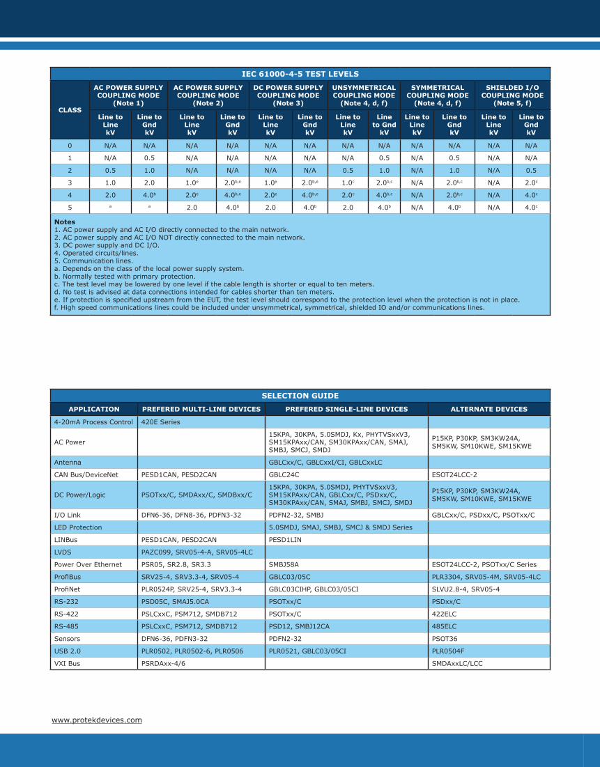
SELECTION GUIDE
APPLICATION PREFERED MULTI-LINE DEVICES PREFERED SINGLE-LINE DEVICES ALTERNATE DEVICES
4-20mA Process Control 420E Series
AC Power15KPA, 30KPA, 5.0SMDJ, Kx, PHYTVSxxV3, SM15KPAxx/CAN, SM30KPAxx/CAN, SMAJ, SMBJ, SMCJ, SMDJ
P15KP, P30KP, SM3KW24A, SM5KW, SM10KWE, SM15KWE
Antenna GBLCxx/C, GBLCxxI/CI, GBLCxxLC
CAN Bus/DeviceNet PESD1CAN, PESD2CAN GBLC24C ESOT24LCC-2
DC Power/Logic PSOTxx/C, SMDAxx/C, SMDBxx/C15KPA, 30KPA, 5.0SMDJ, PHYTVSxxV3, SM15KPAxx/CAN, GBLCxx/C, PSDxx/C, SM30KPAxx/CAN, SMAJ, SMBJ, SMCJ, SMDJ
P15KP, P30KP, SM3KW24A, SM5KW, SM10KWE, SM15KWE
I/O Link DFN6-36, DFN8-36, PDFN3-32 PDFN2-32, SMBJ GBLCxx/C, PSDxx/C, PSOTxx/C
LED Protection 5.0SMDJ, SMAJ, SMBJ, SMCJ & SMDJ Series
LINBus PESD1CAN, PESD2CAN PESD1LIN
LVDS PAZC099, SRV05-4-A, SRV05-4LC
Power Over Ethernet PSR05, SR2.8, SR3.3 SMBJ58A ESOT24LCC-2, PSOTxx/C Series
ProfiBus SRV25-4, SRV3.3-4, SRV05-4 GBLC03/05C PLR3304, SRV05-4M, SRV05-4LC
ProfiNet PLR0524P, SRV25-4, SRV3.3-4 GBLC03CIHP, GBLC03/05CI SLVU2.8-4, SRV05-4
RS-232 PSD05C, SMAJ5.0CA PSOTxx/C PSDxx/C
RS-422 PSLCxxC, PSM712, SMDB712 PSOTxx/C 422ELC
RS-485 PSLCxxC, PSM712, SMDB712 PSD12, SMBJ12CA 485ELC
Sensors DFN6-36, PDFN3-32 PDFN2-32 PSOT36
USB 2.0 PLR0502, PLR0502-6, PLR0506 PLR0521, GBLC03/05CI PLR0504F
VXI Bus PSRDAxx-4/6 SMDAxxLC/LCC
IEC 61000-4-5 TEST LEVELS
CLASS
AC POWER SUPPLY COUPLING MODE
(Note 1)
AC POWER SUPPLYCOUPLING MODE
(Note 2)
DC POWER SUPPLYCOUPLING MODE
(Note 3)
UNSYMMETRICALCOUPLING MODE
(Note 4, d, f)
SYMMETRICALCOUPLING MODE
(Note 4, d, f)
SHIELDED I/OCOUPLING MODE
(Note 5, f)
Line to LinekV
Line to GndkV
Line to LinekV
Line to GndkV
Line to LinekV
Line to GndkV
Line to LinekV
Line to Gnd
kV
Line to LinekV
Line to GndkV
Line to LinekV
Line to GndkV
0 N/A N/A N/A N/A N/A N/A N/A N/A N/A N/A N/A N/A
1 N/A 0.5 N/A N/A N/A N/A N/A 0.5 N/A 0.5 N/A N/A
2 0.5 1.0 N/A N/A N/A N/A 0.5 1.0 N/A 1.0 N/A 0.5
3 1.0 2.0 1.0e 2.0b,e 1.0e 2.0b,e 1.0c 2.0b,c N/A 2.0b,c N/A 2.0c
4 2.0 4.0b 2.0e 4.0b,e 2.0e 4.0b,e 2.0c 4.0b,c N/A 2.0b,c N/A 4.0c
5 a a 2.0 4.0b 2.0 4.0b 2.0 4.0b N/A 4.0b N/A 4.0c
Notes1. AC power supply and AC I/O directly connected to the main network.2. AC power supply and AC I/O NOT directly connected to the main network.3. DC power supply and DC I/O.4. Operated circuits/lines.5. Communication lines.a. Depends on the class of the local power supply system.b. Normally tested with primary protection.c. The test level may be lowered by one level if the cable length is shorter or equal to ten meters.d. No test is advised at data connections intended for cables shorter than ten meters.e. If protection is specified upstream from the EUT, the test level should correspond to the protection level when the protection is not in place.f. High speed communications lines could be included under unsymmetrical, symmetrical, shielded IO and/or communications lines.
www.protekdevices.com
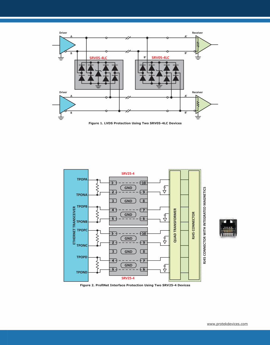
Figure 1. LVDS Protection Using Two SRV05-4LC Devices
B’
DriverA
B
A’
B’
Receiver
SRV05-4LC SRV05-4LC
DriverA
B
A’
B’
Receiver
Figure 2. ProfiNet Interface Protection Using Two SRV25-4 Devices
SRV25-4
GND
1
2
3
4
5 6
7
8
9
10
GND
GND
GND
1
2
3
4
5 6
7
8
9
10
GND
GND
TPOPA
TPONA
TPOPB
TPONB
TPOPC
TPONC
TPOPD
TPOND
ETHE
RNET
TRA
NSC
EIVE
R
SRV25-4
QUA
D TR
ANSF
ORM
ER
RJ45
CO
NN
ECTO
R W
ITH
INTE
GRA
TED
MAG
NET
ICS
RJ45
CO
NN
ECTO
R
www.protekdevices.com
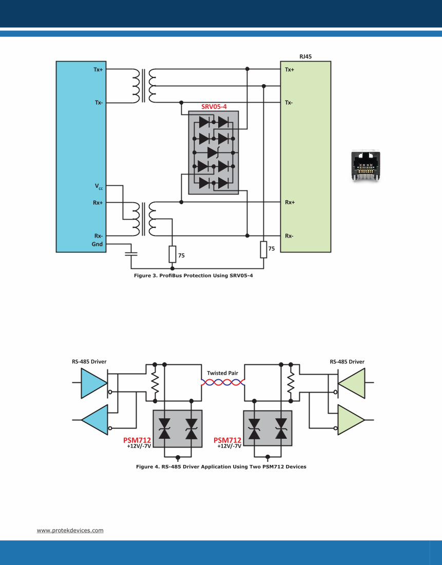
Figure 4. RS-485 Driver Application Using Two PSM712 Devices
RS-485 Driver RS-485 Driver
Twisted Pair
PSM712+12V/-7V
PSM712+12V/-7V
Figure 3. ProfiBus Protection Using SRV05-4
Tx+
Tx-
Rx+
RJ45
SRV05-4
Rx-
Rx+
Tx+
Tx-
Rx-
VCC
Gnd
7575
www.protekdevices.com
ADC
Sensor
Sensor
ADC
Sen
sor
Pro
tect
ion AMP
AMP
Multiplexor ADC µProcessor andMemory
DFN
6-3
6
USBRS-232
Ethernet
PLR0524P =>PSOTxx/C =>
PLR Family =>
I/O
Pro
tect
ion
I/O Interface
Ethernet PHY
AC In ACProtection
BridgeRectifier PFC Voltage
RegulationDC
Protection DC Out
15KPA/30KPA PSDxx/C
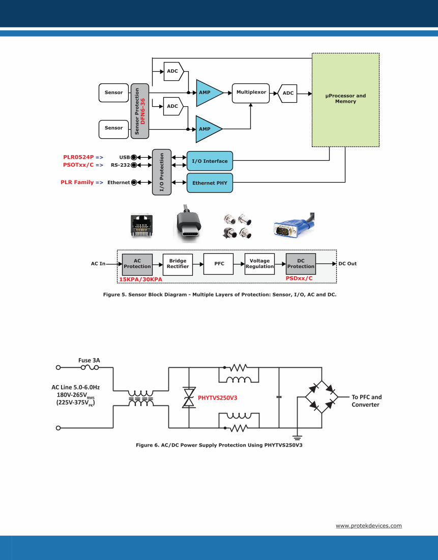
Figure 5. Sensor Block Diagram - Multiple Layers of Protection: Sensor, I/O, AC and DC.
Figure 6. AC/DC Power Supply Protection Using PHYTVS250V3
Fuse 3A
AC Line 5.0-6.0Hz180V-265VRMS(225V-375VPK)
PHYTVS250V3 To PFC and Converter
www.protekdevices.com
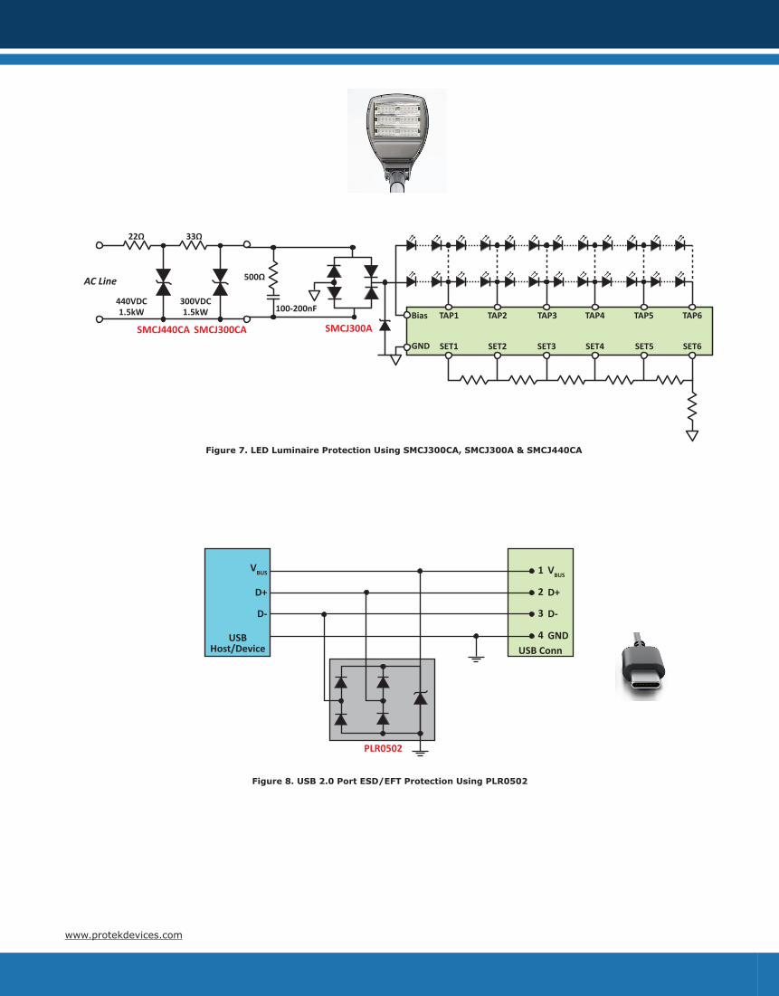
SMCJ440CA SMCJ300CA
22Ω 33Ω
AC Line
440VDC1.5kW
300VDC1.5kW
500Ω
100-200nFBias
GND
TAP1 TAP2 TAP3 TAP4 TAP5 TAP6
SET1 SET2 SET3 SET4 SET5 SET6
SMCJ300A
Figure 7. LED Luminaire Protection Using SMCJ300CA, SMCJ300A & SMCJ440CA
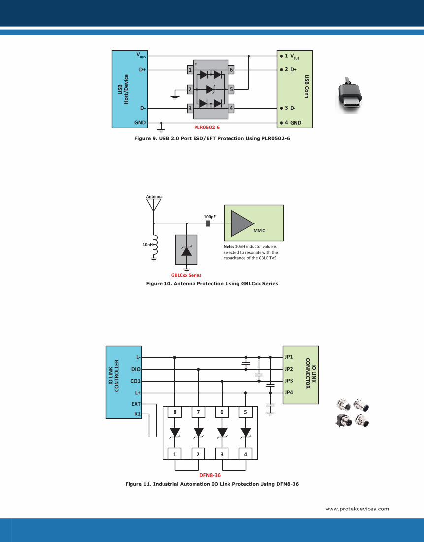
PLR0502
USB Conn
VBUS
D+
D-
USB Host/Device
1
2
3
4
VBUS
D+
D-
GND
Figure 8. USB 2.0 Port ESD/EFT Protection Using PLR0502
www.protekdevices.com
PLR0502-6
USB Conn
VBUS
D+
D-
USB
Ho
st/D
evic
e
1
2
3
4
VBUS
D+
D-
GND
1 6
52
3 4
GND
Figure 9. USB 2.0 Port ESD/EFT Protection Using PLR0502-6
MMIC
10nH
GBLCxx Series
Antenna
100pF
Note: 10nH inductor value is selected to resonate with the capacitance of the GBLC TVS
Figure 10. Antenna Protection Using GBLCxx Series
DFN8-36
IO LIN
K CO
NN
ECTOR
L-
DIO
IO L
INK
CON
TRO
LLER
JP1
JP2
JP3
JP4
8 7 6
1 2 3
5
4
L+
CQ1
EXT
K1
Figure 11. Industrial Automation IO Link Protection Using DFN8-36
www.protekdevices.com
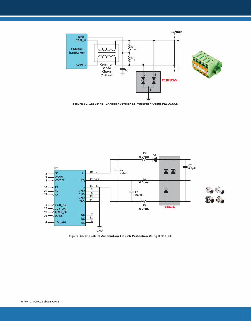
Figure 13. Industrial Automation IO Link Protection Using DFN6-36
NCVCCINVCCSET
TXENRX
PWR_OKCUR_OKTEMP_OKWAKE
ILM_ADJ
U2
871
182017
5151916
4
L+
CQ
L-GNDGNDGNDPAD
NCNCNC
211
9
2113
63
14
12
10
L-
C/Q
L+
GND
C52.2µF
C7300pF
R90 Ohms
R30 Ohms
R40 Ohms
C70.1µF
D3
DFN6-36
CAN_L
RT/2
PESD1CAN
CAN_HSPLIT
CANBusTransceiver
RT/2
CG
CANBus
CommonModeChoke(Op�onal) 12
3
Figure 12. Industrial CANBus/DeviceNet Protection Using PESD1CAN
www.protekdevices.com
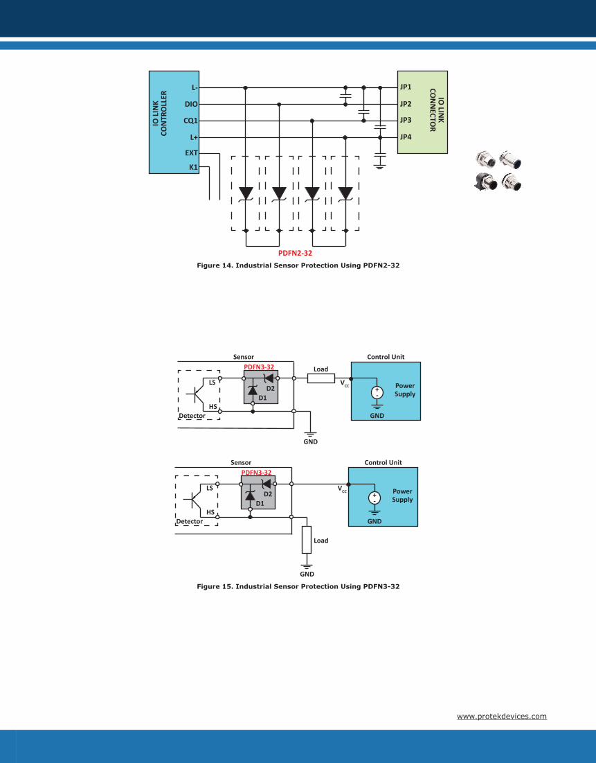
PDFN2-32
IO LIN
K CO
NN
ECTOR
L-
DIO
IO L
INK
CON
TRO
LLER
JP1
JP2
JP3
JP4L+
CQ1
EXT
K1
Figure 14. Industrial Sensor Protection Using PDFN2-32
Load
D1D2
LS
HSDetector
PDFN3-32Sensor
GND
GND
Power Supply
Control Unit
VCC +-
Load
D1D2
LS
HSDetector
PDFN3-32Sensor
GND
GND
Power Supply
Control Unit
VCC +-
Figure 15. Industrial Sensor Protection Using PDFN3-32
www.protekdevices.com

GND
LINLIN Bus
Transceiver
BAT
LIN NodeConnector
1
PESD1LIN
CBAT
Power Applica�on (e.g., Electro Motor, Induc�ve Loads)
Applica�on (e.g., Voltage Regulator, Microcontroller)
CBAT24
15
Figure 16. Industrial LinBus Protection Using PESD1LIN
SR2.8
SR2.8
ETH TX-P
ETH TX-N
ETH 3.3V
ETH RX-P
ETH RX-P
ETH
PHY
LAN TRANS
DA+DA-DB+DB-DC+DC-DD+DD-SHIELD S1SHIELD S2
GREEN LEDYELLOW LED
PoE MODE A
PoE MODE BPoE PD
RJ45 CON
Figure 17. PoE (802.3at) Protection Using SR2.8
www.protekdevices.com
DC Out
SM15KPA_AN
VoltageRegulator
SM15KPA_CAN
AC In
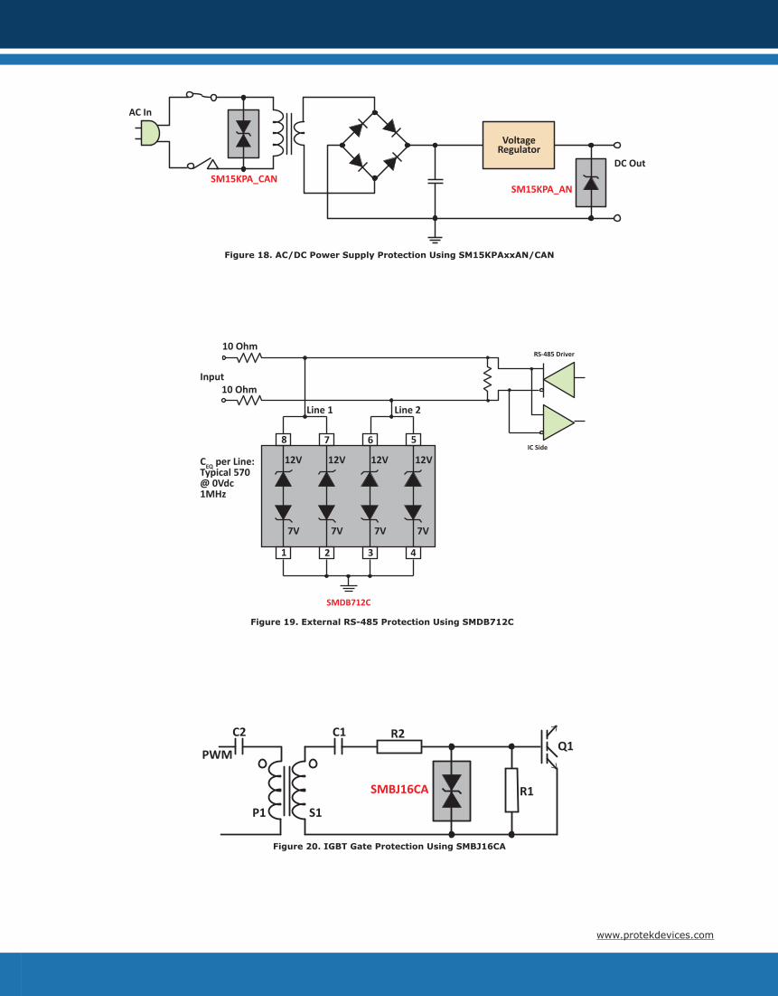
Figure 18. AC/DC Power Supply Protection Using SM15KPAxxAN/CAN
Figure 19. External RS-485 Protection Using SMDB712C
RS-485 Driver
IC Side
1 2 4
8
3
567
12V
7V
10 Ohm
10 OhmInput
Line 1 Line 2
CEQ per Line:Typical 570@ 0Vdc 1MHz
12V
7V
12V
7V
12V
7V
SMDB712C
SMBJ16CA
C2
P1
PWM
S1
C1 R2
R1
Q1
Figure 20. IGBT Gate Protection Using SMBJ16CA
www.protekdevices.com
IPP
Vc
P-N+ -
BVVR
IR
IR
VRBV
IPP
Vc
- +
CURRENT I
VOLTAGE V
IFPP
P-N+ -
VF
IF
IR
VRBV
IPP
Vc
CURRENT I
VOLTAGE V
P-N- +
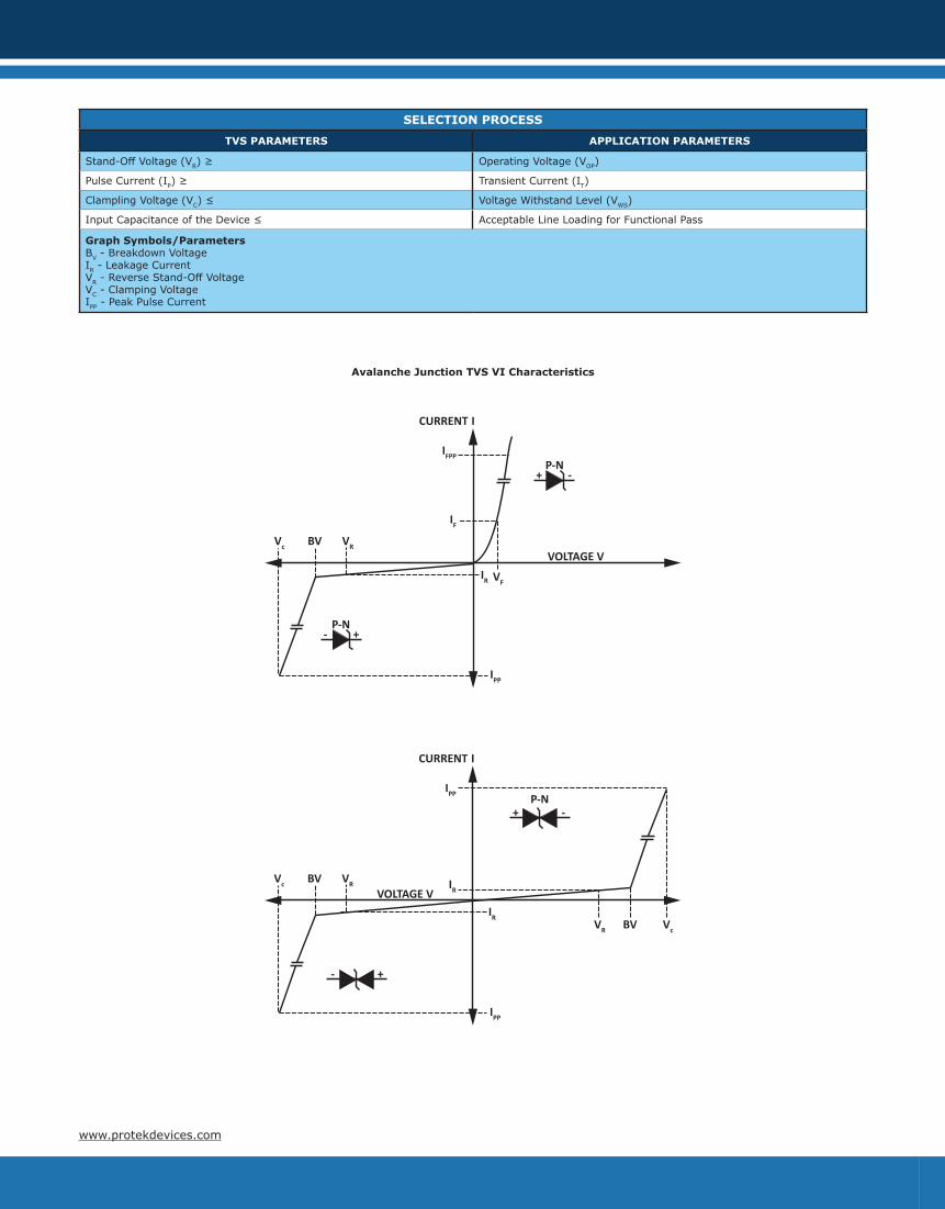
SELECTION PROCESS
TVS PARAMETERS APPLICATION PARAMETERS
Stand-Off Voltage (VR) ≥ Operating Voltage (VOP)
Pulse Current (IP) ≥ Transient Current (IT)
Clampling Voltage (VC) ≤ Voltage Withstand Level (VWS)
Input Capacitance of the Device ≤ Acceptable Line Loading for Functional Pass
Graph Symbols/ParametersBV - Breakdown Voltage IR - Leakage CurrentVR - Reverse Stand-Off VoltageVC - Clamping VoltageIPP - Peak Pulse Current
Avalanche Junction TVS VI Characteristics
www.protekdevices.com

OVERVOLTAGE PART SPECIFICATIONSPART
NUMBERSTAND-OFF VOLTAGE
VWMVOLTS
BREAKDOWN VOLTAGE
V(BR)VOLTS
CLAMPINGVOLTAGE
VCVOLTS
PEAK PULSECURRENT8/20μs
IPPAMPS
MAXIMUMLEAKAGECURRENT
IDμA
TYPICALCAPACITANCE
CpF
NO.OF
LINES
POWER8/20μs
WATTS
PACKAGE
15KPAxxxx 17.0 - 280.0 - - - 5000 - 10 - 1 15000* Axial
30KPAxxxx 30.0 - 360.0 - - - 5000 - 2 - 1 30000* Axial
420E Series 12.0 - 60.0 - 22.0 - 95.0 200.0 5 6000 - 1000 1 - Module
422ELC ±12.0 - 30.0 500.0 1 25 1 - Module
485ELC ±7.0 - 20.0 500.0 10 25 1 - Module
5.0SMDJ Series 6.0 - 440.0 6.67 - 492.0 - - 2000 - 5 - 1 - DO-214AB
DFN6-36 33.0 35.0 45.0 2.0 5 50 3 300 DFN-6
DFN8-36 33.0 35.0 45.0 2.0 5 50 3 300 DFN-8
ESOT24LCC-2 24.0 26.6 - - 1 6 2 100 SOT-23
GBLC03CIHP 3.0 4.0 24.0 20.0 5 0.6 1 500 SOD-323
GBLCxx/C 3.0 - 24.0 - 7.0 - 43.0 1.0 5 - 1 3 1 350 SOD-323
GBLCxx/CI 3.0 - 24.0 - 7.0 - 43.0 1.0 5 - 1 0.6 1 250 SOD-323
GBLCxxLC 3.3 - 5.0 4.0 - 6.0 7.0 - 9.8 1.0 1 - 5 0.8 - 0.7 1 250 SOD-323
P15KPxxxx 17.0 - 280.0 - - - 5000 - 10 - 1 15000* Axial
P30KPxxxx 30.0 - 260.0 - - - 5000 - 10 - 1 30000* Axial
PAZC099 5.0 6.0 12.0 1.0 0.5 0.5 4 100 SOT-23-6
PDFN2-32 32.0 34.0 55.0 25.0 200nA - 1 - DFN2020-3
PDFN3-32 32.0 34.0 55.0 25.0 200nA - 1 - DFN-3
PESD1CAN 24.0 25.4 70.0 3.0 0.05 11 2 200 SOT-23
PESD1LIN 15.0, 24.0 17.2, 25.5 25.0, 40.0 1.0 0.001 14 1 200 SOD-323
PESD2CAN 24.0 25.4 60.0 4.0 0.05 11 2 230 SOT-23
PHYTVSxxxV3 125 - 277 200 - 410 130 - 250 250 10 80 1 250 DFN-2KW
PLR0502 5.0 6.0 20.0 10.0 1 0.6 2 200 SOT-543
PLR0502-6 5.0 6.0 17.0 3.0 1 0.7 2 50 SC-89
PLR0504F 5.0 6.0 25.0 5.0 3 1.9 4 200 SC70-6L
PLR0506 5.0 6.0 18.0 4.0 3 0.8 6 - DFN-8
PLR0521 5.0 6.0 20.0 4.0 1 0.4 1 80 DFN-2
PLR0524P 5.0 6.0 9.0 6.0 0.5 0.7 4 - DFN-10
PLR3304 3.3 3.3 10.0 10.0 1 4 4 400 DFN-10
PSDxx/C 3.3 - 36.0 - 6.5 - 60.0 1.0 125 - 1 500 - 35 1 500 SOD-323
PSLCxx/C 3.3 - 24.0 - 9.0 - 30.0 5.0 125 - 1 3 1 350 SOT-143
PSM712 7.0 - 12.0 - 11.0 - 19.0 1.0 20 - 1 75 1 600 SOT-23
PSOTxx/C 3.3 - 36.0 - 6.5 - 51.0 1.0 125 - 1 500 - 60 1 500 SOT-23
PSRDAxx-4 3.3 - 15.0 - 6.5 - 24.0 1.0 125 - 1 5 4 500 SO-8
SLVU2.8-4 2.8 3.0 21.0 30.0 1 3 2P 600 SO-8
SM15KPAxx/CAN 17.0 - 220.0 18.9 - 245.0 - - 5000 - 10 - 1 15000* Module
SM30KPAxx/CAN 30.0 - 75.0 33.3 - 83.3 - - 5000 - 10 - 1 30000* Module
SM3KW24A 24.0 26.7 43.0 69.8 3 - 1 3000* DFN-2
1. *10/1000μs waveshape.2. For detail about each voltage level, please refer to the product datasheet.
www.protekdevices.com
OVERVOLTAGE PART SPECIFICATIONSPART
NUMBERSTAND-OFF VOLTAGE
VWMVOLTS
BREAKDOWN VOLTAGE
V(BR)VOLTS
CLAMPINGVOLTAGE
VCVOLTS
PEAK PULSECURRENT8/20μs
IPPAMPS
MAXIMUMLEAKAGECURRENT
IDμA
TYPICALCAPACITANCE
CpF
NO.OF
LINES
POWER8/20μs
WATTS
PACKAGE
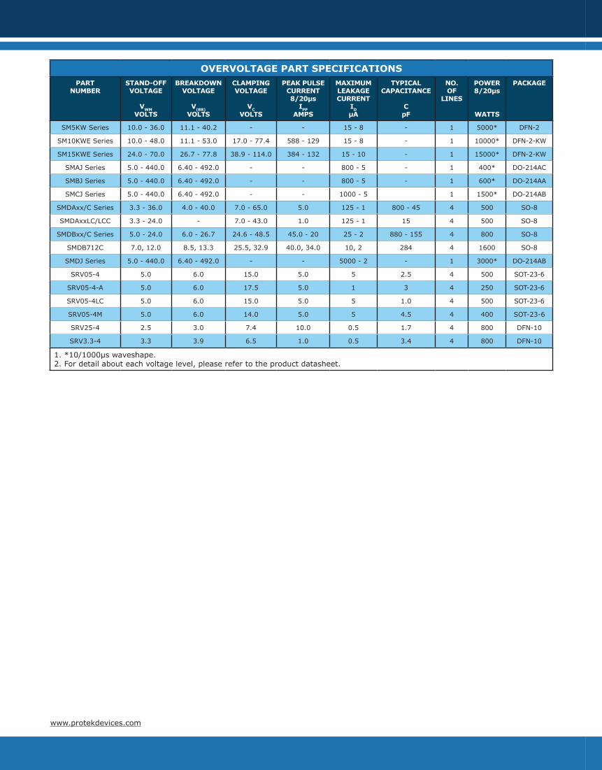
SM5KW Series 10.0 - 36.0 11.1 - 40.2 - - 15 - 8 - 1 5000* DFN-2
SM10KWE Series 10.0 - 48.0 11.1 - 53.0 17.0 - 77.4 588 - 129 15 - 8 - 1 10000* DFN-2-KW
SM15KWE Series 24.0 - 70.0 26.7 - 77.8 38.9 - 114.0 384 - 132 15 - 10 - 1 15000* DFN-2-KW
SMAJ Series 5.0 - 440.0 6.40 - 492.0 - - 800 - 5 - 1 400* DO-214AC
SMBJ Series 5.0 - 440.0 6.40 - 492.0 - - 800 - 5 - 1 600* DO-214AA
SMCJ Series 5.0 - 440.0 6.40 - 492.0 - - 1000 - 5 1 1500* DO-214AB
SMDAxx/C Series 3.3 - 36.0 4.0 - 40.0 7.0 - 65.0 5.0 125 - 1 800 - 45 4 500 SO-8
SMDAxxLC/LCC 3.3 - 24.0 - 7.0 - 43.0 1.0 125 - 1 15 4 500 SO-8
SMDBxx/C Series 5.0 - 24.0 6.0 - 26.7 24.6 - 48.5 45.0 - 20 25 - 2 880 - 155 4 800 SO-8
SMDB712C 7.0, 12.0 8.5, 13.3 25.5, 32.9 40.0, 34.0 10, 2 284 4 1600 SO-8
SMDJ Series 5.0 - 440.0 6.40 - 492.0 - - 5000 - 2 - 1 3000* DO-214AB
SRV05-4 5.0 6.0 15.0 5.0 5 2.5 4 500 SOT-23-6
SRV05-4-A 5.0 6.0 17.5 5.0 1 3 4 250 SOT-23-6
SRV05-4LC 5.0 6.0 15.0 5.0 5 1.0 4 500 SOT-23-6
SRV05-4M 5.0 6.0 14.0 5.0 5 4.5 4 400 SOT-23-6
SRV25-4 2.5 3.0 7.4 10.0 0.5 1.7 4 800 DFN-10
SRV3.3-4 3.3 3.9 6.5 1.0 0.5 3.4 4 800 DFN-10
1. *10/1000μs waveshape.2. For detail about each voltage level, please refer to the product datasheet.
www.protekdevices.com

COMPANY INFORMATIONIn business more than 25 years, ProTek Devices™ is a privately held semiconductor company. The compa-ny offers a product line of overvoltage protection and overcurrent protection components. These include transient voltage suppressor array (TVS arrays) avalanche breakdown diode, steering diode TVS array and electronics SMD chip fuses. These components deliver circuit protection in electronic systems from nu-merous overvoltage events. They include lightning; electrostatic discharge (ESD); nuclear electromagnetic pulses (NEMP); inductive switching; and electromagnetic interference (EMI) / radio frequency interference (RFI).
CONTACT US
ProTek Devices L.P.2929 South Fair LaneTempe, Arizona 85282USAPhone: +1 602-431-8101FAX: +1 602-431-2288
ProTek Devices (Asia Pacific) Pte. Ltd.8 Ubi Road 2, #06-19, ZervexSingapore 408538Phone: +65 6748-8312FAX: +65 6748-8313
By E-mail:Asia Sales: [email protected] Sales: [email protected]. Sales: [email protected] Sales: [email protected] Service: [email protected] Support: [email protected]
Webwww.protekdevices.com
ROHS & REACH COMPLIANCEAll devices, with the exception the PAM16AL30A(RoHS, exemption #7) are Lead-Free, RoHS & REACH compliant. These products are designated as “lead free” and meet the requirements of the European Union’s restriction on the use of hazardous substances in electrical equipment as stated in (RoHS) direction, 2002/95/EC. ProTek Devices defines “lead free” as products that are compatible with current RoHS requirements for the 6 “banned” substances: Lead (Pb, <1000ppm), Cadmium (Cd, <100ppm), Mercury (Hg, <1000ppm), Hexavalent Chromium (Cr6+, <1000ppm), Poly Brominated Biphenyls (PPB, <1000ppm), Poly Brominated Diphenyl Ethers (PBDE, <1000ppm). This includes the requirements that lead not exceed 0.1% by weight in homogeneous materials.
STANDARD TAPE & REEL NOMENCLATURE-T7 for 7” Reels-T13 for 13” Reels-TS for sample size ReelsNot all products are available in 7” or 13” reels. Quantities per reel vary depending upon package size. Please consult product data sheet or the factory for ordering information regarding a specific part series. All data sheets can be found on ProTek Devices website: www.protekdevices.com
COPYRIGHT © ProTek Devices (2020 - This literature is subject to all applicable copyright laws and is not for resale in any manner.
SPECIFICATIONS: ProTek Devices reserves the right to change the electrical and or mechanical characteristics described herein without notice.
DESIGN CHANGES: ProTek Devices reserves the right to discontinue product lines without notice and that the final judgment concerning selection and specifications is the buyer’s and that in furnishing engineering and technical assistance. ProTek Devices assumes no responsibility with respect to the selection or specifications of such products. ProTek Devices makes no warranty, representation or guarantee regarding the suitability of its products for any particular purpose, nor does ProTek Devices assume any liability arising out of the application or use of any product or circuit and specifically disclaims any and all liability without limitation special, consequential or incidental damages.
LIFE SUPPORT POLICY: ProTek Devices products are not authorized for use in life support systems without written consent from the factory.