
Incremental object part detection toward object classification in a sequence of noisy range images
8
DRAFT Incremental Object Part Detection toward Object Classification in a Sequence of Noisy Range Images Stefan G¨ achter, Ahad Harati, and Roland Siegwart Autonomous Systems Lab (ASL) Swiss Federal Institute of Technology, Zurich (ETHZ) 8092 Zurich, Switzerland {gaechter, harati, siegwart}@mavt.ethz.ch Abstract— This paper presents an incremental object part detection algorithm using a particle filter. The method infers object parts from 3D data acquired with a range camera. The range information is uniquely quantized and enhanced by local structure information to partially cope with considerable measurement noise and distortion. The augmented voxel repre- sentation allows the adaptation of known track-before-detect algorithms to infer multiple object parts in a range image sequence. The appropriateness of the method is successfully demonstrated by an experiment. I. I NTRODUCTION In recent years, a novel type of range camera to capture 3D scenes emerged on the market. One such camera is depicted in figure 1. The measurement principle is based on time- of-flight using modulated radiation of an infrared source. Compared with other range sensors [1], range cameras have the advantage to be compact and at the same time to have a measurement range of several meters, which makes them suitable for indoor robotic applications. Further, range cameras provide an instant single image of a scene at a high frame rate though with a lower image quality in general [2], [3]. The 3D information acquired with a range camera is strongly affected by noise, outliers and distortions, because of its particular measurement principle using a CMOS/CCD imager [4], [5], [6]. This makes it difficult to apply range image algorithms developed in the past. Hence, the goal of this paper is to present an object part detection method adapted to range cameras. Object parts are quite proper features for object classifica- tion based on geometric models [7], [8], [9]. This approach can account for different views of the same object and for variations in structure, material, or texture for the objects of the same kind, since more or less the decomposition of the objects into its parts remains unchanged. The majority of the currently available approaches in this field are appearance based, which makes them very sensitive to the mentioned variations. In general, range image algorithms depend on the ro- bust estimation of the differential properties of object sur- faces [10]. Given the noisy nature of images from range cameras, this can only be obtained with high computational This work was partially supported by the EC under the FP6-IST-045350 robots@home project. Fig. 1. Range Camera SR-3000. cost [11], [12]. However, the detailed reconstruction of object surface geometry is not necessary for part based object classification as far as the parts are detected. On the other hand, object parts can be represented properly by bounding- boxes [9], because the overall structure of an object part is more important and informative than the details of its shape or texture. For example, the concept of a chair leg is more about its stick like structure than wether it is wooden or metallic, of light or dark color, round or square. However, segmentation of range images into object parts remains the most challenging stage. Because of the low signal-to-noise ratio of the mentioned sensor, this is an ill posed problem. Using an incremental algorithm and several range images can improve the performance. In fact, it is possible to skip segmentation and track hypothetical parts in the scene. This is a common approach in radar applications, where a target has to be jointly tracked and classified in highly noisy data [13], [14]. Hence, for each part category, a classifier is considered which incrementally collects the evidences from the sequence of range images and tracks the hypothetical parts. Therefore, the object part detection becomes the sequential state estimation process of multiple bounding-boxes at potential object part poses in the three- dimensional space. This is realized in the framework of a particle filter [15], [14], which can cope with different sources of uncertainty, among them scene registration errors. To reduce the computational burden and at the same time partially remove the outliers, five sequential input point clouds are quantized into a voxel space and voxels containing less than three points are neglected. The voxel representation is enhanced with the shape factor, a local structure measure of linear, planar, or spherical likeliness which is then used for obtaining particle weights in the resampling phase. The contribution of this work lies in bringing well es-
Transcript of Incremental object part detection toward object classification in a sequence of noisy range images
DRAFT
Incremental Object Part Detection toward Object Classification in aSequence of Noisy Range Images
Stefan Gachter, Ahad Harati, and Roland SiegwartAutonomous Systems Lab (ASL)
Swiss Federal Institute of Technology, Zurich (ETHZ)8092 Zurich, Switzerland
{gaechter, harati, siegwart}@mavt.ethz.ch
Abstract— This paper presents an incremental object partdetection algorithm using a particle filter. The method infersobject parts from 3D data acquired with a range camera.The range information is uniquely quantized and enhanced bylocal structure information to partially cope with considerablemeasurement noise and distortion. The augmented voxel repre-sentation allows the adaptation of known track-before-detectalgorithms to infer multiple object parts in a range imagesequence. The appropriateness of the method is successfullydemonstrated by an experiment.
I. INTRODUCTION
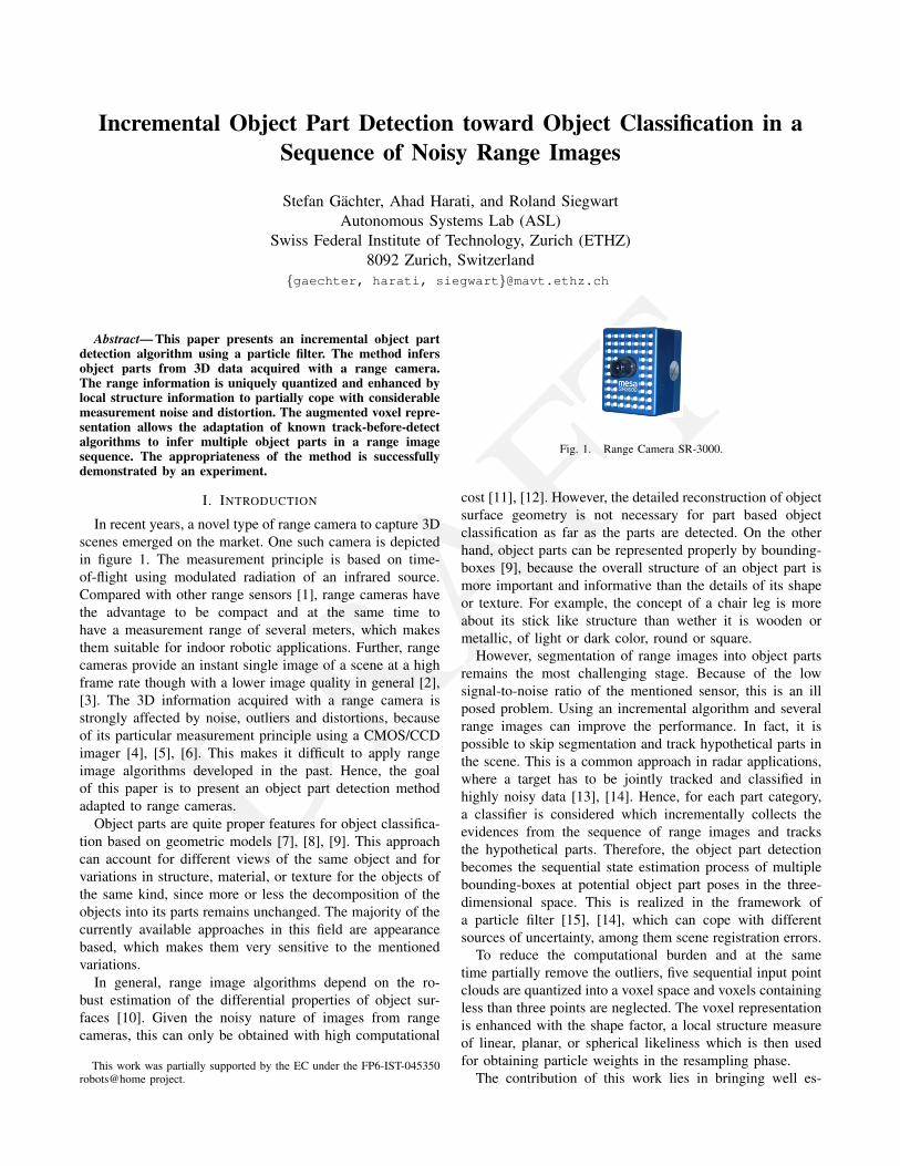
In recent years, a novel type of range camera to capture 3Dscenes emerged on the market. One such camera is depictedin figure 1. The measurement principle is based on time-of-flight using modulated radiation of an infrared source.Compared with other range sensors [1], range cameras havethe advantage to be compact and at the same time tohave a measurement range of several meters, which makesthem suitable for indoor robotic applications. Further, rangecameras provide an instant single image of a scene at a highframe rate though with a lower image quality in general [2],[3]. The 3D information acquired with a range camera isstrongly affected by noise, outliers and distortions, becauseof its particular measurement principle using a CMOS/CCDimager [4], [5], [6]. This makes it difficult to apply rangeimage algorithms developed in the past. Hence, the goalof this paper is to present an object part detection methodadapted to range cameras.
Object parts are quite proper features for object classifica-tion based on geometric models [7], [8], [9]. This approachcan account for different views of the same object and forvariations in structure, material, or texture for the objects ofthe same kind, since more or less the decomposition of theobjects into its parts remains unchanged. The majority of thecurrently available approaches in this field are appearancebased, which makes them very sensitive to the mentionedvariations.
In general, range image algorithms depend on the ro-bust estimation of the differential properties of object sur-faces [10]. Given the noisy nature of images from rangecameras, this can only be obtained with high computational
This work was partially supported by the EC under the FP6-IST-045350robots@home project.
Fig. 1. Range Camera SR-3000.
cost [11], [12]. However, the detailed reconstruction of objectsurface geometry is not necessary for part based objectclassification as far as the parts are detected. On the otherhand, object parts can be represented properly by bounding-boxes [9], because the overall structure of an object part ismore important and informative than the details of its shapeor texture. For example, the concept of a chair leg is moreabout its stick like structure than wether it is wooden ormetallic, of light or dark color, round or square.
However, segmentation of range images into object partsremains the most challenging stage. Because of the lowsignal-to-noise ratio of the mentioned sensor, this is an illposed problem. Using an incremental algorithm and severalrange images can improve the performance. In fact, it ispossible to skip segmentation and track hypothetical parts inthe scene. This is a common approach in radar applications,where a target has to be jointly tracked and classified inhighly noisy data [13], [14]. Hence, for each part category,a classifier is considered which incrementally collects theevidences from the sequence of range images and tracksthe hypothetical parts. Therefore, the object part detectionbecomes the sequential state estimation process of multiplebounding-boxes at potential object part poses in the three-dimensional space. This is realized in the framework ofa particle filter [15], [14], which can cope with differentsources of uncertainty, among them scene registration errors.
To reduce the computational burden and at the sametime partially remove the outliers, five sequential input pointclouds are quantized into a voxel space and voxels containingless than three points are neglected. The voxel representationis enhanced with the shape factor, a local structure measureof linear, planar, or spherical likeliness which is then usedfor obtaining particle weights in the resampling phase.
The contribution of this work lies in bringing well es-
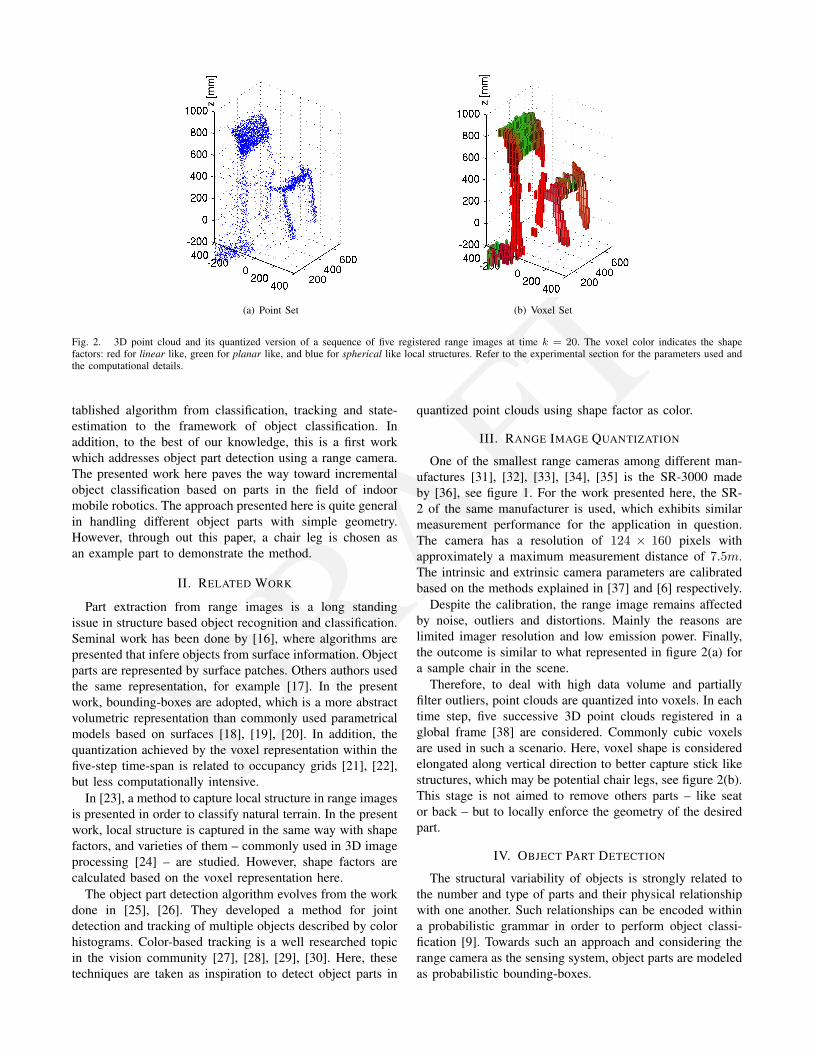
DRAFT(a) Point Set (b) Voxel Set
Fig. 2. 3D point cloud and its quantized version of a sequence of five registered range images at time k = 20. The voxel color indicates the shapefactors: red for linear like, green for planar like, and blue for spherical like local structures. Refer to the experimental section for the parameters used andthe computational details.
tablished algorithm from classification, tracking and state-estimation to the framework of object classification. Inaddition, to the best of our knowledge, this is a first workwhich addresses object part detection using a range camera.The presented work here paves the way toward incrementalobject classification based on parts in the field of indoormobile robotics. The approach presented here is quite generalin handling different object parts with simple geometry.However, through out this paper, a chair leg is chosen asan example part to demonstrate the method.
II. RELATED WORK
Part extraction from range images is a long standingissue in structure based object recognition and classification.Seminal work has been done by [16], where algorithms arepresented that infere objects from surface information. Objectparts are represented by surface patches. Others authors usedthe same representation, for example [17]. In the presentwork, bounding-boxes are adopted, which is a more abstractvolumetric representation than commonly used parametricalmodels based on surfaces [18], [19], [20]. In addition, thequantization achieved by the voxel representation within thefive-step time-span is related to occupancy grids [21], [22],but less computationally intensive.
In [23], a method to capture local structure in range imagesis presented in order to classify natural terrain. In the presentwork, local structure is captured in the same way with shapefactors, and varieties of them – commonly used in 3D imageprocessing [24] – are studied. However, shape factors arecalculated based on the voxel representation here.
The object part detection algorithm evolves from the workdone in [25], [26]. They developed a method for jointdetection and tracking of multiple objects described by colorhistograms. Color-based tracking is a well researched topicin the vision community [27], [28], [29], [30]. Here, thesetechniques are taken as inspiration to detect object parts in
quantized point clouds using shape factor as color.
III. RANGE IMAGE QUANTIZATION
One of the smallest range cameras among different man-ufactures [31], [32], [33], [34], [35] is the SR-3000 madeby [36], see figure 1. For the work presented here, the SR-2 of the same manufacturer is used, which exhibits similarmeasurement performance for the application in question.The camera has a resolution of 124 × 160 pixels withapproximately a maximum measurement distance of 7.5m.The intrinsic and extrinsic camera parameters are calibratedbased on the methods explained in [37] and [6] respectively.
Despite the calibration, the range image remains affectedby noise, outliers and distortions. Mainly the reasons arelimited imager resolution and low emission power. Finally,the outcome is similar to what represented in figure 2(a) fora sample chair in the scene.
Therefore, to deal with high data volume and partiallyfilter outliers, point clouds are quantized into voxels. In eachtime step, five successive 3D point clouds registered in aglobal frame [38] are considered. Commonly cubic voxelsare used in such a scenario. Here, voxel shape is consideredelongated along vertical direction to better capture stick likestructures, which may be potential chair legs, see figure 2(b).This stage is not aimed to remove others parts – like seator back – but to locally enforce the geometry of the desiredpart.
IV. OBJECT PART DETECTION
The structural variability of objects is strongly related tothe number and type of parts and their physical relationshipwith one another. Such relationships can be encoded withina probabilistic grammar in order to perform object classi-fication [9]. Towards such an approach and considering therange camera as the sensing system, object parts are modeledas probabilistic bounding-boxes.
DRAFT(a) Maximum (b) Sum (c) Volume
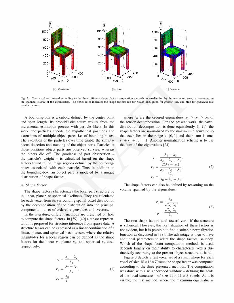
Fig. 3. Test voxel set colored according to the three different shape factor computation methods: normalization by the maximum, sum, or reasoning onthe spanned volume of the eigenvalues. The voxel color indicates the shape factors: red for linear like, green for planar like, and blue for spherical likelocal structures.
A bounding-box is a cuboid defined by the center pointand span length. Its probabilistic nature results from theincremental estimation process with particle filters. In thiswork, the particles encode the hypothetical positions andextensions of multiple object parts, i.e. of bounding-boxes.The evolution of the particles over time enable the simulta-neous detection and tracking of the object parts. Particles atthose positions object parts are observed survive, whereasthe others die off. The goodness of part observation –the particle’s weight – is calculated based on the shapefactors found in the image regions defined by the bounding-boxes associated with each particle. Thus in addition tothe bounding-box, an object part is modeled by a uniquedistribution of shape factors.
A. Shape Factor
The shape factors characterizes the local part structure byits linear, planar, or spherical likeliness. They are calculatedfor each voxel from its surrounding spatial voxel distributionby the decomposition of the distribution into the principalcomponents – a set of ordered eigenvalues and -vectors.
In the literature, different methods are presented on howto compute the shape factors. In [39], [40] a tensor represen-tation is proposed for structure inference from sparse data. Astructure tensor can be expressed as a linear combination of alinear, planar, and spherical basis tensor, where the relativemagnitudes for a local region can be defined as the shapefactors for the linear rl, planar rp, and spherical rs case,respectively:
rl =λ1 − λ2
λ1,
rp =λ2 − λ3
λ1,
rs =λ3
λ1,
(1)
where λi are the ordered eigenvalues λ1 ≥ λ2 ≥ λ3 ofthe tensor decomposition. For the present work, the voxeldistribution decomposition is done equivalently. In (1), theshape factors are normalized by the maximum eigenvalue sothat each lies in the range ∈ [0, 1] and their sum is one,rl + rp + rs = 1. Another normalization scheme is to usethe sum of the eigenvalues [24]:
rl =λ1 − λ2
λ3 + λ2 + λ1,
rp =2(λ2 − λ3)λ3 + λ2 + λ1
,
rs =3λ3
λ3 + λ2 + λ1.
(2)
The shape factors can also be defined by reasoning on thevolume spanned by the eigenvalues:
rl =λ1√λ2 λ3
,
rp =√λ2 λ1
λ3.
(3)
The two shape factors tend toward zero, if the structureis spherical. However, the normalization of these factors isnot evident, but it is possible to find a suitable normalizationfunction as discussed in [38]. The advantage is then to haveadditional parameters to adapt the shape factors’ saliency.Which of the shape factor computation methods is used,depends largely on their ability to characterize voxels dis-tinctively according to the present object structure at hand.
Figure 3 depicts a test voxel set of a chair, where for eachvoxel of size 15×15×70mm the shape factor was computedaccording to the three presented methods. The computationwas done with a neighborhood window – defining the scaleof the local structure – of size 11 × 11 × 3 voxels. As it isvisible, the first method, where the maximum eigenvalue is
DRAFT0 0.2 0.4 0.6 0.8 1
0
0.05
0.1
0.15
0.2
0.25
0.3
0.35
0.4
Shape Factor Histogram
(a) Maximum
0 0.2 0.4 0.6 0.8 10
0.05
0.1
0.15
0.2
0.25
0.3
0.35
0.4
Shape Factor Histogram
(b) Sum
0 0.2 0.4 0.6 0.8 10
0.05
0.1
0.15
0.2
0.25
0.3
0.35
0.4
Shape Factor Histogram
(c) Volume
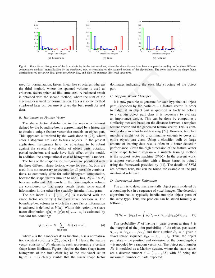
Fig. 4. Shape factor histograms of the front chair leg in the test voxel set, where the shape factors have been computed according to the three differentcomputation methods: normalization by the maximum, sum, or reasoning on the spanned volume of the eigenvalues. The color indicates the shape factordistribution: red for linear like, green for planar like, and blue for spherical like local structures.
used for normalization, favors linear like structures, whereasthe third method, where the spanned volume is used ascriterion, favors spherical like structures. A balanced resultis obtained with the second method, where the sum of theeigenvalues is used for normalization. This is also the methodemployed later on, because it gives the best result for realdata.
B. Histogram as Feature Vector
The shape factor distribution in the region of interestdefined by the bounding-box is approximated by a histogramto obtain a unique feature vector that models an object part.This approach is inspired by the work done in [27], wherecolor histograms are used to track objects. In the presentapplication, histograms have the advantage to be robustagainst the structural variability of object parts: rotation,partial occlusion, and scale have little effect on the model.In addition, the computational cost of histograms is modest.
The bins of the shape factor histogram are populated withthe three different shape factors, where for each Nb bins areused. It is not necessary to account for all possible combina-tions, as commonly done for color histogram computation,because the shape factors sum up to one. Thus, Nt = 3×Nb
bins are sufficient. All voxels in the bounding-box volumeare considered so that empty voxels retain some spatialinformation in the otherwise spatially invariant histogram.
The bin index b ∈ {1, . . . , Nt} is associated with theshape factor vector r(u) for each voxel position u. Thebounding-box volume in which the shape factor informationis gathered is defined as V (x). Within this region the shapefactor distribution q(x) = {q(n;x)}n=1...Nt
is estimated bystandard bin counting:
q(n;x) = K∑
u∈V (x)
δ(b(x)− n), (4)
where δ is the Kronecker delta function; K is a normaliza-tion constant ensuring
∑Nt
n=1 q(n;x) = 1. Hence, the featurevector consists of Nt elements, each representing a certainshape factor likeliness. Figure 4 depicts the three shape factorhistograms of the front chair leg of the test voxel set infigure 3. It is clearly visible that the linear shape factor
dominates indicating the stick like structure of the objectpart.
C. Support Vector Classifier
It is now possible to generate for each hypothetical objectpart – encoded by the particles – a feature vector. In orderto judge, if an object part in question is likely to belongto a certain object part class it is necessary to evaluatean importance weight. This can be done by computing asimilarity measure based on the distance between a templatefeature vector and the generated feature vector. This is com-monly done in color based tracking [27]. However, templatematching might not be discriminative enough to cover anentire object part class. Using a classifier built on largeamount of training data results often in a better detectionperformance. Given the high dimension of the feature vector– the shape factor histogram – a suitable training methodis the support vector machine (SVM). In the present work,a support vector classifier with a linear kernel is trainedusing the framework provided by [41]. The details of SVMare omitted here, but can be found for example in the justmentioned reference.
D. Incremental State Estimation
The aim is to detect incrementally object parts modeled bya bounding-box in a sequence of voxel images. The detectionalgorithm has to typically handle multiple object parts ofthe same type. Thus, the problem can be stated formally asfollows:
P (Rk = r|z1:k) =∫p(Rk = r,x1:r,k|z1:k)dx1:r,k. (5)
The probability P of having r parts present at time k isthe marginal of the joint probability of the object part statesx1:r,k = [x1,k, . . . ,xr,k] and their number Rk = r given avoxel image sequence z1:k = z1, . . . , zk. Thus, the objectpart state – the position and extension of the bounding-box– is modeled by a random vector xk. The object part numberRk is modeled as a Markov system, where the state valuesare a discrete number r = {1, . . . ,M} with M being themaximum number of parts expected.
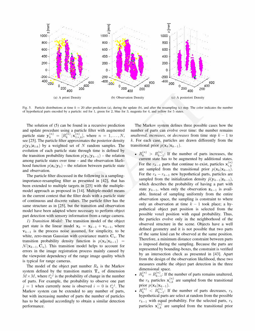
DRAFT(a) A priori Density (b) Observation Density (c) A posteriori Density
Fig. 5. Particle distributions at time k = 20 after prediction (a), during the update (b), and after the resampling (c) step. The color indicates the numberof hypothetical parts encoded by a particle: red for 1, green for 2, blue for 3, magenta for 4, and yellow for 5 states.
The solution of (5) can be found in a recursive predictionand update procedure using a particle filter with augmentedparticle state y(n)
k = [R(n)k ;x(n)
1:r,k], where n = 1, . . . , N ,see [25]. The particle filter approximates the posterior densityp(yk|z1:k) by a weighted set of N random samples. Theevolution of each particle state through time is defined bythe transition probability function p(yk|yk−1) – the relationamong particle states over time – and the observation likeli-hood function p(zk|yk) – the relation between particle stateand observation.
The particle filter discussed in the following is a sampling-importance-resampling filter as presented in [42], that hasbeen extended to multiple targets in [25] with the multiple-model approach as proposed in [14]. Multiple-model meansin the current context that the filter deals with a particle stateof continuous and discrete values. The particle filter has thesame structure as in [25], but the transition and observationmodel have been adapted where necessary to perform objectpart detection with sensory information from a range camera.
1) Transition Model: The transition model of the objectpart state is the linear model xk = xk−1 + vk−1, wherevk−1 is the process noise assumed, for simplicity, to bewhite, zero-mean Gaussian with covariance matrix Cu. Thetransition probability density function is p(xk|xk−1) =N (xk−1,Cu). This transition model helps to account forerrors in the image registration process mainly caused bythe viewpoint dependency of the range image quality whichis typical for range cameras.
The model of the object part number Rk is the Markovsystem defined by the transition matrix Tu of dimensionM×M , where ti,ju is the probability of change in the numberof parts. For example, the probability to observe one partj = 1 when currently none is observed i = 0 is ti,ju . TheMarkov system can be extended to any number of parts,but with increasing number of parts the number of particleshas to be adjusted accordingly to obtain a similar detectionperformance.
The Markov system defines three possible cases how thenumber of parts can evolve over time: the number remainsunaltered, increases, or decreases from time step k − 1 tok. For each case, particles are drawn differently from thetransitional prior p(xk|xk−1).
• R(n)k > R
(n)k−1: If the number of parts increases, the
current state has to be augmented by additional states.For the rk−1 parts that continue to exist, particles x(n)
i,k
are sampled from the transitional prior p(xk|xk−1).For the rk − rk−1 new hypothetical parts, particles aresampled from the initialization density p(yk−1|zk−1),which describes the probability of having a part withstate yk−1, when only the observation zk−1 is avail-able. Instead of sampling uniformly from the entireobservation space, the sampling is constraint to whereonly an observation at time k − 1 took place; a hy-pothetical object part position is selected from thepossible voxel position with equal probability. Thus,the particles evolve only in the neighborhood of theobserved structure in the scene. Objects have a welldefined geometry and it is not possible that two partsof the same kind can be observed at the same position.Therefore, a minimum distance constraint between partsis imposed during the sampling. Because the parts arerepresented by bounding-boxes, the constraint is verifiedby an intersection check as presented in [43]. Apartfrom the design of the observation likelihood, these twomeasures enable the object part detection in the threedimensional space.
• R(n)k = R
(n)k−1: If the number of parts remains unaltered,
the rk particles x(n)i,k are sampled from the transitional
prior p(xk|xk−1).• R
(n)k < R
(n)k−1: If the number of parts decreases, rk
hypothetical parts are select at random from the possiblerk−1 with equal probability. For the selected parts, rkparticles x(n)
i,k are sampled from the transitional prior
DRAFT
p(xk|xk−1).2) Observation Model: The observation likelihood func-
tion generates the importance weights used to incorpo-rate the measurement information zk in the particle set{y(1)
k , . . . ,y(N)k }. Given the problem at hand – the parts have
to be detected from various view angles out of sparse andnoisy data – the observation model is a non-linear functionzk = g(xk,wk) of the part state xk and measurementnoise wk. Instead of using a generative observation model,as it is common in a Bayesian estimation framework, adiscriminative one is selected [44], i.e. the learned supportvector machine presented previously.
In the detection framework, the observation likelihoodfunction is defined by the comparison of the probability thatan object part is present with that an object part is absent.This is equivalent to the likelihood ratio of the classificationprobabilities computed with the learned classifier. Assumingthat the classification can be done independently for eachhypothetical object part, the likelihood ratio is then
L(Rk) =r∏
i=1
p(zk|xi,k)1− p(zk|xi,k)
. (6)
Considering the classification probability p(zk|xi,k) asa discriminative measure ai,k in the range ∈ [0, 1], thelikelihood ratio can be expressed as
L(Rk) = exp
(−1b
r∑i=1
(1− 2ai,k)
), (7)
where b is a parameter to adjust the observation sensitivity,which has to be determined experimentally. With this defini-tion, the likelihood ratio takes large values in the 3D spacewhere object parts are present and correctly identified.
Thus, the unnormalized importance weight π(n)k for each
particle with state y(n)k = [R(n)
k ;x(n)1:r,k] is computed as:
π(n)k =
{1, if R
(n)k = 0
L(R(n)k ), if R
(n)k > 0.
(8)
The likelihood ratio defined above has a pivoting point fora probability equal 0.5. Further, particles with large numberof hypothetical object parts but having a classification proba-bility only slightly greater than 0.5 are favored over particleswith small number of parts but having a high probability.Hence, the object part detection algorithm has an inherenttendency for exploration.
V. EXPERIMENT
The above discussed incremental object part detectionmethod is exemplified by the detection of chair legs, alinear object structure in vertical direction. It is reasonableto assume – especially for indoor robotic applications – thatthe pose of the range camera with respect to the groundplane can be inferred. With this knowledge, the object partrepresentation of the class of chair legs can be simplified:a bounding-box defined by its center point position s =[sx, sy, sz]T and span length t = [tx, ty, tz]T. For other
0 0.2 0.4 0.6 0.8 10
0.2
0.4
0.6
0.8
1ROC Curve
False Positive Rate
Tru
e P
ositi
ve R
ate
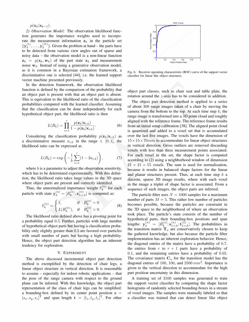
Fig. 6. Receiver operating characteristic (ROC) curve of the support vectorclassifier for linear like object structures.
object part classes, such as chair seat and table plate, therotation around the z-axis has to be considered in addition.
The object part detection method is applied to a seriesof about 300 range images taken of a chair by moving thecamera from the bottom to the top. At each time step k, therange image is transformed into a 3D point cloud and roughlyaligned with the reference frame. The reference frame resultsfrom an initial setup calibration [38]. The aligned point cloudis quantized and added to a voxel set that is accumulatedover the last five images. The voxels have the dimension of15×15×70mm to accommodate for linear object structuresin vertical direction. Gross outliers are removed discardingvoxels with less than three measurement points associated.For each voxel in the set, the shape factor is computedaccording to (2) using a neighborhood window of dimension21 × 21 × 15 voxels. The sum is used for normalization,because it results in balanced shape factors for the linearand planar structures present. Thus, at each time step k adiscrete, sparse 3D image results, where with each voxelin the image a triplet of shape factor is associated. From asequence of such images, the object parts are inferred.
The particle filter uses N = 1000 samples for a maximumnumber of parts M = 5. This rather low number of particlesbecomes possible, because the particles are constraint inthe 3D space to the neighborhood of where an observationtook place. The particle’s state consists of the number ofhypothetical parts, their bounding-box positions and spanlengths: y(n)
k = [R(n)k ; s(n)
1:r,k; t(n)1:r,k]. The probabilities in
the transition matrix Tu are conservatively chosen to keepthe gathered knowledge, but also because the particle filterimplementation has an inherent exploration behavior. Hence,the diagonal entries of the matrix have a probability of 0.7,the entries from r to r + 1 parts have a probability of0.1, and the remaining entries have a probability of 0.05.The covariance matrix Cu for the transition model has thediagonal entries of 100, 100, and 2500mm2. Importance isgiven to the vertical direction to accommodate for the highpart position uncertainty in this dimension.
A training set of 3100 samples was generated to trainthe support vector classifier by computing the shape factorhistograms of randomly selected bounding-boxes in a streamof voxel images. The samples were manually labeled so thata classifier was trained that can detect linear like object
DRAFT0 5 10 15 20
0
0.2
0.4
0.6
0.8
1
k
P(R
= r
|z)
(a) Part Presence Probability (b) Estimated Parts
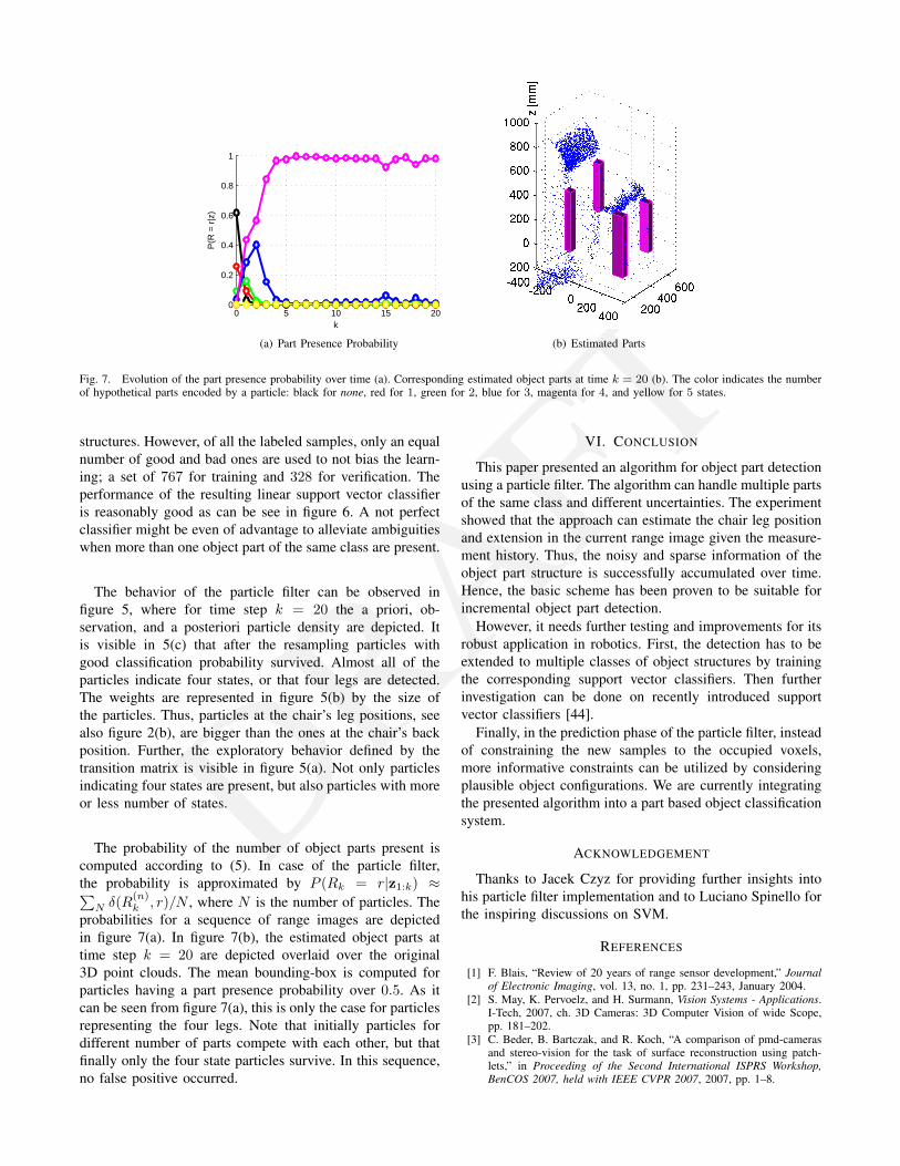
Fig. 7. Evolution of the part presence probability over time (a). Corresponding estimated object parts at time k = 20 (b). The color indicates the numberof hypothetical parts encoded by a particle: black for none, red for 1, green for 2, blue for 3, magenta for 4, and yellow for 5 states.
structures. However, of all the labeled samples, only an equalnumber of good and bad ones are used to not bias the learn-ing; a set of 767 for training and 328 for verification. Theperformance of the resulting linear support vector classifieris reasonably good as can be see in figure 6. A not perfectclassifier might be even of advantage to alleviate ambiguitieswhen more than one object part of the same class are present.
The behavior of the particle filter can be observed infigure 5, where for time step k = 20 the a priori, ob-servation, and a posteriori particle density are depicted. Itis visible in 5(c) that after the resampling particles withgood classification probability survived. Almost all of theparticles indicate four states, or that four legs are detected.The weights are represented in figure 5(b) by the size ofthe particles. Thus, particles at the chair’s leg positions, seealso figure 2(b), are bigger than the ones at the chair’s backposition. Further, the exploratory behavior defined by thetransition matrix is visible in figure 5(a). Not only particlesindicating four states are present, but also particles with moreor less number of states.
The probability of the number of object parts present iscomputed according to (5). In case of the particle filter,the probability is approximated by P (Rk = r|z1:k) ≈∑
N δ(R(n)k , r)/N , where N is the number of particles. The
probabilities for a sequence of range images are depictedin figure 7(a). In figure 7(b), the estimated object parts attime step k = 20 are depicted overlaid over the original3D point clouds. The mean bounding-box is computed forparticles having a part presence probability over 0.5. As itcan be seen from figure 7(a), this is only the case for particlesrepresenting the four legs. Note that initially particles fordifferent number of parts compete with each other, but thatfinally only the four state particles survive. In this sequence,no false positive occurred.
VI. CONCLUSION
This paper presented an algorithm for object part detectionusing a particle filter. The algorithm can handle multiple partsof the same class and different uncertainties. The experimentshowed that the approach can estimate the chair leg positionand extension in the current range image given the measure-ment history. Thus, the noisy and sparse information of theobject part structure is successfully accumulated over time.Hence, the basic scheme has been proven to be suitable forincremental object part detection.
However, it needs further testing and improvements for itsrobust application in robotics. First, the detection has to beextended to multiple classes of object structures by trainingthe corresponding support vector classifiers. Then furtherinvestigation can be done on recently introduced supportvector classifiers [44].
Finally, in the prediction phase of the particle filter, insteadof constraining the new samples to the occupied voxels,more informative constraints can be utilized by consideringplausible object configurations. We are currently integratingthe presented algorithm into a part based object classificationsystem.
ACKNOWLEDGEMENT
Thanks to Jacek Czyz for providing further insights intohis particle filter implementation and to Luciano Spinello forthe inspiring discussions on SVM.
REFERENCES
[1] F. Blais, “Review of 20 years of range sensor development,” Journalof Electronic Imaging, vol. 13, no. 1, pp. 231–243, January 2004.
[2] S. May, K. Pervoelz, and H. Surmann, Vision Systems - Applications.I-Tech, 2007, ch. 3D Cameras: 3D Computer Vision of wide Scope,pp. 181–202.
[3] C. Beder, B. Bartczak, and R. Koch, “A comparison of pmd-camerasand stereo-vision for the task of surface reconstruction using patch-lets,” in Proceeding of the Second International ISPRS Workshop,BenCOS 2007, held with IEEE CVPR 2007, 2007, pp. 1–8.
DRAFT
[4] O. Gut, “Untersuchungen des 3D-Sensors SwissRanger,”Master’s thesis, Institute of Geodesy and Photogrammetry- Swiss Federal Institute of Technology, Zurich, 2004,http://www.geometh.ethz.ch/publicat/diploma/gut2004/ (14.9.2007).
[5] S. A. Gudmundsson, H. Aanaes, and R. Larsen, “Environmentaleffects on measurement uncertainties of time-of-flight cameras,” inInternational Symposium on Signals, Circuits and Systems (ISSCS2007), vol. 1, 2007, pp. 1–4.
[6] S. May, B. Werner, H. Surmann, and K. Pervolz, “3D time-of-flightcameras for mobile robotics,” in Proceedings of the 2006 IEEE/RSJInternational Conference on Intelligent Robots and Systems, 2006.
[7] R. A. Brooks, “Symbolic reasoning among 3-D models and 2-Dimages,” Artificial Intelligence, vol. 17, pp. 285–348, 1981.
[8] L. Stark and K. W. Bowyer, Generic Object Recognition usingForm and Function, ser. Series in Machine Perception and ArtificialIntelligence, H. W. P. Bunke, Ed. World Scientific, 1996.
[9] M. A. Aycinena, “Probabilistic geometric grammars for object recog-nition,” Master’s thesis, Massachusetts Institute of Technology - De-partment of Electrical Engineering and Computer Science, 2005.
[10] P. J. Besl, Surfaces In Range Image Understanding. Springer-VerlagInc., New York, 1988.
[11] G. Danuser and M. Stricker, “Parametric model fitting: From inliercharacterization to outlier detection,” IEEE Transactions on PatternAnalysis and Machine Intelligence, vol. 20, no. 3, pp. 263–280, March1998.
[12] H. Wang and D. Suter, “Robust adaptive-scale parametric model esti-mation for computer vision,” IEEE Transactions on Pattern Analysisand Machine Intelligence, vol. 26, no. 11, pp. 1459–1474, November2004.
[13] Y. Bar-Shalom and X. R. Li, Estimation and Tracking: Principles,Techniques, and Software. Artech House, 1993.
[14] B. Ristic, S. Arulampalam, and N. Gordon, Beyond the Kalman Filter- Particle Filters for Tracking Applications. Artech House, 2004.
[15] Y. Boers and H. Driessen, “A particle-filter-based detection scheme,”Signal Processing Letters, IEEE, vol. 10, no. 10, pp. 300–302, October2003.
[16] R. B. Fisher, From Surfaces to Objects - Computer Vision and ThreeDimensional Scene Analysis. John Wiley & Sons Ltd., Chichester,Great Britain, 1989, http://homepages.inf.ed.ac.uk/rbf/BOOKS/FSTO/(14.9.2007).
[17] N. S. Raja and A. K. Jain, “Obtaining generic parts from range imagesusing a multi-view representation,” CVGIP: Image Understanding,vol. 60, no. 1, pp. 44–64, 1994.
[18] Q.-L. Nguyen and M. D. Levine, “Representing 3-d objects in rangeimages using geons,” Computer Vision and Image Understanding,vol. 63, no. 1, pp. 158–168, 1996.
[19] H. Rom and G. Medioni, “Part decomposition and description of 3Dshapes,” in Proceedings of the 12th IAPR International Conference onPattern Recognition, vol. 1, 1994, pp. 629–632.
[20] W. H. Field, D. L. Borges, and R. B. Fisher, “Class-based recognitionof 3D objects represented by volumetric primitives,” Image and VisionComputing, vol. 15, no. 8, pp. 655–664, August 1997.
[21] J. P. Jones, “Real-time construction of three-dimensional occupancymaps,” in Proceedings of the IEEE International Conference onRobotics and Automation (ICRA ’93), vol. 1, 1993, pp. 52–57.
[22] P. Payeur, P. Hebert, D. Laurendeau, and C. Gosselin, “Probabilisticoctree modeling of a 3d dynamic environment,” in Robotics andAutomation, 1997. Proceedings., 1997 IEEE International Conferenceon, vol. 2, 1997, pp. 1289–1296.
[23] N. Vandapel, D. Huber, A. Kapuria, and M. Hebert, “Natural terrainclassification using 3-d ladar data,” in Proceedings of the IEEEInternational Conference on Robotics and Automation (ICRA ’04),vol. 5, 2004, pp. 5117–5122.
[24] C.-F. Westin, S. Peled, H. Gudbjartsson, R. Kikinis, and F. A. Jolesz,“Geometrical diffusion measures for MRI from tensor basis analysis,”in Proceedings of the 5th Annual Meeting of the International Societyfor Magnetic Resonance Medicine (ISMRM), 1997, p. 1742.
[25] J. Czyz, B. Ristic, and B. Macq, “A color-based particle filter for jointdetection and tracking of multiple objects,” in Proceedings of the IEEEInternational Conference on Acoustics, Speech, and Signal Processing(ICASSP ’05), vol. 2, 2005, pp. 217–220.
[26] Y. Boers and H. Driessen, “Hybrid state estimation: A target trackingapplication,” Automatica, vol. 38, December 2002.
[27] P. Perez, C. Hue, J. Vermaak, and M. Gangnet, “Color-based proba-bilistic tracking,” in Proceedings of the European Conference Com-
puter Vision (ECCV), ser. LNCS 2350, A. H. et al., Ed. Springer-Verlag, 2002.
[28] K. Nummiaro, E. Koller-Meier, and L. J. Van Gool, “Object trackingwith an adaptive color-based particle filter,” in Proceedings of the 24thDAGM Symposium on Pattern Recognition, 2002, pp. 353–360.
[29] E. Maggio and A. Cavallaro, “Hybrid particle filter and mean shifttracker with adaptive transition model,” in Proceedings of the IEEEInternational Conference on Acoustics, Speech, and Signal Processing(ICASSP ’05), vol. 2, 2005, pp. 221–224.
[30] H. Wang, D. Suter, K. Schindler, and C. Shen, “Adaptive objecttracking based on an effective appearance filter,” IEEE Transactions onPattern Analysis and Machine Intelligence, vol. 29, no. 9, pp. 1661–1667, 2007.
[31] Canesta Inc., USA, http://www.canesta.com/ (13.9.2007).[32] PMDTechnologies GmbH, Germany, http://www.pmdtec.com/
(13.9.2007).[33] Matsushita Electric Industrial Co. Ltd, Japan,
http://biz.national.jp/Ebox/security/tomozure/index.html/ (13.9.2007).[34] Sharp Co., Japan, http://www.sharp.co.jp/corporate/news/060323-
a.html/ (13.12.2006).[35] 3DV Systems, Israel, http://www.3dvsystems.com/ (13.9.2007).[36] MESA Imaging AG, Switzerland, http://www.swissranger.ch/
(13.9.2007).[37] T. Kahlmann, F. Remondino, and H. Ingensand, “Calibration for
increased accuracy of the range imaging camera SwissRanger,” in In-ternational Archives of Photogrammetry, Remote Sensing and SpatialInformation Sciences, ISPRS Commission V Symposium, vol. XXXVI,no. 5, 2006, pp. 136–141.
[38] S. Gachter, “Incremental object part detection with a range camera,”Autonomous Systems Lab, Swiss Federal Institute of Technology,Zurich (ETHZ), Switzerland, Tech. Rep. ETHZ-ASL-2006-12, 2006.
[39] C.-F. Westin, “A tensor framework for multidimensional signal pro-cessing,” Ph.D. dissertation, Department of Electrical Engineering -Linkoping University, Sweden, 1994.
[40] G. Medioni, M.-S. Lee, and C.-K. Tang, A Computational Frameworkfor Segmentation and Grouping. Elsevier, 2000.
[41] C.-W. Hsu, C.-C. Chang, and C.-J. Lin, “A practical guide to supportvector classification,” Department of Computer Science - NationalTaiwan University, Tech. Rep. July 18, 2007, 2007.
[42] M. Isard and A. Blake, “CONDENSATION - conditional density propa-gation for visual tracking,” International Journal of Computer Vision,vol. 29, no. 1, pp. 5–28, 1998.
[43] T. Akenine-Moller and E. Haines, Real-Time Rendering, second edi-tion ed. A K Peters, 2002.
[44] C. Shen, H. Li, and M. J. Brooks, “Classification-based likelihoodfunctions for bayesian tracking,” in Proceedings of the IEEE Interna-tional Conference on Video and Signal Based Surveillance (AVSS’06),2006, p. 33.


![KLV-30MR1 - Error: [object Object]](https://static.fdokumen.com/doc/165x107/631786651e5d335f8d0a6a63/klv-30mr1-error-object-object.jpg)