In Vivo , In Situ Imaging of Microneedle Insertion into the Skin of Human Volunteers Using Optical...
16
RESEARCH PAPER In Vivo, In Situ Imaging of Microneedle Insertion into the Skin of Human Volunteers Using Optical Coherence Tomography Siôn A. Coulman & James C. Birchall & Aneesh Alex & Marc Pearton & Bernd Hofer & Conor O’Mahony & Wolfgang Drexler & Boris Považay Received: 19 January 2010 / Accepted: 28 April 2010 / Published online: 13 May 2010 # Springer Science+Business Media, LLC 2010 ABSTRACT Purpose To gather sub-surface in situ images of microneedle- treated human skin, in vivo, using optical coherence tomogra- phy (OCT). This is the first study to utilise OCT to investigate the architectural changes that are induced in skin following microneedle application. Methods Steel, silicon and polymer microneedle devices, with different microneedle arrangements and morphologies, were applied to two anatomical sites in human volunteers following appropriate ethical approval. A state-of-the-art ultrahigh resolution OCT imaging system operating at 800 nm wavelength and <3 μm effective axial resolution was used to visualise the microneedle-treated area during insertion and/or following removal of the device, without any tissue processing. Results Transverse images of a microneedle device, in situ, were captured by the OCT system and suggest that the stratified skin tissue is compressed during microneedle applica- tion. Following removal of the device, the created micro- channels collapse within the in vivo environment and, therefore, for all studied devices, microconduit dimensions are markedly smaller than the microneedle dimensions. Conclusions Microchannels created in the upper skin layers by microneedles are less invasive than previous histology predicts. OCT has the potential to play a highly influential role in the future development of microneedle devices and other transdermal delivery systems. KEY WORDS in vivo . microneedle . optical coherence tomography . skin . transdermal ABBREVIATIONS OCT Optical coherence tomography INTRODUCTION Topical application of medicinal formulations, e.g. creams, ointments and transdermal patches, is a non-invasive and patient-friendly method of drug delivery. However the barrier properties of the outermost skin layer, the stratum corneum, significantly restrict the number of drug candi- dates that can be delivered via this route. Traditional transdermal delivery systems are therefore restricted to a small number of drug candidates with specific physio- chemical properties, i.e. high potency, low molecular weight (<500 Daltons) and moderate lipophilicity (1). In the last decade, there has been a concerted effort from academic and industrial scientists to produce a delivery system that can facilitate transdermal penetration of a more diverse range of therapeutic candidates, including biological Electronic supplementary material The online version of this article (doi:10.1007/s11095-010-0167-x) contains supplementary material, which is available to authorized users. S. A. Coulman (*) : J. C. Birchall : M. Pearton Gene Delivery Research Group, Welsh School of Pharmacy Cardiff University Cardiff CF10 3NB, UK e-mail: [email protected] B. Hofer : W. Drexler : B. Považay Center of Medical Physics and Biomedical Engineering Medical University Vienna Vienna 1090, Austria A. Alex : B. Hofer : W. Drexler : B. Považay School of Optometry and Vision Sciences, Cardiff University Cardiff CF24 4LU, UK C. O’Mahony Tyndall National Institute, University College Cork, Lee Maltings Cork, Ireland Pharm Res (2011) 28:66–81 DOI 10.1007/s11095-010-0167-x
-
Upload
independent -
Category
Documents
-
view
5 -
download
0
Transcript of In Vivo , In Situ Imaging of Microneedle Insertion into the Skin of Human Volunteers Using Optical...

RESEARCH PAPER
In Vivo, In Situ Imaging of Microneedle Insertion into the Skinof Human Volunteers Using Optical Coherence Tomography
Siôn A. Coulman & James C. Birchall & Aneesh Alex & Marc Pearton & Bernd Hofer & Conor O’Mahony & Wolfgang Drexler &Boris Považay
Received: 19 January 2010 /Accepted: 28 April 2010 /Published online: 13 May 2010# Springer Science+Business Media, LLC 2010
ABSTRACTPurpose To gather sub-surface in situ images of microneedle-treated human skin, in vivo, using optical coherence tomogra-phy (OCT). This is the first study to utilise OCT to investigatethe architectural changes that are induced in skin followingmicroneedle application.Methods Steel, silicon and polymer microneedle devices,with different microneedle arrangements and morphologies,were applied to two anatomical sites in human volunteersfollowing appropriate ethical approval. A state-of-the-artultrahigh resolution OCT imaging system operating at800 nm wavelength and <3 μm effective axial resolution wasused to visualise the microneedle-treated area during insertionand/or following removal of the device, without any tissueprocessing.Results Transverse images of a microneedle device, in situ,were captured by the OCT system and suggest that the
stratified skin tissue is compressed during microneedle applica-tion. Following removal of the device, the created micro-channels collapse within the in vivo environment and, therefore,for all studied devices, microconduit dimensions are markedlysmaller than the microneedle dimensions.Conclusions Microchannels created in the upper skin layersby microneedles are less invasive than previous histologypredicts. OCT has the potential to play a highly influential rolein the future development of microneedle devices and othertransdermal delivery systems.
KEY WORDS in vivo . microneedle . optical coherencetomography. skin . transdermal
ABBREVIATIONSOCT Optical coherence tomography
INTRODUCTION
Topical application of medicinal formulations, e.g. creams,ointments and transdermal patches, is a non-invasive andpatient-friendly method of drug delivery. However thebarrier properties of the outermost skin layer, the stratumcorneum, significantly restrict the number of drug candi-dates that can be delivered via this route. Traditionaltransdermal delivery systems are therefore restricted to asmall number of drug candidates with specific physio-chemical properties, i.e. high potency, low molecularweight (<500 Daltons) and moderate lipophilicity (1). Inthe last decade, there has been a concerted effort fromacademic and industrial scientists to produce a deliverysystem that can facilitate transdermal penetration of a morediverse range of therapeutic candidates, including biological
Electronic supplementary material The online version of this article(doi:10.1007/s11095-010-0167-x) contains supplementary material,which is available to authorized users.
S. A. Coulman (*) : J. C. Birchall :M. PeartonGene Delivery Research Group, Welsh School of PharmacyCardiff UniversityCardiff CF10 3NB, UKe-mail: [email protected]
B. Hofer :W. Drexler : B. PovažayCenter of Medical Physics and Biomedical EngineeringMedical University ViennaVienna 1090, Austria
A. Alex : B. Hofer :W. Drexler : B. PovažaySchool of Optometry and Vision Sciences, Cardiff UniversityCardiff CF24 4LU, UK
C. O’MahonyTyndall National Institute, University College Cork, Lee MaltingsCork, Ireland
Pharm Res (2011) 28:66–81DOI 10.1007/s11095-010-0167-x
macromolecules. Such a feat could revolutionise drugdelivery to and through the skin.
One proposed strategy to overcome the skin barrier is tocreate conduits, with micron dimensions, within theepidermal layer either by localised tissue ablation (thermalablation (2,3), radiofrequency ablation (4,5)) or mechanicalpenetration (microneedle devices (6)). Interestingly, thelatter of these technologies, the microneedle device, wasconceptualised in the 1970s (7). However, it was the adventof silicon microfabrication methods, developed for themicroelectronics industry, which enabled manufacture ofthe first microneedle device (8). In the last decade,engineering capabilities have developed significantly, andthe microneedle device has now been manufactured using arange of materials and in a variety of geometries (9–11).
Laboratory studies have successfully used microneedledevices to create micron-sized channels within skin.Importantly, the created conduits are able to facilitatelocalised delivery of a range of therapeutic candidates,including small drug molecules (12), peptides (13,14),proteins (15–20), nanoparticles (9,21) and plasmid DNA(22). Within such studies, the depth and morphology ofmicrochannels, which are created in the tissue uponremoval of the device, are typically characterised bytraditional histological methods. These features providethe researcher with an indication of the dimensions ofmicroneedle-induced conduits and the invasiveness ofspecific microneedle designs, and thus these studies arerelevant to drug delivery and device safety.
To date, the majority of microneedle studies have beenconducted using animal models, and, although thesemodels provide essential pre-clinical data, there aresignificant architectural and immunological differencesbetween human and animal skin (23). Therefore, micro-needle channels created in animal skin are not an accuraterepresentation of the human environment. Ex vivo humanskin provides an anatomically relevant model for micro-needle studies (24). However, excision of the skin from itsnatural environment results in considerable biomechanicalchanges to the tissue. These changes must be consideredwhen interpreting evidence of microneedle penetration.
In recent years there have been an increasing number ofstudies that have examined microneedle penetration inhuman volunteers (25–29). This provides data that canoften be directly extrapolated to the clinical environment.The principal goal of these studies has been to evaluate thepain associated with microneedle insertion. As a corollary,microneedle penetration is often assessed by application ofa staining agent to permit en face visualisation of micro-channels (26,29). Trans-epidermal water loss (TEWL) canalso provide a surrogate measure of in vivo microneedle-mediated tissue disruption (25–27); however, this laboratorytechnique suffers from a number of limitations, and the
quality of the data achieved is variable (30). Transverseimaging of microchannel structure relies upon biopsy of themicroneedle-treated skin area and subsequent histologicalanalysis, i.e. fixation and sectioning. These experimentalprocedures inevitably alter the skin structure and produceartefacts. Limitations in analytical tools and procedures havetherefore prevented the accurate elucidation of microconduitstructure in human skin, in vivo, following application of amicroneedle or similar minimally invasive device.
Significant advances have been made in optical imagingmethods over the previous decade. At the forefront of thesetechniques is optical coherence tomography (OCT). OCTis a non-invasive interferometric technique that is capableof resolving skin architecture, in vivo and in real time, atmicrometer scale and up to a depth of 1–2 mm, solelybased on local optical backscatter (31,32). The principles ofOCT are often likened to ultrasound, and the technologyhas been used to characterise structural and biomechanicalfeatures of both ‘normal’ and diseased human skin (33–39).Whilst OCT is establishing itself as a routine imagingmethod in ophthalmology, the evaluation of skin is at amore developmental stage. Continuous advancements oflight source and detection system technology have lead toimprovements in speed, resolution, sensitivity, penetrationdepth and contrast necessary for histology quality imagingin dermatology (40). Investigation of skin disruption inhuman subjects, following treatment with novel intra-/trans-dermal drug delivery systems, has not been reporteddue to the limited image quality and resolution of earlierOCT systems. Interestingly, microneedle devices have beenused in some animal studies to deliver agents across theepidermal layer, with the goal of enhancing specific OCTimaging parameters (41–43). However, these studies do notcharacterise microneedle penetration due to the limitedresolution of the OCT imaging systems that were used.
The aim of this investigation is to use a state-of-the-artOCT system, in vivo, to obtain in situ images of microneedle-treated human skin. This will provide unique informationon the morphological changes that are induced followingmicroneedle application to the skin surface. Further, thisstudy will provide evidence to support the fundamentalconcept of the microneedle device as a minimally invasivemeans to overcome the outer skin barrier and is the firstcomprehensive investigation of the potential of currentOCT imaging systems in microneedle research.
MATERIALS AND METHODS
Microneedle Devices
Two of these devices were manufactured by laser-cuttingstainless steel sheets using a process described previously
In Vivo, In Situ OCT Imaging of Microneedle Insertion 67

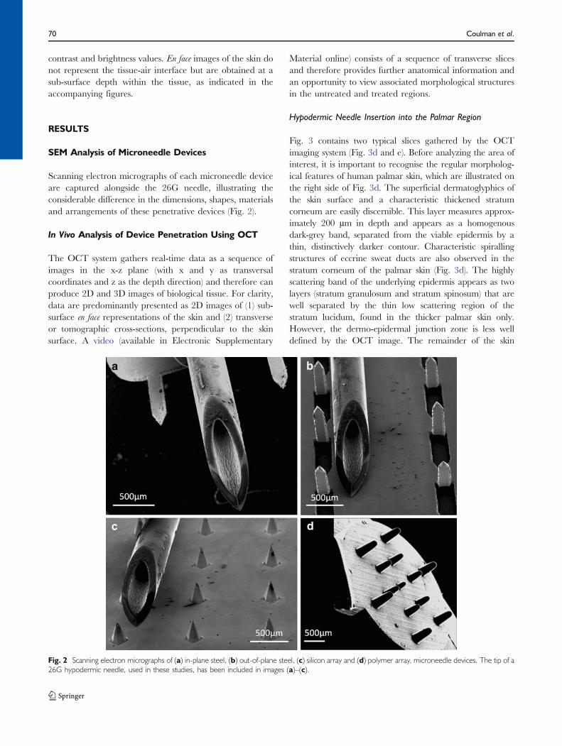
(44). Within this manuscript, these will be referred to as (A)in-plane steel microneedles, which consist of a row of fiveadjacent microneedles, and (B) out-of-plane steel micro-needles, arranged in an array of 50 microneedles thatprotrude orthogonally from a steel sheet. The third micro-needle device (C) was fabricated and supplied by TyndallNational Institute and consists of an array of siliconmicroneedles that have been produced using wet-etchingtechnology (45). The final microneedle device (D) was aprototype polycarbonate polymer array, produced atCardiff University, using an injection moulding process. A26 gauge hypodermic needle (E), used in clinical practicefor intradermal injections, was used as a comparativedelivery device. Steel microneedles (A & B) can be directlymanipulated by the user. However silicon and polymerarrays were mounted upon applicator devices, a practicalnecessity owing to their smaller dimensions. Table Iprovides a summary of the characteristics of the devicesused in this study.
SEM Analysis of Microneedle Devices
All microneedles were inspected prior to, and following,application to the skin to ensure that the integrity of thedevice was maintained. Steel microneedle devices, the
hypodermic needle and the silicon array were mountedon an aluminium stub and examined using a Philips XL-20Scanning Electron Microscope (Philips, Eindhoven, TheNetherlands). Polymer microneedles were gold sputter-coated (EM Scope, Kent, UK) prior to SEM analysis.
Optical Coherence Tomography System
Imaging was performed using a hand-held probe that wasconnected to the spectrometer-based frequency-domainOCT device via an optical fibre link (Fig. 1), operating at20,000 depth scans per second. It reached an axialresolution of <3 µm in tissue by using a broadband laserlight source (Ti:sapphire) that illuminated the tissue withless than 1 mW at 800 nm central wavelength and 160 nmbandwidth (46). The 1 Gigavoxel cube (1024×1024×1024voxel) was acquired in ∼50 s and was sampled usingparameters approaching critical sampling, approximately5 µm transversally at an approximately 10 µm transversalresolution, across a field of view of typically 9×9 mm and3 mm sampling depth. The depth of field, where the imageis still well focussed, could be specified as ∼600 µm; hence,the focus was typically set at the papillary dermis. Despitethe availability of the more penetrative broadband1,060 nm and 1,300 nm lasers, the 800 nm wavelength
Table I A Summary of the Characteristics of the Devices Used in This Study
ID Device name Microneedle characteristics
Population Order Length Material Surface finish
A In-plane steel 5 Row 700 μm Steel electropolished
B Out-of-plane steel 50 5×10 700 μm Steel electropolished
C Silicon array 16 4×4 280 μm Silicon platinum coated
D Polymer array 13 Concentric circles Outer - 600 μm Polymer polycarbonateInner - 400 μm
E Hypodermic 26G 1 – 10,000 μm Steel polished
Fig. 1 (a) Schematic representation of OCT and (b) the handheld probe used to capture images in human subjects.
68 Coulman et al.
region provided greater axial resolution and contrast whilstmaintaining sufficient penetration depth, and therefore wasselected for this study.
Study Design
Approval for the application of microneedle devices tohuman subjects was obtained from a Cardiff Universityethics committee; research followed the tenets of theDeclaration of Helsinki. Human volunteers were recruitedfrom the staff population at the Welsh School of Pharmacy,Cardiff University, and participants were provided with aninformation sheet and consent form prior to the study.Three healthy Caucasian male volunteers, aged between 21and 40 years of age with no pre-existing skin conditions,were chosen and randomly allocated to microneedle treat-ments. Participant One was treated with steel microneedles(in-plane and out-of-plane), Participant Two with thesilicon microneedles and Participant Three with polymermicroneedles. Additionally, participants were also treatedwith a 26-gauge needle, inserted into the skin at an angle ofapproximately 15°, to represent the traditional intradermalinjection process (positive control).
Two anatomical sites were selected for microneedletreatment, the upper arm and the palm. The microneedledevice is currently being investigated as a means offacilitating intradermal vaccination (18,19,28,47), and theupper arm, a recognised intradermal vaccination site (48),was therefore selected as an easily accessible and clinicallyrelevant anatomical site. At the palmar site the skinpossesses a low-scattering, thickened stratum corneumwhich is interspersed by a dense regular arrangement ofhighly scattering sweat ducts. The palmar site was thereforeselected for its optical properties and provided the greatestpossibility of microneedle channel detection using OCTimaging. Additionally, the hand is one of the most likelysites of needle-stick injury, and therefore evaluation ofmicroneedle penetration at this site would inform safetyaspects of microneedle systems.
Experimental Protocol
The study took place in Cardiff School of Optometry andVision Sciences. Following receipt of written consent, aproposed treatment area (2 cm2) on the left hand of thevolunteer was identified, swabbed with ethanol and markedon the border of the imaging region to ensure that repeatimages of the treatment site could be obtained. A handheldprobe (Fig. 1b) was then positioned on the site, andparameters of the OCT system were optimised by theoperator using the real-time preview. To avoid the strongreflections from an air interface, a thin film of indexmatching fluid (i.e. glycerine or a commercial water-based
gel) was applied to a flat tilted cover glass, which wasmounted in front of the telecentric ∼30 mm diameterobjective of the handheld probe. The gel therefore acted asa contact medium. Fixation was achieved simply by restingthe probe on the body of the subject and was secured by thehands of the operator. During alignment and measurement,the imaging volume was controlled by the real-time view ofthe local cross-section.
Following image capture, the probe was removed, andthe selected area was cleaned, swabbed and treated with themicroneedle device. Microneedle administration involveddownward application of a sterilised microneedle device tothe skin surface at a sufficient pressure to enable skinpenetration. All devices were held in place for 5 s andsubsequently withdrawn. Index matching fluid was thenapplied topically to the microneedle-treated area, whichwas imaged using the hand-held probe, as describedpreviously. The same procedure was used to examinetreatment with a sterile 26G hypodermic needle at anadjacent area (positive control). Additionally, the two-dimensional nature of the in-plane steel microneedle arrayalso permitted OCT imaging of the skin with the micro-needle device in situ. This was performed by tilting the arrayupon insertion, holding the array in position with a forcepsand subsequently applying the hand-held probe above themicroneedle-treated area. To accommodate the greaterworking distance the objective was refocused.
Following application, the microneedle devices wereimmersed in 70% ethanol for at least 24 h prior to theirvisual analysis by SEM. Volunteers remained in thetreatment room for at least 15 min following applicationof the devices to ensure there were no localised adverseeffects. The experimental protocol was then repeated forthe upper arm region.
Optical Coherence Tomography Image Analysis
After acquisition with Labview (National Instruments), thedata was stored to a high-speed RAID array and convertedfrom its original format to its three-dimensional represen-tation using specifically designed routines in Matlab (Math-works) and ImageJ (U. S. National Institutes of Health).The first stage was correction of the spectral data for non-linearities, dispersive shifts and unwanted backgroundsignals followed by conversion from its spectral form, byFourier-transformation, into a sequence of slices. Sliceswere then transversally rearranged to eliminate motionartefacts, and the tilt was numerically compensated. Thedensely sampled three-dimensional stack containing 16-bitdata was filtered to reduce noise and speckle by non-linearfiltering of outliers and local convolution. Cross-sectionsand en face scans were generated by local integration indepth across selected sites and successive adjustment of the
In Vivo, In Situ OCT Imaging of Microneedle Insertion 69
contrast and brightness values. En face images of the skin donot represent the tissue-air interface but are obtained at asub-surface depth within the tissue, as indicated in theaccompanying figures.
RESULTS
SEM Analysis of Microneedle Devices
Scanning electron micrographs of each microneedle deviceare captured alongside the 26G needle, illustrating theconsiderable difference in the dimensions, shapes, materialsand arrangements of these penetrative devices (Fig. 2).
In Vivo Analysis of Device Penetration Using OCT
The OCT system gathers real-time data as a sequence ofimages in the x-z plane (with x and y as transversalcoordinates and z as the depth direction) and therefore canproduce 2D and 3D images of biological tissue. For clarity,data are predominantly presented as 2D images of (1) sub-surface en face representations of the skin and (2) transverseor tomographic cross-sections, perpendicular to the skinsurface. A video (available in Electronic Supplementary
Material online) consists of a sequence of transverse slicesand therefore provides further anatomical information andan opportunity to view associated morphological structuresin the untreated and treated regions.
Hypodermic Needle Insertion into the Palmar Region
Fig. 3 contains two typical slices gathered by the OCTimaging system (Fig. 3d and e). Before analyzing the area ofinterest, it is important to recognise the regular morpholog-ical features of human palmar skin, which are illustrated onthe right side of Fig. 3d. The superficial dermatoglyphics ofthe skin surface and a characteristic thickened stratumcorneum are easily discernible. This layer measures approx-imately 200 µm in depth and appears as a homogenousdark-grey band, separated from the viable epidermis by athin, distinctively darker contour. Characteristic spirallingstructures of eccrine sweat ducts are also observed in thestratum corneum of the palmar skin (Fig. 3d). The highlyscattering band of the underlying epidermis appears as twolayers (stratum granulosum and stratum spinosum) that arewell separated by the thin low scattering region of thestratum lucidum, found in the thicker palmar skin only.However, the dermo-epidermal junction zone is less welldefined by the OCT image. The remainder of the skin
Fig. 2 Scanning electron micrographs of (a) in-plane steel, (b) out-of-plane steel, (c) silicon array and (d) polymer array, microneedle devices. The tip of a26G hypodermic needle, used in these studies, has been included in images (a)–(c).
70 Coulman et al.
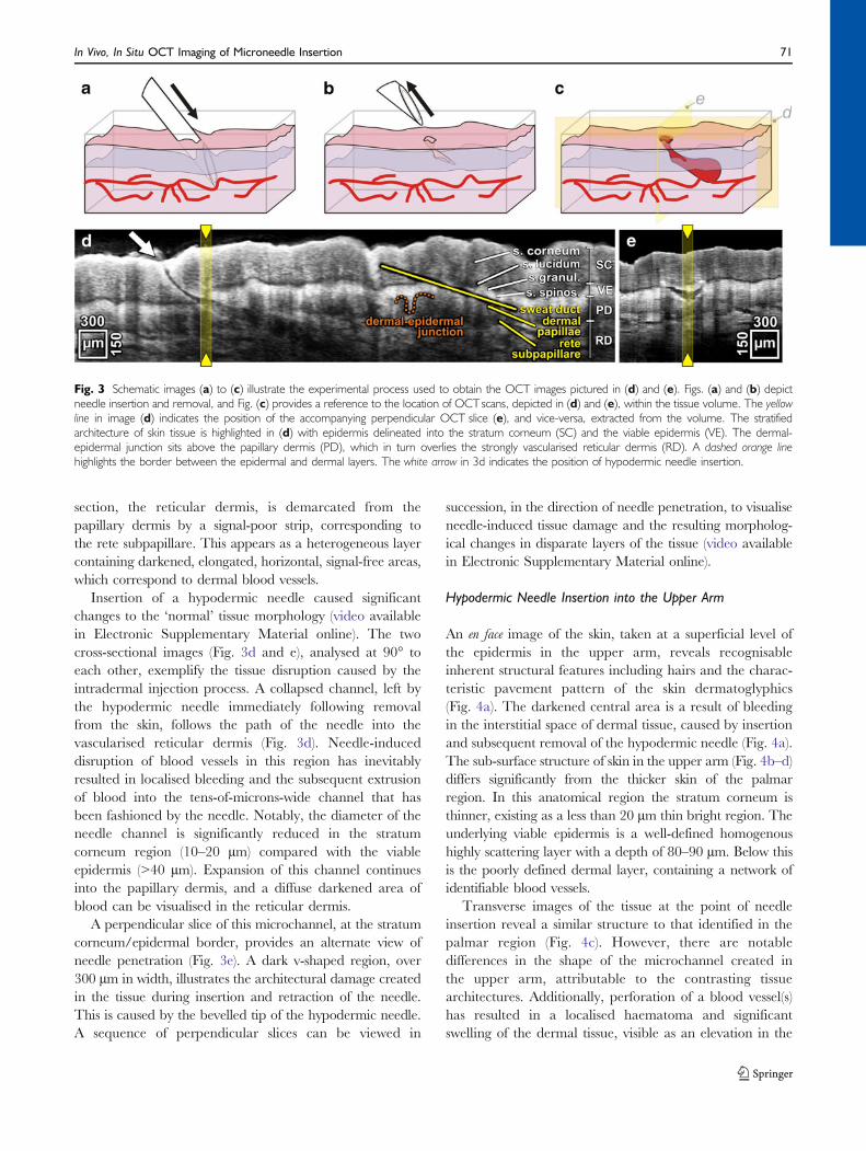
section, the reticular dermis, is demarcated from thepapillary dermis by a signal-poor strip, corresponding tothe rete subpapillare. This appears as a heterogeneous layercontaining darkened, elongated, horizontal, signal-free areas,which correspond to dermal blood vessels.
Insertion of a hypodermic needle caused significantchanges to the ‘normal’ tissue morphology (video availablein Electronic Supplementary Material online). The twocross-sectional images (Fig. 3d and e), analysed at 90° toeach other, exemplify the tissue disruption caused by theintradermal injection process. A collapsed channel, left bythe hypodermic needle immediately following removalfrom the skin, follows the path of the needle into thevascularised reticular dermis (Fig. 3d). Needle-induceddisruption of blood vessels in this region has inevitablyresulted in localised bleeding and the subsequent extrusionof blood into the tens-of-microns-wide channel that hasbeen fashioned by the needle. Notably, the diameter of theneedle channel is significantly reduced in the stratumcorneum region (10–20 µm) compared with the viableepidermis (>40 µm). Expansion of this channel continuesinto the papillary dermis, and a diffuse darkened area ofblood can be visualised in the reticular dermis.
A perpendicular slice of this microchannel, at the stratumcorneum/epidermal border, provides an alternate view ofneedle penetration (Fig. 3e). A dark v-shaped region, over300 µm in width, illustrates the architectural damage createdin the tissue during insertion and retraction of the needle.This is caused by the bevelled tip of the hypodermic needle.A sequence of perpendicular slices can be viewed in
succession, in the direction of needle penetration, to visualiseneedle-induced tissue damage and the resulting morpholog-ical changes in disparate layers of the tissue (video availablein Electronic Supplementary Material online).
Hypodermic Needle Insertion into the Upper Arm
An en face image of the skin, taken at a superficial level ofthe epidermis in the upper arm, reveals recognisableinherent structural features including hairs and the charac-teristic pavement pattern of the skin dermatoglyphics(Fig. 4a). The darkened central area is a result of bleedingin the interstitial space of dermal tissue, caused by insertionand subsequent removal of the hypodermic needle (Fig. 4a).The sub-surface structure of skin in the upper arm (Fig. 4b–d)differs significantly from the thicker skin of the palmarregion. In this anatomical region the stratum corneum isthinner, existing as a less than 20 µm thin bright region. Theunderlying viable epidermis is a well-defined homogenoushighly scattering layer with a depth of 80–90 µm. Below thisis the poorly defined dermal layer, containing a network ofidentifiable blood vessels.
Transverse images of the tissue at the point of needleinsertion reveal a similar structure to that identified in thepalmar region (Fig. 4c). However, there are notabledifferences in the shape of the microchannel created inthe upper arm, attributable to the contrasting tissuearchitectures. Additionally, perforation of a blood vessel(s)has resulted in a localised haematoma and significantswelling of the dermal tissue, visible as an elevation in the
Fig. 3 Schematic images (a) to (c) illustrate the experimental process used to obtain the OCT images pictured in (d) and (e). Figs. (a) and (b) depictneedle insertion and removal, and Fig. (c) provides a reference to the location of OCTscans, depicted in (d) and (e), within the tissue volume. The yellowline in image (d) indicates the position of the accompanying perpendicular OCT slice (e), and vice-versa, extracted from the volume. The stratifiedarchitecture of skin tissue is highlighted in (d) with epidermis delineated into the stratum corneum (SC) and the viable epidermis (VE). The dermal-epidermal junction sits above the papillary dermis (PD), which in turn overlies the strongly vascularised reticular dermis (RD). A dashed orange linehighlights the border between the epidermal and dermal layers. The white arrow in 3d indicates the position of hypodermic needle insertion.
In Vivo, In Situ OCT Imaging of Microneedle Insertion 71
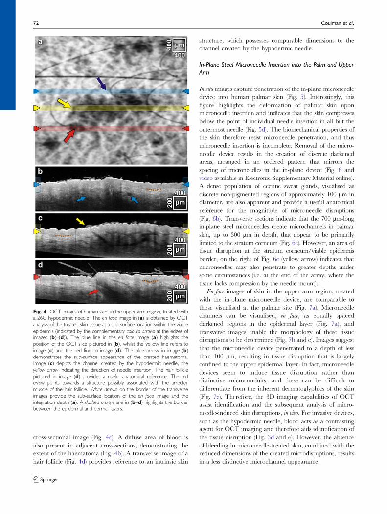
cross-sectional image (Fig. 4c). A diffuse area of blood isalso present in adjacent cross-sections, demonstrating theextent of the haematoma (Fig. 4b). A transverse image of ahair follicle (Fig. 4d) provides reference to an intrinsic skin
structure, which possesses comparable dimensions to thechannel created by the hypodermic needle.
In-Plane Steel Microneedle Insertion into the Palm and UpperArm
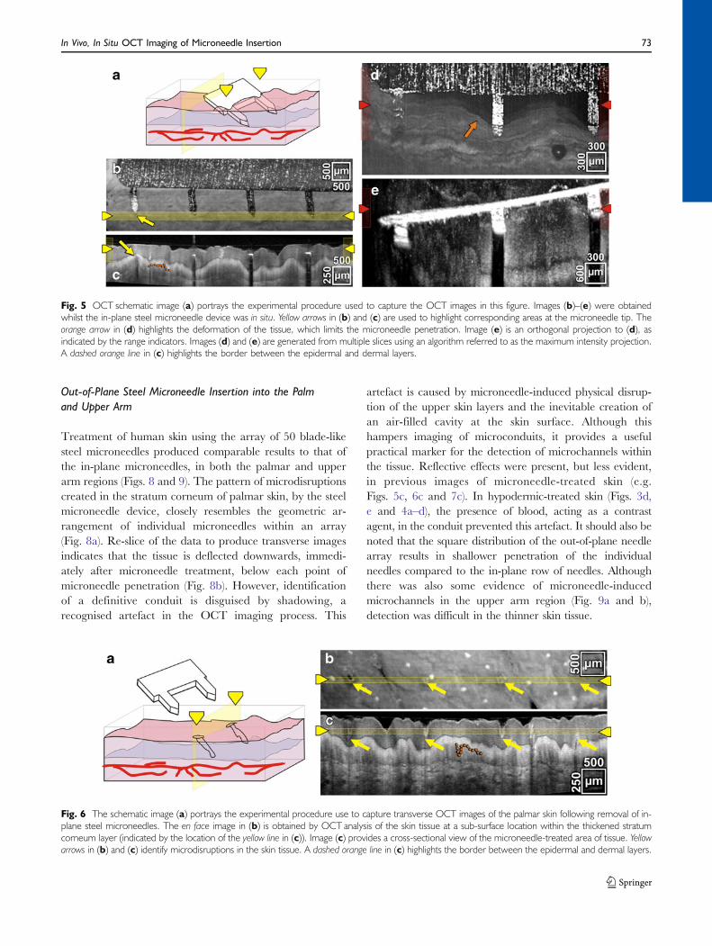
In situ images capture penetration of the in-plane microneedledevice into human palmar skin (Fig. 5). Interestingly, thisfigure highlights the deformation of palmar skin uponmicroneedle insertion and indicates that the skin compressesbelow the point of individual needle insertion in all but theoutermost needle (Fig. 5d). The biomechanical properties ofthe skin therefore resist microneedle penetration, and thusmicroneedle insertion is incomplete. Removal of the micro-needle device results in the creation of discrete darkenedareas, arranged in an ordered pattern that mirrors thespacing of microneedles in the in-plane device (Fig. 6 andvideo available in Electronic Supplementary Material online).A dense population of eccrine sweat glands, visualised asdiscrete non-pigmented regions of approximately 100 µm indiameter, are also apparent and provide a useful anatomicalreference for the magnitude of microneedle disruptions(Fig. 6b). Transverse sections indicate that the 700 µm-longin-plane steel microneedles create microchannels in palmarskin, up to 300 µm in depth, that appear to be primarilylimited to the stratum corneum (Fig. 6c). However, an area oftissue disruption at the stratum corneum/viable epidermisborder, on the right of Fig. 6c (yellow arrow) indicates thatmicroneedles may also penetrate to greater depths undersome circumstances (i.e. at the end of the array, where thetissue lacks compression by the needle-mount).
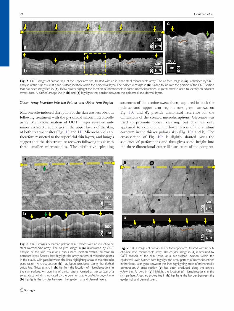
En face images of skin in the upper arm region, treatedwith the in-plane microneedle device, are comparable tothose visualised at the palmar site (Fig. 7a). Microneedlechannels can be visualised, en face, as equally spaceddarkened regions in the epidermal layer (Fig. 7a), andtransverse images enable the morphology of these tissuedisruptions to be determined (Fig. 7b and c). Images suggestthat the microneedle device penetrated to a depth of lessthan 100 µm, resulting in tissue disruption that is largelyconfined to the upper epidermal layer. In fact, microneedledevices seem to induce tissue disruption rather thandistinctive microconduits, and these can be difficult todifferentiate from the inherent dermatoglyphics of the skin(Fig. 7c). Therefore, the 3D imaging capabilities of OCTassist identification and the subsequent analysis of micro-needle-induced skin disruptions, in vivo. For invasive devices,such as the hypodermic needle, blood acts as a contrastingagent for OCT imaging and therefore aids identification ofthe tissue disruption (Fig. 3d and e). However, the absenceof bleeding in microneedle-treated skin, combined with thereduced dimensions of the created microdisruptions, resultsin a less distinctive microchannel appearance.
Fig. 4 OCT images of human skin, in the upper arm region, treated witha 26G hypodermic needle. The en face image in (a) is obtained by OCTanalysis of the treated skin tissue at a sub-surface location within the viableepidermis (indicated by the complementary colours arrows at the edges ofimages (b)–(d)). The blue line in the en face image (a) highlights theposition of the OCT slice pictured in (b), whilst the yellow line refers toimage (c) and the red line to image (d). The blue arrow in image (b)demonstrates the sub-surface appearance of the created haematoma.Image (c) depicts the channel created by the hypodermic needle, theyellow arrow indicating the direction of needle insertion. The hair folliclepictured in image (d) provides a useful anatomical reference. The redarrow points towards a structure possibly associated with the arrectormuscle of the hair follicle. White arrows on the border of the transverseimages provide the sub-surface location of the en face image and theintegration depth (a). A dashed orange line in (b–d) highlights the borderbetween the epidermal and dermal layers.
72 Coulman et al.
Out-of-Plane Steel Microneedle Insertion into the Palmand Upper Arm
Treatment of human skin using the array of 50 blade-likesteel microneedles produced comparable results to that ofthe in-plane microneedles, in both the palmar and upperarm regions (Figs. 8 and 9). The pattern of microdisruptionscreated in the stratum corneum of palmar skin, by the steelmicroneedle device, closely resembles the geometric ar-rangement of individual microneedles within an array(Fig. 8a). Re-slice of the data to produce transverse imagesindicates that the tissue is deflected downwards, immedi-ately after microneedle treatment, below each point ofmicroneedle penetration (Fig. 8b). However, identificationof a definitive conduit is disguised by shadowing, arecognised artefact in the OCT imaging process. This
artefact is caused by microneedle-induced physical disrup-tion of the upper skin layers and the inevitable creation ofan air-filled cavity at the skin surface. Although thishampers imaging of microconduits, it provides a usefulpractical marker for the detection of microchannels withinthe tissue. Reflective effects were present, but less evident,in previous images of microneedle-treated skin (e.g.Figs. 5c, 6c and 7c). In hypodermic-treated skin (Figs. 3d,e and 4a–d), the presence of blood, acting as a contrastagent, in the conduit prevented this artefact. It should also benoted that the square distribution of the out-of-plane needlearray results in shallower penetration of the individualneedles compared to the in-plane row of needles. Althoughthere was also some evidence of microneedle-inducedmicrochannels in the upper arm region (Fig. 9a and b),detection was difficult in the thinner skin tissue.
Fig. 5 OCT schematic image (a) portrays the experimental procedure used to capture the OCT images in this figure. Images (b)–(e) were obtainedwhilst the in-plane steel microneedle device was in situ. Yellow arrows in (b) and (c) are used to highlight corresponding areas at the microneedle tip. Theorange arrow in (d) highlights the deformation of the tissue, which limits the microneedle penetration. Image (e) is an orthogonal projection to (d), asindicated by the range indicators. Images (d) and (e) are generated from multiple slices using an algorithm referred to as the maximum intensity projection.A dashed orange line in (c) highlights the border between the epidermal and dermal layers.
Fig. 6 The schematic image (a) portrays the experimental procedure use to capture transverse OCT images of the palmar skin following removal of in-plane steel microneedles. The en face image in (b) is obtained by OCT analysis of the skin tissue at a sub-surface location within the thickened stratumcorneum layer (indicated by the location of the yellow line in (c)). Image (c) provides a cross-sectional view of the microneedle-treated area of tissue. Yellowarrows in (b) and (c) identify microdisruptions in the skin tissue. A dashed orange line in (c) highlights the border between the epidermal and dermal layers.
In Vivo, In Situ OCT Imaging of Microneedle Insertion 73
Silicon Array Insertion into the Palmar and Upper Arm Region
Microneedle-induced disruption of the skin was less obviousfollowing treatment with the pyramidal silicon microneedlearray. Meticulous analysis of OCT images revealed onlyminor architectural changes in the upper layers of the skin,at both treatment sites (Figs. 10 and 11). Microchannels aretherefore restricted to the superficial skin layers, and imagessuggest that the skin structure recovers following insult withthese smaller microneedles. The distinctive spiralling
structures of the eccrine sweat ducts, captured in both thepalmar and upper arm regions (see green arrows onFig. 10c and d), provide anatomical reference for thedimensions of the created microdisruptions. Glycerine wasused to promote optical clearing, but channels onlyappeared to extend into the lower layers of the stratumcorneum in the thicker palmar skin (Fig. 10a and b). Thecross-section of Fig. 10b is slightly slanted versus thesequence of perforations and thus gives some insight intothe three-dimensional crater-like structure of the compres-
Fig. 7 OCT images of human skin, at the upper arm site, treated with an in-plane steel microneedle array. The en face image in (a) is obtained by OCTanalysis of the skin tissue at a sub-surface location within the epidermal layer. The dashed rectangle in (b) is used to indicate the portion of the OCTsectionthat has been magnified in (c). Yellow arrows highlight the location of microneedle-induced microdisruptions. A green arrow is used to identify an adjacentsweat duct. A dashed orange line in (b) and (c) highlights the border between the epidermal and dermal layers.
Fig. 8 OCT images of human palmar skin, treated with an out-of-planesteel microneedle array. The en face image in (a) is obtained by OCTanalysis of the skin tissue at a sub-surface location within the stratumcorneum layer. Dashed lines highlight the array pattern of microdisruptionsin the tissue, with gaps between the lines highlighting areas of microneedlepenetration. A cross-section (b) has been produced along the dashedyellow line. Yellow arrows in (b) highlight the location of microdisruptions inthe skin surface. An opening of similar size is formed at the surface of asweat duct, which is indicated by the green arrows. A dashed orange line in(b) highlights the border between the epidermal and dermal layers.
Fig. 9 OCT images of human skin of the upper arm, treated with an out-of-plane steel microneedle array. The en face image in (a) is obtained byOCT analysis of the skin tissue at a sub-surface location within theepidermal layer. Dashed lines highlight the array pattern of microdisruptionsin the tissue, with gaps between the lines highlighting areas of microneedlepenetration. A cross-section (b) has been produced along the dashedyellow line. Arrows in (b) highlight the location of microdisruptions in theskin surface. A dashed orange line in (b) highlights the border between theepidermal and dermal layers.
74 Coulman et al.
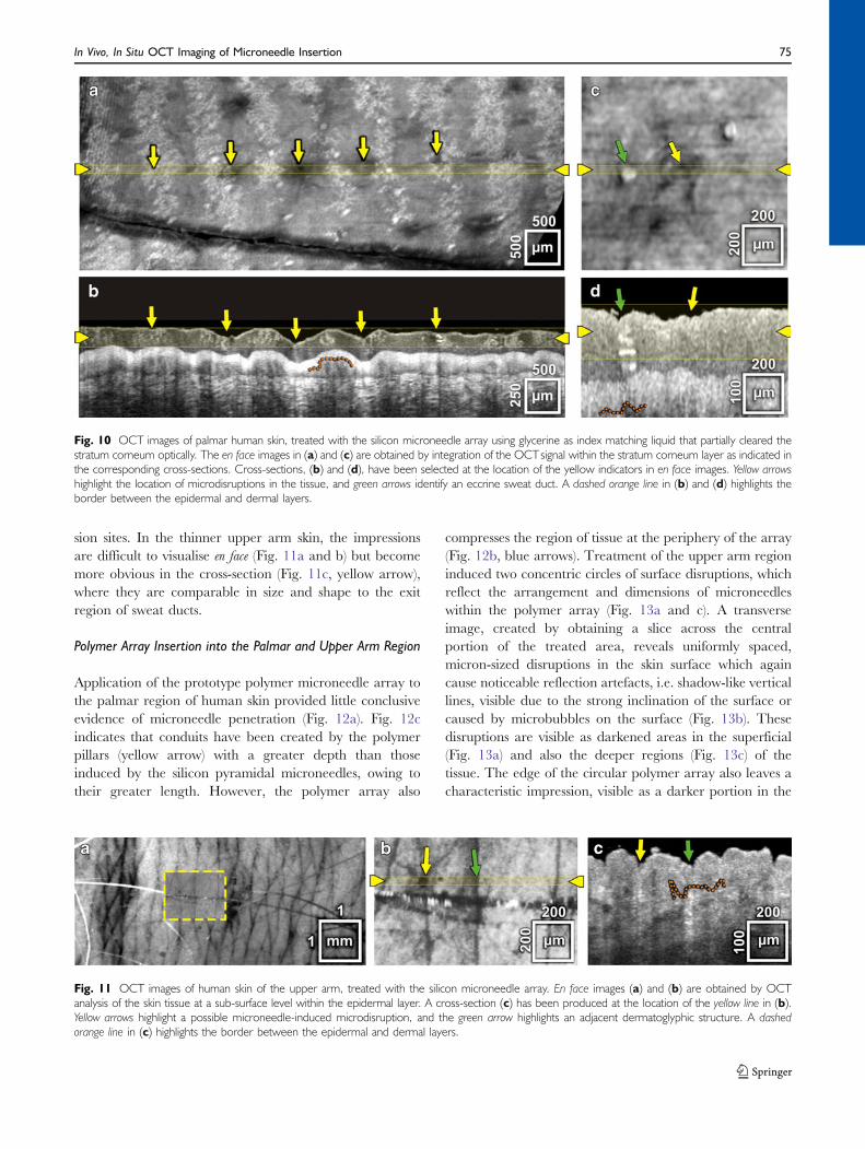
sion sites. In the thinner upper arm skin, the impressionsare difficult to visualise en face (Fig. 11a and b) but becomemore obvious in the cross-section (Fig. 11c, yellow arrow),where they are comparable in size and shape to the exitregion of sweat ducts.
Polymer Array Insertion into the Palmar and Upper Arm Region
Application of the prototype polymer microneedle array tothe palmar region of human skin provided little conclusiveevidence of microneedle penetration (Fig. 12a). Fig. 12cindicates that conduits have been created by the polymerpillars (yellow arrow) with a greater depth than thoseinduced by the silicon pyramidal microneedles, owing totheir greater length. However, the polymer array also
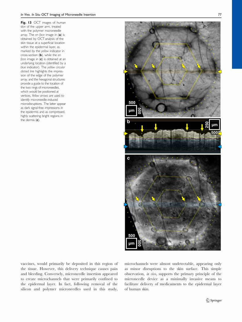
compresses the region of tissue at the periphery of the array(Fig. 12b, blue arrows). Treatment of the upper arm regioninduced two concentric circles of surface disruptions, whichreflect the arrangement and dimensions of microneedleswithin the polymer array (Fig. 13a and c). A transverseimage, created by obtaining a slice across the centralportion of the treated area, reveals uniformly spaced,micron-sized disruptions in the skin surface which againcause noticeable reflection artefacts, i.e. shadow-like verticallines, visible due to the strong inclination of the surface orcaused by microbubbles on the surface (Fig. 13b). Thesedisruptions are visible as darkened areas in the superficial(Fig. 13a) and also the deeper regions (Fig. 13c) of thetissue. The edge of the circular polymer array also leaves acharacteristic impression, visible as a darker portion in the
Fig. 10 OCT images of palmar human skin, treated with the silicon microneedle array using glycerine as index matching liquid that partially cleared thestratum corneum optically. The en face images in (a) and (c) are obtained by integration of the OCTsignal within the stratum corneum layer as indicated inthe corresponding cross-sections. Cross-sections, (b) and (d), have been selected at the location of the yellow indicators in en face images. Yellow arrowshighlight the location of microdisruptions in the tissue, and green arrows identify an eccrine sweat duct. A dashed orange line in (b) and (d) highlights theborder between the epidermal and dermal layers.
Fig. 11 OCT images of human skin of the upper arm, treated with the silicon microneedle array. En face images (a) and (b) are obtained by OCTanalysis of the skin tissue at a sub-surface level within the epidermal layer. A cross-section (c) has been produced at the location of the yellow line in (b).Yellow arrows highlight a possible microneedle-induced microdisruption, and the green arrow highlights an adjacent dermatoglyphic structure. A dashedorange line in (c) highlights the border between the epidermal and dermal layers.
In Vivo, In Situ OCT Imaging of Microneedle Insertion 75

superficial en face image (Fig. 13a) and as brightenedregions, due to the shift of the highly scattering viabledermis, at a deeper position in the tissue (Fig. 13c). Thisfeature is indicative of tissue compression. Although micro-channels created by this device appear to be less than100 µm deep, transverse images confirm breach of the skinsurface at the upper arm site by the microprojections andnot simply indentation of the tissue. Interestingly, imagesalso indicate that the longer microneedles, located on theperipheral circle of the array, create disruptions that areapproximately twice as deep (Fig. 13b).
DISCUSSION
The physical response of human skin to injury is dictated bythe biomechanical properties of the tissue. It is difficult toreproduce these properties within laboratory models; there-fore, although the number of human subjects used in this studyis very small (N=3), the data collected provides a uniqueinsight into the penetration performance of microneedledevices in vivo. This study has used an OCT imaging system tosuccessfully capture sub-surface in situ images of microneedle-treated human skin and has demonstrated differences inpenetration efficacy and depths using different microneedledevices. This technique could have major implications for themicroneedle research community, providing unique datarelating to the mechanical response of human skin tomicroneedle insertion and demonstrating the effect of micro-needle design on penetration characteristics.
Intradermal administration of a hypodermic needle wasused as a clinically relevant comparator to the microneedledevice. OCT images of palmar skin, punctured by a 26Gneedle, indicate that the diameter of the microchannel thatis created in the thickened SC layer (10–20 µm) is almostfifty times smaller than the width of the needle itself(450 µm) (Fig. 3d). This demonstrates the elasticity of theskin and the ability of the physical ‘brick-and-mortar’structure of the stratum corneum to constrict followinginsult, an inherent physiological function of this protectiveexternal barrier. The underlying viable epidermis does notshare the same biomechanical properties; therefore, as themicrochannel extends into the cellular region, it becomessignificantly wider. Further, perpendicular transverse imagesat the point of insertion suggest that removal of the needleresults in displacement of a region of the tissue, leaving adistinctive v-shaped void in the centre of the viable epidermis(Fig. 3e and Electronic Supplementary Material onlinevideo). Tissue damage in the stratum corneum appears lessextensive, again indicating that the compact keratin-filledlayer endeavours to ‘seal’ following insult.
Insertion of the hypodermic needle into the upper armresulted in the creation of a more homogenous and widerchannel. Acknowledged distinctions in the tissue architectureand biomechanics at the two anatomical treatment sites, mostnotably the significant disparity between the thicknesses of thestratum corneum layers, contribute to the different tissueresponses. This disparity might also be expected to influencemicroneedle penetration. However, the minimal damagecaused by microneedle devices, due to the elastic propertiesof the skin in vivo, limits comparative assessment of themicroconduits that are fashioned by insertion of the studiedmicroneedle devices into the two treatment sites.
The channel created by insertion of a hypodermicneedle extends into the dermis. Therefore, therapeuticsdelivered using the traditional Mantoux technique, e.g.
Fig. 12 OCT images of palmar human skin treated with the polymermicroneedle array. The en face image in (a) is obtained by OCTanalysis ofthe skin tissue at a sub-surface location within the stratum corneum layeras indicated by the yellow and red arrows in (b) and (c). The yellow circulardotted line highlights the impression left by the edge of the polymer array,and the hexagonal structures provide a guide to the location ofmicroneedles, which would be positioned close to the vertices. Images(b) and (c) are OCT slices at the two locations indicated in (a) by theyellow and red indicators, respectively. Blue arrows indicate the impressionby the polymer edge, yellow arrows highlight possible microneedle-inducedmicrodisruptions in the tissue, and the green arrows identify eccrine sweatducts. A dashed orange line in (b) highlights the border between theepidermal and dermal layers.
76 Coulman et al.
vaccines, would primarily be deposited in this region ofthe tissue. However, this delivery technique causes painand bleeding. Conversely, microneedle insertion appearedto create microchannels that were primarily confined tothe epidermal layer. In fact, following removal of thesilicon and polymer microneedles used in this study,
microchannels were almost undetectable, appearing onlyas minor disruptions to the skin surface. This simpleobservation, in vivo, supports the primary principle of themicroneedle device as a minimally invasive means tofacilitate delivery of medicaments to the epidermal layerof human skin.
Fig. 13 OCT images of humanskin of the upper arm, treatedwith the polymer microneedlearray. The en face image in (a) isobtained by OCT analysis of theskin tissue at a superficial locationwithin the epidermal layer, asmarked by the yellow indicator incross-section (b), while the enface image in (c) is obtained at anunderlying location (identified by ablue indicator). The yellow circulardotted line highlights the impres-sion of the edge of the polymerarray, and the hexagonal structuresprovide a guide to the location ofthe two rings of microneedles,which would be positioned atvertices. Yellow arrows are used toidentify microneedle-inducedmicrodisruptions. The latter appearas dark signal-free impressions inthe epidermis and as compressed,highly scattering bright regions inthe dermis (c).
In Vivo, In Situ OCT Imaging of Microneedle Insertion 77
Sub-surface en face OCT images are comparable to en faceimages captured in previous studies by identification of skinsurface disruptions using a simple dye (25–29). However,lateral diffusion of these dyes can result in over-estimationof the microchannel diameter; therefore, OCT produces amore accurate measurement. Importantly, OCT analysisalso provides transverse images of microneedle-treated skin,in vivo, without tissue preparation. Prior to this study, the mostrepresentative transverse images of microneedle-inducedmicrochannels were obtained by traditional histologicalanalysis of excised skin tissue from patients or cadavers.Removal of the tissue from the biological environment resultsin significant alterations to the skin, including an inevitablechange in the tension of the individual skin layers due to theloss of transversal mechanical stress, the removal of support-ive sub-cutaneous layers and altered hydration. Excisedhuman skin is therefore not an accurate representation ofthe in vivo state. Further, subsequent traditional histologicalprocessing stages, i.e. fixation, sectioning and histologicalstaining of the skin, cause artefacts related to factors such asdehydration of the tissue and mechanical insult. The resultspresented in this study therefore provide a more accuraterepresentation of microneedle penetration into human skin.
The skin penetration of an in-plane steel microneedledevice has previously been characterised by traditionalmethods (49). The images of microchannels obtained usingconventional methods, however, show a number of differ-ences to OCT images. Most notably, microchannels thatare visualised following histological preparation havegreater dimensions than equivalent OCT images, i.e. inhistological sections, the channels penetrate further andcreate a markedly wider conduit than OCT imagesindicate. This is attributable to the tissue-processing factorsdescribed previously and, more importantly, the elasticproperties of human skin in vivo. Application of the array ofsteel microneedles appears to restrict penetration further,possibly due to the distribution of pressure and a bed-of-nails effect. Smaller microneedles, present on the silicondevice, created minor epidermal disruptions in the palmarand upper arm region rather than obvious conduits across theskin barrier (Figs. 11 and 12). Comparison of OCT imageswith previously published histological images of micro-channels created by these silicon devices (22) supports thegeneral principle that histological techniques overestimatethe dimensions of microneedle-created microchannels.
This observation has a number of implications. First,microneedle devices are possibly less invasive than previ-ously suggested; therefore, the risk of microbial infectionfollowing microneedle treatment is likely to be low (50).This is an important safety issue that is likely to promote theuse of microneedles in the clinical setting. Conversely, for thedevelopment of two-step delivery systems that use a transder-mal patch to deliver medicaments across a microneedle-
treated area of skin, i.e. the ‘‘poke-with-patch’’ concept (51),the physical pathway may be more restrictive than previoushistological images suggest. Although excised human skinis a crucial laboratory model for examining localised andtransdermal delivery of drugs and vaccines (24), it isimportant to recognise the limitations of an ex vivo system.However, greater understanding of the biomechanics ofhuman skin may enable the in vivo state to be betterreproduced in the laboratory.
Transverse images of in-plane steel microneedles, in situ(Fig. 5d), suggest that during microneedle application theentire microprojection does not protrude fully into the skin.Indeed, microneedle penetration does not appear to bereproducible within a single device; the outer microneedleof the in-plane row penetrates to the hilt, whilst adjacentmicroneedles insert less than half of their needle shaft intothe skin. Repeatable differences in the penetration charac-teristics of microneedles, positioned at different locationswithin an ordered arrangement, are consistent withprevious en face observations (26). The transverse images(Fig. 5d) indicate that the skin resists insertion of the device,with deformation of the skin tissue apparent aroundindividual microneedles and compression of the stratumcorneum layer observed directly below the needle tip.These in situ observations have numerous implications forthe microneedle research community and the future clinicaluse of the microneedle device.
A major proposed therapeutic application of the micro-needle device is the minimally invasive, intradermaldelivery of vaccines such as influenza. This strategy relieson localised vaccine delivery to the immune responsiveviable cells of the epidermis. In situ images (Fig. 5e) haveconfirmed that microneedle devices containing 700-µmprojections can successfully penetrate to a depth ofapproximately 200 µm below the skin surface. In the thickskin of the palmar region, this may only facilitate directdelivery of a medicament to the stratum corneum layer.However, at the upper arm site (an accepted site forintradermal vaccination), this would result in direct accessof the vaccine to its target region, the viable epidermis. Thishighlights the importance of developing microneedledelivery systems that are specific to a treatment site. Thiswas underlined further by the prototype polymer device,which failed to penetrate the thickened stratum corneum ofpalmar skin but successfully negated the skin barrier in thearchitecturally distinct upper arm region. Current penetra-tion studies utilise either animal or human skin that hasbeen excised from various anatomical sites, which are oftennot representative of the proposed therapeutic treatmentsite, neither in their anatomical thickness nor theirelasticity. In vivo data, produced by the OCT system, cantherefore be used in conjunction with laboratory studies,performed in ex vivo/in vitro models, to ensure that clinically
78 Coulman et al.

effective and safe microneedle delivery systems, includingmounts and application procedures, are developed.
Additionally, in situ images also provide useful informa-tion relating to the potential deposition site for medica-ments upon penetration of a coated microneedle deliverysystem. Coated microneedles provide a means to deliver anumber of therapeutics. Dosing, restricted by the coatingcapacity, is recognised as the limiting factor in this deliverysystem; therefore, efforts have been made to optimisecoating (17,44,52). However, delivery of the coated doserelies upon contact and subsequent rapid dissolution of thecoating in the sub-surface aqueous environment of the skintissue. Images of in situ steel microneedles (Fig. 5d) and themicrochannels that are subsequently created by this device(Fig. 6c) suggest that only a proportion of the microneedleshaft penetrates into the tissue. Therefore, coating of theentire microneedle shaft with a pre-determined dose ofmedicament would not result in complete transfer of thisdose to the skin tissue and even less into the sub-stratumcorneum layers. In order to combat this, coatings could berestricted to the tips of microneedles, and/or devices couldbe modified to enhance the depth of skin penetration. Thiswould ensure accurate dosing from the microneedle deviceand would also reduce drug wastage.
Similarly, these factors should also be considered in thedevelopment of biodegradable microneedles (10). Degra-dation of an inserted microneedle, in situ, is dependent ondissolution of the needle body within the aqueous tissueenvironment. Therefore, to determine the delivery char-acteristics of biodegradable microneedles, it will beimportant to determine the portion of the microneedlethat will degrade following application to the skin tissue.This may influence the design of the microneedle structureand/or loading of the therapeutic, e.g. the titrated dose ofthe therapeutic may only be loaded into the tip of themicroneedle. Alternatively, it may be appropriate todesign microneedles using non-biodegradable materialsbut to include a biodegradable drug-loaded tip. Interest-ingly, the OCT system would be an effective means ofimaging microneedle insertion and also to assess thedeposition and subsequent degradation kinetics of thebiodegradable portion of the delivery system, in situ, due toa difference in the refractive index of the substrate and theskin.
Microneedle technology has made significant advancesin the previous decade, and studies have proven theprimary concept of the delivery system as a means topainlessly deliver a diversity of therapeutics across the skinbarrier. However, there are a number of considerablechallenges to address before microneedle devices become aclinically useful tool, including reproducible penetration ofhuman skin, improved methods of drug loading andcontrolled deposition of therapeutics into a target area
within the stratified skin tissue. The studies detailed in thismanuscript have provided an early insight into the potentialof the OCT system as a powerful research tool forevaluating the microneedle device and other transdermaldelivery systems. Importantly, in vivo, non-invasive imagingof sub-surface skin architecture can provide the researcherwith instant feedback on the performance of devices, andacquisition of highly detailed data-volumes permits detailedanalysis of the three-dimensional interaction of the tissueand the delivery system. Future studies may use the OCTsystem to evaluate the penetration characteristics of adiversity of microneedle designs (various geometries, mor-phologies and arrangements), device materials and appli-cation methods. This screening process would be asignificant advance on current imaging techniques, bothpractically and scientifically, and has the potential tosignificantly accelerate the optimisation of microneedledevices. Further, OCT imaging could possibly be used inconjunction with the microneedle-based drug delivery systemin the clinic to guide microneedle insertion for the delivery oftherapeutics to a specific depth at a targeted location in thestratified skin tissue. Finally, following microneedle treatmentand subsequent OCT analysis of human skin, the tissue is notsacrificed; therefore, this non-invasive imaging technique alsofacilitates functional imaging of skin in its natural state, i.e.repeated imaging to examine changes in the tissue over aprolonged period of time.
CONCLUSION
This investigation has utilised a state-of-the-art OCTimaging system, optimized for dermatologic application,to provide the first in vivo images of sub-surface human skinlayers in response to microneedle insertion. These imagesprovide representative illustrations of microneedle penetra-tion and have also permitted analysis of the epidermal/dermal disruptions that remain following removal ofmicroneedle devices and also a conventional hypodermicneedle. Microchannels created in the upper skin layers bymicroneedles are less invasive than previous histologypredicts, and penetration depth was shown to be influencedby multiple parameters, not only microneedle length. Inthis study, a limited range of locations and subjects wereinvestigated, and further work is required to determine theinfluence of microneedle structure and human skin biome-chanics on the penetration characteristics of a device.Importantly though, this study has successfully utilised theOCT imaging system to provide a non-invasive means of invivo skin characterisation and has demonstrated the poten-tial value of OCT in the future development andoptimization of microneedles and other transdermal deliv-ery systems.
In Vivo, In Situ OCT Imaging of Microneedle Insertion 79
ACKNOWLEDGEMENTS
Wewould like to acknowledge the support of JessikaWeingastfrom the Division of General Dermatology at the Departmentof Dermatology of the Medical University of Vienna. Thisresearch was supported in part by the BBSRC, CardiffUniversity, FP6-IST-NMP-2 STREPT (017128, NanoUB),DTI grant (OMICRON), AMR grant (AP1110), EuropeanUnion project FUN OCT (FP7 HEALTH, contract no.201880) and CARL ZEISS Meditec Inc.
REFERENCES
1. Bos JD, Meinardi M. The 500 Dalton rule for the skin penetration ofchemical compounds and drugs. Exp Dermatol. 2000;9(3):165–9.
2. Badkar AV, Smith AM, Eppstein JA, Banga AK. Transdermaldelivery of interferon alpha-2B using microporation and ionto-phoresis in hairless rats. Pharm Res. 2007;24(7):1389–95.
3. Bramson J, Dayball K, Evelegh C, Wan YH, Page D, Smith A.Enabling topical immunization via microporation: a novel methodfor pain-free and needle-free delivery of adenovirus-basedvaccines. Gene Ther. 2003;10(3):251–60.
4. Birchall J, Coulman S, Anstey A, Gateley C, Sweetland H,Gershonowitz A, et al. Cutaneous gene expression of plasmidDNA in excised human skin following delivery via microchannelscreated by radio frequency ablation. Int J Pharm. 2006;312(1–2):15–23.
5. Levin G, Gershonowitz A, Sacks H, Stern M, Sherman A,Rudaev S, et al. Transdermal delivery of human growth hormonethrough RF-microchannels. Pharm Res. 2005;22(4):550–5.
6. Banga AK. Microporation applications for enhancing drugdelivery. Expert Opin Drug Deliv. 2009;6(4):343–54.
7. Gerstel MS, Place VA. Drug Delivery Device. 1976: US.8. Henry S, McAllister DV, Allen MG, Prausnitz MR. Micro-
fabricated microneedles: a novel approach to transdermal drugdelivery. J Pharm Sci. 1998;87(8):922–5.
9. McAllister DV, Wang PM, Davis SP, Park JH, Canatella PJ, AllenMG, et al. Microfabricated needles for transdermal delivery ofmacromolecules and nanoparticles: fabrication methods andtransport studies. Proc Nal Acad Sci USA. 2003;100(24):13755–60.
10. Park JH, Allen MG, Prausnitz MR. Biodegradable polymermicroneedles: fabrication, mechanics and transdermal drugdelivery. J Control Release. 2005;104(1):51–66.
11. Kolli CS, Banga AK. Characterization of solid maltose micro-needles and their use for transdermal delivery. Pharm Res.2008;25(1):104–13.
12. Sivamani RK, Stoeber B, Wu GC, Zhai HB, Liepmann D,Maibach H. Clinical microneedle injection of methyl nicotinate:stratum corneum penetration. Skin Res Technol. 2005;11(2):152–6.
13. Nordquist L, Roxhed N, Griss P, Stemme G. Novel microneedlepatches for active insulin delivery are efficient in maintainingglycaemic control: an initial comparison with subcutaneousadministration. Pharm Res. 2007;24(7):1381–8.
14. Martanto W, Davis SP, Holiday NR, Wang J, Gill HS, PrausnitzMR. Transdermal delivery of insulin using microneedles in vivo.Pharm Res. 2004;21(6):947–52.
15. Li GH, Badkar A, Nema S, Kolli CS, Banga AK. In vitrotransdermal delivery of therapeutic antibodies using maltosemicroneedles. Int J Pharm. 2009;368(1–2):109–15.
16. Coulman SA, Barrow D, Anstey A, Gateley C, Morrissey A,Wilke N, et al. Minimally invasive cutaneous delivery of macro-molecules and plasmid DNA via microneedles. Curr Drug Deliv.2006;3(1):65–75.
17. Cormier M, Johnson B, Ameri M, Nyam K, Libiran L, ZhangDD, et al. Transdermal delivery of desmopressin using a coatedmicroneedle array patch system. J Control Release. 2004;97(3):503–11.
18. Alarcon JB, Hartley AW, Harvey NG, Mikszta JA. Preclinicalevaluation of microneedle technology for intradermal deliveryof influenza vaccines. Clin Vaccine Immunol. 2007;14(4):375–81.
19. Mikszta JA, Dekker JP, Harvey NG, Dean CH, Brittingham JM,Huang J, et al. Microneedle-based intradermal delivery of theanthrax recombinant protective antigen vaccine. Infect Immun.2006;74(12):6806–10.
20. Widera G, Johnson J, Kim L, Libiran L, Nyam K, Daddona PE,et al. Effect of delivery parameters on immunization to ovalbuminfollowing intracutaneous administration by a coated microneedlearray patch system. Vaccine. 2006;24(10):1653–64.
21. Coulman SA, Anstey A, Gateley C, Morrissey A, McLoughlin P,Allender C, et al. Microneedle mediated delivery of nanoparticlesinto human skin. Int J Pharm. 2009;366(1–2):190–200.
22. Birchall J, Coulman S, Pearton M, Allender C, Brain K, AnsteyA, et al. Cutaneous DNA delivery and gene expression in ex vivohuman skin explants via wet-etch microfabricated microneedles. JDrug Target. 2005;13(7):415–21.
23. Godin B, Touitou E. Transdermal skin delivery: predictions forhumans from in vivo, ex vivo and animal models. Adv Drug DelivRev. 2007;59(11):1152–61.
24. Ng KW, Pearton M, Coulman S, Anstey A, Gateley C, MorrisseyA, et al. Development of an ex vivo human skin model forintradermal vaccination: tissue viability and Langerhans cellbehaviour. Vaccine. 2009;27(43):5948–55.
25. Bal SM, Caussin J, Pavel S, Bouwstra JA. In vivo assessment ofsafety of microneedle arrays in human skin. Eur J Pharm Sci.2008;35(3):193–202.
26. Haq MI, Smith E, John DN, Kalavala M, Edwards C, Anstey A,et al. Clinical administration of microneedles: skin puncture, painand sensation. Biomed Microdevices. 2009;11(1):35–47.
27. Sivamani RK, Stoeber B, Liepmann D, Maibach HI. Micro-needle penetration and injection past the stratum corneum inhumans. J Dermatol Treat. 2009;20(3):156–9.
28. Van Damme P, Oosterhuis-Kafeja F, Van der Wielen M,Almagor Y, Sharon O, Levin Y. Safety and efficacy of a novelmicroneedle device for dose sparing intradermal influenzavaccination in healthy adults. Vaccine. 2009;27(3):454–9.
29. Gill HS, Denson DD, Burris BA, Prausnitz MR. Effect ofmicroneedle design on pain in human volunteers. Clin J Pain.2008;24(7):585–94.
30. Levin J, Maibach H. The correlation between transepidermalwater loss and percutaneous absorption: an overview. J ControlRelease. 2005;103(2):291–9.
31. Welzel J. Optical coherence tomography in dermatology: areview. Skin Res Technol. 2001;7(1):1–9.
32. Huang D, Swanson E, Lin C, Schuman J, Stinson W, Chang W, etal. Optical coherence tomography. Science. 1991;254(5035):1178–81.
33. Gambichler T, Boms S, Stucker M, Kreuter A, Moussa G, SandM, et al. Epidermal thickness assessed by optical coherencetomography and routine histology: preliminary results of methodcomparison. J Eur Acad Dermatol. 2006;20(7):791–5.
34. Gambichler T, Matip R, Moussa G, Altmeyer P, Hoffmann K. Invivo data of epidermal thickness evaluated by optical coherencetomography: effects of age, gender, skin type, and anatomic site. JDermatol Sci. 2006;44(3):145–52.
80 Coulman et al.
35. Konig K, Speicher M, Buckle R, Reckfort J, McKenzie G, WelzelJ, et al. Clinical optical coherence tomography combined withmultiphoton tomography of patients with skin diseases. JBiophotonics. 2009;2(6–7):389–97.
36. Mogensen M, Nurnberg BM, Forman JL, Thomsen JB, Thrane L,Jemec GBE. In vivo thickness measurement of basal cell carcinomaand actinic keratosis with optical coherence tomography and20-MHz ultrasound. Br J Dermatol. 2009;160(5):1026–33.
37. Neerken S, Lucassen GW, Bisschop MA, Lenderink E, Nuijs TAM.Characterization of age-related effects in human skin: a comparativestudy that applies confocal laser scanning microscopy and opticalcoherence tomography. J Biomed Opt. 2004;9(2):274–81.
38. Querleux B, Baldeweck T, Diridollou S, de Rigal J, Huguet E,Leroy F, et al. Skin from various ethnic origins and aging: an in vivocross-sectional multimodality imaging study. Skin Res Technol.2009;15(3):306–13.
39. Welzel J, Reinhardt C, Lankenau E, Winter C, Wolff HH.Changes in function and morphology of normal human skin:evaluation using optical coherence tomography. Br J Dermatol.2004;150(2):220–5.
40. Alex A, Považay B, Hofer B, Popov S, Glittenberg C, Binder S,Drexler W. Multispectral in vivo three-dimensional optical coherencetomography of human skin. J Biomed Opt. 2010;026025.
41. Kim CS, Wilder-Smith P, Ahn YC, Liaw LHL, Chen ZP, KwonYJ. Enhanced detection of early-stage oral cancer in vivo by opticalcoherence tomography using multimodal delivery of gold nano-particles. J Biomed Opt. 2009;14(3):034008.
42. Yoon J, Son T, Choi EH, Choi B, Nelson JS, Jung B.Enhancement of optical skin clearing efficacy using a microneedleroller. J Biomed Opt. 2008;13(2):021103.
43. Stumpp O, Welch AJ, Gill HS, Prausnitz MR. OCT analysis ofmicroneedle and Er: YAG surface ablation for enhanced
transdermal delivery of hyper-osmotic agents for optical skinclearing. Laser Interaction with Tissue and Cells Xv. 2004;5319:121–9.
44. Gill HS, Prausnitz MR. Coated microneedles for transdermaldelivery. J Control Release. 2007;117(2):227–37.
45. Wilke N, Morrissey A. Silicon microneedle formation usingmodified mask designs based on convex corner undercut. JMicromech Microeng. 2007;17(2):238–44.
46. Unterhuber A, Považay B, Hermann B, Sattmann H, Drexler W,Yakovlev V, et al. Compact, low-cost Ti: Al2O3 laser for in vivoultrahigh-resolution optical coherence tomography. Opt Lett.2003;28(11):905–7.
47. Kim Y-C, Quan F-S, Yoo D-G, Compans RW, Kang S-M,Prausnitz MR. Improved influenza vaccination in the skin usingvaccine coated microneedles. Vaccine. 2009;27(49):6932–8.
48. Laurent A, Mistretta F, Bottigioli D, Dahel K, Goujon C, NicolasJF, et al. Echographic measurement of skin thickness in adults byhigh frequency ultrasound to assess the appropriate microneedlelength for intradermal delivery of vaccines. Vaccine. 2007;25(34):6423–30.
49. Kim Y-C, Quan F-S, Compans RW, Kang S-M, Prausnitz MR.Formulation and coating of microneedles with inactivatedinfluenza virus to improve vaccine stability and immunogenicity.J Control Release. 2010;142(2):187–95.
50. Donnelly RF, Singh TRR, Tunney MM, Morrow DIJ, McCarronPA, O’Mahony C, et al. Microneedle arrays allow lower microbialpenetration than hypodermic needles in vitro. Pharm Res. 2009;26(11):2513–22.
51. Prausnitz MR. Microneedles for transdermal drug delivery. AdvDrug Del Rev. 2004;56(5):581–7.
52. Gill HS, Prausnitz MR. Coating formulations for microneedles.Pharm Res. 2007;24(7):1369–80.
In Vivo, In Situ OCT Imaging of Microneedle Insertion 81