
"In pursuit of preparing tomorrow's technologists" On Job Training Report Training Organization
40
"In pursuit of preparing tomorrow's technologists" Royal University of Bhutan College of Science and Technology Rinchhending :: Phuentsholing, Bhutan Electronics and Communication Engineering Department On Job Training Report Submitted by: Rajen Biswa ECE2009070 Training Organization: Bhutan Telecom Ltd., South Western Region: Phuentsholing Training Duration: 7 th December, 2012 to 17 th January, 2013 February 2013
Transcript of "In pursuit of preparing tomorrow's technologists" On Job Training Report Training Organization

"In pursuit of preparing tomorrow's
technologists"
Royal University of Bhutan
College of Science and Technology
Rinchhending :: Phuentsholing, Bhutan
Electronics and Communication Engineering Department
On Job Training Report
Submitted by: Rajen Biswa
ECE2009070
Training Organization:
Bhutan Telecom Ltd., South Western Region: Phuentsholing
Training Duration: 7th
December, 2012 to 17th
January, 2013
February 2013

Page | i
ABSTRACT
The following report presents the OJT experience and knowledge gained
through it. I was placed in Phuentsholing, South Western Region of Bhutan
Telecom Ltd. Bhutan Telecom Ltd dates back its birth when India and Bhutan
formally agreed to establish calls in 1974. BTL came into existence on 1 July
2000 as a fully state-owned company with former Department of
Telecommunications.
Telecommunication in the modern era is the science and practice of transmitting
and receiving information by electromagnetic means and through fibre. The
long term evolution of new technologies and services has continued, focusing
attention on the growing importance of telecommunications for national
economies and the growth of international trade in telecommunications services.
In turn this has fuelled the transition in recent decades from monopoly
structures to competitive ones with two companies to operate in Bhutan since
few years back.
This report is sectioned into different categories based on the works that we
were allocated. Since three of us attained the programme together we were
assigned with different projects in due course of time.
The following report also presents the other practical knowledge gained and
concept understood to after the programme.

Page | ii
ACKNOWLEDGEMENT
This On-Job-Training programme has been one of the greatest experiences of
learning an engineering programme. This enhanced and enriched the relation of
the theoretical knowledge gained in the college with the field experience. I
would like to humbly thank the college authorities for providing us with such
opportunity and in particular Mr. Sonam Norbu the IIR head for his tireless
effort in contacting the organizations and finding the means to make us
comfortable.
I also would like to thank all the organization who accepted us in their
organization and in particular my deepest gratitude for the manager and the
staffs of Bhutan Telecom Ltd. South Western Region, Phuentsholing for
accepting me in their kind organisation and the willingness and corporation of
the staffs there to help us learn and practise. It was the great experience to learn
under the guidance Mr. Jigme Wangchuck the exchange manager and our
immediate guide.
Page | iii
TABLE OF CONTENT
ABSTRACT ................................................................................................................................ i
ACKNOWLEDGEMENT ......................................................................................................... ii
TABLE OF CONTENT ........................................................................................................... iii
LIST OF FIGURE...................................................................................................................... v
LIST OF TABLE ....................................................................................................................... v
LIST OF ABBREVIATION ..................................................................................................... vi
CHAPTER 1. ORGANIZATION PROFILE....................................................................... 1
1.1. Introduction ................................................................................................................. 1
1.2. Organogram of Bhutan Telecom Ltd. ......................................................................... 2
CHAPTER 2. TRAINING SUMMERY .............................................................................. 4
CHAPTER 3. PROJECTs involved ..................................................................................... 5
3.1. Project I: IP Phone Installation at the Centre .............................................................. 5
3.2. Project II: Fibre Cable Laying from Omchhu BTS to YDF BTS ............................... 6
3.3. Project III: Installation and configuration of MINI-LINK and OPTIMUX at the
YDF BTS................................................................................................................................ 8
3.3.1. MINI-LINK.......................................................................................................... 8
3.3.2. OPTIMUX ......................................................................................................... 10
3.4. Project IV: Installation of 2G and 3G service at the CST BTS................................. 11
CHAPTER 4. PRACTICAL TRANING ........................................................................... 13
4.1. Fibre Splicing and Use of ODTR .............................................................................. 13
4.1.1. Fusion splicer ..................................................................................................... 13
4.1.2. Use of OTDR ..................................................................................................... 15
4.2. Networking cable: Rollover cable ............................................................................. 16
4.3. Preparing Positive stop connector ............................................................................. 18
CHAPTER 5. CONCEPT OF 2G AND 3G SERVICE ..................................................... 21
5.1. GSM: Network Architecture ..................................................................................... 21
5.2. GSM system specification summary ......................................................................... 24
5.3. 2G and 3G services of Bhutan Telecom Ltd. ............................................................ 25
5.3.1. Facilities supported by 2G ................................................................................. 25
5.3.2. Facilities supported by 3G: ................................................................................ 25

Page | iv
CHAPTER 6. OBSERVATIONS AND DISCUSSION.................................................... 27
6.1. Technical Observation............................................................................................... 27
6.2. Relational Observation .............................................................................................. 28
CHAPTER 7. RECOMMENDATION .............................................................................. 30
7.1. To college .................................................................................................................. 30
7.2. To the organization.................................................................................................... 30
CONCLUSION ........................................................................................................................ 31
BIBLIOGRAPHY .................................................................................................................... 32
Page | v
LIST OF FIGURE Figure 1-1 Bhutan Telecom Ltd.'s logo .................................................................................. 1
Figure 1-2 General organisational chart of Bhutan Telecom Ltd .............................................. 2
Figure 1-3 Organizational chart of South western region, Phuentsholing the shaded region
represents the section involvement during the OJT programme ............................................... 3
Figure 3-1 CISCO VoIP Phone.................................................................................................. 5
Figure 3-2 VoIP over computer to computer and Computer to telephone ................................ 6
Figure 3-3 Dug for pulling the fibre cable ................................................................................. 6
Figure 3-4 Fibre laying route from BT-Exchange centre to YDF-BTS..................................... 7
Figure 3-5 Function of Mini-Link.............................................................................................. 9
Figure 3-6 OPTMUX used for multiplexing ........................................................................... 10
Figure 3-7 Function of OPTIMUX .......................................................................................... 11
Figure 3-8 Installation of Dual antenna at CST BTS ............................................................... 11
Figure 4-1Modern Fusion splicer and tool box [10] ................................................................ 13
Figure 4-2 Good and bad splice of the fusion splicer (source: Sumitomo manual) ................ 14
Figure 4-3ODTR being used for fault location in the fibre line [10]....................................... 15
Figure 4-4 Example of ODTR being used for fault location in the fibre line [10] .................. 15
Figure 4-5 RJ45 Modular connector and necessary tools [12] ................................................ 17
Figure 4-6 7/8’’ Positive Stop Connector and tolls used [13] ................................................. 19
Figure 4-7 step for preparing the positive stop connector [13] ................................................ 20
Figure 5-1 GSM Architecture .................................................................................................. 21
Figure 6-1 The MDF section in the switching centre .............................................................. 28
LIST OF TABLE
Table 4-1 Rollover console cable configuration ...................................................................... 17
Table 5-1 GSM overview......................................................................................................... 24
Table 5-2 Difference between 2G and 3G Technology ........................................................... 26

Page | vi
LIST OF ABBREVIATION
Sl.
No. Term Description
Sl.
No. Term Description
1. OptiMux Optical Multiplxer 22. FDD Frequency Division Duplex
2. PDH Plesiochronous digital
hierarchy
23. GMSK Gaussian Minimum Shift Keying
3. SDH Synchronous digital
hierarchy
24. MS Mobile Station
4. ATM Asynchronous Transfer
Mode
25. SIM Subscriber Identity Module
5. RAU Radio Unit 26. PIN PersonalIdentification Number
6. TDM Time Division Multiplexing 27. ME Mobile Equipment
7. CDMA Code Division
Multiplexing
28. IMSI International Mobile subscriber
identity
8. GSM Global System for Mobile
System
29.
BSS
Base Station Subsystem
9. WDM Wave Division
Multiplexing
30. BSC Base Station Controller
10. YDF Youth DevelopmentFund 31. BTS
Base Transceiver Station
11. BTS Base Transceiver Station 32. NSS Network and Switching
Subsystem
12. RAP Random Access Point 33. MSC:
Mobile switching center
13. CST College of Science &
Technology
34. GMSC:
Gateway Mobile switching center
14. 2G Second Generation 35. HLR Home Location Register
15. 3G Third Generation 36. VLR Visitor Location Register
16. OTDR Optical Time Domain
Reflectometer
37.
AuC
Authentication Center
17. PSC Positive Stop Connector 38. EIR Equipment Identity Register
18. ISP Internet Service Provider 39. GIWU GSM Interworking Unit
19. IP Internet Protocol 40. OSS Operation and Support Subsystem
20. PSTN Public Switched Telephone
Network
41. PSTN public switched telephone
network

Page | 1
CHAPTER 1. ORGANIZATION PROFILE
1.1. Introduction
Bhutan Telecom Ltd., (BTL) is the one of the provider
of telecommunications and Internet services in Bhutan.
It has its service besides fixed line telephony, it the
GSM Mobile services under its flagship brand B-
Mobile, and Internet Services under the brand name of
DrukNet. It is the leading provider of both mobile
telephony and Internet services in the country, and the
only fixed line telephony services provider in the
country [1].
In less than seven years Bhutan has moved from having no mobile phones to claiming more
than 70% mobile penetration. Bhutan had been isolated from the rest of the world for a long
time – both generally, and particularly in terms of its telecommunications. Its mountainous
landscape made it especially difficult to build the necessary telecoms infrastructure. Back in
1974, Bhutan and India formally agreed to the introduction of trunk calls between the two
countries. However, in a remarkable contrast with the rest of the world, it was not until 1999
that the country saw television stations, satellite dishes and internet services for the first time
[2].
BTL came into existence on 1 July 2000 as a fully state-owned company, with the
corporatization of the erstwhile Department of Telecommunications which was established in
1970. The first rudimentary works in building a telecommunication network in the country
was taken up in 1963 to aid development works of the First Five Year Plan for modern
economic development of the country. Since then, BTL has come a long way from its
humble beginnings and today boasts of a fully digital microwave and optical fibre backbone
network covering the length and breadth of the country [1].
Figure 1-1 Bhutan Telecom
Ltd.'s logo

Page | 2
1.2. Organogram of Bhutan Telecom Ltd.
The organogram is divided into two sections. The first covers the general chart of the Bhutan
Telecom and the second presents the organizational chart of Phuentsholing exchange.
Figure 1-2 General organisational chart of Bhutan Telecom Ltd

Page | 3
Figure 1-3 Organizational chart of South western region, Phuentsholing the shaded region represents
the section involvement during the OJT programme
I was placed with the networking section along with two of my friends. Under this section I
had an opportunity to be trained and work in B-mobile section, Druknet section,
Transmission section and OSP section. We were guided by the technicians and the immediate
supervisor of the organization. Mr. Jigme Wangchuck, the manager of the Phuentsholing
exchange was the immediate supervisor along with other technicians under different section.

Page | 4
CHAPTER 2. TRAINING SUMMERY
During the On-The-Job Training programme the major part of the time was spent training in
the OSP and Networking section in Bhutan Telecom, South Western Region at
Phuentsholing. Most of the training was at BTS side of the Exchange for various works like
installation and maintenance works at the Base station, maintenances of MDF room for the
existing lease line with intermediate supervisor and other staff of the organisation. The
installation of new devices at BTs and lying out of fibre links from the exchange centre to the
other nearby BTS. Besides the above mentioned work, included preparation of fibre optic
cables and splicing at BTSs and exchange centre.
The training duration was divided different section along with the on-going projects.
Project I: IP Phone Installation at the Centre
Project II: Fibre Cable Laying from Omchhu BTS to YDF BTS
Project III: Installation and configuration of MINI-LINK and OPTIMUX
Project IV: Installation of 2G and 3G service at CST BTS
Aside from the training within the projects the following trainings and works were involved:
- Lease line configuration in Main Distribution Frame room for customers and
checking of free port for other customers.
- Radio alignment and checking
- Fibre splicing
- Fault detection using OTDR

Page | 5
CHAPTER 3. PROJECTS INVOLVED
3.1. Project I: IP Phone Installation at the Centre
Bhutan Telecom has initiated the project to
install the VoIP phone to all employees in
the organization replacing the old telephone
system. Telecom is using the CISCO IP to
install for the test within its organization
and later move outside it buildings [3].
Nowadays VoIP technology is becoming
more and more popular because of the
broadband availability and the many
exciting features that are offered. This emerging technology allows users to make free calls
between computers and among devices that have access to the Internet and are equipped with
the appropriate software, independently of the location of their users. There is also the
possibility of making international or long-distance calls at very low rates unlike normal
phone lines.
Some of the most common applications of VoIP are computer to computer connection where
two or more computers are connected via an IP network and computer to telephone
connection where the communication is established via a Public Switched Telephone
Network (PSTN) through a PSTN-to-IP gateway (PIG) and telephone to telephone
connection [3].
Figure 3-1 CISCO VoIP Phone
Page | 6
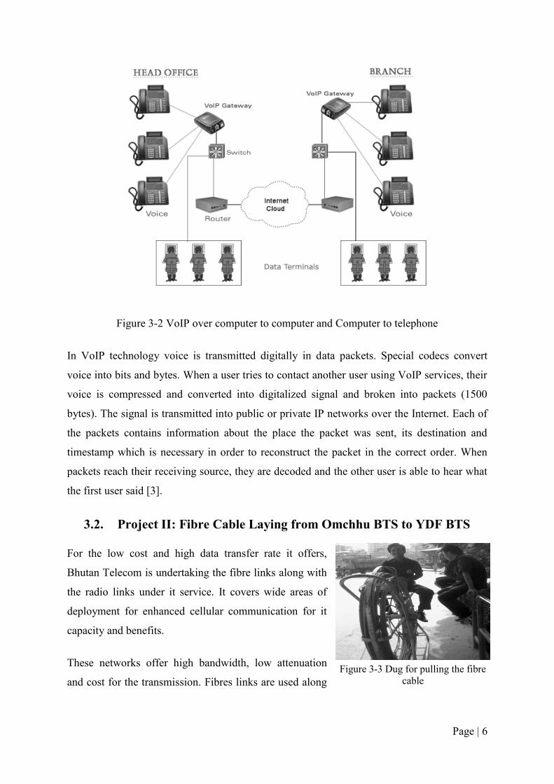
Figure 3-2 VoIP over computer to computer and Computer to telephone
In VoIP technology voice is transmitted digitally in data packets. Special codecs convert
voice into bits and bytes. When a user tries to contact another user using VoIP services, their
voice is compressed and converted into digitalized signal and broken into packets (1500
bytes). The signal is transmitted into public or private IP networks over the Internet. Each of
the packets contains information about the place the packet was sent, its destination and
timestamp which is necessary in order to reconstruct the packet in the correct order. When
packets reach their receiving source, they are decoded and the other user is able to hear what
the first user said [3].
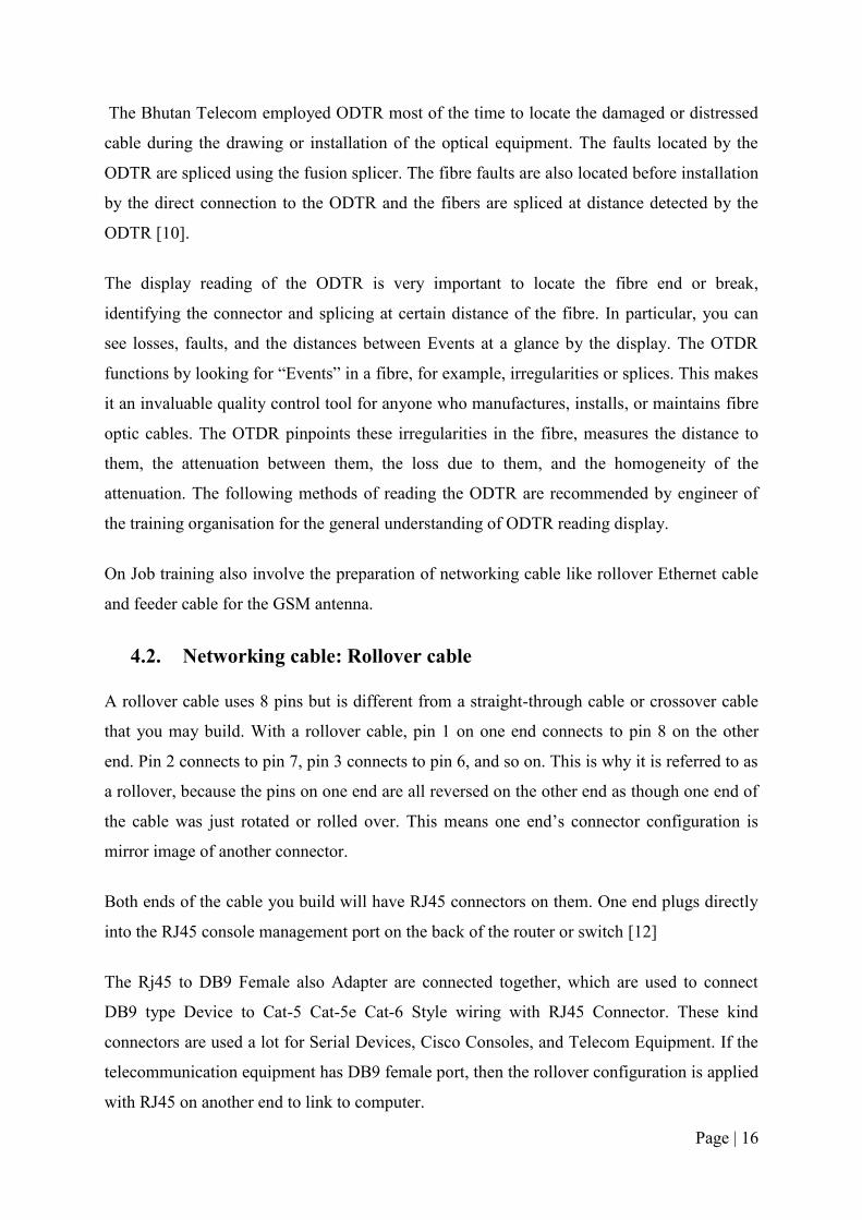
3.2. Project II: Fibre Cable Laying from Omchhu BTS to YDF BTS
For the low cost and high data transfer rate it offers,
Bhutan Telecom is undertaking the fibre links along with
the radio links under it service. It covers wide areas of
deployment for enhanced cellular communication for it
capacity and benefits.
These networks offer high bandwidth, low attenuation
and cost for the transmission. Fibres links are used along
Figure 3-3 Dug for pulling the fibre
cable

Page | 7
with the radio link to transfer the radio signals from the base stations (BSs) to multiple radio
access points (RAPs).
Figure 3-4 Fibre laying route from BT-Exchange centre to YDF-BTS
The blue line shows the fibre cable route from the Phuentsholing exchange to the YDF BTS.
The fibre link systems provide dynamic channel allocation and adaptive antenna selection.
Following are the benefits of mobile communication systems using this technology:
- Low maintenance cost
- High Bandwidth and data transfer rate
- Improved quality of signals
- Low fibre attenuation loss
- No electromagnetic interference
- Multimedia broadband communication
- Wide area coverage
- Dynamic radio resource management
- Low power consumption for RAPs

Page | 8
- Less multipath fading effects
- Increased channel capacity and efficiency
- Reduced handovers
3.3. Project III: Installation and configuration of MINI-LINK and
OPTIMUX at the YDF BTS
3.3.1. MINI-LINK
MINI-LINK TN is a unique microwave transmission node, handling single hops and access
sites as well as advanced hub sites for large networks, optimized for traffic aggregation and
capacity savings [4]. MINI-LINK TN provides an end-to-end range of nodes that are scalable
in capacity and size, flexible to carry PDH, SDH, Ethernet, and ATM, and with integrated
powerful protection mechanisms, as well as integrated cross-connect functionality. Capacity
upgrades, as well as migration to Ethernet traffic, are seamless and gradual without disturbing
on-going traffic. A new radio and plug-in modem can easily be added to any node at any
time. [5]
MINI-LINK using the principle of hybrid joints with native mapping Ethernet traffic and E1
circuits in the radio channel. This method ensures the most efficient use of the radio channel
capacity. In addition, MINI-LINK supports the transmission SDH and ATM circuits [3].
MINI-LINK Traffic Node (MINI-LINK TN), the internal unit for the concept node of the
transmission grid where it is possible within this unit route and aggregate different types of
traffic. The function of the indoor unit is determined by the size of the indoor unit and the
type of plug-in cards used.
MINI-LINK Compact Node (MINI-LINK CN) is an indoor unit connections destined for
different independent connections or as a cost-effective indoor unit terminal station
transmission network with MINI-LINK TN units on nodal stations.
Outdoor unit RAU is always connected to the indoor unit MINI-LINK TN or MINI-LINK
CN via a coaxial cable. Outdoor unit RAU determines the frequency band in which the
connection will work. The system supports frequency bands, 6, 7, 8, 10, 11, 13, 15, 18, 23,
28, 32 and 38 GHz.

Page | 9
Portfolio summary of MINI-LINK shown below
Figure 3-5 Function of Mini-Link
The modular architecture of MINI-LINK TN provides a simple and cost-effective expansion
of the solution used. The MINI-LINK TN simply realize small outdoor units from capacity
building 8 MBit / s without the location of the indoor unit in the building to large aggregation
nodes with 19 modems in a single 10U cabinet interior. Maximum capacity of connections
with the indoor unit MINI-LINK TN in a single radio channel is 405 MBit / s system also
allows you to combine the capacity of several radio channels for one circuit [6]. Using
software keys can remotely modify capacity, function or topology of connections. MINI-
LINK TN is optimized for the migration of voice and data services and efficiently transmits
both TDM and packet data transfers. MINI-LINK TN provides quality of service necessary
for the transmission of Ethernet in telecommunication networks [6].
MINI-LINK TN microwave has long been the most reliable equipment on the global market
due to which it is to ensure maximum service availability, minimizes the need for backup
solutions and investment in spare parts and support. Modern surveillance system "Service on
Microwave" with advanced fault management is another tool that reduces operating costs
microwave network [6]

Page | 10
3.3.2. OPTIMUX
Optical line multiplexers are cost-effective devices for extending multiple voice and data
circuits over fibre optic links. Opti-mux optical line multiplexer can transmit four E1
channels or four T1 channels, respectively, up to 120 kilometres (75 miles) over optical fibre.
The Optimux-4E1 multiplexer and Optimux-4T1 optical line multiplexers can be equipped
with redundant links and power supplies, ensuring transmission reliability and fail-safe
operations [7].
Figure 3-6 OPTMUX used for multiplexing
The Optimux devices transmit each E1channel separately so that the clock of
each E1 channel is independent. These supports internal and loop back timing modes. The
134 Mbps operation mode uses only internal timing [8].

Page | 11
Figure 3-7 Function of OPTIMUX
OPTIMUX devices connect cellular base stations to controllers. This solution meets the
requirements of cellular backhaul applications by providing TDM and Ethernet traffic for
CDMA and GSM connectivity.
The OPTIMUX offers the following benefits
Low cost, long distance E1/T1 connectivity
Large range of optical options available; can be used in any fibre optic network
Compact size reduces co-location costs
Single fibre (WDM) option reduces fibre optic cable costs
3.4. Project IV: Installation of 2G and 3G service at the CST BTS
CST was chosen as one of the BTS owing to
the number of users here. It was running on
providing with the 2G service. With the up
gradation of the better service and as an on-
going project Bhutan Telecom wants to install
the 3G service at the CST, owing to the large
number of possible users residing in the
campus. Figure 3-8 Installation of Dual antenna at CST
BTS

Page | 12
The new type of antenna is the dual GSM antenna which can work for both 2G and 3G
service. This one sectorial antenna can operate for both the generations of service.
The 2G service using GSM 900 was installed over the bachelor’s quarter. The 3G service was
to be installed over the over-head water tank of the CST. The 3G service was based on the
GSM 1800. The antenna used is the dual transceiver sectorial antennae. This antenna is able
to transmit and receive the signal at both the 2G and 3G frequency. The three sectorial
antenna which covers 1200 each are used, facing to three directions covering the area of its
target [9]. This is linked with the fibre link so that the redundancy can be maintained and the
speed for the next generation service can be enabled.

Page | 13
CHAPTER 4. PRACTICAL TRANING
4.1. Fibre Splicing and Use of ODTR
Since the Telecom is carrying out the fibre link project all over the country instrument like
fibre splicer and ODTR are introduced and practical implementation of splicing the fibre are
done. Fibre splicers are used to join or splice the fibres which are damaged during the fibre
draw and they also join the two end of fibre coming from different BTS. Before splicing the
fibre, the fibre fault is detected by the OTDR.
4.1.1. Fusion splicer
Fusion splicing is the method of joining two optical fibres end-to-end using heat. The goal is
to join the two fibres together in such a way that optical signal passing through the fibres is
not attenuated or reflected back by the splice. The splice and the region surrounding should
be almost as strong as the fibre itself. The source of the necessary heat is usually an electric
arc.
Figure 4-1Modern Fusion splicer and tool box [10]
The following steps are observed during optical fibre splicing:
1. Clean the fibre
2. Stripping the coating off the two fibres that will be spliced together
3. Cleaning of the stripped fibre by the alcoholic matter.
4. Each fibre must be cleaved so that its end-face is perfectly flat and perpendicular to
the axis of the fibre

Page | 14
5. Aligning of two end-faces of the fibres. This is normally done by the splicing machine
by means of: fixed V-groove, optical core alignment, cladding alignment or local
injection and detection of light (LID)
6. The two fibres are fused together Visual inspection of the splice and splice loss.
7. Visual inspection of the splice and splice loss estimation (available on most splicing
machine). Redo the splice (step 1 to 7) in case an error is found.
8. Check mechanical strength of the splice (normally done by the splicing machine)
9. The bare fibre area around the splice is protected with a splice protector or sleeves by
heating the plastic material.
Alternatives to fusion splicing include using optical fibre connectors or mechanical splices
both of which have in general higher insertion losses, lower reliability and higher return
losses than fusion splicing [10].
The visual inspection of the estimated loss of the fibre is the important aspect of the fusion
splicing. The technician of the BT centre is trained to inspect the visual estimated loss and
they classified it as good splice and bad splice.
Good Splices: Visually inspect splice after the program has run, using both X and Y views.
Some flaws that do not affect optical transmission are acceptable, as shown. Some fibres (e.g.
fluorine-doped) may cause
white or black lines in splice
region that are not faults.
Bad Splices: Some flaws are
unacceptable and require
starting the splicing process
over. Some, like black spots
or lines, can be improved by
repeating the ARC step, but
never more than twice. For
large core offsets, bubbles or bulging splices always redo [11].
Figure 4-2 Good and bad splice of the fusion splicer (source:
Sumitomo manual)

Page | 15
4.1.2. Use of OTDR
Optical Time Domain Reflectometers
(OTDR) is widely used in the
telecommunication industry for testing
bare and cabled fibre, including final
link commissioning. OTDRs can
measure the attenuation coefficient of
fibre and are extremely useful to analyse
discreet events in a link such as splice
points or connector pairs. These
instruments are also extremely useful in
locating damaged or distressed cable or broken fibres.
OTDR is based on ray light scattering. A small fraction of the light is spread in all directions
when it encounters in-homogeneities of the size of its wavelength. A small part of this light is
captured by the core of the fibre and propagates backwards. It is called backscattered light. It
is a local phenomenon and any variation of the backscattered level along the fibre is due to a
defect or to an alteration of the properties at a local point. When measuring, a light pulse is
first injected into the fibre(s) under test. Then the OTDR measures the amount of
backscattered light as a function to the time from the initial pulse.
Figure 4-4 Example of ODTR being used for fault location in the fibre line [10]
Figure 4-3ODTR being used for fault location in the
fibre line [10]
Page | 16
The Bhutan Telecom employed ODTR most of the time to locate the damaged or distressed
cable during the drawing or installation of the optical equipment. The faults located by the
ODTR are spliced using the fusion splicer. The fibre faults are also located before installation
by the direct connection to the ODTR and the fibers are spliced at distance detected by the
ODTR [10].
The display reading of the ODTR is very important to locate the fibre end or break,
identifying the connector and splicing at certain distance of the fibre. In particular, you can
see losses, faults, and the distances between Events at a glance by the display. The OTDR
functions by looking for “Events” in a fibre, for example, irregularities or splices. This makes
it an invaluable quality control tool for anyone who manufactures, installs, or maintains fibre
optic cables. The OTDR pinpoints these irregularities in the fibre, measures the distance to
them, the attenuation between them, the loss due to them, and the homogeneity of the
attenuation. The following methods of reading the ODTR are recommended by engineer of
the training organisation for the general understanding of ODTR reading display.
On Job training also involve the preparation of networking cable like rollover Ethernet cable
and feeder cable for the GSM antenna.
4.2. Networking cable: Rollover cable
A rollover cable uses 8 pins but is different from a straight-through cable or crossover cable
that you may build. With a rollover cable, pin 1 on one end connects to pin 8 on the other
end. Pin 2 connects to pin 7, pin 3 connects to pin 6, and so on. This is why it is referred to as
a rollover, because the pins on one end are all reversed on the other end as though one end of
the cable was just rotated or rolled over. This means one end’s connector configuration is
mirror image of another connector.
Both ends of the cable you build will have RJ45 connectors on them. One end plugs directly
into the RJ45 console management port on the back of the router or switch [12]
The Rj45 to DB9 Female also Adapter are connected together, which are used to connect
DB9 type Device to Cat-5 Cat-5e Cat-6 Style wiring with RJ45 Connector. These kind
connectors are used a lot for Serial Devices, Cisco Consoles, and Telecom Equipment. If the
telecommunication equipment has DB9 female port, then the rollover configuration is applied
with RJ45 on another end to link to computer.
Page | 17
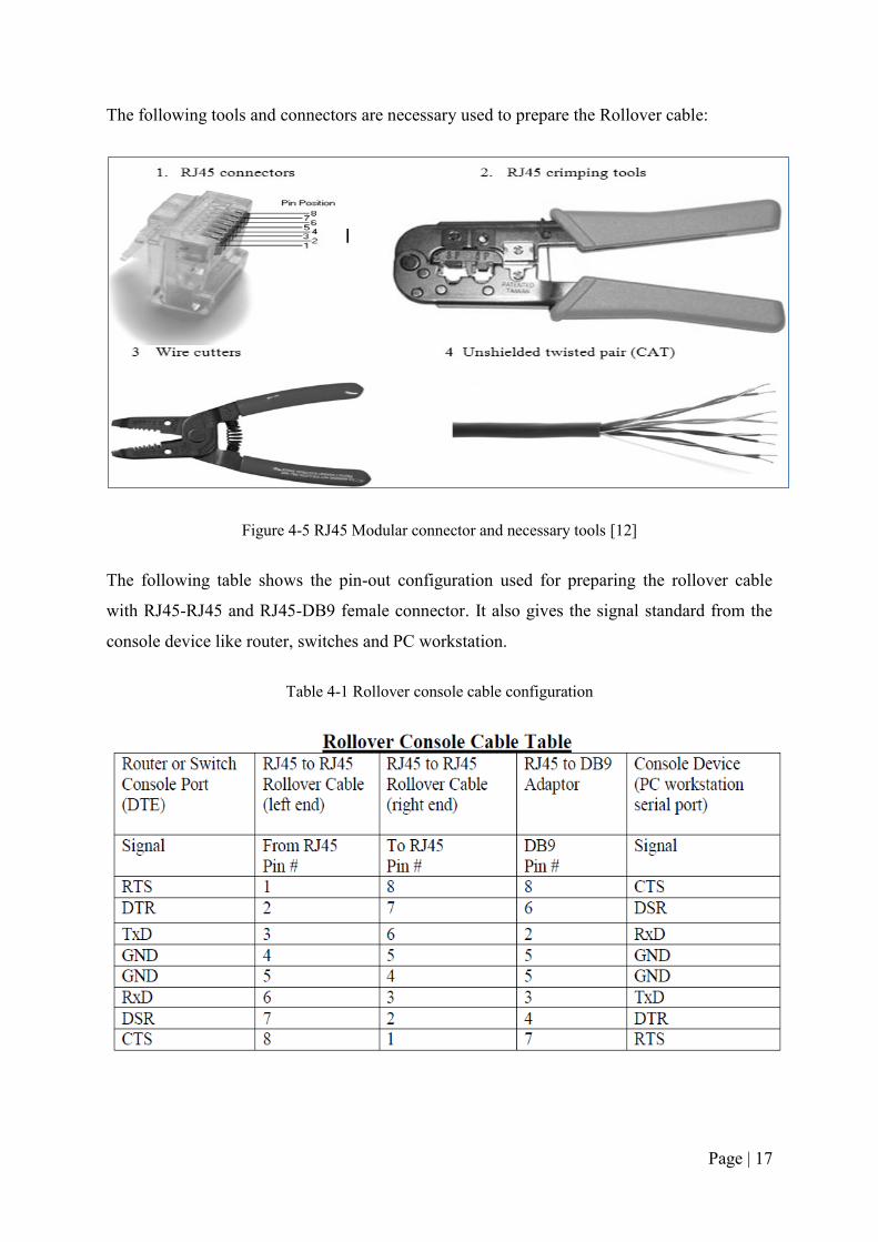
The following tools and connectors are necessary used to prepare the Rollover cable:
Figure 4-5 RJ45 Modular connector and necessary tools [12]
The following table shows the pin-out configuration used for preparing the rollover cable
with RJ45-RJ45 and RJ45-DB9 female connector. It also gives the signal standard from the
console device like router, switches and PC workstation.
Table 4-1 Rollover console cable configuration

Page | 18
The preparation of roll over cable involves the following steps:
1. Measure the cable to reach the two devices intended to connect and keep few meter
longer than measured length.
2. Next, strip of jacket off one end of the cable.
3. Hold the pairs of twisted cables tightly where the jacket was cut away, and use the
rollover configuration table (given above) to arrange the cable.
4. Straighten, flatten, and line up the wires, then trim them in a straight line within ½”-
3/4” from the edge of the jacket. Make sure not to go off the jacket and the wires,
which are now in order.
5. Place an RJ45 plug on the end of the cable, with the prong on the underside and the
orange pair at the top of the connector.
6. Gently push the plug onto the wires until you can see the copper ends of the wires
through the end of the plug. Make sure the end of the jacket is inside the plug and all
the wires are in correct order. If the jacket is not inside the plug, it will not be
properly strain-relieved and will eventually cause problems. If everything is correct,
firmly crimp the plug hard enough to force the contacts through the insulation on the
wires, therefore, completing the conducting path.
7. Repeat Steps 2-6 to terminate the other end of the cable, but reversing every pair of
wires as indicated in the table above of the prepared end.
8. Last test the finished cable and use it for the console devices [12].
4.3. Preparing Positive stop connector
Bhutan Telecom is amidst of upgrading the mobile network from 2G to 3G and lots of
projects are going on to replace the 2G antenna by the dual antenna which work for both 2G
and 3G. In doing so feeder cable are required to collect the radio signal from antenna to the
BTS and vice versa happens to transmit the signal back. Therefore the Positive stop
connectors are used to connect the two feeder cable reach to BTS and antenna.
The following are part of 7/8’’ positive stop connector for the HELIAX Coaxial cable and
they are used to prepare connector for the feeder cable.

Page | 19
Figure 4-6 7/8’’ Positive Stop Connector and tolls used [13]
The preparation of the positive stop connectors is done in the following steps as taught by the
technician and RF engineer:

Page | 20
Figure 4-7 step for preparing the positive stop connector [13]
Finally the prepared feeder connector is ready for use to connect the two feeder cable and it
look like following diagram. Trainee are advised to tighten the nut and bolt for the to prevent
distortion.

Page | 21
CHAPTER 5. CONCEPT OF 2G AND 3G SERVICE
5.1. GSM: Network Architecture
The GSM technical specifications define the different entities that form the GSM network by
defining their functions and interface requirements [14].
Figure 5-1 GSM Architecture
The GSM network can be divided into four main parts:
1. The Mobile Station (MS): Two Parts
a. The Subscriber Identity Module (SIM):
It is protected by a four-digit Personal Identification Number (PIN). In order to identify the
subscriber to the system, the SIM card contains amongst others a unique International Mobile
Subscriber Identity (IMSI). User mobility is provided through mapping the subscriber to the
SIM card rather than the terminal as we done in past cellular systems [14].
b. Mobile equipment/terminal (ME):
There are different types of terminals (MN) distinguished principally by their power and
application:

Page | 22
- Fixed' terminals mainly installed in cars. Their maximum allowed output power is
20W
- Portable terminals can also be installed in vehicles. Their maximum allowed
output power is 8W.
- Handheld terminals; their popularity is owed to their weight and volume, which is
continuously decreasing. According to some specification these terminals may
emit up to 0.8W. However, as technology has evolved their maximum allowed
power outputs is limited to 0.1W [14].
2. The Base Station Subsystem (BSS).
The BSS provides the interface between the ME and the NSS. It is in charge of the
transmission and reception. It may be divided into two parts:
a. Base Station Controller (BSC):
It controls a group of BTSs and manages their radio resources. A BSC is principally in
charge of handoffs, frequency hopping, exchange functions and power control over
each managed BTS’s.
b. Base Transceiver Station (BTS) or Base Station:
It maps to transceivers and antennas used in each cell of the network. It is usually
placed in the center of a cell. Its transmitting power defines the size of a cell. Each BTS
has between 1-16 transceivers depending on the density of users in the cell.
c. The Network and Switching Subsystem (NSS).
Its main role is to manage the communications between the mobile users and other
users, such as mobile users, ISDN users, fixed telephony users, etc. It also includes data
bases needed in order to store information about the subscribers and to manage their
mobility. The different components of the NSS are described below.
i. MSC:
- The central component of the NSS. The MSC performs the switching functions of
the network. It also provides connection to other networks.

Page | 23
ii. GMSC:
- A gateway that interconnects two networks: the cellular network and the PSTN:
It is in charge of routing calls from the fixed network towards a GSM user. The
GMSC is often implemented in the same machines as the MSC.
iii. HLR:
- The HLR stores information of the subscribers belonging to the coverage area of
a MSC; it also stores the current location of these subscribers and the services to
which they have access. The location of the subscriber maps to the SS7 address of
the Visitor Location Register (VLR) associated to the MN.
iv. VLR:
- Contains information from a subscriber's HLR necessary to provide the
subscribed services to visiting users. When a subscriber enters the covering area
of a new MSC, the VLR associated to this MSC will request information about the
new subscriber to its corresponding HLR. The VLR will then have enough data to
assure the subscribed services without needing to ask the HLR each time a
communication is established. The VLR is always implemented together with a
MSC; thus, the area under control of the MSC is also the area under control of the
VLR.
v. Authentication Center (AuC):
- It serves security purposes; it provides the parameters needed for authentication
and encryption functions. These parameters allow verification of the subscriber's
identity.
vi. Equipment Identity Register (EIR):
- EIR stores security-sensitive information about the mobile equipment’s. It
maintains a list of all valid terminals as identified by their International Mobile
Equipment Identity (IMEI). The EIR allows then to forbid calls from stolen or

Page | 24
unauthorized terminals (e.g., a terminal which does not respect the specifications
concerning the output RF power).
vii. GSM Interworking Unit (GIWU):
- The GIWU provides an interface to various networks for data communications.
During these communications, the transmission of speech and data can be
alternated.
d. The Operation and Support Subsystem (OSS).
It is connected to components of the NSS and the BSC, in order to control and monitor the
GSM system. It is also in charge of controlling the traffic load of the BSS. It must be noted
that as the number of BS increaseswith the scaling of the subscriber population some of the
maintenance tasks are transferred to the BTS, allowing savings in the cost of ownership of
the system [14]
5.2. GSM system specification summary
The table below summarizes the main points of the GSM system specification, showing some
of the highlight features of technical interest.
Table 5-1 GSM overview
Multiple access technology FDMA / TDMA
Duplex technique FDD
Uplink frequency band 890 - 915 MHz
(basic 900 MHz band only)
Downlink frequency band 933 -960 MHz
(basic 900 MHz band only)
Channel spacing 200 kHz
Modulation GMSK
Speech coding Various - original was RPE-LTP/13
Speech channels per RF channel 8
Channel data rate 270.833 kbps
Frame duration 4.615 MS

Page | 25
5.3. 2G and 3G services of Bhutan Telecom Ltd.
Bhutan Telecom Ltd uses GSM- 900 for 2G network and GSM 1800 for 3G services.
GSM-900 uses 890–915 MHz to send information from the mobile station to the base station
(uplink) and 935–960 MHz for the other direction (downlink) which provides 124 RF
channels (channel numbers 1 to 124) spaced at 200 kHz and uses duplex spacing of 45
MHz’s. The guard bands of 100 kHz are placed at either ends of range of frequencies, so the
GSM-1800 uses 1710–1785 MHz to send information from the mobile station to the base
transceiver station (uplink) and 1805–1880 MHz for the other direction (downlink). Duplex
spacing is 95 MHz’s GSM 1800 frequencies can carry more traffic than GSM 900 due to
more frequencies available. But GSM-1800 has high propagation losses so more number of
sites are required (approx.1.5~2 times that of GSM-900).
GSM-900 has low propagation losses and has double the coverage as compared to GSM-
1800.
5.3.1. Facilities supported by 2G
- Text messages
- Pictures messages
- Multimedia messaging services.
5.3.2. Facilities supported by 3G:
- video calling
- high speed Broadband internet Access
- mobile TV
- video mail and SMS
- Games – single user and Multiplayer

Page | 26
Table 5-2 Difference between 2G and 3G Technology
2G MOBILE NETWORKS 3G MOBILE NETWORKS
Cost Very low cost Highly expensive
Data
Transmission
- Are less compatible with the
functions of smart phone.
- less than 50,000 bits per sec
- transmission of information
via voice signals
- faster download speeds, faster
access to the data and applications
- < 4 million bits per sec.
- Data transfer via video
conferencing, MMS etc.
Frequencies broad range of frequencies in
both upper and lower bands
simply not available in certain
regions.
Implication Low level of security Offers a high level of security
Making Calls No video calls & data limit &
rate is slow
Can avail video calls using 3G & No
data limit
Speed
Downloading and uploading
speeds available is up to 236
Kbps.
Downloading and uploading speeds
are up to 21 Mbps and 5.7 Mbps

Page | 27
CHAPTER 6. OBSERVATIONS AND DISCUSSION
During the one and half months OJT programme at South Western Region Phuentsholing, I
have observed different experience than the normal daily life of the college and school. There
was broadly technical observation, relational observation.
6.1. Technical Observation
Since the Telecommunication service in Bhutan is in its growing and tender age, there is
swift change of technologies and the organization have to rush and find the ways to cope with
the changing technology. Thus, the instruments used keeps on changing for the better and
efficient communication. But some of the instruments are the old ones that operates based on
analog communication when the telecom industry is moving to digital system for more
efficient and reliable communication. The digital system is secure, reliable, more resistant to
fading, and error free.
Other main reason nagging the quality of the telecommunication service by Bhutan Telecom
Ltd is the lack of experts. All the experts are Bhutanese and they are less qualified and
experienced beside exposure. Though the organization trains her staffs within and outside the
country, still there is the lack of confident experts. Therefore, the experts should be trained
more and given the exposure to the new technologies.
The webs hosted by the Bhutan Telecom Ltd being hacked are one of the prime complain
from the customers. This was not really the hole in their security but the designer’s
substandard designing. They host the webs designed by any qualified designer(s) of the
customer. But the organization doesn’t have the design standard to monitor. Thus, leaving
vast loop in the design to penetrate and mess up things. Thus, there should be a standard set
by the experts to monitor the quality of the design of the webs and its security. Moreover,
there is no division that is looking in this matter. It is handled by Druknet and section. So if
there were experts placed then the proper monitoring could have been possible.
Other technical observation I have made is the negative power used for the system. All the
systems use the -48 volt DC. The negative power offers the following advantages over the
positive voltage:

Page | 28
- Positive voltages cause comparatively more corrosion in metal than negative
voltages.
- Negative voltages are safer for human body while doing Telecom activities.
- Lightning may cause positive voltages in the equipment circuitry. In that case,
negative voltages (lack of electrons) neutralize positive charges and prevent excessive
heat.
- Negative voltage is safer for long telephone line for transmitting power through it.
- The reason for electing -48V in reference to ground is to avoid the nasty galvanic
effects in telephone cabling. +48V would have nastier effect on wet cabling.
For the reason of daily changing customer and demand the
MDF (Main Distribution Frame) at the switching centre for
the lease line telephone system not well maintained.
Moreover, it is still the manually operated. The technician has
to be there with tools ready to operate. This manual could be
operated remotely through software, so that there will be
fewer mess-ups and less chances of making mistake and other
inconveniences.
6.2. Relational Observation
Though the efficient instrument and service are available in the other parts of the world, the
customers in use matter in this field. The service to be provided depends on the scope of the
customers. Since our customers who are using the telecommunication service are from
different background and with different abilities, the service to be provided differs. Thus, the
higher and sophisticated technologies are yet not in the demand of the customers. I have
found out that the slow rate of up-gradation in the technology is one due to the nature of the
customer and other the lack of experts.
To move far with the technology the service provider looks at the customer demand and their
ability to utilize the service. For instance, 3G services are being installed only in Paro,
Thimphu and Phuentsholing regions only. Other parts of the area still operate with 2G and
telephone system. But we can see the possible users in the main areas especially at the
Dzongkhag headquarters and the place of institutional establishment. Therefore, such areas in
other places also are the source of probable users.
Figure 6-1 The MDF section
in the switching centre

Page | 29
Through my personal observation on the quality of service they provide is the lack of strong
competitor. Today there is only one rival competing and still the Tashi InfoCom doesn’t
serve all the service provided by the Bhutan Telecom Ltd. Moreover, Bhutan Telecom Ltd is
old in the market and is already a common service provider of the customers. The customers
don’t have the multiple choices. But it should not be mattered only the competition but the
quality to be served should be taken care. There is always a chance that the established
foreign company may come and thence the well growing company of the country will face a
steeper challenge. There was already an interest shown by companies like Aircel Group of
India.
Looking at the number of services they utilise under the able belt of the telecommunication
height is less. Today we can do lot more with the telecommunication. Bhutan Telecom has
introduced the B-Wallet Service system in collaboration with Bhutan National Bank
providing sms banking, money transfer, sms voucher recharge and others. But critically
looking there are other customers who can be a possible users. So if Bhutan Telecom Ltd
launches similar service with other institutes, it is huge income for them. But the securities in
such venture remain big issues.
Page | 30
CHAPTER 7. RECOMMENDATION
Through my one and half months experience and observation during my OJT programme, I
have observed and found the followings to be recommended.
7.1. To college
The OJT programme is really a great experience to the students. It gives us an opportunity to
make ourselves prepared to go into the working field. Since the technological world is vast
and ever changing I found the precious OJT programme is short and I would recommend it to
be more than usual. And the continuous effort of the college authorities are crucial in
fostering the beforehand for the young and enthusiastic engineers in making.
The concern of the institutions and the organizations on such programme is less receptive.
Therefore, I find it is very essential for the concerned college authorities to shower the rights
of responsibilities for the probable and abled organizations to take this programme as an
opportunity to shape the younger minds of today for the better and brighter technocrats of
tomorrow.
7.2. To the organization
The concerned immediate supervisor remains busy and at some points I found we are less
guided and concerned. It is fearing and difficult to handle the instruments and machines
without the experience and the proper guide. Thus, I feel the guide have to be more receptive
to the quest of the trainees.
The nature of the work needed to be handled by the trainee is fluctuating, as we were not
designated to a particular work but as per the availability of the task. Thus, I found it was
difficult to grabs the concept of any properly and confidently.
The technician at the centre(s) needs to be frequently trained as they remain with the old
trains and are faces difficulties in handling the new instruments.
On a whole the OJT programme has really been a good experience for me. I was able to see
and relate the signals of my classroom knowledge with how things go in practicality. I hope
and find it recommendable to the upcoming engineers.

Page | 31
CONCLUSION
Telecom Limited (BTL) is the leading provider of telecommunications and Internet services
in Bhutan. Since its establishment it today offers fixed line telephony, it provides GSM
Mobile services under its flagship brand B-Mobile, and Internet Services under the brand
name of DrukNet. It uses the GSM system technology.
Today it provides 2G service and it has covered almost all parts of the country. Bhutan
Telecom Ltd started the up-gradation to 3G service starting with the trail on21st April, 2008
and commercially operating from May 2008. Today there are 3G services available in
Phuentsholing, Thimphu and Paro only. The instrument used for 3G network is GSM 1800.
They have the plan upgrade the service to all parts of the country.
GSM system has the following advantages:
- Increased radio spectrum efficiency to provide even greater network capacity. (Which
means it can support a high amount of subscribers!)
- Provides highly sophisticated subscriber authentication which reduces the possibility
of fraud.
- Prevents the eavesdropping of conversations by employing sophisticated voice
encryption techniques which are totally secure.
- Provides better voice clarity and consistency, emanating interference due to digital
transmission. (Turns speech into binary numbers!)
- Simplifies the transmission of data which allows the connection of laptop and palmtop
computers to GSM cellular phones.
- A single standard allowing International Roaming between the worlds GSM networks
- (International Standards.)
- Settle one bill in the subscribers’ local currencies at home.
Telecommunication system is ever changing field and there is the swift change in the
technology.

Page | 32
BIBLIOGRAPHY
[1] (2013, February) Bhutan Telecom Ltd. [Online]. http://www.bt.bt/?page_id=333
[2] Paul. (2013, February) Budde Comm. [Online].
http://www.budde.com.au/Research/Bhutan-Telecoms-Mobile-and-Internet.html
[3] Aikaterini Gkritsi, "INtroduction to VoIP Technology and its Security issues," in
COMP3013 CONFERENCE COMPUTING, Southampton, 2006.
[4] Anonymous. (2013, January) ERICSOn. [Online].
http://www.ericsson.com/ourportfolio/products/mini-link-tn
[5] Ericsson, "MICROWAVE OFFER: Deployment and evolution of microwave
transmission networks," Ericsson Company, EN/LZT 712 0117 R3, ETSI, 2008.
[6] Mini-link. (2013, January) ERICSSON. [Online]. http://www.mini-link.cz/mini-
link.aspx
[7] Anonymous. (2013, January) Atlantic Communiation Products. [Online].
http://www.goacp.com/product_optimux_4e1.html
[8] Cutter Networks. (2013, January) Cutter Networks: Your best DataCom Source.
[Online]. http://www.bestdatasource.com/rad/OP-134.htm
[9] Syed Shahzaib Raza and Osama Zaid. (2013, January) Scrid. [Online].
http://www.scribd.com/doc/62156743/Radio-over-Fiber-WCDMA
[10] Draka Communication, "Single-Mode Fiber Splicing and OTDR splice measurements,"
no. www.draka.com, Feb. 2013.
[11] The Fiber Optic Association. (2013, January) The Fiber Optic Association, Inc.,:
Reference Guide To Fiber Optics. [Online]. http://www.draka.com
[12] David Groth, Jim McBee, and David Barnett, Cabling: The Complete Gguide to Network
Wiring, 2nd ed. San Francisco, Pari, USA: Sybex, 2001.
[13] Andrew Corporation, "Installation Instructions: 7/8" Positive Stop™ Connectors for
HELIAX® Coaxial Cable,r, Suite 900, Westchester," Westbrook Corporate Cente,
Illinois U.S.A, Manual 60154, 2007.
[14] Computer Science Department. (2013, Feb.) The UCL DEPARTMENT OF
COMPUTER SCIENCE. [Online].
http://www0.cs.ucl.ac.uk/staff/t.pagtzis/wireless/gsm/arch.html
[15] Agilent Technologies, "Optical Time Domain Reflectometers: Pocket Guide," Agilent
Page | 33
Technologies, Germany, Manual E6000-91017, 2013.
[16] Jeff Tyson and Julia Layton Marshall Brain. (2000) How cell phone works. [Online].
http://electronics.howstuffworks.com/cell-phone7.htm
[17] Anonymous. (2012) Free WIMAX Infro.com. [Online]. http://freewimaxinfo.com/how-
2g-works.html
[18] Anoynomous. Aaj Ki Deals.com. [Online]. http://www.aajkideals.com/3gservices.php
[19] Puneet Jain. (2010, February ) MOBIGYAAN. [Online].
http://www.mobigyaan.com/3g-and-its-benefits