Improvement of electrical property for Pb (Zr0. 53Ti0. 47) O3 ferroelectric thin film deposited by...
7
Improvement of electrical property for Pb(Zr 0.53 Ti 0.47 )O 3 ferroelectric thin film deposited by sol-gel method on SRO electrode This article has been downloaded from IOPscience. Please scroll down to see the full text article. 2009 J. Phys.: Conf. Ser. 187 012063 (http://iopscience.iop.org/1742-6596/187/1/012063) Download details: IP Address: 130.89.25.23 The article was downloaded on 02/12/2010 at 19:31 Please note that terms and conditions apply. View the table of contents for this issue, or go to the journal homepage for more Home Search Collections Journals About Contact us My IOPscience
-
Upload
independent -
Category
Documents
-
view
4 -
download
0
Transcript of Improvement of electrical property for Pb (Zr0. 53Ti0. 47) O3 ferroelectric thin film deposited by...
Improvement of electrical property for Pb(Zr0.53Ti0.47)O3 ferroelectric thin film deposited by
sol-gel method on SRO electrode
This article has been downloaded from IOPscience. Please scroll down to see the full text article.
2009 J. Phys.: Conf. Ser. 187 012063
(http://iopscience.iop.org/1742-6596/187/1/012063)
Download details:
IP Address: 130.89.25.23
The article was downloaded on 02/12/2010 at 19:31
Please note that terms and conditions apply.
View the table of contents for this issue, or go to the journal homepage for more
Home Search Collections Journals About Contact us My IOPscience
Improvement of electrical property for Pb(Zr0.53Ti0.47)O3 ferroelectric thin film deposited by sol-gel method on SRO electrode
Vu Ngoc Hung1, Le Van Minh1, Bui Thi Huyen1 and Nguyen Duc Minh1,2
1International Training Institute for Materials Science (ITIMS), Hanoi University of Technology, Hanoi, Vietnam 2Twente University, MESA+, Netherlands
E-mail: [email protected]
Abstract. Pb(Zr,Ti)O3 thin films with Zr/Ti ratio of 53:47 were deposited on SRO/YSZ/Si(100) and Pt/Ti/SiO2/Si(100) substrates using the sol-gel method. The thermal process of the PZT thin films included treating two-step pyrolysis, at 300oC for 30 minutes and 400oC for 10 minutes, and annealing crystallization, at 600oC for 10 minutes in air ambient. The remnant polarization and the coercive field of the PZT/SRO/YSZ/Si were 28 μC/cm2 and 65 kV/cm2, and those of the PZT/Pt/Ti/SiO2/Si were 12 μC/cm2 and 79 kV/cm2. This indicates that the use of the metallic SRO-electrodes significantly improves electrical property of PZT piezoelectric thin film as compared with a metal-electrode Pt.
Keywords: Ferroelectric thin film, SRO-electrode, sol-gel method.
1. Introduction Ferroelectric lead zirconate titanate (PZT) thin film capacitors have been studied with great interest in the last decade because of their potential applications in piezoelectric sensors, actuators, power generators and non-volatile memory devices [1, 2]. Electrode materials can play a significant role in determining the quality of ferroelectric thin films. Among metal electrode materials, platinum presents very attractive properties as bottom electrode material for ferroelectric thin films due to its high electrical conductivity, good stability in oxidation at high electrical conductivity, good stability in oxidation at high temperatures and a high Schottky barrier, which lowers the leakage currents. However, when using Pt film as a ferroelectric device electrode, the Pt electrode cannot be used for more than 106 switching cycles because of the fatigue. On the contrast, conductive metal oxide such as SrRuO3 (SRO) [3], YBa2CuO7-x, IrO2, RuO2, LaNiO3 (LNO) [4], and La0.5Sr0.5CoO3 (LSCO) were found to be effective candidates to improve the fatigue property for PZT thin films. All these materials possess relatively good electrical conductivity. The lattice-matched hetero-structures of PZT/oxide electrode ferroelectric thin films can be expected to improve the electrical properties, especially for the fatigue property. Perovskite-type oxide electrode such as LNO and SRO are promising candidates because of their similar lattice parameters (the lattice parameters for a PZT of a morphotropic phase boundary: a=4.036 Å, c=4.146 Å [5] and the pseudocubic lattice parameter of a SRO: at=3.928 Å [6]). Recently, great efforts have been taken to research in the interfaces between the ferroelectric film and electrode for optimizing the properties of ferroelectric devices.
APCTP–ASEAN Workshop on Advanced Materials Science and Nanotechnology (AMSN08) IOP PublishingJournal of Physics: Conference Series 187 (2009) 012063 doi:10.1088/1742-6596/187/1/012063
c© 2009 IOP Publishing Ltd 1

In this study, the results on the fabrication of PZT thin films with SRO and Pt electrodes by sol-gel spin coating method are presented. It is shown that the microstructure and ferroelectric properties of the fabricated PZT thin films are significantly affected by SRO conducting oxide electrode.
2. Experimental procedure Our sol-gel experiment was prepared to make Pb(Zr,Ti)O3 (Zr:Ti=53:47) thin films with 15% added lead. The raw materials for the solution synthesis were lead acetate [Pb(CH3COO)23H2O], Titan iso-propoxit [Ti(i-C3H7O)4] and Zirconi n-propoxit[Zr (n-C3H7O)4]. Acetic acid (CH3COOH) and 2-methoxyethanol [CH3OCH2CH2OH] were a stabilizer and solvent, respectively. The PZT solutions were deposited on both SRO/YSZ/Si and Pt/Ti/SiO2/Si substrates by the spin coating at 4000 rpm for 30 sec. After that, the PZT thin films were treated by thermal process shown in figure 1. Every PZT-coating layer was pyrolyzed at two-step heat treatment - the first step at 300oC for 30 minutes and the second at 400oC for 10 minutes. The crystallization of every two PZT-coating layers was performed by annealing at 650oC in air ambient environment. In our work, the PZT thin films with four-coating layers were fabricated.
Spin coating PZT solution: 4000 rpm
for 30 sec.
Pyrolysis: at 300oC for 30 min and 400oC for 10 min
Annealing crystallization: at 650oC for 10 min
After two layers Suitable thickness
Figure 1. Diagram for the thermal process of PZT thin films.
The orientation of the PZT thin film was determined by X-ray diffraction (XRD) method, Philips
X’Pert SR5056. The PZT thin film thickness was measured by using cross-section scanning electron microscopy (SEM), FE-SEM Hitachi S-4800. The atomic force microscopy (AFM) was used to examine the surface morphology and roughness of thin films. The electrical properties of PZT thin films were measured by TF2000 ferroelectric test system.
(a) (b)
Figure 2. XRD patterns for PZT/SRO/YSZ/Si (a) and PZT/Pt/Ti/SiO2/Si (b).
APCTP–ASEAN Workshop on Advanced Materials Science and Nanotechnology (AMSN08) IOP PublishingJournal of Physics: Conference Series 187 (2009) 012063 doi:10.1088/1742-6596/187/1/012063
2
3. Results and discussion Figures 2a and 2b illustrate the XRD patterns for the PZT/SRO/YSZ/Si film and the PZT/Pt/Ti/SiO2/Si film, respectively. It is shown that the SRO film exhibited the (110) preferred orientation. The PZT phase in PZT/SRO/YSZ/Si showed preferential (110) orientation. The PZT lattice constant and the SRO lattice constant were very close, therefore, it is assumed that the (110)-oriented PZT film was grown on the pseudo-cubic SRO (110) plane. Meanwhile, the PZT phase in the PZT/Pt/SiO2/Si film showed a high (001) orientation, thus the resultant PZT film on Pt was not greatly affected by the Pt substrate.
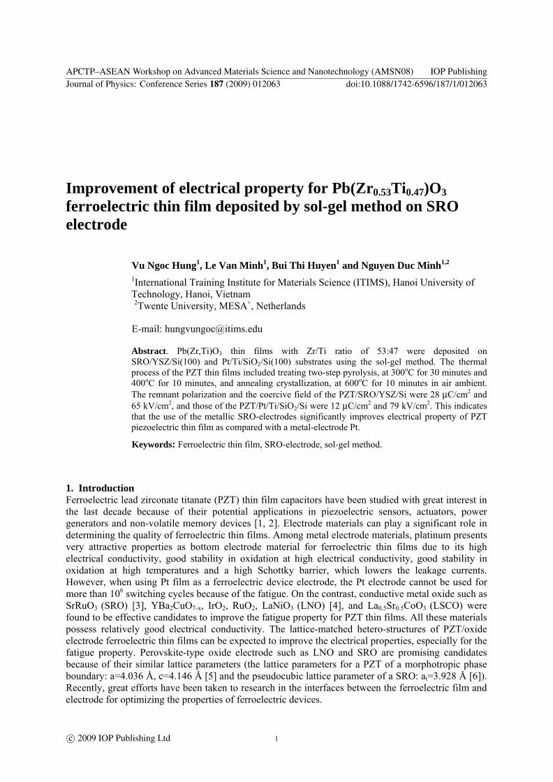
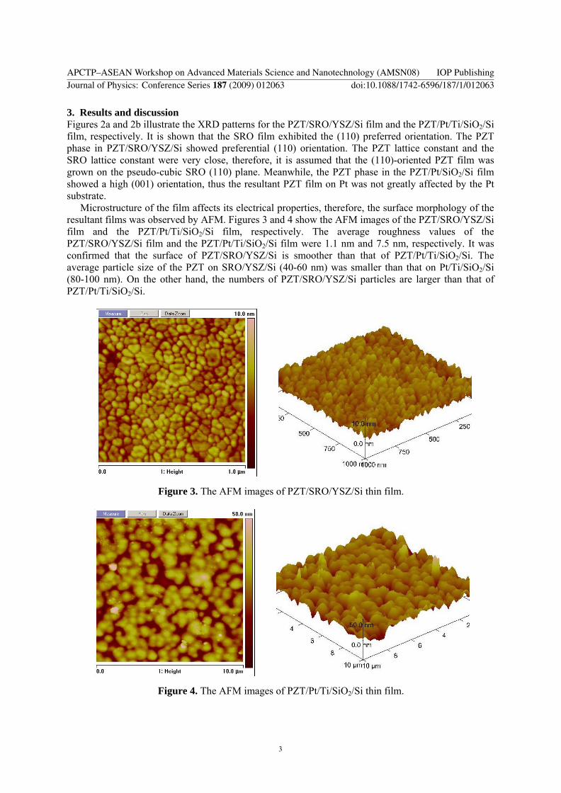
Microstructure of the film affects its electrical properties, therefore, the surface morphology of the resultant films was observed by AFM. Figures 3 and 4 show the AFM images of the PZT/SRO/YSZ/Si film and the PZT/Pt/Ti/SiO2/Si film, respectively. The average roughness values of the PZT/SRO/YSZ/Si film and the PZT/Pt/Ti/SiO2/Si film were 1.1 nm and 7.5 nm, respectively. It was confirmed that the surface of PZT/SRO/YSZ/Si is smoother than that of PZT/Pt/Ti/SiO2/Si. The average particle size of the PZT on SRO/YSZ/Si (40-60 nm) was smaller than that on Pt/Ti/SiO2/Si (80-100 nm). On the other hand, the numbers of PZT/SRO/YSZ/Si particles are larger than that of PZT/Pt/Ti/SiO2/Si.
Figure 3. The AFM images of PZT/SRO/YSZ/Si thin film.
Figure 4. The AFM images of PZT/Pt/Ti/SiO2/Si thin film.
APCTP–ASEAN Workshop on Advanced Materials Science and Nanotechnology (AMSN08) IOP PublishingJournal of Physics: Conference Series 187 (2009) 012063 doi:10.1088/1742-6596/187/1/012063
3
(a) (b)
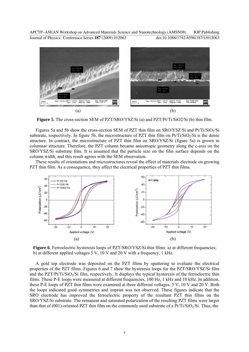
Figure 5. The cross-section SEM of PZT/SRO/YSZ/Si (a) and PZT/Pt/Ti/SiO2/Si (b) thin film. Figures 5a and 5b show the cross-section SEM of PZT thin film on SRO/YSZ/Si and Pt/Ti/SiO2/Si
substrate, respectively. In figure 5b, the microstructure of PZT thin film on Pt/Ti/SiO2/Si is the dense structure. In contract, the microstructure of PZT thin film on SRO/YSZ/Si (figure 5a) is grown in columnar structure. Therefore, the PZT column became anisotropic geometry along the c-axis on the SRO/YSZ/Si substrate film. It is assumed that the particle size on the film surface depends on the column width, and this result agrees with the SEM observation.
These results of orientations and microstructures reveal the effect of materials electrode on growing PZT thin film. As a consequence, they affect the electrical properties of PZT thin films.
(a) (b)
Figure 6. Ferroelectric hysteresis loops of PZT/SRO/YSZ/Si thin films: a) at different frequencies; b) at different applied voltages 5 V, 10 V and 20 V with a frequency, 1 kHz.
A gold top electrode was deposited on the PZT films by sputtering to evaluate the electrical
properties of the PZT films. Figures 6 and 7 show the hysteresis loops for the PZT/SRO/YSZ/Si film and the PZT/Pt/Ti/SiO2/Si film, respectively. It displays the typical hysteresis of the ferroelectric thin films. These P-E loops were measured at different frequencies, 100 Hz, 1 kHz and 10 kHz. In addition, these P-E loops of PZT thin films were examined at three different voltages, 5 V, 10 V and 20 V. Both the loops indicated good symmetries and imprint was not observed. These figures indicate that the SRO electrode has improved the ferroelectric property of the resultant PZT thin films on the SRO/YSZ/Si substrate. The remanent and saturated polarization of the resulting PZT films were larger than that of (001)-oriented PZT thin film on the commonly used substrate of a Pt/Ti/SiO2/Si. Thus, the
APCTP–ASEAN Workshop on Advanced Materials Science and Nanotechnology (AMSN08) IOP PublishingJournal of Physics: Conference Series 187 (2009) 012063 doi:10.1088/1742-6596/187/1/012063
4
(a) (b)
Figure 7. Ferroelectric hysteresis loops of PZT/Pt/Ti/SiO2/Si thin films: a) at different frequencies; b) at different applied voltages 5 V, 10 V and 20 V with a frequency, 1 kHz.
remanent polarization and the saturation polarization of the PZT/SRO/YSZ/Si film were 28µC/cm2 and 58 µC/cm2, and those of the PZT/Pt/Ti/SiO2/Si film were 12 µC/cm2 and 38 µC/cm2, respectively. In addition, coercive field of the resulting PZT films was also reduced by using the SRO electrode because of the better contact of the interface between electrode and the ferroelectric PZT thin film. The coercive field for the PZT/SRO and the PZT/Pt capacitor was 60 kV/cm and 75 kV/cm, respectively.
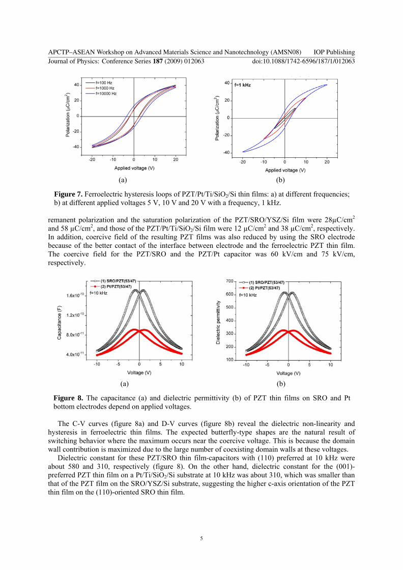
(a) (b)
Figure 8. The capacitance (a) and dielectric permittivity (b) of PZT thin films on SRO and Pt bottom electrodes depend on applied voltages.
The C-V curves (figure 8a) and D-V curves (figure 8b) reveal the dielectric non-linearity and
hysteresis in ferroelectric thin films. The expected butterfly-type shapes are the natural result of switching behavior where the maximum occurs near the coercive voltage. This is because the domain wall contribution is maximized due to the large number of coexisting domain walls at these voltages.
Dielectric constant for these PZT/SRO thin film-capacitors with (110) preferred at 10 kHz were about 580 and 310, respectively (figure 8). On the other hand, dielectric constant for the (001)-preferred PZT thin film on a Pt/Ti/SiO2/Si substrate at 10 kHz was about 310, which was smaller than that of the PZT film on the SRO/YSZ/Si substrate, suggesting the higher c-axis orientation of the PZT thin film on the (110)-oriented SRO thin film.
APCTP–ASEAN Workshop on Advanced Materials Science and Nanotechnology (AMSN08) IOP PublishingJournal of Physics: Conference Series 187 (2009) 012063 doi:10.1088/1742-6596/187/1/012063
5

4. Conclusion We have successfully deposited PZT thin films on the SRO/YSZ/Si substrates with preferred orientation by sol-gel process. The orientation and microstructure of the PZT thin films are affected strongly by the SRO bottom electrode. These PZT/SRO thin films exhibited better ferroelectric properties compared with those of the (001)-textured PZT/Pt thin films on the Si substrates. These results indicate that the thin-film oxide electrode is essential for the led-based ferroelectric thin films.
References [1] Xie J, Hu M, Ling S F and Du H 2006 Sensors and Actuators A 126 182 [2] Jeon Y B, Sood R, Jeong J H and Kim S G 2005 Sensors and Actuators A 122 16 [3] Wang Y K, Tseng T Y and Lin P 2002 Appl. Phys. Lett. 80 3790 [4] Sama N, Herdier R, Jenkins D, Soyer C, Remiens D, Detalle M and Bouregba R 2008 J. Cryst.
Growth 310 3299 [5] Suzuki H, Miwa Y, Naoe T, Miyazaki H, Ota T, Fuji M and Takahashi M 2006 J. of the
European Ceramic Society 26 1953 [6] Lee H N, Senz S, Zakharov N D, Harnagea C, Pignolet A, Hesse D and Gosele U 2000 Appl.
Phys. Lett. 77 3260
APCTP–ASEAN Workshop on Advanced Materials Science and Nanotechnology (AMSN08) IOP PublishingJournal of Physics: Conference Series 187 (2009) 012063 doi:10.1088/1742-6596/187/1/012063
6