Improved load frequency control with superconducting magnetic energy storage in interconnected power...
11
TRANSACTIONS ON ELECTRICAL AND ELECTRONIC ENGINEERING IEEJ Trans 2007; 2: 387–397 Published online in Wiley InterScience (www.interscience.wiley.com). DOI:10.1002/tee.20160 Paper Improved Load Frequency Control with Superconducting Magnetic Energy Storage in Interconnected Power Systems Mairaj ud din Mufti ∗a , Non-member Shameem Ahmad Lone ∗ , Non-member Sheikh Javed Iqbal ∗ , Non-member Imran Mushtaq ∗ , Non-member This paper presents adaptive neural control of a superconducting magnetic energy storage system (SMES) in a power system for improved load frequency control (LFC). The proposed scheme for SMES control is a new one, tackles the deficiencies in the existing SMES control schemes and is clear about its implementation aspects. The power conversion system (PCS) of SMES used in this paper comprises of a voltage source converter (VSC) and a two-quadrant chopper. The control in each control area is implemented through a neural estimator and a neural controller with both of them operating online. The neural estimator extracts the control area dynamics around an operating point, and the neural controller then generates the power command for the corresponding SMES unit on the basis of a newly introduced variable which is a function of area control error and the change in stored energy in the SMES coil. This feature leads to a suitable and pure adaptive control of SMES. Moreover, in this paper the supplementary controller associated with the automatic generation control (AGC) is made to act on the area control error, with a modified gain setting, which is obtained by the integral square error (ISE) criterion. Simulation studies based on MATLAB are presented on a two-area power system after carrying out the necessary modeling exercise. 2007 Institute of Electrical Engineers of Japan. Published by John Wiley & Sons, Inc. Keywords: SMES, adaptive neural control, load frequency control Received 13 October 2006; Revised 17 January 2007; Accepted 30 January 2007 1. Introduction In an interconnected power system, as the load demand varies randomly, the area frequency and tie-power inter- change also vary. The objective of the load frequency control (LFC) problem is to minimize the transient devi- ations in these variables and to ensure their zero steady state values. The solution to the LFC problem by a gover- nor control alone imposes a limit on the degree to which the deviations in frequency and tie-power exchange can be minimized. However, the LFC problem fundamen- tally being that of an instantaneous mismatch between the generation and demand of active power, the incor- poration of a fast-acting energy storage device in the power system can improve the performance under such a Correspondence to: Mairaj ud din Mufti. E-mail: [email protected] ∗ Electrical Engineering Department, National Institute of Technol- ogy, Hazratbal, Kashmir, India, 190006, India conditions. The superconducting magnetic energy storage (SMES) features highly efficient energy storage and high- speed power control. At the same time, its operation and life are not influenced by the number of charge/discharge cycles unlike the classical batteries. The estimated life of a typical SMES unit is more than 20 years. As a result of this, many attractive applications of SMES have been reported [1–8]. In the literature [3,4,7,8] the controller used for SMES in the LFC problem is the conventional one. The fixed gain controller for SMES cannot, however, perform optimally [1,5] under different operating conditions in a power system and the suitable controllers for SMES are those with adaptive features [5]. Although the scheme presented in Ref. 5 is based on self-tuning type of adaptive control, it has some deficiencies. For example, the SMES model has been unnecessarily linearized, and the SMES control scheme is not purely adaptive but contains an inner proportional control loop for SMES 2007 Institute of Electrical Engineers of Japan. Published by John Wiley & Sons, Inc.
-
Upload
independent -
Category
Documents
-
view
0 -
download
0
Transcript of Improved load frequency control with superconducting magnetic energy storage in interconnected power...

TRANSACTIONS ON ELECTRICAL AND ELECTRONIC ENGINEERINGIEEJ Trans 2007; 2: 387–397Published online in Wiley InterScience (www.interscience.wiley.com). DOI:10.1002/tee.20160
Paper
Improved Load Frequency Control with Superconducting MagneticEnergy Storage in Interconnected Power Systems
Mairaj ud din Mufti∗a, Non-member
Shameem Ahmad Lone∗, Non-member
Sheikh Javed Iqbal∗, Non-member
Imran Mushtaq∗, Non-member
This paper presents adaptive neural control of a superconducting magnetic energy storage system (SMES) ina power system for improved load frequency control (LFC). The proposed scheme for SMES control is a newone, tackles the deficiencies in the existing SMES control schemes and is clear about its implementation aspects.The power conversion system (PCS) of SMES used in this paper comprises of a voltage source converter (VSC)and a two-quadrant chopper. The control in each control area is implemented through a neural estimator and aneural controller with both of them operating online. The neural estimator extracts the control area dynamicsaround an operating point, and the neural controller then generates the power command for the correspondingSMES unit on the basis of a newly introduced variable which is a function of area control error and the change instored energy in the SMES coil. This feature leads to a suitable and pure adaptive control of SMES. Moreover,in this paper the supplementary controller associated with the automatic generation control (AGC) is made toact on the area control error, with a modified gain setting, which is obtained by the integral square error (ISE)criterion. Simulation studies based on MATLAB are presented on a two-area power system after carrying outthe necessary modeling exercise. 2007 Institute of Electrical Engineers of Japan. Published by John Wiley &Sons, Inc.
Keywords: SMES, adaptive neural control, load frequency control
Received 13 October 2006; Revised 17 January 2007; Accepted 30 January 2007
1. Introduction
In an interconnected power system, as the load demandvaries randomly, the area frequency and tie-power inter-change also vary. The objective of the load frequencycontrol (LFC) problem is to minimize the transient devi-ations in these variables and to ensure their zero steadystate values. The solution to the LFC problem by a gover-nor control alone imposes a limit on the degree to whichthe deviations in frequency and tie-power exchange canbe minimized. However, the LFC problem fundamen-tally being that of an instantaneous mismatch betweenthe generation and demand of active power, the incor-poration of a fast-acting energy storage device in thepower system can improve the performance under such
a Correspondence to: Mairaj ud din Mufti.E-mail: [email protected]
∗ Electrical Engineering Department, National Institute of Technol-ogy, Hazratbal, Kashmir, India, 190006, India
conditions. The superconducting magnetic energy storage(SMES) features highly efficient energy storage and high-speed power control. At the same time, its operation andlife are not influenced by the number of charge/dischargecycles unlike the classical batteries. The estimated life ofa typical SMES unit is more than 20 years. As a resultof this, many attractive applications of SMES have beenreported [1–8].
In the literature [3,4,7,8] the controller used for SMESin the LFC problem is the conventional one. The fixedgain controller for SMES cannot, however, performoptimally [1,5] under different operating conditions in apower system and the suitable controllers for SMES arethose with adaptive features [5]. Although the schemepresented in Ref. 5 is based on self-tuning type ofadaptive control, it has some deficiencies. For example,the SMES model has been unnecessarily linearized, andthe SMES control scheme is not purely adaptive butcontains an inner proportional control loop for SMES
2007 Institute of Electrical Engineers of Japan. Published by John Wiley & Sons, Inc.
M. MUFTI ET AL.
current control. Also, in most of these already existingschemes, the converters used drain reactive power fromthe network and the SMES dynamics and control modelsused lack the practical implementation aspects related toSMES coil charging/discharging.
This paper presents a new scheme in which adaptiveneural control is proposed for SMES. The adaptiveneural control of SMES in each area is implementedthrough a pair of Adaline neural networks. The areacontrol dynamics around an operating point is extractedonline with the help of a neural estimator. For achievingthe control objective on a continuous basis, the neuralcontroller in each area is made to produce the powercommand for the corresponding SMES unit on the basisof a newly introduced variable which is a function ofarea control error and the change in stored energy ofthe SMES coil. The nonlinearity of the SMES model isretained, and power conversion system used is capableof independent active and reactive power modulation.All these features help in tackling the deficiencies inthe already existing control schemes of SMES mentionedabove. The paper also explains in depth how the chargingand discharging of the SMES coil can be practicallyimplemented in the proposed scheme.
Moreover, keeping in view the fact that a suddenrelease or absorption of power by SMES in accordancewith the change in load demand partially countersthe effect of supplementary controller associated withautomatic gain control (AGC), the gain of the integralcontroller in the supplementary control loop is set at anew value in this work, as per integral square error (ISE)criterion.
The necessary models are developed and the simula-tion studies made using MATLAB on a two-area powersystem are presented for a variety of disturbances toassess the performance of the proposed scheme.
2. Configuration of SMES in a Two-area PowerSystem
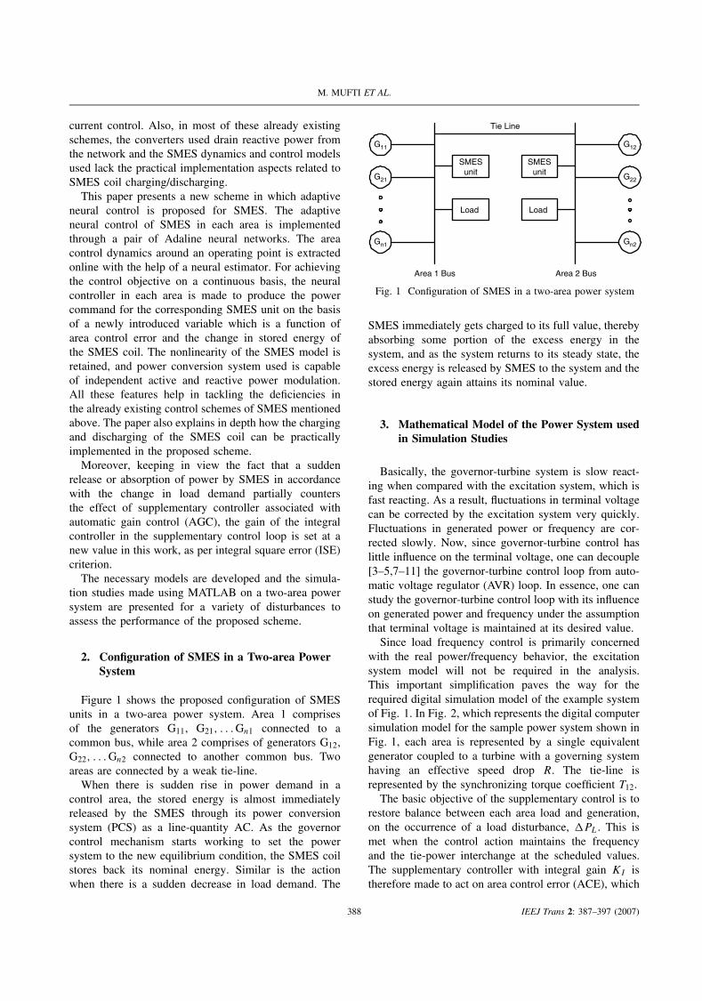
Figure 1 shows the proposed configuration of SMESunits in a two-area power system. Area 1 comprisesof the generators G11, G21, . . . Gn1 connected to acommon bus, while area 2 comprises of generators G12,G22, . . . Gn2 connected to another common bus. Twoareas are connected by a weak tie-line.
When there is sudden rise in power demand in acontrol area, the stored energy is almost immediatelyreleased by the SMES through its power conversionsystem (PCS) as a line-quantity AC. As the governorcontrol mechanism starts working to set the powersystem to the new equilibrium condition, the SMES coilstores back its nominal energy. Similar is the actionwhen there is a sudden decrease in load demand. The
G11
G21
Gn1
SMESunit
Load Load
Tie Line
Area 1 Bus Area 2 Bus
SMESunit
G12
G22
Gn2
Fig. 1 Configuration of SMES in a two-area power system
SMES immediately gets charged to its full value, therebyabsorbing some portion of the excess energy in thesystem, and as the system returns to its steady state, theexcess energy is released by SMES to the system and thestored energy again attains its nominal value.
3. Mathematical Model of the Power System usedin Simulation Studies
Basically, the governor-turbine system is slow react-ing when compared with the excitation system, which isfast reacting. As a result, fluctuations in terminal voltagecan be corrected by the excitation system very quickly.Fluctuations in generated power or frequency are cor-rected slowly. Now, since governor-turbine control haslittle influence on the terminal voltage, one can decouple[3–5,7–11] the governor-turbine control loop from auto-matic voltage regulator (AVR) loop. In essence, one canstudy the governor-turbine control loop with its influenceon generated power and frequency under the assumptionthat terminal voltage is maintained at its desired value.
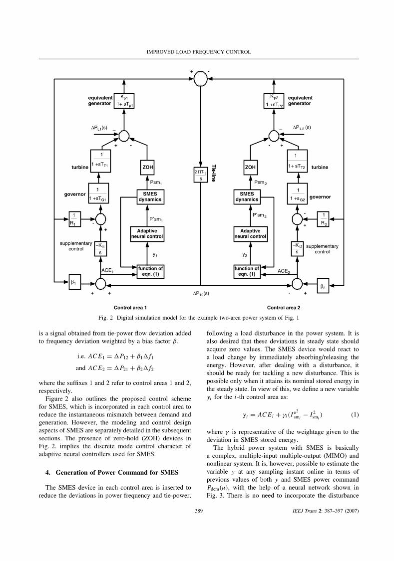
Since load frequency control is primarily concernedwith the real power/frequency behavior, the excitationsystem model will not be required in the analysis.This important simplification paves the way for therequired digital simulation model of the example systemof Fig. 1. In Fig. 2, which represents the digital computersimulation model for the sample power system shown inFig. 1, each area is represented by a single equivalentgenerator coupled to a turbine with a governing systemhaving an effective speed drop R. The tie-line isrepresented by the synchronizing torque coefficient T12.
The basic objective of the supplementary control is torestore balance between each area load and generation,on the occurrence of a load disturbance, �PL. This ismet when the control action maintains the frequencyand the tie-power interchange at the scheduled values.The supplementary controller with integral gain KI istherefore made to act on area control error (ACE), which
388 IEEJ Trans 2: 387–397 (2007)
IMPROVED LOAD FREQUENCY CONTROL
ZOH
SMESdynamics
Adaptiveneural control
function ofeqn. (1)
ZOH
+ -
+ - - +
_ _
+ + - +
+-
-
+
1+ sTp1
Kp1
s
−KI1
1 +sG2
1
s−KI2
R1
1
R2
1
β2
β1
ACE1 ACE2function of
eqn. (1)
Adaptiveneural control
SMESdynamics
P*sm1
Psm2Psm1
P*sm2
s2 ΠT12
∆PL1(s) ∆PL2 (s)
equivalentgenerator
equivalentgenerator1 +sTP2
Kp2
turbine turbine
governor governor
Tie-lin
e
Control area 1 Control area 2
supplementarycontrol supplementary
control
1 +sTT1
1
1 +sTG1
1
y1 y2
∆P12(s)
1 + sTT2
1
Fig. 2 Digital simulation model for the example two-area power system of Fig. 1
is a signal obtained from tie-power flow deviation addedto frequency deviation weighted by a bias factor β.
i.e. ACE1 = �P12 + β1�f1
and ACE2 = �P21 + β2�f2
where the suffixes 1 and 2 refer to control areas 1 and 2,respectively.
Figure 2 also outlines the proposed control schemefor SMES, which is incorporated in each control area toreduce the instantaneous mismatch between demand andgeneration. However, the modeling and control designaspects of SMES are separately detailed in the subsequentsections. The presence of zero-hold (ZOH) devices inFig. 2. implies the discrete mode control character ofadaptive neural controllers used for SMES.
4. Generation of Power Command for SMES
The SMES device in each control area is inserted toreduce the deviations in power frequency and tie-power,
following a load disturbance in the power system. It isalso desired that these deviations in steady state shouldacquire zero values. The SMES device would react toa load change by immediately absorbing/releasing theenergy. However, after dealing with a disturbance, itshould be ready for tackling a new disturbance. This ispossible only when it attains its nominal stored energy inthe steady state. In view of this, we define a new variableyi for the i-th control area as:
yi = ACEi + γi(Io2
smi− I 2
smi) (1)
where γ is representative of the weightage given to thedeviation in SMES stored energy.
The hybrid power system with SMES is basicallya complex, multiple-input multiple-output (MIMO) andnonlinear system. It is, however, possible to estimate thevariable y at any sampling instant online in terms ofprevious values of both y and SMES power commandPdem(u), with the help of a neural network shown inFig. 3. There is no need to incorporate the disturbance
389 IEEJ Trans 2: 387–397 (2007)

M. MUFTI ET AL.
+
delta rulelearning
x1 = -y(k-1)
x2 = -y(k-2)
xn = -y(k-n)
xn+1 = u(k-1)
xn+2 = u(k-2)
xn+m = u(k-m)
w1(k-1)
w2(k-1)
wn(k-1)
wn+1(k-1)
wn+2(k-1)
wn+m(k-1)
y(k)e(k)
+
-
.
.
.
.
.
.
y(k)^
Fig. 3 Neural model of the control area
term in the neural model of the control area as the neuralnetwork will extract the control area dynamics online, inthe presence of load disturbances [12].
In order to ensure that the estimated modified areacontrol error yi follows the actual modified area controlerror, the Widrow–Hoff delta rule [13,14] is used toupdate the weight vector W(k) of the neural estimatorat the sampling instant k as per the following:
W(k + 1) = W(k) + αe(k + 1)X(k)
ε + XT (k)X(k)
where X(k) = [−y(k) − y(k − 1) . . . y(k − n + 1)
u(k) . . . u(k − m + 1)]′ (2)
and W(k) = [W1(k) W2(k) . . .Wn(k)
Wn+1(k) . . .Wn+m(k)]′
α ∈ (0, 2) is the reduction factor and ε
is chosen to be close to zero.
Another Adaline neural network shown in Fig. 4 isthen used to generate the power demand Pdem(k) = u(k)
for the SMES. We have chosen the structure of thissecond neural network (called as neural controller) insuch a way that it generates the power demand for SMESto minimize the cost function (3). The minimization ofJ (k) with respect to u(k) will result in an optimal control
+
-x2(k)
u(k)
-xn-1(k)
-xn(k)
-xn+2(k)
-xn+m(k)
.
.
.
.
.
.
-x1(k)
W′1(k)
W′2(k)
W′n-1(k)
W′n(k)
W′n+1(k)
W′n+m-1(k)
Fig. 4 Neural controller of the control area
signal, which minimizes the modified area control errorat the very next sampling instant.
J (k) = y2i (k + 1) + λu2
i (k) (3)
where λ is a weighing constant of penalty on control andits nonzero value in many cases prevents instability.
The weight vector W′(k) of the neural controller isfound to be related to the weight vector W(k) of the
390 IEEJ Trans 2: 387–397 (2007)

IMPROVED LOAD FREQUENCY CONTROL
Adaptiveneural control
Controlmodel for
SMES
2-quadrantchopper
A/D
Control area i
SMES unit
D/A
D
Yi
AC
E
Ismi
∆fi
∆ptiei
_
P*smi
∆PLi
+
+
+-1
bi
X
Ui
I°smi X I°smi
gi
Fig. 5 Control scheme for SMES in the i-th control area
neural estimator through the following relationship:
W′(k) = c[W1(k)W2(k) . . . Wn(k)
Wn+2(k) . . . Wn+m(k)] (4)
where c = Wn+1(k)
W2n+1(k) + λ
It may be noted that the neural controller of Fig. 4 willbecome the inverse model [13,14] of the control area ifλ is set to zero.
Figure 5 shows an outline of the i-th control area withits SMES unit controlled through the adaptive neuralcontroller. The implementation of the control schemerequires local measurements only. The blocks ‘controlmodel for SMES’ and ‘2-quarant chopper’ of Fig. 5 areexplained in Section 5.
The sequence of actions carried out in the blocklabeled as adaptive neural control in Fig. 5, at instantk are as follows:
(a) Measure y(k);(b) Use neural model of the control area to compute the
predicted value of y(k) i.e. y(k).(c) Compute the error e(k) = y(k) − y(k), and use the
delta rule to calculate the weights in the neural model;(d) Update the neural controller weights as per (4);(e) Use the neural controller to generate the power
demand ui for SMES.
5. Control Model for SMES
The PCS for interfacing the SMES unit in eachcontrol area with the electric network is shown inFig. 6. It consists of a six-pulse Pulse-width modulated
(PWM), voltage source converter (VSC) linked to aDC–DC chopper through a DC link capacitor. Thesix-pulse converter operates synchronously with thepower system [3,6,] and the beauty with this converterscheme is that unlike the other converter schemes forSMES, independent real and reactive power control ispossible by adjustment of voltage angle and magnitude,respectively, at the converter terminals. To start with,the DC link capacitor is charged through the diodesof the six-pulse converter, with the gating signals toInsulated gate bipolar transistor (IGBTs) blocked. Whenthe appropriate gating signals are released to the IGBTs,the DC link voltage builds up to reference value and ismaintained constant throughout [3,6]. To enable chargingand discharging of the SMES, a DC voltage of propermagnitude and polarity is impressed upon the SMES coil.This is in turn accomplished by the automatic adjustmentof the duty cycle of a two-quadrant chopper in a mannerdetailed in the subsequent sections.
In effect, for the load frequency control problem, thescheme of Fig. 6 is equivalent to that of Fig. 7. In Fig. 7,S1 and S2 are the chopper switches with the same dutycycle and D1 and D2 are the diodes, and it is importantto note that everything excepting the chopper and SMEScoil is modeled by a capacitor with a constant voltageacross it, in view of the action performed by the six-pulsePWM converter.
Depending upon the value of chopper duty cycleD, three regions of operation can be identified for thechopper arrangement of Fig. 7. The timing diagramspertaining to these regions of operation are shown inFig. 8.
It is clear from Fig. 8 that voltage appearing across theSMES coil and chopper current at any instant of time can
391 IEEJ Trans 2: 387–397 (2007)

M. MUFTI ET AL.
SMEScoiltransformer
6-pulse PWMvoltagesourced
converterusing IGBT
Two-quadrantclass BDC-DCchopper
3-phase AC
DC linkcapacitor
Y/∆
Fig. 6 Basic components of the SMES
ics
Vsm
Vdc
S1 D1
D2
+ -
ism
S2
Fig. 7 Chopper for SMES-active power modulation
be represented, respectively, by (5) and (6):
vsm = sfVdc (5)
ics = sfism (6)
where sf = −1/0/ + 1Assuming that the SMES current at the sampling
instant is Ism, it can be shown from Fig. 8 that theaverage value of chopper current Ics is related to chopperduty cycle D through (7)
D = 0.5 + Ics
2Ism(7)
Now if P ∗sm represents the desired power to be inputted
to SMES, then
P ∗sm = VdcIcs (8)
Once (7) and (8) are cast in a block diagram, the controlmodel of Fig. 9 results for SMES. This model outputsthe duty cycle D, in response to desired SMES power,P ∗
sm.
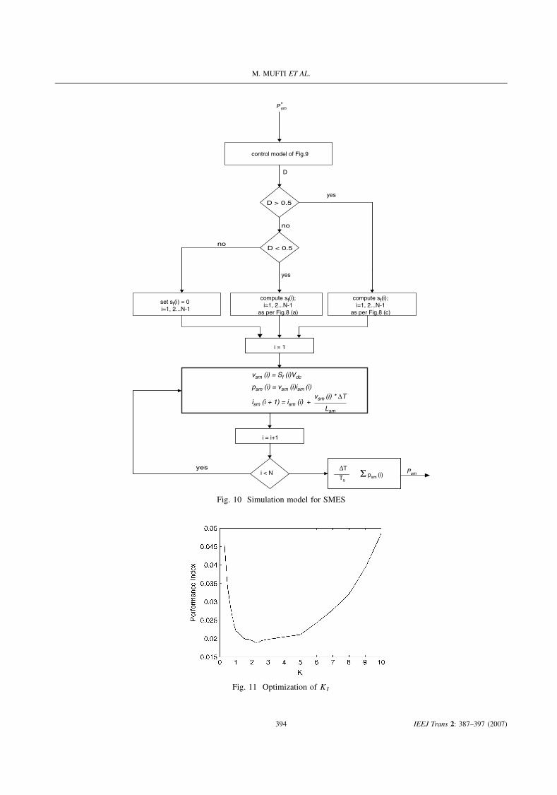
6. Simulation Model of SMES
It is important to note that the actual average powerinputted to the SMES over a sampling period differs fromP ∗
sm because of the SMES unit dynamics. This actualvalue of SMES power is computed as per the algorithmof Fig. 10, in which N represents the number of timesteps in one sampling period of Ts seconds.
sf
sf
sf
S1 D2 S1 D2
D1
S1
D1
S1
D1
S1
D1
S1
D1
D1
0
-1
DT
T
S2
D2
S2
D2
S2S2
D2S2
D2
S2
D2
S2
0
T
DT
DT
T
0
+1
(a) Chopper operation for D < 0.5
(b) Chopper operation for D = 0.5
(c) Chopper operation for D > 0.5
Fig. 8 Details about the on positions of various switchingdevices of the chopper for different range of values for the
duty cycle
7. Digital Simulation Studies
Digital simulation studies using MATLAB werecarried out by subjecting the two-area system to variousdisturbances given in Table I. Before presenting thesimulation results for the various load disturbances, itis important to mention here that a very low value of γ
in (1) results in a discontinuous control, and, on the otherhand, its high value does not improve the LFC. On the
392 IEEJ Trans 2: 387–397 (2007)

IMPROVED LOAD FREQUENCY CONTROL
Vdc
1
±0.5
+
+
D
0.5
P*sm x
Ism
y
2
Xy
Fig. 9 Control model for SMES
Table I. Disturbance profiles
Load disturbance profile No. 1
�PL1 = 0.01 p.u. t > 0 seconds�PL2 = 0.00 p.u. t > 0 seconds
Load disturbance profile No. 2
�PL1 ={
0.01 p.u. 0 < t ≤ 15 seconds0.02 p.u. t > 15 seconds
}
�PL2 ={
0.01 p.u. 0 < t ≤ 15 seconds0.00 p.u. t > 15 seconds
}
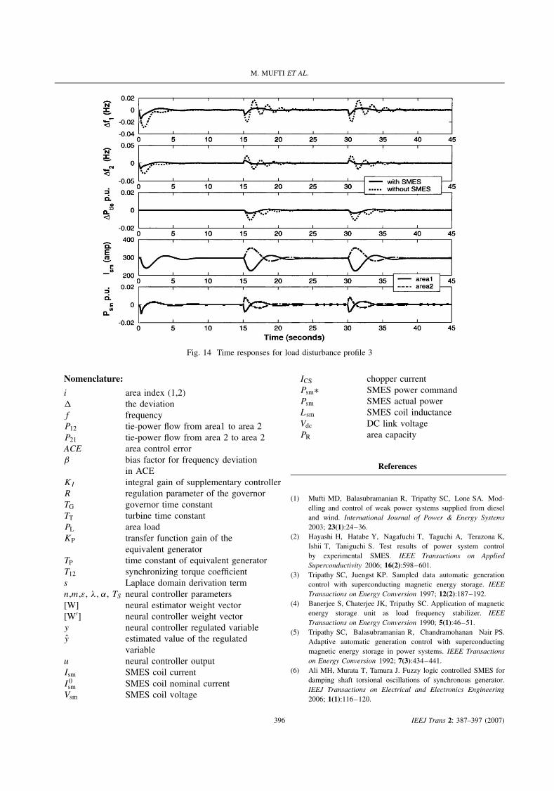
Load disturbance profile No. 3
�PL1 =
0.01 p.u. 0 < t ≤ 15 seconds0.02 p.u. 15 < t ≤ 30 seconds0.03 p.u. t > 30 seconds
�PL2 =
0.01 p.u. 0 < t ≤ 15 seconds0.00 p.u. 15 < t ≤ 30 seconds
−0.01 p.u. t > 30 seconds
basis of a number of simulation runs, a compromisingvalue for γ was found to be 8 × 10⁻⁸. The curve ofFig. 11 is plotted for this value of γ . The performanceindex (PI) that is plotted in this figure is given in (9) andthe load disturbances for which the curve is plotted isgiven in (10). It is clear from this figure that the newoptimal value of KI has shifted to 2.4.
PI =∫
((�f1)2 + (�f2)
2 + (�Ptie)2)dt (9)
�PL1 = +0.01p.u. t > 0 seconds
�PL2 = −0.01p.u. t > 0 seconds (10)
Figures (12–14) present the digital simulation resultsfor the various disturbances. These results pertain to thesystem parameters given in Table II. In these figures,the plots corresponding to ‘without SMES’ pertain to avalue of KI = 0.5. It is clear from these figures that theproposed scheme brings a considerable improvement indynamic performance of the power system. The SMEScurrents and therefore their stored energies are alsoreturning to their nominal values in the steady state, afterdealing with the disturbances, which is a desired featurefor the continuous control.
Table II. System data
Power system dataArea capacity = PR1 = PR2 = 10 MWKP1 = KP2 = 120 Hz/puMWR1 = R2 = 2.4 Hz/puMWTP1 = TP2 = 20 secondsTG1 = TG2 = 0.08 secondsTT1 = TT2 = 0.3 secondsT12 = 0.0707 puMW/radβ1 = 0.425β2 = 0.425
SMES and adaptive neural controllersLsm1 = Lsm2 = 2.65 henryI o
sm1 = I osm2 = 300 amperes
Same data for both the areas: Converter rating for eachSMES unit = 100 kW, Vdc = 800 voltsChopper frequency = 100 HzIntelligent controller sampling period, Ts = .01 seconds,N = 25n = m = 3, ε = .001 λ = 0.3γ = 0.00000008, α = 1
8. Conclusions
A control strategy based on a pair of neural net-works is proposed for optimal control of SMES. Theproposed scheme is a new one and tackles the defi-ciencies in the already existing schemes for SMES con-trol. Complete models for control and simulation ofSMES units are presented. The proposed control strat-egy directly outputs the power command for the SMESunit in response to a variable, which is a function ofarea control error and the deviation in SMES storedenergy. The integral gain setting of the controller associ-ated with AGC is modified for better performance. Thesimulation studies are carried out on a two-area powersystem to investigate the impact of the proposed intelli-gently controlled SMES on the power system dynamicperformance. The results show that the scheme is verypowerful in reducing the frequency and tie-power devi-ations under a variety of load perturbations. Because oftheir adaptive feature, the proposed intelligent controllersare expected to perform optimally under different oper-ating conditions.
Acknowledgement
The authors are thankful to Head, Department of Electrical Engi-neering, N.I.T. Srinagar, Prof (Dr.) Naseer Ahmad Laway for providingall the necessary facilities to carry out this work. We also acknowledgethe technical guidance provided by Prof. T. Ise at Electrical Engineer-ing Department, Osaka University, Japan to first two authors of thispaper.
393 IEEJ Trans 2: 387–397 (2007)
M. MUFTI ET AL.
control model of Fig.9
D > 0.5yes
P*sm
D
set sf(i) = 0 i=1, 2...N-1
no
D < 0.5
yes
no
compute sf(i);i=1, 2...N-1
as per Fig.8 (a)
compute sf(i);i=1, 2...N-1
as per Fig.8 (c)
i = 1
vsm (i) = Sf (i)Vdc
psm (i) = vsm (i)ism (i)
ism (i + 1) = ism (i) +
i = i+1
i < Nyes
PsmTs
∆T Σ psm (i)
vsm (i) * ∆T
Lsm
Fig. 10 Simulation model for SMES
Fig. 11 Optimization of KI
394 IEEJ Trans 2: 387–397 (2007)

IMPROVED LOAD FREQUENCY CONTROL
Fig. 12 Time responses for load disturbance profile 1
Fig. 13 Time responses for load disturbance profile 2
395 IEEJ Trans 2: 387–397 (2007)
M. MUFTI ET AL.
Fig. 14 Time responses for load disturbance profile 3
Nomenclature:
i area index (1,2)� the deviationf frequencyP12 tie-power flow from area1 to area 2P21 tie-power flow from area 2 to area 2ACE area control errorβ bias factor for frequency deviation
in ACEKI integral gain of supplementary controllerR regulation parameter of the governorTG governor time constantTT turbine time constantPL area loadKP transfer function gain of the
equivalent generatorTP time constant of equivalent generatorT12 synchronizing torque coefficients Laplace domain derivation termn,m,ε, λ, α, TS neural controller parameters[W] neural estimator weight vector[W′] neural controller weight vectory neural controller regulated variabley estimated value of the regulated
variableu neural controller outputIsm SMES coil currentI 0
sm SMES coil nominal currentVsm SMES coil voltage
ICS chopper currentPsm∗ SMES power commandPsm SMES actual powerLsm SMES coil inductanceVdc DC link voltagePR area capacity
References
(1) Mufti MD, Balasubramanian R, Tripathy SC, Lone SA. Mod-elling and control of weak power systems supplied from dieseland wind. International Journal of Power & Energy Systems2003; 23(1):24–36.
(2) Hayashi H, Hatabe Y, Nagafuchi T, Taguchi A, Terazona K,Ishii T, Taniguchi S. Test results of power system controlby experimental SMES. IEEE Transactions on AppliedSuperconductivity 2006; 16(2):598–601.
(3) Tripathy SC, Juengst KP. Sampled data automatic generationcontrol with superconducting magnetic energy storage. IEEETransactions on Energy Conversion 1997; 12(2):187–192.
(4) Banerjee S, Chaterjee JK, Tripathy SC. Application of magneticenergy storage unit as load frequency stabilizer. IEEETransactions on Energy Conversion 1990; 5(1):46–51.
(5) Tripathy SC, Balasubramanian R, Chandramohanan Nair PS.Adaptive automatic generation control with superconductingmagnetic energy storage in power systems. IEEE Transactionson Energy Conversion 1992; 7(3):434–441.
(6) Ali MH, Murata T, Tamura J. Fuzzy logic controlled SMES fordamping shaft torsional oscillations of synchronous generator.IEEJ Transactions on Electrical and Electronics Engineering2006; 1(1):116–120.
396 IEEJ Trans 2: 387–397 (2007)

IMPROVED LOAD FREQUENCY CONTROL
(7) Ngamroo I, Mitani Y, Tsuji K. Application of SMES coordinatedwith solid-phase shifter to load frequency control. IEEETransactions on Applied Superconductivity 1999; 9(2):322–325.
(8) Demiroren A, Yesil E. Automatic generation control with fuzzylogic controllers in the power system including SMES units.International Journal of Electrical Power & Energy Systems2004; 26:291–305.
(9) Kundur P. Power System Stability and Control . McGraw-HillBook Company: New York, 1994.
(10) Debs AS. Modern Power Systems Control and Operation. KulwerAcademic Publishers: Boston, 1988.
(11) Elgerd OI. Electrical Energy Systems Theory An Introduction.McGraw-Hill Book Company: New York, 1982.
(12) Jha R, He C. Neural-network based adaptive predictive controlfor vibration suppression of smart structures. Smart MaterialStructures 2002; 11:909–916.
(13) Etxbarria V. Adaptive control of discrete time systems usingneural networks. IEE Proceedings Control Theory Applications1994; 141(4):209–215.
(14) Lim CM, Ling Q. An enhanced adaptive neural network controlscheme for power systems. IEEE Transactions on EnergyConversion 1997; 12(2):166–174.
Mairaj ud din Mufti received his B.E. degree in Elec-trical Engineering from the RegionalEngineering College, Srinagar, India,in 1986. He received his M.Tech. andPh. D degrees in 1991 and 1998,respectively, from the Indian Insti-tute of Technology (IIT), New Delhi,India. Dr. Mufti was a Visiting For-eign Fellow at the Osaka University,Japan, in 2006. He has been withthe Faculty of Electrical Engineering,
National Institute of Technology, Srinagar, India, for pasttwo decades and his research interests include intelligentcontrol, renewable energy, energy storage devices andpower system dynamics and control.
Shameem Ahmad Lone received his B.E. degree in Elec-trical Engineering from the RegionalEngineering College, Srinagar, India,in 1989. He received his M.E. degreefrom the University of Roorkee,India, in 1998 and Ph.D. degreein 2006 from the National Instituteof Technology, Srinagar, India. Hewas a Visiting Foreign Fellow at theOsaka University, Japan, in 2006. Dr.Lone has been on the Faculty of Elec-
trical Engineering, National Institute of Technology, Sri-nagar, India, since 1994 and his research interests includeintelligent control, renewable energy and energy storagedevices.
Sheikh Javed Iqbal received his B.E. degree in Elec-trical Engineering from the RegionalEngineering College, Srinagar, India,in 1993. After working with PowerGrid Corporation of India, Ltd. asan Assistant Engineer Trainee forsome time, he joined the Departmentof Electrical Engineering, RegionalEngineering College, Srinagar, as aLecturer in 1996. He received hisM.E. degree in High Voltage Engi-
neering from the Indian Institute of Science, Bangalore,India, in 2002. He is presently working for his Ph.D.degree in Intelligent Control at the Electrical EngineeringDepartment, National Institute of Technology, Srinagar,India.
Imran bin Mushtaq received his B.Tech. degree in Elec-trical Engineering from the NationalInstitute of Technology, Hazratbal,Srinagar, in 2006 and is presentlywith the Plant Engineering Depart-ment of Alstom Projects India Lim-ited.
397 IEEJ Trans 2: 387–397 (2007)