Impact of rotary instruments upon fiber-matrix integrity ...
21
Zurich Open Repository and Archive University of Zurich Main Library Strickhofstrasse 39 CH-8057 Zurich www.zora.uzh.ch Year: 2015 Fiber-matrix integrity, micromorphology and fexural strength of glass fber posts: Evaluation of the impact of rotary instruments Pereira, Gabriel Kalil Rocha ; Lançanova, Mateus ; Wandscher, Vinicius Felipe ; Kaizer, Osvaldo Bazzan ; Limberger, Inácio ; Özcan, Mutlu ; Valandro, Luiz Felipe Abstract: Several rotary instruments have been daily employed on clinic to promote cut aiming to ad- just the length of fber posts to the radicular conduct, but there is no information on the literature about the efects of the diferent rotary instruments and its impact on the micromorphology of surface and mechanical properties of the glass fber post. This study aimed the impact of rotary instruments upon fber-matrix integrity, micromorphology and fexural-strength of glass-fber posts (GFP). GFP (N=110) were divided into 5 groups: Ctrl: as-received posts, DBc: coarse diamond-bur, DBf: extra-fne diamond-bur, CB: carbide-bur, DD: diamond-disc. Cutting procedures were performed under abundant irrigation. Posts exposed to rotary instruments were then subjected to 2-point inclined loading test (com- pression 45°) (n=10/group) and 3-point fexural-strength test (n=10/group). Fiber-matrix integrity and micromorphology at the cut surface were analyzed using a SEM (n=2/group). Cutting procedures did not signifcantly afect the 2-point (51.7±4.3-56.7±5.1 MPa) (p=0.0233) and 3-point fexural-strength (671.5±35.3-709.1±33.1 MPa) (p=0.0968) of the posts (One-way ANOVA and Tukeys test). Fiber de- tachment was observed only at the end point of the cut at the margins of the post. Cut surfaces of the CB group were smoother than those of the other groups. After 3-point fexural strength test, fber-matrix separation was evident at the tensile side of the post. Rotary instruments tested with simultaneous water-cooling did not afect the resistance of the tested fber posts but caused disintegration of the fbers from the matrix at the end of the cut, located at the margins. DOI: https://doi.org/10.1016/j.jmbbm.2015.04.008 Posted at the Zurich Open Repository and Archive, University of Zurich ZORA URL: https://doi.org/10.5167/uzh-116035 Journal Article Accepted Version The following work is licensed under a Creative Commons: Attribution-NonCommercial-NoDerivatives 4.0 International (CC BY-NC-ND 4.0) License. Originally published at: Pereira, Gabriel Kalil Rocha; Lançanova, Mateus; Wandscher, Vinicius Felipe; Kaizer, Osvaldo Bazzan; Limberger, Inácio; Özcan, Mutlu; Valandro, Luiz Felipe (2015). Fiber-matrix integrity, micromorphology and fexural strength of glass fber posts: Evaluation of the impact of rotary instruments. Journal of the Mechanical Behavior of Biomedical Materials, 48:192-199.
-
Upload
khangminh22 -
Category
Documents
-
view
2 -
download
0
Transcript of Impact of rotary instruments upon fiber-matrix integrity ...
Zurich Open Repository andArchiveUniversity of ZurichMain LibraryStrickhofstrasse 39CH-8057 Zurichwww.zora.uzh.ch
Year: 2015
Fiber-matrix integrity, micromorphology and flexural strength of glass fiberposts: Evaluation of the impact of rotary instruments
Pereira, Gabriel Kalil Rocha ; Lançanova, Mateus ; Wandscher, Vinicius Felipe ; Kaizer, OsvaldoBazzan ; Limberger, Inácio ; Özcan, Mutlu ; Valandro, Luiz Felipe
Abstract: Several rotary instruments have been daily employed on clinic to promote cut aiming to ad-just the length of fiber posts to the radicular conduct, but there is no information on the literatureabout the effects of the different rotary instruments and its impact on the micromorphology of surfaceand mechanical properties of the glass fiber post. This study aimed the impact of rotary instrumentsupon fiber-matrix integrity, micromorphology and flexural-strength of glass-fiber posts (GFP). GFP(N=110) were divided into 5 groups: Ctrl: as-received posts, DBc: coarse diamond-bur, DBff: extra-finediamond-bur, CB: carbide-bur, DD: diamond-disc. Cutting procedures were performed under abundantirrigation. Posts exposed to rotary instruments were then subjected to 2-point inclined loading test (com-pression 45°) (n=10/group) and 3-point flexural-strength test (n=10/group). Fiber-matrix integrity andmicromorphology at the cut surface were analyzed using a SEM (n=2/group). Cutting procedures didnot significantly affect the 2-point (51.7±4.3-56.7±5.1 MPa) (p=0.0233) and 3-point flexural-strength(671.5±35.3-709.1±33.1 MPa) (p=0.0968) of the posts (One-way ANOVA and Tukeys test). Fiber de-tachment was observed only at the end point of the cut at the margins of the post. Cut surfaces of the CBgroup were smoother than those of the other groups. After 3-point flexural strength test, fiber-matrixseparation was evident at the tensile side of the post. Rotary instruments tested with simultaneouswater-cooling did not affect the resistance of the tested fiber posts but caused disintegration of the fibersfrom the matrix at the end of the cut, located at the margins.
DOI: https://doi.org/10.1016/j.jmbbm.2015.04.008
Posted at the Zurich Open Repository and Archive, University of ZurichZORA URL: https://doi.org/10.5167/uzh-116035Journal ArticleAccepted Version
The following work is licensed under a Creative Commons: Attribution-NonCommercial-NoDerivatives4.0 International (CC BY-NC-ND 4.0) License.
Originally published at:Pereira, Gabriel Kalil Rocha; Lançanova, Mateus; Wandscher, Vinicius Felipe; Kaizer, Osvaldo Bazzan;Limberger, Inácio; Özcan, Mutlu; Valandro, Luiz Felipe (2015). Fiber-matrix integrity, micromorphologyand flexural strength of glass fiber posts: Evaluation of the impact of rotary instruments. Journal of theMechanical Behavior of Biomedical Materials, 48:192-199.
DOI: https://doi.org/10.1016/j.jmbbm.2015.04.008
2
1
Category of manuscript: Original
Title:
Impact of rotary instruments upon fiber-matrix integrity, micromorphology and flexural strength of
glass fiber posts
Gabriel Kalil Rocha PEREIRA1, Mateus LANCANOVA1, Vinicius Felipe WANDSCHER1, Osvaldo Bassan
KAIZER1, Inácio Fontoura LIMBERGER2, Mutlu ÖZCAN3 and Luiz Felipe VALANDRO1
1Department of Restorative Dentistry, Faculty of Dentistry, Federal University of Santa Maria, Brazil
2Department of Mechanical Engineering, Faculty of Mechanical Engineering, Federal University of Santa
Maria, Brazil
3Dental Materials Unit, Center for Dental and Oral Medicine, Clinic for Fixed and Removable
Prosthodontics and Dental Materials Science, University of Zürich, Plattenstrasse 11, CH-8032 Zürich,
Switzerland
Keywords: Fiber post, Fiber reinforced composite, Flexural strength, Root post, Rotary instruments
Numbers of reprints: 50
Corresponding author, Luiz Felipe VALANDRO; Email: [email protected]
Tel: (55) 55-3220-9276, Fax: (55) 55-3220-927
2
ABSTRACT
This study assessed the impact of rotary instruments upon fiber-matrix integrity, micromorphology and
flexural strength of glass fiber posts (GFP). Glass fiber posts (N=110) were divided into 5 groups: Ctrl: As-
received posts, DBc: Coarse diamond bur, DBff: Extra-fine diamond bur, CB: Carbide bur, DD: Diamond
disc. Cutting procedures were performed under abundant irrigation. Posts exposed to rotary instruments
were then subjected to 2-point (compression 45°) (n=10/group) and 3-point flexural strength (n=10/group).
Fiber-matrix integrity and micromorphology at the cut surface were analyzed using a Scanning Electron
Microscope (n=2/group). Cutting procedures did not significantly affect the 2-point (51.7±4.3 - 56.7±5.1
MPa) (p=0.0233) and 3-point flexural strength (671.5±35.3 - 709.1±33.1 MPa) (p=0.0968) of the posts
(One-way ANOVA and Tukey’s test). Fiber detachment was observed only at the end point of the cut at the
margins of the post. CB cut surfaces was smoother than those of the other groups. After 3-point flexural
strength test, fiber-matrix separation was evident at the tensile side of the post.
3
INTRODUCTION
Endodontically treated teeth that have lost a great portion of coronal structure often require intraradicular
anchoring to retain the reconstruction material1). The choice of a suitable material for intraradicular
retainers is still controversial and generates discussion in the dental community2-6). In addition to retention,
one of the important requirements of intraradicular retainers is their effect in terms of homogeneous
distribution of stress on the restored assembly. Accordingly, fiber reinforced composite (hereon: fiber)
posts seem to better fulfill this biomechanical aspect, as they have a Young's modulus similar to dentin1,3-
5). The fact that these materials are also more biomechanically compatible also contributes to reduce the
risk of root fracture6-8).
The flexural properties of the fiber posts are influenced by the type, percentage, diameter9), and quantity
of the fibers10). Rigidity and strength of the fiber posts are strongly linked to the polymer matrix and type of
reinforcing fiber polymer9). On the other hand, the reinforcing capacity of the fibers is based on their
orientation, diameter, bonding to the polymer matrix, and impregnation to the matrix10).
From the clinical point of view, a part of the crown portion of pre-fabricated fiber posts should be cut when
used as intraradicular retainers. This cutting procedure may affect the strength of the posts, since it may
have some impact on their integrity, damaging the bond between fibers and resin matrix11). The bonding of
fibers to the polymeric matrix is a factor of great importance for the resistance of the posts. This adhesion
might be influenced by a process of controlled pre-industrial silanization of glass fibers that provides better
chemical bonding of the fibers (inorganic material) to the organic matrix12,13). The mechanical
characteristics and performance of resin composite materials greatly increase when the bond between the
inorganic filler and the organic matrix has been optimized14). As a consequence, the resistance of fiber
posts can be affected, which may have significant clinical consequences, including the fracture of fiber
posts, catastrophic failure of the restoration or loss of retention of the root post.
There is limited information in the literature regarding the effect of cutting fiber post and the integrity of
fiber-reinforced polymers when using different rotary instruments11). Thus, the objectives of this study were
4
a) to assess the impact of rotary instruments upon fiber-matrix integrity, 2-point and 3-point flexural
strength and b) to study the surface micromorphology after cutting procedures. The null hypothesis tested
was that the various rotary instruments used for cutting fiber posts would not affect their flexural strength.
MATERIALS AND METHODS
Experimental design and specimen preparation
Double-tapered fiber posts (N=60) (White Post DC #3, FGM, Joinville, SC, Brazil; coronal diameter: 2 mm,
apical diameter: 1.25 mm, length: 20 mm) were used for the 2-point flexural test. Cylindrical fiber posts
(N=60) (20 mm x 2 mm), exclusively fabricated for this investigation by the same manufacturer with the
same composition as the double-tapered fiber posts, were utilized for the 3-point flexural test.
For the 2-point flexural strength test, posts (n=10/group) were embedded in acrylic resin (Vipi,
Pirassununga, SP, Brazil). They were marked with graphite at 10 mm from the apical aspect, measured
using a digital caliper, coupled to an adapted surveyor to ensure parallelism to the vertical plan, and
embedded in acrylic resin in PVC cylinders (Ø= 25 mm x h=14 mm) until the marking (10 mm inside the
acrylic resin). After acrylic resin polymerization, the level to be cut was marked (5 mm above the acrylic
resin) and the sectioning was performed for each group, with the exception for posts fabricated by the
manufacturer having a length of 15 mm constituting the control group.
For the 3-point flexural strength test, the cylindrical fiber posts (n=10) were previously marked by graphite
at 15 mm with the aid of a digital caliper (Starrett 727, Starrett, Itu, SP, Brazil). Subsequently, a single
calibrated operator blinded to the objectives of this study performed a manual sectioning of the specimens
at the marking, using cutting instruments as described below, with the exception of the control group.
The fiber posts were assigned randomly according to the rotary instruments (Table 1):
CTRL: Control group, as received fiber posts were not exposed to any cutting procedure. For the 2-point
flexural test, 10 fiber posts with a length of 15 mm were produced by the manufacturer, since the posts
were not cut, they had the same length as the fiber posts from the other groups after those posts had been
5
cut.
DBc: Coarse diamond bur (3216 KG Sorensen, Cotia, SP, Brazil)
DBff: Extra-fine diamond bur (3216FF KG Sorensen)
CB: Carbide bur (558 KG Sorensen)
DD: Diamond disc (double-sided, Ø= 22 mm, thickness= 0.1 mm, ref. 7020; KG Sorensen).
Cutting in groups DBc, DBff, and CB were performed at high speed (Kavo Extra Torque 605C – 380.000
rpm, Kavo Factory Ind. Ltd., Joinville, SC, Brazil), while group DD was sectioned with a handpiece at low
speed (Kavo handpiece INTRAmatic ABN 10 181 1:1 and Micromotor INTRAmatic DBN – 20.000 rpm,
Kavo Factory Ind.). All of the cutting procedures were performed under water-cooling.
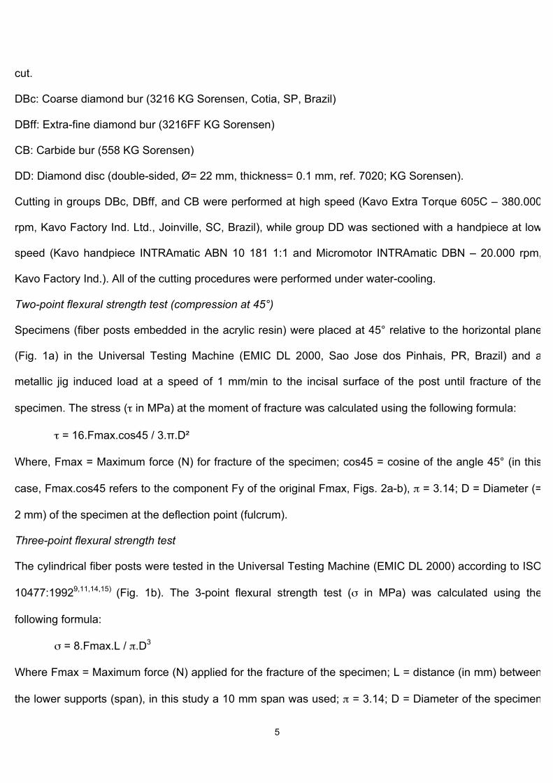
Two-point flexural strength test (compression at 45°)
Specimens (fiber posts embedded in the acrylic resin) were placed at 45° relative to the horizontal plane
(Fig. 1a) in the Universal Testing Machine (EMIC DL 2000, Sao Jose dos Pinhais, PR, Brazil) and a
metallic jig induced load at a speed of 1 mm/min to the incisal surface of the post until fracture of the
specimen. The stress (τ in MPa) at the moment of fracture was calculated using the following formula:
τ = 16.Fmax.cos45 / 3.π.D²
Where, Fmax = Maximum force (N) for fracture of the specimen; cos45 = cosine of the angle 45° (in this
case, Fmax.cos45 refers to the component Fy of the original Fmax, Figs. 2a-b), π = 3.14; D = Diameter (=
2 mm) of the specimen at the deflection point (fulcrum).
Three-point flexural strength test
The cylindrical fiber posts were tested in the Universal Testing Machine (EMIC DL 2000) according to ISO
10477:19929,11,14,15) (Fig. 1b). The 3-point flexural strength test (σ in MPa) was calculated using the
following formula:
σ = 8.Fmax.L / π.D3
Where Fmax = Maximum force (N) applied for the fracture of the specimen; L = distance (in mm) between
the lower supports (span), in this study a 10 mm span was used; π = 3.14; D = Diameter of the specimen
6
(2 mm) (Fig. 3)14-16).
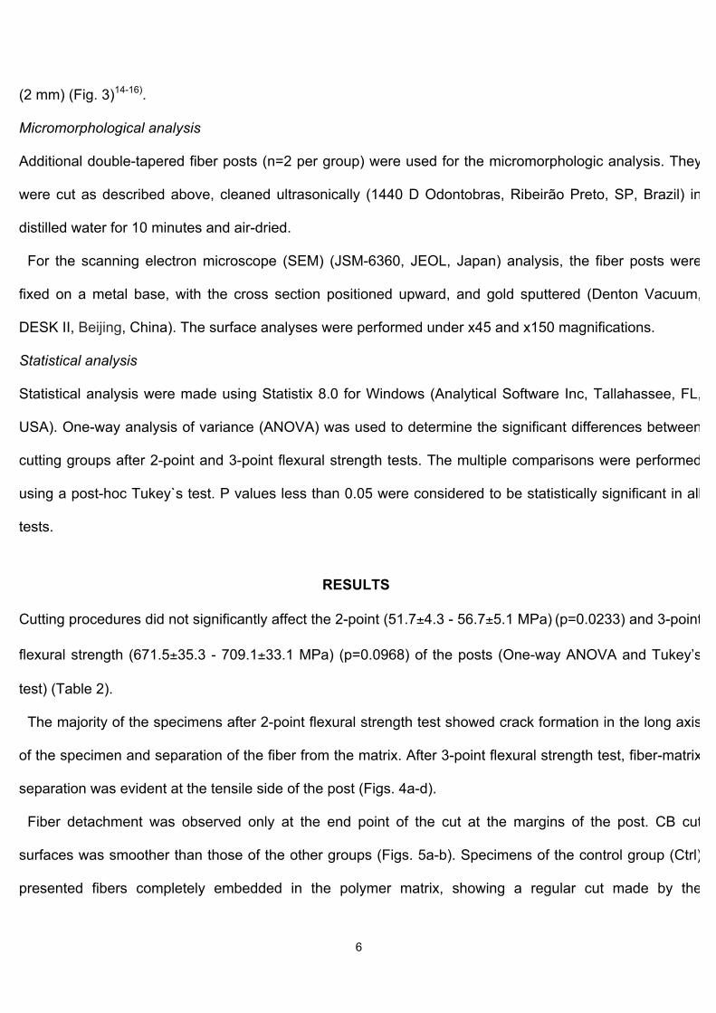
Micromorphological analysis
Additional double-tapered fiber posts (n=2 per group) were used for the micromorphologic analysis. They
were cut as described above, cleaned ultrasonically (1440 D Odontobras, Ribeirão Preto, SP, Brazil) in
distilled water for 10 minutes and air-dried.
For the scanning electron microscope (SEM) (JSM-6360, JEOL, Japan) analysis, the fiber posts were
fixed on a metal base, with the cross section positioned upward, and gold sputtered (Denton Vacuum,
DESK II, Beijing, China). The surface analyses were performed under x45 and x150 magnifications.
Statistical analysis
Statistical analysis were made using Statistix 8.0 for Windows (Analytical Software Inc, Tallahassee, FL,
USA). One-way analysis of variance (ANOVA) was used to determine the significant differences between
cutting groups after 2-point and 3-point flexural strength tests. The multiple comparisons were performed
using a post-hoc Tukey`s test. P values less than 0.05 were considered to be statistically significant in all
tests.
RESULTS
Cutting procedures did not significantly affect the 2-point (51.7±4.3 - 56.7±5.1 MPa) (p=0.0233) and 3-point
flexural strength (671.5±35.3 - 709.1±33.1 MPa) (p=0.0968) of the posts (One-way ANOVA and Tukey’s
test) (Table 2).
The majority of the specimens after 2-point flexural strength test showed crack formation in the long axis
of the specimen and separation of the fiber from the matrix. After 3-point flexural strength test, fiber-matrix
separation was evident at the tensile side of the post (Figs. 4a-d).
Fiber detachment was observed only at the end point of the cut at the margins of the post. CB cut
surfaces was smoother than those of the other groups (Figs. 5a-b). Specimens of the control group (Ctrl)
presented fibers completely embedded in the polymer matrix, showing a regular cut made by the
7
manufacturer, with no apparent flaws on the surface whereas other groups showed separation of fibers
from matrix at the end point of the cut (Figs. 5c-l).
DISCUSSION
The results of the present study showed that the effect of cutting glass fiber posts, irrespective of the type
of rotating instruments according to both type of tests, were unable to promote any structural changes that
might adversely affect the flexural strength of fiber posts.
Although some detachment of fibers from the polymer has been observed in the final portion of the cut,
this detachment was found to be insufficient to interfere with the 2-point and 3-point flexural strength
results. These findings could indicate suitable quality of the composite material tested. Yet, additional
studies for predicting the long-term effect of the cutting methods tested (mechanical cycling) are
necessary. It is important to note that when the post was cut after cementation and resin core
reconstruction, composite resin around the post promoted a protective effect and prevented the
detachment of fibers. The lowest granulation of the DBff bur generated greater friction during cutting, which
may have caused a greater displacement of fibers at the final portion of the section. The cut when using
carbide burs created a surface with different cutting planes because of the inherent characteristics of the
cutting tool as a multi-laminated bur.
The material tested is classified as a composite produced by combining two or more distinct
components to form a new material with improved properties. The most common engineering composites
are composed of strong fibers retained by a matrix17,18). Some important factors influencing the mechanical
properties of the fiber posts include intrinsic properties, such as the elastic and flexural moduli, surface
treatment of the fibers and their impregnation in resin, bonding between the fibers and the matrix, the fiber
density9), diameter, orientation, position18-19), and water absorption by the matrix9,18). One of the most
important chemical factors influencing the resistance of the post is related to the process of bonding
between the fibers and the resin matrix. The mechanical characteristics and performance of composite
8
resins increased after improving the bond between the inorganic filler and the organic matrix14). This bond
improvement is created by applying a layer of silane to the inorganic material (fibers) in order to provide a
better chemical bond to the organic matrix12-14). Given this evidence, the type of resin matrix and the
manufacturing process used to promote chemical bonding between fibers and resin may be one of the
most important factors in the resistance of fiber posts14). However, details of cutting procedures for the
control group were not available by the manufacturers.
Clinically, cutting the fiber post is carried out prior to cementation and/or after core reconstruction11). The
factors characteristic to the fiber reinforced polymers, did not appear to have been affected by the methods
tested, since the 2-point and 3-point flexural strengths did not change the results compared to the control
group.
When considering micromorphological analysis, Grandini et al.11), observed that the cut provided by a
carborundum disk generated less regular surfaces when compared with diamond burs and presented
burnt areas ("Burns"), probably caused by the absence of cooling during the cutting. However, those
authors indicated that these factors were not sufficient to contraindicate their clinical use. In contrast, the
specimens in the current study that were sectioned with a carbide disk presented a more regular surface,
showing that water irrigation may be sufficient to promote a more homogeneous surface and prevent the
formation of burnt areas (Burns).
Two-point2) and three-point16,20-22) flexural strength test have been extensively used to assess the
mechanical properties (hardness, tensile, flexural modulus) of fiber reinforced polymeric materials used in
dentistry. Therefore, these evaluation methods provide data that can be compared to the data from other
studies. Failures from the 2-point test can be explained as a consequence of shear stresses within the
specimen. When a fiber post is subjected to a load at 45⁰, it generates tensile, compression, and shear
stresses23). In order to understand these effects, the load on the specimen must be decomposed into a
Cartesian axis, creating two vector components, X and Y. The component X causes only compressive
stresses in the structure, which is uniformly distributed in the cross section, while the Y component leads to
9
the bending of the post. This bending generates tensile stresses at the lingual portion and compression
stresses at the buccal portion, with maximum values at the specimen edges and minimum values at the
center of the specimen24). As a consequence of the Y component, shear stress occurs inside the post due
to bending. Transverse loading causes stresses, although these stresses are minimum at the external
portions and maximum at the center24). Thus, the explanation for this failure is described as a function of
the mechanical factors of loading in association with the fiber post composition. Since the post is basically
composed of matrix and fiber, it is possible to conclude that the final fracture does not occur in the region
exposed to tension due to the elasticity of these materials. Thus, the shear stress induces the separation
of the fiber-matrix at the central portion of the post, where the shear is maximum. This type of failure is
classified as “mode II in-plane shear, intralaminar”25).
As the prevalent fracture in the current specimens basically was a consequence of shear stresses, the
formula shown in Fig. 3 was used to calculate that stress. This formula is different from the one used by
Asmussen et al.2), which takes the original force "F" into consideration for calculating the bending stress. In
order to calculate the tensile, compressive and shear stresses, the vector component Fy, from the original
force F, should be used, since Fy is responsible for the bending of the specimen, causing tensile stress on
the upper surface and compression on the lower surface, and shear stress being maximum on the neutral
axis of the specimen. On the other hand, when considering the 3-point test, failure typically occurred on
the surface opposite of the load application. This could be attributed to the characteristics of the polymer in
question. The materials that comprise the fiber post are elastic upon the load application. Therefore, in the
region where the force is applied (the central area of the specimen), the post undergoes a slight plastic
deformation, becoming more elliptical in shape and presenting a crack on the opposite face due to
"kneading" caused by the application of force. The failures in the current study were characterized as a
fiber-to-matrix separation at the margins, and occurred as a consequence of the tensile stresses caused
by “kneading”. These failures are characterized as “mode I tension-intralaminar”25).
One limitation of this current study is that the specimens were not aged by mechanical fatigue, which
10
can simulate clinical loading. Restorative materials fail more often under cyclic loading at lower values
when compared to monotonic uniaxial loads8,25). The mechanical fatigue loading could lead to the
propagation of defects generated by cutting instruments, which could affect the strength of the fiber posts.
Studies involving the cementing of posts in root canals to better simulate the clinical conditions should be
conducted using mechanical fatigue to better predict the effects of the cutting methods26).
It is also important to note that this study assessed a glass fiber reinforced polymer with a coronal
diameter of 2 mm. It is possible that fiber posts with smaller diameters may have a different outcome,
requiring further studies.
CONCLUSION
Based on the results of this study, the following conclusions could be drawn:
1. Rotary instruments tested with simultaneous water-cooling did not affect the resistance of the tested
fiber posts but caused disintegration of the fibers from the matrix at the end of the cut, located at the
margins.
2. Failures after 3-point flexural test were mainly at the tensile side at the fiber-matrix interface.
ACKNOWLEDGMENTS
This study financially was supported by the National Council for Research and Technology Developments
(CNPq). The authors gratefully acknowledge FGM for providing the glass fiber posts. This work is based
on the dissertation submitted to the Graduate School of Dentistry, Federal University of Santa Maria as
part of the requirements for the DDS degrees of Gabriel Pereira and Mateus Lançanova.
11
REFERENCES
1. Assif D, Gorfil C. Biomechanical considerations in restoring endodontically treated teeth. J Prosthet
Dent 1994; 71: 565-567.
2. Asmussen E, Peutzfeldt A, Heitmann T. Stiffness, elastic limit, and strength of newer types of
endodontic posts. J Dent 1999; 27: 275-278.
3. Vallittu PK. Flexural properties of acrylic resin polymers reinforced with unidirectional and woven glass
fibers. J Prosthet Dent 1999; 81: 318-326.
4. Lanza A, Aversa R, Rengo S, Apicella D, Apicella A. 3D FEA of cemented steel, glass and carbon
posts in a maxillary incisor. Dent Mater 2005; 21: 709-715.
5. Baldissara P, Zicari F, Valandro LF, Scotti R. Effect of root canal treatments on quartz fiber posts
bonding to root dentin. J Endod 2006; 32: 985-988.
6. Monticelli F, Osorio R, Sadek FT, Radovic I, Toledano M, Ferrari M. Post-surface conditioning
improves interfacial adhesion in post/core restorations. Dent Mater 2006; 7: 602-609.
7. Isidor F, Odman P, Brondum K. Intermittent loading of teeth restored using prefabricated carbon fiber
posts. Int J Prosthodont 1996; 9: 131-136.
8. Ferrari M, Cagidiaco MC, Goracci C, Vichi A, Mason PN, Radovic I et al. Long-term retrospective study
of the clinical performance of fiber posts. Am J Dent 2007; 20: 287-291.
9. Lassila LV, Nohrstrom T, Vallittu PK. The influence of short-term water storage on the flexural
properties of unidirectional glass fiber-reinforced composites. Biomater 2002; 23: 2221-2229.
10. Obukuro M, Takahashi Y, Shimizy H. Effect of diameter of glass fibers on flexural properties of fiber-
reinforced composites. Dent Mater J 2008; 27: 541-548.
11. Grandini S, Balleri P, Ferrari M. Scanning Electron Microscopic investigation of the surface of fiber
posts after cutting. J Endod 2002; 28: 610-612.
12. Söderholm KJM, Shang SW. Molecular orientation of silane at the surface of colloidal silica. J Dent
Res 1993; 72: 1050-1054.
12
13. Anusavise KJ, Phillips RW. Science of dental materials, 10th ed. Philadelphia: WB Saunders; 1996.
14. Galhano GA, Valandro LF, Melo RM, Scotti R, Bottino MA. Evaluation of the flexural strength of carbon
fiber-, quartz fiber-, and glass fiber-based posts. J Endod 2005; 31: 209-211.
15. Lassila LV, Tanner J, Vallittu PK. Flexural properties of fiber reinforced root canal posts. Dent Mater
2004; 20: 29-36.
16. D’Arcangelo C, D`Amario M, Vadini M, De Angelis F, Caputi S. Influence of surface treatments on the
flexural properties of fiber posts. J Endod 2007;33:864-867.
17. Barbero EJ. Introduction to composite materials design. 1st ed. Taylor and Francis, Philadelphia, 1999,
p. xx-xx.
18. Dyer SR, Lassila LV, Jokinen M, Vallittu PK. Effect of fiber position and orientation on fracture load of
fiber-reinforced composite. Dent Mater 2004; 20: 947-955.
19. Chung KH, Ling T, Wang F. Flexural strength of a provisional resin material with fibre addition. J Oral
Rehabil 1998; 25: 214-217.
20. Ellakwa AE, Shortall AC, Shehata MK, Marquis PM. The influence of fibre placement and position on
the efficiency of reinforcement of fibre reinforced composite bridgework. J Oral Rehabil 2001; 28: 785-791.
21. Abdulmajeed AA, Närhi TO, Vallittu PK, Lassila L. The effect of high fiber fraction on some mechanical
properties of unidirectional glass fiber-reinforced composite. Dent Mater 2011; 27: 313-321.
22. Kim MJ, Jung WC, Seunghan OH, Hattori M, Yoshinari M, Kawada E et al. Flexural properties of three
kinds of experimental fiber-reinforced composite posts. Dent Mater J 2011; 30: 38-44.
23. Hibbeler, RC. Mechanics of materials. 5th ed. São Paulo Pearson/Prentice Hall; 2006.
24. Beer FP, Johnston R Jr. Vector mechanics for engineers Statics. 5th ed. Makron Books do Brasil;
1994.
25. Smith TW, Grove RA. Failure Analysis Continuous Fiber Reinforced Composites. In: ASM Handbook
Volume 11: Failure Analysis and Prevention. Shipley RJ and Becker WT (editors). Ohio: ASM
International; 2002. p. 731-743.
13
26. Baldissara P, Özcan M, Melilli D, Valandro LF. Effect of cyclic loading on fracture strength and
microleakage of a quartz fiber dowel with different adhesive, cement and resin core material
combinations.Minerva Stomatol. 2010; 59: 407-414.
14
Captions to the legends and tables
Tables
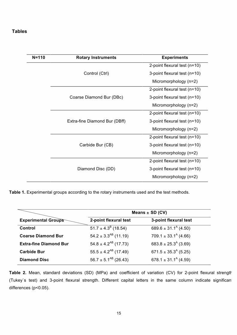
Table 1. Experimental groups according to the rotary instruments used and the test methods.
Table 2. Mean, standard deviations (SD) (MPa) and coefficient of variation (CV) for 2-point flexural
strength (Tukey`s test) and 3-point flexural strength. Different capital letters in the same column indicate
significant differences (p<0.05).
Figures
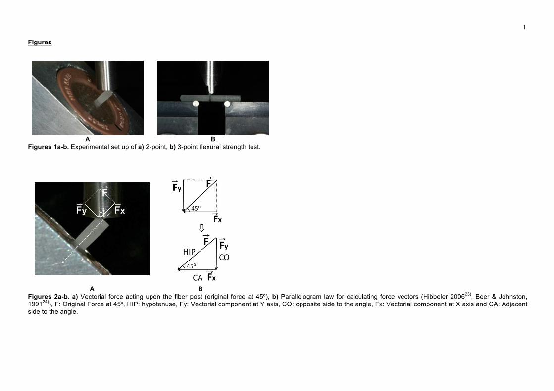
Figs. 1a-b Experimental set up of a) 2-point, b) 3-point flexural strength test.
Figs. 2a-b a) Vectorial force acting upon the fiber post (original force at 45º), b) Parallelogram law for
calculating force vectors (Hibbeler 200623), Beer & Johnston, 199124)), F: Original Force at 45º, HIP:
hypotenuse, Fy: Vectorial component at Y axis, CO: opposite side to the angle, Fx: Vectorial component at
X axis and CA: Adjacent side to the angle.
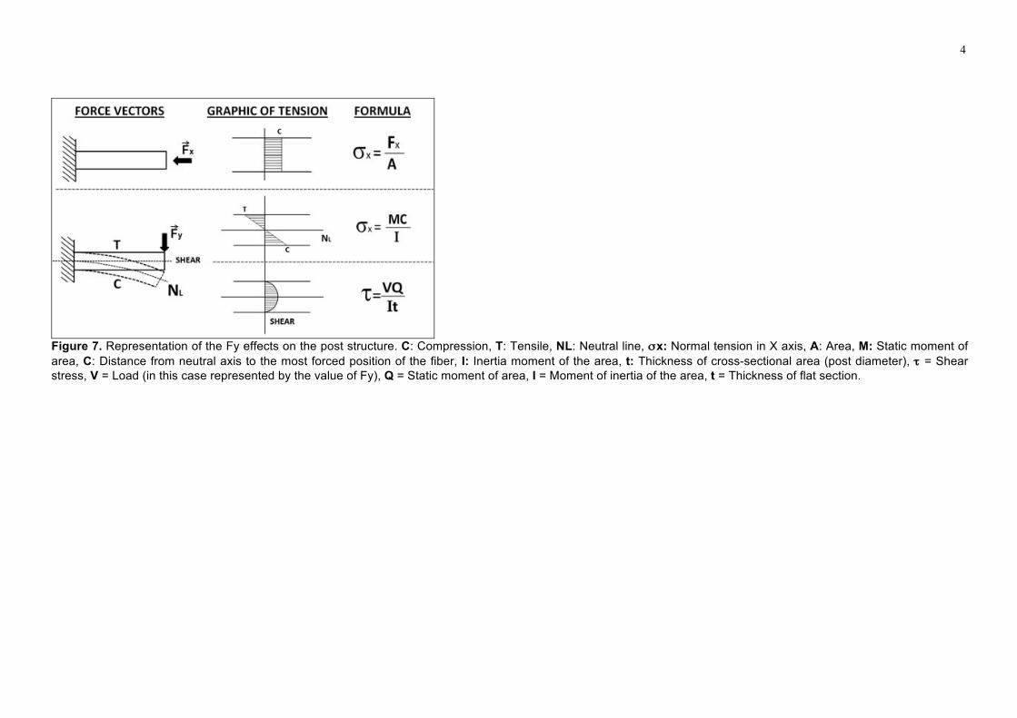
Fig. 3 Representation of the Fy effects on the post structure. C: Compression, T: Tensile, NL: Neutral line,
σx: Normal tension in X axis, A: Area, M: Static moment of area, C: Distance from neutral axis to the most
forced position of the fiber, I: Inertia moment of the area, t: Thickness of cross-sectional area (post
diameter), τ = Shear stress, V = Load (in this case represented by the value of Fy), Q = Static moment of
area, I = Moment of inertia of the area, t = Thickness of flat section.
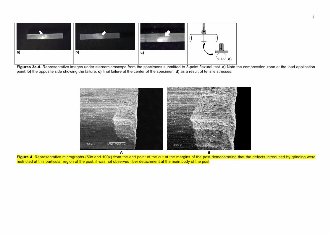
Figs. 4a-d Representative images under stereomicroscope from the specimens submitted to 3-point
flexural test. a) Note the compression zone at the load application point, b) the opposite side showing the
failure, c) final failure at the center of the specimen, d) as a result of tensile stresses.
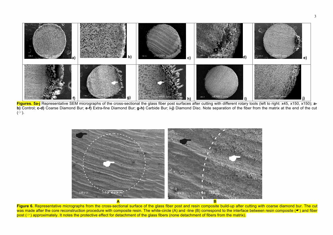
Figs. 5a-l Representative SEM micrographs of the cross-sectional the glass fiber post surfaces after
cutting with different rotary tools (left to right: x45, x150, x150); a-b) Control; c-d) Coarse Diamond Bur; e-
f) Extra-fine Diamond Bur; g-h) Carbide Bur; i-j) Diamond Disc. Note separation of the fiber from the matrix at
the end of the cut (C).
15
Tables
N=110 Rotary Instruments Experiments
Control (Ctrl)
2-point flexural test (n=10)
3-point flexural test (n=10)
Micromorphology (n=2)
Coarse Diamond Bur (DBc)
2-point flexural test (n=10)
3-point flexural test (n=10)
Micromorphology (n=2)
Extra-fine Diamond Bur (DBff)
2-point flexural test (n=10)
3-point flexural test (n=10)
Micromorphology (n=2)
Carbide Bur (CB)
2-point flexural test (n=10)
3-point flexural test (n=10)
Micromorphology (n=2)
Diamond Disc (DD)
2-point flexural test (n=10)
3-point flexural test (n=10)
Micromorphology (n=2)
Table 1. Experimental groups according to the rotary instruments used and the test methods.
Experimental Groups
Means ± SD (CV)
2-point flexural test 3-point flexural test
Control 51.7 ± 4.3B (18.54) 689.6 ± 31.1A (4.50)
Coarse Diamond Bur 54.2 ± 3.3AB (11.19) 709.1 ± 33.1A (4.66)
Extra-fine Diamond Bur 54.8 ± 4.2AB (17.73) 683.8 ± 25.3A (3.69)
Carbide Bur 55.5 ± 4.2AB (17.49) 671.5 ± 35.3A (5.25)
Diamond Disc 56.7 ± 5.1AB (26.43) 678.1 ± 31.1A (4.59)
Table 2. Mean, standard deviations (SD) (MPa) and coefficient of variation (CV) for 2-point flexural strength
(Tukey`s test) and 3-point flexural strength. Different capital letters in the same column indicate significant
differences (p<0.05).
1
Figures
A B
Figures 1a-b. Experimental set up of a) 2-point, b) 3-point flexural strength test.
A B
Figures 2a-b. a) Vectorial force acting upon the fiber post (original force at 45º), b) Parallelogram law for calculating force vectors (Hibbeler 200623)
, Beer & Johnston, 1991
24)), F: Original Force at 45º, HIP: hypotenuse, Fy: Vectorial component at Y axis, CO: opposite side to the angle, Fx: Vectorial component at X axis and CA: Adjacent
side to the angle.
2
a)
b)
c)
d)
Figures 3a-d. Representative images under stereomicroscope from the specimens submitted to 3-point flexural test. a) Note the compression zone at the load application point, b) the opposite side showing the failure, c) final failure at the center of the specimen, d) as a result of tensile stresses.
A B
Figure 4. Representative micrographs (50x and 100x) from the end point of the cut at the margins of the post demonstrating that the defects introduced by grinding were restricted at this particular region of the post; it was not observed fiber detachment at the main body of the post.
3
a) b) c) d) e)
f) g) h) i) j)
Figures. 5a-j Representative SEM micrographs of the cross-sectional the glass fiber post surfaces after cutting with different rotary tools (left to right: x45, x150, x150); a-b) Control; c-d) Coarse Diamond Bur; e-f) Extra-fine Diamond Bur; g-h) Carbide Bur; i-j) Diamond Disc. Note separation of the fiber from the matrix at the end of the cut ().
A B
Figure 6. Representative micrographs from the cross-sectional surface of the glass fiber post and resin composite build-up after cutting with coarse diamond bur. The cut was made after the core reconstruction procedure with composite resin. The white-circle (A) and -line (B) correspond to the interface between resin composite () and fiber post () approximately. It notes the protective effect for detachment of the glass fibers (none detachment of fibers from the matrix).
! !
4
Figure 7. Representation of the Fy effects on the post structure. C: Compression, T: Tensile, NL: Neutral line, σx: Normal tension in X axis, A: Area, M: Static moment of
area, C: Distance from neutral axis to the most forced position of the fiber, I: Inertia moment of the area, t: Thickness of cross-sectional area (post diameter), τ = Shear
stress, V = Load (in this case represented by the value of Fy), Q = Static moment of area, I = Moment of inertia of the area, t = Thickness of flat section.