Impact of Distributed Generation on Short Circuit Level of Power System
10
[Chavhan, 3(9): September, 2014] ISSN: 2277-9655 Scientific Journal Impact Factor: 3.449 (ISRA), Impact Factor: 2.114 http: // www.ijesrt.com (C)International Journal of Engineering Sciences & Research Technology [1] IJESRT INTERNATIONAL JOURNAL OF ENGINEERING SCIENCES & RESEARCH TECHNOLOGY Impact of Distributed Generation on Short Circuit Level of Power System Minal M.Chavhan*, D. B. Meshram, D. Subroto *M-Tech, Associate Professor, Rajiv Gandhi College of Engineering Research and Technology, Chandrapur, India mi [email protected] Abstracts Renewable energy is that as it is sustainable and so will never run out . Renewable energy facilities generally require less maintenance than traditional generator. Importance of conventional energy wind form is the best of energy for future. DFIG are nowadays widely used in variable speed wind power plant. The ability of the wind power plant to stay connected to the grid during disturbance is important to avoid a cascading effect due to lack of power. This paper investigate the impact of short circuit fault on the stability of DFIG wind turbine using crowbar resistance. Simulation test using MATLAB-Simulink toolbox is implemented on a 9MW, six 1.5MW turbine of wind form export its power to 120KV grid. The variation of the rotor current , rotor speed active and reactive power on wind form are investigated. Keywords: DFIG, IGBT, Rotor current and Active power. Introduction Organized by UBM India, the 7th Renewable Energy India 2013 Expo was the epicenter of deliberations and brainstorming towards Up-scaling and Mainstreaming Renewable in achieving Energy Security and Economic Development. Held from the 12th – 14th September 2013 at the India Expo Centre & Mart, Greater Noida (National Capital Region of Delhi), the event urged the industry to step up innovations and leverage on the multiple investment opportunities being created by the Indian Government. The expo proved to be a catalyst for industry stakeholders, domestic and International, in exploring business opportunities and served as a hub for knowledge exchange whilst widening the sector’s insights on sustainable financing models, cutting-edge technologies and successful, proven business practices. The sector has grown at an annual rate of 23% to achieve 28,446 MW by May 2013. The renewable power installed capacity forms 12.5% of the total installed capacity in FY 2011- 2012 Additional capacity of 30,000 MW is planned from various renewable energy technologies in the next five years. India now ranks as a "wind superpower" with an installed wind power capacity of 1167 MW and about 5 billion units of electricity have been fed to the national grid so far. Wind resource assessment programmed, wind monitoring, wind mapping, are in programs covering 800 stations in 24 states with 193 wind monitoring stations in operations. Altogether 13 states of India have a net potential of about 45000 MW. Wind turbines based on the DFIG are very sensitive to grid disturbance especially to voltage dips[1] The power system switchgear and power system protection for WPPs should be carefully designed to be compatible with the operation of conventional synchronous generators connected to the same grid. This paper attempts to illustrate the behavior of SC current contributions of WTGs.[2] One aspect of planning a wind power plant is the calculation of short circuit (SC) current contribution from a wind power plant (WPP). With the different types of wind turbine generators (WTGs) available from different turbine manufacturers, the task of computing SC current is no longer a simple task as in calculating SC current for a synchronous generator in a conventional power plant[3]. As a mainstream configuration for large wind turbines, DFIG wind turbines are required to remain grid connected during grid faults so that they contribute to the stability of the power transmission system. This raises problems in terms of generator/converter protection and control. In the case of grid faults, the controllability of the DFIG variable speed wind turbine embraces both the wind turbine control for preventing over-speeding of the wind turbine and the control and protection of the power converter during and after grid faults. The DFIG wind farm equipped with voltage grid support control are help a nearby active stall wind farm to remove a grid fault,
Transcript of Impact of Distributed Generation on Short Circuit Level of Power System

[Chavhan, 3(9): September, 2014] ISSN: 2277-9655 Scientific Journal Impact Factor: 3.449
(ISRA), Impact Factor: 2.114
http: // www.ijesrt.com (C)International Journal of Engineering Sciences & Research Technology [1]
IJESRT INTERNATIONAL JOURNAL OF ENGINEERING SCIENCES & RESEARCH
TECHNOLOGY Impact of Distributed Generation on Short Circuit Level of Power System
Minal M.Chavhan*, D. B. Meshram, D. Subroto
*M-Tech, Associate Professor, Rajiv Gandhi College of Engineering Research and Technology,
Chandrapur, India
Abstracts Renewable energy is that as it is sustainable and so will never run out . Renewable energy facilities
generally require less maintenance than traditional generator. Importance of conventional energy wind form is the
best of energy for future. DFIG are nowadays widely used in variable speed wind power plant. The ability of the
wind power plant to stay connected to the grid during disturbance is important to avoid a cascading effect due to
lack of power. This paper investigate the impact of short circuit fault on the stability of DFIG wind turbine using
crowbar resistance. Simulation test using MATLAB-Simulink toolbox is implemented on a 9MW, six 1.5MW
turbine of wind form export its power to 120KV grid. The variation of the rotor current , rotor speed active and
reactive power on wind form are investigated.
Keywords: DFIG, IGBT, Rotor current and Active power.
Introduction Organized by UBM India, the 7th Renewable
Energy India 2013 Expo was the epicenter of
deliberations and brainstorming towards Up-scaling and
Mainstreaming Renewable in achieving Energy Security
and Economic Development. Held from the 12th – 14th
September 2013 at the India Expo Centre & Mart,
Greater Noida (National Capital Region of Delhi), the
event urged the industry to step up innovations and
leverage on the multiple investment opportunities being
created by the Indian Government. The expo proved to
be a catalyst for industry stakeholders, domestic and
International, in exploring business opportunities and
served as a hub for knowledge exchange whilst widening
the sector’s insights on sustainable financing models,
cutting-edge technologies and successful, proven
business practices. The sector has grown at an annual
rate of 23% to achieve 28,446 MW by May 2013. The
renewable power installed capacity forms 12.5% of the
total installed capacity in FY 2011- 2012 Additional
capacity of 30,000 MW is planned from various
renewable energy technologies in the next five years.
India now ranks as a "wind superpower" with an
installed wind power capacity of 1167 MW and about 5
billion units of electricity have been fed to the national
grid so far. Wind resource assessment programmed,
wind monitoring, wind mapping, are in programs
covering 800 stations in 24 states with 193 wind
monitoring stations in operations. Altogether 13 states of
India have a net potential of about 45000 MW. Wind
turbines based on the DFIG are very sensitive to grid
disturbance especially to voltage dips[1]
The power system switchgear and power system
protection for WPPs should be carefully designed to be
compatible with the operation of conventional
synchronous generators connected to the same grid. This
paper attempts to illustrate the behavior of SC current
contributions of WTGs.[2]
One aspect of planning a wind power plant is the
calculation of short circuit (SC) current contribution
from a wind power plant (WPP). With the different types
of wind turbine generators (WTGs) available from
different turbine manufacturers, the task of computing
SC current is no longer a simple task as in calculating
SC current for a synchronous generator in a conventional
power plant[3].
As a mainstream configuration for large wind turbines,
DFIG wind turbines are required to remain grid
connected during grid faults so that they contribute to the
stability of the power transmission system. This raises
problems in terms of generator/converter protection and
control. In the case of grid faults, the controllability of
the DFIG variable speed wind turbine embraces both the
wind turbine control for preventing over-speeding of the
wind turbine and the control and protection of the power
converter during and after grid faults. The DFIG wind
farm equipped with voltage grid support control are help
a nearby active stall wind farm to remove a grid fault,
[Chavhan, 3(9): September, 2014] ISSN: 2277-9655 Scientific Journal Impact Factor: 3.449
(ISRA), Impact Factor: 2.114
http: // www.ijesrt.com (C)International Journal of Engineering Sciences & Research Technology [2]
without implementation of any additional fault removing
control setup in the nearby active stall wind farm. [4].
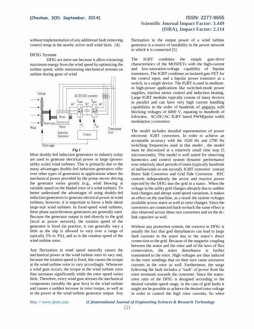
DFIG System DFIG are more use because it allow extracting
maximum energy from the wind speed by optimizing the
turbine speed, while minimizing mechanical stresses on
turbine during gusts of wind
Fig 1
Most doubly-fed induction generators in industry today
are used to generate electrical power in large (power-
utility scale) wind turbines. This is primarily due to the
many advantages doubly-fed induction generators offer
over other types of generators in applications where the
mechanical power provided by the prime mover driving
the generator varies greatly (e.g., wind blowing at
variable speed on the bladed rotor of a wind turbine). To
better understand the advantages of using doubly-fed
induction generators to generate electrical power in wind
turbines, however, it is important to know a little about
large-size wind turbines. In fixed-speed wind turbines,
three phase asynchronous generators are generally used.
Because the generator output is tied directly to the grid
(local ac power network), the rotation speed of the
generator is fixed (in practice, it can generally vary a
little as the slip is allowed to vary over a range of
typically 2% to 3%), and so is the rotation speed of the
wind turbine rotor.
Any fluctuation in wind speed naturally causes the
mechanical power at the wind turbine rotor to vary and,
because the rotation speed is fixed, this causes the torque
at the wind turbine rotor to vary accordingly. Whenever
a wind gust occurs, the torque at the wind turbine rotor
thus increases significantly while the rotor speed varies
little. Therefore, every wind gust stresses the mechanical
components (notably the gear box) in the wind turbine
and causes a sudden increase in rotor torque, as well as
in the power at the wind turbine generator output. Any
fluctuation in the output power of a wind turbine
generator is a source of instability in the power network
to which it is connected [5]
The IGBT combines the simple gate-drive
characteristics of the MOSFETs with the high-current
and low-saturation-voltage capability of bipolar
transistors. The IGBT combines an isolated gate FET for
the control input, and a bipolar power transistor as a
switch, in a single device. The IGBT is used in medium-
to high-power applications like switched-mode power
supplies, traction motor control and induction heating.
Large IGBT modules typically consist of many devices
in parallel and can have very high current handling
capabilities in the order of hundreds of amperes with
blocking voltages of 6000 V, equating to hundreds of
kilowatts. AC/DC/AC IGBT based PWM(pulse width
modulation ) convertor.
The model includes detailed representation of power
electronic IGBT converters. In order to achieve an
acceptable accuracy with the 1620 Hz and 2700 Hz
switching frequencies used in this model , the model
must be discretized at a relatively small time step (5
microseconds). This model is well suited for observing
harmonics and control system dynamic performance
over relatively short periods of times (typically hundreds
of milliseconds to one second). IGBT convertor contain
Rotor Side Convertor and Grid Side Convertor. RSC
controls independently the active and reactive power
injected by the DFIG into the grid in a stator . When the
voltage in the utility grid changes abruptly due to sudden
load changes and abrupt wind speed variations, it makes
an effect on the machine, as a result the system voltages
available across stator as well as rotor changes. Since the
converters are connected back-to-back the same effect is
also observed across these two converters and on the dc-
link capacitor as well.
Without any protection system, the concern in DFIG is
usually the fact that grid disturbances can lead to large
fault currents in the stator due to the stator’s direct
connection to the grid. Because of the magnetic coupling
between the stator and the rotor and of the laws of flux
conservation, the stator disturbance is further
transmitted to the rotor. High voltages are thus induced
in the rotor windings that on their turn cause excessive
currents in the rotor as well. Furthermore, the surge
following the fault includes a “rush” of power from the
rotor terminals towards the converter. Since the stator-
rotor ratio of the DFIG is designed according to the
desired variable speed range, in the case of grid faults it
might not be possible to achieve the desired rotor voltage
in order to control the high rotor currents, So when

[Chavhan, 3(9): September, 2014] ISSN: 2277-9655 Scientific Journal Impact Factor: 3.449
(ISRA), Impact Factor: 2.114
http: // www.ijesrt.com (C)International Journal of Engineering Sciences & Research Technology [3]
converter reaches fast its limits it looses the control of
the generator during the grid fault. As the grid voltage
drops in the fault moment, the GSC is not able to transfer
the power from the RSC further to the grid and therefore
the additional energy goes into charging the dc bus
capacitor, i.e. dc bus voltage rises rapidly. A protection
system of DFIG converter is thus necessary to break the
high currents and the uncontrollable energy flow
through the RSC to the dc-link and thus to minimize the
effects of possible abnormal operating conditions. The
protection system monitors usually different signals,
such as the rotor current, the dc-link voltage and when at
least one of the monitored signals exceeds its respective
relay settings, the protection is activated. [4]
Simulation A 9 MW wind farm consisting of six 1.5 MW
wind turbines connected to a 25 kV distribution system
exports power to a 120kV grid through a 30 km, 25 kV
feeder shown in Fig 2.

[Chavhan, 3(9): September, 2014] ISSN: 2277-9655 Scientific Journal Impact Factor: 3.449
(ISRA), Impact Factor: 2.114
http: // www.ijesrt.com (C)International Journal of Engineering Sciences & Research Technology [4]
Fig 2
Wind turbines using a doubly-fed induction generator
(DFIG) consist of a wound rotor induction generator and
an AC/DC/AC IGBT-based PWM converter. The stator
winding is connected directly to the 60 Hz grid while the
rotor is fed at variable frequency through the AC/DC/AC
converter. In this model the wind speed is maintained

[Chavhan, 3(9): September, 2014] ISSN: 2277-9655 Scientific Journal Impact Factor: 3.449
(ISRA), Impact Factor: 2.114
http: // www.ijesrt.com (C)International Journal of Engineering Sciences & Research Technology [5]
constant at 10 m/s. The control system uses a torque
controller in order to maintain the speed at 1.2 pu. The
reactive power produced by the wind turbine is regulated
at 0 Mvar. For a wind speed of 10m/s, the turbine output
power is 1 pu of its rated power, the pitch angle is 8.7
deg and the generator speed is 1.2 pu.
In this model observe the steady-state operation of the
DFIG and its dynamic response to voltage sag resulting
from a remote fault on the 120-kV system. Observe
voltage and current waveforms on the Scope.
Fig 3
Initially the DFIG wind farm produces 9 MW. The
corresponding turbine speed is 1.2 pu of generator
synchronous speed. The DC voltage is regulated at 1150
V and reactive power is kept at 0 Mvar. At t=0.03 s the
positive-sequence voltage suddenly drops to 0.5 p.u.
causing an oscillation on the DC bus voltage and on the
DFIG output power. During the voltage sag the control
system tries to regulate DC voltage and reactive power
at their set points (1150 V, 0 Mvar). The system recovers
in approximately 4 cycles.
Simulation result The simulation result show the investigated of
rotor current , rotor speed , active power, DC link voltage
, line current and line voltage with different crowbar
resistor during grid fault or 3 phase ground fault. Fault
time 0.03sec and relies 0.013sec.

[Chavhan, 3(9): September, 2014] ISSN: 2277-9655 Scientific Journal Impact Factor: 3.449
(ISRA), Impact Factor: 2.114
http: // www.ijesrt.com (C)International Journal of Engineering Sciences & Research Technology [6]
Increased of rotor current by 3pu is observed during fault
condition is shown in the Fig 4. The variation in rotor
resistance 10,50 & 100 times & corresponding resistance
on fault current level are shown on Fig 5,6 &7,
Reduction upto 1.5 pu is observed on the system.
Fig 4

[Chavhan, 3(9): September, 2014] ISSN: 2277-9655 Scientific Journal Impact Factor: 3.449
(ISRA), Impact Factor: 2.114
http: // www.ijesrt.com (C)International Journal of Engineering Sciences & Research Technology [7]
The variation in rotor speed with different
values of rotor resistance are also investigated during
fault condition. It is observed that , there is wide
variation of rotor speed occurs with the inserting rotor
resistance. So that to limit the rotor speed rotor
resistance is an important tool.
Fig 5
Also the effect of this rotor resistance on
active power generation is of upmost important.
Different result draw many such creation to control &
sustain steady state operation of the given system. This
can be evaluated by observing the variation of active
power with change of rotor resistance.
Active power generation with a wind speed of
10m/s before the occurrence of fault was observed to be
9MW, during fault condition by inserting rotor
resistance with rotor speed & maintain rotor speed will
going to reduced upto 0.47MW. it is going to uplift upto
11MW generation after clearances the fault & return to
steady state operation shown in Fig 4.

[Chavhan, 3(9): September, 2014] ISSN: 2277-9655 Scientific Journal Impact Factor: 3.449
(ISRA), Impact Factor: 2.114
http: // www.ijesrt.com (C)International Journal of Engineering Sciences & Research Technology [8]
Fig 6

[Chavhan, 3(9): September, 2014] ISSN: 2277-9655 Scientific Journal Impact Factor: 3.449
(ISRA), Impact Factor: 2.114
http: // www.ijesrt.com (C)International Journal of Engineering Sciences & Research Technology [9]
Fig 7
Conclusion In the present simulation of 9MW, 6* 1.5MW
wind turbine connected to the grid system is
investigated.
The parameters such as DFIG rotor current, rotor speed
& active power are selected to study the performance of
wind form system. So all these parameter are compared
for normal running condition & during fault condition .
the fault duration is mainted with 10 ms delays with the
opposition of rotor resistance which will tends to
increased rotor circuit resistance in the short circuit
level.
It is observed that by increased in the rotor circuit
resistance there is sufficient improvement in the active
power generation and rotor speed, reduction in the rotor
current are observed so as to stabilizing the system &
overall uplifting of the performance.
Reference 1. Omar Noureldeen, “Behavior of DFIG Wind
Turbine with Crowbar Protection under Short
Circuit”, international journal of electrical &
computer sciences , vol 12no.03.
2. E. Muljadi, “Different Factors Affecting Short
Circuit Behavior of a Wind Power Plant”, IEEE
NREL 1617 Cole Blvd
3. E. Muljadi and V. Gevorgian , “ Short Circuit
Current Contribution for Different Wind
Turbine Generator Types Preprint”, IEEE,
National Renewable Energy Laboratory.
4. Prof. Sushil Kumar1, Shilpa Manoj Rawte2,
“Grid voltage control by using DFIG during
grid faults”, IOSR Journal of Engineering
(IOSRJEN) e-ISSN: 2250-3021, p-ISSN: 2278-
8719 Vol. 3, Issue 1 (Jan. 2013), ||V1|| PP
5. “Principles of doubly-fed induction generators
(DFIG)” courseware sample by the staff of lab-
volt ltd.
6. Satish choudhury, “Investigation on
Performance of Double-Fed Induction
Generator driven by Wind Turbine under Grid
voltage Fluctuation”, IEEE 2011.
7. “Renewable energy scenario in India”.
8. Kenneth E.Okedu , “Stability Enhancement of
DFIG-based variable speed wind turbine with a
crowbar by FACTS device as per grid
requirement”, international journal of
renewable energy research .
9. Francesco Sulla ,“Simulation of DFIG and
FSIG wind form in MATLAB sim power
system”, division of industrial electrical
engineering and automation lund university.
10. F.D. Kanellos and John Kabouris, “Wind farm
modeling for short circuit lavel calculation in

[Chavhan, 3(9): September, 2014] ISSN: 2277-9655 Scientific Journal Impact Factor: 3.449
(ISRA), Impact Factor: 2.114
http: // www.ijesrt.com (C)International Journal of Engineering Sciences & Research Technology [10]
large power system”, IEEE traction on power
delivery vol 24, no.3, july 2009.
11. G. B Gharehpetion, Farhad Shahnia “Short
Circuit Fault Transient studies of power
distribution system including dispersed
genrattion”,
12. E.Muljadi “Different Factor Affecting Short
Circuit Behavior Of A Wind Power Plant”
IEEE,2010