Impact dynamics of rough and surface protected MEMS gears
9
Impact dynamics of rough and surface protected MEMS gears M. Teodorescu a , S. Theodossiades b, , H. Rahnejat b a School of Engineering, Cranfield University, UK b Wolfson School of Mechanical and Manufacturing Engineering, Loughborough University, Loughborough, Leicestershire LE113TU, UK article info Article history: Received 15 January 2008 Received in revised form 22 May 2008 Accepted 26 May 2008 Available online 23 July 2008 Keywords: Impact dynamics Adhesion MEMS SAM Nanoscopic contact mechanics abstract The paper provides an analysis of dynamics of micro-gear pairs, typically used in an assortment of micro-electromechanical system (MEMS) devices. It includes a mathematical hierarchical model of the impact dynamics of meshing gear teeth. It comprises the nanoscopic effect of asperity tips’ adhesion for relatively rough surfaces on a microscopic level (overall contact domain). The analysis is extended to the depletion of long chain molecule self-assembled molecules (SAM) in impact behaviour of meshing gear- teeth pairs. The analyses show that for the usual high operating speeds of MEMS gears, due to high impact velocities, the role of asperity tips’ adhesion is quite insignificant. However, the same is not true for lower impact velocities, which would occur under start-up, run-up to normal operating speeds or during deccelerative motions. The paper proposes a novel spectral-based approach to predict the degradation of the protective SAM layer between meshing teeth, while the mechanism is in continual relative motion. & 2008 Elsevier Ltd. All rights reserved. 1. Introduction In recent years, the microelectronics industry has experienced an unprecedented growth. The initial trend has been based on a growing demand for faster and smaller devices. This demand is also currently driven by the need for embedding ubiquitous computing power in every aspect of modern life. Silicon has become the foundation block for microelectronics, thus the justifiably used phrase: ‘‘the age of silicon’’. The increased demand for silicon components has triggered significant improve- ments in methods of fabrication. New techniques have allowed deposition of thin successive layers of silicon, as well as the cutting techniques with nano-scale precision. These have enabled manufacture of complete micro-scale interconnected structures, using techniques that resemble carving and printing rather than the traditional manufacturing methods. One bene- ficiary has been the emerging micro-electromechanical systems (MEMS) [1–3]. Most MEMS contain a significant number of micro-size components. Many of these components act as load bearing and torque transmitting members, usually at very high speeds. However, the minute size of these elements means that the inertial forces are also quite small, allowing them to withstand relative velocities and accelerations which are prohibitive for their macro-scale counterparts. Although the methodology for manu- facturing these mechanisms has been relatively successful, the early design theories were based on principles which may be regarded as those applied at macrocosm, in relative terms. However, closer analyses suggest that these theories do not immediately extend to the case of micro-scale mechanisms, particularly with respect to contact/impact dynamics in gaps of molecular dimensions (nanoscopic interactions). Consequently, from the outset it has become clear that the fabrication of such components would rely, at least in parts, on an implicit acceptance of some empirical approach, which has clearly manifested itself in an inherent level of unreliability. Macroscopic gears are cut using specialised techniques. However, after the initial cutting process, gear teeth are carefully polished and their contact surfaces treated for certain improved characteristics, usually related to tribological performance. In contrast, the comfort of post-cutting treatments is lost in the case of micro-size gears due to the complexity of the required processes and cost implications. These gears are cut out of fabricated media in-situ, therefore, their surface roughness and minimum separations (backlash) are directly proportional to the precision of the cutting technique used. In practice, this is in the nano-scale range. Thus, for the minute size of MEMS gears, contact between meshing teeth is actually relatively rough. This means that adhesion between individual asperities can play a significant role [4]. In nano-scale conjunctions molecular interactions cannot be ignored, nor surface energy effects, as well as the aforementioned adhesion. Furthermore, stiction by wetting action of any inter- vening fluidic media would also play an important role. In most ARTICLE IN PRESS Contents lists available at ScienceDirect journal homepage: www.elsevier.com/locate/triboint Tribology International 0301-679X/$ - see front matter & 2008 Elsevier Ltd. All rights reserved. doi:10.1016/j.triboint.2008.05.019 Corresponding author. E-mail address: [email protected] (S. Theodossiades). Tribology International 42 (2009) 197– 205
Transcript of Impact dynamics of rough and surface protected MEMS gears
ARTICLE IN PRESS
Tribology International 42 (2009) 197– 205
Contents lists available at ScienceDirect
Tribology International
0301-67
doi:10.1
� Corr
E-m
journal homepage: www.elsevier.com/locate/triboint
Impact dynamics of rough and surface protected MEMS gears
M. Teodorescu a, S. Theodossiades b,�, H. Rahnejat b
a School of Engineering, Cranfield University, UKb Wolfson School of Mechanical and Manufacturing Engineering, Loughborough University, Loughborough, Leicestershire LE11 3TU, UK
a r t i c l e i n f o
Article history:
Received 15 January 2008
Received in revised form
22 May 2008
Accepted 26 May 2008Available online 23 July 2008
Keywords:
Impact dynamics
Adhesion
MEMS
SAM
Nanoscopic contact mechanics
9X/$ - see front matter & 2008 Elsevier Ltd. A
016/j.triboint.2008.05.019
esponding author.
ail address: [email protected] (S. T
a b s t r a c t
The paper provides an analysis of dynamics of micro-gear pairs, typically used in an assortment of
micro-electromechanical system (MEMS) devices. It includes a mathematical hierarchical model of the
impact dynamics of meshing gear teeth. It comprises the nanoscopic effect of asperity tips’ adhesion for
relatively rough surfaces on a microscopic level (overall contact domain). The analysis is extended to the
depletion of long chain molecule self-assembled molecules (SAM) in impact behaviour of meshing gear-
teeth pairs. The analyses show that for the usual high operating speeds of MEMS gears, due to high
impact velocities, the role of asperity tips’ adhesion is quite insignificant. However, the same is not true
for lower impact velocities, which would occur under start-up, run-up to normal operating speeds or
during deccelerative motions. The paper proposes a novel spectral-based approach to predict the
degradation of the protective SAM layer between meshing teeth, while the mechanism is in continual
relative motion.
& 2008 Elsevier Ltd. All rights reserved.
1. Introduction
In recent years, the microelectronics industry has experiencedan unprecedented growth. The initial trend has been basedon a growing demand for faster and smaller devices. Thisdemand is also currently driven by the need for embeddingubiquitous computing power in every aspect of modern life.Silicon has become the foundation block for microelectronics,thus the justifiably used phrase: ‘‘the age of silicon’’. The increaseddemand for silicon components has triggered significant improve-ments in methods of fabrication. New techniques have alloweddeposition of thin successive layers of silicon, as well as thecutting techniques with nano-scale precision. These haveenabled manufacture of complete micro-scale interconnectedstructures, using techniques that resemble carving and printingrather than the traditional manufacturing methods. One bene-ficiary has been the emerging micro-electromechanical systems(MEMS) [1–3].
Most MEMS contain a significant number of micro-sizecomponents. Many of these components act as load bearing andtorque transmitting members, usually at very high speeds.However, the minute size of these elements means that theinertial forces are also quite small, allowing them to withstandrelative velocities and accelerations which are prohibitive for theirmacro-scale counterparts. Although the methodology for manu-
ll rights reserved.
heodossiades).
facturing these mechanisms has been relatively successful, theearly design theories were based on principles which may beregarded as those applied at macrocosm, in relative terms.However, closer analyses suggest that these theories do notimmediately extend to the case of micro-scale mechanisms,particularly with respect to contact/impact dynamics in gaps ofmolecular dimensions (nanoscopic interactions). Consequently,from the outset it has become clear that the fabrication of suchcomponents would rely, at least in parts, on an implicitacceptance of some empirical approach, which has clearlymanifested itself in an inherent level of unreliability.
Macroscopic gears are cut using specialised techniques.However, after the initial cutting process, gear teeth are carefullypolished and their contact surfaces treated for certain improvedcharacteristics, usually related to tribological performance. Incontrast, the comfort of post-cutting treatments is lost in the caseof micro-size gears due to the complexity of the requiredprocesses and cost implications. These gears are cut out offabricated media in-situ, therefore, their surface roughness andminimum separations (backlash) are directly proportional to theprecision of the cutting technique used. In practice, this is in thenano-scale range. Thus, for the minute size of MEMS gears,contact between meshing teeth is actually relatively rough. Thismeans that adhesion between individual asperities can play asignificant role [4].
In nano-scale conjunctions molecular interactions cannot beignored, nor surface energy effects, as well as the aforementionedadhesion. Furthermore, stiction by wetting action of any inter-vening fluidic media would also play an important role. In most
ARTICLE IN PRESS
Nomenclature
a contact area of an asperityb backlash half-widthDk;l
i:j influence coefficient matrixd local deformation of the gear toothe(j1) static transmission errorE1,2 Young’s modulus of elasticityE0 reduced elastic modulus of contacting solidsh elastic gap shapehmin minimum elastic separationhref minimum rigid gapI1,2 mass moments of inertia of gear pairM1 excitation moment on the pinionM2 resistance moment developed at the driven gearM1h harmonic component of the excitation momentn number of asperitiesN number of asperities in unit areaP applied load on an asperityP non-dimensional applied load on an asperityPb
0 Hertzian contact force per asperityPb
a force of adhesion of an asperitypasp(k,l) pressure at any location k,l in the computational gridPb
c pull-off force
R1,2 base circle radii of gear pairr1,2 local principal radii of curvature of the meshing teethr equivalent radius of curvaturet timeTg torque variation on gear due to contact forceu dynamic transmission errorv impact velocityw contact loadx transverse contact directionz mean asperity heightb asperity tip radiusd local deformation of an asperityd non-dimensional local deformationdbc maximum extent of asperity extension (stretching)g free surface energy
j1
j2
" #rotational coordinates of the gear pair
s RMS surface roughnessu1,2 Poisson’s ratio of contacting solidsm Tabor parametere range of surface forcesO excitation frequency
M. Teodorescu et al. / Tribology International 42 (2009) 197–205198
cases, nano-scale conjunctions are prone to failure or malfunctiondue to structural degradation (wear and damage) of the loadbearing and power transmitting conjunctions. This is usually dueto adverse kinetic balance, principally caused by surface adhesionand ingression of moisture, giving rise to stiction [5]. Remedialsolutions include measures against environmental humidity suchas the introduction of self-assembled monolayers (SAM), whichadhere to the surfaces and are hydrophobic in nature. Addition-ally, such devices are maintained in sealed inert atmospheres,thus reducing the chance of ingressing condensation. Theseactions have proven to be relatively successful [6–9]. Thus, thecurrent analysis is confined to the contact mechanics of asperitytips’ interactions at nanoscopic level, when they are treated ashemispheres subject to the combined effect of Hertzian impactand adhesion. Therefore, the current analysis embodies theinherent assumption of very small strain elastic impacts.
This paper provides a numerical investigation of micro-dynamics of a pair of silicon gears (a pinion and a gear),incorporating detailed nano-scale impact dynamics of roughmeshing gear teeth, protected with a self-assembled monolayerof hydrophobic octadecyltrichlorosilane (OTS) long chain mole-cules. These develop reliable bonds with the silicon substrateand reduce the free surface energy. The mathematical modelaccounts for an assumed progressive degradation of the SAM layer(emulating gradual wear) and investigates its effect over thedynamics of the micro-gear assembly. The paper proposes a novelapproach to ascertain the state of SAM layer during operatingconditions.
2. The mechanical model
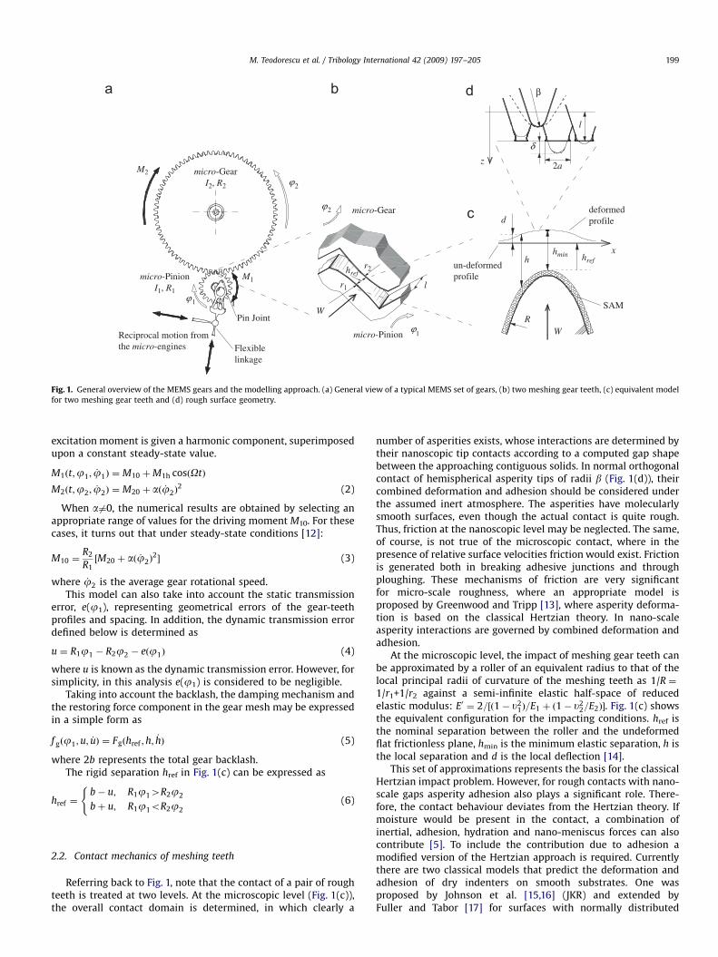
Fig. 1 shows an overview of the micro-gear system consideredin this study. It consists of a pair of spur gears used in MEMSmechanisms. The purpose of this study is to highlight some of theparticular characteristics of gear dynamics and contact mechanicsof meshing gear-teeth pairs. Therefore, a generic gear geometry isused.
MEMS gears are typically very small (20–100mm outsidediameter) and relatively slender; of the order of 2mm and quiterough (4–20 nm Ra) [9]. In macroscopic conventional gear pairs,the separation between the two meshing teeth (href in Fig. 1(b)) isorders of magnitude smaller than the tooth thickness. However,for MEMS, the manufacturing technique leads to separations thatcan be comparable to the tooth thickness itself (i.e. backlash of theorder of 0.1mm).
2.1. Micro-scale dynamics under impacting conditions
The model comprises a pair of spur gears with mass momentsof inertia In and base radii Rn (where n ¼ 1, 2 represent the pinionand the gear, respectively). Both gears are assumed to besupported by rigid shafts. The driving gear (n ¼ 1) is subjectedto a known torsional moment, M1, whilst the driven gear (n ¼ 2)develops a resistance moment, M2.
The essential dynamics of the system can be described by atwo-degrees of freedom torsional system, with coordinates (j1,j2)T [10,11].
The equations of motion for the two-degrees of freedomsystem can be expressed as
I1 €j1 þ R1f gðj1;u; _uÞ ¼ M1ðt;j1; _j1Þ
I2 €j2 � R2f gðj1;u; _uÞ ¼ �M2ðt;j2; _j2Þ
((1)
where M1ðt;j1; _j1Þ represents the excitation moment on thepinion and M2ðt;j2; _j2Þ the resisting moment developed at thedriven gear.
The excitation torque applied to the pinion is generated by tworeciprocal micro-engines mounted orthogonally to each other [1].These engines are coupled to the same flexible linkage, which inturn is connected to the pinion through a pin-joint, mountedeccentrically with respect to the centre of the pinion. The pinion isspanned by conveniently operating the two micro-engines with aprescribed phase angle. Therefore, the moment applied on thepinion has an oscillatory behaviour about an equilibrium position.To capture this characteristics, in the current analysis the
ARTICLE IN PRESS
r1
r2
lmicro-Pinion
I1, R1
micro-GearI2, R2
Pin Joint
Reciprocal motion fromthe micro-engines
micro-Gear
micro-Pinion
Flexiblelinkage
un-deformedprofile
ϕ
W
2
1ϕ
ϕ1
2ϕ
M1
M2
SAM
d
h href
hmin hrefx
deformedprofile
WR
β
l
2a
δz
1
Fig. 1. General overview of the MEMS gears and the modelling approach. (a) General view of a typical MEMS set of gears, (b) two meshing gear teeth, (c) equivalent model
for two meshing gear teeth and (d) rough surface geometry.
M. Teodorescu et al. / Tribology International 42 (2009) 197–205 199
excitation moment is given a harmonic component, superimposedupon a constant steady-state value.
M1ðt;j1; _j1Þ ¼ M10 þM1h cosðOtÞ
M2ðt;j2; _j2Þ ¼ M20 þ að _j2Þ2 (2)
When a6¼0, the numerical results are obtained by selecting anappropriate range of values for the driving moment M10. For thesecases, it turns out that under steady-state conditions [12]:
M10 ¼R2
R1½M20 þ að _j2Þ
2� (3)
where _j2 is the average gear rotational speed.This model can also take into account the static transmission
error, e(j1), representing geometrical errors of the gear-teethprofiles and spacing. In addition, the dynamic transmission errordefined below is determined as
u ¼ R1j1 � R2j2 � eðj1Þ (4)
where u is known as the dynamic transmission error. However, forsimplicity, in this analysis e(j1) is considered to be negligible.
Taking into account the backlash, the damping mechanism andthe restoring force component in the gear mesh may be expressedin a simple form as
f gðj1;u; _uÞ ¼ Fgðhref ;h;_hÞ (5)
where 2b represents the total gear backlash.The rigid separation href in Fig. 1(c) can be expressed as
href ¼b� u; R1j14R2j2
bþ u; R1j1oR2j2
((6)
2.2. Contact mechanics of meshing teeth
Referring back to Fig. 1, note that the contact of a pair of roughteeth is treated at two levels. At the microscopic level (Fig. 1(c)),the overall contact domain is determined, in which clearly a
number of asperities exists, whose interactions are determined bytheir nanoscopic tip contacts according to a computed gap shapebetween the approaching contiguous solids. In normal orthogonalcontact of hemispherical asperity tips of radii b (Fig. 1(d)), theircombined deformation and adhesion should be considered underthe assumed inert atmosphere. The asperities have molecularlysmooth surfaces, even though the actual contact is quite rough.Thus, friction at the nanoscopic level may be neglected. The same,of course, is not true of the microscopic contact, where in thepresence of relative surface velocities friction would exist. Frictionis generated both in breaking adhesive junctions and throughploughing. These mechanisms of friction are very significantfor micro-scale roughness, where an appropriate model isproposed by Greenwood and Tripp [13], where asperity deforma-tion is based on the classical Hertzian theory. In nano-scaleasperity interactions are governed by combined deformation andadhesion.
At the microscopic level, the impact of meshing gear teeth canbe approximated by a roller of an equivalent radius to that of thelocal principal radii of curvature of the meshing teeth as 1/R ¼1/r1+1/r2 against a semi-infinite elastic half-space of reducedelastic modulus: E0 ¼ 2=½ð1� u2
1Þ=E1 þ ð1� u22=E2Þ�. Fig. 1(c) shows
the equivalent configuration for the impacting conditions. href isthe nominal separation between the roller and the undeformedflat frictionless plane, hmin is the minimum elastic separation, h isthe local separation and d is the local deflection [14].
This set of approximations represents the basis for the classicalHertzian impact problem. However, for rough contacts with nano-scale gaps asperity adhesion also plays a significant role. There-fore, the contact behaviour deviates from the Hertzian theory. Ifmoisture would be present in the contact, a combination ofinertial, adhesion, hydration and nano-meniscus forces can alsocontribute [5]. To include the contribution due to adhesion amodified version of the Hertzian approach is required. Currentlythere are two classical models that predict the deformation andadhesion of dry indenters on smooth substrates. One wasproposed by Johnson et al. [15,16] (JKR) and extended byFuller and Tabor [17] for surfaces with normally distributed
ARTICLE IN PRESS
M. Teodorescu et al. / Tribology International 42 (2009) 197–205200
asperities. The other asperity contact model was proposed byDerjaguin et al. [18] (DMT). The JKR model is applicable to morecompliant asperities with strong adhesion, whilst DMT is moresuited to stiffer asperities with weak adhesion (with theintermediate range covered by the model proposed by Maguis[19]). To differentiate between these two classical models it iscustomary to compute the Tabor parameter [20–22] as m ¼(b1/3Dg2/3/[E0/2]2/3e), where e is the acting range for the surfaceforces [22] and Dg ¼ g1+g2+g12. As the Tabor parameter shows thesignificance of adhesion depends on free surface energy andasperity geometry. This is more significant in nano-scale rough-ness. Therefore, for the JKR approach to be used m should be largerthan 5. Therefore, using Tabor’s formulation, the surface rough-ness should be below 50 nm for unprotected silicon surfaces and8 nm for the same surfaces protected by SAM. The nanoscopiccontact of the hemispherical asperities is regarded as smooth,thus the use of JKR model is justified with Fuller and Tabor’sapproach. Hence,
PbðzÞ ¼ Pb
0 � Pba ¼
4E0a3
3b�
ffiffiffiffiffiffiffiffiffiffiffiffiffiffiffiffiffiffiffiffiffiffi8pa3 DgE0
q(7)
After a contact is established, the removal of the initial loadleads to the diminution of the contact force. To separate anasperity with the undeformed radius b, a pull-off force of Pb
c ¼
1:5pbDg is required and a maximum asperity extension (stretch-ing) of dbc ¼ ð9bPb
c =4E0Þ2=3=3b would be required. For the currentcontact conditions: g1 ¼ g2 and for relatively smooth surfaces itcan be assumed that: g12 ¼ 0. Adhesion of asperities manifestsitself under any contact condition, but its effect can be observedmainly with very small-scale asperities.
For ease of implementation in a computer code, it is customaryto use Eq. (5) in a non-dimensional form:
P ¼ 2ða3�
ffiffiffiffiffiffiffiffi2a3
pÞ; d ¼
ffiffiffiffiffiffi323
p� a2 1�
2ffiffiffi2p
3a�3=2
!(8)
The above expounded approach predicts the contact conditionbetween two approaching hemispherical asperities. For two roughsurfaces in contact many asperity pairs can be involved simulta-neously. Therefore, the statistical distribution of these asperitiesshould to be taken into account. Considering a normallydistributed asperity tips, the probability that an asperity has aheight between z and z+dz above the plane, defined by the meanasperity height, is usually given as
fðzÞ ¼1
sffiffiffiffiffiffi2pp e�z2=2s2
(9)
Similarly, considering a normal distribution for asperity tipradius, the probability of an asperity having a radius between rand r+dr can be given as
cðrÞ ¼ 2
bffiffiffiffiffiffi2pp e�z2=2b2
(10)
If the unit area is covered with N asperities, the number ofasperities with the height between any arbitrary limits z1 and z2
and curvature radius between r1 and r2 is
nr12r2z12z2
¼ N
Z z2
z1
fðzÞdz
Z r2
r1
cðrÞdr (11)
The pressure due to the asperity interactions can thus beexpressed as
pasp ¼ NPB
cffiffiffiffiffiffi2pp
Z 1�L
fnDDc
� �exp �
1
2ðhþDÞ2
� �dD (12)
where
PBc ¼ 1:5pBDg; B ¼
ffiffiffiffi2
p
r Z 10
exp �r2
2b2
!dr; D ¼
ds
,
Dc ¼dbcs; h ¼
l
sThe lower integration limit correlates with the history of
contact loading-unloading cycle. This is fully described in [4]. Ifthe action previously compressing an asperity is removed, thenthe asperity may stretch and apply a negative force (adhesion).Therefore, to account for the stretched asperities, the integrationlimit has to be adjusted at each computational time step.
Eq. (12) predicts the total pressure between two rough planesurfaces separated by a known gap [17]. For a roller of radius R, thelocal gap at any position in the contact is given in a computationalgrid as
h ¼x2
2Rþ href þ d (13)
where the local deformation is obtained as [14]
di;j ¼1
pE0XX
Dk;li;j paspðk;lÞ (14)
where Dk;li;j is the influence coefficient matrix, determining the
local deflection at a point (i, j) as a result of a pressurecontribution at a point (k, l) (see [23]).
Although the set of Eqs. (12)–(14) is relatively simple, it is notpossible to obtain a direct solution, which would determine thedeformed gap shape h, as well as the instantaneous impact forcefor a given rigid approach href. This drawback can be overcomeusing an iterative method. When the gap is relatively large, thecontact pressure is negligible. Therefore, there is no deflection(Eq. (12)), and the rigid gap is parabolic (Eq. (13), where d ¼ 0). Fora diminishing gap some of the asperities interact and the resultantpressures (Eq. (12)) cause elastic deformation of asperity withsmall strains in accord with the classical Hertzian theory. In turn,the resultant deformed gap gives rise to an increased pressuredistribution which should be recomputed. After several iterations,the correct equilibrium between the deformed gap shape and thecorresponding pressure distribution is reached.
Finally, the net impact force is obtained as
W ¼X
k
Xl
paspðk;lÞ (15)
3. Results and discussion
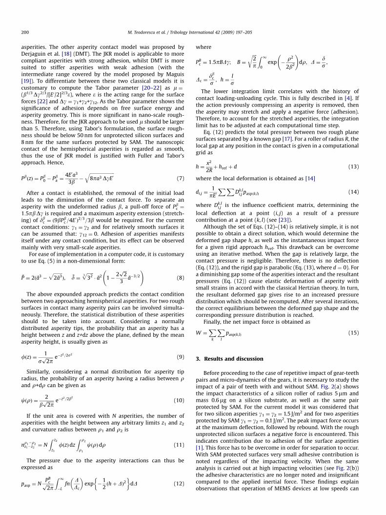
Before proceeding to the case of repetitive impact of gear-teethpairs and micro-dynamics of the gears, it is necessary to study theimpact of a pair of teeth with and without SAM. Fig. 2(a) showsthe impact characteristics of a silicon roller of radius 5mm andmass 0.6mg on a silicon substrate, as well as the same pairprotected by SAM. For the current model it was considered thatfor two silicon asperities g1 ¼ g2 ¼ 1.5 J/m2 and for two asperitiesprotected by SAM g1 ¼ g2 ¼ 0.1 J/m2. The peak impact force occursat the maximum deflection, followed by rebound. With the roughunprotected silicon surfaces a negative force is encountered. Thisindicates contribution due to adhesion of the surface asperities[1]. This force has to be overcome in order for separation to occur.With SAM protected surfaces very small adhesive contribution isnoted regardless of the impacting velocity. When the sameanalysis is carried out at high impacting velocities (see Fig. 2(b))the adhesive characteristics are no longer noted and insignificantcompared to the applied inertial force. These findings explainobservations that operation of MEMS devices at low speeds can
ARTICLE IN PRESS
-5
0
5
10
15
20
25
0.E+00time [ms]
Impa
ct F
orce
[μN
]
SiSAM
-100
100
300
500
700
0.E+00time [ms]
Impa
ct F
orce
[μN
]
0
SAM Si
2.E-03 4.E-03 6.E-03 2.E-04 4.E-04 6.E-04 8.E-04
Fig. 2. Impact force characteristics of a rough silicon roller with and without SAM. (a) Low impact velocity (v ¼ 10�2 m/s) and (b) high impact velocity (v ¼ 10�1 m/s).
0.E+00
1.E-02
2.E-02
3.E-02
4.E-02
0.E+00
time [ms]
h min
[μm
]
0.E+00
1.E-02
2.E-02
3.E-02
4.E-02h m
in [μ
m]
SAM
Si
0.0E+00time [ms]
SAM
Si
2.E-03 4.E-03 6.E-03 2.0E-04 4.0E-04 6.0E-04 8.0E-04
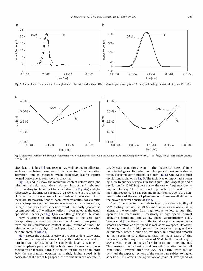
Fig. 3. Transient approach and rebound characteristics of a rough silicon roller with and without SAM. (a) Low impact velocity (v ¼ 10�2 m/s) and (b) high impact velocity
(v ¼ 10�1 m/s).
M. Teodorescu et al. / Tribology International 42 (2009) 197–205 201
often lead to failure [1], one reason may well be due to adhesion,with another being formation of micro-menisci if condensationactivation time is exceeded when protective sealing againstnormal atmospheric conditions is breached.
Fig. 3(a) and (b) show the maximum contact deformation (theminimum elastic separations) during impact and rebound,corresponding to the impact force variations in Fig. 2(a) and (b),respectively. The surfaces separate at a slower rate in the presenceof adhesion at lower impact and rebound velocities. It is,therefore, noteworthy that at even lower velocities, for examplein a start-up process in micro-gear operations, circumstances mayemerge that excessive adhesion would seriously jeopardisesystem operation. The adhesion effect is even noted at the usualoperational speeds (see Fig. 3(b)), even though this is quite small.
Now returning to the micro-dynamics of the gear pair,incorporating the described contact model, one or two pairs ofteeth are in simultaneous contact at any instant of time. Therelevant geometrical, physical and operational data for the gearingpair are given in Table 1.
Fig. 4 shows the angular velocity of the gear under steady-stateconditions for two ideal cases. Firstly, the SAM is assumed toremain intact (100% SAM) and secondly the layer is assumed tohave completely perished (Si). In both cases the mechanism wasexcited by an identical torque. Although for the case of an intactSAM the mechanism operates at slightly higher speed, it isnoticeable that once at high speed, the mechanism can operate in
steady-state conditions even in the theoretical case of fullyunprotected gears. Its rather complex periodic nature is due tovarious spectral contributions, see later (Fig. 6). One cycle of suchoscillations is shown in Fig. 5. The instances of impact are shownby high frequency reversals in the figure. The longest periodicoscillation (at 10,012 Hz) pertains to the carrier frequency due toimposed forcing. The other shorter periods correspond to themeshing frequency (38,813 Hz) and its harmonics due to the non-linear nature of the impact phenomenon. These are all shown inthe power spectral density of Fig. 6.
One of the accepted methods to investigate the reliability ofSAM coatings, as well as MEMS mechanisms as a whole, is toalternate the excitation from high torque to low torque. Thisoperates the mechanism successively at high speed (normaloperating conditions) and at low speed (approximately 1 Hz).Tanner et al. [1] noticed that in the initial stages the engine has asmooth operation at high speed as well as at low speed. However,following the this initial period the behaviour progressivelydeteriorated, when running at low speed, but remained smoothat high speed. It is understood that the main cause of thisbehaviour is the progressive wear of SAM. In the initial stages,SAM covers the contacting surfaces in an uninterrupted manner.This ensures low adhesion and smooth operation under allconditions. However, after the SAM has partly worn out orperished, the exposed sections of the contact are subject to higheradhesion. This affects the operation of gears at low speed as

ARTICLE IN PRESS
0.0001Time <s>
2600
2800
3000
Gea
r Spe
ed <
rad/
s>
100% SAMSi
0.0002 0.0003 0.0004 0.0005
Fig. 4. Angular velocity of the gear _j2 at high speed under steady-state condition.
0.00012 0.00016Time <s>
2600
2800
3000
Gea
r Spe
ed <
rad/
s>
0.0001
100% SAMSi
0.00014 0.00018 0.0002
Fig. 5. One cycle of the angular velocity of the gear _j2 at high speed under steady-
state condition.
Ta
ble
1P
hy
sica
ld
ata
use
din
the
mo
de
l
I 1(k
gm
2)
I 2(k
gm
2)
R1
(mm
)R
2(m
m)
hre
f(m
m)
M1
0(N
m)
M2
0(N
m)
M2
h(N
m)
aS
(Hz)
ES
i
(N/m
2)
ES
AM
(N/m
2)
[7]
vS
iv
SA
MN
[24
]s
(nm
)N
um
be
r
of
tee
th
(pin
ion
)[1
]
Nu
mb
er
of
tee
th
(ge
ar)
[1]
1.5
26
3E�
20
6.1
05
2E�
20
34
.71
38
.86
0.1
2.4
3E�
113
.E�
110
.3E�
118
.E�
18
10
,00
01
61
E9
2E
90
.23
0.4
16
9.0
E1
46
19
76
M. Teodorescu et al. / Tribology International 42 (2009) 197–205202
shown in Figs. 2 and 3, when the inertial dynamics has toovercome a higher adhesive force. In practice, if the SAM isdamaged, a smaller proportion of the impacting surfaces areprotected and the adhesive forces during the rebound increase.
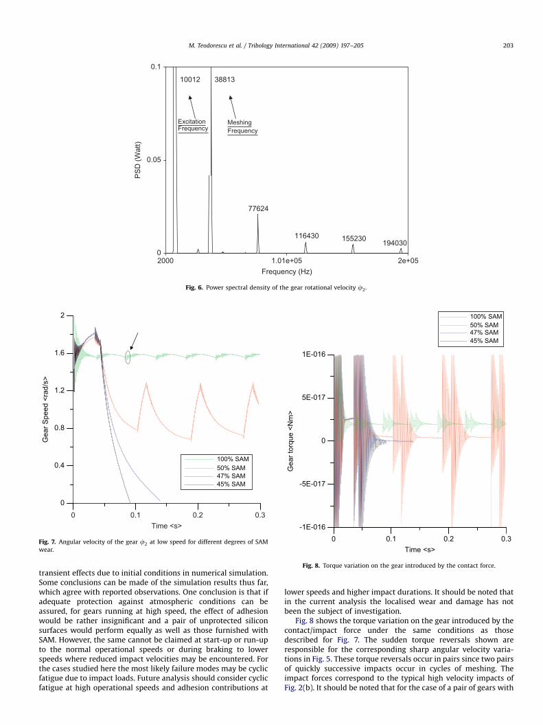
To understand the implications of operating the set of gearsat low speed, the model was run for a very low excitation torque.Fig. 7 shows the results for different assumed percentages of SAMwear. It should be noted that at low speed the gears operatesmoothly if the layer is continuous (100% SAM), and quiteerratically if only 50% of the layer remains intact. The currentmodel assumes uniform wear of the SAM protective layer.Therefore, equal proportion was assumed in calculation ofadhesion contributions for exposed (worn) and protected areas.However, if the layer is even further damaged, the mating pairstend to stick. The high vibrations in the initial section of Fig. 7 are
ARTICLE IN PRESS
0
0.4
0.8
1.2
1.6
2
Gea
r Spe
ed <
rad/
s>
100% SAM50% SAM47% SAM45% SAM
0.1 0.2 0.30Time <s>
Fig. 7. Angular velocity of the gear _j2 at low speed for different degrees of SAM
wear.
2000 1.01e+05 2e+05Frequency (Hz)
0
0.05
0.1
PS
D (W
att)
77624
38813 10012
116430 155230 194030
ExcitationFrequency
MeshingFrequency
Fig. 6. Power spectral density of the gear rotational velocity _j2.
0.1 0.2 0.30Time <s>
-1E-016
-5E-017
0
5E-017
1E-016
Gea
r tor
que
<Nm
>
100% SAM50% SAM47% SAM45% SAM
Fig. 8. Torque variation on the gear introduced by the contact force.
M. Teodorescu et al. / Tribology International 42 (2009) 197–205 203
transient effects due to initial conditions in numerical simulation.Some conclusions can be made of the simulation results thus far,which agree with reported observations. One conclusion is that ifadequate protection against atmospheric conditions can beassured, for gears running at high speed, the effect of adhesionwould be rather insignificant and a pair of unprotected siliconsurfaces would perform equally as well as those furnished withSAM. However, the same cannot be claimed at start-up or run-upto the normal operational speeds or during braking to lowerspeeds where reduced impact velocities may be encountered. Forthe cases studied here the most likely failure modes may be cyclicfatigue due to impact loads. Future analysis should consider cyclicfatigue at high operational speeds and adhesion contributions at
lower speeds and higher impact durations. It should be noted thatin the current analysis the localised wear and damage has notbeen the subject of investigation.
Fig. 8 shows the torque variation on the gear introduced by thecontact/impact force under the same conditions as thosedescribed for Fig. 7. The sudden torque reversals shown areresponsible for the corresponding sharp angular velocity varia-tions in Fig. 5. These torque reversals occur in pairs since two pairsof quickly successive impacts occur in cycles of meshing. Theimpact forces correspond to the typical high velocity impacts ofFig. 2(b). It should be noted that for the case of a pair of gears with
ARTICLE IN PRESS
0 1000 2000 3000 4000 5000Frequency (Hz)
0
5
10
15
20
25
30
35
40
45
50
PS
D (W
att)
1301
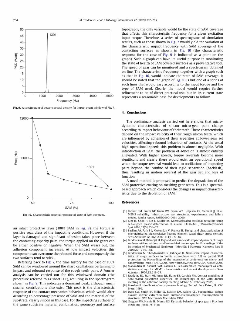
Fig. 9. A spectrogram of power spectral density for impact event window of Fig. 7.
10075500
6000
12000
SAM (%)
Freq
(Hz)
1301
Fig. 10. Characteristic spectral response of state of SAM coverage.
M. Teodorescu et al. / Tribology International 42 (2009) 197–205204
an intact protective layer (100% SAM in Fig. 8), the torque ispositive regardless of the impacting conditions. However, if thelayer is damaged and significant adhesion takes place betweenthe contacting asperity pairs, the torque applied on the gears canbe either positive or negative. When the SAM wears out, theadhesion component increases. At low impact velocities thiscomponent can overcome the rebound force and consequently thetwo surfaces tend to stick.
Referring back to Fig. 7, the time history for the case of 100%SAM can be windowed around the sharp oscillations pertaining toimpact and rebound response of the rough teeth-pairs. A Fourieranalysis can be carried out for this windowed domain (theprocedure referred to as short FFT), resulting in the spectrogramshown in Fig. 9. This indicates a dominant peak, although muchsmaller contributions also exist. This peak is the characteristicresponse of the contact mechanics behaviour, which would alteraccording to percentage presence of SAM and the material of thesubstrate, clearly silicon in this case. For the impacting surfaces ofthe same substrate material combination, geometry and surface
topography the only variable would be the state of SAM coveragethat affects this characteristic frequency for a given excitationinput torque. Therefore, a series of spectrograms of simulationresults, such as those shown in Fig. 7 would yield the variation ofthe characteristic impact frequency with SAM coverage of thecontacting surfaces as shown in Fig. 10 (the characteristicresponse for the case of Fig. 9 is indicated as a point on thegraph). Such a graph can have its useful purpose in monitoringthe state of health of SAM covered surfaces as a preventative tool.The speed of gear can be monitored and a spectrogram obtainedon line. The characteristic frequency, together with a graph suchas that in Fig. 10, would indicate the state of SAM coverage. Itshould be noted that the graph of Fig. 10 is but one of a series ofsuch lines that would vary according to the input torque and thetype of SAM used. Clearly, the model would require furtherrefinement to be of direct practical use, but in its current staterepresents a reasonable base for developments to follow.
4. Conclusions
The preliminary analysis carried out here shows that micro-dynamic characteristics of silicon micro-gear pairs changeaccording to impact behaviour of their teeth. These characteristicsdepend on the impact velocity of their rough silicon teeth, whichare influenced by adhesion of their asperities at lower gear setvelocities, affecting rebound behaviour of contacts. At the usualhigh operational speeds this problem is almost negligible. Withintroduction of SAM, the problem of adhesion is almost entirelyalleviated. With higher speeds, torque reversals become moresignificant and clearly there would exist an operational speedwhen the torque reversal would lead to oscillations of impactingpairs beyond the confine of their rigid separation (backlash),thus resulting in motion reversal of the gear set and loss offunction.
A novel method is proposed to predict the degradation of theSAM protective coating on meshing gear teeth. This is a spectral-based approach which considers the changes in impact character-istics due to the depletion of SAM.
References
[1] Tanner DM, Smith NF, Irwin LW, Eaton WP, Helgesen KS, Clement JJ, et al.MEMS reliability: infrastructure, test structures, experiments, and failuremodes. Sandia report, SAND2000–0091, 2000.
[2] Kim JB, Choo H, Lin L, Muller RS. Microfabricated torsional actuators usingself-aligned plastic deformation of silicon. IEEE/ASME J MicroelectromechSyst 2006;15(3):553–62.
[3] Barlian AA, Park S-J, Mukundan V, Pruitta BL. Design and characterization ofmicrofabricated piezoresistive floating element-based shear stress sensors.Sens Actuators A: Phys 2007;134(1):77–87.
[4] Teodorescu M, Rahnejat H. Dry and wet nano-scale impact dynamics of roughsurfaces with or without a self-assembled mono-layer. In: Proceedings of theInstitution of Mechanical Engineers (IMechE); J Nanoeng Nanosyst-Part N2007;221(2):49–58.
[5] Teodorescu M, Theodossiades S, Rahnejat H. Nano-scale impact character-istics of rough surfaces in humid atmosphere with full or partial SAMprotection. In: Proceedings of the international conference on micro- andnanosystems (MNS), IDETC2008, New York City, New York, USA, August 2008.
[6] Maboudian R, Ashurst WR, Carraro C. Self-assembled monolayers as anti-stiction coatings for MEMS: characteristics and recent developments. SensActuators 2000;82:219–23.
[7] Reedy Jr. ED, Starr MJ, Jones RE, Flater EE, Carpick RW. Contact modeling ofSAM-coated polysilicon asperities. In: Proceedings of the 28th annualmeeting of the adhesion society meeting, Mobile AL, February 2005.
[8] Bhushan B. Handbook of micro/nanotechnology. 2nd ed. Boca Raton, FL: CRCPress; 1999.
[9] Dyck CW, Smith JH, Miller SL, Russick EM, Adkins CLJ. Supercritical carbondioxide solvent extraction from surface-micromachined micromechanicalstructures. SPIE Micromach Micro-fabr 1996.
[10] Gregory RW, Harris SL, Munro RG. Dynamic behavior of spur gears. Proc InstMech Eng 1963;178:1–28.

ARTICLE IN PRESS
M. Teodorescu et al. / Tribology International 42 (2009) 197–205 205
[11] Ozguven HN, Houser DR. Mathematical models used in gear dynamics—
a review. J Sound Vib 1988;121:383–411.[12] Theodossiades S, Natsiavas S. On geared rotordynamic systems with oil
journal bearings. J Sound Vib 2001;243(4):721–45.[13] Greenwoon J, Tripp JH. The contact of two nominally flat rough surfaces. Proc
Inst Mech Eng 1970/1971;185(48/71):625–33.[14] Teodorescu M, Balakrishnan S, Rahnejat H. Physics of ultra-thin surface films
on molecularly smooth surfaces. Proc Inst Mech Eng, J Nano-Technol 2006;220(1):7–19.
[15] Johnson KL, Kendall K, Roberts AD. Surface energy and the contact of elasticsolids. Proc R Soc, Ser A 1971;324(1558):301–13.
[16] Johnson KL, Sridhar I. Adhesion between a spherical indenter and anelastic solid with a compliant elastic coating. J Phys D: Appl Phys 2001;34:683–9.
[17] Fuller KNG, Tabor D. The effect of surface roughness on the adhesion of elasticsolids. Proc R Soc, Ser A 1975;345(1642):327–42.
[18] Derjaguin BKL, Muller VM, Toporov YP. Effect of contact deformation on theadhesion of particles. J Colloid Interface Sci 1971;53:314–26.
[19] Maugis D. Adhesion of spheres: the JKR–DMT transition using a Dugdalemodel. J Colloid Interface Sci 1992;150:243–69.
[20] Johnson KL, Greenwood JA. An adhesion map for the contact of elasticspheres. J Colloids Interface Sci 1997;192:326–33.
[21] Tabor D. Surface forces and surface interactions. J Colloids Interface Sci1977;58(1):2–13.
[22] Johnson KL. Adhesion and friction between a smooth elastic sphericalasperity and a plane surface. Proc R Soc Lond A 1997;453:163–79.
[23] Hamrock BJ. Fundamentals of fluid film lubrication. New York, London, NewMexico: McGraw-Hill International Editions; 1994.
[24] Starr MJ, Sumali H, Redmond JM, Flater EE, Carpick RW. Analysis of contactforces using AFM data of polycrystalline silicon. In: Proceedings of the SEM Xinternational congress and exposition on experimental and applied me-chanics, Costa Mesa, CA, July 2004.