A Decision Support System for Corporations Cyber Security ...

CAD Research Center, Cal Poly, San Luis Obispo, CA 93407: Techn. Report CADRU-14-01 (Jun.’01)
DESIGN INSTITUTE REPORT: CADRU-14-01
I M M A C C S
A Multi-Agent Decision-Support System
Jens Pohl Mark Porczak
Kym Jason Pohl Russell Leighton
Hisham Assal Alan Davis
Lakshmi Vempati Anthony Wood
Collaborative Agent Design (CAD) Research Center California Polytechnic State University, San Luis Obispo, California
and
Thomas McVittie, Jet Propulsion Laboratory California Institute of Technology, Pasadena, California
Kathy Houshmand, SPAWAR Systems Center San Diego, California
Abstract
This report describes work performed by the Collaborative Agent Design Research Center for the US Marine Corps Warfighting Laboratory (MCWL), on the IMMACCS experimental decision-support system. IMMACCS (Integrated Marine Multi-Agent Command and Control System) incorporates three fundamental concepts that distinguish it from existing (i.e., legacy) command and control applications. First, it is a collaborative system in which computer-based agents assist human operators by monitoring, analyzing, and reasoning about events in near real-time. Second, IMMACCS includes an ontological model of the battlespace that represents the behavioral characteristics and relationships among real world entities such as friendly and enemy assets, infrastructure objects (e.g., buildings, roads, and rivers), and abstract notions. This object model provides the essential common language that binds all IMMACCS components into an integrated and adaptive decision-support system. Third, IMMACCS provides no ready made solutions that may not be applicable to the problems that will occur in the real world. Instead, the agents represent a powerful set of tools that together with the human operators can adjust themselves to the problem situations that cannot be
1

CAD Research Center, Cal Poly, San Luis Obispo, CA 93407: Techn. Report CADRU-14-01 (Jun.’01)
predicted in advance. In this respect, IMMACCS is an adaptive command and control system that supports planning, execution and training functions concurrently.
The report describes the nature and functional requirements of military command and control, the architectural features of IMMACCS that are designed to support these operational requirements, the capabilities of the tools (i.e., agents) that IMMACCS offers its users, and the manner in which these tools can be applied. Finally, the performance of IMMACCS during the Urban Warrior Advanced Warfighting Experiment held in California in March, 1999, is discussed from an operational viewpoint.
Acknowledgements
The work on the IMMACCS project described in this report was sponsored by the US Marine Corps Warfighting Laboratory (MCWL), Quantico (VA) with design and development responsibilities assigned as follows: overall design concept, Agent Engine, Object Model, and Object Browser (CAD Research Center, Cal Poly, San Luis Obispo, CA); Shared Net and Object Instance Store (Jet Propulsion Laboratory, Pasadena, CA); objectified infrastructure (Navy Research Laboratory, Stennis Space Center, MS); 2-D Viewer and Backup System (SRI International, Menlo Park, CA); Translator(s) for external (i.e., legacy) applications and System Engineering Integration (SPAWAR Systems Center, San Diego, CA).
IMMACCS within a distributed C4I environment.
2

CAD Research Center, Cal Poly, San Luis Obispo, CA 93407: Techn. Report CADRU-14-01 (Jun.’01)
I M M A C C S
A Multi-Agent Decision-Support System
Table of Contents
1. Executive Summary and Introduction ………………………………………… 7
1.1 Military Command and Control ……………………………………… 7
1.2 The Road to the Urban Warrior AWE ………………………………… 10
1.3 IMMACCS Military Capabilities and Characteristics ……………… 10
2. The Integrated Collaborative Decision Model (ICDM) Framework …………. 15
2.1 Object-Based Representation …………………………………………. 15
2.2 A Three-Tier Architecture ……………………………………………. 15
2.2.1 The Information Server ……………………………………. 16
2.2.2 The Agent Engine …………………………………………. 18
2.2.2.1 Agent Session Configuration ……………………….. 18 2.2.2.2 Agent Session Architecture ………………………… 20
2.3 Future Directions ……………………………………………………… 23
3. The IMMACCS System Components………………………………………… 25
3.1 Overall Configuration and Architecture ……………………………… 25
3.1.1 The SharedNet Information Server ………………………… 25 3.1.2 The Representation of Information ………………………… 26 3.1.3 The Agent Engine …………………………………………. 26 3.1.4 The Presentation Facility …………………………………… 27
3.2 The IMMACCS Object Model (IOM)………………………………… 28
3.2.1 Object Model Development ……………………………….. 28 3.2.2 Implementation Process Development …………………….. 29 3.2.3 Planned Enhancements and Extensions …………………… 31
3.3 The IMMACCS Agent Engine (IAE)…………………………………. 32
3.3.1 Object Representation for the Agents ……………………… 33 3.3.2 Opportunistic Agent Execution ……………………………. 34 3.3.3 Functional Specifications ………………………………….. 34 3.3.4 Agent Engine Architecture ………………………………… 35 3.3.5 The Dynamic Agents ………………………………………. 37
3

CAD Research Center, Cal Poly, San Luis Obispo, CA 93407: Techn. Report CADRU-14-01 (Jun.’01)
3.3.6 Agent Design and Implementation Guidelines …………….. 38 3.3.7 Implemented Agent Capabilities …………………………... 40
3.4 The SharedNet Facility ……………………………………………….. 42
3.4.1 Models of Sharing Information …………………………… 42 3.4.2 Overview of the SharedNet ………………………………… 48 3.4.3 The SharedNet Architecture ………………………………. 50 3.4.4 A Subscription Example …………………………………… 52 3.4.5 Continuing Work ………………………………………….. 55
3.5 The IMMACCS Object Browser (IOB) ………………………………. 56
3.5.1 The Object Management Layer ……………………………. 58 3.5.2 The Graphical User-Interface Layer (GUIL) ………………… 62
3.6 The IMMACCS Scenario Driver …………………………………….. 67
3.6.1 Implementation Design ……………………………………. 67
3.7 The MCSIT Translator ………………………………………………. 69
4. Operating IMMACCS through the IOB User-Interface ……………………… 73
4.1 IMMACCS as a Set of Tools ………………………………………… 73
4.2 A Simulated Demonstration Scenario ………………………………… 74
4.3 Typical Examples of Real World Sequences …………………………. 80
4.4 Exercising Individual Agent Capabilities …………………………….. 93
4.4.1 The Logistics Agent ……………………………………….. 93 4.4.2 The Fires Agent ……………………………………………. 95 4.4.3 The Engagement Agent ……………………………………. 101 4.4.4 The Blue-On-Blue Agent …………………………………... 102 4.4.5 The Intel Agent ……………………………………………. 103 4.4.6 The Hazard (NBC) Agent …………………………………. 103 4.4.7 The ROE Agent ……………………………………………. 104 4.4.8 The General Sentinel Agent ……………………………….. 105 4.4.9 The EUT Sentinel Agent …………………………………… 106
4.5 The Logistics Assistance Capabilities………………………………… 108
4.6 Utilizing the IMMACCS Scenario Driver ……………………………. 112
4.6.1 The Script Preparation Process ……………………………. 112
4.7 Using IMMACCS as a Training Tool ………………………………… 114
5. The Urban Warrior AWE Field Test …………………………………………. 117
5.1 Exercise Objectives and Commander’s Intent ……………………….. 120
5.2 The Final Operational Plan …………………………………………… 121
4

CAD Research Center, Cal Poly, San Luis Obispo, CA 93407: Techn. Report CADRU-14-01 (Jun.’01)
5.2.1 Overall Urban Warrior AWE Context …………………….. 121 5.2.2 The Monterey Experiment ………………………………… 122 5.2.3 The Concord Experiment ………………………………….. 124 5.2.4 The Oak Knoll Experiment ……………………………….. 126 5.2.5 The Embarcadero Experiment …………………………….. 128
5.3 Performance of IMMACCS During the AWE ……………………….. 130
6. References and Bibliography ………………………………………………… 133
7. Appendices ……………………………………………………………………. 137
7.1 Appendix A: IMMACCS Object Model Sample ……………………. 139
7.2 Appendix B: Glossary of Terms …………………………………….. 187
8. Keyword Index ……………………………………………………………….. 191
5

CAD Research Center, Cal Poly, San Luis Obispo, CA 93407: Techn. Report CADRU-14-01 (Jun.’01)
6

CAD Research Center, Cal Poly, San Luis Obispo, CA 93407: Techn. Report CADRU-14-01 (Jun.’01)
1. Executive Summary and Introduction
IMMACCS is a near real-time decision-support application that utilizes the Integrated Collaborative Decision Model (ICDM) architecture, developed by the Collaborative Agent Design (CAD) Research Center, as an underlying framework for coordinating the activities of multiple computer-based agents and human operators. With an emphasis on application, IMMACCS was designed and implemented in concert with its military users. It is therefore not a proof-of-concept system designed to demonstrate advanced theoretical concepts in a laboratory research environment. Instead, IMMACCS was designed as an integral component of experiments conceived by the US Marine Corps to tests emerging concepts in military command and control. In this respect, the experimental objectives of the military users cannot be separated from the advanced technological concepts and principles embodied in the IMMACCS application.
For this reason the emerging principles of distributed command and control that have been the focus of many of the experimental exercises performed by the Marine Corps Warfighting Laboratory since its establishment in 1995, are given some prominence in this technical report. The military concepts that shaped the implementation design of IMMACCS are explained in this Executive Summary (i.e., Sections 1.1, 1.2 and 1.3), and the objectives and operational plans of the Urban Warrior Advanced Warfighting Experiment which served as a field test for IMMACCS are described in Section 5. This leaves Sections 2, 3 and 4, which are dedicated to the technical aspects of the ICDM architecture and the individual IMMACCS system components.
1.1 Military Command and Control
In July 1995, General Charles Krulak, newly appointed Commandant of the Marine Corps, directed formation of the Marine Corps Warfighting Laboratory (MCWL). His action was based on a deep conviction that it was no longer sufficient to modify cold war practices and procedures, but that the era ahead demanded a new approach. It was his desire that the Sea Dragon program, a series of concept-based experiments, would provide the basis for examining new capabilities.
The Sea Dragon program was designed to be executed in phases. Hunter Warrior, the first phase, was planned to focus on the capabilities required for small units employing enhanced tactics and equipment to shape the battlefield through information and fires. Urban Warrior would follow Hunter Warrior as the second phase, and would focus on combat in cities. Capable Warrior, the third phase, drawing on the preceding four years of experimentation and integrating new concepts and technologies, would identify selected concepts and capabilities for introduction into the Marine Corps operating forces.
Almost immediately MCWL began formulating a set of command and control capabilities appropriate for a post Cold War Marine Corps. Four sets of issues prominently defined the initial formulation:
• an assessment of the nature of future military conflicts;
• the tenets of Marine Corps maneuver warfare theory;
7

CAD Research Center, Cal Poly, San Luis Obispo, CA 93407: Techn. Report CADRU-14-01 (Jun.’01)
• notions on the meaning of command versus control, and decision making versus decision-support, and;
• the impacts that the digital revolution is exerting on both of these.
From the beginning of these early internal debates the small MCWL staff postulated that while various forms of cyber-warfare and even more ambiguous types of conflict were probable, armed conflict requiring commitment of trained military forces on the ground would remain decisive in forcing national will on potential enemies. Furthermore, it was argued that future warfare would have several other characteristics that collectively point to the need for a fresh approach to command and control. For example, warfare would be increasingly public, implying the need for quick and decisive results in complex conflicts. The outcomes of these conflicts would depend largely on the judgements of subordinate leaders, particularly the small unit leaders struggling simultaneously with the enemy, non-combatants, and rules of engagement. Additionally, potential foes eyeing the results of Desert Storm would employ asymmetric approaches to minimize the growing technology advantages in traditional conflicts.
While Marines would have to remain prepared for conflict in any environment, the MCWL staff and its civilian advisors felt that cities are especially probable battle grounds from both military and demographic standpoints. Complicating this developing "…public, asymmetric, urban, small unit leader…" command and control framework, was MCWL's conviction that Marine Corps forces would have to remain prepared for very short warning commitment to these complex conflicts. This consideration contained significant implications not only for the preparation of commanders and battle leaders at all levels but also for the capabilities required in the new command and control system design that would support them.
Clearly future conflicts could involve widely divergent political objectives and scope. Furthermore, the location and nature of the conflicts could vary just as greatly, while the attitudes on all sides of multi-sided conflicts would likely differ and alter as the conflict progressed. What was needed was a command and control framework that could adapt to these wide variances and seamlessly integrate the air, ground, and logistic capabilities needed to support emerging concepts such as Operational Maneuver From The Sea (OMFTS). This developing framework of adaptive and integrated command and control capabilities became the major influence in determining the shape of the Integrated Marine Multi-Agent Command and Control System (IMMACCS).
While MCWL planners struggled to extrapolate trends and identify the likely characteristics of future battle grounds, they had far less difficulty in perceiving the enormous potential as well as serious threats inherent in the on-going information processing advances of the digital revolution. Nowhere was the promise and the threat posed by these technical advances in information gathering more hotly argued than in the discussions focused on centralized versus decentralized control.
In visualizing the new approach MCWL planners postulated the need for the subordinate leaders who actually did the fighting to exercise maximum initiative supported by greatly expanded access to information. However, they saw the potential for the significant advances in information gathering to create just the opposite situation; namely, to reinforce centralized control. The reasons for this concern were related to the role
8

CAD Research Center, Cal Poly, San Luis Obispo, CA 93407: Techn. Report CADRU-14-01 (Jun.’01)
played by uncertainty. I was argued that centralized control would reduce uncertainty at the top, but the price to be paid was to constrain initiative and flexibility among the subordinates facing the enemy. Decentralized control and enhanced access to information would encourage initiative and flexibility among these subordinates, but at the price of increased uncertainty at the top. In the end MCWL opted for decentralized control coupled with the long-standing Marine notion that commanders must accustom themselves to a high degree of uncertainty as the norm.
While debate continued on how to deal with control, a parallel and equally passionate discussion simmered on the proper approach to command. This discussion focused on the commanders and the future decision environment in which they would operate. Here, MCWL planners felt that the art of command had been far less affected by changes in warfare or technological advances, than was the case with control. Instead there was a developing consensus among MCWL staff that the ‘tempo’ of a commander’s (or any leader’s) decision making capabilities could be significantly accelerated if:
1. A means could be found to improve and maintain individual decision skills.
2. The decision environment around the commander could be disciplined.
3. Useful decision-support were to be provided in the form of enhanced situation awareness at every level.
Fundamental to the discussion of command was the belief that while uncertainty would remain a permanent condition, the decision pace of skilled commanders would accelerate as they gained confidence in the currency and accuracy of the information available. To achieve that enhanced currency and accuracy, a way would have to be found for the new command and control system to filter and convert data into useful information and inference on entry into the system.
Another key system characteristic that emerged from this discussion on future command was the need for man-machine collaboration. It was generally agreed that while simulation and prediction can be useful in certain situations, these are necessarily linear capabilities. War is not linear, but presents a series of complex problems that defy simplistic approaches. Accepting this notion, MCWL planners felt that the chaos and chance that pervade conflict demand a command and control system that is collaborative, while maximizing human intuition, creativity and conceptualization. Thus, to the adaptive set of characteristics already mentioned was added a requirement that the emerging system concept provide tailored decision-support rather than reshaping combat problems to fit the mould of pre-determined solutions.
Finally, the nature of the Marine Corps as the principal expeditionary force in readiness within the US, demanded that the design of the new command and control system be focused on execution and be near real-time. Further, because no one could predict just what doctrine would be employed in future conflicts, the new command and control system would have to be capable of accommodating any doctrine. The framework of required capabilities was now complete. Building and testing IMMACCS, a proof-ofconcept system embodying these capabilities was the next step.
9

CAD Research Center, Cal Poly, San Luis Obispo, CA 93407: Techn. Report CADRU-14-01 (Jun.’01)
1.2 The Road to the Urban Warrior AWE
In March, 1999, in the San Francisco Bay area and offshore aboard the USS Coronado, Brigadier General Tim Donovan, MCWL's commander, and his staff mounted a series of experiments designed to identify capabilities and test operational concepts appropriate to future urban operations. This Advanced Warfighting Experiment (AWE) would culminate Urban Warrior, the second phase of the Sea Dragon program. It would also premiere a new proof-of-concept command and control system, IMMACCS.
This initial field trial of IMMACCS was the culmination of a whole series of carefully planned experiments stretching over the previous 18 months. Like the rungs in a ladder, MCWL had mounted a succession of Limited Objective Experiments (LOE) which combined evaluation of new tactics and procedures with the postulated new command and control requirements. The Marines sought first hand to test their findings and wring out the results on simulated urban battlefields of the future. Urban centers such as New York City, Charleston (South Carolina), and Chicago (Illinois) as well as the Marine Bases at Camp Lejeune (North Carolina) and Camp Pendleton (California) all hosted relatively small scale experiments as Urban Warrior progressed. The challenge was to successfully identify the capabilities needed on a complex battlefield in which the Marines would face not only the enemy, but non-combatants, delicate political issues, and the daunting urban infrastructure itself.
Eventually this LOE process culminated in a Concluding Phase Experiment (CPE) in which the Command Element of MCWL's experimental Special Purpose Marine Air Ground Task Force (SPMAGTF(X)) integrated a revised decision process, enhanced decision skills, new tactics and procedures, and an experimental decision-support process. Using the results of the CPE MCWL set the stage for the Urban Warrior AWE and the first field test for IMMACCS. For the first time, Marines and Sailors would exercise the new system's combination of maneuver-oriented military capabilities and advanced technical characteristics; - a set of military capabilities and technical characteristics which set it apart from any existing command and control package.
1.3 IMMACCS: Military Capabilities and Characteristics
Responding to the set of command and control capabilities which MCWL postulated for the future, IMMACCS was conceived and designed by the CAD Research Center of Cal Poly State University (San Luis Obispo, California), in conjunction with the Jet Propulsion Laboratory of the California Institute of Technology (Pasadena, California), the SPAWAR Systems Center of the Space and Warfare Systems Command (San Diego, California), the Navy Research Laboratory at the Stennis Space Center (Mississippi), and the Stanford Research Institute International (Menlo Park, California).
From the military perspective, as a collaborative and adaptive decision-support system, IMMACCS consists of:
10

CAD Research Center, Cal Poly, San Luis Obispo, CA 93407: Techn. Report CADRU-14-01 (Jun.’01)
• an internal Object Model, an Agent Engine (incorporating several types of agents), and an Object Browser user-interface, developed by the CAD Research Center (Cal Poly);
• an object-serving and subscription-based communication facility, referred to in this report as the SharedNet, developed by the Jet Propulsion Laboratory (JPL);
• a translation facility capable of mapping external applications (i.e., legacy systems) to the IMMACCS Object Model, referred to in this report as the MCSIT Translator, developed by the SPAWAR Systems Center (SPAWAR);
• an infrastructure objectification facility developed by NRL (Stennis);
• and, a battlefield user-interface facilities (incorporating an integrated differential GPS positioning device) developed by SRI International and FGM Inc., respectively.
Based on the needs of military missions, and similar crisis coordination and management environments, IMMACCS was designed to provide a common tactical picture with integrated and meaningful decision-support facilities to authorized operators at any access node.
As a command and control system designed explicitly to aid in execution, IMMACCS incorporates a number of unique characteristics. First, while its design inherently permits both training and planning, the system functions as a collaborative assistant to trained commanders and their staff executing in the field. This ability to integrate planning, execution and training functions within a single system environment is a unique characteristic against a backdrop of existing simulation, visualization and planning tools.
Second, IMMACCS is a first generation example of adaptive command and control. By allowing the user to control the manner in which information is to be displayed and to modify the resulting view 'on-the-fly', the system attempts to adapt to the changing and unpredictable nature of the battlefield as well as the needs of various users.
Third, IMMAACCS explicitly recognizes the impossibility of eliminating uncertainty on the battlefield. Instead, it seeks to eliminate some of the principal causes of that uncertainty through the use of agents to filter and tag information according to its currency and reliability. In performing this function, the goal is to discipline and enhance the decision making environment of the commander by capturing data streams as information, as the information enters the command post.
Fourth, IMMACCS offers the commander the capability to specify a set of agent-assisted custom views that correspond to elements of the commander's intent for that period of time. The system will then track and integrate information which is automatically updated and available to the commander for evaluation until a change is made in the commander's intent. At that point, the commander can specify a new set of custom views of the battlefield. Thus, in a first generation sense, IMMACCS assists the commander in monitoring execution vis-à-vis intent.
11
CAD Research Center, Cal Poly, San Luis Obispo, CA 93407: Techn. Report CADRU-14-01 (Jun.’01)
Fifth, IMMACCS is explicitly designed to assist in accelerating the 'tempo' of the execution environment. The system's agents can cooperate with the staff and with other agents to very rapidly alert to Rules of Engagement (ROE) problems, penetrations, new hostile activities, or potential fratricide situations. This capability of instantaneously alerting commanders at all levels complements the filtering and refining of information entering the decision loop. The result can be an upsurge in confidence that the information being received is reliable and timely, a potentially significant decrease in decision time, and a resulting acceleration of 'tempo'.
From the technical perspective IMMACCS is a distributed, open architecture system that applies object-oriented principles within a collaborative, multi-agent, decision-support environment. It incorporates three notions that are fundamental to its decision-assistance capabilities.
Notion (1): IMMACCS processes information, not data, in the form of real world objects and their relationships. In other words, the key to the assistance capabilities of IMMACCS is that the system has some understanding of the information that it is processing. In IMMACCS every entity in the screen display of the battlefield (e.g., road, building, truck, tank, enemy unit, civilian group, etc.) as well as intangible entities such as weather, attack, defense, and so on, are represented as individual objects with behavioral characteristics and relationships to each other. Therefore, the user interacts with a computer display that consists of hundreds of real world entities (i.e., objects) that all have some understanding of each other’s nature, interests and objectives, and a great deal of understanding of their own behavior and capabilities. Similarly, the computer-based agents in IMMACCS are able to reason about current events in terms of the same objects and their dynamically changeable associations.
Notion (2): IMMACCS is a collection of powerful collaborative tools, and not a library of predefined solutions. This approach is intended to overcome the deficiencies of legacy systems in which built-in solutions to predetermined problems often differ significantly from the complex operational situations encountered in the real world. IMMACCS is a collaborative decision-support system in which users interact with computer-based agents (i.e., decision making tools) to solve problems that cannot be precisely nor easily predetermined, even though the boundaries of the knowledge domain in which they operate is at least broadly defined in advance. In other words, IMMACCS is a knowledge-based system of problem solving tools. By far the most powerful of these tools are computer-based agents that incorporate communication and reasoning capabilities.
Notion (3): IMMACCS is a decision-support system in which computer-based agents and human users, with very different but complimentary capabilities, interact to solve problems collaboratively. Subject to the object-based internal representation of information, the parallel and much faster
12

CAD Research Center, Cal Poly, San Luis Obispo, CA 93407: Techn. Report CADRU-14-01 (Jun.’01)
computational capabilities of the machine directly support the intuitive conceptualization capabilities of the human users. IMMACCS includes service agents that: apply their domain specific knowledge to weapon selection and deconfliction; monitor nuclear, chemical and biological hazards; filter and report intelligence; monitor enemy engagements and, for example, warn friendly units of current and recent engagements in any region of the battlefield; advise on ROE violations; and, anticipate logistical re-supply requirements. IMMACCS also utilizes mentor agents that may be dynamically created to represent the interests of warfighters and warfighting machines. Mentor agents extend the capabilities of the human user by warning friendly units of enemy intrusions into their territory, and by looking out for the occurrence of events specified by the operator, such as satisfaction of critical information requirements.
IMMACCS is an integrated system and not a confederation of loosely linked subsystems. It consists of the following principal components:
• An Object Model (see Section 3.2) that facilitates the internal representation of information (rather than data). In particular, IMMACCS supports the dynamic formation of associations among objects at both the user and agent levels.
• An Agent Engine (see Section 3.3) that automatically initiates an agent session in support of any desired view of the battlespace. Apart from the current ‘common tactical picture’ of the battlespace operators may create any number of projected views in support of planning and training activities (see Section 4.7).
• A SharedNet communication facility (see Section 3.4), designed and developed by the Jet Propulsion Laboratory (JPL) that manages the object-based interactions among the various components on a subscription basis. All IMMACCS components are clients of the SharedNet and indicate their information interests by registering a subscription profile.
• A hardware independent Object Browser (see Section 3.5) that facilitates user interaction within the object-based information context and the collaborative agent assistance capabilities of IMMACCS.
• A set of Translators (see Section 3.7), designed and developed by the SPAWAR Systems Center, that are capable of mapping data received from external applications, such as the Joint Maritime Command Information System (JMCIS), to the object-based representation held within the IMMACCS Object Model.
13

CAD Research Center, Cal Poly, San Luis Obispo, CA 93407: Techn. Report CADRU-14-01 (Jun.’01)
• A hardware independent, lightweight 2-D Viewer (not described in this report), designed and developed by SRI International, that served during the Urban Warrior AWE as a user-interface for the Marine in the battlespace.
• A hardware independent user-interface, referred to as the Battlefield Visualization Tool (BVT) (not described in this report), designed and developed by FGM, Inc. that has replaced the 2-D Viewer as the principal IMMACCS user-interface following the Urban Warrior AWE.
The Urban Warrior AWE represented the first use and evaluation of IMMACCS as the command and control system of record. Its design is still unfolding, building on the experiences of Hunter Warrior and Urban Warrior as well as its predecessor, FEAT (Force Employment and Analysis Tool), a system designed and developed jointly by the Collaborative Agent Design (CAD) Research Center and CDM Technologies, Inc. In both military and technical senses IMMACCS represents a significant departure from previous approaches to collaborative decision-support systems.
The remaining sections of this report detail the nature of that departure, through a technical description of its underlying ICDM architecture and the interaction of its various components, an explanation of its functional capabilities, and a review of the objectives and operational plans of the Urban Warrior experiment that served as a field test.
14

CAD Research Center, Cal Poly, San Luis Obispo, CA 93407: Techn. Report CADRU-14-01 (Jun.’01)
2. The Integrated Collaborative Decision Model (ICDM) Framework
Agent-based, decision-support systems provide human decision-makers with a means of solving complex problems through the collaboration of both human and computer-based expert agents in a distributed environment. Over the past decade the CAD Research Center has progressively developed the Integrated Cooperative Decision Model (ICDM) framework as an underlying architecture in support of such multi-agent systems (Myers and Pohl 1994; Pohl 1995, 1997, 1998). The revised three-tier version of the ICDM framework that was utilized in the IMMACCS architecture is described in this Section.
The employment of a three-tier model as the underlying framework of IMMACCS offered several benefits, including location transparency and automatic client notification. ICDM Version 2 incorporates forefront technologies such as distributed-object servers, inference engines, and web-based presentation facilities.
2.1 Object-Based Representation For more than a decade the CAD Research Center has been engaged in the design and development of agent-based decision-support systems, with a decided focus on real world applications (Pohl et al. 1997). As a result of these efforts, the CAD Research Center has developed a manifesto of sorts describing a collection of criteria that we consider to be fundamental to the development and practical application of such systems (Pohl 1997).
First and foremost among these criteria is the need for an object-based representation of information. Information processed within the system must be described as objects having attributes, behavior, and relationships to other objects. Collectively, these descriptions form the information object model of the application (Fowler and Scott 1997). This requirement not only applies to the modeling of information but is also at times portrayed in the manner in which the agents themselves are represented. Without such an objectified representation that allows critical information relationships to be captured, determination of the meaning and implication of information becomes extremely difficult if not impossible. It became clear that a framework that is object-centric in nature was needed to support such a representation requirement.
2.2 A Three-Tier Architecture Renewed emphasis on the representation of information within the application itself, provided the impetus for a significant restructuring and enhancement of the original ICDM framework. While supporting a similar agent-based, decision-support environment, ICDM Version 2 is based on a considerably different model than that employed by ICDM Version 1 (Pohl 1998 and 1997, Myers and Pohl 1994).
ICDM Version 2 (ICDM-V2) is based on a three-tier architecture that clearly distinguishes among information, logic, and presentation (Gray et al. 1997). These tiers are shown in Figure 2.1 as representing the three major components comprising the
15

CAD Research Center, Cal Poly, San Luis Obispo, CA 93407: Techn. Report CADRU-14-01 (Jun.’01)
ICDM-V2: the Information Server (i.e., information tier); the Agent Engine (i.e., logic tier); and, the Client User Interface (i.e., presentation tier) (Figure 2.1). Each of these components functions in an integrated fashion to form a comprehensive agent-based decision-support execution framework. From the viewpoint of the application environment, this framework allows multiple human decision-makers to solve complex problems in a collaborative fashion while obtaining decision-support assistance from a collection of heterogeneous on-line agents.
Information Tier
Information Server
Presentation Tier
Client User Interface
Client User Interface
Client User Interface
Logic Tier
Agent ServerAgent
Session Agent
Session Agent Session
Agent Session
Agent Engine
OODBMS
Figure 2.1: Basic Three-Tier Architecture
2.2.1 Information Server
The core of the ICDM-V2 model is the Information Server. Conceptually, the Information Server represents a library of objectified information that clients utilize to both obtain and contribute knowledge. The only difference is that clients can obtain this information not only in a pull fashion, but can also have the Information Server push
16

CAD Research Center, Cal Poly, San Luis Obispo, CA 93407: Techn. Report CADRU-14-01 (Jun.’01)
them information on a subscription basis. Physically, the Information Server exists as a distributed object server based on the Common Object Request Broker Architecture (CORBA) (Mowbray and Zahavi 1995).
Distributed object servers are designed to service client requests for information. The knowledge of exactly where the information resides and how it can be retrieved is completely encapsulated inside the object server. This means that clients need not be concerned with who has what information and in what form that information exists. This feature becomes instrumental in providing an environment where collaborative application components operate in an essentially de-coupled manner.
Regardless of the native representation of the information, distributed object servers can be used to present information to clients in the form of objects. However, this does not discount the need for information to be modeled as high-level objects in its native form portraying behavior and conveying relationships. While at face value this representational morphing capability of object servers seems promising, it is nevertheless misleading in practice. If the information is not represented at a high level upon its inception, such objectification amounts to little more than wrapping data in communicable object shells. These shells fail to convey any additional insight into the meaning or implication of the information than was present to begin with in its original form. Although in the future there may be potential for successful research efforts in this area, at present, unless information is originally modeled as objects, knowledge-oriented applications prove to gain little from this distributed object server feature.
However, applications that do model information as high-level objects stand to gain considerably from employing distributed object servers. Distributed object servers preserve an objectified representation of information as it moves throughout the system. This is due to the fact that the internal mechanisms of distributed object servers process information as components of an application object model. The ICDM-V2 model takes full advantage of these object-oriented facilities by integrating an Object-Oriented Database Management System (OODBMS) into its information environment (Bancilhon et al. 1992). The advantages that accrue through the strategy of having the Information Server store the objects of the application in the OODBMS, are twofold.
First, an OODBMS preserves the object-oriented representational nature of the information as it transitions into its persistent form. Whenever there is representational degradation there is potential for loss of information content and meaning. By utilizing both transport and storage facilities that are capable of processing and manipulating information as native objects, degradation of representation is held to an absolute minimum while the information flows throughout the application environment.
The second advantage relates to the manner in which the clients of the Information Server request information. Whether mining for information or posting a standing subscription, clients formulate their information requests in terms of objects. More specifically, clients describe their queries and interests in terms of object attributes and inter-object relationships. These queries can range from simple existence criteria to more complex relationships incorporating both logical and relational operators. For example, such a query may request all ‘InfoTech’ employees with a salary of more then $40,000. In this example, the client is essentially pulling information out of the Information Server. The operands of the query are each specified in terms of the application’s object model.
17

CAD Research Center, Cal Poly, San Luis Obispo, CA 93407: Techn. Report CADRU-14-01 (Jun.’01)
Another method that may be employed to obtain information from the Information Server depends on the notion of subscription. Clients are able to dynamically register standing subscriptions, or interests with the Information Server, which are again described in terms of the application’s object model. For example, a client may request to be notified whenever ‘InfoTech’ hires a new employee. Once registered, this condition is continually monitored by the Information Server. When satisfied, the Information Server pushes the relevant information to whatever client has indicated an interest in this kind of information (i.e., registered an appropriate subscription).
The most obvious alternative to this subscription mechanism would be to have interested clients perform the same query on an iterative basis until such a condition occurs. Each unsatisfied query would potentially decrease resources (i.e., computing cycles) available to other application components and would therefore be wasteful of computing resources. With a more conservative approach, in which the repeated query is made on a less frequent basis, the client risks being out of date with the current state of the system until the next iteration is performed. Accordingly, the ability to push information to interested clients on a subscription basis is considered to be an important feature for providing decision-support applications with an efficient and responsive operational environment.
2.2.2 The Agent Engine
The Agent Engine represents the logic-tier of the underlying three-tier architecture of ICDM-V2. Existing as a client to the Information Server the Agent Engine is capable of both obtaining and injecting information. Architecturally, the Agent Engine consists of an agent server capable of serving collections of agents (Figure 2.1). These collections, or Agent Sessions, exist as self-contained, self-managing agent communities capable of interacting with the Information Server to both acquire and inject information. For the most part, the exact nature of the agents and the particular collaborative model employed is left to the application specification.
However, regardless of the types of agents contained in an Agent Session, agent activity is triggered by changes in the objectified application information. These objects may take the form of global objects managed by the Information Server or local objects utilized in agent collaborations that are managed by the Agent Session itself. Regardless of whether agents are interacting with the Information Server or each other, interaction takes place in terms of objects and object attributes. This again illustrates the degree to which an object representation is preserved as information, and knowledge is processed throughout the application environment.
2.2.2.1 Agent Session Configuration
Decomposing agent analysis into heterogeneous collections of agents (i.e., Agent Sessions) allows for a number of interesting configurations. These configurations determine the size, number, and individual scope of the Agent Sessions. While a wide variety of Agent Session configurations exist, the CAD Research Center has found considerable success in formulating this configuration based on two primary criteria.
18

CAD Research Center, Cal Poly, San Luis Obispo, CA 93407: Techn. Report CADRU-14-01 (Jun.’01)
The first criterion introduces the notion of a view. A view can be thought of as a single investigation into solving a problem whether it be based on fact or speculation. In some cases, a view may be a conceptual perspective of reality. For example, a view may describe events and information relating to what is actually occurring in reality. Yet, another view may describe an alternative or desired reality.
View Information
Tier
Agent Session
Logic Tier
Client User Interface
Client User Interface
Client User Interface
Presentation Tier
“Current set of view users…”
Figure 2.2 - Multiple users can interact with a view which in turn is analyzed by a single Agent Session
An illustration of this approach is found in the IMMACCS application, which uses a single view to represent the information and events occurring in the battlespace. In a similar manner, IMMACCS employs any number of additional views to represent hypothetical investigations to determine suitable strategies for dealing with potential events or circumstances. Regardless of use, however, ICDM-V2 maintains a one-to-one correspondence between a conceptual view and an Agent Session (Figure 2.2). This means that independent of exactly which version of reality a view represents, there exists a dedicated Agent Session providing users of that view with agent-based analysis and decision-support. Each agent of a particular Agent Session deals only with the view associated with its Agent Session. Organizing information analysis in this manner allows for an efficient and effective means of distinguishing activities relating to one view from activities pertaining to another view. Unless prompted by user intervention, each set of information is completely separate from the other.
The second configuration criterion determines the number and nature of agents contained in an Agent Session at any point in time. As mentioned earlier, the decision-support applications developed by the CAD Research Center utilize a variety of agent types.
19

CAD Research Center, Cal Poly, San Luis Obispo, CA 93407: Techn. Report CADRU-14-01 (Jun.’01)
Three of these agent types include Domain Agents, Object Agents, and Mediator Agents (Pohl 1995). Service-oriented Domain Agents embody expertise in various application-relevant domains (e.g., structural systems and thermal dynamics for building design, tidal dynamics and trim and stability for ship load planning, and so on). The collection of Domain Agents populating an Agent Session at any point in time determines the variety of domain specific perspectives and the analytical depth available during analysis of the associated view. Under the configuration scheme commonly utilized by the CAD Research Center, users can add or remove these domain perspectives in a dynamic fashion as analytical needs change over time.
Object Agents, on-the-other-hand extend the notion of high-level information representation by essentially agentifying information through empowering information objects with the ability to act on their own behalf. Both human users and even other agents can initiate agentification of information into Object Agents on an as needed basis. In an attempt to resolve conflicts arising between collaborating agents, Mediator Agents may be employed as third party conflict identifiers and resolvers. It is the goal of these mediators to bring about consensus among agents that have reached an impasse.
Under the ICDM-V2 model each of these agent contingents is dynamically configurable by both the user(s) in addition to the system itself. This approach to Agent Session configuration promotes the notion of offering assistance in the form of dynamically configurable tools rather than predefined solutions (Pohl 1997).
2.2.2.2 Agent Session Architecture
Architecturally, an Agent Session consists of several components including the Semantic Network and Semantic Network Manager, Session Manager, Inference Engine, and Agent Manager (Figure 2.3). These components operate in an integrated fashion to maintain a current information connection between the agents residing in the Agent Session and the associated view described in the Information Server.
Semantic Network: The Semantic Network consists of a collection of two sets of application specific information objects. The first set is used for local collaboration among agents. Depending on the specific collaborative model employed, agents may use this local Semantic Network to propose recommendations to each other or request various services. This information is produced and modified by the agents and remains local to the Agent Session.
The second set of information is a duplicate or mirror image of the view information stored in the Information Server. In actuality, this information exists as a collection of object-based interfaces allowing access to the view information stored in the Information Server. The interfaces are directly related to the information object model of the application. In other words, these interfaces or proxies (Mowbray and Zahavi 1995), are represented in terms of the objects described in the information object model. Through these interfaces, the clients of the Information Server have the ability to access and modify objects contained in the Information Server as though they are local to the client’s own environment. All communication between the object interfaces and their remote object counterparts is encapsulated and managed by the Information Server and
20

CAD Research Center, Cal Poly, San Luis Obispo, CA 93407: Techn. Report CADRU-14-01 (Jun.’01)
completely transparent to the clients. This is a fundamental feature of the concept of distributed object servers on which the Information Server is based (Orfali et al. 1996).
Information Connection
Session Manager
Object Manager
Semantic Network Manager
Proxy Semantic Network
Alert Manager
Agent Manager
Mirror Semantic Network
Agent Semantic Network
Agent Community
Inference Engine
Agent Analysis
Figure 2.3: Agent Session Architecture
Semantic Network Manager: As the primary manager of the two sets of information described above, the Semantic Network (SN) Manager focuses the majority of its efforts on the management of the bi-directional propagation of information between Information Server proxies and an equivalent representation understandable by the Inference Engine. Such propagation is accomplished through employing an Object Manager. The purpose of this manager is to essentially maintain mappings between the Information Server proxies and their corresponding Inference Engine counterparts. The necessity of this mapping reveals a limitation inherent in most distributed object server and inference engine facilities. Most facilities supporting one of these two services require control over either the way client information is represented or the manner in which it is generated. This is due to the fact that both facilities require specific behavior to be present in each object they process. Nonetheless, this dilemma can be solved through the use of an intermediate object manager which maintains mappings between the two sets of objects.
An additional responsibility of the SN Manager is related to the subscriptions or interests held on behalf of the agent community. In this respect, the SN Manager is responsible for maintaining the registration of a dynamically changing set of information interests held on behalf of the Agent Session agents. As part of this responsibility the SN Manager is also required to process the notifications that indicate when these interests have been satisfied. Such processing includes the propagation of information changes to the agent community that may in turn trigger agent activity. To perform these two interest-related tasks the SN Manager employs the services of the Alert Manager.
21

CAD Research Center, Cal Poly, San Luis Obispo, CA 93407: Techn. Report CADRU-14-01 (Jun.’01)
The Alert Manager exists as an interface to the subscription facility of the Information Server and is available to any Information Server client wishing to maintain a set of information interests. Employment of the Alert Manager by subscribers has two distinct advantages. First, Information Server clients are effectively de-coupled from the specifics of the Information Server subscription interface. This allows the same application client to be compatible with a variety of object server implementations.
Second, the Alert Manager interface allows subscribers to effectively decompose themselves into a dynamic collection of thread-based interest clients (Lewis and Berg 1996). In other words, the Alert Manager extends the monolithic one-to-one relationship between the Information Server and its client into one which supports a one-to-many relationship. This strategy of decomposing functionally related behavior into lightweight processes promotes the concepts of multi-processing in conjunction with resource conservation.
Inference Engine: The Inference Engine provides the link between changes occurring in the Semantic Network and agent activation. As discussed earlier, agent activation can occur when a change in the Semantic Network is of interest to a particular agent. In such a case, the Inference Engine, having knowledge of specific agent interests in addition to changes occurring in the Semantic Network, is responsible for activating or scheduling any actions that the agent wishes to execute. This activation list forms the basis for the Agent Manager to determine which agent actions to execute on behalf of the currently executing agent.
Agent Manager: The Agent Manager is responsible for the management of the agent community housed in an Agent Session. Such management includes the instantiation and destruction of agents as they are dynamically allocated and de-allocated to and from the agent community. In addition, the Agent Manager is responsible for managing the distribution of execution cycles that allow each agent to perform actions. Disbursement of execution cycles occurs in a round-robin fashion allowing agent analysis to be evenly distributed among relevant agents. Whether or not an agent utilizes its allotted cycles depends on whether it has any tasks or actions to perform.
Session Manager: As the overall manager of the Agent Session environment the Session Manager has two main responsibilities. The first responsibility focuses on the initialization of each of the other Agent Session components upon creation. When an Agent Session is created in response to the creation of a view, the Session Manager is the first component to be activated. Once initialized, the Session Manager first activates the SN Manager and the Inference Engine, and then the Agent Manager. Upon startup, the Agent Manager initializes itself by allocating an appropriate initial set of agents. Depending on the specific requirements of the application, these agents may in turn perform a series of initial queries and subscriptions which will eventually propagate to the Information Server via the SN Manager.
The Client User Interface: Representing the third and final tier of the three-tier architecture employed by ICDM-V2 the Client User Interface exists as a web-based application that can operate in a lightweight computing environment. The Client User
22

CAD Research Center, Cal Poly, San Luis Obispo, CA 93407: Techn. Report CADRU-14-01 (Jun.’01)
Interface essentially provides human users with a means of viewing and manipulating the information and analysis provided by the other two tiers. Recognizing the importance of data presentation, the Client User Interface presents the user with this information in a graphical manner whenever possible.
As clients of the Information Server, users have the ability to interact with each other. By either injecting or obtaining information from the Information Server, users working on the same view are able to exchange design information in a collaborative manner. This type of information exchange occurs regardless of whether the relevant view represents the main effort or exists as a localized solution attempt explored by a subset of users. All information and analysis remains localized within its particular view unless explicitly copied into another view as a user-initiated action. In this manner, no informational or analytical collisions occur between conceptual views without user-based supervision and subsequent reconciliation.
2.3 Future Directions
As a further formalization of the ICDM-V2 approach to the design and implementation of agent-based, decision-support applications, the creation of a robust collection of design and development tools is planned within the near future. It is proposed that these tools combine the roles of application designer and application developer into a single effort.
Decision-support applications can be designed and developed through a series of high level models describing information structure and analytical logic. Within this context high-level object classes can be identified through a series of Unified Modeling Language (UML) class diagrams forming a comprehensive information object model (Fowler and Scott 1997). Such an object model essentially describes the application-specific problem space as a collection of high-level objects complete with attributes and inter-object relationships. This is the same high-level description of application information that was identified earlier as being crucial to agent-based, decision-support applications.
By the same token, much of the analytical reasoning applied to this information can be described in terms of a methodology suitable for representing logic. The methodology intended to be employed by this set of design and development tools attempts to represent logic as a series of conceptual rules (Hayes-Roth et al. 1983). Each of these rules identifies both a condition and a corresponding action to take upon the satisfaction of that condition. This is where the advantages of using a high-level, object-based representation again become apparent. Both the condition and action components of such rules can be described in terms of the information object model of the application. The conditions can be represented as a series of references to object attributes strung together with logical and relational operators, and the corresponding action is itself described in terms of the object model. When the information state described in the condition section of the rule occurs, then the corresponding action component will modify or produce information thus creating an entirely new information state. This new state may in turn trigger other rules to execute in a similar fashion. Although not all logic can be represented in this manner, it is our expectation that this approach can be applied to a significant portion of analytical reasoning found in decision-support applications.
23

CAD Research Center, Cal Poly, San Luis Obispo, CA 93407: Techn. Report CADRU-14-01 (Jun.’01)
Once both the information and portions of the logic have been described as high-level design models, much of the decision-support application can be automatically generated. The object model can be used as a basis for automatically generating any object-specific behavior required by the various ICDM-V2 components outlined in this report including the Information Server, the Agent Engine, and the Client User Interface. In a similar manner, the logic model can be used to automatically generate the condition and action components of rules that typically form a significant portion of the agent communities. This automatic generation is possible because the information required to implement the application-specific portions of the components is present in a concise and unambiguous form within these two design perspectives.
By elevating much of the application development to the level of conceptual design, such applications can be developed, maintained, and modified in a considerably more efficient manner than is currently possible with more traditionally based multi-agent, decision-support applications. Furthermore, this approach essentially eliminates the loss of intent that often occurs as application development moves from the design phase to the implementation phase. Utilizing the ICDM-V2 model together with its design and development tools, it is now possible for these roles to become synonymous.
24

����������������������������������������
�������������������������������������������������������������������������������
��������
������������
���������� ���������� ���������
���������� ���������� ���������������������
����������
���������
�����������
���������
�����������
������������������
����������������������������������
��������������������
���������� �����������
����������
���������
����������
�����������
�����������
���������� ����������� ����������� �����������
CAD Research Center, Cal Poly, San Luis Obispo, CA 93407: Techn. Report CADRU-14-01 (Jun.’01)
3. The IMMACCS System Components
3.1 Overall Configuration and Architecture
Based on the ICDM framework described in Section 2, the IMMACCS software system is designed as a three-tier architecture that makes clear distinctions between information, logic, and presentation. These tiers are represented schematically in Figure 3.1 by the three major IMMACCS system components; namely: the SharedNet object-serving communication facility and the IMMACCS Object Model (i.e., the information tier); the Agent Engine (i.e., the logic tier); and, the IMMACCS Object Browser (i.e., the presentation tier).
OBJECT BROWSER
(IOB) ���������������������������������������� ��������������������������������������� ��������������������������������������� ��������������������������������������� ����������������������������������������
�������� ������������ ���������� ����������
���������� ��������� ���������� ���������� ���������� ����������� ����������
���������� ��������� ��������� ���������
����������� ��������� ��������� ���������
����������������������� ���������
����������� ���������� �����������
���������� ����������
��������� ���������� ����������� �����������
����������� LINKAGE TO NON-IOM CLIENTS VIA TRANSLATOR
SHARED NET OBJECT-SERVING COMMUNICATION
IMMACCS OBJECT MODEL (IOM)
OBJECT INSTANCE
STORE
AGENT SESSION
AGENT SESSION
AGENT SESSION
OBJECT BROWSER
(IOB)
OBJECT BROWSER
(IOB)
Figure 3.1: Schematic representation of the IMMACCS components
3.1.1 The SharedNet Information Server
The SharedNet, developed by the Jet Propulsion Laboratory (JPL), represents the core of the IMMACCS model (see Section 3.4). It functions as an object-serving communication facility. Clients subscribe to information and this information is automatically pushed to the subscribers as soon as it is instantiated and posted in the Object Instance Store (Figure 3.1). Additionally, clients may send queries to the SharedNet and pull information out of the Object Instance Store. In this respect the SharedNet operates very much in the fashion of a distributed object server based on the Common Object Request Broker Architecture (CORBA) specification (Mowbray and Zahavi 1995).
The information service capabilities of a distributed object broker, obviate the need for clients to be knowledgeable of either the source or the form of the information. In other
25

CAD Research Center, Cal Poly, San Luis Obispo, CA 93407: Techn. Report CADRU-14-01 (Jun.’01)
words, clients (including agents) communicate with the SharedNet and not directly with each other.
3.1.2 The Representation of Information
Fundamental to the decision-support capabilities of IMMACCS is the representation of information within the system as objects with behavioral characteristics and relationships with other objects (Myers et al. 1993). It is important to note that the relationships among these objects are often far more important than the characteristics that describe the individual behavior of each object. For example, the word house holds little meaning if we strip away the many associations that this word represents in our mind. However, such associations to our knowledge of construction materials, our experiences in having lived in houses, and our understanding of how our own home is impacted by external factors (such as rain, sunshine, neighbors, mortgage interest rates, and so on) constitute the rich meaning of the object house (Minsky 1982). Accordingly, any useful representation of information in the computer must be capable of capturing the relationships among the entities (i.e., objects) in the problem system.
While some of these associations are fairly static (e.g., a weapon is a kind of asset and a lethal weapon is a kind of weapon) many of the associations are governed by current conditions and are therefore highly dynamic. For example, as a platoon of soldiers moves through the battlefield it continuously establishes new associations (e.g., to windows in buildings from which snipers could fire on individual members of the platoon), changes existing associations (e.g., higher levels of risk as the platoon nears an active combat zone), and severs previous associations (e.g., as the platoon is forced to abandon its compromised command post).
Although distributed object servers by virtue of their name deal with objects, this in itself does not guarantee the kind of object-based representation described above. If the information is not represented at a high level upon its entry into the system, then the objects serve simply as shells (i.e., wrappers) for data. In IMMACCS, the Object Model serves as the information framework that preserves the objectified representation of information as it moves throughout the system, and the SharedNet incorporates an object-oriented database management system (OODBMS) for maintaining persistence.
3.1.3 The Agent Engine
The Agent Engine (see Section 3.3) represents the logic-tier of the underlying three-tier architecture of IMMACCS. Existing as a client of the SharedNet the Agent Engine is capable of both obtaining and injecting information into the SharedNet. Architecturally, the Agent Engine consists of an agent server capable of supporting collections of agents. These collections, or agent sessions, exist as self-contained, self-managing, agent communities capable of interacting with the SharedNet to both acquire and contribute information. As a SharedNet client with interests in events and information, agent activity is triggered by changes in the environment represented by the IMMACCS Object Model (i.e., the battlespace). Regardless of whether agents are interacting with the SharedNet or each other, interaction takes place in terms of objects. This again illustrates the degree to
26

CAD Research Center, Cal Poly, San Luis Obispo, CA 93407: Techn. Report CADRU-14-01 (Jun.’01)
which an object representation is preserved as information as it is processed throughout IMMACCS.
In IMMACCS heterogeneous collections of agents are attached to the notion of a view. A view may describe events and information relating to what is actually occurring in reality, or it may be the result of a planning process. In either case, a one-to-one correspondence exists between a view and the corresponding agent session that is dedicated to that view.
The IMMACCS Agent Engine currently supports two kinds of agents: service agents; and, mentor agents. Service agents embody expertise in narrow knowledge domains. Therefore, the collection of service agents combined within an agent session at any particular time, determines the number of points of view that are under consideration in that session at that time. Mentor Agents, represent the interests of specific objects within the object model. In other words, they constitute an agentification of information and essentially empower information objects to act on their own behalf. Mentor agents may be instantiated by human users or other agents on an as-needed basis.
3.1.4 The Presentation Facility
Representing the third tier of the three-tier architecture employed by IMMACCS the client user-interface exists as a culmination of instances of the IMMACCS Object Browser (see Section 3.5). The object browser provides users with a means of viewing and manipulating the information currently stored in the SharedNet. In addition, users have the ability to interact with each other in a collaborative fashion. By sending and receiving information from the SharedNet, the actions of any particular user (i.e., client) are transparently reflected to all other clients (i.e., including users) that are sharing the same view and have subscribed to the same kind of information.
As a direct client to the SharedNet the object browser serves as a window to all object instances, which includes all characteristics and relationships that define them. Thus, conceptually, the browser serves to visually represent objects by imparting specific visual behavior to certain classes of objects (e.g., ‘Track’ objects which can be geo-spatially placed and moved).
27

CAD Research Center, Cal Poly, San Luis Obispo, CA 93407: Techn. Report CADRU-14-01 (Jun.’01)
3.2 The IMMACCS Object Model (IOM)
The object model that was developed to represent the characteristics and relationships of the information expected in the urban battlespace environment is significant, even beyond the scope of IMMACCS. A major achievement of this project has been to take an object model through a complete development cycle, creating the necessary tools along the way to highly automate the process. This capability allows for development of an object model using a standard graphical methodology, the Unified Modeling Language (UML), and directly produce final application code. (See Section 7.1, Appendix A, for a diagrammatic overview and a detailed sample of the IMMACCS Object Model.)
3.2.1 Object Model Development
A primary goal of the IMMACCS project, from the very beginning, was to develop a model describing the urban battlespace environment in terms that reflect not just characteristics, but relationships and behavior as well. An object-oriented approach was the obvious choice for defining this representation. Additionally, a significant amount of work had been done by others to describe real world environments for the battlespace as classes of objects. The information used in the IMMACCS project borrowed heavily from these past efforts (Conwell 1995, DARPA 1996, GRC 1996).
While the models described in these references define hierarchy in great detail, characteristics and more specifically relationships between classes of objects are typically lacking. Therefore, a great deal of the effort was focused on defining the relationships. Also, a good deal of information was obtained from standards defined to describe textual as well as visual information used in the battlespace arena (DoD 1996, NCTSI 1995). In addition to these published documents, much information used to complete the object model was obtained directly from subject matter experts, typically members of the Marine Corps Warfighting Laboratory (MCWL) and the Special Purpose Marine Air Ground Task Force Experimental (SPMAGTF(X)) .
In the case of IMMACCS, the primary reason for developing a rich object-oriented description of the battlespace was the requirement for decision-support. An information representation that can accurately reflect status conditions and interactions, is a prerequisite for providing realistic decision-support. In other words, the data themselves had to impart a certain level of intelligence in organization otherwise the task of providing even near real-time decision-support would have been intractable.
Figure 3.2 shows a representative sample of the IOM illustrating several key features of the UML methodology (see also Appendix 7.1). The root class for the IOM is ‘SNBase’ which defines attributes (i.e., characteristics) that all objects will inherit. The ‘IMMACCSObject’ class is a direct descendant of ‘SNBase’ and, therefore, any objects created based on this class will be characterized by the attributes defined in ‘SNBase’ and ‘IMMACCSObject’. In UML, inheritance is shown using the generalization link (i.e., a line with a single open arrow) with the arrow end connected to the general class.
A particular feature of the IOM is the notion of a view which is characterized in the model with the ‘View’ class. Views can be thought of as managers of collections of objects that represent a particular operational picture of the battlespace. The collection of
28

CAD Research Center, Cal Poly, San Luis Obispo, CA 93407: Techn. Report CADRU-14-01 (Jun.’01)
managed objects of a view is represented in the ‘View’ class through the aggregate relationship ‘managedObjects’. The implication of an aggregate relationship (as opposed to a simple relationship) is to infer ownership. That is, in this case, a view object owns its managed objects. An additional implication is that if any view object is destroyed then all its managed objects will also be destroyed. In addition to its managed objects a view may also have one or more defined areas of interest. The aggregate relationship to the ‘AreaOfInterest’ class gives view objects control over the definition of specific physical areas in the battlespace. How these physical areas are presented and managed is subject to interpretation and under the current architecture is entirely up to the client application.
Specializing from the ‘IMMACCSObject’ class the fundamental classes ‘Physical’, ‘Event’, and ‘Information’ are defined. These classes represent the top level classes used to define distinctly separate groups of conceptual objects, namely physical objects (i.e., objects that have geometry and location), information (i.e., pure data objects), and events (i.e., temporal objects).
From the ‘Physical’ class the ‘Track’, ‘Environment’, and ‘Supply’ classes are defined. The ‘Track’ class defines a composite relationship with the complex data type ‘TrackPosition’. The implication of a composite relationship is that the attributes defined in the associated data structure are considered to be a physical part of the owning class (i.e., a complex data definition comprising a set of simple data types). In this case, any track objects created from the ‘Track’ class are given a collection of data defining the track position. Additionally, track objects may also be associated with environment objects that represent place(s) where the track objects reside. For example, a truck may be located on a road. This simple association provides a much richer description of where a track is located in contrast to providing only a location and attempting to infer a relationship through a geo-spatial search (which may be computationally expensive). The implication of a simple association is that no ownership is implied, but just the relationship. An additional implication is that if either object is destroyed then only the relationship is removed not the associated object.
3.2.2 Implementation Process Development
The selection of the modeling tool used to develop the object model was dictated to a large degree by the requirement for extensibility. In particular, this object modeling application needed to be able to generate both code and various kinds of reports. The code and report generation could not be predetermined but instead was required to be customizable. At the time of the selection, GDPro (Advanced Software Technologies, Inc.) satisfied these requirements as well as providing a complete implementation of the UML methodology. The macro language utilized by GDPro is Perl, therefore, development of the specialized scripts was straightforward. Specifically, scripts were developed to generate CORBA IDL1, a parseable text report, an HTML report, and a LaTeX (Lamport 1998) report for the IOM data dictionary. The generated CORBA IDL was then submitted to another team member (i.e., Jet Propulsion Laboratory, Pasedena, CA) who in turn generated both the server side and client side libraries. These libraries
1 Common Object Request Broker Architecture (CORBA) Interface Definition Language (IDL)
29

CAD Research Center, Cal Poly, San Luis Obispo, CA 93407: Techn. Report CADRU-14-01 (Jun.’01)
were then distributed to the various developer teams for use in their client applications. The client side libraries were provided as compiled ‘Java’ language class archives.
Figure 3.2: Representative sample of the IMMACCS Object Model
30

CAD Research Center, Cal Poly, San Luis Obispo, CA 93407: Techn. Report CADRU-14-01 (Jun.’01)
3.2.3 Planned Enhancements and Extensions
The class diagram for the IOM is complex. This complexity is a direct result of trying to incorporate a number of knowledge domains all under the same model. Both to reduce this complexity as well as to logically define knowledge domains the IOM could be divided into several sub-models that focus on specific areas of knowledge. As an additional benefit this would allow distribution of object services across a network with each server providing a specialized knowledge domain. The servers would be interconnected serving specialized classes defined with associations to classes serviced by other servers, thereby retaining the relationships provided by the monolithic model. This distribution of services would result in increased computational efficiency as well as provide client application flexibility (i.e., dynamic selection of knowledge domains).
The IOM currently defines classes of objects essentially as simple data objects. As alluded to previously object definitions can include behavior as well as characteristics. Currently, because of the lack of defined behavior, it is strictly up to the client applications to interpret and implement behavior for classes of objects. For example, track objects have a location attribute to indicate physical position, altitude (i.e., elevation), bearing, course, and speed. If a track object moves these attribute values must be changed to reflect this movement.
Additionally, client applications must interpret the meaning of these values to accurately reflect the movement in the application interface. Much of this interpretation could (and should) be handled by the ‘Track’ class itself thereby providing logical constraints on the attribute values (which could otherwise be violated because of faulty interpretation by the client application). This, in turn, off-loads the client application from having to deal with properly constraining related attribute values. Potentially, very complex behavior could be implemented, leading to the possible elimination of at least some client applications.
31

CAD Research Center, Cal Poly, San Luis Obispo, CA 93407: Techn. Report CADRU-14-01 (Jun.’01)
3.3 The IMMACCS Agent Engine (IAE)
An appropriate definition of agents is given by Wooldridge and Jennings (1995), as follows “… Agents are computer systems, situated in some environment, that are capable of flexible autonomous actions …”. In this definition the three critical words situated, flexible, and autonomous, require further explanation.
• Situated means that the system receives sensory information from its environment and is capable of performing acts that change this environment.
• Autonomous means that the system is able to act without the direct intervention of human users (or other agents) and that the system has control over its own actions and internal state.
• Flexible means that the system is: responsive - by perceiving its environment and being able to respond in a timely fashion to changes that occur in it; proactive - by exhibiting opportunistic, goal-directed behavior and exercising initiative where appropriate; and, social - by interacting, when appropriate, with other agents and human users in order to complete its own problem solving tasks and help others with their activities.
Agents in IMMACCS follow the same definition. They are situated since they receive sensory information from the battlefield in addition to the information coming through other components of the system, and perform acts that may change that environment (e.g., creating alerts, making suggestions, and formulating recommendations). IMMACCS agents are autonomous because they act without the direct intervention of human users, although they allow the latter to interact with them at any time. They also have control over their own actions and internal state.
In respect to flexibility, IMMACCS agents possess the three qualities that define flexibility within the context of the above definition. They are responsive, since they perceive their environment through an object model that describes all of the relationships and associations that exist in the warfighting environment. They are proactive because they can take the initiative in making suggestions or recommendations (e.g., weapon selection for a call-for-fire, or route selection for moving troops or equipment) and they do that in an opportunistic fashion. For example, when a Call-For-Fire is initiated, the Fire agent immediately, without the explicit request of the user, determines the feasible weapons that can fullfil that task.
The third quality is the ability of agents to communicate (i.e., socialize) with each other and with human users to work on their own problems or assisst others with their problems. Conceptually, IMMACCS provides a framework for this to be managed by a coordination agent that looks at suggestions made by different agents and determines if conflicts exist. If there is a conflict, negotiation could be initiated among the conflicting agents in an attempt to reach a consensus solution (Jennings et al. 1998).
An agent is a collection of rules that monitors specific conditions and generates alerts when these conditions are statisfied. An alert is one mechanism through which agents communicate information to others. The information that agents operate on comes into
32

CAD Research Center, Cal Poly, San Luis Obispo, CA 93407: Techn. Report CADRU-14-01 (Jun.’01)
the Agent Engine through the SharedNet, an object-serving communication facility. The general design of an agent consists of the following components:
1. The conditions that trigger the agent. This is the functional specification of the agent.
2. The objects and their attributes that are involved in these conditions. This is the part of the representation that is used by the agent.
3. The logic that defines the relationships among these objects and attributes.
3.3.1 Object Representation for the Agents
The SharedNet provides the main repository of information in the system, whether it comes directly from sensors, through other systems, or is entered manually by the user. The representation in the SharedNet is object-oriented and it provides a subscription mechanism to notify other components in the system when objects change.
Agent
Condition
Alert
SharedNet Semantic Network Manager Pattern
Pattern
Pattern
Figure 3.3: The agent alert mechanism
The Agent Engine acts on a subset of the SharedNet objects, subscribing to the subset of objects and attributes that it needs1. The Agent Session Manager receives the event notifications from the SharedNet and processes the information in them. The Semantic Network Manager then reflects the changes into the agent environment, while the agent manager controls the execution of the agents (Figure 3.3).
Since the agents are programmed in the CLIPS (Version 6.05) expert system shell (NASA 1992, Giarratano and Riley 1994) that utilizes the RETE algorithm, they do not perform any search or checking for the required information. The RETE algorithm takes the incoming information and automatically allocates it to the rule patterns that provide a match (Forgy 1982). When all of the information for one rule is available (i.e., when all of the predicate patterns in the rule are matched with new information received from the SharedNet) the rule is placed on the agenda to execute (i.e., fire) at the earliest opportunity. In this regard, the agents simply wait for all of the information slots to be filled, rather than having to check for new information.
1 A small utility generates the subscription list based on what the agents actually use in their reasoning.
33

CAD Research Center, Cal Poly, San Luis Obispo, CA 93407: Techn. Report CADRU-14-01 (Jun.’01)
3.3.2 Opportunistic Agent Execution
One element of autonomy in agent applications is the ability of agents to perform tasks whenever these may be appropriate. This requires agents to be continuously looking for an opportunity to execute. In this context opportunity is typically defined by the existence of sufficient information. For example, to identify a shortage of supplies (e.g., munitions or fuel) in a military operation, some agent has to monitor the consumption of the particular supply item until there is a shortage and then issue a warning.
The implementation of agents in CLIPS provides a natural way for opportunistic execution to occur. The RETE algorithm matches objects with rules and keeps track of the partial matches of each rule. When there is a full match (i.e., all of the predicate patterns of the rule have objects to match) the rule is activated and placed on the agenda for execution. If any of the objects that are involved in the match of an activated rule are deleted, this match becomes partial again and the rule is de-activated (i.e., removed from the agenda). This mechanism provides an environment in which rules fire whenever they have an opportunity, rather than in a sequential fashion.
3.3.3 Functional Specifications
The requirements for agents are defined in terms of two elements: conditions; and, actions. The conditions are the specifications of the situation that the agent monitors, while the actions are the alerts that should be generated when these conditions are true.
• Conditions: The conditions are specified in terms of objects, attributes and the relationships among them. Each condition is formed by a pattern of object, attributes, values, and Boolean tests. Patterns are grouped by logical connectors, such as AND, OR, and NOT. The more patterns and relationships are specified, the more specific these conditions become.
• Actions: The right hand side (RHS) of a rule represents the action to be taken when the conditions are satisfied. The most general type of action is to generate an alert. There are a number of alerts in the object model that deal with different types of information. Alerts include warnings, violations, and recommendations.
A formal description of the functional specification of agents may take several forms. A graphical representation of agents is proposed in Figure 3.4 and utilized in Figure 3.5, to describe the design of agents and the communication of agent requirements with the object model. An agent is described in terms of rules. Each rule consists of two parts: a pattern group; and, an action group. The pattern group contains a number of patterns (i.e., at least one) that are connected by a logical operator. The default operator is AND. Each pattern represents an object that is of interest to this rule.
The object pattern is identified by a class name and possibly an instance name. Any number of attributes of this object may be part of the pattern as long as they have logical
34

CAD Research Center, Cal Poly, San Luis Obispo, CA 93407: Techn. Report CADRU-14-01 (Jun.’01)
implications for the rule. Constraints can be defined to limit the values of attributes or to define a relationship among a group of attributes. They can be defined for single patterns or across patterns. A special type of constraint is implicitly defined by using the same slot variable in two different slots. This type of constraint is referred to as a ‘binding’ constraint and can be replaced by an ‘equality’ constraint in the regular form.
The action group contains a number of actions. An action is typically a change to the object repository (create, update, or delete an object.) Some computation may be needed to determine the values of the change. Computations include math functions, object-access functions, and any user-defined functions.
Constraint
Computation (User-defined
function)
Pattern
Class Instance
Slot Value
Slot Value
Binding
Constraint Parameter
Logical Operator
Figure 3.4: Graphical representation of agents
3.3.4 Agent Engine Architecture
The creation and operation of IMMACCS agents are managed by an agent engine that has a number of components. The responsibilities of the agent engine include the creation of agent sessions, managing the update changes in the object repository, and managing agent communications. The principal components of the agent engine include:
• Agent Session Server: Every view in IMMACCS is associated with an agent session. The agent session server is the component that creates new sessions whenever new views are created, and associates these views with their sessions.
• Agent Session Manager: The session manager is responsible for all agent session operations, and the management of their relationships to views. An agent session is created as a result of the creation of a view and is attached to that view in a one-to-one relationship. If the view is deleted the session manger is responsible for deleting the agent session.
35

CAD Research Center, Cal Poly, San Luis Obispo, CA 93407: Techn. Report CADRU-14-01 (Jun.’01)
• SharedNet Manager: The difference in internal representation of objects, in both the user-interface and the agent engine, requires a module that is dedicated to the management of change on both sides. The SharedNet manager is a module that handles the alert notifications coming from the SharedNet to update the agent engine objects. It also manages the changes in the object repository that come as a direct result of the work of the agent engine. There are three basic operations that are performed on objects: create; update; and, delete. Each object is identified in the SharedNet by a unique object name, and the SharedNet manager uses this name to identify objects in the agent engine.
Action Group Pattern Group
Pattern Class Instance
Slot Value
Slot Value
Slot Value
Constraint
Pattern Class Instance
Slot Value
Slot Value
Constraint
Constraint
Logical Operator
Action Class Instance
Slot Value
Slot Value
Slot Value
Computation
Action Class Instance
Slot Value
Slot Value
Slot Value
Computation
Figure 3.5: Agent engine architecture (utilizing the graphical symbols of Figure 3.4)
• Agent Manager: The agent manager is a CLIPS module that handles the scheduling of agents for execution. It has knowledge about each agent such as its name, type and the alerts that it is capable of generating. Every agent is identified by an agent identity object, and the agent manager relies on this object to cycle through all of the agents. Several aspects of this component require further explanation, as follows:
1. Scheduling Strategies – The agent manager can be configured to apply a selected strategy for executing agents, based on: the length of time of execution; the number of rules on the agent’s agenda; the order of agents in the list; or, at random. Various user-selectable strategies can alter the order in which the agent manager focuses agents. Whichever strategy is in use selects the next agent for execution. No matter what order the agents are selected in, all
36

CAD Research Center, Cal Poly, San Luis Obispo, CA 93407: Techn. Report CADRU-14-01 (Jun.’01)
agents are guaranteed one execution opportunity every cycle. Users can easily extend the agent manager to include additional strategies by copying an appropriate existing strategy and modifying it.
2. Iteration Limits of the Execution Cycle – For various reasons, users may wish to limit the number of control cycle iterations during execution. The agent manager currently supports cycle limits ranging from one to infinity (i.e., no limit). If users set a fixed cycle limit, then the agent manager will stop execution following the specified cycle number.
Users may also limit the number of rules each agent may execute when focused. The agent manager currently supports rule limits ranging from one to infinity (i.e., no limit). If users set a fixed rule limit, then the agent manager will allow a module to run no more than the specified number of rules. If an agent agenda runs dry before firing the specified number of rules, then that agent terminates execution and returns to the agent manager. If a fixed rule limit is not specified, then the agent manager will use the current number of activations for a particular agent as the rule limit for that agent during the current control cycle.
3. Debugging Reports – The agent manager offers a reporting capability for debugging purposes that may be activated by the user. These reports provide the following information:
• Initial option values and data file used, if any. • Agent status (e.g., executing or idle) as a text phrase. • Cycle (i.e., iteration) count. • Termination notice when the agent manager shuts down.
4. Agent Status Indication – The agent manager has the ability to indicate when each agent starts executing and when it becomes idle, by setting a status flag in the agent identity object. It can also report the number of rules currently on the agenda for each agent. This information is used by the user-interface to visually display agent activity.
3.3.5 The Dynamic Agents
At any time during the operation of IMMACCS the user may create new agents. Mentor agents are created by selecting an object in the field and attaching an agent object to it. The conditions that trigger this agent are defined by the user through a user-interface that provides a set of tools for creating complex conditions.
When a new agent is created one or more conditions can be associated with it. Each condition contributes one rule to that agent. The new agent is then added to the list of active agents in the agent manager module. This is accomplished by creating agent
37
CAD Research Center, Cal Poly, San Luis Obispo, CA 93407: Techn. Report CADRU-14-01 (Jun.’01)
control objects with the user-specified settings and adding the new agent name to the current list of agents. The next execution cycle will automatically include the new agent.
If the agent object is deleted, the agent itself will be removed from the system. All the rules of that agent will be deleted and the agent name will be removed from the current list of active agents. There is one restriction imposed by the way CLIPS handles module names. A module definition statement cannot be deleted at runtime. Since agents are implemented as CLIPS modules, an agent name cannot be deleted from the system. However, the same name may be re-used for a new agent, which may have completely different functionality.
3.3.6 Agent Design and Implementation Guidelines
The design and coding of agents proceeds in several steps, as summarized below together with some of the conventions and practices adhered to in the development of IMMACCS.
• Identifying the Logical Rules of the Agent: The agent functionality must be translated into rules. Even functionality that is a response to a user request can be described as rules. For example, a decision point or a trigger object may be used to indicate a request by the user for certain information, or for monitoring user-defined conditions.
• Identifying the Objects and their Attributes: Within the set of objects and attributes that are used in these rules it is necessary to identify those that logically describe the conditions and those that provide necessary information. The first set should be used on the left hand side (LHS) of the rule to determine when a rule should fire. The second set should be used on the right hand side (RHS) to extract the information using the COOL (NASA 1992) object manipulation functions.
• Identifying the Logic that Relates the Objects: Next the logical relationships that exist among this specific set of objects and attributes are arranged on the LHS of each rule. Where possible variable binding and test conditional elements are used to relate objects and attribute values across objects. In the rules that create or modify objects on the RHS, it is necessary to identify the objects (and their attributes) that are a factor in creating or modifying the RHS object and enclose same in ‘logical <patterns>’ operators. This provides for truth maintenance throughout the system.
• Adding Agents to the Agent Engine: The addition of an agent proceeds in three steps:
1. Agent Identity - The first step is to create an agent object that identifies the agent name, type and a few other attributes. This allows the agent engine to deal with this agent by name in terms of scheduling, execution, alert management, and so on.
38

CAD Research Center, Cal Poly, San Luis Obispo, CA 93407: Techn. Report CADRU-14-01 (Jun.’01)
2. Agent Module – The second step is to create a ‘(defmodule <agent-name>)’ statement and determine its import and export objects. As a general practice, the main module exports all objects and all other modules import all objects from the main module.
3. Agent List – The third step is to add this agent name to the list of agents in the configuration file. If the chosen strategy for scheduling the agents is random, the place of the new agent in the list is irrelevant. If all agents are written in a logically independent way, the order is also irrelevant. Otherwise, the new agent should be added in the appropriate place in the list.
• Rule Structure: Complex rules require many objects and relationships to exist in order for the rule to fire. When a rule is not activated, it is difficult to determine which objects, or more importantly, which relationships do not exist. A better approach is to design the agent so that it has a variety of rules that range from simple (i.e., a few patterns) to more complex. Actions should be simple, as well. If the RHS of a rule has many actions, it is better subdivided into a number of rules, with each one rule representing a subset of these actions.
In general, rules should be as specific as possible since that ensures that the actions are also specific and simple. If all the conditions that describe what a particular rule deals with are defined on the LHS of the rule, then no more checking is required on the RHS, and actions can be performed directly.
The structure of rules should rely on the logic that relates the rule objects on the LHS. All tests should be performed on the LHS. There should be no tests to determine actions on the RHS of any rule. Branching should be handled by multiple rules. An ‘if … then … else…’ statement on the RHS implies that this rule could be subdivided into two or more rules with conditions being checked by ‘test’ conditional elements on the LHS.
1. Patterns - The relationships of objects that are involved in a rule should be described fully in patterns on the LHS of the rule.
2. Actions - The action on the RHS should be simple computations, and the main activity should be changes to the objects (e.g., create, update, or delete) in the working memory.
3. Alerts – In IMMACCS the creation of alerts is the main result of the firing of a rule. The alert object has reference to the cause objects and the effect object. The cause objects are the objects on the LHS of the rule that triggered the rule. More than one object can contribute to this slot. The effect object is the object that is being monitored by the given rule.
39

CAD Research Center, Cal Poly, San Luis Obispo, CA 93407: Techn. Report CADRU-14-01 (Jun.’01)
4. Truth Maintenance – Alert objects are created when certain conditions are satisfied (e.g., an enemy unit comes within a specified distance from a friendly unit). When these conditions are no longer valid (e.g., the enemy unit moves out of the specified range of the friendly unit) the alert object is no longer valid. The management of the validity of such objects is called ‘truth maintenance’.
The use of the ‘logical’ conditional element provides a truth maintenance capability for the agents. A group of patterns on the LHS that are contained within a ‘logical’ conditional element makes the objects that are created on the RHS, namely alerts, dependent on them. If any of these objects are changed, or if an attribute of one of these objects that is used in the pattern group is changed, the dependent object is automatically deleted.
3.3.7 Implemented Agent Capabilities
The relatively limited set of agents available during the Urban Warrior AWE has since been supplemented with the addition of CASEVAC, decision point, area of interest, and battlespace management, agents. The full set of agents available in IMMACCS at the time of this report (June, 2001) is described below.
Sentinel Agents: These mentor agents are dynamic and are automatically created by the agent session and tasked to monitor and alert on simple conditions. A sentinel agent is created for every friendly EUT-based ground unit. For example, Sentinel Agents can be used to generate alerts if an enemy unit or a hostile civilian group enters within the area of a given radius around a unit's location in the battlefield.
Fires Agent: The Fires agent is a static service agent that responds to a Call for Fire (CFF) message by selecting the best available weapon for the target. The selection parameters include: appropriateness for engaging the target; distance from weapon to target; effective casualty radius (ECR) of the weapon; circular error of probability (CEP); and, the existence of objects in the gun target line from the weapon to the target.
Logistics Agent: The Logistics agent is a static service agent. It is not currently active due to the unavailability of logistics data in IMMACCS. The Logistics agent’s general capabilities are to monitor selected supplies and alert when quantities drop below a predefined threshold.
Hazard Agent: The Hazard agent is a static service agent, with general capabilities to monitor the battlespace and alert on nuclear, biological, and chemical events.
Intel Agent: The Intel agent is a static service agent that monitors the battle space for hostile RADAR or missile launcher tracks. If either of these types of tracks exists in the battle space, the Intel agent will generate an alert calling attention to their existence and suggesting that a Call For Fire (CFF) be submitted, since they are considered high value targets. If either of these types of tracks exist in the battlespace and are also noted to be active the Intel agent will not only generate an alert calling attention to their existence, it will also simultaneously submit a CFF on the track.
40

CAD Research Center, Cal Poly, San Luis Obispo, CA 93407: Techn. Report CADRU-14-01 (Jun.’01)
Blue on Blue Agent: The Blue-on-Blue agent is a static service agent that monitors for threats posed by the proposed action of one friendly unit on another friendly unit. For example, the Blue-on-Blue agent will generate an alert if the location of friendly unit is within 500 meters of a Call For Fire target location.
ROE Agent Capabilities: The ROE agent is a static service agent that monitors the battle space for violation of a simplified set of Rules of Engagement. This version of the ROE agent will generate an alert if buildings that are subject to Rules of Engagement restrictions are targeted by a Call For Fire (CFF) or if a CFF target location is within 300 meters of neutral civilian tracks.
Sentinel Agent Capabilities: The Sentinel agents are dynamic mentor agents that are automatically created when a friendly unit in the battlespace accesses IMMACCS. The Sentinel agent’s interests are solely focused on the unit it is mentoring. It monitors the vicinity of its mentored unit and generates an alert when a hostile unit comes within 4000 meters of its location.
Engagement Agent: The Engagement agent is a static service agent that monitors the proximity of friendly units to hostile units in the battlespace. The Engagement agent will generate an alert when a friendly unit comes within range of a hostile unit’s typical organic fires assets.
CASEVAC Agent: The CASEVAC agent is a static service agent that responds to CASEVAC requests by identifying the nearest track that may be of assistance. The CASEVAC agent limits its search to friendly MEDEVAC or Search and Rescue rotary wings tracks, medical support unit tracks, or ground vehicles.
Decision Point Agent: The Decision Point agent is a static service agent that monitors the battle space for the creation of decision points. Upon creation of a decision point the Decision Point agent monitors the decision point’s tolerance (or radius) and generates an alert when a friendly unit encroaches within the tolerance of the decision point. Tasks may be added (or associated) to a decision point and will be included and displayed with the Decision Point agent alerts.
NAI Agent: The NAI agent is a static service agent that monitors the battlespace for the creation of Named Areas of Interest (NAI). NAIs are represented by enclosed polygons of at least three sides. Upon creation of a NAI the NAI agent monitors the NAI generating an alert when an enemy unit encroaches within the boundaries of the NAI. Tasks may be added (or associated) to a NAI and will be included and displayed with the NAI agent alerts.
TAI Agent: The TAI agent is a static service agent that monitors the battlespace for the creation of Targeted Areas of Interest (TAI). TAIs are represented by enclosed polygons of at least three sides. Upon creation of a TAI the TAI agent monitors the TAI generating an alert when an enemy unit encroaches within the boundaries of the TAI. Tasks may be added (or associated) to a TAI and will be included and displayed with the TAI agent alerts.
DBMA Agent: The DBMA (Dynamic Battlespace Management Area) agent is a static service agent that monitors the battlespace for the existence of friendly ground units that have an association to weapon assets. The DBMA agent also takes into consideration any associated platforms that have an associated weapons system. The longest effective range of all the associated weapon assets is used to establish the unit’s radius of influence. The DBMA agent will generate an alert upon initial calculation of the DBMA. A graphic can be displayed on the BVT user-interface depicting the DBMA, if the appropriate options are set.
41

CAD Research Center, Cal Poly, San Luis Obispo, CA 93407: Techn. Report CADRU-14-01 (Jun.’01)
3.4 The SharedNet Facility1
The decision-maker of today whether a corporate executive, military commander, or spacecraft mission planner, is faced by almost insurmountable challenges. Increasing amounts of data are available from a bewildering number of sources such as: overhead imagery; sensor nets; telemetry systems; intelligence assets; and, in-situ personnel. The pace at which a decision-maker must make critical choices has decreased from days to minutes. The decision-maker is expected to manage multiple simultaneous (and often conflicting) dynamic missions rather than a single monolithic and statically planned mission. Additionally, the classical hierarchical decision making approach where decision-makers make all the decisions based on input from a few individuals is rapidly giving way to a distributed decision making process where decisions are made simultaneously at all levels within an organization.
Decision-makers are increasingly being overwhelmed by data, but remain starved for information. They are surrounded by mountains of data, but do not have the resources to turn the data into insightful information that is a prerequisite for making decisions. Also, once information is discovered, we have only primitive tools to share that information among a heterogeneous collection of systems and humans that may themselves be widely distributed.
3.4.1 Models of Sharing Information
It is well understood that organizations need to share information in order to make effective decisions. However, the specific mechanisms that are used to share information between users and systems vary greatly. For example, information may be exchanged between people using free text e-mail messages, or between applications using a rigorously defined language and protocol.
Two methods for sharing and representing information are discussed below, from the point of view of how they support the decision-making process. The first approach is based on a commonly used message passing approach. This approach is widely used in both industry and government organizations. The second approach is based on an object sharing system that can greatly enhance our ability to represent and share information.
In order to contrast these two approaches we will use the situation depicted in Figure 3.6 below. Let us assume that we have a number of intelligence assets (e.g., spotters) monitoring an evolving situation involving the ABC insurgents. At some time ‘n’, one of the spotters reports that a woman, matching the description of the leader of the ABC insurgents and wearing a pink dress, was seen in a taxi heading eastbound on Main Street. At a later time, another spotter, located at the other end of town, reports that a woman wearing a pink dress was seen exiting a taxi and entering a building located at 123 Maple Street.
1 This entire section has been contributed by Dr.Thomas McVittie of the Jet Propulsion Laboratory (California Institute of Technology) and is based on: ‘Toward an Effective Information Sharing System: SharedNet’, presented at the Office of Naval Research Workshop on Collaborative Decision-Support Systems hosted by the CAD Research Center, Cal Poly State University, San Luis Obispo, California, on April 20-22, 1999.
42

CAD Research Center, Cal Poly, San Luis Obispo, CA 93407: Techn. Report CADRU-14-01 (Jun.’01)
Woman wearing pink dress may be leader of the ABC insurgents. Last seen in a taxi heading east on Main
Woman wearing pink dress seen leaving taxi and entering building at 123 Maple street.
Figure 3.6: Data from the field
Based on this information we need to determine whether both reports reference the same woman. The information must be effectively communicated to others who will use this information to make decisions (e.g., to investigate the building further, etc.).
The Message Passing Approach: Today (1999), throughout the US Department of Defense (DoD) and industry, message passing is the primary mechanism used to exchange information among users and systems. For example, e-mail is often used to convey complex concepts between users. Likewise, most software systems use internal data structures to represent some facet of the real world, and use structured messages to communicate some of that data to other systems. In most message-based environments, information is fragmented across multiple systems and users (e.g., e-mail boxes, databases, file formats, etc.) with each user and/or system maintaining only a slice of the corporate knowledge.
The format and content of the message may be rigidly defined (as in a military position report (i.e., POSREP) message), or may be ad hoc as in a typical e-mail message. Where automatic processing support is desired, the messages tend to be rigidly formatted with well defined terms and values. However, where humans are the intended audience, messages tend to be free form.
Figure 3.7 depicts how the two messages might be processed in a typical command center. First, the messages are received by an automated processing center. Once received, the processing center may:
1. Parse the incoming message for key words and route the message in its entirety to one or more individuals or desks. For example, the Automated Message Handling System (AMHS), which is utilized in most major DoD command centers, could be used to route messages containing the key word “insurgents” to the intelligence watch officer.
43

CAD Research Center, Cal Poly, San Luis Obispo, CA 93407: Techn. Report CADRU-14-01 (Jun.’01)
2. Extract data from the message (e.g., the location where the report was made) and display the message as an icon on a map. This is traditionally how messages such as SALUTE and SPOTREP reports appear. In some instances, such as a POSREP message, the content of the message is extracted and used to update the position of the reporting unit on the display map.
3. Simply store the incoming message and present it to a human for routing and disposition. This is typical of some command centers where all AUTODIN traffic is routed to a desk that reads the message and based on the reader's previous experience, routes it to the appropriate users.
Woman wearing pink dress may be leader of the ABC insurgents. Last seen in a taxi heading east on Main.
Woman wearing pink dress seen leaving taxi and entering building at 123 Maple street.
Agents
Figure 3.7: A message passing environment
The ability of the automated system to perform each of these activities is based on the format of the message. Automated systems are best able to handle messages that have a rigid and well-defined format. For example, in order to display the message on a map, the automated system must be able to locate the part of the message that contains coordinate information. Further, the coordinate information must be in a well understood format (e.g., latitude-longitude, or MGRS). However, humans are much better equipped for processing natural language messages and for inferring structure and format.
Returning to Figure 3.6, we see that both messages have been routed to the in-box of an user and have also been displayed as icons on the common map. At some point we trust that some combination of users and computer system will examine the two messages and determine whether or not the “lady in pink” in both messages is indeed the same lady. For example, a correlater might be used to determine whether a taxi could move from the first reported position to the second reported position within the time observed. Similarly, a human could ask the spotters for more information about the reported lady, such as her hair color and height, that could be used to aid in determining whether the reports relate to the same person.
44

CAD Research Center, Cal Poly, San Luis Obispo, CA 93407: Techn. Report CADRU-14-01 (Jun.’01)
Once the relationship has been identified or disproved, it must be shared with other interested users. Receiving this new piece of information may also impact the processes and decisions of other users. For example, the fact that the leader of the ABC insurgents is located at 123 Maple Street may prompt the intelligence officer to investigate the building to determine whether it is an insurgent safe house or whether there is only a casual relationship between the building and the lady. If the new information is not shared, then each user receiving the messages must make the inference independently, and it is likely that some set of users will recognize the relationship while others will not.
Unfortunately, most message formats provide only limited tools for representing and sharing complex relationships with other users. For example, the current form of the SALUTE report does not contain the ability to relate one message to another message, nor does it have the capability to specify a complex relationship in anything other than free text. Therefore, it is likely that the new information and relationship would be transmitted in the form of yet another message which would go through the same routing system as the original messages. Users receiving the message must recognize that this new message is related to the first set of messages. Only by reading all three messages are users able to construct a mental model of the situation that they can use to make decisions. This process is repeated for each individual receiving the messages. If the volume of messages is large, or if messages arrive frequently, users may have difficulty in maintaining a correct model of the situation.
Likewise, agent-based decision-support systems must rely on complex natural language processing to extract information and relationships from free text messages. Additionally, they must possess a detailed understanding of the format and meaning (i.e., ontology) of the messages produced by each system. For example, they must understand that the messages produced by system A express coordinates in latitude-longitude format, but that system B uses MGRS format. Thus in order to reason about the data contained in the message, the agent must develop a translator for each message type it must handle. Further, the agent is responsible for knowing how to compare and convert the similar (but not identical) data provided in different messages (e.g., how to convert the latitude-longitude and MGRS formats). Thus, an agent needing to extract data from a large number of different message types must be very sophisticated. Unfortunately, these approaches often yield poor results and agents are rarely productive in this type of environment. Clearly, we require a better approach if we wish to move from data sharing to information sharing.
The Object Sharing Approach: Object sharing systems assume that all users and systems utilize a common object model to represent and exchange information about the real world. Objects are modeled after their real world counterparts and contain a rich set of attributes. More importantly, the object model allows us to create relationships between objects which are immediately available to all other users and the system.
To better understand this concept we will examine how the same two messages would be processed in an Object Sharing System (OSS). First we will assume that the object model has been defined, and populated with a variety of different objects such as:
Infrastructure Objects (e.g., buildings, roads, rivers, etc.) Organization Objects (e.g., ABC insurgents, peace keeping forces, etc.)
45

CAD Research Center, Cal Poly, San Luis Obispo, CA 93407: Techn. Report CADRU-14-01 (Jun.’01)
Transportation Objects (e.g., taxis, trains, planes, etc.)
To a reasonable extent the attributes for these objects have been likewise populated. For example, in creating the building infrastructure objects, we may utilize data from publicly available maps (or GIS systems), but may not have the information necessary to populate attributes detailing the type of construction. In our simple example, we will assume that the OSS contains objects for:
ABC Insurgents (an organization) 123 Maple Street (a building) Main Street (a street)
and also object definitions (i.e., templates) for defining a Person, and a Vehicle (in this case a taxi).
Woman wearing pink dress may be leader of ABC insurgents. Last seen in a taxi heading east on Main.
Woman wearing pink dress seen leaving taxi and entering building at 123 Maple street.
Is in
Person: lady in pink
Was in
? Person: lady in pink
Organization: ABC Insurgents
Building: 123 Maple
Vehicle: taxi Vehicle: taxi
Figure 3.8: Objects and relationships
The first report causes an object (of type Person) to be instantiated (i.e., created) and populated with any available attributes about “the lady in pink” (e.g., her sex, color of her clothing, etc.) The report also causes an object (of type Vehicle) to be instantiated to represent the reported taxi. Again, the taxi object is populated with any available attribute information (such as the color, current location, direction, and speed of the taxi). More importantly, the report causes relationships to be established between the various objects. For example, the statement in the report that the “Woman wearing pink dress may be leader of the ABC insurgents” causes a “leader of” relationship to be constructed between the “lady in pink” object and the “ABC insurgents” object. Similarly, the fact that the taxi is reported to be driving on Main Street would be represented as an “is on” relationship between the taxi and the “Main Street” object. Finally, the fact that the woman is in the taxi is likewise represented by an “is in” relationship between the “lady in pink” and the “taxi”.
The ability to connect objects using relationships is very powerful. It represents information in a manner that is very close to the way in which humans model
46

CAD Research Center, Cal Poly, San Luis Obispo, CA 93407: Techn. Report CADRU-14-01 (Jun.’01)
information. For example, the taxi is associated with Main Street, and the “lady in pink” is associated with the ABC insurgents. However, the model tells us that there is only an indirect relationship between the ABC insurgents and Main Street. This approach also allows us to easily express changing information while preserving other information. For example, if we later determine that the lady is not the leader of the ABC insurgents, we can easily break the relationship or replace it with a more appropriate one (e.g., “sympathizes with”). The lady's association with the taxi is still valid. This type of flexibility is very difficult to achieve using message passing.
Continuing with our example, we receive the second report that indicates that a lady wearing a pink dress exited a cab and entered the building at 123 Maple Street. This report likewise creates objects for a “lady in pink” and a “taxi”. Additionally, it indicates that the “lady in pink” is “in” the building at 123 Maple, and that she “was in” the taxi.
Figure 3.6 correctly depicts our understanding of the situation at the moment; namely, we have reports on two women. We still need to apply resources for determining whether or not the ladies reported in the first and second report are the same lady. However, unlike the message-based system, automated decision-support systems can reason about the object model, and therefore can aid in determining whether the two ladies are indeed the same person.
Organization: ABC Insurgents
Person: lady in pink
Building: 123 Maple
Vehicle: taxi Infrastructure:street:main
Leader of
Is in
Was in
Figure 3.9: The merged object model
47

CAD Research Center, Cal Poly, San Luis Obispo, CA 93407: Techn. Report CADRU-14-01 (Jun.’01)
Let us assume that an automated system notices similarities between the two objects and their associated relationships and suggests to a human decision-maker that they may indeed be the same person. If the human agrees, he or she merges the object models. As shown in Figure 3.9, the object model now correctly depicts our model of the real world. Any other users of the system (i.e., humans, agents, or software systems) are automatically aware of the new relationships (Figure 3.8).
For example, a user may wish to be informed of any buildings that are either directly or indirectly associated with the ABC insurgents. Likewise, we may wish to display each of the objects on a map (i.e., instead of the map displaying the location of the reports, the map may now display an icon representing the “lady in pink”, the building, and possibly also the association between the “lady in pink” and the ABC insurgents). More importantly, since all of the systems share the same object model, a user seeing the icon representing the “lady in pink” could choose to explore the relationships stored in the OSS. For example, a user recognizing that the suspected leader of the ABC insurgents is in the building may choose to examine the other objects (e.g., persons) that are also associated with the building. The required information (i.e., the objects and their relationships) is already available in the shared object model (Figure 3.10).
Data + relationships = information
Figure 3.10: Information sharing in an object system
3.4.2 Overview of the SharedNet
As discussed previously in Section 3.1, the SharedNet is the primary information storage, management and distribution system within IMMACCS. It is intended to provide the
48

CAD Research Center, Cal Poly, San Luis Obispo, CA 93407: Techn. Report CADRU-14-01 (Jun.’01)
tools necessary to transmit the correct information to the appropriate decision-maker (i.e., from General to the soldier in the battlefield). Clients may update information stored in the SharedNet, or they can issue on-time requests for information (i.e., queries), or they can set up standing requests for information (i.e., subscriptions). Subscriptions are acceptable at the class, object, or attribute levels (e.g., a user could subscribe to: the creation of a friendly aircraft; the movement of any hostile unit within a particular area; or, any change in life-status of a specific member of his squad). Whenever a change in the SharedNet satisfies a subscription request, the requesting client is notified.
In addition, the design of the SharedNet was heavily influenced by the following operational considerations:
1. The SharedNet must support the information needs of several hundred simultaneous clients.
2. The SharedNet must be able to support a sustained rate of 100 to 200 object updates per second from its aggregate clients.
3. SharedNet users (i.e., subscribers) will likely have widely varying information interests. For example, data concerning the fuel level in a supply truck is of primary interest to the logistics officer, and generally of little interest to the intelligence officer.
4. In general, users will require only a small fraction of the information available in the SharedNet to support their information needs.
5. Similar kinds of users will likely have common subscriptions. For example, most members of a squad would likely subscribe to changes in the reported positions of all other squad members, as well as any nearby hostile forces.
6. Even if users subscribe to the same data, they will assign a different level of importance (i.e., priority) to a change in that data.
7. Users must be able to handle higher priority changes before lower priority changes.
8. Users will view the battlespace at various levels of detail. For example, a commander in a command center may wish to maintain an overview of the battlespace, while the squad leaders may be interested only in information concerning their local areas.
9. The subscriptions of an individual user may change dynamically. Such change may be caused by the situation or by geography. For example, in an urban canyon, “… tell me if enemy aircraft are within 10 miles” and in an open field on the outskirts of the city, “… notify me if enemy aircraft are within 50 miles.
49

CAD Research Center, Cal Poly, San Luis Obispo, CA 93407: Techn. Report CADRU-14-01 (Jun.’01)
10. The communication channels used by the SharedNet may be relatively small and unreliable, particularly tactical communications to soldiers in the battlespace (e.g., radio frequency communications in urban canyons, jamming, equipment failure, and so on).
11. Some, but not all, of the information handled by the SharedNet is likely to be deemed ‘mission critical’.
12. The SharedNet must not be a single point of failure.
13. Commercial off-the-shelf (COTS) products should be used where feasible.
These considerations have driven an architecture that uses a hybrid of various distributed computing techniques. A traditional client-server architecture, built on CORBA, is used when clients need to reliably update the contents of the SharedNet. A distributed cache model has been used to guarantee that individual clients can continue to function (i.e., at least to a limited extent) even if the SharedNet should become unavailable. Finally, a modified ‘publish and subscribe’ approach (Gamma et al. 1995) has been used to efficiently distribute changes in the SharedNet to subscribing clients. By transmitting only the changes to the object model, many of the problems associated with distributing a large object infrastructure across a narrow communication link are essentially overcome.
While many of these objectives were completely met in the initial system, others are being addressed as part of the on-going research and development work (see Section 3.4.5).
3.4.3 The SharedNet Architecture
The SharedNet is comprised of five major components, as shown in Figure 3.11. These components are connected via common internet protocols such as CORBA/IIOP or IP. Servers are hosted on a Solaris Ultra-2 processor and written in the ‘C++’ language. Client applications are hosted on Windows NT, Solaris, and HP-UX operating system platforms and written in Java for portability.
The major SharedNet components include:
The Object Instance Store (OIS) is the primary object factory and repository for the SharedNet. It is responsible for managing object creation, deletion, and modification of object attributes. The OIS provides a CORBA interface that is invoked by the clients via the SharedNet application programming interface (SNAPI), through a direct CORBA/IIOP interface, or through a local management interface. The OIS provides object persistence by periodically saving object changes to an object-oriented database. The OIS notifies the OIS Subscription Server whenever a change is made to the OIS (e.g., an object is created/destroyed, or the value of one of its attributes has changed).
50

CAD Research Center, Cal Poly, San Luis Obispo, CA 93407: Techn. Report CADRU-14-01 (Jun.’01)
The SharedNet Application Programmer Interface (SNAPI) provides an abstract set of client-side APIs that are used by all clients to access SharedNet services. SNAPI isolates the client from the particular distributed computing model (CORBA, TCP, etc.). SNAPI allows the SharedNet to define and manage network diagnosis and recovery policies (e.g., when to retry a failed connection). It also distributes the processing load associated with first order business rules (e.g., data integrity checks) to the clients rather than the OIS. Finally, SNAPI maintains an up-to-date local cache of subscribed objects on each client. Changes made to the OIS, by the client, are automatically written to the local cache. Likewise, the cache is automatically updated (i.e., via the alert and subscription system) if another client changes the object. The cache also allows the client to read from the local store (i.e., rather than retrieving the value via a CORBA connection to the OIS) which reduces the load on the OIS for non-time-critical retrievals. More importantly, the cache provides the ability for a SharedNet client to continue to work (albeit on potentially old data) even if the network connection to the OIS is severed. For example, a fielded Marine or soldier who has lost communications would have, at least, the latest position of friendly and hostile forces. SNAPI uses the services of both the OIS and the Alert Daemon.
Object Instance
Store (OIS)
OIS Subscription
Server
Alert Server (MC)
SN APIs Alert
Daemon
Client Application
cache
SN APIs Alert Daemon
Client Application
cache
SN APIs Alert
Daemon
Client Application
cache
Alert Server (TCP)
Figure 3.11: The major SharedNet components
The OIS Subscription Server (SS) is responsible for maintaining the list of current client subscriptions and ensuring that clients are notified when a change in the OIS satisfies one or more of their subscription requests. Clients communicate with the SS via SNAPI, and indicate the combination of objects, classes or attributes that make up their subscription (e.g., hostile tank movement within one mile of the client’s current position). The subscription request also indicates how the client needs to be notified (e.g., reliable TCP or broadcast), and the priority at
51

CAD Research Center, Cal Poly, San Luis Obispo, CA 93407: Techn. Report CADRU-14-01 (Jun.’01)
which the client wants to be notified when a subscription is met. Note that several different subscribers may assign different priorities to the same subscription. The SS stores the subscription information locally, and passes information concerning who is to be notified when the subscription is satisfied to the appropriate Alert Server. When a change is made to the OIS, the OIS sends a summary of the change to the SS. The summary includes sufficient information to update the distributed cache maintained by SNAPI on each client. At a minimum, it includes the object reference, its class, and the name and value of any attributes that have changed. The SS server compares this information with its list of subscriptions. If a subscription is met, the SS passes the summary information to the appropriate Alert Server and requests that it raise the appropriate alert to any subscribed clients.
The Alert Server (AS) is responsible for notifying subscribing clients when their subscriptions have been met. Currently there are two forms of the AS, one for reliable TCP notification, and one for broadcast. The AS receives a summary message from the SS and forwards the message to the appropriate subscribers using the appropriate model (e.g., via a TCP connection to each subscriber, or a message sent to a multicast group, etc.) The AS is also responsible for maintaining a reasonable cache of previous alerts and ensuring that they are delivered to the subscriber upon request. For example, the TCP implementation must be able to maintain a finite ordered set of alerts that meet the subscription request of a client that may be currently out of range. Likewise, the UDP implementation supports a request to rebroadcast a subset of recent alerts. The alerts generated by the AS are received and processed by the client's Alert Daemon (AD).
The Alert Daemon (AD) is responsible for receiving alerts from various Alert Servers. Once it validates the alert as being of interest to the local client it uses the client's original subscription request to place the alert in the appropriate priority queue. It then notifies the client that an alert is waiting to be processed.
3.4.4 A Subscription Example
The heart of the SharedNet's ability to efficiently distribute information to a large number of clients across possibly unreliable networks is largely provided by the Subscription and Alert system. As an example of how these systems functions, we will assume that there are three clients. The first is a Medevac Agent that is responsible for monitoring life status readings and proposing medical evacuations if the life signs of an individual reach a critical threshold. The second client is a Squad Leader who is naturally concerned about the health of the other squad members. The third client is an Operations Agent responsible for monitoring the assets (i.e., human and machinery) assigned to a particular operation to ensure that the operation can be completed according to plan.
In order to complete their missions, each of these clients subscribes to information within the SharedNet.
52

CAD Research Center, Cal Poly, San Luis Obispo, CA 93407: Techn. Report CADRU-14-01 (Jun.’01)
• The Medevac Agent subscribes to “life status of any blue force personnel that fall outside a specified norm”, indicating that this information should be processed at the priority level. The subscription system determines that this is a new (unique) subscription and returns a unique alert identification (ID) to the Medevac Agent. In addition, the Medevac Agent subscribes to all changes in blue force positions at the priority level. The subscription system again determines that this is a new (unique) subscription and returns a new unique alert ID.
• The Squad Leader needs the most up-to-date information concerning his team, and so subscribes to all changes in the life status of all members of his squad. He indicates that this information should be processed at the critical level. The subscription system determines that this is a new (unique) subscription and returns a unique alert ID. To keep his map current, the Squad Leader also subscribes to all friendly force position changes, but at the normal priority. The subscription system determines that an identical subscription has already been entered, and returns the original alert ID to the client. (Note that the priority assigned to the subscription is ignored by the subscription system.) Finally, the Squad Leader indicates that at the moment, he does not want to handle anything below a priority alert.
• The Operations Agent subscribes to the life status of the personnel assigned to a particular mission. The agent assigns a flash priority to this information. The subscription system determines that this is a new (unique) subscription and returns a unique alert ID. Like the other client, the Operations Agent subscribes to all friendly position changes, again at the normal priority. The subscription system recognizes that an existing subscription meets this request and returns the original alert ID.
!Life Status Change on Corporal Adams priority
critic
Operations Agent
flash
priority
Squad Leader
Medevac Agent
Figure 3.12: Priority-based alerts
The subscription system has now been configured to watch for the following subscriptions:
53

CAD Research Center, Cal Poly, San Luis Obispo, CA 93407: Techn. Report CADRU-14-01 (Jun.’01)
1. Changes in friendly forces life status that falls outside the norm. 2. Changes in the position of any friendly force. 3. Changes to the life status of any member of the squad. 4. Changes to the life status of any member of a mission.
Again, the priorities assigned by the client to the subscription impact only the Alert Daemon, not the Subscription or Alert Servers.
We will assume that one of the members of the mission and the squad is Corporal Adams. As part of its normal operation, Corporal Adams’ palm-top computer terminal periodically reports on his position and any significant changes in life status. Two different reports are issued by Adams’ system.
In the first report, Corporal Adams’ system updates the SharedNet (via SNAPI) and indicates that only his position has changed. The OIS updates the appropriate object’s attribute and notifies the Subscription Server that a change has been made. The Subscription Server examines its subscription list, and determines that subscription # 2 has been met. It sends a message (including the summary data it received from the OIS) to the Alert Server and indicates that it should notify subscription #2 clients that their subscription has been met. The Alert Server, in this case we will assume a broadcast server, broadcasts an alert message to the appropriate group. The message contains the subscription #, and the original summary received from the OIS. Each client’s Alert Daemon (AD) is responsible for receiving alert messages transmitted by the Alert Server(s), and determining whether the alert is relevant to the particular machine. In this case, all three ADs recognize that it is an alert of interest. However, here the processing for each AD differs.
The squad leader has assigned a priority of normal to alerts associated with subscription #2, and has also instructed his system to ignore alerts with a priority of less than priority. In this case, the AD appends the alert to the normal queue but does not notify the client that an alert is waiting to be processed. The Operations Agent’s AD receives the alert, adds it to the normal priority queue, and notifies the client that an alert is waiting to be processed. When the client chooses to process the alert, it uses the summary information to automatically update the client’s cached copy of the object to reflect the new coordinates. The Medevac Agent’s AD performs similarly, but adds the alert to the priority rather than normal queue.
In the second report, Corporal Adams’ systemt updates the SharedNet (via SNAPI) and indicates that only his life status has changed and that it is outside normal parameters. The OIS updates the appropriate object’s attribute and notifies the Subscription Server that a change has been made. The Subscription Server examines its subscription list, and determines that subscriptions #s 1, 3 and 4 have all been met. It is important to note that a single object update can satisfy multiple subscription requests. The Subscription Server sends three independent messages to the Alert Server each of which contains a unique alert ID, but the same summary information. As before, the Alert Server generates the appropriate alert messages that are received by the subscribing ADs. The latter again determine whether the alert is of interest, append it to the appropriate queue, and notify the client that a subscription has been met.
54

CAD Research Center, Cal Poly, San Luis Obispo, CA 93407: Techn. Report CADRU-14-01 (Jun.’01)
While perhaps confusing at first, the priority based ‘publish and subscribe’ system allows a great deal of flexibility in dealing with a large number of clients, and subscriptions that are common to a large number of clients as well as those associated with only a single client.
3.4.5 Continuing Work
The first version of the SharedNet was fielded with IMMACCS as part of the Urban Warrior AWE in March, 1999. This version of the SharedNet was able to handle a small number of clients (i.e., 10 to 20) and support a sustained transaction rate of 60 to 70 object updates per second. While it performed well during the AWE, a number of potential improvements were noted as follows:
• The SharedNet must provide and enforce strong authorization and authentication. The initial version system allowed any client to modify objects. The next version system should recognize that only certain users are authorized to modify certain objects or attributes.
• The SharedNet must be distributed across multiple servers in a variety of configurations. At a minimum it should support both fully and partially replicated, and cooperating autonomous servers. In the former case, some or all of the data on one SharedNet server would be replicated on another SharedNet server. In the case of a primary failure, or for purposes of load balancing, the replicate server can serve the information. The existing subscription mechanisms can easily support these requirements. In the latter case, various parts of the object model are maintained on independent SharedNet nodes.
• The SharedNet must be scalable to support a much larger number of clients (i.e., 100 to 200) and a larger transaction rate (i.e., hundreds of updates per second). Currently CORBA and the object-oriented database that provides persistence to the OIS, are significant processing bottlenecks. While replicated SharedNet nodes can be used to distribute some of the processing load across multiple systems, it is likely that the use of Real Time CORBA, as well as more efficient methods of providing persistence to the OIS, will need to be investigated.
55

CAD Research Center, Cal Poly, San Luis Obispo, CA 93407: Techn. Report CADRU-14-01 (Jun.’01)
3.5 The IMMACCS Object Browser (IOB)
The IMMACCS Object Browser (IOB) is very much an evolutionary application. The original intent was to produce a user-interface tool suitable for in-house use by the IMMACCS development team, that could directly manipulate object data but not necessarily visualize same. This intent later changed as it became necessary for the IOB to serve a broader constituency extending to particular military personnel in the Extended Combat Operations Centers (ECOC) during the Urban Warrior exercise. In fact, the Tool-Box application built during the first part of the IMMACCS project was strictly a text based user interface implemented using a Design Meta-Language (DML) to define the object model. The DML file was auto-generated from the object model using a proprietary scripting language utilized by the GDPro (Advanced Software Technologies, Inc., Highland Ranch, Colorado) modeling application. A later version was developed using HTML (Darnell et al. 1997) forms which were auto-generated directly from the object model and tied together using the JavaScript language.
When the decision was made to extend the functionality of the IOB into a more general user-interface facility, it became apparent that with an existing design and the supporting general object management in place the primary missing component was an intuitive graphical map-oriented interface. The final selection for this component was the SpatialX geo-spatial tool set (ObjectFX Corporation, St. Paul, Minnesota). The primary deciding factors in choosing this product were its Java compliance, object-oriented feature representation, cost, and support. The choice of the Java language (Coad and Mayfield 1999), as the primary development language, had been made previously but was given more weight because of the selection of SpatialX.
The decision to use the Java language was motivated by the promise of platform independence and by its distinctively object-oriented nature. Additionally, the Java-CORBA (Common Object Request Broker, Object Management Group (OMG)) connection is well established and supported (Siegel 1996). The development of the IOB was greatly simplified by the selection of the CORBA architecture and the Java programming language. In particular, the Java reflection facility was instrumental in the development of a highly de-coupled application making the object model class definitions essentially ‘plug-ins’.
The basic IMMACCS architecture is illustrated in Figure 3.13. The SharedNet represents the middle tier of the architecture, providing several services including: the naming service (i.e., object binding); the factory service (i.e., domain specific object maintenance); the query service (i.e., complex constrained queries); and, the subscription/alert services (i.e., interest management). Aside from the SharedNet application programming interface (SNAPI) functions that provide access to specialized services, interaction with object instances occurs transparently through access with the local proxy object. In other words, to the client application object manipulation appears to be performed directly with the object instances, through class constructors and accessor methods.
A typical scenario, illustrating object interaction could be outlined as follows:
1. Find object names for objects of a particular class and satisfying some attribute value constraints, through a call to the SNAPI query.
56

CAD Research Center, Cal Poly, San Luis Obispo, CA 93407: Techn. Report CADRU-14-01 (Jun.’01)
2. Obtain an existing object through a call to the SNAPI resolve, by passing in an object name.
Client Application
SNAPI Subscribe to creation/deletion/changeProxy
Object
Resolve to object Query for objects
Factory Service Naming Service Subscription Service
Alert Service Query Service
Shared Net
Object Instance Store
Object Instance
Object-Oriented Database
Notification of creation/deletion changeBind to object
Create/modify object
Query for instancesCreate/modify instance
Figure 3.13: The IMMACCS three-tier architecture
57

CAD Research Center, Cal Poly, San Luis Obispo, CA 93407: Techn. Report CADRU-14-01 (Jun.’01)
3. If the naming service successfully resolves the object then a proxy object is returned.
4. Obtain the object attribute values through calls to the object instance ‘get’ methods.
5. Modify the object attributes through calls to the object instance ‘set’ methods.
6. Create a new object instance using a class constructor (i.e., new class name).
7. If the factory service successfully creates an object in the instance store then a proxy object is returned.
If any attribute values are changed in the Object Instance Store (OIS) of the SharedNet, then any subsequent accesses to those values will reflect the modifications. However, if modification of any values should result in an immediate feedback (e.g., for display purposes) then the subscription service may be used to register an interest in these attributes. In this case, if any of these attribute values are changed the alert service will notify the client application. The latter can then retrieve the value and take action.
The following sections describe the specific design implemented in the IOB which encapsulates the general behavior of the SharedNet as outlined above with additional functionality to support a complete graphical interface.
3.5.1 The Object Management Layer
The fundamental theme in the design of the IOB focuses on an object-oriented representation of the data managed and displayed by the application. Every interacting element of the IOB is represented as an object. Some additional behavior and characteristics are imparted, by the IOB, through a collection of ‘wrapper’ classes. These ‘wrapper’ classes and their associated utility classes make up the Object Management Layer (OML).
Basic Object Management: The design of the OML centers on the Proxy Object Wrapper (POW) class. The POW class and its associated object management classes (i.e., Template, Attribute, Association, etc) adds generic functionality to the object model classes to aid in object manipulation and, in particular, association management. As implemented, the object model class associations are stored as object names (strings) in the SharedNet. As such, it is entirely up to the client application to insure that valid object reference names are used. Furthermore, client applications must manage associations by appropriately adding or removing references when objects are created (and associated) or destroyed.
The POW class implements association management thereby relieving the using classes and hopefully eliminating invalid associations (i.e., at least in applications that use the POW). Association management is encapsulated in the add, remove and destroy methods of the POW. For example, when a call is made to add an object reference to an association the POW adds the appropriate object reference to the other end of the association. In the process, the POW class verifies the existence (and therefore validity)
58

CAD Research Center, Cal Poly, San Luis Obispo, CA 93407: Techn. Report CADRU-14-01 (Jun.’01)
of the associated object. Additionally, if a call is made to remove an association, and if the associated object is an aggregate part of the object, then the associated object is also destroyed. To illustrate this sequence let us consider the following code statements:
• POW myTank = POW.create(“myTank”, “sharednet.immaccs. Tank”); • POW myFuel = POW.create(“myFuel”, “sharednet.immaccs. POL”);
• myTank.add(“platformFuel”, “myFuel”); • myTank.remove(“platformFuel”, “myFuel”);
In the first two statements, which create objects: the first argument to the create method is the object name; the second argument is the fully qualified class name; and, the third statement adds a string (‘myFuel’) to the string array named ‘platformFuel’. In this case, the object model defines this attribute as an aggregation and, therefore, the POW looks for an object referred to as ‘myFuel’. If found then the role of that object for this association (in this case ‘Platform_role’) is updated to now include a string with a value that is the object name of the platform (in this case ‘myTank’). If the object name had referred to a non-existent object then an exception would have been thrown at this point. Finally, the last statement removes this newly added association. However, since the object model defines this relationship as an aggregation the associated object (‘myFuel’) is also destroyed. If instead, the following call were to be made:
• myFuel.destroy();
then the POW would also remove the object reference from the ‘platformFuel’ role of ‘myTank’. It should be noted that object creation, deletion and attribute modification transactions are queued locally and will not be reflected in the SharedNet instance store until a call is made to the POW update method. For example, the following call:
• myTank.update();
results in the creation of the ‘myTank’ object with the corresponding set of attributes passed in as arguments to the Tank object constructor. Likewise, since the related POL (‘myFuel’) object is an aggregate part of ‘myTank’ it is also created by this single call. Any subsequent calls to the POW instance accessor methods will result in calls to the proxy object accessor methods (with the next call to the update method). The using class does not need to be concerned about these details since this object management behavior is taken care of by the POW classes.
Figure 3.14 shows the class diagram for the POW class, its associated utility classes, and its subclasses. The subclasses add additional functionality that is specific to the kinds of objects they are designed to ‘wrap’. For example: the SNPOW class adds specialized functionality to deal with the SharedNet API; the GUIPOW class adds functionality to support the user-interface; and, the PhysicalPOW class adds functionality to support the visualization of geospatially representable objects. Of particular note, the TrackPOW class adds support for objects that move and are displayed using specialized symbology. Whenever the location of a track object is changed, by setting its location attribute value, the symbol representing the track on the map display is moved to that position. This is accomplished by overriding the POW set method (i.e., by adding in the specific calls to move the symbol on the display).
59

CAD Research Center, Cal Poly, San Luis Obispo, CA 93407: Techn. Report CADRU-14-01 (Jun.’01)
POW
SNPOW COOLPOW
GUIPOW StructTemplate
PhysicalPOW AgentPOW AlertPOW
TrackPOW EnvPOW Attribute
Association EnumAttr NumAttr StructAttr
Aggregation BoolAttr
Template
Figure 3.14: POW class diagram
The EnvPOW class adds support for environment objects by mapping object instances to map features. Map features contain the geometric data necessary to accurately represent objects like roads and buildings. These geometric data are contained in a local map database, separate from the data contained in the instance store. Additionally, map feature data can be created dynamically through the use of the GraphicPOW class (not shown in Figure 3.14). In this case the coordinates describing the geometry, are stored in a graphic object in the instance store. The association is defined in the object model, between the Environment and Graphic classes, with the role ‘graphicData’.
60

CAD Research Center, Cal Poly, San Luis Obispo, CA 93407: Techn. Report CADRU-14-01 (Jun.’01)
The Template class implements functionality to support attribute constraints and validation. Additionally, it contains support for the determination of class constructor and access methods, through runtime class reflection and properties. A Template instance is created for each class, as required, with each class represented through the defined hierarchy. The class hierarchy is represented through a recursive association. For example, if a template for the Track class is required then Template instances are created for the following classes, with the hierarchy indicated by arrows;
• SNBase->IMMACCSObject->Physical->Track
Subsequent template instances for classes that lie in any branch defined in this path will not require new template instances for those super classes previously defined. The Template class determines attribute accessor methods through Java reflection. It is assumed that class attributes are at least readable and that the ‘get‘ accessor method name is equivalent to the attribute name. Subject to this assumption the determination of the attributes is simply a matter of looking up all methods with a null signature. Then the data-type class for the returned value is found and a corresponding set method is searched for (i.e., assuming a single parameter signature with the data-type of the ‘get’ method return value). If one is found then the attribute is assumed to be writable. Once all attributes are determined, a constructor is found by assuming that the signature consists of all attributes in the order found previously.
Additional information to further describe the attributes is found from properties. These properties are generated directly from the object model and describe, for example, the attribute type (i.e., simple attribute, association, aggregation, enumeration, etc), visibility, units of measure (for numerical attributes), and default values. The associated Attribute class and its subclasses make use of this information to provide constraints on attribute values. One of the benefits incurred through the use of the POW is the fact that all attribute values are entered and obtained as strings. The constraint on attribute values is handled internal to the Attribute classes. The benefit, from a user-interface point of view, is that specialized attribute value management becomes unnecessary or is at least greatly simplified since only strings need be dealt with. As an example consider the following code statements:
• myTank.set(“fuelType”, “DIESEL”); • myTank.set(“maxSpeed”, “40 mi/hr”);
• myTank.set(“fuelType”, “WATER”); • myTank.set(“maxSpeed”, “incredibly slow”);
The first two statements result in the successful setting of the indicated attribute values, as follows: the first sets the enumeration attribute ‘fuelType’ to ‘DIESEL’, which is a valid value contained in the enumerated value set defined in the object model; and, the second sets the numerical attribute ‘maxSpeed’ to 40 miles per hour and is internally converted to the store unit of measure (i.e., kilometers per hour) by the Attribute subclass, ‘NumAttr’. The third and fourth statements result in exceptions, since neither are valid values for those particular attributes.
Query Functionality: The SNPOW class provides additional functionality to access the SharedNet query service. The query method is an instance method that makes use of any
61

CAD Research Center, Cal Poly, San Luis Obispo, CA 93407: Techn. Report CADRU-14-01 (Jun.’01)
attributes set in the update cache of the SNPOW instance. However, the update cache contains attribute values that have been set in the local POW object but have not yet been updated in the SharedNet instance store (i.e., the update method has not been called). These values are used to set constraints for the query request. The returned object names (i.e., array of strings) is constrained only to those objects of the class (or subclasses) represented by the the SNPOW instance and by the attribute constraints (defined previously). As an example, let us consider the following code statements:
• SNPOW trackPOW = SNPOW.create(null, “sharednet.immaccs. Track”); • trackPOW.set(“forceCode”, “LNDFRD”); • String[] trackObjects = trackPOW.query();
The first statement creates a temporary SNPOW (i.e., the object is not cached locally) for a Track. The second statement sets its ‘forceCode’ attribute to the value ‘LNDFRD’ (i.e., land friendly). The last statement invokes the query method on the SNPOW instance returning any ‘land friendly’ Track objects found in the SharedNet instance store.
Subscription/Interest Management: The functionality of the SharedNet subscription service is encapsulated in the SNPOW class through its ‘setSubscription’ method. This static (i.e., class scoped) method is used to register an interest in object creation and deletion, as well as individual attribute modifications on classes of objects or object instances. Interests, created through subscription, are managed by a ‘SubscriptionInterestClient’ which is a thread process that waits for notification of any satisfactions of its interest condition. Upon receipt of a notification the ‘SubscriptionInterestClient’ calls the appropriate method on its related POW (i.e., create, delete for object creation/deletion, or set for an attribute modification).
Depending on the specific POW class the behavior implied by certain events is automatically reflected in the user-interface. For example, if an interest is registered for Track location changes and notification is received then the set method on the affected TrackPOW is called, with the new location value, and the symbol representing the track is moved on the map display. This behavior is implemented in the TrackPOW class relieving the need for the ‘SubscriptionInterestClient’ from having to know how to specifically deal with track location changes. Subscribing and unsubscribing to interests can occur dynamically as requirements change. The IOB supports dynamic subscriptions through its Template interface.
3.5.2 The Graphical User-Interface Layer (GUIL)
The original design of the object interface did not include a graphical front-end to enable geo-spatial visualization. It was initially felt that this functionality would not be necessary for the restricted in-house use of the IOB as an user-interface for the development team. However, as the contemplated use of the IOB broadened to include end-users the need for a graphical user-interface became apparent.
Map Display: Several commercially available off-the-shelf components that could be incorporated in the IOB were investigated. The final choice was the SpatialX Geospatial
62

CAD Research Center, Cal Poly, San Luis Obispo, CA 93407: Techn. Report CADRU-14-01 (Jun.’01)
tool-set (ObjectFX Corporation, St.Paul, Minnesota), due to its decidedly object-oriented approach and complete Java compliance.
Figure 3.15: IMMACCS Object Browser (IOB) map display
Figure 3.15 shows a typical IOB display illustrating several features specifically enabled by the SpatialX map component. The map display itself is managed by the SpatialX suite of tools with specialized rendering functionality handled by the Java AWT graphics primitives. The map display is comprised of layers, with each layer handling specialized display requirements. The map feature layer is managed and rendered by the SpatialX MapViewer class. The GUIL ‘AOIMap’ class is an extension of the ‘MapViewer’ class which adds in the additional specialized layers and the methods to access the functionality of these layers.
One of the layers is the object layer which handles the display of track and graphic symbols. In particular, track symbology is defined by the military standard MIL-STD 2525A (DoD 1996). In fact, the symbols themselves were downloaded from the DISA web-site1 and utilized directly (i.e., the final version of the IOB accesses these symbols from their original archives). The code that ultimately enabled the direct use of these symbols (in CGM form) was provided by the ObjectFX Corporation. Another advantage of using these symbols is the fact that the storage format is in vector form which allows essentially infinite scalability.
1 The Warrior Symbology Standardization Program, http://www-symbology.itsi.disa.mil/symbol/
63

CAD Research Center, Cal Poly, San Luis Obispo, CA 93407: Techn. Report CADRU-14-01 (Jun.’01)
An additional function of this layer is to provide the link between ‘Environment’ objects and map features. This link is established through the ‘identification’ attribute of the ‘Environment’ class. When an Environment object is created the ‘identification’ attribute value is set to the map feature class and identification (i.e., ‘class:id’). Objects created from the ‘Graphic’ class are displayed by plotting lines connected at coordinates defined in the ‘coordinate’ attribute of the ‘Graphic’ class. This attribute is defined as a string in the object model and is interpreted to be a set of coordinates paired in parentheses (i.e., (lat1, lon1) (lat2, lon2) ... (lat#, lon#)). Objects created from other classes (e.g., ‘Boundary’, ‘Environment’, ‘AOI’) can be visually represented through an association to ‘Graphic’ objects.
Agent Status Bar: Referring to Figure 3.15, the icons shown along the left side of the IOB, provide a visual display of agent status and agent alerts. These agent icons are managed by the ‘AgentPOW’ class. By default, when the IOB is connected to the SharedNet, subscriptions are set for interests in ‘Agent’ and ‘Alert’ object creations and deletions. When an agent is loaded in the Agent Engine an ‘Agent’ object, representing this agent, is created in the SharedNet instance store. The notification of these Agent object creations are received by the IOB and result in the creation (locally) of an ‘AgentPOW’ object. The latter, in turn, creates an agent icon for display in the agent status bar. This mechanism provides the capability to dynamically add and remove agent representation from all connected IOBs and effectively de-couples agent functionality from the user-interface. Ultimately this allows for the development and management of agents independently of the IOB.
Agent alerts are created by agents and represented in the SharedNet instance store as ‘Alert’ objects (i.e., associated with the ‘Agent’ object representing the agent that produced the alert). When an ‘Alert’ object is created the IOB receives a notification and an ‘AlertPOW’ is created. The creation of the ‘AlertPOW’ results in an update of the associated ‘AgentPOW’ icon by changing the border color to reflect the alert status of the agent. If the user then clicks on the agent icon an alert dialog is displayed showing a list of posted alerts. If a specific alert is selected from the list then the alert message is displayed along with the associated objects (i.e., the causing and affected objects).
Template Interface: The template interface provides a direct interface to the object model and specifically allows manipulation of object instance attributes, aggregations, and associations. The template interface is, in essence, a link to the ‘Template’ class providing attribute constraints and utilizing standard graphical user-interface components (i.e., Java AWT). The interface presented is dynamically assembled during execution utilizing the facilities of the ‘Template’ class and its associated utility classes.
Figure 3.16 shows a typical template interface illustrating its features: the top section contains the field for entering an object instance reference name; the specialize button; the help/reach-back button (i.e., represented by the “?”); the creation and deletion checkboxes; and, the panel selection choice box. The specialize button displays a tree list showing the current template class, its parent class, and all its subclasses arranged by hierarchy. A class may be selected from this list thereby narrowing (or specializing) the current class. The parent class may also be selected thereby widening (or generalizing)
64

CAD Research Center, Cal Poly, San Luis Obispo, CA 93407: Techn. Report CADRU-14-01 (Jun.’01)
the class. The check-boxes allow the setting of interests in the creation and/or deletion of objects in this class (or subclasses).
Figure 3.16: The Template interface of the IOB
In the middle section (Figure 3.16), the choice-box cycles through panels displaying attributes, aggregations, and associations. This section also contains various input elements that are dependent on the data-type of the attribute they represent. For example, string attributes are given a text-box for input, enumeration attributes are given a choice-box, and Boolean attributes are given a check-box. The check-boxes to the left of the attribute names are used to set an interest in attribute modifications of objects in this class (or subclasses).
The bottom section provides buttons for loading and saving instances to local disk files, querying for instances, resetting the template to its default state, and canceling the operation. If an object instance is displayed then the buttons in the bottom section provide for submitting and updating changes to the SharedNet, saving instance data to a disk file, destroying an instance, clearing instance data from the template, resetting instance data to previous values, and finally canceling the operation.
The ‘IMMACCSObject’ class defines an ‘objectResources’ attribute which is an array of ‘Resource’ data. As implemented in the IOB, if any ‘Resource’ data are defined for an object instance then the ‘Resource’ address is interpreted as an Universal Resource Locator (URL) referencing additional information (assumed to be in HTML format) pertaining to the object instance. This URL can point to local or remote information that may contain a variety of information formats including text (i.e., with, possibly, links to
65
CAD Research Center, Cal Poly, San Luis Obispo, CA 93407: Techn. Report CADRU-14-01 (Jun.’01)
other information), images, video, and audio. This information will be displayed if the “Help/Reach-Back” button is selected.
As implemented the IOB is a fairly generic tool for managing object instances, displaying and manipulating geo-spatially represented objects, and displaying agent status. To some extent the IOB does depend on the object model representation, but, only at a fairly high level. Therefore, even in its current implementation the IOB can be easily tailored to apply to other knowledge domains.
However, the possible extension of this flexibility by further decoupling the domain specific functionality, is under consideration. Additionally, much of the object management functionality, currently handled by the Object Management Layer, should be moved to the SharedNet thereby simplifying the IOB client (and for that matter all clients) as well as reducing its resource requirements. The following paragraphs discuss some additional specific enhancements that could be implemented to improve and add to the capabilities of the IOB.
• The Agent Engine is currently implemented as a client to the SharedNet. This is a very flexible mechanism for providing a common decision-support capability that is seen by all visual clients to the SharedNet. However, there are scenarios under which one could envision a need to provide decision-support specific to individuals. It may be possible, and highly desirable’ to implement a local agent engine that would provide localized decision-support in addition to centralized domain decision-support.
• The map component of the IOB is organized into several layers that handle the display of specific geo-spatial information (e.g., track symbols, environment features, and raster backdrops). An additional layer could be added to support the display of generated information such as interpolated digital terrain elevation data (i.e., elevation contours).
• The IOB, as currently implemented, was specifically designed to support visualization of geo-spatial information. The component supporting this information display should be further decoupled from the overall IOB to enable substitution with components that offer alternative visual representations. Also, the template interface used to display object information should be decoupled with additional components developed to support alternative textual (or graphical) displays.
• The client-side methods used to interact with the SharedNet should be encapsulated in a generic object server API to facilitate changes in object server implementations.
66

CAD Research Center, Cal Poly, San Luis Obispo, CA 93407: Techn. Report CADRU-14-01 (Jun.’01)
3.6 The IMMACCS Scenario Driver
The Scenario Driver was designed to provide the IMMACCS user with the ability to record and playback event sequences in either real-time or simulated time (i.e., faster or slower than real-time). It incorporates a simple user-interface (Figure 3.17) to facilitate the rapid recording of object-based events occurring within a view in the IMMACCS Object Browser (IOB). Such events may include: the creation and deletion of objects (e.g., tracks, infrastructure objects, fire events, etc.); the changing of values of object attributes (e.g., fuel level of a vehicle); and, the movement of a track from one location to another.
Once a sequence of events has been recorded it can be played back at varying speeds, up to 50 times the recorded speed. Events may also be entered into the Scenario Driver through a manual process (i.e., off-line) and later played back on-line.
Figure 3.17: The Scenario Driver control panel
3.6.1 Implementation Design
The functional objectives of the Scenario Driver were based on the desire to provide a means of injecting events and activities into IMMACCS from a source that could be conveniently controlled by users. This desire arose for several reasons. First, IMMACCS recognizes that in the dynamically changing environment of a military mission planning and execution functions must be supported in an integrated fashion. Not only does this require the ability to simulate events during planning activities, but it also implies the need for playback of simulated plans during execution activities. Second, early during the design of IMMACCS it was postulated that the resulting system would be very useful for training purposes. In particular, it was agreed that IMMACCS should be able to support gaming sessions in which several users assume different roles (e.g., friendly units, enemy units, neutral civilians, and hostile civilians) under a combination of interactive and simulated scenarios. Third, during the earliest design stages the IMMACCS development team considered the possibility of utilizing a facility such as the Scenario Driver for regression testing purposes during the later stages of software development.
The following functional objectives were established to guide the design of the Scenario Driver:
• Ability to record and playback scenarios in simulated or real-time.
• Ability to step through simulated scenarios under user control, with pause or continue and stop or restart capabilities.
• Ability to control the playback speed of a simulated scenario.
• Ability to take a snap-shot of a current view so as to be able to restore that view at a later time.
• Ability to playback multiple scenarios that are synchronized in time.
67

CAD Research Center, Cal Poly, San Luis Obispo, CA 93407: Techn. Report CADRU-14-01 (Jun.’01)
The Scenario Driver is implemented as a multi-threaded application that can be used in stand-alone mode connected to the SharedNet, or embedded within the IOB. The class diagram shown in Figure 3.18, reflects the relationships among the various driver components. The user-interface consists of a driver control panel (Figure 3.17) that provides a toolbar, a slider, and a choice-box. The toolbar provides the interface to control the scenario (i.e., start, stop, pause, continue, step, record, etc.). The slider allows the playback speed of scenario to be controlled, and the choice-box displays a list of the currently open scenarios. The ‘DriverControlPanel’ class serves as the controller (i.e., it takes all requests entered through the user-interface and causes the current driver thread(s) to perform the necessary tasks.
Figure 3.18: Scenario Driver class diagram
Each Scenario Driver is a single thread that reads from an input scenario file. The thread parses and arranges this file in chronological order, then executes the content of the file, and finally releases control once the scenario has been completely executed or if the driver is interrupted.
Although the Scenario Driver is a potentially powerful tool, in its current implementation it suffers from the following shortcomings.
• It experiences occasional, but largely unpredictable, synchronization problems when multiple scenarios are executed concurrently.
• It lacks flexibility when recording scenarios. Since each event is associated with a time stamp, it is not a trivial task to record realistic scenarios.
• It does not support a ‘rewind’ capability that would allow the user to return to previous events in a stepped fashion. Currently, to replay events the scenario has to be replayed from the beginning.
68
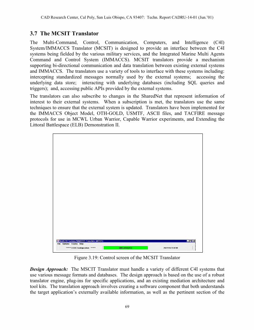
CAD Research Center, Cal Poly, San Luis Obispo, CA 93407: Techn. Report CADRU-14-01 (Jun.’01)
3.7 The MCSIT Translator
The Multi-Command, Control, Communication, Computers, and Intelligence (C4I) System/IMMACCS Translator (MCSIT) is designed to provide an interface between the C4I systems being fielded by the various military services, and the Integrated Marine Multi Agents Command and Control System (IMMACCS). MCSIT translators provide a mechanism supporting bi-directional communication and data translation between existing external systems and IMMACCS. The translators use a variety of tools to interface with these systems including: intercepting standardized messages normally used by the external systems; accessing the underlying data store; interacting with underlying databases (including SQL queries and triggers); and, accessing public APIs provided by the external systems.
The translators can also subscribe to changes in the SharedNet that represent information of interest to their external systems. When a subscription is met, the translators use the same techniques to ensure that the external system is updated. Translators have been implemented for the IMMACCS Object Model, OTH-GOLD, USMTF, ASCII files, and TACFIRE message protocols for use in MCWL Urban Warrior, Capable Warrior experiments, and Extending the Littoral Battlespace (ELB) Demonstration II.
Design Appuse various translator entool kits. Ththe target ap
Figure 3.19: Control screen of the MCSIT Translator
roach: The MSCIT Translator must handle a variety of different C4I systems that message formats and databases. The design approach is based on the use of a robust gine, plug-ins for specific applications, and an existing mediation architecture and e translation approach involves creating a software component that both understands plication’s externally available information, as well as the pertinent section of the
69

CAD Research Center, Cal Poly, San Luis Obispo, CA 93407: Techn. Report CADRU-14-01 (Jun.’01)
IMMACCS object model. The translator is responsible for providing a bi-directional connection between the two systems. For example, changes to the information maintained in the IMMACCS object model will be used to update the corresponding information in one or more of the existing C4I systems. The translator engine is responsible for correctly mapping the information between the systems, and guaranteeing the ordering and referential integrity of the
data. The translator may interact with the application’s externally available information via a number of different mechanisms that include directly accessing the application’s underlying data store (e.g., a relational database), or mimicking the behavior of an application’s client or peer server. The latter method may include subscribing to messages sent between systems, or tapping into the client-server data stream. In either case, the translator must ensure that its activities do not hinder the operation of the existing system or corrupt the underlying data stores.
Figure 3.20: The MCSIT Interface
Implementation: A separate ‘TranslatorEngine’ instance is instantiated for each protocol, with protocol-specific support classes instantiated in the ‘ObjectToMessage’ and ‘MessageToObject’ components.
The right diagram depicts the general structure and dependencies for a MCSIT ‘TranslatorEngine’. The ‘ObjectToMessage’ component receives notifications on IMMACCS objects via the ‘AlertAPI’ interface, retrieving the actual IMMACCS object on the SNAPI interface. The protocol-specific representation of the IMMACCS object(s) is then forwarded to the external system. On the inbound side, a protocol-specific representation is received by ‘MessageToObject’, translated into an IMMACCS object(s), and persisted into SharedNet on the SharedNet API interface. Figure 3.21: MCSIT dependencies
70

CAD Research Center, Cal Poly, San Luis Obispo, CA 93407: Techn. Report CADRU-14-01 (Jun.’01)
History: The initial MCSIT implementation was successfully used during a Limited Objective Exercise (LOE) at Camp Lejeune (North Carolina), during September 1998, and the Urban Warrior Advanced Warfighting Experiment in Oakland and Monterey (California), in March 1999. It was also successfully used in the Capable Warrior Millennium Dragon at Gulfport, Mississippi, during September 2000.
Development continues with expanding on message protocols and implementing the Variable Message Format (VMF), and interface to other external systems such as the Army Battle Command System (ABCS). MCSIT will support the ELB Major Demonstration II, at USS Coronado, and CW AWE at Camp Pendleton, during June 2001.
To date, the MCSIT has had experience with several major C4I Systems including:
• Joint Maritime Command Information System (JMCIS).
• Army Battle Command System (ABCS).
• Joint Warning and Reporting Network (JWARN).
• Reconnaissance, Surveillance, Targeting Vehicle (RST-V).
• Land Attack Warfare System (LAWS).
• Tactical Strike Coordination Module (TSCM).
• Joint Conflict and Tactical Simulation (JCATS).
• Instrumentation System.
• IMMACCS Interface: (1) The Object Oriented Database (OODB) interface through the Shared Net APIs, or (2) Direct 2-D Viewer system interface through Java objects.
71

CAD Research Center, Cal Poly, San Luis Obispo, CA 93407: Techn. Report CADRU-14-01 (Jun.’01)
72

CAD Research Center, Cal Poly, San Luis Obispo, CA 93407: Techn. Report CADRU-14-01 (Jun.’01)
4. Operating IMMACCS through the IOB User-Interface
The purpose of this section is to provide some examples of the functional capabilities of IMMACCS during typical military mission situations. It should be noted that IMMACCS does not incorporate any solutions to predefined problems. Rather, IMMACCS should be viewed as a set of tools that interact with each other and the users to collaboratively solve problems as they occur in the real world.
4.1 IMMACCS as a Set of Tools
The agents are the most powerful members of this tool set, for several reasons. First, they are able to communicate with each other and the users. This allows one agent to spontaneously enlist the services of one or more other agents in its inferencing tasks. Therefore, by virtue of their communication capabilities, agents are able to collaborate among themselves in an opportunistic manner. Also, through the alert mechanism agents are able to involve the human user in their collaborations. This provides an avenue for an agent to enlist the assistance of a human in matters that are either not discernable through logical reasoning alone or require deeper domain knowledge than is available to the agent. In the current version of IMMACCS this potentially powerful agent capability is only marginally present.
Second, those agents that have deep knowledge in a particular domain (i.e., service agents such as the Fires agent and the Hazard agent (see Section 3.3.7)) are able to represent the views of that domain and unemotional argue those views as they participate in the analysis and evaluation of the current state of the situation. In other words, the service agents ensure that all available viewpoints are represented throughout all collaborations. The use of the word “available” is intended to stress that these viewpoints are limited to the existence of an agent to represent a particular viewpoint.
Third, the agents work in parallel and undertake their tasks opportunistically. Both of these characteristics are essential qualities of a truly collaborative environment. As opposed to the rationalistic approach to problem solving (Pohl et al. 1997) which proceeds in an essentially sequential manner and may be undertaken by a single problem solver, collaboration requires the participation of multiple parties whether human or computer-based or both. These parties should, and will, exercise their autonomy and initiative to contribute when they are able and willing to do so, in a largely unpredictable fashion.
In this respect even the current, initial version of IMMACCS incorporates the beginnings of what might be termed an adaptive quality. While the knowledge domains of individual service agents are clearly defined and their deep knowledge capabilities therefore entirely predetermined, the interactions of the agents are not at all predefined. In addition, the behavior of all agents is of course to a large extent governed by the events that occur in the real world problem environment, and that are at any particular point in time reflected in the Object Instance Store (OIS) of the SharedNet. It can be argued that while the knowledge and reasoning capabilities of the agents are predictable, the interaction of these limited individual capabilities within an unconstrained event-driven environment
73

CAD Research Center, Cal Poly, San Luis Obispo, CA 93407: Techn. Report CADRU-14-01 (Jun.’01)
are to some extent unpredictable. Therefore, IMMACCS incorporates at least the foundations of adaptive behavior.
Finally, it is worthy of note that despite their communication capabilities and opportunistic behavior the agents contain relatively simple inferencing mechanisms that operate on the complexities of the current state of the problem situation. This current state is represented by the OIS in the SharedNet within the contextual framework of the IMMACCS Object Model (see Section 3.2). The relationships, and in particular the dynamic associations, among the object instances are mostly responsible for the level of complexity inherent in IMMACCS. The agents gain their more sophisticated capabilities and potentially adaptive qualities as they navigate through the complexities represented by the object model. In other words, the complexity of IMMACCS rests in the internal representation of the current state of the problem situation and not in the predetermined inferencing mechanisms (e.g., rules) that are embedded in each agent.
4.2 A Simulated Demonstration Scenario
The following simulated IMMACCS demonstration scenario utilizes both predefined sequences of events injected by the Scenario Driver (see Section 3.6) and user input through the Object Browser (see Section 3.5). These information feeds replace the battlespace information that would normally be received during a real world deployment of IMMACCS as the command and control system.
Demonstration Scenario Context: The situational context is an urban environment in which a Marine Air Ground Task Force (MAGTF) of battalion size is required to protect the local civilian population from military and semi-military hostile elements.
Summary of Scenario Events and Activities: Friendly forces sight two enemy units moving toward a warehouse building which is suspected to be an enemy armory. On friendly Call-for-Fire (CFF) agents identify several possible weapons: USS Russell (NSF - M41 VLS guided missile and SWG 1A Harpoon); Fixed Wing Aircraft (ACE - F/A 18 with missiles and rockets); and, Crew Served Howitzers (155 mm Towed Howitzer and other Howitzer). Agents select the aircraft and the howitzers as the best choice weapons. However, after further analysis of the ECR (Effective Casualty Radius) of each of these recommended weapons the Commander rejects one of the howitzers for political reasons, because its ECR extends over the residence of the local Mayor. The Commander finally selects the Aircraft (F/A 18) as the weapon of choice and gives the ‘fire’ order.
In the meantime several groups of civilians have been sighted in different parts of the battlespace, apparently moving toward an open area (i.e., a local soccer field) which is located near the ‘warehouse’ target. The BDA (Battle Damage Assessment) report received after the target has been hit indicates an unexpected ‘chemical fire’. Apparently the warehouse was also used for the storage of chemical weapons. The agents generate a first warning of the danger of the ‘chemical fire’ to the nearby assembly of civilians. This is followed by a second agent alert indicating the immediate need for civilian evacuation.
The Commander, with the assistance of IMMACCS: determines the location of key civilian support agencies; activates three friendly units to move into the target area;
74

CAD Research Center, Cal Poly, San Luis Obispo, CA 93407: Techn. Report CADRU-14-01 (Jun.’01)
arranges for local police and fire service support; and, identifies surrounding hospitals and medical offices, in readiness for the mass evacuation of civilians out of the ‘chemical fire’ area.
Demonstration Sequence: The following step-by-step sequence of user actions and Scenario Driver input, provides a detailed description of the operation of the IMMACCS Object Browser (IOB) and the controlling role played by the IMMACCS Object Model.
Zoom in on urban area of the battlefield map displayed by the IOB. Click on: Zoom In (+) button
Click and click pan hand to move map somewhat to the right side of the screen.
Define an AOI and set ‘trigger’ to be alerted if any red (enemy) unit moves into AOI. Click on: Edit button
Select: Edit Object Click on: Specialize button
Select: Agent Type name in box: position (as name) ®
Click in: AgentID entry box and type: da1 Select: Associations Select: Triggers
Click on: Query button Select: RedDP1
Click on: Submit Click on: Submit
AOI has been created but is not highlighted on map.
Set another ‘trigger’ to be alerted if any gray (civilian) groups move into AOI. Click on: Edit button
Select: Edit Object Click on: Specialize button
Select: Agent Type name in box: position (as name) ®
Click in: AgentID entry box and type: da2 Select: Associations Select: Triggers
Click on: Query button Select: GrayDP1
Click on: Submit Click on: Submit
AOI has been created but is not highlighted on map.
Request to see all potential helicopter ‘landing zones’. Click on: Edit button
Select: Edit Object Click on: Specialize button
Select: Environment Select: forceCode Select: All Friend force code
Click on: Query button Displays list of possible ‘landing zones’ and highlights those shown on map as objects.
Click on: right top corner of Window close (x) button Click on: Cancel button
75

CAD Research Center, Cal Poly, San Luis Obispo, CA 93407: Techn. Report CADRU-14-01 (Jun.’01)
Request to see all potential ‘fuel sources’. Click on: Edit button
Select: Edit Object Click on: Specialize button
Select: Building Select: function Select: Service/Refueling Station function
Click on: Query button Displays list of possible ‘fuel sources’ and highlights those shown on map as objects.
Click on: right top corner of Window close (x) button Click on: Cancel button
Request to see all civilian ‘residential’ areas. Click on: Edit button
Select: Edit Object Click on: Specialize button
Select: Building Select: Associations Select: builtupAreaRole
Click on: Query button Displays list of ‘residential areas’ (none are highlighted on map).
Select: Residential Area #1 Click on: Submit button Click on: Query button
Buildings in ‘residential area #1’ are highlighted on map.
Click on: right top corner of Window close (x) button Click on: Cancel button
Start Scenario Driver to move two red units toward suspected enemy armory. Click on: Driver button
Select: Scenario Driver Click on: Open button
Double click on: scenarios (i.e., select ‘scenarios’ folder) Double click on: RedMove.txt
Click on: Start button Click on: Exit button (after script has stopped)
Agent ALERT to indicate movement of red unit(s) into AOI. Click on: Agent icon
Window displays current agent ALERTs. Click on: appropriate Alert button
Selected ALERT explanation is displayed in Window.
Click on: OK button
Request CFF template and enter CFF information. Click on: Edit button
Select: Edit Object Click on: Specialize button
Select: CallForFire Type: CFF1 (as Name) ®
Select: targetType Select: Building target type
76

CAD Research Center, Cal Poly, San Luis Obispo, CA 93407: Techn. Report CADRU-14-01 (Jun.’01)
Type Narrative: Suspected Enemy Armory Select Month: SEP Type source: CP
Select: Associations Select: Target
Click on: Specialize button Select: Building
Select forceCode: All Hostile Click on: Query button
Window displays list of hostile buildings.
Select: Landrone/Redesian Armory Click on: Submit button Click on: Submit button
Target is highlighted on map as agent analysis proceeds.
Agents analyze available weapons to destroy this target.
Request to see all feasible weapons based on agent ALERT. Click on: Agent button
Window displays current agent ALERTs.
Click on: appropriate Alert button Selected ALERT explanation is displayed in Window with Effective Casualty Radius.
Click on: OK button
User rejects crew-served weapon with largest Effective Casualty Radius (ECR) due to overlap into residential area where Mayor resides.
Start Driver to move all civilian groups toward Soccer Field near target. Click on: Driver button
Select: Scenario Driver Click on: Open button
Double click on: scenarios (i.e., select ‘scenarios’ folder) Double click on: GrayMove.txt
Click on: Start button Three civilian groups move toward Soccer Field and merge into a Crowd.
Click on: Exit button (after script has stopped)
Start Driver to move Aircraft to target and FIRE on target. Click on: Driver button
Select: Scenario Driver Click on: Open button
Double click on: scenarios (i.e., select ‘scenarios’ folder) Double click on: FWMove2.txt
Click on: Start button F/A-18 aircraft moves over target, fires missile, and then returns to airfield.
Click on: Exit button (after script has stopped)
Start Driver to receive BDA information and change infrastructure objects. Click on: Driver button
Select: Scenario Driver Click on: Open button
77

CAD Research Center, Cal Poly, San Luis Obispo, CA 93407: Techn. Report CADRU-14-01 (Jun.’01)
Double click on: scenarios (i.e., select ‘scenarios’ folder) Double click on: TargetExist.txt
Click on: Start button Nothing is shown on map, but agent ALERT comes next.
Click on: Exit button (after script has stopped)
Create ‘Atmospheric Event’ object instance. Click on: Edit button
Select: Edit Object Click on: Specialize button
Select: AtmosphericEvent Type name in box: Chemical Fire Plume ®
Click in: atmosEventType Select: BIOCHEMICAL Select: Associations
Double Click on: naturalRegion Click on: Query button
Select: CI’ELNCI Soccer Field Click on: Submit button Click on: Submit button
Agent ALERT to warn of Chemical Fire danger to civilians. Click on: Agent button
Window displays current agent ALERTs.
Click on: appropriate Alert button Selected ALERT explanation is displayed in Window.
Click on: OK button
Request to see locations of key civilian support offices (i.e., police, fire, etc.). Click on: Edit button
Select: Edit Object Click on: Specialize button
Select: Building Select: usage Select: Civilian/Public usage
Click on: Query button Displays list of civilian support office buildings.
Select: Ci’Elnci Government Center Select: Associations
Displays list of key civilian occupants of these offices (i.e., buildings).
Click on: right top corner of Window close (x) button Click on: Cancel button
Start Driver to move three blue units toward Soccer Field demonstration area. Click on: Driver button
Select: Scenario Driver Click on: Open button
Double click on: scenarios (i.e., select ‘scenarios’ folder) Double click on: BlueMove1.txt
Click on: Start button Blue units move on map toward Soccer Field demonstration area.
78

CAD Research Center, Cal Poly, San Luis Obispo, CA 93407: Techn. Report CADRU-14-01 (Jun.’01)
Click on: Exit button (after script has stopped)
Start Driver to move civilian emergency support groups toward Soccer Field. Click on: Driver button
Select: Scenario Driver Click on: Open button
Double click on: scenarios (i.e., select ‘scenarios’ folder) Double click on: FireMove1.txt
Click on: Open button Double click on: scenarios (i.e., select ‘scenarios’ folder) Double click on: PoliceMove.txt
Click on: Start All button Fire crews and Police units move toward Soccer Field and target area.
Click on: Exit button (after script has stopped)
Request to see locations of all Hospitals. Click on: Edit button
Select: Edit Object Click on: Specialize button
Select: Building Select: function Select: Hospital function
Click on: Query button Displays list of Hospitals and highlights Hospital buildings on map.
Click on: right top corner of Window close (x) button Click on: Cancel button
Request to see locations of all Physician Offices. Click on: Edit button
Select: Edit Object Click on: Specialize button
Select: Building Select: function Select: Medical Center function
Displays list of Physician Offices and highlights corresponding buildings on map.
Click on: right top corner of Window close (x) button Click on: Cancel button
79

CAD Research Center, Cal Poly, San Luis Obispo, CA 93407: Techn. Report CADRU-14-01 (Jun.’01)
4.3 Typical Examples of Real World Sequences
The following scenario sequences are based on the use of IMMACCS during the Urban Warrior Advanced Warfighting Experiment conducted by the Marine Corps Warfighting Laboratory in conjunction with the US Navy and military contingents from several foreign countries over a seven-day period in March, 1999. The setting for these sequences is the Oak Knoll Naval Base located in Oakland, California. Friendly units in the battlespace utilized laptop computers with integrated differential GPS devices to feed data via wireless line-of-sight communication facilities to the Experimental Combat Operations Center (ECOC) on the USS Coronado (at anchor in the San Francisco harbor).
Depicted on each IOB screen are the various track and infrastructure objects that are participants in the view of the particular sequence described in the caption. These objects are overlaid on a background map showing additional terrain features (e.g., colored vegetation areas) and contours. Friendly and enemy forces are shown in standard US military symbology.
Figure 4.1: IOB representation of the Oak Knoll battlespace showing friendly, enemy, and civilian units as blue rectangles, red diamonds, and green squares, respectively (see inside cover for colored version of Figure 4.1). Roads, buildings, rivers and contour lines are represented in the battlespace, as well as the alert-area boundaries of EUT Sentinel agents.
80

CAD Research Center, Cal Poly, San Luis Obispo, CA 93407: Techn. Report CADRU-14-01 (Jun.’01)
Figure 4.2: An enemy Infantry Unit from the lower portion of the screen has moved and triggered a decision point established at a fork in the road. The agent responsible for monitoring that decision point, the Intel Agent, turns its surround red to notify the operators of a new alert.
81

CAD Research Center, Cal Poly, San Luis Obispo, CA 93407: Techn. Report CADRU-14-01 (Jun.’01)
Figure 4.3: The operator clicks on the Intel Agent icon to determine which decision point has been triggered and why. After reading the agent alert the operator acknowledges the alert, turning the surround blue, and then closes the alert dialogue box.
82

CAD Research Center, Cal Poly, San Luis Obispo, CA 93407: Techn. Report CADRU-14-01 (Jun.’01)
Figure 4.4: The operator has acknowledged the Intel Agent alert and has proceeded to target the enemy Infantry Unit by creating a ‘Call For Fire’ (CFF). Note, that the CFF is associated with the enemy Infantry Unit (i.e., a particular target) not just a point on the ground in close proximity of the target. Therefore, as the target moves the CFF location will move with it until the fire mission has been executed or denied.
83

CAD Research Center, Cal Poly, San Luis Obispo, CA 93407: Techn. Report CADRU-14-01 (Jun.’01)
Figure 4.5: Indicates the results of the agent activity after the CFF has been submitted. The Fires Agent analyzed the CFF request in order to determine possible weapons and ultimately select the best weapon, as well as performing any calculations necessary to determine if the path of the weapon would encounter any obstructions during its flight to the target.
84

CAD Research Center, Cal Poly, San Luis Obispo, CA 93407: Techn. Report CADRU-14-01 (Jun.’01)
Figure 4.6: The enemy Infantry Unit has moved into close proximity of Alpha Company. The Sentinel Agent responsible for monitoring enemy unit locations around Alpha Company alerts the operator of this intrusion. The operator clicks on the Sentinel Agent icon and views the alert.
85

CAD Research Center, Cal Poly, San Luis Obispo, CA 93407: Techn. Report CADRU-14-01 (Jun.’01)
Figure 4.7: The enemy Infantry Unit is now in such close proximity to Alpha Company that the Blue-On-Blue Agent alerts of a possible fratricide situation resulting from the CFF placed on the enemy Infantry Unit. The agent has analyzed the proximity of these two units and determined that based on the characteristics of the selected munitions Alpha Company is in danger.
86

CAD Research Center, Cal Poly, San Luis Obispo, CA 93407: Techn. Report CADRU-14-01 (Jun.’01)
Figure 4.8: The enemy Infantry Unit has come close enough to Alpha Company to establish contact and has been recognized as a friendly unit. The force code is changed to reflect its friendly status causing the Blue-On-Blue Agent to create another friendly fire violation alert. The resulting fratricide alert causes the Fires Mission to be cancelled.
87

CAD Research Center, Cal Poly, San Luis Obispo, CA 93407: Techn. Report CADRU-14-01 (Jun.’01)
Figure 4.9: A friendly Reconnaissance Unit has moved from the top of the screen to take up a position at the hospital building. This close proximity to the enemy’s Crotale Air Defense System causes the Reconnaissance Unit’s Sentinel Agent to register an alert.
88

CAD Research Center, Cal Poly, San Luis Obispo, CA 93407: Techn. Report CADRU-14-01 (Jun.’01)
Figure 4.10: The enemy’s Crotale Air Defense System is now actively using its radar to find friendly air assets. The Intel Agent registers an alert on this electronic intelligence, notifying the operator that procedures call for submitting a CFF on this high value target.
89

CAD Research Center, Cal Poly, San Luis Obispo, CA 93407: Techn. Report CADRU-14-01 (Jun.’01)
Figure 4.11: The enemy Crotale Air Defense System’s radar has acquired a target. Since a CFF has not yet been submitted from the previous alert, the Intel Agent, according to procedure, immediately submits a CFF.
90
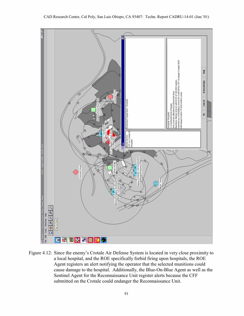
CAD Research Center, Cal Poly, San Luis Obispo, CA 93407: Techn. Report CADRU-14-01 (Jun.’01)
Figure 4.12: Since the enemy’s Crotale Air Defense System is located in very close proximity to a local hospital, and the ROE specifically forbid firing upon hospitals, the ROE Agent registers an alert notifying the operator that the selected munitions could cause damage to the hospital. Additionally, the Blue-On-Blue Agent as well as the Sentinel Agent for the Reconnaissance Unit register alerts because the CFF submitted on the Crotale could endanger the Reconnaissance Unit.
91

CAD Research Center, Cal Poly, San Luis Obispo, CA 93407: Techn. Report CADRU-14-01 (Jun.’01)
Figure 4.13: The state of the agents after all the alerts have been acknowledged.
92

CAD Research Center, Cal Poly, San Luis Obispo, CA 93407: Techn. Report CADRU-14-01 (Jun.’01)
4.4 Exercising Individual Agent Capabilities
This section describes selected individual IMMACCS agent capabilities that were available and successfully tested during the Urban Warrior AWE field test conducted in March’99.
4.4.1 The Logistics Agent
Capabilities: The following Logistics agent capabilities apply to the ‘Entity’ class of objects only: Entity, Organization, Civilian Organization, Military Organization, Ground Unit, Special Ops, CSS Unit (Admin Support Unit, Maint Support Unit, Med Support Unit, Supply Support Unit, Transportation Support Unit), CS Unit (Intel Support Unit, Law Enforcement Unit, NBC Support Unit, Signal Support Unit), Combat Unit (Air Defense Unit, Anti Armor Unit, Armor Unit, Aviation Unit, Engineer Unit, Field Artillery Unit, Infantry Unit, Internal Security Force, Reconnaissance Unit), Person (Military Person, Public Servant).
1. Generates a ‘yellow alert’ if supply level falls below ‘green’ level.
Object Attribute Required Value
Entity forceCode <friendly or neutral>
SupplyInformation quantityOnHand <less than quantityGreen and greater than quantityYellow>
Supply supplyInfo name (SupplyInformation) Supply ownerConsumer name (Entity)
Alert alertMessage “Yellow Alert! The (name of supply class) supplies level for (name of Entity) located at (lat/long position) has fallen below (quantityGreen).”
2. Generates a ‘red alert’ if supply level falls below ‘yellow’ level.
Object Attribute Required Value
Entity forceCode <friendly or neutral> SupplyInformation quantityOnHand <less than quantityYellow> Supply supplyInfo name (SupplyInformation) Supply ownerConsumer name (Entity)
Alert alertMessage “Red Alert! The (name of supply class) supplies level for (name of Entity) located at (lat/long position) has fallen below (quantityYellow).”
3. Automatically determines possible supply sources on ‘yellow alert’.
93

CAD Research Center, Cal Poly, San Luis Obispo, CA 93407: Techn. Report CADRU-14-01 (Jun.’01)
Object Attribute Required Value
Entity forceCode <friendly or neutral> SupplyInformation quantityOnHand <less than quantityGreen> Supply supplyInfo name (SupplyInformation) Supply ownerConsumer name (Entity)
SupplySupportUnit forceCode <friendly or neutral> (or SupplyPoint)
4. Automatically determines best supply source based on nearest friendly or neutral supply support unit.
Object Attribute Required Value
Entity forceCode <friendly or neutral> SupplyInformation quantityOnHand <less than quantityGreen> Supply supplyInfo name (SupplyInformation) Supply ownerConsumer name (Entity)
SupplySupportUnit forceCode <friendly or neutral> (or SupplyPoint)
The following Logistics agent capabilities apply to the ‘Platform’ class of objects only: Platform, Aircraft, Ground Vehicle (Armored Vehicle (Tank)), Sea Surface Vessel (Combat Vessel (Amphibious), Non Combat Vessel, Non Military Vessel), Air Weapon (Missile in Flight), Civil Aircraft, Military Aircraft (Fixed Wing, Rotary Wing).
5. Generates an alert if the fuel level of a platform object falls below 50% (the 50% threshold value cannot be set by the user).
Object Attribute Required Value
Platform forceCode <friendly or neutral> Platform fuelLevel <less than 50%>
Alert alertMessage “The estimated fuel level for (name of platform) located at (lat/long position) has fallen to (value%).”
6. Automatically determines possible fuel sources for ground vehicles based on the function code of structures that are in friendly or neutral hands.
Object Attribute Required Value
Structure forceCode <friendly or neutral> Structure functionCode BFC54 (Serv/Refuel Station)
(BFC120 – Automobile Plant)
94

CAD Research Center, Cal Poly, San Luis Obispo, CA 93407: Techn. Report CADRU-14-01 (Jun.’01)
(BFC83 – Power Generation) (BFC102 – Oil/Gas Fac Bdg) (BFC124 – Repair Fac) (BFC29 – Aircraft Maint Shop) (BFC26 – Railroad Storage) (BFC37 – Fire Station) (BFC110 – Factory)
7. Automatically determines possible fuel sources for trains based on the existence of railway stations.
8. Automatically determines possible fuel sources for aircraft based on the existence of air transportation nodes; including airfields, airports and heliports.
9. Automatically determines possible fuel sources for ships based on the existence of water transportation nodes; including harbors and ports.
10. Automatically determines the best fuel source for ground vehicles based on distance from ground vehicle that requires fuel.
Object Attribute Required Value
GroundVehicle forceCode <friendly or neutral> GroundVehicle fuelLevel <less than 50%> Structure functionCode BFC54 (Serv/Refuel Station)
(BFC120 – Automobile Plant) (BFC83 – Power Generation) (BFC102 – Oil/Gas Fac Bdg) (BFC124 – Repair Fac) (BFC29 – Aircraft Maint Shop) (BFC26 – Railroad Storage) (BFC37 – Fire Station) (BFC110 – Factory) (BFC124 – Repair Fac)
4.4.2 The Fires Agent
Capabilities: The following Fires agent capabilities are currently available in IMMACCS in support of Call For Fire (CFF) requests, for lethal weapons only.
1. Generates a ‘Fire agent alert’ if it finds a lethal weapon with no associated munitions.
Object Attribute Required Value
LethalWeapon LethalWeapon
Alert
forceCode weaponAmmo
alertMessage
<friendly> (empty list)
“Weapon (name of weapon), will not be considered for weaponeering. There are no
95

CAD Research Center, Cal Poly, San Luis Obispo, CA 93407: Techn. Report CADRU-14-01 (Jun.’01)
munitions associated with this weapon.”
2. Generates a ‘Fire agent alert’ if it finds a lethal weapon with associated ammunition, but no associated platform or entity.
Object Attribute Required Value
LethalWeapon forceCode <friendly>
Alert alertMessage “Weapon (name of weapon), has no platform or entity associated with it. Weapon will be considered for weapon- eering, but location of weapon will be unknown.”
3. Generates a ‘Fire agent alert’ if it finds munitions with no associated weapon, platform or entity (one of these will suffice).
Object Attribute Required Value
Munitions forceCode <friendly>
Alert alertMessage “Munitions (munitions name), has no weapon associated with it to fire. Munitions will still be considered for weapon- eering, but location of munitions will be unknown.”
4. Automatically determines all available munitions.
Object Attribute Required Value
Munitions forceCode <friendly>
5. Automatically determines all available lethal weapons associated with the available munitions.
Object Attribute Required Value
Munitions forceCode <friendly> LethalWeapon forceCode <friendly (Munitions)>
6. Automatically finds all platforms with some associated lethal weapons that have not been previously identified, and adds these to the available lethal weapons pool.
96

CAD Research Center, Cal Poly, San Luis Obispo, CA 93407: Techn. Report CADRU-14-01 (Jun.’01)
Object Attribute Required Value
Platform forceCode <friendly>
7. Automatically associates all available lethal weapons (i.e., the current lethal weapons pool) with the friendly entity (e.g., unit) that has this weapon in its arsenal (i.e., assets).
Object Attribute Required Value
Entity forceCode <friendly> Entity assets weapon name (LethalWeapon) LethalWeapon forceCode <friendly>
8. Automatically associates those available lethal weapons (i.e., in the lethal weapons pool) that are associated with platforms, with the appropriate friendly entity (e.g., unit).
Object Attribute Required Value
Entity forceCode <friendly>
Entity (or)
assets embarkedOn
name (Platform)name (Platform)
Platform Platform
forceCode passengersCrew
<friendly> name (Entity)
9. Automatically rates all available lethal weapons (i.e., the current lethal weapons pool), starting with a value of 100 and increasing or decreasing this base rating according to the following rules. However, a rating of zero (i.e., “rating = 0” below) indicates that the weapon is not available for selection.
if munitions caliber < 60mm rating = 0
Object Attribute Required Value
Munitions caliber < 60
if effective range of weapon is out of range rating = 0
Object Attribute Required Value
Munitions effectiveRange (out of range of target) LethalWeapon weaponAmmo name (Munitions) Entity assets name (LethalWeapon)
97

CAD Research Center, Cal Poly, San Luis Obispo, CA 93407: Techn. Report CADRU-14-01 (Jun.’01)
if effective range of platform is out of range rating = 0
Object Attribute Required Value
Munitions effectiveRange (out of range of target) LethalWeapon weaponAmmo name (Munitions) Platform weaponSystems name (LethalWeapon)
if ECR is smaller than target size rating = - 10(weapon count)
Object Attribute Required Value
Munitions ECR (less than target size)
(‘Weapon count’ is the number of rounds that have to fired to saturate the target. Calculated by dividing the ECR of the munitions into the target size.)
if CEP is smaller than ECR rating = - 5(CEP/ECR)
Object Attribute Required Value
Munitions ECR (equal or greater than CEP) Munitions CEP (less than ECR)
if CEP is larger than ECR rating = - 10(CEP/ECR)
Object Attribute Required Value
Munitions ECR (equal or less than CEP) Munitions CEP (greater than ECR)
if guided munitions are required by CFF rating = + 20
Object Attribute Required Value
CallForFire specialEffects GUIDED MUNITIONS
if more than one CFF with EMERGENCY rating = - 20 priority have interest in the same lethal weapon
Object Attribute Required Value
CallForFire targetPriority EMERGENCY
98

CAD Research Center, Cal Poly, San Luis Obispo, CA 93407: Techn. Report CADRU-14-01 (Jun.’01)
if more than one CFF with IMMEDIATE rating = - 20 priority have interest in the same lethal weapon
Object Attribute Required Value
CallForFire targetPriority IMMEDIATE
if a structure would block the trajectory rating = no change in rating of an available lethal weapon or value (but note added) platform
Object Attribute Required Value
Entity location (influences trajectory) Platform location (influences trajectory) Structure location (compared with trajectory) Structure structureDimensions (height considered)
if a rotary wing aircraft is likely to block rating = no change in rating the trajectory of an available lethal value (but note added) weapon or platform
Object Attribute Required Value
Munitions maxSpeed (determines collision point) Entity location (influences trajectory) Platform location (influences trajectory) RotaryWing location (compared with trajectory)
10. Automatically identifies all lethal weapons (i.e., in the current lethal weapons pool) that can arrive on target within 5 min., if CFF has priority of EMERGENCY.
Object Attribute Required Value
CallForFire Munitions LethalWeapon Entity
targetPriority maxSpeed weaponAmmo assets
EMERGENCY > 0 name (Munitions) name (LethalWeapon)
Object Attribute Required Value
CallForFire Munitions LethalWeapon Platform
targetPriority maxSpeed weaponAmmo weaponSystems
EMERGENCY > 0 name (Munitions) name (LethalWeapon)
99

CAD Research Center, Cal Poly, San Luis Obispo, CA 93407: Techn. Report CADRU-14-01 (Jun.’01)
11. Automatically identifies all lethal weapons (i.e., in the current lethal weapons pool) that can arrive on target within 10 min., if CFF has priority of IMMEDIATE.
Object Attribute Required Value
CallForFire Munitions LethalWeapon Entity
targetPriority maxSpeed weaponAmmo assets
IMMEDIATE > 0 name (Munitions) name (LethalWeapon)
Object Attribute Required Value
CallForFire Munitions LethalWeapon Platform
targetPriority maxSpeed weaponAmmo weaponSystems
EMERGENCY > 0 name (Munitions) name (LethalWeapon)
12. Automatically checks if there is a friendly unit or civilian entity near the target (i.e., within the CEP of an available weapon). (Fires agent simply notes “…friendly unit(s) near target” or “…civilian entity near target”, but takes no other action. However, this notation becomes available to the Blue-On-Blue agent and it generates an alert.)
Object Attribute Required Value
Munitions CEP (compared with location of any friendly Entity)
Entity forceCode <friendly> CivilianOrganization location (compared with munitions CEP)
13. Automatically rejects any lethal weapons or platforms (remaining in the weapons pool) that have received a final rating of less than 69.
14. Automatically considers all lethal weapons or platforms (remaining in the weapons pool) that have received a final rating of greater than or equal to 70 as a feasible weapon for the particular CFF.
15. Automatically selects the weapon (of the weapons remaining in the weapons pool) with the highest rating as the best choice weapon for the particular CFF.
16. Generates a ‘Fire agent alert’ to report all FEASIBLE weapons for the particular CFF.
Object Attribute Required Value
Alert alertMessage “Recommended Feasible Weapons: (list) “
100

CAD Research Center, Cal Poly, San Luis Obispo, CA 93407: Techn. Report CADRU-14-01 (Jun.’01)
17. Generates a ‘Fire agent alert’ to report the BEST weapon for the particular CFF.
Object Attribute Required Value
Alert alertMessage “Recommended Best Weapon: (best weapon) “
18. Generates a ‘Fire agent alert’ to report that no BEST weapon for the particular CFF has been found.
Object Attribute Required Value
Alert alertMessage “No Best Weapon Recom- mendation: “
4.4.3 The Engagement Agent
Capabilities: The Engagement agent capabilities currently relate to Fire Events and Calls for Fire (CFFs) only.
1. Generates an ‘Engagement agent alert’ on the occurrence of a Fire Event directly targeting, or indirectly targeting the environment of, a non-friendly entity (i.e., track). Non-friendly includes hostile, neutral and unknown.
Object Attribute Required Value
Alert alertMessage “ENGAGEMENT: (forceCode) track (name of track) located at (lat/long position or name of environment) is currently being engaged as a result of the (Fire Event name) fire event.”
2. Generates an ‘Engagement agent alert’ on the occurrence of a CFF directly targeting, or indirectly targeting the environment of, a non-friendly entity (i.e., track). Non-friendly includes hostile, neutral and unknown.
Object Attribute Required Value
Alert alertMessage “ENGAGEMENT: (forceCode) track (name of track) located at (lat/long position or name of
101

CAD Research Center, Cal Poly, San Luis Obispo, CA 93407: Techn. Report CADRU-14-01 (Jun.’01)
environment) is currently targeted as a result of the (CFF name) CFF.”
4.4.4 The Blue-On-Blue Agent
Capabilities: The Blue-On-Blue agent capabilities currently relate to the presence of friendly forces on or near a Fire Event or CFF target.
1. Generates a ‘Blue-On-Blue agent alert’ on the occurrence of a Fire Event that directly or indirectly threatens a friendly unit. A friendly unit is considered to be threatened if it is located within 100m of the track location of the target.
Object Attribute Required Value
Alert alertMessage “BLUE ON BLUE: (forceCode) track (name of track) located at (lat/long position or name of environment) is currently under attack by another friendly unit resulting from the (CFF name) Call For Fire.”
2. Generates a ‘Blue-On-Blue agent alert’ on the occurrence of a CFF that directly or indirectly threatens a friendly unit. A friendly unit is considered to be threatened if it is located within 100m of the track location of the target.
Object Attribute Required Value
Alert alertMessage “BLUE ON BLUE: (forceCode) track (name of track) located at (lat/long position or name of environment) is currently targeted in the (CFF name) Call For Fire.”
3. Generates a ‘Blue-On-Blue agent alert’ if a non-friendly entity (i.e., track) is endangered due to proximity to a CFF target.
Object Attribute Required Value
Alert alertMessage “Friendly (object type and Reference name) located at (lat/long position)could be affected by indirect fire from Call For Fire (CFF name) with target location (distance) meters away.”
102

CAD Research Center, Cal Poly, San Luis Obispo, CA 93407: Techn. Report CADRU-14-01 (Jun.’01)
4.4.5 The Intel Agent
Capabilities: The Intel agent capabilities currently relate to the detection of hostile radar installations and the automatic generation of a CFF on this potential target.
1. Monitors the creation of all new tracks.
2. Generates an ‘Intel agent alert’ on the detection of a radar installation (i.e., tracks) with a hostile force code, and automatically creates a CFF if the status of the radar installation is ACTIVE.
Object Attribute Required Value
Radar forceCode <not friendly> Radar status ACTIVE (or PASSIVE)
Alert alertMessage “Non friendly radar alert: (name of radar track)”
CallForFire controlMethod WHEN READY (created) targetArea POINT TARGET
targetActivity STATIONARY targetPriority HPT targetDescription ADA AAA TARGET target name (Radar)
4.4.6 The Hazard (NBC) Agent
Capabilities: The Hazard agent capabilities are currently related to the detection of atmospheric and climatic events that are considered to be hazardous. The circular boundary for ‘Hazard agent alerts’ can be set by the operator.
1. Generates a ‘Hazard agent alert’ if a NBC atmospheric event is detected.
Object Attribute Required Value
AtmosphericEvent atmosEventType BIOCHEMICAL NUCLEAR FALLOUT
AtmosphericEvent area <affected area in km>
Alert alertMessage “(Entity name) is endangered by (atmospheric event type).”
2. Generates a ‘Hazard agent alert’ if a climatic event (e.g., flood, fire, earthquake, tornado, hurricane, cyclone, or volcanic eruption) is detected, and any entity (i.e., track) is currently located within its effective bounds.
103

CAD Research Center, Cal Poly, San Luis Obispo, CA 93407: Techn. Report CADRU-14-01 (Jun.’01)
Object Attribute Required Value
ClimaticEvent climaticEventType FLOOD EARTHQUAKE FIRE FORREST FIRE TORNADO HURRICANE TROPICAL CYCLONE VOLCANIC EXPLOSION
ClimaticEvent area <affected area in km>
Alert alertMessage “(Entity name) is endangered by (climatic event type).”
4.4.7 The ROE Agent
Capabilities: The ROE (Rules of Engagement) agent capabilities currently relate to the detection of targets that are subject to rules of engagement restrictions, including the following building types:
BFC6 Hospital BFC7 House of Worship BFC9 Museum BFC15 School BFC50 Church BFC60 University/College BFC83 Power Generation BFC63 Mission BFC84 Filtration Plant BFC100 Medical Center BFC108 Seminary BFC114 Non-Christian Place of Worship
1. Generates a ‘ROE agent alert’ if a CFF directly targets a building that is under ROE restrictions.
Object Attribute Required Value
CallForFire Building
target name
<target list> target name (CallForFire)
Building functionCode BFC6 (Hospital) BFC7 (House of Worship) BFC15 (School) BFC33 (Health Office) BFC50 (Church) BFC100 (Medical Center)
Alert alertMessage “Building (building name) is a restricted target, but is targeted by CFF (CFF name).”
104

CAD Research Center, Cal Poly, San Luis Obispo, CA 93407: Techn. Report CADRU-14-01 (Jun.’01)
2. Generates a ‘ROE agent alert’ if CFF directly targets a target class that is under ROE restrictions.
Object Attribute Required Value
CallForFire target <target list>
<target class> name target name (CallForFire)
Alert alertMessage “(target class name) is a a restricted target, but is targeted by CFF (CFF name).”
3. Generates a ‘ROE agent alert’ if CFF indirectly threatens a target class that is under ROE restrictions.
Object Attribute Required Value
CallForFire target <target list>
<target class> name target name
Munitions ECR Munitions CEP Alert alertMessage “(target class name) is a
a restricted target and could be affected by indirect fire from (name of munitions).”
4.4.8 The General Sentinel Agent
Capabilities: The General Sentinel agent capabilities are currently related to the detection of enemy units and hostile civilian entities within a radius of any operator specified position in the battlefield.
1. Generates a ‘Sentinel agent alert’ if any red unit moves into the circle of detection specified by the operator.
Object Attribute Required Value
DecisionPoint decisionPointLocation (click on battlefield display) DecisionPoint triggerAgent name (Mentor Agent) Track forceCode <hostile>
TriggerAlert alertMessage “Red Unit Alert: (name of red unit). “
2. Generates a ‘Sentinel agent alert’ if any hostile civilian entity moves into the circle of detection specified by the operator.
Object Attribute Required Value
105

CAD Research Center, Cal Poly, San Luis Obispo, CA 93407: Techn. Report CADRU-14-01 (Jun.’01)
DecisionPoint decisionPointLocation (click on battlefield display) DecisionPoint triggerAgent name (Mentor Agent) Track forceCode <hostile>
TriggerAlert alertMessage “Grey Unit Alert: (name of grey unit). “
4.4.9 The EUT Sentinel Agent
Capabilities: The EUT Sentinel agent is automatically created for each EUT (End-User Terminal) and alerts the EUT operator if either an enemy unit moves to within 300m of the current position of the EUT operator, or if a CFF includes a target that is within 300m of the current position of the EUT operator.
1. Automatically creates an EUT Sentinel agent whenever an EUT comes on-line.
Object Attribute Required Value
MentorAgent MentorAgentDecisionPoint DecisionPoint DecisionPoint DecisionPoint
agentId agentType
source range decisionPointLocation triggerAgent
(source of Mentor Agent) MENTOR AGENT source (Mentor Agent) 0.3 (km) (current EUT location) name (Mentor Agent)
2. Automatically updates position of EUT through differential GPS beacon.
3. Generates an ‘EUT Sentinel agent alert’ if any red unit moves into the 300m circle of detection around the current position of the EUT.
Object Attribute Required Value
Track forceCode <hostile> Track location (within 300m of EUT)
TriggerAlert alertMessage “Sentinel Alert: (name of red unit). “
4. Generates an ‘EUT Sentinel agent alert’ if it detects a CFF to a target that is located within 300m of the current position of the EUT.
Object Attribute Required Value
CallForFire targetLocation (within 300m of EUT)
TriggerAlert alertMessage “Sentinel CFF Alert: (name of
106

CAD Research Center, Cal Poly, San Luis Obispo, CA 93407: Techn. Report CADRU-14-01 (Jun.’01)
CFF). “
107

CAD Research Center, Cal Poly, San Luis Obispo, CA 93407: Techn. Report CADRU-14-01 (Jun.’01)
4.5 The Logistics Assistance Capabilities
The Logistics Planning user-interface enables estimation of logistics requirements using simple rules of thumb. The interface supports the projection of supplies for the supply classes listed in Table 4.1. Currently the interface supports the following functionality:
• Subject to user input such as number of days, number of persons (or units), and usage rate, the supply requirements are computed based on default consumption rates as defined in the Staff Officers' Field Manual: Organizational, Technical and Logistical Data Planning Factors (Vol.2)
• For ground vehicles, tracks in the IMMACCS Object Browser (IOB) can be selected, and if consumption rate information is available for those vehicles, then that value is used in the estimation of POL requirements (i.e., Class III).
Figure 4.14: The Logistics Planning user-interface
Figure 4.14 displays a view of the Logistics Planning user-interface. The user may select a supply class from the first column by clicking on the corresponding toggle button. This results in the display of the appropriate categories and sub-categories, and the choices available in that category for the selected supply class. Fields indicating the “Number of
108

CAD Research Center, Cal Poly, San Luis Obispo, CA 93407: Techn. Report CADRU-14-01 (Jun.’01)
People” and the ‘”Number of Days” can be modified at any time for an automatic recalculation of the estimated supply requirements.
SupplyClass Description Sub Category Sub Sub Category Consumption Rate (CR)
CLASS I Subsistence a) Food b) Water
See Table 3 & 4. 4.03lbs. /person/pkg.
CLASS II Secondary Items (consumables, expendables)
a) Clothing b) Tenting
See Table 5. 3.67 lbs./person/day
CLASS III Fuel & Petroleum Products
a) Air b) Ground
None 53.7 lbs./person/day
CLASS IV Construction Construction Materials
None 8.5 lbs./person/day
CLASS V Ammunition Ammunition None 31.29 lbs./person/day
CLASS VI Person Demand Items
Army & Air Force Exchange Service
None 3.2 lbs./person/day
CLASS VII Major End Items Major End Items 1) Tanks 2) Vehicles 3) Aircraft
15 lbs./person/day
CLASS VIII Medical Medical 1) Medical 2) Dental 3) Veterinary
1.22 lbs./person/day
CLASS IX Repair parts & Components
RP&C None 2.5
Table 4.1: Summary of supply classes with corresponding consumption rates
The estimated supply requirements are calculated using the following expression:
Supplies = (number of days) x (number of people) x (consumption rate)
Food supplies are normally available in packages. Therefore, food supply requirements are displayed in terms of the number of packages required for the parameters specified by the user. Table 4.2 shows the various types of food packages available along with their weight and content. The first two types are designed as individual meal packets. The third type is for combat situations and is used where re-supply may be uncertain for as long as 10 days. In the case of the fourth package type a 1/2 packet (Summer) or 1 packet (Winter) are normally issued per person per day. Ration Supplement ‘sundries pack’ contains items for the health and comfort of troops, and normally 1 packet per 100
109
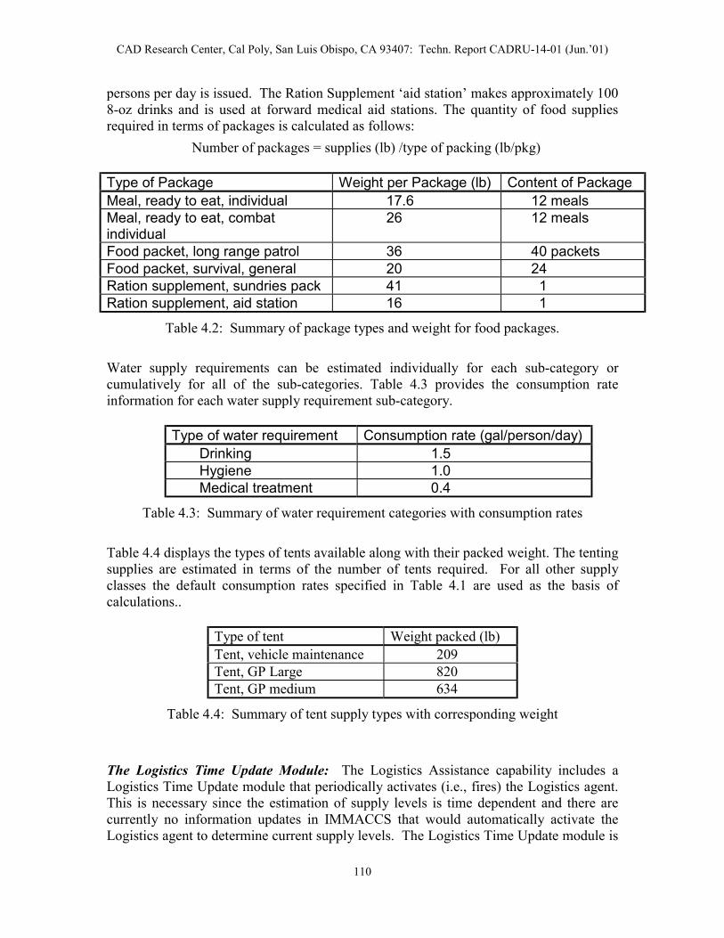
CAD Research Center, Cal Poly, San Luis Obispo, CA 93407: Techn. Report CADRU-14-01 (Jun.’01)
persons per day is issued. The Ration Supplement ‘aid station’ makes approximately 100 8-oz drinks and is used at forward medical aid stations. The quantity of food supplies required in terms of packages is calculated as follows:
Number of packages = supplies (lb) /type of packing (lb/pkg)
Type of Package Weight per Package (lb) Content of Package Meal, ready to eat, individual 17.6 12 meals Meal, ready to eat, combat individual
26 12 meals
Food packet, long range patrol 36 40 packets Food packet, survival, general 20 24 Ration supplement, sundries pack 41 1 Ration supplement, aid station 16 1
Table 4.2: Summary of package types and weight for food packages.
Water supply requirements can be estimated individually for each sub-category or cumulatively for all of the sub-categories. Table 4.3 provides the consumption rate information for each water supply requirement sub-category.
Type of water requirement Consumption rate (gal/person/day) Drinking 1.5 Hygiene 1.0 Medical treatment 0.4
Table 4.3: Summary of water requirement categories with consumption rates
Table 4.4 displays the types of tents available along with their packed weight. The tenting supplies are estimated in terms of the number of tents required. For all other supply classes the default consumption rates specified in Table 4.1 are used as the basis of calculations..
Type of tent Weight packed (lb) Tent, vehicle maintenance 209 Tent, GP Large 820 Tent, GP medium 634
Table 4.4: Summary of tent supply types with corresponding weight
The Logistics Time Update Module: The Logistics Assistance capability includes a Logistics Time Update module that periodically activates (i.e., fires) the Logistics agent. This is necessary since the estimation of supply levels is time dependent and there are currently no information updates in IMMACCS that would automatically activate the Logistics agent to determine current supply levels. The Logistics Time Update module is
110

CAD Research Center, Cal Poly, San Luis Obispo, CA 93407: Techn. Report CADRU-14-01 (Jun.’01)
implemented as a single thread that periodically queries for the existence of supply objects in the SharedNet and updates their “modified”' attribute, which in turn triggers the Logistics agent to recalculate the current supply levels. The time interval between these Logistics agent activations may be set by the user.
User Instructions: To utilize the Logistics Assistance capabilities the user clicks on the “Tools” button in the IOB and selects the “Logistics Planning” option, and then proceeds as follows:
To estimate supply requirements using default consumption rates:
1. Select a supply class
2. Select a sub-category if available.
3. Select a sub-sub-category if available.
4. Specify the number of days, number of persons (or units).
5. The required supplies are estimated using the information as specified and the default consumption rates defined in Table 4.1.
To estimate POL requirements for tracks selected in the IOB view:
1. Select supply class CLASS III, sub-category Ground.
2. With the cursor positioned on the IOB map, press the ‘s’ key. This initializes the ability to select tracks in the current view.
3. Select one or more tracks.
4. Press the ‘d’ key. This signals the end of the selection process.
5. Notice that the Logistics Planning Window reflects the consumption rate information extracted from the selected track.
6. Enter the value for the number of units.
7. Enter the value for the daily usage rate.
8. Enter the value for the number of days.
9. The supplies required for the selected track(s) is estimated for the number of days and the number of units with the specified daily usage rate.
111

CAD Research Center, Cal Poly, San Luis Obispo, CA 93407: Techn. Report CADRU-14-01 (Jun.’01)
4.6 Utilizing the IMMACCS Scenario Driver
As discussed previously in Section 3.6, the ability of the Scenario Driver to record and playback events in the IMMACCS Object Browser (IOB) is useful for testing, training, and planning purposes. While the types of events generated by the Scenario Driver in these simulations usually involve the movement of tracks, the Driver is equally capable for injecting any kind of objects and object attribute changes into battlespace views.
From the user’s perspective the Scenario Driver is made up of several components.
• The playback control panel which features the following options:
1. The “Open” button for opening saved scenario files. 2. The “Record” button to begin recording a scenario file. 3. The “Save” button to terminate recording/saving a scenario file. 4. The “Play” button to start the playback of an open scenario file. 5. The “Step” button to playback an open scenario file incrementally. 6. The “Pause” button to pause a playing scenario file. 7. The “Stop” button to stop a playing scenario file. 8. The “?” or Help button to invoke the on-line Help system.
• The “Date” and “Time” group which displays the current date and time.
• The auto/manual toggle switch (i.e., “Auto” button) which allows the user to select manual or automatic mode for the time and date information of events while recording a scenario. The “Auto” setting records the events in real-time, while the “Manual” setting allows the time and date to be specified as the event is being recorded. This is useful if an event is scheduled or expected to occur at a specific time.
• The “Delete All” button which deletes all the objects in the view. This is a useful, but dangerous capability. If not used carefully, all objects in a view could be inadvertently deleted.
• The “Reset” button which resets the view to the state of the snapshot file.
• The “Snapshot” button which records the current state of a view and assists in returning a view to an initial state.
• The scenario playback speed control which allows the playback speed to be increased up to 50 times the normal speed.
4.6.1 The Script Preparation Process
The creation of a scenario can be accomplished by either recording events as they actually occur during the operation of the IMMACCS system or by scripting and recording events off-line (e.g., for demonstration purposes). Scenarios may be recorded at any time during the operation of IMMACCS. Once the IOB is running and logged into a view, access to the Scenario Driver is gained by clicking on the “Tools” button in the Menu Bar and selecting the “Open Scenario Driver” option. The IOB will ask if a snapshot of the current view is required. An affirmative
112

CAD Research Center, Cal Poly, San Luis Obispo, CA 93407: Techn. Report CADRU-14-01 (Jun.’01)
answer creates a snapshot file that saves the current state of all the objects in the displayed view. Following this sequence the Scenario Driver Control Panel is displayed along the bottom of the IOB window, allowing the user to click on the “Record” button to commence recording the activities as they occur in the view.
Preparing the Script: The recording of a specific scenario for demonstration purposes requires some planning prior to the execution and recording of activities for subsequent playback. The following step-by-step process is highly recommended:
Step 1: Determine the purpose of the demonstration.
Step 2: Prepare written scripts that fully develop the objects and relationships that will be required in support of the demonstration.
Step 3: Start the IOB and subscribe to a view. If there are any objects that need to be created in overall support of the scenario script they should be created using the IOB template forms, prior to the next step.
Step 4: Access the Scenario Driver by clicking on the “Tools” button in the Menu Bar and select the “Open Scenario Driver” option.
Step 5: Create a snapshot file of the current view to save the current state of all objects in the view.
Step 6: Click on the “Record” button in the Scenario Driver Control Panel which is displayed at the bottom of the IOB window.
Everything is now ready for the creation, deletion, movement, and modification of attribute values, of objects through their templates in accordance with the scenario scripts.
Saving the Completed Script: After all of the object manipulations have been completed, the user must click on the “Save” button and enter a filename when prompted to save the scenario script.
Testing the Scenario Script: To test the scenario it is necessary for the user to first click on the “Reset” button and answer in the affirmative when asked if the view should be reset. The user then clicks on the “Open” button, navigates to and selects the saved scenario file, and clicks on “Open”. Finally, the user clicks on the “Play” button, and the Scenario Driver will start to inject the pre-recorded scenario script into IMMACCS.
Exiting the Scenario Driver: To exit the Scenario Driver the user clicks on the “Tools” button in the Menu Bar and selects the “Close Scenario Driver” option.
Exiting the IOB: To exit the IOB the user clicks on the “File” button in the Menu Bar, selects the “Exit” option, and answers affirmatively in the confirmation dialogue box.
113

CAD Research Center, Cal Poly, San Luis Obispo, CA 93407: Techn. Report CADRU-14-01 (Jun.’01)
4.7 Using IMMACCS as a Training Tool
As discussed earlier in Section 4.1, IMMACCS represents a set of tools that collaborate with each other and human users to solve problems. Among these the agents are the most sophisticated and useful tools, principally due to their ability to spontaneously and opportunistically communicate with the world that is external but nevertheless related to their immediate knowledge domains. However, the communication from agent to agent is not direct. In several respects this must be viewed as one of the most powerful features of the IMMACCS architecture. First, this obviates the need for one agent to anticipate what another agent might contribute to the problem solving process. In other words, each agent operates independently within the community of agents. Similar to our human world in which each person operates with a high degree of freedom, in IMMACCS the agents are driven by the information that they receive and send to the SharedNet. This creates an opportunistic and potentially adaptive environment, because the impact on the agent community of the information that passes through the SharedNet is only partially predictive.
Second, the absence of any direct linkages between agents greatly simplifies the design of each agent, by essentially eliminating the need to consider interdependencies among agents. Each agent constitutes a clearly defined set of capabilities that the agent can and will exercise whenever the appropriate information becomes available. It is obviously much easier to design these capabilities in isolation, without having to consider their potential influence and impact on other parts of the system. In IMMACCS each agent is an observer that watches the world represented in the Object Instance Store (OIS) of the SharedNet, and contributes to this world subject to its interests and capabilities.
Third, the IMMACCS architecture considers every component, whether agent or user-interface, to be a client to the SharedNet. This important concept leads to an entirely open architecture that allows components to be readily added or deleted. Therefore, IMMACCS can be viewed as an extensible environment in which no component (i.e., with the exception of the SharedNet) is indispensable, nor is any potential new component unacceptable. There is, however, a need for a common language, in the same way as that need exists in our human world. In IMMACCS this need is satisfied by the Object Model.
These fundamental characteristics allow IMMACCS to function equally well as a planning, execution and training environment, and support these functions concurrently. The same functionality that is available during execution operations is available during training. In other words, the map interface, the template interface, agent analysis, and domain databases all function in the same manner, with the same capabilities, during a training session as they will during actual operations. However, unlike execution mode in which IMMACCS is mostly stimulated by external data feeds from the battlespace, a training session may be driven by: the Scenario Driver; trainee users; trainer users; or, any combination of all of these data feeds.
Script Driven: Whether for demonstration or training purposes a scenario file or multiple scenario files may be created to depict actual battlespace situations. The creation, destruction, modification, or movement of battlespace entities are scripted, recorded, and then used to stimulate the system. Operators, acting as a single or multiple IMMACCS
114

CAD Research Center, Cal Poly, San Luis Obispo, CA 93407: Techn. Report CADRU-14-01 (Jun.’01)
clients then react and contribute to the situation. Driving IMMACCS in this manner, with live operators interacting with the system, allows tactics, techniques, and procedures to be tested, as well as providing the operators valuable opportunities for refining their decision-making skills. Another positive aspect of using IMMACCS for training is that the operators are honing their skills on the same system that they are using for planning and execution.
Gaming Mode: IMMACCS may also be used in a highly dynamic mode allowing multiple operators to engage each other in a gaming session. This mode of operation can also be augmented with Scenario Driver scripts inserted by an independent party to add uncertainty of operations (e.g., weather effects or civilian movements). One very specific application of this mode of use is ‘Red Teaming’, where one group of operators is formed for the specific purpose of testing tactics, techniques, and procedures in a simulated but unscripted, live, real-time decision making environment.
115

CAD Research Center, Cal Poly, San Luis Obispo, CA 93407: Techn. Report CADRU-14-01 (Jun.’01)
116

CAD Research Center, Cal Poly, San Luis Obispo, CA 93407: Techn. Report CADRU-14-01 (Jun.’01)
5. The Urban Warrior AWE Field Test
Quoted from the Urban Warrior (UW) Advanced Warfighting Experiment (AWE) Plan (MCWL 1999) prepared by the Marine Corps Warfighting Laboratory, the historical roots of the fictitious context of the experiment dated back to the late 1940s.
“… prior to World War II, the territories of ORANGE and GREEN were unified under a former colonial power. Today, the population in GREEN is predominantly ethnic Boolean whose religion is Hagi. The population of ORANGE is predominantly ethnic Furze whose religion is Monad. During the colonial period a large number of Furze emigrated into GREEN where they now make up a significant minority. The country of ORANGE became independent in 1948 but turmoil and violence marked the years after independence as the Booleans agitated for an independent state. In 1958 a United Nations mandate created the independent country of GREEN from territory formerly controlled by ORANGE. The creation of the independent country of GREEN has created ongoing instability in Southwest CONUS (SWC) as ORANGE has never accepted the loss of territory. Within GREEN, the Furze minority have formed a political party, the Furze Democratic Union Party (FDUP) whose goal is the reunification of GREEN with ORANGE. An insurgent movement called the Furze Liberation Army (FLA) uses violence and terrorism in pursuit of the same goal. ORANGE provides overt aid to the FDUP and covert aid to the FLA. The government of ORANGE is based on Monadian Law and is a religious oligarchy whose president is also the head of the Monad Church. ORANGE has been antagonistic toward the United States and the other Western powers, seeing US operations in the region as intrusive and a challenge to its own desires to establish itself as the regional hegemonic power. Western values and culture are viewed by Monads as decadent and corrupt. GREEN was established as a democracy at its inception. It has maintained good relations with the US and the other Western countries. It has been a strong supporter of US operations in the region, seeing them as a counterbalance to ORANGE aggression.”
The Urban Warrior (UW) Advanced Warfighting Experiment (AWE) Plan further outlines the Road to Conflict that has progressively led to the current situation.
1990: The country of ORANGE initiates a long-term strategy to establish regional hegemony among neighboring Third World nations in southwestern CONUS (SWC), with which it has close cultural and religious ties. The strategy is aimed at eliminating all foreign military presence from the region.
1991-1994: ORANGE fomented unrest in the region is exacerbated by a growing inability of many countries in the region to satisfy the demands for social services and jobs.
117

CAD Research Center, Cal Poly, San Luis Obispo, CA 93407: Techn. Report CADRU-14-01 (Jun.’01)
1994-1996: ORANGE provides overt and covert aid to anti-Western religious groups and selected terrorist organizations in GREEN. Terrorist and militia training camps in ORANGE support the Furze Liberation Army (FLA). The Furze Democratic Union Party (FDUP) campaigns on a platform opposed to the increasing penetration of Western culture in GREEN. They demand a return to a society controlled by conservative Monad values. The FDUP gains seats in Parliament. ORANGE begins a series of exercises designed to demonstrate its ability to control the Strait of Barbara.
Dec.1996: Regional tensions increase. The forward deployed ARG/MEU and CVBG are ordered to the SWC region. ORANGE begins moving forces into its littoral areas bordering the Gulf of Catalina, particularly those areas adjoining the Strait of Barbara.
Jan.1999: ARG/MEU and the CVBG arrive in theater. TF 31 is formed.
9 Jan.1999: FLA insurgents begin a stepped-up campaign of violence intended to overthrow the government of GREEN and to reunify GREEN with ORANGE.
Jan. to Feb.1999: Insurgent activities in the Francisco Bay Area result in a degradation of living conditions as hostile elements attack infrastructure and communications facilities. GREEN military operations against the insurgency are hampered by the uncertain loyalty of certain GREEN Army units that are led by Furzean officers and NCOs. The US State Department orders all American citizens in GREEN to depart the country and issues a travelers advisory for the region. While many Americans heed this warning a number remain in country.
26 Feb.1999: GREEN capital of Francisco City suffers a 5.5 magnitude earthquake. Significant damage to infrastructure, communications systems and port facilities results. FLA insurgents seize the opportunity to increase the tempo of their activities including harassment of commercial shipping entering Francisco Bay.
1 Mar.1999: GREEN government requests the assistance of the US in disaster relief and suppression of insurgents. Alert Order issued by USCINCPAC.
3 Mar.1999: Evidence gathered of covert ORANGE logistic support to the FLA and infiltration into GREEN of FLA insurgents from terrorist training camps in ORANGE.
4 Mar.1999: NCA orders deployment of military forces from CONUS and from other CINCs to the SWC region.
118

CAD Research Center, Cal Poly, San Luis Obispo, CA 93407: Techn. Report CADRU-14-01 (Jun.’01)
5 Mar.1999: NCA authorizes the employment of USCINCPAC forward deployed forces, specifically an ARC with a MEU embarked and a CVBG. Warning Order issued by USCINCPAC for operations in support of GREEN in the Francisco Bay Area.
10 Mar.1999: Execution Order issued by USCINCPAC. TF 3l is directed to commence humanitarian and peace operations in the Francisco Bay Area of GREEN.
12 Mar.1999: TF 3l commences operations in the Area of Operation (AO). Special Operations Force (SOF) teams are covertly deployed into ORANGE territory for collection of intelligence and targeting on terrorist training camps, SCUD launch sites, and routes of logistic support to FLA insurgents.
Summary descriptions of the demography and physical theater conditions of the AO are provided in the Urban Warrior (UW) Advanced Warfighting Experiment (AWE) Plan, as quoted below.
“… (a) Area of Operation (AO) has numerous mountain ridges and valleys running parallel along a northwest axis, with numerous valleys used for farming and cattle grazing. Majority of main supply routes traverse the valley floors and along the coast. The San Andreas Rift zone is located on the Francisco Peninsula. A major topographic land feature is the Santa Cruz mountain range.”
“… (b) Francisco city (1990 pop. 723,959; metropolitan area 1,603,678), W GREEN, on a peninsula between the Pacific and FRANCISCO Bay, which are connected by the strait called the Golden Gate; inc. 1850. It is an industrial nucleus, a market for mine and farm products, a transportation hub, and a financial and insurance center. The bay area is GREEN's largest port and a major center of trade. Its industries are increasingly white-collar but processed food and clothing are produced; tourism is an economic mainstay. The city is also the nation's cultural center. Founded by the Boolean traders in the early 17th Century, the city experienced rapid growth after the discovery of precious metal deposits in the nearby mountains which caused the colonization of the region by European powers. During this period of rapid growth, ethnic Furzeans, attracted by jobs in the mining industry and trade related businesses, began arriving from the east in large numbers. Initially, the tension between the two groups remained under control mainly due to the common antipathy toward the European colonists. The earthquake and fire of April 18-20, 1906, devastated the city, but it was quickly rebuilt. On Oct. 17, 1989, another earthquake damaged the city, especially its Marina district. A gracious, picturesque city with a mild climate, it is famous for its individuality. Points of interest include its cable cars, which carry passengers on its steep hills; the Francisco-Oakland Bay Bridge (opened 1936) and the Golden Gate Bridge (opened 1937); Chinatown; Fisherman’s Wharf; and numerous institutions of learning.”
119

CAD Research Center, Cal Poly, San Luis Obispo, CA 93407: Techn. Report CADRU-14-01 (Jun.’01)
5.1 Exercise Objectives and Commander’s Intent
The Commander’s Intent for the exercise, as quoted below from the Urban Warrior (UW) Advanced Warfighting Experiment (AWE) Plan (MCWL 1999), placed particular emphasis on the decision-support capabilities expected from IMMACCS.
“… I see our center of gravity as the Special Purpose MAGTF(X) and its execution of the prescribed experiments. Our critical vulnerability is the projection of the Common Tactical Picture (CTP) with integrated and meaningful decision-support facilities, throughout the command and control architecture of each experiment. As such, I view the successful integration of the Integrated Marine Multi-Agent Command and Control System (IMMACCS), within the overall experiment, as essential. I want to ensure that the UW AWE features “concept based experimentation.” Per my previous guidance, we will start with the USMC concept papers approved by CG MCCDC, with a primary focus on “Future MOUT”. This concept paper identifies seven capability areas that we will examine:
• Command and Control; • Mobility / Countermobility; • Measured Firepower; • Survivability; • Adaptability; • Sustainability; • Awareness.
… The UW AWE involves substantial experimental technologies but the focus of effort remains on experimental Tactics, Techniques and Procedures. In order to make our experiments relevant, we will create realistic crisis response scenarios involving Humanitarian Assistance (HA) and related events.”
Specific experimental objectives cited in the Urban Warrior (UW) Advanced Warfighting Experiment (AWE) Plan include the following:
Capability to generate a Common Tactical Picture (CTP), including near real-time injection of data into the Command and Control system.
Capability to automatically analyze information utilizing IMMACCS.
Capability to convert imagery (data) into IMMACCS objects.
Utilization of IMMACCS for decision-support.
Utilization of IMMACCS as the primary Command and Control system and interface standard for other C4I systems.
120
CAD Research Center, Cal Poly, San Luis Obispo, CA 93407: Techn. Report CADRU-14-01 (Jun.’01)
5.2 The Final Operational Plan
The Urban Warrior Advanced Warfighting Experiment (AWE) was held on March 12 to 18, 1999, in the Monterey, San Francisco and Oakland region of the California Central Coast. During this time IMMACCS was field tested as the Command and Control system of record, with the main Experimental Combat Operations Center (ECOC) located on the USS Coronado, an ECOC-Forward positioned on the Oak Knoll Naval Base in Oakland, and over 100 laptop computers deployed among friendly units throughout the battlespace. Each laptop computer included an integrated differential GPS device which automatically sent periodic position reports to IMMACCS.
The operational plan of the AWE is best described as a series of warfighting and humanitarian assistance experiments, characterized by: venue within the AWE theater; principal participants and role players; operational timetable; objectives; and, actual operations.
5.2.1 Overall Urban Warrior AWE Context
The overall operational context of the AWE is summarized below in terms of: hostile forces; situation; description; and, garrison locations.
Hostile Forces: There were three potentially hostile forces involved in the AWE, but of these the ORANGE armed forces played only an indirect role.
• Hostile elements of the armed Forces of GREEN (played by the 23rd Marines).
• Furze Liberation Army (FLA) (played by the 23rd Marines).
• Armed forces of ORANGE; - SCUD attacks only.
Situation: Armed forces of GREEN are organized by regiment along lines of religious affiliation, and mostly deployed along border defending against ORANGE insurgence threat. Regular GREEN units in San Francisco (Bay Area) are neutral. Majority (90%) of GREEN armed forces and citizens are NOT anti-USA.
The 23rd Marines (23rd MRR), composed mostly of Monad followers (Furze supporters), is considered unreliable and therefore has been kept in garrison.
SPMAGTF(X) has a potential problem distinguishing friendly/neutral GREEN armed forces from hostile GREEN armed forces.
121

CAD Research Center, Cal Poly, San Luis Obispo, CA 93407: Techn. Report CADRU-14-01 (Jun.’01)
Description: The 23rd MRR (Motorized Rifle Regiment) is a full-strength truck-mounted infantry unit with average proficiency. The 23rd MRR is based on a standard BTR equipped MRR with trucks and some LAVs substituted for BTRs. Members of the 23rd MRR are strongly anti-USA and support the Furze Democratic Union Party (FDUP).
Garrison Locations: Garrison locations of the 23rd MRR fall into three categories: notional (assumed); simulated (JCATS); and, real players.
23rd MRR HQ ………… Stockton (real players) 1st MRB ………………. 2nd MRB ……………… 3rd MRB ……………… 23rd TK Bn …………… 23rd Arty Bn …………..
Livermore San Jose Merced Stockton Stockton
(real players) (notional) (notional) (simulated) (simulated)
other MRR elements …. Stockton (various)
5.2.2 The Monterey Experiment
Furze Liberation Army (FLA) forces have occupied the city of Monterey, effectively controlling the city. FLA forces are reported to be constructing biological weapons in the vicinity of the Defense Language Institute (DLI). Local police are ineffective in countering the threat and GREEN military forces are unavailable. GREEN requests assistance from the US. JECG issues FRAGO requiring the SPMAGTF(X) to conduct operations in relief of terrorist activity in the vicinity of Monterey, including a Weapons of Mass Destruction (WMD) threat.
EAO (site) Limits: Naval Postgraduate School (NPS) and Defense Language Institute (DLI), Monterey.
SPMAGTF(X): Tasked to retake vital sites, prevent further bloodshed between rival groups, and neutralize WMD threat. In addition, SPMAGTF(X) tasked to insert Operational Maneuver Element (OME) for operation during and beyond Monterey Experiment.
OPFOR: Militia forces occupy both sites (i.e., DLI and NPS).
Civilians: 200 role-players from 23rd Marines act as civilians, divided into 100 ethnic Booleans and 100 ethnic Furze. In addition, 25 foreign language speakers are attached to each of the two civilian groups.
122

CAD Research Center, Cal Poly, San Luis Obispo, CA 93407: Techn. Report CADRU-14-01 (Jun.’01)
(Thu.) Mar.11: MCWL establishes Experiment Operations Division at Monterey sites.
Mar.12 (12:00): MCWL establishes the Monterey Experiment Area of Operation (EAO), the EXCON Operations Center and the Lab Experiment Control Center (LECC).
(12:00): SPMAGTF(X) inserts reconnaissance forces into Monterey EAO.
(16:30): EXCON terminates experimental operations.
Mar.13 (07:30): MCWL re-establishes the Monterey EAO.
(08:00): SPMAGTF(X) lands first unit (adaptability option 1) across the beach at NPS and seizes terrorist held positions.
(13:00): SPMAGTF(X) lands second unit (adaptability option 2) across the beach at NPS and repeats attack.
SPMAGTF(X) uses its third company and other forces as required to conduct operations at DLI in one iteration. These operations include landing of forces in support of a mass casualty drill conducted by the City of Monterey (incl. deployment of ASSTC, security forces to augment local police, and other support).
SPMAGTF(X) lands the OME forces.
(16:30): EXCON terminates experiment operations. All friendly forces, except the OME force, re-embark on amphibious shipping.
Mar.14 (06:00): MCWL establishes EXCON (mobile) for control of the OME experiment.
(08:00): OME executes maneuver along assigned route and occupies assigned blocking positions at Fort Baker and Moffet Airfield. OME updates the Common Tactical Picture (CTP) at assigned intervals and resupplies itself at the pre-staged cache.
(16:00): After both sites are secured by OME, EXCON makes the PAUSEX signal to pause the experiment. After debriefing and analysis, OME units remain in position until ordered by the SPMAGTF(X) to link up with SPMAGTF(X) forces in the Presidio (San Francisco).
Objectives: SPMAGTF(X) to conduct operations in relief of terrorist activity in vicinity of Monterey, including a WMD threat, and conduct OME operations. Specific objectives include:
� Sniper acquisition and suppression. � Urban navigation � Integration of Monterey Police and Fire Department. � OME secures Moffet Airfield � OME isolates landing area on north side of Golden
Gate Bridge
Operations: SPMAGTF(X) [CE] commands and controls tactical operations from the sea, and generate and maintain CTP while at sea.
123

CAD Research Center, Cal Poly, San Luis Obispo, CA 93407: Techn. Report CADRU-14-01 (Jun.’01)
SPMAGTF(X) [CE] uses reach-back communications to request and receive additional intelligence products.
SPMAGTF(X) [CE] employs CBIRF elements ashore to neutralize WMD threat.
SPMAGTF(X) [CE] employs reconnaissance forces and establishes Civil Military Operations Center (CMOC) in cooperation with local authorities.
SPMAGTF(X) [ACE] Provides assault support and offensive air support sorties as required by tactical operations.
SPMAGTF(X) [CSSE] Demonstrates capability to provide sustainment for forces ashore from the sea-base.
SPMAGTF(X) [CSSE] Demonstrates capability to provide humanitarian assistance in the form of surgical care in coordination with local health authorities.
SPMAGTF(X) [CSSE] Demonstrates capability to operate COTS tactical communications equipment.
SPMAGTF(X) [CSSE] Demonstrates capability to operate EUTs to exploit the CTP for tactical decision making down to the squad leader level.
SPMAGTF(X) [GCE] Utilizes reconnaissance elements as required, plus three Reinforced Rifle Companies.
SPMAGTF(X) [GCE] Demonstrates capability to operate COTS tactical communications equipment.
SPMAGTF(X) [GCE] Demonstrates capability to operate EUTs to exploit the CTP for tactical decision making down to the squad-level leader.
SPMAGTF(X) [GCE] Demonstrates capability to utilize the MCFS to locate, suppress and neutralize snipers in an urban environment.
SPMAGTF(X) [GCE] Demonstrates capability to employ unique task organized maneuver units tailored to the requirements of urban combat.
5.2.3 The Concord Experiment
A large conventional force threat develops outside of San Francisco triggering the requirement to establish a reconnaissance screen along the major avenues of approach. Per the developing scenario SPMAGTF(X) establishes Reconnaissance, Surveillance and Target Acquisition (RSTA) in the EAO (i.e., Concord Naval Weapon Station). Reconnaissance forces provide CTP (friendly and OPFOR) via EUTs. During the mission SPMAGTF(X) uses experimental Tactics, Techniques and Procedures (TTPs) to resupply reconnaissance units ashore from the sea base.
124

CAD Research Center, Cal Poly, San Luis Obispo, CA 93407: Techn. Report CADRU-14-01 (Jun.’01)
EAO (site) Limits: Concord Naval Weapons Station, Concord, and Moffet Airfield.
SPMAGTF(X): Tasked to establish a reconnaissance screen along the major avenues of approach into the city of San Francisco. After completion of operations in the vicinity of Monterey, the SPMAGTF(X) proceeds north. The OME will land with other forces during the Monterey Experiment phase on March13 and occupy a simulated blocking position as part of the Monterey Experiment. When EXCON ends the Monterey Experiment, the OME will occupy a staging area until the EAO for the OME is activated by EXCON. The OME will then travel along the assigned route toward San Francisco, stopping at predefined intervals to update the CTP through digital communication and to resupply at the pre-staged cache. On reaching assigned blocking positions at Moffet Airfield, the OME occupies the site until ordered to link up with other SPMAGTF(X) forces.
OPFOR: Uses military motor transport assets to move a large conventional force into the city of Oakland. OPFOR occupies sites between Monterey and the blocking positions to be established by the SPMAGTF(X). Commercial shipping on the Sacramento River will simulate simultaneous OPFOR movement along that waterway.
Civilians: None involved in this exercise.
(Mon.) Mar.15: MCWL coordinates with local officials at Concord NWS for the establishment of Concord Experiment Area of Operation (EAO).
Mar.17 (08:00): SPMAGTF(X) inserts dismounted reconnaissance teams into Concord and Moffet Airfield, using helicopters. These teams establish Observation Posts (OPs) overlooking avenues of approach into San Francisco. Reconnaissance teams request support, and call in supporting fires to engage targets.
(12:00): EXCON sounds PAUSEX to signal reconnaissance teams to move from OPs to checkpoints Quebec and November.
Mar.18 (08:00): SPMAGTF(X) dismounted reconnaissance teams reoccupy OPs to accomplish experimental objectives.
(16:00): EXCON terminates experiment operations. SPMAGTF(X) transports dismounted reconnaissance teams from checkpoints Quebec and November to Pier 35 for analysis and debriefing.
Objectives: SPMAGTF(X) to provide inputs for the command and control experiment, generate and maintain a Common Tactical Picture (CTP), plan and execute measured firepower, and deliver sustainment to requesting units ashore. Specific objectives include:
� Extension of CTP eastward using sensors. � RSTA (Reconnaissance, Surveillance and Target
Acquisition) including robotics. � CSS (Combat Support Services) from sea base.
125

CAD Research Center, Cal Poly, San Luis Obispo, CA 93407: Techn. Report CADRU-14-01 (Jun.’01)
Operations: SPMAGTF(X) [CE] Generates and maintains CTP (Common Tactical Picture).
SPMAGTF(X) [ACE] Provides assault support to resupply forces from sea base.
SPMAGTF(X) [CSSE] Demonstrates capability to provide sustainment for forces ashore from the sea-base (specifically to use cache TTPs (Tactics, Techniques and Procedures) to resupply the OME.
SPMAGTF(X) [GCE] Demonstrates capability to generate a CTP.
SPMAGTF(X) [GCE] Demonstrates capability to execute TTPs (Tactics, Techniques and Procedures) associated with measured firepower.
SPMAGTF(X) [GCE] Demonstrates capability to resupply from a pre-staged cache.
Background: Urban Warrior AWE Operational Maneuver Element (OME) operations will attempt to exploit emerging technologies to demonstrate the potential for expanding the role of OME for future Marine Corps forces.
OME represents a concept for employing MAGTFs or elements of MAGTFs to attack vulnerable enemy positions with the objective of reducing the center of gravity of the enemy, all as part of the joint campaign of a JTF (Joint Task Force).
A sea-based MAGTF (with integrated C2, air, ground and logistics elements) is ideally suited for providing this capability; - a capability that can be used as: an enabling force; a decisive force; or, an exploitation force.
5.2.4 The Oak Knoll Experiment
GREEN nation requests Humanitarian Assistance (HA). Over time, the situation deteriorates from permissive HA, to some opposed patrolling, and finally to combat with militia and conventional forces. The last two days of the experiment require the SPMAGTF(X) to deal with ‘3-block war’ situations.
EAO (site) Limits: Oak Knoll base.
SPMAGTF(X): Tasked to provide HA in an increasingly hostile environment, ending with ‘3-block war’ situations.
OPFOR: Reinforced Platoon of Urban Militia, and a Reinforced Company of conventional aggressor forces.
Civilians: 200 personnel representing local government and local population.
126

CAD Research Center, Cal Poly, San Luis Obispo, CA 93407: Techn. Report CADRU-14-01 (Jun.’01)
(Sun.) Mar.14: MCWL establishes the Oak Knoll EAO.
Mar.15 (08:00): SPMAGTF(X) uses aviation mobility to secure a HA site at Fort Winfield Scott. In addition, SPMAGTF(X) establishes other security forces ashore.
After the landing the Coronado moves to Pier 35.
(16:30): EXCON pauses (PAUSEX) experimental operations for this day.
Mar.16 (08:00): SPMAGTF(X) uses experimental means to provide HA at Fort Winfield Scott and employs advanced force protection means in this operation.
(16:30): EXCON pauses (PAUSEX) experimental operations for this day.
Mar.17 (08:00): SPMAGTF(X) continues HA operations at Fort Winfield Scott.
SPMAGTF(X) conducts combined arms assault against OPFOR forces located at the Oak Knoll Public Health Hospital.
(16:30): EXCON pauses (PAUSEX) experimental operations for this day.
Mar.18 (08:00): SPMAGTF(X) continues HA operations at Fort Winfield Scott.
SPMAGTF(X) conducts combined arms assault against OPFOR forces located at the Oak Knoll Public Health Complex (PHC).
(16:30): EXCON ends (ENDEX) experimental operations.
Objectives: SPMAGTF(X) to conduct humanitarian assistance in an increasingly hostile environment, ending with ‘3-block war’ situations. Specific objectives include:
� Adaptability of Maneuver Elements. � Urban casualties (CAS). � TRAP (Tactical Recovery of Aircraft Personnel) and
SERE. � CSS (Combat Support Services) support. � Target detection/location for Combined Arms Attacks. � Measured fire power for Combined Arms Attacks. � Red Cell C4I system capabilities.
Operations: SPMAGTF(X) [CE] Demonstrates command and control capabilities related to experimental objectives.
SPMAGTF(X) [ACE] Plans and executes offensive air support missions using measured firepower weapon sets.
SPMAGTF(X) [ACE] Plans and executes sustainment missions using assault support aircraft, to resupply forces from the sea-base.
SPMAGTF(X) [CSSE] Demonstrates capability to operate COTS tactical communications equipment.
127

CAD Research Center, Cal Poly, San Luis Obispo, CA 93407: Techn. Report CADRU-14-01 (Jun.’01)
SPMAGTF(X) [CSSE] Demonstrates capability to execute precise navigation in dense urban areas.
SPMAGTF(X) [CSSE] Demonstrates capability to operate EUTs to exploit the CTP for tactical decision making down to the squad-level leader.
SPMAGTF(X) [GCE] Demonstrates capability to operate COTS tactical communications equipment.
SPMAGTF(X) [GCE] Demonstrates capability to execute precise navigation in dense urban areas.
SPMAGTF(X) [GCE] Demonstrates capability to operate EUTs to exploit the CTP for tactical decision making down to the squad-level leader.
SPMAGTF(X) [GCE] Demonstrates capability to utilize the MCFS to locate, suppress and neutralize snipers in an urban environment.
SPMAGTF(X) [GCE] Demonstrates capability to organize combat and combat support units to meet the requirements of urban combat.
SPMAGTF(X) [GCE] Demonstrates capability for squad leaders to make enhanced combat decisions.
5.2.5 The Embarcadero Experiment
Threat forces occupy key positions in the Embarcadero Experiment Area of Operation (EAO). These key positions are required to be retaken and the security of the area restored.
EAO (site) Limits: Embarcadero area (dense urban terrain) between Market Street, Beach Street, Gough Street, Turk Street, and the Bay of San Francisco.
SPMAGTF(X): Tasked to retake key positions and conduct security operations in the area, in the manner of a Technical Exercise Without Troops (TEWT).
OPFOR: Selected major elements of the OPFOR will be placed into the EAO. Most of these forces will be simulated, but specifically one Platoon and one 5-person team of Militia will play a live role in the Embarcadero EAO.
Civilians: Non-participating civilians in the area will provide a passive context for the experiment.
(Mon.) Mar.15: MCWL establishes the Embarcadero EAO, San Francisco.
(19:30): SPMAGTF(X) forces maneuver in the EAO to complete experiments
128

CAD Research Center, Cal Poly, San Luis Obispo, CA 93407: Techn. Report CADRU-14-01 (Jun.’01)
(23:00): EXCON pauses (PAUSEX) experimental operations for this day.
Mar.16 (10:00): MCWL re-establishes the Embarcadero EAO, San Francisco.
(11:30): SPMAGTF(X) forces maneuver in the EAO to complete experiments.
(16:00): EXCON pauses (PAUSEX) experimental operations for this day.
Objectives: SPMAGTF(X) to use conventional and experimental urban navigation Tactics, Techniques and Procedures (TTPs) to establish and locate caches, acquire and identify potential threat targets, and use experimental COTS communications. Specific objectives include:
� Navigation in urban canyons. � Tactical communication. � Target acquisition and detection.
Operations: This experiment will be conducted in two iterations with identical resources: one during the day; and, one at night.
SPMAGTF(X) [CE] Demonstrates capability to generate and maintain the Common Tactical Picture (CTP).
SPMAGTF(X) [CSSE] Demonstrates capability to establish and mark urban caches.
SPMAGTF(X) [GCE] Demonstrates capability to operate COTS tactical communications equipment.
SPMAGTF(X) [GCE] Demonstrates capability to execute precise navigation in dense urban areas.
SPMAGTF(X) [GCE] Demonstrates capability to operate EUTs to exploit the CTP for tactical decision making down to the squad-level leader.
SPMAGTF(X) [GCE] Demonstrates capability to operate and employ thermal sights and AN/PVS-14s for target acquisition and identification.
129

CAD Research Center, Cal Poly, San Luis Obispo, CA 93407: Techn. Report CADRU-14-01 (Jun.’01)
5.3 Performance of IMMACCS During the AWE
During this extensive field test IMMACCS proved to be a functional success, and the concept of providing effective and adaptive decision-support through the use of collaborative expert agents was essentially validated. The following specific observations relating to the various functional and operational components of IMMACCS were recorded during and after the AWE.
The SharedNet: The SharedNet performed generally very well during the AWE, both in terms of reliability and transaction speed. There were some minor problems when the IMMACCS system needed to be restarted and the Object Instance Store (OIS) had to be reloaded. This was later diagnosed as being apparently due to sequencing problems in the distributed deletion capability of object instances. The ability to repopulate the OIS from any past point in time, as required, was noted as a desirable future enhancement.
It was further indicated that it would be preferable for the SharedNet rather than the clients to take responsibility for cleaning up object associations after the deletion of object instances. Also, an increase in the granularity and complexity of query and subscription capabilities, as well as support for spatial queries, were both identified as being a requirement for additional agent-support decision assistance capabilities.
The Agent Engine: The Agent Engine performed satisfactorily during the AWE. When started and allowed to grow with the day’s events the Agent Engine performed very well. If the Agent Engine needed to be restarted after a very large number of events had been processed it labored to catch up. The Agent Engine suffered most from a lack of information to reason on, and from time to time the objectified information in the system was inadvertently deleted by other components and/or operators.
As the principal data feed from the battlespace, the laptop computers operated by the Marines proved to be awkward and inadequate under combat conditions. Poor wireless data transmission conditions in urban canyons and inside buildings, as well as battery failures and inadequate training of operators, were identified as significant obstacles. In addition, the Marines showed a distinct preference for entering free text rather than defining their messages within the framework of the Object Model. As a result the development of a key word recognition capability has been identified as a necessary enhancement. It is proposed to combine this new capability with a voice recognition facility for the next major IMMACCS field test scheduled for Spring 2001.
The IMMACCS Object Browser (IOB): The utilization of the IOB was limited to the ECOC and the ECOC-Forward during the AWE field test. While it was recognized that the IOB provides a powerful IMMACCS user-interface, it was found to be somewhat overwhelming to the military operator in its current state. Further development work is indicated to allow the IOB to be customized based upon its operational level.
However, immediately prior to the AWE the IOB demonstrated its ability to create infrastructure objects on-the-fly, when the principal experimental site of the AWE was required to be relocated from the Presidio in San Francisco to the Oak Knoll Naval Base in Oakland. Over a 48-hour period the greater part of the Oak Knoll site (i.e., comprising
130

CAD Research Center, Cal Poly, San Luis Obispo, CA 93407: Techn. Report CADRU-14-01 (Jun.’01)
more than 60 buildings) was objectified on-the-fly utilizing an available map, a GPS device and the IOB.
The Legacy System Translator(s): These translators, which were required to map data received from external systems to the IMMACCS Object Model and vice versa, performed quite well during the AWE. The data translation rate for external systems was satisfactory at most times throughout the AWE. Although the data transfer rates from the Experiment Control (EXCON) and simulation systems were initially insufficient and problematic, this situation was satisfactorily resolved through fine-tuning of the translator engine before the end of the AWE.
It is indicated that the translator engine should be given additional functionality prior to the next major field test (i.e., in Spring 2001). For example, the translators could subscribe to signals (i.e., information) from agents providing advice on what kind of information is required more urgently (at this point in time) and what kind of information could be temporarily stored externally to the SharedNet for possible later push to the OIS. Also, it has been suggested that the translators should be able to send information to the SharedNet that deals with the information management function in addition to the information content.
Geographic Infrastructure Database (GIDB): The performance of the GIDB was adequate though it was felt that the full richness of the data available from NIMA (and objectified by the GIDB) was not used effectively because of operational and user interface limitations that existed in the battlespace.
It was noted that there is a need to build a closer working relationship with NIMA and at the same time be able to independently create infrastructure objects on-the-fly for relatively small areas. Additionally, there is a need for a geo-spatial search capability within the IMMACCS system environment. Such a facility is an essential requirement for more sophisticated agent activity that would take advantage of the richer level of NIMA data that was mostly not used during the AWE. Further exploration is necessary to determine how such a spatial search facility should be incorporated in IMMACCS.
131

CAD Research Center, Cal Poly, San Luis Obispo, CA 93407: Techn. Report CADRU-14-01 (Jun.’01)
132

CAD Research Center, Cal Poly, San Luis Obispo, CA 93407: Techn. Report CADRU-14-01 (Jun.’01)
6. References and Bibliography
Bancilhon F., C. Delobel and P. Kanellakis (eds.) (1992); ‘Building an Object-Oriented Database Systems’; Morgan Kaufman, San Mateo, CA.
Coad P. and M. Mayfield (1999); ‘Java Design: Building Better Apps & Applets’; Yourdon Press, Upper Saddle River, New Jersey.
Conwell C. (1995); ‘Joint Warfare Simulation Object Library’; Naval Command, Control and Ocean Surveillance Center, RDT&E Division, June.
Darnell R. (ed.) (1997); ‘HTML’; Sams.net Publishing, Indianapolis, Indiana.
DARPA (1996); ‘Object Model Working Group Command and Control Schema’; Washington (DC), October.
DoD (1996); ‘Department of Defense Interface Standard, Common Warfighting Symbology’; MIL-STD-2525A, Washington (DC), December.
Forgy C. (1982); ‘Rete: A Fast Algorithm for the Many Pattern/Many Object Pattern Match Problem’; Artificial Intelligence, Vol.19 (pp.17-37).
Fowler M. and K. Scott (1997); ‘UML Distilled: Applying the Standard Object Modeling Language’; Addison-Wesley, Reading, Massachusetts.
Gamma, Helm, Johnson and Vlissides (1995); ‘Design Patterns: Elements of Reusable Object-Oriented Software’; Addison-Wesley, Reading, Massachusetts.
Giarratano J. and G. Riley (1994); ‘Expert Systems: Principles and Programming’; 2nd
edition, PWS Publishing Company, Boston, Massachusetts.
Gray S. and R. Lievano (1997); ‘Microsoft Transaction Server 2.0’; SAMS Publishing, Indianapolis, Indiana.
GRC (1996); ‘The Joint Warfare System Object Model’; Office of the Secretary of Defense, Director for Program Analysis and Evaluation, The Joint Warfare System Office, September.
Hayes-Roth F., D. Waterman and D. Lenat (eds.) (1983); ‘Building Expert Systems’; Addison-Wesley, Reading, Massachusetts.
IONA (1996); ‘Orbix Web: Programming Guide’; IONA Technologies Ltd., Dublin, Ireland.
133

CAD Research Center, Cal Poly, San Luis Obispo, CA 93407: Techn. Report CADRU-14-01 (Jun.’01)
Jennings N., K. Sycara and M. Wooldridge (1998); ‘A Roadmap of Agent Research and Development’; Autonomous Agents and Multi-Agent Systems, Vol.1 (pp.7-38).
Lamport L. (1998); ‘LaTeX: A Document Preparation System’; Addison-Wesley, Reading, Massachusetts.
Lewis B. and D. J. Berg (1996); ‘Threads Primer: A Guide to Multithreaded Programming’; SunSoft Press; Mountain View, California.
MCWL (1999); ‘Urban Warrior Advanced Warfighting Experiment Plan’; Marine Corps Warfighting Laboratory, Quantico, Virginia.
Minsky M. (1982); “Why People Think Computers Can’t”; AI Magazine, 3(4), Fall.
Mowbray T. and R. Zahavi (1995); ‘The Essential CORBA: Systems Integration Using Distributed Objects’; Wiley, New York, New York.
Myers L. and J. Pohl (1994); 'ICDM: Integrated Cooperative Decision Making - in Practice'; 6th IEEE International Conference on Tools with Artificial Intelligence, New Orleans, Nov. 6-9.
Myers L., J. Pohl, J. Cotton, J. Snyder, K. Pohl, S. Chien, S. Aly and T. Rodriguez (1993); 'Object Representation and the ICADS-Kernel Design'; Technical Report, CADRU-08-93, CAD Research Center, Design and Construction Institute, College of Architecture and Environmental Design, Cal Poly, San Luis Obispo, CA, January.
NASA (1992); ‘CLIPS 6.0 Reference Manual’; Software Technologies Branch, Lyndon B. Johnson Space Center, Houston, Texas.
NCTSI (1995); ‘Operational Specification for Over-the-Horizon Targeting Gold’; OS-OTG (Rev. B) (Ch. 1), Navy Center for Tactical Systems Interoperability, August.
Orfali R., D. Harkey and J. Edwards.(1996); ‘The Essential Distributed Objects Survival Guide’; Wiley, New York, New York.
Penmetcha K., A. Chapman and A. Antelman (1997); ‘CIAT: Collaborative Infrastructure Assessment Tool’; in Pohl J. (ed.) Advances in Collaborative Design and Decision-Support Systems, Focus Symposium: International Conference on Systems Research, Informatics and Cybernetics, Baden-Baden, Germany, Aug.18-22 (pp.83-90).
Pohl J. (1998); ‘The Future of Computing: Cyberspace’; in Pohl J. (ed.) Advances in Collaborative Decision-Support Systems for Design, Planning, and Execution, focus symposium: International Conference on Systems Research, Informatics and Cybernetics, Baden-Baden, Germany, August 17-21 (pp.9-28).
134

CAD Research Center, Cal Poly, San Luis Obispo, CA 93407: Techn. Report CADRU-14-01 (Jun.’01)
Pohl J., A. Chapman, K. Pohl, J. Primrose and A. Wozniak (1997); ‘Decision-Support Systems: Notions, Prototypes, and In-Use Applications’; Technical Report, CADRU-11-97, CAD Research Center, Design Institute, College of Architecture and Environmental Design, Cal Poly, San Luis Obispo, California, Jan.
Pohl J. (1997); ‘Human-Computer Partnership in Decision-Support Systems: Some Design Guidelines’; in Pohl J. (ed.) Advances in Collaborative Design and Decision-Support Systems, Focus Symposium: International Conference on Systems Research, Informatics and Cybernetics, Baden-Baden, Germany, Aug.18-22 (pp.71-82).
Pohl K. (1998); ‘The Round-Table Model: A Web-Oriented Agent-Based Framework for decision-Support Applications’; in Pohl J. (ed.) Advances in Collaborative Decision-Support Systems for Design, Planning, and Execution, focus symposium: International Conference on Systems Research, Informatics and Cybernetics, Baden-Baden, Germany, August 17-21 (pp.47-59).
Pohl K. (1997); 'ICDM: A Design and Execution Toolkit for Agent-Based, Decision-Support Applications'; in Pohl J. (ed.) Advances in Collaborative Design and Decision-Support Systems, focus symposium: International Conference on Systems Research, Informatics and Cybernetics, Baden-Baden, Germany, August 18-22 (pp.101-110).
Pohl K. (1995); ‘KOALA: An Object-Agent Design System’; in Pohl J. (ed.) Advances in Cooperative Environmental Decision Systems, Focus Symposium: International Conference on Systems Research, Informatics and Cybernetics, Baden-Baden, Germany, Aug.14-18 (pp.81-92).
Pohl K. (1995); 'CMS: A PVM-Based Communication Facility for Cooperative Systems'; in Pohl J.(ed.) Advances in Cooperative Computer-Assisted Environmental Design Systems, focus symposium: 8th International Conference on Systems Research, Informatics and Cybernetics, Baden-Baden, Germany, August 16-20.
Siegel J. (ed.) (1996); ‘CORBA: Fundamentals and Programming’; Wiley, New York, New York.
Wooldridge M. and N. Jennings (1995); ‘Intelligent Agents: Theory and Practice’; The Knowledge Engineering Review, 10(2) (pp.115-152).
135

CAD Research Center, Cal Poly, San Luis Obispo, CA 93407: Techn. Report CADRU-14-01 (Jun.’01)
136

CAD Research Center, Cal Poly, San Luis Obispo, CA 93407: Techn. Report CADRU-14-01 (Jun.’01)
7. Appendices
7.1 APPENDIX A: IMMACCS Object Model Sample
7.2 APPENDIX B: Glossary of Terms
137

CAD Research Center, Cal Poly, San Luis Obispo, CA 93407: Techn. Report CADRU-14-01 (Jun.’01)
138

CAD Research Center, Cal Poly, San Luis Obispo, CA 93407: Techn. Report CADRU-14-01 (Jun.’01)
7.2 Appendix B: Glossary of Terms
AAV: Amphibious Assault Vehicle ACTD: Advanced Concept Technology Demonstration
AD: Alert Daemon AFATDS: Advanced Field Artillery Tactical Data System
AFFOR: Air Force Forces AMHS: Automated Message Handling System
AO: Area of Operation AOI: Area Of Interest API: Application Programming Interface
ARFOR: Army Forces ARG: Amphibious Ready Group
AS: Alert Server ASAS: All Source Analysis System
ASSTC: Advanced Surgical Suite Trauma Center AUTODIN: Automatic Digital Network
AWE: Advanced Warfighting Experiment
BDA: Battle Damage Assessment Boolean: ethnicity of GREEN nation (also: Boolean algebra – a system of symbolic logic)
C3CM: Command, Control, and Communications Countermeasures C4I: Command, Control, Communications, Computers, and Intelligence
CAD: Computer-Assisted Design CADRC: CAD Research Center, Cal Poly, San Luis Obispo
CAG: Civil Affairs Group CBIRF: Chemical-Biological Incident Response Force
CCIR: Commander’s Critical Information Requirements CDS: Combat Development System
CE: Command Element CEB: Combat Engineer Battalion CEP: Circular Error of Probability CFF: Call For Fire CG: Commanding General
CGM: Computer Graphics Metafile CI: Counter Intelligence
CLIPS: C Language Integrated Production System CMOC: Civil Military Operations Center
COMSEC: Communications Security CONPLAN: Contingency Plan
CONUS: Continental United States COOL: CLIPS Object-Oriented Language
CORBA: Common Object Request Broker Architecture COTS: Commercial off The Shelf software
CP: Command Post CQB: Close Quarter Battle
CS: Combat Support CSS: Combat Service Support
CSSOC: Combat Service Support Operations Center CTP: Common Tactical Picture
CVBG: Aircraft Carrier Battle Group
DAMS: Dynamic Air Management System DISA: Defense Information Systems Agency
187

CAD Research Center, Cal Poly, San Luis Obispo, CA 93407: Techn. Report CADRU-14-01 (Jun.’01)
DLI: Defense Language Institute DML: Design Meta-Language DoD: US Department of Defense
DOTES: Doctrine, Organization, Tactics, Equipment, and Support
EAO: Experiment Area of Operations ECOC: Experimental Combat Operations Center
ECR: Effective Casualty Radius ECS: Enhanced CSSOC System ELB: Extended Littoral Battlefield
ELMO: Experiment Land Management Officer ENDEX: End Experiment
ES: Electronic Surveillance EUT: End-User Terminal
EXCON: Experiment Control
Furze: ethnicity of ORANGE nation (changed from Fanta) FBE E: Fleet Battle Experiment Echo FDUP: Furze Democratic Union Party FEAT: Force Employment Analysis Tool
FIIU: Force Imagery Interpretation Unit FIWC: Fleet Information Warfare Center
FLA: Furze Liberation Army FOUO: For Official Use Only
FRAGO: Fragmentary Order
GAF: GREEN Air Force GIS: Geographic Information System
GNDP: GREEN National Democratic Party GPS: Global Positioning System
GREEN: AWE friendly (host) nation
H&S: Headquarters and Service HA: Humanitarian Assistance
Hagi: religion of Booleans HTML: Hypertext Markup Language
HUMINT: Human Intelligence
IAE: IMMACCS Agent Engine ICDM: Integrated Collaborative Decision Model
ICDM-V2: Integrated Collaborative Decision Model – Version 2 ID: Identification
IDL: Interface Definition Language (CORBA-based) IGRS: Integrated GPS Radio Station IIOP: Internet Inter-ORB Protocol
IMMACCS: Integrated Marine Multi-Agent Command and Control System IP: Internet Protocol
IOB: IMMACCS Object Browser IOM: IMMACCS Object Model ITT: Interrogator-Translator team
JCATS: Joint Combat And Tactical Simulation (software system) JECG: Joint Exercise Control Group
JFLCC: Joint Force Land Component Commander JFMCC: Joint Force Maritime Component Commander
JIB: Joint Information Bureau
188

CAD Research Center, Cal Poly, San Luis Obispo, CA 93407: Techn. Report CADRU-14-01 (Jun.’01)
JMCIS: Joint Maritime Command Information System JPL: Jet Propulsion Laboratory, California Institute of Technology
JTW: Joint Targeting Workstation
LAR: Light Armored Reconnaissance (vehicle) LAWS: Land Attack Warfare System LECC: Lab Experiment Coordination Center
LHS: Left Hand Side LLTV: Low Light TV LOAC: Law Of Armed Conflict LOW: Law Of War
MACG: Marine Air Control Group MAGTF: Marine Air Ground Task Force
MALS: Marine Aviation Logistics Squadron MARFOR: Marine Forces
MBC: Maritime Battle Center MCSIT: Multi C4I Systems IMMACCS Translator MCWL: Marine Corps Warfighting Laboratory MGRS: Military Grid Reference System Monad: religion of Furze MCFS: Mobile Counter-Fire System (or Marine Counter-Fire System
MCWL: Marine Corps Warfighting Laboratory MEDEVAC: Medical Evacuation
MEF: Marine Expeditionary Force MEU: Marine Expeditionary Unit
MIL-STD: Military Standard MOUT: Military Operations in Urban Terrain
MRR: Motorized Rifle Regiment MSE: Major Subordinate Element
MSEL: Master Scenario Events List MSPF: Maritime Special Purpose Force
MSWG: Marine Support Wing Group
NAG: National Assessment Group NAI: Named Area of Interest
NASA: National Aeronautics and Space Administration (US) NBC: Nuclear, Biological, and Chemical NCA: National Command Authority NCIS: Naval Criminal Investigative Service NCO: Non-Commissioned Officer NGO: Non-Government Organizations NPS: Naval Postgraduate School NRL: Navy Research Laboratory NSA: National Security Agency
NWS: Naval Weapon Station
OAS: Offensive Air Support ODE: Officer Directing the Experiment OIR: Other Intelligence Requirements OIS: Object Instance Store
OME: Operational Maneuver Element OML: Object Management Layer
OODBMS: Object-Oriented Database Management System OP: Observation Post
OPCON: Operational Control
189

CAD Research Center, Cal Poly, San Luis Obispo, CA 93407: Techn. Report CADRU-14-01 (Jun.’01)
OPFOR: Opposing Forces OPSEC: Operational Security
ORANGE: AWE enemy nation ORB: Object Request Broker OSS: Object Sharing System
PAUSEX: Pause Experiment PHC: Public Health Complex (Presidio) PIR: Priority Intelligence Requirements
POSREP: Position Report POL: Petroleum, Oil, and Lubricants
POW: Proxy Object Wrapper
R&S: Reconnaissance and Surveillance RADBN: Radio Battalion
RCA: Riot Control Agents RECON: Reconnaissance
RHS: Right Hand Side ROE: Rules Of Engagement
RSTA: Reconnaissance, Surveillance, and Target Acquisition
SA: Situational Awareness SALUTE: Size, Activity, Location, Unit, Time, and Equipment report
SCUD: (a type of missile) SN: Semantic Network
SNAPI: SharedNet Application Programming Interface SOC: Sector of Control (also: Special Operations Capability) SOF: Special Operations Force
SPAWAR: Space and Warfare Command Systems Center SPMAGTF(X): Special Purpose Marine Air Ground Task Force (Experimental)
SPOTREP concise report of essential information SRI: Stanford Research Institute
SS: Subscription Server STOM: Ship To Objective Maneuver
SWC: Southwestern CONUS
TCP: Transport Control Protocol TEWT: Tactical Exercise Without Troops
TF: Task Force Topo: Topographic
TOWS: Tracked Optical Guided Weapon System (anti-tank) TSCM: Tactical Strike Coordination Manager
TTPs: Tactics, Techniques and Procedures
UAV: Unmanned Aerial Vehicle UAVS: Unmanned Aerial Vehicle-Strike
UCT: Urban Combat Team UML: Unified Modeling Language URL: Universal Resource Locator
USPF: Urban Special Purpose Force UW: Unconventional Warfare (also: Urban Warrior)
UWT: Urban Warfare Technologies
VMA: Marine Attack Squadron (fixed-wing) WMD: Weapons of Mass Destruction
190

CAD Research Center, Cal Poly, San Luis Obispo, CA 93407: Techn. Report CADRU-14-01 (Jun.’01)
8. Keyword Index
2-D Viewer 2, 14
A Acknowledgements 2 Advanced Warfighting Experiment (AWE) 2, 7, 10, 13, 80-92, 117-129 Agent Engine 18-23 Agent Engine 2, 11, 13, 18-23, 24, 25, 26-27, 32-41, 66, 130 Agent Manager 20, 22, 33, 36-37 Agent Session 18-23, 26 Agent Session Architecture 20-23 Agent Session Configuration 18-20 Agent Session Manager 20, 22, 33, 35 Agent Session Server 35 Alert Daemon 51 Alert Manager 21-22 Alert Server 52 Appendices 137-190 Assal 1 Automated Message Handling System (AMHS) 43 Automatic Digital Network (AUTODIN) 44 actions 34, 35, 39 adaptive 2, 8, 11, 12, 73, 114 addition of agents 38-39
agent 1, 2, 11, 13, 18-23, 26-27, 32-41, 64, 66, 73-74, 93-107, 114, 130 Agent Engine 18-23 Agent Session Architecture 20-23 Agent Session Configuration 18-20 addition 38-39 autonomy 114 Blue-On-Blue Agent 41, 86-87, 91, 102-103 capabilities 40-41, 93-107 CASEVAC Agent 41 DBMA Agent 41 Decision Point Agent 41, 105-106 definition 32 domain agents (see service agent) dynamic agents (see mentor agents) Engagements Agent 41, 101-102 engine 2, 11, 13, 18-23, 24, 25, 26-27, 32-41, 66, 130 execution cycle 37 Fires Agent 40, 73, 95-101
191

CAD Research Center, Cal Poly, San Luis Obispo, CA 93407: Techn. Report CADRU-14-01 (Jun.’01)
Intelligence Agent 41, 81-82, 91, 103 Logistics Agent 41, 93-95 manager 20, 22, 33, 36-37 mentor agents 13, 20, 27, 37-38, 40, 41 NAI Agent 41 ROE Agent 40-41, 91, 104-105 scheduling strategies 36-37 Sentinel Agent 40, 80-92, 105-107 service agents 13, 20, 27, 40-41, 73, 80-92 session 18-23, 26 session manager 20, 22, 23, 35 session server 35 status 37, 64 TAI Agent 41
agent autonomy 114 agent capabilities 40-41, 93-107 agent definition 32 agent execution cycle 37 agent scheduling strategies 36-37 agent status 37, 64 aggregate relationship 29 alert 32-33, 34, 39, 40, 41, 64, 73, 80-92 area of interest (AOI) 29, 64 associations (see relationships) asymmetric warfare 8 attribute 15, 17, 23, 26, 28, 29, 34, 35, 38, 45, 49, 62, 139-186
B Bancelhon 17 Berg 22 Bibliography 133-136 Blue-On-Blue Agent 41, 86-87, 91, 102-103 Boolean 34 backup system 2 battle damage assessment (BDA) 74 behavior (see attribute) BVT 14
C C++ 50 C4I 2 CAD Research Center (CADRC) 1, 2, 7, 10, 11, 14, 15, 18, 19, 20, 42
192

CAD Research Center, Cal Poly, San Luis Obispo, CA 93407: Techn. Report CADRU-14-01 (Jun.’01)
Call-For-Fire (CFF) 40, 41, 74, 83-84, 89-91 Camp Pendleton 10 Camp Lejeune 10 Capable Warrior 7 CASEVAC Agent 41 CDM Technologies, Inc. 14 Chicago 10 Circular Error of Probability (CEP) 40, 98 CLIPS 33, 34, 36, 38 Coad 56 Computer Graphics Metafile (CGM) 63 Concluding Phase Experiment (CPE) 10 Concord 124-126 Concord Experiment 124-126 Conwell 28 COOL 38 CORBA 17, 25, 29, 50, 56 Commercial Off-The-Shelf Software (COTS) 50 complexity (in IMMACCS) 74 centralized 8 characteristics (see attribute) cities 7, 8, 10 collaboration 9, 11, 12, 27, 73 command and control 7, 9, 14 command center 43, 49 commander’s intent 11, 120 common tactical picture (CTP) 11 composite relationship 29 computing cycles 18 conceptualization 12 conditions 34 constraints 35 cyber-warfare 8
D Darnell 56 DARPA 28 Davis 1 DBMA Agent 41 Decision Point Agent 41 Desert Storm 8 Design Meta-Language (DML) 56 DISA 63 DoD 28, 43, 63 Donovan 10
193

CAD Research Center, Cal Poly, San Luis Obispo, CA 93407: Techn. Report CADRU-14-01 (Jun.’01)
data vs. information 9, 11, 12, 42-48 decentralized 8 Decision Point Agent 41, 105-106 deconfliction 13, 40, 41, 84, 99-100 demonstrations 74-79 development tools 23, 29 digital revolution 8 distributed object server 15, 17, 21, 25, 26 domain agents (see service agent) dynamic agents (see mentor agents)
E ECOC 56, 80 Effective Casualty Radius (ECR) 40, 74, 98 Embarcadero 128-129 Embarcadero Experiment 128-129 Engagements Agent 41, 101-102 Executive Summary 7-14 Exercising Individual Agent Capabilities 93-107 Exercise Objectives and Commander’s Intent 120 e-mail 42, 43 engagements 13, 41 execution 9, 11, 67, 114
experiment 117-129 Concord 124-126 Embarcadero 128-129 Monterey 122-124 Oak Knoll 126-128 context 121-122 objectives 120 operational plan 121-129 scenario 117-119
experiment context 121-122 experimental objectives 120 experiment operational plan 121-129 experiment scenario 117-119
F FEAT 14 FGM Inc. 11, 14 Final Operational Plan 121-129 field test 14, 40, 117-131
194

CAD Research Center, Cal Poly, San Luis Obispo, CA 93407: Techn. Report CADRU-14-01 (Jun.’01)
fires 40, 41 Fires Agent 40, 73, 95-101 Forgy 33 Fowler 15, 23 free text 42 fuel 41, 108
G Gamma 50 GDPro 29, 56 Giarratano 33 GIDB 131 GIS 46 Glossary of Terms (Appendix B) 187-190 Gray 15 GRC 28 GUIL 62-65 gaming 67, 115 geo-spatial 29, 56, 66 global objects 18
H Hayes-Roth 23 Hazard Agent 41, 73, 103-104 HP-UX 50 HTML 29, 56, 65 Hunter Warrior 7, 14
I ICDM 7, 14, 15-24 ICDM-V2 (see ICDM) IDL 29 IIDP 50 IMMACCS Agent Engine 32-41 IMMACCS Object Browser 56-66 IMMACCS Object Model 28-31 IMMACCS Object Model Sample (Appendix A) 139-186 IMMACCS Scenario Driver 67-68
195

CAD Research Center, Cal Poly, San Luis Obispo, CA 93407: Techn. Report CADRU-14-01 (Jun.’01)
IMMACCS System Components 25-68 Integrated Collaborative Decision Model (ICDM) Framework 15-24 Introduction 7-14
IMMACCS 1, 7, 8, 9, 13, 25-68, 74-92, 112-115, 130-131, 139-186 Agent Engine 18-23 IMMACCS Agent Engine 32-41 IMMACCS Agent Engine (IAE) 25, 26-27, 32-40, 130 IMMACCS as a Set of Tools 73-74 IMMACCS Object Browser 56-66 IMMACCS Object Browser (IOB) 25, 27, 56-66, 67, 130 IMMACCS Object Model 28-31 IMMACCS Object Model (IOM) 25, 28-31, 130, 139-186 IMMACCS Scenario Driver 67-68 IMMACCS System Components 25-68 Operating IMMACCS through the IOB User-Interface 73-116 Overall Configuration and Architecture 25-27 Scenario Driver 67-68, 112-115 SharedNet 25-26, 27, 48-55, 130 SharedNet Facility 42-55 Simulated Demonstration Scenario 74-79 agent capabilities 40-41 architecture 25-27 complexity 74 demonstration 74-79 performance 130-131 usage 80-92
IMMACCS Military Capabilities 10-12 IMMACCS Characteristics 12-14 Information Server 16-18 Information Server 16-18, 20, 24, 25-26 Intelligence Agent 41, 81-82, 91, 103 inference engine 15, 20, 21, 22 information 12, 15, 20, 21, 23, 25, 26, 42-48 information tier 16-18, 25 infrastructure 2, 10, 11, 40, 46, 131 intelligence 13
J
Java 30, 56, 63, 64 Java Script 56 Jennings 32 Jet Propulsion Laboratory (JPL) 2, 10, 11, 13, 25, 29 JMCIS 13
196

CAD Research Center, Cal Poly, San Luis Obispo, CA 93407: Techn. Report CADRU-14-01 (Jun.’01)
K
Keyword Index 191-201 Krulak 7 knowledge 31, 73 knowledge-based 12, 18
L LaTex 29 Leighton 1 Lewis 22 LOE 10 Logistics Agent 41, 93-95 Logistics Assistance Capabilities 108-111 legacy system 2, 12 location 31, 60 local object 18 logical tier 18, 25 logistics 13, 29, 34, 41, 107-111
M Marine Corps 9 Mayfield 56 MCSIT Translator 11, 69-72 McVittie 1, 42 MCWL 1, 2, 7, 8, 28, 40, 80, 117-129 Medevac Agent 52-55 MGRS 44, 45 Military Command and Control 7-10 MIL-STD 63 Minsky 26 Monterey 122-124 Monterey Experiment 122-124 Mowbray 17, 20, 25 Myers 15, 16 maneuver warfare 7, 10 map display 62-64, mediator agent 20 mentor agents 13, 20, 27, 37-38, 40, 41 message passing 42-45
197

CAD Research Center, Cal Poly, San Luis Obispo, CA 93407: Techn. Report CADRU-14-01 (Jun.’01)
message template 64-65
N NAI Agent 41 Named Area of Interest (NAI) 41 NASA 41 Navy 80 NCTSI 28 New York City 10 NRL (Stennis) 2, 10, 11 noncombatants 10
O Oak Knoll 80-92, 126-127 Oak Knoll Experiment 126-127 Object-Based Representation 15 Object Browser 2, 10, 13, 27, 56-66, 67, 130 Object Instance Store (OIS) 2, 25, 50-51, 56, 73, 114 Object Manager 21 Object Management Layer (OML) 58-62 Object Model 1, 2, 10, 13, 15, 20, 23, 25, 26, 28-31, 32, 45, 58-62, 114, 139-186 Object Sharing System (OSS) 45-49 OMFTS 8 ONR 42 OODBMS 17, 26 Orfali 21 object agent (see mentor agent) object classes 180-186 object-oriented 12, 15, 17, 28, 33, 56, 63 objects 12, 17, 20, 26, 34, 35, 36, 38, 39, 45, 49, 58-62, 140-186 object server 15 object sharing 45-48 ontological model 1, 45 open architecture 12, 114 opportunistic 34, 73, 114
P
Performance of IMMACCS During the AWE 130-132 Perl 29 Pohl J 1, 15, 20, 73
198
CAD Research Center, Cal Poly, San Luis Obispo, CA 93407: Techn. Report CADRU-14-01 (Jun.’01)
Pohl K 1, 15, 20 Porczak 1 POSREP 43, 44 Proxy Object Wrapper (POW) 58-62 patterns 39 planning 11, 67, 114 playback 67, 112 political issues 10 position (see location) predefined solutions 9, 12, 73 presentation tier 22-23, 25, 27 proxy 20, 21, 56-58 pull-push information 16-18, 25
Q queries 61-62
R RECON 41 References 133-136 RETE 33, 34 Riley 33 Road to the Urban Warrior AWE 10 ROE Agent 40-41, 91, 104-105 Rules Of Engagement (ROE) 12, 13, 40-41 reach-back 65-66 real-time 9 recording 67, 112-113 red teaming 115 regression testing 67 relationships 12, 15, 17, 23, 26, 28-31, 32, 34, 45 representation 15, 26, 28-31, 33-34 re-supply points 41 rules 23-24, 33, 34, 37, 38, 39-40
S SALUTE 44, 45 San Francisco Bay 10, 80 Scenario Driver 67-68, 112-115 Scott 15, 23
199

CAD Research Center, Cal Poly, San Luis Obispo, CA 93407: Techn. Report CADRU-14-01 (Jun.’01)
Script Preparation Process 112-113 Sea Dragon 7, 10 Semantic Network (SN) 20, 22 Sentinel Agent 40, 80-92, 105-107 SharedNet Application Programming Interface (SNAPI) 50-52, 56 SharedNet 2, 11, 13, 25-26, 27, 33, 48-45, 130 SharedNet Manager 36 SharedNet requirements 49-50 Siegel 56 Solaris 50 Spatial X 56, 62 SPAWAR 2, 10, 11, 13 SPMAGTF(X) 10, 28, 117-129 SPOTREP 44 SRI International 2, 10, 11, 14 Struct 139 Subscription Server 51-52 sensors 41, 42 service agents 13, 20, 27, 40-41, 73, 80-92 simulated events 67, 114-115 small unit operations 7, 8 subscription 17, 18, 21, 25, 33, 49, 52-55, 62 supplies (see logistics) system integration 2
T TAI Agent 41 Three-Tier Architecture 15-23 Track object 27, 29, 31, 41, 62, 67, 80-92, 108, 112 Translator 11, 69-72 Transport Control Protocol (TCP) 51, 52 Typical Examples of Real World Sequences 80-92 tempo 9, 11, 12 threads 22, 68 three-tier architecture 15-24, 25 tools 12, 20, 73-74, 112, 114-115 training 11, 67, 114-115 translators 2, 11, 13, 45, 131 truth maintenance 38, 40
U UDP 52 Unified Modeling Language (UML) 23, 28, 29
200

CAD Research Center, Cal Poly, San Luis Obispo, CA 93407: Techn. Report CADRU-14-01 (Jun.’01)
Universal Resource Locator (URL) 65 Urban Warrior 2, 7, 10, 13, 14, 40, 55, 56, 80-92, 117-129 Urban Warrior AWE Field Test 117-132 Using IMMACCS as a Training Tool 114-116 USS Coronado 10, 80 Utilizing the IMMACCS Scenario Driver 112-116 uncertainty 9, 11 understanding 12 user-interface 11, 22-23, 24, 27, 80-92, 110-111, 112-115
V Vempati 1 view 11, 13, 19-20, 23, 26, 27, 28-29, 35, 67, 80-92, 112-113 violations 13, 34, 40, 41
W Windows NT 50 Wood 1 Wooldridge 32 water 41 weapons 74, 95-101 weapon selection 13, 40, 41, 84, 95-101 web-based 15, 22 wrapper 26, 58
X
Y
Z Zachari 17, 20, 25
Keyword entries in bold type face refer to report Sections.
201

CAD Research Center, Cal Poly, San Luis Obispo, CA 93407: Techn. Report CADRU-14-01 (Jun.’01)
202
Copyright © 2022 FDOKUMEN