
III Year / VI Semester BE Mechanical Engineering
21
V.S.B. ENGINEERING COLLEGE, KARUR Department of Mechanical Engineering ASSIGNMENT WELDING TECHNOLOGY Class/Semester : III Year / VI Semester B.E. Mechanical Engineering Faculty Name : R.Balamurugan Sl. No. Assignment Topics 1. Welded portraits 2. Simple stool welding 3. Oil and gas pipeline welding 4. Effect of welding on home appliances 5. Air pollution in welding processes 6. Automatic laser welding machine 7. Underwater welding 8. Mars atmosphere effects on arc welds 9. History of Welding In Space 10. Vacuum cementing 11. The problem of cold welding in space 12. Automotive applications of welding technology 13. Dissimilar metal welding in the automotive industry 14. Welding for repair and surfacing 15. Exothermic welding 16. Thermit (alumino thermic) welding of rail joints 17. Welding a rail joint methods used on railways 18. Joining of sheet metals using different welding processes 19. Design for solder and brazed assembly 20. Heat exchanger pipe welding 21. Soldering and brazing of copper and copper alloys 22. Welding technology in the construction industry 23. Selection of welding electrodes 24. Ac vs dc arc welding 25. Selection of welding techniques 26. Fatigue failure analysis of fillet welded joints 27. Welding issues for ship structures
-
Upload
khangminh22 -
Category
Documents
-
view
1 -
download
0
Transcript of III Year / VI Semester BE Mechanical Engineering
V.S.B. ENGINEERING COLLEGE, KARUR
Department of Mechanical Engineering
ASSIGNMENT
WELDING TECHNOLOGY
Class/Semester : III Year / VI Semester B.E. Mechanical Engineering Faculty Name : R.Balamurugan
Sl. No. Assignment Topics
1. Welded portraits
2. Simple stool welding
3. Oil and gas pipeline welding
4. Effect of welding on home appliances
5. Air pollution in welding processes
6. Automatic laser welding machine
7. Underwater welding
8. Mars atmosphere effects on arc welds
9. History of Welding In Space
10. Vacuum cementing
11. The problem of cold welding in space
12. Automotive applications of welding technology
13. Dissimilar metal welding in the automotive industry
14. Welding for repair and surfacing
15. Exothermic welding
16. Thermit (alumino thermic) welding of rail joints
17. Welding a rail joint methods used on railways
18. Joining of sheet metals using different welding processes
19. Design for solder and brazed assembly
20. Heat exchanger pipe welding
21. Soldering and brazing of copper and copper alloys
22. Welding technology in the construction industry
23. Selection of welding electrodes
24. Ac vs dc arc welding
25. Selection of welding techniques
26. Fatigue failure analysis of fillet welded joints
27. Welding issues for ship structures
28. Welding symbols
29. Strength analysis of welded structures
30. Types of welding joints
31. Welding – an automation
32. Analysis and design of fillet welds
33. Welded connection - an overview
34. Industrial lasers and applications in automotive welding
35. Gas welding applications
36.
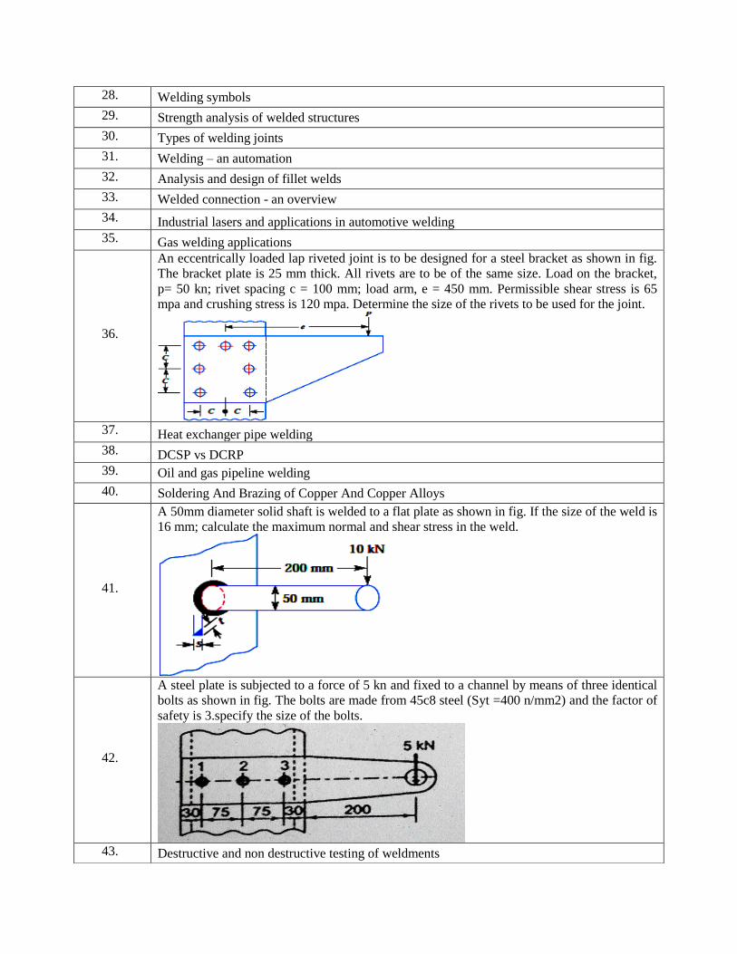
An eccentrically loaded lap riveted joint is to be designed for a steel bracket as shown in fig.
The bracket plate is 25 mm thick. All rivets are to be of the same size. Load on the bracket,
p= 50 kn; rivet spacing c = 100 mm; load arm, e = 450 mm. Permissible shear stress is 65
mpa and crushing stress is 120 mpa. Determine the size of the rivets to be used for the joint.
37. Heat exchanger pipe welding
38. DCSP vs DCRP
39. Oil and gas pipeline welding
40. Soldering And Brazing of Copper And Copper Alloys
41.
A 50mm diameter solid shaft is welded to a flat plate as shown in fig. If the size of the weld is
16 mm; calculate the maximum normal and shear stress in the weld.
42.
A steel plate is subjected to a force of 5 kn and fixed to a channel by means of three identical
bolts as shown in fig. The bolts are made from 45c8 steel (Syt =400 n/mm2) and the factor of
safety is 3.specify the size of the bolts.
43. Destructive and non destructive testing of weldments
44. History of welding
45. Safety measures in welding
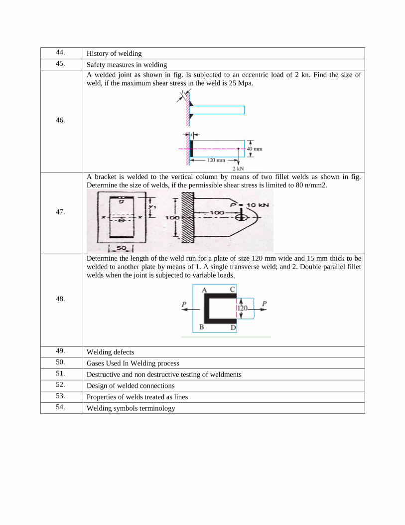
46.
A welded joint as shown in fig. Is subjected to an eccentric load of 2 kn. Find the size of
weld, if the maximum shear stress in the weld is 25 Mpa.
47.
A bracket is welded to the vertical column by means of two fillet welds as shown in fig.
Determine the size of welds, if the permissible shear stress is limited to 80 n/mm2.
48.
Determine the length of the weld run for a plate of size 120 mm wide and 15 mm thick to be
welded to another plate by means of 1. A single transverse weld; and 2. Double parallel fillet
welds when the joint is subjected to variable loads.
49. Welding defects
50. Gases Used In Welding process
51. Destructive and non destructive testing of weldments
52. Design of welded connections
53. Properties of welds treated as lines
54. Welding symbols terminology
V.S.B. ENGINEERING COLLEGE, KARUR
Department of Mechanical Engineering
Assignment Questions
Subject Code & Name : ME 8691 & Computer Aided Design and
Manufacturing Year/Semester & Branch : III Year / VI Semester & B.E. Mech Faculty Name : Dr.J.SELVAKUMAR
SL.
NO ASSIGNMENT DETAILS
1. What is Product Lifecycle Management (PLM)? Write a case study on implementing
PLM.
2. Explain the BIS conventions used for dimensioning a drawing.
3. Explain about various geometrical constraints used in sketching.
4. What do you mean by feature in CAD? Explain about feature manipulation.
5. Explain about the set of features available in AutoDesk inventor.
6. Write a case study on parametric modeling and design.
7. Explain the basic features available in CAD/CAM system with illustrations.
8. What is under defined, fully defined and over defined sketching? Explain your answers
with sketches?
9. Explain in detail about the layers in CAD/CAM system. Also give some example where
layering concept is useful.
10. Explain about grids in a CAD system. Also give some example where grid concept is
useful.
11. Give a list of ANSI symbols for form tolerance and explain them with examples.
12. Describe about tolerance practices in manufacturing.
13. Describe about tolerance modeling.
14. Explain about the various assembly constraints available in AutoDesk inventor.
15. What is Product Data Management (PDM)? Write a case study on implementing PDM.
16. Sketch a simple screw jack assembly, label the parts and generate the assembly tree for
that.
17. Sketch a simple pressure relief valve assembly, label the parts and generate the assembly
tree for that.
18. Sketch a simple plummer block assembly, label the parts and generate the assembly tree
for that.
19. Explain about the set of features available in SolidWorks.
20. Explain about the set of features available in CATIA.
21. Explain the working of Raster displays.
22. Write a case study on Assembly modeling.
23. Explain about the various assembly constraints available in SolidWorks.
24. Explain about the various assembly constraints available in CATIA.
25. Investigate the shading, lighting, shadows, texture and transperencies offered by any CAD
system that you are master with.
26. Compare and contrast the features available in any two popular CAD systems.
27. Explain Datum Features.
SL.
NO ASSIGNMENT DETAILS
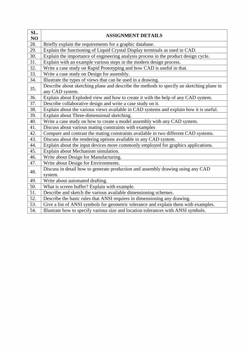
28. Briefly explain the requirements for a graphic database.
29. Explain the functioning of Liquid Crystal Display terminals as used in CAD.
30. Explain the importance of engineering analysis process in the product design cycle.
31. Explain with an example various steps in the modern design process.
32. Write a case study on Rapid Prototyping and how CAD is useful in that.
33. Write a case study on Design for assembly.
34. Illustrate the types of views that can be used in a drawing.
35. Describe about sketching plane and describe the methods to specify an sketching plane in
any CAD system.
36. Explain about Exploded view and how to create it with the help of any CAD system.
37. Describe collaborative design and write a case study on it.
38. Explain about the various views available in CAD systems and explain how it is useful.
39. Explain about Three-dimensional sketching.
40. Write a case study on how to create a model assembly with any CAD system.
41. Discuss about various mating constraints with examples
42. Compare and contrast the mating constraints available in two different CAD systems.
43. Discuss about the rendering options available in any CAD system.
44. Explain about the input devices more commonly employed for graphics applications.
45. Explain about Mechanism simulation.
46. Write about Design for Manufacturing.
47. Write about Design for Environments.
48. Discuss in detail how to generate production and assembly drawing using any CAD
system.
49. Write about automated drafting.
50. What is screen buffer? Explain with example.
51. Describe and sketch the various available dimensioning schemes.
52. Describe the basic rules that ANSI requires in dimensioning any drawing.
53. Give a list of ANSI symbols for geometric tolerance and explain them with examples.
54. Illustrate how to specify various size and location tolerances with ANSI symbols.
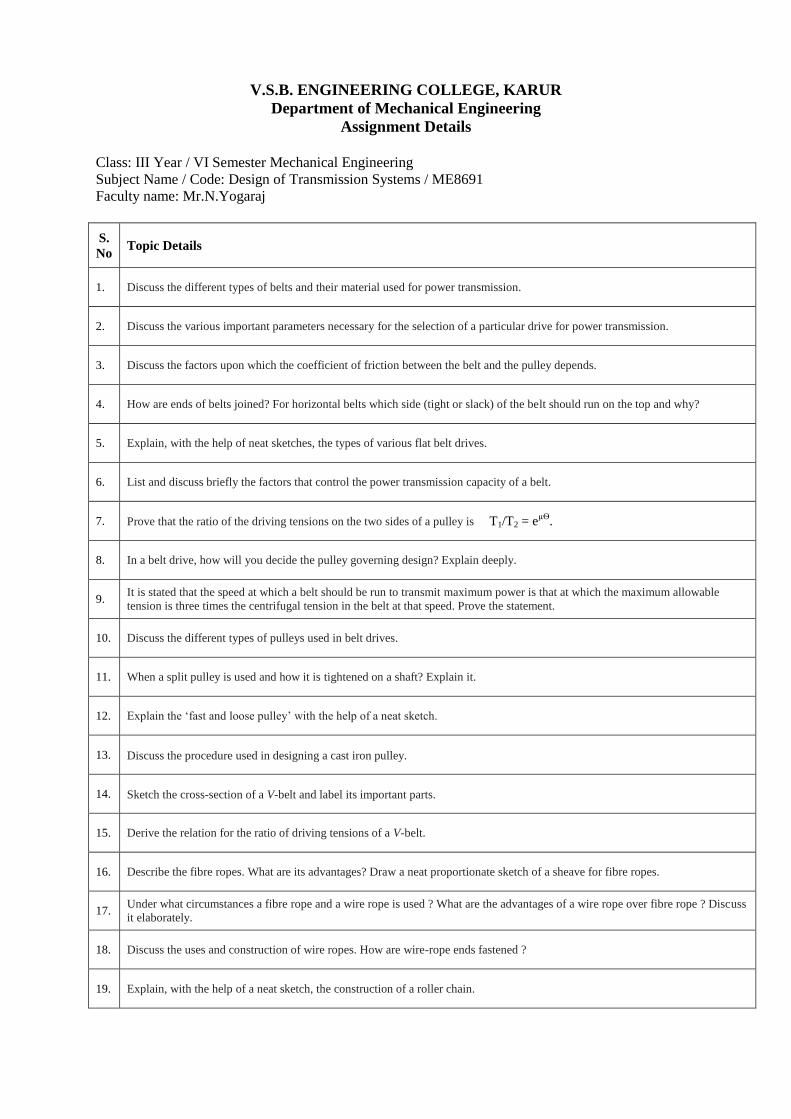
V.S.B. ENGINEERING COLLEGE, KARUR
Department of Mechanical Engineering
Assignment Details
Class: III Year / VI Semester Mechanical Engineering
Subject Name / Code: Design of Transmission Systems / ME8691
Faculty name: Mr.N.Yogaraj
S.
No Topic Details
1. Discuss the different types of belts and their material used for power transmission.
2. Discuss the various important parameters necessary for the selection of a particular drive for power transmission.
3. Discuss the factors upon which the coefficient of friction between the belt and the pulley depends.
4. How are ends of belts joined? For horizontal belts which side (tight or slack) of the belt should run on the top and why?
5. Explain, with the help of neat sketches, the types of various flat belt drives.
6. List and discuss briefly the factors that control the power transmission capacity of a belt.
7. Prove that the ratio of the driving tensions on the two sides of a pulley is T1/T2 = eµѲ
.
8. In a belt drive, how will you decide the pulley governing design? Explain deeply.
9. It is stated that the speed at which a belt should be run to transmit maximum power is that at which the maximum allowable
tension is three times the centrifugal tension in the belt at that speed. Prove the statement.
10. Discuss the different types of pulleys used in belt drives.
11. When a split pulley is used and how it is tightened on a shaft? Explain it.
12. Explain the ‘fast and loose pulley’ with the help of a neat sketch.
13. 1. Discuss the procedure used in designing a cast iron pulley.
14. 2. Sketch the cross-section of a V-belt and label its important parts.
15. Derive the relation for the ratio of driving tensions of a V-belt.
16. Describe the fibre ropes. What are its advantages? Draw a neat proportionate sketch of a sheave for fibre ropes.
17. Under what circumstances a fibre rope and a wire rope is used ? What are the advantages of a wire rope over fibre rope ? Discuss
it elaborately.
18. Discuss the uses and construction of wire ropes. How are wire-rope ends fastened ?
19. Explain, with the help of a neat sketch, the construction of a roller chain.
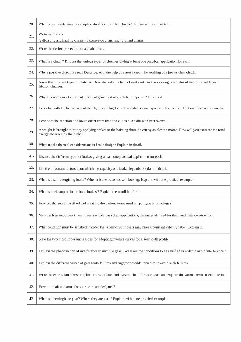
20. What do you understand by simplex, duplex and triplex chains? Explain with neat sketch.
21. Write in brief on
(a)Hoisting and hauling chains, (b)Conveyor chais, and (c)Silent chains.
22. Write the design procedure for a chain drive.
23. What is a clutch? Discuss the various types of clutches giving at least one practical application for each.
24. Why a positive clutch is used? Describe, with the help of a neat sketch, the working of a jaw or claw clutch.
25. Name the different types of clutches. Describe with the help of neat sketches the working principles of two different types of
friction clutches.
26. Why it is necessary to dissipate the heat generated when clutches operate? Explain it.
27. Describe, with the help of a neat sketch, a centrifugal clutch and deduce an expression for the total frictional torque transmitted.
28. How does the function of a brake differ from that of a clutch? Explain with neat sketch.
29. A weight is brought to rest by applying brakes to the hoisting drum driven by an electric motor. How will you estimate the total
energy absorbed by the brake?
30. What are the thermal considerations in brake design? Explain in detail.
31. Discuss the different types of brakes giving atleast one practical application for each.
32. List the important factors upon which the capacity of a brake depends. Explain in detail.
33. What is a self-energizing brake? When a brake becomes self-locking. Explain with one practical example.
34. 1. What is back stop action in band brakes ? Explain the condition for it.
35. How are the gears classified and what are the various terms used in spur gear terminology?
36. Mention four important types of gears and discuss their applications, the materials used for them and their construction.
37. What condition must be satisfied in order that a pair of spur gears may have a constant velocity ratio? Explain it.
38. State the two most important reasons for adopting involute curves for a gear tooth profile.
39. Explain the phenomenon of interference in involute gears. What are the conditions to be satisfied in order to avoid interference ?
40. Explain the different causes of gear tooth failures and suggest possible remedies to avoid such failures.
41. Write the expressions for static, limiting wear load and dynamic load for spur gears and explain the various terms used there in.
42. How the shaft and arms for spur gears are designed?
43. What is a herringbone gear? Where they are used? Explain with none practical example.
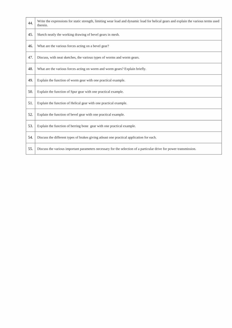
44. Write the expressions for static strength, limiting wear load and dynamic load for helical gears and explain the various terms used
therein.
45. Sketch neatly the working drawing of bevel gears in mesh.
46. What are the various forces acting on a bevel gear?
47. Discuss, with neat sketches, the various types of worms and worm gears.
48. What are the various forces acting on worm and worm gears? Explain briefly.
49. Explain the function of worm gear with one practical example.
50. Explain the function of Spur gear with one practical example.
51. Explain the function of Helical gear with one practical example.
52. Explain the function of bevel gear with one practical example.
53. Explain the function of herring bone gear with one practical example.
54. Discuss the different types of brakes giving atleast one practical application for each.
55. Discuss the various important parameters necessary for the selection of a particular drive for power transmission.
V.S.B. ENGINEERING COLLEGE, KARUR
Department of Mechanical Engineering
Assignment Questions
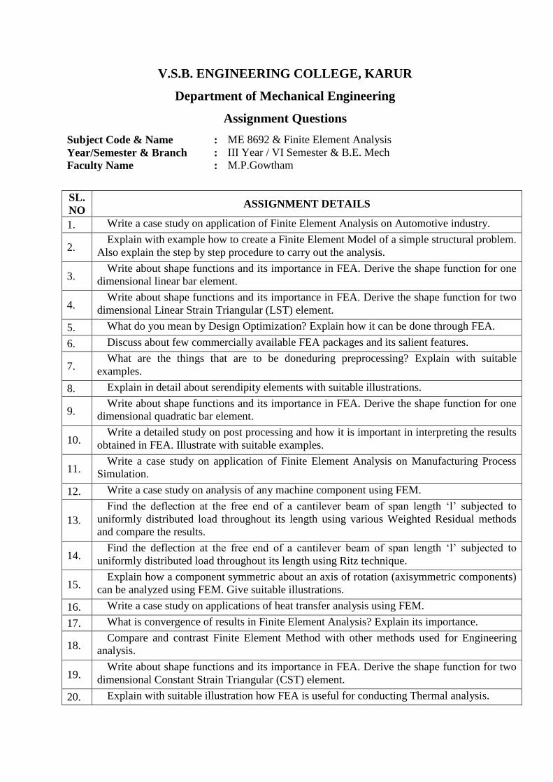
Subject Code & Name : ME 8692 & Finite Element Analysis Year/Semester & Branch : III Year / VI Semester & B.E. Mech Faculty Name : M.P.Gowtham
SL.
NO ASSIGNMENT DETAILS
1. Write a case study on application of Finite Element Analysis on Automotive industry.
2. Explain with example how to create a Finite Element Model of a simple structural problem.
Also explain the step by step procedure to carry out the analysis.
3. Write about shape functions and its importance in FEA. Derive the shape function for one
dimensional linear bar element.
4. Write about shape functions and its importance in FEA. Derive the shape function for two
dimensional Linear Strain Triangular (LST) element.
5. What do you mean by Design Optimization? Explain how it can be done through FEA.
6. Discuss about few commercially available FEA packages and its salient features.
7. What are the things that are to be doneduring preprocessing? Explain with suitable
examples.
8. Explain in detail about serendipity elements with suitable illustrations.
9. Write about shape functions and its importance in FEA. Derive the shape function for one
dimensional quadratic bar element.
10. Write a detailed study on post processing and how it is important in interpreting the results
obtained in FEA. Illustrate with suitable examples.
11. Write a case study on application of Finite Element Analysis on Manufacturing Process
Simulation.
12. Write a case study on analysis of any machine component using FEM.
13.
Find the deflection at the free end of a cantilever beam of span length ‘l’ subjected to
uniformly distributed load throughout its length using various Weighted Residual methods
and compare the results.
14. Find the deflection at the free end of a cantilever beam of span length ‘l’ subjected to
uniformly distributed load throughout its length using Ritz technique.
15. Explain how a component symmetric about an axis of rotation (axisymmetric components)
can be analyzed using FEM. Give suitable illustrations.
16. Write a case study on applications of heat transfer analysis using FEM.
17. What is convergence of results in Finite Element Analysis? Explain its importance.
18. Compare and contrast Finite Element Method with other methods used for Engineering
analysis.
19. Write about shape functions and its importance in FEA. Derive the shape function for two
dimensional Constant Strain Triangular (CST) element.
20. Explain with suitable illustration how FEA is useful for conducting Thermal analysis.
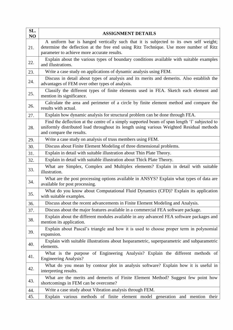
SL.
NO ASSIGNMENT DETAILS
21.
A uniform bar is hanged vertically such that it is subjected to its own self weight;
determine the deflection at the free end using Ritz Technique. Use more number of Ritz
parameter to achieve more accurate results.
22. Explain about the various types of boundary conditions available with suitable examples
and illustrations.
23. Write a case study on applications of dynamic analysis using FEM.
24. Discuss in detail about types of analysis and its merits and demerits. Also establish the
advantages of FEM over other types of analysis.
25. Classify the different types of finite elements used in FEA. Sketch each element and
mention its significance.
26. Calculate the area and perimeter of a circle by finite element method and compare the
results with actual.
27. Explain how dynamic analysis for structural problem can be done through FEA.
28.
Find the deflection at the centre of a simply supported beam of span length ‘l’ subjected to
uniformly distributed load throughout its length using various Weighted Residual methods
and compare the results.
29. Write a case study on analysis of truss members using FEM.
30. Discuss about Finite Element Modeling of three dimensional problems.
31. Explain in detail with suitable illustration about Thin Plate Theory.
32. Explain in detail with suitable illustration about Thick Plate Theory.
33. What are Simplex, Complex and Multiplex elements? Explain in detail with suitable
illustration.
34. What are the post processing options available in ANSYS? Explain what types of data are
available for post processing.
35. What do you know about Computational Fluid Dynamics (CFD)? Explain its application
with suitable examples.
36. Discuss about the recent advancements in Finite Element Modeling and Analysis.
37. Discuss about the major features available in a commercial FEA software package.
38. Explain about the different modules available in any advanced FEA software packages and
mention its application.
39. Explain about Pascal’s triangle and how it is used to choose proper term in polynomial
expansion.
40. Explain with suitable illustrations about Isoparametric, superparametric and subparametric
elements.
41. What is the purpose of Engineering Analysis? Explain the different methods of
Engineering Analysis?
42. What do you mean by contour plot in analysis software? Explain how it is useful in
interpreting results.
43. What are the merits and demerits of Finite Element Method? Suggest few point how
shortcomings in FEM can be overcome?
44. Write a case study about Vibration analysis through FEM.
45. Explain various methods of finite element model generation and mention their
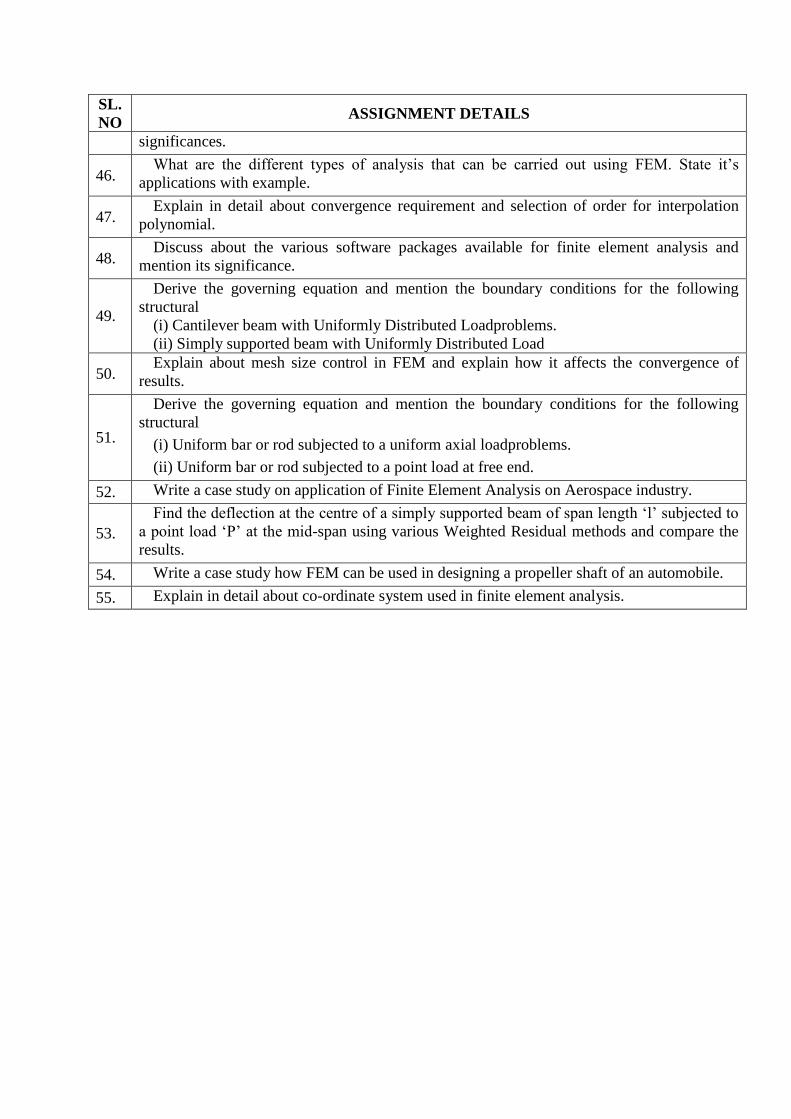
SL.
NO ASSIGNMENT DETAILS
significances.
46. What are the different types of analysis that can be carried out using FEM. State it’s
applications with example.
47. Explain in detail about convergence requirement and selection of order for interpolation
polynomial.
48. Discuss about the various software packages available for finite element analysis and
mention its significance.
49.
Derive the governing equation and mention the boundary conditions for the following
structural
(i) Cantilever beam with Uniformly Distributed Loadproblems.
(ii) Simply supported beam with Uniformly Distributed Load
50. Explain about mesh size control in FEM and explain how it affects the convergence of
results.
51.
Derive the governing equation and mention the boundary conditions for the following
structural
(i) Uniform bar or rod subjected to a uniform axial loadproblems.
(ii) Uniform bar or rod subjected to a point load at free end.
52. Write a case study on application of Finite Element Analysis on Aerospace industry.
53.
Find the deflection at the centre of a simply supported beam of span length ‘l’ subjected to
a point load ‘P’ at the mid-span using various Weighted Residual methods and compare the
results.
54. Write a case study how FEM can be used in designing a propeller shaft of an automobile.
55. Explain in detail about co-ordinate system used in finite element analysis.
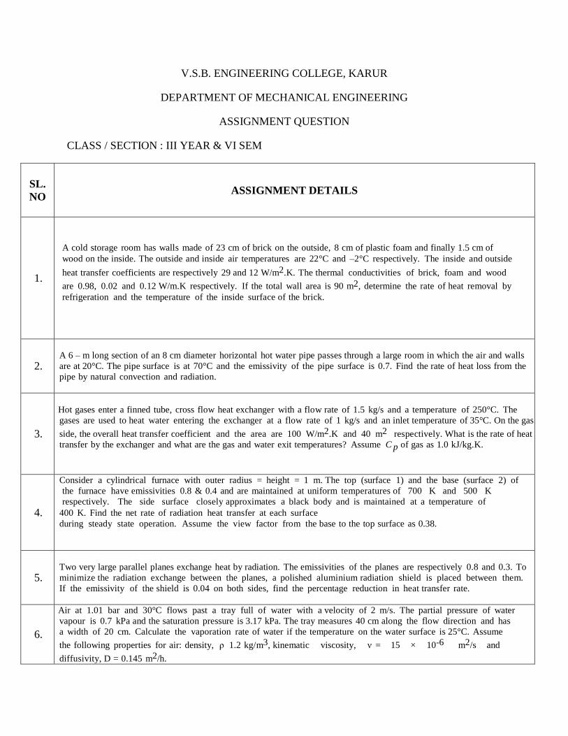
V.S.B. ENGINEERING COLLEGE, KARUR
DEPARTMENT OF MECHANICAL ENGINEERING
ASSIGNMENT QUESTION
CLASS / SECTION : III YEAR & VI SEM
SL.
NO ASSIGNMENT DETAILS
1.
A cold storage room has walls made of 23 cm of brick on the outside, 8 cm of plastic foam and finally 1.5 cm of
wood on the inside. The outside and inside air temperatures are 22°C and –2°C respectively. The inside and outside
heat transfer coefficients are respectively 29 and 12 W/m2.K. The thermal conductivities of brick, foam and wood
are 0.98, 0.02 and 0.12 W/m.K respectively. If the total wall area is 90 m2, determine the rate of heat removal by
refrigeration and the temperature of the inside surface of the brick.
2. A 6 – m long section of an 8 cm diameter horizontal hot water pipe passes through a large room in which the air and walls
are at 20°C. The pipe surface is at 70°C and the emissivity of the pipe surface is 0.7. Find the rate of heat loss from the
pipe by natural convection and radiation.
3.
Hot gases enter a finned tube, cross flow heat exchanger with a flow rate of 1.5 kg/s and a temperature of 250°C. The
gases are used to heat water entering the exchanger at a flow rate of 1 kg/s and an inlet temperature of 35°C. On the gas
side, the overall heat transfer coefficient and the area are 100 W/m2.K and 40 m2 respectively. What is the rate of heat
transfer by the exchanger and what are the gas and water exit temperatures? Assume C p of gas as 1.0 kJ/kg.K.
4.
Consider a cylindrical furnace with outer radius = height = 1 m. The top (surface 1) and the base (surface 2) of
the furnace have emissivities 0.8 & 0.4 and are maintained at uniform temperatures of 700 K and 500 K
respectively. The side surface closely approximates a black body and is maintained at a temperature of
400 K. Find the net rate of radiation heat transfer at each surface
during steady state operation. Assume the view factor from the base to the top surface as 0.38.
5. Two very large parallel planes exchange heat by radiation. The emissivities of the planes are respectively 0.8 and 0.3. To
minimize the radiation exchange between the planes, a polished aluminium radiation shield is placed between them.
If the emissivity of the shield is 0.04 on both sides, find the percentage reduction in heat transfer rate.
6.
Air at 1.01 bar and 30°C flows past a tray full of water with a velocity of 2 m/s. The partial pressure of water
vapour is 0.7 kPa and the saturation pressure is 3.17 kPa. The tray measures 40 cm along the flow direction and has
a width of 20 cm. Calculate the vaporation rate of water if the temperature on the water surface is 25°C. Assume
the following properties for air: density, ρ 1.2 kg/m3, kinematic viscosity, ν = 15 × 10-6 m2/s and
diffusivity, D = 0.145 m2/h.
SL.
NO ASSIGNMENT DETAILS
7.
A steel rod of diameter 12 mm and 60 mm long with an insulated end that has a thermal conductivity of 32 W/(m.°C)
is to be used as a spine. It is exposed to surroundings with a temperature of 60°C and a heat transfer coefficient of 55
W/(m2.°C). The temperature at the base of the fin is 95°C. Calculate the fin efficiency, the temperature at the
edge of the spine and the heat dissipation.
8.
A 60 mm thick large steel plate [k = 42.6 W/m.°C), α = 0.043 m2/h] initially at 440°C is suddenly exposed on
both sides to an ambient with convective heat transfer coefficient 235 W/(m2.°C) and temperature 50°C. Determine
the centre line temperature and the temperature inside the plate 15 mm from the mid plane after
4.3 minutes.
9.
Air is flowing over a flat plate 5 m long and 2.5 m wide with a velocity of 4 m/s at 15°C. If ρ = 1.208 kg/m3
and υ = 1.47 × 10⁻⁵ m2/s, calculate the length of plate over which the boundary layer is laminar and thickness
of the boundary layer (laminar), shear stress at the location where boundary layer ceases to be laminar and the total
drag force on the both sides on that portion of the plate where boundary layer is laminar.
10.
The flow rates of hot and cold water streams running through a parallel flow heat exchanger are 0.2 kg/s and 0.5 kg/s
respectively. The inlet temperatures on the hot and cold sides are 75°C and 25°C respectively. The exit temperature of
hot water is 45°C. If the individual heat transfer coefficients on both sides are 650 W/m°C, calculate the area of the
heat exchanger.
11.
Calculate the following for an industrial furnace in the form of a black body and emitting radiation at 2500 °C 1)
Monochromatic emissive power at 1.2 µ m length (2) Wavelength at which the emission is maximum (3) Maximum
emissive power (4) Total emissive power
(5) Total emissive power of the furnace if it is assumed as a real surface with emissivity is equal to 0.7
12. Calculate the net radiant heat exchange per m2 area for two large parallel plates at temperatures of 427°C and 27°C
respectively. The emissivity of hot and cold plate is 0.9 and 0.6 respectively. If a polished aluminum shield is placed
between them, find the percentage reduction in the heat transfer. The emissivity of shield is 0.4.
13. The radiation shape factor of the circular surface of a thin hollow cylinder of 10 cm diameter and 10 cm length is 0.1716.
What is the shape factor of the curved surface of the cylinder with respect to itself?
14. A vessel contains binary mixture of O2 and N2 with partial pressures in the ratio 0.21 and 0.79 at 15°C. The total pressure of the mixture is 1.1 bar. Calculate the following : (1) Molar concentrations, (2) Mass densities,(3) Mass
fractions and (4) Molar fractions of each species.
15.
A composite wall consists of 2.5 cm thick Copper plate, a 3.2 cm layer of asbestos insulation and a 5 cm
layer fibre plate. Thermal conductivities of the materials are respectively 355, 0.110 and 0.0489 W/m.K. The
temperature difference across the composite wall is 560°C (560°C on one side and 0°C on the other side. Find the
heat flow through the wall per unit area and the interface temperature between asbestos and fiber plate.
SL.
NO ASSIGNMENT DETAILS
16. Air at 20°C at 3m/s flows over a thin plate of 2m long and 1m wide. Estimate the boundary layer thickness at the trailing edge, total drag force ν
6 3 .
17. Two large parallel plates of 1m×1m spaced 0.5m apart in a very large room whose walls are at 27°C. The plates are at 900°C and 400°C with emissivities 0.2 and 0.5 respectively. Find the net heat transfer to each plate and to the room.
18. The temperature recorded by a thermometer whose bulb covered by a
wet wick in dry air at atmospheric pressure is 22°C. Estimate the true air
temperature.
19. Dry air at 27°C and 1 bar flows over a wet plate of 50cm at 50m/s.
Calculate the mass transfer coefficient of water vapour in air at the end of
the plate.
20. Assuming the sun to be a black body emitting radiation with maximum intensity at λ=0.49µm, calculate (i) the surface
temperature of the sun, (ii) the heat flux at surface of the sun.
21.
Calculate the following for an industrial furnace in the form of a black body and emitting radiation at 2500 ºC. (i)
Monochromatic emissive power at 1.2 µm length, (ii) Wavelength at which emission is maximum, (iii) Maximum emissive
power, (iv) Total emissive power & (v) Total emissive power of the furnace if it is assumed as a real surface with emissivity
equal to 0.9.
22.
A 70 mm thick metal plate with a circular hole of 35 mm diameter along the thickness is maintained at a uniform temperature
250 ºC. Find the loss of energy to the surroundings at 27 ºC; assuming the two ends of the hole to be as parallel discs and the
metallic surfaces as shown in the fig. given below and surroundings have black body characteristics.
23. Derive an expression of heat transfer between two non black bodies having infinite parallel planes.
24. A refractory material which has emissivity as 0.4 at 1500 K and emissivity at 1420 K is exposed to black furnace walls at
1500 K. What is the rate of gain of heat radiation per m2 area?
25. Calculate the net radiant heat exchange per m
2 area for two large parallel plates at temperatures of 427 ºC and 27 ºC
respectively. Take ε (hot plate) = 0.9 and ε (hot plate) = 0.6. If a polished aluminum shield is placed between them, find the
percentage reduction in the heat transfer. Take ε (shield) = 0.4.
SL.
NO ASSIGNMENT DETAILS
26. Explain the terms solar radiation and green house effect.
27.
A cylindrical body of 300 mm diameter and 1.6 m height is maintained at a constant temperature of 36.5 ºC. The surrounding
temperature is 13.5 ºC. Find out the amount of heat t be generated by the body per hour if ρ = 1.025 kg/m3, cp = 0.96 kJ/kg ºC,
ν = 15.06 × 10⁻⁶
m2/s. k= 0.0892 kJ/m-h- ºC and β = 1/ 298 K
-1, Assume Nu = 0.12 (Gr.Pr)
1/3.
28. Explain Reynolds analogy for forced convection.
29.
Air at 20 ºC and at a pressure of 1 bar is flowing over a flat plate at a velocity of 3 m/s. The plate is 280 mm wide and 280
mm in length and maintained at 56 ºC. The properties of air at bulk mean temperature are given as: ρ = 1.1374 kg/m3, k =
0.02732 W/m ºC, cp= 1.005 kJ/kgK, ν = 16.768 × 10⁻⁶
m2/s, Pr = 0.7. Determine: (a) Flow is laminar or turbulent, (b)
Boundary layer thickness, (c) Thermal boundary layer thickness, (d) Local convective heat transfer coefficient, (e) Average
convective heat transfer coefficient, (f) Rate of heat transfer by convection, (g) Local friction coefficient, (h) Average friction
coefficient.
30.
A 50 cm × 50 cm copper slab 6.25 mm thick has a uniform temperature of 300 ºC. Its temperature is suddenly lowered to 36
ºC. Calculate the time required for the plate to reach the temperature of 108 ºC. Take ρ = 9000 kg/m3, c = 0.38 kJ/kg ºC, k =
370 W/m ºC and h = 90 W/m2 ºC.
31.
Define a fin and also obtained the expression for temperature distribution and heat flow rate in a rectangular fin. Calculate the
amount of energy required to solder two very long pieces of bare copper wire 1.625 mm in diameter with solder that melts at
195 ºC. The wires are positioned vertically in air at 24 ºC. Assume the heat transfer coefficient on the wire surface is 17 W/m2
ºC and thermal conductivity of wire alloy is 335W/m ºC.
32.
Define critical thickness of radius and derive an expression for critical thickness of radius for a sphere. A wire of 6.5 mm
diameter at a temperature of 60 ºC is to be insulated by a material having k = 0.174 W/m ºC. Convection heat transfer
coefficient (h0) = 8.722 W/m2 ºC. The ambient temperature is 20 ºC. For maximum heat loss, what is the minimum thickness
of insulation and heat loss per meter loss? Also find percentage increase in heat dissipation.
33.
A steam pipe of 160 mm inside diameter and 5 mm thick having k = 58 W/m ºC is covered with first layer of insulating
material 30 mm thick having k = 0.17 W/m ºC and second layer of insulating material 50 mm thick having k = 0.093 W/m ºC.
The temperature of the steam passing through the pipe is 300 ºC and ambient air temperature surrounding the pipe is 30 ºC.
Taking inner and outer heat transfer coefficients 30 and 5.8 W/m2 ºC respectively, find the heat lost per meter length of pipe.
34.
An exterior wall of a house may be approximated by a 0.1 m layer of common brick (k = 0.7 W/m ºC) followed by a 0.04m
layer of gypsum plaster (k = 0.48 W/m ºC).What thickness of loosely packed rock wool insulation (k = 0.065 W/m ºC) should
be added to reduce the heat loss or (gain) through the wall by 80 percent?
35.
The temperatures at the inner and outer surfaces of a boiler wall made of 20 mm thick steel and covered with an insulating
material of 5 mm thickness are 300 ºC and 50 ºC respectively. If the thermal conductivities of steel and insulating material are
58 W/m ºC and 0.116 W/m ºC respectively, determine the rate of heat flow through the boiler wall.
36. Obtain an expression for general heat conduction equation in polar coordinates.
SL.
NO ASSIGNMENT DETAILS
37. Explain Reynolds analogy for forced convection
38. Explain the mechanism of forced convection and free convection.
39. Derive Von Karman integral momentum equation.
40. Explain the boundary layer over a flat plate with neat sketch.\
41. Derive an expression of the rate of heat transfer for Lumped capacitance method.
42. Define efficiency and effectiveness of the fin and developed a relation between them.
43. Write a brief note on radiation exposure from sun and the various spectral properties included in it.
44. With a practical study compare the effectiveness of conventional and modern heat exchangers.
45.
(i). Derive the relation for heat exchange between infinite parallel planes. (ii). Consider double walls as two infinite parallel
planes. The emissivity of the walls is 0.3 and 0.8 respectively. The space between the walls is evacuated. Find the heat
transfer per unit area when inner and outer surface temperature is 300 K and 260 K. To reduce the heat flow, a shield of
polished aluminium of emissivity 0.05 is inserted between the walls. Find the reduction in heat transfer. (May/June 2014)
46.
In a counter flow heat exchanger, water at 20oC flowing at the rate of 520 kg/hr. It is heated by oil of specific heat 2100 J/kgK
flowing at the rate of 520 kg/hr at inlet temp of 45OC. Determine the following,
(i) Total heat transfer
(ii) Outlet temperature of water
(iii) Outlet temperature of oil.
Take, overall heat transfer co-efficient is 1000W/m2K and heat exchanger area as 1 m
2.
47. Hot exhaust gases which enter a cross flow heat exchangers at 300ºC and leaves at 100ºC is used to heat water at flow rate of
1kg/s from 35ºC to 125ºC. The specific heat of gas is 1 kJ/kgK and the overall heat transfer coefficient based on the gas side
surface is 100 W/m2K. Find the required area using LMTD and NTU method.
48. What is a black body? A 20cm diameter spherical ball at 527
o C is suspended in the air. The ball closely approximates a black
body. Determine the total blackbody emissive power and spectral back body emissive power at a wavelength of 3 µm.
(May/June 2013)
49. Discuss briefly the pool boiling regimes of water at atmospheric pressure.
SL.
NO ASSIGNMENT DETAILS
50. Derive a general heat conduction equation for a hollow cylinder.
51. Draw the velocity and temperature profiles for free convection on a hot vertical plate.
52.
Define mass transfer coefficient. Air at 1 bar pressure and 250C containing small quanties of iodine flows with a velocity of
5.2 m/s. inside a tube having an inner diameter of 3.05 cm. Find the mass transfer coefficient for iodine from the gas stream to
the wall surface. If Cm is the mean concentration of iodine in Kg. mole/ m3 in the air stream, find the rate of deposition of
iodine on the tube surface by assuming surface is a perfect for iodine deposition. Assume D= .0843 cm2/s.
53. Write the expression for isothermal evaporation of water into gas with a neat sketch
(ii) Air at 350 C and 1 atmosphere flows at a velocity of 60 m/s over (i) flat plate 0.5 m long (ii) a sphere 5 cm in diameter.
Calculate the mass transfer coefficient of water in air. Neglect the concentration of vapour in air.
54. Derive a general heat conduction equation for a hollow cylinder.

V.S.B. ENGINEERING COLLEGE, KARUR Department of Mechanical Engineering
Assignment Details
Class: III Year/ VI Semester Mechanical Engineering
Subject Name/Code: Hydraulics and Pneumatics / ME8694
Faculty name: Mr.N.Kannan
S.
No Topic Details
1.
Examine the diagram of a simple hydraulic jack. Piston A is pushed down by a weight and piston B
is pushed up raising another weight.
1.a. Which moves the most A or B? _________________
1.b. Which is the heaviest weight A or B? _______________
2.
The diagram shows a simple jack. Write down what happens to NRV1, NRV 2 and piston 2 when
piston 1 is pushed in (the answer is either open or shut in each case).
NRV 1_______________ NRV 2_______________ Piston 2___________________
Write down what happens when piston 1 is pulled out.
NRV 1_______________ NRV 2_______________ Piston 2___________________
What is the purpose of the oil release valve?
___________________________________________________________________________
3.
Study the simple hydraulic system shown below and fill in the answers to the questions.
With the valve in the position shown, which way is the cylinder piston moving, UP or DOWN?
______________________________
4.
Study the simple hydraulic system shown below and fill in the answers to the questions.
With the valve in the position shown, which way is the cylinder piston moving, UP or DOWN?
______________________________
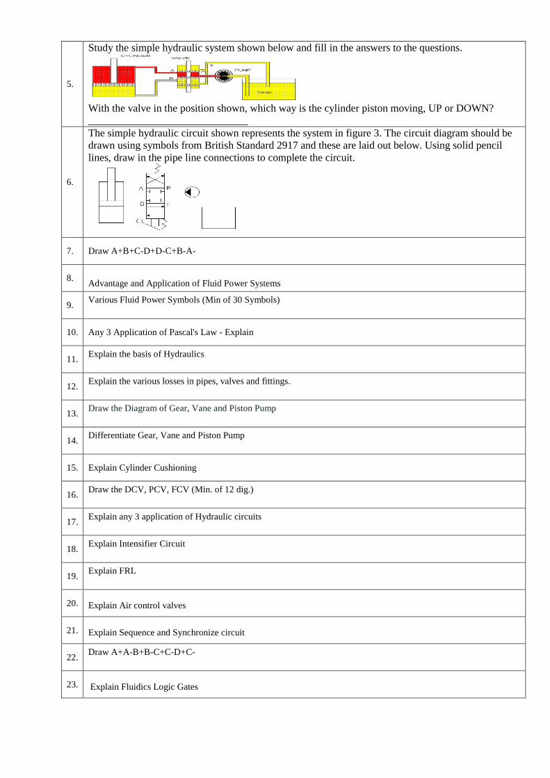
5.
Study the simple hydraulic system shown below and fill in the answers to the questions.
With the valve in the position shown, which way is the cylinder piston moving, UP or DOWN?
______________________________
6.
The simple hydraulic circuit shown represents the system in figure 3. The circuit diagram should be
drawn using symbols from British Standard 2917 and these are laid out below. Using solid pencil
lines, draw in the pipe line connections to complete the circuit.
7. Draw A+B+C-D+D-C+B-A-
8.
Advantage and Application of Fluid Power Systems
9. Various Fluid Power Symbols (Min of 30 Symbols)
10. Any 3 Application of Pascal's Law - Explain
11. Explain the basis of Hydraulics
12. Explain the various losses in pipes, valves and fittings.
13. 1. Draw the Diagram of Gear, Vane and Piston Pump
2.
14. 3. Differentiate Gear, Vane and Piston Pump
4.
15. Explain Cylinder Cushioning
16. Draw the DCV, PCV, FCV (Min. of 12 dig.)
17. 1. Explain any 3 application of Hydraulic circuits
2.
18. Explain Intensifier Circuit
19. Explain FRL
20. Explain Air control valves
21. Explain Sequence and Synchronize circuit
22. Draw A+A-B+B-C+C-D+C-
23. Explain Fluidics Logic Gates
24. Explain ladder Diagram
25. Draw A+B+C+D+D-C-B-A-
26. Explain Low Cost Automation
27. How to differentiate the various fluid power symbols
28. Explain the Functions of the hydraulic components.
29. Darcy's Equation – derivation, equation and its application.
30. Various connecting devices in the Hydraulic Circuits
31. Effects of leakage and losses of oil
32. Effects due to losses in Fittings
33. Basics of Pumping Theory
34. 3. Working Procedure of the Rotary and reciprocating pumps
35. Efficiency calculation of the various gear pumps
36. Efficiency calculation of the various vane pumps
37. Merits and demerits of the various types of the vane pumps.
38. Application of the Piston pump.
39. Brief Explanation on the various types of the Piston pumps and its operating principle.
40. Merits and demerits of the Variable displacement
41. Application of the hydraulic actuators
42. Single Acting Cylinder and its performance measurements.
43. Double acting Cylinder and its performance measurements
44. Various types of special cylinders and its applications.
45. Gear actuator and its various types.
46. Piston actuator and its Various types.
47. Rotary Actuators – types and its various applications.

48. Pressure Control valve and its applications.
Working principle of the PCV.
49. Ladder diagram and its applications.
50. Various electrical control valves based on applications.
51. Operating principle of intensifier.
52. Intensifier – application circuits
53. Construction and working principle of Filter, Regulator and Lubricator.
54. Air control valves and its application circuits.