
II - BP - Pivot Stove
24
® Operating & Installation Instructions AUSTRALIA II - BP
-
Upload
khangminh22 -
Category
Documents
-
view
3 -
download
0
Transcript of II - BP - Pivot Stove

®
Operating & Installation Instructions
AUSTRALIA
II - BP


CONTENT SQUICK GUIDE 4
OPERATING INSTRUCTIONS 5
FUEL 5
LIGHTING 5
CONTROLLING THE FIRE 5
WOOD ASH REMOVAL GRATE 6
RIDDLING 6
REFUELLING 6
ASH CLEARANCE 7
REDUCED BURNING 7
MAINTENANCE 7
BAFFLE AND FLUE CLEANING 7
FLUE SWEEPING 8
TROUBLE SHOOTING 8
IF YOU NEED FURTHER HELP 9
INSTALLATION INSTRUCTIONS 10
UNPACKING THE STOVE 10
HEALTH AND SAFETY PRECAUTIONS 10
FLUE 10
HEARTH AND FIRE SURROUND 10
CONNECTIONS TO FLUES 11
PRE LIGHTING CHECK 11
COMMISSIONING 11
COOKING PLATE 11
CLEARANCES 12
STANDARD HEARTH DIMENSIONS 13
CORNER HEARTH DIMENSIONS 14
FLUE CLEARANCES DIAGRAM 15
STANDARD DEFAULT TRIPLE SKIN FLUE KIT 16
INSULATED ROOM SEAL FLUE KIT 17
INSULATED ROOM SEAL FLUE KIT 18
INSULATED ROOM SEAL FLUE KIT 19
COMPLIANCE DATA 20
ISLAND II - BP DIMENSIONS 21
ISLAND II - BP PARTS LIST 22
CHARNWOOD AUSTRALIA 10 YEAR GUARANTEE 23
Ref.island ii - bp aus v1 12.20

®
QUICK GUIDE
BaffleImproves efficiency of stove by slowing down flue gases
DoorsKeep closed when stove is in use
Door handle
Turn clockwise to open
Riddler knobUse operating tool to riddle
Fuel retainer
Ensure fuel does not protrude beyond retainer
Suitable fuels for your
Charnwood:
Wood logs
Unsuitable fuels:
Petroleum coke
Liquid fuel
Household waste
Coal singles
Small nuts or coal dust
Wet or unseasoned wood
Smokeless mineral fuel
LIGHTING AND CONTROLLING THE FIRE
Add kindling and paper or
firelighters. Keep air control
fully out and door cracked
open.
Once kindling is alight, add
smaller logs. Keep air control
fully out and close door.
Add larger logs once fire is
established. Air control can
be reduced to minimum.
MAINTENANCE AND CLEANING
GLASSWipe with damp, lint free cloth. Any stubborn deposits on the glass may be removed with a proprietary stove glass cleaner or ceramic hob cleaner.
BAFFLE PLATE Take down once a month and clean. Sweep sooty deposits into fire
FLUE Have flue swept anually. Flue can be swept through stove.
SERVICING Stove should be serviced by a professional at least once a year.AIR CONTROL
Boost Nominal
High Output
Low Output

5
®OPERATING INSTRUCTIONS
Congratulations on becoming the owner of a Charnwood Island
Stove. Your stove has been approved to burn wood logs if it is used
in accordance with these instructions. It is very important that you
read and understand these instructions before using the stove.
Before lighting the stove check with the installer that the work and
checks described in the Installation Instructions have been carried
out correctly and that the flue has been swept, is sound and free
from any obstructions. The stove is not suitable for use in a shared
flue system.
This stove will not produce significant smoke if well seasoned logs
of less than 20% moisture content are burnt and these instructions
are adhered to. Burning wet (>20% moisture content) wood and
operating the stove in an irresponsible manner may produce smoke
which is illegal in smoke controlled areas.
Remember that the stove will be hot and that it is made from hard
materials – ensure that you have good balance before operating the
fire. Always use the provided operating tool and gloves.
Do not use an aerosol spray on or near the stove when it is alight.
There is a risk of explosion or flash ignition of the spray.
When using the stove in situations where children, aged and/or
infirm persons are present a fireguard must be used to prevent
accidental contact with the stove.
The stove is suitable for intermittent operation.
FUEL
This stove has been designated to burn wood. Only dry well seasoned
wood should be burnt on this appliance as burning wet unseasoned
wood will give rise to heavy tar deposits in the stove, on the glass
and within the flue. Burning wet unseasoned wood will also result in
considerably reduced outputs. The wood should be cut and split and
then left to season in a well ventilated dry place for at least one year
but preferably two years before use.
Approximate suitable log sizes are:
Island II - BP : 440mm(15in) long and 75mm (3in) diameter
Log moisture content of less than 20% is recommended.
PETROLEUM COKE IS NOT SUITABLE FOR USE ON THIS
APPLIANCE. ITS USE WILL INVALIDATE THE GUARANTEE.
This stove is not designed to burn household waste.
LIGHTING
On initial lighting, the stove may smoke and give off an odour as the
silicon paint with which the firebox is painted reacts to the heat. This
is normal and will cease after a short time, but meanwhile the room
should be kept well ventilated.
At first only light a small fire and burn it slowly for two hours to allow
any residual moisture in the flue to evaporate.
Light the stove using dry kindling wood and paper or fire lighters.
Put the paper, or fire lighters, and kindling in the firebox and cover
with a few small dry logs. Open the air control fully (see Fig. 1) Light
the paper or fire lighters. The door may be left cracked open for a
few minutes to assist the combustion and heat up the firebox more
quickly. When the kindling wood is well alight add a few more small
logs, close the door but leave the air control fully open. When the
flames are established around these logs, load the stove with the
required fuel load. Maintain the air control at maximum at this stage.
Once the fire is up to temperature the airwash system will begin to
work, so allow the fire to become hot before adjusting the air control
to the required setting. During the lighting period, do not leave the
stove unattended. Do not leave the door open except as directed
above to avoid excessive smoke.
When relighting the stove, leave the ash on the base, unless it is
becoming too deep, in which case some of it may be removed.
CONTROLLING THE FIRE
The rate of burning and hence the output is controlled by the air
control (see Fig.1)
Open the air control fully (boost position) when lighting or when
rapid burning is required. It should not be left fully open for long
periods as this can cause over-firing or excessive smoke production.
For high output move the air control to the ‘click position’ or for low
burning to the fully closed position.
When the fire is burning normally the air control gives enough
airwash to keep the glass clean. However, it will not always be
possible to keep the glass clean with the air control fully closed. For
correct firing we recommend the use of a stove pipe thermometer
which may be purchased from your supplier or from Charnwood.
The Charnwood Island II - BP is fitted with an air control stop. This
stops the stove from burning too slowly.

6
®
OPERATING INSTRUCTIONS
Fig. 1 Stove controls
WOOD ASH REMOVAL GRATE
Your Charnwood Island II - BP is fitted with a wood ash removal
grate to enable wood to be burned and ash to be cleared. The grate
has two positions:
1) In the open position the grate bars are vertical with gaps in
between allowing the primary combustion air to come up through
the grate and through the fuel bed.
2) In the closed position the grate bars are horizontal, allowing the
combustion air to come round the sides of the grate and over the top
of it. When in the closed position ash is able to build up on the grate
as is necessary for effective wood burning.
Movement of the grate from one position to the other is effected
using the operation tool supplied as shown in Fig.3.
The grate is put into the open position by turning the operation tool
anticlockwise. The grate is put into the closed position by turning
the operation tool clockwise. When burning wood ensure that the
selector slider is pushed fully back (Fig.2) To riddle the appliance
the tool should be moved between the clockwise and anticlockwise
positions several times. When burning wood the ash should be
allowed to build up and riddling should only be carried out once or
twice a week.
Fig 2. Operating the wood ash removal grate
RIDDLING
When burning wood, ash should be allowed to build up and only
riddled when the ash begins to cover the rear fireplate. The fire
should be riddled with the door shut (see Fig.2). Place the operating
tool onto the riddling lever and rotate between the open and closed
positions several times. Too much riddling can result in emptying
unburnt fuel into the ashpan and should therefore be avoided. After
riddling, the grate should be put back into the closed position for
burning wood.
Fig 3. Riddling tool
REFUELLING
Keep the firebox well filled but do not allow fuel to spill over the top
of the fuel retainer.
Logs should be evenly distributed, filling the firebed to give the most
pleasing flame pattern. The air control must be fully opened after
refuelling until the flames are established above the fire. It is best to
refuel on to a hot bed of embers. If at this point the fire starts to die,
the door must be cracked open until the fire is revived. If the fire has
started to die down before refuelling, then more kindling wood must
Identification Plate, lift to view
Riddler KnobTurn the door handle clockwise to open, and anti-clockwiseto close.
AIR CONTROLPull out to open, push in to close.1. Low Output2. Nominal 3. High Output4. Boost
4 3 2 1
Selector SliderEnsure this is pushed in fully when burning wood.
Closed
Open
Closed
Open

7
®OPERATING INSTRUCTIONS
be added, the air control opened fully and the door cracked open
to re-establish the firebed before adding larger logs (see suitable log
sizes in Fuel section). This will avoid excessive smoke emission.
Care should be taken, especially when burning wood, that fuel does
not project over the fuel retainer or damage to the glass may be
caused when the door is closed. It can also cause the glass to blacken
up. Maximum filling height is such that logs cannot fall from the fire
when the door is opened and does not come above the level of the
air holes in back bricks.
Do not operate with the door open except as directed by the
instructions as this can cause excessive smoke.
ASH CLEARANCE
Before removing ash ensure that it has cooled down. The ashpan
slides out for easy ash removal.
To make ash removal easier there are ash carriers available. These
may be purchased from your supplier or, in case of difficulty, from
Charnwood.
Fig.4 Ashpan
REDUCED BURNING
For reduced burning the fire door must be closed.
When burning wood in areas that are not smoke controlled, load
some large logs on the fire and allow to burn for half an hour before
closing the air control (this will help to reduce tar deposits in the
flue). Some experimentation may be necessary to find the setting
most suitable for the type of fuel being used and the draw on the flue.
MAINTENANCE
Cleaning
The stove is finished with a high temperature paint which will
withstand the temperatures encountered in normal use. This may
be cleaned with a damp lint-free cloth when the stove is cold. Should
re-painting become necessary, high temperature paints are available
from your supplier or from stove shops.
Cleaning the Glass
Most deposits on the glass may be burnt off simply by running the fire
at a fast rate for a few minutes. If it becomes necessary to clean the
glass then open the door and allow it to cool. Clean the glass using
a damp cloth and then wiping over with a dry cloth. Any stubborn
deposits on the glass may be removed with a proprietary stove glass
cleaner or ceramic hob cleaner. Do not use abrasive cleaners or pads
as these can scratch the surface which will weaken the glass and cause
premature failure
When Not in Use
If the fire is going to be out of use for a long period (for instance in
the summer) then to prevent condensation, and hence corrosion,
the air control should be left fully open and the fire door left ajar.
It Is also advisable to sweep the flue and clean out the fire. Spraying
the inside of the door with a light oil, such as WD40, will also help
to keep all internal parts working well. After long periods where the
fire has been out of use, the flue and appliance flue should be cleaned
before lighting.
Door Seals
For the fire to operate correctly it is important that the door seals
are in good condition. Check that they do not become worn or
frayed and replace them when necessary.
Servicing
It is recommended that the fire is serviced once a year to keep it in
first class working order. After cleaning out the firebox thoroughly,
check that all internal parts are in good working order, replacing
any parts that are beginning to show signs of wear. Check that the
door seals are in good condition and that the doors seal correctly. A
servicing guide is available on request. Repairs or modifications may
only be carried out by the Manufacturer or their approved agents.
Use only genuine Charnwood replacement parts.
BAFFLE AND FLUE CLEANING
It is important that the baffle and all the stove flue are kept clean in
order to prevent potentially dangerous fume emission. They should
be cleaned at least monthly, and more frequently if necessary. It is
necessary to let the fire out to carry out these operations.
To remove the baffle, first remove the fuel retainer (item ‘e’ page 4)
and one side fire plate to allow enough room so that the baffle bricks
Operating tool
Extra carry handleUse with glove

8
®
OPERATING INSTRUCTIONS
clear the sides of the fire box when removed.
The Island II - BP baffle consists of two firebricks which rest on the
central bracket (part BP077) and the two side bricks. The central
bracket rests on top of the rear bricks and slots into the hole at the
top face of the stove between the airwash tubes. To lower the baffle
bricks, push a brick up towards the topmost corner of the stove, and
lower down diagonally.
The Island II -BP also has an upper baffle plate that rests centrally on
top of the air wash tubes and locates into the hook at the top of the
front of the firebox.
Fig.5 Baffle Location
FLUE SWEEPING
When installing your Charnwood into an existing brick flue that has
previously served as an open fire, it is possible that the higher flue
gas temperature from a stove may loosen soot deposits with the
consequent risk of flue blockage. It is therefore recommended that
the flue be swept a second time within a month of regular use after
installation.
Your Charnwood flue should be swept at least twice a year. Where
the top outlet or vertical rear flue connector is used it will generally
be possible to sweep the flue through the appliance.
First remove the upper and lower baffles. Then sweep the flue
ensuring that soot is removed from all horizontal surfaces after
sweeping.
In situations where it is not possible to sweep through the appliance
the installer will have provided alternative means, such as a flue
access door.
After clearing any soot from within the stove, replace the baffle (see
Fig. 5 ).
It is important to use the correct flue brush for the flue size, different
types of sweep’s brushes are available to suit different flue.
For prefabricated insulated flues the manufacturers instructions with
regard to sweeping should be consulted.
TROUBLE SHOOTING
Fire Will Not Burn
Check that:
a) the air inlet is not obstructed in any way,
b) flues and flue are clear,
c) a suitable fuel is being used,
d) there is an adequate air supply into the room,
e) If an extractor fan is fitted, that it is not causing lack of flue draft
when operating.
f) there is sufficient draw in the flue. Once the flue is warm a draught
reading of at least 1.25 mm (0.05 in.) water gauge (12Pa) should be
obtained.
Blackening of Door Glass
Differences in flue draughts mean that the best settings of the air
controls will vary for different installations. A certain amount of
experimentation may be required, however the following points
should be noted and with a little care should enable the glass to be
kept clean in most situations:
a) Wet or unseasoned wood, or logs overhanging the front fence will
cause the glass to blacken.
b) The airwash relies on a supply of heated air to keep the glass clean,
therefore, when lighting the stove allow the firebed to become well
established before closing the air control. This may also be necessary
when re-fuelling the stove.
c) When re-fuelling keep the fuel as far back from the front fence as
possible, do not try to fit too much fuel into the firebox
d) Do not completely close the air control.
It is always more difficult to keep the glass clean when running the
stove very slowly for long periods.
If blackening of the glass still occurs check that all flue connections
and the blanking plate are well sealed. It is also important that the flue
draw is sufficient and that it is not affected by down-draught. When
the flue is warm a draught reading of at least 1.25 mm (0.05 in.)
water gauge (12Pa) should be obtained. Some blackening of the glass
may occur below the level of the fuel retainer. This will not obscure
Baffle bricks
Upper baffle(Island II - BP)
Side view
9
®OPERATING INSTRUCTIONS
the view of the fire or affect its performance.
Fume Emission
Warning Note: Properly installed and operated this appliance will
not emit fumes. Occasional fumes from de-ashing and re-fuelling
may occur. Persistent fume emission is potentially dangerous and
must not be tolerated. If fume emission does persist, then the
following immediate actions should be taken:
a) Open doors and windows to ventilate the room and then leave
the premises.
b) Let the fire out and safely dispose of the fuel from the appliance.
c) Check for flue or flue blockage, and clean if required.
d) Do not attempt to re-light the fire until cause of fuming has
been identified, if necessary seek professional advice.
The most common cause of fume emission is a flue blockage. For
your own safety the flue must be kept clean
Fire blazing out of control
Check that:
a) The door is tightly closed.
b) The air control slider is fully closed.
c) A suitable fuel is being used.
d) Door seals and air slide are intact.
Flue Fires
If the flue is thoroughly and regularly swept, flue fires should not
occur. However, if a flue fire does occur close the air control, and
tightly close the door of the appliance. This should cause the flue fire
to go out in which case the controls should be kept closed until the
stove has gone out. The flue should then be cleaned. If the flue fire
does not go out when the above action is taken then the fire brigade
should be called immediately. After a flue fire the chimney should be
carefully examined for any damage. Expert advice should be sought
if necessary
IF YOU NEED FURTHER HELP
If you need further help with your Charnwood then your Installer
will be able to provide the answers to most questions. Your Local
Charnwood Dealer has a great deal of experience and will also be
able to provide helpful advice. Further help is available from Pivot
Stove & Heating who will be pleased to give advice, if necessary.

10
®
INSTALLATION INSTRUCTIONS
UNPACKING THE STOVE
The stove arrives bolted and strapped to its pallet. There must be
adequate facilities for unloading and manoeuvring into position. The
wrapping is first removed, then the stove released from the pallet by
removing 4 pallet bolts using a 10mm spanner. The pallet brackets
can now be removed from the stove by tilting it and using a 13mm
spanner to remove the bolts. The bolts should be refitted and used
for levelling the stove. The pallet is intended to be cut up and used
for kindling fuel.
HEALTH AND SAFETY PRECAUTIONS
Please take care when installing the stove.
Ideally there should not be an extractor fan fitted in the same room
as the appliance. If this situation is unavoidable then specialist advice
should be taken to ensure that the extractor fan does not cause the
appliance to emit fumes into the room. The external air kit will help
with this in some situations. Alternatively, an additional air supply
correctly positioned may be necessary. It is essential to carry out a
spillage test to ensure that the appliance can operate safely when the
extractor fan is operating.
There must be an adequate air supply into the room in which the
appliance is installed to provide combustion air. The combustion air
supply must be via a permanently open vent. The requirement for
minimum free area is partly dependent on the design air permeability
of the house. In older properties the air permeability will be above
5.0m³/(h.m²), but in some modern properties it may be less.
The vent must be positioned such that it is not liable to blockage.
Minimium areas are given in the following table:
A fixed ducted air supply may be used as an alternative to the
traditional method of using a permanent open vent into a room to
supply air for combustion.
External air supply kits are available please contact Charnwood for
more information. Instruction sheet ref: TIS 120
It is recommended that a carbon monoxide alarm is installed
in the same room as the appliance, in accordance with the alarm
manufacturer’s instructions.
FLUE
In order for the appliance to perform satisfactorily the flue
must give sufficient draw when warm (minimum of
12pa/0.05” wg). The height of the flue must comply with
local building regulation requirements. The internal dimensions
of the flue MUST NOT BE LESS THAN 150mm (6”).
The listed flue’s construction and installation must comply with
the requirements of AS/NZS2918:2018 and must also meet local
building codes. The flue must be suitable for burning solid fuel, lined
in good condition and at least 4.6m in height from the base of the
appliance. The flue and all its component’s must be installed according
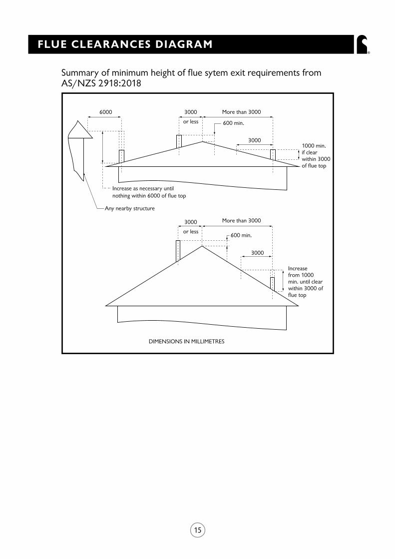
to the manufacturer’s instructions. The flue exit requirements of AS/
NZS2918:2018 are 1000mm above the roof and 600mm above any
projection within 3000mm, see flue clearances diagram (page 15).
This stove is not suitable for use in a shared flue system.
It is important that there is sufficient draw in the flue and that the flue
does not suffer from down-draught. When the flue is warm the draw
should be not less than 1.25mm (0.05”) water gauge (12 Pa). If in
doubt about the chimney seek expert advice.
HEARTH AND FIRE SURROUND
The stove must stand on a fireproof hearth and must not be situated
closer than the minimum distance from combustible materials to
the sides or rear above hearth level unless adequately fireproofed
in accordance with local building regulations. If installed on a
combustible floor, floor protection must be provided in the form of
a non-combustible material to the minimum specifications described
in the ‘minimum distances to combustibles’ section (pages 11 & 12)
When the fire door is open, it extends beyond the flat front of the
stove by 222mm.
If in doubt as to the positioning of the stove, expert advice should be
sought either from the supplier or the local building inspector. The
fireplace must allow good circulation of air around the appliance to
ensure that maximum heat is transferred to the room and also to
prevent the fireplace from overheating. A gap of 150mm (6”) each
side and 300mm (12”) above the appliance should give sufficient air
circulation. If a wooden mantelpiece or beam is used in the fireplace
it should be a minimum of 460mm (18”), and preferably 600mm
(24”) from the appliance. In some situations it may be necessary to
shield the beam or mantelpiece to protect it.
AIR PERMEABILITY m3/(h.m2)
MINIMUM VENT AREA cm2(in2)
ISLAND II - BP
>5.0 16.5 (2.6)
<5.0 44 (6.8)

11
®
In order for the fire to operate correctly the rear air inlet must not
be obstructed.
The appliance should be installed on a floor with adequate load-
bearing capacity. If an existing construction does not meet this
requirement then please take suitable measures to achieve this. (e.g.
load distributing plate.)
CONNECTIONS TO FLUES
The Island II - BP must be connected to the flue using flue pipe of
150mm (6”) diameter : and is tested for both Air Cooled triple Skin
Flue Kits & Room Seal Insulated flue Kits that have been tested to
AS/NZS2918:2018
Horizontal lengths of flue must be kept to a minimum and should not
be more in length than the flue diameter.
The stove comes with the blanking plate (fig. 6) fitted to the rear
flue outlet. The seal for the top outlet is a 155mm dia ring of rope
seal. The seal for the rear outlet is a length of adhesive backed
fibre webbing supplied with instructions ref: TIS093. This is applied
to the flue collar or the Vertical Rear Flue adapter for rear outlet
installations.
PRE LIGHTING CHECK
Ensure that the baffle and upper baffle is fitted in the roof of the
appliance. For location and positioning see Fig. 5.
Check that the front fence is fitted correctly and that the door closes
properly.
COMMISSIONING
Ensure that the rear heatshield extension is fitted to the back of the
heaishield (part 010/BPA170) with 2 x 12mm self tapping screws.
This part must be supplied and fitted to the stove. On completion
of the installation allow a suitable period of time for the fire cement
and mortar to dry out before lighting the fire. Make a layer of ash
or sand on the base of the stove before lighting. Check to ensure
that smoke and fumes are taken from the appliance up the flue and
emitted safely. Also check all joints and seals. On completion of the
installation and commissioning please leave the operating instructions
with the customer and advise them on the use of the appliance.
COOKING PLATE
010/BP150S - 6 inch kit used on the Island II - BP
The kit comprises of a cooking plate and four trivets and can only be
fitted to the stove if a rear flue connection is made.
Fig. 6. Flue Blanking Plate.
INSTALLATION INSTRUCTIONS
Back of StoveBlanking Plate
Glass Fibre Webbing
Blanking Plate
Seal Blanking Plate with Glass Fibre Webbing
Clamping plate finishes flush with the inside face of the firebox top and bottom.
Inside of Stove
Clamping Plate
M8 Nut

12
®CLEARANCES
A
A
B
AB
C
D
PARALLEL POSITIONCOMBUSTIBLE WALLS
CORNER POSITION
Standard Clearance A 225mm B 385mm C 450mm D 757mm
ISLAND II - BP
Corner Clearance A 275mm B 578mm
13
®
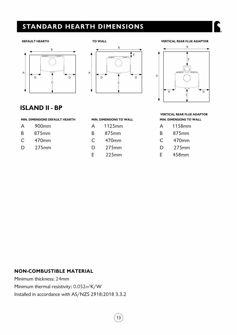
STANDARD HEARTH DIMENSIONS
MIN. DIMENSIONS DEFAULT HEARTH
A 900mmB 875mmC 470mmD 275mm
DEFAULT HEARTH
MIN. DIMENSIONS TO WALL
A 1125mmB 875mmC 470mmD 275mmE 225mm
TO WALL
MIN. DIMENSIONS TO WALL
A 1158mmB 875mmC 470mmD 275mmE 458mm
VERTICAL REAR FLUE ADAPTOR
VERTICAL REAR FLUE ADAPTOR
ISLAND II - BP
NON-COMBUSTIBLE MATERIAL
Minimum thickness: 24mm
Minimum thermal resistivity: 0.052m2K/W
Installed in accordance with AS/NZS 2918:2018 3.3.2
B
C
DD
A
B
E
C
DD
A
B
E
CDD
A

14
®
CORNER HEARTH DIMENSIONS
Minimum dimensions to wall Minimum dimensions to wall
VERTICAL REAR FLUE ADAPTOR
CORNER HEARTH
A 875mmB 578mmC 470mm
WITH VERTICAL REAR FLUE ADAPTOR
A 875mmB 578mmC 470mmD 458mm
ISLAND II - BP
C
A
B
B
B
B
C
D
D
A
NON-COMBUSTIBLE MATERIAL
Minimum thickness: 24mm
Minimum thermal resistivity: 0.052m2K/W
Installed in accordance with AS/NZS 2918:2018 3.3.2
15
®
FLUE CLEARANCES DIAGRAM
6000
3000
3000
3000
or less
or less
1000 min.if clear within 3000of flue top
Increase from 1000min. until clear within 3000 of flue top
DIMENSIONS IN MILLIMETRES
Summary of minimum height of flue sytem exit requirements from AS/NZS 2918:2018
More than 3000
More than 3000
600 min.
600 min.
3000
Any nearby structure
Increase as necessary until nothing within 6000 of flue top

16
®
150
1000
1000
1000
1000
25
600
Cowl
Triple skin flue
FlashingOptional
Decorative Flue Solid OR Mesh
Ceiling Ring
Dropbox
STANDARD DEFAULT TRIPLE SKIN FLUE KIT

17
®
INSULATED ROOM SEAL FLUE KIT
185
1000
1000
1000
25
50
Single skin flue
Room sealed flue adaptor
Ceiling ring
Heatshield
Starter length flue
Cowl
Room sealed flue(with locking band)
STANDARD FLUE KIT

18
®
INSULATED ROOM SEAL FLUE KIT
FULLY SEALED FLUE KIT
1000
1000
1000
1000
25
50
Cowl
Ceiling ring
Heatshield
Starter length flue
Room sealed flue(with locking band)

19
®
1000
2700
Gutter
V
50
25
min 25
Wall Penetration
NOTE:There needs to be 50mm clearance to any timberabove the flue pipe and a 25mm clearance to any timber to the side and underneath.
Min 470Max 620
Cowl
Adjustablewall bracket
Cleaningaccess
Wall Plate
INSULATED ROOM SEAL FLUE KIT
REAR FLUE KIT
Room sealed flue(with locking band)
Room sealed flue(with locking band)
Room sealed flue adaptor
90 degree tee with cap
Wall plate gal
Ceiling ring
Roof support brace

20
®
COMPLIANCE DATA
ISLAND II - BP - COMPLIANCE DATA
Compliance plate riveted onto rear heatshield

21
®
ISLAND II - BP DIMENSIONS
LOW
LE
GH
IGH
LE
GST
OR
E S
TA
ND
FRONT SIDE REAR
PLAN VIEWOptional rear flue adaptor
To suit 150mm(6”) flue pipe
160
134 160
418 482
96
614
728 675
105
602
366
160
448 79 76
560
66
621
813 760
584
795 848
299
225 80 186
680
392
330
190 151
645

22
®
ISLAND II - BP PARTS LIST
22
36
41
37
40
42
44
43
51
52 48 4950
38
39
45
47
46
62
64 57 56 60
58
55
66
3
10
8
5
7
18 17
6 9
14
20 121
54
5315
68
6722
23
24
25
11 12
13
11
4
16
19
32
33
34
35
31
29 27 2830
26
61 65
Charnwood Island II (BP-Australia) Parts ListIssue A
Item Part No. Description Item Part No. Description
*These items are not shown on the drawing.# Please specify colour when ordering.
To obtain spare parts please contact your local stockist giving Model, Part No. and Description. In case of difficulty contact the manufacturer at the address shown. This drawing is for identification purposes only.
1 008/BP035 Door Seal Set Inc. Adhesive2* 008/FW29 Door Seal Adhesive3 002/CG20 Grate Bar4 002/CG20S12 Set of Grate Bars (12)5 002/BU015L LH Side Fire Plate6 002/BU015R RH Side Fire Plate7 002/BP016 Back Fire Plate8 010/BP039 LH Carrier Bar Support9 010/AP040 RH Carrier Bar Support10 010/BP033 Mover Bar11 002/BY30 Carrier Bar12 012/FW14 Idler Rod13 010/BU077 Riddler Rod Assembly14 002/AP098 Riddler Spigot15 004/BP017 Ashpan16 002/BP008 Deepening Bar17 002/BP007 Front Fence (Lower)18 004/BP052 Front Ash Shedding Plate19 006/BP018 Glass20 008/BP045 Glass Seal21 004/KV23 Glass Retainer22 011/BP029S Set of Fire Bricks (4)23 004/XV30 Brick Retainer (4)24 011/BP031S Set of Throatplate Bricks (2)24a 010/BP077 Throat Plate Brick Hanger25 010/BP032 Upper Throatplate26 008/KV16 RH Door Handle27 002/AY14 Door Catch Cam28 008/FFW015 M12 Double Coil Spring Washer29 004/ST008 Tabbed Locking Washer30 008/FFN001 M12 Half Nut31 008/KV13 LH Door Knob32 008/ST068/4 Hinge Pin Set (4)33# 002/AP024 Hinge Post34 004/EZ095 Riddling/Ashpan Tool
35 004/AP051 Tool Holder36 008/BP110 Air Control Gasket37 010/BP111 Air Control Top Slider Plate38 004/BP112 Wood/Multifuel Surround Plate39 004/BP113 Wood/Multifuel Selection Slide40 010/BP114 Air Control Lower Plate41 008/KZ006 Air Box Gasket42 004/BP115 Air Control Slider43 004/BR015 Clicker Retainer Plate44 008/ES36/01 Brass Ball Catch45 004/EZ016 Control Rod46 008/AY37 Air Control Knob47 008/BR052 Felt Washer48 004/KZ039 Air Box Cover49 008/CR063 Duct Gasket50 004/CR064 Blanking Plate51 004/CR048 Air Inlet Spigot52 008/FFS062 Defra Stop53# 003/BP001A LH Door Assembly54# 003/BP002A RH Door Assembly55 001/BP010 Firebox (Island II BP)56 012/TW09 Blanking Plate57 010/AY51 Clamping Plate58# 002/CH12B Flue Collar59* 008/NV38 Flue Fixing Rope Seal60 012/BPA011 Serial No. Label61 012/BPA180 Compliance Plate62# 010/TW33 Vert. Rear Flue Connector (Opt'l Extra)63* 010/EW51 Ash Carrier (Opt'l Extra)64# 010/BP080 Heatshield65 010//BPA170 Heatshield Extension66# 010/BP012S Set of Low Legs (Option)67# 010/AY85S Set of High Legs (Option)68# 010/BP087 Store Stand (Option)

23
®
CHARNWOOD AUSTRALIA 10 YEAR GUARANTEE
TERMS AND CONDITIONS
10 Year Warranty: The firebox of your Charnwood Stove is guaranteed against material and manufacturing defect for a period
of 10 years
1 Year Warranty: The consumable items such as bricks, rope seal and associated parts are guaranteed for a period of 1 year.
• The guarantee registration form must be completed online and submitted within 14 days of purchase to enable the guarantee
to be activated.
• The following conditions apply:
• If any part fails due to manufacturing or material defect within the guarantee period Charnwood will, free of charge, either
repair or replace the part at their discretion. The decision of Charnwood is final.
• This guarantee is for parts only.
• Charnwood will not be liable for any consequential loss or incidental loss, damage or injury however caused.
• This guarantee will become void if the appliance: is not installed in accordance with the installation instructions; is not
regularly serviced in accordance with the installation instructions; is subject to misuse or neglect, including the use of non-
recommended fuel; or if repairs or modifications have been carried out by anyone other than Charnwood or their official
representatives.
• All claims on this guarantee must be made through the supplier of the appliance and must be accompanied by proof of
purchase.
• Nothing in this guarantee shall affect your statutory rights.
EXCLUSIONS AND LIMITATIONS
This Guarantee does not cover the following:
• Charnwood will not be liable for any consequential loss or incidental loss, damage or injury however caused.
• This guarantee will become void if the appliance is not installed by a suitably qualified and is not installed in accordance with
the AS.NZS 2918
• This guarantee will become void if the appliance is not installed in accordance with the installation instructions and is not
regularly serviced, in accordance with the installation instructions.
• If the product is subject to misuse or neglect, including the use of non-recommended fuels.
• If repairs or modifications have been carried out by anyone other than Charnwood or their authorised representatives.
• Damage caused by over-firing of the stove. Please refer to our operating instructions for further details.
• Damage caused by storing or using the product in a damp environment. Corrosion caused by condensation, damp or water
ingress into the flue, chimney or the surrounding of the stove.
• Defects or faults caused by local conditions such as draught problems and chimney defects.
• The paint finish will require touching up or repainting from time to time. Maintaining the finish is normal practice and is not
covered by the guarantee.
To register your 10 Year Stove Guarantee please visit or scan QR:
www.charnwood.com/my-stove/guarantees/
and enter the following code: CGG-AUS

your premier dealer