IEEE POWER ENGINEERING SOCIETY TUTORIAL ON AUTOMATION SYSTEMS CHAPTER 2 SLIDE 1 Automation System...
63
IEEE POWER ENGINEERING SOCIETY TUTORIAL ON AUTOMATION SYSTEMS CHAPTER 2 SLIDE 1 Automation System Master Station
-
Upload
independent -
Category
Documents
-
view
1 -
download
0
Transcript of IEEE POWER ENGINEERING SOCIETY TUTORIAL ON AUTOMATION SYSTEMS CHAPTER 2 SLIDE 1 Automation System...

IEEE POWER ENGINEERING SOCIETY
TUTORIAL ON AUTOMATION SYSTEMSCHAPTER 2 SLIDE 1
Automation System Master Station

IEEE POWER ENGINEERING SOCIETY
TUTORIAL ON AUTOMATION SYSTEMSCHAPTER 2 SLIDE 2
Outline
I. Introduction
II. System Architecture
III. SCADA System Design Criteria
IV. Master Station Functions
V. EMS Functions
VI. DMS Functions

IEEE POWER ENGINEERING SOCIETY
TUTORIAL ON AUTOMATION SYSTEMSCHAPTER 2 SLIDE 3
Introduction
IEEE POWER ENGINEERING SOCIETY
TUTORIAL ON AUTOMATION SYSTEMSCHAPTER 2 SLIDE 4
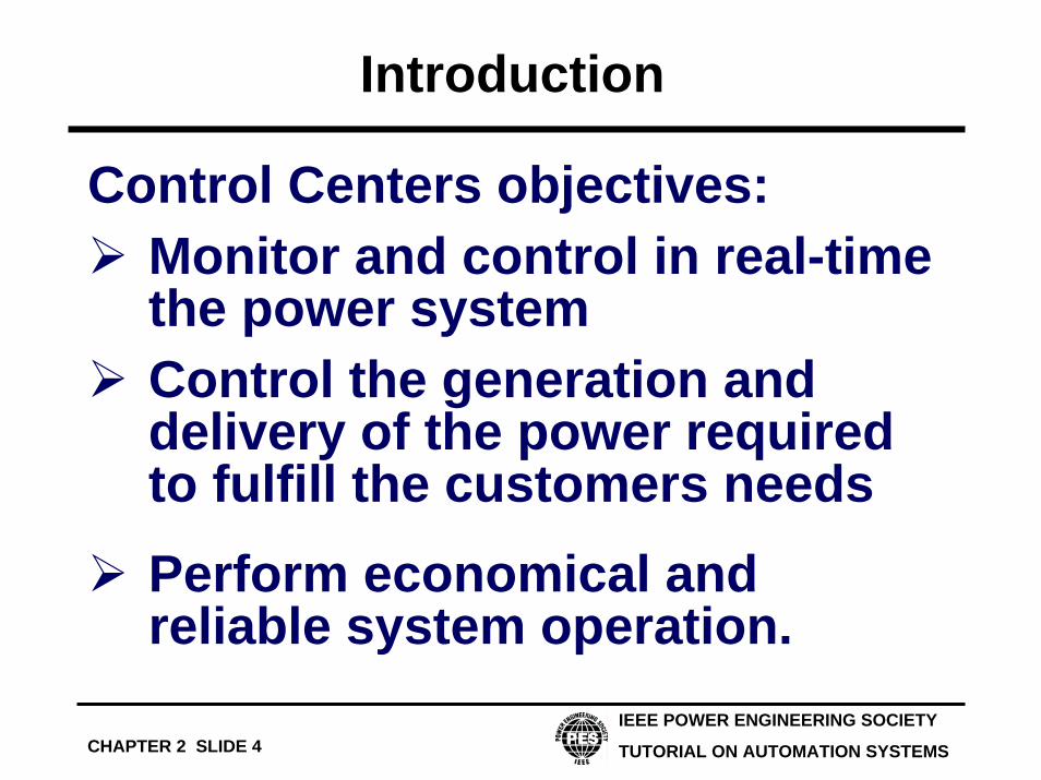
Introduction
Control Centers objectives:Monitor and control in real-time the power systemControl the generation and delivery of the power required to fulfill the customers needsPerform economical and reliable system operation.

IEEE POWER ENGINEERING SOCIETY
TUTORIAL ON AUTOMATION SYSTEMSCHAPTER 2 SLIDE 5
Introduction
Control Centers objectives:Maintain the voltage, frequency and time error within permissible limits

Network Based Automation
IEEE POWER ENGINEERING SOCIETY
TUTORIAL ON AUTOMATION SYSTEMSCHAPTER 2 SLIDE 6
WAN
Hub
RTU
Network Operator
Control Center
Application ServerCommunication
front-endRouter
Router
Gateway1 2 0
1 2 2
1 1 9
IED
1 2 0
1 2 2
1 1 9
IED
Substation A
Hub
RTU
Router
1 2 0
1 2 2
1 1 9
IED
Substation B
Network Operator
Control Center
Application ServerCommunication
front-endRouter
Dedicated Line
Remote Maintenance
1 2 0
1 2 2
1 1 9
IED
IEEE POWER ENGINEERING SOCIETY
TUTORIAL ON AUTOMATION SYSTEMSCHAPTER 2 SLIDE 7
System Architecture

IEEE POWER ENGINEERING SOCIETY
TUTORIAL ON AUTOMATION SYSTEMSCHAPTER 2 SLIDE 8
System Architecture
Modern control systems are based on distributed architecture:
Easier to upgradeEasier to maintainHigher reliabilityEasier to adapt the necessary processing power

IEEE POWER ENGINEERING SOCIETY
TUTORIAL ON AUTOMATION SYSTEMSCHAPTER 2 SLIDE 9
Typical System
Communication Front-endApplicationServer 1
ApplicationServer 2
dual LAN
CommunicationServer
Mimic BoardControler
to otherControlCenters RT
U
HMIHMI

IEEE POWER ENGINEERING SOCIETY
TUTORIAL ON AUTOMATION SYSTEMSCHAPTER 2 SLIDE 10
Subsystems
Human-Machine InterfaceApplication ServersData ServersCommunication Front-EndsCommunication Servers

IEEE POWER ENGINEERING SOCIETY
TUTORIAL ON AUTOMATION SYSTEMSCHAPTER 2 SLIDE 11
Human-Machine Interface
Communication Front-end
MMI
Application Server 1 Application Server 2
MMI
dual LAN
CommunicationServer
Mimic BoardControler
to other ControlCenters
RTU

IEEE POWER ENGINEERING SOCIETY
TUTORIAL ON AUTOMATION SYSTEMSCHAPTER 2 SLIDE 12
Human-Machine Interface
Multi-VDU systems.Based on Windows technology (X-Windows or Microsoft)New trend: WEB based

IEEE POWER ENGINEERING SOCIETY
TUTORIAL ON AUTOMATION SYSTEMSCHAPTER 2 SLIDE 13
Human-Machine Interface
Mapboard
Wall mounted mapboard
Rear-projection systems (more expensive but more flexible)
Mosaic systems (less flexible, but still show topology during complete power failure)

IEEE POWER ENGINEERING SOCIETY
TUTORIAL ON AUTOMATION SYSTEMSCHAPTER 2 SLIDE 14
Application Servers
Communication Front-end
MMI
Application Server 1 Application Server 2
MMI
dual LAN
CommunicationServer
Mimic BoardControler
to other ControlCenters
RTU

IEEE POWER ENGINEERING SOCIETY
TUTORIAL ON AUTOMATION SYSTEMSCHAPTER 2 SLIDE 15
Application Servers
Support SCADA software
Support EMS/DMS functions

IEEE POWER ENGINEERING SOCIETY
TUTORIAL ON AUTOMATION SYSTEMSCHAPTER 2 SLIDE 16
Data Servers
Historical and future data baseConfiguration and database management
Software version management

IEEE POWER ENGINEERING SOCIETY
TUTORIAL ON AUTOMATION SYSTEMSCHAPTER 2 SLIDE 17
Communication front-ends
Communication Front-end
MMI
Application Server 1 Application Server 2
MMI
dual LAN
CommunicationServer
Mimic BoardControler
to other ControlCenters
RTU

IEEE POWER ENGINEERING SOCIETY
TUTORIAL ON AUTOMATION SYSTEMSCHAPTER 2 SLIDE 18
Communication front-ends
Used as an interface between substations and Control SystemMission criticalSupport different communication protocols (DNP3, IEC 60870-5-101)

IEEE POWER ENGINEERING SOCIETY
TUTORIAL ON AUTOMATION SYSTEMSCHAPTER 2 SLIDE 19
Communication Servers
Communication Front-end
MMI
Application Server 1 Application Server 2
MMI
dual LAN
CommunicationServer
Mimic BoardControler
to other ControlCenters
RTU

IEEE POWER ENGINEERING SOCIETY
TUTORIAL ON AUTOMATION SYSTEMSCHAPTER 2 SLIDE 20
Communication Servers
• Used for communication with other systems, control centers or utilities.
• ICCP (TASE.2)• WEB server• Intranet/Internet• Enterprise

IEEE POWER ENGINEERING SOCIETY
TUTORIAL ON AUTOMATION SYSTEMSCHAPTER 2 SLIDE 21
Master Station Design Criteria

IEEE POWER ENGINEERING SOCIETY
TUTORIAL ON AUTOMATION SYSTEMSCHAPTER 2 SLIDE 22
Master Station Design Criteria
AvailabilityMaintainabilityPerformanceSecurityExpandability

IEEE POWER ENGINEERING SOCIETY
TUTORIAL ON AUTOMATION SYSTEMSCHAPTER 2 SLIDE 23
Availability
Total time of satisfactory operationAvailability =
Reference period

IEEE POWER ENGINEERING SOCIETY
TUTORIAL ON AUTOMATION SYSTEMSCHAPTER 2 SLIDE 24
Availability
Redundancy is used to improve the reliability:Hot standbySpare redundancy

IEEE POWER ENGINEERING SOCIETY
TUTORIAL ON AUTOMATION SYSTEMSCHAPTER 2 SLIDE 25
MaintainabilityThe system must have appropriate tools to enable many functions:
preventive maintenance, system debugging, corrections, updates and enhancement,Database updateTests
without affecting system performance or reliability.

IEEE POWER ENGINEERING SOCIETY
TUTORIAL ON AUTOMATION SYSTEMSCHAPTER 2 SLIDE 26
Performance
Response time
the length of time it takes from the instant a function is requested until the instant the outputs from this function are available
Normal state
Emergency state

IEEE POWER ENGINEERING SOCIETY
TUTORIAL ON AUTOMATION SYSTEMSCHAPTER 2 SLIDE 27
Expandability
Available physical spacePower supply capacityHeat dissipationProcessor throughput and number of processorsMemory capacity

IEEE POWER ENGINEERING SOCIETY
TUTORIAL ON AUTOMATION SYSTEMSCHAPTER 2 SLIDE 28
Expandability
• Point limits of hardware, software, or protocol
• Bus length, loading, and traffic• Limitations on routines,
addresses, labels, or buffers• Unacceptable extension of scan
times by increased data

IEEE POWER ENGINEERING SOCIETY
TUTORIAL ON AUTOMATION SYSTEMSCHAPTER 2 SLIDE 29
Security
AccessIntrusion

IEEE POWER ENGINEERING SOCIETY
TUTORIAL ON AUTOMATION SYSTEMSCHAPTER 2 SLIDE 30
Master Station Functions

IEEE POWER ENGINEERING SOCIETY
TUTORIAL ON AUTOMATION SYSTEMSCHAPTER 2 SLIDE 31
Master Station Functions
Data AcquisitionData ProcessingSupervisory ControlTaggingHuman-Machine Interface

IEEE POWER ENGINEERING SOCIETY
TUTORIAL ON AUTOMATION SYSTEMSCHAPTER 2 SLIDE 32
Data Acquisition
Scan the RTU and support the following objects:
Single Point Information (SPI)Double Point Information (DPI)Measurements (ME)Single Command (SC)Double Command (DC)Set-Point (SP)Integrated Total (IT)

IEEE POWER ENGINEERING SOCIETY
TUTORIAL ON AUTOMATION SYSTEMSCHAPTER 2 SLIDE 33
Scanning Mode

IEEE POWER ENGINEERING SOCIETY
TUTORIAL ON AUTOMATION SYSTEMSCHAPTER 2 SLIDE 34
Data Processing
Convert raw values to engineering unitsCheck for limits violationGeneral alarms
IEEE POWER ENGINEERING SOCIETY
TUTORIAL ON AUTOMATION SYSTEMSCHAPTER 2 SLIDE 35
Data Processing
Calculated valueP = V * I
Manually replaced value

IEEE POWER ENGINEERING SOCIETY
TUTORIAL ON AUTOMATION SYSTEMSCHAPTER 2 SLIDE 36
Supervisory Control
Direct OperateSelect before operateSet-point

IEEE POWER ENGINEERING SOCIETY
TUTORIAL ON AUTOMATION SYSTEMSCHAPTER 2 SLIDE 37
Direct Operate
MasterStation RTU
Control

IEEE POWER ENGINEERING SOCIETY
TUTORIAL ON AUTOMATION SYSTEMSCHAPTER 2 SLIDE 38
Select Before Operate
MasterStation RTU
Device Selection
SelectionConfirmation
Control
ControlConfirmation

IEEE POWER ENGINEERING SOCIETY
TUTORIAL ON AUTOMATION SYSTEMSCHAPTER 2 SLIDE 39
Set-point
MasterStation RTU
Set-point

IEEE POWER ENGINEERING SOCIETY
TUTORIAL ON AUTOMATION SYSTEMSCHAPTER 2 SLIDE 40
Tagging
Provides information or warning to operator regarding restrictions or malfunctions of power system devices

IEEE POWER ENGINEERING SOCIETY
TUTORIAL ON AUTOMATION SYSTEMSCHAPTER 2 SLIDE 41
Human-Machine Interface
Worldmap :A Worldmap is a two-dimensional graphical representation of the real world. Each point in a worldmap is defined by a pair of unique X, Y coordinates.

IEEE POWER ENGINEERING SOCIETY
TUTORIAL ON AUTOMATION SYSTEMSCHAPTER 2 SLIDE 42
Human-Machine Interface
Zooming :
This function changes the magnification of the worldmap.

IEEE POWER ENGINEERING SOCIETY
TUTORIAL ON AUTOMATION SYSTEMSCHAPTER 2 SLIDE 43
Human-Machine Interface
Zooming

IEEE POWER ENGINEERING SOCIETY
TUTORIAL ON AUTOMATION SYSTEMSCHAPTER 2 SLIDE 44
Human-Machine Interface
Zooming

IEEE POWER ENGINEERING SOCIETY
TUTORIAL ON AUTOMATION SYSTEMSCHAPTER 2 SLIDE 45
Human-Machine Interface
Decluttering :This function gives the ability to mask or unmask information while zooming.

IEEE POWER ENGINEERING SOCIETY
TUTORIAL ON AUTOMATION SYSTEMSCHAPTER 2 SLIDE 46
Human-Machine Interface
Decluttering :

IEEE POWER ENGINEERING SOCIETY
TUTORIAL ON AUTOMATION SYSTEMSCHAPTER 2 SLIDE 47
Human-Machine Interface
Decluttering :

IEEE POWER ENGINEERING SOCIETY
TUTORIAL ON AUTOMATION SYSTEMSCHAPTER 2 SLIDE 48
Human-Machine Interface
Decluttering :

IEEE POWER ENGINEERING SOCIETY
TUTORIAL ON AUTOMATION SYSTEMSCHAPTER 2 SLIDE 49
Human-Machine Interface
Decluttering :

IEEE POWER ENGINEERING SOCIETY
TUTORIAL ON AUTOMATION SYSTEMSCHAPTER 2 SLIDE 50
Human-Machine Interface
Panning :This function allows the operator to move the worldmap window to different positions over the entire worldmap.

IEEE POWER ENGINEERING SOCIETY
TUTORIAL ON AUTOMATION SYSTEMSCHAPTER 2 SLIDE 51
Human-Machine Interface
Privilege ManagementEach user has some privileges related to its role.For instance, the database administrator must not have the privilege of sending commands to the RTU

IEEE POWER ENGINEERING SOCIETY
TUTORIAL ON AUTOMATION SYSTEMSCHAPTER 2 SLIDE 52
Human-Machine Interface
Area responsibility
Physical parts or functions of the power system can be assigned to different operators.
The operators can obtain information from other areas but are not able to control the devices in other areas.

IEEE POWER ENGINEERING SOCIETY
TUTORIAL ON AUTOMATION SYSTEMSCHAPTER 2 SLIDE 53
Human-Machine Interface
User Profile :Each user has some preferences on the way information is displayed on the screen. Preferences are stored in the user profile and are applied when a user logs into the system.

IEEE POWER ENGINEERING SOCIETY
TUTORIAL ON AUTOMATION SYSTEMSCHAPTER 2 SLIDE 54
Human-Machine Interface
Tabular Displays :Tabular Displays show a listing of application data. For instance, a tabular display can list all the substations and display their current status.

IEEE POWER ENGINEERING SOCIETY
TUTORIAL ON AUTOMATION SYSTEMSCHAPTER 2 SLIDE 55
Human-Machine Interface
Trend Displays :Trend Displays show graphically the variation in time of power system data. This data can be selected by the operator.

IEEE POWER ENGINEERING SOCIETY
TUTORIAL ON AUTOMATION SYSTEMSCHAPTER 2 SLIDE 56
EMS Functions

IEEE POWER ENGINEERING SOCIETY
TUTORIAL ON AUTOMATION SYSTEMSCHAPTER 2 SLIDE 57
Generation Planning and Scheduling
Unit CommitmentInterchange Transaction SchedulingLoad Forecasting

IEEE POWER ENGINEERING SOCIETY
TUTORIAL ON AUTOMATION SYSTEMSCHAPTER 2 SLIDE 58
Generation Control
Economic Dispatch Calculation Automatic Generation Control (AGC-LFC)Generation Reserve MonitoringNERC Performance Monitoring

IEEE POWER ENGINEERING SOCIETY
TUTORIAL ON AUTOMATION SYSTEMSCHAPTER 2 SLIDE 59
Power System Analysis
Real time or study mode• Network Topology Processor• State Estimator• Network Reduction• Dispatcher Load Flow

IEEE POWER ENGINEERING SOCIETY
TUTORIAL ON AUTOMATION SYSTEMSCHAPTER 2 SLIDE 60
Power System Analysis
Real time or study mode• Optimal Power Flow• Short Circuit Calculation• Contingency Analysis

IEEE POWER ENGINEERING SOCIETY
TUTORIAL ON AUTOMATION SYSTEMSCHAPTER 2 SLIDE 61
Marketing
OASISAvailable Transfer Capability (ATC)Total Transfer CapabilityRisk management and analysis

IEEE POWER ENGINEERING SOCIETY
TUTORIAL ON AUTOMATION SYSTEMSCHAPTER 2 SLIDE 62
Power System Analysis
DMS Functions

IEEE POWER ENGINEERING SOCIETY
TUTORIAL ON AUTOMATION SYSTEMSCHAPTER 2 SLIDE 63
DMS Functions
Geographic Network DiagramOutage Management SystemFault LocationState EstimatorLoad Flow