IEEE 06607210
7
IEEE TRANSACTIONS ON APPLIED SUPERCONDUCTIVITY, VOL. 24, NO. 1, FEBRUARY 2014 5200207 Design and Performance Analysis of Superconducting Rim-Driven Synchronous Motors for Marine Propulsion Amir Hassannia and Ahmad Darabi Abstract—Rim-driven thrusters have received much attention concerning the potential benefits in vibration and hydrody- namic characteristics, which are of great importance in marine transportation systems. In this sense, the rim-driven permanent magnet, brushless dc, and induction motors have been recently suggested to be employed as marine propulsion motors. On the other hand, high-temperature superconducting (HTS) syn- chronous motors are becoming much fascinating, particularly in transport applications, regarding some considerable advantages such as low loss, high efficiency, and compactness. However, the HTS-type rim-driven synchronous motor has not been studied yet. Therefore, this paper is devoted to a design practice of rim-driven synchronous motors with HTS field winding. A detailed design procedure is developed for the HTS rim-driven motors, and the design algorithm is validated applying the finite element (FE) method. The FE model of a three-phase 2.5-MW HTS rim-driven synchronous motor is utilized, and the electromagnetic character- istics of the motor are then evaluated. The goal is to design an HTS machine fitted in a thin duct to minimize the hydrodynamic drag force. The design problem exhibits some difficulties while considering various constraints. Index Terms—Design, finite elements, marine propulsion, rim– driven synchronous motor, superconductor. I. I NTRODUCTION E LECTRIC propulsion systems are widely used in marine transportation as well as land and air transportation and other industrial applications [1]. Many advantages of electrical propulsion extend their application in warship and military submarine vessels [2], [3]. The azimuth, podded, and rim- driven thrusters are three important types of maritime electric propulsion system. The rim-driven thruster is distinguished from other thrusters because of its benefits in hydrodynamic performance, mechanical noise, hydraulic power dissipation, natural lubrication, etc. [1], [4]–[7]. Although many advantages, some problems are involved in rim-driven motor design. The propeller imposes special con- straints on propulsion motor [7]. The nominal power, speed, and inner diameter of the rotor are given by the rated power, Manuscript received March 9, 2013; revised June 16, 2013 and July 22, 2013; accepted August 14, 2013. Date of current version September 23, 2013. This paper was recommended by Associate Editor M. Parizh. The authors are with the Faculty of Electrical and Robotic Engineering, University of Shahrood, Shahrood 36199 95161, Iran (e-mail: amir.hassannia@ gmail.com; [email protected]). Color versions of one or more of the figures in this paper are available online at http://ieeexplore.ieee.org. Digital Object Identifier 10.1109/TASC.2013.2280346 speed, and outer diameter of the propeller, respectively [8]. The motor radial thickness (stator outer radius minus rotor inner radius) is the next limitation. This dimension forms the surface that is directly in contact with the water flow and should be compacted as much as possible to reduce the hydrodynamic drag force [9]. The axial length of the machine is also limited by the duct length, which can be 1.5 times larger than the propeller length [8]. Furthermore, the water flow between the rotor and the stator imposes a relatively large air gap, which affects the motor magnetic design [8]. The rim-driven propeller concept has been known for a long time, but the marine rim-driven motors came into wide use in recent years. The permanent magnet (PM), brushless dc (BLDC), and induction motors are well known in marine rim-driven thruster. In 2004, a 100-kW PM rim-driven motor was designed and built [10]. Sometime later, a new algorithm was developed to design a BLDC rim-driven propulsion motor in 2006 [11]. These activities were followed by designing a 183-kW induction rim-driven motor in 2010 [12]. The per- formance analysis demonstrates a minor decay in operation characteristics of the rim-driven induction motor, as compared to a similar typical induction motor [12]. Recently, the ax- ial flux PM motor has also been considered in rim-driven thrusters [13]. Superconducting motors are an attractive option in marine propulsion due to their potential benefits such as high power density, light weight, low loss, and high efficiency. Design knowledge and technology of high-temperature superconduct- ing (HTS) propulsion motors has been developed greatly through designing and building various types of HTS motors for azimuth and podded thrusters [14]–[16]. Nevertheless, the superconducting rim-driven propulsion motor seems to be a novel case. In this paper, a new structure of HTS rim-driven motor is presented to embed the benefits of HTS motor in a rim- driven marine propulsion system. Various design considerations are taken into account to plan an HTS motor that satisfies the rim-driven propulsion system requirements. The mentioned limitations for rim-driven thruster arise par- ticularly in the HTS propulsion motor. Radial thickness of superconducting motors is generally large due to rather large air gap. Therefore, it is somewhat difficult to design an enough thin HTS motor for a rim-driven thruster. The groundwork of the present paper is a 2.5-MW PM rim-driven motor, which has been recently designed [8]. A small-size prototype (100 kW) of a similar motor has been 1051-8223 © 2013 IEEE
-
Upload
shahroodut -
Category
Documents
-
view
0 -
download
0
Transcript of IEEE 06607210

IEEE TRANSACTIONS ON APPLIED SUPERCONDUCTIVITY, VOL. 24, NO. 1, FEBRUARY 2014 5200207
Design and Performance Analysis ofSuperconducting Rim-Driven Synchronous
Motors for Marine PropulsionAmir Hassannia and Ahmad Darabi
Abstract—Rim-driven thrusters have received much attentionconcerning the potential benefits in vibration and hydrody-namic characteristics, which are of great importance in marinetransportation systems. In this sense, the rim-driven permanentmagnet, brushless dc, and induction motors have been recentlysuggested to be employed as marine propulsion motors. Onthe other hand, high-temperature superconducting (HTS) syn-chronous motors are becoming much fascinating, particularly intransport applications, regarding some considerable advantagessuch as low loss, high efficiency, and compactness. However, theHTS-type rim-driven synchronous motor has not been studied yet.Therefore, this paper is devoted to a design practice of rim-drivensynchronous motors with HTS field winding. A detailed designprocedure is developed for the HTS rim-driven motors, and thedesign algorithm is validated applying the finite element (FE)method. The FE model of a three-phase 2.5-MW HTS rim-drivensynchronous motor is utilized, and the electromagnetic character-istics of the motor are then evaluated. The goal is to design anHTS machine fitted in a thin duct to minimize the hydrodynamicdrag force. The design problem exhibits some difficulties whileconsidering various constraints.
Index Terms—Design, finite elements, marine propulsion, rim–driven synchronous motor, superconductor.
I. INTRODUCTION
E LECTRIC propulsion systems are widely used in marinetransportation as well as land and air transportation and
other industrial applications [1]. Many advantages of electricalpropulsion extend their application in warship and militarysubmarine vessels [2], [3]. The azimuth, podded, and rim-driven thrusters are three important types of maritime electricpropulsion system. The rim-driven thruster is distinguishedfrom other thrusters because of its benefits in hydrodynamicperformance, mechanical noise, hydraulic power dissipation,natural lubrication, etc. [1], [4]–[7].
Although many advantages, some problems are involved inrim-driven motor design. The propeller imposes special con-straints on propulsion motor [7]. The nominal power, speed,and inner diameter of the rotor are given by the rated power,
Manuscript received March 9, 2013; revised June 16, 2013 and July 22, 2013;accepted August 14, 2013. Date of current version September 23, 2013. Thispaper was recommended by Associate Editor M. Parizh.
The authors are with the Faculty of Electrical and Robotic Engineering,University of Shahrood, Shahrood 36199 95161, Iran (e-mail: [email protected]; [email protected]).
Color versions of one or more of the figures in this paper are available onlineat http://ieeexplore.ieee.org.
Digital Object Identifier 10.1109/TASC.2013.2280346
speed, and outer diameter of the propeller, respectively [8]. Themotor radial thickness (stator outer radius minus rotor innerradius) is the next limitation. This dimension forms the surfacethat is directly in contact with the water flow and should becompacted as much as possible to reduce the hydrodynamicdrag force [9]. The axial length of the machine is also limited bythe duct length, which can be 1.5 times larger than the propellerlength [8]. Furthermore, the water flow between the rotor andthe stator imposes a relatively large air gap, which affects themotor magnetic design [8].
The rim-driven propeller concept has been known for along time, but the marine rim-driven motors came into wideuse in recent years. The permanent magnet (PM), brushlessdc (BLDC), and induction motors are well known in marinerim-driven thruster. In 2004, a 100-kW PM rim-driven motorwas designed and built [10]. Sometime later, a new algorithmwas developed to design a BLDC rim-driven propulsion motorin 2006 [11]. These activities were followed by designing a183-kW induction rim-driven motor in 2010 [12]. The per-formance analysis demonstrates a minor decay in operationcharacteristics of the rim-driven induction motor, as comparedto a similar typical induction motor [12]. Recently, the ax-ial flux PM motor has also been considered in rim-driventhrusters [13].
Superconducting motors are an attractive option in marinepropulsion due to their potential benefits such as high powerdensity, light weight, low loss, and high efficiency. Designknowledge and technology of high-temperature superconduct-ing (HTS) propulsion motors has been developed greatlythrough designing and building various types of HTS motorsfor azimuth and podded thrusters [14]–[16]. Nevertheless, thesuperconducting rim-driven propulsion motor seems to be anovel case. In this paper, a new structure of HTS rim-drivenmotor is presented to embed the benefits of HTS motor in a rim-driven marine propulsion system. Various design considerationsare taken into account to plan an HTS motor that satisfies therim-driven propulsion system requirements.
The mentioned limitations for rim-driven thruster arise par-ticularly in the HTS propulsion motor. Radial thickness ofsuperconducting motors is generally large due to rather largeair gap. Therefore, it is somewhat difficult to design an enoughthin HTS motor for a rim-driven thruster.
The groundwork of the present paper is a 2.5-MW PMrim-driven motor, which has been recently designed [8]. Asmall-size prototype (100 kW) of a similar motor has been
1051-8223 © 2013 IEEE

5200207 IEEE TRANSACTIONS ON APPLIED SUPERCONDUCTIVITY, VOL. 24, NO. 1, FEBRUARY 2014
TABLE IDESIGN PARAMETERS OF HTS RIM-DRIVEN MOTOR
Fig. 1. Overview of selected structure.
manufactured. The given test results of this motor validatesthe design algorithm of PM rim-driven motor [10]. The ratedvalues, required features, and constraints of 2.5-MW PM rim-driven machine are given in Table I. Besides the design al-gorithm, the second goal of the present paper is to design anHTS rim-driven motor with the constraints and rated valuessimilar to the existing PM-type motor to be able to comparecharacteristics of both motors in the end.
Salient-pole radial-flux synchronous structure with HTS ex-citation coils in rotor is picked for the HTS rim-driven motor. Atotal of 30 poles is needed to provide the rated speed at nominalfrequency. The concept of the selected structure is shown inFig. 1. This is the conventional structure of a synchronousmachine, which is optimized for rim-driven superconductingoperation.
II. BASIC PARAMETERS AND DESIGN ALGORITHM
The first stage is selecting the working temperature of HTScoils (tw), which affects significantly the field current densityand consequently size of the machine. Critical current of fieldwinding is increased by any decrement in HTS working temper-ature. As a result, the volume of field winding and consequentlysize of the machine can be reduced. Nevertheless, this issueimposes the need of a stronger and larger cooling system. Areasonable tradeoff between these issues usually yields to ratherhigh working temperature in HTS propulsion motors [8], [15],[17]. The parameter is typically selected as tw = 75 K in thiswork.
The air-gap flux density (Bag) and electrical loading (ac)are the most effective parameters in machine size. The machine
core magnetic saturation is the key criterion to choose themaximum air-gap flux density in conventional machines. Thisparameter is selected fairly high to reduce the weight andvolume of the machine. The HTS coils can provide high mag-netic flux density, which is the main reason of superconductingmachines’ compactness. However, many simulations show thatbesides decreasing the volume and axial length of the machine,the radial thickness is increased by any increment in the air-gap flux density. Therefore, the superconducting rim-drivenmotor design problem involves an exceptional tradeoff betweencompactness and radial thickness minimization.
One of the most critical matters is assigning a proper valuefor the electrical loading defined as
ac =Z · Iconπ ·Dis
(1)
in which Z is total number of conductors of stator winding, Iconis the current of each conductor, and Dis is inner diameter of thestator. Relatively low voltage necessitates employing parallelcoils in the stator winding. The number of turns of the windingin series is related to the number of slots per pole per phaseproportionally. Therefore, the electrical loading factor can bechosen among some individual values within a typical range(acl < ac < acu).
Commonly both ac and Bag have the most significant in-fluences on the total size of the machine so that larger valuesof them yield to a smaller size machine. Similar to Bag , thesimulations show that sometime any increase in electrical load-ing increases radial thickness of the HTS machine beside thevolume and axial length of the machine decrease. This can berelated to the existing complications in rim-driven HTS motorstructure, compelling some caution when assigning values toBag and ac, particularly when the purpose is to obtain a thinand compact machine. In this sense, the algorithm, as shownin Fig. 2, starts with relatively a low value of Bag , and then,its value is increased gradually until the value of axial lengthbecomes less than the maximum predefined value. For eachvalue of Bag , the value of ac is adjusted nearly to the maximumvalue (acu) so that the number of winding turns deduced from(1) becomes an integer coefficient of the number of slots perpole per phase. It is done easily by an internal loop. Final valuesof the air-gap flux density and electrical loading factor obtainedby this algorithm for the case study machine of the presentpaper are Bag = 0.65 T and ac = 43883 A/m.
Rotor, stator, and air gap are the main parts of the machinein design procedure. A number of considerations are needed toproperly design of these parts to realize the desired thin andcompact machine.
III. AIR GAP DESIGN
The vacuum vessel is an isolation layer between cold rotorand warm stator that occupies about 4 mm of radial thicknesstypically [18], [19]. Damper shield thickness is designed as anappropriate percentage of magnetic penetration depth (δthk).The problem is to choose a thick and effective damper shieldor a thin and less effective one. In this case, the damper shieldis designed as thin as possible via a tradeoff. The parameter is

HASSANNIA AND DARABI: SUPERCONDUCTING RIM-DRIVEN SYNCHRONOUS MOTORS FOR MARINE PROPULSION 5200207
Fig. 2. General design process.
considered as 80% of magnetic penetration depth according tothe following equation [20]:
ddamp = 0.8× δthk =0.8√
πμfσKT(2)
where μ is magnetic permeability, σ is electric conductivityat room temperature, and f is stator frequency. Parameter KT
represents the thermal correction factor that is calculated as [8]
KT =234 + t0234 + tw
(3)
where t0 = 293 K is room temperature. The stator teeth mag-netic saturation is a major limitation in usual synchronousmachine. Therefore, the slotless stator is more popular in HTSmachine due to strong air-gap magnetic field, which is providedby the superconducting field winding [21]. The slotless statorreduces the winding layer thickness and consequently the totalradial thickness of the motor. The stator winding layer depth(dwst) can be calculated as
dwst =ac
J · kfull · kiso · ksup(4)
where J is the stator winding current density; kfull is the statorwinding fullness factor; kiso and ksup are defined to considerthe winding isolation and winding support, respectively.
IV. ROTOR DESIGN
The rotor consists of rotor yoke, rotor poles, and HTS coils.The pole pitch angle is calculated considering the total 15 pairsof poles. The ratio of pole body angle (θtp) to pole pitch angle(θp) is a key parameter that affects the pole body saturation,
rotor leakage flux, air-gap flux harmonic content, availablespace for HTS field winding, and notably radial thickness ofthe machine. That is
Kp =θtpθp
. (5)
Obviously, parameter Kp has to be increased by the air-gapflux density increment proportionally to prevent the pole bodysaturation. The algorithm offers the value of 0.4225 for Kp
by a tradeoff between field winding space and machine radialthickness.
The arc length of rotor body (tp) and the rotor yoke thickness(dyr) are found after a number of loops and corrections throughfollowing equations:
tp = θtp(Rir + dyr) (6)
dyr =0.34× tp (7)
where Rir is inner rotor radius. The pole height (hpole) iscalculated using a similar iteration. The procedure starts withan initial guess of pole height. The average flux density of polebody (Btp) is calculated as
Btp =2
πBag
(θp ·Ris
tp(1− kleak)
)(8)
where Ris = Rir + dyr + hpole +Ag is inner radius of statoryoke, and Ag is total air gap. Parameter kleak represents theleakage flux factor, which was defined as
kleak = 1− ϕst
ϕr≈ 0.03 (9)
where ϕst and ϕr are maximum flux in stator and rotor yoke,respectively. The leakage flux factor of the case study machinewas found after some loops and corrections as 3%. The requiredmagnetomotive force per pole can be obtained considering theair gap reluctance (�ag) and desired flux in rotor body (ϕtp).That is
NfIf =(1− kleak) · ϕtp · �ag
=(1− kleak) ·Btp · tp ·Agμ0
(θp+θtp
2
)(Ris − Ag
2
) . (10)
Rated field current depends on HTS wire model, workingtemperature, and magnetic flux density on HTS coils. TheSuperpower-SCS3050 wire is selected for the case study HTSmotor. The wire specifications are shown in Table II [22].Fig. 3 shows the constitutive layers of HTS wire, in which thethickness of all layers is approximately 0.1 mm. Total thicknessof the wire considering the isolation layer is about 0.2 mm [22].
According to Table II, Maximum allowable current valueof superconducting wire is 75 A at 77 K and zero magneticfield. Working temperature of rotor is assumed 75 K to secureassumption of critical current equal to Ic = 75 A in zeromagnetic field. Critical current of HTS wire varies by normalflux density, as shown in Fig. 4 [23]. If the permitted maximumvalue of normal component of flux density is assumed 0.6 T,according to the specification of HTS wire, the critical current

5200207 IEEE TRANSACTIONS ON APPLIED SUPERCONDUCTIVITY, VOL. 24, NO. 1, FEBRUARY 2014
TABLE IISPECIFICATIONS OF SUPERCONDUCTING TAPE
Fig. 3. Structure of HTS tape (without electrical isolator) [22].
Fig. 4. Critical current of HTS tape as a function of magnetic field at differentworking temperature [23].
of superconducting coils will be 23 A. Therefore, the ratedvalue of the field current has to be by a safety margin less than23 A, e.g., If = 18 A. Taking this value for the field current andevaluating the ampere turns per pole using (10), the number ofturns of field winding per pole is simply calculated.
The HTS coil was used in pancake structure for windingconvenience. Considering the HTS wire dimensions, the widthof each pancake is an integer coefficient of 0.2 mm and thepancake height is 3 mm. Due to limited available space betweenrotor poles and consequently limited pancake width, severalseries pancakes are needed to beget the required turns of fieldwinding. Therefore, the pole height will increase in an iterativeloop to provide enough space for pancakes. After a few numberof iteration, 1153 turns of field coil per pole formed in fourpancakes, as shown in Fig. 5. The pancake formation was
Fig. 5. HTS excitation coil.
Fig. 6. Sketch of PEC system.
performed considering the critical bend diameter of SCS-3050HTS wire.
V. COOLING SYSTEM
Design of the cooling system is a voluminous work, which isoutside the scope of this paper, but it is necessary to consider themain requirements of cooling system. The thermosyphon, openevaporative cooling, and piping evaporative cooling (PEC) arethree customary refrigeration approaches in superconductingmachines [24], where the PEC is more conventional for large-size and low-speed machine [24]. The system consists of coolisolated rotor with embedded cooling pipe in rotor core accord-ing to Fig. 6. An enough space is considered for cooling pipe inthe studied motor.
VI. STATOR DESIGN
Due to relatively low rated voltage, 15 parallel circuits areconsidered in the stator winding. The number of stator windingturns in series (Nph) is calculated as
Nph =π ·Dis · ac2m · Iph
(11)
where m is the number of phases, and Iph is rated phase current.Parameter Nph is an integer coefficient of number of co-slot perpole per phase. The authorized value of ac realizes the correctvalue of Nph.
VII. AXIAL LENGTH
The axial length of machine is determined by the requiredflux per rotor pole. This quantity is a function of choseninduced voltage in armature. The terminal rated voltage is acommon choice for armature-induced voltage in conventionalsynchronous motors. Lagging power factor is a result of thischoice. In this situation, armature reaction can increases thecore flux density of machine. On the other hand, rim-driven

HASSANNIA AND DARABI: SUPERCONDUCTING RIM-DRIVEN SYNCHRONOUS MOTORS FOR MARINE PROPULSION 5200207
Fig. 7. Phasor diagram of the machine.
motors are usually designed very near to the magnetic satura-tion point to reduce the radial thickness. Therefore, lagging-power-factor rim-driven synchronous motor may be saturatedmagnetically by armature reaction. After a number of loops andcorrections, the armature-induced voltage is selected as 1.027times larger than terminal voltage to achieve the unity powerfactor motor. Phasor diagram of machine is shown in Fig. 7. Theunity power factor machine will not saturate in partial loadingcondition. The axial length of the machine can be calculated byfollowing equations:
Ef =1.027× Vt (12)
ϕp =Ef
4.44f ·Nph · kw(13)
L =ϕp
(1− kleak) tp ·Btp(14)
where Ef and Vt are the armature-induced and terminal volt-ages, respectively, ϕp is flux per pole, and kw is winding factor.
As mentioned earlier, there is a constraint on axial lengthof rim-driven propulsion motor. If it exceeds the predefinedmaximum value, the design algorithm of Fig. 2 needs to berepeated with a higher air-gap flux density until all constraintsincluding axial length requirement be satisfied. However, if thedesign algorithm is applied to design the HTS rim-driven motorwith the same specifications of the PM motor given in Table I,the main design parameters of the studied HTS motor will be asbriefly listed in Table III.
VIII. FE ANALYSIS
Finite element (FE) analysis is performed to evaluate thedesign algorithm accuracy and investigation of main perfor-mance characteristics. The flux density in different parts ofmachine was calculated during design procedure. These resultsare verified by developing a 2-D FE model of machine. Fig. 8shows the flux density distribution for a pair of poles in no-loadcondition. The figure shows that the flux density in rotor core,stator core, and air gap is matched to that calculated in designprocedure.
Furthermore, the maximum flux density of 0.577 T occurson the corner of HTS coil, as shown in Fig. 9. The permittedvalue of this parameter has been assumed 0.6 T in designprocedure, which guarantees the valid performance of HTS
TABLE IIIKEY DESIGN PARAMETERS
Fig. 8. No-load flux density distribution.
Fig. 9. Flux density distribution on excitation coil.
coil. The leakage flux factor is another parameter, which canbe calculated and verified from FE model as follows:
kleak = 1− ϕst
ϕr= 1− 0.0248
0.0255= 0.0274. (15)
The armature-induced voltage is shown in Fig. 10, whichis obtained via FE model by rotor step rotation with ratedspeed and nominal field current. The voltages include rathernoticeable third harmonic component, which is removed incurrent wave form due to nongrounded star connection of statorwinding.
A similar model was developed to evaluate the motor per-formance in under-load condition. The FE model is coupledwith a current source drive model. The supply source appliesthree-phase rated current wave to the stator winding. By a loopand correction trial, the phase difference of armature-induced
5200207 IEEE TRANSACTIONS ON APPLIED SUPERCONDUCTIVITY, VOL. 24, NO. 1, FEBRUARY 2014
Fig. 10. Armature-induced voltage.
Fig. 11. Three-phase current applied to the armature by drive system.
Fig. 12. Rotor-induced torque.
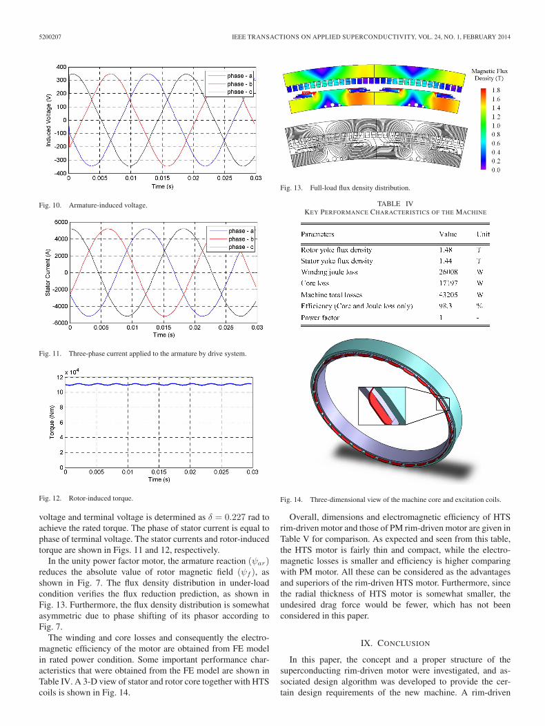
voltage and terminal voltage is determined as δ = 0.227 rad toachieve the rated torque. The phase of stator current is equal tophase of terminal voltage. The stator currents and rotor-inducedtorque are shown in Figs. 11 and 12, respectively.
In the unity power factor motor, the armature reaction (ψar)reduces the absolute value of rotor magnetic field (ψf ), asshown in Fig. 7. The flux density distribution in under-loadcondition verifies the flux reduction prediction, as shown inFig. 13. Furthermore, the flux density distribution is somewhatasymmetric due to phase shifting of its phasor according toFig. 7.
The winding and core losses and consequently the electro-magnetic efficiency of the motor are obtained from FE modelin rated power condition. Some important performance char-acteristics that were obtained from the FE model are shown inTable IV. A 3-D view of stator and rotor core together with HTScoils is shown in Fig. 14.
Fig. 13. Full-load flux density distribution.
TABLE IVKEY PERFORMANCE CHARACTERISTICS OF THE MACHINE
Fig. 14. Three-dimensional view of the machine core and excitation coils.
Overall, dimensions and electromagnetic efficiency of HTSrim-driven motor and those of PM rim-driven motor are given inTable V for comparison. As expected and seen from this table,the HTS motor is fairly thin and compact, while the electro-magnetic losses is smaller and efficiency is higher comparingwith PM motor. All these can be considered as the advantagesand superiors of the rim-driven HTS motor. Furthermore, sincethe radial thickness of HTS motor is somewhat smaller, theundesired drag force would be fewer, which has not beenconsidered in this paper.
IX. CONCLUSION
In this paper, the concept and a proper structure of thesuperconducting rim-driven motor were investigated, and as-sociated design algorithm was developed to provide the cer-tain design requirements of the new machine. A rim-driven

HASSANNIA AND DARABI: SUPERCONDUCTING RIM-DRIVEN SYNCHRONOUS MOTORS FOR MARINE PROPULSION 5200207
TABLE VCOMPARISON OF PM AND HTS MOTORS
superconducting motor was designed for the purpose to beemployed as electric propulsion of a relatively medium sizesubmarine. The design algorithm of machine was validated by2-D FE modeling. It has been discussed that the diameter ofordinary HTS motors, which is commonly large comparingwith axial length, can be reduced significantly by tuning somekey design parameters of a rim-driven-type superconductingmotor. The undesired drag force can be decreased significantlyin resultant thin motor. These form the proposed structure asan eligible electric propulsion system owning superior andadvantages of both rim-driven and superconducting motor.
ACKNOWLEDGMENT
The authors would like to thank the Research Center forMarine Propulsions, University of Shahrood, and the MarineIndustry Organization for the support and information.
REFERENCES
[1] J. F. Gieras, Advancements in Electric Machines. Rockford, IL, USA.:Springer, 2008.
[2] D. S. Parker and C. G. Hodge, “The electric warship,” in Proc. 8th Int.Conf. Elect. Mach. Drives, 1997, pp. 319–325.
[3] J. K. Holt, “Propulsion systems for submarine vessels,” U.S. Patent5 306 183, Apr. 26, 1994.
[4] M. F. Hsieh, J. H. Chen, Y. H. Yeh, C. L. Lee, P. H. Chen, Y. C. Hsu,and Y. H. Chen, “Integrated design and realization of a hubless rim-driventhruster,” in Proc. IEEE 33rd Annu. Conf. IECON, Taipei, Taiwan, 2007,pp. 3033–3038.
[5] A. Y. Yakovlev, M. A. Sokolov, and N. V. Marinich, “Numerical designand experimental verification of a rim-driven thruster,” presented at the2nd Int. Symp. Marine Propulsors, Hamburg, Germany, 2011.
[6] K. H. Kim, S. Turnock, J. Ando, P. Becchi, E. Korkut, A. Minchev,E. Y. Semionicheva, S. H. Van, and W. X. Zhou, “The propulsion com-mittee: Final report and recommendations to the 25th ITTC,” in Proc. Int.Towing Tank Conf., Fukuoka, Japan, 2008, pp. 115–121.
[7] C. Pashias and S. R. Turnock, Hydrodynamic design of bi-directional,rim-driven ducted thruster suitable for underwater vehicles, Univ.Southampton, Southampton, U.K. [Online]. Available: http://eprints.soton.ac.uk/id/eprint/46052
[8] Q. Krovel, “Design of large permanent magnetized synchronous electricmachines,” Ph.D. dissertation, Dept. Elect. Pow. Eng., Norwegian Univ.Sci. Tech., Trodheim, Norway, 2011.
[9] S. M. Sharkh and S. H. Lai, “Slotless PM brushless motor with helicaledge-wound laminations,” IEEE Trans. Energy Conv., vol. 24, no. 3,pp. 594–598, Sep. 2009.
[10] O. Krovel, R. Nilssen, S. E. Skaar, E. Lvli, and N. Sandoy, “Designof an integrated 100 kW permanent magnet synchronous machine in aprototype thruster for ship propulsion,” in Proc. ICEM, Cracow, Poland,2004, pp. 117–123.
[11] S. H. Lai, “Design optimisation of a slotless brushless permanent magnetDC motor with helically-wound laminations for underwater rim-driventhrusters,” Ph.D. dissertation, Facul. Eng. Sci. Math., Univ. Southampton,Southampton, U.K., 2006.
[12] P. M. Tuohy, A. C. Smith, and M. Husband, “Induction rim-drive for amarine propulsor,” presented at the 5th IET Int. Conf. Power Electron.,Machines Drives, Brighton, U.K., 2010.
[13] S. Djebarri, J. F. Charpentier, F. Scuiller, M. Benbouzid, and S. Guemard,“Rough design of a double-stator axial flux permanent magnet genera-tor for a rim-driven marine current turbine,” in Proc. IEEE ISIE, 2012,pp. 1450–1455.
[14] B. Gamble, G. Snitchler, and T. MacDonald, “Full power test of a36.5 MW HTS propulsion motor,” IEEE Trans. Appl. Supercond., vol. 21,no. 3, pp. 1083–1088, Jun. 2011.
[15] J. Li and K. T. Chau, “A novel HTS PM vernier motor for direct-drivepropulsion,” IEEE Trans. Appl. Supercond., vol. 21, no. 3, pp. 1175–1179,Jun. 2011.
[16] D. Sugyo, Y. Kimura, T. Sano, K. Yamaguchi, K. Tsuzuki, R. Taguchi,M. Izumi, M. Miki, M. Kitano, H. Sugimoto, and H. Fujimoto, “Bi-2223field-poles without iron core for an axial type of HTS propulsion motor,”IEEE Trans. Appl. Supercond., vol. 19, no. 3, pp. 1687–1691, Jun. 2009.
[17] Y. Kim, T. Ki, H. Kim, S. Jeong, J. Kim, and J. Jung, “High tempera-ture superconducting motor cooled by on-board cryocooler,” IEEE Trans.Appl. Supercond., vol. 21, no. 3, pp. 2217–2220, Jun. 2011.
[18] H. M. Jang, I. Muta, T. Hoshino, T. Nakamura, S. W. Kim, M. H. Sohn,Y. K. Kwon, and K. S. Ryu, “Conceptual design of 100 HP synchronousmotor with HTS field winding,” in Proc. Int. Conf. Elect. Eng. Japan,2002, pp. 1618–1628.
[19] Y. S. Jo, Y. K. Kwon, M. H. Sohn, K. S. Ryu, Y. K. Kim, and J. P. Hong,“High temperature superconducting synchronous motor,” IEEE Trans.Appl. Supercond., vol. 12, no. 1, pp. 833–836, Mar. 2002.
[20] H. M. Kim, Y. S. Yoon, Y. K. Kwon, Y. C. Kim, S. H. Lee, J. P. Hong,J. B. Song, and H. G. Lee, “Design of damper to protect the field coilof an HTS synchronous motor,” IEEE Trans. Appl. Supercond., vol. 19,no. 3, pp. 1683–1686, Jun. 2009.
[21] D. Wu and E. Chen, “Stator design for a 1000 kW HTSC motor withair-gap winding,” IEEE Trans. Appl. Supercond., vol. 21, no. 3, pp. 1093–1096, Jun. 2011.
[22] SuperPower 2G HTS wire specifications, Schenectady, NY, USA2013. [Online]. Available: www.superpower-inc.com/system/files/SP_2G+Wire+Spec+Sheet_for+web_2013FEC_v2_0.pdf
[23] D. Hazelton and T. Lehner, SuperPower 2G HTS wire for electricaland magnet applications (2010). [Online]. Available: indico.cern.ch/materialDisplay.py?materialId=slides&confId=96071
[24] B. Chen, G. B. Gu, G. Q. Zhang, F. C. Song, and C. H. Zhao, “Anal-ysis and design of cooling system in high temperature superconductingsynchronous machines,” IEEE Trans. Appl. Supercond., vol. 17, no. 2,pp. 1557–1560, Jun. 2007.
Amir Hassannia was born in Gonabad, Iran, in February 1984. He received theB.S. degree in electrical engineering from the Ferdowsi University of Mashhad,Mashhad, Iran, in 2006 and the M.S. degree in electrical engineering in 2008from the University of Shahrood, Shahrood, Iran, where he is currently workingtoward the Ph.D. degree in electrical engineering.
His research interests include design and modeling of electrical machines,superconducting motors, and fuzzy control.
Ahmad Darabi received the B.S. degree in electrical engineering from TehranUniversity, Tehran, Iran, in 1989, the M.S. degree in electrical engineeringfrom the Ferdowsi University of Mashhad, Mashhad, Iran, in 1992, and thePh.D. degree in 2002 from Queen’s University, Belfast, U.K., working with theelectrical machine group.
He is currently an Associate Professor with the University of Shahrood,Shahrood, Iran, where he has been with the Faculty of Electrical and RoboticEngineering since 1993. In addition, he is the Head of the Research Center forMarine Propulsions, University of Shahrood. His research activities are mostlyon design, modeling, and manufacturing of miniature electrical machines andgenerating sets.