IEEE-PEDS-5LEVEL-Shiny
6
A Space Vector Based Pulse Width Modulation Scheme for a 5-Level Induction Motor Drive Shiny G., M.R.Baiju Power Electronics Research Laboratory Dept. of Electronics & Communication Engineering College of Engineering Trivandrum, Kerala, India [email protected] Abstract- A Space Vector based Pulse Width Modulation (SVPWM) scheme for a 5-level inverter is presented. Sector identification is carried out using an approach based on fractal concept. To represent the space vectors, 60° coordinate system is used. The use of 60° coordinate system avoids fractal arithmetic compared to Cartesian coordinate system, and increases speed of computation. No look up tables are used to generate sectors and switching vectors. The scheme also works in over modulation region. Experimental results for a 5-level inverter using induction motor in open-end winding configuration are presented to validate the scheme. I. INTRODUCTION Multilevel inverters found wide application in the field of industrial drives. Typical applications include pumps, fans, compressors, grinding mills, wind energy conversion and railway traction [1-3]. Advantages of multilevel inverters such as reduced / dv dt stresses, low electromagnetic compatibility problems, low switching losses and smaller common mode voltage have been reported in literature [1-4]. Different multilevel inverter topologies like Neutral Point Clamped multilevel inverter, diode clamped multilevel inverter, flying capacitor multilevel inverter and cascaded multilevel inverters with separate DC sources are proposed in [5]. Realization of a 3-level inverter structure by feeding an open-end winding induction motor from both ends by two 2-level inverters with symmetric DC link voltage is proposed in [6]. If the 2-level inverters in open-end winding configuration are fed with asymmetric DC link voltages, it will result in a 4-level inverter configuration [7]. Higher multilevel inverter structures can also be realized if an open- end winding induction motor is fed with a 3-level inverter at one end and a 2-level inverter at the other end [8]. The 3-level inverter structure in the above topology is realized by cascaded connection of two 2-level inverters. The modulation and control strategies used for multilevel inverters like carrier based PWM, space vector PWM and selective harmonic elimination PWM are also discussed [3]. This paper proposes a Space Vector based Pulse Width Modulation (SVPWM) scheme for a 5-level inverter. Sector identification is one of the steps in the implementation of SVPWM, even though schemes with out sector identification are also been proposed [9]. In SVPWM, as the number of levels of the inverter increases, identification of the sector to locate the instantaneous reference space vector will become a tedious process. The space vector pulse width modulation scheme proposed in [10] uses an approach based on fractal concept to find the sector of operation. Identification of sector by fractal approach involves progressively dividing the basic sector to locate the instantaneous reference space vector. The fractal based scheme discussed in [10] uses the Cartesian coordinate system to represent the space vectors. Representation of space vectors in Cartesian coordinate system build up large number of fractional values and this will increase the computational complexity of the scheme. In this paper a low computation PWM scheme based on fractal concept is presented. Instead of the Cartesian coordinate system, 60° coordinate frame work is used to represent the space vectors [11-13]. In 60° coordinate system the switching vectors will have integer values and hence this scheme reduces the computation time significantly [11]. The switching vectors needed to realize the reference space vector are automatically generated, with out using look up tables. II. POWER CIRCUIT OF FIVE - LEVEL INVERTER USING INDUCTION MOTOR IN OPEN-END WINDING CONFIGURATION Fig. 1 shows the power circuit configuration of the 5-level inverter structure. The 5-level inverter is realized by feeding an open-end winding induction motor from both ends by a 3-level inverter at one side and a 2-level inverter at the other side. The 3-level inverter uses a cascaded connection of two 2-level inverters (Inverter-1 and Inverter-2). Inverter-3 is a 2-level inverter. The phase winding of the open-end induction motor is connected across the poles of Inverter-2 and Inverter-3. The inverters are fed with asymmetric DC link voltages. Inverter-1 and Inverter-3 are fed with DC link voltages of 4 DC V . The DC link voltage of Inverter-2 is 2 DC V , where DC V is the DC link voltage of a conventional 2-level inverter. The pole voltage of a given phase of Inverter-2 can assume three possible values : 0, 2 DC V and 3 4 DC V , which is the characteristics of a 3-level inverter. The pole voltage of Inverter-3 assumes two values viz. 0 and 4 DC V , depending on whether the top switch or the bottom switch of a given phase leg is turned ON. When these inverters drive the induction motor from both ends, each phase of the induction motor can achieve five different voltage levels. The voltage levels realized for the proposed 5-level inverter are 4 − DC V , 0 , 4 DC V , 2 DC V and 3 4 DC V . These five voltage levels can be represented by vectors 0,1,2,3 and 4 respectively. IEEE PEDS 2011, Singapore, 5 - 8 December 2011 978-1-4577-0001-9/11/$26.00 ©2011 IEEE 292
-
Upload
sep11-insiteadd-ons-courtyarddesign -
Category
Documents
-
view
1 -
download
0
Transcript of IEEE-PEDS-5LEVEL-Shiny
A Space Vector Based Pulse Width Modulation Scheme for a 5-Level Induction Motor Drive
Shiny G., M.R.Baiju Power Electronics Research Laboratory
Dept. of Electronics & Communication Engineering College of Engineering Trivandrum, Kerala, India
Abstract- A Space Vector based Pulse Width Modulation (SVPWM) scheme for a 5-level inverter is presented. Sector identification is carried out using an approach based on fractal concept. To represent the space vectors, 60° coordinate system is used. The use of 60° coordinate system avoids fractal arithmetic compared to Cartesian coordinate system, and increases speed of computation. No look up tables are used to generate sectors and switching vectors. The scheme also works in over modulation region. Experimental results for a 5-level inverter using induction motor in open-end winding configuration are presented to validate the scheme.
I. INTRODUCTION
Multilevel inverters found wide application in the field of industrial drives. Typical applications include pumps, fans, compressors, grinding mills, wind energy conversion and railway traction [1-3]. Advantages of multilevel inverters such as reduced /dv dt stresses, low electromagnetic compatibility problems, low switching losses and smaller common mode voltage have been reported in literature [1-4]. Different multilevel inverter topologies like Neutral Point Clamped multilevel inverter, diode clamped multilevel inverter, flying capacitor multilevel inverter and cascaded multilevel inverters with separate DC sources are proposed in [5]. Realization of a 3-level inverter structure by feeding an open-end winding induction motor from both ends by two 2-level inverters with symmetric DC link voltage is proposed in [6]. If the 2-level inverters in open-end winding configuration are fed with asymmetric DC link voltages, it will result in a 4-level inverter configuration [7]. Higher multilevel inverter structures can also be realized if an open-end winding induction motor is fed with a 3-level inverter at one end and a 2-level inverter at the other end [8]. The 3-level inverter structure in the above topology is realized by cascaded connection of two 2-level inverters. The modulation and control strategies used for multilevel inverters like carrier based PWM, space vector PWM and selective harmonic elimination PWM are also discussed [3]. This paper proposes a Space Vector based Pulse Width Modulation (SVPWM) scheme for a 5-level inverter. Sector identification is one of the steps in the implementation of SVPWM, even though schemes with out sector identification are also been proposed [9]. In SVPWM, as the number of levels of the inverter increases, identification of the sector to locate the instantaneous reference space vector will become a tedious process. The space vector pulse width modulation scheme
proposed in [10] uses an approach based on fractal concept to find the sector of operation. Identification of sector by fractal approach involves progressively dividing the basic sector to locate the instantaneous reference space vector. The fractal based scheme discussed in [10] uses the Cartesian coordinate system to represent the space vectors. Representation of space vectors in Cartesian coordinate system build up large number of fractional values and this will increase the computational complexity of the scheme. In this paper a low computation PWM scheme based on fractal concept is presented. Instead of the Cartesian coordinate system, 60° coordinate frame work is used to represent the space vectors [11-13]. In 60° coordinate system the switching vectors will have integer values and hence this scheme reduces the computation time significantly [11]. The switching vectors needed to realize the reference space vector are automatically generated, with out using look up tables.
II. POWER CIRCUIT OF FIVE - LEVEL INVERTER USING INDUCTION MOTOR IN OPEN-END WINDING CONFIGURATION
Fig. 1 shows the power circuit configuration of the 5-level inverter structure. The 5-level inverter is realized by feeding an open-end winding induction motor from both ends by a 3-level inverter at one side and a 2-level inverter at the other side. The 3-level inverter uses a cascaded connection of two 2-level inverters (Inverter-1 and Inverter-2). Inverter-3 is a 2-level inverter. The phase winding of the open-end induction motor is connected across the poles of Inverter-2 and Inverter-3. The inverters are fed with asymmetric DC link voltages. Inverter-1 and Inverter-3 are fed with DC link voltages of 4DCV . The DC link voltage of Inverter-2 is
2DCV , where DCV is the DC link voltage of a conventional 2-level inverter. The pole voltage of a given phase of Inverter-2 can assume three possible values : 0, 2DCV and 3 4DCV , which is the characteristics of a 3-level inverter. The pole voltage of Inverter-3 assumes two values viz. 0 and
4DCV , depending on whether the top switch or the bottom switch of a given phase leg is turned ON. When these inverters drive the induction motor from both ends, each phase of the induction motor can achieve five different voltage levels. The voltage levels realized for the proposed 5-level inverter are 4− DCV , 0 , 4DCV , 2DCV and 3 4DCV . These five voltage levels can be represented by vectors 0,1,2,3 and 4 respectively.
IEEE PEDS 2011, Singapore, 5 - 8 December 2011
978-1-4577-0001-9/11/$26.00 ©2011 IEEE 292

Fig. 1. 5-Level Inverter structure realized by feeding an open-end winding
induction motor from both ends by a 3-Level inverter and a 2-Level inverter.
Table-I shows pole voltage of the individual inverters and
the corresponding motor phase voltage. Since isolated power supplies are used to feed the individual inverters, the harmonic components of triplen order will be dropped across the points O and O’ (Fig. 1). Therefore triplen harmonics will be absent in the motor phase voltage.
Fig. 2 shows the space vector representation of a 5-level inverter. The space vector diagram of multilevel inverters can be viewed as a hexagonal structure with one inner hexagon and several outer sub hexagons as shown in Fig. 2. Each hexagon is identified with a center referred as Sub Hexagon Center (SHC). The sub hexagon center of the inner hexagon is named as ' 'O . The centers of the outer sub hexagons are designated as 1 6−A A , 1 12−B B and 1 18−C C . Each hexagon is also divided into small triangular region called sectors. There are 96 such sectors in the space vector diagram of a 5-level inverter. Fig. 3 shows the space vector representation of the 5-level inverter in 60° coordinate system. Computational efficiency can be increased by representing the space vectors in 60° coordinate framework [11] .
TABLE I POLE VOLTAGE OF INDIVIDUAL INVERTERS AND CORRESPONDING MOTOR
PHASE VOLTAGE IN A-PHASE WINDING
Pole voltage of 3-Level Inverter
(VA2O)
Pole voltage of 2-Level Inverter
(VA3O’)
Motor Phase Voltage in
A-phase winding VA2A3= VA2O -VA3O’
Realized switching
level
0 4/DCV 4/− DCV 0
0 0 0 1
2/DCV 4/DCV 4/DCV 2
2/DCV 0 2/DCV 3
3 4/DCV 4/DCV 2/DCV 3
3 4/DCV 0 3 4/DCV 4
Fig. 2. Space Vector Representation of a 5-Level Inverter. The redundant
switching vector combinations not shown.
Fig. 3. Space Vector Representation of a 5-level Inverter in
60° Coordinate System III. MODULATION SCHEME FOR THE FIVE-LEVEL INVERTER
The proposed Space Vector based pulse width modulation scheme involves the following steps to realize the reference space vector OX shown in Fig. 2.
a. Determine the small sector which encloses the tip of the reference space vector OX and to find the sub hexagon center which is nearest to the tip of the reference space phasor.
b. Mapping to determine the duration of switching vectors. This is done by shifting the sub hexagon enclosing the tip of reference space vector to coincide with the inner sub hexagon with center ' 'O . The reference space vector OX gets mapped to OX' as shown in Fig. 2.
c. Generation of actual switching vectors which forms the vertices of the sector enclosing the tip of reference space phasor.
293

A. Identification of Sector and Sub Hexagon Center In the proposed work an approach based on fractals is used
to find the sector which encloses the tip of the reference vector. Since the space vector representation of multilevel inverters has an inherent fractal structure, the sectors of higher level inverter can be generated by a technique called triangularization [10]. Fig. 4 shows the space vector representation of a 5-level inverter ( only the vectors in the periphery are shown) and a reference space vector OX situated in basic sector 3. Here the term basic sector is used to represent the sector which is equivalent to the sector of a conventional 2-level inverter. The 60° coordinates corresponding to basic sector 3 are (0,0), (-4,4) and (-4,0). In triangularization, each basic sector is divided into similar small triangular regions. This is achieved by finding the midpoints of the lines joining the vertices of the basic sector. Applying triangularization to basic sector 3 generates four similar sectors as shown in Fig. 5. The new switching vectors formed by the process of triangularization are (-2,2), (-2,0) and (-4,2). Further triangularization will generate sixteen small sectors as shown in Fig. 6. The centroid of each sector is also calculated as the average value of the vertices enclosing the sector. The sector with its centroid closest to the tip of the reference space vector is taken as the sector of operation. As shown in Fig. 6, the sector of operation identified for reference space vector OX is sector with number 14.
Once the sector of operation is found out by applying triangularization, the sub hexagon which is closest to the tip of the reference space vector is also identified. For the reference space phasor OX , the sub hexagon center identified is C7 , with coordinate (-3,3).
B. Mapping to 2-level and determination of duration of switching vectors
The time duration of the switching vectors is determined by mapping the reference space vector to 2-level [14]. In mapping, the identified sub hexagon is shifted to coincide with the center of the inner sub hexagon ' 'O . The mapped reference space vector is shown in Fig. 2 as OX' .
Let the instantaneous amplitudes of the three phase reference sinusoid are denoted as ,aV bV and cV . The
corresponding ' 'm and ' 'n coordinates of reference space vector OX are calculated as
= −m a bV V V (1)
= −n b cV V V (2) The ( , )m n coordinates of the sub hexagon center are
represented as )( ,ms nsV V . For sub hexagon center C7 , the
values of )( ,ms nsV V are (-3,3). Then the coordinates of the mapped reference vector OX' are found out by using the following equations.
_ = −m map m msV V V (3)
_ = −n map n nsV V V (4)
The new phase values of the mapped reference vector
OX' are denoted as asV , bsV and csV and are also found out.
( ) 3_ _2= +m map n mapasV V V (5)
( ) 3_ _= −n map m mapbsV V V (6)
( ) 3_ _2= − −m map n mapcsV V V (7)
The phase voltage timings gaT , gbT and gcT for the three
phases are calculated as given in [15].
C. Actual Switching Vector Generation
To find out the actual switching vectors for realizing the reference space vector, the ( , )m n coordinates corresponding
to the sub hexagon center )( ,ms nsV V are converted to
switching vectors aS , bS and cS as given in Table-II
Fig. 4. Space Vector Representation of a 5-level Inverter with reference space vector
OX situated in basic sector number 3.
Fig. 5. First triangularization of the basic sector
generates four small sectors, numbered 1 to 4.
Fig. 6. Second triangularization generates sixteen sectors, numbered 1 to 16. The tip of the reference space vector is
located in small sector with number 14.
294

TABLE II CONVERSION OF ( , )m n COORDINATES OF SUB HEXAGON CENTER INTO
CORRESPONDING SWITCHING VECTORS Basic Sector
(2-Level)
Switching Vectors
aS bS cS
1 and 2 +ms nsV V nsV 0
3 and 4 0 − msV −− ms nsV V
5 and 6 msV 0 − nsV
For the sub hexagon center C7 , the ( , )m n coordinates are
(-3,3). Since the sub hexagon center is situated in basic sector number 3, the switching vectors calculated are
0=aS
3= =−b msS V
0= − =−c ms nsS V V Thus the switching vector corresponding to the sub
hexagon center C7 is (030). This vector is then added with the vectors corresponding to the mapped reference space vector OX' to generate the actual switching vectors for reference space phasor OX [16], as shown in Fig. 7.
D. Generation of switching signals for over modulation region The proposed scheme also works in over modulation
region. If the tip of the reference space vector OX lies outside the hexagon, it will be considered as over modulation region of operation. During over modulation, the vector representing sub hexagon center is not switched. The two other active vectors will switch for the entire sample period.
Fig. 7. Adding Sub hexagon center vector with Mapped 2- level
PWM signal generates actual switching vectors
IV. EXPERIMENTAL VERIFICATION
The proposed SVPWM scheme is experimentally verified by implementing the scheme on a 2 HP, 3 - phase induction motor drive in open loop with /v f control for different modulation indices. The gating pulses for the three inverters are generated using the dSPACE DS 1104 RTI platform and FPGA Xilinx Virtex. The gating signals used to drive the inverters in 3-level (modulation index, 0.4)m = , 4-level ( 0.53)=m , 5-level ( 0.85)m = and over modulation operation ( 1.1)=m are shown in Fig. 8, Fig. 9, Fig. 10 and Fig. 11 respectively.
The experimental results of pole voltage, phase voltage and motor current for all regions of operation including over modulation are shown from Fig. 12 to Fig. 23.
Fig. 8. Gating Signal for Inverters for 3 - level Operation.
Upper Three Traces for Inverter-1, Middle Three Traces for Inverter-2 Lower Three Traces for Inverter-3 (m = 0.4)
Fig. 9. Gating Signal for Inverters for 4 - level Operation.
Upper Three Traces for Inverter-1, Middle Three Traces for Inverter-2 Lower Three Traces for Inverter-3 (m = 0.53)
Fig. 10. Gating Signal for Inverters for 5 - level Operation.
Upper Three Traces for Inverter-1, Middle Three Traces for Inverter-2 Lower Three Traces for Inverter-3 (m = 0.85)
Fig. 11. Gating Signal for Inverters for Over modulation Operation. Upper Three Traces for Inverter-1, Middle Three Traces for Inverter-2
Lower Three Traces for Inverter-3 (m =1.1)
295
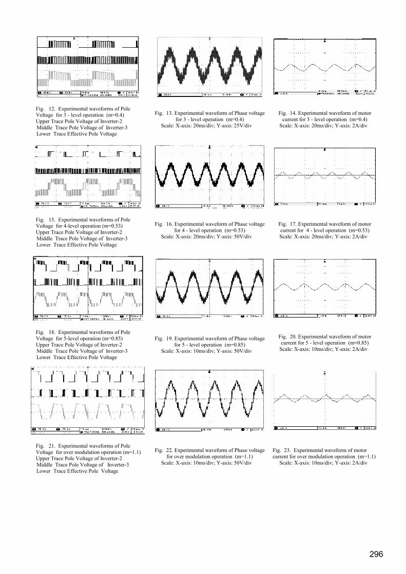
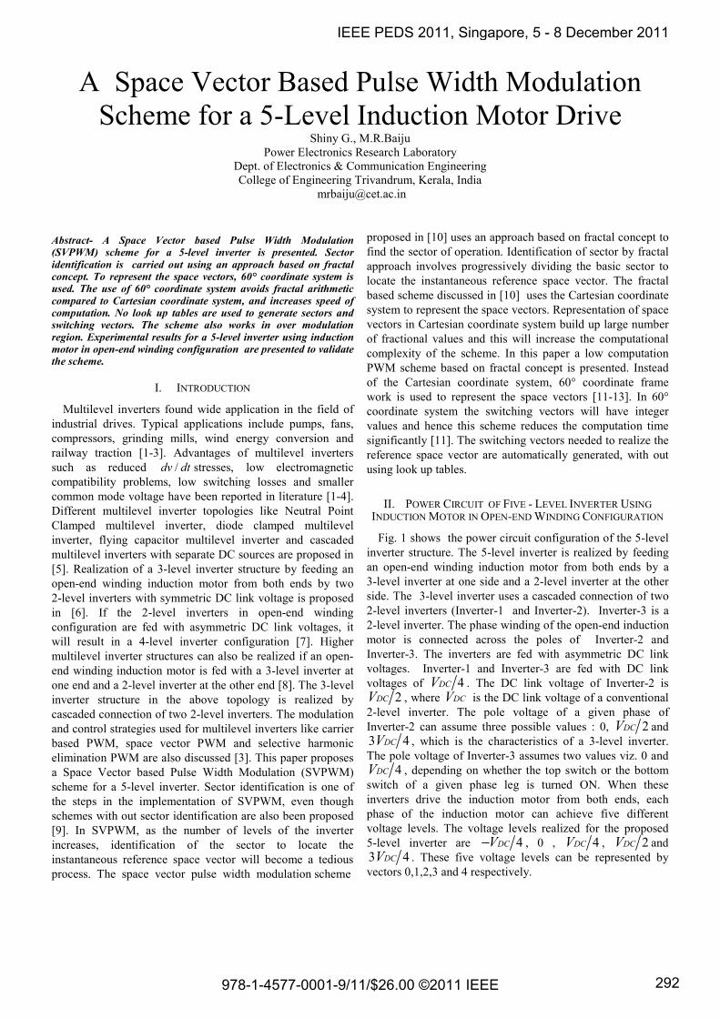
Fig. 12. Experimental waveforms of Pole Voltage for 3 - level operation (m=0.4) Upper Trace Pole Voltage of Inverter-2
Middle Trace Pole Voltage of Inverter-3 Lower Trace Effective Pole Voltage
Fig. 13. Experimental waveform of Phase voltage for 3 - level operation (m=0.4)
Scale: X-axis: 20ms/div; Y-axis: 25V/div
Fig. 14. Experimental waveform of motor current for 3 - level operation (m=0.4)
Scale: X-axis: 20ms/div; Y-axis: 2A/div
Fig. 15. Experimental waveforms of Pole Voltage for 4-level operation (m=0.53) Upper Trace Pole Voltage of Inverter-2
Middle Trace Pole Voltage of Inverter-3 Lower Trace Effective Pole Voltage
Fig. 16. Experimental waveform of Phase voltage for 4 - level operation (m=0.53)
Scale: X-axis: 20ms/div; Y-axis: 50V/div
Fig. 17. Experimental waveform of motor current for 4 - level operation (m=0.53) Scale: X-axis: 20ms/div; Y-axis: 2A/div
Fig. 18. Experimental waveforms of Pole Voltage for 5-level operation (m=0.85) Upper Trace Pole Voltage of Inverter-2 Middle Trace Pole Voltage of Inverter-3
Lower Trace Effective Pole Voltage
Fig. 19. Experimental waveform of Phase voltage for 5 - level operation (m=0.85)
Scale: X-axis: 10ms/div; Y-axis: 50V/div
Fig. 20. Experimental waveform of motor current for 5 - level operation (m=0.85)
Scale: X-axis: 10ms/div; Y-axis: 2A/div
Fig. 21. Experimental waveforms of Pole Voltage for over modulation operation (m=1.1) Upper Trace Pole Voltage of Inverter-2
Middle Trace Pole Voltage of Inverter-3 Lower Trace Effective Pole Voltage
Fig. 22. Experimental waveform of Phase voltage for over modulation operation (m=1.1)
Scale: X-axis: 10ms/div; Y-axis: 50V/div
Fig. 23. Experimental waveform of motor current for over modulation operation (m=1.1)
Scale: X-axis: 10ms/div; Y-axis: 2A/div
296

The pole voltage for a modulation index of 0.4=m (3-level operation) is shown in Fig. 12. The effective pole voltage 'A2O A3O( )−V V is captured using the MATH subtraction feature of the scope. The effective pole voltage show a three level waveform with levels 4− DCV , 0
and 4DCV . The phase voltage and motor current in A-phase winding for a modulation index of 0.4=m are shown in Fig. 13 and Fig. 14. The corresponding voltages and motor current for 4-level operation are shown in Fig. 15, Fig. 16 and Fig. 17 respectively. In Fig. 15, the pole voltage show four distinct levels viz., 4− DCV ,0, 4DCV and 2DCV .The experimental results for 5-level operation ( 0.85)=m are shown in Fig. 18 to Fig. 20. In 5-level operation mode, the pole voltage show all the five levels of operation. When the modulation index is increased, the phase voltage waveform also gets refined and show more number of steps compared to lower modulation indices. The results for over modulation operation are shown from Fig. 21 to Fig. 23. In over modulation, the reference space vector traces the boundary of the outer hexagon. The inverters show less switching in this region, since only the active vectors are switched during over modulation. The phase voltage also shows reduced switching during this mode of operation.
V. CONCLUSION
A space vector based pulse width modulation scheme for a 5-level inverter in open-end configuration is presented. The induction motor is driven by a 3-level from one side and a 2-level inverter from the other side. The combined inverter structure produces voltage space vectors similar to that of a 5-level inverter. All the computations are done in 60° coordinate frame work, thereby avoiding computational complexity. No look up tables are used to generate the switching vectors. The vectors are automatically generated. The space vector diagram of the 5-level inverter consists of 96 sectors and to simplify the task of sector identification, a method based on fractal approach is employed. Experimental results are presented along with the gating signals used to drive the inverters in all the regions of operation, including operation in over modulation.
ACKNOWLEDGMENT
The authors wish to acknowledge the assistance provided by Centre for Engineering Research and Development (CERD), Govt. of Kerala.
REFERENCES [1] Samir Kouro, Mariusz Malinowski, K. Gopakumar, Josep Pou,
Leopoldo G. Franquelo, BinWu, Jose Rodriguez, Marcelo A. Pérez, and Jose I. Leon, “Recent Advances and Industrial Applications of Multilevel Converters”, IEEE Transactions on Industrial Electronics, vol.57, No. 8, August 2010, pp 2553-2580.
[2] Haitham Abu-Rub, Joachim Holtz, Jose Rodriguez and Ge Baoming, “Medium-Voltage Converters-State of the Art, Challenges, and Requirements in Industrial Applications”, IEEE Transactions on Industrial Electronics, vol.57, No. 8, August 2010, pp 2581-2596.
[3] Jose Rodriguez, Leopoldo G. Franquelo, Samir Kouro, Jose I. Leon et al, “Multilevel Converters: An Enabling Technology for High-Power Applications”, Proceedings of the IEEE, vol. 97, No. 11, November 2009, pp 1786–1817.
[4] L. G. Franquelo, J. Rodriguez, J.I. Leon, S. Kouro, R. Portillo, and M.A.M Prats, ‘‘The Age of Multilevel Converters Arrives’’, IEEE Industrial Electronics Magazine, vol. 2, No. 2, June 2008, pp 28---39.
[5] J.-S. Lai and F. Z. Peng, “Multilevel converters—A new breed of power converters”, IEEE Transactions on Industry Applications, vol. 32, No. 3, May 1996, pp 509–517.
[6] Shivkumar E.G, Gopakumar. K, Sinha S.K, Andre Pittet, and Ranganathan V.T, “Space Vector PWM control of dual inverter fed open- end winding induction motor drive”, Proc. Applied Power Electronics Conf (APEC), 2001, pp 399-405.
[7] Shivkumar E.G, Somasekhar V.T, Krushna K, Mohapatra K, Gopakumar. K, Umanand L, and S.K. Sinha, “A multilevel space phasor based PWM strategy for an open- end winding induction motor drive using two inverters with different DC link voltages”, Proc. IEEE PEDS 2001, pp 169-175.
[8] V.T.Somasekhar, K.Gopakumar, M.R.Baiju, Krishna K.Mohapatra, and L.Umanand, “A Multilevel Inverter System for an Induction Motor with Open-end Windings”, IEEE Transactions on Industrial Electronics, vol.52, No.3, June 2005, pp 824-836.
[9] M.R.Baiju, K.K.Mohapatra and K.Gopakumar,“PWM Signal Generation for Dual Inverter Fed Open-end Winding Induction Motor Drive Using Only the Instantaneous Reference Phase Amplitudes”. Pro. IEEE PEDS 2003, pp 450-455.
[10] Anish Gopinath, Aneesh Mohamed A.S and M.R.Baiju, “Fractal Based Space Vector PWM for Multilevel Inverters – a Novel Approach”, IEEE Transactions on Industrial Electronics, vol.52, No. 4, April 2009, pp 1230-1238.
[11] N.Celanovic and Dushan Boroyevich, “A Fast Space-Vector Modulation Algorithm for Multilevel Three-Phase Converters”, IEEE Transactions on Industry Applications, vol.37, No.2, March/April 2001, pp 637-641.
[12] Wenxi Yao, Haibing Hu and Zhengyu Lu, “Comparison of Space Vector Modulation and Carrier based Modulation of Multilevel Inverter”, IEEE Transactions on Power Electronics, vol.23,No.1, January 2008, pp 45-51.
[13] Sanmin Wei, Bin Wu, Fahai Li and Congwei Liu, “A General Space Vector PWM Control Algorithm for Multilevel Inverters”, Proc. APEC 2003, pp 562-568.
[14] P.F Seixas, M.A. Severo Mendes, P.Donoso Garcia, A.M.N. Lima, “A Space Vector PWM Method for Three-Level Voltage Source Inverters”, Proc. APEC, vol.1, 2000, pp 549-555.
[15] Joohn-Sheok Kim, Seung-Ki Sul, “A Novel Voltage Modulation Technique of the Space Vector PWM”, IPEC Yokohama-95, pp 742-747.
[16] Aneesh Mohamed A.S, Anish Gopinath and M.R.Baiju, “A Simple Space Vector PWM Generation for any General N-Level Inverter”, IEEE Transactions on Industrial Electronics, vol.56,No. 5, May 2009, pp 1649-1656.
297