
IEEE P802.15 - IEEE Mentor
117
IEEE P802.15.4e/D0.01, (15-09/604/r1), 2009-08-26 Copyright © 2009 IEEE. All rights reserved. This is an unapproved IEEE Standards Draft, subject to change. i IEEE P802.15 1 Wireless Personal Area Networks 2 3 Project IEEE P802.15 Working Group for Wireless Personal Area Networks (WPANs) Title IEEE Std 802.15.4e-D0.01/r1 Date Submitted 2009/08/26 Source [Ludwig Winkel, Zafer Sahinoglu, Liang Li], and feeded by the following subgroups: PA, FA, E-GTS, Low-Energy, Short-Header] Voice: [] E-mail: [[email protected],] [[email protected],] [[email protected]] Re: [] Abstract [1 st draft IEEE Std 802.15.4e-D0.01 based on submissions of the PA-, FA-, E-GTS-, Low-Energy-subgroups, of TG4e. Changes r0 to r1: Editorial improvements, corrected refs.] Purpose [] Notice This document has been prepared to assist the IEEE P802.15. It is offered as a basis for discussion and is not binding on the contributing individual(s) or organization(s). The material in this document is subject to change in form and content after further study. The contributor(s) reserve(s) the right to add, amend or withdraw material contained herein. Release The contributor acknowledges and accepts that this contribution becomes the property of IEEE and may be made publicly available by P802.15. 4
-
Upload
khangminh22 -
Category
Documents
-
view
0 -
download
0
Transcript of IEEE P802.15 - IEEE Mentor

IEEE P802.15.4e/D0.01, (15-09/604/r1), 2009-08-26
Copyright © 2009 IEEE. All rights reserved. This is an unapproved IEEE Standards Draft, subject to change.
i
IEEE P802.15 1
Wireless Personal Area Networks 2 3
Project IEEE P802.15 Working Group for Wireless Personal Area Networks (WPANs)
Title IEEE Std 802.15.4e-D0.01/r1
Date Submitted
2009/08/26
Source [Ludwig Winkel, Zafer Sahinoglu, Liang Li], and feeded by the following subgroups: PA, FA, E-GTS, Low-Energy, Short-Header]
Voice: [] E-mail: [[email protected],] [[email protected],] [[email protected]]
Re: []
Abstract [1st draft IEEE Std 802.15.4e-D0.01 based on submissions of the PA-, FA-, E-GTS-, Low-Energy-subgroups, of TG4e. Changes r0 to r1: Editorial improvements, corrected refs.]
Purpose []
Notice This document has been prepared to assist the IEEE P802.15. It is offered as a basis for discussion and is not binding on the contributing individual(s) or organization(s). The material in this document is subject to change in form and content after further study. The contributor(s) reserve(s) the right to add, amend or withdraw material contained herein.
Release The contributor acknowledges and accepts that this contribution becomes the property of IEEE and may be made publicly available by P802.15.
4

2009-08-26, (15-09/604/r1), IEEE P802.15.4e/D0.01, August 2009
Copyright © 2009 IEEE. All rights reserved. This is an unapproved IEEE Standards Draft, subject to change.
ii
IEEE P802.15.4e™/D0.01 1
Draft Standard for Information 2
technology— Telecommunications and 3
information exchange between 4
systems— Local and metropolitan area 5
networks— Specific requirements— 6
Part 15.4: Wireless Medium Access 7
Control (MAC) and Physical Layer 8
(PHY) Specifications for Low-Rate 9
Wireless Personal Area Networks 10
(WPANs) Amendment 1: Add MAC 11
enhancements for industrial 12
applications and CWPAN 13
Prepared by the LAN/MAN Standards Committee Working Group of the 14
IEEE Computer Society Committee 15
Copyright © 2009 by the Institute of Electrical and Electronics Engineers, Inc. 16 Three Park Avenue 17 New York, New York 10016-5997, USA 18 All rights reserved. 19 This document is an unapproved draft of a proposed IEEE Standard. As such, this document is subject to 20 change. USE AT YOUR OWN RISK! Because this is an unapproved draft, this document must not be 21 utilized for any conformance/compliance purposes. Permission is hereby granted for IEEE Standards 22 Committee participants to reproduce this document for purposes of international standardization 23 consideration. Prior to adoption of this document, in whole or in part, by another standards development 24 organization, permission must first be obtained from the IEEE Standards Activities Department 25 ([email protected]). Other entities seeking permission to reproduce this document, in whole or in part, must 26 also obtain permission from the IEEE Standards Activities Department. 27 IEEE Standards Activities Department 28 445 Hoes Lane 29 Piscataway, NJ 08854, USA 30

IEEE P802.15.4e/D0.01, (15-09/604/r1), 2009-08-26
Copyright © 2009 IEEE. All rights reserved. This is an unapproved IEEE Standards Draft, subject to change.
iii
Abstract: First draft of 802 WG15 TG4e. Amendment to IEEE Std 802.15.4-2009 1 Keywords: Amendment for application domains like Process automation, Low latency, 2 Commercial, and enhancements for Security, low energy, etc. 3 4
• 5
The Institute of Electrical and Electronics Engineers, Inc. 3 Park Avenue, New York, NY 10016-5997, USA Copyright © 200X by the Institute of Electrical and Electronics Engineers, Inc. All rights reserved. Published XX Month XXXX. Printed in the United States of America. IEEE is a registered trademark in the U.S. Patent & Trademark Office, owned by the Institute of Electrical and Electronics Engineers, Incorporated. PDF: ISBN 978-0-XXXX-XXXX-X STDXXXXX Print: ISBN 978-0-XXXX-XXXX-X STDPDXXXXX No part of this publication may be reproduced in any form, in an electronic retrieval system or otherwise, without the prior written permission of the publisher.

2009-08-26, (15-09/604/r1), IEEE P802.15.4e/D0.01, August 2009
Copyright © 2009 IEEE. All rights reserved. This is an unapproved IEEE Standards Draft, subject to change.
iv
This page is left blank intentionally. 1


2009-08-26, (15-09/604/r1), IEEE P802.15.4e/D0.01, August 2009
Copyright © 2009 IEEE. All rights reserved. This is an unapproved IEEE Standards Draft, subject to change.
iv
Introduction 1
This introduction is not part of IEEE P802.15.4e/D0.01, Draft Standard for Information technology— 2 Telecommunications and information exchange between systems— Local and metropolitan area networks— Specific 3 requirements— Part 15.4: Wireless Medium Access Control (MAC) and Physical Layer (PHY) Specifications for Low-4 Rate Wireless Personal Area Networks (WPANs) Amendment 1: Add MAC enhancements for industrial applications 5 and CWPAN. 6
Notice to users 7
Text formatted as this line means an editor note and will be removed before 8 publication. 9
Laws and regulations 10
Users of these documents should consult all applicable laws and regulations. Compliance with the 11 provisions of this standard does not imply compliance to any applicable regulatory requirements. 12 Implementers of the standard are responsible for observing or referring to the applicable regulatory 13 requirements. IEEE does not, by the publication of its standards, intend to urge action that is not in 14 compliance with applicable laws, and these documents may not be construed as doing so. 15
Copyrights 16
This document is copyrighted by the IEEE. It is made available for a wide variety of both public and 17 private uses. These include both use, by reference, in laws and regulations, and use in private self-18 regulation, standardization, and the promotion of engineering practices and methods. By making this 19 document available for use and adoption by public authorities and private users, the IEEE does not waive 20 any rights in copyright to this document. 21
Updating of IEEE documents 22
Users of IEEE standards should be aware that these documents may be superseded at any time by the 23 issuance of new editions or may be amended from time to time through the issuance of amendments, 24 corrigenda, or errata. An official IEEE document at any point in time consists of the current edition of the 25 document together with any amendments, corrigenda, or errata then in effect. In order to determine whether 26 a given document is the current edition and whether it has been amended through the issuance of 27 amendments, corrigenda, or errata, visit the IEEE Standards Association web site at 28 http://ieeexplore.ieee.org/xpl/standards.jsp, or contact the IEEE at the address listed previously. 29
For more information about the IEEE Standards Association or the IEEE standards development process, 30 visit the IEEE-SA web site at http://standards.ieee.org. 31

IEEE P802.15.4e/D0.01, (15-09/604/r1), 2009-08-26
Copyright © 2009 IEEE. All rights reserved. This is an unapproved IEEE Standards Draft, subject to change.
v
Errata 1
Errata, if any, for this and all other standards can be accessed at the following URL: 2 http://standards.ieee.org/reading/ieee/updates/errata/index.html. Users are encouraged to check this URL 3 for errata periodically. 4
Interpretations 5
Current interpretations can be accessed at the following URL: http://standards.ieee.org/reading/ieee/interp/ 6 index.html. 7
Patents 8
Attention is called to the possibility that implementation of this standard may require use of subject matter 9 covered by patent rights. By publication of this standard, no position is taken with respect to the existence 10 or validity of any patent rights in connection therewith. The IEEE is not responsible for identifying 11 Essential Patent Claims for which a license may be required, for conducting inquiries into the legal validity 12 or scope of Patents Claims or determining whether any licensing terms or conditions provided in 13 connection with submission of a Letter of Assurance, if any, or in any licensing agreements are reasonable 14 or non-discriminatory. Users of this standard are expressly advised that determination of the validity of any 15 patent rights, and the risk of infringement of such rights, is entirely their own responsibility. Further 16 information may be obtained from the IEEE Standards Association. 17
Participants 18
At the time this draft standard was submitted to the IEEE-SA Standards Board for approval, the LAN/MAN 19 Standards Committee Working Group had the following membership: 20
Bob Heile, Chair 21 Pat Kinney, Vice Chair 22
23 Participant1 24 Participant2 25 Participant3 26
Participant4 27 Participant5 28 Participant6 29
Participant7 30 Participant8 31 Participant9 32
33 34 The following members of the [individual/entity] balloting committee voted on this standard. Balloters may 35 have voted for approval, disapproval, or abstention. 36 37 (to be supplied by IEEE) 38 39 Participant1 40 Participant2 41 Participant3 42
Participant4 43 Participant5 44 Participant6 45
Participant7 46 Participant8 47 Participant9 48
49 50

2009-08-26, (15-09/604/r1), IEEE P802.15.4e/D0.01, August 2009
Copyright © 2009 IEEE. All rights reserved. This is an unapproved IEEE Standards Draft, subject to change.
vi
Contents 1
1. Overview .................................................................................................................................................... 2 2
2. Normative references.................................................................................................................................. 2 3
3. Definitions .................................................................................................................................................. 2 4
4. Acronyms and abbreviations ...................................................................................................................... 2 5
5. General description..................................................................................................................................... 2 6 5.1 Introduction ......................................................................................................................................... 2 7 5.2 Components of the IEEE 802.15.4 WPAN.......................................................................................... 3 8 5.3 Network topologies.............................................................................................................................. 3 9
5.3.1 Star network formation............................................................................................. 3 10 5.3.2 Peer-to-peer network formation................................................................................ 3 11 5.3.3 LL-Star network for wireless low latency networks ................................................. 3 12
5.3.3.1 General ...................................................................................................... 3 13 5.3.3.2 TDMA Access ........................................................................................... 3 14 5.3.3.3 Addressing................................................................................................. 3 15 5.3.3.4 Network Topology..................................................................................... 3 16
5.4 Architecture ......................................................................................................................................... 4 17 5.5 Functional overview ............................................................................................................................ 4 18
5.5.1 Superframe structure ................................................................................................ 4 19 5.5.1.1 General ...................................................................................................... 4 20 5.5.1.2 Superframe structure based on Beacons .................................................... 5 21
5.5.2 Data transfer model .................................................................................................. 6 22 5.5.2.1 Data transfer to a coordinator .................................................................... 6 23 5.5.2.2 Data transfer from a coordinator................................................................ 7 24
5.5.3 .................................................................................................................................. 8 25 5.5.4 Improving probability of successful delivery ........................................................... 8 26
5.5.4.1 CSMA-CA mechanism.............................................................................. 8 27 5.5.4.2 ALOHA mechanism for the UWB device ................................................. 8 28
5.5.5 .................................................................................................................................. 9 29 5.5.6 .................................................................................................................................. 9 30 5.5.7 .................................................................................................................................. 9 31 5.5.8 .................................................................................................................................. 9 32
5.6 Concept of primitives .......................................................................................................................... 9 33
6. PHY specification....................................................................................................................................... 9 34 6.1 .............................................................................................................................................................. 9 35
6.1.1 .................................................................................................................................. 9 36 6.1.2 .................................................................................................................................. 9 37
7. MAC sublayer specification ....................................................................................................................... 9 38 7.1 MAC sublayer service specification .................................................................................................... 9 39
7.1.1 MAC data service..................................................................................................... 9 40 7.1.1.1 MCPS-DATA.request................................................................................ 9 41

IEEE P802.15.4e/D0.01, (15-09/604/r1), 2009-08-26
Copyright © 2009 IEEE. All rights reserved. This is an unapproved IEEE Standards Draft, subject to change.
vii
7.1.1.1.1 Semantics of the service primitive ...................................................... 9 1 7.1.1.1.1.1 General ........................................................................................ 9 2 7.1.1.1.1.2 PA-Semantics of the service primitive ....................................... 10 3
7.1.1.1.2 When generated ................................................................................ 11 4 7.1.1.1.3 Effect on receipt................................................................................ 11 5
7.1.1.2 MCPS-DATA.confirm............................................................................. 12 6 7.1.1.2.1 Semantics of the service primitive .................................................... 12 7
7.1.1.2.1.1 General ...................................................................................... 12 8 7.1.1.2.1.2 PA-Semantics of the service primitive ....................................... 12 9
7.1.1.2.2 When generated ................................................................................ 12 10 7.1.1.2.3 Appropriate usage............................................................................. 12 11
7.1.1.3 MCPS-DATA.indication ......................................................................... 13 12 7.1.2 MAC management service ..................................................................................... 13 13
7.1.2.1 General .................................................................................................... 13 14 7.1.2.2 PA-MAC management service ................................................................ 13 15 7.1.2.3 LL-MAC management service ................................................................ 13 16 7.1.2.4 C-MAC management service................................................................... 13 17
7.1.3 Association primitives ............................................................................................ 14 18 7.1.4 Disassociation primitives........................................................................................ 14 19 7.1.5 Beacon notification primitive ................................................................................. 14 20 7.1.6 ................................................................................................................................ 14 21 7.1.7 ................................................................................................................................ 14 22 7.1.8 ................................................................................................................................ 14 23 7.1.9 ................................................................................................................................ 14 24 7.1.10 .............................................................................................................................. 14 25 7.1.11 .............................................................................................................................. 14 26 7.1.12 .............................................................................................................................. 14 27 7.1.13 .............................................................................................................................. 14 28 7.1.14 .............................................................................................................................. 14 29 7.1.15 .............................................................................................................................. 14 30 7.1.16 Primitives for requesting data from a coordinator ................................................ 14 31 7.1.17 Primitives for specifying dynamic preamble (for UWB PHYs)............................ 14 32 7.1.18 .............................................................................................................................. 14 33 7.1.19 .............................................................................................................................. 14 34 7.1.20 MAC enumeration description ............................................................................. 14 35 7.1.21 PA-specific MAC sublayer service specification.................................................. 15 36
7.1.21.1 MLME-SET-SLOTFRAME.................................................................. 15 37 7.1.21.1.1 MLME-SET-SLOTFRAME.request............................................... 15 38
7.1.21.1.1.1 General .................................................................................... 15 39 7.1.21.1.1.2 Semantics................................................................................. 15 40 7.1.21.1.1.3 When generated ....................................................................... 16 41 7.1.21.1.1.4 Effect on receipt....................................................................... 16 42
7.1.21.1.2 MLME-SET-SLOTFRAME.confirm.............................................. 16 43 7.1.21.1.2.1 General .................................................................................... 16 44 7.1.21.1.2.2 Semantics................................................................................. 16 45 7.1.21.1.2.3 When generated ....................................................................... 17 46

2009-08-26, (15-09/604/r1), IEEE P802.15.4e/D0.01, August 2009
Copyright © 2009 IEEE. All rights reserved. This is an unapproved IEEE Standards Draft, subject to change.
viii
7.1.21.1.2.4 Effect on receipt....................................................................... 17 1 7.1.21.2 MLME-SET-LINK................................................................................ 17 2
7.1.21.2.1 MLME-SET-LINK.request............................................................. 17 3 7.1.21.2.1.1 General .................................................................................... 17 4 7.1.21.2.1.2 Semantics................................................................................. 17 5 7.1.21.2.1.3 When generated ....................................................................... 18 6 7.1.21.2.1.4 Effect on receipt....................................................................... 18 7
7.1.21.2.2 MLME-SET-LINK.confirm............................................................ 19 8 7.1.21.2.2.1 General .................................................................................... 19 9 7.1.21.2.2.2 Semantics................................................................................. 19 10 7.1.21.2.2.3 When generated ....................................................................... 19 11 7.1.21.2.2.4 Effect on receipt....................................................................... 19 12
7.1.21.3 MLME-PA-MODE................................................................................ 20 13 7.1.21.3.1 MLME-PA-MODE.request............................................................. 20 14
7.1.21.3.1.1 Semantics................................................................................. 20 15 7.1.21.3.1.2 When generated ....................................................................... 20 16 7.1.21.3.1.3 Effect on receipt....................................................................... 20 17
7.1.21.3.2 MLME-PA-MODE.confirm ........................................................... 20 18 7.1.21.3.2.1 Semantics................................................................................. 20 19 7.1.21.3.2.2 When generated ....................................................................... 21 20 7.1.21.3.2.3 Effect on receipt....................................................................... 21 21
7.1.21.4 MLME-LISTEN .................................................................................... 21 22 7.1.21.4.1 MLME-LISTEN.request................................................................. 21 23
7.1.21.4.1.1 Semantics................................................................................. 21 24 7.1.21.4.1.2 When generated ....................................................................... 22 25 7.1.21.4.1.3 Effect on receipt....................................................................... 22 26
7.1.21.4.2 MLME-LISTEN.confirm................................................................ 22 27 7.1.21.4.2.1 Semantics................................................................................. 22 28 7.1.21.4.2.2 When generated ....................................................................... 23 29 7.1.21.4.2.3 Effect on receipt....................................................................... 23 30
7.1.21.5 MLME-ADVERTISE............................................................................ 23 31 7.1.21.5.1 MLME-ADVERTISE.request......................................................... 23 32
7.1.21.5.1.1 Semantics................................................................................. 23 33 7.1.21.5.1.2 When generated ....................................................................... 24 34 7.1.21.5.1.3 Effect on receipt....................................................................... 24 35
7.1.21.5.2 ADVERTISE.indication ................................................................. 24 36 7.1.21.5.2.1 Semantics................................................................................. 25 37 7.1.21.5.2.2 When generated ....................................................................... 26 38 7.1.21.5.2.3 Effect on receipt....................................................................... 26 39
7.1.21.5.3 MLME-ADVERTISE.confirm........................................................ 26 40 7.1.21.5.3.1 Semantics................................................................................. 26 41 7.1.21.5.3.2 When generated ....................................................................... 26 42 7.1.21.5.3.3 Effect on receipt....................................................................... 26 43
7.1.21.6 MLME-KEEP-ALIVE........................................................................... 27 44 7.1.21.6.1 MLME-KEEP-ALIVE.request........................................................ 27 45
7.1.21.6.1.1 Semantics................................................................................. 27 46

IEEE P802.15.4e/D0.01, (15-09/604/r1), 2009-08-26
Copyright © 2009 IEEE. All rights reserved. This is an unapproved IEEE Standards Draft, subject to change.
ix
7.1.21.6.1.2 When generated ....................................................................... 27 1 7.1.21.6.1.3 Effect on receipt....................................................................... 27 2
7.1.21.6.2 MLME-KEEP-ALIVE.confirm ...................................................... 27 3 7.1.21.6.2.1 Semantics................................................................................. 27 4 7.1.21.6.2.2 When generated ....................................................................... 28 5 7.1.21.6.2.3 Effect on receipt....................................................................... 28 6
7.1.21.7 MLME-JOIN ......................................................................................... 28 7 7.1.21.7.1 MLME-JOIN.request...................................................................... 28 8
7.1.21.7.1.1 Semantics................................................................................. 28 9 7.1.21.7.1.2 When generated ....................................................................... 29 10 7.1.21.7.1.3 Effect on receipt....................................................................... 29 11
7.1.21.7.2 MLME-JOIN.indication.................................................................. 29 12 7.1.21.7.2.1 Semantics................................................................................. 29 13 7.1.21.7.2.2 When generated ....................................................................... 30 14 7.1.21.7.2.3 Effect on receipt....................................................................... 30 15
7.1.21.7.3 MLME-JOIN.confirm..................................................................... 30 16 7.1.21.7.3.1 Semantics................................................................................. 30 17 7.1.21.7.3.2 When generated ....................................................................... 30 18 7.1.21.7.3.3 Effect on receipt....................................................................... 31 19
7.1.21.8 MLME-ACTIVATE.............................................................................. 31 20 7.1.21.8.1 MLME-ACTIVATE.request........................................................... 31 21
7.1.21.8.1.1 Semantics................................................................................. 31 22 7.1.21.8.1.2 When generated ....................................................................... 32 23 7.1.21.8.1.3 Effect on receipt....................................................................... 32 24
7.1.21.8.2 MLME-ACTIVATE.indication ...................................................... 32 25 7.1.21.8.2.1 Semantics................................................................................. 32 26 7.1.21.8.2.2 When generated ....................................................................... 33 27 7.1.21.8.2.3 Effect on receipt....................................................................... 33 28
7.1.21.8.3 MLME-ACTIVATE.confirm.......................................................... 33 29 7.1.21.8.3.1 Semantics................................................................................. 33 30 7.1.21.8.3.2 When generated ....................................................................... 33 31 7.1.21.8.3.3 Effect on receipt....................................................................... 33 32
7.1.21.9 MLME-DISCONNECT......................................................................... 33 33 7.1.21.9.1 MLME-DISCONNECT.request...................................................... 34 34
7.1.21.9.1.1 Semantics................................................................................. 34 35 7.1.21.9.1.2 When generated ....................................................................... 34 36 7.1.21.9.1.3 Effect on receipt....................................................................... 34 37
7.1.21.9.2 MLME-DISCONNECT.indication ................................................. 34 38 7.1.21.9.2.1 Semantics................................................................................. 34 39 7.1.21.9.2.2 When generated ....................................................................... 35 40 7.1.21.9.2.3 Effect on receipt....................................................................... 35 41
7.1.21.9.3 MLME-DISCONNECT.confirm .................................................... 35 42 7.1.21.9.3.1 Semantics................................................................................. 35 43 7.1.21.9.3.2 When generated ....................................................................... 35 44 7.1.21.9.3.3 Effect on receipt....................................................................... 35 45
7.1.22 LL-specific MAC sublayer service specification.................................................. 35 46

2009-08-26, (15-09/604/r1), IEEE P802.15.4e/D0.01, August 2009
Copyright © 2009 IEEE. All rights reserved. This is an unapproved IEEE Standards Draft, subject to change.
x
7.1.22.1 Primitives for Superframe Configuration of low latency networks ........ 36 1 7.1.22.1.1 General ........................................................................................... 36 2 7.1.22.1.2 MLME-SFCF.discovery ................................................................. 36 3
7.1.22.1.2.1 General .................................................................................... 36 4 7.1.22.1.2.2 Semantics of the Service Primitive .......................................... 36 5 7.1.22.1.2.3 When generated ....................................................................... 36 6 7.1.22.1.2.4 Appropriate usage .................................................................... 36 7
7.1.22.1.3 MLME-SFCF.discovery_confirm................................................... 36 8 7.1.22.1.3.1 General .................................................................................... 36 9 7.1.22.1.3.2 Semantics of the Service Primitive .......................................... 36 10 7.1.22.1.3.3 When generated ....................................................................... 37 11 7.1.22.1.3.4 Appropriate usage .................................................................... 37 12
7.1.22.1.4 MLME-SFCF.configuration ........................................................... 37 13 7.1.22.1.4.1 General .................................................................................... 37 14 7.1.22.1.4.2 Semantics of the Service Primitive .......................................... 37 15 7.1.22.1.4.3 When generated ....................................................................... 37 16 7.1.22.1.4.4 Appropriate usage .................................................................... 37 17
7.1.22.1.5 MLME-SFCF.configuration_confirm ............................................. 37 18 7.1.22.1.5.1 General .................................................................................... 37 19 7.1.22.1.5.2 Semantics of the Service Primitive .......................................... 37 20 7.1.22.1.5.3 When generated ....................................................................... 38 21 7.1.22.1.5.4 Appropriate usage .................................................................... 38 22
7.1.22.1.6 MLME-SFCF.online....................................................................... 38 23 7.1.22.1.6.1 General .................................................................................... 38 24 7.1.22.1.6.2 Semantics of the Service Primitive .......................................... 38 25 7.1.22.1.6.3 When generated ....................................................................... 38 26 7.1.22.1.6.4 Appropriate usage .................................................................... 38 27
7.1.22.1.7 MLME-SFCF.online_indication ..................................................... 38 28 7.1.22.1.7.1 General .................................................................................... 38 29 7.1.22.1.7.2 Semantics of the Service Primitive .......................................... 38 30 7.1.22.1.7.3 When generated ....................................................................... 39 31 7.1.22.1.7.4 Appropriate usage .................................................................... 39 32
7.1.23 C-specific MAC sublayer service specification .................................................... 39 33 7.2 MAC frame formats........................................................................................................................... 39 34
7.2.1 General MAC frame format ................................................................................... 39 35 7.2.1.1 Frame Control field ................................................................................. 39 36
7.2.1.1.1 Frame Type subfield ......................................................................... 39 37 7.2.2 Format of individual frame types ........................................................................... 40 38
7.2.2.1 Beacon frame format ............................................................................... 40 39 7.2.3 Frame compatibility ............................................................................................... 40 40 7.2.4 PA-Frame Formats ................................................................................................. 40 41 7.2.5 LL-Frame Formats ................................................................................................. 43 42
7.2.5.1 General MAC Frame Format with MHR of 1 octet ................................. 43 43 7.2.5.1.1 General ............................................................................................. 43 44 7.2.5.1.2 Shortened Frame Control field.......................................................... 43 45
7.2.5.1.2.1 General ...................................................................................... 43 46 7.2.5.1.2.2 Frame Type subfield .................................................................. 44 47

IEEE P802.15.4e/D0.01, (15-09/604/r1), 2009-08-26
Copyright © 2009 IEEE. All rights reserved. This is an unapproved IEEE Standards Draft, subject to change.
xi
7.2.5.1.2.3 Security Enabled subfield .......................................................... 44 1 7.2.5.1.2.4 Frame Version subfield.............................................................. 44 2 7.2.5.1.2.5 ACK Request subfield ............................................................... 44 3 7.2.5.1.2.6 Sub Frame Type subfield ........................................................... 44 4
7.2.5.1.3 Frame Payload field .......................................................................... 45 5 7.2.5.1.4 FCS field........................................................................................... 45 6
7.2.5.2 Format of individual frame types with MHR of 1 octet ........................... 45 7 7.2.5.2.1 General ............................................................................................. 45 8 7.2.5.2.2 Beacon frame format ........................................................................ 45 9
7.2.5.2.2.1 General ...................................................................................... 45 10 7.2.5.2.2.2 Beacon frame MHR fields ......................................................... 46 11 7.2.5.2.2.3 Flags / Beacon Payload in online mode ..................................... 46 12 7.2.5.2.2.4 Flags / Beacon payload for discovery and configuration mode .. 47 13
7.2.5.2.3 Data frame format............................................................................. 48 14 7.2.5.2.3.1 General ...................................................................................... 48 15 7.2.5.2.3.2 Data frame MHR fields.............................................................. 48 16 7.2.5.2.3.3 Data Payload field...................................................................... 48 17
7.2.5.2.4 Acknowledgement frame format....................................................... 48 18 7.2.5.2.4.1 General ...................................................................................... 48 19 7.2.5.2.4.2 Acknowledgement frame MHR fields ....................................... 49 20 7.2.5.2.4.3 Acknowledgement Type field .................................................... 49 21 7.2.5.2.4.4 Acknowlegement Payload field ................................................. 49 22 7.2.5.2.4.5 Data Group ACK (GACK) ........................................................ 49 23
7.2.5.2.5 MAC Command frame format .......................................................... 50 24 7.2.5.2.5.1 General ...................................................................................... 50 25 7.2.5.2.5.2 MAC command frame MHR fields............................................ 50 26 7.2.5.2.5.3 Command Payload field............................................................. 51 27
7.3 MAC command frames...................................................................................................................... 51 28 7.3.1 Association request command ................................................................................ 51 29 7.3.2 ................................................................................................................................ 52 30 7.3.3 ................................................................................................................................ 52 31 7.3.4 ................................................................................................................................ 52 32 7.3.5 ................................................................................................................................ 52 33 7.3.6 ................................................................................................................................ 52 34 7.3.7 Beacon request command....................................................................................... 52 35
7.3.7.1 General .................................................................................................... 52 36 7.3.7.2 SUN-Enhanced Beacon request command .............................................. 53 37
7.3.7.2.1 General ............................................................................................. 53 38 7.3.7.2.2 Request Field .................................................................................... 53 39
7.3.7.2.2.1 General ...................................................................................... 53 40 7.3.7.2.2.2 Permit Joining On ...................................................................... 54 41 7.3.7.2.2.3 LinkQuality Level...................................................................... 54 42 7.3.7.2.2.4 Percent filter .............................................................................. 54 43 7.3.7.2.2.5 Extended Payload ...................................................................... 54 44
7.3.8 Coordinator realignment command ........................................................................ 54 45 7.3.9 GTS request command ........................................................................................... 54 46 7.3.10 PA-commands ...................................................................................................... 55 47

2009-08-26, (15-09/604/r1), IEEE P802.15.4e/D0.01, August 2009
Copyright © 2009 IEEE. All rights reserved. This is an unapproved IEEE Standards Draft, subject to change.
xii
7.3.10.1 Advertisement command ....................................................................... 55 1 7.3.10.1.1 General ........................................................................................... 55 2 7.3.10.1.2 MHR field....................................................................................... 55 3 7.3.10.1.3 Command Frame Identifier field..................................................... 55 4 7.3.10.1.4 Timing Information field ................................................................ 55 5 7.3.10.1.5 Security Control field...................................................................... 55 6 7.3.10.1.6 Join Control field ............................................................................ 56 7 7.3.10.1.7 Timeslot Template and Hopping Sequence ID field ....................... 56 8 7.3.10.1.8 Channel Page/Map Length field...................................................... 56 9 7.3.10.1.9 Channel Page field .......................................................................... 56 10 7.3.10.1.10 Channel Map field ........................................................................ 57 11 7.3.10.1.11 Number of Slotframes field........................................................... 57 12 7.3.10.1.12 Slotframe Information and Links (for each slotframe) field.......... 57 13 7.3.10.1.13 General ......................................................................................... 57 14 7.3.10.1.14 Slotframe ID subfield.................................................................... 57 15 7.3.10.1.15 Slotframe Size subfield ................................................................. 57 16 7.3.10.1.16 Number of Links subfield ............................................................. 57 17 7.3.10.1.17 Link Information (for each link) subfield...................................... 57 18 7.3.10.1.18 Timeslot subfield .......................................................................... 58 19 7.3.10.1.19 Channel Offset Information subfield............................................. 58 20 7.3.10.1.20 Link Option subfield ..................................................................... 58 21 7.3.10.1.21 MIC .............................................................................................. 58 22
7.3.10.2 Join command........................................................................................ 58 23 7.3.10.2.1 General ........................................................................................... 58 24 7.3.10.2.2 MHR fields ..................................................................................... 59 25 7.3.10.2.3 Command Frame Identifier field..................................................... 59 26 7.3.10.2.4 Capability Information field............................................................ 59 27 7.3.10.2.5 Clock Accuracy Capability field..................................................... 59 28 7.3.10.2.6 Join Security Information field ....................................................... 59 29 7.3.10.2.7 Number of Neighbor field............................................................... 59 30 7.3.10.2.8 Neighbor field................................................................................. 60 31 7.3.10.2.9 MIC ................................................................................................ 60 32
7.3.10.3 Activate command................................................................................. 60 33 7.3.10.3.1 General ........................................................................................... 60 34 7.3.10.3.2 MHR............................................................................................... 60 35 7.3.10.3.3 Command Frame Identifier field..................................................... 61 36 7.3.10.3.4 Short Address field ......................................................................... 61 37 7.3.10.3.5 Number of Links field..................................................................... 61 38 7.3.10.3.6 Link field ........................................................................................ 61 39 7.3.10.3.7 Activate Security Information field................................................. 61 40 7.3.10.3.8 MIC ................................................................................................ 61 41
7.3.11 LL-commands ...................................................................................................... 62 42 7.3.11.1 Discover Response command ................................................................ 62 43
7.3.11.1.1 General ........................................................................................... 62 44 7.3.11.1.2 7.3.10.1 MHR fields ....................................................................... 62 45
7.3.11.1.2.1 General .................................................................................... 62 46

IEEE P802.15.4e/D0.01, (15-09/604/r1), 2009-08-26
Copyright © 2009 IEEE. All rights reserved. This is an unapproved IEEE Standards Draft, subject to change.
xiii
7.3.11.1.2.2 Using MAC command frames.................................................. 62 1 7.3.11.1.2.3 Using MAC command frames with shortened frame control ... 62 2
7.3.11.1.3 7.3.10.2 Command Frame Identifier field ....................................... 63 3 7.3.11.1.4 7.3.10.3 Discovery Parameters field ............................................... 63 4
7.3.11.2 Configuration Response Frame.............................................................. 63 5 7.3.11.2.1 General ........................................................................................... 63 6 7.3.11.2.2 MHR fields ..................................................................................... 63 7 7.3.11.2.3 7.3.11.1.1 Using MAC command frames........................................ 64 8
7.3.11.2.3.1 General .................................................................................... 64 9 7.3.11.2.3.2 Using MAC command frames with shortened frame control ... 64 10
7.3.11.2.4 Command Frame Identifier field..................................................... 64 11 7.3.11.2.5 Configuration Parameters field ....................................................... 64 12
7.3.11.3 Configuration Request Frame ................................................................ 64 13 7.3.11.3.1 General ........................................................................................... 64 14 7.3.11.3.2 MHR fields ..................................................................................... 65 15
7.3.11.3.2.1 General .................................................................................... 65 16 7.3.11.3.2.2 Using MAC command frames.................................................. 65 17 7.3.11.3.2.3 Using MAC command frames with shortened frame control ... 65 18
7.3.11.3.3 Command Frame Identifier field..................................................... 65 19 7.3.11.3.4 Configuration Parameters field ....................................................... 65 20
7.3.11.4 Clear to Send (CTS) Shared Group Frame............................................. 66 21 7.3.11.4.1 General ........................................................................................... 66 22 7.3.11.4.2 MHR fields ..................................................................................... 66 23 7.3.11.4.3 Command Frame Identifier field..................................................... 66 24 7.3.11.4.4 Network ID field............................................................................. 66 25
7.3.11.5 Request to Send (RTS) Frame ............................................................... 67 26 7.3.11.5.1 General ........................................................................................... 67 27 7.3.11.5.2 MHR fields ..................................................................................... 67 28 7.3.11.5.3 Command Frame Identifier field..................................................... 67 29 7.3.11.5.4 Short Originator Address ................................................................ 67 30 7.3.11.5.5 Network ID field............................................................................. 67 31
7.3.11.6 Clear to Send (CTS) Frame ................................................................... 68 32 7.3.11.6.1 General ........................................................................................... 68 33 7.3.11.6.2 MHR fields ..................................................................................... 68 34 7.3.11.6.3 Command Frame Identifier field..................................................... 68 35 7.3.11.6.4 Short Destination Address .............................................................. 68 36 7.3.11.6.5 Network ID field............................................................................. 68 37
7.4 MAC constants and PIB attributes..................................................................................................... 69 38 7.4.1 MAC constants....................................................................................................... 69 39 7.4.2 MAC PIB attributes................................................................................................ 69 40
7.4.2.1 General .................................................................................................... 69 41 7.4.2.2 PA-specific MAC PIB attributes ............................................................. 69 42
7.4.2.2.1 General ............................................................................................. 69 43 7.4.2.2.2 PA-MAC PIB attributes for macSlotframeTable .............................. 69 44 7.4.2.2.3 PA-MAC PIB attributes for macLinkTable ...................................... 70 45 7.4.2.2.4 PA-MAC PIB attributes for macTimeslotTemplate .......................... 70 46 7.4.2.2.5 PA-MAC PIB attributes for macHoppingSequence .......................... 71 47

2009-08-26, (15-09/604/r1), IEEE P802.15.4e/D0.01, August 2009
Copyright © 2009 IEEE. All rights reserved. This is an unapproved IEEE Standards Draft, subject to change.
xiv
7.4.2.3 LL-specific MAC PIB attributes.............................................................. 71 1 7.5 MAC functional description .............................................................................................................. 72 2
7.5.1 Channel access ....................................................................................................... 72 3 7.5.1.1 Superframe structure................................................................................ 72 4
7.5.1.1.1 Contention access period (CAP) ....................................................... 72 5 7.5.1.1.2 Contention-free period (CFP) ........................................................... 72 6 7.5.1.1.3 LL-Superframe structure................................................................... 73 7
7.5.1.1.3.1 General Structure of Superframe................................................ 73 8 7.5.1.1.3.2 Beacon Time Slot....................................................................... 74 9 7.5.1.1.3.3 Management Time Slots ............................................................ 74 10 7.5.1.1.3.4 Sensor Time Slots ...................................................................... 74 11 7.5.1.1.3.5 Actuator Time Slots ................................................................... 74 12 7.5.1.1.3.6 Channel access within time slots................................................ 74 13
7.5.1.2 Incoming and outgoing superframe timing .............................................. 75 14 7.5.1.3.................................................................................................................. 75 15 7.5.1.4 CSMA-CA algorithm .............................................................................. 75 16
7.5.1.4.1 General ............................................................................................. 75 17 7.5.1.4.2 PA-CCA Algorithm.......................................................................... 75 18 7.5.1.4.3 PA-CA Algorithm............................................................................. 76 19 7.5.1.4.4 LL-Simplified CSMA-CA ................................................................ 77 20
7.5.1.5 PA-Slotframe structure ............................................................................ 78 21 7.5.1.5.1 General ............................................................................................. 78 22 7.5.1.5.2 Multiple slotframes........................................................................... 78 23
7.5.2 Starting and maintaining PANs .............................................................................. 79 24 7.5.2.1.................................................................................................................. 79 25 7.5.2.2.................................................................................................................. 79 26 7.5.2.3.................................................................................................................. 79 27 7.5.2.4.................................................................................................................. 79 28 7.5.2.5 Device discovery ..................................................................................... 79 29 7.5.2.6 PA-network formation ............................................................................. 79 30
7.5.2.6.1 Overview .......................................................................................... 79 31 7.5.2.6.2 Advertising ....................................................................................... 81 32 7.5.2.6.3 Joining .............................................................................................. 81 33
7.5.3 Association and disassociation ............................................................................... 82 34 7.5.4 Synchronization...................................................................................................... 82 35
7.5.4.1 Synchronization with beacons ................................................................. 82 36 7.5.4.2.................................................................................................................. 82 37 7.5.4.3.................................................................................................................. 82 38 7.5.4.4 Synchronization in PA-network............................................................... 82 39
7.5.4.4.1 Timeslot communication .................................................................. 82 40 7.5.4.4.2 Node synchronization ....................................................................... 84 41
7.5.4.4.2.1 General ...................................................................................... 84 42 7.5.4.4.2.2 Acknowledgement-based synchronization ................................. 84 43 7.5.4.4.2.3 Frame-based synchronization..................................................... 84 44 7.5.4.4.2.4 Network time synchronization ................................................... 85 45 7.5.4.4.2.5 Keep-Alive mechanism.............................................................. 86 46
7.5.5 Transaction handling .............................................................................................. 86 47

IEEE P802.15.4e/D0.01, (15-09/604/r1), 2009-08-26
Copyright © 2009 IEEE. All rights reserved. This is an unapproved IEEE Standards Draft, subject to change.
xv
7.5.6 ................................................................................................................................ 86 1 7.5.6.1.................................................................................................................. 86 2 7.5.6.2 Reception and rejection ........................................................................... 86 3 7.5.6.3.................................................................................................................. 88 4 7.5.6.4.................................................................................................................. 88 5
7.5.6.4.1........................................................................................................... 88 6 7.5.6.4.2 Acknowledgment.............................................................................. 88 7 7.5.6.4.3 Retransmissions ................................................................................ 88 8
7.5.6.4.3.1 General ...................................................................................... 88 9 7.5.6.4.3.2 PA-Retransmissions................................................................... 88 10
7.5.6.5 Promiscuous mode................................................................................... 89 11 7.5.7 GTS allocation and management............................................................................ 89 12
7.5.7.1.................................................................................................................. 89 13 7.5.7.2.................................................................................................................. 89 14 7.5.7.3.................................................................................................................. 89 15 7.5.7.4.................................................................................................................. 89 16 7.5.7.5.................................................................................................................. 89 17 7.5.7.6 GTS expiration ........................................................................................ 89 18 7.5.7.7 LL-Transmission Modes in star networks using short MAC headers ...... 89 19
7.5.7.7.1 General ............................................................................................. 89 20 7.5.7.7.2 Discovery Mode ............................................................................... 89 21 7.5.7.7.3 Configuration Mode.......................................................................... 90 22 7.5.7.7.4 Online Mode..................................................................................... 91 23
7.5.8 Ranging .................................................................................................................. 93 24 7.6 Security suite specifications .............................................................................................................. 93 25 7.7 Message sequence charts illustrating MAC-PHY interaction............................................................ 93 26
Annex L (informative) Bibliography........................................................................................................... 94 27 L.1 Documents for MAC enhancements in support of LL-applications .......................................... 94 28
Annex M (informative) Requirements of indistrial and other application domains .................................... 95 29 M.1 General ...................................................................................................................................... 95 30 M.2 Process automation (PA) ........................................................................................................... 96 31 M.3 Low latency networks (LL) ....................................................................................................... 96 32
M.3.1 Typical application domains for LL-networks................................................. 96 33 M.3.2 Application overview ...................................................................................... 97 34 M.3.3 Requirements and Assumptions....................................................................... 98 35
M.4 Commercial (CM) ..................................................................................................................... 99 36 M.5 Low energy (LE) ....................................................................................................................... 99 37 M.6 Channel Diversity...................................................................................................................... 99 38
39
40


IEEE P802.15.4e/D0.01, (15-09/604/r1), 2009-08-26
Copyright © 2009 IEEE. All rights reserved. This is an unapproved IEEE Standards Draft, subject to change.
1
Draft Standard for Information 1
technology— Telecommunications and 2
information exchange between 3
systems— Local and metropolitan area 4
networks— Specific requirements— 5
Part 15.4: Wireless Medium Access 6
Control (MAC) and Physical Layer 7
(PHY) Specifications for Low-Rate 8
Wireless Personal Area Networks 9
(WPANs) Amendment 1: Add MAC 10
enhancements for industrial 11
applications and CWPAN 12
13
NOTE—The editing instructions contained in this <amendment/corrigendum> define how to merge the material 14 contained therein into the existing base standard and its amendments to form the comprehensive standard. 15
The editing instructions are shown in bold italic. Four editing instructions are used: change, delete, insert, and replace. 16 Change is used to make corrections in existing text or tables. The editing instruction specifies the location of the 17 change and describes what is being changed by using strikethrough (to remove old material) and underscore (to add 18 new material). Delete removes existing material. Insert adds new material without disturbing the existing material. 19 Insertions may require renumbering. If so, renumbering instructions are given in the editing instruction. Replace is used 20 to make changes in figures or equations by removing the existing figure or equation and replacing it with a new one. 21 Editorial notes will not be carried over into future editions because the changes will be incorporated into the base 22 standard. 23 24

2009-08-26, (15-09/604/r1), IEEE P802.15.4e/D0.01, August 2009
Copyright © 2009 IEEE. All rights reserved. This is an unapproved IEEE Standards Draft, subject to change.
2
1. Overview 1
2
2. Normative references 3
4
3. Definitions 5
Insert in alphabetical order the following definitions. 6
low latency network (LLNW): A PAN organized as star-network with a superframe 7 structure and using frames with a MAC header of 1 octet length (frame type b100). The 8 gateway of a low latency network indicates the existence of such a low latency network 9 by periodically sending beacons with a MAC header of 1 octet (frame type b100). 10
4. Acronyms and abbreviations 11
Insert in alphabetical order the following acronyms. 12
13
CM Commercial
FA Factory automation
LL Low latency
LLNW Low Latency Network
ND Network device
PA Process automation 14
5. General description 15
5.1 Introduction 16
Insert before 5.2 the following text. 17
In addition, several behaviors are amended for 18
⎯ different industrial and other application domains and 19 ⎯ functional improvements. 20
The different industrial and other application domains have quite different requirements as they are often 21 also diametrical opposition to each other so that the resulting solutions cannot be the same (see Annex M). 22

IEEE P802.15.4e/D0.01, (15-09/604/r1), 2009-08-26
Copyright © 2009 IEEE. All rights reserved. This is an unapproved IEEE Standards Draft, subject to change.
3
That is the rational for specifying more than one solution because they are more than one problem to solve. 1 Those solutions are marked in the normative clauses with terms that are given in Annex M. 2
5.2 Components of the IEEE 802.15.4 WPAN 3
5.3 Network topologies 4
5.3.1 Star network formation 5
5.3.2 Peer-to-peer network formation 6
Insert before 5.4 the following subclauses. 7
5.3.3 LL-Star network for wireless low latency networks 8
5.3.3.1 General 9
Due to the stringent latency requirements of low latency applications, the star network becomes a topology 10 of choice with a superframe structure that supports low latency communication between the gateway device 11 and its sensor/actuator devices. Both to accelerate frame processing and to reduce transmission time, short 12 MAC frames with a 1-octet MAC header (shortened frame control) are deployed. 13
5.3.3.2 TDMA Access 14
The PHY is accessed by a TDMA scheme, which is defined by a superframe of fixed length. The 15 superframe is synchronized with a beacon transmitted periodically from the gateway. Access within the 16 superframe is divided into time slots. The superframe can be configured to provide the full spectrum from 17 complete deterministic access to shared access. For deterministic access each device is assigned to a 18 particular time slot of fixed length. Shared Group timeslots allow multiple access for a group of nodes 19 within a duration enclosing an arbitrary number (up to the whole superframe) of dedicated time slots. 20
To ensure coexistence with other RF technologies in the 2.4GHz ISM band, no channel hopping is applied. 21
5.3.3.3 Addressing 22
The LL-star network supports two addressing schemes. The first addressing mode is based on the time slot 23 assigned to a device for communication, i.e. the time slot corresponds exactly to a single device. The 24 second mode supports the short address format. 25
5.3.3.4 Network Topology 26
The LL sensor network requires a star topology (see Figure 1.a). Sensor/actuator devices are connected to a 27 single gateway. The sensors send the sensor-data unidirectionally to the gateway. Actuators are configured 28 to exchange data bidirectionally with the gateway. 29

2009-08-26, (15-09/604/r1), IEEE P802.15.4e/D0.01, August 2009
Copyright © 2009 IEEE. All rights reserved. This is an unapproved IEEE Standards Draft, subject to change.
4
Device
DeviceDevice
Device
Device
Device
Device
Gateway
Device
DeviceDevice
Device
Device
Device
Device
Gateway
1 Figure 1.a—Star topology LL-MAC. 2
The selection of channels and time slots for communication is planned in a network management instance. 3 The sensors and actuators are configured over the gateway based on planning information of the network 4 management instance. 5
6
5.4 Architecture 7
5.5 Functional overview 8
5.5.1 Superframe structure 9
Insert after the heading of 5.5.1 the following subclause. 10
5.5.1.1 General 11
Insert after the first sentence of 5.5.1 the following paragraph and subclauses. 12
There are different superframe structures possible: 13
⎯ Superframe structure based on beacons of frame type Beacon as defined in 7.2.2.1. These beacons 14 have a long MAC header. 15
⎯ Superframe structure based on beacons with a 1-octet MAC header as defined in 7.2.5.2.2. These 16 beacons have a short MAC header. 17
Insert before 5.5.2 the following subclause. 18

IEEE P802.15.4e/D0.01, (15-09/604/r1), 2009-08-26
Copyright © 2009 IEEE. All rights reserved. This is an unapproved IEEE Standards Draft, subject to change.
5
5.5.1.2 Superframe structure based on Beacons 1
If macFAlowLatencePAN is set to TRUE, the device is the gateway in a low latency network as described 2 in 5.3.3. 3
The superframe is divided into a beacon slot and macFAnumTimeSlots number of time slots of equal 4 length, see Figure 1.b. 5
6 Figure 1.b—Superframe with dedicated time slots. 7
8 The first time slot of each superframe contains a beacon frame. The beacon frame is used for 9 synchronization with the superframe structure. It is also used for re-synchronization of devices that went 10 into power save or sleep mode. 11
The remaining time slots are assigned to the sensor and actuator devices in the network, so that there is no 12 explicit addressing necessary inside the frames provided that there is exactly one device assigned to a time 13 slot (see 7.5.1.1.3.6). The determination of the sender is achieved through the indexing of time slots. If 14 there are more than one device assigned to a time slot, the time slot is referred to as shared group time slot, 15 and a simple addressing scheme is used as described in 7.1.1. 16
As shown in Figure 1.c, there is a specific order in the meaning or usage of the time slots. 17
18
19 Figure 1.c—Usage and order of slots in a superframe. 20
21 ⎯ Beacon Time Slot: always there (cf. 7.5.1.1a.2) 22 ⎯ Management Time Slots: one time slot for downlink, one time slot for uplink, existence is 23
configurable in macFAmgmtTS during setup (cf. 7.5.1.1a.3) 24 ⎯ Sensor Time Slots: macFAnumSensorTS time slots for uplink (uni-directional communication), 25
macFAnumRetransmitTS time slots at the beginning are reserved for retransmissions according to 26 the Group Acknowledgement field contained in the beacon (cf. 7.5.1.1a.4, 7.2.2a.1.2 and 7.5.7a.3). 27

2009-08-26, (15-09/604/r1), IEEE P802.15.4e/D0.01, August 2009
Copyright © 2009 IEEE. All rights reserved. This is an unapproved IEEE Standards Draft, subject to change.
6
⎯ Actuator Time Slots: macFAnumActuatorTS time slots for uplink / downlink (bi-directional 1 communication) (cf. 7.5.1.1a.5) 2
3 It is also possible to use a separate Group Acknowledgement (GACK) frame (see 7.2.2a.3.4) in order to 4 facilitate retransmissions of the sensor transmissions within the same superframe. The use of a separate 5 GACK is configurable during configuration mode. If the use of a separate GACK is configured, the structure 6 of the superframe is as depicted in Figure 1.d 7
8
9 Figure 1.d—Usage and order of slots in a superframe with configured use of separate 10
GACK 11 Descriptions of the configuration parameters and intervals for the superframe with a separate GACK are 12 only different for the Sensor Time Slots: 13
⎯ Beacon Time Slot 14 ⎯ Management Time Slots 15 ⎯ Sensor Time Slots: macFAnumSensorTS denotes the total number of time slots available for 16
sensors for uplink (uni-directional) communication. Typically, one time slot is allocated to each 17 sensor. In this case, M denotes the number of sensors. The macFAnumRetransmitTS denotes the 18 number of time slots allocated for sensors that failed their original transmissions prior to the GACK 19 and need to retransmit their message. N denotes the number of sensors that need to retransmit. One 20 time slot is allocated for each retransmitting sensor. 21
⎯ GACK: It contains an M-bit bitmap to indicate successful and failed sensor transmissions in the 22 same order as the sensor transmissions (cf. 7.2.2a.3.4). 23
⎯ Actuator Time Slots 24 25 In this configuration mode, no group acknowledgment field is present in the beacon frame, because it is 26 explicitly reported in the GACK time slot. 27
5.5.2 Data transfer model 28
5.5.2.1 Data transfer to a coordinator 29
Insert after Figure 6 the following paragraph and figure. 30
When a device wishes to transfer data to a gateway in a low latency network, it first listens for the network 31 beacon. When the beacon is found, the device synchronizes to the superframe structure. At the appropriate 32

IEEE P802.15.4e/D0.01, (15-09/604/r1), 2009-08-26
Copyright © 2009 IEEE. All rights reserved. This is an unapproved IEEE Standards Draft, subject to change.
7
time, the device transmits its data frame to the gateway. If the device transmits its data frame in a dedicated 1 time slot or as slot owner of a shared group time slot, the data frame is transmitted without using CSMA-2 CA. If the device transmits its data frame in a shared group timeslot and is not the slot owner, the data 3 frame is transmitted using slotted CSMA-CA as described in 7.5.1.5, or ALOHA, as appropriate. The 4 gateway may acknowledge the successful reception of the data by transmitting an optional 5 acknowledgment frame. Successful data transmissions in dedicated time slots or by the slot owner are 6 acknowledged by the gateway with a Group Acknowledgement either in the next beacon or as a separate 7 GACK frame. This sequence is summarized in Figure 6.a. 8
9
Figure 6.a—Communication to a gateway in a low latency network (left: dedicated time 10 slot, right: shared group time slot) 11
5.5.2.2 Data transfer from a coordinator 12
Insert after Figure 8 the following paragraph and figure. 13
In low latency networks, a data transfer from a gateway is only possible in the macFAnumActuatorTS 14 actuator time slots (cf. 5.5.1.2) and if the Actuator Direction subfield in the Flags field of the beacon 15 indicates downlink direction (see 7.2.2a.1.2). 16
When the gateway wishes to transfer data to an actuator in a low latency network, it indicates in the 17 network beacon that the actuator direction is downlink. At the appropriate time, the gateway transmits its 18 data frame to the device without using CSMA-CA. The device may acknowledge the successful reception 19 of the data by transmitting an acknowledgement frame to the gateway in the same time slot of the next 20 superframe. In order to do so, the atuator direction has to be uplink in that superframe. This sequence is 21 summarized in Figure 8.a. 22

2009-08-26, (15-09/604/r1), IEEE P802.15.4e/D0.01, August 2009
Copyright © 2009 IEEE. All rights reserved. This is an unapproved IEEE Standards Draft, subject to change.
8
Gateway
Data
Beacon(actuator direction: uplink)
Acknowledgement(if requested)
Actuator
Beacon(actuator direction: downlink)
1
Figure 8.a—Communication from a gateway to an actuator in a low latency network 2
5.5.4 Improving probability of successful delivery 3
5.5.4.1 CSMA-CA mechanism 4
Insert before 5.5.4.2 the following paragraph. 5
Low Latency Networks use a slotted CSMA-CA channel access mechanism, where the backoff slots are 6 aligned 7
⎯ with the start of the beacon transmission in management time slots. 8 ⎯ with tSlotTxOwner in shared group time slots. 9
The backoff slots of all devices within one Low Latency Network are aligned to the gateway. Each time a 10 device wishes to transmit data frames with CSMA-CA at the appropriate places, it locates the boundary of 11 the next backoff slot and then waits for a random number of backoff slots. If the channel is busy, following 12 this random backoff, the device waits for another random number of backoff slots before trying to access 13 the channel again. If the channel is idle, the device begins transmitting on the next available backoff slot 14 boundary. Acknowledgment and beacon frames are sent without using a CSMA-CA mechanism. 15
5.5.4.2 ALOHA mechanism for the UWB device 16
17

IEEE P802.15.4e/D0.01, (15-09/604/r1), 2009-08-26
Copyright © 2009 IEEE. All rights reserved. This is an unapproved IEEE Standards Draft, subject to change.
9
5.5.5 1
5.5.6 2
5.5.7 3
5.5.8 4
5
5.6 Concept of primitives 6
6. PHY specification 7
6.1 8
7. MAC sublayer specification 9
7.1 MAC sublayer service specification 10
7.1.1 MAC data service 11
7.1.1.1 MCPS-DATA.request 12
Insert before 7.1.1.1.1 the following sentence. 13
For PA, the following requirement applies in addition: 14
These addresses shall be specified in any of the destination addresses in DstAddr and additionalDstAddr. 15
7.1.1.1.1 Semantics of the service primitive 16
Insert after the heading of 7.1.1.1.1 the following subclause. 17
7.1.1.1.1.1 General 18
Insert before 7.1.1.1.2 the following paragraph and subclause. 19

2009-08-26, (15-09/604/r1), IEEE P802.15.4e/D0.01, August 2009
Copyright © 2009 IEEE. All rights reserved. This is an unapproved IEEE Standards Draft, subject to change.
10
The semantics of the MCPS-DATA.confirm primitive for PA shall have additional parameter 1 numberOfAdditionalDstAddr and additionalDstAddr compared to 7.1.1.1.1.1, see 7.1.1.1.1.2. 2
7.1.1.1.1.2 PA-Semantics of the service primitive 3
The semantics of the MCPS-DATA.request primitive are as follow: 4
MCPS-DATA.request ( 5 SrcAddrMode, 6 DstAddrMode, 7 DstPANId, 8 DstAddr, 9 msduLength, 10 msdu, 11 msduHandle, 12 TxOptions, 13 SecurityLevel, 14 KeyIdMode, 15 KeySource, 16 KeyIndex, 17 numberOfAdditionalDstAddr 18 additionalDstAddr, 19
) 20 21
Table 41.a specifies parameters for the MCPS-DATA.request primitive. 22 23

IEEE P802.15.4e/D0.01, (15-09/604/r1), 2009-08-26
Copyright © 2009 IEEE. All rights reserved. This is an unapproved IEEE Standards Draft, subject to change.
11
Table 41.a—MCPS-DATA.request parameters 1
Name Type Valid Range Description
SrcAddrMode Table 41 Table 41 See Table 41 in IEEE802.15.4-2006.
DstAddrMode Table 41 Table 41 See Table 41 in IEEE802.15.4-2006.
DstPANId Table 41 Table 41 See Table 41 in IEEE802.15.4-2006.
DstAddr Table 41 Table 41 See Table 41 in IEEE802.15.4-2006.
msduLength Table 41 Table 41 See Table 41 in IEEE802.15.4-2006.
msdu Table 41 Table 41 See Table 41 in IEEE802.15.4-2006.
msduHandle Table 41 Table 41 See Table 41 in IEEE802.15.4-2006.
TxOptions Table 41 Table 41 See Table 41 in IEEE802.15.4-2006.
SecurityLevel Table 41 Table 41 See Table 41 in IEEE802.15.4-2006.
KeyIdMode Table 41 Table 41 See Table 41 in IEEE802.15.4-2006.
KeySource Table 41 Table 41 See Table 41 in IEEE802.15.4-2006.
KeyIndex Table 41 Table 41 See Table 41 in IEEE802.15.4-2006.
numberOfAdditionalDstAddr Integer 0x00-0x04 If the number of additionalDstAddr is zero, no additionalDstAddr will follow.
additionalDstAddr List of DstAddr
0x0000-0xffff for each DstAddr
One or more alternate destination addresses. The data SPDU should be transferred to the destination specified by either DstAddr or any of destinations in additionalDstAddr.
2
7.1.1.1.2 When generated 3
Insert before 7.1.1.1.3 the following paragraph. 4
For PA, the following requirement applies in addition: 5
These addresses shall be specified in any of the destination addresses in DstAddr and additionalDstAddr. 6
7.1.1.1.3 Effect on receipt 7
Insert before 7.1.1.2 the following paragraph. 8
For PA, the following requirement applies in addition: 9
If numberOfAdditionalDstAddr is not zero and the transmission to the first transfer attempt to destAddr 10 fails, then MAC should transfer the data SPDU to any of the alternate destinations specified in 11 additionalDstAddr using the linkHandle provided in linkHandleList. MAC should transfer the requested 12 data SPDU on one of these links. MAC will select a link to transmit (or retransmit if ACK is not received) 13 in earliest possible opportunity. 14

2009-08-26, (15-09/604/r1), IEEE P802.15.4e/D0.01, August 2009
Copyright © 2009 IEEE. All rights reserved. This is an unapproved IEEE Standards Draft, subject to change.
12
7.1.1.2 MCPS-DATA.confirm 1
7.1.1.2.1 Semantics of the service primitive 2
Insert after the heading of 7.1.1.2.1 the following subclause header. 3
7.1.1.2.1.1 General 4
Insert before 7.1.1.2.2 the following paragraph and subclause. 5
The semantics of the MCPS-DATA.confirm primitive for PA shall have the parameter according to 6 7.1.1.2.1.2. 7
7.1.1.2.1.2 PA-Semantics of the service primitive 8
The PA-Semantics of the service primitive is as follows: 9
MCPS-DATA.confirm ( 10 msduHandle, 11 status, 12 Timestamp, 13 DstAddr, 14 ) 15
Table 78.a specifies parameters for the MCPS-DATA.request primitive. 16 17
Table 78.a—MCPS-DATA.confirm parameters 18
Name Type Valid Range Description
msduHandle Table 78 Table 78 See Table 78.
status Table 78 Table 78 See Table 78.
Timestamp Table 78 Table 78 See Table 78.
DstAddr Device address
As specified by the DstAddrMode parameter of MCPS-DATA.request
Destination address to which the data SPDU was transferred.
19
7.1.1.2.2 When generated 20
7.1.1.2.3 Appropriate usage 21
Insert before 7.1.1.3 the following paragraph. 22
For PA, the following requirement applies in addition: 23 If the transmission attempt was successful, DstAddr is set to the address of the destination to which the data 24 SPDU was transferred. 25

IEEE P802.15.4e/D0.01, (15-09/604/r1), 2009-08-26
Copyright © 2009 IEEE. All rights reserved. This is an unapproved IEEE Standards Draft, subject to change.
13
7.1.1.3 MCPS-DATA.indication 1
7.1.2 MAC management service 2
Insert after the heading of 7.1.2 the following subclause. 3
7.1.2.1 General 4
Insert before 7.1.3 the following subclause. 5
7.1.2.2 PA-MAC management service 6
For PA the MAC management services shown in Table 82.a are mandatory. The primitives are discussed in 7 the subclauses referenced in the table. 8
Table 82.a—Summary of the primitives accessed through the MLME-SAP for PA 9
Name Request Indication Response Confirm MLME-SET-SLOTFRAME 7.1.21.1.1 — — 7.1.21.1.2
MLME-SET-LINK 7.1.21.2.1 — — 7.1.21.2.2
MLME-PA-MODE 7.1.21.3.1 — — 7.1.21.3.2
MLME-LISTEN 7.1.21.4.1 — — 7.1.21.4.2
MLME-ADVERTISE 7.1.21.5.1 7.1.21.5.2 — 7.1.21.5.3
MLME-KEEP-ALIVE 7.1.21.6.1 — — 7.1.21.6.2
MLME-JOIN 7.1.21.7.1 7.1.21.7.2 — 7.1.21.7.3
MLME-ACTIVATE 7.1.21.8.1 7.1.21.8.2 — 7.1.21.8.3
MLME-DISCONNECT 7.1.21.9.1 7.1.21.9.2 — 7.1.21.9.3
10
7.1.2.3 LL-MAC management service 11
LL-provider Comment: Other primitives might be needed to be extended for 1-octet 12 MHR data frames. 13
7.1.2.4 C-MAC management service 14
For the commercial (C) applications the MAC management services shown in Table 82.a are mandatory. 15 The primitives are discussed in the subclauses referenced in the table. 16
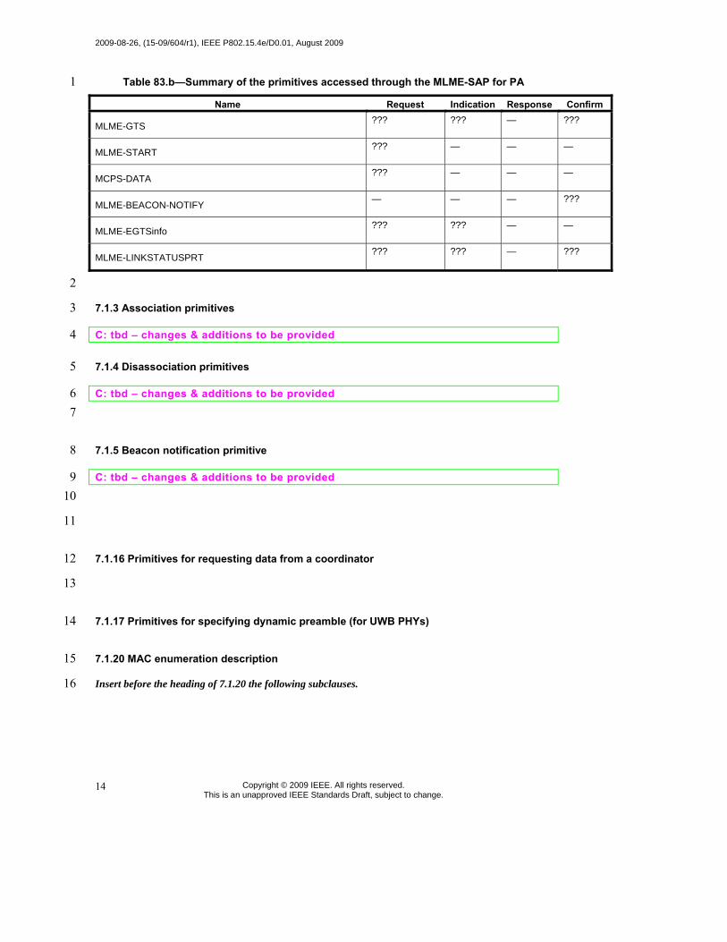
2009-08-26, (15-09/604/r1), IEEE P802.15.4e/D0.01, August 2009
Copyright © 2009 IEEE. All rights reserved. This is an unapproved IEEE Standards Draft, subject to change.
14
Table 83.b—Summary of the primitives accessed through the MLME-SAP for PA 1
Name Request Indication Response Confirm
MLME-GTS ??? ??? — ???
MLME-START ??? — — —
MCPS-DATA ??? — — —
MLME-BEACON-NOTIFY — — — ???
MLME-EGTSinfo ??? ??? — —
MLME-LINKSTATUSPRT ??? ??? — ???
2
7.1.3 Association primitives 3
C: tbd – changes & additions to be provided 4
7.1.4 Disassociation primitives 5
C: tbd – changes & additions to be provided 6 7
7.1.5 Beacon notification primitive 8
C: tbd – changes & additions to be provided 9 10
11
7.1.16 Primitives for requesting data from a coordinator 12
13
7.1.17 Primitives for specifying dynamic preamble (for UWB PHYs) 14
7.1.20 MAC enumeration description 15
Insert before the heading of 7.1.20 the following subclauses. 16
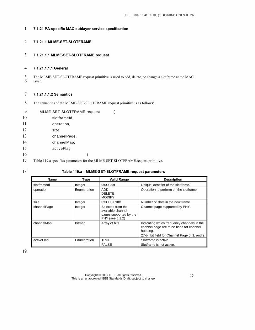
IEEE P802.15.4e/D0.01, (15-09/604/r1), 2009-08-26
Copyright © 2009 IEEE. All rights reserved. This is an unapproved IEEE Standards Draft, subject to change.
15
7.1.21 PA-specific MAC sublayer service specification 1
7.1.21.1 MLME-SET-SLOTFRAME 2
7.1.21.1.1 MLME-SET-SLOTFRAME.request 3
7.1.21.1.1.1 General 4
The MLME-SET-SLOTFRAME.request primitive is used to add, delete, or change a slotframe at the MAC 5 layer. 6
7.1.21.1.1.2 Semantics 7
The semantics of the MLME-SET-SLOTFRAME.request primitive is as follows: 8
MLME-SET-SLOTFRAME.request ( 9 slotframeId, 10 operation, 11 size, 12 channelPage, 13 channelMap, 14 activeFlag 15
) 16 Table 119.a specifies parameters for the MLME-SET-SLOTFRAME.request primitive. 17
Table 119.a—MLME-SET-SLOTFRAME.request parameters 18
Name Type Valid Range Description slotframeId Integer 0x00-0xff Unique identifier of the slotframe. operation Enumeration ADD
DELETE MODIFY
Operation to perform on the slotframe.
size Integer 0x0000-0xffff Number of slots in the new frame. channelPage Integer Selected from the
available channel pages supported by the PHY (see 6.1.2)
Channel page supported by PHY.
channelMap Bitmap Array of bits Indicating which frequency channels in the channel page are to be used for channel hopping. 27-bit bit field for Channel Page 0, 1, and 2
activeFlag Enumeration TRUE FALSE
Slotframe is active. Slotframe is not active.
19

2009-08-26, (15-09/604/r1), IEEE P802.15.4e/D0.01, August 2009
Copyright © 2009 IEEE. All rights reserved. This is an unapproved IEEE Standards Draft, subject to change.
16
7.1.21.1.1.3 When generated 1
An MLME-SET-SLOTFRAME.request is generated by the device management layer and issued to the 2 MLME to create, delete, or update a slotframe on the MAC layer. 3
7.1.21.1.1.4 Effect on receipt 4
On receipt of an MLME-SET-SLOTFRAME.request, the MLME shall verify the parameters passed with 5 the primitive. If the requested operation is ADD, the MLME shall attempt to add an entry into the 6 macSlotframeTable. If the operation is MODIFY, it shall attempt to update an existing slotframe record in 7 the table. If the operation is DELETE, all parameters except slotframeId and operation shall be ignored, and 8 the slotframe record must be deleted from the macSlotFrameTable. If there are links in the slotframe that is 9 being deleted, the links shall be deleted from the MAC layer. If the device is in the middle of using a link in 10 the slotframe that is being updated or deleted, the update should be postponed until after the link operation 11 completes. 12
7.1.21.1.2 MLME-SET-SLOTFRAME.confirm 13
7.1.21.1.2.1 General 14
The MLME-SET-SLOTFRAME.confirm primitive reports the results of the MLME-SET-15 SLOTFRAME.request command. 16
7.1.21.1.2.2 Semantics 17
The semantics of the MLME-SET-SLOTFRAME.confirm primitive is as follows: 18
MLME-SET-SLOTFRAME.confirm ( 19 slotframeId, 20 operation, 21 status 22
) 23 Table 119.b specifies parameters for the MLME-SET-SLOTFRAME.confirm primitive. 24
Table 119.b—MLME-SET-SLOTFRAME.confirm parameters 25
Name Type Valid Range Description slotframeId Integer 0x00-0xff Unique identifier of the slotframe to be
added, modified, or deleted. operation Enumeration ADD
DELETE MODIFY
Operation to perform on the slotframe.
status Enumeration SUCCESS INVALID_PARAMETER SLOTFRAME_NOT_FOUND MAX_SLOTFRAMES_EXCEEDED
Results of the MLME-SET-SLOTFRAME.request command.
26

IEEE P802.15.4e/D0.01, (15-09/604/r1), 2009-08-26
Copyright © 2009 IEEE. All rights reserved. This is an unapproved IEEE Standards Draft, subject to change.
17
7.1.21.1.2.3 When generated 1
The MLME-SET-SLOTFRAME.confirm primitive is generated by the MLME when the MLME-SET-2 SLOTFRAME.request is completed. 3
If any of the arguments fail a range check, the status shall be INVALID_PARAMETER. If a new slotframe 4 is being added and the macSlotFrameTable is already full, the status shall be 5 MAX_SLOTFRAMES_EXCEEDED. If an update or deletion is being requested and the corresponding 6 slotframe cannot be found, the status shall be SLOTFRAME_NOT_FOUND. If an add is being requested 7 with a slotframeID corresponding to an existing slotframe, the status shall be INVALID PARAMETER. 8
7.1.21.1.2.4 Effect on receipt 9
On receipt of a MLME-SET-SLOTFRAME.confirm primitive, the device management application is 10 notified of the status of its corresponding MLME-SET-SLOTFRAME.request. 11
7.1.21.2 MLME-SET-LINK 12
7.1.21.2.1 MLME-SET-LINK.request 13
7.1.21.2.1.1 General 14
The MLME-SET-LINK.request primitive requests to add a new link, modify or delete an existing link at 15 the MAC layer. The operationType parameter indicates whether the MLME-SET-LINK operation is to add 16 or to delete a link. 17
7.1.21.2.1.2 Semantics 18
The semantics of the MLME-SET-LINK.request primitive is as follows: 19
MLME-SET-LINK.request to add a link ( 20 operationType (ADD_LINK or MODIFY_LINK), 21 linkHandle, 22 slotframeId, 23 timeslot, 24 chanOffset, 25 linkOptions, 26 linkType, 27 nodeAddr 28
) 29 MLME-SET-LINK.request to delete a link ( 30
operationType (DELETE_LINK), 31 linkHandle, 32
) 33

2009-08-26, (15-09/604/r1), IEEE P802.15.4e/D0.01, August 2009
Copyright © 2009 IEEE. All rights reserved. This is an unapproved IEEE Standards Draft, subject to change.
18
Table 119.c specifies parameters for the MLME-SET-LINK.request primitive with the ADD_LINK or 1 MODIFY_LINK operationType. 2
Table 119.c– MLME-SET-LINK.request parameters 3
Name Type Valid Range Description operation Enumeration ADD_LINK,
MODIFY_LINK, DELETE_LINK
Type of link management operation to be performed.
linkHandle Integer 0x00–0xFF Unique identifier (local to specified slotframe) for the link.
slotframeId Integer 0x00-0xFF Slotframe ID of the link to be added. timeslot Integer 0x0000-0xFFFF Timeslot of the link to be added. chanOffset Integer 0x01-0xFF Channel offset of the link. linkOptions Bitmap b000 – b111 b001 = Transmit.
b010 = Receive. b100 = Shared.
linkType Enumeration NORMAL ADVERTISING
Type of link. Links marked advertising are to be included in the advertisement frame generated in response to a MLME-ADVERTISE.request.
nodeAddr Integer 0x0000-0xffff Address list of neighbor devices connected to the link. 0xffff means the broadcasting to every node.
4
7.1.21.2.1.3 When generated 5
When operationType=ADD_LINK or MODIFY_LINK: 6
MLME-SET-LINK.request primitive is generated by the device management layer to add a link or 7 to modify an existing link in a slotframe. 8
When operationType=DELETE_LINK: 9
MLME-SET-LINK.request primitive is generated by the device management layer to delete an 10 existing link at the MAC layer. 11
7.1.21.2.1.4 Effect on receipt 12
When operationType=ADD_LINK or MODIFY_LINK: 13
On receipt of the MLME-SET-LINK.request, the MAC layer shall attempt to add the indicated link 14 to the macLinkTable and add the new neighbor to its neighbor table, if needed. Upon completion, 15 the result of the operation must be reported through the corresponding MLME-SET-LINK.confirm 16 primitive. The use of the Shared bit in the linkOptions bitmap indicates that if the link is also a 17 transmit link that the device must back off according to the method described in 7.5.5. Its behavior 18 is not defined for receive links. Resolution between the short form nodeAddr and its long form 19 address (8 octets) may be needed for security purposes. This is determined by NHL (next higher 20 layer). 21
When operationType=DELETE_LINK: 22

IEEE P802.15.4e/D0.01, (15-09/604/r1), 2009-08-26
Copyright © 2009 IEEE. All rights reserved. This is an unapproved IEEE Standards Draft, subject to change.
19
On receipt of the MLME-SET-LINK request the device shall attempt to remove the link from the 1 macLinkTable. If the link is currently in use, the deletion shall be postponed until after the link 2 operation completes. 3
7.1.21.2.2 MLME-SET-LINK.confirm 4
7.1.21.2.2.1 General 5
The SET-LINK.confirm primitive indicates the result of add, modify or delete link operation. 6
7.1.21.2.2.2 Semantics 7
The semantics of the MLME-SET-SLOTFRAME.confirm primitive is as follows: 8
MLME-SET-LINK.confirm ( 9 status, 10 linkHandle 11
) 12 Table 119.d specifies parameters for the MLME-SET-LINK.confirm primitive. 13
Table 119.d—MLME-SET-LINK.confirm parameters 14
Name Type Valid Range Description status Enumeration SUCCESS
INVALID_PARAMETER UNKNOWN_SLOTFRAME MAX_LINKS_EXCEEDED MAX_NEIGHBORS_EXCEEDED
Result of the add or modify link operation.
linkHandle Integer 0x00 – 0xFF Unique (local to specified slotframe) identifier for the link.
15
7.1.21.2.2.3 When generated 16
The MLME-SET-LINK.confirm is generated as a result of the MLME-SET-LINK.request operation. 17
If any of the arguments fail a range check, the status shall be INVALID_PARAMETER. If a new slotframe 18 is being added and the macSlotFrameTable is already full, the status shall be 19 MAX_SLOTFRAMES_EXCEEDED. If an update or deletion is being requested and the corresponding 20 slotframe cannot be found, the status shall be SLOTFRAME_NOT_FOUND. If an add is being requested 21 with a slotframeID corresponding to an existing slotframe, the status shall be INVALID PARAMETER. 22
7.1.21.2.2.4 Effect on receipt 23
The layer that issued the MLME-SET-LINK.request to the MAC may process the result of the operation. 24 The status of the primitive shall indicate SUCCESS if the operation completed successfully. Otherwise, the 25 status indicates the cause of the failure. If the operationType=ADD_LINK of the MLME-26 SET_LINK.request and the linkHandle already exists, the status of the primitive shall indicate INVALID 27 PARAMETER. 28

2009-08-26, (15-09/604/r1), IEEE P802.15.4e/D0.01, August 2009
Copyright © 2009 IEEE. All rights reserved. This is an unapproved IEEE Standards Draft, subject to change.
20
7.1.21.3 MLME-PA-MODE 1
7.1.21.3.1 MLME-PA-MODE.request 2
The MLME-PA-MODE.request puts the MAC into PA-mode, or out of PA-mode. 3
7.1.21.3.1.1 Semantics 4
The semantics of the MLME-PA-MODE.request primitive is as follows: 5
MLME-PA-MODE.request ( 6 modeSwtich 7 ) 8
Table 119.e specifies parameters for the MLME-PA-MODE.request primitive. 9
Table 119.e—MLME-PA-MODE.request parameters 10
Name Type Valid Range Description modeSwitch Enumeration ON, OFF Target mode. This mode indicates
whether PA-mode should be started or stopped.
7.1.21.3.1.2 When generated 11
The MLME-PA-MODE.request may be generated by the higher layer after the device has received 12 advertisements from the network and is synchronized to a network (i.e. in response to an MLME-13 ADVERTISE.indication). 14
7.1.21.3.1.3 Effect on receipt 15
Upon receipt of the request, the MAC shall start operating its PA- state machine using slotframes and links 16 already contained in its database. To successfully complete this request the device must already be 17 synchronized to a network. Once in PA-mode, non-PA- frames are ignored by the device until it is taken 18 out of PA-mode or the MAC is reset by a higher layer. 19
7.1.21.3.2 MLME-PA-MODE.confirm 20
The MLME-PA-MODE.confirm primitive reports the result of the MLME-PA-MODE.request primitive. 21
7.1.21.3.2.1 Semantics 22
The semantics of the MLME-PA-MODE.confirm primitive is as follows: 23
MLME-PA-MODE.confirm ( 24 modeSwitch, 25 status 26 ) 27

IEEE P802.15.4e/D0.01, (15-09/604/r1), 2009-08-26
Copyright © 2009 IEEE. All rights reserved. This is an unapproved IEEE Standards Draft, subject to change.
21
Table 119.f specifies parameters for the MLME-PA-MODE.confirm primitive. 1
Table 119.f—MLME-PA-MODE.confirm parameters 2
Name Type Valid Range Description modeSwitch Enumeration ON, OFF Target mode. This mode indicates
whether this confirmation is due to PA-mode ON request or OFF request.
status Enumeration SUCCESS NO_SYNC
3
7.1.21.3.2.2 When generated 4
The MLME-PA-MODE.confirm is generated by the MAC layer to indicate completion of the 5 corresponding request. If the corresponding request was to turn on the PA-MODE, but the MAC layer has 6 not been synchronized to a network, the status shall be NO_SYNC. Otherwise, the status shall be 7 SUCCESS. 8
If the corresponding request was to turn off the PA-MODE, the status shall be SUCCESS, and the MAC 9 layer will stop the PA-MODE operation. 10
7.1.21.3.2.3 Effect on receipt 11
The higher layer may use the confirmation to process the result of MLME-PA-MODE.request. 12
7.1.21.4 MLME-LISTEN 13
7.1.21.4.1 MLME-LISTEN.request 14
7.1.21.4.1.1 Semantics 15
The semantics of the MLME-LISTEN.request primitive is as follows: 16
MLME-LISTEN.request ( 17 time, 18 numPageChannel, 19 pageChannels[] 20 ) 21
Table 119.g specifies parameters for the MLME-LISTEN.request primitive. 22

2009-08-26, (15-09/604/r1), IEEE P802.15.4e/D0.01, August 2009
Copyright © 2009 IEEE. All rights reserved. This is an unapproved IEEE Standards Draft, subject to change.
22
Table 119.g—MLME-LISTEN.request parameters 1
Name Type Valid Range Description
onTime Integer 0x0000 – 0xFFFF
The amount of time (10 ms units) to stay on each channel. 0x0000 indicates that the MAC stops listening
offTime Integer 0x0000 – 0xFFFF The amount of time (10 ms units) to wait between channel changes.
numPageChannel Integer 0x01-0xFF The number of page channel descriptors in the page channels array.
pageChannelsDes[] Table 119.h Table 119.h Array of page channel descriptor. See
Table 119.h for the format of page channel descriptor.
2 Table 119.h—MLME-LISTEN.request pageChannelDesc parameters 3
Name Type Valid Range Description
channelPageId
Integer Selected from the available channel pages supported by the PHY (see 6.1.2)
Channel page ID.
numChannel Integer 0x01-0xFF The number of channels in this channel page to be included in listening.
Channels[] Array of Channel Table 4.
The array of channels on which to listen. See Table 4 for the valid range of channels in each channel page.
4
7.1.21.4.1.2 When generated 5
The MLME-LISTEN.request shall be generated by the next higher layer to initiate the search for a PA-6 network. 7
7.1.21.4.1.3 Effect on receipt 8
Upon receipt of the request the MAC layer shall activate the radio on the indicated channel and wait for an 9 Advertisement command. The MAC shall listen on Channel[0] for onTime, inactivate the radio for 10 offTime, then repeat with Channels[1], etc. After listening to the last channel in Channels[], the MAC 11 returns to Channel[0]. Valid Advertisement command frames received in this state shall result in the 12 generation of MLME-ADVERTISE.indication. All other frames shall be dropped. The MAC shall stay in 13 the listening state until it receives a MLML-LISTEN.request with an onTime of 0x0000, or a MLME-PA-14 MODE.request is received. The higher layer selects the advertiser and the network before setting the 15 slotframe, link(s), and PA-mode. Advertisements will continue to be received, and passed on to the higher 16 layer until leaving the listen state. 17
7.1.21.4.2 MLME-LISTEN.confirm 18
7.1.21.4.2.1 Semantics 19
The semantics of the MLME-LISTEN.confirm primitive is as follows: 20

IEEE P802.15.4e/D0.01, (15-09/604/r1), 2009-08-26
Copyright © 2009 IEEE. All rights reserved. This is an unapproved IEEE Standards Draft, subject to change.
23
MLME-LISTEN.confirm ( 1 status 2 ) 3
Table 119.i specifies parameters for the MLME-LISTEN.confirm primitive. 4
Table 119.i—MLME-LISTEN.confirm parameters 5
Name Type Valid Range Description status Enumeration SUCCESS
INVALID_PARAMETER
6
7.1.21.4.2.2 When generated 7
The MAC layer shall generate MLME-LISTEN.confirm when it completes the listen operation started by 8 MLME-LISTEN.request. 9
7.1.21.4.2.3 Effect on receipt 10
On receipt of the primitive, the higher layer may continue with its joining state machine. 11
7.1.21.5 MLME-ADVERTISE 12
7.1.21.5.1 MLME-ADVERTISE.request 13
7.1.21.5.1.1 Semantics 14
The semantics of the MLME-ADVERTISE.request primitive is as follows: 15
MLME-ADVERTISE.request ( 16 advertiseInterval, 17 channelPage, 18 channelMap, 19 hoppingSequenceId, 20 timeslotTemplateId, 21 securityLevel, 22 joinPriority, 23 numSlotframe, 24 slotframes[] 25 ) 26
Table 119.j specifies parameters for the MLME-ADVERTISE.request primitive. 27

2009-08-26, (15-09/604/r1), IEEE P802.15.4e/D0.01, August 2009
Copyright © 2009 IEEE. All rights reserved. This is an unapproved IEEE Standards Draft, subject to change.
24
Table 119.j—MLME-ADVERTISE.request parameters 1
Name Type Valid Range Description
advertiseInterval Integer 0x0000 – 0xFFFF Interval specifying the transmission of the Advertisement command (in 10 ms units)
channelPage Integer
Selected from the available channel pages supported by the PHY (see 6.1.2)
Channel page supported by PHY.
channelMap Bitmap Array of bits Map of channels to be included in the Advertisement command.
hoppingSequenceId Integer 0x0 – 0xF ID of hopping sequence used. timeslotTemplateId Integer 0x0 – 0xF ID of timeslot template used.
securityLevel Enumeration Table 136 Security level in the Advertisement command. See Table 136.
joinPriority Integer 0x00 – 0xFF Join priority to be indicated in the Advertisement command.
numSlotframe Integer 0x0 – 0xF Number of slotframes to be indicated in the Advertisement command.
Slotframes[] See Table 119.k See Table 119.k See Table 119.k.
2 3
Table 119.k—MLME-ADVERTISE.request Slotframe parameters (per slotframe) 4
Name Type Valid Range Description slotframeId Integer 0x00 – 0xFF Slotframe ID.
5
7.1.21.5.1.2 When generated 6
The next higher layer requests the MAC layer to start sending Advertisement command frames using 7 MLME-ADVERTISE.request so that new nodes can find the network and this device. 8
7.1.21.5.1.3 Effect on receipt 9
Upon receipt of the request the MAC layer shall send the Advertisement command frame on the first 10 available TX link. Whenever the time specified in AdvertiseInterval lapses from the previous transmission 11 of Advertisement command frame, the MAC layer shall repeat the Advertisement command frame on next 12 TX link available. The remaining parameters specify the slotframes to be included in the Advertisement 13 command frames. Links in the specified slotframes with an Advertising linkType are to be included in the 14 Advertisement command. 15
7.1.21.5.2 ADVERTISE.indication 16
The MLME-ADVERTISE.indication indicates that a device received an Advertisement command frame. 17

IEEE P802.15.4e/D0.01, (15-09/604/r1), 2009-08-26
Copyright © 2009 IEEE. All rights reserved. This is an unapproved IEEE Standards Draft, subject to change.
25
7.1.21.5.2.1 Semantics 1
The semantics of the MLME-ADVERTISE.indication primitive is as follows: 2
MLME-ADVERTISE.indication ( 3 PANId, 4 timingInformation, 5 channelPage, 6 channelMap, 7 hoppingSequenceId, 8 timeslotTemplateId, 9 securityLevel, 10 joinPriority, 11 linkQuality, 12 numSlotframes, 13 slotframes[] 14 ) 15
Table 119.l specifies parameters for the MLME-ADVERTISE.indication primitive. 16
Table 119.l—MLME-ADVERTISE.indication parameters 17
Name Type Valid Range Description
PANId Integer 0x0000 – 0xFFFF The PAN identifier indicated in the Advertisement command.
timingInformation The time information (absolute slot number) of the timeslot in which the Advertisement command was received.
channelPage
Integer Selected from the available channel pages supported by the PHY (see 6.1.2)
Channel page.
channelMap Bitmap Array of bits Bit map of channels. hoppingSequenceId Integer 0x0 – 0xF ID of hopping sequence used. timeslotTemplateId Integer 0x0 – 0xF ID of timeslot template used.
securityLevel Enumeration Table 136 Security level in advertisement packet See Table 136.
joinPriority Integer 0x00 – 0xFF Join priority indicated in advertisement.
linkQuality Integer 0x00 – 0xFF Link quality indicated in the frame by the PHY layer.
numSlotframes Integer 0x0 – 0xF Number of slotframes indicated in the Advertisement command received.
slotframes[] See Table 119.k See Table 119.k See Table 119.k
18

2009-08-26, (15-09/604/r1), IEEE P802.15.4e/D0.01, August 2009
Copyright © 2009 IEEE. All rights reserved. This is an unapproved IEEE Standards Draft, subject to change.
26
7.1.21.5.2.2 When generated 1
The MLME-ADVERTISE.indication shall be generated when an Advertisement command frame has been 2 received by the device. Upon receiving a valid Advertisement command, the device shall be synchronized 3 to the network and ready to enable the PA-MODE if requested by the higher layer. 4
7.1.21.5.2.3 Effect on receipt 5
The higher layer may wait and record more than one advertisement and then select the desired advertising 6 device before configuring the superframe(s) and link(s) and before enabling PA-MODE. After joining a 7 PA-network, the high layer uses the indication to collect the list of neighbors and information about 8 neighbors. 9
7.1.21.5.3 MLME-ADVERTISE.confirm 10
7.1.21.5.3.1 Semantics 11
The semantics of the MLME-ADVERTISE.confirm primitive is as follows: 12
MLME-ADVERTISE.confirm ( 13 status 14 ) 15
Table 119.m specifies parameters for the MLME-ADVERTISE.confirm primitive. 16
Table 119.m—MLME-ADVERTISE.confirm parameters 17
Name Type Valid Range Description Status Enumeration SUCCESS
INVALID_PARAMETER
18
7.1.21.5.3.2 When generated 19
The MAC layer shall generate MLME-ADVERTISE.confirm when it starts sending the Advertisement 20 command. 21
7.1.21.5.3.3 Effect on receipt 22
On receipt of the primitive, the higher layer may expect that it will receive the Join command on any of the 23 links provided in the Advertisement command. 24

IEEE P802.15.4e/D0.01, (15-09/604/r1), 2009-08-26
Copyright © 2009 IEEE. All rights reserved. This is an unapproved IEEE Standards Draft, subject to change.
27
7.1.21.6 MLME-KEEP-ALIVE 1
7.1.21.6.1 MLME-KEEP-ALIVE.request 2
7.1.21.6.1.1 Semantics 3
The semantics of the MLME-KEEP-ALIVE.request primitive is as follows: 4
MLME-KEEP-ALIVE.request ( 5 dstAddr, 6 linkHandle, 7 period 8 ) 9
Table 119.n specifies parameters for the MLME-KEEP-ALIVE.request primitive. 10
Table 119.n—MLME-KEEP-ALIVE.request parameters 11
Name Type Valid Range Description
dstAddr Integer 0x0000 - 0xFFFF Address of neighbor device to maintain the timing. Keepalives with dstAddr of 0xFFFF do not not expect to be acknowledged.
period Integer 0x0001 – 0xFFFF Duration of quiet time in seconds that a Keep-Alive command frame should be sent if no traffic is present.
12
7.1.21.6.1.2 When generated 13
7.1.21.6.1.3 Effect on receipt 14
Upon receipt of the request, the MAC layer shall monitor the frame sent to the destination node specified in 15 the dstAddr parameter. If no frame is sent to the destination node for any duration defined by the period 16 parameter, the MAC shall send an empty (no MAC payload) frame to the node dstAddr. The Sequence 17 Number subfield of the MHR of the frame shall be set to the least significant byte of the absolute slot 18 number. Resolution between the short form dstAddr and its long form address (8 octets) may be needed for 19 security purposes. This is determined by NHL (next higher layer). 20
7.1.21.6.2 MLME-KEEP-ALIVE.confirm 21
7.1.21.6.2.1 Semantics 22
The semantics of the MLME-KEEP-ALIVE.confirm primitive is as follows: 23
MLME-KEEP-ALIVE.confirm ( 24 status 25 ) 26
Table 119.o specifies parameters for the MLME-KEEP-ALIVE.confirm primitive. 27

2009-08-26, (15-09/604/r1), IEEE P802.15.4e/D0.01, August 2009
Copyright © 2009 IEEE. All rights reserved. This is an unapproved IEEE Standards Draft, subject to change.
28
Table 119.o—MLME-KEEP-ALIVE.confirm parameters 1
Name Type Valid Range Description Status Enumeration SUCCESS
INVALID_PARAMETER
2
7.1.21.6.2.2 When generated 3
The MAC layer shall generate MLME-KEEP-ALIVE.confirm to acknowledge that it received MLME-4 KEEP-ALIVE request. 5
7.1.21.6.2.3 Effect on receipt 6
None. 7
7.1.21.7 MLME-JOIN 8
7.1.21.7.1 MLME-JOIN.request 9
7.1.21.7.1.1 Semantics 10
The semantics of the MLME-JOIN.request primitive is as follows: 11
MLME-JOIN.request ( 12 dstAddr, 13 securityInformation, 14 numNeighbors, 15 neighbors[] 16 ) 17
Table 119.p specifies parameters for the MLME-JOIN.request primitive. 18
Table 119.p—MLME-JOIN.request parameters 19
20
Name Type Valid Range Description
dstAddr Integer 0x0000 - 0xFFFF Address of neighbor device to send Join command.
securityInformation Table 119.q Table 119.q See Table 119.q for the detail.
numNeighbors Integer 0x0 – 0xF Number of neighbors found by the joining device.
neighbors Table 119.r Table 119.r Neighbor information for the number of
neighbors specified in numNeighbors. See Table 119.r for the definition of a neighbor.

IEEE P802.15.4e/D0.01, (15-09/604/r1), 2009-08-26
Copyright © 2009 IEEE. All rights reserved. This is an unapproved IEEE Standards Draft, subject to change.
29
Table 119.q—MLME-JOIN.request securityInformation parameters 1
2 Table 119.r—MLME-JOIN.request neighbors parameters 3
4
7.1.21.7.1.2 When generated 5
Device management of a new device (or device who lost connection with the PA-network) will invoke this 6 service primitive to join the PA-network. 7
7.1.21.7.1.3 Effect on receipt 8
Upon receipt of the request, the MAC layer shall send either a Join command frame or data frame 9 containing a higher layer management packet requesting to join the network, using any link to the dstAddr. 10 The content of the Join command frame will be formatted using the other parameters and the format of Join 11 command frame is specified in 7.3.10.2.9. If a data frame with the higher layer management packet is used 12 instead of a Join command frame, the content of the higher layer payload of the data frame containing the 13 request to join the network is constructed using the other parameters. The explicit format of the higher layer 14 payload is out of scope of this document. Resolution between the short form dstAddr and its long form 15 address (8 octets) may be needed for security purposes. This is determined by NHL (next higher layer). 16
7.1.21.7.2 MLME-JOIN.indication 17
7.1.21.7.2.1 Semantics 18
The semantics of the MLME-JOIN.indication primitive is as follows: 19
MLME-JOIN.indication ( 20 linkHandle, 21 newNodeAddr, 22 securityInformation, 23 numNeighbors, 24 neighbors[] 25 ) 26
Table 119.s specifies parameters for the MLME-JOIN.indication primitive. 27
Name Type Valid Range Description
TBD TBD TBD The securityInformation definition will be defined with Security sub-group.
Name Type Valid Range Description neighborId Integer 0x0000 – 0xFFFF 16 bit address of neighbor.
RSSI Integer -128 to 127 Received signal strength (in dBm) of frames received from the neighbor.

2009-08-26, (15-09/604/r1), IEEE P802.15.4e/D0.01, August 2009
Copyright © 2009 IEEE. All rights reserved. This is an unapproved IEEE Standards Draft, subject to change.
30
Table 119.s—MLME-JOIN.indication parameters 1
Name Type Valid Range Description
linkHandle Integer 0x00 – 0xFF Unique identifier for the link that Join command frame is received on.
newNodeAddr Array of octets 64-bit binary string 64-bit long address of new device sending the Join command.
securityInformation Table 119.q Table 119.q See Table 119.q.
numNeighbors Integer 0x0 – 0xF Number of neighbors reported by the joining device.
Neighbors
Table 119.r Table 119.r Neighbor information for the number of neighbors specified in numNeighbors. See Table 119.r for the definition of a neighbor in neighbors.
7.1.21.7.2.2 When generated 2
MLME-JOIN.indication indicates the Device Management layer that the MAC layer has received a Join 3 command frame from a new device attempting to join the PA-network. 4
7.1.21.7.2.3 Effect on receipt 5
Upon receipt of the MLME-JOIN.indication, the Device Management layer shall invoke the device 6 management procedure to transfer the join attempt of the new device to the Device Manager. 7
7.1.21.7.3 MLME-JOIN.confirm 8
7.1.21.7.3.1 Semantics 9
The semantics of the MLME-JOIN.confirm primitive is as follows: 10
MLME-JOIN.confirm ( 11 status 12 ) 13
Table 119.t specifies parameters for the MLME-JOIN.confirm primitive. 14
Table 119.t—MLME-JOIN.confirm parameters 15
Name Type Valid Range Description Status Enumeration SUCCESS
INVALID_PARAMETER
16
7.1.21.7.3.2 When generated 17
The MAC layer shall generate MLME-JOIN.confirm to acknowledge that it received the MLME-18 JOIN.request primitive. 19

IEEE P802.15.4e/D0.01, (15-09/604/r1), 2009-08-26
Copyright © 2009 IEEE. All rights reserved. This is an unapproved IEEE Standards Draft, subject to change.
31
7.1.21.7.3.3 Effect on receipt 1
None 2
7.1.21.8 MLME-ACTIVATE 3
7.1.21.8.1 MLME-ACTIVATE.request 4
7.1.21.8.1.1 Semantics 5
The semantics of the MLME-ACTIVATE.request primitive is as follows: 6
MLME-ACTIVATE.request ( 7 dstAddr, 8 securityInformation, 9 slotframes[] 10 ) 11
Table 119.u and Table 119.w specify parameters for the MLME-ACTIVATE.request primitive. 12
Table 119.u—MLME-ACTIVATE.request parameters 13
14 Table 119.v—MLME-ACTIVATE.request securityInformation parameters 15
16 Table 119.w—MLME-ACTIVATE.request slotframe parameters (per slotframe) 17
18
Name Type Valid Range Description
dstAddr Integer 0x0000 - 0xFFFF Address of neighbor device to send Activate command.
securityInformation Table 119.v Table 119.v See Table 119.v for details. slotframes[] Table 119.k Table 119.k See Table 119.k.
Name Type Valid Range Description
TBD TBD TBD The securityInformation definition will be defined with the Security sub-group.
Name Type Valid Range Description slotframeId Integer 0x00 – 0xFF Slotframe ID. slotframeSize Integer 0x00 – 0xFFFF Slotframe size.
numLink Integer 0x0 – 0xF Number of links for the specified slotframe to be indicated in the Advertisement command.
links Table 119.x Table 119.x See Table 119.x for parameters (per link)

2009-08-26, (15-09/604/r1), IEEE P802.15.4e/D0.01, August 2009
Copyright © 2009 IEEE. All rights reserved. This is an unapproved IEEE Standards Draft, subject to change.
32
Table 119.x—MLME-ACTIVATE.request Link parameters (per link) 1
2
7.1.21.8.1.2 When generated 3
An Activate command is generated by a higher layer in response to a Join command or a Join data frame. 4
7.1.21.8.1.3 Effect on receipt 5
Upon receipt of the request, the MAC layer shall send either the Activate command frame to activate the 6 new joining device, or a data frame containing a higher layer management packet to activate the new 7 joining device. The MAC shall send the Activate command frame to the node using the linkHandle 8 parameter. The content of the Activate command is formatted using the other parameters. If a data frame 9 with a higher layer management packet is used instead of Activate command frame, the content of the 10 higher layer payload to activate the network is constructed using the other parameters. The explicit format 11 of the higher layer payload is out of scope of this document. Resolution between the short form dstAddr 12 and its long form address (8 octets) may be needed for security purposes. This is determined by NHL (next 13 higher layer). 14
7.1.21.8.2 MLME-ACTIVATE.indication 15
7.1.21.8.2.1 Semantics 16
The semantics of the MLME-ACTIVATE.indication primitive is as follows: 17
MLME-ACTIVATE.indication ( 18 srcAddr, 19 securityInformation, 20 ) 21
Table 119.y specifies parameters for the MLME-ACTIVATE.indication primitive. 22
Table 119.y—MLME-ACTIVATE.indication parameters 23
24
Name Type Valid Range Description timeslot Integer 0x0000 – 0xFFFF Timeslot. chanOffset Integer 0x00 – 0xFF Channel offset. linkOption Enumeration TX
RX SHARED_TX
Option of the link.
Name Type Valid Range Description
srcAddr Integer 0x0000 - 0xFFFF Address of neighbor from whom the Activate command was received.
securityInformation Table 119.v Table 119.v Table 119.v.

IEEE P802.15.4e/D0.01, (15-09/604/r1), 2009-08-26
Copyright © 2009 IEEE. All rights reserved. This is an unapproved IEEE Standards Draft, subject to change.
33
7.1.21.8.2.2 When generated 1
MLME-ACTIVATE.indication indicates the device management layer that the MAC layer has received an 2 Activate command frame from the neighbor indentified in srcAddr. 3
7.1.21.8.2.3 Effect on receipt 4
Upon receipt of the MLME-ACTIVATE.indication, the device management layer shall process the 5 securityInformation received to set up secure connections. Resolution between the short form srcAddr and 6 its long form address (8 octets) may be needed for security purposes. This is determined by NHL (next 7 higher layer). 8
7.1.21.8.3 MLME-ACTIVATE.confirm 9
7.1.21.8.3.1 Semantics 10
The semantics of the MLME-ACTIVATE.confirm primitive is as follows: 11
MLME-ACTIVATE.confirm ( 12 status 13 ) 14
Table 119.z specifies parameters for the MLME-ACTIVATE.confirm primitive. 15
Table 119.z—MLME-ACTIVATE.confirm parameters 16
17
7.1.21.8.3.2 When generated 18
The MAC layer shall generate MLME-ACTIVATE.confirm to acknowledge that it received MLME-19 ACTIVATE.request. 20
7.1.21.8.3.3 Effect on receipt 21
22
7.1.21.9 MLME-DISCONNECT 23
24
Name Type Valid Range Description Status Enumeration SUCCESS
INVALID_PARAMETER

2009-08-26, (15-09/604/r1), IEEE P802.15.4e/D0.01, August 2009
Copyright © 2009 IEEE. All rights reserved. This is an unapproved IEEE Standards Draft, subject to change.
34
7.1.21.9.1 MLME-DISCONNECT.request 1
2
7.1.21.9.1.1 Semantics 3
The semantics of the MLME-DISCONNECT.request primitive is as follows: 4
MLME-DISCONNECT.request ( 5 ) 6
7.1.21.9.1.2 When generated 7
MLME-DISCONNECT.request primitive is used to initiate the graceful disconnection from PA-network. 8
7.1.21.9.1.3 Effect on receipt 9
Upon receipt of the request, the MAC layer shall send a disassociation notification command frame or a 10 data frame containing a higher layer management packet to indicate that it is about to leave the PA-network 11 on all unicast transmit links. The Sequence Number subfield of the MHR of the frame shall be set to the 12 least significant byte of the absolute slot number. 13
After the MAC sends the disassociation notification command frame for macDisconnectTime, it shall 14 release all slotframe and link resources. 15
7.1.21.9.2 MLME-DISCONNECT.indication 16
7.1.21.9.2.1 Semantics 17
The semantics of the MLME-DISCONNECT.indication primitive is as follows: 18
MLME-DISCONNECT.indication ( 19 srcAddress, 20 ) 21
Table 119.aa specifies parameters for the MLME-DISCONNECT.indication primitive. 22
Table 119.aa—MLME-DISCONNECT.indication parameters 23
Name Type Valid Range Description
srcAddr Integer 0x0000 – 0xFFFF 16-bit short address of the neighbor node from which the DISCONNECT command frame was received.
24

IEEE P802.15.4e/D0.01, (15-09/604/r1), 2009-08-26
Copyright © 2009 IEEE. All rights reserved. This is an unapproved IEEE Standards Draft, subject to change.
35
7.1.21.9.2.2 When generated 1
MLME-DISCONNECT.indication indicates to the device management layer that the MAC layer has 2 received a Disconnect command frame from a neighbor node, the address of which is indicated by 3 srcAddress. 4
7.1.21.9.2.3 Effect on receipt 5
Upon receipt of the MLME-DISCONNECT.indication, the device management layer shall process the 6 disconnection of the neighbor from which the Disconnect command frame is received. Resolution between 7 the short form srcAddr and its long form address (8 octets) may be needed for security purposes. This is 8 determined by NHL (next higher layer). 9
7.1.21.9.3 MLME-DISCONNECT.confirm 10
7.1.21.9.3.1 Semantics 11
The semantics of the MLME-DISCONNECT.confirm primitive is as follows: 12
MLME-DISCONNECT.confirm ( 13 status 14 ) 15
Table 119.bb specifies parameters for the MLME-DISCONNECT.confirm primitive. 16
Table 119.bb—MLME-DISCONNECT.confirm parameters 17
Name Type Valid Range Description Status Enumeration SUCCESS
18
7.1.21.9.3.2 When generated 19
The MAC layer shall generate MLME-DISCONNECT.confirm to acknowledge that it received MLME-20 DISCONNECT request. 21
7.1.21.9.3.3 Effect on receipt 22
None. 23
7.1.22 LL-specific MAC sublayer service specification 24
(tbd) Subclauses without text will be filled up later on. 25 26

2009-08-26, (15-09/604/r1), IEEE P802.15.4e/D0.01, August 2009
Copyright © 2009 IEEE. All rights reserved. This is an unapproved IEEE Standards Draft, subject to change.
36
7.1.22.1 Primitives for Superframe Configuration of low latency networks 1
7.1.22.1.1 General 2
These primitives control the different modes for the configuration and operation of the superframe in a low 3 latency network. 4
7.1.22.1.2 MLME-SFCF.discovery 5
7.1.22.1.2.1 General 6
This primitive switches the sFCF network into discover mode. 7
7.1.22.1.2.2 Semantics of the Service Primitive 8
The semantics of the MLME-SFCF.discovery primitive is as follows: 9
10 MLME-SFCF.discovery ( 11
… 12 ) 13
Table eXX specifies the parameters for the MLME-SFCF.discovery primitive. 14
LL: tbd: Parameter and Table xxx will be defined by technology provider. 15
7.1.22.1.2.3 When generated 16
7.1.22.1.2.4 Appropriate usage 17
7.1.22.1.3 MLME-SFCF.discovery_confirm 18
7.1.22.1.3.1 General 19
This primitive indicates the end of the discover mode and gives the status of the discover mode to the next 20 higher layer. 21
7.1.22.1.3.2 Semantics of the Service Primitive 22
The semantics of the MLME-SFCF.discovery_confirm primitive is as follows: 23
MLME-SFCF.discovery_confirm ( 24 … 25 ) 26

IEEE P802.15.4e/D0.01, (15-09/604/r1), 2009-08-26
Copyright © 2009 IEEE. All rights reserved. This is an unapproved IEEE Standards Draft, subject to change.
37
Table eXX specifies the parameters for the MLME-SFCF.discovery_confirm primitive. 1 LL: tbd: Parameter and Table xxx will be defined by technology provider. 2
7.1.22.1.3.3 When generated 3
4
7.1.22.1.3.4 Appropriate usage 5
6
7.1.22.1.4 MLME-SFCF.configuration 7
7.1.22.1.4.1 General 8
This primitive switches the sFCF network into configuration mode. 9
7.1.22.1.4.2 Semantics of the Service Primitive 10
The semantics of the MLME-SFCF.configuration primitive is as follows: 11
12 MLME-SFCF.configuration ( 13
… 14 ) 15
Table eXX specifies the parameters for the MLME-SFCF.configuration primitive. 16
LL: tbd: Parameter and Table xxx will be defined by technology provider. 17
7.1.22.1.4.3 When generated 18
7.1.22.1.4.4 Appropriate usage 19
7.1.22.1.5 MLME-SFCF.configuration_confirm 20
7.1.22.1.5.1 General 21
This primitive indiciates the end of the configuration mode and gives the status of the configuration mode 22 to the next higher layer. 23
7.1.22.1.5.2 Semantics of the Service Primitive 24
The semantics of the MLME-SFCF.configuration_confirm primitive is as follows: 25
MLME-SFCF.configuration_confirm ( 26

2009-08-26, (15-09/604/r1), IEEE P802.15.4e/D0.01, August 2009
Copyright © 2009 IEEE. All rights reserved. This is an unapproved IEEE Standards Draft, subject to change.
38
… 1 ) 2
Table eXX specifies the parameters for the MLME-SFCF.configuration_confirm primitive. 3
LL: tbd: Parameter and Table xxx will be defined by technology provider. 4
7.1.22.1.5.3 When generated 5
7.1.22.1.5.4 Appropriate usage 6
7.1.22.1.6 MLME-SFCF.online 7
7.1.22.1.6.1 General 8
This primitive switches the sFCF network into online mode. 9
7.1.22.1.6.2 Semantics of the Service Primitive 10
The semantics of the MLME-SFCF.online primitive is as follows: 11
MLME-SFCF.online ( 12 … 13 ) 14
Table eXX specifies the parameters for the MLME-SFCF.online primitive. 15
LL: tbd: Parameter and Table xxx will be defined by technology provider. 16
7.1.22.1.6.3 When generated 17
7.1.22.1.6.4 Appropriate usage 18
7.1.22.1.7 MLME-SFCF.online_indication 19
7.1.22.1.7.1 General 20
This primitive indicates any problems during the online mode to the next higher layer. 21
7.1.22.1.7.2 Semantics of the Service Primitive 22
The semantics of the MLME-SFCF.online_indication primitive is as follows: 23
MLME-SFCF.online_indication ( 24 … 25

IEEE P802.15.4e/D0.01, (15-09/604/r1), 2009-08-26
Copyright © 2009 IEEE. All rights reserved. This is an unapproved IEEE Standards Draft, subject to change.
39
) 1 Table eXX specifies the parameters for the MLME-SFCF.online_indication primitive. 2
LL: tbd: Parameter and Table xxx will be defined by technology provider. 3
7.1.22.1.7.3 When generated 4
7.1.22.1.7.4 Appropriate usage 5
7.1.23 C-specific MAC sublayer service specification 6
7
7.2 MAC frame formats 8
7.2.1 General MAC frame format 9
Change the first paragraph 7.2.1. 10
The MAC frame format is composed of a MHR, a MAC payload, and a MFR. The fields of the MHR 11 appear in a fixed order; however, the addressing fields may not be included in all frames. Furthermore, 12 some frame types use a MHR of only 1 octet length with a shortened Frame Control field. The general 13 MAC frame shall be formatted as illustrated in Figure 79. 14
7.2.1.1 Frame Control field 15
7.2.1.1.1 Frame Type subfield 16
Change Table 120. 17
Frame type value b2 b1 b0
Description
000 Beacon 001 Data 010 Acknowledgment 011 MAC command 100 MHR of 1 octet
1010-111 Reserved
18

2009-08-26, (15-09/604/r1), IEEE P802.15.4e/D0.01, August 2009
Copyright © 2009 IEEE. All rights reserved. This is an unapproved IEEE Standards Draft, subject to change.
40
7.2.2 Format of individual frame types 1
7.2.2.1 Beacon frame format 2
7.2.3 Frame compatibility 3
Insert before 7.3 the following subclause. 4
The contribution from TSCH named “7.2 New Frame Formats” is not correct related 5 neither to IEEE 802.15.4-2006 nor to IEEE 802.15.4-2009 and have a lot of problems: 6 - The Table and Figure numbers are not related. 7 - The first sentence is an editor note and not a std paragraph. 8 - Figure 85 shall be a PPT or WORD editable figure. 9 - Table 109 is not similar to IEEE 802.15.4 MHR representations. It should be 10 according to Figure 92 or so. 11 - Table 110 is unclear. 12 13
7.2.4 PA-Frame Formats 14
Secure Extended ACKs with payload is to be jointly defined with Security subgroup. ACK/NACK frame in 15 Figure 93.a is authenticate only/no payload and should be a subset of the Extended ACK definition. 16
17
Figure 93.a—Typical acknowledgement frame layout 18 The source address of an ACK/NACK is the address of the device that transmits the ACK/NACK. The 19 destination address is the address of the intended recipient of the ACK/NACK. 20
Every ACK/NACK frame shall be authenticated with a MMIC, but not encrypted. Some fields are virtual, 21 used in creating the MMIC but not actually transmitted. 22
The format of a MHR is summarized in Figure 93.b. 23

IEEE P802.15.4e/D0.01, (15-09/604/r1), 2009-08-26
Copyright © 2009 IEEE. All rights reserved. This is an unapproved IEEE Standards Draft, subject to change.
41
bits octets 7 6 5 6 3 2 1 0
1 Frame control (octet 0) 2 Frame control (octet 1) 3 Sequence number
Figure 93.b—Acknowledgement frame MHR 1 As shown in Figure 93.b, attributes include: 2
• Frame control attributes for ACK/NACKs, as follows: 3
⎯ Frame type shall be data. 4 ⎯ Security shall be disabled, as it is handled in the DHR. 5 ⎯ Frame pending shall be false. 6 ⎯ Ack.Request shall be false (IEEE Std 802.15.4 does not recognize this as an ACK). 7 ⎯ Source addressing mode shall be 0x00 (i.e., implicit), except for cases described below where the 8
source address and PAN ID are included in the MHR. 9 ⎯ Destination addressing mode shall be 0x00 (i.e., implicit). 10 ⎯ Frame version shall be 0x01 0x10. 11
• Sequence number shall be incremented after each use as described in 7.3.10.1.2. 12 The acknowledgers EUI-64 shall be included in the source address field of the ACK/NACKs MHR if so 13 requested in the received DPDU’s DHDR. Normally, the 16-bit DL source address of the ACK/NACK is 14 not transmitted, because it matches the destination address of the received DPDU. However, in duocast or 15 n-cast acknowledgements, one or more acknowledgements may be sent by different devices. Therefore, in 16 cases where the acknowledger’s address is different from the destination address of the received DPDU, the 17 acknowledgement shall also include the acknowledger’s 16-bit DL source address in the MHR, with the 18 assumption that the acknowledger’s EUI-64 is already known by the recipient of the acknowledgement. 19 All correspondent devices must be operating within the same security context or they will not possess 20 appropriate information to authenticate the frame. 21
A prototype DHR following a MHR is summarized in Figure 93.c. 22
bits octets 7 6 5 4 3 2 1 0
1 octet DHR ACK/NACK Frame control
4 octets (virtual)
Echoed MMIC of received DPDU
0-2 octets Time correction (LSB) When requested
0-1 octets Timeslot offset When needed
0-4 octets DAUX sub-header Usually absent
Figure 93.c—Acknowledgement frame DHR 23 As shown in Figure 93.c, attributes include: 24
• The DHR ACK/NACK frame control octet is described in Figure 93.d. 25 • Echoed MMIC of received DPDU. For a discussion of handling of this virtual field, see 26
7.3.4. To unambiguously connect the ACK/NACK with the DPDU, the MMIC of the 27 DPDU is included in the ACK/NACK’s DHR as a virtual field, with octet ordering 28

2009-08-26, (15-09/604/r1), IEEE P802.15.4e/D0.01, August 2009
Copyright © 2009 IEEE. All rights reserved. This is an unapproved IEEE Standards Draft, subject to change.
42
matching the DPDUs MMIC. This virtual field is used to calculate the ACK/NACK’s 1 MMIC, but not transmitted. If the received MMIC is longer than 4 octets, only the final 2 4 octets of the MMIC are echoed as a virtual field. 3
• Time correction (LSB). Used by DL clock sources to correct the time of the DL clock 4 recipient, if it is requested in the received DPDU’s DHDR. This 2-octet value, when 5 included in the ACK/NACK, echoes the time that the DPDU was received. The value, 6 in 2-20 s (approximately 0.954 µs), reports an offset from the scheduled start time of 7 the current timeslot in the acknowledger’s time base. The reported value is based on 8 DPDU’s start time. See.9.1.9.3.2 9
PA: The ref 9.1.9.3.2 will be revised to a valid ref. 10 • Acknowledger’s timeslot offset is provided, when needed, within a slow hopping 11
period. This one-octet value, when included in the NACK/ACK, indicates the current 12 timeslot in the acknowledger’s time base. It shall be included only when the received 13 DPDU is received in a different slow hopping timeslot than is used for the 14 acknowledgement. The first timeslot in a slow hopping period has an offset of zero. 15 When the corrected timeslot offset is nonzero, the time correction (previous field), 16 when included, shall be an offset of the corrected scheduled timeslot time, Security 17 requires that a device’s time increases from timeslot to timeslot. Therefore, if the 18 timeslot is corrected to an earlier timeslot by a clock recipient, there shall be an 19 interruption in service, equal to the magnitude of the timeslot correction plus at least 20 one timeslot. See 9.1.9.4.9 21
PA: The ref 9.1.9.4.9 will be revised to a valid ref. 22 • Auxiliary sub-header (DAUX). DAUX may be included in an ACK/NACK, for the limited 23
purpose of echoing received signal quality (see ).9.3.5.5 24 PA: The ref 9.3.5.5 will be revised to a valid ref. 25 In an ACK/NACK DPDU, the DHR frame control octet communicates the ACK/NACK selections, as 26 shown in Figure 93.d. 27
bits octets 7 6 5 4 3 2 1 0
1 Include clock correction 0= no 1= yes
Include slow-hopping timeslot offset 0= no 1= yes
ACK/NACK type 0= ACK 1=ACK/ECN 2= NACK0 3=NACK1
Auxiliary sub-header 0= no DAUX 1= DAUX included
MMIC alternative (LSB) 0= reserved 1= MMIC-32 2= MMIC-64 3= reserved
Reserved=0
Figure 93.d—DHR ACK/NACK frame control 28 The DL protocol version number and MAC security key always match the received DPDU, and therefore 29 are not indicated in the ACK/NACK. 30
Bit content is as follows: 31
• Bit 7 shall indicate whether the ACK/NACK includes clock correction information. 32 • Bit 6 shall indicate whether the ACK/NACK includes a slow hopping offset. 33 • Bits 5 and 4 shall indicate whether the PDU is an ACK or a NACK, as follows: 34
⎯ 00 is an acknowledgement. 35

IEEE P802.15.4e/D0.01, (15-09/604/r1), 2009-08-26
Copyright © 2009 IEEE. All rights reserved. This is an unapproved IEEE Standards Draft, subject to change.
43
⎯ 01 is an acknowledgement with an explicit congestion notification (ECN). See. A router that is 1 signaling ECN bits in the forward direction should also signal the ECN through DL 2 acknowledgements, if the priority of the DPDU is 7 or less. A device receiving an ECN through a 3 DL acknowledgement may treat this signal as early notification that it is likely to receive an ECN at 4 upper layers. 5
⎯ 02 is a NACK0, signaling that the DPDU was received but could not be acknowledged due to 6 message queue congestion. See.9.1.9.4.4 7
⎯ 03 is a NACK1, signaling that the DPDU was received but was not accepted due to recent history 8 of forwarding problems along the route. See .9.1.9.4.4 9
• Bit 3 shall indicate whether the ACK/NACK includes a DAUX sub-header. DAUX may 10 be included in an ACK/NACK for the limited purpose of reporting received signal 11 quality. 12
• Bits 2 and 1 shall indicate the MMIC alternative. 13 • Bit 0 is reserved and shall be set to 0. 14
7.2.5 LL-Frame Formats 15
7.2.5.1 General MAC Frame Format with MHR of 1 octet 16
7.2.5.1.1 General 17
Subclause 7.2.5.1 describes the general MAC frame format that is used within a LL- network. A new frame 18 type is defined in Table X1. All other conformant frames can be also sent as long as they fit into the 19 available time slot. 20
The general structure of frame with a shortened frame control (MHR of 1 octet) is shown in Figure 93.e. 21
22
23 Figure 93.e—General MAC frame format with shortened frame control field 24
The MAC frame does have a very short MAC header (MHR) of one octet containing the Shortened Frame 25 Control with the frame type, followed by the MAC payload and the MAC footer (MFR). 26
7.2.5.1.2 Shortened Frame Control field 27
7.2.5.1.2.1 General 28
The Shortened Frame Control field is 1 octet in length and contains information defining the frame type. 29 The Shortened Frame Control Field shall be formatted as illustrated in Figure 93.f. 30

2009-08-26, (15-09/604/r1), IEEE P802.15.4e/D0.01, August 2009
Copyright © 2009 IEEE. All rights reserved. This is an unapproved IEEE Standards Draft, subject to change.
44
1
2 Figure 93.f—Format of the Shortened Frame Control field 3
7.2.5.1.2.2 Frame Type subfield 4
The Frame Type subfield is 3 bits in length and shall be set to b100 indicating this type of shortened MAC 5 frame. 6
The Frame Type subfield corresponds to the Frame Type subfield of the general MAC frame format in 7 7.2.1. in meaning and position. The new type b100 allows efficient recognition of frames with a Shortened 8 Frame Control field, but allows the usage of all other MAC frames within the superframe structure 9 associated with this frame type. 10
7.2.5.1.2.3 Security Enabled subfield 11
The Security Enabled subfield is 1 bit in length, and it shall be set to one if the frame is protected by the 12 MAC sublayer and shall be set to zero otherwise. The Auxiliary Security Header field of the MHR shall be 13 present only if the Security Enabled subfield is set to one. 14
7.2.5.1.2.4 Frame Version subfield 15
The Frame Version subfield is 1 bit in length and specifies the version number corresponding to the frame. 16 This subfield shall be set to 0 to indicate a frame compatible with IEEE Std 802.15.4-2006 and newer 17 editions. All other subfield values shall be reserved for future use. 18
7.2.5.1.2.5 ACK Request subfield 19
The ACK Request subfield is 1 bit in length and specifies whether an acknowledgment is required from the 20 recipient device on receipt of a data or MAC command frame. If this subfield is set to one, the recipient 21 device shall send an acknowledgment frame only if, upon reception, the frame passes the third level of 22 filtering (see 7.5.6.2). If this subfield is set to zero, the recipient device shall not send an acknowledgment 23 frame. 24
7.2.5.1.2.6 Sub Frame Type subfield 25
The Sub Frame Type subfield is 2 bits in length and indicates the type of frame with a Shortened Frame 26 Control field. Possible values are given in Table 122.g. 27

IEEE P802.15.4e/D0.01, (15-09/604/r1), 2009-08-26
Copyright © 2009 IEEE. All rights reserved. This is an unapproved IEEE Standards Draft, subject to change.
45
Table 122.g—Values of Frame Subtype subfield 1 Value of Sub Frame Type subfield Frame with Shortened Frame Control field of type
b00 Beacon frame b01 Command frame b10 Acknowledgement frame b11 Data frame
2
7.2.5.1.3 Frame Payload field 3
The Frame Payload field has a variable length and contains information specific to individual sub frame 4 types. 5
7.2.5.1.4 FCS field 6
The FCS field is 2 octets in length and contains a 16-bit ITU-T CRC. The FCS is calculated over the MHR 7 and MAC payload parts of the frame. The calculation of the FCS follows the same rules as defined in 8 7.2.1.9. 9
7.2.5.2 Format of individual frame types with MHR of 1 octet 10
7.2.5.2.1 General 11
Four sub frame types are defined: beacon, data, acknowledgment, and MAC command. These sub frame 12 types are discussed in 7.2.5.1. The definition of the sub frame types is given in Table 122.g. 13
7.2.5.2.2 Beacon frame format 14
7.2.5.2.2.1 General 15
The Beacon frame with shortened frame control (1 octet MAC header) is sent during the beacon slot in 16 every superframe. The structure of a Beacon frame depends on the current transmission mode (see 7.5.7.7). 17 The general structure of the beacon frame is shown in Figure 93.h. 18
19
20 Figure 93.h—Format of the Shortened Beacon Frame 21
The beacon frame does have a very short MAC header (MHR) of one octet containing the frame type and 22 sub frame type, followed by the beacon payload and the MAC footer (MFR). The beacon payload contains 23 the transmission mode and several flags and information fields, those existences depend on the current 24 transmission mode. 25

2009-08-26, (15-09/604/r1), IEEE P802.15.4e/D0.01, August 2009
Copyright © 2009 IEEE. All rights reserved. This is an unapproved IEEE Standards Draft, subject to change.
46
7.2.5.2.2.2 Beacon frame MHR fields 1
The beacon frame does have a very short MAC header (MHR) of one octet containing the Shortened Frame 2 Control field. 3
In the Shortened Frame Control field, the Frame Type subfield shall contain the value that indicates a MAC 4 frame with a shortened frame control, as shown in Table 120, and the Sub Frame Type subfield shall 5 contain the value that indicates a beacon frame, as shown in Table 122.g. 6
7.2.5.2.2.3 Flags / Beacon Payload in online mode 7
The beacon payload in online mode is of variable length. It contains flags which includes the transmission 8 mode, the Gateway ID and configuration sequence number, the size of a base time slot, and a group 9 acknowledgement. The structure of the beacon payload for beacon frames indicating online mode is 10 depicted in Figure 93.i. 11
12
13 Figure 93.i—Beacon payload in online mode 14
15 The Flags field contains several control information. The structure of the Flags field is shown in Figure 16 93.j. 17
18 Figure 93.j—Structure of Flags field of Beacons with 1-octet MAC-Header in online mode 19
20 The Transmission Mode subfield defines the transmission mode. It is set to the value for online mode as 21 specified in Table 122.k. 22
Table 122.k—Transmission Mode settings 23 Bits 0-2 Transmission Mode
000 Online Mode (see 7.5.7.7.4) 100 Discovery Mode (see 7.5.7.7.2) 110 Configuration Mode (see 7.5.7.7.3) 1x1 Mode Reset: The devices reset their state of the discovery or configuration mode. The setting of bit 1
is of no significance. 24 The Actuator Direction subfield indicates the transmission direction of all actuator time slots. The bit 25 defines the transmission direction of all actuator time slots during this superframe. If the Actuator Direction 26 subfield is set to 0, the direction of all actuator time slots is uplink (from actuator to gateway). If the 27

IEEE P802.15.4e/D0.01, (15-09/604/r1), 2009-08-26
Copyright © 2009 IEEE. All rights reserved. This is an unapproved IEEE Standards Draft, subject to change.
47
Actuator Direction subfield is set to 1, the direction of all actuator time slots is downlink (from gateway to 1 actuator). 2
The Number of Base Timeslots per Management Timeslot subfield contains the number of base time slots 3 per management time slot. This value applies to both the downlink and the uplink management time slot. A 4 value of 0 indicates that there are no management time slots available in the superframe. 5
The Group Acknowledgement field is a bitmap of length (macFAnumTimeSlots – 6 macFAnumRetransmitTS) bits as shown in Figure 1.c and Figure 93.l to indicate failed sensor and actuator 7 transmissions from the previous superframe. In the separate group acknowledgment configuration, this 8 field is not present in the beacon. The Group Acknowledgement field contains a bit field where each bit 9 corresponds to a time slot associated with a sensor device or an actuator device excluding retransmission 10 time slots. Bit b0 of the Group Acknowledgement bitmap corresponds to the first time slot after the 11 macFAnumRetransmitTS retransmission time slots, bit b1 of the Group Acknowledgement bitmap 12 corresponds to the second time slot, and so on. Bit value 1 means the sensor transmission was successful, 13 and bit value 0 means the sensor transmission in the previous superframe failed and the sensor is allocated 14 a time slot for retransmission in the current superframe. Because concatenated time slots are multiples of 15 base time slots, a concatenated time slot of length of n base time slots will have n bits in the group 16 acknowledgement bitmap at the corresponding positions. 17
18 Figure 93.l—Structure of Group Acknowledgement bitmap 19
If the gateway received a data frame successfully in a time slot associated with a sensor device or an 20 actuator device during the previous superframe, it shall set the corresponding bit in the Group 21 Acknowledgement field to 1, otherwise to 0 (corrupted transmission, no transmission). If the data frame has 22 been received during a shared group time slot, all corresponding bits of this shared group time slot will be 23 set accordingly in the Group Acknowledgement bitmap. 24
7.2.5.2.2.4 Flags / Beacon payload for discovery and configuration mode 25
The beacon payload in discovery or configuration mode is 1 octet of length. It contains a flags field which 26 contains the transmission mode. The structure of the beacon payload for beacon frames indicating 27 discovery or configuration mode is depicted in Figure 93.m. 28
29 Figure 93.m—Beacon payload in discovery / configuration mode 30
The Transmission Mode field is represented by 3 bits in discovery and configuration mode. The values that 31 are allowed for the setting of the transmission mode are given in Table 122.k, x meaning 0 or 1. 32
Bits 3 through 7 are reserved and set to 0 on transmission. 33

2009-08-26, (15-09/604/r1), IEEE P802.15.4e/D0.01, August 2009
Copyright © 2009 IEEE. All rights reserved. This is an unapproved IEEE Standards Draft, subject to change.
48
7.2.5.2.3 Data frame format 1
7.2.5.2.3.1 General 2
The structure of the data frame with shortened frame control is illustrated in Figure 93.n. 3
4 Figure 93.n—Format of Data Frame with Shortened Frame Control Field 5
The data frame does have a very short MAC header (MHR) of one octet containing the frame type and sub 6 frame type, followed by the data payload and the MAC footer (MFR). 7
7.2.5.2.3.2 Data frame MHR fields 8
The data frame does have a very short MAC header (MHR) of one octet containing the Shortened Frame 9 Control field. 10
In the Shortened Frame Control field, the Frame Type subfield shall contain the value that indicates a MAC 11 frame with a shortened frame control, as shown in Table 120, and the Sub Frame Type subfield shall 12 contain the value that indicates a data frame, as shown in Table 122.g. 13
7.2.5.2.3.3 Data Payload field 14
The payload of a data frame with shortened frame control shall ocntain the sequence of octets that the next 15 higher layer has requested the MAC sublayer to transmit. 16
7.2.5.2.4 Acknowledgement frame format 17
7.2.5.2.4.1 General 18
The structure of the acknowledgement frame with shortened frame control is shown in Figure 93.o. 19
20 Figure 93.o—Format of the Shortened Acknowledgement Frame 21

IEEE P802.15.4e/D0.01, (15-09/604/r1), 2009-08-26
Copyright © 2009 IEEE. All rights reserved. This is an unapproved IEEE Standards Draft, subject to change.
49
The acknowledgement frame does have a very short MAC header (MHR) of one octet containing the frame 1 type and sub frame type, followed by the acknowledgement type and, if applicable, the acknowlegdement 2 payload, and the MAC footer (MFR). 3
7.2.5.2.4.2 Acknowledgement frame MHR fields 4
The acknowledgement frame does have a very short MAC header (MHR) of one octet containing the 5 Shortened Frame Control field. 6
In the Shortened Frame Control field, the Frame Type subfield shall contain the value that indicates a MAC 7 frame with a shortened frame control, as shown in Table 120, and the Sub Frame Type subfield shall 8 contain the value that indicates an acknowledgement frame, as shown in Table 122.g. 9
7.2.5.2.4.3 Acknowledgement Type field 10
The Acknowledgement Type field is 1 octet in length and indicates the type of frame that is acknowledged. 11 Possible values are listed in Table 122.p. 12
Table 122.p—Acknowledgement Types 13 Numeric Value Acknowledged Frame Type Acknowledgement Payload
0x11 Discover Response No 0x92 Configuration Request No 0x01 Data No 0x02 Data Group ACK Yes (see 7.2.5.2.4.5)
14
7.2.5.2.4.4 Acknowlegement Payload field 15
The Acknowledgement Payload field is only available in certain acknowledgement types as depcited in 16 Table 122.p. The structure and the length of the Acknowledgement Payload field depends on the value of 17 the Acknowledgement Type field. 18
7.2.5.2.4.5 Data Group ACK (GACK) 19
The structure of the Acknowledgement Payload field of the group acknowledgement frame is shown in 20 Figure 93.q. 21
22

2009-08-26, (15-09/604/r1), IEEE P802.15.4e/D0.01, August 2009
Copyright © 2009 IEEE. All rights reserved. This is an unapproved IEEE Standards Draft, subject to change.
50
1 Figure 93.q—Format of the GACK Frame 2
3 The Source ID field identifies the transmitting gateway. 4
The Group Ack Flags field is a bitmap that indicates the states of transmissions of the sensors in the sensor 5 time slots of the current superframe. A bit set to 1 indicates the fact that the coordinator received the data 6 frame successfully in the corresponding time slot. A value of 0 means that the coordinator failed in 7 receiving a data frame in the corresponding slot from the sensor. 8
7.2.5.2.5 MAC Command frame format 9
7.2.5.2.5.1 General 10
There are different types of MAC command frames with a shortened frame control. They follow the same 11 general structure of MAC command frames with shortened frame control as shown in Figure 93.r. Only the 12 Command Payload is different. 13
14 Figure 93.r—Format of the shortened Command frames 15
16 The MAC command frame does have a very short MAC header (MHR) of one octet containing the frame 17 type and sub frame type, followed by the command payload and the MAC footer (MFR). 18
7.2.5.2.5.2 MAC command frame MHR fields 19
The MAC command frame does have a very short MAC header (MHR) of one octet containing the 20 Shortened Frame Control field. 21
22
Comment [MB-03D1]: M should be M-1

IEEE P802.15.4e/D0.01, (15-09/604/r1), 2009-08-26
Copyright © 2009 IEEE. All rights reserved. This is an unapproved IEEE Standards Draft, subject to change.
51
In the Shortened Frame Control field, the Frame Type subfield shall contain the value that indicates a MAC 1 frame with a shortened frame control, as shown in Table 120, and the Sub Frame Type subfield shall 2 contain the value that indicates a MAC command frame, as shown in Table 122.g. 3
7.2.5.2.5.3 Command Payload field 4
The first octet of the command payload contains the command frame identifier. Table 123 contains the 5 values that are defined. 6
The remaining octets of the Command Payload field are of variable length and contain data specific to the 7 different command frame types. 8
9
7.3 MAC command frames 10
Change the first two paragraphs according to the text below. 11
The command frames defined by the MAC sub-layer are listed in Table 123. An FFD shall be capable of 12 transmitting and receiving all command frame types, with the exception of the GTS request command, 13 while the requirements for an RFD are indicated in the table. MAC commands shall only be transmitted in 14 the CAP for beacon-enabled PANs, in management time slots of Low Latency networks, or at any time for 15 non-beacon-enabled PANs. 16
17 How the MLME shall construct the individual commands for transmission is detailed in 7.3.1 through 18 7.3.129. MAC command reception shall abide by the procedure described in 7.5.6.2. 19
7.3.1 Association request command 20
Change the Table 123 according to the Table below. 21
LL: Unclear in 15-09-0401-03-004e-draft-text-for-factory-automation.doc: Table 82 22 the row: 23
0x0a Range notification X 7.3.4.1 24

2009-08-26, (15-09/604/r1), IEEE P802.15.4e/D0.01, August 2009
Copyright © 2009 IEEE. All rights reserved. This is an unapproved IEEE Standards Draft, subject to change.
52
Table 123—MAC command frames 1
RFD Command frame
identifier
Command name
Tx Rx
Subclause
0x01 Association request X 7.3.1
0x02 Association response X 7.3.2
0x03 Disassociation notification X X 7.3.3
0x04 Data request X 7.3.4
0x05 PAN ID conflict notification X 7.3.5
0x06 Orphan notification X 7.3.6
0x07 Beacon request 7.3.7
0x08 Coordinator realignment X 7.3.8
0x09 GTS request 7.3.9
0x0a–0xff Reserved —
0x0a Advertisement X 7.3.10.1
0x0b Join X 7.3.10.2
0x0c Activate X 7.3.10.3
0x0d Discover Response X 7.3.11.1
0x0e Configuration Response X 7.3.11.2
0x0f Configuration Request X 7.3.11.3
0x10 CTS Shared Group X 7.3.11.4
0x11 Request to send (RTS) X X 7.3.11.5
0x12 Clear to Send (CTS) X 7.3.11.6
0x13–0xff Reserved —
2 3
7.3.7 Beacon request command 4
Insert after the heading of 7.3.7 the following subclause. 5
7.3.7.1 General 6
Insert before 7.3.8 the following subclauses. 7

IEEE P802.15.4e/D0.01, (15-09/604/r1), 2009-08-26
Copyright © 2009 IEEE. All rights reserved. This is an unapproved IEEE Standards Draft, subject to change.
53
7.3.7.2 SUN-Enhanced Beacon request command 1
7.3.7.2.1 General 2
The enhanced beacon request command is intended to be used by a device to locate a subset of all 3 coordinators within its POS during an active scan. 4
This command is optional for an FFD and an RFD. 5
The enhanced beacon request command shall be formatted as illustrated in Figure 100.a. 6
Octets:7 1 1 0/1 0/1 Variable
MHR fields Command Frame Identifier (see Table 123)
Request Field Link Quality Percent filter Extended Payload
Figure 100.a—SUN-Enhanced Beacon request command 7 The Destination Addressing Mode subfield of the Frame Control field shall be set to two (i.e., 16-bit short 8 addressing), and the Source Addressing Mode subfield shall be set to zero (i.e., source addressing 9 information not present). 10
The Frame Pending subfield of the Frame Control field shall be set to zero and ignored upon reception. 11
The Acknowledgment Request subfield and Security Enabled subfield shall be set to zero. If the enhanced 12 beacon request is being sent on a particular PAN Identifier that is not the broadcast PAN identifier the 13 Security Enable subfield may be set to 1, otherwise it shall be set to 0. 14
The Destination PAN Identifier field shall contain the any appropriate PAN identifier. If the broadcast 15 PAN identifier is used, any device may respond however if a specific PAN identifier is used only devices 16 using that PAN identifier will respond to the enhanced beacon request. 17
The Destination Address field shall contain the broadcast short address (i.e., 0xffff). 18
7.3.7.2.2 Request Field 19
7.3.7.2.2.1 General 20
The request field is a 1 octet field indicating what optional request discriminators are included in the 21 Enhanced Beacon Request Command Payload. The Request Field is as shown in Table 125.b. 22

2009-08-26, (15-09/604/r1), IEEE P802.15.4e/D0.01, August 2009
Copyright © 2009 IEEE. All rights reserved. This is an unapproved IEEE Standards Draft, subject to change.
54
Table 125.b—LL-specific MAC PIB attributes 1
Bit SubField
0 Permit Joining On
1 LinkQuality
2 Percent filter
3 - 6 Reserved
7 Extended Payload
2 For any bits set in the request field the following is done. 3
7.3.7.2.2.2 Permit Joining On 4
Only devices with permit joining on shall respond to the enhanced beacon request. 5
7.3.7.2.2.3 LinkQuality Level 6
Following the Request field the enhanced beacon request will include a field containing a value for 7 LinkQuality. The device will respond to the enhanced beacon request if the MCPS-DATA.indication 8 indicates a mpduLinkQuality equal or lower than this value (where lower values represent higher quality 9 links). 10
7.3.7.2.2.4 Percent filter 11
Following the Request Field a byte will be included of a scaled value from 0x00 to 0x64 representing zero 12 to 100 percent probability for a given device to respond to the enhanced beacon request. The device will 13 then randomly determine if it is to respond to the enhanced beacon request based on meeting this 14 probability. For example if the probability is set to 10% then 1 of 10 devices would randomly be expected 15 to respond. 16
7.3.7.2.2.5 Extended Payload 17
If this bit is set the extended payload field shall be included in the enhanced beacon request. The extended 18 payload should be provided as the MSDU in the MCPS-DATA.indication to the local SSCS entity in which 19 case the SSCS entity would be responsible for handling beacon responses based on data in this extended 20 payload. 21
7.3.8 Coordinator realignment command 22
7.3.9 GTS request command 23
Insert before 7.4 the following subclauses. 24

IEEE P802.15.4e/D0.01, (15-09/604/r1), 2009-08-26
Copyright © 2009 IEEE. All rights reserved. This is an unapproved IEEE Standards Draft, subject to change.
55
7.3.10 PA-commands 1
7.3.10.1 Advertisement command 2
7.3.10.1.1 General 3
The Advertisement command is used by FFDs to invite new devices into the network. When a device 4 wishes to join a network, it shall use the information in Advertisement command frames to synchronize to 5 the network and request an association. Figure 103.a shows the format of the Advertisement command. 6
octets: variable
(see 7.2.2.4)
1 6 1 1 1 1 1 variable 1 variable 0/4/8/ 16
2
MHR Command
Frame
Identifier
(see table 82)
Timing Information
Security Control Field
Join Control
Timeslot Template and Hopping Sequence ID
Channel Page/Map Length
Channel
Page
Channel
Map
Number of Slot-frames
Slotframe Info. and Links (for Each Slotframe)
MIC MFR
Figure 103.a—Advertisement command format 7 8
7.3.10.1.2 MHR field 9
The Source Addressing Mode subfield of the Frame Control field shall be set to three (64-bit extended 10 addressing). The Destination Addressing Mode subfield shall be set to the broadcast address, i.e. 0xFFFF. 11
The Frame Pending subfield of the Frame Control field shall be set to zero and ignored upon receipt, and 12 the Acknowledgment Request subfield shall be set to zero. The Source PAN Identifier field shall contain 13 the PAN identifier of the node. The Source Address field shall contain the value of an ExtendedAddress. 14
The Sequence Number subfield shall be set to the least significant byte of the absolute slot number. 15
7.3.10.1.3 Command Frame Identifier field 16
The Type field shall be set to Advertisement (0x0a). 17
7.3.10.1.4 Timing Information field 18
The Timing Information field shall be set to the time information (i.e. Absolute Slot Number) of the 19 timeslot being used for transmission of this command frame. 20
7.3.10.1.5 Security Control field 21
Figure 103.b shows the Security Control field. 22

2009-08-26, (15-09/604/r1), IEEE P802.15.4e/D0.01, August 2009
Copyright © 2009 IEEE. All rights reserved. This is an unapproved IEEE Standards Draft, subject to change.
56
Bit 4–7 Bit 0–3
Reserved Security Level
Figure 103.b—Security Control field 1 The Security Level subfield should be set to the security level supported. The definition of the Security 2 Level subfield can be found in Table 136. 3
7.3.10.1.6 Join Control field 4
Figure 103.c shows the Join Control field. 5
Bit 4–7 0–3
Reserved Join Priority
Figure 103.c—Join Control field 6 The Join Priority subfield can be used by a joining device to decide which Network Devices to include in 7 its Association Request if it hears advertisements from more than one device. 8
A lower value of join priority indicates that the device is a preferred one to connect to. 9
10
7.3.10.1.7 Timeslot Template and Hopping Sequence ID field 11
The Timeslot Template and Hopping Sequence ID field shall be set to the ID of the timeslot template and 12 the ID of the hopping sequence used by the MAC. The timeslot templates and hopping sequences are 13 defined in MAC PIB. 14
Figure 103.d shows the Timeslot Template and Hopping Sequence ID field. 15
Bit 4–7 0–3
Hopping Sequence ID
Timeslot Template ID
Figure 103.d—Timeslot Template and Hopping Sequence ID field 16 17
7.3.10.1.8 Channel Page/Map Length field 18
The Channel Page/Map field shall be set to the combined length of following channel page and channel 19 map fields. 20
7.3.10.1.9 Channel Page field 21
The Channel Page field shall be set to the channel page of channels that the joining device shall use for its 22 hopping sequence. 23
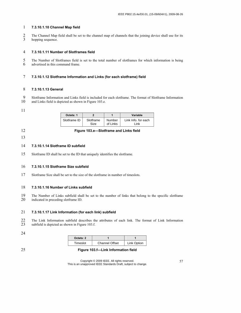
IEEE P802.15.4e/D0.01, (15-09/604/r1), 2009-08-26
Copyright © 2009 IEEE. All rights reserved. This is an unapproved IEEE Standards Draft, subject to change.
57
7.3.10.1.10 Channel Map field 1
The Channel Map field shall be set to the channel map of channels that the joining device shall use for its 2 hopping sequence. 3
7.3.10.1.11 Number of Slotframes field 4
The Number of Slotframes field is set to the total number of slotframes for which information is being 5 advertised in this command frame. 6
7.3.10.1.12 Slotframe Information and Links (for each slotframe) field 7
7.3.10.1.13 General 8
Slotframe Information and Links field is included for each slotframe. The format of Slotframe Information 9 and Links field is depicted as shown in Figure 103.e. 10
11 Octets: 1 2 1 Variable
Slotframe ID Slotframe Size
Number of Links
Link Info. for each Link
Figure 103.e—Slotframe and Links field 12 13
7.3.10.1.14 Slotframe ID subfield 14
Slotframe ID shall be set to the ID that uniquely identifies the slotframe. 15
7.3.10.1.15 Slotframe Size subfield 16
Slotframe Size shall be set to the size of the slotframe in number of timeslots. 17
7.3.10.1.16 Number of Links subfield 18
The Number of Links subfield shall be set to the number of links that belong to the specific slotframe 19 indicated in preceding slotframe ID. 20
7.3.10.1.17 Link Information (for each link) subfield 21
The Link Information subfield describes the attributes of each link. The format of Link Information 22 subfield is depicted as shown in Figure 103.f. 23
24 Octets: 2 1 1
Timeslot Channel Offset Link Option
Figure 103.f—Link Information field 25

2009-08-26, (15-09/604/r1), IEEE P802.15.4e/D0.01, August 2009
Copyright © 2009 IEEE. All rights reserved. This is an unapproved IEEE Standards Draft, subject to change.
58
7.3.10.1.18 Timeslot subfield 1
The Timeslot subfield shall be set to the timeslot of this link. 2
7.3.10.1.19 Channel Offset Information subfield 3
The Channel Offset Information subfield shall be set to the channel offset of this link. 4
7.3.10.1.20 Link Option subfield 5
The Link Option subfield indicates whether this link is a TX link, an RX link, or a SHARED TX link. 6 SHARED TX links can be used for a joining device to send its Join command. RX links are used for a new 7 device to receive Advertisement commands. RX links can also be used for a joining device to receive its 8 Activate command from the network. It is possible for one link to be used as both SHARED_TX and RX 9 link. 10
7.3.10.1.21 MIC 11
The message integrity check of the Advertisement command frame. 12
7.3.10.2 Join command 13
7.3.10.2.1 General 14
The Join command is used by a device to join the PA-network through the advertiser. This command shall 15 only be sent by a new device that wishes to join the PA-network or a device that lost connection with the 16 PA-network. 17
All devices shall be capable of transmitting this command, although an RFD is not required to be capable 18 of receiving it. 19
The Join command shall be formatted as illustrated in Figure 103.g. 20
octets: variable
(see 7.2.2.4)
1 1 1 1 0/3 variable 0/3 tbd 0/4/8/16
MHR Command
Frame
Identifier
(see table 82)
Capability Information
(see Figure 56)
Clock Accuracy Capability
Number of Neighbors
Neighbor 1 ... Neighbor n Join Security Information
(TBD by Security sub-group)
MIC
Figure 103.g—Join command format 21

IEEE P802.15.4e/D0.01, (15-09/604/r1), 2009-08-26
Copyright © 2009 IEEE. All rights reserved. This is an unapproved IEEE Standards Draft, subject to change.
59
7.3.10.2.2 MHR fields 1
The Source Addressing Mode subfield of the Frame Control field shall be set to three (64-bit extended 2 addressing). The Destination Addressing Mode subfield shall be set to the same mode as indicated in 3 Advertisement command frame to which the Join command refers. 4
The Frame Pending subfield of the Frame Control field shall be set to zero and ignored upon receipt, and 5 the Acknowledgment Request subfield shall be set to one. 6
The Destination PAN Identifier field shall contain the identifier of the PAN to which to join. The 7 Destination Address field shall contain the address from the Advertisement frame that was transmitted by 8 the coordinator to which the Join command is being sent. The PAN ID Compression subfield may be set to 9 one and the Source PAN Identifier may be omitted. The Source Address field shall contain the value of an 10 ExtendedAddress. 11
The Sequence Number subfield shall be set to the least significant byte of the absolute timeslot number. 12
7.3.10.2.3 Command Frame Identifier field 13
The Type field shall be set to Join (0x0b). 14
15
7.3.10.2.4 Capability Information field 16
17 The Capability Information field shall be formatted as illustrated in Figure 94. 18
19
7.3.10.2.5 Clock Accuracy Capability field 20
The Clock Accuracy Capability field shall be formatted as illustrated in Figure 103.h. 21
22 23
Bit: 0 1 - 7
10ppm capable reserved
Figure 103.h—Clock Accuracy Capability 24
7.3.10.2.6 Join Security Information field 25
The definition of Join Security Information field shall contain the security information that the new device 26 to mutually authenticate the new joining device and Security Manager. This will be defined by Security 27 sub-group. 28
7.3.10.2.7 Number of Neighbor field 29
The Number of Neighbor field indicates the number of neighbors included in this command frame. 30

2009-08-26, (15-09/604/r1), IEEE P802.15.4e/D0.01, August 2009
Copyright © 2009 IEEE. All rights reserved. This is an unapproved IEEE Standards Draft, subject to change.
60
7.3.10.2.8 Neighbor field 1
The Neighbor field shall contain the information about the neighbors of the new device. The Neighbor field 2 shall be formatted as illustrated in Figure 103.h. 3
4
5 Octets: 2 1
16 bit address of the neighbor
RSSI
Figure 103.i—Neighbor 6
7.3.10.2.9 MIC 7
This field contains the message integrity check of the Join command frame. 8
7.3.10.3 Activate command 9
7.3.10.3.1 General 10
The Activate command allows the advertiser to communicate the results of a Join attempt back to the 11 device requested joining. The Activate command can also include the description of slotframe and links for 12 the joining device to communicate with the PA-network. 13
This command shall only be sent by the advertiser to the device that is currently trying to join. 14
All devices shall be capable of receiving this command, although an RFD is not required to be capable of 15 transmitting it. 16
The Activate command shall be formatted as illustrated in Figure 103.j. 17
Octets: (see 7.2.2.4)
1 2 1 varaibale tbd 0/4/8/16
MHR fields Command frame Identifier (see Table 123)
Short Address Number of Slot-frames
Slotframe Info. and Links (for Each Slotframe)
Activate Security Information (TBD by Security sub-group)
MIC
Figure 103.j— Activate command format 18
7.3.10.3.2 MHR 19
The Destination Addressing Mode subfield of the Frame Control field shall be set to three (i.e., 64-bit 20 extended addressing). The Source Addressing Mode subfield of the Frame Control field shall be set to two 21 (i.e., 16-bit addressing. 22
The Frame Pending subfield of the Frame Control field shall be set to zero and ignored upon receipt, and 23 the Acknowledgment Request subfield shall be set to one. 24
IEEE P802.15.4e/D0.01, (15-09/604/r1), 2009-08-26
Copyright © 2009 IEEE. All rights reserved. This is an unapproved IEEE Standards Draft, subject to change.
61
The Source PAN Identifier field shall contain the value of macPANId. The Source Address field shall 1 contain the value of a CoordShortAddress. 2
The Destination PAN Identifier field should be set to 0xFFFF. Destination Address field shall contain the 3 extended address of the device requesting to join the network. 4
The Sequence Number subfield shall be set to the least significant byte of the absolute timeslot number. 5
7.3.10.3.3 Command Frame Identifier field 6
The Type field shall be set to Activate (0x0c). 7
7.3.10.3.4 Short Address field 8
If the advertiser was not able to join this device to its PAN, the Short Address field shall be set to 0xffff, 9 and the Join Status field shall contain the reason for the failure. If the was advertiser is able to Join the 10 device to its PAN, this field shall contain the short address that the device shall use in its communications 11 on the PAN until it is disconnected. 12
The device shall use the source PANID of the Activate command as its PANID. 13
7.3.10.3.5 Number of Links field 14
The Number of Links field shall be set to the total number of links assigned to new device being activated. 15
7.3.10.3.6 Link field 16
Link field shall have the description of link allocated to new device being activated. The format of Link 17 field shall be according to 7.3.10.1.11. 18
7.3.10.3.7 Activate Security Information field 19
The definition of Activate Security Information field shall contain the security information that the new 20 device should use to securely communicate to the PA-network. It may include keys for data link and 21 session layers. 22
7.3.10.3.8 MIC 23
This field contains the message integrity check of the Activate command frame. 24

2009-08-26, (15-09/604/r1), IEEE P802.15.4e/D0.01, August 2009
Copyright © 2009 IEEE. All rights reserved. This is an unapproved IEEE Standards Draft, subject to change.
62
7.3.11 LL-commands 1
7.3.11.1 Discover Response command 2
7.3.11.1.1 General 3
The Discover Response command contains the configuration parameters that have to be transmitted to the 4 gateway as input for the configuration process in a Low Latency network. 5
This command shall only be sent by a device that has received a beacon with shortened frame control (see 6 7.2.2.1) indicating discovery mode as determined through the procedures of the discovery mode (see 7 7.5.7.7.2). 8
All devices shall be capable of transmitting this command, although an RFD is not required to be capable 9 of receiving it. 10
The command payload of the discover response frame shall be formatted as illustrated in Figure 103.k. 11
12
13 Figure 103.k—Discover response command MAC payload 14
7.3.11.1.2 7.3.10.1 MHR fields 15
7.3.11.1.2.1 General 16
The discover response command can be sent using both MAC command frames (7.2.2.4) or MAC 17 command frames with shortened frame control (7.2.5.2.5). 18
7.3.11.1.2.2 Using MAC command frames 19
The Frame Type subfield of the Frame Control field shall contain the value that indicates a MAC command 20 frame, as shown in Table 120. 21
The Source Addressing Mode subfield of the Frame Control field shall be set to 3 (64-bit extended 22 addressing). 23
The Source Address field shall contain the value of aExtendedAddress. 24
7.3.11.1.2.3 Using MAC command frames with shortened frame control 25
In the Shortened Frame Control field, the Frame Type subfield shall contain the value that indicates a MAC 26 frame with a shortened frame control, as shown in Table 120, and the Sub Frame Type subfield shall 27 contain the value that indicates a MAC command frame, as shown in Table 122.g. 28

IEEE P802.15.4e/D0.01, (15-09/604/r1), 2009-08-26
Copyright © 2009 IEEE. All rights reserved. This is an unapproved IEEE Standards Draft, subject to change.
63
7.3.11.1.3 7.3.10.2 Command Frame Identifier field 1
The Command Frame Identifier field contains the value for the discover response command frame as 2 defined in Table 123. 3
7.3.11.1.4 7.3.10.3 Discovery Parameters field 4
The Discovery Parameters field contains the configuration parameters that have to be transmitted to the 5 gateway as input for the configuration process. The discovery parameters consist of: 6
⎯ full MAC address 7 ⎯ required time slot duration, this is defined by the application of the device (e.g. size of sensor data) 8 ⎯ sensor / actuator type indicator 9
7.3.11.2 Configuration Response Frame 10
7.3.11.2.1 General 11
The Configuration Response command contains the configuration parameters that are currently configured 12 at the device as input for the configuration process in a Wireless Factory Automation network. 13
This command shall only be sent by a device that has received a beacon with shortened frame control (see 14 7.2.5.2.2) indicating configuration mode as determined through the procedures of the configuration mode 15 (see 7.5.7.7.3). 16
All devices shall be capable of transmitting this command, although an RFD is not required to be capable 17 of receiving it. 18
The command payload of the Configuration Response Frame shall be formatted as illustrated in Figure 19 103.l. 20
21
22
Figure 103.l—Configuration response command MAC payload 23
7.3.11.2.2 MHR fields 24
The configuration response command can be sent using both MAC command frames (7.2.2.4) or MAC 25 command frames with shortened frame control (see 7.2.5.2.5). 26
variable
Configuration Parameters
Octets : 1
Command Frame Identifier (see Table 123)

2009-08-26, (15-09/604/r1), IEEE P802.15.4e/D0.01, August 2009
Copyright © 2009 IEEE. All rights reserved. This is an unapproved IEEE Standards Draft, subject to change.
64
7.3.11.2.3 7.3.11.1.1 Using MAC command frames 1
7.3.11.2.3.1 General 2
The Frame Type subfield of the Frame Control field shall contain the value that indicates a MAC command 3 frame, as shown in Table 120. 4
The Source Addressing Mode subfield of the Frame Control field shall be set to 1 (8-bit short addressing) 5 or 3 (64-bit extended addressing). 6
The Source Address field shall contain the value of aVeryShortAddress or aExtendedAddress respectively. 7
7.3.11.2.3.2 Using MAC command frames with shortened frame control 8
In the Shortened Frame Control field, the Frame Type subfield shall contain the value that indicates a MAC 9 frame with a shortened frame control, as shown in Table 120, and the Sub Frame Type subfield shall 10 contain the value that indicates a MAC command frame, as shown in Table 122.g. 11
7.3.11.2.4 Command Frame Identifier field 12
The Command Frame Identifier field contains the value for the configuration response frame as defined in 13 Table 123. 14
7.3.11.2.5 Configuration Parameters field 15
The Configuration Parameters field contains the configuration parameters that are currently configured at 16 the device. The configuration parameters consist of: 17
⎯ full MAC address 18 ⎯ short MAC address 19 ⎯ required time slot duration, this is defined by the application of the device (e.g. size of sensor data) 20 ⎯ sensor / actuator 21 ⎯ assigned time slots 22
7.3.11.3 Configuration Request Frame 23
7.3.11.3.1 General 24
The Configuration Request command contains the configuration parameters that the receiving device is 25 requested to use during online mode in a Wireless LL-network. 26
This command shall only be sent by a gateway in response to a received Configuration Response frame of a 27 device during configuration mode. 28
Only gateways are requested to be capable of transmitting this command, RFD are required to be capable 29 of receiving it. 30

IEEE P802.15.4e/D0.01, (15-09/604/r1), 2009-08-26
Copyright © 2009 IEEE. All rights reserved. This is an unapproved IEEE Standards Draft, subject to change.
65
The command payload of the Configuration Request Frame shall be formatted as illustrated in Figure 1 103.m. 2
3
4 Figure 103.m—Configuration request command MAC payload 5
7.3.11.3.2 MHR fields 6
7.3.11.3.2.1 General 7
The configuration request command can be sent using both MAC command frames (7.2.2.4) or MAC 8 command frames with shortened frame control (7.2.5.2.5). 9
7.3.11.3.2.2 Using MAC command frames 10
The Frame Type subfield of the Frame Control field shall contain the value that indicates a MAC command 11 frame, as shown in Table 120. 12
The Source Addressing Mode subfield of the Frame Control field shall be set to 1 (8-bit short addressing) 13 or 3 (64-bit extended addressing). 14
The Destination Address field shall contain the value of source address of the corresponding Configuration 15 Response frame. 16
7.3.11.3.2.3 Using MAC command frames with shortened frame control 17
In the Shortened Frame Control field, the Frame Type subfield shall contain the value that indicates a MAC 18 frame with a shortened frame control, as shown in Table 120, and the Sub Frame Type subfield shall 19 contain the value that indicates a MAC command frame, as shown in Table 122.g. 20
7.3.11.3.3 Command Frame Identifier field 21
The Command Frame Identifier field contains the value for the configuration response frame as defined in 22 Table 123. 23
7.3.11.3.4 Configuration Parameters field 24
The Configuration Parameters field contains the new configuration parameters that are sent to the device in 25 order to (re-)configure it. The configuration parameters consist of: 26
⎯ full MAC address 27 ⎯ short MAC address 28
variable
Configuration Parameters
Octets : 1
Command Frame Identifier (see Table 123)

2009-08-26, (15-09/604/r1), IEEE P802.15.4e/D0.01, August 2009
Copyright © 2009 IEEE. All rights reserved. This is an unapproved IEEE Standards Draft, subject to change.
66
⎯ transmission channel 1 ⎯ existence of management frames 2 ⎯ time slot duration 3 ⎯ assigned time slots 4
7.3.11.4 Clear to Send (CTS) Shared Group Frame 5
7.3.11.4.1 General 6
The Clear to Send Shared Group command indicates to the devices of the star network that they now may 7 use the time slot for transmitting their own data with a simplified CSMA/CA. 8
This command shall only be sent by a gateway in a time slot after tSlotTxOwner has been elapsed and the 9 slot owner is not transmitting. 10
Only gateways are requested to be capable of transmitting this command, devices are required to be capable 11 of receiving it. 12
The command payload of the Clear to Send Shared Group frame shall be formatted as illustrated in Figure 13 103.n. 14
15
16 Figure 103.n—Clear to send shared group command MAC payload 17
7.3.11.4.2 MHR fields 18
The clear to send shared group command can be sent using MAC command frames with shortened frame 19 control (7.2.5.2.5). 20
In the Shortened Frame Control field, the Frame Type subfield shall contain the value that indicates a MAC 21 frame with a shortened frame control, as shown in Table 120, and the Sub Frame Type subfield shall 22 contain the value that indicates a MAC command frame, as shown in Table 122.g. 23
7.3.11.4.3 Command Frame Identifier field 24
The Command Frame Identifier field contains the value for the clear to send shared group frame as defined 25 in Table 123. 26
7.3.11.4.4 Network ID field 27
The Network ID field contains an identifier specific to the gateway. 28
Octets: 1 1
Network IDCommand Frame Identifier (see Table 123)

IEEE P802.15.4e/D0.01, (15-09/604/r1), 2009-08-26
Copyright © 2009 IEEE. All rights reserved. This is an unapproved IEEE Standards Draft, subject to change.
67
7.3.11.5 Request to Send (RTS) Frame 1
7.3.11.5.1 General 2
The Request to Send command may be used by devices to indicates to the gateway and to the other devices 3 of the star network that it wants to transmit data with a simplified CSMA/CA. The request to send frame is 4 transmitted using a simplified CSMA/CA. 5
This command shall only be sent by a device in a time slot after tSlotOwner has been elapsed and and a 6 clear to send shared group frame has been received from the gateway. 7
Devices are requested to be capable of transmitting and receiving this command. 8
The command payload of the Request to Send frame shall be formatted as illustrated in Figure 103.o. 9
10
11 Figure 103.o—Request to send command MAC payload 12
7.3.11.5.2 MHR fields 13
The request to send command can be sent using MAC command frames with shortened frame control (see 14 7.2.5.2.5). 15
In the Shortened Frame Control field, the Frame Type subfield shall contain the value that indicates a MAC 16 frame with a shortened frame control, as shown in Table 120, and the Sub Frame Type subfield shall 17 contain the value that indicates a MAC command frame, as shown in Table 122.g. 18
7.3.11.5.3 Command Frame Identifier field 19
The Command Frame Identifier field contains the value for the request to send frame as defined in Table 20 123. 21
7.3.11.5.4 Short Originator Address 22
The Short Originator Address field contains the 1-octet short address of the device sending this request to 23 send frame. 24
7.3.11.5.5 Network ID field 25
The Network ID field contains an identifier specific to the gateway. It has to be identical to the Network ID 26 of the corresponding received CTS shared group frame. 27

2009-08-26, (15-09/604/r1), IEEE P802.15.4e/D0.01, August 2009
Copyright © 2009 IEEE. All rights reserved. This is an unapproved IEEE Standards Draft, subject to change.
68
7.3.11.6 Clear to Send (CTS) Frame 1
7.3.11.6.1 General 2
The Clear to Send command indicates to a specific device of the star network that it may now use the time 3 slot for transmitting its own data with a simplified CSMA/CA. 4
This command shall only be sent by a gateway in a time slot after tSlotOwner has been elapsed and the slot 5 owner is not transmitting. 6
Only gateways are requested to be capable of transmitting this command, devices are required to be capable 7 of receiving it. 8
The command payload of the Clear to Send Shared Group frame shall be formatted as illustrated in Figure 9 103.p. 10
11
12 Figure 103.p—Clear to send command MAC payload 13
7.3.11.6.2 MHR fields 14
The clear to send command can be sent using MAC command frames with shortened frame control (see 15 7.2.5.2.5). 16
In the Shortened Frame Control field, the Frame Type subfield shall contain the value that indicates a MAC 17 frame with a shortened frame control, as shown in Table 120, and the Sub Frame Type subfield shall 18 contain the value that indicates a MAC command frame, as shown in Table 122.g. 19
20
7.3.11.6.3 Command Frame Identifier field 21
The Command Frame Identifier field contains the value for the clear to send shared group frame as defined 22 in Table 123. 23
7.3.11.6.4 Short Destination Address 24
The Short Destination Address field contains the 1-octet short address of the device to which this clear to 25 send frame is directed. 26
7.3.11.6.5 Network ID field 27
The Network ID field contains an identifier specific to the gateway. It has to be identical to the Network ID 28 of the corresponding received RTS frame. 29

IEEE P802.15.4e/D0.01, (15-09/604/r1), 2009-08-26
Copyright © 2009 IEEE. All rights reserved. This is an unapproved IEEE Standards Draft, subject to change.
69
7.4 MAC constants and PIB attributes 1
7.4.1 MAC constants 2
7.4.2 MAC PIB attributes 3
Insert after the heading of 7.4.2 the following subclause header. 4
7.4.2.1 General 5
Insert before 7.5 the following subclauses. 6
7.4.2.2 PA-specific MAC PIB attributes 7
7.4.2.2.1 General 8
Subclause 7.4.2.1 applies except that the attributes macMinBE and macMaxBE in Table 127 shall be 9 according to Table 127.a and an additional attribute macDisconnectTime is required, see Table 127.a. 10
Table 127.a—PA-specific MAC PIB attributes 11
Attribute Identifier Type Range Description Default
macMinBE 0x4f Integer 0–macMaxBE The minimum value of the backoff exponent (BE) in the CSMA-CA algorithm or the PA- CA algorithm. See 7.5.1.4 for a detailed explanation of the backoff exponent. See 7.5.4.2 for use of the backoff exponent in PA-mode.
3/1
macMaxBE 0x57 Integer 3–8 The maximum value of the backoff exponent, BE, in the CSMA-CA algorithm or the PA- CA algorithm. See 7.5.1.4 for a detailed explanation of the backoff exponent. See 7.5.4.2 for use of the backoff exponent in PA-mode.
5/7
macDisconnectTime 0x64 Integer 0x00-0xFFFF Time to send out Disconnect frames before disconnecting.
12
7.4.2.2.2 PA-MAC PIB attributes for macSlotframeTable 13
The attributes contained in the MAC PIB for macSlotframeTable are presented in Table 127.b. 14

2009-08-26, (15-09/604/r1), IEEE P802.15.4e/D0.01, August 2009
Copyright © 2009 IEEE. All rights reserved. This is an unapproved IEEE Standards Draft, subject to change.
70
Table 127.b—PA-MAC PIB attributes for macSlotframeTable 1
Attribute Identifier Type Range Description Default
slotframeId 0x64 Integer 0x00-0xFF Identifier of the slotframe
slotframeSize 0x65 Integer 0x0000-0xFFFF
Number of timeslots in the slotframe
activeFlag 0x66 Boolean 0x0-0x1 Flag indicating if the slotframe is currently activated
channelPage 0x67 Integer 0x00-0x1F Channel Page of channels used in this slotframe
channelMap 0x68 Bitmap Bitmap of active channels.
2
7.4.2.2.3 PA-MAC PIB attributes for macLinkTable 3
The attributes contained in the MAC PIB for macLinkTable are presented in Table 127.c. 4
Table 127.c— PA-MAC PIB attributes for macLinkTable 5
Attribute Identifier Type Range Description Default
linkId 0x69 Integer 0x00-0xFF Identifier of Link
linkOption 0x6a Bitmap 0x00-0x7 Flags indicating whether the link is used for transmit, receive, or shared transmissions:
linkType 0x6b Integer 0x00-0x2 Enumeration indicating the type of link: Normal, Join, or Advertising
slotframeId 0x6c Integer 0x00-0xFF Identifier of Slotframe to which this link belongs
nodeAddress 0x6d IEEE address
16 bit address Address of the node connected to this link
timeslot 0x6e Integer 0x0000-0xFFFF
Timeslot for this link
channelOffset 0x6f 0x00-0xFF Channel offset for this link
6
7.4.2.2.4 PA-MAC PIB attributes for macTimeslotTemplate 7
The attributes contained in the MAC PIB for macTimeslotTemplate are presented in Table 127.d. 8

IEEE P802.15.4e/D0.01, (15-09/604/r1), 2009-08-26
Copyright © 2009 IEEE. All rights reserved. This is an unapproved IEEE Standards Draft, subject to change.
71
Table 127.d—PA-MAC PIB attributes for macTimeslotTemplate 1
Attribute Identifier Type Range Description Default
Timeslot Template Id 0x70 Integer 0x0-0xF Identifier of Timeslot Template
TsCCAOffset 0x71 Integer 0x0000-0xFFFF
The time between the beginning of timeslot and start of CCA operation
TsCCA 0x72 Integer 0x0000-0xFFFF
Duration of CCA
TsTxOffset 0x73 Integer 0x0000-0xFFFF
The time between the beginning of the timeslot and the start of packet transmission
TsRxOffset 0x74 Integer 0x0000-0xFFFF
Beginning of the timeslot to when the receiver must be listening
TsRxAckDelay 0x75 Integer 0x0000-0xFFFF
End of packet to when the transmitter must listen for Acknowledgment
TsTxAckDelay 0x76 Integer 0x0000-0xFFFF
End of packet to start of Acknowledgment
TsRxWait 0x77 Integer 0x0000-0xFFFF
The time to wait for start of packet
TsAckWait 0x78 Integer 0x0000-0xFFFF
The minimum time to wait for start of an Acknowledgment
TsRxTx 0x79 Integer 0x0000-0xFFFF
Transmit to Receive turnaround (12 symbols)
TsMaxAck 0x7a Integer 0x0000-0xFFFF
Transmission time to send Acknowledgment
TsMaxTx 0x7b Integer 0x0000-0xFFFF
Transmission time to send the maximum length packet (133 bytes)
2
7.4.2.2.5 PA-MAC PIB attributes for macHoppingSequence 3
To be jointly defined with Channel Hopping/Channel Diversity subgroup. 4 The attributes contained in the MAC PIB for macHoppingSequence are presented in Table 127.c. 5
Table 127.e— PA-MAC PIB attributes for macHoppingSequence 6
Attribute Identifier Type Range Description Default
7 8
7.4.2.3 LL-specific MAC PIB attributes 9
Subclause 7.4.2.1 applies and an additional attributes are required, see Table 127.a. 10

2009-08-26, (15-09/604/r1), IEEE P802.15.4e/D0.01, August 2009
Copyright © 2009 IEEE. All rights reserved. This is an unapproved IEEE Standards Draft, subject to change.
72
Table 127.f—LL-specific MAC PIB attributes 1
Attribute Identifier Type Range Description Default
macFAlowLatencyPAN 0x7c Boolean TRUE or FALSE
Indicates that the PAN is using the mechanisms as described in 5.3.3, 5.5.1.2, and related clauses.
Set by configuration
macFAnumTimeSlots 0x7d Integer 0 … 254 Number of time slots within superframe excluding time slot for beacon frame
20
macFAnumSensorTS 0x7e Integer 0 … macFAnum-TimeSlots
Number of sensor time slots within superframe for unidirectional communication (uplink)
20
macFAnumRetransmitTS 0x7f Integer 0 … macFAnum-SensorTS/2
Number of sensor time slots reserved for retransmission (see 5.5.1.2 and 7.5.1.1.3.1)
0
macFAnumActuatorTS 0x80 Integer 0 … macFAnum-TimeSlots
Number of actuator time slots within superframe for bidirectional communication
0
macFAmgmtTS 0x81 Boolean TRUE or FALSE
Indicates existence of management time slots in Online Mode
FALSE
macFAlowLatencyNWid 0x82 Integer 0x00–0xff The 8-bit identifier of the LLNW on which the device is operating. If this value is 0xff, the device is not associated.
0xff
2
7.5 MAC functional description 3
7.5.1 Channel access 4
7.5.1.1 Superframe structure 5
Insert after the frist paragraph the following text. 6
For LL-applications an additional superframe structure with beacons is required using a shortened frame 7 control, see 7.5.1.1.3. 8
7.5.1.1.1 Contention access period (CAP) 9
7.5.1.1.2 Contention-free period (CFP) 10
Insert before 7.5.1.2 the following subclauses. 11
12

IEEE P802.15.4e/D0.01, (15-09/604/r1), 2009-08-26
Copyright © 2009 IEEE. All rights reserved. This is an unapproved IEEE Standards Draft, subject to change.
73
7.5.1.1.3 LL-Superframe structure 1
7.5.1.1.3.1 General Structure of Superframe 2
The superframe is divided into a beacon slot and macFAnumTimeSlots base time slots of equal length, see 3 Figure 104.a. 4
5 Figure 104.a—Superframe with dedicated time slots 6
7 The first time slot of each superframe contains a beacon frame. The beacon frame is used for 8 synchronization with the superframe structure. It is also used for re-synchronisation of devices that went 9 into power save or sleep mode. 10
The remaining time slots are assigned to specific devices of the network. Each time slot may have assigned 11 a so-called slot owner. The slot owner has access privileges in the time slot (dedicated time slot). There is 12 no explicit addressing necessary inside the frames if the slot owner transmits in its time slot. The 13 determination of the sender is achieved through the number of the time slot. More than one device can be 14 assigned to a time slot (shared group time slot). The devices use a contention-based access method 15 (modified CSMA/CA) a simple addressing scheme. 16
Multiple adjacent base time slots can be concatenated to a single, larger time slot. 17
As shown in Figure 104.b, there is a specific order in the meaning or usage of the time slots. 18
19
Figure 104.b—Usage and order of slots in a superframe 20 21 ⎯ Beacon Time Slot: always there (see 5.2) 22 ⎯ Management Time Slots: one time slot downlink, one time slot uplink, existence is configurable in 23
macFAmgmtTS during setup (see 5.3) 24

2009-08-26, (15-09/604/r1), IEEE P802.15.4e/D0.01, August 2009
Copyright © 2009 IEEE. All rights reserved. This is an unapproved IEEE Standards Draft, subject to change.
74
⎯ Time slots for sensors: macFAnumSensorTS time slots uplink (uni-directional communication), 1 macFAnumRetransmitTS time slots at the beginning can be reserved for retransmissions (see 5.4) 2
⎯ Time slots for actuators: macFAnumActuatorTS time slots uplink / downlink (bi-directional 3 communication) (see 5.5) 4
7.5.1.1.3.2 Beacon Time Slot 5
The beacon time slot is reserved for the gateway to indicate the start of a superframe with the transmission 6 of a beacon. The beacon is used to synchronize the devices and to indicate the current transmission mode. 7 The beacon contains also acknowledgements for the data transmitted in the last superframe. 8
The beacon time slot is available in every superframe. 9
7.5.1.1.3.3 Management Time Slots 10
The first portion of a superframe after the beacon time slot is formed by the management time slots, i.e. the 11 downlink/uplink management time slots. 12
The downlink direction is defined as sending data to the device (sensor, actuator). The uplink direction is 13 defined as sending data from the device (sensor, actuator). 14
Management time slots provide a mechanism for bidirectional transmission of management data in 15 downlink and uplink direction. Downlink and uplink time slots are provided in equal number in a 16 superframe. There are two management time slots per superframe at maximum. Management down-/uplink 17 time slots are implemented as shared group access time slots. 18
Management down-/uplink time slots are used in discovery and configuration mode and are optional in the 19 online mode. 20
7.5.1.1.3.4 Sensor Time Slots 21
After the management time slots, time slots for the transmission of sensor data are contained in a 22 superframe. Sensor time slots allow for unidirectional communication (uplink) only. 23
The first macFAnumRetransmitTS of the macFAnumSensorTS sensor time slots are dedicated time slots for 24 retransmissions of failed uplink transmission attempts in dedicated time slots of the previous superframe. 25 The dynamic assignment of nodes to retransmission time slots is described in 7.5.7.7.4. 26
7.5.1.1.3.5 Actuator Time Slots 27
Actuator time slots allow for bidirectional communication between the gateway and the device (actuator). 28 The direction of the communication is signalled in the beacon as described in 7.2.5.2.2. Actuator time slots 29 are used for the transmission of device data to the gateway (uplink) as well as of actuator information from 30 the gateway to the device (downlink). 31
32
7.5.1.1.3.6 Channel access within time slots 33
Each time slot is described by four time attributes as illustrated in Figure 104.c and described in Table 34 127.d. 35

IEEE P802.15.4e/D0.01, (15-09/604/r1), 2009-08-26
Copyright © 2009 IEEE. All rights reserved. This is an unapproved IEEE Standards Draft, subject to change.
75
1
2 Figure 104.c—Time attributes of time slots 3
Table 127.d—Time attributes of time slots 4 Attribute Description
tSlotStart starting time of time slot tSlotTxOwner end time of priviledged access by device that owns the time slot tSlotTxGW if time slot is unused, gateway can use the time slot tSlotEnd end time of time slot
5 From tSlotStart till tSlotTxOwner, the device that owns the slot, the slot owner, has exclusive access to the 6 time slot. 7
From tSlotTxOwner till tSlotTxGW, any device may use the time slot with a modified CSMA/CA access 8 scheme as described in 7.5.1.5, if the time slot is not used by the slot owner. 9
From tSlotTxGW till tSlotEnd, the gateway may use the time slot, if the time slot is still unused. 10
Dedicated time slots are reserved for a single device (slot owner). This is achieved by setting tSlotTxOwner 11 and tSlotTxGW to tSlotEnd. A dedicated time slot allows the transmission of exactly one packet. Dedicated 12 time slots are only used during online mode (see 7.5.7.7.4). 13
Shared group time slots with contention-based access for every allowed device can be achieved by setting 14 tSlotTxOwner to tSlotStart. 15
7.5.1.2 Incoming and outgoing superframe timing 16
7.5.1.4 CSMA-CA algorithm 17
Insert after the heading of 7.5.1.4 the following subclause. 18
7.5.1.4.1 General 19
Insert before 7.5.2 the following subclauses. 20
7.5.1.4.2 PA-CCA Algorithm 21
When a device is operating in the PA-mode (see 7.1.21.3) the CCA is used to promote coexistence with 22 other users of the radio channel. For other devices in the same network the start time of transmissions, 23 TxTxOffset, is closely aligned making intra-network collision avoidance using CCA ineffective. The PA- 24 devices also do channel hopping so there is no backoff period used when CCA prevents a transmission. 25

2009-08-26, (15-09/604/r1), IEEE P802.15.4e/D0.01, August 2009
Copyright © 2009 IEEE. All rights reserved. This is an unapproved IEEE Standards Draft, subject to change.
76
When a device has a packet to transmit. it waits for a link it can transmit it in. If CCA has been enabled, the 1 MAC requests the PHY to perform a CCA at the designated time in the timeslot, TxCCAOffset, without 2 any backoff delays. Figure 107.a extend Figure 107 for the PA-mode. 3
4 Figure 107.a—PA-CSMA-CA Algorithm 5
7.5.1.4.3 PA-CA Algorithm 6
Shared links (links with the linkOption shared bit set) are intentionally assigned to more than one device for 7 transmission. This can lead to collisions and result in a transmission failure detected by not receiving an 8 acknowledgement. To reduce the probability of repeated collisions when the packets are retransmitted a 9 retransmission backoff algorithm shall be implemented for shared links. 10
When a packet is transmitted on a shared link for which an acknowledgement is expected and none is 11 received, the transmitting device shall invoke the PA- CA retransmission algorithm. Subsequent 12

IEEE P802.15.4e/D0.01, (15-09/604/r1), 2009-08-26
Copyright © 2009 IEEE. All rights reserved. This is an unapproved IEEE Standards Draft, subject to change.
77
retransmissions may be in either shared links or dedicated links. This backoff algorithm has the following 1 properties: 2
3 ⎯ The retransmission backoff wait applies only to the transmission on shared links. There is no 4
waiting for transmission on dedicated links. 5 ⎯ The retransmission backoff is calculated in the number of shared link transmission links. 6 ⎯ The backoff window increases for each consecutive failed transmission in a shared link. 7 ⎯ A successful transmission in a shared link resets the backoff window to the minimum value. 8 ⎯ The backoff window does not change when a transmission is a failure in a dedicated link. 9 ⎯ The backoff window does not change when a transmission is successful in a dedicated link and 10
there transmission queue is still not empty afterwards. 11 ⎯ The backoff window is reset to the minimum value if the transmission in a dedicated link is 12
successful and the transmit queue is then empty. 13 14
In PA-mode, backoff is calculated in shared links, so the CSMA-CA aUnitBackoffPeriod is not used. 15
macMaxBE and macMinBE have different default values when the device is in PA-mode (see table 86). 16
The device shall use an exponential backoff mechanism analogous to that described in 7.5.1.4.1. A device 17 upon encountering a transmission failure in a shared link shall initialize the backoff exponent (BE) to 18 macMinBE. The MAC sublayer shall delay for a random number in the range 0 to 2BE–1 shared links (on 19 any slotframe) before attempting a retransmission on a shared link. Retransmission on a dedicated link 20 may occur at any time. For each successive failure on a shared link, the device should increase the backoff 21 exponent until the backoff exponent = macMaxBE. Successful transmission on a shared link resets the 22 backoff exponent to macMinBE. 23
If an acknowledgment is still not received after macMaxFrameRetries retransmissions, the MAC sublayer 24 shall assume the transmission has failed and notify the next higher layer of the failure. 25
26
7.5.1.4.4 LL-Simplified CSMA-CA 27
This subclause defines a simplified CSMA-CA algorithm that is used during Management Time slots and 28 Shared Group Timeslots in low latency networks. 29
30
The simplified CSMA-CA is a slotted CSMA-CA mechanism and follows the same algorithm as described 31 in 7.5.1.4.1. However, some MAC PIB attributes have different default values as shown in Table 127.b. 32

2009-08-26, (15-09/604/r1), IEEE P802.15.4e/D0.01, August 2009
Copyright © 2009 IEEE. All rights reserved. This is an unapproved IEEE Standards Draft, subject to change.
78
Table 127.b—Default values for MAC PIB attributes for slotted CSMA-CA in LL-Networks 1
MAC PIB attribute Default Value in Low Latency Networks
macMinBE 3
macMaxBE 3
macMaxCSMABackoffs 0
2 The backoff slots of aUnitBackoffPeriod symbols are aligned with the start of the beacon transmission in 3 management time slots and with tSlotTxOwner in shared group time slots. 4
7.5.1.5 PA-Slotframe structure 5
7.5.1.5.1 General 6
A slotframe is a collection of timeslots repeating in time. The number of timeslots in a given slotframe 7 (slotframe size) determines how often each timeslot repeats, thus setting a communication schedule for 8 nodes that use the timeslots. When a slotframe is created, it is associated with a slotframe ID for 9 identification. Every new slotframe instance in time is called a slotframe cycle. Figure 107.c shows how 10 nodes may communicate in a sample three-timeslot slotframe. Nodes A and B communicate during timeslot 11 0, nodes B and C communicate during timeslot 1, and timeslot 2 is not being used. Every three timeslots, 12 the schedule repeats. The total number of timeslots that has elapsed since the start of the network is called 13 the Absolute Slot Number (ASN). The pairwise assignment of a directed communication between devices 14 in a given timeslot on a given channel offset is a link. Logical channel selection in a link is made by taking 15 (Absolute Slot Number + channel offset) % Number of channels. Mapping of logical channel to physical 16 channel is to be jointly defined with Channel Hopping/Channel Diversity subgroup 17
18
Cycle N Cycle N+1 Cycle N+2
TS2TS1B->C
TS0A->B
TS0A->B
TS1B->C
TS2 TS0A->B
TS1B->C
TS2
Figure 107.c—Example of a three-timeslot slotframe 19
Several performance parameters are determined by slotframe size and how timeslots are assigned within a 20 slotframe for communication. In general, shorter slotframes result in lower latency and increased 21 bandwidth, but at the expense of increased power consumption. Long slotframes generally result in higher 22 latency and lower bandwidth, but power consumption is reduced and the number of communication 23 resources (links) is increased. This affects the scale of the network. 24
25
7.5.1.5.2 Multiple slotframes 26
A given network using timeslot-based access may contain several concurrent slotframes of different sizes. 27 Slotframe size defines the bandwidth of a timeslot. A timeslot within a slotframe of a particular size repeats 28 twice as fast as a timeslot within a slotframe that is twice as long, thus allowing for double throughput on 29 any given link. Multiple slotframes may be used to define a different communication schedule for various 30 groups of nodes or to run the entire network at different duty cycles. 31

IEEE P802.15.4e/D0.01, (15-09/604/r1), 2009-08-26
Copyright © 2009 IEEE. All rights reserved. This is an unapproved IEEE Standards Draft, subject to change.
79
A network device may participate in one or more slotframes simultaneously, and not all devices need to 1 participate in all slotframes. By configuring a network device to participate in multiple overlapping 2 slotframes of different sizes, it is possible to establish different communication schedules and connectivity 3 matrices that all work at the same time. 4
Slotframes can be added, removed, and modified while the network is running. Even though this is the 5 case, all slotframes logically start in the same place in time. Cycle 0, timeslot 0 of every slotframe occurs at 6 the beginning of epoch, which is determined by the network device that starts the network. Because of this, 7 timeslots in different slotframes are always aligned, even though beginnings and ends of slotframes may 8 not be (see Figure 107.d). Because all slotframes begin at the same time, it is always possible to identify 9 time of a given slotframe cycle and timeslot, and ASN is the same across slotframes. 10
Figure 107.d—Multiple slotframes in the network 11
12
7.5.2 Starting and maintaining PANs 13
7.5.2.5 Device discovery 14
Insert before 7.5.3 the following subclause. 15
7.5.2.6 PA-network formation 16
7.5.2.6.1 Overview 17
There are two components of network formation in the PA-network: 18
⎯ advertising and 19 ⎯ joining. 20
As a part of advertising, network devices that are already part of the network may send command frames 21 announcing the presence of the network. Advertisement command frames include time synchronization 22 information and a unique PAN ID. A new device trying to join listens for the Advertisement command 23 frames. If the device is pre-provisioned with a PAN ID, then it matches the advertised PAN ID with the 24 provisioned one at the higher layer. If there is no provisioned PAN ID, the device does not look for a 25 match. When at least one acceptable Advertisement command frame is received, the new device can 26 attempt to join the network. A new device joins the network by sending a Join request command frame to 27 an advertising node. In a centralized management system this join command is routed to the PAN 28 coordinator. In a distributed management system it can be processed locally. When the device is accepted 29 into the network, the advertiser activates the device by setting up slotframes and links between the new 30 device and other existing devices. These slotframes and links can also be deleted and modified and new 31 slotframes and links added any time after a device has joined the network. The sequence of messages 32

2009-08-26, (15-09/604/r1), IEEE P802.15.4e/D0.01, August 2009
Copyright © 2009 IEEE. All rights reserved. This is an unapproved IEEE Standards Draft, subject to change.
80
exchanged to synchronize a device to the networks is shown in Figure 107.a. The join sequence is shown 1 in Figure 107.b. 2
A new network starts when the PAN coordinator starts to advertise (typically at the request of Network 3 Manager residing in the PAN coordinator). Being the first node in the network, the PAN coordinator starts 4 at least one slotframe, to which other network devices may later synchronize. 5
6
7 8
Figure 107.a—Message sequence chart for PA- procedure to find an advertising device 9 10

IEEE P802.15.4e/D0.01, (15-09/604/r1), 2009-08-26
Copyright © 2009 IEEE. All rights reserved. This is an unapproved IEEE Standards Draft, subject to change.
81
1 2
Figure 107.b—Message sequence chart for join and activate procedures 3
7.5.2.6.2 Advertising 4
In order for new devices to join a network they must first learn network information from some devices that 5 are already part of the network. This is done through advertising. Network devices may send Advertisement 6 command frames to invite new devices into the network. This is shown in Figure 107.a. The advertising 7 device begins advertising on receipt of a ADVERTISE.request command from its NHL (next higher layer). 8 At some time the device wishing to join the network begins listening (as result of receiving a 9 LISTEN.request from its NHL). Once the listening device has heard an advertisement, it will generate an 10 ADVERTISE.indication to a higher layer. The higher layer may initialize the slotframe and links contained 11 in the advertisement and switch the device into PA-mode with a PA-MODE.request or wait for additional 12 ADVERTISE.indications before doing so. At this point the device is synchronized to the network and may 13 send in a Join request. 14
Advertisement command frames contain the following information: 15
⎯ PAN ID. 16 ⎯ Time information so new devices can synchronize to the network. 17 ⎯ Channel page and a list of RF channels in that channel page being used. 18 ⎯ Link and slotframe information so new devices know when they can transmit to the advertising 19
device. 20 ⎯ Link and slotframe information so new devices know when to listen for transmits from the 21
advertising network device. 22 23
7.5.2.6.3 Joining 24
After a new device hears at least one valid Advertisement command frame, it may synchronize to the 25 network and start joining. Advertisement command frames contain information about the links through 26

2009-08-26, (15-09/604/r1), IEEE P802.15.4e/D0.01, August 2009
Copyright © 2009 IEEE. All rights reserved. This is an unapproved IEEE Standards Draft, subject to change.
82
which the new device may communicate with the advertising neighbor, and through it forward frames to 1 the Network Manager. The joining procedure may include a security handshake to mutually authenticate 2 the joining device and the Network Manager and establish the secure session between the new device and 3 the Network Manager in addition to allocating the communication resource to the joining device. The 4 content of authentication messages is beyond the scope of this document. 5
6
The joining process is shown in Figure 107.b. The joining device sends in a join message which contains 7 its identity, capability and security information, and a list of potential neighbors heard during listening. 8 The advertising device that receives this join request may process it locally or send it to a Network 9 manager. If the device is to be allowed into the network, then an activate command is sent containing some 10 slotframes and links that the device may use to communicate to its neighbors, which may or may not be the 11 neighbor to whom the join request was sent. After receiving the activate command, the device may be 12 instructed to remove slotframes and links obtained from advertisements. The device may receive additional 13 slotframes and links from a Network Manager or peer as required by the application. 14
7.5.3 Association and disassociation 15
7.5.4 Synchronization 16
Insert before 7.5.4.1 the following paragraph. 17
For PA, Subclause 7.5.4 specifies in addition the procedures for coordinators to generate beacon frames for 18 devices to synchronize to the PA-network. For PANs not supporting beacons, synchronization is performed 19 by time synchronized communication within a timeslot of the slotframe. 20
7.5.4.1 Synchronization with beacons 21
Insert before 7.5.5 the following subclauses. 22
7.5.4.4 Synchronization in PA-network 23
7.5.4.4.1 Timeslot communication 24
During a timeslot in a slotframe, one node typically sends a frame, and another sends back an 25 acknowledgement if it successfully receives that frame. An acknowledgement can be positive (ACK) or 26 negative (NACK). A positive acknowledge indicates that the receiver has successfully received the frame 27 and has taken ownership of it for further routing. A negative acknowledgement indicates that the receiver 28 cannot accept the frame at this time, but has heard it with no errors. Both ACKs and NACKs carry timing 29 information used by nodes to maintain network synchronization. Frames sent to a unicast node address 30 require that a link-layer acknowledgement be sent in response during the same timeslot as shown in Figure 31 107.c. If an acknowledgement is requested and not received within the timeout period, retransmission of 32 the frame waits until the next assigned transmit timeslot (in any active slotframe) to that address occurs. 33

IEEE P802.15.4e/D0.01, (15-09/604/r1), 2009-08-26
Copyright © 2009 IEEE. All rights reserved. This is an unapproved IEEE Standards Draft, subject to change.
83
Figure 107.c—Timeslot diagram of acknowledged transmission 1
2 As shown in Figure 107.c, the timeslot starts at time T=0 from the transmitting device’s perspective. The 3 transmitter waits TsCCAOffset µs, and then performs CCA (if active). At TsTxOffset µs, the device begins 4 transmitting the packet. The transmitter then waits TsRxAckDelay µs, then goes into receive mode to await 5 the acknowledgement. If the acknowledgement doesn't arrive within TsAckWait (AWT) µs the device may 6 idle the radio and that no acknowledgement will arrive. 7
On the receiver's side, at it's estimate of T=0 it waits TsRxOffset µs and then goes into receive for 8 TsRxWait (PWT) µs. If the frame has not started by that time, it may idle the receiver. Otherwise, once the 9 frame has been received, the receiver waits TsTxAckDelay µs and then sends an acknowledgement. 10
The transmitter or receiver may resynchronize clocks as described in 7.5.4.4.2. 11
EXAMPLE: 12
Below is the calculation of a 10 ms length timeslot template (from the transmitter's perspective): 13
TsTxOffset 2 120 µs TsMaxPacket 4 256 µs TsRxAckDelay 800 µs TsAckWait 400 µs TsMaxAck 2 400 µs Total 9 976 µs
14 This allows for a maximum 133 octet frame (total including all SHR, PHR, MHR, etc.) to be sent, and an 15 acknowledgement of up to 75 octets to be returned within 10 ms. 16
17

2009-08-26, (15-09/604/r1), IEEE P802.15.4e/D0.01, August 2009
Copyright © 2009 IEEE. All rights reserved. This is an unapproved IEEE Standards Draft, subject to change.
84
7.5.4.4.2 Node synchronization 1
7.5.4.4.2.1 General 2
Device-to-device synchronization is necessary to maintain connection with neighbors in a slotframe-based 3 network. There are two methods for a device to synchronize to the network. 4
7.5.4.4.2.2 Acknowledgement-based synchronization 5
Unicast communication provides a basic method of time synchronization through the exchange of data and 6 acknowledgement frames. The algorithm involves the receiver calculating the delta between the expected 7 time of frame arrival and its actual arrival, and providing that information to the sender node. 8
The algorithm can be described as follows: 9
⎯ Transmitter node sends a frame, timing the start symbol to be sent at TsTxOffset. 10 ⎯ Receiver records the timestamp TsRxActual of receiving the start symbol of the packet. 11 ⎯ Receiver calculates TimeAdj = TsTxOffset – TsRxActual. 12 ⎯ Receiver send back TimeAdj as part of acknowledgement packet. 13 ⎯ Transmitter receives the acknowledgement. If the receiver node is a clock source node, the 14
transmitter adjusts its network clock by TimeAdj. 15 16
7.5.4.4.2.3 Frame-based synchronization 17
A node may synchronize its own network clock if it receives a frame from a clock source neighbor. The 18 mechanism is similar to that of ACK-based synchronization. The receiver calculates the delta between 19 expected time of frame arrival and its actual arrival time, and adjusts its own clock by the difference. 20
The algorithm can be described as follows: 21
⎯ Receiver records the timestamp TsRxActual of receiving the start symbol of the packet. 22 ⎯ Receiver calculates TimeAdj = TsTxOffset – TsRxActual. 23 ⎯ Receiver adjusts its own network time by –TimeAdj. 24
Note that this procedure should only be executed if the node from which the frame is received is a clock 25 source for the receiver. 26
Figure 107.d illustrates both time synchronization mechanisms. In both cases, the receiver calculates 27 TimeAdj to either send back to the transmitter or to use locally. 28
29

IEEE P802.15.4e/D0.01, (15-09/604/r1), 2009-08-26
Copyright © 2009 IEEE. All rights reserved. This is an unapproved IEEE Standards Draft, subject to change.
85
1 2
Figure 107.d—Time synchronization 3 4
7.5.4.4.2.4 Network time synchronization 5
Precise time synchronization is critical to the operation of networks based on time division multiplexing. 6 Since all communication happens in timeslots, the network devices must have the same notion of when 7 each timeslot begins and ends, with minimal variation. The acknowledgement and frame-based 8 synchronization are used for pair-wise synchronization, as outlined below. In a typical PA-network, time 9 propagates outwards from the PAN coordinator. It is very important to maintain unidirectional time 10 propagation and avoid timing loops. A network device must periodically synchronize its network clock to 11 at least one other network device. It may also provide its network time to one or more network devices. A 12 network device determines whether to follow a neighbor’s clock based on the presence of a ClockSource 13 flag in the corresponding neighbor’s record (configured by the Network Manager). The direction of time 14 propagation is independent of data flow in the network. 15
A network device may have more than one neighbor as its clock source. In such cases, the device may 16 synchronize its clock to any of the neighbors that are acting as its clock source. 17
Figure 107.e shows typical time propagation in PA-network. The arrows indicate the direction of clock 18 distribution. In this example, the PAN coordinator acts as the clock source for the entire network. Network 19 Device (ND) 20 synchronizes to the PAN coordinator only, while ND 22 synchronizes its clock to both ND 20 20 and ND 21. If ND 20 and ND 23 were to be connected, ND 20 must provide time to ND 23. Setting it up 21 otherwise would create a timing loop. 22

2009-08-26, (15-09/604/r1), IEEE P802.15.4e/D0.01, August 2009
Copyright © 2009 IEEE. All rights reserved. This is an unapproved IEEE Standards Draft, subject to change.
86
1 Figure 107.e—Time propagation in PA-network 2
7.5.4.4.2.5 Keep-Alive mechanism 3
In order to ensure that it remains synchronized with the PA-network (and to detect when paths may be 4 down) a network device shall ensure that it communicates with each of its clock sources at least once per 5 Keep Alive period. 6
If a network device has not sent a packet to its clock parent within this interval, it shall send a Keep-Alive 7 command frame and use the ACK to perform ACK-based synchronization as usual. 8
7.5.5 Transaction handling 9
7.5.6.2 Reception and rejection 10
Change text in 7.5.6.2. 11
Each device may choose whether the MAC sublayer is to enable its receiver during idle periods. During 12 these idle periods, the MAC sublayer shall still service transceiver task requests from the next higher layer. 13 A transceiver task shall be defined as a transmission request with acknowledgment reception, if required, or 14 a reception request. On completion of each transceiver task, the MAC sublayer shall request that the PHY 15 enables or disables its receiver, depending on the values of macBeaconOrder and macRxOnWhenIdle. If 16 macBeaconOrder is less than 15, the value of macRxOnWhenIdle shall be considered relevant only during 17 idle periods of the CAP of the incoming superframe. If macBeaconOrder is equal to 15 or 18 macFAlowLatencyPAN is FALSE, the value of macRxOnWhenIdle shall be considered relevant at all 19 times. If macFAlowLatencyPAN is TRUE, the value of macRxOnWhenIdle is not considered relevant. 20
Due to the nature of radio communications, a device with its receiver enabled will be able to receive and 21 decode transmissions from all devices complying with this standard that are currently operating on the 22 same channel and are in its POS, along with interference from other sources. The MAC sublayer shall, 23 therefore, be able to filter incoming frames and present only the frames that are of interest to the upper 24 layers. 25

IEEE P802.15.4e/D0.01, (15-09/604/r1), 2009-08-26
Copyright © 2009 IEEE. All rights reserved. This is an unapproved IEEE Standards Draft, subject to change.
87
For the first level of filtering, the MAC sublayer shall discard all received frames that do not contain a 1 correct value in their FCS field in the MFR (see 7.2.1.9 and 7.2.5.1.4). The FCS field shall be verified on 2 reception by recalculating the purported FCS over the MHR and MAC payload of the received frame and 3 by subsequently comparing this value with the received FCS field. The FCS field of the received frame 4 shall be considered to be correct if these values are the same and incorrect otherwise. 5
The second level of filtering shall be dependent on whether the MAC sublayer is currently operating in 6 promiscuous mode. In promiscuous mode, the MAC sublayer shall pass all frames received after the first 7 filter directly to the upper layers without applying any more filtering or processing. The MAC sublayer 8 shall be in promiscuous mode if macPromiscuousMode is set to TRUE. 9
If the MAC sublayer is not in promiscuous mode (i.e., macPromiscuousMode is set to FALSE), it shall 10 accept only frames that satisfy all of the following third-level filtering requirements: 11
— The Frame Type subfield shall not contain a reserved frame type. 12
— The Frame Version subfield shall not contain a reserved value. 13
— If a destination PAN identifier is included in the frame, it shall match macPANId or shall be the 14 broadcast PAN identifier (0xffff). 15
— If a short destination address is included in the frame, it shall match either macShortAddress, 16 macVeryShortAddress, or the broadcast address (0xffff). Otherwise, if an extended destination address is 17 included in the frame, it shall match aExtendedAddress. 18
— If the frame type indicates that the frame is a beacon frame (frame type b000), the source PAN identifier 19 shall match macPANId unless macPANId is equal to 0xffff, in which case the beacon frame shall be 20 accepted regardless of the source PAN identifier. If the frame type indicates that the frame is a beacon 21 frame of an LLNW (frame type b100, subframe type b00) and indicates online mode, the Gateway ID field 22 shall match macFAlowLatencyNWid. 23
— If only source addressing fields are included in a data or MAC command frame, the frame shall be 24 accepted only if the device is the PAN coordinator and the source PAN identifier matches macPANId. 25
If any of the third-level filtering requirements are not satisfied, the MAC sublayer shall discard the 26 incoming frame without processing it further. If all of the third-level filtering requirements are satisfied, the 27 frame shall be considered valid and processed further. For valid frames that are not broadcast, if the Frame 28 Type subfield indicates a data or MAC command frame and the Acknowledgment Request subfield of the 29 Frame Control field is set to one, the MAC sublayer shall send an acknowledgment frame. Prior to the 30 transmission of the acknowledgment frame, the sequence number included in the received data or MAC 31 command frame shall be copied into the Sequence Number field of the acknowledgment frame. This step 32 will allow the transaction originator to know that it has received the appropriate acknowledgment frame. 33
If the PAN ID Compression subfield of the Frame Control field is set to one and both destination and 34 source addressing information is included in the frame, the MAC sublayer shall assume that the omitted 35 Source PAN Identifier field is identical to the Destination PAN Identifier field. 36
The device shall process the frame using the incoming frame security procedure described in 7.5.9.2.3. 37
If the status from the incoming frame security procedure is not SUCCESS, the MLME shall issue the 38 corresponding confirm or MLME-COMM-STATUS.indication primitive with the status parameter set to 39 the status from the incoming frame security procedure, indicating the error, and with the security-related 40 parameters set to the corresponding parameters returned by the unsecuring process. 41

2009-08-26, (15-09/604/r1), IEEE P802.15.4e/D0.01, August 2009
Copyright © 2009 IEEE. All rights reserved. This is an unapproved IEEE Standards Draft, subject to change.
88
If the valid frame is a data frame, the MAC sublayer shall pass the frame to the next higher layer. This is 1 achieved by issuing the MCPS-DATA.indication primitive containing the frame information. The 2 securityrelated parameters of the MCPS-DATA.indication primitive shall be set to the corresponding 3 parameters returned by the unsecuring process. 4
If the valid frame is a MAC command or beacon frame, it shall be processed by the MAC sublayer 5 accordingly, and a corresponding confirm or indication primitive may be sent to the next higher layer. The 6 security-related parameters of the corresponding confirm or indication primitive shall be set to the 7 corresponding parameters returned by the unsecuring process. 8
7.5.6.4.2 Acknowledgment 9
Insert before 7.5.6.4.3 the following paragraph. 10
When operating in PA-mode (see 7.1.21.3), the acknowledgement frame is sent at the time specified by the 11 macTimeslotTemplate being used (see 7.4.2 and 7.5.4.4.1). 12
7.5.6.4.3 Retransmissions 13
Insert after the heading of 7.5.6.4.3 the following subclause. 14
7.5.6.4.3.1 General 15
Insert before 7.5.6.5 the following subclause. 16
7.5.6.4.3.2 PA-Retransmissions 17
A device that sends a data or MAC command frame with its Acknowledgment Request subfield set to one 18 shall wait for TsRxAckDelay µs. If an acknowledgment frame is received within macAckWaitDuration 19 symbols and contains the same DSN as the original transmission, the transmission is considered successful, 20 and no further action regarding retransmission shall be taken by the device. If an acknowledgment is not 21 received within the appropriate timeout or an acknowledgment is received containing a DSN that was not 22 the same as the original transmission, the device shall conclude that the single transmission attempt has 23 failed. 24
If a single transmission attempt has failed and the transmission was indirect, the coordinator shall not 25 retransmit the data or MAC command frame. Instead, the frame shall remain in the transaction queue of the 26 coordinator and can only be extracted following the reception of a new data request command. If a new 27 data request command is received, the originating device shall transmit the frame using the same DSN as 28 was used in the original transmission. 29
If a single transmission attempt has failed and the transmission was direct, the device shall repeat the 30 process of transmitting the data or MAC command frame and waiting for the acknowledgment, up to a 31 maximum of macMaxFrameRetries times. The retransmitted frame shall contain the same DSN as was used 32 in the original transmission. Each retransmission shall only be attempted if it can be completed within the 33 same portion of the superframe, i.e., the CAP or a GTS in which the original transmission was attempted. If 34 this timing is not possible, the retransmission shall be deferred until the same portion in the next 35 superframe. In PA-mode (see 7.1.21.3), retransmissions only occur on subsequent transmit links to the 36 same recipient on any active slotframe. If an acknowledgment is still not received after 37 macMaxFrameRetries retransmissions, the MAC sublayer shall assume the transmission has failed and 38 notify the next higher layer of the failure. 39

IEEE P802.15.4e/D0.01, (15-09/604/r1), 2009-08-26
Copyright © 2009 IEEE. All rights reserved. This is an unapproved IEEE Standards Draft, subject to change.
89
7.5.6.5 Promiscuous mode 1
7.5.7 GTS allocation and management 2
7.5.7.6 GTS expiration 3
Insert before 7.5.8 the following subclauses. 4
7.5.7.7 LL-Transmission Modes in star networks using short MAC headers 5
7.5.7.7.1 General 6
The transitions between the different transmission modes are illustrated in Figure 111.a. 7
8
9 10
Figure 111.a—Transitions between transmission modes 11 12 The discovery mode is the first step during network setup: the new devices are discovered and configured 13 in the second step, the configuration mode. After the successful completion of the configuration mode, the 14 network can go into online mode. Productivity data, that is, data and readings from the devices such as 15 sensors and actuators, can only be transmitted during online modus. In order to reconfigure a network, the 16 configuration mode can be started again. 17
7.5.7.7.2 Discovery Mode 18
The Discovery Mode is the first step during network setup or for the addition of new devices to an existing 19 network. 20
In discovery mode, the superframe contains only the time slot for the beacon (see 7.5.1.1.3.2) and two 21 management time slots, one downlink and one uplink (7.5.1.1.3.3). 22
A new device scans the different channels until it detects a gateway sending beacons that indicate discovery 23 mode. 24

2009-08-26, (15-09/604/r1), IEEE P802.15.4e/D0.01, August 2009
Copyright © 2009 IEEE. All rights reserved. This is an unapproved IEEE Standards Draft, subject to change.
90
If a new device received a beacon indicating discovery mode, it tries to get access to the transmission 1 medium in the uplink management time slot in order to send a Discover Response frame to the gateway. 2 The Discover Response frame is described in 7.3.11.1. The Discover Response frame contains the current 3 configuration of the device. The new device shall repeat sending the Discover Response frame until it 4 receives an Acknowledgement frame for it or the Discovery Mode is stopped by the gateway. The 5 Acknowledgement frame is described in 7.2.5.2.4. 6
Figure 111.b illustrates the discovery mode. 7
Gateway Sensor/Actuator
Mgmt Slot
Mgmt Slot
Beacon
Beacon
Start Discover Mode
Synchronize and prepare Response
Frame that contains the current device
configurationDiscover Response Frame
Time
Beacon
Mgmt Slot
Mgmt Slot
Beacon
Mgmt Slot
Mgmt Slot
Beacon
Mgmt Slot
Mgmt Slot
Beacon
...
ResynchronizesAck Frame
Received a Discover
Response Frame;
prepare Ack
Gateway Sensor/Actuator
Mgmt Slot
Mgmt Slot
Beacon
Beacon
Start Discover Mode
Synchronize and prepare Response
Frame that contains the current device
configurationDiscover Response Frame
Time
Beacon
Mgmt Slot
Mgmt Slot
Beacon
Mgmt Slot
Mgmt Slot
Beacon
Mgmt Slot
Beacon
...
ResynchronizesAck Frame
8 Figure 111.b—Flow diagram of Discovery Mode 9
10
7.5.7.7.3 Configuration Mode 11
The Configuration Mode is the second step during network setup. It is also used for network 12 reconfiguration. 13
In configuration mode, the superframe contains only the time slot for the beacon (see 7.5.1.1.3.2) and two 14 management time slots, one downlink and one uplink (see 7.5.1.1.3.3). 15
If a device received a beacon indicating configuration mode, it tries to get access to the transmission 16 medium in the uplink management time slot in order to send a Configuration Response frame to the 17 gateway. The Configuration Response frame is described in 7.3.11.2. The Configuration Response frame 18 contains the current configuration of the device. The new device shall repeat sending the Configuration 19 Response frame until it receives a Configuration Request frame for it or the Configuration Mode is stopped 20 by the gateway. The Configuration Request frame is described in 7.3.11.3. The Configuration Request 21 frame contains the new configuration for the receiving device. After successfully receiving the 22 Configuration Request frame, the device sends an Acknowledgement frame to the gateway. The 23 Acknowledgement frame is described in 7.2.5.2.4. 24
Figure 111.c illustrates the configuration mode. 25

IEEE P802.15.4e/D0.01, (15-09/604/r1), 2009-08-26
Copyright © 2009 IEEE. All rights reserved. This is an unapproved IEEE Standards Draft, subject to change.
91
Gateway Sensor/Actuator
Mgmt Slot
Mgmt Slot
Beacon
Beacon
Time
Beacon
Mgmt Slot
Mgmt Slot
Beacon
BeaconBeacon Resynchronizes
Received a Response
Frame; create Configuration
Request Frame
Gateway Sensor/Actuator
Mgmt Slot
Mgmt Slot
Beacon
Beacon
Start Configuration
ModeSynchronize and
prepare a Response Frame that contains the current device
configurationResponse Frame
Time
Beacon
Mgmt Slot
Mgmt Slot
Beacon
BeaconBeacon
...
ResynchronizesConfiguration Request FrameMgmt Slot
Mgmt Slot
Mgmt Slot
Mgmt Slot
Mgmt Slot
Mgmt Slot
Mgmt Slot
Mgmt Slot
BeaconBeaconBeaconBeacon
Mgmt Slot
Mgmt Slot
Mgmt Slot
Mgmt Slot
Mgmt Slot
Mgmt Slot
Mgmt Slot
Mgmt Slot
BeaconBeacon
Received the Configuration Request
with the new configuration; prepare Ack
ResynchronizesResynchronizes
Ack
1 Figure 111.c—Flow diagram of configuration mode 2
7.5.7.7.4 Online Mode 3
User data is only sent during Online mode. The superframe starts with a beacon and is followed by several 4 time slots. The devices can sent their data during the time slots assigned to them during configuration 5 mode. The different types of time slots are described in clause 5. 6
The existence and length of management time slots in online mode is signalled in the configuration request 7 frame. 8
The successful reception of data frames by the gateway is acknowledged in the Group Acknowledgement 9 bitmap of the beacon frame of the next superframe (see 7.2.5.2.2.3) or in a separate Data Group 10 Acknowledgement frame (see 7.2.5.2.2.4) if so configured. This is the case for both sensor time slots and 11 actuator time slots if the actuator direction is uplink. Figure 111.d illustrates an example of the online mode 12 for uplink transmissions. The network has 3 dedicated time slots, and sensor 2 is assigned to time slot 2. 13
14

2009-08-26, (15-09/604/r1), IEEE P802.15.4e/D0.01, August 2009
Copyright © 2009 IEEE. All rights reserved. This is an unapproved IEEE Standards Draft, subject to change.
92
Data Frame by Sensor 3
Gateway Sensor/Actuator
Mgmt Slot
Beacon
Time
Beacon
Mgmt Slot
Time Slot 2
Beacon
Received a Data Frame; Set ACK in
Beacon
Gateway Sensor 2
Mgmt Slot
Start Online Mode
Synchronize and prepare a Data frame
Data Frame
Time
Beacon
Time Slot 1
Beacon
Beacon
...
Beacon (with acknowledgements)
Beacon (with acknowledgements) Resynchronizes
Resynchronize and prepare a Data frame
Time Slot 1Time Slot 1
Time Slot 3
Time Slot 1
Time Slot 3
Time Slot 2
Beacon
Data Frame by Sensor 1
Data Frame by Sensor 3
Data Frame
Data Frame by Sensor 1
Received a Data Frame; Set ACK in
Beacon
1 Figure 111.d—Flow diagram of online mode for sensor devices 2
If retransmission time slots are configured (macFAnumRetransmitTS > 0), the retransmission slots are 3 assigned to the owners of the first macFAnumRetransmitTS with the corresponding bit in the group 4 acknowledgement bitmap set to 0. Each sensor node has to execute the following algorithm in order to 5 determine its retransmission time slot r. The gateway has to execute a similar algorithm in order to 6 determine the senders of the frames in the retransmission slots. 7
Assume that the sensor node has been assigned to sensor time slot s. ack[i] means the bit bi-1 in the group 8 acknowledgment bitmap according to Figure 93.l in 7.2.5.2.2.3. 9
if (ack[s] == false) { 10 num_failed := number of (ack[i] == 0 with 11 (macFAnumRetransmitTS+1) ≤ i ≤ (s-1)) 12 if (num_failed < macFAnumRetransmitTS) { 13 retransmission_possible = true 14 r = num_failed + 1 15 } 16 else { 17 retransmission_possible = false 18 } 19 } 20 The successful reception of data frames by actuator devices (actuator direction is downlink) is 21 acknowledged by an explicit acknowledgement frame by the corresponding actuator devices in the 22 following superframe. This means that after setting the actuator direction bit in the beacon (see 7.2.5.2.2.3) 23 to downlink and sending a data frame to one or more actuator devices, the gateway shall set the actuator 24 direction bit to uplink in the directly following superframe. Actuator devices having successfully received a 25 data frame from the gateway during the previous superframe shall sent an acknowledgement frame to the 26 gateway. Actuator devices that did not receive a data frame from the gateway, may send data frames to the 27 gateway during this superframe with actuator direction bit set to uplink. Figure 111.e illustrates the online 28
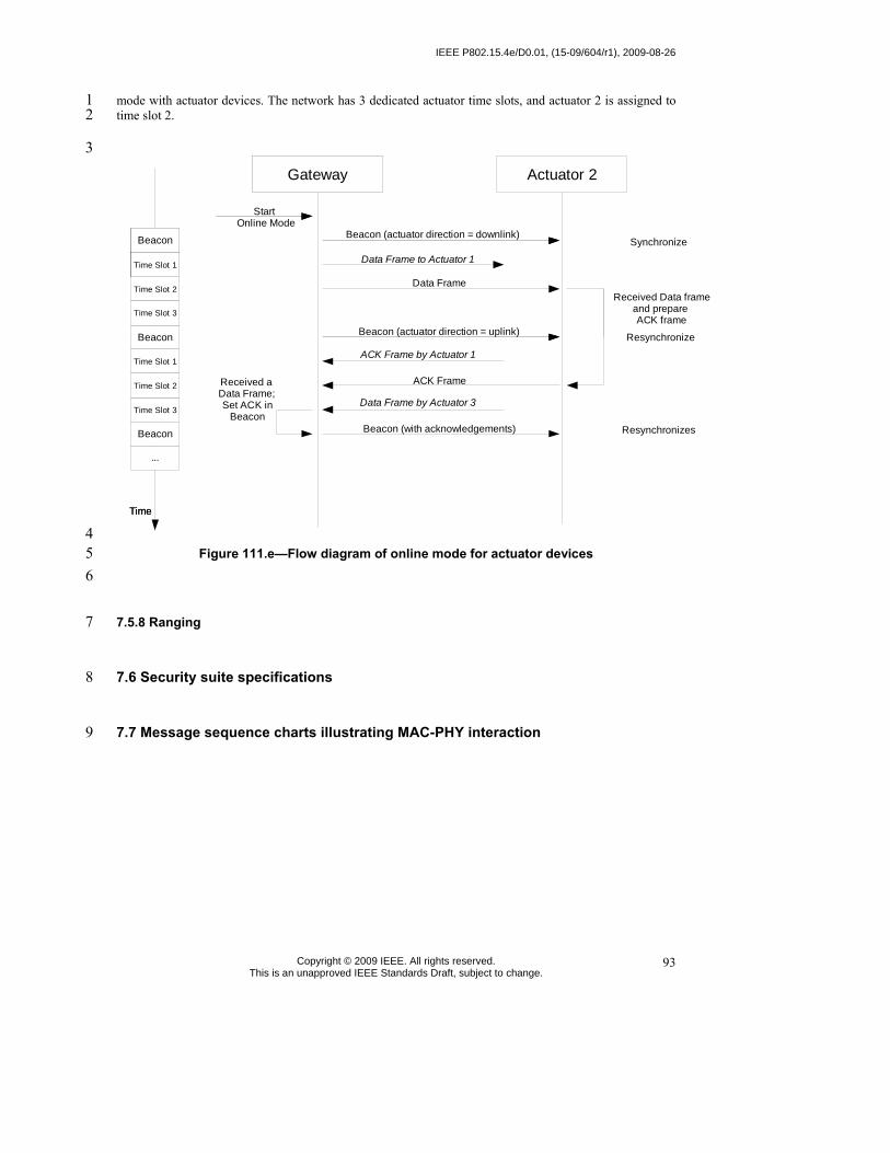
IEEE P802.15.4e/D0.01, (15-09/604/r1), 2009-08-26
Copyright © 2009 IEEE. All rights reserved. This is an unapproved IEEE Standards Draft, subject to change.
93
mode with actuator devices. The network has 3 dedicated actuator time slots, and actuator 2 is assigned to 1 time slot 2. 2
3
Actuator 2Gateway
Mgmt Slot
Beacon (actuator direction = downlink)
Time
Beacon
Mgmt Slot
Time Slot 2
Beacon
Gateway
Mgmt Slot
Start Online Mode
Synchronize
Data Frame
Time
Beacon
Time Slot 1
Beacon
Beacon
...
Beacon (actuator direction = uplink)
Beacon (with acknowledgements) Resynchronizes
Resynchronize
Time Slot 1Time Slot 1
Time Slot 3
Time Slot 1
Time Slot 3
Time Slot 2
Beacon
Data Frame to Actuator 1
Data Frame by Actuator 3
ACK Frame
ACK Frame by Actuator 1
Received a Data Frame; Set ACK in
Beacon
Received Data frame and prepare ACK frame
4 Figure 111.e—Flow diagram of online mode for actuator devices 5
6
7.5.8 Ranging 7
7.6 Security suite specifications 8
7.7 Message sequence charts illustrating MAC-PHY interaction 9

2009-08-26, (15-09/604/r1), IEEE P802.15.4e/D0.01, August 2009
Copyright © 2009 IEEE. All rights reserved. This is an unapproved IEEE Standards Draft, subject to change.
94
Annex L 1 (informative) 2
3 Bibliography 4
5
L.1 Documents for MAC enhancements in support of LL-applications 6
⎯ 15-09/0254r0 Proposal for Factory Automation presentation of proposal for factory automation at 7 March 09 IEEE 802.15.4e meeting 8
⎯ 15-08/0827r0 Shared Group Timeslots presentation with further details on Shared Group Timeslots 9 ⎯ 15-09/0228r0 Proposal for Factory Automation text of proposal for factory automation at March 09 10
IEEE 802.15.4e meeting 11 ⎯ 15-08/0420r2 Extending the MAC Superframe of 802.15.4 Spec presentation with separate GACK 12
mechanism 13 ⎯ 15-08/0503r0 Preliminary Proposal for Factory Automation presentation of preliminary proposal 14
for factory automation at July 08 IEEE 802.15.4e meeting 15 ⎯ 15-08/0571r1 Proposal for Factory Automation presentation of proposal for factory automation at 16
September/November 08 IEEE 802.15.4e meetings 17 ⎯ 15-08/0572r0 Proposal for Factory Automation text of proposal for factory automation at 18
September 08 IEEE 802.15.4e meeting 19 20

IEEE P802.15.4e/D0.01, (15-09/604/r1), 2009-08-26
Copyright © 2009 IEEE. All rights reserved. This is an unapproved IEEE Standards Draft, subject to change.
95
Annex M 1 (informative) 2
3 Requirements of indistrial and other application domains 4
M.1 General 5
The intentions of these add-ons are to enhance and add functionality to the 802.15.4-2009 MAC to 6
a) better support the industrial markets and 7 b) permit compatibility with modifications being proposed within the Chinese WPAN. 8
This functionality will facilitate industrial applications (such as addressed by IEC 62591 and the 9 ISA100.11a), and those enhancements defined by the Chinese WPAN standard that aren't included in the 10 Amendment of TG4c. 11
Industrial applications have requirements that are not addressed by the edition 2009 such as low latency, 12 robustness in the harsh industrial RF environment, and determinism. 13
The Chinese Wireless Personal Area Network (CWPAN) standard has identified enhancements to improve 14 network reliability and increase network throughput to support higher duty-cycle data communication 15 applications. 16
This amendment addresses coexistence with wireless protocols such as 802.11, 802.15.1, 802.15.3, and 17 802.15.4. 18
Specifically, the MAC enhancements are grouped into two categories: 19
a) Industrial and other application domains and 20 b) Additional functional improvements. 21
To identify easier the specific amendments to which category these apply in the normative clauses, the 22 specific subclauses are named with the following acronyms in the order as they appear here. 23
a) Process automation (PA), 24 b) Low latency networks (LL) 25 c) Commercial (CM) 26 d) ?Smart utility networks (SUN)? (reserved for future requests) 27 e) ?(RFID)? (reserved for future requests) 28
The question marks will disappear in the final version. These marked topics are 29 potential candidates, but it is not decided nor limited to those. 30 Additional functional improvements are: 31
a) Low Energy (LE) 32 b) ?Overhead reduction/Security(ORS)? (reserved for future submissions) 33
The question marks will disappear in the final version. These marked topics are 34 potential candidates, but it is not decided nor limited to those. 35 The convention as used in Clause 7 is that same headings needed for different solutions based on different 36 requirements have a prefix as the given acronyms above to differentiate the subclauses. 37

2009-08-26, (15-09/604/r1), IEEE P802.15.4e/D0.01, August 2009
Copyright © 2009 IEEE. All rights reserved. This is an unapproved IEEE Standards Draft, subject to change.
96
EXAMPLES; 1
⎯ PA-Heading 2 ⎯ LL-Heading 3 ⎯ CM-Heading 4
M.2 Process automation (PA) 5
Typical parts of the application domain of process automation are facilities for 6
⎯ Oil & gas industry, 7 ⎯ Food & beverage products, 8 ⎯ Chemical products 9 ⎯ Pharmacutical products 10 ⎯ Water/waist water treatnments 11 ⎯ etc. 12
For this application domain exists the following major requirements: 13
⎯ IEEE 802.15.4 header extensions for mesh support 14
• Additional addresses (source, destination) 15
• Sequence number 16
• TTL („transmissions to live“) 17
⎯ Framework for chosing path selection mechanisms 18
• Path selection protocol 19
• Link metrics 20
M.3 Low latency networks (LL) 21
M.3.1 Typical application domains for LL-networks 22 Typical parts of the application domain of low latency networks are facilities for 23
⎯ Factory automation as for automotive manufacturing 24 ⎯ Robots 25 ⎯ Suspension tracks 26 ⎯ Portable machine tools 27 ⎯ Milling, turning 28 ⎯ Robot revolver 29

IEEE P802.15.4e/D0.01, (15-09/604/r1), 2009-08-26
Copyright © 2009 IEEE. All rights reserved. This is an unapproved IEEE Standards Draft, subject to change.
97
⎯ Filling 1 ⎯ Cargo 2 ⎯ Airport logistics 3 ⎯ Post 4 ⎯ Packaging industry 5 ⎯ Special engineering 6 ⎯ Conveyor technique 7 ⎯ etc. 8
For this application domain exists the following major requirements: 9
⎯ High determinism 10 ⎯ High reliability 11 ⎯ Low latency: 12
• transmission of sensor data in � 10 ms 13
• low round-trip time 14
⎯ Many sensors per gateway 15
• might be more than 100 sensors per gateway 16
⎯ Assume controlled envi-ronment (factory floor) 17 ⎯ Configuration for optimal performance 18 ⎯ Network management and frequency planning for avoidance of co-existence issues. 19 ⎯ Roaming capability (no channel hopping) 20
M.3.2 Application overview 21 Factory automation comprises today a large number of sensors and actuators observing and controlling the 22 production. Sensors and actuators are located for example at robots, suspension tracks and portable tools in 23 the automotive industry, collect data on machine tools, such as milling or turning machines and control 24 revolving robots. Further application areas are control of conveyor belts in cargo and logistics scenarios or 25 special engineering machines. Depending on the specific needs of different factory automation branches 26 many more examples could be named. 27
Common to these sensor applications in factory automation context is the requirement of low latency and 28 high cyclic determinism. The performance should allow for reading sensor data from 20 sensors within 29 10ms. 30
Cabling these sensors is very time consuming and expensive. Furthermore, cables are a frequent source for 31 failures due to the harsh environment in a factory and may cause additional costs by production outage. 32
Wireless access to sensors and actuators solves the cabling issue and provides also advantages in case of 33 mobility and retrofit situations. 34
Wireless technologies that could be applied for the factory automation scenario include 802.11 (WLAN), 35 802.15.1 (Bluetooth) and 802.15.4. 804.15.4 is designed for sensor applications and offers the lowest 36

2009-08-26, (15-09/604/r1), IEEE P802.15.4e/D0.01, August 2009
Copyright © 2009 IEEE. All rights reserved. This is an unapproved IEEE Standards Draft, subject to change.
98
energy consumption as well as the required communication range and capacity. Moreover, four 802.15.4 1 channels can be utilized in good coexistence with three non-overlapping WLAN channels (cf. Error! 2 Reference source not found.). Bluetooth offers good real-time capabilities, but interferes inevitably with 3 any existing WLAN installations. 4
802.15.4 is a worldwide and successfully applied standard for wireless and low power transmission of 5 sensor data. Different protocols on top of 802.15.4 (WirelessHART™ according to IEC 62591, ISA100.11a 6 or ZigBee) in the context of process automation are already in the process of standardization. Those 7 protocols aim at different requirements, but employ the same physical layer hardware as the proposed 8 solution for factory automation, which indicates potential hardware synergies and cost savings. Thus, a 9 solution for factory automation based on 802.15.4 would be beneficial. 10
802.15.4 operates usually in Carrier Sense Multiple Access (CSMA) mode which gives no guarantees for 11 media access. Optionally, 802.15.4 specifies the beacon-enabled mode which defines a TDMA like 12 superframe structure with Guaranteed Time Slots (GTS) for deterministic access. The performance of 7 13 GTS in an interval of 15ms does not fulfill the factory automation requirements and makes not full use of 14 the available capacity. Therefore a modification of the 802.15.4 MAC for application in industrial factory 15 automation, i.e. defining a fine granular deterministic TDMA access, is envisaged. 16
17
18 M.3.3 Requirements and Assumptions 19 The above mentioned factory automation applications impose the following requirements to a wireless 20 system: 21
⎯ high determinism, 22
Figure M.1―RF technology coexistence in the 2.4GHz ISM band.

IEEE P802.15.4e/D0.01, (15-09/604/r1), 2009-08-26
Copyright © 2009 IEEE. All rights reserved. This is an unapproved IEEE Standards Draft, subject to change.
99
⎯ high reliability, 1 ⎯ low latency, i.e. transmission of sensor date in ≤ 10ms, 2 ⎯ low round trip time, 3 ⎯ support for many sensors per gateway. 4
The proposed TDMA scheme, as described in the remainder of this document, supports these requirements. 5 Allocating a dedicated time slot for each sensor provides a deterministic system. The 802.15.4 DSSS 6 coding together with the exclusive channel access for each sensor ensures high reliability of the system. 7 Small time slots and short packets lead to superframes as small as 10ms, which provides a latency of less 8 than 10ms and a low round trip time. The number of slots in a superframe determines the number of 9 sensors that can access each channel. By operating the gateway with multiple transceivers on different 10 channels, a high number of sensors is supported. 11
The proposed system needs to be operated in a controlled configuration to achieve the required 12 performance. Thus, it is assumed that the system is operated in a controlled environment with frequency 13 planning. The TDMA channels are allocated in a way that. 14
15
M.4 Commercial (CM) 16
Typical parts of the application domain of commercial networks are facilities for 17
⎯ etc. 18 For this application domain exists the following major requirements: 19
⎯ ... 20
M.5 Low energy (LE) 21
For this general improvement.... 22
23
M.6 Channel Diversity 24
Annex M.6 provides tutorial material for a better understanding for the different solutions specified in 25 Clauses 7. 26
27
28
29