Ice core stratigraphy using dual energy x-ray absorptiometry (DEXA
33
Ice core stratigraphy using Ice core stratigraphy using dual energy x dual energy x - - ray ray absorptiometry absorptiometry (DEXA) (DEXA) Chris Chris Kr Kr ö ö ger ger , , Julian Thomson, Julian Thomson, Nancy Nancy Bertler Bertler , , Uwe Uwe Morgenstern Morgenstern
Transcript of Ice core stratigraphy using dual energy x-ray absorptiometry (DEXA
Ice core stratigraphy using Ice core stratigraphy using dual energy xdual energy x--ray ray
absorptiometryabsorptiometry (DEXA)(DEXA)Chris Chris KrKröögerger, , Julian Thomson, Julian Thomson,
Nancy Nancy BertlerBertler, , UweUwe MorgensternMorgenstern
OutlineOutline
1.1. MotivationMotivation2.2. DEXA principlesDEXA principles3.3. Scanning Scanning
procedureprocedure4.4. Analysis methodsAnalysis methods5.5. ResultsResults
i.i. StratigraphiesStratigraphiesii.ii. DensitiesDensities
6.6. ConclusionsConclusions
MotivationMotivationIce cores retrieved from remote locations, Ice cores retrieved from remote locations, serve for the analysis of various serve for the analysis of various informationinformationNonNon--invasive technique sought that allows invasive technique sought that allows further invasive analysis for chemicalsfurther invasive analysis for chemicalsDensity important information for ice core Density important information for ice core dating, as density allows to draw dating, as density allows to draw conclusions on stability of ice constituents conclusions on stability of ice constituents Usually no density data available beyond Usually no density data available beyond volumetric densityvolumetric densityLess cumbersome and more accurate Less cumbersome and more accurate method sought to analogue x/method sought to analogue x/γγ--rayray testingtesting
DEXA principlesDEXA principles
XX--rays penetrating radiation, in rays penetrating radiation, in particular sensitive to high atomic particular sensitive to high atomic numbers (xnumbers (x--rays interact with rays interact with electrons in atomic shell)electrons in atomic shell)Single xSingle x--ray source emits xray source emits x--ray ray spectrumspectrum•• Max. xMax. x--ray energy: 140 ray energy: 140 keVkeV•• Mean xMean x--ray energy: 70 ray energy: 70 keVkeV
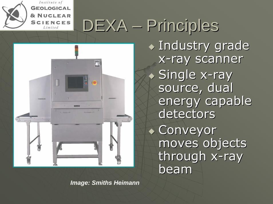
DEXA DEXA –– Principles Principles Industry grade Industry grade xx--ray scannerray scannerSingle xSingle x--ray ray source, dual source, dual energy capable energy capable detectorsdetectorsConveyor Conveyor moves objects moves objects through xthrough x--ray ray beambeam
Image: Smiths Heimann
DEXA Principles DEXA Principles
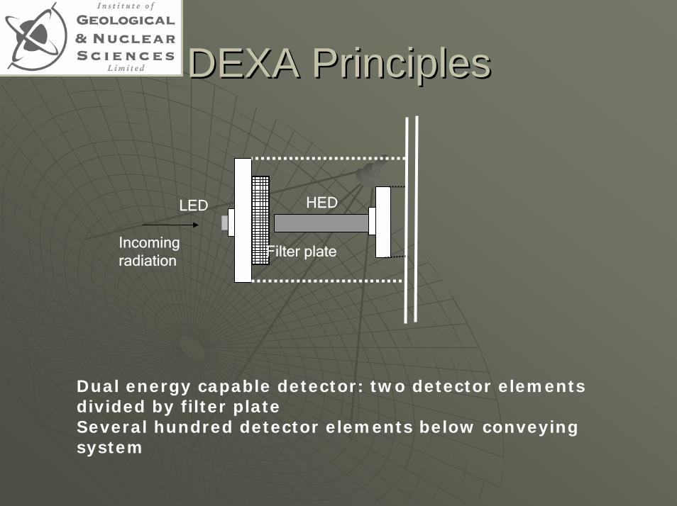
Filter plate
HEDLED
Incoming radiation
Dual energy capable detector: two detector elements divided by filter plateSeveral hundred detector elements below conveying system
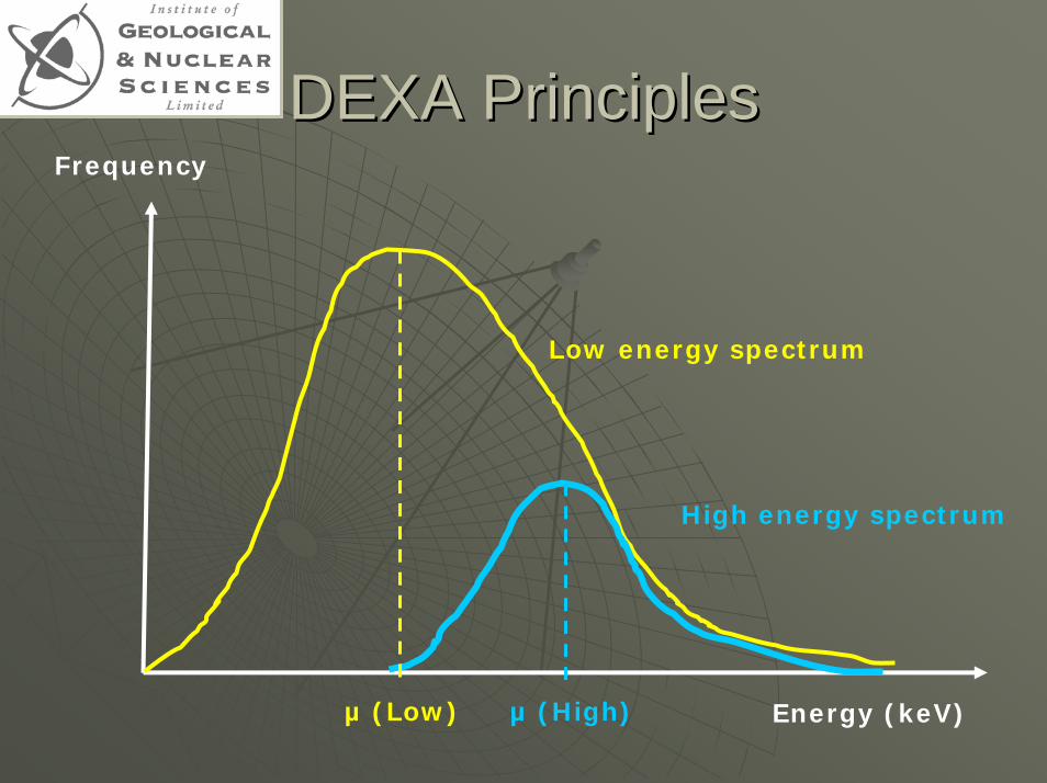
DEXA Principles DEXA Principles Frequency
Low energy spectrum
High energy spectrum
µ (Low) µ (High) Energy (keV)
Scanning proceduresScanning procedures
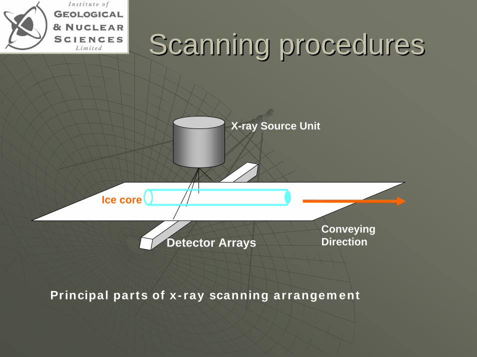
Conveying Direction
X-ray Source Unit
Ice core
Detector Arrays
Principal parts of x-ray scanning arrangement
Scanning proceduresScanning procedures
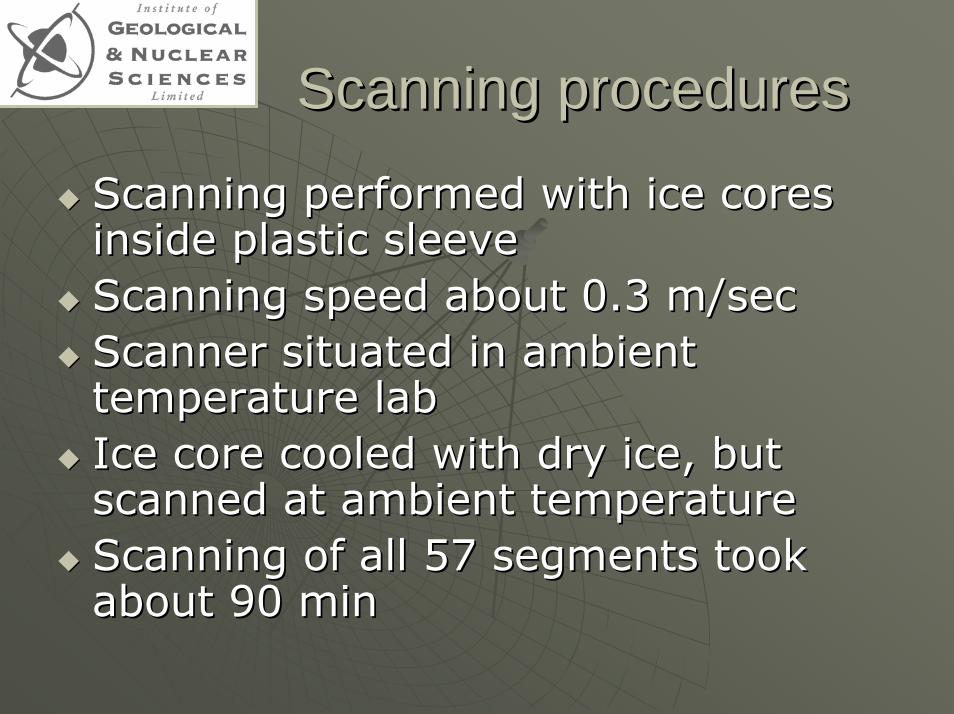
Scanning performed with ice cores Scanning performed with ice cores inside plastic sleeve inside plastic sleeve Scanning speed about 0.3 m/secScanning speed about 0.3 m/secScanner situated in ambient Scanner situated in ambient temperature labtemperature labIce core cooled with dry ice, but Ice core cooled with dry ice, but scanned at ambient temperaturescanned at ambient temperatureScanning of all 57 segments took Scanning of all 57 segments took about 90 minabout 90 min
Analysis methodsAnalysis methods
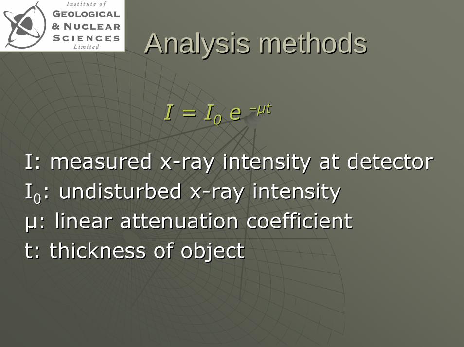
I = II = I00 e e ––µµtt
I:I: measured xmeasured x--ray intensity at detectorray intensity at detectorII00: undisturbed x: undisturbed x--ray intensityray intensityµµ: linear attenuation coefficient: linear attenuation coefficientt: thickness of objectt: thickness of object
Analysis methodsAnalysis methods
Attenuation law valid for Attenuation law valid for •• Pencil sourcePencil source•• MonoMono--energetic xenergetic x--raysrays
Does not take into account scattering Does not take into account scattering effects at edgeseffects at edgesSnow porous, containing air pocketsSnow porous, containing air pockets
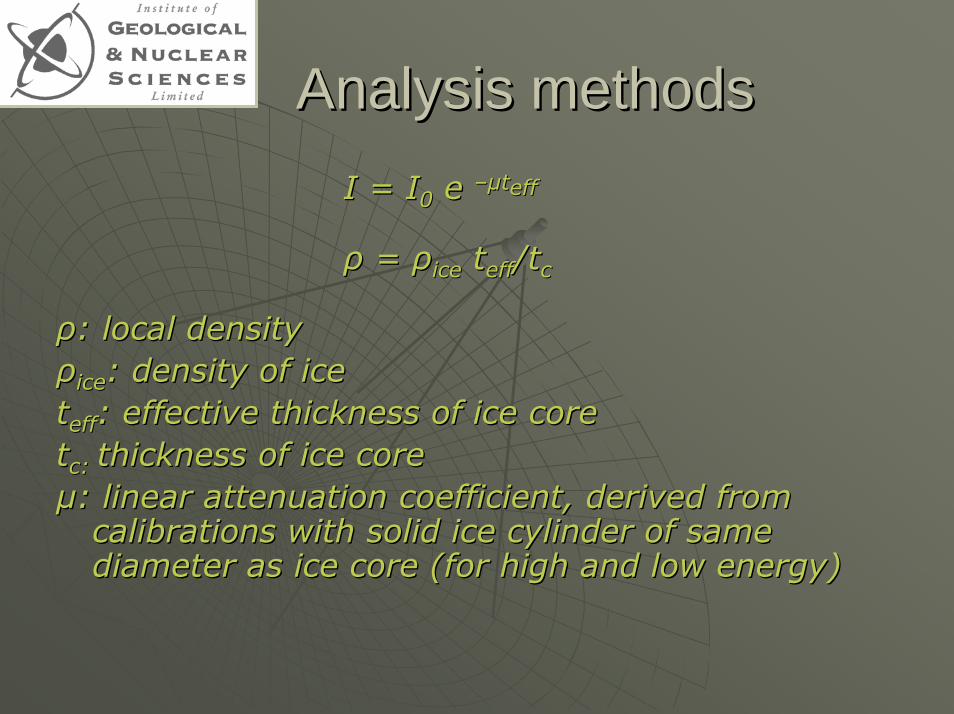
Analysis methodsAnalysis methodsI = II = I00 e e ––µµtteffeff
ρρ = = ρρiceice tteffeff/t/tcc
ρρ: local density: local densityρρiceice: density of ice : density of ice tteffeff: effective thickness of ice core: effective thickness of ice corettcc: : thickness of ice corethickness of ice coreµµ: linear attenuation coefficient, derived from : linear attenuation coefficient, derived from
calibrations with solid ice cylinder of same calibrations with solid ice cylinder of same diameter as ice core (for high and low energy)diameter as ice core (for high and low energy)
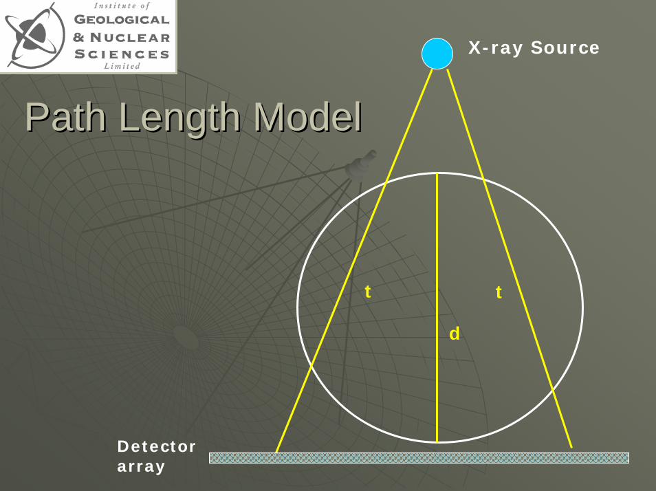
Path Length ModelPath Length Model
t t
d
X-ray Source
Detectorarray
X-ray Source
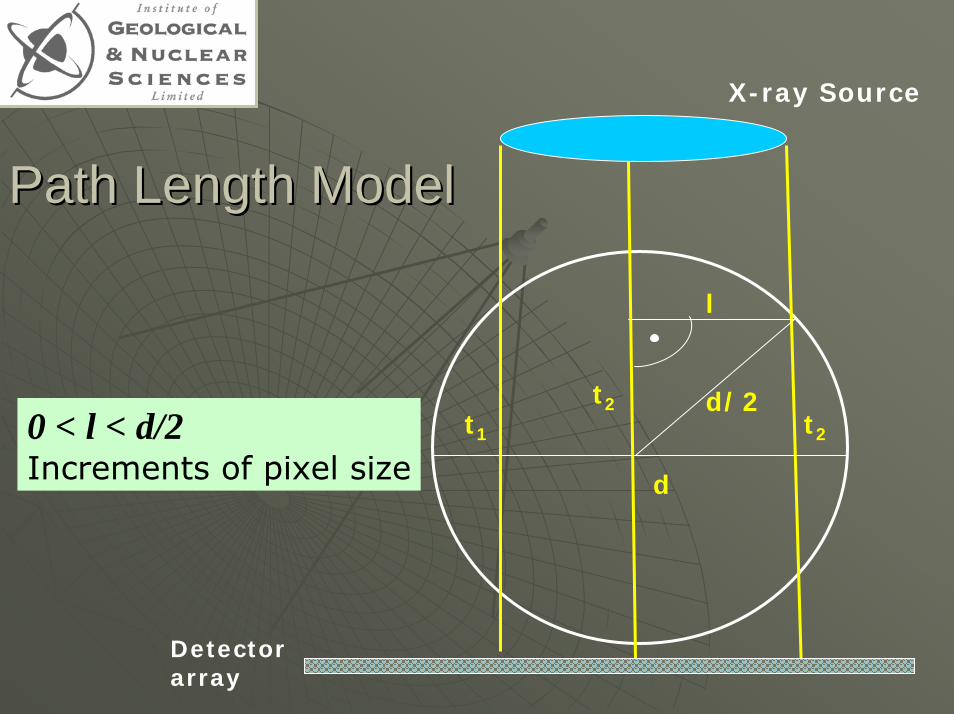
Path Length ModelPath Length Model
t1 t2
d
d/2t2
l
0 < l < d/2Increments of pixel size
Detectorarray
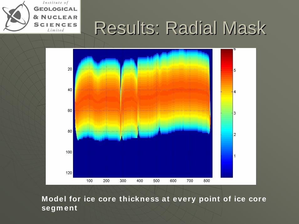
Results: Radial Mask Results: Radial Mask
Model for ice core thickness at every point of ice core segment
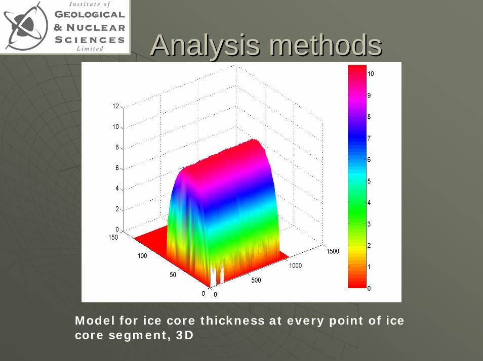
Analysis methodsAnalysis methods
Model for ice core thickness at every point of ice core segment, 3D
Results Results
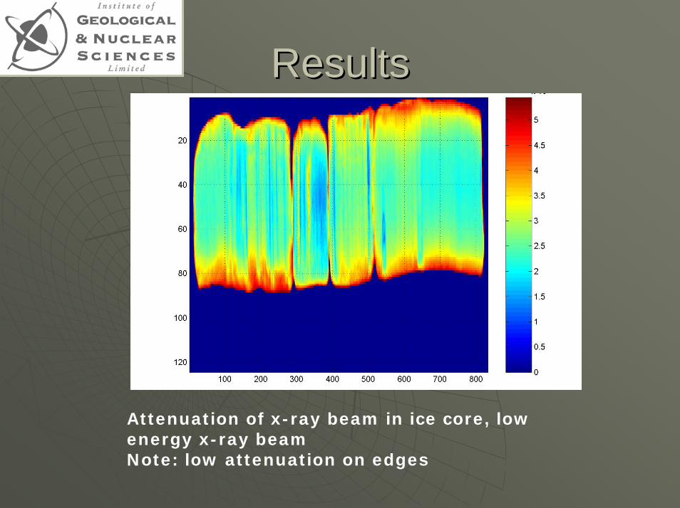
Attenuation of x-ray beam in ice core, low energy x-ray beamNote: low attenuation on edges
ResultsResults
ResultsResults
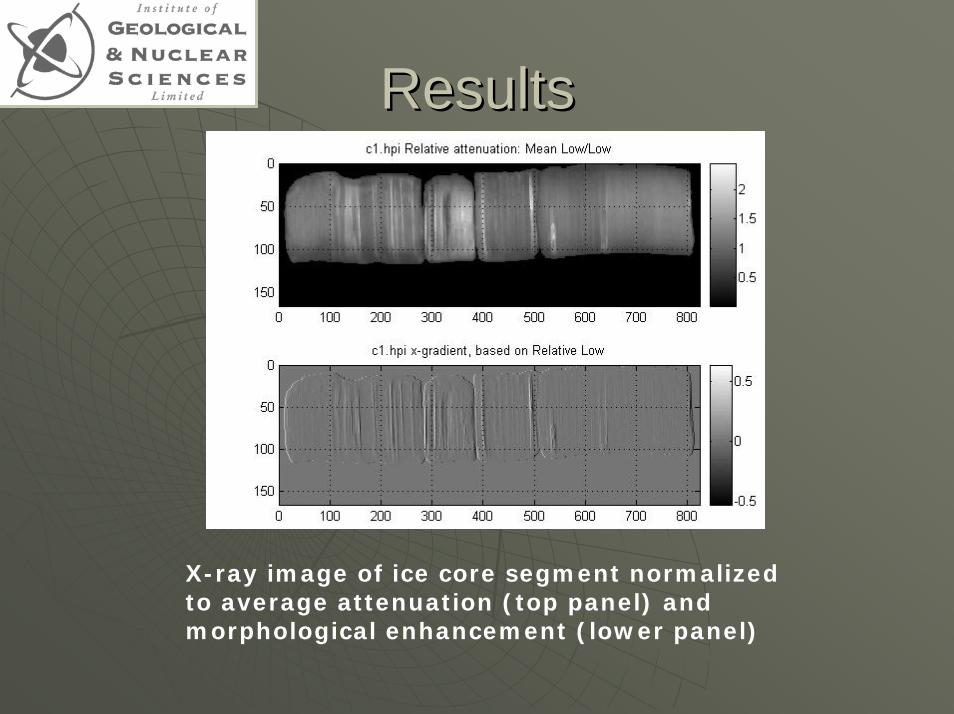
X-ray image of ice core segment normalized to average attenuation (top panel) and morphological enhancement (lower panel)
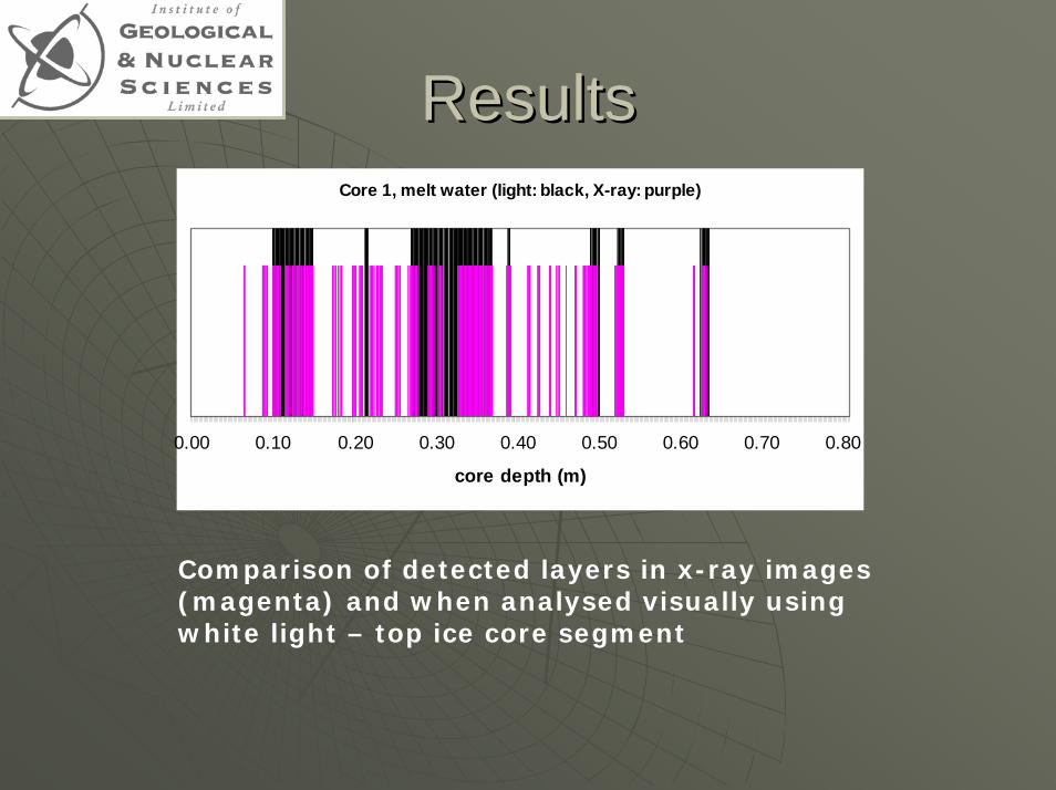
ResultsResultsCore 1, melt water (light: black, X-ray: purple)
0.00 0.10 0.20 0.30 0.40 0.50 0.60 0.70 0.80
core depth (m)
Comparison of detected layers in x-ray images (magenta) and when analysed visually using white light – top ice core segment
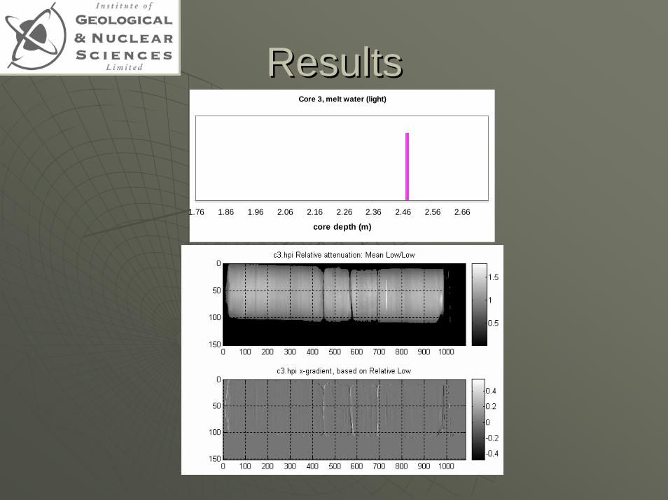
ResultsResultsCore 3, melt water (light)
1.76 1.86 1.96 2.06 2.16 2.26 2.36 2.46 2.56 2.66
core depth (m)
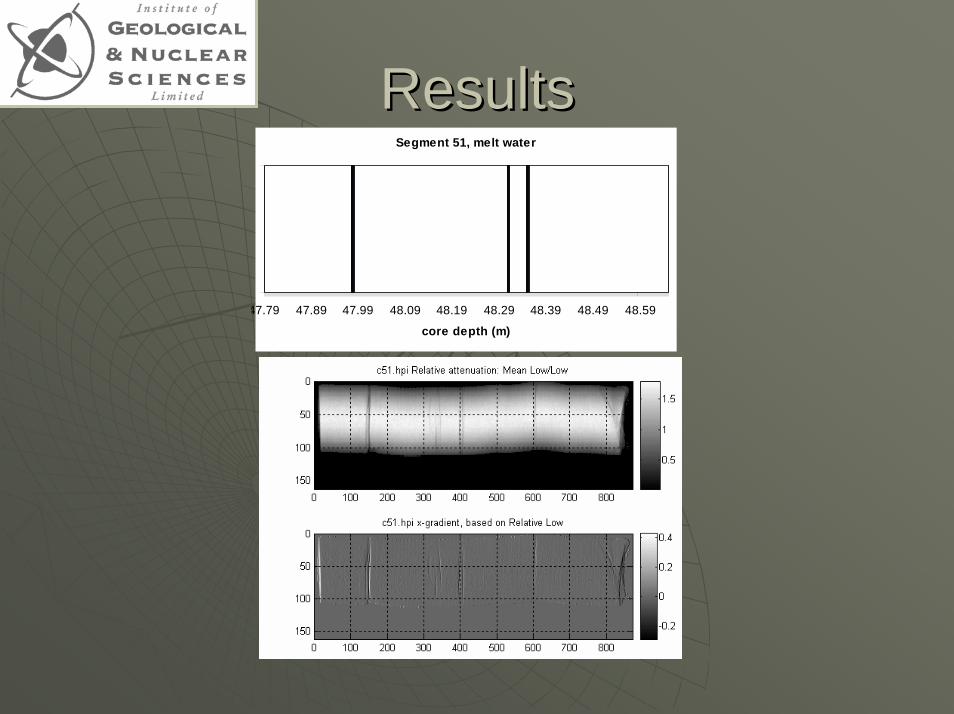
ResultsResultsSegment 51, melt water
47.79 47.89 47.99 48.09 48.19 48.29 48.39 48.49 48.59
core depth (m)
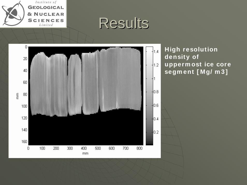
ResultsResultsHigh resolution density of uppermost ice core segment [Mg/m3]
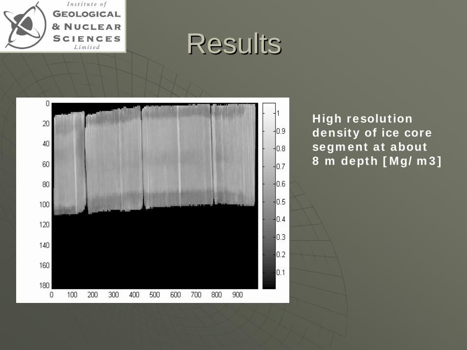
ResultsResults
High resolution density of ice core segment at about 8 m depth [Mg/m3]
ResultsResults
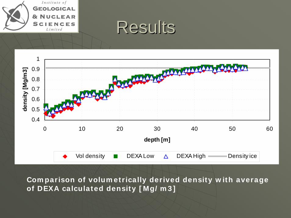
0.4
0.5
0.6
0.7
0.8
0.9
1
0 10 20 30 40 50 60
depth [m]
dens
ity [M
g/m
3]
Vol density DEXA Low DEXA High Density ice
Comparison of volumetrically derived density with average of DEXA calculated density [Mg/m3]
ResultsResults
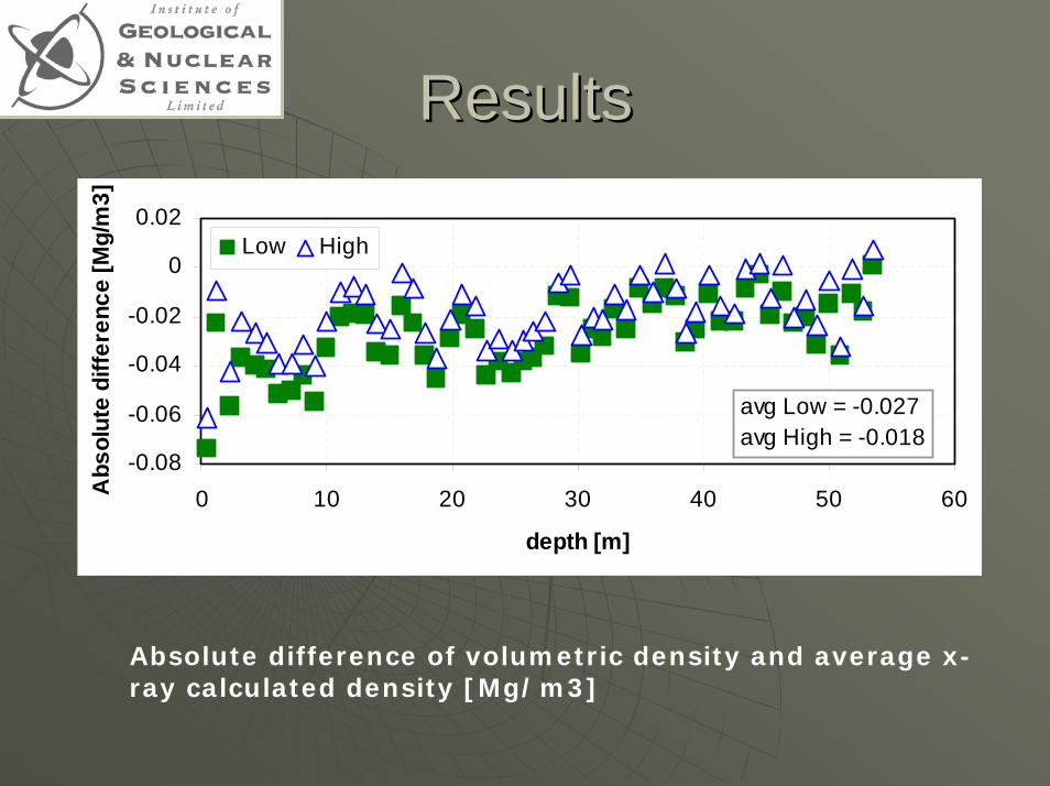
-0.08
-0.06
-0.04
-0.02
0
0.02
0 10 20 30 40 50 60
depth [m]
Abs
olut
e di
ffere
nce
[Mg/
m3]
Low High
avg Low = -0.027avg High = -0.018
Absolute difference of volumetric density and average x-ray calculated density [Mg/m3]
ResultsResults
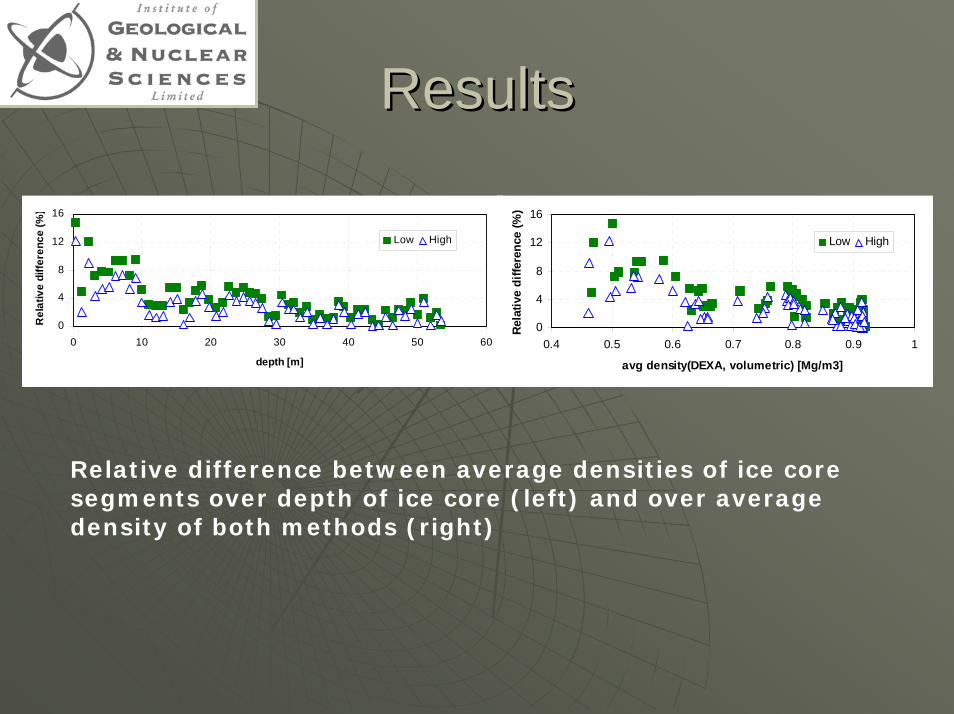
0
4
8
12
16
0 10 20 30 40 50 60
depth [m]
Rel
ativ
e di
ffere
nce
(%)
Low High
0
4
8
12
16
0.4 0.5 0.6 0.7 0.8 0.9 1
avg density(DEXA, volumetric) [Mg/m3]
Rela
tive
diffe
renc
e (%
)
Low High
Relative difference between average densities of ice core segments over depth of ice core (left) and over average density of both methods (right)
Error estimationError estimation
Error sources: Error sources: 1.1. xx--ray variationray variation2.2. edges of images, detector element edges of images, detector element
coverage for calibration coverage for calibration 3.3. linear attenuation coefficient (as linear attenuation coefficient (as
consequence of 2.)consequence of 2.)4.4. edges of images, in ice core scansedges of images, in ice core scans
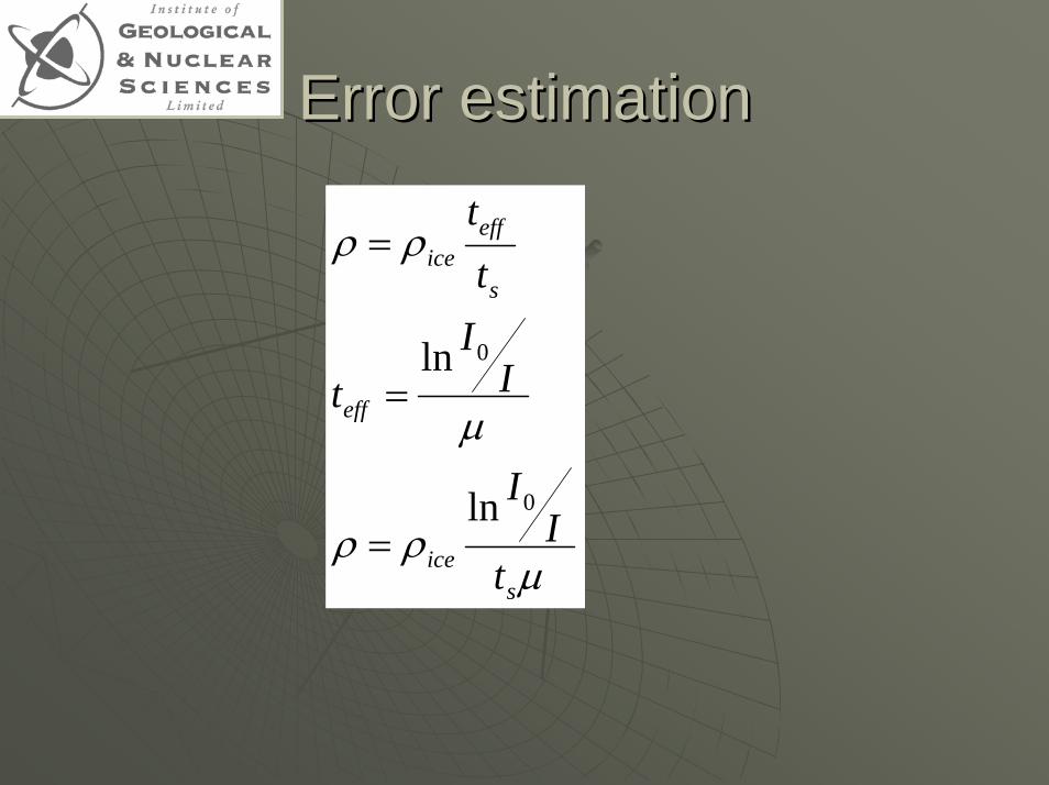
Error estimationError estimation
µρρ
µ
ρρ
sice
eff
s
effice
tI
I
II
t
tt
0
0
ln
ln
=
=
=
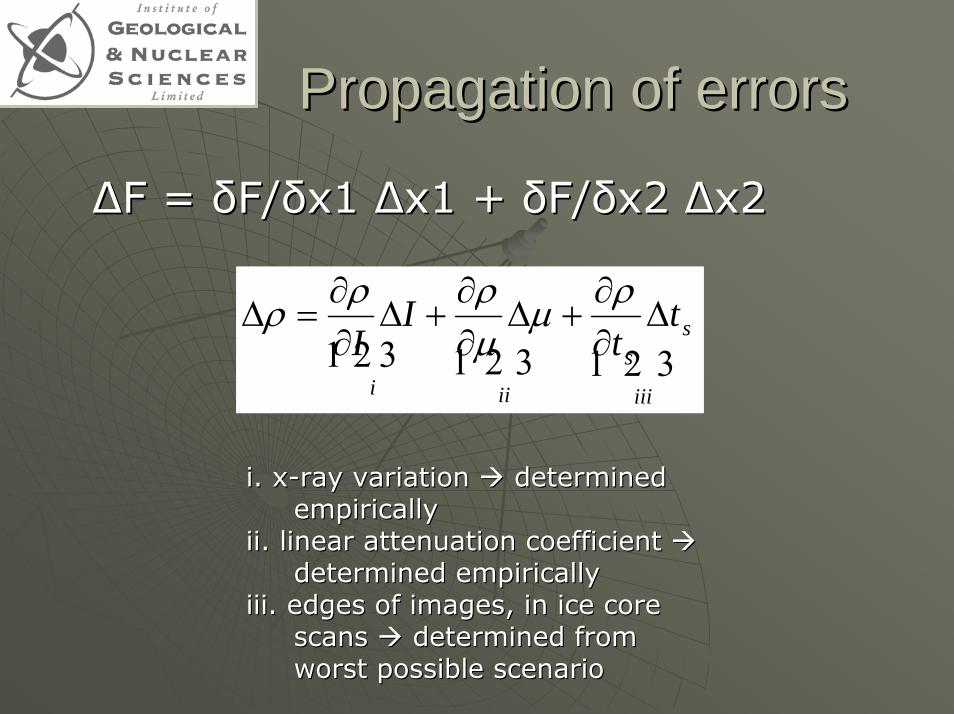
Propagation of errorsPropagation of errors
∆∆F = F = δδF/F/δδx1 x1 ∆∆x1 + x1 + δδF/F/δδx2 x2 ∆∆x2
321321321iii
ss
iii
tt
II
∆∂∂
+∆∂∂
+∆∂∂
=∆ρµ
µρρρ
i. xi. x--ray variation ray variation determined determined empiricallyempirically
ii. linear attenuation coefficient ii. linear attenuation coefficient determined empiricallydetermined empirically
iii. edges of images, in ice core iii. edges of images, in ice core scans scans determined from determined from worst possible scenarioworst possible scenario
x2
Error estimateError estimate
The error was estimated at 2% using the The error was estimated at 2% using the propagation of errors theory and standard propagation of errors theory and standard deviations of individual errors.deviations of individual errors.
However, the bias experienced cannot be However, the bias experienced cannot be explained with standard error estimation explained with standard error estimation and needs further investigation. In situ and needs further investigation. In situ volume determination, assumptions of ice volume determination, assumptions of ice attenuation coefficients, and calibration attenuation coefficients, and calibration and/or ice core size models may be the and/or ice core size models may be the cause of discrepancies.cause of discrepancies.
ConclusionsConclusionsXX--ray analysis useful tool to detect strata ray analysis useful tool to detect strata in ice cores of shallow to medium depthin ice cores of shallow to medium depthHigh resolution density determination High resolution density determination possible with DEXApossible with DEXAImproved calibrations may reduce offset Improved calibrations may reduce offset of averaged density dataof averaged density dataTruly nonTruly non--invasive method, allows further invasive method, allows further analysis, such as chemistryanalysis, such as chemistryVery small anomalies, such as air bubbles Very small anomalies, such as air bubbles in ice not detectablein ice not detectable
OutlookOutlook
Physical model shall be further Physical model shall be further improved with respect to calibration improved with respect to calibration of linear attenuation coefficientof linear attenuation coefficientProject will be included into 5Project will be included into 5--year year programme, where several hundred programme, where several hundred meters of ice core will be analysed meters of ice core will be analysed per year per year