Hydrodynamics Performance of a Dual Shaft Mixer with Viscous Newtonian Liquids
8
HYDRODYNAMICS PERFORMANCE OF A DUAL SHAFT MIXER WITH VISCOUS NEWTONIAN LIQUIDS F. Cabaret, C. Rivera, L. Fradette, M. Heniche and P. A. Tanguy URPEI, Department of Chemical Engineering, Ecole Polytechnique, Montreal, QC, Canada. Abstract: The mixing performance of a dual shaft mixer with a Rushton turbine installed on each shaft was investigated experimentally and numerically in the laminar regime using viscous Newtonian liquids. A mixing quantification method based on the analysis of a fast acid-base discolouration reaction was used to follow the macro-mixing evolution in the tank. The macro- mixing curves generated by this method were used to determine the mixing times as well as to reveal the presence of flow compartmentalization and dead zones. In comparison with to a dual impeller system with two Rushton turbines on the same shaft, it is shown that the dual shaft mixing system can eliminate the flow compartmentalization, break the segregated regions and reduce the mixing time. Experimental results show that the counter-rotating mode of the impellers give smaller mixing times than the co-rotating one. A mixing time correlation was devel- oped and used to characterize the strong interaction between the impellers when operated in counter-rotating mode. Numerical simulation results were used to highlight and explain the differ- ence in global performance between the two rotating modes. Keywords: dual impeller; compartmentalization; mixing evolution; experimental; simulation; hydrodynamics. INTRODUCTION Fluid mixing is known to be central to reactive process operations. However, as shown by Alvarez et al. (2005), few data exist regarding the flow and the mixing in multiple impellers stirred-tank reactors operating in the laminar regime. This situation arises because over the last decades biosystems were mainly operated in turbulent flow, with the develop- ment of high-value products resulting from recent progresses in biotechnology, the indus- try has to deal with large scale multiple impel- lers fermentors to mix shear-sensitive cells suspensions, or highly concentrated and vis- cous cell broths. That is why new efforts are needed to investigate the operation of mul- tiple impellers mixers in the laminar and tran- sition flow regimes. The main problems of current multiple impellers bioreactors in viscous fluids mixing are the presence of segregated regions and the poor axial circulation which result in a flow compartmentalization inside the vessel (Alvarez et al., 2005; Harvey et al., 1997; Szalai et al., 2004; Zalc et al., 2001). Figure 1 illustrates these pathologies during an acid-base discolouration reaction (dark zones represent the unmixed zones). It can be seen on Figure 1 that, after many impeller revolutions, unmixed segregated regions are developed around the upper impeller and a flow compartmentalization exist between the two impellers. In laminar flow, the only route to achieve effi- cient mixing is chaos (Alvarez et al., 2002b, c). That is why different authors (Alvarez, 2000; Alvarez et al., 2002a; Ascanio et al., 2002, 2004; Ascanio and Tanguy, 2005; Szalai et al., 2004) introduce hydrodynamic pertur- bations to allow chaotic mixing to take place. Using variable agitation speeds, Szalai et al. (2004) showed that convective mixing occurs significantly faster in the axial direction than at constant rates of agitation. Alvarez et al. (2002a) studied the mixing behaviours in eccentric laminar stirred tanks and reported later (Alvarez et al., 2005) that eccentrically agitated multiple impellers bioreactors appear as a good alternative to solve the problems of segregated regions and poor axial circulation in bio-systems operated with viscous fluids. Along the line of using the break of symmetry to promote mixing, the strategy tested in this paper is to use a dual impeller system with two eccentric shafts to mix viscous Newtonian fluids. A comparable mixing system was pre- sented earlier by Ascanio et al. (2002) using 583 Vol 85 (A5) 583–590 Correspondence to: Professor P.A. Tanguy, URPEI, Department of Chemical Engineering, Ecole Polytechnique, P. O. Box 6079, Station Center-Ville, Montreal, QC, H3C 3A7, Canada. E-mail: [email protected] DOI: 10.1205/Cherd06175 0263–8762/07/ $30.00 þ 0.00 Chemical Engineering Research and Design Trans IChemE, Part A, May 2007 # 2007 Institution of Chemical Engineers
-
Upload
independent -
Category
Documents
-
view
6 -
download
0
Transcript of Hydrodynamics Performance of a Dual Shaft Mixer with Viscous Newtonian Liquids

HYDRODYNAMICS PERFORMANCE OFA DUAL SHAFT MIXER WITH VISCOUSNEWTONIAN LIQUIDS
F. Cabaret, C. Rivera, L. Fradette, M. Heniche and P. A. Tanguy�
URPEI, Department of Chemical Engineering, Ecole Polytechnique, Montreal, QC, Canada.
Abstract: The mixing performance of a dual shaft mixer with a Rushton turbine installed oneach shaft was investigated experimentally and numerically in the laminar regime using viscousNewtonian liquids. A mixing quantification method based on the analysis of a fast acid-basediscolouration reaction was used to follow the macro-mixing evolution in the tank. The macro-mixing curves generated by this method were used to determine the mixing times as well asto reveal the presence of flow compartmentalization and dead zones. In comparison with to adual impeller system with two Rushton turbines on the same shaft, it is shown that the dualshaft mixing system can eliminate the flow compartmentalization, break the segregated regionsand reduce the mixing time. Experimental results show that the counter-rotating mode of theimpellers give smaller mixing times than the co-rotating one. A mixing time correlation was devel-oped and used to characterize the strong interaction between the impellers when operated incounter-rotating mode. Numerical simulation results were used to highlight and explain the differ-ence in global performance between the two rotating modes.
Keywords: dual impeller; compartmentalization; mixing evolution; experimental; simulation;hydrodynamics.
INTRODUCTION
Fluid mixing is known to be central to reactiveprocess operations. However, as shown byAlvarez et al. (2005), few data exist regardingthe flow and the mixing in multiple impellersstirred-tank reactors operating in the laminarregime. This situation arises because overthe last decades biosystems were mainlyoperated in turbulent flow, with the develop-ment of high-value products resulting fromrecent progresses in biotechnology, the indus-try has to deal with large scale multiple impel-lers fermentors to mix shear-sensitive cellssuspensions, or highly concentrated and vis-cous cell broths. That is why new efforts areneeded to investigate the operation of mul-tiple impellers mixers in the laminar and tran-sition flow regimes.The main problems of current multiple
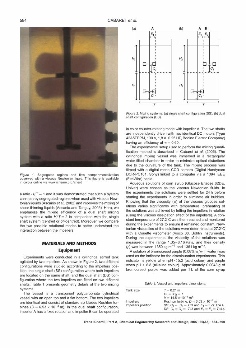
impellers bioreactors in viscous fluids mixingare the presence of segregated regions andthe poor axial circulation which result in aflow compartmentalization inside the vessel(Alvarez et al., 2005; Harvey et al., 1997;Szalai et al., 2004; Zalc et al., 2001).Figure 1 illustrates these pathologies duringan acid-base discolouration reaction (darkzones represent the unmixed zones). It can
be seen on Figure 1 that, after many impellerrevolutions, unmixed segregated regions aredeveloped around the upper impeller and aflow compartmentalization exist between thetwo impellers.In laminar flow, the only route to achieve effi-
cient mixing is chaos (Alvarez et al., 2002b, c).That is why different authors (Alvarez, 2000;Alvarez et al., 2002a; Ascanio et al., 2002,2004; Ascanio and Tanguy, 2005; Szalaiet al., 2004) introduce hydrodynamic pertur-bations to allow chaotic mixing to take place.Using variable agitation speeds, Szalai et al.(2004) showed that convective mixing occurssignificantly faster in the axial direction thanat constant rates of agitation. Alvarez et al.(2002a) studied the mixing behaviours ineccentric laminar stirred tanks and reportedlater (Alvarez et al., 2005) that eccentricallyagitated multiple impellers bioreactors appearas a good alternative to solve the problems ofsegregated regions and poor axial circulationin bio-systems operated with viscous fluids.Along the line of using the break of symmetry
to promote mixing, the strategy tested in thispaper is to use a dual impeller system withtwo eccentric shafts to mix viscous Newtonianfluids. A comparable mixing system was pre-sented earlier by Ascanio et al. (2002) using
583 Vol 85 (A5) 583–590
�Correspondence to:Professor P.A. Tanguy,URPEI, Department ofChemical Engineering, EcolePolytechnique, P. O. Box6079, Station Center-Ville,Montreal, QC, H3C 3A7,Canada.E-mail:[email protected]
DOI: 10.1205/Cherd06175
0263–8762/07/$30.00þ 0.00
Chemical EngineeringResearch and Design
Trans IChemE,Part A, May 2007
# 2007 Institutionof Chemical Engineers
a ratio H/T ¼ 1 and it was demonstrated that such a systemcan destroy segregated regions when used with viscous New-tonian liquids (Ascanio et al., 2002) and improves themixing ofshear-thinning liquids (Ascanio and Tanguy, 2005). Here, weemphasize the mixing efficiency of a dual shaft mixingsystem with a ratio H/T ¼ 2 in comparison with the singleshaft system (centred or off-centred). Moreover, we comparethe two possible rotational modes to better understand theinteraction between the impellers.
MATERIALS AND METHODS
Equipment
Experiments were conducted in a cylindrical stirred tankagitated by two impellers. As shown in Figure 2, two differentconfigurations were studied according to the impellers pos-ition: the single shaft (SS) configuration where both impellersare located on the same shaft; and the dual shaft (DS) con-figuration where the two impellers are fitted on two differentshafts. Table 1 presents geometry details of the two mixingsystems.The vessel is a transparent polycarbonate cylindrical
vessel with an open top and a flat bottom. The two impellersare identical and consist of standard six blades Rushton tur-bines (D ¼ 6.53 � 1022 m). In the dual shaft configuration,impeller A has a fixed rotation and impeller B can be operated
in co or counter-rotating mode with impeller A. The two shaftsare independently driven with two identical DC motors (Type42A5FEPM, 130 V, 1,8 A, 0.25 HP, Bodine Electric Company)having an efficiency of h ¼ 0.60.The experimental setup used to perform the mixing quanti-
fication method is described in Cabaret et al. (2006). Thecylindrical mixing vessel was immersed in a rectangularwater-filled chamber in order to minimize optical distortionsdue to the curvature of the tank. The mixing process wasfilmed with a digital mono CCD camera (Digital HandycamDCR-PC101, Sony) linked to a computer via a 1394 IEEE(FireWire) cable.Aqueous solutions of corn syrup (Glucose Enzose 62DE,
Univar) were chosen as the viscous Newtonian fluids. Inthe experiments the solutions were settled for 24 h beforestarting the experiments in order to eliminate air bubbles.Knowing that the viscosity (m) of the viscous glucose sol-utions varies significantly with temperature, preheating ofthe solutions was achieved by letting the impellers in rotation(using the viscous dissipation effect of the impellers). A con-stant temperature of 27.28C was then reached and monitoredduring the experiments to ensure it remained constant. New-tonian viscosities of the solutions were determined at 27.28Cwith a Couette viscometer (Visco 88, Bohlin Instruments).During the experiments, the viscosity of the solutions wasmeasured in the range 1.35–8.16 Pa s, and their density(r) was between 1350 kg m23 and 1361 kg m23.A solution of bromocresol purple (0.08% w/w in water) was
used as the indicator for the discolouration experiments. Thisindicator is yellow when pH , 5.2 (acid colour) and purplewhen pH . 6.8 (alkaline colour). Approximately 0.0043 g ofbromocresol purple was added per 1 L of the corn syrup
Figure 1. Segregated regions and flow compartmentalizationobserved with a viscous Newtonian liquid. This figure is availablein colour online via www.icheme.org/cherd
Figure 2. Mixing systems: (a) single shaft configuration (SS), (b) dualshaft configuration (DS).
Table 1. Vessel and impellers dimensions.
Tank size T ¼ 0.21 mH1 ¼ H2 ¼ TV ¼ 14.5 � 1023 m3
Impellers Rushton turbine, D ¼ 6.53 � 1022 mImpellers position SS: C1 ¼ C2 ¼ T/3 and E1 ¼ 0 or T/4.4
DS: C1 ¼ C2 ¼ T/3 and E1 ¼ E2 ¼ T/4.4
Trans IChemE, Part A, Chemical Engineering Research and Design, 2007, 85(A5): 583–590
584 CABARET et al.

solution in order to colour the solution. In the experiments, wefollowed the colour evolution from the purple (alkaline colour)towards the yellow (acid colour) because it is far easier andmore reliable to detect purple unmixed zones in a yellowliquid than the opposite. The acidic dye injected at the begin-ning of each experiment is composed of 4 mL of aqueousHCl at 10 mol L21 diluted in 200 mL of the glucose solution.For reproducibility purposes, the acidic solution was alwaysrapidly poured at the same distance from the shafts on thefree surface. This distance was 5 cm from the shaft in theSS configuration and half way between the two shafts forthe DS configuration.
Methods
The impeller power consumption was determined by meansof an ammeter and a voltmeter (52-0052-2, Mastercraft)plugged on the DC motors. The impeller power consumptionis given by the relation:
P ¼ hW � h0W0 (1)
where W and W0 are respectively the motor power consump-tion with and without load and h and h0 are the motorefficiencies.Mixing curves were determined using the mixing evaluation
method developed by Cabaret et al. (2006) following the sameexperimental protocol. This method based on image analysisoutputs the evolution of the percentage of yellow pixels (acidcolour) present in an area of interest during the acid-base dis-colouration method. In our experiments, the area of interestwas the liquid seen by an observer placed in front of thevessel (as presented in Figure 1). Each video captured bythe digital camera during the acid-base colour change wassampled and the resulting imageswere then analysed individu-ally. For each pixel, the evolution of the green colour brightnessin the RGB model is followed over time. By defining on eachpixel a threshold on the green colour model, a pixel can be con-sidered eithermixed or unmixed by comparing its green level ofbrightness with the threshold. In our experiments we havedefined the green threshold with a X separation value of 50%as recommended by Cabaret et al. (2006). For each imagesampled from the video, we then count the number of mixedpixels NMixed Pixels, and plot the ratio (M %) NMixed Pixels/NTotal Pixels over time to obtain the mixing curve. The resultingcurve quantifies the colour change in time from the observerpoint of view. On the mixing curves, the macro-mixing timetm90% is determined when 90% of the pixels have reachedthe yellow colour (M ¼ 90%).Computational fluid dynamics was used to simulate the
dual shaft configuration in order to calculate the three-dimen-sional flow field. The incompressible Navier–Stokes equationwas solved with the help of the finite element method, inconjunction with the following boundary conditions:
. No normal velocity at the fluid surface (vz ¼ 0);
. No slip condition at the vessel wall (v ¼ 0);
. Constant angular velocity at the impeller surface(N ¼ constant).
The pressure–velocity variables were handled with acoupled approach with help of TFQMR method as a linearsolver (Freund, 1993). This loop was immersed into aNewton scheme to tackle the convective term. Due the
eccentricity of the impellers, the use of a Lagrangian frameof reference was not possible. Then, in this work, an Eulerianframe of reference was used resorting to the fictitious domainmethod to reproduce the unsteady rotation of the impellers(Bertrand et al., 1997; Glowinski et al., 1994). To take intoaccount the unsteady nature of the flow, a Gear schemewas used (Gear, 1971). Computations were carried out untilperiodic solutions were obtained. The CPU time necessaryto run a typical simulation was about 70–80 h.The mesh was constructed using block partitions as it has
been suggested in other work (Rivera et al., 2004). Due to theintrinsic complexity of the geometry, tetrahedral nine nodeselements (eight for velocityþ one for pressure) P1
þ2 P0
that approximate the velocity with a super-linear polynomialand consider constant the pressure inside each elementwere employed. This type of elements ensures a rigorousstability and convergence for complex fluid flow problems(Bertrand et al., 1992). The final computational mesh requiredapproximately 480 000 elements and 1.5 million of nodesproducing a system of approximately 3.5 million of equations.All the described numerical features are available in the com-mercial 3D finite element software POLY3DTM (Rheosoft,Inc.) developed in our group. The total memory requirementswere approximately 3 Gbytes. All simulations were run on anIBM computer cluster. The meshing was generated onI-DEAS (EDS) software and the visual post-processing wascarried out with Ensight (CEI).
RESULTS AND DISCUSSION
Comparison Between the Single Shaft and theDual Shaft Configuration
To test the ability of the single and dual shaft configurationsto eliminate the flow compartmentalization in the tank volume,we performed the same mixing experiment with different shaftconfigurations. The experiments were performed at Re ¼ 13.6(r ¼ 1360 kg m23, N ¼ 8.33 s21 and m ¼ 3.55 Pa s). Let usnote that here the Reynolds number calculation is based onthe speed and diameter of one impeller, and not a combinationof speed and diameter. Firstly, two experiments were carriedout with the single shaft configuration; in one experiment theshaft was centred (E1 ¼ 0) and in the other one the shaftwas off-centred (E1 ¼ T/4.4). Then, two experiments wererepeated with the dual shaft configuration, one in the co-rotat-ing mode and the other in the counter-rotating mode. Themixing curves obtained in the different experiments are pre-sented in Figure 3. Video frames taken at different times onthe corresponding mixing curves are presented in Figure 4.The single shaft experiments clearly demonstrate that off-
centred impellers are far more effective in terms of mixing effi-ciency than the same centred impellers. Indeed, in Figure 4the completely mixed state is reached with the off-centredshaft, which is not the case with the centred one. This resultis in accordance with recent studies on open impellers(Alvarez, 2000; Ascanio et al., 2002; Alvarez et al., 2002a;Hall et al., 2004) which conclude that, in laminar flow, thedynamic perturbations generated by an eccentric shaft helpto break the segregated regions and increase the axial circula-tion in the tank even if the agitator is of the radial type. More-over, for the single shaft experiments, both curves exhibit aplateau before the completion of the mixing (see Figure 3).These plateaus are a signature of flow compartmentalization,
Trans IChemE, Part A, Chemical Engineering Research and Design, 2007, 85(A5): 583–590
HYDRODYNAMICS OF DUAL SHAFT MIXER WITH VISCOUS NEWTONIAN LIQUIDS 585
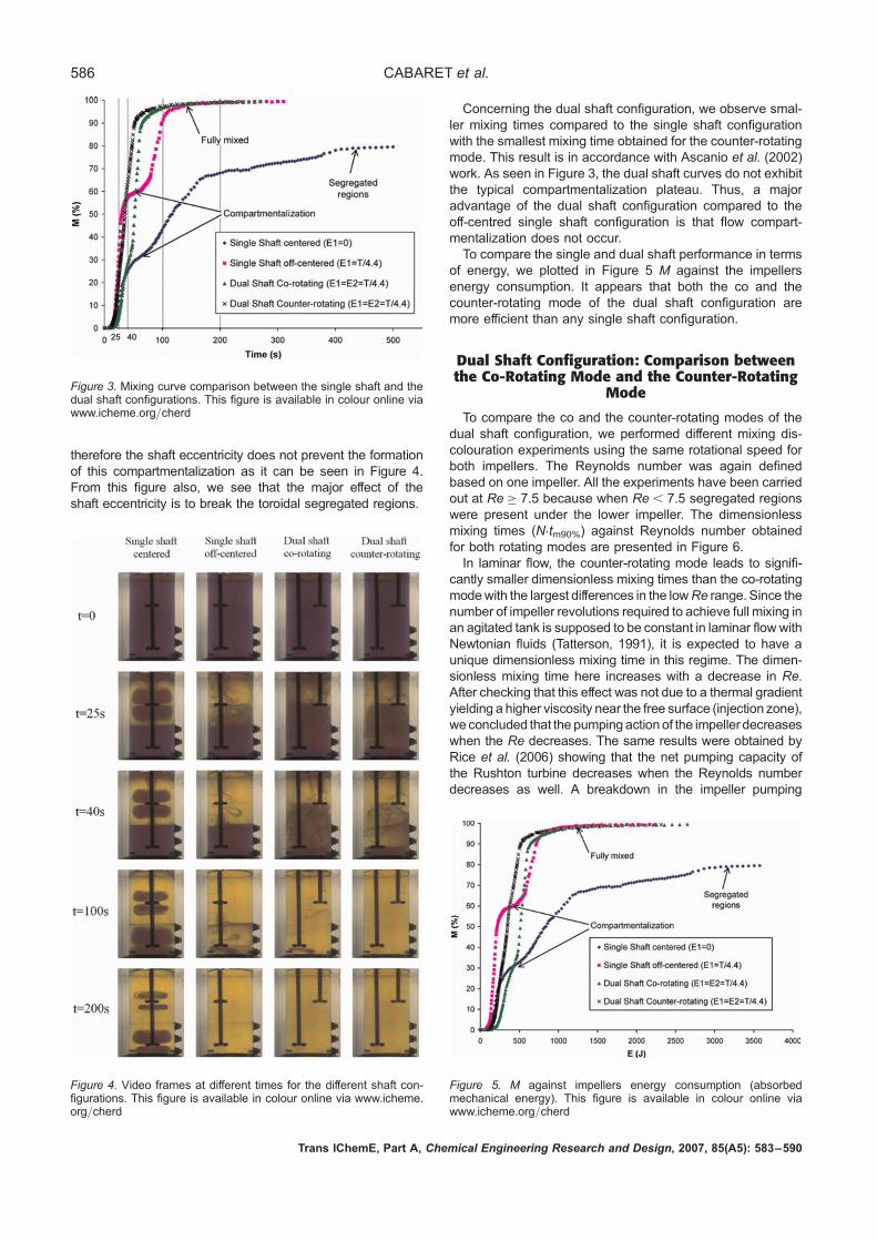
therefore the shaft eccentricity does not prevent the formationof this compartmentalization as it can be seen in Figure 4.From this figure also, we see that the major effect of theshaft eccentricity is to break the toroidal segregated regions.
Concerning the dual shaft configuration, we observe smal-ler mixing times compared to the single shaft configurationwith the smallest mixing time obtained for the counter-rotatingmode. This result is in accordance with Ascanio et al. (2002)work. As seen in Figure 3, the dual shaft curves do not exhibitthe typical compartmentalization plateau. Thus, a majoradvantage of the dual shaft configuration compared to theoff-centred single shaft configuration is that flow compart-mentalization does not occur.To compare the single and dual shaft performance in terms
of energy, we plotted in Figure 5 M against the impellersenergy consumption. It appears that both the co and thecounter-rotating mode of the dual shaft configuration aremore efficient than any single shaft configuration.
Dual Shaft Configuration: Comparison betweenthe Co-Rotating Mode and the Counter-Rotating
Mode
To compare the co and the counter-rotating modes of thedual shaft configuration, we performed different mixing dis-colouration experiments using the same rotational speed forboth impellers. The Reynolds number was again definedbased on one impeller. All the experiments have been carriedout at Re � 7.5 because when Re , 7.5 segregated regionswere present under the lower impeller. The dimensionlessmixing times (N.tm90%) against Reynolds number obtainedfor both rotating modes are presented in Figure 6.In laminar flow, the counter-rotating mode leads to signifi-
cantly smaller dimensionless mixing times than the co-rotatingmodewith the largest differences in the lowRe range. Since thenumber of impeller revolutions required to achieve full mixing inan agitated tank is supposed to be constant in laminar flowwithNewtonian fluids (Tatterson, 1991), it is expected to have aunique dimensionless mixing time in this regime. The dimen-sionless mixing time here increases with a decrease in Re.After checking that this effect was not due to a thermal gradientyielding a higher viscosity near the free surface (injection zone),we concluded that the pumping action of the impeller decreaseswhen the Re decreases. The same results were obtained byRice et al. (2006) showing that the net pumping capacity ofthe Rushton turbine decreases when the Reynolds numberdecreases as well. A breakdown in the impeller pumping
Figure 3. Mixing curve comparison between the single shaft and thedual shaft configurations. This figure is available in colour online viawww.icheme.org/cherd
Figure 4. Video frames at different times for the different shaft con-figurations. This figure is available in colour online via www.icheme.org/cherd
Figure 5. M against impellers energy consumption (absorbedmechanical energy). This figure is available in colour online viawww.icheme.org/cherd
Trans IChemE, Part A, Chemical Engineering Research and Design, 2007, 85(A5): 583–590
586 CABARET et al.
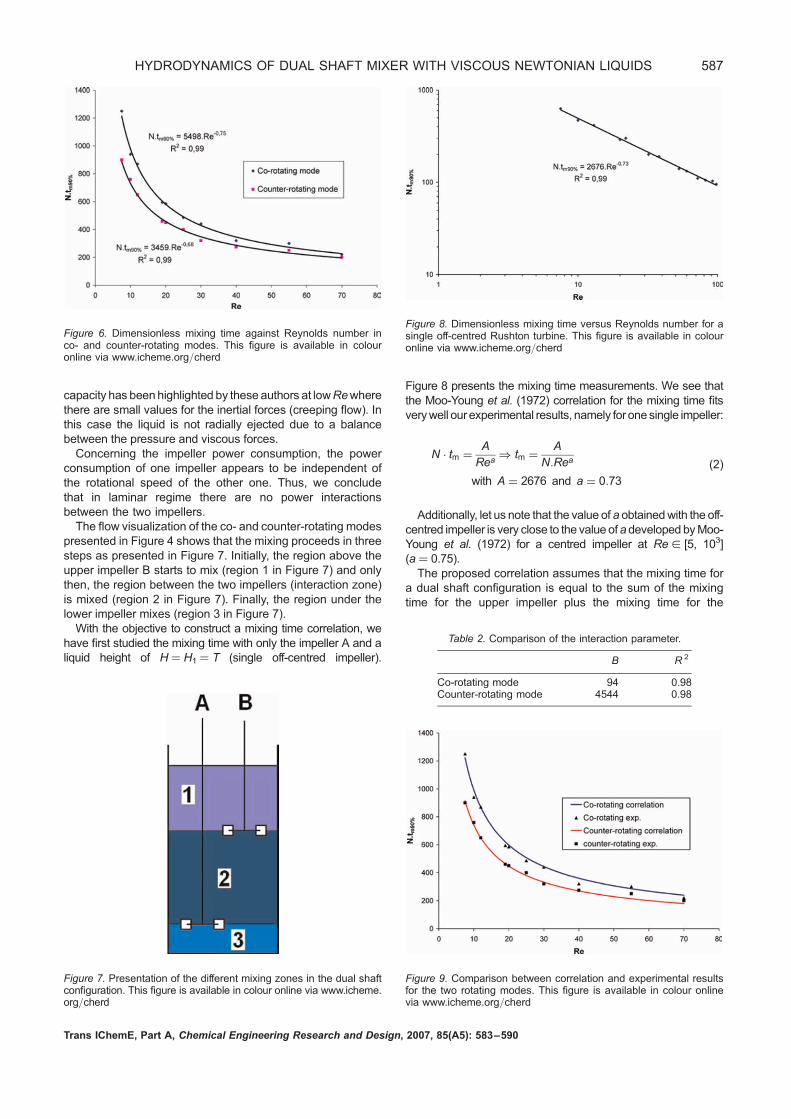
capacity has beenhighlighted by these authors at lowRewherethere are small values for the inertial forces (creeping flow). Inthis case the liquid is not radially ejected due to a balancebetween the pressure and viscous forces.Concerning the impeller power consumption, the power
consumption of one impeller appears to be independent ofthe rotational speed of the other one. Thus, we concludethat in laminar regime there are no power interactionsbetween the two impellers.The flow visualization of the co- and counter-rotating modes
presented in Figure 4 shows that the mixing proceeds in threesteps as presented in Figure 7. Initially, the region above theupper impeller B starts to mix (region 1 in Figure 7) and onlythen, the region between the two impellers (interaction zone)is mixed (region 2 in Figure 7). Finally, the region under thelower impeller mixes (region 3 in Figure 7).With the objective to construct a mixing time correlation, we
have first studied the mixing time with only the impeller A and aliquid height of H ¼ H1 ¼ T (single off-centred impeller).
Figure 8 presents the mixing time measurements. We see thatthe Moo-Young et al. (1972) correlation for the mixing time fitsverywell our experimental results, namely for one single impeller:
N � tm ¼A
Rea) tm ¼
A
N:Rea
with A ¼ 2676 and a ¼ 0:73
(2)
Additionally, let us note that the value of a obtainedwith the off-centred impeller is very close to the value ofadevelopedbyMoo-Young et al. (1972) for a centred impeller at Re [ [5, 103](a ¼ 0.75).The proposed correlation assumes that the mixing time for
a dual shaft configuration is equal to the sum of the mixingtime for the upper impeller plus the mixing time for the
Figure 6. Dimensionless mixing time against Reynolds number inco- and counter-rotating modes. This figure is available in colouronline via www.icheme.org/cherd
Figure 8. Dimensionless mixing time versus Reynolds number for asingle off-centred Rushton turbine. This figure is available in colouronline via www.icheme.org/cherd
Table 2. Comparison of the interaction parameter.
B R 2
Co-rotating mode 94 0.98Counter-rotating mode 4544 0.98
Figure 7. Presentation of the different mixing zones in the dual shaftconfiguration. This figure is available in colour online via www.icheme.org/cherd
Figure 9. Comparison between correlation and experimental resultsfor the two rotating modes. This figure is available in colour onlinevia www.icheme.org/cherd
Trans IChemE, Part A, Chemical Engineering Research and Design, 2007, 85(A5): 583–590
HYDRODYNAMICS OF DUAL SHAFT MIXER WITH VISCOUS NEWTONIAN LIQUIDS 587

lower impeller minus a term that represents the interactionbetween the two impellers. Since the interaction zone(region 2 in Figure 7) counts two impellers, the interactionterm is defined with N1þN2 as the representative rotationalspeed N. Thus, the Re in the interaction zone becomesRe1þRe2 and the interaction time ti is written:
ti ¼B
(N1 þ N2) � (Re1 þ Re2)a (3)
The complete expression for the mixing time is therefore:
tm ¼A
N1 � Rea1þ
A
N2 � Rea2�
B
(N1 þ N2) � (Re1 þ Re2)a (4)
Expressed in this form, it is easy to see that the B value onlyscales the interactions between the impellers. This correlation
have shown extremely good fitting with the experimentalresults that were carried out with N1 and N2 [ [1.67, 16.67]and with Re1 and Re2 [ [7.5, 70] (let us note that N1 and N2
can take different values). The B values and the correlationfactors for the two rotating modes are presented in Table 2.In Figure 9 we have compared the correlation with experimen-tal results given in Figure 6 for N1 ¼ N2 ¼ N.In order to explain why the counter-rotating mode leads to
smaller dimensionless mixing time than the co-rotating mode,simulations at Re ¼ 2, 10.1 and 50.7 in co- and counter-rotat-ing modes were carried out. For validation purposes thenumerical and experimental power consumptions were com-pared. The model showed an over-prediction of about 10%which indicates a very good accuracy for such a complexflow field. In Figure 10(a) it can be observed that the velocityin the XZ plane presents similar structure for both co- andcounter-rotating modes with four asymmetric rings above
Figure 10. Velocity profiles for the dual shaft configuration at Re ¼ 50.7. (a) XZ plane, (b) XY plane at C2 ¼ T/3 (left: co-rotating; right: counter-rotating). Impeller A (on left) is added for reference only. This figure is available in colour online via www.icheme.org/cherd
Trans IChemE, Part A, Chemical Engineering Research and Design, 2007, 85(A5): 583–590
588 CABARET et al.
and below each impeller. Nevertheless, there is a significantdifference in the flow in the XY plane as is depicted inFigure 10(b) caused by the fact that Rushton turbine mainlyproduces a flow in the radial direction. The shaft of impellerA (on the left) plays an important role in this situation.When both turbines are in co-rotating mode there is anabrupt change in the velocity close to the shaft of impellerA. This situation is not present when the impellers are incounter-rotating mode where a good collaboration betweenimpellers A and B is observed.To assess the performance of the investigated scenarios,
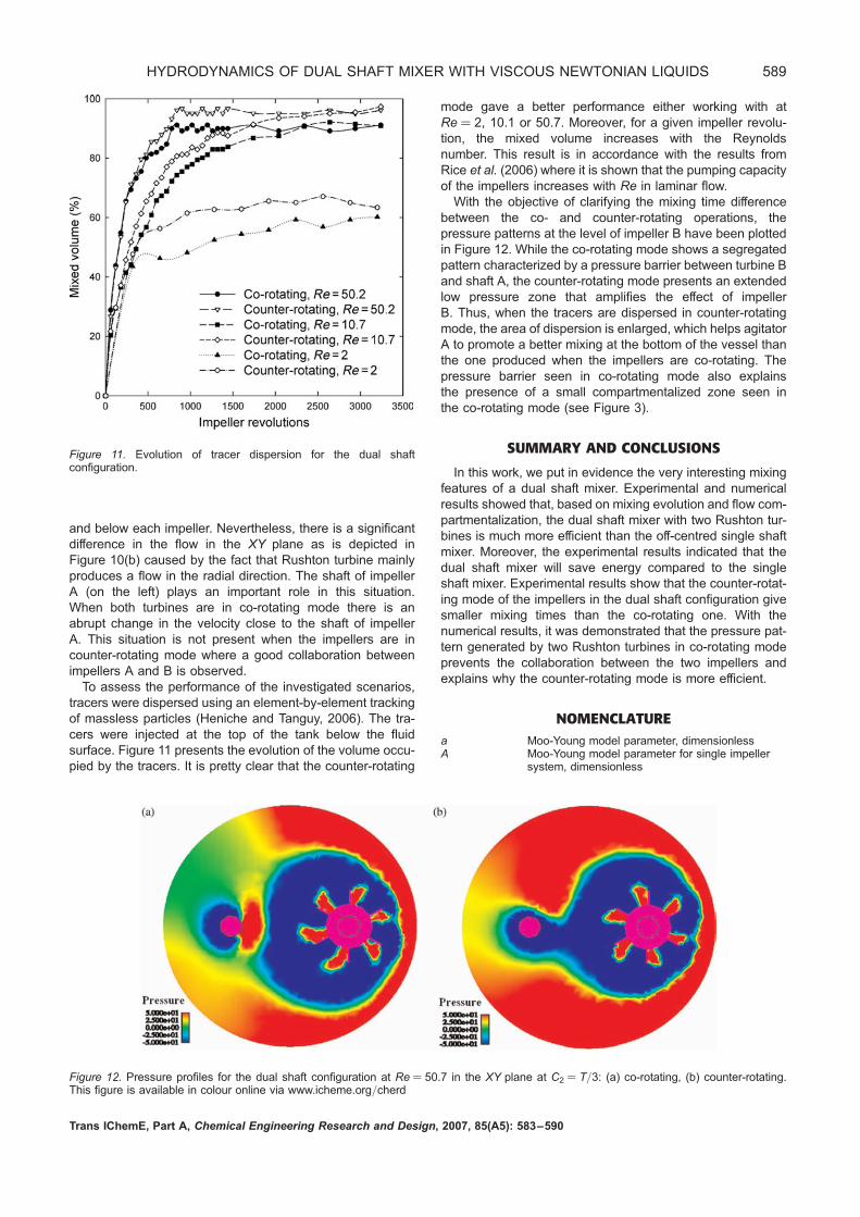
tracers were dispersed using an element-by-element trackingof massless particles (Heniche and Tanguy, 2006). The tra-cers were injected at the top of the tank below the fluidsurface. Figure 11 presents the evolution of the volume occu-pied by the tracers. It is pretty clear that the counter-rotating
mode gave a better performance either working with atRe ¼ 2, 10.1 or 50.7. Moreover, for a given impeller revolu-tion, the mixed volume increases with the Reynoldsnumber. This result is in accordance with the results fromRice et al. (2006) where it is shown that the pumping capacityof the impellers increases with Re in laminar flow.With the objective of clarifying the mixing time difference
between the co- and counter-rotating operations, thepressure patterns at the level of impeller B have been plottedin Figure 12. While the co-rotating mode shows a segregatedpattern characterized by a pressure barrier between turbine Band shaft A, the counter-rotating mode presents an extendedlow pressure zone that amplifies the effect of impellerB. Thus, when the tracers are dispersed in counter-rotatingmode, the area of dispersion is enlarged, which helps agitatorA to promote a better mixing at the bottom of the vessel thanthe one produced when the impellers are co-rotating. Thepressure barrier seen in co-rotating mode also explainsthe presence of a small compartmentalized zone seen inthe co-rotating mode (see Figure 3).
SUMMARY AND CONCLUSIONS
In this work, we put in evidence the very interesting mixingfeatures of a dual shaft mixer. Experimental and numericalresults showed that, based on mixing evolution and flow com-partmentalization, the dual shaft mixer with two Rushton tur-bines is much more efficient than the off-centred single shaftmixer. Moreover, the experimental results indicated that thedual shaft mixer will save energy compared to the singleshaft mixer. Experimental results show that the counter-rotat-ing mode of the impellers in the dual shaft configuration givesmaller mixing times than the co-rotating one. With thenumerical results, it was demonstrated that the pressure pat-tern generated by two Rushton turbines in co-rotating modeprevents the collaboration between the two impellers andexplains why the counter-rotating mode is more efficient.
NOMENCLATUREa Moo-Young model parameter, dimensionlessA Moo-Young model parameter for single impeller
system, dimensionless
Figure 12. Pressure profiles for the dual shaft configuration at Re ¼ 50.7 in the XY plane at C2 ¼ T/3: (a) co-rotating, (b) counter-rotating.This figure is available in colour online via www.icheme.org/cherd
Figure 11. Evolution of tracer dispersion for the dual shaftconfiguration.
Trans IChemE, Part A, Chemical Engineering Research and Design, 2007, 85(A5): 583–590
HYDRODYNAMICS OF DUAL SHAFT MIXER WITH VISCOUS NEWTONIAN LIQUIDS 589

B Moo-Young model interaction parameter,dimensionless
C bottom clearance, mD impeller diameter, mE eccentricity, mH liquid height, mM percentage of mixed pixel from the observer
point of view, %N impeller rotational speed, s21
P impeller power consumption, WRe Reynolds number (Re ¼ rND2/m), dimensionlessT tank diameter, mt time, sti interaction time, stm mixing time, sV tank volume, m3
W motor power consumption, WX pixel separation value, %
Greek symbolsh motor efficiency, dimensionlessm viscosity, Pa sr liquid density, kg m23
Subscripts1 refer to impeller A2 refer to impeller B
REFERENCESAlvarez, M.M., 2000, Using spatio-temporal asymmetry to enhancemixing in chaotic flows: from maps to stirred tanks, PhD thesis,Rutgers University, Piscataway, NJ, USA.
Alvarez, M.M., Arratia, P.E. and Muzzio, F. J., 2002a, Laminar mixingin eccentric stirred tank systems, Canadian Journal of ChemicalEngineering, 80: 546–557.
Alvarez, M.M., Guzman, A. and Elıas, M., 2005, Experimental visual-ization of mixing pathologies in laminar stirred tank bioreactors,Chemical Engineering Science, 60: 2449–2457.
Alvarez-Hernandez, M.M., Shinbrot, T., Zalc, J. and Muzzio, F.J.,2002b, Practical chaotic mixing, Chemical Engineering Science,57: 3749–3753.
Alvarez, M.M., Zalc, J.M., Shinbrot, T., Arratia, P.E. and Muzzio, F.J.,2002c, Mechanisms of mixing and creation of structure in laminarstirred tanks, AIChE Journal, 48: 2135–2148.
Ascanio, G., Brito-Bazan, M., Brito-De La Fuente, E., Carreau, P.J.and Tanguy, P.A., 2002, Unconventional configuration studies toimprove mixing times in stirred tanks, Canadian Journal of Chemi-cal Engineering, 80: 558–565.
Ascanio, G., Foucault, S. and Tanguy, P.A., 2004, Time-periodicmixing of shear-thinning fluids, Chem Eng Res Des, 82(9):1199–1203.
Ascanio, G. and Tanguy, P.A., 2005, Mixing of shear-thinning fluidswith dual off-centered impellers, Canadian Journal of ChemicalEngineering, 83: 393–400.
Bertrand, F., Gadbois, M.R. and Tanguy, P.A., 1992, Tetrahedralelements for fluid flow, International Journal of Numerical MethodsEngineering, 33: 1251–1267.
Bertrand, F., Tanguy, P.A. and Thibault, F., 1997, A three-dimensionalfictitious domain method for incompressible fluid flow problems,International Journal for Numerical Methods in Fluids, 25: 719–736.
Cabaret, F., Fradette, L. and Tanguy, P.A., 2006, Characterizationof mixing kinetics using advanced image analysis, Proceedings12th European Conference on Mixing, Bologna, 27–30 June,391–398.
Freund, R.W., 1993, A transpose-free quasi-minimum residual algor-ithm for non-Hermitian linear systems, SIAM Journal of ScientificComputing, 14: 470–482.
Gear, C.W., 1971, Numerical Initial Value Problems in Ordinary Differ-ential Equations (Prentice-Hall, Englewood Cliffs, USA).
Glowinski, R., Pan, T.W. and Periaux, J., 1994, A fictitious domainmethod for Dirichlet problem and applications, Computer Methodsin Applied Mechanics and Engineering, 111: 283–303.
Hall, J.F., Barigou, M., Simmons, M.J.H. and Stitt, E.H., 2004, Mixingin unbaffled high-throughput experimentation reactors, Industrialand Engineering Chemistry Research, 43: 4149–4158.
Harvey, A.D., Wood, S.P. and Leng, D.E., 1997, Experimental andcomputational study of multiple impellers flows, Chemical Engin-eering Science, 52: 1479–1491.
Heniche, M. and Tanguy, P.A., 2006, A new element-by-elementmethod for trajectory calculations with tetrahedral finite elementmeshes, International Journal for Numerical Methods in Engineer-ing, 67(9): 1290–1317.
Moo-Young, M., Tichar, K. and Dullien, F.A.L., 1972, Blending effi-ciencies of some impellers in batch mixing, AIChE Journal,18(1): 178–182.
Rice, M., Hall, J., Papadakis, G. and Yianneskis, M., 2006, Investi-gation of laminar flow in a stirred vessel at low Reynolds numbers,Chemical Engineering Science, 61: 2762–2770.
Rivera, C., Heniche, M., Ascanio, G. and Tanguy, P.A., 2004, A virtualfinite element model for centered and eccentric mixer configur-ations, Computers and Chemical Engineering, 28: 2459–2468.
Szalai, E.S., Arratia, P., Johnson, K. and Muzzio, F.J., 2004, Mixinganalysis in a tank stirred with Ekato Intermig impellers, ChemicalEngineering Science, 59: 3793–3805.
Tatterson, G.B., 1991, Fluid Mixing and Gas Dispersion in AgitatedTanks (McGraw-Hill, New York, USA).
Zalc, J.M., Alvarez, M.M., Muzzio, F.J. and Arik, B.E., 2001, Exten-sive validation of computed laminar flow in a stirred tank withthree rushton turbines, AIChE Journal, 47: 2144–2154.
ACKNOWLEDGEMENTThe support of NSERC and the members of the Consortium
‘Innovative non-Newtonian Mixing Technologies’ is gratefullyacknowledged.
The manuscript was received 29 September 2006 and acceptedfor publication after revision 10 November 2006.
Trans IChemE, Part A, Chemical Engineering Research and Design, 2007, 85(A5): 583–590
590 CABARET et al.