Humboldt Bay, Caisson Removal Feasibility Study Hundred ...
139
d OKiewit HUMBOLDT BAY POWER PLANT EUREKA, CA CAISSON REMOVAL FEASIBILITY STUDY 100% DRAFT FEASIBILITY REPORT 1 OCTOBER 2012
-
Upload
khangminh22 -
Category
Documents
-
view
0 -
download
0
Transcript of Humboldt Bay, Caisson Removal Feasibility Study Hundred ...

d OKiewit
HUMBOLDT BAY POWER PLANTEUREKA, CA
CAISSON REMOVAL FEASIBILITY STUDY100% DRAFT FEASIBILITY REPORT
1 OCTOBER 2012

S~KiewitHBPP Caisson Removal Feasibility Study
100% Draft Feasibility Report
Table of ContentsList of Abbreviations .................................................................................................................................... iv
1.0 Executive Sum m ary ................................................................................................................................. 1
1.1 Project Description .............................................................................................................................. 1
2.0 Technical Challenges ............................................................................................................................... 2
2.1 Slurry W all Construction ..................................................................................................................... 3
2.2 Soil Stockpile Areas ............................................................................................................................. 3
2.3 Below Grade Obstructions .......................................................................................................... 4
2.4 As-Built Plans ....................................................................................................................................... 4
2.5 Lim its of Contam ination ...................................................................................................................... 4
3.0 Scope 1 Caisson Rem oval Engineering .............................................................................................. 5
3.1 Concept Developm ent ........................................................................................................................ 5
4.0 Caisson Excavation System ............................................................................................................ 6
4 .1 S lu rry W a ll ........................................................................................................................................... 7
4 .2 S o il N a il W a ll ....................................................................................................................................... 8
4.3 Sheet Pile & Ring Beam Shoring ..................................................................................................... 8
4.4 Instrum entation .................................................................................................................................. 9
4.5 Excavation System Rem oval ......................................................................................................... 10
5.0 Engineering Analysis ............................................................................................................................. 10
5.1 Historical Docum ents ........................................................................................................................ 10
5.2 Slurry W all Investigation ................................................................................................................... 11
5 .3 S lu rry W a ll ......................................................................................................................................... 1 2
5.4 Dewatering ........................................................................................................................................ 13
5 .5 S o il N a il W a ll ..................................................................................................................................... 1 3
5.6 Sheet Pile W all .................................................................................................................................. 13
5.7 Settlem ent ......................................................................................................................................... 13
5.8 Construction Vibration Analysis ................................................................................................... 17
6 .0 S a fe ty .................................................................................................................................................... 1 8
Page Ii

O@KiewitHBPP Caisson Removal Feasibility Study
100% Draft Feasibility Report
6.1 Earthquake and Tsunam i Response .............................................................................................. 18
6.2 Equipm ent Noise ............................................................................................................................... 19
7.0 Slurry W all Construction ....................................................................................................................... 19
7.1 PG& E Site Preparation W ork Prior to Slurry W all Construction ................................................... 19
7.2 Slurry W all Contractor W ork ....................................................................................................... 20
8.0 Scope 2 - Foundation Pile Rem oval ................................................................................................... 21
9.0 Excavation Plan ..................................................................................................................................... 22
9.1 Soil Stockpile Area ............................................................................................................................. 22
9.2 Slurry W all Excavation ....................................................................................................................... 23
9.3 Caisson Excavation ............................................................................................................................ 24
9.4 Interm odal Containers - Soil Disposal ......................................................................................... 24
9.5 Concrete Debris ................................................................................................................................ 25
9.6 Interm odal Containers - Concrete Disposal ................................................................................ 25
10.0 Logistics of Backfill Plan ...................................................................................................................... 26
11.0 Traffic Plan .......................................................................................................................................... 26
12.0 Groundw ater Treatm ent Assessm ent ............................................................................................ 26
13.0 Storm W ater ........................................................................................................................................ 27
14.0 Risk Analysis & Assessm ent ................................................................................................................ 27
15.0 Budgetary Estim ate and W ork Breakdow n Structure ................................................................... 31
16.0 Schedule .............................................................................................................................................. 32
17.0 References .......................................................................................................................................... 32
17.1 Historical Docum ents ...................................................................................................................... 32
17.2 Engineering References .................................................................................................................. 33
APPENDIX A .................................................................................................................................................. 34
APPENDIX B ................................................................................................................................................. 60
APPENDIX C ................................................................................................................................................ 62
APPENDIX D ................................................................................................................................................. 71
Page I ii

I(MIKiewitHBPP Caisson Removal Feasibility Study
100% Draft Feasibility Report
APPENDIX E ................................................................................................................................................. 75
APPENDIX F ................................................................................................................................................. 79
APPENDIX G ................................................................................................................................................. 82
APPENDIX H ............................................................................................................................................... 120
APPENDIX I ................................................................................................................................................ 131
Page liii

CfKiewit
HBPP Caisson Removal Feasibility Study
100% Draft Feasibility Report
AISC
ACIALARAANSI
ASME
ASTM
bgs
Bq/m2
BSL
CALTRANS
CCC
CEQA
CFM
CFR
CLSM
COPC
cy
Cs-137
dBA
DCGLs
DOT
DTSC
elev.
FHWA
FSAR
GWTS
gpm
HASP
HBGS
HBPP
HSC
IBC
IM RAO
IM/RAW
ISFSI
KG
LFO
LLMW
LLRW
List of Abbreviation:American Institute of Steel Construction
American Concrete Institute
As Low as Reasonably AchievableAmerican National Standards Institute
American Society of Mechanical Engineers
American Society for Testing and Materials
Below Ground Surface
Becquerel per Square Meter
Background Screening Level
California Department of Transportation
California Coastal Commission
California Environmental Quality Act
Cubic Feet per Minute
Code of Federal Regulations
Controlled Low Strength MaterialConstituent of Potential Concern
Cubic Yards
Cesium -137
A - Weighted Decibel
Derived Concentration Guidelines
Department of Transportation
Department of Toxic Substances Control
Elevation
Federal Highway Administration
Final Safety Analysis Report
Groundwater Treatment System
Gallons per Minute
Health and Safety Plan
Humboldt Bay Generating Station
Humboldt Bay Power Plant
Health and Safety Code
International Building Code
Interim Measures Removal Action Objective
Draft Interim Measures Removal Work Plan
Independent Spent Fuel Storage Installation
Kilogram
Liquid Fuel OilLow-level Mixed Waste
Low Level Radioactive Waste
Lmax Maximum Sound LevelLRW Liquid Radwaste
LSA Low Specific ActivityMDA Minimum Detectable Activity
mCi/ml Microcuries per Milliliter
NEHRP National Earthquake HazardsReduction ProgramNational Institute of Standards andTechnology
NRC Nuclear Regulatory Commission
NUREG NRC Reports
OSHA Occupational Health and Safety
AdministrationPCB Ploy Chlorinated BiphenylPCM Personal Contamination Monitor
PCF Per Cubic FootPGA Peak Ground Acceleration
PG&E Pacific Gas & Electric Company
pCi/g Picocuries per Gram
PPE Personal Protective Equipment
PSF Per Square Foot
PSI Per Square Inch
QA Quality Assurance
QC Quality Control
Qualified Storm Water Pollution
Prevention Plan DeveloperRAM Radioactive Material
RB Radwaste Building
RBL Radionuclide Background Level
RCNM Roadway Construction Noise ModelRCRA Resource Conservation and
Recovery Act
REM Roentgen Equivalent Man
RFB Reactor Fuel Building
RP Radiation Protection
SAFSTOR Safe Storage
SCO Surface Contaminated ObjectSFP Spent Fuel Pool
PG&E's Humboldt Bay Power PlantSite located at 1000 King Salmon
Avenue, Eureka, California
SPT Standard Penetration Test
SVOC Semivolatile Organic Compound
TN Transnuclear, Inc.
TPH Total Petroleum Hydrocarbon
VOC Volatile Organic Compound
Page l iv

IKiewitHBPP Caisson Removal Feasibility Study
100% Draft Feasibility Report
1.0 Executive Summary
This report summarizes the results of our feasibility study for the Unit 3 caisson removal and Units 1, 2and 3 foundation piles removal. The outcome of our study indicates that it is feasible to remove thecaisson and the foundation piles.
We have completed "proof of concept" level analyses and plans for a caisson excavation system, whichconsists of:
1. a cement bentonite slurry wall to minimize groundwater infiltration;2. a soil nail wall for support of the upper excavation; and3. a sheet pile and ring beam shoring system for support of the lower excavation.
In addition, we have completed a subsurface field investigation to confirm the presence of the Unit Fclay. Confirming the presence of the Unit F clay was critical to the feasibility of the slurry wall. Structuralcaisson demolition is proposed to be accomplished from the top.down with an excavator-mountedhydraulic hoe-ram. Plans for the caisson excavation system, the work breakdown structure/budgetaryestimate, level-1 schedule, and final grading specification, are contained in Appendices A through D,respectively.
For the foundation pile removal, our review of the pile foundations, experience, and analysis indicate
that the piles can be removed. Also, because the piles have been in saturated soils except the firstcouple feet in some cases, the piles are not anticipated to be deteriorated. Therefore, we believe thatthe piles will be extracted intact in one piece.
The discussion and documents presented in this report have been used to develop this feasibility study,develop the proposed construction means and methods, and the cost estimate. Sections within thisreport also meet PG&E contract deliverable requirements as outlined in the PG&E Contract No.
3500929301.
1.1 Project DescriptionThis caisson removal feasibility study is divided into two scopes of work:
Scope 1 work items include:
* Installation of a cement bentonite slurry wall around the decommissioning area to controlgroundwater inflow;
" Pre-trenching the slurry wall alignment to remove known and unknown subsurface obstructionsincluding piles and utilities and contaminated soil;
" Excavation around the caisson;" Demolition of the caisson; and," Backfilling the void from the caisson demolition and removal.
Page 1

HBPP Caisson Removal Feasibility Study
100% Draft Feasibifity Report
Scope 2 work items include:* Demolition of Units 1 and 2 foundation slabs and pile caps;* Removal of foundation piles; and,* Backfilling voids from the demolition and pile removal.
The following nine specific deliverables are outlined in the Study Contract Documents for each Scope ofWork:
1. A Work Breakdown Structure (WBS)2. Excavation Plan3. Backfill Plan4. Traffic Plan5. Groundwater Treatment Assessment6. Risk Analysis and Assessment7. Level-i Schedule8. Final Site Grading Specification9. A Budgetary Estimate
2.0 Technical Challenges
Technical challenges associated with the caisson demolition and removal includes:
* Excavation and demolition below the groundwater table;" A PG&E supplied groundwater treatment system with a maximum capacity of 300 gpm;" Trend of and most current regional seismic activity;" Physical site constraints including the operating power plant and other office structures;* Obstructions from original construction; and" Annual precipitation over 38 inches per year.
The purpose of installing the slurry wall is to minimize and control the volume of discharge generatedfrom dewatering such that discharge can be managed and treated through the on-site groundwater
treatment system. Key to assuring performance of the slurry wall is maintaining high quality standardson materials and construction procedures, maintaining integrity of the slurry wall diaphragm betweenpanels, and keying the slurry wall into a low permeability stratum (Unit F clay layer).
The purpose of the shoring systems described herein are to allow the excavation and demolition work tobe safely performed within a controlled footprint, to minimize the volume of excavated materialremoved, and to minimize deformation, settlement, and operational impacts to the operating HBGSplant. Components of the earth retaining systems have been designed to resist "static earth forces,seismic forces, and estimated construction loading forces.
Page 12

I @KiewitHBPP Caisson Removal Feasibility Study
100% Draft Feasibifity Report
Climactic conditions of the Humboldt site also present challenges to the decommissioning work. Theannual rainfall of 38-inches will be accounted for in the planning of soil and debris handling, personnelsafety, and site traffic management. In addition, rainwater management and storage plans will have toaccommodate all site water being processed through the 300 gpm site water treatment system.Additional challenges that have been recognized as the project has developed are also discussed withinthe following sections.
2.1 Slurry Wall ConstructionMobilization, including set up and commissioning of the slurry wall construction equipment, installationof guide walls, batching plant, and de-sanding plant is estimated to require one month prior tobeginning slurry wall production. After mobilization, the estimated production time for completing theslurry wall is five months, based on the PG&E-defined work schedule of four days per week and 10 hoursper day. The estimated five month construction schedule is based on two machines (a hydro-mill andclam shell) operating to collectively produce 150 square feet of wall per hour. This five month scheduleestimate does account for some delays due to inclement weather and routine equipment maintenancebut does not include pre-trenching for obstructions or removal/relocation of utilities. Decommissioningand removal of equipment from the site is anticipated to require approximately three weeks. Therefore,the total estimated time frame for slurry wall construction including mobilization and demobilization isabout 7 months. This schedule exceeds the 6 month window currently included in PG&E's PreliminaryDecommissioning Schedule dated 27 June 2012.
An opportunity to accelerate overall project schedule by approximately 2 months could be realized if the
operation adopted a working schedule five days per week 10 hours per day for production slurry wallconstruction and one 8-hour day (generally Saturday) for equipment maintenance and workpreparation. On occasion, work days may have to increase to 11 or 12 hours per day to completecertain phases of an operation that cannot or should not be stopped before the operation is completed.
2.2 Soil Stockpile AreasCurrently, we are anticipating that the area east of the discharge canal will be available for stockpilingsoils (refer to sheet 12-008-009-4 of the Caisson Removal Plans).
The slurry wall construction will produce about 15,000 to 17,000 cubic yards of soil which is anticipated
to be "clean" and acceptable for re-use as on-site backfill. The direction provided by PG&E is that thesoil will not be allowed to be temporarily stored in the intake or discharge canals. For this study, the soilwill only be able to be used for backfill of the caisson excavation or transported to a Class II landfill.Based on PG&E's CAPSTONE document none of the existing trailers are to be moved until "early 2014".To be able to temporarily stockpile the soils on site for processing, the trailers will need to be removedas shown on sheet #12-08-009-4 of the Caisson Removal Plans. Off-site temporary storage of soil fromthe slurry wall excavation has been included in the study and cost estimate. This will be furtherdiscussed in Section 9.
Page 13

O~KiewitHBPP Caisson Removal Feasibility Study
100% Draft Feasibilty Report
For the caisson excavation, trailer city will be available as a soil stockpile area and we are anticipating
having a minimum of approximately 50,000 ft 2 footprint with a maximum stockpile height of 8 feet. Thecaisson excavation will generate an additional 15,000 cubic yards of soil. The soil will be relatively drybecause of the dewatering and should be able to be shipped off-site once it has been characterized.Management of the caisson soil will need to incorporate the two week waiting period for
characterization.
Depending on the final stockpile location, potential for settlement over or adjacent to utilities or slopefailure should be evaluated. After the final location is selected, some additional subsurface investigation
to evaluate soil properties such as strength, unit weight, and consolidation may be required.
2.3 Below Grade ObstructionsA pre-trenching operation is recommended along the slurry wall alignment to identify and removeshallow obstructions, unidentified utilities, and screen for potential shallow radiological andenvironmental contamination. The recommended pre-trenching would be performed by open-cutexcavation along the entire wall alignment. Recommended trenching dimensions are 6 feet wide andabout 15 feet deep (elev -3ft).
All other existing documented utilities intersecting the slurry wall alignment should be removed,relocated, or abandoned as necessary prior to slurry wall installation. Additional discussion regarding
utility removal and remediation work is contained in identified sections of this report.
For the soil nail wall construction, structures such as the SAS and Turbine building will *need to beremoved and some of the Turbine building foundation piles will have to be removed.
2.4 As-Built PlansHorizontal survey control for the caisson has not been included with this feasibility study, therefore,final adjustments to the slurry wall, soil nail wall, and sheet pile/ring beam wall may be required to allow
for contaminated soil excavation. The horizontal survey control of the caisson should be performedbefore final design of the caisson excavation system is initiated.
2.5 Limits of ContaminationA subsurface investigation is planned for the slurry wall alignment which will help delineate potential
contamination in that area; however, this investigation will not likely provide sufficient data to identifyor delineate the potential contamination immediately adjacent to the caisson. An investigation shouldbe performed to delineate the vertical and horizontal extents of contamination beyond the caisson,after removal of near surface structures such as the turbine building and the SAS. The results of this
survey are critical in understanding the total final scope of the excavation system requirements.Otherwise the caisson removal system could be installed within the limits, precluding the removal ofcontaminated soil.
Page 14

IfOKiewitHBPP Caisson Removal Feasibility Study
100% Draft Feasibility Report
.•.l .•ennp_ 1 Cai.•.nn Remnval F~nsineerinP3 0 Scone 1 Caisson Removal Enpineerinp
3.1 Concept DevelopmentEarly concept development evaluated five potential schemes:
1. Mud jacking the caisson;2. Ground freeze to cut-off groundwater infiltration and provide excavation support;3. Conventional shoring systems with dewatering;4. Cement bentonite slurry wall to cut-off groundwater infiltration; and5. An open cut sloped excavation with dewatering.
An interface meeting was held on 17 April 2012 for the stakeholders to comment on concepts,communicate their concerns, restrictions, and limitations. Based on input from the stakeholders,discussion during the first meeting and review of additional historic documents, the engineering teammodified the options as required, and prepared a revised set of concepts. The result was four conceptswere carried forward to evaluate technical challenges, excavation area and potential dewatering effort.The four schemes are presented in Table 1:
Table 1 - Caisson Removal System Concept Summary
Primary Demo Approach Technical Challenge Dewatering Effort ExcavationScheme Footprint
Cement Open excavate top Depth and continuity of Low 200 ft diameterBentonite portion and utilize shoring Unit F claySlurry Wall system for bottom portionGround Open excavate top Brackish water and Low 200 ft diameterFreeze portion may need shoring flowing tidal water
system for bottom portion adversely affect groundfreeze methods
Conventional Dewatering to control Penetrating cemented High 120 ft diameterShoring groundwater to bottom of layer, groundwater
caisson treatmentMud Jack Open excavate top May need to demo the Moderate 200 ft x 200 ft
portion and use last 10 feet in-place.dewatering to control May require additionalground water dewatering effort
A second interface meeting was held on 1 May 2012; the stakeholders and design team evaluated andranked the alternative concepts. Each concept was ranked on a point scale from 1 to 5 (five being thebest) with 3 being neutral in 15 different categories including cost, risk, feasibility, and site andenvironmental impacts. The evaluation process resulted in the selection of the slurry wall concept forremoval of the caisson. Table 2 presents the ranking matrix.
Page 15

rIOKiewitHBPP Caisson Removal Feasibility Study
100% Draft Feasibility Report
Table 2 - Removal System Concept Ranking Matrix
CEMENTBENTONITE GROUND CONVENTIONAL MUD
SLURRY FREEZE SHORING JACK
WALL
COST 3 1 3 4
SCHEDULE 4 1 3 4
VOLUME OF SOIL DISPOSAL (COST IMPACT) 3 3 3 3
VOLUME OF WATER DISPOSAL (COST IMPACT) 5 5 1 1
LAND AREA REQUIRED 3 1 5 4
ABILITY TO REMOVE SURROUNDING SOIL 4 4 4 1
(NEW) ITEMS LEFT IN PLACE 3 5 5 3
RISK OF LEAVING PRE-EXISTING ITEMS BEHIND 5 5 5 4
SAFETY (PERSONNEL) 3 3 2 4
CONFIDENCE FACTOR 5 1 2 2
RISK OF SITE IMPACT 5 3 2 2
RISK OF UNKNOWNS AND ASSUMPTIONS 3 1 2 1
RISK OF MIXING AQUIFERS 5 5 5 4
COST OF BACKFILL 3 2 2 1
IMPACT TO ENVIRONMENT/PUBLIC PERCEPTION 4 5 1 4
TOTAL 58 45 45 42
Major contributing factors for selection of the slurry wall with conventional excavationinclude the following:
support system
S
0
S
Control and maintenance of dewatering during excavation;Reliability of containment system; and,
Reliable performance of conventional excavation support systems.
The slurry wall concept and the associated support of excavation systems have been designed to a levelof detail sufficient to develop concept-level pricing and construction schedule, and sufficient to developthe deliverables identified in the contract.
4.0 Caisson Excavation System
For the caisson demolition, an excavation system has been designed to maintain a dewateredexcavation with discharge rates that can be adjusted to meet the proposed PG&E groundwatertreatment system's maximum treatment rate of 300 gpm for all site dewatering activity, and retain theadjacent soil. The caisson excavation system will consist of three major components:
Page 16

IKiewitHBPP Caisson Removal Feasibility Study
100% Draft Feasibility Report
1. a cement bentonite slurry wall;2. a soil nail wall for support of the upper excavation; and,3. a sheet pile and ring beam shoring system for support of the lower excavation.
In addition, geotechnical instrumentation to monitor the performance of the system has beenincorporated into the plans. The locations, details and suggested monitoring of the instrumentation arepresented in the plans. Additional discussion regarding the instrumentation is presented in theidentified section of this report that follow.
The caisson demolition will be discussed in section 9.0 of this report including methods, sequencing, and
production.
4.1 Slurry WallThe cement bentonite slurry is a mixture of Portland cement and bentonite powder (natural clay), waterand admixtures. Other materials may be used such as slag cement, which has a slower curing rate and is
generally less expensive than Portland cement. Initially, the slurry is a viscous liquid with a typical unitweight of 65 to 75 pcf. The cured slurry mixture has an unconfined compressive strength of about 20 to
80 psi, depending on the final mix design, and behaves more like a very stiff to hard clay. The netequivalent permeability of the completed slurry wall has been estimated to be 1x10⁻⁶ cm/sec; however
the cured slurry material itself will have a lower permeability.
The wall alignment is excavated with a hydro-mill and clam shell in alternating primary and secondarypanels; both of which are about 30 inches wide. The hydro-mill excavates the primary panels and the
clam shell excavates the secondary panels which overlap the primary panels about one foot on eachside. The panels will be excavated to and penetrate or "key" into the low permeable Unit F clay stratumat an approximate average depth of 170 feet below grade (elev. -160 ft). A graphic of the panelexcavation is presented on sheet 12-008-00-9 of the Caisson Removal plans. Discussion regarding the
subsurface investigation is contained Section 5.2.
The hydro-mill is equipped with a monitoring system that provides real time data for the horizontal and
vertical alignment. The hydro-mill is "steerable" so that when deviations occur the hydro-mill alignment
can be corrected. The clamshell is also equipped with monitoring devices for alignment control. Theclamshell follows the path of least resistance where it follows the softer fresh slurry (i.e. viscous) as
opposed to the surrounding soil. Because the clamshell is excavating in the softer fresh slurry,
essentially a continuous wall is constructed without any seams. Inherently there would be a "seam"between the first and last panels. The key to insuring for the excavation of adjacent panels in freshslurry is the mix design and timing.
The completed slurry wall will essentially create a low permeable "bathtub" for the caisson demolitionand other Unit 3 decommissioning activities. Because the slurry wall prevents horizontal groundwatermovement, the volume of water to be pumped and treated is the groundwater contained in the slurrywall, storm water, and minor infiltration.
Page 17

MKiewitHBPP Caisson Removal Feasibility Study
100% Draft Feasibility Report
The slurry wall is not structurally reinforced, therefore excavations made adjacent to the wall should besupported as if the excavation was made in soil. Hence large deep excavations like that for the caissonremoval would be required to be sloped or support of excavation systems would need to beimplemented. Due to the physical site constraints, equipment surcharges and the seismic design
requirements, the upper 40 feet of the caisson excavation (elev. +12 ft to elev. -30 ft) cannot be sloped
and meet the site requirements. A soil nail wall was selected to reinforce the soil to create slopes thatcan stay within the project constraints, resist the seismic forces, and support construction equipment.
4.2 Soil Nail WallSoil nail wall construction would consist of installing 25 foot long by 1.5 inch diameter high strengthsteel bars on a grid pattern at approximate 4 foot by 4 foot spacing. The steel bars are inserted into the
face of the slope at about 15 degrees from horizontal. There are several possible installation methods;however, the final product is a steel bar encompassed in a 6 to 8 inch diameter grouted 25 foot longhole. The slope or "face" of the wall will be covered with a reinforced shotcrete facing after each levelof nails are installed. The final wall face will be battered about 10 degrees from vertical. The shotcretefacing will resist soil forces and prevent erosion that would occur during rain on an exposed soil slopeand the wall will minimize the volume of soil to excavate, characterize, stockpile, backfill and/or
potentially dispose.
The soil nail wall will be constructed around the entire perimeter of the caisson. The top of the wall willrange from elev. +12 ft around the north, east, and west sides (based on Plant north) of the caisson toelev. +0 ft along the turbine building foundation. The toe of the soil nail wall will be at elev. -30 ft. Thetoe of the wall will be offset about 20 to 25 feet from the outside edge of the circular part of the caisson.This will provide a 10 foot bench between the toe of the soil nail wall and the face of the sheet pile andring beam shoring system. The 10 foot bench will provide an access and egress point for workers during
the caisson excavation and demolition work.
The designed soil nail wall has a 10 degree battered face which will reduce the overall lateral movement.As the excavation proceeds and the soil nail wall is constructed, the inclinometers will be monitored forlateral deflection (further discussed in section 4.4). If the observed lateral deflection data is predictinggreater movement than desired the remaining nails can be post-tensioned to reduce the amount ofmovement required to mobilize the resistance.
4.3 Sheet Pile & Ring Beam ShoringA primary reason for beginning the shoring system at elev. -30 ft was so that the cemented sand and siltlayer between elev.-32 ft and elev. -37 ft can be pre-trenched without specialty equipment from this
elevation; allowing for successful installation of the sheet piles. The subsurface data presented in thehistorical documents showed refusal type blow counts in this stratum. During the recent geotechnicalinvestigation refusal type blow counts were encountered in the granular deposits throughout the depths
explored. Therefore, jetting in conjunction with vibratory hammer pile driving will be used forinstallation of the caisson sheet piles. In addition, a template at the surface would need to be
Page 18

0 Ki lewi tHBPP Caisson Removal Feasibility Study
100% Draft Feasibility Report
constructed so that the correct circular pattern is constructed and the last set of sheet piles connects to
close the circle.
The sheet piles would be installed to elev. -91 ft which would allow for excavation of the entire areabelow the caisson to elev. -81 ft, about 7 feet below the bottom of the caisson tremie slab. If deeper
excavation was required to remove contaminated soil, the excavation could be performed in discreteareas and then backfilled prior to excavating another discrete area. An alternate would be to installadditional sheet piles around the area of contaminated soil.
The ring beams would be installed along the depth of the excavation at 10 ft spacing for five ring beams
and at 12.5 ft spacing for four ring beams. The size of the ring beams would in-part be dependent onthe number of ring beams used. The ring beams would either be cast-in-place concrete or steel beams.The concrete ring beams range in size from 34 inch square beams to 44 inch square beams depending
on the location and number of beams constructed. Details regarding the ring beams and steel alternatesections are presented on sheet 12-008-009-16 of the Caisson Removal plans.
4.4 InstrumentationA geotechnical instrumentation program has been developed for the purpose of monitoringgroundwater levels inside and outside of the excavation, and lateraland vertical ground deformation.
Groundwater levels will be monitored using piezometers, with monitoring points, between the caissonwalls and the slurry wall, and outside of the slurry wall. The difference in piezometric water level insideand outside of the slurry wall will demonstrate the effectiveness or quality of the slurry wall installation.The piezometers would also be used to evaluate the integrity of the slurry wall in the event that an
earthquake occurs during the period of construction. For the purpose of collecting real-time piezometricdata during a seismic event, automated piezometers should be used.
The inclinometers serve to measure lateral movement in the ground surrounding the excavation.Inclinometers would be placed inside and outside the slurry wall, similar to the piezometers, to monitorthe movement inside and outside the slurry wall and near the HBGS operating plant. Theinstrumentation could be manual or automated readout; however, for the inclinometers manual readingwould be most suitable considering the length of the inclinometer casing that would be monitored. In-place inclinometers with automated readings are best suited when specific zones or soil layers are to bemonitored. Similar to the piezometers, the inclinometers could also help evaluate the location of
damage to the slurry wall after a seismic event. This could be observed by excessive deflection or theinclinometer probe would not be able to penetrate the full inclinometer casing depth.
In addition to the piezometers and inclinometers, optical survey points would be installed on structuresthat are considered sensitive to settlement. The points would be set prior to the slurry wall installationand monitored throughout the project. Additional survey points could be installed on the soil nail walland sheet pile wall to monitor vertical and horizontal movement. Discussion about the potential for
settlement and lateral movement is discussed in section 5.7.
Page 19

i 0@Ki ewitHBPP Caisson Removal Feasibility Study
100% Draft Feasibility Report
4.5 Excavation System RemovalThe caisson excavation system will be removed to the extent feasible, logical, and economical. Thesheet pile and ring beam system will be completely removed. The concrete ring beams will bedemolished and disposed of as the excavation is backfilled. Once the backfill has reached approximatelyelev. -30 ft the sheet piles will be extracted and salvaged either for re-use or recycled depending onpotential ground contamination. This would be typical practice for temporary support systems.
Soil nail walls are not typically removed, and are generally left in place and backfilled. The shotcretefacing could be removed if it is determined to be an obstruction, but the nails would be typically left inplace. If it is determined that the nail elements need to be removed, additional steps would be requiredto assure stability of the excavation and to fill voids left by the nails. The cost for removing soil nails hasnot been incorporated in the cost estimate.
Similar to soil nail walls, slurry walls are not anticipated to be removed. In order to equalizegroundwater pressure inside and outside of the excavation post construction, a series of trenches wouldbe excavated through the slurry wall, thereby breaching the wall to elev. +0 ft. Five trenches, atapproximately 100 foot spacing around the slurry wall perimeter would be excavated and backfilled withpermeable fill. Additionally, the slurry wall guide walls will be removed.
Demolition and handling cost to the waste management facility for concrete ring beams, shotcretefacing and guide walls are included in the cost estimate. All disposal fees are by PG&E.
5.0 Engineering Analysis
5.1 Historical DocumentsThe analyses performed to develop this feasibility study were based on historical studies, reports anddesign plans available in PG&E files. Also, a subcontracted surveying company field-verified theproposed slurry wall alignment to help identify potential obstructions. As this conceptual plan forCaisson removal developed, an additional geotechnical field investigation was determined necessary toverify the depth and continuity of the continuous clay layer (Unit F). The details of the investigation arediscussed in section 5.2. A list of the documents referenced and reviewed and initially relied upon forthis study is contained in the Reference section of this report. Several key documents reviewed andrelied upon for this study are:
* "Evaluation of the Potential for Resolving the Geologic and Seismic Issues at the Humboldt BayPower Plant Unit No.3", by Woodward Clyde, November 1980.
* "Hydrogeologic Assessment of Unit 3 Area", Humboldt Bay Power Plant, by SHN, March 2010.* "Humboldt Bay Independent Spent Fuel Storage facility - Final Safety Analysis Report Update",
by PG&E, November 2011.
The Woodward Clyde report provided evidence of the presence and continuity of the Unit F clay at adepth of about 170 feet below grade, about 50 feet thick and was described as the regional aquitard.
Page 110

O@KiewitHBPP Caisson Removal Feasibility Study
100% Draft Feasibility Report
The presence of the Unit F clay in the vicinity of the plant site was primarily presented in Appendix C,
specifically Plates C-2, C-6 through C-8, C-17, C-36a and C-36b, and was discussed within the text of thatreport. Appendix E presented strength data in the form of SPT N values for several of the borings in thevicinity of the Unit 3 caisson.
The SHN report provided a summary of the historical reports, the geological profile and the sitehydrogeology. Additionally, this document provided the permeability parameters used to develop thisfeasibility evaluation. The permeability of the aquifers, based on field data, was presented andsummarized in the SHN report. It also provided field test data that indicates the upper brackish aquiferand the lower fresh water aquifer are not separated by an impermeable layer, referred to as the secondBay Clay. Rather, there is a gradual transition between the two aquifers. Therefore, the second bay clayis not continuous in the area of the Unit 3 caisson, according to SHN's report. This is presented onFigures 4 and 5 in SHN's report.
The ISFSI FSAR report was reviewed to understand the site specific seismic parameters, primarily thedesign ground accelerations for different time and return periods. The final recommended seismicdesign requirements were provided by PG&E and are based on the 100 year return period seismic event.Peak ground acceleration (PGA) of 0.5g was recommended with an equivalent short period (0.2 sec)
acceleration of 1.36g. Electronic communication from PG&E directing the seismic design criteria areattached in Appendix E.
5.2 Slurry Wall InvestigationA geotechnical, radiological, and environmental subsurface investigation has been performed. Theinvestigation consisted of four deep soil borings which were advanced a minimum of 15 feet into theUnit F clay layer and 16 shallow geoprobe borings. In general, the borings were performed along thealignment of the slurry wall where accessible. A summary report including logs of the borings andgeoprobes, a location plan, and the results of the geotechnical, radiological, and environmentallaboratory testing will be provided after the laboratory testing is completed. Currently, copies of thefour deep soil boring logs are attached in Appendix G.
Three of the four deep borings were performed within about 15 feet of the wall alignment; however,
boring KB-2 was performed about 70 feet beyond the wall alignment due to other conflictingdecommissioning activities at the site. Continuous core samples were collected in each of the boringsand SPT sampling was performed at 5 foot intervals in the first 90 feet of each boring and at 10 to 20foot intervals thereafter. Representative samples of the collected soil from the ground surface to theUnit F clay were placed in labeled plastic and core boxes. All of the recovered Unit F clay samples wereplaced in plastic bags and core boxes except the portions used for testing. The samples recovered
during the investigation are stored at SHN's office in Eureka, CA.
The data collected during the investigation confirmed the presence and continuity of the Unit F claylayer at depths ranging from 160 to 181 feet below grade. The radiological testing performed by PG&E
did not indicate the presence of contamination in any of the four borings. Geotechnical laboratorytesting will include strength testing, Atterberg Limits, and grain size analysis. The environmental
Page I11

!•f OKiewitHBPP Caisson Removal Feasibility Study
100% Draft Feasibility Report
laboratory testing program was determined by PG&E personnel. The laboratory data will be tabulatedin the report, in addition to the original lab reports.
The initial geoprobe program consisted of 22 borings at depths ranging from 20 to 45 feet. Three ofgeoprobes were not performed because they were adjacent to the recent deep borings and anadditional three borings could not be cleared due to utilities or obstructions. The maximum achieveddepth of the geoprobes was 28 feet. The locations, depths and laboratory testing requirements for thegeoprobes were provided by PG&E radiological and environmental personnel.
5.3 Slurry_ WallEngineering analyses for slurry trench stability excavation indicates that the standard of industry factorsof safety for continuous trenching (1.15) and panel excavations (1.25) can be achieved. At depths of 160feet below grade, the in-trench slurry will need a unit weight of about 82 pcf based on the dense soilconditions at depth. The required fresh mixed slurry unit weight will depend on the sand content in thein-trench slurry. For a sand content of 20%, the fresh mixed slurry will need to have a unit weight of 71pcf. Fluctuation of slurry within the trench has been assumed to be maintained at least 5 feet above thestatic water level outside of the trench. Final design of the cement bentonite slurry by the contractorwill provide the required range of parameters for trench stability.
The design of the slurry wall assumes that a net aggregate equivalent permeability of the constructedslurry wall is equal to or less than 1x10 6 cm/sec. This factor accounts for local leakage to materialvariability and potential leakage between panels. Using this design basis, an equivalent potential leakagethrough the wall and into the excavation is estimated to be in the range of 6 gpm per 10 feet ofdewatered depth, or less than 60 gpm for the completed excavation. Groundwater infiltration throughthe bottom of the Unit F clay layer will be a function of the continuity of the Unit F clay layer and isestimated to be less than 2 gpm.
Inflow to the excavation from rainwater has also been considered in the overall dewatering scheme. It isassumed that all rainwater falling within the footprint of the slurry wall will eventually enter theexcavation, either by direct runoff or local seepage through the soil within the slurry wall footprint.Using rainfall records from the Humboldt site, we estimate the net inflow from rainfall will contribute anadditional equivalent 30 gpm (1 year-24 hour storm event) to 70 gpm (5 year-24 hour storm event) tothe overall dewatering requirements.
In summary, a maximum total pumping capacity of 130 gpm is sufficient to maintain a workable finaldepth excavation at steady state seepage conditions. A hydrologic evaluation of the slurry wall relativeto the potential impacts to the groundwater and tidal flow was performed by SHN consultants. SHN haspreviously reviewed historical documents, conducted several investigations as well as hydrogeologicalstudies for the site. According to SHN's report "the primary impact of the slurry wall will be itsalteration of localized groundwater flow." This would occur in the upper and lower aquifers at the site.The expected levels of impact, according to SHN, are negligible to the upper aquifer and minimallocalized impact to the lower aquifer. Therefore, it is not expected that the slurry wall will need to be
Page 112

i llOKiewitHBPP Caisson Removal Feasibility Study
100% Draft Feasibility Report
breached any deeper than the 10 to 15 feet previously described. A copy of their evaluation report isincluded herein as Appendix H.
5.4 DewateringThe upper 15 to 20 feet of the site soil is defined as the first Bay Clay layer comprised mostly of silt andclay, therefore the dewatering effort during excavation through these soils is expected to be nominal.However, utility trenches and other areas with granular backfill could hold water requiring increaseddewatering efforts. It is anticipated that localized sump pumps will be able to adequately handle thepotential for increased flow and the flows will decrease with time as stored water depletes. In thegranular soil below the first Bay Clay, the estimated volume of water per vertical foot of the slurry wallfootprint is about 74,000 gallons. To dewater this volume in one day, a pumping rate of about 50 gpmwould be required, not including groundwater or storm water infiltration.
Four dewatering wells have been included in the design, each sized to pump up to 100 gpm. If thepumps were operated at the maximum groundwater treatment capacity of 300 gpm, water levels within
the slurry wall could be drawn down as much as five feet per day.
5.5 Soil Nail WallThe soil nail wall analysis and design was performed in general accordance with the FHWA Soil Nail WallTechnical Manual, FHWAO-IF-03-017, GEC No. 7. The minimum factor of safety against global slopestability failure for seismic (dynamic) conditions was 1.68 and 2.68 for static conditions. The factor ofsafety for internal stability of the soil nail wall, (e.g. nail pullout, face rupture) for the design seismicevent was 1.70. For the static case, the factor of safety was 2.41. Both the seismic and static casesincluded surcharge loading from a Manitowoc 2250 crawler crane.
5.6 Sheet Pile WallThe sheet pile and ring beam system was analyzed with the SupportlT computer software. Seismiclateral forces were analyzed in general accordance with the National Earthquake Hazards ReductionProgram (NEHRP) Recommended Seismic Provisions for non-yielding walls. The ring beams were sizedto resist the greater of the combined static and seismic forces with a factor of safety of 1.25 or the staticforces with a factor of safety of 2.0. The ring beams were designed based on ACI 318 and the AISC SteelConstruction Manual, 1 3 th edition.
5.7 SettlementThe excavation for the caisson demolition will result in both lateral and vertical displacement of the soilsurrounding the excavation. The settlement (vertical displacement) and lateral displacement has been
estimated with empirical models based on observed data presented by Clough and O'Rourke in their"Construction Induced Movements of In-Situ Walls" and checked against numerical models utilizing two-dimensional finite element modeling with the computer software PLAXIS. The PLAXIS model isconsidered preliminary since the input soil parameters were estimated from material index properties
and engineering judgment without specific laboratory data.
Page 113

O@KiewitHBPP Caisson Removal Feasibility Study
100% Draft Feasibility Report
The historical data compiled by Clough and O'Rourke suggest that a triangular distribution of the
settlement profile can be assumed. This distribution assumes the maximum settlement takes place atthe face of the excavation and goes to zero at a distance of approximately two times the excavationdepth, or in our case 180 feet. This method predicts the settlement averages 0.15% of the excavationheight and the lateral movement averages 0.2% of the excavation height. With this empirical method,
the estimated settlement is 1.6 inches and the lateral displacement is 2 inches at the face of theexcavation due to caisson removal.
The finite element model includes the various soil types, excavation stages, dewatering conditions,slurry wall, soil nail wall, and sheet pile and ring beam system. The model was analyzed in stages similarto the actual construction and excavation process. For example, one stage would be excavation for theupper half of the soil nail wall and the following stage would be installation of the soil nails for the upperhalf of the wall. The results of PLAXIS modeling indicate a maximum settlement of 1.7 inches and 2.5inches of lateral displacement at the crest of the excavation which we interpret as verification of theempirical estimate. The finite element model also predicted localized movements of the face of the soilnail wall on the order of 4 inches. The results of the finite element model are shown on Figures 1 and 2,respectively.
Based on the results of our analysis and previous experience, we estimate the settlement to beapproximately 2 inches at the face of the excavation and nil at the operating power plant. Figure 3graphically presents the approximate settlement range versus distance from the caisson excavation. In
addition, the HBGS is supported by pile foundations, according to PG&E personnel. Thereforesettlement of the HBGS structures is not anticipated.
Page 114

1OKiewitHBPP Caisson Removal Feasibility Study
100% Draft Feasibility Report
~inPlads Output Vesion 2010.0.0.5880
I
200.00
160.00
120.00
80.00 -4
40.00 "-j
40.00o
-40.00 OM 40.00 $0.00 120.00 160.10 2001.00 240.00200.00
175.00
150.00
'2600
100.00
75.00
50.00
25.00
000
-2500
-50.00
-75.00
-100M00
-12500
-150.00
-175.00
-200.00
-225.00
Y
Total displacements u y
Maximum value = 0.1888 ft (Element 88 at Node 44)
Minimum value = -0.2116ft (Element 349 aW Node 225) =2.5 in
PLAXIS kt 012I _ __ i 9-13-2012
9/19/201251 IKiewit Corporation
Figure 1 - PLAXIS Model Maximum Settlement
Page 115

eOKiewitHBPP Caisson Removal Feasibility Study
100% Draft Feasibility Report
Plaxis Output VMsio 201 0.0.0.%880
-40.00 0.00 4000 80.00 120.00 160.00 200.00 240.00
2000
100.00-
120.00
80.00-
40.00-
0.00 -
~2.5 in
L3T4..
20.00
0.00
-20.00
40.00
-60.00
-80.00
-100.00
-120.00
-140.00
-180.00
-180.00
-200.00
U20.00
-240.00
-2M000
-29D.00
-20000
-320.00
-40.00
-3•200
Y
Total displacements ux
Maximum value = 0.000 It (Element 7 at Node 10)
Minimum value = -0.3427 ft (Element 349 at Node 2. 7)i= in
-3212 9/19/2012PLAXIS 3_9-13-2012 51 Kiewit Corporation
Figure 2 - PLAXIS Model Maximum Lateral Displacement
Page 116

OGKiewitHBPP Caisson Removal Feasibility Study
100% Draft Feasibility Report
NO SETTLEMENT
OPERATING POWER PLANT
Figure 3 - Estimated Area of Settlement
5.8 Construction Vibration AnalysisThe on-site gas line that feeds the operating power plant was identified as a utility of concern by PG&Epersonnel. Currently, no data regarding the construction of the line (e.g. material type, size, or bedding)or the specific as-built location and depth have been provided. The potential for damage to utilities isrelative to their flexibility, e.g. steel pipelines are more flexible than concrete and therefore canwithstand higher particle velocities without damage. For the purposes of this study, we have calculatedestimates of the peak particle velocity from the pile extraction activity. Because the location materialtype and size of the gas line was not provided, peak particle velocities were calculated at distances fromthe vibration source of 25 feet, 50 feet and 100 feet. It is anticipated that the gas line is at least 25 feetaway from the existing piles that will be removed.
Page 117

Ia OKiewitHBPP Caisson Removal Feasibility Study
100% Draft Feasibility Report
Based on the upper 15 to 20 feet of soil being firm to stiff clay and the gas line located within the claylayer, peak particle velocities are estimated to be about 0.4 in/sec at a distance of 25 feet from thesource and 0.15 in/sec at a distance of 50 feet. At a distance of 100 feet the peak particle velocity isabout 0.05 in/sec. Figure 4 below, by Wiss (1981), presents peak particle velocities for a range ofconstruction equipment versus the distance from the source. Also presented on the figure, is thedamage threshold for commercial construction and the results of our calculations (in red).
1000 Typical Earth Vibrationsdue to Construction
(after Wis, 1981)
100 1. . lb -- I--1Ebedded Dynamite
E -- 1/2 Ton Ball, 10ft SwingE Diesel Pile Driver, 36,000 ft-lb
'10- ... Vibratory Pile Drvero • -x - Pavement Breaker, 6 ft Drop
> C-a- 2 Ton Drop Batl, 40 ft Drop
00 ---- Caisson Drilling & Large Dozer-X- Trucks
... 0 Dacamage Trese eiet
UX
-X -Cranie Idling
0.01 Damage. ... - Threshold - Commercial
10 100 1000
Distance from Source, m
Figure 4 - Construction Vibrations
6.0 Safety
6.1 Earthquake and Tsunami ResponseThe proposed soil nail wall and sheet pile wall have been designed to resist the required seismic designparameters and typical temporary design factors of safety. Details regarding the analysis and resultantfactor of safety are discussed in section 5.0.
In addition to designing safe soil restraining systems, safe worker access and egress to the excavationhas been considered. There is a minimum 10 foot bench designed around the entire caisson betweenthe bottom of the soil nail wall and the top of the sheet pile wall. This 10 foot bench along with thebattered soil nail wall face will allow for easy access and egress with ladders. The ladders can besupported/tied into the soil nails and constructed as the excavation proceeds. As the excavationproceeds inside the sheet pile wall, fixed ladders with cages would be necessary for access and egress.
Page 118

CKiewit
HBPP Caisson Removal Feasibility Study
100% Draft Feasibility Report
As the excavation proceeds and access and egress become challenging, earthquake/tsunami evacuationdrills would be performed to assess the adequacy of the access and egress procedures as well as thetime for all workers to evacuate the excavation and get to the appropriate muster point (the high pointof the site near the ISFSI). The drills would be performed to meet the seven minute tsunami run-upwarning.
6.2 Equipment NoiseTable 3 is based on the Federal Highway Administration's (FHWA) roadway construction noise model(RCNM). The RCNM is based on noise calculations and noise monitoring from the Central Artery Tunnel("Big Dig") project in Boston, Massachusetts. The maximum sound level (Lmax) presented are based onthe A-weighted method in accordance with OSHA 29 CFR standard 1910.95.
Table 3 - Equipment Noise Emissions
Equipment Acoustical Use Lmax at 50 ft Measured Lmax Data PointsFactor (%) (dBA) at 50 ft (dBA)
Clam Shovel 20 93 87 4Excavator 40 85 81 170
Mounted Impact 20 90 90 212Hammer (Hoe Ram)
Slurry Plant 100 78 78 1Slurry Trenching 50 82 80 75
MachineVibratory Pile Driver 20 95 101 44
7.0 Slurry Wall Construction
This section addresses the work to be performed by the slurry wall contractor, and work that will berequired to be performed before the slurry wall construction begins by PG&E.
7.1 PG&E Site Preparation Work Prior to Slurry Wall Construction
The following is to be performed by PG&E prior to the start of the slurry wall congtruction schedule:
1. Review and approval of the following contractor submittals:
* Detailed Slurry Wall Design Plan* Slurry Wall Mix Design
* Slurry Wall Stability Analysis
* Quality Assurance/Quality Control Plan* Instrumentation and Monitoring Plan
Page 119

IKiewitHBPP Caisson Removal Feasibility Study
100% Draft Feasibility Report
2. The superstructure of the SAS, turbine building, and tank structures will need to be removed.Based on the current decommissioning schedule, these activities are planned to occur beforethe slurry wall construction.
3. Based on the plans, the SAS and turbine building have finish floor slabs lower than EL+12. Thearea along the slurry wall alignment will need to be level, so voids left by demolition of the
superstructures will need to be filled. This should be incorporated into the slurry wall contractwork, which would place the responsibility on the contractor for their equipment support.
4. Obtain required permits and approved RAW or license termination plan
7.2 Slurry Wall Contractor Work
The following defines the work to be performed by the slurry wall contractor:
1. Complete additional borings, if necessary, to confirm location and characterization of Unit F clay
aquitard. This information to be utilized for final slurry wall design.2. Develop and submit for PG&E review:
* Detailed Slurry Wall Design Plan
* Slurry Wall Mix Design* Slurry Wall Stability Analysis
* Quality Assurance/Quality Control Plan* Instrumentation and monitoring plan preparation and submittal for review and approval by
PG&E3. Mobilization would include preparation of the subgrade to support construction loads including
voids left from superstructure demolition of the SAS, Hot Shop and Turbine building; setup and
calibration of the slurry plant; setup of de-sanding plant; and mobilization of slurry wallconstruction equipment to the site.
4. Pre-trench the slurry wall alignment. This includes the removal of all non-essential and cold and
dark underground utilities within 10 feet of the slurry and removal or relocation of overheadelectric lines within 20 feet of the proposed slurry wall alignment, removal of contaminatedsoils, and backfilling the excavation with CLSM. Open utility conduits, pipe, tunnels, etc shall becapped and/or filled with CLSM. At a minimum, the pre-trenching shall be 6 feet wide by 15 feetdeep. The final depth of the trench will be dependent on the extent of the contamination. Theremoval of contaminated soils beyond the 6 ft wide trench is not considered part of this scope
of work unless it is expected to contaminate the slurry wall.5. Protect, temporarily support and/or relocate essential utilities servicing Unit 3 such as electric,
water, main plant exhaust system and communication.6. Removal of foundation- piles and concrete slabs from Unit 2 that are along the slurry wall
alignment.7. Install, read, and maintain piezometers, inclinometers, and/or other instrumentation required
by instrumentation and monitoring plan.8. Construct the slurry trench guide walls.9. Construct the slurry wall in accordance with approved QA/QC plan.
Page 120

OKiewitHBPP Caisson Removal Feasibility Study
100% Draft Feasibility Report
10. Verify performance of slurry wall. This would be accomplished by monitoring piezometers atthe beginning of dewatering and observing the reaction of the groundwater levels outside of theexcavation. Successful performance of the slurry wall would be groundwater infiltration ratesless than 30 gpm for a dewatered elevation of elev. -20 ft. Specific details of the performancetesting should be included in the contractor submittals listed under item 2 above. Rainfallmeasurements will need to be collected to account for the additional infiltration.
11. Demobilization
8.0 Scope 2 - Foundation Pile Removal
The timber piles removal is planned to be performed with a vibratory extractor hammer. This method
would require about 3 to 5 feet of competent pile for the extractor clamp to grasp the pile. The analysisindicates that an APE 200 vibratory hammer would be able to remove the 30 to 40 ft long timber piles.In the unlikely event that the vibratory hammer is unable to remove the pile, additional excavationwould be made around the piles by backhoe.
The timber piles installed in Units 1 and 2 have pile cutoff elevations ranging from elev. +3 to elev. +10and Unit 3 has pile cutoff elevations ranging from about elev. -3 ft to elev. +10 ft. Based on the sitehydrogeological studies groundwater levels are generally around elev. +5 ft to elev. +7 ft. This wouldindicate that the timber piles have been submerged with the exception of the first couple of feet and arenot expected to be deteriorated. Therefore, extraction is expected to be accomplished in a single piece.
If the first several feet of the pile are deteriorated, this portion of the pile could be removed and some
over excavation would be done to provide the 3 feet of competent pile necessary for the vibratoryextractor. The upper 15 to 20 feet of soil at the site is low permeable silt and clay, hence, over-excavating in these soils is not expected to significantly increase dewatering volumes. Also, the Unit 3piles will be within the slurry wall, hence deeper excavations will not create a problem withgroundwater control. If significant inflow is encountered, sheet piles could be temporarily installedaround the excavation to minimize the groundwater flow.
The extracted timber piles will be cut into lengths that fit the intermodal units. This would be doneinside the Waste Management Facility or the existing Rubb tent so that the sawdust could be easilycleaned up and placed inside the intermodal unit as well. The handling of soil excavated for the timberpile removal will be handled in accordance with the approved RAW. Additional details includingquantities, production rate, and stockpile locations are addressed in the following Excavation Plansection of this report.
Removal of sheet piles and H piles are not expected to leave significant voids in the groundbecause theyare not displacement piles. Timber piles may leave voids in the ground where they penetrate cohesivesoils which could be filled with a controlled low strength material (CLSM) like flowable fill or cement
Page 121

Of*KiewitHBPP Caisson Removal Feasibility Study
100% Draft Feasibility Report
bentonite grout. Voids from timber piles penetrating saturated granular soils are not expected toremain open.
The estimated volume of soil that will be excavated for Units 1 and 2 is 2,150 cubic yards. The slurry wallpre-trenching will be narrow in width and will only overlap portions of the unit 2 pile caps. Therefore,only partial demolition and pile extraction will occur during the initial pre-trenching activity. Theremaining foundation removal and excavation is scheduled to begin in 2017, the same time that caissonbackfill is scheduled to start. At this time, soil stockpile area in the trailer city area will be available.
9.0 Excavation Plan
Soil testing frequency for characterization of excavated soil is based on the current Interim MeasuresRemoval Action Work Plan (IM/RAW) document which was provided to us by PG&E and approved by theCalifornia Department of Toxic Substances Control (DTSC). The IM/RAW document addresses themanagement of excavated soil including testing requirements and the re-use of excavated soil forbackfill. The current IM/RAW addresses shallow excavations, 3 feet bgs and less as stated on page 12 ofthe report. We understand from conversations with PG&E personnel that a revised IM/RAW will beprepared for the deeper excavations associated with Units 1, 2, and 3 for submittal and approval by theDTSC. Also, the plan will incorporate the DCGL's for radiological contamination as determined by theN RC.
Material flow diagrams for the slurry wall construction and the caisson excavation are attached inAppendix H. Also, Table 6 in Appendix H presents the estimated schedule for excavated soil generatedeach week, options for the number of intermodals units to support the operation and the volume of soilthat would still need to be managed after completion of the excavation.
9.1 Soil Stockpile Area
A temporary Stockpile/Laydown area will need to be constructed in the area east of the discharge canal,referred to as "Trailer City". The proposed soil stockpile area is shown on sheet 12-008-009-4. For slurrywall construction, areas 5 and 5A will be required for stockpiling and processing of soil so that it can beshipped off-site for temporary storage. During the caisson excavation and removal, the same areawould be required for segregation of weekly stockpiles until the soil has been characterized and
transported off-site for disposal. If needed, additional area for caisson excavation would be availableafter the remaining trailers are removed from the trailer city complex.
To mitigate the potential of contaminated water/soil from migrating into the existing subgrade at theTrailer City Stockpile area, the Contractor shall provide an asphalt or concrete pad designed to allow freewater flow out of the stockpiles to a containment area. Free water from the stockpiles will be pumpedto the PG&E water treatment facility. Regardless of the pad construction, all stockpiles shall be coveredwhen not in use.
Page 122

@OKiewitHBPP Caisson Removal Feasibility Study
100% Draft Feasibility Report
9.2 Slurry Wall ExcavationThe slurry wall excavation will consist of two stages, the pre-trenching which includes the removal ofunderground utilities, contaminated soil, foundation piles and other below grade structures and theinstallation of the slurry wall. No superstructure demolition or removal is included in this work.
Based on meetings with PG&E personnel, all the material (soil and utility materials) from the pre-trenching operation will be placed directly into intermodals. Foundation materials will be transported tothe Waste Management Facility for additional processing. After the materials are loaded into theintermodals by the contractor, PG&E will be responsible for the on-site/off-site transportation of theintermodals. The total volume of excavated material will not be determined until after the final sitesurvey (FSS) is completed by PG&E, but based on the minimum recommended pre-trench dimensions ofsix feet wide by 15 feet deep the total neat volume of material for the slurry wall alignment excavationis about 2,250 cubic yards; however, the estimated volume of excavated soil is about 4,000 cubic yards.We are anticipating that the pre-trenching activity can be completed in about 111 working days, whichresults in an average of about 36 cubic yards of waste per day. The pre-trenching excavation willfluctuate depending on the different activity work flows described above. It is anticipated that on somedays, zero intermodals will be required, and during peak excavation activities as many as 13 intermodalswill be required.
Based on the current slurry wall alignment and a wall thickness of 2.5 feet, the theoretical volume of soilis approximately 12,000 cubic yards. With anticipated overage beyond the theoretical quantity andswelling of the soils, approximately 17,000 cubic yards of loose soils will need to be handled andstockpiled. The excavated material is expected to be wet and often fluid in nature during theexcavation, loading, and stockpile operations. Because soil remediation along the slurry wall alignmentwill be completed before slurry wall construction begins, the excavated soil from the slurry wall isanticipated to be acceptable for re-use as backfill for industrial site use. For this study, we haveassumed the excavated material will meet the criteria of the California DTSC for re-use below thegroundwater table.
Approximately 1,000 cubic yards to 1,500 cubic yards could be stockpiled on a weekly basis. For thisstudy, we have assumed 1,000 cubic yard stockpiles. In order to handle this quantity of saturatedmaterial at a fairly rapid pace, allow some time for the excavated material to drain-out, and maintain athree week on site stockpile storage capacity prior to shipments off-site, the proposed soil stockpile areawill be required for laydown and soil processing, if staged/managed correctly. This stockpile areamaximizes the footprint provided by PG&E for contractor use, including the removal area of the phase 1trailers from trailer city on January 1, 2014.
The soil generated from the slurry wall construction will be transported to a temporary off-site storagefacility and back to the site to be used as fill by the contractor. The soil will be transported in dumptrucks and shall not contain free water. Upon completion of the slurry wall and off-site transportation ofsoil, areas 5 and 5A would be available for other site activities until the caisson excavation begins. Weunderstand from PG&E that "clean" soil will not be allowed to be temporarily stockpiled in the canalsnor will any of the other planned restoration activities be able to accept/use the soil for backfill.
Page 123

@OKiewitHBPP Caisson Removal Feasibility Study
100% Draft Feasibility Report
9.3 Caisson ExcavationUpon commencement of the caisson excavation and demolition, all materials from the soil stockpileareas shall be removed.
The caisson excavation is divided up into two phases. Phase 1 consists of ten 4 foot thick lifts, to allowfor the soil nail wall construction, between elev. + 12 ft t and elev. - 30 ft. Phase 2 includes five liftsranging in thickness from 4 feet to 14 feet between elev. - 30 ft and elev. - 80 ft. Materials excavatedfrom around the caisson will be loaded into trucks and hauled to the temporary stockpile location fortesting by PG&E. On average, each lift of excavation within the caisson will generate approximately1,000 to 1,200 cubic yards of material to be stockpiled at the Trailer City Stockpile area. A lift onaverage for both Phases 1 and 2 will have durations for excavation of approximately one week, and thenhave approximately three to five weeks until the next excavation lift begins. For this study, we haveused a four week cycle time. This material flow cycle will allow for the two week testing period and oneto two weeks to relocate the material to its next destination before the next excavated lift of material(1,000 CY) arrives to the stockpile area.
Once the individual stockpile has been characterized, the material within the stockpile can be moved toa larger stockpile with the same characteristics, freeing up additional temporary laydown area for thesmaller individual 1,000 cubic yard stockpiles. The stockpile area can accommodate large quantities ofsimilarly characterized materials. For this study, we have assumed all soil excavated during the caissondemolition will be contaminated. Therefore, any temporary 1,000 cubic yard stockpile that may becharacterized as acceptable for re-use will need to be promptly removed to another area on site to beutilized as fill material or be disposed of off-site. This will provide the necessary area for the next 1,000cubic yards of excavated soil to be stockpiled, tested, and segregated until the laboratory testing iscompleted.
9.4 Intermodal Containers - Soil DisposalThe stockpile area will be staffed full time with one loader operator/loader and one laborer for supportduring excavation operations to load soil into the intermodal units. This crew would be full time duringthe slurry wall excavation and one out of every four weeks during the caisson excavation cycle. Duringcaisson non-excavation weeks, the crew will be part time only to load the required quantity ofintermodals to support the off-haul operations.
Soil treatment for water content in the intermodal containers is not included in the budget estimate noris any re-handling of materials to perform drying operations. The laydown area shown is fully utilizedfor stockpiling purposes only and the stockpiles are allowed to self-drain. For this study, it has beenassumed that the two week waiting period for the testing would allow sufficient time for excess waterto drain from the soil, allowing the soil to be placed into an intermodal. Additional site area would berequired for treatment or intermodals would need to be relocated by PG&E to other areas on site toprovide additional treatment prior to shipment of-site.
Based on the caisson excavation production rates presented in Table 6, a minimum of 30 intermodalunits will be need to be loaded on average every week to accommodate the construction and maintain azero stockpile balance. For example, if a zero balance were to be maintained and soil treatment is
Page 124

! 0 *KiewitHBPP Caisson Removal Feasibility Study
100% Draft Feasibility Report
needed to remove moisture content, potentially more than 30 containers could be in continual use forthis operation. If the disposal cycle time for a container to leave site and return for reuse is four weeks(one week to load plus one week for treatment, plus a two week roundtrip), potentially 120 intermodalswould be required for zero balance. The table also presents different intermodal container quantityoptions which would reduce the quantity of intermodals in the cycle and allow the stockpile to increasein quantity. For example, using 25 intermodals per week allows the stockpile to gradually increase in
quantity at a manageable rate and would be depleted about 6 weeks after completion of the excavationactivities. With the cycle time described above, 25 intermodals would potentially require 100intermodals to be in use at one time to support the work.
9.5 Concrete DebrisConcrete debris will be generated from:
" Units 1 and 2 pile caps and slab-on-grade;* Unit 3 turbine building pile cap(s) and slab-on-grade;* The refueling building slabs above the caisson; and,* The Unit 3 caisson.
Concrete debris will be handled at the Waste Management Facility located south of Count Room Road
and west of Donbass Street (based on plant North). The location of the Waste Management Facility is
shown on sheet 12-008-009-4 of the Caisson Removal Plans. The concrete demolition will be
accomplished with an excavator mounted hydraulic hoe-ram. The in-place demolition will create debris
that can be transported to the Waste Management Facility for additional processing such that the debris
meets the requirements of the waste disposal site. The contractor will segregate piles of concrete, rebar
and other bulk debris for PG&E to load into the intermodal unit. After the intermodal units are filled,
PG&E will either move them to an on-site storage location or transport them for disposal. As concrete
debris is generated it will be temporarily stockpiled in the area of Units 1 or 2. The temporary stockpiles
will likely be required because other concrete debris will be occupying the waste management facility
for processing. Temporary stockpiles will be covered when not in use.
9.6 Intermodal Containers - Concrete Disposal
Concrete removed from the upper section of the caisson will be demolished in 4 foot lifts in conjunction
with the soil nail wall construction. The estimated schedule for demolition of the upper portion of the
caisson (elev. +12 ft to elev. -30 ft) is 60 weeks and the anticipated volume of concrete is 3,660 cubic
yards. On average 60 cubic yards of concrete debris would be generated each week that would need to
be placed into intermodal units; however, this volume could be as high as 100 cubic yards. Therefore,
the number of intermodal units required each week to accommodate the volume of debris will be 18 to
30.
The estimated schedule for demolition of the lower portion of the caisson and tremie slab is 27 weeks
and the anticipated volume of concrete is 2,540 cubic yards. Using an average timeline of 27 weeks will
Page 125

!a OKiewitHBPP Caisson Removal Feasibility Study
100% Draft Feasibility Report
require average processing of 94 cubic yards. This will require 12 intermodals per week to keep up with
debris generation.
10.0 Logistics of Backfill Plan
PG&E has not indicated that the soil excavated would need to be backfilled with similar soil, i.e. that
backfill does not need to match the existing geologic strata. The final grading specification included with
this submittal addresses the specifics of the proposed fill materials including, compaction requirements,
gradation, and Atterberg Limits.
For the purposes of this estimate, we have assumed that all excavated material from the slurry wall will
be used as backfill for the caisson and all material from the caisson excavation will not be acceptable for
re-use as backfill. Backfilling will be done in multiple lifts in accordance with the backfill specification
requirements. Backfill operations will be performed in conjunction with the demolition of the ring
beams in the lower portion of the excavation and the shotcrete fascia in the upper portion of the
excavation. Once the caisson has been backfilled to elev. - 30 ft, the sheet piles will be removed and
backfill will continue to elev. + 12 ft.
11.0 Traffic Plan
Site plans with traffic routing have been developed for the various operations. This includes; import and
export haul trucks, on-site construction equipment, pedestrian traffic, debris storage areas for testing
and re-use, and laydown/office areas. The traffic plans are presented in the plans in Appendix A. The
PG&E site roadways, D-Com Ave, RCA Way, etc., will be used only as necessary to transport materials.
The roads will not be used to store materials or as a place to park equipment.
12.0 Groundwater Treatment Assessment
The slurry wall will limit groundwater infiltration into the caisson excavation and therefore the
dewatering flow rate for the area can be adjusted to meet the groundwater treatment system'smaximum influent rate of 300 gpm. Excavations outside the slurry wall are not expected to extend
beyond elev. +0 ft or into the more permeable granular soils typically encountered at about elev. - 10 ft.
Therefore flow rates in these types of excavations are expected to be nominal.
Page 126

@KiewitHBPP Caisson Removal Feasibility Study
100% Draft Feasibility Report
13.0 Storm Water
Included in the concept plans are anticipated erosion and sediment control details and the locations of
these measures around the proposed construction use area. A qualified Storm Water Pollution
Prevention Plan Developer (QSD) has reviewed the proposed site use plans and developed the erosion
and sediment control plan and details for this feasibility study. The SWPP permit will be obtained by
PG&E.
14.0 Risk Analysis & Assessment
A risk analysis and assessment has been performed for Scope 1 and 2. Tables 4 and 5 below provide therisk, the potential impact(s) to the project, mitigation strategies to reduce and/or prevent the risk, and
action plan(s) should the risk item occur.
Page 127

ewit.moval Feasibility Study
100% Draft Feasibility Report
Table 4 - Scope 1 Risk Analysis & Assessment Matrix
Risk Impact Mitigation Strategy / Action Plan
e to slurry wall Increase in water Depending on severity of breach action items would be to 1) pump and
seismic event infiltration treat more water, 2) Identify breach location and grout to slowinfiltration, 3) identify damaged section and replace section of slurry wall
e to support of Deformation and/or Shoring system design will include seismic forces and will be engineeredtion system/soil failure of the and peer reviewed prior to implementation of the design. The soil nailII from a excavation support wall and SOE are designed based on site specific ground motion studiesevent system and a 100 yr return period. The same ISFSI seismic parameters have
been applied to the soil nail wall and SOE designs.
Iwater inflows Increased water Strict QA/QC of slurry wall construction, increase capacity of GWTS,toff area larger treatment grout high permeability areas in wall, emergency procedure in place to:pected requirement increase GWTS to max capacity allowed by design
ii overtops Flooding of Training - participate in tsunami drills, provide quick means of egress.tion excavation, risk to
worker safetyient of Damage to HBGS Strict procedures will be in place. Design and construct caisson-N excavation removal to minimize settlement of NEWGEN, Monitor
NEWGEN during construction to adjust methods prior to damage.
iinated Unable to release site Sample soils prior to slurry wall construction. Continuously sample and)l outside of monitor soils as they are excavated. Strict soil removal procedures willsystem be in place. Construct additional shoring system outside of circular
sheet pile/soldier pile retaining system.
Page 128

ewit.moval Feasibility Study
100% Draft Feasibility Report
Risk Impact Mitigation Strategy / Action Plan
e to NEWGEN Damage to HBGS Vibration analysis performed during engineering phase prior to
)nstruction beginning construction, monitor vibrations during construction phase,,n and limit equipment based on monitoring.
ial Safety - Injury to people Entry to the excavation will be controlled via barriers per OSHA. Strictfalling into the fall protection procedures will be in place.
xcavationckpiling Insufficient area Find alternative storage areas, revise site use plan to add onsite storage.
onsite
eather/muddy Delays in Prepare for all weather operations, adhere to storm water pollutionDns construction, prevention plan, strict precautionary procedures in place.
negative impact onstorm water quality
:ient on-site Decreased Provide off-site parking and shuttle bus from remote lots, encourageproductivity ride share. Relocate engineering, training, and administrative personnel
off-sitein lab sampling Delay in construction Assure a close and capable lab to evaluate soil samples in expedite form
,osal or reuse activities, overall in case necessaryschedule impact
Page 129

ewitSmoval Feasibility Study
100% Draft Feasibility Report
Table 5 - Scope 2 Risk Analysis & Assessment Matrix
Risk Impact Mitigation Strategy / Action Plan
!akage Foundation elements Excavate to pile and extractleft in ground
ii overtops Flooding of Training - participate in tsunami drills, provide quick means of egresstion excavation, risk to
worker safetye to NEWGEN Damage to HBGS Evaluate equipment during engineering phase, monitor vibrations during)nstruction construction phase, limit equipment based on monitoring, vibration)n analysis performed prior to beginning construction.
ial Safety - Injury to people Entry to the excavation will be controlled via barriers per OSHA. Strictfalling into the fall protection procedures will be in place.xcavationeather/muddy Delays in Prepare for all weather operations, adhere to storm water pollutionons construction, prevention plan, strict precautionary procedures in place
negative impact onstorm water quality
Staff parking Decreased Shuttle bus from remote lots, encourage ride sharee)& transport productivity
Page 130

i @KiewitHBPP Caisson Removal Feasibility Study
100% Draft Feasibility Report
15.0 Budgetary Estimate and Work Breakdown Structure
Our estimate for the caisson feasibility study is $83 million. The budgetary estimate and WBS areattached in Appendix B. The estimate is based on the scope of work outlined in the contract documents,the scope changes, and interaction with PG&E personnel. The following list provides assumptions madefor the purposes of the schedule and estimate.
1. 21 March 2013 is the Notice to Proceed (NTP).
2. 60 days to submit and approve slurry wall design.3. Pre-trenching of slurry wall alignment will be completed in 111 working days.4. No special work conditions exist for workers during demolition or for excavation in an open air
demolition environment.5. We have allowed time for final site survey to be performed but no additional time for work
stoppages or additional excavation due to contamination beyond the planned excavation limits.No contingencies for downtime or work stoppage due to environmental or radiological issues.
6. Slurry Plant and de-sanding plant is outside RCA.7. Pumped concrete will be utilized for flowable fill and guide walls.
8. All equipment is free released without any replaced components.9. Hauling of intermodals empty or full will be performed by PG&E.
10. Caisson soils will be classified as contaminated and be hauled off-site/disposed of at a PG&Eselected dump site. Cost to assist PG&E with loading intermodals is included only. No cost fordelivery of intermodals, transporting of intermodals, or disposal fees are included.
11. Concrete debris, rebar, sheet piles, timber piles and other bulk demolition debris will bedelivered to the Waste Management Facility, processed then loaded into intermodals by PG&E.
Handling of all intermodals, transportation of intermodal and disposals fees is not included.12. Off-site temporary soil stockpile will be covered with tarps.13. Pricing based on Kiewit past experience.14. No time/impact is schedule or priced for RP delays.
15. Used $12/1000 Gal to buy water.16. Slurry wall equipment is mobilized/demobilized to/from the East Coast.
17. Trailers for this contract will be mobilized and removed from the site by the contractor. No
other trailers will be removed /relocated by the contractor.18. Use existing parking for craft/staff.19. All slurry wall soil will be used as backfill for the caisson. The balance of the caisson fill will be
imported.20. Pricing assumes that sheet piling will be salvaged at 50% of cost.
Page 131

O@KiewitHBPP Caisson Removal Feasibility Study
100% Draft Feasibility Report
21. No demobilization of trailers.
22. The instrumentation will be monitored and maintained by the GC selected to perform the slurry
wall and caisson excavation and demolition.
23. The dewatering wells will be operated and maintained by the GC selected to perform the slurry
wall and caisson excavation and demolition.
24. No demolition of underground pits or vaults.
16.0 Schedule
The schedule is resource loaded with major pieces of equipment and man-hour loaded utilizing the crewsize and production rates of the budgetary estimate. This man-hour loading will assist PG&E inidentifying the average number of workers required to complete the project as well as identify anymanpower peaks that are likely to occur throughout the course of the demolition activities. Theschedule is attached in Appendix C.
17.0 References
17.1 Historical Documents* "Evaluation of the Potential for Resolving the Geologic and Seismic Issues at the Humboldt Bay
Power Plant Unit No.3", by Woodward Clyde, November 1980." "Hydrogeologic Assessment of Unit 3 Area", Humboldt Bay Power Plant, by SHN, March 2010.* "Humboldt Bay Independent Spent Fuel Storage Facility - Final Safety Analysis Report Update",
by PG&E, November 2011." "Subsurface investigation Proposed unit No.3, Humboldt Bay Power Plant", by Dames and
Moore, July 1959." "Hydrogeologic Assessment Report Humboldt Bay Power Plant", by Woodward Clyde
November, 1985.* "Effects of Tides on Groundwater Flow at Humboldt Bay Power Plant", January, 1987." "Humboldt Bay Power Plant Historic Site Assessment", January, 2007.* "Removal of Sub-Structures Position Paper, Humboldt Bay Power Plant", by Enercon, November
2009* "Groundwater Treatment System Conceptual Design, Humboldt Bay Power Plant", by CH2MHiII,
November 2011.* "Tidal influence Study of Unit 3 Area, Humboldt Bay Power Plant", by SHN, July 2011.* "Final Draft Interim Measures/Removal Action Work Plan PG&E Humboldt Bay Power Plant", by
Arcadis, December 2009
Page 132

@OKiewitHBPP Caisson Removal Feasibility Study
100% Draft Feasibility Report
17.2 Engineering References" FHWA Soil Nail Wall Technical Manual, FHWAO-IF-03-017, GEC No. 7.* AISC Steel Construction Manual, 1 3 th edition." ACI 318* Slurry Walls as Structural Walls. Xanthakos, Petros P. 1979, 2nd Ed.* Construction Vibrations. Dowding, Charles H. 2000, 1st Ed." Construction Induced Movements of In-Situ Walls. Clough, Wayne G. and O'Rourke, Thomas D.
Page 133

@OKiewitHBPP Caisson Removal Feasibility Study
100% Draft Feasibility Report
APPENDIX ACONCEPT PLANS SCOPE 1 & 2
Page 134

HUMBOLDT BAYPOWER PLANT
EUREKA, CALIFORNIA
JOB NUMBER: 12-008-009
CAISSON REMOVALFEASIBILITY STUDY
VICINITY AUAP
FEASIBILITY STUDY PREPARED BY:
OKiewitKIEWIT ENGINEERING CO.KIEWIT PLAZA OMAHA, NE 66131
DISCLAIMER:THU INFORAI ON•DOITAINED HRiýN I INTRNDED AS A VROOF OF
AND IS DMONSHA IN NATURE.L rr SHALL NOT M CONSTRUED AS CONYMNIMSK ALLNECUGSART IRFORIATIONR EQUIANWO TO PUOFORCHS THlE WOIRKL. CNRO
SML - REPO9NSLE "O INDEFMENDENTLTy VALIDATING ALL ELEMUNWTS OFDUIDiN AND PROVIDING ALL NEGHUSRND EiNEERING NECESSAR TO SUIT ITSOWN MISLANS AND MErHODS4 FOR EXECUrTING THE WO1E.

ABV ABOVEADJ ADJJST/ADJUSTABLEALT ALTERNATEALUM ALUMINUMANCH ANCHOR/ANCHORAGEAPPROX APPROXIMATELYS ATAVG AVERAGEBEL BELOWBLDG BUILDINGBLK BLOCKBM BEAMBOc BOTTOM OF CONCRETEROT BOTTOMRON BOTTOM OF WALLBP BASE PLATE/BEGIN POINTBRO BEARINGBRKT BRACKETRTWN BETWEENBVCE BEGIN VERT CURVE ELEVBVCS BEGIN VERT CURVE STATIONBW BOTH WAYSCc CENTER TO CENTERCAJS CAISSONCAP CAPACITY,_ CENTERLINECF CUBIC FEETCHAN CHARNELCJ CONTROL JOINTCLG CEILINGCLR CLEARCOG CENTER OF GRAVITYCOL COLUMNCONC CONCRETECONN CONNECTIONCONST CONSTRUCTIONCONT CONTINUOUSCONTR CONTRACTORCTR CENTERCU FT CUEIC FOOTCU TD CUBIC YARDB DIAMETERDBL DOUBLEDEG DECREEDEMO DEMOUSH/DEMOUTIONDIAG DIAGONALDN DOWNOWG DRAWINGEA EACHEL ELEVATIONEMNED EMBEDMENTENGR ENGINEEREP END POINTEO EQUALEQUIP EQUIPMENTEVES END VERT CURVE STATIONEVCE END VERT CURVE ELEVEW EACH WAYEXIST EXISTINGECP EXPANSIONFF FINISH FLOORFLG FLANGEFND FOUNDATIONFT FOOTFTG FOOTINGCA GAUGEGALV GALVANIZEDGOVT GOVERNMENT
GRND GROUNDHCL HORIZONTAL CONTROL UNEHORIZ HORIZONTAL10 INSIDE DIAMETERIE INVERT ELEVATIONINV INVERTJOT JOISTJT JOINTK KIP-1OOSKSI KIPS PER SQUARE INCH
ANGLE± PLUS OR MINUSLOS POUNDSLO LONGLLH LONG LEG HORIZONTALLLV LONG LEG VERTICALMAX MAXIMUMMECH MECHANICALMFR MANUFACTURERMIN MINIMUMMISC MISCEL EOUSNO. NUMBERNTS NOT TO SCALEOc ON CENTEROO OUTSIDE DIAMETEROPNG OPENING•t PLATEPLC PROGRAMMABLE LOGISTICS CONTROLPC PRECASTPERP PERPENDICULARPI POINT INTERSECTIONPLF POUNDS PER LINEAR FOOTPLWD PLYWOIODPNL PANELPPM PARTS PER MILLIONPSF POUNDS PER SQUARE FOOTPSI POUNDS PER SQUARE INCHPVI POINT OF VERT INTERSECTR RADIUSRCSC RESEARCH COUNCIL ON STRUCTURAL CONNECTIONSREINP REINFORCEMENTREQU REQUIREDREV REISIONSCHED SCHEDULESF SQUARE FOOTSiM SIMILARSPA SPACINGSPECS SPECIFICATIONSTA STATIONSTD STANDARDSTIFF STIFFENERSTl STEELST STREETSWL SAFE WORKING LOADT&B TOP AND BOTTOMTBD TO BE DETERMINEDTHK THICK / THICKNESSTOG TOP OF CONCRETETOP TOP OF FOOTINGTOP TOP OF PIERTOS TOP OF STEELTOW TOP OF WALLTYP TYPICALUNO UNLESS NOTED OTHERWISEVERT VERTICALW/ WITHW/O WITHOUTWD WOOD
DETAIL INDICATOR
SHEET I FRO - SECTION OR DETAIL
WHICH SECTION (.-,;--/SHEET I WHEREOR DETAIL IS CUT-t'j'i SECTION OR DETAIL
CAN RE FOUND
SHEET INDEXO. IDRmAlWIN SUBJECT
GENERAL
I SHEET INDEX
2 GENERAL NOTES
3 GENERAL ARRANGEMENT PLAN
4 SITE USE PLAN
STORM, SEWER. WATER. & OIL UTILITIES PLAN
, ELECTRIC & TELECOMMUNICATION UTILITIES PLAN
SLURRY WALL
6 SLURRY WALL STE USE PLAN
7 SLURRY WALL AUGNMENT PLAN
B INSTRUMENTATION & DEWATERING PLAN
9 TYP ELEVATION & SECTIONS
10 STORM WATER PREVENTION PLAN
STORIM WATlrwR
11 STORM WATER PREVENTION PLAN (BY OTHERS)
12 STORM WATER PREVENTION DETAILS (BY OTHERS)
SOIL NAIL WALL
13 !SOIL NAIL WALL ELEVATION & DETAILS
14 ISOIL NAIL WALL DETAILS
SHORING AND EQUIPMENT SUPIPORT
15 DEMOLITION EQUIPMENT SUPPORTiN ISHEET PILE & RING BEAM
PRINT IS ONE HALF INDICATED

GEER AL NOTES
1. ALL DIMENSIONS AND ELEVATIONS ARE IN DECIMAL FEET UNLESS NOTED OTHERWISE2. CONTRACTOR IS RESPONSIBLE FOR OBTAINING ALL REQUIRED PERMITS ASSOCIATED WITH THE WORK3. CONTRACTOR SHALL PROVIDE AN OSHA APPROVED FALL PROTECTION SYSTEM WHERE NEEDED4. BASE TOPOGRAPHIC. SITE. AND UTILITY PLANS WERE PROVIDED BY PG&E. NORTHING AND EASTING COORDINATES ARE BASED
ON NADB83. ELEVATIONS ARE BASED ON NAVD8X.5. CAISSON DIMENSIONS AND SECTIONS ARE BASED ON THE UNIT 3 REACTOR CAISSON VERTICAL SECTIONS - SHEET #55428
REV 8. THE UNIT 3 FUEL PIT AREA PLANS AND SECTIONS ARE BASED ON SHEET f55433 REV 4. UNIT 3 TURBINE BUILDINGFOUNDATION PILES LOCATION. TIP, AND CUTOFF ELEVATIONS ARE BASED ON SHEET #55420 FOUNDATIONS PILUN PLAN
6. CONTRACTOR SHALL SUBMIT PROPOSED CONCRETE DESIGN MIX WITH TEST RESULTS TO THE ENGINEER FOR REVIEW ANDAPPROVAL
7. REINFORCING STEEL SHALL BE NEW BILLET STEEL CONFORMING TO THE REQUIREMENTS OF ASTT A-61T GR 60 UNLESS NOTEDOTHERWISE
B. BACKFILL SHALL CONFORM TO THE REOUIREMENTS STATED IN THE CONTRACT SPECIFICATIONS, COORDINATES ARE PROVIDED FOR SURVEY LAYOUT PURPOSES
10. STRUCTURAL STEEL SHALL BE THE FOLLOWING TYPE/ GRADE:A. STRUCTURAL STEEL. EXCEPT AS NOTED, SHALL BE ASTM ASS Fy-SUKSI OR BETTER
TI. WELDINGA. ALL WELDS SHALL BE WITH 70 KSI ELECTRODE PER AWS DI.1
12. BOLTSA. BOLTS SHALL BE A325 SR BETTER UNLESS NOTED OTHERWISEB. BOLTS SHALL BE USED IN ACCORDANCE WITH RCSC SPECIFICATION FOR STRUCTURAL JOINTS USING ASTVF A325 OR
A490 BOLTSC. BOLT HOLES SHALL BE NORMAL SIZE PER RCSC SPECIFICATIONS UNLESS NOTED OTHERWISE0. LONG THREADED BOLTS SHALL BE ASTM F1554 GR 105 OR BETTERE. J BOLTS SHALL BE ASTIA F1554 GR 36 OR BETTER
13. $J.3RRY WALLS(A HALL BE A CEMENT BENTONITE MIX WITH A MINIMUM AVERAGE PERMEABILITY OF 1X10⁻⁶ CM/SEC AND A MINIMUMUNCONFINED COMPRESSIVE STRENGTH OF 20 PSI AT 28 DAYS. CONTRACTOR TO PROVIDE MIX DESIGNS TO PG&E WITHLABORATORY TESTING RESULTS PRIOR TO BEGINNING SLURRY WALL CONSTRUCTTON.
B. SLURRY WALL CONTRACTOR TO PROVIDE SC PLAN FOR SLURRY WALL TO PORE FOR APPROVALC. SLURRY WALL CONTRACTOR IS RESPONSIBLE FOR PRE-TRENCHING THE SLURRY WALL AUGNMENT TO EL -3 AND
INCLUDESC.1. REMOVAL OF ALL NON-ESSENTIAL AND COLD AND DARK UTILITIES WITHIN 10.0' OF THE SLURRY AND REMOVAL OR
RELOCATION OF OVERHEAD ELECTRIC LINES WITHIN 20OD' OF THE PROPOSED SLURRY WALL ALIGNMENTC.2. REMOVAL OF CONTAMINATED SOIL AND BACKFILLING THE EXCAVATION WITH CLSM. OPEN UTILITY CONDUITS. PIPE.
TUNNELS, ETC SHALL BE CAPPED AND/OR FILLED WTH CLSMCA3. PROTECT. TEMPORARILY SUPPORT AND/OR RELOCATE ESSENTIAL UTILITIES SERVICING UNIT 3 SUCH AS
ELECTRICAL. WATER, MAIN PLANT EXHAUST SYSTEM AND COMMUNICATIONCA,. REMOVAL OF FOUNDATION PILES AND CONCRETE SLABS FROM UNIT 2 THAT ARE ALONG THE SLURRY WALL
AUGNMENT14. DEWATERING
A. DEWATERING WELL INSTALLATION AND ABANDONMENT SHALL BE PERFORMED. AT A MINIMUM. IN ACCORDANCE WITH ALLAPPLICABLE STATE AND LOCAL REGULATIONS. CONTRACTOR TO SUBMIT WELL INSTALLATION LOGS IN ACCORDANCE WITHALL APPUCABLE STATE AND LOCAL REGULATIONS.
tQC CONTRACTOR TO VERIFY EXISTING/PROPOSED STRUCTURES AND UTILITIES. NOTIFY THE ENGINEER OF WELLS MOVEDMORE THAN S FT
C, DEWATERING PUMPS FOR THE DEEP WELLS SHALL BE PLC COMPATIBLE FOR AUTOMATIC SHUTDOWN BY SWIS RECEIVERTANK
0. GENERATORS OR SECONDARY POWER SUPPLY IS REQUIRED IN CASE OF PRIMARY POWER SUPPLY FAILURE. ADDITIONALPUMPS SHALL BE AVAILABLE IN CASE OF PUMP FAILURE OR REQUIRED MAINTENANCE.
E. ESTIMATED SPECIFIC YIELD FOR THE CEMENT BENTONITE WALL CONTAINED AREA IS 5 MILLION GALLONSTHE GWTS HAS A MAXIMUM CAPACITY OF 300 GPM FOR THE ENTIRE SITE WHICH MAY INCLUDE OTHER DEWATERINGWORK NOT INCLUDED IN THESE PLANS
A G. DEWATERING SYSTEM DESIGN BASED ON A 160 FEET THICIK AQUIFER CONTAINED WITHIN THE CEMENT BENTONITE SLURRYWALL CUTOFF
(( ALL PIPING SHALL BE MIN DIAMETER SHOWN ON PLANS. PIPING MATERIAL IS THE CONTRACTOR'S OPTION; HOWEVER. THEPIPING WILL NEED TO BE SERVICEABLE THROUGHOUT THE LIFE OF THE PROJECT AND COMPATIBLE WITH THE DWITSRECEIVER TANS
I. PRIOR TO DEWATERING EXCAVATION:1.1. REFER TO THE INSTRUMENTATION & MONITORING SECT7ON FOR REOUIREMENTS PRIOR TO BEGINNING DEWATERING1.2. CEMENT BENTONITE SLURRY WALL SHALL BE COMPLETED1l.3 PROVIDE BERM. AND SLOPE GROUND AWAY FROM EXCAVATION TO CONTROL SURFACE WATER1.4. PROVIDE 150 FEET HAND HELD WATER LEVEL INDICATOR (DURHAM GEO SLOPE INDICATOR OR SIMILAR) FOR USE
BY OWNERI1• iNSTALL A FLOWMETER TO MONITOR THE FLOW RATE ENTERING THE GWTS RECEIVER TANK
I. PROVIDE ROSSUM SAND CONTENT TESTER FOR USE BY ENGINEER. SAND CONTERT IN DISCHARGE SHALL BELIMITED TO IOPPM
J. PRIOR TO INSTALLATION. SUBMIT PROPOSED PUMP INFORMATION. CASING AND SCREEN SPECIFICATIONS. FLOWMETERMODEL AND FILTER PACK GRADUATION TO ENGINEER FOR ACCEPTANCE
K. GROUNDWATER SHALL BE MAINTAINED A MINIMUM OF 5 FEET BELOW THE BOTTOM OF EXCAVATON15 AVATION AND BACKNFILL
CUT SLOPES TO BE OBSERVED ON A DAILY BASIS AND AFTER ANY SIGNIFICANT PRECIPITATION EVENTS FOR SIGNS OFINSTABIUTY
B. UTLITY LOCATIONS SHOULD BE VERIFIED PRIOR TO EXCAVATIONC. SURFACE DRAINAGE SHOULD BE DIRECTED AWAY FROM DESCENDING SLOPES.0. VEHICLE AND MATERIAL SURCHARGES SHOULD BE KEPT A MINIMUM OF 5 FEET BACK FROM CREST OF SLOPES
16. SOIL NAIL WALLA. MATERIALS AND WORKMANSHIP SHALL BE IN ACCORDANCE WITH ACI 318 AND ACI 506 (MOST RECENT ADDITIONS)
A(/ PERFORM MINIMUM OF ONE CREEP TEST PER -HWA GEOTECHNICAL ENGINEERING CIRCULAR NO.5-SECTION 8.5.5.PRE-PRODUCTION SOIL NAIL LOAD TEST SHALL BE PERFORMED IN THE COHESIVE & GRANULAR SOILS.
D. THE SOIL NAILS HAVE BEEN DESIGNED IN ACCORDANCE WITH THE SLD (SERVICE LOAD DESIGN) PROCEDURES CONTAINEDIN THE FHWA 'MANUAL F`OR DESIGN AND CONSTRUCTION MONITORING OF SOIL NAIL WALLS, REPORT NO.FHWA-SA-96-069
E. SO(L NAILS:J,, GROUT: TYPE II CEMENT, 4.0DD PSI MIN, 8 INCH MIN1MUM SLUMP. WATER TO CEMENT RATIO (W/C) SHALL NOT
EXCEED 0.45 BY WEIGNT FOR GROUT. MINIMUM 3 DAY COMPRESSIVE STRENGTH - 1,000 PSI.BARS: Fy-,75 KSI (GRADE 75), CONFORMING TO AS'TM A615.
SOIL NAIL ASSEMBLY HARDWARE. INCLUDING BEARING PLATES. NUTS. AND WASHERS: Fy=36 KSIF 4. LAYOUT OF SOIL NAILS TO BE PERFORMED BY THE CONTRACTOR BASED ON THE DEVELOPED ELEVATIONS AND
TYPICAL SECTION. ADAJSTNENTS MAY BE MADE TO ACCOMMODATE FIELD CONDITIONS AS APPROVED BY THEENGINEER.
E.5. TOTAL LENGTH OF TEST SOIL NAILS EQUALS EMBEDMENT LENGTH PLUS EXTRA LENGTH REQUIRED FOR JACKINGEQUIPMENT
EN6. TESTING OF ALL SOIL NAILS SHALL BE PERFORMED IN ACCORDANCE WITH FHWA SOIL NAI. MANUAL CONTRACTORIS RESPONSIBLE FOR PROVIDING TEST APPARATUS AND LOADING JACK.
E.7. PROOF TESTING SHALL BE PERFORMED ON 5D OF THE NAILS INSTALLED AND VERIFICATION TESTING SHALL BEPERFORMED ON AT LEAST FOUR SACRIFICIAL TEST NAILS
F.B. THE MAXIMUM UNSUPPORTED VERTICAL CUT SHALL NOT EXCEED 5 FEET UNLESS APPROVAL IS GIVEN BY THEENGINEER FOR A TALLER CUT. WALL FACE EXCAVATION SHALL NOT PRECEDE THE INSTALLATION OF NAILS BYMORE THAN 48 HOURS WITHOUT THE PRIOR APPROVAL OF THE ENGINEER.
F. TERETE FACING:REINFORCED SHOTCRETE:
A Fy (REBAR) - 60 ESIF.3. Fy (WRIN) = 65 KSIFA. F'c = TYPE II CEMENT, 4.000 PSI (28 DAY COMPRESSIVE STRENGTH)FT.S WATER TO CEMENT (W/C) RATIO SHALL NOT EXCEED 0.45 BY WEIGHT FOR SHOTCRETEFA. MINIMUM SHOTCRETE COVER MEASURED FROM THE FACE OF SHOTCRETE TO THE FACE OF ANY REINFORCING BAR
OR WIRE SHALL BE 1.5 INCHES. UNLESS OTHERWISE NOTEDG. STRUCTURAL OBSERVATION AND SPECIAL INSPECTION
G.1. CONTRACTOR SHALL ALLOW FOR UP TO ONE WEEK PER LEVEL OF SOIL NAILS FOR FINAL SITE SURVEY BY PG&E.THIS SHALL BE ACCOMPUSHED SUCH THAT EXPOSED SOIL SLOPES ARE NOT EXPOSED FOR MORE THAN 48 HOURS
BEFORE SOIL NAILS ARE INSTALLED.G.2. PG&E QUALIFIED REPRESENTATIVE SHALL.
G.2.1. OBSERVE ALL SOIL NAIL HOLES BEFORE GROUT OR SHOTCRETE IS PLACEDG.2.2. INSPECT ALL REINFORCEMENT PRIOR TO PLACEMENT OF SHOTCRETE
G.3. THE ENGINEER SHALL OBSERVE AND EVALUATE ALL EXCAVATIONS TO ASSESS WHETHER THE GEOLOGIC CONDITIONSARE REPRESENTATIVE OF THOSE ASSUMED IN THE DESIGN
G.4. THE ENGINEER SHALL PERFORM FULL TIME CONSTRUCTION OBSERVATION OF:G.4.1. SOIL NAIL DRILLINGG.4.2. ALL THREAD BAR INSTALLATIONG.4.3. GROUTING
H. THE ENGINEER SHALL BE NOTIFIES TO OBSERVE ALL SOIL NAIL TESTING1. THE CONTRACTOR SHALL NOTIFY THE ENGINEER 48 HOURS PRIOR TO REQUIRED OBSERVATION/INSPECTION
17. SHORINGA•
t" CONCRETE SHALL BE P'c - 5,000 PSI
REINFORCING STEEL SHALL BE ASTM A61TS GR. 60, BAR BENDS PER ACI STANDARDSC. STEEL SHEET PILES SHALL BE ASTT A572. GR. 50 OR BETTER0. SHEET PILES SHALL PENETRATE A MINIMUM OF 10 FEET BEYOND THE BOTTOM OF EXCAVATIONE. EXCAVATION SHALL NOT PROCEED BELOW THE LEVEL OF EACH RING BEAM UNTIL THE RING BEAM HAS REACHED DESIGN
COMPRESSIVE STRENGTHF. GENERAL EQUIPMENT
F.l. SURCHARGE LOADS:F.2. MANITOWOC 2250 CRAWLER CRANE
G. TIMBER0.I. CRANE MATS SHALL BE 75% HEM-FIR (NORTH) NO. 1 AND 25% HEM-FIR (NORTH) NO. 2 OR BETTERG.2. DECK OVERLAY SHALL BE HEMLOCK NO. 2 OR BETTERG.3. GUARDRAIL CONTINUOUS MEMBERS SHALL BE HEMLOCK NO. 1
H. DO NOT DEMOLISH ANY RING BEAM UNTIL BACKFILL HAS BEEN PLACED UP TO THE BOTTOM LEVEL OF THE RING BEAM18. INSTRUMENTATION/MONITORING
A. INCLINOMETERS SHALL BE INSTALLED PRIOR TO CONSTRUCTION OF THE SLURRY WALLB. PIEZOMETERS SHALL BE LOCATED AT THE COORDINATES PROVIDED. WITHIN 5 FEET. IF LOCATIONS VARY MORE THAN S
FEET. THE ENGINEER SHALL BE NOTIFIED FOR APPROVALC. PIEZOMETERS AND INCUNOMETERS SHALL BE READ BASE ON THE FOLLOWING SCHEDULE AND THE RESULTS REVIEWED
IN THE FIELD BY THE CONTRACTOR. IN ADDITION, THE RESULTS SHALL BE TRANSMITTED TO THE ENGINEER AND PG&EFOR REVIEW. READING FREQUENCIES BELOW ARE MINIMUMS. HOWEVER, DURING THE COURSE OF THE JOB THESEMINIMUM FREQUENCIES MAY BE INCREASED OR DECREASED BY CONCURRENCE OF PG&E AND ENGINEER BASED ON THERESULTS OF PREVIOUS READINGS
D. DURING INSTALLATION OF SLURRY WALL - 1 PER DAYE. PRIOR TO START OF EXCAVATION DEWATERING - MIN OF I PER WEEKF. PIEZOMETERS DURING EXCAVATION - I PER DAY (7 DAYS PER WEEK)G. INCLINOMETERS DURING EXCAVATION AND BACKFILL - 2 PER WEEKH. PIEZOMETERS DURING BACRFILL - 3 PER WEEKI. INSTRUMENTATION SHALL BE PROTECTED FROM DAMAGE BY CONCRETE BARRIERS, MANHOLES. OR OTHER APPROVED
METHODS
PRINT IS ONE HALF INDICATED SCALE
L DESIGNED BTNPG
, 09-14-12 G.TIF. IOOX DRAP'T SUBMITTAL K.E.M. DRAWN BY
,& i 0 9 -- 95-2 S I . 9 0Z S U B M IT T A L N .P .G- SI S60 SUBMITTAL MPG KIEWIT ENGINEERING CO. CHECKED BY
BGALE AS OEDATE AFE,-1
PROJECT TITLEHUMBOLDT BAY POWER PLANT
PROJECT LOCATIONEUREKA, CA
JoB No.T2-OOR-009
PROJECTTASN DRAWING NO.CAISSON REMOVAL FEASIBILITY STUDY 12-008-009-2
-ill I1 DRAWING SUBJECTGENERAL NOTES
SHEET N02 OF 16
REV. I DATE IBY I DESCRIPTION CNWD I mffwrr PLAzA OMAHA, HE 6811211 K.E.M.

PLANT LOCATIONSNO. eS PO DNoUumON O. ONO. DUS W ION
IUNIT REMOVED 12-5 OECGM SAFETY TRAILER 24-A RMdS 32 RIGGING STORAGE - REMOVED
2 UNIT REAOVED 12-6 ENGINEERING TRAILER 2-B HASKELL SAFETY TRAILER 3 NOT USED
3 UNIT NUMBER 3 12-7 ENGINEERING TRAILER 24-C FINANCE 34 SHEPHERDS SOURCE
4 HOT SHOP 13 COUNT ROOM 24-D NORTH COAST FABRICATIONS 25 UNIT 3 WORK CREW BLDG
5 OFFICES, SHOPS, & WAREHOUSE 13-A FOSSIL DECOMMISSIONING TRAILER 24-E RADWASTE 36 HBGS WORK SHOP
B ADMINISTRAT10N ANNEX 13-B RAP OFFICE TRAILER 24-F WARTSILA OFFICE TRAILER B 37 ABOS CONTROL ROOM7 TRAINING/NETWORK BLDG 14 SOID RADWASTE HANDDUNG BLDG 24-H FRONT OFFICE/ENVtRONMENTAL 38 HBGS MB-BLDG/CONTROL
8 SECURITY BLDG 15 LOW LEVEL RADWASTE BLDG 24-I PROCUREMENT TRAILER 39 HBGS ENGINE HALL
9 FFD TRAILER TB UOUID RADWASTE BLDG 24-J DECOM 6-WIDE OFFICE TRAILER 40 HBGS LV-ROOM
7ASSEMBLY BLDG 1 SAS BLDG 25 OFFICE TRAILER 41 HBGS FIREPUMP HOUSE
TO-A INITIAL TRAINING AND BADGING 1 UNIT 3 ACCESS CONTROL 26 PAINT/SANDBLAST BLDG 42 HBOS TEMP OPERATIONS - REMOVED
1 PRIMARY ALARM STATION (PAS) T9 27 HBPP RREPUMP HOUSE - REMOVED 42 WACH'S TRAILER - REMOVED
12-1 GENERAL ENGINEERING TRAILER 20 RADWASTE OFFICE TRAILER B 28 MOBILE EMERGENCY POWER PLANT I - REMOVED 44 RUBB TENT
12-2 ELECTRICAL ENGINEERING TRAILER 21 HAZARDOUS WASTE STORAGE 29 MOBILE EMERGENCY POWER PLANT 2 - REMOVED 45 FUTURE USE
12-3 MECHANICAL/PIPING ENGINEERING TRAILER 22 NEWGEN/RP B-WIOE OFFICE TRAILER 30 MEPP ISLAND BLDG12-A CIV1L/STRUCTURAL ENGINEERING TRAILER 23 FUTURE USE 31RELAY BLDG
FOOTPATH
I ASn
'112113-
2 "NLC
SCAL: 2 - it
PRINT IS ONE HALF 2N4ICATED SCALE
N.PG. AS NOTED HUMBOLDT BAY POWER PLANT j EUREKA. CA 12-008-O09t j 9-412OF. .O RAFT ,SUBMITAL FT V I, *.;: K e itI 0.__ _yC•* " AL00U" PROJECT TAS•K DRAWING NO.
io9-o5-121..I Sl. BOX SUBMITTAL MDAIB CL CAISSON REMOVAL FEASIBILITY STUDY T2-oo9-ooB-3
0,86-15--12 S.2.1. BOXI SUBMITTAL N.P.. KIEWIT ENGINEERING CO CHECKED BTY DATE FDRAWING SUBJECT SWEET NO.RE. DT T DSRPIN CIKS KIEwrr PLZA O HIA N IEt613 RE 7-15--12 RI WT GENERAL ARRANGEMENT PLAN 3OPFI
316

72Zvx1
SIn USE SCHEDULEUQEND NO. D IIOI AREA
1 CONSTRUCT1ON STAGING AREA 32.802
2A2A GROIUNDWA•ER TREATMENT SYSTEM 8.120
II 2B OrTS RECEIVER TANK 383
3A WASTE MANAGEMENT FACIUTY 12.000
38 DEBRIS TESTING AREA 5.250
F4f INTERMODAL CONTAINER STOCKPILE AREA 46.988
5 SOIL STOCKPILE AREA 30.850
5 SOIL STOCKPILE AREA 33.750
6A CONTRACTOR OFICE TRAILER 1.440
6B CONTRACTOR OFFICE TRAILER 2,700
7 HAGS - OPERATING POWER PLANT N/A
8 CAISSON REMOVAL AREA N/A
- BUILDINGS / STRUCTURES TO REMAIN N/A
- INTERMODEL TRUCK ROUTE N/A
- CONSTRUCTION EQUIPMENT & MATERIALS TRUCK ROUTE N/A
- STE WALKWAY PAIH N/A
- HBGS ACCESS ROUTE N/A
SOIL STOCKPILE AREA NOTEE1. TRAILERS AFLE NEED TO BE MOVED FROM AREA
SA BY JANUARY 1. 2014 FOR STOCK PILECON STRUCTTON
2. A PORTiON OP AREA 54 1811 RE OPEN FORTRUCA TuRNAROUND PURPOSES
SITE USE PLANS.:C -100 ,.I
PRINT IS ONE HALF INDICATED SCALE
PROJECT DOLE PROJECT LOCATION JOB NO.
00--2 T. 700. DRAFT SUBMITTAL ITEM.P
09-05-12 SJ.H 90RO SUBMITTAL MG
DESIGNED BY
N.P.
OK AAAS NOTED
06- 75- 2
HM PROOECT TBALY ER PLANTPROJE LOCATIONEUREKA, CA 12-008-009
PROJECT TASK DRAWING NO.
CAISSON REMOVAL FEASIBILITY STUDY 12-008-009-4
& 0 78,-21 .,- 6W SUBMIttAL . wr.G KIEIWIT ENOINEPRINZ COj CNEERDESCRIPTION CA I WPAA CBN.N SS
DRAWING SUBJECTSITE USE PLAN A OF 16
REV. I DATE IBYI

1ý/LEGEND
STORM DRAINPRESSURE SEWER
-- -- SANITARY SEWR
FRESH WATERrI- FRE WATER
PIPES
14" PG&E OIL UNEUTIUTY TUNNEL
HUMBEOLDT BAY
UT/LITIES PLANSCAL - I7w , -
HALF
PROJECT LOCATIONEUREKA. CAHUMBOLDT BAY POWER PLANT i
PROJECT TASKPROJECT TASKCAISSON REMOVAL FEASIBILITY STUDY
DRAWING SUBJECTSTORM, SEWER, WATER, & OIL UTILITIES PLAN

LEGEINDiT4111111CKRI FrHO
OVERMEAD POWER- u- UNDERGROUND POWER
TELECOMMUNICA1IONS CONDUIT
FiBER OPTIC
7
HUMBOLDT BAY
ccm
UTILITIES PLANSCAL 1 - 00'
CA
REMOVAL FEASIBILITY STUDYDRAWING SUBJECTERAWINGCSUBJECT
ELECTRIC & TELECOMMUNICATION UTILITIES PLAN

LEGEND IV7HYDRONIILL BOUNDARIES 50- FROM I
CENTER OF SLURRY WALL ON EITHERSIDE
SHEET PILE WALL TO CREATELEVEL GRADE FOR SLURRY WALL
EQUIP. WALL DESIGN TO BECOMPLETED BY CONTRACTOR
RCA ACCESS TRACER TOBEREQEDREO A TED
TRO a Y PG&E
ki
PRINT IS ONE HALF INDICATED SCALE
SLURRY WALL PLAN NOTE;I' - 21r FINAL SLURRY & DESANI1NG PLANT LAYOUT TO
SSIE: I" - 2 BE DETERMINED BY SLURRY WALL CONTRACTOR
PROJECT LOCATION
;&09-4-12 0G I YO
I I @IDESIGNED BY
9DRAFT SUBMITTAL A t BY9OX SUBA4ITTAL NPGSJ
AS NOTED DTPROJECTTLE PLANTTLHUMBOLDT BAY POWERPROJECT LOCATIONEUREKACA
JOB NO.
T2-008-009
PROJECT TASK DRAWING NO.CAISSON REMOVAL FEASIBILITY STUDY 12-0o0-0os-6.& Io9-05-21•,..HI
&~ 0O6-T-2 S.J.H.~ 6OZ SUBMITTAL B.P. KIE IT nOIERNODESCRIPTION OiEDKWTPAA OMNAHA. ME 0101311 I SLURRY WALL SITE USE PLAN
SHEET NO.6 OF 1D
REV.I DATE I By I

CONTROL POINTI IN-m rAWIBA5~l
4
or NO 1NTH N KArllNO1 2161197.6 59493592
2 11 5949401.B3 2161185.6 5949455.44 2161137.2 5949487.15 2161081.5 5949497.66 2161023.8 5949507.87 21E0975A 5949442.5a 216101948 5949383989 2161042.9 __ 5949343.5
10 2161116.5 5949313.6Ii 2161199.3 5949314.6
A REAS OF AN iCIPATED CONTAMINATIONTO BE REMEDIATED PRIOR TO SLURRYWALL CONSTRUCTION. PROPOSEDGEOPROBE INVESTIGATION TODEUNEATE APPROXIMATE AREAS OFCONTAMINATION IN SEPTEMBER 2012
NOTES:1. SLURRY WALL CONSTRUCTION TO START
NEAR CPul AND PROGRESS IN ACOUNTER CLOCKWIME DIRECTION. FINALSTARTING POINT TO BE COORDINATEDPATH PG&E.
2. TIMBER PILES UNDER TIJRBINE BUILDINGHAVE CUT-OPF ELEVATIONS FROM EL-3.0'
TO ELI9.0' ASSUMED PILE CAPTHICKNESS IS 2.0'. LENGTH AND DADTHDIMENSIONS OF PILE CAP WERE NOTSHO1 ON THE PROVIDED DESION PLANSAND HAS BEEN ASSUMED TO EXTEND 18*
/•.( BEYOND THE LIMITS OP THE PILESREFER TO UNITS 1 & 2 FOUNDATIONREMOVAL PLANS FOR PILE FOUNDATIONDETAILS
ALIGNMENT PLANSCALE: 1 - 20
PRINT IS ONES HALF INDICATED SCALE
I I I
09-14-12 0.TF.1 10 DRAFT SUBMITTAL
6 59oA SUBMITTAL
W I DESIGBED BT,, @KiewitI[~K1~!~FVU~hKDRAWN BY N
AS NOTED
06-15-12
PROJECT TITLE IHUMBOLDT BAY POWER PLANTPROJEOT LOCATIONEUREKA, CA
JOB NO.12-0OB--009
PROJECT TASK DRAWING NO.CAISSON REMOVAL FEASIBILITY STUDY 12-008-009-7
E I
V -D5--12 S.J,
REV/. DATE BT
6OX SUBMITTAL N.P.0 KIEWIT ENGINEERINGCODESCRIPTION CHR'D I EWiT PLAZA OMAHA. ME "1131;I ,I DRAWING SUBJECT
SLURRY WALL ALIGNMENT PLAN I 0SR"T-"07 OF 16

17ýýINSTRUMENFT LOCATIONS
INSTNUMENTATION NOWMIING RAMMING
P-1 2161225.0 5949406.0
P-2 2161096.0 5949502.0
P-3 2161010.0 5949376.0
P-4 2161113.0 5949305.0
P-5 2161209.0 5949398,0
P-6 2161092.0 5949480.0
P-7 2161028.0 0949388.0
P-8 2161147.0 5949322.01-1 2161131.8 5949329.5
1-2 2161087.0 5949505.0
1-3 2161075.0 5949477.7
1-4 216112860 5949304.0
I-5 216100860 5949548,0
cl
DEWA TERING LOCATIONSWIILL NOUYI leNU RAMIN
2161027,0 594940652 2161165.5 5949 30.33 2161195.4 5949422q74 2161080.0 5949483.3
STO I LEGEND IBORING/PIEZOMETER
0 DEWATERING WELL
FINAL INSTRUMENT LOCATIONS TO BE DETERMINED IN IFIELD BUT SALL BE WITHIN 10' OF THE SLURRY WALLA UNLESS APPR OVED BY THE ENCINEER
2. PIPING WILL BE BURIED. FINAL DEPTH TO BEDETERMINED BY DEWATERING CONTRACTOR & APPROVEDBY PG-! CONTRACTOR RESPONSIBLE FOR DEWATERINGSYSTEM TO RECEIVER TANK. PGOE RESPONSIBLE FORDEWATERING. FROM RECEIVER TANK TO DISCHARGE
PRINT IS ONE HALF INDICATED SCALE
PLANSCALE: 1-30'
06-15121 -I. ::IABO SUBM~ITTAL NA G KIEWIT ENGINEERING CO. CHECKIED BY
AS NOTE0
AF
IS
A
1
1-- -12
PROJE CT TITLE IHUMBOLDT BAY POWER PLANT
PROJECT LOCATIONEUREKA, CA
JOB NO.12-008-009
PROJECT TASK DRAWING NO.
CAISSON REMOVAL FEASIBILITY STUDY
I Hj rfI LIDRAWING SUBJECT
INSTRUMENTATION & DEWATERING PLANSHEET NO.
8 OP SRRW. I DATE I BY IDATE I BY I D RIPTION CHICO MUNININT PLAZA OMAHA. WE W131 K.E.M.

2.50 SLURRY LINES
04Ix 59CSol~
7 00
2. 50 _ LRR IE
I~ WLL~I,2
CEME 9139/I SAN ATIYET
T2510 BA Y CLr
vl gr
i I~_
I I I I[ I I II I I I I I II I I I I II I I I I I II I I I I I I
I I I I I I I I~J~1J~ Liii
rny~I I II I II I II I I
Lo
1.'r F CLA,ii.E 1-A , -159.1. t I K•I H KI H 1 H
1 t It I i i I I t I
2OR L -PPRSMARY PANEL , SCONDARY PANEL TYP
DISCONINECTSWITCH -,,
GOXE1-O (Th TVP LURRYlW WALL PANEL ELEVATION ~~TiPNSCALE - A'
~Nm
U
INN
fib
C
U
C
"N
~NN
C
NNI'U
170C OROUND
ASSUMED WATER LEVEL0E •o
EXISYT G0O0N0
lb-2e CASING-"•
SLURRY WALL NOTES: FILTER MATERIAL
I. TOP OF UNIT F CLAY DEFINED DY GEOTECHNICAL BORINGS PERFORMED BY -0 ROTEELVTO 12 PERFORATED PVC
CONTRACTOR FOR PRELIMINARY DESIGN OF SLURRY WALL TIP ELEVATION IPE (20' SECTIONS)2. PRIMARY PANELS CONSTRUCTED WITH HYDRO-MILL & SECONDARY PANELS
CONSTRUCTED WTH CLAM-SHELL3. FINAL SLURRY WALL PANEL EXCAVATION SEQUENCE TO BE DETERMINED BY PUMP
SLURRY WALL CONTRACTOR AND APPOVED BY PGOE
INSTRUMENTATION AND DEWATERING NOTES:1. INCUNOMETER CASING SHALL BE DGSI STANDARD 2.75 INCH CASING OR
APPROVED EOUIVALENT2. PIEZOMETERS SHALL BE 0GS0 HEAVY DUTY VISRATING WIRE PIEZOMETERS
OR APPROVED EQUIVALENT •EL -95.0'±3. CEMENT BENTONITE GROUT BACxnLL MIx DESIGN SHALL BE IN
ACCORDANCE WITH THE MANUFACTURER'S RECOMMENDATIONS. FORINCLINOMETER'S HARD AND MEDIUM SOILS MIX DESIGN SHALL BE USED.
4. INCLINOMETER CASING ANCHOR AND GROUT VALVE ARE RECOMMENDED FORINSTALLATION. REGARDLESS OF INSTALLATION METHOD CONTRACTOR ISREGRONSIBLE FOR SUCCESSFUL INSTALLATION OF INSTRUMENTATION WHICHSHALL BE VERIFTED WITH BASELINE READINGS
5. ONE SET OF GROOVES IN THE INCLINOMETER CASING SHALL BE PLACEDPERPENDICJLAR TO THE EXCAVATION SLOPE
I 2 3/4' CASING
CEMENT/SIENTONITEGROUT
SECTIONSCALE - A'
EBT OP BOREHOLE & INCLINOMETER tIEL -l00.0"
I(I> AII~n Cr- O
PRINT IS ONE HALF INDICATED SCALE
DESwIGnED ByNPU6
. 09-14-12 G. TA 0oox DRAFT SUBMITTAL K.EM, DR ByZ• 09--05--12 S.J.H. 90% SUBMITTAL NPG. Sj.hL
-715-72 SJH. 10% SUBMITTAL N.P0. KIEWIT ENOINEERING CO. CHECKEDBY
SCALE AS NO
DATE
PROJECT TITLEHUMBOLDT BAY POWER PLANT
PROJECT LOCATIONEUREKA, CA
JO0B NO.
12-008-009
PROJECT TASK DRAWING NO.CAISSON REMOVAL FEASIBILITY STUDY 12-008-009-9
HiI k DRAWING SUBJECTTYP ELEVATION & SECTIONS
BREET NO.9 OF 16REV.I DATE I BY I DESCRIPTION K.CRKD I KIEn PZ O NE E111S11 K EM I ,

17ýý/STORM WATER PREVENTION NOTES:
1. INSPECTION, CLEANING AND MAINTENANCE OF ALL EROSION CONTROL MEASURES SHALL BEDONE ON A REGULAR BASIS AND PRIOR TO FAILURE OF ANY EROSION CONTROL DEVICE. ALLEROSION AND SEDIMENT CONTROLS SHALL BE INSPECTED AFTER STORM EVENTS AND ON AWEEKLY BASIS. ALL EROSION CONTROL MEASURES SHALL BE PROPERLY MAINTAJNED FOR THEDURATION OF CONSTRUCTION UNTIL THE SITE IS STABIUZED.
2- NO SEDIMENT OR SEDIMENT LADEN WATER SHALL BE ALLOWED TO LEAVE THE SITE WITHOUTBEING FILTERED
3. IF UNFORESEEN SOIL EROSION OCCURS DURING CONSTRUCTION. THE CONTRACTOR SHALL TAKEADDITIONAL MEASURES TO REMEDY SUCH CONDITIONS AND PREVENT DAMAGE TO ADJACENTPROPERTIES, BODIES OF WATER AND SEWER SYSTEMS. AS A RESULT OF INCREASED RUNOFFAND/OR SED4MENT DISPLACEMENT. OR SEDIMENTATION.
4. ANY EXISTiNG CATCH BASINS OR STORMWATER INLETS. SHALL HAVE INLET PROTECTIONINSTALLED FOR THE DURATION OF CONSTRUCTION
S. STOCKPILES SHALL HAVE MAXIMUM 2:1 SIDE SLOPES AND SHALL BE PROTECTED ANDMAINTAINED YEAR ROUND. STOCKPILES SHALL BE COVERED WITH PLASTIC SHEETING WHENSTOCKPILE IS NOT IN USE.
6. STOCKPILES SHALL BE COVERED WITH EROSION CONTROL BLANKETS7. IF DUST/DEBRIS IS DRUG FROM THE SITE INTO THE PUBUC RIGHT-OF-WAY IT SHALL
IMMEDIATELY BE SWEPT TO THE SATISFACTION OF THE TOWNSHIP
GROUNDWATER TREATMENT SYSTEM
SOIL & DEBRIS TESTING AREA
MODULE CONTAINER STOCKPILE AREA
SOIL STOCKPILE AREA - REUSE & IMPORT FOR BACKFILL
SOIL & DEBRIS REMOVAL TRUCK ROUTE
CONSTRUCTION EOUIPMENT & MATERIALS TRUCK ROUTE
HBGS ACCESS ROUTE
SILT FENCE
FIBER ROLLS
UMBOLDT BAY
-INSTALL FIBER ROLLSINSIDE EXIST FENCE UNE
-SEEDETI
- STABIUZED CONSTRUCTIONENTRANCE TYPSEE DETAIL 9
STORM WATER PREVENTION PLAN
PRINT 1S ONE HALF INDICATED
PROJECT LOCATIONEUREKA CA
JOB NO.12--1HUMBOLDT BAY POWER PLANT I
PROJECT TASKCAISSON REMOVAL FEASIBILITY STUDY IDRAING NO.
12-008-0OO- 1
DRAWING SUBJECTSTORM WATER PREVENTION PLAN
SHEET O-.M0 OF 16

AGGREGATE GREATERBUT SMALLER THAN 6*
ONC FILTER FABRIC
. EXIS T GROUND
'mm
'I'm
0)
C
CII.
MATCH
(gD nvTiON
1. SLT FENCE SHALL BE CONSTRUCTED IN ACCORDANCE WITH CALIFORNIASTORMWATER OUAUTY ASSOCIATION STORMWATER BEST MANAGEMENTPRACTICES
2. SILT FENCE SHALL BE INSTALLED PARALLEL TO EYIST1NG CONTOURS ORCONSTRUCTED LEVEL ALIGNMENTS
3. CONSTRUCT THE LENGTH OF EACH REACH SO THAT THE CHANGE IN BASEELEVATION ALONG THE REACH DOES NOT EXCEED 1/3 THE HOGHT OF THEUNEAR BARRIER, IN NO CASE SHALL THE REACH LENGTH EXCEED 5G0'
4. THE LAST B' OF FENCE SHALL BE TURNED UP SLOPE5. STAKE DIMENSIONS ARE NOMINAL6. DIMENSIONS MAY VARY TO FIT FIELD CONDITIONS7. STAKES SHALL BE SPACED AT 8' MAXIMUM AND SHALL BE POSITIONED ON
DOWNSTREAM SIDE OF FENCE8B STAKES TO OVERLAP AND PENCE FABRIC TO FOLD AROUND EACH STAKE
ONE FULL TURN. SECURE FABRIC TO STAKE WITH 4 STAPLES.9. STAKES SHALL BE DRIVEN TIGHTLY TOGETHER TO PREVENT POTENTAL
FLOW-THROUGH OF SEDIMENT AT JOINT. THE TOPS OF THE STAKES SHALLBE SECURED WITH WIRE.
10. FOR END STAKE. FENCE FABRIC SHALL BE FOLDED AROUND TWO STAKESONE FULL TURN AND SECURED HITH 4 STAPLES
11. MINIMUM 4 STAPLES PEN STAKE. DIMENSIONS SHOWN ARE TYPICAL12. CROSS BARRIERS SHALL BE A MINIMUM OF 1/3 AND A MAXIMUM OF 1/2
THE HEIGHT OF THE UNEAR BARRIER13. MAINTENANCE OPENINGS SHALL BE CONSTRUCTED IN A MANNER TO
ENSURE SEDIMENT REMAINS BEHIND THE SILT FENCE14. JOINING SECTIONS SHALL NOT BE PLACED AT SUMP LOCATIONSis. SANDBAG ROWS AND LAYERS SHALL BE OFFSET TO EUMINATE GAPS16. ADD 3-4 BAGS TO CROSS BARRIER ON DOWNGRADIENT SIDE OF SILT
FENCE AS NEEDED TO PREVENT BYPASS OF UNDERMINING AND ASALLOWABLE BASED ON SITE LIMITS OF DISTURBANCE
RUNOFF WATER ý FIBER ROLLW/SEDIMENT
ILTE ED WATER
MAX 3/4- WOOD STAKE0 4.0' SPA
FIBER ROLL
RUNOFF RATER
W/ SEDIMENT FILTERED WATER
MAG 3/4- WOOD STARE0 4.0' SPA
ENTRENCHMENT- SLOPED AREA ENTRENCHMENT- FLAT AREA
FIRER ROLL NOTES'
T. FIBER ROLL INSTALLATION REGUIRES THE PLACEMENT AND SECURE STAKINGOF THE ROLL IN A TRENCH, 3-INCH TO 4-INCH DEEP. DUG ON CONTOUR
2. ADJACENT ROLLS SHALL TIGHTLY ABUT3. RUNOFF MUST NOT BE ALLOWED TO RUN UNDER OR AROUND FIBER ROLL
DT BAY POWER PLANT I
PROJECT TANKCAISSON REMOVAL FEA
DRAWING SUBBJESTORM WATER PREVEN
PRINT IS ONE HALF INDICATED SCALEPROJECT LOCATION JOB NO.
EUREKA, CA 12-008-009
DRAWING NO.IBILITY STUDY 12-008-009--t
OT SHEET NO.iTION DETAILS 1i OF 16

17ýýSOIL NAIL WALL LEGEND
SLEGEND DUSCIRPTION-• ESCAVA1lON V:I OR SLOPE IN DEGREES FROM TVR.1CAI
SPOT ELEVATION
SOIL NAIL WALL PLAN- -l 20'
PRINT IS ONE HALF INDICATED SCALE
4 DESIGNED BYN.P.
, 09--14--12 G. T.F. 100x,• , K iRAFT -UMTA K.E.A 09-05-12 SJ.H. 90, SUBMITTAL N.P.G.
, 06-15-72 S.H. 60X SUBMITTAL N.P.GKIEWIT ENGINEERING CO HECKED BY
SCALE AAS NO70
-2,• A sNOA AAU:E
DATE AF06-15-12 INVi7A
PROJECT TITLEHUMBOLDT BAY POWER PLANT
PROJECT LOCATIONEUREKA, CA
JOB NO.
72-008-009
PROJECT TASK DRAWING NO.
CAISSON REMOVAL FEASIBILITY STUDY 12-008-009-12
lu .1 DRAWING SUBJECTSOIL NAIL WALL PLAN
SHEET NO.
12 OF 16REV. DATE BY DESCRIPTION CI CHO I IKEWrr PLAZA 011AA . NE 601311 K.El.E E

TVP WALL DETAILN 10SCALE: OF16 2 L G-0T
NOTE: 10 LEVELS OF 25' LONG SOIL NAILS. 4' VERT AND HGRIZ SPA TYP
TOP OF SOIL NAIL WALL
GEOCOM POSIEDRAIN STRIPS TYP
ii ii -ii -ii -i -w i i' -III "III "II -II ,IIG iIII III' IIG IIG IIG 'Jim 'Jim G l 11W i
I I Gil M11 M1 ml Wi lwl Gil Gil Gil mlI mI1
I. 11, 11. 11 '11w '11w JM JM JM JM1I I I 119 11w 11w II' ' i I 11w ED1 E 11w-Ii ,i 11 l W11 G il G i i wii G i i ~
< '6
6" MIN
SHOTCRETE CONSTRUCTIONFACING
GEOCOMPOSITE DRAIN STRIP(PLACE GEOTEXTILE AGAINSTGROUND)
GEOCOMPOSITE DRAIN STRIP
BENDED AT THE BOTTOM OFSOIL NAIL WALL TO DAIIGHTFOR WATER DRAINAGE
1 14 ý \ BOTTOM OF WALL S-SOIL NAILS I
GEOCOMPOSITE DRAINAGE STRIP DETAILSCAL.• 3/8" = 1V-0
TVP TOE DRAIN SECTIONscALE 3- - 1V-0-
PRINT IS ONE HALF INDICATED SCALEPROJECT LOCATION
DESIGNED BY
i 09- f4 - 12 O. TF. OO N DRA F T SUBM ITTAL K ,E.M . DRAW N BY
10 9-05-12 S.H. I SOX SUBMITTAL N.P.G. .
SCALE ASN TET•PROJECT TITL NE R L NAS NOTED HUMBOLDT BAY POWER PLANTSCALE APROJECTT PROJECT
IPS=mO CAISSON REMOVAL
DATE AF DRAWING S06-15-12 A- SOIL NAIL WALL ELE
PROJECT LOCATIONEUREKA, CA
JOB NO.12-008-009
TASK DRAWING NO.FEASIBILITY STUDY 12-008-009-13
W06-15-12 SNJ.H. BOX SUBMITTAL B.P.G. KIEWIT ENGINEERING CO. CHECKEDBY lM'JREV. DATE i BY DESCRIPTION CHK'D KIErWIT PLAZA OMAHA. NE CHAEC K. M..
UBJECTVATION & DETAILS
SHEET NO.
13 OF 16

-- PROVIDE MIN 2"COVER OVERWELDED WRE MESH
-SHOTCRETECONSTRUCTION
BEVELED WASHER FACING II " P - -,•
CEN'[AUIZER 0 MAX 8 FT OC ANDý-- -34
PROVIDE CENTRAZERS WIIN 24F WALERSDRI OLEAT EDGE OF PANEL
WHERE RE UIRED-TYPSPHERICAL L LAP = 40 BAR _ L NAIL HOLE TYP
NUT OR DIAMETERS OR 2.00MINIMUM O ,0U TR
NAIL HOLE
11RCAL REINFORCING I2S50. WELDED WRVEMESA
REINFORORNG 4.4-W2.9xW2.9
SOI NAIL DETAIL z HTCRETE PANEL CONNECTOR PLATE131 SC'E . I'-11 SAE
NOT
I, ALL NAIL REINFORCING #12 REBAR OR 1 1/2-0 GRADE 75 KSI
EXIST REINFORCINGSHORT CIER
CONSTRUC77ON GEOCOMPOSITE DRAIN STRIPEXI1ST REINFORCING FACING
SI-ON ICE I EXIST VAIL
CONSTALLCNAIL
CON CIRCONG OEOCOMPOSFTE DRAIN STRIP
STABIUZINS BERM 11101 NAILLODCLEXCAVA nON To LOA CELL IRSTAIJ RAIL
FINAL WALL FACE REFERENCE ItAK VRUU A THROUGH DRILLHOLE GOOPST RI TIEXCAVATION UNE .J AC.K HYDRAULIC IN STABILIZING BERM- GEOCOMPOUIE DRAIN STRIP
FOR SHOTCRETE BURIED IN BERM (12 MIN
EXCAVATION SHALLE /v iiCAION FAVOID HITTING NAILS / BEARING TE CESS
AHER EXCAVATING /N'STABILIZING BERM FNLWL AEml
70 WOOD CRIBBING ANDSTEEL BEARING t
EXCAVATION OF TEMP STABILIZINGBERM FOR sHOTCRETE PLACEMENT NAIL INSTALLATION ITHROUGH TEMPS (CON,,ACTOR OPTION, VERIFICATION TEST SOIL ",IL DET•AL STABILIZING BERM (CONTRACTOR OPTION)SCALE I/2 - 1-0 SCALE: - -- " I-: SC 2' '- "
NOTES:
1. BARE BARS MAY BE USED FOR SACRIFICIAL TEST NAILS2. PROOF TEST DETAIL IS SAME EXCEPT LOAD CELL IS NOT REQUIRED PRINT IS ONE HALF INDICATED SCALE
DESIGNED BYNP.(
S0-9---12 .FJ. 10X AFT SUBMITTAL N..G. BRAWN DB
A io,-T2 S.J.IH AOSUBMITTAL NAG
A 06-15-12 S.J.I B. OX 5159CR TAL N.PCG KIEWIT ENGINEERING CO. 7EHEKEBRY
AS NOTED
.T.O AL '" kET S LSS Q*
PROJECT TITLE PROJECT LOCATION JOB NO.HUMBOLDT BAY POWER PLANT EUREKA, CA 12-0DB-009
PROJECT TASK DRAWING NO.
CAISSON REMOVAL FEASIBILITY STUDY 12-008-009-14
I1DATE AFE DRAWING SUBJECT .GEET NO.d. 0o-15-12 SOIL NAIL WALL DETAILS 14 OF 16REV. I DATE I BY I DESCRIPTION IICOK IIM rr PLAZA oM-I-UL.HENSl K.E,

WEDGE OGHT TO 12.12 TUMBER DECCONC F 7 OR 1 1/2' S I M
ENý7
MANITOWOC2250
5.06MIN
10.
ý0-
V'ARIES 2.0
SOIL NAILTO
/SLURRY WALEXISTING OR
.7.:
" • • ~~HP14x73 ."
UP TO 2' ACTIVATED CONCRETECOULD ALREADY SE REMOVED DURINGPREVIOUS DECOMMISSIONING ACTIVITY.CONTRACTO TO VERIFY INTEGRITY OF
CONCRETE TO RESIST LATERALLOADING FROM DEMOS EOUIPMENTT
EL +.
10.00'
1"P
4.47' ...
FCO 8.01I OOKSHORINGIOKERS TrY
NOTE SHORING TOWERS CANNOT RESIST LATERALLOADING FROM EQUIPMENT CONTRACTOR ISRESPONSIBLE FOR DESIGNING LATERAL RESTRAINTSFOR THEIR PROPOSED EQUIPMENT.
VA TOR
M2pR'DECK
RrNI"N
CONC UFT JOINT.EL -34.011
CONG RINGBM:
WP14.73 GRILLAGE FRAME WELDED TO~ALLOW REMOVAL AS A SINGLE UNIT CONC fFTJOINT
EL 4-47.
____ !X X
ccI
cc
41
ccIi.
-- AZ-36 1ip
FINISH FLOOR
TRFMIF ql1AR RA-F
fl~ EET PILEt2l. ýýEL
{
I*L -- IRU T
SLURRY WALLoEL -51.' TO -172.0P
SECTION. LOWER CAISSON DEMO-CL:1 - lo'
STAGE I: UPPER PORTION OF REACTOR BUILDING STRUCTURE REMOVED. INSTALL SHORING PLATFORMS,POSITION EXCAVATOR IN CENTER OF CAISSON. DEMO TRST LIFT OF EXTERIOR WALLS AND EXCAVATE SOIL TO12' MAX EXCAVATION PAST CENTER OF PREVIOUS RING BEAM
PRINT IS ONE HALF INDICATED SCALE
DESIGNED BTN.P.(
09-14-12 G. TF. 1OXO DRAFT SUBMITTAL KE.M. K ie v t RAWN
A 109-05-12, S.J.H. 1 90X SUBMITTAL N.PG. SG,,h
A PROJECT TITLE PAS NOTED HUMBOLDT BAY POWER PLANTI- A PROJECT
sc, •CAISSON REMOVAL IDRAWINGO
06-15-12 DEMOLITION EQUI
PROJECT LOCATIONEUREKA CA
JOB NO.72-008-0O9
T TANK DRAWING NO.FEASIBILITY STUDY 12-008-009-15
A 06A-T5-T2IL.IH.I& 106-15-121 S-M I 6OX SUBMITTAL N.R.G. KIEWIT ENGINEERING CO. CHECKED BY I
DESCRIPTION CHRO KBSWfl PLAZA O•MIAHA. NB SS13 K. KEM.SUBJECTPMENT SUPPORT
SHEET NO.15 OF 16REV. DATE I BY I

-SLURRY WALL TYP
EXISTILG GRADEEL+2.0';
SOIL
RING BEAM SUMMARYELEVATION CINCiRETE ALT.NAPIr Vc.... W EBE*
( 3T) iEAM IE SE BEIAN (.y) (KIPp)______ (IN) sizE
-34.0 39 W36.232 98.3 58.3-46.5 44 W36.302 125.1 75.9
4 -59.0 43 W36.302 119.5 75.9LEVELS -71.5 38 W36x194 93.3 48.8
436.3 258.9
-33.0 34 W36B170 74.7 42.7- 43.0 44 W 36 .247 125.1 62.1
5 ,-53.0 44 W36 .247 125.1 62.1
LEVELS -83.0 44 W36 .247 125.1 62.1-73.0 34 W ,36 .170 74.7 42.7
TOTAL 524.9 271.7
CONIC EIT J04INT4EL -W."•;
1111
'III
ID)
C
CIII
III.
C
mm'IIIt0.
CONEC uFT JOINToEL -47.0'
FINUR P62261oNO TE:
1. CONCRETE RING BEAMS HAVE BEEN OESIGNEO AS CASTIN-PLACE CONCRETE. CONTRACTOR TO DEVGN REINFORCINGSTEEL ANY CONNECTON DETAIL TO SHEET PILE WALL
/(. 28 SAY COMPRESSIVE STRENGTH IS REQUIRED BEFOREPROCEEDING WITH EXCAVATION UNLESS APPROVED BY ENGINEER
TREMIE SLAB BASEEL OF 4,0DoN
BOT OF EXCAVARI NpEL -80."1
EL-V'SECTION - CAISSON DEMO COMPLETESCAW : I" - 10
PRINT IS ONE HALF INDICATED SCALE
HUMBOLDT BAY POWER PLANTLTNO.
PROJECT TASKCAISSON REMOVAL FEASIBILITY STUDY B RAWING NO.12-008-009-
DRAWING SUBJECTSHEET PILE & RING BEAM
SHEET NO.i's OF .6

HUMBOLDT BAYPOWER PLANT
EUREKA, CALIFORNIA
JOB NUMBER: 12-008-008
UNITS 1 & 2 FOUNDATION REMOVAL
FOUNDAflON REMOVAL AREA
Ai t
VICINITY MAP PROJECT SITESCALE- Nfl SCA.: NTS.
FEASIBILITY STUDY PREPARED BY:
@ KiewitKIEWIT ENGINEERING CO.KIEWnT PLAZA OMAHA. NE 66131
DISCLAIMER:"HNE INFORIATION CONTAINED HEREIN I1 INTENDED AS A "PROOF OF CONCEPTAND IS GENERAL IN NATUREr. IT SALL NOT 0 0CO4ST1IRUED AU CONTAINING ALLNECES•ANY INFORIMATION NE.QUINE1D TO PEWORNiINS T RIL CONTYRWINSNALL WE RESPONSIBLE FO1t INDEENNENTLY VALIDATING ALL ELEWENTS tODESIGN AND PROVIDING ALL REGMUIRED ENGINEERING N!ECWSANY TO SUIT ITSOWN MEANIS AND MERTHODIS FOR EXECUTING THIE WO"IL

SEN ER A NOTE&S
1. ALL DIMENSIONS AND ELEVATIONS ARE IN DECIMAL FEET UNLESS NOTED OTHERWISE2- CONTRACTOR IS RESPONSIBLE FOR OBTAINING ALL REQUIRED PERMITS ASSOCIATED WITH
THE WORK3. BASE TOPOGRAPHIC. SITE. AND UTILITY PLANS AERE PROVIDED BY PG&E. NORTHING
AND EASTING COORDINATES ARE BASED ON NADO3. ELEVATIONS SHOWN ARE BASED ONNAVD 88.
. COMPACTION OF SAND FILL SHALL BE PERFORMED USING A VIBRATORY DRUM ROLLERS. COMPACTION OF CLAY FILL SHALL BE PERFORMED USING A SHEEPS FOOT ROLLERB. EXCAVATION AND BACKFILL TO BE PERFORMED IN ACCORDANCE WITH CONTRACT
SPECIFICATIONS. EXCAVATED SOIL SHALL BE CHARACTERIZED IN ACCORDANCE WITHTHE NRC/DTSC APPROVED REMOVAL ACTION WORK PLAN FOR EXCAVATED SOIL ANDFOR ON-SITE RE-USE AS BACKFILL
7. TIMBER PILE AND FOUNDATION LOCATIONS. SECTIORS AND DETAILS ARE BASED ON:TIMBER PILE PLACEMENT - SHEET #418767 REV 1. 417101 REV 3. SHEET 417102-3REV 3 AND SHEET 417103 REV 2
8. FOUNDATION LOCATIONS FOR UNITS 1 AND 2 TO BE FIELD VERIFIEDN. VOIDS LEFT AFTER PILE EXTRACTION SHALL BE FILLED WITH MINIMUM 50 PSI CLSM
CONCRETE .
ABV ABOVEADJ ADJJST/ADJUSTABLEALT ALTERNATEALUM ALUMINUMANCH ANCHOR/ANCHORAGEAPPROX APPROXIMATELY0 ATAVG AVERAGEBEL BELOWBLDG BUILDINGEBK BLOCKB SI REAMBOC BOTTOM OF CONCRETESOT BOTTOMBOW BOTTOM OF WALLBp BASE PLATE/BEGIN POINTMC BEARINGBRKT BRACKETBTWN BETWEENBVCE BEGIN VERT CURVE ELEVBVCS BEGIN VERT CURVE STATIONBW BOTH WAYSCC CENTER TO CENTERCARS CAISSONCAP CAPACITY(i CENTERUNEOF CUBIC FEETCHAN CHANNELCJ CONTROL JOINTCLG CEIUNGCUR CLEARCLSM CONTROLLED LOW-STRENGTH MATERIALCOG CENTER OF GRAVITYCOL COLUMNCONC CONCRETECONN CONNECTIONCONST CONSTRUCTIONCONT CONTINUOUSCONTR CONTRACTORCTR CENTERCU FT CUBIC FOOTCU YD CUBIC YARDB DIAMETERORL DOUBLEDEG DEGREEDEMO DEMOUSH/DEMOUTIONDIRAG DIAGONALDN DOWNDWO DRAWINGEA EACHEL ELEVATIONEMBED EMBEDMENTENGR ENGINEEREP END POINTES EQUALEQUIP EQUIPMENTEVCS END VERT CURVE STATIONEVCE END VERT CURVE ELEVEW EACH WAYEXIST E STINGEXP EXPANSIONFF FINISH FLOORFLS FLANGEFND FOUNDATIONFT FOOTFTG FOOTTNGCA GAUGE
GALV GALVANIZEDGOvT GOVERNMENTHGRND GROUND
NCR HORIZONTAL CONTROL LINEHORIZ HORIZONTALID INSIDE DIAMETER!E INVERT ELEVATIONINV INVERTJST JOISTJT JOINTK KIP = 10i 0 LBSKOI KIPS PER OSQUARE INCHL ANGLE* PLUS OR MINUSLBS POUNDSLU LONGLLH LONG LEG HORIZONTALLLV LONG LEG VERTICALMAO MAXIMUMMECH MECHANICALMFR MANUFACTURERMIN MINIMUMMISC MISCELLANEOUSNO. NUMBERNTS NOT TO SCALEOC ON CENTEROD OUTSIDE DIAMETEROPNG OPENINGIt PLATEPC PRECASTPERP PERPENDICULARPi POINT INTERSECTIONPLF POUNDS PER LINEAR FOOTPLWD PLYWOODPNL PANELPSF POUNDS PER SOUARE FOOTPSI POUNDS PER SQUARE INCHPM POINT OF VERT INTERSECTR RADIUSRCSC RESEARCH COUNCIL ON STRUCTURAL CONNECTIONSREINF REINFORCEMENTRECD REQUIREDREV REVISIONOCRED SCHEDULESF SQUARE FOOTSiM SIMILARSPA SPACINGSPECS SPECIFICATIONSTA STATIONSTD STANDARDSOFF STFFENERSTL STEELST STREETSW. SAFE WORKING LOADT&B TOP AND BOTTOMTBD TO BE DETERMINEDTHK THICK / THICKNESSTOO TOP OF CONCRETETOF TOP OF FOOTINGTOP TOP OF PIERTOS TOP OF STEELTOW TOP OF WALLTYP TYPICALUNO UNLESS NOTED OTHERWISEVERT VERTICALW/ WITHW/o WITHOUTWD ROO
DETAIL INDICATOR
SHEET 0 FROM / - SECTION OR DETAIL
WMICH SECTION EEL.- SHEET I -NEREOR DETAIL IS CUT-.iJ SECT FN OR DETAIL
CAN BE FOUND
SHEET INDEXNO. DRAWINO SUBJECT
1 C1ENERAL NOTES2 SENERAL ARRANGEMENT PLAN3 SITE USE PLAN
STORM. SEWER WATER, & OIL UTIUTIES PLANAN• L4J n•Pl TII'n~IIIrlnMi~lrT1HCIA
ELECTRIC & TELECOMMUNICATION UTIHMrS PI AlFOUNDATION REMOVAL IIf
S FOUNDATION REMOVAL PLAN & SECTION
ft0.
zj DESIGNED BYN.P.
,• 09-13-12 0. Cr TO.t DRAFT SUBMITTAL KEt BDRAWN BY
A, 09- -0- -2 S.J.H. 9 OX SUBMITTAL SPJ
PRINT IS ONE HALF INDICATED SCALEPROJECTTILE PROJECT LOCATION JOB NO-
HUMBOLDT BAY POWER PLANT EUREKA, CA 12-008-008
PROJECT TASK I DRAWING NO.UNITS I & 2 FOUNDATION REMOVAL FEASIBILITY STUDY 12-oo0-oo08-
R 6- 5-D2AT.E.H. HOt SUBRIPTAL N.P. KIEWIT ENGINEERING CO. OBECKEDO .R D. ATE IBY DESCRIPTION EKE'S KIEfWE PLAZA OMRAN,% NE 501311 K E.
DRAWING SUBJECT RSEET NO.
GENERAL NOTES ± OF 5

PLANT LOCATIONSNO. DEUCPTO RIO NO. Oluboll" ION NO, UCIMMO I ON NO. DUCRPTI ON
I UNIT REMOVED 12-5 DECOM SAFETY TRAILER 24-A RMS 32 RIGGING STORAGE - REMOVEDS2 UNIT REMOVED 12-6 ENGINEERING TRAILER 24-B HASKELL SAFETY TRAILER 33 NOT USED3 UNIT NUMBER 3 12-7 ENGINEERING TRAILER 24-C FINANCE 34 SHEPHERDS SOURCE
4 HOT SHOP 13 COUNT ROOM 24-D NORTH COAST FABRICATONS 35 UNIT 3 WORK CREW BLDG
S OFFICES. SHOPS. & WAREHOUSE 13-A FOSSIL DECOMMISSIONING TRAILER 24-E RADWASTE 36 HBGS WORK SHOP
6 ADMINISTRATION ANNEX 13-8 RVP OFFICE TRAILER 24-F WARTSILA OFFICE TRAILER B 37 HBGS CONTROL ROOM
7 TRAINING/NETWORK BLDG 14 SOUD RADWASTE HANDLING BLDG 24-H FRONT OFFiCE/ENVIRONMENTAL 38 HBGS MB-BLDG/CONTROL
a SECURITY BLDG 15 LOW LEVEL RADWASTE BLDG 24-I PROCUREMENT TRAILER 39 HRGS ENGINE HALL9 FS -TRAILER 16 ULUID RADWASTE BLDG 24-J DECOM 6-MDE OFFICE TRAILER 40 HBGS LV-ROOM
10 ASSEMBLY BLDG 17 RP INSTRUMENTATION BLDG 25 OFFICE TRAILER 41 HBGS FIREPUMP HOUSE
10-A INITIAL TRAINING AND BADGING 16 UNIT 3 ACCESS CONTROL 26 PAINT/SANDBLAST BLDG 42 HBGS TEMP OPERATIONS - REMOVED
11 PRIMARY ALARM STATION (PAS) 19 27 HBPP FIREPUMP HOUSE - REMOVED WACH'S TRAILER - REMOVED
12-1 GENERAL ENGINEERING TRAILER 2D RADWASTE OFFICE TRAILER B 26 MOBILE EMERGENCY POWER PLANT 1 - REMOVED 44 RUBS TERT
12- ELECTRICAL ENGINEERING TRAILER 21 HAZARDOUS WASTE STORAGE 21 MOBILE EMERGENCY POWER PLANT 2 - REMOVED 45 FUTURE USE
12-3 MECHANICAL/PIPING ENGINEERING TRAILER 22 NEWGEN/RP S-WIDE OFFICE TRAILER 30 MEPP ISLAN BLDG
12-4 CISIL/STRUCIURAL ENGINEERING TRAILER 23 FUTURE USE 31 RELAY BLDG
' ~CONTRACTOR •FOOTPATH /-
PRIN Is QN A FI DI A E C
2 C:3
2C12 12--
N AK IN 2""U RJC TS RWN O
IOOX~~~~~~O 8RF UMTALDANB
REV. ~ ~ ~ ~ ~ ~ ~ WRAA DAE BADSRPIO H'D[Kjwfn = AZ• O okJgJNEn r11 ,EM. 6GNRLARNEETPA
PRINT15 OE HAL INDCATEDSCAL
09-IJ-12~~GEN RA ARRAN EMEN PLAN~rSUM~A ROET KDRWN O
A 09-10-12 S.JH. oCx SUBMITTAL N.P. I C~00I UNITS .IN& 2 FOUNDATION REMOVAL FEASIBILITY STUDY 12-0OA8-008-2
AA 06-15-12 SJI. BOX SUBMITTAL N.Pr NI IEWIT ENGINEERING CO. CHECKED BTY DABTE ~ FE Y DRAWINGSUBJECTSETNOREV.J DATE NT DESCRIPTION CR60 MKIEIT PLAZA OMAHA. WNE 68131 K E. M. 08-13-12 GENERAL ARRANGEMENT PLAN 2O

SITE USE SCHEDULELI., ND NO. I0 lmrlON AREA IFllr
1 CONSTRUCTION WORK AREA 1,792
2A GROUNDWATER TREATMIENT SYSTEM 8,120
2B GWITS RECEIVER TANK 383
3A WASTE MANAGEMENT FACILITY 12.000
38 DEBRIS TESTING AREA 5.250
4A INTERMODEL CONTAINER STOCKPLE AREA 26.286
(NTEIN ODEL CONTAINER STOCKPILE AREA 8.379
SOIL STOCKPILE AREA 30.80
SOIL STOCKPILE AREA 33.751
SA CONTRACTOR OFFICE TRAILER 1,440
8B CONTRACTOR OFFICE TRAILER 2.700
LI 7 HBGS - OPERATING POWER PLANT N/A
[8 B CAISSON REMOVAL AREA N/A
- BUILDINGS / STRUCTURES TO REMAIN N/A
- INTERMODEL TRUCK ROUTE N/A
- CONSTRUCTION EQUPMENT & MATERIALS TRUCK ROUTE N/A
- ITE WALKWAY PATH N/A
HBGS ACCESS ROUTE N/A
- CONSTRUCTION ENTRANCE N/A
SOIL STOCAIPILE AREA NOTESiI. TRAILERS BILL REED TO BE MOVED FROM AREA
SA BY JANUART 1. 2014 FOR STOCK PILECON STRUC TI ON
2. A PORTiON OP AREA 5A BILL BE OPEN FORTRUCK TURNAROUND PURPOSES
INS
cc
PRINT IS ONE HALF INDICATED SCALE
SCALE ttPROJECT TITLE. PROJECT LOGAT)ON JOB NO.
AS NOTED HUMBOLDT BAY POWER PLANT EUREKA. CA 12-008-"O8
F ST tS - 1 .- = PROJECT TASK DRAWING NO.
-T -so UNITS 1 & 2 FOUNDATION REMOVAL FEASIBILITY STUDY 12-008-008-3
ATE DRAWING SUBJECT SHEET NO.06-1J-72 SITE USE PLAN 3 OF S4•jKEWrr ENGINEERING CO. ICHECKED BYTCR8.0; KINAW PtfffA OHWAINA. NE M131 K RAI

LEGEND
-- • -- STORM DRAIN
PRESSURE SEWER
-- a - SANITARYSE R
FRESH WATER-FIRE WATER
PIPES
14" PG&E COL UNE... UTIUTY TUNNEL
9IN.
IRN
C
CuN
INN
C
BNIIii
UTILmIES PLANSCALE: 1, . ,•
PRINT IS ONE HALF INDICATED SCALE
rTA-L K7- tN.P.C
IOOX DRAFT SUBMITTAL DRAWN BY90. SUBITAL 1.J1-
0 2 60X SUBMITTAL KIEEWIT ENGINEERING CO. CHECKED BY
SCALE PROJECT TITLE PROJECT LOCATION JOB NO.AS NOTED HUMBOLDT BAY POWER PLANT EUREKA. CA 12-008-008
IT 'I PROJECT TASK DRAWING NO.- -T UNITS 1 & 2 FOUNDATION REMOVAL FEASIBILITY STUDY 12-008-008-4A
DATE DRAWING SUBJECT SHEET R .STORM, SEWER WATER, & OIL UTILITIES PLAN OF 5
"I'jtiREV. I DATE I BY I DESCRIPTION CHWD MKWrr PLAZA OMAHA. ME W131 K.E.M.

LEGENDITEM DESCRIPTION
-• OVERHEAD POWER-- UNDERGROUND POWER
- TELECOMMUNICATIONS CONDUITRIBER OPTIC
HU.BOLDT BMYJI.7
it
ccN
U)V6
sCA : 1, - IBA' PRINT IS ONE 4AJLF INDICATED SCAA
PROJECT LOCATIONEUREKA, CA
JO1 NO.12-008-HUMBOLDT BAY POWER PLANT I
PROJECT TASKUNITS 1 & 2 FOUNDATION REMOVAL FEASIBILITY STUDY
I DRAWING NO.
DRAWING SUBJECTELECTRIC & TELECOMMUNICATION UTILITIES PLAN

FOUNDATION SCHEDULETYPlE QrY PILKS PER TOe EL CONC VOL
CAP (P1 (cu YO)
A/1 4 3 12.00 8ciD 4 14 12.00 155E./F _ 4 16 12.00 _ 200
G/H_ 4 14 9,43 155
J 2 69 VARIES 390
SSUPPORT PERMANENT STRUCTURES AS REQUIRED DURINGFOUNDATION DEMOUTION & PILE REMOVAL
TOP PILE CAPIGROUND SURFACEEL VARIES
INN
ZN
cc)aV6
,MAX PILE PP
r,- TYPICAL PILE & CAP SECTION
ýL -
>SCALE W/V" - "-o*
FOUNDATION PLANSCAL I" - 2a
PRINT IS ONE HALF INDICATED SCALEDESIGNED BY
09-.3-12 G.F. b00 DRAFT SUBMI Kiew it 1RANBY
A 09-10-12 S.J.H. 90X SUBMITTAL NP . SJ ,I
AS NOTED
O'_- 13-2
L PROJECT TITLE IHUMBOLDT BAY POWER PLANT
PROJECT LOCATION
EUREKA. CAIJOB NO.
12-008-008
PROJECTTASK I DRAWING No.
UNITS 1 & 2 FOUNDATION REMOVAL FEASIBILITY STUDY 12-008-008-5A, Inx-,-,I R-IM IJA 106-15-121 SJ.H I 6ox SUBMITTAL N.P.G. KIEWIT ENGINEERING CO. CHECKEDRY JJU
DESCRIPTION CHK'D IKiETrr PLAZA OMAHA. NE 68131 E.M. ik I- DRAWING SUBJECTFOUNDATION REMOVAL PLAN & SECTION
SHEET NO,
S OP 5REV.I DATE I BY I

@ KiewitHBPP Caisson Removal Feasibility Study
100% Draft Feasibility Report
APPENDIX BWORK BREAK DOWN STRUCTURE &
BUDGETARY ESTIMATE
Page 160

HBPP CAISSON DEMOLITION FEASIBILITY STUDY
WORK BREAKDOWN STRUCTURE
WBS Client CBS Position Description (T) Unit of Unit Cost TOTAL COSTCode Code Quantity Measure
1 2.1 Project Management/Supervision 43.00 Mo $197,040 $8,472,713
1 2.2 Office Rent, Utilities and Staff Expenses 43.00 Mo $31,899 $1,371,671
1 3.1 Safety, Quality, Business, Testing & Survey 43.00 Mo $80,308 $3,453,244
1 3.1.5 Design, Engineering and Consultants 1.00 LS $2,561,808 $2,561,808
1 3.2 Temporary Work, Mob, Power, Access 1.00 PLS $2,048,714 $2,048,714
1 3.5 Maintenance Equipment 43.00 Mo $20,432 $878,584
Total 47 ADMINISTRATION SCOPE 1 $18,786,734
1 5.1.1 Concrete Removal (EQP) 6,908.00 Cy $1,773 $12,246,157
1 5.2.1 Machine Access for Demolition (EQP) 1.00 PLS $2,586,186 $2,586,186
1 5.3 Turbine Building Slab Demo 1,150.00 Cy $649 $746,308
1 5.5.1 Spoil Stockpile Facility 64,000.00 SF $27 $1,748,945
1 5.6 Decon Equipment 15.00 Ea $24,160 $362,394
1 5.9 Access equipment and Supplies 1.00 LS $469,837 $469,837
1 7.1 Structure Excavation 17,123.00 Cy $265 $4,536,848
1 7.2 Structure Backfill 25,515.00 Cy $192 $4,904,218
1 7.3 Turbine Building Exc and Backfill 4,505.00 Cy $156 $704,456
1 7.6.1 Environmental Compliance 43.00 Mo $57,664 $2,479,537
1 7.6.2 Dewatering Wells and Maint--Subcontract 1.00 LS $5,344,342 $5,344,342
1 8.2 Sheet Piling (EQP) 21,348.00 SF $114 $2,437,973
1 8.3 Shoring - Soil Nails 15,965.00 SF $140 $2,230,690
1 9.1 Concrete Ring Beams 538.00 CY $1,224 $658,344
1 Total 58 SCOPE 1 - CAISSON DEMOUTION $41,456,235
Grand Total Scope 1 $60,242,969
2 2.1 Project Management 5.00 Mo $115,416 $577,079
2 2.2 Office/Staff Expenses 5.00 Mo $18,685 $93,425
2 3.1 Operational & Compliance Support 5.00 MO $47,040 $235,202
2 3.1.5 Design and Engineering 1.00 LS $174,485 $174,485
2 3.2 Temporary Work 1.00 PLS $138,610 $138,610
2 6.1 Unit I & 2 Demolition 2,860.00 Cy $998 $2,854,046
2 6.2 Unit 1 & 2 Excavation and Backfill 7,600.00 Cy $123 $935,066
Total 15 SCOPE 2 - UNIT 1 & 2 DEMOUTION $S,007,913
3 Slurry Wall Administration 7.00 Mo $4,341,483
3 7.4 Pre-Trench/Piles/Cut&Cap/BF 8,000.00 Cy $151 $1,209,258
1 7.2 Stockpile Area 1.00 LS $2,767,835 $2,767,835
1 5.4 Demo Concrete Clear Zone 485.00 Cy $600 $291,000
3 8.1 Slurry Walls (EQP) 125,901.00 SF $73 $9,203,675
11 3 Total 6 SLURRY WALL $17,813,251
[Grandotal 26 Grnd Toal $8,043

- OKiewitHBPP Caisson Removal Feasibility Study
100% Draft Feasibility Report
APPENDIX CLEVEL-i SCHEDULE
Page 162

'atfornia High Speed Rail Classic Schedule Layout 23-Sep-12 08:31
k~ftp 10 IACIMIsr Nem. 8ql~ Iedoeshaev Ca~arrdl 2013 I 2014 1 2016 IJj 2016 IIIi~ 12017 12D16
----.. . .. . . . ..i .A ... . . . . . . ..11. . . . . . . . . . . . . . . . . .Project , A m nis r tv tetn Ari inini sa ttitsi~ i i l i i i i i i ii i i i1000
1010
1020
1030
1050
1060
1070
1860
1040
Articipated Award
Anticipated Notice to Proceed
Mob Office
SubmirtApprove Schedule
SubmitlApprove Camson De-o Plan
Submit/Approve Sheet Piles
Submit/Approve Excavation/Backdll
Subirdt/Approve InstruerentaboclEnginneering
Submit/Approve Slurry Wall
33 04-Feb-13 20-Mar-13
0 21-Mar-13
10 21-Mar-13 03-Apr-13
60 04-Apr-13 26-Jun-13
60 04-Apr-13 26-Jun-13
60 04-Apr-13 26-Jun- 13
60 04-Apr-13 26-Jun-13
60 04-Apr-13 26-Jun-13
60 23-May-13 14-Aug-13
1000
1010
1020
1020
1020
1020
1020
1020
Standard 5 Day Workweek
Standard 5 Day Workweek
Standard 5 Day Workweek
Standard 5 Day Workweek
Standard 5 Day Workweek
Standard 5 Day Workweek
Standard 5 Day Workweek
Standard 5 Day Workweek
Standard 5 Day Workweek
PGEUtlty-co Reov1165
1295
1155
1185
1215
1225
1245
1255
1265
1175
1275
1285
1235
Remnove Equip fiom Hot Shop
Backfill Turbine Bldg Structures
Perform Sod RercediaSon
Demo SAS to elo +9/BackW
CP-7, CP-6 Remove UG obstruconstsystem
CP-6, CP-5, CP-4 Reronve UG obstr ucionso
CP-4, CP-3, CP-2 Remove Slope to Grade&lr
CP-4, CP-3, CP-2 Remove UG Systems Eas
CP-2, CP-, CP-11 Remove UG obstructions
Demo Hot Shop/Rennove Stab
CP-11 Reroute 480V Cold & Dark power cab
CP-11, CP-10 Remove UG obstrauctons/syste
Relocate Access Control Trailer
40 04-Feb-13 29-Mar-13
11 01-Mar-13* 15-Mar-13
109 01-May-13* 30 Sep-13
43 01-May-13* 280Jun 13
20 03-Jun-13' 28-Jun-13
22 01-Jul-13' 30-Juol13
11 01-Aug-13' 15-Aug-13
12 16-Aug-13* 02-Sep-13
65 03-Sep-13' 02-Dec-13
1215
1225
1245
1255
1265
1275
1285
Standard 5 Day Workweek
Standard 5 Day Workweek
Standard 5 Day Workweek
Standard 5 Day Workweek
Standard 5 Day Workweek
Standard 5 Day Workweek
Standard 5 Day Workweek
Standard 5 Day Workweek
Standard 5 Day Workweek
Standard 5 Day Workweek
Standard 5 Day Workweek
Standard 5 Day Workweek
Standard 5 Day Workweek
41 Anbpilpatd S4hidc to Prdciled
SrbeIprave Scbeidile;
Subr/Appra ve C Pla .em..o . .
t= tbirrVApre $tenta f lrlps
.k .: . I • .+ .+ pl .r I i ,m . i +. + : ik iL:+ ýl]: I ~. :__StiboatAppreve hrborootascrdrerefong
Surr~tA0pir& e Sta.rry Wall
03r14. P136 Ullity Deconp"bov
ji Eaýk!l Tcbloe kBlgStrbuctibrres
0 OP 7, CPOP6 eRmodeUG bettrbuoalattrr nFSooth ydrd&" C-, CF-e. cP- Ac• Retrieve UD vtnsuoryesrstrnevroEast ot tor brte eBdg
I CP-4, Op-.3, CP-2. Reeorn Slope to GradelirntallPiles
12CP-4. CF-S,:. C2' R6"mohe UG Syste"n Badt oRff
J . .De Hbt.S....IR.nt eStal
j P oF eiri Rcea 48D4 Ckid 6 Dark trower cables:
Sq CF-11: OP-iF R-reoveLUG okhstrdcbnohsyterTs
* .+ 0 Reb oc te c e vJ rdro-Tri++~rkr. +.ii
44 01-Oct-13'
7 03-Dec-13
15 12-Dec-13
23 02-Jan-14
29-Nov-13
11-Dec-13
01 -Jan- 14
03-Feb-14
SlUrry Wall Cotistruction ý; ý I
1150
1160
1170
1180
1080
1090
1890
1100
1110
1181
1120
1130
1190
1140
Demo Unit 2 Slab
Eneentelyhornrpt,! PirPIs 184 EABacfl!
Insoale Wells
Install Instrumontation
Pre-trench
Guide Wells
Spoil Managenont Area Install
Mob Slurry Wa# Equapment
Set-up/Test Slurry Wal Equapmnent
Move Trailers
Install Panels 84 EA
Demob Skirry Wall Equrproent
Unwater
Clean-up/Move Out
32 06-Jun-13
5 17Jvn-13
20 27-Jun-13
20 25-Jul-13
26 27-Nov-13
10 19-Dec-13
40 29-Dec-13
5 02-Jan-14
10 09-Jan-t140
B4 07-Feb-14
10 05-Jun-14
60 05-Jun-14
5 19-Jun-14
19-Juo-13
02-Sep-13
24-Jul-13
21-Aug-13
01-Jan-14
01 Jan 14
07 Feb-14
00-Jan-14
22-Jan-14
10-Jan 14'
04-Jun-14
18-Jun-14
27-Aug-14
25-Jun-14
1030
11501860
1170
1160,1285
1040,1080
1040,1181
1080
1100
1110.1090.1890
1120
1180,1120
1130
Standard 5 Day Workweek
Standard 5 Day Workweek
Standard 5 Day Workweek
Standard 5 Day Workweek
Standard 5 Day Workweek
Standard 5 Day Workweek
a-1
Standard 5 Day Workweek
Standard 5 Day Workweek
Standard 5 Day Workweek
Standard 5 Day Workweek
Standard 5 Day Workweek
Standard 5 Day Workweek
Standard 5 Day Workweek
P: Deno Unit2 Slab;
01, Ihstall llstrantatwn
q Comde Web!M oSPil Management Area Install:I Mob$kir rrryWfEquEprmneio: Sel-aprblthISojrry WaON Erjcqlmrhe
*: Move:Tradets ::7P lrwstal!Panel 64 PA
I) De~rabSiurry We EquiprceotF= r :riwvter1! OlC -opokdH Dot
C aiso Demoatio
1200
2320
1210
1220
1230
Demo Turbine Bldg Slab 1200 CY
RFB Slab Demo
Excavate 2000 CY
Pul Piles 143 EA
Badcfill
20 07-Juo-15
15 04-Aug-15
5 25-Aug-15
23 01-Sep-15
10 02+Oct+15
03-Aug-15
24-Aug-15
31-Aug-15
01-Oct-15
15-OCdt15
1050,1120,2190
1200
1070. 2320,1140
1210
1220
Standard 5 Day Workweek
Standard 5 Day Workweek
Standard 5 Day Workweek
Standard 5 Day Workweek
Standard 5 Day Workweek
AN Darrro Tyrtrrrre Bllg $i512k OY
IF RFBStailDe"nl: : : : :: : :: : : : : : :: q::-: :. .:: : : : : : ::: :: :: :: :: : : :: : :11 Excavate 2060 ry C$I P1 Pilese143 EA
: BaCkfill :
Actual Work Crircal Remaining Work Vmmmm Sumnmnary Page 1 of8 ASK filter: All Activities
Remrining Work * 4 Milestone C Oracle Corporatior

,ak ornia High Speed Rail I Classic Schedule Layout T- 23-Sep-12 08:3C
11111 Pnadeeees1 ae1 IJ111 1A 1 8
1240
1250
1260
1270
1280
1290
1300
1310
1320
1330
1340
1350
1360
1370
2330
1380
1390
1400
1410
1420
1430
1440
1450
1460
1470
1480
1490
1500
1510
1520
1530
1540
1550
1560
1570
1580
2340
1590
1600
1610
1620
1630
1640
1650
1660
1670
1680
Install Falework in Center Tower
Esrst Fly Equip/Bridge In +12 to +6
Bsrit Excavation +12 to +6
Bsrnt Soil Nails Instal +12 to +6 (LI)
Bsat Demo Concrete +12 to *6
Bsr6t Fly Equip/Bridge DOt +12 to +6
Bs6t Fly Equip/Bridge In +6 to +2
B6mt Excavabon +6 to +2
Bs6m Soil Nails Instal +6 to +2
Bs6t Demo Concrete +6 to +2
Bsmt Fly Equip/Bridge Out +6 to +2
Bsnrt Fly Equip/Bridge In +2 to -2
Bsmnt Excavation +2 to -2 (L3)
Bs.t Soil Nails Instal +2 to -2
Adjust Center Tower to El -14
Bs6t Demo Concrete +2 to -2
Bsrnd Fly Equip/Bridge DOt +2 to -2
Bsmt Fly Equip/Bridge In -2 to -6
Bs"4 Excavation -2 to -6 (-4)
Bs6t Soil Nails Install -2 to -6
Bs6rt Demo Concrete -2 to -6
Bs6d Fly Equip/Bridge Out -2 to -6
B6t. Fly Equip/Bridge In -6 to -10
Bs6 t Excavaon r-6 to -10 (-5)
Bsrrd Soil Nails Instal -6 to 10
Btnst Demo Concrete -6 to -10
Bsmt Fly Equip/Bridge Out -6 to -10
Bsmt Fly Equip/Bridgeln -10 to -14
Bs6 t Excavation -10 to -14 ([6)
Bs6. Soil Nails Instal -10 to -14
Bs6t Demo Concrete -10 to -14
Bs6. Fly Equip/Bridge Out -10 to -14
Bsmt Fly Equip/Bridge In -14 to -19
Bs6. Excavation -14 to -18n (LT)
Bs6t Soil Nails Instal -14 to -18
Bsrnt Demo Concrete -14 to -18
AdjustAI Towers to El -30
Bsmt Fly Equip/Bridge Out -14 to -18
Bs6t Fly Equip/Bridge In t18 to -22
B64t Excavation -18 to -22 (-8)
B6.t Soil Nails Instal -18 to -22
Bans Dermo Concrete -18 to -22
Bs6t Fly Equip/Bridge Ot -18 to -22
Bsmt Fly Equip/Bridga In -22 to -26
Bsmt Excavation -22 to -26 (L)
Bs6t Soil Nails Instal -22 to -26
Bs6nt Demo Concrete -22 to -26
5 16-Oct-15
1 23-Oct-15
6 26-Oct-15
3 03-Nov-15
12 06-Nov-15
1 24-Nov-15
1 25-Novw15
6 26-Nov-15
3 04-Dec-15
12 09-Dec-15
1 25-Dec-15
1 28-Dec-15
6 29-Dec-15
3 06-Jan-16
4 09-Jan-16
12 12-Jan-16
1 28-Jan-16
1 29-Jan-16
6 01-Feb-16
3 09-Feb-16
12 12-Feb-16
I 01-Mar-16
I 02-Mar-16
6 03-Mar-16
3 11-Mar-16
12 16-Mar-16
1 01-Apr-16
I 04-Apr-16
6 05-Apr-16
3 13-Apr-16
12 18-Apr-16
1 04-May-16
1 05-May-16
6 06-May-16
3 16-May-16
12 19-May-16
15 07-Jun-16
1 21-Jun-16
1 22-Jun-16
6 23-Jun-16
3 01-Ju1-16
12 06-Ju1-16
1 22-Ju -16
1 25-Ju1-16
6 26-Ju4-16
3 03-Aug-16
12 08-Aug-16
22-Ot-15
23-Oct-15
02-Non-15
S5-Non-IS
23-Nov-15
24-Non-15
25-Nov-15
03-0ec-15
08-Dec-15
24-Dec-15
25-Dec-15
28-Dec-15
05-Jan-16
08-Jan-16
12-Jan-16
28-Jan 16
29-Jan-16
01-Feb-16
09-Feb-16
12-Feb-16
01-Mar-16
022Mar-16
03-Mar-16
11 Mar-16
16-Mar-16
01-Apr-16
04-Apr-16
05-Apr-16
13-Apr-16
18-Apr-16
04-May-16
05-May-16
06-May-16
16-May-16
19-May-16
06-Jun-16
21-Jun-16
22-Jun-16
23-Jun-16
01 -Jul,-16
06 Ju4l16
22-Jui-16
25-Jul-16
26-Ju1-16
03-Aug-16
08-Aug-16
24-Aug 16
1230
1240
1250
1260
1270
1280
1290
1300,1190
1310
1320
1330
1340
1350
1360
1370
1370, 2330
1380
1390
1400
1410
1420
1430
1440
1450
1460
1470
1480
1490
15D0
1510
1520
1530
1540
1550
1560
1570
1580
2340
1590
1600
1610
1620
1630
1640
1650
1660
1670
Standard 5 Day Workweek
Standard 5 Day Workweek
Standard 5 Day Workweek
Standard 5 Day Workweek
Standard 5 Day Workweek
St0nd4,d 5 Dey Workweek
Standard 5 Day Workweek
Standard 5 Day Workweek
Standard 5 Day Workweek
Standard 5 Day Workweek
Standard 5 Day Workweek
Standard 5 Day Workweek
Standard 5 Day Workweek
Standard 5 Day Workweek
a-1
Standard 5 Day Workweek
Standard 5oay Workweek
Standard 5 Day Workweek
Standard 5 Day Workweek
Standard 5 Day Workweek
Standard 5 Day Workweek
Standard 5 Day Workweek
Standard 5 Day Workweek
Standard 5 Day Workweek
Standard 5 Day Workweek
Standard 5 Day Workweek
Standard 5 Day Workweek
Stand1rd 5 Day Workwnek
Standard 5 Day Workweek
Standard 5 Day Workweek
Standard 5 Day Workweek
Standard 5 Day Workweek
Standard 5 Day Workweek
Standard 5 Day Workweek
Standard 5 Day Workweek
Standard 5 Day Workweek
a-1
Standard 5 Day Workweek
Standard 5 Day Workweek
Standard 5 Day Workweek
Standard 5 Day Workweek
Standard 5 Day Workweek
Standard 5 Day Workweek
Standard 5 Day Workweek
Standard 5 Day Workweek
Standard 5 Day Workweek
Standard 5 Day Workweek
I: OýaP iaoe nr kentelTw'
IBr4Ply Equip)Brng a~ 4u -12 tot6:
":u 0,k 6 IA i12:tot06:2
1:tn DPly Eyrdorel84g.1 +12 in t
1O B.arrd ly:EqaipAt6dgelIko600.S .-
. .58 .E. .atr n .6.0.2.-
Baal Exca4N4gnp/afid eto 4(0
:0 Print Deram Co ete. 06t.0:2
Psrrjnt0lyEuJ Bi01oD,# 42 :1. -
IB Eot ly Eripypl~reidg In .200 -
I ,0 EocraSt t20, (L3)]
I BroroqNplleotal-t2to 2-
Bi64l~orn aý Concrete -2to a
I OlFyEquipe'65dl1 ~20I 9.4 S i 5r6Ilndall 1 -21 a
i If3;r,4benrmConcrete 201. 10
B .80 Stl:Nails rIntal 10 to -I:
i 65Wt moConcr te -1000o 14
9j80F q rplipfrslnijlgb 'l 0to 14
I sn BWlEioivtknI p44 te- n 140. 79
1: isrritStirnols nsortal 14 to ý19
*: AdjutAITnwe. t~o :El 30
1: 6.80 FNyEq'.!p-ýidtklo ot -1400d 108sirt FlyýEqnjp)jk~oe In t1$tt ý22
* ..... 604Soil"gslostall-atqt-22
1;- B"n PN~Enqdpffrellge Out006-22
$.H O.4lyEjqnipýBidg40016-4 to-;20
I Biro! SoilNalsInta -22 to0-20 <~
:640.1 Boeii~crk 101M-22t -26I. Psr De . 0 eo, -22:0-2
Actual Work Critial Remaining Work . Summ0ary Page 2 of 8 TASK fitter; All Activiies
Remaining Work * * Milestone C Oracle Corporatoi

alilomia High Speed Rail Classic Schedule Layoot 23 Sep-12 08:3C
am I a a 15 1 2017 2011I IJ141I9I I lq 1 IJJI4fF19 1 I1 !1114JII4•19111 11 1_4JH l1:~ . f 14f11"4 . I
1690 Bsmt Fly EquOplBridge Out -22 to -26 1 24-Aug-16 25-Aug-16 1680 Standard 5 DayWorkweek :I: BsrntFEquLpBidigeOt-22to-Re
1700 Bsmt Fly Equip/Bridge In -26 to -30 1 25-Aug-16 26-Aug-16 1690 Standard 5 Day Workweek 1: i ,FWtyEqdougipi ng1: -24to -30S
1710 Bsrt Excavaton -26 to -30 (L10) 6 26-Aug-16 05-Sep-16 1700 Standard 5 Day Workweek I BantlEvaývýOnioi26no-30 (L10)
1720 Bsmt Soil Nair Instal -26 to -30 3 05-Sep-16 08-Sep-16 1710 Standard 5 Day Workweek I BqrlNgrllpstai-6tq-]t
1730 Bsmt Demo Concrete -26 to -30 12 08-Sep-16 26-Sep-16 1720 Standard 5 Day Workweek :i Uisi 60 Denre nCdn•srte -261t,-301740 Bsmt Fly Equip/Bridge Out -26 to -30 1 26-Sep-16 27Sep- 16 1730 Standard 5 Day Workweek : Bovrt FtyEquiptiq dge Oct - -.Io -3
1750 Shake Out/Pile Drivng Equipment Mob 5 27-Sep-16 04-Oct-16 1740,1060 Standard 5 Day Workweek ,: q Stroke Oot :Stae riorfg Equipment M,
1760 Set Sheet ile Template 5 04-Oct-16 11-Oct-16 1750 Standard 5 Day Workweek I : SetSet PItaTmpte
1770 Drive Sheets 112 EA 20 11-Oct-16 08-Noe-16 1760 Standard 5 Day Workweek '1 trnrseýýSej s11 E
1870 Eocavate for Ring Beam (LL1) 4 09-Nov-16 12-Nov-16 1770 I Boda-ateal°c•tRgB6a r(L-L1):
1760 Ring Beam at -34 7 14-Nov-16 22-Nov-16 1870 Standard 5 Day Workweoek C it ea t0
1790 Excavate to -48 (LL2) 11 23-Nov-16 07-Dec-16 1780 Standard 5 Day Workweek 4 Eocivati . 8 e (Lo42.
2350 AdjustOSTowersto-445 5 08-Dec-16 12-Dec-16 1790 a-1 Adj !dsOS Toweirs t1-44:52360 DemoOSWatsto-445 10 13-Dec-16 22-Dec-16 2350 a-1 i pnioO$9Vpltptd4,
2370 Adjust IS Tower 1to -445 4 23-Dec-16 26-Dec-16 2360 a-1 I : Ault!SlTb~e! tý t,-44ý5
2380 Demo IS Wais 1 to -44 5 10 27-Dec-16 05-Jan-17 2370 a-1 | ermlrtSWallils1to -445s
2390 AdjustISTower2to-445 4 06-Jan-17 05-Jan-17 2380 a-1 I AusA•t•1t6Tomwr 2to -44-5:
2400 DemoIS/OS Wais2to-44.5 9 10-Jan-17 18-Jan-17 2390 A 1 Da" iiSiOSWallk2to 4,6.5
1800 Ring Beam at-48 7 18-Jan-17 27-Jan-17 2400 Standard 5 Day Workweek rg 0em at -1
1610 Excaaste to -61 (1-13) 11 27-Jan-17 13 Feb-17 16800 Standard 5 Day WorkweekB00aet 6 L
2410 AdjustOSTowersto-57 5 14-Feb-17 18-Feb-17 1810 a-1 1 Ajuist OS Towersý t0 -S
2420 DemoOSWallsto-57 10 19-Feb-17 28-Feb-17 2410 a-1 ,i PDemoOSWalIa toV5
2430 Adjust IS Tower lto-57 4 01-Mar-17 04-Mar-1 7 2420 a-I M. i :Adjist IS Tower 1 to457
2440 Demo IS Wis 1 to-57 10 05-Mar-17 14-Mar-17 2430 a-I [)etrrp. ltOIs prin y5?
2450 AdjustlSTower2to-57 4 15-Mar-17 18-Mar-17 2440 a-1AdjudtlS Tlr 210
2460 Demo IS/OSWais2to-57 9 19-Mar-17 27-Mar-17 2450 a-. O!1 enioI•OS Wals2Io:
1820 Ring Beamat-61 7 27-Mar-17 05-Apr-17 2460 Standard 5 Day Workweek i q q iN R Beim at-64
1830 Eo ate to -73 (LL4) 11 05-Apr-17 20-Apr-17 1820 St woarad 5 D yVWV.kweek ' Bcavae tol-731(LLO).
2470 Remove OS Towers 5 21-Apr-17 25-Apr-17 1830 a-1i . . . I S•n.e O.owvry
2480 DemoOSWaesto-73 10 26-Apr-17 05-May-17 2470 a-i I DI mDboOS Walato,-
2490 Remove IS Tower 1 4 06-May-17 09-May-17 2480 a-1i I RemoveISTower 1
2500 Demo IS Wals to -73 10 10-May-17 19-May 17 2490 a-i . . *:Qerro hasItol
2510 Remo-eISTower2 4 20-May-17 23-May-17 2500 a-1i 1:. !! IRernelS:TbW•e2
2520 DemolSIOSWaeis2to -73 9 24-May-17 01-Jun-17 2510 a-1 i . . . Opeo S/0SIPa•
1840 Ring Beam at -73 7 01-Juan-17 12 Juoe17 2520 Standard 5 Day Workweek p BolinBat-73
1850 Excavateto-80(LLS) 11 12-Jun-17 27-Juoe17 1840 Standard 5 Day Workweek !l Emvalteto, -,0(
1910 DemoCaisson Concreteto-80 29 27-Jun-17 07-Aug-17 1850 Standard 5 Day Workweek i Dem o r Ca,',
1935 Remov Spoil Management Area 20 26-Jan-17 17-Jul-17 1950 0; Remnove Spoil M
1945 P00 Clearance of Sorls 10 08-Aug-17 17-Aug-17 1910 a-1 t r leg1930 Backfillto -73 8 17-Aug-17 29-Aug-17 1910.1945 Standard 5 Day Workweek :i BrckItd-73
1540 Demo Ring Beam at -73 3 29-Aug-17 01-Sep-17 1930 Standard 5 Day Workwee . I Dmo:Rinj
1800 Bacdllllto -61 8 01-Sep-17 13-Sep-17 1940 Standard 5SDay Workweek~iJ(:
1960 Demo Ring Beam at -61 3 13-Sep-17 18-Sep-17 1950 Standard S Day Workweek ? i De"nhRi
1970 Backfllto -48 8 18-Sep-17 28-Sep-17 1960 Standard 5DayWorkweek q :cliq tot
1980 Demo Ring Beam at -48 3 28-Sep-17 03-Oct-17 1970 Standard 5DayWorkweek i DemoR:1990 Baddilllto -34 8 03-Oct-17 13-Oct-17 1980 Standard 5 Day Workweek lo tacllttto
200 Demo Ring Beam at -34 3 13 Oct-17 18-Oct-17 1990 Standard SDap Workweek e::b mo
Actual Work Critical Remaining Work Suvmmary Page 3 of 8 TASK fitter: All Activities
Remaining Work * • Milestone C Oracle Corporatior

Zaifornia High Speed Rari Classic Schedule Layout 23-Sep-12 08*3C
. =__ - 'Z I . _j8
I'-,- 13"1M - •w 13 29Un1l, l~1+11[A 4nIiii 144'-111'1111 11 11-t111114JlI11 P1~j4-'I111jq1'1 i PI4 14l1-41 I
2010 Pul Sheets 112 EA 8 18-OcG-17 30-Oct-17 2000 Standard 5 Day Workweek
2020 Badritl and Deme Soil Nails -34 to +12 55 30-Oct-17 15-Jan-18 2010 Standard 5 Day Workweek
uLrar . -•o=--_iii Ne
A
I -
I Pon OSen
112040
2G50
20600
21170
LDern •Slb 2000 CY,Excanate 2000 CY
Pon Piles 195 EA
BadcfDeeroblClean
10 25-Dec17 08-Jan-18
40 08-Jan-18 05-Mar-18
20 05-Mar-18 02-Apr-18
5 02-Av-18 08-Aor-18
2010
20402050
2060 2020 1935
Standard 5 Day WorkweekStandard 5 Day Workweek
Standard 5 Day Workweek
Standard 5 Day WorkweekStadar 5 ay orkeek
$laid
29-WW~li ýNoy-IE. PG&E Decomn*OeoaPG EDeo iisir Mi' I I I I I I I I I I I I I I I I I I I I I
- 3010
3370
3530
3040
3960
2590
3070
3160
2530
3920
3800
3020
2600
2610
2800
3360
4160
2620
3930
2630
3080
3180
3190
3120
2640
3690
3200
3090
2650
3960
2540
3540
3130
4140
2660
4180
2550
VWlie Garery equipment removal - Phase 1
LRW Bldg Equip/Pipe Removal Phase I
Offgas Tunnel Equip Removal
Modify PEG roorninstal RFBAHU
Relocate Freline
Reactor Vessel internals Removal
Perform instrument Air Mods
Remove lntermnodals/EquOplTrailers Unit 1,2
Obtain NRC Approval of OOC 3rd Exenmption
Remove unit 3 Intake Lines at New 60KV Yar
Operatons RFBAHU Vent Mods
Build Isolation Wall
Remove Concrete Blodk
Clean-up Heat Exchangers
Supression Chambers (Ring Headers and D(
Cut Wan opening in RDTVauo
Erect Tent at LFO Site to Support Waste Pkg
(-24) Elev Remove Components
FSS New Switchyard During Excavation
(-34) Elev Remove Components
Turn Over Bldg to Contractor
Turn Oxer Unit 1,2 Area to Contractor
Unit 1,2 Slab Prep Grading for Drain
Turbine Bldg Concrete Scabbing
(-44) Elev Remove Components
Offgas Tunnel Equip Removal North th LRW
Remove Above Grade Systems for Oly Wate
Turbine Bldg Open Air Derno Survey
(-54) ELav Remove Components
Turbine Bldg Vent Mods
Drain Reactor Vessel into SFP and Apply FPxn
Remove Item from Stack
Turbine Bldg Demo Phase I el. 12
Operation of GWTS
Shutdown Heat Exchangers Rm (-14) - Rem
Identify Onsde Clean Backdil
Remove CRDMs from Bottom Vessel
175 02-Jan-12A 25-Jun-12A
I 29-Feb-12A 18-Dec-12A
1 01-Mar-12A 30-Aog-12A
116 01-Mar-12A 25-Jun-12A
79 13-Mar-12A 23-Apr-13
1 26-Mar-12A 15-Nov-12A
65 10-Apr-12A 14-Jun-12A
11 13-Apr-12A 24-Apr-12A
1 02-May-12A 01Nowl2A
58 22-Mayl12A 19Jul-12A
11 15-Jun-12A 25-Jun-12A
28 26-Jun-12A 24-Jul-12A
1 02-Ju1-12A 02-Jul-12A
1 02-Jul-12 A 15-Aug-12A
1 02-Jul-12A 31-Dec-13A
1 02-Jul-12A 24-Ju-12A
57 02-Ju1-12A 28-Ang-12A
1 03-Ju1-12 A 31-Juo-12A
92 23-Jul-12 A 22-Oct-12A
1 01-Aug-12A 30-Aog-12A
1 09-Aag-12A 09-Aug-12A
1 09-Aog-12A 09-Aug-12A
25 10-Aog-12A 03-Sep-12A
80 13-Ang-12A 31-Oct-12A
1 03-Sep-12A 27-Sep-12A
32 03-Sep-12A 04-Oct-12A
14 04-Sep-12A 17-Sep-12A
53 17-Sep-12A 08-Nou-12A
1 01-Gct-12A 320 .r-12A
28 01-Non-t2A 28-NOV-12A
1 195Nov 12A 15-Jan-13A
1 295Non12A 28PFeb-13A
90 29-Nov-12A 26-Feb*-13A
1092 29-Nov-12A 25-Nov-15A
1 27-Dec-12A 23-Jan-13A
58 02-Jan-13A 28-Feb-13A
I 16-Jan-13A 19 Mar-13A
a-1 rupirmn, removay Plrpo 1i
a-1 LR Bld1 E*lp/Pipe Rare•oat Phase I
a-1 G 1nel Eqip Renoxat 7
a-1 amnisfltaRFPBAHU:
a-1 i Relocate:FIrPrtea-i ctor Vessel loterpalsRprtonal
a-1 rtAir Moltsa-i appquopr/Trreiers UnW •1 2:
a-1 in NRC Approval of 0•tC 3-rd Exemppton Request
a-1 t 3 bIlnke Lioet at Now 60KV Yard Area
a-1 ; A'-O U Vrit Mods
a-1 0)6W01
a-1 crete Block
a-1 eat Podrenger.a-i :Slpre~slon Chamb"erS IRIng Hoadors and Droncotrner) NorhISoutha-i eprrgrrtiDl/psD' .aut
a Itat:LFO Sdtt SdpPrort aote'P,.
a-I e.nton C.,prt ~rprets ia-I aem• SWdntnyard Guorng Exaavationa-1 Rartnove o Nmporents
a-1 Bldg to CoirercloN
a-1 Uni 1.2 AeatoCnridrdoi
a-1 Sl.b P.rep Grading tsr Dram
a-l ire Bdg Concetle Siabbilng
a-1 lEW Ramove:Compenprts
a-i TvenmlEquip Removal North lb LFWr Big
a-1 Abd Gla0e Srsteln fr:Oity:Water.
a-1 r~ev Rnroye C"As bilipren•
a-1 rhire Bd Ven Mde
a-1 6r pi Reactor \easol irte $OP adApply Friatrie
a-1 ! iif, t~l•nttc
a-1 Sthrtddwn Heat EakE anorslRnr(-d14) Remrrbv aRxmaikng:Cbmponenmts '
a-I jdpirify'pyesitleaornicn N-00
a-i1 eoeCDsfomBfvr'lse
1 Actual Work 1 Crtrcal Remarning Work .mlll Summary Page4 of8 0ASK lfter All Activities
Remaining Work * * Milestone/ Oracle Corporahor

California High Speed Rail Classic Schedule Layout 23-Sep-12 08:31,dK IDt Nam ZZ _".T La 2015...,m 2014 1 016 |0 1
F c"11h111 IiiflJ 11 114J 11 119411t I'IJI• gJ1•' IJIJl• •lJ~j 11 IJIJIA1I1I1,1JI1 I
2750
2080
2260
3810
3700
3030
3210
3780
3550
3820
2730
2090
2560
2760
3150
3830
3560
3580
3220
3590
3850
2570
2670
2680
2690
2100
2820
2770
3230
3860
3600
2110
2580
2700
2740
2830
3610
3790
2840
2780
3240
2120
3620
2850
2930
3870
3890
(-24) Elev Remove Components RPV Relate,
Segment RPV Internals in Spent Fuel Pool
LRW Bldg Equip/Pipe Removal Phase 2
Hot Machine Shop Cal Equip Removal
Ofigas Tunnel Grout FIN Tunnel North to LRV
\aMee Galery equipment removal - Phase 2
Partial Remove Unit 2 Pad and Timber pile
Offigas Tunnel Equip Removal So. RFB and 'r
Grout Embedded Pipe Inside Stack
Hot Machine Shop Equipment
Cut Control Rod Blades
ES to Demob RPV Internals Equip
Airgap 66 Nozzles Below Vessel
(-34) Elev Remove Components RPV Relate
Remove Denmn Fiters in Dernin Room
Characterize and Grout HMS Embedded
FSS Stack Embedded Pipe to Remain
Stack Dame to el. 12
Unit 1,2 Condensate Pump Casings
SAS Bldg Demo to el. 12
Hot Machine Shop Concrete Scabbing
Remove Decon Facilty
Decon/Remove Laydown/Cask Wash Down
DecornRemove New Fuel Storage/Fuel Pool
Decon/Remove Cask Shipping Area
Remove Decon Faciity
Emergency Condenser Removal
( 44) Elev Rmovco Compncnis R,•V Relateo
Unit 1,2 Oily Waste Sumps, Cond Pits, Pipe
Hot Machine Shop Deiposition Survey
Demo SAS Bldg to el 9
Build RV Containment Faciity
Build RV Containment Faility
Survey/Apply Fixatives
Emergency Condenser•Asbestos Removal
Pre-Clean SFP
Offgas Tunnel Decontarmination
Of(gas Tunnel Decontarnination So. RFB and
Build SFP Containment
(-54) Elev Remove Components RPV Relate-
Soil Remediatoen and Backfill unit 2 Removal
Vessel Segmentation
Backfill SAS Bldg renovalArea
Drain SFP and Apply Fixative to Liner
CDP Reactor Caisson Removal CCC Deciaio
Hot Machine Shop Pit Casing Demo to el 9
Unit 3 IntakelDischarge Line Removal for TB
1 24-Jan-13A
26 04-Feb-13A
191 04-Feb-13A
25 04-Feb-13A
53 25-Feb-13A
273 27-Feb-13A
58 27-Feb-13A
126 27-Feb-13A
1 04-Mar-13A
25 04-Mar-13A
1 11-Mar-13A
41 12-Mar-13
1 20-Mar-13A
1 26-Mar-13A
60 01-Apr-13A
30 01-Apr,-13A
1 02-Apr-13A
1 02-Apr-13A
29 29-Apr-13A
1 01-May-13A
30 01-May-13A
1 08-May-13A
1 08-May-13A
1 08-May-13A
1 08-May-13A
22 08-May-13
1 13-May-13A
1 23,Muy-13A
59 28-May-13A
11 03-Jun-13 A
62 06-Jun-13A
43 07-Jun-13
1 10-Jun-13 A
1 11-Jun-13A
1 11-Jun-13A
1 11-Jun-13A
63 03-Jul-13A
91 03-Ju -13 A
1 11-Jul-13A
1 24-Jul-13A
29 29-Jul-13A
171 07-Aug-13
29 07-Aug-13A
1 14-Aug-13A
1 20-Aug-13A
58 01-Oct-13A
25-Mar-13 A
11-Mar-13
28Oct- 13
28-Feb-13 A
18-Apr-13A
26-Nov-13A
25-Apr-13A
02-Jul-13A
01-Apr-13A
28-Mar-13A
02-May-13 A
07-May-13
18-Jun-13A
22-May-13A
30-May-13A
30-Apr-13A
30-Apr-13A
30-Apr,- 3A
27-May-13A
05-Jun-13A
30-May-13A
06-Jun-13 A
05-Jun-13 A
05-Jun-1 3 A
05-Jun-13A
06-Jun-13
10-Jun-13 A
23-Jul-1I A
25-Jui-13 A
13-Jun- 13 A
06-Aug-13 A
06-Aug-13
06-Aug-13 A
24-Jun-13 A
09-Jul-13 A
10-Jul-13A
03-Sep-13 A
01-Oct-13A
13-Aug-13A
22-Oct-13A
26-Aug-13 A
02-Apr-14
04-Sep-13A
07-Jan-14 A
01-Oct-13A
27-Nov-13A
a-i
Standard 5 Day Workweek
Standard 5 Day Workweek
a-1
a-1
a-1
a-i
a-1
a-1
a-I
a-I
2080 Standard 5 Day Workweek
a-1
a-i
a-i
a.-
a-I
a-1
a-1
a-1
a-1
a-1
a-i
a-1
a-1
2090 Standard 5 Day Workweek
a-1
a-1
a-1
a-1
a-1
2100 Standard 5 Day Workweek
a-1
a-i
a-1
a-1
a-I
a-1
a-1
a-1
a-1
2110 Standard 5 Day Workweek
a-i
a-1
a-1
a-I
li (-34) len Rer CymponleoyRPY Relat ebredI ,egretRPVlnterrdakni Spekt•=etPbt F
lRW Mgi E9rdip),i~pe R'etniteal Phabe;2:
,Ifidg •kTunbel Ord•ut FI Tlunhel Nolbtit L'RW4Bkdgl
D gaM chitrnelhEqutpyR•,nloital itS B ',and Ya
0 Gyopt Errhe~dde Pipp Iwui~e Olipol
Cut Cyntrint odc BtadersES ! E8 I eto Demo ib RPV l n,:terriral Eqi . . . . . . .
1 i"::'rggp, 66 Nozzled BelrbwVeus :
M -ý E ýley RermeCmp: eO ýeners:"t kelate4
Sheact roe armd Grout HMSntirdedded .
ii P5stacik Embedded FretoRrua
.* S iecdriemovo•La 12, kah)wn :!i!! i
0 0Jrit i. c 4fleinjlae 'nAny Casings
!qESAS P1,1 P"rdoloe. 12:
W ! p i-ttaclvoetSh p br e crate Scabhi ing
E DeprlthRemo Laydusen/"0k Wash Down:
UDecpnit(Rynpv N"qw FyiqI $tqrjge/Puyl Pool
*Dlecpri/Re"n"n Cask Oh rde4 Aria:
:1 Ernireni••oyCundeiseri
q" ý4A): Ebb? Ran-ood C6hrity itnn RPV Rektull
I" O ! OI W Ve: , n Cpncl ýt ! iPpq
lii Hothi Macblehpl Dinsputiob OravyDemo61'SASB8 g:'t eoI9
4:Baild RV Contpinerriee Faculty.
* rvy dgpy Pygirneep
*Elrjnkred CddneA"estos'Psrdoval
:1 Pie-Cen F
I" - G.a*Tuenel~ecbrtairmloeton.
GI I I ý T.P ne l D .dtaohRr.nIoal n: ý CD ý ý n: : : : m : F
.... : - -5!"ii h'a•t; rinbe Cunt'arl ts R5ii' R a•li"edU o errwdratlan and:Bgctdlll uitr 2 Remvl
*Bachfil S'AS Mg, rbn)6val~ris1. ..a
* D eaftor Cdsidoh Ramoda ICCCDcidWNHot Machiinee:SoPdCse Dem :to el 9
U1cM Pit31ntatrelD 6hrare!Lmq Reirr0ylkorTtStSabtne todicor 10kii119 01-Oct-13A 27-Jan-14A
Actual Work CrificalRemaining Work V Suroonary Page5 of8 ASKfiter: All Activities
Remaining Work * • Milestone 7 Oracle Corporabo

Calilomia High Speed Rail I Classic Schedule Layout I 23-Sep-12 08:3(
F t14 1 1 4111 I9IIIII l11 IJ111 11 1,AI I
2710
2790
3460
2270
2940
3270
3840
2280
3280
4110
2290
2720
2860
4250
3380
3430
3880
2810
2870
2910
2880
3300
4260
3900
3290
3330
3340
2890
3310
3320
3350
2130
2920
2140
4120
2950
2300
3470
3480
3250
3630
3640
3660
3670
3680
3710
3730
(+12) Misc Equip and Systems
(-66) Elav Remove Components RPV Relatet
Active Radwaste Discharge Line Removal
LRW Concrete Scabbing
Low Level Storage Deconta-mination
LLW Bldg Disposion Survey
FSS Hot Machine Shop Removal Area
LRW Buiding Disposition Survey
LLW Storaage Bldg Removal Below Grade
Intake Canal Rernediation
LRW Building Demolition to +12
Charact./Grout RB embedded pipe/penetratk
TB Drain Tank (TBDT) Floor Drain Pump
Refueing Building Concrete Scabbing
LRW HVAC Mods
FSS Active Radwaste Discharge Line Remov
Bacdill HMS RemovalArea
Remove Supression Chamber Liner
Remove SFP Bridge Crane
Remove SFP Liner
Survey SFP Bridge Crane and Apply Fabures
High Level Storage Vaul Removal
Construct Shlrry WanAround RFB
Soil Renaedithon and backfil South End
FSS HPgh Level Storage Vaul Removal Area
Remove Upper Yard Soils 1 Deep
Remove Yard Drain Piping
Reacd., Equip Drain Tank - FSS and Grout
Ba•dll High Level Storage VWul RemovalAre
FSS Upper YardExc'avaton Area
Bakdfil Upper Yard Area
Asbestos Removal from Pipe/Equip in Drywel
SFP Shave Concrete WalllFlor
Reactor Vessel Cavity (Drywel Systems Rem
Discharge Canal - SP, Reined, Char. Dsch St
Disposhion Survey ot RFBAfBer Scabbing
Cut 480V Cold and Dark Trench at Slurry We
Radwaste Tank Removal
Abandoned Radwaste Line Removal
Remove UnLi 1 pad and Remainmig Unit 2 Pa
Offgas Tunnel Demolition
Demo Stack Slab to el. 9
North Yard Elect Ductbank Removal
North Yard Fire Protection Line Removal
Notth Yard Storm Drain Removal
Remove Offgas Tunnel North to LRW Bldg
New Offgas Vaut Demo/Tunnel to el. 9
1 23-Oct-13A
1 23-Oct-13A
1 29-Oct-13A
24 29-Oct-13
28 29-Oct-13A
1 26-No13A
29 28-Nov-13A
8 02-Dec-13
I 03-Dec-13A
182 10-Dec-13A
24 12-Dec-13
1 24-Dec-13A
1 24-Dec-13A
183 24-Dec-13A
1 26-Decn13A
1 30-Dec-13A
29 30-Dec-13A
1 01-Jan-14A
1 08-Jan-14A
1 S0-Jan-14A
1 15-Jan-14A
1 15-Jan-14A
180 16-Jan-14A
23 28-Jan-14A
1 13-Feb-14A
1 13-Feb-14A
1 13-Feb-14A
1 20-Feb-14 A
1 17-Mar-14A
1 17-Mar-14A
1 31-Mar-14A
43 03-Apr-14
1 14-May-14A
80 03-Jun-14
275 10-Jun-14A
1 25-Jun-14A
106 01-Jul-i4A
I 15-Jul-i4A
1 15-Jul-I4A
58 15-Jul-14A
59 15-Jul-14A
59 15-Jul-14A
29 15-Jul-14A
29 15-Jul-14A
29 15-Jul-14A
58 15-JuIl-14A
59 15-Jul-14A
23-Dec-13A
19-Feb-14A
26-Dec-13A
29-Nov-13
25-Nov-13 A
02-Dec-13 A
26-Dec-13A
11-Dec-13
16-Dec-13A
09-Jun-14A
14-Jan-14
24-Apr-14A
19-Feb-14A
24-Jun-14A
22-Jan-14 A
27-Jan-14A
27-Jan-14 A
08-May-14A
14-Jan-14A
13-May-14A
28-Jan- 14 A
12-Feb-14A
14-Jul-14A
19-Feb-14A
13-Mar-14A
13-Mar-14A
13-Mar-14A
25-Mar-14A
14-Apr-14A
27-Mar-14A
07-Apr-14A
02-Jun-14
11-Aug-14A
22-Sep-14
11-Mar-15A
23-Jul-14 A
14-Jul-14A
11-Sep-14A
11-Sep-14A
10-Sep-14A
11-Sep-14A
11-Sep-14A
12-Aug-14A
12-Aug-14A
12-Aug14A
10-Sep-14A
11-Sep-14A
a-I
a-1
a-i
2260 Standard 5 Day Workweek
a-I
a-1a-1
2270 Standard 5 Day Workweek
a.-
a-1
2280 Standard 5 Day Workweek
a-1
a-1
a-1
a-i
a-i
a-1
a-i
a-1
a-1
a-1
a-1
a-1
a-1
a-I
a-1
a-1
a-1a-i
2128 StandardS5 Day Workwveek
a-1
2130 Standard 5 Day Workweek
a-1
a-i
Standard 5 Day Workweek
a-1
a-1
a-1
a-1
a-1a-l
a-1a-i
.- I
a-1
= :m (+12) Misc Equipand Si rto : ! : : !::: :!: : : i: :: : :: : : !:::(-o 466>Lý Eel Reeh-6 C6riP nerrts: RIPY tated
Acrive Rqdsrit•.si cr lhihu Ihi Removal:
Lvi s L aiLv~lStbrbgeD•=b -a n ~ ii! ,iii iiiiiiiiiiii9 LLEW ddg bi Dp .p• .nSus . - -
O PI5 'SHotiMa e Shop Remnovi•a Area- -
: i BLRW:Blalrgý BlpdsigbO Suvey' :
i PIPU Ilntvake gahg Ftepv •t efioh ir r
*J LRW Eiui~hg DeR6-imt!on to02 iiip Ch"a:aýa Gt.rGioat:RB•rWobdidýdpipe/penetratiens
, ,. , ,. . , , , .. .. . . . . . .M:TB Drgin Tank (TBDT) Floor Dribirl Purmp
: ::tCnsterg •Slradrg oy~aaersuadRFB ::: :rrg :::
* RW t~q CM44
hi mFSSActUne •Yts•-d D nhargq Line Rmprrtal:
Rermch'a Supresarn Cravrbro Uriver
:1 Retnmpve OI1P Bjlgq tOrjný
OPM Remciv6 SFF Liheti
:9 Survey BFP 1ridga Crane and Apply Forturmo
Construct Slurry Wall Around R:B
10 Rehmbe Yard, DialnPpieg:
* ~ Tkk RFacu iMd l6,diui . .t . .l . .a
1: FSSUvPet Yardltvba~aldnAred
IBackril Uprer.Yardd~re
RMa~beosr Removal :from Pmpertquir in (Iryrne
St'P Shave)O C lrate We tsFinr;
01":kastor i/asyelCa~tyr (Qrywe0 OSylerrms Renqrnval)
IPPPP Dwisharge Caýal - SP, Rente, Chat- D"l Str: Ren*
ft DlipysS~ SurveyI ot RFQAftnr $casbingi :: .:, ,i ,' i ,:= ýiP knSa~ • f • A r e bn 9 :: cp b :: :. . . :
S Cqut 48qV Cold ind ParI Trench at hSkl ie S l
: RedWaste Tank ReOriovda
A* P~ndudRecive ste Lin Rt incpio
Retrrdim4pal •on•1Rw d1 Revanla 1iirlg:Uit 2:Pid
QC~gasTuInrtetl~emoiirtin
Deem9.. .dSl~ .v e.9 . H*NaGth Yard Elect Duttbamk fRetolvai
*Norsi Yardl ri~e Pio~e-*n iqoJe. F~mqvgl
Remove 'Tunnel•t Tr North ti LRW, Bldg
1 Nes DtthlaskY• wdt r lenma°el Ia e l. a
Actual Work Crital Remaining Work •. Summary Page 6 ot B ASK ilter Alt Achivoes
Remainin9 Work * * Milestone i Oracle Corporatior

-alifornia High Speed Rail Classic Schedule Layout 23-Sep-12 08.30
Azf DAtvt an* :rk 201
290O
3520
3570
3490
3170
3760
3400
3440
3450
3140
3720
3800
2150
3390
3260
2160
3410
3750
2170
4040
40980
4090
4130
2180
2190
4070
2200
4100
2210
3970
3980
3990
4050
4060
3910
2220
4030
3940
2960
2230
400
4150
4210
2240
2250
2990
3000
Dispositon Survey of SFP After Shave Concr
Plant Exhaust Fan
FSS Stack & SAS Bldg RemovalArea
Backt9flAchve Radwaste Discharge Line
FSS UL and U2 Site
North Yard Drainage System Removal
North Yard Soil Remediation
FSS Radwaste Tank Discharge Line Remova
FSSAbandoned Radwaste Disch Line Remo,
Turbine Bldg Demo Phase 2
FSS New Offgas VauJt/StaclfSAS RenovalA
Offga Tunnel Demo So. RFB and Yard
Remove Asbestos from Drywell at Liner Pene
FSS North Yard ExcavationArea
Banckll UL and U2 Site
Remove Drywael Liner
Backfill North Yard to +12
FSS North Yard Drainage System Unit 3
Remove Activated Concrete
North Yard Drainage Removal U1,2
Unit 3 Discharge Line Downstream ofAnchor
Unitl.2 Discharge Lines Dowrntream ofAnch
Charaderze Survey of Bay Outside Disc Can
Remove Crane
Refueing Building Removal to +12
FSS UL,223 Discharge Lines RemovalArea
Remove RFB +12 Stab at Crane Bay
Backfill U1,2,3 Discharge Lines RemovalAreu
SFP Removal
Unit I Intake Line Removal from intake Strucl
Unit 2 Intake Line Removal from intake Strucl
Unit 3 Intake Line Removal from 601k yrad to
Unit 1 Discharge Line removalAnchor block "
Unid 2 Discharge Line removalAnchor Block
Oily Water Separator Removal
Perform Soil Remediataon
FSS U1,2 Discharge Lines Removal toAncho
FSS Unit 1,2,3 Intake Line RemovalArea
FSS Reactor Concrete Caisson
Reactor Caisson Concrete Backfill
Backfill U1,2,3 ines removal area
Removal of GWTS
CDP Developed Areas Restored
Remove RFB +12 Slab
Spent Fuel Pool Backfill
Start Demo of Reactor Caisson/SFP Mileston
Remove Debris from SFP Well Demotion
I 12-Aug-14A 09-Sep-14A
I 12-Aag-14A 1-Sep-14A
1 13-Aag-14A 10-Sep-14A
1 08-Sep-14A 06-Oct-14A
29 11-Sep-14A 09-Oct-14A
62 l1-Sep14A !1 Nov 14A
1 12-Sep-14A S6-Oct-14A
1 15-Sep-14A 13-Oct-14A
1 15-Sep-14A 13-Oct-14A
88 15-Sep-14" 11-Dec-14
29 15-Sep-14A 13-Oct-14A
88 15-Sep-14A 11-Dec-14A
24 23-Sep-14 24-Oct-14
1 07-Oct-14A 04-No-14iA
29 13-Oct-14A 10-Nov-14A
110 27Ocd-14 27-Mar-15
1 05-Nov-14A 03-Den-14A
29 12-Nov-14A 10-Dec-14A
69 19-Jan-15 23-Apr-15
58 20-Jan-15A 18-Mar15A
92 12-Mar-i5A 11-Juan15A
92 12-Mar-15A 11-Jun-15A
29 12-Mar-15A 09-Apr-15A
18 24-Apr-15 19-May-15
34 20-May-15 SB-Jul-15
29 15-Jun-15A 13-Ju1-15A
17 07-Jul-15 29-Jul-15
29 14-Jul-15A 11-Aug-15A
44 30-Jul-15 29-Sep-15
58 12-Aug-15A 08-Oct-15A
58 12-Aug-15A 08-Oct-15A
62 12-Aug15A 12-Oct-15A
58 12 Aug15A 098Oct-15A
58 12-Aug-15A 098-Oct-15A
58 21-Sep-15A 17-Nov-15A
17 30-Sep-15 22-Oct-15
29 12-Oat-15A 09-Non-15A
28 13-Oct-15A 09-Nov-15A
I 21-Oat-15A 19-Jan-16A
35 23-Oct-15 10-Dec-15
28 10-Nov-15A 07-Den-15A
63 26-NoV-15A 27-Jan16A
92 30-Nov-15A 29-Feb-16A
34 11-Dec-15 27-Jan-16
20 28-Jan-1 24-Feb-16
0 04-Feb16BA
1 04-Feb-16A 07-Mar-16A
a-1
a-1
a-1
a-1
a-1
a-1
2140 Standard 5 Day Workweek
a-1
a-1
2150 Standard 5 Day Workweek
a-1
a-1
2160 Standard 5 Day Workweek
a-1
a-1
a-1
a-1
2170 Standard 5 Day Workweek
2180 Standard 5 Day Workweek
a-1
: :is 05:dp Si fSIFey of SIF After: Shave toncrete:
IN Si Stanack & SAS Bdq 'Re~ iir eAL !
0 BPac) rlve Rttadlvaltq Oi.rgutag
1P FSS Ljardji2:SRk6
North Yard Drainage Systemttemon
:4 North Yardl Sol RemneohaohS FPSS Rgdwasia Ta•k Dislcharse Lino Remnoal: I
Tunbihdk Bl Dloip Ptak ý2
1* F5S e gaa R Yrbbi°StaýctS e Removaltregi :
1Wt~ Trunnel eao So. RF1 and Yard
S F$$ Notit 'ard Pcavtin; A•e
P B", dt! Orond2:Ske
ki6denlneDryte; t Liner
:E FSS Ndrth YardDralnagei '"temUnt . . . . . .
hmLimi 3 Dasictrargi Line Dmrmtrstream ot.4rcInror en YLnl 2 D'ch&qa•g e•, Lnes Dowinstream eimAncar Blocky
U0 Charactedze Set•.yot Bay Ostsale Dsc Canal I
RO"m PRqetungBrdinr Rjntovaltai 12 q
:Q PSSRilr3rtisctRarge1inestýnmoy:lr rea:
, RpneeaR . 6ýSlat Ceana Bay
U Lin"Backf ll L'2,3 Discharge LaresReromaa aa
Lnied 1 drake 6" Rdmovdt horS vIt~ke Stiubira rA Li1l SlabI miki L : b•eak io9 Reimoovalo m , intake Stiuarei to LiZ Slob
IM o 3 loriltr (iak y Rermov 1tal. Sami0tkeattu t tohAriBlac
ingI DaariUnitli LriUne rnro"al Ancnr, block YL0 Ong n ischergt Lnj mrnrqamoAnphlý 3oýk•Y:
M qily Wae I Wtdr Pdritr Rdrrlva!l
13 0ertormn So - 'I ralron;:1 FIS$U 2 D:iZ arge: Linis Rprioialto Anctro~r:
* PSS)Reatpr2,3l pk~rjru~sta CalAe
SReAfbe CarbabnCoctete BAckfin
CDP, DesaloapeddhreasR rsord
130:etam rnmotew:bitoralosoniC F~lsa
i~i~ i ::: :: :: ii ii.; :::i Rererf ome Ur ekrlo'•n:_.,r_..SF.P.:a.lp.+pm ii • i i
2190
2200
Standard 5 Day Workweek.- I
Standard 5 Day Workweek
a-1
a-1
a-1
a-1
a-1
2210 Standard 5 Day Workweek
a-1
a-1
a-1
2220 Standard 5 Day Workweek
a-1
a-1
a-1
2230 Standard 5 Day Workweek
2240 Standard 5 Day Workweek
0-1
a-1
/ Actual Work Critical Remaining Work W 1 Summary Page 7 of 8 TASK filter: All Activities
Remaining Work * * Milestone C Oracle Corporatior
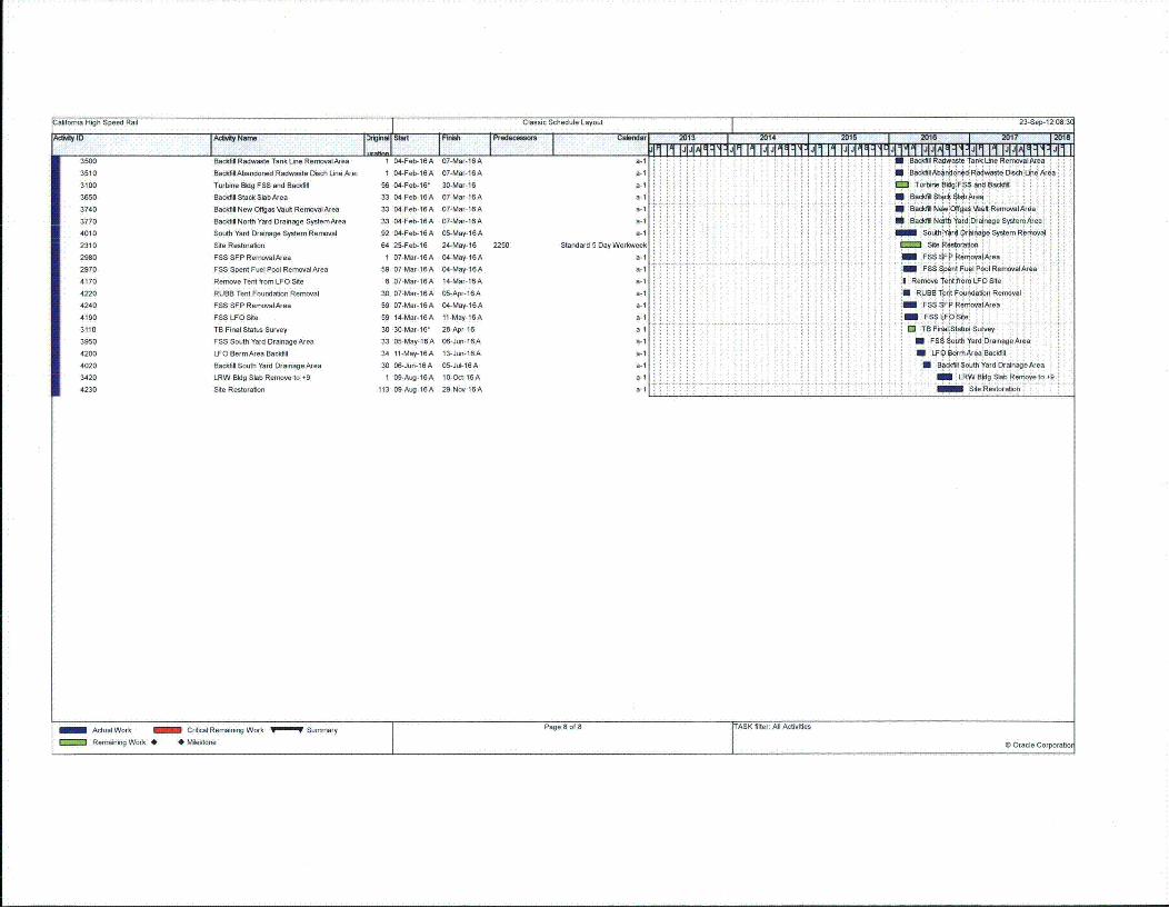
attornla High Speed Rail Classic Schedule Layout 23-Sep-12 08:3C
Calen.lc, 2013 1 2 DI, 1 / 018 1 211117 12018IF' ` .I ..lllt1J~ .q .J~'~l1ll II PI#1•IMIjIJ 114AI I JJI- =l 1! IJI1IAI"II•IJJI I3500 Baddli Radwaste Tank Line RemovalArea 1 04-Feb-16A 07-Mar-16A a Baci ll Rarlate Tanlk Line Rema• t ,agbr
3510 BaddfilAbandoned Radwaste Disch Line re; 1 04-Feb-16A 07-Maw-16A a- I BacdlolAbanadned R0a0wetDindsLiae Aea
3100 Turbine Bldg FSS and Backill 56 04-Feb-16' 30-Mar-16 a-1 Torfi ,n04g:: F0 S nd Baý t :
3650 Baddcll Stac*kSlabArea 33 04-Feb-16A 07-Mar-16A a-i N B tfi* , c1abr i
3740 Backldl New OffgasVaut RemovalArea 33 04-Feb-ISA 07-Mar-16A a-1 Bdd, NeOwaffýak Vault RyboRalArda
3770 Backfill North Yard Drainage SystemnArea 33 04-Feb-16A 07-Mar-16A e i i B6edaNMothatd DreinogoSysten/rgo:
4010 South Yard Drainage System Removal 92 04-Feb-16A 05-May-16A a-1 So1hYb4 , DrbiiageSnernrReroval
2310 Site Restoration 64 25-Feb-16 24-May-16 2250 Standard 5 Day Workweek : : :-:: : :Site Restoration
2980 FSSSFPRernovalbrea 1 07-Mar-16A 04-May-16A a-1 !F$! 8Ft P•F irraIAnep
2970 FSS Spent Fuel Pool RenmoalArea 59 07-Mar-16A 04-May-16A a- 5 F Spk ntS " ouPao!Rethnl.ra
4170 Remove Tent fom LFO Site 8 07-Mar-16A 14-Mar-16A a-1 ::i Re•tvo Tent nonLFOQite,4220 RUBBTentFoundationRemrroval 30 07-Mar-16A 05-Apr-16A a-1 i RUPB TentFoundan Renrvel
4240 FSS SFP Rer•ovalArea 59 07-Mar-16A 04-May-16A a-, FSS SFP Ronio"alAte;
4190 FSS LFOSite 59 14-Mar-16A 11-May-16A a-1 . . . lF Sie
3110 TB Final Status Survey 30 30-Mar-16' 28-Apr-16 a-1 1 TB Final Statii, Soody
3950 FSS South Yard DrainageArea 33 05-May-16A 06-Jun-16A a-1 FS0 South FaradID!ainaglerea :
4200 LFO BermArea Backfill 34 11-May-16A 13-Jun-16A a- Ll3BL• rmArea'Bhcflill
4020 Bacdilt South Yard DrainageArea 30 06-Jun-16A 05-Jul-16 A a-1 I U BsBSo•$°uth Yaird: D nr gArgaa L
3420 LRW Bldg Slab Remo-e to 9 1 09-Ang-16A 10-Oct-16A a-1 m! Loyet 0
4230 Site Restoration 113 09-Ang-16A 29-Nov-16 A a-1 t :-7 f7
Actual Work Critical Remaining Work ,m Summary Page 8 of 8 [ASK filter All Actibies
Remaninig Work * Milestone 0 Oracle Corporathor

KOKiewitHBPP Caisson Removal Feasibility Study
100% Draft Feasibility Report
APPENDIX DFINAL GRADING SPECIFICATION
Page 171

-QOKlewitHBPP Caisson Removal Feasibility Study
100% Draft Feasibility Report
Final Site Grading Snecification
Backfill for the caisson demolition will consist of import fill and on-site excavated soil. Fill material,imported or existing on-site material, shall meet the screening levels and/or requirements set forth by
the DTSC, RCRA, CHSSL, and the NRC. An agency approved set of requirements will be provided by
PG&E when it is available. Radiological screening shall be performed by PG&E and environmental
screening shall be performed by PG&E approved laboratory.
For on-site soils that are determined to be environmentally and radiologically suitable for use as backfill
and for import soil, the following general specifications should apply:
Backfill Below Elev. -10 ft
* Free of debris, organic matter, glass, trash, and unsuitable materials;
* Free of broken concrete and asphalt;
* Free of rocks greater than 8 inches in any dimension;
* Shall meet the SW classification in accordance with USCS with a fines content less than 10%;
* Have gradation curves that lie within the hatched zone in the figure below; and,
* Shall be placed in a uniform manner free of voids and in a manner that limits segregation of
material.
3Mmn No.4:aeuiw No. 1
No. 100No. 40 No. 200 Su.e' iNUMt*r
100
908070
50"40
3020100
111111. H ill I 1 111 1 1 1 1 1111V Hill I 1 111 1 111V Hill I IIII H ill I I
Hill I IN I Hill 1 11YX : Hill I9 A\1 U111 I
111111 t oil100 10 0.1 0-01 0.0011
Grain Size (mm)
Backfill Above Elev. -10 ft
* Free of debris, organic matter, glass, trash, and unsuitable materials;* Free of broken concrete and asphalt,
Page 172

- OKiewitHBPP Caisson Removal Feasibility Study
100% Draft Feasibility Report
* Free of rocks greater than 8 inches in any dimension;" Nesting of cobbles within the fill shall not be allowed;* Open graded or gap graded aggregates shall not be used;* Plasticity index less than 15 (ASTM D-4318);* Liquid limit less than 40 (ASTM D-4318);* Fines content less than 30%;* Non-expansive; and,* Have gradation curves that lie within the hatched zone in the figure below.
3ANia )L 4 No. 100
100908070
0 60in 500. 40
3020100
314nL No 4M& 140-10 No. 40 No. 2W
REL I I IN I I IPIT Hill I I I
Hill I IHill I IHill
N lullItt f M "ýý4 V:N9II
100 10 1 0.1 0.01 0.001Grain Size (mm)
Lift thickness will be dependent on the compaction equipment used, but should not exceed three (3)feet. For proposed lift thicknesses exceeding one (1) foot, the contractor shall submit a "method"compaction specification that shall incorporate methods for verifying the compaction of the entire lift.Backfill shall be compacted to 95% of the maximum dry density and within 3% of the optimum moisturecontent as determined by the standard proctor (ASTM D698). Alternate compaction requirements suchas relative density or post backfill in-situ testing may be incorporated into the contractor's backfillmethod. Alternate methods and method specifications shall be developed and performed at thecontractor's expense and approved by PG&E.
The use of soil mixing should be considered to reduce the fines content and/or plasticity index of on-siteexcavated clay. This could be accomplished with approved on-site soil, imported fill soil, lime, fly ash, orcement (slag or Portland). Additional laboratory testing shall be performed to determine if soil mixing isappropriate and the required mix proportions.
Page 173

HBPP Caisson Removal Feasibility Study
100% Draft Feasibility Report
APPENDIX ESEISMIC DESIGN CRITERIA
DIRECTIVE
Page 175
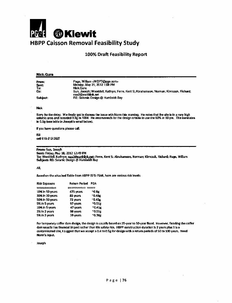
n KiewitHBPP Caisson Removal Feasibility Study
100% Draft Feasibility Report
Nick.Gura
Sent:To:Co:
Subject:
Page. William <WDP7Qjge.com>.Mtonday, May 21, 2012 1.V8 PM
ick.GuraSun, Joseph; Wooddell. Kathlyn; Ferre, Kent S; Abrahamaou Norman; Klimczak, Richard;nha3@eartlttAnelRE: Seismic Design @ Humboldt Bay
Mik
Sorry fo the delay. We finalty gal to disruss the issue with Norm this morning. He noles that the sile i in a very highseismic area and recoded G.Sg in 1994. He ecaommends for the design criteha to use the 50% in 91 yrs. Tihis translatesto G.5g .se. table in Joseph.s email below).
If you have questions please call
Billoell 916-212-3627
From: Sun, JosephSent: Friday, May 18, 2012 12A9 PMTo: Wooddell Kathryn; z Fen-e, Kent:S; Abrahamson, Norman; Kfimczak, Richrd; Page. WilfIamSubject RE Seismic Design @ Humb•et Bay
All
Based on the attached Table from HBPP ISFSI PAR, here are various risk levels:
Risk Exposure
10%in SO years30% in 30 years50% In 50 yearsS% In S years10%CIn S years2% in 2 years5% in 2 years
Return Period PGA
475years t0.%g8S years -0A8g72 years -0.4Sg97 years "-tSi1g47 years -0.41g98 years -. Sig39 years -&38g
For temporary coffer dam design, the design is usually based on 25-year to S0-ear flood. However, flooding the cofferdam usually has flnardal ifmpact rather than Ufe safety risk. HBPP construction duration Is 2 yeaas plus It Is acontaminated site, I suggest that we accept a #A to O.Sg for design with a return periods of 513 to 100 years. NeedNorm'¶s Input.
Joseph
Page 176

-O*KiewitHBPP Caisson Removal Feasibility Study
100% Draft Feasibility Report
NIck.Gura
From: Sun, Joseph <JIS4•pe-comm>Sent: Wednesday, May 23, 2012 11 00 AMTo: MckcGura; Page. WilliamCc: [email protected]: DrucePallterson; [email protected]; Keith.Maltecheck;
Wooddll. Kathryn; Abrahamnson, Norman: naa32earthlhnknaI; Klimczak, RichardSubjact RE: HBPP - Sesimic design criteriaAflachments: RE: Seismic Design @ Humboldt Bay: RE: Seismic Design @ Humboldt Bay
Nick,
Based on our phone discussion yesterday, I understand that you need the response spectra for the design of HBPPinternal temporary bracing support for caisson removal- The information you requested is already shown in the Tableyou provided on May 18, 2012 or Table 2-5-18 from the H-1PP ISFSG FSAR (attached). In consultation with NormAbrahamson, Bill Page sent you an e-mail on May 21, 2012 (attached) and suggested that a design PGA of O.Sg be usedwhich roughly corresponds to the 100-year event. The 100-year response spectra can be developed by plotting the Sd'column against the V1 column from Table 2-6-18. You can treat the 0.01 sec spectral acceleration as the PGA (peakground acceleration). If you have any questions, please free feel to call me.
Joseph
From: -ic-.Gura (•ydU m Fmaio*:Nick.GuralkiewitcpnilSent: Tuesday, May 22, 201.2 7:12 ANTo: Page, William; Sun, JosephCc carizccgopercm.am: 1Bruc.Patmcn~kiewitccn d aeggethaesenrineerina~ca ; Keith.MatbLcheckdbwit.onSubject: HBPP - Sesirnic desin criteria
Bill,Could you provide the graph for seismic acceleration vs time for the 50D6 in 50 years?We are looking for the 0.2 sec seismic acceleration, which is used for calculating lateral loads on earth retainingstructures.
Infirsst .gwe "upNICHOLAS GURA. P.FE
oesign Engneer
KIEWIT ERIHIIEERING CO.
Page 177

HUMBOLDT BAY ISFSI FSAR UPDATE
TABLE 2,6-18
EQUAL HAZARD SPECTRA (g) FOR THE FAULT NORMAL COMPONENTFOR SOIL SAFE CONDITIONS.
Y II n .. .. .Period
Ssec)1 Yr 25 yr 50 yr
n m,
100 yr 500 yr 11.0O00 yvI2,000 yr 5,000 yr1 10,000oyr
VI03
03
'IA.
0.
- ' .4 J. I I--I ani nnrA.9 njiql4R In!•2Ihd I fl7gL7 I A'RAQ• I• •qR?4 I d37gR tI 7"R
-v
O0
0.03 0.04 0.3168 0.4175 0.5379 0.8084 0.9032 09829 1.0971 1.1914L_0,10 0,0076 0.5219 0,6801 0.7940 1,1012 1,95W 1.3389 1.4944 1,6229
0.15 0.0088 0,6578 0.8821 1M 1.528 i 16959 1.8015 1.9487 2.0767.0.20 0.0110 0,.82 1C.0690 ' 2,0493 2,2716 2.151-57 2.8337 3.1006
0.25 0.0104 0.8450 1.1837 1.5217 2.2760 2.6377 2.9280 3.2399 3,47700.30 0.0094 0.7644 1.1031 1A4322 2.2161 2A778 2,7427 3.0941 3.32360.36 0.0087 0,6846 0•.734 1.3427 2,1535 2.4478 2,6454 2.8930 3.11130.40 0.0082 0I6128 0.8953 1.2384 2,0439 2.2503 2.4775 2.086 2,8719
1.-81 1080= 2.02,6128 ____
0.50 0006I 0.5380 0.7170 1.0_10 .. 8 7 2.1O 2,2800 2,5320 2.71280.60 0.00511 0.43 0.654W 0.= 1.7485 I1.9 2.1531 2.4228 2-6150.80 0.0040 0.3210 0,4837 N0.964 _1.444_ !.8 TiB 2.08 2.25!71.00 0.0038 0.2965 0.4469 0.6452 1,3165 1.5507 117382 1.9419 2.12101.50 0T0025 0.2000 0.3196 0.4764 '1.0821 1.3129 1,5282 1.8083 2.0373200 00013s 0.1206 0-1967 0.311- 08237 10551 1.2766 1.578 1.79043.0 0.001 04.465 1 0.0783 016 1 0,3358 0.50550•o•0 2 0.8 1.07 57
(A
0~
3D

i OKiewitHBPP Caisson Removal Feasibility Study
100% Draft Feasibility Report
APPENDIX FPERMITS
Page 179

-OKiewitHBPP Caisson Removal Feasibility Study
100% Draft Feasibility Report
Permits for Humboldt Bay Caisson Removal Project
Water: The site is under the North Coast Regional Water Quality Control Board (Region 1) and is on
Humboldt Bay.
" Construction General Permit for Storm Water - PGE has an existing permit and will modify for
additional construction activity.
* Groundwater De-Watering - PGE to amend SWPPP for GWTS to discharge under Construction
General Permit for Storm Water for dewatering
* Groundwater De-Watering - Contractor to obtain well construction permits.
* Compliance with Water Quality Control Plan for Enclosed Bays and Estuaries - GWTS designed
to comply.
* Coastal Development Permit - PGE to obtain
* Slurry wall construction will need to be reviewed by NCRWQCB; currently, we don't expect that
a WDR permit is required, but follow-up meetings with NCRWQCB will be necessary to confirm.
Air: The site is under the North Coast Unified Air Quality Management District
* Dust - contractor to comply with NCAQMD Rule 104 (Prohibitions). Contractor will also need a
grading permit which may also include a maintenance plan.
" Title V - PGE has a site wide Title V that includes the HBGS operating plant. The NCAQMD
considers the HBPP/HBGS site as one site for permitting purposes. There are some general
conditions under the existing Title V permit that apply to the HBPP portion of the site. Diesel -
We will need to comply with the Portable Air Toxic Control Measures and Portable Equipment
Registration Program (PERP) for diesel powered portable equipment 50hp and greater. Anyindividual permits required by the contractor would need to be obtained via amending the Title
V permit PGEmaintains for the HBGS plant. Therefore, PG&E's preference is to avoid permitted
diesel-powered equipment if possible. All off-road equipment will need to be in compliance with
the In-Use Off-Road Heavy Equipment Regulation.
Page 180

OKiewitHBPP Caisson Removal Feasibility Study
100% Draft Feasibility Report
Hazardous Materials:
" Hazardous Materials - PGE has a Hazardous Materials Business Plan and submits it to the
Certified Unified Program Agency (Humboldt County Division of Environmental Health).
Contractor to provide hazardous materials inventory information to PGE on a monthly basis and
obtain PGE approval before bringing hazardous materials onsite.
* Spill Prevention, Control, and Countermeasures Plan (SPCC) - not planning on storing fuel on-
site.
Sensitive Species
* There are restrictions under the existing CDP for work near environmentally sensitive areas.
New CDP permit may identify new restrictions relating to noise, etc. during nesting season. PGE
will provide biologist for work within environmental sensitive areas, e.g. the
construction/operation of the soil stockpile area.
* Cultural resources - Current CDP requires cultural monitoring although enough work has been
completed that onsite monitor is not likely to be required during excavation. However, if
artifacts are encountered, the PGE cultural resources monitoring will need to be brought onsite
to investigate.
Non-Permit Approvals
" Reuse of soil will require approval of DTSC under IMRAW (or final Remedial Action Plan); will
likely require coordination with NCRWQCB.
" Any potential offsite storage of soil will require approval of DTSC in Remedial Action Plan and
likely require concurrence by NCRWQCB.
Page 181

O@KiewitHBPP Caisson Removal Feasibility Study
100% Draft Feasibility Report
APPENDIX GSUBSURFACE FIELD INVESTIGATION
REPORT
Page 182

Consulting Engineers & Geologists, Inc.I J 812 West Wabash- Eureka, CA ph. (707) 441-8855 fax. (707) 441-8877
PROJ. NAME: HBPP Slurry Wall
PROJ. NUMBER: 012125
DRILLER: PC Exploration
DRILLING METHOD: Mud Rotary
SAMPLER: Punch Core & SPTLOGGED BY: .JPR
LOCATION: Humboldt Bay Power Plant
ELEVATION: 12 feet
DIMETERIDEPTH OF BORING: _&X01 18 6 Feet BGS
DATE STARTED: 8/24112
DATE COMPLETED: 8/26/12
-SAMPLE a!
z
Z ~ .SOIL DESCRIPTION z. REMARKSz Wz
0 0ul _ _ _ __5
12-0
Upper 5' hand augered
17
1022
SSa-001
Ba-002
SSa-.003
004
.SSa-005
Ba-007
007
346
27 • 15
4710
48e
131719
SILTY SAND, dark gray, medium dense, moist to wet, finesand, -40% fines
Grades to siltylclayey
LEAN CLAY, dark yellowish brown, faint mottling, stiff tovery stiff, variable sand content (<20%)
SILT WITH SAND, dark gray, medium stiff to stiff, moist towet, low plasticity, fine sand (10-20%), very fine (<1 mm)Interbeds
Grades into SANDY SILT, strong brown to dark gray(mottled), medium stiff, moist to wet, low plasticity, 40%fine sand
Thin Interbeds (1-2 cm) of SILTY SAND, typ Iron stained
2.5
3.0'
0.51.5
1.0
1.5
'2.5
1.0
2.5
-20
SILTY SAND, brown to dark gray (mottled), medium dense,wet, interbedded with SPISM
POORLY GRADED SAND WITH SILT, dark yellowishbrown (10YR 4/4), medium dense to dense, wet, fine sand,5-10% fines
32
1i9!(
BOIG O Pg"ume Io
BORING LOG Page Number 1 of 9

Consulting Engineer3yu- 812 West Wabash, Eurek6, Ci
PROJ. NAME: HBPP Slurry Wall
PROJ. NUMBER: 012125
DRILLER: PC Exploration
DRILLING METHOD: Mud Rotary
SAMPLER: Punch Core & SPTLOGGED BY: JPB
s & Geologists, Inc.A ph. (707) 441-8856-fax. (707) 441-8877 BORING LOG
LOCATION: Humboldt Bay Power Plant KB-1ELEVATION: 12 feet
DIAMETERIDEPTH OF BORING: / 186 Feet BGS
DATE STARTED: 8/24/12
DATE COMPLETED: 8/26/12
SAMPLE-
> FW: .
z 0 :3 SOIL DESCRIPTION REMARKS
.J _I tw 0inL W c 0 a~ (a,
w!0 9C EE ,. r.j Lu ,4 a.0LU 0 0 , 00 am . '
37
42
-25
w30
SANDY SiLT, dark bluish gray, medium-stiff, wet, lowplasticity, fine sand (40%)
SILTY SAND, olive brown (2.5Y 4/3), medium dense, wet,20-40% fines, fine sand
POORLY GRADED SAND WITH SILT, brown (10YR 3M3),medium dense, wet, 5-10% fines, medium sand
SILTY SAND, dark yellowish brown (10YR 4/4), mediumdense, wet, 30% fines, fine sand, massive
I Same, 20-30% fine sand
47 15
POORLY GRADED SAND WITH SILT, dark yellowishbrown (10YR 4/4), dense, wet, 10% fines, fine sand
Occasional thin (<2%) layer of coarse sand/fine pebble,otherwise massive
Gravel disks in shoe (responsible for high blow counts)
POORLY GRADED SAND WITH SILT, dark yellowishbrown (I0YR 4/4), dense, wet, 10% fines, fine sand
ItSILTY GRAVEL WITH SAND, dark yellowish brown,medium dense, wet, gravels to 3", coarse sand
POORLY GRADED SAND WITH SILT, dark yellowishbrown (10YR 4/4), dense, wet, 10% fines, fine sand
1,4.1
-4052
w Ah as own, medium stiff, wet, interbeddaSwith sands
BORING LOG Page Number2 of .

Consulting Engineers & Geologists, Inc.... .. 812 West Wabash,. Eureka, CA Oh. (707) 441-8855 fax. (707) 441-8877
PROJ. NAME: HBPP Slurry Wall
PROJ. NUMBER: 012125
DRILLER: PC Exploration
DRILLING METHOD: Mud Rotary
SAMPLER: Punch Core & SPTLOGGED BY: JPB
LOCATION: Humboldt Bay Power Plant
ELEVATION: 12 feet
DIAMETER/DEPTH OF BORING: 1 186 Feet BGS
DATE STARTED: 8/24/12
DATE COMPLETED: 8/26/12
BORING LOG
KB-I
[Off1-- SAMPLE-
z -J
0 M SOIL DESCRIPTION REMARKS0 -1 -
aj 12 .2 8 03_ _ _) _ _ _ _ _ _ _ __j_ _ _Iu . U) 8 ~ LC __ _
,4557.
-5062
67 r.55
POORLY GRADED SAND WITH SILT, dark yellowishbrown (1OYR 4/4), dense, wet, 10% fines, fine sand
Very stiff, Iron stained, sandy interbeds
Interbedded SPISM with stiff to very stiff clay, 4-6" max,iron stained sands
SILTY SAND, dark brown (7.5YR 3/3), medium dense todense, wet, -30% fines, interbedded with thin (<1 cm)lenses of clay, fine sand
SILTY SAND, dark brown (7.5YR 3/3), medium dense todense, wet, -10-15% fines, thin interbeds still present, ironstained at boundaries
Interbedded clay/sand (-1" beds)
With gravels, fine, well-rounded, primarily silitlous clasts
POORLY GRADED SAND WITH SILT, dark brown (IOYR3/3), dense, wet, fine to medium well-rounded sand, rarefine gravel
Grades Into SILTY SAND, dark yellowish brown, dense,wet, fine to medium, sand
-SIL'Y-SA••6D, wn(YR 4/3), dense, wet,flne to------medium sand, 20-30% fines, Interbeds of coarse sand,
3.0
4.0
-6072
77 -65
BORING LOG Page Number 3 of 9

(Consulting Engineers & Geologists, Inc.. ...... 812 West Wa.ba0sh, Eureka, CA -ph. (707) 441-8855 fax. (707) 441-8877
PROJ. NAME: HBPP Slurry Wall LOCATION: Humboldt Bay Power Plant
PROJ. NUMBER: 012125 ELEVATION: 12feet
DRILLER: PC Exploration DIAMETERIDEPTH OF BORING: /1
DRILLING METHOD: Mud Rotary DATE STARTED: 8/24/12
SAMPLER: Punch Core & SPT DATE COMPLETED: 8/26/12LOGGED BY: JPB
86 Feet BGS
BORING LOG
KB-1
1/j i L .
- _SAMPLE
S-,
IL E Lu' SOIL DESCRIPTION z.8 REMARKSJI-z
CL2 ) - LL Ua. uJ.? u n _.-. .. • e-J UJI < CL0Oa
LU. 0 V) W 0 U(. M C___._6R__
82
87
92
-70
-75
-80
predominately fine
Sand coarsens at 72' (well graded) in alternating beds
SILTY SAND, dark olive brown (2.5YR 3/3), dense, wet,fine to medium sand, well rounded, -20% fines, rare finegravel
POORLY GRADED SAND WITH SILT, dark olive brown(2.5YR 3/3), massive, dense, wet, 10-15% fines, fine sand
POORLY GRADED SAND WITH SILT, dark olive brown(2.5YR 3/3), massive, dense, wet, 10-15% fines, fine tocoarse sand, well rounded
STTI•F"FLAY, light gray, wet,5% san
5.6
97 85
BORING LOG Page Number 4 of 9
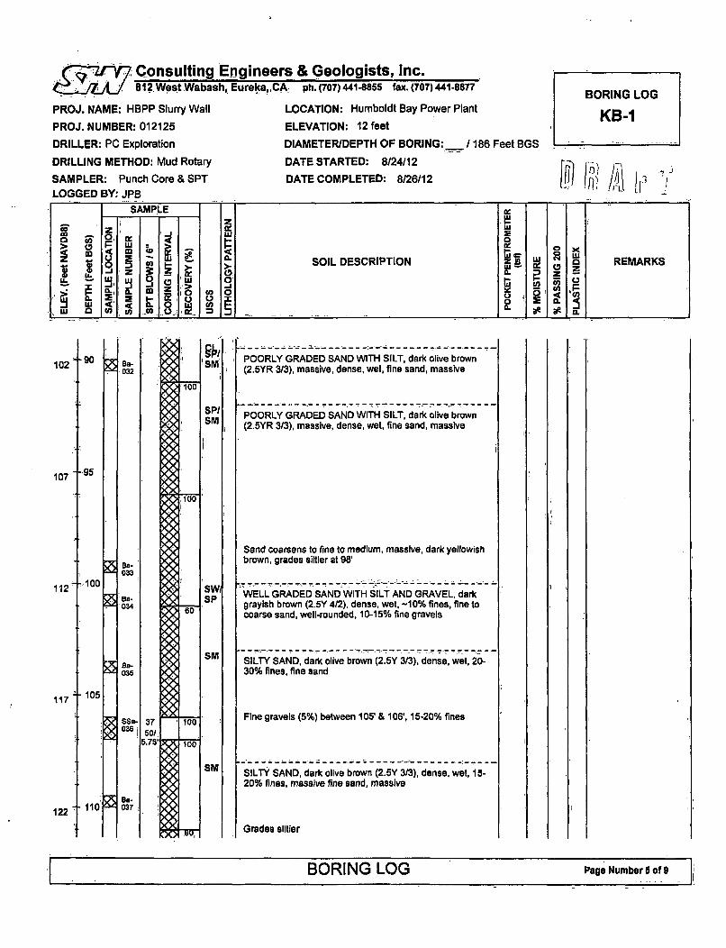
.. - Consulting Engineers & Geologists, Inc... . 812WestWabash, Eureka, CA ph. (707) 441-8855 fax.(707)441-8877
PROJ. NAME: HBPP Slurry Wall
PROJ. NUMBER: 012125
DRILLER: PC Exploration
DRILLING METHOD: Mud Rotary
SAMPLER: Punch Core & SPTLOGGED BY: JPB
LOCATION: Humboldt Bay Power Plant
ELEVATION: 12 feet
DIAMETER/DEPTH OF BORING:___ /186 Feet BGS
DATE STARTED: 8/24112
DATE COMPLETED: 8/26/12
BORING LOG
KB-1
fjI .I7~ A\ LoSAMPLE
zLU w
* aL a. C%U) SOI DECRPTO z. uj 0D REMARKS
*~ ac0 Z ~.
_j W <' ,( a 0 U)LU ) U) u0 I
102 -90 SMsa-032
SPISM
107 -g5
Ba-033
100112
Ba-4,034
BS-035
SWISP
SM
SM
POORLY GRADED SAND WITH SILT, dark olive brown(2.5YR 3/3), massive, dense, wet, fine sand, massive
POORLY GRADED SAND WITH SILT, dark olive brown(2,5YR 3/3), massive, dense, wet, fine sand, massive
Sand coarsens to fine to medium, massive, dark yellowishbrown, grades siltler at 98'
WELL GRADED SAND WITH SILT AND GRAVEL, darkgrayish brown (2.5Y 4/2), dense, wet, -10% fines, fine tocoarse sand, well-rounded, 10-15% fine gravels
SILTY SAND, dark olive brown (2.5Y 3/3), dense, wet, 20-30% fines, fine sand
Fine gravels (5%) between 105' & 106', 15-20% fines
SILTY SAND, dark olive brown (2.5Y 3/3), dense, wet, 15-20% fines, massive fine sand, massive
Grades slitier
117 t 105
ssa-0361
- 110an.037122
BORING LOG Page'Number 6 of-

.. . Consulting Engineers & Geologists, Inc...... 4/ 812 West Wabash,. Eureka, CA- ph. (707) 441-8855 fax. (707) 441-8877
PROJ. NAME: HBPP Slurry Wall LOCATION: Humboldt Bay Power Plant
PROJ. NUMBER: 012125 ELEVATION: 12 feet
DRILLER: PC Exploration DIAMETER/DEPTH OF BORING: /186 Feet BGS
DRILLING METHOD: Mud Rotary DATE STARTED: 8/24/12
SAMPLER: Punch Core & SPT DATE COMPLETED: 8/26/12LOGGED BY: JPB
BORING LOG
KB-1
Ga-038
,039
Ba-'040
127
132
137
142
115
120
- 125
- 130
Ba-41
-4 042
POORLY GRADED SAND WITH SILT, dark olive brown(2.5Y 3/3), massive, dense, wet, medium, well-roundedsand, 10% fines
Trace fine gravels and medium to coarse sand from 116'-116.5'
CLAY, light bluish gray, stiff, moist, stiff, intermittent beds<1" thick
------------------ --------------.-. -- ....----....-......- "
CLAY, light bluish gray, stiff, moist, stiff, intermittent beds,<1" thick
CLAY, light bluish gray, stiff, moist, stiff, intermittent beds<1" thick
Trace fine gravels
Becomes very dark bluish gray (GLEY 2 3/1), at 122',medium to coarse sand
SP/SM, crudely bedded
SILTY SAND, dark bluish gray (GLEY 108 311), dense,30% fines, 5-10% fine gravel, fine to medium sand, well-rounded, massive
Decreases in fines 10-20% at 127'
POORLY GRADED SAND WITH SILT, very dark bluishgray (GLEY 2 10B/311), wet, medium dense to dense, fineto medium sand, -10% fines, massive
Ba-D43
BORING LOG Page Number 6 of 9

Consulting' Engineers & Geologists, Inc.I812 West Wabash; Eureka, CA ph. (707)441-8855 W.(707)441-8877
PROJ. NAME: HBPP Slurry Wall
PROJ. NUMBER: 012125
DRILLER: PC Exploration
DRILLING METHOD: Mud Rotary
SAMPLER: Punch Core & SPTLOGGED BY: JPB
I SAMPLE -
LOCATION: Humboldt Bay Power Plant
ELEVATION: 12 feet
DIAMETER/DEPTH OF BORING: 1186 Feet BGS
DATE STARTED: 8/24/12
DATE COMPLETED: 8/26/12
BORING LOG
KB-1
147 }- 135
- 140152
157
Ba-,045
140
No recovery
POORLY GRADED SAND WITH SILT, dark bluish gray(GLEY 2 10B 3/1), wet, dense, fine to medium sand,subrounded, gradational stratification, fine to coarse sand,-5% fine gravels In lower 6" (very dense)
1451'
SPISM
Ba0046
162 t 150
167 t 155
BORING LOG Page Number 7 of 9
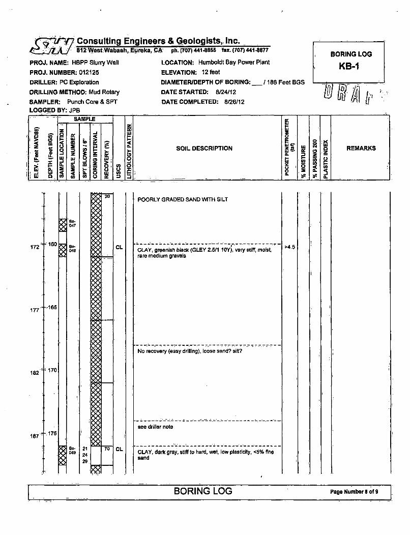
Consulting Engineers & Geologists, Inc.•j§7 812lWest;Wabash, ,Eureka, CAl ph. (707) 441855 fax. (707)44
PROJ. NAME: HBPP Slurry Wall LOCATION: Humboldt Bay Powe
PROJ. NUMBER: 012125
DRILLER: PC Exploration
DRILLING METHOD: Mud Rotary
SAMPLER: Punch Core & SPTLOGGED BY: JPB
ELEVATION: 12 feet
DIAMETERIDEPTH OF BORING:
DATE STARTED: 8/24/12
DATE COMPLETED: 8/26112
41-8877 BORING LOG
-r Plant KB-I
_186 Feet BGS
- SAMPLEz Lu
-L U.1 W L DW U REAI"SOIL DESCRIPTION Z R REMARKS
U- L-j
Lu ~ U) U) C U U) i _ _ _ _ _ __ _ _ _ __ _ _ _
,,, z J .-0. 0•<= 0 0 ca
CL
POORLY GRADED SAND WITH SILT
CLAY, greenish black (GLEY 2.5/1 10Y), very stiff, moist,rare medium gravels
No recovery (easy drilling), loose sand? silt?
see driller note
CLAY, dark gray, stiff to hard, wet, low plasticity, <5% finesand
>4.5
CL
BORING LOG Page Number8 of 9

. 'I 'Consulting Engineert••jj~s4J 812 WestWabash, Eureka, C•
PROJ. NAME: HBPP Slurry Wall
PROJ. NUMBER: 012125
DRILLER: PC Exploration
DRILLING METHOD: Mud Rotary
SAMPLER: Punch Core & SPT
LOGGED BY: JPB
rs & Geologists, Inc..-4 ph. (707) 441-8855 fax. (707) 441-8877 BORING LOG
LOCATION: Humboldt Bay Power Plant KB-1ELEVATION: 12 feet
DIAMETER/DEPTH OF BORING: 186 Feet BGS.
DATE STARTED: 8/24/12
DATE COMPLETED: 8/26/12 ~''~ I
SAMPLE
0 -0
Iz ' SOIL DESCRIPTION M KS
W l R M 1
wow LA _ _ _ __ _ _ _____ _ _
192,
SILT/CLAY, very dark gray, very stiff, moist, low plasticity,occasional shell fragments, gradational variations insilt/clay content, <5% fine sand
197+
202 T
207
BORING LOG Page Numberr 9 of 9

Consulting Engineers & Geologists, Inc.812,West Wabash, Eureka, CA ph. (707)441-8855 fax. (707) 441-8877
PROJ. NAME: HBPP Slurry Wall LOCATION: Humboldt Bay Power Plant
PROJ. NUMBER: 012125 ELEVATION: 12 feet
DRILLER: PC Exploration DIAMETERIDEPTH OF BORING:.__ 1I
DRILLING METHOD: Mud Rotary DATE STARTED: 9/12/12
SAMPLER: Punch Core & SPT DATE COMPLETED: 9/15/12
LOGGED BY: JPB .
86 Feet BGS
BORING LOG
KB-2
T
12 to -r r-~.---¶-,-r -
1 7 -t5 335
22 f1 0
8b-001
Bb-002
8Sb-003
Bb-,004
Bb-005
sb-006
Bb-007
SSb-008
27-15
222
6
GRAVEL AND SAND (imported fill for working surface)
CLAY, dark yellowish brown to gray (mottled), stiff, moist,-5-10% sand, low plasticity
,.CLAYEY SAND, light brown, medium dense, moist?, finesand, -30% fines
SILT WITH SAND, dark yellowish brown to brownish gray(mottled), firm, moist?, -20-25% fine sand, low plasticity
Becomes dark bluish gray
Becomes clayeyer, less sand with organic fines
Laminated beds 2-3 mm with variable sand content 5-25%
LEAN CLAY, very dark greenish gray, moist?, soft to firm,-5% fine sand
LEAN CLAY WITH SAND, dark greenish gray, moist, stiffto very stiff, fine laminated (1-2 mm)
LEAN CLAY, dark greenish gray, moist, firm, <5% finesand
Becomes mottled strong brown to brownish gray, 5-10%
1.01.25
1.0
2.0
0.5
1.5
2.5
1.75
0.751
10
32 t20
BORING LOG Page Number 1 of9

Consulting Engineers & Geologists, Inc.S812 West Wabash, Eureka, CA-''ph.(707)41-8855 fax.,(707) 441-8877
PROJ. NAME: HBPP Slurry Wall
PROJ. NUMBER: 012125
DRILLER: PC Exploration
DRILLING METHOD: Mud Rotary
SAMPLER: Punch Core & SPT
LOGGED BY: JPB
LOCATION: Humboldt Bay Power Plant
ELEVATION: 12 feet
DIAMETER/DEPTH OF BORING: /186 Feet BGS
DATE STARTED: 9/12112
DATE COMPLETED: 9/15/12
SAMPLE
I Z 0:co c- W
zO •= w " SOIL DESCRIPTION REMARKS
uj 0 Wu 0 US~-, W I W 0 ! W- I-
0_ 0 CA c.
37.25
•3042
47
52
sand, homogenous
SANDY CLAY, strong brown to brownish gray, stiff to verystiff, wet, low plasticity, 20-30% fine sand, homogenous
SILTY SAND/SANDY SILT, dark brown to strong brown tobrowish gray, medium dense to stiff, wet, interbeddedlayers (0.5"-3')
SP/SM
POORLY GRADED SAND WITH SILT, dark yellowishbrown (IOYR 3/6), dense, wet, fine sand, -10-15% fines
*WELL GRADED SAND WITH SILT AND GRAVEL
SITY SAND, dark yelloiwsh brown, medium dense, wet,fine sand, stratified with coarser zones, -20% fines
WELL GRADED SAND WITH SILT AND GRAVEL
SITY SAND, dark yellowish brown, medium dense, wet,fine sand, stratified with coarser zones, -20% fines
POORLY GRADED SAND WITH SILT, brown (10YR 4/3),dense, wet, fine sand, -10-15% fines
WELL GRADED SAND WITH GRAVEL AND POORLYGRADED GRAVEL WITH SAND, color?, dense, wet,subangular to subrounded send and gravel, gravels up to
35
40I
3.5
L BORING LOG Page Numbr 2 of 9, . L .. . . . . . .

- -Consulting Engineers & Geologists, Inc.42 D 8.12 West Wabash, Eureka, CA. ph. (707)441-8855 fax. (707) 441-8877
PROJ. NAME: HBPP Slurry Wall
PROJ. NUMBER: 012125
DRILLER: PC Exploration
DRILLING METHOD: Mud Rotary
SAMPLER: Punch Core & SPTLOGGED BY: JPB
LOCATION: Humboldt Bay Power Plant
ELEVATION: 12 feet
DIAMETERIDEPTH OF BORING: 186 Feet BGS
DATE STARTED: 9/12/12
DATE COMPLETED: 9115/12
BORING LOG
KB-2
SAMPLEz
Z Z
m.j
a WSOIL DESCRIPTION W o REMARKS
M~ to0: .
57.
62
67
72
77
r45
t 50
55
'60
-65
Bb-016
s8b-017
Bb-018
Bb-019
SSb-020
2" in distinct zones, poor recovery makes difficult todetermine full thickness and extent of deposits
Stratified with SM & SP
CLAY? (based on drilling resistance and mudperformance), no recovery of clay, so may have bene tightclear sand?
SITY SAND, dark yellowish brown, dense, wet, -20-30 %fines, fine sand, stratified with SP in 1-6" beds, gradational
Grades.into SP
POORLY GRADED SAND WITH SILT, dark yellowishbrown, dense, wet, stratified with SM
CLAY? (based on drilling resistance and mudperformance), did not recover in core
LEAN CLAY, very dark bluish gray (GLEY 2 108 4/1), stiff,moist, -5% fine sand
Grades to dark bliush brown (iron stained)
SILTY SAND, strong brown, dense, wet, stratified with tink(<1") layers of clay
LEAN CLAY, dark bluish gray (GLEY 2 lOB 4/1), stiff,moist, laminated with silty sand and sandy clay, -5% finesand
Interbeds of silt
BORING LOG Page Number 3 of 9

S..Consulting Engineers & Geologists, Inc.812 West Wabash, Eureka,.CA - ph. (707) 441-8855 fax. (707) 441-8877
PROJ. NAME: HBPP Slurry Wall
PROJ. NUMBER: 012125
DRILLER: PC Exploration
DRILLING METHOD: Mud Rotary
SAMPLER: Punch Core & SPTLOGGED BY: JPB
LOCATION: Humboldt Bay Power Plant
ELEVATION: 12 feet
DIAMETERIDEPTH OF BORING: 186 Feet BGS
DATE STARTED: 9/12/12
DATE COMPLETED: 9/15/12
BORING LOG
KB-2
- SAMPLE
zW
SOIL DESCRIPTION REMARKSa U. M R.
1W 0( U) (O) 0 a
82 t-70Becomes dark brown (10YR 3/3)
87
92
75
'80
Stratified sand and clay, iron stained at clay/sand contacts
Laminated from 76.5' to 77.5' (-1/4 inch In 1/2 inch beds)
.. .. _.,- --- ---------. . .. . .--- ;,-- -- - ..,- . ..- '- .
POORLY GRADED SAND WITH SILT, dark yellowishbrown, dense, wet, 10-15% fines, fine to medium sand,interbedded with thin (1/4 inch) beds of clay
POORLY GRADED GRAVEL WITH SILT AND SAND, darkbrown, dense, wet, subrounded to well rounded sand andgravel, 10-15% fines, 30-40% sand, gravely up to 1.5".. ....--- --- - . ,_•' - -. ;• - ,--••-I - L-. ..
POORLY GRADED SAND WITH SILT, dark yellowishbrown, dense, wet, 10-15% fines, fine sand, occasionalbeds of coarse sand and minor fine gravel
Grades into SILTY SAND, 15-20% fines or occasionalcoarse sand bed with fine gravel, typically 4-6" thick
97 85
BORING LOG Page Number 4 of 9

Consulting Engineers & Geologists, Inc.~3'§2 "7 812'West:Wabash, Eureka, CA ph. (707) 441-8855 fax.x(707)441-8877
PROJ. NAME: HBPP Slurry Wall
PROJ. NUMBER: 012125
DRILLER: PC Exploration
DRILLING METHOD: Mud Rotary
SAMPLER: Punch Core & SPTLOGGED BY: JPB
LOCATION: Humboldt Bay Power Plant
ELEVATION: 12 feet
DIAMETER/DEPTH OF BORING: 1186 Feet BGS
DATE STARTED: 9/12/12
DATE COMPLETED: 9/15/12
SAMPLE-
z C) I- 'SOIL DESCRIPf1ON z REMARKSz z
a 0 UW 0 U) 0)UU~~ _ _ _
102 '0
143750/5"
1074 .95
112 f 100
8b-026
'Bb-
027
Bb-028
SM
SWi
Sand grades to coarser
Poorly graded sand with silt in shoe
POORLY GRADED SAND WITH SILT, dark brown (lOYR3/3), dense, wet, 10-15% fines, fine to medium sand withoccasional coarse sand/fine gravel
Grades to very dark grayish brown (2.5Y 3/2)
SILTY SAND, dark brown, dense, wet, fine to coarse sand,5-10% fines subrounded to rounded gravel, 20-30% fines,(SHOE), (relative position, contacts, and extent unknown)
WELL GRADED SAND WITH SILT AND GRAVEL, verydark grayish brown, very dense, wet, 10-15% fines, gravel117
122
- 105
110
SPI/M
Bb-029
POORLY GRADED SAND WITH SILT, very dark grayishbrown, very dense, wet, 10-15% fines, fine sand,occasional gravel 1-3", stratified with variable coarse sandbeds (2-4' thick)
30
BORING LOG Page NumberS5 of 9

( . Consulting Engineers & Geologists, Inc.t....... 812 WestWabash, Eureka, CA - ph. (707) 441-8855 fax. (707) 441-88
PROJ. NAME: HBPP Slurry Wall LOCATION: Humboldt Bay Power Pil
PROJ. NUMBER: 012125
DRILLER: PC Exploration
DRILLING METHOD: Mud Rotary
SAMPLER: Punch Core & SPTLOGGED BY: JPB
ELEVATION: 12 feet
DIAMETER/DEPTH OF BORING:
DATE STARTED: 9/12/12
DATE COMPLETED: 9/15/12
177BORING LOG
ant KB-2
/186 Feet BGS
- SAMPLE
>~ ~ 01 U
40U SOIL DESCRIPTION z UREMARKSIL
I
wu 0_u 0 W:' 0 3I I . C
SP4M
Bb-030
127 =115.
132 -t 120
SPI$M
Bb-031
POORLY GRADED SAND WITH SILT, very dark grayishbrown, very dense, wet, 10-15% fines, fine sand,occasional gravel 1-3", stratified with variable coarse sandbeds (2-6" thick), interbeds of silty sand rare (-1")
POORLY GRADED SAND WTH SILT, very dark greenishgray (GLEY 1 56Y 3/1), very dense, wet, fine to mediumsand, homogenous, -5-15% fines
POORLY GRADED SAND WITH SILT, very dark greenishgray (GLEY I 56Y 3/1), very dense, wet, fine to mediumsand, homogenous, -5-15% fines, interbeds of coarsersand occasional
----- ------- - - --POORLY GRADED SAND WITH SILT, very dark greenishgray (GLEY I 56Y 3/1), very dense, wet, fine to mediumsand, homogenous, -5-15% fines, Interbeds of coarsersand occasional
Becomes dense
5.61,
12A4
125137
sP/
142 t 130
sPi4Ma, 0b-,, ,032
BORING LOG Page Number6 of 9

-Consulting EngineerS812 West Wabash, Eureka, .C
PROJ. NAME: HBPP Slurry Wall
PROJ. NUMBER: 012125
DRILLER: PC Exploration
DRILLING METHOD: Mud Rotary
SAMPLER: Punch Core & SPT
LOGGED BY: JPB
rs & Geologists, Inc. 7-A ph.(707) 441-8855 fax. (707")441-8877 BORING LOG
LOCATION: Humboldt Bay Power Plant KB-2ELEVATION: 12 feet
DIAMETER/DEPTH OF BORING:_/ 186 Feet BGS
DATE STARTED: 9/12/12
DATE COMPLETED: 9/15/12
I SAMPLE ji
-Jz
LU t 0~~ C ( >
=. - 0u SOIL DESCRIPTION N REMARKS
L < z g. oL _z -ul uj 0 j 0--j L3 Cu W a.0 L3
LU <() WUL 0
147
152
157
135
- 140
- 145
POORLY GRADED SAND WITH SILT, very dark greenishgray (GLEY 1 56Y 3/1), very dense, wet, fine to mediumsand, homogenous, -5-15% fines, interbeds of coarsersand occasional
Becomes dense
POORLY GRADED SAND WITH SILT, very dark bluishgray (GLEY 2 lOB 3/1), very dense, wet, fine to mediumsubangular to subrounded sand, -5-15% fines, occasionalbeds of coarse sand (2-6" thick)
POORLY GRADED SAND WITH SILT, very dark bluishgray (GLEY 2 10B 3/1), very dense, wet, fine to mediumsubangular to subrounded sand, -5-15% fines, occasionalbeds of coarse sand (2-6" thick), homogenous
Bb-033
10.6
162 - 150
03SSb- 0/1034 I 6,
- 155167
XA035
BORING LOG Page Number 7 of 9

Consulting Engineers & Geologists, Inc."jJ27 812West;Wabash,, Eureka, CA ph. (707) 441-8855 fax. (707) 441-8877
PROJ. NAME: HBPP Slurry Wall
PROJ. NUMBER: 012125
DRILLER: PC Exploration
DRILLING METHOD: Mud Rotary
SAMPLER: Punch Core & SPT
LOGGED BY: JPB
LOCATION: Humboldt Bay Power Plant
ELEVATION: 12 feet
DIAMETER/DEPTH OF BORING: /1l
DATE STARTED: 9/12/12
DATE COMPLETED: 9/15112
BORING LOG
KB-2
86 Feet BGS
/pf7
-SAMPLE-
SOIL DESCRIPTIONREAK.1 Z
a.a CL Wz
uj 0
172
177
- 160
K165
ab-038
Bb-* 037
b.•
Bb-
039
POORLY GRADED SAND WITH SILT, very dark bluishgray (GLEY 2 10B 3/1), very dense, wet, fine to mediumsubangular to subrounded sand, -5-15% fines, occasionalbeds of coarse sand (2-6" thick), homogenous
POORLY GRADED SAND WITH SILT, very dark bluishgray (GLEY 2 10B 311), medium dense to dense, wet, fineto medium sand, subrounded, -5-15% fines, rare coarsesand, homogenous
POORLY GRADED SAND WITH SILT, very dark bluishgray (GLEY 2 10B 3/1), medium dense to dense, wet, fineto medium sand, subrounded, -5-15% fines, rare coarsesand, homogenous, crudely bedded with variations incoarse sand
CLAY, very dark gray (GLEY I N 3/), very stiff, moist,homogenous, low plasticity, occasional to common shallfragments (zones)
Homogenous clay
182. 170
3.53.04.04.53.75
4.5>4.5.4.0
3.5
4.0>4.5
>4.5>4.5
>4.5
11.'s
187 -175
1 ... BORING LOG Page Number 8 of 9

(•Y Consulting Engineers & Geologists, Inc.812 West Wabash, Eureka, CA ph. (707) 441-8855 fax. (707) 4414877
PROJ. NAME: HBPP Slurry Wall LOCATION: Humboldt Bay Power Plant
PROJ. NUMBER: 012125 ELEVATION: 12 feet
DRILLER: PC Exploration DIAMETER/DEPTH OF BORING:_ 1
DRILLING METHOD: Mud Rotary DATE STARTED: 9/12/12
SAMPLER: Punch Core & SPT DATE COMPLETED: 9/15/12
LOGGED BY: JPB
36 Feet BGS
BORING LOG
KB-2
DO W AiSAMPLE
Z
4 -4
I~ 1o 9 Z) 0 > SOIL DESCRIPTION W o REMARKS
w co
1 W4 0 CnW 0 0 0 Z) _ _ _ __ _ _ _ _
192
197
202
207
Thick accumulations of shelly debris
Slight variations In slit content within crudely bedded zones
Thick accumulations of shelly debris
BORING LOG Page Number 9 of 9

Consulting Engineers & Geologists, Inc.: f 812.West Wabash, Eureka, CA ph. (707) 441.8855 fax. (707) 441.8877
PROJ. NAME: HBPP Slurry Wall
PROJ. NUMBER: 012125
DRILLER: PC Exploration
DRILLING METHOD: Mud Rotary
SAMPLER: Punch Core & SPTLOGGED BY: JPB
LOCATION: Humboldt Bay Power Plant
ELEVATION: 12 feet
DIAMETER/DEPTH OF BORING:(",,'/ 201 Feet BGS
DATE STARTED: 9/4/12
DATE COMPLETED: glhl
BORING LOG
K13-3
SAMPLE
LU XC, REMARKS -.
0MSOIL DESCRIPTION REMARKS.~ z~~wu oF W Z
a. oUL LU 01~-n..j 0LU 0 ) o U) . .a
12
17
F0 :CONCRETE I
AGGREGATE BASE ROCK (up to 3")
SILTY SANDIPOORLY GRADED SAND (FILL), mixture ofsilt and sand
/
22t1 0
I
27
32
-15
-20
SSc-001
go-002
SSM-003
Bo-004
23
4
LEAN CLAY, strong brown, stiff to very stiff, moist, lowplasticity, <10% fine sand
Grades to bluish gray at 11.5'
LEAN CLAY, strong brown, stiff to very stiff, moist, lowplasticity, <1 0% fine sand
LEAN CLAY WITH SAND, very dadr greenish gray (GLEY2 586 3/1), medium stiff to stiff, moist, low plasticity, -15-20% fine sand, occasional plant fiber/roots
235
1.52.52.5
1.251.01.0
1.0
3.51.0
BORING LOG Page Number I of 10

Consulting Engineer812 West Wabash, -Eureka, Cl
PROJ. NAME: HBPP Slurry Wall
PROJ. NUMBER: 012125
DRILLER: PC Exploration
DRILLING METHOD: Mud Rotary
SAMPLER: Punch Core & SPTLOGGED BY: JPB
s & Geologists, Inc.A ph. (707) 441-8855 fax. (707) 441-8877 BORING LOG
LOCATION: Humboldt Bay Power Plant KB-3ELEVATION: 12 feet
DIAMETERIDEPTH OF BORING: /201 Feet BGS
DATE STARTED: 914112
DATE COMPLETED: ___
SAMPLE i
0 W. 0
.1 SOIL DESCRIPTION z REMARKS
U .J Z!~ g w11L4 Uj 09_0 0I=•
NOa-.005
BC-006
SSc-007
8
1212
>4,5>4.5>4.5
"2537
1013
10
SILTY SAND, dark yellowish brown to light gray (mottled),medium dense, wet, 15-40% fines, fine sand
Grades sandier with depth with 1" intervals of clayeysand/sandy clay
POORLY GRADED SAND WITH SILT, dark yellowishbrown, medium dense, wet, -10-15% fines, fine sand, thinlaminated lenses of silty sand/sandy silt
Thin (<0.25") laminations of silty sand/sandy silt from 28.5'-29.5'
Sand coarsens to fine to medium sand, massive
42 t30
47
SSc-009
Bc-010
Sic-011
sBc-
013
17
15
18
10
11
12
Interbedded silty sand/sandy silt with 15% fine gravel
SILTY SAND, dark yellowish brown, medium dense, wet,fine to medium sand, -20-30% fines, grading sandier withdepth
'SILTY GRAVEL SAND, up to 2' gravel, well rounded '
CLAY, 2" layer, bluish gray
SILTY SAND WITH GRAVEL, dark brown (10YR 3/3),dense, wet, fine to coarse sand, subrounded to wellrounded, 15-20% fine to medium gravel, 15-20% fines
POORLY GRADED SAND, dark grayish brown (10YR 4/2),
52 t-40
14
27
.1 BORING LOG Page Number 2of 10

Consulting Engineers & Geologists, Inc.. . 1. 812 West-Wabash, Eureka-CA ph, (707) 441-8856 fax. (707) 41.8877
PROJ. NAME: HBPP Slurry Wall
PROJ. NUMBER: 012125
DRILLER: PC Exploration
DRILLING METHOD: Mud Rotary
SAMPLER: Punch Core & SPTLOGGED BY: JPB
LOCATION: Humboldt Bay Power Plant
ELEVATION: 12 feet
DIAMETERIDEPTH OF BORING: 121
DATE STARTED: 9/4/12
DATE COMPLETED:
BORING LOG
1<KB-3
01 Feet BGS ...
- - SAMPLE
0
Z U ~LU~ ~SOIL DESCRIPTION0~W aI Z Za
_J uj 0, . L 0 9- Io
0~~ 0 (0 gtW 1 1 1 IJ
-4557
80-014
8Sc--015
s0-.016
62 -t 50
SSo-017SSc-016
dense, wet, 5-10% fines, fine sand
Coarse sand layer (2')
Grades toSILTY SAND, dark grayish brown (IOYR 4/2), dense, wet,20-30% fines, massive
6" layer with 10-20% gravel, well rounded, up to 1.5"
SILTY SAND, dark grayish brown (10YR 4/2), dense, wet,20-30% fines, massive
Assume shoe plugged on gravel lense at -49-50'
CLAYEY SAND, light gray, dense, 40% fines (2" in SPT)
WELL GRADED GRAVEL WITH SAND
POORLY GRADED SAND WITH SILT, dark yellowishbrown (1 OYR 4/4), dense, fine sand, -10% fines
WELL GRADED GRAVEL WITH SAND, . color??,dense, wet, medium to coarse gravel (up to 3"), wellrounded
SILTY SAND, dark yellowish brown, medium dense todense, wet, fine to medium sand, 20% fines
'ClY,V ,dark ibluish :g•, (GLEY 2.5PB'A/1 ), veij stlff,.'moist,
lowpqistIblty, -5%~fi~ne sand
POORLY GRADED SAND.WITHSILT, dirk yellowishbrown (110YR 3/4)', medium dense, .wet," e to.mediumsand,i-10-15% fines
Zones of iron staining
Thin lenses of silt/clay (<1/2")
19.C
0c-. 019
67 -55
3.53.54.5
72 t60
Be-021
SSc-022
10.0
BORING LOG Page Number 3 of 10

T 'Consulting Engineers & Geologists, Inc.812Wqst;Wabash,:Eureka, CA ph.(707)441-8855 fax.(707)441-8877
PROJ. NAME: HBPP Slurry Wall LOCATION: Humboldt Bay Power Plant
PROJ. NUMBER: 012125 ELEVATION: 12 feet
DRILLER: PC Exploration DIAMETER/DEPTH OF BORING: /201 Feet BGS
DRILLING METHOD: Mud Rotary DATE STARTED: 9/4/12
SAMPLER: Punch Core & SPT DATE COMPLETED:
LOGGED BY: JPB
BORING LOG
K13-3
SAMPLE
ze -C
Z a2SOIL DESCRIPTION REAK
Z LU Z.
0- 0
W c' IL.
77
CL
-p65
I
'7082
87
iSM
Brownish gray below 63'
LEAN CLAY, dark yellowish brown grading to dark bluishgray, very stiff, moist to wet, interbedded with layers ofsand, fine (1-2 mm) laminations common
Thin laminations of clean sand
Very thin <1 mm laminations of silt/clay with sandyintervals, typically 0.25-0.5" in thickness and iron-stained
SILTY SAND, dark yellowish brown, dense, wet, fine tomedium sand, 15-30% fines, interbeds of clay typically 118-114" thick
SILTY SAND, dark yellowish brown, dense, wet, fine tomedium sand, 15-30% fines, interbeds of clay typically 1/8-1/4" thick
Lay-ers of clay (<1 ") typically with zones up to 6" thick
SILTY SAND, dark yellowish brown, very dense, wet, fineto medium sand, 5-10% fine gravel, well rounded tosubrounded, fine to coarse sand
POORLY GRADED SAND, dark yellowish brown (10Y 3/4),dense, wet, fine sand, -5% fines
>4.5
2.5
1.5
3.5
>4.5
2,5
>4.5
z75
iSM
SM
SP
92 "80
BORING LOG Page Number 4 of 10

(-..Y7 Consulting Engineers & Geologists, !nc........ 812 West Wabash,, Eureka CA ph. (707) "1-8855 hfax (707) 4
PROJ. NAME: HBPP Slurry Wall LOCATION: Humboldt Bay Pow
PROJ. NUMBER: 012125
DRILLER: PC Exploration
DRILLING METHOD: Mud Rotary
SAMPLER: Punch Core & SPTLOGGED BY: JPB
ELEVATION: 12 feet
DIAMETER/DEPTH OF BORING
DATE STARTED: 9/4/12
DATE COMPLETED:
41-8877 BORING LOG
er Plant KB-3
/201 Feet BGS .. .n) iSAMPLE---
zw
z0 90> _j a _ _ _ _ _ _ _ _ _ _ _ _ X5 _ _ _ _
97 t5
sc- :030
SSc-031
0c-032
102
4.5
X: .033
WELL GRADED SAND WITH GRAVEL, very dark grayishbrown (10YR 3/2), very dense, wet, subrounded to wellrounded sand and fine gravel, -30% fine gravel up to 1/2",
-5% fines
Gravel content decreases with depth, fines increase
POORLY GRADED SAND WITH SILT AND GRAVEL, darkolive gray (5Y 3/2), dense, wet, fine to medium sand,subrounded to well rounded sand and fine gravel, -10-20%fine gravel, up to 1/4"
POORLY GRADED SAND WITH SILT AND GRAVEL, darkolive gray (5Y 3/2) grades to very dark greenish gray(GLEY 1 106Y 3/1), dense, wet, fine to medium sand,subrounded to well rounded sand and fine gravel, -10-20%fine gravel, up to 1/4"
WELL GRADED SAND WITH SILT AND GRAVEL, verydark greenish gray, dense, wet, fine to coarse sand,subrounded to well rounded sand and fine gravel (up to3/8"), -10% fines, 30% fine gravel
Poor recovery, so relative position of described sample IsunknownSILT/CLAY, very dark grayish green (GLEY 1 56 3/2), stiff,wet, -0l% fine sand, thin laminations
unkonreco-very, so relative position of described sample i-*unknown
-.95107
Bc-034
112 -,10
105,1
BORING LOG Page Number 5 of 10

Consulting Engineer5... 812 West Wabash. Eureka', C.
PROJ. NAME: HBPP Slurry Wall
PROJ. NUMBER: 012125
DRILLER: PC Exploration
DRILLING METHOD: Mud Rotary
SAMPLER: Punch Core & SPTLOGGED BY: JPB
rs & Geologists, Inc.A ph. (707) 441-8855 1Fax. (707) 441-8877 BORING LOG
LOCATION: Humboldt Bay Power Plant KB-3ELEVATION: 12 feet
DIAMETER/DEPTH OF BORING: /201 Feet BGS
DATE STARTED: 9/4/12
DATE COMPLETED: ___
-SAMPLE
0 0
>, .SOIL DESCRIPTION z 'L4 a REMARKS
J .J > ),k, 0 0CL CL-. 0 mf 0 .
LU~~ ~ C.i.~0.j W I, IS IOU 23 ILUJ 0 U) Cn .U)0~ 1j X.- :3___
117 T 105
122
127
- 110
-115
036
* Bc-037
Bc-038
Bc-,039
BC-040
Bc-0417
SILTICLAY. very dark grayish green (GLEY 1 56 3/2), stiff,wat .1 0%Tfnesand'.thin laminations . .......
WELL GRADED SAND WITH SILT AND GRAVEL, verydark greenish gray, dense, wet, fine to coarse sand,subrounded to well rounded sand and fine gravel (up to3/8"), -10% fines, 15-20% fine gravel, massive
WELL GRADED SAND WITH SILT AND GRAVEL, verydark greenish gray, dense, wet, fine to coarse sand,subrounded to well rounded sand and fine gravel (up to3/8"), -10% fines, 15-20% fine gravel, massive
Grades siltier
tSILTY SAND WITH GRAVEL, very dark greenish gray,dense, wet, subrounded to well rounded, 20-30% fines, 15-20% gravel
WELL GRADED SAND WITH SILT AND GRAVEL, verydark greenish gray, dense, wet, fine to coarse sand,subrounded to well rounded sand and fine gravel (up to
'3/8"), -10% fines, 30% fine gravel
POORLY GRADED SAND, very dark greenish gray, verydense, wet, <5% fines, fine sand
Zones of gravel and coarse sand (location and abundanceuncertain due to poor recovery)
SILTY SAND, very dark greenish gray, dense, wet, 20-30%.1fines, fine to medium sand (SHOE)
,POORLY GRADED SAND, very dark greenish gray, very1dense, wet, <5% fines, fine sand
WELL GRADED SAND WITH GRAVEL, very dark greenishgray, dense, wet, fine to coarse well-rounded sand andfine gravel (up to 3/8"), <5% fines
----------- -----WELL GRADED SAND NMTH GRAVEL, very dark greenishgray, dense, wet, fine to coarse well-rounded sand andfine gravel (up to 3/8'%, <5% fines
WELL GRADED SAND WITH GRAVEL, very dark greenishgray, dense, wet, fine to coarse well-rounded sand andfine gravel (up to 3/8"), <5% fines
132 1 120
137 T 125
BORING LOG Page Number 6 of 10

.•Z9Y7 Consulting Engineer4,7 812 West Wabash, Eureka,',Pj
PROJ. NAME: HBPP Slurry Wall
PROJ. NUMBER: 012125
DRILLER: PC Exploration
DRILLING METHOD: Mud Rotary
SAMPLER: Punch Core & SPTLOGGED BY: JPB
as & Geologists, Inc.A ph. (707) 441-8858 - faxt. (707) 441-8877 BORING LOG
LOCATION: Humboldt Bay Power Plant KB-3ELEVATION: 12 feet
DIAMETERIDEPTH OF BORING: I 201 Feet BGS
DATE STARTED: 9/4/12 pDATE COMPLETED: 51;1 ho!/\A'ý
-- SAMPLE
zz UU
le -
q~ c- SOIL DESCRIPTION Z0 REMARKS
U. U: (9 CL P zIL WLU W 0 ( LU ~Z Ii~~ > E.W LU <4. 0 I-
LU g, 0U U) (f), 51 _ __ _
Bc-042
142
147
152
157
130
-135
- 140
Bc-043
POORLY GRADED SAND WITH SILT, very dark bluishgray (GLEY 2 108 3/1), dense, wet, fine to medium sandwith zones of coarse sand, grading Into fine sand at lowerend of core, 10-15% fines
POORLY GRADED SAND WITH SILT, very dark bluishgray (GLEY 2 108 3/1), dense, wet, fine to medium sandwith zones of coarse sand, grading into fine sand at lowerend of core, 10-15% fines
Sand coarsens between 132.5'-135', 5-10% fine gravel
POORLY GRADED SAND WITH SILT, very dark bluishgray (GLEY 2 108 3/1), dense, wet, fine sand, <5% finegravel
POORLY GRADED SAND WITH SILT, very dark bluish.gray (GLEY 2 108 3/1), dense, wet, fine sand, <5% finegravel, massive
POORLY GRADED SAND WITH SILT, very dark bluishgray (GLEY 2 108 3/1), dense, wet, fine sand, <5% fine
i,!
Bc-044
-145
BORING LOG Page Number 7ef 10

Consulting Engineers & Geologists, Inc.. 2I 812 West Wabash, Eureka, CA ph. (707)441-855 fax. (707) 441-8877
PROJ. NAME: HBPP Slurry Wall LOCATION: Humboldt Bay Power Plant
PROJ. NUMBER: 012125 ELEVATION: 12 feet
DRILLER: PC Exploration DIAMETERIDEPTH OF BORING: 2C
DRILLING METHOD: Mud Rotary DATE STARTED: 9/4112
SAMPLER: Punch Core & SPT DATE COMPLETED:LOGGED BY: JPB
31 Feet BGS
BORING LOG
KB-3
LW] !.! ZrI ,'
gravel, massive, occasional coarse sand
POORLY GRADED SAND WITH SILT, very dark bluishgray (GLEY 2 58 3/1), dense, wet, fine to medium sand,subangular to subrounded, 10-15% fines, occasional zonesof coarse sand and fine gravel (-5%)
POORLY GRADED SAND WITH SILT, very dark bluishgray (GLEY 2 58 3/1), dense, wet, fine to medium sand,subangular to subrounded, 5% fines, occasional zones ofcoarse sand and fine gravel (-5%)
WELL GRADED SAND WITH GRAVEL, very dark bluishgray, dense, wet, fine to coarse sub-rounded sand, -5%fines, -15-20% fine gravel to 1/2"
POORLY GRADED SAND, very dark bluish gray, mediumdense, wet, fine to medium sand, <5% fine gravel, -5-10%fines
BORING LOG Page Number 8 of 10

I Consulting Engineers & Geologists, Inc......... 812 West Wabash, Eureka, CA ph.(707)441-8855 fax. (707)441-8877
PROJ. NAME: HBPP Slurry Wall LOCATION: Humboldt Bay Power Plant
PROJ. NUMBER: 012125 ELEVATION: 12 feet
DRILLER: PC Exploration DIAMETERIDEPTH OF BORING:___/ 2C
DRILLING METHOD: Mud Rotary DATE STARTED: 9/4/12
SAMPLER: Punch Core & SPT DATE COMPLETED:LOGGED BY: JPB
)1 Feet BGS
BORING LOG
KB-3
LM ~iL
SAMPLE
zz 0SOIL DESCRIPTION UZ REMARKS
*1• = Z = ,- _ CD a- ,=. 0 U W LU 0 r... .I-IJ J J -;n _ _ _ _ _ _ _ _ _ W :1
182 170
187 -.1751
POORLY GRADED SAND WITH GRAVEL, very darkbluish gray, dense, wet, fine to medium sand, -20% finegravel, -5-10% fines, possible more based on drillingresistance (limited recovery of this material)
Wood chunk, 5" long, 3" across, embedded in sand
CLAYEY SAND, stong brown to light grayish brown(mottled), loose to medium dense, wet, fine to mediumsand, -40-50% fines, sharp contact with SP above
Contact based on drilling performanceCLAY, small piece recovered after cleaning out hole
CLAY, dark gray (GLEY 1 N 4/), very stiff to hard, wet,medium plasticity, <5% fine sand (sample disturbedheavily) (some material recovered in short core)
CLAY, dark gray (GLEY 1 N 4/), very stiff to hard, wet,medium plasticity, <5% fine sand, laminated with commonshelly debris, thin intervals of silty laminations
192 t o180
197 t 1851
BORING LOG Page Number 9 of 10

Consulting Engineers & Geologists, Inc. .812 West Wabash, Eurpka, CA ph. (707) 441-8855 fax. (707) 441-8877
PROJ. NAME: HBPP Slurry Wall LOCATION: Humboldt Bay Power Plant
PROJ. NUMBER: 012125 ELEVATION: 12 feet
DRILLER: PC Exploration DIAMETER/DEPTH OF BORING: /2
DRILLING METHOD: Mud Rotary DATE STARTED: 9/4/12
SAMPLER: Punch Core & SPT DATE COMPLETED:LOGGED BY: JPB
BORING LOG
KB-3
01 Feet BGS
SAMPLEI--I •I
i ° 00i,z - -L A.• z• " -SOIL DESCRIPTION , REMARKS
'.JJ 0 0_
202
207 g
212
BORING LOG Page Number 10 of 10

Consulting Engineers & Geologists, Inc.812 West Wabash, Eureka, CA ph. (707) 441-8855 fax.(707)-441-8877
PROJ. NAME: HBPP Slurry Wall
PROJ. NUMBER: 012125
DRILLER: PC Exploration
DRILLING METHOD: Mud Rotary
SAMPLER: Punch Core & SPT
LOGGED BY: JPB
LOCATION: Humboldt Bay Power Plant
ELEVATION: 12 feet
DIAMETER/DEPTH OF BORING: -&-el 186 Feet BGS
DATE STARTED: 8/20/12
DATE COMPLETED: 8/30/12
BORING LOG
KB-4
12 T0
1 10" of Imported gravel fill, angular, "washed", dry, filterNfabric, non-woven at 10" /
.5.17 SSd-
001257
4 .d-S002
22 ti1 SSd-003
358
SILT WITH GRAVEL, dark bluish gray, stiff, moist, fine tob medium gravel (fill)
SILT, light olive brown (2.5Y 5/3), medium stiff, moist, <5%
sand, low plasticity
Grades to clayey with depth
LEAN CLAY, olive brown (2.5Y 5/3), medium stiff, moist,low plasticity
Varies from moderately stiff to stiff, becomes dark gray(2.5Y 4/1) at 7'
Grades silty at 8.5'
SILT, dark greenish gray (106Y 4/1), stiff, moist, lowplasticity
Thin interbeds of SILT WITH SAND (11 cm)
SILTY SAND, dark greenish gray (106Y 4/1). mediumdense, moist to wet, 40-50% fines, fine sand
INTERBEDDED SILT AND SILTY SAND, very darkgreenish gray (106Y 3/1), medium dense???, moist to wet,fine sand, rare wood fragments, Interbeds 1-2 cm
INTERBEDDED SILT AND SILTY SAND, very darkgreenish gray (106Y 3/1), medium dense???, moist to wet,fine sand, rare wood fragments, interbeds thicken to 3-4 cm
1.01.25
1.0
2.0
0.5
1.5
2.5
1.75
0.7527-
32
-15
-20
Bd-
005SSd-
88d-006
78
11
81318
BORING LOG Page Number I of 9

( YConsulting Engineers & Geologists, Inc."812 W st Wabash, Eure'ka,'CA ph. (707) 441-8855 fia. (707) 441-8877
PROJ. NAME: HBPP Slurry Wall
PROJ. NUMBER: 012125
DRILLER: PC Exploration
DRILLING METHOD: Mud Rotary
SAMPLER: Punch Core & SPTLOGGED BY: JPB
LOCATION: Humboldt Bay Power Plant
ELEVATION: 12 feet
DIAMETER/DEPTH OF BORING: __ 1186 Feet BGS
DATE STARTED: 8/20/12
DATE COMPLETED: 8/30/12
BORING LOG
KB-4
.n1i3 ~
SAMPLE
S. z
z ' ~ , SOIL DESCRIPTION z 3 REMARKSz Z0 3: z Z-~ ~ W0~'-~
C. [-'' M'3 0 0 0 4-l 2< a 1.- -a 0 X
a. CL U) 1 .. CL.. j IL4.0 3W, 0 CI) U) 0 W 0 Z.
37
42
47
"25
-30
SILTY SAND, dark gray, medium dense to dense, wet, finesand, -30% fines
SILTY SAND, strong brown (7.5YR 4/6), dense, wet, finesand, -30% fines
Grades to dark yellowish brown at 27'Sand coarsens at 28'
WELL GRADED SAND WITH SILT, dark yellowish brown(10YR 4/4), dense, wet, well-rounded gravel, 80% fine tocoarse sand,__ sand/gravel
POORLY GRADED SAND WITH SILT, dark yellowishbrown (IOYR 4/4), very dense, wet, -15% fines, fine sand
POORLY GRADED SAND WITH SILT, dark yellowishbrown (1OYR 4/4), very dense, wet, -15% fines, fine sand
Thin lense (0.25") of well graded sand with slit and gravel
'SILTY GRAVEL WITH SAND, dark yellowish brown,dense, wet, -15% fines, 40% fine to coarse sand, wellrounded medium to coarse gravel (up to 2')SIL•Y•SAND/POORLY GRADED SAND WITH SILT, dark
yellowish brown, dense, wet, fine to medium sand, -20%fines
Iron stained, gravelly sand
POORLY GRADED SAND WITH SILT, very dark brownishgray (2.5YR 3/2), dense, wet, fine sand
Grades to dark yellowish brown at 43'
7.3
"35
52:t40
I CLAY, dark gray, stiff to very stiff, moist to wet, thin clay at. \1 3.5
BORING LOG Page Number 2 of 9

Consulting Engineers & Geologists, Inc.. .. 812 West Wabash, Eureka, CA - ph. (707) 441-8855 fax. (707) 441-8877
PROJ. NAME: HBPP Slurry Wall
PROJ. NUMBER: 012125
DRILLER: PC Exploration
DRILLING METHOD: Mud Rotary
SAMPLER: Punch Core & SPTLOGGED BY: JPB
LOCATION: Humboldt Bay Power Plant
ELEVATION: 12 feet
DIAMETERIDEPTH OF BORING: /186 Feet BGS
DATE STARTED: 8/20112
DATE COMPLETED: 8/30/12
/I BORING LOG
KB-4
SAMPLE -
1E - ~ SOIL DESCRIPTION 06 REMARKSIL. ~ 0)w I
_j Z Z. '
li n CD Co ýI) Un_ I _ _
"4557
bottom of core run capped with gravelly sand (iron stained)
POORLY GRADED SAND WITH SILT, dark yellowishbrown (lOYR 8/6), very dense, wet, fine sand, -15% fines
POORLY GRADED SAND WITH SILT, dark yellowishbrown (10YR 8/6), very dense, wet, fine sand, -15% fines
Sand coarsens at 50'
SILTY SAND, dark yellowish brown (10YR 316), dense,wet, fine to coarse sand, 20% fines, 10% fine gravel, well-rounded, gravels with Isolated zones
62 t 50
4.0
67
72 -60
-65
Gravel content increases to 15% below 55'
POORLY GRADED SAND WITH SILT, dark brown (10YR3/3), dense, wet, fine to medium sand, massive
WELL GRADED SAND WITH SILT AND GRAVEL, darkyellowish brown, dense, wet, fine to coarse well-roundedsand and gravel, -10% fines, 10-15% gravel
-.- - -- - - _ - ------- - - -
POORLY GRADED SAND WITH SILT, dark yellowishbrown (10YR 3/4), dense, wet, fine to medium sand, 10-15% fines
-P-O-O-RL-Y- GRADED SAND WITH SILT, derk yellowish
77
BORING LOG Page Number 3 of 9

Consulting Engineers & Geologists, Inc.#S271257 812 West.Waba;sh,.Eureka,.CA, ph.907).441-8855 fax. (707) 441-8877
PROJ. NAME: HBPP Slurry Wall
PROJ. NUMBER: 012125
DRILLER: PC Exploration
DRILLING METHOD: Mud Rotary
SAMPLER: Punch Core & SPTLOGGED BY: JPB
LOCATION: Humboldt Bay Power Plant
ELEVATION: 12 feet
DIAMETERIDEPTH OF BORING: /186 Feet BGS
DATE STARTED: 8/20112
DATE COMPLETED: 8/30/12
BORING LOG
KB-4
-SAMPLE.
0 0
0 oSOIL DESCRIPTION luRMAK'-j z 3 0 w A. M -
ui W , 0 uW- 0(1 ~ i . ~ _ _ _ _
82 t70
SSd-022
Bd-023
SSd-024
87'.
7 5
brown, dense, wet, fine sand, <5% fines
SILTY SAND/POORLY GRADED SAND, dark yellowishbrown, dense, wet, fine to medium sand, 10-20% fines,massive, Iron stained bands
POORLY GRADED SAND WITH SILT, dark yellowishbrown, dense, wet, fine to coarse sand, 5-10% fine gravel,subrounded to well rounded, 5-15% fines (variable),crudely bedded
POORLY GRADED SAND WITH SILT, dark yellowishbrown, dense, wet, fine to coarse sand, 5-10% fine gravel,subrounded to well rounded, 5-15% fines (variable),crudely bedded
POORLY GRADED SAND, dark brown (10YR 3/3), dense,wet, -5%fines, fine to medium sand
SILTY SAND, olive brown (2.5Y 4/3), dense, wet, 20-30%fines, fine to medium sand, rare fine gravel
Bd-, 02592 t 80
97 .85:
Bd-027
BORING LOG Page-Number4ofg

( U 7Consulting Engineers & Geologists, Inc. _ _t''11j( 82'West:Wabash, Eureka:, CA,, ph. (707) 441-8855 -fax. (707) 441-8877
PROJ. NAME: HBPP Slurry Wall
PROJ. NUMBER: 012125
DRILLER: PC Exploration
DRILLING METHOD: Mud Rotary
SAMPLER: Punch Core & SPT
LOGGED BY: JPB
LOCATION: Humboldt Bay Power Plant
ELEVATION: 12 feet
DIAMETERIDEPTH OF BORING: 1186 Feet BGS
DATE STARTED: 8/20/12
DATE COMPLETED: 8/30/12
BORING LOG
KB-4
- SAMPL E
_ a. 9 -
Z4 SOIL DESCRIPTION i REMARKS
Z: _j21 0 0 .~u
4 61___ W < LJ 0- U) - __
102
107
112
POORLY GRADED SAND, dark brown, dense, wet, fine tomedium sand, rare layers of fine to coarse sand, rare finegravel
WELL GRADED SAND, dark brown, dense, wet, fine tocoarse, sub-rounded to well-rounded sand, intermittent claylenses, -10-15% fine gravel, -5-10% fines
Thin clay layers, greenish gray
POORLY GRADED SAND, dark brown to olive gray (5Y4/2), dense, wet, fine sand, -5% fines
WELL GRADED SAND WITH SILT, dark grayish brown,dense, wet, fine to coarse sand, sub-rounded to rounded,-5-15% fines, -5-10% fine gravel, Interbedded with finesand beds (2-3")
Gravel & coarse sand grades out at 107'
POORLY GRADED SAND, olive brown, dense, wet, fine tomedium sand, 5-10% fines
•'," --------- - ---- --"--- -----'. - .-- '--- ";-'-:•
POORLY GRADED SAND, olive brown, dense, wet, fine tomedium sand, 5-10% fines
CLAY layer (2") iwth a 1.5" chert clast, stiff, low plasticity
POORLY GRADED SAND, olive brown, dense, wet, fine to
117
122
BORING LOG PageNumber5'of 9

( 7 Consulting Engineers & Geologists, Inc.-' j 812 West Wabash, Eureka, CA ph. (707) 41-8855 fax. (707)411-8877
PROJ. NAME: HBPP Slurry Wall
PROJ. NUMBER: 012125
DRILLER: PC Exploration
DRILLING METHOD: Mud Rotary
SAMPLER: Punch Core & SPTLOGGED BY: JPB
LOCATION: Humboldt Bay Power Plant
ELEVATION: 12 feet
DIAMETER/DEPTH OF BORING:; /186 Feet BGS
DATE STARTED: 8/20/12
DATE COMPLETED: 8/30112
B3ORING LOG
K13-4
2ft~)4AJSAMP LE~
0 W
C a F I L- 22-
J. IL 0 x) 51~0 ,
W 0U) q ) U) 0~~-_ _ _ _
034
4 Bd-035
SM
SP
SP
127 t "5
0d-036
120132
SP
SP
mediu-m sand, 5-10% fines
POORLY GRADED SAND WITH SILT AND GRAVEL, olivebrown to dark yellowish brown, dense, wet, fine to mediumsand, 5% coarse sand, 10% fine gravel, well rounded,crude stratification, occasional gravels up to 1V, -10% fines---- --- ---------- -- - - -
POORLY GRADED SAND, olive brown, dense, wet, finesand, -5-10% fines
POORLY GRADED SAND, olive brown, dense, wet, finesand, -5-10% fines
POORLY GRADED SAND, olive brown, dense, wet, finesand, -5-10% fines
Grades to bluish black (GLEY 2 10B 2.511) at 123'
POORLY GRADED SAND, olive brown, dense, wet, finesand, -5-10% fines
POORLY GRADED SAND, olive brown, dense, wet, finesand, -5-10% fines, massive
POORLY GRADED SAND, olive brown, dense, wet, finesand, -5-10% fines, massive
POORLY GRADED SAND, olive brown, dense, wet, fine
Bd-037
137 T 125
SP0d-038
142 -t 130
SP
SP
BORING LOG Page Number 6 of 9

Consulting Engineers & Geologists, Inc...U . 1312 West Wabash, Eureka, CA ph. (707) 441-8855 fax. (707) 441-8877
PROJ. NAME: HBPP Slurry Wall
PROJ. NUMBER: 012125
DRILLER: PC Exploration
DRILLING METHOD: Mud Rotary
SAMPLER: Punch Core & SPTLOGGED BY: JPB
LOCATION: Humboldt Bay Power Plant
ELEVATION: 12 feet
DIAMETER/DEPTH OF BORING: 186 Feet BGS
DATE STARTED: 8/20/12
DATE COMPLETED: 8/30/12
BORING LOG
KB-4
91r jR M\ LSAMPLE--
z -J
6 0. 3 OI DESCRIPTIONRMAK
~~~~, 00 O I-~SI
a.. -C0JU aLu WW U U :3~
I
REMARKS
147
152
135
-140
1 sand, -5-10% fines, slightly coarser sand constituent
157 t 145
POORLY GRADED SAND, olive brown, dense, wet, finesand, -5-10% fines, slightly coarser sand constituent
POORLY GRADED SAND, bluish black (GLEY 2 10B2.511), dense, wet, fine to medium sand, 5-10% fines,massive
POORLY GRADED SAND, bluish black (GLEY 2 10B2.5/1), dense, wet, fine to medium sand, 5-10% fines,massive
POORLY GRADED SAND WITH SILT AND GRAVEL,bluish black (108 2.5/1), dense, wet, 10-15% fines, fine tomedium sand, coarse sand less common, 5-10% finegravel (increases with depth)
'SILTYSND WITH GRAVEL, bluish black, dense, wet, fineto mediumsand, 5-10% fines, subrounded gravel, -20%fines'
SO/T,
Bd-040
Bd-041
162
167
150
155
BORING LOG Page Number 7 of 9

Consulting Engineers & Geologists, Inc.4t 812 West Wabash, Eureka, CA ph. (707)-441-8855 fax. (707) 441-8877
PROJ. NAME: HBPP Slurry Wall LOCATION: Humboldt Bay Power Plant
PROJ. NUMBER: 012125 ELEVATION: 12 feet
DRILLER: PC Exploration DIAMETER/DEPTH OF BORING: /186 Feet BGS
DRILLING METHOD: Mud Rotary DATE STARTED: 8/20/12
SAMPLER: Punch Core & SPT DATE COMPLETED: 8/30/12LOGGED BY: JPB
BORING LOG
KB-4
lLID F J LvSAMPLE
ZZ 0:
SOIL DESCRIPTION a EAKSIL. -~9
a. lE 0 Wu Z_ _ _ 3 5 _ _ _
r,
172
177
160
165
042
*043
Bd-045
Bd-045
Od-.048Bd-047
Ad-049
B&-040
Bd-'050
Bd-051
Bd-053
8d-
064.
Contact based on drilling performance
3" gravel clast in sampler
WELL GRADED GRAVEL WITH SAND, dense, wet, fine tocoarse
A lot of fine gravel in cuttings
Contact based on drillers comments
(SILT/CLAY), show has SW with fine grave, rare light gray,very fine sand (SMIML) (bag sample)
SILT, very dark greenish gray (GLEY 1 5GY 2.5/1), stiff tovery stiff, moist, 5-10% sand, occasional shell fragments
SILT/CLAY, very dark greenish gray, very stiff, moist,clayey and silty interbeds (crude), zones of abundant shellfragments
SILT/CLAY, very dark greenish gray, very stiff, moist,clayey and silty interbeds (crude), less common shellfragments
Interbedded silt, silt with sand (?) and clay, beds typically0.25 to 1" thick
182 t 170
3.53.04.04.53.75
4.5>4.5* 4.0
'3.5
4.0>4.5
>4.5>4.5
>4.5
24A4
25:6
11
17
187 175
BORING LOG Page Number 8 of 9
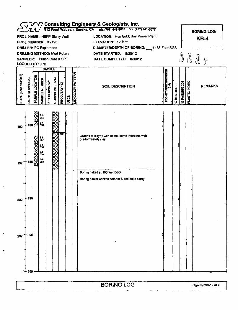
Consulting Engineers & Geologists, Inc.42IT 812 West Wabash, Eureka, CA ph. (707)441-8855 fax. (707) 441-8877
PROJ. NAME: HBPP Slurry Wall LOCATION: Humboldt Bay Power Plant
PROJ. NUMBER: 012125 ELEVATION: 12 feet
DRILLER: PC Exploration DIAMETER/DEPTH OF BORING:_ I
DRILLING METHOD: Mud Rotary DATE STARTED: 8/20/12
SAMPLER: Punch Core & SPT DATE COMPLETED: 8/30/12
LOGGED BY: JPB
86 Feet BGS
BORING LOG
KB-4
192
197
202
207
Grades to clayey with depth, same interbeds withpredominately clay
BORING LOG Page Number 9 of 9

I MKiewitHBPP Caisson Removal Feasibility Study
100% Draft Feasibility Report
APPENDIX HSLURRY WALL HYDROLOGIC
ASSESSMENT
Page 1120

¶ j CONSULTING ENGINEERS & GEOLOGISTS, INC.812 W. Wabash - Eureka, CA 95501-2138 ° 707-441-8855 * FAX: 707-441-8877 [email protected]
Reference: 012125.100
August 15, 2012
Nicholas Gura, PEKiewit Engineering Co.3555 Farnam StreetOmaha, NE 68131
Subject: Assessment of Hydrologic Impacts Associated With Slurry Wall Installation,
Humboldt Bay Power Plant, Eureka, California
Dear Mr. Gura:
SHN Consulting Engineers & Geologists, Inc. (SHN) herein presents our assessment of hydrologicimpacts associated with the installation of a slurry wall in the Unit 3 area at Humboldt Bay PowerPlant (HBPP), in Eureka, California (Figure 1). This study is a qualitative analysis based on reviewof existing data, completed reports, and historic groundwater monitoring activities. A summary ofhistoric groundwater flow conditions and our opinion on the impacts that the slurry wallinstallation would have on the hydrologic system is presented below.
Slurry Wall Design-Basis for Assessment
Installation of a slurry wall around the HBPP Unit 3 reactor caisson and spent fuel pool has beenproposed to facilitate removal of the structures and provide a barrier to groundwater duringexcavation and dewatering activities. The slurry wall will extend to a clay unit that is located at adepth of approximately 150 to 170 feet below ground surface (BGS) in the Unit 3 area. The planview of the proposed slurry wall in relation to Unit 3 is shown on Figures 2 and 3, and a regionalcross-section profile is shown on Figures 3 and 4.
The slurry wall will be keyed into the Unit F Clay, which is believed to be a continuous 50-footthick clay layer below the site. Preliminary soil borings are planned to verify the presence andthickness of this clay layer in the Unit 3 area. With the slurry wall embedded into the Unit F Clay, acomplete barrier to groundwater will be formed, allowing dewatering to occur for excavationpurposes. The 2.5-foot thick slurry wall will have a circumference of approximately 680 feet, and amaximum width and length of 175 feet and 230 feet, respectively.
It is our understanding that once the Unit 3 subgrade structures are removed, the excavation will bebackfilled and the upper 8 to 10 feet of the slurry wall will be breached to allow the flow of shallowgroundwater. Other than the modifications to the wall near the surface, it will be left in placeindefinitely.
\ \Eureka\ Projects\ 2012\012125-HBPPSlurryWaI\ 100-HydologAssess\ PUBS\ rpts\20120815-HydroAssmt.doc

Nicholas GuraAssessment of Hydrologic Impacts Associated With Slurry Wall Installation, Humboldt BayPower Plant, Eureka, CaliforniaAugust 15, 2012Page 2
Stratigraphy
Geologically, the Unit 3 area of HBPP is within the Hookton Formation, which is comprised oflayered sedimentary alluvial deposits of silts, clays, sand, and gravel. The Hookton Formation hasbeen informally divided into the Lower Hookton Formation and the Upper Hookton Formation.Our compilation of subsurface data on the local and regional cross-sections is presented in Figures 3and 4, respectively.
The First Bay Clay (surficial silt and clay terrace deposits) within the Upper Hookton Formation iswidely reported as continuous across the HBPP site in the vicinity of Unit 3. The upper unitconsists of interbedded silt, clay, silty clay, and clayey silt (fine grained sediments) that extendsfrom near the surface (below any fill) to depths ranging from approximately 16 to 25 feet BGS in theUnit 3 area.
The Upper Hookton sand beds, which are comprised of sand and gravel with discontinuousdeposits of interbedded silt and silty sand, extends from below the First Bay Clay to a depth ofapproximately 60 feet BGS. The base of the Upper Hookton sand beds is marked by the Second BayClay, where present. Where the Second Bay Clay is not present, the Upper Hookton sand bedstransition directly into the texturally similar deposits of the Lower Hookton Formation.
The Second Bay Clay is comprised of fine grained sediments and appears to be laterallydiscontinuous beneath the Unit 3 area. The Second Bay Clay has been identified to be 8 to 15 feetthick in the Unit 3 area, and may act as a localized aquitard, retarding the vertical flow ofgroundwater in these areas. The Second Bay Clay was encountered during recent drillingoperations on the southern and eastern sides of Unit 3 at depths ranging from approximately 60 to75 feet BGS. The Second Bay Clay was not recorded northwest of Unit 3.
The Lower Hookton Formation consists of interbedded sand, silty sand, and gravelly sandencountered below the Second Bay Clay. The Lower Hookton Formation also includes a distinct,laterally continuous fine-grained unit termed the Unit F Clay (Woodward-Clyde Consultants, 1980)encountered at a depth of 150 to 170 feet below the HBPP.
The Unit F Clay is an approximately 50-foot thick bed of fine-grained deposits recorded in earlyborings by Woodward-Clyde (1980) as consisting of silt, clay, silty clay, and clayey silt. Previousstudies indicate the Unit F Clay to be present at a depth of approximately 150 to 170 feet BGS at thelocation of HBPP Unit 3 (PG&E, 2002). The Unit F Clay acts as a regional aquitard and isconsidered the lower limit of potential impacts from groundwater.
Aquifers
For the purposes of this assessment, we considered the hydrologic impacts to the three aquifersabove the Unit F Clay aquitard (within the upper 150-170 feet).
\ \Eureka\ Projects\ 2012\ 01 2125-H BPPS~urryWaU1\ 10O-HydologAssess\ PUBS\ rpts\20120815-HydroAssmt. doc g

Nicholas GuraAssessment of Hydrologic Impacts Associated With Slurry Wall Installation, Humboldt BayPower Plant, Eureka, CaliforniaAugust 15, 2012Page 3
Underlying the Unit 3 area, the three distinct water bearing zones include:
1. groundwater in the Upper Hookton silt and clay beds generally within the First Bay Clay(upper 20 feet);
2. groundwater within the Upper Hookton sand beds between the First Bay Clay and SecondBay Clay (approximately 20 to 60 feet BGS); and
3. groundwater within the Lower Hookton Formation between the Second Bay Clay and theUnit F Clay (approximately 60 to 160 BGS).
Currently, there are monitoring wells installed into each of these three aquifers for the HBPPradiological environmental monitoring program (REMP) that are monitored on a quarterly basis.
Groundwater Flow
Groundwater flow within the above-described aquifers is influenced by laterally variablestratigraphy; nearby faults; site infrastructure, including the deep subgrade structures; and thesite's proximity to Humboldt Bay. Previous studies have documented strong tidal influence withinthe two primary aquifers at depth, the Upper Hookton aquifer and the Lower Hookton aquifer, asdiscussed in SHN's hydrogeologic assessment report (SHN, March 2010). The groundwater withinthe upper silt and clay beds does not appear to be tidally influenced.
In order to develop an overall groundwater flow direction, SHN conducted two tidal influencestudies within the Unit 3 area, once in October 2010 (dry season) and again in March 2011 (wetseason) (SHN, 2011). Pressure transducers in eight of the existing Unit 3 area monitoring wellswere used to record groundwater elevations over three complete tidal cycles (approximately 74hours) during each study.
The results of these studies are discussed in a Tidal Influence Study of Unit 3 Area, Humboldt BayPower Plant, Eureka, California dated July 2011 (SHN, 2011). Findings and conclusions relevant tothis slurry wall impacts assessment include:
* Tidal influence on the Upper Hookton aquifer causes cyclic reversals in the groundwaterflow direction during tidal cycles. Flow direction is to the south (inland) at high tide and tothe north (bayward) during low tide.
* Tidal influence on the Lower Hookton aquifer causes variations in the groundwatergradient (and flow rate); however, flow direction appears to be consistently toward thenorthwest (bayward).
* The vertical flow gradient between the Upper and Lower Hookton aquifers is upward in thesouthern portion of the Unit 3 area (where the Second Bay Clay is present), and flat todownward in the northern portion of Unit 3, (where the Second Bay Clay is not present).
" Using estimated values for effective porosity and hydraulic conductivity, groundwater netflow velocity is nearly zero within the Upper Hookton aquifer (no discernable flowdirection), and from 6 to 17 feet per year toward the bay within the Lower Hookton aquifer.
\ \Eureka\ Projects\ 2012\012125-HBPPSlurryWaU\ 100-HydologAssess\ PUBS\ rpts\20120815-HydroAssmt.doc

Nicholas GuraAssessment of Hydrologic Impacts Associated With Slurry Wall Installation, Humboldt BayPower Plant, Eureka, CaliforniaAugust 15, 2012Page 4
The most significant finding from the tidal influence study is that groundwater gradientscontinuously fluctuate in both direction and magnitude, but the net groundwater flow velocitywithin the Unit 3 area generally is very low and in a bayward direction.
Impacts to Hydrologic Conditions
The primary impact of the slurry wall will be its alteration of localized groundwater flow.Groundwater will be forced to flow around the slurry wall. In a simplified groundwater model inwhich a cylindrical barrier is placed in the ground, water flowing through the subsurface moundson the upstream side of the structure, and a stagnation area or low point forms on the downstreamside. Groundwater flow velocity may increase around the lateral margins of the structure wherethe groundwater gradient would be highest.
As discussed, two main water-bearing zones will be impacted: groundwater flowing within theUpper Hookton sands and the Lower Hookton sands. The discontinuous nature of the water-bearing deposits in the Upper Hookton fine-grained deposits (First Bay Clay) limits lateral flow,and is already modified by the below-grade infrastructure of Unit 3. SHN does not expect that theslurry wall will significantly change the existing conditions in the Upper Hookton formation fine-grained deposits.
Based on the 2010/2011 tidal influence study, the net groundwater flow velocity within the UpperHookton aquifer is nearly zero, with no discernable flow direction. With a low to negligible flowvelocity, the impacts to groundwater flow from the slurry wall are expected to be negligible.
Based on the 2010/2011 tidal influence study, the net groundwater flow velocity within the LowerHookton aquifer ranges from 6 to 17 feet per year (0.02 to 0.05 feet per day) toward Humboldt Bay.This flow velocity is low and it is expected that the slurry wall will cause only minimal localizedimpacts to regional groundwater flow.
The slurry wall will be a barrel-shaped barrier within the regional aquifer that will not cut off orinhibit groundwater movement. Highly transmissive deposits in the Upper and Lower HooktonFormations (predominantly sand) allow relatively easy groundwater flow. The area is influencedby tidal changes, currently exhibits very low groundwater velocity, and is recharged by HumboldtHill, Buhne Point and Humboldt Bay.
Generally, the alignment of the structure is parallel to groundwater flow direction and won'tpreclude, groundwater from flowing around it. Groundwater that may mound on the upstreamside of the slurry wall or stagnate on the downstream side would be minimal due to tidal influenceon the Unit 3 area from Humboldt Bay.
Limitations
The findings and conclusions presented herein are based on a study of inherently limited scope.Our interpretations are based on previous studies and site conditions that are known to us at thetime of our study. The analyses and conclusions contained in this report are based on our current
\ \Eureka\Projects\2012\012125-HBPPSlurryWaIl\100-HydologAssess\ PUBS\ rpts\20120815-HydroAssrnt.doc J;2

Nicholas GuraAssessment of Hydrologic Impacts Associated With Slurry Wall Installation, Humboldt BayPower Plant, Eureka, CaliforniaAugust 15, 2012Page 5
understanding of proposed slurry wall installation project We have assumed that the informationobtained from previous subsurface explorations is representative of subsurface conditionsthroughout the site.
If the scope of the proposed slurry wall construction, including the proposed location, depths, orfinal state changes from that described in this report, our recommendations should also bereviewed. No representation, express or implied, of warranty or guarantee is included or intended.
If you have any questions please call me at 707-441-8855.
Sincerely,
SHN Consulting Engineers & Geologists, Inc.
Erik J. Nielsen, PG, CHGProject Manager
EJN:lms HG i.7.62
Attachment 1. Figures ....... . "
References CitedPacific Gas & Electric Company, Geosciences. (December 27, 2002). Technical Report TR-HBIP-2002-
01, Seismic Hazard Assessment for the Humboldt Bay ISFSI Project, Revision 0. NR:PG&E.
SHN Consulting Engineers & Geologists, Inc. (March 2010). Tidal Influence Study of Unit 3 Area,Humboldt Bay Power Plant, Eureka, California (July 2011). Eureka:SHN.
Woodward-Clyde Consultants. (1980). "Evaluation of the Potential for Resolving the Geologic andSeismic Issues at the Humboldt Bay Power Plant Unit No. 3." Unpublished consultantsreport for PG&E. NR:Woodward and Clyde.
\\Eureka\Projects\2012\012125-HBPPSIurryWal\ 100-HydologAssess\ PUBS\ rpts\ 20120815-HydroAssmt.doc

Attachment 1
Figures

J
1,30
fvoiA
AIMIf *i IC/'I,
/
/N
V/l
59
i,!0.v
V.,\V~ ~-
5. ,~
it; -- ,
\ A~
~ / .1
1'.' (
!
SWXRVE.* aiUi' AND FlAUS' LANDINVGU/SGS 7.5 MINUTE 0U40R4M113E
~. I1-JooO~*
5 Pacific Gas & Electric Site Location Map
Humboldt Bay Power Plant
Consulting Engineers Eureka, California SHN 012125
& Geologists, Inc. July, 2012 012125-SITE-LCrN Figure 1

II
SOURCE GO3XLE E4IWH /AWE (SEPT 2(K?) MPLA AGMPacific Gas & Electric Aerial Photo View of HBPP
Humboldt Bay Power Plant with Site FeaturesEureka, California SHN 012125
Consulting .Ie1 012125-ARAL Figure 2& Geolo issInc. May2011 I 022 -E I LI Fg r

AET~
UMTJ f V017PA3T
1 15r BAY"AV i ý
A# Eow
F 20
CROSS SECTION LINE AWELLS RELATIVE TO UN11"6100,
KEY TO MOWNITRNGW
TTND
w 4iIhVNamELLS•
I2
I2
0
j00g
I
M (20•5)
AR4AT (2")
EXPLAMAiTIO
MWI~-MOW-2MOW-4MOW-9 (ASWDAWm)
AO-W-11
UITHOLOGY:
E RYR FO RNED -EWDS
/ W7 ERVY LOW PMVLRWC/Y
*A 6RA4 4?NE SEDMil-A00DEMMTO 1 LOW PERMM&WUY
KRY M~W PMH E W WLI7
r -1 77INY LAMIM~ DVV/7YL J aREN AL7EhMW77P SIUlY & SAPDY
SYMBOLS:
sL 7 FlME- OR
DRE5RL0Wr7?Y
- Lmonto=r coiffrcrQUM" WA
MAMREEN INTEWA OF 5t'UOE P54 IIPMT (2"Q)
LW)UJA.M DEPWh
m
LOCATION OF A-A' RELATIVE TO REGIONAL SETTING
Engineerssts, Inc. July, 2012
Pacific Gas & ElectricHumboldt Bay Power Plant
Eureka, California
Geologic Cross Section A-A'with Proposed Slurry Wall
SHN 012125Consulting F
& GKologi I 012125 XSEC1-5B I Figure 3I 012125-XSEC I -BB I Figure 3

SM*100
a -
L* -US0 WS n 3D N W0 M0 W0 WS M 10 USI 125 VA IM 1 70 U 4 ai lid MS US 20 M M. WO W W US MS W. MS M M M -M M M 40 4 40 40 a 4Wa
SOURML FSAI? UAU47E (2006)
LOCATION OF A-A' RELATIVE TO REGIONAL SE1TING
Consulting n gineers& Geologsts, Inc.
Pacific Gas & ElectricHumboldt Bay Power Plant
Eureka, California
Regional Cross Sectionwith Proposed Slurry Wall
SHN 012125
IJu.ly, 2012 1la~y, 2012 I mn25-xsEc~r-aBI iur3I Figure 4

- lOKiewitHBPP Caisson Removal Feasibility Study
100% Draft Feasibility Report
APPENDIX IEXCAVATION MATERIAL FLOW
DIAGRAMS AND TABLE
Page 1131

Slurry Wall Excavation in WeeksWeek 1 Week 2
200 ,
Week 3
10000 CY
Slur.Ex.....
Week 4-17
1000 CYSlurry Exc.
1000 CYSlurry Exc.
Week 18 Week 19 Week 20 Week 21
3000 CY
. .. ............ ... ............ ..
.......... ..... .......... ....
....... ...... . . . ..... . .......... ..... . .. .....
............ ........... ...................... ..............
200 C
1000 CY 1000 CY Offsite

Caisson Excavation StockpileBased on 25 Intermodal Load-out/Week
Lift IWeeks 1-4
Lift 2Weeks 5-8
rnhtV flr fly
1000 CYLoad-out toIntermodal
Week' fo-e. to
.... ... ... ...
*0
1000 CYLoad-out toIntermodal
pared to betamnatedj
rProcessContinues PerSpreadsheet
:Week' ':Results ::::::;:'':'
. . . . . . . . . . . . . . . .. . . . . . .
;. , -.1" . .1.2.1.12' .1 .2 '.. .: 2" .. . . . . .
....... .. . ..
Lift 10Weeks 37-40
1000 CYLoad-out toIntermodal
Lift 3Weeks 9-12
.600C
tW .. .. .. .. .. .. .. .. .. . .Wee...1......t........ .... . . .... ... ....
We.......o...to
S.... .....
.... . . .
l
.i
Lift 4Weeks 13-16
800 C
Lower Lift 5 (LL5)Weeks 65-70
200 SI
F1000 CYLoad-out toIntermodal
Wek~k 16-: Jhoe )Ito....|i::::i
A poWpriate.... .....:.. .
............ ...... .......
I • .. ,.•.•., ... .. .. ... x x .x .: . . .
.....,• , • . :.:.:.:.. ...... ...W ee. ............eek. ....olW eek..... .... ,.t
. ...oae : ......
.... .... ....
.... .
I

Table 6 - Excavation SchedulePhase 1 Upper Caisson Lift 1-10El +(121 to El -(30) Lift 1 (4 Weeks) Lift 2 (4 Weeks) Lift 3 (4 Weeks) Lift 4 (4 Weeks) ift 5 (4 Weeks) Lift 6 (4 Weeks) Lift 7 (4 Weeks) Lift 8 (4 Weeks) lift 9 (4 Weeks) Lift 10 (4 Weeks)
_tart Finish Stan Finish rst-, T e F-sh .. sh stko I Fnih St....s kFinih Stan I Finish 8F...r n I Frsk Finih Startk FinishElevation 12 6 6 2 2 -- 2 -6 -6 -0 -10 1 -14 -14 1 -18 -18 -22 -22 7 -26 -26 -30
C.Y Removed (Avg) 1020
BCY X 1.2 Swell Factor 1200 1200 1200 1200 1200 1200 1200 1200 1200 1200
Running Total 1200 2400 3600 4800 6000 7200 8400 9600 10800 12000
RunningWeeks 1 I 9 12 03 16 17 20 21 24 25 20 29 32 93 36 37 1 40Neek Count for PG&EestlCkaracterization Results 3 7 11 10 19 2339
/We"ek/lift 0 0 0 0 0 0 0 0 0 020/Week/Lift 200 400 600 800 1000 1200 1400 16 1800 200020/Week/Lift 400 800 1200 1600 2000 2400 2800 3200 3600 4000
/Wee /Lift 600 1200 1800 2400 3000 3600 4200 4600 5400 6000
Phase 2 Lower Caisson Lift 1-5EL -(30) to El -(80) Lower Lift 1 (6 Weeks) Lower Lift 2 (6 Weeks) Lower Lift 3 (6 Weeks) Lower Lift 4 (6 Weeks) Lower Lift 5 (6 Weeks) Weeks to deplete QTY
_________ .... _ __ F olsh_ Finishth tsh Star Finish
Elevation 4- -4 -4 8 6 -73 -73 -80CY Removed (Average) 560 1960 1820 1680 980Running Total 12060 14520 16340 18020 19000
Running Weeks 41 1 46 47 52 53 54 65 70Week Count for PG&E
est/Chakrateriat ion Results 43 49 5561 67
O/Week/Lift 0 160 0 60 0 05/Week/Lift 1060 1520 1040 2020 1500 6
0/Week/Lift 3360 4120 4740 5220 5000 25lS/Week/Lift 5660 6720 7640 6420 8 0SUO

Phase 1 Upper Caisson Lift 1-10El +(12) to El -(30) Lift 1 (4 Weeks) Lift 2 (4 Weeks) Lift 3 (4 Weeks) Lift 4 (4 Weeks) Lift 5 (4 Weeks) Lift 6 (4 Weeks) Lift 7 (4 Weeks) Lift 8 (4 Weeks) Lift 9 (4 Weeks) Lift 10 (4 Weeks)
Start FIn Finish St . F - sh Start2 Finish- Start Fs sh s sh -s 2 Finish
C.Y Removed (Avg) 1020
BCY X 1.2 Swell Facor 1200 1200 1200 1200 1200 1200 1200 1200 1200 1200
1200 2400 3600 4800 6000 7200 8400 9600 10800 12000
Running Weeks 1 14 5 T 8 9 12 13 16 17 20 21 24 2 28 29 32 33 36 37 40
Week Count for PG&E
Test/Charauoerization Results 3 7 11 15 19 23 27 31 35 39
30/Weelift 0 0 0 0 0 0 410 0 0 0
25/Week/ift 200 400 600 000 1000 120 1400 1600 100 2000
20/Week/LUft 400 000 1200 1600 2000 2400 2800 3200 3600 4000
15/Week/Lft 600 1200 1800 2400 3000 3600 4200 4800 5400 6000
Phase 2 Lower Caisson Lift 1-5E L -(30) to El -(80) Lower Lift 1 )6 Weeks) Lower Lift 2 (6 Weeks) Lower Lift 3 (6 Weeks) Lower Lift 4 (6 Weeks) Lower Lift 5 (6 Weeks) Weeks to deplete QTY
Start. I Finish s .... I Finish _t___ Firntis Stern Start I FinishElevation -301 -34 -44 -481 -61 -6_73 -3 8
C.Y Removed )Average) 560 1960 1820 1680 980
Running Total 12560 14520 16340 18020 19000
Running Weeks 41 46 47 2 3 5 64 65 70
Week Count for PG&E
Test/Characterization Results 43 49 55 61 67
30/Week/Lift 0 160 180 60 0 0
25/Week/Lift 1000 1520 1040 2020 1500 620/Week/Lift 330 4120 4740 5220 5000 25
15/lWeek/Lift 5660 6720 7640 8420 8500 57