
HP LaserJet Pro 300/400 Color MFP Service Manual - ENWW
346
LASERJET PRO 300 COLOR MFP LASERJET PRO 400 COLOR MFP Service Manual M375 M475
-
Upload
khangminh22 -
Category
Documents
-
view
0 -
download
0
Transcript of HP LaserJet Pro 300/400 Color MFP Service Manual - ENWW

LASERJET PRO 300 COLOR MFP LASERJET PRO 400 COLOR MFP
Service Manual
M375 M475


HP LaserJet Pro 300 color MFP M375and HP LaserJet Pro 400 color MFPM475 Printers
Service Manual

Copyright and License
© 2012 Copyright Hewlett-PackardDevelopment Company, L.P.
Reproduction, adaptation, or translationwithout prior written permission isprohibited, except as allowed under thecopyright laws.
The information contained herein is subjectto change without notice.
The only warranties for HP products andservices are set forth in the express warrantystatements accompanying such products andservices. Nothing herein should beconstrued as constituting an additionalwarranty. HP shall not be liable for technicalor editorial errors or omissions containedherein.
Part number: CE863-90966
Edition 1, 1/2012
Trademark Credits
Microsoft®, Windows®, Windows® XP,and Windows Vista® are U.S. registeredtrademarks of Microsoft Corporation.
ENERGY STAR and the ENERGY STAR markare registered U.S. marks.

Conventions used in this guide
TIP: Tips provide helpful hints or shortcuts.
NOTE: Notes provide important information to explain a concept or to complete a task.
CAUTION: Cautions indicate procedures that you should follow to avoid losing data or damaging theproduct.
WARNING! Warnings alert you to specific procedures that you should follow to avoid personalinjury, catastrophic loss of data, or extensive damage to the product.
ENWW iii

iv Conventions used in this guide ENWW

Table of contents
1 Removal and replacement .................................................................................................................... 1
Removal and replacement strategy ............................................................................................. 2Introduction .............................................................................................................. 2Removal and replacement strategy .............................................................................. 2Electrostatic discharge ............................................................................................... 3Required tools ........................................................................................................... 3Types of screws ........................................................................................................ 4
Service approach ..................................................................................................................... 5Before performing service .......................................................................................... 5After performing service ............................................................................................. 5Post-service tests ........................................................................................................ 6
Test 1 (print-quality test) ............................................................................... 6Test 2 (copy-quality test) .............................................................................. 6Test 3 (fax-quality test; fax models only) ........................................................ 6
Parts removal order ................................................................................................... 7Removal and replacement procedures ........................................................................................ 9
Rollers and pads ....................................................................................................... 9Transfer roller ............................................................................................ 9Pickup roller (Tray 2 and Tray 3) ................................................................ 10Separation roller (Trays 2 or 3) .................................................................. 13
Reinstall the separation roller ...................................................... 15Document feeder pickup roller assembly ..................................................... 16Pickup roller and separation pad (Tray 1) ................................................... 17
Main assemblies ..................................................................................................... 20Print-cartridge drawer ............................................................................... 20DIMM cover ............................................................................................ 22Right cover .............................................................................................. 23Document feeder input tray ........................................................................ 25Scanner assembly .................................................................................... 26Right-front cover and power button ............................................................. 28Rear-upper cover (duplex product) .............................................................. 30Paper-feed guide assembly ........................................................................ 31
ENWW v

Rear-door stopper and link caps (simplex product) ........................................ 32Rear door (simplex product) ....................................................................... 33Rear door (duplex product) ........................................................................ 35Rear cover and feed guide (simplex product) ............................................... 37
Remove the rear cover and feed guide (simplex product) ................ 37Rear-lower cover and rear-door links (duplex product) ................................... 41
Remove the rear-lower cover and rear-door links (duplex product) . . . 41Rear-door rib assembly (duplex product) ..................................................... 45
Remove the rear-door rib assembly (duplex product) ...................... 45Link guide ............................................................................................... 47Control panel and right-arm mount ............................................................. 48
Reinstall the control panel and right-arm mount ............................. 49Upper-cover assembly ............................................................................... 51
Remove the upper-cover assembly ............................................... 51Reinstall the upper-cover assembly ............................................... 53
Left cover ................................................................................................ 55Remove the left cover ................................................................. 55Reinstall the left cover ................................................................ 57
Front-door assembly ................................................................................. 58Remove the front-door assembly .................................................. 58Reinstall the front-door assembly .................................................. 63
Intermediate transfer belt (ITB) .................................................................... 65Reinstall the ITB ......................................................................... 68
Drum motor (M1) and developer motor (M2) ............................................... 69Reinstall the drum motor (M1) and developer motor (M2) ............... 74
Intermediate PCA ..................................................................................... 75Formatter PCA and fax PCA ...................................................................... 76
Remove the formatter PCA and fax PCA ....................................... 76Wireless PCA .......................................................................................... 79DC controller PCA .................................................................................... 80
Remove the DC controller PCA .................................................... 81Fuser-motor assembly ................................................................................ 83
Remove the fuser-motor assembly ................................................ 83Reinstall the fuser-motor assembly ................................................ 86
High-voltage power-supply PCA ................................................................. 87Remove the high-voltage power-supply PCA .................................. 87
Color-misregistration sensor assembly ......................................................... 90Remove the color-misregistration sensor assembly .......................... 90Reinstall the color-misregistration sensor assembly ......................... 92
Fan (FM1) ............................................................................................... 94USB PCA (fax/memory-card models) .......................................................... 96
vi ENWW

Remove the USB PCA ................................................................ 96Duplex-reverse drive assembly ................................................................... 97
Remove the duplex-reverse drive assembly .................................... 97Fuser .................................................................................................... 100
Remove the fuser ..................................................................... 101Reinstall the fuser .................................................................... 106
Paper-delivery assembly .......................................................................... 107Remove the paper-delivery assembly .......................................... 107
Tray cassettes and optional Tray 3 assembly ............................................................ 110
2 Solve problems ............................................................................................................................... 111
Solve problems checklist ....................................................................................................... 112Menu map .......................................................................................................................... 113Troubleshooting process ........................................................................................................ 114
Pretroubleshooting checklist .................................................................................... 114Power-on checks ................................................................................................... 115
Troubleshooting tools ............................................................................................................ 116Component diagnostics .......................................................................................... 116
LED diagnostics ...................................................................................... 116Network LEDs (network models only) ......................................... 116Control panel LEDs .................................................................. 116Memory card LED (memory-card models only) ............................. 116
Component tests ................................................................................................... 117Control-panel tests .................................................................................. 117
Diagrams ............................................................................................................. 118Plug/jack locations ................................................................................. 118Location of connectors ............................................................................ 119
DC controller PCA ................................................................... 119Location of major components ................................................................. 121
Major components .................................................................. 121Motors and fans ...................................................................... 123Rollers .................................................................................... 124PCAs ..................................................................................... 125Optional 250-sheet cassette ..................................................... 126
General timing diagram .......................................................................... 127General circuit diagram .......................................................................... 128CPU/ASIC diagrams .............................................................................. 129HVT/Toner EMP diagram ........................................................................ 131Driver PCA diagram ............................................................................... 132Duplexer PCA diagram ........................................................................... 133FSR diagram .......................................................................................... 134
ENWW vii
Internal print quality test pages ............................................................................... 135Print quality troubleshooting page ............................................................ 135Print quality assessment page .................................................................. 135Print the Configuration Page .................................................................... 135Service page ......................................................................................... 135Clean the paper path ............................................................................. 136
Print-quality troubleshooting tools ............................................................................ 136Repetitive image defects .......................................................................... 136Calibrate the product .............................................................................. 137
Control panel menus .............................................................................................. 137Setup Menu ........................................................................................... 137
HP Web Services menu ............................................................ 138Reports menu .......................................................................... 139Quick Forms menu .................................................................. 140Fax Setup menu ...................................................................... 141System Setup menu .................................................................. 144Service menu .......................................................................... 149Network Setup menu ............................................................... 151
Function specific menus ........................................................................... 152Copy menu ............................................................................ 152Fax menu ............................................................................... 154Scan menu ............................................................................. 156USB Flash Drive ...................................................................... 157
Interpret control panel messages ............................................................................. 157Control panel message types ................................................................... 157Control panel messages .......................................................................... 157
10.100X Supply Memory Error ................................................. 15749 Error, Turn off then on ......................................................... 15850.x Fuser Error ...................................................................... 15852 Scanner Error .................................................................... 15857 Fan Error, Turn off then on ................................................... 15979 Error Turn off then on .......................................................... 159Black Cartridge Low ................................................................ 159Black in wrong position ............................................................ 160Black Very Low ....................................................................... 160Canceled scan. Clear document ................................................ 160Canceled send. Clear document ............................................... 160Communication error. .............................................................. 161Cyan Cartridge Low ................................................................ 161Cyan in wrong position ............................................................ 161Cyan Very Low ....................................................................... 161
viii ENWW

Device error, press OK ............................................................ 162Device is busy. Try again later .................................................. 162Document feeder door is open. ................................................. 162Document feeder jam. Clear and reload. ................................... 162Document feeder mispick. Reload .............................................. 163Door open .............................................................................. 163Engine Communication Error .................................................... 163Engine error. Press OK to continue. ........................................... 163Fax is busy. Canceled send. ..................................................... 164Fax is busy. Redial pending. ..................................................... 164Fax receive error. .................................................................... 164Fax Send error. ....................................................................... 165Fax storage is full. Canceling the fax receive. ............................. 165Fax storage is full. Canceling the fax send. ................................. 166Fit to Page on flatbed only ........................................................ 166Genuine HP supply installed ..................................................... 166Incompatible <color> ............................................................... 166Install [color] cartridge ............................................................. 166Invalid driver Press OK ............................................................ 167Invalid entry ........................................................................... 167Jam in (area), Open door and clear jam .................................... 167Jam in Tray 1, Clear jam and then press OK .............................. 167Load paper ............................................................................ 167Load Tray 1 <TYPE> <SIZE>, Press OK to use available media ..... 167Load Tray 1, <PLAIN> <SIZE> / Cleaning mode, OK to start ....... 168Load tray <X> Press [OK] for available media ............................ 168Magenta Cartridge Low ........................................................... 168Magenta in wrong position ...................................................... 168Magenta Very Low .................................................................. 168Manual Duplex Load Tray 1, Press OK ...................................... 169Manual feed <SIZE> <TYPE>, Press OK to use available media .... 169Memory is low. Press OK. ........................................................ 169Memory is low. Try again later ................................................. 169Memory low Only 1 copy made. Press OK to continue. ............... 170Misprint, Press OK ................................................................... 170No dial tone. .......................................................................... 170No fax answer. Canceled send. ................................................ 170No fax answer. Redial pending. ............................................... 171No fax detected. ..................................................................... 171Print failure, press OK. If error repeats, turn off then on. ............... 172Remove shipping lock from <color> cartridge ............................. 172
ENWW ix

Remove shipping locks from cartridges ...................................... 172Replace [color] ....................................................................... 172Scanner error #, Turn off then on .............................................. 172Scanner reserved for PC scan ................................................... 173Scanning error Cannot connect ................................................. 173Settings cleared ...................................................................... 173Unexpected size in tray # Load <size> Press [OK] ...................... 173Unsupported <color> Press [OK] to continue ............................... 174Used <color> in use ................................................................ 174Used [color] installed, to accept press OK .................................. 174Used supplies in use ................................................................ 174Yellow Cartridge Low .............................................................. 174Yellow in wrong position .......................................................... 175Yellow Very Low ..................................................................... 175
Event-log messages ............................................................................................... 175Print the event log ................................................................................... 176Event log messages ................................................................................ 176
Clear jams .......................................................................................................................... 180Common causes of jams ........................................................................................ 180Jam locations ........................................................................................................ 180Clear jams from the document feeder ...................................................................... 181Clear jams in Tray 1 .............................................................................................. 183Clear jams in Tray 2 .............................................................................................. 186Clear jams in the fuser area ................................................................................... 187Clear jams in the output bin .................................................................................... 188Clear jams in the duplexer (duplexing models only) ................................................... 189
Solve paper-handling problems .............................................................................................. 191The product picks up multiple sheets of paper ........................................................... 191The product does not pick up paper ........................................................................ 191
Solve image-quality problems ................................................................................................ 192Print quality examples ............................................................................................ 192Color image defects .............................................................................................. 196
Clean the product ................................................................................................................ 198Clean the pickup and separation rollers ................................................................... 198Clean the paper path ............................................................................................ 198
Clean the paper path from the product control panel .................................. 198Clean the scanner glass strip and platen .................................................................. 199Clean the document feeder pickup rollers and separation pad .................................... 200Clean the touch screen .......................................................................................... 201
Solve performance problems ................................................................................................. 202Factors affecting print performance ......................................................................... 202
x ENWW

Print speeds ........................................................................................... 203The product does not print or it prints slowly ............................................................. 204
The product does not print ....................................................................... 204The product prints slowly ......................................................................... 205
Solve product connectivity problems ....................................................................................... 206Solve direct-connect problems ................................................................................. 206Solve network problems ......................................................................................... 206
Poor physical connection ......................................................................... 206The computer is using the incorrect IP address for the product ...................... 206The computer is unable to communicate with the product ............................ 207The product is using incorrect link and duplex settings for the network .......... 207New software programs might be causing compatibility problems ................ 207The computer or workstation might be set up incorrectly .............................. 207The product is disabled, or other network settings are incorrect .................... 207
Solve wireless network problems ............................................................................. 207Wireless connectivity checklist ................................................................. 208The control panel displays the message: The wireless feature on this producthas been turned off ................................................................................ 208The product does not print after the wireless configuration completes ............ 208The product does not print, and the computer has a third-party firewallinstalled ................................................................................................ 209The wireless connection does not work after moving the wireless router orproduct ................................................................................................. 209Cannot connect more computers to the wireless product .............................. 209The wireless product loses communication when connected to a VPN ........... 210The network does not appear in the wireless networks list ........................... 210The wireless network is not functioning ...................................................... 210
Service mode functions ......................................................................................................... 211Service menu ........................................................................................................ 211
Service menu settings .............................................................................. 211Secondary service menu ........................................................................................ 211
Open the secondary service menu ............................................................ 212Secondary service menu structure ............................................................. 212
Product resets ....................................................................................................... 213Restore the factory-set defaults ................................................................. 213NVRAM initialization .............................................................................. 213
Solve fax problems ............................................................................................................... 215Fax troubleshooting checklist .................................................................................. 215Fax error messages ............................................................................................... 217
Communication error. ............................................................................. 217Document feeder door is open. Canceled fax. ........................................... 217
ENWW xi

Fax is busy. Canceled send. .................................................................... 217Fax is busy. Redial pending. .................................................................... 218Fax receive error. ................................................................................... 218Fax Send error. ...................................................................................... 219Fax storage is full. Canceling the fax receive. ............................................ 219Fax storage is full. Canceling the fax receive. ............................................ 219Fax storage is full. Canceling the fax send. ................................................ 220No dial tone. ......................................................................................... 220No fax answer. Canceled send. ............................................................... 220No fax answer. Redial pending. .............................................................. 221No fax detected. .................................................................................... 221
Troubleshoot fax codes and trace reports ................................................................. 223View and interpret fax error codes ........................................................... 223Fax trace report ..................................................................................... 224
Fax logs and reports .............................................................................................. 224Print all fax reports ................................................................................. 225Print individual fax reports ....................................................................... 225Set the fax error report ............................................................................ 226
Change error correction and fax speed ................................................................... 226Set the fax-error-correction mode .............................................................. 226Change the fax speed ............................................................................ 227
Solve problems sending faxes ................................................................................. 227An error message displays on the control panel ......................................... 227
The Communication error. message displays .............................. 227No dial tone. .......................................................................... 228The Fax is busy. message displays ............................................ 229The No fax answer. message displays ....................................... 229Document feeder paper jam ..................................................... 230The Fax storage is full. message displays ................................... 230Scanner error ......................................................................... 230
The control panel displays a Ready message with no attempt to send the fax . 230The control panel displays the message "Storing page 1" and does notprogress beyond that message ................................................................. 231Faxes can be received, but not sent .......................................................... 231Unable to use fax functions from the control panel ...................................... 231Unable to use speed dials ....................................................................... 232Unable to use group dials ....................................................................... 232Receive a recorded error message from the phone company when trying tosend a fax ............................................................................................. 232Unable to send a fax when a phone is connected to the product .................. 233
Solve problems receiving faxes ............................................................................... 234
xii ENWW

The fax does not respond ........................................................................ 234The fax has a dedicated phone line ........................................... 234An answering machine is connected to the product ..................... 234A telephone handset is connected to the product ......................... 235The Answer Mode setting is set to the Manual setting ................... 235Voice mail is available on the fax line ........................................ 235The product is connected to a DSL phone service ........................ 236The product uses a fax over IP or VoIP phone service ................... 236
An error message displays on the control panel ......................................... 237The No fax detected. message displays ..................................... 237The Communication error. message displays .............................. 237The Fax storage is full. message displays ................................... 238The Fax is busy. message displays ............................................ 238
A fax is received but does not print .......................................................... 239The Private Receive feature is on ............................................... 239
Sender receives a busy signal .................................................................. 239A handset is connected to the product ........................................ 239A phone line splitter is being used ............................................. 239
No dial tone .......................................................................................... 239Cannot send or receive a fax on a PBX line ............................................... 239
Solve general fax problems .................................................................................... 240Faxes are sending slowly ........................................................................ 240Fax quality is poor ................................................................................. 241Fax cuts off or prints on two pages ........................................................... 241
Product updates ................................................................................................................... 243
3 Parts and diagrams ......................................................................................................................... 245
Order parts by authorized service providers ............................................................................ 246Orderable parts .................................................................................................... 246Whole unit replacement ......................................................................................... 246Related documentation and software ....................................................................... 247Supplies and accessories ....................................................................................... 248Service parts ........................................................................................................ 248
How to use the parts lists and diagrams .................................................................................. 249Scanner and document feeder main assemblies ....................................................................... 250Covers ................................................................................................................................ 252Internal assemblies ............................................................................................................... 254
Internal assemblies (1 of 5) ..................................................................................... 254Internal assemblies (2 of 5) ..................................................................................... 256Internal components (3 of 5) ................................................................................... 258Internal assemblies (4 of 5) ..................................................................................... 260
ENWW xiii

Internal assemblies (5 of 5) ..................................................................................... 262Internal assemblies (simplex models) ........................................................................ 264Internal assemblies (duplex models) ......................................................................... 266PCAs ................................................................................................................... 268
Input device(s) ..................................................................................................................... 270250-sheet paper feeder (optional Tray 3) ................................................................. 270
Alphabetical parts list ........................................................................................................... 272Numerical parts list .............................................................................................................. 275
Appendix A Service and support ......................................................................................................... 279
Hewlett-Packard limited warranty statement ............................................................................. 280HP's Premium Protection Warranty: LaserJet print cartridge limited warranty statement .................. 282Data stored on the print cartridge ........................................................................................... 283End User License Agreement .................................................................................................. 284OpenSSL ............................................................................................................................. 287Customer support ................................................................................................................. 288
Appendix B Product specifications ........................................................................................................ 289
Physical specifications .......................................................................................................... 290Power consumption, electrical specifications, and acoustic emissions .......................................... 290Environmental specifications .................................................................................................. 290
Appendix C Regulatory information ...................................................................................................... 291
FCC regulations ................................................................................................................... 292Environmental product stewardship program ........................................................................... 292
Protecting the environment ...................................................................................... 292Ozone production ................................................................................................. 292Power consumption ............................................................................................... 292Toner consumption ................................................................................................ 293Paper use ............................................................................................................. 293Plastics ................................................................................................................. 293HP LaserJet print supplies ....................................................................................... 293Return and recycling instructions ............................................................................. 293
United States and Puerto Rico .................................................................. 293Multiple returns (more than one cartridge) .................................. 294Single returns .......................................................................... 294Shipping ................................................................................ 294
Non-U.S. returns .................................................................................... 294Paper .................................................................................................................. 295Material restrictions ............................................................................................... 295
xiv ENWW

Disposal of waste equipment by users in private households in the European Union ...... 295Chemical substances ............................................................................................. 296Material Safety Data Sheet (MSDS) ......................................................................... 296For more information ............................................................................................. 297
Declaration of conformity ...................................................................................................... 298Declaration of conformity (wireless models) ............................................................................. 300Certificate of volatility ........................................................................................................... 302
Types of memory ................................................................................................... 302Volatile memory ..................................................................................... 302Non-volatile memory .............................................................................. 302
Safety statements ................................................................................................................. 303Laser safety .......................................................................................................... 303Canadian DOC regulations .................................................................................... 303VCCI statement (Japan) .......................................................................................... 303Power cord instructions .......................................................................................... 303Power cord statement (Japan) ................................................................................. 303EMC statement (Korea) .......................................................................................... 304Laser statement for Finland ..................................................................................... 304GS statement (Germany) ........................................................................................ 305Substances Table (China) ....................................................................................... 305Restriction on Hazardous Substances statement (Turkey) ............................................. 305Restriction on Hazardous Substances statement (Ukraine) ........................................... 305
Additional statements for telecom (fax) products ....................................................................... 306EU Statement for Telecom Operation ....................................................................... 306New Zealand Telecom Statements ........................................................................... 306Additional FCC statement for telecom products (US) .................................................. 306Telephone Consumer Protection Act (US) .................................................................. 307Industry Canada CS-03 requirements ...................................................................... 307Vietnam Telecom wired/wireless marking for ICTQC Type approved products ............. 308
Additional statements for wireless products .............................................................................. 309FCC compliance statement—United States ................................................................ 309Australia statement ................................................................................................ 309Brazil ANATEL statement ........................................................................................ 309Canadian statements ............................................................................................. 309European Union regulatory notice ........................................................................... 309Notice for use in France ......................................................................................... 310Notice for use in Russia ......................................................................................... 310Korean statement .................................................................................................. 310Taiwan statement .................................................................................................. 311Vietnam Telecom wired/wireless marking for ICTQC Type approved products ............. 311
ENWW xv

Index ................................................................................................................................................. 313
xvi ENWW

List of tables
Table 1-1 Common fasteners ................................................................................................................. 4Table 2-1 Major components ............................................................................................................. 121Table 2-2 Solenoid, sensors, and motors .............................................................................................. 123Table 2-3 Rollers ............................................................................................................................... 124Table 2-4 PCAs ................................................................................................................................ 125Table 2-5 Optional 250-sheet cassette ................................................................................................. 126Table 2-6 Repetitive image defects ...................................................................................................... 136Table 2-7 Event-log messages ............................................................................................................. 176Table 2-8 Event-log-only messages ...................................................................................................... 178Table 2-9 Secondary service menu ...................................................................................................... 212Table 3-1 Order parts, accessories, and supplies .................................................................................. 246Table 3-2 Pro 300 Color MFP M375nw .............................................................................................. 246Table 3-3 Pro 400 Color MFP M475dn ............................................................................................... 246Table 3-4 Pro 400 Color M475dw ..................................................................................................... 246Table 3-5 Related documentation and software .................................................................................... 247Table 3-6 Scanner and document feeder main assemblies ..................................................................... 251
Table 3-7 Covers1,2 ........................................................................................................................... 253Table 3-8 Internal assemblies (1 of 7) .................................................................................................. 255Table 3-9 Internal assemblies (2 of 7) .................................................................................................. 257Table 3-10 Internal assemblies (3 of 7) ................................................................................................ 259Table 3-11 Internal assemblies (4 of 7) ................................................................................................ 261Table 3-12 Internal assemblies (5 of 7) ................................................................................................ 263Table 3-13 Internal assemblies (simplex models) ................................................................................... 265Table 3-14 Internal assemblies (duplex models) .................................................................................... 267Table 3-15 PCAs .............................................................................................................................. 269Table 3-16 250-sheet paper feeder (optional Tray 3) ............................................................................ 271Table 3-17 Alphabetical parts list ....................................................................................................... 272Table 3-18 Numerical parts list ........................................................................................................... 275Table B-1 Physical specifications ......................................................................................................... 290Table B-2 Environmental specifications1 ............................................................................................... 290
ENWW xvii

xviii ENWW

List of figures
Figure 1-1 Phillips and pozidrive screwdriver comparison .......................................................................... 3Figure 1-2 Parts removal order (1 of 2) .................................................................................................... 7Figure 1-3 Parts removal order (2 of 2) .................................................................................................... 8Figure 1-4 Remove the pickup roller (1 of 2) ........................................................................................... 11Figure 1-5 Remove the pickup roller (2 of 2) ........................................................................................... 12Figure 1-6 Remove the pickup roller (1 of 3) ........................................................................................... 13Figure 1-7 Remove the separation roller (2 of 3) ..................................................................................... 14Figure 1-8 Remove the separation roller (3 of 3) ..................................................................................... 14Figure 1-9 Reinstall the separation roller ................................................................................................ 15Figure 1-10 Remove the document feeder pickup roller assembly (1 of 2) .................................................. 16Figure 1-11 Remove the document feeder pickup roller assembly (2 of 2) .................................................. 16Figure 1-12 Remove the Tray 1 pickup roller (1 of 3) .............................................................................. 18Figure 1-13 Remove the Tray 1 pickup roller (2 of 3) .............................................................................. 18Figure 1-14 Remove the Tray 1 pickup roller (3 of 3) .............................................................................. 19Figure 1-15 Remove the Tray 1 separation pad ...................................................................................... 19Figure 1-16 Remove the print-cartridge drawer (1 of 3) ........................................................................... 20Figure 1-17 Remove the print-cartridge drawer (2 of 3) ........................................................................... 20Figure 1-18 Remove the print-cartridge drawer (3 of 3) ........................................................................... 21Figure 1-19 Remove the DIMM cover .................................................................................................... 22Figure 1-20 Remove the right cover (1 of 3) ........................................................................................... 23Figure 1-21 Remove the right cover (2 of 3) ........................................................................................... 23Figure 1-22 Remove the right cover (3 of 3) ........................................................................................... 24Figure 1-23 Remove the document feeder input tray (2 of 2) .................................................................... 25Figure 1-24 Remove the document feeder input tray (2 of 2) .................................................................... 25Figure 1-25 Remove the scanner assembly (1 of 4) ................................................................................. 26Figure 1-26 Remove the scanner assembly (2 of 4) ................................................................................. 26Figure 1-27 Remove the scanner assembly (3 of 4) ................................................................................. 27Figure 1-28 Remove the scanner assembly (4 of 4) ................................................................................. 27Figure 1-29 Remove the rear-upper cover (1 of 2) ................................................................................... 30Figure 1-30 Remove the rear-upper cover (2 of 2) ................................................................................... 30Figure 1-31 Remove the feed assembly (1 of 2) ...................................................................................... 31Figure 1-32 Remove the feed assembly (2 of 2) ...................................................................................... 31
ENWW xix

Figure 1-33 Remove the Rear-door stopper and link caps (simplex product) (1 of 2) .................................... 32Figure 1-34 Remove the Rear-door stopper and link cap (simplex product) (2 of 2) ..................................... 32Figure 1-35 Remove the rear door (simplex product) (1 of 4) .................................................................... 33Figure 1-36 Remove the rear door (simplex product) (2 of 4) .................................................................... 33Figure 1-37 Remove the rear door (simplex product) (3 of 4) .................................................................... 34Figure 1-38 Remove the rear door (simplex product) (4 of 4) .................................................................... 34Figure 1-39 Remove the rear door (duplex product) (1 of 4) ..................................................................... 35Figure 1-40 Remove the rear door (duplex product) (2 of 4) ..................................................................... 35Figure 1-41 Remove the rear door (duplex product) (3 of 4) ..................................................................... 36Figure 1-42 Remove the rear door (duplex product) (4 of 4) ..................................................................... 36Figure 1-43 Remove the rear cover and feed guide (simplex product) (1 of 6) ............................................ 37Figure 1-44 Remove the rear cover and feed guide (simplex product) (2 of 6) ............................................ 38Figure 1-45 Remove the rear cover and feed guide (simplex product) (3 of 6) ............................................ 38Figure 1-46 Remove the rear cover and feed guide (simplex product) (4 of 6) ............................................ 39Figure 1-47 Remove the rear cover and feed guide (simplex product) (5 of 6) ............................................ 40Figure 1-48 Remove the rear cover and feed guide (simplex product) (6 of 6) ............................................ 40Figure 1-49 Remove the rear- lower cover and rear-door links (duplex product) (1 of 6) ............................... 41Figure 1-50 Remove the rear-lower cover and rear-door links (duplex product) (2 of 6) ................................ 42Figure 1-51 Remove the rear-lower cover and rear-door links (duplex product) (3 of 6) ................................ 42Figure 1-52 Remove the rear-lower cover and link-guides (duplex product) (4 of 6) ..................................... 43Figure 1-53 Remove the rear-lower cover and link-guides (duplex product) (5 of 6) ..................................... 43Figure 1-54 Remove the rear-lower cover and rear-door links (duplex product) (6 of 6) ................................ 44Figure 1-55 Remove the rear-door rib assembly (duplex product) (1 of 3) .................................................. 45Figure 1-56 Remove the rear-door rib assembly (duplex product) (2 of 3) .................................................. 46Figure 1-57 Remove the rear-door rib assembly (duplex product) (3 of 3) .................................................. 46Figure 1-58 Replace the link guide (simplex products) ............................................................................. 47Figure 1-59 Replace the link guide (duplex products) .............................................................................. 47Figure 1-60 Remove the control panel and right-arm mount (1 of 3) .......................................................... 48Figure 1-61 Remove the control panel and right-arm mount (2 of 3) .......................................................... 48Figure 1-62 Remove the control panel and right-arm mount (3 of 3) .......................................................... 49Figure 1-63 Reinstall the control panel and right-arm mount (1 of 2) .......................................................... 49Figure 1-64 Reinstall the control panel and right-arm mount (2 of 2) .......................................................... 50Figure 1-65 Remove the upper-cover assembly (1 of 3) ............................................................................ 51Figure 1-66 Remove the upper-cover assembly (2 of 3) ............................................................................ 52Figure 1-67 Remove the upper-cover assembly (3 of 3) ............................................................................ 52Figure 1-68 Reinstall the upper-cover assembly (1 of 3) ........................................................................... 53Figure 1-69 Reinstall the upper-cover assembly (2 of 3) ........................................................................... 53Figure 1-70 Reinstall the upper-cover assembly (3 of 3) ........................................................................... 54Figure 1-71 Remove the left cover (1 of 3) ............................................................................................. 55Figure 1-72 Remove the left cover (2 of 3) ............................................................................................. 56Figure 1-73 Remove the left cover (3 of 3) ............................................................................................. 56
xx ENWW

Figure 1-74 Reinstall the left cover (1 of 2) ............................................................................................. 57Figure 1-75 Reinstall the left cover (2 of 2) ............................................................................................. 57Figure 1-76 Remove the front-door assembly (1 of 10) ............................................................................. 58Figure 1-77 Remove the front-door assembly (2 of 10) ............................................................................. 59Figure 1-78 Remove the front-door assembly (3 of 10) ............................................................................. 59Figure 1-79 Remove the front-door assembly (4 of 10) ............................................................................. 60Figure 1-80 Remove the front-door assembly (5 of 10) ............................................................................. 60Figure 1-81 Remove the front-door assembly (6 of 10) ............................................................................. 61Figure 1-82 Remove the front-door assembly (7 of 10) ............................................................................. 61Figure 1-83 Remove the front-door assembly (8 of 10) ............................................................................. 62Figure 1-84 Remove the front-door assembly (9 of 10) ............................................................................. 62Figure 1-85 Remove the front-door assembly (10 of 10) ........................................................................... 63Figure 1-86 Reinstall the front-door assembly (1 of 2) .............................................................................. 63Figure 1-87 Reinstall the front-door assembly (2 of 2) .............................................................................. 64Figure 1-88 Remove the ITB (1 of 6) ...................................................................................................... 65Figure 1-89 Remove the ITB (2 of 6) ...................................................................................................... 65Figure 1-90 Remove the ITB (3 of 6) ...................................................................................................... 66Figure 1-91 Remove the ITB (4 of 6) ...................................................................................................... 66Figure 1-92 Remove the ITB (5 of 6) ...................................................................................................... 67Figure 1-93 Remove the ITB (6 of 6) ...................................................................................................... 67Figure 1-94 Reinstall the ITB ................................................................................................................. 68Figure 1-95 Remove motor M1 and motor M2 (1 of 6) ............................................................................ 69Figure 1-96 Remove motor M1 and motor M2 (2 of 6) ............................................................................ 70Figure 1-97 Remove motor M1 and motor M2 (3 of 6) ............................................................................ 71Figure 1-98 Remove motor M1 and motor M2 (4 of 6) ............................................................................ 72Figure 1-99 Remove motor M1 and motor M2 (5 of 6) ............................................................................ 72Figure 1-100 Remove motor M1 and motor M2 (6 of 6) .......................................................................... 73Figure 1-101 Reinstall the motor M1 and motor M2 wire-harness retainer .................................................. 74Figure 1-102 Remove the Intermediate PCA (1 of 2) ................................................................................ 75Figure 1-103 Remove the Intermediate PCA (2 of 2) ................................................................................ 75Figure 1-104 Remove the formatter (1 of 4; base model) ......................................................................... 77Figure 1-105 Remove the formatter (2 of 4; fax model) ............................................................................ 77Figure 1-106 Remove the formatter (3 of 4; base model) ......................................................................... 78Figure 1-107 Remove the formatter (4 of 4; fax model) ............................................................................ 78Figure 1-108 Remove the wirelss PCA (1 of 2) ....................................................................................... 79Figure 1-109 Remove the wirelss PCA (2 of 2) ....................................................................................... 79Figure 1-110 Remove the DC controller PCA (1 of 2) .............................................................................. 81Figure 1-111 Remove the DC controller PCA (2 of 2) .............................................................................. 82Figure 1-112 Remove the fuser-motor assembly (1 of 6) ........................................................................... 83Figure 1-113 Remove the fuser-motor assembly (2 of 6) ........................................................................... 84Figure 1-114 Remove the fuser-motor assembly (3 of 6) ........................................................................... 84
ENWW xxi

Figure 1-115 Remove the fuser-motor assembly (4 of 6) ........................................................................... 85Figure 1-116 Remove the fuser-motor assembly (5 of 6) ........................................................................... 85Figure 1-117 Remove the fuser-motor assembly (6 of 6) ........................................................................... 86Figure 1-118 Reinstall the fuser-motor assembly ...................................................................................... 86Figure 1-119 Remove the high-voltage power-supply PCA (1 of 5) ............................................................ 87Figure 1-120 Remove the high-voltage power-supply PCA (2 of 5) ............................................................ 88Figure 1-121 Remove the high-voltage power-supply PCA (3 of 5) ............................................................ 88Figure 1-122 Remove the high-voltage power-supply PCA (4 of 5) ............................................................ 89Figure 1-123 Remove the high-voltage power-supply PCA (5 of 5) ............................................................ 89Figure 1-124 Remove the color-misregistration sensor assembly PCA (1 of 4) ............................................. 90Figure 1-125 Remove the color-misregistration sensor assembly PCA (2 of 4) ............................................. 91Figure 1-126 Remove the color-misregistration sensor assembly PCA (3 of 4) ............................................. 91Figure 1-127 Remove the color-misregistration sensor assembly PCA (4 of 4) ............................................. 92Figure 1-128 Reinstall the color-misregistration sensor assembly PCA (1 of 2) ............................................. 92Figure 1-129 Reinstall the color-misregistration sensor assembly PCA (2 of 2) ............................................. 93Figure 1-130 Remove the fan (FM1) (1 of 2) .......................................................................................... 94Figure 1-131 Remove the fan (FM1) (2 of 2) .......................................................................................... 95Figure 1-132 Remove the USB PCA (fax/memory-card models) ................................................................ 96Figure 1-133 Remove the duplex-reverse drive assembly (1 of 4) .............................................................. 97Figure 1-134 Remove the duplex-reverse drive assembly (2 of 4) .............................................................. 98Figure 1-135 Remove the duplex-reverse drive assembly (3 of 4) .............................................................. 98Figure 1-136 Remove the duplex-reverse drive assembly (4 of 4) .............................................................. 99Figure 1-137 Remove the fuser (1 of 8) ............................................................................................... 101Figure 1-138 Remove the fuser (2 of 8) ............................................................................................... 102Figure 1-139 Remove the fuser (3 of 8) ............................................................................................... 102Figure 1-140 Remove the fuser (4 of 8) ............................................................................................... 103Figure 1-141 Remove the fuser (5 of 8) ............................................................................................... 103Figure 1-142 Remove the fuser (6 of 8) ............................................................................................... 104Figure 1-143 Remove the fuser (7 of 8) ............................................................................................... 104Figure 1-144 Remove the fuser (8 of 8) ............................................................................................... 105Figure 1-145 Reinstall the fuser ........................................................................................................... 106Figure 1-146 Remove the paper-delivery assembly (1 of 4) .................................................................... 107Figure 1-147 Remove the paper-delivery assembly (2 of 4) .................................................................... 108Figure 1-148 Remove the paper-delivery assembly (3 of 4) .................................................................... 108Figure 1-149 Remove the paper-delivery assembly (4 of 4) .................................................................... 109Figure 1-150 Remove the tray cassettes and optional Tray 3 assembly (1 of 2) ......................................... 110Figure 1-151 Remove the tray cassettes and optional Tray 3 assembly (2 of 2) ......................................... 110Figure 2-1 Control-panel test .............................................................................................................. 117Figure 2-2 DC controller connectors .................................................................................................... 119Figure 2-3 Major components ............................................................................................................ 121Figure 2-4 Motors and fans ................................................................................................................ 123
xxii ENWW

Figure 2-5 Rollers .............................................................................................................................. 124Figure 2-6 PCAs ............................................................................................................................... 125Figure 2-7 Optional 250-sheet cassette ................................................................................................ 126Figure 2-8 Timing diagram ................................................................................................................. 127Figure 2-9 Circuit diagram ................................................................................................................. 128Figure 2-10 CPU diagram ................................................................................................................. 129Figure 2-11 ASIC diagram ................................................................................................................. 130Figure 2-12 HVT/Toner EMP diagram ................................................................................................. 131Figure 2-13 Driver PCA diagram ........................................................................................................ 132Figure 2-14 Duplexer PCA diagram .................................................................................................... 133Figure 2-15 FSR diagram ................................................................................................................... 134Figure 2-16 Control-panel test ............................................................................................................ 175Figure 2-17 Control-panel test ............................................................................................................ 211Figure 3-1 Scanner and document feeder main assemblies .................................................................... 250Figure 3-2 External panels and covers ................................................................................................. 252Figure 3-3 Internal assemblies (1 of 7) ................................................................................................. 254Figure 3-4 Internal assemblies (2 of 2) ................................................................................................. 256Figure 3-5 Internal assemblies (3 of 7) ................................................................................................. 258Figure 3-6 Internal assemblies (4 of 7) ................................................................................................. 260Figure 3-7 Internal assemblies (5 of 7) ................................................................................................. 262Figure 3-8 Internal assemblies (simplex models) .................................................................................... 264Figure 3-9 Internal assemblies (duplex models) ..................................................................................... 266Figure 3-10 PCAs ............................................................................................................................. 268Figure 3-11 250-sheet paper feeder (optional Tray 3) ........................................................................... 270
ENWW xxiii

xxiv ENWW

1 Removal and replacement
● Removal and replacement strategy
● Service approach
● Removal and replacement procedures
ENWW 1

Removal and replacement strategy This chapter discusses the removal and replacement of field replaceable units (FRUs) only.
Replacing FRUs is generally the reverse of removal. Occasionally, notes and tips are included toprovide directions for difficult or critical replacement procedures.
HP does not support repairing individual subassemblies or problem solving at the component level.
Note the length, diameter, color, type, and location of each screw. Be sure to return each screw to itsoriginal location during reassembly.
Incorrectly routed or loose wire harnesses can interfere with other internal components and can becomedamaged or broken. Frayed or pinched harness wires can be difficult to locate. When replacing wireharnesses, always use the provided wire loops, lance points, or wire-harness guides.
Introduction
This chapter describes the removal and replacement of field-replaceable units (FRUs) only.
Replacing FRUs is generally the reverse of removal. Occasionally, notes and tips are included toprovide directions for difficult or critical replacement procedures.
HP does not support repairing individual subassemblies or troubleshooting to the component level.
Note the length, diameter, color, type, and location of each screw. Be sure to return each screw to itsoriginal location during reassembly.
Incorrectly routed or loose wire harnesses can interfere with other internal components and can becomedamaged or broken. Frayed or pinched harness wires can be difficult to find. When replacing wireharnesses, always use the provided wire loops, lance points, or wire-harness guides and retainers.
Removal and replacement strategy
WARNING! Turn the product off, wait 5 seconds, and then remove the power cord before attemptingto service the product. If this warning is not followed, severe injury can result, in addition to damage tothe product. The power must be on for certain functional checks during troubleshooting. However,disconnect the power supply during parts removal.
Never operate or service the product with the protective cover removed from the laser/scannerassembly. The reflected beam, although invisible, can damage your eyes.
The sheet-metal parts can have sharp edges. Be careful when handling sheet-metal parts.
CAUTION: Do not bend or fold the flat flexible cables (FFCs) during removal or installation. Also, donot straighten pre-folds in the FFCs. You must fully seat all FFCs in their connectors. Failure to fully seatan FFC into a connector can cause a short circuit in a PCA.
NOTE: To install a self-tapping screw, first turn it counterclockwise to align it with the existing threadpattern, and then carefully turn it clockwise to tighten. Do not overtighten. If a self-tapping screw-holebecomes stripped, repair the screw-hole or replace the affected assembly.
2 Chapter 1 Removal and replacement ENWW

TIP: For clarity, some photos in this chapter show components removed that would not be removed toservice the product. If necessary, remove the components listed at the beginning of a procedure beforeproceeding to service the product.
Electrostatic discharge
CAUTION: Some parts are sensitive to electrostatic discharge (ESD). Look for the ESD reminder
when removing product parts. Always perform service work at an ESD-protected workstation or mat, oruse an ESD strap. If an ESD workstation, mat, or strap is not available, ground yourself by touching thesheet-metal chassis before touching an ESD-sensitive part.
Protect the ESD-sensitive parts by placing them in ESD pouches when they are out of the product.
Required tools
● Number 2 Phillips screwdriver with a magnetic tip and a 152-mm (6-inch) shaft length
● Precision slotted screwdriver with a 1 mm (0.04 in) blade width
NOTE: This fine-point tool is required to release the front door pins. The width of the blade mustbe 2 mm (0.08 in) or less to be able to drive the door pins out of the mounting holes.
● Small, slotted screwdriver
● Needle-nose pliers
● Snap-ring pliers
● ESD mat (if one is available)
● Penlight (optional)
CAUTION: Always use a Phillips screwdriver (callout 1). Do not use a pozidrive screwdriver(callout 2) or any motorized screwdriver. These can damage screws or screw threads.
Figure 1-1 Phillips and pozidrive screwdriver comparison
ENWW Removal and replacement strategy 3
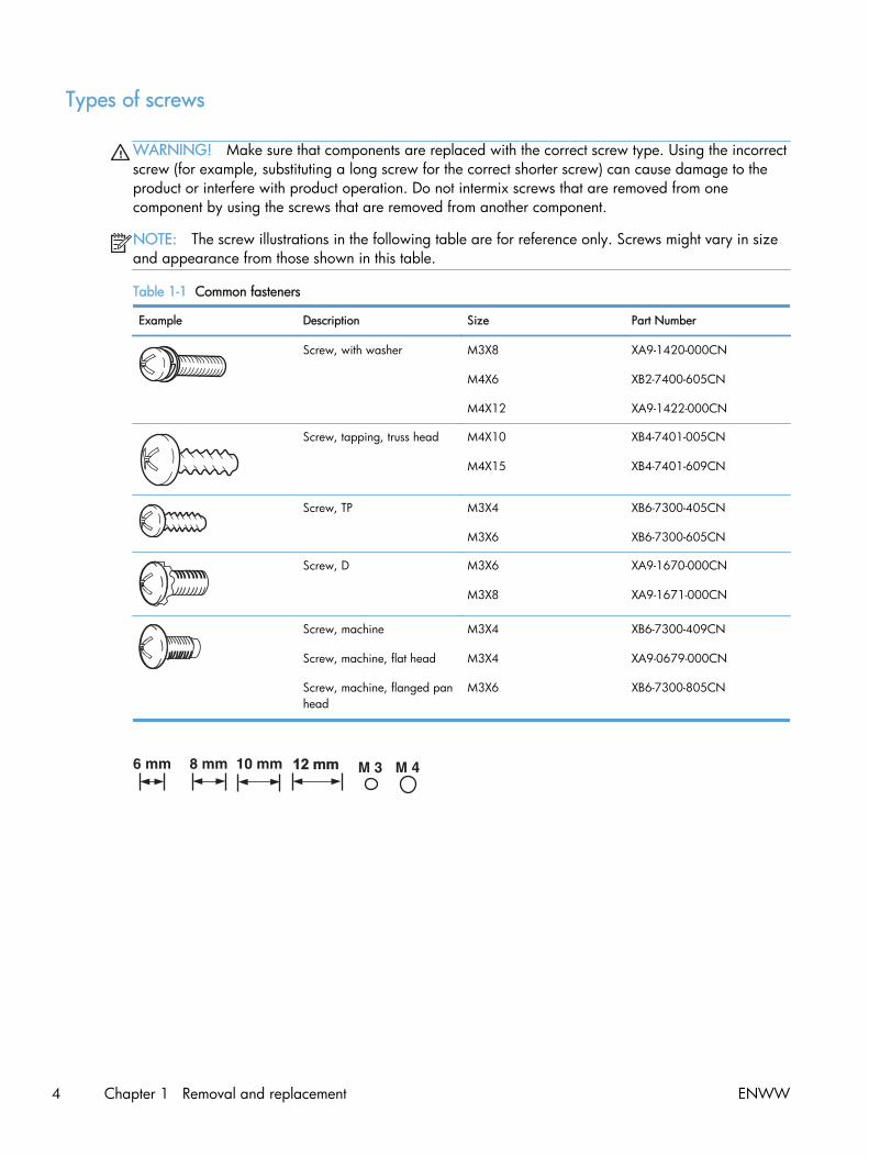
Types of screws
WARNING! Make sure that components are replaced with the correct screw type. Using the incorrectscrew (for example, substituting a long screw for the correct shorter screw) can cause damage to theproduct or interfere with product operation. Do not intermix screws that are removed from onecomponent by using the screws that are removed from another component.
NOTE: The screw illustrations in the following table are for reference only. Screws might vary in sizeand appearance from those shown in this table.
Table 1-1 Common fasteners
Example Description Size Part Number
Screw, with washer M3X8
M4X6
M4X12
XA9-1420-000CN
XB2-7400-605CN
XA9-1422-000CN
Screw, tapping, truss head M4X10
M4X15
XB4-7401-005CN
XB4-7401-609CN
Screw, TP M3X4
M3X6
XB6-7300-405CN
XB6-7300-605CN
Screw, D M3X6
M3X8
XA9-1670-000CN
XA9-1671-000CN
Screw, machine
Screw, machine, flat head
Screw, machine, flanged panhead
M3X4
M3X4
M3X6
XB6-7300-409CN
XA9-0679-000CN
XB6-7300-805CN
12 mm12 mm
4 Chapter 1 Removal and replacement ENWW

Service approach
Before performing service
● Remove all media from the product.
● Turn off the power using the power switch.
● Unplug the power cable and interface cable(s).
● Place the product on an ESD mat (if one is available). If an ESD workstation or mat is notavailable, ground yourself by touching the sheet-metal chassis before touching an ESD-sensitivepart.
● Remove the toner cartridges.
● Remove the tray 2 cassette.
After performing service
● Connect the power cable.
● Reinstall the toner cartridges.
● Reinstall the tray 2 cassette.
ENWW Service approach 5

Post-service tests
After service has been completed, perform the following tests to verify that the repair or replacementwas successful.
Test 1 (print-quality test)
1. Verify that you have completed the necessary reassembly steps.
2. Make sure that the input tray contains clean, unmarked paper.
3. Attach the power cable and interface cable, and then turn on the product.
4. Verify that the expected start-up sounds occur.
5. Print a configuration page, and then verify that the expected printing sounds occur.
6. Print a demo page, and then verify that the print quality is as expected.
7. Send a print job from the host computer, and then verify that the output meets expectations.
8. If necessary, restore any customer-specified settings.
9. Clean the outside of the product by using a damp cloth.
Test 2 (copy-quality test)
1. Verify that you have completed the necessary reassembly steps.
2. Make sure that the input tray contains clean, unmarked paper.
3. Attach the power cable, and then turn on the product.
4. Verify that the expected start-up sounds occur.
5. Print a configuration page, and then verify that the expected printing sounds occur.
6. Place the configuration page in the document feeder.
7. Print a copy job, and then verify the results.
8. Clean the outside of the product by using a damp cloth.
Test 3 (fax-quality test; fax models only)
1. Place the configuration page in the document feeder.
2. Type a valid fax number and send the fax job.
3. Verify that the send quality and receive quality meet expectations.
6 Chapter 1 Removal and replacement ENWW

Parts removal order
Figure 1-2 Parts removal order (1 of 2)
ENWW Service approach 7

Figure 1-3 Parts removal order (2 of 2)
8 Chapter 1 Removal and replacement ENWW

Removal and replacement procedures
Rollers and pads
Transfer roller
The transfer roller is a component of the paper-feed assembly and not available as an individual FRU.To remove and replace the transfer roller, install a replacement paper-feed guide assembly. See Paper-feed guide assembly on page 31.
ENWW Removal and replacement procedures 9

Pickup roller (Tray 2 and Tray 3)
The roller must be rotated into the service position to remove it.
CAUTION: Avoid touching the spongy roller surface unless you are going to replace the roller. Skinoils on the roller can cause paper pickup problems.
1. Turn the product on, and wait for it to reach the Ready state. Perform the following steps to rotatethe roller to the service position.
NOTE: If you have removed Tray 2 to service the product, reinstall the tray before turning thepower on.
TIP: The following steps rotate the engine pickup roller and the Tray 1 pickup roller into theservice position.
a. Simultaneously press the Left Arrow button and the Cancel button to open the 2ndryService menu.
b. Touch the Pick Roller item.
Touch the OK button to confirm that you want the roller to rotate.
c. Listen for the roller to rotate. When the roller is done rotating, unplug the power cable andthen place the power button in the off position.
CAUTION: It is important to place the power button in the off position after unplugging thepower cable so that the product power does not come on immediately when the power cableis plugged in again.
d. Remove Tray 2.
e. Perform the remaining steps in this procedure to remove the roller. After replacing the roller,plug the power cable into the product, and then use the power button to turn the power on.
10 Chapter 1 Removal and replacement ENWW

2. Carefully raise the front of the product.
WARNING! Do not place the product face-up resting on the rear cover and rear door. Excesstoner might enter the laser/scanner assembly and contaminate the mirrors, causing print-qualityproblems. The laser/scanner is not a FRU. If the laser/scanner mirrors are contaminated, the entireproduct must be replaced.
CAUTION: The document feeder and scanner cover are not captive and can open suddenlywhen the product is placed front-side face up. Always support the document feeder and scannercover before placing the product front-side face up.
Do not lift the product grasping the front door and Tray 2 cavity.
NOTE: The roller is located inside the tray cavity.
Figure 1-4 Remove the pickup roller (1 of 2)
ENWW Removal and replacement procedures 11

3. Use a pair of snap-ring pliers to release two locking tabs and remove the pickup roller.
CAUTION: Do not touch the spongy roller surface unless you are going to replace the roller.Skin oils on the roller can cause paper pickup problems.
NOTE: If you do not have a pair of snap-ring pliers, use your fingers to release the tabs.
Figure 1-5 Remove the pickup roller (2 of 2)
12 Chapter 1 Removal and replacement ENWW
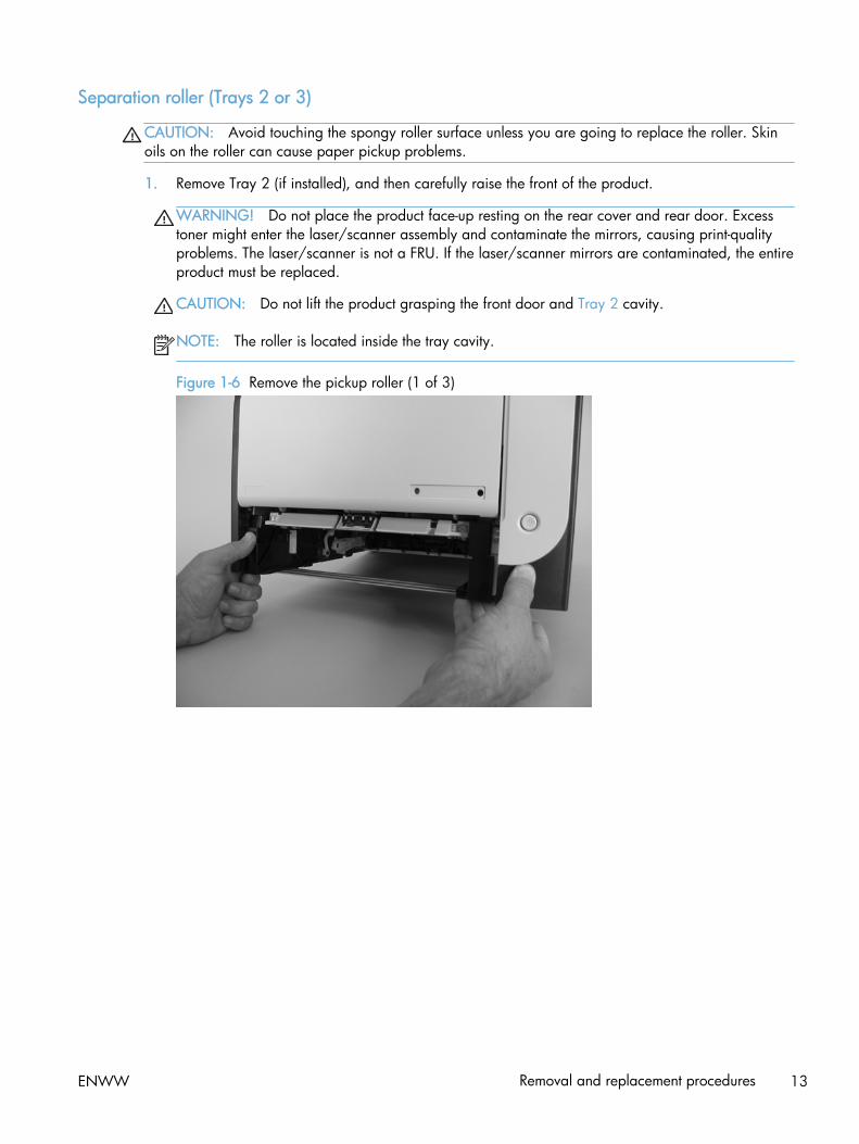
Separation roller (Trays 2 or 3)
CAUTION: Avoid touching the spongy roller surface unless you are going to replace the roller. Skinoils on the roller can cause paper pickup problems.
1. Remove Tray 2 (if installed), and then carefully raise the front of the product.
WARNING! Do not place the product face-up resting on the rear cover and rear door. Excesstoner might enter the laser/scanner assembly and contaminate the mirrors, causing print-qualityproblems. The laser/scanner is not a FRU. If the laser/scanner mirrors are contaminated, the entireproduct must be replaced.
CAUTION: Do not lift the product grasping the front door and Tray 2 cavity.
NOTE: The roller is located inside the tray cavity.
Figure 1-6 Remove the pickup roller (1 of 3)
ENWW Removal and replacement procedures 13

2. Release the two roller-cover locking pins, and then remove the cover.
Figure 1-7 Remove the separation roller (2 of 3)
3. Release the roller holder to release the roller-locking pins. Remove the separation roller.
Figure 1-8 Remove the separation roller (3 of 3)
14 Chapter 1 Removal and replacement ENWW

Reinstall the separation roller
1. Install the replacement separation roller.
2. Reinstall the separation roller cover on the locking pins, and then rotate it toward the roller untilyou hear it snap into place.
Figure 1-9 Reinstall the separation roller
ENWW Removal and replacement procedures 15

Document feeder pickup roller assembly
IMPORTANT: The document feeder pickup roller must be shipped in the down position.
1. Open the document feeder cover.
2. Disconnect one spring (callout 1).
Figure 1-10 Remove the document feeder pickup roller assembly (1 of 2)
1
3. Lift up on the end of the assembly, and then slide it toward the control panel to remove it.
Figure 1-11 Remove the document feeder pickup roller assembly (2 of 2)
2
1
16 Chapter 1 Removal and replacement ENWW

Pickup roller and separation pad (Tray 1)
The roller must be rotated into the service position to remove it.
CAUTION: Avoid touching the spongy roller surface unless you are going to replace the roller. Skinoils on the roller can cause paper pickup problems.
NOTE: Always replace the separation pad when replacing the pickup roller.
1. Turn the product on, and wait for it to reach the Ready state. Perform the following steps to rotatethe roller to the service position.
NOTE: If you have removed Tray 2 to service the product, reinstall the tray before turning thepower on.
TIP: The following steps rotate the engine pickup roller and the Tray 1 pickup roller into theservice position.
a. Open the 2ndry Service menu by pressing the Left Arrow button and the Cancel button simultaneously.
b. Use the arrow buttons to select Pick Roller, and then press the OK button.
Touch the OK button again to confirm that you want the roller to rotate.
c. Listen for the roller to rotate. When the roller is done rotating, unplug the power cable andthen place the power button in the off position.
NOTE: Failure to unplug the product at this point will result in the roller being in theincorrect position for the repair procedure.
CAUTION: It is important to place the power button in the off position after unplugging thepower cable so that the product power does not come on immediately when the power cableis plugged in again.
d. Remove Tray 2.
e. Perform the remaining steps in this procedure to remove the roller. After replacing the roller,plug the power cable into the product, and then use the power button to turn the power on.
ENWW Removal and replacement procedures 17

2. Lower the Tray 1 paper pickup assembly by pushing down on the edges of the assembly.
Figure 1-12 Remove the Tray 1 pickup roller (1 of 3)
3. Carefully raise the front of the product.
WARNING! Do not place the product face-up resting on the rear cover and rear door. Excesstoner might enter the laser/scanner assembly and contaminate the mirrors, causing print-qualityproblems. The laser/scanner is not a FRU. If the laser/scanner mirrors are contaminated, the entireproduct must be replaced.
CAUTION: The document feeder and scanner cover are not captive and can open suddenlywhen the product is placed front-side face up. Always support the document feeder and scannercover before placing the product front-side face up.
CAUTION: Do not lift the product grasping the front door and Tray 2 cavity.
Figure 1-13 Remove the Tray 1 pickup roller (2 of 3)
18 Chapter 1 Removal and replacement ENWW
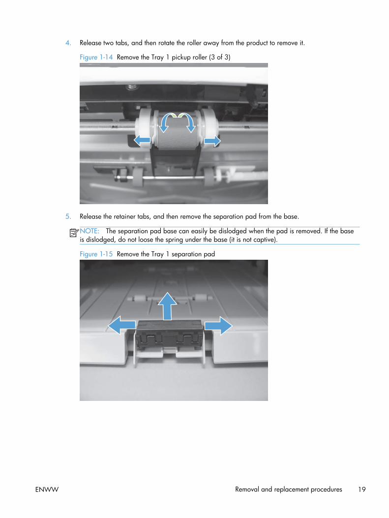
4. Release two tabs, and then rotate the roller away from the product to remove it.
Figure 1-14 Remove the Tray 1 pickup roller (3 of 3)
5. Release the retainer tabs, and then remove the separation pad from the base.
NOTE: The separation pad base can easily be dislodged when the pad is removed. If the baseis dislodged, do not loose the spring under the base (it is not captive).
Figure 1-15 Remove the Tray 1 separation pad
ENWW Removal and replacement procedures 19
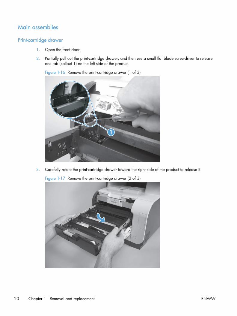
Main assemblies
Print-cartridge drawer
1. Open the front door.
2. Partially pull out the print-cartridge drawer, and then use a small flat blade screwdriver to releaseone tab (callout 1) on the left side of the product.
Figure 1-16 Remove the print-cartridge drawer (1 of 3)
1
3. Carefully rotate the print-cartridge drawer toward the right side of the product to release it.
Figure 1-17 Remove the print-cartridge drawer (2 of 3)
20 Chapter 1 Removal and replacement ENWW

4. Pull the print-cartridge drawer out of the product to remove it.
Figure 1-18 Remove the print-cartridge drawer (3 of 3)
ENWW Removal and replacement procedures 21
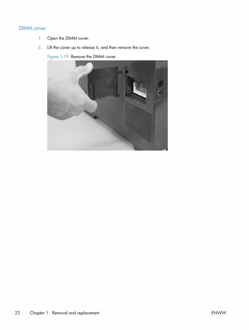
DIMM cover
1. Open the DIMM cover.
2. Lift the cover up to release it, and then remove the cover.
Figure 1-19 Remove the DIMM cover
22 Chapter 1 Removal and replacement ENWW

Right cover
NOTE: For duplex products, open the rear door.
1. Remove three screws (callout 1).
Figure 1-20 Remove the right cover (1 of 3)
1
2. Slide the right cover toward the back of the product.
Figure 1-21 Remove the right cover (2 of 3)
ENWW Removal and replacement procedures 23

3. Remove the right cover.
Figure 1-22 Remove the right cover (3 of 3)
24 Chapter 1 Removal and replacement ENWW

Document feeder input tray
▲ Open the document feeder top cover.
Figure 1-23 Remove the document feeder input tray (2 of 2)
Rotate the document feeder input tray up to release it, and then remove the tray.
TIP: Hold down the scanner lid while removing the tray. It might take considerable pressure to releasethe tray form the document feeder.
Figure 1-24 Remove the document feeder input tray (2 of 2)
ENWW Removal and replacement procedures 25

Scanner assembly
1. Remove the right cover. See Right cover on page 23.
2. Disconnect one FFCs (callout 1), two connectors (callout 2), and one ground-wire connector(callout 3).
Figure 1-25 Remove the scanner assembly (1 of 4)
1
23
3. Remove four screws (callout 1).
Figure 1-26 Remove the scanner assembly (2 of 4)
1
26 Chapter 1 Removal and replacement ENWW

4. Slightly lift up the back of the scanner, and then slide it toward the front of the product.
Figure 1-27 Remove the scanner assembly (3 of 4)
5. Lift the scanner straight up and off of the product.
Figure 1-28 Remove the scanner assembly (4 of 4)
ENWW Removal and replacement procedures 27

Right-front cover and power button
1. Remove the right cover. See Right cover on page 23.
2. Disconnect the USB PCA connector from the formatter PCA (callout 1), and then release the wirefrom the retainer (callout 2).
1
2
3. Open the front door, and then remove three screws (callout 1).
1
28 Chapter 1 Removal and replacement ENWW
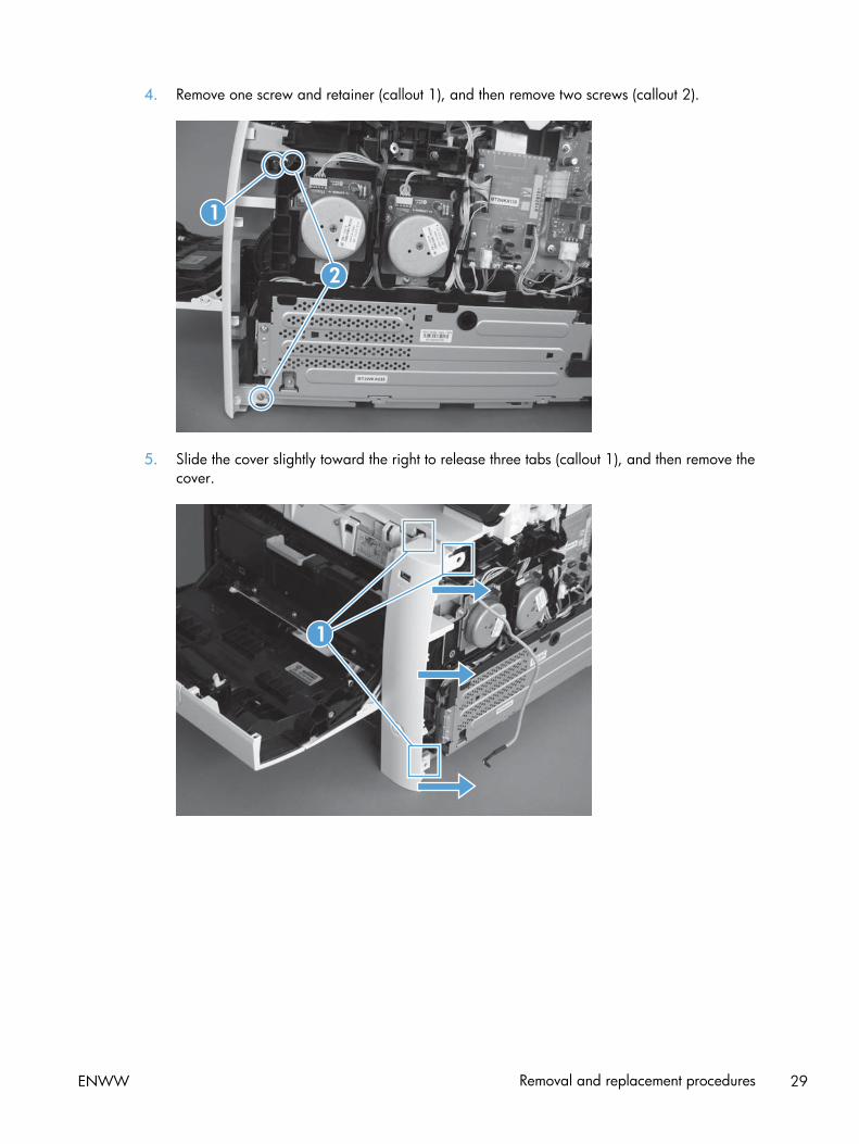
4. Remove one screw and retainer (callout 1), and then remove two screws (callout 2).
2
1
5. Slide the cover slightly toward the right to release three tabs (callout 1), and then remove thecover.
1
ENWW Removal and replacement procedures 29

Rear-upper cover (duplex product)
1. Open the rear cover.
2. Remove two screws (callout 1).
Figure 1-29 Remove the rear-upper cover (1 of 2)
1
3. Slightly separate the cover from the product, and then rotate the cover down and then away fromthe product to remove it.
Figure 1-30 Remove the rear-upper cover (2 of 2)
30 Chapter 1 Removal and replacement ENWW
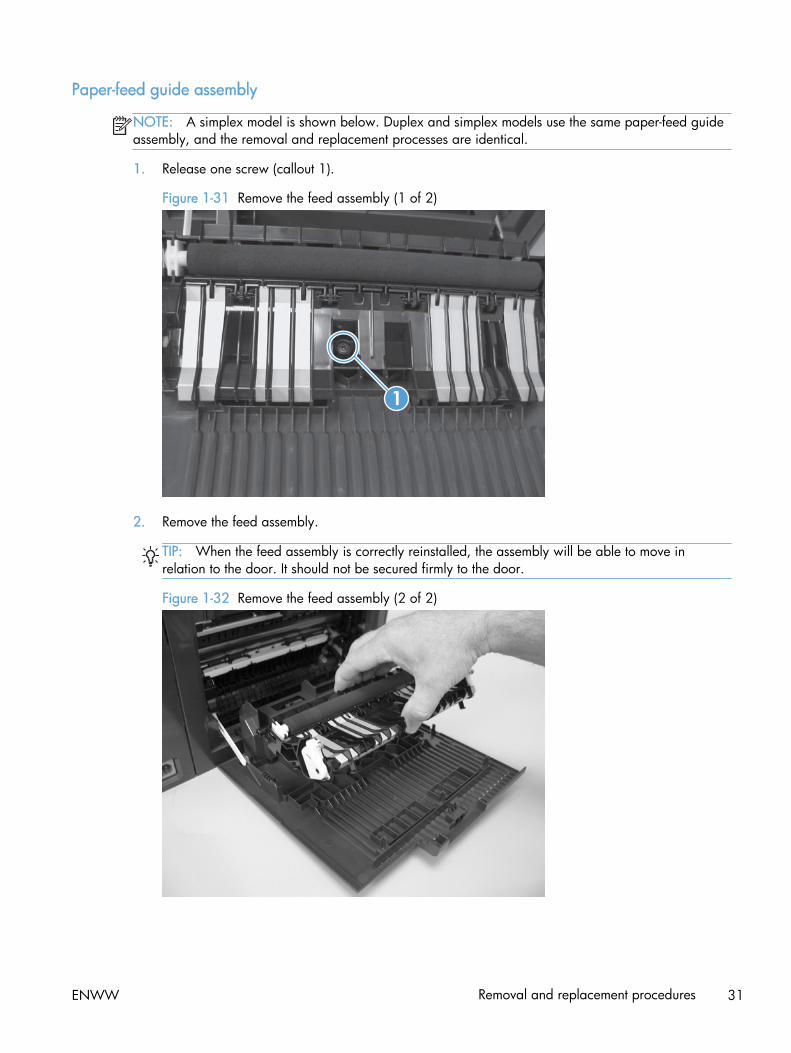
Paper-feed guide assembly
NOTE: A simplex model is shown below. Duplex and simplex models use the same paper-feed guideassembly, and the removal and replacement processes are identical.
1. Release one screw (callout 1).
Figure 1-31 Remove the feed assembly (1 of 2)
1
2. Remove the feed assembly.
TIP: When the feed assembly is correctly reinstalled, the assembly will be able to move inrelation to the door. It should not be secured firmly to the door.
Figure 1-32 Remove the feed assembly (2 of 2)
ENWW Removal and replacement procedures 31

Rear-door stopper and link caps (simplex product)
1. Open the rear door.
2. Use a pair of needle-nose pliers to release two tabs, and then remove the link cap.
Figure 1-33 Remove the Rear-door stopper and link caps (simplex product) (1 of 2)
3. Use a small flat blade screwdriver to carefully remove the remaining link cap, and then remove theRear-door stopper.
Figure 1-34 Remove the Rear-door stopper and link cap (simplex product) (2 of 2)
32 Chapter 1 Removal and replacement ENWW

Rear door (simplex product)
1. Open the rear door.
2. Use a pair of needle-nose pliers to release two tabs, and then remove the link cap.
Figure 1-35 Remove the rear door (simplex product) (1 of 4)
3. Remove four screws (callout 1).
Figure 1-36 Remove the rear door (simplex product) (2 of 4)
1
ENWW Removal and replacement procedures 33
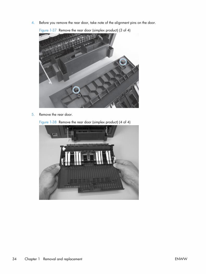
4. Before you remove the rear door, take note of the alignment pins on the door.
Figure 1-37 Remove the rear door (simplex product) (3 of 4)
5. Remove the rear door.
Figure 1-38 Remove the rear door (simplex product) (4 of 4)
34 Chapter 1 Removal and replacement ENWW
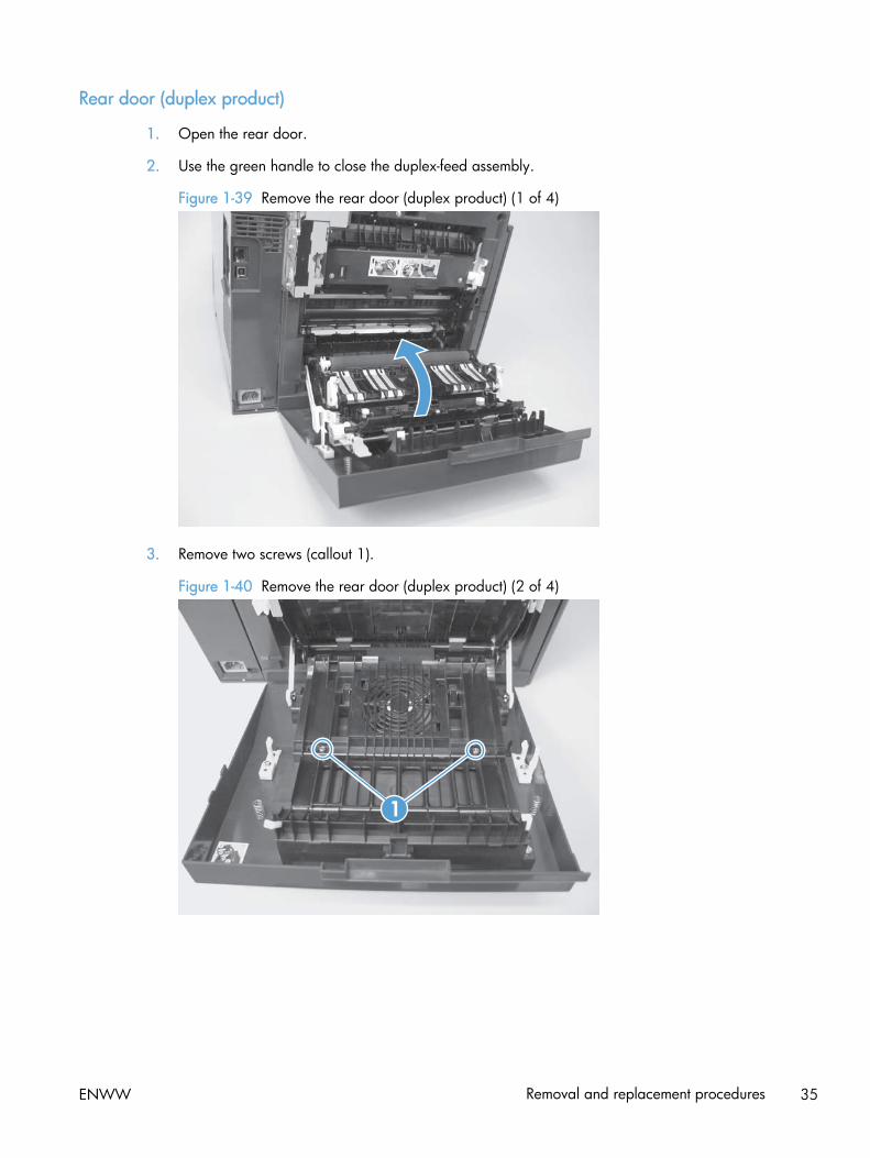
Rear door (duplex product)
1. Open the rear door.
2. Use the green handle to close the duplex-feed assembly.
Figure 1-39 Remove the rear door (duplex product) (1 of 4)
3. Remove two screws (callout 1).
Figure 1-40 Remove the rear door (duplex product) (2 of 4)
1
ENWW Removal and replacement procedures 35
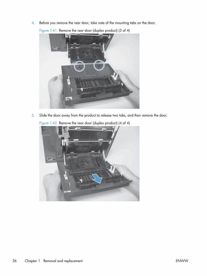
4. Before you remove the rear door, take note of the mounting tabs on the door.
Figure 1-41 Remove the rear door (duplex product) (3 of 4)
5. Slide the door away from the product to release two tabs, and then remove the door.
Figure 1-42 Remove the rear door (duplex product) (4 of 4)
36 Chapter 1 Removal and replacement ENWW

Rear cover and feed guide (simplex product)
Before proceeding, remove the following components:
● Right cover. See Right cover on page 23.
● Rear-door stopper. See Rear-door stopper and link caps (simplex product) on page 32.
● Rear door. See Rear door (simplex product) on page 33 or Rear door (duplex product)on page 35.
Remove the rear cover and feed guide (simplex product)
1. Carefully release the link guide from the pivot pin on the feed guide.
Figure 1-43 Remove the rear cover and feed guide (simplex product) (1 of 6)
ENWW Removal and replacement procedures 37

2. Remove three screws (callout 1).
Figure 1-44 Remove the rear cover and feed guide (simplex product) (2 of 6)
1
3. Release two tabs (callout 1).
Figure 1-45 Remove the rear cover and feed guide (simplex product) (3 of 6)
1
38 Chapter 1 Removal and replacement ENWW
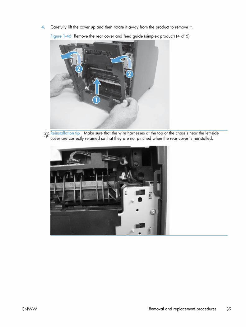
4. Carefully lift the cover up and then rotate it away from the product to remove it.
Figure 1-46 Remove the rear cover and feed guide (simplex product) (4 of 6)
1
22
Reinstallation tip Make sure that the wire harnesses at the top of the chassis near the left-sidecover are correctly retained so that they are not pinched when the rear cover is reinstalled.
ENWW Removal and replacement procedures 39

5. Carefully release a feed-guide hinge pin from the rear cover to release the feed guide.
Figure 1-47 Remove the rear cover and feed guide (simplex product) (5 of 6)
6. Remove the feed guide.
Figure 1-48 Remove the rear cover and feed guide (simplex product) (6 of 6)
40 Chapter 1 Removal and replacement ENWW

Rear-lower cover and rear-door links (duplex product)
Before proceeding, remove the following components:
● Right cover. See Right cover on page 23.
● Rear door. See Rear door (simplex product) on page 33 or Rear door (duplex product)on page 35.
● Rear upper cover. See Rear-upper cover (duplex product) on page 30.
Remove the rear-lower cover and rear-door links (duplex product)
1. Use a pair of needle-nose pliers to release two tabs, and then remove the rear-door link cap.Repeat this step for the remaining rear-door link cap.
Figure 1-49 Remove the rear- lower cover and rear-door links (duplex product) (1 of 6)
ENWW Removal and replacement procedures 41

2. Open the duplex-feed assembly, release one tab (callout 1), and then slightly separate the coverfrom the product.
Figure 1-50 Remove the rear-lower cover and rear-door links (duplex product) (2 of 6)
1
3. Release one tab (callout 1) and slightly separate the cover from the product.
Figure 1-51 Remove the rear-lower cover and rear-door links (duplex product) (3 of 6)
1
42 Chapter 1 Removal and replacement ENWW

4. Close the duplex assembly, and then lift up on one side of the cover, and then the other side of thecover to release it.
Figure 1-52 Remove the rear-lower cover and link-guides (duplex product) (4 of 6)
5. Slightly lift up the rear-door rib assembly, and then carefully slide the cover away from the productto remove it.
Figure 1-53 Remove the rear-lower cover and link-guides (duplex product) (5 of 6)
ENWW Removal and replacement procedures 43

6. Rotate the rear-door link until the slot in the link aligns with the tap on the link-hinge pin, and thenremove the rear-door link. Repeat this step for the remaining rear-door link.
NOTE: If you are installing a replacement rear-lower cover, remove the rear-door links from thediscarded cover, and then install them on the replacement cover.
Figure 1-54 Remove the rear-lower cover and rear-door links (duplex product) (6 of 6)
44 Chapter 1 Removal and replacement ENWW

Rear-door rib assembly (duplex product)
Before proceeding, remove the following components:
● Right cover. See Right cover on page 23.
● Rear door. See Rear door (simplex product) on page 33 or Rear door (duplex product)on page 35.
● Rear upper cover. See Rear-upper cover (duplex product) on page 30.
● Rear-lower cover. See Rear-lower cover and rear-door links (duplex product) on page 41.
Remove the rear-door rib assembly (duplex product)
NOTE: The duplex fan (FM2) is a component of the rear-door rib assembly.
1. Disconnect one connector (callout 1).
TIP: The PCA can be dislodged when disconnecting the connector. To secure the PCA, carefullypush it towards the inside of the product to clear the mounting tabs near the rib assembly(callout 2 shows the PCA correctly positioned under the tabs). Slide the PCA towards the ribassembly to position the edge of the PCA under the mounting tabs.
Figure 1-55 Remove the rear-door rib assembly (duplex product) (1 of 3)
1
ENWW Removal and replacement procedures 45

2. Slide the assembly toward the power cable side of the product to release the hinge pin.
Figure 1-56 Remove the rear-door rib assembly (duplex product) (2 of 3)
3. Remove the assembly.
Figure 1-57 Remove the rear-door rib assembly (duplex product) (3 of 3)
46 Chapter 1 Removal and replacement ENWW

Link guide
The link guide rarely fails and is not a FRU.
The link is attached to the paper guide (callout 1) and the rear door (simplex products; callout 2) orduplexing-feed guide assembly (duplex products; callout 3).
If the link-guide attachment at the rear door or duplexing-feed guide assembly fails, replace theappropriate component.
The interior paper guide is not replaceable. If the link-guide to paper guide attachment fails, you mustreplace the entire product.
Figure 1-58 Replace the link guide (simplex products)
1
2
Figure 1-59 Replace the link guide (duplex products)
3
ENWW Removal and replacement procedures 47

Control panel and right-arm mount
1. Remove the Right cover. See Right cover on page 23.
2. Disconnect two FFCs and three connectors (callout 1) from the formatter PCA. Remove the USBPCA connector from the retainer.
Figure 1-60 Remove the control panel and right-arm mount (1 of 3)
1
3. Remove three screws (callout 1) and disconnect the ground wire (callout 2).
Figure 1-61 Remove the control panel and right-arm mount (2 of 3)
1
2
48 Chapter 1 Removal and replacement ENWW

4. Slide the control panel right-arm mount to the right to remove it from the scanner chassis.
Figure 1-62 Remove the control panel and right-arm mount (3 of 3)
Reinstall the control panel and right-arm mount
1. Slide the control panel right-arm mount assembly into the mounting points on the scanner chassis.
2. Install three screws (callout 1) and attach the grounding wire (callout 2).
IMPORTANT: The grounding wire and the two FFCs must move freely. If the grounding wire istangled with the FFCs, or is retracted too far into the control panel swivel, it might be too short toreach the mounting point on the chassis.
Figure 1-63 Reinstall the control panel and right-arm mount (1 of 2)
1
2
ENWW Removal and replacement procedures 49

3. Attach two FFCs and three connectors (callout 1). Install the USB PCA connector in the retainer.
Figure 1-64 Reinstall the control panel and right-arm mount (2 of 2)
1
50 Chapter 1 Removal and replacement ENWW
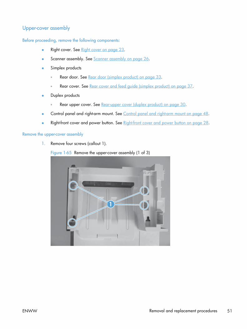
Upper-cover assembly
Before proceeding, remove the following components:
● Right cover. See Right cover on page 23.
● Scanner assembly. See Scanner assembly on page 26.
● Simplex products
◦ Rear door. See Rear door (simplex product) on page 33.
◦ Rear cover. See Rear cover and feed guide (simplex product) on page 37.
● Duplex products
◦ Rear upper cover. See Rear-upper cover (duplex product) on page 30.
● Control panel and right-arm mount. See Control panel and right-arm mount on page 48.
● Right-front cover and power button. See Right-front cover and power button on page 28.
Remove the upper-cover assembly
1. Remove four screws (callout 1).
Figure 1-65 Remove the upper-cover assembly (1 of 3)
1
ENWW Removal and replacement procedures 51

2. Slightly raise the back of the cover up and off of the product.
Figure 1-66 Remove the upper-cover assembly (2 of 3)
3. Slide the cover toward the back of the product to remove it.
Figure 1-67 Remove the upper-cover assembly (3 of 3)
52 Chapter 1 Removal and replacement ENWW

Reinstall the upper-cover assembly
1. Position the upper-cover so that the front-left corner of the upper cover engages the left-side cover(callout 1).
Figure 1-68 Reinstall the upper-cover assembly (1 of 3)
1
2. Slightly push the cover toward the front of the product to engage the front-locking tabs (callout 1)with the holes in the chassis.
NOTE: Make sure that the right-front edge of the upper cover (where the product right-front coverwill be installed) is correctly positioned on the chassis.
Figure 1-69 Reinstall the upper-cover assembly (2 of 3)
1
ENWW Removal and replacement procedures 53

3. Carefully pry the right-rear corner of the upper cover away from the product until the cover fitsover the chassis.
Lower the cover onto the product.
Figure 1-70 Reinstall the upper-cover assembly (3 of 3)
54 Chapter 1 Removal and replacement ENWW
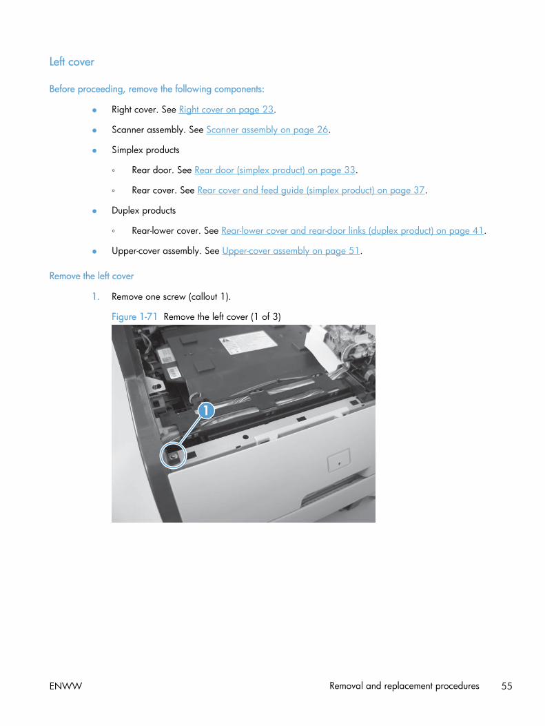
Left cover
Before proceeding, remove the following components:
● Right cover. See Right cover on page 23.
● Scanner assembly. See Scanner assembly on page 26.
● Simplex products
◦ Rear door. See Rear door (simplex product) on page 33.
◦ Rear cover. See Rear cover and feed guide (simplex product) on page 37.
● Duplex products
◦ Rear-lower cover. See Rear-lower cover and rear-door links (duplex product) on page 41.
● Upper-cover assembly. See Upper-cover assembly on page 51.
Remove the left cover
1. Remove one screw (callout 1).
Figure 1-71 Remove the left cover (1 of 3)
1
ENWW Removal and replacement procedures 55

2. Slightly lift up on the cover, and then rotate the top of the cover away from the product.
Figure 1-72 Remove the left cover (2 of 3)
3. Remove the cover.
Figure 1-73 Remove the left cover (3 of 3)
56 Chapter 1 Removal and replacement ENWW
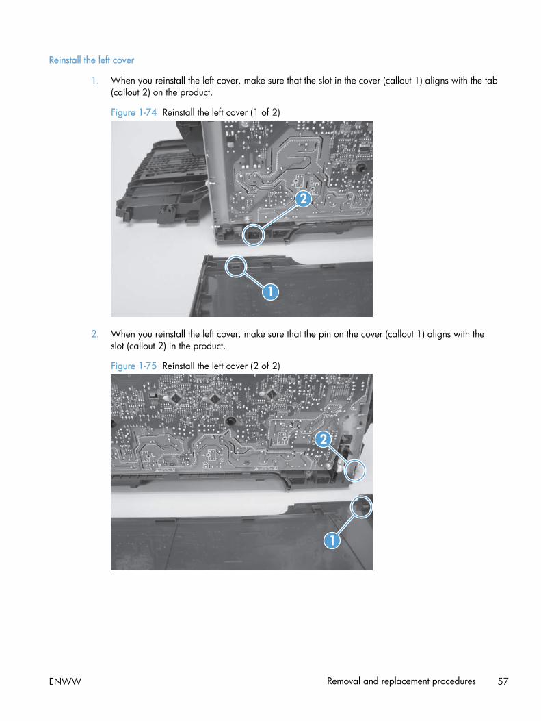
Reinstall the left cover
1. When you reinstall the left cover, make sure that the slot in the cover (callout 1) aligns with the tab(callout 2) on the product.
Figure 1-74 Reinstall the left cover (1 of 2)
1
2
2. When you reinstall the left cover, make sure that the pin on the cover (callout 1) aligns with theslot (callout 2) in the product.
Figure 1-75 Reinstall the left cover (2 of 2)
1
2
ENWW Removal and replacement procedures 57
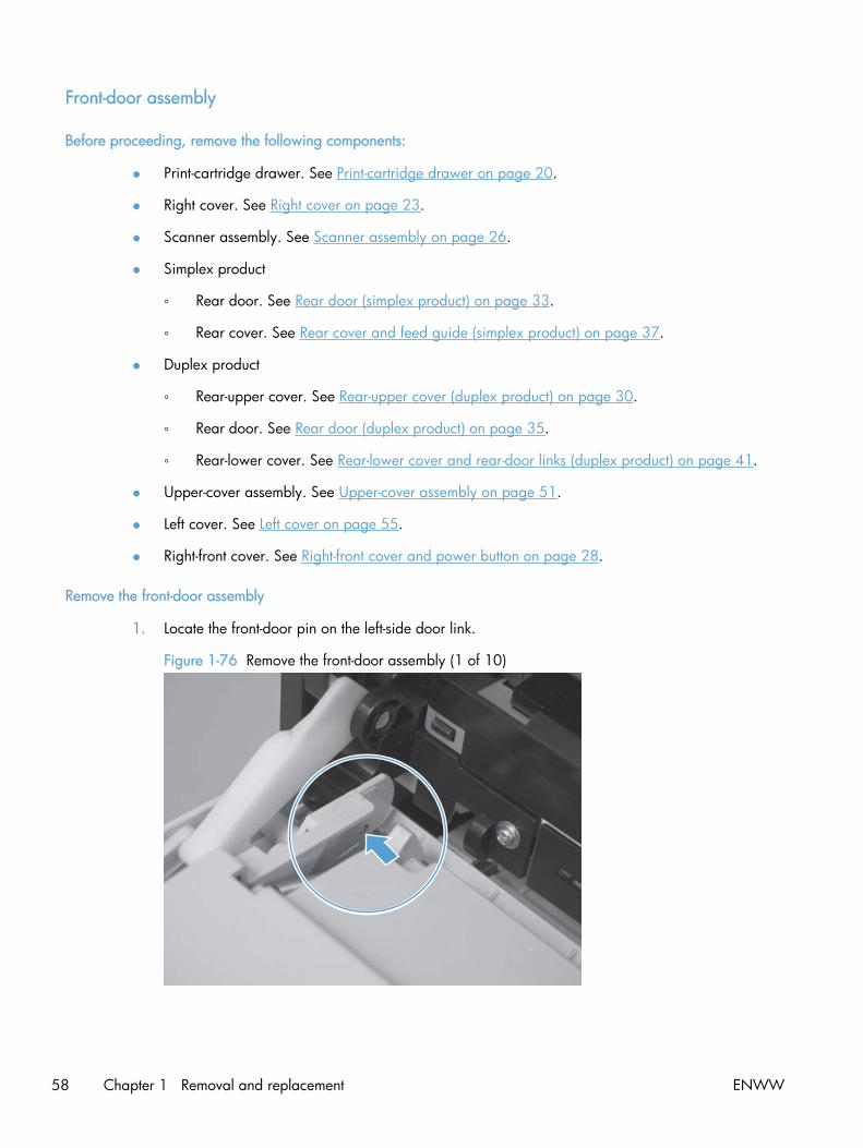
Front-door assembly
Before proceeding, remove the following components:
● Print-cartridge drawer. See Print-cartridge drawer on page 20.
● Right cover. See Right cover on page 23.
● Scanner assembly. See Scanner assembly on page 26.
● Simplex product
◦ Rear door. See Rear door (simplex product) on page 33.
◦ Rear cover. See Rear cover and feed guide (simplex product) on page 37.
● Duplex product
◦ Rear-upper cover. See Rear-upper cover (duplex product) on page 30.
◦ Rear door. See Rear door (duplex product) on page 35.
◦ Rear-lower cover. See Rear-lower cover and rear-door links (duplex product) on page 41.
● Upper-cover assembly. See Upper-cover assembly on page 51.
● Left cover. See Left cover on page 55.
● Right-front cover. See Right-front cover and power button on page 28.
Remove the front-door assembly
1. Locate the front-door pin on the left-side door link.
Figure 1-76 Remove the front-door assembly (1 of 10)
58 Chapter 1 Removal and replacement ENWW

2. Use a precision point screwdriver to push the left-side door pin out of the link.
NOTE: A precision point screwdriver is required to release the front door pins. The width of theblade must be 2 mm (0.08 in) or less to be able to push the door pins out of the mounting holes.
Figure 1-77 Remove the front-door assembly (2 of 10)
3. Use a precision point screwdriver to push the right-side door pin out of the link.
NOTE: A precision point screwdriver is required to release the front door pins. The width of theblade must be 2 mm (0.08 in) or less to be able to push the door pins out of the mounting holes.
Figure 1-78 Remove the front-door assembly (3 of 10)
ENWW Removal and replacement procedures 59

4. Remove two screws (callout 1) and the separate the door bushing (callout 2) from the chassis.
Figure 1-79 Remove the front-door assembly (4 of 10)
12
5. Release the bushing from the door-retainer link (callout 1).
Figure 1-80 Remove the front-door assembly (5 of 10)
1
60 Chapter 1 Removal and replacement ENWW

6. Support the door assembly, and carefully release the pin on the right-side link.
Figure 1-81 Remove the front-door assembly (6 of 10)
7. Support the door assembly, and carefully release the upper pin on the left-side link.
Figure 1-82 Remove the front-door assembly (7 of 10)
ENWW Removal and replacement procedures 61

8. Push the black-plastic arm into the product.
Figure 1-83 Remove the front-door assembly (8 of 10)
9. Support the door assembly, and carefully release the lower pin on the left-side link.
Figure 1-84 Remove the front-door assembly (9 of 10)
62 Chapter 1 Removal and replacement ENWW
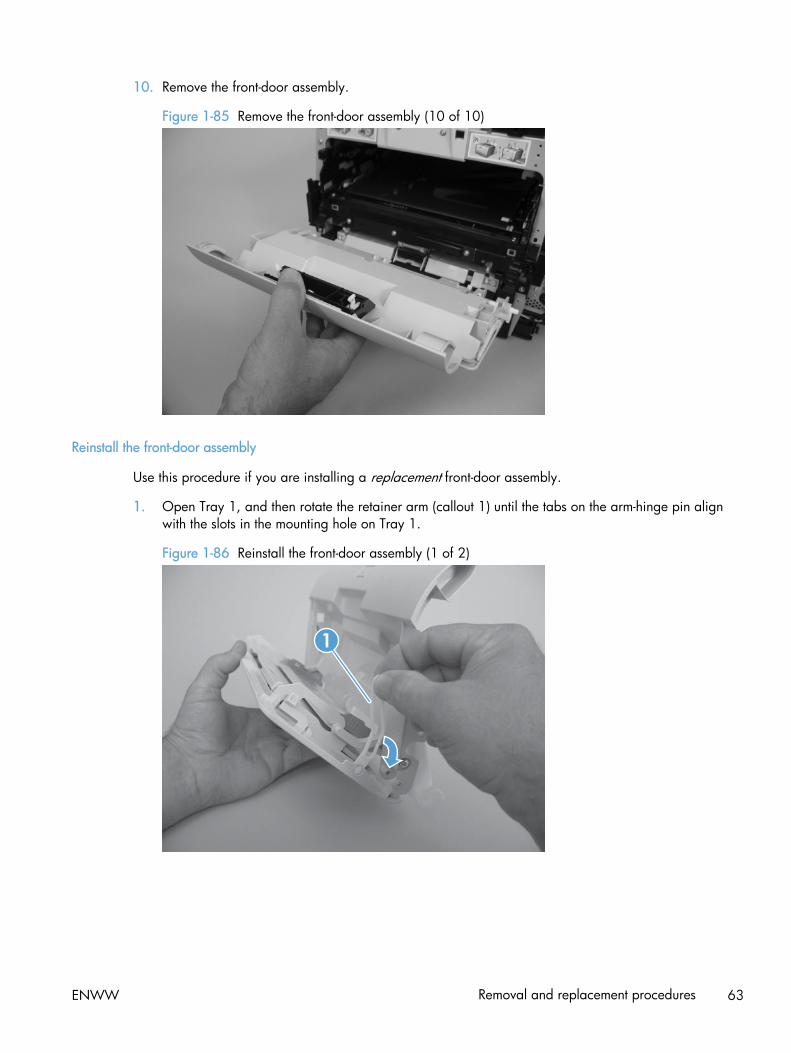
10. Remove the front-door assembly.
Figure 1-85 Remove the front-door assembly (10 of 10)
Reinstall the front-door assembly
Use this procedure if you are installing a replacement front-door assembly.
1. Open Tray 1, and then rotate the retainer arm (callout 1) until the tabs on the arm-hinge pin alignwith the slots in the mounting hole on Tray 1.
Figure 1-86 Reinstall the front-door assembly (1 of 2)
1
ENWW Removal and replacement procedures 63

2. Remove the retainer arm from the door assembly, and then install it on the replacement doorassembly.
Figure 1-87 Reinstall the front-door assembly (2 of 2)
64 Chapter 1 Removal and replacement ENWW

Intermediate transfer belt (ITB)
1. Remove the print-cartridge drawer. See Print-cartridge drawer on page 20.
2. Open the front door, and then remove two screws (callout 1).
Figure 1-88 Remove the ITB (1 of 6)
1
3. Carefully rotate the color-misregistration sensor away from the ITB.
CAUTION: The sensor is still attached to the product and cannot be completely removed.
Figure 1-89 Remove the ITB (2 of 6)
ENWW Removal and replacement procedures 65
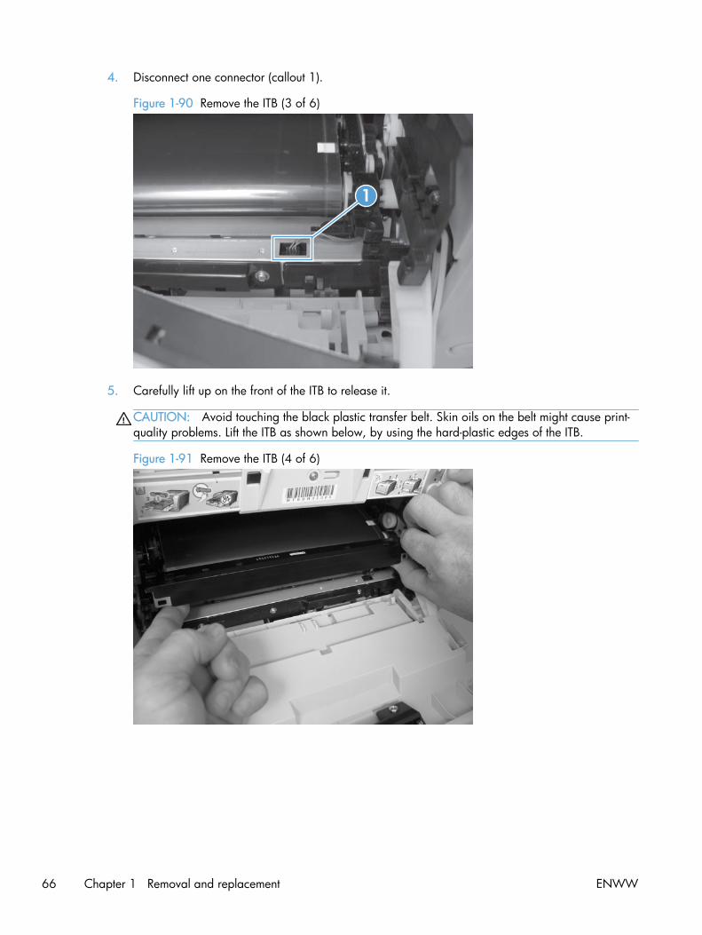
4. Disconnect one connector (callout 1).
Figure 1-90 Remove the ITB (3 of 6)
1
5. Carefully lift up on the front of the ITB to release it.
CAUTION: Avoid touching the black plastic transfer belt. Skin oils on the belt might cause print-quality problems. Lift the ITB as shown below, by using the hard-plastic edges of the ITB.
Figure 1-91 Remove the ITB (4 of 6)
66 Chapter 1 Removal and replacement ENWW

6. Open the rear door, and carefully lift up on the sheet-metal portion (callout 1) of the ITB to releaseit.
CAUTION: Avoid touching the black plastic transfer belt. Skin oils on the belt might cause print-quality problems.
NOTE: You might need to reach in through the front door and support the front portion of the ITBto keep it from falling back into place as you perform this step.
Figure 1-92 Remove the ITB (5 of 6)
1
7. Carefully pull the ITB straight out of the product to remove it.
CAUTION: Avoid touching the black plastic transfer belt. Skin oils on the belt might cause print-quality problems. Handle the ITB as shown below.
Figure 1-93 Remove the ITB (6 of 6)
ENWW Removal and replacement procedures 67

Reinstall the ITB
Use this procedure to verify that the ITB is correctly reinstalled.
1. Use the control panel to print the diagnostics pages.
2. Verify that rows one through four, columns A through I (callout 1) contain hexadecimal numbers.
If these rows and columns are all zero, ensure that the calibration sensor was correctly reinstalled.The sensor must be correctly positioned and fit securely against the chassis before the mountingscrews are installed. See 1 and 2.
Figure 1-94 Reinstall the ITB
HP Color LaserJet PRO 400
Diagnostics PageCalibration Information Color Density
Power-On Calibration : 15 MinutesCalibration Timing: 48 Hours
C M Y KContrast 0 0 0 0Highlights 0 0 0 0Midtones 0 0 0 0Shadows 0 0 0 0
Parameters 041
68 Chapter 1 Removal and replacement ENWW

Drum motor (M1) and developer motor (M2)
This procedure can be used to remove the drum motor (M1) or the developer motor (M2). HP does notrecommend removing both of the motors at the same time.
1. Remove the right cover. See Right cover on page 23.
2. Disconnect one connector (callout 1) for motor M1 or motor M2.
NOTE: The drum motor (callout 2) is motor M1. The developer motor (callout 3) is motor M2.
Figure 1-95 Remove motor M1 and motor M2 (1 of 6)
1
23
ENWW Removal and replacement procedures 69

3. Remove one screw (callout 1), and then remove the black-plastic retainer (callout 2).
NOTE: There is a small clip—the clip is used to activate the engine test button—attached to theretainer that can be easily dislodged when the retainer is removed. Do not lose this clip whenhandling the retainer.
Figure 1-96 Remove motor M1 and motor M2 (2 of 6)
1
2
70 Chapter 1 Removal and replacement ENWW

4. Release the wire harnesses from the retainer (callout 1).
NOTE: One of the wire harnesses—behind the drum motor wire harness—is difficult to releasefrom the retainer. Be careful to not damage this wire harness when releasing it.
TIP: Additional connectors might need to be disconnected to release the wire harnesses from theretainer.
Figure 1-97 Remove motor M1 and motor M2 (3 of 6)
1
ENWW Removal and replacement procedures 71

5. Release one tab (callout 1).
Figure 1-98 Remove motor M1 and motor M2 (4 of 6)
1
6. Rotate the top of the retainer away from the chassis, and then lift it up to remove it.
Figure 1-99 Remove motor M1 and motor M2 (5 of 6)
72 Chapter 1 Removal and replacement ENWW
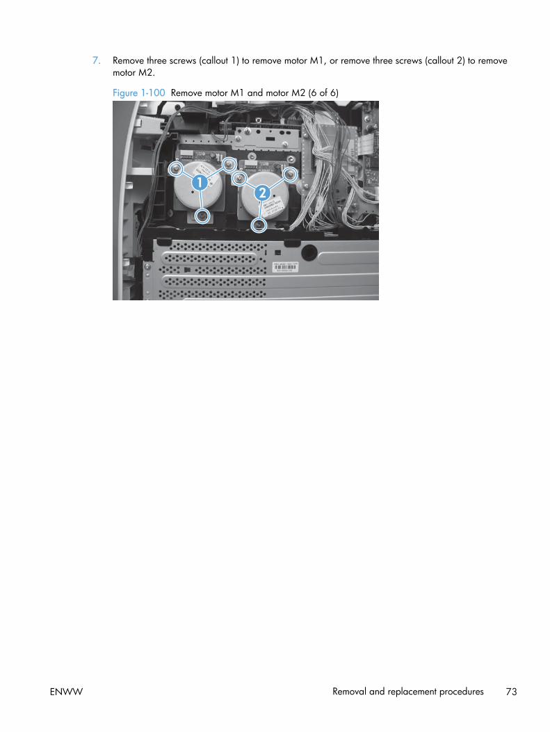
7. Remove three screws (callout 1) to remove motor M1, or remove three screws (callout 2) to removemotor M2.
Figure 1-100 Remove motor M1 and motor M2 (6 of 6)
12
ENWW Removal and replacement procedures 73

Reinstall the drum motor (M1) and developer motor (M2)
When the motor wire harness retainer is reinstalled, the two tabs at the bottom of the retainer must bepositioned behind the retainer on the low-voltage power supply. The tab at the side of motor wireharness retainer must be positioned behind the PCA next to motor M2.
Figure 1-101 Reinstall the motor M1 and motor M2 wire-harness retainer
74 Chapter 1 Removal and replacement ENWW

Intermediate PCA
1. Remove the right cover. See Right cover on page 23.
2. Disconnect all of the connectors and one FFC (callout 1) on the PCA.
Figure 1-102 Remove the Intermediate PCA (1 of 2)
1
3. Remove three screws (callout 1) , and then remove the intermediate PCA.
Figure 1-103 Remove the Intermediate PCA (2 of 2)
1
ENWW Removal and replacement procedures 75

Formatter PCA and fax PCA
WARNING! Do not install a replacement formatter PCA and DC controller PCA at the same time.
The formatter PCA and the DC controller PCA store important product configuration information(NVRAM data) that is lost if both PCAs are replaced at the same time. When the product power isturned on, the DC controller restores the NVRAM data on the replacement formatter.
Replacing both the formatter and the DC controller at the same time will result in severe print-qualityproblems.
NOTE: The base model does not have a fax card installed.
Replacing the formatter PCA before the DC controller PCA
Use the following procedure if you need to install a replacement formatter PCA and a replacement DCcontroller.
NOTE: If you are only installing a replacement formatter PCA, go to Remove the formatter PCA andfax PCA on page 76.
1. Install a replacement formatter PCA.
2. Turn the product on, and wait for the print-cartridge volume indicators to appear on the control-panel display.
NOTE: This allows important product information to be written to the replacement formatter PCA.
3. Turn the product off.
4. Install a replacement DC controller. See DC controller PCA on page 80.
5. Turn the product on.
Remove the formatter PCA and fax PCA
CAUTION: Do not bend or fold the flat flexible cables (FFCs) during removal or installation. Also, donot straighten pre-folds in the FFCs. You must make sure that all FFCs are fully seated in theirconnectors. Failure to fully seat an FFC into a connector can cause a short circuit in a PCA.
Some parts are sensitive to electrostatic discharge (ESD). Always perform service work at an ESD-
protected workstation or mat. If an ESD workstation or mat is not available, ground yourself bytouching the sheet-metal chassis before touching an ESD-sensitive part.
NOTE: The base model does not have a fax PCA.
1. Remove the right cover. See Right cover on page 23.
76 Chapter 1 Removal and replacement ENWW

2. Disconnect all of the connectors (callout 1).
Figure 1-104 Remove the formatter (1 of 4; base model)
1
Figure 1-105 Remove the formatter (2 of 4; fax model)
1
ENWW Removal and replacement procedures 77

3. Remove six screws for the base model or ten screws (callout 1) for the fax model, and then removethe formatter PCA and the fax PCA.
NOTE: The base model does not have a fax PCA.
Figure 1-106 Remove the formatter (3 of 4; base model)
1
Figure 1-107 Remove the formatter (4 of 4; fax model)
1
78 Chapter 1 Removal and replacement ENWW
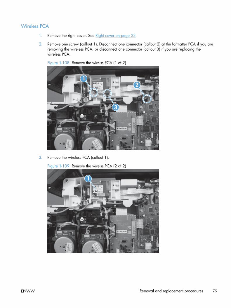
Wireless PCA
1. Remove the right cover. See Right cover on page 23
2. Remove one screw (callout 1). Disconnect one connector (callout 2) at the formatter PCA if you areremoving the wireless PCA, or disconnect one connector (callout 3) if you are replacing thewireless PCA.
Figure 1-108 Remove the wirelss PCA (1 of 2)
1
3
2
3. Remove the wireless PCA (callout 1).
Figure 1-109 Remove the wirelss PCA (2 of 2)
1
ENWW Removal and replacement procedures 79
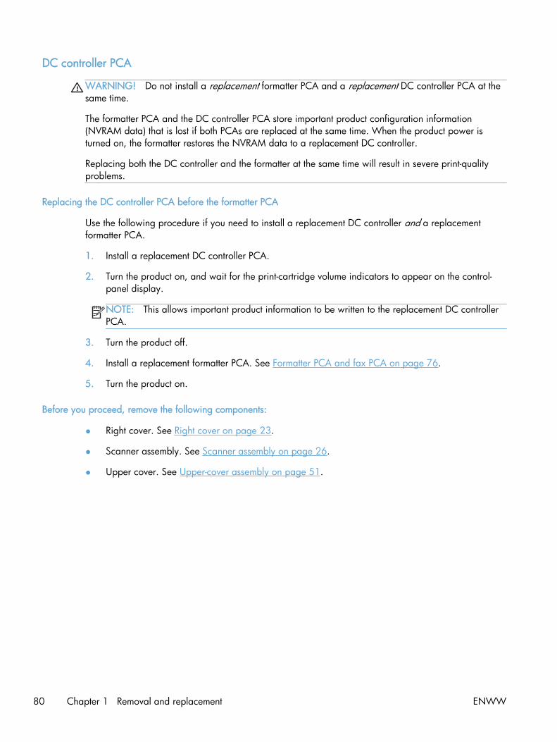
DC controller PCA
WARNING! Do not install a replacement formatter PCA and a replacement DC controller PCA at thesame time.
The formatter PCA and the DC controller PCA store important product configuration information(NVRAM data) that is lost if both PCAs are replaced at the same time. When the product power isturned on, the formatter restores the NVRAM data to a replacement DC controller.
Replacing both the DC controller and the formatter at the same time will result in severe print-qualityproblems.
Replacing the DC controller PCA before the formatter PCA
Use the following procedure if you need to install a replacement DC controller and a replacementformatter PCA.
1. Install a replacement DC controller PCA.
2. Turn the product on, and wait for the print-cartridge volume indicators to appear on the control-panel display.
NOTE: This allows important product information to be written to the replacement DC controllerPCA.
3. Turn the product off.
4. Install a replacement formatter PCA. See Formatter PCA and fax PCA on page 76.
5. Turn the product on.
Before you proceed, remove the following components:
● Right cover. See Right cover on page 23.
● Scanner assembly. See Scanner assembly on page 26.
● Upper cover. See Upper-cover assembly on page 51.
80 Chapter 1 Removal and replacement ENWW
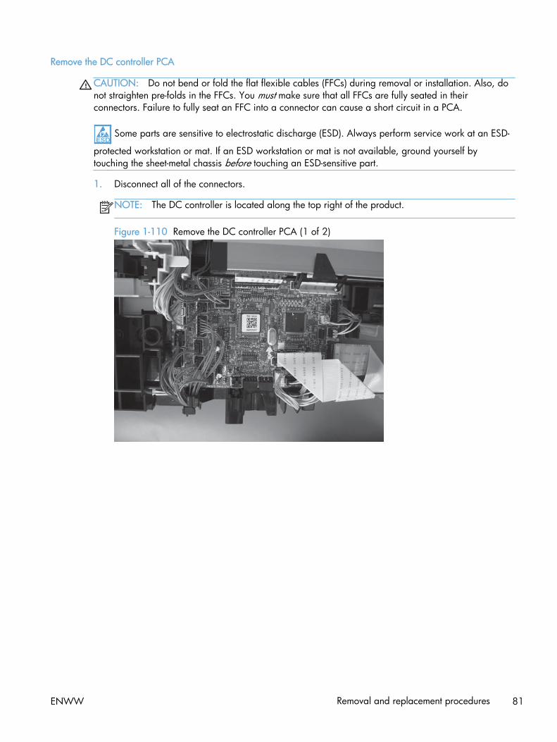
Remove the DC controller PCA
CAUTION: Do not bend or fold the flat flexible cables (FFCs) during removal or installation. Also, donot straighten pre-folds in the FFCs. You must make sure that all FFCs are fully seated in theirconnectors. Failure to fully seat an FFC into a connector can cause a short circuit in a PCA.
Some parts are sensitive to electrostatic discharge (ESD). Always perform service work at an ESD-
protected workstation or mat. If an ESD workstation or mat is not available, ground yourself bytouching the sheet-metal chassis before touching an ESD-sensitive part.
1. Disconnect all of the connectors.
NOTE: The DC controller is located along the top right of the product.
Figure 1-110 Remove the DC controller PCA (1 of 2)
ENWW Removal and replacement procedures 81

2. Remove four screws (callout 1) and then remove the DC controller PCA.
Figure 1-111 Remove the DC controller PCA (2 of 2)
82 Chapter 1 Removal and replacement ENWW

Fuser-motor assembly
Before proceeding, remove the following components:
● Right cover. See Right cover on page 23.
● Control panel and right-arm mount. See Control panel and right-arm mount on page 48.
● Formatter and fax PCAs. See Formatter PCA and fax PCA on page 76.
● Simplex products
◦ Rear door. See Rear door (simplex product) on page 33.
◦ Rear cover (simplex products). See Rear cover and feed guide (simplex product) on page 37.
● Duplex products
◦ Rear-upper cover. See Rear-upper cover (duplex product) on page 30.
Remove the fuser-motor assembly
1. Remove 5 screws (callout 1) and 3 screws (callout 2).
Figure 1-112 Remove the fuser-motor assembly (1 of 6)
2
1
ENWW Removal and replacement procedures 83

2. Remove three screws (callout 1) and release the wire harness from the retainer. Remove the fanassembly.
NOTE: The fan assembly is still attached to the product. Move the fan assembly off to one side.
Figure 1-113 Remove the fuser-motor assembly (2 of 6)
1
3. Release three tabs (callout 1), and then remove the retainer.
Figure 1-114 Remove the fuser-motor assembly (3 of 6)
1
84 Chapter 1 Removal and replacement ENWW
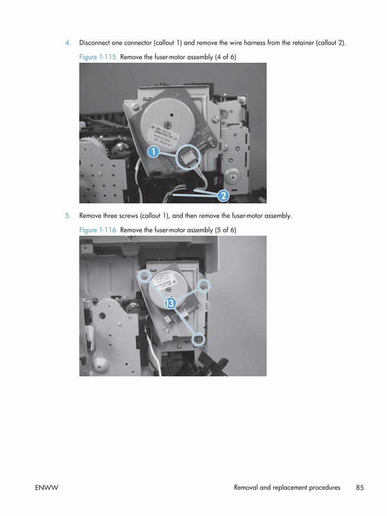
4. Disconnect one connector (callout 1) and remove the wire harness from the retainer (callout 2).
Figure 1-115 Remove the fuser-motor assembly (4 of 6)
2
1
5. Remove three screws (callout 1), and then remove the fuser-motor assembly.
Figure 1-116 Remove the fuser-motor assembly (5 of 6)
13
ENWW Removal and replacement procedures 85

6. Before you proceed, take note that the spring and the gears behind the fuser-motor assembly arenot captive.
CAUTION: Do not lose the spring or gears when you remove the fuser-motor assembly.
Figure 1-117 Remove the fuser-motor assembly (6 of 6)
Reinstall the fuser-motor assembly
Make sure that the fuser-motor assembly spring (callout 1) and gear pin (callout 2) are correctlypositioned in the hole and slot provided in the assembly mounting bracket. The assembly mountingbracket will fit flat against the product chassis when the fuser-motor assembly is correctly installed.
Figure 1-118 Reinstall the fuser-motor assembly
2
1
86 Chapter 1 Removal and replacement ENWW

High-voltage power-supply PCA
Before proceeding, remove the following components:
● Right cover. See Right cover on page 23.
● Scanner assembly. See Scanner assembly on page 26.
● Simplex products
◦ Rear door. See Rear door (simplex product) on page 33.
◦ Rear cover. See Rear cover and feed guide (simplex product) on page 37.
● Duplex products
◦ Rear door. See Rear door (duplex product) on page 35.
◦ Rear-lower cover. See Rear-lower cover and rear-door links (duplex product) on page 41.
● Upper-cover assembly. See Upper-cover assembly on page 51.
● Left cover. See Left cover on page 55.
Remove the high-voltage power-supply PCA
1. Remove two screws (callout 1), and then remove the sheet-metal plate (callout 2).
Figure 1-119 Remove the high-voltage power-supply PCA (1 of 5)
2
1
ENWW Removal and replacement procedures 87

2. Release six tabs (callout 1), and then remove the black-plastic cover.
Figure 1-120 Remove the high-voltage power-supply PCA (2 of 5)
1
3. Disconnect one FFC (callout 1) on the DC controller.
Figure 1-121 Remove the high-voltage power-supply PCA (3 of 5)
1
88 Chapter 1 Removal and replacement ENWW
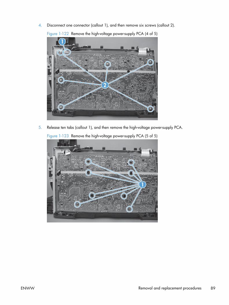
4. Disconnect one connector (callout 1), and then remove six screws (callout 2).
Figure 1-122 Remove the high-voltage power-supply PCA (4 of 5)
1
2
5. Release ten tabs (callout 1), and then remove the high-voltage power-supply PCA.
Figure 1-123 Remove the high-voltage power-supply PCA (5 of 5)
1
ENWW Removal and replacement procedures 89
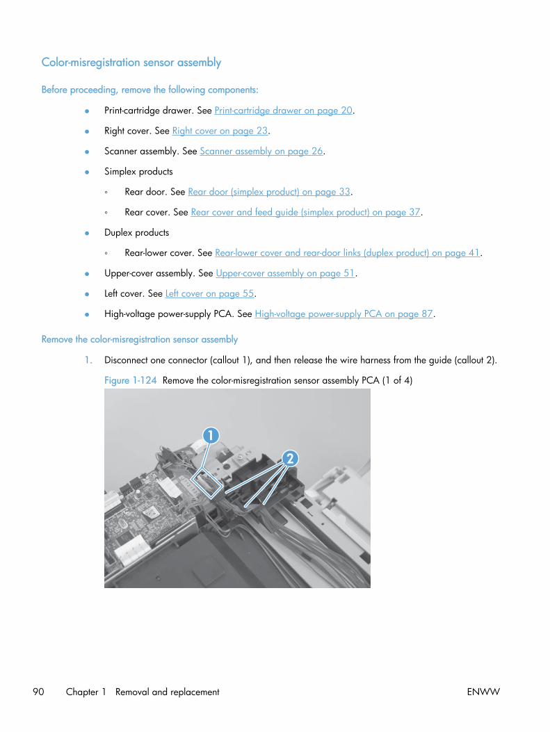
Color-misregistration sensor assembly
Before proceeding, remove the following components:
● Print-cartridge drawer. See Print-cartridge drawer on page 20.
● Right cover. See Right cover on page 23.
● Scanner assembly. See Scanner assembly on page 26.
● Simplex products
◦ Rear door. See Rear door (simplex product) on page 33.
◦ Rear cover. See Rear cover and feed guide (simplex product) on page 37.
● Duplex products
◦ Rear-lower cover. See Rear-lower cover and rear-door links (duplex product) on page 41.
● Upper-cover assembly. See Upper-cover assembly on page 51.
● Left cover. See Left cover on page 55.
● High-voltage power-supply PCA. See High-voltage power-supply PCA on page 87.
Remove the color-misregistration sensor assembly
1. Disconnect one connector (callout 1), and then release the wire harness from the guide (callout 2).
Figure 1-124 Remove the color-misregistration sensor assembly PCA (1 of 4)
1
2
90 Chapter 1 Removal and replacement ENWW

2. Release the wire harness from the guide (callout 1).
NOTE: When you remove the sensor assembly later in this procedure, pass the connector andwire harness through the hole in the chassis (callout 2).
Figure 1-125 Remove the color-misregistration sensor assembly PCA (2 of 4)
1
2
3. Remove two screws (callout 1).
Figure 1-126 Remove the color-misregistration sensor assembly PCA (3 of 4)
1
ENWW Removal and replacement procedures 91

4. Carefully separate the sensor assembly (callout 1) from the product, pass the wire harness throughthe hole in the chassis, and then remove the assembly.
NOTE: Pass the connector and wire harness through the hole in the chassis. See Figure 1-125Remove the color-misregistration sensor assembly PCA (2 of 4) on page 91.
Figure 1-127 Remove the color-misregistration sensor assembly PCA (4 of 4)
Reinstall the color-misregistration sensor assembly
TIP: You might have to attempt this reinstall procedure several times before you successfully pass theconnector through the hole in the chassis.
1. Push the sensor assembly wire-harness connector into the hole in the chassis from the ITB side ofthe product.
Figure 1-128 Reinstall the color-misregistration sensor assembly PCA (1 of 2)
92 Chapter 1 Removal and replacement ENWW

2. Use a small flat blade screwdriver to guide the connector through the hole.
Figure 1-129 Reinstall the color-misregistration sensor assembly PCA (2 of 2)
ENWW Removal and replacement procedures 93

Fan (FM1)
CAUTION: When the fan is reinstalled, it must pull air into the product. The air-flow indicator arrowembossed on the fan chassis point into the fan duct when the fan is correctly installed.
1. Remove the right cover. See Right cover on page 23.
2. Disconnect one connector (callout 1; J206)
Figure 1-130 Remove the fan (FM1) (1 of 2)
1
94 Chapter 1 Removal and replacement ENWW
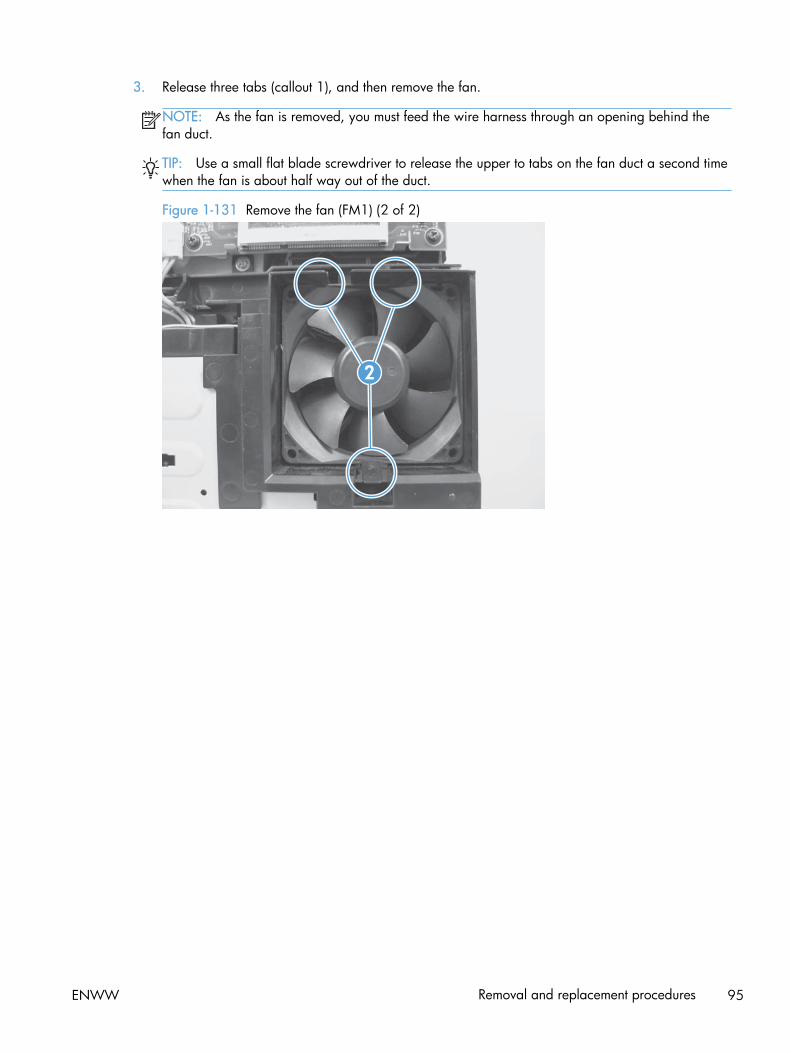
3. Release three tabs (callout 1), and then remove the fan.
NOTE: As the fan is removed, you must feed the wire harness through an opening behind thefan duct.
TIP: Use a small flat blade screwdriver to release the upper to tabs on the fan duct a second timewhen the fan is about half way out of the duct.
Figure 1-131 Remove the fan (FM1) (2 of 2)
2
ENWW Removal and replacement procedures 95

USB PCA (fax/memory-card models)
Before proceeding, remove the following components:
● Right cover. See Right cover on page 23.
● Right-front cover and power button. See Right-front cover and power button on page 28.
Remove the USB PCA
Release one tab (callout 1), and then remove the USB PCA.
Figure 1-132 Remove the USB PCA (fax/memory-card models)
1
96 Chapter 1 Removal and replacement ENWW
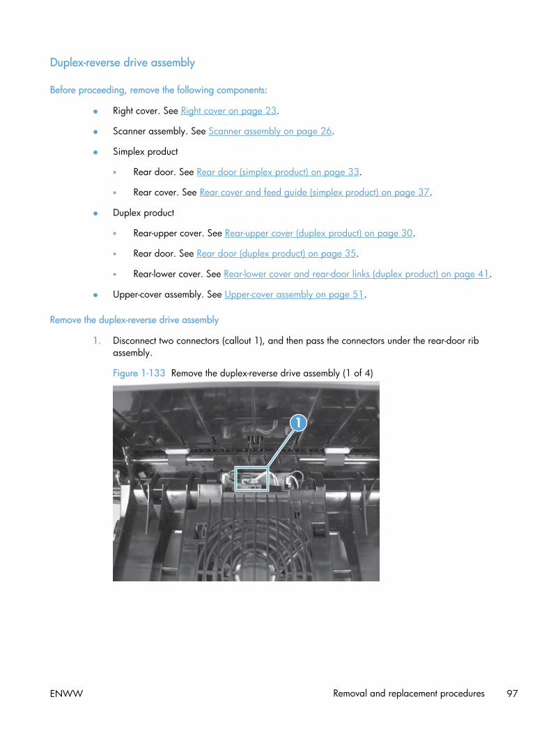
Duplex-reverse drive assembly
Before proceeding, remove the following components:
● Right cover. See Right cover on page 23.
● Scanner assembly. See Scanner assembly on page 26.
● Simplex product
◦ Rear door. See Rear door (simplex product) on page 33.
◦ Rear cover. See Rear cover and feed guide (simplex product) on page 37.
● Duplex product
◦ Rear-upper cover. See Rear-upper cover (duplex product) on page 30.
◦ Rear door. See Rear door (duplex product) on page 35.
◦ Rear-lower cover. See Rear-lower cover and rear-door links (duplex product) on page 41.
● Upper-cover assembly. See Upper-cover assembly on page 51.
Remove the duplex-reverse drive assembly
1. Disconnect two connectors (callout 1), and then pass the connectors under the rear-door ribassembly.
Figure 1-133 Remove the duplex-reverse drive assembly (1 of 4)
1
ENWW Removal and replacement procedures 97

2. Release the wire harnesses from the retainer (callout 1).
Figure 1-134 Remove the duplex-reverse drive assembly (2 of 4)
1
3. Remove three screws (callout 1).
Figure 1-135 Remove the duplex-reverse drive assembly (3 of 4)
1
98 Chapter 1 Removal and replacement ENWW

4. Remove the duplex-reverse drive assembly.
Figure 1-136 Remove the duplex-reverse drive assembly (4 of 4)
ENWW Removal and replacement procedures 99

Fuser
NOTE: The fuser can be removed without removing the scanner assembly and the upper-coverassembly. However, it might be easier to access some of the connectors with these componentsremoved.
Before proceeding, remove the following components:
● Right cover. See Right cover on page 23.
● Scanner assembly. See Scanner assembly on page 26.
● Simplex product
◦ Rear door. See Rear door (simplex product) on page 33.
◦ Rear cover. See Rear cover and feed guide (simplex product) on page 37.
● Duplex product
◦ Rear-upper cover. See Rear-upper cover (duplex product) on page 30.
◦ Rear door. See Rear door (duplex product) on page 35.
◦ Rear-lower cover. See Rear-lower cover and rear-door links (duplex product) on page 41.
● Upper-cover assembly. See Upper-cover assembly on page 51.
● Left cover. See Left cover on page 55.
100 Chapter 1 Removal and replacement ENWW

Remove the fuser
WARNING! The fuser might be very hot. After turning off the product power, allow the fuser to coolfor at least 5 minutes before removing it.
1. Duplex models only: Remove three screws (callout 1) and separate the duplex-reverse driveassembly from the product.
CAUTION: The duplex-reverse drive assembly is still attached to the product. Carefully set theassembly out of the way.
Figure 1-137 Remove the fuser (1 of 8)
1
ENWW Removal and replacement procedures 101

2. Disconnect two connectors (callout 1), and then release the wire harnesses from the guide(callout 2).
Reinstallation tip When the upper cover is reinstalled, make sure that these wire harnesses (nearthe connectors) are correctly routed under the cover.
Figure 1-138 Remove the fuser (2 of 8)
1
2
3. Disconnect one connector (callout 1).
Figure 1-139 Remove the fuser (3 of 8)
1
102 Chapter 1 Removal and replacement ENWW
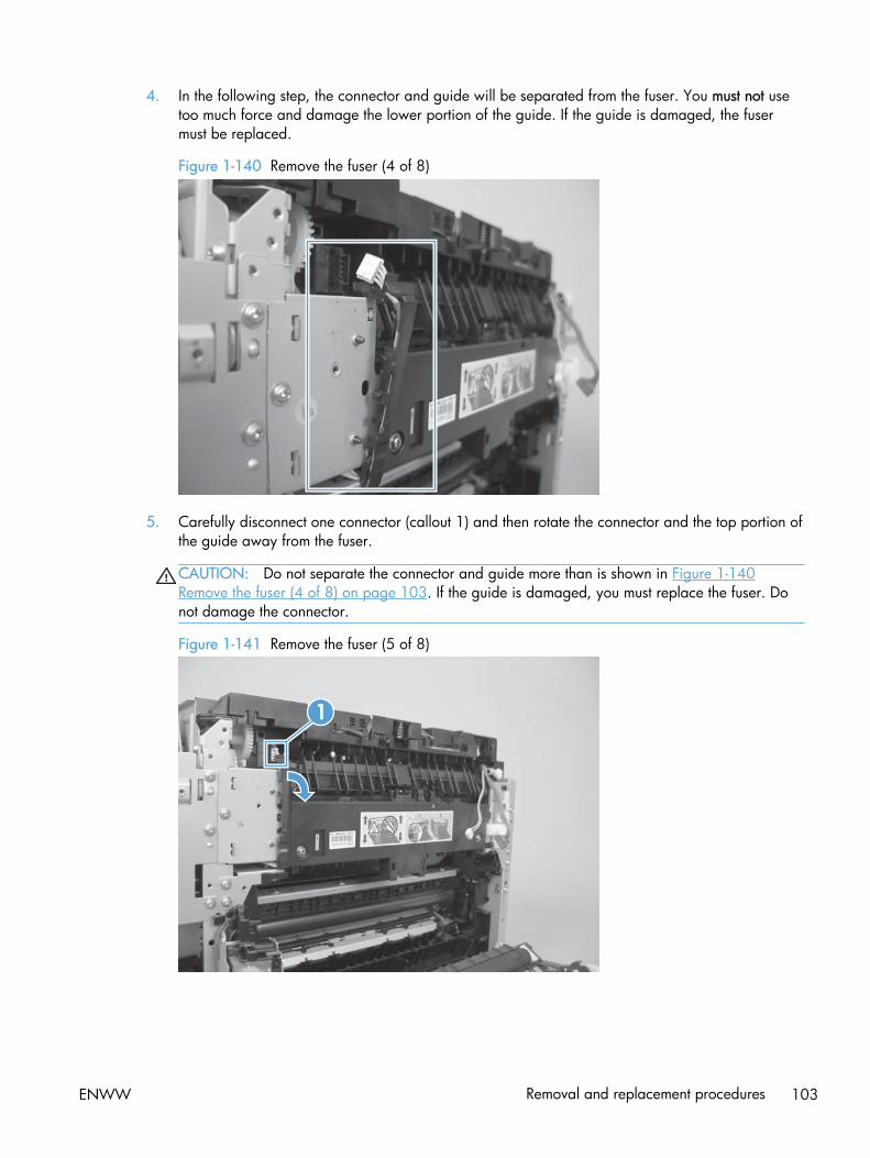
4. In the following step, the connector and guide will be separated from the fuser. You must not usetoo much force and damage the lower portion of the guide. If the guide is damaged, the fusermust be replaced.
Figure 1-140 Remove the fuser (4 of 8)
5. Carefully disconnect one connector (callout 1) and then rotate the connector and the top portion ofthe guide away from the fuser.
CAUTION: Do not separate the connector and guide more than is shown in Figure 1-140Remove the fuser (4 of 8) on page 103. If the guide is damaged, you must replace the fuser. Donot damage the connector.
Figure 1-141 Remove the fuser (5 of 8)
1
ENWW Removal and replacement procedures 103

6. Remove two screws (callout 1).
Figure 1-142 Remove the fuser (6 of 8)
1
7. Remove the fuser.
Figure 1-143 Remove the fuser (7 of 8)
104 Chapter 1 Removal and replacement ENWW

8. Duplex models only: Remove two screws (callout 1) and remove the duplex-gear assembly(callout 2). Install the assembly on the replacement fuser.
Figure 1-144 Remove the fuser (8 of 8)
12
ENWW Removal and replacement procedures 105

Reinstall the fuser
To reinstall you must insert the tabs (callout 1) on the fuser frame into the slots on the product chassis(callout 2).
CAUTION: The fuser frame must be flush with the product chassis before you install the two fusermounting screws. Do not use the screws to pull the fuser frame against the chassis.
Figure 1-145 Reinstall the fuser
1
2
106 Chapter 1 Removal and replacement ENWW

Paper-delivery assembly
Before proceeding, remove the following components:
● Right cover. See Right cover on page 23.
● Scanner assembly. See Scanner assembly on page 26.
● Simplex product
◦ Rear door. See Rear door (simplex product) on page 33.
◦ Rear cover. See Rear cover and feed guide (simplex product) on page 37.
● Duplex product
◦ Rear-upper cover. See Rear-upper cover (duplex product) on page 30.
◦ Rear door. See Rear door (duplex product) on page 35.
◦ Rear-lower cover. See Rear-lower cover and rear-door links (duplex product) on page 41.
● Upper-cover assembly. See Upper-cover assembly on page 51.
● Left cover. See Left cover on page 55.
Remove the paper-delivery assembly
1. Disconnect three connectors (callout 1), and then release the wire harnesses from the retainer(callout 2).
Figure 1-146 Remove the paper-delivery assembly (1 of 4)
12
ENWW Removal and replacement procedures 107

2. Disconnect two connectors (callout 1), and then release the wire harness from the wire clip(callout 2).
Figure 1-147 Remove the paper-delivery assembly (2 of 4)
1
2
3. Remove three screws (callout 1).
Figure 1-148 Remove the paper-delivery assembly (3 of 4)
1
108 Chapter 1 Removal and replacement ENWW

4. Remove the paper-delivery assembly.
Figure 1-149 Remove the paper-delivery assembly (4 of 4)
ENWW Removal and replacement procedures 109
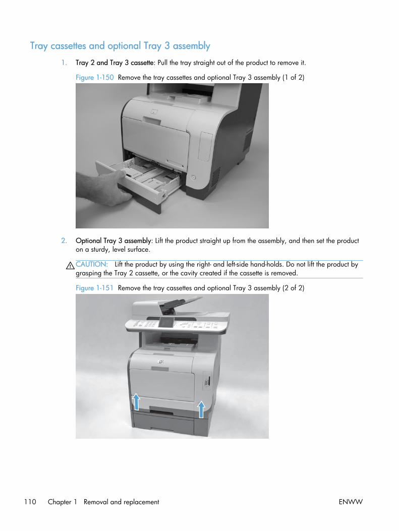
Tray cassettes and optional Tray 3 assembly
1. Tray 2 and Tray 3 cassette: Pull the tray straight out of the product to remove it.
Figure 1-150 Remove the tray cassettes and optional Tray 3 assembly (1 of 2)
2. Optional Tray 3 assembly: Lift the product straight up from the assembly, and then set the producton a sturdy, level surface.
CAUTION: Lift the product by using the right- and left-side hand-holds. Do not lift the product bygrasping the Tray 2 cassette, or the cavity created if the cassette is removed.
Figure 1-151 Remove the tray cassettes and optional Tray 3 assembly (2 of 2)
110 Chapter 1 Removal and replacement ENWW

2 Solve problems
To use the information in this chapter, you should have a basic understanding of the HP LaserJetprinting process. Explanations of each mechanical assembly, the printer systems, and the basic theoryof operation are contained in LASERJET PRO 300/400 COLOR MFP Theory of Operation. Do notperform any of these troubleshooting processes unless you understand the function of each productcomponent.
● Solve problems checklist
● Menu map
● Troubleshooting process
● Troubleshooting tools
● Clear jams
● Solve paper-handling problems
● Solve image-quality problems
● Clean the product
● Solve performance problems
● Solve product connectivity problems
● Service mode functions
● Solve fax problems
● Product updates
ENWW 111

Solve problems checklistIf you are experiencing problems with the product, use the following checklist to identify the cause ofthe problem:
● Is the product connected to power?
● Is the product on?
● Is the product in the Ready state?
● Are all necessary cables connected?
● Are any lights blinking or do any messages appear on the control panel?
● Are genuine HP supplies installed?
● Was a recently replaced toner cartridge installed correctly, and was the pull tab on the cartridgeremoved?
For additional information about installation and setup, see the product getting started guide.
If you cannot find solutions to problems in this guide, go to www.hp.com/go/LJColorMFPM375 orwww.hp.com/go/LJColorMFPM475.
112 Chapter 2 Solve problems ENWW

Menu map
Print a menu map
1. Touch the Setup button.
2. Open the Reports menu, and then touch the Menu Structure item.
TIP: Touch the area of the control-panel display where the Cancel button would be to closethe menus without printing the report.
ENWW Menu map 113
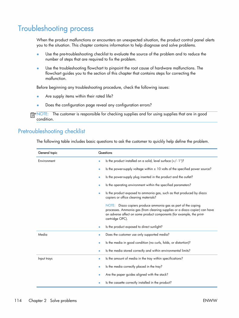
Troubleshooting processWhen the product malfunctions or encounters an unexpected situation, the product control panel alertsyou to the situation. This chapter contains information to help diagnose and solve problems.
● Use the pre-troubleshooting checklist to evaluate the source of the problem and to reduce thenumber of steps that are required to fix the problem.
● Use the troubleshooting flowchart to pinpoint the root cause of hardware malfunctions. Theflowchart guides you to the section of this chapter that contains steps for correcting themalfunction.
Before beginning any troubleshooting procedure, check the following issues:
● Are supply items within their rated life?
● Does the configuration page reveal any configuration errors?
NOTE: The customer is responsible for checking supplies and for using supplies that are in goodcondition.
Pretroubleshooting checklist
The following table includes basic questions to ask the customer to quickly help define the problem.
General topic Questions
Environment ● Is the product installed on a solid, level surface (+/- 1°)?
● Is the power-supply voltage within ± 10 volts of the specified power source?
● Is the power-supply plug inserted in the product and the outlet?
● Is the operating environment within the specified parameters?
● Is the product exposed to ammonia gas, such as that produced by diazocopiers or office cleaning materials?
NOTE: Diazo copiers produce ammonia gas as part of the copingprocesses. Ammonia gas (from cleaning supplies or a diazo copier) can havean adverse affect on some product components (for example, the print-cartridge OPC).
● Is the product exposed to direct sunlight?
Media ● Does the customer use only supported media?
● Is the media in good condition (no curls, folds, or distortion)?
● Is the media stored correctly and within environmental limits?
Input trays ● Is the amount of media in the tray within specifications?
● Is the media correctly placed in the tray?
● Are the paper guides aligned with the stack?
● Is the cassette correctly installed in the product?
114 Chapter 2 Solve problems ENWW

General topic Questions
Toner cartridges ● Is each toner cartridge installed correctly?
Transfer unit and fuser ● Are the transfer unit and fuser installed correctly?
Doors ● Is the front door closed?
Condensation ● Does condensation occur following a temperature change (particularly inwinter following cold storage)? If so, wipe affected parts dry or leave theproduct on for 10 to 20 minutes.
● Was a toner cartridge opened soon after being moved from a cold to a warmroom? If so, allow the toner cartridge to sit at room temperature for 1 to 2hours.
Miscellaneous ● Check for and remove any non-HP components (for example, toner cartridgesor memory modules) from the product.
● Check to see whether the hardware or software configuration has changed orthe problem is not associated with any specific software.
● Remove the product from the network and ensure that the failure is associatedwith the product before beginning troubleshooting.
● For any print-quality issues, calibrate the product. See Calibrate the producton page 137
Power-on checks
When you turn on the product, if it does not make any sound or if the control-panel display is blank,check the following items:
● Verify that the product is plugged directly into an active electrical outlet that has the correctvoltage. Do not plug the product into a surge protector or power strip.
● Verify that the power button is in the on position.
● Verify that the formatter is seated correctly.
● Remove any HP Jetdirect or other devices, and then try to turn the product on again.
● Ensure that the control-panel display is connected.
● Check the two fuses on the power supply.
● If necessary, replace the power supply.
● If necessary, replace the DC controller.
ENWW Troubleshooting process 115
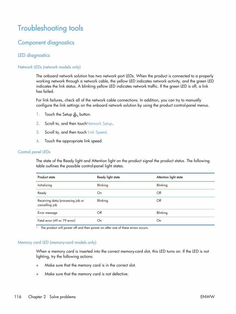
Troubleshooting tools
Component diagnostics
LED diagnostics
Network LEDs (network models only)
The onboard network solution has two network port LEDs. When the product is connected to a properlyworking network through a network cable, the yellow LED indicates network activity, and the green LEDindicates the link status. A blinking yellow LED indicates network traffic. If the green LED is off, a linkhas failed.
For link failures, check all of the network cable connections. In addition, you can try to manuallyconfigure the link settings on the onboard network solution by using the product control-panel menus.
1. Touch the Setup button.
2. Scroll to, and then touchNetwork Setup.
3. Scroll to, and then touch Link Speed.
4. Touch the appropriate link speed.
Control panel LEDs
The state of the Ready light and Attention light on the product signal the product status. The followingtable outlines the possible control-panel light states.
Product state Ready light state Attention light state
Initializing Blinking Blinking
Ready On Off
Receiving data/processing job orcancelling job
Blinking Off
Error message Off Blinking
Fatal error (49 or 79 error)1 On On
1 The product will power off and then power on after one of these errors occurs.
Memory card LED (memory-card models only)
When a memory card is inserted into the correct memory-card slot, this LED turns on. If the LED is notlighting, try the following actions:
● Make sure that the memory card is in the correct slot.
● Make sure that the memory card is not defective.
116 Chapter 2 Solve problems ENWW

● Verify that the flat flexible cable connection from the formatter to the memory-card readerassembly is firmly connected.
● If the card is not defective and the card is in the correct slot, the circuit board might have beeninadvertently damaged by an electrostatic discharge from someone inserting a memory card. Ifthis is the case, replace the memory-card reader assembly. If the error still occurs, replace theformatter.
Component tests
The control-panel tests require touching the Left Arrow button and the Cancel button on thetouchscreen when they are not illuminated. Use the figure below to locate these buttons on thetouchscreen.
Figure 2-1 Control-panel test
Control-panel tests
Test the control-panel display
1. Touch the Setup button.
2. Touch the Left Arrow button and the Cancel button at the same time.
3. Touch the Setup button.
4. Open the 2ndry Service menu.
5. Touch the Dispaly Test item.
Test the control-panel buttons
1. Touch the Setup button.
2. Touch the Left Arrow button and the Cancel button at the same time.
3. Touch the Setup button.
ENWW Troubleshooting tools 117

4. Open the 2ndry Service menu.
5. Touch the Button Test item.
Diagrams
Plug/jack locations
1 Telephone “line out” port for attaching an extension phone, answering machine, or other device
2 Fax “line in” port for attaching fax line to product
3 Network port
4 Hi-Speed USB 2.0 port
118 Chapter 2 Solve problems ENWW

Location of connectors
DC controller PCA
Figure 2-2 DC controller connectors
Loose DC controller connections can cause issues. Check the following connections whentroubleshooting product problems.
Connector Board
J130 DC controller
J131 DC controller
J132 DC controller
J133 DC controller
J140 DC controller
J141 DC controller
J150 DC controller
ENWW Troubleshooting tools 119

Connector Board
J151 DC controller
J152 DC controller
J153 DC controller
J154 DC controller
J156 DC controller
J157 DC controller
J1 Formatter
J2 Formatter
J3 Formatter
J4 Formatter
J6 Formatter
J9 Formatter
J11 Formatter
P1 Formatter
P2 Formatter
P12 Formatter
120 Chapter 2 Solve problems ENWW

Location of major components
Major components
Figure 2-3 Major components
1
13
14
2 89
5
6
7 3
4
10
11
12
Table 2-1 Major components
Item Description
1 Duplex feed assembly (duplex models only)
2 Rear door rib assembly (duplex models only)
3 Power supply assembly
4 Duplex reverse drive assembly (duplex models only)
5 ITB assembly
6 Delivery assembly
7 Registration assembly
8 Fuser assembly
9 Secondary transfer feed assembly
10 Cassette pickup assembly
11 Duplex re-pickup guide assembly (duplex models only)
ENWW Troubleshooting tools 121

Table 2-1 Major components (continued)
Item Description
12 Multipurpose tray pickup assembly
13 Drive assembly
14 Color misregistration and density sensor
122 Chapter 2 Solve problems ENWW

Motors and fans
Figure 2-4 Motors and fans
2 6
3
4
1
5
Table 2-2 Solenoid, sensors, and motors
Item Description
1 Fuser motor
2 Drum motor (M1)
3 Developing motor (M2)
4 Fan 1
5 Fan 2 (duplex models only)
6 Pickup motor
ENWW Troubleshooting tools 123

Rollers
Figure 2-5 Rollers
4
3 1
2
Table 2-3 Rollers
Item Description
1 Cassette pickup roller
2 Multipurpose tray pickup roller
3 Multipurpose tray separation pad
4 Cassette separation roller
124 Chapter 2 Solve problems ENWW

PCAs
Figure 2-6 PCAs
5
6 1
23
4
Table 2-4 PCAs
Item Description
1 DC controller PCA
2 Connector PCA
3 Driver PCA
4 High-voltage power supply PCA
5 Formatter
6 Sub-power supply PCA
ENWW Troubleshooting tools 125

Optional 250-sheet cassette
Figure 2-7 Optional 250-sheet cassette
12
3
4
Table 2-5 Optional 250-sheet cassette
Item Description
1 Paper feeder pickup assembly
2 Paper feeder connector PCA
3 Paper feeder separation roller
4 Paper feeder pickup roller
126 Chapter 2 Solve problems ENWW

General timing diagram
Approximate timing in seconds.
Figure 2-8 Timing diagram
Fuse
r
Fuse
r
Fuse
r
ENWW Troubleshooting tools 127
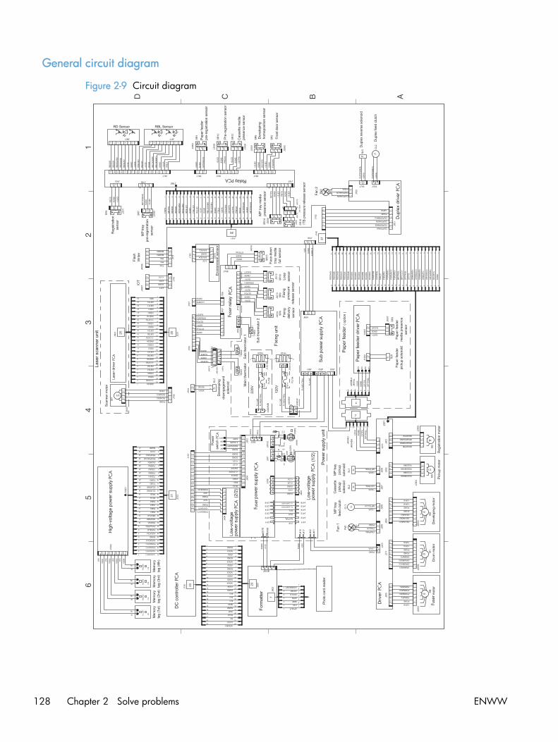
General circuit diagram
Figure 2-9 Circuit diagram
PCA
PCA
PCA
PCA
PCA
Fuse
r
PCA
PCA
Fuse
r
PCA
PCA PCA
PCA
PCA
Fuse
r
PCA
128 Chapter 2 Solve problems ENWW

CPU/ASIC diagrams
Figure 2-10 CPU diagram
CD
1-3
J
J
check
check
check
A
43
2
CB D E F
76
51
J5
P J5
P
J5
P
VD
D
VO
UT
MR
VS
S
CD
J4
P
J4
P
J4
P
J4
P
J5
P
J5
P
check
check
J
VC
C
WP
SC
L
SD
AG
ND
A2
A1
A0
check
check
FB
ch
eck
J1
P
CH
G
(A5
04
)
(A5
03
)
(A5
04
)
(A5
05
)
(A5
05
)
(A5
04
)
(A5
04
)
(A5
04
)
(A5
04
) (A5
04
)
(A5
04
)(A
50
4)
(A5
04
)
(A5
04
)
(A5
04
)
(A5
04
)
(A5
04
)
(A503)
(A503)
(A503)
(A5
04
)
(A5
04
)
(A5
04
)
(A5
04
)
(A5
04
)
(A5
04
)
(A5
04
)
(A5
04
)
Ch
eck P
ad
Ch
eck P
in
ON
OF
F
CP
U
<<
M-C
PU
Write
r >>
<<
IOT
>>
N.C.
+24B
: Shutd
ow
ned b
y in
terlo
ck S
W+
24A
: alw
ays a
live
EE
PR
OM
ON
ON
<<
CP
U >
>
DE
VS
L
(ASIC-11p)
(ASIC-12p)
(ASIC-13p)
(ASIC-14p)
(ASIC-15p)
(ASIC-16p)
(ASIC-17p)
(ASIC-18p)
(ASIC-19p)
(ASIC-20p)
6: F
SR
2: A
SIC
(AS
IC-2
1p
)
(AS
IC-2
2p
)
5: F
SR
, LV
T, D
UP
, OP
T, E
NV
<<
Functio
n C
heck >
>
(A5
05
)
(A5
05
)
(A5
04
)
(A506)(A505)
(A505)
(A503)
(A504)
(A5
05
)
(A5
05
)(A
50
5)
(A5
03
)
(A5
03
)
(A503)
(A5
05
)
(A5
05
)
(A5
04
)
(A5
03
)
(A5
04
)
(AS
IC-6
p)
(AS
IC-8
p)
(A505)
(A5
04
)
(A5
05
)
(AS
IC-2
3p
)(A
SIC
-26
p)
(A5
04
)
(A5
04
)
<<
TE
ST
PR
INT
SW
>>
Sle
ep
OF
FS
tand-b
y
ON
OF
F
+3.3
VA
+3.3
VB
(A505)
(A504)(A504)
RE
SE
T IC
4: D
RIV
ER
PC
A, S
EN
SO
R
3: V
IF, L
SR
, SC
N, H
VT
,TG
1: C
PU
1: C
PU
+3
.3V
A
+3
.3V
A
1J2
LC
-2-G
-WH
T/N
OT
MN
T
1C
P1
12
0.1
U,2
5V
C13
WAKEVC
RB
LS
GA
IN0
CC
RT
REGIMA
REGIMB
RLD
TE
ST
PR
T
RB
LS
GA
IN1
RD
SG
AIN
1
RD
SG
AIN
0
ITB
LL
ED
21 N
F101
21
R3
3.3
K,0
.1W
VC
TR
LO
FF
100
99
98
97
96
95
94
93
92
91
90
89
88
87
86
85
84
83
82
81
80
79
78
77
76
75
74
73
72
71
70
69
68
67
66
65
64
63
62
61
60
59
58
57
56
55
54
53
52
51
50
49
48
47
46
45
44
43
42
41
40
39
38
37
36
35
34
33
32
31
30
29
28
27
26
25
24
23
22
21
20
19
18
17
16
15
14
13
12
11
10 9 8 7 6 5 4 3 2 1
IC1
1CP81CP3
+2
4V
A
FS
RP
RS
S
RD
OO
RS
OP
TP
S
P8
1
P8
0
RE
GIM
I1B
12
10
0,0
.06
3W
R198
RE
GIM
I0A
ZE
RO
X
RE
GIM
I0B
RE
GIM
I1A
FE
ED
MI0
A
PW
RS
WO
N
FE
ED
MA
FE
ED
MB
FE
ED
MI1
A
FE
ED
MI0
B1
21
00
,0.0
63
WR
9F
EE
DM
I1B
12
10
0,0
.06
3W
R199
RE
GS
12
10
0,0
.06
3W
R34
RS
LE
D
21
R8
10
0,0
.06
3W
RS
CP
R
24
AL
IVE
87654 3 2 1 IC
4
R1
EX
24
00
4A
SA
S0
A
P8
0
P8
1
FD
OO
RS
MO
DE
0
AL
E
2 1
JN
T1
1 2100,0.063WR59
+3
.3V
A
21
C74
10
0P
,50
V/N
OT
MN
T
21
C69
10
0P
,50
V/N
OT
MN
T
12
10
0,0
.06
3W
R50
21
R65
10
0,0
.06
3W
21
R48
10
0,0
.06
3W
12 1
00
,0.0
63
WR
49
RD
SL
ED
1 2 0,1AR13
1 2 0,1AR215
21
R56
10
0,0
.06
3W
AS
ICR
ST
OP
TP
KS
L1
2
10
0,0
.06
3W
R46
21
R10
43
0,0
.1W
21
C522
0.1
U,2
5V
21
2.7
K,0
.1W
R531
1CP7
+3
.3V
A
+3
.3V
A
+3
.3V
A
21
R4
15
0,0
.1W
/NO
TM
NT
1 2
X501
12 2
2P
,50
V
C3
1
CP12
21
R29
33
,0.0
63
W
21
R27
33
,0.0
63
W
21C10
0.1U,25V/NOTMNT
21
C11
0.1
U,2
5V
21C120.1U,25V
21
R28
33
,0.0
63
W
21
R25
1K,0.063W
21
C90.1U,25V
21C7
0.1U,25V
2J111
1J111
21
R1147
K,0
.06
3W
4J110
3J110
2J110
1J110
21 R
32
1K
,0.0
63
W
21 R
31
1K
,0.0
63
W
3
21
DA
2D
AN
21
7U
/NO
TM
NT
3
21
DA
1D
AN
21
7U
/NO
TM
NT
1 2
10K,0.063W
R30
543 2 1
IC7
NJU
77
04
F2
9A
-@-#
ZZ
ZB
21 R
26
1K
,0.0
63
W
21
R647
K,0
.06
3W
21 R
19
1K
,0.0
63
W 21 R
18
1K
,0.0
63
W
21 R
17
1K
,0.0
63
W
21 R
16
1K
,0.0
63
W
12
1K
,0.0
63
W
R14
WR
RD
TC
K
MO
DE
2
MO
DE
0
IOT
R
IOT
T
3J111
4J111
5J111
1CP41CP51CP6
12
22
P,5
0V
C4
+3
.3V
A
+3
.3V
A
+3
.3V
A
21
R530
2.7
K,0
.1W
+3
.3V
A
21
R3
5
3.3
K,0
.1W
2 1
0.0
1U
,50
V
C106
1 2
24
K,0
.1W
R5
4
+3
.3V
A
21
R1
1K
,0.0
63
W
21
47
K,0
.06
3W
R12
FC
T2
11
00
,0.0
63
WR
21
DU
PF
AN
ON
21
JN
T3
PR
EG
S
TC
K
B1
A1
D1
C1
SW
1
KS
HS
63
6A
T
21
R3
05
10
K,0
.06
3W
1 2
10K,0.063W
R304
12
3.3
K,0
.06
3W
R60
PL
LE
NB
L
21
R69
10
0,0
.06
3W
12
3.3
K,0
.06
3W
R195
12
10
0,0
.06
3W
R22
21
R63
10
0,0
.06
3W
12
10
0,0
.06
3W
R62
1 2100,0.063WR64
C8
0.1
U,2
5V
ADB0
ADB1
ADB2
ADB3
ADB4
ADB5
ADB6
ADB7
ADB8
ADB9
PF
UL
LS
RE
SE
TW
AK
EE
NG
FS
RD
RD
SC
PR
IOT
T
SUB2TH
MAINTH
SUBTH
TNR4
TNR3
TNR2
TNR1
ASICOFF
MO
DE
2
ITBLS
IOT
R
OP
TP
RE
GS
CS
TP
S
MP
TP
RE
GS
DE
VH
PS
MP
TP
S
ITB
TS
TN
RR
SP
WM
PO
UT
S
AS
ICC
LK
2 1
JN
T2
12
10
0,0
.06
3W
R7
+3
.3V
A
ENWW Troubleshooting tools 129
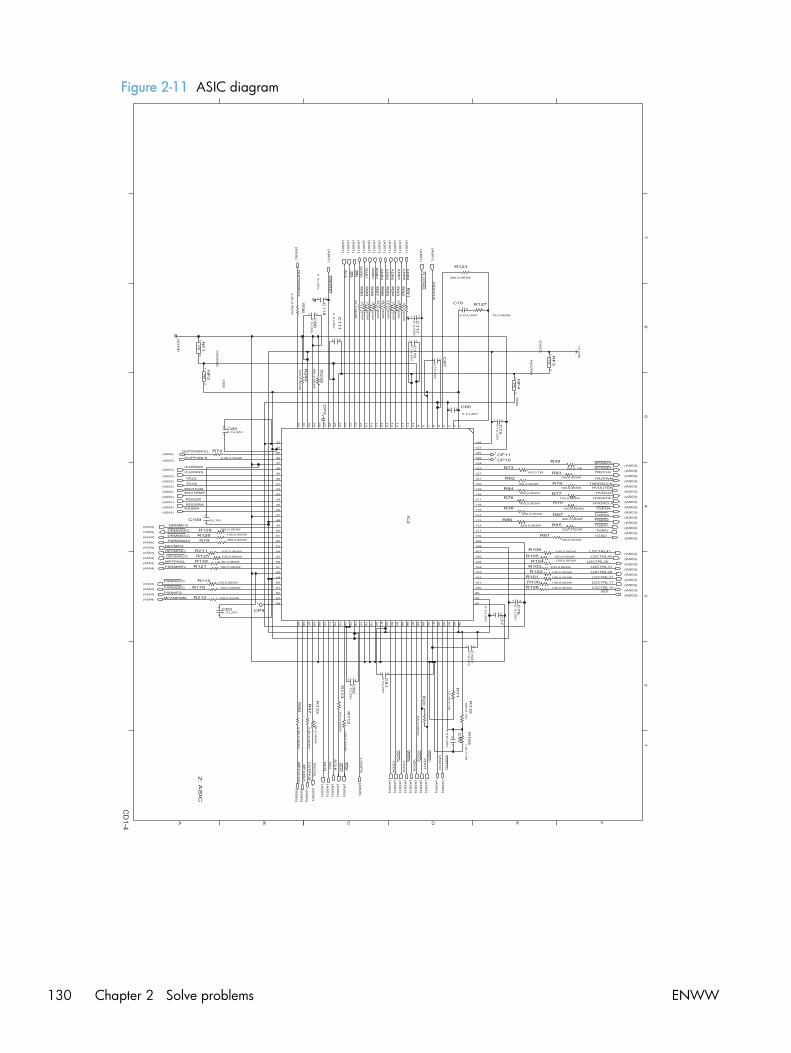
Figure 2-11 ASIC diagram
CD
1-4
A B
43
2
C D E F
65
17
FB
FB
FB
FB
ch
eck
check
check
check
(A503)
(A503)
(A503)
(A503)
(A503)
(A503)
(A503)
(A503)
(A503)
(A503)
(A503)
(A503)
(A503)
(A503)
(A503)
(A503)
(A503)
(A503)
(A503)
(A503)
(A503)
(A503)
(A5
03
)
(A5
03
)
(A5
03
)
(A5
03
)
(A5
03
)
(A5
03
)
(A5
03
)
(A5
03
)
(A5
03
)
(A5
03
)
(A5
03
)
(A5
03
)
(A5
03
)
(A5
05
)
(A5
05
)
(A5
05
)
(A504)
(A504)
(A504)
(A504)
(A504)
(A504)
(A504)
(A504)
(A504)
(A504)
(A504)
(A504)
(A504)
(A503)
(A503)
(A5
01
)
(A5
01
)
(A5
01
)
(A5
01
)
(A5
01
)
(A5
01
)
(A5
01
)
(A5
01
)
(A5
01
)
(A5
01
)
(A5
01
)
(A5
01
)
(A5
01
)
(A5
01
)
OG
ND
VS
S
HO
GN
D
OV
DD
HO
VD
D
VD
D
(A5
01
)
(A5
01
)
(A5
05
)
(A505)
(A505)
(A503)
(A503)
(A505)
(A505)
(A504)
(A505)
(A504)
(A5
05
)
(A5
03
)
(A5
05
)
(A5
03
)
(A503)
(A503)
2: A
SIC
AL
E
AD
B7
AD
B8
12
10
K,0
.06
3W
R240
MFANPWM
FSRMDEC
FSRMACC
21
C79
0.01U,50V
12
75,0.063W
R127
AD
B2
TR1S
DUPSWBKSLS
CL
K
LDCTRL41
LDCTRL40
LDCTRL30
TGRD
TGSD
HVOUTEN
HVDALD1 2
100,0.063WR77
TR2PWM
TR2CLKSCNDEC
TGEN3
21R86220,0.063W
HVDACLK
TGEN4
HVDATA1
TNRRSCLK
1 2
220,0.063W
R38
21
R76100,0.063W
21R84100,0.063W
21
R82100,0.063W
1 2
100,0.1WR73
BDI
TGEN2
21 C80
0.1U,25V
MF
AN
LK
128
127
126
125
124
123
122
121
120
119
118
117
116
115
114
113
112
111
110
109
108
107
106
105
104
103
102
101
100
99
98
97
96
95
94
93
92
91
90
89
88
87
86
85
84
83
82
81
80
79
78
77
76
75
74
73
72
71
70
69
68
67
66
65
64
63
62
61
60
59
58
57
56
55
54
53
52
51
50
49
48
47
46
45
44
43
42
41
40
39
38
37
36
35
34
33
32
31
30
29
28
27
26
25
24
23
22
21
20
19
18
17
16
15
14
13
12
11
10 9 8 7 6 5 4 3 2 1
IC2
1CP10
1CP11
1
CP9
21
C118
0.1
U,2
5V
AS
ICC
LK
21
C117
0.1
U,2
5V
21
C110
0.1
U,2
5V
123
3,0
.06
3W
R93
1233
,0.0
63
WR
95
AD
B9
21
C86
0.1
U,2
5V
12
10
K,0
.06
3W
R239
12
3.3
K,0
.06
3W
R36
123
3,0
.06
3W
R91
SC
O
RSSRA
21C109 1U,10V
1C
P2
21
C101
0.1
U,2
5V
21
C81
0.1
U,2
5V
21 C77
0.1
U,2
5V
DU
PS
WB
KC
L
VD
O1
O
VD
O1
O
FSRMFG
DEVMFG
DRMMFG
21
C92
0.0
1U
,50
V
12 1
1K
,0.1
WR
164
12
18
K,0
.1W
R132
12
12
.1K
,0.1
W
R71
12
10
0,0
.06
3W
R20
VD
O1VD
O1
21
C870.1
U,2
5V
21
C850.1U,25V
21
C830.1U,25V
21
C82
0.1
U,2
5V
21
C76
0.1
U,2
5V
21
C75
0.1
U,2
5V
12
20K,0.063W
R123
+3
.3V
B
21 N
F3
21 N
F1
LDCTRL10
1 2
100,0.1W
R39 SCNACC
1 2
100,0.063WR83
1 2
100,0.063WR78
1 2
100,0.063W
R75
1 2
220,0.063WR87
1 2
220,0.063WR85
AD
B1
12
3.3K,0.063W
R74
2 1R125 100,0.063W
2 1R211 100,0.063W
12390,0.063WR79
12100,0.063WR128
2 1R129 100,0.063W
21R81100,0.063W
21R104 100,0.063W
1 2 100,0.063WR108
PSREM24V
21R100 100,0.063W
DEVMACC
DEVMDEC
12 1
00
,0.0
63
WR
113
12 100,0.063WR212
2 1R121 100,0.063W
12 3.3K,0.063WR139
12 100,0.063WR1162 1
R115 100,0.063W
21
R133
3.3
K,0
.06
3W
12 3
.3K
,0.0
63
WR
47
12 3
.3K
,0.0
63
WR
40
21R102 100,0.063W
1 2100,0.063WR101
1 2100,0.063WR103
1 2 100,0.063WR10521
R106 100,0.063W
21
R90
33
,0.0
63
W
123
3,0
.06
3W
R89
21
R88
33
,0.0
63
W
123
3,0
.06
3W
R97
21
R96
33
,0.0
63
W
21
R94
33
,0.0
63
W
21
R92
33
,0.0
63
W
21
R112
10
0,0
.06
3W
DE
VS
L
CS
TP
KS
L
MP
TC
LC
H
AD
B0
AD
B3
AD
B4
AD
B5
AD
B6
TO
P
BD
O
FSRMREV
MPTPKSL
DRMMACC
DRMMDEC
VD
O2V
DO
2
VD
O3V
DO
3
VD
O4V
DO
4
LO
OP
S
SC
IDUPFANLK
ICLBSNS
ICLRSNS
TR2S
ENVHUMENVTEMP
RDSDR
RDSSRA
RD
WR
TGEN1
LDCTRL20
LDCTRL31
LDCTRL21
LDCTRL112
1 NF
2
21 N
F4
21
C111
0.1
U,2
5V
PL
LE
NB
L
AS
ICR
ST
130 Chapter 2 Solve problems ENWW

HVT/Toner EMP diagram
Figure 2-12 HVT/Toner EMP diagram
CD
1-5
J29P
J29P
J2
5P
J2
5P
J2
5P
J2
5P
J2
5P
J2
5P
J2
5PJ2
5P
J2
5P
J2
5P
J2
5P
J2
5P
J2
5P
J2
5P
J2
5P
J2
5P
J2
5PJ2
5PJ2
5P
J2
5P
J2
5PJ2
5PJ2
5P
J4
P
J4
P
J4
P
A
43
2
CB D E F
76
51
J2
5P
J2
3P
J2
3P
J2
3P
J2
3P
J2
3P
J2
3P
J2
3P
J2
3P
J2
3P
J2
3P
J2
3P
J2
3P
J2
3P
J2
3P
J2
3P
J2
3P
J2
3P
J2
3P
J29P
J29P
J29P
J29P
J29P
J29P
J29P
J29P
J29P
J29P
J29PJ29P
J29P
J29P
J29P
J29P
J29P
J29P
J29PJ29P
J29P
J29P
J29
P
J29P
J29P
J29P
J2
3P
J2
3P J2
3P
J4
P
J2
3P
J2
3P
J2
5P
J29P
<<
LA
SE
R(1
-N) >
><
< S
CA
NN
ER
MO
TO
R >
>
(CP
U-7
3p
)
(AS
IC-7
0p
)
(AS
IC-7
1p
)
(AS
IC-7
2p
)
(AS
IC-7
4p
)
(CP
U-7
4p
)
(CP
U-7
6p
)
(AS
IC-7
3p
)
(AS
IC-8
3p
)
(AS
IC-8
4p
)
(AS
IC-8
5p
)
(AS
IC-8
6p
)
(AS
IC-8
7p
)
(AS
IC-8
8p
)
(AS
IC-9
0p
)
(AS
IC-8
9p
)
(AS
IC-1
24
p)
(AS
IC-1
23
p)
(AS
IC-9
9p
)
(AS
IC-1
00
p)
(AS
IC-1
01
p)
(AS
IC-9
2p
)
(AS
IC-9
3p
)
(AS
IC-1
03
p)
(AS
IC-1
02
p)
(AS
IC-1
05
p)
(AS
IC-1
06
p)
(AS
IC-1
07
p)
(CP
U-4
p)
(AS
IC-1
17
p)
(AS
IC-1
18
p)
(AS
IC-1
16
p)
(AS
IC-1
19
p)
(AS
IC-1
22
p)
(AS
IC-1
21
p)
(AS
IC-1
20
p)
(CP
U-4
1p
)
(CP
U-3
9p
)
(AS
IC-1
04
p)
(AS
IC-4
1p
)
(AS
IC-4
0p
)
(AS
IC-3
9p
)
(AS
IC-3
8p
)
(AS
IC-1
10
p)
(AS
IC-1
12
p)
(AS
IC-1
13
p)
(AS
IC-1
14
p)
(AS
IC-1
15
p)
(CP
U-1
2p
)
<<
HV
T / T
ON
ER
_E
MP
<<
VID
EO
I/F (1
-N)>
>
(CP
U-4
3p
)
(CP
U-4
2p
)
(AS
IC-1
11
p)
3: V
IF, L
SR
, SC
N, H
VT
,TG
/TG
(1-1
)>>
21
JP
1
RK
73
Z1
JT
/NO
TM
NT
LD
CT
RL
41
LD
CT
RL
40
LD
CT
RL
20
LD
CT
RL
21
21
C6510
0P
,50
V
21
C16
10
0P
,50
V
RD
OO
RS
ICL
RS
NS
TN
RR
SC
LK
+3
.3V
B+
3.3
VB
121
00
,0.0
63
W/N
OT
MN
T
R53
10
J133
96
15
S-2
9A
-PP
-A
VS
1-6
84
90
29
25
96
15
S-2
5A
-PP
-AV
S1
-68
49
02
5
J131
23
VS
1-6
84
90
23
96
15
S-2
3A
-PP
-A
J130
22
J130
4J132
VS
1-7
14
50
04
2-2
92
20
7-4
21
C120
0.1
U,2
5V
/NO
TM
NT
21
C78
10
0P
,50
V/N
OT
MN
T
+3
.3V
A
+2
4V
B
+2
4V
A
+2
4V
S
WA
KE
VC
BD
O
CC
RT
R241
33
0,0
.06
3W
R114
1K
,0.0
63
W10
0,0
.1W
R42
+3
.3V
B
32 1
RB
71
5F
DA
6
+3
.3V
B
TR
2S
TR
1S
12
3.3
K,0
.06
3W
R107
12
3.3
K,0
.06
3W
R118
32 1
RB
71
5F
/NO
TM
NT
DA
4
32 1
RB
71
5F
/NO
TM
NT
DA
5
32 1
RB
71
5F
DA
3
SC
O
SC
I
R43
10
0,0
.06
3W
2.2
K,0
.06
3W
R44
8J130
VD
O4
12
C14
0.0
1U
,50
V
9J130
10
0,0
.06
3W
R80
10
J130
WA
KE
EN
G
33
K,0
.06
3W
R41
TN
RR
SP
WM
21
D2
1S
S3
88
(F)/N
OT
MN
T
21
D3
1S
S3
88
(F)/N
OT
MN
T
21
D1
1S
S3
88
(F)/N
OT
MN
T
TO
P
12
10
0,0
.06
3W
R135
21
C53
10
0P
,50
V/N
OT
MN
T
24
J133
22
J133
2J133
1J133
4J133
5J133
6J133
7J133
8J133
9J133
13
J133
11
J133
12
J133
14
J133
15
J133
16
J133
17
J133
18
J133
19
J133
20
J133
21
J133
23
J133
26
J133
27
J133
28
J133
29
J133
21 C
17
68
P,5
0V
/NO
TM
NT
12
R130
3.3
K,0
.06
3W
ICL
BS
NS
21
3.3
K,0
.06
3W
R238
VD
OE
N
21
J130
20
J130
19
J130
18
J130
17
J130
16
J130
15
J130
14
J130
13
J130
11
J130
7J130
6J130
5J130
4J130
3J130
2J130
1J130
1 2
10K,0.063W
R15
1 2
10
K,0
.06
3W
/NO
TM
NT
R58
1K
,0.0
63
W
R136
+3
.3V
B
+3
.3V
B
+3
.3V
B
33
K,0
.06
3W
R24
+3
.3V
B+
3.3
VB
12
24
K,0
.1W
R2
3
12
3.3
K,0
.1W
R2
17
VD
O1
12
J130
21
3.3
K,0
.06
3W
R124
21
3.3
K,0
.06
3W
R122
22
J131
SC
NA
CC
TR
2P
WM
HV
DA
TA
1
HV
OU
TE
N
TN
R1
TN
R4
TN
R3
3
21
Q7
RT
1N
43
6M
-@1
11
21
C27
47
P,5
0V
/NO
TM
NT
21 C
21
68
P,5
0V
/NO
TM
NT
21
C15
10
0P
,50
V
3J132
2J132
1J132
21
C28
22
00
P,5
0V
/NO
TM
NT
21
C26
47
P,5
0V
/NO
TM
NT
VD
O1
VD
O2
VD
O2
VD
O3
VD
O3
VD
O4
SC
LK
SC
ND
EC
23
J131
21
J131
20
J131
18
J131
19
J131
5J131
4J131
2J131
11
J131
24
J131
17
J131
16
J131
15
J131
14
J131
13
J131
12
J131
10
J131
9J131
8J131
7J131
6J131
3J131
1J131
2 1
C2
10
0P
,50
V/N
OT
MN
T
12
10
0,0
.06
3W
R57
VD
O3
VD
O3
VD
O2
VD
O2
VD
O1
O
VD
O1
O
BD
I
VD
O4
VD
O4
12
22
0P
,50
VC
91
21
C20
10
0P
,50
V/N
OT
MN
T
2 1
0.0
1U
,50
VC
62
2 1
0.0
1U
,50
V
C1
2 10
.01
U,5
0V
C64
2 1
0.0
1U
,50
VC
61
12
0.0
1U
,50
VC
60
12
0.0
1U
,50
VC
52
12
C23
0.0
1U
,50
V
2 1
0.0
1U
,50
VC
115
12
C30
0.0
1U
,50
V
12
10
0P
,50
V/N
OT
MN
T
C22
12
10
0P
,50
V/N
OT
MN
T
C19
21
C18
10
0P
,50
V/N
OT
MN
T
12
10
0P
,50
V/N
OT
MN
T
C6
21
C51
00
P,5
0V
/NO
TM
NT
21
3.3
K,0
.06
3W
R126
12
1K
,0.1
W
R2
16
12
C55
10
0P
,50
V/N
OT
MN
T
21
C54
10
0P
,50
V/N
OT
MN
T
21
3.3
K,0
.06
3W
R119
21
10
0P
,50
V/N
OT
MN
T
C24
12
C25
10
0P
,50
V/N
OT
MN
T
21
10
0P
,50
V/N
OT
MN
T
C29
TG
EN
1
TN
R2
HV
DA
LD
TG
EN
4
TG
EN
3
TG
EN
2
TG
SD
TR
2C
LK
TG
RD
+3
.3V
B
+3
.3V
B
+3
.3V
B
+3
.3V
B
+3
.3V
B
3J133
21
C59
10
0P
,50
V
HV
DA
CL
K
25
J133
+3
.3V
B
+3
.3V
RT
C
LD
CT
RL
10
21
C8410
0P
,50
V
LD
CT
RL
11
21
C105
10
0P
,50
V
21
C108
10
0P
,50
V
21
C112
10
0P
,50
V
LD
CT
RL
31
21
C113
10
0P
,50
V
LD
CT
RL
30
21
C114
10
0P
,50
V
21
C122
10
0P
,50
V
ENWW Troubleshooting tools 131

Driver PCA diagram
Figure 2-13 Driver PCA diagram
CD
1-6
J6P
J7P J
7P
J3P
J3PJ
3P
J6P
J6PJ
6P
J7P
J7P
A
43
2
CB D E F
76
51
J6P
J1
7P
V
J7P
J7P
J4P
V
J4P
J1
7P
J1
7P
J1
7P
J1
7P
J1
7P
J1
7P
J1
7P
J1
7P
J1
7P
J1
7P
J1
7PJ1
7P
J1
7P
J1
7P
J1
7P
J2P
J4P
J4P
J2
9P
J2
9P
J2
9P
J2
9P
J2
9P
J2
9P
J2
9P
J2
9P
J2
9P
J2
9P
J2
9P
J2
9P
J2
9P
J2
9P
J2
9P
J2
9P
J2
9P
J2
9P
J2
9P
J2
9P
J2
9P
J2
9PJ2
9P
J2
9PJ2
9P
J2
9P
J2
9P
J2
9P
J6P
J2
9P
J1
7P
J4P
J4PJ
3P
J3P
J3P
J4P
J4PJ
2P
J7P
Fo
r CP
U W
RIT
ER
<R
DS
>
(CP
U-6
5p
)
(CP
U-6
4p
)
(CP
U-6
0p
)
(CP
U-5
9p
)
(CP
U-5
8p
)
(CP
U-5
7p
)
(CP
U-3
0p
)
(CP
U-2
9p
)
(CP
U-5
4p
)
(CP
U-5
3p
)
(CP
U-5
2p
)
(CP
U-5
1p
)
(AS
IC-6
7p
)
(AS
IC-6
3p
)
(AS
IC-6
6p
)
(AS
IC-6
5p
)
(AS
IC-5
6p
)
(AS
IC-6
0p
)
(AS
IC-6
1p
)
(AS
IC-4
9p
)
(AS
IC-5
1p
)
(AS
IC-5
0p
)
(AS
IC-5
5p
)
(AS
IC-5
4p
)
(AS
IC-4
4p
)
(CP
U-7
p)
(CP
U-8
p)
(CP
U-5
p)
(CP
U-6
p)
(CP
U-P
61
)
(AS
IC-4
5p
)
(AS
IC-4
6p
)
(CP
U-1
1p
)
(CP
U-1
0p
)
(CP
U-1
9p
)
(CP
U-2
3p
)
(CP
U-2
7p
)
(CP
U-6
2p
)
(CP
U-6
3p
)
(CP
U-5
6p
)
(CP
U-1
3p
)
(CP
U-1
4p
)
(CP
U-5
0p
)
(CP
U-4
5p
)
(AS
IC-5
3p
)
(AS
IC-5
7p
)
(AS
IC-6
2p
)
Fo
r CP
U W
RIT
ER
<<
DR
IVE
R P
CA
(1-1
)>>
(CP
U-2
0p
)
(CP
U-1
8p
)
4: D
RIV
ER
PC
A, S
EN
SO
R
+3
.3V
B
MF
AN
LK
MF
AN
PW
M
7J167
VS
1-7
14
50
07
2-2
92
20
7-7 2
J168
8-2
92
13
1-2
VS
1-7
17
10
02
4J166
8-2
92
13
1-4
VS
1-7
17
10
04
3J166
3
8-2
92
13
1-3
VS
1-7
17
10
03
J164
2
2-2
92
20
7-3
VS
1-7
14
50
03
J163
3J163
3J162V
S1
-71
45
00
42
-29
22
07
-4
4J162
17
J161
VS
1-7
32
70
17
55
44
7-1
77
0
1J140
96
15
S-2
9A
-PP
-AV
S1
-68
49
02
9
FS
RM
FG
6J165
VS
1-7
14
50
06
2-2
92
20
7-6
+3
.3V
A+
24
VA
+2
4V
A
21 R
24
3
10
0,0
.06
3W
21
R2
42
3.3
K,0
.06
3W
8J140
FS
RM
RE
V1
1J140
DE
VM
FG
7J140
2J140
6J140
5J140
DR
MM
AC
C
+3
.3V
A
21
C9
3
10
0P
,50
V/N
OT
MN
T
DR
MM
FG
17
J140
RE
GIM
I1B
CS
TP
KS
L
RE
GIM
A
FE
ED
MA
RE
GIM
I0B
RE
GIM
I1A
RE
GIM
I0A
RE
GIM
B
FE
ED
MI1
B
FE
ED
MB
FE
ED
MI0
B
FE
ED
MI0
A
FE
ED
MI1
A
29
J140
28
J140
27
J140
26
J140
25
J140
24
J140
23
J140
22
J140
21
J140
20
J140
19
J140
18
J140
16
J140
15
J140
14
J140
13
J140
12
J140
10
J140
9J140
4J140
3J140
+3
.3V
B2J166
1J166
1J168
DE
VM
DE
C
DE
VM
AC
C
DR
MM
DE
C
16
J161
15
J161
14
J161
13
J161
12
J161
11
J161
10
J161
8J161
7J161
6J161
5J161
4J161
3J161
2J161
1J161
+3
.3V
B
+3
.3V
B
MP
TC
LC
H
MP
TP
KS
L
+3
.3V
B
+3
.3V
B
123
DA
7
RB
71
5F
RD
SS
RA
RD
SD
R
RS
SR
A
+3
.3V
B2 1
R1
67
22
K,0
.06
3W
MP
TP
S2
1
R1
65
1K
,0.0
63
W
ITB
TS
12
1K
,0.0
63
W
R1
70
+3
.3V
B
+3
.3V
B
+3
.3V
B
+3
.3V
B
+3
.3V
B
+3
.3V
B
+3
.3V
B
2J162
+3
.3V
B
25 4
312
LM
33
9E
DT
IC3
1J162
RD
SG
AIN
0
6J167
3J167
12
22
K,0
.06
3W
R1
59
12 3
671
IC3
LM
33
9E
DT
DE
VH
PS
12
10
K,0
.06
3W
R1
66
21
C98
0.0
22
U,5
0V
/NO
TM
NT
RS
CP
R
RD
SC
PR
RB
LS
GA
IN0
RS
LE
D
RD
SL
ED
12
1K
,0.0
63
W
R1
44
21 R
14
9
10
0,0
.06
3W
21 R
14
6
10
0,0
.06
3W
32 1
RB
71
5F
DA
8
12
3.3
K,0
.06
3W
R1
74
1 2
10
00
P,5
0V
/NO
TM
NT
C4
2
21
C96
0.0
1U
,50
V
MP
TP
RE
GS
RB
LS
GA
IN1
21
C4
5
10
00
P,5
0V
/NO
TM
NT
1 2
10
00
P,5
0V
/NO
TM
NT
C4
6
12
22
K,0
.06
3W
R1
51
21
C3
7
10
00
P,5
0V
/NO
TM
NT
RS
SR
RD
SS
R
21
C90
0.1
U,2
5V
1 2
0.1
U,2
5V
C88
RD
SG
AIN
1
21 C100
0.1
U,2
5V
12
0.1
U,2
5V
C99
12 R
186
1K
,0.0
63
W
21
1K
,0.0
63
W
R185
1 2
0.0
22
U,5
0V
/NO
TM
NT C97
12 R
184
10
0K
,0.0
63
W
21
39
0,0
.06
3W
R183
21
R182
39
0,0
.06
3W
21
4.7K,0.063W
R181
21
R180
1K,0.063W
21
R179
1.8K,0.063W
21
R178
4.7K,0.063W
21
C95
10
0P
,50
V/N
OT
MN
T
21
10
0P
,50
V/N
OT
MN
TC
94
21
10
0K
,0.0
63
W
R177
21
R175
3.3
K,0
.1W
12
3.3
K,0
.1W
R163
21
C33
0.1
U,2
5V
21
R137
3.3
K,0
.1W
12
3.3
K,0
.1W
R138
1 2
0.1
U,2
5V
C34
12
22
K,0
.06
3W
R1
45
21
R1
47
3.3
K,0
.06
3W
21
R1
50
3.3
K,0
.06
3W
12
1K
,0.0
63
W
R1
87
21
R1
53
1K
,0.0
63
W
2 1
R1
52
22
K,0
.06
3W
12
22
K,0
.06
3W
R1
55
12
1K
,0.0
63
W
R1
54
21
R1
57
1K
,0.0
63
W
2 1
R1
56
22
K,0
.06
3W
12
1K
,0.0
63
W
R1
58
2 1
R1
62
22
K,0
.06
3W
21
R1
68
1K
,0.0
63
W
12
22
K,0
.06
3W R
17
1
1 2
10
00
P,5
0V
/NO
TM
NT
C3
821
C3
9
10
00
P,5
0V
/NO
TM
NT
1 2
10
00
P,5
0V
/NO
TM
NT
C4
0
21
C4
1
10
00
P,5
0V
/NO
TM
NT
21
C4
31
00
0P
,50
V/N
OT
MN
T
1 2
10
00
P,5
0V
/NO
TM
NT
C4
8
21
C4
91
00
P,5
0V
1 2
10
0P
,50
VC
50
FD
OO
RS
ITB
LL
ED
ITB
LS
OP
TP
RE
GS
CS
TP
S
RE
GS
PR
EG
S
12
1.5
K,0
.06
3W
R52
21C32
100P,50V/NOTMNT
3
1 2
2S
C3
05
2-@
11
2-@
GQ
1
21
C31
1U
,10
V
2 1
R33
22
.0,0
.12
5W
21
R5
1.2
K,0
.06
3W
12
1.2
K,0
.06
3W
R109
12
22
.0,0
.12
5W
R99
1 2
1U
,10
VC
36
21
3
Q22
SC
30
52
-@1
12
-@G
1 2
100P,50V/NOTMNT
C35
2 1
R72
1.5
K,0
.06
3W
12
1.5
K,0
.06
3W
R117
21C89
100P,50V/NOTMNT
3
1 2
2S
C3
05
2-@
11
2-@
GQ
4
21
C63
1U
,10
V
2 1
R111
22
.0,0
.12
5W
21
R110
1.2
K,0
.1W
9J161
3J165
21
R37
16
0,0
.1W
+3
.3V
B
+3
.3V
B
12
16
0,0
.12
5W
R173
12
16
0,0
.1W
R169
21
R148
16
0,0
.1W
21
R172
16
0,0
.12
5W
21
R161
16
0,0
.1W
12
16
0,0
.1W
R160
12
16
0,0
.12
5W
R140
4J167
1J167
5J165
2J165
1J165
2J164
1J164
1J163
2J167
5J167
4J165
+3
.3V
B
+3
.3V
B
+3
.3V
B
+3
.3V
B
+3
.3V
B
RS
SR
RD
SS
R
+3
.3V
B
+3
.3V
B
21
C4
7
10
0P
,50
V/N
OT
MN
T
FS
RM
DE
C
FS
RM
AC
C
+3
.3V
B
1 2
10
0P
,50
V
C1
16
+3
.3V
A
+3
.3V
B
+3
.3V
B
132 Chapter 2 Solve problems ENWW

Duplexer PCA diagram
Figure 2-14 Duplexer PCA diagram
CD
1-7 A B
43
2
C D E F
65
17
J6P
J6P
J6P
J6P
J1
0P J1
0P J1
0P
J4P
J2P
J4P
ch
eck
J1
0P
J1
0P
J1
0PJ1
0P
J1
0P
J1
0P
J6P
J6P
J6P
J6P
J6P
V
V
V
J6P
J
J4P
J1
8P
J1
8P
J1
8P
J1
8P
J1
8P
J1
8P
J1
8P
J1
8P
J1
8P
J1
8P
J1
8P
J1
8P
J1
8P
J1
8P
J1
8P
J1
8P
J1
8P
J1
0P
J1
8P
J6P
J2P
J4P
J6P
(A5
06
)
for H
VT
HV
T
Zebra
patte
rn
<<
EN
VIR
ON
ME
NT
SE
NS
OR
>>
(Du
p_
un
it De
tect)
(10
0V
/20
0V
De
tect)
(CH
KG
ND
)
(CH
K2
4V
)
<<
LV
T >
>
(CP
U-7
1p
)
(CP
U-3
7p
)
(A5
06
)
(CP
U-3
8p
)
(CP
U-2
p)
(CP
U-1
00
p)
(CP
U-1
p)
(AS
IC-7
7p
)
(CP
U-7
2p
)
(CP
U-5
5p
)
(CP
U-6
6p
)
(AS
IC-5
2p
)
(CP
U-1
6p
)
(CP
U-1
5p
)
(AS
IC-6
8p
)
(A5
06
)
(AS
IC-4
3p
)
(AS
IC-4
2p
)
(CP
U-2
4p
)
(AS
IC-3
5p
)
(AS
IC-3
2p
)
<<
OP
TIO
N P
CA
>>
<<
DE
V S
L >
>
<<
DU
PL
EX
PC
A>
>
(CP
U-4
4p
)
(CP
U-2
8p
)
5: F
SR
, LV
T, D
UP
, OP
T, E
NV
, DE
VS
L
(AS
IC-3
6p
)
<<
FU
SE
R >
>
FS
RP
RS
S
FS
RP
RS
S
PW
RS
WO
N
1 2
C67
22
U,5
0V
/NO
TM
NT
21
C121
10
0P
,50
V
2 1
R2
10
0K
,0.0
63
W
+3
.3V
B
VC
TR
LO
FF
1
55
44
7-0
67
0V
S1
-73
27
00
6
J152
4
B4
B-P
H-K
BL
-H(L
F)
VS
1-7
13
40
04
J153
2
8-2
92
13
1-2
VS
1-7
17
10
02
J154
6
VS
1-7
17
10
06
8-2
92
13
1-6
J155
18
J151
3-2
92
20
7-8
VS
1-7
14
50
18
10
3-2
92
20
7-0
VS
1-7
14
50
10
J150
+2
4V
S
+2
4V
A
+2
4V
A
+2
4V
A
+2
4V
B
+2
4V
B2
21
10
U,6
.3V
C119
210.1
U,2
5V
/NO
TM
NT
C70
12
C6847U,35V/NOTMNT
+3
.3V
B
PF
UL
LS
+3
.3V
A
21
D801
1S
S3
55
@
FS
RR
LD
2
17
J151
16
J151
15
J151
14
J151
13
J151
12
J151
11
J151
10
J151 9
J151
8J151
7J151
6J151
5J151
4J151
3J151
2J151
1J151
EN
VH
UM
EN
VT
EM
P
21
C103
0.1
U,2
5V
12
51
K,0
.1W
R1501
21
R1503
3.3
K,0
.06
3W
1 2
0.1
U,2
5V
C104
+3
.3V
B
1 2
0.1
U,2
5V
C10
2
12
3.3
K,0
.06
3W
R1502
2J153
2 1 JN
T4
AS
ICO
FF
12
C107
0.1
U,2
5V
+3
.3V
B
21
R45
1K
,0.1
W/N
OT
MN
T
21
R824
1K
,0.1
W
+3
.3V
B
+3
.3V
B
21 R
66
10
0,0
.06
3W
21 R
70
1
1K
,0.0
63
W
OP
TP
KS
L
12
47
K,0
.06
3W
R7
03
1J155
21 R
815
1K
,0.0
63
W
21
R825
10
K,0
.06
3W
2 1
R1
34
22
K,0
.06
3W +
3.3
VA
14
9 8
312
LM
33
9E
DT
IC3
12
1.2
K,0
.06
3W
R98
2 1
R1
41
1.3
K,0
.06
3W
21
R828
2K
,0.0
63
W
12 3
10
11
13
IC3
LM
33
9E
DT
2 1
0.1
U,5
0V
/NO
TM
NT
C72
21
C870
0.1
U,2
5V
1 2
0.1
U,2
5V
/NO
TM
NT
C824
567
84
IC831
LM
39
3E
DT
DE
VS
L
DU
PF
AN
LK
12
0,1
AW
/NO
TM
NT
R9
03
SU
BT
H
MA
INT
H
FS
RD
1 2
10
00
P,5
0V
/NO
TM
NT
C6
6
12
1K
,0.1
W
R2
01
SU
PR
T
4J152
6J152
5J152
3J152
2J152
1 2
22
K,0
.1W
R2
02
21
R61
47
K,0
.1W
12
22
K,0
.06
3W
R5
1
21
R816
10
0,0
.06
3W
2 1
R813
4.7
K,0
.1W
9J150
7J150
5J150
3J150
2J150
1J150
12
22
K,0
.06
3W
R1
97
12
15
0,0
.06
3W
R826
21
C71
0.1
U,2
5V
/NO
TM
NT
21
3Q
11
2S
D1
86
6
1C
P900
21
3 Q10
RT
R0
30
P0
2
12
1K
,0.0
63
W
R1
31
21
R1
91
1K
,0.0
63
W
2 1
R1
90
22
K,0
.06
3W
21
C823
0.0
1U
,50
V
21
C813
0.0
1U
,50
V/N
OT
MN
T
2 1
R823
4.7
K,0
.1W
1J153
12
30
K,0
.06
3W
R1
88
2 1
6.8
K,0
.06
3W
R821
2 1
R822
2K
,0.0
63
W
12
1K
,0.0
63
W
R1
76
2 1
R812
82
0,0
.06
3W21
C822
0.1
U,2
5V
21
R827
2.7
K,0
.1W
21
R814
1K
,0.1
W
21
C812
0.1
U,2
5V
2 1
3.9
K,0
.06
3W
R811
21
C5
1
10
00
P,5
0V
/NO
TM
NT
1 2
10
00
P,5
0V
/NO
TM
NT
C5
6
12
1K
,0.0
63
W
R1
93
12
22
K,0
.06
3W
R1
92
21
C5
7
10
0P
,50
V
21
C5
8
10
00
P,5
0V
1J154
3J153
21
C7
3
10
00
P,5
0V
/NO
TM
NT
1 2
0.1
U,2
5V
C4
4
2 1
R7
02
2K
,0.0
63
W
21
R6
8
1K
,0.0
63
W
4J150
6J150
8J150
DU
PF
AN
ON
DU
PS
WB
KC
L
DU
PS
WB
KS
L
RL
D
PS
RE
M2
4V
PO
UT
S
LO
OP
S
ZE
RO
X
+3
.3V
A
+3
.3V
A
+3
.3V
B
+3
.3V
B
+3
.3V
B
+3
.3V
B
5J155
4J155
2J155
3J155
2 1
R7
00
22
K,0
.06
3W
1 2
10
00
P,5
0V
/NO
TM
NT
C7
00
OP
TP
S
+3
.3V
B
FS
RR
LD
1
+3
.3V
B
+2
4V
A
+3
.3V
D
+3
.3V
D
+3
.3V
B
+3
.3V
B
+3
.3V
B
+3
.3V
B
ENWW Troubleshooting tools 133

FSR diagram
Figure 2-15 FSR diagram
CD
1-8 A
43
2
CB D E F
76
51
J2
P
V
V
V
J2
P
ch
eck
JJJ J
(A5
05
)
(CP
U-3
6p
)
(A5
05
)
(A5
05
)
6: F
SR
21
JP
3
RK
73
Z1
JT
/NO
TM
NT
21JP
4R
K7
3Z
1E
T/N
OT
MN
T
21
JP
5
RK
73
Z1
JT
/NO
TM
NT
21
JP
2R
K7
3Z
1E
T/N
OT
MN
T
FS
RR
LD
2
21
JP
6R
K7
3Z
1JT
/NO
TM
NT
21
JP
7R
K7
3Z
1JT
+3
.3V
D
+3
.3V
A
2 1
8.2
K,0
.06
3W
R854
+3
.3V
D
+3
.3V
D
+3
.3V
D
1 2
0.1
U,2
5V
/NO
TM
NT
C872
21
R851
2.2
K,0
.1W
2 1
4.7
K,0
.1W
R850
1 2
0.1
U,2
5V
/NO
TM
NT
C871
2 1
2.2
K,0
.1W
R831
2 1
4.7
K,0
.06
3W
R830
1 2
0.1
U,2
5V
/NO
TM
NT
C832
SU
B2
TH
3 2 1
JN
T803
123 JN
T5
123 JN
T802
3 2 1 JN
T801
1C
P100
2 1
R860
75
0,0
.1W
21
10
K,0
.1W
R869
21
3Q
863
2S
C3
62
4-@
-A1
2
3.3
K,0
.1W
R863
FS
RR
LD
1
21
10
K,0
.1W
R868
21
3Q
861
2S
C2
71
2-Y
(F)
21 R
861
4.7
K,0
.1W
21
4.7
K,0
.1W
R865
21
C843
0.0
1U
,50
V
3
21
Q831
RT
1N
43
6M
-@1
11
2J157
21
C844
0.1
U,2
5V
/NO
TM
NT
1 2
3R
B5
58
W@
DA
841 3
21
DA
821
RB
55
8W
@
3
21
Q851
RT
1N
43
6M
-@1
11
21
C841
0.1
U,2
5V
21
R856
4.7
K,0
.1W
2 1
3.3
K,0
.06
3W
R866
21R
857
15
0,0
.06
3W
21 R
837
15
0,0
.06
3W
21
R836
4.7
K,0
.06
3W
4 8
12 3
LM
39
3E
DT
IC831
3 21
84 IC841
LM
39
3E
DT
4 8
765
LM
39
3E
DT
IC841
21
C842
0.1
U,2
5V
1J157
2 1
R852
4.7
K,0
.06
3W
2 1
R86275
0,0
.1W
12
R864
3.3
K,0
.1W
21
R844
1K
,0.1
W
1 2
C851
47
U,3
5V
1 2
C831
47
U,3
5V
2 1
R833
4.3
K,0
.06
3W
2 1
R853
4.3
K,0
.06
3W
2 1
R843
4.7
K,0
.1W
2 1
6.8
K,0
.06
3W
R841
2 1
R842
2K
,0.0
63
W
21
R845
10
K,0
.06
3W
2 1
R832
4.7
K,0
.06
3W
2 1
8.2
K,0
.06
3W
R834
21
C852
0.1
U,2
5V
/NO
TM
NT
2 1
3.3
K,0
.06
3W
R867
3
1 2
2S
C2
71
2-Y
(F)
Q862
12
R870
10
K,0
.1W
SU
PR
T
+3
.3V
D+
3.3
VD
+3
.3V
D
+3
.3V
D
+3
.3V
D
+3
.3V
D+
3.3
VD
+3
.3V
D
+3
.3V
D
+3
.3V
B+
3.3
VA
134 Chapter 2 Solve problems ENWW

Internal print quality test pages
Print quality troubleshooting page
The print quality page helps solve problems with print quality.
Print a print quality page
1. Touch the Setup button.
2. Open the Reports menu.
3. Scroll to, and then touch the Print Quality Page item.
Print quality assessment page
The print quality assessment page (diagnostics page) prints the calibration and color diagnostics pages.
On the first page, verify that all four toner cartridge colors appear on the page. Also, verify that the 90-degree angles in the corners are single toner colors and that the color plane registration is correct.
On the second page, verify that there are four print-cartridge color sweep bars near the top of thepage.From right to left, there should be even steps of toner gradation from light to 100%. The othersquareson the page are for use only during manufacturing.
Print a Diagnostics Page
1. Touch the Setup button.
2. Open the Reports menu.
3. Touch the Diagnostics Page item.
Print the Configuration Page
The configuration page lists the current settings and properties of the product. You can use this page tocheck for color-plane registration and cartridge half tones. Print a configuration page from the productor from one of the Toolbox software programs.
Print a Configuration Page
1. Touch the Setup button.
2. Open the Reports menu.
3. Touch the Configuration Report item.
Service page
The service page lists information about paper type settings, copy quality settings, and other statussettings.
ENWW Troubleshooting tools 135

Print the Service Page
1. Touch the Setup button.
2. Open the Reports menu.
3. Touch the Service Page item.
Clean the paper path
To clean the paper path, process a cleaning page.
Print the cleaning page
1. Touch the Setup button.
2. Open the Service menu.
3. Touch the Cleaning Page item.
Print-quality troubleshooting tools
Repetitive image defects
If the product output has a consistent, repetitive defect, then use the table in this section to determinewhich part needs to be replaced based on the measured distance between the repetitions of the defect.
NOTE: The following table replaces the graphical repetitive defect ruler. You can make your ownruler by using these measurements. For the most accurate results, use a metric ruler.
Table 2-6 Repetitive image defects
Distance between identicaldefects
Component Notes
22 mm (0.87 in) Developer roller Replace the toner cartridge.
38 mm (1.5 in) Primary charging roller Replace the toner cartridge.
44.0 mm (1.73 in) Registration roller Clean the roller. If dirt still displays on the page, replacethe registration unit.
58 mm (2.3 in) Fuser sleeve Process a cleaning page. If dirt still displays on the page,replace the fuser.
58 mm (2.3 in) Transfer roller Replace the secondary transfer feed unit.
63 mm (2.5 in) Preasure roller (one rotation) Process a cleaning page. If dirt still displays on the page,replace the fuser.
75 mm (2.9 in) OPC drum Replace the toner cartridge.
78 mm (3 in) ITB Calibrate the product. If dirt still displays on the page,replace the ITB unit.
136 Chapter 2 Solve problems ENWW

Calibrate the product
Calibration is a product function that optimizes print quality. If you experience any print-qualityproblems, calibrate the product.
Calibrate the product from the control panel
1. Touch the Setup button.
2. Open the System Setup menu.
3. Open the Print Quality menu.
4. Open the Color Calibration menu.
5. Touch the Calibrate Now item.
Calibrate the product from HP ToolboxFX
1. Open HP ToolboxFX.
2. Click the Device Settings folder, and then click the Print Quality page.
3. In the area for Color Calibration, select the Calibrate Now check box.
4. Click the Apply item to calibrate the product immediately.
Control panel menus
Setup Menu
To open this menu, touch the Setup button. The following sub menus are available:
● HP Web Services
● Reports
● Quick Forms
● Fax Setup
● System Setup
● Service
● Network Setup
ENWW Troubleshooting tools 137

HP Web Services menu
Menu item Description
Enable Web Services Enables HP Web Services so you can use HP ePrint and the Apps menu.
HP ePrint is a tool that prints documents by using any e-mail enabled device to send them tothe product’s e-mail address.
Use the Apps menu to print directly from select Web applications.
Display E-Mail Address Select whether to display the product's IP address on the control panel.
Print Information Sheet Print a page that contains the e-mail address for the product as well as other information forHP Web Services.
Turn ePrint On/Off Turn HP ePrint on or off.
Turn Apps On/Off Turn the Apps feature on or off.
Remove Web Services Remove HP Web Services from this product.
138 Chapter 2 Solve problems ENWW

Reports menu
Use the Reports menu to print reports that provide information about the product.
Menu item Description
Demo Page Prints a page that demonstrates print quality
Menu Structure Prints a map of the control panel-menu layout. The active settings for each menu arelisted.
Configuration Report Prints a list of all the product settings. Includes basic network information when theproduct is connected to a network.
Supplies Status Prints the status for each toner cartridge, including the following information:
● Estimated percentage of cartridge life remaining
● Approximate pages remaining
● Part numbers for HP toner cartridges
● Number of pages printed
● Information about ordering new HP toner cartridges and recycling used HPtoner cartridges
Network Summary Prints a list of all product network settings
Usage Page Prints a page that lists pages that were jammed or mispicked in the product,monochrome (black and white) or color pages, and reports the count for pagesscanned, faxed, and copied.
PCL Font List Prints a list of all the PCL fonts that are installed.
PS Font List Prints a list of all the PostScript (PS) fonts that are installed
PCL6 Font List Prints a list of all the PCL6 fonts that are installed
Color Usage Log Prints a report that shows the user name, application name, and color usageinformation on a job-by-job basis
Service Page Prints the service report
Diagnostics Page Prints the calibration and color diagnostics pages
Print Quality Page Prints a page that helps solve problems with print quality
ENWW Troubleshooting tools 139

Quick Forms menu
Menu item Sub-menu item Description
Notebook Paper Narrow Rule
Wide Rule
Child Rule
Prints pages that have preprinted lines
Graph Paper 1/8 inch
5 mm
Prints pages that have preprinted graph lines
Checklist 1-Column
2-Column
Prints pages that have preprinted lines with check boxes
Music Paper Portrait
Landscape
Prints pages that have preprinted lines for writing music
140 Chapter 2 Solve problems ENWW

Fax Setup menu
In the following table, items that have an asterisk (*) indicate the factory default setting.
Menu item Sub-menu item Sub-menu item Description
Fax Set-Up Utility This is a tool for configuring the fax settings. Follow the on-screenprompts and select the appropriate response for each question.
Basic Setup Time/Date (Settings for timeformat, current time,date format, andcurrent date.)
Sets the time and date setting for the product.
Fax Header Enter your faxnumber.
Enter company name.
Sets the identifying information that is sent to the receivingproduct.
Answer Mode Automatic*
Manual
TAM
Fax/Tel
Sets the type of answer mode. The following options areavailable:
● Automatic: The product automatically answers an incomingcall on the configured number of rings.
● Manual: The user must press the Start Fax button or use anextension phone (press buttons 1-2-3 on the extension phone)to make the product answer the incoming call.
● TAM: A telephone answering machine (TAM) is attached tothe Aux phone port of the product. The product will listen forfax tones after the answering machine has picked up the call-and pick up a call if fax tones are detected.
● Fax/Tel: The product will automatically pick up all calls anddetermine if the call is a voice or fax call. If the call is a faxcall, the product handles the call as an incoming fax. If theincoming call is detected as a voice call, the product willgenerate an audible synthesized ring to alert the user of anincoming voice call.
Rings to Answer Sets the number of rings that must occur before the fax modemanswers. The default setting is 5.
Distinctive Ring All Rings*
Single
Double
Triple
Double and Triple
If you have distinctive ring phone service, use this item toconfigure how the product responds to incoming calls.
● All Rings: The product answers all ring patterns or calls thatcome through the telephone line.
● Single: The product answers any calls that produce a single-ring pattern.
● Double: The product answers any calls that produce adouble-ring pattern.
● Triple: The product answers any calls that produce a triple-ring pattern.
● Double and Triple: The product answers any calls thatproduce a double-ring or triple-ring pattern.
ENWW Troubleshooting tools 141

Menu item Sub-menu item Sub-menu item Description
Dial Prefix On
Off*
Specifies a prefix number that must be dialed when sending faxesfrom the product. If you turn this feature on, the product promptsyou to enter the number and then it automatically includes thatnumber every time you send a fax.
Advanced Setup Fax Resolution Standard
Fine*
Superfine
Photo
Sets the resolution for sent documents. Higher resolution imageshave more dots per inch (dpi), so they show more detail. Lowerresolution images have fewer dots per inch and show less detail,but the document size is smaller and the fax takes less time totransmit.
Lighter/Darker Sets the darkness of outgoing faxes.
Fit to Page On*
Off
Shrinks incoming faxes that are larger than the paper size set forthe tray.
Glass Size Letter
A4
Sets the default paper size for documents being scanned from theflatbed scanner.
Dialing Mode Tone*
Pulse
Sets whether the product should use tone or pulse dialing.
Redial if Busy On*
Off
Sets whether the product should attempt to redial if the line isbusy.
Redial if No Answer On
Off*
Sets whether the product should attempt to redial if the recipientfax number does not answer.
Redial if Comm. Error On*
Off
Sets whether the product should attempt to redial the recipient faxnumber if a communication error occurs.
Detect Dial Tone On
Off*
Sets whether the product should check for a dial tone beforesending a fax.
Billing Codes On
Off*
Enables the use of billing codes when set to On. A promptdisplays where you can enter the billing code for an outgoing fax.
Extension Phone On*
Off
When this feature is enabled, you can press the 1-2-3 buttons onthe extension phone to cause the product to answer an incomingfax call.
Stamp Faxes On
Off*
Sets the product to print the date, time, sender's phone number,and page number on each page of incoming faxes.
142 Chapter 2 Solve problems ENWW

Menu item Sub-menu item Sub-menu item Description
Private Receive On
Off*
Setting the Private Receive feature to On requires you to set aproduct password. After setting the password, the followingoptions are set:
● The Private Receive feature is turned on.
● All old faxes are deleted from memory.
● Fax forwarding is set to Off and is not allowed to bechanged.
● All incoming faxes are stored in memory.
Confirm Fax Number On
Off*
Confirm a fax number by entering it a second time.
Allow Fax Reprint On*
Off
Sets whether incoming faxes are stored in memory for reprintinglater.
Fax/Tel Ring Time 20*
30
40
70
Sets the time, in seconds, after which the product should stopsounding the Fax/Tel audible ring to notify the user of anincoming voice call.
Print Duplex On
Off*
Sets duplex printing as the default for faxes.
NOTE: This item is available only for duplex models.
Fax Speed Fast (V.34)*
Medium (V.17)
Slow (V.29)
Sets the allowed fax communication speed.
ENWW Troubleshooting tools 143

System Setup menu
In the following table, items that have an asterisk (*) indicate the factory default setting.
Menu item Sub-menu item Sub-menu item Sub-menu item Description
Language (List of availablecontrol-paneldisplaylanguages.)
Sets the language in which the control panel displaysmessages and product reports.
Paper Setup Default Paper Size Letter
A4
Legal
Sets the size for printing internal reports, faxes, or anyprint job that does not specify a size.
Default Paper Type Lists availablepaper types.
Sets the type for printing internal reports, faxes, or anyprint job that does not specify a type.
Tray 1 Paper Type
Paper Size
Select the default size and type for Tray 1 from the listof available sizes and types.
Tray 2 Paper Type
Paper Size
Select the default size and type for Tray 2 from the listof available sizes and types.
Paper Out Action Wait forever*
Cancel
Override
Determines how the product reacts when a print jobrequires a paper size or type that is unavailable orwhen the tray is empty.
● Wait forever: The product waits until you load thecorrect paper.
● Override: Print on a different size paper after aspecified delay.
● Cancel: Automatically cancel the print job after aspecified delay.
● If you select either the Override or Cancel item, thecontrol panel prompts you for the number ofseconds to delay.
Print Quality Color Calibration Calibrate Now
Power-OnCalibration
Performs a full calibration.
● Calibrate Now: Performs an immediatecalibration.
● Power-On Calibration: Specify the length of timethe product should wait after you turn it on beforeit calibrates.
Adjust Alignment Print Test Page Use this menu to shift the margin alignment to center theimage on the page from top to bottom and from left toright. Before adjusting these values, print a test page. Itprovides alignment guides in the X and Y directions soyou can determine which adjustments are necessary.
144 Chapter 2 Solve problems ENWW

Menu item Sub-menu item Sub-menu item Sub-menu item Description
Adjust Tray <X> X1 Shift
X2 Shift
Y Shift
Use the X1 Shift setting to center the image from side toside on a single-sided page or for the second side of atwo-sided page.
Use the X2 Shift setting to center the image from side toside on the first side of a two-sided page.
Use the Y Shift setting to center the image from top tobottom on the page.
Energy Settings Sleep Delay 15 Minutes*
30 Minutes
1 Hour
2 Hours
Off
1 Minute
Sets how long the product remains idle before it entersSleep mode. The product automatically exits Sleepmode when you send a print job or press a controlpanel button.
NOTE: The default Sleep Delay time is 15 minutes.
Auto Power Down Power DownDelay
30 Minutes*
1 Hour
2 Hours
4 Hours
8 Hours
24 Hours
Never
Select the length of time after which the productautomatically turns off.
NOTE: The default Power Down Delay time is 30minutes.
Wake Events USB Job
LAN Job
Wireless Job
Button Press
Select whether the product wakes when it receives eachof these types of jobs or actions.
The default for each option is Yes.
Volume Settings Alarm Volume
Ring Volume
Key-Press Volume
Phone Line Volume
Set the volume levels for the product. The followingoptions are available for each volume setting:
● Off
● Soft
● Medium*
● Loud
Time/Date (Settings for timeformat, currenttime, date format,and current date.)
Sets the time and date setting for the product.
ENWW Troubleshooting tools 145
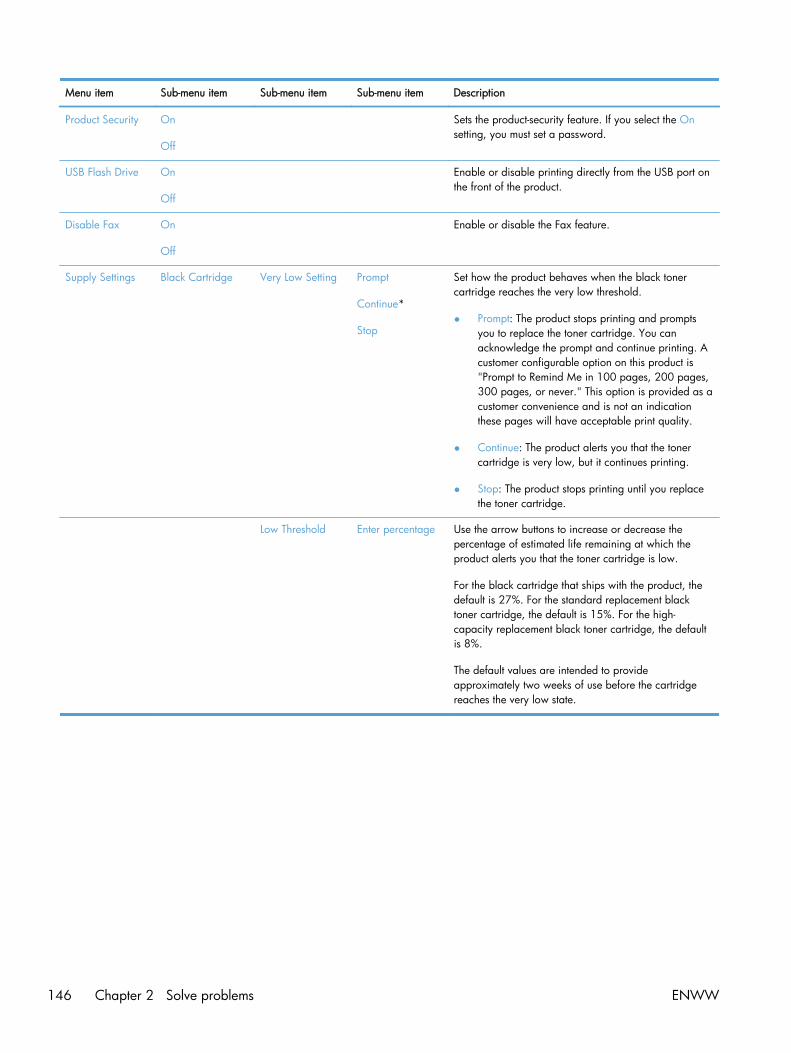
Menu item Sub-menu item Sub-menu item Sub-menu item Description
Product Security On
Off
Sets the product-security feature. If you select the Onsetting, you must set a password.
USB Flash Drive On
Off
Enable or disable printing directly from the USB port onthe front of the product.
Disable Fax On
Off
Enable or disable the Fax feature.
Supply Settings Black Cartridge Very Low Setting Prompt
Continue*
Stop
Set how the product behaves when the black tonercartridge reaches the very low threshold.
● Prompt: The product stops printing and promptsyou to replace the toner cartridge. You canacknowledge the prompt and continue printing. Acustomer configurable option on this product is"Prompt to Remind Me in 100 pages, 200 pages,300 pages, or never." This option is provided as acustomer convenience and is not an indicationthese pages will have acceptable print quality.
● Continue: The product alerts you that the tonercartridge is very low, but it continues printing.
● Stop: The product stops printing until you replacethe toner cartridge.
Low Threshold Enter percentage Use the arrow buttons to increase or decrease thepercentage of estimated life remaining at which theproduct alerts you that the toner cartridge is low.
For the black cartridge that ships with the product, thedefault is 27%. For the standard replacement blacktoner cartridge, the default is 15%. For the high-capacity replacement black toner cartridge, the defaultis 8%.
The default values are intended to provideapproximately two weeks of use before the cartridgereaches the very low state.
146 Chapter 2 Solve problems ENWW

Menu item Sub-menu item Sub-menu item Sub-menu item Description
Color Cartridges Very Low Setting Stop
Prompt
Continue
Print Black*
Set how the product behaves when the one of the colortoner cartridges reaches the very low threshold.
● Prompt: The product stops printing and promptsyou to replace the toner cartridge. You canacknowledge the prompt and continue printing. Acustomer configurable option on this product is"Prompt to Remind Me in 100 pages, 200 pages,300 pages, or never." This option is provided as acustomer convenience and is not an indicationthese pages will have acceptable print quality.
● Continue: The product alerts you that the tonercartridge is very low, but it continues printing.
● Print Black: The product has been customerconfigured to print using only the black tonercartridge when the level of a color supply is verylow. The color supply might still be able to produceacceptable print quality. To print in color, eitherreplace the color supply or reconfigure theproduct.
When you choose to replace the very low tonercartridge, color printing resumes automatically.
● Stop: The product stops printing until you replacethe toner cartridge.
Low Threshold Cyan
Magenta
Yellow
Enter percentage
Use the arrow buttons to increase or decrease thepercentage of estimated life remaining at which theproduct alerts you that the toner cartridge is low.
For the color toner cartridges that ship with the product,the default is 20%. For the replacement color tonercartridges, the default is 10%.
The default values are intended to provideapproximately two weeks of use before the cartridgereaches the very low state.
ENWW Troubleshooting tools 147

Menu item Sub-menu item Sub-menu item Sub-menu item Description
Store Usage Data On Supply*
Not on Supply
The product automatically stores toner cartridge usagedata in its internal memory. It can also store this data onmemory chips in the toner cartridges. Select the Not onSupply option to store the data only in the productmemory.
The information stored on the toner cartridge memorychip helps HP design future products to meet ourcustomers' printing needs. HP collects a sampling ofmemory chips from toner cartridges returned to HP'sfree return and recycling program. The memory chipsfrom this sampling are read and studied in order toimprove future HP products.
The data collected from the toner cartridge memory chipdoes not contain information that can be used toidentify a customer or user of the toner cartridge or theirproduct.
Courier Font Regular
Dark
Sets Courier font values.
Color Copy On
Off
Enables or disables color copying.
148 Chapter 2 Solve problems ENWW

Service menu
In the following table, items that have an asterisk (*) indicate the factory default setting.
Menu item Sub-menu item Sub-menu item Description
Fax Service Clear Saved Faxes Clears all faxes in memory.
Run Fax Test Performs a fax test to verify that the phone cord is pluggedin the correct outlet and that there is a signal on the phoneline. A fax test report is printed indicating the results.
Print T.30 Trace Now
Never*
If Error
At End of Call
Prints or schedules a report that is used to troubleshoot faxtransmission issues.
Error Correction On*
Off
The error correction mode allows the sending device to re-transmit data if it detects an error signal.
Fax Service Log The fax service log prints out the last 40 entries in the faxlog.
Cleaning Page Cleans the product when specks or other marks appear onprinted output. The cleaning process removes dust andexcess toner from the paper path.
When selected, the product prompts you to load plain Letteror A4 paper in Tray 1. Touch the OK button to begin thecleaning process. Wait until the process completes. Discardthe page that prints.
NOTE: For models that do not have an automaticduplexer, the product prints the first side and then promptsyou to remove the page from the output bin and reload it inTray 1, keeping the same orientation.
USB Speed High*
Full
Sets the USB speed for the USB connection to the computer.For the product to actually operate at high speed, it musthave high speed enabled and be connected to an EHCIhost controller that is also operating at high speed. Thismenu item also does not reflect the current operating speedof the product.
Less Paper Curl On
Off*
When printed pages are consistently curled, this option setsthe product to a mode that reduces curl.
Archive Print On
Off*
When printing pages that will be stored for a long time, thisoption sets the product to a mode that reduces tonersmearing and dusting.
FirmwareDatecode
Displays the current firmware datecode
ENWW Troubleshooting tools 149

Menu item Sub-menu item Sub-menu item Description
RestoreDefaults
Sets all settings to the factory default values
HP SmartInstall
On*
Off
Enable or disable the HP Smart Install tool.
Disable the tool if you want to connect to a network byusing an Ethernet cable.
If you disable HP Smart Install, you must use the productsoftware CD to install the product software.
150 Chapter 2 Solve problems ENWW

Network Setup menu
In the following table, items that have an asterisk (*) indicate the factory default setting.
Menu item Sub-menu item Sub-menu item Description
Wireless Menu
NOTE: You can alsoaccess this menu bytouching the Wireless
button on the controlpanel.
Wireless Direct Settings Wireless Direct On/Off Enables or disables the Direct Wi-Fi wireless accessfeature.
Wireless Direct Name Set the product's Direct Wifi name, so you can access itfrom other wireless devices that support the Wi-Fi Directprotocol.
Wireless Direct Mode Set the product's Direct Wifi mode.
● Select the Print Only option (the default setting) toallow wireless access to only the product printfunctions from a mobile device.
● Select the Open Network option to allow wirelessaccess to all product functions and settings from amobile device.
Wireless Setup Wizard Guides you through the steps to set up the product on awireless network
Wi-Fi Protected Setup If your wireless router supports this feature, use this methodto set up the product on a wireless network. This is thesimplest method.
Run Network Test Tests the wireless network and prints a report with theresults.
Turn Wireless On/Off Enables or disables the wireless network feature.
TCP/IP Config Automatic*
Manual
Automatic: The product automatically configures all theTCP/IP settings via DHCP, BootP or AutoIP.
Manual: You can manually configure the IP address,subnet mask, and default gateway. The control panelprompts you to specify values for each address section. Aseach address is completed, the product prompts foraddress confirmation before moving to the next one. Afterall three addresses are set, the network reinitializes.
Auto Crossover On*
Off
Enables or disables the use of a standard 10/100 networkcable when the product is directly connected to acomputer.
Network Services IPv4
IPv6
Enable or disable the IPv4 and IPv6 protocols. By default,each protocol is enabled.
Link Speed Automatic*
10T Full
10T Half
100TX Full
100TX Half
Sets the link speed manually if needed.
After setting the link speed, the product automaticallyrestarts.
ENWW Troubleshooting tools 151
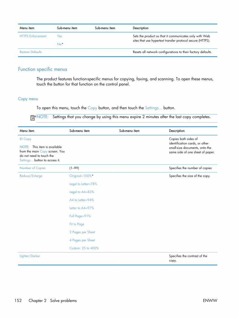
Menu item Sub-menu item Sub-menu item Description
HTTPS Enforcement Yes
No*
Sets the product so that it communicates only with Websites that use hypertext transfer protocol secure (HTTPS).
Restore Defaults Resets all network configurations to their factory defaults.
Function specific menus
The product features function-specific menus for copying, faxing, and scanning. To open these menus,touch the button for that function on the control panel.
Copy menu
To open this menu, touch the Copy button, and then touch the Settings... button.
NOTE: Settings that you change by using this menu expire 2 minutes after the last copy completes.
Menu item Sub-menu item Sub-menu item Description
ID Copy
NOTE: This item is availablefrom the main Copy screen. Youdo not need to touch theSettings... button to access it.
Copies both sides ofidentification cards, or othersmall-size documents, onto thesame side of one sheet of paper.
Number of Copies (1–99) Specifies the number of copies
Reduce/Enlarge Original=100%*
Legal to Letter=78%
Legal to A4=83%
A4 to Letter=94%
Letter to A4=97%
Full Page=91%
Fit to Page
2 Pages per Sheet
4 Pages per Sheet
Custom: 25 to 400%
Specifies the size of the copy.
Lighter/Darker Specifies the contrast of thecopy.
152 Chapter 2 Solve problems ENWW

Menu item Sub-menu item Sub-menu item Description
Optimize Describe Original Auto Select*
Mixed
Text
Picture
Specifies the type of content inthe original document, so thecopy is the best match for theoriginal.
Paper Paper Size
Paper Type
Specifies the paper size and typefor copies.
Multi-Page Copy Off*
On
When this feature is on, theproduct prompts you to loadanother page onto the scannerglass or to indicate that the job iscomplete.
Collation On*
Off
Specifies whether to collate copyjobs
Tray Select Auto Select*
Tray 1
Tray 2
Specifies which tray to use forcopies.
Two Sided 1-Sided to 1-Sided*
1-Sided to 2-Sided
2-Sided to 1-Sided
2-Sided to 2-Sided
Specifies the duplex setting forcopies.
NOTE: This item is availablefor duplex models only.
Draft Mode Off*
On
Specifies whether to use draft-quality printing for copies
Image Adjustment Lightness
Contrast
Sharpen
Background Removal
Color Balance
Grayness
Adjusts the image quality settingsfor copies
Set as New Defaults Saves any changes you havemade to this menu as the newdefaults
Restore Defaults Restores the factory defaults forthis menu
ENWW Troubleshooting tools 153
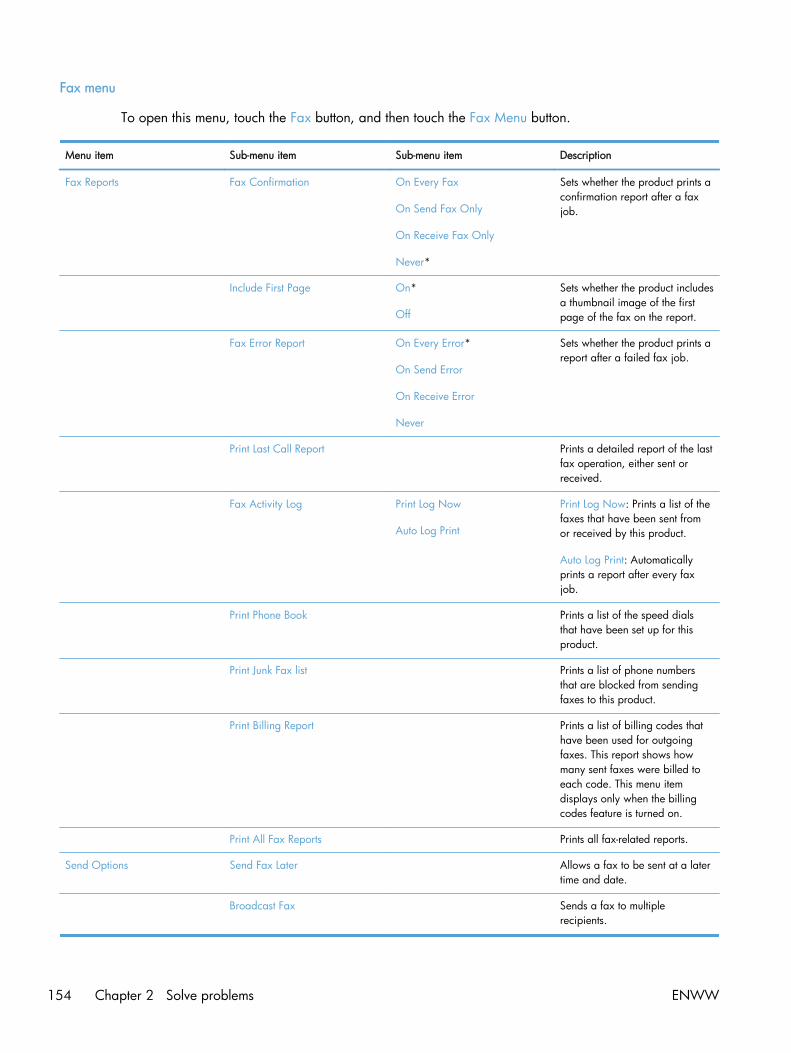
Fax menu
To open this menu, touch the Fax button, and then touch the Fax Menu button.
Menu item Sub-menu item Sub-menu item Description
Fax Reports Fax Confirmation On Every Fax
On Send Fax Only
On Receive Fax Only
Never*
Sets whether the product prints aconfirmation report after a faxjob.
Include First Page On*
Off
Sets whether the product includesa thumbnail image of the firstpage of the fax on the report.
Fax Error Report On Every Error*
On Send Error
On Receive Error
Never
Sets whether the product prints areport after a failed fax job.
Print Last Call Report Prints a detailed report of the lastfax operation, either sent orreceived.
Fax Activity Log Print Log Now
Auto Log Print
Print Log Now: Prints a list of thefaxes that have been sent fromor received by this product.
Auto Log Print: Automaticallyprints a report after every faxjob.
Print Phone Book Prints a list of the speed dialsthat have been set up for thisproduct.
Print Junk Fax list Prints a list of phone numbersthat are blocked from sendingfaxes to this product.
Print Billing Report Prints a list of billing codes thathave been used for outgoingfaxes. This report shows howmany sent faxes were billed toeach code. This menu itemdisplays only when the billingcodes feature is turned on.
Print All Fax Reports Prints all fax-related reports.
Send Options Send Fax Later Allows a fax to be sent at a latertime and date.
Broadcast Fax Sends a fax to multiplerecipients.
154 Chapter 2 Solve problems ENWW
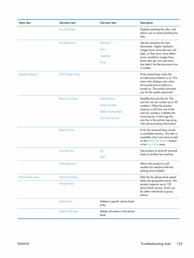
Menu item Sub-menu item Sub-menu item Description
Fax Job Status Displays pending fax jobs, andallows you to cancel pending faxjobs.
Fax Resolution Standard
Fine
Superfine
Photo
Sets the resolution for sentdocuments. Higher resolutionimages have more dots per inch(dpi), so they show more detail.Lower resolution images havefewer dots per inch and showless detail, but the document sizeis smaller.
Receive Options Print Private Faxes Prints stored faxes when theprivate-receive feature is on. Thismenu item displays only whenthe private-receive feature isturned on. The product promptsyou for the system password.
Block Junk Faxes Add Number
Delete Number
Delete All Numbers
Print Junk Fax list
Modifies the junk fax list. Thejunk fax list can contain up to 30numbers. When the productreceives a call from one of thejunk fax numbers, it deletes theincoming fax. It also logs thejunk fax in the activity log alongwith job-accounting information.
Reprint Faxes Prints the received faxes storedin available memory. This item isavailable only if you have turnedon the Allow Fax Reprint featurein the Fax Setup menu.
Forward Fax On
Off*
Sets product to send all receivedfaxes to another fax machine.
Polling Receive Allows the product to callanother fax machine that haspolling send enabled.
Phone Book Setup Individual Setup Edits the fax phone book speeddials and group-dial entries. Theproduct supports up to 120phone book entries, which canbe either individual or groupentries.
Group Setup
Delete Entry Deletes a specific phone bookentry.
Delete All Entries Deletes all entries in the phonebook.
ENWW Troubleshooting tools 155
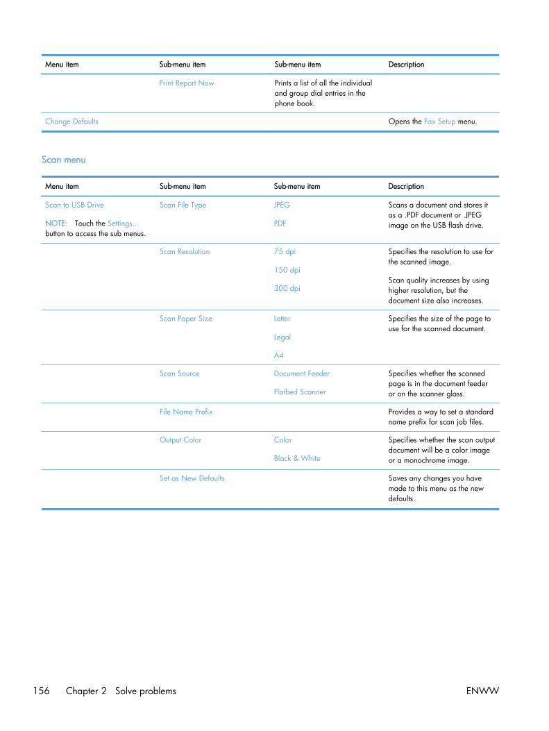
Menu item Sub-menu item Sub-menu item Description
Print Report Now Prints a list of all the individualand group dial entries in thephone book.
Change Defaults Opens the Fax Setup menu.
Scan menu
Menu item Sub-menu item Sub-menu item Description
Scan to USB Drive
NOTE: Touch the Settings...button to access the sub menus.
Scan File Type JPEG
Scans a document and stores itas a .PDF document or .JPEGimage on the USB flash drive.
Scan Resolution 75 dpi
150 dpi
300 dpi
Specifies the resolution to use forthe scanned image.
Scan quality increases by usinghigher resolution, but thedocument size also increases.
Scan Paper Size Letter
Legal
A4
Specifies the size of the page touse for the scanned document.
Scan Source Document Feeder
Flatbed Scanner
Specifies whether the scannedpage is in the document feederor on the scanner glass.
File Name Prefix Provides a way to set a standardname prefix for scan job files.
Output Color Color
Black & White
Specifies whether the scan outputdocument will be a color imageor a monochrome image.
Set as New Defaults Saves any changes you havemade to this menu as the newdefaults.
156 Chapter 2 Solve problems ENWW

USB Flash Drive
Menu item Description
Print Documents Prints documents stored on the USB drive. Use the arrowbuttons to scroll through the documents. Touch the names ofdocuments that you want to print.
Touch the summary screen to change settings such as thenumber of copies, the paper size, or the paper type.
Touch the Print button when you are ready to print thedocuments.
View and Print Photos Previews photos on the USB drive. Use the arrow buttons toscroll through the photos. Touch the preview image for eachphoto that you want to print. You can adjust the settings, andyou can save the changes as the new default settings. Whenyou are ready to print the photos, touch the Print button.
Scan to USB Drive Scans a document and stores it as a .PDF document or .JPEGimage on the USB flash drive.
Interpret control panel messages
MANY OF THE SOLUTION SAY PRESS OK, IS THIS CORRECT?
PLEASE PROVIDE SERVICE SOLUTIONS FOR ERRORS THAT NOW HAVE “CONTACT HP” AS THEACTION ITEM.
Control panel message types
The control panel messages indicate the current product status or situations that might require action.
Alert and warning messages appear temporarily and might require you to acknowledge the messageby pressing the OK button to resume or by pressing the Cancel button to cancel the job. Withcertain warnings, the job might not complete or the print quality might be affected. If the alert orwarning message is related to printing and the auto-continue feature is on, the product will attempt toresume the printing job after the warning has appeared for 10 seconds without acknowledgement.
Critical error messages can indicate some kind of failure. Turning off and then turning on the powermight fix the problem. If a critical error persists, the product might require service.
Control panel messages
10.100X Supply Memory Error
Description
A specific toner cartridge has a faulty or missing memory chip.
"X" indicates the cartridge: 0=black, 1=cyan, 2=magenta, 3=yellow.
ENWW Troubleshooting tools 157

Recommended action
Check the memory chip. If it is broken or damaged, replace the cartridge.
Verify that the cartridge is installed in the correct location.
Reinstall the toner cartridge.
Turn off and then turn on the product.
If the error is with a color cartridge, try swapping it with a different color cartridge in the tray. If thesame message displays, then there is an engine problem. If a different 10.100X message displays,replace the cartridge.
If the problem is not solved, replace the cartridge.
49 Error, Turn off then on
Description
The product has experienced an internal embedded software error. Under most conditions, the productautomatically restarts.
Recommended action
Turn off the power by using the power switch, wait at least 30 seconds, and then turn on the powerand wait for the product to initialize.
If the error persists, contact HP. See www.hp.com/go/LJColorMFPM375 or www.hp.com/go/LJColorMFPM475 or the support flyer that came in the product box.
50.x Fuser Error
Description
The product has experienced an internal hardware error.
Recommended action
1. Turn off the power by using the power switch, and then wait at least 30 seconds.
2. If a surge protector is being used, remove it. Connect the product directly into the wall socket.
3. Turn on the power and wait for the product to initialize.
If the error persists, contact HP. See www.hp.com/go/LJColorMFPM375 or www.hp.com/go/LJColorMFPM475 or the support flyer that came in the product box.
52 Scanner Error
Description
The product has experienced an internal hardware error.
158 Chapter 2 Solve problems ENWW

Recommended action
Turn off the power by using the power switch, wait at least 30 seconds, and then turn on the powerand wait for the product to initialize.
If a surge protector is being used, remove it. Connect the product directly into the wall socket. Use thepower switch to turn the product on.
If the error persists, contact HP. See www.hp.com/go/LJColorMFPM375 or www.hp.com/go/LJColorMFPM475 or the support flyer that came in the product box.
57 Fan Error, Turn off then on
Description
The product has experienced a problem with its internal fan.
Recommended action
Turn off the power by using the power switch, wait at least 30 seconds, and then turn on the powerand wait for the product to initialize.
If the error persists, contact HP. See www.hp.com/go/LJColorMFPM375 or www.hp.com/go/LJColorMFPM475 or the support flyer that came in the product box.
79 Error Turn off then on
Description
The product has experienced an internal firmware error. Under most conditions, the productautomatically restarts.
Recommended action
Turn off the power by using the power switch, wait at least 30 seconds, and then turn on the powerand wait for the product to initialize.
If a surge protector is being used, remove it. Connect the product directly into the wall socket. Use thepower switch to turn the product on.
If the error persists, contact HP. See www.hp.com/go/LJColorMFPM375 or www.hp.com/go/LJColorMFPM475 or the support flyer that came in the product box.
Black Cartridge Low
Description
The toner cartridge is nearing the end of its useful life.
Recommended action
Printing can continue, but consider having a replacement supply on hand.
ENWW Troubleshooting tools 159

Black in wrong position
Description
The toner cartridge is installed in the incorrect slot.
Recommended action
Make sure that each toner cartridge is installed in the correct slot. From front to back, the tonercartridges are installed in this order: black, cyan, magenta, and yellow.
Black Very Low
Description
The toner cartridge is at the end of its useful life. The product continues printing to prevent faxinterruptions.
Recommended action
To ensure optimal print quality, HP recommends replacing the toner cartridge at this point. You cancontinue printing until you notice a decrease in print quality. Actual cartridge life may vary.
Once an HP supply has reached very low, HP's premium Protection Warranty on that supply hasended. All print defects or cartridge failures incurred when an HP supply is used in continue at very lowmode will not be considered to be defects in materials or workmanship in the supply under the HPToner cartridge Warranty Statement.
Canceled scan. Clear document
Description
You touched the Cancel button while scanning, faxing, or copying to cancel the current job whilepages were feeding from the document feeder. The cancel process does not automatically clear thedocument feeder.
Recommended action
Remove the jammed item. Then, clear the items in the document feeder tray and start over.
Canceled send. Clear document
Description
You touched the Cancel button while faxing to cancel the current job while pages were feeding fromthe document feeder. The cancel process does not automatically clear the document feeder.
Recommended action
Remove the jammed item. Then, clear the items in the document feeder tray and start over.
160 Chapter 2 Solve problems ENWW

Communication error.
Description
A fax communication error occurred between the product and the sender or receiver.
Recommended action
Allow the product to retry sending the fax. Unplug the product telephone cord from the wall, plug in atelephone, and try making a call. Connect the product phone cord into a jack for another phone line.
Try a different phone cord.
Set the Fax Speed option to the Slow (V.29) setting or disable the Fast (V.34) setting.
Turn off the Error Correction feature to prevent automatic error correction.
NOTE: Turning off the Error Correction feature can reduce image quality.
Print the Fax Activity Log report from the control panel to determine if the error occurs by using aspecific fax number.
If the error persists, contact HP. See www.hp.com/go/LJColorMFPM375 or www.hp.com/go/LJColorMFPM475 or the support flyer that came in the product box.
Cyan Cartridge Low
Description
The toner cartridge is nearing the end of its useful life.
Recommended action
Printing can continue, but consider having a replacement supply on hand.
Cyan in wrong position
Description
The toner cartridge is installed in the incorrect slot.
Recommended action
Make sure that each toner cartridge is installed in the correct slot. From front to back, the tonercartridges are installed in this order: black, cyan, magenta, and yellow.
Cyan Very Low
Description
The toner cartridge is at the end of its useful life. When a color toner cartridge becomes very low, theproduct prints in black only to prevent fax interruptions. When you choose to replace the very low tonercartridge, color printing resumes automatically.
ENWW Troubleshooting tools 161

Recommended action
To ensure optimal print quality, HP recommends replacing the toner cartridge at this point. You cancontinue printing until you notice a decrease in print quality. Actual cartridge life may vary.
Once an HP supply has reached very low, HP's premium Protection Warranty on that supply hasended. All print defects or cartridge failures incurred when an HP supply is used in continue at very lowmode will not be considered to be defects in materials or workmanship in the supply under the HP PrintCartridge Warranty Statement.
Device error, press OK
Description
Generic engine error.
Recommended action
This is a warning message only. Job output might be affected.
Device is busy. Try again later
Description
The product is currently in use.
Recommended action
Wait for the product to finish the current job, or to finish initializing.
Document feeder door is open.
Description
The document feeder cover is open, or a sensor is malfunctioning.
Recommended action
Make sure that the document feeder cover is closed.
If the message persists, turn off the power by using the power switch, wait at least 30 seconds, andthen turn on the power and wait for the product to initialize.
If the error persists, contact HP. See www.hp.com/go/LJColorMFPM375 or www.hp.com/go/LJColorMFPM475 or the support flyer that came in the product box.
Document feeder jam. Clear and reload.
Description
A piece of paper is jammed in the document feeder tray.
Recommended action
Clear the jam.
162 Chapter 2 Solve problems ENWW

If the error persists, contact HP. See www.hp.com/go/LJColorMFPM375 or www.hp.com/go/LJColorMFPM475 or the support flyer that came in the product box.
Document feeder mispick. Reload
Description
The product did not pick up the paper in the document feeder.
Recommended action
Remove the paper from the document feeder tray, and then reload it.
If the error persists, contact HP. See www.hp.com/go/LJColorMFPM375 or www.hp.com/go/LJColorMFPM475 or the support flyer that came in the product box.
Door open
Description
The toner cartridge door is open.
Recommended action
Close the toner cartridge door.
Engine Communication Error
Description
The product has experienced an engine communication timeout error.
Recommended action
Turn off the power by using the power switch, wait at least 30 seconds, and then turn on the powerand wait for the product to initialize.
If a surge protector is being used, remove it. Connect the product directly into the wall socket. Use thepower switch to turn the product on.
If the error persists, contact HP. See www.hp.com/go/LJColorMFPM375 or www.hp.com/go/LJColorMFPM475 or the support flyer that came in the product box.
Engine error. Press OK to continue.
Description
The product experienced a print engine error.
Recommended action
This is a warning message only. Job output might be affected.
ENWW Troubleshooting tools 163
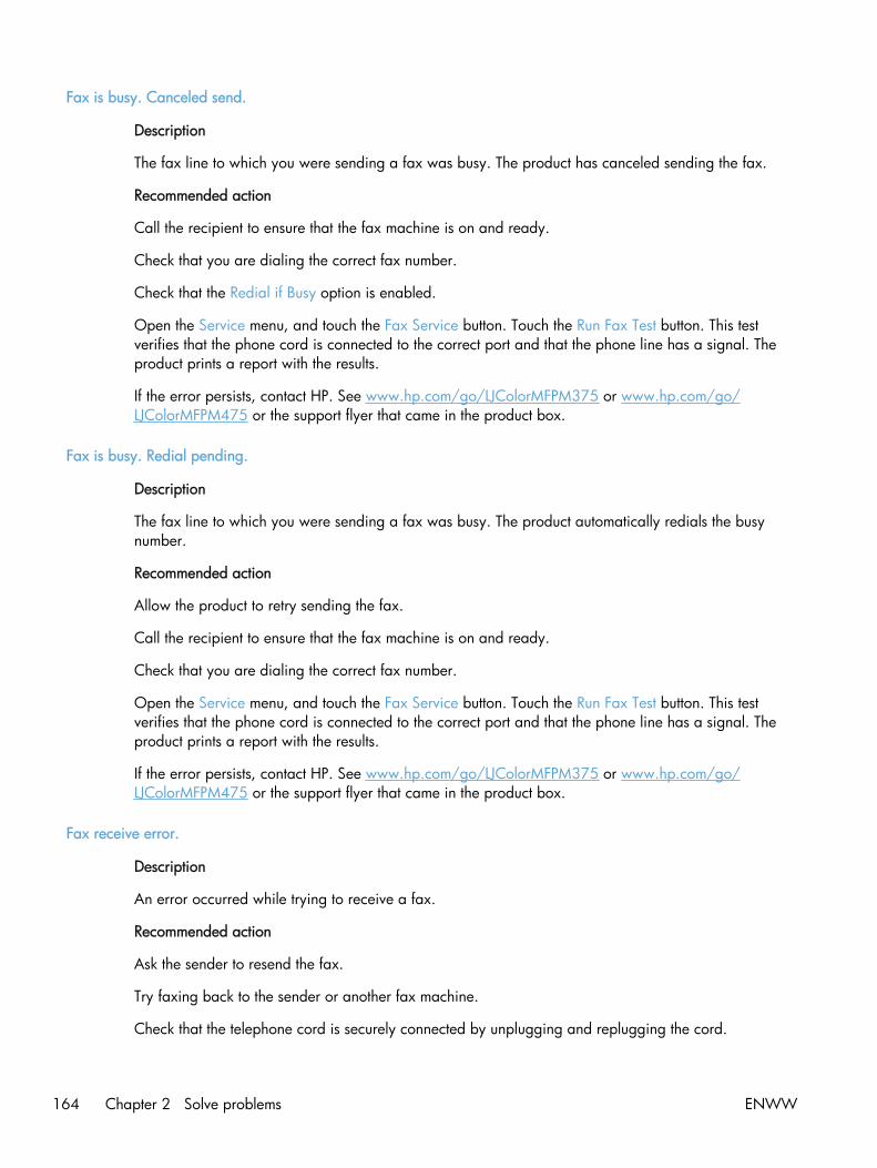
Fax is busy. Canceled send.
Description
The fax line to which you were sending a fax was busy. The product has canceled sending the fax.
Recommended action
Call the recipient to ensure that the fax machine is on and ready.
Check that you are dialing the correct fax number.
Check that the Redial if Busy option is enabled.
Open the Service menu, and touch the Fax Service button. Touch the Run Fax Test button. This testverifies that the phone cord is connected to the correct port and that the phone line has a signal. Theproduct prints a report with the results.
If the error persists, contact HP. See www.hp.com/go/LJColorMFPM375 or www.hp.com/go/LJColorMFPM475 or the support flyer that came in the product box.
Fax is busy. Redial pending.
Description
The fax line to which you were sending a fax was busy. The product automatically redials the busynumber.
Recommended action
Allow the product to retry sending the fax.
Call the recipient to ensure that the fax machine is on and ready.
Check that you are dialing the correct fax number.
Open the Service menu, and touch the Fax Service button. Touch the Run Fax Test button. This testverifies that the phone cord is connected to the correct port and that the phone line has a signal. Theproduct prints a report with the results.
If the error persists, contact HP. See www.hp.com/go/LJColorMFPM375 or www.hp.com/go/LJColorMFPM475 or the support flyer that came in the product box.
Fax receive error.
Description
An error occurred while trying to receive a fax.
Recommended action
Ask the sender to resend the fax.
Try faxing back to the sender or another fax machine.
Check that the telephone cord is securely connected by unplugging and replugging the cord.
164 Chapter 2 Solve problems ENWW
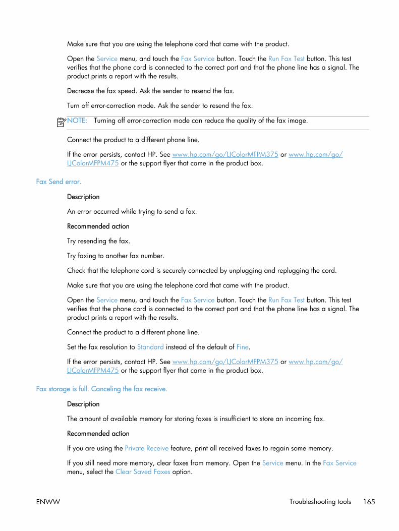
Make sure that you are using the telephone cord that came with the product.
Open the Service menu, and touch the Fax Service button. Touch the Run Fax Test button. This testverifies that the phone cord is connected to the correct port and that the phone line has a signal. Theproduct prints a report with the results.
Decrease the fax speed. Ask the sender to resend the fax.
Turn off error-correction mode. Ask the sender to resend the fax.
NOTE: Turning off error-correction mode can reduce the quality of the fax image.
Connect the product to a different phone line.
If the error persists, contact HP. See www.hp.com/go/LJColorMFPM375 or www.hp.com/go/LJColorMFPM475 or the support flyer that came in the product box.
Fax Send error.
Description
An error occurred while trying to send a fax.
Recommended action
Try resending the fax.
Try faxing to another fax number.
Check that the telephone cord is securely connected by unplugging and replugging the cord.
Make sure that you are using the telephone cord that came with the product.
Open the Service menu, and touch the Fax Service button. Touch the Run Fax Test button. This testverifies that the phone cord is connected to the correct port and that the phone line has a signal. Theproduct prints a report with the results.
Connect the product to a different phone line.
Set the fax resolution to Standard instead of the default of Fine.
If the error persists, contact HP. See www.hp.com/go/LJColorMFPM375 or www.hp.com/go/LJColorMFPM475 or the support flyer that came in the product box.
Fax storage is full. Canceling the fax receive.
Description
The amount of available memory for storing faxes is insufficient to store an incoming fax.
Recommended action
If you are using the Private Receive feature, print all received faxes to regain some memory.
If you still need more memory, clear faxes from memory. Open the Service menu. In the Fax Servicemenu, select the Clear Saved Faxes option.
ENWW Troubleshooting tools 165
Fax storage is full. Canceling the fax send.
Description
During the fax job, the memory filled. All pages of the fax have to be in memory for a fax job to workcorrectly. Only the pages that fit into memory were sent.
Recommended action
Cancel the current job. Turn the product off, and then turn it on again. Try sending the job again.
If the error reoccurs, cancel the job and turn the product off and then on a second time. The productmight not have enough memory for some jobs.
Fit to Page on flatbed only
Description
The copy reduce/enlarge feature (called "Fit to Page") applies only to copies made from the flatbedscanner.
Recommended action
Use the flatbed or select another reduction/enlargement setting.
Genuine HP supply installed
Description
A genuine HP supply was installed.
Recommended action
No action necessary.
Incompatible <color>
Description
You have installed a toner cartridge that is intended for use in a different HP product model. Theproduct might not function correctly with this toner cartridge installed.
Recommended action
Install the correct toner cartridge for this product.
Install [color] cartridge
Description
One of the color cartridges is not installed with the door closed.
Recommended action
Install the indicated color cartridge.
166 Chapter 2 Solve problems ENWW

Invalid driver Press OK
Description
You are using the incorrect printer driver.
Recommended action
Select the printer driver that is appropriate for your product.
Invalid entry
Description
Invalid data or response.
Recommended action
Correct the entry.
Jam in (area), Open door and clear jam
Description
There is a paper jam in the print paper path or output bin.
Recommended action
Clear the jam from the area indicated on the product control panel, and then follow the control panelinstructions.
Jam in Tray 1, Clear jam and then press OK
Description
The product has detected a jam in Tray 1.
Recommended action
Clear the jam, and then follow the control panel instructions.
Load paper
Description
The tray is empty.
Recommended action
Load paper in the tray.
Load Tray 1 <TYPE> <SIZE>, Press OK to use available media
Description
Device is processing a job, but no trays match.
ENWW Troubleshooting tools 167

Recommended action
Load paper in the correct orientation.
Touch the OK button to use existing tray settings.
Load Tray 1, <PLAIN> <SIZE> / Cleaning mode, OK to start
Description
Cleaning mode paper prompt.
Recommended action
Load a clean sheet of paper in the correct orientation, then touch the OK button to begin the cleaningprocedures.
Load tray <X> Press [OK] for available media
Description
The tray is empty.
Recommended action
Load paper into the tray to continue printing. Press the OK button to select a different tray.
Magenta Cartridge Low
Description
The toner cartridge is nearing the end of its useful life.
Recommended action
Printing can continue, but consider having a replacement supply on hand.
Magenta in wrong position
Description
The toner cartridge is installed in the incorrect slot.
Recommended action
Make sure that each toner cartridge is installed in the correct slot. From front to back, the tonercartridges are installed in this order: black, cyan, magenta, and yellow.
Magenta Very Low
Description
The toner cartridge is at the end of its useful life. When a color toner cartridge becomes very low, theproduct prints in black only to prevent fax interruptions. When you choose to replace the very low tonercartridge, color printing resumes automatically.
168 Chapter 2 Solve problems ENWW
Recommended action
To ensure optimal print quality, HP recommends replacing the toner cartridge at this point. You cancontinue printing until you notice a decrease in print quality. Actual cartridge life may vary.
Once an HP supply has reached very low, HP's premium Protection Warranty on that supply hasended. All print defects or cartridge failures incurred when an HP supply is used in continue at very lowmode will not be considered to be defects in materials or workmanship in the supply under the HP PrintCartridge Warranty Statement.
Manual Duplex Load Tray 1, Press OK
Description
Manual duplex mode.
Recommended action
Load paper in the correct orientation.
Manual feed <SIZE> <TYPE>, Press OK to use available media
Description
Print Manual Feed mode.
Recommended action
Load paper into Tray 1.
Memory is low. Press OK.
Description
The product memory has been almost completely filled.
Recommended action
Touch the OK button to cancel the job.
Break the job into smaller jobs that contain fewer pages.
Turn the product off and then on to clear the memory.
Memory is low. Try again later
Description
The product does not have enough memory to start a new job.
Recommended action
Wait until the current job is finished before starting a new job.
Turn the product off and then on to clear the memory.
ENWW Troubleshooting tools 169

Memory low Only 1 copy made. Press OK to continue.
Description
The product does not have enough memory to complete the collated copy job.
Recommended action
Break the job into smaller jobs that contain fewer pages.
Turn the product off and then on to clear the memory.
Misprint, Press OK
Description
Feed delay misprint.
Recommended action
Verify that paper is loaded in the input tray.
Reload paper.
No dial tone.
Description
The product could not detect a dial tone.
Recommended action
Check for a dial tone on the phone line by touching the Start Fax button.
Unplug the telephone cord from both the product and the wall and replug the cord.
Make sure that you are using the telephone cord that came with the product.
Open the Service menu, and touch the Fax Service button. Touch the Run Fax Test button. This testverifies that the phone cord is connected to the correct port and that the phone line has a signal. Theproduct prints a report with the results.
If the error persists, contact HP. See www.hp.com/go/LJColorMFPM375 or www.hp.com/go/LJColorMFPM475 or the support flyer that came in the product box.
No fax answer. Canceled send.
Description
Attempts to redial a fax number failed, or the Redial if No Answer option was turned off.
Recommended action
Call the recipient to ensure that the fax machine is on and ready.
Check that you are dialing the correct fax number.
170 Chapter 2 Solve problems ENWW
Check that the redial option is enabled.
Unplug the telephone cord from both the product and the wall and replug the cord.
Open the Service menu, and touch the Fax Service button. Touch the Run Fax Test button. This testverifies that the phone cord is connected to the correct port and that the phone line has a signal. Theproduct prints a report with the results.
If the error persists, contact HP. See www.hp.com/go/LJColorMFPM375 or www.hp.com/go/LJColorMFPM475 or the support flyer that came in the product box.
No fax answer. Redial pending.
Description
The receiving fax line did not answer. The product attempts to redial after a few minutes.
Recommended action
Allow the product to retry sending the fax.
Call the recipient to ensure that the fax machine is on and ready.
Check that you are dialing the correct fax number.
If the product continues to redial, unplug the product telephone cord from the wall, connect atelephone, and try making a voice call.
Open the Service menu, and touch the Fax Service button. Touch the Run Fax Test button. This testverifies that the phone cord is connected to the correct port and that the phone line has a signal. Theproduct prints a report with the results.
If the error persists, contact HP. See www.hp.com/go/LJColorMFPM375 or www.hp.com/go/LJColorMFPM475 or the support flyer that came in the product box.
No fax detected.
Description
The product answered the incoming call but did not detect that a fax machine was calling.
Recommended action
Allow the product to retry receiving the fax.
Open the Service menu, and touch the Fax Service button. Touch the Run Fax Test button. This testverifies that the phone cord is connected to the correct port and that the phone line has a signal. Theproduct prints a report with the results.
If the error persists, contact HP. See www.hp.com/go/LJColorMFPM375 or www.hp.com/go/LJColorMFPM475 or the support flyer that came in the product box.
ENWW Troubleshooting tools 171
Print failure, press OK. If error repeats, turn off then on.
Description
The product could not print the current page because of its complexity.
Recommended action
Touch the OK button to clear the message.
Remove shipping lock from <color> cartridge
Description
A toner cartridge shipping lock is installed.
Recommended action
Pull the orange tab to remove the shipping lock from the cartridge.
Remove shipping locks from cartridges
Description
A toner cartridge shipping lock is installed on one or more toner cartridges.
Recommended action
Pull the orange tab to remove the shipping lock from the cartridge.
Replace [color]
Description
The toner cartridge is at the end of its useful life, and the product is customer-configured to stop printingwhen it reaches the very low state.
Recommended action
To ensure optimal print quality, HP recommends replacing the toner cartridge at this point. You cancontinue printing until you notice a decrease in print quality. Actual cartridge life may vary.
Once an HP supply has reached very low, HP's premium Protection Warranty on that supply hasended. All print defects or cartridge failures incurred when an HP supply is used in continue at very lowmode will not be considered to be defects in materials or workmanship in the supply under the HP PrintCartridge Warranty Statement.
Scanner error #, Turn off then on
Description
The product has experienced an error in the scanner sub-assembly area.
172 Chapter 2 Solve problems ENWW

Recommended action
Turn off the power by using the power switch, wait at least 30 seconds, and then turn on the powerand wait for the product to initialize.
Do not open the scanner lid until the initialization process is complete.
If a surge protector is being used, remove it. Connect the product directly into the wall socket. Use thepower switch to turn the product on.
If the error persists, contact HP. See www.hp.com/go/LJColorMFPM375 or www.hp.com/go/LJColorMFPM475 or the support flyer that came in the product box.
Scanner reserved for PC scan
Description
A computer is using the product to create a scan.
Recommended action
Wait until the computer scan has finished, or cancel the scan from the computer software, or touch theCancel button.
Scanning error Cannot connect
Description
The product cannot transmit scan information to a computer.
Recommended action
Verify that the connection cable is not loose or damaged. Replace the cable if necessary, and try thescan again.
Settings cleared
Description
The product has cleared job settings.
Recommended action
Re-enter any appropriate job settings.
Unexpected size in tray # Load <size> Press [OK]
Description
The product has detected paper in the tray that does not match the configuration for the tray.
Recommended action
Load the correct paper into the tray, or configure the tray for the size that you have loaded.
ENWW Troubleshooting tools 173

Unsupported <color> Press [OK] to continue
Description
The product has detected a toner cartridge that was not made by HP.
Recommended action
Press the OK button to continue printing.
If you believe you purchased an HP supply, go to www.hp.com/go/anticounterfeit. Service or repairsthat are required as a result of using unsupported supplies is not covered under HP warranty.
Used <color> in use
Description
You are using a toner cartridge that reached the default low threshold while it was installed in aproduct.
Recommended action
Printing can continue, but consider having a replacement supply on hand.
Used [color] installed, to accept press OK
Description
A used color toner cartridge has been installed or moved.
Recommended action
Touch the OK button to return to the Ready state.
Used supplies in use
Description
You are using more than one toner cartridge that reached the default low threshold while it wasinstalled in a product.
Recommended action
Printing can continue, but consider having replacement supplies on hand.
Yellow Cartridge Low
Description
The toner cartridge is nearing the end of its useful life.
Recommended action
Printing can continue, but consider having a replacement supply on hand.
174 Chapter 2 Solve problems ENWW

Yellow in wrong position
Description
The toner cartridge is installed in the incorrect slot.
Recommended action
Make sure that each toner cartridge is installed in the correct slot. From front to back, the tonercartridges are installed in this order: black, cyan, magenta, and yellow.
Yellow Very Low
Description
The toner cartridge is at the end of its useful life. When a color toner cartridge becomes very low, theproduct prints in black only to prevent fax interruptions. When you choose to replace the very low tonercartridge, color printing resumes automatically.
Recommended action
To ensure optimal print quality, HP recommends replacing the toner cartridge at this point. You cancontinue printing until you notice a decrease in print quality. Actual cartridge life may vary.
Once an HP supply has reached very low, HP's premium Protection Warranty on that supply hasended. All print defects or cartridge failures incurred when an HP supply is used in continue at very lowmode will not be considered to be defects in materials or workmanship in the supply under the HP PrintCartridge Warranty Statement.
Event-log messages
Accessing the event log requires touching the Left Arrow button and the Cancel button on thetouchscreen when they are not illuminated. Use the figure below to locate these buttons on thetouchscreen.
Figure 2-16 Control-panel test
ENWW Troubleshooting tools 175

Print the event log
NOTE: You can use HP ToolboxFX to view the event log from a computer.
1. Make sure the product is in the Ready state.
2. Touch the Setup button.
3. Simultaneously touch the Left Arrow button and the Cancel button.
4. Touch the Setup button.
5. Open the 2ndry Service menu.
6. Open the Service Reports menu.
7. Touch the Error Report item.
Event log messages
The following table contains all event log codes for this product. Many event log codes correspond to acontrol-panel error message.
Some product events do not produce a message that displays on the control panel. Instead, they areonly recorded in the event log.
Table 2-7 Event-log messages
Event code Description
13.0000 Paper jam
20.0000 Memory out
21.0000 Page misfeed or mispick
41.2000 Beam detect malfunction
41.3000 Unexpected size
50.1000 Low fuser temperature error
50.2000 Slow fuser error
50.3000 High fuser temperature error
50.4000 Fuser drive circuit error
50.7000 Fuser open error
50.8000 Low sub-thermistor fuser error
50.9000 High sub-thermistor fuser error
51.2000 Black scanner laser error (inline devices only)
51.2100 Cyan scanner laser error (inline devices only)
51.2200 Magenta scanner laser error (inline devices only)
176 Chapter 2 Solve problems ENWW

Table 2-7 Event-log messages (continued)
Event code Description
51.2300 Yellow scanner laser error (inline devices only)
54.0100 Environmental sensor error
54.0600 Density sensor error
54.1100 Black density out of range
54.1101 Cyan density out of range
54.1102 Magenta density out of range
54.1103 Yellow density out of range
54.1200 Black density measurement abnormality
54.1201 Cyan density measurement abnormality
54.1202 Magenta density measurement abnormality
54.1203 Yellow density measurement abnormality
54.1400 Color plane registration sensor error (inline devices only)
54.1599 Black CPR pattern cannot be read
54.1501 Cyan CPR pattern cannot be read
54.1502 Magenta CPR pattern cannot be read
54.1503 Yellow CPR pattern cannot be read
54.1500 Yellow toner level sensor error
54.1600 Magenta toner level sensor error
54.1700 Cyan toner level sensor error
54.1800 Black toner level sensor error
54.1900 Bad top-of-page (TOP) sensor
54.2100 Beam detect (BD) error
54.2500 Top-of-page sensor error
55.0000 Engine internal communication error
55.0601 DC controller NVRAM data error
55.0602 DC controller NVRAM access error
55.1000 DC controller memory error
57.0100 Fan motor error
57.0200 Fan error
59.0160 ITB or main motor rotation error (59.A0)
59.0192 Developer motor rotation error (59.C0)
59.0240 Transfer alienation failure (59.F0)
ENWW Troubleshooting tools 177

Table 2-7 Event-log messages (continued)
Event code Description
59.3000 Fuser motor startup error
59.4000 Fuser motor error
59.5000 Image drum motor startup error—black
59.5300 Image drum motor startup error—yellow
59.6000 Image drum motor rotation error—black
59.6300 Image drum motor rotation error—yellow
59.7000 Black developer motor startup error
59.7300 Yellow developer motor startup error
59.8000 Black developer motor rotation error
59.8300 Yellow developer motor rotation error
59.9000 ITB motor start error
Table 2-8 Event-log-only messages
Event code Description Solution
20.0000 Memory out 1. Turn off the power by using the power switch, and then wait at least 30seconds.
2. Turn on the power and wait for the product to initialize.
If the error persists, break the job into smaller jobs that contain fewer pages.
If the error persists, update the firmware.
NOTE: For memory-card models, adding memory to the DIMM slot mighthelp solve this problem.
54.0100 Environmental sensor error Verify that the DC controller connectors are firmly connected.
If the error persists, replace the temperature/humidity sensor.
If the error persists, replace the DC controller.
178 Chapter 2 Solve problems ENWW

Table 2-8 Event-log-only messages (continued)
Event code Description Solution
54.0600 Density sensor error Verify that the cables between the DC controller and the ITB are firmlyconnected.
If the error persists, replace the color misregistration sensor.
If the error persists, replace the ITB.
If the error persists, replace the DC controller.
54.1100 Black density out of range
54.1101 Cyan density out of range
54.1102 Magenta density out ofrange
54.1103 Yellow density out of range
54.1200 Black density measurementabnormality
54.1201 Cyan density measurementabnormality
54.1202 Magenta densitymeasurement abnormality
54.1203 Yellow density measurementabnormality
54.1400 Color plane registrationsensor error (inline devicesonly)
1. Turn off the power by using the power switch, and then wait at least30 seconds.
2. Turn on the power and wait for the product to initialize.
If the error persists, verify that the cables between the color misregistrationsensor and the DC controller are firmly connected.
If the error persists, replace the color misregistration sensor.
If the error persists, replace the ITB.
If the error persists, replace the toner cartridge tray.
If the error persists, replace the DC controller.
54.1501 Cyan CPR pattern cannot beread
54.1502 Magenta CPR pattern cannotbe read
54.1503 Yellow CPR pattern cannotbe read
54.1599 Black CPR pattern cannot beread
54.2100 Beam detect (BD) error If the error persists, replace the DC controller.
If the error persists, replace the product.
54.2500 Top-of-page sensor error Verify that the DC controller connectors are firmly connected.
If the error persists, replace the DC controller.
ENWW Troubleshooting tools 179

Clear jams
Common causes of jams
To reduce the number of paper jams, try these solutions.
1. Use only paper that meets HP specifications for this product.
2. Use paper that is not wrinkled, folded, or damaged. If necessary, use paper from a differentpackage.
3. Use paper that has not previously been printed or copied on.
4. Make sure the tray is not overfilled. If it is, remove the entire stack of paper from the tray,straighten the stack, and then return some of the paper to the tray.
5. Make sure the paper guides in the tray are adjusted correctly for the size of paper. Adjust theguides so they are touching the paper stack without bending it.
6. Make sure that the tray is fully inserted in the product.
7. If you are printing on heavy, embossed, or perforated paper, use the manual feed feature andfeed sheets one at a time.
Jam locations
Jams can occur in these locations:
1 Document feeder
2 Rear door
3 Output bin
4 Tray 1
180 Chapter 2 Solve problems ENWW

5 Tray 2
6 Tray 2 jam-access area
Loose toner might remain in the product after a jam. This problem typically resolves itself after a fewsheets have been printed.
Clear jams from the document feeder
1. Turn the product off.
2. Open the document feeder cover.
ENWW Clear jams 181
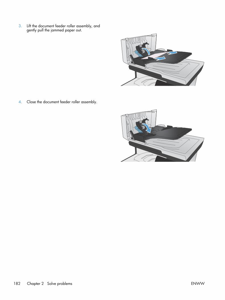
3. Lift the document feeder roller assembly, andgently pull the jammed paper out.
4. Close the document feeder roller assembly.
182 Chapter 2 Solve problems ENWW

5. Close the document feeder cover.
6. Open the scanner lid. If paper is jammedbehind the white plastic backing, gently pull itout.
Clear jams in Tray 1
1. Pull the jammed sheet from Tray 1.
NOTE: If the sheet tears, make sure that all ofthe fragments are removed before you resumeprinting.
ENWW Clear jams 183

2. Pull out Tray 2 and place it on a flat surface.
3. Lower the jam-access tray.
184 Chapter 2 Solve problems ENWW
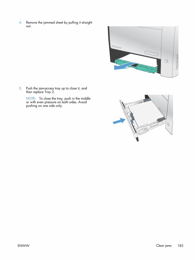
4. Remove the jammed sheet by pulling it straightout.
5. Push the jam-access tray up to close it, andthen replace Tray 2.
NOTE: To close the tray, push in the middleor with even pressure on both sides. Avoidpushing on one side only.
ENWW Clear jams 185
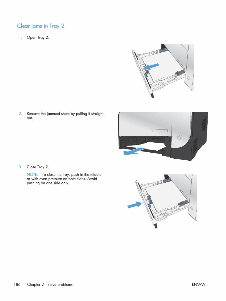
Clear jams in Tray 2
1. Open Tray 2.
2. Remove the jammed sheet by pulling it straightout.
3. Close Tray 2.
NOTE: To close the tray, push in the middleor with even pressure on both sides. Avoidpushing on one side only.
186 Chapter 2 Solve problems ENWW

Clear jams in the fuser area
1. Open the rear door.
CAUTION: The fuser, located in the back ofthe product, is hot. Wait for the fuser to coolbefore continuing.
2. If necessary, push the guide (callout 1) andremove any visible paper (callout 2) from thebottom of the delivery area.
NOTE: If the sheet tears, make sure that allfragments are removed before you resumeprinting. Do not use sharp objects to removefragments.
3. Close the rear door.
ENWW Clear jams 187

Clear jams in the output bin
1. Look for jammed paper in the output bin area.
2. Remove any visible media.
NOTE: If the sheet tears, make sure that allfragments are removed before resumingprinting.
3. Open and then close the rear door to clear themessage.
188 Chapter 2 Solve problems ENWW
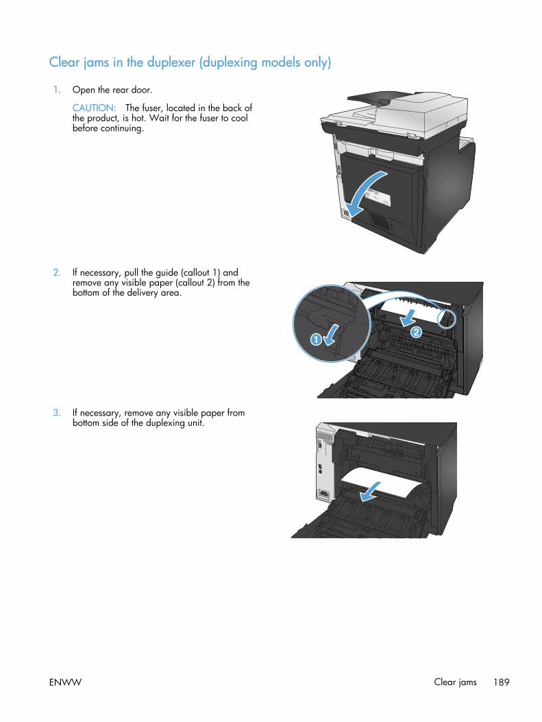
Clear jams in the duplexer (duplexing models only)
1. Open the rear door.
CAUTION: The fuser, located in the back ofthe product, is hot. Wait for the fuser to coolbefore continuing.
2. If necessary, pull the guide (callout 1) andremove any visible paper (callout 2) from thebottom of the delivery area.
3. If necessary, remove any visible paper frombottom side of the duplexing unit.
ENWW Clear jams 189

4. If you can not see any jammed paper, lift theduplexing unit using the tab on the side of theduplexing unit.
5. If you can see the trailing edge of the paper,remove the paper from the product.
6. If you can see the leading edge of the paper,remove it from the product.
7. Close the rear door.
190 Chapter 2 Solve problems ENWW

Solve paper-handling problems
The product picks up multiple sheets of paper
If the product picks up multiple sheets of paper from the tray, try these solutions.
1. Remove the stack of paper from the tray and flex it, rotate it 180 degrees, and flip it over. Do notfan the paper. Return the stack of paper to the tray.
2. Use only paper that meets HP specifications for this product.
3. Use paper that is not wrinkled, folded, or damaged. If necessary, use paper from a differentpackage.
4. Make sure the tray is not overfilled. If it is, remove the entire stack of paper from the tray,straighten the stack, and then return some of the paper to the tray.
5. Make sure the paper guides in the tray are adjusted correctly for the size of paper. Align theguides with the paper-size markings in the bottom of the tray.
The product does not pick up paper
If the product does not pick up paper from the tray, try these solutions.
1. Open the product and remove any jammed sheets of paper.
2. Load the tray with the correct size of paper for your job.
3. Make sure the paper guides in the tray are adjusted correctly for the size of paper. Align theguides with the paper-size markings in the bottom of the tray.
4. Check the product control panel to see if the product is waiting for you to acknowledge a promptto feed the paper manually. Load paper, and continue.
ENWW Solve paper-handling problems 191

Solve image-quality problems
Print quality examples
The following examples depict Letter-size paper that has passed through the product short-edge first.These examples illustrate problems that would affect all the pages that you print, whether you print incolor or in black only. The topics that follow list the typical cause and solution for each of theseexamples.
Problem Cause Solution
Print is light or faded. The media might not meetHP specifications.
Use media that meets HP specifications.
One or more toner cartridges might bedefective.
Print the Supplies status page to checkthe remaining life.
Replace any low toner cartridges.
The product is set to override theReplace [color] message and to continueprinting.
Replace any low toner cartridges.
The print density settings might havebeen changed.
Set the print density setting to 0.
The product might need to becalibrated.
Run a calibration.
Toner specks appear. The media might not meet HPspecifications.
Use only media that meetsHP specifications.
The paper path might need cleaning. Clean the paper path. See the completeversion of the English service manual.
One or more of the cartridges might beleaking.
Try to verify the color of the toner specksand check the cartridge for leaks.
The cartridge waste tank might beoverfilled.
Check for error code 10.98.XX in theevent log. The XX portion of the codeidentifies the cartridge (00 is black, 01is cyan, 02 is magenta, 03 is yellow). Ifthe error was logged, replace theappropriate cartridge.
Dropouts appear. A single sheet of print media might bedefective.
Try reprinting the job.
The moisture content of the paper isuneven or the paper has moist spots onits surface.
Try different paper, such as high-qualitypaper that is intended for color laserprinters.
The media is flawed. The mediamanufacturing processes can causesome areas to reject toner.
Try different paper, such as high-qualitypaper that is intended for color laserprinters.
192 Chapter 2 Solve problems ENWW

Problem Cause Solution
Vertical streaks or bands appear on thepage.
A
A
A
A
A
B
B
B
B
B
C
C
C
C
C
a
a
a
a
a
c
c
c
c
c
b
b
b
b
b
One or more toner cartridges might bedefective.
Print the Supplies status page to checkthe remaining life.
Replace any low toner cartridges.
The product is set to override theReplace [color] message and to continueprinting.
Replace any low toner cartridges.
The amount of background tonershading becomes unacceptable.
Extreme dry (low humidity) conditionscan increase the amount of backgroundshading.
Check the device environment.
The extended print mode setting isincorrect.
Try the print job again using the Transferextended print mode, Dry paper setting.
One or more toner cartridges might bedefective.
Replace any low toner cartridges.
The product is set to override theReplace [color] message and to continueprinting.
Replace any low toner cartridges.
Smooth media shows more backgroundthan plain media
Think about using rougher media.
Toner smears appear on the media. The media might not meet HPspecifications.
Use only media that meetsHP specifications.
If toner smears appear on the leadingedge of the paper, the media guides aredirty, or debris has accumulated in theprint path.
Clean the media guides.
Clean the paper path.
The toner smears easily when touched. The device is not set to print on the typeof media on which you want to print.
In the printer driver, select the Paper taband set Type is to match the type ofmedia on which you are printing. Printspeed might be slower if you are usingheavy paper.
The media might not meet HPspecifications.
Use only media that meetsHP specifications.
The paper path might need cleaning. Clean the paper path.
ENWW Solve image-quality problems 193

Problem Cause Solution
Marks repeatedly appear at evenintervals on the printed side of the page.
The device is not set to print on the typeof media on which you want to print.
In the printer driver, select the Paper taband set Type is to match the type ofpaper on which you are printing. Printspeed might be slower if you are usingheavy paper.
Internal parts might have toner on them. The problem typically corrects itself aftera few more pages.
The paper path might need cleaning. Clean the paper path.
The fuser might be damaged or dirty. To determine if the fuser has a problem.Print-quality diagnostics page.
Clean the paper path.
A toner cartridge might have a problem. To determine which cartridge has aproblem. Print the print-qualitydiagnostics page.
Marks repeatedly appear at evenintervals on the unprinted side of thepage.
Internal parts might have toner on them. The problem typically corrects itself aftera few more pages.
The paper path might need cleaning. Clean the paper path.
The fuser might be damaged or dirty. To determine if the fuser has a problem.Print the print-quality diagnostics page.
Clean the paper path.
The printed page contains misformedcharacters.
The media might not meet HPspecifications.
Use a different paper, such as high-quality paper that is intended for colorlaser printers.
If characters are incorrectly formed sothat they produce a wavy effect, thelaser scanner might need service.
Verify that the problem also occurs onthe configuration page.
The printed page is curled or wavy. The device is not set to print on the typeof media on which you want to print.
In the printer driver, select the Paper taband set Type is to match the type ofpaper on which you are printing. Printspeed might be slower if you are usingheavy paper.
The Service menu item Less Paper Curl isset to Off.
Use the control-panel menus to changethe setting.
The media might not meet HPspecifications.
Use a different paper, such as high-quality paper that is intended for colorlaser printers.
Both high temperature and humidity cancause paper curl.
Check the device environment.
194 Chapter 2 Solve problems ENWW

Problem Cause Solution
Text or graphics are skewed on theprinted page.
The media might be loaded incorrectly. Ensure that the paper or other printmedia is loaded correctly and that themedia guides are not too tight or tooloose against the stack.
The media might not meet HPspecifications.
Use a different paper, such as high-quality paper that is intended for colorlaser printers.
The printed page contains wrinkles orcreases.
The media might be loaded incorrectly. Verify that the media is loaded correctlyand that the media guides are not tootight or too loose against the stack.
Turn over the stack of paper in the inputtray, or try rotating the paper 180° inthe input tray.
The media might not meet HPspecifications.
Use a different paper, such as high-quality paper that is intended for colorlaser printers.
Toner displays around the printedcharacters.
The media might be loaded incorrectly. Turn over the stack of paper in the tray.
If large amounts of toner have scatteredaround the characters, the paper mighthave high resistivity.
Use a different paper, such as high-quality paper that is intended for colorlaser printers.
An image that displays at the top of thepage (in solid black) repeats fartherdown the page (in a gray field).
Software settings might affect imageprinting.
In your software program, change thetone (darkness) of the field in which therepeated image displays.
In your software program, rotate thewhole page 180° to print the lighterimage first.
The order of images printed might affectprinting.
Change the order in which the imagesare printed. For example, have thelighter image at the top of the page, andthe darker image farther down thepage.
A power surge might have affected thedevice.
If the defect occurs later in a print job,turn the device off for 10 minutes, andthen turn on the device to restart theprint job.
Use non-glossy media to help reduce theseverity of the defect
ENWW Solve image-quality problems 195

Color image defects
This section describes issues that can occur when you print in color.
Problem Cause Solution
Only black is printing when thedocument should be printing in color.
Color mode is not selected in yourprogram or printer driver.
Select color mode instead of gray scalemode.
The correct printer driver might not beselected in the program.
Select the correct printer driver.
The device might not be correctlyconfigured.
Print a configuration page to checkwhether color displays on theconfiguration page.
The color supply is out and the ColorSupply Out menu setting is set toContinue Black.
Replace the color supply.
One or more colors are not printing, orare inaccurate.
Sealing tape might be on the tonercartridges.
Verify that the sealing tape has beencompletely removed from the tonercartridges.
The media might not meet HPspecifications.
Use a different paper, such as high-quality paper that is intended for colorlaser printers.
The device might be operating inexcessively humid conditions.
Verify that the device environment iswithin humidity specifications.
One or more toner cartridges might bedefective.
Replace any low toner cartridges.
The product is set to override theReplace [color] message and to continueprinting.
Replace any low toner cartridges.
One or more of the cartridges might nothave been engaged properly by theprint engine.
Remove and reinstall the cartridges.
A color is printing inconsistently afteryou load a new toner cartridge.
Another toner cartridge might bedefective.
Remove the toner cartridge for the colorthat is printing inconsistently andreinstall it.
The product is set to override theReplace [color] message and to continueprinting.
Replace any low toner cartridges.
196 Chapter 2 Solve problems ENWW

Problem Cause Solution
The colors on the printed page do notmatch the colors as they appear on thescreen.
AaBbCcAaBbCcAaBbCcAaBbCcAaBbCc
The colors on your computer monitormight differ from the device output.
See the product user guide.
If extremely light colors or extremelydark colors on-screen are not printing,your software program might interpretextremely light colors as white orextremely dark colors as black.
If possible, avoid using extremely lightor extremely dark colors.
The media might not meet HPspecifications.
Use a different paper, such as high-quality paper that is intended for colorlaser printers.
The finish on the printed color page isinconsistent.
The media might be too rough. Use a smooth paper or print media,such as a high-quality paper that ismade for color laser printers. Generally,smoother media produces better theresults.
ENWW Solve image-quality problems 197

Clean the product
Clean the pickup and separation rollers
1. Turn off the product, unplug the power cable from the product, and then remove the rollers.
2. Dab a lint-free cloth in isopropyl alcohol, and then scrub the roller.
WARNING! Alcohol is flammable. Keep the alcohol and cloth away from an open flame. Beforeyou close the product and connect the power cable, allow the alcohol to dry completely.
NOTE: In certain areas of California (USA), air pollution control regulations restrict the use ofliquidisopropyl alcohol (IPA) as a cleaning agent. In those areas of California, please disregardtheprevious recommendations and use a dry, lint free cloth, moistened with water, to cleanthepickup roller.
3. Use a dry, lint free cloth, to wipe the rollers and remove loose dirt.
Clean the paper path
During the printing process, paper, toner, and dust particles can accumulate inside the product. Overtime, this buildup can cause print-quality problems such as toner specks or smearing. This product has acleaning mode that can correct and prevent these types of problems.
Clean the paper path from the product control panel
1. From the Home screen, touch the Setup button.
2. Touch the Service menu.
3. Touch the Cleaning Page button.
4. Load plain letter or A4 paper when you are prompted.
5. Touch the OK button to begin the cleaning process.
A page feeds through the product slowly. Discard the page when the process is completed.
NOTE: For models that do not have an automatic duplexer, the product prints the first side andthen prompts you to remove the page from the output bin and reload it in Tray 1, keeping thesame orientation.
198 Chapter 2 Solve problems ENWW

Clean the scanner glass strip and platen
Over time, specks of debris might collect on the scanner glass and white plastic backing, which canaffect performance. Use the following procedure to clean the scanner glass and white plastic backing.
1. Use the power switch to turn off the product, and then unplug the power cable from the electricalsocket.
2. Open the scanner lid.
3. Clean the scanner glass and the white plastic backing with a soft cloth or sponge that has beenmoistened with nonabrasive glass cleaner.
CAUTION: Do not use abrasives, acetone, benzene, ammonia, ethyl alcohol, or carbontetrachloride on any part of the product; these can damage the product. Do not place liquidsdirectly on the glass or platen. They might seep and damage the product.
4. Dry the glass and white plastic backing with a chamois or a cellulose sponge to prevent spotting.
5. Connect the product, and then use the power switch to turn on the product.
ENWW Clean the product 199

Clean the document feeder pickup rollers and separation pad
If the product document feeder experiences paper-handling problems, such as jams or multiple-pagefeeds, clean the document feeder rollers and separation pad.
1. Open the document feeder cover.
2. Use a moist, lint-free cloth to wipe both pickup rollers and the separation pad to remove dirt.
200 Chapter 2 Solve problems ENWW

3. Close the document feeder cover.
Clean the touch screen
Clean the touch screen whenever it is necessary to remove fingerprints or dust. Wipe the touch screengently with a clean, water-dampened, lint-free cloth.
CAUTION: Use water only. Solvents or cleaners can damage the touch screen. Do not pour or spraywater directly onto the touch screen.
ENWW Clean the product 201
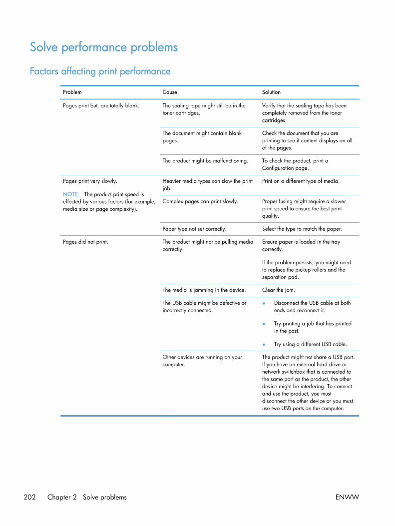
Solve performance problems
Factors affecting print performance
Problem Cause Solution
Pages print but, are totally blank. The sealing tape might still be in thetoner cartridges.
Verify that the sealing tape has beencompletely removed from the tonercartridges.
The document might contain blankpages.
Check the document that you areprinting to see if content displays on allof the pages.
The product might be malfunctioning. To check the product, print aConfiguration page.
Pages print very slowly.
NOTE: The product print speed iseffected by various factors (for example,media size or page complexity).
Heavier media types can slow the printjob.
Print on a different type of media.
Complex pages can print slowly. Proper fusing might require a slowerprint speed to ensure the best printquality.
Paper type not set correctly. Select the type to match the paper.
Pages did not print. The product might not be pulling mediacorrectly.
Ensure paper is loaded in the traycorrectly.
If the problem persists, you might needto replace the pickup rollers and theseparation pad.
The media is jamming in the device. Clear the jam.
The USB cable might be defective orincorrectly connected.
● Disconnect the USB cable at bothends and reconnect it.
● Try printing a job that has printedin the past.
● Try using a different USB cable.
Other devices are running on yourcomputer.
The product might not share a USB port.If you have an external hard drive ornetwork switchbox that is connected tothe same port as the product, the otherdevice might be interfering. To connectand use the product, you mustdisconnect the other device or you mustuse two USB ports on the computer.
202 Chapter 2 Solve problems ENWW

Print speeds
Print speed is the number of pages that print in one minute. Print speed depends on different engine-process speeds or operational pauses between printed pages during normal product operation. Factorsthat determine the print speed of the product include the following:
● Page formatting time
The product must pause for each page to be formatted before it prints. Complex pages take moretime to format, resulting in reduced print speed. However, most jobs print at full engine speed(21 ppm on Letter-size media or 20 ppm on A4-size media).
● Color mode
Monochrome printing (black only) provides the maximum print speed. Full color print jobs cause areduction in print speed.
● Media size
Legal-size media reduces print speed because it is longer than the standard Letter- or A4–sizemedia. A reduce print speed is used when printing on narrow media to prevent the edges of thefuser from overheating.
● Media mode
Some media types require a reduced print speed to achieve maximum print quality on that media.For example, glossy, heavy, and specialty media (for example, envelopes or photos) require areduced print speed. To maximize the print speed for special media types, ensure that you selectthe correct media type in the print driver.
● Product temperature
To prevent product damage, print speed is reduced if the product reaches a specific internaltemperature (thermal slow down). The starting temperature of the product, ambient environmenttemperature, and the print job size effect the number of pages that can be printed before theproduct reduces the print speed. Thermal slow down reduces print speed by printing four pagesand then pausing for an amount of time before printing continues.
● Other print speed reduction factors
Other factors (especially during large print jobs) that can cause reduced print speeds include:
◦ ITB cleaning and lubrication; occurs every 50 to 80 pages and takes about 60 seconds.
◦ CPR control sequence; occurs every 450 pages and takes about 90 seconds.
◦ Density control sequence; occurs every 150 pages and takes about 120 seconds.
ENWW Solve performance problems 203

The product does not print or it prints slowly
The product does not print
If the product does not print at all, try the following solutions.
1. Make sure the product is turned on and that the control panel indicates it is ready.
◦ If the control panel does not indicate the product is ready, turn the product off and then onagain.
◦ If the control panel indicates the product is ready, try sending the job again.
2. If the control panel indicates the product has an error, resolve the error and then try sending thejob again.
3. Make sure the cables are all connected correctly. If the product is connected to a network, checkthe following items:
◦ Check the light next to the network connection on the product. If the network is active, thelight is green.
◦ Make sure that you are using a network cable and not a phone cord to connect to thenetwork.
◦ Make sure the network router, hub, or switch is turned on and that it is working correctly.
4. Install the HP software from the CD that came with the product. Using generic printer drivers cancause delays clearing jobs from the print queue.
5. From the list of printers on your computer, right-click the name of this product, click Properties, andopen the Ports tab.
◦ If you are using a network cable to connect to the network, make sure the printer name listedon the Ports tab matches the product name on the product configuration page.
◦ If you are using a USB cable and are connecting to a wireless network, make sure the box ischecked next to Virtual printer port for USB.
6. If you are using a personal firewall system on the computer, it might be blocking communicationwith the product. Try temporarily disabling the firewall to see if it is the source of the problem.
7. If your computer or the product is connected to a wireless network, low signal quality orinterference might be delaying print jobs.
204 Chapter 2 Solve problems ENWW

The product prints slowly
If the product prints, but it seems slow, try the following solutions.
1. Make sure the computer meets the minimum specifications for this product. For a list ofspecifications, go to this Web site: www.hp.com/go/LJColorMFPM375 or www.hp.com/go/LJColorMFPM475.
2. When you configure the product to print on some paper types, such as heavy paper, the productprints more slowly so it can correctly fuse the toner to the paper. If the paper type setting is notcorrect for the type of paper you are using, change the setting to the correct paper type.
3. If your computer or the product is connected to a wireless network, low signal quality orinterference might be delaying print jobs.
ENWW Solve performance problems 205

Solve product connectivity problems
Solve direct-connect problems
If you have connected the product directly to a computer, check the cable.
● Verify that the cable is connected to the computer and to the product.
● Verify that the cable is not longer than 5 m (16.4 ft). Try using a shorter cable.
● Verify that the cable is working correctly by connecting it to another product. Replace the cable ifnecessary.
Solve network problems
Check the following items to verify that the product is communicating with the network. Beforebeginning, print a configuration page from the product control panel and locate the product IP addressthat is listed on this page.
● Poor physical connection
● The computer is using the incorrect IP address for the product
● The computer is unable to communicate with the product
● The product is using incorrect link and duplex settings for the network
● New software programs might be causing compatibility problems
● The computer or workstation might be set up incorrectly
● The product is disabled, or other network settings are incorrect
Poor physical connection
1. Verify that the product is attached to the correct network port using a cable of the correct length.
2. Verify that cable connections are secure.
3. Look at the network port connection on the back of the product, and verify that the amber activitylight and the green link-status light are lit.
4. If the problem continues, try a different cable or port on the hub.
The computer is using the incorrect IP address for the product
1. Open the printer properties and click the Ports tab. Verify that the current IP address for theproduct is selected. The product IP address is listed on the product configuration page.
2. If you installed the product using the HP standard TCP/IP port, select the box labeled Always printto this printer, even if its IP address changes.
206 Chapter 2 Solve problems ENWW

3. If you installed the product using a Microsoft standard TCP/IP port, use the hostname instead ofthe IP address.
4. If the IP address is correct, delete the product and then add it again.
The computer is unable to communicate with the product
1. Test network communication by pinging the network.
a. Open a command-line prompt on your computer. For Windows, click Start, click Run, andthen type cmd.
b. Type ping followed by the IP address for your product.
c. If the window displays round-trip times, the network is working.
2. If the ping command failed, verify that the network hubs are on, and then verify that the networksettings, the product, and the computer are all configured for the same network.
The product is using incorrect link and duplex settings for the network
Hewlett-Packard recommends leaving this setting in automatic mode (the default setting). If you changethese settings, you must also change them for your network.
New software programs might be causing compatibility problems
Verify that any new software programs are correctly installed and that they use the correct printerdriver.
The computer or workstation might be set up incorrectly
1. Check the network drivers, printer drivers, and the network redirection.
2. Verify that the operating system is configured correctly.
The product is disabled, or other network settings are incorrect
1. Review the configuration page to check the status of the network protocol. Enable it if necessary.
2. Change the network settings if necessary.
Solve wireless network problems
● Wireless connectivity checklist
● The control panel displays the message: The wireless feature on this product has been turned off
● The product does not print after the wireless configuration completes
● The product does not print, and the computer has a third-party firewall installed
● The wireless connection does not work after moving the wireless router or product
ENWW Solve product connectivity problems 207

● Cannot connect more computers to the wireless product
● The wireless product loses communication when connected to a VPN
● The network does not appear in the wireless networks list
● The wireless network is not functioning
Wireless connectivity checklist
● The product and the wireless router are turned on and have power. Also make sure the wirelessradio in the product is turned on.
● The service set identifier (SSID) is correct. Print a configuration page to determine the SSID. If youare not sure the SSID is correct, run the wireless setup again.
● With secured networks, make sure the security information is correct. If the security information isincorrect, run the wireless setup again.
● If the wireless network is working correctly, try accessing other computers on the wireless network.If the network has Internet access, try connecting to the Internet over a wireless connection.
● The encryption method (AES or TKIP) is the same for the product as it is for the wireless accesspoint (on networks using WPA security).
● The product is within the range of the wireless network. For most networks, the product must bewithin 30 m (100 ft) of the wireless access point (wireless router).
● Obstacles do not block the wireless signal. Remove any large metal objects between the accesspoint and the product. Make sure poles, walls, or support columns containing metal or concretedo not separate the product and wireless access point.
● The product is located away from electronic devices that might interfere with the wireless signal.Many devices can interfere with the wireless signal including motors, cordless phones, securitysystem cameras, other wireless networks, and some Bluetooth devices.
● The printer driver is installed on the computer.
● You have selected the correct printer port.
● The computer and product connect to the same wireless network.
The control panel displays the message: The wireless feature on this product has been turnedoff
1. Touch the Wireless Menu button.
2. Touch the Turn Wireless On/Off button, and then touch the On button.
The product does not print after the wireless configuration completes
1. Make sure the product is turned on and in the ready state.
2. Make sure you are connecting to the correct wireless network.
208 Chapter 2 Solve problems ENWW

3. Make sure that the wireless network is working correctly.
a. Open the Network Setup menu, and then open the Wireless Menu item.
b. Select the Run Network Test item to test the wireless network. The product prints a report withthe results.
4. Make sure that the correct port or product is selected.
a. From the list of printers on your computer, right-click the name of this product, clickProperties, and then open the Ports tab.
b. Make sure the box is checked next to Virtual printer port for USB.
5. Make sure that your computer is working correctly. If necessary, restart your computer.
The product does not print, and the computer has a third-party firewall installed
1. Update the firewall with the most recent update available from the manufacturer.
2. If programs request firewall access when you install the product or try to print, make sure youallow the programs to run.
3. Temporarily turn off the firewall, and then install the wireless product on the computer. Enable thefirewall when you have completed the wireless installation.
The wireless connection does not work after moving the wireless router or product
Make sure that the router or product connects to the same network that your computer connects to.
1. Open the Reports menu, and select the Configuration Report item to print the report.
2. Compare the service set identifier (SSID) on the configuration report to the SSID in the printerconfiguration for your computer.
3. If the SSIDs are not the same, the devices are not connecting to the same network. Reconfigure thewireless setup for your product.
Cannot connect more computers to the wireless product
1. Make sure that the other computers are within the wireless range and that no obstacles block thesignal. For most networks, the wireless range is within 30 m (100 ft) of the wireless access point.
2. Make sure the product is turned on and in the ready state.
3. Turn off any third-party firewalls on your computer.
4. Make sure that the wireless network is working correctly.
a. On the product control panel, open the Network Setup menu, and then open the WirelessMenu item.
b. Select the Run Network Test item to test the wireless network. The product prints a report withthe results.
ENWW Solve product connectivity problems 209

5. Make sure that the correct port or product is selected.
a. From the list of printers on your computer, right-click the name of this product, clickProperties, and then open the Ports tab.
b. Click the Configure Port button to verify that the IP address matches the IP address listed onthe Run Network Test report.
6. Make sure that your computer is working correctly. If necessary, restart your computer.
The wireless product loses communication when connected to a VPN
● Typically, you cannot connect to a VPN and other networks at the same time.
The network does not appear in the wireless networks list
● Make sure the wireless router is turned on and has power.
● The network might be hidden. However, you can still connect to a hidden network.
The wireless network is not functioning
1. To verify if the network has lost communication, try connecting other devices to the network.
2. Test network communication by pinging the network.
a. Open a command-line prompt on your computer. For Windows, click Start, click Run, andthen type cmd.
b. Type ping followed by the service set identifier (SSID) for your network.
c. If the window displays round-trip times, the network is working.
3. Make sure that the router or product connects to the same network that your computer connects to.
a. Open the Reports menu, and select the Configuration Report item to print the report.
b. Compare the service set identifier (SSID) on the configuration report to the SSID in the printerconfiguration for your computer.
c. If the SSIDs are not the same, the devices are not connecting to the same network.Reconfigure the wireless setup for your product.
210 Chapter 2 Solve problems ENWW

Service mode functions
Service menu
Use the control-panel Service menu to troubleshoot product problems.
Service menu settings
The Service menu is used to calibrate, restore factory default settings, and clean the print paper path.
The following Service menu items are available:
● Fax Service—used to test, diagnose, and maintain the fax functionality.
● Cleaning Page—used to remove dust and toner from the print paper path
● PowerSave Time—used to configure the amount of idle time before the engine enters sleep mode
● USB Speed—used to set the USB speed
● Less Paper Curl—used to decrease the fuser temperature, which can reduce paper curl
● Archive Print—used to decrease the likelihood of toner smearing on a print job
● Restore Defaults—used to reset all customer-accessible menu settings back to the factory defaultsettings (except language) via the control panel or software
NOTE: This menu item does not reset factory-settable settings, including formatter number, pagecounts, factory paper settings, language, and so on.
Secondary service menu
Accessing the Secondary service menu requires touching the Left Arrow button and the Cancel button on the touchscreen when they are not illuminated. Use the figure below to locate these buttonson the touchscreen.
Figure 2-17 Control-panel test
ENWW Service mode functions 211
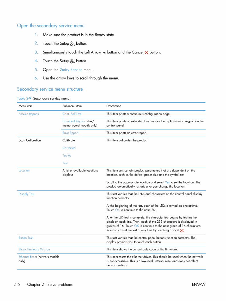
Open the secondary service menu
1. Make sure the product is in the Ready state.
2. Touch the Setup button.
3. Simultaneously touch the Left Arrow button and the Cancel button.
4. Touch the Setup button.
5. Open the 2ndry Service menu.
6. Use the arrow keys to scroll through the menu.
Secondary service menu structure
Table 2-9 Secondary service menu
Menu item Sub-menu item Description
Service Reports Cont. Self-Test This item prints a continuous configuration page.
Extended Keymap (fax/memory-card models only)
This item prints an extended key map for the alphanumeric keypad on thecontrol panel.
Error Report This item prints an error report.
Scan Calibration Calibrate
Corrected
Tables
Test
This item calibrates the product.
Location A list of available locationsdisplays
This item sets certain product parameters that are dependent on thelocation, such as the default paper size and the symbol set.
Scroll to the appropriate location and select Yes to set the location. Theproduct automatically restarts after you change the location.
Dispaly Test This test verifies that the LEDs and characters on the control-panel displayfunction correctly.
At the beginning of the test, each of the LEDs is turned on one-at-time.Touch OK to continue to the next LED.
After the LED test is complete, the character test begins by testing thepixels on each line. Then, each of the 255 characters is displayed ingroups of 16. Touch OK to continue to the next group of 16 characters.You can cancel the test at any time by touching Cancel .
Button Test This test verifies that the control-panel buttons function correctly. Thedisplay prompts you to touch each button.
Show Firmware Version This item shows the current date code of the firmware.
Ethernet Reset (network modelsonly)
This item resets the ethernet driver. This should be used when the networkis not accessible. This is a low-level, internal reset and does not affectnetwork settings.
212 Chapter 2 Solve problems ENWW
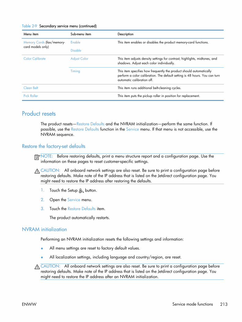
Table 2-9 Secondary service menu (continued)
Menu item Sub-menu item Description
Memory Cards (fax/memory-card models only)
Enable
Disable
This item enables or disables the product memory-card functions.
Color Calibrate Adjust Color This item adjusts density settings for contrast, highlights, midtones, andshadows. Adjust each color individually.
Timing This item specifies how frequently the product should automaticallyperform a color calibration. The default setting is 48 hours. You can turnautomatic calibration off.
Clean Belt This item runs additional belt-cleaning cycles.
Pick Roller This item puts the pickup roller in position for replacement.
Product resets
The product resets—Restore Defaults and the NVRAM initialization—perform the same function. Ifpossible, use the Restore Defaults function in the Service menu. If that menu is not accessible, use theNVRAM sequence.
Restore the factory-set defaults
NOTE: Before restoring defaults, print a menu structure report and a configuration page. Use theinformation on these pages to reset customer-specific settings.
CAUTION: All onboard network settings are also reset. Be sure to print a configuration page beforerestoring defaults. Make note of the IP address that is listed on the Jetdirect configuration page. Youmight need to restore the IP address after restoring the defaults.
1. Touch the Setup button.
2. Open the Service menu.
3. Touch the Restore Defaults item.
The product automatically restarts.
NVRAM initialization
Performing an NVRAM initialization resets the following settings and information:
● All menu settings are reset to factory default values.
● All localization settings, including language and country/region, are reset.
CAUTION: All onboard network settings are also reset. Be sure to print a configuration page beforerestoring defaults. Make note of the IP address that is listed on the Jetdirect configuration page. Youmight need to restore the IP address after an NVRAM initialization.
ENWW Service mode functions 213

After performing an NVRAM initialization, reconfigure any computers that print to this product.Uninstall and then reinstall the product software on the computers.
1. Turn the product off.
2. Simultaneously touch the Right Arrow button and the Cancel button. Continue touching thesebuttons, and then turn the product on.
3. When the Permanent Strorage Intitialization message displays, release both buttons.
When the product has finished the NVRAM initialization, it returns to the Ready state.
214 Chapter 2 Solve problems ENWW
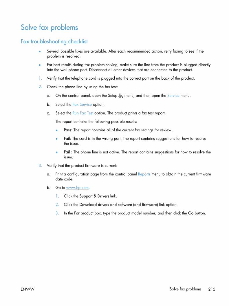
Solve fax problems
Fax troubleshooting checklist
● Several possible fixes are available. After each recommended action, retry faxing to see if theproblem is resolved.
● For best results during fax problem solving, make sure the line from the product is plugged directlyinto the wall phone port. Disconnect all other devices that are connected to the product.
1. Verify that the telephone cord is plugged into the correct port on the back of the product.
2. Check the phone line by using the fax test:
a. On the control panel, open the Setup menu, and then open the Service menu.
b. Select the Fax Service option.
c. Select the Run Fax Test option. The product prints a fax test report.
The report contains the following possible results:
● Pass: The report contains all of the current fax settings for review.
● Fail: The cord is in the wrong port. The report contains suggestions for how to resolvethe issue.
● Fail : The phone line is not active. The report contains suggestions for how to resolve theissue.
3. Verify that the product firmware is current:
a. Print a configuration page from the control panel Reports menu to obtain the current firmwaredate code.
b. Go to www.hp.com.
1. Click the Support & Drivers link.
2. Click the Download drivers and software (and firmware) link option.
3. In the For product box, type the product model number, and then click the Go button.
ENWW Solve fax problems 215
4. Click the link for your operating system.
5. Scroll to the Firmware section of the table.
◦ If the listed version matches the version on the configuration page, you have themost current version.
◦ If the versions are different, download the firmware upgrade and update thefirmware on the product following the instructions onscreen.
NOTE: The product must be connected to a computer with internet access toupgrade firmware.
◦ Resend the fax.
4. Verify that the fax was set up when the product software was installed.
From the computer, in the HP program folder, run the Fax Setup Utility.
5. Verify that the telephone service supports analog fax.
● If using ISDN or digital PBX, contact your service provider for information about configuringto an analog fax line.
● If using a VoIP service, change the Fax Speed setting to Slow (V.29) or disable Fast (V.34)from the control panel. Ask if your service provider supports fax and for the recommendedfax modem speed. Some companies might require an adapter.
● If using a DSL service, ensure that a filter is included on the phone line connection to theproduct. Contact the DSL service provider or purchase a DSL filter if you do not have one. If aDSL filter is installed, try another because these filters can be defective.
6. If the error persists, find more detailed problem-solving solutions in the sections that follow this one.
216 Chapter 2 Solve problems ENWW

Fax error messages
Alert and warning messages appear temporarily and might require you to acknowledge the messageby touching the OK button to resume or by touching the Cancel button to cancel the job. Withcertain warnings, the job might not complete or the print quality might be affected. If the alert orwarning message is related to printing and the auto-continue feature is on, the product will attempt toresume printing the job after the warning has appeared for 10 seconds without acknowledgement.
Communication error.
Description
A fax communication error occurred between the product and the sender or receiver.
Recommended action
Allow the product to retry sending the fax. Unplug the product telephone cord from the wall, plug in atelephone, and try making a call. Connect the product phone cord into a jack for another phone line.
Try a different phone cord.
Set the Fax Speed option to the Slow (V.29) setting or disable the Fast (V.34) setting.
Turn off the Error Correction feature to prevent automatic error correction.
NOTE: Turning off the Error Correction feature can reduce image quality.
Print the Fax Activity Log report from the control panel to determine if the error occurs with a specificfax number.
If the error persists, contact HP. See www.hp.com/go/LJColorMFPM375 or www.hp.com/go/LJColorMFPM475 or the support flyer that came in the product box.
Document feeder door is open. Canceled fax.
Description
The cover at the top of the document feeder is open, and the product cannot send the fax.
Recommended action
Close the cover, and send the fax again.
Fax is busy. Canceled send.
Description
The fax line to which you were sending a fax was busy. The product has canceled sending the fax.
Recommended action
Call the recipient to ensure that the fax machine is on and ready.
Check that you are dialing the correct fax number.
ENWW Solve fax problems 217

Check that the Redial if Busy option is enabled.
Open the Service menu, and touch the Fax Service button. Touch the Run Fax Test button. This testverifies that the phone cord is connected to the correct port and that the phone line has a signal. Theproduct prints a report with the results.
If the error persists, contact HP. See www.hp.com/go/LJColorMFPM375 or www.hp.com/go/LJColorMFPM475 or the support flyer that came in the product box.
Fax is busy. Redial pending.
Description
The fax line to which you were sending a fax was busy. The product automatically redials the busynumber.
Recommended action
Allow the product to retry sending the fax.
Call the recipient to ensure that the fax machine is on and ready.
Check that you are dialing the correct fax number.
Open the Service menu, and touch the Fax Service button. Touch the Run Fax Test button. This testverifies that the phone cord is connected to the correct port and that the phone line has a signal. Theproduct prints a report with the results.
If the error persists, contact HP. See www.hp.com/go/LJColorMFPM375 or www.hp.com/go/LJColorMFPM475 or the support flyer that came in the product box.
Fax receive error.
Description
An error occurred while trying to receive a fax.
Recommended action
Ask the sender to resend the fax.
Try faxing back to the sender or another fax machine.
Check for a dial tone on the phone line by touching the Start Fax button.
Check that the telephone cord is securely connected by unplugging and replugging the cord.
Make sure that you are using the telephone cord that came with the product.
Open the Service menu, and touch the Fax Service button. Touch the Run Fax Test button. This testverifies that the phone cord is connected to the correct port and that the phone line has a signal. Theproduct prints a report with the results.
Decrease the fax speed. Ask the sender to resend the fax.
Turn off error-correction mode. Ask the sender to resend the fax.
218 Chapter 2 Solve problems ENWW

NOTE: Turning off error-correction mode can reduce the quality of the fax image.
Connect the product to a different phone line.
If the error persists, contact HP. See www.hp.com/go/LJColorMFPM375 or www.hp.com/go/LJColorMFPM475 or the support flyer that came in the product box.
Fax Send error.
Description
An error occurred while trying to send a fax.
Recommended action
Try resending the fax.
Try faxing to another fax number.
Check for a dial tone on the phone line by touching the Start Fax button.
Check that the telephone cord is securely connected by unplugging and replugging the cord.
Make sure that you are using the telephone cord that came with the product.
Make sure that the phone is working by disconnecting the product, plugging in a telephone to thephone line, and making a voice call.
Connect the product to a different phone line.
Set the fax resolution to Standard instead of the default of Fine.
If the error persists, contact HP. See www.hp.com/go/LJColorMFPM375 or www.hp.com/go/LJColorMFPM475 or the support flyer that came in the product box.
Fax storage is full. Canceling the fax receive.
Description
During the fax transmission, the product ran out of memory. Only the pages that fit into memory will beprinted.
Recommended action
Print all of the faxes, and then have the sender resend the fax. Have the sender divide the fax job intomultiple jobs before resending. Cancel all fax jobs or clear the faxes from memory.
Fax storage is full. Canceling the fax receive.
Description
The amount of available memory for storing faxes is insufficient to store an incoming fax.
ENWW Solve fax problems 219

Recommended action
If you are using the Private Receive feature, print all received faxes to regain some memory.
If you still need more memory, clear faxes from memory. Open the Service menu. In the Fax Servicemenu, select the Clear Saved Faxes option.
Fax storage is full. Canceling the fax send.
Description
During the fax job, the memory filled. All pages of the fax have to be in memory for a fax job to workcorrectly. Only the pages that fit into memory were sent.
Recommended action
Cancel the current job. Turn the product off, and then turn it on again. Try sending the job again.
If the error reoccurs, cancel the job and turn the product off and then on a second time. The productmight not have enough memory for some jobs.
No dial tone.
Description
The product could not detect a dial tone.
Recommended action
Check for a dial tone on the phone line by touching the Start Fax button.
Unplug the telephone cord from both the product and the wall and replug the cord.
Make sure that you are using the telephone cord that came with the product.
Unplug the product telephone cord from the wall, connect a telephone, and try making a voice call.
Make sure that the phone cord from the wall telephone jack is plugged into the line port.
Connect the product phone cord into a jack for another phone line.
Check the phone line by using the Run Fax Test option from the Service menu on the control panel.
If the error persists, contact HP. See www.hp.com/go/LJColorMFPM375 or www.hp.com/go/LJColorMFPM475 or the support flyer that came in the product box.
No fax answer. Canceled send.
Description
Attempts to redial a fax number failed, or the Redial if No Answer option was turned off.
Recommended action
Call the recipient to ensure that the fax machine is on and ready.
220 Chapter 2 Solve problems ENWW

Check that you are dialing the correct fax number.
Check that the redial option is enabled.
Unplug the telephone cord from both the product and the wall and replug the cord.
Unplug the product telephone cord from the wall, connect a telephone, and try making a voice call.
Make sure that the phone cord from the wall telephone jack is plugged into the line port.
Connect the product phone cord into a jack for another phone line.
If the error persists, contact HP. See www.hp.com/go/LJColorMFPM375 or www.hp.com/go/LJColorMFPM475 or the support flyer that came in the product box.
No fax answer. Redial pending.
Description
The receiving fax line did not answer. The product attempts to redial after a few minutes.
Recommended action
Allow the product to retry sending the fax.
Call the recipient to ensure that the fax machine is on and ready.
Check that you are dialing the correct fax number.
If the product continues to redial, unplug the product telephone cord from the wall, connect atelephone, and try making a voice call.
Make sure that the phone cord from the wall telephone jack is plugged into the line port.
Connect the product phone cord into a jack for another phone line.
Try a different phone cord.
If the error persists, contact HP. See www.hp.com/go/LJColorMFPM375 or www.hp.com/go/LJColorMFPM475 or the support flyer that came in the product box.
No fax detected.
Description
The product answered the incoming call but did not detect that a fax machine was calling.
Recommended action
Allow the product to retry receiving the fax.
Try a different phone cord.
Connect the product phone cord into a jack for another phone line.
ENWW Solve fax problems 221

If the error persists, contact HP. See www.hp.com/go/LJColorMFPM375 or www.hp.com/go/LJColorMFPM475 or the support flyer that came in the product box.
222 Chapter 2 Solve problems ENWW
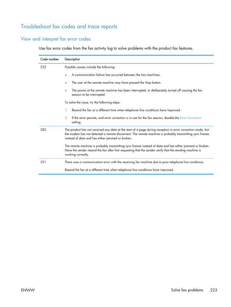
Troubleshoot fax codes and trace reports
View and interpret fax error codes
Use fax error codes from the fax activity log to solve problems with the product fax features.
Code number Description
232 Possible causes include the following:
● A communication failure has occurred between the two machines.
● The user at the remote machine may have pressed the Stop button.
● The power at the remote machine has been interrupted, or deliberately turned off causing the faxsession to be interrupted.
To solve the issue, try the following steps:
1. Resend the fax at a different time when telephone line conditions have improved.
2. If the error persists, and error correction is in use for the fax session, disable the Error Correctionsetting.
282 The product has not received any data at the start of a page during reception in error correction mode, butthe modem has not detected a remote disconnect. The remote machine is probably transmitting sync framesinstead of data and has either jammed or broken.
The remote machine is probably transmitting sync frames instead of data and has either jammed or broken.Have the sender resend the fax after first requesting that the sender verify that the sending machine isworking correctly.
321 There was a communication error with the receiving fax machine due to poor telephone line conditions.
Resend the fax at a different time when telephone line conditions have improved.
ENWW Solve fax problems 223
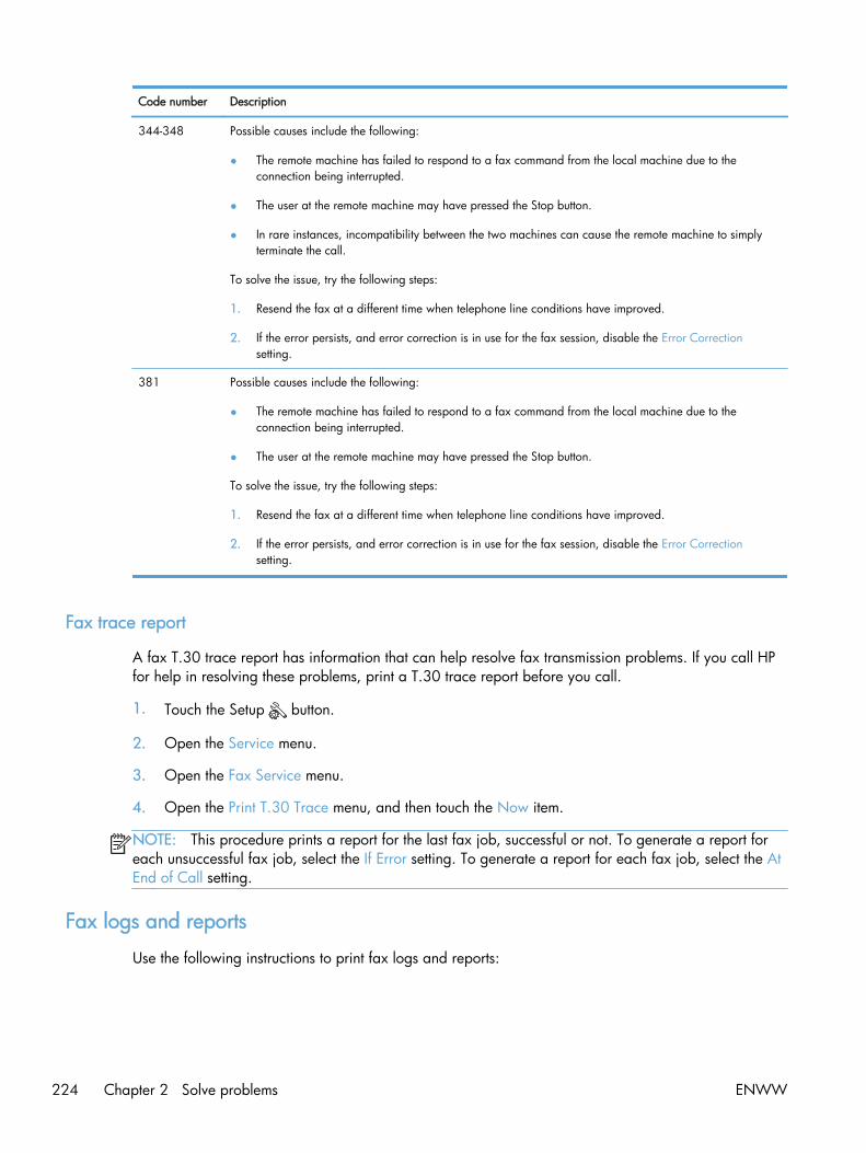
Code number Description
344-348 Possible causes include the following:
● The remote machine has failed to respond to a fax command from the local machine due to theconnection being interrupted.
● The user at the remote machine may have pressed the Stop button.
● In rare instances, incompatibility between the two machines can cause the remote machine to simplyterminate the call.
To solve the issue, try the following steps:
1. Resend the fax at a different time when telephone line conditions have improved.
2. If the error persists, and error correction is in use for the fax session, disable the Error Correctionsetting.
381 Possible causes include the following:
● The remote machine has failed to respond to a fax command from the local machine due to theconnection being interrupted.
● The user at the remote machine may have pressed the Stop button.
To solve the issue, try the following steps:
1. Resend the fax at a different time when telephone line conditions have improved.
2. If the error persists, and error correction is in use for the fax session, disable the Error Correctionsetting.
Fax trace report
A fax T.30 trace report has information that can help resolve fax transmission problems. If you call HPfor help in resolving these problems, print a T.30 trace report before you call.
1. Touch the Setup button.
2. Open the Service menu.
3. Open the Fax Service menu.
4. Open the Print T.30 Trace menu, and then touch the Now item.
NOTE: This procedure prints a report for the last fax job, successful or not. To generate a report foreach unsuccessful fax job, select the If Error setting. To generate a report for each fax job, select the AtEnd of Call setting.
Fax logs and reports
Use the following instructions to print fax logs and reports:
224 Chapter 2 Solve problems ENWW

Print all fax reports
Use this procedure to print all of the following reports at one time:
● Last Call Report
● Fax Activity Log
● Phone Book Report
● Junk Fax List
● Billing Report (when Billing Codes are turned on)
● Configuration Report
● Usage Page
1. Touch the Fax button.
2. Open the Fax Menu menu.
3. Open the Fax Reports menu.
4. Touch the Print All Fax Reports item.
Print individual fax reports
1. Touch the Fax button.
2. Open the Fax Menu menu.
3. Open the Fax Reports menu.
4. Touch the name of the report that you want toprint.
ENWW Solve fax problems 225

Set the fax error report
A fax error report is a brief report that indicates the product experienced a fax job error. You can set itto print after the following events:
● Every fax error (the factory-set default)
● Send fax error
● Receive fax error
● Never
NOTE: With this option, you will have no indication that a fax failed to be transmitted unless youprint a fax activity log.
1. Touch the Fax button.
2. Open the Fax Menu menu.
3. Open the Fax Reports menu.
4. Open the Fax Error Report menu, and thentouch the printing option that you want to use.
Change error correction and fax speed
Set the fax-error-correction mode
Usually, the product monitors the signals on the telephone line while it is sending or receiving a fax. Ifthe product detects an error during the transmission and the error-correction setting is On, the productcan request that the portion of the fax be resent. The factory-set default for error correction is On.
You should turn off error correction only if you are having trouble sending or receiving a fax, and youare willing to accept the errors in the transmission. Turning off the setting might be useful when you aretrying to send a fax overseas or receive one from overseas, or if you are using a satellite telephoneconnection.
1. Touch the Setup button.
2. Open the Service menu.
3. Open the Fax Service menu.
4. Open the Error Correction menu, and then touch the On button.
226 Chapter 2 Solve problems ENWW

Change the fax speed
The fax-speed setting is the modem protocol that the product uses to send faxes. It is the worldwidestandard for full-duplex modems that send and receive data across telephone lines at up to 33,600 bitsper second (bps). The factory-set default for the fax-speed setting is Fast (V.34).
You should change the setting only if you are having trouble sending a fax to or receiving a fax from aparticular device. Decreasing the fax speed might be useful when you are trying to send a faxoverseas, or receive one from overseas, or if you are using a satellite telephone connection.
1. Touch the Setup button.
2. Open the Fax Setup menu.
3. Open the Advanced Setup menu.
4. Open the Fax Speed menu, and then touch the speed setting that you want to use.
Solve problems sending faxes
● An error message displays on the control panel
● The control panel displays a Ready message with no attempt to send the fax
● The control panel displays the message "Storing page 1" and does not progress beyond thatmessage
● Faxes can be received, but not sent
● Unable to use fax functions from the control panel
● Unable to use speed dials
● Unable to use group dials
● Receive a recorded error message from the phone company when trying to send a fax
● Unable to send a fax when a phone is connected to the product
An error message displays on the control panel
The Communication error. message displays
● Allow the product to retry sending the fax. Re-sending temporarily reduces the fax speed.
● Unplug the product telephone cord from the wall, connect a telephone, and try making a call.Connect the product phone cord into a jack for another phone line.
If the product is connected to a digital phone line, verify that you are using the correct filter andsettings provided by the digital service provider.
● Try a different phone cord.
ENWW Solve fax problems 227

● From the control panel, change the Fax Speed option to the Medium (V.17) setting or Slow (V.29)setting.
a. Touch the Setup button.
b. Open the Fax Setup menu.
c. Open the Advanced Setup menu.
d. Open the Fax Speed menu.
e. Select the correct setting.
● Turn off the Error Correction option.
a. Touch the Setup button.
b. Open the Service menu.
c. Open the Fax Service menu.
d. Open the Error Correction menu.
e. Touch the Off setting.
NOTE: Turning off the Error Correction option can reduce image quality.
● If the error persists, contact HP. See www.hp.com/go/LJColorMFPM375 or www.hp.com/go/LJColorMFPM475 or the support flyer that came in the product box.
No dial tone.
● Make sure that the telephone cord is plugged into the correct port on the product.
● Make sure that the telephone cord from the product is plugged directly into the wall telephonejack.
● Check for a dial tone on the phone line by using the Start Fax button.
● Unplug the product telephone cord from the wall, connect a telephone, and try making a voicecall.
● Unplug the telephone cord from both the product and the wall and replug the cord.
● Make sure that you are using the telephone cord that came with the product.
● Connect the product phone cord into a jack for another phone line.
● Check the phone line by using the Run Fax Test option from the Service menu on the control panel.
a. Touch the Setup button.
b. Open the Service menu.
c. Open the Fax Service menu.
d. Select the Run Fax Test item.
228 Chapter 2 Solve problems ENWW

The Fax is busy. message displays
● Try sending the fax again.
● Call the recipient to ensure that the fax machine is on and ready.
● Check that you are dialing the correct fax number.
● Check for a dial tone on the phone line by using the Start Fax button.
● Make sure that the phone is working by disconnecting the product, plugging in a telephone to thephone line, and making a voice call.
● Connect the product phone cord into a jack for another phone line, and try sending the fax again.
● Try a different phone cord.
● Send the fax at a later time.
● If the error persists, contact HP. See www.hp.com/go/LJColorMFPM375 or www.hp.com/go/LJColorMFPM475 or the support flyer that came in the product box.
The No fax answer. message displays
● Try to resend the fax.
● Call the recipient to ensure that the fax machine is on and ready.
● Check that you are dialing the correct fax number.
● Unplug the product telephone cord from the wall, connect a telephone, and try making a voicecall.
● Connect the product phone cord into a jack for another phone line.
● Try a different phone cord.
● Make sure that the phone cord from the wall telephone jack is plugged into the line port.
● Check the phone line by using the Run Fax Test option from the Service menu on the control panel.
a. Touch the Setup button.
b. Open the Service menu.
c. Open the Fax Service menu.
d. Select the Run Fax Test item.
● If the error persists, contact HP. See www.hp.com/go/LJColorMFPM375 or www.hp.com/go/LJColorMFPM475 or the support flyer that came in the product box.
ENWW Solve fax problems 229
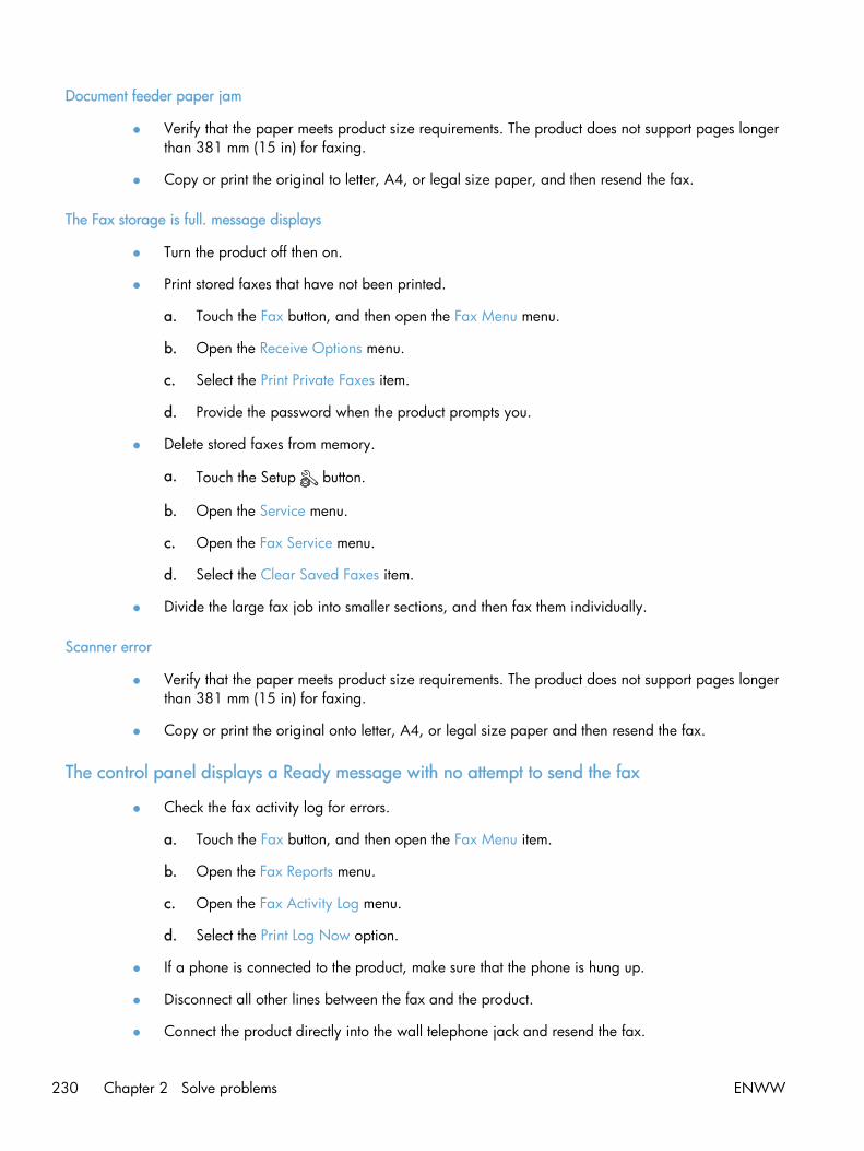
Document feeder paper jam
● Verify that the paper meets product size requirements. The product does not support pages longerthan 381 mm (15 in) for faxing.
● Copy or print the original to letter, A4, or legal size paper, and then resend the fax.
The Fax storage is full. message displays
● Turn the product off then on.
● Print stored faxes that have not been printed.
a. Touch the Fax button, and then open the Fax Menu menu.
b. Open the Receive Options menu.
c. Select the Print Private Faxes item.
d. Provide the password when the product prompts you.
● Delete stored faxes from memory.
a. Touch the Setup button.
b. Open the Service menu.
c. Open the Fax Service menu.
d. Select the Clear Saved Faxes item.
● Divide the large fax job into smaller sections, and then fax them individually.
Scanner error
● Verify that the paper meets product size requirements. The product does not support pages longerthan 381 mm (15 in) for faxing.
● Copy or print the original onto letter, A4, or legal size paper and then resend the fax.
The control panel displays a Ready message with no attempt to send the fax
● Check the fax activity log for errors.
a. Touch the Fax button, and then open the Fax Menu item.
b. Open the Fax Reports menu.
c. Open the Fax Activity Log menu.
d. Select the Print Log Now option.
● If a phone is connected to the product, make sure that the phone is hung up.
● Disconnect all other lines between the fax and the product.
● Connect the product directly into the wall telephone jack and resend the fax.
230 Chapter 2 Solve problems ENWW

The control panel displays the message "Storing page 1" and does not progress beyond thatmessage
● Delete stored faxes from memory.
a. Touch the Setup button.
b. Open the Service menu.
c. Open the Fax Service menu.
d. Select the Clear Saved Faxes item.
Faxes can be received, but not sent
Send fax and nothing happens.
1. Check for a dial tone on the phone line by using the Start Fax button.
2. Turn the product off then on.
3. Use the control panel or the HP Fax Setup Wizard to configure the fax time, date, and fax headerinformation.
a. Touch the Setup button.
b. Open the Fax Setup menu.
c. Open the Basic Setup menu.
d. Open the Fax Header menu.
e. Enter the correct settings.
4. Verify that any extension phones on the line are hung up.
5. If using a DSL service, make sure that the phone line connection to the product includes a high-pass filter.
Unable to use fax functions from the control panel
● The product might be password protected. Use the HP Embedded Web Server, HP Toolboxsoftware, or the control panel to set a password.
● If you do not know the password for the product, contact your system administrator.
● Verify with the system administrator that the fax functionality has not been disabled.
ENWW Solve fax problems 231
Unable to use speed dials
● Make sure that the fax number is valid.
● If an outside line requires a prefix, turn on the Dial Prefix option or include the prefix in the speeddial number.
a. Touch the Setup button.
b. Open the Fax Setup menu.
c. Open the Basic Setup menu.
d. Open the Dial Prefix menu.
e. Select the On setting.
Unable to use group dials
● Make sure that the fax number is valid.
● If an outside line requires a prefix, turn on the Dial Prefix option or include the prefix in the speeddial number.
a. Touch the Setup button.
b. Open the Fax Setup menu.
c. Open the Basic Setup menu.
d. Open the Dial Prefix menu.
e. Select the On setting.
● Set up all entries in the group with speed dial entries.
a. Open an unused speed dial entry.
b. Enter the fax number for the speed dial.
c. Touch the OK button to save the speed dial.
Receive a recorded error message from the phone company when trying to send a fax
● Make sure you dial the fax number correctly, and make sure that the phone service is not blocked.For example, some phone services might prevent long distance calling.
● If an outside line requires a prefix, turn on the Dial Prefix option or include the prefix in the speeddial number.
a. Touch the Setup button.
b. Open the Fax Setup menu.
c. Open the Basic Setup menu.
232 Chapter 2 Solve problems ENWW

d. Open the Dial Prefix menu.
e. Select the On setting.
NOTE: To send a fax without a prefix, when the Dial Prefix option is turned on, send the faxmanually.
● Send a fax to an international number
a. If a prefix is required, manually dial the telephone number with the prefix.
b. Enter the country/region code before dialing the phone number.
c. Wait for pauses as you hear the tones on the phone.
d. Send the fax manually from the control panel.
Unable to send a fax when a phone is connected to the product
● Make sure that the telephone is hung up.
● Make sure that the telephone is not being used for a voice call when faxing.
● Unplug the phone from the line, and then try sending the fax.
ENWW Solve fax problems 233
Solve problems receiving faxes
● The fax does not respond
● An error message displays on the control panel
● A fax is received but does not print
● Sender receives a busy signal
● No dial tone
● Cannot send or receive a fax on a PBX line
The fax does not respond
The fax has a dedicated phone line
● Set the Answer Mode option to the Automatic setting from the control panel.
a. Touch the Setup button.
b. Open the Fax Setup menu.
c. Open the Basic Setup menu.
d. Open the Answer Mode menu.
e. Select the Automatic setting.
An answering machine is connected to the product
● Set the Answer Mode option to the TAM setting and plug the answering machine into the“telephone” port.
a. Touch the Setup button.
b. Open the Fax Setup menu.
c. Open the Basic Setup menu.
d. Open the Answer Mode menu.
e. Select the TAM setting.
If the TAM setting is unavailable, set the Answer Mode option to the Automatic setting.
● Set the Rings to Answer setting to at least one ring more than the number of rings for which theanswering machine is set.
a. Touch the Setup button.
b. Open the Fax Setup menu.
c. Open the Basic Setup menu.
234 Chapter 2 Solve problems ENWW

d. Open the Rings to Answer menu.
e. Select the correct setting.
● Connect the answering machine into the “telephone” port.
● If the product has a telephone handset connected, set the Answer Mode option to the Fax/Telsetting to route calls to the correct device. When detecting a voice call, the product generates aring tone that alerts you to pick up the telephone handset.
a. Touch the Setup button.
b. Open the Fax Setup menu.
c. Open the Basic Setup menu.
d. Open the Answer Mode menu.
e. Select the Fax/Tel setting.
A telephone handset is connected to the product
Set the Answer Mode option to the Automatic setting.
1. Touch the Setup button.
2. Open the Fax Setup menu.
3. Open the Basic Setup menu.
4. Open the Answer Mode menu.
5. Select the Automatic setting.
The Answer Mode setting is set to the Manual setting
● Touch the Start Fax button on the control panel.
Voice mail is available on the fax line
● Add a distinctive ring service to your telephone line and change the Distinctive Ring setting on theproduct to match the ring pattern supplied by the telephone company. Contact your telephonecompany for information.
a. Verify that the answer mode is set to the Automatic setting.
b. Touch the Setup button.
c. Open the Fax Setup menu.
d. Open the Basic Setup menu.
ENWW Solve fax problems 235
e. Open the Distinctive Ring menu.
f. Select the correct setting.
● Buy a dedicated line for faxing.
● Set the Answer Mode option to the Manual setting.
a. Touch the Setup button.
b. Open the Fax Setup menu.
c. Open the Basic Setup menu.
d. Open the Answer Mode menu.
e. Select the Manual setting.
NOTE: You must be present to receive faxes.
The product is connected to a DSL phone service
● Check the installation and features. A DSL modem requires a high-pass filter on the phone lineconnection to the product. Contact your DSL service provider for a filter or buy a filter.
● Verify that the filter is plugged in.
● Replace the existing filter to make sure that it is not defective.
The product uses a fax over IP or VoIP phone service
● Set the Fax Speed option to the Slow (V.29) or Medium (V.17) setting, or disable the Fast (V.34)setting.
a. Touch the Setup button.
b. Open the Fax Setup menu.
c. Open the Advanced Setup menu.
d. Open the Fax Speed menu.
e. Select the correct setting.
● Contact your service provider to make sure that fax is supported and for a recommended faxspeed settings. Some companies might require an adapter.
236 Chapter 2 Solve problems ENWW
An error message displays on the control panel
The No fax detected. message displays
NOTE: This error does not always refer to a missed fax. If a voice call is made to a fax number bymistake and the caller hangs up, the No fax detected. message displays on the control panel.
● Ask the sender to resend the fax.
● Make sure that the telephone cord from the product is plugged into the wall telephone jack.
● Try a different phone cord.
● Connect the product phone cord into a jack for another phone line.
● Make sure the telephone line and phone wall jack are active by plugging in a telephone andchecking for a dial tone.
● Make sure that the telephone cord is plugged into the “line” port on the product.
● Check the phone line by running a fax test from the control panel.
● If the error persists, contact HP. See www.hp.com/go/LJColorMFPM375 or www.hp.com/go/LJColorMFPM475 or the support flyer that came in the product box.
The Communication error. message displays
● Ask the sender to send the fax again or send at a later time when line conditions have improved.
● Unplug the product telephone cord from the wall, connect a telephone, and try making a call.Connect the product phone cord into a jack for another phone line.
● Try a different phone cord.
● Set the Fax Speed option to the Slow (V.29) or Medium (V.17) setting, or disable the Fast (V.34)setting.
a. Touch the Setup button.
b. Open the Fax Setup menu.
c. Open the Advanced Setup menu.
d. Open the Fax Speed menu.
e. Select the correct setting.
● Turn off the Error Correction feature to prevent automatic error correction.
NOTE: Turning off the Error Correction feature can reduce image quality.
a. Touch the Setup button.
b. Open the Service menu.
c. Open the Fax Service menu.
ENWW Solve fax problems 237
d. Open the Error Correction menu.
e. Select the Off setting.
● Print the Fax Activity Log report from the control panel to determine if the error occurs with aspecific fax number.
a. Touch the Fax button, and then touch the Fax Menu button.
b. Open the Fax Reports menu.
c. Open the Fax Activity Log menu.
d. Select the Print Log Now option.
● If the error persists, contact HP. See www.hp.com/go/LJColorMFPM375 or www.hp.com/go/LJColorMFPM475 or the support flyer that came in the product box.
The Fax storage is full. message displays
● Turn the product off then on.
● Print all of the faxes, and then have the sender resend the fax.
● Ask the sender to divide a large fax job into smaller sections, and then fax them individually.
● Make sure that the resolution of the sending fax machine is not set to the Photo setting or theSuperfine setting.
a. Touch the Setup button.
b. Open the Fax Setup menu.
c. Open the Advanced Setup menu.
d. Open the Fax Resolution menu.
e. Select the correct setting.
● Cancel all fax jobs or clear the faxes from memory.
The Fax is busy. message displays
● The product cannot receive a fax while attempting to send one. Cancel the fax send and trysending at a later time.
● Allow the product to try sending the fax again.
238 Chapter 2 Solve problems ENWW

A fax is received but does not print
The Private Receive feature is on
● When the Private Receive feature is activated, received faxes are stored in memory. A password isrequired to print the stored faxes.
● Enter the password to print the fax. If you do not know the password, contact the productadministrator.
NOTE: Memory errors might occur if the faxes are not printed. The product will not answer if thememory is full.
Sender receives a busy signal
A handset is connected to the product
● Make sure the phone is hung up.
● Change the Answer Mode option to match the product setup.
a. Touch the Setup button.
b. Open the Fax Setup menu.
c. Open the Basic Setup menu.
d. Open the Answer Mode menu.
e. Select the setting that matches the product setup.
Set the Answer Mode option to the Fax/Tel setting to automatically receive faxes. The Fax/Tel setting automatically detects whether the incoming transmission is a fax or a voice calland routes the call to the appropriate device.
A phone line splitter is being used
● If you are using a phone line splitter, remove the splitter and set up the phone as a downstreamphone.
● Make sure the phone is hung up.
● Make sure the phone is not being used for a voice call when faxing.
No dial tone
● If using a phone line splitter, remove the phone line splitter and set up the phone as a downstreamphone.
Cannot send or receive a fax on a PBX line
● If you are using a PBX phone line, contact your PBX administrator to configure an analog fax linefor your product.
ENWW Solve fax problems 239

Solve general fax problems
● Faxes are sending slowly
● Fax quality is poor
● Fax cuts off or prints on two pages
Faxes are sending slowly
The product is experiencing poor phone line quality.
● Retry sending the fax when the line conditions have improved.
● Check with the phone service provider that the line supports fax.
● Turn off the Error Correction setting.
a. Open the Setup menu.
b. Open the Service menu.
c. Open the Fax Service menu.
d. Open the Error Correction menu.
e. Select the Off setting.
NOTE: This can reduce image quality.
● Use white paper for the original. Do not use colors such as gray, yellow, or pink.
● Increase the Fax Speed setting.
a. Open the Setup menu.
b. Open the Fax Setup menu.
c. Open the Advanced Setup menu.
d. Open the Fax Speed menu.
e. Select the correct setting.
● Divide large fax jobs into smaller sections, and then fax them individually.
● Change the fax settings on the control panel to a lower resolution.
a. Open the Setup menu.
b. Open the Fax Setup menu.
c. Open the Advanced Setup menu.
d. Open the Fax Resolution menu.
e. Select the correct setting.
240 Chapter 2 Solve problems ENWW

Fax quality is poor
Fax is blurry or light.
● Increase fax resolution when sending faxes. Resolution does not affect received faxes.
a. Open the Setup menu.
b. Open the Fax Setup menu.
c. Open the Advanced Setup menu.
d. Open the Fax Resolution menu.
e. Select the correct setting.
NOTE: Increasing resolution slows transmission speed.
● Turn on the Error Correction setting from the control panel.
a. Open the Setup menu.
b. Open the Service menu.
c. Open the Fax Service menu.
d. Open the Error Correction menu.
e. Select the On setting.
● Check the print cartridges and replace if necessary.
● Ask the sender to darken the contrast setting on the sending fax machine, and then resend the fax.
Fax cuts off or prints on two pages
● Set the Default Paper Size setting. Faxes print on a single size of paper based on the DefaultPaper Size settings.
a. Open the Setup menu.
b. Open the System Setup menu.
c. Open the Paper Setup menu.
d. Open the Default Paper Size menu.
e. Select the correct setting.
● Set the paper type and size for the tray used for faxes.
● Turn on the Fit to Page setting to print longer length faxes on letter or A4 size paper.
a. Open the Setup menu.
b. Open the Fax Setup menu.
ENWW Solve fax problems 241

c. Open the Advanced Setup menu.
d. Open the Fit to Page menu.
e. Select the On setting.
NOTE: If the Fit to Page setting is off and the Default Paper Size setting is set to letter, a legal sizeoriginal prints on two pages.
242 Chapter 2 Solve problems ENWW

Product updatesSoftware and firmware updates and installation instructions for this product are available atwww.hp.com/go/LJColorMFPM375 or www.hp.com/go/LJColorMFPM475. Click Support & Drivers,click the operating system, and then select the download for the product.
ENWW Product updates 243

244 Chapter 2 Solve problems ENWW

3 Parts and diagrams
● Order parts by authorized service providers
● How to use the parts lists and diagrams
● Scanner and document feeder main assemblies
● Covers
● Internal assemblies
● Input device(s)
● Alphabetical parts list
● Numerical parts list
ENWW 245
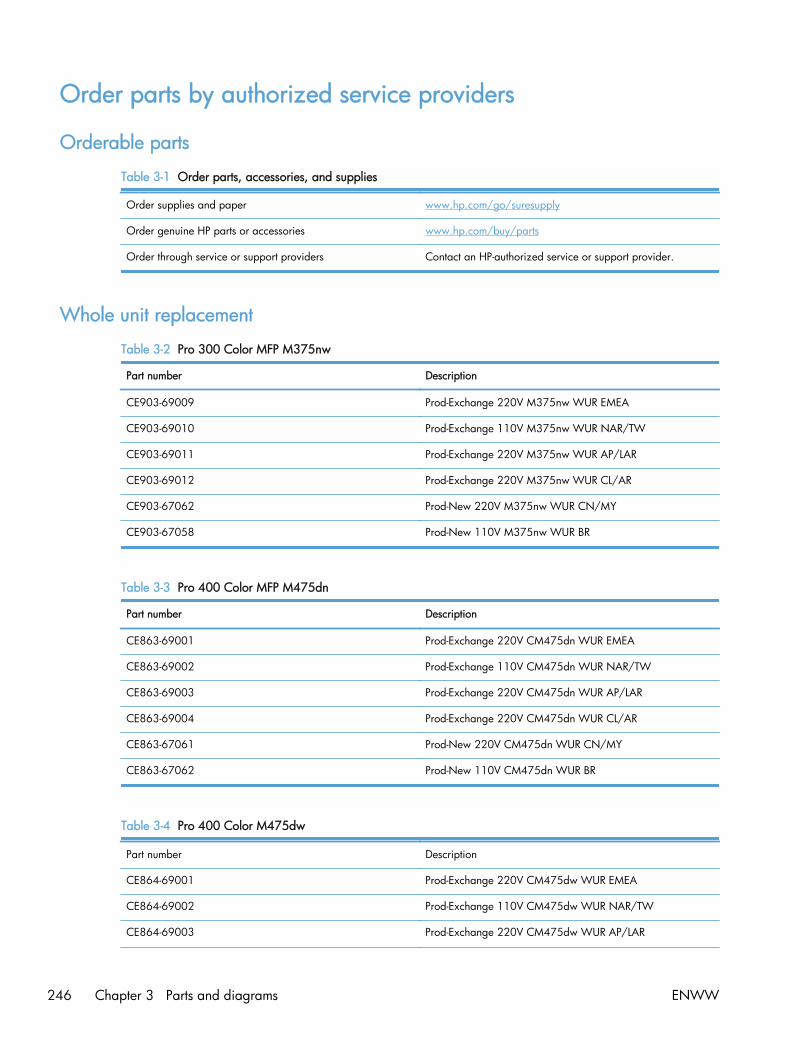
Order parts by authorized service providers
Orderable parts
Table 3-1 Order parts, accessories, and supplies
Order supplies and paper www.hp.com/go/suresupply
Order genuine HP parts or accessories www.hp.com/buy/parts
Order through service or support providers Contact an HP-authorized service or support provider.
Whole unit replacement
Table 3-2 Pro 300 Color MFP M375nw
Part number Description
CE903-69009 Prod-Exchange 220V M375nw WUR EMEA
CE903-69010 Prod-Exchange 110V M375nw WUR NAR/TW
CE903-69011 Prod-Exchange 220V M375nw WUR AP/LAR
CE903-69012 Prod-Exchange 220V M375nw WUR CL/AR
CE903-67062 Prod-New 220V M375nw WUR CN/MY
CE903-67058 Prod-New 110V M375nw WUR BR
Table 3-3 Pro 400 Color MFP M475dn
Part number Description
CE863-69001 Prod-Exchange 220V CM475dn WUR EMEA
CE863-69002 Prod-Exchange 110V CM475dn WUR NAR/TW
CE863-69003 Prod-Exchange 220V CM475dn WUR AP/LAR
CE863-69004 Prod-Exchange 220V CM475dn WUR CL/AR
CE863-67061 Prod-New 220V CM475dn WUR CN/MY
CE863-67062 Prod-New 110V CM475dn WUR BR
Table 3-4 Pro 400 Color M475dw
Part number Description
CE864-69001 Prod-Exchange 220V CM475dw WUR EMEA
CE864-69002 Prod-Exchange 110V CM475dw WUR NAR/TW
CE864-69003 Prod-Exchange 220V CM475dw WUR AP/LAR
246 Chapter 3 Parts and diagrams ENWW
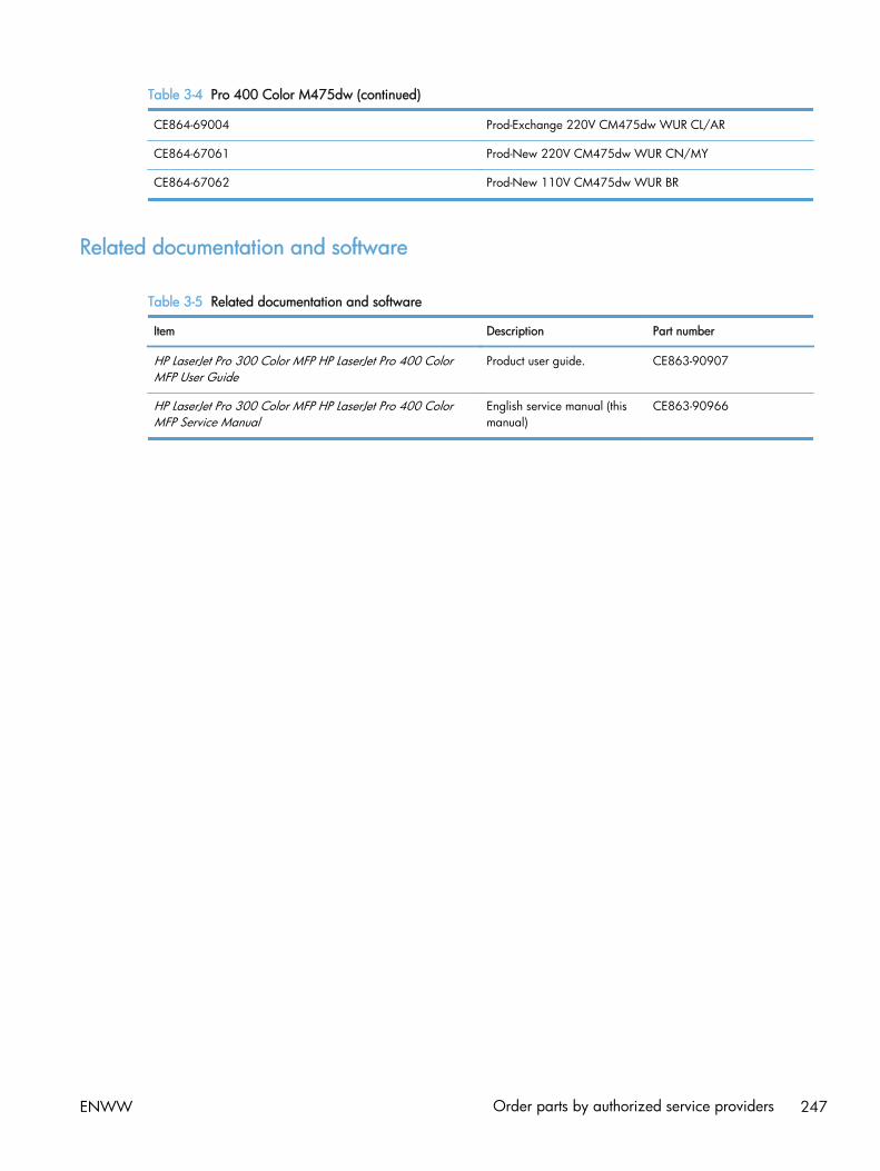
Table 3-4 Pro 400 Color M475dw (continued)
CE864-69004 Prod-Exchange 220V CM475dw WUR CL/AR
CE864-67061 Prod-New 220V CM475dw WUR CN/MY
CE864-67062 Prod-New 110V CM475dw WUR BR
Related documentation and software
Table 3-5 Related documentation and software
Item Description Part number
HP LaserJet Pro 300 Color MFP HP LaserJet Pro 400 ColorMFP User Guide
Product user guide. CE863-90907
HP LaserJet Pro 300 Color MFP HP LaserJet Pro 400 ColorMFP Service Manual
English service manual (thismanual)
CE863-90966
ENWW Order parts by authorized service providers 247

Supplies and accessories
Item Part number Cartridge number Description
Tonercartridges
CE410-67901 305A Standard-capacity black toner cartridge with HPColorSphere toner
CE411-67901 305A Cyan toner cartridge with HP ColorSphere toner
CE412-67901 305A Yellow toner cartridge with HP ColorSphere toner
CE413-67901 305A Magenta toner cartridge with HP ColorSphere toner
Memory CB423A 256 MB memory DIMM
Paper-handlingaccessories
RM1-8063-000CN
250-sheet paper feeder (optional Tray 3)
USB cable 8121-0868 2-meter A-to-B cable
NOTE: For information about the yield for the cartridges, see www.hp.com/go/pageyield. Actualyield depends on specific use.
Service parts
NOTE: The parts in the following table are not shown in the assembly illustrations in this chapter.
Item Description Part number
Regulatory label Blank label 5969-9497
248 Chapter 3 Parts and diagrams ENWW

How to use the parts lists and diagramsThe figures in this chapter show the major subassemblies in the product and their component parts. Aparts list table follows each exploded view assembly diagram. Each table lists the item number, theassociated part number, and the description of each part. If a part is not listed in the table, then it is nota field replacement unit (FRU).
CAUTION: Be sure to order the correct part. When looking for part numbers for electricalcomponents, pay careful attention to the voltage that is listed in the description column. Doing so willensure that the part number selected is for the correct all-in-one model.
NOTE: In this manual, the abbreviation “PCA” stands for “printed circuit-board assembly.”Components described as a PCA might consist of a single circuit board or a circuit board plus otherparts, such as cables and sensors.
ENWW How to use the parts lists and diagrams 249

Scanner and document feeder main assembliesFigure 3-1 Scanner and document feeder main assemblies
1
24
5
6
250 Chapter 3 Parts and diagrams ENWW
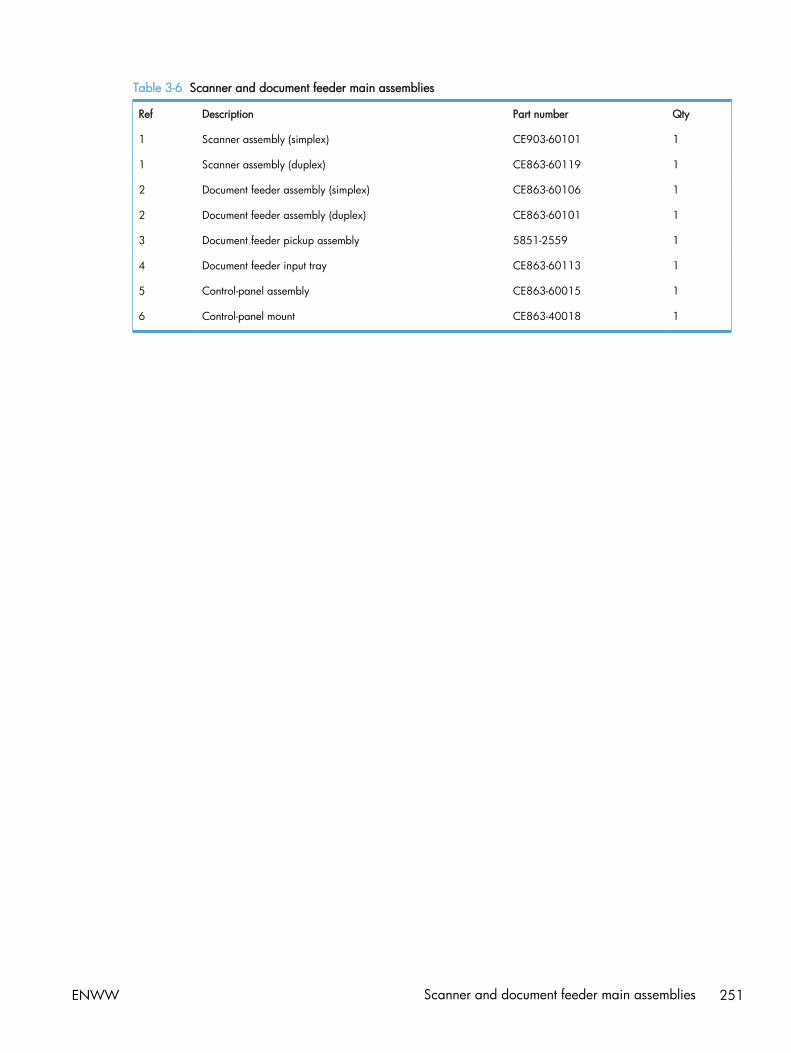
Table 3-6 Scanner and document feeder main assemblies
Ref Description Part number Qty
1 Scanner assembly (simplex) CE903-60101 1
1 Scanner assembly (duplex) CE863-60119 1
2 Document feeder assembly (simplex) CE863-60106 1
2 Document feeder assembly (duplex) CE863-60101 1
3 Document feeder pickup assembly 5851-2559 1
4 Document feeder input tray CE863-60113 1
5 Control-panel assembly CE863-60015 1
6 Control-panel mount CE863-40018 1
ENWW Scanner and document feeder main assemblies 251
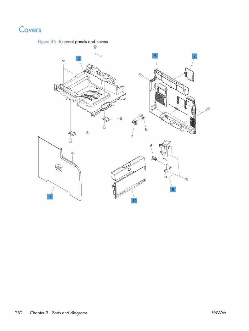
CoversFigure 3-2 External panels and covers
1
6
9
7
1
2 34
5
5
8
10
252 Chapter 3 Parts and diagrams ENWW
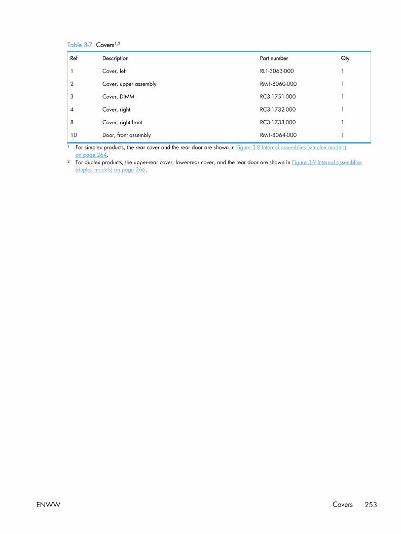
Table 3-7 Covers1,2
Ref Description Part number Qty
1 Cover, left RL1-3063-000 1
2 Cover, upper assembly RM1-8060-000 1
3 Cover, DIMM RC3-1751-000 1
4 Cover, right RC3-1732-000 1
8 Cover, right front RC3-1733-000 1
10 Door, front assembly RM1-8064-000 1
1 For simplex products, the rear cover and the rear door are shown in Figure 3-8 Internal assemblies (simplex models)on page 264.
2 For duplex products, the upper-rear cover, lower-rear cover, and the rear door are shown in Figure 3-9 Internal assemblies(duplex models) on page 266.
ENWW Covers 253
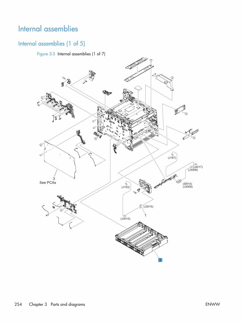
Internal assemblies
Internal assemblies (1 of 5)
Figure 3-3 Internal assemblies (1 of 7)
(J153)
(J3015)
(J3015)
(J167)
(J3006)(J4017)
(J3006)(SR14)See PCAs
1
3
2
254 Chapter 3 Parts and diagrams ENWW

Table 3-8 Internal assemblies (1 of 7)
Ref Description Part number Qty
2 Cartridge-tray assembly RM1-8041-000 1
ENWW Internal assemblies 255

Internal assemblies (2 of 5)
Figure 3-4 Internal assemblies (2 of 2)
(SL1)
(J209)
(J161)
3
4
2
1
256 Chapter 3 Parts and diagrams ENWW

Table 3-9 Internal assemblies (2 of 7)
Ref Description Part number Qty
1 Solenoid, Tray 1 (SL1; MP tray) RM1-5420-000 1
2 Color misregistration sensor assembly RM1-8029-000 1
3 Intermediate transfer belt (ITB) RM1-4852-000 1
4 Roller, paper-pickup Tray 1 RL1-1802-000 1
ENWW Internal assemblies 257

Internal components (3 of 5)
Figure 3-5 Internal assemblies (3 of 7)
(CL1)(J208)
(J3010)(SR7)
(J203)
(J207)
(J164) (J163)
(J165)
(J162)
(J3010)
2
8
6
1
4
3
9
5
7
258 Chapter 3 Parts and diagrams ENWW
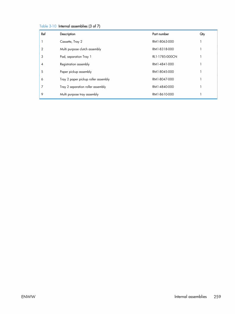
Table 3-10 Internal assemblies (3 of 7)
Ref Description Part number Qty
1 Cassette, Tray 2 RM1-8063-000 1
2 Multi purpose clutch assembly RM1-8318-000 1
3 Pad, separation Tray 1 RL1-1785-000CN 1
4 Registration assembly RM1-4841-000 1
5 Paper pickup assembly RM1-8045-000 1
6 Tray 2 paper pickup roller assembly RM1-8047-000 1
7 Tray 2 separation roller assembly RM1-4840-000 1
9 Multi purpose tray assembly RM1-8610-000 1
ENWW Internal assemblies 259

Internal assemblies (4 of 5)
Figure 3-6 Internal assemblies (4 of 7)
(J168)(SW1) (M1)
(M2)
(J301)
(J131)(J501)
Wireless model
(J2001)
(J904) (J992)
(J204) (J2002)
(J166)
(J3001)
(J2002)
(J2003)
(J151)(J903)
(J210)
(J2003)
(J4004)
See PCAsSee PCAs
See PCAs
(Jxxx)
(Jxxx)
(J140)
(J155)
102
9
8
5
7
6
4
(J901)
(J130)
1
*A03
260 Chapter 3 Parts and diagrams ENWW

Table 3-11 Internal assemblies (4 of 7)
Ref Description Part number Qty
6 Motor, developer DC (M1) RL1-3053-000 1
7 Motor, drum DC (M2) RL1-1800-000 1
8 Fan RK2-3847-000
ENWW Internal assemblies 261

Internal assemblies (5 of 5)
Figure 3-7 Internal assemblies (5 of 7)
(J706)(J157)
(J206)
(FM1)
(M5)
(M4)
(J202)
(J2004)
(J2004)
(J2001)
5
4
6
1
2
3
262 Chapter 3 Parts and diagrams ENWW

Table 3-12 Internal assemblies (5 of 7)
Ref Description Part number Qty
1 Motor, feed assembly (M5) RM1-5419-000 1
2 Fuser assembly (110v) RM1-8061-000 1
2 Fuser assembly (220v) RM1-8062-000 1
3 Motor, fuser assembly (M4) RM1-8609-000 1
6 Paper delivery assembly RM1-8049-000 1
ENWW Internal assemblies 263

Internal assemblies (simplex models)
Figure 3-8 Internal assemblies (simplex models)
A
A
1
2
3*A01
*A04*A06
*A05
*A07*A02*A09
*A11
*A03
*A03
*A10
*A09
*A08
*A12
264 Chapter 3 Parts and diagrams ENWW

Table 3-13 Internal assemblies (simplex models)
Ref Description Part number Qty
1 Paper feed guide assembly (simplex; includes transfer roller) RM1-8043-000 1
2 Door, rear (simplex) RC3-1665-000 1
3 Cover, rear (simplex) RL1-3072-000 1
ENWW Internal assemblies 265

Internal assemblies (duplex models)
Figure 3-9 Internal assemblies (duplex models)
(FM2)
(J705)
(J703)
(J704)
(J701)
(J152)
8
1
2
3
4
5
67
9
266 Chapter 3 Parts and diagrams ENWW
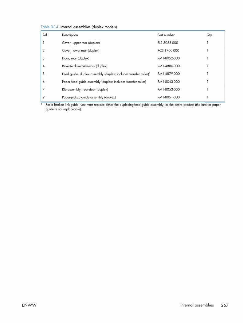
Table 3-14 Internal assemblies (duplex models)
Ref Description Part number Qty
1 Cover, upper-rear (duplex) RL1-3068-000 1
2 Cover, lower-rear (duplex) RC3-1700-000 1
3 Door, rear (duplex) RM1-8052-000 1
4 Reverse drive assembly (duplex) RM1-4880-000 1
5 Feed guide, duplex assembly (duplex; includes transfer roller)1 RM1-4879-000 1
6 Paper feed guide assembly (duplex; includes transfer roller) RM1-8043-000 1
7 Rib assembly, rear-door (duplex) RM1-8053-000 1
9 Paper-pickup guide assembly (duplex) RM1-8051-000 1
1 For a broken link-guide: you must replace either the duplexing-feed guide assembly, or the entire product (the interior paperguide is not replaceable).
ENWW Internal assemblies 267

PCAs
Figure 3-10 PCAs
2
54 1
3
6
7
268 Chapter 3 Parts and diagrams ENWW

Table 3-15 PCAs
Ref Description Part number Qty
1 Driver PCA RM1-8032-000 1
2 High-voltage power supply RM1-8031-000 1
3 DC controller RM1-8039-000 1
4 Low-voltage power supply (110v) RM1-9034-000 1
4 Low-voltage power supply (220v) RM1-9036-000 1
5 Fax PCA CE682-60001 1
5 Fax PCA (Europe only) CE683-60001 1
6 Wireless controller PCA 1150-7938 1
7 USB connector PCA RK2-3846-000 1
Not shown Formatter PCA CE855-60001 1
ENWW Internal assemblies 269

Input device(s)
250-sheet paper feeder (optional Tray 3)
Figure 3-11 250-sheet paper feeder (optional Tray 3)
1
2
270 Chapter 3 Parts and diagrams ENWW

Table 3-16 250-sheet paper feeder (optional Tray 3)
Ref Description Part number Qty
1 250-sheet paper feeder (optional Tray 3; includes cassette) RM1-8544-000CN 1
2 Cassette (optional Tray 3) RM1-8063-000CN 1
ENWW Input device(s) 271

Alphabetical parts listTable 3-17 Alphabetical parts list
Description Part number Table and page
250-sheet paper feeder (optional Tray 3; includes cassette) RM1-8544-000CN 250-sheet paper feeder(optional Tray 3) on page 271
Cartridge-tray assembly RM1-8041-000 Internal assemblies (1 of 7)on page 255
Cassette (optional Tray 3) RM1-8063-000CN 250-sheet paper feeder(optional Tray 3) on page 271
Cassette, Tray 2 RM1-8063-000 Internal assemblies (3 of 7)on page 259
Color misregistration sensor assembly RM1-8029-000 Internal assemblies (2 of 7)on page 257
Control-panel assembly CE863-60015 Scanner and document feedermain assemblies on page 251
Control-panel mount CE863-40018 Scanner and document feedermain assemblies on page 251
Cover, DIMM RC3-1751-000 Covers1,2 on page 253
Cover, left RL1-3063-000 Covers1,2 on page 253
Cover, lower-rear (duplex) RC3-1700-000 Internal assemblies (duplexmodels) on page 267
Cover, rear (simplex) RL1-3072-000 Internal assemblies (simplexmodels) on page 265
Cover, right RC3-1732-000 Covers1,2 on page 253
Cover, right front RC3-1733-000 Covers1,2 on page 253
Cover, upper assembly RM1-8060-000 Covers1,2 on page 253
Cover, upper-rear (duplex) RL1-3068-000 Internal assemblies (duplexmodels) on page 267
DC controller RM1-8039-000 PCAs on page 269
Document feeder assembly (duplex) CE863-60101 Scanner and document feedermain assemblies on page 251
Document feeder assembly (simplex) CE863-60106 Scanner and document feedermain assemblies on page 251
Document feeder input tray CE863-60113 Scanner and document feedermain assemblies on page 251
Document feeder pickup assembly 5851-2559 Scanner and document feedermain assemblies on page 251
Door, front assembly RM1-8064-000 Covers1,2 on page 253
272 Chapter 3 Parts and diagrams ENWW
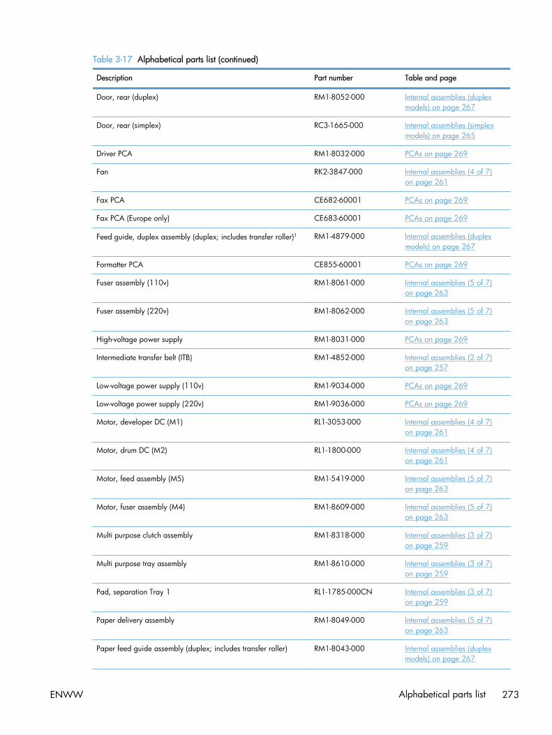
Table 3-17 Alphabetical parts list (continued)
Description Part number Table and page
Door, rear (duplex) RM1-8052-000 Internal assemblies (duplexmodels) on page 267
Door, rear (simplex) RC3-1665-000 Internal assemblies (simplexmodels) on page 265
Driver PCA RM1-8032-000 PCAs on page 269
Fan RK2-3847-000 Internal assemblies (4 of 7)on page 261
Fax PCA CE682-60001 PCAs on page 269
Fax PCA (Europe only) CE683-60001 PCAs on page 269
Feed guide, duplex assembly (duplex; includes transfer roller)1 RM1-4879-000 Internal assemblies (duplexmodels) on page 267
Formatter PCA CE855-60001 PCAs on page 269
Fuser assembly (110v) RM1-8061-000 Internal assemblies (5 of 7)on page 263
Fuser assembly (220v) RM1-8062-000 Internal assemblies (5 of 7)on page 263
High-voltage power supply RM1-8031-000 PCAs on page 269
Intermediate transfer belt (ITB) RM1-4852-000 Internal assemblies (2 of 7)on page 257
Low-voltage power supply (110v) RM1-9034-000 PCAs on page 269
Low-voltage power supply (220v) RM1-9036-000 PCAs on page 269
Motor, developer DC (M1) RL1-3053-000 Internal assemblies (4 of 7)on page 261
Motor, drum DC (M2) RL1-1800-000 Internal assemblies (4 of 7)on page 261
Motor, feed assembly (M5) RM1-5419-000 Internal assemblies (5 of 7)on page 263
Motor, fuser assembly (M4) RM1-8609-000 Internal assemblies (5 of 7)on page 263
Multi purpose clutch assembly RM1-8318-000 Internal assemblies (3 of 7)on page 259
Multi purpose tray assembly RM1-8610-000 Internal assemblies (3 of 7)on page 259
Pad, separation Tray 1 RL1-1785-000CN Internal assemblies (3 of 7)on page 259
Paper delivery assembly RM1-8049-000 Internal assemblies (5 of 7)on page 263
Paper feed guide assembly (duplex; includes transfer roller) RM1-8043-000 Internal assemblies (duplexmodels) on page 267
ENWW Alphabetical parts list 273

Table 3-17 Alphabetical parts list (continued)
Description Part number Table and page
Paper feed guide assembly (simplex; includes transfer roller) RM1-8043-000 Internal assemblies (simplexmodels) on page 265
Paper pickup assembly RM1-8045-000 Internal assemblies (3 of 7)on page 259
Paper-pickup guide assembly (duplex) RM1-8051-000 Internal assemblies (duplexmodels) on page 267
Registration assembly RM1-4841-000 Internal assemblies (3 of 7)on page 259
Reverse drive assembly (duplex) RM1-4880-000 Internal assemblies (duplexmodels) on page 267
Rib assembly, rear-door (duplex) RM1-8053-000 Internal assemblies (duplexmodels) on page 267
Roller, paper-pickup Tray 1 RL1-1802-000 Internal assemblies (2 of 7)on page 257
Scanner assembly (duplex) CE863-60119 Scanner and document feedermain assemblies on page 251
Scanner assembly (simplex) CE903-60101 Scanner and document feedermain assemblies on page 251
Solenoid, Tray 1 (SL1; MP tray) RM1-5420-000 Internal assemblies (2 of 7)on page 257
Tray 2 paper pickup roller assembly RM1-8047-000 Internal assemblies (3 of 7)on page 259
Tray 2 separation roller assembly RM1-4840-000 Internal assemblies (3 of 7)on page 259
USB connector PCA RK2-3846-000 PCAs on page 269
Wireless controller PCA 1150-7938 PCAs on page 269
274 Chapter 3 Parts and diagrams ENWW

Numerical parts listTable 3-18 Numerical parts list
Part number Description Table and page
1150-7938 Wireless controller PCA PCAs on page 269
5851-2559 Document feeder pickup assembly Scanner and document feedermain assemblies on page 251
CE682-60001 Fax PCA PCAs on page 269
CE683-60001 Fax PCA (Europe only) PCAs on page 269
CE855-60001 Formatter PCA PCAs on page 269
CE863-40018 Control-panel mount Scanner and document feedermain assemblies on page 251
CE863-60015 Control-panel assembly Scanner and document feedermain assemblies on page 251
CE863-60101 Document feeder assembly (duplex) Scanner and document feedermain assemblies on page 251
CE863-60106 Document feeder assembly (simplex) Scanner and document feedermain assemblies on page 251
CE863-60113 Document feeder input tray Scanner and document feedermain assemblies on page 251
CE863-60119 Scanner assembly (duplex) Scanner and document feedermain assemblies on page 251
CE903-60101 Scanner assembly (simplex) Scanner and document feedermain assemblies on page 251
RC3-1665-000 Door, rear (simplex) Internal assemblies (simplexmodels) on page 265
RC3-1700-000 Cover, lower-rear (duplex) Internal assemblies (duplexmodels) on page 267
RC3-1732-000 Cover, right Covers1,2 on page 253
RC3-1733-000 Cover, right front Covers1,2 on page 253
RC3-1751-000 Cover, DIMM Covers1,2 on page 253
RK2-3846-000 USB connector PCA PCAs on page 269
RK2-3847-000 Fan Internal assemblies (4 of 7)on page 261
RL1-1785-000CN Pad, separation Tray 1 Internal assemblies (3 of 7)on page 259
RL1-1800-000 Motor, drum DC (M2) Internal assemblies (4 of 7)on page 261
RL1-1802-000 Roller, paper-pickup Tray 1 Internal assemblies (2 of 7)on page 257
ENWW Numerical parts list 275

Table 3-18 Numerical parts list (continued)
Part number Description Table and page
RL1-3053-000 Motor, developer DC (M1) Internal assemblies (4 of 7)on page 261
RL1-3063-000 Cover, left Covers1,2 on page 253
RL1-3068-000 Cover, upper-rear (duplex) Internal assemblies (duplexmodels) on page 267
RL1-3072-000 Cover, rear (simplex) Internal assemblies (simplexmodels) on page 265
RM1-4840-000 Tray 2 separation roller assembly Internal assemblies (3 of 7)on page 259
RM1-4841-000 Registration assembly Internal assemblies (3 of 7)on page 259
RM1-4852-000 Intermediate transfer belt (ITB) Internal assemblies (2 of 7)on page 257
RM1-4879-000 Feed guide, duplex assembly (duplex; includes transfer roller)1 Internal assemblies (duplexmodels) on page 267
RM1-4880-000 Reverse drive assembly (duplex) Internal assemblies (duplexmodels) on page 267
RM1-5419-000 Motor, feed assembly (M5) Internal assemblies (5 of 7)on page 263
RM1-5420-000 Solenoid, Tray 1 (SL1; MP tray) Internal assemblies (2 of 7)on page 257
RM1-8029-000 Color misregistration sensor assembly Internal assemblies (2 of 7)on page 257
RM1-8031-000 High-voltage power supply PCAs on page 269
RM1-8032-000 Driver PCA PCAs on page 269
RM1-8039-000 DC controller PCAs on page 269
RM1-8041-000 Cartridge-tray assembly Internal assemblies (1 of 7)on page 255
RM1-8043-000 Paper feed guide assembly (simplex; includes transfer roller) Internal assemblies (simplexmodels) on page 265
RM1-8043-000 Paper feed guide assembly (duplex; includes transfer roller) Internal assemblies (duplexmodels) on page 267
RM1-8045-000 Paper pickup assembly Internal assemblies (3 of 7)on page 259
RM1-8047-000 Tray 2 paper pickup roller assembly Internal assemblies (3 of 7)on page 259
RM1-8049-000 Paper delivery assembly Internal assemblies (5 of 7)on page 263
276 Chapter 3 Parts and diagrams ENWW

Table 3-18 Numerical parts list (continued)
Part number Description Table and page
RM1-8051-000 Paper-pickup guide assembly (duplex) Internal assemblies (duplexmodels) on page 267
RM1-8052-000 Door, rear (duplex) Internal assemblies (duplexmodels) on page 267
RM1-8053-000 Rib assembly, rear-door (duplex) Internal assemblies (duplexmodels) on page 267
RM1-8060-000 Cover, upper assembly Covers1,2 on page 253
RM1-8061-000 Fuser assembly (110v) Internal assemblies (5 of 7)on page 263
RM1-8062-000 Fuser assembly (220v) Internal assemblies (5 of 7)on page 263
RM1-8063-000 Cassette, Tray 2 Internal assemblies (3 of 7)on page 259
RM1-8063-000CN Cassette (optional Tray 3) 250-sheet paper feeder(optional Tray 3) on page 271
RM1-8064-000 Door, front assembly Covers1,2 on page 253
RM1-8318-000 Multi purpose clutch assembly Internal assemblies (3 of 7)on page 259
RM1-8544-000CN 250-sheet paper feeder (optional Tray 3; includes cassette) 250-sheet paper feeder(optional Tray 3) on page 271
RM1-8609-000 Motor, fuser assembly (M4) Internal assemblies (5 of 7)on page 263
RM1-8610-000 Multi purpose tray assembly Internal assemblies (3 of 7)on page 259
RM1-9034-000 Low-voltage power supply (110v) PCAs on page 269
RM1-9036-000 Low-voltage power supply (220v) PCAs on page 269
ENWW Numerical parts list 277

278 Chapter 3 Parts and diagrams ENWW

A Service and support
● Hewlett-Packard limited warranty statement
● HP's Premium Protection Warranty: LaserJet print cartridge limited warranty statement
● Data stored on the print cartridge
● End User License Agreement
● OpenSSL
● Customer support
ENWW 279

Hewlett-Packard limited warranty statement
HP PRODUCT DURATION OF LIMITED WARRANTY
HP LaserJet Pro 300 color MFP M375nw and HP LaserJet Pro400 color MFP M475dn, and M475dw
One year from date of purchase
HP warrants to you, the end-user customer, that HP hardware and accessories will be free from defectsin materials and workmanship after the date of purchase, for the period specified above. If HP receivesnotice of such defects during the warranty period, HP will, at its option, either repair or replaceproducts which prove to be defective. Replacement products may be either new or equivalent inperformance to new.
HP warrants to you that HP software will not fail to execute its programming instructions after the dateof purchase, for the period specified above, due to defects in material and workmanship whenproperly installed and used. If HP receives notice of such defects during the warranty period, HP willreplace software which does not execute its programming instructions due to such defects.
HP does not warrant that the operation of HP products will be uninterrupted or error free. If HP isunable, within a reasonable time, to repair or replace any product to a condition as warranted, youwill be entitled to a refund of the purchase price upon prompt return of the product.
HP products may contain remanufactured parts equivalent to new in performance or may have beensubject to incidental use.
Warranty does not apply to defects resulting from (a) improper or inadequate maintenance orcalibration, (b) software, interfacing, parts or supplies not supplied by HP, (c) unauthorizedmodification or misuse, (d) operation outside of the published environmental specifications for theproduct, or (e) improper site preparation or maintenance.
TO THE EXTENT ALLOWED BY LOCAL LAW, THE ABOVE WARRANTIES ARE EXCLUSIVE AND NOOTHER WARRANTY OR CONDITION, WHETHER WRITTEN OR ORAL, IS EXPRESSED OR IMPLIEDAND HP SPECIFICALLY DISCLAIMS ANY IMPLIED WARRANTIES OR CONDITIONS OFMERCHANTABILITY, SATISFACTORY QUALITY, AND FITNESS FOR A PARTICULAR PURPOSE. Somecountries/regions, states or provinces do not allow limitations on the duration of an implied warranty,so the above limitation or exclusion might not apply to you. This warranty gives you specific legal rightsand you might also have other rights that vary from country/region to country/region, state to state, orprovince to province.
HP's limited warranty is valid in any country/region or locality where HP has a support presence forthis product and where HP has marketed this product. The level of warranty service you receive mayvary according to local standards. HP will not alter form, fit or function of the product to make itoperate in a country/region for which it was never intended to function for legal or regulatory reasons.
TO THE EXTENT ALLOWED BY LOCAL LAW, THE REMEDIES IN THIS WARRANTY STATEMENT AREYOUR SOLE AND EXCLUSIVE REMEDIES. EXCEPT AS INDICATED ABOVE, IN NO EVENT WILL HP ORITS SUPPLIERS BE LIABLE FOR LOSS OF DATA OR FOR DIRECT, SPECIAL, INCIDENTAL,CONSEQUENTIAL (INCLUDING LOST PROFIT OR DATA), OR OTHER DAMAGE, WHETHER BASEDIN CONTRACT, TORT, OR OTHERWISE. Some countries/regions, states or provinces do not allow theexclusion or limitation of incidental or consequential damages, so the above limitation or exclusion maynot apply to you.
280 Appendix A Service and support ENWW

THE WARRANTY TERMS CONTAINED IN THIS STATEMENT, EXCEPT TO THE EXTENT LAWFULLYPERMITTED, DO NOT EXCLUDE, RESTRICT OR MODIFY AND ARE IN ADDITION TO THEMANDATORY STATUTORY RIGHTS APPLICABLE TO THE SALE OF THIS PRODUCT TO YOU.
ENWW Hewlett-Packard limited warranty statement 281

HP's Premium Protection Warranty: LaserJet print cartridgelimited warranty statement
This HP product is warranted to be free from defects in materials and workmanship.
This warranty does not apply to products that (a) have been refilled, refurbished, remanufactured ortampered with in any way, (b) experience problems resulting from misuse, improper storage, oroperation outside of the published environmental specifications for the printer product or (c) exhibitwear from ordinary use.
To obtain warranty service, please return the product to place of purchase (with a written description ofthe problem and print samples) or contact HP customer support. At HP's option, HP will either replaceproducts that prove to be defective or refund your purchase price.
TO THE EXTENT ALLOWED BY LOCAL LAW, THE ABOVE WARRANTY IS EXCLUSIVE AND NOOTHER WARRANTY OR CONDITION, WHETHER WRITTEN OR ORAL, IS EXPRESSED OR IMPLIEDAND HP SPECIFICALLY DISCLAIMS ANY IMPLIED WARRANTIES OR CONDITIONS OFMERCHANTABILITY, SATISFACTORY QUALITY, AND FITNESS FOR A PARTICULAR PURPOSE.
TO THE EXTENT ALLOWED BY LOCAL LAW, IN NO EVENT WILL HP OR ITS SUPPLIERS BE LIABLEFOR DIRECT, SPECIAL, INCIDENTAL, CONSEQUENTIAL (INCLUDING LOST PROFIT OR DATA), OROTHER DAMAGE, WHETHER BASED IN CONTRACT, TORT, OR OTHERWISE.
THE WARRANTY TERMS CONTAINED IN THIS STATEMENT, EXCEPT TO THE EXTENT LAWFULLYPERMITTED, DO NOT EXCLUDE, RESTRICT OR MODIFY AND ARE IN ADDITION TO THEMANDATORY STATUTORY RIGHTS APPLICABLE TO THE SALE OF THIS PRODUCT TO YOU.
282 Appendix A Service and support ENWW

Data stored on the print cartridgeThe HP print cartridges used with this product contain a memory chip that assists in the operation of theproduct.
In addition, this memory chip collects a limited set of information about the usage of the product, whichmight include the following: the date when the print cartridge was first installed, the date when the printcartridge was last used, the number of pages printed using the print cartridge, the page coverage, theprinting modes used, any printing errors that might have occurred, and the product model. Thisinformation helps HP design future products to meet our customers' printing needs.
The data collected from the print cartridge memory chip does not contain information that can be usedto identify a customer or user of the print cartridge or their product. However, a customer can choosenot to store usage data on the memory chip through the control panel.
HP collects a sampling of the memory chips from print cartridges returned to HP's free return andrecycling program (HP Planet Partners: www.hp.com/recycle). The memory chips from this samplingare read and studied in order to improve future HP products. HP partners who assist in recycling thisprint cartridge might have access to this data, as well.
Any third party possessing the print cartridge might have access to the anonymous information on thememory chip.
ENWW Data stored on the print cartridge 283

End User License AgreementPLEASE READ CAREFULLY BEFORE USING THIS SOFTWARE PRODUCT: This End-User LicenseAgreement (“EULA”) is a contract between (a) you (either an individual or the entity you represent) and(b) Hewlett-Packard Company (“HP”) that governs your use of the software product (“Software”). ThisEULA does not apply if there is a separate license agreement between you and HP or its suppliers forthe Software, including a license agreement in online documentation. The term “Software” may include(i) associated media, (ii) a user guide and other printed materials, and (iii) “online” or electronicdocumentation (collectively “User Documentation”).
RIGHTS IN THE SOFTWARE ARE OFFERED ONLY ON THE CONDITION THAT YOU AGREE TO ALLTERMS AND CONDITIONS OF THIS EULA. BY INSTALLING, COPYING, DOWNLOADING, OROTHERWISE USING THE SOFTWARE, YOU AGREE TO BE BOUND BY THIS EULA. IF YOU DO NOTACCEPT THIS EULA, DO NOT INSTALL, DOWNLOAD, OR OTHERWISE USE THE SOFTWARE. IFYOU PURCHASED THE SOFTWARE BUT DO NOT AGREE TO THIS EULA, PLEASE RETURN THESOFTWARE TO YOUR PLACE OF PURCHASE WITHIN FOURTEEN DAYS FOR A REFUND OF THEPURCHASE PRICE; IF THE SOFTWARE IS INSTALLED ON OR MADE AVAILABLE WITH ANOTHERHP PRODUCT, YOU MAY RETURN THE ENTIRE UNUSED PRODUCT.
1. THIRD PARTY SOFTWARE. The Software may include, in addition to HP proprietary software (“HPSoftware”), software under licenses from third parties (“Third Party Software” and “Third PartyLicense”). Any Third Party Software is licensed to you subject to the terms and conditions of thecorresponding Third Party License. Generally, the Third Party License is in a file such as“license.txt” or a “readme” file. You should contact HP support if you cannot find a Third PartyLicense. If the Third Party Licenses include licenses that provide for the availability of source code(such as the GNU General Public License) and the corresponding source code is not included withthe Software, then check the product support pages of HP's website (hp.com) to learn how toobtain such source code.
2. LICENSE RIGHTS. You will have the following rights provided you comply with all terms andconditions of this EULA:
a. Use. HP grants you a license to Use one copy of the HP Software. “Use” means installing,copying, storing, loading, executing, displaying, or otherwise using the HP Software. Youmay not modify the HP Software or disable any licensing or control feature of theHP Software. If this Software is provided by HP for Use with an imaging or printing product(for example, if the Software is a printer driver, firmware, or add-on), the HP Software mayonly be used with such product (“HP Product”). Additional restrictions on Use may appear inthe User Documentation. You may not separate component parts of the HP Software for Use.You do not have the right to distribute the HP Software.
b. Copying. Your right to copy means you may make archival or back-up copies of theHP Software, provided each copy contains all the original HP Software’s proprietary noticesand is used only for back-up purposes.
3. UPGRADES. To Use HP Software provided by HP as an upgrade, update, or supplement(collectively “Upgrade”), you must first be licensed for the original HP Software identified by HP aseligible for the Upgrade. To the extent the Upgrade supersedes the original HP Software, you mayno longer use such HP Software. This EULA applies to each Upgrade unless HP provides otherterms with the Upgrade. In case of a conflict between this EULA and such other terms, the otherterms will prevail.
284 Appendix A Service and support ENWW
4. TRANSFER.
a. Third Party Transfer. The initial end user of the HP Software may make a one-time transfer ofthe HP Software to another end user. Any transfer will include all component parts, media,User Documentation, this EULA, and if applicable, the Certificate of Authenticity. The transfermay not be an indirect transfer, such as a consignment. Prior to the transfer, the end userreceiving the transferred Software will agree to this EULA. Upon transfer of the HP Software,your license is automatically terminated.
b. Restrictions. You may not rent, lease or lend the HP Software or Use the HP Software forcommercial timesharing or bureau use. You may not sublicense, assign or otherwise transferthe HP Software except as expressly provided in this EULA.
5. PROPRIETARY RIGHTS. All intellectual property rights in the Software and User Documentation areowned by HP or its suppliers and are protected by law, including applicable copyright, tradesecret, patent, and trademark laws. You will not remove any product identification, copyrightnotice, or proprietary restriction from the Software.
6. LIMITATION ON REVERSE ENGINEERING. You may not reverse engineer, decompile, ordisassemble the HP Software, except and only to the extent that the right to do so is allowed underapplicable law.
7. CONSENT TO USE OF DATA. HP and its affiliates may collect and use technical information youprovide in relation to (i) your Use of the Software or the HP Product, or (ii) the provision of supportservices related to the Software or the HP Product. All such information will be subject to HP’sprivacy policy. HP will not use such information in a form that personally identifies you except tothe extent necessary to enhance your Use or provide support services.
8. LIMITATION OF LIABILITY. Notwithstanding any damages that you might incur, the entire liabilityof HP and its suppliers under this EULA and your exclusive remedy under this EULA will be limitedto the greater of the amount actually paid by you for the Product or U.S. $5.00. TO THEMAXIMUM EXTENT PERMITTED BY APPLICABLE LAW, IN NO EVENT WILL HP OR ITS SUPPLIERSBE LIABLE FOR ANY SPECIAL, INCIDENTAL, INDIRECT, OR CONSEQUENTIAL DAMAGES(INCLUDING DAMAGES FOR LOST PROFITS, LOST DATA, BUSINESS INTERRUPTION,PERSONAL INJURY, OR LOSS OF PRIVACY) RELATED IN ANY WAY TO THE USE OF ORINABILITY TO USE THE SOFTWARE, EVEN IF HP OR ANY SUPPLIER HAS BEEN ADVISED OF THEPOSSIBILITY OF SUCH DAMAGES AND EVEN IF THE ABOVE REMEDY FAILS OF ITS ESSENTIALPURPOSE. Some states or other jurisdictions do not allow the exclusion or limitation of incidentalor consequential damages, so the above limitation or exclusion may not apply to you.
9. U.S. GOVERNMENT CUSTOMERS. Software was developed entirely at private expense. AllSoftware is commercial computer software within the meaning of the applicable acquisitionregulations. Accordingly, pursuant to US FAR 48 CFR 12.212 and DFAR 48 CFR 227.7202, use,duplication and disclosure of the Software by or for the U.S. Government or a U.S. Governmentsubcontractor is subject solely to the terms and conditions set forth in this End User LicenseAgreement, except for provisions which are contrary to applicable mandatory federal laws.
10. COMPLIANCE WITH EXPORT LAWS. You will comply with all laws, rules, and regulations (i)applicable to the export or import of the Software, or (ii) restricting the Use of the Software,including any restrictions on nuclear, chemical, or biological weapons proliferation.
11. RESERVATION OF RIGHTS. HP and its suppliers reserve all rights not expressly granted to you inthis EULA.
ENWW End User License Agreement 285

© 2009 Hewlett-Packard Development Company, L.P.
Rev. 04/09
286 Appendix A Service and support ENWW

OpenSSLThis product includes software developed by the OpenSSL Project for use in the OpenSSL Toolkit(http://www.openssl.org/)
THIS SOFTWARE IS PROVIDED BY THE OpenSSL PROJECT ``AS IS'' AND ANY EXPRESSED ORIMPLIED WARRANTIES, INCLUDING, BUT NOT LIMITED TO, THE IMPLIED WARRANTIES OFMERCHANTABILITY AND FITNESS FOR A PARTICULAR PURPOSE ARE DISCLAIMED. IN NO EVENTSHALL THE OpenSSL PROJECT OR ITS CONTRIBUTORS BE LIABLE FOR ANY DIRECT, INDIRECT,INCIDENTAL, SPECIAL, EXEMPLARY, OR CONSEQUENTIAL DAMAGES (INCLUDING, BUT NOTLIMITED TO, PROCUREMENT OF SUBSTITUTE GOODS OR SERVICES;
LOSS OF USE, DATA, OR PROFITS; OR BUSINESS INTERRUPTION) HOWEVER CAUSED AND ONANY THEORY OF LIABILITY, WHETHER IN CONTRACT, STRICT LIABILITY, OR TORT (INCLUDINGNEGLIGENCE OR OTHERWISE) ARISING IN ANY WAY OUT OF THE USE OF THIS SOFTWARE,EVEN IF ADVISED OF THE POSSIBILITY OF SUCH DAMAGE.
This product includes cryptographic software written by Eric Young ([email protected]). This productincludes software written by Tim Hudson ([email protected]).
ENWW OpenSSL 287

Customer support
Get telephone support for your country/region
Have the product name, serial number, date of purchase, andproblem description ready.
Country/region phone numbers are on the flyer that was inthe box with your product or at www.hp.com/support/.
Get 24-hour Internet support www.hp.com/go/LJColorMFPM375 or www.hp.com/go/LJColorMFPM475
Get support for products used with a Macintosh computer www.hp.com/go/macosx
Download software utilities, drivers, and electronicinformation
www.hp.com/go/LJColorMFPM375_software orwww.hp.com/go/LJColorMFPM475_software
Order additional HP service or maintenance agreements www.hp.com/go/carepack
Register your product www.register.hp.com
288 Appendix A Service and support ENWW

B Product specifications
● Physical specifications
● Power consumption, electrical specifications, and acoustic emissions
● Environmental specifications
ENWW 289

Physical specifications
Table B-1 Physical specifications
Product Height Depth Width Weight
HP LaserJet Pro 300color MFP M375nw
500 mm (19.7 inches) 483 mm (19.0 inches) 420 mm (16.5 inches) 28.2 kg (62.2 lb)
HP LaserJet Pro 400color MFP M475dn
500 mm (19.7 inches) 483 mm (19.0 inches) 420 mm (16.5 inches) 29.5 kg (65.0 lb)
HP LaserJet Pro 400color MFP M475dw
500 mm (19.7 inches) 483 mm (19.0 inches) 420 mm (16.5 inches) 29.5 kg (65.0 lb)
Power consumption, electrical specifications, and acousticemissions
See www.hp.com/go/LJColorMFPM375_regulatory or www.hp.com/go/LJColorMFPM475_regulatoryfor current information.
CAUTION: Power requirements are based on the country/region where the product is sold. Do notconvert operating voltages. This will damage the product and void the product warranty.
Environmental specifications
Table B-2 Environmental specifications1
Recommended Operating Storage
Temperature 15° to 32.5° C
(59° to 90.5° F)
15° to 32.5° C
(59° to 90.5° F)
–20° to 40° C
(–4° to 104° F)
Relative humidity 20 to 70% 10 to 80% 95% or less
Altitude 0 to 3048 m (0 to 10,000 ft)
1 Values are subject to change.
290 Appendix B Product specifications ENWW

C Regulatory information
● FCC regulations
● Environmental product stewardship program
● Declaration of conformity
● Declaration of conformity (wireless models)
● Certificate of volatility
● Safety statements
● Additional statements for telecom (fax) products
● Additional statements for wireless products
ENWW 291

FCC regulationsThis equipment has been tested and found to comply with the limits for a Class B digital device,pursuant to Part 15 of the FCC rules. These limits are designed to provide reasonable protectionagainst harmful interference in a residential installation. This equipment generates, uses, and canradiate radio frequency energy. If this equipment is not installed and used in accordance with theinstructions, it may cause harmful interference to radio communications. However, there is no guaranteethat interference will not occur in a particular installation. If this equipment does cause harmfulinterference to radio or television reception, which can be determined by turning the equipment off andon, the user is encouraged to try to correct the interference by one or more of the following measures:
● Reorient or relocate the receiving antenna.
● Increase separation between equipment and receiver.
● Connect equipment to an outlet on a circuit different from that to which the receiver is located.
● Consult your dealer or an experienced radio/TV technician.
NOTE: Any changes or modifications to the printer that are not expressly approved by HP could voidthe user’s authority to operate this equipment.
Use of a shielded interface cable is required to comply with the Class B limits of Part 15 of FCC rules.
Environmental product stewardship program
Protecting the environment
Hewlett-Packard Company is committed to providing quality products in an environmentally soundmanner. This product has been designed with several attributes to minimize impacts on ourenvironment.
Ozone production
This product generates no appreciable ozone gas (O3).
Power consumption
Power usage drops significantly while in Ready or Sleep mode, which saves natural resources andsaves money without affecting the high performance of this product. Hewlett-Packard printing andimaging equipment marked with the ENERGY STAR® logo is qualified to the U.S. EnvironmentalProtection Agency's ENERGY STAR specifications for imaging equipment. The following mark willappear on ENERGY STAR qualified imaging products:
292 Appendix C Regulatory information ENWW
Additional ENERGY STAR qualified imaging product model information is listed at:
www.hp.com/go/energystar
Toner consumption
EconoMode uses less toner, which might extend the life of the print cartridge. HP does not recommendthe full-time use of EconoMode. If EconoMode is used full-time, the toner supply might outlast themechanical parts in the print cartridge. If print quality begins to degrade and is no longer acceptable,consider replacing the print cartridge.
Paper use
This product’s manual/automatic duplex feature (two-sided printing) and N-up printing (multiple pagesprinted on one page) capability can reduce paper usage and the resulting demands on naturalresources.
Plastics
Plastic parts over 25 grams are marked according to international standards that enhance the ability toidentify plastics for recycling purposes at the end of the product’s life.
HP LaserJet print supplies
It’s easy to return and recycle your HP LaserJet print cartridges after use—free of charge—withHP Planet Partners. Multilingual program information and instructions are included in every newHP LaserJet print cartridge and supplies package. You help reduce the toll on the environment furtherwhen you return multiple cartridges together rather than separately.
HP is committed to providing inventive, high-quality products and services that are environmentallysound, from product design and manufacturing to distribution, customer use and recycling. When youparticipate in the HP Planet Partners program, we ensure your HP LaserJet print cartridges are recycledproperly, processing them to recover plastics and metals for new products and diverting millions of tonsof waste from landfills. Since this cartridge is being recycled and used in new materials, it will not bereturned to you. Thank you for being environmentally responsible!
NOTE: Use the return label to return original HP LaserJet print cartridges only. Please do not use thislabel for HP inkjet cartridges, non-HP cartridges, refilled or remanufactured cartridges or warrantyreturns. For information about recycling your HP inkjet cartridges please go to http://www.hp.com/recycle.
Return and recycling instructions
United States and Puerto Rico
The enclosed label in the HP LaserJet toner cartridge box is for the return and recycling of one or moreHP LaserJet print cartridges after use. Please follow the applicable instructions below.
ENWW Environmental product stewardship program 293

Multiple returns (more than one cartridge)
1. Package each HP LaserJet print cartridge in its original box and bag.
2. Tape the boxes together using strapping or packaging tape. The package can weigh up to 31 kg(70 lb).
3. Use a single pre-paid shipping label.
OR
1. Use your own suitable box, or request a free bulk collection box from www.hp.com/recycle or1-800-340-2445 (holds up to 31 kg (70 lb) of HP LaserJet print cartridges).
2. Use a single pre-paid shipping label.
Single returns
1. Package the HP LaserJet print cartridge in its original bag and box.
2. Place the shipping label on the front of the box.
Shipping
For US and Puerto Rico HP LaserJet print cartridge recycling returns, use the pre-paid, pre-addressedshipping label contained in the box. To use the UPS label, give the package to the UPS driver duringyour next delivery or pick-up, or take it to an authorized UPS drop-off center. (Requested UPS Groundpickup will be charged normal pick-up rates) For the location of your local UPS drop-off center, call1-800-PICKUPS or visit www.ups.com.
If you are returning the package with the FedEx label, give the package to either the U.S. Postal Servicecarrier or FedEx driver during your next pick-up or delivery. (Requested FedEx Ground pickup will becharged normal pick-up rates). Or, you can drop off your packaged print cartridge(s) at any U.S. PostOffice or any FedEx shipping center or store. For the location of your nearest U.S. Post Office, pleasecall 1-800-ASK-USPS or visit www.usps.com. For the location of your nearest FedEx shipping center/store, please call 1-800-GOFEDEX or visit www.fedex.com.
For more information, or to order additional labels or boxes for bulk returns, visit www.hp.com/recycleor call 1-800-340-2445. Information subject to change without notice.
Residents of Alaska and Hawaii
Do not use the UPS label. Call 1-800-340-2445 for information and instructions. The U.S. PostalService provides no-cost cartridge return transportation services under an arrangement with HP forAlaska and Hawaii.
Non-U.S. returns
To participate in HP Planet Partners return and recycling program, just follow the simple directions inthe recycling guide (found inside the packaging of your new product supply item) or visitwww.hp.com/recycle. Select your country/region for information on how to return your HP LaserJetprinting supplies.
294 Appendix C Regulatory information ENWW

Paper
This product is capable of using recycled papers when the paper meets the guidelines outlined in theHP LaserJet Printer Family Print Media Guide. This product is suitable for the use of recycled paperaccording to EN12281:2002.
Material restrictions
This HP product does not contain added mercury.
This HP product contains a battery that might require special handling at end-of-life. The batteriescontained in or supplied by Hewlett-Packard for this product include the following:
HP LaserJet Pro 300 color MFP M375 and HP LaserJet Pro 400 color MFP M475
Type Carbon monofluoride lithium
Weight 0.8 g
Location On formatter board
User-removable No
For recycling information, you can go to www.hp.com/recycle, or contact your local authorities or theElectronics Industries Alliance: www.eiae.org.
Disposal of waste equipment by users in private households in the EuropeanUnion
This symbol on the product or on its packaging indicates that this product must not be disposed of withyour other household waste. Instead, it is your responsibility to dispose of your waste equipment byhanding it over to a designated collection point for the recycling of waste electrical and electronicequipment. The separate collection and recycling of your waste equipment at the time of disposal willhelp to conserve natural resources and ensure that it is recycled in a manner that protects human healthand the environment. For more information about where you can drop off your waste equipment forrecycling, please contact your local city office, your household waste disposal service or the shopwhere you purchased the product.
ENWW Environmental product stewardship program 295

Chemical substances
HP is committed to providing our customers with information about the chemical substances in ourproducts as needed to comply with legal requirements such as REACH (Regulation EC No 1907/2006of the European Parliament and the Council). A chemical information report for this product can befound at: www.hp.com/go/reach.
Material Safety Data Sheet (MSDS)
Material Safety Data Sheets (MSDS) for supplies containing chemical substances (for example, toner)can be obtained by accessing the HP Web site at www.hp.com/go/msds or www.hp.com/hpinfo/community/environment/productinfo/safety.
296 Appendix C Regulatory information ENWW

For more information
To obtain information about these environmental topics:
● Product environmental profile sheet for this and many related HP products
● HP’s commitment to the environment
● HP’s environmental management system
● HP’s end-of-life product return and recycling program
● Material Safety Data Sheets
Visit www.hp.com/go/environment or www.hp.com/hpinfo/globalcitizenship/environment.
ENWW Environmental product stewardship program 297

Declaration of conformity
Declaration of Conformity
according to ISO/IEC 17050-1 and EN 17050-1
Manufacturer's Name: Hewlett-Packard Company DoC#: BOISB-1002-03-rel.1.0
Manufacturer's Address: 11311 Chinden Boulevard
Boise, Idaho 83714-1021, USA
declares, that the product
Product Name: HP LaserJet Pro 400 color MFP M475dn
Regulatory Model Number2) BOISB-1002-03
BOISB-0903-00 – (US-Fax Module LIU)
BOISB-0903-01 – (EURO-Fax Module LIU)
Product Options: ALL
Print Cartridges: CE410A, CE410X, CE411A, CE412A, CE413A
conforms to the following Product Specifications:
SAFETY: IEC 60950-1:2005 / EN60950-1: 2006+A11
IEC 60825-1:2007 / EN 60825-1:2007 (Class 1 Laser/LED Product)
IEC 62311:2007 / EN62311:2008
GB4943-2001
EMC: CISPR22:2005 +A1 / EN55022:2006 +A1 - Class B1)
EN 61000-3-2:2006
EN 61000-3-3:2008
EN 55024:1998 +A1 +A2
FCC Title 47 CFR, Part 15 Class B1) / ICES-003, Issue 4
GB9254-2008, GB17625.1-2003
TELECOM: ES 203 021; FCC Title 47 CFR, Part 683)
ENERGY USE: Regulation (EC) No. 1275/2008
ENERGY STAR® Qualified Imaging Equipment Typical Electricity Consumption (TEC) Test Procedure
Supplementary Information:
The product herewith complies with the requirements of the EMC Directive 2004/108/EC and the Low Voltage Directive 2006/95/EC, the
R&TTE Directive 1999/5/EC (Annex II), the EuP Directive 2005/32/EC and carries the CE-Marking accordingly.
298 Appendix C Regulatory information ENWW

This Device complies with Part 15 of the FCC Rules. Operation is subject to the following two Conditions: (1) this device may not causeharmful interference, and (2) this device must accept any interference received, including interference that may cause undesired operation.
1. The product was tested in a typical configuration with Hewlett-Packard Personal Computer Systems.
2. For regulatory purposes, this product is assigned a Regulatory model number. This number should not be confused with the productname or the product number(s).
3. Telecom approvals and standards appropriate for the target countries/regions have been applied to this product, in addition to thoselisted above.
4. This product uses an analog fax accessory module which Regulatory Model numbers are: BOISB-0903-00 (US-LIU) or BOISB-0903-01(EURO LIU), as needed to meet technical regulatory requirements for the countries/regions this product will be sold.
Boise, Idaho USA
October 2011
For regulatory topics only:
European Contact: Your Local Hewlett-Packard Sales and Service Office or Hewlett-Packard GmbH, Department HQ-TRE / Standards Europe, Herrenberger Straße 140, D-71034, Böblingen (FAX: +49-7031-14-3143)www.hp.eu/certificates
USA Contact: Product Regulations Manager, Hewlett-Packard Company, PO Box 15, Mail Stop 160, Boise, Idaho83707-0015 (Phone: 208-396-6000)
ENWW Declaration of conformity 299
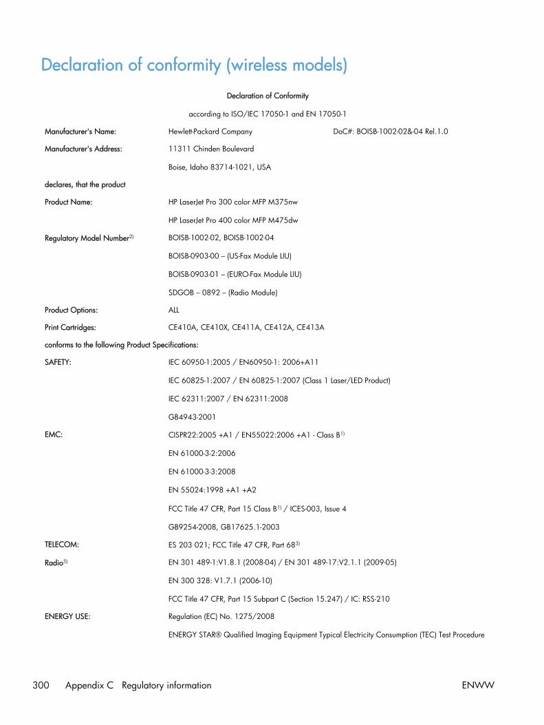
Declaration of conformity (wireless models)
Declaration of Conformity
according to ISO/IEC 17050-1 and EN 17050-1
Manufacturer's Name: Hewlett-Packard Company DoC#: BOISB-1002-02&-04 Rel.1.0
Manufacturer's Address: 11311 Chinden Boulevard
Boise, Idaho 83714-1021, USA
declares, that the product
Product Name: HP LaserJet Pro 300 color MFP M375nw
HP LaserJet Pro 400 color MFP M475dw
Regulatory Model Number2) BOISB-1002-02, BOISB-1002-04
BOISB-0903-00 – (US-Fax Module LIU)
BOISB-0903-01 – (EURO-Fax Module LIU)
SDGOB – 0892 – (Radio Module)
Product Options: ALL
Print Cartridges: CE410A, CE410X, CE411A, CE412A, CE413A
conforms to the following Product Specifications:
SAFETY: IEC 60950-1:2005 / EN60950-1: 2006+A11
IEC 60825-1:2007 / EN 60825-1:2007 (Class 1 Laser/LED Product)
IEC 62311:2007 / EN 62311:2008
GB4943-2001
EMC: CISPR22:2005 +A1 / EN55022:2006 +A1 - Class B1)
EN 61000-3-2:2006
EN 61000-3-3:2008
EN 55024:1998 +A1 +A2
FCC Title 47 CFR, Part 15 Class B1) / ICES-003, Issue 4
GB9254-2008, GB17625.1-2003
TELECOM: ES 203 021; FCC Title 47 CFR, Part 683)
Radio5) EN 301 489-1:V1.8.1 (2008-04) / EN 301 489-17:V2.1.1 (2009-05)
EN 300 328: V1.7.1 (2006-10)
FCC Title 47 CFR, Part 15 Subpart C (Section 15.247) / IC: RSS-210
ENERGY USE: Regulation (EC) No. 1275/2008
ENERGY STAR® Qualified Imaging Equipment Typical Electricity Consumption (TEC) Test Procedure
300 Appendix C Regulatory information ENWW

Supplementary Information:
The product herewith complies with the requirements of the R&TTE; Directive 1999/5/EC Annex II and Annex IV, EMC Directive
2004/108/EC, the Low Voltage Directive 2006/95/EC, the EuP Directive 2005/32/EC and carries the CE-Marking
accordingly.
This Device complies with Part 15 of the FCC Rules. Operation is subject to the following two Conditions: (1) this device may not causeharmful interference, and (2) this device must accept any interference received, including interference that may cause undesired operation.
1. The product was tested in a typical configuration with Hewlett-Packard Personal Computer Systems.
2. For regulatory purposes, this product is assigned a Regulatory model number. This number should not be confused with the productname or the product number(s).
3. Telecom approvals and standards appropriate for the target countries/regions have been applied to this product, in addition to thoselisted above.
4. This product uses an analog fax accessory module which Regulatory Model numbers are: BOISB-0903-00 (US-LIU) or BOISB-0903-01(EURO LIU), as needed to meet technical regulatory requirements for the countries/regions this product will be sold.
5. This product uses a radio module device which Regulatory Model number is SDGOB-0892 as needed to meet technical regulatoryrequirements for the countries/regions this product will be sold.
Boise, Idaho USA
October 2011
For regulatory topics only:
European Contact: Your Local Hewlett-Packard Sales and Service Office or Hewlett-Packard GmbH, Department HQ-TRE / Standards Europe, Herrenberger Straße 140, D-71034, Böblingen (FAX: +49-7031-14-3143)www.hp.eu/certificates
USA Contact: Product Regulations Manager, Hewlett-Packard Company, PO Box 15, Mail Stop 160, Boise, Idaho83707-0015 (Phone: 208-396-6000)
ENWW Declaration of conformity (wireless models) 301

Certificate of volatilityThis is a statement regarding the volatility of customer data stored in memory. It also outlines how tosecurely erase data from the product.
Types of memory
Volatile memory
The product utilizes 192 MB of volatile memory (SDRAM) used for temporary storage during theprocess of jobs, and for applications running on the operating system. When the printer is powered off,the memory is erased.
Non-volatile memory
The product utilizes 2.1 GB of non-volatile memory (EEPROM, Flash) containing the boot code andfactory product configuration data required for the device to function. No customer print data is storedin non-volatile memory. There are no steps to clear this data.
302 Appendix C Regulatory information ENWW

Safety statements
Laser safety
The Center for Devices and Radiological Health (CDRH) of the U.S. Food and Drug Administration hasimplemented regulations for laser products manufactured since August 1, 1976. Compliance ismandatory for products marketed in the United States. The device is certified as a “Class 1” laserproduct under the U.S. Department of Health and Human Services (DHHS) Radiation PerformanceStandard according to the Radiation Control for Health and Safety Act of 1968. Since radiationemitted inside the device is completely confined within protective housings and external covers, thelaser beam cannot escape during any phase of normal user operation.
WARNING! Using controls, making adjustments, or performing procedures other than those specifiedin this user guide may result in exposure to hazardous radiation.
Canadian DOC regulations
Complies with Canadian EMC Class B requirements.
« Conforme à la classe B des normes canadiennes de compatibilité électromagnétiques. « CEM ». »
VCCI statement (Japan)
Power cord instructions
Make sure your power source is adequate for the product voltage rating. The voltage rating is on theproduct label. The product uses either 100-127 Vac or 220-240 Vac and 50/60 Hz.
Connect the power cord between the product and a grounded AC outlet.
CAUTION: To prevent damage to the product, use only the power cord that is provided with theproduct.
Power cord statement (Japan)
ENWW Safety statements 303

EMC statement (Korea)
Laser statement for Finland
Luokan 1 laserlaite
Klass 1 Laser Apparat
HP LaserJet Pro 300 color MFP M375nw, HP LaserJet Pro 400 color MFP M475dn, M475dw,laserkirjoitin on käyttäjän kannalta turvallinen luokan 1 laserlaite. Normaalissa käytössä kirjoittimensuojakotelointi estää lasersäteen pääsyn laitteen ulkopuolelle. Laitteen turvallisuusluokka on määritettystandardin EN 60825-1 (2007) mukaisesti.
VAROITUS !
Laitteen käyttäminen muulla kuin käyttöohjeessa mainitulla tavalla saattaa altistaa käyttäjänturvallisuusluokan 1 ylittävälle näkymättömälle lasersäteilylle.
VARNING !
Om apparaten används på annat sätt än i bruksanvisning specificerats, kan användaren utsättas förosynlig laserstrålning, som överskrider gränsen för laserklass 1.
HUOLTO
HP LaserJet Pro 300 color MFP M375nw, HP LaserJet Pro 400 color MFP M475dn, M475dw -kirjoittimen sisällä ei ole käyttäjän huollettavissa olevia kohteita. Laitteen saa avata ja huoltaaainoastaan sen huoltamiseen koulutettu henkilö. Tällaiseksi huoltotoimenpiteeksi ei katsotaväriainekasetin vaihtamista, paperiradan puhdistusta tai muita käyttäjän käsikirjassa lueteltuja,käyttäjän tehtäväksi tarkoitettuja ylläpitotoimia, jotka voidaan suorittaa ilman erikoistyökaluja.
VARO !
Mikäli kirjoittimen suojakotelo avataan, olet alttiina näkymättömällelasersäteilylle laitteen ollessatoiminnassa. Älä katso säteeseen.
VARNING !
Om laserprinterns skyddshölje öppnas då apparaten är i funktion, utsättas användaren för osynliglaserstrålning. Betrakta ej strålen.
Tiedot laitteessa käytettävän laserdiodin säteilyominaisuuksista: Aallonpituus 775-795 nm Teho 5 m WLuokan 3B laser.
304 Appendix C Regulatory information ENWW
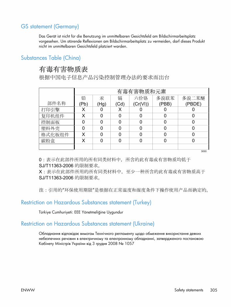
GS statement (Germany)
Das Gerät ist nicht für die Benutzung im unmittelbaren Gesichtsfeld am Bildschirmarbeitsplatzvorgesehen. Um störende Reflexionen am Bildschirmarbeitsplatz zu vermeiden, darf dieses Produktnicht im unmittelbaren Gesichtsfeld platziert warden.
Substances Table (China)
Restriction on Hazardous Substances statement (Turkey)
Türkiye Cumhuriyeti: EEE Yönetmeliğine Uygundur
Restriction on Hazardous Substances statement (Ukraine)
Обладнання відповідає вимогам Технічного регламенту щодо обмеження використання деякихнебезпечних речовин в електричному та електронному обладнанні, затвердженого постановоюКабінету Міністрів України від 3 грудня 2008 № 1057
ENWW Safety statements 305

Additional statements for telecom (fax) products
EU Statement for Telecom Operation
This product is intended to be connected to the analog Public Switched Telecommunication Networks(PSTN) of European Economic Area (EEA) countries/regions.
It meets requirements of EU R&TTE Directive 1999/5/EC (Annex II) and carries appropriate CEconformity marking.
For more details see Declaration of Conformity issued by the manufacturer in another section of thismanual.
However due to differences between individual national PSTNs the product may not guaranteeunconditional assurance of successful operation on every PSTN termination point. Networkcompatibility depends on the correct setting being selected by the customer in preparation of itsconnection to the PSTN. Please follow the instructions provided in the user manual.
If you experience network compatibility issues, please contact your equipment supplier or Hewlett-Packard help desk in the country/region of operation.
Connecting to a PSTN termination point may be the subject of additional requirements set out by thelocal PSTN operator.
New Zealand Telecom Statements
The grant of a Telepermit for any item of terminal equipment indicates only that Telecom has acceptedthat the item complies with minimum conditions for connection to its network. It indicates noendorsement of the product by Telecom, nor does it provide any sort of warranty. Above all, it providesno assurance that any item will work correctly in all respects with another item of Telepermittedequipment of a different make or model, nor does it imply that any product is compatible with all ofTelecom’s network services.
This equipment may not provide for the effective hand-over of a call to another device connected to thesame line.
This equipment shall not be set up to make automatic calls to the Telecom “111” Emergency Service.
This product has not been tested to ensure compatibility with the FaxAbility distinctive ring service forNew Zealand.
Additional FCC statement for telecom products (US)
This equipment complies with Part 68 of the FCC rules and the requirements adopted by the ACTA. Onthe back of this equipment is a label that contains, among other information, a product identifier in theformat US:AAAEQ##TXXXX. If requested, this number must be provided to the telephone company.
The REN is used to determine the quantity of devices, which may be connected to the telephone line.Excessive RENs on the telephone line may result in the devices not ringing in response to an incomingcall. In most, but not all, areas, the sum of the RENs should not exceed five (5.0). To be certain of the
306 Appendix C Regulatory information ENWW

number of devices that may be connected to the line, as determined by the total RENs, contact thetelephone company to determine the maximum REN for the calling area.
This equipment uses the following USOC jacks: RJ11C.
An FCC-compliant telephone cord and modular plug is provided with this equipment. This equipment isdesigned to be connected to the telephone network or premises wiring using a compatible modularjack, which is Part 68 compliant. This equipment cannot be used on telephone company-provided coinservice. Connection to Party Line Service is subject to state tariffs.
If this equipment causes harm to the telephone network, the telephone company will notify you inadvance that temporary discontinuance of service may be required. If advance notice is not practical,the telephone company will notify the customer as soon as possible. Also, you will be advised of yourright to file a complaint with the FCC if you believe it is necessary.
The telephone company may make changes in its facilities, equipment, operations, or procedures thatcould affect the operation of the equipment. If this happens, the telephone company will provideadvance notice in order for you to make the necessary modifications in order to maintain uninterruptedservice.
If trouble is experienced with this equipment, please see the numbers in this manual for repair and (or)warranty information. If the trouble is causing harm to the telephone network, the telephone companymay request you remove the equipment from the network until the problem is resolved.
The customer can do the following repairs: Replace any original equipment that came with the device.This includes the print cartridge, the supports for trays and bins, the power cord, and the telephonecord. It is recommended that the customer install an AC surge arrestor in the AC outlet to which thisdevice is connected. This is to avoid damage to the equipment caused by local lightning strikes andother electrical surges.
Telephone Consumer Protection Act (US)
The Telephone Consumer Protection Act of 1991 makes it unlawful for any person to use a computer orother electronic device, including fax machines, to send any message unless such message clearlycontains, in a margin at the top or bottom of each transmitted page or on the first page of thetransmission, the date and time it is sent and an identification of the business, other entity, or individualsending the message and the telephone number of the sending machine or such business, or otherentity, or individual. (The telephone number provided cannot be a 900 number or any other number forwhich charges exceed local or long distance transmission charges).
Industry Canada CS-03 requirements
Notice: The Industry Canada label identifies certified equipment. This certification means the equipmentmeets certain telecommunications network protective, operational, and safety requirements asprescribed in the appropriate Terminal Equipment Technical Requirement document(s). The Departmentdoes not guarantee the equipment will operate to the user’s satisfaction. Before installing thisequipment, users should ensure that it is permissible for the equipment to be connected to the facilitiesof the local telecommunications company. The equipment must also be installed using an acceptablemethod of connection. The customer should be aware that compliance with the above conditions maynot prevent degradation of service in some situations. Repairs to certified equipment should becoordinated by a representative designated by the supplier. Any repairs or alterations made by theuser to this equipment, or equipment malfunctions, may give the telecommunications company cause to
ENWW Additional statements for telecom (fax) products 307

request the user to disconnect the equipment. Users should ensure for their own protection that theelectrical ground connections of the power utility, telephone lines, and internal metallic water pipesystem, if present, are connected together. This precaution can be particularly important in rural areas.
CAUTION: Users should not attempt to make such connections themselves, but should contact theappropriate electric inspection authority, or electrician, as appropriate. The Ringer EquivalenceNumber (REN) of this device is 0.0.
Notice: The Ringer Equivalence Number (REN) assigned to each terminal device provides an indicationof the maximum number of terminals allowed to be connected to a telephone interface. The terminationon an interface may consist of any combination of devices subject only to the requirement that the sumof the Ringer Equivalence Number of all the devices does not exceed five (5.0). The standardconnecting arrangement code (telephone jack type) for equipment with direct connections to thetelephone network is CA11A.
Vietnam Telecom wired/wireless marking for ICTQC Type approved products
308 Appendix C Regulatory information ENWW

Additional statements for wireless products
FCC compliance statement—United States
Exposure to radio frequency radiation
CAUTION: The radiated output power of this device is far below the FCC radio frequency exposurelimits. Nevertheless, the device shall be used in such a manner that the potential for human contactduring normal operation is minimized.
In order to avoid the possibility of exceeding the FCC radio frequency exposure limits, human proximityto the antenna shall not be less than 20 cm ( (8 in)) during normal operation.
This device complies with Part 15 of FCC Rules. Operation is subject to the following two conditions:(1) this device may not cause interference, and (2) this device must accept any interference, includinginterference that may cause undesired operation of the device.
CAUTION: Based on Section 15.21 of the FCC rules, changes of modifications to the operation ofthis product without the express approval by Hewlett-Packard Company may invalidate its authorizeduse.
Australia statement
This device incorporates a radio-transmitting (wireless) device. For protection against radio transmissionexposure, it is recommended that this device be operated no less than 20 cm from the head, neck, orbody.
Brazil ANATEL statement
Este equipamento opera em caráter secundário, isto é, não tem direito à proteção contra interferênciaprejudicial, mesmo de estações do mesmo tipo, e não pode causar interferência a sistemas operandoem caráter primário.
Canadian statements
For Indoor Use. This digital apparatus does not exceed the Class B limits for radio noise emissions fromdigital apparatus as set out in the radio interference regulations of the Canadian Department ofCommunications. The internal wireless radio complies with RSS 210 of Industry Canada.
Pour l´usage d´intérieur. Le présent appareil numérique n´émet pas de bruits radioélectriques dépassantles limites applicables aux appareils numériques de Classe B prescribes dans le règlement sur lebrouillage radioélectrique édicté par le Ministère des Communications du Canada. Le composant RFinterne est conforme à la norme CNR-210 d´Industrie Canada.
European Union regulatory notice
The telecommunications functionality of this product may be used in the following EU and EFTAcountries/regions:
ENWW Additional statements for wireless products 309

Austria, Belgium, Bulgaria, Cyprus, Czech Republic, Denmark, Estonia, Finland, France, Germany,Greece, Hungary, Iceland, Ireland, Italy, Latvia, Liechtenstein, Lithuania, Luxembourg, Malta,Netherlands, Norway, Poland, Portugal, Romania, Slovak Republic, Slovenia, Spain, Sweden,Switzerland, and United Kingdom.
Notice for use in France
For 2.4 GHz Wireless LAN operation of this product certain restrictions apply: This equipment may beused indoor for the entire 2400-2483.5 MHz frequency band (channels 1-13). For outdoor use, only2400-2454 MHz frequency band (channels 1-9) may be used. For the latest requirements, seewww.arcep.fr.
L'utilisation de cet equipement (2.4 GHz Wireless LAN) est soumise à certaines restrictions : Cetéquipement peut être utilisé à l'intérieur d'un bâtiment en utilisant toutes les fréquences de2400-2483.5 MHz (Chaine 1-13). Pour une utilisation en environnement extérieur, vous devez utiliserles fréquences comprises entre 2400-2454 MHz (Chaine 1-9). Pour les dernières restrictions, voir,www.arcep.fr.
Notice for use in Russia
Существуют определенные ограничения по использованию беспроводных сетей (стандарта802.11 b/g) с рабочей частотой 2,4 ГГц: Данное оборудование может использоваться внутрипомещений с использованием диапазона частот 2400-2483,5 МГц (каналы 1-13). Прииспользовании внутри помещений максимальная эффективная изотропно–излучаемая мощность(ЭИИМ) должна составлять не более 100мВт.
Korean statement
310 Appendix C Regulatory information ENWW

Taiwan statement
Vietnam Telecom wired/wireless marking for ICTQC Type approved products
ENWW Additional statements for wireless products 311

312 Appendix C Regulatory information ENWW

Index
Symbols/Numerics2ndary service menu 211
Aaccessories
ordering 246acoustic specifications 290advanced setup
fax 142after service checklist 5
Bbackground, gray 193bands, troubleshooting 193batteries included 295bin, output
jams, clearing 188black and white printing
troubleshooting 196blank pages, troubleshooting 202
Ccables
USB, troubleshooting 202calibrating color 137, 213Canadian DOC regulations 303cartridges
recycling 293supplies status page 139warranty 282
cautions iiicharacters, troubleshooting 194checklist
fax troubleshooting 215checklists
after service 5preservice 5pretroubleshooting 114
checklists, printing 140
circuit diagram 128clean
touch screen 201cleaning
glass 199mode 211page 136paper path 198
colorcalibrating 137, 213troubleshooting 196
color usage log 139components
diagram 121configuration page 116, 139connectivity
solving problems 206connectors
DC controller 119control panel
blank, troubleshooting 115button test 212clean touch screen 201cleaning page, printing 198display test 212HP Web Services menu 138menu map, printing 139menus 137message types 157messages, troubleshooting
157reinstalling 49removing the control panel 48Reports menu 139
conventions, document iiicopy menu 152copy-quality test 6covers
left, removing 55
locations 252parts list 252right, removing 23upper, removing 51
creases, troubleshooting 195crooked pages 195curled media 194customer support
online 288
DDC controller
connectors 119DC controller PCA, removing 80defaults
NVRAM initialization 213restoring 211, 213
defects, repetitive 136demo page
troubleshooting 116diagrams 245
covers 252internal assemblies 254troubleshooting 121
dimensions 290disposal, end-of-life 295document conventions iiidocument feeder
jams 181document feeder pickup roller
removing 16doors
front, removing 58dots, troubleshooting 192dpi (dots per inch)
faxing 142drive components
diagrams 121
ENWW Index 313

driversusage page 139
Eelectrical specifications 290electrostatic discharge (ESD) 3end-of-life disposal 295environmental specifications 290environmental stewardship
program 292ePrint
enabling or disabling 138error messages
control panel 157error report 175event log 175
error messages, fax 217, 227,234
error report, faxprinting 226
error-correction setting, fax 226ESD (electrostatic discharge) 3European Union, waste disposal
295event log 116
Ffactory defaults, restoring
NVRAM initialization 213faded print 192fans
location 123fax
answer mode 141error report, printing 226error-correction 226reports 154reports, printing all 225ring type 141solve general problems 240unable to receive 234unable to send 227V.34 setting 227
fax menu 154fax PCA, removing 76fax ports, locating 118fax reports, printing 154fax troubleshooting
checklist 215fax-quality test 6
fax-quality test 6Finnish laser safety statement 304firmware
version 212fonts
lists, printing 139formatter PCA, removing 76front door, removing 58fuser
assembly diagrams 121jams, clearing 187
Gglass, cleaning 199graph paper, printing 140gray background,
troubleshooting 193grayscale
troubleshooting 196
HHP Customer Care 288HP ePrint
enabling or disabling 138HP Jetdirect print server
NVRAM initialization 213HP Web Services menu 138humidity specifications
environment 290
Iimage defects, troubleshooting
192image quality
repetitive image defects 136initialization
NVRAM 213interface ports
locating 118internal assemblies
parts list 254internal assembly
locations 254ITB
assembly diagrams 121
Jjams
causes of 180document feeder, clearing
181
locating 180output bin, clearing 188paper path, clearing 187tracking number of 139
Japanese VCCI statement 303Jetdirect print server
NVRAM initialization 213
KKorean EMC statement 304
Llaser safety statements 303, 304LEDs, troubleshooting 116left cover, removing 55license, software 284light print, troubleshooting 192lightness
faded print, troubleshooting192
lines, troubleshooting 193printed pages 193
locationsetting 212
logs, faxerror 226printing all 225
loose toner, troubleshooting 193
MMacintosh
support 288material restrictions 295Material Safety Data Sheet
(MSDS) 296media
curled, troubleshooting 194wrinkled 195
memoryNVRAM initialization 213part number 248
memory chip, print cartridgedescription 283
menucontrol panel, access 137copy 152fax 154Fax setup 141Network config 151Quick Forms 140scan 156
314 Index ENWW

Service 149System setup 144USB 157
menus, control panelHP Web Services 138map, printing 139Reports 139
mercury-free product 295messages
control panel 157motors
location 123music paper, printing 140
Nnetwork
configuring 151Network config menu 151network port
locating 118networks
configuration page 139settings report 139
notebook paper, printing 140notes iiiNVRAM initialization 213
Oonline support 288operating environment,
specifications 290ordering
product documents 247supplies and accessories 246
output binjams, clearing 188
output qualityrepetitive image defects 136
Ppage count 139pages
blank 202not printing 202printing slowly 202skewed 195
papercurled, troubleshooting 194jams 180wrinkled 195
paper jams. See jams
paper pathjams, clearing 187
paper pickup problemssolving 191
parts 245cover locations 252internal assembly locations
254screws 4using lists and diagrams 249
PCAs, diagrams 125PCL font list 139physical specifications 290pickup roller
locating 124removing 10
pliers, required 3ports
locating 118post-service tests 6power
consumption 290supplies diagrams 121
power-ontroubleshooting 115
powersave 211preservice checklist 5pretroubleshooting checklist 114print cartridges
memory chips 283recycling 293warranty 282
print qualityrepetitive image defects 136
print quality, troubleshootingimage defects 192
print-quality test 6printing
troubleshooting 202problem-solving
no response 204slow response 205
protocol settings, fax 227PS font list 139
Qquality
repetitive image defects 136
Rreceiving faxes
error report, printing 226recycling 293
HP printing supplies returns andenvironmental program 293
reinstalling partscontrol panel 49DC controller PCA 80
removing partscautions for 2checklists 5control panel 48DC controller PCA 80document feeder pickup roller
16fax PCA 76formatter PCA 76front door 58left cover 55pickup roller 10right cover 23rollers 9separation roller 13tools, required 3upper cover 51
repetitive defects, troubleshooting136, 195
replacingparts 2
reportsdemo page 139error 175, 212fax 154menu map 113print quality page 139service 212
Reports menu 139reports, fax
error 226printing all 225
resetsNVRAM initialization 213
restoringdefault settings 213defaults 211factory defaults 213NVRAM initialization 213
right cover, removing 23
ENWW Index 315

rollerslocating 124pickup and separation,
removing 9repetitive image defects 136
rollers and padsremoving 9
Ssafety statements 303, 304scan menu 156scanner
assembly, removing 26glass cleaning 199
scatter, troubleshooting 195screwdrivers, required 3screws
replacing 2secondary service menu 211sending faxes
error report, printing 226separation roller, removing 13separation rollers
locating 124service
tools, required 3Service menu 149, 211
cleaning mode 211powersave 211restoring defaults 211secondary 211settings 211
service page 139settings
network report 139size 290skewed pages 195smeared toner, troubleshooting
193software
software license agreement284
solvefax problems 227
solve problemsfax 240
solvingdirect-connect problems 206network problems 206
specificationselectrical and acoustic 290environmental 290physical 290
specks, troubleshooting 192spots, troubleshooting 192static precautions 3status
page 116supplies, printing report 139
storingenvironmental specifications
290streaks, troubleshooting 193supplies
ordering 246recycling 293
supplies status page 139support
online 288System setup menu 144
Ttechnical support
online 288temperature specifications
environment 290tests
component 117copy-quality 6fax-quality 6internal print quality 135post-service 6print-quality 6service page 135
text, troubleshootingmisformed characters 194
timing diagram 127tips iiitoner
loose, troubleshooting 193scatter, troubleshooting 195smeared, troubleshooting 193specks, troubleshooting 192
toner cartridgespart numbers 248supplies status page 139
tools, required 3touch screen, clean 201
Tray 1jams, clearing 183
Tray 2jams, clearing 186
Tray 3part number 248
traysjams, clearing 186
troubleshootingabout 114blank pages 202calibration 137checklist 112, 114color 196configuration page 116control panel messages 157control-panel tests 117curled media 194demo page 116diagrams 121direct-connect problems 206event log 116faded print 192fax error-correction setting
226faxes 215image defects 192jams 180LED diagnostics 116lines, printed pages 193loose toner 193network problems 206NVRAM initialization 213pages not printing 202pages printing slowly 202power-on 115receive fax 234repetitive defects 195reports and tools 116send fax 227skewed pages 195status page 116text 194toner scatter 195toner smear 193toner specks 192USB cables 202using service mode 211wrinkles 195
316 Index ENWW

Uupper cover, removing 51usage page 139USB cable, part number 248USB menu 157USB port
locating 118troubleshooting 202
VV.34 setting 227vertical lines, troubleshooting 193volume
settings 145
Wwarnings iiiwarranty
license 284print cartridges 282product 280
wavy paper, troubleshooting 194Web sites
customer support 288Macintosh customer support
288Material Safety Data Sheet
(MSDS) 296weight 290wireless
configuring 151wrinkles, troubleshooting 195
ENWW Index 317

318 Index ENWW


© 2012 Hewlett-Packard Development Company, L.P.
www.hp.com
*CE863-90966**CE863-90966*CE863-90966