
HP Officejet Enterprise Color X555 Warranty & Legal Guide - PTWW
Upload
khangminh22Category
view
4download
0
HP CM8060/8050 Color MFP with EdgelineTechnology
Service and Support Training
Student Guide

HP CM8060/8050 Color MFP with Edgeline Technology Service and Support Training Student Guide
Notice
The information contained herein is subject to change without notice. The only warranties for HP products and services are set forthin the express warranty statements accompanying such products and services. Nothing herein should be construed as constituting anadditional warranty. HP shall not be liable for technical or editorial errors or omissions contained herein. This is an HP copyrightedwork that may not be reproduced without the written permission of HP. You may not use these materials to deliver training to anyperson outside of your organization without the written permission of HP.
© 2008 Copyright Hewlett-Packard Development Company, L.P.
All Rights Reserved. Reproduction, adaptation, or translation without prior written permission is prohibited, except as allowed underthe copyright laws.
Apple® and the Apple logo are trademarks of Apple Computer, Inc., registered in the U.S. and other countries.
Adobe® and PostScript® are trademarks of Adobe Systems Incorporated.
Microsoft® and Windows® are U.S. registered trademark of Microsoft Corporation.
UNIX® is a registered trademark of The Open Group.
Printed in U.S.A. HP CM8060/8050 Color MFP with Edgeline Technology materials.
HP Restricted - Contact HP Education for customer training
Rev 3.1, 3/2008
Revision History
Revision Date Change summary1 1/2007 First release
2 5/2007 • MFP Overview: Added detailed description of Edgeline Technology andsection on ink durability
• Service and Maintenance: Added more information on web wipemaintenance and drum spittoon maintenance
• Remove and Replace – Getting started: Revised Tetris sensor calibrationsection
• Remove and Replace – Getting started: Corrected error in color-codingstandards table
• Remove and Replace – Power and electronics: Corrected engineelectronics diagram
• Remove and Replace – Power and electronics: Corrected PSU autorange
• Remove and Replace – Power and electronics: Corrected powermanagement section
• Remove and Replace – Power and electronics: Corrected power linevoltage chart
• Remove and Replace – Power and electronics: Corrected error on PowerDistribution PCA slide
• Remove and Replace – Power and electronics: Added information onMain Engine PCA
• Remove and Replace – Power and electronics: Added information onInk Assist PCA
2 HP Restricted Rev. 3.1 -- 03/08
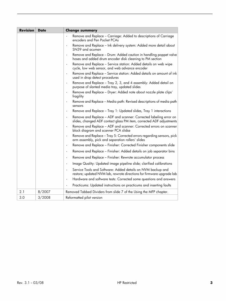
Revision Date Change summary
• Remove and Replace – Carriage: Added to descriptions of Carriageencoders and Pen Pocket PCAs
• Remove and Replace – Ink delivery system: Added more detail aboutSN39 and acumen
• Remove and Replace – Drum: Added caution in handling poppet valvehoses and added drum encoder disk cleaning to PM section
• Remove and Replace – Service station: Added details on web wipecycle, low web sensor, and web advance encoder
• Remove and Replace – Service station: Added details on amount of inkused in drop detect procedures
• Remove and Replace – Tray 2, 3, and 4 assembly: Added detail onpurpose of slanted media tray, updated slides
• Remove and Replace – Dryer: Added note about nozzle plate clips'fragility
• Remove and Replace – Media path: Revised descriptions of media pathsensors
• Remove and Replace – Tray 1: Updated slides, Tray 1 interactions
• Remove and Replace – ADF and scanner: Corrected labeling error onslides, changed ADF contact glass PM item, corrected ADF adjustments
• Remove and Replace – ADF and scanner: Corrected errors on scannerblock diagram and scanner PCA slidse
• Remove and Replace – Tray 5: Corrected errors regarding sensors, pickarm assembly, pick and separation rollers' slides
• Remove and Replace – Finisher: Corrected Finisher components slide
• Remove and Replace – Finisher: Added details on job separator bins
• Remove and Replace – Finisher: Rewrote accumulator process
• Image Quality: Updated image pipeline slide; clarified calibrations
• Service Tools and Software: Added details on NVM backup andrestore; updated NVM lab, rewrote directions for firmware upgrade lab
• Hardware and software tests: Corrected some questions and answers
• Practicums: Updated instructions on practicums and inserting faults
2.1 8/2007 Removed Tabbed Dividers from slide 7 of the Using the MFP chapter.
3.0 3/2008 Reformatted pilot version
Rev. 3.1 -- 03/08 HP Restricted 3
HP CM8060/8050 Color MFP with Edgeline Technology Service and Support Training Student Guide
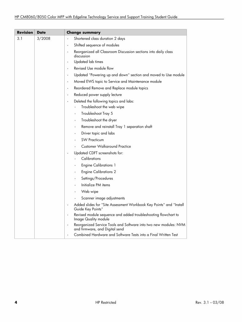
Revision Date Change summary3.1 3/2008 • Shortened class duration 2 days
• Shifted sequence of modules
• Reorganized all Classroom Discussion sections into daily classdiscussion
• Updated lab times
• Revised Use module flow
• Updated "Powering up and down" section and moved to Use module
• Moved EWS topic to Service and Maintenance module
• Reordered Remove and Replace module topics
• Reduced power supply lecture
• Deleted the following topics and labs:
• Troubleshoot the web wipe
• Troubleshoot Tray 5
• Troubleshoot the dryer
• Remove and reinstall Tray 1 separation shaft
• Driver topic and labs
• SW Practicum
• Customer Walkaround Practice
• Updated CDFT screenshots for:
• Calibrations
• Engine Calibrations 1
• Engine Calibrations 2
• Settings/Procedures
• Initialize PM items
• Web wipe
• Scanner image adjustments
• Added slides for "Site Assessment Workbook Key Points" and "InstallGuide Key Points"
• Revised module sequence and added troubleshooting flowchart toImage Quality module
• Reorganized Service Tools and Software into two new modules: NVMand firmware, and Digital send
• Combined Hardware and Software Tests into a Final Written Test
4 HP Restricted Rev. 3.1 -- 03/08
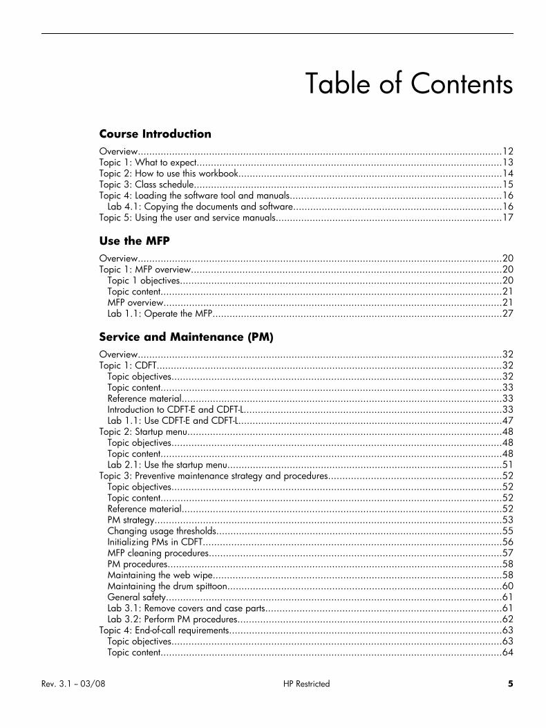
Table of ContentsCourse IntroductionOverview................................................................................................................................12Topic 1: What to expect...........................................................................................................13Topic 2: How to use this workbook.............................................................................................14Topic 3: Class schedule............................................................................................................15Topic 4: Loading the software tool and manuals...........................................................................16
Lab 4.1: Copying the documents and software.........................................................................16Topic 5: Using the user and service manuals................................................................................17
Use the MFPOverview................................................................................................................................20Topic 1: MFP overview.............................................................................................................20
Topic 1 objectives.................................................................................................................20Topic content........................................................................................................................21MFP overview.......................................................................................................................21Lab 1.1: Operate the MFP......................................................................................................27
Service and Maintenance (PM)Overview................................................................................................................................32Topic 1: CDFT..........................................................................................................................32
Topic objectives....................................................................................................................32Topic content........................................................................................................................33Reference material.................................................................................................................33Introduction to CDFT-E and CDFT-L...........................................................................................33Lab 1.1: Use CDFT-E and CDFT-L.............................................................................................47
Topic 2: Startup menu...............................................................................................................48Topic objectives....................................................................................................................48Topic content........................................................................................................................48Lab 2.1: Use the startup menu.................................................................................................51
Topic 3: Preventive maintenance strategy and procedures.............................................................52Topic objectives....................................................................................................................52Topic content........................................................................................................................52Reference material.................................................................................................................52PM strategy..........................................................................................................................53Changing usage thresholds.....................................................................................................55Initializing PMs in CDFT.........................................................................................................56MFP cleaning procedures.......................................................................................................57PM procedures......................................................................................................................58Maintaining the web wipe......................................................................................................58Maintaining the drum spittoon.................................................................................................60General safety......................................................................................................................61Lab 3.1: Remove covers and case parts...................................................................................61Lab 3.2: Perform PM procedures.............................................................................................62
Topic 4: End-of-call requirements................................................................................................63Topic objectives....................................................................................................................63Topic content........................................................................................................................64
Rev. 3.1 -- 03/08 HP Restricted 5
HP CM8060/8050 Color MFP with Edgeline Technology Service and Support Training Student Guide
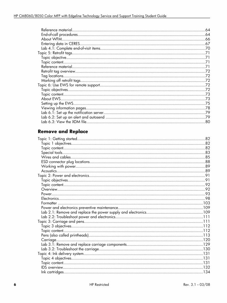
Reference material.................................................................................................................64End-of-call procedures............................................................................................................64About WFM.........................................................................................................................66Entering data in CERES..........................................................................................................67Lab 4.1: Complete end-of-visit items.........................................................................................70
Topic 5: Retrofit tags.................................................................................................................71Topic objective......................................................................................................................71Topic content........................................................................................................................71Reference material.................................................................................................................71Retrofit tag overview..............................................................................................................72Tag locations........................................................................................................................72Marking off retrofit tags..........................................................................................................72
Topic 6: Use EWS for remote support.........................................................................................72Topic objectives....................................................................................................................72Topic content........................................................................................................................73About EWS..........................................................................................................................73Setting up the EWS................................................................................................................75Viewing information pages.....................................................................................................78Lab 6.1: Set up the notification server......................................................................................79Lab 6.2: Set up an alert and autosend ....................................................................................79Lab 6.3: View the XDM file.....................................................................................................80
Remove and ReplaceTopic 1: Getting started............................................................................................................82
Topic 1 objectives.................................................................................................................82Topic content........................................................................................................................82Special tools.........................................................................................................................83Wires and cables..................................................................................................................85ESD connector plug locations..................................................................................................88Working with power..............................................................................................................89Acoustics..............................................................................................................................89
Topic 2: Power and electronics..................................................................................................91Topic objectives....................................................................................................................91Topic content........................................................................................................................92Overview.............................................................................................................................92Power..................................................................................................................................93Electronics............................................................................................................................98Formatter ...........................................................................................................................103Power and electronics preventive maintenance........................................................................109Lab 2.1: Remove and replace the power supply and electronics................................................109Lab 2.2: Troubleshoot power and electronics..........................................................................111
Topic 3: Carriage and pens....................................................................................................111Topic 3 objectives...............................................................................................................112Topic content......................................................................................................................112Pens (also called printheads).................................................................................................113Carriage............................................................................................................................120Lab 3.1: Remove and replace carriage components................................................................129Lab 3.2: Troubleshoot the carriage........................................................................................130
Topic 4: Ink delivery system.....................................................................................................131Topic 4 objectives...............................................................................................................131Topic content......................................................................................................................131IDS overview......................................................................................................................132Ink cartridges......................................................................................................................134
6 HP Restricted Rev. 3.1 -- 03/08
Air pressure system..............................................................................................................135ISS PCA (A8)......................................................................................................................137Lab 4.1: Remove and replace air pressure system...................................................................137Lab 4.2: Troubleshoot the IDS...............................................................................................138
Topic 5: Drum........................................................................................................................139Topic 5 objectives...............................................................................................................139Topic content......................................................................................................................139Drum theory of operation.....................................................................................................140Lab 5.1: Remove and reinstall drum components.....................................................................154Lab 5.2: Troubleshoot the drum.............................................................................................155
Topic 6: Vacuum and aerosol..................................................................................................156Topic 6 objectives...............................................................................................................156Topic content......................................................................................................................157Vacuum theory of operation..................................................................................................157Aerosol theory of operation..................................................................................................160Muffler and charcoal filter....................................................................................................163Vacuum and aerosol preventive maintenance..........................................................................163Vacuum and aerosol tool page.............................................................................................164Lab 6.1: Remove and replace vacuum and aerosol components................................................164Lab 6.2: Troubleshoot the vacuum and aerosol.......................................................................165
Topic 7: Service station and web wipe......................................................................................166Topic 7 objectives...............................................................................................................166Topic content......................................................................................................................166Web wipe .........................................................................................................................167Service station.....................................................................................................................168Drop detect.........................................................................................................................172Service station and web wipe preventive maintenance.............................................................175Lab 7.1: Remove and replace service station and web wipe.....................................................175
Topic 8: Tray 2, 3, and 4 assembly and dryer...........................................................................176Topic 8 objectives...............................................................................................................177Topic content......................................................................................................................177Tray 2, 3, and 4 assembly...................................................................................................178Dryer.................................................................................................................................184Dryer and Trays 2, 3, and 4 tool pages.................................................................................187Lab 8.1: Remove and reinstall tray assembly and dryer components..........................................188Lab 8.2: Troubleshoot Trays 2, 3, and 4................................................................................189
Topic 9: Media path and Tray 1..............................................................................................189Topic 9 objectives...............................................................................................................190Topic content......................................................................................................................190Media path overview...........................................................................................................191Vertical..............................................................................................................................195Tray 1................................................................................................................................196Horizontal..........................................................................................................................198Input/duplex/output (IDO)....................................................................................................200Lab 9.1: Remove and reinstall the horizontal..........................................................................205Lab 9.2: Remove and reinstall IDO RM components.................................................................205Lab 9.3: Troubleshoot the IDO..............................................................................................206
Topic 10: HP 4000-Sheet Input Tray (Tray 5).............................................................................206Topic 10 objectives.............................................................................................................207Topic content......................................................................................................................207Tray 5 theory of operation....................................................................................................207Lab 10.1: Remove and replace Tray 5 components.................................................................215
Topic 11: HP Edgeline MFP Multifunction Finisher......................................................................215Topic 11 objectives.............................................................................................................216
Rev. 3.1 -- 03/08 HP Restricted 7
HP CM8060/8050 Color MFP with Edgeline Technology Service and Support Training Student Guide
Topic content......................................................................................................................216HP Multifunction Finisher......................................................................................................217Lab 11.1: Remove and replace finisher components................................................................229Lab 11.2: Troubleshoot the finisher........................................................................................230
Topic 12: ADF and scanner.....................................................................................................232Topic 12 objectives.............................................................................................................232Topic content......................................................................................................................232Overview...........................................................................................................................233ADF...................................................................................................................................234Scanner.............................................................................................................................241Lab 12.1: Adjust the scanner and ADF...................................................................................246
Image QualityOverview..............................................................................................................................248Topic 1: Image pipeline..........................................................................................................248
Topic objectives..................................................................................................................248Topic content......................................................................................................................248Image pipeline – scanner and copy path................................................................................250Image pipeline – formatter print job/copy processing..............................................................251Image pipeline – engine.......................................................................................................252
Topic 2: Calibrations and adjustments......................................................................................252Topic objectives..................................................................................................................253Topic content......................................................................................................................253Lab 2.1: Perform calibrations................................................................................................260
Topic 3: Test pages................................................................................................................261Topic objectives..................................................................................................................262Topic content......................................................................................................................262Printing test pages...............................................................................................................262Using test pages..................................................................................................................262Lab 3.1: Print a set of test pages...........................................................................................263Interpreting the test pages.....................................................................................................264
Topic 4: Image quality troubleshooting......................................................................................268Topic objectives..................................................................................................................268Topic content......................................................................................................................269Reference material...............................................................................................................269Image quality problems........................................................................................................269Evaluating IQ problems with scan and analyze.......................................................................271Lab 4.1: Diagnose IQ problems from samples.........................................................................272Lab 4.2: Diagnose IQ problems on the MFP...........................................................................272
Hardware PracticumInstructions............................................................................................................................274
Reinstall covers...................................................................................................................274
Install and ConfigureOverview..............................................................................................................................276
Module objectives...............................................................................................................276Module content...................................................................................................................277
Site preparation and assessment..............................................................................................277Install the MFP and accessories................................................................................................279Calibrations and configurations...............................................................................................281
8 HP Restricted Rev. 3.1 -- 03/08
Decommission and move.........................................................................................................282Types of moves...................................................................................................................282Shipping kits.......................................................................................................................283Preparing for shipment.........................................................................................................283
Lab 1.1: Prepare MFP for an extended move.............................................................................284Reference material...............................................................................................................284Exercise.............................................................................................................................284
Lab 1.2: Install the MFP and accessories...................................................................................284Reference material...............................................................................................................285Exercise.............................................................................................................................285
Lab 1.3: Perform calibrations and configurations........................................................................285Reference material...............................................................................................................285Exercise.............................................................................................................................285
Customer walkaround.............................................................................................................286
NVM and firmwareOverview..............................................................................................................................288Topic 1: Non-volatile memory..................................................................................................288
Topic 1 objectives...............................................................................................................288Topic content......................................................................................................................289NVM backup and restore.....................................................................................................291NVM resets and initializations..............................................................................................293Lab 1.1: Back up and restore NVM machine data...................................................................293Lab 1.2: Perform a “Restore Factory Settings” reset..................................................................294
Topic 2: Perform firmware upgrade..........................................................................................295Topic objectives..................................................................................................................295Topic content......................................................................................................................295Lab 2.1: Perform firmware upgrades......................................................................................300
Digital sendOverview..............................................................................................................................302Topic 1: Security....................................................................................................................302
Topic objectives..................................................................................................................302Topic content......................................................................................................................303Security overview................................................................................................................303Authentication.....................................................................................................................305Configuring permission sets..................................................................................................306Restricting color use.............................................................................................................307Lab 1.1: Set up security........................................................................................................307
Topic 2: Digital send..............................................................................................................309Topic 2 objectives...............................................................................................................309Topic content......................................................................................................................310Network terms....................................................................................................................310Digital send responsibilities...................................................................................................311Configuring digital send at the control panel...........................................................................312Lab 2.1: Complete the digital send worksheet.........................................................................312Lab 2.2: Configure digital send at control panel......................................................................313Differences between digital send versions...............................................................................314Configuring digital send using EWS......................................................................................314Lab 2.3: Configure digital send using EWS............................................................................318Using digital send...............................................................................................................319Lab 2.4: Use digital send.....................................................................................................319
Rev. 3.1 -- 03/08 HP Restricted 9

HP CM8060/8050 Color MFP with Edgeline Technology Service and Support Training Student Guide
Final written testInstructions............................................................................................................................322
Acronym glossary
10 HP Restricted Rev. 3.1 -- 03/08

Course Introduction
Course Introduction• Overview
• Topic 1: What to expect
• Topic 2: How to use this workbook
• Topic 3: Class schedule
• Topic 4: Loading the software tool and manuals
• Topic 5: Using the user and service manuals
Rev. 3.1 -- 03/08 HP Restricted 11
HP CM8060/8050 Color MFP with Edgeline Technology Service and Support Training Student Guide
Overview
This module provides you with an overview of the course.
12 HP Restricted Rev. 3.1 -- 03/08
Course Introduction
Topic 1: What to expect
Throughout the course, you can expect to spend most of your time with your hands in the MFP (multi-function printer) – this is a veryhands-on class. We will spend some time in lectures and discussions, but most of our efforts will be focused on the tasks you will needto accomplish when working in the field or call center. There will be skill assessments, practicums, and written tests throughout theclass. Your qualification to service the MFP is based on all of these items.
Rev. 3.1 -- 03/08 HP Restricted 13
HP CM8060/8050 Color MFP with Edgeline Technology Service and Support Training Student Guide
Topic 2: How to use this workbook
In this topic, you'll get familiar with your student workbook.
Successful completion of the course, the lab exercises, and the practicums provides you with "Service Qualification," allowing you toservice the MFP.
14 HP Restricted Rev. 3.1 -- 03/08
Course Introduction
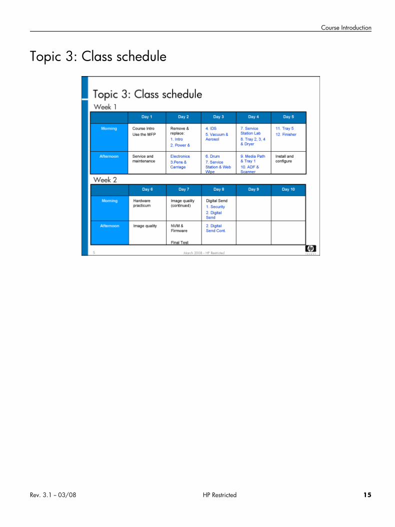
Topic 3: Class schedule
Rev. 3.1 -- 03/08 HP Restricted 15
HP CM8060/8050 Color MFP with Edgeline Technology Service and Support Training Student Guide
Topic 4: Loading the software tool and manuals
In this topic you will load the software tool and manuals on your laptop PC. This way, you'll have all the tools and documents you willneed when you are servicing the MFP. Completing this topic should take approximately 15 minutes.
Lab 4.1: Copying the documents and software1. Open Windows Explorer.2. Copy the CM8060-50 folder from the CD or USB flash drive to your C: drive. This folder contains subfolders of service documents,
user documents, training materials, CDFT-L, the printer driver, and the XDM viewer.3. Once all of the files have been copied, open the CDFT-L folder. It contains two installation files.4. Open the CDFT core .msi first. Then, open the CDFT-printer-specific .msi file.
Note You will install the printer driver during the “Service Tools and Software” module of this training.
16 HP Restricted Rev. 3.1 -- 03/08
Course Introduction
Topic 5: Using the user and service manuals
As you noticed when you downloaded the manuals, there are two manuals for the users of the MFP and four for the service and supportstaff.
As you look through these guides, here are a few things you should notice:
• The field service manual is organized into three parts: service manual, parts manual, and image-quality troubleshooting manual.There is no theory of operation information in the field service manual. Instead, theory of operation is covered in the trainingmaterials. The field service manual also has more error and warning deductive information, and more wiring diagrams than pastservice manuals.
• All of the guides point out special information with the following tags: Tip, Note, Caution, and Warning. We recommend youreview these items carefully. The Tip and Note items will point out special situations or ideas that can make you more efficient.The Caution and Warning items point out situations that could cause harm to you and/or the MFP.
Rev. 3.1 -- 03/08 HP Restricted 17

HP CM8060/8050 Color MFP with Edgeline Technology Service and Support Training Student Guide
18 HP Restricted Rev. 3.1 -- 03/08

Use the MFP
Use the MFP• Overview
• Topic 1: MFP overview
Rev. 3.1 -- 03/08 HP Restricted 19
HP CM8060/8050 Color MFP with Edgeline Technology Service and Support Training Student Guide
Overview
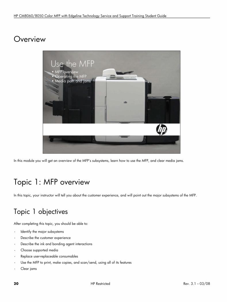
In this module you will get an overview of the MFP's subsystems, learn how to use the MFP, and clear media jams.
Topic 1: MFP overviewIn this topic, your instructor will tell you about the customer experience, and will point out the major subsystems of the MFP.
Topic 1 objectivesAfter completing this topic, you should be able to:
• Identify the major subsystems
• Describe the customer experience
• Describe the ink and bonding agent interactions
• Choose supported media
• Replace user-replaceable consumables
• Use the MFP to print, make copies, and scan/send, using all of its features
• Clear jams
20 HP Restricted Rev. 3.1 -- 03/08
Use the MFP
Topic content
Activity Estimated timeLecture: MFP overview 35 minutes
Lab 1.1: Operate the MFP 75 minutes
MFP overview
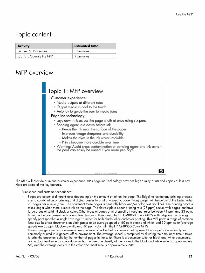
The MFP will provide a unique customer experience. HP's Edgeline Technology provides high-quality prints and copies at less cost.Here are some of the key features.
• Print speed and customer experience:
• Pages are output at different rates depending on the amount of ink on the page. The Edgeline technology printing processuses a combination of printing and drying passes to print any specific page. Many pages will be output at the fastest rate,71 pages per minute (ppm). The content of these pages is generally black and/or color, text and lines. The printing processtakes longer when there is more ink on the page. The slowest plain paper printing rate (23 ppm) occurs with pages that havelarge areas of solid fill-black or color. Other types of pages print at specific throughput rates between 71 ppm and 23 ppm.To aid in the comparison with alternative devices in their class, the HP CM8060 Color MFP's with Edgeline Technologyspecify print speed as a single "average" number for both black/white and color printing. This MFP prints a range of commonletter-size business documents on plain paper at an average speed of 60 ppm black-and-white, and 50 ppm color (averagespeeds are 50 ppm black-and-white and 40 ppm color with the HP CM8050 Color MFP).These average speeds are measured using a suite of individual documents that represent the range of document typescommonly printed in a general office environment. The average speed is computed by dividing the amount of time it takesto print the document suite by the number of pages in the suite. There is a document suite for black and white documents,and a document suite for color documents. The average density of the pages in the black and white suite is approximately5%, and the average density in the color document suite is approximately 20%.
Rev. 3.1 -- 03/08 HP Restricted 21
HP CM8060/8050 Color MFP with Edgeline Technology Service and Support Training Student Guide
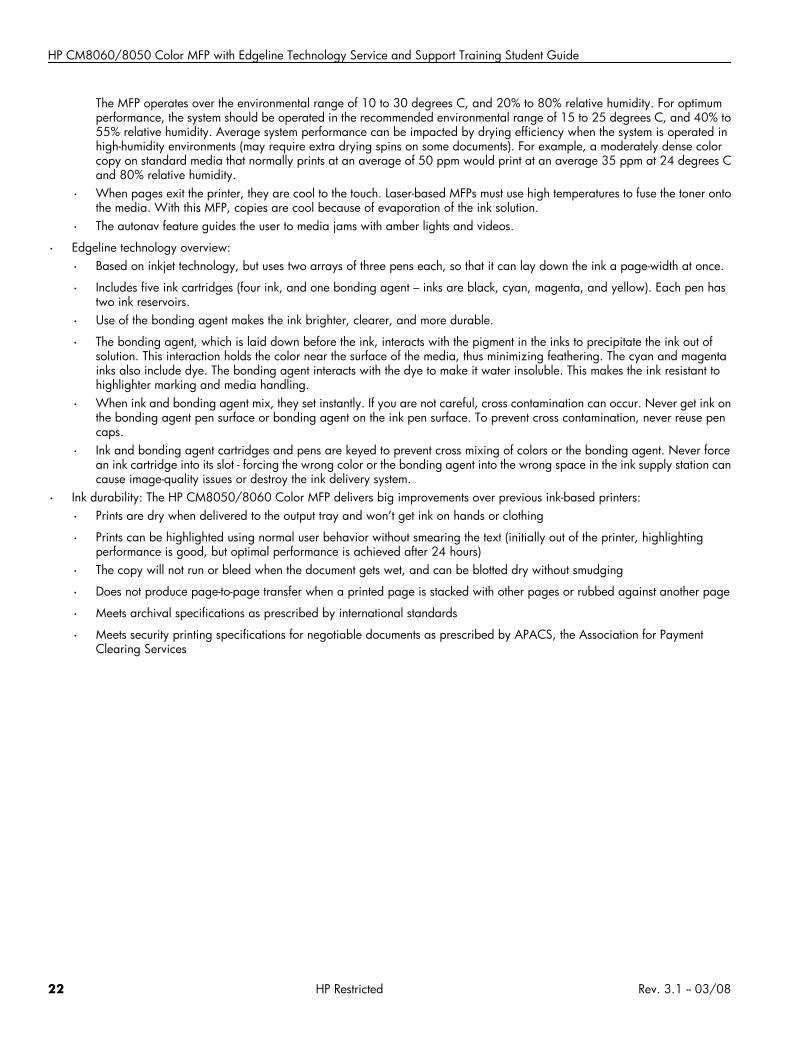
The MFP operates over the environmental range of 10 to 30 degrees C, and 20% to 80% relative humidity. For optimumperformance, the system should be operated in the recommended environmental range of 15 to 25 degrees C, and 40% to55% relative humidity. Average system performance can be impacted by drying efficiency when the system is operated inhigh-humidity environments (may require extra drying spins on some documents). For example, a moderately dense colorcopy on standard media that normally prints at an average of 50 ppm would print at an average 35 ppm at 24 degrees Cand 80% relative humidity.
• When pages exit the printer, they are cool to the touch. Laser-based MFPs must use high temperatures to fuse the toner ontothe media. With this MFP, copies are cool because of evaporation of the ink solution.
• The autonav feature guides the user to media jams with amber lights and videos.
• Edgeline technology overview:
• Based on inkjet technology, but uses two arrays of three pens each, so that it can lay down the ink a page-width at once.
• Includes five ink cartridges (four ink, and one bonding agent – inks are black, cyan, magenta, and yellow). Each pen hastwo ink reservoirs.
• Use of the bonding agent makes the ink brighter, clearer, and more durable.
• The bonding agent, which is laid down before the ink, interacts with the pigment in the inks to precipitate the ink out ofsolution. This interaction holds the color near the surface of the media, thus minimizing feathering. The cyan and magentainks also include dye. The bonding agent interacts with the dye to make it water insoluble. This makes the ink resistant tohighlighter marking and media handling.
• When ink and bonding agent mix, they set instantly. If you are not careful, cross contamination can occur. Never get ink onthe bonding agent pen surface or bonding agent on the ink pen surface. To prevent cross contamination, never reuse pencaps.
• Ink and bonding agent cartridges and pens are keyed to prevent cross mixing of colors or the bonding agent. Never forcean ink cartridge into its slot - forcing the wrong color or the bonding agent into the wrong space in the ink supply station cancause image-quality issues or destroy the ink delivery system.
• Ink durability: The HP CM8050/8060 Color MFP delivers big improvements over previous ink-based printers:
• Prints are dry when delivered to the output tray and won’t get ink on hands or clothing
• Prints can be highlighted using normal user behavior without smearing the text (initially out of the printer, highlightingperformance is good, but optimal performance is achieved after 24 hours)
• The copy will not run or bleed when the document gets wet, and can be blotted dry without smudging
• Does not produce page-to-page transfer when a printed page is stacked with other pages or rubbed against another page
• Meets archival specifications as prescribed by international standards
• Meets security printing specifications for negotiable documents as prescribed by APACS, the Association for PaymentClearing Services
22 HP Restricted Rev. 3.1 -- 03/08
Use the MFP
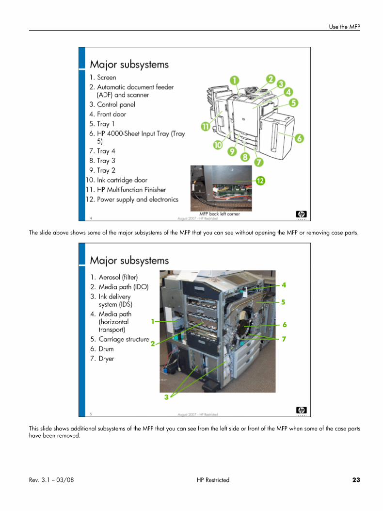
The slide above shows some of the major subsystems of the MFP that you can see without opening the MFP or removing case parts.
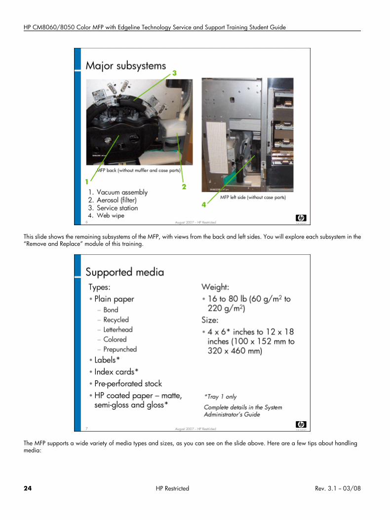
This slide shows additional subsystems of the MFP that you can see from the left side or front of the MFP when some of the case partshave been removed.
Rev. 3.1 -- 03/08 HP Restricted 23
HP CM8060/8050 Color MFP with Edgeline Technology Service and Support Training Student Guide
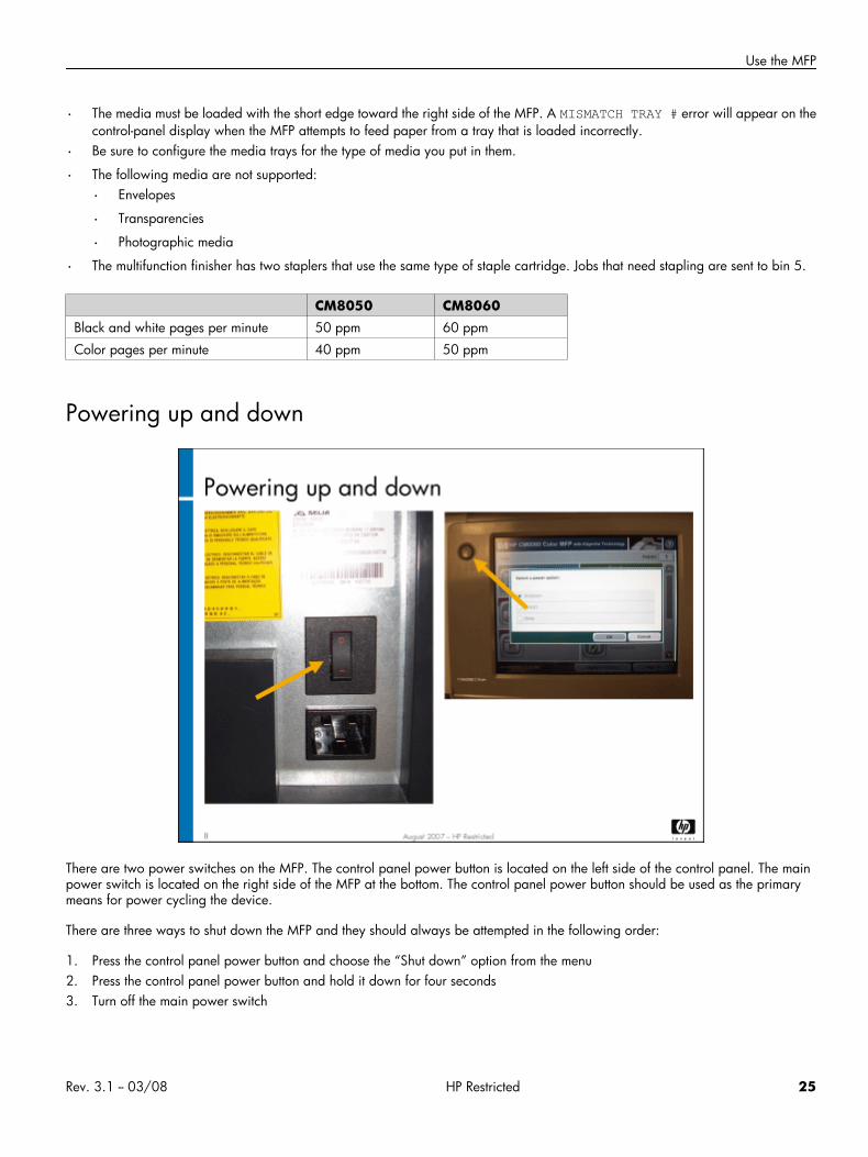
This slide shows the remaining subsystems of the MFP, with views from the back and left sides. You will explore each subsystem in the“Remove and Replace” module of this training.
The MFP supports a wide variety of media types and sizes, as you can see on the slide above. Here are a few tips about handlingmedia:
24 HP Restricted Rev. 3.1 -- 03/08
Use the MFP
• The media must be loaded with the short edge toward the right side of the MFP. A MISMATCH TRAY # error will appear on thecontrol-panel display when the MFP attempts to feed paper from a tray that is loaded incorrectly.
• Be sure to configure the media trays for the type of media you put in them.
• The following media are not supported:
• Envelopes
• Transparencies
• Photographic media
• The multifunction finisher has two staplers that use the same type of staple cartridge. Jobs that need stapling are sent to bin 5.
CM8050 CM8060Black and white pages per minute 50 ppm 60 ppm
Color pages per minute 40 ppm 50 ppm
Powering up and down
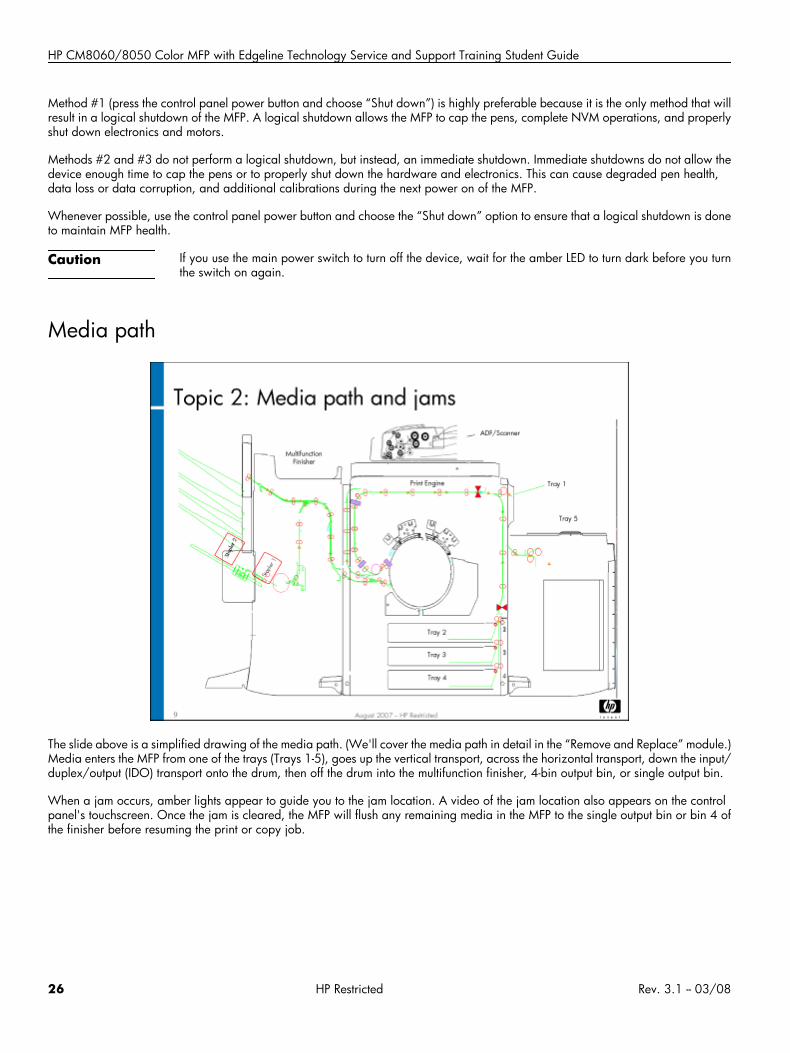
There are two power switches on the MFP. The control panel power button is located on the left side of the control panel. The mainpower switch is located on the right side of the MFP at the bottom. The control panel power button should be used as the primarymeans for power cycling the device.
There are three ways to shut down the MFP and they should always be attempted in the following order:
1. Press the control panel power button and choose the “Shut down” option from the menu2. Press the control panel power button and hold it down for four seconds3. Turn off the main power switch
Rev. 3.1 -- 03/08 HP Restricted 25
HP CM8060/8050 Color MFP with Edgeline Technology Service and Support Training Student Guide
Method #1 (press the control panel power button and choose “Shut down”) is highly preferable because it is the only method that willresult in a logical shutdown of the MFP. A logical shutdown allows the MFP to cap the pens, complete NVM operations, and properlyshut down electronics and motors.
Methods #2 and #3 do not perform a logical shutdown, but instead, an immediate shutdown. Immediate shutdowns do not allow thedevice enough time to cap the pens or to properly shut down the hardware and electronics. This can cause degraded pen health,data loss or data corruption, and additional calibrations during the next power on of the MFP.
Whenever possible, use the control panel power button and choose the “Shut down” option to ensure that a logical shutdown is doneto maintain MFP health.
Caution If you use the main power switch to turn off the device, wait for the amber LED to turn dark before you turnthe switch on again.
Media path
The slide above is a simplified drawing of the media path. (We'll cover the media path in detail in the “Remove and Replace” module.)Media enters the MFP from one of the trays (Trays 1-5), goes up the vertical transport, across the horizontal transport, down the input/duplex/output (IDO) transport onto the drum, then off the drum into the multifunction finisher, 4-bin output bin, or single output bin.
When a jam occurs, amber lights appear to guide you to the jam location. A video of the jam location also appears on the controlpanel's touchscreen. Once the jam is cleared, the MFP will flush any remaining media in the MFP to the single output bin or bin 4 ofthe finisher before resuming the print or copy job.
26 HP Restricted Rev. 3.1 -- 03/08
Use the MFP
Replacing consumables
The users are responsible for replacing the following consumables:
• Media
• Ink cartridges
• Staple cartridges
You will practice these activities in the lab. Complete instructions are in the system administrator guide.
Lab 1.1: Operate the MFPYou will now learn how to operate the MFP, identifying its major subsystems and trying its various features.
Reference material
Document ChapterQuick reference guide Device basics
Use the device
Maintain the device
System administrator guide Introduction
Paper and trays
Rev. 3.1 -- 03/08 HP Restricted 27
HP CM8060/8050 Color MFP with Edgeline Technology Service and Support Training Student Guide
Document ChapterCopy
Digital send
Store jobs
Maintain the device
Field service manual Product information
Lab time: 75 minutes
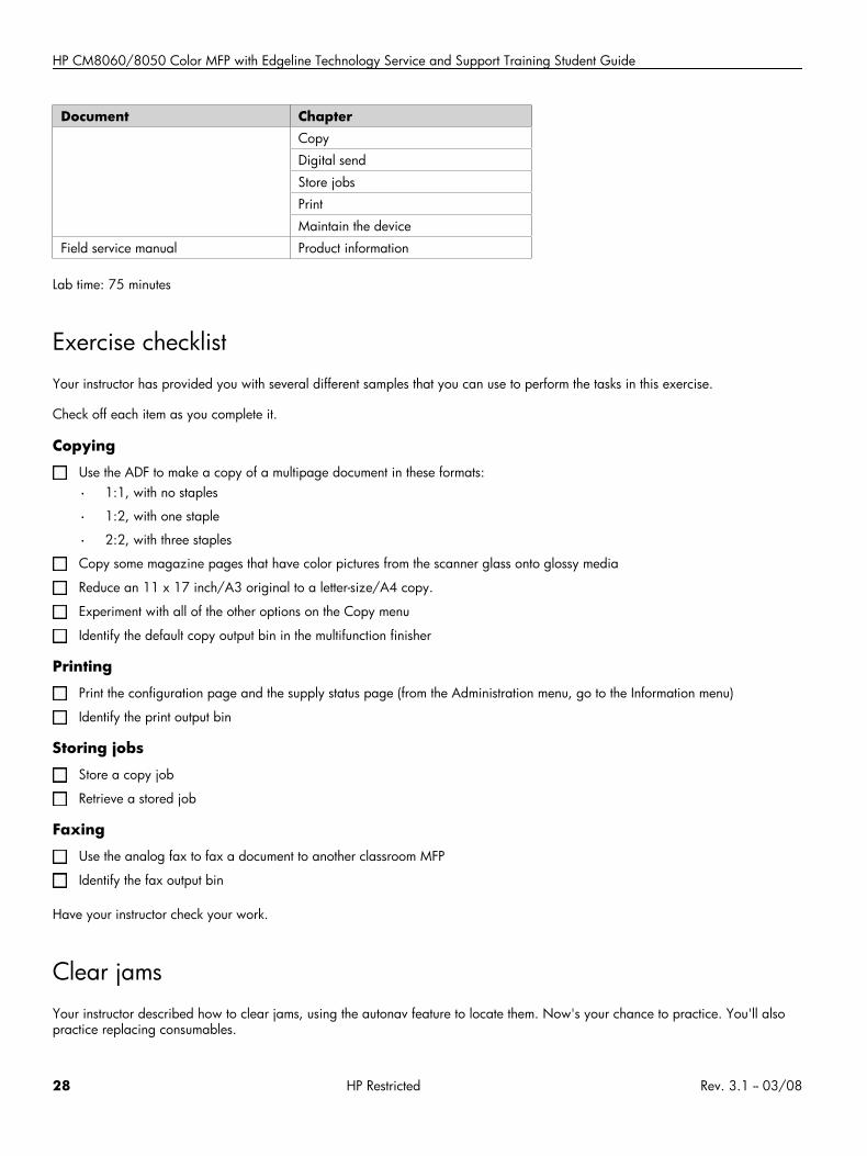
Exercise checklistYour instructor has provided you with several different samples that you can use to perform the tasks in this exercise.
Check off each item as you complete it.
Copying
Use the ADF to make a copy of a multipage document in these formats:
• 1:1, with no staples
• 1:2, with one staple
• 2:2, with three staples
Copy some magazine pages that have color pictures from the scanner glass onto glossy media
Reduce an 11 x 17 inch/A3 original to a letter-size/A4 copy.
Experiment with all of the other options on the Copy menu
Identify the default copy output bin in the multifunction finisher
Printing
Print the configuration page and the supply status page (from the Administration menu, go to the Information menu)
Identify the print output bin
Storing jobs
Store a copy job
Retrieve a stored job
Faxing
Use the analog fax to fax a document to another classroom MFP
Identify the fax output bin
Have your instructor check your work.
Clear jamsYour instructor described how to clear jams, using the autonav feature to locate them. Now's your chance to practice. You'll alsopractice replacing consumables.
28 HP Restricted Rev. 3.1 -- 03/08
Use the MFP
Exercise
1. Place the jam creation tool in the IDO path per your instructor.2. Use the control panel to make a copy.3. Wait to see the control panel jam message.4. Use the autonav amber lights and the video to locate and clear the jam. (Follow the amber lights to the jam.)5. Observe how the MFP handles the media left in the paper path after clearing the jam.
Replace consumables
Check the status of supplies (Supplies Status button)
Load regular media into tray 2
Load a few sheets of A3 or 11 x 17” media in Tray 3
Load regular media into Tray 5
Remove and reinsert an ink cartridge
Remove and reinsert a staple cartridge
Have your instructor check your work.
Rev. 3.1 -- 03/08 HP Restricted 29

HP CM8060/8050 Color MFP with Edgeline Technology Service and Support Training Student Guide
30 HP Restricted Rev. 3.1 -- 03/08

Service and Maintenance (PM)
Service and Maintenance (PM)• Overview
• Topic 1: CDFT
• Topic 2: Startup menu
• Topic 3: Preventive maintenance strategy and procedures
• Topic 4: End-of-call requirements
• Topic 5: Retrofit tags
• Topic 6: Use EWS for remote support
Rev. 3.1 -- 03/08 HP Restricted 31
HP CM8060/8050 Color MFP with Edgeline Technology Service and Support Training Student Guide
Overview
This module guides you through service and preventive maintenance (PM) procedures for the MFP and its accessories. It introducesthe copier diagnostics field tool (CDFT) and how to use it to log PM work and troubleshoot problems.
Topic 1: CDFTIn this topic, you will learn about the Copier Diagnostics Field Tool (CDFT) and general troubleshooting procedures.
Topic objectivesAfter completing this topic, you should be able to:
• Describe the differences between CDFT-E and CDFT-L
• Describe the uses of CDFT
• Use CDFT to determine when to do PM work
• Use CDFT to troubleshoot problems
32 HP Restricted Rev. 3.1 -- 03/08
Service and Maintenance (PM)
Topic contentCompleting this topic should take approximately 75 minutes.
Title DurationLecture and demonstration: CDFT 45 minutes
Lab 1.1: Use CDFT 30 minutes
Reference material
Document ChapterField service manual Copier Diagnostics Field Tool (CDFT)
Managing and maintenance
Removal and replacement
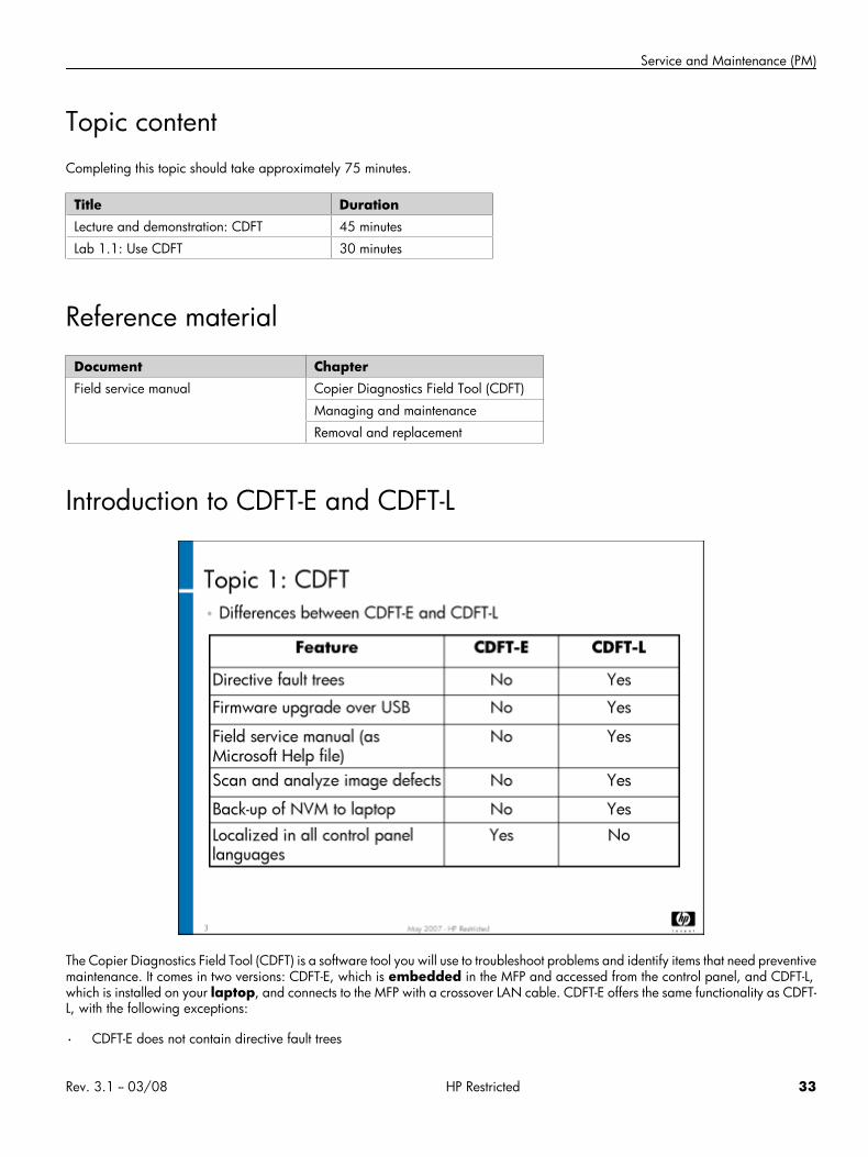
Introduction to CDFT-E and CDFT-L
The Copier Diagnostics Field Tool (CDFT) is a software tool you will use to troubleshoot problems and identify items that need preventivemaintenance. It comes in two versions: CDFT-E, which is embedded in the MFP and accessed from the control panel, and CDFT-L,which is installed on your laptop, and connects to the MFP with a crossover LAN cable. CDFT-E offers the same functionality as CDFT-L, with the following exceptions:
• CDFT-E does not contain directive fault trees
Rev. 3.1 -- 03/08 HP Restricted 33
HP CM8060/8050 Color MFP with Edgeline Technology Service and Support Training Student Guide
• CDFT-E does not support firmware upgrade over USB
• CDFT-E does not contain the electronic version of the field service manual
• CDFT-E does not allow you to scan and analyze print defects
• CDFT-L allows you to back up non-volatile memory (NVM) to your laptop or CD-ROM
• CDFT-E is localized in all control panel languages
Note Directive fault trees tell you exactly what to do with step-by-step instructions. Deductive fault trees suggestpossible root causes and possible actions for you to try to resolve the problem.
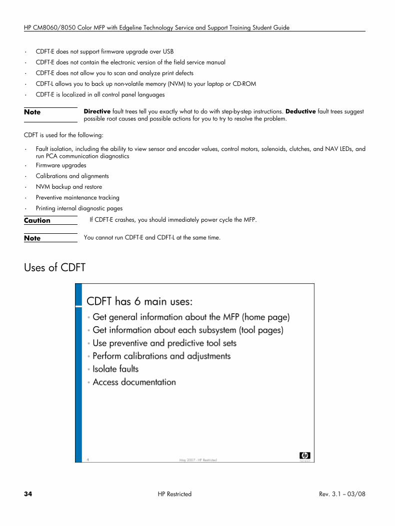
CDFT is used for the following:
• Fault isolation, including the ability to view sensor and encoder values, control motors, solenoids, clutches, and NAV LEDs, andrun PCA communication diagnostics
• Firmware upgrades
• Calibrations and alignments
• NVM backup and restore
• Preventive maintenance tracking
• Printing internal diagnostic pages
Caution If CDFT-E crashes, you should immediately power cycle the MFP.
Note You cannot run CDFT-E and CDFT-L at the same time.
Uses of CDFT
34 HP Restricted Rev. 3.1 -- 03/08
Service and Maintenance (PM)
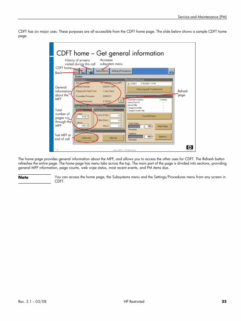
CDFT has six major uses. These purposes are all accessible from the CDFT home page. The slide below shows a sample CDFT homepage.
The home page provides general information about the MFP, and allows you to access the other uses for CDFT. The Refresh buttonrefreshes the entire page. The home page has menu tabs across the top. The main part of the page is divided into sections, providinggeneral MFP information, page counts, web wipe status, most recent events, and PM items due.
Note You can access the home page, the Subsystems menu and the Settings/Procedures menu from any screen inCDFT.
Rev. 3.1 -- 03/08 HP Restricted 35
HP CM8060/8050 Color MFP with Edgeline Technology Service and Support Training Student Guide
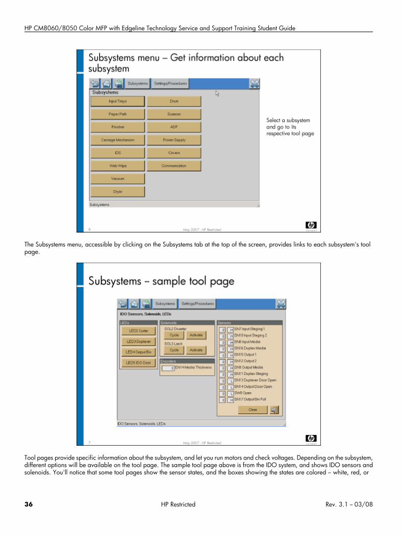
The Subsystems menu, accessible by clicking on the Subsystems tab at the top of the screen, provides links to each subsystem's toolpage.
Tool pages provide specific information about the subsystem, and let you run motors and check voltages. Depending on the subsystem,different options will be available on the tool page. The sample tool page above is from the IDO system, and shows IDO sensors andsolenoids. You'll notice that some tool pages show the sensor states, and the boxes showing the states are colored – white, red, or
36 HP Restricted Rev. 3.1 -- 03/08
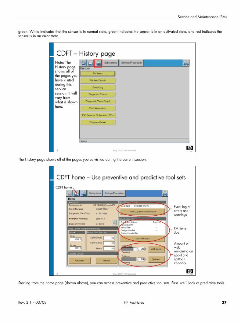
Service and Maintenance (PM)
green. White indicates that the sensor is in normal state, green indicates the sensor is in an activated state, and red indicates thesensor is in an error state.
The History page shows all of the pages you've visited during the current session.
Starting from the home page (shown above), you can access preventive and predictive tool sets. First, we'll look at predictive tools.
Rev. 3.1 -- 03/08 HP Restricted 37
HP CM8060/8050 Color MFP with Edgeline Technology Service and Support Training Student Guide
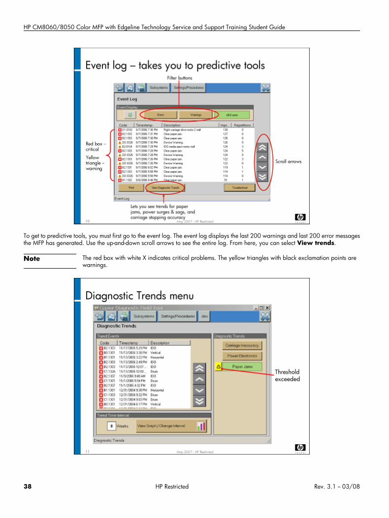
To get to predictive tools, you must first go to the event log. The event log displays the last 200 warnings and last 200 error messagesthe MFP has generated. Use the up-and-down scroll arrows to see the entire log. From here, you can select View trends.
Note The red box with white X indicates critical problems. The yellow triangles with black exclamation points arewarnings.
38 HP Restricted Rev. 3.1 -- 03/08
Service and Maintenance (PM)
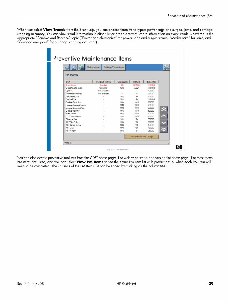
When you select View Trends from the Event Log, you can choose three trend types: power sags and surges, jams, and carriagestopping accuracy. You can view trend information in either list or graphic format. More information on event trends is covered in theappropriate “Remove and Replace” topic (“Power and electronics” for power sags and surges trends, “Media path” for jams, and“Carriage and pens” for carriage stopping accuracy).
You can also access preventive tool sets from the CDFT home page. The web wipe status appears on the home page. The most recentPM items are listed, and you can select View PM Items to see the entire PM item list with predictions of when each PM item willneed to be completed. The columns of the PM Items list can be sorted by clicking on the column title.
Rev. 3.1 -- 03/08 HP Restricted 39
HP CM8060/8050 Color MFP with Edgeline Technology Service and Support Training Student Guide
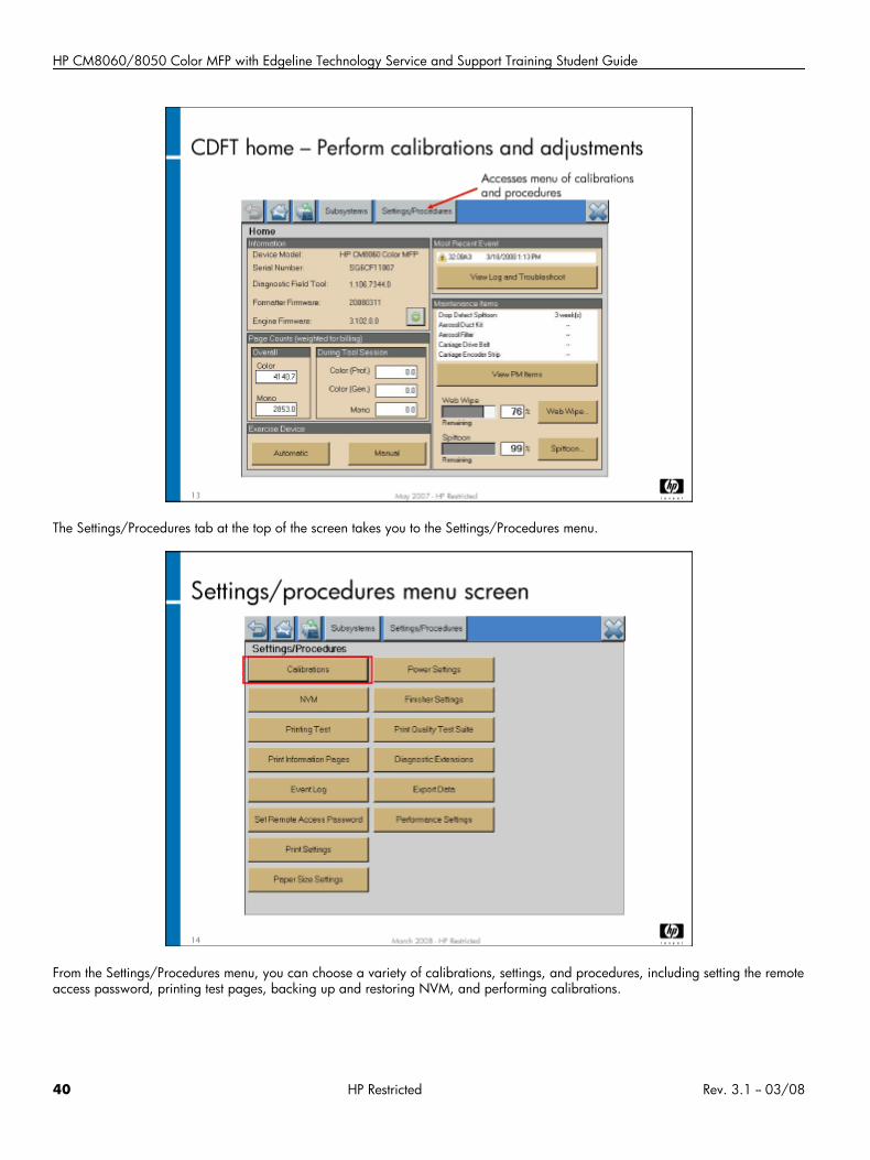
The Settings/Procedures tab at the top of the screen takes you to the Settings/Procedures menu.
From the Settings/Procedures menu, you can choose a variety of calibrations, settings, and procedures, including setting the remoteaccess password, printing test pages, backing up and restoring NVM, and performing calibrations.
40 HP Restricted Rev. 3.1 -- 03/08
Service and Maintenance (PM)
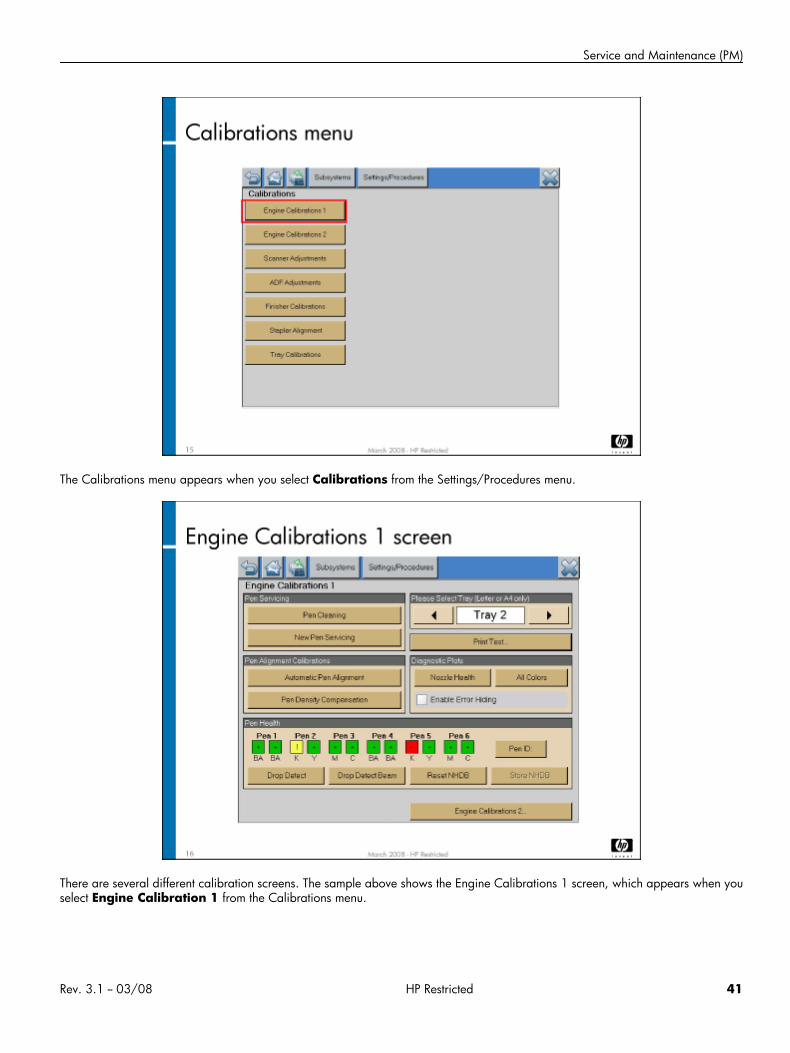
The Calibrations menu appears when you select Calibrations from the Settings/Procedures menu.
There are several different calibration screens. The sample above shows the Engine Calibrations 1 screen, which appears when youselect Engine Calibration 1 from the Calibrations menu.
Rev. 3.1 -- 03/08 HP Restricted 41
HP CM8060/8050 Color MFP with Edgeline Technology Service and Support Training Student Guide
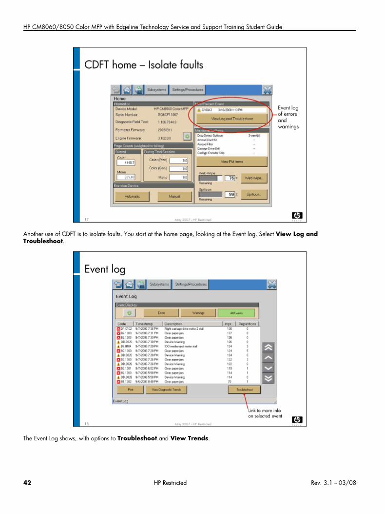
Another use of CDFT is to isolate faults. You start at the home page, looking at the Event log. Select View Log andTroubleshoot.
The Event Log shows, with options to Troubleshoot and View Trends.
42 HP Restricted Rev. 3.1 -- 03/08
Service and Maintenance (PM)
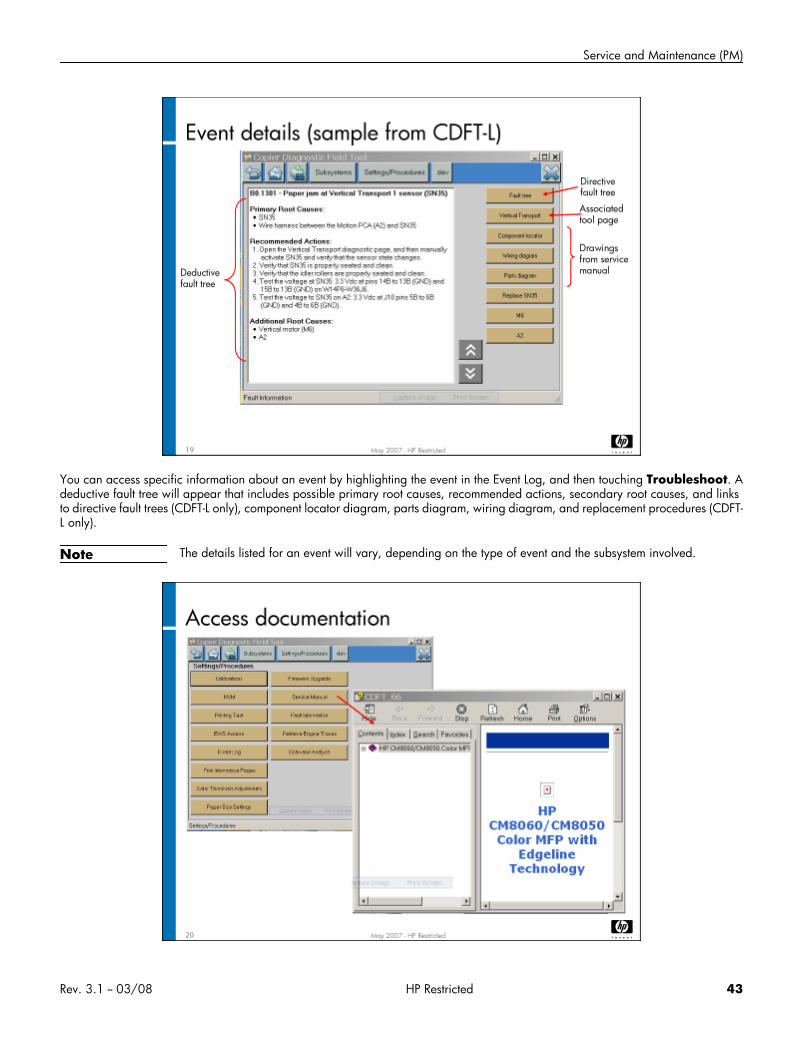
You can access specific information about an event by highlighting the event in the Event Log, and then touching Troubleshoot. Adeductive fault tree will appear that includes possible primary root causes, recommended actions, secondary root causes, and linksto directive fault trees (CDFT-L only), component locator diagram, parts diagram, wiring diagram, and replacement procedures (CDFT-L only).
Note The details listed for an event will vary, depending on the type of event and the subsystem involved.
Rev. 3.1 -- 03/08 HP Restricted 43
HP CM8060/8050 Color MFP with Edgeline Technology Service and Support Training Student Guide
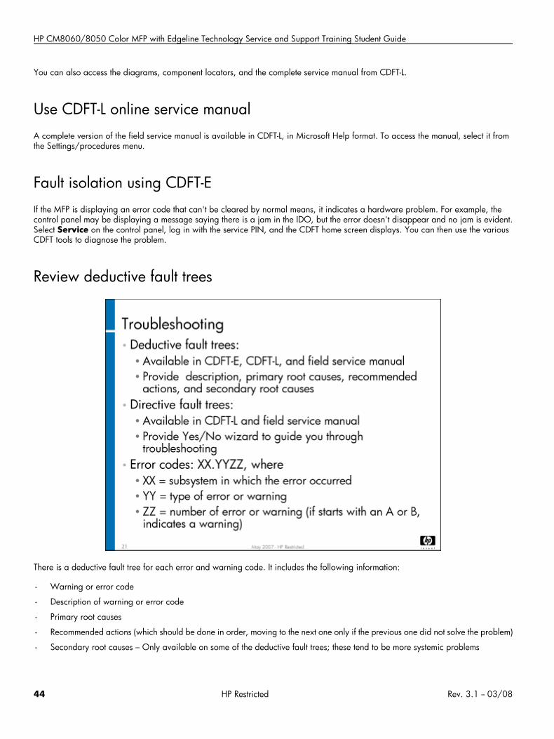
You can also access the diagrams, component locators, and the complete service manual from CDFT-L.
Use CDFT-L online service manualA complete version of the field service manual is available in CDFT-L, in Microsoft Help format. To access the manual, select it fromthe Settings/procedures menu.
Fault isolation using CDFT-EIf the MFP is displaying an error code that can't be cleared by normal means, it indicates a hardware problem. For example, thecontrol panel may be displaying a message saying there is a jam in the IDO, but the error doesn't disappear and no jam is evident.Select Service on the control panel, log in with the service PIN, and the CDFT home screen displays. You can then use the variousCDFT tools to diagnose the problem.
Review deductive fault trees
There is a deductive fault tree for each error and warning code. It includes the following information:
• Warning or error code
• Description of warning or error code
• Primary root causes
• Recommended actions (which should be done in order, moving to the next one only if the previous one did not solve the problem)
• Secondary root causes – Only available on some of the deductive fault trees; these tend to be more systemic problems
44 HP Restricted Rev. 3.1 -- 03/08
Service and Maintenance (PM)
Deductive fault trees are listed in the field service manual in the appendix of error and warning codes, and in CDFT-E or CDFT-L, whenyou select an event from the event log and choose Troubleshoot.
Review directive fault treesDirective fault trees are available for some of the error and warning codes, and provide a Yes/No wizard to guide you through solvinga problem. (A subset of the deductive fault trees are also directive.) They are available in CDFT-L and in the field service manual. InCDFT-L, you can access the directive fault tree, if there is one available, on the event detail page. A Fault Tree button will appearin the top-right corner of the page. In the field service manual, the directive fault trees are in the “Fault Trees” chapter.
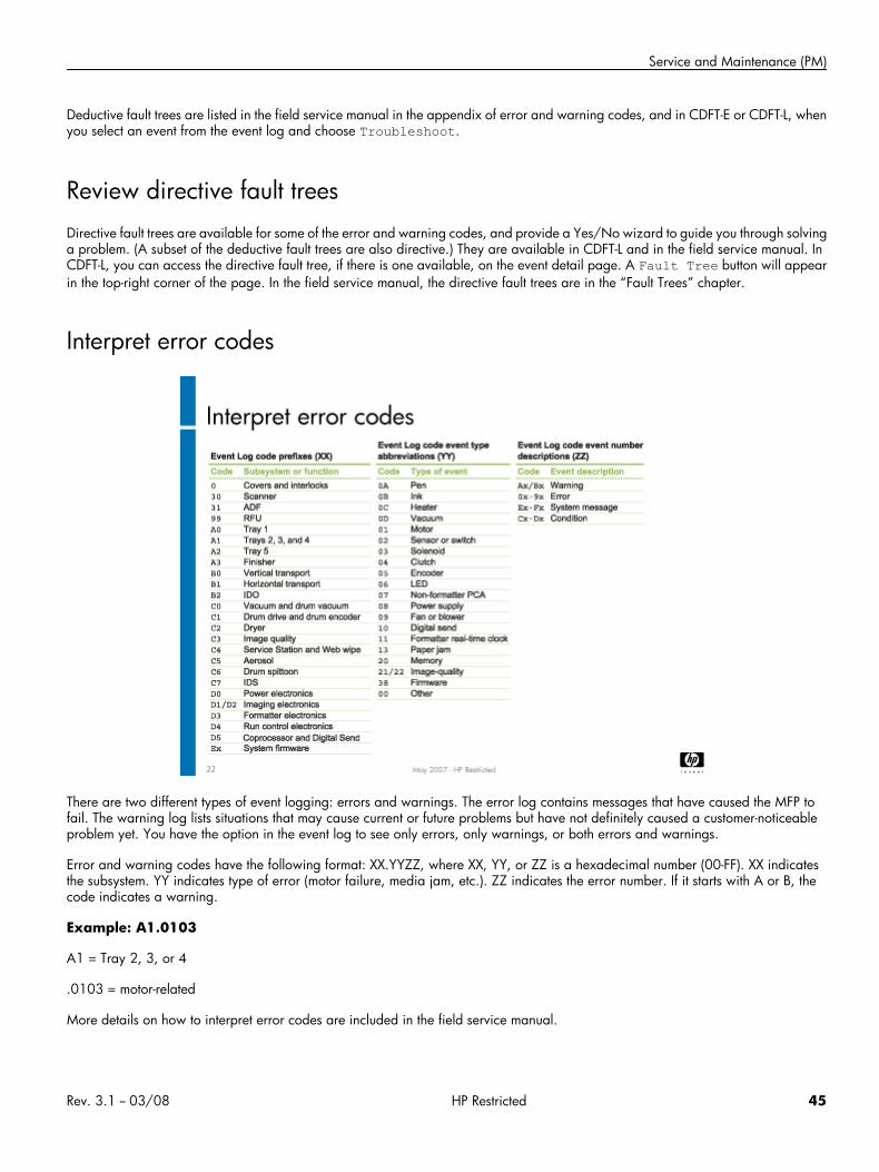
Interpret error codes
There are two different types of event logging: errors and warnings. The error log contains messages that have caused the MFP tofail. The warning log lists situations that may cause current or future problems but have not definitely caused a customer-noticeableproblem yet. You have the option in the event log to see only errors, only warnings, or both errors and warnings.
Error and warning codes have the following format: XX.YYZZ, where XX, YY, or ZZ is a hexadecimal number (00-FF). XX indicatesthe subsystem. YY indicates type of error (motor failure, media jam, etc.). ZZ indicates the error number. If it starts with A or B, thecode indicates a warning.
Example: A1.0103
A1 = Tray 2, 3, or 4
.0103 = motor-related
More details on how to interpret error codes are included in the field service manual.
Rev. 3.1 -- 03/08 HP Restricted 45
HP CM8060/8050 Color MFP with Edgeline Technology Service and Support Training Student Guide
Note Control panel messages that may appear on the control panel do not have error codes. They are listed in the“Troubleshooting” section of the field service manual, grouped by subsystem and problem.
Use CDFT-E in service assist modeService assist mode, a limited version of CDFT-E, is available for use by the system administrator, under your direction. This will allowyou to do remote troubleshooting over the phone. Typical features that are disabled include subsystem tests such as running motors,backup of the non-volatile memory, and firmware upgrades.
To access CDFT-E in service assist mode, your user will need the service assist PIN #, which is set at the factory and is the same forall MFPs. Refer to the instructions in the field service manual on how to access and use service assist mode.
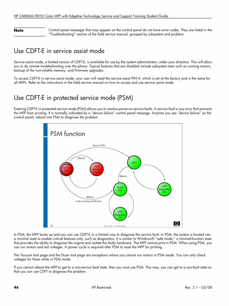
Use CDFT-E in protected service mode (PSM)Entering CDFT-E in protected service mode (PSM) allows you to resolve power-on service faults. A service fault is any error that preventsthe MFP from printing. It is normally indicated by a “device failure” control panel message. Anytime you see “device failure” on thecontrol panel, reboot into PSM to diagnose the problem.
In PSM, the MFP boots up and you can use CDFT-E in a limited way to diagnose the service fault. In PSM, the system is booted intoa minimal state to enable critical features only, such as diagnostics. It is similar to Windows® “safe mode,” a minimal-function statethat provides the ability to diagnose the engine and isolate the faulty hardware. The MFP cannot print in PSM. When using PSM, youcan run motors and test voltages. A power cycle is required after PSM to reset the MFP for printing.
The Vacuum tool page and the Dryer tool page are exceptions where you cannot run motors in PSM mode. You can only checkvoltages for these while in PSM mode.
If you cannot reboot the MFP to get to a non-service fault state, then you must use PSM. This way, you can get to a non-fault state sothat you can use CDFT to diagnose the problem.
46 HP Restricted Rev. 3.1 -- 03/08
Service and Maintenance (PM)
PSM is accessed by using the startup menu, which is discussed in the next topic.
The major differences in CDFT when in full service mode compared to protected service mode is shown in the chart below:
Component Cannot use in full service mode Cannot use in PSMVoltage tests Aerosol motor
Dryer fan
Vacuum motors
Run motors Electronics bay cooling fan
Pen cooling fans
Aerosol motor
Dryer heater
Dryer fan
Vacuum motors
Printing from CDFT
Update CDFT-LIf new updates become available for CDFT-L, you will need to download them to your laptop. You can download them from Tech Web(HP employees) or CSN (partners).
Lab 1.1: Use CDFT-E and CDFT-LIn this lab, you will take a look at both CDFT-E and CDFT-L. Be sure you understand the differences between the two, so that you willknow which one to use when troubleshooting or working on the MFP.
Reference material
Document ChapterField service manual CDFT
Troubleshooting
Hardware fault trees
Appendix A: Event Log codes
Lab time: 30 minutes
ExerciseAt the control panel, enter CDFT-E.
Use CDFT-E to look at the following items:
Rev. 3.1 -- 03/08 HP Restricted 47
HP CM8060/8050 Color MFP with Edgeline Technology Service and Support Training Student Guide
• Log into CDFT and look at the CDFT home page
• Go to the Subsystems menu
• Select several of the subsystems and look at their tools page
• Go to the Settings/procedures menu
• Look at some of the items available on the Settings/Procedures menu
• Return to the CDFT home page and then go to the Event Log page
• Select one of the events and look at the Event details (troubleshooting) page
Return to the control panel home page. Enter CDFT-E in service assist mode.
Look through some of the subsystem tool pages in CDFT-E, noticing differences between CDFT-E in regular mode and service assistmode. For example, you should not be able to run motors in service assist mode.Exit CDFT-E and return to the control panel home page.
Connect your laptop with a LAN cable to an MFP and run CDFT-L. Look at the following items:
• Directive fault tree (from one of the Event Details pages)
• Service manual (available from the Settings/Procedures menu)
Have your instructor check your work.
Note You will have a chance to use protected service mode later in the training.
Topic 2: Startup menuIn this topic, you will learn about the startup menu.
Topic objectivesAfter completing this topic, you should be able to:
• Calibrate the touchscreen
• Describe other capabilities in the startup menu
• Enter the protected service mode from the startup menu
Topic contentCompleting this topic should take approximately 30 minutes.
Title DurationLecture: Startup menu 15 minutes
Lab 2.1: Use the startup menu 15 minutes
48 HP Restricted Rev. 3.1 -- 03/08
Service and Maintenance (PM)
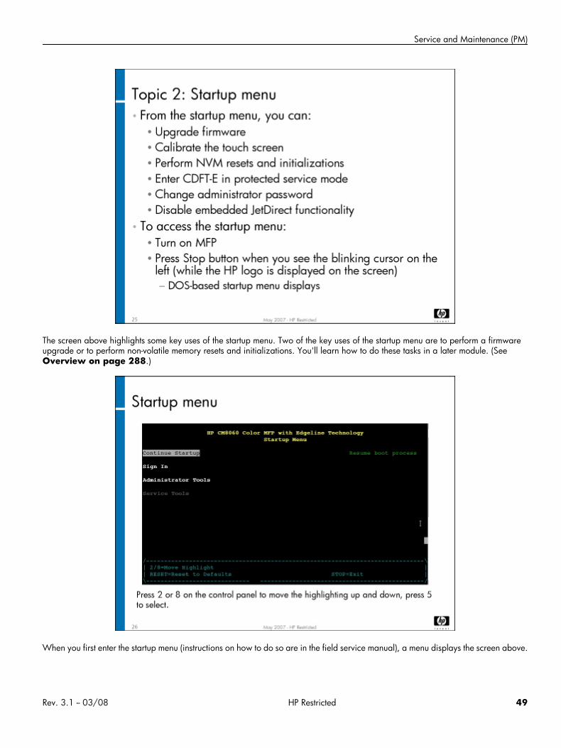
The screen above highlights some key uses of the startup menu. Two of the key uses of the startup menu are to perform a firmwareupgrade or to perform non-volatile memory resets and initializations. You'll learn how to do these tasks in a later module. (SeeOverview on page 288.)
When you first enter the startup menu (instructions on how to do so are in the field service manual), a menu displays the screen above.
Rev. 3.1 -- 03/08 HP Restricted 49
HP CM8060/8050 Color MFP with Edgeline Technology Service and Support Training Student Guide
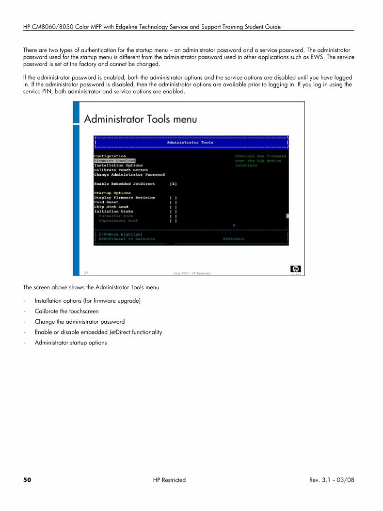
There are two types of authentication for the startup menu – an administrator password and a service password. The administratorpassword used for the startup menu is different from the administrator password used in other applications such as EWS. The servicepassword is set at the factory and cannot be changed.
If the administrator password is enabled, both the administrator options and the service options are disabled until you have loggedin. If the administrator password is disabled, then the administrator options are available prior to logging in. If you log in using theservice PIN, both administrator and service options are enabled.
The screen above shows the Administrator Tools menu.
• Installation options (for firmware upgrade)
• Calibrate the touchscreen
• Change the administrator password
• Enable or disable embedded JetDirect functionality
• Administrator startup options
50 HP Restricted Rev. 3.1 -- 03/08
Service and Maintenance (PM)
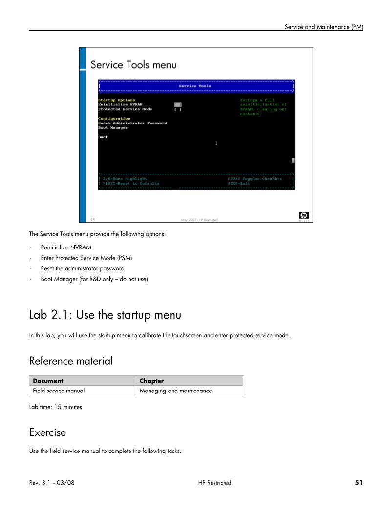
The Service Tools menu provide the following options:
• Reinitialize NVRAM
• Enter Protected Service Mode (PSM)
• Reset the administrator password
• Boot Manager (for R&D only – do not use)
Lab 2.1: Use the startup menuIn this lab, you will use the startup menu to calibrate the touchscreen and enter protected service mode.
Reference material
Document ChapterField service manual Managing and maintenance
Lab time: 15 minutes
ExerciseUse the field service manual to complete the following tasks.
Rev. 3.1 -- 03/08 HP Restricted 51
HP CM8060/8050 Color MFP with Edgeline Technology Service and Support Training Student Guide
Enter the startup menu
Calibrate the touchscreen (Administrator tools menu)
Enter protected service mode (Service Tools menu)
Look at the Event Log.
Have your instructor check your work
Topic 3: Preventive maintenance strategy and proceduresDifferent components within the MFP need to be serviced on a regular basis. Some need to be cleaned, and others need to be replaced.The MFP tracks usage of these components, and will predict when they will need to be maintained.
Topic objectivesAfter completing this topic, you should be able to:
• Describe the PM strategy
• Use CDFT to determine when to do PM work
• Determine appropriate cleaning materials
• Perform PM procedures
Topic contentCompleting this topic should take approximately 120 minutes.
Title DurationLecture: PM strategy, cleaningprocedures, PM procedures
45 minutes
Lab 3.1: Remove covers and case parts 30 minutes
Lab 3.2: Perform PM procedures 45 minutes
Reference material
Document ChapterField service manual Managing and maintenance
52 HP Restricted Rev. 3.1 -- 03/08
Service and Maintenance (PM)
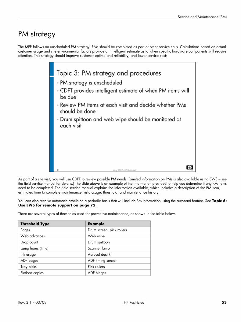
PM strategyThe MFP follows an unscheduled PM strategy. PMs should be completed as part of other service calls. Calculations based on actualcustomer usage and site environmental factors provide an intelligent estimate as to when specific hardware components will requireattention. This strategy should improve customer uptime and reliability, and lower service costs.
As part of a site visit, you will use CDFT to review possible PM needs. (Limited information on PMs is also available using EWS – seethe field service manual for details.) The slide above is an example of the information provided to help you determine if any PM itemsneed to be completed. The field service manual explains the information available, which includes a description of the PM item,estimated time to complete maintenance, risk, usage, threshold, and maintenance history.
You can also receive automatic emails on a periodic basis that will include PM information using the autosend feature. See Topic 6:Use EWS for remote support on page 72.
There are several types of thresholds used for preventive maintenance, as shown in the table below.
Threshold Type ExamplePages Drum screen, pick rollers
Web advances Web wipe
Drop count Drum spittoon
Lamp hours (time) Scanner lamp
Ink usage Aerosol duct kit
ADF pages ADF timing sensor
Tray picks Pick rollers
Flatbed copies ADF hinges
Rev. 3.1 -- 03/08 HP Restricted 53
HP CM8060/8050 Color MFP with Edgeline Technology Service and Support Training Student Guide
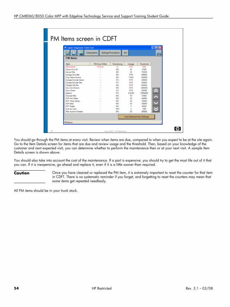
You should go through the PM items at every visit. Review when items are due, compared to when you expect to be at the site again.Go to the Item Details screen for items that are due and review usage and the threshold. Then, based on your knowledge of thecustomer and next expected visit, you can determine whether to perform the maintenance then or at your next visit. A sample ItemDetails screen is shown above.
You should also take into account the cost of the maintenance. If a part is expensive, you should try to get the most life out of it thatyou can. If it is inexpensive, go ahead and replace it, even if it is a little sooner than required.
Caution Once you have cleaned or replaced the PM item, it is extremely important to reset the counter for that itemin CDFT. There is no systematic reminder if you forget, and forgetting to reset the counters may mean thatsome items get repeated needlessly.
All PM items should be in your trunk stock.
54 HP Restricted Rev. 3.1 -- 03/08
Service and Maintenance (PM)
Changing usage thresholds
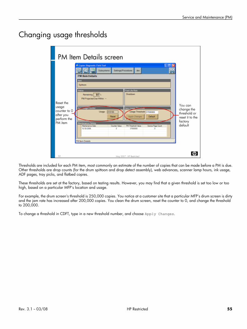
Thresholds are included for each PM item, most commonly an estimate of the number of copies that can be made before a PM is due.Other thresholds are drop counts (for the drum spittoon and drop detect assembly), web advances, scanner lamp hours, ink usage,ADF pages, tray picks, and flatbed copies.
These thresholds are set at the factory, based on testing results. However, you may find that a given threshold is set too low or toohigh, based on a particular MFP's location and usage.
For example, the drum screen's threshold is 250,000 copies. You notice at a customer site that a particular MFP's drum screen is dirtyand the jam rate has increased after 200,000 copies. You clean the drum screen, reset the counter to 0, and change the thresholdto 200,000.
To change a threshold in CDFT, type in a new threshold number, and choose Apply Changes.
Rev. 3.1 -- 03/08 HP Restricted 55
HP CM8060/8050 Color MFP with Edgeline Technology Service and Support Training Student Guide
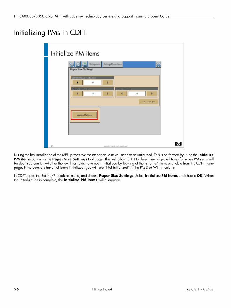
Initializing PMs in CDFT
During the first installation of the MFP, preventive maintenance items will need to be initialized. This is performed by using the InitializePM items button on the Paper Size Settings tool page. This will allow CDFT to determine projected times for when PM items willbe due. You can tell whether the PM thresholds have been initialized by looking at the list of PM items available from the CDFT homepage. If the counters have not been initialized, you will see “Not initialized” in the PM Due Within column
In CDFT, go to the Setting/Procedures menu, and choose Paper Size Settings. Select Initialize PM items and choose OK. Whenthe initialization is complete, the Initialize PM items will disappear.
56 HP Restricted Rev. 3.1 -- 03/08
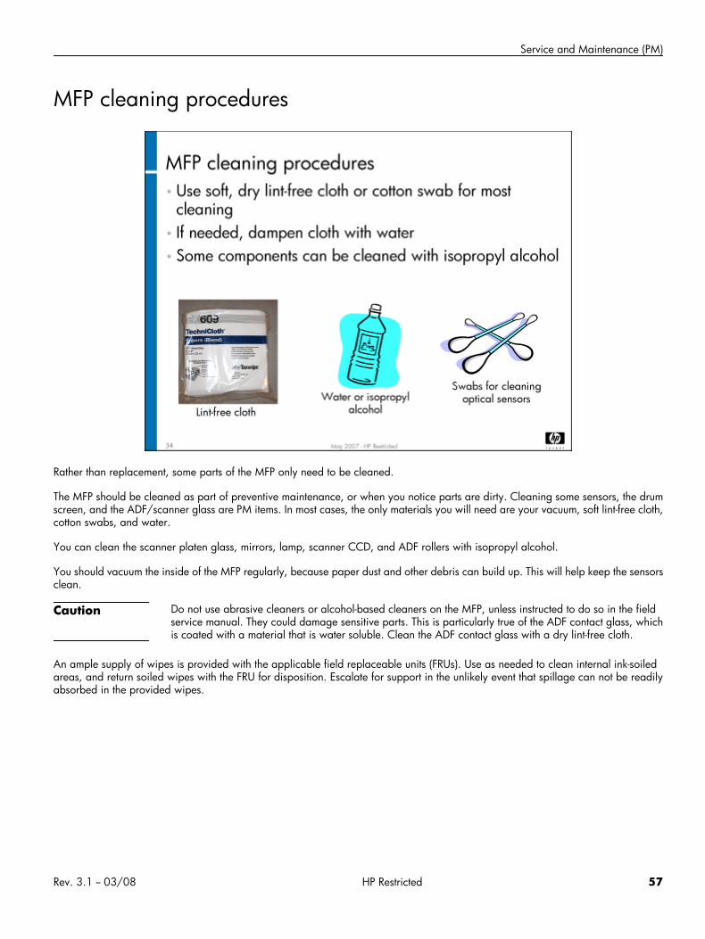
Service and Maintenance (PM)
MFP cleaning procedures
Rather than replacement, some parts of the MFP only need to be cleaned.
The MFP should be cleaned as part of preventive maintenance, or when you notice parts are dirty. Cleaning some sensors, the drumscreen, and the ADF/scanner glass are PM items. In most cases, the only materials you will need are your vacuum, soft lint-free cloth,cotton swabs, and water.
You can clean the scanner platen glass, mirrors, lamp, scanner CCD, and ADF rollers with isopropyl alcohol.
You should vacuum the inside of the MFP regularly, because paper dust and other debris can build up. This will help keep the sensorsclean.
Caution Do not use abrasive cleaners or alcohol-based cleaners on the MFP, unless instructed to do so in the fieldservice manual. They could damage sensitive parts. This is particularly true of the ADF contact glass, whichis coated with a material that is water soluble. Clean the ADF contact glass with a dry lint-free cloth.
An ample supply of wipes is provided with the applicable field replaceable units (FRUs). Use as needed to clean internal ink-soiledareas, and return soiled wipes with the FRU for disposition. Escalate for support in the unlikely event that spillage can not be readilyabsorbed in the provided wipes.
Rev. 3.1 -- 03/08 HP Restricted 57
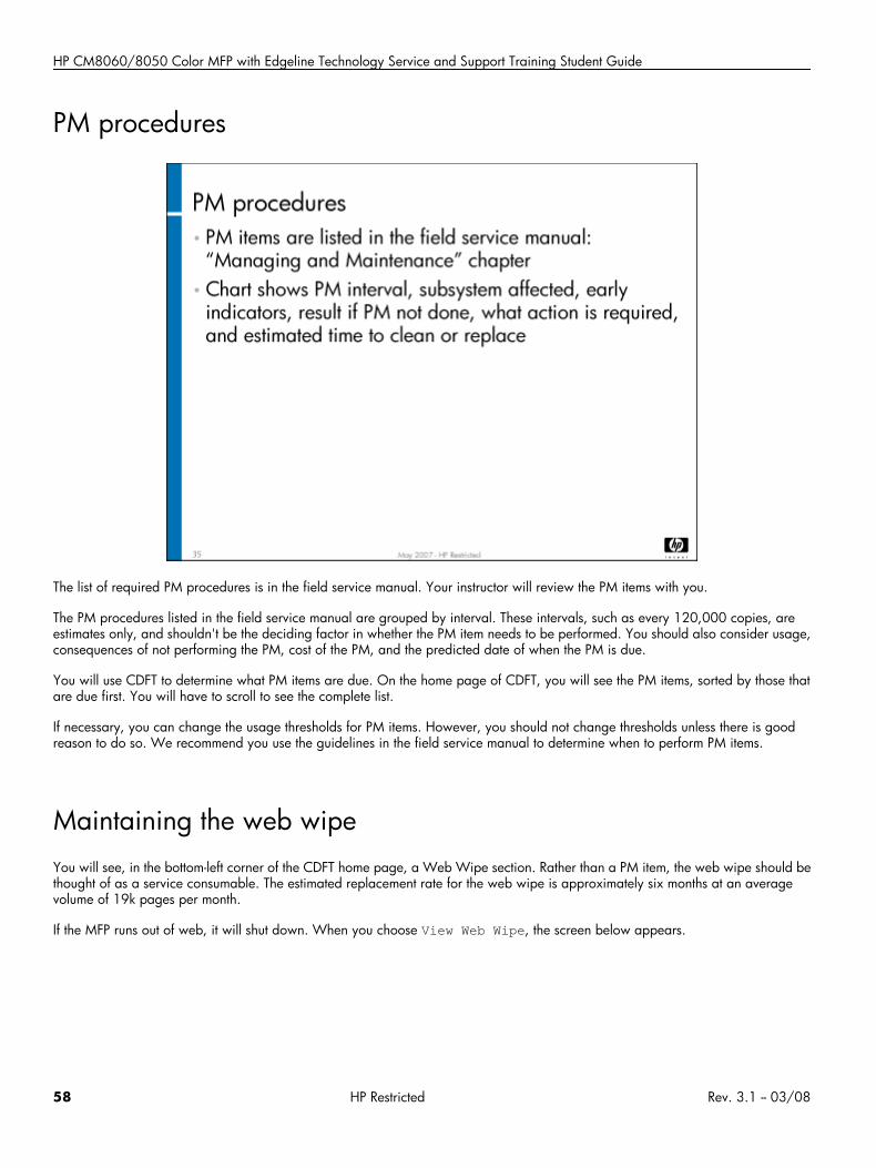
HP CM8060/8050 Color MFP with Edgeline Technology Service and Support Training Student Guide
PM procedures
The list of required PM procedures is in the field service manual. Your instructor will review the PM items with you.
The PM procedures listed in the field service manual are grouped by interval. These intervals, such as every 120,000 copies, areestimates only, and shouldn't be the deciding factor in whether the PM item needs to be performed. You should also consider usage,consequences of not performing the PM, cost of the PM, and the predicted date of when the PM is due.
You will use CDFT to determine what PM items are due. On the home page of CDFT, you will see the PM items, sorted by those thatare due first. You will have to scroll to see the complete list.
If necessary, you can change the usage thresholds for PM items. However, you should not change thresholds unless there is goodreason to do so. We recommend you use the guidelines in the field service manual to determine when to perform PM items.
Maintaining the web wipeYou will see, in the bottom-left corner of the CDFT home page, a Web Wipe section. Rather than a PM item, the web wipe should bethought of as a service consumable. The estimated replacement rate for the web wipe is approximately six months at an averagevolume of 19k pages per month.
If the MFP runs out of web, it will shut down. When you choose View Web Wipe, the screen below appears.
58 HP Restricted Rev. 3.1 -- 03/08
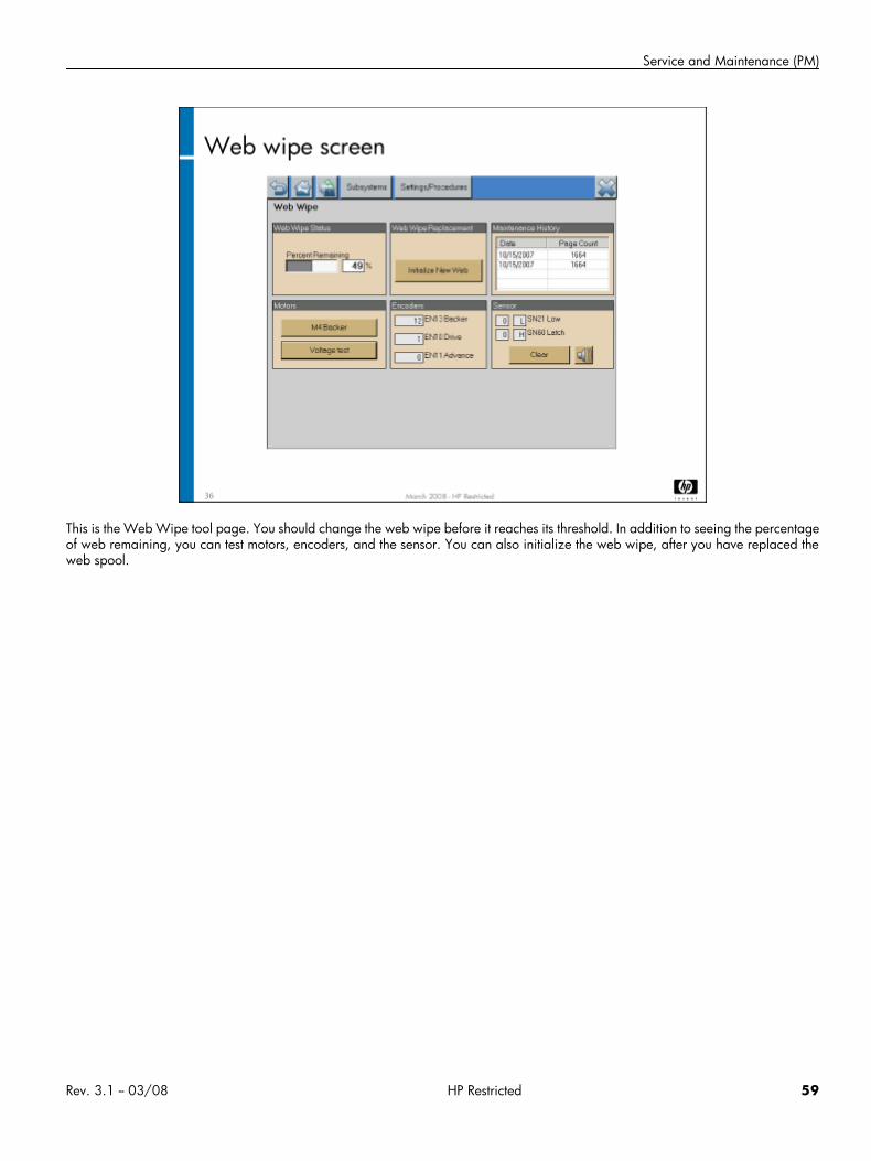
Service and Maintenance (PM)
This is the Web Wipe tool page. You should change the web wipe before it reaches its threshold. In addition to seeing the percentageof web remaining, you can test motors, encoders, and the sensor. You can also initialize the web wipe, after you have replaced theweb spool.
Rev. 3.1 -- 03/08 HP Restricted 59
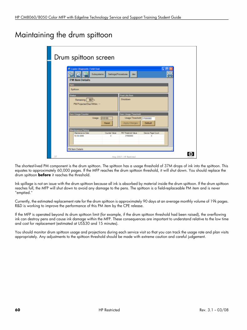
HP CM8060/8050 Color MFP with Edgeline Technology Service and Support Training Student Guide
Maintaining the drum spittoon
The shortest-lived PM component is the drum spittoon. The spittoon has a usage threshold of 37M drops of ink into the spittoon. Thisequates to approximately 60,000 pages. If the MFP reaches the drum spittoon threshold, it will shut down. You should replace thedrum spittoon before it reaches the threshold.
Ink spillage is not an issue with the drum spittoon because all ink is absorbed by material inside the drum spittoon. If the drum spittoonreaches full, the MFP will shut down to avoid any damage to the pens. The spittoon is a field-replaceable PM item and is never"emptied."
Currently, the estimated replacement rate for the drum spittoon is approximately 90 days at an average monthly volume of 19k pages.R&D is working to improve the performance of this PM item by the CPE release.
If the MFP is operated beyond its drum spittoon limit (for example, if the drum spittoon threshold had been raised), the overflowingink can destroy pens and cause ink damage within the MFP. These consequences are important to understand relative to the low timeand cost for replacement (estimated at US$30 and 15 minutes).
You should monitor drum spittoon usage and projections during each service visit so that you can track the usage rate and plan visitsappropriately. Any adjustments to the spittoon threshold should be made with extreme caution and careful judgement.
60 HP Restricted Rev. 3.1 -- 03/08
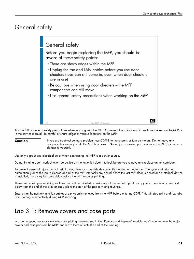
Service and Maintenance (PM)
General safety
Always follow general safety precautions when working with the MFP. Observe all warnings and instructions marked on the MFP orin the service manual. Be careful of sharp edges at various locations on the MFP.
Caution If you are troubleshooting a problem, use CDFT-E to move parts or turn on motors. Do not move anycomponents manually while the MFP has power. Not only can moving parts damage the MFP, it can be adanger to yourself.
Use only a grounded electrical outlet when connecting the MFP to a power source.
Do not install a door interlock override device on the lower-left door interlock before you remove and replace an ink cartridge.
To prevent personal injury, do not install a door interlock override device while clearing a media jam. The system will start upautomatically once the jam is cleared and all of the MFP interlocks are closed. Once the last MFP door is closed or an interlock deviceis installed, there may be some delay before the MFP resumes printing.
There are certain pen servicing routines that will be initiated occasionally at the end of a print or copy job. There is a two-seconddelay from the end of the print or copy job to the start of the pen servicing routines.
Ensure that the network and fax cables are physically removed from the MFP before entering CDFT. This will stop print and fax jobsfrom starting unexpectedly during MFP servicing.
Lab 3.1: Remove covers and case partsIn order to speed up your work when completing the exercises in the “Remove and Replace” module, you'll now remove the majorcovers and case parts on the MFP, and leave them off until the end of the training.
Rev. 3.1 -- 03/08 HP Restricted 61
HP CM8060/8050 Color MFP with Edgeline Technology Service and Support Training Student Guide
Reference material
Document ChapterField service manual Removal and replacement
Lab time: 45 minutes (including break)
ExerciseComplete the following tasks:
Power down the MFP
Remove the front doors (door engine left, door engine right)
Remove the carriage plate cover
Remove the upper inner cover
Pull out Trays 2, 3, and 4
Remove the lower inner cover
Reinsert Trays 2, 3, and 4
Remove web wipe access case parts
Remove some of the left case parts (lower left trim, left-side lower cover)
Remove the upper right and lower right case parts
Remove the rear case parts
Power up the MFP
Insert door interlock devices
Have your instructor check your work
Note You will remove any remaining covers and case parts necessary during the “Remove and Replace” moduleexercises.
Lab 3.2: Perform PM proceduresIn this lab, you will perform some of the PM procedures. You will complete other PM procedures, during the “Remove and Replace“module. If you are unclear about any of the procedures, and they are not included in this exercise, be sure to discuss them with yourinstructor.
Reference material
Document ChapterField service manual Managing and maintenance
Service quick reference guide General information
62 HP Restricted Rev. 3.1 -- 03/08
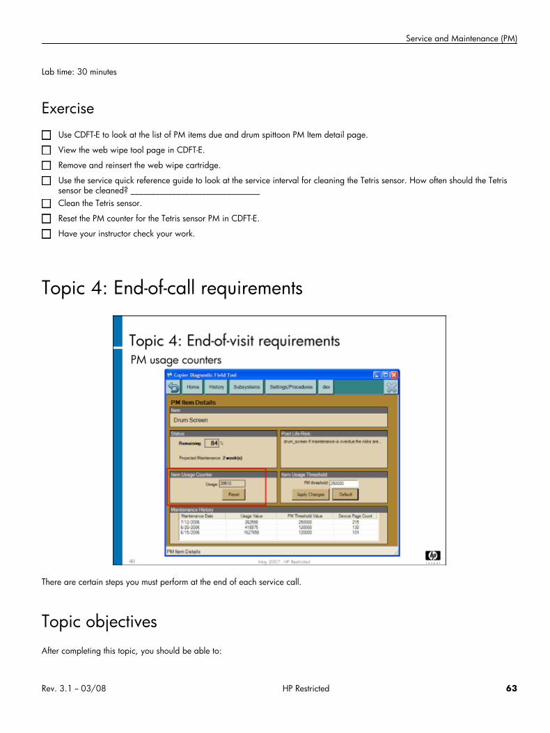
Service and Maintenance (PM)
Lab time: 30 minutes
ExerciseUse CDFT-E to look at the list of PM items due and drum spittoon PM Item detail page.
View the web wipe tool page in CDFT-E.
Remove and reinsert the web wipe cartridge.
Use the service quick reference guide to look at the service interval for cleaning the Tetris sensor. How often should the Tetrissensor be cleaned? _______________________________Clean the Tetris sensor.
Reset the PM counter for the Tetris sensor PM in CDFT-E.
Have your instructor check your work.
Topic 4: End-of-call requirements
There are certain steps you must perform at the end of each service call.
Topic objectivesAfter completing this topic, you should be able to:
Rev. 3.1 -- 03/08 HP Restricted 63
HP CM8060/8050 Color MFP with Edgeline Technology Service and Support Training Student Guide
• Perform end-of-visit requirements
• Use WFM to enter maintenance information
Topic contentCompleting this topic should take approximately 60 minutes.
Title DurationLecture: End-of-call requirements 45 minutes
Lab 4.1: Complete end-of-visit items 15 minutes
Reference material
Document ChapterField service manual Managing and maintenance
End-of-call proceduresThere are certain steps you must perform at the end of each service visit. These steps should be performed regardless of whether anypreventive maintenance was completed. Follow these steps:
1. Reset the PM counters for any PM items completed. (We recommend you reset each counter as you complete each PM item, ratherthan waiting until the end of call.)
2. Perform the following end-of-visit routines to validate that the MFP meets the customer's expectations for image quality andfunctionality:
• Automatic printing exercise – Run the “automatic exercise device” routine from CDFT. This routine takes about eight minutesand includes:- Printing, using all input trays and output bins- Both color and black ink- Both single-sided and double-sided prints- Both staplers with dual stitch and single angled stitch (if MFP has the HP Multifunction Finisher)- Job offsetting on all finisher output trays- The print patterns will be printed on the paper loaded in the MFP and selected so they fit on that paper.
• ADF copies – Manually run a copy job through the ADF
• Copy from the scanner glass – Manually copy a page from the scanner glass
64 HP Restricted Rev. 3.1 -- 03/08
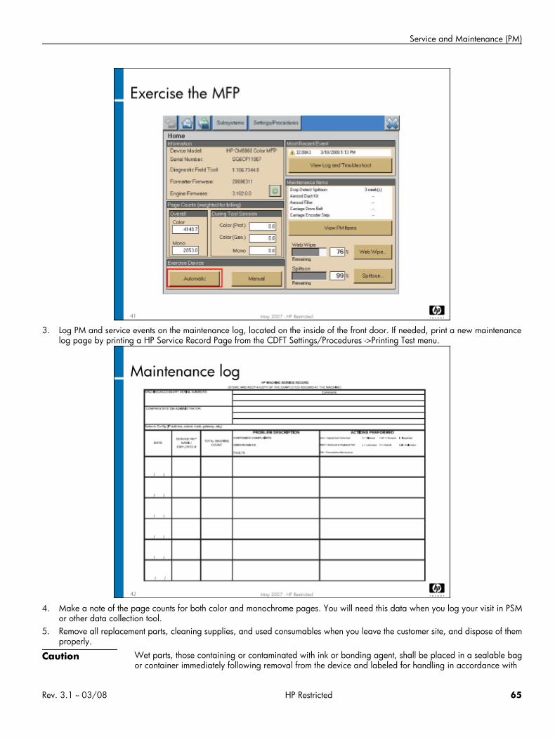
Service and Maintenance (PM)
3. Log PM and service events on the maintenance log, located on the inside of the front door. If needed, print a new maintenancelog page by printing a HP Service Record Page from the CDFT Settings/Procedures ->Printing Test menu.
4. Make a note of the page counts for both color and monochrome pages. You will need this data when you log your visit in PSMor other data collection tool.
5. Remove all replacement parts, cleaning supplies, and used consumables when you leave the customer site, and dispose of themproperly.
Caution Wet parts, those containing or contaminated with ink or bonding agent, shall be placed in a sealable bagor container immediately following removal from the device and labeled for handling in accordance with
Rev. 3.1 -- 03/08 HP Restricted 65
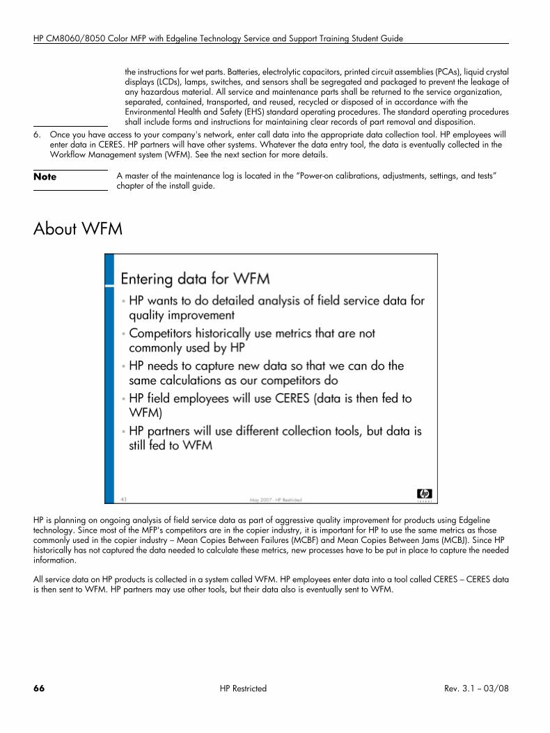
HP CM8060/8050 Color MFP with Edgeline Technology Service and Support Training Student Guide
the instructions for wet parts. Batteries, electrolytic capacitors, printed circuit assemblies (PCAs), liquid crystaldisplays (LCDs), lamps, switches, and sensors shall be segregated and packaged to prevent the leakage ofany hazardous material. All service and maintenance parts shall be returned to the service organization,separated, contained, transported, and reused, recycled or disposed of in accordance with theEnvironmental Health and Safety (EHS) standard operating procedures. The standard operating proceduresshall include forms and instructions for maintaining clear records of part removal and disposition.
6. Once you have access to your company's network, enter call data into the appropriate data collection tool. HP employees willenter data in CERES. HP partners will have other systems. Whatever the data entry tool, the data is eventually collected in theWorkflow Management system (WFM). See the next section for more details.
Note A master of the maintenance log is located in the “Power-on calibrations, adjustments, settings, and tests”chapter of the install guide.
About WFM
HP is planning on ongoing analysis of field service data as part of aggressive quality improvement for products using Edgelinetechnology. Since most of the MFP's competitors are in the copier industry, it is important for HP to use the same metrics as thosecommonly used in the copier industry – Mean Copies Between Failures (MCBF) and Mean Copies Between Jams (MCBJ). Since HPhistorically has not captured the data needed to calculate these metrics, new processes have to be put in place to capture the neededinformation.
All service data on HP products is collected in a system called WFM. HP employees enter data into a tool called CERES – CERES datais then sent to WFM. HP partners may use other tools, but their data also is eventually sent to WFM.
66 HP Restricted Rev. 3.1 -- 03/08
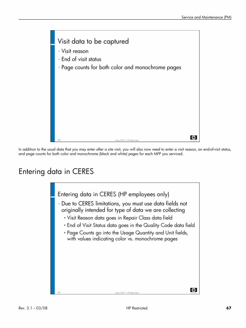
Service and Maintenance (PM)
In addition to the usual data that you may enter after a site visit, you will also now need to enter a visit reason, an end-of-visit status,and page counts for both color and monochrome (black and white) pages for each MFP you serviced.
Entering data in CERES
Rev. 3.1 -- 03/08 HP Restricted 67
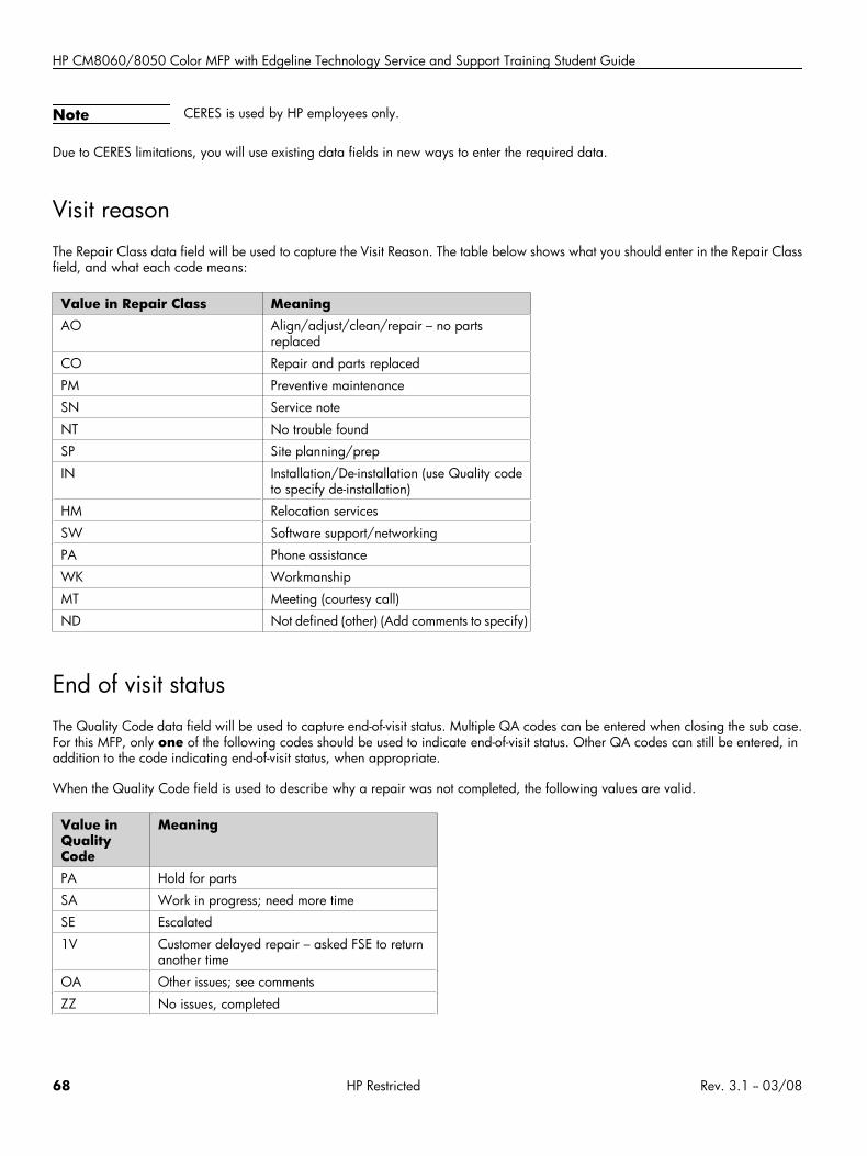
HP CM8060/8050 Color MFP with Edgeline Technology Service and Support Training Student Guide
Note CERES is used by HP employees only.
Due to CERES limitations, you will use existing data fields in new ways to enter the required data.
Visit reasonThe Repair Class data field will be used to capture the Visit Reason. The table below shows what you should enter in the Repair Classfield, and what each code means:
Value in Repair Class MeaningAO Align/adjust/clean/repair – no parts
replaced
CO Repair and parts replaced
PM Preventive maintenance
SN Service note
NT No trouble found
SP Site planning/prep
IN Installation/De-installation (use Quality codeto specify de-installation)
HM Relocation services
SW Software support/networking
PA Phone assistance
WK Workmanship
MT Meeting (courtesy call)
ND Not defined (other) (Add comments to specify)
End of visit statusThe Quality Code data field will be used to capture end-of-visit status. Multiple QA codes can be entered when closing the sub case.For this MFP, only one of the following codes should be used to indicate end-of-visit status. Other QA codes can still be entered, inaddition to the code indicating end-of-visit status, when appropriate.
When the Quality Code field is used to describe why a repair was not completed, the following values are valid.
Value inQualityCode
Meaning
PA Hold for parts
SA Work in progress; need more time
SE Escalated
1V Customer delayed repair – asked FSE to returnanother time
OA Other issues; see comments
ZZ No issues, completed
68 HP Restricted Rev. 3.1 -- 03/08
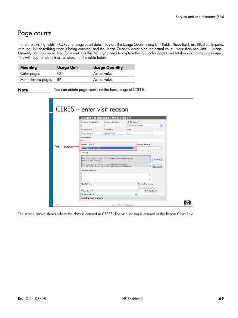
Service and Maintenance (PM)
Page countsThere are existing fields in CERES for page count data. They are the Usage Quantity and Unit fields. These fields are filled out in pairs,with the Unit describing what is being counted, and the Usage Quantity describing the actual count. More than one Unit — UsageQuantity pair can be entered for a visit. For this MFP, you need to capture the total color pages and total monochrome pages used.This will require two entries, as shown in the table below.
Meaning Usage Unit Usage QuantityColor pages CP Actual value
Monochrome pages BP Actual value
Note You can obtain page counts on the home page of CDFT-E.
The screen above shows where the data is entered in CERES. The visit reason is entered in the Repair Class field.
Rev. 3.1 -- 03/08 HP Restricted 69
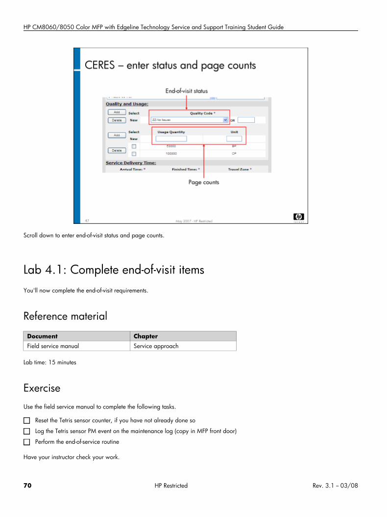
HP CM8060/8050 Color MFP with Edgeline Technology Service and Support Training Student Guide
Scroll down to enter end-of-visit status and page counts.
Lab 4.1: Complete end-of-visit itemsYou'll now complete the end-of-visit requirements.
Reference material
Document ChapterField service manual Service approach
Lab time: 15 minutes
ExerciseUse the field service manual to complete the following tasks.
Reset the Tetris sensor counter, if you have not already done so
Log the Tetris sensor PM event on the maintenance log (copy in MFP front door)
Perform the end-of-service routine
Have your instructor check your work.
70 HP Restricted Rev. 3.1 -- 03/08
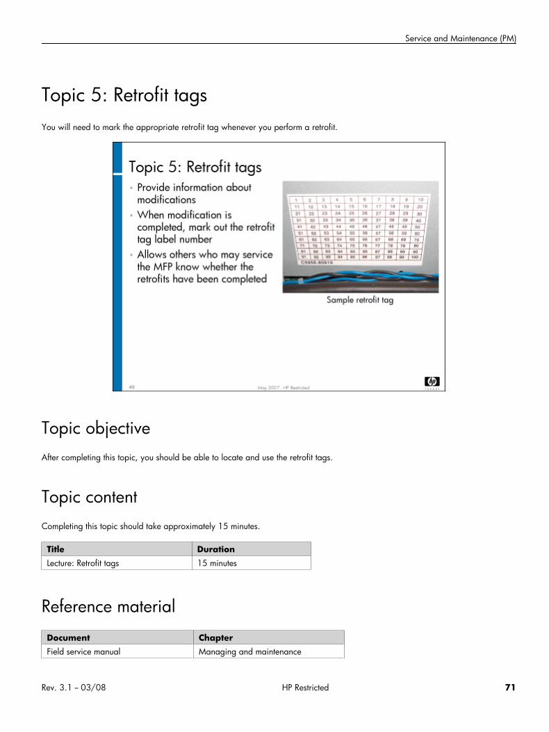
Service and Maintenance (PM)
Topic 5: Retrofit tagsYou will need to mark the appropriate retrofit tag whenever you perform a retrofit.
Topic objectiveAfter completing this topic, you should be able to locate and use the retrofit tags.
Topic contentCompleting this topic should take approximately 15 minutes.
Title DurationLecture: Retrofit tags 15 minutes
Reference material
Document ChapterField service manual Managing and maintenance
Rev. 3.1 -- 03/08 HP Restricted 71
HP CM8060/8050 Color MFP with Edgeline Technology Service and Support Training Student Guide
Retrofit tag overviewRetrofit tags are importance because the information they convey may impact safety issues, service time, and service costs. Here aretwo retrofit examples:
• Safety retrofit – Manufacturing finds a loose ground wire and notifies Technical Marketing. Technical Marketing issues a retrofitand notifies the field, providing instructions for checking and securing the loose ground wire. Once the retrofit is completed, it ismarked on the appropriate tag label. This allows future service personnel to quickly check that this safety issue has been addressed.
• Optional retrofit – Certain customers use a special type of media that contains a custom hardware change to support. TechnicalMarketing issues a retrofit and notifies the field, providing instructions for which customers need this customized part. If the retrofitis completed, it is marked on the appropriate tag label, which is helpful for future maintenance purposes.
Tag locationsRetrofit tag labels provide information about modifications that have been made to the MFP and accessories. Labels are attached toa frame or non-removable section of the MFP or accessory. They can be used to identify non-interchangeable parts, diagnosticprocedures, remove and replace procedures, and adjustment procedures.
The field service manual describes the locations of all the retrofit tag labels. The following components have retrofit tags:
• ADF
• Scanner
• Multifunction finisher or 4-bin job separator
• 4000-sheet input tray
• MFP
Marking off retrofit tagsField notes or bulletins regarding retrofits will have a unique retrofit tag label number associated with them. When you complete aretrofit, you should mark out its tag number on the appropriate tag label. Make sure you are marking off the item on the correct retrofittag. For example, if you do a retrofit on the ADF, you would mark the retrofit number off the ADF retrofit tag.
Topic 6: Use EWS for remote supportIn this topic, you will learn how to use the Embedded Web Server (EWS) for remote monitoring of the MFP.
Topic objectivesAfter completing this topic, you should be able to:
• Describe the advantages of using the EWS for remote monitoring
72 HP Restricted Rev. 3.1 -- 03/08
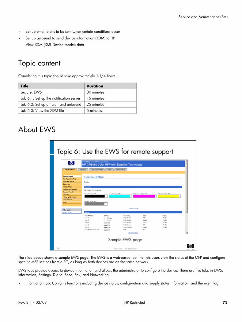
Service and Maintenance (PM)
• Set up email alerts to be sent when certain conditions occur
• Set up autosend to send device information (XDM) to HP
• View XDM (XML Device Model) data
Topic contentCompleting this topic should take approximately 1-1/4 hours.
Title DurationLecture: EWS 30 minutes
Lab 6.1: Set up the notification server 15 minutes
Lab 6.2: Set up an alert and autosend 25 minutes
Lab 6.3: View the XDM file 5 minutes
About EWS
The slide above shows a sample EWS page. The EWS is a web-based tool that lets users view the status of the MFP and configurespecific MFP settings from a PC, as long as both devices are on the same network.
EWS tabs provide access to device information and allows the administrator to configure the device. There are five tabs in EWS:Information, Settings, Digital Send, Fax, and Networking.
• Information tab: Contains functions including device status, configuration and supply status information, and the event log
Rev. 3.1 -- 03/08 HP Restricted 73
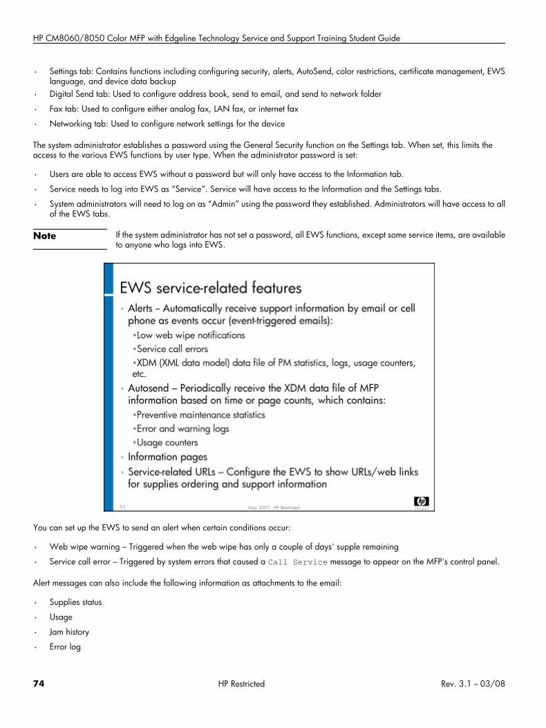
HP CM8060/8050 Color MFP with Edgeline Technology Service and Support Training Student Guide
• Settings tab: Contains functions including configuring security, alerts, AutoSend, color restrictions, certificate management, EWSlanguage, and device data backup
• Digital Send tab: Used to configure address book, send to email, and send to network folder
• Fax tab: Used to configure either analog fax, LAN fax, or internet fax
• Networking tab: Used to configure network settings for the device
The system administrator establishes a password using the General Security function on the Settings tab. When set, this limits theaccess to the various EWS functions by user type. When the administrator password is set:
• Users are able to access EWS without a password but will only have access to the Information tab.
• Service needs to log into EWS as “Service”. Service will have access to the Information and the Settings tabs.
• System administrators will need to log on as “Admin” using the password they established. Administrators will have access to allof the EWS tabs.
Note If the system administrator has not set a password, all EWS functions, except some service items, are availableto anyone who logs into EWS.
You can set up the EWS to send an alert when certain conditions occur:
• Web wipe warning – Triggered when the web wipe has only a couple of days' supple remaining
• Service call error – Triggered by system errors that caused a Call Service message to appear on the MFP's control panel.
Alert messages can also include the following information as attachments to the email:
• Supplies status
• Usage
• Jam history
• Error log
74 HP Restricted Rev. 3.1 -- 03/08
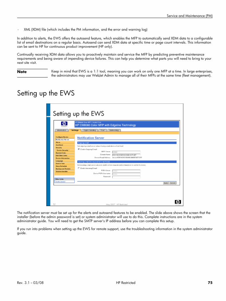
Service and Maintenance (PM)
• XML (XDM) file (which includes the PM information, and the error and warning log)
In addition to alerts, the EWS offers the autosend feature, which enables the MFP to automatically send XDM data to a configurablelist of email destinations on a regular basis. Autosend can send XDM data at specific time or page count intervals. This informationcan be sent to HP for continuous product improvement (HP only).
Continually receiving XDM data allows you to proactively maintain and service the MFP by predicting preventive maintenancerequirements and being aware of impending device failures. This can help you determine what parts you will need to bring to yournext site visit.
Note Keep in mind that EWS is a 1:1 tool, meaning you can work on only one MFP at a time. In large enterprises,the administrators may use WebJet Admin to manage all of their MFPs at the same time (fleet management).
Setting up the EWS
The notification server must be set up for the alerts and autosend features to be enabled. The slide above shows the screen that theinstaller (before the admin password is set) or system administrator will use to do this. Complete instructions are in the systemadministrator guide. You will need to get the SMTP server's IP address before you can complete this setup.
If you run into problems when setting up the EWS for remote support, use the troubleshooting information in the system administratorguide.
Rev. 3.1 -- 03/08 HP Restricted 75
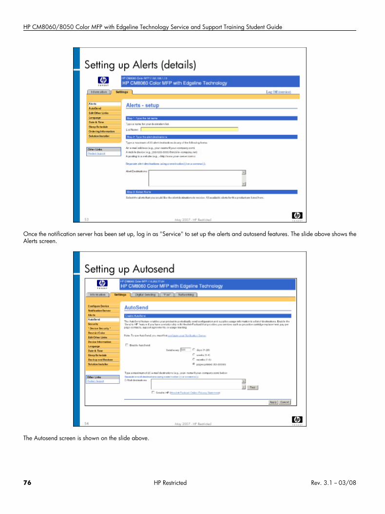
HP CM8060/8050 Color MFP with Edgeline Technology Service and Support Training Student Guide
Once the notification server has been set up, log in as "Service" to set up the alerts and autosend features. The slide above shows theAlerts screen.
The Autosend screen is shown on the slide above.
76 HP Restricted Rev. 3.1 -- 03/08
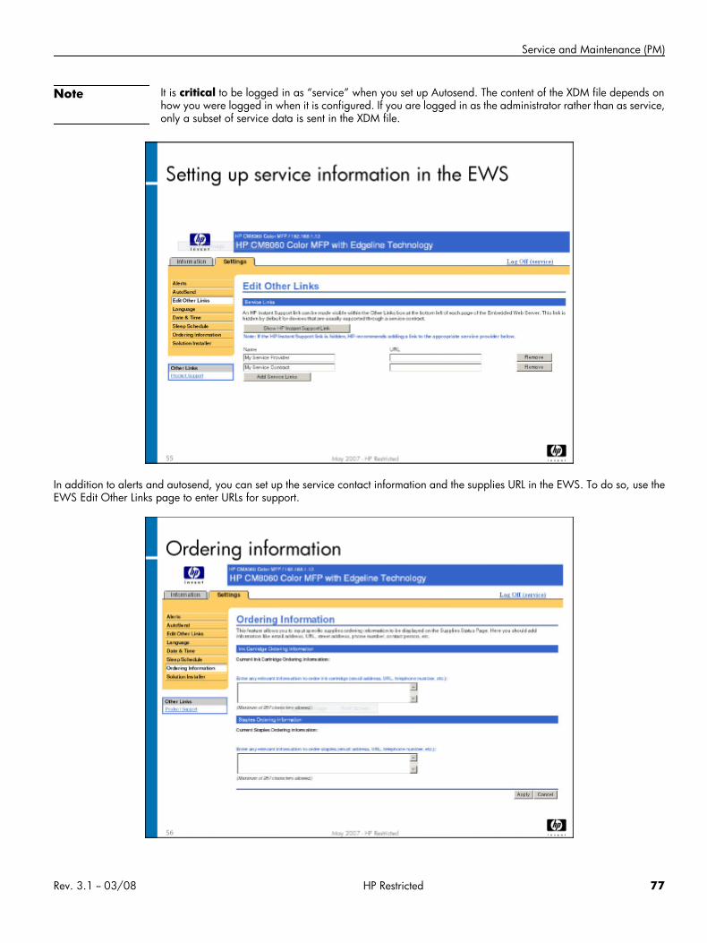
Service and Maintenance (PM)
Note It is critical to be logged in as “service” when you set up Autosend. The content of the XDM file depends onhow you were logged in when it is configured. If you are logged in as the administrator rather than as service,only a subset of service data is sent in the XDM file.
In addition to alerts and autosend, you can set up the service contact information and the supplies URL in the EWS. To do so, use theEWS Edit Other Links page to enter URLs for support.
Rev. 3.1 -- 03/08 HP Restricted 77
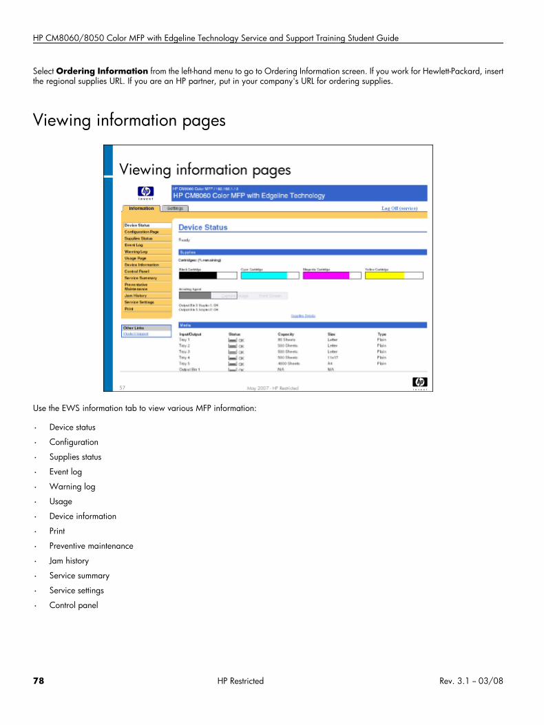
HP CM8060/8050 Color MFP with Edgeline Technology Service and Support Training Student Guide
Select Ordering Information from the left-hand menu to go to Ordering Information screen. If you work for Hewlett-Packard, insertthe regional supplies URL. If you are an HP partner, put in your company's URL for ordering supplies.
Viewing information pages
Use the EWS information tab to view various MFP information:
• Device status
• Configuration
• Supplies status
• Event log
• Warning log
• Usage
• Device information
• Preventive maintenance
• Jam history
• Service summary
• Service settings
• Control panel
78 HP Restricted Rev. 3.1 -- 03/08
Service and Maintenance (PM)
Lab 6.1: Set up the notification serverIn this lab, you will set up the notification server in the EWS. The notification server must be set up prior to setting up alerts andautosend.
Reference material
Document ChapterField service manual Service approach
System administrator guide Manage the device
Lab time: 15 minutes
ExerciseLaunch the EWS from CDFT-L (Settings/Procedures menu) connected to an MFP. Follow the instructions in the system administratorguide to set up the notification server. Have your instructor check your work.
Lab 6.2: Set up an alert and autosendIn this lab, you will set up the EWS to automatically send the XDM file to an email address [all service providers or HP (HP only)] usingautosend, and send a web wipe alert. You'll also review some of the MFP information that is available in EWS.
Note You must get the customer's permission before configuring alerts and autosend. No customer-private data isavailable to service. Be sure to test alerts and autosend after you configure them.
Reference material
Document ChapterField service manual Service approach
System administrator guide Manage the device
Lab time: 25 minutes
ExerciseFollow the instructions in the system administrator guide to set up an email alert for when the MFP's web wipe needs replacing. Then,configure autosend to send an email with the attached XDM file to HP once a week. Have your instructor check your work.
Next, take a few minutes to examine the other information about the MFP available in EWS. Take a look at the following screens:
Configuration page
Rev. 3.1 -- 03/08 HP Restricted 79
HP CM8060/8050 Color MFP with Edgeline Technology Service and Support Training Student Guide
Supplies status
Event log
Device information
Jam history
Service summary
Service settings
Preventive maintenance
Warning log
Even though you set up an alert to be sent to you when the web wipe needs replacing, you won't actually receive an email messagebecause the training room MFPs are not connected to an outside network. Because of this, your instructor will show you what the emailmessage will look like.
Lab 6.3: View the XDM fileIn this lab, you will view the XDM data file that is sent to you by EWS using the autosend function.
Reference material
Document ChapterField service manual Service approach
Lab time: 5 minutes
ExerciseYour instructor will provide the XDM viewer to you, along with a sample XDM file. Use the viewer to look at the sample XDM file.
80 HP Restricted Rev. 3.1 -- 03/08

Remove and Replace
Remove and Replace• Topic 1: Getting started
• Topic 2: Power and electronics
• Topic 3: Carriage and pens
• Topic 4: Ink delivery system
• Topic 5: Drum
• Topic 6: Vacuum and aerosol
• Topic 7: Service station and web wipe
• Topic 8: Tray 2, 3, and 4 assembly and dryer
• Topic 9: Media path and Tray 1
• Topic 10: HP 4000-Sheet Input Tray (Tray 5)
• Topic 11: HP Edgeline MFP Multifunction Finisher
• Topic 12: ADF and scanner
Rev. 3.1 -- 03/08 HP Restricted 81
HP CM8060/8050 Color MFP with Edgeline Technology Service and Support Training Student Guide
Topic 1: Getting startedBefore you begin removing and replacing components on the MFP, there are a few things you should know. This topic covers specialtools, wires and cables, ESD connector plug locations, working with power, and acoustics.
Topic 1 objectivesAfter completing this topic, you should be able to:
• Identify any special tools needed
• Interpret information about wires and cables from their color and tag
• Locate ESD connector plugs
• Identify types of acoustic material used in the MFP
Topic contentCompleting this topic should take approximately 30 minutes.
Title DurationLecture: Getting started 30 minutes
82 HP Restricted Rev. 3.1 -- 03/08
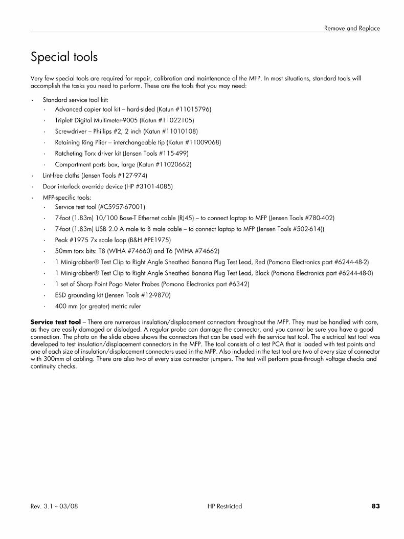
Remove and Replace
Special toolsVery few special tools are required for repair, calibration and maintenance of the MFP. In most situations, standard tools willaccomplish the tasks you need to perform. These are the tools that you may need:
• Standard service tool kit:
• Advanced copier tool kit – hard-sided (Katun #11015796)
• Triplett Digital Multimeter-9005 (Katun #11022105)
• Screwdriver – Phillips #2, 2 inch (Katun #11010108)
• Retaining Ring Plier – interchangeable tip (Katun #11009068)
• Ratcheting Torx driver kit (Jensen Tools #115-499)
• Compartment parts box, large (Katun #11020662)
• Lint-free cloths (Jensen Tools #127-974)
• Door interlock override device (HP #3101-4085)
• MFP-specific tools:
• Service test tool (#C5957-67001)
• 7-foot (1.83m) 10/100 Base-T Ethernet cable (RJ45) – to connect laptop to MFP (Jensen Tools #780-402)
• 7-foot (1.83m) USB 2.0 A male to B male cable – to connect laptop to MFP (Jensen Tools #502-614))
• Peak #1975 7x scale loop (B&H #PE1975)
• 50mm torx bits: T8 (WIHA #74660) and T6 (WIHA #74662)
• 1 Minigrabber® Test Clip to Right Angle Sheathed Banana Plug Test Lead, Red (Pomona Electronics part #6244-48-2)
• 1 Minigrabber® Test Clip to Right Angle Sheathed Banana Plug Test Lead, Black (Pomona Electronics part #6244-48-0)
• 1 set of Sharp Point Pogo Meter Probes (Pomona Electronics part #6342)
• ESD grounding kit (Jensen Tools #12-9870)
• 400 mm (or greater) metric ruler
Service test tool – There are numerous insulation/displacement connectors throughout the MFP. They must be handled with care,as they are easily damaged or dislodged. A regular probe can damage the connector, and you cannot be sure you have a goodconnection. The photo on the slide above shows the connectors that can be used with the service test tool. The electrical test tool wasdeveloped to test insulation/displacement connectors in the MFP. The tool consists of a test PCA that is loaded with test points andone of each size of insulation/displacement connectors used in the MFP. Also included in the test tool are two of every size of connectorwith 300mm of cabling. There are also two of every size connector jumpers. The test will perform pass-through voltage checks andcontinuity checks.
Rev. 3.1 -- 03/08 HP Restricted 83
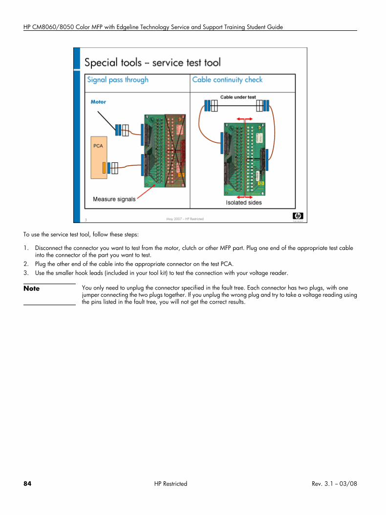
HP CM8060/8050 Color MFP with Edgeline Technology Service and Support Training Student Guide
To use the service test tool, follow these steps:
1. Disconnect the connector you want to test from the motor, clutch or other MFP part. Plug one end of the appropriate test cableinto the connector of the part you want to test.
2. Plug the other end of the cable into the appropriate connector on the test PCA.3. Use the smaller hook leads (included in your tool kit) to test the connection with your voltage reader.
Note You only need to unplug the connector specified in the fault tree. Each connector has two plugs, with onejumper connecting the two plugs together. If you unplug the wrong plug and try to take a voltage reading usingthe pins listed in the fault tree, you will not get the correct results.
84 HP Restricted Rev. 3.1 -- 03/08
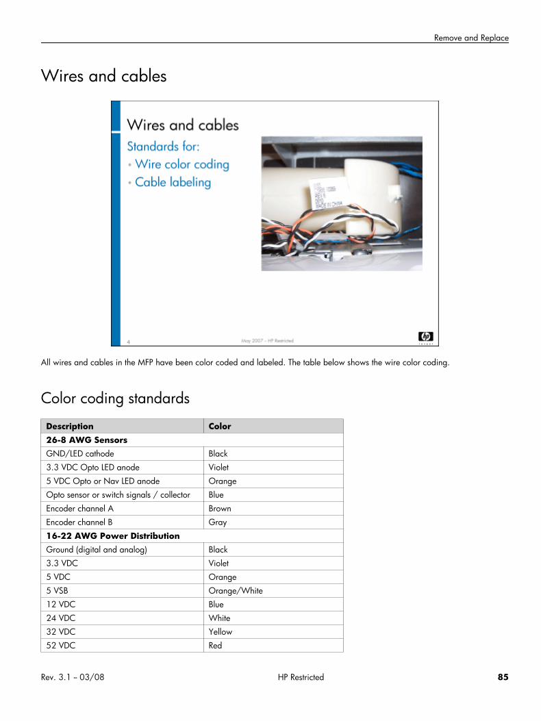
Remove and Replace
Wires and cables
All wires and cables in the MFP have been color coded and labeled. The table below shows the wire color coding.
Color coding standards
Description Color26-8 AWG SensorsGND/LED cathode Black
3.3 VDC Opto LED anode Violet
5 VDC Opto or Nav LED anode Orange
Opto sensor or switch signals / collector Blue
Encoder channel A Brown
Encoder channel B Gray
16-22 AWG Power DistributionGround (digital and analog) Black
3.3 VDC Violet
5 VDC Orange
5 VSB Orange/White
12 VDC Blue
24 VDC White
32 VDC Yellow
52 VDC Red
Rev. 3.1 -- 03/08 HP Restricted 85
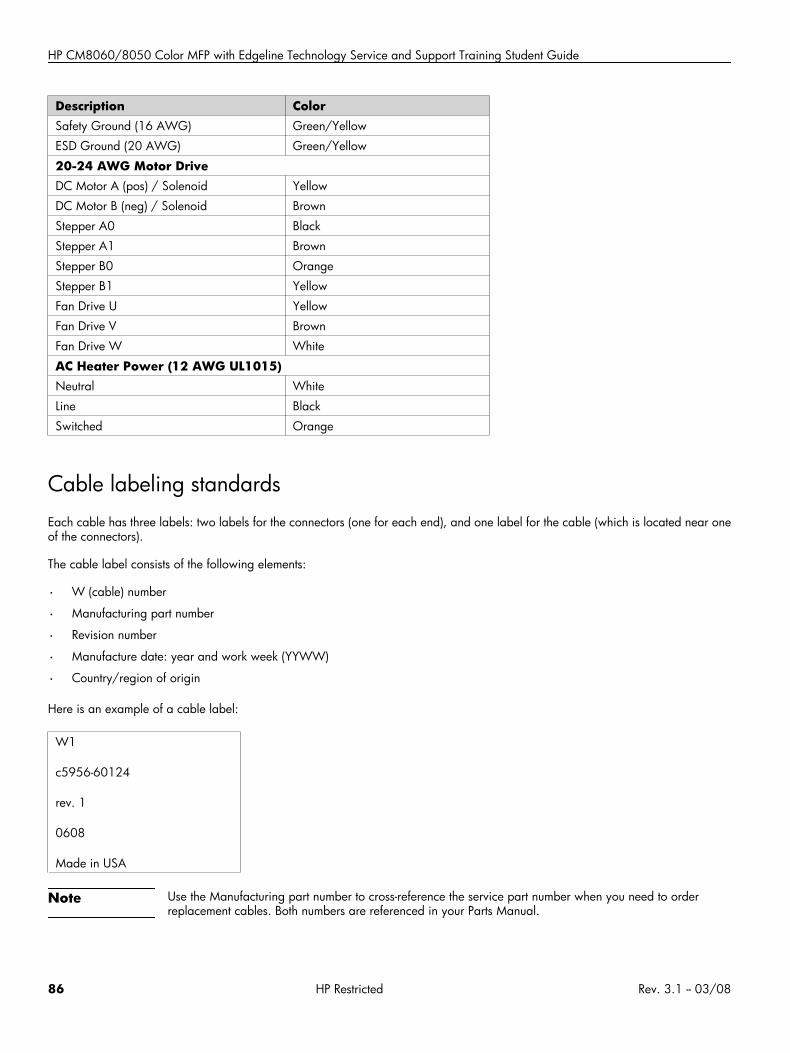
HP CM8060/8050 Color MFP with Edgeline Technology Service and Support Training Student Guide
Description ColorSafety Ground (16 AWG) Green/Yellow
ESD Ground (20 AWG) Green/Yellow
20-24 AWG Motor DriveDC Motor A (pos) / Solenoid Yellow
DC Motor B (neg) / Solenoid Brown
Stepper A0 Black
Stepper A1 Brown
Stepper B0 Orange
Stepper B1 Yellow
Fan Drive U Yellow
Fan Drive V Brown
Fan Drive W White
AC Heater Power (12 AWG UL1015)Neutral White
Line Black
Switched Orange
Cable labeling standardsEach cable has three labels: two labels for the connectors (one for each end), and one label for the cable (which is located near oneof the connectors).
The cable label consists of the following elements:
• W (cable) number
• Manufacturing part number
• Revision number
• Manufacture date: year and work week (YYWW)
• Country/region of origin
Here is an example of a cable label:
W1
c5956-60124
rev. 1
0608
Made in USA
Note Use the Manufacturing part number to cross-reference the service part number when you need to orderreplacement cables. Both numbers are referenced in your Parts Manual.
86 HP Restricted Rev. 3.1 -- 03/08
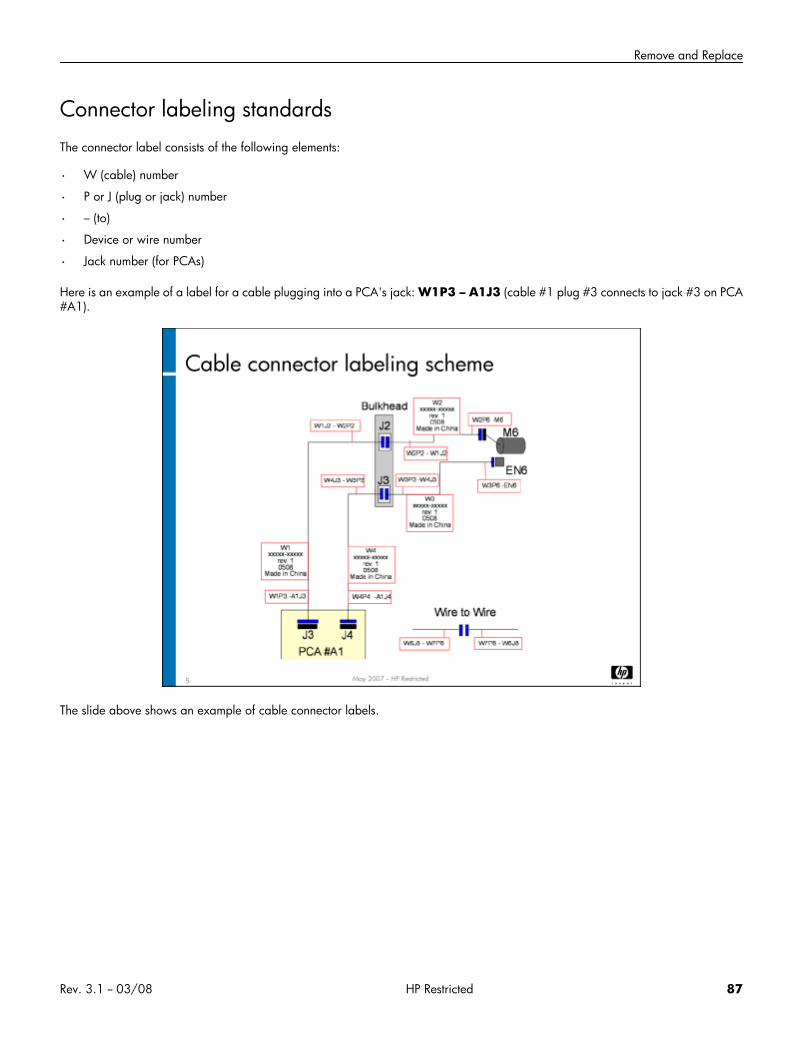
Remove and Replace
Connector labeling standardsThe connector label consists of the following elements:
• W (cable) number
• P or J (plug or jack) number
• – (to)
• Device or wire number
• Jack number (for PCAs)
Here is an example of a label for a cable plugging into a PCA's jack: W1P3 – A1J3 (cable #1 plug #3 connects to jack #3 on PCA#A1).
The slide above shows an example of cable connector labels.
Rev. 3.1 -- 03/08 HP Restricted 87
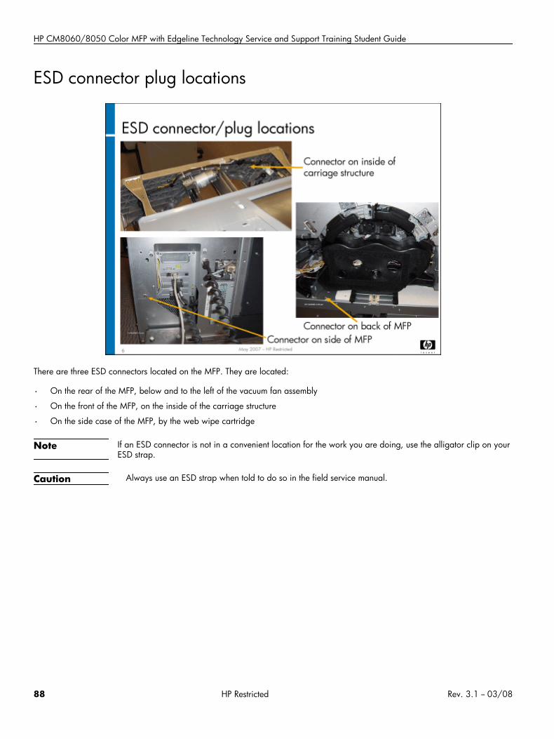
HP CM8060/8050 Color MFP with Edgeline Technology Service and Support Training Student Guide
ESD connector plug locations
There are three ESD connectors located on the MFP. They are located:
• On the rear of the MFP, below and to the left of the vacuum fan assembly
• On the front of the MFP, on the inside of the carriage structure
• On the side case of the MFP, by the web wipe cartridge
Note If an ESD connector is not in a convenient location for the work you are doing, use the alligator clip on yourESD strap.
Caution Always use an ESD strap when told to do so in the field service manual.
88 HP Restricted Rev. 3.1 -- 03/08
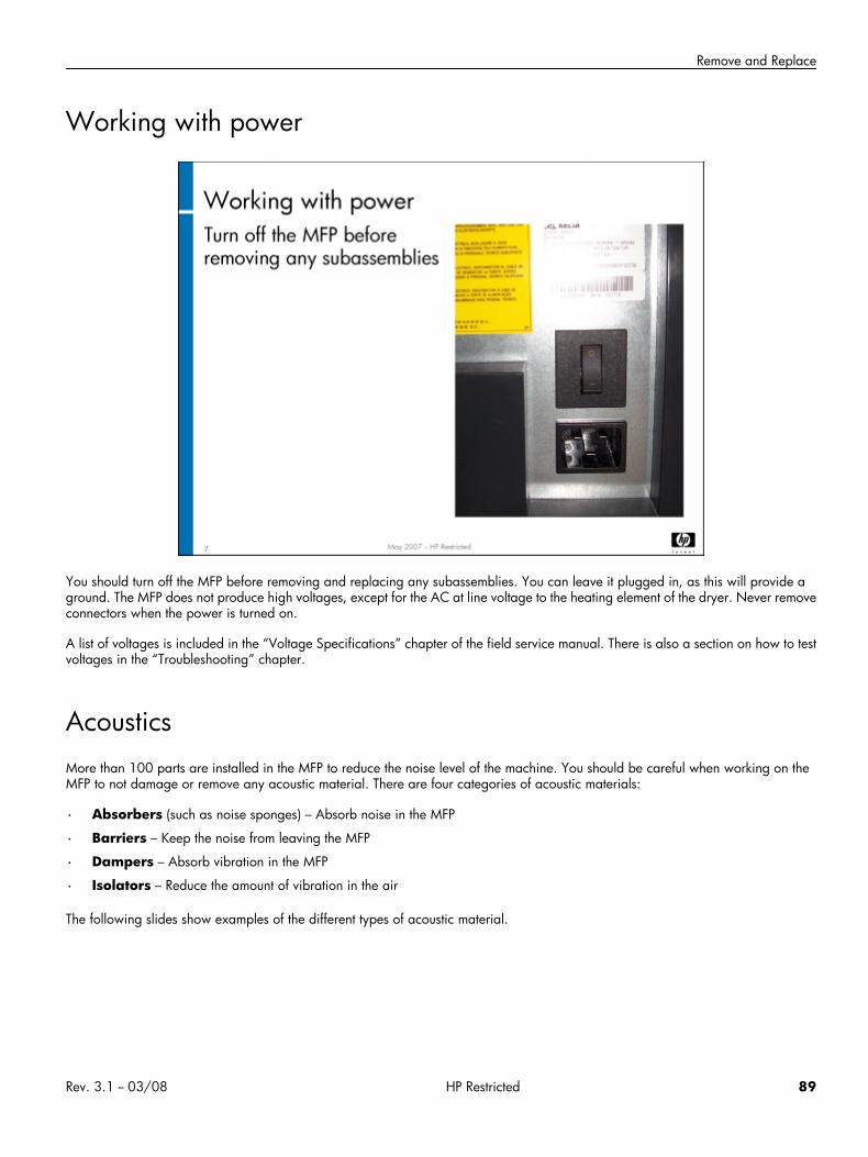
Remove and Replace
Working with power
You should turn off the MFP before removing and replacing any subassemblies. You can leave it plugged in, as this will provide aground. The MFP does not produce high voltages, except for the AC at line voltage to the heating element of the dryer. Never removeconnectors when the power is turned on.
A list of voltages is included in the “Voltage Specifications” chapter of the field service manual. There is also a section on how to testvoltages in the “Troubleshooting” chapter.
AcousticsMore than 100 parts are installed in the MFP to reduce the noise level of the machine. You should be careful when working on theMFP to not damage or remove any acoustic material. There are four categories of acoustic materials:
• Absorbers (such as noise sponges) – Absorb noise in the MFP
• Barriers – Keep the noise from leaving the MFP
• Dampers – Absorb vibration in the MFP
• Isolators – Reduce the amount of vibration in the air
The following slides show examples of the different types of acoustic material.
Rev. 3.1 -- 03/08 HP Restricted 89
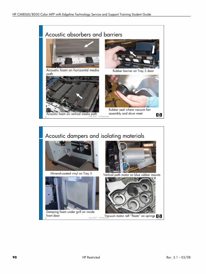
HP CM8060/8050 Color MFP with Edgeline Technology Service and Support Training Student Guide
90 HP Restricted Rev. 3.1 -- 03/08
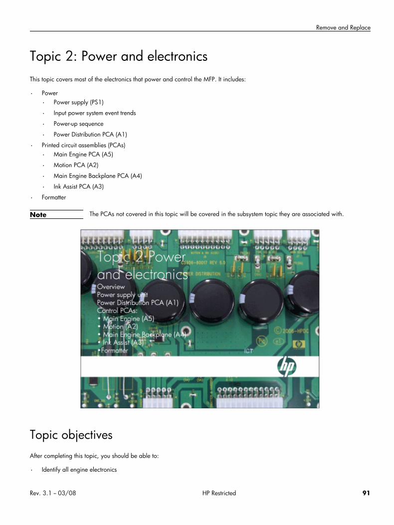
Remove and Replace
Topic 2: Power and electronicsThis topic covers most of the electronics that power and control the MFP. It includes:
• Power
• Power supply (PS1)
• Input power system event trends
• Power-up sequence
• Power Distribution PCA (A1)
• Printed circuit assemblies (PCAs)
• Main Engine PCA (A5)
• Motion PCA (A2)
• Main Engine Backplane PCA (A4)
• Ink Assist PCA (A3)
• Formatter
Note The PCAs not covered in this topic will be covered in the subsystem topic they are associated with.
Topic objectivesAfter completing this topic, you should be able to:
• Identify all engine electronics
Rev. 3.1 -- 03/08 HP Restricted 91
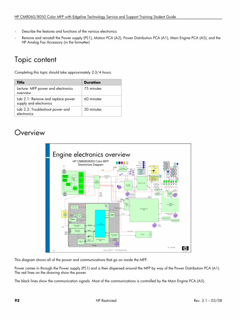
HP CM8060/8050 Color MFP with Edgeline Technology Service and Support Training Student Guide
• Describe the features and functions of the various electronics
• Remove and reinstall the Power supply (PS1), Motion PCA (A2), Power Distribution PCA (A1), Main Engine PCA (A5), and theHP Analog Fax Accessory (in the formatter)
Topic contentCompleting this topic should take approximately 2-3/4 hours.
Title DurationLecture: MFP power and electronicsoverview
75 minutes
Lab 2.1: Remove and replace powersupply and electronics
60 minutes
Lab 2.2: Troubleshoot power andelectronics
30 minutes
Overview
This diagram shows all of the power and communications that go on inside the MFP.
Power comes in through the Power supply (PS1) and is then dispersed around the MFP by way of the Power Distribution PCA (A1).The red lines on the drawing show the power.
The black lines show the communication signals. Most of the communications is controlled by the Main Engine PCA (A5).
92 HP Restricted Rev. 3.1 -- 03/08
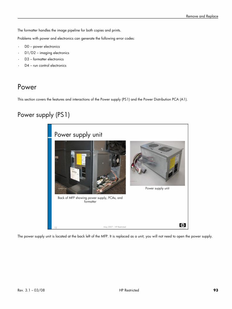
Remove and Replace
The formatter handles the image pipeline for both copies and prints.
Problems with power and electronics can generate the following error codes:
• D0 – power electronics
• D1/D2 – imaging electronics
• D3 – formatter electronics
• D4 – run control electronics
PowerThis section covers the features and interactions of the Power supply (PS1) and the Power Distribution PCA (A1).
Power supply (PS1)
The power supply unit is located at the back left of the MFP. It is replaced as a unit; you will not need to open the power supply.
Rev. 3.1 -- 03/08 HP Restricted 93
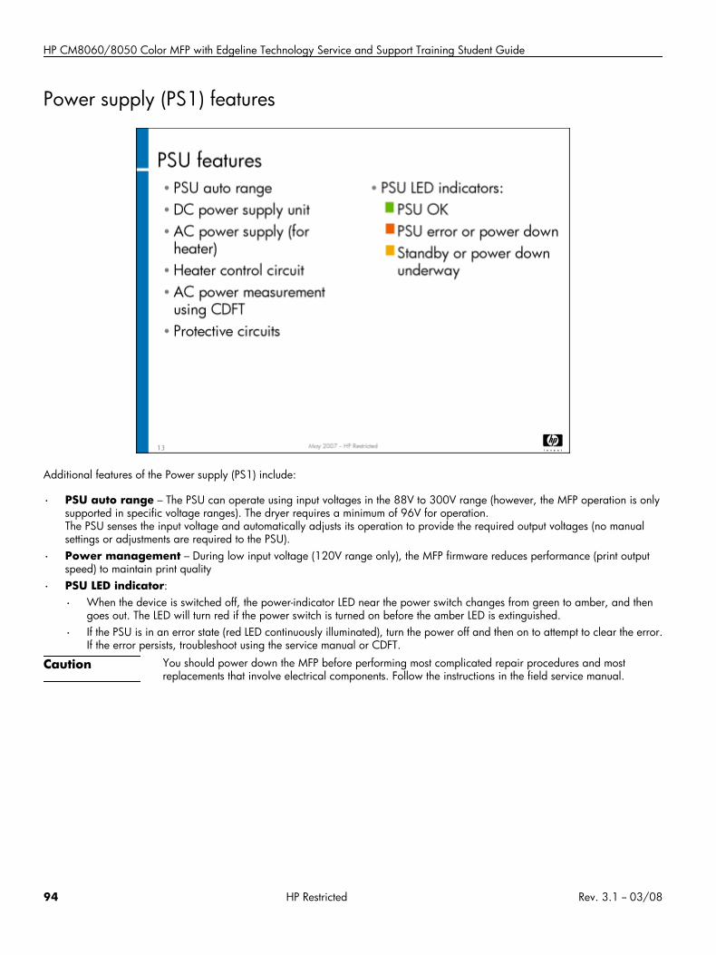
HP CM8060/8050 Color MFP with Edgeline Technology Service and Support Training Student Guide
Power supply (PS1) features
Additional features of the Power supply (PS1) include:
• PSU auto range – The PSU can operate using input voltages in the 88V to 300V range (however, the MFP operation is onlysupported in specific voltage ranges). The dryer requires a minimum of 96V for operation.The PSU senses the input voltage and automatically adjusts its operation to provide the required output voltages (no manualsettings or adjustments are required to the PSU).
• Power management – During low input voltage (120V range only), the MFP firmware reduces performance (print outputspeed) to maintain print quality
• PSU LED indicator:
• When the device is switched off, the power-indicator LED near the power switch changes from green to amber, and thengoes out. The LED will turn red if the power switch is turned on before the amber LED is extinguished.
• If the PSU is in an error state (red LED continuously illuminated), turn the power off and then on to attempt to clear the error.If the error persists, troubleshoot using the service manual or CDFT.
Caution You should power down the MFP before performing most complicated repair procedures and mostreplacements that involve electrical components. Follow the instructions in the field service manual.
94 HP Restricted Rev. 3.1 -- 03/08
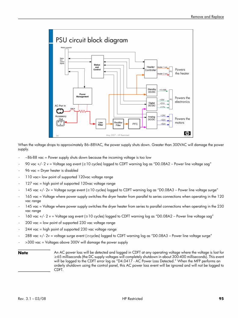
Remove and Replace
When the voltage drops to approximately 86–88VAC, the power supply shuts down. Greater than 300VAC will damage the powersupply.
• ~86-88 vac = Power supply shuts down because the incoming voltage is too low
• 90 vac +/- 2 v = Voltage sag event (≥10 cycles) logged to CDFT warning log as “D0.08A2 – Power line voltage sag”
• 96 vac = Dryer heater is disabled
• 110 vac= low point of supported 120vac voltage range
• 127 vac = high point of supported 120vac voltage range
• 145 vac +/- 2v = Voltage surge event (≥10 cycles) logged to CDFT warning log as “D0.08A3 – Power line voltage surge”
• 165 vac = Voltage where power supply switches the dryer heater from parallel to series connections when operating in the 120vac range
• 145 vac = Voltage where power supply switches the dryer heater from series to parallel connections when operating in the 230vac range
• 160 vac +/- 2 v = Voltage sag event (≥10 cycles) logged to CDFT warning log as “D0.08A2 – Power line voltage sag”
• 200 vac = low point of supported 230 vac voltage range
• 244 vac = high point of supported 230 vac voltage range
• 288 vac +/- 2v = voltage surge event (≥cycles) logged to CDFT warning log as “D0.08A3 – Power line voltage surge”
• >300 vac = Voltages above 300V will damage the power supply
Note An AC power loss will be detected and logged in CDFT at any operating voltage where the voltage is lost for≥65 milliseconds (the DC supply voltages will completely shutdown in about 300-400 milliseconds). This eventwill be logged to the CDFT error log as “D4.0417 - AC Power Loss Detected.” When the MFP performs anorderly shutdown using the control panel, this AC power loss event will be ignored and will not be logged toCDFT.
Rev. 3.1 -- 03/08 HP Restricted 95
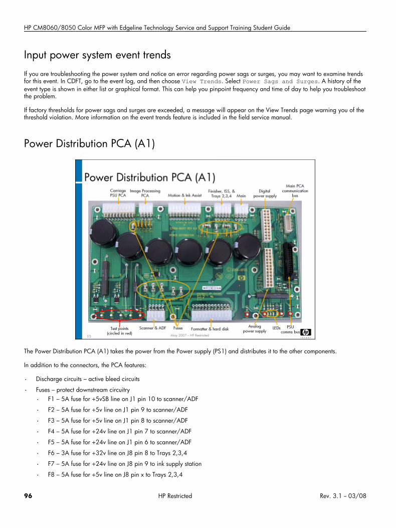
HP CM8060/8050 Color MFP with Edgeline Technology Service and Support Training Student Guide
Input power system event trendsIf you are troubleshooting the power system and notice an error regarding power sags or surges, you may want to examine trendsfor this event. In CDFT, go to the event log, and then choose View Trends. Select Power Sags and Surges. A history of theevent type is shown in either list or graphical format. This can help you pinpoint frequency and time of day to help you troubleshootthe problem.
If factory thresholds for power sags and surges are exceeded, a message will appear on the View Trends page warning you of thethreshold violation. More information on the event trends feature is included in the field service manual.
Power Distribution PCA (A1)
The Power Distribution PCA (A1) takes the power from the Power supply (PS1) and distributes it to the other components.
In addition to the connectors, the PCA features:
• Discharge circuits – active bleed circuits
• Fuses – protect downstream circuitry
• F1 – 5A fuse for +5vSB line on J1 pin 10 to scanner/ADF
• F2 – 5A fuse for +5v line on J1 pin 9 to scanner/ADF
• F3 – 5A fuse for +5v line on J1 pin 8 to scanner/ADF
• F4 – 5A fuse for +24v line on J1 pin 7 to scanner/ADF
• F5 – 5A fuse for +24v line on J1 pin 6 to scanner/ADF
• F6 – 3A fuse for +32v line on J8 pin 8 to Trays 2,3,4
• F7 – 5A fuse for +24v line on J8 pin 9 to ink supply station
• F8 – 5A fuse for +5v line on J8 pin x to Trays 2,3,4
96 HP Restricted Rev. 3.1 -- 03/08

Remove and Replace
• F9 – 5A fuse for +5v line on J11 pin 20 to Carriage PSU PCA
• F10 – 10A fuse for +52v line on J8 pins 6 & 7 to finisher
• Indicator LEDs (see Interactions below)
• Capacitors – keep voltage constant for pens
• Test points – for measuring voltages
• TP1 – PGND
• TP2 – +52V
• TP3 – GND_D/C
• TP4 – +5V
• TP5 – +5VSB
• TP6 – +3.3V
• TP7 – +32V
• TP8 – +24V
• TP9 – +12V
The Power Distribution PCA (A1) is where the Power supply (PS1) and chassis grounds come together.
The firmware accesses the power measurement circuit inside the PSU every 50 milliseconds (amber LED).
LED lights indicate power and firmware activity, as shown below:
• LED1 – +5V
• LED2 – 24V
• LED3 – 5VSB
• LED4 – Firmware activity
Rev. 3.1 -- 03/08 HP Restricted 97
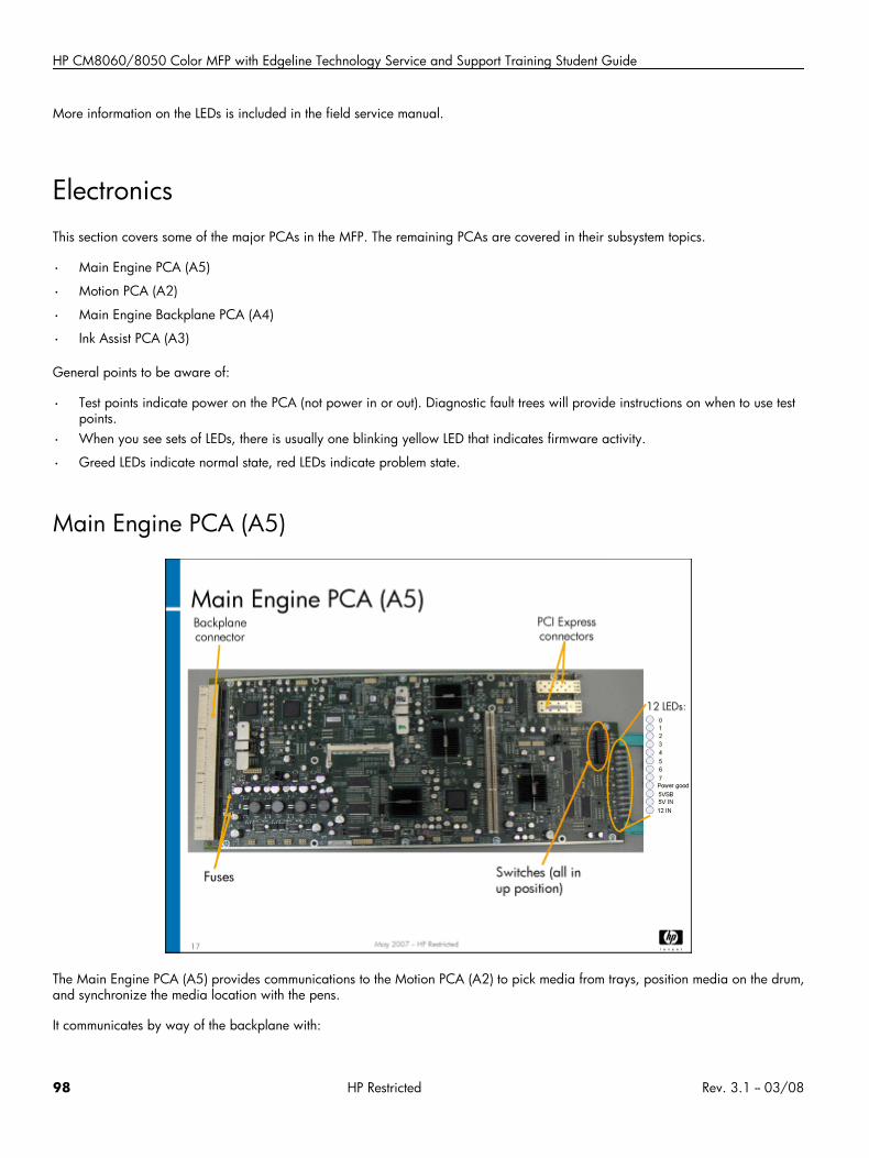
HP CM8060/8050 Color MFP with Edgeline Technology Service and Support Training Student Guide
More information on the LEDs is included in the field service manual.
ElectronicsThis section covers some of the major PCAs in the MFP. The remaining PCAs are covered in their subsystem topics.
• Main Engine PCA (A5)
• Motion PCA (A2)
• Main Engine Backplane PCA (A4)
• Ink Assist PCA (A3)
General points to be aware of:
• Test points indicate power on the PCA (not power in or out). Diagnostic fault trees will provide instructions on when to use testpoints.
• When you see sets of LEDs, there is usually one blinking yellow LED that indicates firmware activity.
• Greed LEDs indicate normal state, red LEDs indicate problem state.
Main Engine PCA (A5)
The Main Engine PCA (A5) provides communications to the Motion PCA (A2) to pick media from trays, position media on the drum,and synchronize the media location with the pens.
It communicates by way of the backplane with:
98 HP Restricted Rev. 3.1 -- 03/08
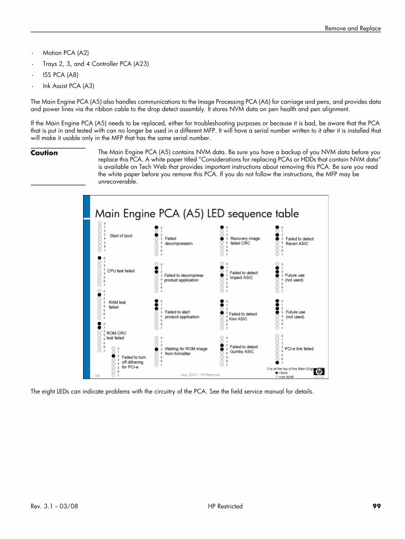
Remove and Replace
• Motion PCA (A2)
• Trays 2, 3, and 4 Controller PCA (A23)
• ISS PCA (A8)
• Ink Assist PCA (A3)
The Main Engine PCA (A5) also handles communications to the Image Processing PCA (A6) for carriage and pens, and provides dataand power lines via the ribbon cable to the drop detect assembly. It stores NVM data on pen health and pen alignment.
If the Main Engine PCA (A5) needs to be replaced, either for troubleshooting purposes or because it is bad, be aware that the PCAthat is put in and tested with can no longer be used in a different MFP. It will have a serial number written to it after it is installed thatwill make it usable only in the MFP that has the same serial number.
Caution The Main Engine PCA (A5) contains NVM data. Be sure you have a backup of you NVM data before youreplace this PCA. A white paper titled “Considerations for replacing PCAs or HDDs that contain NVM data”is available on Tech Web that provides important instructions about removing this PCA. Be sure you readthe white paper before you remove this PCA. If you do not follow the instructions, the MFP may beunrecoverable.
The eight LEDs can indicate problems with the circuitry of the PCA. See the field service manual for details.
Rev. 3.1 -- 03/08 HP Restricted 99
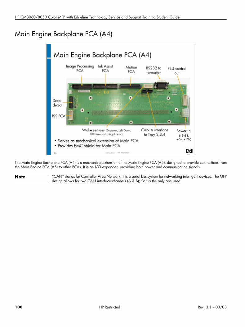
HP CM8060/8050 Color MFP with Edgeline Technology Service and Support Training Student Guide
Main Engine Backplane PCA (A4)
The Main Engine Backplane PCA (A4) is a mechanical extension of the Main Engine PCA (A5), designed to provide connections fromthe Main Engine PCA (A5) to other PCAs. It is an I/O expander, providing both power and communication signals.
Note “CAN” stands for Controller Area Network. It is a serial bus system for networking intelligent devices. The MFPdesign allows for two CAN interface channels (A & B); “A” is the only one used.
100 HP Restricted Rev. 3.1 -- 03/08
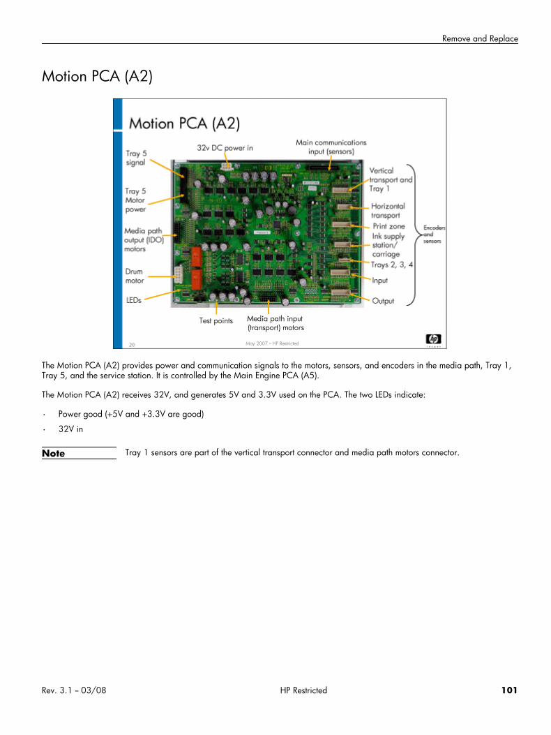
Remove and Replace
Motion PCA (A2)
The Motion PCA (A2) provides power and communication signals to the motors, sensors, and encoders in the media path, Tray 1,Tray 5, and the service station. It is controlled by the Main Engine PCA (A5).
The Motion PCA (A2) receives 32V, and generates 5V and 3.3V used on the PCA. The two LEDs indicate:
• Power good (+5V and +3.3V are good)
• 32V in
Note Tray 1 sensors are part of the vertical transport connector and media path motors connector.
Rev. 3.1 -- 03/08 HP Restricted 101
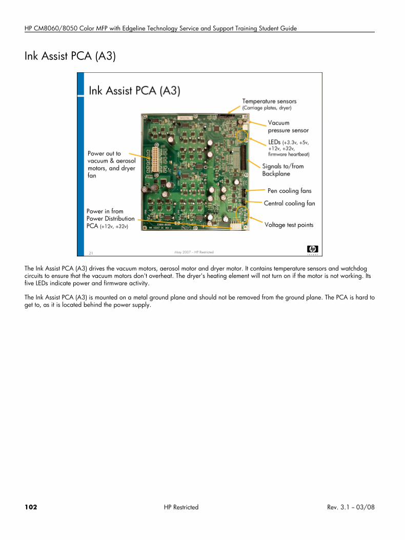
HP CM8060/8050 Color MFP with Edgeline Technology Service and Support Training Student Guide
Ink Assist PCA (A3)
The Ink Assist PCA (A3) drives the vacuum motors, aerosol motor and dryer motor. It contains temperature sensors and watchdogcircuits to ensure that the vacuum motors don't overheat. The dryer's heating element will not turn on if the motor is not working. Itsfive LEDs indicate power and firmware activity.
The Ink Assist PCA (A3) is mounted on a metal ground plane and should not be removed from the ground plane. The PCA is hard toget to, as it is located behind the power supply.
102 HP Restricted Rev. 3.1 -- 03/08
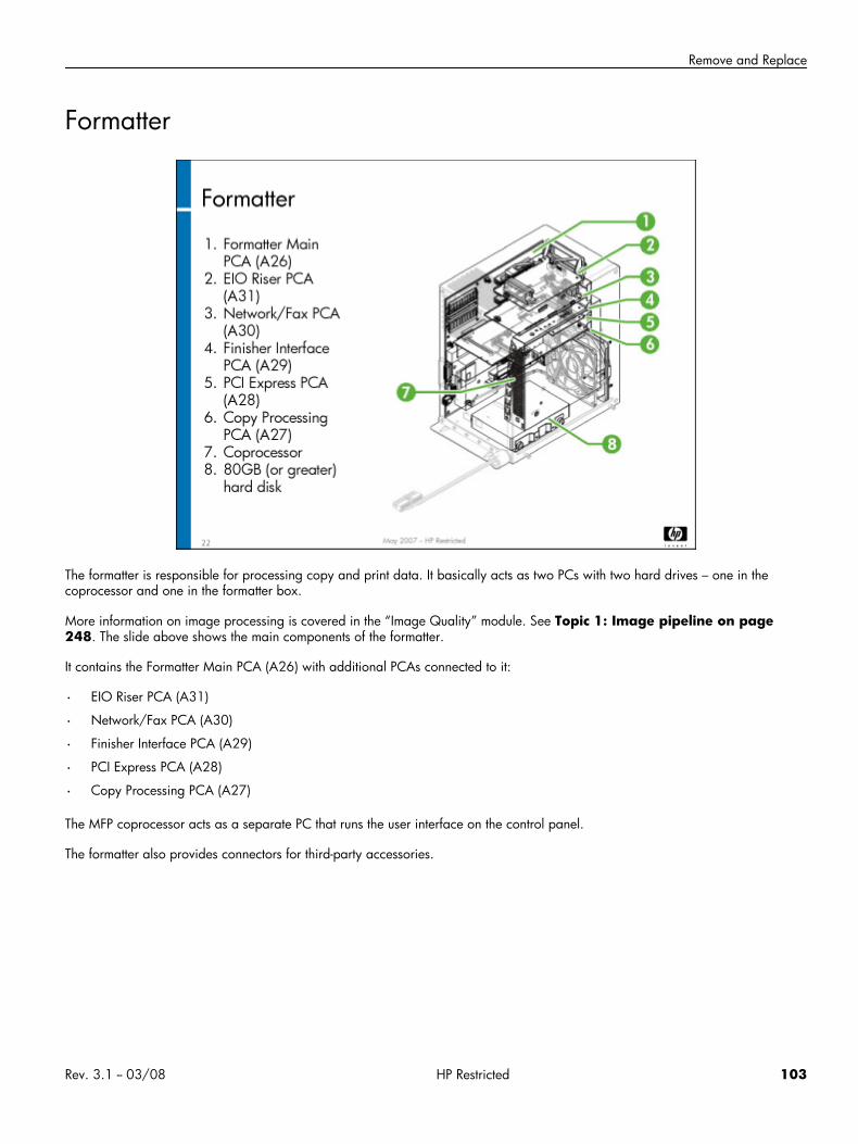
Remove and Replace
Formatter
The formatter is responsible for processing copy and print data. It basically acts as two PCs with two hard drives – one in thecoprocessor and one in the formatter box.
More information on image processing is covered in the “Image Quality” module. See Topic 1: Image pipeline on page248. The slide above shows the main components of the formatter.
It contains the Formatter Main PCA (A26) with additional PCAs connected to it:
• EIO Riser PCA (A31)
• Network/Fax PCA (A30)
• Finisher Interface PCA (A29)
• PCI Express PCA (A28)
• Copy Processing PCA (A27)
The MFP coprocessor acts as a separate PC that runs the user interface on the control panel.
The formatter also provides connectors for third-party accessories.
Rev. 3.1 -- 03/08 HP Restricted 103
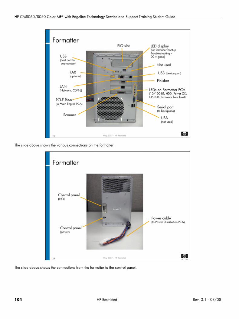
HP CM8060/8050 Color MFP with Edgeline Technology Service and Support Training Student Guide
The slide above shows the various connections on the formatter.
The slide above shows the connections from the formatter to the control panel.
104 HP Restricted Rev. 3.1 -- 03/08
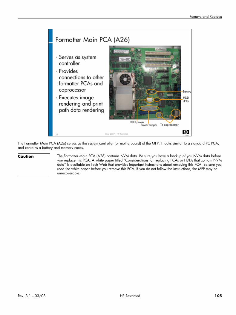
Remove and Replace
The Formatter Main PCA (A26) serves as the system controller (or motherboard) of the MFP. It looks similar to a standard PC PCA,and contains a battery and memory cards.
Caution The Formatter Main PCA (A26) contains NVM data. Be sure you have a backup of you NVM data beforeyou replace this PCA. A white paper titled “Considerations for replacing PCAs or HDDs that contain NVMdata” is available on Tech Web that provides important instructions about removing this PCA. Be sure youread the white paper before you remove this PCA. If you do not follow the instructions, the MFP may beunrecoverable.
Rev. 3.1 -- 03/08 HP Restricted 105
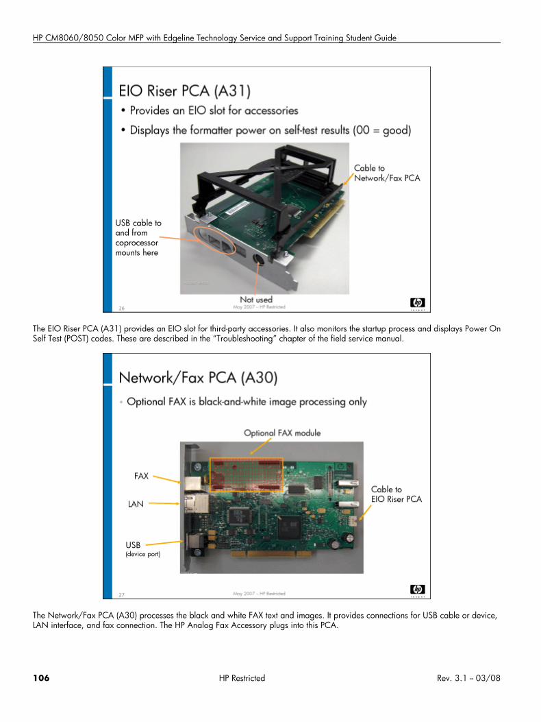
HP CM8060/8050 Color MFP with Edgeline Technology Service and Support Training Student Guide
The EIO Riser PCA (A31) provides an EIO slot for third-party accessories. It also monitors the startup process and displays Power OnSelf Test (POST) codes. These are described in the “Troubleshooting” chapter of the field service manual.
The Network/Fax PCA (A30) processes the black and white FAX text and images. It provides connections for USB cable or device,LAN interface, and fax connection. The HP Analog Fax Accessory plugs into this PCA.
106 HP Restricted Rev. 3.1 -- 03/08
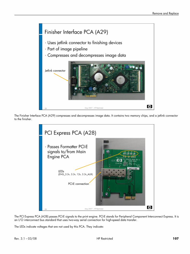
Remove and Replace
The Finisher Interface PCA (A29) compresses and decompresses image data. It contains two memory chips, and a jetlink connectorto the finisher.
The PCI Express PCA (A28) passes PCI-E signals to the print engine. PCI-E stands for Peripheral Component Interconnect Express. It isan I/O interconnect bus standard that uses two-way serial connection for high-speed data transfer.
The LEDs indicate voltages that are not used by this PCA. They indicate:
Rev. 3.1 -- 03/08 HP Restricted 107
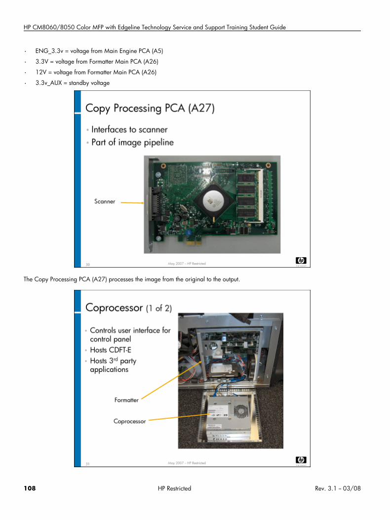
HP CM8060/8050 Color MFP with Edgeline Technology Service and Support Training Student Guide
• ENG_3.3v = voltage from Main Engine PCA (A5)
• 3.3V = voltage from Formatter Main PCA (A26)
• 12V = voltage from Formatter Main PCA (A26)
• 3.3v_AUX = standby voltage
The Copy Processing PCA (A27) processes the image from the original to the output.
108 HP Restricted Rev. 3.1 -- 03/08
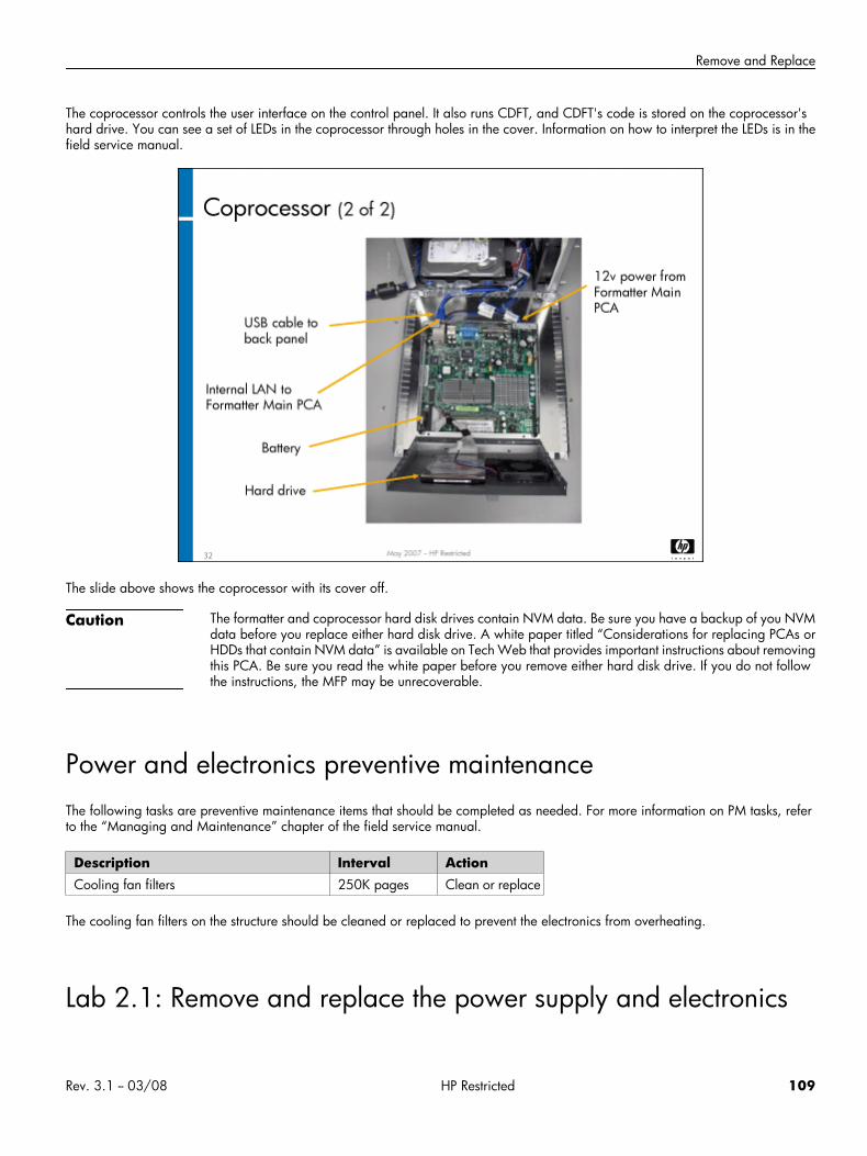
Remove and Replace
The coprocessor controls the user interface on the control panel. It also runs CDFT, and CDFT's code is stored on the coprocessor'shard drive. You can see a set of LEDs in the coprocessor through holes in the cover. Information on how to interpret the LEDs is in thefield service manual.
The slide above shows the coprocessor with its cover off.
Caution The formatter and coprocessor hard disk drives contain NVM data. Be sure you have a backup of you NVMdata before you replace either hard disk drive. A white paper titled “Considerations for replacing PCAs orHDDs that contain NVM data” is available on Tech Web that provides important instructions about removingthis PCA. Be sure you read the white paper before you remove either hard disk drive. If you do not followthe instructions, the MFP may be unrecoverable.
Power and electronics preventive maintenanceThe following tasks are preventive maintenance items that should be completed as needed. For more information on PM tasks, referto the “Managing and Maintenance” chapter of the field service manual.
Description Interval ActionCooling fan filters 250K pages Clean or replace
The cooling fan filters on the structure should be cleaned or replaced to prevent the electronics from overheating.
Lab 2.1: Remove and replace the power supply and electronics
Rev. 3.1 -- 03/08 HP Restricted 109
HP CM8060/8050 Color MFP with Edgeline Technology Service and Support Training Student Guide
Reference material
Document ChapterField service manual Removal and replacement
Troubleshooting
Lab time: 60 minutes
Exercise
Caution Wear an ESD strap.
Use the instructions in the field service manual to complete the following tasks. You will perform this lab in two sections: removing andreplacing the power supply and control electronics, and working in the formatter.
First, look at the Communications and Power supply tool pages in CDFT-E, and try the function available. Also look through the eventlog and see if there are any errors regarding power surges or sags. If so, choose the View Trends button to see the trends.
Power supply and control electronics
Power down the MFP
Remove the Power supply (PS1) assembly and set it aside
Observe the Motion PCA (A2)
Observe the Power Distribution PCA (A1)
Remove the Main Engine PCA (A5) and set it aside
Observe the Main Engine Backplane PCA (A4) and the Ink Assist PCA (A3)
Reinstall the Main Engine PCA (A5) and the Power supply (PS1) assembly
Power up the MFP and make sure it is working correctly
Have your instructor check your work
Formatter
Power down the MFP
Remove the Network/Fax PCA (A30)
Observe the HP Analog Fax Accessory on the Network/Fax PCA (A30)
Observe the other components of the formatter.
Have your instructor check your work to make sure everything was removed correctly
Reinstall the Network/Fax PCA (A30)
Power up the MFP and make sure it is working correctly
Have your instructor check your work
110 HP Restricted Rev. 3.1 -- 03/08
Remove and Replace
Lab 2.2: Troubleshoot power and electronicsYou will now troubleshoot an error in the power or electronics, using CDFT-L.
Reference materialYou will not use the field service manual for this exercise. Instead, you will use CDFT-L.
Lab time: 30 minutes
ExerciseYour instructor has injected a fault into the power supply or electronics. Follow these steps to resolve the error:
Read the control panel error message.
Connect your laptop to the MFP (if it is not already connected) and run CDFT-L.
In CDFT-L, go to the tool page for Power supply, then select Fault Trees.
Follow the tree to solve the problem.
Have your instructor check your work.
Topic 3: Carriage and pensThis topic guides you through theory of operation for the carriage and pens. You will remove and reinstall a pen and various carriagecomponents. You will also examine carriage-related PCAs.
Note Pens are also referred to as printheads.
Rev. 3.1 -- 03/08 HP Restricted 111
HP CM8060/8050 Color MFP with Edgeline Technology Service and Support Training Student Guide
Topic 3 objectivesAfter completing this topic, you should be able to:
• Describe the MFP's pens and how they work
• Identify the carriage-related PCAs
• Describe the carriage assembly theory of operation
• Remove and reinstall pens and various carriage components
Topic contentCompleting this topic should take approximately 3-1/4 hours.
Title DurationLecture: Pens and carriage 60 minutes
Lab 3.1: Remove and replace carriagecomponents
90 minutes
Lab 3.2: Troubleshoot the carriage 45 minutes
112 HP Restricted Rev. 3.1 -- 03/08
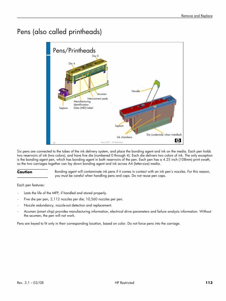
Remove and Replace
Pens (also called printheads)
Six pens are connected to the tubes of the ink delivery system, and place the bonding agent and ink on the media. Each pen holdstwo reservoirs of ink (two colors), and have five die (numbered 0 through 4). Each die delivers two colors of ink. The only exceptionis the bonding agent pen, which has bonding agent in both reservoirs of the pen. Each pen has a 4.25 inch (108mm) print swath,so the two carriages together can lay down bonding agent and ink across A4 (letter-size) media.
Caution Bonding agent will contaminate ink pens if it comes in contact with an ink pen's nozzles. For this reason,you must be careful when handling pens and caps. Do not reuse pen caps.
Each pen features:
• Lasts the life of the MFP, if handled and stored properly.
• Five die per pen, 2,112 nozzles per die; 10,560 nozzles per pen.
• Nozzle redundancy, nozzle-out detection and replacement.
• Acumen (smart chip) provides manufacturing information, electrical drive parameters and failure analysis information. Withoutthe acumen, the pen will not work.
Pens are keyed to fit only in their corresponding location, based on color. Do not force pens into the carriage.
Rev. 3.1 -- 03/08 HP Restricted 113
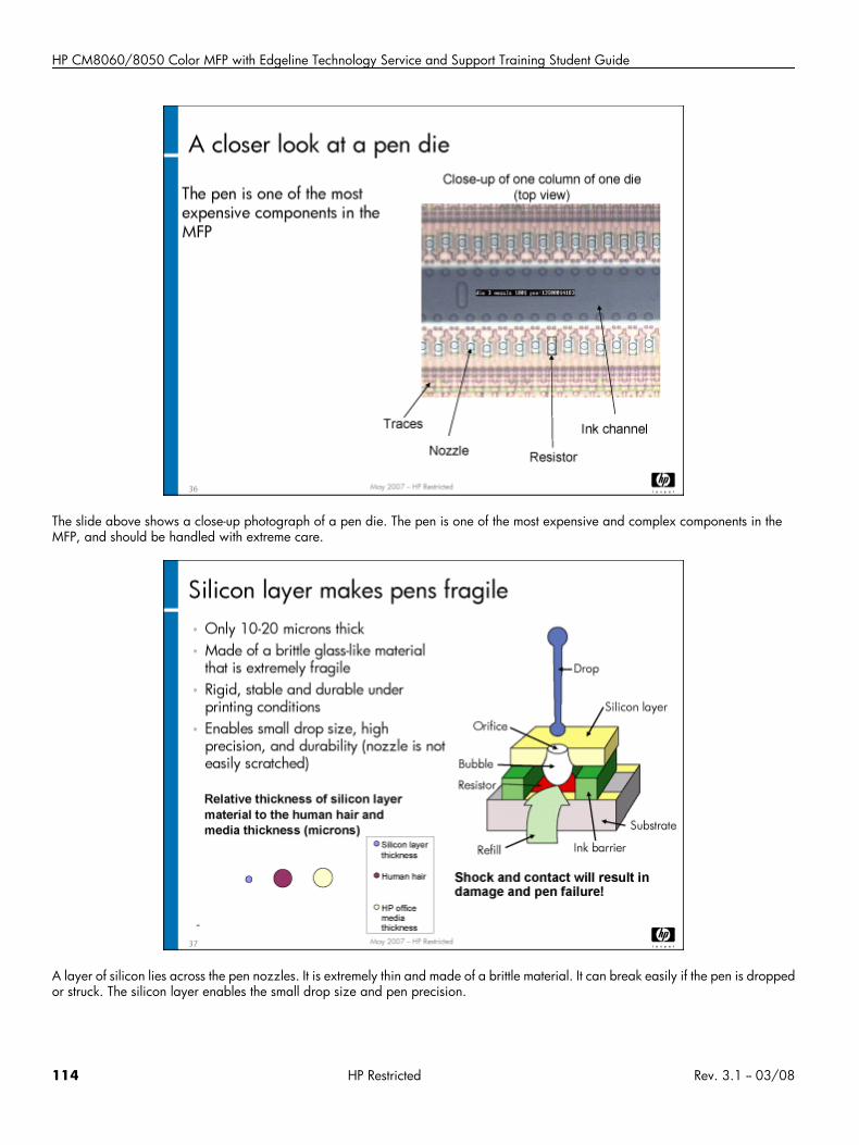
HP CM8060/8050 Color MFP with Edgeline Technology Service and Support Training Student Guide
The slide above shows a close-up photograph of a pen die. The pen is one of the most expensive and complex components in theMFP, and should be handled with extreme care.
A layer of silicon lies across the pen nozzles. It is extremely thin and made of a brittle material. It can break easily if the pen is droppedor struck. The silicon layer enables the small drop size and pen precision.
114 HP Restricted Rev. 3.1 -- 03/08
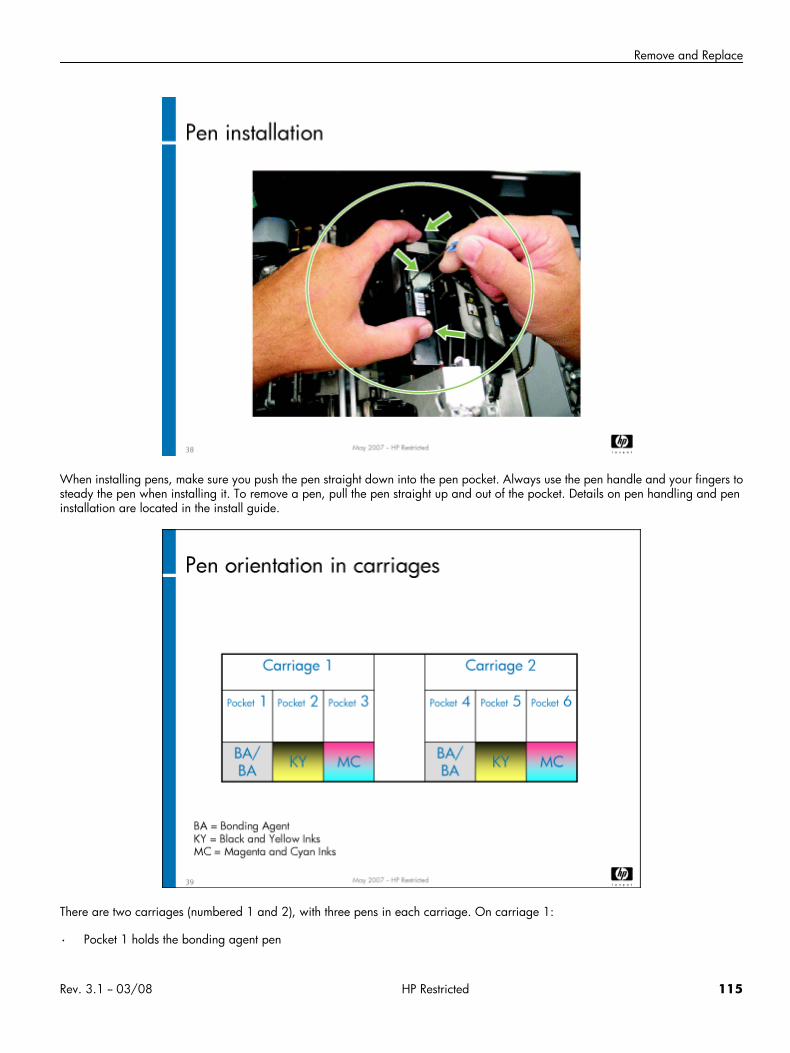
Remove and Replace
When installing pens, make sure you push the pen straight down into the pen pocket. Always use the pen handle and your fingers tosteady the pen when installing it. To remove a pen, pull the pen straight up and out of the pocket. Details on pen handling and peninstallation are located in the install guide.
There are two carriages (numbered 1 and 2), with three pens in each carriage. On carriage 1:
• Pocket 1 holds the bonding agent pen
Rev. 3.1 -- 03/08 HP Restricted 115
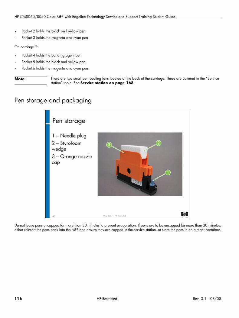
HP CM8060/8050 Color MFP with Edgeline Technology Service and Support Training Student Guide
• Pocket 2 holds the black and yellow pen
• Pocket 3 holds the magenta and cyan pen
On carriage 2:
• Pocket 4 holds the bonding agent pen
• Pocket 5 holds the black and yellow pen
• Pocket 6 holds the magenta and cyan pen
Note There are two small pen cooling fans located at the back of the carriage. These are covered in the “Servicestation” topic. See Service station on page 168.
Pen storage and packaging
Do not leave pens uncapped for more than 30 minutes to prevent evaporation. If pens are to be uncapped for more than 30 minutes,either reinsert the pens back into the MFP and ensure they are capped in the service station, or store the pens in an airtight container.
116 HP Restricted Rev. 3.1 -- 03/08
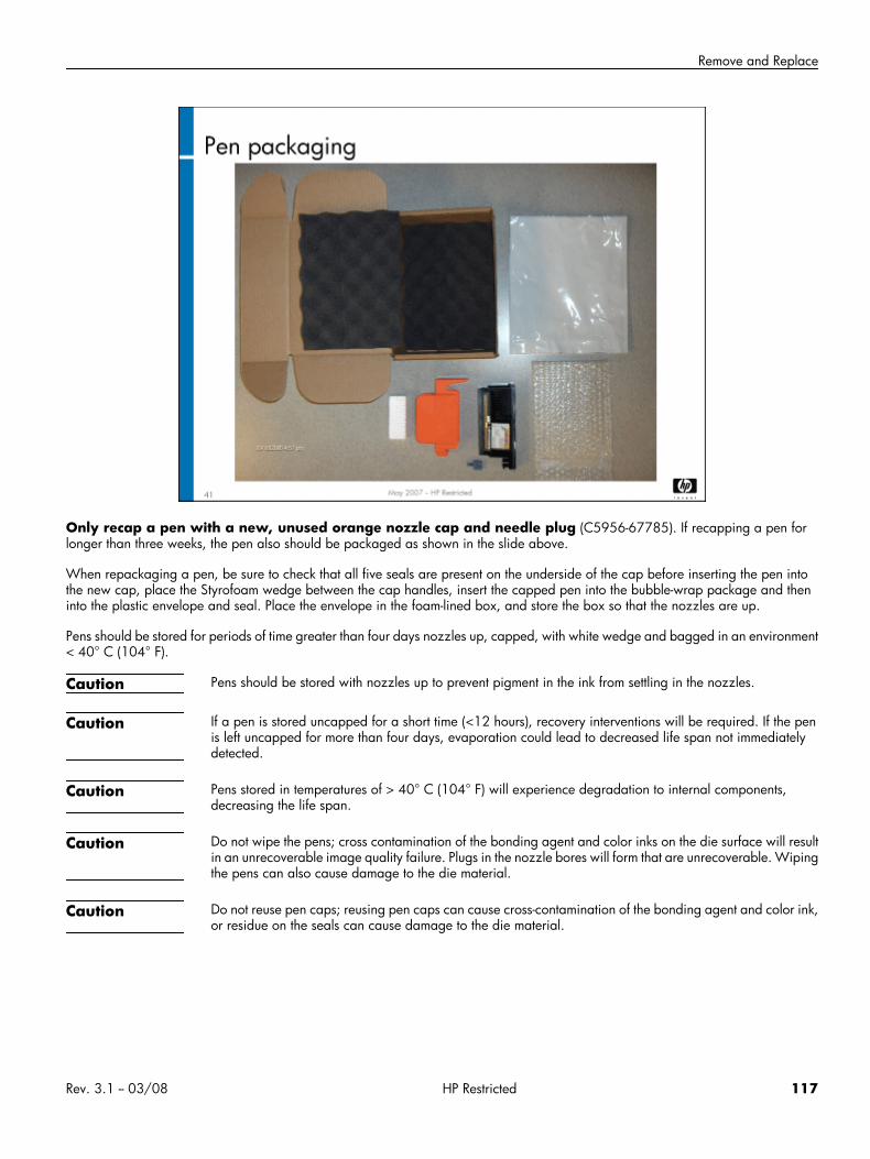
Remove and Replace
Only recap a pen with a new, unused orange nozzle cap and needle plug (C5956-67785). If recapping a pen forlonger than three weeks, the pen also should be packaged as shown in the slide above.
When repackaging a pen, be sure to check that all five seals are present on the underside of the cap before inserting the pen intothe new cap, place the Styrofoam wedge between the cap handles, insert the capped pen into the bubble-wrap package and theninto the plastic envelope and seal. Place the envelope in the foam-lined box, and store the box so that the nozzles are up.
Pens should be stored for periods of time greater than four days nozzles up, capped, with white wedge and bagged in an environment< 40° C (104° F).
Caution Pens should be stored with nozzles up to prevent pigment in the ink from settling in the nozzles.
Caution If a pen is stored uncapped for a short time (<12 hours), recovery interventions will be required. If the penis left uncapped for more than four days, evaporation could lead to decreased life span not immediatelydetected.
Caution Pens stored in temperatures of > 40° C (104° F) will experience degradation to internal components,decreasing the life span.
Caution Do not wipe the pens; cross contamination of the bonding agent and color inks on the die surface will resultin an unrecoverable image quality failure. Plugs in the nozzle bores will form that are unrecoverable. Wipingthe pens can also cause damage to the die material.
Caution Do not reuse pen caps; reusing pen caps can cause cross-contamination of the bonding agent and color ink,or residue on the seals can cause damage to the die material.
Rev. 3.1 -- 03/08 HP Restricted 117
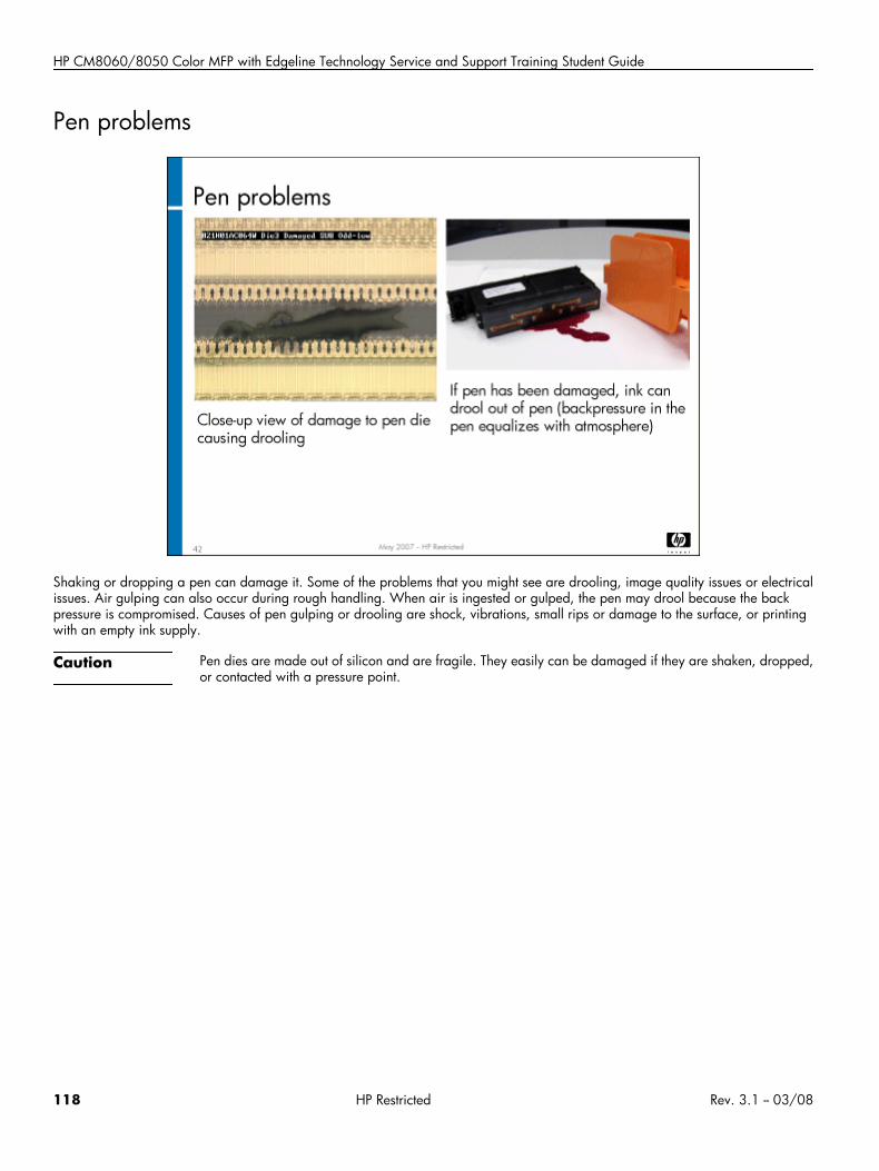
HP CM8060/8050 Color MFP with Edgeline Technology Service and Support Training Student Guide
Pen problems
Shaking or dropping a pen can damage it. Some of the problems that you might see are drooling, image quality issues or electricalissues. Air gulping can also occur during rough handling. When air is ingested or gulped, the pen may drool because the backpressure is compromised. Causes of pen gulping or drooling are shock, vibrations, small rips or damage to the surface, or printingwith an empty ink supply.
Caution Pen dies are made out of silicon and are fragile. They easily can be damaged if they are shaken, dropped,or contacted with a pressure point.
118 HP Restricted Rev. 3.1 -- 03/08
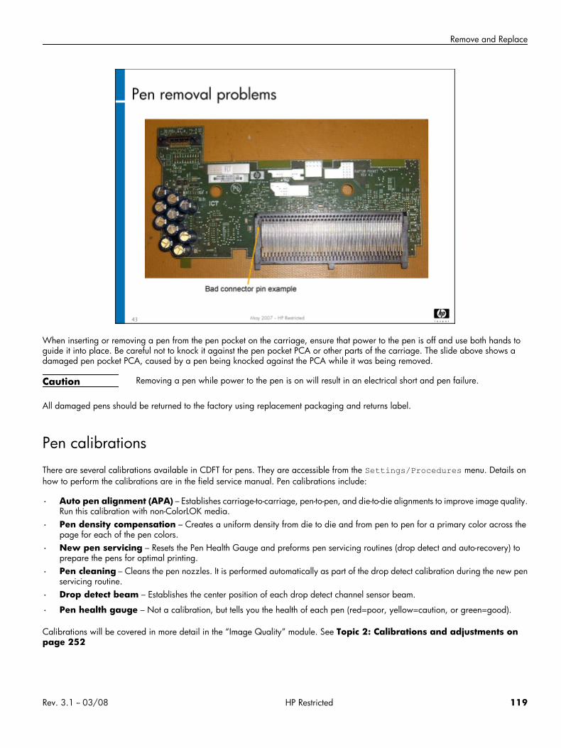
Remove and Replace
When inserting or removing a pen from the pen pocket on the carriage, ensure that power to the pen is off and use both hands toguide it into place. Be careful not to knock it against the pen pocket PCA or other parts of the carriage. The slide above shows adamaged pen pocket PCA, caused by a pen being knocked against the PCA while it was being removed.
Caution Removing a pen while power to the pen is on will result in an electrical short and pen failure.
All damaged pens should be returned to the factory using replacement packaging and returns label.
Pen calibrationsThere are several calibrations available in CDFT for pens. They are accessible from the Settings/Procedures menu. Details onhow to perform the calibrations are in the field service manual. Pen calibrations include:
• Auto pen alignment (APA) – Establishes carriage-to-carriage, pen-to-pen, and die-to-die alignments to improve image quality.Run this calibration with non-ColorLOK media.
• Pen density compensation – Creates a uniform density from die to die and from pen to pen for a primary color across thepage for each of the pen colors.
• New pen servicing – Resets the Pen Health Gauge and preforms pen servicing routines (drop detect and auto-recovery) toprepare the pens for optimal printing.
• Pen cleaning – Cleans the pen nozzles. It is performed automatically as part of the drop detect calibration during the new penservicing routine.
• Drop detect beam – Establishes the center position of each drop detect channel sensor beam.
• Pen health gauge – Not a calibration, but tells you the health of each pen (red=poor, yellow=caution, or green=good).
Calibrations will be covered in more detail in the “Image Quality” module. See Topic 2: Calibrations and adjustments onpage 252
Rev. 3.1 -- 03/08 HP Restricted 119
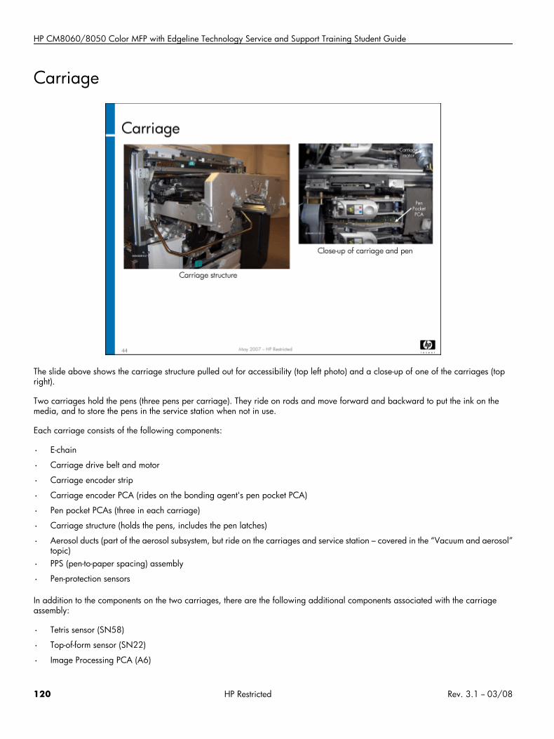
HP CM8060/8050 Color MFP with Edgeline Technology Service and Support Training Student Guide
Carriage
The slide above shows the carriage structure pulled out for accessibility (top left photo) and a close-up of one of the carriages (topright).
Two carriages hold the pens (three pens per carriage). They ride on rods and move forward and backward to put the ink on themedia, and to store the pens in the service station when not in use.
Each carriage consists of the following components:
• E-chain
• Carriage drive belt and motor
• Carriage encoder strip
• Carriage encoder PCA (rides on the bonding agent's pen pocket PCA)
• Pen pocket PCAs (three in each carriage)
• Carriage structure (holds the pens, includes the pen latches)
• Aerosol ducts (part of the aerosol subsystem, but ride on the carriages and service station – covered in the “Vacuum and aerosol”topic)
• PPS (pen-to-paper spacing) assembly
• Pen-protection sensors
In addition to the components on the two carriages, there are the following additional components associated with the carriageassembly:
• Tetris sensor (SN58)
• Top-of-form sensor (SN22)
• Image Processing PCA (A6)
120 HP Restricted Rev. 3.1 -- 03/08
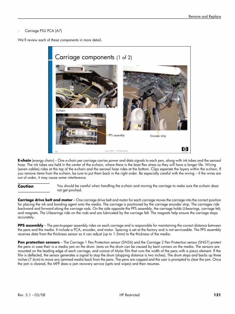
Remove and Replace
• Carriage PSU PCA (A7)
We'll review each of these components in more detail.
E-chain (energy chain) – One e-chain per carriage carries power and data signals to each pen, along with ink tubes and the aerosolhose. The ink tubes are held in the center of the e-chain, where there is the least flex stress so they will have a longer life. Wiring(seven cables) rides at the top of the e-chain and the aerosol hose rides at the bottom. Clips separate the layers within the e-chain. Ifyou remove items from the e-chain, be sure to put them back in the right order. Be especially careful with the wiring – if the wires areout of order, it may cause some interference.
Caution You should be careful when handling the e-chain and moving the carriage to make sure the e-chain doesnot get pinched.
Carriage drive belt and motor – One carriage drive belt and motor for each carriage moves the carriage into the correct positionfor placing the ink and bonding agent onto the media. The carriage is positioned by the carriage encoder strip. The carriages ridebackward and forward along the carriage rods. On the side opposite the PPS assembly, the carriage holds U-bearings, carriage felt,and magnets. The U-bearings ride on the rods and are lubricated by the carriage felt. The magnets help ensure the carriage stopsaccurately.
PPS assembly – The pen-to-paper assembly rides on each carriage and is responsible for maintaining the correct distance betweenthe pens and the media. It include a PCA, encoder, and motor. Spacing is set at the factory and is not serviceable. The PPS assemblyreceives data from the thickness sensor so it can adjust (up to 1.5mm) to the thickness of the media.
Pen protection sensors – The Carriage 1 Pen Protection sensor (SN56) and the Carriage 2 Pen Protection sensor (SN57) protectthe pens in case their is a media jam on the drum. Jams on the drum can be caused by bent corners on the media. The sensors aremounted on the leading edge of each carriage, and consist of Mylar film that runs the width of the pens with a piezo element. If thefilm is deflected, the sensor generates a signal to stop the drum (stopping distance is two inches). The drum stops and backs up threeinches (7.6cm) to move any jammed media back from the pens. The pens are capped and the user is prompted to clear the jam. Oncethe jam is cleared, the MFP does a jam recovery service (spits and wipes) and then resumes.
Rev. 3.1 -- 03/08 HP Restricted 121

HP CM8060/8050 Color MFP with Edgeline Technology Service and Support Training Student Guide
The slide above shows the location of the carriage encoder strip, carriage encoder PCA, and pen pocket PCA.
Carriage encoder strip – One encoder strip per carriage positions the pens accurately. The strip has lines on it that the encoderPCA can read to determine its position. First it reads the home position, which is the large clear space on the encoder strip. After eachcarriage has been homed, they monitor their relative positions based on the stripes on the encoder strip. After a power-up, the carriagesmoves to the front to determine a rough idea of its location, then it finds the home position and is ready to work. Its maximum errorrate is 2 microns. It is driven by the carriage drive belt and motor.
Caution When installing the carriage encoder strip at the front end of the carriage, be sure you position it betweenthe two outside tabs on the locating pin. Do not position it on one of the tabs – this will cause carriage stalls.
Check the alignment of each carriage encoder strip after it is moved or replaced. The alignment is described in the field servicemanual. It uses the carriage index sensors on the CDFT Carriage tool page. Once it is aligned, you need to run the carriage encoderreset calibration.
Caution Be careful not to get fingerprints on the encoder strip.
122 HP Restricted Rev. 3.1 -- 03/08
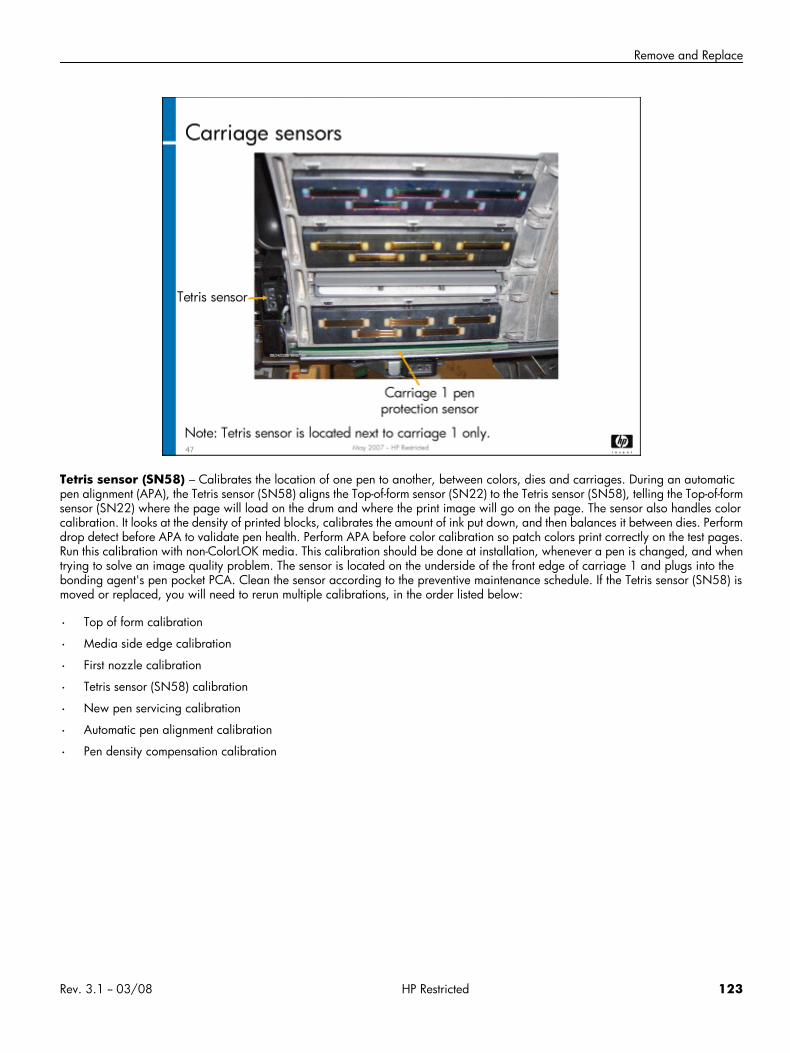
Remove and Replace
Tetris sensor (SN58) – Calibrates the location of one pen to another, between colors, dies and carriages. During an automaticpen alignment (APA), the Tetris sensor (SN58) aligns the Top-of-form sensor (SN22) to the Tetris sensor (SN58), telling the Top-of-formsensor (SN22) where the page will load on the drum and where the print image will go on the page. The sensor also handles colorcalibration. It looks at the density of printed blocks, calibrates the amount of ink put down, and then balances it between dies. Performdrop detect before APA to validate pen health. Perform APA before color calibration so patch colors print correctly on the test pages.Run this calibration with non-ColorLOK media. This calibration should be done at installation, whenever a pen is changed, and whentrying to solve an image quality problem. The sensor is located on the underside of the front edge of carriage 1 and plugs into thebonding agent's pen pocket PCA. Clean the sensor according to the preventive maintenance schedule. If the Tetris sensor (SN58) ismoved or replaced, you will need to rerun multiple calibrations, in the order listed below:
• Top of form calibration
• Media side edge calibration
• First nozzle calibration
• Tetris sensor (SN58) calibration
• New pen servicing calibration
• Automatic pen alignment calibration
• Pen density compensation calibration
Rev. 3.1 -- 03/08 HP Restricted 123
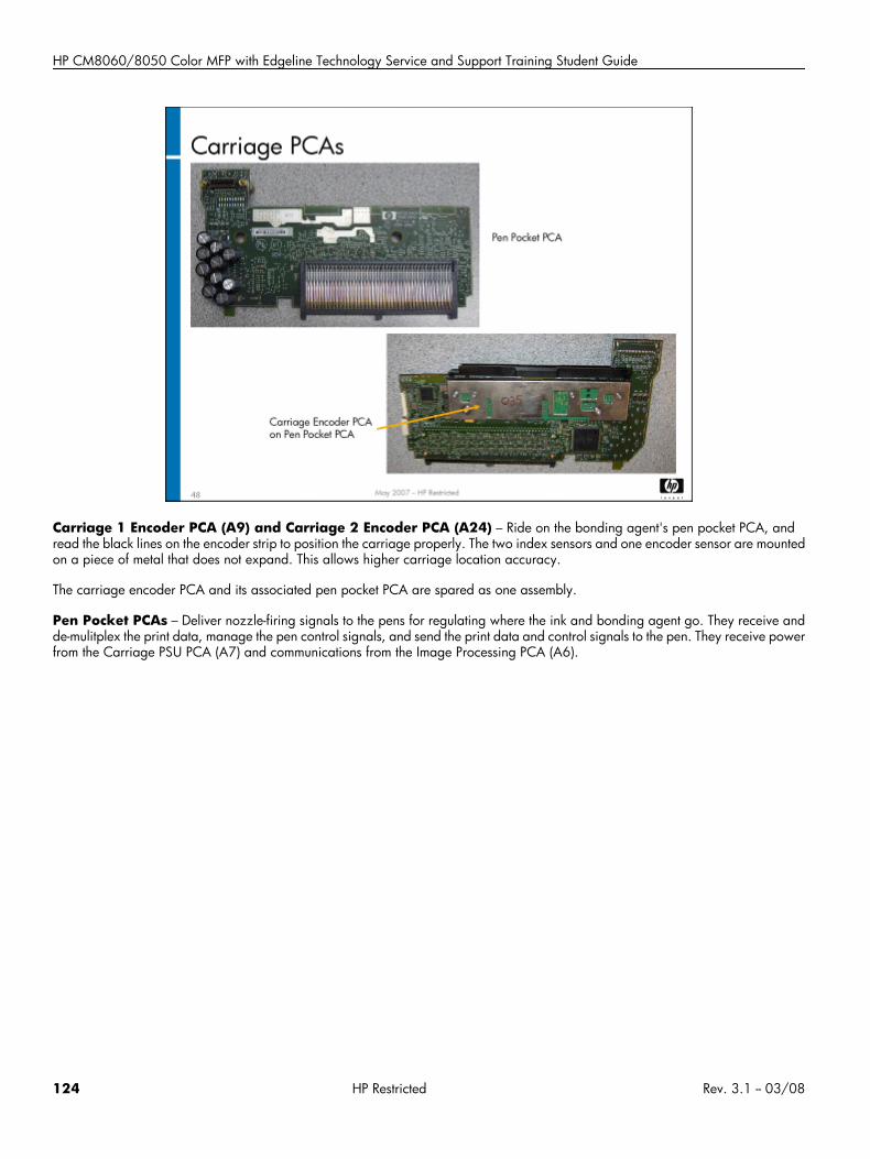
HP CM8060/8050 Color MFP with Edgeline Technology Service and Support Training Student Guide
Carriage 1 Encoder PCA (A9) and Carriage 2 Encoder PCA (A24) – Ride on the bonding agent's pen pocket PCA, andread the black lines on the encoder strip to position the carriage properly. The two index sensors and one encoder sensor are mountedon a piece of metal that does not expand. This allows higher carriage location accuracy.
The carriage encoder PCA and its associated pen pocket PCA are spared as one assembly.
Pen Pocket PCAs – Deliver nozzle-firing signals to the pens for regulating where the ink and bonding agent go. They receive andde-mulitplex the print data, manage the pen control signals, and send the print data and control signals to the pen. They receive powerfrom the Carriage PSU PCA (A7) and communications from the Image Processing PCA (A6).
124 HP Restricted Rev. 3.1 -- 03/08
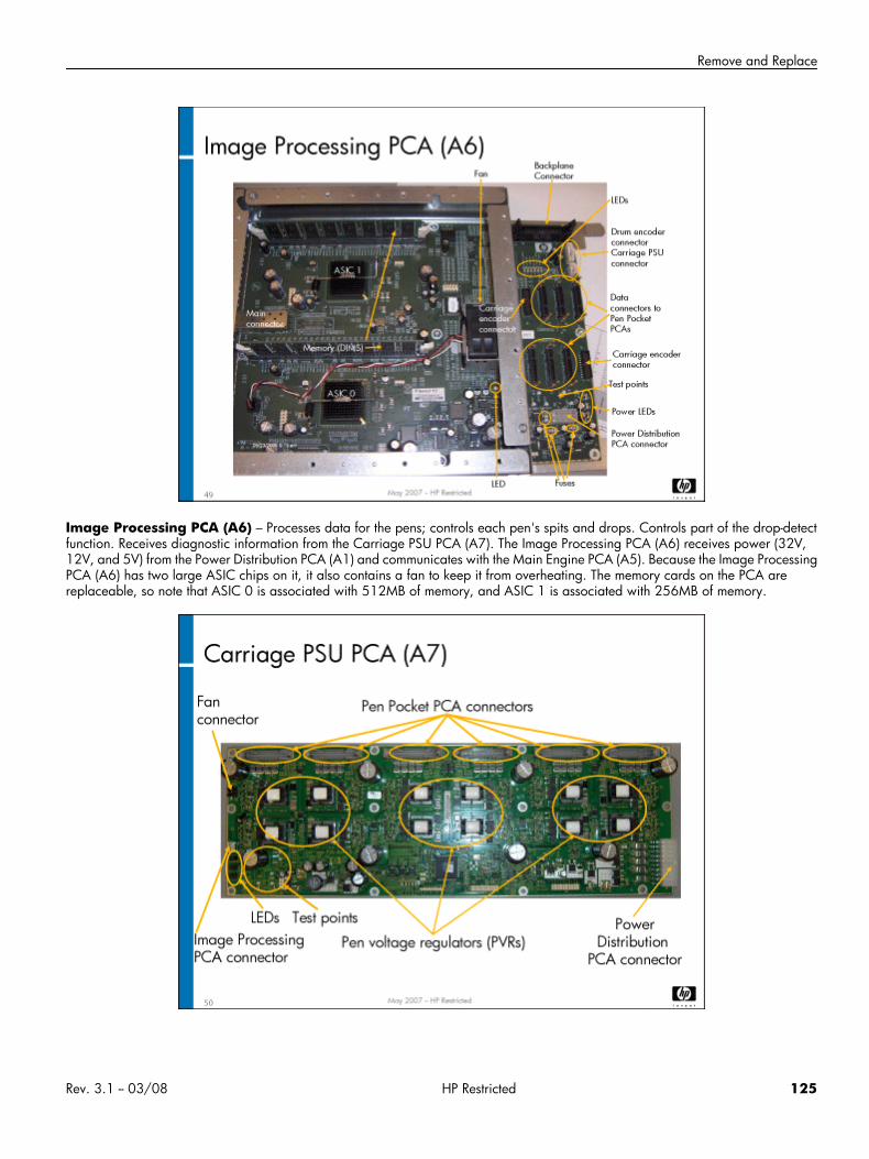
Remove and Replace
Image Processing PCA (A6) – Processes data for the pens; controls each pen's spits and drops. Controls part of the drop-detectfunction. Receives diagnostic information from the Carriage PSU PCA (A7). The Image Processing PCA (A6) receives power (32V,12V, and 5V) from the Power Distribution PCA (A1) and communicates with the Main Engine PCA (A5). Because the Image ProcessingPCA (A6) has two large ASIC chips on it, it also contains a fan to keep it from overheating. The memory cards on the PCA arereplaceable, so note that ASIC 0 is associated with 512MB of memory, and ASIC 1 is associated with 256MB of memory.
Rev. 3.1 -- 03/08 HP Restricted 125
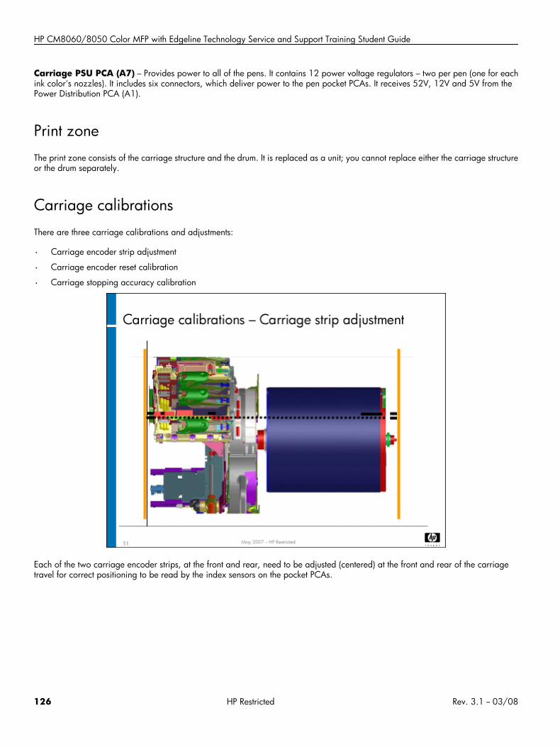
HP CM8060/8050 Color MFP with Edgeline Technology Service and Support Training Student Guide
Carriage PSU PCA (A7) – Provides power to all of the pens. It contains 12 power voltage regulators – two per pen (one for eachink color's nozzles). It includes six connectors, which deliver power to the pen pocket PCAs. It receives 52V, 12V and 5V from thePower Distribution PCA (A1).
Print zoneThe print zone consists of the carriage structure and the drum. It is replaced as a unit; you cannot replace either the carriage structureor the drum separately.
Carriage calibrationsThere are three carriage calibrations and adjustments:
• Carriage encoder strip adjustment
• Carriage encoder reset calibration
• Carriage stopping accuracy calibration
Each of the two carriage encoder strips, at the front and rear, need to be adjusted (centered) at the front and rear of the carriagetravel for correct positioning to be read by the index sensors on the pocket PCAs.
126 HP Restricted Rev. 3.1 -- 03/08
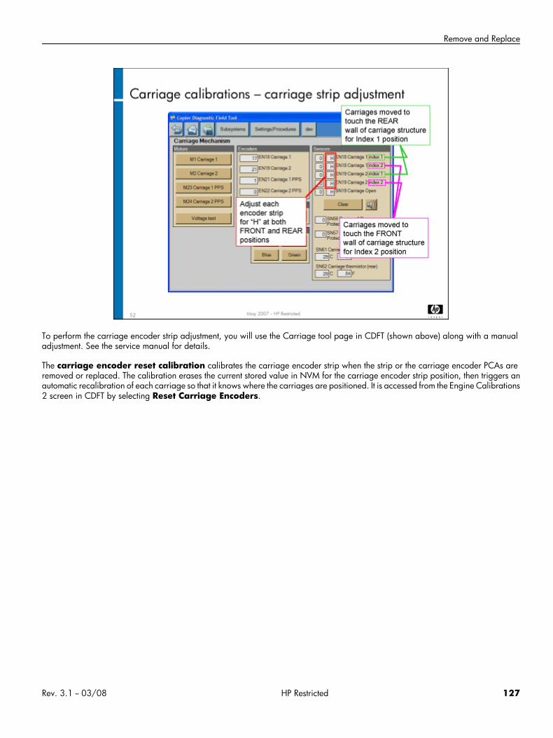
Remove and Replace
To perform the carriage encoder strip adjustment, you will use the Carriage tool page in CDFT (shown above) along with a manualadjustment. See the service manual for details.
The carriage encoder reset calibration calibrates the carriage encoder strip when the strip or the carriage encoder PCAs areremoved or replaced. The calibration erases the current stored value in NVM for the carriage encoder strip position, then triggers anautomatic recalibration of each carriage so that it knows where the carriages are positioned. It is accessed from the Engine Calibrations2 screen in CDFT by selecting Reset Carriage Encoders.
Rev. 3.1 -- 03/08 HP Restricted 127
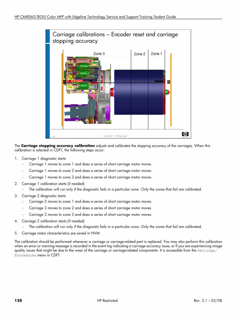
HP CM8060/8050 Color MFP with Edgeline Technology Service and Support Training Student Guide
The Carriage stopping accuracy calibration adjusts and calibrates the stopping accuracy of the carriages. When thiscalibration is selected in CDFT, the following steps occur:
1. Carriage 1 diagnostic starts
• Carriage 1 moves to zone 1 and does a series of short carriage motor moves
• Carriage 1 moves to zone 2 and does a series of short carriage motor moves
• Carriage 1 moves to zone 3 and does a series of short carriage motor moves
2. Carriage 1 calibration starts (if needed)
• The calibration will run only if the diagnostic fails in a particular zone. Only the zones that fail are calibrated.
3. Carriage 2 diagnostic starts
• Carriage 2 moves to zone 1 and does a series of short carriage motor moves
• Carriage 2 moves to zone 2 and does a series of short carriage motor moves
• Carriage 2 moves to zone 3 and does a series of short carriage motor moves
4. Carriage 2 calibration starts (if needed)
• The calibration will run only if the diagnostic fails in a particular zone. Only the zones that fail are calibrated.
5. Carriage motor characteristics are saved in NVM
The calibration should be performed whenever a carriage or carriage-related part is replaced. You may also perform this calibrationwhen an error or warning message is recorded in the event log indicating a carriage accuracy issue, or if you are experiencing imagequality issues that might be due to the wear of the carriage or carriage-related components. It is accessible from the Settings/Procedures menu in CDFT.
128 HP Restricted Rev. 3.1 -- 03/08
Remove and Replace
Carriage event trends
If you notice an error message regarding carriage accuracy, you may want to examine the carriage stopping accuracy eventtrend. This shows, either in list or graph format, all of the events detected that indicate out-of-specification stopping accuracy problems.To see the event trends for carriage stopping accuracy, go to the event log in CDFT, and choose the View Trends button.
If factory thresholds for carriage stopping accuracy are exceeded, a message will appear on the View Trends page warning youof the threshold violation.
Carriage preventive maintenanceThe following tasks are preventive maintenance items that should be completed as needed. For more information on PM tasks, referto the “Managing and Maintenance” chapter of the field service manual.
Description Interval ActionTetris sensor (SN58) 120K copies Clean
Carriage encoder sensor/PCA 250K copies Replace
Carriage encoder strip 250K copies Replace
Carriage felt oiler clip 500K copies Replace
Carriage drive belt 500K copies Replace
Lab 3.1: Remove and replace carriage componentsIn this exercise, you will remove a carriage encoder strip and PCA, a pen pocket PCA, the carriage drive belt and motor, and theaerosol ducts. You will also observe the Tetris sensor (SN58), the Top-of-form sensor (SN22), the Image Processing PCA (A6) and theCarriage PSU PCA (A7).
Reference material
Document ChapterField service manual Removal and replacement – Carriage
Lab time: 90 minutes
ExerciseBefore you begin, take a look at the Carriage tool page in CDFT-E. Try some of the functions available on the page.
Caution Wear an ESD strap.
Caution When you remove the pen to get to the pen pocket PCA, make sure you reinsert it in the correct location.The pen color matches the color on the pen latch.
Rev. 3.1 -- 03/08 HP Restricted 129
HP CM8060/8050 Color MFP with Edgeline Technology Service and Support Training Student Guide
Use the instructions in the field service manual to complete the following tasks. As you go through the exercise, you'll be disconnectingcables from the Image Processing PCA (A6) and the Carriage PSU PCA (A7). Be sure to take a look at these PCAs when you workon them. Also, locate the Tetris sensor (SN58).
Power down the MFP.
Remove the carriage 2 encoder strip (PM item).
Remove the Carriage 2 drive belt (PM item) and Carriage 2 motor (M2).
Remove the Carriage 2 Encoder PCA (A24), which includes the Pen Pocket PCA.
Remove the carriage 2 aerosol manifolds and aerosol duct assembly (PM item).
Remove the carriage 2 felt oiler (PM item).
Pull out the carriage structure and then go to the rear of the MFP. Locate and observe the Carriage PSU PCA (A7).
Observe the Image Processing PCA (A6).
Have your instructor check your work.
Reinstall all of the carriage components
Power up the MFP and make sure it is working correctly.
Check the encoder strip alignment.
Use CDFT-E to perform the following calibrations:
• Carriage encoder reset
• Carriage stopping accuracy
Note Outside the classroom, you would need to perform the APA, new pen servicing, and pen density calibrationsif you inserted a new pen in an MFP.
Lab 3.2: Troubleshoot the carriageYou will now troubleshoot an error in the carriage, using CDFT-E.
Reference materialYou will not use the field service manual during this exercise.
Lab time: 45 minutes
ExerciseYour instructor has injected a fault into the carriage. Follow these steps to resolve the error:
Try to make a copy.
Read the control panel error message.
In CDFT-E, locate the error message and try the recommended actions.
Verify that you correctly solved the problem.
130 HP Restricted Rev. 3.1 -- 03/08
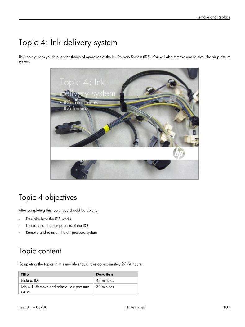
Remove and Replace
Topic 4: Ink delivery systemThis topic guides you through the theory of operation of the Ink Delivery System (IDS). You will also remove and reinstall the air pressuresystem.
Topic 4 objectivesAfter completing this topic, you should be able to:
• Describe how the IDS works
• Locate all of the components of the IDS
• Remove and reinstall the air pressure system
Topic contentCompleting the topics in this module should take approximately 2-1/4 hours.
Title DurationLecture: IDS 45 minutes
Lab 4.1: Remove and reinstall air pressuresystem
30 minutes
Rev. 3.1 -- 03/08 HP Restricted 131
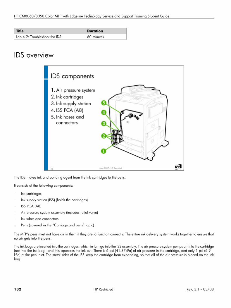
HP CM8060/8050 Color MFP with Edgeline Technology Service and Support Training Student Guide
Title DurationLab 4.2: Troubleshoot the IDS 60 minutes
IDS overview
The IDS moves ink and bonding agent from the ink cartridges to the pens.
It consists of the following components:
• Ink cartridges
• Ink supply station (ISS) (holds the cartridges)
• ISS PCA (A8)
• Air pressure system assembly (includes relief valve)
• Ink tubes and connectors
• Pens (covered in the “Carriage and pens” topic)
The MFP's pens must not have air in them if they are to function correctly. The entire ink delivery system works together to ensure thatno air gets into the pens.
The ink bags are inserted into the cartridges, which in turn go into the ISS assembly. The air pressure system pumps air into the cartridge(not into the ink bag), and this squeezes the ink out. There is 6 psi (41.37kPa) of air pressure in the cartridge, and only 1 psi (6.9kPa) at the pen inlet. The metal sides of the ISS keep the cartridge from expanding, so that all of the air pressure is placed on the inkbag.
132 HP Restricted Rev. 3.1 -- 03/08
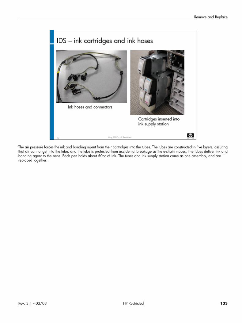
Remove and Replace
The air pressure forces the ink and bonding agent from their cartridges into the tubes. The tubes are constructed in five layers, assuringthat air cannot get into the tube, and the tube is protected from accidental breakage as the e-chain moves. The tubes deliver ink andbonding agent to the pens. Each pen holds about 50cc of ink. The tubes and ink supply station come as one assembly, and arereplaced together.
Rev. 3.1 -- 03/08 HP Restricted 133
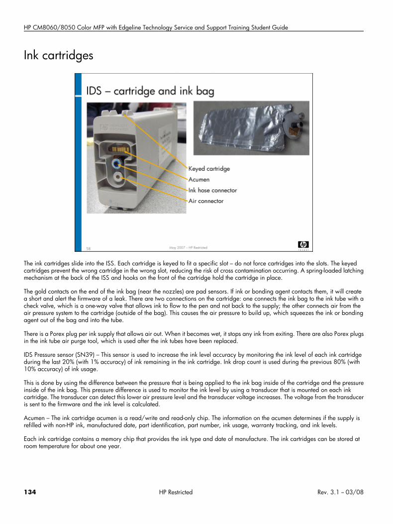
HP CM8060/8050 Color MFP with Edgeline Technology Service and Support Training Student Guide
Ink cartridges
The ink cartridges slide into the ISS. Each cartridge is keyed to fit a specific slot – do not force cartridges into the slots. The keyedcartridges prevent the wrong cartridge in the wrong slot, reducing the risk of cross contamination occurring. A spring-loaded latchingmechanism at the back of the ISS and hooks on the front of the cartridge hold the cartridge in place.
The gold contacts on the end of the ink bag (near the nozzles) are pad sensors. If ink or bonding agent contacts them, it will createa short and alert the firmware of a leak. There are two connections on the cartridge: one connects the ink bag to the ink tube with acheck valve, which is a one-way valve that allows ink to flow to the pen and not back to the supply; the other connects air from theair pressure system to the cartridge (outside of the bag). This causes the air pressure to build up, which squeezes the ink or bondingagent out of the bag and into the tube.
There is a Porex plug per ink supply that allows air out. When it becomes wet, it stops any ink from exiting. There are also Porex plugsin the ink tube air purge tool, which is used after the ink tubes have been replaced.
IDS Pressure sensor (SN39) – This sensor is used to increase the ink level accuracy by monitoring the ink level of each ink cartridgeduring the last 20% (with 1% accuracy) of ink remaining in the ink cartridge. Ink drop count is used during the previous 80% (with10% accuracy) of ink usage.
This is done by using the difference between the pressure that is being applied to the ink bag inside of the cartridge and the pressureinside of the ink bag. This pressure difference is used to monitor the ink level by using a transducer that is mounted on each inkcartridge. The transducer can detect this lower air pressure level and the transducer voltage increases. The voltage from the transduceris sent to the firmware and the ink level is calculated.
Acumen – The ink cartridge acumen is a read/write and read-only chip. The information on the acumen determines if the supply isrefilled with non-HP ink, manufactured date, part identification, part number, ink usage, warranty tracking, and ink levels.
Each ink cartridge contains a memory chip that provides the ink type and date of manufacture. The ink cartridges can be stored atroom temperature for about one year.
134 HP Restricted Rev. 3.1 -- 03/08
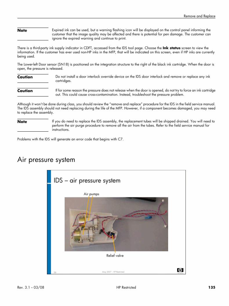
Remove and Replace
Note Expired ink can be used, but a warning flashing icon will be displayed on the control panel informing thecustomer that the image quality may be affected and there is potential for pen damage. The customer canignore the expired warning and continue to print.
There is a third-party ink supply indicator in CDFT, accessed from the IDS tool page. Choose the Ink status screen to view theinformation. If the customer has ever used non-HP inks in the MFP, that will be indicated on this screen, even if HP inks are currentlybeing used.
The Lower-left Door sensor (SN18) is positioned on the integration structure to the right of the black ink cartridge. When the door isopen, the pressure is released.
Caution Do not install a door interlock override device on the IDS door interlock and remove or replace any inkcartridges.
Caution If for some reason the pressure does not release when the door is opened, do not try to force an ink cartridgeout. This could cause cross-contamination. Instead, troubleshoot the pressure problem.
Although it won't be done during class, you should review the “remove and replace” procedure for the IDS in the field service manual.The IDS assembly should not need replacing during the life of the MFP. However, if a component becomes damaged, you may needto replace the assembly.
Note If you do need to replace the IDS assembly, the replacement tubes will be shipped drained. You will need toperform the air purge procedure to remove all the air from the tubes. Refer to the field service manual forinstructions.
Problems with the IDS will generate an error code that begins with C7.
Air pressure system
Rev. 3.1 -- 03/08 HP Restricted 135
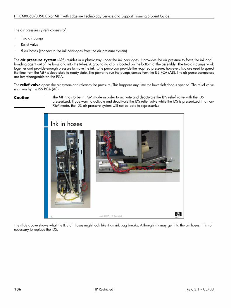
HP CM8060/8050 Color MFP with Edgeline Technology Service and Support Training Student Guide
The air pressure system consists of:
• Two air pumps
• Relief valve
• 5 air hoses (connect to the ink cartridges from the air pressure system)
The air pressure system (APS) resides in a plastic tray under the ink cartridges. It provides the air pressure to force the ink andbonding agent out of the bags and into the tubes. A grounding clip is located on the bottom of the assembly. The two air pumps worktogether and provide enough pressure to move the ink. One pump can provide the required pressure; however, two are used to speedthe time from the MFP's sleep state to ready state. The power to run the pumps comes from the ISS PCA (A8). The air pump connectorsare interchangeable on the PCA.
The relief valve opens the air system and releases the pressure. This happens any time the lower-left door is opened. The relief valveis driven by the ISS PCA (A8).
Caution The MFP has to be in PSM mode in order to activate and deactivate the IDS relief valve with the IDSpressurized. If you want to activate and deactivate the IDS relief valve while the IDS is pressurized in a non-PSM mode, the IDS air pressure system will not be able to repressurize.
The slide above shows what the IDS air hoses might look like if an ink bag breaks. Although ink may get into the air hoses, it is notnecessary to replace the IDS.
136 HP Restricted Rev. 3.1 -- 03/08
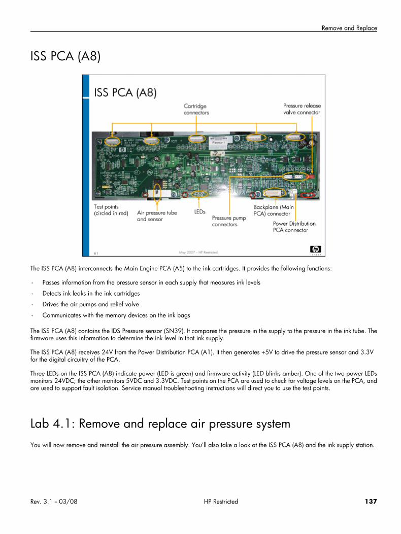
Remove and Replace
ISS PCA (A8)
The ISS PCA (A8) interconnects the Main Engine PCA (A5) to the ink cartridges. It provides the following functions:
• Passes information from the pressure sensor in each supply that measures ink levels
• Detects ink leaks in the ink cartridges
• Drives the air pumps and relief valve
• Communicates with the memory devices on the ink bags
The ISS PCA (A8) contains the IDS Pressure sensor (SN39). It compares the pressure in the supply to the pressure in the ink tube. Thefirmware uses this information to determine the ink level in that ink supply.
The ISS PCA (A8) receives 24V from the Power Distribution PCA (A1). It then generates +5V to drive the pressure sensor and 3.3Vfor the digital circuitry of the PCA.
Three LEDs on the ISS PCA (A8) indicate power (LED is green) and firmware activity (LED blinks amber). One of the two power LEDsmonitors 24VDC; the other monitors 5VDC and 3.3VDC. Test points on the PCA are used to check for voltage levels on the PCA, andare used to support fault isolation. Service manual troubleshooting instructions will direct you to use the test points.
Lab 4.1: Remove and replace air pressure systemYou will now remove and reinstall the air pressure assembly. You'll also take a look at the ISS PCA (A8) and the ink supply station.
Rev. 3.1 -- 03/08 HP Restricted 137
HP CM8060/8050 Color MFP with Edgeline Technology Service and Support Training Student Guide
Reference material
Document ChapterField service manual Removal and Replacement — IDS
Lab time: 30 minutes
ExerciseBefore you begin, take a look at the IDS tool page in CDFT-E. Try some of the functions available on the page Be sure to pressurizeand depressurize the system.
Use the instructions in the field service manual to complete the following tasks. Take a look at the ISS PCA (A8). To see the PCA, youwill need to open the IDO and remove the ISS side panel. Remove a few of the cartridges and take a look at the ink supply station,noting the keys and the latches at the back. When you have everything removed, have your instructor check your work.
Power down the MFP.
Remove the air pressure system (APS) assembly.
Remove one of the pumps from the air pressure system.
Remove some of the cartridges so that you can see the ink supply station.
Look at the ISS PCA (A8), noting the LEDs and the connectors.
Have your instructor check your work to make sure you removed the air pressure system and air pump correctly.
Reinstall the air pump and air pressure system.
Reinsert the ink cartridges.
Power up the MFP and make sure it is working correctly.
Lab 4.2: Troubleshoot the IDSYou will now troubleshoot an error in the IDS, using CDFT-L.
Reference materialYou will not use the field service manual in this exercise.
Lab time: 60 minutes
ExerciseYour instructor has injected a fault into the IDS. Follow these steps to resolve the error:
Read the control panel error message.
If you have not already done so, connect your laptop to the MFP and open CDFT-L in PSM.
138 HP Restricted Rev. 3.1 -- 03/08
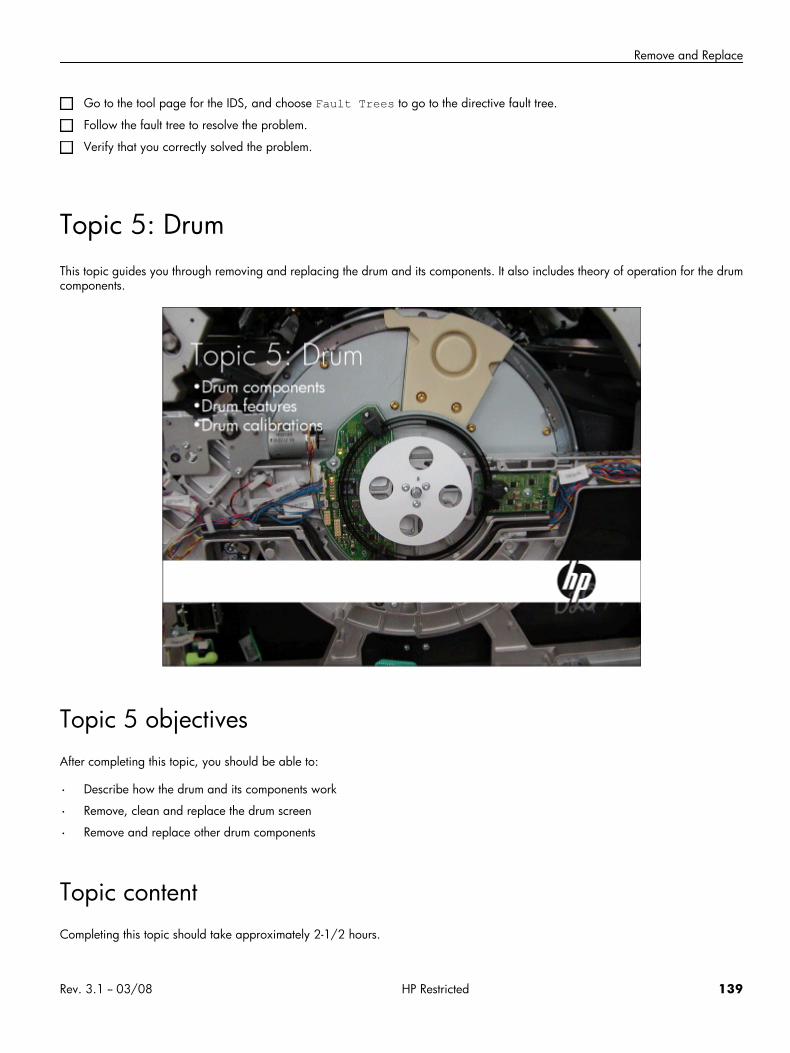
Remove and Replace
Go to the tool page for the IDS, and choose Fault Trees to go to the directive fault tree.
Follow the fault tree to resolve the problem.
Verify that you correctly solved the problem.
Topic 5: DrumThis topic guides you through removing and replacing the drum and its components. It also includes theory of operation for the drumcomponents.
Topic 5 objectivesAfter completing this topic, you should be able to:
• Describe how the drum and its components work
• Remove, clean and replace the drum screen
• Remove and replace other drum components
Topic contentCompleting this topic should take approximately 2-1/2 hours.
Rev. 3.1 -- 03/08 HP Restricted 139
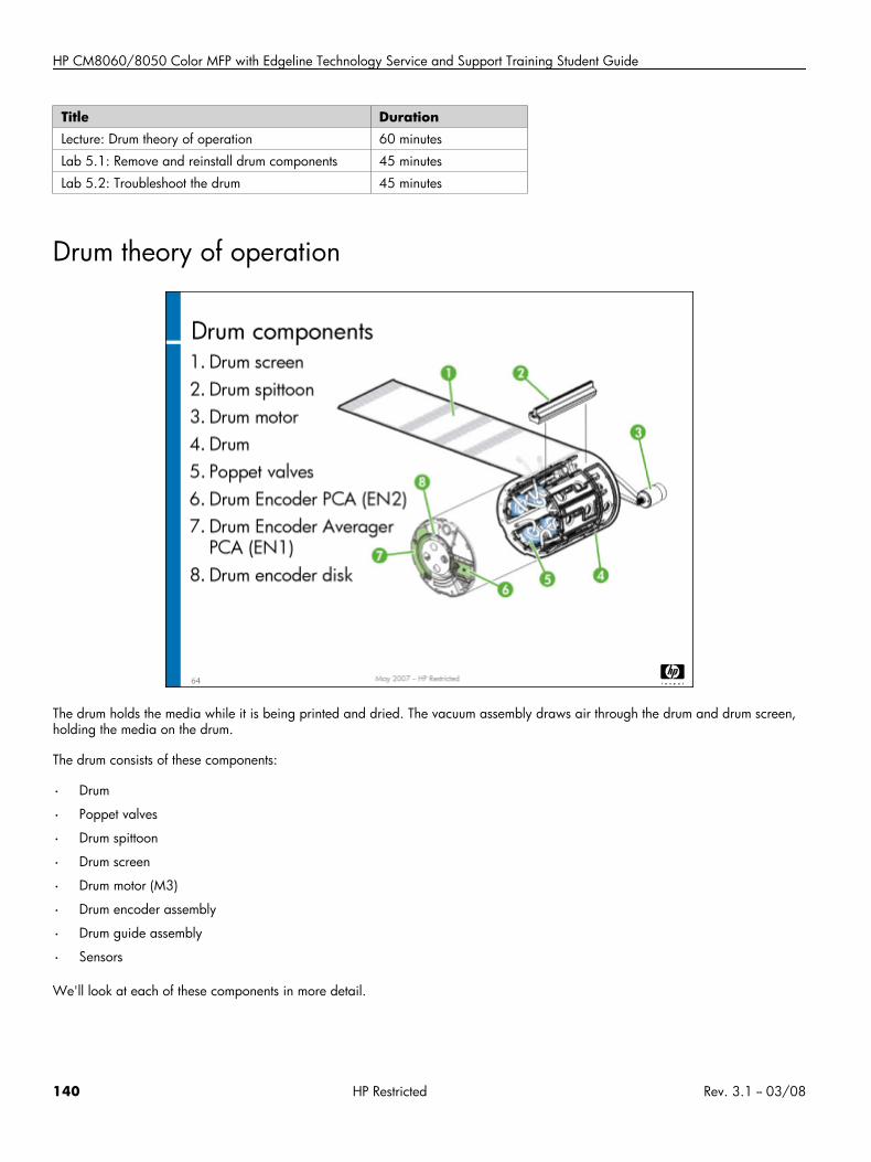
HP CM8060/8050 Color MFP with Edgeline Technology Service and Support Training Student Guide
Title DurationLecture: Drum theory of operation 60 minutes
Lab 5.1: Remove and reinstall drum components 45 minutes
Lab 5.2: Troubleshoot the drum 45 minutes
Drum theory of operation
The drum holds the media while it is being printed and dried. The vacuum assembly draws air through the drum and drum screen,holding the media on the drum.
The drum consists of these components:
• Drum
• Poppet valves
• Drum spittoon
• Drum screen
• Drum motor (M3)
• Drum encoder assembly
• Drum guide assembly
• Sensors
We'll look at each of these components in more detail.
140 HP Restricted Rev. 3.1 -- 03/08
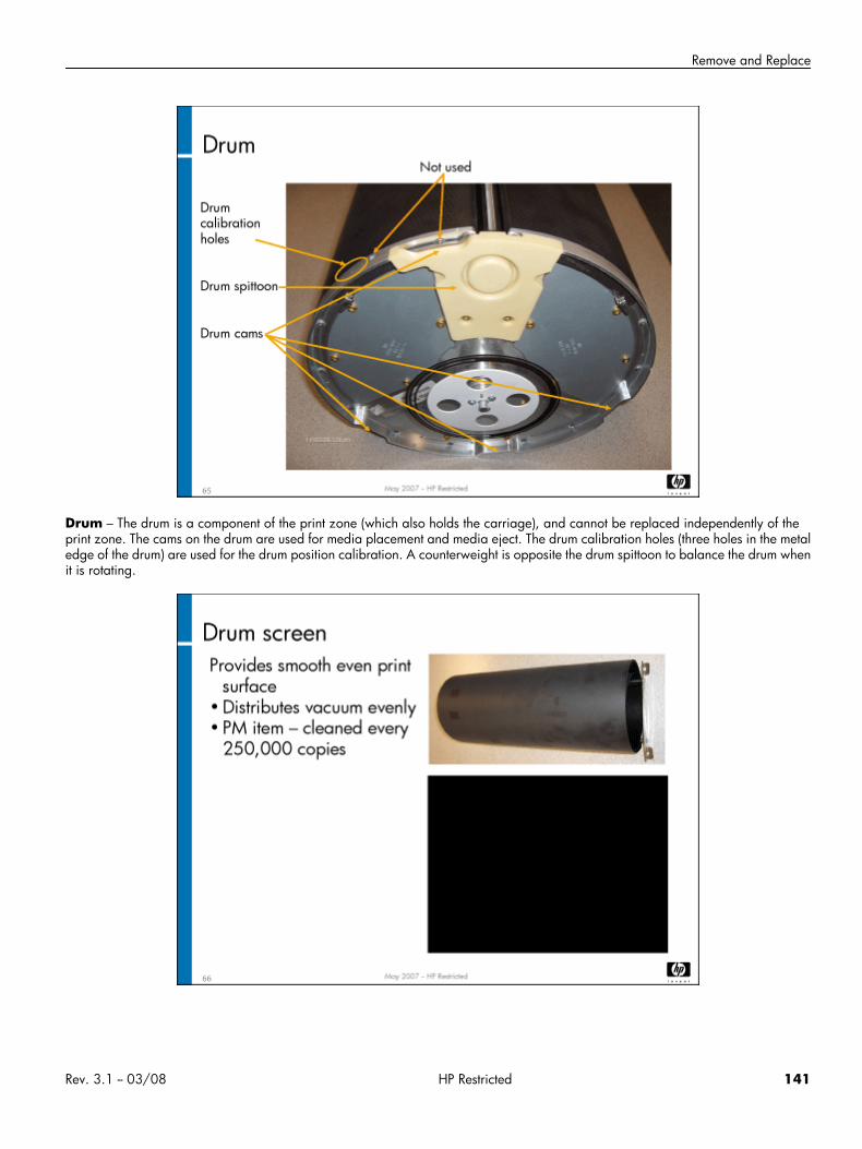
Remove and Replace
Drum – The drum is a component of the print zone (which also holds the carriage), and cannot be replaced independently of theprint zone. The cams on the drum are used for media placement and media eject. The drum calibration holes (three holes in the metaledge of the drum) are used for the drum position calibration. A counterweight is opposite the drum spittoon to balance the drum whenit is rotating.
Rev. 3.1 -- 03/08 HP Restricted 141
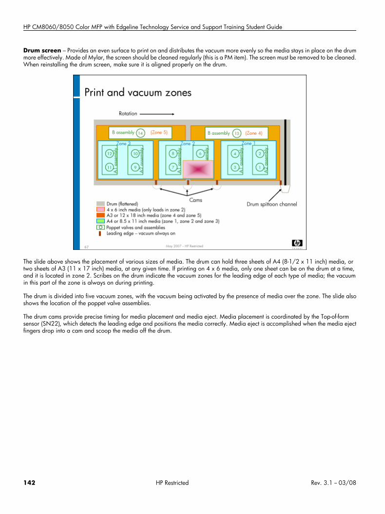
HP CM8060/8050 Color MFP with Edgeline Technology Service and Support Training Student Guide
Drum screen – Provides an even surface to print on and distributes the vacuum more evenly so the media stays in place on the drummore effectively. Made of Mylar, the screen should be cleaned regularly (this is a PM item). The screen must be removed to be cleaned.When reinstalling the drum screen, make sure it is aligned properly on the drum.
The slide above shows the placement of various sizes of media. The drum can hold three sheets of A4 (8-1/2 x 11 inch) media, ortwo sheets of A3 (11 x 17 inch) media, at any given time. If printing on 4 x 6 media, only one sheet can be on the drum at a time,and it is located in zone 2. Scribes on the drum indicate the vacuum zones for the leading edge of each type of media; the vacuumin this part of the zone is always on during printing.
The drum is divided into five vacuum zones, with the vacuum being activated by the presence of media over the zone. The slide alsoshows the location of the poppet valve assemblies.
The drum cams provide precise timing for media placement and media eject. Media placement is coordinated by the Top-of-formsensor (SN22), which detects the leading edge and positions the media correctly. Media eject is accomplished when the media ejectfingers drop into a cam and scoop the media off the drum.
142 HP Restricted Rev. 3.1 -- 03/08
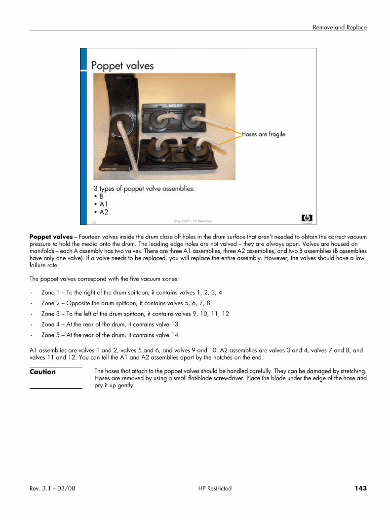
Remove and Replace
Poppet valves – Fourteen valves inside the drum close off holes in the drum surface that aren't needed to obtain the correct vacuumpressure to hold the media onto the drum. The leading edge holes are not valved – they are always open. Valves are housed onmanifolds – each A assembly has two valves. There are three A1 assemblies, three A2 assemblies, and two B assemblies (B assemblieshave only one valve). If a valve needs to be replaced, you will replace the entire assembly. However, the valves should have a lowfailure rate.
The poppet valves correspond with the five vacuum zones:
• Zone 1 – To the right of the drum spittoon, it contains valves 1, 2, 3, 4
• Zone 2 – Opposite the drum spittoon, it contains valves 5, 6, 7, 8
• Zone 3 – To the left of the drum spittoon, it contains valves 9, 10, 11, 12
• Zone 4 – At the rear of the drum, it contains valve 13
• Zone 5 – At the rear of the drum, it contains valve 14
A1 assemblies are valves 1 and 2, valves 5 and 6, and valves 9 and 10. A2 assemblies are valves 3 and 4, valves 7 and 8, andvalves 11 and 12. You can tell the A1 and A2 assemblies apart by the notches on the end.
Caution The hoses that attach to the poppet valves should be handled carefully. They can be damaged by stretching.Hoses are removed by using a small flat-blade screwdriver. Place the blade under the edge of the hose andpry it up gently.
Rev. 3.1 -- 03/08 HP Restricted 143
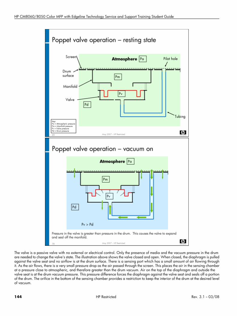
HP CM8060/8050 Color MFP with Edgeline Technology Service and Support Training Student Guide
The valve is a passive valve with no external or electrical control. Only the presence of media and the vacuum pressure in the drumare needed to change the valve's state. The illustration above shows the valve closed and open. When closed, the diaphragm is pulledagainst the valve seat and no airflow is at the drum surface. There is a sensing port which has a small amount of air flowing throughit. As the air flows, there is a very small pressure drop as the air passed through the screen. This places the air in the sensing chamberat a pressure close to atmospheric, and therefore greater than the drum vacuum. Air on the top of the diaphragm and outside thevalve seat is at the drum vacuum pressure. This pressure difference forces the diaphragm against the valve seat and seals off a portionof the drum. The orifice in the bottom of the sensing chamber provides a restriction to keep the interior of the drum at the desired levelof vacuum.
144 HP Restricted Rev. 3.1 -- 03/08
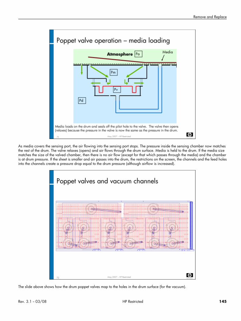
Remove and Replace
As media covers the sensing port, the air flowing into the sensing port stops. The pressure inside the sensing chamber now matchesthe rest of the drum. The valve relaxes (opens) and air flows through the drum surface. Media is held to the drum. If the media sizematches the size of the valved chamber, then there is no air flow (except for that which passes through the media) and the chamberis at drum pressure. If the sheet is smaller and air passes into the drum, the restrictions on the screen, the channels and the feed holesinto the channels create a pressure drop equal to the drum pressure (although airflow is increased).
The slide above shows how the drum poppet valves map to the holes in the drum surface (for the vacuum).
Rev. 3.1 -- 03/08 HP Restricted 145
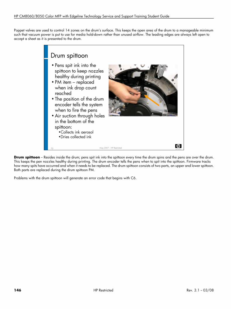
HP CM8060/8050 Color MFP with Edgeline Technology Service and Support Training Student Guide
Poppet valves are used to control 14 zones on the drum’s surface. This keeps the open area of the drum to a manageable minimumsuch that vacuum power is put to use for media hold-down rather than unused airflow. The leading edges are always left open toaccept a sheet as it is presented to the drum.
Drum spittoon – Resides inside the drum; pens spit ink into the spittoon every time the drum spins and the pens are over the drum.This keeps the pen nozzles healthy during printing. The drum encoder tells the pens when to spit into the spittoon. Firmware trackshow many spits have occurred and when it needs to be replaced. The drum spittoon consists of two parts, an upper and lower spittoon.Both parts are replaced during the drum spittoon PM.
Problems with the drum spittoon will generate an error code that begins with C6.
146 HP Restricted Rev. 3.1 -- 03/08
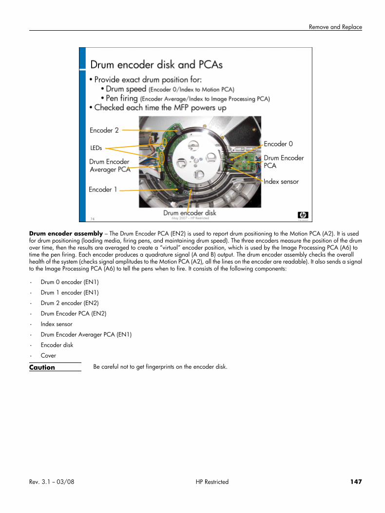
Remove and Replace
Drum encoder assembly – The Drum Encoder PCA (EN2) is used to report drum positioning to the Motion PCA (A2). It is usedfor drum positioning (loading media, firing pens, and maintaining drum speed). The three encoders measure the position of the drumover time, then the results are averaged to create a “virtual” encoder position, which is used by the Image Processing PCA (A6) totime the pen firing. Each encoder produces a quadrature signal (A and B) output. The drum encoder assembly checks the overallhealth of the system (checks signal amplitudes to the Motion PCA (A2), all the lines on the encoder are readable). It also sends a signalto the Image Processing PCA (A6) to tell the pens when to fire. It consists of the following components:
• Drum 0 encoder (EN1)
• Drum 1 encoder (EN1)
• Drum 2 encoder (EN2)
• Drum Encoder PCA (EN2)
• Index sensor
• Drum Encoder Averager PCA (EN1)
• Encoder disk
• Cover
Caution Be careful not to get fingerprints on the encoder disk.
Rev. 3.1 -- 03/08 HP Restricted 147
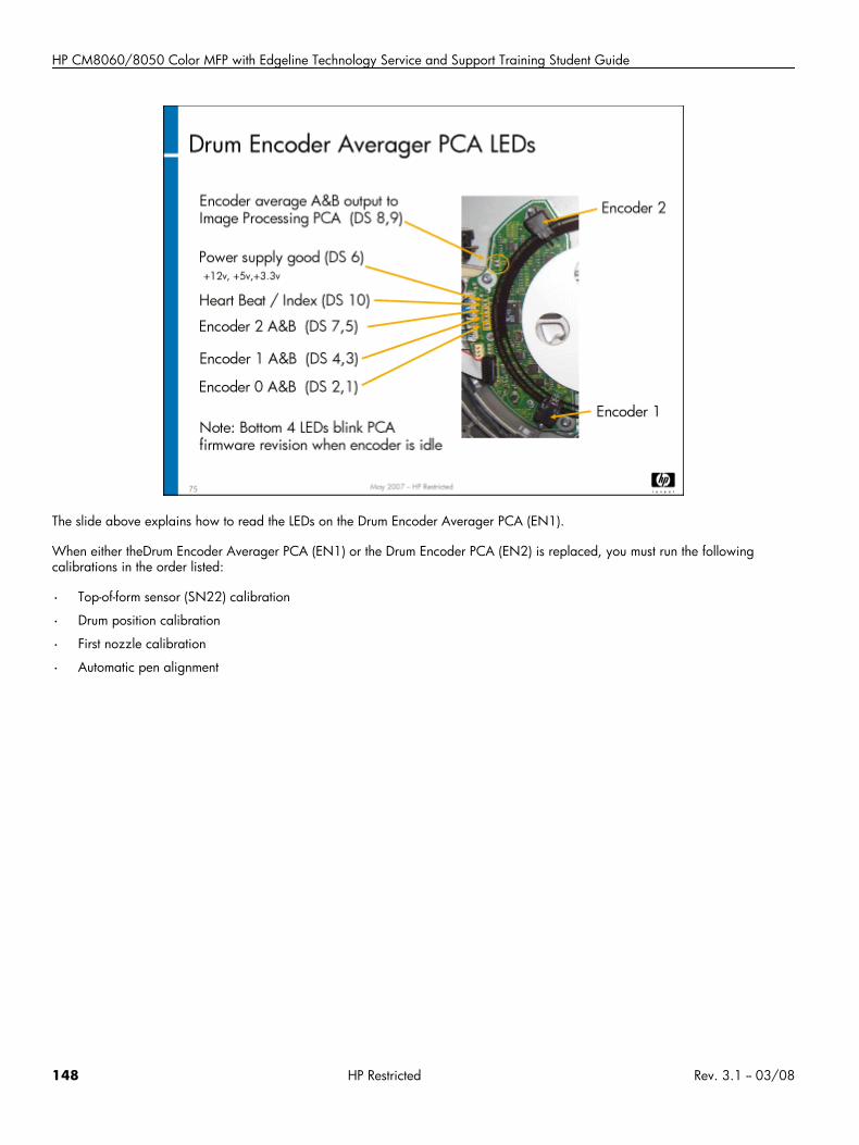
HP CM8060/8050 Color MFP with Edgeline Technology Service and Support Training Student Guide
The slide above explains how to read the LEDs on the Drum Encoder Averager PCA (EN1).
When either theDrum Encoder Averager PCA (EN1) or the Drum Encoder PCA (EN2) is replaced, you must run the followingcalibrations in the order listed:
• Top-of-form sensor (SN22) calibration
• Drum position calibration
• First nozzle calibration
• Automatic pen alignment
148 HP Restricted Rev. 3.1 -- 03/08
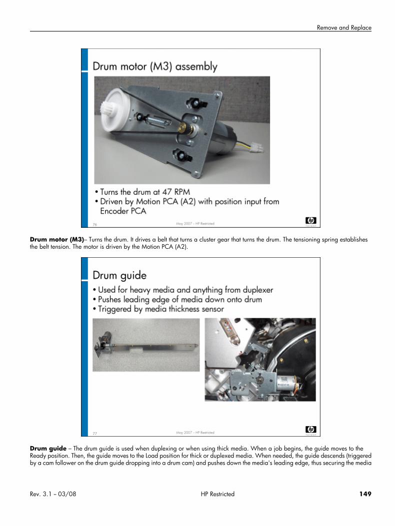
Remove and Replace
Drum motor (M3)– Turns the drum. It drives a belt that turns a cluster gear that turns the drum. The tensioning spring establishesthe belt tension. The motor is driven by the Motion PCA (A2).
Drum guide – The drum guide is used when duplexing or when using thick media. When a job begins, the guide moves to theReady position. Then, the guide moves to the Load position for thick or duplexed media. When needed, the guide descends (triggeredby a cam follower on the drum guide dropping into a drum cam) and pushes down the media's leading edge, thus securing the media
Rev. 3.1 -- 03/08 HP Restricted 149
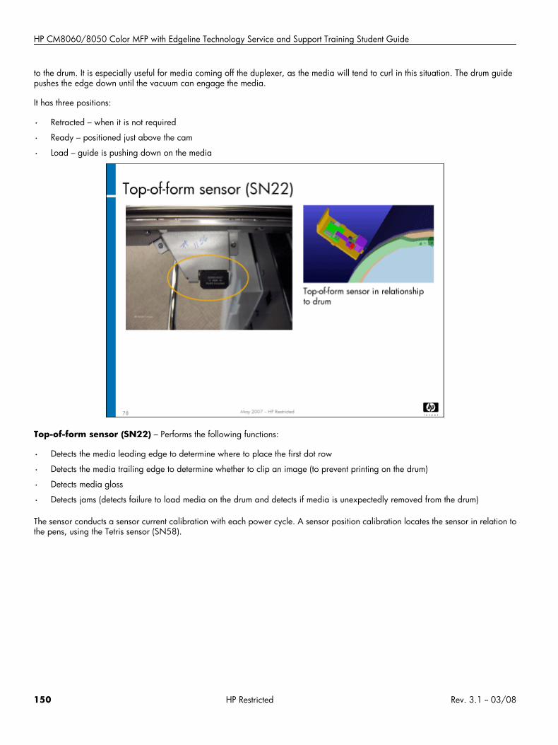
HP CM8060/8050 Color MFP with Edgeline Technology Service and Support Training Student Guide
to the drum. It is especially useful for media coming off the duplexer, as the media will tend to curl in this situation. The drum guidepushes the edge down until the vacuum can engage the media.
It has three positions:
• Retracted – when it is not required
• Ready – positioned just above the cam
• Load – guide is pushing down on the media
Top-of-form sensor (SN22) – Performs the following functions:
• Detects the media leading edge to determine where to place the first dot row
• Detects the media trailing edge to determine whether to clip an image (to prevent printing on the drum)
• Detects media gloss
• Detects jams (detects failure to load media on the drum and detects if media is unexpectedly removed from the drum)
The sensor conducts a sensor current calibration with each power cycle. A sensor position calibration locates the sensor in relation tothe pens, using the Tetris sensor (SN58).
150 HP Restricted Rev. 3.1 -- 03/08
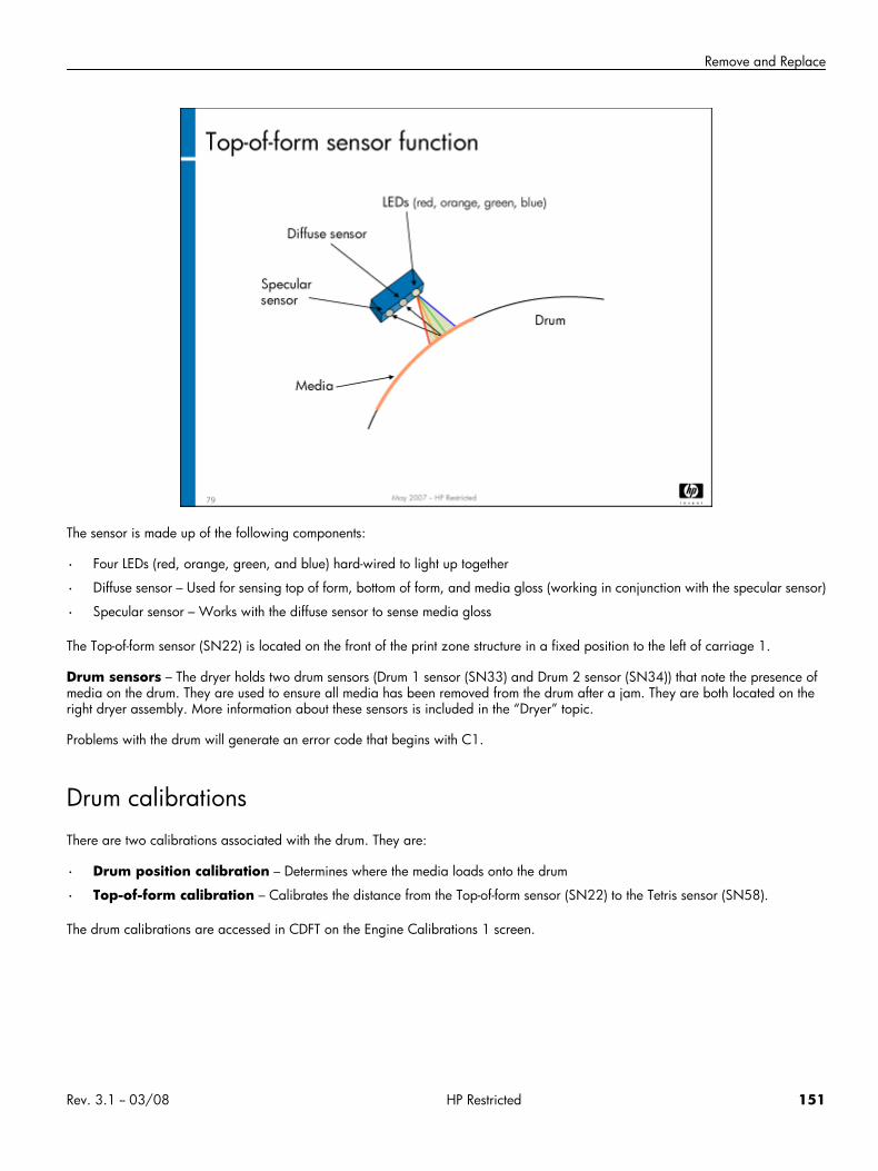
Remove and Replace
The sensor is made up of the following components:
• Four LEDs (red, orange, green, and blue) hard-wired to light up together
• Diffuse sensor – Used for sensing top of form, bottom of form, and media gloss (working in conjunction with the specular sensor)
• Specular sensor – Works with the diffuse sensor to sense media gloss
The Top-of-form sensor (SN22) is located on the front of the print zone structure in a fixed position to the left of carriage 1.
Drum sensors – The dryer holds two drum sensors (Drum 1 sensor (SN33) and Drum 2 sensor (SN34)) that note the presence ofmedia on the drum. They are used to ensure all media has been removed from the drum after a jam. They are both located on theright dryer assembly. More information about these sensors is included in the “Dryer” topic.
Problems with the drum will generate an error code that begins with C1.
Drum calibrationsThere are two calibrations associated with the drum. They are:
• Drum position calibration – Determines where the media loads onto the drum
• Top-of-form calibration – Calibrates the distance from the Top-of-form sensor (SN22) to the Tetris sensor (SN58).
The drum calibrations are accessed in CDFT on the Engine Calibrations 1 screen.
Rev. 3.1 -- 03/08 HP Restricted 151
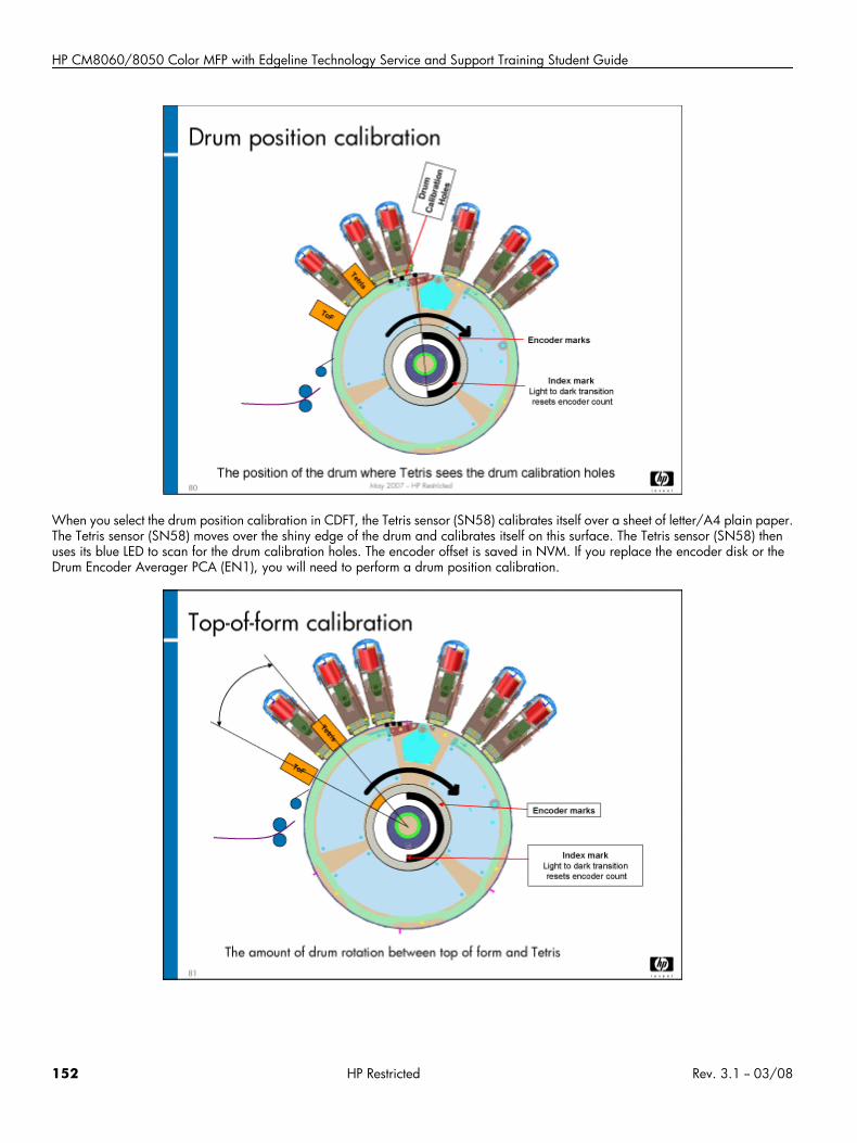
HP CM8060/8050 Color MFP with Edgeline Technology Service and Support Training Student Guide
When you select the drum position calibration in CDFT, the Tetris sensor (SN58) calibrates itself over a sheet of letter/A4 plain paper.The Tetris sensor (SN58) moves over the shiny edge of the drum and calibrates itself on this surface. The Tetris sensor (SN58) thenuses its blue LED to scan for the drum calibration holes. The encoder offset is saved in NVM. If you replace the encoder disk or theDrum Encoder Averager PCA (EN1), you will need to perform a drum position calibration.
152 HP Restricted Rev. 3.1 -- 03/08
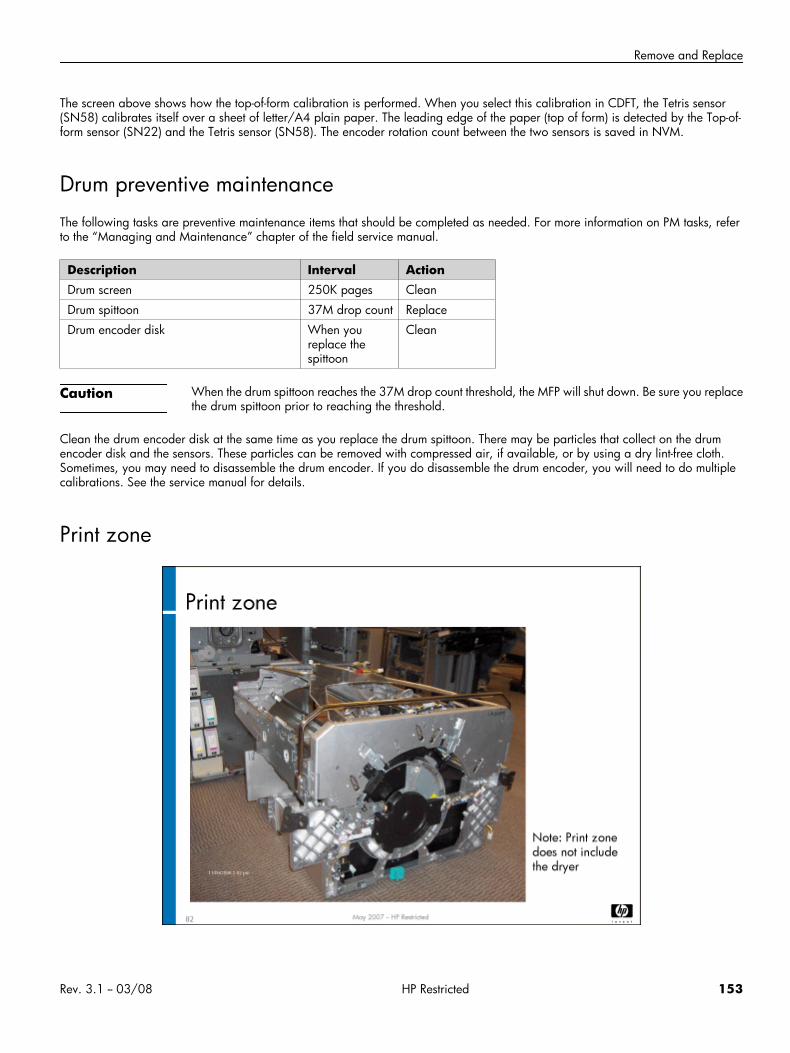
Remove and Replace
The screen above shows how the top-of-form calibration is performed. When you select this calibration in CDFT, the Tetris sensor(SN58) calibrates itself over a sheet of letter/A4 plain paper. The leading edge of the paper (top of form) is detected by the Top-of-form sensor (SN22) and the Tetris sensor (SN58). The encoder rotation count between the two sensors is saved in NVM.
Drum preventive maintenanceThe following tasks are preventive maintenance items that should be completed as needed. For more information on PM tasks, referto the “Managing and Maintenance” chapter of the field service manual.
Description Interval ActionDrum screen 250K pages Clean
Drum spittoon 37M drop count Replace
Drum encoder disk When youreplace thespittoon
Clean
Caution When the drum spittoon reaches the 37M drop count threshold, the MFP will shut down. Be sure you replacethe drum spittoon prior to reaching the threshold.
Clean the drum encoder disk at the same time as you replace the drum spittoon. There may be particles that collect on the drumencoder disk and the sensors. These particles can be removed with compressed air, if available, or by using a dry lint-free cloth.Sometimes, you may need to disassemble the drum encoder. If you do disassemble the drum encoder, you will need to do multiplecalibrations. See the service manual for details.
Print zone
Rev. 3.1 -- 03/08 HP Restricted 153
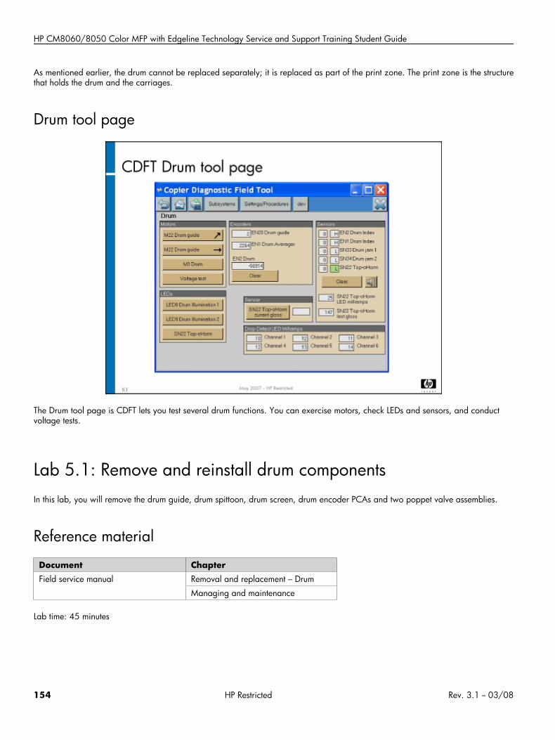
HP CM8060/8050 Color MFP with Edgeline Technology Service and Support Training Student Guide
As mentioned earlier, the drum cannot be replaced separately; it is replaced as part of the print zone. The print zone is the structurethat holds the drum and the carriages.
Drum tool page
The Drum tool page is CDFT lets you test several drum functions. You can exercise motors, check LEDs and sensors, and conductvoltage tests.
Lab 5.1: Remove and reinstall drum componentsIn this lab, you will remove the drum guide, drum spittoon, drum screen, drum encoder PCAs and two poppet valve assemblies.
Reference material
Document ChapterField service manual Removal and replacement – Drum
Managing and maintenance
Lab time: 45 minutes
154 HP Restricted Rev. 3.1 -- 03/08
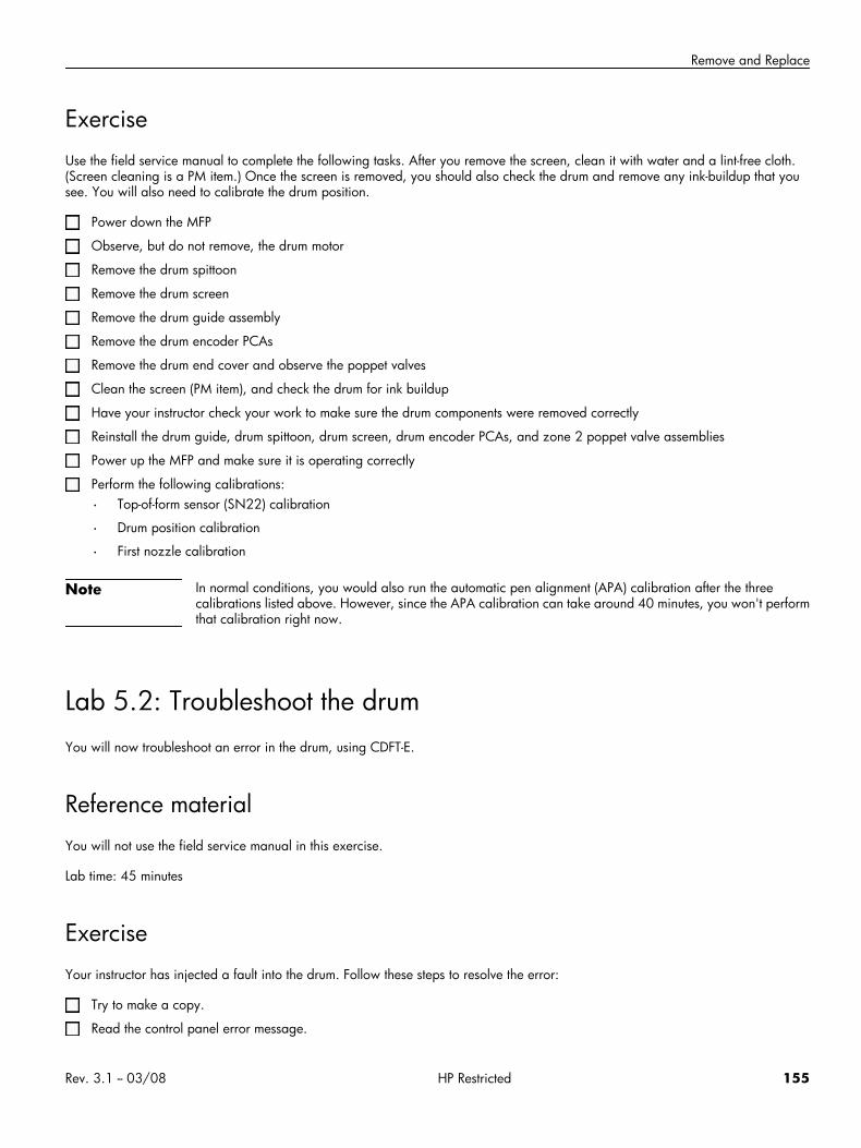
Remove and Replace
ExerciseUse the field service manual to complete the following tasks. After you remove the screen, clean it with water and a lint-free cloth.(Screen cleaning is a PM item.) Once the screen is removed, you should also check the drum and remove any ink-buildup that yousee. You will also need to calibrate the drum position.
Power down the MFP
Observe, but do not remove, the drum motor
Remove the drum spittoon
Remove the drum screen
Remove the drum guide assembly
Remove the drum encoder PCAs
Remove the drum end cover and observe the poppet valves
Clean the screen (PM item), and check the drum for ink buildup
Have your instructor check your work to make sure the drum components were removed correctly
Reinstall the drum guide, drum spittoon, drum screen, drum encoder PCAs, and zone 2 poppet valve assemblies
Power up the MFP and make sure it is operating correctly
Perform the following calibrations:
• Top-of-form sensor (SN22) calibration
• Drum position calibration
• First nozzle calibration
Note In normal conditions, you would also run the automatic pen alignment (APA) calibration after the threecalibrations listed above. However, since the APA calibration can take around 40 minutes, you won't performthat calibration right now.
Lab 5.2: Troubleshoot the drumYou will now troubleshoot an error in the drum, using CDFT-E.
Reference materialYou will not use the field service manual in this exercise.
Lab time: 45 minutes
ExerciseYour instructor has injected a fault into the drum. Follow these steps to resolve the error:
Try to make a copy.
Read the control panel error message.
Rev. 3.1 -- 03/08 HP Restricted 155
HP CM8060/8050 Color MFP with Edgeline Technology Service and Support Training Student Guide
Use CDFT-E in PSM to troubleshoot the error.
Fix the problem.
Verify that you correctly solved the problem.
Note Once this lab is completed, you should run the automatic pen alignment calibration. (This calibration shouldhave been run as part of the previous lab, but because it is time consuming, you can run it now. It can thenbe running while you attend the next topic's lecture.
Topic 6: Vacuum and aerosolThis topic guides you through removing and replacing the vacuum fan assembly and the aerosol system. It also includes theory ofoperation for the vacuum, aerosol, odor filter, and muffler.
Topic 6 objectivesAfter completing this topic, you should be able to:
• Describe how the vacuum assembly works
• Describe how the aerosol system works
• Remove and reinstall the vacuum assembly and housing
• Remove and reinstall the aerosol filter, manifold and snorkel assembly, and bonding agent duct
• Identify the odor filter and muffler
156 HP Restricted Rev. 3.1 -- 03/08
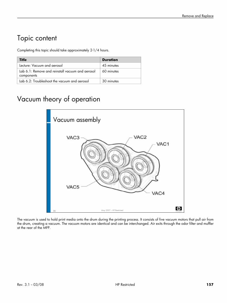
Remove and Replace
Topic contentCompleting this topic should take approximately 2-1/4 hours.
Title DurationLecture: Vacuum and aerosol 45 minutes
Lab 6.1: Remove and reinstall vacuum and aerosolcomponents
60 minutes
Lab 6.2: Troubleshoot the vacuum and aerosol 30 minutes
Vacuum theory of operation
The vacuum is used to hold print media onto the drum during the printing process. It consists of five vacuum motors that pull air fromthe drum, creating a vacuum. The vacuum motors are identical and can be interchanged. Air exits through the odor filter and mufflerat the rear of the MFP.
Rev. 3.1 -- 03/08 HP Restricted 157
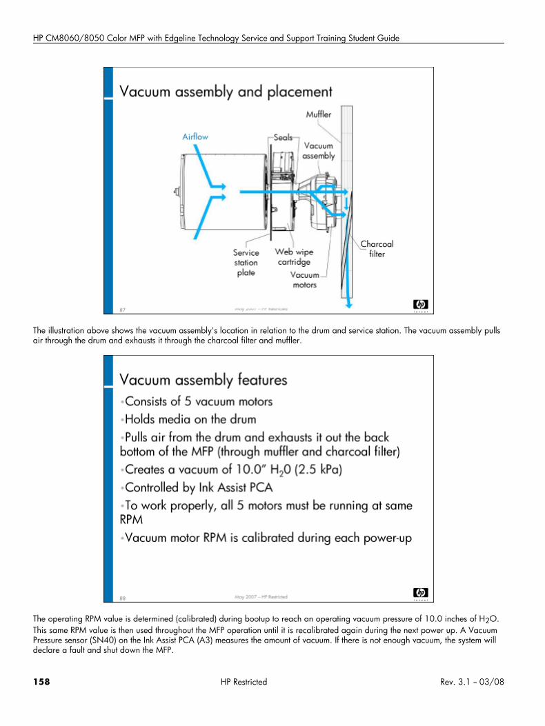
HP CM8060/8050 Color MFP with Edgeline Technology Service and Support Training Student Guide
The illustration above shows the vacuum assembly's location in relation to the drum and service station. The vacuum assembly pullsair through the drum and exhausts it through the charcoal filter and muffler.
The operating RPM value is determined (calibrated) during bootup to reach an operating vacuum pressure of 10.0 inches of H2O.This same RPM value is then used throughout the MFP operation until it is recalibrated again during the next power up. A VacuumPressure sensor (SN40) on the Ink Assist PCA (A3) measures the amount of vacuum. If there is not enough vacuum, the system willdeclare a fault and shut down the MFP.
158 HP Restricted Rev. 3.1 -- 03/08
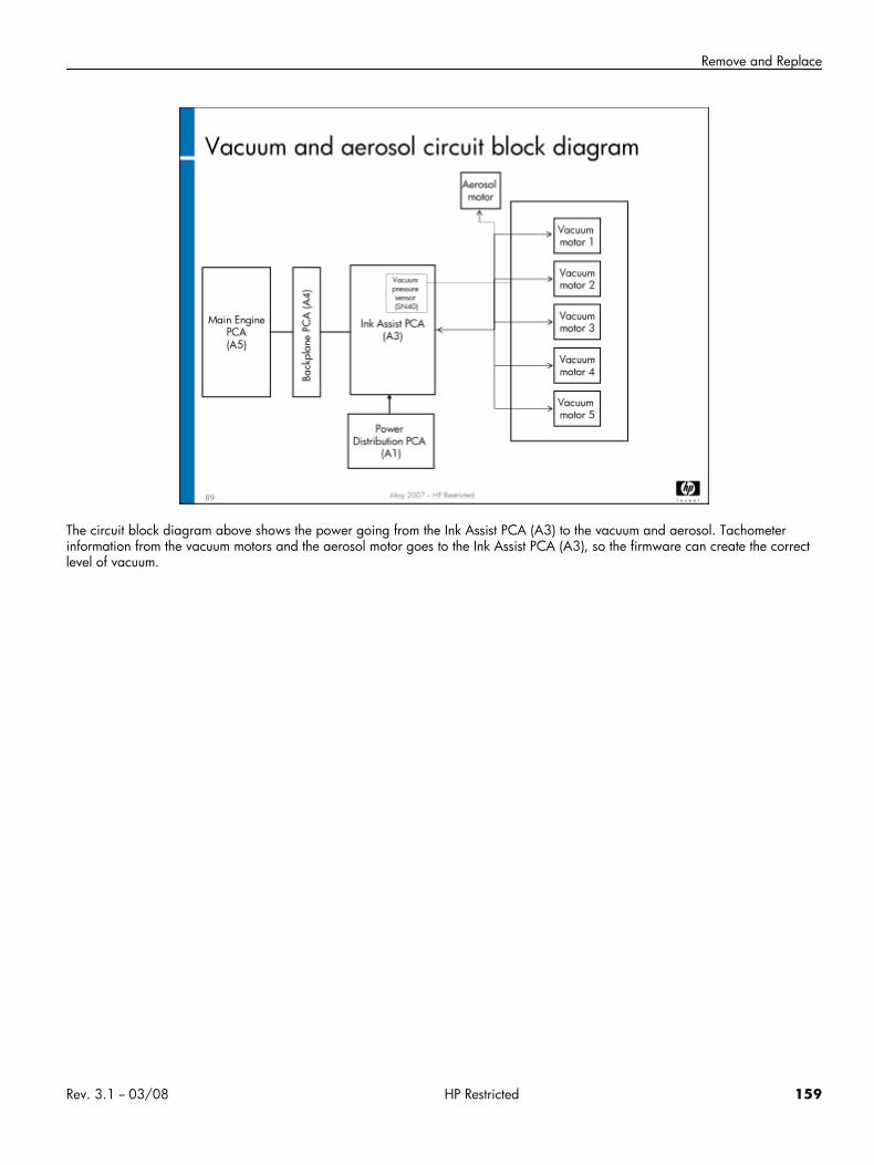
Remove and Replace
The circuit block diagram above shows the power going from the Ink Assist PCA (A3) to the vacuum and aerosol. Tachometerinformation from the vacuum motors and the aerosol motor goes to the Ink Assist PCA (A3), so the firmware can create the correctlevel of vacuum.
Rev. 3.1 -- 03/08 HP Restricted 159
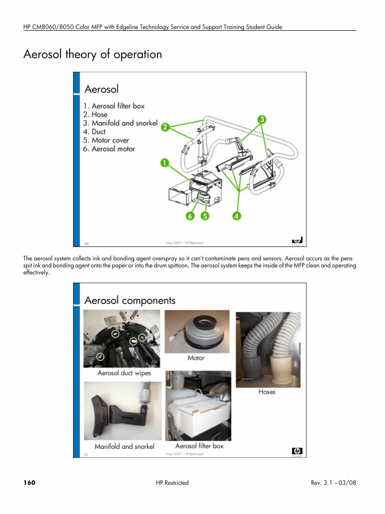
HP CM8060/8050 Color MFP with Edgeline Technology Service and Support Training Student Guide
Aerosol theory of operation
The aerosol system collects ink and bonding agent overspray so it can't contaminate pens and sensors. Aerosol occurs as the pensspit ink and bonding agent onto the paper or into the drum spittoon. The aerosol system keeps the inside of the MFP clean and operatingeffectively.
160 HP Restricted Rev. 3.1 -- 03/08
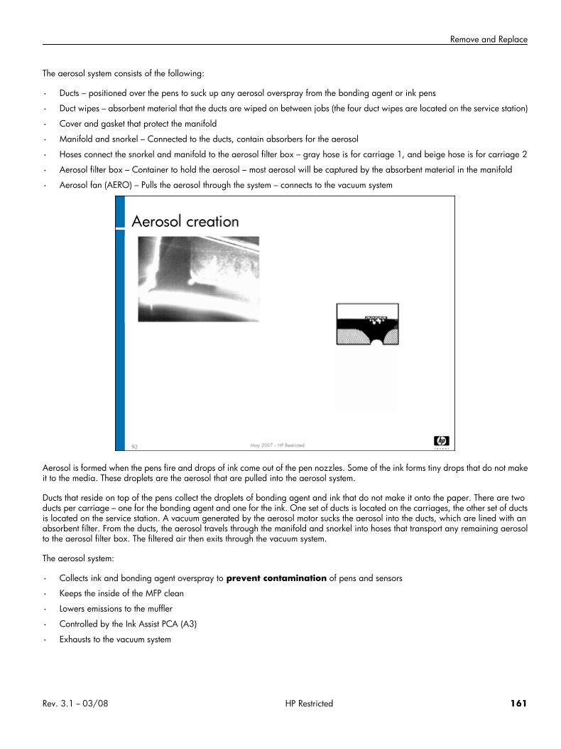
Remove and Replace
The aerosol system consists of the following:
• Ducts – positioned over the pens to suck up any aerosol overspray from the bonding agent or ink pens
• Duct wipes – absorbent material that the ducts are wiped on between jobs (the four duct wipes are located on the service station)
• Cover and gasket that protect the manifold
• Manifold and snorkel – Connected to the ducts, contain absorbers for the aerosol
• Hoses connect the snorkel and manifold to the aerosol filter box – gray hose is for carriage 1, and beige hose is for carriage 2
• Aerosol filter box – Container to hold the aerosol – most aerosol will be captured by the absorbent material in the manifold
• Aerosol fan (AERO) – Pulls the aerosol through the system – connects to the vacuum system
Aerosol is formed when the pens fire and drops of ink come out of the pen nozzles. Some of the ink forms tiny drops that do not makeit to the media. These droplets are the aerosol that are pulled into the aerosol system.
Ducts that reside on top of the pens collect the droplets of bonding agent and ink that do not make it onto the paper. There are twoducts per carriage – one for the bonding agent and one for the ink. One set of ducts is located on the carriages, the other set of ductsis located on the service station. A vacuum generated by the aerosol motor sucks the aerosol into the ducts, which are lined with anabsorbent filter. From the ducts, the aerosol travels through the manifold and snorkel into hoses that transport any remaining aerosolto the aerosol filter box. The filtered air then exits through the vacuum system.
The aerosol system:
• Collects ink and bonding agent overspray to prevent contamination of pens and sensors
• Keeps the inside of the MFP clean
• Lowers emissions to the muffler
• Controlled by the Ink Assist PCA (A3)
• Exhausts to the vacuum system
Rev. 3.1 -- 03/08 HP Restricted 161
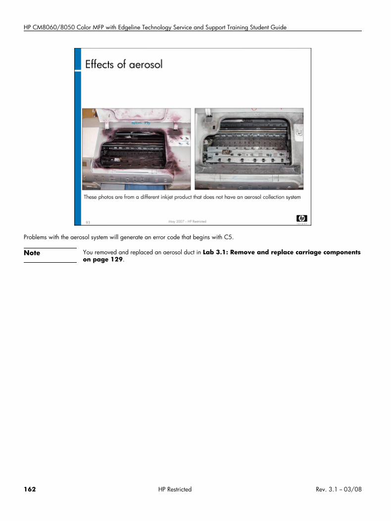
HP CM8060/8050 Color MFP with Edgeline Technology Service and Support Training Student Guide
Problems with the aerosol system will generate an error code that begins with C5.
Note You removed and replaced an aerosol duct in Lab 3.1: Remove and replace carriage componentson page 129.
162 HP Restricted Rev. 3.1 -- 03/08
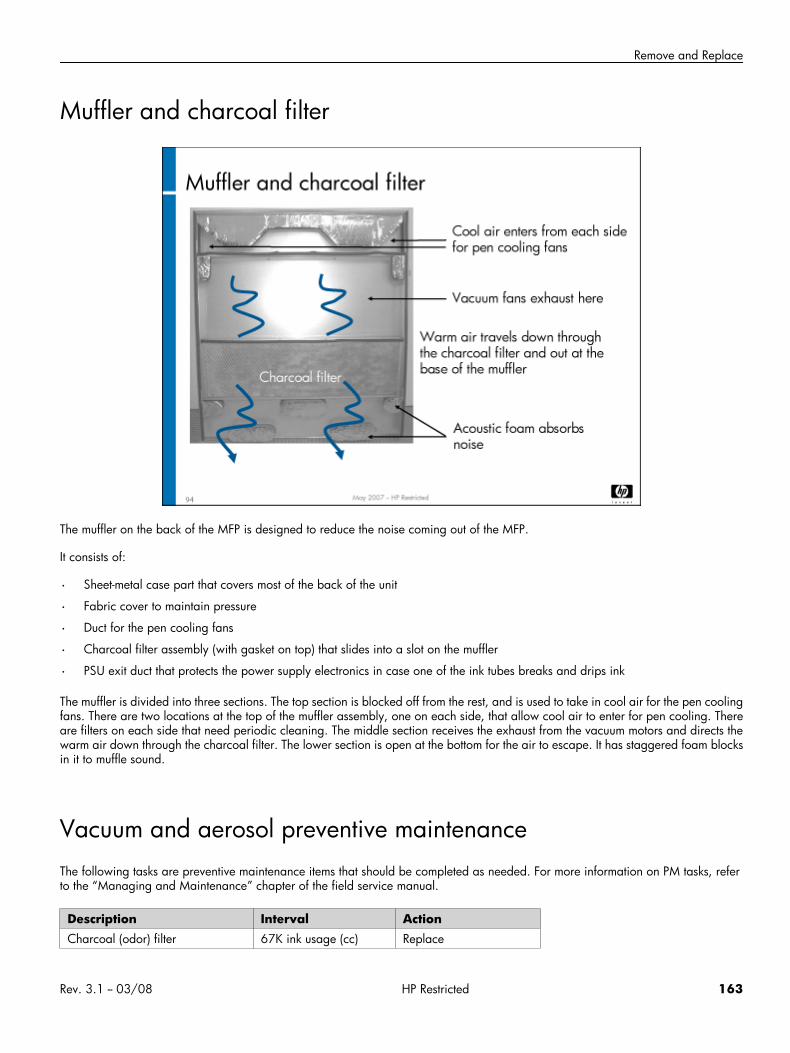
Remove and Replace
Muffler and charcoal filter
The muffler on the back of the MFP is designed to reduce the noise coming out of the MFP.
It consists of:
• Sheet-metal case part that covers most of the back of the unit
• Fabric cover to maintain pressure
• Duct for the pen cooling fans
• Charcoal filter assembly (with gasket on top) that slides into a slot on the muffler
• PSU exit duct that protects the power supply electronics in case one of the ink tubes breaks and drips ink
The muffler is divided into three sections. The top section is blocked off from the rest, and is used to take in cool air for the pen coolingfans. There are two locations at the top of the muffler assembly, one on each side, that allow cool air to enter for pen cooling. Thereare filters on each side that need periodic cleaning. The middle section receives the exhaust from the vacuum motors and directs thewarm air down through the charcoal filter. The lower section is open at the bottom for the air to escape. It has staggered foam blocksin it to muffle sound.
Vacuum and aerosol preventive maintenanceThe following tasks are preventive maintenance items that should be completed as needed. For more information on PM tasks, referto the “Managing and Maintenance” chapter of the field service manual.
Description Interval ActionCharcoal (odor) filter 67K ink usage (cc) Replace
Rev. 3.1 -- 03/08 HP Restricted 163
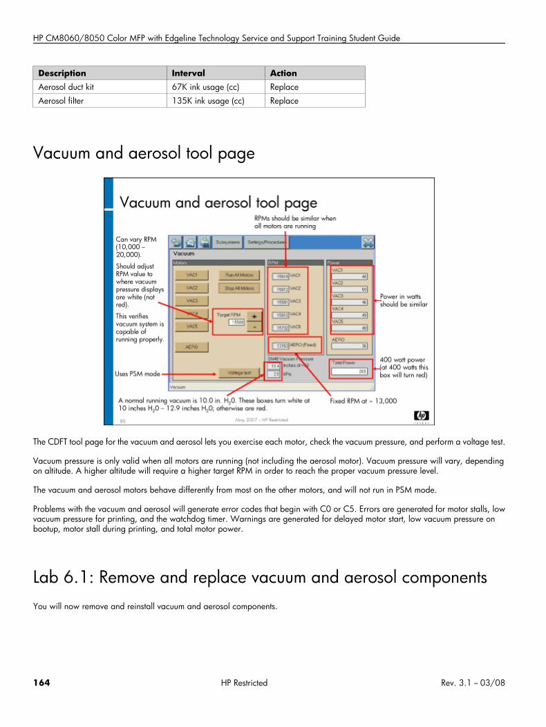
HP CM8060/8050 Color MFP with Edgeline Technology Service and Support Training Student Guide
Description Interval ActionAerosol duct kit 67K ink usage (cc) Replace
Aerosol filter 135K ink usage (cc) Replace
Vacuum and aerosol tool page
The CDFT tool page for the vacuum and aerosol lets you exercise each motor, check the vacuum pressure, and perform a voltage test.
Vacuum pressure is only valid when all motors are running (not including the aerosol motor). Vacuum pressure will vary, dependingon altitude. A higher altitude will require a higher target RPM in order to reach the proper vacuum pressure level.
The vacuum and aerosol motors behave differently from most on the other motors, and will not run in PSM mode.
Problems with the vacuum and aerosol will generate error codes that begin with C0 or C5. Errors are generated for motor stalls, lowvacuum pressure for printing, and the watchdog timer. Warnings are generated for delayed motor start, low vacuum pressure onbootup, motor stall during printing, and total motor power.
Lab 6.1: Remove and replace vacuum and aerosol componentsYou will now remove and reinstall vacuum and aerosol components.
164 HP Restricted Rev. 3.1 -- 03/08
Remove and Replace
Reference material
Document ChapterField service manual Removal and replacement: Vacuum
Removal and replacement: Aerosol
Lab time: 60 minutes
ExerciseBefore you begin, take a look at the vacuum tool page in CDFT-E. (Note that aerosol is also listed on the vacuum tool page. Try someof the functions available on the page.
Use the instructions in the field service manual to complete the following tasks:
Power down the MFP
Remove the vacuum supply housing
Observe the aerosol ducts and duct wipes
Remove the Aerosol fan (AERO)
Have your instructor check your work to make sure everything was removed correctly
Reinstall the Aerosol fan (AERO)
Reinstall the vacuum supply housing
Power up the MFP and make sure it is working correctly
Lab 6.2: Troubleshoot the vacuum and aerosolYou will now troubleshoot an error in the vacuum and aerosol, using CDFT-L.
Reference materialYou will not use the field service manual in this exercise.
Lab time: 30 minutes
ExerciseYour instructor has injected a fault into the vacuum or aerosol system. Follow these steps to resolve the error:
Read the control panel error message.
If you have not already done so, connect your laptop to the MFP and open CDFT-L.
Go to the tool page for the vacuum, and choose Fault Trees to go to the directive fault tree.
Rev. 3.1 -- 03/08 HP Restricted 165
HP CM8060/8050 Color MFP with Edgeline Technology Service and Support Training Student Guide
Follow the fault tree to resolve the problem.
Verify that you correctly solved the problem.
Topic 7: Service station and web wipeThis topic guides you through the service station and web wipe. It covers both the theory of operation and how to remove and replacemost of the components.
Topic 7 objectivesAfter completing this topic, you should be able to:
• Identify the components and location of the service station and web wipe
• Describe how the web wipe works
• Describe how the service station works
• Remove and reinstall most of the service station components
Topic contentCompleting this topic should take approximately 2 hours.
166 HP Restricted Rev. 3.1 -- 03/08
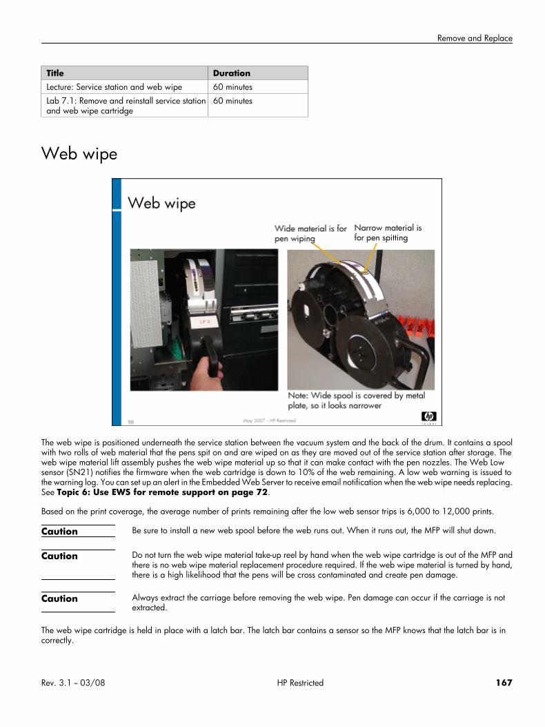
Remove and Replace
Title DurationLecture: Service station and web wipe 60 minutes
Lab 7.1: Remove and reinstall service stationand web wipe cartridge
60 minutes
Web wipe
The web wipe is positioned underneath the service station between the vacuum system and the back of the drum. It contains a spoolwith two rolls of web material that the pens spit on and are wiped on as they are moved out of the service station after storage. Theweb wipe material lift assembly pushes the web wipe material up so that it can make contact with the pen nozzles. The Web Lowsensor (SN21) notifies the firmware when the web cartridge is down to 10% of the web remaining. A low web warning is issued tothe warning log. You can set up an alert in the Embedded Web Server to receive email notification when the web wipe needs replacing.See Topic 6: Use EWS for remote support on page 72.
Based on the print coverage, the average number of prints remaining after the low web sensor trips is 6,000 to 12,000 prints.
Caution Be sure to install a new web spool before the web runs out. When it runs out, the MFP will shut down.
Caution Do not turn the web wipe material take-up reel by hand when the web wipe cartridge is out of the MFP andthere is no web wipe material replacement procedure required. If the web wipe material is turned by hand,there is a high likelihood that the pens will be cross contaminated and create pen damage.
Caution Always extract the carriage before removing the web wipe. Pen damage can occur if the carriage is notextracted.
The web wipe cartridge is held in place with a latch bar. The latch bar contains a sensor so the MFP knows that the latch bar is incorrectly.
Rev. 3.1 -- 03/08 HP Restricted 167
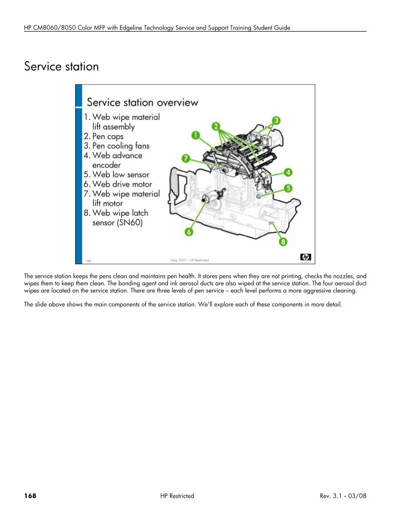
HP CM8060/8050 Color MFP with Edgeline Technology Service and Support Training Student Guide
Service station
The service station keeps the pens clean and maintains pen health. It stores pens when they are not printing, checks the nozzles, andwipes them to keep them clean. The bonding agent and ink aerosol ducts are also wiped at the service station. The four aerosol ductwipes are located on the service station. There are three levels of pen service – each level performs a more aggressive cleaning.
The slide above shows the main components of the service station. We'll explore each of these components in more detail.
168 HP Restricted Rev. 3.1 -- 03/08
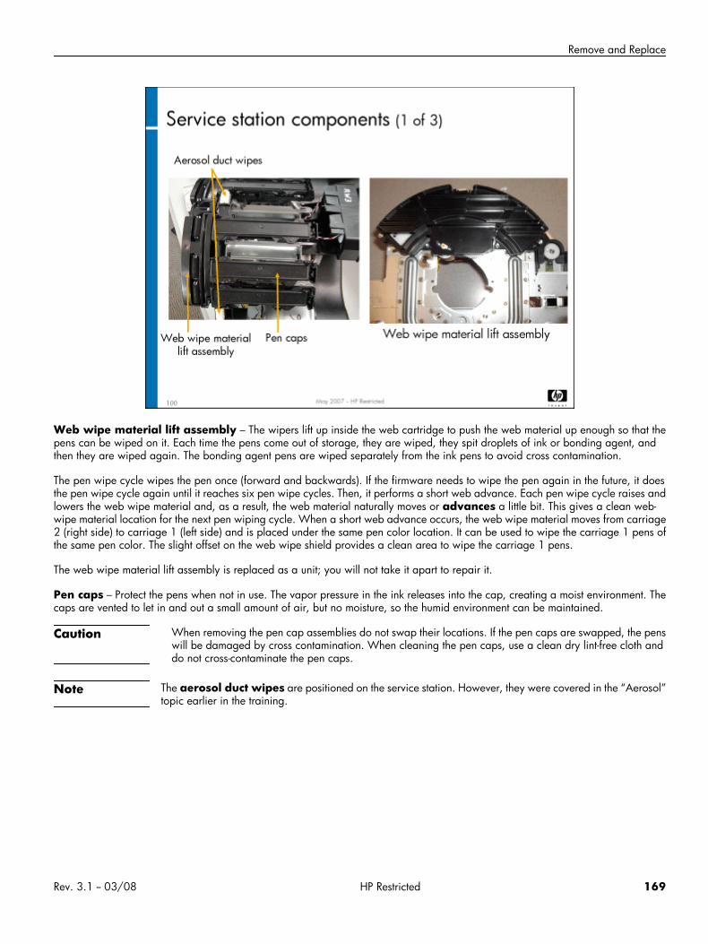
Remove and Replace
Web wipe material lift assembly – The wipers lift up inside the web cartridge to push the web material up enough so that thepens can be wiped on it. Each time the pens come out of storage, they are wiped, they spit droplets of ink or bonding agent, andthen they are wiped again. The bonding agent pens are wiped separately from the ink pens to avoid cross contamination.
The pen wipe cycle wipes the pen once (forward and backwards). If the firmware needs to wipe the pen again in the future, it doesthe pen wipe cycle again until it reaches six pen wipe cycles. Then, it performs a short web advance. Each pen wipe cycle raises andlowers the web wipe material and, as a result, the web material naturally moves or advances a little bit. This gives a clean web-wipe material location for the next pen wiping cycle. When a short web advance occurs, the web wipe material moves from carriage2 (right side) to carriage 1 (left side) and is placed under the same pen color location. It can be used to wipe the carriage 1 pens ofthe same pen color. The slight offset on the web wipe shield provides a clean area to wipe the carriage 1 pens.
The web wipe material lift assembly is replaced as a unit; you will not take it apart to repair it.
Pen caps – Protect the pens when not in use. The vapor pressure in the ink releases into the cap, creating a moist environment. Thecaps are vented to let in and out a small amount of air, but no moisture, so the humid environment can be maintained.
Caution When removing the pen cap assemblies do not swap their locations. If the pen caps are swapped, the penswill be damaged by cross contamination. When cleaning the pen caps, use a clean dry lint-free cloth anddo not cross-contaminate the pen caps.
Note The aerosol duct wipes are positioned on the service station. However, they were covered in the “Aerosol”topic earlier in the training.
Rev. 3.1 -- 03/08 HP Restricted 169
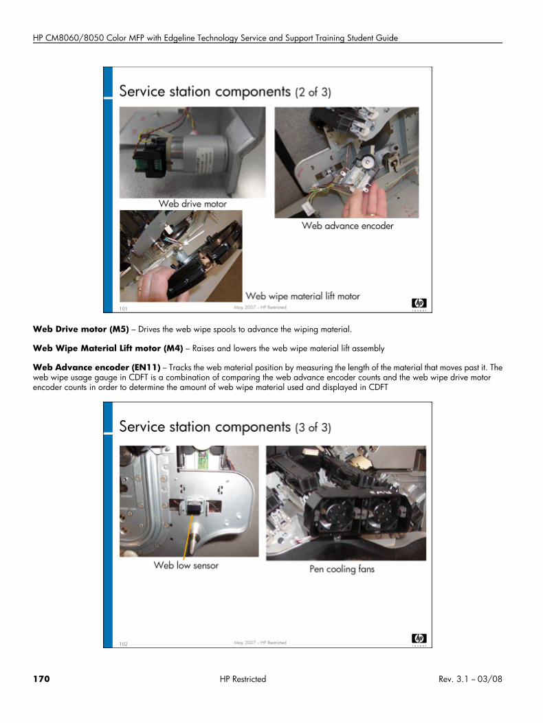
HP CM8060/8050 Color MFP with Edgeline Technology Service and Support Training Student Guide
Web Drive motor (M5) – Drives the web wipe spools to advance the wiping material.
Web Wipe Material Lift motor (M4) – Raises and lowers the web wipe material lift assembly
Web Advance encoder (EN11) – Tracks the web material position by measuring the length of the material that moves past it. Theweb wipe usage gauge in CDFT is a combination of comparing the web advance encoder counts and the web wipe drive motorencoder counts in order to determine the amount of web wipe material used and displayed in CDFT
170 HP Restricted Rev. 3.1 -- 03/08
Remove and Replace
Web Low sensor (SN21) – Optical sensor on the service station's main housing looks at the web wipe cartridge for the last 10%of the cartridge. When it detects the last 10%, the firmware issues a warning that the web wipe spool needs to be replaced. Whenthe spool is empty, the MFP will shut down.
The low web warning occurs when ten short-web advances remain. This should last at least two days of normal copier operation togive enough time for the service technician to replace the web, based on 64,000 prints between service calls. Based on the printcoverage, the average number of prints remaining after the low web sensor trips is 6,000 to 12,000 prints.
Service Station Latch sensor (SN60) is used to detect if the web wipe cartridge is properly latched.
Pen cooling fans – Two small fans blow air over the pens when capped in the service station to cool the pens. This helps promotelonger pen life. The assembly includes two fans, two diffusers, a cable, and an inlet duct that pulls in cool air from outside of the MFP(through the muffler).
Service station functionThe service station can perform up to three levels of pen servicing with drop detect, each more aggressive than the previous one. Ifthe pens are left out of cap when the MFP is powered down, the service station will perform pen servicing when the MFP is poweredback on. This is sometimes referred to as a “dirty power on.” This will occur when you start an MFP when one or both carriages areout of the service station, if you shut down the MFP while the service station is in the middle of a servicing, or if a fault occurs and theengine is not able to get the carriages back to the service station and the pens capped properly.
To prevent a dirty power on service from occurring, you should always make sure the pens are capped in the service station beforeyour shut down the MFP. If you think the pens may be uncapped, manually push the carriages into cap before you shut down theMFP. If you are working on the MFP and you pull the carriages out of cap, put them back when you are done.
Problems with the service station and web wipe will generate an error code that begins with C4.
Rev. 3.1 -- 03/08 HP Restricted 171
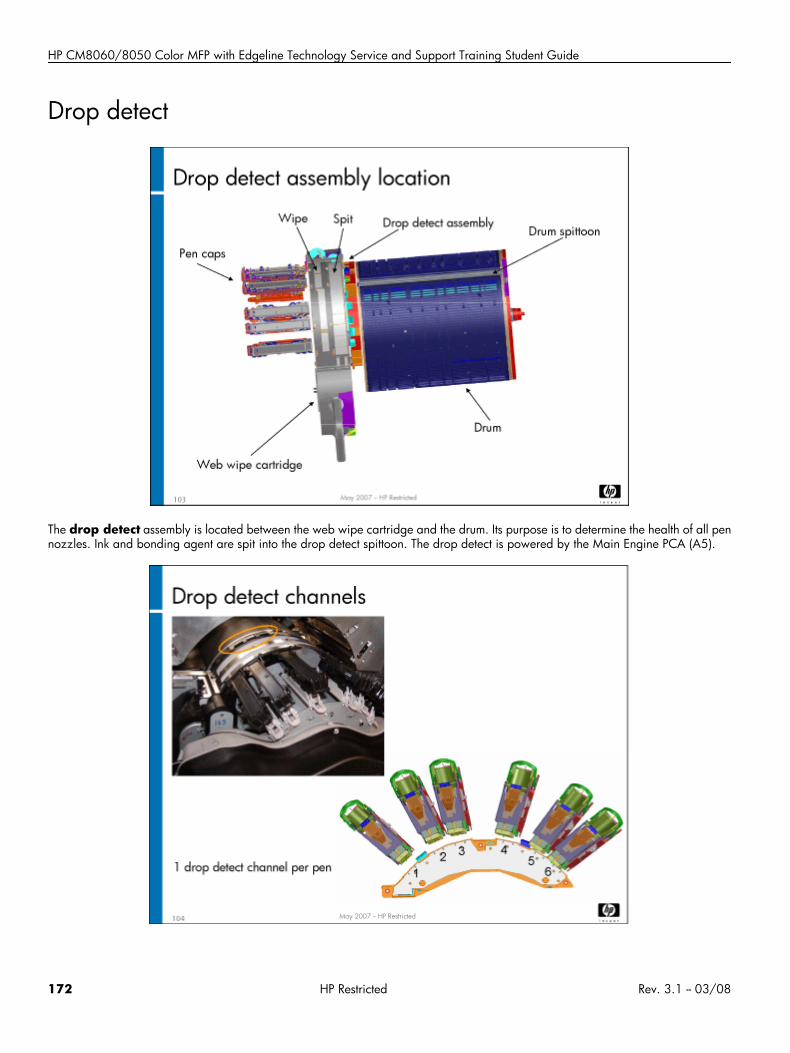
HP CM8060/8050 Color MFP with Edgeline Technology Service and Support Training Student Guide
Drop detect
The drop detect assembly is located between the web wipe cartridge and the drum. Its purpose is to determine the health of all pennozzles. Ink and bonding agent are spit into the drop detect spittoon. The drop detect is powered by the Main Engine PCA (A5).
172 HP Restricted Rev. 3.1 -- 03/08
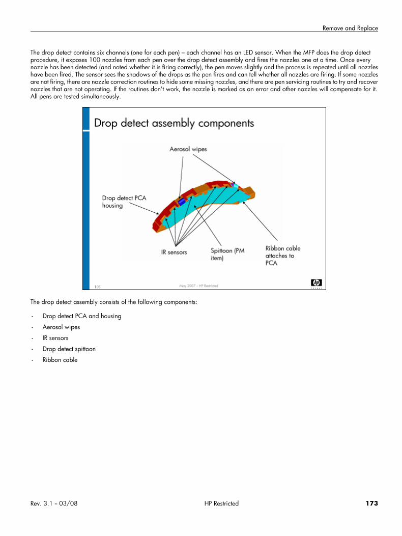
Remove and Replace
The drop detect contains six channels (one for each pen) – each channel has an LED sensor. When the MFP does the drop detectprocedure, it exposes 100 nozzles from each pen over the drop detect assembly and fires the nozzles one at a time. Once everynozzle has been detected (and noted whether it is firing correctly), the pen moves slightly and the process is repeated until all nozzleshave been fired. The sensor sees the shadows of the drops as the pen fires and can tell whether all nozzles are firing. If some nozzlesare not firing, there are nozzle correction routines to hide some missing nozzles, and there are pen servicing routines to try and recovernozzles that are not operating. If the routines don't work, the nozzle is marked as an error and other nozzles will compensate for it.All pens are tested simultaneously.
The drop detect assembly consists of the following components:
• Drop detect PCA and housing
• Aerosol wipes
• IR sensors
• Drop detect spittoon
• Ribbon cable
Rev. 3.1 -- 03/08 HP Restricted 173
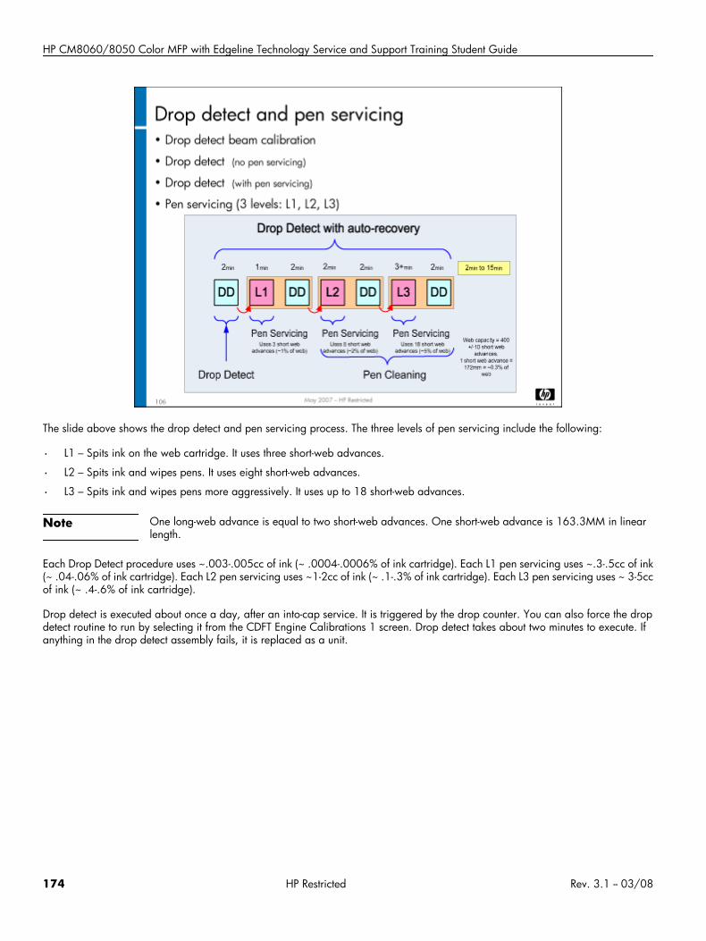
HP CM8060/8050 Color MFP with Edgeline Technology Service and Support Training Student Guide
The slide above shows the drop detect and pen servicing process. The three levels of pen servicing include the following:
• L1 – Spits ink on the web cartridge. It uses three short-web advances.
• L2 – Spits ink and wipes pens. It uses eight short-web advances.
• L3 – Spits ink and wipes pens more aggressively. It uses up to 18 short-web advances.
Note One long-web advance is equal to two short-web advances. One short-web advance is 163.3MM in linearlength.
Each Drop Detect procedure uses ~.003-.005cc of ink (~ .0004-.0006% of ink cartridge). Each L1 pen servicing uses ~.3-.5cc of ink(~ .04-.06% of ink cartridge). Each L2 pen servicing uses ~1-2cc of ink (~ .1-.3% of ink cartridge). Each L3 pen servicing uses ~ 3-5ccof ink (~ .4-.6% of ink cartridge).
Drop detect is executed about once a day, after an into-cap service. It is triggered by the drop counter. You can also force the dropdetect routine to run by selecting it from the CDFT Engine Calibrations 1 screen. Drop detect takes about two minutes to execute. Ifanything in the drop detect assembly fails, it is replaced as a unit.
174 HP Restricted Rev. 3.1 -- 03/08
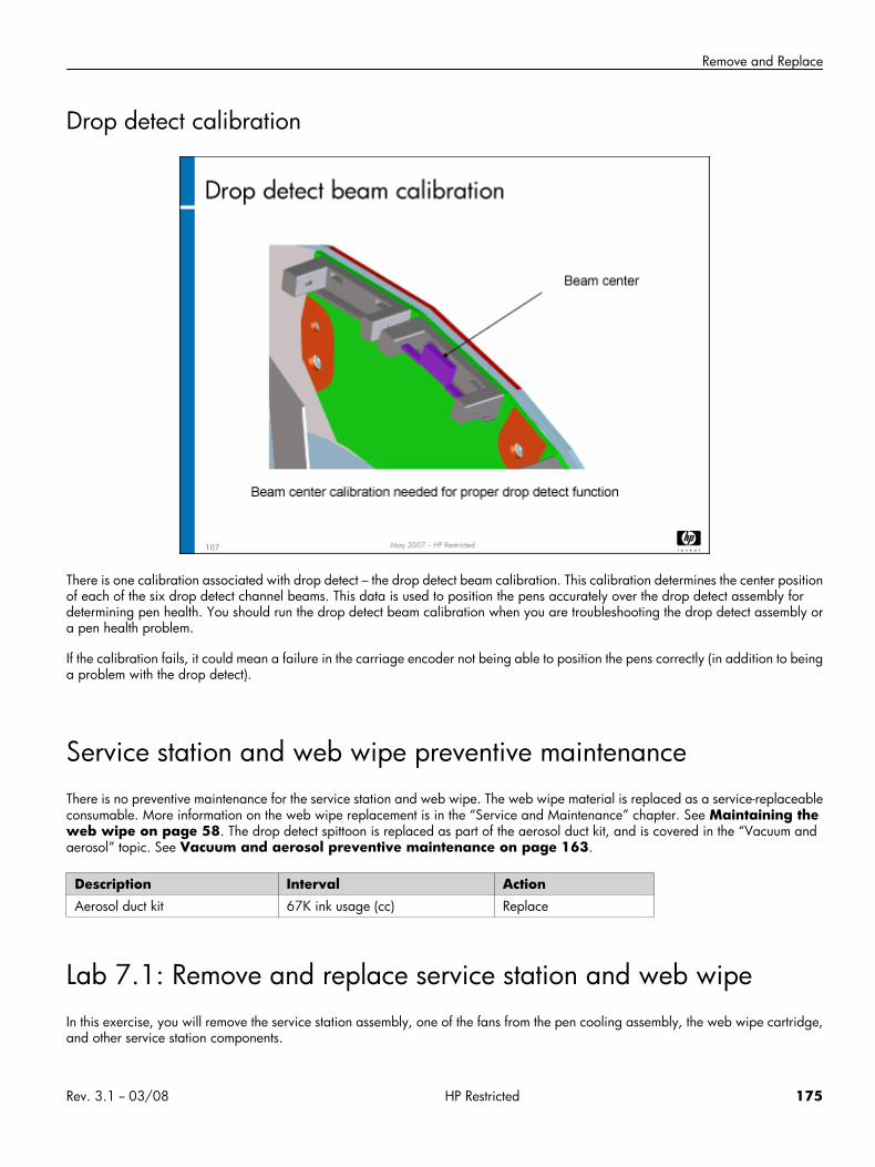
Remove and Replace
Drop detect calibration
There is one calibration associated with drop detect – the drop detect beam calibration. This calibration determines the center positionof each of the six drop detect channel beams. This data is used to position the pens accurately over the drop detect assembly fordetermining pen health. You should run the drop detect beam calibration when you are troubleshooting the drop detect assembly ora pen health problem.
If the calibration fails, it could mean a failure in the carriage encoder not being able to position the pens correctly (in addition to beinga problem with the drop detect).
Service station and web wipe preventive maintenanceThere is no preventive maintenance for the service station and web wipe. The web wipe material is replaced as a service-replaceableconsumable. More information on the web wipe replacement is in the “Service and Maintenance” chapter. See Maintaining theweb wipe on page 58. The drop detect spittoon is replaced as part of the aerosol duct kit, and is covered in the “Vacuum andaerosol” topic. See Vacuum and aerosol preventive maintenance on page 163.
Description Interval ActionAerosol duct kit 67K ink usage (cc) Replace
Lab 7.1: Remove and replace service station and web wipeIn this exercise, you will remove the service station assembly, one of the fans from the pen cooling assembly, the web wipe cartridge,and other service station components.
Rev. 3.1 -- 03/08 HP Restricted 175
HP CM8060/8050 Color MFP with Edgeline Technology Service and Support Training Student Guide
Reference material
Document ChapterField service manual Removal and replacement – Service
station
Removal and replacement – Web wipe
Lab time: 60 minutes
ExerciseBefore you begin, take a look at the web wipe tool page in CDFT-E. Try some of the functions available on the page.
Use the instructions in the field service manual to complete the following tasks.
On the extra web wipe cartridge in the classroom, remove and replace the web spool, threading it properly
Power down the MFP
Remove the service station assembly
Remove the Web Drive motor (M5)
Remove one of the cap assemblies
Remove the web wipe material lift assembly
Observe the Web Advance encoder (EN11)
Remove the drop detect assembly
Have the instructor check your work
Reinstall all of the components
Power up the MFP and make sure it is working correctly
Perform the drop detect beam calibration
Topic 8: Tray 2, 3, and 4 assembly and dryerThis topic guides you through the theory of operation and removing and replacing the tray 2,3, and 4 assembly and the dryer.
176 HP Restricted Rev. 3.1 -- 03/08
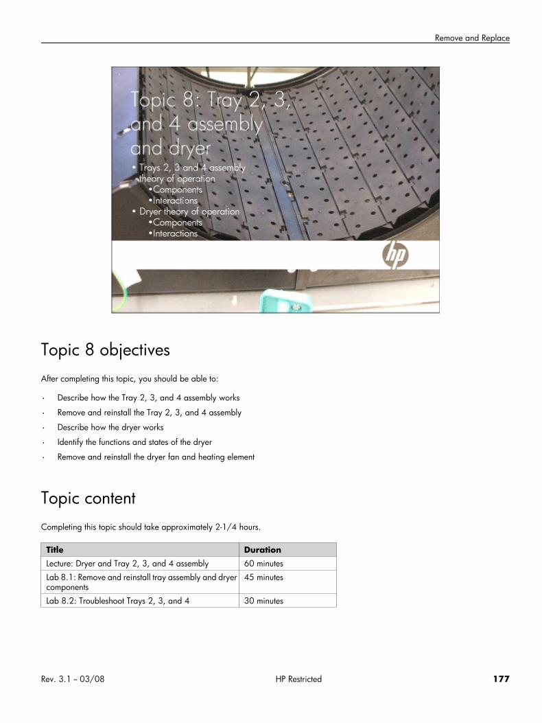
Remove and Replace
Topic 8 objectivesAfter completing this topic, you should be able to:
• Describe how the Tray 2, 3, and 4 assembly works
• Remove and reinstall the Tray 2, 3, and 4 assembly
• Describe how the dryer works
• Identify the functions and states of the dryer
• Remove and reinstall the dryer fan and heating element
Topic contentCompleting this topic should take approximately 2-1/4 hours.
Title DurationLecture: Dryer and Tray 2, 3, and 4 assembly 60 minutes
Lab 8.1: Remove and reinstall tray assembly and dryercomponents
45 minutes
Lab 8.2: Troubleshoot Trays 2, 3, and 4 30 minutes
Rev. 3.1 -- 03/08 HP Restricted 177
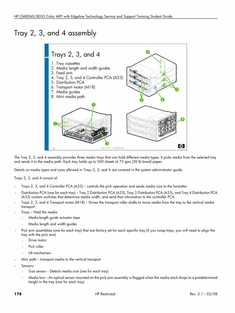
HP CM8060/8050 Color MFP with Edgeline Technology Service and Support Training Student Guide
Tray 2, 3, and 4 assembly
The Tray 2, 3, and 4 assembly provides three media trays that can hold different media types. It picks media from the selected trayand sends it to the media path. Each tray holds up to 500 sheets of 75 gsm (20 lb bond) paper.
Details on media types and sizes allowed in Trays 2, 3, and 4 are covered in the system administrator guide.
Trays 2, 3, and 4 consist of:
• Trays 2, 3, and 4 Controller PCA (A23) – controls the pick operation and sends media size to the formatter
• Distribution PCA (one for each tray) – Tray 2 Distribution PCA (A33), Tray 3 Distribution PCA (A33), and Tray 4 Distribution PCA(A33) contain switches that determine media width, and send that information to the controller PCA
• Trays 2, 3, and 4 Transport motor (M18) – Drives the transport roller shafts to move media from the tray to the vertical mediatransport
• Trays – Hold the media
• Media-length guide actuator tape
• Media length and width guides
• Pick arm assemblies (one for each tray) that are factory set for each specific tray (if you swap trays, you will need to align thetray with the pick arm)
• Drive motor
• Pick roller
• Lift mechanism
• Mini path – transport media to the vertical transport
• Sensors:
• Size sensor – Detects media size (one for each tray)
• Media low – An optical sensor mounted on the pick arm assembly is flagged when the media stack drops to a predeterminedheight in the tray (one for each tray)
178 HP Restricted Rev. 3.1 -- 03/08
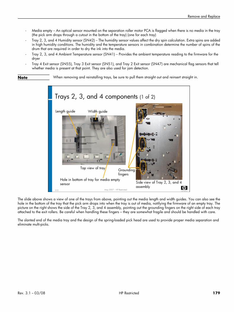
Remove and Replace
• Media empty – An optical sensor mounted on the separation roller motor PCA is flagged when there is no media in the tray(the pick arm drops through a cutout in the bottom of the tray) (one for each tray)
• Tray 2, 3, and 4 Humidity sensor (SN42) – The humidity sensor values affect the dry spin calculation. Extra spins are addedin high humidity conditions. The humidity and the temperature sensors in combination determine the number of spins of thedrum that are required in order to dry the ink into the media.
• Tray 2, 3, and 4 Ambient Temperature sensor (SN41) – Provides the ambient temperature reading to the firmware for thedryer
• Tray 4 Exit sensor (SN55), Tray 3 Exit sensor (SN51), and Tray 2 Exit sensor (SN47) are mechanical flag sensors that tellwhether media is present at that point. They are also used for jam detection.
Note When removing and reinstalling trays, be sure to pull them straight out and reinsert straight in.
The slide above shows a view of one of the trays from above, pointing out the media length and width guides. You can also see thehole in the bottom of the tray that the pick arm drops into when the tray is out of media, notifying the firmware of an empty tray. Thepicture on the right shows the side of the Tray 2, 3, and 4 assembly, pointing out the grounding fingers on the right side of each trayattached to the exit rollers. Be careful when handling these fingers – they are somewhat fragile and should be handled with care.
The slanted end of the media tray and the design of the spring-loaded pick head are used to provide proper media separation andeliminate multi-picks.
Rev. 3.1 -- 03/08 HP Restricted 179
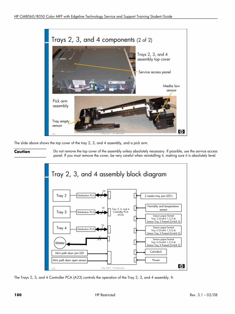
HP CM8060/8050 Color MFP with Edgeline Technology Service and Support Training Student Guide
The slide above shows the top cover of the tray 2, 3, and 4 assembly, and a pick arm.
Caution Do not remove the top cover of the assembly unless absolutely necessary. If possible, use the service accesspanel. If you must remove the cover, be very careful when reinstalling it, making sure it is absolutely level.
The Trays 2, 3, and 4 Controller PCA (A23) controls the operation of the Tray 2, 3, and 4 assembly. It:
180 HP Restricted Rev. 3.1 -- 03/08
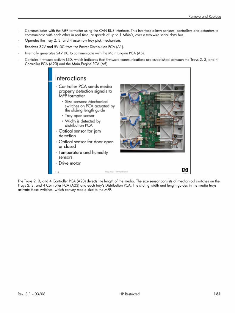
Remove and Replace
• Communicates with the MFP formatter using the CAN-BUS interface. This interface allows sensors, controllers and actuators tocommunicate with each other in real time, at speeds of up to 1 MBit/s, over a two-wire serial data bus.
• Operates the Tray 2, 3, and 4 assembly tray pick mechanism.
• Receives 32V and 5V DC from the Power Distribution PCA (A1).
• Internally generates 24V DC to communicate with the Main Engine PCA (A5).
• Contains firmware activity LED, which indicates that firmware communications are established between the Trays 2, 3, and 4Controller PCA (A23) and the Main Engine PCA (A5).
The Trays 2, 3, and 4 Controller PCA (A23) detects the length of the media. The size sensor consists of mechanical switches on theTrays 2, 3, and 4 Controller PCA (A23) and each tray's Distribution PCA. The sliding width and length guides in the media traysactivate these switches, which convey media size to the MFP.
Rev. 3.1 -- 03/08 HP Restricted 181
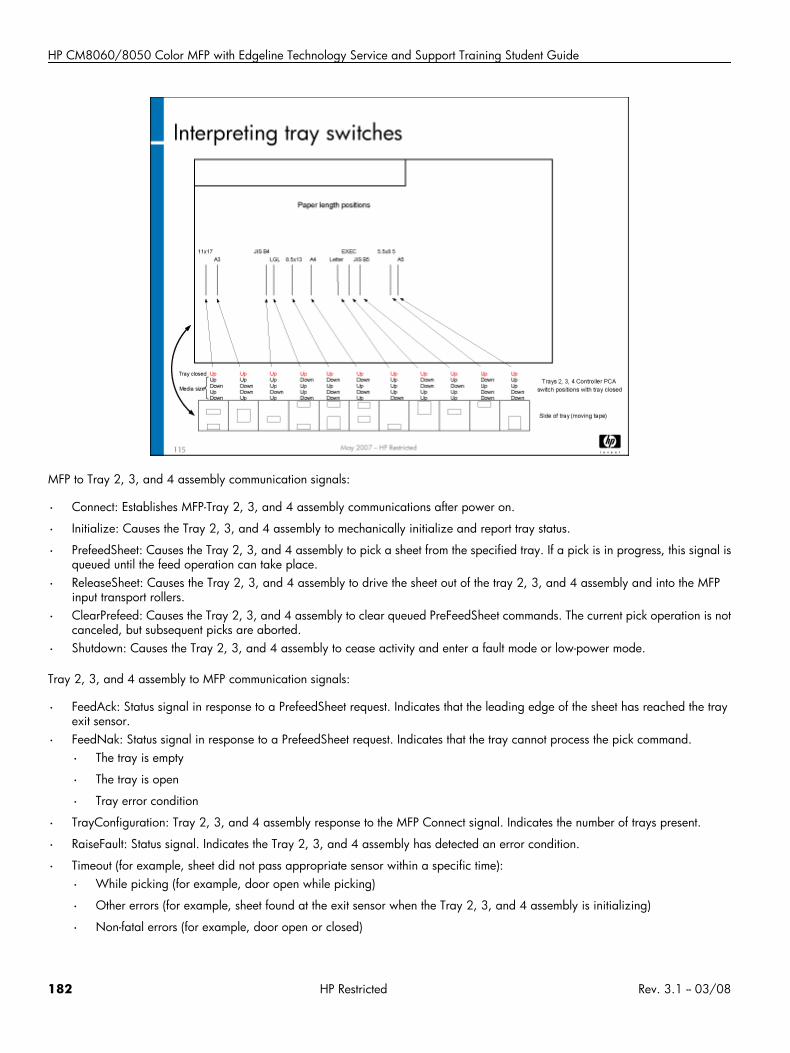
HP CM8060/8050 Color MFP with Edgeline Technology Service and Support Training Student Guide
MFP to Tray 2, 3, and 4 assembly communication signals:
• Connect: Establishes MFP-Tray 2, 3, and 4 assembly communications after power on.
• Initialize: Causes the Tray 2, 3, and 4 assembly to mechanically initialize and report tray status.
• PrefeedSheet: Causes the Tray 2, 3, and 4 assembly to pick a sheet from the specified tray. If a pick is in progress, this signal isqueued until the feed operation can take place.
• ReleaseSheet: Causes the Tray 2, 3, and 4 assembly to drive the sheet out of the tray 2, 3, and 4 assembly and into the MFPinput transport rollers.
• ClearPrefeed: Causes the Tray 2, 3, and 4 assembly to clear queued PreFeedSheet commands. The current pick operation is notcanceled, but subsequent picks are aborted.
• Shutdown: Causes the Tray 2, 3, and 4 assembly to cease activity and enter a fault mode or low-power mode.
Tray 2, 3, and 4 assembly to MFP communication signals:
• FeedAck: Status signal in response to a PrefeedSheet request. Indicates that the leading edge of the sheet has reached the trayexit sensor.
• FeedNak: Status signal in response to a PrefeedSheet request. Indicates that the tray cannot process the pick command.
• The tray is empty
• The tray is open
• Tray error condition
• TrayConfiguration: Tray 2, 3, and 4 assembly response to the MFP Connect signal. Indicates the number of trays present.
• RaiseFault: Status signal. Indicates the Tray 2, 3, and 4 assembly has detected an error condition.
• Timeout (for example, sheet did not pass appropriate sensor within a specific time):
• While picking (for example, door open while picking)
• Other errors (for example, sheet found at the exit sensor when the Tray 2, 3, and 4 assembly is initializing)
• Non-fatal errors (for example, door open or closed)
182 HP Restricted Rev. 3.1 -- 03/08
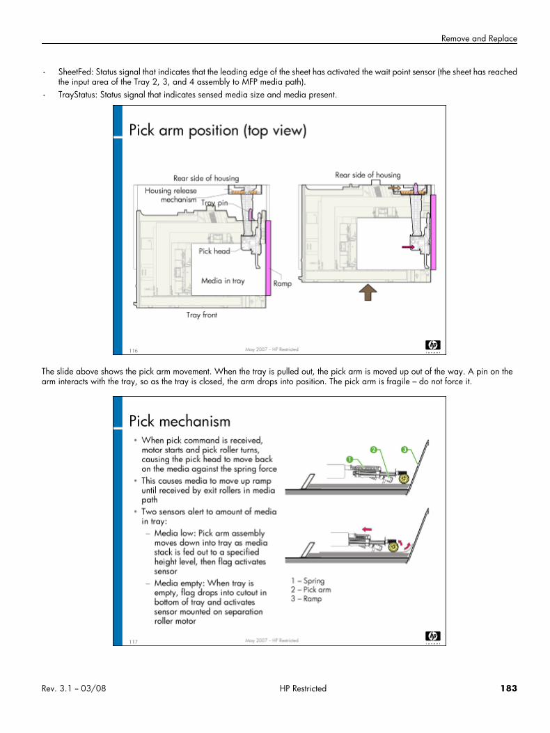
Remove and Replace
• SheetFed: Status signal that indicates that the leading edge of the sheet has activated the wait point sensor (the sheet has reachedthe input area of the Tray 2, 3, and 4 assembly to MFP media path).
• TrayStatus: Status signal that indicates sensed media size and media present.
The slide above shows the pick arm movement. When the tray is pulled out, the pick arm is moved up out of the way. A pin on thearm interacts with the tray, so as the tray is closed, the arm drops into position. The pick arm is fragile – do not force it.
Rev. 3.1 -- 03/08 HP Restricted 183
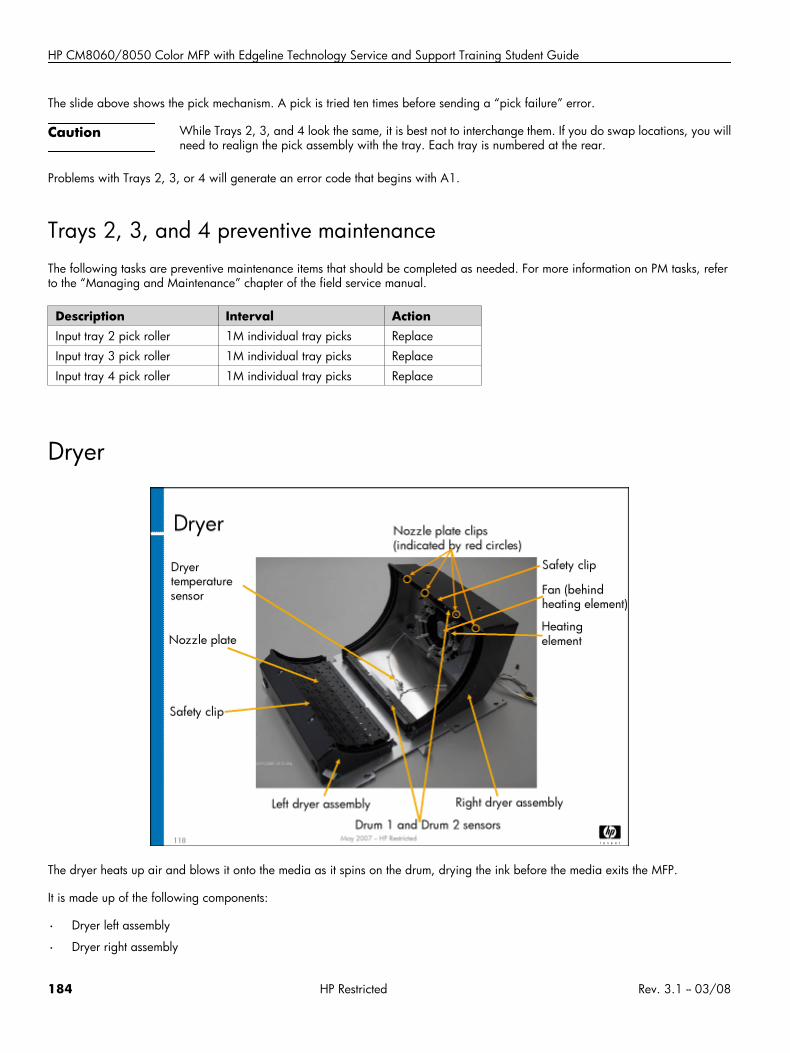
HP CM8060/8050 Color MFP with Edgeline Technology Service and Support Training Student Guide
The slide above shows the pick mechanism. A pick is tried ten times before sending a “pick failure” error.
Caution While Trays 2, 3, and 4 look the same, it is best not to interchange them. If you do swap locations, you willneed to realign the pick assembly with the tray. Each tray is numbered at the rear.
Problems with Trays 2, 3, or 4 will generate an error code that begins with A1.
Trays 2, 3, and 4 preventive maintenanceThe following tasks are preventive maintenance items that should be completed as needed. For more information on PM tasks, referto the “Managing and Maintenance” chapter of the field service manual.
Description Interval ActionInput tray 2 pick roller 1M individual tray picks Replace
Input tray 3 pick roller 1M individual tray picks Replace
Input tray 4 pick roller 1M individual tray picks Replace
Dryer
The dryer heats up air and blows it onto the media as it spins on the drum, drying the ink before the media exits the MFP.
It is made up of the following components:
• Dryer left assembly
• Dryer right assembly
184 HP Restricted Rev. 3.1 -- 03/08
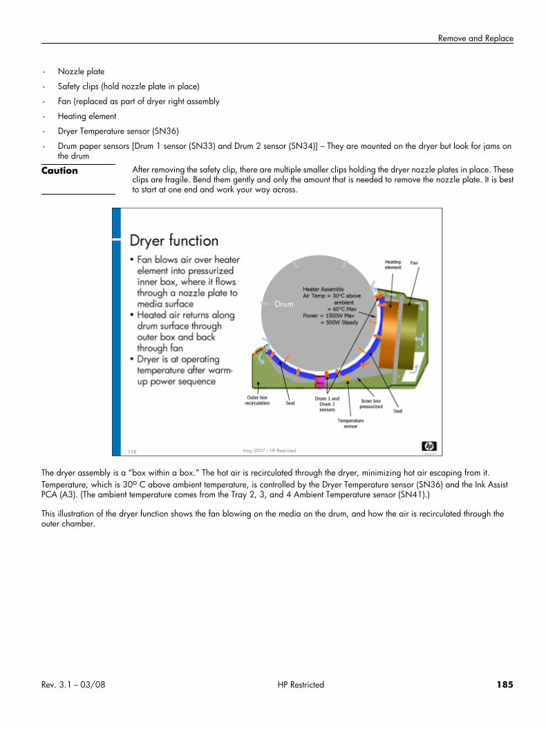
Remove and Replace
• Nozzle plate
• Safety clips (hold nozzle plate in place)
• Fan (replaced as part of dryer right assembly
• Heating element
• Dryer Temperature sensor (SN36)
• Drum paper sensors [Drum 1 sensor (SN33) and Drum 2 sensor (SN34)] – They are mounted on the dryer but look for jams onthe drum
Caution After removing the safety clip, there are multiple smaller clips holding the dryer nozzle plates in place. Theseclips are fragile. Bend them gently and only the amount that is needed to remove the nozzle plate. It is bestto start at one end and work your way across.
The dryer assembly is a “box within a box.” The hot air is recirculated through the dryer, minimizing hot air escaping from it.Temperature, which is 30o C above ambient temperature, is controlled by the Dryer Temperature sensor (SN36) and the Ink AssistPCA (A3). (The ambient temperature comes from the Tray 2, 3, and 4 Ambient Temperature sensor (SN41).)
This illustration of the dryer function shows the fan blowing on the media on the drum, and how the air is recirculated through theouter chamber.
Rev. 3.1 -- 03/08 HP Restricted 185
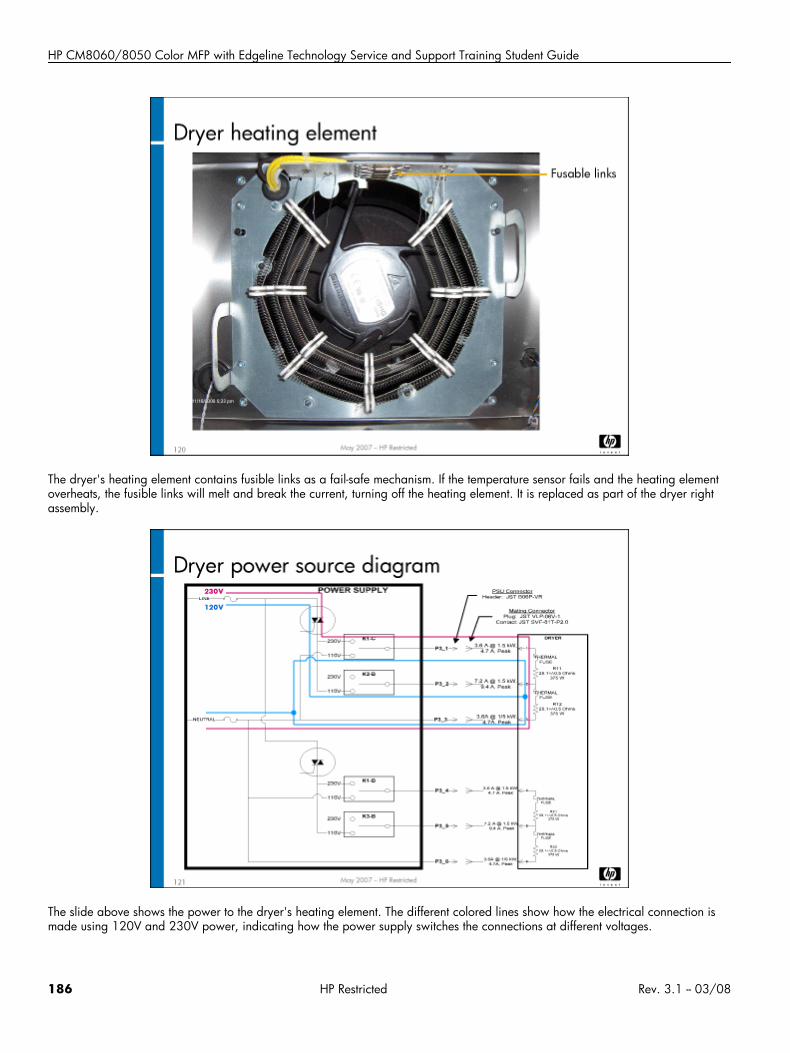
HP CM8060/8050 Color MFP with Edgeline Technology Service and Support Training Student Guide
The dryer's heating element contains fusible links as a fail-safe mechanism. If the temperature sensor fails and the heating elementoverheats, the fusible links will melt and break the current, turning off the heating element. It is replaced as part of the dryer rightassembly.
The slide above shows the power to the dryer's heating element. The different colored lines show how the electrical connection ismade using 120V and 230V power, indicating how the power supply switches the connections at different voltages.
186 HP Restricted Rev. 3.1 -- 03/08
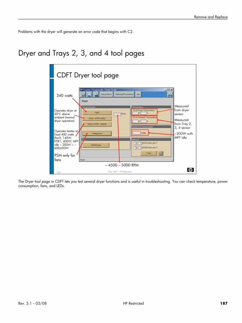
Remove and Replace
Problems with the dryer will generate an error code that begins with C2.
Dryer and Trays 2, 3, and 4 tool pages
The Dryer tool page in CDFT lets you test several dryer functions and is useful in troubleshooting. You can check temperature, powerconsumption, fans, and LEDs.
Rev. 3.1 -- 03/08 HP Restricted 187
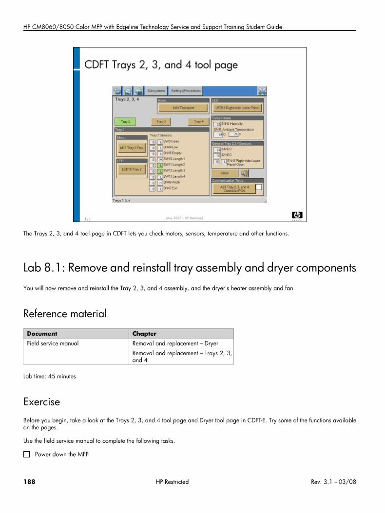
HP CM8060/8050 Color MFP with Edgeline Technology Service and Support Training Student Guide
The Trays 2, 3, and 4 tool page in CDFT lets you check motors, sensors, temperature and other functions.
Lab 8.1: Remove and reinstall tray assembly and dryer componentsYou will now remove and reinstall the Tray 2, 3, and 4 assembly, and the dryer's heater assembly and fan.
Reference material
Document ChapterField service manual Removal and replacement – Dryer
Removal and replacement – Trays 2, 3,and 4
Lab time: 45 minutes
ExerciseBefore you begin, take a look at the Trays 2, 3, and 4 tool page and Dryer tool page in CDFT-E. Try some of the functions availableon the pages.
Use the field service manual to complete the following tasks.
Power down the MFP
188 HP Restricted Rev. 3.1 -- 03/08
Remove and Replace
Remove the Tray 2, 3, and 4 assembly and observe how the mechanism works
Remove the dryer assembly
Remove the nozzle plate on the dryer assembly right and observe the dryer heater assembly
Have your instructor check your work to make sure everything was removed correctly
Reinstall the dryer components
Reinstall the Tray 2, 3, and 4 assembly
Power up the MFP and make sure it is working correctly
Lab 8.2: Troubleshoot Trays 2, 3, and 4You will now troubleshoot an error in Trays 2, 3, or 4, using CDFT-E
Reference materialYou will not use the field service manual in this exercise.
Lab time: 30 minutes
ExerciseYour instructor has injected a fault into Tray 3. Follow these steps to resolve the error:
1. Try to make a copy from Tray 3.2. Read the control panel error message.3. In CDFT-E, use the Event Log to locate the error event.4. Troubleshoot the problem.5. Verify you correctly solved the problem by making a copy from Tray 3.
Topic 9: Media path and Tray 1This topic guides you through removing and replacing various media path components and Tray 1. It also includes the theory ofoperation for the media path components and Tray 1.
Rev. 3.1 -- 03/08 HP Restricted 189
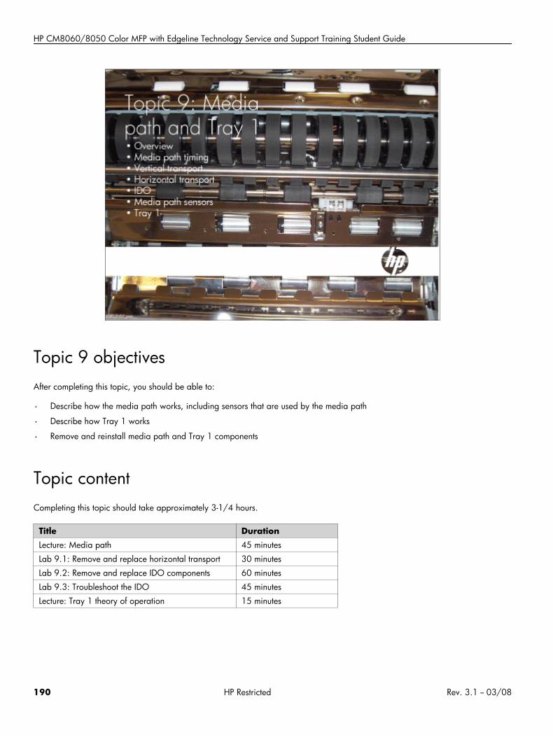
HP CM8060/8050 Color MFP with Edgeline Technology Service and Support Training Student Guide
Topic 9 objectivesAfter completing this topic, you should be able to:
• Describe how the media path works, including sensors that are used by the media path
• Describe how Tray 1 works
• Remove and reinstall media path and Tray 1 components
Topic contentCompleting this topic should take approximately 3-1/4 hours.
Title DurationLecture: Media path 45 minutes
Lab 9.1: Remove and replace horizontal transport 30 minutes
Lab 9.2: Remove and replace IDO components 60 minutes
Lab 9.3: Troubleshoot the IDO 45 minutes
Lecture: Tray 1 theory of operation 15 minutes
190 HP Restricted Rev. 3.1 -- 03/08
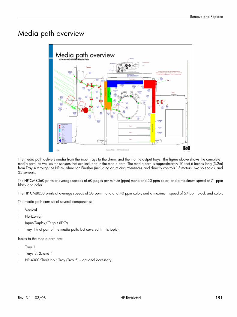
Remove and Replace
Media path overview
The media path delivers media from the input trays to the drum, and then to the output trays. The figure above shows the completemedia path, as well as the sensors that are included in the media path. The media path is approximately 10 feet 6 inches long (3.2m)from Tray 4 through the HP Multifunction Finisher (including drum circumference), and directly controls 13 motors, two solenoids, and25 sensors.
The HP CM8060 prints at average speeds of 60 pages per minute (ppm) mono and 50 ppm color, and a maximum speed of 71 ppmblack and color.
The HP CM8050 prints at average speeds of 50 ppm mono and 40 ppm color, and a maximum speed of 57 ppm black and color.
The media path consists of several components:
• Vertical
• Horizontal
• Input/Duplex/Output (IDO)
• Tray 1 (not part of the media path, but covered in this topic)
Inputs to the media path are:
• Tray 1
• Trays 2, 3, and 4
• HP 4000-Sheet Input Tray (Tray 5) – optional accessory
Rev. 3.1 -- 03/08 HP Restricted 191
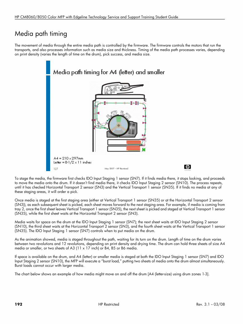
HP CM8060/8050 Color MFP with Edgeline Technology Service and Support Training Student Guide
Media path timingThe movement of media through the entire media path is controlled by the firmware. The firmware controls the motors that run thetransports, and also processes information such as media size and thickness. Timing of the media path processes varies, dependingon print density (varies the length of time on the drum), pick success, and media size.
To stage the media, the firmware first checks IDO Input Staging 1 sensor (SN7). If it finds media there, it stops looking, and proceedsto move the media onto the drum. If it doesn’t find media there, it checks IDO Input Staging 2 sensor (SN10). The process repeats,until it has checked Horizontal Transport 2 sensor (SN3) and the Vertical Transport 1 sensor (SN35). If it finds no media at any ofthese staging areas, it will order a pick.
Once media is staged at the first staging area (either at Vertical Transport 1 sensor (SN35) or at the Horizontal Transport 2 sensor(SN3)), as each subsequent sheet is picked, each sheet moves forward to the next staging area. For example, if media is coming fromtray 2, once the first sheet leaves Vertical Transport 1 sensor (SN35), the next sheet is picked and staged at Vertical Transport 1 sensor(SN35), while the first sheet waits at the Horizontal Transport 2 sensor (SN3).
Media waits for space on the drum at the IDO Input Staging 1 sensor (SN7); the next sheet waits at IDO Input Staging 2 sensor(SN10), the third sheet waits at the Horizontal Transport 2 sensor (SN3), and the fourth sheet waits at the Vertical Transport 1 sensor(SN35). The IDO Input Staging 1 sensor (SN7) controls when to put media on the drum.
As the animation showed, media is staged throughout the path, waiting for its turn on the drum. Length of time on the drum variesbetween two revolutions and 12 revolutions, depending on print density and drying time. The drum can hold three sheets of size A4media or smaller, or two sheets of A3 (11 x 17 inch) or B4, B5 or B6 media.
If space is available on the drum, and A4 (letter) or smaller media is staged at both the IDO Input Staging 1 sensor (SN7) and IDOInput Staging 2 sensor (SN10), the MFP will execute a “burst load,” putting two sheets of media onto the drum almost simultaneously.Burst loads cannot occur with larger media.
The chart below shows an example of how media might move on and off the drum [A4 (letter-size) using drum zones 1-3].
192 HP Restricted Rev. 3.1 -- 03/08
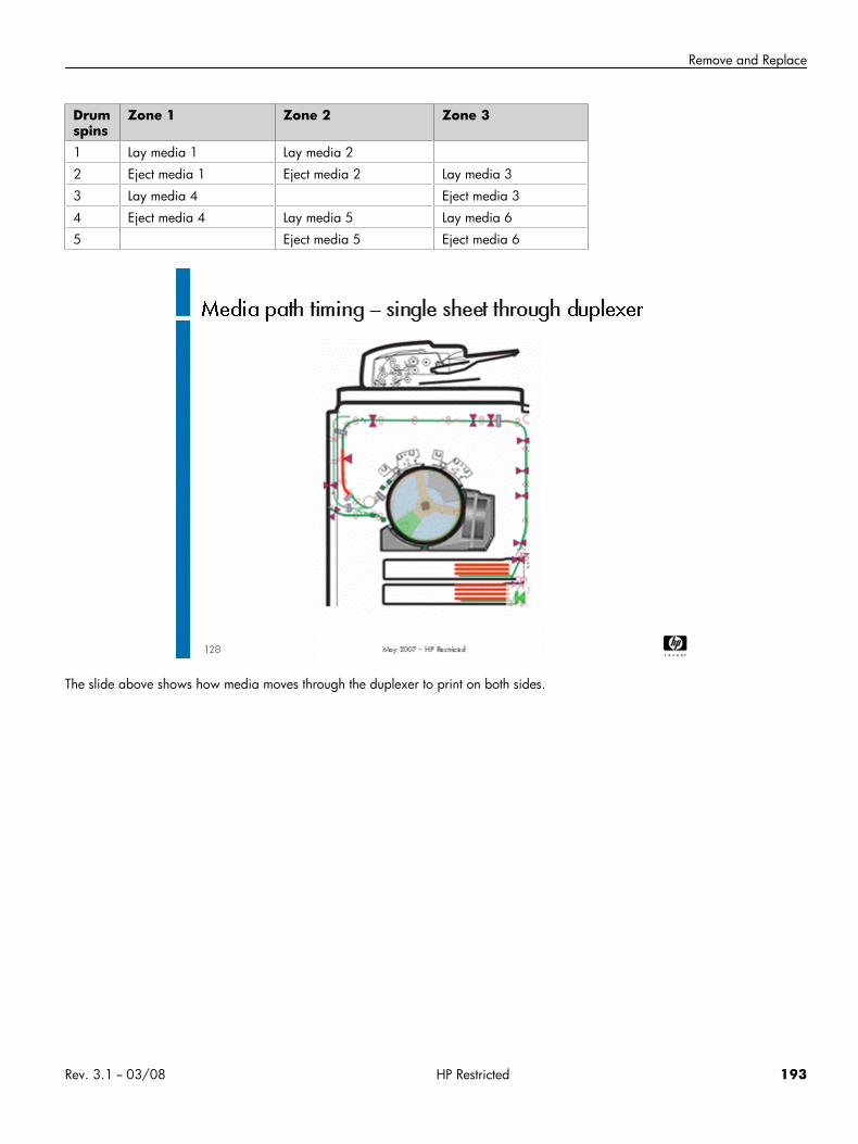
Remove and Replace
Drumspins
Zone 1 Zone 2 Zone 3
1 Lay media 1 Lay media 2
2 Eject media 1 Eject media 2 Lay media 3
3 Lay media 4 Eject media 3
4 Eject media 4 Lay media 5 Lay media 6
5 Eject media 5 Eject media 6
The slide above shows how media moves through the duplexer to print on both sides.
Rev. 3.1 -- 03/08 HP Restricted 193
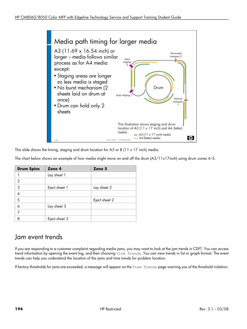
HP CM8060/8050 Color MFP with Edgeline Technology Service and Support Training Student Guide
This slide shows the timing, staging and drum location for A3 or B (11 x 17 inch) media.
The chart below shows an example of how media might move on and off the drum (A3/11x17inch) using drum zones 4–5.
Drum Spins Zone 4 Zone 51 Lay sheet 1
2
3 Eject sheet 1 Lay sheet 2
4
5 Eject sheet 2
6 Lay sheet 3
7
8 Eject sheet 3
Jam event trendsIf you are responding to a customer complaint regarding media jams, you may want to look at the jam trends in CDFT. You can accesstrend information by opening the event log, and then choosing View Trends. You can view trends in list or graph format. The eventtrends can help you understand the location of the jams and time trends for problem location.
If factory thresholds for jams are exceeded, a message will appear on the View Trends page warning you of the threshold violation.
194 HP Restricted Rev. 3.1 -- 03/08
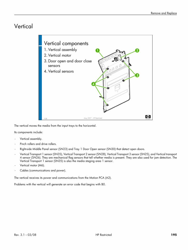
Remove and Replace
Vertical
The vertical moves the media from the input trays to the horizontal.
Its components include:
• Vertical assembly.
• Pinch rollers and drive rollers.
• Right-side Middle Panel sensor (SN23) and Tray 1 Door Open sensor (SN30) that detect open doors.
• Vertical Transport 1 sensor (SN35), Vertical Transport 2 sensor (SN28), Vertical Transport 3 sensor (SN25), and Vertical transport4 sensor (SN26). They are mechanical flag sensors that tell whether media is present. They are also used for jam detection. TheVertical Transport 1 sensor (SN35) is also the media staging area 1 sensor.
• Vertical motor (M6).
• Cables (communications and power).
The vertical receives its power and communications from the Motion PCA (A2).
Problems with the vertical will generate an error code that begins with B0.
Rev. 3.1 -- 03/08 HP Restricted 195
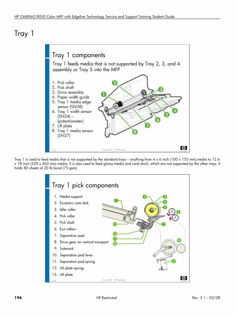
HP CM8060/8050 Color MFP with Edgeline Technology Service and Support Training Student Guide
Tray 1
Tray 1 is used to feed media that is not supported by the standard trays – anything from 4 x 6 inch (100 x 152 mm) media to 12.6x 18 inch (320 x 460 mm) media. It is also used to feed glossy media and card stock, which are not supported by the other trays. Itholds 80 sheets of 20 lb bond (75 gsm).
196 HP Restricted Rev. 3.1 -- 03/08
Remove and Replace
Tray 1 is comprised of the following components:
• Separation pad
• Pick roller
• Pick shaft
• Lift plate
• Drive assembly (Tray 1 drive gear, MFP drive gear, Tray 1 Pick solenoid (SOL1))
• Three sensors:
• Tray 1 Media sensor (SN27)
• Tray 1 Width sensor (SN24)
• Tray 1 Media Edge sensor (SN38)
• Paper-width guide
The pick roller, pick shaft, lift plate and drive assembly make up the Tray 1 pick mechanism. The Tray 1 Media sensor (SN27) andTray 1 Media Edge sensor (SN38) send a signal to the MFP when media is placed in the tray. The media width guide includes Tray1 Width sensor (SN24) (potentiometer) that is used to tell the firmware the media size in the tray. It produces a reference voltage thatis sent to the MFP formatter. MFP firmware reads the optical sensor signal as media present in the tray, and associates a media widthwith the reference voltage from the media potentiometer.
Tray 1 interactionsThis is how Tray 1 works:
1. Media is loaded into Tray 1 and the media is adjusted to the stack.2. The Tray 1 Media sensor (SN27) alerts the firmware that media is present.3. The firmware sends a pick signal by way of the Motion PCA (A2).4. The Motion PCA (A2) sends a signal to release the Tray 1 drive gear (Tray 1 Pick solenoid (SOL1) releases the gear).5. The Tray 1 drive gear engages the MFP drive gear on the vertical.6. The pick roller rotates.7. The lift plate lifts the cam and releases the media stack.8. Media contacts the pick roller and separation pad. Friction causes only one sheet to be picked.9. The Tray 1 drive gear continues to rotate the pick roller.10. A single sheet feeds into the exit rollers, leaving Tray 1 and entering the vertical.11. The Tray 1 gear disengages from the MFP drive gear and is caught by the lip on the Tray 1 drive gear.12. Tray 1 is ready for its next pick.
A pick is tried ten times, once the firmware knows that media is present in the tray. After three tries, the process times out and declaresan A0.1301 error code.
Problems with Tray 1 will generate an error code that begins with A0.
Tray 1 calibrationsThe Tray 1 calibration calibrates the Tray 1 sliding media guide to correctly detect the width of media in Tray 1. It should be performedif you replace Tray 1, or if you experience print margin problems on pages fed through Tray 1. The calibration is accessed throughCDFT.
Rev. 3.1 -- 03/08 HP Restricted 197
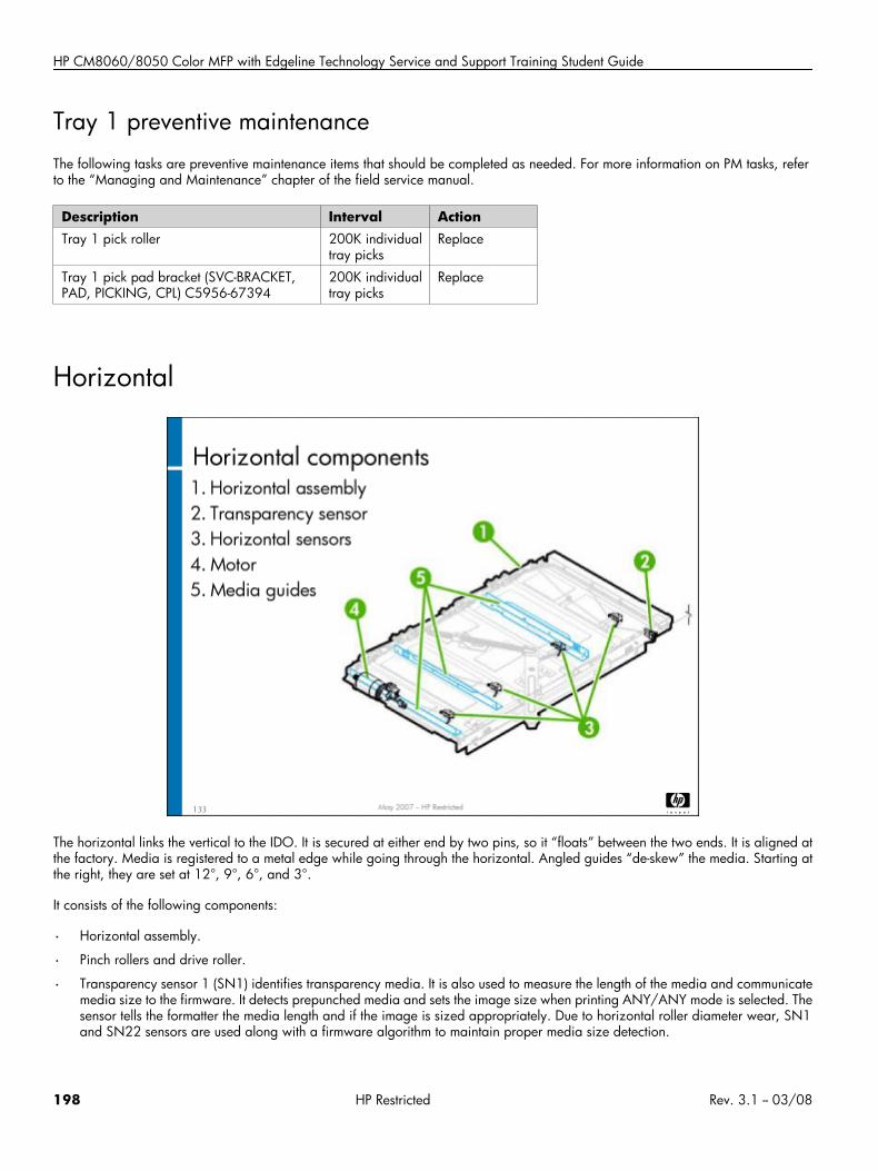
HP CM8060/8050 Color MFP with Edgeline Technology Service and Support Training Student Guide
Tray 1 preventive maintenanceThe following tasks are preventive maintenance items that should be completed as needed. For more information on PM tasks, referto the “Managing and Maintenance” chapter of the field service manual.
Description Interval ActionTray 1 pick roller 200K individual
tray picksReplace
Tray 1 pick pad bracket (SVC-BRACKET,PAD, PICKING, CPL) C5956-67394
200K individualtray picks
Replace
Horizontal
The horizontal links the vertical to the IDO. It is secured at either end by two pins, so it “floats” between the two ends. It is aligned atthe factory. Media is registered to a metal edge while going through the horizontal. Angled guides “de-skew” the media. Starting atthe right, they are set at 12°, 9°, 6°, and 3°.
It consists of the following components:
• Horizontal assembly.
• Pinch rollers and drive roller.
• Transparency sensor 1 (SN1) identifies transparency media. It is also used to measure the length of the media and communicatemedia size to the firmware. It detects prepunched media and sets the image size when printing ANY/ANY mode is selected. Thesensor tells the formatter the media length and if the image is sized appropriately. Due to horizontal roller diameter wear, SN1and SN22 sensors are used along with a firmware algorithm to maintain proper media size detection.
198 HP Restricted Rev. 3.1 -- 03/08
Remove and Replace
• Horizontal Transport 2 sensor (SN3), Horizontal Transport 3 sensor (SN2), and Horizontal Transport 4 sensor (SN5). TheHorizontal Transport 2 sensor (SN3) is also the media staging area 2 sensor. These sensors are mechanical flag sensors that tellwhether media is present. They are also used for jam detection.
• Horizontal Open sensor (SN4).
• Horizontal motor (M7).
• Cables (communications and power).
Not only does the horizontal feed the media to the IDO, it feeds it at higher speed so that the IDO can do “burst loads” of the mediaonto the drum. Media moves on the horizontal at approximately 35 to 40 inches per second.
The horizontal receives its power and communications from the Motion PCA (A2).
Caution The black idler rollers and drive rollers look similar, but have different functions. Idler rollers in the remainderof the media path are white. Do not put a white idler roller in the horizontal; be sure to use the black idlerrollers. The white idler rollers will wear out the drive rollers prematurely, if inserted in the horizontal.
Problems with the horizontal will generate an error code that begins with B1.
Horizontal preventive maintenanceThe following tasks are preventive maintenance items that should be completed as needed. For more information on PM tasks, referto the “Managing and Maintenance” chapter of the field service manual.
Description Interval ActionHorizontal transport rollers 500K pages Replace
Rev. 3.1 -- 03/08 HP Restricted 199
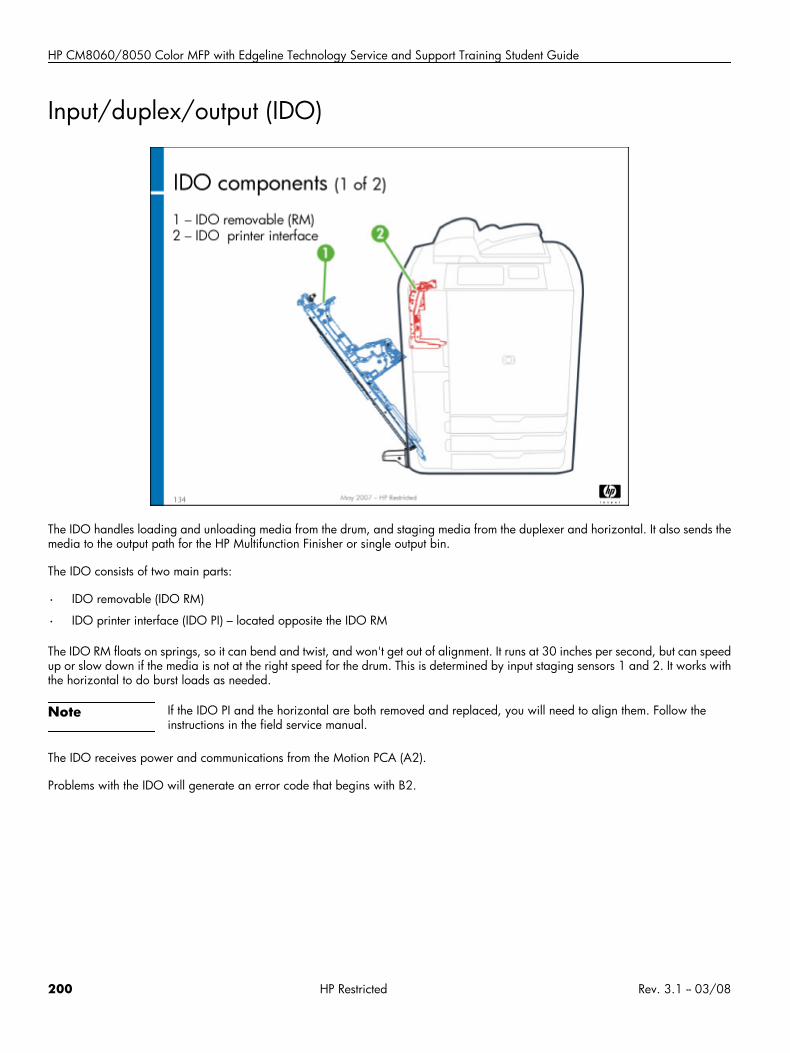
HP CM8060/8050 Color MFP with Edgeline Technology Service and Support Training Student Guide
Input/duplex/output (IDO)
The IDO handles loading and unloading media from the drum, and staging media from the duplexer and horizontal. It also sends themedia to the output path for the HP Multifunction Finisher or single output bin.
The IDO consists of two main parts:
• IDO removable (IDO RM)
• IDO printer interface (IDO PI) – located opposite the IDO RM
The IDO RM floats on springs, so it can bend and twist, and won't get out of alignment. It runs at 30 inches per second, but can speedup or slow down if the media is not at the right speed for the drum. This is determined by input staging sensors 1 and 2. It works withthe horizontal to do burst loads as needed.
Note If the IDO PI and the horizontal are both removed and replaced, you will need to align them. Follow theinstructions in the field service manual.
The IDO receives power and communications from the Motion PCA (A2).
Problems with the IDO will generate an error code that begins with B2.
200 HP Restricted Rev. 3.1 -- 03/08
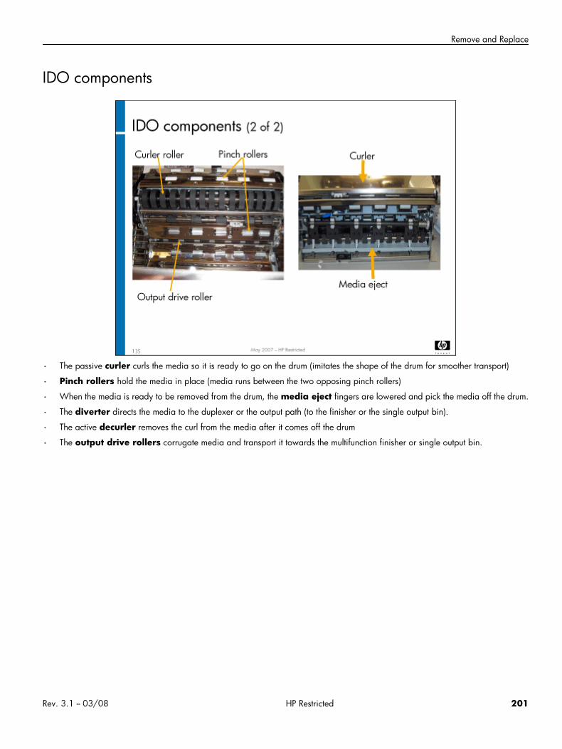
Remove and Replace
IDO components
• The passive curler curls the media so it is ready to go on the drum (imitates the shape of the drum for smoother transport)
• Pinch rollers hold the media in place (media runs between the two opposing pinch rollers)
• When the media is ready to be removed from the drum, the media eject fingers are lowered and pick the media off the drum.
• The diverter directs the media to the duplexer or the output path (to the finisher or the single output bin).
• The active decurler removes the curl from the media after it comes off the drum
• The output drive rollers corrugate media and transport it towards the multifunction finisher or single output bin.
Rev. 3.1 -- 03/08 HP Restricted 201
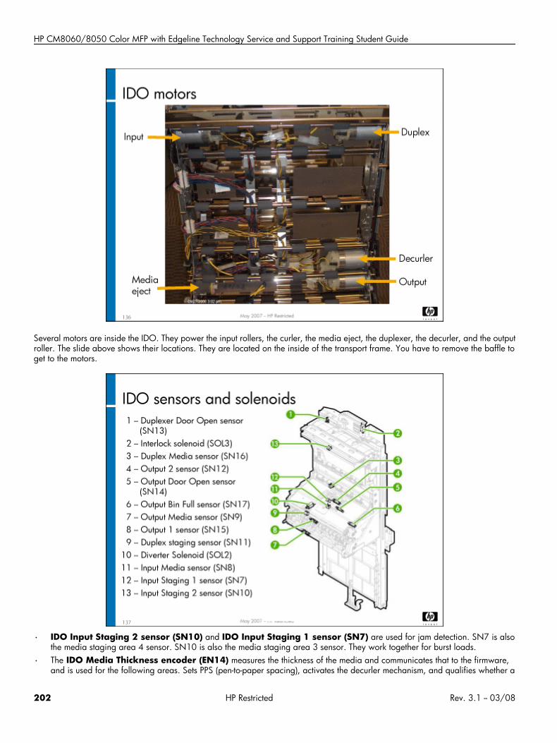
HP CM8060/8050 Color MFP with Edgeline Technology Service and Support Training Student Guide
Several motors are inside the IDO. They power the input rollers, the curler, the media eject, the duplexer, the decurler, and the outputroller. The slide above shows their locations. They are located on the inside of the transport frame. You have to remove the baffle toget to the motors.
• IDO Input Staging 2 sensor (SN10) and IDO Input Staging 1 sensor (SN7) are used for jam detection. SN7 is alsothe media staging area 4 sensor. SN10 is also the media staging area 3 sensor. They work together for burst loads.
• The IDO Media Thickness encoder (EN14) measures the thickness of the media and communicates that to the firmware,and is used for the following areas. Sets PPS (pen-to-paper spacing), activates the decurler mechanism, and qualifies whether a
202 HP Restricted Rev. 3.1 -- 03/08
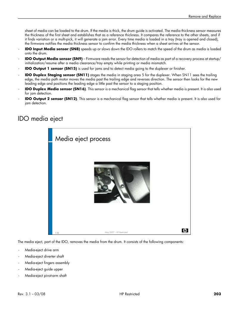
Remove and Replace
sheet of media can be loaded to the drum. If the media is thick, the drum guide is activated. The media thickness sensor measuresthe thickness of the first sheet and establishes that as a reference thickness. It compares the reference to the other sheets, and ifit finds variation or a multi-pick, it will generate a jam error. Every time media is loaded in a tray (tray is opened and closed),the firmware notifies the media thickness sensor to confirm the media thickness when a sheet arrives at the sensor.
• IDO Input Media sensor (SN8) speeds up or slows down the IDO rollers to match the speed of the drum as media is loadedonto the drum.
• IDO Output Media sensor (SN9) – Firmware reads the sensor for detection of media as part of a recovery process at startup/initialization/resume after a media clearance/tray empty while printing or media mismatch.
• IDO Output 1 sensor (SN15) is used for jams and to detect media going to the duplexer or finisher.
• IDO Duplex Staging sensor (SN11) stages the media in staging area 5 for the duplexer. When SN11 sees the trailingedge, the media path motor moves the media past the trailing edge and reverses direction. The sensor then looks for the newleading edge and positions the leading edge a little past the sensor to a staging position.
• IDO Duplex Media sensor (SN16). This sensor is a mechanical flag sensor that tells whether media is present. It is also usedfor jam detection.
• IDO Output 2 sensor (SN12). This sensor is a mechanical flag sensor that tells whether media is present. It is also used forjam detection.
IDO media eject
The media eject, part of the IDO, removes the media from the drum. It consists of the following components:
• Media-eject drive arm
• Media-eject diverter shaft
• Media-eject fingers assembly
• Media-eject guide upper
• Media-eject pivot-arm shaft
Rev. 3.1 -- 03/08 HP Restricted 203
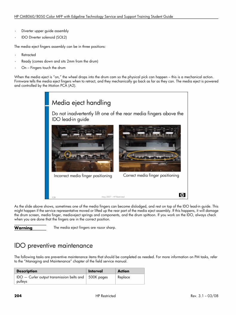
HP CM8060/8050 Color MFP with Edgeline Technology Service and Support Training Student Guide
• Diverter upper guide assembly
• IDO Diverter solenoid (SOL2)
The media eject fingers assembly can be in three positions:
• Retracted
• Ready (comes down and sits 2mm from the drum)
• On – Fingers touch the drum
When the media eject is “on,” the wheel drops into the drum cam so the physical pick can happen – this is a mechanical action.Firmware tells the media eject fingers when to retract, and they mechanically go back as far as they can. The media eject is poweredand controlled by the Motion PCA (A2).
As the slide above shows, sometimes one of the media fingers can become dislodged, and rest on top of the IDO lead-in guide. Thismight happen if the service representative moved or lifted up the rear part of the media eject assembly. If this happens, it will damagethe drum screen, media finger, media-eject springs and components, and the drum spittoon. If you work on the IDO, always checkwhen you are done that the fingers are in the correct position.
Warning The media eject fingers are razor sharp.
IDO preventive maintenanceThe following tasks are preventive maintenance items that should be completed as needed. For more information on PM tasks, referto the “Managing and Maintenance” chapter of the field service manual.
Description Interval ActionIDO — Curler output transmission belts andpulleys
500K pages Replace
204 HP Restricted Rev. 3.1 -- 03/08
Remove and Replace
Lab 9.1: Remove and reinstall the horizontalYou will now remove and reinstall the horizontal assembly.
Reference material
Document ChapterField service manual Removal and replacement – Horizontal
Lab time: 30 minutes
ExerciseUse the field service manual to complete the following tasks. When you have the assembly removed, and again when you have itreplaced, have your instructor check your work.
Power down the MFP
Remove the horizontal assembly
Observe the angled guides that “de-skew” the media
Remove a drive roller
Have your instructor check your work to make sure the horizontal assembly has been removed correctly.
Reinstall the drive roller and the horizontal assembly.
Power up the MFP and make sure it is operating correctly
Lab 9.2: Remove and reinstall IDO RM componentsYou will now remove and reinstall several components of the IDO RM. To do so, you will first remove the IDO RM from the MFP.
Reference material
Document ChapterField service manual Removal and replacement – IDO
Lab time: 60 minutes
ExerciseLook at the media path tool pages in CDFT-E, and the jam event trends.
Rev. 3.1 -- 03/08 HP Restricted 205
HP CM8060/8050 Color MFP with Edgeline Technology Service and Support Training Student Guide
Use the field service manual to complete the following tasks.
Power down the MFP
Remove the IDO RM from the MFP
Remove the IDO Input 2 motor (M10)
Observe the media eject fingers
Have your instructor check your work to make sure the IDO RM components have been removed correctly.
Reinstall the IDO components
Replace the IDO RM
Power up the MFP and make sure it is working correctly
Lab 9.3: Troubleshoot the IDOYou will now troubleshoot an error in the IDO, using CDFT-E.
Reference materialDo not use the field service manual for this lab. Use only CDFT-E.
Lab time: 45 minutes
ExerciseYour instructor has injected a fault into the IDO. Follow these steps to resolve the error:
Note the message on the control panel.
Use CDFT-E to find the error.
Follow the recommended actions until you locate and solve the problem.
Topic 10: HP 4000-Sheet Input Tray (Tray 5)This topic guides you through the theory of operation for the HP 4000-Sheet Input Tray (Tray 5). You will remove and reinstall theTray 5 Elevator motor (M102), the pick rollers, and the Tray 5 pick arm assembly.
206 HP Restricted Rev. 3.1 -- 03/08
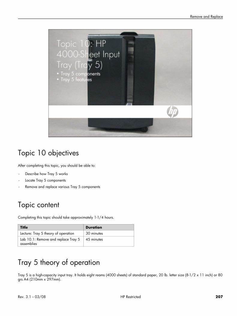
Remove and Replace
Topic 10 objectivesAfter completing this topic, you should be able to:
• Describe how Tray 5 works
• Locate Tray 5 components
• Remove and replace various Tray 5 components
Topic contentCompleting this topic should take approximately 1-1/4 hours.
Title DurationLecture: Tray 5 theory of operation 30 minutes
Lab 10.1: Remove and replace Tray 5assemblies
45 minutes
Tray 5 theory of operationTray 5 is a high-capacity input tray. It holds eight reams (4000 sheets) of standard paper, 20 lb. letter size (8-1/2 x 11 inch) or 80grs A4 (210mm x 297mm).
Rev. 3.1 -- 03/08 HP Restricted 207
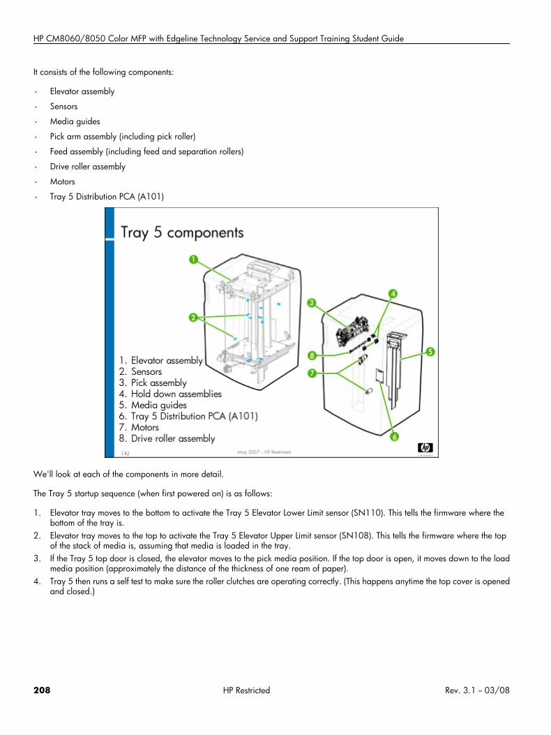
HP CM8060/8050 Color MFP with Edgeline Technology Service and Support Training Student Guide
It consists of the following components:
• Elevator assembly
• Sensors
• Media guides
• Pick arm assembly (including pick roller)
• Feed assembly (including feed and separation rollers)
• Drive roller assembly
• Motors
• Tray 5 Distribution PCA (A101)
We'll look at each of the components in more detail.
The Tray 5 startup sequence (when first powered on) is as follows:
1. Elevator tray moves to the bottom to activate the Tray 5 Elevator Lower Limit sensor (SN110). This tells the firmware where thebottom of the tray is.
2. Elevator tray moves to the top to activate the Tray 5 Elevator Upper Limit sensor (SN108). This tells the firmware where the topof the stack of media is, assuming that media is loaded in the tray.
3. If the Tray 5 top door is closed, the elevator moves to the pick media position. If the top door is open, it moves down to the loadmedia position (approximately the distance of the thickness of one ream of paper).
4. Tray 5 then runs a self test to make sure the roller clutches are operating correctly. (This happens anytime the top cover is openedand closed.)
208 HP Restricted Rev. 3.1 -- 03/08
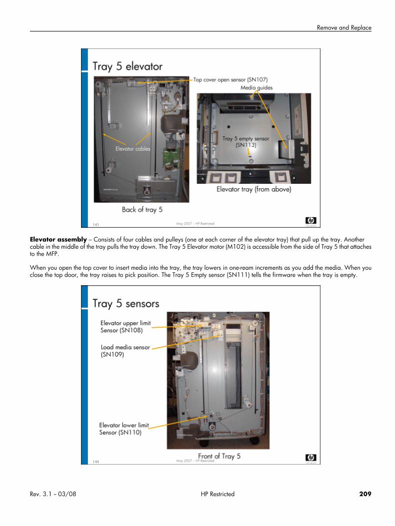
Remove and Replace
Elevator assembly – Consists of four cables and pulleys (one at each corner of the elevator tray) that pull up the tray. Anothercable in the middle of the tray pulls the tray down. The Tray 5 Elevator motor (M102) is accessible from the side of Tray 5 that attachesto the MFP.
When you open the top cover to insert media into the tray, the tray lowers in one-ream increments as you add the media. When youclose the top door, the tray raises to pick position. The Tray 5 Empty sensor (SN111) tells the firmware when the tray is empty.
Rev. 3.1 -- 03/08 HP Restricted 209
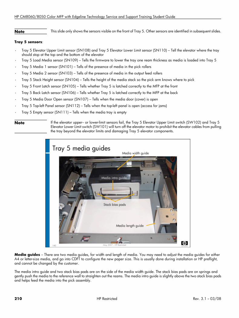
HP CM8060/8050 Color MFP with Edgeline Technology Service and Support Training Student Guide
Note This slide only shows the sensors visible on the front of Tray 5. Other sensors are identified in subsequent slides.
Tray 5 sensors:
• Tray 5 Elevator Upper Limit sensor (SN108) and Tray 5 Elevator Lower Limit sensor (SN110) – Tell the elevator where the trayshould stop at the top and the bottom of the elevator
• Tray 5 Load Media sensor (SN109) – Tells the firmware to lower the tray one ream thickness as media is loaded into Tray 5
• Tray 5 Media 1 sensor (SN101) – Tells of the presence of media in the pick rollers
• Tray 5 Media 2 sensor (SN103) – Tells of the presence of media in the output feed rollers
• Tray 5 Stack Height sensor (SN104) – Tells the height of the media stack so the pick arm knows where to pick
• Tray 5 Front Latch sensor (SN105) – Tells whether Tray 5 is latched correctly to the MFP at the front
• Tray 5 Back Latch sensor (SN106) – Tells whether Tray 5 is latched correctly to the MFP at the back
• Tray 5 Media Door Open sensor (SN107) – Tells when the media door (cover) is open
• Tray 5 Top-left Panel sensor (SN112) – Tells when the top-left panel is open (access for jams)
• Tray 5 Empty sensor (SN111) – Tells when the media tray is empty
Note If the elevator upper– or lower-limit sensors fail, the Tray 5 Elevator Upper Limit switch (SW102) and Tray 5Elevator Lower Limit switch (SW101) will turn off the elevator motor to prohibit the elevator cables from pullingthe tray beyond the elevator limits and damaging Tray 5 elevator components.
Media guides – There are two media guides, for width and length of media. You may need to adjust the media guides for eitherA4 or letter-size media, and go into CDFT to configure the new paper size. This is usually done during installation or HP preflight,and cannot be changed by the customer.
The media intro guide and two stack bias pads are on the side of the media width guide. The stack bias pads are on springs andgently push the media to the reference wall to straighten out the reams. The media intro guide is slightly above the two stack bias padsand helps feed the media into the pick assembly.
210 HP Restricted Rev. 3.1 -- 03/08
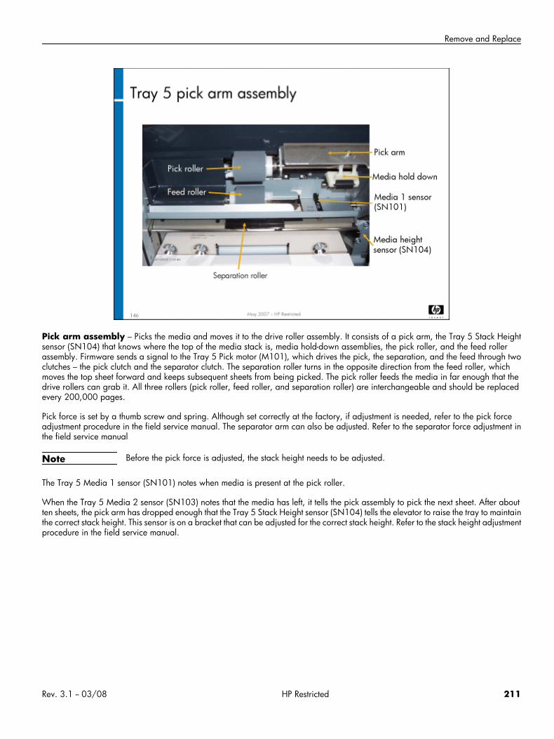
Remove and Replace
Pick arm assembly – Picks the media and moves it to the drive roller assembly. It consists of a pick arm, the Tray 5 Stack Heightsensor (SN104) that knows where the top of the media stack is, media hold-down assemblies, the pick roller, and the feed rollerassembly. Firmware sends a signal to the Tray 5 Pick motor (M101), which drives the pick, the separation, and the feed through twoclutches – the pick clutch and the separator clutch. The separation roller turns in the opposite direction from the feed roller, whichmoves the top sheet forward and keeps subsequent sheets from being picked. The pick roller feeds the media in far enough that thedrive rollers can grab it. All three rollers (pick roller, feed roller, and separation roller) are interchangeable and should be replacedevery 200,000 pages.
Pick force is set by a thumb screw and spring. Although set correctly at the factory, if adjustment is needed, refer to the pick forceadjustment procedure in the field service manual. The separator arm can also be adjusted. Refer to the separator force adjustment inthe field service manual
Note Before the pick force is adjusted, the stack height needs to be adjusted.
The Tray 5 Media 1 sensor (SN101) notes when media is present at the pick roller.
When the Tray 5 Media 2 sensor (SN103) notes that the media has left, it tells the pick assembly to pick the next sheet. After aboutten sheets, the pick arm has dropped enough that the Tray 5 Stack Height sensor (SN104) tells the elevator to raise the tray to maintainthe correct stack height. This sensor is on a bracket that can be adjusted for the correct stack height. Refer to the stack height adjustmentprocedure in the field service manual.
Rev. 3.1 -- 03/08 HP Restricted 211
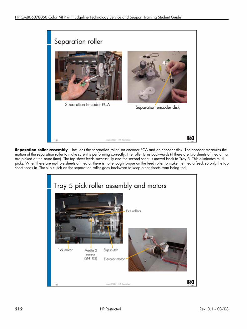
HP CM8060/8050 Color MFP with Edgeline Technology Service and Support Training Student Guide
Separation roller assembly – Includes the separation roller, an encoder PCA and an encoder disk. The encoder measures themotion of the separation roller to make sure it is performing correctly. The roller turns backwards (if there are two sheets of media thatare picked at the same time). The top sheet feeds successfully and the second sheet is moved back to Tray 5. This eliminates multi-picks. When there are multiple sheets of media, there is not enough torque on the feed roller to make the media feed, so only the topsheet feeds in. The slip clutch on the separation roller goes backward to keep other sheets from being fed.
212 HP Restricted Rev. 3.1 -- 03/08
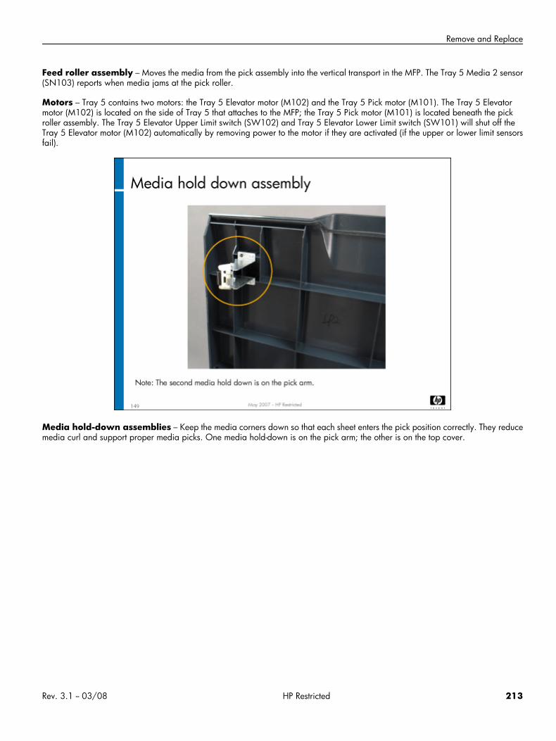
Remove and Replace
Feed roller assembly – Moves the media from the pick assembly into the vertical transport in the MFP. The Tray 5 Media 2 sensor(SN103) reports when media jams at the pick roller.
Motors – Tray 5 contains two motors: the Tray 5 Elevator motor (M102) and the Tray 5 Pick motor (M101). The Tray 5 Elevatormotor (M102) is located on the side of Tray 5 that attaches to the MFP; the Tray 5 Pick motor (M101) is located beneath the pickroller assembly. The Tray 5 Elevator Upper Limit switch (SW102) and Tray 5 Elevator Lower Limit switch (SW101) will shut off theTray 5 Elevator motor (M102) automatically by removing power to the motor if they are activated (if the upper or lower limit sensorsfail).
Media hold-down assemblies – Keep the media corners down so that each sheet enters the pick position correctly. They reducemedia curl and support proper media picks. One media hold-down is on the pick arm; the other is on the top cover.
Rev. 3.1 -- 03/08 HP Restricted 213
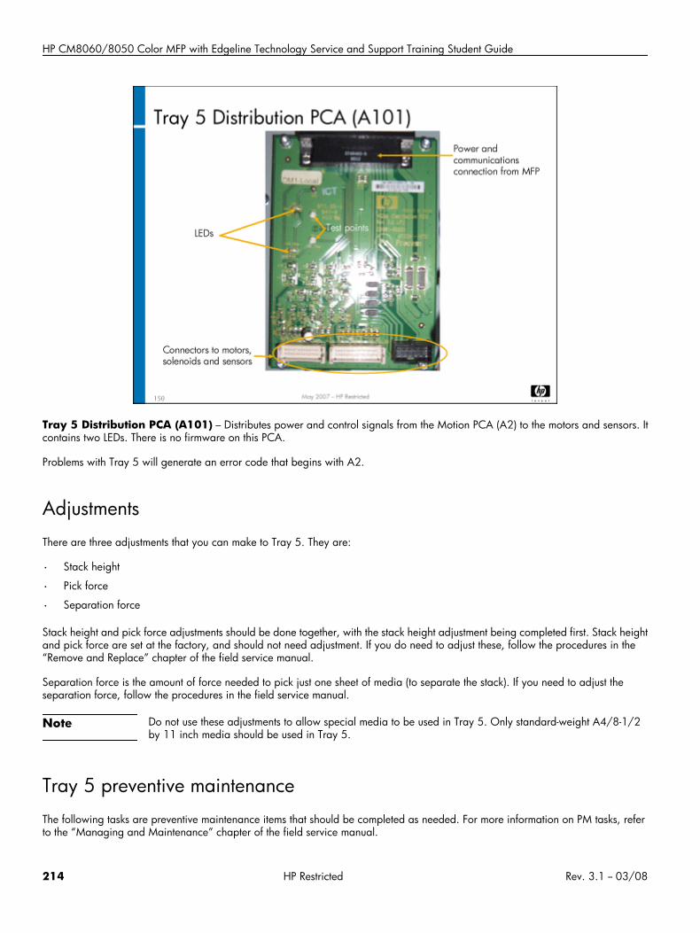
HP CM8060/8050 Color MFP with Edgeline Technology Service and Support Training Student Guide
Tray 5 Distribution PCA (A101) – Distributes power and control signals from the Motion PCA (A2) to the motors and sensors. Itcontains two LEDs. There is no firmware on this PCA.
Problems with Tray 5 will generate an error code that begins with A2.
AdjustmentsThere are three adjustments that you can make to Tray 5. They are:
• Stack height
• Pick force
• Separation force
Stack height and pick force adjustments should be done together, with the stack height adjustment being completed first. Stack heightand pick force are set at the factory, and should not need adjustment. If you do need to adjust these, follow the procedures in the“Remove and Replace” chapter of the field service manual.
Separation force is the amount of force needed to pick just one sheet of media (to separate the stack). If you need to adjust theseparation force, follow the procedures in the field service manual.
Note Do not use these adjustments to allow special media to be used in Tray 5. Only standard-weight A4/8-1/2by 11 inch media should be used in Tray 5.
Tray 5 preventive maintenanceThe following tasks are preventive maintenance items that should be completed as needed. For more information on PM tasks, referto the “Managing and Maintenance” chapter of the field service manual.
214 HP Restricted Rev. 3.1 -- 03/08
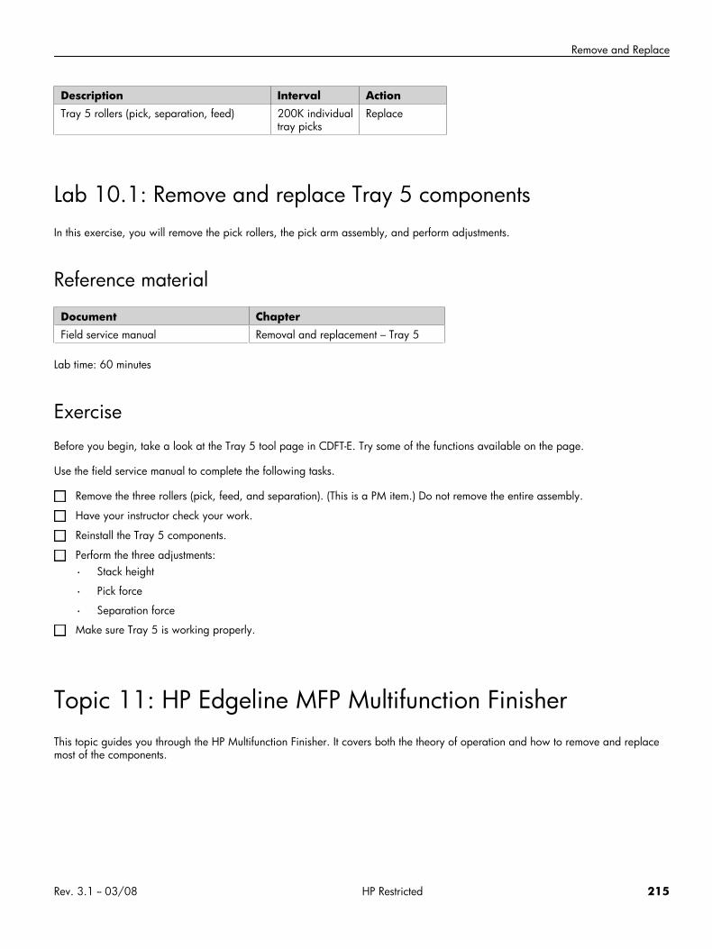
Remove and Replace
Description Interval ActionTray 5 rollers (pick, separation, feed) 200K individual
tray picksReplace
Lab 10.1: Remove and replace Tray 5 componentsIn this exercise, you will remove the pick rollers, the pick arm assembly, and perform adjustments.
Reference material
Document ChapterField service manual Removal and replacement – Tray 5
Lab time: 60 minutes
ExerciseBefore you begin, take a look at the Tray 5 tool page in CDFT-E. Try some of the functions available on the page.
Use the field service manual to complete the following tasks.
Remove the three rollers (pick, feed, and separation). (This is a PM item.) Do not remove the entire assembly.
Have your instructor check your work.
Reinstall the Tray 5 components.
Perform the three adjustments:
• Stack height
• Pick force
• Separation force
Make sure Tray 5 is working properly.
Topic 11: HP Edgeline MFP Multifunction FinisherThis topic guides you through the HP Multifunction Finisher. It covers both the theory of operation and how to remove and replacemost of the components.
Rev. 3.1 -- 03/08 HP Restricted 215
HP CM8060/8050 Color MFP with Edgeline Technology Service and Support Training Student Guide
Topic 11 objectivesAfter completing this topic, you should be able to:
• Identify the components of the finisher
• Describe how the finisher works
• Remove and reinstall finisher components
Topic contentCompleting this topic should take approximately 3-3/4 hours.
Title DurationLecture: Finisher theory of operation 60 minutes
Lab 11.1: Remove and reinstall finishercomponents
120 minutes
Lab 11.2: Troubleshoot the multifunctionfinisher
45 minutes
216 HP Restricted Rev. 3.1 -- 03/08
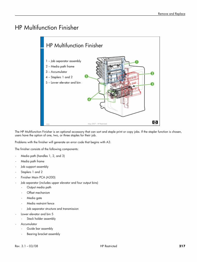
Remove and Replace
HP Multifunction Finisher
The HP Multifunction Finisher is an optional accessory that can sort and staple print or copy jobs. If the stapler function is chosen,users have the option of one, two, or three staples for their job.
Problems with the finisher will generate an error code that begins with A3.
The finisher consists of the following components:
• Media path (handles 1, 2, and 3)
• Media path frame
• Job support assembly
• Staplers 1 and 2
• Finisher Main PCA (A200)
• Job separator (includes upper elevator and four output bins)
• Output media path
• Offset mechanism
• Media gate
• Media restraint fence
• Job separator structure and transmission
• Lower elevator and bin 5
• Stack holder assembly
• Accumulator
• Guide bar assembly
• Bearing bracket assembly
Rev. 3.1 -- 03/08 HP Restricted 217
HP CM8060/8050 Color MFP with Edgeline Technology Service and Support Training Student Guide
• Accumulator Distribution PCA (A240)
• Axle lever support shaft
• Lever paper switch
• Offset shaft
• Offsetters (front and rear)
• Lower eject shaft
• Motors
• Finisher Input Paper Path motor (M210)
• Finisher Lower Paper Path motor (M220)
• Finisher Upper Paper Path motor (M230)
• Accumulator Entry motor (M240)
• Accumulator Exit motor (M241)
• Accumulator Bearing Bracket motor (M242)
• Accumulator Guide Bar motor (M243)
• Accumulator Offset 1 motor (M244)
• Accumulator Offset 2 motor (M245)
• Accumulator Retainer Finger motor (M246)
• Finisher Lower Elevator motor (M250)
• Finisher Stack Holder motor (M252)
• Finisher Job Support Arm motor (M253)
• Accumulator Open motor (M256)
• Finisher Separator Drive motor (M260)
• Finisher Job Separator Gate motor (M262)
• Finisher Separator Offset motor (M264)
• Finisher Separator Input motor (M268)
• Stapler 1 Rotate motor (M271)
• Stapler 1 motor (M272)
• Stapler 2 Safety motor (M280)
• Stapler 2 motor (M281)
• Sensors:
• Finisher Back Latch sensor (SN200)
• Finisher Front Latch sensor (SN204)
• Finisher Handle 1 (upper transport) Front sensor (SN206)
• Finisher Input 0 sensor (SN211)
• Finisher Input 1 sensor (SN212)
• Finisher Input 2 sensor (SN213)
• Finisher Input 3 sensor (SN214)
• Finisher Lower 1 sensor (SN215)
• Finisher Right Side Panel sensor (SN216)
• Finisher Lower 2 sensor (SN221)
218 HP Restricted Rev. 3.1 -- 03/08
Remove and Replace
• Finisher Handle 3 (lower transport) sensor (SN222)
• Finisher Upper 1 sensor (SN231)
• Finisher Upper 2 sensor (SN232)
• Finisher Upper 3 sensor (SN233)
• Accumulator Job Height sensor (SN240)
• Accumulator Bearing Bracket Home sensor (SN248)
• Finisher Lower Elevator Move sensor (SN250)
• Finisher Lower Elevator Bottom sensor (SN251)
• Finisher Stack Holder sensor (SN252)
• Finisher Job Support Pivot Position 1 sensor (SN253)
• Finisher Job Support Pivot Position 2 sensor (SN254)
• Accumulator Open sensor (SN255)
• Accumulator Entry sensor (SN246)
• Finisher Lower Elevator Stack Height sensor (SN257)
• Finisher Lower Elevator Paper Present sensor (SN258)
• Finisher Job Separator Lower Limit sensor (SN260)
• Finisher Job Separator Gate Open sensor (SN262)
• Finisher Separator Gate Closed sensor (SN263)
• Finisher Separator Offset Front sensor (SN264)
• Finisher Job Separator Offset Back sensor (SN265)
• Finisher Job Separator Stack Height sensor (SN267)
• Stapler 1 Pivot Position 1 sensor (SN271)
• Stapler 1 Pivot Position 2 sensor (SN272)
• Stapler 2 Guard Position 1 sensor (SN280)
• Stapler 2 Guard Position 2 sensor (SN281)
• Finisher Lower Elevator Bottom switch (SW251)
• Switches and solenoids
Rev. 3.1 -- 03/08 HP Restricted 219
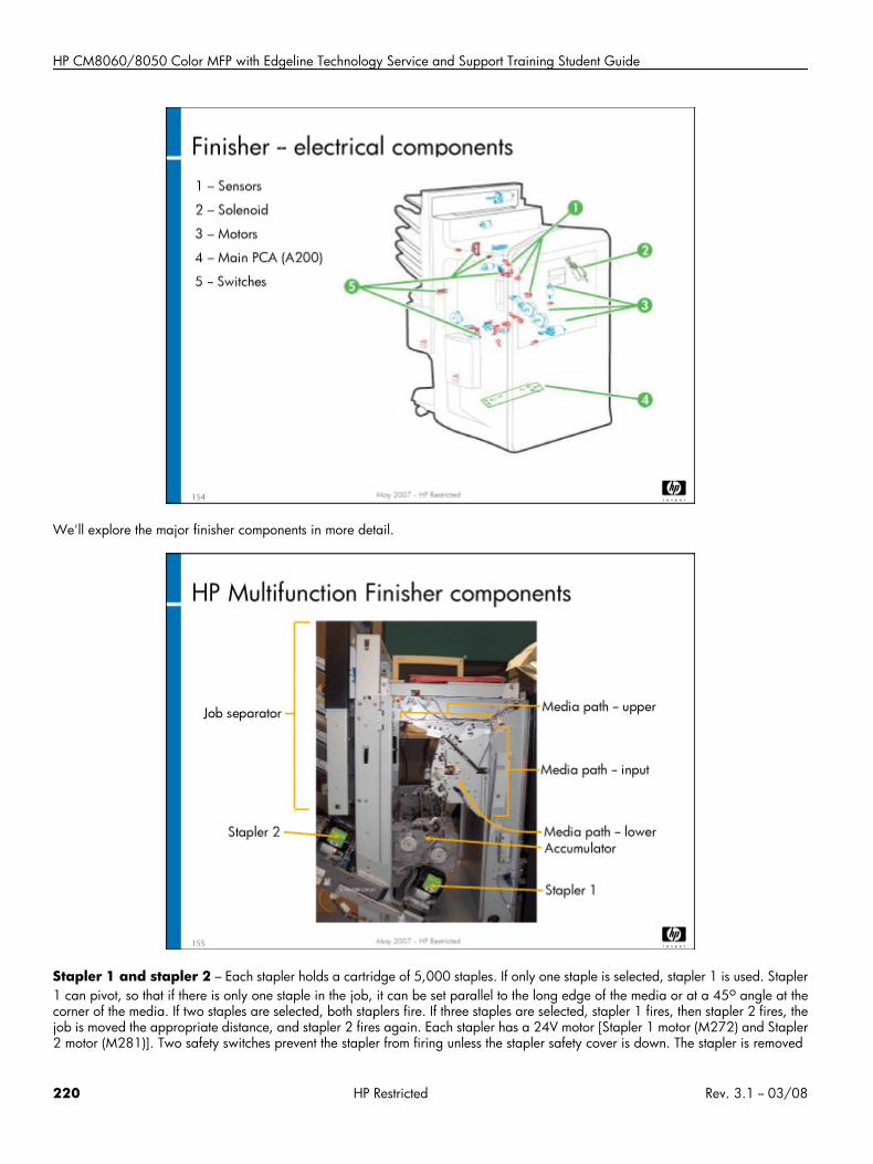
HP CM8060/8050 Color MFP with Edgeline Technology Service and Support Training Student Guide
We'll explore the major finisher components in more detail.
Stapler 1 and stapler 2 – Each stapler holds a cartridge of 5,000 staples. If only one staple is selected, stapler 1 is used. Stapler1 can pivot, so that if there is only one staple in the job, it can be set parallel to the long edge of the media or at a 45o angle at thecorner of the media. If two staples are selected, both staplers fire. If three staples are selected, stapler 1 fires, then stapler 2 fires, thejob is moved the appropriate distance, and stapler 2 fires again. Each stapler has a 24V motor [Stapler 1 motor (M272) and Stapler2 motor (M281)]. Two safety switches prevent the stapler from firing unless the stapler safety cover is down. The stapler is removed
220 HP Restricted Rev. 3.1 -- 03/08
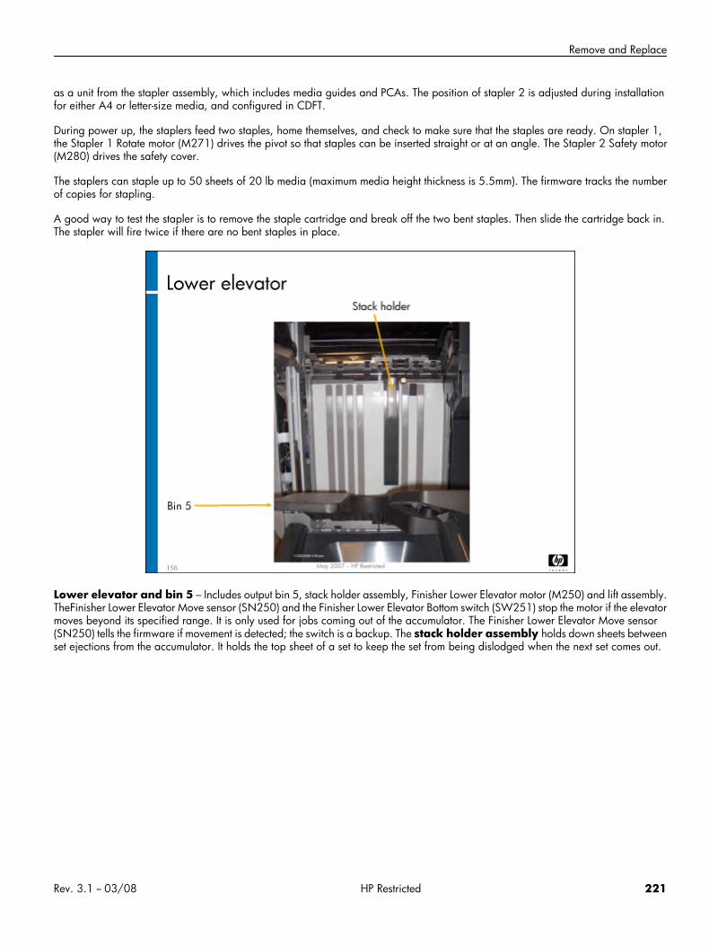
Remove and Replace
as a unit from the stapler assembly, which includes media guides and PCAs. The position of stapler 2 is adjusted during installationfor either A4 or letter-size media, and configured in CDFT.
During power up, the staplers feed two staples, home themselves, and check to make sure that the staples are ready. On stapler 1,the Stapler 1 Rotate motor (M271) drives the pivot so that staples can be inserted straight or at an angle. The Stapler 2 Safety motor(M280) drives the safety cover.
The staplers can staple up to 50 sheets of 20 lb media (maximum media height thickness is 5.5mm). The firmware tracks the numberof copies for stapling.
A good way to test the stapler is to remove the staple cartridge and break off the two bent staples. Then slide the cartridge back in.The stapler will fire twice if there are no bent staples in place.
Lower elevator and bin 5 – Includes output bin 5, stack holder assembly, Finisher Lower Elevator motor (M250) and lift assembly.TheFinisher Lower Elevator Move sensor (SN250) and the Finisher Lower Elevator Bottom switch (SW251) stop the motor if the elevatormoves beyond its specified range. It is only used for jobs coming out of the accumulator. The Finisher Lower Elevator Move sensor(SN250) tells the firmware if movement is detected; the switch is a backup. The stack holder assembly holds down sheets betweenset ejections from the accumulator. It holds the top sheet of a set to keep the set from being dislodged when the next set comes out.
Rev. 3.1 -- 03/08 HP Restricted 221
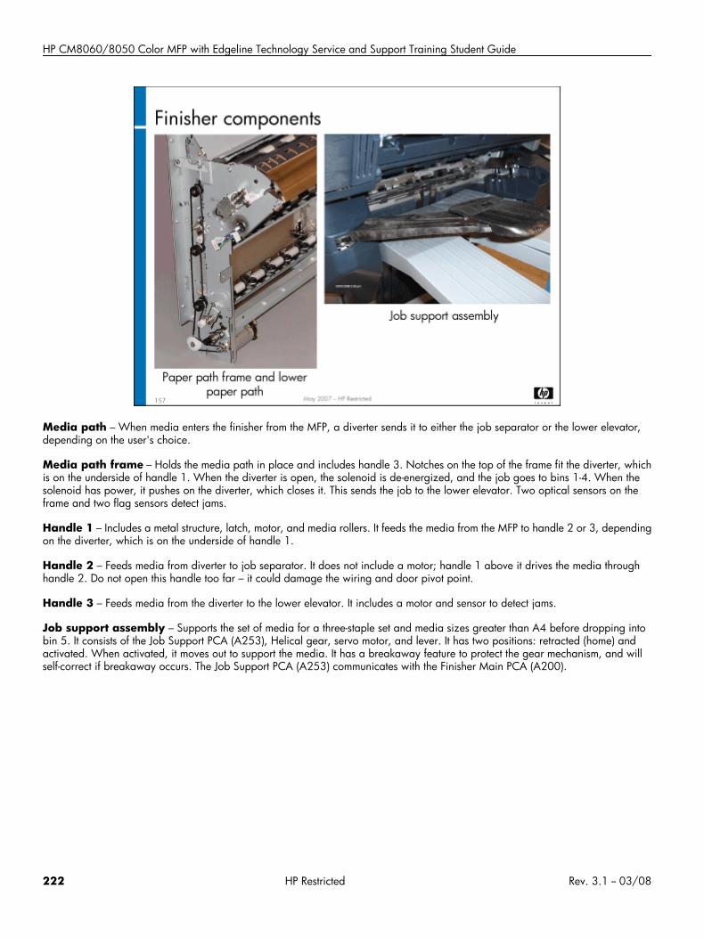
HP CM8060/8050 Color MFP with Edgeline Technology Service and Support Training Student Guide
Media path – When media enters the finisher from the MFP, a diverter sends it to either the job separator or the lower elevator,depending on the user's choice.
Media path frame – Holds the media path in place and includes handle 3. Notches on the top of the frame fit the diverter, whichis on the underside of handle 1. When the diverter is open, the solenoid is de-energized, and the job goes to bins 1-4. When thesolenoid has power, it pushes on the diverter, which closes it. This sends the job to the lower elevator. Two optical sensors on theframe and two flag sensors detect jams.
Handle 1 – Includes a metal structure, latch, motor, and media rollers. It feeds the media from the MFP to handle 2 or 3, dependingon the diverter, which is on the underside of handle 1.
Handle 2 – Feeds media from diverter to job separator. It does not include a motor; handle 1 above it drives the media throughhandle 2. Do not open this handle too far – it could damage the wiring and door pivot point.
Handle 3 – Feeds media from the diverter to the lower elevator. It includes a motor and sensor to detect jams.
Job support assembly – Supports the set of media for a three-staple set and media sizes greater than A4 before dropping intobin 5. It consists of the Job Support PCA (A253), Helical gear, servo motor, and lever. It has two positions: retracted (home) andactivated. When activated, it moves out to support the media. It has a breakaway feature to protect the gear mechanism, and willself-correct if breakaway occurs. The Job Support PCA (A253) communicates with the Finisher Main PCA (A200).
222 HP Restricted Rev. 3.1 -- 03/08
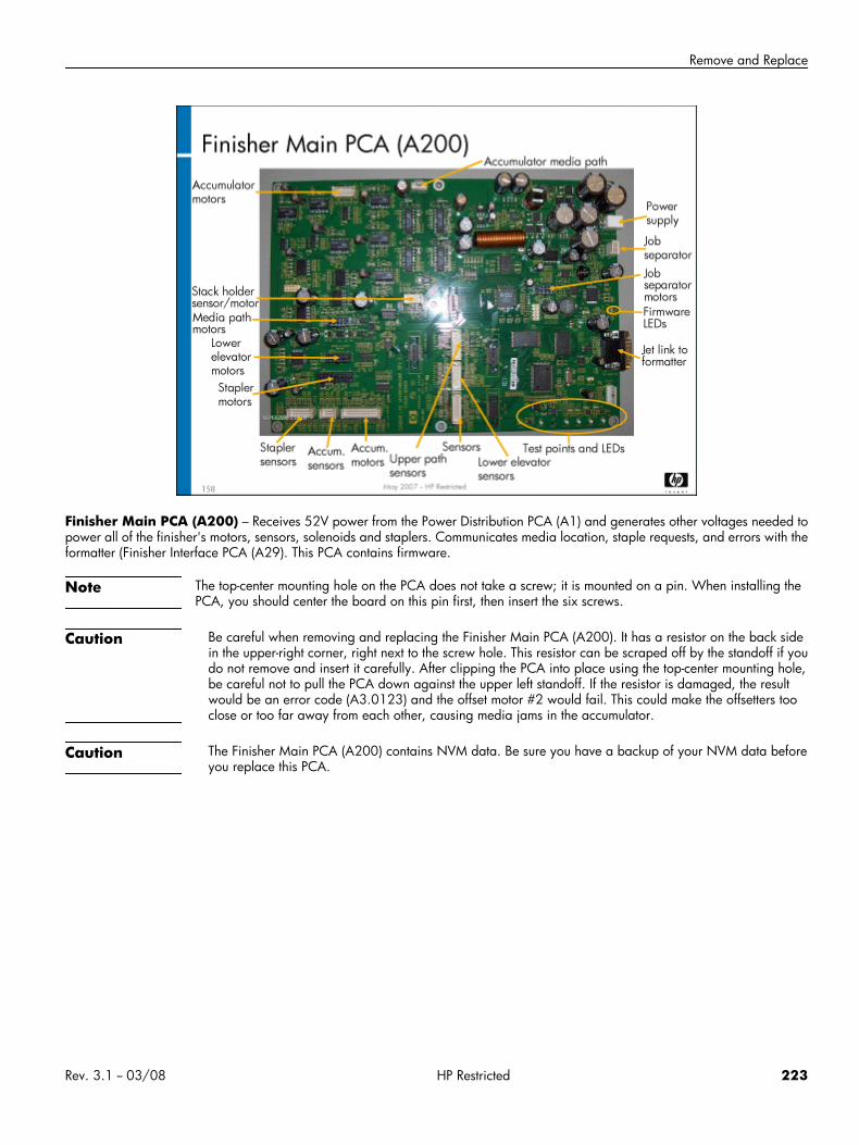
Remove and Replace
Finisher Main PCA (A200) – Receives 52V power from the Power Distribution PCA (A1) and generates other voltages needed topower all of the finisher's motors, sensors, solenoids and staplers. Communicates media location, staple requests, and errors with theformatter (Finisher Interface PCA (A29). This PCA contains firmware.
Note The top-center mounting hole on the PCA does not take a screw; it is mounted on a pin. When installing thePCA, you should center the board on this pin first, then insert the six screws.
Caution Be careful when removing and replacing the Finisher Main PCA (A200). It has a resistor on the back sidein the upper-right corner, right next to the screw hole. This resistor can be scraped off by the standoff if youdo not remove and insert it carefully. After clipping the PCA into place using the top-center mounting hole,be careful not to pull the PCA down against the upper left standoff. If the resistor is damaged, the resultwould be an error code (A3.0123) and the offset motor #2 would fail. This could make the offsetters tooclose or too far away from each other, causing media jams in the accumulator.
Caution The Finisher Main PCA (A200) contains NVM data. Be sure you have a backup of your NVM data beforeyou replace this PCA.
Rev. 3.1 -- 03/08 HP Restricted 223
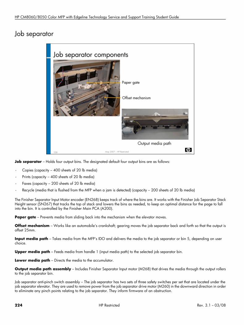
HP CM8060/8050 Color MFP with Edgeline Technology Service and Support Training Student Guide
Job separator
Job separator – Holds four output bins. The designated default four output bins are as follows:
• Copies (capacity – 400 sheets of 20 lb media)
• Prints (capacity – 400 sheets of 20 lb media)
• Faxes (capacity – 200 sheets of 20 lb media)
• Recycle (media that is flushed from the MFP when a jam is detected) (capacity – 200 sheets of 20 lb media)
The Finisher Separator Input Motor encoder (EN268) keeps track of where the bins are. It works with the Finisher Job Separator StackHeight sensor (SN267) that tracks the top of stack and lowers the bins as needed, to keep an optimal distance for the page to fallinto the bin. It is controlled by the Finisher Main PCA (A200).
Paper gate – Prevents media from sliding back into the mechanism when the elevator moves.
Offset mechanism – Works like an automobile's crankshaft; gearing moves the job separator back and forth so that the output isoffset 25mm.
Input media path – Takes media from the MFP's IDO and delivers the media to the job separator or bin 5, depending on userchoice.
Upper media path – Feeds media from handle 1 (input media path) to the selected job separator bin.
Lower media path – Directs the media to the accumulator.
Output media path assembly – Includes Finisher Separator Input motor (M268) that drives the media through the output rollersto the job separator bin.
Job separator anti-pinch switch assembly – The job separator has two sets of three safety switches per set that are located under thejob separator elevator. They are used to remove power from the job separator drive motor (M260) in the downward direction in orderto eliminate any pinch points relating to the job separator. They inform firmware of an obstruction.
224 HP Restricted Rev. 3.1 -- 03/08
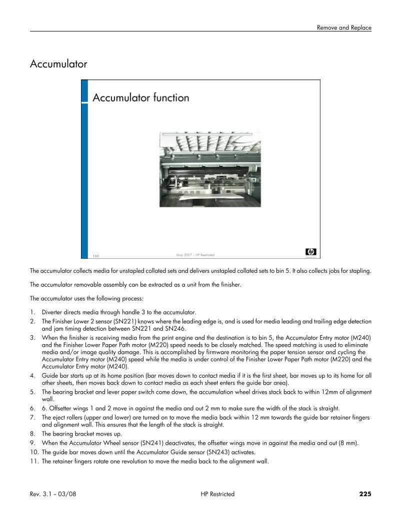
Remove and Replace
Accumulator
The accumulator collects media for unstapled collated sets and delivers unstapled collated sets to bin 5. It also collects jobs for stapling.
The accumulator removable assembly can be extracted as a unit from the finisher.
The accumulator uses the following process:
1. Diverter directs media through handle 3 to the accumulator.2. The Finisher Lower 2 sensor (SN221) knows where the leading edge is, and is used for media leading and trailing edge detection
and jam timing detection between SN221 and SN246.3. When the finisher is receiving media from the print engine and the destination is to bin 5, the Accumulator Entry motor (M240)
and the Finisher Lower Paper Path motor (M220) speed needs to be closely matched. The speed matching is used to eliminatemedia and/or image quality damage. This is accomplished by firmware monitoring the paper tension sensor and cycling theAccumulator Entry motor (M240) speed while the media is under control of the Finisher Lower Paper Path motor (M220) and theAccumulator Entry motor (M240).
4. Guide bar starts up at its home position (bar moves down to contact media if it is the first sheet, bar moves up to its home for allother sheets, then moves back down to contact media as each sheet enters the guide bar area).
5. The bearing bracket and lever paper switch come down, the accumulation wheel drives stack back to within 12mm of alignmentwall.
6. 6. Offsetter wings 1 and 2 move in against the media and out 2 mm to make sure the width of the stack is straight.7. The eject rollers (upper and lower) are turned on to move the media back within 12 mm towards the guide bar retainer fingers
and alignment wall. This ensures that the length of the stack is straight.8. The bearing bracket moves up.9. When the Accumulator Wheel sensor (SN241) deactivates, the offsetter wings move in against the media and out (8 mm).10. The guide bar moves down until the Accumulator Guide sensor (SN243) activates.11. The retainer fingers rotate one revolution to move the media back to the alignment wall.
Rev. 3.1 -- 03/08 HP Restricted 225
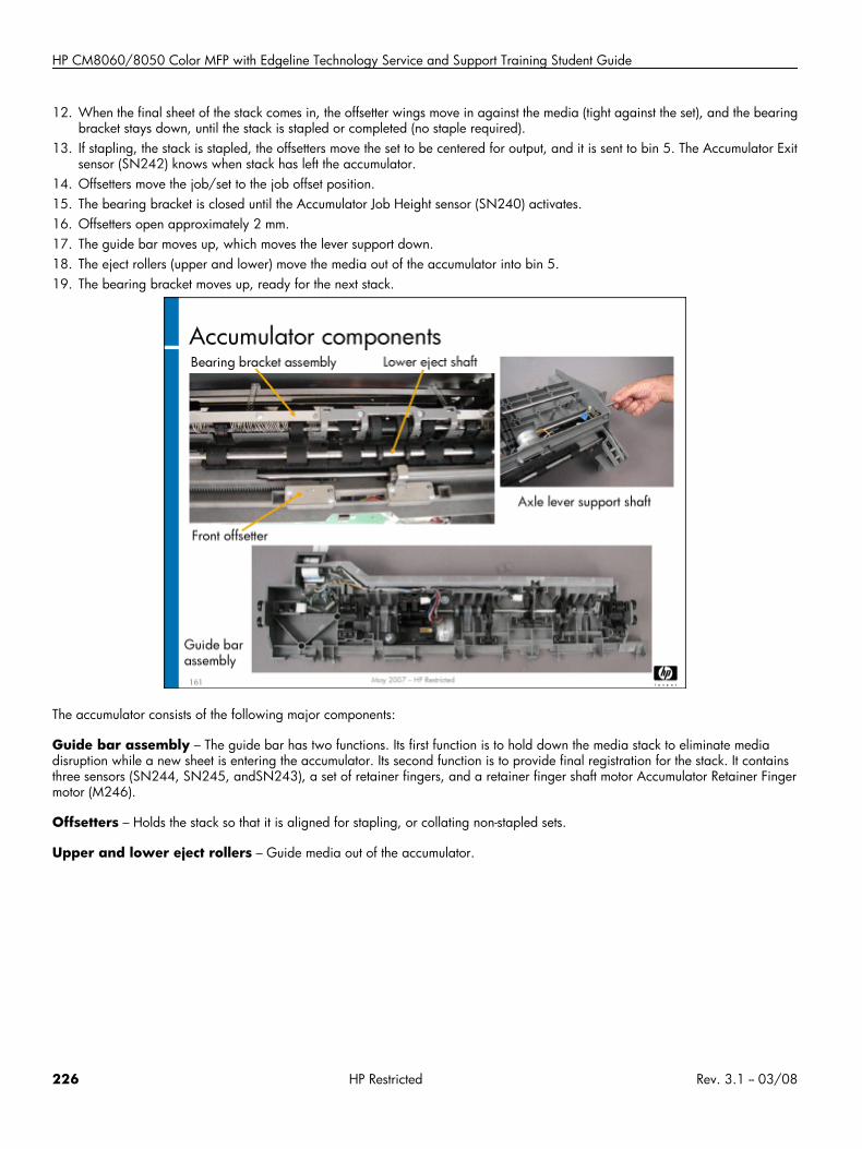
HP CM8060/8050 Color MFP with Edgeline Technology Service and Support Training Student Guide
12. When the final sheet of the stack comes in, the offsetter wings move in against the media (tight against the set), and the bearingbracket stays down, until the stack is stapled or completed (no staple required).
13. If stapling, the stack is stapled, the offsetters move the set to be centered for output, and it is sent to bin 5. The Accumulator Exitsensor (SN242) knows when stack has left the accumulator.
14. Offsetters move the job/set to the job offset position.15. The bearing bracket is closed until the Accumulator Job Height sensor (SN240) activates.16. Offsetters open approximately 2 mm.17. The guide bar moves up, which moves the lever support down.18. The eject rollers (upper and lower) move the media out of the accumulator into bin 5.19. The bearing bracket moves up, ready for the next stack.
The accumulator consists of the following major components:
Guide bar assembly – The guide bar has two functions. Its first function is to hold down the media stack to eliminate mediadisruption while a new sheet is entering the accumulator. Its second function is to provide final registration for the stack. It containsthree sensors (SN244, SN245, andSN243), a set of retainer fingers, and a retainer finger shaft motor Accumulator Retainer Fingermotor (M246).
Offsetters – Holds the stack so that it is aligned for stapling, or collating non-stapled sets.
Upper and lower eject rollers – Guide media out of the accumulator.
226 HP Restricted Rev. 3.1 -- 03/08
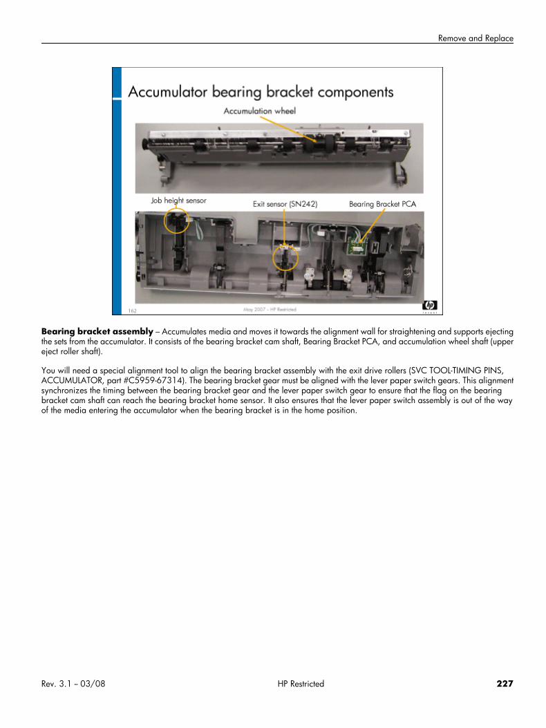
Remove and Replace
Bearing bracket assembly – Accumulates media and moves it towards the alignment wall for straightening and supports ejectingthe sets from the accumulator. It consists of the bearing bracket cam shaft, Bearing Bracket PCA, and accumulation wheel shaft (uppereject roller shaft).
You will need a special alignment tool to align the bearing bracket assembly with the exit drive rollers (SVC TOOL-TIMING PINS,ACCUMULATOR, part #C5959-67314). The bearing bracket gear must be aligned with the lever paper switch gears. This alignmentsynchronizes the timing between the bearing bracket gear and the lever paper switch gear to ensure that the flag on the bearingbracket cam shaft can reach the bearing bracket home sensor. It also ensures that the lever paper switch assembly is out of the wayof the media entering the accumulator when the bearing bracket is in the home position.
Rev. 3.1 -- 03/08 HP Restricted 227
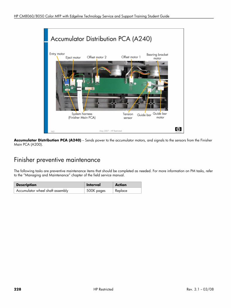
HP CM8060/8050 Color MFP with Edgeline Technology Service and Support Training Student Guide
Accumulator Distribution PCA (A240) – Sends power to the accumulator motors, and signals to the sensors from the FinisherMain PCA (A200).
Finisher preventive maintenanceThe following tasks are preventive maintenance items that should be completed as needed. For more information on PM tasks, referto the “Managing and Maintenance” chapter of the field service manual.
Description Interval ActionAccumulator wheel shaft assembly 500K pages Replace
228 HP Restricted Rev. 3.1 -- 03/08
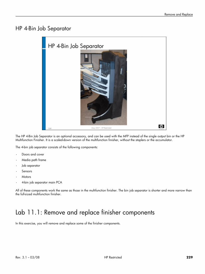
Remove and Replace
HP 4-Bin Job Separator
The HP 4-Bin Job Separator is an optional accessory, and can be used with the MFP instead of the single output bin or the HPMultifunction Finisher. It is a scaled-down version of the multifunction finisher, without the staplers or the accumulator.
The 4-bin job separator consists of the following components:
• Doors and cover
• Media path frame
• Job separator
• Sensors
• Motors
• 4-bin job separator main PCA
All of these components work the same as those in the multifunction finisher. The bin job separator is shorter and more narrow thanthe full-sized multifunction finisher.
Lab 11.1: Remove and replace finisher componentsIn this exercise, you will remove and replace some of the finisher components.
Rev. 3.1 -- 03/08 HP Restricted 229
HP CM8060/8050 Color MFP with Edgeline Technology Service and Support Training Student Guide
Reference material
Document ChapterField service manual Removal and replacement – HP
Multifunction Finisher
Lab time: 120 minutes
ExerciseBefore you begin, take a look at the various tool pages for the finisher in CDFT-E. Try some of the functions available on the pages.
Use the field service manual to complete the following tasks.
Remove the stapler 1 assembly.
Remove and reinstall the bearing bracket assembly in the accumulator. You will need to use the timing pins to realign the bearingbracket assembly to the paper-lever switch. Make sure the finisher is working properly.Have your instructor check your work.
Reinstall the stapler 1 assembly.
Remove and reinstall the offset mechanism assembly in the job separator.
Have your instructor check your work.
Check to make sure the finisher is working correctly.
While you are working on the finisher, be sure to observe its media path.
Lab 11.2: Troubleshoot the finisherYou will now troubleshoot an error in the finisher, using the field service manual.
Reference material
Document ChapterField service manual Appendix A: Event Log codes
Lab time: 45 minutes
ExerciseYour instructor has injected a fault into the finisher. Follow these steps to resolve the error:
Try to make a copy using the finisher.
Read the control panel error message.
230 HP Restricted Rev. 3.1 -- 03/08

Remove and Replace
In the field service manual, locate the error message and try the recommended actions.
Verify that you correctly solved the problem.
Rev. 3.1 -- 03/08 HP Restricted 231
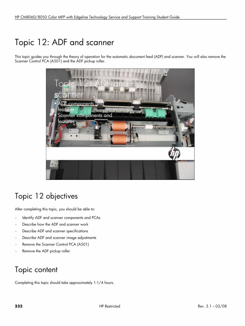
HP CM8060/8050 Color MFP with Edgeline Technology Service and Support Training Student Guide
Topic 12: ADF and scannerThis topic guides you through the theory of operation for the automatic document feed (ADF) and scanner. You will also remove theScanner Control PCA (A501) and the ADF pickup roller.
Topic 12 objectivesAfter completing this topic, you should be able to:
• Identify ADF and scanner components and PCAs
• Describe how the ADF and scanner work
• Describe ADF and scanner specifications
• Describe ADF and scanner image adjustments
• Remove the Scanner Control PCA (A501)
• Remove the ADF pickup roller
Topic contentCompleting this topic should take approximately 1-1/4 hours.
232 HP Restricted Rev. 3.1 -- 03/08
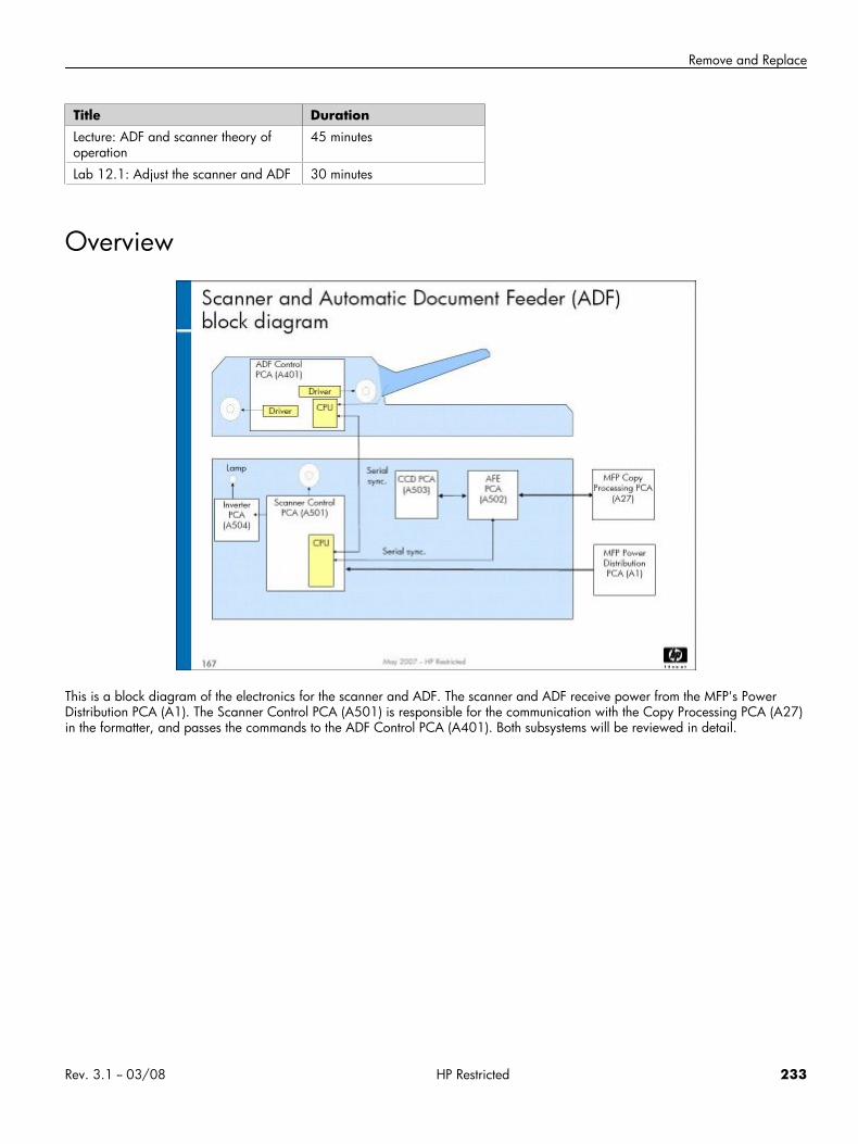
Remove and Replace
Title DurationLecture: ADF and scanner theory ofoperation
45 minutes
Lab 12.1: Adjust the scanner and ADF 30 minutes
Overview
This is a block diagram of the electronics for the scanner and ADF. The scanner and ADF receive power from the MFP's PowerDistribution PCA (A1). The Scanner Control PCA (A501) is responsible for the communication with the Copy Processing PCA (A27)in the formatter, and passes the commands to the ADF Control PCA (A401). Both subsystems will be reviewed in detail.
Rev. 3.1 -- 03/08 HP Restricted 233
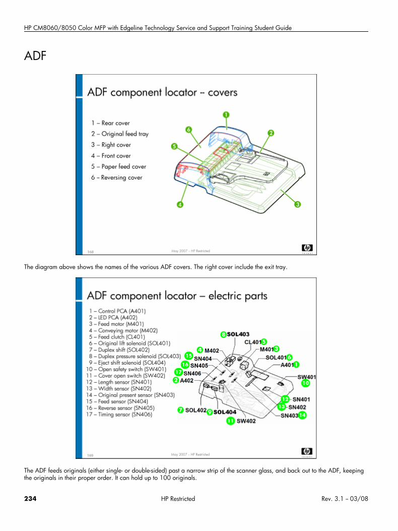
HP CM8060/8050 Color MFP with Edgeline Technology Service and Support Training Student Guide
ADF
The diagram above shows the names of the various ADF covers. The right cover include the exit tray.
The ADF feeds originals (either single- or double-sided) past a narrow strip of the scanner glass, and back out to the ADF, keepingthe originals in their proper order. It can hold up to 100 originals.
234 HP Restricted Rev. 3.1 -- 03/08
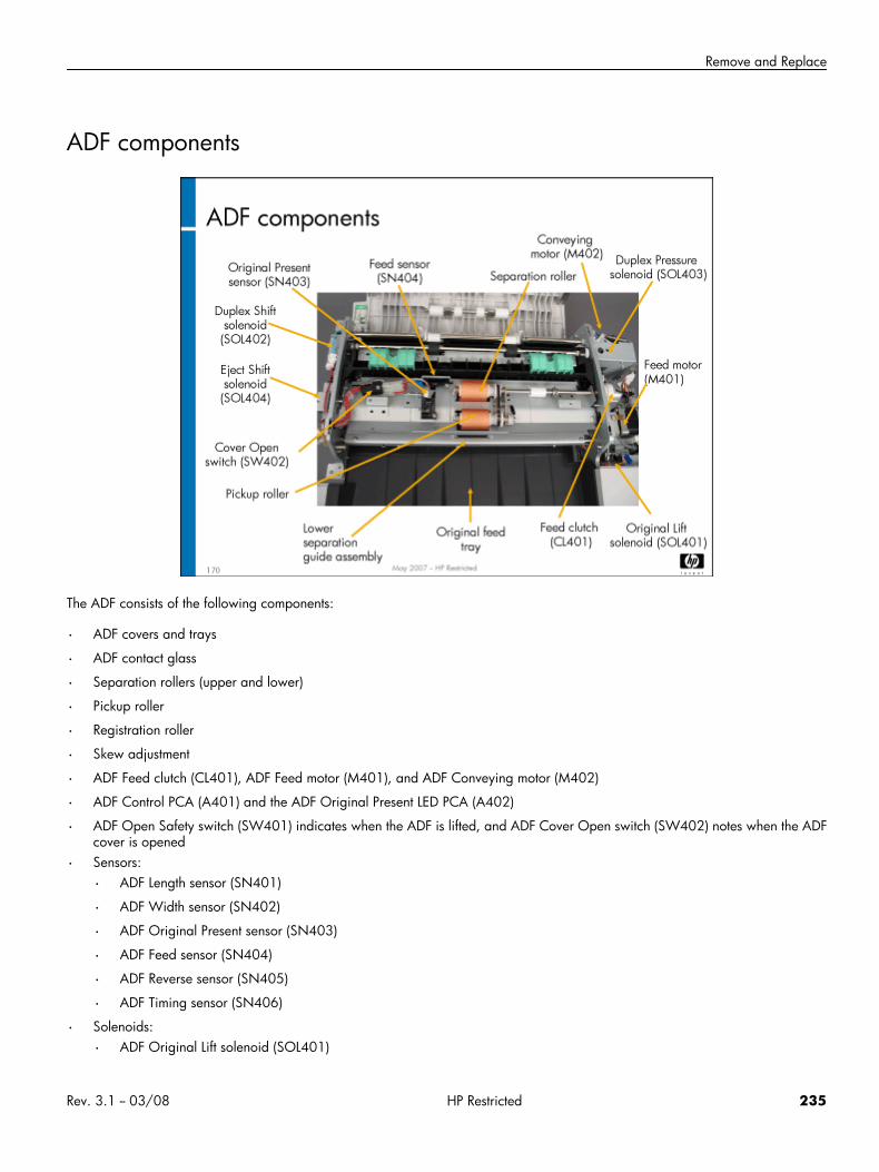
Remove and Replace
ADF components
The ADF consists of the following components:
• ADF covers and trays
• ADF contact glass
• Separation rollers (upper and lower)
• Pickup roller
• Registration roller
• Skew adjustment
• ADF Feed clutch (CL401), ADF Feed motor (M401), and ADF Conveying motor (M402)
• ADF Control PCA (A401) and the ADF Original Present LED PCA (A402)
• ADF Open Safety switch (SW401) indicates when the ADF is lifted, and ADF Cover Open switch (SW402) notes when the ADFcover is opened
• Sensors:
• ADF Length sensor (SN401)
• ADF Width sensor (SN402)
• ADF Original Present sensor (SN403)
• ADF Feed sensor (SN404)
• ADF Reverse sensor (SN405)
• ADF Timing sensor (SN406)
• Solenoids:
• ADF Original Lift solenoid (SOL401)
Rev. 3.1 -- 03/08 HP Restricted 235
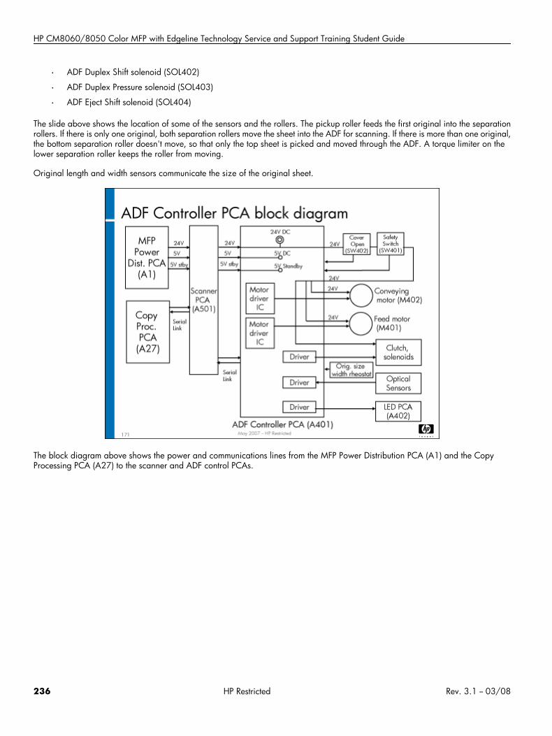
HP CM8060/8050 Color MFP with Edgeline Technology Service and Support Training Student Guide
• ADF Duplex Shift solenoid (SOL402)
• ADF Duplex Pressure solenoid (SOL403)
• ADF Eject Shift solenoid (SOL404)
The slide above shows the location of some of the sensors and the rollers. The pickup roller feeds the first original into the separationrollers. If there is only one original, both separation rollers move the sheet into the ADF for scanning. If there is more than one original,the bottom separation roller doesn't move, so that only the top sheet is picked and moved through the ADF. A torque limiter on thelower separation roller keeps the roller from moving.
Original length and width sensors communicate the size of the original sheet.
The block diagram above shows the power and communications lines from the MFP Power Distribution PCA (A1) and the CopyProcessing PCA (A27) to the scanner and ADF control PCAs.
236 HP Restricted Rev. 3.1 -- 03/08
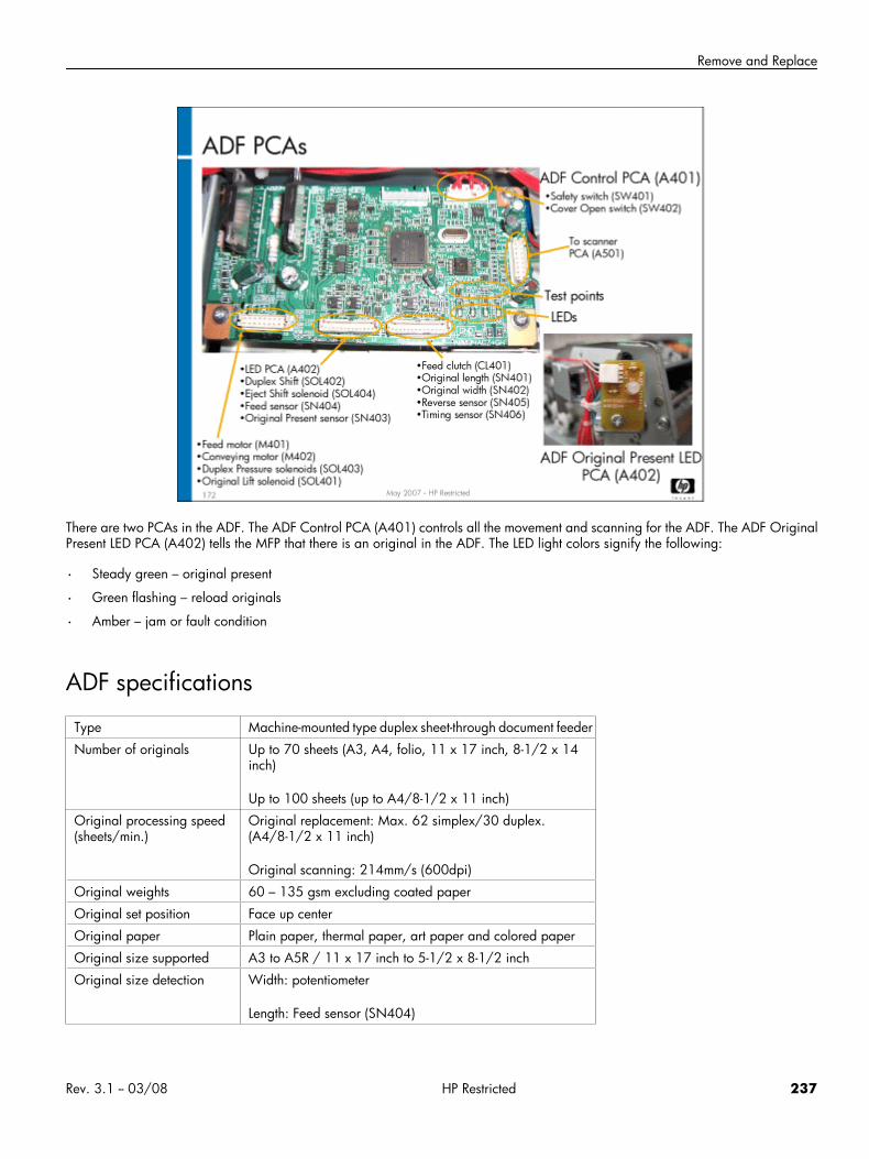
Remove and Replace
There are two PCAs in the ADF. The ADF Control PCA (A401) controls all the movement and scanning for the ADF. The ADF OriginalPresent LED PCA (A402) tells the MFP that there is an original in the ADF. The LED light colors signify the following:
• Steady green – original present
• Green flashing – reload originals
• Amber – jam or fault condition
ADF specifications
Type Machine-mounted type duplex sheet-through document feeder
Number of originals Up to 70 sheets (A3, A4, folio, 11 x 17 inch, 8-1/2 x 14inch)
Up to 100 sheets (up to A4/8-1/2 x 11 inch)
Original processing speed(sheets/min.)
Original replacement: Max. 62 simplex/30 duplex.(A4/8-1/2 x 11 inch)
Original scanning: 214mm/s (600dpi)
Original weights 60 – 135 gsm excluding coated paper
Original set position Face up center
Original paper Plain paper, thermal paper, art paper and colored paper
Original size supported A3 to A5R / 11 x 17 inch to 5-1/2 x 8-1/2 inch
Original size detection Width: potentiometer
Length: Feed sensor (SN404)
Rev. 3.1 -- 03/08 HP Restricted 237
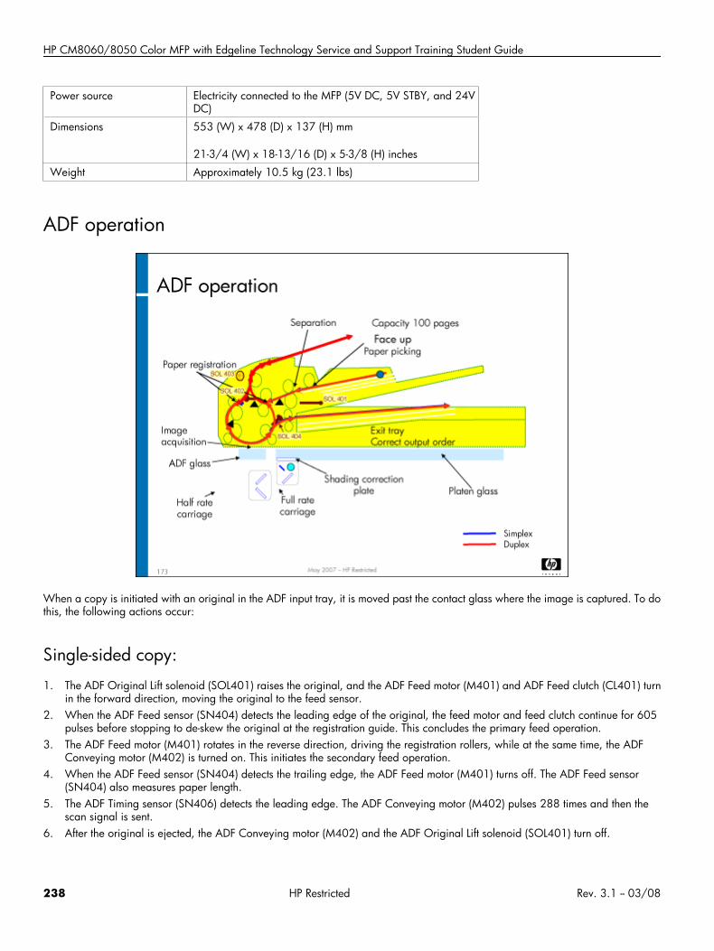
HP CM8060/8050 Color MFP with Edgeline Technology Service and Support Training Student Guide
Power source Electricity connected to the MFP (5V DC, 5V STBY, and 24VDC)
Dimensions 553 (W) x 478 (D) x 137 (H) mm
21-3/4 (W) x 18-13/16 (D) x 5-3/8 (H) inches
Weight Approximately 10.5 kg (23.1 lbs)
ADF operation
When a copy is initiated with an original in the ADF input tray, it is moved past the contact glass where the image is captured. To dothis, the following actions occur:
Single-sided copy:
1. The ADF Original Lift solenoid (SOL401) raises the original, and the ADF Feed motor (M401) and ADF Feed clutch (CL401) turnin the forward direction, moving the original to the feed sensor.
2. When the ADF Feed sensor (SN404) detects the leading edge of the original, the feed motor and feed clutch continue for 605pulses before stopping to de-skew the original at the registration guide. This concludes the primary feed operation.
3. The ADF Feed motor (M401) rotates in the reverse direction, driving the registration rollers, while at the same time, the ADFConveying motor (M402) is turned on. This initiates the secondary feed operation.
4. When the ADF Feed sensor (SN404) detects the trailing edge, the ADF Feed motor (M401) turns off. The ADF Feed sensor(SN404) also measures paper length.
5. The ADF Timing sensor (SN406) detects the leading edge. The ADF Conveying motor (M402) pulses 288 times and then thescan signal is sent.
6. After the original is ejected, the ADF Conveying motor (M402) and the ADF Original Lift solenoid (SOL401) turn off.
238 HP Restricted Rev. 3.1 -- 03/08
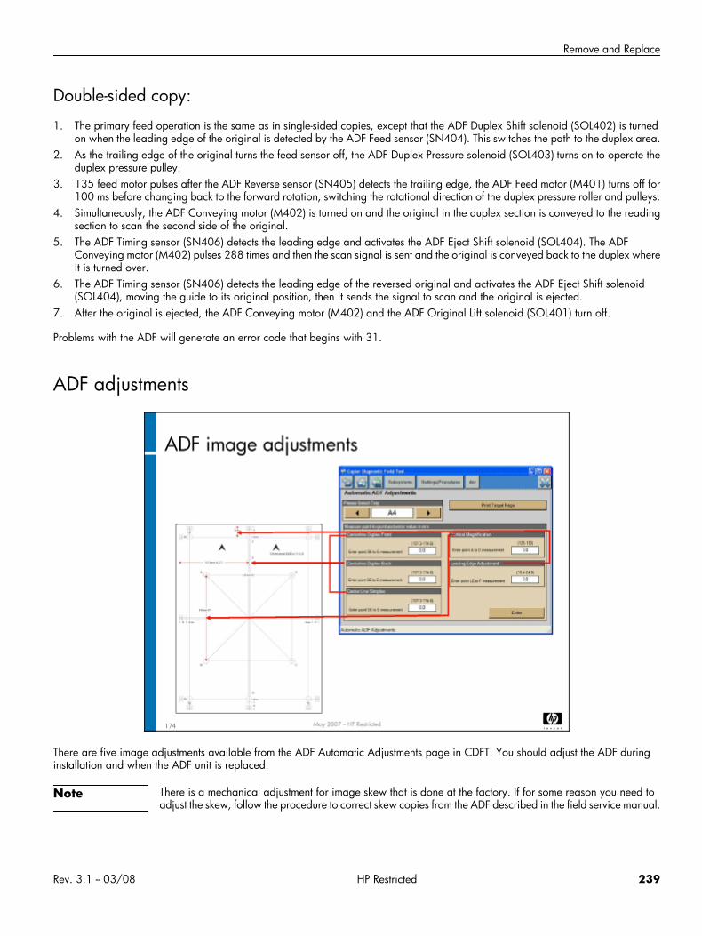
Remove and Replace
Double-sided copy:
1. The primary feed operation is the same as in single-sided copies, except that the ADF Duplex Shift solenoid (SOL402) is turnedon when the leading edge of the original is detected by the ADF Feed sensor (SN404). This switches the path to the duplex area.
2. As the trailing edge of the original turns the feed sensor off, the ADF Duplex Pressure solenoid (SOL403) turns on to operate theduplex pressure pulley.
3. 135 feed motor pulses after the ADF Reverse sensor (SN405) detects the trailing edge, the ADF Feed motor (M401) turns off for100 ms before changing back to the forward rotation, switching the rotational direction of the duplex pressure roller and pulleys.
4. Simultaneously, the ADF Conveying motor (M402) is turned on and the original in the duplex section is conveyed to the readingsection to scan the second side of the original.
5. The ADF Timing sensor (SN406) detects the leading edge and activates the ADF Eject Shift solenoid (SOL404). The ADFConveying motor (M402) pulses 288 times and then the scan signal is sent and the original is conveyed back to the duplex whereit is turned over.
6. The ADF Timing sensor (SN406) detects the leading edge of the reversed original and activates the ADF Eject Shift solenoid(SOL404), moving the guide to its original position, then it sends the signal to scan and the original is ejected.
7. After the original is ejected, the ADF Conveying motor (M402) and the ADF Original Lift solenoid (SOL401) turn off.
Problems with the ADF will generate an error code that begins with 31.
ADF adjustments
There are five image adjustments available from the ADF Automatic Adjustments page in CDFT. You should adjust the ADF duringinstallation and when the ADF unit is replaced.
Note There is a mechanical adjustment for image skew that is done at the factory. If for some reason you need toadjust the skew, follow the procedure to correct skew copies from the ADF described in the field service manual.
Rev. 3.1 -- 03/08 HP Restricted 239
HP CM8060/8050 Color MFP with Edgeline Technology Service and Support Training Student Guide
There also is an ADF Manual Adjustments page in CDFT, where the current NVM values for these same adjustment are available, plusthe ADF scan start position, which is used in case the image leading edge has been cut or there is a visible background in copiesfrom the ADF but not present in copies from the platen glass.
Adjustment Specification Target referenceVertical magnification 127 +/- 1 mm Point A to D
Leading edge 20 +/- 2 mm Paper lead edge to point F
Center line: Reference according to target size selected (11 x 17 inch shown inexample above)
• Simplex 139.7 +/- 2 mm Left side of the page to point E
• Duplex front
• Duplex back
The ADF scanner glass (the narrow strip of glass to the side of the large scanner glass plate) has a special coating that is water soluble,so should not be washed or wiped vigorously. Use a dry lint-free cloth to clean it.
ADF preventive maintenanceThe following tasks are preventive maintenance items that should be completed as needed. For more information on PM tasks, referto the “Managing and Maintenance” chapter of the field service manual.
Description Interval ActionADF Timing sensor (SN406) 25K copies Clean
ADF Feed sensor (SN404) 25K copies Clean
ADF hinges 50K copies Lubricate
ADF contact glass Every servicevisit
Clean
ADF pick rollers/separation rollers 240K copies Replace
240 HP Restricted Rev. 3.1 -- 03/08
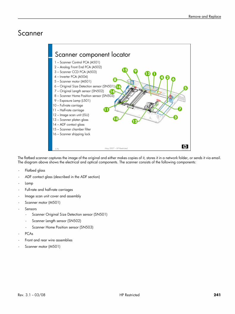
Remove and Replace
Scanner
The flatbed scanner captures the image of the original and either makes copies of it, stores it in a network folder, or sends it via email.The diagram above shows the electrical and optical components. The scanner consists of the following components:
• Flatbed glass
• ADF contact glass (described in the ADF section)
• Lamp
• Full-rate and half-rate carriages
• Image scan unit cover and assembly
• Scanner motor (M501)
• Sensors
• Scanner Original Size Detection sensor (SN501)
• Scanner Length sensor (SN502)
• Scanner Home Position sensor (SN503)
• PCAs
• Front and rear wire assemblies
• Scanner motor (M501)
Rev. 3.1 -- 03/08 HP Restricted 241
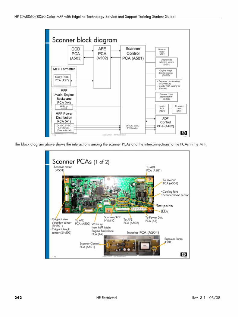
HP CM8060/8050 Color MFP with Edgeline Technology Service and Support Training Student Guide
The block diagram above shows the interactions among the scanner PCAs and the interconnections to the PCAs in the MFP.
242 HP Restricted Rev. 3.1 -- 03/08
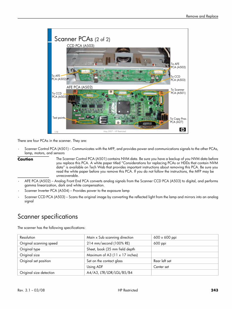
Remove and Replace
There are four PCAs in the scanner. They are:
• Scanner Control PCA (A501) – Communicates with the MFP, and provides power and communications signals to the other PCAs,lamp, motors, and sensors
Caution The Scanner Control PCA (A501) contains NVM data. Be sure you have a backup of you NVM data beforeyou replace this PCA. A white paper titled “Considerations for replacing PCAs or HDDs that contain NVMdata” is available on Tech Web that provides important instructions about removing this PCA. Be sure youread the white paper before you remove this PCA. If you do not follow the instructions, the MFP may beunrecoverable.
• AFE PCA (A502) – Analog Front End PCA converts analog signals from the Scanner CCD PCA (A503) to digital, and performsgamma linearization, dark and white compensation.
• Scanner Inverter PCA (A504) – Provides power to the exposure lamp
• Scanner CCD PCA (A503) – Scans the original image by converting the reflected light from the lamp and mirrors into an analogsignal
Scanner specificationsThe scanner has the following specifications:
Resolution Main x Sub scanning direction 600 x 600 ppi
Original scanning speed 214 mm/second (100% RE) 600 ppi
Original type Sheet, book (35 mm field depth
Original size Maximum of A3 (11 x 17 inches)
Original set position Set on the contact glass Rear left set
Using ADF Center set
Original size detection A4/A3, LTR/LDR/LGL/B5/B4
Rev. 3.1 -- 03/08 HP Restricted 243
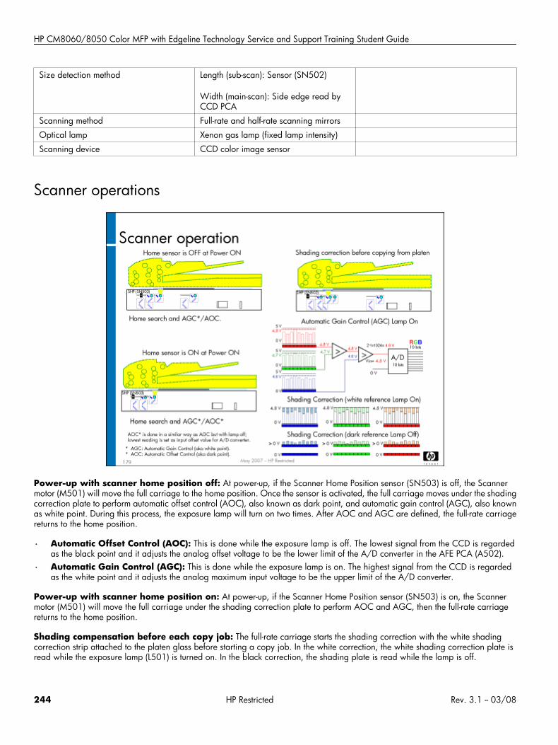
HP CM8060/8050 Color MFP with Edgeline Technology Service and Support Training Student Guide
Size detection method Length (sub-scan): Sensor (SN502)
Width (main-scan): Side edge read byCCD PCA
Scanning method Full-rate and half-rate scanning mirrors
Optical lamp Xenon gas lamp (fixed lamp intensity)
Scanning device CCD color image sensor
Scanner operations
Power-up with scanner home position off: At power-up, if the Scanner Home Position sensor (SN503) is off, the Scannermotor (M501) will move the full carriage to the home position. Once the sensor is activated, the full carriage moves under the shadingcorrection plate to perform automatic offset control (AOC), also known as dark point, and automatic gain control (AGC), also knownas white point. During this process, the exposure lamp will turn on two times. After AOC and AGC are defined, the full-rate carriagereturns to the home position.
• Automatic Offset Control (AOC): This is done while the exposure lamp is off. The lowest signal from the CCD is regardedas the black point and it adjusts the analog offset voltage to be the lower limit of the A/D converter in the AFE PCA (A502).
• Automatic Gain Control (AGC): This is done while the exposure lamp is on. The highest signal from the CCD is regardedas the white point and it adjusts the analog maximum input voltage to be the upper limit of the A/D converter.
Power-up with scanner home position on: At power-up, if the Scanner Home Position sensor (SN503) is on, the Scannermotor (M501) will move the full carriage under the shading correction plate to perform AOC and AGC, then the full-rate carriagereturns to the home position.
Shading compensation before each copy job: The full-rate carriage starts the shading correction with the white shadingcorrection strip attached to the platen glass before starting a copy job. In the white correction, the white shading correction plate isread while the exposure lamp (L501) is turned on. In the black correction, the shading plate is read while the lamp is off.
244 HP Restricted Rev. 3.1 -- 03/08
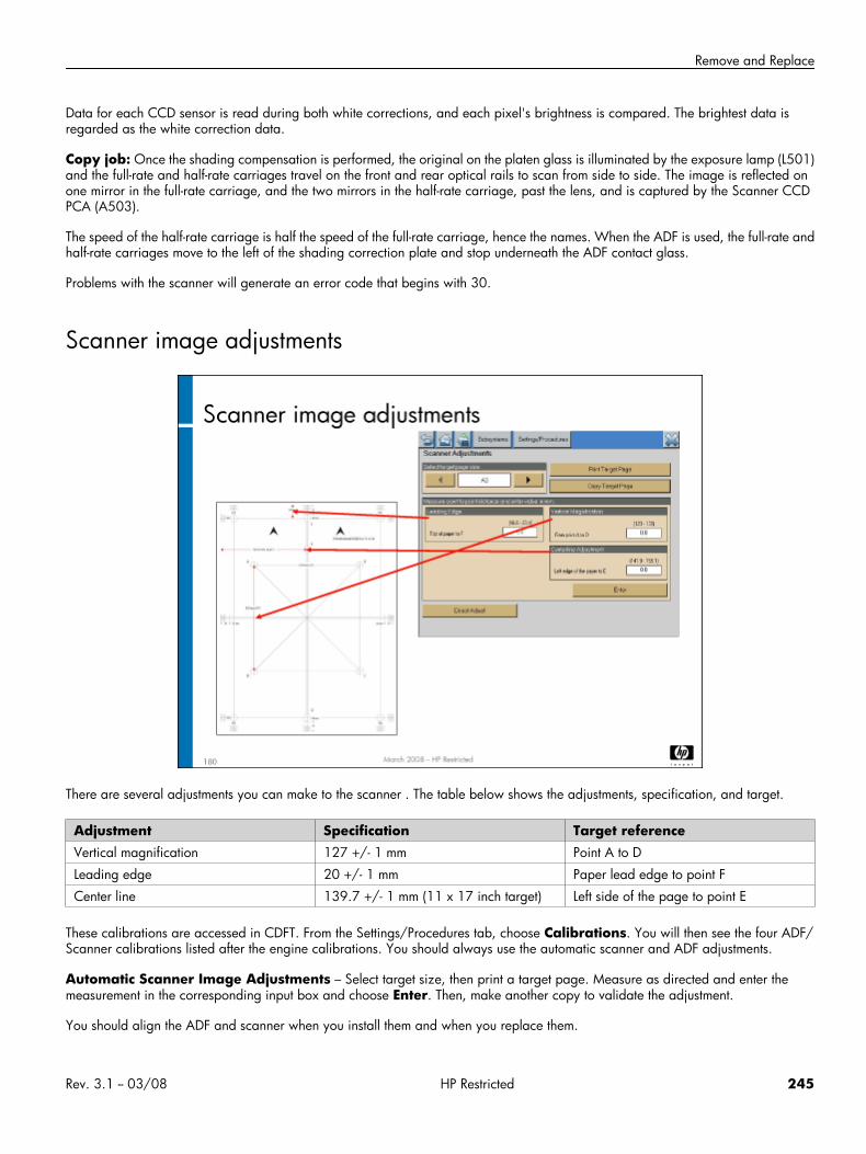
Remove and Replace
Data for each CCD sensor is read during both white corrections, and each pixel's brightness is compared. The brightest data isregarded as the white correction data.
Copy job: Once the shading compensation is performed, the original on the platen glass is illuminated by the exposure lamp (L501)and the full-rate and half-rate carriages travel on the front and rear optical rails to scan from side to side. The image is reflected onone mirror in the full-rate carriage, and the two mirrors in the half-rate carriage, past the lens, and is captured by the Scanner CCDPCA (A503).
The speed of the half-rate carriage is half the speed of the full-rate carriage, hence the names. When the ADF is used, the full-rate andhalf-rate carriages move to the left of the shading correction plate and stop underneath the ADF contact glass.
Problems with the scanner will generate an error code that begins with 30.
Scanner image adjustments
There are several adjustments you can make to the scanner . The table below shows the adjustments, specification, and target.
Adjustment Specification Target referenceVertical magnification 127 +/- 1 mm Point A to D
Leading edge 20 +/- 1 mm Paper lead edge to point F
Center line 139.7 +/- 1 mm (11 x 17 inch target) Left side of the page to point E
These calibrations are accessed in CDFT. From the Settings/Procedures tab, choose Calibrations. You will then see the four ADF/Scanner calibrations listed after the engine calibrations. You should always use the automatic scanner and ADF adjustments.
Automatic Scanner Image Adjustments – Select target size, then print a target page. Measure as directed and enter themeasurement in the corresponding input box and choose Enter. Then, make another copy to validate the adjustment.
You should align the ADF and scanner when you install them and when you replace them.
Rev. 3.1 -- 03/08 HP Restricted 245
HP CM8060/8050 Color MFP with Edgeline Technology Service and Support Training Student Guide
Scanner preventive maintenanceThe following tasks are preventive maintenance items that should be completed as needed. For more information on PM tasks, referto the “Managing and Maintenance” chapter of the field service manual.
Description Interval ActionScanner lamp 1000 lamp hours Replace
Platen glass Every service visit Clean
Scanner chamber filter 250K pages Replace
Lab 12.1: Adjust the scanner and ADFIn this exercise, you will observe the Scanner Control PCA (A501) and remove the ADF pickup roller.
Reference material
Document ChapterField service manual Removal and replacement – ADF
Removal and replacement – Scanner
Lab time: 30 minutes
ExerciseBefore you begin, take a look at the ADF tool page in CDFT-E. Try some of the functions available on the page.
Use the field service manual to complete the following tasks.
In CDFT, select the manual ADF and scanner adjustments, and write down the current numbers.
Next, change the numbers on the manual adjustments screen for both the ADF and scanner.
Perform the ADF and scanner automatic adjustments
Go back into the manual adjustment screens and verify that the numbers are close to what you had originally written down
246 HP Restricted Rev. 3.1 -- 03/08

Image Quality
Image Quality• Overview
• Topic 1: Image pipeline
• Topic 2: Calibrations and adjustments
• Topic 3: Test pages
• Topic 4: Image quality troubleshooting
Rev. 3.1 -- 03/08 HP Restricted 247

HP CM8060/8050 Color MFP with Edgeline Technology Service and Support Training Student Guide
Overview
This module guides you through understanding the image quality pipeline, calibrations and adjustments that may impact image quality,and identifying and troubleshooting image quality defects.
Topic 1: Image pipelineIn this topic, you will learn about the MFP's image pipeline.
Topic objectivesAfter completing this topic, you should be able to:
• Describe the image pipeline
• Identify the PCAs involved in the image pipeline
Topic contentCompleting this topic should take approximately 40 minutes.
248 HP Restricted Rev. 3.1 -- 03/08
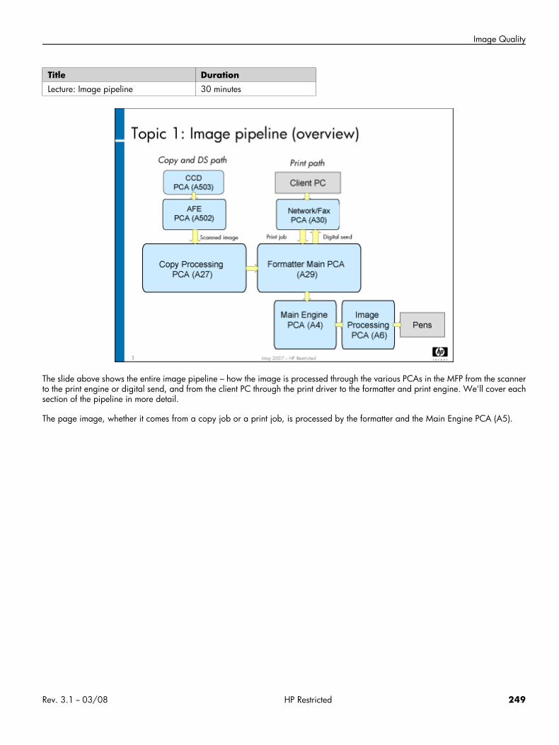
Image Quality
Title DurationLecture: Image pipeline 30 minutes
The slide above shows the entire image pipeline – how the image is processed through the various PCAs in the MFP from the scannerto the print engine or digital send, and from the client PC through the print driver to the formatter and print engine. We'll cover eachsection of the pipeline in more detail.
The page image, whether it comes from a copy job or a print job, is processed by the formatter and the Main Engine PCA (A5).
Rev. 3.1 -- 03/08 HP Restricted 249
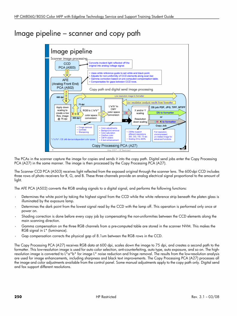
HP CM8060/8050 Color MFP with Edgeline Technology Service and Support Training Student Guide
Image pipeline – scanner and copy path
The PCAs in the scanner capture the image for copies and sends it into the copy path. Digital send jobs enter the Copy ProcessingPCA (A27) in the same manner. The image is then processed by the Copy Processing PCA (A27).
The Scanner CCD PCA (A503) receives light reflected from the exposed original through the scanner lens. The 600-dpi CCD includesthree rows of photo receivers for R, G, and B. These three channels provide an analog electrical signal proportional to the amount oflight.
The AFE PCA (A502) converts the RGB analog signals to a digital signal, and performs the following functions:
• Determines the white point by taking the highest signal from the CCD while the white reference strip beneath the platen glass isilluminated by the exposure lamp.
• Determines the dark point from the lowest signal read by the CCD with the lamp off. This operation is performed only once atpower on.
• Shading correction is done before every copy job by compensating the non-uniformities between the CCD elements along themain scanning direction.
• Gamma compensation on the three RGB channels from a pre-computed table are stored in the scanner NVM. This makes theRGB signal in L* (luminance).
• Gap compensation corrects the physical gap of 8.1um between the RGB rows in the CCD.
The Copy Processing PCA (A27) receives RGB data at 600 dpi, scales down the image to 75 dpi, and creates a second path to theformatter. This low-resolution image is used for auto color selection, anti-counterfeiting, auto type, auto exposure, and so on. The high-resolution image is converted to L*a*b* for image L* noise reduction and fringe removal. The results from the low-resolution analysisare used for image enhancements, including sharpness and black text improvements. The Copy Processing PCA (A27) processes allthe image and color adjustments available from the control panel. Some manual adjustments apply to the copy path only. Digital sendand fax support different resolutions.
250 HP Restricted Rev. 3.1 -- 03/08
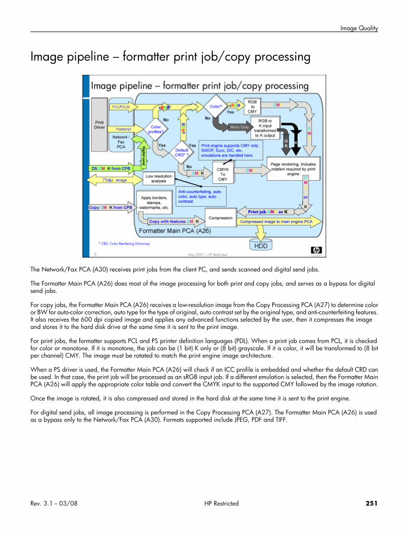
Image Quality
Image pipeline – formatter print job/copy processing
The Network/Fax PCA (A30) receives print jobs from the client PC, and sends scanned and digital send jobs.
The Formatter Main PCA (A26) does most of the image processing for both print and copy jobs, and serves as a bypass for digitalsend jobs.
For copy jobs, the Formatter Main PCA (A26) receives a low-resolution image from the Copy Processing PCA (A27) to determine coloror BW for auto-color correction, auto type for the type of original, auto contrast set by the original type, and anti-counterfeiting features.It also receives the 600 dpi copied image and applies any advanced functions selected by the user, then it compresses the imageand stores it to the hard disk drive at the same time it is sent to the print image.
For print jobs, the formatter supports PCL and PS printer definition languages (PDL). When a print job comes from PCL, it is checkedfor color or monotone. If it is monotone, the job can be (1 bit) K only or (8 bit) grayscale. If it is color, it will be transformed to (8 bitper channel) CMY. The image must be rotated to match the print engine image architecture.
When a PS driver is used, the Formatter Main PCA (A26) will check if an ICC profile is embedded and whether the default CRD canbe used. In that case, the print job will be processed as an sRGB input job. If a different emulation is selected, then the Formatter MainPCA (A26) will apply the appropriate color table and convert the CMYK input to the supported CMY followed by the image rotation.
Once the image is rotated, it is also compressed and stored in the hard disk at the same time it is sent to the print engine.
For digital send jobs, all image processing is performed in the Copy Processing PCA (A27). The Formatter Main PCA (A26) is usedas a bypass only to the Network/Fax PCA (A30). Formats supported include JPEG, PDF and TIFF.
Rev. 3.1 -- 03/08 HP Restricted 251
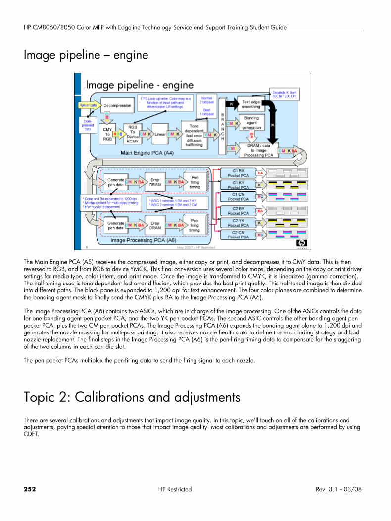
HP CM8060/8050 Color MFP with Edgeline Technology Service and Support Training Student Guide
Image pipeline – engine
The Main Engine PCA (A5) receives the compressed image, either copy or print, and decompresses it to CMY data. This is thenreversed to RGB, and from RGB to device YMCK. This final conversion uses several color maps, depending on the copy or print driversettings for media type, color intent, and print mode. Once the image is transformed to CMYK, it is linearized (gamma correction).The half-toning used is tone dependent fast error diffusion, which provides the best print quality. This half-toned image is then dividedinto different paths. The black pane is expanded to 1,200 dpi for text enhancement. The four color planes are combined to determinethe bonding agent mask to finally send the CMYK plus BA to the Image Processing PCA (A6).
The Image Processing PCA (A6) contains two ASICs, which are in charge of the image processing. One of the ASICs controls the datafor one bonding agent pen pocket PCA, and the two YK pen pocket PCAs. The second ASIC controls the other bonding agent penpocket PCA, plus the two CM pen pocket PCAs. The Image Processing PCA (A6) expands the bonding agent plane to 1,200 dpi andgenerates the nozzle masking for multi-pass printing. It also receives nozzle health data to define the error hiding strategy and badnozzle replacement. The final steps in the Image Processing PCA (A6) is the pen-firing timing data to compensate for the staggeringof the two columns in each pen die slot.
The pen pocket PCAs multiplex the pen-firing data to send the firing signal to each nozzle.
Topic 2: Calibrations and adjustmentsThere are several calibrations and adjustments that impact image quality. In this topic, we'll touch on all of the calibrations andadjustments, paying special attention to those that impact image quality. Most calibrations and adjustments are performed by usingCDFT.
252 HP Restricted Rev. 3.1 -- 03/08
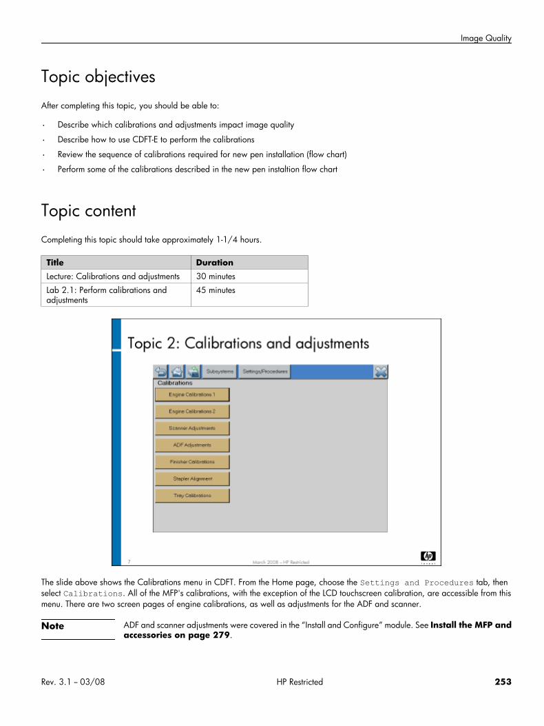
Image Quality
Topic objectivesAfter completing this topic, you should be able to:
• Describe which calibrations and adjustments impact image quality
• Describe how to use CDFT-E to perform the calibrations
• Review the sequence of calibrations required for new pen installation (flow chart)
• Perform some of the calibrations described in the new pen instaltion flow chart
Topic contentCompleting this topic should take approximately 1-1/4 hours.
Title DurationLecture: Calibrations and adjustments 30 minutes
Lab 2.1: Perform calibrations andadjustments
45 minutes
The slide above shows the Calibrations menu in CDFT. From the Home page, choose the Settings and Procedures tab, thenselect Calibrations. All of the MFP's calibrations, with the exception of the LCD touchscreen calibration, are accessible from thismenu. There are two screen pages of engine calibrations, as well as adjustments for the ADF and scanner.
Note ADF and scanner adjustments were covered in the “Install and Configure” module. See Install the MFP andaccessories on page 279.
Rev. 3.1 -- 03/08 HP Restricted 253
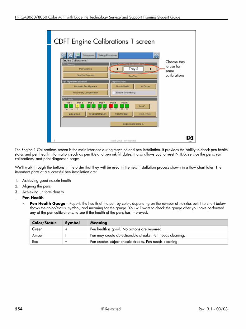
HP CM8060/8050 Color MFP with Edgeline Technology Service and Support Training Student Guide
The Engine 1 Calibrations screen is the main interface during machine and pen installation. It provides the ability to check pen healthstatus and pen health information, such as pen IDs and pen ink fill dates. It also allows you to reset NHDB, service the pens, runcalibrations, and print diagnostic pages.
We'll walk through the buttons in the order that they will be used in the new installation process shown in a flow chart later. Theimportant parts of a successful pen installation are:
1. Achieving good nozzle health2. Aligning the pens3. Achieving uniform density
• Pen Health
• Pen Health Gauge – Reports the health of the pen by color, depending on the number of nozzles out. The chart belowshows the color/status, symbol, and meaning for the gauge. You will want to check the gauge after you have performedany of the pen calibrations, to see if the health of the pens has improved.
Color/Status Symbol MeaningGreen + Pen health is good. No actions are required.
Amber ! Pen may create objectionable streaks. Pen needs cleaning.
Red – Pen creates objectionable streaks. Pen needs cleaning.
254 HP Restricted Rev. 3.1 -- 03/08
Image Quality
Color/Status Symbol MeaningGray ? The Nozzle Health Data Base (NHDB) will show gray and question mark (?) in the
following conditions:
• The Reset NHDB is performed
• Drop Detect Beam calibration failed
• Drop detect is uncalibrated
• Nozzle health score numbers are out of range or negative invalid
A Drop Detect needs to be run so the PHG indicators show the actual condition of thepens.
• Reset NHDB – Button to Reset Nozzle Health Database loaded in Engine RAM, it will not reset the NHDB in the formatterHDD until the Store NHDB button is pressed. We reset the NHDB when we install new pens to erase data from previous pensused in the unit.
Note If NHDB is reset and the unit is rebooted, the NHDB stored in HDD will be restored at boot up. This will returnthe NHDB to the same state it was before using the Reset NHDB button.
• Store NHDB – Button to store NHDB loaded in Engine RAM into formatter HDD.
Note If the Store NHDB follows the Reset NHDB command, the cleared NHDB will replace the old NHDB informatter HDD. A drop detect and maybe a pen cleaning will be necessary to create the NHDB baseline code.
• Drop Detect Beam – Calibrates the center location of the beam detector. This data is used to position the pens accuratelyover the drop-detect assembly for determining pen health.
• Drop Detect – During the Drop Detect routine, each pen is positioned over a drop-detect channel. A group of nozzles fromeach pen fires ink into the channel. The sensor beam detects each ink drop fired. The carriages then position the next groupof nozzles for testing. This process repeats until all nozzles have been tested. The information is stored in NVM, and is usedas a baseline for other image-quality calibrations. Perform the Drop Detect calibration when you are troubleshooting thedrop-detect sensor assembly or a pen health problem. Drop Detect finds “outs” but not “misdirects.”
• Pen Servicing
• New Pen Servicing – Perform basic servicing (spitting), clears the Nozzle Health Database (NHDB), performs a DropDetect beam calibration, followed by a Drop Detect. If needed it runs a level 1 pen servicing followed by drop detect andupdate to the base line.
Note L2 is no longer run as part of New Pen Servicing. If the Drop Detect beam calibration fails, the Drop DetectBeam button will turn Red indicating that the beam center calibration must be run again.
New Pen servicing should be performed when the MFP is installed or when a pen is replaced.
• Pen Cleaning – Cleans the pen nozzles. It initiates a level 2 servicing, performs a drop detect, and if the results of the Dropdetect indicates that the pens are OK it will stop there. Otherwise it will show a pop up message indicating that additionalcleaning is recommended and will give the FSE the option to continue cleaning or to exit pen cleaning.If the FSE selects continue with pen cleaning, then it does a level 3 servicing followed by another Drop Detect. The base linecode will be updated from the results of the last Drop Detect every time a L3 is run.
• Pen Alignment calibrations
• Automatic Pen Alignment (APA) – Establishes carriage-to-carriage, pen-to-pen, and die-to-die alignment to improveimage quality. It should be performed when the MFP is installed, when a new pen is removed and reinserted, or if image-quality issues exist. It should be run after a New Pen Servicing calibration. Run this calibration with non-ColorLok media.
• Pen Density Compensation – Creates a uniform density from die to die and from pen to pen for a primary color acrossthe page. It should be performed when the MFP is installed, when a new pen is installed, or if image-quality issues exist. Itshould be run after an APA and a New Pen Servicing calibration.Pen Density compensation details: Formatter invokes the calibration, Engine uses RGB data with a special color mapto generate direct drive test plots images (4 pages, C M Y K), get raw scan data, average raw scan data. Test plots areejected after printing & scanning from a printer. Engine applies Tetris sensor algorithms in FW to convert scan data into L* ,b* and save those L* b* ( 170 x 4 colors) into NVM after pages are been ejected.
Rev. 3.1 -- 03/08 HP Restricted 255
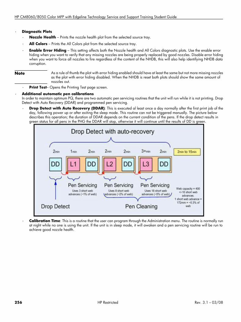
HP CM8060/8050 Color MFP with Edgeline Technology Service and Support Training Student Guide
• Diagnostic Plots
• Nozzle Health – Prints the nozzle health plot from the selected source tray.
• All Colors – Prints the All Colors plot from the selected source tray.
• Enable Error Hiding – This setting affects both the Nozzle health and All Colors diagnostic plots. Use the enable errorhiding when you want to verify that any missing nozzles are being properly replaced by good nozzles. Disable error hidingwhen you want to force all nozzles to fire regardless of the content of the NHDB, this will also help identifying NHDB datacorruption.
Note As a rule of thumb the plot with error hiding enabled should have at least the same but not more missing nozzlesas the plot with error hiding disabled. When the NHDB is reset both plots should show the same amount ofnozzles out.
• Print Test– Opens the Printing Test page screen.
• Additional automatic pen calibrationsIn order to maintain optimum PQ, there are two automatic pen servicing routines that the unit will run while it is not printing. DropDetect with Auto Recovery (DDAR) and programmed pen servicing.
• Drop Detect with Auto Recovery (DDAR): This is executed al least once a day normally after the first print job of theday, following power up or after exiting the sleep mode. This routine can not be triggered manually. The picture belowdescribes this operation; the duration of DDAR depends on the current condition of the pens. If the drop detect results ingreen status for all pens in the PHG the DDAR will stop, otherwise it will continue until the results of DD is green.
• Calibration Time: This is a routine that the user can program through the Administration menu. The routine is normally runat night while no one is using the unit. If the unit is in sleep mode, it will awaken and a pen servicing routine will be run toachieve good nozzle health.
256 HP Restricted Rev. 3.1 -- 03/08
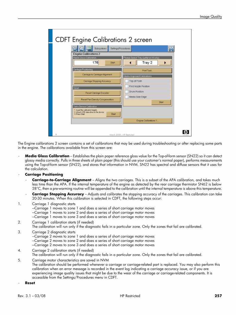
Image Quality
The Engine calibrations 2 screen contains a set of calibrations that may be used during troubleshooting or after replacing some partsin the engine. The calibrations available from this screen are:
• Media Gloss Calibration – Establishes the plain paper reference gloss value for the Top-of-form sensor (SN22) so it can detectglossy media correctly. Pulls in three sheets of plain paper (this should use your customer's normal paper), performs measurementsusing the Top-of-form sensor (SN22), and stores that information in NVM. SN22 has spectral and diffuse sensors that it uses forthe calculation.
• Carriage Positioning
• Carriage-to-Carriage Alignment – Aligns the two carriages. This is a subset of the APA calibration, and takes muchless time than the APA. If the internal temperature of the engine as detected by the rear carriage thermistor SN62 is below28°C, then a pre-warming routine will be appended to the calibration until the internal temperature is above this temperature.
• Carriage Stopping Accuracy – Adjusts and calibrates the stopping accuracy of the carriages. This calibration can take20-30 minutes. When this calibration is selected in CDFT, the following steps occur:
1. Carriage 1 diagnostic starts---Carriage 1 moves to zone 1 and does a series of short carriage motor moves---Carriage 1 moves to zone 2 and does a series of short carriage motor moves---Carriage 1 moves to zone 3 and does a series of short carriage motor moves
2. Carriage 1 calibration starts (if needed)The calibration will run only if the diagnostic fails in a particular zone. Only the zones that fail are calibrated.
3. Carriage 2 diagnostic starts---Carriage 2 moves to zone 1 and does a series of short carriage motor moves---Carriage 2 moves to zone 2 and does a series of short carriage motor moves---Carriage 2 moves to zone 3 and does a series of short carriage motor moves
4. Carriage 2 calibration starts (if needed)The calibration will run only if the diagnostic fails in a particular zone. Only the zones that fail are calibrated.
5. Carriage motor characteristics are saved in NVMThe calibration should be performed whenever a carriage or carriage-related part is replaced. You may also perform thiscalibration when an error message is recorded in the event log indicating a carriage accuracy issue, or if you areexperiencing image quality issues that might be due to the wear of the carriage or carriage-related components. It isaccessible from the Settings/Procedures menu in CDFT.
• Reset
Rev. 3.1 -- 03/08 HP Restricted 257
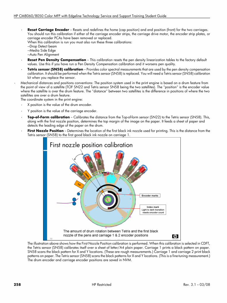
HP CM8060/8050 Color MFP with Edgeline Technology Service and Support Training Student Guide
• Reset Carriage Encoder – Resets and redefines the home (cap position) and end position (front) for the two carriages.You should run this calibration if either of the carriage encoder strips, the carriage drive motor, the encoder strip plates, orcarriage encoder PCAs have been removed or replaced.When this calibration is run you must also run these three calibrations:---Drop Detect beam---Media Side Edge---Auto Pen Alignment
• Reset Pen Density Compensation – This calibration resets the pen density linearization tables to the factory defaultvalues. Use this if you have run a Pen Density Compensation calibration and it worsens pen quality.
• Tetris sensor (SN58) calibration – Provides color spectral measurements that are used by the pen density compensationcalibration. It should be performed when the Tetris sensor (SN58) is replaced. You will need a Tetris sensor (SN58) calibrationkit when you replace the sensor.
• Mechanical distances and positions conventions: The position system used in the print engine is based on a drum feature fromthe point of view of a satellite (TOF SN22 and Tetris sensor SN58 being the two satellites). The "position" is the encoder valuewhere the satellite is over the drum feature. The "distance" between two satellites is the difference in positions of where the twosatellites are over a drum feature.The coordinate system in the print engine:
• X position is the value of the drum encoder.
• Y position is the value of the carriage encoder.
• Top-of-Form calibration – Calibrates the distance from the Top-of-form sensor (SN22) to the Tetris sensor (SN58). This,along with the first nozzle position, determines the top margin of the image on the paper. It feeds a sheet of paper anddetects the leading edge of the paper on the drum.
• First Nozzle Position – Determines the location of the first black ink nozzle used for printing. This is the distance from theTetris sensor (SN58) to the first good black ink nozzle on carriage 1.
The illustration above shows how the First Nozzle Position calibration is performed. When this calibration is selected in CDFT,the Tetris sensor (SN58) calibrates itself over a sheet of letter/A4 plain paper. Carriage 1 prints a black pattern on paper.SN58 scans the black pattern for X and Y locations. (These are rough measurements.) Carriage 1 and carriage 2 print blackpatterns on paper. The Tetris sensor (SN58) scans the black patterns for X and Y locations. (This is a fine-tuning measurement.)The drum encoder and carriage encoder positions are saved in NVM.
258 HP Restricted Rev. 3.1 -- 03/08
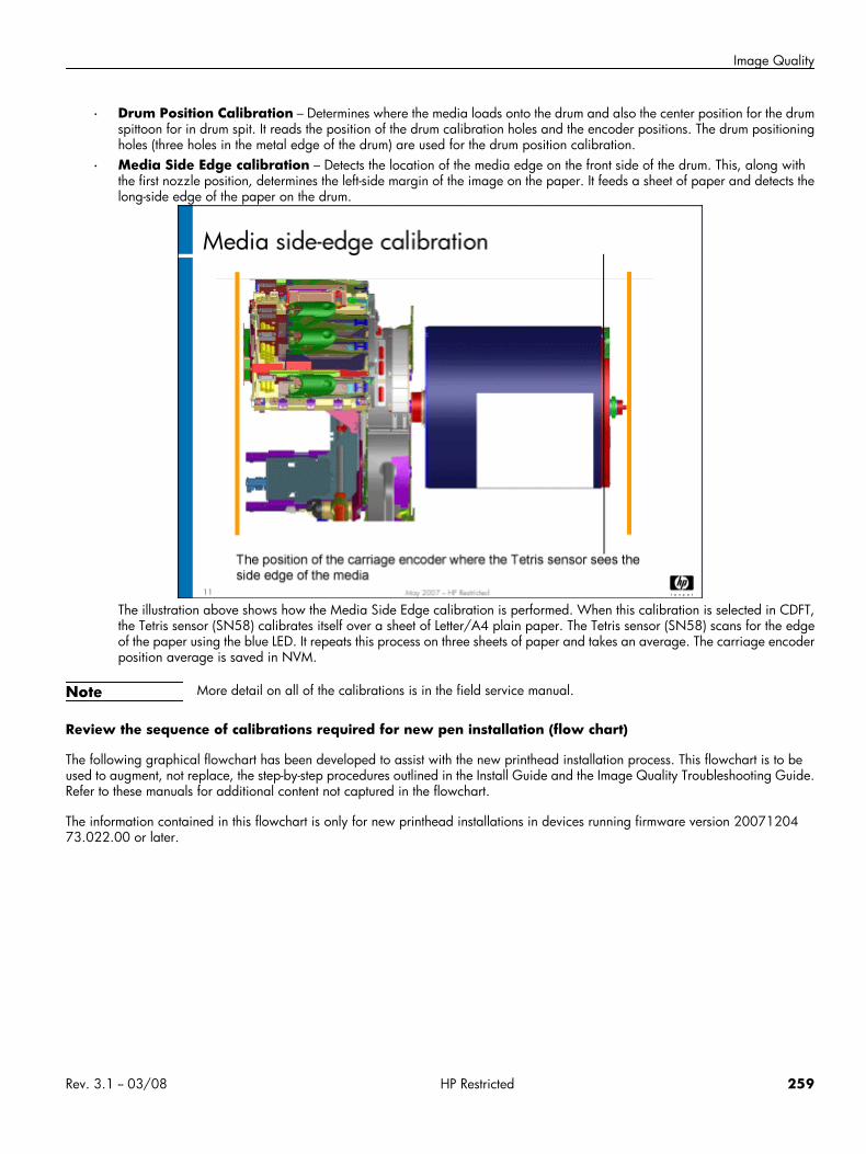
Image Quality
• Drum Position Calibration – Determines where the media loads onto the drum and also the center position for the drumspittoon for in drum spit. It reads the position of the drum calibration holes and the encoder positions. The drum positioningholes (three holes in the metal edge of the drum) are used for the drum position calibration.
• Media Side Edge calibration – Detects the location of the media edge on the front side of the drum. This, along withthe first nozzle position, determines the left-side margin of the image on the paper. It feeds a sheet of paper and detects thelong-side edge of the paper on the drum.
The illustration above shows how the Media Side Edge calibration is performed. When this calibration is selected in CDFT,the Tetris sensor (SN58) calibrates itself over a sheet of Letter/A4 plain paper. The Tetris sensor (SN58) scans for the edgeof the paper using the blue LED. It repeats this process on three sheets of paper and takes an average. The carriage encoderposition average is saved in NVM.
Note More detail on all of the calibrations is in the field service manual.
Review the sequence of calibrations required for new pen installation (flow chart)
The following graphical flowchart has been developed to assist with the new printhead installation process. This flowchart is to beused to augment, not replace, the step-by-step procedures outlined in the Install Guide and the Image Quality Troubleshooting Guide.Refer to these manuals for additional content not captured in the flowchart.
The information contained in this flowchart is only for new printhead installations in devices running firmware version 2007120473.022.00 or later.
Rev. 3.1 -- 03/08 HP Restricted 259
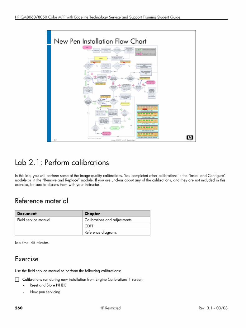
HP CM8060/8050 Color MFP with Edgeline Technology Service and Support Training Student Guide
Lab 2.1: Perform calibrationsIn this lab, you will perform some of the image quality calibrations. You completed other calibrations in the “Install and Configure”module or in the “Remove and Replace” module. If you are unclear about any of the calibrations, and they are not included in thisexercise, be sure to discuss them with your instructor.
Reference material
Document ChapterField service manual Calibrations and adjustments
CDFT
Reference diagrams
Lab time: 45 minutes
ExerciseUse the field service manual to perform the following calibrations:
Calibrations run during new installation from Engine Calibrations 1 screen:
• Reset and Store NHDB
• New pen servicing
260 HP Restricted Rev. 3.1 -- 03/08
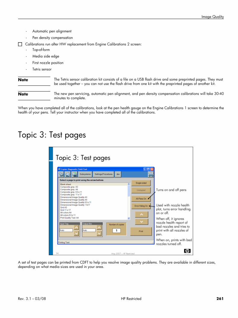
Image Quality
• Automatic pen alignment
• Pen density compensation
Calibrations run after HW replacement from Engine Calibrations 2 screen:
• Top-of-form
• Media side edge
• First nozzle position
• Tetris sensor
Note The Tetris sensor calibration kit consists of a file on a USB flash drive and some preprinted pages. They mustbe used together – you can not use the flash drive from one kit with the preprinted pages of another kit.
Note The new pen servicing, automatic pen alignment, and pen density compensation calibrations will take 30-40minutes to complete.
When you have completed all of the calibrations, look at the pen health gauge on the Engine Calibrations 1 screen to determine thehealth of your pens. Tell your instructor when you have completed all of the calibrations.
Topic 3: Test pages
A set of test pages can be printed from CDFT to help you resolve image quality problems. They are available in different sizes,depending on what media sizes are used in your area.
Rev. 3.1 -- 03/08 HP Restricted 261
HP CM8060/8050 Color MFP with Edgeline Technology Service and Support Training Student Guide
Topic objectivesAfter completing this topic, you should be able to:
• Describe the use of test pages
• Print a set of test pages
• Use test pages to solve image quality problems
Topic contentCompleting this topic should take approximately 75 minutes.
Title DurationLecture: Test pages 30 minutes
Lab 3.1: Print a set of test pages 15 minutes
Interpreting the test pages 30 minutes
Printing test pagesA set of test pages is available for use in troubleshooting image quality problems or mechanical problems. These pages offer a varietyof images, text, and color density, so that you can check various types of problems. The test pages are accessible from CDFT-L andCDFT-E.
In CDFT, choose the Settings/Procedures tab, and then choose Printing Test. From the screen that appears, you can choosedifferent paper sizes, different paper trays, stapler options, and different page types. Several pages are particularly helpful in imagequality troubleshooting. These are:
• Dimensional IQ – To evaluate print image placement and as a copy target for scanner/ADF image adjustment.
• All colors – Prints all colors at 100% and 40% density for the primary colors Black, Yellow, Cyan, Magenta, plus the primarycomposite colors Red, Green, and Blue. Use this page for streaks, image area damage, and ink mixing.
• Composite gray – Prints a composite gray area with primary color blocks. Use this page for vertical banding, graininess, bleed,and color misregsitration.
• Print quality (PQ) test – Used to verify overall print quality. Contains color and black text and graphics, skin tones, gray areasand color registration marks.
• Pen alignment (direct drive format, available in letter/A4 size only) – Tells whether the pens, dies and carriages are aligned.
• Nozzle health (direct drive format, available in letter/A4 size only) – Tells whether there is a problem with pen nozzles.
• Streaks (direct drive format, available in letter/A4 size only) – Shows whether an ink color is streaking.
• Engine footprint – Used to determine whether the rollers and diverter fingers in the engine paper path are damaging the prints.
Using test pagesThere are two uses for test pages in regards to image quality:
262 HP Restricted Rev. 3.1 -- 03/08
Image Quality
• Printing a test page to help troubleshoot an image quality defect
• Printing a test page to validate that an image quality defect has been fixed
Take a look at one of the image quality defect descriptions in the field service manual (“Troubleshooting” chapter). You'll see thatprinting a specific test page is often listed in the recommended actions. This is also often a step in the fault trees.
The directions will also tell you where to look on the test page and what specifically to look for.
If the problem is a copy defect rather than a print defect, you can copy the good test page to help troubleshoot the copy defect.
After you have fixed the problem, you can print the test page again so that you can verify your fix.
Note You may want to use a magnifying loop to examine image quality problems more closely.
Lab 3.1: Print a set of test pagesIn this exercise, you will print a set of internal pages for your own use.
Reference material
Document ChapterField service manual CDFT
Troubleshooting
Lab time: 15 minutes
ExerciseUse the instructions in the field service manual to print the test pages. Once you have accessed the correct page in CDFT, make sureyou have the correct media loaded in one of the trays, and you select that tray to print from. You should print pages according to thesize you are most likely to be working with on the job. Print these pages:
Dimensional IQ (11 x 17 or A3)
All colors
Composite gray (8-1/2 x 11)
PQ test
Pen alignment
Nozzle health
Streaks test
Engine footprint
Vertical banding
Rev. 3.1 -- 03/08 HP Restricted 263
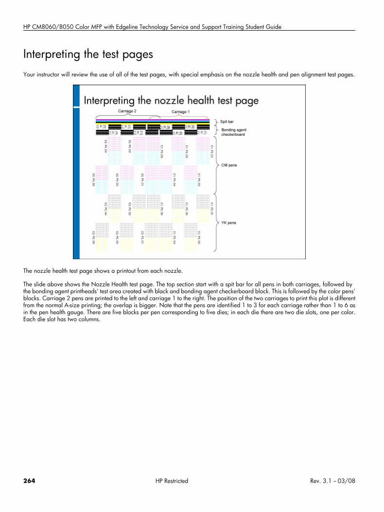
HP CM8060/8050 Color MFP with Edgeline Technology Service and Support Training Student Guide
Interpreting the test pagesYour instructor will review the use of all of the test pages, with special emphasis on the nozzle health and pen alignment test pages.
The nozzle health test page shows a printout from each nozzle.
The slide above shows the Nozzle Health test page. The top section start with a spit bar for all pens in both carriages, followed bythe bonding agent printheads' test area created with black and bonding agent checkerboard block. This is followed by the color pens'blocks. Carriage 2 pens are printed to the left and carriage 1 to the right. The position of the two carriages to print this plot is differentfrom the normal A-size printing; the overlap is bigger. Note that the pens are identified 1 to 3 for each carriage rather than 1 to 6 asin the pen health gauge. There are five blocks per pen corresponding to five dies; in each die there are two die slots, one per color.Each die slot has two columns.
264 HP Restricted Rev. 3.1 -- 03/08
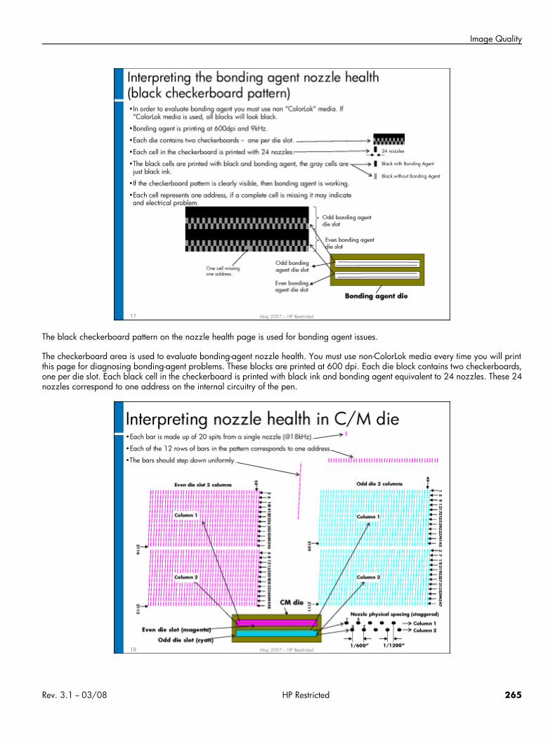
Image Quality
The black checkerboard pattern on the nozzle health page is used for bonding agent issues.
The checkerboard area is used to evaluate bonding-agent nozzle health. You must use non-ColorLok media every time you will printthis page for diagnosing bonding-agent problems. These blocks are printed at 600 dpi. Each die block contains two checkerboards,one per die slot. Each black cell in the checkerboard is printed with black ink and bonding agent equivalent to 24 nozzles. These 24nozzles correspond to one address on the internal circuitry of the pen.
Rev. 3.1 -- 03/08 HP Restricted 265
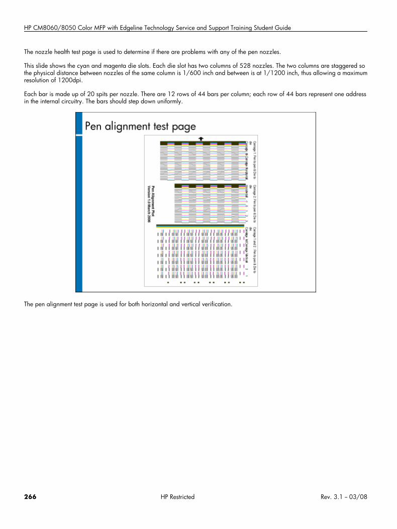
HP CM8060/8050 Color MFP with Edgeline Technology Service and Support Training Student Guide
The nozzle health test page is used to determine if there are problems with any of the pen nozzles.
This slide shows the cyan and magenta die slots. Each die slot has two columns of 528 nozzles. The two columns are staggered sothe physical distance between nozzles of the same column is 1/600 inch and between is at 1/1200 inch, thus allowing a maximumresolution of 1200dpi.
Each bar is made up of 20 spits per nozzle. There are 12 rows of 44 bars per column; each row of 44 bars represent one addressin the internal circuitry. The bars should step down uniformly.
The pen alignment test page is used for both horizontal and vertical verification.
266 HP Restricted Rev. 3.1 -- 03/08
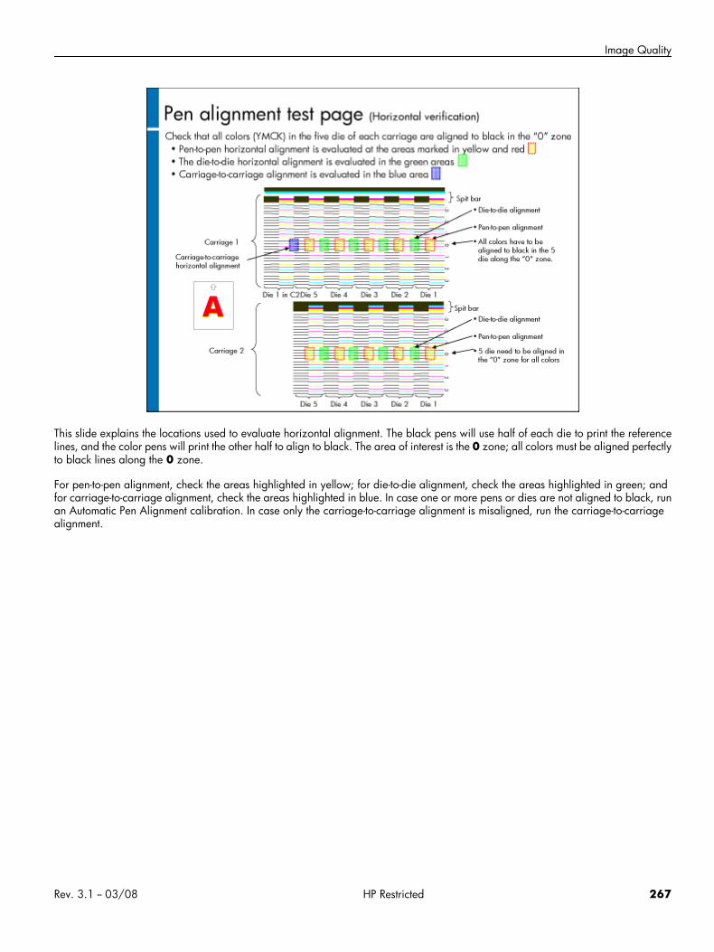
Image Quality
This slide explains the locations used to evaluate horizontal alignment. The black pens will use half of each die to print the referencelines, and the color pens will print the other half to align to black. The area of interest is the 0 zone; all colors must be aligned perfectlyto black lines along the 0 zone.
For pen-to-pen alignment, check the areas highlighted in yellow; for die-to-die alignment, check the areas highlighted in green; andfor carriage-to-carriage alignment, check the areas highlighted in blue. In case one or more pens or dies are not aligned to black, runan Automatic Pen Alignment calibration. In case only the carriage-to-carriage alignment is misaligned, run the carriage-to-carriagealignment.
Rev. 3.1 -- 03/08 HP Restricted 267
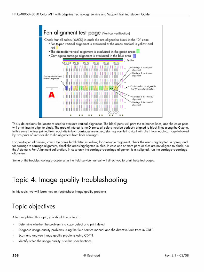
HP CM8060/8050 Color MFP with Edgeline Technology Service and Support Training Student Guide
This slide explains the locations used to evaluate vertical alignment. The black pens will print the reference lines, and the color penswill print lines to align to black. The area of interest is the 0 zone; all colors must be perfectly aligned to black lines along the 0 zone.In this zone the lines printed from each die in both carriages are mixed, starting from left to right with die 1 from each carriage followedby two pairs of lines for die-to-die alignment from both carriages.
For pen-to-pen alignment, check the areas highlighted in yellow; for die-to-die alignment, check the areas highlighted in green; andfor carriage-to-carriage alignment, check the areas highlighted in blue. In case one or more pens or dies are not aligned to black, runthe Automatic Pen Alignment calibration. In case only the carriage-to-carriage alignment is misaligned, run the carriage-to-carriagealignment.
Some of the troubleshooting procedures in the field service manual will direct you to print these test pages.
Topic 4: Image quality troubleshootingIn this topic, we will learn how to troubleshoot image quality problems.
Topic objectivesAfter completing this topic, you should be able to:
• Determine whether the problem is a copy defect or a print defect
• Diagnose image quality problems using the field service manual and the directive fault trees in CDFT-L
• Scan and analyze image quality problems using CDFT-L
• Identify when the image quality is within specifications
268 HP Restricted Rev. 3.1 -- 03/08
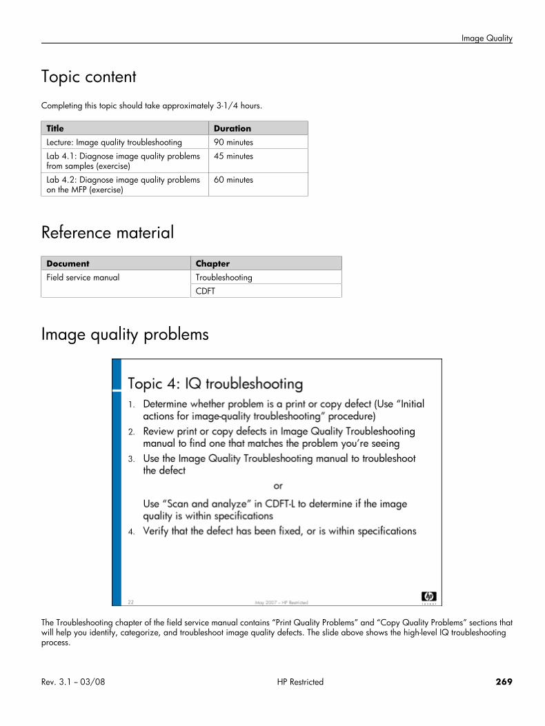
Image Quality
Topic contentCompleting this topic should take approximately 3-1/4 hours.
Title DurationLecture: Image quality troubleshooting 90 minutes
Lab 4.1: Diagnose image quality problemsfrom samples (exercise)
45 minutes
Lab 4.2: Diagnose image quality problemson the MFP (exercise)
60 minutes
Reference material
Document ChapterField service manual Troubleshooting
CDFT
Image quality problems
The Troubleshooting chapter of the field service manual contains “Print Quality Problems” and “Copy Quality Problems” sections thatwill help you identify, categorize, and troubleshoot image quality defects. The slide above shows the high-level IQ troubleshootingprocess.
Rev. 3.1 -- 03/08 HP Restricted 269
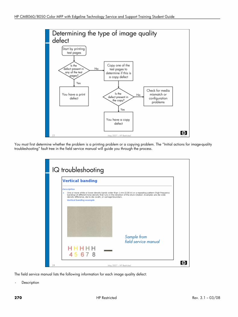
HP CM8060/8050 Color MFP with Edgeline Technology Service and Support Training Student Guide
You must first determine whether the problem is a printing problem or a copying problem. The “Initial actions for image-qualitytroubleshooting” fault tree in the field service manual will guide you through the process.
The field service manual lists the following information for each image quality defect:
• Description
270 HP Restricted Rev. 3.1 -- 03/08
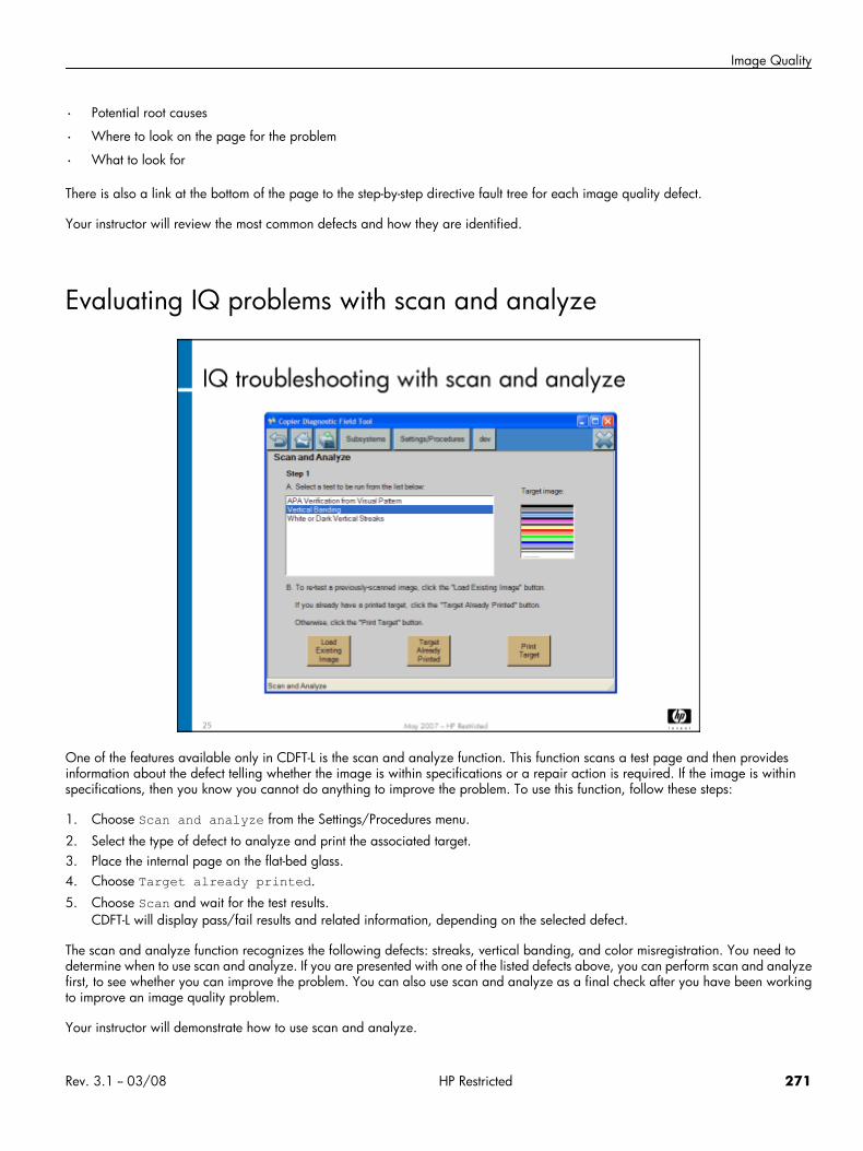
Image Quality
• Potential root causes
• Where to look on the page for the problem
• What to look for
There is also a link at the bottom of the page to the step-by-step directive fault tree for each image quality defect.
Your instructor will review the most common defects and how they are identified.
Evaluating IQ problems with scan and analyze
One of the features available only in CDFT-L is the scan and analyze function. This function scans a test page and then providesinformation about the defect telling whether the image is within specifications or a repair action is required. If the image is withinspecifications, then you know you cannot do anything to improve the problem. To use this function, follow these steps:
1. Choose Scan and analyze from the Settings/Procedures menu.
2. Select the type of defect to analyze and print the associated target.3. Place the internal page on the flat-bed glass.4. Choose Target already printed.
5. Choose Scan and wait for the test results.CDFT-L will display pass/fail results and related information, depending on the selected defect.
The scan and analyze function recognizes the following defects: streaks, vertical banding, and color misregistration. You need todetermine when to use scan and analyze. If you are presented with one of the listed defects above, you can perform scan and analyzefirst, to see whether you can improve the problem. You can also use scan and analyze as a final check after you have been workingto improve an image quality problem.
Your instructor will demonstrate how to use scan and analyze.
Rev. 3.1 -- 03/08 HP Restricted 271

HP CM8060/8050 Color MFP with Edgeline Technology Service and Support Training Student Guide
Lab 4.1: Diagnose IQ problems from samplesYour instructor will now distribute IQ problem samples. You will categorize the defect and use CDFT-L and the field service manual tofind solutions. You will need a magnifying loop to examine the samples.
Lab time: 45 minutes
ExerciseYour instructor will distribute five IQ defect samples to each team. Use the designated tool in the list below to categorize the defectand list possible solutions.
Sample 1: Use service manual to find the defect and come up with recommended actions. The sample is a print sample.Defect type: _______________________Possible solutions: ______________________________________________________________________________________________________________________________________________________________________Sample 2: Use the field service manual to find the defect and come up with recommended actions. The sample is a print sample.Defect type: _______________________Possible solutions: ______________________________________________________________________________________________________________________________________________________________________Sample 3: Use CDFT-L to launch the online service manual to categorize the defect and determine the problem. The sample is acopy sample.Defect type: _______________________Possible solutions: ______________________________________________________________________________________________________________________________________________________________________Sample 4: Use CDFT-L to categorize the defect and find a solution. The sample is a print sample.Defect type: _______________________Possible solutions: ______________________________________________________________________________________________________________________________________________________________________Sample 5: Use Scan and analyze from CDFT-L. Run the vertical banding test with the sample to determine whether it is withinspecifications.Within specifications? ___ Yes ___ No
Have your instructor check your work.
Lab 4.2: Diagnose IQ problems on the MFPIn this exercise, your instructor will insert a fault into your MFP that will cause an image quality problem.
Lab time: 75 minutes
ExerciseYour instructor will give you a print sample to copy. Make a few copies of the sample. You will see an image quality problem. UseCDFT-L or your field service manual to classify the defect and troubleshoot the problem. Tell your instructor when you have completedthe exercise.
272 HP Restricted Rev. 3.1 -- 03/08

Hardware Practicum
Hardware Practicum• Instructions
Rev. 3.1 -- 03/08 HP Restricted 273
HP CM8060/8050 Color MFP with Edgeline Technology Service and Support Training Student Guide
InstructionsThe hardware practicum consists of troubleshooting problems in an MFP. You will have two hours to complete it. Your instructor willevaluate your performance as you go through the troubleshooting and repairs. You can use any manuals or tools you want totroubleshoot and complete the repairs. Passing this practicum is part of your service qualification.
Each MFP in the classroom is presenting a different problem. You will move from MFP to MFP, troubleshooting the fault to root cause,but not fixing it. Use the worksheets to write down each problem you encounter, and the steps you would take to resolve each problem.
Reinstall coversOnce you have completed the hardware practicum and your instructor has checked your work, please replace all the covers and caseparts.
Reference material
Document ChapterField service manual Removal and replacement
274 HP Restricted Rev. 3.1 -- 03/08

Install and Configure
Install and Configure• Overview
• Site preparation and assessment
• Install the MFP and accessories
• Calibrations and configurations
• Decommission and move
• Lab 1.1: Prepare MFP for an extended move
• Lab 1.2: Install the MFP and accessories
• Lab 1.3: Perform calibrations and configurations
• Customer walkaround
Rev. 3.1 -- 03/08 HP Restricted 275
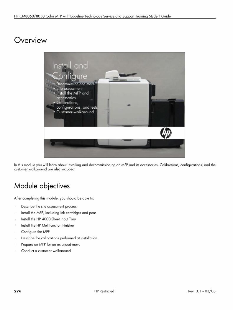
HP CM8060/8050 Color MFP with Edgeline Technology Service and Support Training Student Guide
Overview
In this module you will learn about installing and decommissioning an MFP and its accessories. Calibrations, configurations, and thecustomer walkaround are also included.
Module objectivesAfter completing this module, you should be able to:
• Describe the site assessment process
• Install the MFP, including ink cartridges and pens
• Install the HP 4000-Sheet Input Tray
• Install the HP Multifunction Finisher
• Configure the MFP
• Describe the calibrations performed at installation
• Prepare an MFP for an extended move
• Conduct a customer walkaround
276 HP Restricted Rev. 3.1 -- 03/08
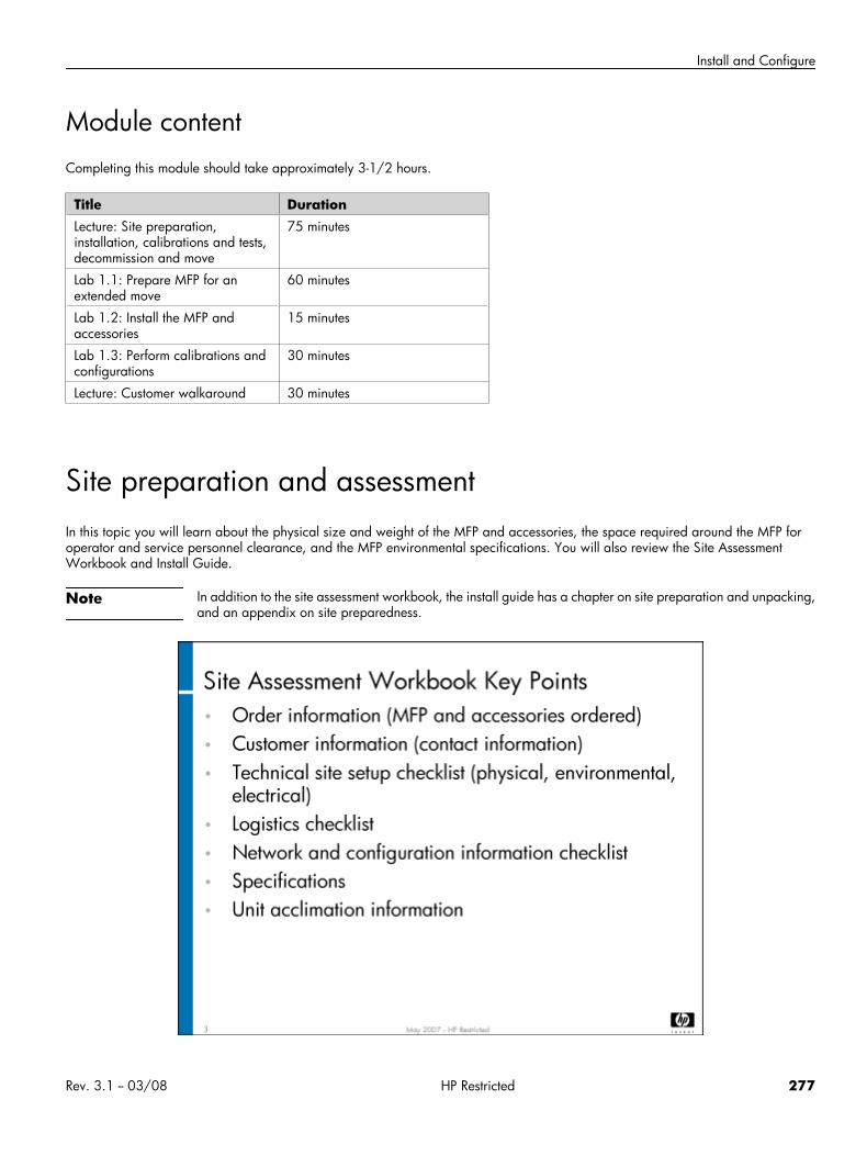
Install and Configure
Module contentCompleting this module should take approximately 3-1/2 hours.
Title DurationLecture: Site preparation,installation, calibrations and tests,decommission and move
75 minutes
Lab 1.1: Prepare MFP for anextended move
60 minutes
Lab 1.2: Install the MFP andaccessories
15 minutes
Lab 1.3: Perform calibrations andconfigurations
30 minutes
Lecture: Customer walkaround 30 minutes
Site preparation and assessmentIn this topic you will learn about the physical size and weight of the MFP and accessories, the space required around the MFP foroperator and service personnel clearance, and the MFP environmental specifications. You will also review the Site AssessmentWorkbook and Install Guide.
Note In addition to the site assessment workbook, the install guide has a chapter on site preparation and unpacking,and an appendix on site preparedness.
Rev. 3.1 -- 03/08 HP Restricted 277
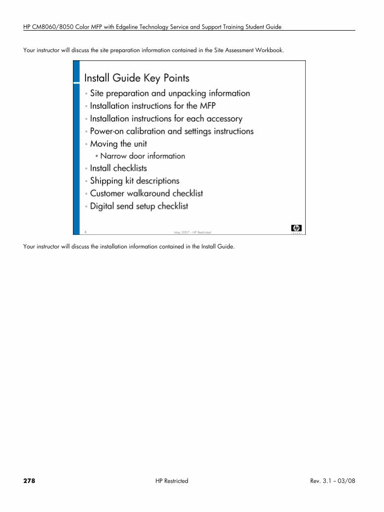
HP CM8060/8050 Color MFP with Edgeline Technology Service and Support Training Student Guide
Your instructor will discuss the site preparation information contained in the Site Assessment Workbook.
Your instructor will discuss the installation information contained in the Install Guide.
278 HP Restricted Rev. 3.1 -- 03/08
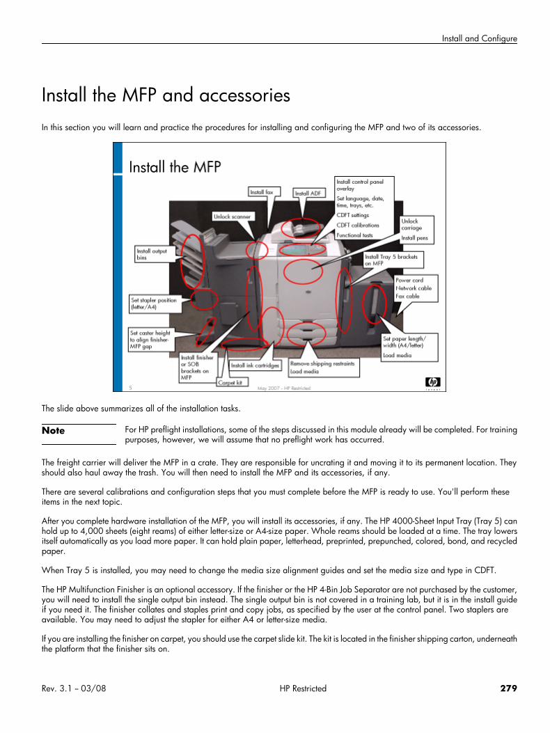
Install and Configure
Install the MFP and accessoriesIn this section you will learn and practice the procedures for installing and configuring the MFP and two of its accessories.
The slide above summarizes all of the installation tasks.
Note For HP preflight installations, some of the steps discussed in this module already will be completed. For trainingpurposes, however, we will assume that no preflight work has occurred.
The freight carrier will deliver the MFP in a crate. They are responsible for uncrating it and moving it to its permanent location. Theyshould also haul away the trash. You will then need to install the MFP and its accessories, if any.
There are several calibrations and configuration steps that you must complete before the MFP is ready to use. You'll perform theseitems in the next topic.
After you complete hardware installation of the MFP, you will install its accessories, if any. The HP 4000-Sheet Input Tray (Tray 5) canhold up to 4,000 sheets (eight reams) of either letter-size or A4-size paper. Whole reams should be loaded at a time. The tray lowersitself automatically as you load more paper. It can hold plain paper, letterhead, preprinted, prepunched, colored, bond, and recycledpaper.
When Tray 5 is installed, you may need to change the media size alignment guides and set the media size and type in CDFT.
The HP Multifunction Finisher is an optional accessory. If the finisher or the HP 4-Bin Job Separator are not purchased by the customer,you will need to install the single output bin instead. The single output bin is not covered in a training lab, but it is in the install guideif you need it. The finisher collates and staples print and copy jobs, as specified by the user at the control panel. Two staplers areavailable. You may need to adjust the stapler for either A4 or letter-size media.
If you are installing the finisher on carpet, you should use the carpet slide kit. The kit is located in the finisher shipping carton, underneaththe platform that the finisher sits on.
Rev. 3.1 -- 03/08 HP Restricted 279

HP CM8060/8050 Color MFP with Edgeline Technology Service and Support Training Student Guide
Warning Do not attempt to lift or move the finisher by grasping the top of the job separator.
Note It might be necessary to allow the MFP and accessories to acclimate if they have been subjected to extendedperiods of cold or heat during storage or transportation. After the MFP have been moved to the installationarea, open the doors for about one hour to allow the internal temperature of MFP and accessories to normalize.This will help prevent condensation from forming inside the MFP and accessories.
280 HP Restricted Rev. 3.1 -- 03/08
Install and Configure
Calibrations and configurations
In this topic, you will perform configurations and calibrations necessary to get the MFP and its accessories running correctly.
There are many adjustments, configurations, and calibrations you must make to the MFP and its accessories once they are installed.Some of these will be covered in this module. A few, however, were covered during the “Remove and Replace” module or will becovered in the remaining modules of this training. We will mention all of them here, so that you will have a good idea of all the itemsneeded to get the MFP running. Refer to the install guide to see all of the tasks you will need to perform.
Rev. 3.1 -- 03/08 HP Restricted 281
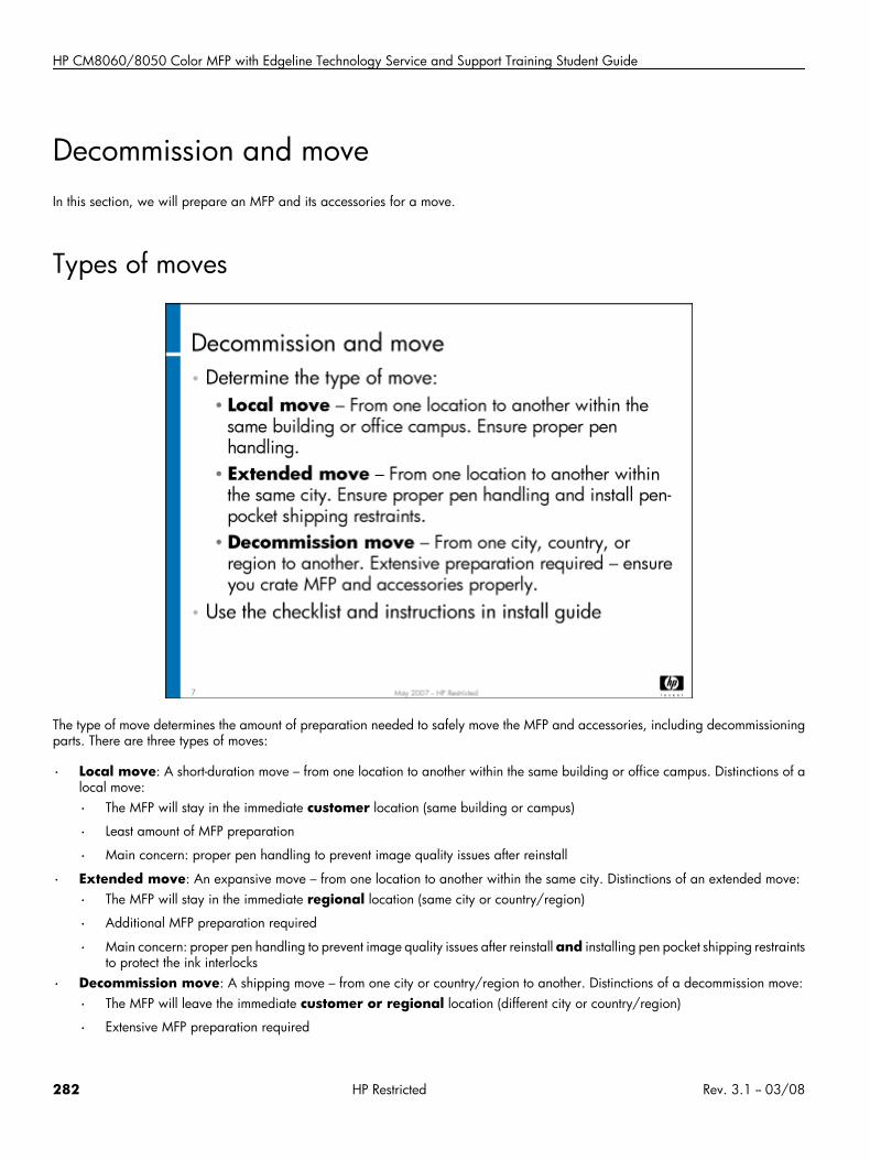
HP CM8060/8050 Color MFP with Edgeline Technology Service and Support Training Student Guide
Decommission and moveIn this section, we will prepare an MFP and its accessories for a move.
Types of moves
The type of move determines the amount of preparation needed to safely move the MFP and accessories, including decommissioningparts. There are three types of moves:
• Local move: A short-duration move – from one location to another within the same building or office campus. Distinctions of alocal move:
• The MFP will stay in the immediate customer location (same building or campus)
• Least amount of MFP preparation
• Main concern: proper pen handling to prevent image quality issues after reinstall
• Extended move: An expansive move – from one location to another within the same city. Distinctions of an extended move:
• The MFP will stay in the immediate regional location (same city or country/region)
• Additional MFP preparation required
• Main concern: proper pen handling to prevent image quality issues after reinstall and installing pen pocket shipping restraintsto protect the ink interlocks
• Decommission move: A shipping move – from one city or country/region to another. Distinctions of a decommission move:
• The MFP will leave the immediate customer or regional location (different city or country/region)
• Extensive MFP preparation required
282 HP Restricted Rev. 3.1 -- 03/08
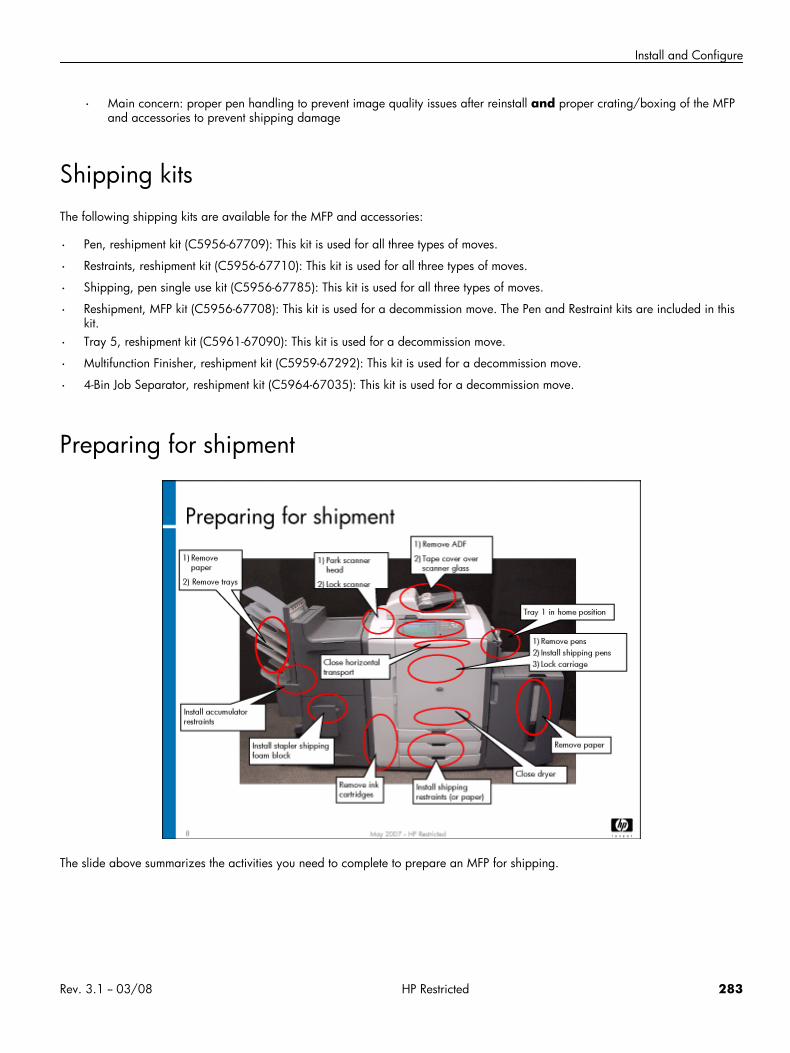
Install and Configure
• Main concern: proper pen handling to prevent image quality issues after reinstall and proper crating/boxing of the MFPand accessories to prevent shipping damage
Shipping kitsThe following shipping kits are available for the MFP and accessories:
• Pen, reshipment kit (C5956-67709): This kit is used for all three types of moves.
• Restraints, reshipment kit (C5956-67710): This kit is used for all three types of moves.
• Shipping, pen single use kit (C5956-67785): This kit is used for all three types of moves.
• Reshipment, MFP kit (C5956-67708): This kit is used for a decommission move. The Pen and Restraint kits are included in thiskit.
• Tray 5, reshipment kit (C5961-67090): This kit is used for a decommission move.
• Multifunction Finisher, reshipment kit (C5959-67292): This kit is used for a decommission move.
• 4-Bin Job Separator, reshipment kit (C5964-67035): This kit is used for a decommission move.
Preparing for shipment
The slide above summarizes the activities you need to complete to prepare an MFP for shipping.
Rev. 3.1 -- 03/08 HP Restricted 283
HP CM8060/8050 Color MFP with Edgeline Technology Service and Support Training Student Guide
Lab 1.1: Prepare MFP for an extended moveIn this lab you will prepare an MFP for an extended move.
Reference material
Document ChapterInstall guide Moving the HP CM8050/60 MFP
Appendix B: Shipping Kits
Lab time: 60 minutes
ExerciseOne of your customers is moving to a new office across town and has submitted a request for you to move their MFP. Using the toolsavailable to you and the install guide, prepare the MFP for an extended move.
Caution Some components of the MFP and accessories are sensitive to electrostatic discharge (ESD). Be careful whenworking around ESD-sensitive components.
Determine the kits required.
Determine the tools required.
Review the warnings, cautions, and steps for an extended move in the install guide.
Prepare the MFP for an extended move, according to the instructions in the install guide. Due to time constraints, do noterase customer data.
Note Remove all carriage 1 pens (not carriage 2 pens) for this exercise. Be sure to insert pen-pocket shippingrestraints in the carriage after you remove the pens. Cap the pens with needle and nozzle caps.
Prepare the accessories (Tray 5 and the finisher) for an extended move, according to the instructions in the install guide. In thisexercise, you do not need to remove the brackets that connect the accessories to the MFP.
Note You do not have to tape the doors closed, install bubble wrap in the finisher, or bag and crate the MFP andaccessories.
When you are finished, have your instructor check your work.
Lab 1.2: Install the MFP and accessoriesYou will now install the MFP and its accessories.
284 HP Restricted Rev. 3.1 -- 03/08
Install and Configure
Reference material
Document ChapterInstall guide Install the HP CM8050/60 MFP
Install the HP 4000-sheet input tray (Tray5)
Install the HP multifunction finisher
Install the HP 4-bin job separator
Appendix A: Quick reference installchecklists
Lab time: 15 minutes
ExerciseFollow the instructions in the install guide to install the MFP, Multifunction Finisher, and Tray 5.
When you are finished, have your work checked by the instructor.
Lab 1.3: Perform calibrations and configurationsYou will now set up the MFP, performing required configurations and calibrations. You will also examine configuration tasks thatwould normally be performed by the system administrator.
Reference material
Document ChapterInstall guide Power-on calibrations, adjustments,
settings and tests
Lab time: 30 minutes
ExerciseFollow the instructions in the install guide to complete the calibrations and configurations of the MFP and its accessories.
Note You will perform NVM backups, upgrade firmware, and configure EWS and digital send in later modules.
Rev. 3.1 -- 03/08 HP Restricted 285
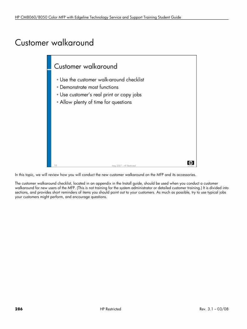
HP CM8060/8050 Color MFP with Edgeline Technology Service and Support Training Student Guide
Customer walkaround
In this topic, we will review how you will conduct the new customer walkaround on the MFP and its accessories.
The customer walkaround checklist, located in an appendix in the Install guide, should be used when you conduct a customerwalkaround for new users of the MFP. (This is not training for the system administrator or detailed customer training.) It is divided intosections, and provides short reminders of items you should point out to your customers. As much as possible, try to use typical jobsyour customers might perform, and encourage questions.
286 HP Restricted Rev. 3.1 -- 03/08

NVM and firmware
NVM and firmware• Overview
• Topic 1: Non-volatile memory
• Topic 2: Perform firmware upgrade
Rev. 3.1 -- 03/08 HP Restricted 287
HP CM8060/8050 Color MFP with Edgeline Technology Service and Support Training Student Guide
Overview
This module guides you through performing NVM backup/restore and upgrading firmware.
Topic 1: Non-volatile memoryThis topic guides you through performing a non-volatile memory (NVM) backup and restore, and NVM resets and initializations.
Topic 1 objectivesAfter completing this topic, you should be able to:
• Describe what NVM data is
• Back up NVM
• Restore NVM
• Perform NVM resets and initializations
288 HP Restricted Rev. 3.1 -- 03/08
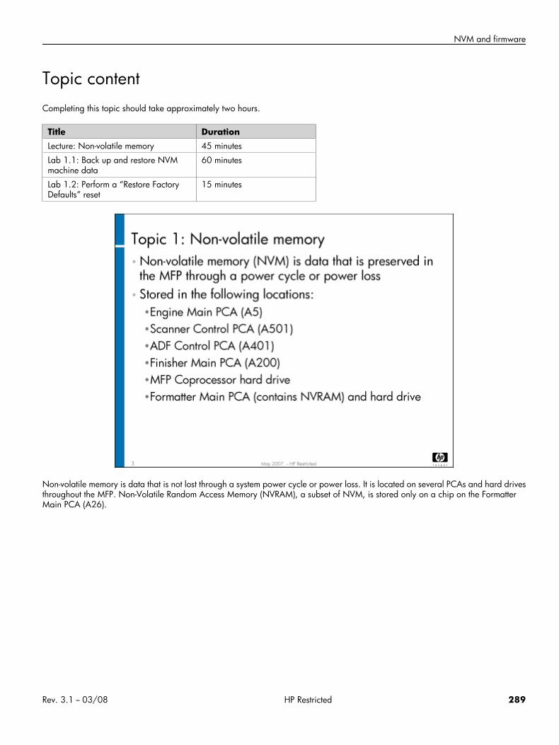
NVM and firmware
Topic contentCompleting this topic should take approximately two hours.
Title DurationLecture: Non-volatile memory 45 minutes
Lab 1.1: Back up and restore NVMmachine data
60 minutes
Lab 1.2: Perform a “Restore FactoryDefaults” reset
15 minutes
Non-volatile memory is data that is not lost through a system power cycle or power loss. It is located on several PCAs and hard drivesthroughout the MFP. Non-Volatile Random Access Memory (NVRAM), a subset of NVM, is stored only on a chip on the FormatterMain PCA (A26).
Rev. 3.1 -- 03/08 HP Restricted 289
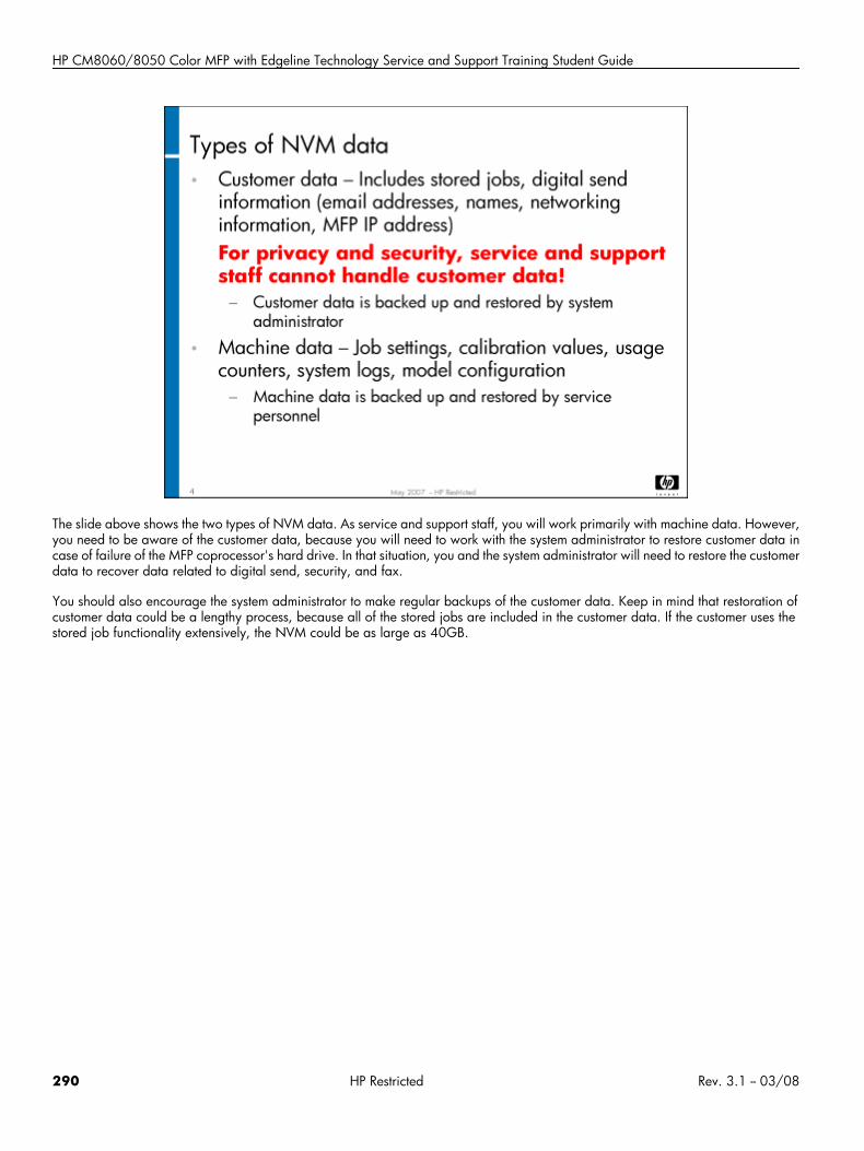
HP CM8060/8050 Color MFP with Edgeline Technology Service and Support Training Student Guide
The slide above shows the two types of NVM data. As service and support staff, you will work primarily with machine data. However,you need to be aware of the customer data, because you will need to work with the system administrator to restore customer data incase of failure of the MFP coprocessor's hard drive. In that situation, you and the system administrator will need to restore the customerdata to recover data related to digital send, security, and fax.
You should also encourage the system administrator to make regular backups of the customer data. Keep in mind that restoration ofcustomer data could be a lengthy process, because all of the stored jobs are included in the customer data. If the customer uses thestored job functionality extensively, the NVM could be as large as 40GB.
290 HP Restricted Rev. 3.1 -- 03/08
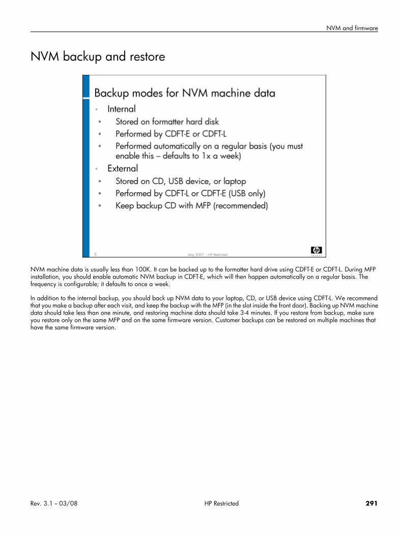
NVM and firmware
NVM backup and restore
NVM machine data is usually less than 100K. It can be backed up to the formatter hard drive using CDFT-E or CDFT-L. During MFPinstallation, you should enable automatic NVM backup in CDFT-E, which will then happen automatically on a regular basis. Thefrequency is configurable; it defaults to once a week.
In addition to the internal backup, you should back up NVM data to your laptop, CD, or USB device using CDFT-L. We recommendthat you make a backup after each visit, and keep the backup with the MFP (in the slot inside the front door). Backing up NVM machinedata should take less than one minute, and restoring machine data should take 3-4 minutes. If you restore from backup, make sureyou restore only on the same MFP and on the same firmware version. Customer backups can be restored on multiple machines thathave the same firmware version.
Rev. 3.1 -- 03/08 HP Restricted 291
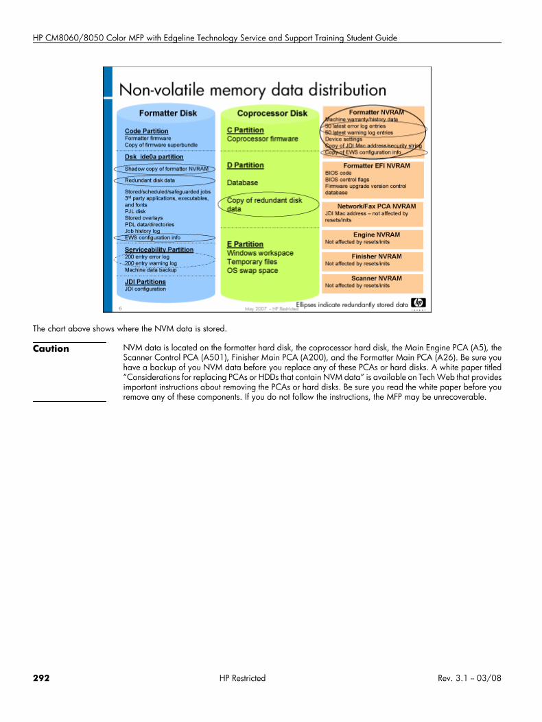
HP CM8060/8050 Color MFP with Edgeline Technology Service and Support Training Student Guide
The chart above shows where the NVM data is stored.
Caution NVM data is located on the formatter hard disk, the coprocessor hard disk, the Main Engine PCA (A5), theScanner Control PCA (A501), Finisher Main PCA (A200), and the Formatter Main PCA (A26). Be sure youhave a backup of you NVM data before you replace any of these PCAs or hard disks. A white paper titled“Considerations for replacing PCAs or HDDs that contain NVM data” is available on Tech Web that providesimportant instructions about removing the PCAs or hard disks. Be sure you read the white paper before youremove any of these components. If you do not follow the instructions, the MFP may be unrecoverable.
292 HP Restricted Rev. 3.1 -- 03/08
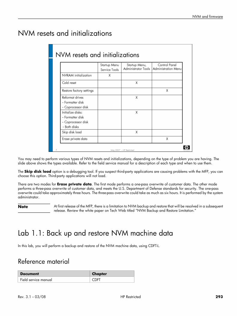
NVM and firmware
NVM resets and initializations
You may need to perform various types of NVM resets and initializations, depending on the type of problem you are having. Theslide above shows the types available. Refer to the field service manual for a description of each type and when to use them.
The Skip disk load option is a debugging tool. If you suspect third-party applications are causing problems with the MFP, you canchoose this option. Third-party applications will not load.
There are two modes for Erase private data. The first mode performs a one-pass overwrite of customer data. The other modeperforms a three-pass overwrite of customer data, and meets the U.S. Department of Defense standards for security. The one-passoverwrite could take approximately three hours. The three-pass overwrite could take as much as six hours. It is performed by the systemadministrator.
Note At first release of the MFP, there is a limitation to NVM backup and restore that will be resolved in a subsequentrelease. Review the white paper on Tech Web titled “NVM Backup and Restore Limitation.”
Lab 1.1: Back up and restore NVM machine dataIn this lab, you will perform a backup and restore of the NVM machine data, using CDFT-L.
Reference material
Document ChapterField service manual CDFT
Rev. 3.1 -- 03/08 HP Restricted 293
HP CM8060/8050 Color MFP with Edgeline Technology Service and Support Training Student Guide
Lab time: 60 minutes
ExerciseUse the field service manual to complete the following tasks.
Check the setting on the CDFT-E Auto NVM Backup screen to make sure that automatic backup has been enabled
You will use different methods to back up the NVM machine data:
• Use CDFT-E to back up NVM machine data to USB flash drive.
• Use CDFT-L to back up NVM machine data to the internal formatter hard drive. The file name will be the MFP's serial number,with a file extension of .tar.gz. Each time you back up the NVM machine data to your hard disk, it will overwrite any existingfile of the same name. If you want to keep a history of the backups, you should move them to a different file folder.
Go into the Administration menu and change the Device Behavior –> Inactivity TImeout option to 300 (it should be set for 60)
Restore the NVM machine data
Go into the Administration menu and make sure the Inactivity TImeout option is set to 60, indicating that the previous data hasbeen restored.Have your instructor check your work
Lab 1.2: Perform a “Restore Factory Settings” resetIn this lab, you will perform a Restore Factory Settings reset of the NVM machine data. This is done in the Administration menu on thecontrol panel.
Reference material
Document ChapterSystem administrator guide Administration Menu
Lab time: 15 minutes
ExerciseGo into the Administration menu and change the Default Copy option to black and white copies (it should be set for color copies)
Follow the instructions in the system administrator guide to perform a “Restore Factory Settings” reset. This type of reset will restorethe following items to factory settings:
• Analog fax configuration
• Show/hide applications on the home screen
• Send to folder (email, fax)
• Fax store/print scheduling
• Sleep mode/sleep delay
• Supplies low order threshold
294 HP Restricted Rev. 3.1 -- 03/08
NVM and firmware
• Stored job management
• Default print options
• Tray/bin configuration
• Warning/error behavior configuration
• Virtual keyboard layout
• Copy configuration
• Email configuration
The reset takes only a few seconds to complete. When you have completed the reset, verify that the Default Copy option has beenreset to color copies.Have your instructor check your work.
Topic 2: Perform firmware upgradeIn this topic, you will learn about firmware upgrades.
Topic objectivesAfter completing this topic, you should be able to:
• Download the firmware image using one of several tools
• Upgrade firmware
Topic contentCompleting this topic should take approximately 2-1/2 hours.
Title DurationLecture 30 minutes
Lab 2.1: Perform firmware upgrades 105 minutes
Rev. 3.1 -- 03/08 HP Restricted 295
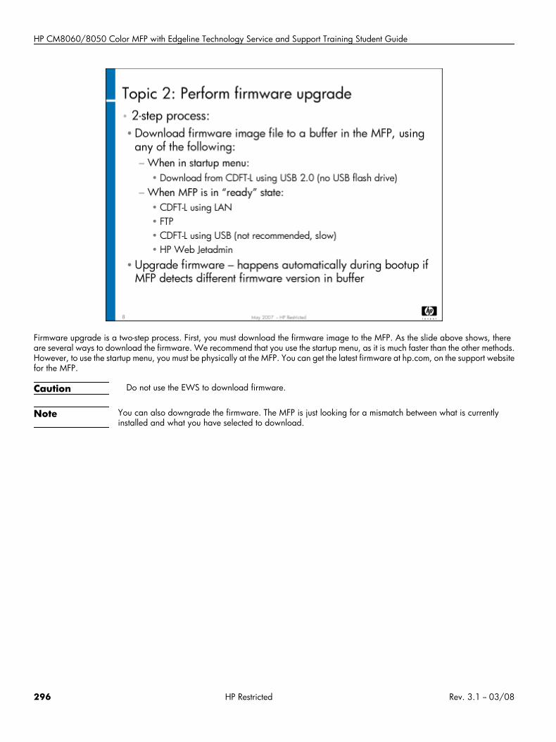
HP CM8060/8050 Color MFP with Edgeline Technology Service and Support Training Student Guide
Firmware upgrade is a two-step process. First, you must download the firmware image to the MFP. As the slide above shows, thereare several ways to download the firmware. We recommend that you use the startup menu, as it is much faster than the other methods.However, to use the startup menu, you must be physically at the MFP. You can get the latest firmware at hp.com, on the support websitefor the MFP.
Caution Do not use the EWS to download firmware.
Note You can also downgrade the firmware. The MFP is just looking for a mismatch between what is currentlyinstalled and what you have selected to download.
296 HP Restricted Rev. 3.1 -- 03/08
NVM and firmware
As the illustration above shows, you can download the firmware when the MFP is in ready state or during the bootup process. If youperform the download in ready state, using CDFT-L over LAN or FTP, it will take 2-1/2 to 3 minutes to download (the firmware isgreater than 800 MB). If you perform the download using the startup menu and a PC connected with a USB 2.0 cable, it will takeabout two minutes.
Once the firmware image is on the MFP, it will be upgraded automatically during a reboot. The MFP looks at the version number ofthe MFP's installed firmware. If it is the same version as what is currently on the MFP, it will not continue with the upgrade. If it is anewer version, it will automatically perform the upgrade. When the regular control panel image appears, the upgrade is done. Thiscould take approximately 25-30 minutes.
Caution Do not cut power to the MFP during the firmware upgrade. This can damage the Scanner Control PCA(A501) and it will not be recoverable. The window of vulnerability lasts 2-3 minutes. You will see a 30.0725error. You can still use the MFP in print mode.
Rev. 3.1 -- 03/08 HP Restricted 297
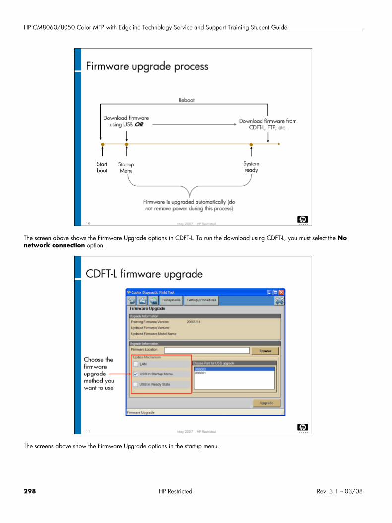
HP CM8060/8050 Color MFP with Edgeline Technology Service and Support Training Student Guide
The screen above shows the Firmware Upgrade options in CDFT-L. To run the download using CDFT-L, you must select the Nonetwork connection option.
The screens above show the Firmware Upgrade options in the startup menu.
298 HP Restricted Rev. 3.1 -- 03/08
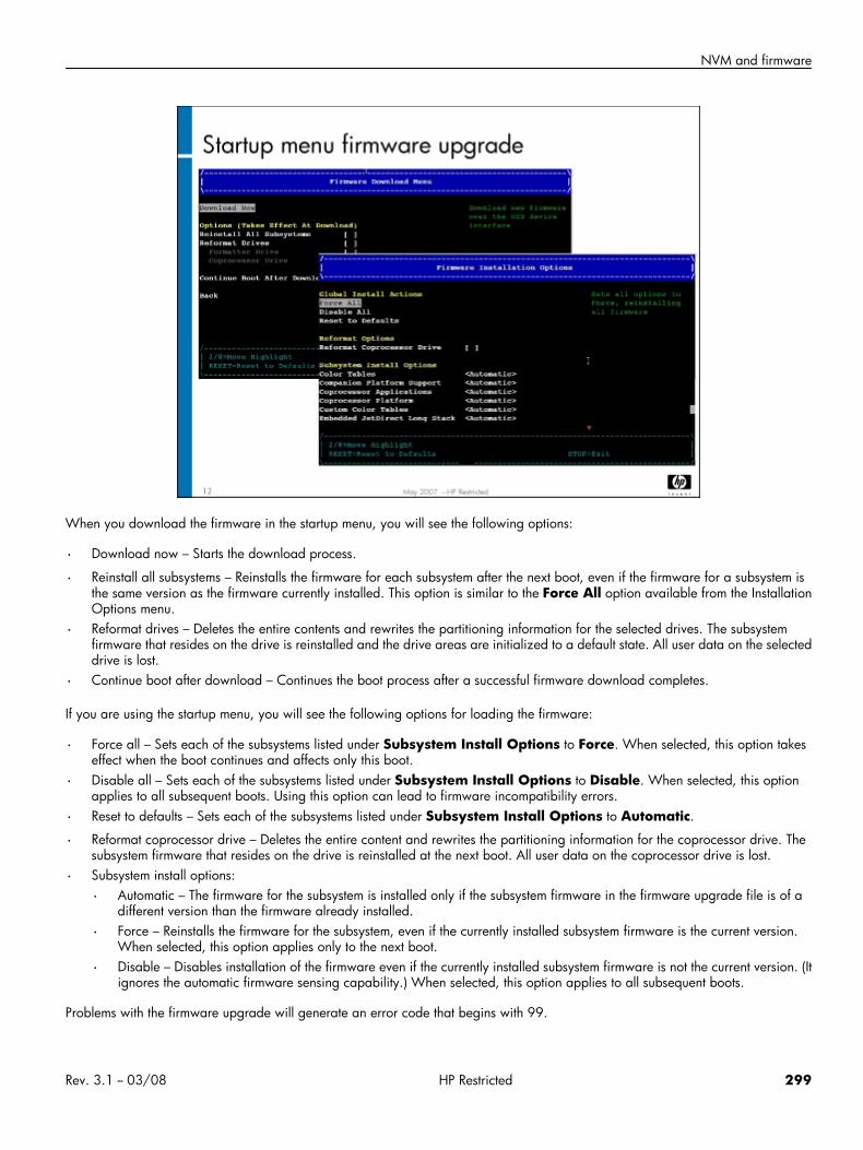
NVM and firmware
When you download the firmware in the startup menu, you will see the following options:
• Download now – Starts the download process.
• Reinstall all subsystems – Reinstalls the firmware for each subsystem after the next boot, even if the firmware for a subsystem isthe same version as the firmware currently installed. This option is similar to the Force All option available from the InstallationOptions menu.
• Reformat drives – Deletes the entire contents and rewrites the partitioning information for the selected drives. The subsystemfirmware that resides on the drive is reinstalled and the drive areas are initialized to a default state. All user data on the selecteddrive is lost.
• Continue boot after download – Continues the boot process after a successful firmware download completes.
If you are using the startup menu, you will see the following options for loading the firmware:
• Force all – Sets each of the subsystems listed under Subsystem Install Options to Force. When selected, this option takeseffect when the boot continues and affects only this boot.
• Disable all – Sets each of the subsystems listed under Subsystem Install Options to Disable. When selected, this optionapplies to all subsequent boots. Using this option can lead to firmware incompatibility errors.
• Reset to defaults – Sets each of the subsystems listed under Subsystem Install Options to Automatic.
• Reformat coprocessor drive – Deletes the entire content and rewrites the partitioning information for the coprocessor drive. Thesubsystem firmware that resides on the drive is reinstalled at the next boot. All user data on the coprocessor drive is lost.
• Subsystem install options:
• Automatic – The firmware for the subsystem is installed only if the subsystem firmware in the firmware upgrade file is of adifferent version than the firmware already installed.
• Force – Reinstalls the firmware for the subsystem, even if the currently installed subsystem firmware is the current version.When selected, this option applies only to the next boot.
• Disable – Disables installation of the firmware even if the currently installed subsystem firmware is not the current version. (Itignores the automatic firmware sensing capability.) When selected, this option applies to all subsequent boots.
Problems with the firmware upgrade will generate an error code that begins with 99.
Rev. 3.1 -- 03/08 HP Restricted 299
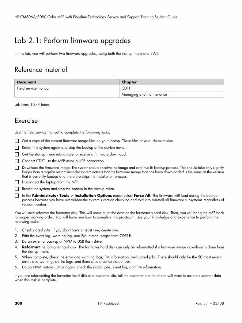
HP CM8060/8050 Color MFP with Edgeline Technology Service and Support Training Student Guide
Lab 2.1: Perform firmware upgradesIn this lab, you will perform two firmware upgrades, using both the startup menu and EWS.
Reference material
Document ChapterField service manual CDFT
Managing and maintenance
Lab time: 1-3/4 hours
ExerciseUse the field service manual to complete the following tasks.
Get a copy of the current firmware image files on your laptop. These files have a .rfu extension.
Restart the system again and stop the bootup at the startup menu.
Get the startup menu into a state to receive a firmware download.
Connect CDFT-L to the MFP using a USB connection.
Download the firmware image. The system should receive the image and continue its bootup process. This should take only slightlylonger than a regular restart since the system detects that the firmware image that has been downloaded is the same as the versionthat is currently loaded and therefore skips the installation process.Disconnect the laptop from the MFP.
Restart the system and stop the bootup in the startup menu.
In the Administrator Tools -> Installation Options menu, select Force All. The firmware will load during the bootupprocess because you have overridden the system’s version checking and told it to reinstall all firmware subsystems regardless ofversion number.
You will now reformat the formatter disk. This will erase all of the data on the formatter's hard disk. Then, you will bring the MFP backto proper working order. You will have one hour to complete this practicum. Use your knowledge and experience to perform thefollowing tasks:
1. Check stored jobs. If you don't have at least one, create one.2. Print the event log, warning log, and PM internal pages from CDFT-E.3. Do an external backup of NVM to USB flash drive.4. Reformat the formatter hard disk. The formatter hard disk can only be reformatted if a firmware image download is done from
the startup menu.5. When complete, check the error and warning logs, PM information, and stored jobs. There should only be the 50 most recent
errors and warnings on the logs, and there should be no stored jobs.6. Do an NVM restore. Once again, check the stored jobs, event log, and PM information.
If you are reformatting the formatter hard disk at a customer site, tell the customer that he or she will want to restore customer datawhen this task is complete.
300 HP Restricted Rev. 3.1 -- 03/08

Digital send
Digital send• Overview
• Topic 1: Security
• Topic 2: Digital send
Rev. 3.1 -- 03/08 HP Restricted 301
HP CM8060/8050 Color MFP with Edgeline Technology Service and Support Training Student Guide
Overview
This module is optional depending on the availability of an alternative Web-based training class in your region.
Topic 1: SecurityIn this topic, you will learn how to set up the MFP's security functions.
Topic objectivesAfter completing this topic, you should be able to:
• Describe the three levels of authentication
• Set up permission sets
• Use color access control
302 HP Restricted Rev. 3.1 -- 03/08
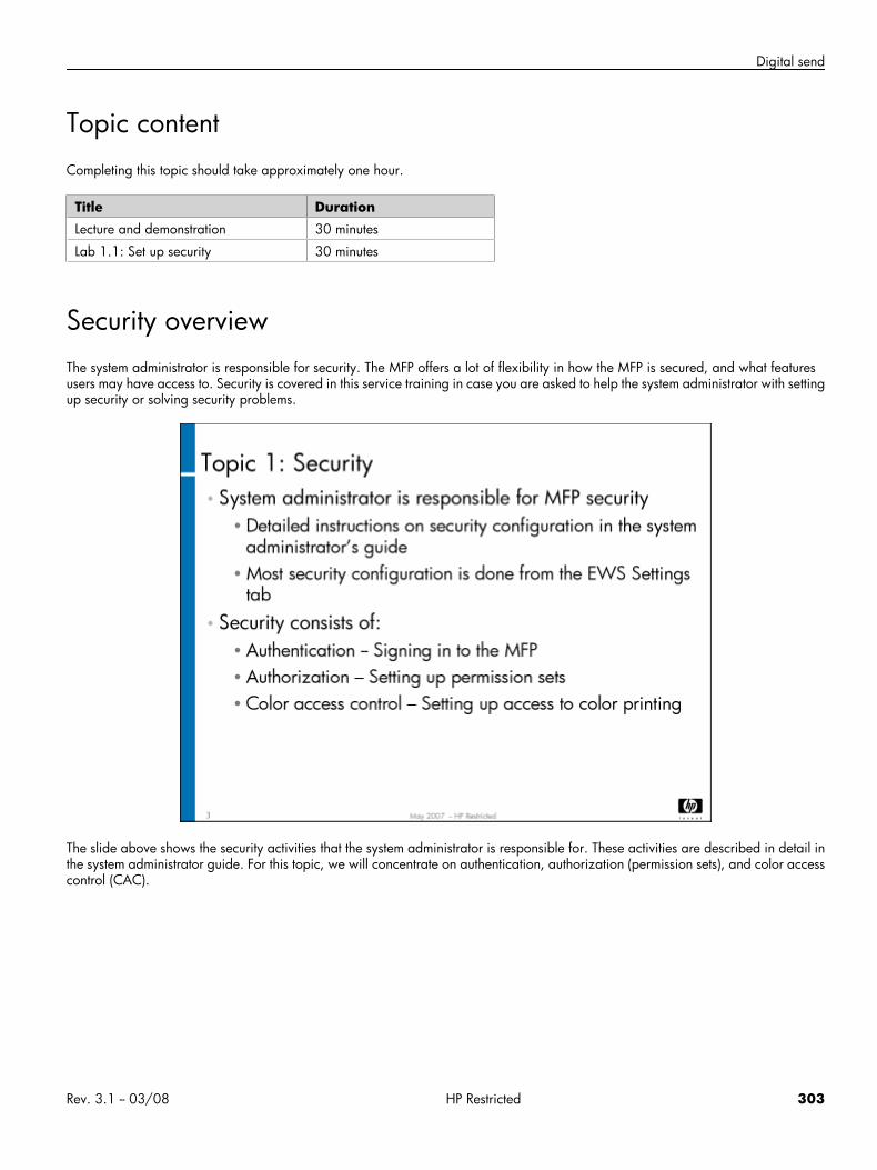
Digital send
Topic contentCompleting this topic should take approximately one hour.
Title DurationLecture and demonstration 30 minutes
Lab 1.1: Set up security 30 minutes
Security overviewThe system administrator is responsible for security. The MFP offers a lot of flexibility in how the MFP is secured, and what featuresusers may have access to. Security is covered in this service training in case you are asked to help the system administrator with settingup security or solving security problems.
The slide above shows the security activities that the system administrator is responsible for. These activities are described in detail inthe system administrator guide. For this topic, we will concentrate on authentication, authorization (permission sets), and color accesscontrol (CAC).
Rev. 3.1 -- 03/08 HP Restricted 303
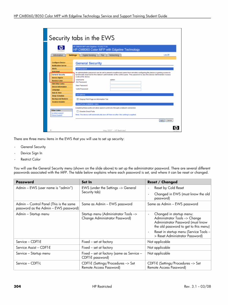
HP CM8060/8050 Color MFP with Edgeline Technology Service and Support Training Student Guide
There are three menu items in the EWS that you will use to set up security:
• General Security
• Device Sign In
• Restrict Color
You will use the General Security menu (shown on the slide above) to set up the administrator password. There are several differentpasswords associated with the MFP. The table below explains where each password is set, and where it can be reset or changed.
Password Set In Reset / ChangedAdmin – EWS (user name is “admin”) EWS (under the Settings –> General
Security tab)• Reset by Cold Reset
• Changed in EWS (must know the oldpassword)
Admin – Control Panel (This is the samepassword as the Admin – EWS password)
Same as Admin – EWS password Same as Admin – EWS password
Admin – Startup menu Startup menu (Administrator Tools –>Change Administrator Password)
• Changed in startup menu:Administrator Tools –> ChangeAdministrator Password (must knowthe old password to get to this menu)
• Reset in startup menu (Service Tools –> Reset Administrator Password)
Service – CDFT-E Fixed – set at factory Not applicable
Service Assist – CDFT-E Fixed – set at factory Not applicable
Service – Startup menu Fixed – set at factory (same as Service –CDFT-E password)
Not applicable
Service – CDFT-L CDFT-E (Settings/Procedures –> SetRemote Access Password)
CDFT-E (Settings/Procedures –> SetRemote Access Password)
304 HP Restricted Rev. 3.1 -- 03/08
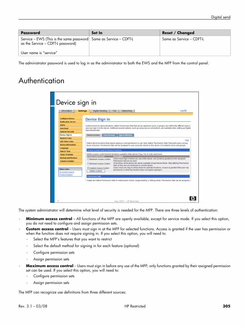
Digital send
Password Set In Reset / ChangedService – EWS (This is the same passwordas the Service – CDFT-L password)
User name is “service”
Same as Service – CDFT-L Same as Service – CDFT-L
The administrator password is used to log in as the administrator to both the EWS and the MFP from the control panel.
Authentication
The system administrator will determine what level of security is needed for the MFP. There are three levels of authentication:
• Minimum access control – All functions of the MFP are openly available, except for service mode. If you select this option,you do not need to configure and assign permission sets.
• Custom access control – Users must sign in at the MFP for selected functions. Access is granted if the user has permission orwhen the function does not require signing in. If you select this option, you will need to:
• Select the MFP's features that you want to restrict
• Select the default method for signing in for each feature (optional)
• Configure permission sets
• Assign permission sets
• Maximum access control – Users must sign in before any use of the MFP; only functions granted by their assigned permissionset can be used. If you select this option, you will need to:
• Configure permission sets
• Assign permission sets
The MFP can recognize use definitions from three different sources:
Rev. 3.1 -- 03/08 HP Restricted 305
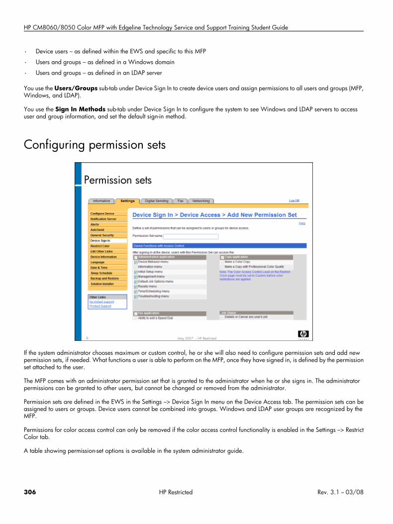
HP CM8060/8050 Color MFP with Edgeline Technology Service and Support Training Student Guide
• Device users – as defined within the EWS and specific to this MFP
• Users and groups – as defined in a Windows domain
• Users and groups – as defined in an LDAP server
You use the Users/Groups sub-tab under Device Sign In to create device users and assign permissions to all users and groups (MFP,Windows, and LDAP).
You use the Sign In Methods sub-tab under Device Sign In to configure the system to see Windows and LDAP servers to accessuser and group information, and set the default sign-in method.
Configuring permission sets
If the system administrator chooses maximum or custom control, he or she will also need to configure permission sets and add newpermission sets, if needed. What functions a user is able to perform on the MFP, once they have signed in, is defined by the permissionset attached to the user.
The MFP comes with an administrator permission set that is granted to the administrator when he or she signs in. The administratorpermissions can be granted to other users, but cannot be changed or removed from the administrator.
Permission sets are defined in the EWS in the Settings –> Device Sign In menu on the Device Access tab. The permission sets can beassigned to users or groups. Device users cannot be combined into groups. Windows and LDAP user groups are recognized by theMFP.
Permissions for color access control can only be removed if the color access control functionality is enabled in the Settings –> RestrictColor tab.
A table showing permission-set options is available in the system administrator guide.
306 HP Restricted Rev. 3.1 -- 03/08
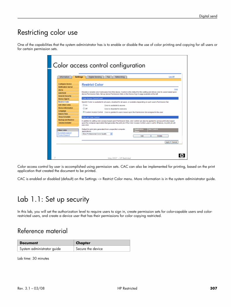
Digital send
Restricting color useOne of the capabilities that the system administrator has is to enable or disable the use of color printing and copying for all users orfor certain permission sets.
Color access control by user is accomplished using permission sets. CAC can also be implemented for printing, based on the printapplication that created the document to be printed.
CAC is enabled or disabled (default) on the Settings –> Restrict Color menu. More information is in the system administrator guide.
Lab 1.1: Set up securityIn this lab, you will set the authorization level to require users to sign in, create permission sets for color-capable users and color-restricted users, and create a device user that has their permissions for color copying restricted.
Reference material
Document ChapterSystem administrator guide Secure the device
Lab time: 30 minutes
Rev. 3.1 -- 03/08 HP Restricted 307
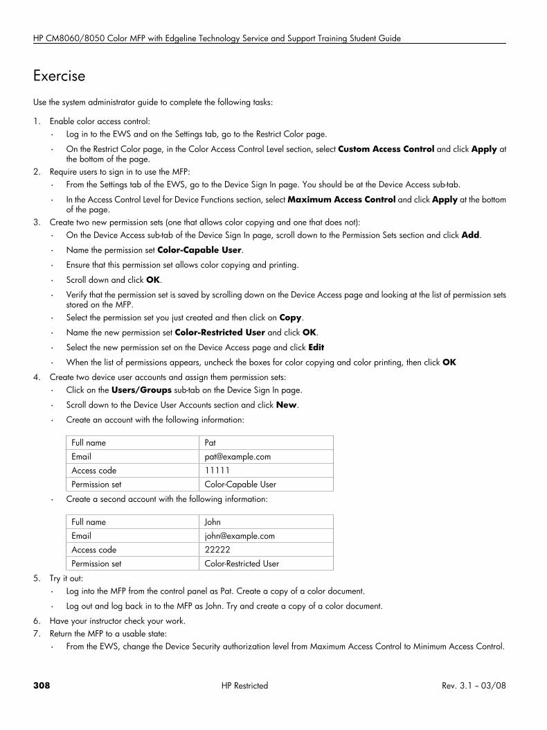
HP CM8060/8050 Color MFP with Edgeline Technology Service and Support Training Student Guide
ExerciseUse the system administrator guide to complete the following tasks:
1. Enable color access control:
• Log in to the EWS and on the Settings tab, go to the Restrict Color page.
• On the Restrict Color page, in the Color Access Control Level section, select Custom Access Control and click Apply atthe bottom of the page.
2. Require users to sign in to use the MFP:
• From the Settings tab of the EWS, go to the Device Sign In page. You should be at the Device Access sub-tab.
• In the Access Control Level for Device Functions section, select Maximum Access Control and click Apply at the bottomof the page.
3. Create two new permission sets (one that allows color copying and one that does not):
• On the Device Access sub-tab of the Device Sign In page, scroll down to the Permission Sets section and click Add.
• Name the permission set Color-Capable User.
• Ensure that this permission set allows color copying and printing.
• Scroll down and click OK.
• Verify that the permission set is saved by scrolling down on the Device Access page and looking at the list of permission setsstored on the MFP.
• Select the permission set you just created and then click on Copy.
• Name the new permission set Color-Restricted User and click OK.
• Select the new permission set on the Device Access page and click Edit
• When the list of permissions appears, uncheck the boxes for color copying and color printing, then click OK
4. Create two device user accounts and assign them permission sets:
• Click on the Users/Groups sub-tab on the Device Sign In page.
• Scroll down to the Device User Accounts section and click New.
• Create an account with the following information:
Full name Pat
Email [email protected]
Access code 11111
Permission set Color-Capable User
• Create a second account with the following information:
Full name John
Email [email protected]
Access code 22222
Permission set Color-Restricted User
5. Try it out:
• Log into the MFP from the control panel as Pat. Create a copy of a color document.
• Log out and log back in to the MFP as John. Try and create a copy of a color document.
6. Have your instructor check your work.7. Return the MFP to a usable state:
• From the EWS, change the Device Security authorization level from Maximum Access Control to Minimum Access Control.
308 HP Restricted Rev. 3.1 -- 03/08
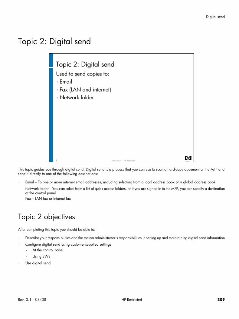
Digital send
Topic 2: Digital send
This topic guides you through digital send. Digital send is a process that you can use to scan a hard-copy document at the MFP andsend it directly to one of the following destinations:
• Email – To one or more internet email addresses, including selecting from a local address book or a global address book
• Network folder – You can select from a list of quick access folders, or if you are signed in to the MFP, you can specify a destinationat the control panel
• Fax – LAN fax or Internet fax
Topic 2 objectivesAfter completing this topic you should be able to:
• Describe your responsibilities and the system administrator's responsibilities in setting up and maintaining digital send information
• Configure digital send using customer-supplied settings
• At the control panel
• Using EWS
• Use digital send
Rev. 3.1 -- 03/08 HP Restricted 309
HP CM8060/8050 Color MFP with Edgeline Technology Service and Support Training Student Guide
Topic contentCompleting this topic should take approximately 4 hours.
Title DurationLecture: Digital send 30 minutes
Lab 2.1: Complete the digital sendworksheet
30 minutes
Lab 2.2: Configure digital send atcontrol panel
30 minutes
Lecture: Configuring digital send withEWS
30 minutes
Lab 2.3: Configure digital send usingEWS
60 minutes
Lecture: Using digital send 15 minutes
Lab 2.4: Use digital send 30 minutes
Network termsThere are certain network terms you should be familiar with before you begin working with digital send. They are:
• Active Directory – An implementation of LDAP directory services by Microsoft for use in Windows environments.
• Internet fax – Software modem emulator (third-party solution) that uses Fax-over-IP technology to transmit the signal over an IPnetwork.
• IP address (Internet Protocol address) – A unique address that devices use in order to identify and communicate with each otheron a computer network.
• LAN fax – Mechanism to set up a Windows PC to act as a fax server, using a third-party solution.
• LDAP (Lightweight Directory Access Protocol) – A networking protocol for querying and modifying directory servicesrunning over TCP/IP. It is a tree of entries, each of which consists of a set of named attributes and values. An LDAP directory oftenuses Domain Name System (DNS) names for structuring the levels of the hierarchy.
• SMTP (Simple Mail Transfer Protocol) – The de facto standard for email transmissions across the Internet.
310 HP Restricted Rev. 3.1 -- 03/08
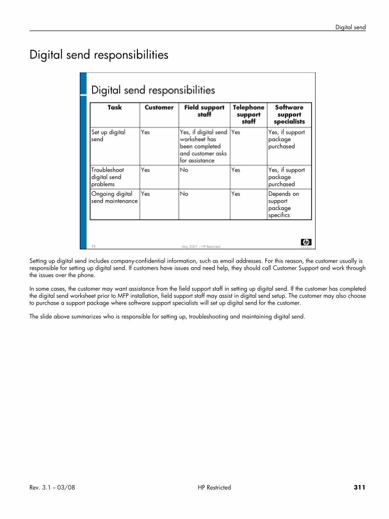
Digital send
Digital send responsibilities
Setting up digital send includes company-confidential information, such as email addresses. For this reason, the customer usually isresponsible for setting up digital send. If customers have issues and need help, they should call Customer Support and work throughthe issues over the phone.
In some cases, the customer may want assistance from the field support staff in setting up digital send. If the customer has completedthe digital send worksheet prior to MFP installation, field support staff may assist in digital send setup. The customer may also chooseto purchase a support package where software support specialists will set up digital send for the customer.
The slide above summarizes who is responsible for setting up, troubleshooting and maintaining digital send.
Rev. 3.1 -- 03/08 HP Restricted 311
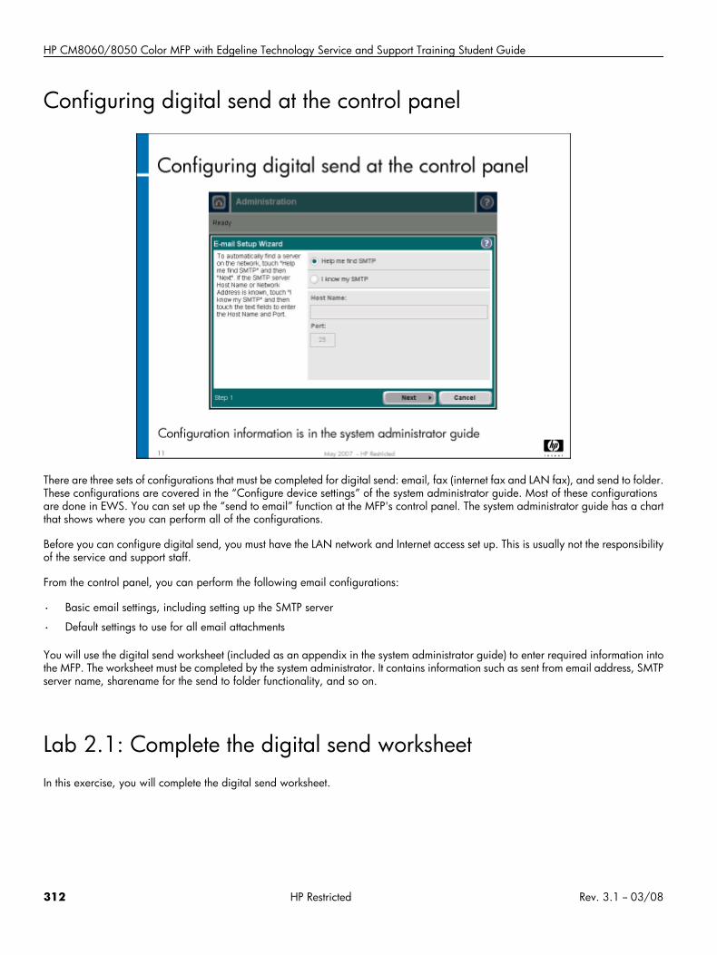
HP CM8060/8050 Color MFP with Edgeline Technology Service and Support Training Student Guide
Configuring digital send at the control panel
There are three sets of configurations that must be completed for digital send: email, fax (internet fax and LAN fax), and send to folder.These configurations are covered in the “Configure device settings” of the system administrator guide. Most of these configurationsare done in EWS. You can set up the “send to email” function at the MFP's control panel. The system administrator guide has a chartthat shows where you can perform all of the configurations.
Before you can configure digital send, you must have the LAN network and Internet access set up. This is usually not the responsibilityof the service and support staff.
From the control panel, you can perform the following email configurations:
• Basic email settings, including setting up the SMTP server
• Default settings to use for all email attachments
You will use the digital send worksheet (included as an appendix in the system administrator guide) to enter required information intothe MFP. The worksheet must be completed by the system administrator. It contains information such as sent from email address, SMTPserver name, sharename for the send to folder functionality, and so on.
Lab 2.1: Complete the digital send worksheetIn this exercise, you will complete the digital send worksheet.
312 HP Restricted Rev. 3.1 -- 03/08
Digital send
Reference material
Document ChapterSystem administrator guide Configure device settings
Secure the device
Lab time: 30 minutes
DemonstrationYour instructor will now show you where to find the information to complete the digital send worksheet. While this is normally doneby the customer (system administrator), you should be familiar with the worksheet and where to get the information to complete it.
As your instructor finds the various items, write them down on your worksheet. You will use the worksheet in the next lab to configurethe MFP for digital send.
Lab 2.2: Configure digital send at control panelIn this exercise, you will configure digital send at the MFP's control panel.
Reference material
Document ChapterSystem administrator guide Configure device settings
Lab time: 30 minutes
ExerciseYou will now configure the send to email function at the control panel of the MFP. Follow the instructions in the system administratorguide to run the email setup wizard. Use the digital send worksheet that you completed in the last lab to enter the appropriateinformation.
Rev. 3.1 -- 03/08 HP Restricted 313
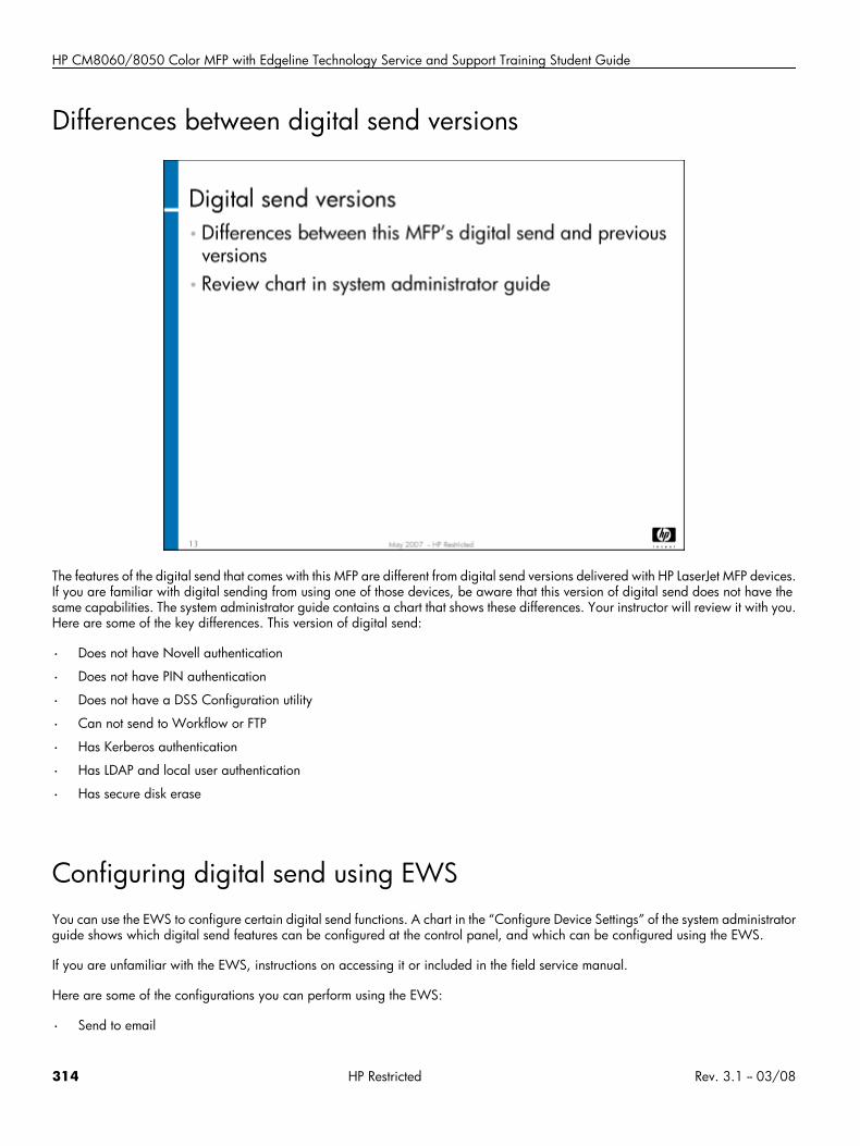
HP CM8060/8050 Color MFP with Edgeline Technology Service and Support Training Student Guide
Differences between digital send versions
The features of the digital send that comes with this MFP are different from digital send versions delivered with HP LaserJet MFP devices.If you are familiar with digital sending from using one of those devices, be aware that this version of digital send does not have thesame capabilities. The system administrator guide contains a chart that shows these differences. Your instructor will review it with you.Here are some of the key differences. This version of digital send:
• Does not have Novell authentication
• Does not have PIN authentication
• Does not have a DSS Configuration utility
• Can not send to Workflow or FTP
• Has Kerberos authentication
• Has LDAP and local user authentication
• Has secure disk erase
Configuring digital send using EWSYou can use the EWS to configure certain digital send functions. A chart in the “Configure Device Settings” of the system administratorguide shows which digital send features can be configured at the control panel, and which can be configured using the EWS.
If you are unfamiliar with the EWS, instructions on accessing it or included in the field service manual.
Here are some of the configurations you can perform using the EWS:
• Send to email
314 HP Restricted Rev. 3.1 -- 03/08
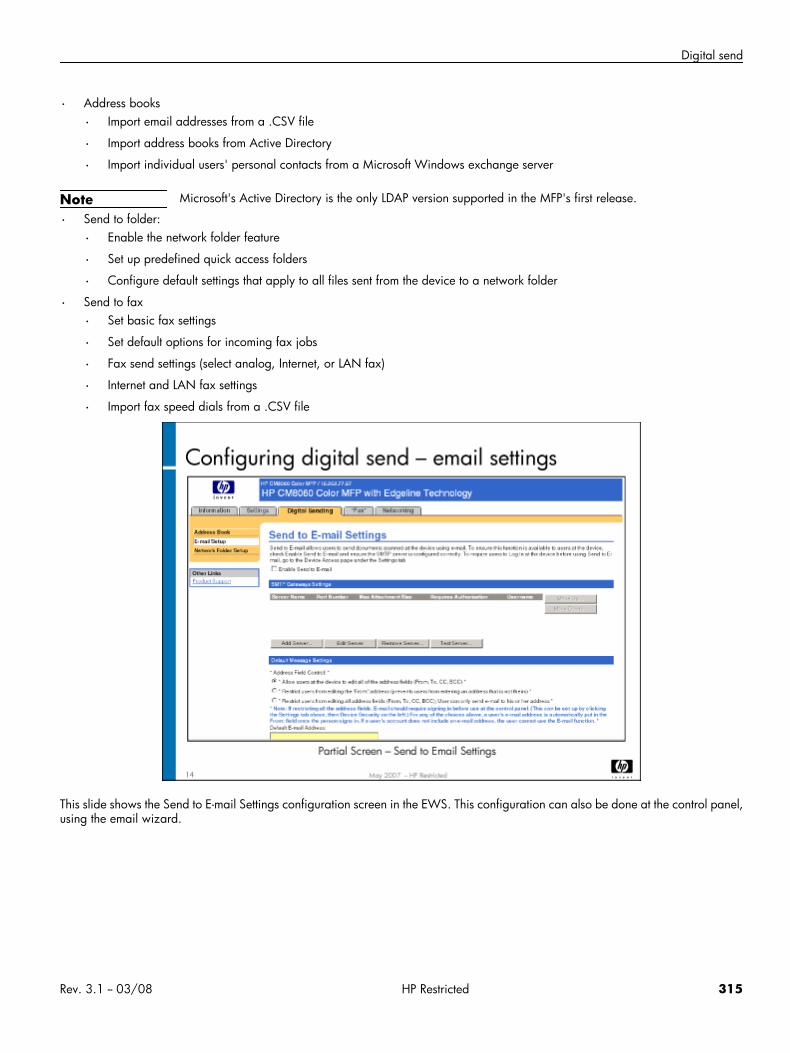
Digital send
• Address books
• Import email addresses from a .CSV file
• Import address books from Active Directory
• Import individual users' personal contacts from a Microsoft Windows exchange server
Note Microsoft's Active Directory is the only LDAP version supported in the MFP's first release.
• Send to folder:
• Enable the network folder feature
• Set up predefined quick access folders
• Configure default settings that apply to all files sent from the device to a network folder
• Send to fax
• Set basic fax settings
• Set default options for incoming fax jobs
• Fax send settings (select analog, Internet, or LAN fax)
• Internet and LAN fax settings
• Import fax speed dials from a .CSV file
This slide shows the Send to E-mail Settings configuration screen in the EWS. This configuration can also be done at the control panel,using the email wizard.
Rev. 3.1 -- 03/08 HP Restricted 315
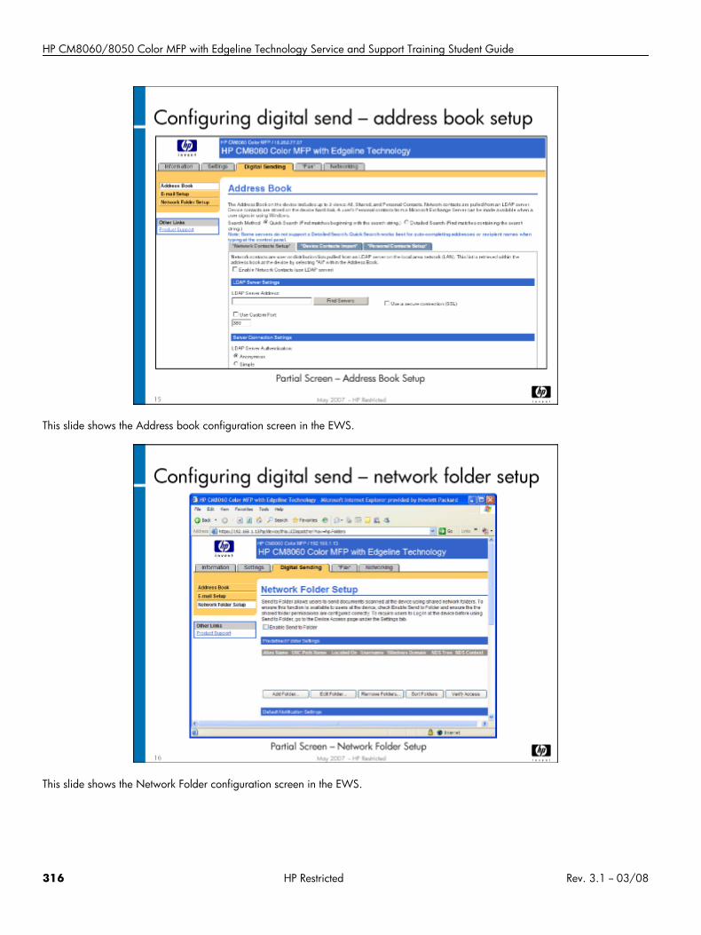
HP CM8060/8050 Color MFP with Edgeline Technology Service and Support Training Student Guide
This slide shows the Address book configuration screen in the EWS.
This slide shows the Network Folder configuration screen in the EWS.
316 HP Restricted Rev. 3.1 -- 03/08
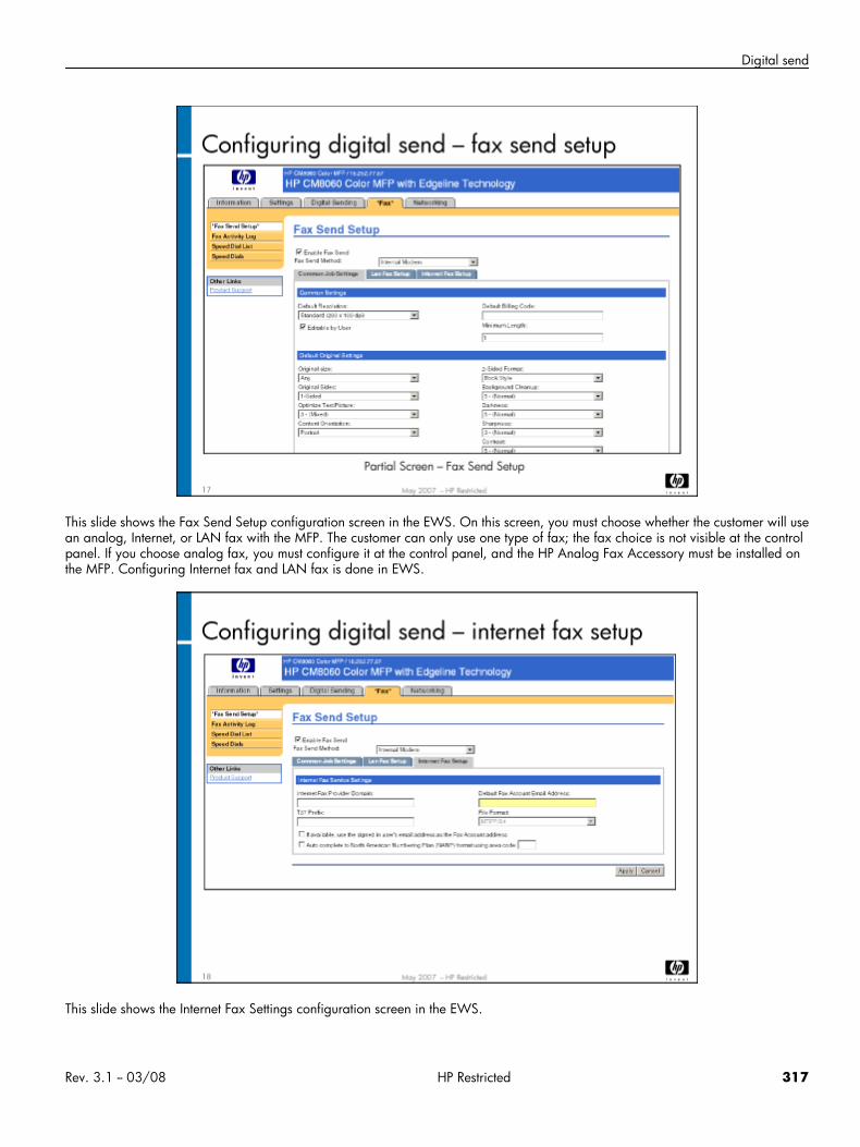
Digital send
This slide shows the Fax Send Setup configuration screen in the EWS. On this screen, you must choose whether the customer will usean analog, Internet, or LAN fax with the MFP. The customer can only use one type of fax; the fax choice is not visible at the controlpanel. If you choose analog fax, you must configure it at the control panel, and the HP Analog Fax Accessory must be installed onthe MFP. Configuring Internet fax and LAN fax is done in EWS.
This slide shows the Internet Fax Settings configuration screen in the EWS.
Rev. 3.1 -- 03/08 HP Restricted 317
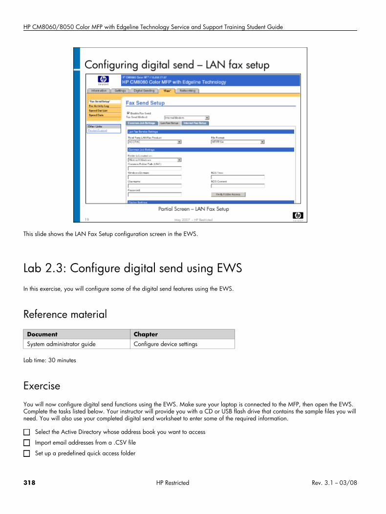
HP CM8060/8050 Color MFP with Edgeline Technology Service and Support Training Student Guide
This slide shows the LAN Fax Setup configuration screen in the EWS.
Lab 2.3: Configure digital send using EWSIn this exercise, you will configure some of the digital send features using the EWS.
Reference material
Document ChapterSystem administrator guide Configure device settings
Lab time: 30 minutes
ExerciseYou will now configure digital send functions using the EWS. Make sure your laptop is connected to the MFP, then open the EWS.Complete the tasks listed below. Your instructor will provide you with a CD or USB flash drive that contains the sample files you willneed. You will also use your completed digital send worksheet to enter some of the required information.
Select the Active Directory whose address book you want to access
Import email addresses from a .CSV file
Set up a predefined quick access folder
318 HP Restricted Rev. 3.1 -- 03/08
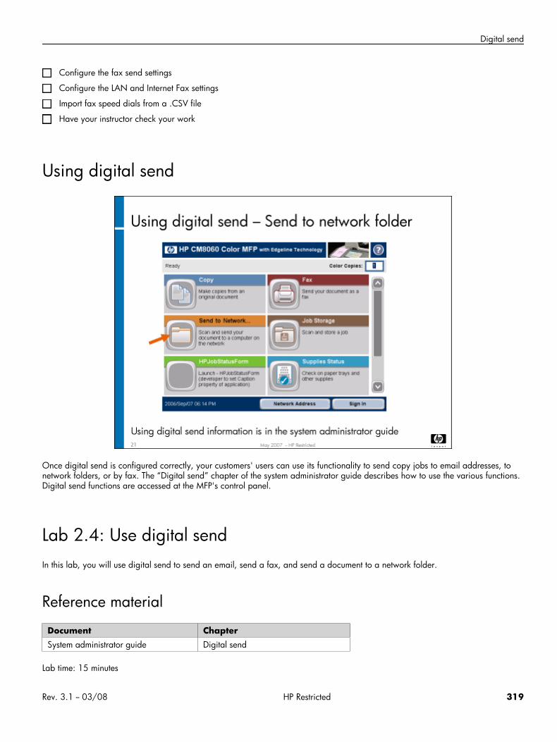
Digital send
Configure the fax send settings
Configure the LAN and Internet Fax settings
Import fax speed dials from a .CSV file
Have your instructor check your work
Using digital send
Once digital send is configured correctly, your customers' users can use its functionality to send copy jobs to email addresses, tonetwork folders, or by fax. The “Digital send” chapter of the system administrator guide describes how to use the various functions.Digital send functions are accessed at the MFP's control panel.
Lab 2.4: Use digital sendIn this lab, you will use digital send to send an email, send a fax, and send a document to a network folder.
Reference material
Document ChapterSystem administrator guide Digital send
Lab time: 15 minutes
Rev. 3.1 -- 03/08 HP Restricted 319

HP CM8060/8050 Color MFP with Edgeline Technology Service and Support Training Student Guide
ExerciseUse the instructions in the system administrator guide to use digital send to perform the following tasks:
Send a document by email to yourself by typing in your email address
Send a document by email to someone by selecting an email address from the active directory
Fax a document (if the MFP has the HP Analog Fax Accessory installed)
Fax a document using the LAN fax option
Send a document to a network folder – choose one of the existing quick access folders
Have your instructor check your work
320 HP Restricted Rev. 3.1 -- 03/08

Final written test
Final written test
Rev. 3.1 -- 03/08 HP Restricted 321

HP CM8060/8050 Color MFP with Edgeline Technology Service and Support Training Student Guide
InstructionsTo complete your service qualification, you must take the final written test. The test results will be used as part of the total score youneed to pass the course.
322 HP Restricted Rev. 3.1 -- 03/08
Acronym glossary
Acronym glossaryAPA
Automatic Pen Alignment: A calibration that is done when a new pen is inserted, and then the MFP is first installed.
APS
Air Pressure System: A component of the IDS; it provides air pressure to force the ink from the cartridge and into the ink hoses.
BA
Bonding Agent.
CDFT
Copier Diagnostics Field Tool: A tool to help you maintain the MFP. It includes access to calibrations, error and warning logs, onlinefield service manual, tool pages, and other information.
CDFT-E
Copier Diagnostics Field Tool – Embedded: A version of CDFT that runs on the MFP from the control panel.
CDFT-L
Copier Diagnostics Field Tool – Laptop: A version of CDFT that runs on a laptop connected to the MFP with a LAN cable.
CM
Cyan and Magenta inks.
EWS
Embedded Web Server: A software tool that allows you to configure and get data about an MFP.
IDO RM
Input/Duplex/Output Removable: The part of the IDO that opens to access jams.
IDO PI
Input/Duplex/Output Print Interface: The part of the IDO that is fixed in the MFP.
IDO
Input/Duplex/Output: The part of the media path that feeds media onto the drum, removes media from the drum, and prepares mediafor duplexing.
IDS
Ink Delivery System: The subsystem that provides ink and bonding agent to the pens.
ISS
Ink Supply Station: A component of the ink delivery system. It holds the ink cartridges.
KY
Rev. 3.1 -- 03/08 HP Restricted 323

HP CM8060/8050 Color MFP with Edgeline Technology Service and Support Training Student Guide
Black and Yellow inks.
NVM
Non-volatile memory: Persistent data that is not lost when the MFP power cycles.
NVRAM
Non-volatile random access memory: A subset of NVM that is stored on the Formatter Main PCA (A26).
PPS
Pen-to-Paper Spacing.
PSM
Protected Service Mode: A mode of CDFT-E that provides limited functionality. Used to troubleshoot problems when the MFP cannotcome up to “ready” state.
PSU
Power Supply Unit.
TOF sensor
Top-of-Form sensor: A sensor on the MFP with many functions, including the location of the top of form and end of form on a sheet ofmedia.
WFM
Workflow Management System: A software tool that HP uses to capture service information.
XDM
XML Device Model: A data file containing MFP information
XML
Extensible Markup Language: A general-purpose markup language that supports a wide variety of applications.
324 HP Restricted Rev. 3.1 -- 03/08
Copyright © 2022 FDOKUMEN