HP 85620A Mass Memory Module Installation, Operation ...
297
About this Manual We’ve added this manual to the Agilent website in an effort to help you support your product. This manual is the best copy we could find; it may be incomplete or contain dated information. If we find a more recent copy in the future, we will add it to the Agilent website. Support for Your Product Agilent no longer sells or supports this product. Our service centers may be able to perform calibration if no repair parts are needed, but no other support from Agilent is available. You will find any other available product information on the Agilent Test & Measurement website, www.tm.agilent.com . HP References in this Manual This manual may contain references to HP or Hewlett-Packard. Please note that Hewlett-Packard's former test and measurement, semiconductor products and chemical analysis businesses are now part of Agilent Technologies. We have made no changes to this manual copy. In other documentation, to reduce potential confusion, the only change to product numbers and names has been in the company name prefix: where a product number/name was HP XXXX the current name/number is now Agilent XXXX. For example, model number HP8648A is now model number Agilent 8648A.
-
Upload
khangminh22 -
Category
Documents
-
view
3 -
download
0
Transcript of HP 85620A Mass Memory Module Installation, Operation ...
About this Manual We’ve added this manual to the Agilent website in an effort to help you support your product. This manual is the best copy we could find; it may be incomplete or contain dated information. If we find a more recent copy in the future, we will add it to the Agilent website. Support for Your Product Agilent no longer sells or supports this product. Our service centers may be able to perform calibration if no repair parts are needed, but no other support from Agilent is available. You will find any other available product information on the Agilent Test & Measurement website, www.tm.agilent.com. HP References in this Manual This manual may contain references to HP or Hewlett-Packard. Please note that Hewlett-Packard's former test and measurement, semiconductor products and chemical analysis businesses are now part of Agilent Technologies. We have made no changes to this manual copy. In other documentation, to reduce potential confusion, the only change to product numbers and names has been in the company name prefix: where a product number/name was HP XXXX the current name/number is now Agilent XXXX. For example, model number HP8648A is now model number Agilent 8648A.

Printed in USA March 2000
NoticeHewlett-Packard to Agilent Technologies TransitionThis documentation supports a product that previously shipped under the Hewlett-Packard company brand name. The brand name has now been changed to AgilentTechnologies. The two products are functionally identical, only our name has changed. Thedocument still includes references to Hewlett-Packard products, some of which have beentransitioned to Agilent Technologies.

Installation, Operation,Programming, and ServiceGuide
HP 85620A Mass MemoryModule
@ia HEWLETTPACKARD
HPhrtNo. 85620-90041 Supersedes 85620-90040PriitedinUSA October1996

QCopyright Hewlett-Packard Company 1992, 1996All Rights Reserved. Reproduction, adaptation, or translation withoutprior written permission is prohibited, except as allowed under thecopyright laws.1400 Fountaingrove Parkway, Santa Rosa, CA 95403-1799, USA

Certification Hewlett-Packard Company certifies that this product met itspublished specifications at the time of shipment from the factory.Hewlett-Packard further certifies that its calibration measurementsare traceable to the United States National Institute of Standards andTechnology, to the extent allowed by the Institute’s calibration facility,and to the calibration facilities of other International StandardsOrganization members.
Warranty This Hewlett-Packard instrument product is warranted against defectsin material and workmanship for a period of one year from date ofshipment. During the warranty period, Hewlett-Packard Companywill, at its option, either repair or replace products which prove to bedefective.
For warranty service or repair, this product must be returned to aservice facility designated by Hewlett-Packard. Buyer shall prepayshipping charges to Hewlett-Packard and Hewlett-Packard shall payshipping charges to return the product to Buyer. However, Buyer shallpay all shipping charges, duties, and taxes for products returned toHewlett-Packard from another country.
Hewlett-Packard warrants that its software and firmware designatedby Hewlett-Packard for use with an instrument will executeits programming instructions when properly installed on thatinstrument. Hewlett-Packard does not warrant that the operationof the instrument, or software, or firmware will be uninterrupted orerror-free.
LIMITATION OF WARRANTY
The foregoing warranty shall not apply to defects resulting fromimproper or inadequate maintenance by Buyer, Buyer-suppliedsoftware or interfacing, unauthorized modification or misuse,operation outside of the environmental specifications for theproduct, or improper site preparation or maintenance.
NO OTHER WARRANTY IS EXPRESSED OR IMPLIED.HEWLETT-PACKARD SPECIFICALLY DISCLAIMS THE IMPLIEDWARRANTIES OF MERCHANTABILITY AND FITNESS FOR APARTICULAR PURPOSE.
EXCLUSIVE REMEDIES
THE REMEDIES PROVIDED HEREIN ARE BUYER’S SOLE ANDEXCLUSIVE REMEDIES. HEWLETT-PACKARD SHALL NOT BELIABLE FOR ANY DIRECT, INDIRECT, SPECIAL, INCIDENTAL, ORCONSEQUENTIAL DAMAGES, WHETHER BASED ON CONTRACT,TORT, OR ANY OTHER LEGAL THEORY
. . .III

Assistance Product maintenance agreements and other custom assistanceagreements are available for Hewlett-Rzckard products.
Irbr an9 assistance, contact POW nearest Hewlett-Rzckard Sales andService 0mt-z

Safety Notes The following safety notes are used throughout this manual.Familiarize yourself with each of the notes and its meaning beforeoperating this instrument.
Glution
Warning
The caution sign denotes a hazard. It calls attention to a procedurewhich, if not correctly performed or adhered to, could result indamage to or destruction of the instrument. Do not proceed beyond acaution sign until the indicated conditions are fully understood andmet.
The warning sign denotes a hazard. It calls attention to aprocedure which, if not correctly performed or adhered to, couldresult in injury or loss of life. Do not proceed beyond a warningsign until the indicated conditions are fully understood and met.
General Safety Considerations
Warning Before this instrument is switched on, make sure it has beenproperly grounded through the protective conductor of the acpower cable to a socket outlet provided with protective earthcontact.
Warning
Caution
Any interruption of the protective (grounding) conductor, insideor outside the instrument, or disconnection of the protectiveearth terminal can result in personal injury.
There are many points in the instrument which can, if contacted,cause personal injury. Be extremely careful.
Any adjustments or service procedures that require operationof the instrument with protective covers removed should beperformed only by trained service personnel.
Before this instruct is switched on, make sure its primary powercircuitry has been adapted to the voltage of the ac power source.
Failure to set the ac power input to the correct voltage could causedamage to the instrument when the ac power cable is plugged in.

Contents
1. InstallationIntroduction . . . . . . . . . . . . . . . . . . . . .
HP 85620A Mass Memory Module Description . . . .Modules Covered by This Manual . . . . . . . . . . .
Serial Numbers . . . . . . . . . . . . . . . . . . .Firmware Revisions . . . . . . . . . . . . . . . . .
Specifications and Characteristics . . . . . . . . . . .Auxiliary Interface Connector . . . . . . . . . . . .Memory Card Specifications and Characteristics . . .
Preparation for Use . . . . . . . . . . . . . . . . . .Initial Inspection . . . . . . . . . . . . . . . . . .Installing the Module . . . . . . . . . . . . . . . .Installing Memory Cards . . . . . . . . . . . . . .
Changing the Memory Card Battery . . . . . . . .Memory Card Demonstration Programs . . . . . . . . .Module Operation . . . . . . . . . . . . . . . . . .
Introduction . . . . . . . . . . . . . . . . . . . .Menu Structure . . . . . . . . . . . . . . . . . . .
Main Menu Softkey Descriptions . . . . . . . . . .Packaging . . . . . . . . . . . . . . . . . . . . . .
Origind Packaging . . . . . . . . . . . . . . . . .Other Packaging . . . . . . . . . . . . . . . . . .
Error Messages . . . . . . . . . . . . . . . . . . . .Error Codes . . . . . . . . . . . . . . . . . . . .
2. OperationIntroduction . . . . . . . . . . . . . . . . . . . . .Module Features . . . . . . . . . . . . . . . . . . .Using the Mass Memory Module . . . . . . . . . . . .
Main Menu Keys Descriptions . . . . . . . . . . . .USER KEYS Menu . . . . . . . . . . . . . . . . . .TRACE SAVERCL Menu . . . . . . . . . . . . . . .LIMIT LINE Menu . . . . . . . . . . . . . . . . . .AUTOEXEC Menu . . . . . . . . . . . . . . . . . .KEYDEF Menu . . . . . . . . . . . . . . . . . . . .UTILITY Menu . . . . . . . . . . . . . . . . . . . .
l-ll-ll-3l-3l-3l-5l-61-8l-9l-9l-9
l-11l-111-131-141-141-141-151-161-161-171-181-18
2-l2-22-32-32-42-5
2-132-222-262-28

3. Softkey MenuIntroduction . . . . . . . . . . . . . . . . . . . . . 3-l
4. ProgrammingIntroduction . . . . . . . . . . . . . . . . . . . . . 4-lGetting Started with DLPs . . . . . . . . . . . . . . 4-l
WhatIsaDLP?. . . . . . . . . . . . . . . . . . . 4-lDLP Examples . . . . . . . . . . . . . . . . . . 4-2Equipment Setup . . . . . . . . . . . . . . . . . 4-2
Programming Front-Panel Functions . . . . . . . 4-3Programming User-Defined Functions . . . . . . 4-4Determining Available User Memory . . . . . . . 4-6User-Defined Variable and Trace Declaration . . . 4-7Displaying Variable and Trace Values . . . . . . . 4-8Using EP to Modify User-Defined Variables
(firmware revisions 910116 and later) . . . . . 4-9Erasing User-Defined Memory . . . . . . . . . . 4-10Storing DLPs on RAM Cards and in the Module . . 4-11Programming Hints . . . . . . . . . . . . . . . 4-12Command Syntax Diagrams . . . . . . . . . . . 4-17ABORT . . . . . . . . . . . . . . . . . . . . 4-28ABS . . . . . . . . . . . . . . . . . . . . . . 4-30ACTVFUNC . . . . . . . . . . . . . . . . . . 4-31ADD . . . . . . . . . . . . . . . . . . . . . . 4-33ARRAYDEF . . . . . . . . . . . . . . . . . . 4-35AUTOEXEC . . . . . . . . . . . . . . . . . . 4-37AUTOFUNC . . . . . . . . . . . . . . . . . . 4-38AUTOSAVE . . . . . . . . . . . . . . . . . . . 4-40A V G . . . . . . . . . . . . . . . . . . . . . . 4-41CARDLOAD . . . . . . . . . . . . . . . . . . 4-43CARDSTORE . . . . . . . . . . . . . . . . . . 4-45CATALOG . . . . . . . . . . . . . . . . . . . 4-47CLRDSP . . . . . . . . . . . . . . . . . . . . 4-53CLRSCHED . . . . . . . . . . . . . . . . . . . 4-54CNTLA . . . . . . . . . . . . . . . . . . . . 4-55CNTLB . . . . . . . . . . . . . . . . . . . . . 4-56CNTLC . . . . . . . . . . . . . . . . . . . . . 4-57CNTLD . . . . . . . . . . . . . . . . . . . . 4-58CNTLI . . . . . . . . . . . . . . . . . . . . . 4-59CTRLHPIB . . . . . . . . . . . . . . . . . . . 4-60DATEMODE . . . . . . . . . . . . . . . . . . 4-62DISPOSE . . . . . . . . . . . . . . . . . . . . 4-63DIV . . . . . . . . . . . . . . . . . . . . . . 4-66DSPLY . . . . . . . . . . . . . . . . . . . . . 4-68EDITDONE . . . . . . . . . . . . . . . . . . . 4-70EDITLIML . . . . . . . . . . . . . . . . . . . 4-72EME N T E R ’ : : : : : : : : : : : : : : : : : : : :
4-744-75
EXP . . . . . . . . . . . . . . . . . . . . . . 4-76FUNCDEF . . . . . . . . . . . . . . . . . . . 4-78IF/THEN/ELSE/ENDIF . . . . . . . . . . . . . 4-80INT . . . . . . . . . . . . . . . . . . . . . . 4-82KEYCLR . . . . . . . . . . . . . . . . . . . . 4-84KEYDEF . . . . . . . . . . . . . . . . . . . . 4-85LCLVAR . . . . . . . . . . . . . . . . . . . . 4-87
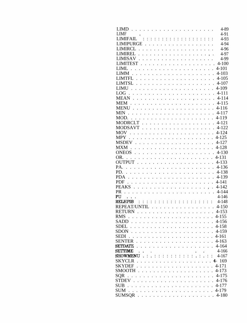
LIMD . . . . . . . . . . . . . . . . . . . . . 4-89LIMF 4-91LIMIFAIL ’ : : : : : : : : : : : : : : : : : : : 4-93LIMIPURGE . . . . . . . . . . . . . . . . . . 4-94LIMIRCL . . . . . . . . . . . . . . . . . . . . 4-96LIMIREL . . . . . . . . . . . . . . . . . . , . 4-97LIMISAV . . . . . . . . . . . . . . . . . . . . 4-99LIMITEST . . . . . . . . . . . . . . . . . . . 4-100LIML . . . . . . . . . . . . . . . . . . . . . 4-101LIMM . . . . . . . . . . . . . . . . . . . . . 4-103LIMTFL . . . . . . . . . . . . . . . . . . . . 4-105LIMTSL . . . . . . . . . . . . . . . . . . . . 4-107LIMU . . . . . . . . . . . . . . . . . . . . . 4-109LOG . . . . . . . . . . . . . . . . . . . . . . 4-111MEAN . . . . . . . . . . . . . . . , . . . . . 4-114MEM . . . . . . . . . . . . . . . . . . . . . 4-115MENU . . . . . . . . . . . . . . . . . . . . . 4-116MIN . . . . . . . . . . . . . . . . . . . . . . 4-117MOD. . . . . . . . . . . . . . . . . . . . . . 4-119MODRCLT . . . . . . . . . . . . . . . . . . . 4-121MODSAVT . . . . . . . . . . . . . . . . . . . 4-122MOV . . . . . . . . . . . . . . . . . . . . . . 4-124MPY . . . . . . . . . . . . . . . . . . . . . . 4-125MSDEV . . . . . . . . . . . . . . . . . . . . 4-127MXM . . . . . . . . . . . . . . . . . . . . . 4-128ONEOS . . . . . . . . . . . . . . . . . . . . 4-130OR. . . . . . . . . . . . . . . . . . . . . . . 4-131OUTPUT . . . . . . . . . . . . . . . . . . . . 4-133PA. . . . . . . . . . . . . . . . . . . . . . . 4-136PD. . . . . . . . . . . . . . . . . . . . . . . 4-138PDA . . . . . . . . . . . . . . . . . . . . . . 4-139PDF . . . . . . . . . . . . . . . . . . . . . . 4-141PEAKS . . . . . . . . . . . . . . . . . . , . 4-142PR . . . . . . . . . . . . . . . . . . . . . . . 4-144PU 4-146RELHi’Ii3’ : : : : : : : : : : : : : : : : : : : 4-148REPEAT/UNTIL . . . . . . . . . . . . . . . . 4-150RETURN . . . . . . . . . . . . . . . . . . . . 4-153RMS . . . . . . . . . . . . . . . . . . . . . . 4-155SADD . . . . . . . . . . . . . . . . . . . . . 4-156SDEL . . . . . . . . . . . . . . . . . . . . . 4-158SDON . . . . . . . . . . . . . . . . . . . . . 4-159SEDI . . . . . . . . . . . . . . . . . . . . . . 4-161SENTER . . . . . . . . . . . . . . . . . . . . 4-163SETDATE . . . . . . . . . . . . . . . . . . . 4-164SETTIME 4-166SHOWMENU : : : : : : : : : : : : : : : : : : 4-167SKYCLR . . . . . . . . . . . . . . . . . . . . 4- 169SKYDEF . . . . . . . . . . . . . . . . . . . . 4-171SMOOTH . . . . . . . . . . . . . . . . . . . . 4-173SQR . . . . . . . . . . . . . . . . . . . . . . 4-175STDEV . . . . . . . . . . . . . . . . . . . . . 4-176SUB . . . . . . . . . . . . * . . . . . . . . . 4-177SUM . . . . . . . . . . . . . . . . . . . . . . 4-179SUMSQR . . . . . . . . . . . . . . . . . . . . 4-180

TEXTTIMEDATE : : : : : : : : : : : : : : : : : : :
4-1814-182
TRDEF . . . . . . . . . . . . . . . . . . . . . 4-183VARDEF . . . . . . . . . . . . . . . . . . . . 4-185VARIANCE . . . . . . . . . . . . . . . , . . . 4-187
5. ServiceTurning on the Module . . . . . . . . . . . . . . . .Electrostatic Discharge . . . . . . . . . . . . . . . .
Static-Safe Accessories . . . . . . . . . . . . . . .Returning Modules for Service . . . . . . . . . . . .Back-Up Battery Voltage Test . . . . . . . . . . . .
Replacement Procedures . . . . . . . . . . . . . . .Introduction . . . . . . . . . . . . . . . . . . . .Al Memory Board Assembly Replacement . . . . . .Bl Module Battery Replacement . . . . . . . . . . .Memory Card Battery Replacement . . . . . . . . .
Troubleshooting and Replaceable Parts . . . . . . . . .Introduction . . . . . . . . . . . . . . . . . . . .Troubleshooting . . . . . . . . . . . . . . . . . .
Missing Features . . . . . . . . . . . . . . . . .Back-up Battery Voltage Test . . . . . . . . . . .Memory Card Connector . . . . . . . . . . . . .Error Codes . . . . . . . . . . . . . . . . . . .
Replaceable Parts . . . . . . . . . . . . . . . . . .Component-Level Information . . . . . . . . . . . . .
5-l5-l5-25-25-25-35-35-35-35-65-75-75-75-75-75-75-85-9
A. AppendixesComponent-Level Information Packet for 85620-60001 .Component-Level Information Packet for 85620-60006 .Component-Level Information Packet for 85620-60008 .Component-Level Information Packet for 85620-60018 .

Figures
l-l. HP 85620A Mass Memory Module and HP 85700AMemory Card (Option TO1 does not include memorycard capability.) . . . . . . . . . . . . . . . . .
l-2. HP 85620A Dimensions . . . . . . . . . . . . . . .l-3. Command Timing OUTPUT 98-LSB First or OUTPUT
99-MSB First . . . . . . . . . . . . . . . . . .l-4. Auxiliary Connector Timing OUTPUT 98/OUTPUT 99 .l-5. Memory Card Dimensions (Option TO1 does not include
memory card capability.) . . . . . . . . . . . . .l-6. Installing an HP 85620A Mass Memory Module and
Memory Card (Option TO1 does not include memorycard capability.) . . . . . . . . . . . . . . . . .
l-7. Memory Card Battery Replacement (Option TO1 doesnot include memory card capability.) . . . . . . .
l-8. HP 85620A Main Menu Softkeys . . . . . . . . . . .l-9. HP 85620A Shipping Container Materials (Option TO1
does not include memory card capability.) . . . .2-l. HP 85620A Main Menu Softkeys . . . . . . . . . . .2-2. User Keys Menu with DLP Label Examples . . . . . .2-3. Trace Save/Recall Menu Softkeys . . . . . . . . . .2-4. Autosave Trace Menu Softkeys . . . . . . . . . . .2-5. Edit Autosave Menu Softkey . . . . . . . . . . . .2-6. Save-Trigger Menu Softkeys . . . . . . . . . . . . .2-7. Recall Trace Menu Softkeys . . . . . . . . . . . . .2-8. Limit-line Menu Softkeys . . . . . . . . . . . . . .2-9. Recall Line Menu Softkeys . . . . . . . . . . . . .
2-10. Save Line Menu Softkeys . . . . . . . . . . . . . .2-l 1. Edit Line Menu Softkeys and Table Example . . . . .2-12. Sample Limit Line Using Figure 2-11 Table Data . . .2-13. Enter Parameters Menu Softkeys . . . . . . . . . .2-14. Segment Type Menu Softkey . . . . . . . . . . . .2-15. Autoexec Menu Softkeys . . . . . . . . . . . . . .2-16. Edit Autoexec Softkeys . . . . . . . . . . . . . . .2-17. DLP Directory Example . . . . . . . . . . . . . . .2-18. Execute Criteria Softkeys . . . . . . . . . . . . . .2-19. Keydef Menu Softkeys . . . . . . . . . . . . . . .2-20. Utility Menu Softkeys (MEM selected) . . . . . . . .2-21. Utility Menu Softkeys (CARD selected) . . . . . . . .2-22. Timedate Menu Softkeys . . . . . . . . . . . . . .3-l. User Keys . . . . . . . . . . . . . . . . . . . . .3-2. Trace Save/Rcl . . . . . . . . . . . . . . . . . . .3-3. Limit Line . . . . . . . . . . . . . . . . . . . . .3-4. Autoexec Menu . . . . . . . . . . . . . . . . . . .3-5. Keydef . . . . . . . . . . . . . . . . . . . . . . .3-6. Utility . . . . . . . . . . . . . . . . . . . . . . .4-l. Equipment Setup . . . . . . . . . . . . . . . . . .
l-ll-5
l-6l-7
l-8
l-10
1-121-14
1-162-l2-42-62-82-82-9
2-112-142-142-162-172-172-182-192-222-222-232-242-262-282-282-29
3-23-33-43-53-63-74-2

4-2. Preparing the Spectrum Analyzer for Programming . . 4-34-3. Typical DLP Listing . . . . . . . . . . . . . . . . . 4-44-4. Program Structure Flowchart . . . . . . . . . . . . 4-155-l. Static-Safe Workstation . . . . . . . . . . . . . . . 5-l5-2. AlTPl Configuration . . . . . . . . . . . . . . . . 5-25-3. Al Board Assembly & Battery Replacement (Serial
Prefix <3143A) . . . . . . . . . . . . . . . . . 5-45-4. Al Board Assembly & Battery Replacement (Serial
Prefix 23 143A) . . . . . . . . . . . . . . . . . 5-55-5. Memory Card Battery Replacement . . . . . . . . . 5-65-6. HP 85620A Parts Identification (Serial Prefix <3143A) 5-105-7. HP 85620A Parts Identification (Serial Prefix 13143A) 5-115-8. HP 85620A Block Diagram . . . . . . . . . . . . . 5-14

‘I);tbles
l-l. HP 85620A and HP 856X Firmware Compatibility . . .l-2. HP 85620A Mass Memory Module Specifications and
Characteristics . . . . . . . . . . . . . . . . .l-3. Subminiature “D” (g-pin) Connector Pinoutl-4. AuxiIiary Connector Timing Parameters OUTPUT ’ ’ ’
9WOUTPUT 99 . . . . . . . . . . . . . . . . .l-5. HP 85700A RAM Memory Card Specifications and
Characteristics (Option TO1 does not includememory card capability.) . . . . . . . . . . . . .
1-6. HP 85620A Shipping Container Materials Contents . .l-7. Hewlett-Packard Sales and Service Offices . . . . . .2-l. Autosave-Function Settings and Results . . . . . . .4-l. Functional Command Listing . . . . . . . . . . . .4-2. Alphabetical Command Listing . . . . . . . . . . .4-3. Dispose Command File Search Hierarchy and
Programming Examples . . . . . . . . . . . . .5- 1. Static-Safe Accessories . . . . . . . . . . . . . . .5-2. Manufacturer’s Code List . . . . . . . . . . . . . .5-3. HP 85620A Parts Identification . . . . . . . . . . .5-4. Firmware Revision and ROM Part Numbers . . . . . .5-5. HP 85620A Mass Memory Module Documented
Assemblies . . . . . . . . . . . . . . . . . . .
l-4
l-5l-6
l-7
l-81-17l-202-114-234-25
4-635-25-9
5-125-13

1Installation
Introduction This chapter describes the HP 85620A Mass Memory Module, providesspecifications and characteristics, and illustrates accompanyingaccessories. The serial numbers covered by this document are alsolisted here.
Figure l-l.HP 85620A Mass Memory Module and HP 85700A Memory Card
(Option TO1 does not include memory card capability.)
HP 86620A Mass Memory Module Description
Note The spectrum analyzer save-trace registers 5, 6, and 7 are overwrittenwhen the module is connected to the its rear panel OPTION MODULECONNECTOR. These registers are used for module data and are notavailable for spectrum analyzer operation. If you attempt to storedata to these registers while the module is attached, module operatingmemory is corrupted.
The mass memory module is an optional memory package that isattached to Hewlett-Packard portable spectrum analyzers. It providessubstantially greater user memory than other spectrum analyzerproducts. This general-purpose memory may be used to store tracedata, downloadable programs (DLPs), limit lines, and variables. Themodule memory is battery-backed. The battery needs to be checkedat least annually. Refer to Chapter 5, “Service,” for information onhow to check the battery voltage.
The module is attached to the OPTION MODULE connector (53)on the spectrum analyzer rear panel and locked into place with al/4-turn fastener. The module interface with the spectrum analyzer isestablished through this connector.
Installation 1-l

Caution You must turn the spectrum analyzer OFF before attaching orremoving the mass memory module. Connecting the module while thespectrum analyzer is ON can damage both the spectrum analyzer andthe module circuitry.
The connector pins on the module and on the spectrum analyzer areelectrostatic discharge (ESD) sensitive. Do not touch the pins oneither instrument unless you are adequately protected against ESD.
You may also store data on memory cards that are compatible withthe module. Memory cards contain lithium batteries which must bechecked at least annually. Refer to Chapter 5, “Service,” for howto check the battery. Instructions for installing memory cards andbatteries are in “Installing Memory Cards” in this chapter. (Option TO1does not include memory card capability.)
l-2 Installation

Modules Covered by This Manual
Serial Numbers The serial-number label is on the rear cover (connector side) of themass memory module. The first five characters make up the serialnumber prefix; the last five are the suffix. The only time the serialprefix changes is when there are substantial changes to the module.Suffix numbers are different for each module.
Firmware Revisions Mass memory module operation is controlled by ROM (read-onlymemory) firmware. The module firmware version is displayedafter pressing the [MODULE) key on the spectrum analyzer. Refer to‘Pable l-l for firmware versions of the module that are compatiblewith the different portable spectrum analyzers
It is possible to get a different set of functions from a given massmemory module, depending on the firmware revision of the hostspectrum analyzer. In spectrum analyzers with firmware revision960401 and later, the firmware that controls the mass memory moduleactually resides in the host spectrum analyzer and contains a morerecent set of features and functionality. If that same mass memorymodule is installed on a host spectrum analyzer with firmwarerevision 941028 or earlier, the firmware that resides in the massmemory module (revision A, B, or C) will control the features andfunctionality of the module.
Installation l-3

‘able l-l.HP 85620A and HP 856X Firmware Compatibility
870728 and later
ware revision
Mass memory module firmware revision 960830 is in spectrum analyzershaving instrument firmware revision 960830.
14 Installation

Specifications and CharacteristicsSpecifications describe the warranted HP 85620A Mass MemoryModule performance over the indicated temperature range.Characteristics provide useful information in the form of typical,nominal, or approximate values. lhble l-2 lists specifications andcharacteristics of the module. Refer to Table l-5 for snecifications andcharacteristics of the RAM memory card and its battery. (Option TO1does not include memory card capability.)
R E A R S I DE T O P B O T T O M
Figure 1-2. HP 85620A Dimensions
‘Ihble 1-2.HP 85620A Mass Memory Module Specifications and Characteristics
Electrical Specifications General Specifications Characteristics3perating Power Requirement Environmental Module Battery5.0 W at +5 Vdc, supplied by the Military Specification: Lithium Iodine 2.8 V,analyzer, not by the battery. per MIL-T-28800C, 1 A-hour capacity
Type III, Class 3 See ‘I%ble 5-3 for thebattery part number.
Battery LifeRead Only Memory (ROM) Temperature Range Worst Case: 1.0 year256 kilobytes Operating Typical: 6.5 years
-1OOC to +55”CUser Memory Module Weight
128 kilobytes Storage Net: 453 g (1 lb)(battery-backed RAM) -62OC to +85OC Shipping: 1.59 kg (3.5 lb)
Real-Time Clock+ 50, - 120 ppm over temperature
Module Dimensions(See Figure l-2)
Height: 131.25 mm (5.25 in:Width: 91.25 mm (3.65 in)Depth: 37 mm (1.48 in)
Installation 1.5

Auxiliary Interface ConnectorThe auxiliary interface connector allows the user, by way of thespectrum analyzer, a method of providing minimal power to externaldevices and to control or receive inputs from external devices. Thisinterface is to provide an alternative to HP-IB in the control of simpleswitches in “Logic” mode and to control external devices in “SerialBit” mode. The “Serial Bit” mode is especially useful for AutomatedTest Equipment (ATE) applications.
The Auxiliary Interface Connector has four output control linesand one input line. In the “Serial Bit” mode one of the outputs isdesignated as the serial line and another as the strobe. There areactually two serial modes: “OUTPUT 99” sends out the data mostsignificant bit (MSB) first, and “OUTPUT 98” sends out the leastsignificant bit (LSB) first.
As implemented the Auxiliary Interface Connector runs open loop.The serial data is clocked out as fast as the software can toggle thedata lines as illustrated in Figure l-3.
F i r s t Data B y t e S e c o n d D a t a B y t e
Figure 1-3.Command Timing
OUTPUT 98-LSB First or OUTPUT 99-MSB First
‘Ihble l-3. Subminiature ‘D” (g-pin) Connector Pinout
PinI
FunctionNumber
1 Control A2 Control B3 Control C4 Control D5 Control I6 Ground7 -15 Vdc f5%8 +5 Vdc f5%9 + 15 Vdc f5%
Current “Logic” Mode
150 ma150 ma150 ma
T’I’L OutDut Hi/Lo‘ITL Output Hi/Lo‘ITL Output Hi/Lo‘ITL Output Hi/Lo‘ITL Input Hi/Lo
Ground
’ “Serial Bit” ModeI
Note The current drawn by devices using the Auxiliary Interface connectormust be limited to 150 ma since this is the limit of the power supply.
1-6 Installation

F i r s t Doto B y t e S e c o n d D a t a B y t e
D a t a 1 2 1(control D) I
V a l i d
C o n t r o l A
Figure 1-4.Auxiliary Connector Timing
OUTPUT 9WOUTPUT 99
‘Ihble 1-4.Auxiliary Connector Timing Parameters
OUTPUT 9WOUTPUT 99
Symbol Parameter Limit
t” Minimum setup time, data to strobe 2 5 0 n s
the Minimum hold time, strobe to data 250 ns
tw Minimum pulse width, strobe 500 ns
td Maximum delay, strobe to data not read 250 ns
tlatch Minimum pulse width, latch 150 /x3
Installation 1-7
Memory Card Specifications and Characteristics
BP
+-54 + 0 . 1 ml+
- - f.=
INSERTlON END 1
W R I T E P R O T E C T B A T T E R Y H O L D E R
2.4+0.15nm -
1 . 8 + 0 . 1 5 Km I I
( C O N T A C T S ) C O N T A C T S S H U T T E R
OF.23
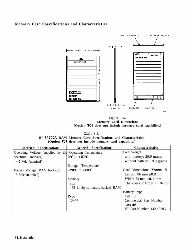
Figure 1-5.Memory Card Dimensions
(Option TO1 does not include memory card capability.)
lhble 1-5.85700A RAM Memory Card Specifications and Characteristics
(Option TO1 does not include memory card capability.)
Electrical Specifications General Specifications CharacteristicsOperating Voltage (supplied by the Operating Temperature Card Weightspectrum analyzer) O°C to +6O”C with battery: 20.9 grams
+5 Vdc (nominal) without battery: 19.0 gramsStorage Temperature
Battery Voltage (RAM back-up) -20°C to +60°C Card Dimensions (Figure 1-5)
3 Vdc (nominal) Length: 86 mm f0.2 mmMemory Width: 54 mm *O. 1 mm
Size Thickness: 2.4 mm f0.15 mm32 kilobyte, battery-backed RAM
Battery TypeType Lithium
CMOS Commercial Part Number:CR2016HP Part Number: 1420-0383
l-8 Installation
Preparation for UseIn this section, we cover initial inspection of the module and theshipping container, installing the module, and module operation.
Initial Inspection Inspect the shipping container upon receipt. Retain it and thecushioning materials for future use. If you need to ship the module toanother location or return it to Hewlett-Packard for service, refer tothe repackaging and shipping instructions in this section.
If the container or the cushioning materials are damaged, keepthem until you have verified that the contents are complete and themodule is functioning properly. If the contents are incomplete or themodule does not function properly, notify one of the HP Sales andService Offices listed in Table l-7. The HP Sales and Service Officewill arrange for repair or replacement without waiting for a claimsettlement. Also, notify the carrier about container damages, thenshow the damaged items to the carrier for inspection.
Refer to Figure l-9 for an illustration of the shipping container,packaging materials, and associated HP part numbers.
Installing the Module
Caution The portable spectrum analyzer must be turned OFF before themodule is connected. Connecting the module while the spectrumanalyzer is ON can damage both the spectrum analyzer and themodule circuitry.
The connector pins on the module and on the spectrum analyzer areESD-sensitive. Do not touch the pins on either instrument unless youare adequately protected against ESD.
Refer to the following steps to install your HP 85620A Mass MemoryModule properly and safely onto a portable spectrum analyzer.
1. With the spectrum analyzer set to OFF, line the 50-pin connectoron the module up with the OPTION MODULE connector (53) on therear panel of the analyzer. See Figure l-6.
2. Press the module into place.
3. Using a flat-blade screwdriver, tighten the l/4-turn fastener thatholds the module in place.
Installation 1-9

Figure 1-6.Installing an HP 85620A Mass Memory Module and Memory Card
(Option TO1 does not include memory card capability.)
l-10 Installation

Installing Memory Cards
Caution
(Option TO1 does not include memory card capability.)
Use the following information to ensure that the memory card isinserted correctly. Improper insertion causes error messages to occur,but generally does not damage the card or the module. Care must betaken, however, not to force the card into place. The cards are easyto insert when installed properly.
1. Locate the arrow printed on the card label.
2. Insert the card with its arrow matching the raised arrow on thebezel around the card-insertion slot. See Figure l-6.
3. Press the card into the slot. When correctly inserted, about 4 cm(1.6 in) of the card is exposed above the slot.
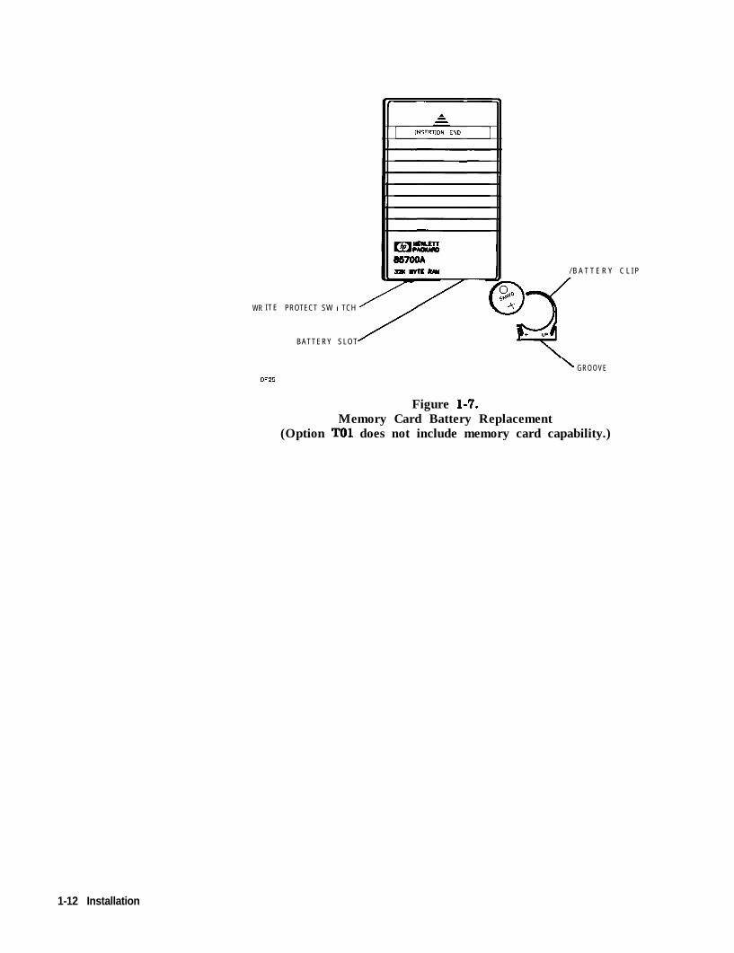
Changing the Memory Card Battery
The battery is located beside the card write-protect switch on the endopposite the connector. Refer to Table l-5 for memory-card batteryspecifications and characteristics.
Memory-card data is retained by the battery in the card. You can losethe data when the battery is removed. Replace the battery whilethe card is installed in a powered-up module. Memory-card datamay be backed up in module memory before beginning the batteryreplacement procedure that follows.
1. Locate the groove along the edge of the battery clip. SeeFigure l-7.
2. Gently pry the battery clip out of the card. The battery fits withinthis clip.
3. Replace the battery, making sure the plus (+) sign on the battery ison the same side as the plus (+) sign on the clip.
4. Insert the battery clip into the memory card, holding the clip asoriented in Figure l-7. (Face the “open” edge of the clip towardthe write-protect switch on the memory card.)
Installation l-1 1
WR ITE PROTECT SW I TCH
BATTERY SLOT
/ B A T T E R Y C L I P
\ GROOVEOF25
Figure l-7.Memory Card Battery Replacement
(Option TO1 does not include memory card capability.)
1-12 Installation
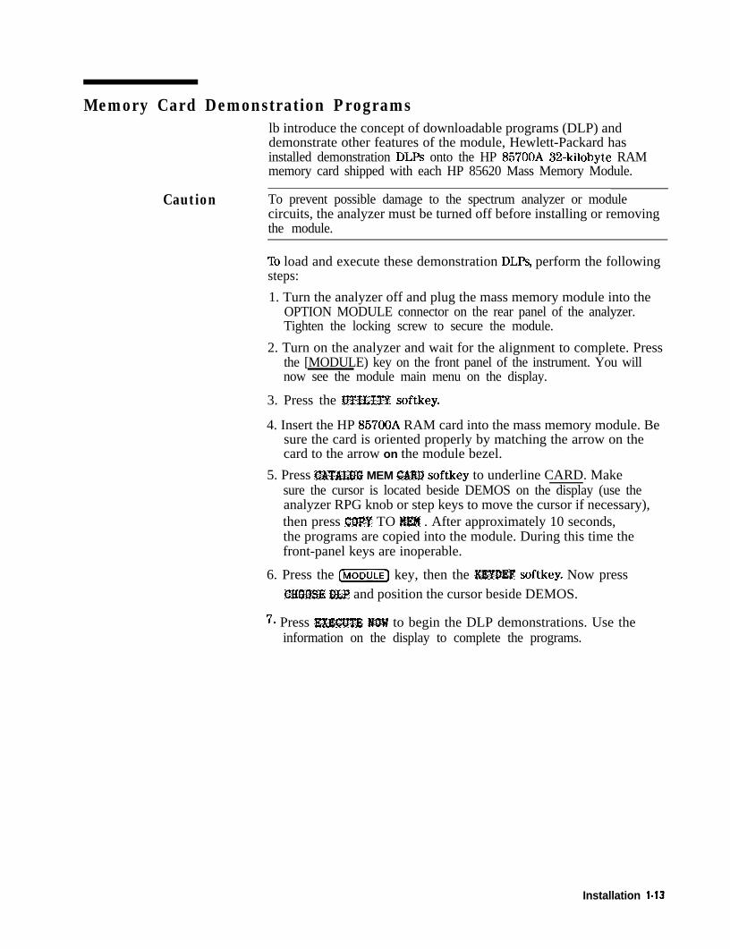
Memory Card Demonstration Programslb introduce the concept of downloadable programs (DLP) anddemonstrate other features of the module, Hewlett-Packard hasinstalled demonstration DLPs onto the HP 85700A 32-kilobyte RAMmemory card shipped with each HP 85620 Mass Memory Module.
Caution To prevent possible damage to the spectrum analyzer or modulecircuits, the analyzer must be turned off before installing or removingthe module.
To load and execute these demonstration DLPs, perform the followingsteps:
1. Turn the analyzer off and plug the mass memory module into theOPTION MODULE connector on the rear panel of the analyzer.Tighten the locking screw to secure the module.
2. Turn on the analyzer and wait for the alignment to complete. Pressthe [MODULE) key on the front panel of the instrument. You willnow see the module main menu on the display.
3. Press the JJTILITY softkey.
4. Insert the HP 85700A RAM card into the mass memory module. Besure the card is oriented properly by matching the arrow on thecard to the arrow on the module bezel.
5. Press CATAWG MEM &W softkey to underline CARD. Makesure the cursor is located beside DEMOS on the display (use theanalyzer RPG knob or step keys to move the cursor if necessary),then press icOPY TO MEM . After approximately 10 seconds,the programs are copied into the module. During this time thefront-panel keys are inoperable.
6. Press the LMODULE) key, then the Kl$YpEF softkey. Now pressC~00$8 DLP and position the cursor beside DEMOS.
7. Press mm MOW to begin the DLP demonstrations. Use theinformation on the display to complete the programs.
Installation l-13

Module Operation
Introduction This operating information is a brief introduction to the main menuof the HP 85620A Mass Memory Module. For detailed operatinginformation, refer to Chapter 2.
Menu Structure With the spectrum analyzer in normal operation mode, press thespectrum analyzer (MODULE) key to display the main menu of theHP 85620A Mass Memory Module. See Figure l-8. The menu isfriendly enough for the first-time user, but structured so that anexperienced user can get going quickly. Generally, there are no morethan three menu levels nested below the main menu level.
lb exit the module functions, press any of the front-panel keys on theanalyzer.
MODULE7LIMIT LINE
Figure 1-8. HP 85620A Main Menu Softkeys
l-14 Installation

Main Menu Softkey Descriptions
USER KEYSaccesses 10 user-definable softkeys. These keys, when definedusing the User Entry Menu, activate DLPs assigned to them. Youcan also assign DLPs to softkeys remotely.
TRACE SAVE/RCLenables you to save and recall traces. You can also create triggercriteria (data specifying when an event starts and stops) andautomatically store traces.
LIMIT LINEaccesses features for you to create or edit limit lines. Limit linescan be specified by up to 18 points. Each point is composed of afrequency and at least one amplitude value. Trace data can becompared against limit lines.
AUTOEXEC MENUaccesses features for you to execute a DLP automatically. Youselect the criteria that determines when the DLP starts to run.
KEYDEFaccesses the 10 user-definable softkeys and the DLP Directoryso that you can load DLPs onto the module User Keys Menusoftkeys.
accesses the module utility functions. You can set the currenttime and date, catalog the module or memory card contents,copy data between the memory card and the module memory,and delete any memory contents. (Option TO1 does not includememory card capability.)
Installation 1-15

Packaging
Original Packaging Save the original packaging materials. If the original materials havebeen discarded, identical materials may be ordered from HP Salesand Service Offices for shipping or transporting purposes. Refer toFigure l-9 and ‘lhble l-6 for these shipping container materials.
On the outside of the container, write clearly, FRAGILE, HANDLEWITH CARE. If the module is being returned to Hewlett-Packardfor servicing, include one of the blue repair tags along with theinformation listed below:
n Type of service required, including a description of the problem.
w Return address, phone number, and person to contact for moreinformation.
n Model number and serial number of the module.
w List of any accessories accompanying the module.
Figure 1-9.HP 85620A Shipping Container Materials
(Option TO1 does not include memory card capability.)
l-16 Installation

‘Ihble 1-6. HP 85620A Shipping Container Materials Contents
ItemI
Description
1 Memory card with slip case
HPPartNumber85700A
(Option TO1 does not include memory card capability.)
Envelope and inner carton 9211-4916Bubble-pack bag (with separate card orders) 9222-0784Envelope (with separate card orders) 9222-1219Carton, outer 9211-5570Styrene sheets 9223-0476
Check Digit QQ
3
Other Packaging Use the steps below if you plan to use materials other than the onesspecified as original packaging.
Caution Do not use packaging materials other than those specified. Improperpackaging can damage the module. Never use styrene pellets in anyshape as packaging materials. Their cushioning ability may not beadequate enough prevent the module from shifting within the carton.They also generate static electricity and can cause ESD damage to themodule.
1. Wrap the module in two or three inches of static-shieldingcushioning materials (for example, S.D.-240 Air CapTM from SealedAir Corporation, Commerce, CA, 90001).
2. If the module is being returned to Hewlett-Packard, include a bluerepair tag with the information listed in “Original Packaging.”
3. Place the module in a strong shipping container. Make sure thereis enough cushioning material to prevent the module from shiftingwithin the container. Securely seal the shipping container.
4. Print FRAGILE, HANDLE WITH CARE clearly on the shippingcontainer.
Installation 1-17

Error Messages Error messages and recovery information are included in this section.If you are unable to recover from an error, contact an HP Sales andService Office. These offices are listed in Table l-7.
CHK CARD INSERTIONThe memory card is either inserted incorrectly ornot inserted at all. Make sure the arrow printed onthe card label and the arrow on the module matchup. Press the card into place firmly, but do notuse excessive force. (Option TO1 does not includememory card capability.)
INSUFFICIENT MEMORYThere is not enough user memory available to savethe data you are attempting to save. You can eitherrelocate some of the contents in the destinationyou have selected, or purge some of the contents.
READ ONLY CARD The card inserted in the module is a ROM card.Replace the ROM card with a RAM card and besure the write-protect switch is not set in the SAFEposition. (Option TO1 does not include memorycard capability.)
No applicable entriesYou attempted to access data from a memorylocation that contained no DLPs, limit-lines, ortraces.
Error Codes Error-code numbers for the module range from 800 to 899.
Note Pressing c-1 then (PRESET) on the analyzer, or sending thecommand IP over HP-IB, will clear module errors reported in thelower left-hand corner of the display. After using the ERR commandover HP-IB, an IP command must be used to clear mass memorymodule errors.
800 Ul EPROM Check Sum Error, hardware failure.
801 U2 EPROM Check Sum Error, hardware failure.
802 U3 EPROM Check Sum Error, hardware failure.
803 U4 EPROM Check Sum Error, hardware failure.
804 Mass Memory Initialized. RAM data has been erased.Hardware failure or the module battery is intermittent orhas failed.
805 Mass Memory Module Usage Error. The command used wasinvalid and cannot be executed.
806 Mass Memory RAM full. Available memory is insufficient forcommand execution.
807 Symbol Define Error. There was an attempt to definesomething illegal, or not of the correct type.
l-18 Installation

808
809
810
850
851
853
854
855
856
Memory Card Operation Error. There was an attempt todo an illegal operation. For example, a write-to attemptwas made with the memory card removed, or the filenameused for the store operation contained non-alphanumericcharacters. (Option TO1 does not include memory cardcapability.)
Memory Card Memory Full. (Option TO1 does not includememory card capability.)
Memory Card File Not Found. (Option TO1 does not includememory card capability.)
Reserved Word. There was an attempt to use a word in afilename that is reserved for a command.
857
858
Syntax Error.
Type Error. The defined type does not match the requestedtype.
859 Command Error. Destination invalid or improperly defined.
860 Reserved.
Symbol Read Error. There was an attempt to readsomething that was not there.
Symbol Write Error. There was an attempt to writesomething that was not defined.
Symbol Delete Error. There was an attempt to deletesomething that did not exist.
Symbol Table Corrupt. The file apparently exists but cannotbe accessed.
Memory Card Not Inserted. The module cannot recognizethe memory card. It may be inserted incorrectly or thecontacts are damaged. (Option TO1 does not includememory card capability.)
Write to ROM Card or a Write-Protected RAM card. Youmust use a RAM card with the write-protect switch notset to SAFE. (Option TO1 does not include memory cardcapability.)
Installation 1-19

‘Ihble 1-7. Hewlett-Packard Sales and Service OfRces
US FIELD OPERATIONS
Headquarters California, NorthernHewlett-Packard Co. Hewlett-Packard Co.19320 Pruneridge Avenue 301 E. EvelynCupertino, CA 96014 Mountain View, CA 94041(800) 752-0900 (415) 694-2000
Colorado Atlanta AnnexHewlett-Packard Co. Hewlett-Packard Co.24 Inverness Place, East 2124 Barrett Park DriveEnglewood, CO 80112 Kennesaw, GA 30144(303) 649-5512 (404) 648-0000
New Jersey Texas4Hewlett-Packard Co. Hewlett-Packard Co.150 Green Pond Rd. 930 E. Campbell Rd.Rockaway, NJ 07866 Richardson, TX 75081:201) 686-6400 (214) 231-6101
California, SouthernHewlett-Packard Co.1421 South Manhattan Ave.Fullerton, CA 92631(714) 999-6700
HlinoisHewlett-Packard Co.5201 ‘lbllview DriveRolling Meadows, IL 60008(708) 266-9800
EUROPEAN FIELD OPERATIONS
Headquarters France h-YHewlett-Packard S.A. Hewlett-Packard France Hewlett-Packard GmbH160, Route du Nant-d’Avril 1 Avenue Du Canada Hewlett-Packard Strasse12 17 Meyrin a/Geneva Zone D’Activite De Courtaboeuf 61362 Bad Homburg v.d.HSwitzerland F-91947 Les Ulis Cedex Germany:41 22) 780.8111 France (49 6172) 16-O
(33 1) 69 82 60 60Zreat BritainHewlett-Packard Ltd.%skdale Road, Winnersh TriangleWokingham, Berkshire RG41 6DZSngland44 734) 696622
INTERCON FIELD OPERATIONS
leadquartersIewlett-Packard Company1495 Deer Creek Road‘alo Alto, California, USA)4304-1316415) 867-5027
AustraliaHewlett-Packard Australia Ltd.31-41 Joseph StreetBlackbum, Victoria 3130(61 3) 896-2895
CanadaHewlett-Packard (Canada) Ltd.17600 South Service RoadTrans-Canada HighwayKirkland, Quebec H9J 2X8Canada(614) 697-4232
mna Japan%ina Hewlett-Packard Company Hewlett-Packard Japan, Ltd.18BeiSanHuanXlRoad 1-27-15 Yabe, SagamiharaWang Yu Shu Kanagawa 229, JapanIai Dian District (81 427) 59-1311keiiin& china86 1) 266-6888
fW4wreHewlett-Packard Singapore (Pte.) Ltd.160 Beach Road#29-00 Gateway WestSingapore 0718(65) 291-9088
CaiWtMlIewlett-Packard lbiwanLth Floor, H-P Building137 Fu Hsing North Roadbipei, lbiwan886 2) 712-0404
l-20 Installation

2Operation
Introduction This chapter introduces you to the operation of the HP 85620A MassMemory Module. The module is designed to enhance the memory andcapabilities of Hewlett-Packard portable high performance spectrumanalyzers. Figure 2-l illustrates the main menu display whichappears after you press the (MODULE) key on the spectrum analyzerfront panel. Refer to Chapter 1, “Installation, n for informationabout connecting the module to the spectrum analyzer or inserting amemory card into the module.
Figure 2-1. HP 856208 Main Menu Softkeys
Operation 2-1

Module Features The module provides the spectrum analyzer with 128 kilobytes ofavailable memory. With this memory you can store and recall tracedata, define and store variables, use downloadable programs (calledDLPs or personalities), create and store limit lines, or define usersoftkeys so that you can activate DLPs from the front panel.
Features provided to the portable spectrum analyzer by the massmemory module include:
n DLP execution remotely over HP-IB or using the module softkeys.There are ten softkeys you can assign to activate DLPs youpurchase through Hewlett-Packard or create yourself. Thesesoftkeys are defined remotely with the KEYDEF command or locallyin the KEYDEF menu.
n Trace Save/Recall capability. With the module built-in real-timeclock and calendar, you can set up automatic-save conditions tosave trace data at specified times and dates, and specified intervals.
n Limit-line generation. You enter the frequency and amplitudeparameters to generate a limit line, then activate it with the pressof a key. It tracks changes in the spectrum analyzer state andadjusts the displayed line accordingly.
n Automatic execution of DLPs. You can enter up to seven operationsor DLPs in the AUTOEXEC/AUTOSAVE SCHEDULE that will executeautomatically according to the criteria you define. The location ofthe operation name in the schedule and the operation start- andstop-times determine its priority for execution. As an example,if a program listed beside the number 1 has an earlier start timethan the program listed beside the number 2, program number 1 isexecuted first.
n Memory card capability (except Option TOl). With the mass memorymodule, you are able to use RAM and ROM memory cards. RAMcards are primarily used for read/write data storage, while theone-time programmable (OTP) ROM cards are used for personalityDLPs available from Hewlett-Packard. RAM card memory ismaintained by a lithium battery when the card is removed from apowered-up module. Check the battery voltage at least annually tobe assured of data retention.
Note When mass memory module functions are used, the analyzersave-trace registers 5, 6, and 7 are overwritten with module data.Therefore, these registers are not available for spectrum analyzeroperations. If you attempt to store data to these registers while themodule is active, it corrupts the module operating memory.
Note ‘Ib perform a complete instrument preset from the front panel ofthe spectrum analyzer, you must first press (MODULE), then [PRESET).If you do not press (MODULE) first, some module error codes will notclear.
2-2 Operation

‘sing the Mass Memory Module
Note
This section provides descriptions of the module menus and operationinformation to help you learn to use the HP 85620A Mass MemoryModule. It begins with the first menu that appears after you pressthe (M-) key on the spectrum analyzer, then moves through thevarious levels of menu. Generally, there are no more than threemenus nested beneath the [m) key. Press (MODULE) to activatethe module main menu.
You should not attempt to perform multiple mass-memorymodule/spectrum analyzer operations simultaneously. Doing so canproduce improper or unexpected results. For example, you should notperform signal identification or attempt to download a DLP while anautoexec/autosave operation is in progress.
Main Menu Keys DescriptionsThe main menu offers six softkey selections. Press any one of thekeys to access their lower-level menus. Refer to each menu sectionfor specific information. A brief description of the main-menusoftkeys is provided below.
n Press USI& WS to access the module ten user-definable softkeys.After you have loaded a program onto one of these softkeys, youcan activate it from this menu by pressing its softkey. There aretwo menu pages: one appears when you press USEE .N?J?$ and the
other is accessed by pressing @#E.
. Press ‘3&K ~~~~~~~ to access softkeys for saving or recallinga spectrum analyzer trace. Trace A or trace B may be stored ineither the battery-backed RAM of the module or on a memory card.(Option TO1 does not include memory card capability). Traces canbe saved manually or automatically using the Autosave function.
. Press Li?&% I;&$ to access the softkeys that allow you to create,review, save, recall, or edit limit lines. You can turn an active limitline on or off in this menu as well.
w Press ~4W”I’QEXEC MElW to access the AUTOEXEC/AUTOSAVESCHEDULE. Use the softkey of the Autoexec menu to set upautomatic-execution conditions for DLl?s. You can modify conditionsand priority, or eliminate functions (DLPs) that are scheduled toexecute, in this menu.
:. Press .Z%Yi%V to assign a DLP to one of the User Keys menu
softkeys. Display the softkey labels by pressing V$#% $CEYS .
W Press ‘$!fW% to access the various Utility menu features of themodule. A few of these are the time/date settings, cataloging themodule or card memory, and deleting DLl?s, limit lines, variables, ortraces from memory.
Operation 2-3

USER KEYS Menu Press E5ER KEYS to access five user-definable softkeys and a sixth
one labeled #MEI ; press MORE to access five additional user-definablesoftkeys and a sixth one labeled PBEV MEMT? . Press PREV MEMS toreturn to the first set of user-definable softkeys.
There are 10 user-definable softkeys that can be labeled through theKeydef menu. Softkeys that have not been assigned a program namedisplay the default label EWTY . DLPs can be written so that theyredefine softkeys for specified functions within the program.
Once you have loaded a program onto one of the User Keys menusoftkeys, you can activate its operation simply by pressing its softkey.Labeling the softkeys is defined in the Keydef menu section of thischapter.
Figure 2-2. User Keys Menu with DLP Label Examples
2-4 Operation
TRACE SAVE/RCL Menu
TRACE SAVE/RCL activates the Trace Save/Recall functions menu.See Figure 2-3. In this menu you can access the features that allowyou to manually or automatically save spectrum analyzer traces, orrecall traces from memory. If you save a trace without specifyinga unique name, it is given the default name “TR” and a time/datestamp when traces are saved on a memory card, or “TRACE” and atime/date stamp when saved to module memory. To create a tracetitle, you can use the spectrum analyzer screen-title function or theremote command, TITLE. Press the [DISPLA;Y) key, then #OR%; to access
the 23CRF,EN TITLE softkey. Memory cards are LIF formatted (LogicalInterchange Format). LIF entries are from 1 to 10 ASCII characterslong. The module reserves one of the 10 for file encoding purposes,such as .LMT, .TRC, or .DLP. The user, therefore provides 1 to 9 ofthe ASCII characters for memory card entries. (Refer to the LIFDocument, HP part number 5955-2676.)
The information saved by the save-trace operation includes tracedata, spectrum analyzer state, the trace name, if one is created, andthe time/date that the trace was stored. The date and time format isYYMMDDHHMMSS.
Note Traces stored on memory cards using a mass-memory module withfirmware datecode 910116 or later cannot be read into a module withan earlier firmware datecode (for example, 890524). Traces stored oncards using modules with firmware datecode 890524 or earlier can beread into a module with firmware datacode 910116 or later.
If available memory is insufficient, the save-trace operation is aborted.The message INSUFFICIENT MEMORY appears momentarily in the activefunction block of the CRT.
The first step in saving traces is to name the trace, if you choose to,and select where you want the trace saved. Choose module or cardmemory by underlining your preference with S$V+E X1Q &# CAR0 .(Option TO1 does not include memory card capability.) Manuallysave trace A or B by selecting $A%$ .TRAGE A or $‘WE T&U% 3 .These last two softkeys are immediate-execute function keys.Immediate-execute means that pressing the softkey immediatelyactivates its function.
If you want to save traces automatically, select AUTOSA~ ‘l”RACE,determine whether to save, trace A or B by underlining yourpreference with the AUTUSAF :Tl$A TN! softkey. Move the cursorto the position of prior&&m d&ire in the AUTOEXEC/AUTOSAVESCHEDULE (placing the trace at position one makes it the firstpriority), then press ERfT ‘&“K$&E . In this menu, enter start- andstop-time/date values with the sI%&um analyzer data keys and set upsave-triggering conditions by pressing $A@ TRfGGEE . Refer to thesoftkeys described in the following pages for more information.
Operation 2-5

Note A maximum of one trace per second can be saved.
Figure 2-3. Trace Save/Recall Menu Softkeys
SAVJZTRACEAhighlights and immediately; stores trace ,A and the instrument state in the memory locationyou selected using the WVE &I. &I$?$. CAI@ softkey. (Option TO1 does not include memorycard capability.)
SAVETRACJZBhighlights and immediately stores, trace B and the instrument state in the memory locationyou selected using the ;$AV& :~~;;;~.~:~~ softkey. (Option TO1 does not include memory/i i ..i ., ..:. . . .card capability.)
SAVE IN MEM CARDtoggles between memory locations. The default setting is MEM, which stores the trace in theinternal, battery-backed RAM of the module. Choose CARD to save the trace on a memorycard. If CARD is selected and the write-protect switch is set to SAFE, an error messageappears on the display. If the card is inserted incorrectly, or not at all, the messageCHECK CARD INSERTION is displayed in the active function block of the spectrum analyzerdisplay.
Note The memory card must be inserted correctly. Match the black arrowon the memory-card label with the raised arrow on the modulebezel, then insert the card into the slot. Also be aware of whetherthe write-protect switch on the RAM card is switched to the writeposition or to SAFE.
AUTOSAVE TRACEdisplays the AUTOEXEC/AUTOSAVE SCHEDULE and accesses another menu from which you canset up conditions that save a trace automatically.
Note The default name “TRACE” is assigned to traces saved in modulememory without unique names. When saving to a card, the defaultname “TR” and a time/date stamp is assigned to the saved trace unlessyou.,~eate.;and assign a unique name using the spectrum analyzer~8C~N T@I& function key. Memory cards are LIF formatted(Logical Interchange Format). LIF entries are from 1 to 10 ASCII
2-6 Operation
Note
Note
characters long. The module reserves one of the 10 for file encodingpurposes, such as .LMT, .TRC, or .DLP. The user, therefore, provides1 to 9 of the ASCII characters for memory card entries. (Refer to theLIF Document, HP part number 5955-2676.) In either case, the timeand date are saved along with the trace data. Return to the TraceSave/RCL menu by pressing [MODULE), TlWE SAVE/ftCL .
Traces stored on memory cards using a mass-memory module withfirmware datecode 910116 or later cannot be read into a module withan earlier firmware datecode (for example, 890524). Traces stored oncards using modules with firmware datecode 890524 or earlier can beread into a module with firmware datacode 910116 or later.
The following steps may be used to set up the Autosave operation.
1. Determine where you want the trace saved, either the modulememory or card memory. Press SAVE IN MEM CAW until yourpreference is underlined.
2. Press AUTWAKI$ TlW$ . Move the cursor, using the RPG knobor STEP keys, to one of the seven FUNCTION NAME positions inthe schedule. This position helps determine the priority of thetrace-saving operation in relation to other operations scheduledhere.
3. Press AUTUSA#S TkA Tm until your preference is underlined.
4. Press ED’LT AUTfBAVE and define.the criteria to save tracesautomatically. Refer to ‘Ihble 2-l in this chapter for Autosavefunction settings and results information. The label AUTOSAVE isloaded into the AUTOEXEWAUTOSAVE SCHEDULE in the position youselected.
5. Complete the sequence by pressing FMV MEBlu , thenAU’IQSAVE 131 O?% to ON. This activates the Autosave function.
The trace is stored by its assigned name and according to yourstart/stop time settings and trigger conditions. Recall stored traces byusing the M&$LL T&K% softkey. Autosave Trace menu softkeys areillustrated in Figure 2-4.
If Autosave is set to ON ,and there are no DLPs currently running,then you select EDIT AUTUSAVE , any currently running Autosaveoperation is suspended until you have completed your edits andexited the Edit Autosave menu. PRESET) sets Autosave to OFF.
Operation 2-7

Figure 2-4. Autosave Trace Menu Softkeys
EDIT AUTOSAVEdisplays the AUTOEXEC/AUTOSAVE SCHEDULE and the start/stop times anddates and trigger selections that you can set up for Autosave operations. Presseither the start- or stop-time softkey to set up these conditions. Use thespectrum analyzer data keys to enter time values in 24-hour clock mode. ThegAVl3 .RWW%I$ softkey operation is described below.
DELETE 1 1 1
“Y&z% 1
Figure 2-5. Edit Autosave Menu Softkey
2-8 Operation

START TIMEallows entry of the start-time value which determines the time, as well as thedate, that the Autosave function begins operation. Use the spectrum analyzerdata keys and terminate the entry with any units key. After being entered,the time and date appear beside START TIME in the AUTOEXEC/AUTOSAVESCHEDULE. The default value is negative infinity.
STOP TIMEallows entry of the stop-time value which determines the time, as well as thedate, that the Autosave function ends. Use the spectrum analyzer data keysand terminate the entry with any units key. After being entered, the time anddate appear beside STOP TIME in the AUTOEXEC/AUTOSAVE SCHEDULE. If youdo not enter a stop-time, or you enter a stop-time that is earlier than thestart-time, the stop-time entry is ignored, and when Autosave is active, thefunction stops only when the memory location is full. The default value ispositive infinity.
SAVE TRIGGERaccesses a menu in which conditions that automatically save a trace may beselected. Select the conditions you want using the softkeys illustrated inFigure 2-6 and described below. The default setting is ON EOS (on end ofsweep).
Note
Figure 2-6. Save-Trigger Menu Softkeys
ON END OF SWEEPsaves the trace at the end of the next sweep to occur after thestart-time you provided. ON EOS appears next to TRIGGER inthe schedule display.
LIMIT TST FAILsaves the active trace at the end of the sweep any time thetrace exceeds the parameters of an active limit line.LIMIT TEST appears next to TRIGGER in the schedule.
The default name “TRACE” is assigned to traces saved in modulememory without unique names. When saving to a card, the defaultname “TR” and a time/date stamp is assigned to the saved trace unlessyou create and assign a unique name using the spectrum analyzer
Operation 2-9

SCREEN TITLE function key. Trace data is saved any time the traceexceeds the active limit-line parameters.
Note If a file has been stored into memory using a 16-character title, thefirst 9 characters must be unique to avoid writing over an existing file.If a file name is longer than 9 characters or if lower-case letters areused, the file name will be converted, if possible, to an LIF compatiblefile name using only the first 9 characters.
TIME INTERVALdisplays INTERVAL (HHMMSS) next to TRIGGER in the schedule.Use the spectrum analyzer data keys to enter the time intervalyou want the Autosave function to use. Trace data is stored inthe memory location you selected after the end of a sweep isreached and at the first interval specified. The last time tracedata is saved is when the stop-time, minus the time interval, isreached.
PREV MENUreturns you to the Edit Autosave menu softkeys in Figure 2-6.Press PREV MENU again to return to the Autosave Trace menu.
DELETEdeletes the function name you have highlighted by locating the cursor besideits number in the AUTlJEXEC/AUTOSAVE SCHEDULE.
AUTOSAVE TRA TRBtoggles between saving trace A or trace B. Press the softkey until yourpreference is underlined. The default setting is TRA.
AUTO!&WE ON OFFtoggles to set the Autosave function to on or off. AUTOSAVE ZlFF deactivatesall Autosave functions. Before turning the Autosave function on, you mustdetermine which memory location trace data is to be stored in, either modulememory or on the memory card. If stop/start times or trigger conditions havenot been specified, A~~~A~ ON will set default conditions and begin storingtraces. Refer to Table 2-l which lists the results of setting start/stop times ortrigger conditions. Autosave remains activated until the stop-time is reachedor until the memory location is full. When memory is full, Autosave stops andINSUFFICIENT MEMORY is displayed on the spectrum analyzer screen.
PREV MENUdisplays the main menu of TRACE SAlWK!L .
2-10 Operation
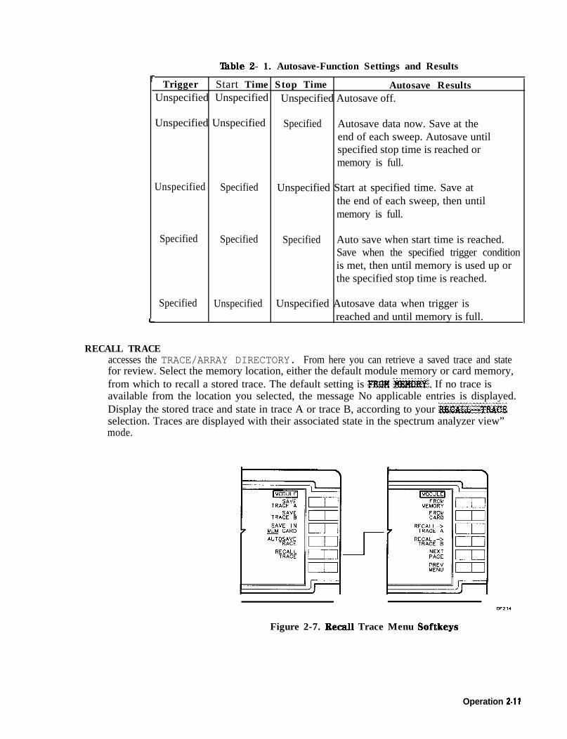
lhble 2- 1. Autosave-Function Settings and Resultsr
-
Trigger Start Time Stop Time Autosave ResultsUnspecified Unspecified Unspecified Autosave off.
Unspecified Unspecified Specified Autosave data now. Save at theend of each sweep. Autosave untilspecified stop time is reached ormemory is full.
Unspecified Specified Unspecified Start at specified time. Save atthe end of each sweep, then untilmemory is full.
Specified Specified Specified Auto save when start time is reached.Save when the specified trigger conditionis met, then until memory is used up orthe specified stop time is reached.
Specified Unspecified Unspecified Autosave data when trigger isreached and until memory is full.I-
RECALL TRACEaccesses the TRACE/ARRAY DIRECTORY. From here you can retrieve a saved trace and statefor review. Select the memory location, either the default module memory or card memory,from which to recall a stored trace. The default setting is RWH ;#&+KM~‘. If no trace isavailable from the location you selected, the message No applicable entries is displayed.Display the stored trace and state in trace A or trace B, according to your I!%CALL%TMCEselection. Traces are displayed with their associated state in the spectrum analyzer view”mode.
- I
Figure 2-7. Recall Trace Menu Softkeys
Operation 2.11

FROM MEMORYdisplays the TRACE/ARRAY DIRECTORY and all traces stored in thebattery-backed RAM of the HP 85620A Mass Memory Module. The date andtime that the trace was saved is displayed in the lower box of the directorywhen you highlight the trace in the directory with the cursor. Use either theRPG knob or STEP keys on the spectrum analyzer to highlight your selection,
FROM CARDdisplays the MEMORY CARD DIRECTORY and all traces stored on the cardcurrently inserted into the module. Traces saved without created names arelabeled TR and an encoded date code. If the card is improperly inserted,missing, or empty, the message No applicable entries appears. Highlightyour trace selection using either the RPG knob or STEP keys. (Option TO1does not include memory card capability.)
Note Traces stored on memory cards using a mass-memory module withfirmware datecode 910116 or later cannot be read into a module withan earlier firmware datecode (for example, 890524). Traces stored oncards using modules with firmware datecode 890524 or earlier can beread into a module with firmware datacode 910116 or later.
RECALL+ TRACE Aimmediately recalls the trace and its associated spectrum analyzer state fromthe specified location. The state is changed to that of the recalled trace andtrace A is placed in the view mode.
RECAIJH TRACE Bimmediately recalls the trace and its associated spectrum analyzer state fromthe specified location. The state is changed to that of the recalled trace andtrace B is placed in the view mode.
NEXT PAGEdisplays the subsequent page(s) of the directory. There can be up to 54 entriesper page of directory.
PREV MENUdisplays the TRACj$ ,%WEIWL main menu.
2-l 2 Operation
LIMIT LINE Menu A limit line is a display line specified by a set of coordinate points,each point consists of a frequency component, an amplitude value,and, optionally, a second amplitude value. The amplitude valuesrepresent either upper/lower or middle/delta amplitude limits for thecorresponding frequency component. Limit lines work only whenthe spectrum analyzer vertical scaling is in the log mode, not thelinear mode. One of the advantages of using the HP 85620A MassMemory Module limit-line feature is that, coupled with its Autosavefunction, trace data can be stored automatically any time a signal failsa specified limit.
A set of limit-line coordinates makes up a segment. These segmentsare entered into a limit-line table. There can be up to 18 segments perlimit line. You may enter amplitude values in one of the two followingformats.
n Upper/Lower: input upper and/or lower amplitude values. If anupper-limit value is not entered, the upper limit assumes a defaultvalue of +50 dBm. If a lower-limit value is not entered, the lowerlimit assumes the default value of -175 dBm. If the lower-limitvalue is greater than the upper-limit value, the two values are setequal to the value entered last.
n The middle/delta format requires the input of a middle amplitudevalue. You may also specify a deviation (positive and negativevalues) from either side of this value. If no deviation is entered, thedeviation defaults to zero.
The limit line is displayed according to the spectrum analyzer settings(instrument state). If the spectrum analyzer is in single-sweep modeand you change the settings, the limit line is not updated until anothersweep is initiated.
The two types of limit lines that you can generate are relativeand absolute limit lines. Relative limit lines consist of frequencycomponents referenced to a center frequency, and amplitudecomponents relative to the reference level. A frequency componentof 0 Hz corresponds to the current center frequency of the signal. Anamplitude component of -10 dB indicates that -10 dB is added to thereference level value to obtain the amplitude of the given component(reference level offset included).
Absolute limit lines contain only absolute amplitude and frequencyvalues. The amplitude and frequency offsets of the spectrum analyzer(FOFFSET and ROFFSET) do, however, affect the absolute displayedamplitude and frequency. This then influences the actual location ofthe limit line on the screen.
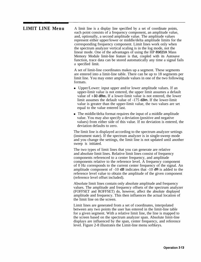
Limit lines are generated from a set of coordinates, interpolatedbetween any two points the user has entered in the limit-line tablefor a given segment. With a relative limit line, the line is mapped tothe screen based on the spectrum analyzer span. Absolute limit-linedisplays are influenced by the span, center frequency, and referencelevel. Figure 2-8 illustrates the Limit-line menu softkeys.
Operation 2-13
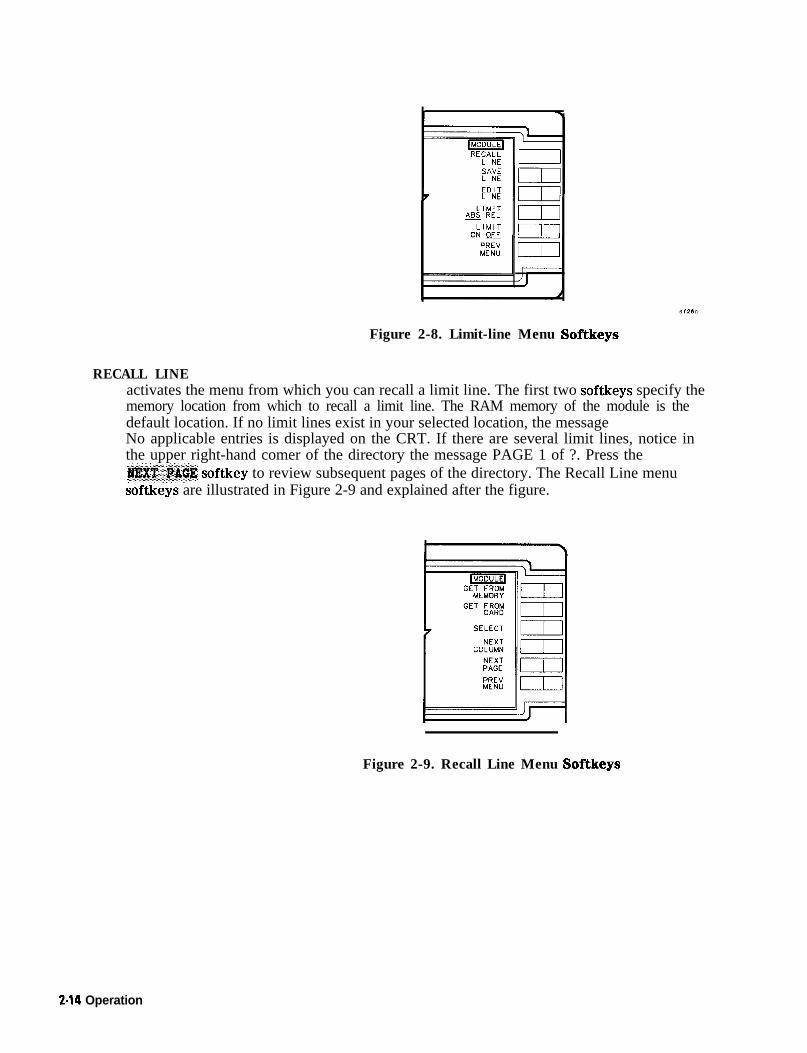
Figure 2-8. Limit-line Menu Softkeys
RECALL LINEactivates the menu from which you can recall a limit line. The first two softkeys specify thememory location from which to recall a limit line. The RAM memory of the module is thedefault location. If no limit lines exist in your selected location, the messageNo applicable entries is displayed on the CRT. If there are several limit lines, notice inthe upper right-hand comer of the directory the message PAGE 1 of ?. Press the@X$T,:.~@K softkey to review subsequent pages of the directory. The Recall Line menusoftkeys are illustrated in Figure 2-9 and explained after the figure.
Figure 2-9. Recall Line Menu Softkeys
2-14 Operation
GET FROM MEMORYdisplays the limit lines stored in the battery-backed RAM of the module.Use the RPG knob or STEP keys to move the cursor to the limit line you wantto recall. Its full name is displayed in the lower box of the directory. PressSELECT to activate the limit line.
GET FROM CARDdisplays limit lines stored on a memory card. If the card is empty, improperlyinstalled, or not installed at all, the message No applicable entries isdisplayed on the CRT. Press SEECT to activate the limit line. (Option TO1does not include memory card capability.)
Note Limit lines stored on memory cards using a mass-memory module withfirmware datecode 910116 or later cannot be read into a module withan earlier firmware datecode (for example, 890524). Limit lines storedon cards using modules with firmware datecode 890524 or earlier canbe read into a module with firmware datecode 910116 or later.
SELECI’selects the limit line that you have highlighted. Highlight the limit-line title byusing the STEP keys or RPG knob to move the cursor to the title.
NEXT PAGEdisplays the subsequent page(s) of the directory. There can be up to 54 itemsper page of menu.
PREV MENUdisplays the main menu for limit lines.
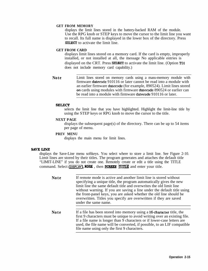
!3AvELlNEdisplays the Save-Line menu softkeys. You select where to store a limit line. See Figure 2-10.Limit lines are stored by their titles. The program generates and attaches the default title“LIMIT-LINE” if you do not create one. Remotely create or edit a title using the TITLEcommand. Select (DISPLAY], l$QR% , then X%J$@# ;%X’&E and enter your title.
Note If remote mode is active and another limit line is stored withoutspecifying a unique title, the program automatically gives the newlimit line the same default title and overwrites the old limit linewithout warning. If you are saving a line under the default title usingthe front-panel keys, you are asked whether the old line should beoverwritten. Titles you specify are overwritten if they are savedunder the same name.
Note If a file has been stored into memory using a 16-character title, thefirst 9 characters must be unique to avoid writing over an existing file.If a file name is longer than 9 characters or if lower-case letters areused, the file name will be converted, if possible, to an LIF compatiblefile name using only the first 9 characters.
Operation 2-15

I”I”YYLL
LIM LINE-> MEM
LIM LINE--> CARD
Figure 2-10. Save Line Menu Softkeys
LIMLINE-MEMhighlights as the program stores the table of limit-line data in thebattery-backed RAM of the module.
LIM LINE +CARDhighlights as the program stores the table of limit-line data on a RAM card, ifone is installed and not set to safe. (Option TO1 does not include memory cardcapability.)
Note Limit lines stored on memory cards using a mass-memory module withfirmware datecode 910116 or later cannot be read into a module withan earlier firmware datecode (for example, 890524). Limit lines storedon cards using modules with firmware datecode 890524 or earlier canbe read into a module with firmware datecode 910116 or later.
PREV MENUreturns you to the previous menu displaying the S&Z LINE softkey.
EDIT LINEdisplays the table of limit-line segments and the menu of softkeys illustrated in Figure 2-l 1.The softkeys are explained below. Refer to Figure 2-12 for the screen display of the limit line.You can create up to 18 limit-line segments per table. Determine whether you want a relativeor absolute limit line then begin creating or editing limit lines using the following steps:
1. Choose either upper/lower or middle/delta amplitude parameters.
2. Enter the parameter data into the table for each segment.
3. Select the segment type.
4. Name the limit line using the Display menu keys.
5. Return to the module Limit-line menu to save the limit line. The limit-line informationyou enter into the table is volatile; therefore, be sure to save the information with theSJUIE ’ LXTYE softkey.
2-16 Operation

Figure 2-l 1. Edit Line Menu Softkeys and able Example
Figure 2-12. Sample Limit Line Using Figure 2-11 ‘Ihble Data
ENTER PARMSdisplays the softkeys you use to edit or create limit lines. To create a line,press SmCT %&!HElQ’” followed by one of the other softkeys. Enter theparameter value using the RPG knob, STEP, or data keys. Use the spectrumanalyzer (BK key to correct errors. Press an appropriate units key tocomplete the data entry. Select the remaining parameters and enter theirvalues by pressing the appropriate softkey and data keys. When all segmentsare defined, press PKlZV l@ZN and DO’WE; , then, title the line using the(DISPLAY) function keys. Press SATE LJHl% to store the limit-line parameters ina table. If you are editing the parameters of an existing limit line, you canselect which segment you want to activate for editing. PressSI$LJ%~ $EGML!X~ , then using the keypad or the RPG select the segment youwant to edit. If using the keypad, follow the number with any units key. Thecursor moves to the segment you have specified. Figure 2-13 illustrates thesoftkeys described below.
Operation 2-17

SELECTSEGMENT
FREQ
I/
Figure 2-13. Enter Parameters Menu Softkeys
SELECT SEGMENTallows you to choose a segment number. You may either createnew parameters for another segment or edit the parameters ofan existing segment. Locate the cursor at the segment numberby using the RPG knob or step keys, or enter a numeric keycorresponding to the segment number you want, followed byany units key. The cursor moves to the segment you havespecified.
The number of characters accepted for frequency values is to thenearest 100 Hz over the full range of spectrum analyzer frequencies.The number of characters accepted for amplitude values is to thenearest tenth of a dB over the full range of spectrum analyzeramplitudes.
2-16 Operation

highlights and allows you to enter up to 12 characters (10 plusthe decimal point and sign) for a frequency value using thedata keys, RPG knob, or STEP keys. Terminate the data entryby pressing a units key, then any other parameter softkey tocontinue creating or editing a limit-line segment.
MID or UPPER AMPLhighlights and allows you to enter up to six characters (plus orminus sign, four digits, and a decimal point) for the upper- ormid-amplitude value using the data keys, RPG knob, or STEPkeys. Terminate the data entry by pressing an appropriateunits terminator key, then any other parameter softkey tocontinue creating or editing a limit-line segment.
DEIXlA or LOWER AMPLhighlights and allows you to enter up to six characters (plus orminus sign, four digits, and a decimal point) for the lower ordelta amplitude value using the data keys, RPG knob, or STEPkeys. Terminate the data entry by pressing the appropriateunits key, then any other parameter softkey to continuecreating or editing a limit-line segment.
SEGMENT TYPEaccesses the SL(TFE w)L,SM FREQ (default setting) or FLAT
segment type softkeys and PMY ?4HW softkey. SeeFigure 2-14. Choose a line type, or return to the previousmenu.
Note Limit-line data is sorted in frequency order in the limit-line table. Thesorting occurs after you have pressed the Fl%J! *HIBl’lJ key. If twodata points are at the same frequency, they are sorted by the order inwhich they were entered.
\MODULE/
---i&z=
DF22 I
Figure 2-14. Segment Type Menu Softkey
Operation 2.19

SLOPE w/ LIN FREQdraws lines by connecting allfrequency/amplitude pairs in the orderdetermined by the sorting operation previouslyexplained. The data is displayed with a linearslope in frequency and a logarithmic slope inamplitude.
FLATdraws a flat line, connectingfrequency/amplitude pairs point to point untilthe line encounters another frequency whoseamplitude is different, then the line is drawnvertically to the next amplitude value. Thelimit line is drawn without the logarithmicslope in amplitude.
PBEV MENUreturns you to the previous menu displayingthe SEGm ‘TYPE softkey.
PREV MENUreturns you to the previous menu displaying the&R83 ‘PAR!&?3 softkey. Pressing this key also performs thesorting of the limit-line segments in frequency order in thelimit-line table.
AMPL MODE U/L Aselect upper/lower to enter amplitude values that display a limit line above orbelow an active trace. Use the delta (A) amplitude mode to create a dual limitline with an upper limit of MID plus DEUI’A, and a lower limit of MID minusDELTA. The delta should be positive.
DELETE SEGMENTdeletes the limit-line segment highlighted with the cursor. When the table isempty (no limit-line segments defined), only 1 appears under SEG X.
PRINT TABLEThis softkey label exists only if your spectrum analyzer has printer capability.Pressing this key prints the currently selected limit-line table on an HP-IBprinter. The output format is tabular Pressing the 31R&@ softkey prints thetable only; softkey labels, graticule, or other characters and symbols are notprinted. If the printer is disconnected or off, the print function must berepeated after you connect or turn the printer on.
Note The limit-line table cannot be printed while the instrument isoperating with Trace A in VIEW or BLANK mode. Pressing thePRXJ”l? ?&&,E key under these conditions will have no effect until theModule menu is exited, at which time the current trace and displaywill be printed.
2-20 Operation

DELETE TABLEdisplays CONFIRM WLETE CANCEL DELETE softkeys. Select CAWXL DELETE
if you do not want the contents of the table deleted. Select CONFIRM DELETEif you wish to delete all table contents.
DONErestores the menu containing the EDfT LINE softkey.
LIMITS ABS BELuses the current limit line as a reference for absolute frequency and amplitude values whenthe default AM mode is activated. The REL setting causes the current limit-line value to berelative to the displayed center frequency and reference-level amplitude values.
LIMITS ON OFFallows you to turn the currently selected limit-line function on or off. With limit lines set toON, a limit-line test is made at the end of each sweep. If the active trace falls outside anypoint of the upper or lower limit, the message LIMIT FAILED is displayed on the screen. Iflimits are set to OFF, the active trace is not tested. Press the [MODULE) key on the spectrumanalyzer to return to the module main menu.
Operation 2-21

AUTOEXEC Menu Accessing this menu displays the AUTOEXEC/AUTOSAVE SCHEDULE.From here, you can define the criteria to execute DLPs automatically.Up to seven DLPs may be scheduled. These may be interleaved withthe Autosave operations. The schedule can be revised in this menuby using the RPG knob or STEP keys and other softkeys for editingdescribed below.
CANCELCLEAR
Figure 2-15. Autoexec Menu Softkeys
EDIT AUTOEXECuses RPG knob or STEP keys to move cursor to the position, based on numeric hierarchy, inwhich you want the DLP scheduled. The softkeys of the menu illustrated in Figure 2-16 aredescribed below.
Figure 2-16. Edit Autoexec Softkeys
2-22 Operation

CHOOSE DLPdisplays the DLP directory and suspends any running DLPs until you exit thismenu. See Figure 2-17 for an example of the directory. If no DLPs are storedin memory, the message No applicable entries is displayed. Otherwise,use the RPG knob or STEP keys to move the cursor to the entry you wish tochoose. Notice that there is a NEXT P&Z softkey. If your DLP is not listed inthe first page of entries, check the subsequent pages. DLPs stored only onmemory cards are not listed in the directory. (Option TO1 does not includememory card capability.) They must be stored in the module RAM before theyappear in the directory. Do this through the Utility menu. Press VTfLfTT and
CI1TALOG Ml3M GAm until card is underlined. Move the cursor to the DLP you
want to copy, press cf.&Y TQ HB&#!#” . Now return to the Autoexec menu,
press EMT A~tB$Xl3&, then CIIOQ$I3: l&P. With the cursor located by yourselection, press one of the Choose DLP menu softkeys listed below.
Note DLPs stored on memory cards using a mass-memory module withfirmware datecode 910116 or later cannot be read into a module withan earlier firmware datecode (for example, 890524). DLPs stored oncards using modules with firmware datecode 890524 or earlier can beread into a module with firmware datecode 910116 or later.
SELECTloads the DLP into one of the seven positions of the schedule.The position the DLP occurs in the schedule determines itspriority in execution.
EXECUTE NOWinitiates the selected DLP immediately.
NEXT PAGEaccesses the subsequent page of the directory.
PREV MENUreturns you to the preceding menu.
Figure 2-17. DLP Directory Example
Operation 2-23

START TIMEallows you to enter the date and time you want the Autoexecute function tobegin. Enter the date and time in the format shown in the lower box of theschedule display. Any DLPs which were running when you selectedEDIT 1UXlEKEC are suspended during the editing process.
STOP TIMEallows you to enter the date and time you want the Autoexecute function toend. Enter the time and date in the format shown in the lower box of theschedule display. If the stop time is less than the start-time, the stop-time isleft undefined.
EXEC CRITERIAaccesses the menu for you to define the criteria, or conditions, that willactivate the Autoexec function. Execute criteria defaults to ON EOS(on end of sweep). Select one of the softkeys illustrated in Figure 2-18.
Figure 2-18. Execute Criteria Softkeys
2-24 Operation

ON END OF SWEEPexecutes the selected DLP at the end of every normal sweep.This is the default criteria if no other is selected. If the DLPoperation is incomplete at the end of the sweep, the DLPcompletes before more data is evaluated.
TIME INTERVALdisplays HHMMSS in the lower box of the AUTOEXEC/AUTOSAVESCHEDULE display. Use the data keys to enter a time interval inits displayed format. The program executes the selected DLPat the specified intervals. (If you enter an interval value ofzero, the module defaults to the ON EOS setting.)
LIMIT TST FAILcauses the module to execute a DLP when an active limit lineis exceeded. The first step in setting up a limit-test failfunction is to have an active signal with all the spectrumanalyzer settings determined. Next, build or recall a limit line,select a start/stop time, then press LIMIT Y$!T FAlL .
PREV MENUreturns you to the previous menu displaying theEXEC CKJHHfA softkey. Press PM.52 MENU again to return to
the menu displaying the EDIT ~$UTflHXMC softkey.
DELETEdeletes the function name you have selected using the RPG knob or STEP keys.
CLEAR SCHEDULEdisplays the C[3ESFIHM ~Ll%M CAMa CLF&B softkeys. Select $ZQMFJffw;, CLKAM if you wish to
remove all entries from the AUTOEXEC/AUTOSAVE SCHEDULE. Otherwise, press CAIKEL CLEARto return to the previous menu.
Al ‘TOEXEC ON OFFturns the Autoexec schedule on or off. While you are in this menu, no DLPs are allowed toexecute. If AUTOEXEC is set to ON, DLP execution priority is determined by its location inthe schedule. If a DLP is activated as soon as you turn Autoexec on, you will have to press[Pm) on the spectrum analyzer to interrupt the DLP and regain control of any module orspectrum analyzer front panel keys.
PREV MENUreturns you to the previous menu displaying the AUTt%XMC MHMU softkey, if there are noDLPs running. If a DLP is activated as soon as you turn Autoexec on, you will have to press(PRESET) on the spectrum analyzer to interrupt the DLP and regain control of any module orspectrum analyzer front panel keys. (PRESET) turns the Autoexec schedule off.
Operation 2-25

KEYDEF Menu Press KRYIIZF to display the User Key D$nitions table. The10 user-definable softkeys that can be labeled to activate DLPs storedin the module are listed here. Use the RPG knob or STEP keys toplace the cursor beside one of the 10 user-definable softkeys in thismenu. The DLP name you select from the module memory is loadedonto this softkey. lb load a DLP stored on the memory card ontoa user softkey, you must first copy it into the module memory.(Option TO1 does not include memory card capability.) Do thisremotely with the CARDLOAD command or locally using the Utilitymenu softkeys. Figure 2-19 illustrates the softkeys described below.
Figure 2-19. Keydef Menu Softkeys
2.26 Operation

CHOOSE DLPdisplays the DLP directory. If no DLPs are stored in memory, the message No applicableentries is displayed. Otherwise, use the RPG knob or STEP keys to move the cursor to theentry you wish to choose. Notice that there is a i?EXT PAGE softkey. If your DLP is not listedin the first page of entries, check the subsequent page. Either run it by pressingl%UBXTE NW to start the operation, or press %ZLECT to load it onto the selected key.
Note DLPs stored on memory cards using a mass-memory module withfirmware datecode 910116 or later cannot be read into a module withan earlier firmware datecode (for example, 890524). DLPs stored oncards using modules with firmware datecode 890524 or earlier can beread into a module with firmware datecode 910116 or later.
SELECTassigns the DLP you have highlighted to a User Key menu key. Use the RPGknob or STEP keys to move to the DLP you want to assign to a key.
EXECUTE NOWexecutes the highlighted DLP immediately.
NEXT PAGEaccesses the subsequent page of the directory.
PREV MENUreturns you to the previous menu displaying the CHOO$E pLP softkey.
CLEARclears the DLP name from the user-key you have highlighted. Move the cursor to theuser-key number with the RPG knob or STEP keys.
CLEAR ALLaccesses the CXXVFI3W :CWZA~ CZXEL C&EJ3 softkeys. Press CfHJFIW CX,E&A to clear allthe DLPs from the user keys. Otherwise, press C&B%L CZLEAR to return to the previous menu
displaying the CLEAB ALL softkey.
PRJw MENUreturns you to the previous menu displaying the module main menu.
Operation 2-27

UTILITY Menu Press UTILITY to gain access to the utility functions available withthe HP 85620A Mass Memory Module. See Figure 2-20.
CATALOGMEM CARD
COPY IlrT” PAD!7
DELETEENTRY ,,i
Figure 2-20. Utility Menu Softkeys (MEM selected)
I \
Figure 2-21. Utility Menu Softkeys (CARD selected)
2-28 Operation

TIMEDATEactivates menu selections for setting the time and date. See Figure 2-22 for the softkeysdefined below.
SET TIME m
SET DATE [I]
Figure 2-22. Timedate Menu Softkeys
TIMEDATE ON OFFdisplays the time and date in the active function block of the spectrumanalyzer display when set to ON. .The default setting is OFF. The date displayformat is a function of the R~~~~~. softkey. The time display can beformatted for a 24-hour or 12-hour clock. The clock is updated every minute.Seconds are not displayed.
TIME 24H 12Htoggles the time display to either 24-hour (International) mode or 12-hour(AM/PM) mode. Press the x.X&, softkey until your preference is underlined.The default format is the 24-hour mode.
DATEMODE MDY DMYtoggles the format of the date displayed on the CRT. Select MDY (month, day,year) or DMY (day, month, year) by pressing the R~T~OR~ MDT X&W softkeyuntil your preference is underlined. The default setting is MDY.
SET TIMEsets the real-time clock to the time you specify. Enter the 24-hour time in theHHMMSS format (the time display format is a function of the TXJ#Z %@I ‘. 12Hsoftkey). Valid hour (HH) values are from 00 to 23. Valid minute (MM) andsecond (SS) values are from 00 to 59.
SET DATEinitializes the real-time clock to the date you specify. Enter the date in theMMDDYY or DDMMYY format, depending on the date format you haveselected. The default format is MDY. Valid data entry for the month is MM(values 01 through 12), DD (values 01 through 31), and YY (values 00through 99).
PEEV MENUreturns you to the previous menu containing the TI!#lUTlZ softkey.
Operation 2-29

CATALOG MEM CARDtoggles between the catalogs of the contents of the module battery-backed memory orcontents of the memory card, if one is installed. If CARD is selected, the card format menukey is made available by pressing FORNAT MENU on later firmware revisions, or by pressingthe blank softkey on earlier firmware revisions. (Option TO1 does not include memory cardcapability.) If the card is missing, empty, or incorrectly installed the message No applicableentries is displayed in the MEMORY CARD DIRECTORY. Memory cards are LIF formatted(Logical Interchange Format). LIF entries are from 1 to 10 ASCII characters long. The modulereserves one of the 10 characters for file encoding purposes, such as .LMT, .TRC, or .DLP. Theuser, therefore provides 1 to 9 ASCII characters for titling memory card entries. (Refer to theLIF Document, HP part number 5955-2676.) The default setting is MEM.
COPY TO MEMORY CA&Dtoggling the $%T&L!JG MEN CARD key automatically toggles the copy key between memoryand card to allow you to copy any of the directory entries to module memory or to a card.(Option TO1 does not include memory card capability.) The card must be properly installedand not write-protected. Use the RPG knob or STEP keys to move the cursor to yourselection. Press the COPY TO EfEMBRY CARD softkey to activate the copy function.
Note DLPs, traces, and limit lines stored on memory cards using amass-memory module with firmware datecode 910116 or later cannotbe read into a module with an earlier firmware datecode (for example890524). DLPs, traces, and limit lines stored on cards using moduleswith firmware datecode 890524 or earlier can be read into a modulewith firmware datecode 910116 or later.
NEXT PAGEaccesses any subsequent page(s) of the directory.
DELETE ENTRYpress this softkey after using the RPG knob or STEP keys to move the cursor to the entry youwish to delete. The STW lBI%TlX and ~~~~~ l#IJKfE softkeys are then displayed.
STOP DELETEreturns you to the directory.
CONTINUE DELETEimmediately deletes the highlighted entry.
FORMAT MENU (firmware revision 950829 and later)accesses the card formatting key.
FORMAT CARDrequests you to enter the number of directory entries. The number of entriesMUST be a multiple of 8 (for example, 8, 16, 24, 32, 40, and so on). Optimummemory utilization is obtained when one directory per kilobyte of memory isselected. For example, enter 32 for a 32 kilobyte RAM card, or 128 for a 128kilobyte RAM card.
2.30 Operation

3Softkey Menu
Introduction The menus of the HP 85620A Mass Memory Module are graphicallyrepresented in this chapter. The Main Menu keys are labeled in theupper right-hand corner of each grouping. Main Menu keys are listedbelow:
w USER KEYS
n TRACE SAVE/RCL
n LIMIT LINE
n AUTOEXEC MENU
n KEYDEF
n UTILITY
SoftkeyMenu 3-l

1 USER KEYS]
-
1
Figure 3- 1. User Keys
I J
3-2 Softkey Menu

ITRACE SAVE/RCLI
Figure 3-2. Trace Save/Rcl
’ default
Softkey Menu 3-3

- I LIMIT LINEI
I- I
Figure 3-3. Limit Line
* default
t This mftkey label appears only if the spectrum analyzer has printing capability.
3.4 Softkey Menu
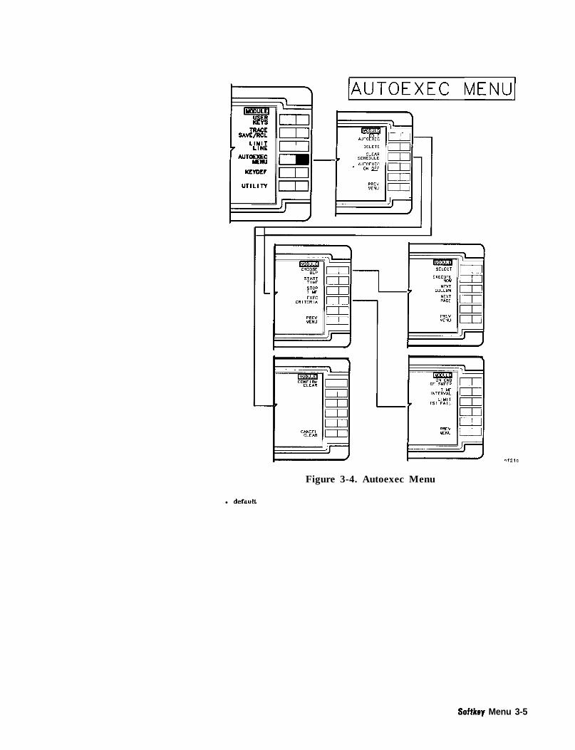
(AUTOEXK MENUI
mI-
Figure 3-4. Autoexec Menu
l default
Softkey Menu 3-5

IKEYDEFI
I II L
I UTILITY
II I
I[
i
Figure
J
3-5. Keydef
3-6 Softkey Menu

Note
c L:Yi4iAUTOE ctd&JKErnEF
UTILITY L
I \
f
Figure 3-6. Utility
’ Alternate functions appear when CARD is underlined in OA’&Txl(3 mM CAaD .
t This softkey is absent for mass memory modules having firmware revision 010116 andearlier.
FOWT’ IBBU does not appear (blank softkey) for firmware revisions910116 and earlier, but the RB!@T HERFU functionality is stillavailable by pressing the blank softkey.
Softkey Menu 3-7

Programming
Introduction This chapter contains programming information for the HP 85620AMass Memory Module. The section that follows providessome fundamental information about creating your own DLPs(downloadable programs). Also included are descriptions of syntaxdiagram terms along with syntax diagrams and some programexamples.
Getting Started with DLPsThis section is an introduction to the concept of DLPs. It includesfront-panel operation and information on how to program anddownload programs into the mass memory module from a controlleror from a memory card. You will find out how to correctly declarefunctions, variables, and traces, then allocate these variables inspectrum analyzer memory. After these are declared and allocated,the module allows you to execute DLPs without an externalcontroller. Special features such as limit lines and automatic execution(autoexec), are also discussed. This section assumes that you arefamiliar with HP 9000 Series 200/300 Controllers.
What Is a DLP? A DLP is a single command or a sequence of commands used toperform a customer-specified operation. The user can define DLPsmade up of several functions, variables, and traces, download theminto the module RAM memory as one DLP, or define each commandas a DLl? In the HP 85620A, there are one hundred twenty-eightkilobytes of RAM available for user DLPs. This memory is called theuser-defined memory. Almost any instruction that can be executedover HP-IB can be executed in a DLl? In addition, DLPs have theability to control other instruments over HP-IB. It is possible to designapplication programs and store them in user-defined memory as DLPs.These programs can then be executed without an external controller.
DLPs remain in memory even when the spectrum analyzer power isturned off. They are stored in the battery-backed RAM of the massmemory module and can be used repeatedly, whenever needed.
Programming 4-1

DLP Examples
Several programming examples are included in this section toillustrate the operation of DLPs both remotely and via user-definedsoftkeys. Examples showing commands unique to DLPs are also given.Refer to the list of required equipment and the equipment setupinformation to set your system up and begin running the programexamples.
Required Equipment
n HP 85620A Mass Memory Module
w HP 8560A/E, or HP 8561A/B/E, or HP 8562A/B/E, or HP 8563A/ESpectrum Analyzer
n HP Series 200/300 Controller
n 10833 A/B/C/D HP-IB Cable Assembly
n HP BASIC 2.0 (or greater)
Optional Equipment
n Any HP-IB Compatible Printer such as an HP 2225D ThinkJet
Equipment Setup
Connect the CAL OUTPUT to the RF INPUT of the spectrum analyzer.Set up the equipment as shown in Figure 4-l.
Figure 4-1. Equipment Setup
4.2 Programming

Programming Front-Panel Functions
Programming Front-Panel Functions
Example 4- 1
To prepare the spectrum analyzer for programming, use an externalcontroller to enter the following literal example of the diagrammedcommand. It will preset the spectrum analyzer, set center frequencyto 300 MHz, and span to 10 MHz.
10 OUTPUT 718;"IP;CF 300MHZ;SP 10MHZ;";20 END
OUTPUT 7 18; “lp: CF 31
A n a l y z e r a d d r e s s
I n s t r u m e n t p r e s e t
A c t i v a t e c e n t e r f r e q u e n c y
s e t c e n t e r f r e q u e n c y value
S e m i - c o l o n s s e p a r a t e a n a l y z e r c o m m a n d s
I.
t=
A c t i v a t e f r e q u e n c y s p a n
s e t f r e q u e n c y s p a n v a l u e
S u p p r e s s c a r r i a g e r e t u r n / l i n e f e e d
Figure 4-2. Preparing the Spectrum Analyzer for Programming
Executing the above program initiates the sequence of operationsdescribed above. If the CAL OUTPUT is connected to the RF INPUT,the 300 MHz calibrator signal should be displayed. The last functionactivated, SPAN, appears with its current value on the spectrumanalyzer display.
It is important to note that the sequence of operations executed abovemay also be entered manually, from the front panel, to yield the sameresult. In fact, a manual sequence of keystrokes is usually developedfirst, then used as a basis for executing the same procedure underprogram control. This simple technique is recommended as a tool indeveloping software for automatic spectrum analyzers.
The semicolon (;) at the end of command lines serves to suppress thecarriage-return/line-feed, and therefore conserves user memory.
Programming 4-3

Programming User-Defined FunctionsExample 4-2 demonstrates how to make a DLP from the commandsused in Example 4-l.
Example 4-210 OUTPUT 718;"FUNCDEF ZOOM, @;IP;CF 300MHZ;SP 1OMHZ;Q;";
!Assign the!label "ZOOM"
20 !to the indicated30 !sequence of commands.40 END
The FUNCDEF command specifies a user-defined function. The “at”sign (a) is used as a delimiter for the user-defined function “ZOOM”.All characters between the “at” signs are part of the “ZOOM” routine.
Refer to the “Remote Programming” section in this chapter for furtherdiscussion of programming delimiters. Downloading the program inExample 4-2 from an external controller to the spectrum analyzerstores the routine in the mass memory module internal battery-backedRAM. The routine can now be executed without an external controllerfrom the spectrum analyzer front panel. Press LtrcSr., (~-1,
‘~~~~:~,~, IB’XV HITIBXE~‘, and rcHoW# BW . Locate thecursor at the DLP you want to execute, press lGQX$TK NOW..A typical listing of DLPs stored in a mass memory module is shown inFigure 4-3.
Figure 4-3. Typical DLP Listing
4-4 Programming

Programming User-Defined Functions
For frequently used DLPs, it may be more convenient to load theprogram onto one of the user softkeys in the User Keys menu. AnyDLP can occupy one of these ten user-definable softkeys. The DLP,once assigned to a softkey, can be executed independently without acontroller by pressing the appropriate softkey in the User Keys menu.To assign a DLP to a softkey, the KEYDEF command must be invoked.The following program stores the DLP named “ZOOM” under softkeynumber 1 in the User Keys menu. Notice that the percent sign is usedto delimit the title “ZOOM”.
Example 4-310 OUTPUT 718;“FUNCDEF ZOOM,Q;IP;CF 300MHZ;SP 1OMHZ;O;“;
! Assigns the label20 ! ZOOM to the indicated30 ! sequence of commands.40 OUTPUT 718;“KEYDEF 1, ZOOM,%ZOOM%;“; ! Assigns the label “ZOOM”50 ! to user key I.60 END
‘RI execute this DLP, press USER NEW . “ZOOM” should be labeled on
softkey number 1. Press the ZDOH softkey. Labels for user-definedsoftkeys can be from 1 to 16 characters long. You can manually assignDLPs to a User Keys softkey from the Keydef menu found in the mainmenu of the module. Refer to the Operation Chapter in this manualfor details about the Keydef menu.
Note The user-defined softkeys do not need to be labeled with the samelabel used to define the DLPs they will activate.
Programming 4-5

Determining Available User MemorySince user memory is limited, it may sometimes be valuable todetermine the amount of memory a DLP requires. Doing this is asimple four-step process that requires the use of the MEM command.
1. Enter the command OUTPUT 718; "DISPOSE ZOOM; ” ; ‘I, then runExample 4-4 before the DLP is downloaded to verify availablememory in the mass memory module.
Example 4-410 OUTPUT 718 ; “MEM? ; ” ; ! Determine available user-memory20 ! value and prepare to output value.30 ENTER 718;M ! Store the available user-memory40 ! value in the variable "M".50 PRINT "MEMORY = U ;M;"BYTES" ! Print the user-memory value.60 END
2. Run Example 4-3 to download the entire DLP and allocate therequired memory.
3. Run the program in step 1 again to determine the new value ofavailable memory in the mass memory module.
4. Calculate the user memory required for the DLP by subtracting thevalue of memory found in step 1 from the value found in step 3.
Note The mass memory module has 12%kilobytes of memory. Thiscorresponds to 131,072 bytes (1024 bytes/kilobyte x 128 kilobytes).
4-6 Programming

User-Defined Variable and Trace Declaration
User-Defined Variable and Trace DeclarationTo store a single value in the mass memory module RAM, a variablemust be defined and set to an initial value. This allocates space ininternal RAM for the variable name and value. The following exampleshows how to declare a variable and how the amplitude of a signalcan be stored in a variable.
Example 4-6IO OUTPUT 718;"VARDEF AMPLITUDE, 0;"; ! Define variable, "AMPLITUDE20 ! and initialize its value to zero.30 OUTPUT 718;"IP;SNGLS;"; ! Instrument preset, single sweep.40 OUTPUT 718;"FA 275MHZ;FB 325MHZ;“; ! Set the start and stop frequencies50 ! to 275 and 325 MHz respectively.60 OUTPUT 718;"TS;MKPK HI;"; ! Put a marker on the largest70 ! signal on the trace.80 OUTPUT 718;"MOV AMPLITUDE,MKA;"; ! Move the marker amplitude90 ! value into "AMPLITUDE".100 END
The programming example above alters the variable “AMPLITUDE”that was defined using the VARDEF command. Other commandslike MOV that can be used to alter variable values are the mathcommands ADD, DIV, and MPY. Refer to these commands in the“Syntax Diagrams, Descriptions, and Program Examples” section ofthis chapter.
lb store a trace in the module RAM, define a trace array within a DLPusing the TRDEF command. TRDEF allocates a specified amount ofmemory to a specified trace name.
Example 4-6IO OUTPUT 718;"TRDEF EXAMPLETRACE,GOl;"; ! Define a 601-point array20 ! labeled "EXAMPLETRACE".30 OUTPUT. 718;"MOV EXAMPLETRACE,O;"; ! Initialize trace values to zero.40 END
The programming commands for a user-defined trace, function, orvariable name may consist of 1 to 16 capital letters.
It is important to realize that VARDEF and TRDEF are globalvariables. This means that variables and traces retain their valuesuntil redefined, disposed of, or altered by MOV or math commands.Each time the variable or trace is altered, the new value writesover the old value in memory. Potential problems can be avoidedby defining variables and traces at the beginning of a program. Ifvariables and traces are defined at the beginning of a program, thenthe MEM? query returns the correct value for available memory afterthe DLP is downloaded by an external controller.
Programming 4-7

Displaying Variable and Trace ValuesThe value of a variable in user memory can be displayed on thespectrum analyzer screen using the DSPLY command. The DSPLYcommand requires that two numbers be specified after the variablename. The first number indicates the total field width, or the totalamount of numbers to be displayed. The second number specifiesthe resolution, or the amount of numbers to be displayed after thedecimal point. Those numbers should be separated by a comma.
The variable may also be displayed at a particular location on thespectrum analyzer screen by specifying the pen location. Refer to the“Graphics Operation Commands” in Table 4-l for command mnemonicsthat perform this operation. Then locate the actual commandalphabetically listed in this chapter for a description.
User-defined traces that are stored in memory can be displayed byusing the MOV command. The user-defined trace must first be movedinto either trace A or B, then it can be displayed. The followingexample demonstrates how to move the trace EXAMPLETRACE(previously defined in Example 4-6) so it can be displayed in trace A.
OUTPUT 718;"MOV TRA, EXAMPLETRACE;";
4-8 Programming

Using EP to Modify User-Defined Variables (firmware revisions 910116 and later)
Usifig EP to Modify User-Defined Variables(firmware revisions 910116 and later)
102030405060708090100110120130140150160170180
The secondary keyword EP can be used within a DLP to modifyvalues of user-defined variables (e.g. variables defined using LCLVARor VARDEF). This keyword can be used in a DLP to pause theprogram, allowing the user to input a value for the variable, andthen continue. This is a simple alternative to using the ACTVFUNCcommand and can be very helpful in debugging a DLP
When EP is used with a user-defined variable and the data entry keysare used, the terminators have the following effect on entered values:
GHz/ + dBm/dB . . . . . . . . . . . . . . . . . . . . Multiplies entered value by 1~10~MHz/-dBm/sec . . . . . . . . . . . . . . . . . . . . . Multiplies entered value by 1~10~kHz/mV/ms . . . . . . . . . . . . . . . . . . . . . . . . Multiplies entered value by 1x10³Hz/uV/us/ENTER . . . . . . . . . . . . . . . . . . . . . . . Multiplies entered value by 1
These multipliers are convenient when entering frequency values,but care should be taken when entering amplitude values, especiallyin dB.
For proper operation, the display annotation should be turned onand at least one trace must be in either CLEAR/WRITE or MAXHOLD. When using EP, display a prompt in the first line of the activefunction block, as shown in the example below. A question mark willappear on the next line, and will be overwritten as data is entered.If a prompt is not displayed, the first line of the most current activefunction will appear with a question mark on the next line.
Program Example:
The following example could be used to setup for a totalharmonic distortion measurement. The user will enter thefundamental frequency of the input signal into the variable E-NTRY.Line 70 prompts the user to enter the frequency. The HD commandclears the active function block before writing the prompt text.
!ASSIGN OSa TO 718!OUTPUT OSa;"FUNCDEF H,ARMDIST,O;";OUTPUT 6Sa;"LCLVAR E-NTRY,O;";OUTPUT QSa;"IP;SNGLS;TS;";OUTPUT 9Sa;"HD;PU;PA l00,575;TEXT/ENTER FUNDAMENTAL FREDUENCY/;";OUTPUT OSa*"E NTRY EP*"*OUTPUT Wal"EM;";
, #
OUTPUT (OSa;"DIV FA,E,NTRY,2;";OUTPUT @Sa;"MPY FB,E,NTRY,3.5;";OUTPUT QSa;"TS;MKPK HI;MKD;MKPK NH;";OUTPUT @Sa;"(P;"!OUTPUT QSa;"KEYDEF l,H,ARMDIST,/ THD SETUP/;"!ASSIGN OSa TO *END
Programming 4-9


Storing DLPs on RAM Cards and in the Module
Storing DLPs on RAM Cards and in the Module
Downloading DLPs From Memory Cards to the ModuleTo download a DLP from a memory card, correctly insert the memorycard into the module as described in Chapter 1, “Installation.” Press(MODULE), UTILITY , then press CATALOG MEMC A R D u n t i l CgftD i sunderlined. Use the RPG knob or STEP keys to move the cursor tothe DLP you want to copy. Press CWY YQ MEMOW .
Storing DLPs on Memory CardsTo copy a DLP from the module RAM to a memory card, first installa RAM card into the module. Be sure the write-protect switch is notset to SAFE (write-protected). Refer to Chapter 1, “Installation.”Press (MODULE), UTILITY, then press WTAL06 HEM WilW until Ml%is underlined. Use the RPG knob or STEP keys to move the cursor tothe DLP you want to copy. Press COPY TO EbRD .
Note DLPs stored on memory cards using a mass-memory module withfirmware datecode 910116 or later cannot be read into a module withan earlier firmware datecode (for example, 890524). DLPs stored oncards using modules with firmware datecode 890524 or earlier can beread into a module with firmware datecode 910116 or later.
Programming 4-l 1

Programming Hints Making a program easy to read also makes it easier to debug anddocument. Here are a few simple rules to follow which help makeany program, including a DLP, more readable.
1. Write short program lines.
2. Use standard indent format for looping, branching, andsubroutines.
3. Use descriptive variable names and labels.
4. Document program lines clearly.
In addition to the general readability rules above, here are some otherprocedures which apply specifically to DLPs to make them morereadable and less prone to error.
1. Define all variables with VARDEF, traces with TRDEF, and arrayswith ARRAYDEF at the beginning of the program NOT within aFUNCDEF. Use LCLVAR to define local variables within DLPs. Formore information about LCLVAR, refer to its description in theSyntax Diagram, Descriptions, and Program Example section.
2. Use unique names (unique from command language) for ailuser-defined function, variable, trace, and array labels.
3. Use semicolons between commands. IEEE Standard 728recommends this use of semicolons to avoid possiblemisinterpretation by the spectrum analyzer.
If rule number 2 is not followed, an error results and the definitionprocess is aborted. Commands are reserved names and must not beused.
The program in Example 4-7 below demonstrates the conceptsdescribed above. It checks to see if there are any signals on thespectrum analyzer screen that are above -60 dBm. If there are, thespectrum analyzer zooms in on the signal to a 100 kHz span and savesthat trace in the module battery-backed memory.
The “@“symbols, appearing in lines 60 and 170, delimit the functiondefinition. All commands appearing between delimiters are assignedto the function label, CHECK.
4-12 Programming

Programming Hints
Example 4- 710 OUTPUT 718;"VARDEF POWER,O;";2030 OUTPUT 718;"TRDEF SAVE, 601;";4050 !
! Define a variable named POWER! and initialized it to zero.! Define a 601-point trace! named SAVE.
60 OUTPUT 718;"FUNCDEF CHECK,Q;"; ! Define a function named "CHECK".70 OUTPUT 718;"IP;"; ! Perform instrument preset.80 OUTPUT 718;"SNGLS;CF 600MHZ;SP 1GZ;TS;";
90100110120130140145150160
170180190200210
OUTPUT 718;"MKPK H1;T.S";
OUTPUT 718;"IF MA,GT,-60 THEN;";OUTPUT 718;" SP 1KZ;TS;TS;";OUTPUT 718;" MKRL;TS;";OUTPUT 718;" MOV POWER, MKA;";
OUTPUT 718;" MOV SAVE, TRA;";
OUTPUT 718~"ENDIF~"*t 8 3OUTPUT 718*"@*"*# 3,END
! Set to single sweep, set the! center frequency to 600 MHz,! span to 1 GHz, take a sweep.! Place the marker on the highest! peak, then take a sweep.! If a peak is greater than -60 dHm,! then set span to 100 kHz.! Move marker to reference level! Move the marker amplitude! to the previously defined variable! POWER.! Move Trace A into previously defined! TRDEF named SAVE! End the IF statement.! End the definition of CHECK.
Modularity The preceding example, 4-7, is a DLP formatted in a modular style.This style offers four distinct advantages:
n easy to read
n easy to change
n easy to debug
n easy to document
Before beginning Example 4-8, manually set the spectrum analyzer tothe correct span. ‘Ib automate the operation completely, we can addcommand lines to set the span automatically. The following DLP stepsthrough four predefined spans to find a signal higher than -60 dBm.If no signal is found in the first span, it steps to the next higher span.When a signal is found, the DLP zooms in on the signal, stores thesignal, and records its amplitude. If a signal is found in any of thefour spans, the DLP halts execution and displays the last signal found.
Programming 4-13

Programming Hints
Example 4-810 ! File name: EXAMPLE20 ! Date: 9/l/88 Author: Jane Doe30 ! Description of the program: This program checks for signals above40 ! -50 dBm in the following frequency50 ! spans: 10 - 12 MHz, 12 - 14 MHz,60 ! 14 - 16 MHz, and 16 - 110 MHz. If a70 ! signal is found, it "autozooms" to80 ! 1 MHz span, records the signal90 ! level, and displays the highest frequency100 ! signal found in trace B.110 OUTPUT 718;"VARDEF POWER,O;";120130 OUTPUT 718;"TRDEF SAVE, 601;";140 ! Subroutines:150 OUTPUT 718;"FUNCDEF SPANONE,@;";170 OUTPUT 718;"FA 10MHZ;FB 12MHZ;";180 OUTPUT 718*"@*"* , 8,190 !200 OUTPUT 718;"FUNCDEF SPANTWO,@;";210 OUTPUT 718;"FA 12MHZ;FB 14MHZ;";220 OUTPUT 718;"@;";230 OUTPUT 718;"FUNCDEF SPANTHREE,O;";240 OUTPUT 718;"FA 14MHZ;FB IGMHZ;";250 OUTPUT 718;"Q;";260 OUTPUT 718;"FUNCDEF SPANFOUR,Q;";270 OUTPUT 718;"FA 16MHZ;FB IIOMHZ;";280 OUTPUT 718;"@;";290 OUTPUT 718;"FUNCDEF CHECK,Q;";300 OUTPUT 718;"TS;MKPK HI;";310 OUTPUT 718;"IF MA,GT,-50 THEN";320 OUTPUT 718;" MKTRACK ON;";330 OUTPUT 718;" SP IMHZ;";340 OUTPUT 718;" MKTRACK 0FF;TS;";350 OUTPUT 718;" MKPK HI;MKCF;TS;";360 OUTPUT 718;" MKRL;TS;";370 OUTPUT 718;" MOV POWER, MKA;";380 OUTPUT 718;" MOV SAVE, TRA;";390 OUTPUT 718;" SAVES 1;";400 OUTPUT 718;"ENDIF;";410 OUTPUT 718;"O;";420430 OUTPUT 718;"FUNCDEF EXAMPLE,@;";440 OUTPUT 718;"IP;SNGLS;MOV SAVE,O;";445450 OUTPUT 718;" REPEAT";460 OUTPUT 718;" SPANONE;CHECK;";470 OUTPUT 718;" SPANTWO;CHECK;";480 OUTPUT 718;" SPANTHREE;CHECK;";490 OUTPUT 718;" SPANFOUR;CHECK;";500 OUTPUT 718; " UNTIL SAVE[O],NE,O;";510 OUTPUT 718;" MOV TRB,SAVE;";
! Define a variable named "POWER"! and initialize it to zero.! Define a 601-point trace, "SAVE".
! Define function SPANONE! Set the start and stop frequencies
! Define function SPANTWO.
! Define function named CHECK.-! Place a marker on the highest signal.! If there is a signal higher! than -50 dBm, zoom to 1 MHz! span, center it and bring it! to the reference level.! Store it in a 601-point! trace previously defined as! having the label, "SAVE".! Save the control settings! in register 1.! End the IF statement.! End the definition of "CHECK".! Main Program! Label the main program EXAMPLE.! Place the analyzer in single-sweep! and set all values in "SAME" to zero.
! Check each span for a! signal greater than -50 dBm.! Repeat sequence until! a non-zero value is found in! "SAVE". It then displays the located
520 OUTPUT 718;"RCLS l;BLANK TRA;VIEW TRB;";! signal in trace B, and
4-14 Programming

Programming Hints
530 OUTPUT 718*"@."-s ,, ! recalls the analyzer settings540 ! that existed when the signal550 ! was found. "EXAMPLE" is assigned560 OUTPUT 718;"KEYDEF 2,EXAMPLE,%EXAMPLE%;";
! to User Keys menu softkey 2 so the570 END' ! program may be executed from580 ! the front panel.
Notice that four subroutines have been added (SPANONE, SPANTWO,and so on). Each subroutine sets the spectrum analyzer to a differentfrequency range. The lines from 150 through 410 now become asubprogram. Each of the five subroutines is called from the mainprogram, Example. Line 560 enables access to the DLP stored in aUSER KEYS softkey labeled HXAMPLB .
The DLP in Example 4-8 uses descriptive labels and flows in a logicalfashion, making it readable. In addition, it is easy to modify. Forexample, if the application requires the stop frequency of the lastspan to extend to 4 GHz, simply change FB 1lOMHZ in SPANFOUR toFB 4GHZ.
Program Structure It is important for the DLP to follow a logical, structured order. Theprogram structure illustrated in Figure 4-4 is highly recommended formaking all downloadable programs easy to read and easy to debug.
DATE OF LAST RMSIONSUBPROGRAM MODULES
DEFINE LOCAL “ARLABLES
PROGRAM DESCRlPTlON
Figure 4-4. Program Structure Flowchart
Looping and BranchingLooping and branching are the main types of program-flow control.The REPEAT/UNTIL command is used for program looping and theIF/THEN/ELSE/ENDIF statement is used for program branching.
Programming 4-15

Programming Hints
Debugging More often than not, new programs require debugging. In DLPs, bugsmay appear in any of the following ways:
n As an error message displayed on the spectrum analyzer screen.
n The DLP does the unexpected. For example, it halts execution, orenters an infinite loop, or starts executing before its start-executioncommand occurs.
H As an unexpected or out-of-range result or value is obtained.
4-16 Programming

Command Syntax Diagrams
Command Syntax Diagrams
pA~U’” RECCWENDEDTERM I NATOR
TERM I NATOR
Syntax Format
Syntax Diagram Notation
circles or ovals enclose literals which must be entered exactly as shown (except forSP, ASCII code 32, which creates a space). Literals enclosed by ovalsare printed in bold, capital letters in this manual. Literals enclosedby circles include the items listed below:
CR carriage return (ASCII code 13)LF’ line-feed (ASCII code 10).SP space (ASCII code 32), used to separate parameters., comma (ASCII code 44), used to separate parameters.; semi-colon (ASCII code 59), used to separate and terminate
commands. LF, CR, SP, and comma (,) are allowed, but notrecommended.
solid lines
dotted lines represent optional paths. These paths are not recommended.
curvedintersections
rectangles
represent the recommended command path. Each line can befollowed in only one direction, as indicated by an arrow at the end ofeach line. Any combination of items generated by following the linesin the indicated direction is syntactically correct.
clarify the flow of command path direction.
contain a parameter used in the command sequence. A description ofeach parameter is provided with its command description.
Syntax Diagram ParametersParameters or elements contained in rectangular boxes of syntaxdiagrams may be any of the following:
analyzer commandany spectrum analyzer command.
array element any point of a user-defined array that describes thearray being accessed. When an array of a greaterlength is operated upon and stored in an array of
Programming 4-17

Command Syntax Diagrams
lesser length, the array is truncated to fit. When anarray of a lesser length is operated upon and storedin a trace of greater length, the last array element isextended for operations with the greater length.
array range any segment or point of a user-defined array thatspecifies the array limits.
character sp ! n v # $ % & [ \ ] ? () + ,-/0123456789: ;A B C D E F G H I J K L M N O P Q R S T U V W X YZ a b c d e f g h i j k l m n o p q r s t u v w x y z
compatible functionany spectrum-analyzer command in this chapter thatperforms an action on another function and containspredefined function in the syntax diagram. Referto predefined function in this section. Some of thecompatible functions are listed below:
AVG EXPDIV IF/THEN/ELSEDSPLY KEYDEFENTER
data byte
identifier
delimiter
&bit byte, containing numeric or character data.
ASCII string composed of from 1 to 16 characters.Alpha character strings require an underscore toseparate the alpha characters from subsequentnumeric characters that are embedded into theidentifier. As an example ZOOM-2 is an acceptableidentifier, but ZOOM2 or ZOOM 2 is not.
matching characters marking the beginning andend of character strings, user-defined functions, orpre-defined functions. They include these characters:
! fl $ % % ’ / \ : (0 -
digit 0 1 2 3 4 5 6 7 8 9
DLP a user-defined function.
LF with EOI line feed with end-or-identify function. ASCII code10 (LF) is sent via HP-IB, then the end-or-identifycontrol line on HP-IB sets to indicate the transmissionis complete.
measurement unitsapply to ‘IRA and TRB and range from 0 to 600points.
4-16 Programming

Command Syntax Diagrams
number integer or real numerical data. Integers are numbershaving no fractional part. Integer range is -32,768through + 32,767.Real numbers include integers and all other numbers.The range for reals is -1.790E+30a through-2.225Em3’“, 0, and +2.225EA3’” through+ 1.798E+30a.The byte mnge is 0 through 255.
predefined functionmath functions that return a value. The following listcontains some predefined function commands. Theyare predefined functions when they do not end with aquestion mark (?). If they end with a question mark,they are queries.
MEAN STDEVPEAKS SUMPWRBW SUMsqRRMS VARIANCE
predefhed variablefunctions that include variable data, usually numericdata. Some of these are included in the following list:
AT IDFREQCF LGCNV MKADL MKNFA MKPTFB MKPXFOFFSET MKTHNLOCK ML
MLRBRBRRLROFFSETSPs sST
STBTHTRATRBVBVBRVTLLIMIFAIL*
* Firmware datecode 910116 and later.
trace element any point (element) of a user-defined trace elementthat identifies the trace being accessed. When a traceof a greater length is operated upon and stored in atrace of lesser length, the trace is truncated to fit.When a trace of a lesser length is operated upon andstored in a trace of greater length, the last traceelement is extended for operations with the greaterlength.
trace range any segment or point of a user-defined trace thatspecifies trace limits. When a trace of a greater lengthis operated upon and stored in a trace of lesserlength, the trace is truncated to fit. When a trace of alesser length is operated upon and stored in a trace ofgreater length, the last trace element is extended foroperations with the greater length.
Programming 4-1 g

Command Syntax Diagrams
units frequency, amplitude, time, and current units. Theseare listed below.
Frequency Amplitude Time Current EntryHZ DB S A EP1KHZ DBM SC MAMHZ DBMV US UAGHZ DBUV MSKZ DMMZ MVGZ u v
MWV
1 For llrmware datecode 910116 and later, the value ofa user-defined variable may be modified using EP.Refer to “Using EP to Modify User-Defined Variables(firmware revision 910116 and later)” in this chapter.
user-deflned functionuser-dehned label from 1 to 16 characters longdeclared in FUNCDEF statement. Choice ofcharacters are A to Z, 0 through 9, and underscorec-1.
user-defined arrayuser-defined array label from 1 to 16 characterslong declared in ARRAYDEF statement. Choice ofcharacters are A to Z, 0 through 9, and underscore(-). The range is from 2 to 2047 elements.
user-defined traceuser-defined trace or array label from 1 to 16characters long declared in TRDEF statement. Choiceof characters are A to Z, 0 through 9, and underscore(-). The maximum number of elements possible isabout 65,000. The actual number is dependent onavailable user memory. M format supported foruser-defined traces only.
user-defined variableuser-defined variable label from 1 to 16 characterslong declared in VARDEF or LCLVAR statement.Choice of characters are A to Z, 0 through 9, andunderscore (-).
4-20 Programming


Command Syntax Diagrams
Textual Notation Conventions
<A-block data field> #A<high-byte><low-byte><databyte><data byte &END>
<A-block data format> #A<high-byte><low-byte><data
<analyzer command>
<block data field>
<CR>
<destination>
<EOI>
<integer>
<key number>
<length>
<LF>
<numeric data field>
<numeric data format>
<real>
<source 1 or 2>
<string data field>
<string delimiter>
<trace destination>
<trace label>
<trace source>
<variable identifier>
byte><data byte &END>
any spectrum analyzer command
<A-block data field> 1 <M-block data field>> (B, I, and P block-data fields are notsupported)
{ 13) (ASCII carriage return)
<trace label 1 array label> Invariableidentifier>lTRAlTRB
end or identify
integer number
integer l-10 defined in KEYDEF statement
two &bit bytes specifying the length of theidentifier
{ 10) (ASCII line feed)
<real>
<real><CR><LF><EOI><trace label>1<variable identifier> [<numeric datafield>lTRAITRB)
positive or negative real number
<trace label I array label> [<variableidentifier> [<numeric data field> ITRAITRB Ipredefined variable
<string delimiter><ASCIIcharacter><string delimiter>
<!>I<“>l<$>l<%>)<&>I<‘>-I</>I<\>I<:>I<@>
<trace label> ITRAITRB
1 to 16 ASCII characters defined in TRDEFstatement
<trace label> ITRAITRB
1 to 16 ASCII characters defined inthe VARDEF statement, LCLVAR, orARRAYDEF.
4-22 Programming

Command Syntax Diagrams
‘lhble 4-1. Functional Command ListingFunction Mnemonic Description
Auto-function command AUTOEXEC Automatic executionAUTOFUNC Automatic functionAUTOSAVE Automatic trace saveCLRSCHED Clear autoexec/
autosave schedule
Active function command ACTVFUNC Active function
Clock command SETDATE Set dateSETTIME Set timeTIMEDATE Set time and date display on or off
Graphics operation command CLRDSP Clear displayDATEMODE Date format displayDSPLY DisplayEM Erase user graphics memoryOR Set originPA Plot absolutePD Pen downPR Plot relativePU Pen upTEXT Screen text
HP-IB control command CTRLHPIBENTEROUTPUTRELHPIB
Control HP-IBEnter from HP-IBOutput from HP-IBRelease HP-IB control
Limit-line command EDITDONEEDITLIMLLIMDLIMFLIMIFAIL
Limit-line edit doneEdit limit lineLimit-line segment deltaLimit-line segment freqLimit-line test fail status
LIMIPURGE Purge limit lineLIMIREL Relative limit lineLIMIRCL Recall limit lineLIMISAV Save limit lineLIMITEST Limit-line test modeLIML Lower amplitude limitLIMM Middle amplitude limitLIMTFL Flat limit-line segmentLIMTSL Sloped limit-line segmentLIMU Upper limit-line valueSADD Add limit-line segmentSDEL Delete limit-line segmentSDON Limit-line segment edit doneSEDI Edit limit-line segmentSENTER Enter limit-line segment
parameters
Programming 4-23

Command Syntax Diagrams
‘able 4-1. Functional Command Listing (continued)Function Mnemonic Description
Memory Operation Command CARDLOAD Copy card data to moduleCARDSTORE Copy module data to cardCATALOG Catalog module memory or card over HP-IBFORMAT Format the memory cardMSDEV Mass storage device
Module-menu command KEYCLR Clear user softkey labelsKEYDEF Define user softkey labelMENU Show user softkey menuSHOWMENU Show all user softkeysSKYDEF Define user softkeySKYCLR Clear user softkey
Trace Operation
Predefine math operation ABSADDAVGDIVEXPINTLOGMINMODMOVMPY
f&WSUB
MEANMODRCLI’MODSAVTPDAPDFPEAKSRMSSMOOTHSTDEV
SUMSUMSQRVARIANCE
User definition command ARRAYDEFDISPOSEFUNCDEFLCLVARMEMONEOSTRDEFVARDEF
AbsoluteAdditionTrace averageDivisionExponentIntegerLogarithmMinimumModuloMoveMultiplyMaximumSquare rootSubtract
Trace meanRecall trace from module or cardSave trace in module memory or cardProbability distribution of amplitudeProbability distribution of frequencyTrace peaksTrace root-mean squareSmooth traceStandard deviation of
trace amplitudeSum of trace amplitudeSum of squared trace amplitudeVariance
Array definitionDisposeFunction definitionLocal variable definitionMemory availableOn end of sweepTrace definitionVariable definition
4-24 Programming

Command Syntax Diagrams
‘Ihble 4-1. Functional Command Listing (continued)Function Mnemonic Description
User program control flow ABORT AbortIF/THEN/ELSE/END IF If/then/else/end ifREPEAT/UNTIL repeat/untilRETURN Return from function
Auxiliary interface CNTLA Aux control line ACNTLB Aux control line BCNTLC Aux control line CCNTLD Aux control line DCNTLI Aux control line I
Mnemonic‘Ihble 4-2. Alphabetical Command Listing
Description Function
ABORT AbortABS AbsoluteACTVFUNC Active functionADD AdditionARRAYDEF Array definitionAUTOEXEC Automatic executeAUTOFUNC Automatic functionAUTOSAVE Automatic save traceAVG Average trace
-A-User program control flowPredefined math operationActive function commandPredefined math operationUser definition commandAuto-function commandAuto-function commandAuto-function commandPredefined math operation
-C-CARDLOAD Copy card data to memory Memory operation commandCARDSTORE Copy memory data to card Memory operation commandCATALOG Catalog module memory or card over HP-IB Memory operation commandCLRDSP Clear display Graphics control commandCLRSCHED Clear autoexec/ Auto-function command
autosave scheduleCNTLA Sets control line A Aux interface commandCNTLB Sets control line B Aux interface commandCNTLC Sets control line C Aux interface commandCNTLD Sets control line D Aux interface commandCNTLI Status of control line I Aux interface commandCTRLHPIB Control HP-IB HP-IB control command
-D-DATEMODE Date mode Clock control commandDISPOSE Dispose User definition commandDIV Divide Predefined math operationDSPLY Display Graphics control command
-E-EDITDONE Edit done Limit-line commandEDITLIML Edit limit line Limit-line commandEM Erase user display memory HP-IB control commandENTER Enter HP-IB control commandEXP Exponent Predefined math operation
Programming 4-25

Command Syntax Diagrams
‘Ihble 4-2. Alphabetical Command Listing (continued)FunctionMnemonic Description
-F-FORMAT FormatFUNCDEF Function definition
-I-IF/THEN/ELSE/END IF If/then/else/end ifINT Integer
-K-KEYCLR Clear a user keyKEYDEF Define a user key
-L-LCLVAR Local variableLIMD Limit-line deltaLIMF Limit-line frequencyLIMIFAIL Limit-line failLIMIPURGE Limit-line purgeLIMIRCL Limit-line recallLIMIREL Relative limit lineLIMISAV Limit-line saveLIMITEST Limit-line testLIML lower limit valueLIMM Middle limit valueLIMTFL Flat limit-line segmentLIMTSLLIMULOG
MEANMEMMENUMINMODMODRCLTMODSAWMOVMPYMSDEVMXM
Formats the memory cardUser definition command
User program control flowPredefined math operation
Module menu commandModule menu command
User definition commandLimit-line commandLimit-line commandLimit-line commandLimit-line commandLimit-line commandLimit-line commandLimit-line commandLimit-line commandLimit-line commandLimit-line commandLimit-line command
Slope limit-line segment, Limit-line commandUpper limit value Limit-line commandLogarithm Predefined math operation
-M-Trace meanMemory availableMenuMinimumModuloRecall module traceSave module traceMoveMultiplyMass storage deviceMaximum
Predefined math operationMemory operation commandModule menu commandPredefined math operationPredefined math operationTrace operation commandTrace operation commandPredefined math operationPredefined math operationMemory operation commandpredefined math operation
4-26 Programming

‘Ihble 4-2. Alphabetical Command Listing (continued)Mnemonic
ONEOSOROUTPUT
Description-O-
On end of sweepSet OriginOutput to HP-IB
PAPDPDAPDFPEAKSPRPU
-P-Plot absolute Graphics control commandPen Down Graphics control commandProbability distribution of amplitude Trace operation commandProbability distribution of frequency Trace operation commandTrace peaksPlot relativePen up
RELHPIBREPEAT/UNTILRETURN
-R-Release HP-IBRepeat sequence until
Return from function
RMS Trace root-mean-square root value
SADDSDELSDONSEDISENTERSETDATESE’ITIME
Add line segmentDelete line segmentLine segment doneEdit line segmentEnter line segmentSet dateSet time
-s-
Command Syntax Diagrams
Function
User definition commandGraphics control commandHP-IB control command
Trace operation commandGraphics control commandGraphics control command
SHOWMENU Show menuSKYCLRSKYDEFSMOOTHSQRSTDEV
Clear user softkeyDefine user softkeySmooth traceSquare rootStandard deviation ofTrace amplitudeSubtractSum of trace amplitudeSum of squared trace amplitude
SUBSUMSUMSQR
TEXTTIMEDATETRDEF
VARDEFVARIANCE
TextTime and date modeTrace definition
-T-
Variable definitionVariance
-v-
HP-IB control commandUser program controlFlowUser program controlFlowTrace operation command
Limit-line commandLimit-line commandLimit-line commandLimit-line commandLimit-line commandClock control commandClock control commandMenu commandMenu commandMenu commandTrace operation commandPredefined math operationTrace operation commandMemory operation commandPredefined math operationTrace operation commandTrace operation command
Graphics control commandClock control commandUser definition command
User definition commandTrace operation command
Programming 4.27
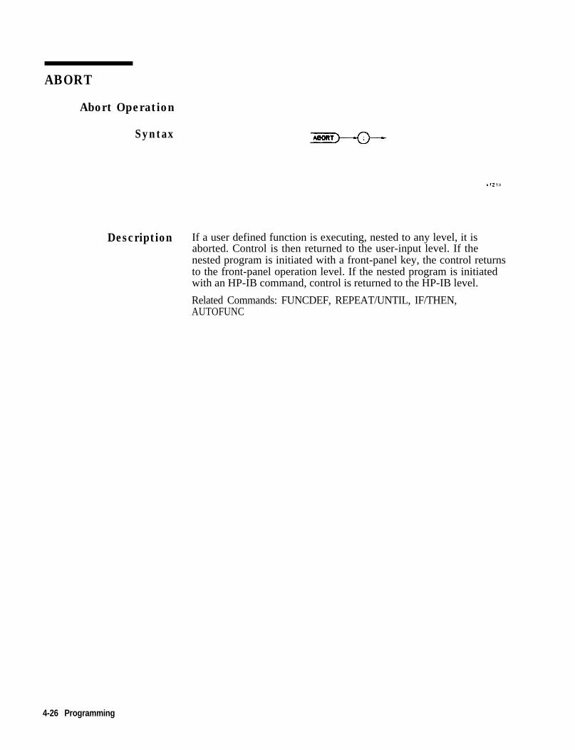
ABORT
Abort Operation
Syntax
Description If a user defined function is executing, nested to any level, it isaborted. Control is then returned to the user-input level. If thenested program is initiated with a front-panel key, the control returnsto the front-panel operation level. If the nested program is initiatedwith an HP-IB command, control is returned to the HP-IB level.
Related Commands: FUNCDEF, REPEAT/UNTIL, IF/THEN,AUTOFUNC
4-26 Programming

ABORT
Program ExampleIO2030405060708090100110120
130140
150160170180190200210220230240250260270280290300
! The following example shows the use of the ABORT command. The! instructions within the FUNCDEF '6' delimiters form a structure! called a DLP (downloadable program).!ASSIGN Wa TO 718 ! Assign I/O path to address 718.!OUTPUT (PSa; "FUNCDEF TST,Q;"; ! Logical start of the DLP.OUTPUT QSa;"VARDEF Y,500;"; ! Create variable and initialize to 500.OUTPUT OSa;"VARDEF X,500;"; ! Create variable and initialize to 500.OUTPUT (PSa* "CLRDSP*"*OUTPUT BSai"REPEATi":
! Clear display.! Begin loop.
OUTPUT (OSa;" IF Y,LT,lOO; THEN;";! Test condition.
OUTPUT (DSa;" PU;PA 100,X;"; ! Move pen.OUTPUT (OSa;" TEXT%DLP ABORTED%;";
! Print text.OUTPUT (DSa;" ABORT;";OUTPUT Ma;" ELSE;";OUTPUT (OSa;" PU;PA 100,X;"; ! Move pen.OUTPUT (OSa;” DSPLY Y,5,2;"; ! Display 'Y'.OUTPUT QSa;" SUB X,X,40;"; ! Decrement pen pointer.OUTPUT @a;" SUB Y,Y,lOO;"; ! Decrement variable.OUTPUT OSa;" ENDIF;";OUTPUT QSa;WNTIL Y,EQ,-100;"; ! End loop (the abort will occur
! before this condition will be! satisfied).
OUTPUT BSa;"@;"; ! Logical end of DLP.!OUTPUT QSa;"TST;"; ! Execute DLP.!ASSIGN cDSa TO * ! Close I/O path.END
Programming 4-29

ABS
Absolute Value
Syntax
Description The absolute value of the source is stored in the destination.
Program Example1050607080819091100101103104105107190330340
! The following example shows the use of the ABS command.!ASSIGN cDSa TO 718 ! Assign I/O path to address 718.!OUTPUT @Sa;"IP;"; !OUTPUT (DSa; "CF 300MHZ;SP 1MHZ;"; !OUTPUT QSa;"VARDEF ABSLT,VAL,O;";OUTPUT QSa;"TS;MKPK HI;";OUTPUT OSa;"ABS ABSLT,VAL,MKA;";
OUTPUT QSa;"ABSLT,VAL?;";ENTER OSa;Abs-val!
Instrument preset.Set center frequency and span.Create variable, initialize to 0.Marker to signal peak.Put the absolute value of themarker amplitude into ABSLT,VAL.Query ABSLT,VAL.
! Get the value from the analyzer.
PRINT "The absolute value of the marker amplitude =";Abs,val!ASSIGN cOSa TO * ! Close I/O path.END
4-30 Programming
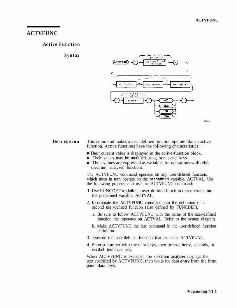
ACTVFUNC
ACTVFUNC
Active Function
Syntax ,--downloadable-..,program
character
Description This command makes a user-defined function operate like an activefunction. Active functions have the following characteristics:
w Their current value is displayed in the active-function block.n Their values may be modified using front panel keys.n Their values are expressed as variables for operations with other
spectrum analyzer functions.
The ACTVFUNC command operates on any user-defined function,which must in turn operate on the predefined variable, ACTVAL. Usethe following procedure to use the ACTVFUNC command:
1. Use FUNCDEF to define a user-defined function that operates onthe predefined variable, ACTVAL.
2. Incorporate the ACTVFUNC command into the definition of asecond user-defined function (also defined by FUNCDEF).
a. Be sure to follow ACTVFUNC with the name of the user-definedfunction that operates on ACTVAL. Refer to the syntax diagram.
b. Make ACTVFUNC the last command in the user-defined functiondefinition.
3. Execute the user-defined function that executes ACTVFUNC.
4. Enter a number with the data keys, then press a hertz, seconds, ordecibel terminate key.
When ACTVFUNC is executed, the spectrum analyzer displays thetext specified by ACTVFUNC, then waits for data entry from the frontpanel data keys.
Programming 4-3 1

ACTVFUNC
Note The command line causes the prompt-response input to be multipliedby the corresponding multiplier of the terminate key. As an example,if the initial value is 10 Hz and the GHz units key is used to terminatethe prompt response, 10 GHz is displayed in the active-function block.
Restrictions: Subject to available memory. The following commandsconsume memory: ONEOS, ARRAYDEF, TRDEF, KEYDEF, LCLVAR,VARDEF REPEAT/UNTIL, and IF/THEN.
Program Example102030405060708090100110120130140150160170180190200
210220230240
250260
example.270280290300310320330340
! The following example shows the use of the ACTVFUNC command. The! example uses an input signal of 300 MHz such as the CAL OUTPUT and! may be set (by the user input) to look at its harmonics. An input! signal is not necessary to the function of this example, but acts as! a visual aid.!ASSIGN (DSa TO 718 ! Assign I/O path to address 718.!OUTPUT OSa;"FUNCDEF TST,@;"; ! Logical start of the DLP.OUTPUT 6Sa;"VARDEF FREQ,O;"; ! Create variable, initialize to 0.OUTPUT (DSa;"SP 5MHZ;"; ! Set span.OUTPUT OSa;"REPEAT;"; ! Begin loop.OUTPUT OSa;" ADD FREQ,FREQ,ACTVAL;"; ! Increment freq by number entered.OUTPUT (DSa;" MOV CF,FREQ;TS;"; ! Set new center freq; take sweep.OUTPUT 9Sa;"UNTIL FREQ,GT,2.9ES;"; ! Loop until frequency is 2.9 GHz.OUTPUT (DSa;"O;"; ! Logical end of DLP.!OUTPUT QSa ;"FUNCDEF SETUP,@;"; ! Logical start of the DLP.OUTPUT QSa;"IP;SNGLS;"; ! Instrument preset; single sweep.OUTPUT QSa;"ACTVFUNC TST,%ENTER FREQ%,300EG,HZ;“;
! Set up the analyzer to! wait for front-panel input.
OUTPUT cDSa*"cP*"*, 33 ! Logical end of DLP.!OUTPUT QSa;"KEYDEF I,SETUP,%DEMO ACTVFUNCX;";
! Create a softkey to! initiate the example.
PRINT "Press (LcL) [MODULE] {USER KEY), then (ACTVFUNC) to run the0
PRINTPRINT "Then enter a starting frequency such as 300 MHz. When the units"PRINT "key has been pressed, the example will begin to increment the"PRINT "Center Frequency from the entered frequency to 2.9 GHz in steps"PRINT “equal to the entered value.”!ASSIGN OSa TO * ! Close I/O path.END
4-32 Programming

ADD
ADD
Addition
SyntaxA D D
- d e s t i n a t i o n - ,
T R A
Description The values of source 1 and 2 are added and the sum is sent to thedestination.
Programming 4-33

ADD
Program Example102030405060708090
100110120130140150
160170180190200210220
! The following example shows the use of the ADD command. The example! uses an input signal of 300 MHz, such as the CAL OUTPUT signal, and! looks at its harmonics. An input signal is not necessary to the! function of this example, but acts as a visual aid.!ASSIGN QSa TO 718 ! Assign I/O path to address 718.!OUTPUT QSa;"FUNCDEF ADDEX,O;"; ! Logical start of the DLP function.OUTPUT QSa;"VARDEF FREQ,300E6;"; ! Create variable and initialize it to
! 300 MHz.OUTPUT OSa;"IP;SP IMHZ;";!
! Instrument preset; set span.
OUTPUT QSa*"REPEAT*"*OUTPUT @Sail' MOV CF:FREQ;~~;
! Begin loop.! Set center frequency.
OUTPUT (OSa;" TS;"; ! Take a sweep to update display.OUTPUT (DSa;" ADD FREQ,FREQ,300EG;";
! Increase FREQ by 300 MHz.OUTPUT sDSa;WNTIL FREQ,GT,3ES;"; ! End of loop.OUTPUT cBSa*"O*"*8 ,, ! Logical end of DLP function.!OUTPUT QSa-"ADDEX*"*t # , ! Execute function.!ASSIGN @Sa TO * ! Close I/O path.END
4-34 Programming

ARRAYDEF
ARRAYDEF
Array Definition
Syntax
Description The ARRAYDEF command allows you to create user-defined arraysof the type REAL, INTEGER, or BYTE. The number of elements inthe array is limited only by the amount of free user memory in themodule. In array operations, arrays of different types (such as REAL,INTEGER, or BYTE) cannot be operated on unless they are accessedelement by element. For example a REAL array defined by thecommand in line 10 below, then executed with line 20, is an invalidcombination.
10 OUTPUT 718;"ARRAYDEF REAL,TST,GOl;"20 OUTPUT 718;"MOV TRA,TST;"
This is because TST is a REAL array and TRA is an integer array. Avalid command combination to access an array element by element isas follows:
10 OUTPUT 718;"ARRAYDEF REAL,TST,GOl;"20 OUTPUT 718; “MOV TRA[l],TST[l];"
Restrictions: Subject to available memory. The following commandsconsume memory: ONEOS, ARRAYDEF, TRDEF, KEYDEF, LCLVAR,VARDEF REPEAT/UNTIL, and IF/THEN.
Query Response For array data transfer to and from an external controller, only Mformat is supported. A, B, I, and P block-data field formats are notcurrently supported.
Programming 4-35

ARRMDEF
Program Examplelo-2030405060708090100110120130140150160170180190200210220230240250
260270280290300310320330340350360370380390
! The following example shows the use of the ARRAYDEF command. The! example uses an input signal of 300 MHz such as the CAL OUTPUT and! looks at its harmonics.!ASSIGN QSa TO 718 ! Assign I/O path to address 718.!OUTPUT QSa;"ARRAYDEF REAL,FREQS,lO;"; ! Create a lo-element REAL array.
;"ARRAYDEF REAL,AMPLS,lO;"; ! Create another REAL array.;"VARDEF X,l;VARDEF Y,600;"; ! Create, initialize two variables.
OUTPUT OSaOUTPUT OSaOUTPUT @SaOUTPUT @SaOUTPUT OSa!
;"IP;FA IOOMHZ;";;"FB 2900MHZ;TS;";;"MKPK HI;";
! Preset; set start frequency.! Set stop frequency; take sweep.! Marker to peak of highest signal.
OUTPUT OSa*"REPEAT*"*OUTPUT QSaj” MOV ;REQS[XI,MKF;";! element of FREQS array.OUTPUT (PSa;" MOV AMPLSCXI,MKA;";! element of AMPLS array.OUTPUT QSa;" MKPK NH;";OUTPUT (PSa;” ADD X,X,1;";OUTPUT @Sa;"UNTIL X,GT,lO;";!OUTPUT OSa; "CLRDSP;";OUTPUT (OSa;"PA 110,650;";ouwm (OSa;"TEXT %FREQUENCY(Hz)
OUTPUT OSa; "MOV X,1;";OUTPUT @Sa*"PA 100 Y*"*8 , 9 2!OUTPUT QSa*"REPEAT*"*9 , ,
! Begin loop.! Put marker frequency into Xth
! Put marker amplitude into Xth
! Marker to next highest peak.! Increment array pointer.! Loop until array pointer > 10.
! Clear analyzer display.! Move pen to starting point.
AMPLITUDE(dBm)%;";! Write titles.! Initialize array pointer.! Pen to first column.
! Begin loop.OUTPUT OSa;" DSPLY FREQSCXl,l0,3;"; ! Display Xth frequency.OUTPUT (PSa;" TEXT % X;"; ! Space over to next column.OUTPUT QSa;" DSPLY AMPLS[XI,l0,3;"; ! Display Xth amplitude.OUTPUT (DSa;” SUE3 Y,Y,30;“; ! Decrement pen location.OUTPUT (DSa;" PA 100,Y;"; ! Move pen to new locationOUTPUT OSa;" ADD X,X,1;"; ! Increment array pointer.OUTPUT BSa;"UNTIL X,GT,lO;"; ! Loop until array pointer > 10.
ASSIGN OSa TO * ! Close I/O path.END
4-36 Programming

AUTOEXEC
AUTOEXEC
Automatic Execution
Syntax
Description Turns off or on the automatic function as defined with theAUTOFUNC command.
Prerequisite Command: AUTOFUNC
Related Commands: AUTOSAVE, CLRSCHED
Program Example102030405060708090100110120130140150160170180190200210220230240250260270280290300310
! The following example shows!ASSIGN QSa TO 718 !!Autoexec,status=999 !
!OUTPUT QSa;"AUTOEXEC ON;"; !OUTPUT OSa;"AUTOEXEC?;"; !ENTER OSa;Autoexec-status !GOSUR Check-status!OUTPUT OSa;"AUTOEXEC OFF;"; !OUTPUT QSa;"AUTOEXEC?;"; !ENTER OSa;Autoexec,status !GOSUB Check-statusSTOP!Check-status: !
!SELECT Autoexec,statusCASE 0
the use of the AUTOEXEC command.
Assign I/O path to address 718.
Initialize status variable toELSE case value.Turn AUTOEXEC function on.Query its status.Get the status from the analyzer.
Turn AUTOEXEC function off.Query its status.Get the status from the analyzer.
Subroutine to display the status ofthe AUTOEXEC function.
PRINT "The AUTOEXEC function is OFF."CASE 1
PRINT "The AUTOEXEC function is ON."CASE ELSE! This condition does not exist, however it is a good programming! practice to include an ELSE case for unexpected situations.
PRINT "The AUTOEXEC function returned an unknown status value.”END SELECTRETURN ! From Check-status subroutine.END
Programming 4-37
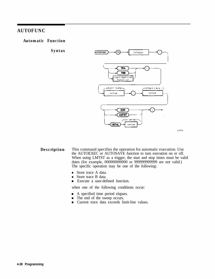
AUTOFUNC
Automatic Function
Syntax AUTOFUNC
/rstop t i m e - \
Description This command specifies the operation for automatic execution. Usethe AUTOEXEC or AUTOSAVE function to turn execution on or off.When using LMTST as a trigger, the start and stop times must be validdates (for example, 000000000000 or 999999999999 are not valid.)The specific operation may be one of the following:
l Store trace A data.l Store trace B data.n Execute a user-defined function.
when one of the following conditions occur:
n A specified time period elapses.n The end of the sweep occurs.n Current trace data exceeds limit-line values.
4-38 Programming

AUTOFUNC
Parameters 1. There can be from one to seven processes scheduled.2. TRA ( TRB 1 DLP (TRA, TRB for autosaving traces; DLP:: = name of
user-defined function.)3. Start-time format: MMDDYYHHMMSS or DDMMYYHHMMSS
(depending on datemode format)4. Stop-time: MMDDYYHHMMSS or DDMMYYHHMMSS (depending on
datemode format)5. EOS / LMTST ( INTVL selects criteria to perform autosave or to
execute a DLP.a. EOS occurs at the end of a sweep.b. LMTST occurs at the end of a sweep after a limit test failure.c. IN’I’VL occurs after the end of a sweep, when the first
designated time interval is reached. The format for an intervalentry is HHMMSS.
6. INTVL occurs at the interval time if INTVL is selected.
Restrictions: Subject to available memory. The following commandsconsume memory: ONEOS, ARRAYDEF, TRDEF, KEYDEF, LCLVAR,VARDEF REPEAT/UNTIL, and IF/THEN.
Prerequisite Commands: FUNCDEF, CONTS, TITLE, SLRW, andlimit-line commands.
Related Commands: CLRDSP, TITLE, ABORT, RETURN, PAUSE,ERASE, DISPOSE.
Program Example102030405060708090100110120130140150160170180190200210220230240250260
! The following example shows the use of the AUTOFUNC command.!ASSIGN cOSa TO 718 ! Assign I/O path to address 718.!OUTPUT @Sa; “IP; ‘I ; ! Instrument preset.! Create three items for the AUTOEXEC Schedule.OUTPUT QSa;"AUTOFUNC 1 ,B0X,010189000000,010589000000 EOS;";OUTPUT OSa;"AUTOFUNC 2 ,CHK,S1G,123188235500,123188235900 INTVL 000030;";OUTPUT OSa;"AUTOFUNC 3 TRA,122488090000,122488125900 LMTST;";PRINT "Press CLCL) [MODULE] AUTOEXEC MENU to see the new schedule."DISP "Press [CONTINUE] on the computer when ready”PAUSE!! Remove one item from the schedule.OUTPUT OSa;"IP;CLRSCHED 2;";PRINT "Press (LCL) [MODULE] {AUTOEXEC MENU) to see the updated schedule."DISP "Press [CONTINUE] on the computer when ready"PAUSEI! Clear the entire schedule.OUTPUT QSa;"IP;CLRSCHED ALL;";PRINT "Press (LCL) [MODULE] (AUTOEXEC MENU) to see the cleared schedule."DISP 'I"!ASSIGN QSa TO *END
Programming 4-39

AUTOSAVE
Automatically Save Traces
Syntax
Description When set to ON, this command activates the automatic saving oftraces. The data to be automatically saved must be identified in theAUTOFUNC command.
Prerequisite Commands: AUTOFUNC and TITLE.
Restrictions: A maximum of one trace per second and subject toavailable memory. The following commands consume memory:ONEOS, ARRAYDEF, TRDEF, KEYDEF, LCLVAR, VARDEFREPEAT/UNTIL, and IF/THEN.
4-40 Programming

AVG
AVG
Average
Syntax ,- d e s t i n a t i o n - . ,
roverag. r a t i o - \
u s e r - d e f i n e d\ vorioble
L p r e d e f i n e d Jv a r i a b l e
L p r e d e f ined 2f u n c t i o n
Lr t r a c e ie l e m e n t
Description The data in the source and destination are averaged, then stored inthe destination. The following averaging algorithm is used:
DESTnew = ((RATIO - 1) x DESTold + SOURCE)/RATIO
Parameter Range Average Ratio:
Minimum: -32,7670 is not allowedMaximum: + 32,767
Programming 4-41

AVG
Program Example10 ! The following example shows the use of the AVG command.20 !30 ASSIGN OSa TO 718 ! Assign I/O path to address 740 !50 OUTPUT (PSa;"IP;"; ! Instrument preset.60 OUTPUT OSa;"SNGLS;CLRW TRA;TS;"; ! \ Set up the analyzer.70 OUTPUT OSa;"FA 300MHZ;FB 2GHZ;TS;"; ! /80 OUTPUT 9Sa;"VAVG 1O;TS;";90 OUTPUT (OSa;"VIEW TRA;VIEW TRB;"; !100 OUTPUT @Sa;"AVG TRB,TRA,2;"; ! Average trace A and trace B,110 ! place result in trace B.120 ASSIGN 6Sa TO * ! Close I/O path.130 END
.8.
442 Programming

CARDLOAD
CARDLOAD
Copy Data From Memory Card to Module Memory
Syntax ,-file n a m e -,
CARDLOAD del i m i t e r de i m i t e r
Description Copy the specified data from the memory card to the modulebattery-backed memory. The filename label (identifier) should followthis format: 1 to 9 ASCII characters followed by a period, thenfollowed by one of these three-letter suffixes: DLP or LMT. ValidASCII characters that may be selected are: A through Z, 0 through 9,and _ (underscore).
A limit line may be created with the extension .lim appended tothe filename. The extension LMT must be used when using theCARDLOAD and CARDSTORE commands with mass memory modulefirmware revisions before 950829. For later firmware, either extensionis allowed.
The following statement copies the DLP “ABCDEFGHI” from thememory card to the module:
CARDLOAD %ABCDEFGHI.DLP%;
Programming 443

CARDLOAD
Program Example
102030405060708090100110120130140150160170180190200210220230240250260270280290300
Note DLPs, traces, and limit lines stored on memory cards using amass-memory module with firmware datecode 910116 or later cannotbe read into a module with an earlier firmware datecode (for example890524). DLFs, traces, and limit lines stored on cards using moduleswith firmware datecode 890524 or earlier can be read into a modulewith firmware datecode 910116 or later.
! The following example shows the use of the CARDLOAD command. The! example creates a DLP (downloadable program) and stores it in memory.! It is then copied to the memory card, if available.!ASSIGN QISa TO 718 ! Assign I/O path to address 718.!OUTPUT OSa;"FUNCDEF BOX,@;"; ! Logical start of function 'BOX'.OUTPUT OSa;" IP;"; ! Instrument preset.OUTPUT (PSa;" CLRDSP;"; ! Clear the analyzer screen.OUTPUT (OSa;" PU;PA 300,300;"; ! Move pen to starting point.OUTPUT (PSa;” PD;PR 240,O;"; ! \OUTPUT OSa;" PR 0,240;"; ! \ DrawOUTPUT (OSa;" PR -240,O;"; ! / rectangle.OUTPUT Wa;" PR 0,-240;"; ! /OUTPUT OSa;"O;"; ! Logical end of function.!OUTPUT OSa;"CARDSTORE %BOX.DLP%;"; ! Copy DLP to memory card.!! The DLP now appears on the catalog of the memory card available in! the module utility menu.!OUTPUT OSa;"DISPOSE BOX;";
!
! Remove the DLP 'BOX' from! the module memory. It is! still on the card!!
OUTPUT OSa;"CARDLOAD %BOX.DLP%;"; ! Copy DLP from card to module! memory. Now it's in both places.
!ASSIGN OSa TO * ! Close I/O path.END
4-44 Programming

CARDSTORE
CARDSTORE
Copy Data to a Memory Card
Syntax
Description Copy the specified data from the module memory to a RAM card. Thefilename should follow this format: 1 to 9 ASCII characters followedby a period, then followed by one of these three-letter suffixes: DLPor LMT. Valid ASCII characters that may be selected are: A through Z(upper-case only), 0 through 9, and _ (underscore). RAM cards use theLogical Interchange Format (LIF) and therefore accept only 9 of the16 characters used to title data.
Note The Iirst 9 characters must be unique to avoid writing over an existingfile. If a file name is longer than 9 characters or if lower-case lettersare used, the file name will be converted, if possible, to an LIFcompatible file name using only the first 9 characters.
Note
A limit line may be created with the extension Jim appended tothe filename. The extension .LMT must be used when using theCARDLOAD and CARDSTORE commands with mass memory modulefirmware revisions before 950829. For later firmware, either extensionis allowed.
DLPs, traces, and limit lines stored on memory cards using a mass-memory module with firmware datecode 910116 or later cannot beread into a module with an earlier firmware datecode (for example890524). DLPs, traces, and limit lines stored on cards using moduleswith firmware datecode 890524 or earlier can be read into a modulewith firmware datecode 910116 or later.
Programming 4-45

CARDSTORE
Program Example102030405060708090100110120130140150160170180190
! The following example shows the use of the CARDSTORE command. The! example creates a DLP (downloadable program) and stores it in memory.! It is then copied to the memory card, if available.!ASSIGN OSa TO 718 ! Assign I/O path to address 718.!OUTPUT QSa;"FUNCDEF BOX,(O;"; ! Logical start of function 'BOX'.OUTPUT QSa;" IP;"; ! Instrument preset.OUTPUT OSa;" CLRDSP;"; ! Clear the analyzer screen.OUTPUT OSa;" PU;PA 300,300;"; ! Move pen to starting point.OUTPUT (DSa;" PD;PR 240,O;"; ! \OUTPUT (DSa;" PR 0,240;"; ! \ DrawOUTPUT &?a;" PR -240,O;"; ! / rectangle.OUTPUT @Sa;" PR 0,-240;"; ! /OUTPUT QSa;'W;"; ! Logical end of function.!OUTPUT QSa;"CARDSTORE #BOX.DLP%;"; ! Copy DLP to memory card.ASSIGN QISa TO * ! Close I/O path.END
446 Programming

CATALOG
CATALOG
Directory Listing over HPIB
Syntax
Description The CATALOG command returns a directory listing of the currentmass storage device over the HPIB interface. The mass storage deviceshould be specified using MSDEV prior to executing the CATALOGcommand.
Related command: MSDEV
The listing is in the form of one string terminated by a linefeed withEOI. The string is divided into two substrings by a linefeed character.The first substring contains the actual listing and the second substringcontains the amount of free memory in bytes. Refer to the QueryResponse figure and Pile Information Parameters table for moreinformation.
Note The CATALOG command is only available in firmware revisiondatecodes of 910116 and later.
Query Response
Ilf21a
Where:
filename up to 16 characters (up to 9 if MSDEV is CARD)filelength up to 6 characterstimestamp 12 characterstitle up to 32 characters
* These paths only available when MSDEV is MEM.
t This path only available when MSDEV is CARD.
Programming 4-47

CATALOG
File Information Parameters
File Information
filename.LIM
filename.VAR
Description
This file contains a limit line
This file is a variable defined using theVARDEF, or TRDEF, or ARRAYDEFcommand.
It is only available when MSDEV is setto MEM.
f ilename.DLP If MSDEV is set to MEM this is thedownloadable program defined using theFUNCDEF command.
filename.timestamp.TRC This file is a trace. It can be recalledby way of the front panel or by usingfilename.timestamp asan argumentto MODRCIX when MSDEV is setto MEM
filename.TRC :title:timestamp: This trace file is storedin thememory card. When the file is copiedto the module memory, it will bestored under filename titlewith the corresponding t imest amp.
Program Examde 1 The following example simply queries the module memory for itscatalog and prints the string returned from the module. Example 2shows how to query the catalog and parse the output string.
102030406070
8090100110120130140
ASSIGN @Sa TO 718DIM Cat$[lOOOOl ! Dimension string arbitrarily large.DIM Bytes,avail$[20] ! Must accommodate "BYTES FREE XXXXXX<lf>".OUTPUT @a-"MSDEV MEM."OUTPUT @SaI"CATALOG?;:'
! Specify MSDEV to be cataloged.! Query module for directory listing.
ENTER @Sa USING "#,K";Cat$,Bytes,avail$! Data up to the first <If>! will go into Cat$; data up! to <If-EOI> will go into! Bytes,avail$.
PRINT Cat$PRINT Bytes-avail$ASSIGN QSa TO *END
4-46 Programming

CATALOG
The following is a sample output of the mass memory module memoryafter the DEMO DLPshavebeenloaded:
ANALYZER.DLP 966,CONNECTCAL.DLP 157,DEMOS.DLP 34,DISTORTION-l.DLP 691,DISTORTION-2.DLP 78,DISTORTION-3.DLP 1458,FRAME.DLP 42,PAGE,l.DLP 804,PAGEDlO.DLP 961,PAGE-ll.DLP 891,PAGEB12.DLP 848,PAGE,l3.DLP 958,PAGED13A.DLP 86,PAGE-2.DLP 945,PAGEB3.DLP 882,PAGE,4.DLP 1012,PAGEB4A.DLP 884,PAGEB5.DLP 999,PAGE,5A.DLP 802,PAGE,6 .DLP 828,PAGE,6A.DLP 697,PAGEB7.DLP 563,PAGEB7A.DLP 56l,PAGE,8.DLP 856,PAGE,8A.DLP857,PAGEm9.DLP 1007,PRESET.DLP 2l,SIGMON-l.DLP 1056,SIGMON-2.DLP 73,SIGMON,3. DLP1145,SIMPLE,l.DLP 284,SIMPLE,2.DLP 285,SIMPLEB3.DLP 279,SIMPLEB4.DLP 287,SIMPLE,
5.DLP 244,SIMPLE,6.DLP 589,SIMPLE,7.DLP 699,SIMPLEm8.DLP 1134BYTES FREE 103886
Program Example 2 The following example parses the output of the CATALOG command.The program displays softkeys enabling the user to catalog the entiremass storage device or only certain file types, such as DLPs, limit lines,or traces. Variables can be cataloged only if the mass storage device isMEM; variables cannot be stored to the memory card.
This example is written for HP BASIC 2.1 or greater and runs on anHP Series 200/300 Controller.
102030405060708090100110120130140150160170180190200210220230240250260270280290300310320330
!The following example shows the use of the CATALOG command. The example!catalogs the current mass storage device (CARD or MEM) and parses the!returned string into a holding array. Softkeys are then enabled to!allow the user to select which part of the catalog to display.!INTEGER Last,match,Entry-name,Entry,length,Entry-type,EntryINTEGER Space,loc,Dot,loc,Two,dotsDIM String_parsed$[75],String$C751,Rev_str$C75l,Bytes-avail$ CiOlDIM Mass,stg,dev$[ll,Temp$C751DIM Ent$(l:3,1:500)[75],Cat$[5000]
!ASSIGN OSa TO 718 ! Spectrum analyzer HP-IB addressDISP "Loading user defined memory."OUTPUT QSa*"MSDEV?*"ENTER @Sa;Mass&dev$IF Mass,stg,dev$="M" THEN PRINT "Mass Storage Device is MEMORY"IF Mass-stg,dev$=" Cl' THEN PRINT "Mass Storage Device is CARD"
!OUTPUT QSa*"CATALOG?*"ENTER @Sa USING "#,N';Cat$,Bytes-avail$PRINT Bytes,avail$;" (of available user memory)"
!Entry=0Entry,name=FNWhich,pos("NAME")Entry,length=FNWhich_pos("LENGTH")Entry,type=FNWhich,pos("TYPE")REPEATEntry=Entry+lCALL Universal-parse("," ,Cat$,String-parsed$,Last_match)IF LEN(String,parsed$)=O THEN No-entriesDot-loc=POS(String,parsed$,".")Two-dots=POS(String,parsed$[Dot,loc+ll,".")IF Two-dots THEN ! (it must be a trace in MEM)
Programming 4-49

CATALOG
340350360370380390400410420430440450460470480490500510520530540550560570580590
Dot,loc=Two,dots+Dot,locEND IFSpace-loc=POS(String_parsed$," ">WHILE Space,loc<Dot-lot ! Ignore spaces which are
Temp$=String,parsed$CSpace,loc+l] ! part of LIMIT LINE title.Space,loc=Space,loc+POS(Temp$," ">
END WHILE!String$=String-parsed$[l,Dot,loc-11WHILE NUM(String$[l,l1)<32 ! Strip any special characters from
String$=String$[21 ! system-generated dlp names.END WHILEEnt$(Entry,name,Entry)=String$!SELECT Mass-stg-dev$ !Allow for differences in stringCASE "M" !of the Memory Card and Module MemoryEnt$(Entry_length,Entry)=String,parsed$[Space-loc]
CASE "C"Rev-str$=REV$(String,parsed$)Ent$(Entry,length,Entry)=TRIM$(REV$(Rev,str$[l,POS(Rev-str$," ">I>>
END SELECT!Ent$(Entry_type,Entry)=TRIM$(String,parsed$[Dot-loc+l;4])
UNTIL Last-match!
LOOP ! Display softkeys until Exit key! is pressed.
600 ON KEY 1 LABEL "DLP" GOSUB List-dlps610 ON KEY 2 LABEL "All" GOSUB List-all620 ON KEY 4 LABEL "Exit" RECOVER Exit-cat630 ON KEY 3 LABEL "Lim Line" GOSUB List-limit640 IF Mass,stg-dev$="M" THEN ON KEY 6 LABEL "Variable" GOSUB List,vars650 !Variable key is only displayed for a catalog of MEM. Variables660 !cannot be stored on the card.670 ON KEY 8 LABEL "Trace" GOSUB List-traces680 DISP "Select list mode."690 END LOOP700 No,entries:PRINT "No Catalog Entries ! !"710 Exit,cat:ASSIGN QSa TO *720 DISP "PROGRAM ENDED"730 STOP740 I-----------------------------------------------------------------l750 List-dlps:Display-cat("DLP",Ent$(*),Entry)760 RETURN770 List-all:Display-cat("ALL",Ent$(*),Entry)780 RETURN790 List,vars:Display,cat("VAR",Ent$(*),Entry)800 RETURN810 List-traces:Display-cat("TRC",Ent$(*),Entry)820 RETURN830 List,limit:Display-cat("LIM",Ent$(*),Entry)840 RETURN850 END860I-------------------------------------------------------------------
4-50 Programming

CATALOG
870 SUB Universal,parse(Delimiter$,In_n_out$,String-parsed$,IN~GER Last-match)880 !A generic parsing routine.890 Universal-parse: !900 INTEGER Delim-loc,Len-delim910 Len,delim=LEN(Delimiter$)920 Delim,loc=POS(In,n-out$,Delimiter$)930 IF Delim,loc=O THEN940 String-parsed$=In,n,out$950 Last-match=1960 ELSE970 String,parsed$=TRIM$(In_n,out$[l,Delim-lot-11)980 In-n,out$=TRIM$(In,n,out$[Delim-loc+Len-deliml)990 Last-match=01000 END IF1010 SUBEND ! <Universal-parse>1020 ! ----___----____-_--------------------------------------------------1030 SUB Display,cat(Class$,Ent$(*),INTEGER Num,entries)1040 !Displays the previously parsed catalog retrieved from the 85620A+.1050 Display-cat:!1060 INTEGER Entry,name,Entry,length,Entry,type,Entry1070 REAL Total,length,Total-entries1080 !1090 Entry,name=FNWhich-pos("NAME")1100 Entry,length=FNWhich,pos("LENGTH")1110 Entry,type=FNWhich-pos("TYPE")1120 Total-length=01130 Total-entries=01140 !1150 1m:IMAGE 12A,2X,20A,2X,8D1160 Im2:IMAGE 12A,2X,20A,2X,l5A117011801190120012101220123012401250126012701280129013001310132013301340
135013601370138013901400
DISPOUTPUT KBD;CHR$(255)t"K"; ! Clear screenPRINT USING Im2;" Type
,I II Name II ,I Byte total"PRINT USING Im2;” --__------- It;,, -------------------- +I --em -- --m-w--- 11
!FOR Entry=1 TO Num,entriesIF Class$=Ent$(Entry,type,Entry) OR Class$="ALL" THENSELECT Ent$(Entry,type,Entry)CASE "DLP"
String$="DLP (Func) "CASE "VAR"
String$="Variable 'CASE "TRC"
String$="Trace 'CASE "LIM"
String$="Limit Line 'END SELECTPRINT USING Im;String$,Ent$(Entry,name,Entry),
VAL(Ent$(Entry,length,Entry))GOSUB Totals
END IFNEXT EntryPRINTPRINT "TOTALS. ";VAL$(Total,length);" bytes."PRINT fl ' ' ;VAL$(Total,entries);" entries."
Programming 4-51

CATALOG
1410 SUBEXIT1420 !1430 Totals: !1440 Total-entries=Total-entries+11450 Total,length=Total_length+VAL(Ent$(Entry-length,~try))1460 RETURN1470 !1480 SUBEND1490 !---------------------------------------------------------------11500 DEF FNWhich,pos(Class$)1510 !Determines where information is placed in the array. Allows1520 !for re-arranging of the array.1530 Which,pos: !1540 SELECT Class$1550 CASE "NAME"1560 RETURN 11570 CASE "LENGTH"1580 RETURN 21590 CASE "TYPE"1600 RETURN 31610 CASE ELSE1620 RETURN01630 END SELECT1640 FNEND
4-52 Programming
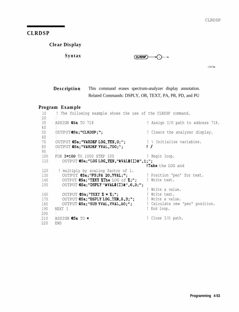
CLRDSP
CLRDSP
Clear Display
Syntax (CLRDSP
Description This command erases spectrum-analyzer display annotation.
Related Commands: DSPLY, OR, TEXT, PA, PR, PD, and PU
Program Example102030405060708090100110
! The following example shows the use of the CLRDSP command.!ASSIGN (DSa TO 718 ! Assign I/O path to address 718.!OUTPUT OSa;"CLRDSP;"; ! Clears the analyzer display.!OUTPUT QSa;"VARDEF LOG-TEN,O;";OUTPUT OSa;"VARDEF YVAL,700;";!
! \ Initialize variables.! /
FOR I=100 TO 1000 STEP 100 ! Begin loop.OUTPUT OSa;"LOG LOG,TEN,"&VAL$(I>&",l;";
!Take the LOG and120130140150
! multiply by scaling factor of 1.OUTPUT OSa;"PU;PA 20,YVAL;"; ! Position "pen" for text.OUTPUT (OSa;"TEXT %The LOG of %;'I; ! Write text.OUTPUT QSa;"DSPLY "&VAL$(I)&",6,3;";
! Write a value.160 OUTPUT QSa;"TEXT % = 1;"; ! Write text.170 OUTPUT QSa;"DSPLY LOG_TEN,5,3;"; ! Write a value.180 OUTPUT @Sa;'%JB YVAL,YVAL,50;"; ! Calculate new "pen" position.190 NEXT I ! End loop.200 !210 ASSIGN OSa TO * ! Close I/O path.220 END
Programming 4-53

CLRSCHED
Clear Autosave/Autoexec Schedule Buffer
Syntax
Description
Program Example
Clears the Autosave/Autoexec Schedule of all or individually specifiedcontents. Clear all schedule contents with the ALL command orselectively by specifying which number (from one to seven) to clear.
102030405060708090100110120130140150160170180190200210220230240250260
! The following example shows the use of the CLRSCHED command.!ASSIGN 9Sa TO 718 ! Assign I/O path to address 718.!OUTPUT OSa*"IP*"- ! Instrument preset.! Create tkee'iiems for the AUTOEXEC Schedule.OUTPUT QSa;"AUTOFUNC 1 ,B0X,010189000000,010589000000 EOS;";OUTPUT OSa;"AUTOFUNC 2 ,CHK~S1G,123188235500,123188235900 INTVL 000030;";OUTPUT OSa;"AUTOFUNC 3 TRA,122488090000,122488125900 LMTST;";PRINT "Press (LCL) [MODULE] (AUTOEXEC MENU) to see the new schedule."DISP "Press [CIJNTIIVUEI on the computer when ready"PAUSE!
! Remove one item from the schedule.OUTPUT QSa;"IP;CLRSCHED 2;";PRINT "Press (LCL) [MODULE] (AUTOEXEC MENU) to see the updated schedule."DISP "Press [CONTINUE1 on the computer when ready"PAUSE!
! Clear the entire schedule.OUTPUT 9Sa;"IP;CLRSCHED ALL;";PRINT "Press (LCL) [MODULE] (AUTOEXEC MENU) to see the cleared schedule."DISP "'I!ASSIGN cPSa TO *END
4-54 Programming

CNTLA
CNTLA
Auxiliary Control Line A
Syntax
Description
Preset State
Program Example102030405060708090100110120130140150160170
!The following example shows a use of the CNTLA command.!ASSIGN (BSa TO 718 !Assign I/O path to address 718.!OUTPUT QSa;"VARDEF S,CNTLA,O;" !CNTLA STATEOUTPUT OSa;"FUNCDEF AUX,CLR,A,O;";OUTPUT cDSa;" CNTLA 0;"; !SET LINE A TO 0OUTPUT OSa;" MOV S,CNTLA,O;"; !UPDATE CNTLA IMAGEOUTPUT (DSa;"Q;"OUTPUT QSa;"FUNCDEF AUX-SET-A,@;";OUTPUT OSa; I' CNTLA 1;"; !SET LINE A TO 1OUTPUT QISa;” MOVE S,CNTLA,l;"; !UPDATE CNTLA IMAGEOUTPUT OSa-"(9*"OUTPUT QSai"AbX-CLR-A;"OUTPUT OSa;"S-CNTLA?;"ENTER (OSa;A$END
The CNTLA command* sets control line A of the auxiliary interfacehigh or low.
Related commands: CNTLB* , CNTLC*, CNTLD* , CNTLI*, andOUTPUT*
Refer to “Specifications and Characteristics” in Chapter 1, Installation,for a detailed description of the auxiliary interface.
On
!CLEAR LINE A!GET LINE A STATUS
* These auxiliary interface connector commands can only beaccessed remotely by way of the HPIB and DLPs and are onlyavailable with 85620A with serial prefix 3143A or higher andfirmware 910116 and later date codes.
Programming 4-55

CNTLB
Auxiliary Control Line B
Syntax
Description The CNTLB command* sets control line B of the auxiliary interfacehigh or low.
Related commands: CNTLA* , CNTLC*, CNTLD* , CNTLI*, andOUTPUT*
Refer to “Specifications and Characteristics” in Chapter 1, Installation,for a detailed description of the auxiliary interface.
Preset State On
Program Example102030405060708090100110120130140150160170
!The following example shows a use of the CNTLB command.!ASSIGN @Sa TO 718 !Assign I/O path to address 718.!OUTPUT QSa; "VARDEF S-CNTLB,O;" !CNTLB STATEOUTPUT QISa; "FUNCDEF AUX-CLR-B,Q;";OUTPUT OSa;" CNTLB 0;"; !SET LINE B TO 0OUTPUT &?a;" MOV S-CNTLB,O;"; !UPDATE CNTLB IMAGEOUTPUT QISa*"O*"OUTPUT QSaI"FUNCDEF AUX-SET-B,@;";OUTPUT OSa;" CNTLB 1;"; !SET LINE B TO 1OUTPUT (OSa;" MOVE S,CNTLB,l;"; !UPDATE CNTLB IMAGEOUTPUT @Sa*"Q*"OUTPUT QSa~"AUX-SET-B;"OUTPUT QSa;"S,CNTLB?;"ENTER (DSa; A$END
!SET LINE B!GET LINE B STATUS
* These auxiliary interface connector commands can only beaccessed remotely by way of the HPIB and DLPs and are onlyavailable with 85620A with serial prefix 3143A or higher andfirmware 910116 and later date codes.
4-56 Programming

CNTLC
CNTLC
Auxiliary Control Line C
Syntax
Description
Preset State
Program Example102030405060708090100110120130140150160170
!The following example shows a use of the CNTLC command.!ASSIGN @Sa TO 718 !Assign I/O path to address 718.!OUTPUT QSa;"VARDEF S,CNTLC,O;" !CNTLC STATEOUTPUT OSa;"FUNCDEF AUX,CLR,C,Q;";OUTPUT (OSa;" CNTLC 0;"; !SET LINE C TO 0OUTPUT OSa;" MOV S,CNTLC,O;"; !UPDATE CNTLC IMAGEOUTPUT OSa*"@*"OUTPUT OSaj"FUNCDEF AUX,SET,C,Q;";OUTPUT QSa;" CNTLC 1;"; !SET LINE C TO 1OUTPUT OSa;" MOVE S,CNTLC,l;"; !UPDATE CNTLC IMAGEOUTPUT @Sa*“(Q*”OUTPUT QSaI"A;X-SET-C;"OUTPUT QSa;"S-CNTLC?;"ENTER rPSa; A$END
The CNTLC command* sets control line C of the auxiliary interfacehigh or low.
Related commands: CNTLA*, CNTLB*, CNTLD*, CNTLI’, andOUTPUT*
Refer to “Specifications and Characteristics” in Chapter 1, Installation,for a detailed description of the auxiliary interface.
On
!SET LINE C!GET LINE C STATUS
* These auxiliary interface connector commands can only beaccessed remotely by way of the HPIB and DLPs and are onlyavailable with 85620A with serial prefix 3143A or higher andfirmware 910116 and later date codes.
Programming 4-57

CNTLD
Auxiliary Control Line D
Syntax
Description The CNTLD command* sets control line D of the auxiliary interfacehigh or low.
Related commands: CNTLA* , CNTLB’, CNTLC* , CNTLI*, andOUTPUT*
Refer to “Specifications and Characteristics” in Chapter 1, Installation,for a detailed description of the auxiliary interface.
Preset State On
Program Example102030405060708090100110120130140150160170
!The following example shows a use of the CNTLD command.!ASSIGN cDSa TO 718!OUTPUT OSa;"VARDEF S,CNTLD,O;"OUTPUT QSa;"FUNCDEF AUX-CLR,D,@;";OUTPUT OSa;" CNTLD 0;";OUTPUT QSa;” MOV S,CNTLD,O;";OUTPUT QSa;"Q;"OUTPUT QSa;"FUNCDEF AUX,SET,D,Q;";OUTPUT (DSa;" CNTLD 1;";OUTPUT QSa;" MOVE S,CNTLD,l;";OUTPUT @Sa;"Q;"OUTPUT OSa;"AUXJET-D;"OUTPUT QSa;"S-CNTLD?;"ENTER (DSa;A$END
!Assign I/O path to address 718.
!CNTLD STATE
!SET LINE D TO 0!UPDATE CNTLD IMAGE
!SET LINE D TO 1!UPDATE CNTLD IMAGE
!SET LINE D!GET LINE D STATUS
* These auxiliary interface connector commands can only beaccessed remotely by way of the HPIB and DLPs and are onlyavailable with 85620A with serial prefix 3143A or higher andllrmware 910116 and later date codes.
4.58 Programming

CNTLI
CNTLI
Auxiliary Control Line Input
Syntax
Description The CNTLI command* is a predefined variable used to read thecontrol line I status of the auxiliary interface.
Related commands: CNTLA*, CNTLB*, CNTLC’, CNTLD*, OUTPUT*
Refer to “Specifications and Characteristics” in Chapter 1, Installation,for a detailed description of the auxiliary interface.
Program Example102030405060708090100110
!The following example shows a use of the CNTLI command.ASSIGN (PSa TO 718 !Assign I/O path to address 718.OUTPUT QSa;FUNCDEF AUX,GET,CTRLI,O;";OUTPUT (PSa;" LCLVAR I,VAL,O;"; !CONTROL VALUE TEMPOUTPUT QSa;" MOV I,VAL,CNTLI;"; !GET CONTROL I VALUEOUTPUT (PSa;" EM; PU;PA 110,576;"; !DISPLAY VALUE ON SCREENOUTPUT @Sa;" TEXT 'CNTLI:';";OUTPUT QSa;" DISPLY I,VAL,2,0;";OUTPUT (PSa*"@*"OUTPUT QSaj"AUX-GET-CTRLI;"END
* These auxiliary interface connector commands can only beaccessed remotely by way of the HPIB and DLPs and are onlyavailable with 85620A with serial prefix 3143A or higher andfirmware 910116 and later date codes.
Programming 4-59

CTRLHPIB
Control HP-IB
Syntax
Description This command takes control of the HP-IB. If a controller is active anddetected on the bus, then the command is not executed and an errorresults. If none is detected, the spectrum analyzer assumes control byasserting the remote-enable (REN) line. This command should precedethe related commands RELHPIB, ENTER, and OUTPUT.
4-60 Programming

CTRLHPIB
Program Example10 ! The following example shows how to use the CTRLHPIB command to have20 ! the analyzer send data to another HP-IB device. The instructions30 ! within the FUNCDEF '6' delimiters form a structure called a40 ! DLP (downloadable program).50 !60 ! NOTE: A printer (HP-IB address 01) needs to be connected.70 !80 ASSIGN (OSa TO 718 ! Assign I/O path to address 718.90 !100 OUTPUT OSa;"FUNCDEF E,XMPLE,Q;"; ! Logical start of the DLP.110 OUTPUT QSa;" CTRLHPIB;"; ! Tells analyzer to take control120130 OUTPUT (PSa140 OUTPUT (BSa
SENDING'.".
! of the bus:" MKN;"; ! Turn on a marker.' OUTPUT l,KC,'THIS IS AN EXAMPLE OF THE ANALYZER
, ,OUTPUT QSaOUTPUT @SaOUTPUT @Sa
150160170180190200210220230240250260270280290300310320330340350360370380
' OUTPUT l,KC,'DATA TO ANOTHER HPIB DEVICE';";II OUTPUT l,KC,";";" OUTPUT l,K,'MARKER FREQUENCY = ';";
OUTPUT (BSa;” OUTPUT l,K,MKF;";OUTPUT @Sa;" OUTPUT l,KC,' Hz';"*,OUTPUT (PSa;" OUTPUT l,KC,";";OUTPUT QSa;" RELHPIB;";OUTPUT (PSa."(D*"8 ,!OUTPUT OSa*"E XMPLE.", - ,
! Release HP-IB control.! Logical end of the DLP.
! Have the analyzer execute the! DLP E,XMPLE.
SEND 7;UNL TALK 18 LISTEN 1 DATA
LOCAL 7WAIT 2REMOTE 7LOCAL @Sa!ASSIGN QSa TO *END
! Send to HP-IB select code 7 the! commands necessary-to allow! the analyzer (address 18) to! talk to the printer (address 1)! while this controller is still! connected.! Local HP-IB select code 7.! Wait for printer to finish.! Toggle the HP-IB REN line.! Local the SA.
! Close I/O path.
Programming 4.61

DATEMODE
Date Mode
Syntax
Description Used to set European (DDMMYY) or United States (MMDDYY) dateformat. This command cannot be queried.
4.62 Programming

DISPOSE
DISPOSE
Dispose
Syntax
u s e r - d e f i n e d
L d o w n loadable,p r o g r a m
4 u s e r - d e f i n e d Jv a r i a b l e
u s e r - d e f i n e dl i m i t l i n e
Description Dispose allows the user to free module RAM previously allocated foruser-defined functions. These functions include traces, user-definedvariables, DLPs, and limit-lines. The DISPOSE command will searchfor the first occurrence of the indicated Ele name and delete it. Thecommand has a file search hierarchy; it searches for different types offiles in the order shown in Table 4-3. This table also shows examplesof using the DISPOSE command for each file type.
‘I&ble 4-3.Dispose Command File Search Hierarchy and Programming
Examples
File File ProgrammingHierarchy 5Pe Example1. Trace DISPOSE TRACE.961225101522.TRC2. User-Defined Variable DISPOSE D-DATA.VAR3. DLP (DownLoadable Program) DISPOSE F-PRCTAM.DLP4. Limit Line DISPOSE BCDMA.LIM
File extensions such as .TRC, .VAR, and .DLP shown in theprogramming examples in Table 4-3 are not required, as long asthe file name is unique. However, using extensions help reducethe possibility that an incorrect file type is deleted. The DISPOSEcommand chooses the first filename match in its hierarchy and ignoresthe extension if the extension is omitted in the DISPOSE command.
Programming 4-63

DISPOSE
A timedate stamp is included as part of the filename for a trace. Ifthere are multiple traces with the same filename, the timedate stampcan be used to identify each trace individually. When the DISPOSEcommand is used to dispose of a trace, the timedate stamp must beincluded with the trace filename or it will dispose of the first tracethat it finds with that filename. The CATALOG command can be usedto obtain timedate stamps for traces.
The dispose command file search was limited to DLP files in earlierrevisions of firmware.
The DISPOSE ALL command deletes all existing files and makesavailable the maximum amount of memory.
4-64 Programming

DISPOSE
Program Example102030405060708090100110120130140150160170180190200210220230240250260270280290300
! The following example shows the use of the DISPOSE command. First it! clears memory. Then it creates a DLP and a variable. Finally, it deletes! the variable. Since this example disposes EVERYTHING currently downloaded! into the memory module, it should be used with caution.!ASSIGN QSa TO 718 ! Assign I/O path to address 718.!OUTPUT QSa;"IP;DISPOSE ALL;";PRINT "DISPOSE ALL executed. Press (LCL) [MODULE] (UTILITY) to"PRINT "observe that there are no applicable entries."DISP "Press CCONTINUEI on computer when ready"PAUSE!OUTPUT dSa;"FUNCDEF TST,O;"; ! Create a DLP function.OUTPUT OSa;"VARDEF NUMBER,999;"; ! Create, initialize a real variable.OUTPUT @Sa;"ADD NUMBER,NUMBER,l;";OUTPUT @Sa;"Q;";!OUTPUT OSa;"IP;TST;"; ! Execute the DLP creating.PRINT "Press (LCL) [MODULE] (UTILITY) to observe that there are"PRINT "now two entries."DISP "Press [CONTINUE] on computer when ready"PAUSE!OUTPUT QSa;"IP;DISPOSE NUMBER;";PRINT "Press (LCL) [MODULE] (UTILITY) to observe that there is"PRINT "now ONE entry. The variable NUMBER has been disposed."!ASSIGN (OSa TO * ! Close I/O path.END
Programming 4-65

DIV
Divide
Syntax
i, u s e r - d e f i n e d Jt r a c e
Luser-defined -,variable
L predef ined ,v a r i a b l e
p r e d e f i n e df u n c t i o nre:t r a c e r a n g e
n u m b e r
4 u s e r - d e f i n e dt r a c e
4 u s e r - d e f i n e d Av a r i a b l e
4 p r e d e f ined Jv a r i a b l e
L+ p r e d e f i n e d Jf u n c t i o n
4 t r a c e range J
number 2
Description Divides source 1 by source 2, then stores the results in thedestination. A divide-by-zero attempt generates an error, attaches thesign of the value contained in source 1 to the maximum value, andsends it to the destination.
4-66 Programming

DIV
Program Example1020304050607080100110
120130140150160170180190200210220230240250
! The following example shows the use of the DIV command. The example! uses an input signal of 300MHz, such as the CAL OUTPUT.! An input signal is not necessary to the function of! this example, but acts as a visual aid.!ASSIGN QSa TO 718 ! Assign I/O path to address 718.!OUTPUT QSa;"FUNCDEF DIVEX,Q;"; ! Logical start of the DLP function.OUTPUT OSa;"TRDEF ARY,300;"; ! Create 300 element trace.OUTPUT QSa;"IP; CF 300MHZ;SP IMHZ;";
! Instrument preset; set center! frequency and span.
OUTPUT (OSa;"CLRW TRA; TS;"; ! Clear trace A and take a sweep.OUTPUT @Sa;"VIEW TRA;"; ! View trace A.OUTPUT QISa; “MOV ARY,TRA;"; ! Move first 300 points of trace A
! into user-defined trace.OUTPUT (OSa;"DIV TRA,ARY,2;"; ! Divide user-defined trace by 2 and
! place result in trace A.OUTPUT @Sa;"VIEW TRA;"; ! View result.OUTPUT (OSa;"Q;"; ! Logical end of DLP function.!OUTPUT QSa;"DIVEX;"; ! Execute function.!ASSIGN (DSa TO * ! Close I/O path.END
Note Since in this example the 300-point user-defined trace called ARY issmaller than the 600-point trace A, the last value in the user-definedtrace is used as an operand on the remaining elements of trace A.
Programming 4.67

DSPLY
Display Variable
Syntax rdisploy v a r i a b l e ,
Description Displays the value of the variable at the current position of thegraphics pen. Refer to the OR, PA, PR, PU, or PD commands. Thevariable is displayed according to the field-width specifier and thedecimal places assigned to the current position. Field width is madeup of all digits, including the sign and decimal point. If the variablevalue is too large to fit into the field-width and decimal-placesspecification, exponential notation is used.
Note For the OR command to function properly in conjunction with theDSPLY command, you must use PU or PA after OR to position thegraphics pen correctly.
Prerequisite Command: LCLVAR or VARDEF when using auser-defined variable, user-defined trace or user-defined array.
Related Commands: CLRDSP, PA, and PR
Field Width: 1 to 16
Decimal-Place Range: Minimum = 0. Maximum = if Field Width is>3, then maximum is Field Width -3, otherwise it is 0.
4-68 Programming
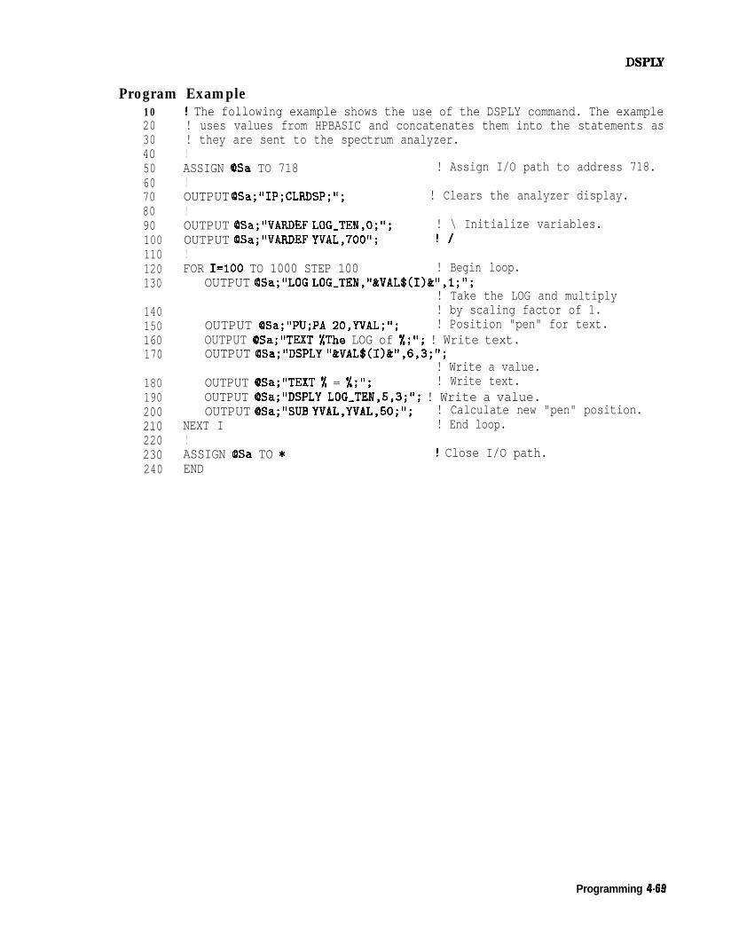
Program Example102030405060708090100110120130
! The following example shows the use of the DSPLY command. The example! uses values from HPBASIC and concatenates them into the statements as! they are sent to the spectrum analyzer.!ASSIGN 8Sa TO 718 ! Assign I/O path to address 718.!OUTPUT QSa;"IP;CLRDSP;";!
! Clears the analyzer display.
OUTPUT QSa;"VARDEF LOG,TEN,O;";OUTPUT QSa;"VARDEF YVAL,700";!
! \ Initialize variables.! /
140150160170
FOR I=100 TO 1000 STEP 100 ! Begin loop.OUTPUT @Sa;"LOG LOG-TEN,"BtVAL$(I)&",l;";
! Take the LOG and multiply! by scaling factor of 1.
OUTPUT QSa;"PU;PA 20,YVAL;"; ! Position "pen" for text.OUTPUT (PSa;"TEXT #The LOG of %;"; ! Write text.OUTPUT OSa;"DSPLY "&VAL$(I)&",6,3;";
! Write a value.180 OUTPUT (DSa;"TEXT % = %;'I; ! Write text.190 OUTPUT OSa;"DSPLY LOG,TEN,5,3;"; ! Write a value.200 OUTPUT QSa;"SUB YVAL,YVAL,SO;"; ! Calculate new "pen" position.210 NEXT I ! End loop.220 !230 ASSIGN QlSa TO * ! Close I/O path.240 END
Programming 4-68

EDITDONE
Limit-Line Edit Done
Syntax
Description This command is used at the completion of limit-line editing with theEDITLIML command.
4.70 Programming

EDITDONE
Program Example130140150160170180190200210220230240250260270280
290300310320330340350360370380390400410420430440450460470480490500
505510
! This program demonstrates the use of the EDITDONE command! to generate a limit line:!OUTPUT 718;"LIMIPURGE;"; ! Purge current limit line.OUTPUT 718;"EDITLIML;"; ! Begin editing limit line.OUTPUT 718;"LIMIREL OFF;"; ! Make sure it is an absolute limit line.OUTPUT 718;"SADD;"; ! Add segment to limit line.OUTPUT 718;"SEDI I;"; ! Edit the first limit line.OUTPUT 718;"LIMF 250MHZ;"; ! Set the frequency of the segment.OUTPUT 718;"LIMU -35DBM;"; ! Provide the upper amplitude.OUTPUT 718;"LIML -8ODBM;"; ! Enter the lower amplitude.OUTPUT 718;"LIMTFL;"; ! Set type of segment to flat.OUTPUT 718*"SDON~"*OUTPUT 718;"SADD;S~I 2;";
! Enter parameters into table.! Add, then edit second segment.
OUTPUT 718;"LIMF 290MHZ;"; ! Set the frequency of segment 2.OUTPUT 718;"LIMU -35DBM;LIML -8ODBM;";
! Set amplitude data for segment.OUTPUT 718;"LIMTSL;"; ! Set segment type to slope.OUTPUT 718;"SDON;"; ! Enter parameters into table.OUTPUT 718;"SADD;SEDI 3;";OUTPUT 718;"LIMF 296.5MHZ;LIMU -5DBM;LIML -8ODBM;LIMTSL;";OUTPUT 718;"SDON;";OUTPUT 718;"SADD;SEDI 4;";OUTPUT 718;"LIMF 300MHZ;LIMU -5DBM;LIML -25DBM;LIMTSL;";OUTPUT 718*"SDON*"*OUTPUT 718;"SADD;SEDI 5;";OUTPUT 718;"LIMF 303.5MHZ;LIMU -5DBM;LIML -8ODBM;LIMTSL;";OUTPUT 718;"SDON;";OUTPUT 718;"SADD;SEDI 6;";OUTPUT 718;"LIMF 304.5MHZ;LIMU -5DBM;LIML -8ODBM;LIMTSL;";OUTPUT 718;"SDON;";OUTPUT 718;"SADD;SEDI 7;";OUTPUT 718;"LIMF 3IOMHZ;LIMU -35DBM;LIML -8ODBM;LIMTFL;";OUTPUT 718;"SDON;";OUTPUT 718;"SADD;SEDI 8;";OUTPUT 718;"LIMF 350MHZ;LIMU -35DBM;LIML -8ODBM;LIMTFL;";OUTPUT 718;"SDON;";OUTPUT 718;"EDITDONE;"; ! End of limit-line definition.OUTPUT 718;"CF 300MHZ;SP 50MHZ;RB 2MHZ;VB 30KHZ;TS;";
! Set up analyzer to display! the limit line.
END
Programming 4-7 1

EDITLIML
Edit Limit Line
Syntax
Description This command turns off the currently active limit line, then places youin limit-line edit mode. Use this command with the commands SEDIand SADD to call up a limit-line segment for editing. The editing ofeach segment is terminated with SDON. EDITLIML is terminated withthe EDITDONE command.
Related commands are SENTER and SEDI.
4.72 Programming

EDITLIML
Program Example130 ! This program demonstrates the use of the EDITLIML command140 ! to generate a limit line:150 !160 OUTPUT 718;"LIMIPURGE;"; ! Purge current limit line.170 OUTPUT 718;"EDITLIML;"; ! Begin editing limit line.180 OUTPUT 718;"LIMIREL OFF;"; ! Make sure it is an absolute limit line.190 OUTPUT 718;"SADD;"; ! Add segment to limit line.200 OUTPUT 718;"SEDI I;"; ! Edit the first limit line.210 OUTPUT 718;"LIMF 250MHZ;"; ! Set the frequency of the segment.220 OUTPUT 718;"LIMU -35DBM;"; ! Provide the upper amplitude.230 OUTPUT 718;"LIML -8ODBM;“; ! Enter the lower amplitude.240 OUTPUT 718;"LIMTFL;"; ! Set type of segment to flat.250 OUTPUT 718;"SDON;"; ! Enter parameters into table.260 OUTPUT 718;"SADD;SEDI 2;"; ! Add, then edit second segment.270 OUTPUT 718;"LIMF 290MHZ;"; ! Set the frequency of segment 2.280 OUTPUT 718;"LIMU -35DBM;LIML-80DBM;";
290300310320330340350360370380390400410420430440450460470480490500
OUTPUT 718*"LIMTSL*"., , 8OUTPUT 718~"SDON~"~
! Set amplitude data for segment.! Set segment type to slope.
OUTPUT 718;"SADD;SEDI 3;";! Enter parameters into table.
OUTPUT 718;"LIMF 296.5MHZ;LIMU -5DBM;LIML -8ODBM;LIMTSL;";OUTPUT 718*"SDON~"~OUTPUT 718;"SADD;SEDI 4;";OUTPUT 718;"LIMF 300MHZ;LIMU -5DBM;LIML -25DBM;LIMTSL;";OUTPUT 718*"SDON~"~OUTPUT 718I"SADD;SEDI 5;";OUTPUT 718;"LIMF 303.5MHZ;LIMU -5DBM;LIML -8ODBM;LIMTSL;";OUTPUT 718;"SDON;";OUTPUT 718;"SADD;SEDI 6;";OUTPUT 718*"LIMFOUTPUT 718;"SDON
304.5MHZ;LIMU -5DBM;LIML -8ODBM;LIMTSL;";II .
OUTPUT 718;"SADD SEDI 7;";OUTPUT 718*"LIMFOUTPUT 718;"SDON
3IOMHZ;LIMU -35DBM;LIML -8ODBM;LIMTFL;";II .
OUTPUT 718;"SADD SEDI 8;";OUTPUT 718;"LIMF 350MHZ;LIMU -35DBM;LIML -8ODBM;LIMTFL;";
505510
OUTPUT 718~"SDON~"~OUTPUT 718;"EDITDONE;"; ! End of limit-line definition.OUTPUT 718;"CF 300MHZ;SP 50MHZ;RB 2MHZ;VB 30KHZ;TS;";
! Set up analyzer to display! the limit line.
END !
Programming 4-73

E M
Erase User Display Memory
Syntax
Description This command can be used to clear the display of user-generatedgraphics. EM does not erase spectrum analyzer display annotation.Refer to the CLRDSP command as well.
4-74 Programming

ENTER
ENTER
Enter from HP-IB
Syntax ,-HP-IB a d d r e s s - ,
u s e r - d e f i n e dv a r i a b l e
p r e d e f i n e d Jv a r i a b l e
L p r e d e f ined 2f u n c t i o n
L t r a c e Je l e m e n t
number J
/
/---format----, ,--dest inot i o n - - ,
Description This command allows a DLP, or user-defined function, to enterdata over HP-IB. If the spectrum analyzer is not the controller, thecommand aborts. The controller that is active and detected on thebus has control. Use the CTRLHPIB command to gain control of theHP-IB, then RELHPIB after the ENTER command to relinquish HP-IBcontrol. The data entered is formatted as specified by the format fieldof the syntax diagram. This format may be one of the following:
n K, a free field (ASCII real-number format)n B, one binary byten W, one binary word (two bytes)
Prerequisite Commands: VARDEF and LCLVAR when usinguser-defined variable, user-defined trace, or user-defined array.
Programming 4-75

EXP
Exponent
Syntax -destination7
( E X P
- u s e r - d e f i n e d -,trace
- u s e r - d e f i n e d Jv a r i a b l e
L p r e d e f i n e d Jv a r i a b l e
I-source \ / s c a l i n g f a c t o r ,
TRA
TRB)-
k-w. u s e r;-daecfei n e d _
4 u s e r - d e f i n e dv a r i a b l e
4 p r e d e f inedv a r i a b l e
4 p r e d e f ined _f u n c t i o n
- t r a c e r a n g e -
‘--...+ n u m b e r
u s e r - d e f i n e d
L p r e d e f i n e d ,v a r i a b l e
L p r e d e f i n e d Jf u n c t i o n
L t r a c e Je l e m e n t
n u m b e r
x f223.3
Description The source is divided by the scaling factor and the result is raised to apower of 10, then stored in the destination.
Parameters<scaling factor>:: = <variable identifier> 1 <numeric data field><destination> = 10 <source>/<scaling factor>
4-76 Programming

EXP
Program Example1020304050607080
90100110
120130150160170180190200210220230
! The following example shows the use of the EXP command. This example! calculates the power in milliwatts of the largest signal on the analyzer! CRT. Initial settings are sent outside the function to set up the! CAL OUTPUT signal on the CRT. These settings act as a visual aid.!ASSIGN QSa TO 718 ! Assign I/O path to address 718.!OUTPUT QSa;"IP; CF 300MHZ; SP IOOMHZ;";
!! CAL OUTPUT signal to center-screen.
OUTPUT OSa;"FUNCDEFDBM,TO-MW,O;"; ! Logical start of DLP.OUTPUT OSa;" LCLVAR PWR-MW,O;";
! Define local variable andinitialize to 0.
OUTPUT QSa;" TS;MKPK HI;"; ! Take sweep; marker to peak;OUTPUT QSa;" EXP PWR-MW,MKA,lO;"; ! pwr,mw = lO^(mka/lO).OUTPUT OSa;" PU;PA 100,650;PD;"; ! Move to starting position.OUTPUT (OSa;" TEXT %POWER (mW>=%;"; ! Write text.OUTPUT OSa;" DSPLY PWR,MW,5,3;"; ! Write results.OUTPUT @Sa*"@*"*8 9, ! Logical end of DLP.!OUTPUT QSa;"DBM,TO-MW;"; ! Execute DLP.!ASSIGN QSa TO * ! Close I/O path.END
Programming 4-77

FUNCDEF
Function Definition
Syntax
Description This command allows you to define a program which is identified asa user-defined function or a DLl? If the user-defined function label isthe same as a command mnemonic, an error results and the commandis ignored.
This command requires user memory in the module to execute.Memory is allocated by executing this function and becomes free usermemory with the DISPOSE command.
Restrictions: Subject to available memory. The following commandsconsume memory: ONEOS, ARRAYDEF, TRDEF, KEYDEF, LCLVAR,VARDEF REPEAT/UNTIL, and IF/THEN.
Related Commands: ABORT, RETURN, ERASE, and DISPOSE
4-76 Programming

FUNCDEF
Program Example10 ! The following example shows the use of the FUNCDEF command. The example20 ! uses an input signal of 300 MHz, such as the CAL OUTPUT, and looks at30 ! its harmonics. An input signal is not necessary to the function of40 ! this example, but acts as a visual aid.50 !60 ASSIGN (PSa TO 718 ! Assign I/O path to address 718.70 !80 OUTPUT QSa;"FUNCDEF INCRFREQ,O;"; ! Logical start of the DLP function.90 OUTPUT QSa;"VARDEF FREQ,300E6;"; ! Create variable and initialize
! to 300 MHz.100 OUTPUT QSa;"IP;SP IMHZ;";110120130140150
! Instrument preset.!OUTPUT OSa;"REPEAT;"; !OUTPUT (QSa;" MOV CF,FRED;"; !OUTPUT Wa;” TS;“; !OUTPUT QISa;" ADD FREQ,FREQ,300EG;";
!OUTPUT QSa;YJNTIL FREQ,GT,3ES;"; !OUTPUT (PSa*"Q-"*9 t, !!!OUTPUT (DSa;" INCRFREQ;"; !!ASSIGN @Sa TO * !END
Begin loop.Set center frequency.Take a sweep to update display.
160170180190200210220230
Increase FRED by 300 MHz.End of loop.Logical end of DLP function.
Execute function.
Close I/O path.
Programming 4-79

IF/TEIEN/ELSE/ENDIF
If/Then/Else/Endif
Syntax
f
Description The IF/THEN/ELSE/ENDIF statement combination allows thecomparison of two operands to a condition. If the condition is true,the command list following THEN is executed. If false, commandsfollowing either the next ELSE or ENDIF statements are executed.Valid conditions are less than (IX), greater than (GT), less than orequal to (LE), greater than or equal to (GE), equal (EQ), and not equal(NE).TEEN The THEN command is treated as a no-operation function,
but is required for user program flow purposes.
ELSE The ELSE command delimits the alternate condition of anIF command.
ENDIF The ENDIF command delimits the end of a conditionalcommand sequence.
4-90 Programming

IF/THEN/ELSE/ENDIF
Program Example10 !The following example shows the use of the IF/THEN/ELSE/ENDIF command.20 !The instructions within the FUNCDEF '6' delimiters form a structure30 !called a DLP (downloadable program).40 !50 ASSIGN @Sa TO 718 ! Assign I/O path to address 718.60 !70 OUTPUT QSa;"FUNCDEF TST,(B;"; ! Logical start of the DLP.80 OUTPUT QSa;"VARDEF Y,500;"; ! Create variable and initialize to 500.90 OUTPUT QSa;"VARDEF X,500;"; ! Create variable and initialize to 500.100 OUTPUT QSa;"CLRDSP;"; ! Clear display.110 OUTPUT QSa;"REPEAT;"; ! Begin loop.120 OUTPUT QSa;" IF Y,LT,lOO; THEN;";
! Test condition.130 OUTPUT QSa;" PU;PA 100,X;"; ! Move pen.140 OUTPUT (OSa;" TEXT%DLP ABORTED%;";
! Print text.150 OUTPUT (PSa;" ABORT;";160 OUTPUT QSa;" ELSE;";170 OUTPUT QSa;” PU;PA 100,X;"; ! Move pen.180 OUTPUT OSa;" DSPLY Y,5,2;"; ! Display 'Y'.190 OUTPUT (PSa;" SUB X,X,40;"; ! Decrement pen pointer.200 OUTPUT (OSa;" SUB Y,Y,lOO;"; ! Decrement variable.210 OUTPUT cOSa;” ENDIF;";220 OUTPUT QSa;"UNTIL Y,ECj,-100;"; ! End loop (The abort will occur230 ! before this condition will be240 ! satisfied.250 OUTPUT OSa;"O;" ! Logical end of DLP.260 !270 OUTPUT (DSa;"TST;" ! Execute DLP.280 !290 ASSIGN QSa TO * ! Close I/O path.300 END
Programming 4-81

INT
Integer
Syntax I N T
/ - d e s t i n a t i o n - ,
u s e r - d e f i n e d
-user-definedv a r i a b l e
L p r e d e f inedv a r i a b l e
4 p r e d e f i n e d Jf u n c t i o n
t r a c e r a n g e J
Description Stores in the destination the greatest integer number which is lessthan or equal to the real number in the source. Since traces and traceranges consist of integers only, using them as source data in the INTcommand yields the same result as using them as source data with theMOV command.
4-82 Programming

INT
Program Example102030405060
70
80
90100110120130140150
160170180190
! The following example shows the use of the INT command. The real! value is truncated by the INT command.!ASSIGN @Sa TO 718 ! Assign I/O path to address 718.!OUTPUT QSa;"VARDEF REALJUM,3.14;";
! Create and initialize a real variable.OUTPUT QSa;"VARDEF INT,NUM,O;";
! Create and initialize a real variable.OUTPUT QSa;"INT INT-NUM,REAL,NUM;";
! Put the integer portion of the! real number into INT,NUM.
OUTPUT OSa;"REAL,NUM?;"; ! Query REAL-NW!.ENTER OSa;Real,num ! Get contents of variable.OUTPUT OSa;"INT,NUM?;"; ! Query INT-NUM.ENTER @Sa;Int-num ! Get contents of variable.!PRINT "REAL=" ;Real-num,"INTEGER=";Int_num
! Print contents of variables! to computer CRT.
!ASSIGN OSa TO * ! Close I/O path.END
Programming 4-83

KEYCLR
Clear User Defined Keys
Syntax
Description Use this command to clear all the softkeys in the module User Keysmenu.
Program Example10 ! The following example shows the use of the KEYCLR command.20 !30 ASSIGN OSa TO 718 ! Assign I/O path to address 718.40 !50 OUTPUT QSa;"KEYCLR;"; ! Clear all user-defined keys.60 ASSIGN (PSa TO * ! Close I/O path.70 END
4-84 Programming

KEYDEF
KEYDEF
User Defined Key Definition
Syntax /key n u m b e r ,
u s e r - d e f i n e d
,- k e y l a b e l \
/
c h a r a c t e r
Description KEYDEF assigns a DLP (function label) to a USER KEY (key number)and labels the key with the function label. Pressing the softkeyexecutes the function or DLP There are 10 softkeys available to label.Softkey labels may be up to two lines long containing eight charactersin each line.
Parameters Minimum: 1Maximum: 10
Query Response The query returns the function or softkey name.
Programming 4-85

KEYDEF
Program Example10203040
5060708090100110120
130140150160170180190200
! The following example shows the use of the KEYDEF command.!ASSIGN QSa TO 718 ! Assign I/O path to address 718.OUTPUT OSa;"KEYDEF 2,BOX,%DRAW BOX%;";
! Define softkey 2 to execute the! DLP BOX when key is pressed.! Give the key a label 'DRAW BOX'.
!OUTPUT OSa;"FUNCDEF BOX,(B;"; ! Logical start of function.OUTPUT (OSa;" IP;"; ! Instrument preset.OUTPUT QSa;" CLRDSP;"; ! Clear the analyzer screen.!OUTPUT QSa;" PU;PA 300,300;";
! Move pen to starting point.OUTPUT (OSa;" PD;PR 240,O;"; ! \OUTPUT cOSaOUTPUT OSaOUTPUT OSaOUTPUT @Sa!ASSIGN QSaEND
" PR 0,240;"; ! \ Draw" PR -240,O;"; ! / Rectangle" PR 0,-240;"; ! /'I@ ; " ; ! Logical end of function.
TO * ! Close I/O path.
4-86 Programming

LCLVAR
LCLVAR
Local Variable
Syntax
Description A local variable is a variable that is defined within a FUNCDEF. Itis recognized only when the FUNCDEF which defined it is running.Local variables have no meaning in a program outside the FUNCDEFthat defined it, but are recognized by any FUNCDEF that is called upby the defining FUNCDEF.
Note In Mass Memory Modules with firmware datecode 910116 and later,the value of a user-defined variable can be modified using thesecondary keyword EP. Refer to “Using EP to Modify User-DefinedVariables (firmware revision 910116 and later)” in this chapter.
Memory is allocated for the local-variable operation only as long as itsdefining FUNCDEF is running. Memory used by the local variable isfreed at the completion of the defining FUNCDEF.
Programming 4-87

LCLVAR
Program Example1020304050607080
! The following example shows the use of the LCLVAR command. This example! calculates the power in milliwatts of the largest signal on the analyzer! CRT. Initial settings are sent outside the function to set up the! CAL OUTPUT signal on the CRT. These settings act as a visual aid.IASSIGN QSa TO 718!
! Assign I/O path to address 718.
OUTPUT OSa;"IP; CF BOOMHZ; SP IOOMHZ;";
90100110
!! CAL OUTPUT signal to center screen.
OUTPUT QSa;"FUNCDEFDBM,TO,MW,@;"; ! Logical start of DLP.OUTPUT QSa;" LCLVAR PWR,MW,O;";
! Define local variable andinitialize to 0.
120 OUTPUT (OSa;" TS;MKPK HI;"; ! Take sweep; marker to peak;130 OUTPUT (DSa;" EXP PWR,MW,MKA,lO;"; ! pwr-mw = IO-(mka/lO)150 OUTPUT OSa;" PU;PA 100,650;PD;"; ! Move to starting position.160 OUTPUT (DSa;" TEXT IPOWER (mW>=%;"; ! Write text.170 OUTPUT (OSa;" DSPLY PWR,MW,5,3;"; ! Write results.180 OUTPUT @Sa*"O*"*# 9, ! Logical end of DLP.190 !200 OUTPUT QSa;"DBM,TOJiW;"; ! Execute DLP.210 !220 ASSIGN cOSa TO * ! Close I/O path.230 END
4-68 Programming

LIMD
LIMD
Limit-Line Delta
Syntax /amplitude,
Description Use this command to enter the delta value for the amplitude of alimit-line segment. Related commands are EDITLIML and SEDI. Thiscommand is used along with LIMM to define the deviation, bothpositive and negative, from a middle value.
Parameter Number Range: -175 dB to 50 dB
Programming 4-88

LIMD
Program Example120130150160170180190200210220230240250260270280
290300310320330340350360370380390400410420430440450460470480490500
505510
! This program demonstrates the use of the LIMD command! to generate a limit line:!OUTPUT 718;"LIMIPURGE;"; ! Purge current limit line.OUTPUT 718*"EDITLIML*"*OUTPUT 718;"LIMIREL ;lF;;";
! Begin edit of limit line.! Make sure it's an absolute limit line.
OUTPUT 718*"SADD*"., , , ! Add segment to the limit line.OUTPUT 718;"SEDI I;"; ! Edit the first segment.OUTPUT 718;"LIMF 250MHZ;"; ! Set frequency of the segment.OUTPUT 718;"LIMU -35DBM;"; ! Provide the upper amplitude.OUTPUT 718;"LIML -8ODBM;"; ! Enter the lower amplitude.OUTPUT 718;"LIMTFL;"; ! Set type of segment to flat.OUTPUT 718;"SDON;"; ! Enter parameters into table.OUTPUT 718;"SADD;SEDI 2;"; ! Add, then edit second segment.OUTPUT 718;"LIMF 290MHZ;"; ! Set frequency of segment 2.OUTPUT 718;"LIMU -35DBM;LIML-80DBM;";
OUTPUT 718;"LIMTSL;";OUTPUT 718~"SDON~"~
! Set amplitude data for segment.! Set segment type to slope.
OUTPUT 718;"SADD;SEDI 3;";! Enter parameters into table.
OUTPUT 718;"LIMF 296.5MHZ;LIMU -5DBM;LIML-80DBM;LIMTSL;";OUTPUT 718*"SDON*"*OUTPUT 718;"SADD;SEDI 4;";OUTPUT 718;"LIMF 300MHZ;LIMM -15DBM;LIMD 10DBM;LIMTSL;";OUTPUT 718;"SDON;";OUTPUT 718OUTPUT 718 .
9
OUTPUT 718OUTPUT 718 iOUTPUT 718OUTPUT 718
"SADD;SEDI 5;";"LIMF 303.5MHZ;LIMU -5DBM;LIML -8ODBM;LIMTSL;";"SDON;";"SADD;SEDI 6;";"LIMF 304.5MHZ;LIMU -5DBM;LIML -8ODBM;LIMTSL;";
. II .
;L;MU -35DBM;LIML -8ODBM;LIMTFL;";
;"SDON;";OUTPUT 718;"SADD;SEDI 7OUTPUT 718;"LIMF 310MHZOUTPUT 718*"SDON*"*OUTPUT 718;"SADD;SEDI 8OUTPUT 718;"LIMF 350MHZOUTPUT 718;"SDON;";OUTPUT 718;"EDITDONE;";
. II ., ,
;LIMU -35DBM;LIML -8ODBM;LIMTFL;";
! End of limit-line definition.OUTPUT 718;"CF 300MHZ;SP 50MHZ;RB 2MHZ;VB 30KHZ;TS;";
! Set up analyzer to display the! limit line.
END
4-90 Programming

LIMF
LIMF
Limit-Line Frequency
Syntax /frequency,
Description Use this command to enter a frequency value for a limit-line segment.This command is used along with the SEDI command while editing atable of limit-line segments.
Programming 4-91

LIMF
Program Example120130150160170180190200210220230240250260270280
290300310320330340350360370380390400410420430440450460470480490500
505510
! This program demonstrates the use of the LIMF command! to generate a limit line:!OUTPUT 718;"LIMIPURGE;"; ! Purge current limit line.OUTPUT 718;"EDITLIML;"; ! Begin edit of limit line.OUTPUT 718;"LIMIREL OFF;"; ! Make sure it's an absolute limit line.OUTPUT 718;"SADD;"; ! Add segment to the limit line.OUTPUT 718;"SEDI 1;"; ! Edit the first segment.OUTPUT 718;"LIMF 250MHZ;"; ! Set frequency of the segment.OUTPUT 718*"LIMU -35DBM;";OUTPUT 718;"LIML -8ODBM;";
! Provide the upper amplitude.! Enter the lower amplitude.
OUTPUT 718*"LIMTFL*"*, , JOUTPUT 718*"SDON*"*OUTPUT 718;"SADD;SEDI 2;";
! Set type of segment to flat.! Enter parameters into table.! Add, then edit second segment.
OUTPUT 718;"LIMF 290MHZ;"; ! Set frequency of segment 2.OUTPUT 718;"LIMU -35DBM;LIML-80DBM;";
OUTPUT 718;"LIMTSL;";OUTPUT 718*"SDON*"*
! Set amplitude data for segment.! Set segment type to slope.
OUTPUT 718;"SADD;SEDI 3;";! Enter parameters into table.
OUTPUT 718;"LIMF 296.5MHZ;LIMU -5DBM;LIML-80DBM;LIMTSL;";OUTPUT 718;"SDON;";OUTPUT 718;"SADD;SEDI 4;";OUTPUT 718;"LIMF 300MHZ;LIMU -5DBM;LIML-25DBM;LIMTSL;";OUTPUT 718;"SDON;";OUTPUT 718;"SADD;SEDI 5;";OUTPUT 718;"LIMF 303.5MHZ;LIMU -5DBM;LIML-80DBM;LIMTSL;";OUTPUT 718;"SDON;";OUTPUT 718;"SADD;SEDI 6;";OUTPUT 718;"LIMF 304.5MHZ;LIMU -5DBM;LIML-80DBM;LIMTSL;";OUTPUT 718;"SDON;";OUTPUT 718;"SADD;SEDI 7;";OUTPUT 718;"LIMF 3IOMHZ;LIMU -35DBM;LIML-80DBM;LIMTFL;";OUTPUT 718;"SDON;";OUTPUT 718;"SADD;SEDI 8;";OUTPUT 718;"LIMF 350MHZ;LIMU -35DBM;LIML-80DBM;LIMTFL;";OUTPUT 718;"SDON;";OUTPUT 718;"EDITDONE;"; ! End of limit-line definition.OUTPUT 718;"CF 300MHZ;SP 50MHZ;RB 2MHZ;VB 30KHZ;TS;";
! Set up analyzer to display the! limit line.
END
4-92 Programming

LIMIFAIL
LIMIFAIL
Limit-Fail Query
Syntax LIMIFAIL
Description This command is a query which returns a zero when a limit-line testpasses. If an active trace fails the lower-amplitude parameter, thequery response is 1; an upper-amplitude failure query response is 2. Ifan active trace fails both upper- and lower-limits, the query responseis 3.
Programming 4-93

LIMIPURGE
Purge Limit Line
Syntax
Description Deletes the current limit line, but does not remove any limit-linetables saved in the module RAM. Use the DISPOSE command toremove limit-line tables from module memory.
4-94 Programming

LIMIPURGE
Program Example130140150160170180190200210220230240250260270280
290300310320330340340350360370380390400410420430440450460470480490500
505510
! This program demonstrates the use of the LIMIPURGE command! to generate a limit line:!OUTPUT 718;"LIMIPURGE;"; ! Purge current limit line.OUTPUT 718;"EDITLIML;"; ! Begin edit of limit line.OUTPUT 718;"LIMIREL OFF;"; ! Make sure it's an absolute limit line.OUTPUT 718*"SADD*"*OUTPUT 718;"SEDI'l;";
! Add segment to the limit line.
OUTPUT 718;"LIMF 250MHZ;";! Edit the first segment.
! Set frequency of the segment.OUTPUT 718*"LIMU -35DBM;"; !OUTPUT 718;"LIML -8ODBM;";
Provide the upper amplitude.! Enter the lower amplitude.
OUTPUT 718~"LIMTFL~"~OUTPUT 718;"SDON;"; '
! Set type of segment to flat.! Enter parameters into table.
OUTPUT 718;"SADD;SEDI 2;"; ! Add, then edit second segment.OUTPUT 718;"LIMF 290MHZ;"; ! Set frequency of segment 2.OUTPUT 718;"LIMU -35DBM;LIML-80DBM;";
! Set amplitude data for segment.OUTPUT 718*"LIMTSL."*OUTPUT 718;"SDON;"; '
! Set segment type to slope.! Enter parameters into table.
OUTPUT 718;"SADD;SEDI 3;";OUTPUT 718;"LIMF 296.5MHZ;LIMU -5DBM;LIML-80DBM;LIMTSL;";OUTPUT 718;"SDON;";OUTPUT 718;"LIMTFL;"OUTPUT 718;"SADD;SEDI 4;"; 1OUTPUT 718*"LIMF9 300MHZ;LIMU -5DBM;LIML-25DBM;LIMTSL;";OUTPUT 718OUTPUT 718OUTPUT 718OUTPUT 718OUTPUT 718OUTPUT 718
. II .
iSED1 5;";"SDON"SADD"LIMF"SDON"SADD"LIMF
303.5MHZ;LIMU -5DBM;LIML-80DBM;LIMTSL;";. II .
;SEDI 6;";304.5MHZ;LIMU -5DBM;LIML-80DBM;LIMTSL;";
OUTPUT 718;"SDON;";OUTPUT 718;"SADD;SEDI 7;";OUTPUT 718;"LIMF 3lOMHZ;LIMU -35DBM;LIML-80DBM;LIMTFL;";OUTPUT 718*"SDON*"*OUTPUT 718;"SADD;SEDI 8;";OUTPUT 718;"LIMF 350MHZ;LIMU -35DBM;LIML-80DBM;LIMTFL;";OUTPUT 718*"SDON*"*, , ,OUTPUT 718*"EDITDONE*"* ! End of limit-line definition.OUTPUT 718;"CF 3OOMHZ;SP 50MHZ;RB 2MHZ;VB 30KHZ;TS;";
! Set up analyzer to display the! limit line.
END
Programming 4-95

LIMIRCL
Recall Limit Line
Syntax /----- I i m i t I i n e names-,
( L I Y I R C L de imiter i d e n t i f i e r
Description
Note Limit lines stored on memory cards using a mass-memory module withfirmware datecode 910116 or later cannot be read into a module withan earlier firmware datecode (for example, 890524). Limit lines storedon cards using modules with firmware datecode 890524 or earlier canbe read into a module with firmware datecode 910116 or later.
Recalls a limit-line set from the limit-line table in the module usermemory. The table is stored in user memory with the LIMISAVEcommand. The command displays a limit line which is recalled bythe name assigned to it. A limit line may be saved and given a nameusing the remote command LIMISAV, or entered from the front panelwith the screen-title function. ‘lb recall a limit line from a memorycard, use the command CARDLOAD first to copy the limit line to themodule memory. Use the LIMITEST ON command to display the line.
4-96 Programming

LIMIREL
LIMIREL
Relative Limit line
Syntax
Description When set to ON, this command used with the EDITLIML commandcreates a relative limit line. The default setting is OFF, which makesthe limit line amplitude and frequency parameters absolute.
Programming 4-97

IJMIREL
Program Example130140150160170180190200210220230240250260270280
290300310320330340350360370380390400410420430440450460470480490500
505510
! This program demonstrates the use of the LIMIREL command! to generate a limit line:!OUTPUT 718;"LIMIPURGE;"; ! Purge current limit line.OUTPUT 718*"EDITLIML*"*OUTPUT 718;"LIMIREL ;lN;";
! Begin edit of limit line.! Make sure it's a relative limit line.
OUTPUT 718;"SADD;"; ! Add segment to the limit line.OUTPUT 718*"SEDI 1.".OUTPUT 718;"LIMF 2;OI;HZ;";
! Edit the first segment.! Set frequency of the segment.
OUTPUT 718;"LIMU -35DBM;"; ! Provide the upper amplitude.OUTPUT 718;"LIML -8ODBM;"; ! Enter the lower amplitude.OUTPUT 718;"LIMTFL;"; ! Set type of segment to flat.OUTPUT 718;"SDON;"; ! Enter parameters into table.OUTPUT 718;"SADD;SEDI 2;"; ! Add, then edit second segment.OUTPUT 718;"LIMF 290MHZ;"; ! Set frequency of segment 2.OUTPUT 718;"LIMU -35DBM;LIML-80DBM;";
OUTPUT 718;"LIMTSL;";OUTPUT 718*"SDON*"*
! Set amplitude data for segment.! Set segment type to slope.
OUTPUT 718;"SADD;SEDI 3;";! Enter parameters into table.
OUTPUT 718;"LIMF 296.5MHZ;LIMU -5DBM;LIML-80DBM;LIMTSL;";OUTPUT 718;"SDON;";OUTPUT 718;"SADD;SEDI 4;";OUTPUT 718;"LIMF 300MHZ;LIMU -5DBM;LIML-25DBM;LIMTSL;";OUTPUT 718;"SDON;";OUTPUT 718;"SADD;SEDI 5;";OUTPUT 718;"LIMF 303.5MHZ;LIMU -5DBM;LIML-80DBM;LIMTSL;";OUTPUT 718;"SDON;";OUTPUT 718;"SADD;SEDI 6;";OUTPUT 718;"LIMF 304.5MHZ;LIMU -SDBM;LIML-80DBM;LIMTSL;";OUTPUT 718*"SDON*"*OUTPUT 718;"SADD;SEDI 7;";OUTPUT 718;"LIMF 3lOMHZ;LIMU -35DBM;LIML-80DBM;LIMTFL;";OUTPUT 718;"SDON;";OUTPUT 718;"SADD;SEDI 8;";OUTPUT 718;"LIMF 350MHZ;LIMU -35DBM;LIML-80DBM;LIMTFL;";OUTPUT 718;"SDON;";OUTPUT 718;"EDITDONE;"; ! End of limit-line definition.OUTPUT 718;"CF 300MHZ;SP 50MHZ;FlB 2MHZ;VB 30KHZ;TS;";
! Set up analyzer to display the! limit line.
END
4.98 Programming

LIMBAV
LIMISAV
Limit-Line Save
Syntax del i m i t e r i d e n t i f i e r de i m i t e r
Description
Note Limit lines stored on memory cards using a mass-memory module withfirmware datecode 910116 or later cannot be read into a module withan earlier firmware datecode (for example, 890524). Limit lines storedon cards using modules with firmware datecode 890524 or earlier canbe read into a module with firmware datecode 910116 or later.
This command saves the active limit line to module memory underthe name assigned to it. Any previously existing limit line having thesame name is overwritten with the new limit-line table data. Referalso to the LIMIRCL command. lb save a limit line to the memorycard, execute CARDSTORE after the LIMISAV command.
Programming 4-99

LIMITEST
Limit-Line Test
Syntax
Description This command activates the limit-line test function, which comparesthe trace data in the current sweep with the limits set up in the limittable of the active limit line. The results of the current active tracecompared with the active limit line can be read using the LIMIFAILcommand. When this command is set to ON, the active limit-line testlimits are displayed on-screen along with a LIMIT FAILED message ifthe trace data fails.
4-100 Programming

LIML
LIML
Lower Limit-Line Value
Syntax
Description This command is used within the SEDI command to assign thelower-limit amplitude value to a limit-line segment. This commandused with the LIMU command creates upper and lower limit-lineamplitude parameters.
Parameter Number range: -175 dB to 50 dB
Programming 4-101

LIML
Program Example130140150160170180190200210220230240250260270280
290300310320330340350360370380390400410420430440450460470480490500
505510
! This program demonstrates the use of the LIML command! to generate a limit line:!OUTPUT 718;"LIMIPURGE;"; ! Purge current limit line.OUTPUT 718;"EDITLIML;"; ! Begin edit of limit line.OUTPUT 718;"LIMIREL OFF;"; ! Make sure it's an absolute limit line.OUTPUT 718*"SADD*"*OUTPUT 718I"SEDI'I;";
! Add segment to the limit line.! Edit the first segment.
OUTPUT 718;"LIMF 250MHZ;";OUTPUT 718;"LIMU -35DBM;";
! Set frequency of the segment.! Provide the upper amplitude.
OUTPUT 718;"LIML -8ODBM;"; ! Enter the lower amplitude.OUTPUT 718;"LIMTFL;"; ! Set type of segment to flat.OUTPUT 718;"SDON;"; ! Enter parameters into table.OUTPUT 718;"SADD;SEDI 2;"; ! Add, then edit second segment.OUTPUT 718;"LIMF 290MHZ;"; ! Set frequency of segment 2.OUTPUT 718;"LIMU -35DBM;LIML -8ODBM;";
! Set amplitude data for segment.OUTPUT 718;"LIMTSL;"; ! Set segment type to slope.OUTPUT 718;"SDON;"; ! Enter parameters into table.OUTPUT 718;"SADD;SEDI 3;";OUTPUT 718;"LIMF 296.5MHZ;LIMU -5DBM;LIML -8ODBM;LIMTSL;";OUTPUT 718;"SDON;";OUTPUT 718;"SADD;SEDI 4;";OUTPUT 718;"LIMF 300MHZ;LIMU -5DBM;LIML -25DBM;LIMTSL;";OUTPUT 718;"SDON;";OUTPUT 718;"SADD;SEDI 5;";OUTPUT 718;"LIMF 303.5MHZ;LIMU -5DBM;LIML -8ODBM;LIMTSL;";OUTPUT 718;"SDON;";OUTPUT 718;"SADD;SEDI 6;";OUTPUT 718;"LIMF 304.5MHZ;LIMU -5DBM;LIML -8ODBM;LIMTSL;";OUTPUT 718;"SDON;";OUTPUT 718;"SADD;SEDI 7;";OUTPUT 718;"LIMF 310MHZ;LIMU -35DBM;LIML -8ODBM;LIMTFL;";OUTPUT 718*"SDON*"*OUTPUT 718I"SADD;SEDI 8;";OUTPUT 718;"LIMF 350MHZ;LIMU -35DBM;LIML -8ODBM;LIMTFL;";OUTPUT 718;"SDON;";OUTPUT 718;"EDITDONE;"; ! End of limit-line definition.OUTPUT 718;"CF 300MHZ;SP 50MHZ;RB 2MHZ;VB 30KHZ;TS;";
! Set up analyzer to display the! limit line.
END
4-102 Programming

LIMM
LIMM
Middle Limit-Line Value
Syntax DB
DBM
Description This command is used within the SEDI command to assign a middleamplitude value to a limit line. This command used with the LIMDcommand create middle and delta limit-line amplitude parameters.
Parameter Number range: -175 dB to 50 dB
Programming 4-103

LIMM
Program Example120130150160170180190200210220230240250260270280
290300310320330340350360370380390400410420430440450460470480490500
505510
! This program demonstrates the use of the LIMM command! to generate a limit line:!OUTPUT 718;"LIMIPURGE;"; ! Purge current limit line.OUTPUT 718;"EDITLIML;"; ! Begin edit of limit line.OUTPUT 718;"LIMIREL OFF;"; ! Make sure it's an absolute limit line.OUTPUT 718*"SADD*"*OUTPUT 718;"SEDI'lj";
! Add segment to the limit line.! Edit the first segment.
OUTPUT 718;"LIMF 250MHZ;"; ! Set frequency of the segment.OUTPUT 718;"LIMU -35DBM;"; ! Provide the upper amplitude.OUTPUT 718;"LIML -8ODBM;"; ! Enter the lower amplitude.OUTPUT 718;"LIMTFL;"; ! Set type of segment to flat.OUTPUT 718;"SDON;"; ! Enter parameters into table.OUTPUT 718;"SADD;SEDI 2;"; ! Add, then edit second segment.OUTPUT 718;"LIMF 290MHZ;"; ! Set frequency of segment 2.OUTPUT 718;"LIMU -35DBM;LIML-80DBM;";
! Set amplitude data for segment.OUTPUT 718;"LIMTSL;"; ! Set segment type to slope.OUTPUT 718;"SDON;"; ! Enter parameters into table.OUTPUT 718;"SADD;SEDI 3;";OUTPUT 718;"LIMF 296.5MHZ;LIMU -5DBM;LIML-80DBM;LIMTSL;";OUTPUT 718;"SDON;";OUTPUT 718;"SADD;SEDI 4;";OUTPUT 718;"LIMF 300MHZ;LIMM -15DBM;LIMD 1ODBM;LIMTSL;";OUTPUT 718;"SDON;";OUTPUT 718;"SADD;SEDI 5;";OUTPUT 718;"LIMF 303.5MHZ;LIMU -5DBM;LIML -8ODBM;LIMTSL;";OUTPUT 718*"SDON*"*OUTPUT 718;"SADD;SEDI 6;";OUTPUT 718;"LIMF 304.5MHZ;LIMU -5DBM;LIML -8ODBM;LIMTSL;";OUTPUT 718;"SDON;";OUTPUT 718;"SADD;SEDI 7;";OUTPUT 718;"LIMF 3lOMHZ;LIMU -35DBM;LIML -8ODBM;LIMTFL;";OUTPUT 718;"SDON;";OUTPUT 718;"SADD;SEDI 8;";OUTPUT 718;"LIMF 350MHZ;LIMU -35DBM;LIML -8ODBM;LIMTFL;";OUTPUT 718;"SDON;";OUTPUT 718;"EDITDONE;"; ! End of limit-line definition.OUTPUT 718;"CF 300MHZ;SP 50MHZ;RB 2MHZ;VB 30KHZ;TS;";
! Set up analyzer to display the! limit line.
END
4-104 Programming

LIMTFL
LIMTFL
Flat Limit-Line Segment
Syntax
Description This command is used within the SEDI command to make the selectedlimit-line segment flat.
Programming 4-105

LIMTFL
Program Example130140150160170180190200210220230240250260270280
290300310320330340350360370380390400410420430440450460470480490491492493494500
! This program demonstrates the use of the LIMTFL command! to generate a limit line:!OUTPUT 718;"LIMIPURGE;";OUTPUT 718;"EDITLIML;";OUTPUT 718;"LIMIREL OFF;";OUTPUT 718*"SADD*"*, 9 8OUTPUT 718*"SEDI 1."., 9 9
! Purge current limit line.! Begin edit of limit line.! Make sure it's an absolute limit line.! Add segment to the limit line.! Edit the first segment.
OUTPUT 718;"LIMF 250MHZ;"; !OUTPUT 718;"LIMU -35DBM;"; !OUTPUT 718;"LIML -8ODBM;"; !OUTPUT 718;"LIMTFL;";OUTPUT 718*"SDON*"*OUTPUT 718;"SADD;SEDI 2;";
Set frequency of the segment.Provide the upper amplitude.Enter the lower amplitude.Set type of segment to flat.Enter parameters into table.Add, then edit second segment.
OUTPUT 718;"LIMF 290MHZ;"; ! Set frequency of segment 2.OUTPUT 718;"LIMU-35DBM;LIML-8ODBM;";
! Set amplitude data for segment.OUTPUT 718;"LIMTSL;"; ! Set segment type to slope.OUTPUT 718;"SDON;"; ! Enter parameters into table.OUTPUT 718;"SADD;SEDI 3;";OUTPUT 718;"LIMF 296.5MHZ;LIMW5DBM;LIML-8ODBM;LIMTSL;";OUTPUT 718;"SDON;";OUTPUT 718;"SADD;SEDI 4;";OUTPUT 718;"LIMF 300MHZ;LIMWSDBM;LIML-25DBM;LIMTSL;";OUTPUT 718~"SDON~"~OUTPUT 718;"SADD;SEDI 5;";OUTPUT 718;"LIMF 303.5MHZ;LIMW5DBM;LIML-8ODBM;LIMTSL;";OUTPUT 718;"SDON;";OUTPUT 718;"SADD;SEDI 6;";OUTPUT 718;"LIMF 304.5MHZ;LIMW5DBM;LIML-8ODBM;LIMTSL;";
;LIML-80DBM;LIMTFL;";
OUTPUT 718*"SDON."*OUTPUT 718I"SADD;SEDI 7;";OUTPUT 718;"LIMF 3lOMHZ;LIMW35DBMOUTPUT 718;"SDON;";OUTPUT 718;"SADD;SEDI 8;";OUTPUT 718;"LIMF 350MHZ;LIMW35DBMOUTPUT 718;"SDON;";
;LIML-80DBM;LIMTFL;";
OUTPUT 718;"EDITDONE;"; ! End of limit-line definition.
! Set up analyzer to display the! limit line.
OUTPUT 718;"CF 300MHZ;SP 50MHZ;RB 2MHZ;VB 30KHZ;TS;";END
4-l 06 Programming

LIMTSL
LIMTSL
Sloped Limit-Line Segment
Syntax
Description This command is used within the SEDI command to create a limit linewith a sloped line segment.
Programming 4-l 07

LIMTSL
Program Example130140150160170180190200210220230240250260270280
290300310320330340350360370380390400410420430440450460470480490491492493494500
! This program demonstrates the use of the LIMTSL command! to generate a limit line:!OUTPUT 718;"LIMIPURGE;";OUTPUT 718*"EDITLIML~"~OUTPUT 718;"LIMIREL ;JF;;";OUTPUT 718*"SADD*"*, , ,OUTPUT 718*"SEDI 1.".
! Purge current limit line.! Begin edit of limit line.! Make sure it's an absolute limit line.! Add segment to the limit line.
OUTPUT 718;"LIMF 2;OMHZ;";! Edit the first segment.
! Set frequency of the segment.OUTPUT 718;"LIMU -35DBM;"; ! Provide the upper amplitude.OUTPUT 718;"LIML -8ODBM;"; ! Enter the lower amplitude.OUTPUT 718;"LIMTFL;"; ! Set type of segment to flat.OUTPUT 718*"SDON*"*OUTPUT 718;"SADD;SEDI 2;";
! Enter parameters into table.! Add, then edit second segment.
OUTPUT 718;"LIMF 290MHZ;"; ! Set frequency of segment 2.OUTPUT 718;"LIMU-35DBM;LIML-8ODBM;";
OUTPUT 718;"LIMTSL;";OUTPUT 718*"SDON*"*OUTPUT 718; "SADD;SEDI 3;";
! Set amplitude data for segment.! Set segment type to slope.! Enter parameters into table.
OUTPUT 718;"LIMF 296.5MHZ;LIMW5DBM;LIML-8ODBM;LIMTSL;";OUTPUT 718*"SDON*"*OUTPUT 718;"SADD;SEDI 4;";OUTPUT 718;"LIMF 300MHZ;LIMU-SDBM;LIML-25DBM;LIMTSL;";OUTPUT 718*"SDON*"*9 , ,OUTPUT 718 ;OUTPUT 718OUTPUT 718OUTPUT 718 ;OUTPUT 718OUTPUT 718OUTPUT 718
"SADD;SEDI 5;";"LIMF 303.5MHZ;LIMW5DBM;LIML-8ODBM;LIMTSL;";"SDON;";"SADD;SEDI 6;";"LIMF 304.5MHZ;LIMW5DBM;LIML-8ODBM;LIMTSL;";,"SDON;";"SADD;SEDI 7 . II .
9 8
;LIMU-35DBM;LIML-80DBM;LIMTFL;";OUTPUT 718;"LIMF 310MHZOUTPUT 718."SDON*"*OUTPUT 718;"SADD;SEDI 8OUTPUT 718;"LIMF 350MHZOUTPUT 718*"SDON*"*OUTPUT 718;"EDITDOI;E;";!
. II .I t
;LIMU-35DBM;LIML-80DBM;LIMTFL;";
! End of limit-line definition.
! Set up analyzer to display the! limit line.
OUTPUT 718;"CF 300MHZ;SP 50MHZ;RB 2MHZ;VB 30KHZ;TS;";END
4-108 Programming

LIMU
LIMU
Upper Limit-Line Value
SyntaxDE
DBM
Description This command is used within the SEDI command to assign theupper-amplitude value to a limit-line segment. This commandcombined with the LIML command may be used to create upper andlower limit-line amplitude parameters.
Parameters Number Range: -175 dB to 50 dB
Programming 4-l 09

LIMU
Program Example130 ! This program demonstrates the use of the LIMU command140 ! to generate a limit line:150 !160 OUTPUT 718;"LIMIPURGE;"; ! Purge current limit line.170 OUTPUT 718;"EDITLIML;"; ! Begin edit of limit line.180 OUTPUT 718;"LIMIREL OFF;"; ! Make sure it's an absolute limit line.190 OUTPUT 718;"SADD;"; ! Add segment to the limit line.200 OUTPUT 718;"SEDI 1;"; ! Edit the first segment.210 OUTPUT 718;"LIMF 250MHZ;"; ! Set frequency of the segment.220 OUTPUT 718;"LIMU -35DBM;"; ! Provide the upper amplitude.230 OUTPUT 718;"LIML -8ODBM;"; ! Enter the lower amplitude.240 OUTPUT 718;"LIMTFL;"; ! Set type of segment to flat.250 OUTPUT 718;"SDON;"; ! Enter parameters into table.260 OUTPUT 718;"SADD;SEDI 2;"; ! Add, then edit second segment.270 OUTPUT 718;"LIMF 290MHZ;"; ! Set frequency of segment 2.280 OUTPUT 718;"LIMU-35DBM;LIML-8ODBM;";
290300310320330340350360370380390400410420430440450460470480490491492493494500
OUTPUT 718~"LIMTSL~"~OUTPUT 718;"SDON;";
,
OUTPUT 718OUTPUT 718OUTPUT 718OUTPUT 718 iOUTPUT 718OUTPUT 718OUTPUT 718 .,
! Set amplitude data for segment.! Set segment type to slope.! Enter parameters into table.
"SADD;SEDI 3;";"LIMF 296.5MHZ;LIMU-5DBM;LIML-8ODBM;LIMTSL;";"SDON;";"SADD;SEDI 4;";"LIMF 300MHZ;LIMW5DBM;LIML-25DBM;LIMTSL;";"SDON;";"SADD;SEDI 5;";
OUTPUT 718;"LIMF 303.5MHZ;LIMW5DBM;LIML-8ODBM;LIMTSL;";OUTPUT 718*"SDON*"*OUTPUT 718;"SADD;SEDI 6;";OUTPUT 718;"LIMF 304.5MHZ;LIMW5DBM;LIML-8ODBM;LIMTSL;";OUTPUT 718*"SDON*"*OUTPUT 718;"SADD;SEDI 7;";OUTPUT 718;"LIMF 3l0MHZ;LIMU-35DBM;LIML-8ODBM;LIMTFL;";OUTPUT 718;"SDON;";OUTPUT 718;"SADD;SEDI 8;";OUTPUT 718;"LIMF 350MHZ;LIMW35DBM;LIML-8ODBM;LIMTFL;";OUTPUT 718*"SDON*"*9 , #OUTPUT 718*"EDITDONE*"*, 9 , ! End of limit-line definition.!
! Set up analyzer to display the! limit line.
OUTPUT 718;"CF 300MHZ;SP 50MHZ;RB 2MHZ;VB 3OKHZ;TS;";END
4-l 10 Programming

LOG
LOG
Logarithm
Syntax -destination7
L O G T R A /
T R B p
L u s e r - d e f i n e d Jt r a c e
Luser-defined -,v a r i a b l e
i, p r e d e f ined Jv a r i a b l e
L t r a c e r a n g e J
I - Source - /scol i n g f a c t o r ,
Description The logarithm (base 10) of the source is taken, the result is multipliedby a specified scaling factor, then sent to the destination.
Programming 4-l 11

LOG
Program Examples
102030405060708090100110120130
140150160
170
180190
200210220230240
Example #l! The following example shows the use of the LOG command. The example! uses values from HP BASIC and concatenates them into the statements as! they are sent to the spectrum analyzer.!ASSIGN cDSa TO 718 ! Assign I/O path to address 718.!OUTPUT OSa;"CLRDSP;";!
! Clears the analyzer display.
OUTPUT (OSa; "VARDEF LOG,TEN,O;"; ! \ Initialize variables.OUTPUT OSa;"VARDEF YVAL,700;"; ! /!FOR I=100 TO 1000 STEP 100 ! Begin loop.
OUTPUT (DSa;"LOG LOG,TEN,"&VAL$(I>&",l;";! Take the LOG and multiply! by scaling factor of 1.
OUTPUT QSa;"PU;PA 20,YVAL;"; ! Position "pen" for text.OUTPUT (OSa;"TEXT %The LOG of 1;";
! Write text.OUTPUT OSa;"DSPLY "%VAL$(I>&",6,3;";
! Write a value.OUTPUT (OSa;"TEXT % = %;I'; ! Write text.OUTPUT QSa;"DSPLY LOG_TEN,5,3;";
! Write a value.OUTPUT QISa;"SUB YVAL,YVAL,50;"; ! Calculate new "pen" position.
NEXT I ! End loop.!ASSIGN QSa TO * ! Close I/O path.END
4-112 Programming

102030405060708090
100110120130140150160170
175190200210220230240250
260270280290300310
LOG
Example #2!The following example shows another use of the LOG command. This example!performs the same function as the previous example, but is fully!downloadable. Note that only minor changes need to be made to convert!a program from computer-dependent to computer-independent! This method!is also visibly much faster for the spectrum analyzer to execute.!ASSIGN (OSa TO 718 !!OUTPUT QSa; "FUNCDEF LOG-EX,O;";
!OUTPUT @Sa;"CLRDSP;"; !!OUTPUT OSa;"VARDEF LOG,TEN,O;"; !OUTPUT OSa;"VARDEF YVAL,700;"; !OUTPUT QSa;"VARDEF LP,CTR,lOO;"; !!OUTPUT OSa;"REPEAT;"; !
OUTPUT (DSa;"LOG LOG,TEN,LP-CTR,l;";!!
OUTPUT QSa;"PU;PA 20,YVAL;"; !OUTPUT QSa;"TEXT %The LOG of )/I;"; !OUTPUT OSa;"DSPLY LP_CTR,6,3;"; !OUTPUT OSa;"TEXT % = %;'I; !OUTPUT QSa;"DSPLY LOG,TEN,5,3;"; !OUTPUT @Sa;"SUB YVAL,YVAL,SO;"; !
Assign I/O path to address 718.
Logical start of DLP.Clears the analyzer display.
\ Initialize variables./Initialize loop counter.
Begin loop.
Take the LOG and multiplyby scaling factor of 1.Position "pen" for text.Write text.Write a value.Write text.Write a value.Calculate new "pen" position.
OUTPUT (OSa;"ADD LP,CTR,LP-CTR,lOO;";! Increment loop counter.
OUTPUT QSa;"UNTIL LP,CTR,GT,lOOO;"; ! End loop.OUTPUT OSa;"(D;"!OUTPUT QSa;"LOG,EX;"; ! Execute the DLP.ASSIGN @Sa TO * ! Close I/O path.END
Programming 4-l 13

MEAN
Trace Mean
Syntax
Note This bypass command path is only legal if you use MEAN as apredefined function. It must reside within a compatible-functionoperation.
Description
10 ! The following example shows how to use the trace MEAN function20 ! to return the mean value to the controller using an internal-variable.30 !40 INTEGER Mean-value ! Define an INTEGER variable.50 ASSIGN (DSa TO 718 ! Assign I/O path to address 718.60 OUTPUT OSa;"VARDEF M-VALUE,O;"; ! Define an analyzer variable.70 OUTPUT (DSa;"MOV M,VALUE,MEAN TRA;"; ! Determine the mean of trace A.80 OUTPUT QSa;"M-VALUE?;" ! Return contents of variable.90 ENTER QSa;Mean,value ! Read value from analyzer.100 PRINT "MEAN of trace A in measurement units = ";Mean,value110 ASSIGN (DSa TO * ! Close I/O path.120 END
Program Examples
Example #l
10 ! The following example shows how to use the trace MEAN function to return20 ! the mean value of the specified trace to the controller.30 !40 INTEGER Mean-value ! Define an INTEGER variable.50 ASSIGN OSa TO 718 ! Assign I/O path to address 718.60 OUTPUT OSa;"MEAN TRA,?;"; ! Determine the mean of trace A.70 ENTER QSa;Mean,value ! Read value from analyzer.80 PRINT "MEAN of trace A in measurement units = ";Mean-value90 ASSIGN @Sa TO * ! Close I/O path.100 !110 END
Returns the mean value of a trace in measurement units. This singlevalue must be used as the <source> of another function. In the firstexample below, MEAN TRA is the source for the MOV command.
Example #2
4-l 14 Programming

MEM
MEM
Memory Available
Syntax
Note This bypass command path is only legal if you use MEM as apredefined function. It must reside within a compatible-functionoperation.
Description Use this command to query the amount of unused user memory. Thiscommand cannot be used within a DLP (or a FUNCDEF). The quantityis dependent on the following conditions:
n number and length of DLPs storedw number of traces storedw number of limit lines storedw number and length of variables stored
The following commands use available memory to store data:
n LIMISAV (save a limit line)w ARRAYDEF (define an array)a TRDEF (define a trace)w VARDEF (define a variable)w FUNCDEF (define a function)H ONEOS (on-end-of-sweep)n REPEAT/UNTIL (looping construct sent as remote HP-IB command)w IF/THEN/ELSE/ENDIF (conditional construct sent as remote HP-IB
command)w MODSAVT (save trace data in module memory)
Related Commands: DISPOSE, FUNCDEF, VARDEF, LCLVAR,ARRAYDEF, TRDEF, REPEAT/UNTIL, IF/THEN, and ONEOS
Program Example10 ! The following example shows the use of the MEM command.20 !30 ASSIGN @Sa TO 718 ! Assign I/O path to address 718.40 !50 OUTPUT @Sa;"IP;"; ! Instrument preset.60 !70 OUTPUT, QSa;"MEM?;"; ! Query available memory.80 ENTER @Sa;A,mem ! Enter value.90 PRINT "AVAILABLE ANALYZER MEMORY = ";A-mem;" BYTES"100 !110 ASSIGN @Sa TO * ! Close I/O path.120 END
Programming 4-l 15

MENU
Show the User Key Menu
Syntax
Description This command can be used in a DLP only to display the moduleUser Keys menu you specify. Specify zero to display the User Keysmenu with all labels removed, 1 to display the first level of userkeys (1 through 5), and 2 to display the second level of user keys(6 through 10). This command is used only within a DLP and has nomeaning if the spectrum analyzer is in remote mode. It must be usedin a user-defined function, or DLP. If used from an external controller,an error results.
Program Example102030405060708090100
! The following example shows the use of the MENU command. The! example is a function that loads two user softkeys. By executing! this function (from the front panel), softkeys will be displayed! which can then be used to execute other previously loaded DLPs.!ASSIGN cDSa TO 718 ! Assign I/O path to address 718.!OUTPUT QSa;"FUNCDEF DISP,KEYS,O;"; ! Logical start of DLP.OUTPUT QSa;"KEYDEF l,BOX,%DRAW BOX%;"; ! Create a labeled softkey.OUTPUT OSa;"KEYDEF 2,DBM,TO,MW,%dBm TO mW%;“;
110 OUTPUT (PSa;"MENU 1;";120 OUTPUT cDSa*"cD*"*# 9,130 !140 ASSIGN @Sa TO *150 END
!Create another softkey.! Display softkey menu 1.! Logical end of DLP.
! Close I/O path.
4-l 16 Programming

MIN
MIN
Minimum
Syntax /-destination--,
TM_) /
+ TRB -+-’
- u s e r - d e f i n e d Jt r a c e
- u s e r - d e f i n e d Jv a r i a b l e
- p r e d e f i n e d ,vorioble
L trace range J
----( TRA > I
+ TAB w
u e e rt-rdoecfei n e d J
L u s e r - d e f i n e dv a r i a b l e
& p r e d e f i n e d Jv a r i a b l e
L-.+ p r e d e f ined Jf u n c t i o n
- t r a c e r a n g e J
TRA
TRB )---
4 u e e rt-rdoecfei n e d -
L u s e r - d e f i n e dv a r i a b l e
- p r e d e f i n e dv a r i a b l e
4 p r e d e f ined _f u n c t i o n
Description Compares source 2 with source 1, point by point, and sends the lesservalue of each comparison to the destination.
Programming 4-l 17

MIN
Program Example10203040506070
8090100110120130140150160170180190200210220230
! The following example shows a use of the MIN command. The example! requires an input signal of 300 MHz, such as the CAL OUTPUT.!,ASSIGN (OSa TO 718
!! Assign I/D path to address 718.
OUTPUT QSa;"IP;"; ! Instrument preset.OUTPUT @Sa;"CF BOOMHZ; SP 200KHZ;";
! Set center frequency and span.OUTPUT OSa;"CLRW TRA;"; ! Clear-write trace A.OUTPUT @Sa;"CLRW TRB;"; ! Clear-write trace B.OUTPUT @Sa;"TS;"; ! Update the display.OUTPUT OSa*"VIEW TRA*"*, f # ! View trace A.!FOR Counter=1 TO 10
OUTPUT QSa*"APB*"*t , , ! A + B --> ANEXT CounterOUTPUT OSa*"AMB ON*"*9 8 , ! A - B --> A!OUTPUT @Sa;"MIN TRA,TRA,TRB;"; ! Compare trace A and trace B.
! Put the minimum point in trace A.OUTPUT @Sa*"BLANK TRB*"*, , 9 ! Blank trace B to view the results!ASSIGN (OSa TO * ! Close I/O path.END
4-118 Programming
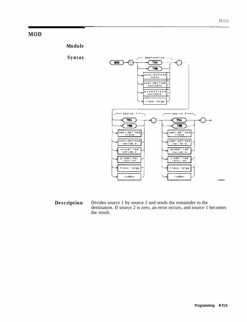
MOD
MOD
Module
Syntax
L u s e r - d e f i n e d Jt r a c e
Luser-defined,v a r i a b l e
L p r e d e f i n e d Jv a r i a b l e
Description Divides source 1 by source 2 and sends the remainder to thedestination. If source 2 is zero, an error occurs, and source 1 becomesthe result.
Programming 4-l 1 N

MOD
Program ExampleIO2030405060708090100110120130
140150160170180190200210220230240250
! The following example shows the use of the MOD command. The! instructions within the FUNCDEF ‘(B' delimiters form a structure! called a DLP (downloadable program).!ASSIGN (OSa TO 718 ! Assign I/O path to address 718.!OUTPUT (DSa*"IP*"*OUTPUT QSa~"FUIkkF M,OD-EX,O;";
! Instrument preset.! Logical start of the DLP.
OUTPUT QSa;"VARDEF DIVIDEND,lO;"; ! Create variable and initialize to IO.OUTPUT OSa;"VARDEF DIVISOR,G;"; ! Create variable and initialize to 6.OUTPUT QSa;"VARDEF RESULT,O;"; ! Create variable.!OUTPUT 9Sa;"MOD RESULT,DIVIDEND,DIVISOR;";
OUTPUT OSa*"CLRDSP*"*OUTPUT QSai"PU;PA ;0:400;";
! Perform calculation.! Clear display.! Move pen to starting position.
OUTPUT OSa;"DSPLY DIVIDEND,4,2;TEXT % MOD %;I; ! \ Display calculationOUTPUT QSa;"DSPLY DIVISOR,2,1;"; ! and results.OUTPUT @Sa;"TEXT % =%;DSPLY RESULT,2,0;"; ! /OUTPUT QSa;"Q;"; ! Logical end of the DLP.!OUTPUT QSa*"M OD EX*"*! DLP M-OD-Ex, -
, , ! Have the analyzer execute the
!ASSIGN OSa TO *END
! Close I/O path.
4-120 Programming

MODRCEI’
MODRCLT
Recall Trace from Module Memory
Syntax
i d e n t i f i e r
Description Recall a specified trace from the source specified by the MSDEVcommand, to the TRA or TRB of the instrument. This commandspecifies that the recall occur from a memory module or memory cardas specified by the MSDEV command.
Note
Note
I;br.fimware datecode 890524 and earlier:
If more than one trace is labeled with the same name, MODRCLTcannot distinguish between them.
Traces stored on memory cards using a mass-memory module withfirmware datecode 910116 or later cannot be read into a module withan earlier firmware datecode (for example, 890524). Traces stored oncards using modules with firmware datecode 890524 or earlier can beread into a module with firmware datecode 910116 or later.
Prerequisite Command: MSDEV
Related Commands: MODSAVET and DISPOSE
Program Example102030405060708090100110120130140150160
! The following example shows the use of the MODRCLT command. The! instructions within the FUNCDEF '0' delimiters form a structure! called a DLP (downloadable program).!ASSIGN QSa TO 718 ! Assign I/O path to address 718.!OUTPUT QSa;"FUNCDEF GET,TRC,O;"; ! Logical start of the DLP.OUTPUT QSa;"IP;SNGLS;TS;VIEW TRA;"; ! Set up the analyzer.OUTPUT OSa;"MSDEV MEM;"; ! Tell the analyzer where the
! trace is stored.OUTPUT QSa;"MODRCLT TRA,%CAL,OUT%;";! Recall the trace from memory.OUTPUT @Sa;"O;"; ! Logical end of the DLP.OUTPUT QSa;"GET,TRC;"; ! Execute the DLP.!ASSIGN QSa TO * ! Close I/O path.END
Programming 4-121

MODSAVT
Save Trace in Module Memory
d e l i m i t e r i d e n t i f i e r del i m i t e r
Description
Note
Note
This command saves a trace in module memory by its created name orby the default name, trace. The spectrum analyzer state and the timeand date the trace was saved is also stored. The trace is stored in thedestination specified with the MSDEV command.
firjimware dutewde 890524 and earlier: It is recommended thatunique names be assigned to each trace, since the MODRCUI’ commanddoes not distinguish traces by the time and date stamp. In addition,when traces are saved on the card the title is modified. If no nameis given, the title becomes TR plus the last five digits of the timeand date stamp. If a name is given, the title becomes the first fourcharacters of the name plus the last five digits of the time and datestamp.
Traces stored on memory cards using a mass-memory module withfirmware datecode 910116 or later cannot be read into a module withan earlier firmware datecode (for example, 890524). Traces stored oncards using modules with firmware datecode 890524 or earlier can beread into a module with firmware datecode 910116 or later.
Restrictions: Subject to available memory. The following commandsconsume memory: ONEOS, ARRAYDEF, TRDEF, KEYDEF, LCLVAR,VARDEF REPEAT/UNTIL, and IF/THEN.
Prerequisite Command: MSDEV
Related Commands: MODRCLT and DISPOSE
Program Example10 ! The following example shows the use of the MODSAVT command. The20 ! instructions within the FUNCDEF ‘0' delimiters form a structure30 ! called a DLP (downloadable program).40 !50 ASSIGN (PSa TO 718 ! Assign I/O path to address 718.60 !70 OUTPUT OSa;"FUNCDEF SAVE,TRC,Q;"; ! Logical start of the DLP.80 OUTPUT OSa;"IP;CF 3OOMHZ;SP 1MHZ;TS;"; ! Set up the analyzer.
4-122 Programming
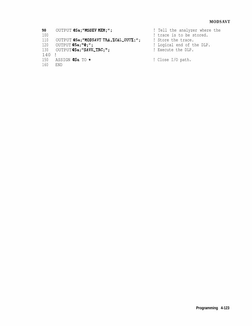
MODSAVT
90 OUTPUT QSa;"MSDEV MEM;"; ! Tell the analyzer where the100 ! trace is to be stored.110 OUTPUT QSa;"MODSAVT TRA,%CAL-OUT%;"; ! Store the trace.120 OUTPUT OSa;"(B;"; ! Logical end of the DLP.130 OUTPUT OSa;"SAVE-TRC;"; ! Execute the DLP.140 !150 ASSIGN &Isa TO * ! Close I/O path.160 END
Programming 4-123

MOV
Move
Svntax /-destination\ /---- s o u r c e \
i, u s e r;p,“,’ n e d J
1 u s e r - d e f i n e d Jv a r i a b l e
L p r e d e f i n e d Avariable
L t r a c e J L p r e d e f i n e d Je l e m e n t f u n c t i o n
L t r a c e r a n g e -/
L t r a c e Je l e m e n t
Description Store the source contents in the destination.
Program Example102030405060708090
! The following example shows the use of the MOV command. The example! uses an input signal of 300 MHz,such as the CAL OUTPUT, and looks at! its harmonics. An input signal is not necessary to the function of! this example, but acts as a visual aid.!ASSIGN (DSa TO 718 ! Assign I/O path to address 718.!OUTPUT OSa;"FUNCDEF INCRFREQ,Q;"; ! Logical start of the DLP function.OUTPUT OSa;"VARDEF FREQ,300E6;"; ! Create variable and initialize to
300 MHz.100 OUTPUT QSa-"IP*SP lMHZ*"*‘ 8 , , ! Instrument preset; set span;110 !120 OUTPUT OSa;"REPEAT;"; ! Begin loop.130 OUTPUT (OSa;" MOV CF,FRED;"; ! Set center frequency.140 OUTPUT (DSa;" TS;"; ! Take a sweep to update display.150 OUTPUT (OSa;" ADD FREQ,FREq,300EG;"; ! Increase FREQ by 300 MHz.160 OUTPUT QSa;"UNTIL FREQ,GT,3E9;"; ! End of loop.170 OUTPUT @Sa* “0 * ” *, ,, ! Logical end of DLP function.180 !190 OUTPUT (DSa;" INCRFREQ;"; ! Execute function.200 ! 210 ASSIGN QISa TO * ! Close I/O path.220 END
4-l 24 Programming

MPY
Multiply
Syntax
L+ u s e r - d e f i n e d Jt r a c e
4 u s e rt-rdaecfei n e d
4 u s e r - d e f i n e d -,v a r i a b l e
4 u s e r - d e f i n e d Jv a r i a b l e
1 p r e d e f ined Jv a r i a b l e
ir p r e d e f i n e d Jvariable
L p r e d e f i n e d /f u n c t i o n
p r e d e f i n e d Jf u n c t i o n
L t r a c e r a n g e J trace r a n g e J
number J L n u m b e r
Description Multiplies source 1 by source 2, point by point, and sends the result tothe destination. In case of destination overflow, an error is reportedand the result is limited to its maximum legal value with a propersign.
Programming 4-125

MPY
Program Example102030405060708090
! The following example shows the use of the MPY command. The example! uses an input signal of 300MHz, such as the CAL OUTPUT) and looks at! its harmonics. An input signal is not necessary to the function of! this example, but acts as a visual aid.!ASSIGN QSa TO 718 ! Assign I/O path to address 718.!OUTPUT QSa;"FUNCDEF MPYEX,Q;"; ! Logical start of the DLP function.OUTPUT QSa;"VARDEF FUNDMNTL,300EG;";
! Create variable and initialize to! 300 MHz.
100105
OUTPUT QSA;"VARDEF HARMNC,O;"; ! Create variable and initialize to 0.OUTPUT @Sa;"MOV HARMNC,FUNDMNTL;"; ! Let HARMNC equal
! FUNDMNTL.110 OUTPUT OSa;"VARDEF HARMNUM,O;"; ! Initialize HARMNUM to 0.120 OUTPUT QSa;"IP;SP IMHZ;"; ! Instrument preset; set span.130 !140 OUTPUT (DSa; "REPEAT;"; ! Begin loop.150 OUTPUT QSa;" ADD HARMNUM,HARMNUM,l;";
160! Increment to next harmonic.
OUTPUT (DSa;” MPY HARMNC,FUNDMNTL,HARMNUM;";! Harm freq=fund * harm num.
170 OUTPUT (DSa;" MOV CF,HARMNC;"; ! Set center frequency.180 OUTPUT (OSa;” TS;"; ! Take a sweep to update display.190 OUTPUT OSa;WNTIL HARMNC,GE,3ES;"; ! End of loop.200 OUTPUT (DSa;“@;“; ! Logical end of DLP function.210 !220 OUTPUT QSa;"MPYEX;"; ! Execute function.230 !240 ASSIGN OSa TO * ! Close I/O path.250 END
4-l 26 Programming

MSDEV
MSDEV
Mass Storage Device
Syntax
Description Establishes the data storage and access device as either the modulememory or the memory card.
Query Response
Program Example102030405060708090100110120130140150160
! The following example shows the use of the MSDEV command. The! instructions within the FUNCDEF '6' delimiters form a structure! called a DLP (downloadable program).!ASSIGN @Sa TO 718 ! Assign I/O path to address 718.!OUTPUT QSa;"FUNCDEF SAVE-TRC,B;"; ! Logical start of the DLP.OUTPUT QSa;"IP;CF300MHZ;SP 1MHZ;TS;"; ! Set up the analyzer.OUTPUT OSa;"MSDEV CARD;"; ! Tell the analyzer where the!OUTPUT QSa;"MODSAVT TRA,%CAL-OUT%;"; ! Store the trace on the card.OUTPUT OSa;"@;"; ! Logical end of the DLP.OUTPUT QSa"'SAVE TRC*"-# - 8, ! Execute the DLP.!ASSIGN QSa TO* !Close I/O path.END
Programming 4.127

MXM
Maximum
Syntax - d e s t i n a t i o n - - - - ,I
MW
i, u s e r - d e f i n e d Jt r a c e
Luser-defined Jv a r i a b l e
< p r e d e f ined Jvorioble
Description Compares source 2 with source 1, point by point, and sends thegreater value of each comparison to the destination.
4-126 Programming

MXM
Program Example10 ! The following example shows a use of the MXM command. The example20 ! requires an input signal of 300 MHz, such as the CAL OUTPUT signal.30 !40 ASSIGN QSa TO 718 ! Assign I/O path to address 718.50 I60 OUTPUT @Sa;"IP;"; ! Instrument preset.70 OUTPUT @Sa;"CF 300MHZ; SP 200KHZ;";
8090100110120130140150160170180190200210220
OUTPUT OSa;"CLRW TRA;";OUTPUT (OSa*"CLRW TRB.".OUTPUT BSa~"TS;";
9 ,
! Set center frequency and span.! Clear-write trace A.! Clear-write trace B.! Update the display.
OUTPUT @Sa;"VIEW TRA;";!FOR Counter=1 TO IO
! View trace A.
OUTPUT OSa;"APB;";NEXT CounterOUTPUT QSa ;"AMB ON;";!
! A + B --> A
! A - B --> A
OUTPUT OSa;"MXM TRA,TRA,TRB;"; ! Compare trace A and trace B.! Put the maximum point in trace A.
OUTPUT QSa;"BLANK TRB;";ASSIGN (PSa TO *END
! Blank trace B to view the results.! Close I/O path.
Programming 4-129

ONEOS
On End of Sweep
user-defined
Description ONEOS is a predefined function name. The contents of ONEOS areexecuted at the end of a sweep, after completing trace processing andall other end-of-sweep functions.
User memory is required to execute the ONEOS command. TheONEOS command allocates memory which can be freed with theDISPOSE command.
Restrictions: Subject to available memory. The following commandsconsume memory: ONEOS, ARRAYDEF, TRDEF, KEYDEF, LCLVAR,VARDEF REPEAT/UNTIL, and IF/THEN.
Program Example1020304050607080
90100110120130140150160
! The following example shows the use of the ONEOS command. The! example uses an input signal of 300 MHz such as the CAL OUTPUT.!ASSIGN @Sa TO 718 ! Assign I/O path to address 718.!OUTPUT QSa;"IP;ST 1SC;TS;"; ! Instrument preset; set sweep
! time; take a sweep.OUTPUT QSa;"ONEOS $CF 300MHZ;SP lMHZ;$;";
! At the end of the following! sweep, set frequency and span.
OUTPUT 9Sa;"TS;ONEOS OFF;"; ! Take sweep; turn ONEOS off.!! Note: If the ONEOS OFF command is not given, the analyzer will! continue to set the frequency and span at the end of each sweep.!ASSIGN QSa TO * ! Close I/O path.END
4-130 Programming

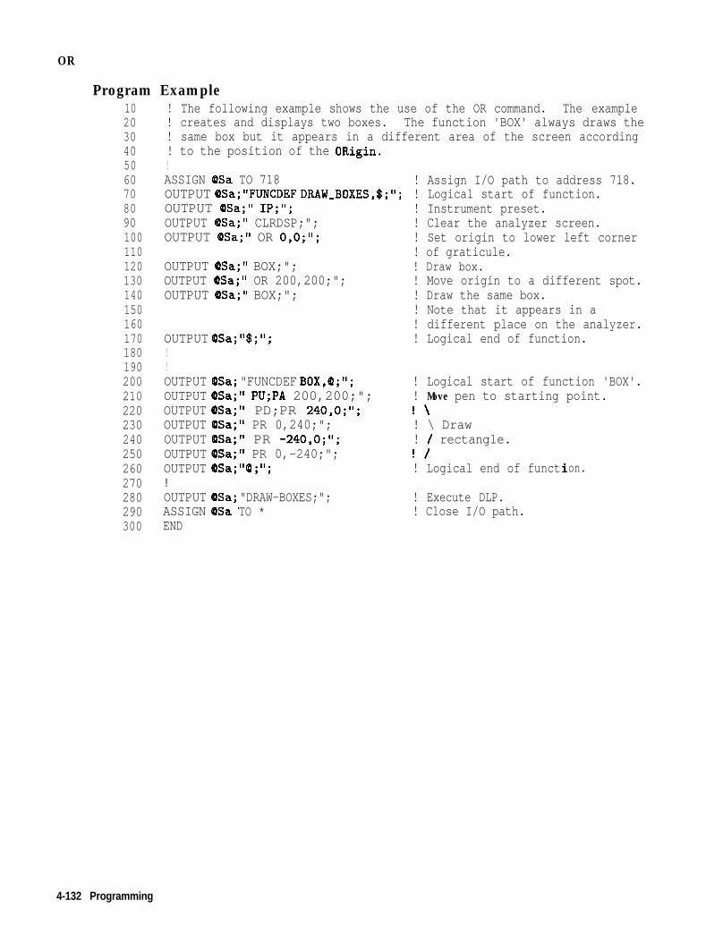
OR
Program Example102030405060708090100110120130140150160170180190200210220230240250260270280290300
! The following example shows the use of the OR command. The example! creates and displays two boxes. The function 'BOX' always draws the! same box but it appears in a different area of the screen according! to the position of the ORigin.!ASSIGN QSa TO 718 ! Assign I/O path to address 718.OUTPUT QSa;"FUNCDEF DRAW,BOXES,$;"; ! Logical start of function.OUTPUT OSa;" IP;";OUTPUT (OSa;" CLRDSP;";OUTPUT (OSa;" OR 0,O;";
OUTPUT (OSa;" BOX;";OUTPUT (DSa;" OR 200,200;";OUTPUT (PSa;" BOX;";
OUTPUT @Sa;"$;";!!OUTPUT @SaOUTPUT @SaOUTPUT OSa ;OUTPUT @SaOUTPUT @SaOUTPUT @SaOUTPUT @Sa ;!OUTPUT QISa ;ASSIGN dDSaEND
"FUNCDEF BOX,@;";" PU;PA 200,200;";" PD;PR 240,O;";" PR 0,240;";" PR -240,O;";' PR 0,-240;";'I@ ; " ;
! Logical start of function 'BOX'.! Move pen to starting point.! \! \ Draw! / rectangle.! /! Logical end of function.
"DRAW-BOXES;"; ! Execute DLP.TO * ! Close I/O path.
! Instrument preset.! Clear the analyzer screen.! Set origin to lower left corner! of graticule.! Draw box.! Move origin to a different spot.! Draw the same box.! Note that it appears in a! different place on the analyzer.! Logical end of function.
4-132 Programming

OUTPUT
OUTPUT
Output to HP-IB
Syntax
Jyformot- -output data-
predefined voriabie
Description This command sends output data in the format appropriate to theaddressed device. The data may be from a function definition ora DLP, The command assumes the CTRLHPIB command has beenexecuted to place the spectrum analyzer in controller mode. If acontroller is detected on HP-IB, the command is aborted. The outputformat is determined by the format field specifications.
Related commands: RELHPIB, ENTER, and CTRLHPIB
Programming 4.133

OUTPUT
Parameters Address
Format
Integers 0 to 30 are for the HPIB interface, excludingthe HP-IB address of the spectrum analyzer.
Integers 98 and 99 are for the Auxiliary interface. *
98 outputs with the least-significant bit (LSB) ofthe serial data byte first.
99 outputs with the most-significant bit (MSB) ofthe serial data byte first.
B Output a single &bit byte to the specifiedinterface.
F Output a number in ASCII format, using thespecified field width and precision, with LF andEND terminators.
K Output in ASCII format, without a terminator, to afree field.
KC Output in ASCII format, with CR and LFterminators, to a free field.
KL Output in ASCII format, with LF and ENDterminators, to a free field.
Related Commands: CTRLHPIB, RELHPIB, and ENTER
* These auxiliary interface connector commands can only be accessedremotely using DLPs, and are only available with 85620A with serialprefix 3143A or higher and firmware 910116 and later date codes.
4-134 Programming

OUTPUT
Program Example10 ! The following example shows how to use the OUTPUT command to have20 ! the analyzer send data to another HP-IB device. The instructions30 ! within the FUNCDEF '6' delimiters form a structure called a40 ! DLP (downloadable program).50 !60 ! NOTE: A printer (HP-IB address 01) needs to be connected.70 !80 ASSIGN OSa90 !100 OUTPUT @Sa110 OUTPUT (PSa120130 OUTPUT @Sa ;
TO 718
"FUNCDEF E-XMPLE,Q;";" CTRLHPIB;";
! Assign I/O path to address 718.
! Logical start of the DLP.! Tells analyzer to take control! of the bus.
" MKN;"; ! Turn on a marker.140 OUTPUT OSa;" OUTPUT l,KC,'THIS IS AN EXAMPLE OF THE ANALYZERSENDING';";150160170180190200210220230240250260270280290300310320330340350360370380
OUTPUT (PSa;" OUTPUT l,KC,'DATA TO ANOTHER HPIB DEVICE';";OUTPUT QSa;" OUTPUT l,KC,";";OUTPUT QSa;” OUTPUT l,K,'MARKER FREGUENCY = ';I';OUTPUT (DSa;" OUTPUT IjKiMKF;";OUTPUT (OSa;" OUTPUT l,KC,' Hz';";OUTPUT OSa;" OUTPUT l,KC,";";OUTPUT (OSa;" RELHPIB;";OUTPUT QSa*"@*"*9 ,,
! Release HP-IB control.! Logical end of the DLP.
!OUTPUT @Sa*"E XMPLE.".9 - , ,
SEND 7;UNL TALK 18 LISTEN 1 DATA
LOCAL 7WAIT 2REMOTE 7LOCAL 9Sa!ASSIGN cDSa TO *END
! Have the analyzer execute the! DLP E,XMPLE.! Send to HP-IB select code 7 the! commands necessary to allow! the analyzer (address 18) to! talk to the printer (address I)! while this controller is still! connected.! Local HP-IB select code 7.! Wait for printer to finish.! Toggle the HP-IB REN line.! Local the SA.
! Close I/O path.
Programming 4.135

P A
Plot Absolute
Syntax
k..+ predefined Ivariable
1 user-defined 2variable
L trace Ielement
,,- y coordinate \
predefined* function
predefinedvariable
Xf258.3
Description This command moves the pen from its current position to the positionspecified by the coordinates with respect to the origin (refer to theOR command). A line is drawn if the pen is down. Refer to PD (pendown) or PU (pen up) commands. The x and y coordinates are inmeasurement units.
Note With the origin at (O,O), the lower left-hand corner of the spectrumanalyzer graticule is at (100,100) and the upper right-hand comer is at(700,700).
Parameters The following parameters apply with OR set to 0,O.
X Maximum = 710 Y Maximum = 710 X Minimum = 90 Y Minimum =25
Related Commands: OR, PU, PD, and DSPLY
4-136 Programming

PA
Program Example102030405060708090100110120130140150160
170180190200210
220230240250260
! The following example shows the use of the PA, PR, PU, and PD commands.! The figures drawn are an ellipse within a rectangle.!ASSIGN (OSa TO 718 ! Assign I/O path to address 718.OUTPUT @Sa;"IP;"; ! Instrument preset.OUTPUT (DSa; "CLRDSP;"; ! Clear the analyzer screen.!
! Draw a rectangle with fixed points.OUTPUT OSa;"PU;PA 300,300;"; ! Move pen to starting point.OUTPUT QSa;"PD;PR 240,O;"; ! \OUTPUT @Sa*"PR 0 240.".OUTPUT OSai"PR -;40,;);:';
! \ Draw! / rectangle.
OUTPUT (PSa;"PR 0,-240;";!
! /
! Draw an ellipse with calculated points.OUTPUT OSa;"PU;PA 415,305; PD;";
! Move pen to starting point.FOR I=0 TO 2*PI STEP PI/40
X=PROUND(lO*COS(I>,-3) ! \ Calculate x and yY=PROUND(lO*SIN(I>,-3) ! / coordinates.!OUTPUT QSa;"PR "~VAL$(X>C","~VAL$(Y)~";";
! Create plot statement using! calculated coordinates.
NEXT I!ASSIGN (8Sa TO * ! Close I/O path.END
Programming 4-137

PD
Pen Down
Syntax
Description This command causes the pen to draw a line when the PA or PRcommands are activated.
Program Example102030405060708090100110120130140150160
170180190200210
220230240250260
! The following example shows the use of the PA, PR, PU, and PD commands.! The figures drawn are an ellipse within a rectangle.!ASSIGN @Sa TO 718 ! Assign I/O path to address 718.OUTPUT (OSa*"IP*"*OUTPUT QSa i"CLRDSP;";!
! Instrument preset.! Clear the analyzer screen.
! Draw a rectangle with fixed points.OUTPUT QSa;"PU;PA 300,300;'1; ! Move pen to starting point.OUTPUT OSa;"PD;PR 240,O;"; ! \OUTPUT OSa;"PR 0,240;"; ! \ DrawOUTPUT @Sa;"PR -240,O;"; ! / rectangle.OUTPUT (DSa;"PR 0,-240;"; ! /!
! Draw an ellipse with calculated points.OUTPUT QSa;"PU;PA 415,305; PD;";
! Move pen to starting point.FOR I=0 TO 2*PI STEP PI/40
X=PROUND(lO*COS(I>,-3) ! \ Calculate x and yY=PROUND(lO*SIN(I>,-3) ! / coordinates.!OUTPUT (DSa;"PR "&VAL$(X>&","~VAL$(Y)&";";
! Create plot statement using! calculated coordinates.
NEXT I!ASSIGN QSa TO * ! Close I/O path.END
4.138 Programming

PDA
PDA
Probability Distribution of Amplitude
Syntax
Description Replace the destination trace with the amplitude distribution functionof the source trace. The source trace data is taken point by point.The value for bottom-screen is subtracted from the value of each datapoint, then the difference is divided by the resolution value (which isrounded to an integer). If the result falls within the bucket range ofthe destination trace (0 to 600), the corresponding destination traceelement is increased by one. The function is complete after all sourcepoints are dealt with.
Resolution Range: Limited by source amplitude.
Programming 4-139

PDA
Program Example102030405060708090100110120130140150160170180190200210220230240
! The following example shows how to use the PDA command to determine! the probability distribution of the amplitude values in trace A.! The results are placed in trace B and expanded by a factor of 20! to make the results more visible.!ASSIGN QSa TO 718 ! Assign I/O path to address 718.!OUTPUT QSa;"FUNCDEF TST,Q;"; ! Logical start of DLP.OUTPUT QSa;"IP;SNGLS;"; ! Instrument preset the analyzer.OUTPUT OSa;"VBlOKZ;HD;TS;"; ! Set video BW at IO kHz.OUTPUT QSa; "MOV TRB,O;"; ! Put all zeros into trace B.OUTPUT @Sa;"PDA TRB,TRA,.8;"; ! Determine the distribution
! of trace A and put results! into trace B.
OUTPUT (DSa;"MPY TRB,TRB,20;"; ! Multiply values in trace B! by 20.
OUTPUT (PSa"'VIEW TRB*"*OUTPUT QSaj"Q;";
, f ! View trace B.! Logical end of DLP.
!OUTPUT QSa;"TST;"; ! Execute the DLP.!LOCAL QSa ! Local analyzer for manual use.ASSIGN QSa TO * ! Close I/O path.END
4-140 Programming

Probability Distribution of Frequency
SyntaxPDF
,-destination7
Description Replace the destination trace with the frequency distribution functionof the source trace. Source trace elements falling above the THcommand threshold level increase the corresponding destination traceelements amplitude by one display unit. The default threshold valueis nine major divisions below the reference level.
Program Example 10 OUTPUT 718;"TRDEF S,AMPLE,SO;";20 OUTPUT 718;"PDF S,AMPLE,TRA;";30 END
Programming 4-141
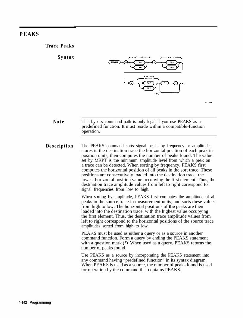
PEAKS
Trace Peaks
Syntax
Isortin
dQ-metho 7
X,2620
Note This bypass command path is only legal if you use PEAKS as apredefined function. It must reside within a compatible-functionoperation.
Description The PEAKS command sorts signal peaks by frequency or amplitude,stores in the destination trace the horizontal position of each peak inposition units, then computes the number of peaks found. The valueset by MKPT is the minimum amplitude level from which a peak ona trace can be detected. When sorting by frequency, PEAKS firstcomputes the horizontal position of all peaks in the sort trace. Thesepositions are consecutively loaded into the destination trace, thelowest horizontal position value occupying the first element. Thus, thedestination trace amplitude values from left to right correspond tosignal frequencies from low to high.
When sorting by amplitude, PEAKS first computes the amplitude of allpeaks in the source trace in measurement units, and sorts these valuesfrom high to low. The horizontal positions of the peaks are thenloaded into the destination trace, with the highest value occupyingthe first element. Thus, the destination trace amplitude values fromleft to right correspond to the horizontal positions of the source traceamplitudes sorted from high to low.
PEAKS must be used as either a query or as a source in anothercommand function. Form a query by ending the PEAKS statementwith a question mark (?). When used as a query, PEAKS returns thenumber of peaks found.
Use PEAKS as a source by incorporating the PEAKS statement intoany command having “predefined function” in its syntax diagram.When PEAKS is used as a source, the number of peaks found is usedfor operation by the command that contains PEAKS.
4-142 Programming

PEAKS
Query Response The PEAKS command outputs the number of signal peaks found.
Program Example102030405060708090100110120
130140150160170180190200210220230240250
! The following example shows the use of the PEAKS command. The example! uses an input signal of 300 MHz such as the CAL OUTPUT and looks at its! harmonics.!ASSIGN @Sa TO 718 ! Assign I/O/ path to address 718.
OUTPUT QSa ;"FUNCDEF NUM,PKS,@;"; ! Logical start of DLP.OUTPUT @Sa ;"VARDEF NUM,PEAKS,O;"; ! Create and initialize variable.OUTPUT (PSa ;"FA 250MHZ;FB 2900MHZ;"; ! Set start and stop frequencies.OUTPUT cDSa ;"MKPT -60DB;MKPX 3DB;TS;"; ! Set the threshold and marker-
! peak excursion. Take a sweep.OUTPUT OSa;"MOV NUM-PEAKS,PEAKS TRB,TRA,AMP;";
! Sort signals by amplitude! and place results in trace B.! Trace B now contains position! information.
OUTPUT (DSa;"Q;"; ! Logical end of DLP.!OUTPUT QSa; "NUM,PKS;"; ! Execute DLP.!OUTPUT OSa;"NUM,PEAKS?;"; ! How many peaks?ENTER OSa;Number,of,peaks ! Get returned value.PRINT "The number of signals above -60 dBm is ",Number-of-peaks!ASSIGN @Sa TO * ! Close I/O path.END
Programming 4-143

PR
Plot Relative
Syntax
c predefinedfunction \
predef inedvariable
_
J
r y coordinate -,
Description This command moves the pen from its current location to a positiondetermined by adding the new x and y coordinates to the current x, yposition.
Prerequisite Commands: VARDEF when using user-defined variable
Related Commands: OR PU, and PD
4-144 Programming

PR
Program Example10 ! The following example shows the use of the PA, PR, PU, and PD commands.20 ! The figures drawn are an ellipse within a rectangle.30 !40 ASSIGN QSa TO 718 ! Assign I/O path to address 718.50 OUTPUT @Sa;"IP;"; ! Instrument preset.60 OUTPUT OSa;"CLRDSP;"; ! Clear the analyzer screen.70 !80 ! Draw a rectangle with fixed points.90 OUTPUT OSa;"PU;PA 300,300;"; ! Move pen to starting point.100 OUTPUT QSa;"PD;PR 240,O;"; ! \110 OUTPUT (OSa*"PR 0 240.". ! \ Draw120 OUTPUT @SaI"PR -;40,;);:'; ! / rectangle.130 OUTPUT @Sa;"PR 0,-240;"; I /140 !150 ! Draw an ellipse with calculated points.160 OUTPUT QSa;"PU;PA 415,305; PD;";
! Move pen to starting point.170 FOR I=0 TO 2*PI STEP PI/40180 X=PROUND(lO*COS(I>,-3) ! \ Calculate x and y190 Y=PROUND(lO*SIN(I),-3) ! / coordinates.200 !210 OUTPUT @Sa;"PR "~VAL$(X)&","bVAL$(Y)≪ll;
! Create plot statement using220 ! calculated coordinates.230 NEXT I240 !250 ASSIGN @Sa TO * ! Close I/O path.260 END
Programming 4-145
PU
Pen Up
Syntax
Description This command causes the pen to stop drawing at the location specifiedin the last plot statement.
Related Commands: PA, PR, and DSPLY
4-146 Prouramming

PU
Program Example102030405060708090100110120130140150160
170180190200210
220230240250260
! The following example shows the use of the PA, PR, PU, and PD commands.! The figures drawn are an ellipse within a rectangle.!ASSIGN OSa TO 718 ! Assign I/O path to address 718.OUTPUT @Sa"'IP*"*OUTPUT OSaj"CLRDSP;";!
! Instrument preset.! Clear the analyzer screen.
! Draw a rectangle with fixed points.OUTPUT OSa;"PU;PA 300,300;"; ! Move pen to starting point.OUTPUT OSa;"PD;PR 240,O;"; ! \OUTPUT @Sa;"PR 0,240;"; ! \ DrawOUTPUT @Sa;"PR -240,O;"; ! / rectangle.OUTPUT (8Sa;"PR 0,-240;"; ! /!
! Draw an ellipse with calculated points.OUTPUT QSa;"PU;PA 415,305; PD;";
! Move pen to starting point.FOR I=0 TO 2*PI STEP PI/40
X=PROUND(lO*COS(I>,-3) ! \ Calculate x and yY=PROUND(lO*SIN(I),-3) ! / coordinates.!OUTPUT @Sa;"PR "&VAL$(X)&","&VAL$(Y)≪ll;
! Create plot statement using! calculated coordinates.
NEXT I!ASSIGN QSa TO * ! Close I/O path.END
Programming 4-147

RELEIPIB
Release HP-IB
Syntax (RELHPIB
Description This command releases HP-IB control taken by the CTRLHPIBcommand. Refer also to the commands ENTER, OUTPUT, andCTRLHPIB.
Restrictions: Subject to available memory. The following commandsconsume memory: ONEOS, ARRAYDEF, TRDEF, KEYDEF, LCLVAR,VARDEF REPEAT/UNTIL, and IF/THEN.
Prerequisite Commands: FUNCDEF when using user-defined function.VARDEF or LCLVAR when using user-defined variable, user-definedarray, or user-defined trace.
Related Commands: ABORT and RETURN
4-148 Programming
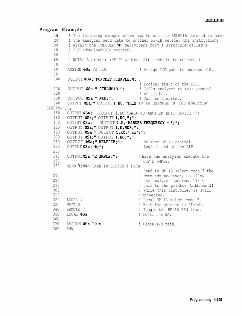
RJiXHPIB
Program Example102030405060708090100
110120130140
! The following example shows how to use the RELHPIB command to have! the analyzer send data to another HP-IB device. The instructions! within the FUNCDEF '@' delimiters form a structure called a! DLP (downloadable program).!! NOTE: A printer (HP-IB address 01) needs to be connected.!ASSIGN @Sa TO 718 ! Assign I/O path to address 718.!OUTPUT OSa;"FUNCDEF E,XMPLE,Q;";
! Logical start of the DLP.OUTPUT (PSa;" CTRLHPIB;"; ! Tells analyzer to take control
! of the bus.OUTPUT QSa;" MKN;"; ! Turn on a marker.OUTPUT (PSa;" OUTPUT l,KC,'THIS IS AN EXAMPLE OF THE ANALYZER
SENDING'.".150160170180190200210220230240250260
, ,OUTPUT QSa;" OUTPUT l,KC,'DATA TO ANOTHER HPIB DEVICE';";OUTPUT @Sa;" OUTPUT l,KC,";";OUTPUT QSa;" OUTPUT l,K,'MARKER FREIJUENCY = ';";OUTPUT (PSa;" OUTPUT l,K,MKF;";OUTPUT (DSa;" OUTPUT l,KC,' Hz';";OUTPUT QSa;" OUTPUT l,KC,";";OUTPUT (OSa;" RELHPIB;"; ! Release HP-IB control.OUTPUT QSa;"(P;"; ! Logical end of the DLPI. .OUTPUT OSa;"E,XMPLE;"; 1 Have the analyzer execute the
! DLP E,XMPLE.SEND 7;UNL TALK 18 LISTEN 1 DATA
! Send to HP-IB select code 7 the! commands necessary to allow! the analyzer (address 18) to! talk to the printer (address I)! while this controller is still! connected.
LOCAL 7 ! Local HP-IB select code 7.WAIT 2 ! Wait for printer to finish.REMOTE 7 ! Toggle the HP-IB REN line.LOCAL QSa ! Local the SA.!ASSIGN QSa TO * ! Close I/O path.END
270280290300310320330340350360370380
Programming 4.148

REPEAT/UNTIL
Repeat/Until
Syntax
user-defined Jvariable
L.+ predefined 2variable
Description
Repeat The REPEAT command determines the starting point of the loopingprocess. UNTIL determines the end of the REPEAT/UNTIL commandloop based on the comparison of two variables. Valid conditions areless than (LT), greater than (GT), less than or equal to (LE), greaterthan or equal to (GE), equal (EQ), and not equal (NE). The commandswithin the repeat/until loop are executed until the comparison resultis true.
This command requires user memory while executing as a remotecommand. When the command is complete, memory is returned asavailable user memory.
4-160 Programming

REPEAT/UNTIL
Program Example #l102030405060708090100110120130140150160
170180190200210220
230240250260270280290300310320330340
! The following example shows the use of the REPEAT/UNTIL commands! in a FOR/NEXT loop context. A previously downloaded function may! be executed repeatedly from within an immediate execute download.! This is one way of nesting REPEATS.!ASSIGN @Sa TO 718 ! Assign I/O path to address 718.!OUTPUT OSa*"IP*"-OUTPUT QSaI"VARDEF OUTER,LP,O;";
! Instrument preset.! Create variable and initialize to 0.
OUTPUT OSa;"VARDEF TOTAL,O;";!
! Create variable and initialize to 0.
OUTPUT QSa;"FUNCDEF CNT-LP,Q;"; ! Logical start of the DLP function.OUTPUT QSa;" VARDEF INNER,LP,O;"; ! Create and initialize inner loop counter.OUTPUT (DSa;" REPEAT;"; ! Begin inner loop.OUTPUT @Sa;" ADD TOTAL,TOTAL,l;"*,! Increment running total.OUTPUT QSa;" ADD INNER,LP,INNER-LP,l;";
! Increment inner loop counter.OUTPUT OSa;" UNTIL INNER,LP,EQ,3;";! End of inner loop.OUTPUT OSa*"Q*"*3 83!OUTPUT QSa;"REPEAT;"; ! Begin outer loop.OUTPUT QSa;" CNT,LP;"; ! Execute function.OUTPUT (PSa;" ADD OUTER,LP,OUTER-LP,l;";
! Increment outer loop counter.OUTPUT QSa;"UNTIL OUTER_LP,ECj,4;"; ! End of outer loop.!OUTPUT QSa;"CLRDSP;";OUTPUT OSa;"PU;PA 10,500;TEXT %INNER LOOP COUNTER = %;";OUTPUT QSa;"DSPLY INNER,LP,5,2;";OUTPUT OSa;"PU;PA 10,400;TEXT %OUTER LOOP COUNTER = (/(;";OUTPUT QSa;"DSPLY OUTER,LP,5,2;";OUTPUT QSa;"PU;PA 10,300;TEXT %TOTAL ITERATIONS = %;";OUTPUT OSa;"DSPLY TOTAL,6,2;";!ASSIGN cOSa TO * ! Close I/O path.END
Programming 4-151

REPEAT/UNTIL
Program Example #2102030405060708090100110120130140150
160170
180190200210220230240250260270280290
! The following example shows the use of the REPEAT/UNTIL commands! in a FOR/NEXT loop context. This is an immediate-execute DLP! (downloadable program). This is another way of nesting REPEATS.!ASSIGN cOSa TO 718 ! Assign I/O path to address 718.!OUTPUT Q)Sa*"IP*"*OUTPUT @Sai"VARDEF OUTER,LP,O;";
! Instrument preset.! Create variable and initialize to 0.
OUTPUT QSa;"VARDEF TOTAL,O;"; ! Create variable and initialize to 0.!OUTPUT QSa;'%EPEAT;"; ! Begin outer loop.OUTPUT QSa;" VARDEF INNER,LP,O;"; ! Create and initialize inner loop counter.OUTPUT (DSa;" REPEAT;"; ! Begin inner loop.OUTPUT &?a;" ADD TOTAL,TOTAL,l;";! Increment running totalOUTPUT QSa;" ADD INNER-LP,INNER,LP,l;";
! Increment inner loop counter.OUTPUT QSa;" UNTIL INNER,LP,EL),3;";! End of inner loop.OUTPUT (DSa;" ADD OUTER,LP,OUTER,LP,I;";
! Increment outer loop counter.OUTPUT QSa;WNTIL OUTER,LP,EQ,4;"; ! End of outer loop.!OUTPUT OSa;"CLRDSP;";OUTPUT QSa;"PU;PA 10,500;TEXT %INNER LOOP COUNTER=%;";OUTPUT OSa;"DSPLY INNER_LP,5,2;";OUTPUT OSa;"PU;PA 10,400;TEXT IOUTER LOOP COUNTER=%;";OUTPUT QSa;"DSPLY OUTER,LP,5,2;";OUTPUT QSa;"PU;PA 10,300;TEXT %TOTAL ITERATIONS=%;";OUTPUT QSa;"DSPLY TOTAL,5,2;";!ASSIGN @Sa TO * ! Close I/O path.END
4.152 Programming

RETURN
Return from Function
Syntax (RETURN
Description Use this command to return from a user-defined function beforeits completion. The program returns to the point from which thefunction was called.
Related Commands: IF/THEN and FUNCDEF
Programming 4-153

RETURN
Program Example102030405060708090100110120130140150160170180190200210220230240250260270280290300310320330340350360370
! Program to test the RETURN command for use in DLPs. Two FUNCDEFs! are defined, C-ALLER and C-ALLEE. C,ALLER sets the spectrum analyzer! up in single sweep mode with a 1 second sweeptime, so instrument! state changes can be easily observed. C-ALLER first sets the CF to! 1 GHz and then calls C,ALLEE. C-ALLEE tests the CF value, and if it! is less than 1.5 GHz, it changes the span to 300 MHz and takes! another sweep. C-ALLEE then changes the span to 100 MHz, takes! another sweep, and returns to C,ALLER.!! C-ALLER then changes the CF to 2 GHz, takes a sweep, and again calls! C,ALLEE. Since the CF is now greater than 1.5 GHz, C-ALLEE returns! immediately to C,ALLER changes the span to 200 MHz and takes a sweep.I---------------------------------------------------------------!ASSIGN (PSa TO 718!OUTPUT OSa;"FUNCDEF C,ALLER,Q;";OUTPUT QSa;"IP;SNGLS;ST ISC;";OUTPUT (DSa;"CF 1GZ;TS;SP 500MZ;TS;";OUTPUT OSa*"C ALLEE-".OUTPUT QSai"CF 2 GZITS;";OUTPUT OSa*"C ALLEE*"*OUTPUT QSaj"SP 2OOMZ;k;";OUTPUT cOSa*"(0*"*, ,,!OUTPUT QSa;"FUNCDEF C,ALLEE,O;";OUTPUT OSa;"IF CF,LT,l.5E+S;THEN;";OUTPUT @Sa;"SP 300MZ; TS;";OUTPUT OSa*"ELSE*"*OUTPUT QSa~VlETURN~";OUTPUT OSa;"SP 1GZ;TS;";OUTPUT QSa;"ENDIF;";OUTPUT OSa;"SP 1OOMZ;TS;";OUTPUT cOSa*"@*"*9 8,!ASSIGN OSa TO *END
4-154 Programming

RMS
RMS
Trace Root Mean Square Value
Syntax
Note This bypass command path is only legal if you use RMS as apredefined function. It must reside within a compatible-functionoperation.
Description The root mean square (rms) value of a trace is determined andreturned in measurement units.
Restrictions: Subject to available memory. The following commandsconsume memory: ONEOS, ARRAYDEF, TRDEF, KEYDEF, LCLVAR,VARDEF REPEAT/UNTIL, and IF/THEN.
Program Example102030405060708090100110120130140150
! The following example shows the use of the RMS command.!ASSIGN QSa TO 718 ! Assign an I/O path.!OUTPUT OSa;"IP;"; ! Instrument preset.OUTPUT QISa; "SNGLS;"; ! Single sweep mode.OUTPUT OSa;"TS;RMS TRA,?;"; ! Take sweep; find RMS value.ENTER QSa;Rms,value ! Get RMS value from analyzer.!Rms,value=PROUND(Rms-value,-2) ! Round the value to two decimal
! places.PRINT "The RMS value of the trace is ";Rms,value;" measurement units"!ASSIGN @Sa TO * ! Close I/O path.END
Programming 4-155

SADD
Add a Limit-Line Segment
Syntax
Description This command is used to add a limit-line segment to the current limitline,
Related commands include: LIMU, LIML, LIMM, LIMD, LIMIFL,LIMISL, LIMISP, SDEL, SEDI
4-156 Programming

SADD
Program Example130140150160170180190200210220230240250260270280
290300310320330340350360370380390400410420430440450460470480490491492493494500
! This program demonstrates the use of the SADD command! to generate a limit line:!OUTPUT 718;"LIMIPURGE;"; ! Purge current limit line.OUTPUT 718*"EDITLIML*"*OUTPUT 718;"LIMIREL ;)FF;";
! Begin edit of limit line.! Make sure it's an absolute line.
OUTPUT 718*"SADD*".OUTPUT 718;"SEDI'lj";
! Add segment to the limit line.! Edit the first segment.
OUTPUT 718;"LIMF 250MHZ;";OUTPUT 718;"LIMU -35DBM;";
! Set frequency of the segment.! Provide the upper amplitude.
OUTPUT 718;"LIML -8ODBM;"; ! Enter the lower amplitude.OUTPUT 718;"LIMTFL;";OUTPUT 718;"SDON;";
! Set type of segment to flat.! Enter parameters into table.
OUTPUT 718;"SADD;SEDI 2;";OUTPUT 718;"LIMF 290MHZ;";
! Add then edit second segment.! Set frequency of segment 2.
OUTPUT 718;"LIMU-35DBM;LIML-8ODBM;";
OUTPUT 718;"LIMTSL;";! Set amplitude data for segment.! Set segment type to slope.
OUTPUT 718*"SDON*"*OUTPUT 718;"SADD;SEDI 3;";
! Enter parameters into table.
OUTPUT 718;"LIMF 296.5MHZ;LIMW5DBM;LIML-8ODBM;LIMTSL;";OUTPUT 718*"SDON*"*OUTPUT 718;"SADD;SEDI 4;";OUTPUT 718;"LIMF 300MHZ;LIMU-5DBM;LIML-25DBM;LIMTSL;";OUTPUT 718;"SDON;";OUTPUT 718;"SADD;SEDI 5;";OUTPUT 718;"LIMF 303.5MHZ;LIMW5DBM;LIML-8ODBM;LIMTSL;";OUTPUT 718*"SDON*"*OUTPUT 718;"SADD;SEDI 6;";OUTPUT 718;"LIMF 304.5MHZ;LIMW5DBM;LIML-8ODBM;LIMTSL;";OUTPUT 718;"SDON;";OUTPUT 718;"SADD;SEDI 7;";OUTPUT 718;"LIMF 3lOMHZ;LIMU-35DBM;LIML-8ODBM;LIMTFL;";OUTPUT 718;"SDON;";OUTPUT 718;"SADD;SEDI 8;";OUTPUT 718;"LIMF 350MHZ;LIMU-35DBM;LIML-8ODBM;LIMTFL;";OUTPUT 718;"SDON;";OUTPUT 718;"EDITDONE;"; ! End of limit-line definition.!! Set up spectrum analyzer to display the limit line.!OUTPUT 718;"CF 300MHZ;SP 50MHZ;RB 2MHZ;VB 3OKHZ;TS;";END
Programming 4-l 57

SDEL
Delete Limit-Line Segment
Syntax
Description This command deletes the limit-line segment specified with the SEDIcommand.
4-158 Programming

SDON
SDON
Limit-Line Segment Done
Syntax
Description This command is used to terminate the SEDI command.
Programming 4-159

SDON
Program Example130140150160170180190200210220230240250260270280
290300310320330340350360370380390400410420430440450460470480490491492493494500
! This program demonstrates the use of the SDON command! to generate a limit line:!OUTPUT 718 ;"LIMIPURGE;"; ! Purge current limit line.OUTPUT 718 ;"EDITLIML;"; ! Begin edit of limit line.OUTPUT 718 ;"LIMIREL OFF;"; ! Make sure it's an absolute line.OUTPUT 718 ;"SADD;"; ! Add segment to the limit line.OUTPUT 718 ;"SEDI 1;"; ! Edit the first segment.OUTPUT 718;"LIMF 250MHZ;"; ! Set frequency of the segment.OUTPUT 718;"LIMU -35DBM;"; ! Provide the upper amplitude.OUTPUT 718;"LIML -8ODBM;"; ! Enter the lower amplitude.OUTPUT 718*"LIMTFL*"*OUTPUT 718;"SDON;";
, ! Set type of segment to flat.! Enter parameters into table.
OUTPUT 718;"SADD;SEDI 2;"; ! Add then edit second segment.OUTPUT 718;"LIMF 290MHZ;"; ! Set frequency of segment 2.OUTPUT 718;"LIMU-35DBM;LIML-8ODBM;";
OUTPUT 718;"LIMTSL;";OUTPUT 718*"SDON*"*OUTPUT 718;"SADD;SEDI 3;";
! Set amplitude data for segment.! Set segment type to slope.! Enter parameters into table.
OUTPUT 718;"LIMF 296.5MHZ;LIMW5DBM;LIML-8ODBM;LIMTSL;";OUTPUT 718;"SDON;";OUTPUT 718;"SADD;SEDI 4;";OUTPUT 718;"LIMF 300MHZ;LIMWSDBM;LIML-25DBM;LIMTSL;";OUTPUT 718*"SDON*"*OUTPUT 718; "SADD;SEDI 5;";OUTPUT 718;"LIMF 303.5MHZ;LIMW5DBM;LIML-8ODBM;LIMTSL;";OUTPUT 718;"SDON;";OUTPUT 718;"SADD;SEDI 6;";OUTPUT 718;"LIMF 304.5MHZ;LIMW5DBM;LIML-8ODBM;LIMTSL;";OUTPUT 718;"SDON;";OUTPUT 718;"SADD;SEDI 7;";OUTPUT 718;"LIMF 3l0MHZ;LIMU-35DBM;LIML-8ODBM;LIMTFL;";OUTPUT 718*"SDON*"*OUTPUT 718;"SADD;SEDI 8;";OUTPUT 718;"LIMF 350MHZ;LIMU-35DBM;LIML-8ODBM;LIMTFL;";OUTPUT 718;"SDON;";OUTPUT 718;"EDITDONE;"; ! End of limit-line definition.!
! Set up to display the limit line.!OUTPUT 718;"CF 300MHZ;SP 50MHZ;RB 2MHZ;VB 30KHZ;TS;";END
4.160 Programming

SEDI
SEDI
Edit Limit-Line Segment
Syntax
Description Activates the limit-line segment you identify by its segment number inthe limit-line table.
Related commands: LIMU, LIML, LIMM, LIMD, SDEL, LIMTFL, andLIMTSL to modify the limit-line parameters.
Programming 4.161

SEDI
Program Example130140150160170180190200210220230240250260270280
290300310320330340350360370380390400410420430440450460470480490491492493494500
! This program demonstrates the use of the SEDI command! to generate a limit line:!OUTPUT 718;"LIMIPURGE;"; ! Purge current limit line.OUTPUT 718;"EDITLIML;"; ! Begin edit of limit line.OUTPUT 718;"LIMIREL OFF;"; ! Make sure it's an absolute line.OUTPUT 718;"SADD;"; ! Add segment to the limit line.OUTPUT 718;"SEDI 1;"; ! Edit the first segment.OUTPUT 718;"LIMF 250MHZ;"; ! Set frequency of the segment.OUTPUT 718;"LIMU -35DBM;"; ! Provide the upper amplitude.OUTPUT 718;"LIML -8ODBM;"; ! Enter the lower amplitude.OUTPUT 718;"LIMTFL;"; ! Set type of segment to flat.OUTPUT 718."SDON.".OUTPUT 718;"SADD;SEDI 2;";
! Enter parameters into table.! Add then edit second segment.
OUTPUT 718;"LIMF 290MHZ;"; ! Set frequency of segment 2.OUTPUT 718;"LIMU-35DBM;LIML-8ODBM;";
! Set amplitude data for segment.OUTPUT 718;"LIMTSL;"; ! Set segment type to slope.OUTPUT 718*"SDON*"*OUTPUT 718;"SADD;SEDI 3;";
! Enter parameters into table.
OUTPUT 718;"LIMF 296.5MHZ;LIMW5DBM;LIML-8ODBM;LIMTSL;";OUTPUT 718*"SDON*"*OUTPUT 718; "SADD;SEDI 4;";OUTPUT 718;"LIMF 300MHZ;LIMW5DBM;LIML-25DBM;LIMTSL;";OUTPUT 718."SDON."*OUTPUT 718; "SADD;SEDI 5;";OUTPUT 718;"LIMF 303.5MHZ;LIMW5DBM;LIML-8ODBM;LIMTSL;";OUTPUT 718*"SDON*"*OUTPUT 718;"SADD;SEDI 6;";OUTPUT 718;"LIMF 304.5MHZ;LIMW5DBM;LIML-8ODBM;LIMTSL;";OUTPUT 718*"SDON*"*OUTPUT 718; "SADD;SEDI 7;";OUTPUT 718;"LIMF 3l0MHZ;LIMU-35DBM;LIML-8ODBM;LIMTFL;";OUTPUT 718;"SDON;";OUTPUT 718;"SADD;SEDI 8;";OUTPUT 718;"LIMF 350MHZ;LIMU-35DBM;LIML-8ODBM;LIMTFL;";OUTPUT 718;"SDON;";OUTPUT 718~"EDITDONE~"~, , 9 ! End of limit-line definition.!
! Set up to display the limit line.!OUTPUT 718;"CF 300MHZ;SP 50MHZ;RB 2MHZ;VB 30KHZ;TS;";END
4-162 Programming
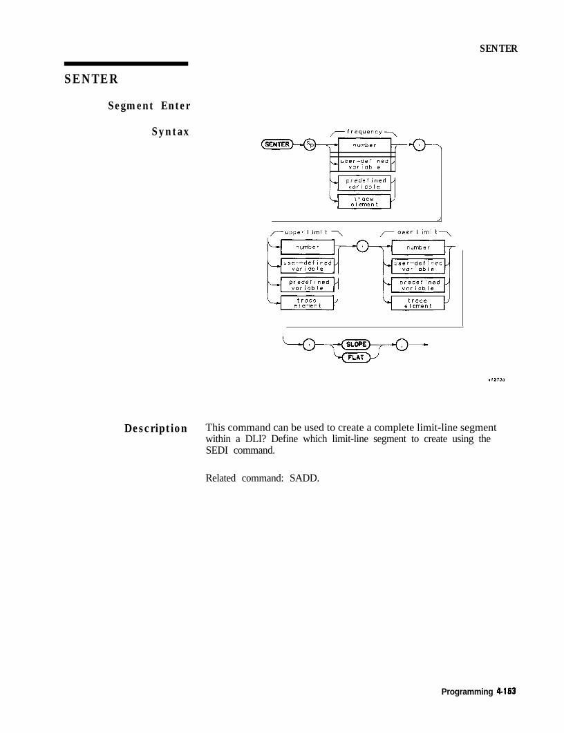
SENTER
SENTER
Segment Enter
Syntax
L user-defined,variable
/-upper I imi t 7 rlower I imi t7
X ,273O
Description This command can be used to create a complete limit-line segmentwithin a DLI? Define which limit-line segment to create using theSEDI command.
Related command: SADD.
Programming 4-163

SETDATE
Set Date
Syntax
Description Use this command to set the date.
Parameter Where integer = MMDDYY
Program Example102030405060708090100110120130140150160170180190200
210220
! The following examples show the use of the SETDATE command<M>.! The date can be specified directly or generated from another! source such as the HP BASIC TIMEDATE command.!OUTPUT 718;"TIMEDATE ON;"; ! Turn on the time and date display
! so that date changes can be observed.DISP "Setting date to g/12/88"OUTPUT 718;"SETDATE 091288;";!WAIT 5!
! Set the date to g/12/88 directly.
! Note the date on the display.
DISP "Setting date to Series 200/300 Internal clock"Day,mon,year$=DATE$(TIMEDATE) ! \Day$=Day,mon,year$[i;21 ! \IF VAL(Day$) (10 THEN Day$[l;ll="O" ! Fill in leading "0".Mon$=Day,mon,year$[4;31 ! Convert date from TIMEDATE.Year$=Day,mon,year$[lO;21 ! / format to spectrum analyzerGOSUB Translate-month ! / format.!OUTPUT 718;"SETDATE "tMonth$kDay$&Year$t";";
! Set the new date.STOP!
230 Translate-month: !240 ! Converts the month from alpha characters to ‘numerics'. The numbers250 ! are left as strings so that they can be concatenated later.260 !270 SELECT Mon$280 CASE "Jan"290 Month$="Ol"300 CASE "Feb"310 Month$="02"320 CASE "Mar"330 Month$="03"340 CASE "Apr"350 Month$="04"360 CASE "May"
4-164 Programming

SETDATE
370 Month$="05"380 CASE "Jun"390 Month$="06"400 CASE "Jul"410 Month$="07"420 CASE "Aug"430 Month$="08"440 CASE "Sep"450 Month$="09"460 CASE "Ott"470 Month$="lO"480 CASE "Nov"490 Month$="ll"500 CASE "Dee"510 Month$="l2"520 END SELECT530 RETURN540 END
Programming 4-165

SETTIME
Set Time
Syntax
Description Use this command to set the time. (Enter the 24-hour time in thisformat: HHMMSS.)
Parameter Where integer = HHMMSS
Program Example10 ! The following example shows the use of the SETTIME command. The clock20 ! is set using 24-hour notation. When time is displayed on the spectrum30 ! analyzer screen, it appears in the current time mode, that is, the40 ! 12- or 24-hour mode.50 !60 OUTPUT 718;"TIMEDATE ON;" ! Turn on the time and date display to70 ! observe the results of the next command.80 OUTPUT 718;"SETTIME 183000;" ! The clock is set using 24-hour notation.90 !100 END
4-166 Programming

SHOWMENU
SHOWMENU
Show the Menu
Syntax
Description This command displays labels in the softkey area on the display.The user specifies the softkey labels using the SKYCLR and SKYDEFcommands. This command has no meaning if the spectrum analyzer isin remote mode. It must be used in a user-defined function, or DLI? Ifused from an external controller, an error results.
Programming 4-l 67

SHOWMENU
Program Example102030405060
708090100110120130
140150160170180190200210220230240250260270280290300310
! The following example shows the use of the SHOWMENU command. The! example creates and displays a softkey which can be used to execute! a DLP (downloadable program).! ,! Note: Since SHOWMENU is not executable over HP-IB, the function! KEYS needs to be executed from the front panel of the analyzer
after being loaded. Press! CLCL) CMODULEI (AUTOEXEC MENU) (EDIT moExEc3 (CHOOSE DLP).! Scroll knob to 'KEYS' and press (EXECUTE NOW).!ASSIGN QSa TO 718 ! Assign I/O path to address 718.OUTPUT OSa;"FUNCDEF KEYS,$;"; ! Logical start of function 'KEYS'.OUTPUT OSa*"SKYCLR."* ! Clear softkeys.OUTPUT QSa~"SKYDEF'l:BOX,%DRAW BOX%;";
! Define softkey 1 to execute! function BOX. Label key with! DRAW BOX.
OUTPUT OSa;"SHOWMENU;";OUTPUT QSa;"$;";!
! Display the SKYDEF'ed label.! Logical end of function.
OUTPUT QSa;"FUNCDEF BOX,@;"; ! Logical start of function 'BOX'.OUTPUT ODSa;" IP;"; ! Instrument preset.OUTPUT QSa; I' CLRDSP;"; ! Clear the analyzer screen.!OUTPUT QISa;" PU;PA 300,300;"; ! Move pen to starting point.OUTPUT @Sa;" PD;PR 240,O;"; ! \OUTPUT (DSa;” PR 0,240;"; ! \ DrawOUTPUT cPSa;" PR -240,O;"; ! / rectangle.OUTPUT QSa;" PR 0,-240;"; ! IOUTPUT QSa;"@;"; ! Logical end of function.!ASSIGN OSa TO * ! Close I/O path.END
4-166 Programming
SKYCLR
SKYCLR
Clear User Softkeys
Syntax SKYCLR
x ‘2770
Description Use this command to clear all user-definable softkeys set up in DLPs.The command SKYDEF can then be used to define other DLP-relatedsoftkey labels.
Related commands: SKYDEF and SHOWMENU.
Programming 4-169

SKYCLR
Program Example102030405060
708090100110120130
140150160170180190200210220230240250260270280290300310
! The following example shows the use of the SKYCLR command. The! example creates and displays a softkey which can be used to execute! a DLP (downloadable program).!! Note: Since SHOWMENU is not executable over the HP-IB, the function! KEYS needs to be executed from the front panel of the analyzer
after it is loaded. Press! (LCL~ [MODULE] (AUTOEXEC MENU) {EDIT AUTOEXEC~ (CHOOSE DLP~.! Scroll knob to 'KEYS' and press (EXECUTE NOW).!ASSIGN QSa TO 718 ! Assign I/O path to address 718.OUTPUT QSa;"FUNCDEF KEYS,$;"; ! Logical start of function 'KEYS'.OUTPUT QSa;"SKYCLR;"; ! Clear softkeys.OUTPUT QSa;"SKYDEF l,BOX,%DRAW BOX%;";
! Define softkey 1 to execute! function BOX. Label key with! DRAW BOX.
OUTPUT QSa;"SHOWMENU;"; ! Display the SKYDEF'ed label.OUTPUT OSa;"$;"; ! Logical end of function.!OUTPUT QSa;"FUNCDEF BOX,(O;"; ! Logical start of function 'BOX'.OUTPUT (OSa;" IP;"; ! Instrument preset.OUTPUT (DSa;" CLRDSP;"; ! Clear the analyzer screen.!OUTPUT (PSa;" PU;PA 300,300;";! Move pen to starting point.OUTPUT @Sa;" PD;PR 240,O;"; ! \OUTPUT (DSa;" PR 0,240;"; ! \ DrawOUTPUT QSa;" PR -240,O;"; ! / rectangle.OUTPUT (OSa;" PR 0,-240;"; ! /OUTPUT (OSa*"@*"*Y ,, ! Logical end of function.!ASSIGN @Sa TO * ! Close I/O path.END
4-170 Programming

SKYDEF
SKYDEF
Define a User Keys Menu Softkey
Syntax / - k e y n u m b e r
Description In a DLP, use this command to attach a program to a softkey. SKYDEFmust be followed in the DLP with SHOWMENU to display the softkeysfor the DLP operation. This then keeps the softkey labels within theDLP; they are activated only when the DLP is operating.
Related commands: SKYCLR and SHOWMENU.
Programming 4-l 7 1

SKYJIEF
Program Example102030405060
708090100110120130
140150160170180190200210220230240250260270280290300310
! The following example shows the use of the SKYDEF command. The! example creates and displays a softkey which can be used to execute! a DLP (downloadable program).!! Note: Since SHOWMENU is not executable over HP-IB, the function! KEYS needs to be executed from the front panel of the analyzer
after it is loaded. Press! (LCL) [MODULE] (AUTOEXEC MENU) (EDIT AUTOEXEC) {CHOOSE DLP).! Scroll knob to 'KEYS' and press (EXECUTE NOW).!ASSIGN QSa TO 718 ! Assign I/O path to address 718.OUTPUT OSa;"FUNCDEF KEYS,$;"; ! Logical start of function 'KEYS'.OUTPUT QSa;"SKYCLR;"; ! Clear softkeys.OUTPUT QSa;"SKYDEF I,BOX,%DRAW BOX%;";
! Define softkey 1 to execute! function BOX. Label key with! DRAW BOX.
OUTPUT QSa*"SHOWMENU*"*OUTPUT QSaI"$;";
9 , ! Display the SKYDEF'ed label.! Logical end of function.
!OUTPUT OSa;"FUNCDEF BOX,(O;"; ! Logical start of function 'BOX'.OUTPUT (DSa;” IP;"; ! Instrument preset.OUTPUT (DSa;" CLRDSP;"; ! Clear the analyzer screen.!OUTPUT @Sa;" PU;PA 300,300;";! Move pen to starting point.OUTPUT OSa;" PD;PR 240,O;"; ! \OUTPUT QSa;" PR 0,240;"; ! \ DrawOUTPUT @Sa;" PR -240,O;"; ! / rectangle.OUTPUT OSa;" PR 0,-240;"; ! /OUTPUT @Sa*"cO*"*9 ,a ! Logical end of function.!ASSIGN OSa TO * ! Close I/O path.END
4-172 Programming
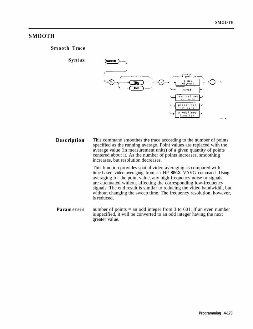
SMOOTH
SMOOTH
Smooth Trace
Syntax
Description This command smoothes the trace according to the number of pointsspecified as the running average. Point values are replaced with theaverage value (in measurement units) of a given quantity of pointscentered about it. As the number of points increases, smoothingincreases, but resolution decreases.
This function provides spatial video-averaging as compared withtime-based video-averaging from an HP 856X VAVG command. Usingaveraging for the point value, any high-frequency noise or signalsare attenuated without affecting the corresponding low-frequencysignals. The end result is similar to reducing the video bandwidth, butwithout changing the sweep time. The frequency resolution, however,is reduced.
Parameters number of points = an odd integer from 3 to 601. If an even numberis specified, it will be converted to an odd integer having the nextgreater value.
Programming 4-173

SMOOTH
Program Example102030405060708090100110120130140150160170180190200210
! The following example shows the use of the SMOOTH command. The! instructions within the FUNCDEF '9' delimiters form a structure! called a DLP (downloadable program).!ASSIGN (BSa TO 718 I Assign I/O path to address 718.
OUTPUT 6Sa;"FUNCDEF S-MOOTH,EX,O;"; !OUTPUT @Sa*"IP*"*, Y, !!OUTPUT (BSa;"TS; VIEW TRA;"; !
!OUTPUT OSa;"SMOOTH TRA,5;";
!OUTPUT OSa;"(O;";!OUTPUT OSa;"S,MOOTH-EX;";
ASSIGN (DSa TO *END
Logical start of the DLP.Instrument preset.
Take a sweep and put trace intoView mode.
Smooth the trace with a five-pointrunning average.
Logical end of the DLP.
Have the analyzer execute theDLP S-MOOTH,EXClose I/O path.
4.174 Programming

SQR
SQRSquare Root
Syntax SQRL?-destination-
Description Computes the square root of the source and sends the result to thedestination. If the source is negative, an error message is generated,and the absolute value of the source is returned.
Program Example102030405060708090100110120
130140150160170180
! The following example shows the use of the SqR command.!ASSIGN GDSa TO 718 ! Assign I/O path to address 718.!OUTPUT OSa;"IP;CLRDSP;"; ! Instrument preset;! Clear CRT for text display.
OUTPUT QSa;"VARDEF NUMBER,l23;"; ! \ Create variable andOUTPUT QSa;"VARDEF ROOT,O;"; ! / initialize.OUTPUT @Sa;"SQR ROOT,NUMBER;"; ! Take the square root.!OUTPUT OSa;"PU;PA 10,500;"; ! Move "pen" to starting point.OUTPUT OSa; "TEXT %The Square Root of 1/1;";
! Write text.OUTPUT QSa;"DSPLY NUMBER,7,5;"; ! Write value.OUTPUT @Sa;"TEXT % = I/(;"; ! Write text.OUTPUT OSa;"DSPLY ROOT,7,5;"; ! Write value.!ASSIGN QISa TO * ! Close I/O path.END
Programming 4-175

STDEV
Standard Deviation of Trace Amplitudes
Syntax
Note
Description
Program Example
This bypass command path is only legal if you use STDEV as apredellned function. It must reside within a compatible-functionoperation.
Return the standard deviation of the trace amplitude in measurementunits.
Prerequisite Commands: TS when using TRA, TRB, or trace range forsource.
1020304050607080
90100110120130140150160170180
! The following example shows the use of.the STDEV function to return! the standard deviation of the trace to the controller. The example! uses an input signal of 300 MHz such as the CAL OUTPUT.!INTEGER Mean-value ! Define an INTEGER variable.ASSIGN OSa TO 718 ! Assign I/O path to address 718.!OUTPUT QSa;"IP;CF 300MHZ;SP 1MHZ;TS;";
! Set up the analyzer.OUTPUT (DSa;"MEAN TRA,?;"; ! Determine the mean of trace A.ENTER OSa;Mean-value ! Read value from analyzer.PRINT "MEAN of trace A in measurement units = ";Mean-valueOUTPUT QSa;"STDEV TRA,?;";ENTER QSa;Stdev,valuePRINT "STANDARD DEVIATION of trace A in measurement units = ";Stdev-value!ASSIGN (DSa TO * ! Close I/O path.!END
4-176 Programming

SUB
SUB
Subtract
Syntax -destination---\
a-*
Description Subtract the value of source 1 from source 2 and send the results tothe destination.
Programming 4-177

102030405060708090100110120130140150160170180190200210220
SUB
Program Example! The following example shows the use of the SUB command. The example! uses an input signal of 300 MHz, such as the CAL OUTPUT signal, and! looks at its harmonics. An input signal is not necessary to the! function of this example, but acts as a visual aid.!ASSIGN QSa TO 718 ! Assign I/O path to address 718.!OUTPUT QSa;"FUNCDEF SUB-EX,Q;"; ! Logical start of the DLP function.OUTPUT OSa;"VARDEF FREC),3E9;"; ! Create variable and initialize to 3 GHz.OUTPUT OSa;"IP;SP IMHZ;"; ! Instrument preset; set span.!OUTPUT QSa;"REPEAT;"; ! Begin loop.OUTPUT QSa;" MOV CF,FREq;"; ! Set center frequency.OUTPUT (DSa;" TS;"; ! Take a sweep to update display.OUTPUT Wa;" SUB FREQ,FREq,300EG;";! Decrease FREQ by 300 MHz.OUTPUT OSa;WNTIL FREQ,LT,300EG;"; ! End of loop.OUTPUT @Sa;"(O;"; ! Logical end of DLP function.!OUTPUT QSa;"SUB,EX;"; ! Execute function.!ASSIGN @Sa TO * ! Close I/O path.END
4-176 Programming

SUM
SUM
Sum of Trace Amplitudes
Syntax \( SW TRA
TRB
Note This bypass command path is only legal if you use SUM as apredefined function. It must reside within a compatible-functionoperation.
Description Compute the sum of the given trace.
Program Example10 ! The following example shows the use of the SUM command. The example20 ! uses an input signal of 300 MHz such as the CAL OUTPUT.30 !40 ASSIGN QSa TO 718 ! Assign I/O path to address 718.50 !60 OUTPUT QSa;"IP;"; ! Instrument preset.70 OUTPUT @Sa;"CF 300MZ; SP IMZ;"; ! \80 OUTPUT QSa;";SNGLS;TS;"; ! Set up analyzer.90 OUTPUT OSa;"MKPK HI;MKRL;TS;HD;"; ! /100 !110 OUTPUT (OSa; "SUM TRA,?;"; ! Returns sum in measurement units.120 ENTER BSa;Sum,trace ! Bring result into computer.130 PRINT "The sum of all the trace points equals ";Sum-trace140 !150 ASSIGN OSa TO * ! Close I/O path.160 END
Programming 4-179

SUMSQR
Sum of Squared Trace Amplitudes
Syntax
Note
Description
Program Example102030405060708090100110120130140150160170
This bypass command path is only legal if you use SUMSQR as apredefined function. It must reside within a compatible-functionoperation.
Squares the amplitude of each trace element, and returns the sum ofthe squares to the controller in measurement units.
! The following example shows the use of the SUMSC)R command. The! example uses an input signal of 300 MHz such as the CAL OUTPUT.!ASSIGN (DSa TO 718 ! Assign I/O path to address 718.!OUTPUT (DSa; “IP; I’; ! Instrument preset.OUTPUT OSa;"CF 300MZ; SP IMZ;"; ! \OUTPUT (OSa;"RH 30KHZ;"; ! Set up the analyzer.OUTPUT QSa;"TS;MKPK HI;MKRL;TS;HD;";! /!OUTPUT QSa;"SUMSQR TRA,?;"; ! query the analyzer.ENTER (DSa;Sum,sqr ! Get the value from the analyzer.PRINT "The Sum of the Squares of the trace points = ";Sum,sqr;PRINT "measurement units."!ASSIGN QSa TO * ! Close I/O path.END
4-160 Programming

TEXT
TEXT
Text
102030405060708090100110120130140150
! The following example shows the use of the REPEAT/UNTIL commands! in a FOR/NEXT loop context. This is an immediate-execute DLP! (downloadable program). This is another way of nesting REPEATS.!ASSIGN @Sa TO 718 ! Assign I/O path to address 718.!OUTPUT Wa;"IP;"; ! Instrument preset.OUTPUT OSaOUTPUT (PSa!OUTPUT cOSaOUTPUT @SaOUTPUT QSa i
"VARDEF OUTER,LP,O;"; ! Create variable and initialize to 0."VARDEF TOTAL,O;"; ! Create variable and initialize to 0.
"REPEAT;"; ! Begin outer loop." VARDEF INNER-LP,O;"; ! Create and initialize inner loop counter." REPEAT;"; ! Begin inner loop.
OUTPUT QSa;" ADD TOTAL,TOTAL,l;";! Increment running total.OUTPUT OSa;" ADD INNER,LP,INNER-LP,l;";
! Increment inner loop counter.160 OUTPUT (DSa;" UNTIL INNER,LP,EQ,3;";! End of inner loop.170 OUTPUT QISa;" ADD OUTER-LP,OUTER-LP,l;";
180190200210220230240250260270280290
! Increment outer loop counter.OUTPUT 6Sa; "UNTIL OUTER,LP,EG,4;"; ! End of outer loop.!OUTPUT QSa;"CLRDSP;";OUTPUT OSa;"PU;PA 10,500;TEXT #INNER LOOP COUNTER=%;";OUTPUT OSa;"DSPLY INNER_LP,5,2;";OUTPUT OSa;"PU;PA 10,400;TEXT XOUTER LOOP COUNTER=%;";OUTPUT OSa;"DSPLY OUTER_LP,5,2;";OUTPUT QSa;"PU;PA 10,300;TEXT #TOTAL ITERATIONS=%;";OUTPUT OSa;"DSPLY TOTAL,5,2;";!ASSIGN QSa TO * ! Close I/O path.END
Syntax
Description This command is used to display the user-defined text on the spectrumanalyzer screen at the current graphics pen location. Relatedcommands are PU, PA, and PD.
Program Example
Programming 4-18 1

TIMEDATE
Time Date
Syntax
Description
Note
Query Response
Program Example102030405060708090100110120130140
Use this command to turn the time and date display on or off. Thedefault setting is OFF.
The time/date display must be turned off in order to display HP-IBerrors properly on the spectrum analyzer display.
The time/date setting of the module is returned in the MMDDYYformat.
! The following example shows the use of the TIMEDATE command.!ASSIGN OSa TO 718 ! Assign I/O path to address 718.OUTPUT (OSa; “IP; ‘I ; ! Instrument preset.DISP “Activate 856X Time and Date Display”OUTPUT OSa;"TIMEDATE ON;";!WAIT 5 ! Note that time and date are displayed.!DISP "De-activate 8562 Time and Date Display"OUTPUT QSa;"TIMEDATE OFF;";!ASSIGN @Sa TO * ! Close I/O path.END
4-182 Programming

TRDEF
TRDEF
Trace Definition
Syntax
Description
Parameters
Defines the name and length of a user-defined trace. Any number ofpoints from 0 to 65,000 may be used for a trace length. Changingthe length of predefined traces results in an error. The length of apredefined trace can be queried.
User memory is required to execute the TRDEF command.
<trace length>:: = integer from 1 to 65,000(there are 601 points in a predefined trace)
Restrictions: Subject to available memory. The following commandsconsume memory: ONEOS, ARRAYDEF, TRDEF, KEYDEF, LCLVAR,VARDEF REPEAT/UNTIL, and IF/THEN.
Related Command: DISPOSE
Querying a User-Defhed TraceFor user-defined trace data transfer to and from an externalcontroller, only M format is supported. A, B, I, and P block-data fieldformats are not currently supported.
User-Defined Trace Query Response
Response Syntax Notation: <trace length>
Parameters Minimum Range: 1
Maximum Range: 65000
Programming 4-183

TR.DEF
Program Example102030405060708090100110120130140150160170180190200210220230240250260270280290300310
320330340350360370380390400410
420430440450460
! The following example shows the use of the TRDEF command. The example! creates a sine wave in the computer and sends it to trace A of the! analyzer. It is then moved to the user-defined trace where it can be! manipulated to fit the user's needs.!ASSIGN 0Sa TO 718 ! Assign I/O path to address 718.DIM Y,axis(l:601) ! Create an array in the computer.RAD ! Angles measured in radians.GINIT ! Graphics Init (computer).GRAPHICS ON ! Graphics On (computer).WINDOW 1,601,1,601 ! Set up the calculator screen to
! have the same number of points as! the spectrum analyzer.
MOVE O,SIN(O) ! Move the pen (computer).x=0
! Create the array in the computer.FOR Angle=0 TO 2O*PI STEP (2*PI)/60
x=x+1 ! Increment array pointer.Y=SIN(Angle)*120+300 ! 120 gives +/- 2 divs of amplitude.
! 300 offsets to mid-screenPLOT X,Y ! Draw sine wave on computer screen.Y,axis(X)=Y ! Load the array.
NEXT Angle!! Set up the analyzer to receive the trace array from the computer.!OUTPUT 0Sa;"IP;SNGLS;TS;"; ! Instrument preset. Single sweep
! so that the trace is not over-! written by another sweep.
OUTPUT 0Sa;"VIEW TRA;TDF A;"; ! View trace A. Set to 'A' format.OUTPUT 0Sa USING "#,K,W,6Ol(W>";"TRA#A",l202,Y~axis(*~,";";
! Send the trace.!OUTPUT 0Sa;"TRDEF SINE,GOl;"; ! Create a user-defined trace that
! is the same size as a default! screen trace.
OUTPUT 0Sa;"MOV SINE,TRA;"; ! Copy trace A to the user-defined! trace.
OUTPUT 0Sa;"ADD SINE,SINE,GO;"*,! Add 60 to each point in SINE.OUTPUT 0Sa;"MOV TRB,SINE;"; ! Copy the modified SINE trace to
! trace B.OUTPUT 0Sa;"VIEW TRA; VIEW TRB;";
! View both traces.!! Note that 60 offsets the sine wave one division from the original trace.!ASSIGN 0Sa TO * ! Close I/O path.END
4-184 Programming

VARDEF
VARDEF
Variable Definition
Syntax
Description Defines the name of a user-defined variable and assigns its initialvalue. If a command mnemonic and the label of the user-definedvariable match, an error results.
Note In Mass Memory Modules with firmware datecode 910116 and later,the value of a user-defined variable can be modified using thesecondary keyword El? Refer to “Using EP to Modify User-DefinedVariables (firmware revision 910116 and later)” in this chapter.
User memory is required to execute the VARDEF command. Afterusing VARDEF to define a label, other commands may be used asdescribed below.
Parameters <initial value>:: = <real>
Restrictions: Subject to available memory. The following commandsconsume memory: ONEOS, ARRAYDEF, TRDEF, KEYDEF, LCLVAR,VARDEF REPEAT/UNTIL, and IF/THEN.
Prerequisite Commands: VARDEF when using user-defined variable.
Related Command: DISPOSE
Programming 4-185

VARDEF
Program Examplei02030405060708090
100110120130140150
160170180190200210220230
! The following example shows the use of the VARDEF command. The! example uses an input signal of 300 MHz, such as the CAL OUTPUT signal! and looks at its harmonics. An input signal is not necessary to the! function of this example, but acts as a visual aid.!ASSIGN QSa TO 718 ! Assign I/O path to address 718.!OUTPUT QSa;"FUNCDEF INCRFRElJ,Q;"; ! Logical start of the DLP function.OUTPUT QSa;"VARDEF FREQ,300E6;"; ! Create variable and initialize to
! 300 MHz.OUTPUT QSa;"IP;SP IMHZ;"; ! Instrument preset.!OUTPUT QSa*"REPEAT*"*OUTPUT @Sal" MOV CF;FREQ;";
!!
OUTPUT QSa;" TS;"; !OUTPUT (OSa;" ADD FREQ,FREQ,300EG;";
!OUTPUT QISa;WNTIL FREQ,GT,3ES;"; !OUTPUT (DSa;"@;"; !!!OUTPUT OSa;" INCRFREQ;"; !!ASSIGN QSa TO * !END
Begin loop.Set center frequency.Take a sweep to update display.
Increase FREQ by 300 MHz.End of loop.Logical end of DLP function.
Execute function.
Close I/O path.
Query Value of Current VariableVariable value may be queried by executing the command as shown:
10 OUTPUT 718;"FREQ?;"20 OUTPUT 718;FREQUENCY
4.166 Programming

VARIANCE
VARIANCE
Variance
Syntax
Note
Description
Program Example102030405060708090100110120130140150
This bypass command path is only legal if you use VARIANCE as apredefined function. It must reside within a compatible-functionoperation.
The VARIANCE command returns the amplitude variations of thespecified trace to the controller in measurement units.
Prerequisite Commands: TS when using TRA, TRB, or trace range forsource.
! The following example shows the use of the VARIANCE command.! The example uses an input signal of 300 MHz such as the CAL OUTPUT.!ASSIGN (DSa TO 718 ! Assign I/O path to -address 718.!OUTPUT @Sa*"IP*SNGLS*"OUTPUT QSaj"CF'300 MZ;SP 1KHZ;"
! Instrument preset.! \ Set up analyzer.
OUTPUT rPSa;"RB 300HZ; TS;"!
! /
OUTPUT QSa;"VARIANCE TRA,?;" ! query the trace variance.ENTER OSa;Variance ! Get the value from the analyzer.PRINT "The variance of trace A is ";Variance!ASSIGN (PSa TO * ! Close I/O path.END
Programming 4-l 67

5Service
Turning on the ModuleThe HP 85620A Mass Memory Module requires no specificperformance verification tests nor adjustment procedures. If themodule should fail to power up at turn-on, turn the spectrum analyzeroff, then verify that the module is installed correctly. Refer toChapter 1, “Installation, n for module connection information. If theconnection appears to be correct, contact one of the Hewlett-PackardSales and Service Offices listed in Chapter 1, ‘lhble l-7.
Electrostatic DischargeElectrostatic discharge (ESD) can damage or destroy electroniccomponents. All work performed on assemblies containing electroniccomponents should be done ONLY at a static-safe workstation.See Figure 5-l. Static-safe accessories may be ordered from anyHewlett-Packard Sales and Service Office listed in Chapter 1,‘lhble l-7. Refer to Table 5-l for a list of the part numbers for theseaccessories.
B u i l d i n gGround
1 MegOhmR e s i s t o r n
Figure 5-1. Static-Safe Workstation
Service 5-l
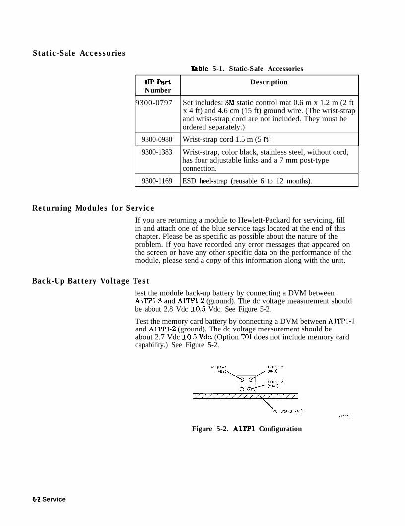
Static-Safe Accessories
able 5-1. Static-Safe Accessories
HPFartNumber
Description
9300-0797
9300-0980
Set includes: 3M static control mat 0.6 m x 1.2 m (2 ftx 4 ft) and 4.6 cm (15 ft) ground wire. (The wrist-strapand wrist-strap cord are not included. They must beordered separately.)
Wrist-strap cord 1.5 m (5 ft)
9300-1383 Wrist-strap, color black, stainless steel, without cord,has four adjustable links and a 7 mm post-typeconnection.
9300-1169 ESD heel-strap (reusable 6 to 12 months).
Returning Modules for ServiceIf you are returning a module to Hewlett-Packard for servicing, fillin and attach one of the blue service tags located at the end of thischapter. Please be as specific as possible about the nature of theproblem. If you have recorded any error messages that appeared onthe screen or have any other specific data on the performance of themodule, please send a copy of this information along with the unit.
Back-Up Battery Voltage Testlest the module back-up battery by connecting a DVM betweenAlTPl-3 and AlTPl-2 (ground). The dc voltage measurement shouldbe about 2.8 Vdc f0.5 Vdc. See Figure 5-2.
Test the memory card battery by connecting a DVM between AlTPl-1and AlTPl-2 (ground). The dc voltage measurement should beabout 2.7 Vdc f0.5 Vdc (Option TO1 does not include memory cardcapability.) See Figure 5-2.
AITPI-1 AlTPl-2VW (GND)
AlTPl-3o w/--- @AT)
///////////J////l-
PC BOARD (Al)
Figure 5-2. AlTPl Configuration
5-2 Service

Replacement Procedures
Introduction Replacement procedures provide specific disassembly and assemblyinformation. Refer to the appropriate replacement procedures for theassembly you are replacing.
n Al Memory Board Replacement
n Bl Module Battery Replacement
n Memory Card Battery Replacement
Al Memory Board Assembly Replacement
Caution n The module and board assembly are static sensitive. Be sure toperform any disassembly at a static-safe workstation as illustratedin Figure 5-1.
n Store or transport these items ONLY in static-shielding containers.
n Personnel should be grounded with a resistor-isolated wrist strapbefore touching any connector pins or before removing anyassembly from the module.
w Be sure that all instruments are properly earth-grounded to preventbuild up of static charge.
1. Remove the four module-assembly screws (1). See Figure 5-3 orFigure 5-4.
2. Open the module from the left-hand side (2) with the front-panellabel facing you.
3. With the module laying flat, remove the brace (3) and the eightboard-assembly screws (4). Lift the board assembly out of themodule.
4. Replace the board assembly into the module and secure it withthe eight board-assembly screws (4). Torque each one to threeinch-pounds.
5. Replace the brace (3), then close the module halves.
6. Replace the four module screws (1) and torque each one to sixinch-pounds.
Bl Module Battery Replacement1. Refer to the Al Memory Board Assembly Replacement procedure
to remove the Al assembly.
2. Carefully desolder the battery (5). * See Figure 5-3 or Figure 5-4.
Service 5-3
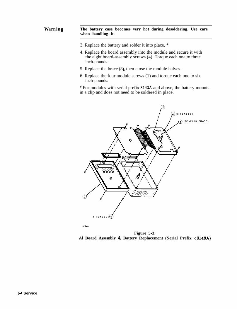
Warning The battery case becomes very hot during desoldering. Use carewhen handling it.
3. Replace the battery and solder it into place. *
4. Replace the board assembly into the module and secure it withthe eight board-assembly screws (4). Torque each one to threeinch-pounds.
5. Replace the brace (3), then close the module halves.
6. Replace the four module screws (1) and torque each one to sixinch-pounds.
* For modules with serial prefix 3143A and above, the battery mountsin a clip and does not need to be soldered in place.
/ p ( 8 P L A C E S )
(BENEA T H )
k( 4 P L A C E S ) 1
Figure 5-3.Al Board Assembly & Battery Replacement (Serial Prefix <3143A)
54 Service

“12I P4 ( 8 P L A C E S )
cl( 4 P L A C E S ) 1
Figure 5-4.Al Board Assembly & Battery Replacement (Serial Prefix L3143A)
Service 5-5

Memory Card Battery ReplacementThe battery is located beside the card write-protect switch on theend opposite the connector. Table l-5 in Chapter 1 contains batteryspecifications and characteristics. (Option TO1 does not includememory card capability.)
Caution Unless you replace the battery with the card installed and the modulepowered up by the spectrum analyzer, you lose memory-card datawhen the battery is removed. Back up memory-card data on someother medium before beginning the battery replacement procedurethat follows.
1. Locate the groove (1) along the edge of the battery clip. SeeFigure 5-5.
2. Gently pry the battery clip out of the card. The battery fits withinthis clip.
3. Replace the battery, HP part number 1420-0383, making sure theplus (+) sign (2) on the battery is on the same side as the plus (+)sign (3) on the clip.
4. Insert the battery clip into the memory card, holding the clip asoriented in Figure 5-5. (Face the “open” edge of the clip towardthe write-protect switch.)
Figure 5-5. Memory Card Battery Replacement
5-6 Service

Troubleshooting and Replaceable Parts
Introduction The HP 85620A Mass Memory Module is supported to the componentlevel. Refer to the “Troubleshooting” section when troubleshootingthe module. Table 5-3 contains the list of components in the module.Refer to Figure 5-6 or Figure 5-7 for the illustration of replaceablehardware. Figure 5-8 is the block diagram. Component levelinformation is at the end of this chapter.
TroubleshootingMissing Features
It is possible to get a different set of features from the HP 85620Aif you connect it to the rear panel of a different spectrum analyzer,depending on the firmware revision of the host spectrum analyzer.In spectrum analyzers with firmware revision 960401 and later, thefirmware that controls the mass memory module actually resides inthe host spectrum analyzer and contains a more recent set of featuresand functionality. If the same mass memory module is installed on ahost spectrum analyzer with firmware revision 941028 or earlier, thefirmware that resides in the mass memory module (revision A, B, or C)will control the features and functionality of the module.
Verify the mass memory firmware revision by pressing (-1.The firmware revision that controls the features and functionalityof the module is displayed. Firmware revision 910116 or earlier willbe displayed when the host spectrum analyzer firmware revision is941028 or earlier. Firmware revision 950829 or later will be displayedwhen the host spectrum analyzer firmware revision is 960401 or later.
If the HP 85620A mass memory module does not exhibit the setof features and functionality that you expect it to have, check itsfirmware revision as indicated above. New features and functionalitythat were added in firmware revisions 950829 and later require theuse of a host spectrum analyzer with firmware revision 960401 orlater.
Back-up Battery Voltage Test
Test the module back-up battery at least annually by connectinga DVM between AlTPl-3 and AlTPl-2 (ground). The dc voltagemeasurement should be about 2.8 Vdc *0.5 Vdc. See Figure 5-2.
Test the memory card battery at least annually by connecting aDVM between AlTPl-1 and AlTPl-2 (ground). The dc voltagemeasurement should be about 2.7 Vdc f0.5 Vdc. See Figure 5-2.
Memory Card Connector
If there appear to be intermittent problems and other failures relatedto using the memory card, a possible cause is memory card connectorwear Connector life can be shortened by frequent memory cardinsertion. In applications where the memory card is inserted morethan twice daily, we recommend that you change the connecter onthe Al board assembly at least every 5 years. Replacement part
Service 5-7

numbers for the connector and the board assembly are included in thecomponent level information packets.
Error Codes
Refer to “Error Codes” in Chapter 1 for an explanation of error-codenumbers 800 to 899, which are reserved for the mass memory moduleand its memory card.
5-8 Service

Replaceable Parts ‘Iable 5-3 lists the mechanical parts illustrated in the partsidentification drawing, Figure 5-6 or Figure 5-7, depending on theserial prefix of the mass memory module. The component-levelreplaceable parts, component location diagram, and schematic foreach board assembly are contained in individual packets for eachboard assembly. Refer to component-level information at the end ofthis chapter.
‘0.ble 5-2. Manufacturer’s Code List
Mfr. Code Manufacturer Name AddressCl433 ABELEKTRONIK GMBH SALZBURG, AUK7253 STDSTANTEL DEVON, EGS4013 HITACHI AMERICA LTD SUNNYVALE, CA, US00779 AMP INC HARRISBURG, PA, US08709 EPSON AMERICA TORRANCE, CA, US01295 TEXAS INSTRUMENTS INC DALLAS, TX, US04222 AVX CORP GREAT NECK, NY, US10421 PANASONIC, INC SECAUCUS, NJ, US06383 PANDUIT CORP TINLEY PARK, IL, US06424 SPERRY RAND ,u - WAVE ELEK DIV CLEARWATER, FL, US10899 EASTERN AIR DEVICES INC GREAT NECK, NY, US18873 DUPONT E I DE NEMOURS & CO WILMINGTON, DE, US2M627 ROHM CORP IRVINE, CA, US28480 HEWLETT-PACKARD CO CORP HQ PALO AUTO, CA, US34335 ADVANCED MICRO DEVICES INC SUNNYVALE, CA, US71468 ITT CORP NEW YORK, NY, US72794 DZUS FASTENER CO INC WEST ISLIP, NY, US
ZIP CodeA-501
940861711175265905051102107094694773351811021198019271394304940861002211795
L
Service 5-9

( 8 P L A C E S )
( B E N E A T H B R A C E )
I/’7 A‘ E
( 4 P L A C E S ) 1
1 2 1 1
Figure 5-6. HP 85620A Parts Identification (Serial Prefix <3143A)
5-1 a Service

(8 P L A C E S )
Figure 5-7. HP 85620A Parts Identification (Serial Prefix L3143A)
Service 5-11

‘Ihble 5-3. HP 85620A Parts Identification
[tern BP Part C D Qty Description Mfg Mfg FartNumber Code Number
1 0515-1236 9 4 SCREW-MACH M3 X 0.5 14MM-LG 28480 0515-12362 502.1-9304 6 1 COV-BTM TEST 28480 5021-93043 8160-0448 8 1 RF1 ROUND STRIP BE-CU SN-PL 10899 ss-04
.062-IN-OD4 8160-0650 4 1 GASKET-OPTION MODULE 28480 8160-0650
CONNECTOR5 85620-40002* 0 1 BEZEL MEMORY CARD SLOT 28480 85620-400026 85620-60001t 1 1 BD AY-PORT MEM 28480 85620-600016 85620-60006$ 6 1 BD AY-PORT MEM 28480 85620-600066 85620-60008§ 8 1 BD AY-PORT MEM 28480 85620-600086 85620-60014)/ 6 1 BD AY-PORT MEM 28480 85620-600147 0515-0894 3 8 SCREW-MACH M2.5 X 0.45 GMM-LG 28480 0515-0894
PAN-HD8 1420-037ot 0 1 BATTERY, 2.8 V l.OAH 28480 1420-03708 1420-0341$11 1 BATTERY, 3 V 1.2AH 28480 1420-03418 1420-0394j 1 BATTERY, 3 V 1 .OAH 08709 CR2477- 1HF9 85620-40001# 9 1 BRACE 28480 85620-400019 5041-8980§** 4 1 BRACE 28480 5041-898010 85620-20005t 1 1 COVER-TOP 28480 85620-2000510 5021-9303§11 5 1 COVER-TOP 28480 5021-930310 5022-0002$ 5 1 COVER-TOP 28480 5022-000211 1390-0750 5 1 FASTENER-l/4-TURN RCPT 72794 A3.5T127BllOO-Z12 5041-7247 4 1 SPACER 28480 5041-7247
85620-80003 5 1 LABEL SET 28480 85620-80003’ Option TO1 does not include memory card capability.Serial prefix 2929A and belowStandard Serial preEx 3143A and aboveSerial prefix 3003AOption TO1 Serial prefix 3143A and above
F Serial prefix 3003A and below* Serial prefix 3143A
5.12 Service

‘Ihble 5-4. Firmware Revision and ROM Fart Numbers
BP 85620AFirmware
Revision/Date Code Ul
ROM Fart Number*
u2 u3
Al8902 14 85620-80005 85620-80007 85620-80009
B/890524 85620-80014 85620-80015 85620-80016
C/9101 16t 85620-80023 85620-80024 85620-80025
U7 ROM Fart NumberS
U910116t 85620-8002 1
* Serial prefix 3003A and below.
t The HP part number for the current firmware revision label is85620-80003.
$ Serial prefix 3143A and above.
See Firmware Note, HP part number 5962-0452, for descriptions ofthe firmware revisions.
Service 5-13

AlJ
A l M A S S M E M O R Y B O A R D
C O N T R O LL I N E S
A D D R E :ss BUS
C O N T R O L L E R
d e c o d e l o g i c
V”“““““’ RAM
h (128K)
P A G E L A T C H
I A U X I L I A R Y
P A G E L A T C H
ROM
(7.56~)
I
D A T A B U S
ITPi- TPl-1
* A U X I L I A R Y I N T E R F A C E I S P R E S E N T O N L Y O N M O D U L E W I T H
S E R I A L P R E F I X 3143A A N D A B O V E .
DF243
Figure 5-8. HP 85620A Block Diagram
AlJ4
>
AlJ2I
M E M O R Y
5-14 Service

Component-Level InformationComponent-Level information is available for selected instrumentassemblies.
Table 5-5 lists board assembly part numbers and where they are used.
Note Drawings may not be available for recently introduced assemblies.
‘Ihble 5-5. HP 85620A Mass Memory Module Documented Assemblies
Board Assembly Instrument Assembly CLIP Fart NumberSerial Prefix Part Number
Mass Memory Assembly 2929A and below 85620-60001 85620-90033
Mass Memory Assembly 3003A 85620-60008 85620-90034
Mass Memory Assembly Standard only (3143A) 85620-60006 85620-90035
Mass Memory Assembly 3526A and above 85620-60018 85620-90038
Mass Memory Assembly Option TO1 only 85620-60014 Contact HP3143A and above (MID)
Service

Component-Level Information Packetfor 85620-6000 1
Mass Memory Assembly
F! HEWLETTPACKARD
HP Part No. 85820-80033Printed in USA April 1995

Notice. The information contained in this document is subject to change without notice.
Hewlett-Packard makes no warranty of any kind with regard to this material, including,but not limited to, the implied warranties of merchantability and fitness for a particularpurpose. Hewlett-Packard shall not be liable for errors contained herein or for incidental orconsequential damages in connection with the furnishing, performance, or use of this material.
@Copyright Hewlett-Packard Company 1990, 1991, 1992, 1993, 1994,1995All Rights Reserved. Reproduction, adaptation, or translation without prior writtenpermission is prohibited, except as allowed under the copyright laws.
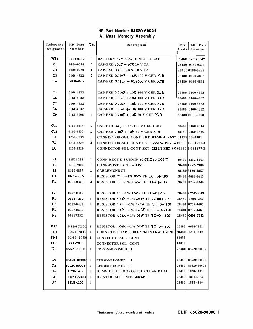
HP Part Number 85820-80001Al Mass Memory Assembly
Reference HP PartDesignator Number
BTl 1420-0307
Cl 0180-0374
c2 0180-0229
c3 0160-4832
c4 016@4832
c5 0160-4832
C6 0160-4832
c7 0160-4832
C8 0160-4832
c9 0160-5098
Cl0 0160-4814
Cl1 0160-4835
El 1251-6939
E2 1251-2229
E3 1251-2229
Jl 12521263
J2 1252-2906
53 8120-4857
Rl 06988615
R2 0757-0346
Ix.3 0757-0346
R4 069&7252
R5 0757-0465
R7 0757-0465
R9 06987252
Rio 0 6 9 8 7 2 5 2 1 RESISTOR 4.64K +-1% .05W TF TC=o+-loo 28480
TPl 1251-7819 1 CONN-POST TYPE .lO@PIN-SPCG-MTG-END 28480
TP2 0360-2050 2 CONNECTOR-SGL CONT 04055
TP3 036Cb2050 CONNECTOR-SGL CONT 04055
Ul 8562~80005 1 EPROM-PRGMED Ul 28480
u2 85620-80007 1 EPROM-PRGMED U2 28480 85620-80007
u3 8562CL80009 1 EPROM-PRGMED U3 28480 85620-80009
u5 1820-1437 1 IC MV TTL/LS MONOSTBL CLEAR DUAL 28480 1820-1437
U6 1820-5384 1 IC-INTERFACE CMOS -888BIT 28480 1820-5384
u7 1818-4160 1 28480 1818-4160
Qty Description Mfr
I I
Mfr PartCode Number
1
3
2
BATTERY 7.2V .45A-HR NI-CD FLAT
CAP-FXD 1OuF +-lo% 20 V TA
CAP-FXD 33uF +-lo% 10 V TA
CAP-FXD O.OluF +-lo% 100 V CER X7R
CAP-FXD O.OluF +-lo% lo0 V CER X7R
CAP-FXD O.OluF +-lo% 100 V CER X7R
CAP-FXD O.OluF +-lo% 100 V CER X7R
CAP-FXD O.OluF +-lo% 100 V CER X7R
CAP-FXD O.OluF +-lo% 100 V CER X7R
CAP-FXD 0.22uF +-lo% 50 V CER X7R
28480 0180-0374
28480 0180-0229
28480 0160-4832
28480 0160-4832
28480 0160-4832
28480 0160-4832
28480 0160-4832
28480 0160-4832
28480 0160-5098
CAP-FXD 150pF +-5% 100 V CER COG 28480 0160-4814
CAP-FXD O.luF +-lo% 50 V CER X7R 28480 0160-4835
CONNECTOR-SGL CONT SKT .032-IN-BSC-SZ 01075 0064801
CONNECTOR-SGL CONT SKT .033-IN-BSC-SZ 01380 1-331677-3
CONNECTOR-SGL CONT SKT .033-IN-BSC-SZ 01380 1-331677-3
CONN-RECT D-SUBMIN 50-CKT 50-CONT 28480 1252-1263
CONN-POST TYPE 0-CONT 28480 1252-2906
CABLEMCNDCT 28480 8120-4857
RESISTOR 75K +-1% .05W TF TC=O+-loo 28480 0698-8615
RESISTOR 10 +-1% .125W TF T&O+-100 28480 0757-0346
RESISTOR 10 +-1% .125W TF TC=O+-100 28480 0757-0346
RESISTOR 4.64K +-1% .05W TF TC=O+-loo 28480 06967252
RESISTOR 1OOK +-1% .125W TF TC=O+-loo 28480 0757-0465
RESISTOR 1OOK +-1% .125W TF TC=o+-loo 28480 0757-0465
RESISTOR 4.64K +-1% .05W TF TC=O+-loo 28480 0698-7252
0698-7252
1251-7819
85620-80005
*Indicates factory-selected value C L I P 85820-90033 1

Reference HP PartDesignatol Number
U8 1826-1858
u9 35620-80001
UlO 1820-1198
Ull 1820-3143
u12 1820-2024
u13 1810-0205
u14 1820-1199
u15 1820-5497
XUl 1200-0567
xu2 1200-0567
xu3 1200-0567
0950-1964
1420-0383
2 CLIP 85620-90033 *Indicates factory-selected value
HP Part Number 85620-60001Al Mass Memory Assembly (continued)-3tJ
-1
1
1
1
1
1
1
1
1
1
1
1
1-
Description
IC PWR MGT-BAT-MGT 28480 1826-1858
PAL-PROGRAMMED U9 28480 85620-80001
IC GATE TTL/LS NAND QUAD 2-INP 28480 1820-1198
IC FF TTL/ALS D-TYPE POS-EDGE-TRIG COM 28480 1820-3143
IC DRVR TTL/LS BUS OCTL 28480 1820-2024
NETWORK-RES &SIP 4.7K OHM X 7 28480 1810-0205
IC INV TTL/LS HEX 1-INP 28480 1820-1199
IC-NONVOLATILE MEMORY CONTROLLER 28480 1820-5497
SOCKET-IC28-CONT DIP DIP-SLDR 00779 641605-l
SOCKET-IC28-CONT DIP DIP-SLDR 00779 641605-l
SOCKET-IC28-CONT DIP DIP-SLDR DO779 641605-l
HP 85620A ACCESSORIES PARTS LIST
MEMORY CARD, SRAM
MEMORY CARD BATTERY
Mfr Mfr PartCode Number
10421 RBC0321EOO
38709 CR2016


Component-Level Information Packetfor 85620-60006
Mass Memory Assembly
w HEWLETTPACKARD
HP Part No. 65620-90035Printed in USA April 1995

Notice. The information contained in this document is subject to change without notice.
Hewlett-Packard makes no warranty of any kind with regard to this material, including,but not limited to, the implied warranties of merchantability and fitness for a particularpurpose. Hewlett-Packard shall not be liable for errors contained herein or for incidental orconsequential damages in connection with the furnishing, performance, or use of this material.
@Copyright Hewlett-Packard Company 1990, 1991, 1992, 1993, 1994, 1995All Rights Reserved. Reproduction, adaptation, or translation without prior writtenpermission is prohibited, except as allowed under the copyright laws.

Qty
HP Part Number 65620-60006Al Mass Memory Assembly
Description Mfr Mfr PartCode Number
BTl 1420-0341
Cl 0180-4135
c2 0160-4832
c3 0160-4832
c4 016CL4832
c5 0160-4835
C6 0180-4136
c7 0160-4832
C8 016CL4832
c9 0160-4832
Cl0 018CL3817
Cl1 018CL3817
Cl2 016CL4832
Cl3 0180-4214
El 91001788
E2 91001788
E3 91001788
E4 9100-1788
E5 91001788
Es 91001788
Jl 1252-1263
52 1252-2906
J3 8120-4857
54 1252-1327
MP2 5001-8737
MP4 05901361
MP6 0515-0367
Rl 0757-0346
R2 0757-0465
R3 0693-3155
R4 0757-0346
R5 0698-8816
R6 0757-0465
R7 0698-8816
R8 0696-8816
1
1
1
1
1
1
1
1
1
1
1
1
1
1
1
1
1
1
1
1
1
1
1
1
1
2
2
1
1
1
1
1
1
1
1
BATTERY 3V 1.2A-HR LITHIUM POLYCARBON 28480 1420-0341
CAP-FXD 33uF +-lo% 10 V TA 28480 0180-4135
CAP-FXD O.oluF +-lo% 100 V CER X7R 28480 0160-4832
CAP-FXD o.oluF +-lo% 100 V CER X7R 28480 0160-4832
CAP-FXD o.oluF +-lo% 100 V CER X7R 28480 0160-4832
CAP-FXD o.luF +-lo% 50 V CER X7R 28480 0160-4835
CAP-FXD 1OuF +-lo% 20 V TA
’ CAP-FXD O.OluF +-lo% 100 V CER X7R
28480 0180-4136
28480 0160-4832
CAP-FXD o.oluF +-lo% 100 V CER X7R 28480 0160-4832
CAP-FXD O.oluF +-lo% 100 V CER X7R 28480 0160-4832
CAP-FXD 1OouF +-ZOO/o 50 V AL-ELCTLT 28480 01803817
CAP-FXD 1OOuF +-20% 50 V AL-ELCTLT 28480 0180-3817
CAP-FXD o.oluF +-lo% 100 V CER X7R 28480 0160-4832
CAP-FXD 220uF +-lo% lo V TA 28480 0180-4214
COREFERRITE CHOKEWIDEBAND;IMP:>680 28480 9100-1788
COREFERRITE CHOKE-WIDEBAND;IMP:>680 28480 9100-1788
CORE-FERRITE CHOKE-WIDEBAND;IMP:,680 28480 9100-1788
COREFERRITE CHOKEWlDEBAND;IMP:>680 28480 9100-1788
COREFERRITE CHOKE-WIDEBAND;IMP:>680 28480 91001788
CORE-FERRITE CHOKEWIDEBAND;IMP:>680 28480 91001788
CONN-RECT D-SUBMIN 50-CKT 50-CONT 28480 1252-1263
CONN-POST TYPE o-CONT 28480 1252-2906
CABLEMCNDCT 28480 8120-4857
CONN-RECT D-SUBMIN 9-CKT 9-CONT 28480 1252-1327
CONTACT-GROUND 28480 5001-8737
THREADED INSERT-NUT M2.5 X 0.45 03981 KF2-2.5M-ET
SCREW-MACHINE ASSEMBLY M2.5 X 0.45 28480 0515-0367
RESISTOR 10 +-1% .125W TF T&o+-100 28480 0757-0346
RESISTOR 1ooK +-lo/o .125W TF TC=O+-100 28480 0757-0465
RESISTOR 4.64K +-1% .125W TF TC=O+-100 28480 0698-3155
RESISTOR 10 +-1% .125W TF TC=O+-100 28480 0757-0346
RESISTOR 2.15 +-1% .125W TF TC=O+-100 28480 0698-8816
RESISTOR 1ooK +-1% .125W TF TC=O+-100 28480 0757-0465
RESISTOR 2.15 +-1% .125W TF TC=O+-100 28480 0698-8816
RESISTOR 2.15 +-1% .125W TF TC=O+-100 28480 0698-8816
*Indicates factory-selected value C L I P 85620.90035 1

HP Part Number 85820-80008Al Mass Memory Assembly (continued)
Description
RESISTOR 10K +-1% .125W TF TC=O+-100 2848G 0757-0442
CONN-POST TYPE .lOO-PIN-SPCG-MTG-END 28480 1251-7819
IC FF TTL/ALS D-TYPE POS-EDGETRIG COM 28480 1820-3143
IC IM-BIT SRAM 120-NS CMOS 28480 1818-4604
PAL-PRGM U3 28480 85620-80020
IC GATE TTL/LS NAND QUAD 2-INP
IC-INTERFACE CMOS -888-BIT
NETWORK-RES 8-SIP 4.7K OHM X 7
EPROM, PROGRAMMED
NETWORK-RES 8-SIP 4.7K OHM X 7
-3s
-1
1
1
1
1
1
1
1
1
1
1
1
1
1
1
1
1
1
1
1
1
-
IC INV TTL/LS HEX l-INP 28480 1820-1199
IC DRVR TTL/LS BUS OCTL 28480 1820-2024
IC PWR MGT-BAT-MGT 28480 1826-1858
[C-NONVOLATILE MEMORY CONTROLLER 28480 1820-5497
IC FF TTL/ALS D-TYPE POS-EDGETRIG COM 28480 1820-3465
DIODEARRAY 50V 400MA TO-116 28480 1906-0229
RESISTOR 0 CWM 28480 8159-0005
HOLDER-BAT .625-WD AG2024T4 05535 131
SOCKET-IC-DIP 32-CONT DIP-SLDR D1380 2-644018-l
HP 85620A ACCESSORIE PARTS LIST
MEMORY CARD, SRAM
MEMORY CARD BATTERY
Reference HP PartDesignatol Number
R9 0757-0442
TPl 1251-7819
Ul 1820-3143
u2 1818-4604
u3 %5620-8002C
u4 1820-1198
u5 1820-5384
U6 1810-0205
u7 S5620-80021
U8 1810-0205
u9 1820-1199
UlO 1820-2024
Ull 1826-1858
u12 1820-5497
u13 1820-3465
u14 1906-0229
Wl 81540005
XBTl 1400-1465
xu7 1200-1314
0950-1964
1420-0383
2 C L I P 85820-90035 *Indicates factory-selected value
Mfr Mfr PartCode Number
28480
28480
28480
28480
10421
08709
1820-1198
1820-5384
1810-0205
85620-80021
1810-0205
RBC032IEOO
CR2016
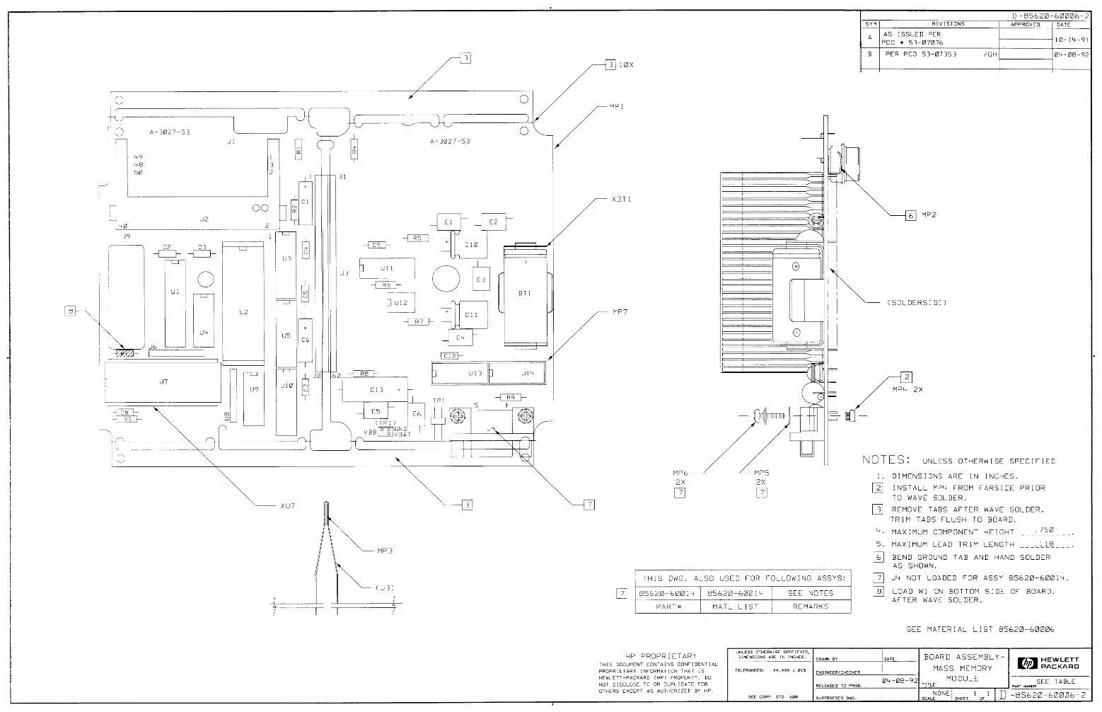
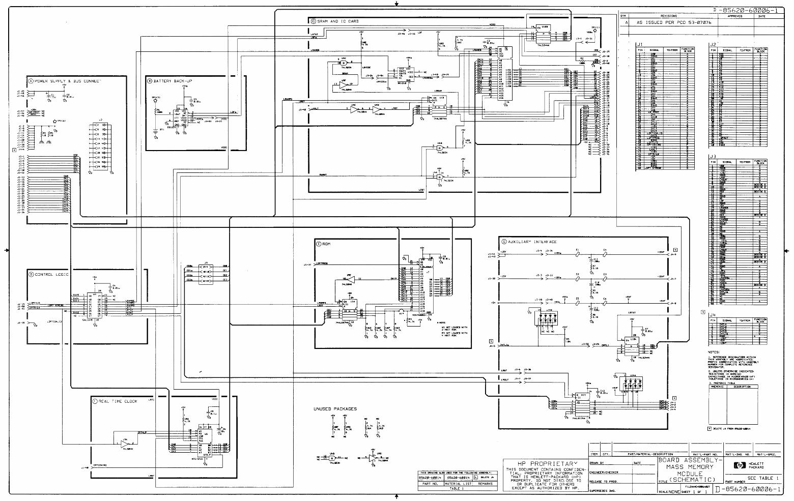

Component-Level Information Packetfor 85620-60008
Mass Memory Assembly
Et! HEWLETTPACKARD
HP Part No. 85820-90034Printed in USA April 1995

Notice. The information contained in this document is subject to change without notice.
Hewlett-Packard makes no warranty of any kind with regard to this material, including,but not limited to, the implied warranties of merchantability and fitness for a particularpurpose. Hewlett-Packard shall not be liable for errors contained herein or for incidental orconsequential damages in connection with the furnishing, performance, or use of this material.
@Copyright Hewlett-Packard Company 1990, 1991, 1992, 1993, 1994, 1995All Rights Reserved. Reproduction, adaptation, or translation without prior writtenpermission is prohibited, except as allowed under the copyright laws.

HP Part Number 85820-60008Al Mass Memory Assembly
BTlBT1 1420-03941420-0394 1 BATTERY 3V IA-HR LI MANGANESE DIOXIDE 28480 1420-0394
ClCl 0180-41360180-4136 1 CAP-FXD 1OuF +-lo% 20 V TA 28480 0180-4136
c2c2 0180-41350180-4135 1 CAP-FXD 33uF +-lo% 10 V TA 28480 0180-4135
c3c3 0160-48320160-4832 1 CAP-FXD O.OluF +-lo% 100 V CER X7R 28480 0160-4832
c4c4 0160-48320160-4832 1 CAP-FXD O.OluF +-lo% 100 V CER X7R 28480 0160-4832
c5c5 0160-48320160-4832
C6C6 0160-48320160-4832
c7c7 0160-48320160-4832
C8C8 016@4832016@4832
c9c9 0160-50980160-5098
1 CAP-FXD O.OluF +-lo% 100 V CER X7R 28480 0160-4832
1 CAP-FXD O.OluF +-lo% 100 V CER X7R 28480 0160-4832
1 CAP-FXD O.OluF +-lo% 100 V CER X7R 28480 0160-4832
1 CAP-FXD O.OluF +-lo% 100 V CER X7R 28480 0160-4832
1 CAP-FXD 0.22uF +-lo% 50 V CER X7R 28480 0160-5098
Cl0Cl0 0160-48140160-4814
Cl1Cl1 0160-48350160-4835
JlJl 1252-12631252-1263
J2J2 1252290612522906
J3J3 812CL4857812CL4857
1 CAP-FXD 15OpF +-5% 100 V CER COG 28480 0160-4814
1 CAP-FXD o.luF +-lo% 50 V CER X7R 28480 0160-4835
1 CONN-RECT D-SUBMIN 50-CKT 50-CONT 28480 1252-1263
1 CONN-POST TYPE 0-CONT 28480 1252-2906
1 CABLEMCNDCT 28480 8120-4857
NONE0033NONE0033 0515-17170515-1717
NONE0034NONE0034 0590-13550590-1355
NONE0035NONE0035 3050-08903050-0890
NONE0036NONE0036 5022-00085022-0008
NONE0037NONE0037 5041-72825041-7282
1 SCREW-MACHINE ASSEMBLY M2.5 X 0.45 01125
1 THREADED INSERT-NUT M2.5 X 0.45 03981 F-M2.5-1
1 WASHER-FL MTLC 2.5 2.78MM-ID 6.35MM-OD 06691
1 BATTERY SUPPORT 28480 5022-0008
1 B-INSUL TO-220 28480 5041-7282
NONE0038NONE0038 7121-46117121-4611
RlRl 0757-03460757-0346
R2R2 0757-03460757-0346
R3R3 0757-03460757-0346
R4R4 0698725206987252
1 LABEL-INFORMATION .15-IN-WD .06-IN-LG 09002
1 RESISTOR 10 +-1% .125W TF TC=O+-loo 28480 0757-0346
1 RESISTOR 10 +-1% .125W TF TC=O+-100 28480 0757-0346
1 RESISTOR 10 +-1% .125W TF TC=O+-100 28480 0757-0346
1 RESISTOR 4.64K +-1% .05W TF TC=O+-100 28480 0698-7252
R5R5 0757-04650757-0465
R7R7 0757-04650757-0465
R9R9 0698725206987252
RlORlO 0698-72520698-7252
TPlTPl 1251-78191251-7819
TP2TP2 0360-16820360-1682
TP3TP3 036CL1682036CL1682
UlUl 8562&800148562&80014
u2u2 85620-8001585620-80015
u3u3 8562@800168562@80016
1 RESISTOR 1OOK +-1% .125W TF TC=O+-100 28480 0757-0465
1 RESISTOR 1OOK +-1% .125W TF TC=O+-100 28480 0757-0465
1 RESISTOR 4.64K +-lo/o .05W TF TC=O+-100 28480 0698-7252
1 RESISTOR 4.64K +-1% .05W TF TC=O+-100 28480 0698-7252
1 CONN-POST TYPE .lOO-PIN-SPCG-MTG-END 28480 1251-7819
1 TERMINAGSTUD SGL-TUR PRESS-MTG 05364 147588
1 TERMINAL-STUD SGGTUR PRESS-MTG 05364 14758-8
1 EPROM-PRGMEDUl 28480 85620-80014
1 EPROM-PRGMEDUZ 28480 85620-80015
1 EPROM-PRGMEDU3 28480 85620-80016
Reference HP PartDesignator Number
Qty! I Description
*Indicates factory-selected value CLIP 85620-90034 1

HP Part Number 85620-60008Al Mass Memory Assembly (continued)
Reference HP Part Qty Description Mfr Mfr PartDesignator Number Code Number
u5 1820-1437 1 IC MV TTL/LS MONOSTBL CLEAR DUAL 28480 1820-1437
U6 1820-5384 1 IC-INTERFACE CMOS -888BIT 28480 1820-5384
u7 1818-4604 1 IC lM-BIT SRAM 120-NS CMOS 28480 18184604
U8 1826-1858 1 IC PWR MGT-BAT-MGT 28480 1826-1858
u9 85620-80001 1 PAL, PROGRAMMED 28480 85620-80001
UlO 1820-1198 1 IC GATE TTL/LS NAND QUAD 2-INP 28480 1820-1198
Ull 1820-3143 1 IC FF TTL/ALS D-TYPE POS-EDGE-TRIG COM 28480 1820-3143
u12 1820-2024 1 IC DRVR TTL/LS BUS OCTL 28480 1820-2024
u13 1810-0205 1 NETWORK-RES 8-SIP 4.7K OHM X 7 28480 1810-0205
u14 1826-1199 1 IC INV TTL/LS HEX l-INP 28480 1820-1199
u15 1820-5497 1 IC-NONVOLATILE MEMORY CONTROLLER 28480 1820-5497
XUl 1200-0567 1 SOCKET-IC2aCONT DIP DIP-SLDR 00779 641605-l
xu2 1200-0567 1 SOCKET-IC28-CONT DIP DIP-SLDR 00779 641605-l
xu3 1200-0567 1 SOCKET-IC28-CONT DIP DIP-SLDR 00779 641605-l
HP 85620A ACCESSORIES PARTS LIST
0950-1964 1 MEMORY CARD, SRAM 10421 RBC032IEOO
1420-0383 1 MEMORY CARD BATTERY 08709 CR2016
2 CLIP 85620-90034 *Indicates factory-selected value


Component-Level Information Packetfor 85620=60018
Mass Memory
E!! HEWLETTPACKARD
HP Part No. 85820-90038Printed in USA May 1998

Notice. The information contained in this document is subject to change without notice.
Hewlett-Packard makes no warranty of any kind with regard to this material, including,but not limited to, the implied warranties of merchantability and fitness for a particularpurpose. Hewlett-Packard shall not be liable for errors contained herein or for incidental orconsequential damages in connection with the furnishing, performance, or use of this material.
@Copyright Hewlett-Packard Company 1990, 1991, 1992, 1993, 1994, 1995, 1996All Rights Reserved. Reproduction, adaptation, or translation without prior writtenpermission is prohibited, except as allowed under the copyright laws.

HP Part Number 85820-80018Mass Memory
Reference! H P P a r tDesignato r N u m b e r
BTl 1420-0341
Cl 0180-4135
c2 0160-4832
c3 0160-4832
c4 0160-4832
c5 0160-4835
C6 0180-4136
c7 0160-4832
C8 0160-4832
c9 0160-4832
Cl0 01803817
Cl1 01803817
Cl2 0160-4832
Cl3 0180-2208
El 9100-1788
E2 9100-1788
E3 9100-1788
E4 9100-1788
E5 9100-1788
E6 9100-1788
Jl 1252-1263
52 1252-2906
J3 8120-4857
54 1252-1327
MP3 5001-8737
MP4 0590-1361
MP5 0590-1361
MP6 0515-0367
MP7 0515-0367
MP8 1400-2112
MP9 0361-0009
MPlo 0361-0009
NONE 8567190007
NONE 0470-0440
Rl 0757-0346
Description Mfr PartNumber
BATTERY 3V 1.2A-HR LITHIUM POLYCARBON 28480 1420-0341
CAP-FXD 33uF +-lo% 10 V TA 28480 0180-4135
CAP-FXD O.OluF +-lo% 100 V CER X7R 28480 0160-4832
CAP-FXD O.OluF +-lo% 100 V CER X7R 28480 0160-4832
CAP-FXD O.OluF +-lo% 100 V CER X7R 28480 0160-4832
CAP-FXD O.luF +-lo% 50 V CER X7R
CAP-FXD 1OuF +-lo% 20 V TA
CAP-FXD O.OluF +-lo% 100 V CER X7R
CAP-FXD O.OluF +-lo% 100 V CER X7R
CAP-FXD O.OluF +-lo% 100 V CER X7R
CAP-FXD 1OOuF +-20% 50 V AL-ELCTLT 28480 0180-3817
CAP-FXD 1OOuF +-20% 50 V AL-ELCTLT 28480 0180-3817
CAP-FXD O.OluF +-lo% 100 V CER X7R 28480 0160-4832
CAP-FXD 22OuF +-lo% 10 V TA 28480 0180-2208
COREFERRITE CHOKE-WIDEBAND;IMP:>680 28480 9100-1788
COREFERRITE CHOKE-WIDEBAND;IMP:>680 28480 9100-1788
COREFERRITE CHOKEWIDEBAND;IMP:>680 28480 9100-1788
COREFERRITE CHOKEWIDEBAND;IMP:>680 28480 9100-1788
COREFERRITE CHOKEWIDEBAND;IMP:>680 28480 9100-1788
COREFERRITE CHOKEWIDEBAND;IMP:>680 28480 9100-1788
CONN-RECT D-SUBMIN 50-CKT 50-CONT
CONN-POST TYPE 0-CONT
CABLEMCNDCT
CONN-RECT D-SUBMIN SCKT 9-CONT
CONTACT-GROUND
THREADED INSERT-NUT M2.5 X 0.45 03981 KF2-2.5M-ET
THREADED INSERT-NUT M2.5 X 0.45 03981 KF2-2.5M-ET
SCREW-MACHINE ASSEMBLY M2.5 X 0.45 05610
SCREW-MACHINE ASSEMBLY M2.5 X 0.45 05610
ACCESS .89-WD ABS 05535 1029c
RIVET-SEMITUB OVH .123DIA .188LG
RIVET-SEMITUB OVH .123DIA .188LG
DEMO QR CARD
COATING DOW CORNING 3140 SIGRBR-RTV 1P
RESISTOR 10 +-1% .125W TF TC=O+-100
*Indicates factory-selected value C L I P 85820-90038 1
28480 0160-4835
28480 0180-4136
28480 0160-4832
28480 0160-4832
28480 0160-4832
28480 1252-1263
28480 1252-2906
28480 8120-4857
28480 1252-1327
28480 5001-8737
02531 R-4012
02531 R-4012
28480 85671-90007
’ 04514 3140
28480 0757-0346

Reference HP Part QtyDesignatort N u m b e r
R2 0757-0465
R3 06983155
R4 0757-0346
R5 06988816
R6 0757-0465
RESISTOR 1OOK +-1% .125W TF TC=O+-loo
RESISTOR 4.64K +-1% .125W TF TC=O+-100
RESISTOR 10 +-1% .125W TF TC=O+-100
RESISTOR 2.15 +-1% .125W TF TC=O+-100
RESISTOR 1OOK +-1% .125W TF TC=O+-100
R7 06988816
R8 0698-8816
R9 0757-0442
TPl 1251-7819
Ul 1820-3143
u2 18164604
u3 8562CL80020
u4 182Cb1198
u5 182Cb5384
U6 1810-0205
u7 85620-80021
US 1810-0205
u9 1820-1199
UlO 1820-2024
Ull 18261858
u12 1820-5497
u13 1820-3465
u14 19060229
Wl 8159-0005
XBTl 14062111
HP Part Number 85820-60018Mass Memory (continued)
Description
1 RESISTOR 2.15 +-1% .125W TF TC=O+-100
1 RESISTOR 2.15 +-1% .125W TF TC=O+-100
1 RESISTOR 10K +-1% .125W TF TC=O+-100
1 CONN-POST TYPE .loO-PIN-SPCG-MTG-END
1 IC FF TTL/ALS D-TYPE POS-EDGETRIG COM
1 IC lM-BIT SRAM 120-NS CMOS
1 PAL-PRGM U3
1 IC GATE TTL/LS NAND QUAD P-INP
1 IC-INTERFACE CMOS -888BIT
1 NETWORK-RES 8-SIP 4.7K OHM X 7
1 EPROM-PROGRAMMED
1 NETWORK-RES 8-SIP 4.7K OHM X 7
1 IC INV TTL/LS HEX l-INP
1 IC DRVR TTL/LS BUS OCTL
1 IC PWR MGT-BAT-MGT
1 IC-NONVOLATILE MEMORY CONTROLLER
1 IC FF TTL/ALS D-TYPE POS-EDGETRIG COM
1 DIODEARRAY 50V 4ooMA TO-116
1 RESISTOR 0 CWM
1 HOLDER-BAT FOR 1 A CELLS .72-WD
Mfr Mfr PartCode Number
28480 0757-0465
28480 06983155
28480 0757-0346
28480 0698-8816
28480 0757-0465
28480 06988816
28480 06988816
28480 0757-0442
28480 1251-7819
28480 182CL3143
28480 1818-4604
28480 85620-80020
28480 182@1198
28480 182C5384
28480 1810-0205
28480 85620-80021
28480 1810-0205
28480 1820-1199
28480 1820-2024
28480 18261858
28480 1820-5497
28480 1820-3465
28480 19060229
28480 81540005
05535 1029
2 C L I P 85620-90038 *Indicates factory-selected value