How to Draw Perspective Directly on a 3D Plane - The Bridges ...
8
How to Draw Perspective Directly on a 3D Plane Tomás García Salgado Faculty of Architecture, National Autonomous University of México Ciudad Universitaria 04510, Cd. de México [email protected] Abstract The aim of this Workshop is to learn hands-on to draw a building directly in perspective. You will experience how easy is to draw a view of The Arch of Defense (Paris) in accurate proportions, without the aid of blueprints. Unlike traditional methods, the entire process takes place on the perspective plane. All that it takes is the ability to see the building’s points of interest in three-dimensions on this plane. We will begin with the basic notions of the Modular Perspective model and how the three modular scales of the perspective plane are read. The time lapse for each activity of the workshop is indicated (in minutes) at the beginning of each page. Introduction The modular perspective model (see Figure 1) is composed of three planes, namely: plane of symmetry X (PLSX), plane of symmetry Y (PLSY), and the perspective plane (PPL). All three planes are read in modular coordinates from the observer (OB). In the model, it is self evident that human vision vanishes to a single vanishing point; whereas an object vanishes to as many vanishing points as parallel systems it may have. In practice, the modular coordinates (X, Y, & P) of any point given in space are read on the PPL by the scales: X-scale, Y-scale, and P-scale. In simple terms: X is the width, Y the height, and P the depth of a point. Figure 1: The model of Modular Perspective. Bridges Finland Conference Proceedings 673
-
Upload
khangminh22 -
Category
Documents
-
view
10 -
download
0
Transcript of How to Draw Perspective Directly on a 3D Plane - The Bridges ...

How to Draw Perspective Directly on a 3D Plane
Tomás García Salgado
Faculty of Architecture, National Autonomous University of México Ciudad Universitaria 04510, Cd. de México
Abstract
The aim of this Workshop is to learn hands-on to draw a building directly in perspective. You will experience how easy is to draw a view of The Arch of Defense (Paris) in accurate proportions, without the aid of blueprints. Unlike traditional methods, the entire process takes place on the perspective plane. All that it takes is the ability to see the building’s points of interest in three-dimensions on this plane. We will begin with the basic notions of the Modular Perspective model and how the three modular scales of the perspective plane are read. The time lapse for each activity of the workshop is indicated (in minutes) at the beginning of each page.
Introduction
The modular perspective model (see Figure 1) is composed of three planes, namely: plane of symmetry X (PLSX), plane of symmetry Y (PLSY), and the perspective plane (PPL). All three planes are read in modular coordinates from the observer (OB). In the model, it is self evident that human vision vanishes to a single vanishing point; whereas an object vanishes to as many vanishing points as parallel systems it may have. In practice, the modular coordinates (X, Y, & P) of any point given in space are read on the PPL by the scales: X-scale, Y-scale, and P-scale. In simple terms: X is the width, Y the height, and P the depth of a point.
Figure 1: The model of Modular Perspective.
Bridges Finland Conference Proceedings
673

00-15. Getting familiar with the PPL In Figure 2 is shown the standard position of the X-scale, Y-scale, and P-scale. The former two scales are given in true modular dimension, while P-scale is given in modules that decrease from 0 to infinity. These scales are ready to be used graphically on the PPL75 (Perspective Plane, 75º of Aperture of Visual Field). The math of my method, including the P-scale, is discussed in a previous work [1].
To start, participants will receive a printed sheet of the PPL75. A module (M) can be of any dimension you want it to be, either small or larger. The X-scale (at the bottom margin) is used to read modular coordinates X, on the PLSX. The Y-scale (at the right margin) is used to read modular coordinates Y, on the PLSY. The P-scale (at the left margin) is used to place in depth both coordinates, X and Y (one at a time). The vp (at the center of the PPL) is the observer’s vanishing point.
Figure 2: Square-12 (Sq12) is a square in perspective measuring 12 x 12 M. Drawing a square of 12 x 12 modules (M) on the PPL 75, from here on abridged as Sq12. The AmVF (amplitude of visual field) is a secondary scale to measure either X or Y values bigger
than ± 5.00 M. It’s placed within the PPL in both positions vertical and horizontal (see Fig. 2). First. Measure on the AmVF scale, X = + 6.00 M (right), and carry it to the vp. Measure on the AmVF scale, X = – 6.00 M (left), and carry it to the vp. This would be the width of Sq12 = |12.00 M|. Second. Trace a horizontal line from P = 4.00 M across the PPL, and another horizontal line from P = 16.00 M across the PPL. Notice that the subtraction of both P values = |12.00 M|. Third. Give shape to Sq12 (shaded in grey).
Salgado
674

15-25. To lay out the Defense plan in foreshortened view mark the sequence (9 M, 3 M) at all sides of Sq12. To measure, use either the AmVF or the X-scale. First. Measure on the frontal side of Sq12, 9.00 M, from right to left, and draw a line to the vp until it crosses the frontal side (leave a stroke). Second. Measure on the left side of Sq12, 9.00 M. Use for this the P-scale at P = 13.00 M. Third. Measure on the rear side of Sq12, 9.00 M, from left to right, and draw a line to the vp until it crosses the rear side (leave a stroke). Fourth. Measure on the right side of Sq12, 9.00 M. Use for this the P-scale at P = 7.00 M. Fifth. Inscribe a new square from the marked points. This would be the Defense ideal plan in foreshortened view, from here on as SqD.
Figure 3: The Arch of Defense, square plan (SqD).
As we know, The Arch of Defense is about 110 meters by side and so of height. By the Pythagorean theorem, the side length of SqD result ≈ 9.5 M. Notice that all inner angles of
SqD are of 90º. On the PPL, the 9.5 M x 9.5 M SqD represents the actual plan of The Arch of Defense that in reality measures 110 m x 110 m (meters); which means that 1 M = 11.6 m.
Now, again in modules (M), the proportions of the building that you should know in advance are: a) The outer glazing-walls of the building measures 9.5 M. b) The width of the Arch’s legs is 1.7 M on the X-scale, and on the oblique side of SqD ≈ 1.8 M. * c) The interior plaza of the Arch rises 1.0 M from the esplanade (Le Parvis). d) The thickness of the roof of the Arch is 1.3 M. * (As the ratio 9.5 / 9.0 = 1.05, then we have: 1.05 x 1.7 ≈ 1.8 M).
How to Draw Perspective Directly on a 3D Plane
675
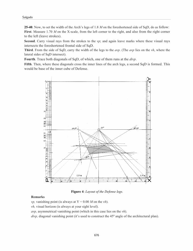
25-40. Now, to set the width of the Arch’s legs of 1.8 M on the foreshortened side of SqD, do as follow: First. Measure 1.70 M on the X-scale, from the left corner to the right, and also from the right corner to the left (leave strokes). Second. Carry visual rays from the strokes to the vp; and again leave marks where these visual rays intersects the foreshortened frontal side of SqD. Third. From the side of SqD, carry the width of the legs to the avp. (The avp lies on the vh, where the lateral sides of SqD intersect). Fourth. Trace both diagonals of SqD, of which, one of them runs at the divp. Fifth. Then, where these diagonals cross the inner lines of the arch legs, a second SqD is formed. This would be base of the inner cube of Defense.
Figure 4: Layout of the Defense legs. Remarks vp, vanishing point (is always at Y = 0.00 M on the vh). vh, visual horizon (is always at your sight level). avp, asymmetrical vanishing point (which in this case lies on the vh). divp, diagonal vanishing point (it’s used to construct the 45º angle of the architectural plan).
Salgado
676

40-55. Next, to shape the volume, do the following carefully. First. Draw vertical lines from the corner points of both squares. Second. Measure on the Y-scale, from the vh, Y = – 3.70 M (downwards), and Y = + 5.80 M (upwards), that is |9.5 M|. These would be the outer edges’ height. Third. Measure on the Y-scale, from the vh, Y = – 2.70 M (downwards), and Y = + 4.50 M (upwards). These would be the inner edges’ height. Fourth. Look for the diagonal. Now, trace a horizontal line from each corner point (of both squares) until it crosses the diagonal. Fifth. Next, from the diagonal, raise 8 new vertical lines (corner points of the volume).
Figure 5: The corner points delimit the shading areas.
Remark Keep in mind that you have drawn two sets of vertical lines, one belonging to the figure points, and
the other along the diagonal (see Glossary). The function of the diagonal is to carry P from any pair (X, P) to its corresponding Y. In other words, the two pairs of coordinates (X, P) and (Y, P) that a point has, must have the very same P. This is the key to establish the heights of all corner points.
How to Draw Perspective Directly on a 3D Plane
677

55-85. Before shaping the volume, keep in mind that the height of the observer is |3.7 M|. The square plan of both cubes is given by their corner points. As we know, there is an X and a P for
each corner point but to simplify the process, here we will use only its P value. First. Select a vertical of a corner point in plan (let’s say the nearest one to the observer). Then, follow the P = 4.00 M horizontal line up to the diagonal; from there, turn up and follow its vertical line until intersecting with both Y = – 3.7 M and Y = + 5.8 M, leave strokes. Second. Now, from both Y’s marks draw horizontal lines until intersecting with the vertical of the corner point, to thus determine the edge of the outer cube we are looking for. Third. Take a corner-point at a time and repeat this very same procedure over and over until get the volume shaped. It would be easier if you first draw the outer cube and then the inner cube. Make sure of proceed systematically in both cases.
Figure 6: The Arch of Defense drawn in accurate proportions. Remark The observer distance to the building is deduced as follow: P = 4 M + d (6.51 M) = 10.51 M = 121.9 m. Where (d) is the distance from the observer to the
PPL, which for an aperture of visual field of 75º is of 6.51 M. Other interesting measures are the following. The nearest corner of the building is at 121.9 m from the observer. The vh is at 42.9 m high (3.7 M x 11.6 m). And the viewing foreshortened angle is of 18.43º (tan-1, 3/9).
Salgado
678

85-90. The foreshortened angle in this view (Figure 8), of 19.5º, was set for the purpose to occlude the left lateral surface [2]. This is why I decided to change it a little bit to make more comprehensible its perspective construction, for the practice of this workshop.
Figure 8: La Grande Arche (Paris), Johan Von Spreckelsen.
How to Draw Perspective Directly on a 3D Plane
679

References
[1] T. García-Salgado, A Modular Perspective Model Vs. Vectorial Models, Leonardo, Vol. 21, No. 3, pp. 277-284, 1988. (See equation of P-scale in Note 9, p. 283).
[2] T. García-Salgado, Modular Perspective for Architects & other Related Professionals (Mexico:
author’s pilot edition, 2014, ISBN 978-607-00-8057-9), p 96.
Glossary
Diagonal, it is any of the “diagonal lines” of the PPL. These diagonals are actually visual rays running parallel to the observer sightline.
distance (d). It is the interval between the observer station (OB) and the PPL. It therefore, the aperture of visual field depends on (d). Notice that the term “distance” is often used to refer the distance between the observer and an object, which is not the same concept of “distance” here defined.
Perspective Plane (PPL). It is the plane onto which objects as perceived by the observer are projected in perspective. The PPL construction is made by means of the modular scales: X-scale, Y-scale, and P-scale.
Plane of Symmetry X (PLSX). It is the plane onto which modular coordinates (X, P) are measured. Plane of Symmetry Y (PLSY). It is the plane onto which modular coordinates (Y, P) are measured.
Vanishing Point (vp). It is a point at infinity where the observer’s visual rays meet, though these rays actually run parallel.
Salgado
680