How boiler management solutions can improve the bottom line
24
PGE2010_id145_BMS.doc 1 / 24 How boiler management solutions can improve the bottom line Marc Antoine * , Mehmet Mercangoez ** ABB Power Systems, Baden *, ABB Corporate Research, Dättwil ** (Switzerland) Abstract High reliability requirements for steam and power supply, large variations in load and energy consumption, and changing market conditions for fuel and electricity are challenging tasks for modern power plants. For power generation, advanced control solutions have been implemented focusing on coordinated control and optimization of boilers, fuels, turbines, steam headers, and power flows to and from the grid. The range of benefits, such as improved plant stability, higher availability and lower overall energy costs, have paved the way for wider applications. Further improvements are possible by providing advanced boiler management solutions as packaged systems, combining advanced control and optimization techniques with special instruments in and around the boiler. This approach enhances combustion control, improves unit ramp rates, and offers new monitoring capabilities to the operator. Concurrently, such solutions are also able to achieve emission reductions and thus reduce the CO2 footprint of the installed base. Today’s advanced control and optimization solutions provide high return compared to expensive boiler retrofits for improving operational efficiency as well as reducing emissions. This paper presents how advanced boiler management systems achieve significant results impacting the bottom line.
-
Upload
khangminh22 -
Category
Documents
-
view
3 -
download
0
Transcript of How boiler management solutions can improve the bottom line
PGE2010_id145_BMS.doc 1 / 24
How boiler management solutions can improve the bottom line
Marc Antoine*, Mehmet Mercangoez**
ABB Power Systems, Baden*, ABB Corporate Research, Dättwil** (Switzerland)
Abstract
High reliability requirements for steam and power supply, large variations in load and energy consumption, and changing market conditions for fuel and electricity are challenging tasks for modern power plants.
For power generation, advanced control solutions have been implemented focusing on coordinated control and optimization of boilers, fuels, turbines, steam headers, and power flows to and from the grid. The range of benefits, such as improved plant stability, higher availability and lower overall energy costs, have paved the way for wider applications. Further improvements are possible by providing advanced boiler management solutions as packaged systems, combining advanced control and optimization techniques with special instruments in and around the boiler. This approach enhances combustion control, improves unit ramp rates, and offers new monitoring capabilities to the operator. Concurrently, such solutions are also able to achieve emission reductions and thus reduce the CO2 footprint of the installed base.
Today’s advanced control and optimization solutions provide high return compared to expensive boiler retrofits for improving operational efficiency as well as reducing emissions. This paper presents how advanced boiler management systems achieve significant results impacting the bottom line.

PGE2010_id145_BMS.doc 2 / 24
1 Introduction
Coal fired power plants have come a long way in the last decades to become generators of electrical energy with high efficiency and sharply reduced emissions. Big steps have been taken particularly with improved boilers, steam turbines and advanced cycles. Utility boilers are complex systems, frequently with more than 50 actuators involved in a sub-system like e.g. combustion control. Typical sub-systems in and around the boiler are indicated in Fig. 1. This provides a great deal of flexibility for operators, but the basic automation system typically does not help them much with these extra degrees of freedom.
Model Predictive Control (MPC, or sometimes called MVPC for Multivariable MPC) was designed to solve these types of problems. The pioneer use of MPC was in the process industries and in recent years MPC has proven to be the ideal technology for complex applications in the power generation industry as well. Such solutions are commonly referred to as Advanced Process Control (APC).
Fig. 1: Sub-systems in and around the boiler.
2 Boiler Management Systems
Although many control tasks can be solved by classic PID control schemes, a considerable improvement potential remains untapped, specifically related to multivariable control, or coordinated control between different boiler sub-systems. The use of Model Predictive Control (MPC) delivers superior performance over traditional single-input single-output control strategies. This has led to a system-approach around the boiler, i.e. providing a
PGE2010_id145_BMS.doc 3 / 24
common platform for integration and deployment of Advanced Process Control (APC) solutions, on top of the existing classic controls.
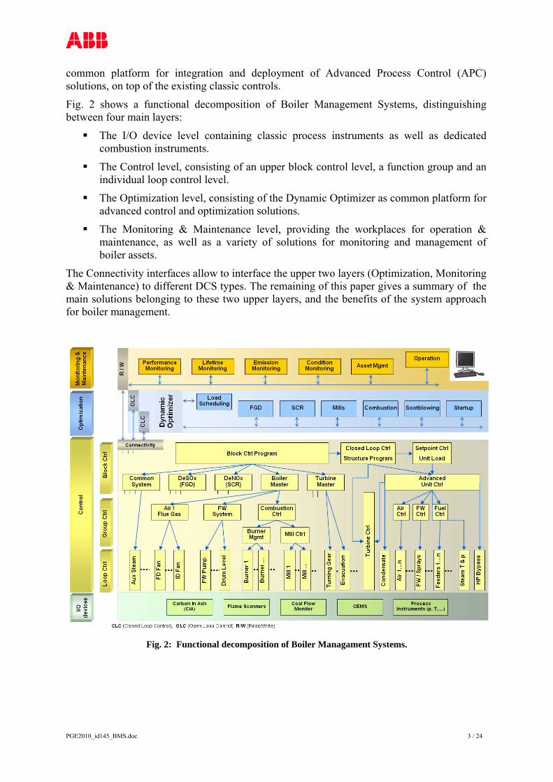
Fig. 2 shows a functional decomposition of Boiler Management Systems, distinguishing between four main layers:
The I/O device level containing classic process instruments as well as dedicated combustion instruments.
The Control level, consisting of an upper block control level, a function group and an individual loop control level.
The Optimization level, consisting of the Dynamic Optimizer as common platform for advanced control and optimization solutions.
The Monitoring & Maintenance level, providing the workplaces for operation & maintenance, as well as a variety of solutions for monitoring and management of boiler assets.
The Connectivity interfaces allow to interface the upper two layers (Optimization, Monitoring & Maintenance) to different DCS types. The remaining of this paper gives a summary of the main solutions belonging to these two upper layers, and the benefits of the system approach for boiler management.
Fig. 2: Functional decomposition of Boiler Managament Systems.

PGE2010_id145_BMS.doc 4 / 24
3 Boiler Startup Optimization
Large boilers represent major assets in any power generation utility. Today’s plant managers look for new solutions to improve their startup response and satisfy dispatcher requests. They want to achieve these goals while reducing their operating costs and saving resources. The challenge of optimizing the startup of such boilers lies in three main areas:
High thermal stresses in steam tubes and in particular, in the headers, consume asset lifetime and may cause damage if material limits are not respected.
From a control viewpoint, the optimization problem is a multivariable control problem with strong nonlinear relationships.
From the operational viewpoint, the startup is a cost factor, since no power is generated.
The boiler startup optimization solution (BoilerMax) is based on dynamic optimization using Nonlinear MPC (NMPC) and can satisfy requirements that are beyond the reach of conventional closed-loop controllers.
By implementing BoilerMax, plant operators are able to bring their units online faster, save fuel costs, reduce emissions and improve flexibility to respond to demands from the load dispatcher. The specific basic process conditions, such as thermal stress of critical thick-walled components and the margins for maximum permissible loads are predicted and included in a closed control loop. In addition to this, the startup operation can be adapted to changing basic conditions, such as fuel costs and maximum permissible loads, when necessary [3].
During a startup procedure, the actual values, which are cyclically scanned for temperatures, pressures and steam mass flow rates, are used for adjusting a dynamic boiler model. Based on this nonlinear model, BoilerMax applies its predictive optimization routines to the rest of the startup procedure. The resulting startup curves computed online are then integrated into the existing unit control concept, serving as correction setpoints.
The prediction horizon is 60’ to 90’, thus covering the entire length of a boiler startup up to the point where the turbine is rolled on steam. This way the most cost-efficient overall operating mode can be computed. The predicted data is updated every one to two minutes, thus enabling an adequate response to disturbance conditions. Because of the high computing power required, BoilerMax runs on the Dynamic Optimizer platform (Fig. 2) on a PC which is configured as an application server.
The startup costs to be minimized refer to fuel, auxiliary power and auxiliary steam costs incurred during a boiler startup, from 'Flame ON' to 'Generator Online' or 'HP Bypass Closed'. Independent of the cost savings realized, the MPC controller also enables a predictive integration of thermal stress data into the closed control loop. The level of flexibility — e.g. covering different downtimes — is improved as the physical model is continually adjusted to match the current state of the plant. Moreover, the startup can be adapted to changing basic conditions, such as different fuel costs or maximum permissible loads, by modifying the target function and optimization constraints, respectively [4]. A typical overview schematic showing the process and data flow is indicated in Fig. 3. In this diagram the blue and red lines represent the water/ steam circuit, the black inputs supply BoilerMax with information about the actual status of the steam generator, and the magenta outputs represent the optimized control variables, ie the setpoints for the secondary controllers.

PGE2010_id145_BMS.doc 5 / 24
Fig. 3: Boiler startup optimization - schematic overview.
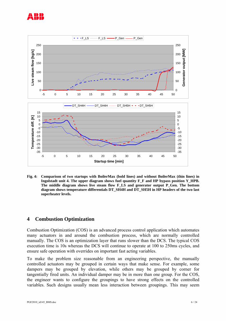
With the predictive startup optimization, it is often possible to run a startup using less fuel, while maintaining the usual startup time and stress loading on critical thick-walled components. Fig. 4 shows a comparison of two startup procedures. The diagrams clearly show an approximate 20% reduction of fuel consumption. Such fuel savings are possible, since the steam flow used for startup can be decreased by simultaneous and coordinated reduction of the HP bypass opening. In addition, the startup time is slightly reduced.
0
50
100
150
200
250
-5 0 5 10 15 20 25 30 35 40 45 50
Star
tup
pow
er [M
W]
0102030405060708090100
HP
bypa
ss p
ositi
on [%
]
F_F F_F Y_HPB Y_HPB
PGE2010_id145_BMS.doc 6 / 24
0
50
100
150
200
250
-5 0 5 10 15 20 25 30 35 40 45 50
Live
ste
am fl
ow [k
g/s]
0
50
100
150
200
250
Gen
erat
or o
utpu
t [M
W]
F_LS F_LS P_Gen P_Gen
-35-30-25-20-15-10-505
1015
-5 0 5 10 15 20 25 30 35 40 45 50
Startup time [min]
Tem
pera
ture
diff
. [K
]
-35-30-25-20-15-10-5051015
DT_SH4H DT_SH4H DT_SH5H DT_SH5H
Fig. 4: Comparison of two startups with BoilerMax (bold lines) and without BoilerMax (thin lines) in Ingolstadt unit 4. The upper diagram shows fuel quantity F_F and HP bypass position Y_HPB. The middle diagram shows live steam flow F_LS and generator output P_Gen. The bottom diagram shows temperature differentials DT_SH4H and DT_SH5H in HP headers of the two last superheater levels.
4 Combustion Optimization
Combustion Optimization (COS) is an advanced process control application which automates many actuators in and around the combustion process, which are normally controlled manually. The COS is an optimization layer that runs slower than the DCS. The typical COS execution time is 10s whereas the DCS will continue to operate at 100 to 250ms cycles, and ensure safe operation with overrides on important fast acting variables.
To make the problem size reasonable from an engineering perspective, the manually controlled actuators may be grouped in certain ways that make sense. For example, some dampers may be grouped by elevation, while others may be grouped by corner for tangentially fired units. An individual damper may be in more than one group. For the COS, the engineer wants to configure the groupings to have strong effects on the controlled variables. Such designs usually mean less interaction between groupings. This may seem

PGE2010_id145_BMS.doc 7 / 24
unnecessary when you have a multivariable controller automatically decoupling, but it is based more on practical engineering experience of identifying process models [2].
The boiler construction will determine the variables available. Wall fired units and corner fired units will have different handles available. Multiple furnace boxes with common back ends will create more options, and spray configurations can also vary. Each boiler and site can be a little different, requiring some upfront thought when designing the controller. Objectives will depend on boiler construction and local environmental law.
The COS works with the base DCS controls, such as:
The boiler master still manipulates air and fuel.
The pressure and MW control does not change. The COS works with the many actuators not tied to feedback in the DCS and also biases the DCS (PID) setpoints, such as:
Auxiliary Air Dampers (Level biases, Furnace bias).
Over Fire Air Dampers (Overall demand, Furnace bias).
Wind Box ΔP setpoint bias.
O2 setpoint bias.
Burner tilt demands.
Mill Elevation biases. Examples of optimization constraints are:
NOx – maximum constraint, is the main objective.
Opacity – maximum constraint, is a noisy value which needs filtering and non-aggressive tuning.
O2 imbalance – maximum constraint on the delta O2 between furnaces, which is controlled with furnace biases on auxiliary air and over-fire air dampers (OFAD).
Actuator constraints – to keep the base DCS loops within their operating range, usually below a maximum output (e.g. Spray valves, Dampers).
Increasing the size of a COS problem may be a cost effective method of addressing other process problems. If the infrastructure is in place or the plant owner is planning to put the infrastructure in place, expanding the MPC controller can deliver more benefits. Expanded COS scopes are, for example:
Increasing the size of the MPC controller/optimizer.
Adding other analyzer variables, e.g. CO or Combustibles.
Using the MPC optimizing capability to reduce heat rate by including the fluid side of the boiler:
o Either including temperature controls in MPC or adding spray flows (or valves) as measured values.
o Designing the controller to minimize reheat spray flow. o Keeping main steam spray flow within a controllable range. o Possibly adding ΔT limits for balancing.
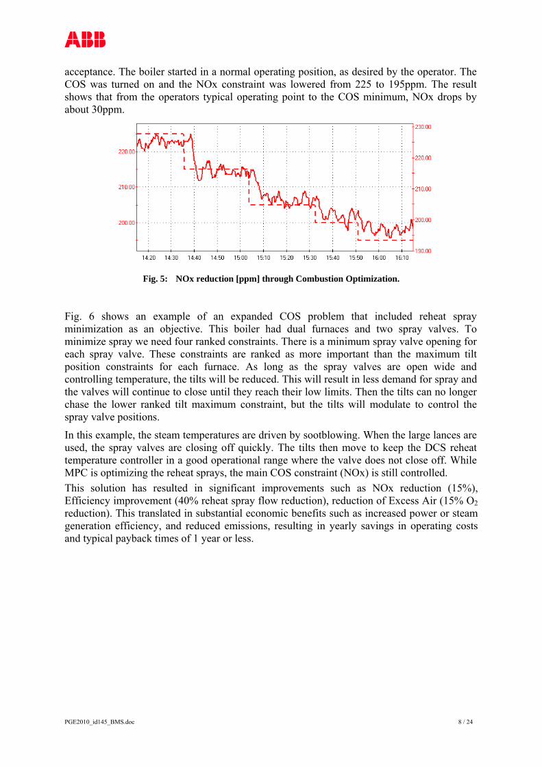
The data in Fig. 5 show a performance test during commissioning used for customer
PGE2010_id145_BMS.doc 8 / 24
acceptance. The boiler started in a normal operating position, as desired by the operator. The COS was turned on and the NOx constraint was lowered from 225 to 195ppm. The result shows that from the operators typical operating point to the COS minimum, NOx drops by about 30ppm.
Fig. 5: NOx reduction [ppm] through Combustion Optimization.
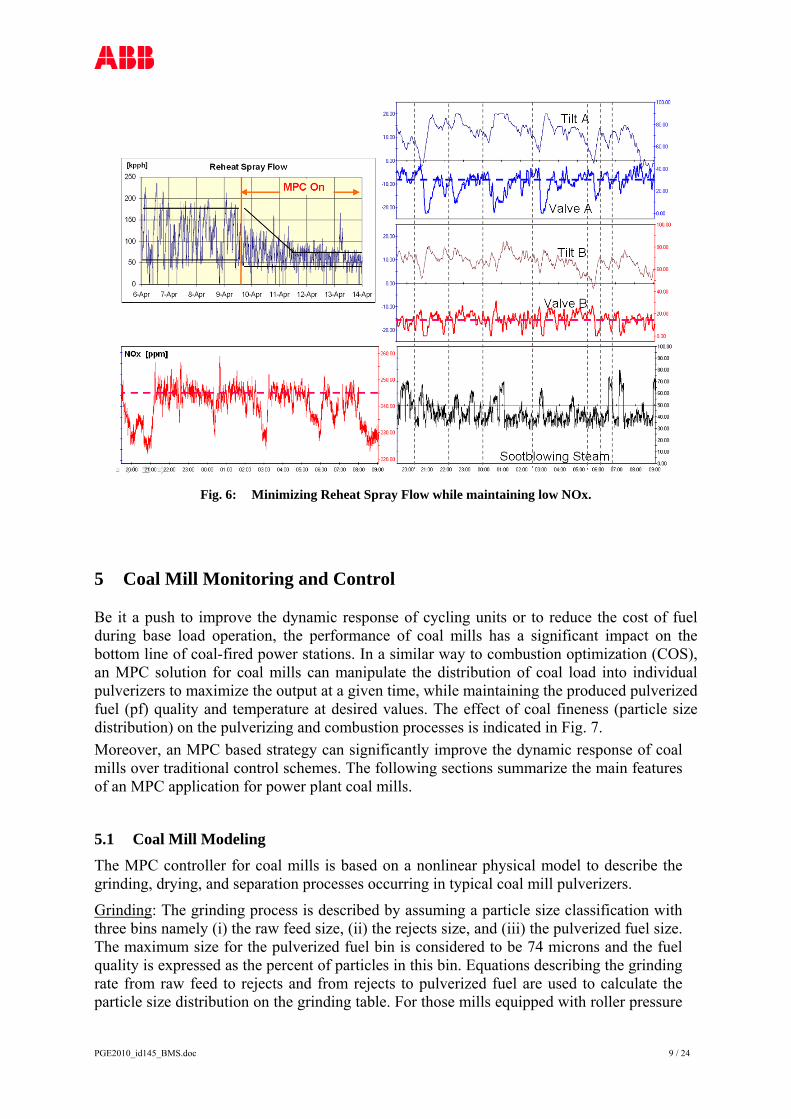
Fig. 6 shows an example of an expanded COS problem that included reheat spray minimization as an objective. This boiler had dual furnaces and two spray valves. To minimize spray we need four ranked constraints. There is a minimum spray valve opening for each spray valve. These constraints are ranked as more important than the maximum tilt position constraints for each furnace. As long as the spray valves are open wide and controlling temperature, the tilts will be reduced. This will result in less demand for spray and the valves will continue to close until they reach their low limits. Then the tilts can no longer chase the lower ranked tilt maximum constraint, but the tilts will modulate to control the spray valve positions.
In this example, the steam temperatures are driven by sootblowing. When the large lances are used, the spray valves are closing off quickly. The tilts then move to keep the DCS reheat temperature controller in a good operational range where the valve does not close off. While MPC is optimizing the reheat sprays, the main COS constraint (NOx) is still controlled. This solution has resulted in significant improvements such as NOx reduction (15%), Efficiency improvement (40% reheat spray flow reduction), reduction of Excess Air (15% O2 reduction). This translated in substantial economic benefits such as increased power or steam generation efficiency, and reduced emissions, resulting in yearly savings in operating costs and typical payback times of 1 year or less.
PGE2010_id145_BMS.doc 9 / 24
Fig. 6: Minimizing Reheat Spray Flow while maintaining low NOx.
5 Coal Mill Monitoring and Control
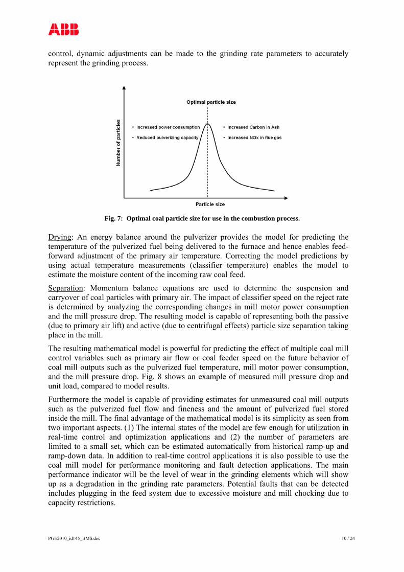
Be it a push to improve the dynamic response of cycling units or to reduce the cost of fuel during base load operation, the performance of coal mills has a significant impact on the bottom line of coal-fired power stations. In a similar way to combustion optimization (COS), an MPC solution for coal mills can manipulate the distribution of coal load into individual pulverizers to maximize the output at a given time, while maintaining the produced pulverized fuel (pf) quality and temperature at desired values. The effect of coal fineness (particle size distribution) on the pulverizing and combustion processes is indicated in Fig. 7. Moreover, an MPC based strategy can significantly improve the dynamic response of coal mills over traditional control schemes. The following sections summarize the main features of an MPC application for power plant coal mills.
5.1 Coal Mill Modeling The MPC controller for coal mills is based on a nonlinear physical model to describe the grinding, drying, and separation processes occurring in typical coal mill pulverizers.
Grinding: The grinding process is described by assuming a particle size classification with three bins namely (i) the raw feed size, (ii) the rejects size, and (iii) the pulverized fuel size. The maximum size for the pulverized fuel bin is considered to be 74 microns and the fuel quality is expressed as the percent of particles in this bin. Equations describing the grinding rate from raw feed to rejects and from rejects to pulverized fuel are used to calculate the particle size distribution on the grinding table. For those mills equipped with roller pressure
PGE2010_id145_BMS.doc 10 / 24
control, dynamic adjustments can be made to the grinding rate parameters to accurately represent the grinding process.
Fig. 7: Optimal coal particle size for use in the combustion process.
Drying: An energy balance around the pulverizer provides the model for predicting the temperature of the pulverized fuel being delivered to the furnace and hence enables feed-forward adjustment of the primary air temperature. Correcting the model predictions by using actual temperature measurements (classifier temperature) enables the model to estimate the moisture content of the incoming raw coal feed.
Separation: Momentum balance equations are used to determine the suspension and carryover of coal particles with primary air. The impact of classifier speed on the reject rate is determined by analyzing the corresponding changes in mill motor power consumption and the mill pressure drop. The resulting model is capable of representing both the passive (due to primary air lift) and active (due to centrifugal effects) particle size separation taking place in the mill.
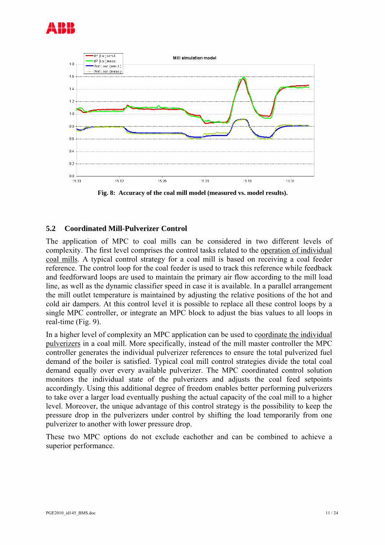
The resulting mathematical model is powerful for predicting the effect of multiple coal mill control variables such as primary air flow or coal feeder speed on the future behavior of coal mill outputs such as the pulverized fuel temperature, mill motor power consumption, and the mill pressure drop. Fig. 8 shows an example of measured mill pressure drop and unit load, compared to model results.
Furthermore the model is capable of providing estimates for unmeasured coal mill outputs such as the pulverized fuel flow and fineness and the amount of pulverized fuel stored inside the mill. The final advantage of the mathematical model is its simplicity as seen from two important aspects. (1) The internal states of the model are few enough for utilization in real-time control and optimization applications and (2) the number of parameters are limited to a small set, which can be estimated automatically from historical ramp-up and ramp-down data. In addition to real-time control applications it is also possible to use the coal mill model for performance monitoring and fault detection applications. The main performance indicator will be the level of wear in the grinding elements which will show up as a degradation in the grinding rate parameters. Potential faults that can be detected includes plugging in the feed system due to excessive moisture and mill chocking due to capacity restrictions.
PGE2010_id145_BMS.doc 11 / 24
Fig. 8: Accuracy of the coal mill model (measured vs. model results).
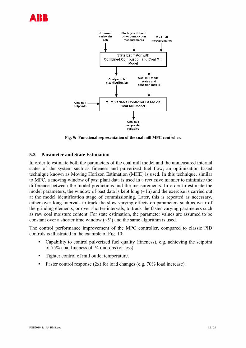
5.2 Coordinated Mill-Pulverizer Control The application of MPC to coal mills can be considered in two different levels of complexity. The first level comprises the control tasks related to the operation of individual coal mills. A typical control strategy for a coal mill is based on receiving a coal feeder reference. The control loop for the coal feeder is used to track this reference while feedback and feedforward loops are used to maintain the primary air flow according to the mill load line, as well as the dynamic classifier speed in case it is available. In a parallel arrangement the mill outlet temperature is maintained by adjusting the relative positions of the hot and cold air dampers. At this control level it is possible to replace all these control loops by a single MPC controller, or integrate an MPC block to adjust the bias values to all loops in real-time (Fig. 9).
In a higher level of complexity an MPC application can be used to coordinate the individual pulverizers in a coal mill. More specifically, instead of the mill master controller the MPC controller generates the individual pulverizer references to ensure the total pulverized fuel demand of the boiler is satisfied. Typical coal mill control strategies divide the total coal demand equally over every available pulverizer. The MPC coordinated control solution monitors the individual state of the pulverizers and adjusts the coal feed setpoints accordingly. Using this additional degree of freedom enables better performing pulverizers to take over a larger load eventually pushing the actual capacity of the coal mill to a higher level. Moreover, the unique advantage of this control strategy is the possibility to keep the pressure drop in the pulverizers under control by shifting the load temporarily from one pulverizer to another with lower pressure drop.
These two MPC options do not exclude eachother and can be combined to achieve a superior performance.
PGE2010_id145_BMS.doc 12 / 24
Fig. 9: Functional representation of the coal mill MPC controller.
5.3 Parameter and State Estimation In order to estimate both the parameters of the coal mill model and the unmeasured internal states of the system such as fineness and pulverized fuel flow, an optimization based technique known as Moving Horizon Estimation (MHE) is used. In this technique, similar to MPC, a moving window of past plant data is used in a recursive manner to minimize the difference between the model predictions and the measurements. In order to estimate the model parameters, the window of past data is kept long (~1h) and the exercise is carried out at the model identification stage of commissioning. Later, this is repeated as necessary, either over long intervals to track the slow varying effects on parameters such as wear of the grinding elements, or over shorter intervals, to track the faster varying parameters such as raw coal moisture content. For state estimation, the parameter values are assumed to be constant over a shorter time window (~5’) and the same algorithm is used.
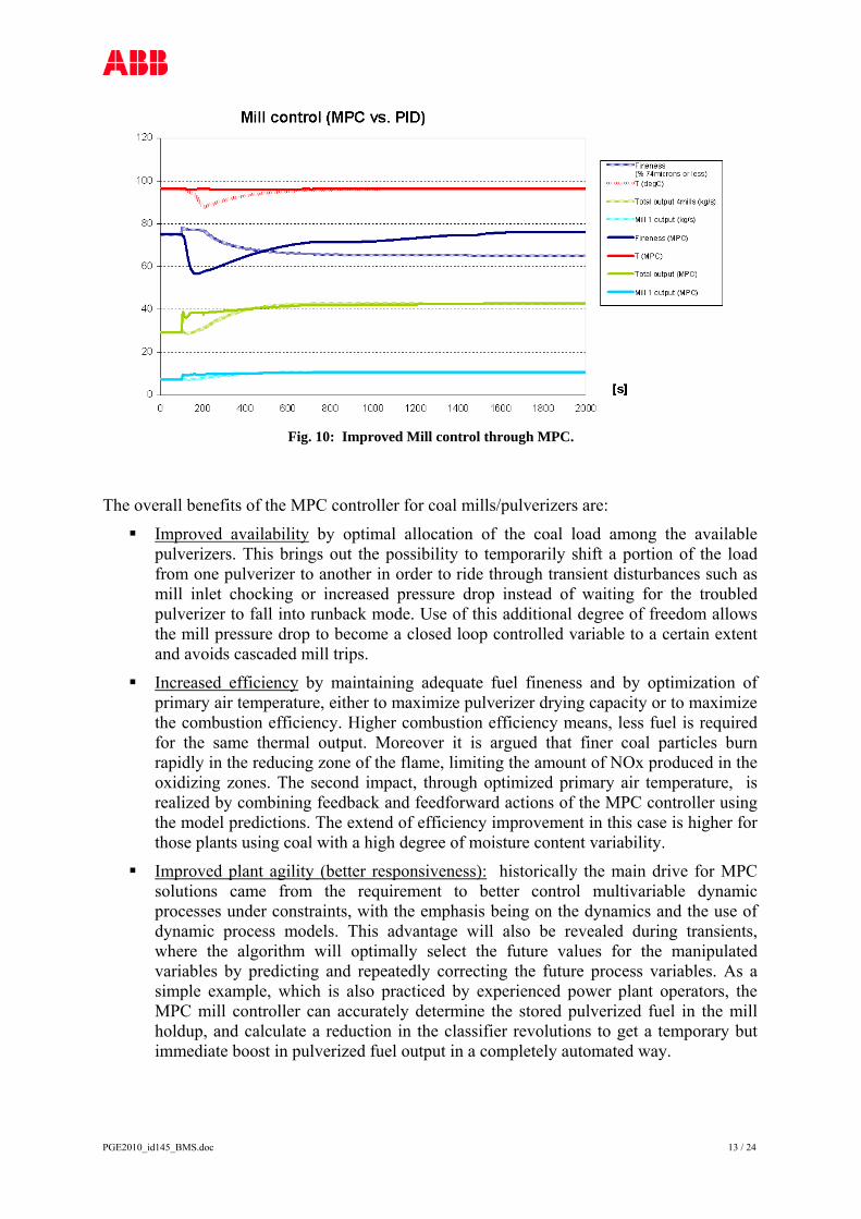
The control performance improvement of the MPC controller, compared to classic PID controls is illustrated in the example of Fig. 10:
Capability to control pulverized fuel quality (fineness), e.g. achieving the setpoint of 75% coal fineness of 74 microns (or less).
Tighter control of mill outlet temperature.
Faster control response (2x) for load changes (e.g. 70% load increase).
PGE2010_id145_BMS.doc 13 / 24
Fig. 10: Improved Mill control through MPC.
The overall benefits of the MPC controller for coal mills/pulverizers are:
Improved availability by optimal allocation of the coal load among the available pulverizers. This brings out the possibility to temporarily shift a portion of the load from one pulverizer to another in order to ride through transient disturbances such as mill inlet chocking or increased pressure drop instead of waiting for the troubled pulverizer to fall into runback mode. Use of this additional degree of freedom allows the mill pressure drop to become a closed loop controlled variable to a certain extent and avoids cascaded mill trips.
Increased efficiency by maintaining adequate fuel fineness and by optimization of primary air temperature, either to maximize pulverizer drying capacity or to maximize the combustion efficiency. Higher combustion efficiency means, less fuel is required for the same thermal output. Moreover it is argued that finer coal particles burn rapidly in the reducing zone of the flame, limiting the amount of NOx produced in the oxidizing zones. The second impact, through optimized primary air temperature, is realized by combining feedback and feedforward actions of the MPC controller using the model predictions. The extend of efficiency improvement in this case is higher for those plants using coal with a high degree of moisture content variability.
Improved plant agility (better responsiveness): historically the main drive for MPC solutions came from the requirement to better control multivariable dynamic processes under constraints, with the emphasis being on the dynamics and the use of dynamic process models. This advantage will also be revealed during transients, where the algorithm will optimally select the future values for the manipulated variables by predicting and repeatedly correcting the future process variables. As a simple example, which is also practiced by experienced power plant operators, the MPC mill controller can accurately determine the stored pulverized fuel in the mill holdup, and calculate a reduction in the classifier revolutions to get a temporary but immediate boost in pulverized fuel output in a completely automated way.
PGE2010_id145_BMS.doc 14 / 24
6 Coordinated Boiler/Turbine Control
6.1 Motivation The operating mode(s) for a unit consisting of a single boiler and turbine is dependent on the intended duty cycle for the unit:
Base Loading: the unit will be operated at a constant load (24/7).
Shift Loading: the unit will be operated at a constant load during each 8h shift, but the load may be changed or the unit banked from one shift to the next.
Day/Night Loading: the unit will be operated at a constant load during the day and either banked or shut down completely overnight.
Frequency Response: the unit will be operated at a nominal load (base, shift or day/night loading), but the actual load is modulated to compensate for electrical power system frequency disturbances.
Changing the intended duty cycle may require extensive physical modifications to the unit. Converting a base-loaded unit designed for fixed-pressure operation to a shift-loaded frequency response unit with dual-pressure operation may be totally impractical physically and/or cost prohibitive. However, if the equipment design will allow variable-pressure operation with only minor modifications, a control system which will accommodate fixed-pressure operation, variable-pressure operation and automatic transition between the modes can provide the benefits of both fixed-pressure and variable-pressure operation.
The Boiler/Turbine coordinated control strategy uses throttle pressure, generator megawatt and unit load demand signals as the basis for coordination of boiler and turbine. Throttle pressure indicates the energy balance between the boiler and turbine. Generator megawatt output indicates the turbine’s output and must match the unit demand established by the load dispatcher or operator.
Several operating modes are selectable by the operator through the automation of the boiler master, turbine master and unit master stations. These modes are summarized in Fig. 11.
Manual Mode: the Boiler Master and Turbine Master stations are in manual and the operator is responsible for controlling the unit load and throttle pressure.
Turbine Following Mode: the Turbine Master is in automatic and the Boiler Master in manual. In this mode, the turbine valves control throttle pressure and the operator establishes the unit load by setting the boiler demand.
Boiler Following Mode: the Boiler Master is in automatic and the Turbine Master in manual. In this mode, the boiler demand controls throttle pressure and the operator establishes the unit load by setting the turbine demand. The turbine valve demand rate of change is calculated from the unit load rate of change to provide smooth ramping of the unit.
Coordinated (Manual) Mode: the Boiler Master is in automatic, the Turbine Master is in automatic, and the Unit Master is in manual. In this mode, the control strategy coordinates the boiler and turbine to control throttle pressure and megawatts. The operator establishes the unit load from the Unit Master Station.
Coordinated (Auto) Mode: the Boiler Master is in automatic, the Turbine Master is

PGE2010_id145_BMS.doc 15 / 24
in automatic, and Unit Master (not shown) is in automatic. In this mode, the control strategy coordinates the boiler and turbine to control throttle pressure and megawatts. The remote dispatcher establishes the unit load demand.
Modes Boiler Master Turbine Master Unit Master Manual Manual Manual Manual Turbine Follow
Manual (Operator adjusts unit load)
Automatic (Controls TP)
Manual
Boiler Follow
Automatic (Controls TP)
Manual (Operator adjusts unit load)
Manual
Coordinated (Manual)
Automatic (Controls MWe - TP)
Automatic (Controls MWe + TP)
Manual (Operator adjusts unit load)
Coordinated (Auto)
Automatic (Controls MWe -TP)
Automatic (Controls MWe + TP)
Automatic (Dispatcher adjusts unit load)
Fig. 11: Boiler/Turbine classic operating and control modes.
6.2 Coordinated Control Mode In coordinated mode, the unit load demand establishes both the boiler and the turbine demands. The unit can respond rapidly to load increases by using the stored energy in the boiler and to load decreases by storing more energy into the boiler. The control philosophy is to follow load changes with minimum fluctuation in throttle pressure. Since the turbine is primarily responsible for controlling the steam flow to generate the required megawatt output, a limited megawatt error trims the unit load demand by offsetting the throttle pressure error. This allows an initial change in megawatts to be sustained until steam production in the boiler can catch up. The megawatt error is adjusted for fixed pressure or variable pressure operation. The boiler is responsible for supplying the required steam at the desired pressure and temperature. Thus, throttle pressure and megawatt error trims the boiler demand and maintains the desired energy balance.
Coordinated control recognizes that interaction between the boiler and turbine exists when maintaining both throttle pressure and megawatts. To reduce this interaction, the control uses the relationship of turbine valve position, throttle pressure, and megawatts. Thus, the turbine is trimmed by the difference between the megawatt error and throttle pressure error. The firing rate (boiler demand) is trimmed by megawatt error plus pressure error. This cross coupling prevents destabilizing interaction between the boiler and turbine controls.
For example, if both megawatts and pressure are 1% high, the transient correction to the turbine is zero, and the transient correction to the boiler is doubled. This is the correct control action as the turbine valves are in the correct position, but there is too much fire in the boiler.
Thus, in coordinated mode the turbine demand is developed as the difference of a limited megawatt error and throttle pressure error integrated to drive a trim controller that operates the turbine governor. The megawatt error is also adjusted by a function of the throttle pressure set point to account for changes in energy storage in the unit. The unit load demand establishes the turbine demand by converting the maximum continuous rating of megawatts into the turbine valve position. A dynamic function acts on the demand signal to overcome the inertia inherent in the turbine. The feedforward is then adjusted by a function
PGE2010_id145_BMS.doc 16 / 24
of throttle pressure set point for variable pressure operation. The feedforward plus feedback controller develop the turbine demand signal.
In coordinated mode, the boiler demand is developed as the sum of throttle pressure error and megawatt error that integrates a trim controller to modify the unit load demand. The throttle pressure error is adjusted by a function of the turbine valve position to account for nonlinear throttle pressure error sensitivity and the controller’s tuning is adjusted for changes in energy storage upon large load changes. The unit load demand establishes the boiler demand by converting the maximum continuous rating of megawatts into the maximum continuous rating of fuel. A dynamic function acts on the demand signal to overcome the inertia inherent in the boiler and changes in throttle pressure setpoint. More details can be found in [1].
6.3 Optional Coordinated Control Modes Free Pressure Operation is an optional coordinated control mode also referred to as “turbine valve point control” and exists as an add-on to the Boiler Turbine Coordinated Controls. In this mode, the method of operation for partial arc sequential turbine valves combines the concept of valves wide-open variable pressure operation and hybrid variable pressure operation. The control system will drive the turbine valves to one of several predetermined positions for steady load conditions. Load changes are then accomplished by changing the boiler steam pressure.
Turbine Valve Wide Open Operation is another optional coordinated control mode referred to as “valve wide open operation”. When the turbine valves reach maximum position, the boiler control must then try to regulate boiler demand for both megawatts and pressure. This cannot be done accurately or with good stability. To overcome this, the control system includes a turbine valve wide-open mode. In this mode, the boiler fires for megawatts and ignores throttle pressure as long as the pressure is between the operator set minimum and maximum throttle pressure limits.
6.4 Benefits Boiler/Turbine coordinated control provides the following benefits:
Operating flexibility for base load or ramp loading.
Coordinate with other subloops for safe operation.
Feedforward techniques to provide rapid response for unit load changes.
Adaptive tuning of model parameters to adjust for different load sensitivities.
Improved turbine life and reduced turbine maintenance costs in variable pressure operation through the relatively stable turbine inlet temperature.
7 Advanced Unit Control
The advanced unit control solutions achieve controlled startups/shutdowns and load changes of a power plant unit under economically optimized conditions, within the framework of primary grid frequency and secondary control demanded by the load dispatcher.
PGE2010_id145_BMS.doc 17 / 24
The primary grid frequency control of the unit is responsible for the balance between the power generation and consumption. The response time of this control is extremely short (few seconds) and is decisive for the grid stability in case of major disturbances of the power generation. Therefore a dynamic coordination of the grid-frequency error for turbine and boiler load has been introduced.
The grid secondary control (load-frequency control) is provided by a load dispatcher, who regulates the agreed load exchange between the interconnected power supply partners. Its control response time is in the range of minutes, where the units adapt their power generation according to the dispatcher demand signals.
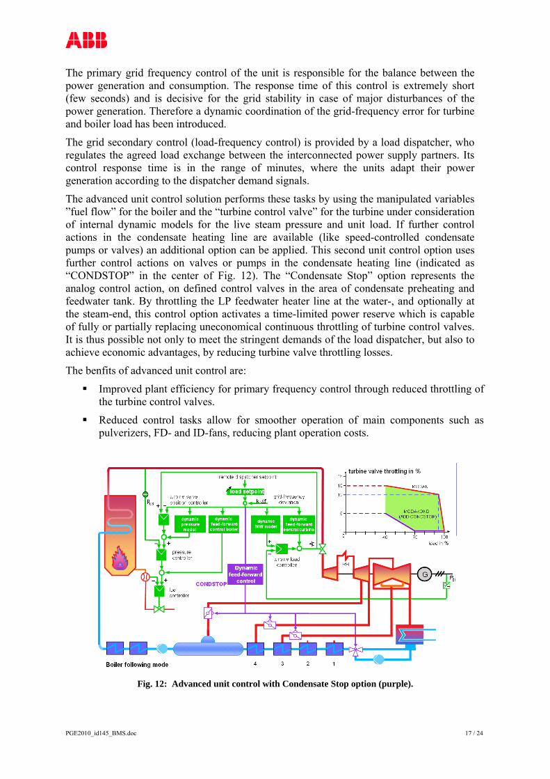
The advanced unit control solution performs these tasks by using the manipulated variables ”fuel flow” for the boiler and the “turbine control valve” for the turbine under consideration of internal dynamic models for the live steam pressure and unit load. If further control actions in the condensate heating line are available (like speed-controlled condensate pumps or valves) an additional option can be applied. This second unit control option uses further control actions on valves or pumps in the condensate heating line (indicated as “CONDSTOP” in the center of Fig. 12). The “Condensate Stop” option represents the analog control action, on defined control valves in the area of condensate preheating and feedwater tank. By throttling the LP feedwater heater line at the water-, and optionally at the steam-end, this control option activates a time-limited power reserve which is capable of fully or partially replacing uneconomical continuous throttling of turbine control valves. It is thus possible not only to meet the stringent demands of the load dispatcher, but also to achieve economic advantages, by reducing turbine valve throttling losses.
The benfits of advanced unit control are:
Improved plant efficiency for primary frequency control through reduced throttling of the turbine control valves.
Reduced control tasks allow for smoother operation of main components such as pulverizers, FD- and ID-fans, reducing plant operation costs.
Fig. 12: Advanced unit control with Condensate Stop option (purple).

PGE2010_id145_BMS.doc 18 / 24
8 FGD Control
Advanced control soutions for the Flue Gas Desulphurization (FGD) process can be formulated as a model predictive control problem with the overall objective of minimizing operations cost while maintaining the performance of FGD at desired level (Fig. 13). The performance variables to be controlled include gypsum quality, outlet SO2 concentration and oxidation reduction potential. The major cost to be minimized in FGD operation is the raw material cost of limestone which is the reagent in the FGD process, removing SO2 from the flue gas. Another FGD operations cost is the power consumption by pumps that recirculate the limestone slurry, and of fans that provide oxidation air.
The variables that can be manipulated to achieve the desired performance and minimize FGD operations cost include Liquid/Gas ratio (limestone slurry to flue gas mass flow rate ratio), limestone slurry pH, oxidation air flow, amount of additives, choice of spray level and amount of slurry at each spray level.
The cost of limestone in power plants is frequently the second largest, after fuel costs. The amount of limestone to be added depends on the flue gas flow rate and can be represented as Liquid/Gas ratio. The reaction rate is mainly limited by limestone dissolution rate, which in turn mainly depends on the pH of the slurry.
Fig. 13: FGD optimization.
9 Control of SCR and SCNR combined with Combustion Optimization
Selective Catalytic Reduction (SCR) is a post-combustion NOx reduction technology using ammonia/urea as a reagent. The reagent is added to the flue gas which then passes through a layer of catalysts which reduce NOx to N2. SCR reactions are generally effective in flue gas temperature range of 340 - 400degC but temperature imbalances of up to 150degC are common in a power plants due to changes in fuel type, fuel amount, fuel distribution and air supply. The most critical variable in the operation of Selective (Non)-Catalytic Reduction processes (SNCR/SCR) is the flue gas temperature during the reduction of NOx to N2. Above the specified temperature range for the reduction reaction, NH3 is oxidized to NOx and at low temperature there is a possibility of lower rate of reaction leading to an
PGE2010_id145_BMS.doc 19 / 24
unreacted portion of NH3, called ammonia slip.
This is one of the major problems in SCR processes, hence it is essential to avoid it, to achieve optimal operation of the SCR. There is a large time constant (~30’) associated with deposition of NH3 on the catalyst, and only when NH3 gets deposited on the catalyst, it is available for NOx reduction. But simultaneously, if maximum deposition is reached, the risk of ammonia slip is also large due to the saturation effect of the catalyst.
Therefore, an online estimate of deposited NH3 is needed, relative to maximum possible deposition. The first step towards getting on-line deposition estimates is to formulate a dynamic model that involves the deposition of ammonia, the measured variables and the actuating variables. The designed controller uses a high deposition degree, but avoids exceeding a safe value of it. With deposition close to maximum, the control avoids increasing the NH3 injection further.
The flue gas temperature depends on the combustion process and therefore depends on controlling the flue gas temperature as a part of the Combustion Optimization (COS) itself, by manipulating the O2 bias. This helps in reducing the temperature imbalances in the SNCR/SCR. However, NOx reduction measures such as air and fuel distribution can result in high carbon content in the fly ash. For example, the use of low NOx burners in the combustion process will help reducing the amount of NOx in the flue gas but at the same time increases the carbon content in the fly ash. Since fly ash is also a saleable product, it is important to maintain the carbon content within limits. So the carbon in ash (CIA) measurement in fly ash can be used as additional feed-forward variable, or as bounded variable in MPC. This measurement helps to achieve a better distribution of NOx removal between the combustion process and SCR reactors.
The system approach for this solution is to combine the Combustion Optimization and the SNCR/SCR optimization due to the obvious interaction between the two in terms of temperature. For example, if the CIA hits the upper bound, it is better to have more NOx removal in the SCR than in the combustion process itself, in order to keep the carbon in ash also within desired bounds.
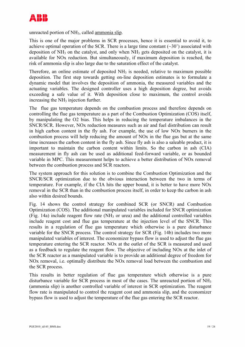
Fig. 14 shows the control strategy for combined SCR (or SNCR) and Combustion Optimization (COS). The additional manipulated variables included for SNCR optimization (Fig. 14a) include reagent flow rate (NH3 or urea) and the additional controlled variables include reagent cost and flue gas temperature at the injection level of the SNCR. This results in a regulation of flue gas temperature which otherwise is a pure disturbance variable for the SNCR process. The control strategy for SCR (Fig. 14b) includes two more manipulated variables of interest. The economizer bypass flow is used to adjust the flue gas temperature entering the SCR reactor. NOx at the outlet of the SCR is measured and used as a feedback to regulate the reagent flow. The objective of including NOx at the inlet of the SCR reactor as a manipulated variable is to provide an additional degree of freedom for NOx removal, i.e. optimally distribute the NOx removal load between the combustion and the SCR process.
This results in better regulation of flue gas temperature which otherwise is a pure disturbance variable for SCR process in most of the cases. The unreacted portion of NH3 (ammonia slip) is another controlled variable of interest in SCR optimization. The reagent flow rate is manipulated to control the reagent cost and ammonia slip, and the economizer bypass flow is used to adjust the temperature of the flue gas entering the SCR reactor.
PGE2010_id145_BMS.doc 20 / 24
Fig. 14: Combustion optimization combined with (a) SNCR and (b) SCR.
The benefits of combined SCR/SNCR and COS control are:
Exploiting the interaction between both processes to improve NOx control. To operate the SCR process at optimum levels, resulting in maximum NOx reduction
with minimum ammonia slip. Better flue gas temperature regulation using the variables from both COS (air flows)
and SCR (economizer bypass flow).
10 Load Scheduling Optimization
Utilities need to continuously minimize operation and maintenance costs and improve their commitments for bidding in their markets. For this reason, they need decision-support tools to determine their optimal operation strategy taking into account their existing constraints. Bes the APC solutions for advanced closed-loop control, described above, a further minimization of operating costs can be achieved with the aid of Load Scheduling Optimization (also know as Unit Commitment).
Because of the wide variety of demands on plant operations, anywhere from a few minutes to weeks, optimized load scheduling can take a wide range of time horizons into consideration. Unit or component models for power generation and water utilities can take static, dynamic and integral factors into account. These factors include fuel heat consumption as a function of generated power, auxiliary consumption, minimum standstill period, minimum operating time, load gradient limitation, hot start/cold start, limitations on operating time, limitations on production quantities, limitations on storage and limitations on startup frequency.
In addition, the solution is able to model lifetime consumption of critical equipment (ageing), as well as emission costs and constraints.

PGE2010_id145_BMS.doc 21 / 24
Supply contracts can take factors into account such as kWh rates for time of day, time of year, power supplied, quantity supplied and, in the case of heat supply contracts, a rate scale for the district heat outlet temperature.
Once a load forecast has been specified, an operating schedule with startup and shutdown points (unit selection) and power/heat generation schedules (load scheduling) is determined.
Fig. 15: Example of a model for Load Scheduling Optimization of multiple units.
Fig. 16: Forecasted power/steam demand, and corresponding optimized generation schedule.
11 Monitoring and Maintenance Solutions
Before any kind of optimization and control decisions are made, plant managers need to know how efficient their plant and equipment is working. Regardless of a plant’s age, the major portion of a power plant’s lifecycle costs is attributed to fuel and operation, whereas maintenance represents most of the remaining costs. Minimizing these costs and improving predictive maintenance are the key objectives of the operation and maintenance staff. Such solutions belong to the upper layer of Boiler Management Systems, as mentioned above (indicated in Fig. 2).
PGE2010_id145_BMS.doc 22 / 24
To help them achieve these objectives, the Performance Monitoring system is an application designed for real-time monitoring of plant and equipment performance. It facilitates online or offline analysis of the process so that the user can determine how current operating conditions affect, for example, the plant heat rate and therefore plant fuel costs.
Such a system is based on steady-state calculations and can run cyclically or on-demand. Its main task is to calculate deviations between actual and expected plant Key Performance Indicators (KPIs) and its main equipment at current operating conditions.
The task of accurately monitoring and predicting plant performance, however, involves more than simply calculating the expected power and efficiency of the plant. The calculation of detailed performance values (pressures, temperatures, flows, etc.) at several hundred locations throughout the plant has become a standard requirement. Short- and long-term equipment degradation of individual components can only be recognized if deviations from the best achievable (expected) efficiency levels are clearly identified.
The Lifetime Monitoring system for boilers is used by power plant operators and engineers to provide them with automatic monitoring and prediction of critical component exhaustion in boilers and turbines.
The rotating machinery Condition Monitoring system monitors bearing vibration, eccentricity and axial rotor position on any type of rotating machinery. It can also measure rotor-to-case differential and case expansion of a turbine shell. The machinery protection function, along with operator information is integrated in the DCS. Powerful graphical analysis tools recognize patterns and trends in data. Correlating machinery data with process data often leads to quicker and better conclusions. When an alarm, a runup, a rundown or a plant trip occurs, Condition Monitoring modules send their time waveforms to their data server over Ethernet. In addition, a time waveform is stored periodically for each vibration measurement.
Continuous Emission Monitoring Systems (CEMS) consist of complete measurement and analysis systems calculating chemical or physical composition of emissions in real-time. This is key to providing tight control for the combustion process as well as the downstream FGD and SCR processes. In addition, the CEMS system provides alarming and reporting funtions according to compliance rules defined by environmental authorities.
The benefits of these monitoring and maintenance solutions within the Boiler Management System, are:
Early detection of deviations and decision support for pro-active maintenance. Verification of performance improvements in plant processes. Detection of faults, which may lead to shortened service life. Documented evidence of operational use of equipment. Long-term maintenance planning. Potential for reduced inspection frequency. Certified report generation of performance, service life and emissions, for authorities.
12 Instrumentation
Besides standard process instruments in and around the boiler, additional dedicated

PGE2010_id145_BMS.doc 23 / 24
combustion instruments provide added value to Boiler Management Systems.
The Carbon-In-Ash instrument (CIA) is a real-time non-extractive monitoring system which incorporates advanced microwave technology for reliable, accurate measurement of unburned carbon in the fly ash. In addition, the CIA instrument measures the quality and the quantity of the ash produced in the boiler. Good quality ash may be sold as a profitable by-product for the construction industry instead of having to pay for its disposal in costly landfills. Other benefits of the CIA instrument are:
Non-extractive on-line measurement. Accurate measurements in real-time (1% absolute across duct width). Complete in-situ measurement methodology. Reduction of unburned carbon in ash when integrated in a Boiler Management system.
Flame Scanners are designed as multi-fuel scanners to provide stable and reliable information of both the flame consistency and the flame quality on utility and industrial boiler burners. They contain a solid state sensor module, covering the entire flame radiant spectrum (UV-Vis-IR and dual sensor UVIR), and have redundant communication channels to the Boiler Management System. The Pulverized Fuel flow device (coal flow) provide real-time measurements of PF distribution (PF split), velocity and mass flow-rate. The device is based on a non-intrusive, passive measurement across the entire coal pipe cross-section and is virtually unaffected by PF roping. Other benefits are:
The real-time use of velocity information for trimming of primary mill air. Mills that have multiple coal pipes exiting the classifier can use control valves to
balance the fuel distribution. The real-time feedback allows tuning of coal flow distribution, and control of
secondary air at the burners to balance the combustion at individual burners.
13 Conclusions
A Boiler Management System (BMS) consists of different layers of instrumentation, control and optimization solutions, in and around fossil-fired boilers. In the past, each of the solutions typically addressed a sub-system of the boiler, but rarely spanned across multiple sub-systems having complex interdependencies. Today’s developments in instrumentation and controls allow a broader system-approach, i.e. the strength of a BMS lies not in the individual solutions, but in the capability to connect those solutions together and thus achieve better results. The BMS therefore consists of integrated coordinated control and optimization solutions between different boiler sub-systems.
The underlying technology to implement Advanced Process Control and Optimization solutions is based on multivariable Model Predictive Control (MPC). Such solutions deliver superior performance over traditional single-input single-output control strategies and are able to implement the necessary optimization algorithms. This has paved the way for wider applications such as startup optimization, combustion optimization, monitoring and control of coal mills, optimization of DeNOx and DeSOx processes, etc.
The benefits of a BMS range from faster ramping rates, reduced emissions, improved plant stability and availability, and higher plant efficiency.
PGE2010_id145_BMS.doc 24 / 24
14 References
[1] “Boiler Tuning Basics, Parts 1 and 2”, Tim Leopold, Power Magazine, March and May 2009.
[2] “Model Predictive Control and Optimization improves Plant Efficiency and lowers Emissions”, P. Immonen, T. Matsko, M. Antoine, PowerGen Asia 2008.
[3] “Reducing Operating Costs and Saving Resources”, R. Franke, M. Antoine, PowerGen Asia 2007.
[4] „Model Predictive Control for Optimized Startup of Boilers“, M. Rode, R. Franke, K. Krüger, ABB Review 3/2003.
15 Acronyms
APC Advanced Process Control COS Combustion Optimization System CV Control Variable DCS Distributed Digital Control System FGD Flue Gas Desulphurization MPC Model Predictive Control MV Manipulated Variable MVPC Multivariable Model Predictive Control NMPC Nonlinear MPC OFAD Over-Fire Air Damper SCR Selective Catalytic Reduction SNCR Selective Non-Catalytic Reduction WB Wind Box