Hot Spot Removal System - INL Digital Library
280
Idaho National Engineering Laboratory INEEL/EXT-97-00666 Hot Spot Removal System: System Description LOCKHEED MART V I September 1997
-
Upload
khangminh22 -
Category
Documents
-
view
6 -
download
0
Transcript of Hot Spot Removal System - INL Digital Library

IdahoNational
EngineeringLaboratory
INEEL/EXT-97-00666
Hot Spot Removal System:System Description
LOCKHEED MART V I
September 1997

INEEL/EXT-97-00666
Hot Spot Removal System:System Description
Published September 1997
Idaho National Engineering and Environmental LaboratoryLockheed Martin Idaho Technologies Company
Idaho Falls, Idaho 83415
Prepared for theU.S. Department of Energy
Assistant Secretary for Environmental ManagementUnder DOE Idaho Operations Office
Contract DE-AC07-941D13223

ABSTRACT
Hazardous wastes contaminated with radionuclides, chemicals, andexplosives exist across the Department of Energy complex and need to beremediated due to environmental concerns. Currently, an opportunity is beingdeveloped to dramatically reduce remediation costs and to assist in theacceleration of schedules associated with these wastes by deploying a Hot SpotRemoval System. Removing the hot spot from the waste site will remove riskdriver(s) and enable another, more cost effective process/option/remedialalternative (i.e., capping) to be applied to the remainder of the site.
The Hot Spot Removal System consists of a suite of technologies that willbe utilized to locate and remove source terms. Components of the system canalso be used in a variety of other cleanup activities.
This Hot Spot Removal System Description document presentstechnologies that were considered for possible inclusion in the Hot SpotRemoval System, technologies made available to the Hot Spot Removal System,industrial interest in the Hot Spot Removal System's subsystems, the schedulerequired for the Hot Spot Removal System, the evaluation of the relevanttechnologies, and the recommendations for equipment and technologies as statedin the Plan section.
iii

iv

EXECUTIVE SUMMARY
Background
More than 3,000 inactive waste sites have been identified at U.S.Department of Energy (DOE) facilities, including ponds, basins, pits, piles,injection wells, spill areas, and landfills. Even though the waste sites have beenidentified, the extent and complexity of subsurface contamination is largelyunknown. This is a result of several factors, such as incomplete recordsdescribing quantities and types of chemicals disposed of at individual wastesites. At some sites, a disparity exists between the chemicals reported to havebeen disposed of and those that were analytically determined to be in theunderlying ground waters.
The waste sites were created in the early days of DOE whenenvironmental disposal was an acceptable practice. However, many of theindividual chemical constituents in the wastes streams are now considered ahealth and/or environmental risk, and are either regulated under federal and statelaws or are currently under evaluation for regulatory control.
The Office of Environmental Management (EM) mission will bring DOEsites into compliance with all environmental regulations while minimizing risksto the environment, human health, and safety. The responsibility for managingthe cleanup of DOE waste sites belongs to the DOE Office of EnvironmentalRestoration and Waste Management (EM-40). Many of the waste sites havebeen classified in terms of the preferred remedial option, such as removal andtreatment, in situ treatment, containment, institutional controls, or no action.Removal and treatment is further defined into two divisions: selective or full-retrieval sites. Selective retrieval is the removal by excavation of selectedcontaminants of concern from a waste stream. Full retrieval is the removal byexcavation of the entire waste stream.
The development of the Hot Spot Removal System (HSRS) under EM-50(the Office of Science and Technology) for use by EM-40 is part of EM-40'swaste site cleanup effort. The purpose of HSRS is to locate and remove hotspots at selective retrieval and small-scale (<l,000-yd3) full-retrieval locations.Approximately 25% of the sites across the DOE complex that have a preferredoption for retrieval are planning to perform some type of selective retrieval.Selectively removing source term hot spots provides a number of cost savingbenefits. Selective removal of hot spots reduces the risk associated with the areaand allows less costly excavation methods to be used in remediating theremainder of the site. At some sites, selectively removing hot spots couldpreclude full retrieval as the remedial action. This would reduce the totalvolume of waste that is removed at a number of sites, subsequently reducing theoverall cost of retrieval, assay, handling, treatment, storage, and disposal. Othersites could benefit from less stringent controls for retrieving the remainder of thesite after the hot spot is selectively removed. This would reduce costs andaccelerate remediation schedules. The potential for making an impact on

EM-40's mortgage, by remediating landfills using selective retrieval rather thanfull retrieval, is considered significant.
In order to understand the types of sites that HSRS must operate in, theSubsurface Contaminants Focus Area System's Engineering Project collectedand summarized DOE landfill site information and then determined which ofthose sites would be applicable for hot spot removal. The data needed toaccomplish this task were obtained from historical records, interviews with sitemanagers, and from actual site visits. Fourteen sites were identified whereselective retrieval was the preferred remedial action. Additional DOE sites havesince been identified as good candidates for HSRS. Nine of these additionalcandidates include sites where the entire contaminated waste stream is less than1,000 yd3. Other candidate sites include those that will require remoteoperations and/or stringent contamination control measures during retrievalactivities. Selective retrieval might be used at these sites to realize substantialcost savings in a subsequent full-scale retrieval.
In addition to the DOE sites, 31 potential sites were identified for hot spotremoval using Internet key word searches, as well as a line-by-line search of theNational Priority List established by the Environmental Protection Agency. Asan example, HSRS could be used to selectively retrieve extremely hazardouswastes, such as unexploded ordnance or alpha radiological contamination. Theremainder of the site could then be remediated using more conventional and lesscostly methods.
An overall objective established by DOE is that HSRS must be capable oflocating and removing hot spots from 90% of the identified DOE selectiveretrieval sites. The 14 sites were studied to develop the draft Hot Spot RemovalSystem Requirements Document, which outlines the requirements that will beused in the design and selection of a Hot Spot Removal System.
The next phase of the project involved conducting benchmarking studiesto determine relevant technologies and equipment that are currently available orare emerging in industry as well as within DOE. The benchmarking effortinvolved (1) gathering information from vendors by placing advertisements inthe Commerce Business Daily, (2) searching DOE databases, and (3) performingInternet searches. Due to the volatile environment in which HSRS would beused (unexploded ordnance, volatile organics, pyrophorics, and transuranicwaste with high alpha concentrations), it is necessary to limit the exposure ofpersonnel to the waste terms according to As Low As Reasonably Achievable(ALARA) standards. Thus, the majority of the HSRS retrieval activities will beimplemented using teleoperated (remotely controlled) equipment.
Alternatives identified during benchmarking were evaluated based on therequirements defined in the draft Requirements Document and by means of adecision analysis methodology developed by the Air Force Institute ofTechnology based on the Environmental Protection Agency's ComprehensiveEnvironmental Responsibility, Compensation, and Liability Act criteria. Thesecriteria can be found in detail in Section 6 of this report. This decision analysis
vi

methodology was designed to evaluate completely different technologies for agiven task; however, it was slightly modified to allow the evaluation of similartechnologies to accomplish the same task. For example, the main categoriesfound in the process, with modified subcategories, were used to evaluate thedifferent excavators to determine which one would be best suited to HSRS.Through this process, some gaps were identified. An overall strategy wasdeveloped to meet these requirements, to obtain necessary equipment (purchaseor partner), and to fill technology gaps. This strategy is discussed in detail inSection 7.
This report provides a description of the technologies and equipment thatwere considered for use in HSRS, the evaluations that were performed onapplicable equipment or technologies, the recommendations forequipment/technologies that should be included in HSRS, and the gaps in thecorresponding technologies.
As HSRS will be adaptable to many different sites and contaminants ofconcern, a suite of technologies were identified from existing and developingtechnologies, not all of which will be used at all sites. Specific equipmentinformation is included in this report but is not necessarily recommended due tothe fact that most of the equipment to be used in HSRS can be provided by anumber of vendors or companies. As a result, Requests for Proposals must beused in order to determine the exact equipment to be used in the system. Withthe exception of a few subsystems, a competitive bid can be used to acquire thenecessary equipment. Only a couple of the subsystems require engineeringdesign time and fabrication.
Before deploying HSRS at a particular site, all of the documentation,safety analyses, and historical records will be used to determine thosetechnologies that should be mobilized for a particular site. The proposed HSRSequipment and technologies are applicable for use at the majority of theidentified selective retrieval sites.
Results
The overall HSRS was divided into a number of subsystems according totheir function. These subsystems include characterization, contaminationcontrol, retrieval, waste separation/segregation, waste minimization, wastesizing, waste packaging/transfer, and decontamination. Control and visionsystems are incorporated into each of the previously mentioned subsystems. Theequipment and technologies that have been proposed for inclusion in HSRS are
based on currently available data from the 14 DOE selective retrieval sites.
Characterization
Geophysical, radiological, and chemical characterization will be needed inorder to identify the location, geometry, or concentration of large buried objects
vii

and contaminants of concern, as well as to verify that the hot spot has beenremoved following the selective retrieval.
The types of sensors and detectors that can be used for characterization aredependent on the contaminants of concern, and will thus be chosen for each siteindividually. A list of the recommended sensors for each of the 14 representative
sites has been created (Section 2.2). As HSRS will consist of a suite of sensorsfor characterization, several sensors would be available to choose from. FiguresES-I through ES-3 reflect the frequency of usage at the 14 identified selectiveretrieval sites.
There are a few gaps (deficiencies) in the technologies for the geophysicalsensors, radiological sensors, and chemical sensors. It is recommended that theseissues be addressed prior to their use in HSRS. The gaps for each of the abovetechnologies are outlined in Sections 2.2 and 7, but are touched on here forinformation purposes.
3%
36%
Geophysical Sensors
39%
Figure ES-1. Frequency of usage of geophysical sensors.
viii
u Electromagnetic
■ Magnetica Ground Penetrating Radar
a Acoustic
■ Direct Current• Induced Polarization

46%
Chemical Sensors
a Laser-Induced BreakdownSpectroscopy
■ Infrared Spectrometer
o VOC Sensor
▪ X-Ray Fluorenscence
18%
Figure ES-2. Frequency of usage of chemical sensors.
Radiological Sensors
10%
• Plastic Scintiliator
■ Three Layer XenonProportional Counter
a Calcium Fluoride Detector
Ge Spectrometer
Figure ES-3. Frequency of usage of radiological sensors.
ix

The real-time field geophysical sensors would require some research toimprove poor resolution capabilities, to provide a means of distinguishingbetween metal types, and to gain a better understanding of the relationshipbetween the measured physical and chemical properties.
A number of gaps in technology exist for real-time radiological sensors.Further development on plastic scintillators is required to determine electroniccutoff energies in order to convert count rates to radioactivity levels. A methodneeds to be developed in order to use germanium detectors with and without ashield. In addition, at present, no effective in situ analysis techniques exist forthe detection of 14C and 99Tc. None should be expected either, due to the lowactivity levels expected at waste sites.
Real-time field chemical characterization also presents sometechnological deficiencies. Some of the deficiencies that need to be improvedwith chemical characterization include (1) detecting volatile organics that cannotcurrently be detected, (2) reducing air currents that tend to disperse vaporsemanating from the digface, and (3) increasing the effectiveness of gas samplingsensors when foams or mists are used for dust suppression.
Contamination Control
Contamination control is a major driver of HSRS at sites that have alphacontamination because the risk of spreading alpha contamination throughout thesite is high. The threat of contamination spread leads to greater problems indecontamination, releases to the environment, and personnel exposure. As aresult, an aggressive means of contamination control is highly recommended forkeeping the generation of dust at the digface to a minimum.
One defense against fugitive dust is the use of a confinement enclosure inconjunction with a ventilation system. This would be used at all sites havingTRU waste. In addition, secondary contamination control methods would beused at each site, and would include a suite of technologies to choose from foreach site, depending on soil conditions, contaminants of concern, etc..
The suite of technologies that could be used might consist of a systemwhich applies different foams, soil fixatives, and water/dust suppressant misters;in situ soil stabilization; jet-grouted cement subsurface barrier walls (to allowvertical excavation); electrostatic curtains; electrostatically charged plastic;vacuum systems; and the encapsulation (cocooning) of the waste packages withparaffin to prevent the spread of contamination.
The recommended contamination control technologies to be included inHSRS are shown in Figure ES-4. This figure reflects the frequency of usage foreach contamination control method with respect to the 14 identified selectiveretrieval sites.
Some specific gaps would have to be addressed prior to using theproposed contamination control strategy. The ventilation system would have tobe designed for the specific confinement enclosure used in HSRS, and a local

18%
Contamination Control Suite
18% 18%
18%
28%
U ContinementStructurewithVentilationSystem
■ ContarninationControlUnit
▪ InSituJet-groutedpilings
O InSituStabilization
■ ElectrostaticCurtains
Figure ES-4. Frequency of usage of contamination control technologies.
ventilation method would have to be designed for use with the retrievalequipment used in HSRS.
Engineering and fabrication work would have to be accomplished prior tousing an agent to stabilize the waste in situ. A few of these tasks include fieldtesting to determine if a particular agent will work at a given site; a spoils returnmanagement strategy; physical properties determination of an agent, as it couldchange the resistivity, dielectric permeability, and acoustic velocity, thus affectinggeophysical characterization; and density determination of the waste matrix/agentcomposition prior to characterization, as the sensitivity of the radiological sensorswould be affected and would have to be adjusted for the new density. These arejust a few of the tasks required prior to using a stabilization agent. A fulldescription of all of the tasks required is presented in Section 7.
There is some promise in using microbial polymers as an in situstabilization medium, as they are biodegradable, and thus can be removed easilyfrom the site following retrieval, if desired. Field testing should be performed onthis agent type to determine its applicability to the HSRS. A full description of thistechnology is presented in Section 2.3.7.4.
In order to use electrostatic curtains as a means of contamination control for alphacontamination, a secondary enclosure must be designed and built from electrostatic curtainmaterials. At this time, electrostatic curtain technology must be developed to operate in a full-scale capacity. This enclosure will surround the excavation pit and provide access holesthrough which the retrieval equipment will work, thus providing a form of "dust shield" forthe equipment. These access ports would have seals between the enclosure and the equipmentto prevent leaks. Contamination Control Unit, digface monitoring equipment,
XI

shredder, and parts of the waste transfer system would be located inside thiselectrostatic curtain enclosure.
Retrieval
Retrieval equipment is necessary for the removal of the contaminated soiland buried objects at the waste site. In general, the only piece of heavyequipment needed for use in this type of application is a teleoperated excavator,which is fully developed. Companies offer units capable of remote operationfrom greater than a mile away with collision avoidance sensors and visionsystems.
An excavator of the 60,000-lb class is recommended for use at the digfaceto allow for the removal of 4,000-lb objects within the entire working envelopeof the excavator. Also, a comparably sized excavator would allow for the use ofan overburden removal end-effector when needed.
A standard heavy duty bucket with a hydraulic thumb is recommended forthe excavator's end-effector. Other end-effectors, including a Vacuum systemfor sludge removal within casks, may be necessary for a few activities.
While most of the equipment intended to be used for retrieval in HSRS iswell developed, a major gap does exist. Integrating the excavator's control,lighting, and vision systems with other HSRS subsystems could prove to bedifficult. A supervisory control system is necessary for controlling the multiplesubsystems in HSRS. At this time, none of the supervisory control systems thathave been identified are fully capable of controlling all of the remotely operatedequipment.
Waste Separation and Segregation
As a result of using in situ stabilization, the separation of the wastestream, according to radioactivity level, contaminant of concern, etc., will not beconsidered as part of HSRS. However, equipment has been identified forpossible inclusion into the system, if deemed necessary for some sites.
Waste Minimization
HSRS is by definition a waste minimization system. The concentratedwaste is removed from the soil, which allows for more conventional andinexpensive methods to be used for remediation of the rest of the site. Becausehot spots are smaller areas of concern, further waste minimization or reductionmay be considered unnecessary.
Equipment does exist that is capable of reducing the volume of waste thatis removed from the proposed sites. Standard waste compactors are available inmany different sizes with very high compacting forces. These compactors are
xii

standard in industry and could be added to HSRS in the future if deemednecessary by a given site.
Waste Sizing
Waste sizing equipment may be necessary at sites with large objectsburied in the soil. In order to package these large objects into standard wastecontainers, the objects must be reduced to required dimensions.
A few options are available for use in waste sizing in HSRS. However,after an evaluation of these different sizing methods was performed, the methodof shredding was found to be the most applicable sizing technology forapplication to the 14 DOE selective retrieval sites.
A number of gaps do exist for shredders being used in a mixed wasteenvironment. Unexploded ordnance, volatile organics, and pyrophorics will bepresent. As a result, the shredder must be capable of handling explosions andfire, and operate under a negative pressure. These types of modifications can beperformed on most existing equipment.
Waste Packaging and Transfer
A transfer system will be needed inside and outside the confinementenclosure to move the waste from the digface (1) to the packaging system, (2) tothe decontamination station, and (3) out of the facility to the transport vehicle.
An overhead trolley crane system will need to be designed and fabricatedspecifically for the needed operations within the facility. The transfer unitoutside of the confinement enclosure will determined from site requirements.
Decontamination
Waste boxes that have been filled with waste will be lifted up by theoverhead trolley crane system to be sprayed and covered with an encapsulationagent to prevent the spread of contaminants. The transfer system will thentransport the containers to the airlock doors for removal from the confinementenclosure. As a result, the waste boxes never come in contact with the floor ofthe site after encapsulation, thus preventing them from becoming contaminated.
A hot water bath will be used to decontaminate the equipment that is mosthighly contaminated, which in this case will be the excavator's end-effector.After the end-effector is decontaminated, the ventilation system will be run for asufficient amount of time to safely allow manned entry.
Standard decontamination methods will be used to clean equipmentduring manned entry of the confinement enclosure.

Control System
Separate control systems are available for each subsystem in HSRS.However, engineering time and funds will be needed to develop the protocols forinteraction between each piece of equipment.
Vision System
The vision system for HSRS will provide the primary feedback tooperators for the entire system. At this time, a combination of stereoscopic andtwo-dimensional cameras and monitors is recommended. The visiontechnologies are very well developed and will be subjected to a competitive bid.
Summary
The Hot Spot Removal System, as described in this report, offers a suiteof technologies to locate and remove hazardous wastes contaminated withradionuclides, chemicals, and explosives at sites across the DOE complex.Components of HSRS can be used in a variety of selective and small full-scaleretrieval activities.
xiv

ACKNOWLEDGMENTS
This document was authored by the Hot Spot Removal System Team,consisting of Michelle Dahlmeir, Robert Gehrke, Richard Helmer, Reva Hyde,Nick Josten, Cathy Pfeifer, Doug Stacey, and Steven Swanson. The authorswish to acknowledge the vendors who provided knowledge about variousequipment discussed in this document.
xv

xvi

CONTENTS
ABSTRACT iii
EXECUTIVE SUMMARY
ACKNOWLEDGMENTS xv
ACRONYMS xxv
1. INTRODUCTION 1-1
1.1 Background 1-1
L2 Objective 1-1
1.3 Applications 1-2
2. IDENTIFICATION AND SCREENING OF TECHNOLOGIES 2-1
2.1 Candidate Technology Identification Procedure 2-1
2.2 Characterization 2-2
2.2.1 Geophysical Characterization 2-22.2.2 Radiological Characterization 2-122.2.3 Chemical Characterization 2-20
2.2.4 Characterization Sensor Deployment 2-24
2.2.5 Other Sensor Deployment Platforms 2-27
2.3 Contamination Control 2-28
2.3.1 General Description 2-28
2.3.2 Requirements 2-29
2.3.3 Confinement Enclosure 2-30
2.3.4 Ventilation System 2-31
2.3.5 Foams 2-33
2.3.6 Sprays and Water Misters 2-36
2.3.7 In Situ Soil Stabilization 2-392.3.8 Electrostatic Curtains 2-52
2.3.9 Electrostatically Charged Plastic 2-53
2.3.10 Dust Suppression/Soil Fixatives 2-53
2.3.11 Vacuum System 2-57
2.3.12 Encapsulate/Cocoon Waste 2-57
xvii

2.4 Retrieval 2-59
2.4.1 General Description 2-592.4.2 Remotely Operated Excavators 2-592.4.3 Cranes 2-792.4.4 End-Effectors 2-852.4.5 Mining Technologies 2-95
2.5 Waste Separation/Segregation 2-97
2.5.1 General Description 2-972.5.2 Requirements and Applications 2-972.5.3 Technologies 2-98
2.6 Waste Minimization 2-104
2.6.1 General Description 2-1042.6.2 Requirements and Applications 2-1042.6.3 Compactors 2-104
2.7 Waste Sizing 2-107
2.7.1 General Description 2-1072.7.2 Arc Saw Cutting 2-1082.7.3 Plasma Arc Cutting 2-1092.7.4 Oxygen Burning 2-1112.7.5 Hacksaws and Guillotine Saws 2-1122.7.6 Shredding 2-1132.7.7 Cryogenic Fracturing 2-1142.7.8 Abrasive Cutter 2-1152.7.9 Thermite Reaction Lance 2-1162.7.10 Laser Cutting 2-1162.7.11 Water Jet Cutting 2-1182.7.12 Abrasive Jet Cutting 2-1202.7.13 Cryogenic Cutting 2-1212.7.14 Shears 2-1222.7.15 Pipe and Wire Cutters 2-123
2.8 Waste Packaging/Transfer/Sizing 2-123
2.8.1 General Description 2-1232.8.2 Ground Level Transport 2-1242.8.3 Above-Ground Transport 2-1282.8.4 Sizing/Packaging 2-1282.8.5 Double Door Systems 2-129
xviii

2.9 Decontamination 2-130
2.9.1 General Description 2-1302.9.2 Decontamination Requirements 2-1302.9.3 Mechanical Decontamination 2-1312.9.4 Strippable Coatings 2-1332.9.5 Decontamination Chambers 2-1342.9.6 Chemical Decontamination 2-136
2.10 Remote Vision/Telecommunication 2-138
2.10.1 General Description 2-1382.10.2 Remote Vision Requirements 2-1412.10.3 Pipecrawler 2-1432.10.4 Skycam TM 2-1432.10.5 Stereoscopic Vision 2-1442.10.6 FERRET 2-1442.10.7 LVA-1 2-1452.10.8 Virtual Interactive Enhanced Workstation (VIEW) 2-1452.10.9 Franklin Scanner 2-1462.10.10 Camera-Aided Virtual Reality Builder (CAVRB) 2-1462.10.11 TRICLOPS 2-1472.10.12 Excavator Vision 2-1472.10.13 MAR-512 2-1482.10.14 Laser Ranging Telerobot 2-1492.10.15 Andros Robots 2-1492.10.16 Vision Components 2-1492.10.17 Scout 2-1502.10.18 3D Laser Camera 2-1502.10.19 Gamma / X-ray Imaging System 2-1512.10.20 VE-379 2-1522.10.21 General Issues/Gaps in Vision Technology 2-152
2.11 Control System 2-152
2.11.1 General Description 2-1522.11.2 Control System Requirements 2-1532.11.3 VME Control System 2-1532.11.4 Supervisory Control System 2-1542.11.5 Enabling System Software/Generic Intelligent System Control 2-1552.11.6 SICOR Control System 2-1552.11.7 VERO 2-156
3. AVAILABLE TECHNOLOGIES 3-1
3.1 T-Rex 3-1
3.2 Contamination Control Unit 3-2
xix

3.3
3.4
3.5
Cooperative Telerobotic Retrieval System
Rapid Transuranic Monitoring Laboratory
Digface Characterization System
3-3
3-4
3-5
4. INDUSTRY INTEREST 4-1
4.1 RAHCO International 4-1
4.2 Sage Earth Sciences 4-1
5. SCHEDULE 5-1
6. ALTERNATIVE EVALUATION/TECHNICAL SCREENING OF TECHNOLOGIES 6-1
6.1 Site Characterization 6-2
6.2 Contamination Control 6-2
6.2.1 In Situ Stabilization 6-26.2.2 Confinement Enclosure 6-56.2.3 Discussion 6-9
6.3 Retrieval 6-9
6.4 Waste Separation/Segregation 6-16
6.5 Sizing 6-16
6.6 Waste Minimization 6-17
6.7 Waste Packaging 6-18
6.8 Decontamination 6-18
6.8.1 Confinement Enclosure 6-186.8.2 Excavator 6-186.8.3 End-Effector 6-196.8.4 Waste Packages 6-20
6.9 Waste Transfer 6-23
6.10 Vision Systems 6-25

7. THE PLAN 7-1
7.1 Characterization 7-1
7.1.1 Recommendations 7-17.1.2 Gaps in Characterization Technology 7-4
7.2 Contamination Control Strategy 7-7
7.2.1 Recommendation 7-77.2.2 Gaps in Technology 7-10
7.3 Site Preparation and Equipment Staging 7-12
7.3.1 Overburden Removal 7-127.3.2 Site Preparation 7-127.3.3 Equipment Staging 7-12
7.4 Contaminated Soil Removal 7-13
7.4.1 Recommendation 7-137.4.2 Gaps in Technology 7-13
7.5 Waste Separation/Segregation 7-13
7.6 Sizing and Packaging 7-14
7.6.1 Recommendation 7-147.6.2 Gaps in Technology 7-14
7.7 Decontamination 7-15
7.7.1 Recommendation 7-157.7.2 Gaps in Technology 7-15
7.8 Remote Vision 7-15
7.8.1 Recommendation 7-157.8.2 Gaps in Technology 7-16
7.9 Control System 7-16
7.9.1 Recommendations 7-167.9.2 Gaps in Technology 7-16
7.10 Summary 7-16
8. REFERENCES 8-1
xxi

Appendix A—Responses to Contamination Control Commerce Business Daily Advertisement
Appendix B Confinement Structure Data From Scientech
Appendix C—Waste Minimization, Separation, & Decontamination Commerce Business DailyResponses
Appendix D—Excavator Evaluations
Appendix E—Confinement Structure Evaluations

FIGURES
ES-1. Frequency of usage of geophysical sensors viii
ES-2. Frequency of usage of chemical sensors ix
ES-3. Frequency of usage of radiological sensors ix
ES-4. Frequency of usage of contamination control technologies xi
1-1. Relationship between frequency and different EM system operations ranges 2-3
2-1. Warthog (Patent Pending) 2-26
2-2. Picture of vortex tube supplied by Delta-21 Resources, Inc. 2-32
2-3. Contamination Control Unit 2-35
2-4. Jet-grouted wall using cement 2-40
2-5. Jet-grouted wall for vertical excavation 2-41
2-6. Dual concentric annulus nozzle 2-43
2-7. Paraffin emanating from an uncovered crack in the thrust block during the paraffinfield trials (96-517-2-18) 2-44
2-8. Detail of paper from paraffin pit (96-584-2-5) 2-44
2-9. Paraffin pit 30 in. from face (96-584-1-3) 2-45
2-10. Large tanker used for transporting hot paraffin and hot water for cleanout(96-517-2-11) 2-46
2-11. Cryogenic retrieval process 2-48
2-12. Cryogenic retrieval 2-49
2-13. T-Rex excavator, developed by LMAES 2-64
2-14. Remote operator console for the T-Rex system 2-65
2-15. Teleoperated excavator, developed by Lockheed Martin Advanced EnvironmentalSystems 2-67
2-16. Remote Excavator System, developed by DOE and the U.S. Army's AmmunitionLogistics Command 2-73
2-17. REMote EXcavator (REMEX), modified by Spar Aerospace Ltd 2-78

2-18. Cooperative Telerobotic Retrieval System 2-81
2-19. Soil Skimmer attached to an excavator, developed by Sonsub International 2-92
2-20. Innovative End-Effector (IEE) developed by Spar Environmental. The multipurposeend-effector integrates innovative features with proven excavation and retrievaltechnology 2-93
2-21. Radwaste sorting system, developed by Container Products Corporation 2-98
2-22. SETTM soil washing process, developed by Advanced Sciences, Inc. 2-101
2-23. Automated Conveyor Monitor, developed by Canberra 2-103
2-24. CGR Compactor, made by CGR Compacting, Inc 2-106
2-25. Enabling system software being used for cooperative motion between robots, developed bySandia National Laboratories 2-156
3-1. Cooperative Telerobotic Retrieval System 3-3
3-2. Interior of RTML (93-444-1-0) 3-4
6-1. HSRS process flow 6-1
7-1. Sketch of site process equipment 7-17
TABLES
1-1. DOE sites preferring remediation by selective retrieval 1-3
1-2. HSRS potentially applicable sites 1-4
2-1. Sensors/detectors for radiological characterization 2-14
2-2. Radiations, abundance, and depth of overburden 2-18
2-3. Radiation, abundance, and depth of overburden 2-19
2-4. U.S. institutions 2-20
2-5. Foreign institutions 2-21
2-6. Commercial companies—in situ equipment, software, and services 2-21
2-7. Speed and resolution 2-22
2-8. Vendor and equipment list 2-62
xxiv
2-9. Crane vendor and equipment list 2-80
2-10. End-effector vendor and equipment list 2-86
2-11. Vision technology vendors and equipment 2-141
2-12. List of controller vendors and equipment 2-153
3-1. Cooperative Telerobotic Retrieval System 3-3
5-1. Schedules of hot spot removal candidate sites. 5-1
6-1. Jet-grouting versus cryogenic retrieval 6-4
6-2. Relative effectiveness weighting and overall weighting of contamination control 6-7
6-3. Relative implementability weighting and overall weighting of contamination control 6-8
6-4. Relative cost weighting and overall weighting of contamination control 6-9
6-5. Phase I - comparison with requirements 6-13
6-6. Relative effectiveness weighting and overall weighting of retrieval 6-15
6-7. Relative implementability weighting and overall weighting of retrieval 6-15
6-8. Relative cost weighting and overall weighting of retrieval 6-16
6-9. End effector—mechanical versus chemical decontamination 6-21
6-10. Waste package decontamination 6-24
7-1. Recommended geophysical sensor(s) 7-2
7-2. Recommended chemical and radiological sensor(s) 7-3
7-3. Summary of recommended contamination control strategies 7-8
7-4. Summary of HSRS components needed 7-17
xxv
ACRONYMS
2THPIC 2-Armed, Tethered Hydraulically Powered Interstitial Conveyance System
ac alternating current
AFIT Air Force Institute of Technology
ALARA as low as reasonably achievable
AMT audio magnetotellurics
AOE Automated Ordnance Excavator
ART Alternative Remedial Technologies, Inc.
CAN Controller Area Network
CAVRB Camera-Aided Virtual Reality Builder
CBD Commerce Business Daily
CCD charge coupled device
CCR Controlled-Cure Resins
CCTV closed-circuit television
CCU Contamination Control Unit
CERCLA Comprehensive Environmental Responsibility, Compensation and Liability Act
cfrn cubic feet per minute
CFR Code of Federal Regulations
CMC coordinated motion control
CO2 carbon dioxide
COC contaminant of concern
CR cryogenic retrieval
CSAMT controlled source audio magnetotellurics
CSEF Confined Sluicing End-Effector
CTRS Cooperative Telerobotic Retrieval System
xxvi

DARPA Defense Advanced Research Project Agency
de direct current
DGPS Differential Global Positioning System
DOD U.S. Department of Defense
DOE U.S. Department of Energy
DOE-ID U.S. Department of Energy Idaho Operations Office
DOS Direct Operating System
dps disintegrations per second
EBR-I Experimental Breeder Reactor I
EM electromagnetic methods
EPA U.S. Environmental Protection Agency
ERT electrical resistance tomography
FPW fermented potato waste
Ge Germanium
GHz gigahertz
gpm gallons per minute
GPR ground-penetrating radar
GPS Global Positioning System
GUI graphic user interface
HIEF Hydraulic Impact End-Effector
HEPA high-efficiency particulate air (filter)
HMD head mounted display
hp horsepower
HSRS Hot Spot Removal System
HV AC heating, ventilating, and air-conditioning
xxvii

Hz hertz
ICP/MS inductively coupled plasma/mass spectrometry
IEE Innovative End-Effector
INEEL Idaho National Engineering and Environmental Laboratory
IP induced polarization
ITM integrated transfer module
IUOE International Union of Operating Engineers
JPG Jefferson Proving Ground
kHz kilohertz
ksi kilopounds per square inch
LCD liquid crystal display
lfpm linear feet per minute
LIBS laser-induced breakdown spectroscopy
LLD lower level of detection
LMAES Lockheed Martin Advanced Environmental Systems
LMITCO Lockheed Martin Idaho Technologies Company
LMTD Lockheed Martin Tactical Defense
LN2 liquid nitrogen
MCS mobile command station
MHz megahertz
mph miles per hour
NIST National Institute of Standards and Technology
NORM naturally occurring radioactive materials
OCU operator control unit
ORNL Oak Ridge National Laboratory
xxviii

OSHA Occupational Safety and Health Administration
PAW portable acoustic wave
PCBs polychlorinated biphenyls
pCi/g pico Curies per gram
pCi/L pico Curies per liter
PCPs pentachloro phenols
PLC programmable logic controller
PNNL Pacific Northwest National Laboratory
ppb parts per billion
ppm parts per million
psi pounds per square inch
psig pounds per square inch gauge
PVC polyvinyl chloride
REMEX REMote EXcavator
RES Remote Excavator System
REVS Remote Excavator Vehicle System
RF radio frequency
RFI request for information
RFP Request for Proposal
RGS Rapid Geophysical Sensor
ROME Remotely Operated Excavator
rpm revolutions per minute
RTML Rapid Transuranic Monitoring Laboratory
RWMC Radioactive Waste Management Complex
SAFEXTm SAFe EXcavation
SAM Small Area Manipulator
SAW surface acoustic wave
SEE Small Emplacement Excavator
SGTV Self Guided Transport Vehicle
SNL Sandia National Laboratory
TCA trichloroacetic acid
TCE trichloroethylene
TDR time domain reflectometry
TEM transient electromagnetic methods
TNT trinitrotoluene
TODS Teleoperated Ordnance Disposal System
TORCE TeleOperated Remote Controlled Excavator
TRU transuranic
UPS uninterrupted power supply
UXO unexploded ordnance
VIEW Virtual Interactive Enhanced Workstation
VME versa module eurocard
VOC volatile organic compound
WAG waste area group
WHC Westinghouse Hanford Company
XDCA liquid sugar beet product with additives
XRF x-ray fluorescence
ZAWCAD zero added waste cutting, abrading, and drilling
xxx

Hot Spot Removal System:System Description
1. INTRODUCTION
1.1 Background
This document presents a strategy for the Hot Spot Removal System (HSRS), which will be usedto remediate source term hot spots and small-scale full-retrieval sites (<1,000 yd3). Hot spot removal isthe selective removal of small regions of a waste site where the concentration of chemical or radiologicalcontamination is markedly higher than the remainder of the area.
HSRS will consist of two basic subsystems: (1) a suite of characterization technologies that willbe used to locate and map hot spots prior to excavation activities and that provide characterization data atthe digface during excavation and (2) a suite of technologies and equipment for excavating the hot spot,removing and separating the contaminants, and packaging and transporting the waste from the immediatearea.
This document focuses on defining technologies for locating, removing, and verifying that a hotspot has been removed. This System Description builds from the requirements document, whichidentifies the needs of each site, allowing for the evaluation of technologies. Development of the overallstrategy was accomplished by evaluating the available and emerging technologies into an integratedsystem plan, and looking at gaps and developing plans to fill the gaps.
Technologies that meet specific technical requirements for characterization and removal wereevaluated. Characterization requirements included (1) mapping the source term and contaminantboundaries and (2) monitoring for contaminants at the digface. Specific technical requirements forexcavation/removal included (1) ensuring compatibility with the waste characteristics and surroundingmatrix, (2) excavating or otherwise removing contaminants to the estimated depth of the hot spot,(3) retrieving landfill waste and matrix material (including large and/or heavy objects), while providingfor contamination control (where necessary) and personnel safety, (4) classifying and sorting the wastefor treatment, (5) packaging the waste, and (6) placing the waste for transportation or storage.Technologies that were reviewed, but deemed inapplicable, are also included for reference.
1.2 Objective
The objective of the Hot Spot Removal System is to provide a system that can be transported fromsite to site for the remediation of hot spots at U.S. Department of Energy (DOE) mixed-waste landfillsand pits. The need for certain subsystems will be site dependent and may not be necessary at every site(i.e., sizing equipment, used to reduce the physical size of buried waste to accommodate packaging, maynot be needed at some sites due to a lack of large buried objects).
A general suite of technologies has been proposed for HSRS and is presented in Section 7. Thissystem includes a suite of geophysical, radiological, and chemical sensors, the sensor used at a particular
1-1
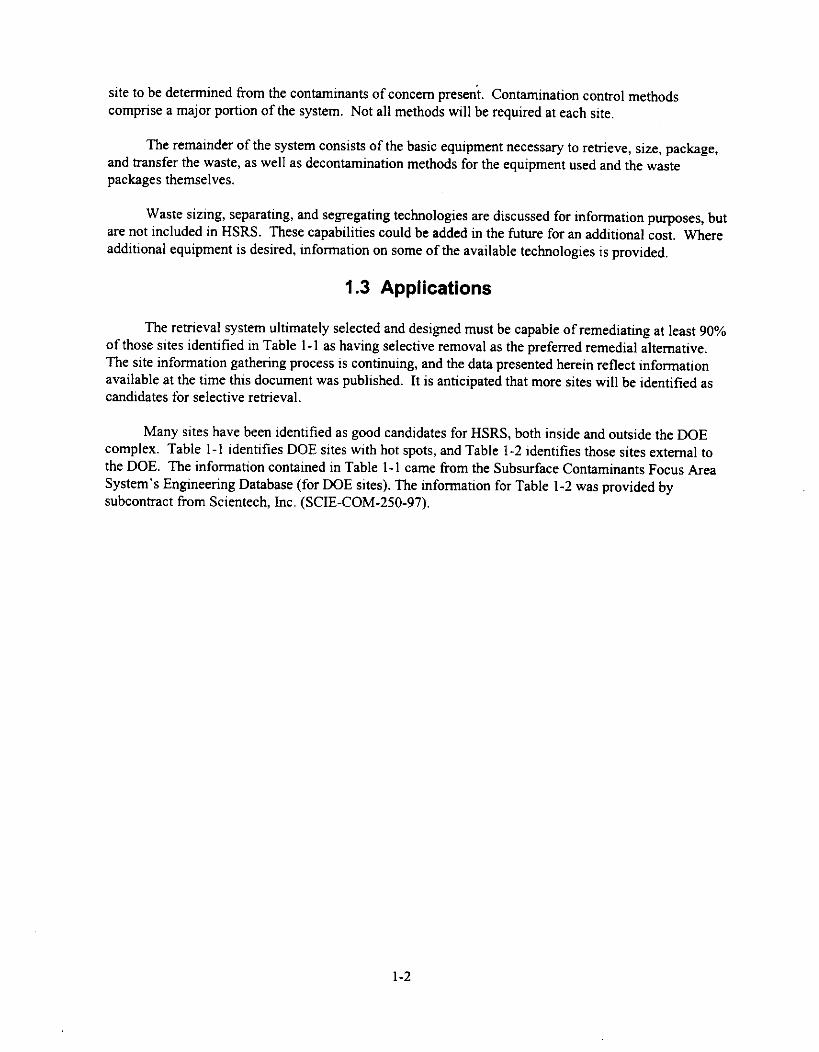
site to be determined from the contaminants of concern present. Contamination control methodscomprise a major portion of the system. Not all methods will be required at each site.
The remainder of the system consists of the basic equipment necessary to retrieve, size, package,and transfer the waste, as well as decontamination methods for the equipment used and the wastepackages themselves.
Waste sizing, separating, and segregating technologies are discussed for information purposes, butare not included in HSRS. These capabilities could be added in the future for an additional cost. Whereadditional equipment is desired, information on some of the available technologies is provided.
1.3 Applications
The retrieval system ultimately selected and designed must be capable of remediating at least 90%of those sites identified in Table 1-1 as having selective removal as the preferred remedial alternative.The site information gathering process is continuing, and the data presented herein reflect informationavailable at the time this document was published. It is anticipated that more sites will be identified ascandidates for selective retrieval.
Many sites have been identified as good candidates for HSRS, both inside and outside the DOEcomplex. Table 1-1 identifies DOE sites with hot spots, and Table 1-2 identifies those sites external tothe DOE. The information contained in Table 1-1 came from the Subsurface Contaminants Focus AreaSystem's Engineering Database (for DOE sites). The information for Table 1-2 was provided bysubcontract from Scientech, Inc. (SCIE-COM-250-97).
1-2

Table 1-1. DOE sites preferring remediation by selective retrieval.
OperationsOffice
Operable Unit/Group Name
Waste StreamMatrix
Total Area(vol.)
TotalDepth(ft)
Depth ofOver-burden
(ft)
Waste StreamVolume
Expected Objects
Max.Dim.
(ft)
Max.Weight(Ib)
Albuquerque UMTRA Hardware in soil 15 acres (122,835 yd3) 61.42 yd3 Drums, gas cylinders, cars 16 24
Idaho Idaho WAG 2 Soil with clay 0.5 0 1,000 yd3 None
Idaho Idaho WAG 7,OU 7-13,OU 7-14
Misc. debris in soil 97 acres (252,000 yd3) 20 3 12 600 yd3unknown
Barrels, tanks, casks,debris
5 350
Nevada DNA Muck Piles Mine tailings 37,000 yd3 0 1,850 yd3 Soil, rock, debris, cobble
Nevada Soils Media OU Sand, silt, gravel 207.4 acres 0.5 3,000 yd3 Sand, silt, gravel
Oak Ridge ORNL WAG 5SWSA 5 South
Soil with clay 60 acres 29 20,461.6 yd3 Wooden boxes, drums,gloveboxes, lead bricks,casks
6
Oak Ridge ORNL WAG 5SWSA 5 North
Misc. debris in soil 10 acres 15 132.5 yd3 Wooden boxes, drums,gloveboxes
6 150
Oakland LEHR I & 5 Soil with clay 400 yd3
Richland OU-200 TRUCaissons
Misc. debris in soil 10 10,000 drums TRU caissons, 5-gal cans 10
Richland OU-200TRU Drums
Metal debris 1,000 acres 20 TRU drums, ion exchangemetals
5 350
Richland OU-300-FF-2misc. debris insoil
I acre Culverts, lab waste 2 20
Richland OU-300-FF-2soil
1 acre Culverts, lab waste 8 100
SavannahRiver
488 D Ash Basin Soil with clay 755,000 yd3 5 ft. Barrels 5 350
SavannahRiver
LLRWDF/OBG Misc. debris in soil 194 acres(5,035,800 yd3)

Table 1-2. (continued).Table 1-2. HSRS potentially applicable sites.
Site Name Location Contaminants Date Needed Point of Contact Source
Kaho'olawe Site Kaho'olawe UnexplodedIsland, Hawaii ordnance
Demonstration was scheduledto be completed in 1995.Cleanup is expected to take10 years.
E-mail: [email protected]: Ms. Christine Arigo
Ms. Christine AkauCode 0213Pacific Division, Naval FacilitiesEngineering CommandPearl Harbor, HI 96860-7300
Phone: (808) 471-3764/471-9648
http://sedaar_edu.ciesin.org/5remed.htm
Sioux Army Depot Sidney,Nebraska
Unexplodedordnance
Cleanup is on-going. E-mail: [email protected]: U.S. Army Corps of Engineers
Huntsville DivisionP.O. Box 1600Huntsville, AL 35807-4301
Phone: (205) 955-2369
http://w2.hnd.usace.army.mil.pao.sioux.html
NansemondOrdnance Depot
Suffolk,Virginia
Unexplodedordnance
Engineering evaluations andcost estimates should becomplete in early 1997.Construction of the remedy willbegin soon after.
Kirk StevensPhone: (804) 441-7674
http://w2thrid.usace.army.mil/oefact.sht/nansod.html
Illinois Ordnance Marion,Plant Illinois
Unexplodedordnance
Engineering evaluations andcost estimates should becomplete in early 1997.Construction of the remedy willbegin soon after.
David MuellerleilePhone: (205) 895-1549
http://w2/hnd/usace.army.mil/oew/oefactsht/i I lop.html
Camp Sibert Gadsden,Alabama
Unexplodedordnance
Site characterization contracthas been awarded. Estimateretrieval will begin by mid-1998.
Mail: U.S. Army Corps of EngineersHuntsville DivisionP.O. Box 1600Huntsville, AL 35807-4301
Phone: (205) 955-2369
http://w2.hnd.usace.army.mil/pao/sibert.html
Davisville NavalConstructionBattalion Center
WashingtonCounty,
Rhode Island
Calcium hypo-chlorite,organic solvents,heavy metals
Site investigations should becomplete by 1998. Remedialdesign will follow.
Mail: Christine WilliamsEPA Region IJFK Federal BuildingBoston, MA 02203
Phone: (617) 573-5707
http://www.epa.gov/regionO I /remedisfsites/davisvil.html
4

Table 1-2. (continued).
Site Name Location Contaminants Date Needed Point of Contact SourceFort Devens Worcester
County,Massachusetts
Unexplodedordnance
Design of the remedy isexpected to begin in 1997.
Mail: Bob LimEPA Region IJFK Federal BuildingBoston, MA 02203
Phone: (617) 573-5707
http://www.epa.gov/region01/remed/sfsites/fortdev. html
MaterialsTechnologyLaboratory
MiddlesexCounty,Massachusetts
Chlorinatedsolvents, xylene,radiologicalcontamination
Site studies were initiated in1992. Remedial design may beunder way.
Mail: Mary SandersonEPA Region IJFK Federal BuildingBoston, MA 02203
Phone: (617) 573-5707
http://www.epa.gov/region0l/remedisfsites/material.htrn1
Shpack Landfill Bristol County, Radium, uranium,Massachusetts heavy metals
Site studies are in progress.Remedial design will beginupon completion of site studies.
Mail: Dave LedererEPA Region IJFK Federal BuildingBoston, MA 02203
Phone: (617) 573-5707
http://www.epa.gov/region01/remed/sfsites/shpack.html
U.S. Radium Corp Orange,New Jersey
Radium, radon Site studies were to becompleted in 1995. It is likelythat remedial design is underway.
Mail: Department of EnvironmentalProtection401 E. State St.7th Floor, East WingCN 402Trenton, NJ 08625
Phone: (609) 292-2885
http://www.epa.gov/superfund/oerr/impm/products/nplsites/html/0200772n.htm
Naval WeaponsStation Earle
MonmouthCounty, NewJersey
Unexplodedordnance, lead,zinc, titanium
Site investigations are expectedto be completed by 1996.Remedial design may be underway.
Mail: Department of EnvironmentalProtection401 E. State St.7th Floor, East WingCN 402Trenton, NJ 08625
Phone: (609) 292-2885
http://ww-w.epa.gov/superfund/oerr/impm/products/nplsites/html/0201 I 60n.htm
Picatinny Arsenal Morris County,New Jersey
Heavy metals, Site investigations are underexplosives, dioxins way. Remedial design will
begin upon completion ofinvestigations.
Mail: Department of EnvironmentalProtection401 E. State St.7th Floor, East WingCN 402Trenton, NJ 08625
Phone: (609) 292-2885
http://www.epa.gov/superfund/oerr/impm/products/nplsites/html/0201168mhtm
5
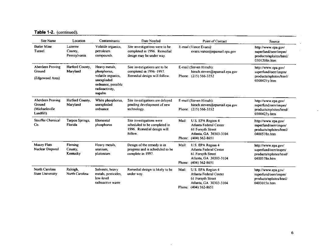
Table 1-2. (continued).
Site Name Location Contaminants Date Needed Point of Contact Source
Butler MineTunnel
LuzerneCounty,Pennsylvania
Volatile organics,petroleumcompounds
Site investigations were to becompleted in 1996. Remedialdesign may be under way.
E-mail (Vance Evans):[email protected]
http://www.epa.gov/superfund/oerriimpm/products/nplsites/html/0301208n.htm
Aberdeen Proving Harford County,Ground Maryland
(Edgewood Area)
Heavy metals,phosphorus,volatile organics,unexplodedordnance, possibleradioactivity,napalm
Site investigations are to becompleted in 1996-1997.Remedial design will follow.
E-mail (Steven Hirsch):hi rsch [email protected]. gov
Phone: (215) 566-3352
http://www.epa.gov/superfundioerr/impm/products/nplsites/html/0300421y.htm
Aberdeen Proving Harford County,Ground Maryland(MichaelsvilleLandfill)
White phosphorus,unexplodedordnance
Site investigations are delayedpending development of newtechnology.
E-mail (Steven Hirsch):[email protected]
Phone: (215) 566-3352
http://www.epa.gov/superfund/oerr/impm/products/nplsites/html/0300423y.htm
Stauffer Chemical Tarpon Springs, ElementalCo. Florida phosphorus
Site investigations werescheduled to be completed in1996. Remedial design willfollow.
Mail: U.S. EPA Region 4Atlanta Federal Center61 Forsyth StreetAtlanta, GA 30303-3104
Phone: (404) 562-8651
http://www.epa.gov/superfund/oerr/impm/products/nplsites/html/0400578n.htm
Maxey FlatsNuclear Disposal
FlemingCounty,Kentucky
Heavy metals,uranium,plutonium
Design of the remedy is inprogress and is scheduled to becomplete in 1997.
Mail: U.S. EPA Region 4Atlanta Federal Center61 Forsyth StreetAtlanta, GA 30303-3104
Phone: (404) 562-8651
http://www.epa.gov/superfundTherr/impm/products/nplsites/html/0400578n.htm
North Carolina Raleigh,State University North Carolina
Solvents, heavymetals, pesticides,low-levelradioactive waste
Remedial design is likely to beunder way.
Mail: U.S. EPA Region 4Atlanta Federal Center61 Forsyth StreetAtlanta, GA 30303-3104
Phone: (404) 562-8651
http://www.epa.gov/superfund/oerr/imprn/products/nplsites/html/0403015 n.htm
6

Table 1-2. (continued).
Site Name Location Contaminants Date Needed Point of Contact Source
Redstone Arsenal MadisonCounty,Alabama
Unexplodedordnance, sulfurmono-chloride,thionyl chloride,lewisite, and otherchemical warfareagents
Site investigations are underway. No date is given for startof remedial design.
Mail: U.S. EPA Region 4Atlanta Federal Center61 Forsyth StreetAtlanta, GA 30303-3104
Phone: (404) 562-8651
http://www.epa.gov/superfund/oerr/imprn/products/nplsites/html/0405545n.htm
Kerr-McGee West Chicago,Illinois
Thorium, radium,uranium, rareearths, lead
Remedial design is under way. Mail: Michael NechvatalIllinois EPA, 2200 Churchill RoadSpringfield, IL 62794-9276
Phone: (217) 785-8604
http://www.epa.gov/superfund/oerr/impm/products/npisites/html/0500763n.htm
Joliet Army Will County,Ammunition Plant Illinois(load-assembly-packing area)
Heavy metals,PCBs, trinotro-toluene
Site investigations were to becompleted in 1996. Remedialdesign may be under way.
Mail: Michael NechvatalIllinois EPA, 2200 Churchill RoadSpringfield, IL 62794-9276
Phone: (217) 785-8604
http://www.epa.gov/superfund/oerr/impm/products/nplsites/html/0501170n.htm
Joliet Army Will County,Ammunition Plant Illinois(Mfc. Area)
Heavy metals,PCBs, trinotro-toluene
Site investigations were to becompleted in 1996. Remedialdesign may be under way.
Mail: Michael NechvatalIllinois EPA, 2200 Churchill RoadSpringfield, IL 62794-9276
Phone: (217) 785-8604
http://www.epa.gov/superfund/oerr/impm/products/nplsites/html/0501179n.htrn
Lone Star Army Bowie County, Heavy metals,Ammunition Plant Texas explosives
Site investigations are to becompleted in 1997.
Mail: Mary Ann AbrahamsonU.S. EPA Region 6 (SF-A)1445 Ross Ave.Dallas, TX 75202
Phone: (214) 665-6754
http://www.epa.gov/superfundJoerr/impin/products/nplsites/html/0603609n.htrn
Iowa Army Des MoinesAmmunition Plant County,
Iowa
Explosives Site investigations werecompleted in 1996. Remedialdesign is likely to be underway.
Mail: Lavoy HaageSolid Waste SectionIowa Dept. Of Natural ResourcesWallace State Office BuildingDes Moines, IA 50319
Phone: (515) 281-8707
http://www.epa.gov/superfund/oerr/impm/products/nplsites/html/0700413n.htm
Sunflower ArmyAmmunition Plant
JohnsonCounty,Kansas
Explosivesheavy metals
Site investigations are inprogress. A start date forremedial design is not given.
Mail: Rick Bean, ChiefRemedial SectionDept. of Health and EnvironmentForbes Field, Building 740Topeka, KS 66620
Phone: (913) 296-1675
http://www.epa.gov/superfund/oerr/impm/products/nplsites/html/0700736n.htm
7

Table 1-2. (continued).
Site Name Location Contaminants Date Needed Point of Contact Source
Westlake Landfill St. Louis Radioactive waste Site investigations were to be Mail: Gary Behms http://www.epa.gov/County, (uranium ore completed in 1996. Remedial Hazardous Waste Programs superfund/oerr/imprn/Missouri processing design will follow. Missouri Dept. of Natural Resources products/nplsites/html/
residues) Jefferson Building, 13th Floor 0701039n.htmP.O. Box 176Jefferson City, MO 65102
Phone: (573) 751-4187
Weldon Spring St. Charles Explosives,Former Army County, heavy metalsOrdnance Works Missouri
RFP for construction of theremedy has been published.
Mail: Gary Behms http://www.epa.gov/Hazardous Waste Programs superfund/oerr/impm/Missouri Dept. of Natural Resources products/nplsites/html/Jefferson Building, 13th Floor 0701773n.htmP.O. Box 176Jefferson City, MO 65102
Phone: (573) 751-4187
Lake City Army Jackson County, Explosives, heavy Site investigations are to be Mail: Gary Behms http://www.epa.gov/Ammunition Plant Missouri metals, organic completed in 1997. Remedial Hazardous Waste Programs superfund/oerr/impm/
compounds design will follow. Missouri Dept. of Natural Resources products/nplsites/html/Jefferson Building, 13th Floor 0701757n.htmP.O. Box 176Jefferson City, MO 65102
Phone: (573) 751-4187
Nebraska Army Saunders Explosives, PCBs Remedial design is under way. Mail: Richard Schlenker http://www.epa.gov/Ordnance Plant County, Superfund Section superfund/oerr/impm/
Nebraska Nebraska Dept. Or Env. Quality products/nplsites/html/The Atrium 0702031n.htm1200 North Street, Suite 400Lincoln, NE 68509
Phone: (402) 471-2541
Comhusker Army Hall County, Explosives, heavy Site investigations were to be Mail: Richard Schlenker http://www.epa.gov/Ammunition Plant Nebraska metals completed in 1996. Remedial Superfund Section superfund/oerr/impm/
design may be under way. Nebraska Dept. Or Env. Quality products/nplsites/html/The Atrium 0702020n.htm1200 North Street, Suite 400Lincoln, NE 68509
Phone: (402) 471-2541
8

Table 1-2. (continued).
Site Name Location Contaminants Date Needed Point of Contact Source
Teledyne Wah Linn County, Thorium, uranium, Site investigations were to be Mail: U.S. EPA Region 10 http://www.epa.gov/Chang Oregon radium, heavy completed in 1995. Remedial 1200 6th Avenue, ECL-1117 superfuncVoerr/impm!
metals design may be under way. Seattle, WA 98101 productslnplsitesllnml/Phone: (206) 553-1296 1000421n,htm
9

2. IDENTIFICATION AND SCREENING OF TECHNOLOGIES
Section 2.1 explains how the technologies were identified, and Sections 2.2 through 2.11 discussthe technologies that were reviewed for possible use in HSRS. The discussion of individual technologiesis broken down into functions: characterization, contamination control, retrieval, decontamination, wastepackaging/transfer, and remote vision/telecommunications. For each technology that supports afunction, such as retrieval technologies, contamination control technologies, etc., a description, theapplications, issues/gaps, and vendors/sources in technology are given. Due to the large number ofvendors/sources for the various geophysical characterization and decontamination systems, and as thetechnologies are well developed, just a description and the applications will be discussed for eachtechnology. The general issues and the vendors/sources will be included for geophysical characterizationand decontamination systems. The radiation characterization section (see Section 2.2.2) is presented byradionuclide of interest.
Information is included on the following:
• Characterization (Section 2.2)
• Contamination control (Section 2.3)
• Retrieval (Section 2.4)
• Waste separation/segregation (Section 2.5)
• Waste minimization (Section 2.6)
• Waste sizing (Section 2.7)
• Waste packaging/transfer/sizing (Section 2.8)
• Decontamination (Section 2.9)
• Remote vision/telecommunication (Section 2.10)
• Control system (Section 2.11).
2.1 Candidate Technology Identification Procedure
Several different avenues have been used to collect information on currently availabletechnologies both in industry and in the DOE complex. These include the following:
Commerce Business Daily (CBD) advertisementsInternal reports [EG&G Idaho, Lockheed Martin Idaho Technologies Company (LMITCO), etc.]Internet searches on key wordsScientech, Inc. database of technologiesCurrent journal articlesPrior historyConferences/solicitations from vendors
2-1

Vendor brochuresTechnical expert networkingMSE, Inc.—has done previous benchmarking on characterization technologiesSandia National Laboratories—has done previous benchmarking on monitoring technologiesMeetingsReview/monitoring of Environmental Monitoring-50 (EM-50) cross-cutting programDOE Rainbow books.
2.2 Characterization
Characterization technologies are needed to locate the hot spots, guide the removal action, andverify that the hot spots have been removed. This section discusses geophysical, radiological, andchemical characterization.
2.2.1 Geophysical Characterization
Geophysical characterization technologies are used for object detection. Object detectionactivities define the physical (rather than chemical) characteristics of the subsurface. Commonobjectives include delineating boundaries of solid waste, determining depth to waste, and locatingindividual objects or groups of objects.
2.2.1.1 General Description. Characterization, an important component of the remediation process,becomes even more so when the issue is hot spot remediation. To fill the need for characterization,numerous tools have been developed, one of which is a group of geophysical techniques. Thesetechniques have been used for site characterization, remediation verification, and long-term monitoring.Numerous papers have been written baselining these techniques for various uses (Borns 1995;Reichhardt 1997).
Some of the numerous geophysical techniques that can be used to characterize hot spots includeacoustic, electromagnetic, magnetic, nuclear logging, and gravity methods. The techniques mostcommonly used for environmental characterization are magnetic and electromagnetic methods (includingground-penetrating radar).
The requirements for geophysical site characterization vary depending on the needs of a specificsite and are summarized in the draft Hot Spot Removal System Requirements Document. Commonrequirements are:
• Determination of waste boundaries within the waste seam
• Location of individual objects within the waste seam
• Location and identification of individual buried objects such as unexploded ordnance(UXO) and mines
• Location of secondary hot spots such as plumes that have migrated from their originallocations to new areas
• Buried utilities and structures.
2-2

The accuracy with which a site needs to be characterized also depends on the needs of the site andthe goals of the remediation activity. The physical and technical limitations of the characterizationtechnologies used can also limit the ability of the characterization effort. To date, there has been asignificant amount of research and development in the area of improving the resolution capabilities of allenvironmental geophysical techniques. These limitations must be considered and incorporated into siteremediation characterization requirements for all characterization activities, not just geophysicalcharacterization.
Each of the geophysical methods described below have their own strengths and weaknesses. In
many instances, improved characterization can be achieved by using multiple geophysical techniquesalong with other characterization techniques (historical records, hydrologic information, etc.).
2.2.1.2 Electromagnetic Methods (EM).
2.2.1.2.1 General Description—Electromagnetic methods are used extensively to detect
small isolated objects such as drums, tanks, and metallic objects at waste sites along with changes in
permeability, porosity, saturation, and pore fluid chemistry. These methods utilize man-made or
naturally occurring electromagnetic fields to investigate the conductivity and dielectric structures of the
subsurface. In instances where the magnetic permeability also varies, these methods also measure
changes in this property. EM techniques use fields operating over the spectrum from 0 Hz to tens of
GHz (Figure 1-1). No single system operates over this frequency range. To cover the complete range,
several systems need to be used. Although dc resistivity, induced polarization (IP), and ground-
penetrating radar (GPR) are electromagnetic methods, they are usually separated, and EM methods are
considered to be those operating below 100 kHz and above 0 Hz. Traditionally, the EM methods have
been collected in both the frequency domain and the time domain, which are essentially equivalent when
transformed and grouped into frequency ranges as outlined in Figure 1-1. The resolution and limitations
for each frequency range are different. In general, the higher the frequency, the greater the resolvingpower. However, the higher frequencies are also attenuated much more substantially than the lower
frequencies so that systems operating at higher frequencies are limited to shallow applications in the low
conductivity, dielectric environments common at many waste sites. Also, at lower frequency, resolution
can be greater than the resolution dictated by higher frequency by changing array geometries. A
discussion of EM techniques follows, starting with the lower frequency methods and progressing to
higher frequencies.
10° Hz 10' Hz 102 Hz 103 Hz 104 Hz 106 Hz 106 Hz 107 Hz 108 Hz 109Hz
I I I I I I I I- I I
+--dc Induced Polarization 4-
Resistivity Loop-Loop AMTI Il• 4—.Frequency Domain Experimental
Systems 4 Systems
Time Domain4
SystemsGround-Penetrating •
Radar
Figure 1-1. Relationship between frequency and different EM system operations ranges.
2-3

2.2.1.2.2 Loop-Loop EM Systems—Low-frequency loop-loop EM systems are used to mapconductivity changes in the subsurface (conductivity changes are equivalent to resistivity changes).These techniques are sensitive to metallic objects and changes in the conductivity of soils, and can beused to determine the location of metallic objects in waste sites as well as detect soil contamination andother non-metallic changes in conductivity to some degree. The resolution of these methods depends onspatial sampling and the number of orientations/frequencies used. These techniques usually use a fixed-loop orientation, separation, and/or frequency and do not lend themselves to three-dimensionalinterpretation. Interpretation is limited to anomaly detection with little information on anything but thelateral extents of the anomalies. However, there is ongoing development of new systems for dataacquisition and interpretation to provide three-dimensional images of the subsurface. Common loop-loop EM systems used are the Geonics EM-31, EM-34, and the Geophex GEM-2B systems. There arealso many small-loop EM devices that are used mainly for near-surface metal detection, such as for UXOand land mine detection applications. These systems are typically analog systems designed to signal(most make a noise) when metal objects are encountered. Loop-loop EM systems have limited depthpenetration, and most do not have recording or display capabilities.
2.2.1.2.3 Controlled Source Audio Magnetotellurics and Audio MagnetotelluricsMethods—Controlled source audio magnetotellurics (CSAMT) and audio magnetotellurics (AMT)techniques use either the earth's naturally occurring EM field or the field generated by radio stations tomap the subsurface. These techniques are typically used for deep exploration or determination of thehost physical properties and are not typically used for hot spot detection.
2.2.1.2.4 Transient EM (TEM) Systems—The Geonics EM-47 and the Zonge nanotemsystems are typical, low-frequency time-domain systems used for shallow to moderate investigation.These systems can detect changes in subsurface conductivity and have also shown progress in collectingand interpreting three-dimensional data. However, to fully utilize these sorts of data sets, large data setsare required and collection is slow and more expensive than with loop-loop systems. Thus, thesesystems are more commonly used in geophysical exploration applications. One exception is the GeonicsEM-61, a time-domain metal detector system that can be used to detect shallow-buried metallic objectswith high resolution. The Geonics EM-61 is different from most mine detection EM systems in that it hasdeeper penetration capabilities and records data so it can be analyzed to obtain some depth informationand used to detect deeper buried objects than those near the surface.
2.2.1.2.5 Time Domain Reflectometry (TDR)—Time domain reflectometry (TDR) is ahigh-frequency EM system operating in the tens of GHz range that measures the time lag and attenuationof a pulse sent along a waveguide placed in the ground. These probes can be placed on devices such ascone penetrometers and provide information on the dielectric properties of the subsurface. The maincause for change in the dielectric properties of soils is the amount of moisture contained in the porespace. TDRs are most commonly used to determine the water content of soils. The depth of investigationfor TDR systems is only along the length of the probes (typically under 1 ft long) without significantpenetration into the subsurface and, as such, has limited hot spot characterization applications.
2.2.1.2.6 General Applications—Electromagnetic methods are not only sensitive to metallicobjects, but also to changes in permeability, porosity, saturation, and pore fluid chemistry. Commonuses of loop-loop EM systems, such as the Geonics EM-31, are to perform site characterization activitiesby locating boundaries of landfills and identification of zones containing metallic objects within andoutside landfill boundaries. Other EM systems, such as the Geonics EM-61 and other EM mine detectionsystems, are also used to detect shallow individual metallic objects such as UXO and land mines, but canbe used to detect individual objects associated with a hot spot within a landfill. EM methods, commonly
2-4

used prior to remediation activities for object detection, may be used for verification purposes during orafter remediation, but probably have limited digface applications due to the nature of the data collected.
Resolution is not only dependent on the location of the object as described in the followingparagraph, but also on the physical properties of the hot spot and surrounding medium. EM methods aresensitive and measure changes in the resistivity of the subsurface. The user must be aware of andunderstand the relationship between the resistivity structure, measured or interpreted, and the objects inthe subsurface to be imaged. Without adequate understanding of the physical properties and theirrelationship to the data collected and interpreted, the hot spot cannot be properly detected. Detection of ahot spot is dependent on an adequately large contrast in resistivity between the medium and the hot spot.Thus, although metallic objects are relatively easy to detect when compared to the detection of plumefeatures or other hot spots not associated with metallic objects, they can often obscure the detection ofnon-metallic hot spots.
Another aspect of EM methods resolution can be described as being comprised of two issues thatare not necessarily independent, and also related to the resistivity contrast between the hot spot and thesurrounding medium: (1) lateral resolution, i.e., how small an object can be detected or how well cananomalies be separated into distinct anomalies and (2) depth resolution. Lateral resolution is dependenton the station spacing used during data collection. A typical rule of thumb for detection is to design thestation spacing used to be half the distance of the size of the object to be detected. However, torealistically achieve adequate resolution, the spacing usually needs to be much less than the size of thehot spot to be able to determine the true lateral size of the object and if the object is one large object ormany small objects located close together. Because distance attenuates the signal from a buried object,smaller objects are typically more difficult to detect when buried at depth and may be detected at depthonly if there is a group of objects. For detection of individual hot spots such as UXO or land mines, thislimits the use of some EM systems. The EM systems that function best for these types of targets are theGeonics EM-61 and other continuous EM loop mine detection systems. For larger/deeper targets, theGeonics EM-31 and EM-61 are commonly used for detection, but determination of depth and geometryof the hot spot are limited with these systems.
Depth resolution is dependent on two interrelated parameters: (1) the operational frequency of theEM system and (2) the size of the hot spot. Lower frequency EM systems have greater depth penetration,but resolution is limited and dependent on station spacing. To achieve adequate anomaly resolution, itmay be necessary to have a dense station spacing, but determination of geometry and depth of the hotspot is currently limited to anomaly detection with surface systems. As the size of the hot spot decreases,the difficulty of detection increases with increasing depth due to attenuation.
2.2.1.3 Direct Current (dc) Resistivity Methods.
2.2.1.3.1 Description—Direct current (dc) resistivity methods typically use two ground-contacting current source electrodes and two ground-contacting receiver potential voltage recordingelectrodes. A near dc current is injected into the ground using the two source electrodes; the potential ofthe electric field is measured at the receiving electrodes. The potential field is dependent on thegeometric relationship of the four electrodes and also the resistivity structure of the subsurface. Byvarying the geometry of the source and receiver electrodes, images of the subsurface resistivity structurecan be obtained. Common arrays used are surface Wenner and Schlumberger arrays, borehole loggingdevices, borehole to borehole, and borehole to surface arrays, such as those used in electrical resistancetomography (ERT). Data collected with these arrays can be inverted to provide three-dimensional
2-5

images of the subsurface resistivity structure. All dc arrays are relatively inexpensive to deploy, andthere are many interpretation methods available.
2.2.1.3.2 Application—Direct current methods are essentially potential field measurements;resolution is dependent on the array geometry, not the frequency. This array design flexibility and theability to collect a large number of station combinations gives dc resistivity techniques higher resolutionat many sites than is possible by using higher frequency (such as loop-loop frequency domain) systemsand varying the frequency. While site characterization can be accomplished using dc resistivitytechniques, it is often more economical to use the more portable EM systems like the Geonics EM-31and also magnetometers for general landfill location and initial characterization studies.
Like EM techniques, resolution of dc resistivity methods is dependent on the size of the anomalyto be detected, the depth of the hot spot, and the resistivity contrast between the hot spot and thesurrounding medium. This is important for non-metallic hot spots and may limit the ability of dcresistivity methods to image a particular hot spot. For surface arrays, the smaller the distance betweensource electrodes and the receiver electrodes, the smaller the depth of investigation. The distance isgenerally expanded to obtain greater depth information. To improve resolution of three-dimensionaltargets, such as localized hot spots, not only are the distances changed but the number of stations is alsoincreased, and often tomographic arrays are used.
2.2.1.4 induced Polarization (1P) Methods.
2.2.1.4.1 Description—Induced polarization (IP) is a geophysical technique similar to deresistivity techniques. Like dc resistivity, IP measures the potential electric field, but unlike dcresistivity measurements, IP measures a time-varying electric field. IP typically utilizes two ground-contacting source current electrodes and two ground-contacting receiver voltage measuring electrodes.The geometry of the four electrodes is varied to change the zone of influence and, using multiple sourcereceiver configurations (borehole to borehole or surface to borehole), provides the user with theequivalent of an electrical complex resistance tomogram. A time-varying electric current, either a stepfunction to obtain a suite of frequencies when transformed from the time domain to the frequencydomain, or two or more ac frequencies, is injected into the subsurface through the two current electrodesmeasuring the voltage difference between the two receiver electrodes. The apparent resistivities obtainedat different frequencies is also known as the complex impedance and is dependent on the resistivity anddielectric permittivity structure of the medium being investigated. Like dc resistivity methods, IPsystems are fairly easy to deploy, and dc resistivity interpretation techniques are being modified byuniversities and national laboratories to interpret IP data. Like the seismic and dc resistivity tomographicimages, the data are collected using numerous source pair and receiver pair combinations and theninverted to image the subsurface based on the geoelectric properties of resistivity and dielectricpermittivity rather than seismic velocity or attenuation. To obtain useful IP data, the electrodes usedmust be electrically stable so they do not create their own electrical potentials due to degradation, andmust have good electrical coupling with the medium. These two issues are easily solved in surface-to-surface surveys where commercial electrodes can be effectively used and maintained. In boreholeapplications, under caps, and in other in situ remediation structures, both the source and receiverelectrodes must be installed so that they are in electrical contact with the medium and are stable overtime.
2.2.1.4.2 Applications—The application of IP techniques to hot spot characterization andremediation are similar to those for dc resistivity because the methods of deployment are the same. Also,the constraints on the resolution are similar to those for dc resistivity methods, but because IP methods
2-6

measure the complex impedance of the subsurface, it is dependent on not only the resistivity but also onother electrical properties such as dielectric permeability. This has allowed IP techniques to detect somefeatures not detectable by commonly used dc resistivity methods. IP methods for hot spotcharacterization and remediation verification activities are just beginning to be used, and their superiorityis not yet fully understood.
2.2.1.5 Ground-Penetrating Radar (GPR).
2.2.1.5.1 Description—Ground-penetrating radar (GPR) techniques are similar to seismictechniques in that the velocity, phase shift, and attenuation of an electromagnetic wave traveling from asource antenna to a receiver antenna are measured for one or more source and receiver configurations.GPR systems are sensitive not only to changes in the permeability and porosity, but because they aresensitive to dielectric changes, they are also sensitive to the presence of some organic compounds. GPRmeasurements can be collected using numerous configurations. The most common configurations areeither surface antenna arrays or borehole tomographic GPR arrays. Surface arrays usually consist of onesource antenna and one receiver antenna. Data are most commonly collected along lines using a constantoffset between the antennae, but multiple offsets are sometimes used in special cases. These data areusually displayed as travel time versus position along line plots with little post-processing. For higherresolution work, several processing techniques can be used. These include but are not limited tomigration, inverse scattering, and other imaging techniques. Radar systems typically operate in the rangeof hundreds of MHz to the GHz range, and in environments favorable to radar propagation, provide high-resolution images. In areas of extreme attenuation, however, GPR techniques have limited use.
Tomographic data are collected using cross borehole geometries with numerous source locationsin one borehole and data collected from numerous receiver locations in another borehole. From thesedata, a tomogram of the velocity or attenuation through the medium can be reconstructed and used toinfer the dielectric permittivity and resistivity structure in a manner similar to that employed by seismictomography. Like surface GPR techniques, borehole radar systems typically operate at frequencies inthe hundreds of MHz to the GHz range, and can provide high-resolution tomograms, but are easilyattenuated in low-resistivity mediums similar to the way seismic tomograms loose resolution in poorlyconsolidated sediments.
2.2.1.5.2 Applications—Resolution of GPR techniques is influenced by the frequency of theGPR as well as the resistivity and dielectric permittivity of the medium. In low-resistivity soil, soilcontaining minerologic clay, or saturated soils, the attenuation rate for GPR frequency EM waves is quithigh, resulting in poor depth of investigation. In some instances, the depth of penetration for lowerfrequency GPR systems may be less than a meter and even less for higher frequency GPR systems.However, in high-resistivity media, such as dry sand, attenuation is low, and the depth of penetration cantypically be up to 5 to 10 m. In these sorts of environments, GPR resolution of small structures isexcellent, and much research has been directed at using complex imaging algorithms to provide three-dimensional images of objects and structures in the subsurface. In favorable conditions, the resolution isdependent on the frequency content of the GPR system, and using high-frequency antennae can providehigh-resolution images.
Uses of GPR systems include initial site characterization to determine landfill boundaries,qualitative identification of objects within a landfill that are associated with a hot spot, UXO detection,and mine detection. GPR systems can also be deployed at the digface to detect the location of metallicand objects. Because GPR is sensitive to both dielectric and resistivity structures, GPR techniques arebeing developed to detect non-metallic mines and other non-metallic objects such as organic chemicals.
2-7

2.2.1.6 Magnetic Methods.
2.2.1.6.1 Description—Magnetic methods are some of the most commonly used techniquesfor environmental characterization of buried objects. These methods are sensitive to changes in themagnetic permeability within the subsurface and are sensitive to ferrous iron objects such as drums andtanks. Commonly, the earth's magnetic field—either the total field or the vertical gradient of the totalfield—is measured, and the limiting factors for resolution are the depth of the metallic object and thespacing of the sampling points. There are numerous systems that have the capability of collecting data atsub-foot spacings so that lateral resolution is good using magnetic methods. Magnetic methods are mostcommonly used as a mapping tool much like the Geonics EM-31 loop-loop system; however, tensormagnetometers and interpretation techniques have been developed to estimate target size and depth.
2.2.1.6.2 Applications—Magnetic methods are useful for detecting ferrous metallic objects.Because magnetic methods measure a potential field, resolution is a function of the size of the ferrousiron object, the depth to the object, and the data collection density. To detect small ferrous iron objects,such as UXO or landmines, these objects must be near the surface (less than 1.5 m), and the stationspacing used must be sufficiently tight so that the sensor is within detection range of the object. Fordetection of deeper objects, there must be a grouping of small objects or the size of the object mustincrease with depth. Objects such as barrels and other metallic debris (file cabinets, support beams, etc.)can often be detected at depths commonly associated with landfills. Although larger station spacings canbe used to detect landfill boundaries and larger objects, and to attempt to make distinctions betweenanomalies associated with numerous objects within a landfill, dense station spacing is still needed. Atpresent, magnetometers (like many EM systems) are simply used to map anomalies.
Depth can be determined from magnetic data in many situations, particularly UXO applications,using various software packages. The ability to determine three-dimensional geometry is not welldeveloped due to the inherent properties of the field measured. Tensor magnetic gradiometers, beingdeveloped by companies such as Conductus, may provide better information on the depth and size ofthese anomalies but may still have difficulty separating out the effects of multiple anomalies.
Uses for magnetic sensors include initial site characterization to determine landfill boundaries,qualitative identification of ferrous metallic objects within a landfill that are associated with a hot spot,UXO detection, and mine detection. Magnetic sensors are also deployed at the digface to detect thelocation of metallic objects.
2.2.1.7 Acoustic Methods.
2.2.1.7.1 Description—Acoustic methods have been extensively developed and used in oiland gas exploration. At the scale associated with oil and gas exploration (tens to thousands of meters),these methods provide high resolution. However, at the engineering scale (one-tenth to tens of meters),these methods are not as well developed and have difficulty with resolution due to attenuation of high-frequency acoustic waves in unconsolidated sediments. Also, the deployment of acoustic surveys withthe needed resolution can be prohibitively expensive. However, one method of data collection used incharacterization of shallow targets applicable to hot spot characterization is acoustic tomography.Acoustic tomography is the process by which either the velocity distribution or the energy attenuationbetween adjacent boreholes is mapped. A seismic source is placed in one borehole, and a set of seismicreceivers is placed in an adjacent borehole. The source is moved up and down the length of eachborehole. The set of receivers may also be moved to provide more source-receiver combinations. Foreach borehole location, the acoustic energy is measured at every receiver location after traveling from
2-8

the source, through the medium, to the receiver until sufficient coverage of the subsurface is achieved.Typically, sufficient coverage is achieved by using boreholes that extend well above and below the areato be imaged. In instances where it is not possible to place boreholes in this manner, coverage isincreased by placing either sources or receivers on the surface along with those in the boreholes. Witheither array geometry, the recorded wave form can be used to estimate travel time for acoustic energyfrom the source to the receiver, and the travel time inversion method can be used to construct thetomogram. The attenuation of the energy of the wave form across the area can also be measured, and atomogram of either the variations in seismic attenuation or a diffraction tomogram can be constructed.Because resolution is a function of the frequency content of the seismic wave, the geometry, and thevelocity structure of the medium, it will be necessary to determine the attenuation and dispersionassociated with the volume to be surveyed for a site. These properties will limit the resolution along
with the number of boreholes used, the number of source and receiver locations, and the spacing ofsources and receivers in the boreholes or on the surface. Another factor influencing the resolution ofseismic methods is the cost and labor involved with collecting data.
2.2.1.7.2 Surface Acoustic Wave Technologies—The surface acoustic wave (SAW)
technologies currently being developed utilize thin, polymer-coated sensors to detect volatile organic
compounds (VOCs). The operating principle is that the character of an acoustic wave traveling along the
sensor is altered depending on the medium it is in contact with. Volatile organic compounds cause a
known alteration and can be detected at the ppm or ppb level, depending on the compound. Theseinstruments are designed to make in situ measurements to detect VOCs, but are only point measurements
and do not provide information external to the area immediately adjacent to the probe. The depth of
limitation make SAW technology more useful for monitoring and detection at a large scale than for hot
spot characterization, as the system must be in contact with the VOC and cannot detect a hot spot
external to the sensor position.
One means of using SAW technology is to incorporate it into a portable acoustic wave (PAW)
system or to increase its utility. The PAW system is still limited in depth of investigation and, as such, is
difficult to use. Both SAW and PAW sensors for VOC detection are emerging technologies and, atpresent, have limited hot spot characterization applications.
2.2.1.7.3 Applications—Acoustic methods are sometimes used to map the lateral extents of
objects in geotechnical activities because they are sensitive to changes in the shear and bulk modules and
density of the subsurface.
Use of acoustic techniques for site characterization are often limited for two reasons: (1)
high-resolution acoustic techniques are expensive to deploy and interpret and (2) near-surface soils
attenuate high-frequency acoustic signals, making it difficult to obtain high-resolution images of this
region. Traditionally, acoustic methods have been used to map boundaries, such as the interface between
soil and bedrock. Acoustic methods have also been used to some extent, with limited success, to provide
three-dimensional images of hot spots. Because of its prohibitive cost and difficulty in obtaining high-
resolution images, most development of geophysical techniques for high-resolution images has been in
other techniques, such as GPR, not in acoustic methods. Most of the knowledge used has come from the
oil industry. However, in recent years, acoustic techniques have been developed and used in the shallow
subsurface. Acoustics does show promise as an application for verifying and monitoring long-term in
situ stabilization structures, detecting deep hot spots using tomographic techniques, and also fordetecting structures that may limit the migration of contaminants to detect secondary hot spots.
2-9

2.2.1.8 Gravity Methods.
2.2.1.8.1 Description--Gravity methods measure the density differences of various materialsby measuring changes in the ambient gravity field. As such, this is a potential field measurement,similar to magnetics. However, the contrasts in density between various objects are much less withgravity methods than those in magnetic permeability measured using magnetic techniques, makingacquisition of high-resolution gravity data difficult.
Gravity methods are not used as extensively as other methods due to the difficulty of measuringthe small fields associated with gravity measurements and their difficulty in detecting small objects withsimilar densities to the surrounding medium.
2.2.1.8.2 Applications—Gravity measurements are used in some geotechnical applications,but have limited use in detecting hot spot features. The main limitation for gravity measurements for hotspot remediation is the difficulty of measuring the small changes in the gravity field associated with thechange in density associated with the hot spot in the presence of other noise structures, such as uneventerrain, even when using a sensitive gravity gradiometer. Thus, at present, gravity methods have a verylimited application to the hot spot characterization problem.
2.2.1.9 Nuclear Logging Devices.
2.2.1.9.1 Description—Neutron probes are currently being used to measure moisture contentfor monitoring purposes at many sites. These probes use neutron attenuation by water or hydratedmaterials to determine the moisture content of the zone investigated. The investigation depth of thesedevices is typically between a few inches, for probes used in environmental applications, to 1 to 3 ft, forlarger probes used in oil field characterization activities.
2.2.1.9.2 Application—Neutron probe systems are used in borehole applications and are welldeveloped. Their application to detection and characterization of hot spots is limited due to their limiteddepth of investigation and the fact that they are used primarily for the detection of water.
2.2.1.10 Gamma-Ray Spectroscopy. Gamma-ray spectroscopy has a limited depth ofinvestigation due to the limitations of penetration of gamma and neutron radiation but can providequantitative detection of nuclides and metals. The instruments available include both passive and activesensors. The passive sensors detect gamma radiation produced by the medium, and the active sensorsgenerate gamma rays that interact with the medium. Delineation of nuclides and metals is based on theenergy spectrum recorded because each element has a known gamma spectroscopy signature. There areseveral borehole instruments available, and the technology is fairly advanced. However, the depth ofinvestigation in the subsurface for these systems is typically shallow (less than 1 m at best) and, as such,has limited use for hot spot characterization applications.
2.2.1.11 General Issues Concerning Geophysical Characterization. At present, geophysicaltechniques are able to address some of the hot spot characterization issues at some sites to the neededaccuracy. Detection of metallic objects and UXO in waste seams is possible at many sites. The ability todistinguish different types of metallic objects from one another in a waste site is not easily accomplished.At present, distinctions are most often made in a heuristic fashion based solely on size. Other difficultiesin providing high-resolution images are associated with the resolving power of the techniques. This iscontrolled by the physical properties of the medium and hot spot, and the ability of the techniques used
2-10

to achieve a high-resolution image. Finally, the relationship between the physical properties measuredand the chemical and physical characteristics of the hot spot need to be understood. Currently, bettermethods of data collection are being developed, but have not been extensively tested. These include theuse of non-traditional survey design, higher sampling density, improvement in interpretation techniques,and investigation into the relationship between the geophysical properties measured and the chemicaland physical properties of interest to regulators.
At present, it is difficult to non-intrusively detect and characterize many subsurface hot spots,mainly because the resolution and correlation of geophysical techniques to the parameters that define thehot spot are not known or understood. There are several ways to improve the resolution to some degree,but basic research is needed to better define the methods (to improve resolution) and also to betterunderstand the relationship between the risk drivers and the physical properties measured usinggeophysical techniques.
In the short term, characterization resolution can be improved by collecting more data on a largerand denser grid, using more survey points, and utilizing boreholes. However, this is often costprohibitive. Means are needed to improve the efficiency of data collection so that high-resolution datacan be collected.
It is also difficult to interpret or image collected data. Better imaging techniques need to bedeveloped along with better methods to collect data to have the most information possible.
It is necessary to better understand the physical properties, the medium, hot spots, and how themedium and hot spot physical properties interact.
Resolution at a specific site is difficult because each site has different requirements and differenthot spots that have different physical properties, some easier to detect than others. There are, however,three basic questions that need to be addressed when determining if the required resolution can beachieved: (1) What is the minimum size object, structure, or change in physical property associated withcontamination that can be detected with the system used? (2) How well can the position of the hot spotbe defined? and (3) How well can the hot spot be distinguished from other objects or areas near the hotspot that are not of concern?
The first two questions depend on the intrinsic resolution of the technique and the survey design;the intrinsic resolution depends on the detection limits of the system. For example, for object imaging,high-frequency data need to be collected; but these systems are often severely attenuated by the hostmedium, making resolution difficult. Also, if the contrast between the hot spot's measured physicalproperties and those of the host is small, resolution also becomes more difficult. The survey designaffects the resolution in several ways. If data are collected far from the object, the response of the targetmay be too small to detect. If data are not collected at a sufficient spacing, the object may be undetected.The signals from many objects may interfere to produce an unresolvable signal. For example, UXO isoften detected using densely spaced magnetometer data.
The third question depends on correct interpretation of the measured quantities. This involvesunderstanding the relationship between the measured quantities and the hot spot. In some cases,geophysical systems detect containers but not the contents of the container, which are the real concern.In other cases, they directly detect an object of concern (such as UXO). In others, they detect thestructures controlling the position of the hot spot (such as geologic traps for dense non-aqueous phase
2-11

liquids or waste seam boundaries). Finally, in some cases, the technique may be used to directly detect acontaminant of concern, as is the case for some organics.
2.2.1.12 Vendors/Source. There are many groups performing geophysical characterization forenvironmental applications. Some are research and development groups (such as private sectorcompanies, national laboratories, and other government entities); others provide standardcharacterization services (but mostly private companies, some government organizations). Because it isnot possible to name all of the organizations, we will simply discuss what is necessary when decidingwhat type of organization will perform the work.
Not all groups performing characterization have the same expertise. Choose a group that has theexpertise in the area needed for the job. Also, use reputable subcontractors who have proven to bereliable and understand the environmental problem.
There are numerous groups developing improved geophysical techniques focused onenvironmental problems. Some are developing three-dimensional imaging of EM data (Sandia NationalLaboratories and Lawrence Berkeley National Laboratory, along with other groups and universities);some are developing acoustic imaging specifically for shallow targets; and the improvements in GPRtechniques by groups such as Pacific Northwest Laboratory, Northeastern University, and Ohio StateUniversity have also improved the resolution of this technique. In the defense industry, there has alsobeen development of UXO systems and solutions to other environmental problems. Finally, groups likethe University of British Columbia and MSE are conducting investigations into the relationship betweengeophysical properties and contaminant concentrations to attempt to quantify and aid interpretation ofhot spot contamination.
2.2.2 Radiological Characterization
The radioactive characterization system will need to consist of a suite of detectors that will(a) provide rapid measurements to map the activity as a function of position, (b) identify theradionuclides present at various positions, (c) determine the depth distributions for appropriateradionuclides, and (d) quantify the amount of the nuclides present for given assumptions relative to thedepth distributions.
Actual detection limits, or a lower level of detection (LLD), will depend on the conditions of themeasurement. They are generally determined for the case when other radionuclides and cosmic-raybackground are not a significant contribution to the count rate in the sensor/detector. In the presence ofother radiation, the LLD for any particular detector/radionuclide combination will be larger and in somecases much larger. (The actual LLD should be determined for each in situ situation.)
This section is organized by contaminants of concern from the 14 sites that identified selectiveremoval as their preferred remedial alternative. Table 2-1 summarizes the contaminants of concern andapplicable sensors/detectors that can be used for locating and quantifying them.
2.2.2.1 Cesium-137. Cesium-137 can be detected using plastic scintillators, Ge spectrometers, andsodium iodide scintillators. Cesium-137 has a gamma ray at 662 keV and x-rays at 32 keV.
2-12

2.2.2.1.1 Plastic Scintillators-
2.2.Z1.1.1 Description. The plastic scintillator will observe the 662-keV y-rays, so itcan be used to observe the presence of 137Cs. This detector will not respond to photons below about60 keV, so it can track the 137Cs in the presence of most transuranic nuclides. If it is known that theonly nuclide observed by this sensor is 137Cs, it can provide an accurate mapping of the activity.
2-13

Table 2-1. Sensors/detectors for radiological characterization.
Contaminantof Concern Potentially Applicable Sensor,Detector
137Cs
108mAg
232Th
60Co
90Sr and90y
14C and99Tc
241Am
238Pu
239pu
244cm
233u
238u
235u
Plastic scintillator, Ge semiconductor, sodium iodide scintillator
Plastic scintillator, Ge semiconductor, sodium iodide scintillator
Plastic scintillator, Ge semiconductor, sodium iodide scintillator
Plastic scintillator, Ge semiconductor, sodium iodide scintillator
Three-layer xenon proportional counter, multi-layer plastic scintillation counter
No in situ field analysis techniques currently available
Plastic scintillator, Ge semiconductor, sodium iodide scintillator
Calcium fluoride detectors
Calcium fluoride detectors
Calcium fluoride detectors
Calcium fluoride detectors
Xenon proportional counter, Ge semiconductor
Plastic scintillator, Ge semiconductor, sodium iodide scintillator
The plastic detector has been used to map the radioactivity, but in cases where only 137Cs andbackground radiation are present, its count rates could be converted to radioactivity levels. Adetermination of the electronic cutoff energy, some calibration measurements, and a procedure fordetermining the background and subtracting it would be needed to do this. It might be possible to getsome depth profile information from the plastic scintillator, but would require putting a multichannelanalyzer on the detector, writing a special spectral analysis code, and figuring much longer countingtimes.
2.2.2.1.1.2 Issues with the Plastic Scintillators. Since the plastic scintillator cannotdistinguish between the radiations from different nuclides, except the fact that they are above or belowthe electronic cutoff, it cannot in general identify the nuclides present (speciate).
The y-ray energy is high enough that it can be observed through as much as 6 in. of soiloverburden (which gives about 18% transmission).
2.2.2.1.2 Ge Semiconductor Detector-
2.2.2.1.2.1 Description. A Ge semiconductor detector can be used to identify 137Csand distinguish it from other y-ray-emitting radionuclides. At a contamination level of about 1 pCi/g,typical counting times might be 15 to 30 minutes for a 6-in. standoff distance. From the relativeintensity of the 32-keV K x-ray and the 662-keV y-ray, some crude information can be obtained on thedepth profile of the material. (This requires that the detector be of the type that does not have a thick Ge
2-14

dead layer on the front surface, i.e., an N-type rather than a P-type, and that it have a "thin" frontwindow, so that the K x-rays are not attenuated in the dead layer or the window.) As it has been used sofar, this system views a 12-in. diameter circle at the soil surface and a 24-in. diameter circle 6 in. deep inthe soil.
Estimated detection limits are — 1 pCi/g for uniform distribution with depth for a 900-secondcount using a Ge N-type detector whose crystal size is 50 mm in diameter and 20 mm deep.
In this section, reference is made to a Ge semiconductor detector rather than a Ge spectrometer.The detector is the front end of the equipment, whereas the spectrometer includes all of the electronics toproduce a spectrum, including but not limited to the detector itself. The full description of this detectoris given as a Ge semiconductor detector to differentiate it from a Ge silicon detector.
2.2.2.1.2.2 Issues with the Ge Semiconductor Detector. If one knows the spatialdistribution of the 137Cs, the Ge detector spectrum can be used to determine the contamination level.However, without knowledge of this distribution, the contamination level may be determined to only afactor of about 10.
2.2.2.1.3 Sodium Iodide Scintillation ilkial(T1)1--
2.2.2.1.3.1 Description. Sodium iodide scintillation [NaI(T1)] spectrometers can also beused to measure 137Cs. Their energy resolution is good enough to identify radionuclides with well-separated y-ray lines. (At the 137Cs line of 662 keV, their resolution is about 50 keV compared to a Gedetector resolution of about 1.5 keV.) An array of four or nine 3-in. diameter by 3-in. high NaI(T1)detectors could be very useful.
2.2.2.1.3.2 Issues with the Nal(T1) Detector. To measure the y-ray spectrum, thesodium iodide scintillators would need to be matched to give the same height electronic pulse for a given'y-ray energy, and all of their outputs fed into one multichannel analyzer. This system would not be asrobust as the plastic scintillator system due to the multiple number of detectors to be matched andchecked in the field.
The electronics for the sodium iodide multi-detector array would need to be designed and built andthe protocol prepared to match the detectors. The LLD would need to be determined.
2.2.2.2 Silver-108m. Silver-108m emits y-rays of 79, 433, 614, and 722 keV, and x-rays at 21 and23 keV, which is similar to 137Cs. The intensities of the K x-rays and the 79-keV y-ray relative to thehigher energy y-rays provide an excellent opportunity to obtain constraints on the depth distributions.
The same discussion and types of detectors apply as to the 137Cs.
2.2.2.3 Thorium-232. The LLD is expected to be —3 pCi/g for a 900-second count at a 6-in. standofffrom the ground. Laboratory analysis by ICP/MS (inductively coupled plasma/mass spectrometry) canachieve much greater sensitivities.
The same discussion and types of detectors apply as to the 137Cs.
2-15

2.2.2.4 Cobalt-60. The comments concerning 137Cs apply with the exception that 60Co does not emitany 1ow-energy y- or x-rays, so it will not provide any information on its distribution with depth in soil.The LLD is expected to be —1 pCi/g for a 900-second count at a 6-in. standoff from the ground.
2.2.2.5 Strontium-90 and Yttrium-90. The radionuclide 90Sr and its daughter 90Y are both purebeta emitters, i.e., they only emit electrons in a continuous spectrum from 0 keV out to a maximumenergy. These beta particles lose their energy continuously as they interact with the atoms in thesurrounding material and will be completely stopped by a few inches of air or in a few millimeters ofsoil. Hence, in most cases, direct measurement of 90Sr contamination, if possible, is very crude unless itis all on the surface.
When 90Sr and 137Cs are produced by nuclear fission, they are produced in comparable amounts,and since they have similar half-lives, their activities remain comparable. Therefore, if it is known thatthe environment has not produced a chemical separation, the amount of 90Sr present can be estimatedfrom the amount of 137Cs present.
When 90Sr is on the surface, it can be detected through the use of a three-layer xenon proportionalcounter. Beta particles of sufficiently high energy, for example, from 90Y will produce counts in thefirst two counter layers. In contrast, most y- and x-ray events will usually produce counts in only onelayer, or in two layers including the third layer. Cosmic-ray background events may produce counts inthe third layer. Therefore, by requiring simultaneous counts in the first two layers—and only theselayers—one can select beta particles. A square counter of this type, 12 in. by 12 in., has been designedand built at the Idaho National Engineering and Environmental Laboratory (INEEL), and has asensitivity of about 1 pCi/g for near-surface contamination in a 10-minute count.
A multi-layer plastic scintillation counter based on the same concept has been developed atHanford. Initial tests at the INEEL indicated that it is less sensitive than the xenon counter for thedetection of 90Sr and 90Y.
2.2.2.6 Carbon-14 and Technetium-99. Carbon-14 (5,730 y) and 99Tc (2.14 x 10⁵ y) both decayonly by low-energy 13 decay; the endpoints of their 13 spectra are 156 and 293 keV, respectively. Theseradionuclides are difficult to assay reliably even in a radioanalytical laboratory because they requiremeticulous sample preparation and have a very low probability to decay due to their long half-lives. For99Tc, techniques such as neutron activation analysis and ICP/MS are often used, rather than directradiation counting. Carbon-14 is most frequently analyzed by liquid scintillation counting, but can alsobe analyzed by gas counting or mass spectrometry. This requires careful sample preparation so thatsome of the 14C is not lost. At present, there are no effective in situ analysis techniques for 14C and99Tc, and one should not expect any to be developed for the low activity levels expected at waste sites.The laboratory LLD for 99Tc is approximately 0.33 pCi/L for aqueous samples using ICP/MS. Liquidscintillation analyzers have an LLD for 14C of 7 x 10⁻² disintegrations per second (dps) in a watersample. A volume factor would have to be applied to calculate the LLD in pCi/L.
2.2.2.7 Americium-241.
2.2.2.7.1 Description—The strongest radiation from this nuclide is a 59-keV y-ray, and isgenerally used for the identification and quantification of this nuclide. If the nuclide is not mixed withother transactinium nuclides (i.e., plutonium isotopes), the L x-rays at 13 to 21 keV can be used. Thehigher energy y-rays can be used for identification and quantification, but these are weaker than the59-keV line by factors of 103. The 59-keV y-ray will allow observation through as much as about 2 in.
2-16

of soil overburden. In principle, it would be possible to use the relative intensities of the L x-rays and the59-keV 7-ray to estimate the depth profile over the first couple of inches, but this requires the absence ofany plutonium nuclides.
2.2.2.7.2 Plastic Scintillation Defector—As discussed previously in Section 2.2.2.1.1, theelectronic cutoff for the plastic detector is above 60 keV and therefore, if this cutoff cannot be lowered,this detector will not be useful for mapping 241Am contamination.
2.2.2.7.3 Sodium Iodide Scintillation ptlal(T1)]-
2.2.2.7.3.1 Description. A NaI(Tl) detector, with a thickness between 0.04 and 0.08 in.,is ideal for the measurement of 241Am. A 0.005-in.-thick copper absorber can be used to remove theL x-rays of 241Am as well as other actinide nuclides and still allow a good efficiency for the 59-keVy-ray. Such a detector would have some energy resolution, so it could distinguish between the 59-keVy-ray and the L x-rays (13 to 20 keV) from the transactinium nuclides. An array of four such detectors(3-in.-diameter) would have an area five times smaller than the plastic detector by a factor of five, so itsscanning capability would probably be acceptable for many environmental cleanup characterizationactivities.
2.2.2.7.3.2 Issues with the Nal(T1) Detector. Development work is needed on theNaI(Tl) electronics and calibration protocol to establish and maintain the energy selection window foreach detector and among the detectors of the array for the conditions in the field. Whether the data fromthis detector should be processed with a single-channel or a multichannel analyzer needs to bedetermined. If the latter is preferred, analysis software will be needed.
2.2.2.7.4 Ge Detector-
2.2.2.7.4.1 Description. A Ge detector can be used to identify and quantify the 241Am.It could be used to map an area via a series of point measurements. For this purpose, one would use anN-type Ge detector, since a P-type has a lower efficiency at 59 keV.
Based on measurements of 238Pu at the Mound Plant, it appears that 241Am uniformly distributedwith depth can be detected down to less than 100 pCi/g for an array of four 3-in.-diameter NaI(T1)detectors at a standoff of 6 in. and a scan speed of 0.5 ft/s with individual counts of 1 second.
2.2.2.7.4.2 Issues with the Ge Detector. Measurement times would be quite long if aGe detector were used for continuous mapping.
If used for this type of mapping, it would probably be desirable to be able to make measurementswith and without a shield. In the unshielded configuration, the detector will survey a large area, so acomparison of the unshielded and shielded count rates can be used to get a crude idea of the sourcedistribution, thereby increasing the spacing between the points at which measurements are needed.Therefore, one should consider designing a system for which the shield can be retracted from the controlcenter.
2.2.2.8 Plutonium-239.
2.2.2.8.1 CaF2 Detectors—The radiation used to identify and quantify this nuclide depends onthe amount present. For large samples, it is common to use the y-rays at 51, 129, or 413 keV. However,for very small amounts, these radiations may be too weak and it may be necessary to use the L x-rays
2-17

(13 to 20) keV. At these low energies, one can only observe sources that are on or very near the surfaceof the soil. Table 2-2 shows the radiations that one might use, their abundance, and the depth of soilthrough which one could see the nuclide. The lower limit of detection with an array of six CaF2detectors, each 3 by 3 in., scanning at a speed of 0.5 ft/s with 1-second counts at a standoff distance of6 in., is estimated to be —150 pCi/g for a source uniformly distributed with depth.
Laboratory analysis of 239Pu in soil can be accomplished by chemical separation of theplutonium followed by a spectrometry. For a 1-g soil sample analyzed by this method with a 1,000-minute count on
Table 2-2. Radiations, abundance, and depth of overburden.
Photon Energy(keV)
Photons per100 Decays
Maximum SoilOverburden
(in.)
13 to 20 4.4 0.1
51 2.7 1.5
129 0.63 3
413 0.15 4
a silicon (Si) surface barrier detector, which is a low-energy x-ray detector, an LLD of approximately0.010 pCi/g is achievable.
2.2.2.9 Plutonium-238. The same methods of detection are recommended for 238Pu as for 239Pu.The lower limit of detection is estimated to be —80 pCi/g under the same conditions.
Laboratory analysis of 238Pu in soil is performed by the same procedure as for 239Pu andproduces a similar LLD.
2.2.2.10 Curium-244. The same methods of detection are recommended for 244Cm as for 239Pu.The lower limit of detection cannot be estimated until L x-ray intensities are determined.
2.2.2.11 Uranium-233. The same methods of detection are recommended for 233U as for 239Pu. Wedon't have a good estimate as to the lower limit of detection, under the same conditions, at this time.
2.2.2.12 Uranium-238. Assay of 238U is often done as a non-radioactive element by ICP/MS. Thisis only done in the laboratory at this time. It can also be measured with the triple xenon proportionalcounter discussed for 90Sr and 90Y. In situ Ge y-ray spectrometry can achieve about 1 pCi/g for a counttime of 900 seconds with a source uniformly distributed with depth.
2.2.2.13 Uranium-235. The same methods of detection are recommended for 235U as for 241Am.The lower limit of detection from the 185-keV y-ray is estimated to be —10 pCi/g with a plasticscintillator for the same distribution conditions. Table 2-3 shows the radiations one might use, theabundance, and the depth of soil through which one might see the nuclide.
2-18

2.2.2.14 Interferences. Assay, in the presence of multiple radionuclides, requires a method ofdetermining the relative amounts of the individual radionuclides. This requires the use of a detector, or
Table 2-3. Radiation, abundance, and depth of overburden.
Energy Intensity Maximum Soil Overburden(keV) (photons per 100 decays) (in.)
10 to 20? ?? 0.1
25.6 14.6 0.2
185 57.2 3
detectors, that can distinguish between the radionuclides. Usually, this requires measurements with a Gesemiconductor detector since it has good resolution of y-rays and x-rays. If a multichannel analyzer isused with a NaI(Tl) detector, it can often be used to distinguish the various radionuclides (excluding theseparation of the various actinides).
2.2.2.15 Gaps in Technologies. The plastic detector has been used to map radioactivity at severalremediation sites. However, its count rates could be converted to radioactivity levels in cases where only137Cs and background radiation are present. A determination of the electronic cutoff energy and somecalibration measurements are needed to do this. Also, a procedure for determining the background andsubtracting it would be needed. It might be possible to get some depth profile information from theplastic scintillator. This would require putting a multichannel analyzer on the detector and writing aspecial spectral analysis code. If the plastic detector were used for this purpose, much longer countingtimes would be needed.
The electronics for the sodium iodide multidetector array would need to be designed and built andthe protocol prepared to match the detectors. The LLD would need to be determined.
At present, there are no effective in situ analysis techniques for 14C and 99Tc, and one should notexpect any to be developed for the low activity levels expected at waste sites.
Development work is needed on the NaI(TI) electronics and calibration protocol to establish andmaintain the energy selection window for each detector and among the detectors of the array for theconditions in the field. Whether the data from this detector should be processed with a single- or amultichannel analyzer needs to be determined. If the latter is preferred, analysis software will be needed.
If a Ge is used for mapping, it would probably be desirable to be able to make measurements withand without a shield. In the unshielded configuration, the detector will survey a large area, so acomparison of the unshielded and shielded count rates can be used to get a crude idea of the sourcedistribution, thereby increasing the spacing between the points at which measurements are needed. Asystem should be designed for which the shield can be retracted from the control center.
2.2.2.16 Sources/Vendors. Tables 2-4, 2-5, and 2-6 show those institutions, and a point of contact,that are doing research on the various means to characterize radionuclides in situ.
2-19

2.2.3 Chemical Characterization
Chemical characterization technologies are used to detect VOCs, metals, and other variouschemicals. The chemical characterization system will need to consist of a suite of detectors that would(a) provide rapid measurement to map contamination as a function of position, (b) identify chemicalspresent at various positions, (c) determine the depth distributions, if possible, and (d) quantify theamount of the chemical contamination present.
2.2.3.1 General Description. Hazardous organics are a ubiquitous problem in both the governmentand private sectors. The list of hazardous organics includes many compounds with high vapor pressures.Volatilization of these compounds causes gases to be dispersed into the surrounding soil, forming afringe zone around the main concentration of hazardous material. Fringe zones can extend largedistances from the contaminant source, a fact that forms the basis for using soil gas measurements or airsamples to detect the presence of subsurface contaminants.
Table 2-4. U.S. institutions.
U.S. Institutionsand Contact Person
U.S. DOE EnvironmentalMeasurements Laboratory,Kevin Miller
Pacific Northwest NationalLaboratory, Alan Schilk
Technical MeasurementsCompany, Ron Reiman
Yankee Atomic Electric Company,David Keefer
Savannah River TechnologyCenter, Ken Hoffstelter
Idaho National Engineering andEnvironmental Laboratory,Bob Gehrke and Dick Helmer
Los Alamos National Laboratory,John Conway
Idaho National Engineering andEnvironmental Laboratory,John Giles
Uniform SurfaceDistribution at 1-m
Well Logging Detector Height
y-ray-emitting radionuclides
y-ray-emittingradionuclides
y-ray-emittingradionuclides
y-ray-emittingradionuclides
y-tay-emitting radionuclides
y-ray-emitting radionuclides,and x-rays from actinides
y-ray-emitting radionuclides
Non-uniform SurfaceDistribution at <1-m
Detector Height
y-ray-emitting radionuclides
y-ray-emitting radionuclides y-ray-emitting radionuclidesand x-rays from actinides
2-20

Table 2-5. Foreign institutions.
Foreign Institutionsand Contact Person Well Logging
Institute of Physics and Biophysics,University of Salzburg (Austria);H. Lettner
1CFICI Atomic Energy ResearchInstitute, Budapest, Hungary;A. Andrasi
Forschungezentrum Seibirsdort,Vienna, Austria; E. Lovranich
SCK-CEN, Mol, Belgium; StefanPommi
GSF-Forschungszantrum furUmwelt and Gesundlisit, GmbH;Neubergerg, Germany; K. Rybacek
Low-Level Radioactive WasteManagement Office, Canada; R.L.Zelrner & C.H. Clement
Ra, V, Th, K(naturallyoccurringradionuclides)
Uniform SurfaceDistribution at 1-mDetector Height
y-ray-emitting radionuclides
y-ray-emitting radionuclides
y-ray-emitting radionuclides
y-ray-emittin radionuclides(especially " Cs)
Ra, V, Th, K (naturallyoccurring radionuclides)
Non-uniform SurfaceDistribution at <1-m
Detector Height
137CS
137CS
Table 2-6. Commercial companies—in situ equipment, software, and services.
Commercial CompaniesSelling In Situ Equipment,Software and Services Well Logging
Uniform SurfaceDistribution at 1-mDetector Height
Non-uniform SurfaceDistribution at <1-m
Detector Height
Canberra Industries, FrazerBronson
EG&G Ortec, Ron Keyser
- y-ray-emitting radionuclides
7-ray-emitting radionuclides
7-ray-emitting radionuclides
The conditions described above are well known. Perhaps not as obvious is the fact that the groupof compounds that are (a) organic, (b) hazardous, (c) volatile, and (d) commonly associated with DOEwaste sites is one of the largest groups of hazardous compounds that is detectable and differentiable by asingle type of measurement.
Volatile organics can be toxic and/or explosive. Soil contaminated by hazardous organics aboveregulatory levels must be either treated or stored. Mixing organic contaminants with radioactivecontaminants creates mixed waste, which must be treated or stored using unique and often expensivemethods.
Table 2-7 may be helpful when reading through the descriptions of the various chemical sensors,and includes general comments on chemical sensor speed and resolution. Although this classification isgreatly oversimplified, it should be useful for understanding basic differences between the sensors andtheir appropriate uses.
2-21

2.2.3.2 Rapid Mapping VOC Sensor/Infrared Spectrometer.
2.2.3.2.1 Description—The INEEL has developed and tested a high-speed sensor for mappingand broadly classifying VOCs in air. This device can locate and identify volatile organic species at ppmlevels in less than a second. The sensor's repetition rate supports continuous measurements whilemoving or scanning the sensor across a target area, which permits high-fidelity mapping of the spatialdistribution of VOCs. The mapping system consists of a sniffer tube, quick purge optical cell, and acomputer-controlled rapid-scan infrared spectrometer. The optical cell has an effective path length of40 m, an internal volume of only 0.3 L, and has been specially designed for rapid clearing and high-repetition-rate operation. This sensor, which weighs approximately 75 lb, is currently in workingcondition and packaged for field use. The Ames Laboratory has developed a similar VOC sensor.
2.2.3.2.2 Application—The VOC sensor is used for molecular analysis of volatile organics inair with a moderate spatial resolution at a high speed. The sensor is designed to serve as an all-purposeVOC detector and could be used to generate maps of VOC distribution around a waste site. In digfacecharacterization applications, as the excavation approaches a VOC source, the detector will see astronger response.
Table 2-7. Speed and resolution.
Low Moderate High
Spatial resolution
Speed
>5 ft
>300 sec
0.5 to 5 ft <0.5 ft
5 to 300 sec <5 sec
2.2.3.2.3 Issues/Gaps in Technology—The Ames research focuses on modifying the basicinstrument for measuring very small concentrations of known VOCs. The INEEL effort focused ondeveloping rapid throughput rates for identifying unknown volatile organics, at lesser sensitivity. It isfelt that this is the proper role for the digface characterization system to be used in HSRS.
Field testing of the sensor would be needed.
2.2.3.2.4 Source—Ames Laboratory and LMITCO at the 1NEEL.
2.2.3.3 Laser-induced Breakdown Spectroscopy (LIBS).
2.2.3.3.1 Description—Laser-induced breakdown spectroscopy (LIBS) is an analyticaltechnique in which laser pulses are focused onto a sample or surface. The intense radiation forms a high-temperature plasma in which sample particles are atomized and ionized, producing emissions that maybe analyzed spectrally and temporally to determine the elemental composition of the sample material.Sensitivities range from 0.1 to 1,000 ppm. The 1NEEL has developed a version of this technology foruse in dust monitoring. Modern components permit construction of a compact sensor weighing less than200 lb. This is a highly promising technology, but a 1-year program would be required to develop aportable system.
2.2.3.3.2 Application—A LIBS system provides elemental analysis of solids or surfaces with ahigh spatial resolution at a moderate speed.
2-22
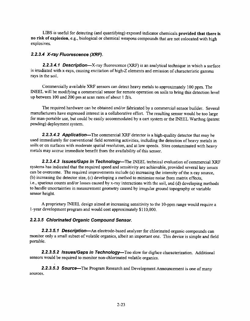
LIBS is useful for detecting (and quantifying) exposed indicator chemicals provided that there isno risk of explosion, e.g., biological or chemical weapons compounds that are not colocated with highexplosives.
2.2.3.4 X-ray Fluorescence (XRF).
2.2.3.4.1 Description—X-ray fluorescence (XRF) is an analytical technique in which a surfaceis irradiated with x-rays, causing excitation of high-Z elements and emission of characteristic gammarays in the soil.
Commercially available XRF sensors can detect heavy metals to approximately 100 ppm. TheINEEL will be modifying a commercial sensor for remote operation on soils to bring this detection levelup between 100 and 200 pm at scan rates of about 1 ft/s.
The required hardware can be obtained and/or fabricated by a commercial sensor builder. Severalmanufacturers have expressed interest in a collaborative effort. The resulting sensor would be too largefor man-portable use, but could be easily accommodated by a cart system or the INEEL Warthog (patentpending) deployment system.
2.2.3.4.2 Application—The commercial XRF detector is a high-quality detector that may beused immediately for conventional field screening activities, including the detection of heavy metals insoils or on surfaces with moderate spatial resolution, and at low speeds. Sites contaminated with heavymetals may accrue immediate benefit from the availability of this sensor.
2.2.3.4.3 Issues/Gaps in Technology—The INEEL technical evaluation of commercial XRFsystems has indicated that the required speed and sensitivity are achievable, provided several key issuescan be overcome. The required improvements include (a) increasing the intensity of the x-ray source,(b) increasing the detector size, (c) developing a method to minimize noise from matrix effects,i.e., spurious counts and/or losses caused by x-ray interactions with the soil, and (d) developing methodsto handle uncertainties in measurement geometry caused by irregular ground topography or variablesensor height.
A proprietary INEEL design aimed at increasing sensitivity to the 10-ppm range would require a1-year development program and would cost approximately $110,000.
2.2.3.5 Chlorinated Organic Compound Sensor.
2.2.3.5.1 Description—An electrode-based analyzer for chlorinated organic compounds canmonitor only a small subset of volatile organics, albeit an important one. This device is simple and fieldportable.
2.2.3.5.2 Issues/Gaps in Technology—Too slow for digface characterization. Additionalsensors would be required to monitor non-chlorinated volatile organics.
2.2.3.5.3 Source—The Program Research and Development Announcement is one of manysources.
2-23

2.2.3.6 Issues/Gaps in Technology. Due to the toxicity and explosive characteristics of somevolatile organics, it will always be worthwhile to know when such substances are present in the vicinityof a digging operation. Currently, there are no means of accomplishing this.
It is not currently known how effective the above technologies would be in a digfacecharacterization system used in HSRS. There are two specific issues related to real-time characterizationof chemical contamination that must be considered.
1. This issue concerns the effect of air currents, which tend to move and disperse vaporsemanating from the digface. In the worst case, the locations where VOCs are detected maybe completely unrelated to the location of the contaminants in the waste seam. Thisphenomenon should be recognized, since the mapped distribution of volatile organics woulditself indicate whether one is looking at dispersed gases or gases residing in the vicinity oftheir source. A hood or hose sampling system to gather samples close to the digface couldhelp alleviate this problem. In any case, for a contained retrieval, where the air currentsarise from artificial ventilation, air flow would be weak to avoid generation of dust andairborne contamination.
2. This issue concerns the effectiveness of any gas sampling sensor when the retrievaloperation includes dust suppression. Foams or mists would undoubtedly block freemovement of soil gases into the atmosphere. This would mean that VOCs could probablynot be detected unless a major release occurred.
Basically, field testing of chemical sensors in a confined excavation environment should be doneprior to use in HSRS.
The INEEL technical evaluation of commercial XRF systems has indicated that the required speedand sensitivity are achievable, provided several key issues can be overcome. The required improvementsinclude (a) increasing the intensity of the x-ray source, (b) increasing the detector size, (c) developing amethod to minimize noise from matrix effects, i.e., spurious counts and/or losses caused by x-rayinteractions with the soil, and (d) developing methods to handle uncertainties in measurement geometrycaused by irregular ground topography or variable sensor height.
A proprietary INEEL design aimed at increasing sensitivity to the 10-ppm range would require a1-year development program and would cost approximately $110,000.
2.2.4 Characterization Sensor Deployment
The 1NEEL's prejudice for high-precision, high-fidelity measurement tools has led to developmentof several unique sensor deployment systems aimed at producing highly specific, real-time informationon buried hazards within local areas (tens to hundreds of feet) that can be reacquired and refinedrepeatedly during progressive excavation of hazardous materials. These have been pursued to provide apractical means for making correct measurements, with maximum information content, under realisticfield conditions.
2.2.4.1 Rapid Geophysical Surveyor.
2.2.4.1.1 Description—The rapid geophysical sensor (RGS) is an extremely simple but usefuldeployment system for making "on the fly" measurements over large areas. The system is manually
2-24
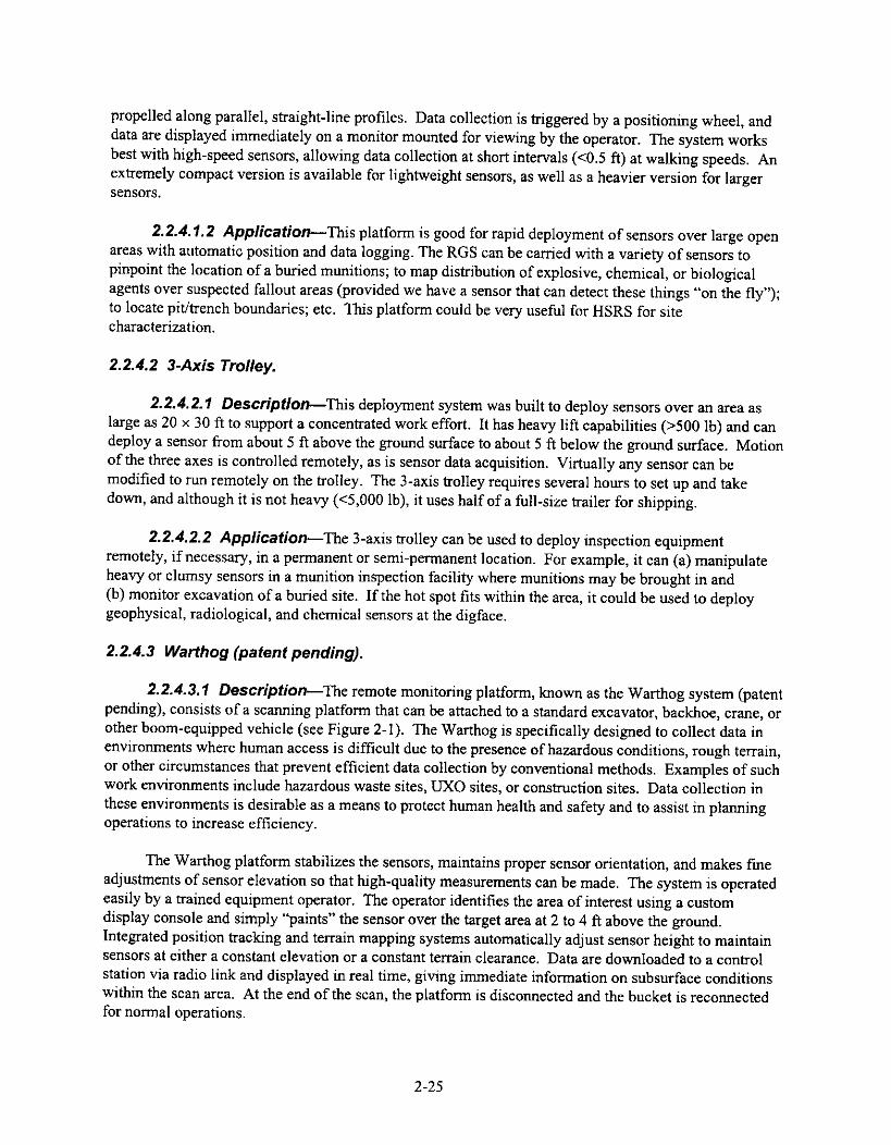
propelled along parallel, straight-line profiles. Data collection is triggered by a positioning wheel, anddata are displayed immediately on a monitor mounted for viewing by the operator. The system worksbest with high-speed sensors, allowing data collection at short intervals (<0.5 ft) at walking speeds. Anextremely compact version is available for lightweight sensors, as well as a heavier version for largersensors.
2.2.4.1.2 Application—This platform is good for rapid deployment of sensors over large openareas with automatic position and data logging. The RGS can be carried with a variety of sensors topinpoint the location of a buried munitions; to map distribution of explosive, chemical, or biologicalagents over suspected fallout areas (provided we have a sensor that can detect these things "on the fly");to locate pit/trench boundaries; etc. This platform could be very useful for HSRS for sitecharacterization.
2.2.4.2 3-Axis Trolley.
2.2.4.2.1 Description—This deployment system was built to deploy sensors over an area aslarge as 20 x 30 ft to support a concentrated work effort. It has heavy lift capabilities (>500 Ib) and candeploy a sensor from about 5 ft above the ground surface to about 5 ft below the ground surface. Motionof the three axes is controlled remotely, as is sensor data acquisition. Virtually any sensor can bemodified to run remotely on the trolley. The 3-axis trolley requires several hours to set up and takedown, and although it is not heavy (<5,000 lb), it uses half of a full-size trailer for shipping.
2.2.4.2.2 Application—The 3-axis trolley can be used to deploy inspection equipmentremotely, if necessary, in a permanent or semi-permanent location. For example, it can (a) manipulateheavy or clumsy sensors in a munition inspection facility where munitions may be brought in and(b) monitor excavation of a buried site. If the hot spot fits within the area, it could be used to deploygeophysical, radiological, and chemical sensors at the digface.
2.2.4.3 Warthog (patent pending).
2.2.4.3.1 Description—The remote monitoring platform, known as the Warthog system (patentpending), consists of a scanning platform that can be attached to a standard excavator, backhoe, crane, orother boom-equipped vehicle (see Figure 2-1). The Warthog is specifically designed to collect data inenvironments where human access is difficult due to the presence of hazardous conditions, rough terrain,or other circumstances that prevent efficient data collection by conventional methods. Examples of suchwork environments include hazardous waste sites, UXO sites, or construction sites. Data collection inthese environments is desirable as a means to protect human health and safety and to assist in planningoperations to increase efficiency.
The Warthog platform stabilizes the sensors, maintains proper sensor orientation, and makes fineadjustments of sensor elevation so that high-quality measurements can be made. The system is operatedeasily by a trained equipment operator. The operator identifies the area of interest using a customdisplay console and simply "paints" the sensor over the target area at 2 to 4 ft above the ground.Integrated position tracking and terrain mapping systems automatically adjust sensor height to maintainsensors at either a constant elevation or a constant terrain clearance. Data are downloaded to a controlstation via radio link and displayed in real time, giving immediate information on subsurface conditionswithin the scan area. At the end of the scan, the platform is disconnected and the bucket is reconnectedfor normal operations.
2-25
The Warthog system is highly mobile and can be moved around a site as easily as the heavyequipment that carries it. The system can scan approximately 1,000 ft2 of terrain per 90 degrees of arc inapproximately 10 to 15 minutes. The sensor platform never touches the ground, thus avoiding problemswith equipment contamination at hazardous sites. Device self-stabilizing and elevation-adjustmentfeatures permit operation in very difficult terrain without degrading sensor data quality. The structureitself is small and lightweight, easily transported, uses mostly off-the-shelf components, and may beconstructed at low cost.
side view
Figure 2-1. Warthog (patent pending).
plan view
2.2.4.3.2 Applications—The Warthog can be used to deploy geophysical, radiological, orchemical sensors. In highly delicate operations, scanning and excavating can be alternated in smallincrements for maximum safety. If the platform is deployed by a standard excavator or backhoe, bothscanning and excavation can be accomplished by the same piece of equipment.
Summary of the INEEL Warthog (patent pending) scanning platform capabilities:
• Adapts to nearly any boom-equipped vehicle for use as a portable scanning system withminimal hardware modifications. Attached to a backhoe, excavator, or boom-equippedHumvee, the Warthog platform could operate to deploy heavy or clumsy sensors in virtuallyany field environment, remotely if necessary.
• Permits precision scanning of approximately 1,000-ft2 areas from safe standoff distanceswithout moving the deployment vehicle.
• The platform can be repositioned quickly through boom manipulations or deploymentvehicle relocation.
• Deploys virtually any type of sensor or lightweight mechanical system.
• Sensor output can be displayed in real time on a remote workstation.
2-26

2.2.5 Other Sensor Deployment Platforms
Some of the other platforms that can be used for the deployment of sensors at waste sites forcharacterization include wheeled vehicles, cable suspension methods, aircraft, and other, more exoticmethods. The following information is included to provide alternatives for HSRS. Short descriptions ofrelevant methods are given. This information was taken from a final draft of a report titled Evaluation ofPlatforms for Electromagnetic and Magnetic Geophysical Sensors in Site Characterization, written byDr. M. Cathy Pfiefer et al. for the U.S. Geological Survey.
2.2.5.1 Wheeled Vehicles.
2.2.5.1.1 Description—Wheeled vehicles include everything from a man-powered cart to aremote-controlled truck. Wheeled vehicles have the advantage of moving quickly over the ground, butengines and metal parts can severely interfere with electromagnetic and magnetic sensors(Hildenbrand 1982).
2.2.5.1.2 Applications—These platforms can be used to provide positioning data and arehighly available and adaptable. The systems are capable of operating in a wide variety of environmentalconditions including hard-packed surfaces, loose sand, ice, snow, mud, shallow water, and swamp lands.
2,2.5.1.3 Issues—Limitations of wheeled platforms include steep terrain, heavy vegetation,terrain deeply covered with water, unstable ground with holes and pits, and mine fields with unexplodedor buried ordnance. Contamination is also an issue as vehicle parts (i.e., wheels) or the entire vehiclemay be disposed of as secondary waste.
2.2.5.2 Cable Suspension Methods.
2.2.5.2.1 Description—This category includes items that are used commonly in constructionand are readily available. They include items such as cranes, cable tools, scissor lifts, and other cabletechniques to suspend the characterization sensors over the survey area. As with any platform,appropriate navigation and data logging devices must be used in chorus with the geophysical sensors andmust not interfere with the platform.
2.2.5.2.2 Applications—These types of deployment platforms can be used to suspend thesensors above the site without the platform coming in contact with the waste.
2.2.5.2.3 Issues—A sensor could traverse the survey area on a cable suspended betweentowers, gantries, or scissor lifts. Large construction equipment containing metal parts can act asconductive and magnetic noise. Radio frequency noise is created by equipment motors. Non-magnetic/conductive cable (e.g., kevlar) can be used to reduce interference with geophysical sensors.
There are a number of size and weight limitations to using cable-suspending methods and tools assurvey platforms. Many cranes, cable tools, etc., are extremely heavy vehicles (25 tons) and requirestable ground for access and operation. Specifically constructed roads may be required around a surveysite in order to use a large crane-like tool to suspend a platform. For a relatively large survey, a craneworking around the perimeter may not be able to reach the center of the contaminated area.
2-27

2.2.5.3 Walking Human Operator, Aircraft, and Exotics. Walking human operators are capableof deploying sensors over a site, but are not applicable to HSRS due to the high probability of explosivesand alpha contamination. Aircraft are common sensor platforms but are not applicable due to the factthat the site must be covered by a containment enclosure to prevent the spread of contamination. Exoticmethods including blimps, weather balloons, boats, and rafts are also not applicable to HSRS due to theconditions of the sites. Further information on these deployment platforms can be gathered from thefinal draft of Evaluation of Platforms for Electromagnetic and Magnetic Geophysical Sensors in SiteCharacterization, authored by Dr. M. Cathy Pfiefer et al.
2.3 Contamination Control
2.3.1 General Description
During waste retrieval operations, it is expected that fugitive dusts will be generated during theexcavation and subsequent dumping of soil/waste matrix into waste packages, causing transuranic (TRU)contaminated and/or hazardous materials to become airborne. Due to the high toxicity and low bodyburdens for TRU and/or hazardous materials, it is important to minimize their generation and spread asclose to the source as possible. Controlling contamination will decrease the cost of operations andmaintenance on equipment in the confinement by allowing manned entry when required. Effectivecontamination control also decreases the cost of decontamination.
Controlling airborne contamination can be accomplished in various ways, including, but notlimited to:
• Confinement enclosure
• Ventilation system
• Foams
• Sprays and water misters
• In situ soil stabilization
• Electrostatic curtains
• Electrostatically charged plastic
• Dust suppression/soil fixatives
• Vacuum systems
• Encapsulate/cocoon waste
• Excavation equipment/techniques.
2-28
Due to the fact that HSRS concentrates on hot spots, which are by definition the nastiest areas ofenvironmental concern, contamination should be controlled as close to the source as possible. Sites thathave designated selective retrieval as their preferred option have unique contaminants of concern, soilmakeup, and environmental conditions. Therefore, it is assumed that the contamination control methodswill need to be tailored for each site at which HSRS is deployed.
This section discusses contamination control requirements and methods. Methods presentedinclude a confinement enclosure, ventilation system, foams, sprays and water misters, in situ soilstabilization, electrostatic curtains, electrostatically charged plastic, dust suppression/soil fixatives,vacuum systems, and encapsulate/cocoon waste.
By matching the contamination control methods available to the needs of the sites with selectiveretrieval as the preferred option, three primary methods of contamination control are recommended.These include a confinement enclosure, a ventilation system (including HEPA filters), and in situ soilstabilization. Other methods for controlling contamination can be used as redundant means ofcontamination control or as site-specific needs and requirements dictate. Because in situ soilstabilization was rated so highly (see Section 6.2.1), it is assumed that this will be used as a part of HSRSthroughout this document. This is important because use of the stabilization agents affects retrieval andseparation.
2.3.2 Requirements
For a complete discussion on requirements concerning contamination control, please seeSections 4.12 and 5.4 of the draft Hot Spot Removal System Requirements Document. HSRScontamination control requirements are the following:
• HSRS shall control the generation of fugitive dust during the following activities, ifperformed: overburden removal, waste removal, size reduction, shredding, and packagingto control the spread of potential beta, gamma, alpha, and hazardous contamination
• HSRS shall not interfere with video equipment used for controlling operations
• Appropriate controls shall be maintained and verified that prevent the inadvertent transfer ofremovable contamination to locations outside of radiological areas under normal operatingconditions
• Contamination control system(s)/method(s) shall be easily deployed
• HSRS shall minimize the generation of new waste streams
• HSRS shall minimize secondary waste streams
• HSRS shall not degrade the characterization technology's effectiveness to monitorcontamination spread for levels above background during removal operations
• HSRS shall not adversely affect the characterization of the contaminant(s) of concern
• HSRS shall not adversely affect any subsequent treatment process
2-29

• The specific contamination control processes and materials shall be defined on a site-by-sitebasis.
2.3.3 Confinement Enclosure
2.3.3.1 General Description. The following information was provided by Scientech and AlphaEngineers under subcontract.
There are many structures available that are advertised as being portable. The most common is ametal frame structure with a fabric material tensioned over or between the framing. The framing isusually galvanized steel or aluminum. The metal frames are easily dismantled into sections that can betransported on flatbed trucks. The life expectancy of the metal frames is 20 years or more and canusually be resold. There are a variety of fabrics with life expectancies usually determined by thematerial makeup and thickness ranging from less than 2 years up to 20 years. The fabrics are usually aPVC-coated polyester scrim material or a vinyl, either reinforced or plain. Each manufacturer has adifferent method for attaching the fabric to the frames, which affects the setup and takedown time. Also,some require an additional weather strip at each joint.
There are also air-supported structures secured by steel cables and anchored to the ground, wherethe inside of the containment is pressurized to inflate the structure. These usually have two layers offabric allowing an outer layer of air to be pressurized greater than the interior of the structure, thussimulating a negative-pressure structure; however, air locks are required to maintain a true vacuum atvehicle and personnel access points.
Both metal framed and air supported structures must be anchored to the ground. Where loads andsoil conditions will allow, anchorage can be provided by earth augers. Also, a block of concrete abovegrade could be used as a ballast block. Some conditions may require concrete piers at each frameconnection placed below frost depth.
Other systems, advertised as portable, are generally anchored to a concrete pad and include:
• Smaller metal buildings, which can be moved as one unit by a crane or forklift, but are notpractical to transport over the highways if they are very large.
• Pre-fabricated building panels that can be arranged in unlimited sizes and shapes. However,panels for outdoor use large enough for this application are too bulky and heavy totransport, and the lighter duty panels are not intended for exposure to the environment.
• Pre-molded fiberglass structures that are typically fabricated in smaller units and assembledinto a larger complex on location. For a pre-molded type of structure to be cost effective, alarge number of units must be made to the same mold and must be small enough totransport.
The confinement enclosures evaluated in this section are also presented in tabular form inSection 6, "Alternative Evaluation," and are compared to the requirements found in the HSRSRequirements Document.
2-30
2.3.3.2 Applications. Confinement enclosures would be used mainly at sites containing TRU wasteand would house the excavating and retrieval equipment, the waste transfer system (or parts thereof), andany decontamination equipment deemed necessary. The main function of the enclosure is to provide onelevel of confinement to prevent the spread of contamination.
2.3.3.3 Issues/Gaps in Technology. A few gaps are present concerning the confinementenclosure:
• Methods need to be developed to maintain a negative pressure on the confinement duringhigh winds
• Wind loading will be site specific and will require a hazard analysis to determine if theequipment will have to be designed for natural phenomena per the Safety Analysis Reports(i.e., tornadoes)
• Keeping in mind mobilization and demobilization issues, the method for anchoring downthe confinement during operations to maintain a negative pressure on the structure will haveto be engineered.
2.3.4 Ventilation System
2.3.4.1 General Description. Laminar air flow, which can be used effectively to control and directdust to high-efficiency particulate air (HEPA) filter units, could be used in three ways:
1. Overall facility air flow can be established to limit contamination spread. Laminar air flowcould be directed from the source ducts to the receiving ducts and HEPA filter system.Facility air flow should be in one direction at all times.
2. A laminar air flow hood, or shroud, could be deployed in close proximity to the digface tobetter control dust generation at the source. The hood could be deployed as part of theexcavator (near the end-effector) or separately as a facility support system.
3. Laminar-directed air flow could be used in conjunction with the waste packaging system tocontrol fugitive dust during dumping operations. Test reports (Winberg et al. 1992) showthat a 98% reduction in dust spread can be achieved when using a funnel to focus retrievedoverburden soils or buried wastes with a face velocity of 120 linear feet per minute (lfpm).
A ventilation system would be comprised of fans, blowers, HEPA filters, etc., sized to the HSRSconfinement enclosure. Because these components are common items, they will not be described indetail in this report; however, vortex tubes, which act like a pre-filter for the HEPA filters, are relativelynew and will be described briefly in the following section.
2.3.4.2 Vortex Tubes.
2.3.4.2.1 Description—Vortex tubes have been developed and manufactured by Delta-21Resources, Inc./Robertson Technologies Corporation to separate particulate (dust) from the air stream byusing centrifugal action similar to cyclone separators (see Figure 2-2). These tubes have been shown to
2-31

have 90% extraction efficiency for respirable dust and, when used as a pre-filter where the dust loadingis high, can extend the interval between media filter cleaning by a factor of 10 or more.
Because these tubes can be constructed of several different types of materials, using them in aradioactive environment would not constitute a problem. They are flexible in size and design, have lowassociated pressure drops, are simple to install, require minimal maintenance, and have low capital costs.
2.3.4.2.2 Application—Vortex tubes, used either with a local ventilation/vacuum system nearthe excavator or in the exhaust of the confinement enclosure upstream of the HEPA filters to remove themajority of the dust prior to entering the filters, will not only minimize the frequency at which the HEPAfilters will have to be changed, but will also help with air emission control.
2.3.4.2.3 lssues/Gaps in Technology—Contamination control measures would have to betaken where the dust leaves the vortex tubes, either in the confinement enclosure in close proximity tothe exhaust ducting, or close to the retrieval equipment if used for local ventilation.
2.3.4.2.4 Source—This information was provided by Delta-21 Resources, Inc. in response tothe Commerce Business Daily advertisement placed January 29, 1997. There are other vendors withsimilar systems commercially available.
Figure 2-2. Picture of vortex tube supplied by Delta-21 Resources, Inc.
2.3.4.3 Application. A ventilation system could be used to direct air flow from areas of lessercontamination to areas of higher contamination, thus minimizing the amount of cross-contamination inthe confinement enclosure. Ventilation could also be used on the exhaust side of the confinementenclosure to filter the confinement exhaust to meet regulatory air emissions requirements as defined inthe individual sites' safety paperwork.
2.3.4.4 General issues/Gaps in Technology. The ventilation system would have to be designedfor the specific structure used in the HSRS, as all blowers, fans, HEPA filters, etc., must be sized to thespecific air volume in the confinement chosen. The system would be comprised of off-the-shelfcomponents designed for use in hazardous/radioactive environments. These components are readilyavailable in industry.
2-32

For local ventilation methods, some type of hood/shroud would have to be designed for use withthe retrieval equipment used in HSRS. Several hundred different hoods have been designed forcontamination control and could possibly be modified for use in HSRS. In Winberg et al. (1992),references are given as to where these designs are, and these references should be consulted as a sourceof information when designing a local ventilation system to control contaminants.
2.3.5 Foams
2.3.5.1 General Description. Foam soil fixatives are applied over an emitting surface to controlodors, VOCs, dust, and other emissions. The foam creates a continuous barrier between the surface andthe atmosphere. Foam soil fixatives are used in place of soils, tarps, and other cover materials to controlodors, VOCs, dust, windblown emissions, etc. Foam soil fixatives completely cover any surface towhich they are applied and will conform to irregular and vertical surfaces. Foam soil fixatives can beapplied quickly and easily and can prevent emissions better than soil or tarps. They are available in non-toxic, non-hazardous, non-flammable, and biodegradable forms. They have been used on soil, surfacewater, construction materials/debris, containers/equipment, drums/tanks/piping, sediments in water, andprocess wastes and sludge. Foam soil fixatives have been used throughout the United States and abroadfor a variety of applications including remediation projects, Superfund projects, lagoon and pondclosures, as odor control on a liquid surface, for dust and VOC suppression, emergency response, vaporand odor suppression in industrial applications and erosion control, to prevent surface water infiltrationon stockpiled soils, for in-transit odor control on sludge-filled containers, and dust control duringdemolition of asbestos-contaminated buildings.
Some of the foam soil fixatives products require water to dilute the product prior to use. Duringmonths of freezing weather, all foam soil fixatives products and equipment must be protected fromfreezing. There may be some application temperature limitations on foam soil fixatives products. Caremust be exercised when applying foam soil fixatives products with respect to weather; a heavy rain willnot allow the membrane to form. Rain is not an issue for HSRS as the equipment will be used in anenclosure, but if water misters are used for contamination control, they may cause problems with thefoams.
Some foam soil fixatives can be applied using a pneumatic foam unit. These foam soil fixativesconsist of a single component material requiring non-chemical mixing and no post-application cleanup.The pneumatic foam units are simple and easy to operate; they require no special training. Foam soilfixatives are available with durations ranging from a few hours to 6 months. The pneumatic foam unitsare available in a variety of sizes ranging from a small, skid-mounted unit to a large, self-propelled track-mounted unit. These units are available for purchase or rental.
Other foam soil fixatives are combined with a stabilizer and water. The stabilizer and concentrateare stored in separate containers near the nozzle and are delivered by suction to the nozzle. In afield-deployable setting, this type of unit is capable of fixing 45 m2/min with a total encapsulated foam.
2.3.5.2 Application. Foam soil fixatives and pneumatic foam units have been in use in the field forseveral years and can be applied at a rate of 45 m2/min.
2.3.5.3 General Issues. Most dried foams do not dissolve; thus, they increase the waste volume.These foams also contain diisocyanates, which, even though they instantly react with air and water to
2-33

form innocuous products, may require more personal protective equipment and respiratory equipmentduring applications, if not applied remotely.
Foam soil fixatives do not face any general challenges.
2.3.5.4 Contamination Control Unit.
2.3.5.4.1 Description—The Contamination Control Unit (CCU) was specifically developed tosuppress and fix contamination, and inhibit its spread during retrieval operations of buried wastes thatare normally quite dusty. The CCU, a field-deployable, self-contained unit, is capable of dispensing soilfixatives, dust suppression agents, and misted water, and uses a vacuum system to control contaminationspread (see Figure 2-3). Dust control using the CCU is 70% efficient. All of the dust control productsare non-hazardous and can be disposed of in sanitary landfills. The CCU is a 9 by 26-ft trailer.
The vacuum, a nuclear grade system with a HEPA filter and a critically safe 55-gal wastecontainer, can pull 1.5-in. debris (3/4 in. if the debris is heavy) through 100 ft of hose. The dustsuppression system applies a water mist, soil fixant, and dust suppressant.
The water misting system, Dryfog (manufactured by Sonics, Inc.), uses compressed air to forcedemineralized water through six nozzles. Each nozzle can be attached to its own stand from 1 to 18 ftover the area to be misted. The nozzles discharge a mist curtain that captures and removes aerosolizedsoil. The CCU can hold 300 gal of water for use in the water misting system.
The concentrated soil-fixant, 3M Foamer (manufactured by 3M, Inc.), is combined with astabilizer and water pumped from a trailer-mounted 325-gal tank. The stabilizer and concentrate, storedin 5-gal cans near the nozzle, are delivered by suction to the expansion nozzle, 3M Foamer is a vapor-suppressing foam used for uneven contaminated soil, such as steep sloping digfaces. The cure time forthis foam is 30 to 90 seconds.
The dust suppressant, Flambinder (calcium lignosulfate, manufactured by Flambequ Corporation),is commonly used on U.S. Forest Service roads to suppress dust. This product is mixed with water,stored in 325-gal tanks, and pumped to a nozzle via a hose-and-reel system. Flambinder cures in a fewhours and can withstand traffic of hundreds of vehicles without reapplication. This is important in that itcould be used to control dust generated due to heavy equipment mobilization in and out of theconfinement.
Natural polysaccharides can also be applied for dust control measures using the CCU.
2-34
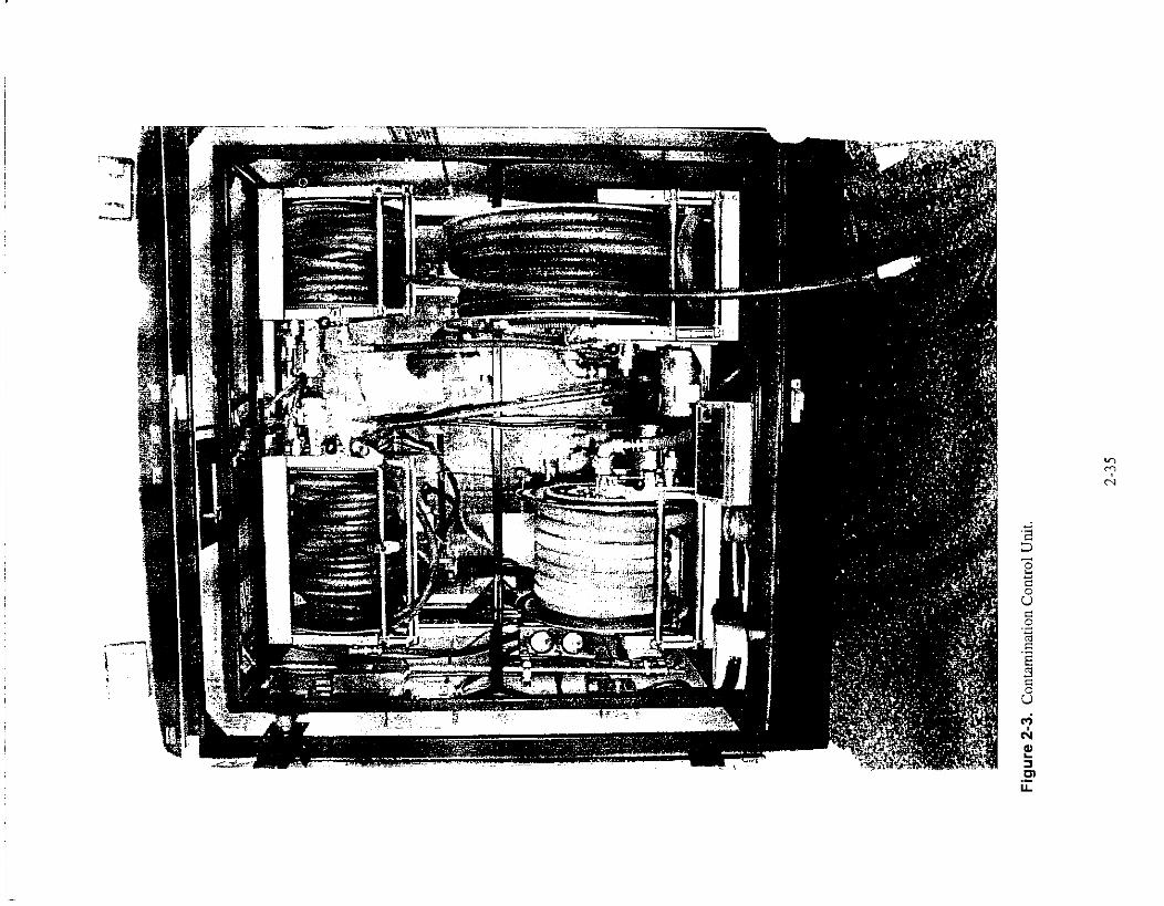
I. ur
e - . Contamination Co
ntro
l Un
it

In a field-deployable setting, the unit is capable of fixing 500 ft2/min with total encapsulation(3M Foamer), or applying 1,000 ft2/15 minutes of dust suppressant (Flambinder) while simultaneouslyproviding 2 gpm mist from six misting nozzles. The vacuum system can be operated continuouslyduring the spray operation. In an emergency response situation, the system is capable of spraying dustsuppressant at a rate of 1,000 ft2/3 minutes. The system has been used at Hanford for a retrievaltreatability study and by INEEL Environmental Restoration during a capping action at the EnvironmentalBreeder Reactor I (EBR-I). At EBR-I, Wendon dust suppressant was used on 1.5 acres.
2.3.5.4.2 Application—The CCU can be used as a means of dust control during excavationactivities and achieves 70% efficiency.
2.3.5.4.3 Issues—Calcium lignosulfate, the main ingredient in Flambinder, may be difficult toremove from the soil later, which could affect characterization and/or treatment (Sackschewsky 1993).
The 3M Foamer is not cost effective and probably not appropriate for continuous applicationduring excavation activities. It is best applied once to areas in the confinement enclosure that will not bedisturbed during the excavation activities. In addition, the foam contains toluene diisocyanates (TDIs),which require the use of a Class B bubble suit and self-contained breathing apparatus while in use.
The vacuum system needs more evaluation using sieved soil spiked with rare earth tracers toidentify the contamination control problems associated with it.
The water-to-air ratio of the misting heads in the water misting system need further work.
2.3.5.4.4 Source—The Contamination Control Unit is an INEEL-owned technology.
The information discussed above was taken from Evaluation of Contamination Control UnitDuring Simulated Transuranic Waste Retrieval, by D. N. Thompson, A. L. Freeman, and V. E. Wixom,November 1993, EGG-WTD-10973.
2.3.6 Sprays and Water Misters
2.3.6.1 General Description. Sprays and water misters are commonly used in industry as a meansof controlling dust, and therefore the spread of contamination. Chemicals or water are continuouslysprayed into the controlled area through nozzles that adjust the direction of flow and the volume. Thechemicals or water adheres to the airborne dust particle, forcing it to fall to the ground.
2.3.6.2 Application. Misters could be used as a form of contamination control during excavationactivities to control the spread of airborne dust.
2.3.6.3 Issues. Water or chemical is added to the waste stream, thus adding volume to the waste. Inaddition, some chemicals may interfere with later treatment of the waste.
Because dust must become airborne before this technology even comes into play, the spread ofcontamination is not controlled as close to the source as possible. Some contaminants will not becontained within the water mist as the laminar air flow created in the confinement enclosure by theventilation system may carry the dust-laden air to the exhaust ventilation system prior to being entrained
2-36

in the mist. This indicates that water or chemical sprays and misters are not an efficient means ofcontrolling the spread of airborne contamination.
2.3.6.4 Source. There are many vendors capable of providing sprays and/or water misters.Sections 2.3.6.4.1 through 2.3.6.4.4 describe these vendors.
2.3.6.4.1 Sonics, Inc.-
2.3.6.4.1.1 Description. See Section 2.3.5.4 on the Contamination Control Unit for adescription of the Dryfog system by Sonics, Inc.
2.3.6.4.1.2 Issues/Gaps in Technology. Water would be added to the waste stream,albeit not much.
2.3.6.4.1.3 Source. Sonics, Inc.
The information discussed above was taken from Evaluation of Contamination Control UnitDuring Simulated Transuranic Waste Retrieval, by D. N. Thompson, A. L. Freeman, and V. E. Wixom,November 1993, EGG-WTD- 10973 .
2.3.6.4.2 Hydrogeophysics Company-
2.3.6.4.2.1 Description. A twist on sprays and water misters is the Electrically ChargedFog (Fog Gun) from Hydrogeophysics Company. Natural dust is normally electrically charged. Thesmall particles, 1 micron in size, are usually negative; the larger particles, 7 microns, are positivelycharged. The same thing is observed with industrial dust from grinding, walking, sweeping, or abrasion(Zimon 1982). In some cases, impurities may affect the sign or value of the charge, but there is alwayssome charge. This means that oppositely charged water fog is very effective in contacting the dust andcausing it to drop out of the atmosphere. The amount of water required is small, and the collection isvery effective. Devices have been used in a laboratory and have been successfully demonstrated in oneor more lead, copper, or steel foundries, in ore milling, battery building companies, several sections of asteel mill including ore recovery, coke ovens, and rough and fine grinding areas. Use in a copper minehas covered the drilling, milling, casting areas, and disposal of wastes. In a wood fabrication facility,operations were successful in the primary (rough fabrication) area and in the finishing area. In the paintshop, the charged spray was very successful in removing excess paint from the atmosphere. In a tirerebuilding shop, it was possible to suppress floating dust in several areas.
Performance data are available. A single unit is 2.5 ft (0.75 m) long and 8 in. (0.203 m) indiameter. It requires 110 V at 3 A, 1 cubic foot per minute (cfm) of compressed air at 80 psi and asupply of water, 1 gal (3.79 L) per minute. No other support services are required. There is no electricalhazard if people get into the fog spray. The area must permit water spraying, but there is no hazard withflammable or explosive dusts. The water spray is designed to reduce the natural charge on the dust, sothe system becomes safe if the charged fog is used. There have been some tests on fire, and it appearsthat the charged fog is more effective than the usual uncharged material. The system is easy to use. Itcan be hand-held or mounted on a stand. For larger applications, more fog guns can be used, or largerfog guns can be built. There have been tests on mine trucks moving over dirt roads, and there was aboutan 80% reduction of visible dust. Very little infrastructure is needed.
2-37
2.3.6.4.2.2 Application. The Fog Gun may be used for HSRS as a means of dust controlduring excavation activities.
Water would be added to the waste stream, albeit not much.
Throwing the fog for long distances, over large ore piles, is a problem, and special high speedblowers are needed.
Dust must become airborne before this technology becomes effective. This may reduce visibilityfor the remote vision system.
2.3.6.4.2.3 Issues. As HSRS will contain, by definition, the worst contamination at thesite, the dust and contamination control is more effectively controlled at its source. Due to the fact thatthe dust must become airborne before the Fog Gun will work, it is not applicable, to HSRS.
2.3.6.4.2.4 Source. Hydrogeophysics, Inc. Many other vendors could provide thistechnology.
2.3.6.4.3 Foster-Miller-
2.3.6.4.3.1 Description. The "Shearer Clearer" is a new water spray system that usesair-moving techniques of water sprays to split the ventilation air stream. This is used extensively in themining industry, where the clean air split is directed over the operator and the dusty air is redirectedaway from the operator.
2.3.6.4.3.2 Application. The Shearer Clearer may be used in conjunction with otherequipment in the ventilation system to redirect the dust-laden air back into the enclosure and the clean airto the exhaust system on the confinement enclosure.
2.3.6.4.3.3 Issues/Gaps in Technologies. This technology redirects the dust-ladenair rather than minimizing it.
2.3.6.4.3.4 Source. Information was received in response to a Commerce BusinessDaily advertisement placed January 29, 1997.
2.3.6.4.4 MEC Systems Inc.-
2.3.6.4.4.1 Description. The "MISTer—rm system is an arrangement of atomizingnozzles, controlled by a central control module, with very low-volume rates (0.0128 to 0.0195 gpm) at600 to 1,000 psi. The low volume rates, governed by a thermostat, humidistat, timer, or computer, aredelivered with high forward discharge velocities, causing high turbulence and thus extremely uniformparticle distribution.
When used for dust control, the dust particles are saturated by droplets of fog, 1 to 30 microns insize, making them heavier than air, which causes them to fall to the ground.
2-38

2.3.6.4.4.2 Applications. The MISTerTm would be used to minimize airborne dust andcontamination during retrieval activities.
2.3.6.4.4.3 Issues. Water would be added to the waste stream, albeit not much.Demonstrations may show that due to the very low-flow rates, the water would evaporate shortly aftershutting down the water misting system.
2.3.6.4.4.4 Source. An information package was received from Peter Melnyk of MECSystems, Inc. in response to an advertisement placed in the Commerce Business Daily on January 29,1997.
2.3.7 In Situ Soil Stabilization
2.3.7.1 Description. In situ stabilization controls contamination at its source—in the soil/wastematrix. A monolith is formed by injecting a grout, resin, or polymer into the soil/waste matrix. Thismonolith can then be considered as either in situ disposal of the buried waste with enhancedconfinement, or as a means of contamination control during retrieval operations. In addition, in situ soilstabilization can be used to form subsurface walls in the excavation pit, which minimizes the size of theexcavation considerably as the walls would no longer have to be sloped. By minimizing the size of theexcavation pit, the size of the retrieval equipment can also be minimized, thus reducing capital costs.
As HSRS is concerned with the nastiest contaminants encountered at a remedial site, thecontamination control should occur as close to the source as possible. In researching the differentmethods of contamination control, the only method that actually does control the dust/contamination atits source is in situ stabilization, and is thus the preferred option of HSRS at this point. Several methodsof in situ stabilization will be discussed here to represent the various methods that can be used. Somehave not been field tested, and none are known to work in all soil types. It must be assumed thatwhatever method of in situ stabilization is chosen, field tests for each site will have to be conducted priorto use to determine what media should be used.
2.3.7.2 Jet-Grouting.
2.3.7.2.1 Description—Full-scale demonstrations of two innovative subsurface stabilizationtechniques were performed at the INEEL in 1995 (Loomis et al. 1995). The first demonstration involvedcreating a jet-grouted wall to be used for preventing the horizontal migration of contamination as well asfor preventing sloughing of waste materials during retrieval. The second demonstration involved creatinga waste monolith with different polymers to agglomerate the waste into less aerosolable forms. The twopolymers differed in that one was a soft, eraser-like polymer for ease of retrieval while still enhancingcontamination control, the other a hard, more durable material for long-term encapsulation.
The jet-grouted wall (Figure 2-4) was created with cement and a CASA GRANDE jet-groutingapparatus consisting of a drill system, high-pressure positive displacement pump (JETS), and associatedsupply tanks and high-pressure hoses. To inject the grout: grout is delivered to a surge tank (a 55-galdrum with a screened top), and is then pumped to the suction end of the CASA GRANDE positivedisplacement pump and on to the drill/grouting system. The drill stem is driven into the waste andjet-grouted at 6,000 psi while withdrawing the drill stem in 5-cm incremental steps. The drill parametersduring grouting were as follows: two revolutions of the drill stem per step, 5-cm withdrawal of stem perstep, and 4 to 6 seconds per step. This created a "soilcrete" wall (see Figure 2-5) composed of 67% soiland 33% grout material. Using these parameters, there were no visible voids in the wall, which
2-39

supported a 98,000 excavator in the excavation position on the wall. The wall did not undergo anystructural damage.
The estimated cost for the jet-grouted wall (outside dimensions of 30 by 30 ft, two holes wide on atriangular pitch) was based on 114 injection holes at $400 per hole, 100 gal of cement per hole at $0.49 pergallon, contamination control during operations (assuming 2 weeks at $1,000 per day),
Figure 2-4. Jet-grouted wall using cement.
2-40

Figure 2-5. Jet-grouted wall for vertical excavation.
mobilization/demobilization costs of $15,000, and secondary waste management of five drums at$5,000 per drum. The total estimated cost came to $104,600.
To stabilize a waste matrix with a "soft" polymer for ease of retrieval and enhanced contaminationcontrol, a 3M acrylic polymer composed of two comonomers (equal parts of A and B components),benzoyl peroxide and amine additives, were used to start the polymerization process. To inject atwo-component polymer, a JET5 high-pressure injection pump injects Part A of the polymer at 6,000 psi,while a SCHWING pump injects Part B at 1,000 psi using a dual concentric annulus nozzle (see Figure 2-6) to prevent the two components from mixing in the nozzle itself rather than in the soil/waste matrix. Thedrill step was withdrawn in 3-cm steps, with two revolutions per step and 2 seconds per step. The maincutting force of the grout was done with Part A at 6,000 psi, Part B at 1,000 psi simply mixed with Part A.
After injecting the two-component polymer, a standard backhoe can be used to retrieve the waste.The "eraser-like" polymer behaves similarly to wet clay in consistency and showed a 91% reduction indust spread, as compared to 70% using misting sprays and fixants. This method did not, however,eliminate the spread of simulated plutonium oxide, which showed a two-order-of-magnitude increase onair-monitoring filters during the retrieval over background values. This was thought to be caused by thepenetration of a waste drum during retrieval, which had not been penetrated by the grout material.
The hard polymer, also a two-component polymer, is injected the same way as the soft polymer.The hard polymer is easily fractured with a standard backhoe, and the pit can be retrieved in large, cohesivechunks of soil/waste/polymer. The hard polymer may work better than the soft polymer for
2-41

contarr ;-,ation control and retrieval as it is more cohesive and tends to reduce the spread of contaminantsbetter the soft polymer.
The estimated cost of using a polymer grout for contamination control is based on a10 x 10 x 10-ft hot spot in a TRU pit, and the region grouted is 30 x 30 x 10 ft. The site would require270 injection holes at $250 per hole, grout material at $25 per gallon, which equates to 38,000 gal,assuming 57% voids, and labor. This makes a grand total of just over $1M plusmobilizationldemobilization costs, which we will assume would be similar to those costs associated withthe jet-grouted wall of $15,000, and contamination control costs, if required.
In 1996, the scope of the in situ stabilization research was expanded to find more grout materialssuitable for in situ stabilization. This expanded list of grout materials would allow more soil types to begrouted in situ.
During this effort, one commercially available grouting material, a high-sulfate-resistant cement,and four innovative materials were evaluated. The four innovative materials included a proprietarywater-based epoxy, an INEEL-developed two-component grout resembling hematite when cured withsoil, molten low-temperature WAXFIT (a proprietary agent from Carter Technologies with paraffin asthe main ingredient), and a proprietary iron oxide cement-based grout called TECT.
The WAXFIT grout will be discussed here because it is the most applicable to HSRS as it has thehighest penetration in the soil (the least voids) and can be removed easily from the waste stream prior totreatment. For more information on the other four grouts, see Loomis et al. (1996).
2-42

A part
90
I
Outer annulus
B part
Inner annulus
o. 1,000 psi
6,000 psi
Bit
Figure 2-6. Dual concentric annulus nozzle.
M95 0315
The WAXFIT grout, when injected, permeates the ungrouted soil as well, resulting in all contentsof the pit, both soil and waste, being saturated with WAXFIT (see Figures 2-7 through 2-10). A cohesive(stand-alone) monolith with essentially no voids is thus created. This monolith is easily retrieved with astandard backhoe and minimal dust spread. This material is suitable for use in transuranic andradioactive-contaminated waste sites.
In the field demonstrations, 15 holes could be grouted in 1 hour and 30 minutes. The WAXFITcomes in a large tanker truck in a molten form at 140°F. The tanker holds 1,400 gal of WAXFIT. Eachhole requires approximately 81 gal of grout.
2-43

Figure 2-7. WAXFTT emanating from an uncovered crack in the thrust block during the WAXFIT field
trials (96-517-2-18).
Figure 2-8. Detail of paper from WAXFIT pit (96-584-2-5).
2-44
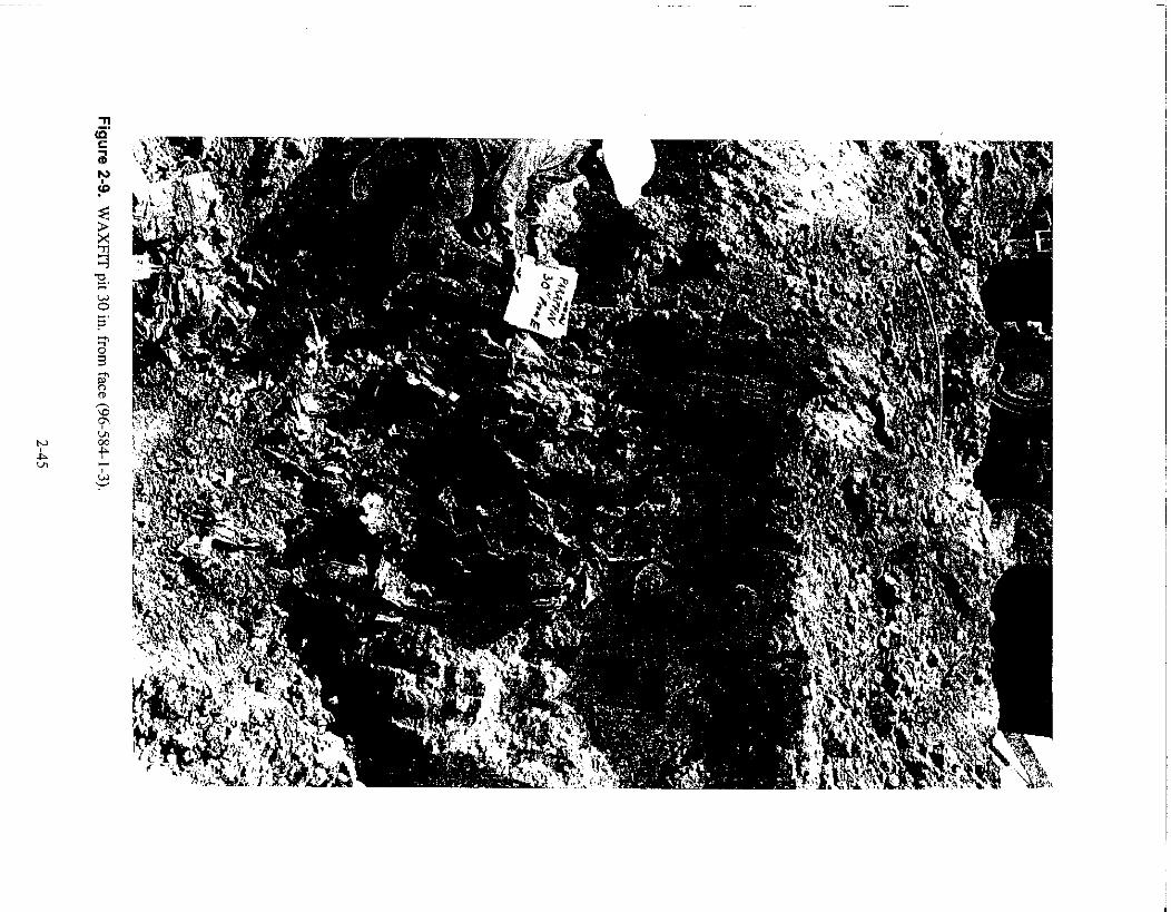
(El -PSC' 6) oonj
wag '
II? OE II' 1I4XV

Figure 2-10. Large tanker used for transporting hot WAXFIT and hot water for cleanout (96-517-2-11).
The cost of WAXFIT grouting is approximately $816/yd3.
2.3.7.21 Applications—In situ stabilization could be used to aid in hot spot removal by eitherencapsulating the waste during retrieval to suppress dust, or as a means of shoring walls during excavation.
WAXFIT can be used as a grout and is injected approximately 2 weeks prior to excavation to allowthe liquid WAXFIT to penetrate the soil and run into all of the void spaces, thus encapsulating the mostdust particles. The WAXFIT has been shown to be 99% efficient in controlling dust and is preferred overthe other grouts in that it can be removed easily from the waste matrix prior to treatment.
This form of jet grouting for in situ stabilization, including the use of WAXFIT, is ready for hotapplications.
2.3.7.2.3 issues/Gaps in Technology—If molten WAXFIT is used, a spoils returnmanagement strategy should be refined, as currently there is a 33% return of the injected volume. Alternateemplacement techniques can be pursued to improve the overall grout return management process.
The drilling system should be modified for radioactive applications.
2-46
Each site may require a different agent, so limited tests should be performed prior to fulldeployment.
The grout/polymer should go beyond the hot spot or zone to be retrieved to prevent surroundingsoils from sloughing into the waste pit, causing aerosolization during retrieval.
For future applications, an on-line flow meter, to alert operators of potential plugging of nozzlesduring jet-grouting, is recommended. In the event a nozzle is plugged, the hole should be grouted again.
When using in situ stabilization for shoring walls, the interior of the wall should be excavatedusing other contamination control technologies, such as misting systems, fixants, or ventilation. It isrecommended that a relatively cheap wall material be used for the shoring walls.
More research is required to develop a polymer with a less obnoxious smell. For the polymerscurrently used, full-face respirators should be made available, but are not required.
It is recommended that during the injection process, any drums known to exist in the waste matrixshould be punctured and filled with grout to quasi-solidify the contents of the drum before excavation.This minimizes the threat of small explosions due to pressure or gas buildup in the drums.
2.3.7.2.4 Source—LMITCO at the INEEL. Other companies can provide similar agents for insitu stabilization and a means to inject them into the excavation pit.
Information was taken from Innovative Subsurface Stabilization of Transuranic Pits and Trenches,by Guy G. Loomis, David N. Thompson, and John H. Heiser, December 1995, INEL-95/0632, andInnovative Subsurface Stabilization Project—Final Report, by Guy G. Loomis, Andrew P. Zdinak, andCarolyn W. Bishop, INEL-96/0439.
2.3.7.3 Cryogenic Retrieval.
2.3.7.3.1 Description—Cryogenic retrieval of buried waste is a technology that relies on liquidnitrogen (LN2) to freeze soil and buried waste in order to immobilize the radioactive and hazardouswaste and reduce the spread of contamination while the buried material is retrieved with a series ofremotely operated tools (see Figure 2-11).
To freeze the soil for the cryogenic retrieval process, a series of carbon or stainless-steel small-diameter freeze pipes, approximately 10 to 12 ft in length, are driven into the area to be excavated with astandard vibratory drill. Water is injected into the soil to aid in the cohesion of the soil and wasteparticles. LN2 is then delivered into the freeze pipes. In addition to the freeze pipes, a series oftemperature and moisture probes are installed to indicate when the mass is frozen and the quantity ormovement of moisture in the soil. While the pit to be excavated is frozen, the perimeters of adjacent pitsare also frozen. Once the area to be removed is frozen, an access pit in clean soil just to the side of thearea to be extracted is excavated. The access pit serves to create a digface from which excavation of thewaste can proceed.
A gantry equipped with a breakout tool, which develops 360 tons of force, is used to pry the freezepipes out, hopefully developing an ice column, or "popsicle" of waste around the freeze pipe. It wasdetermined later that this ice column is not feasible. A mining technique would have to be developed toextract the freeze pipes.
2-47

ControlTrailer
Freeqe pipes(S oil is frozen using liquid nitrogen and Waste
water to prevent the spread of Transportcontamination) Box
Cryogenic Retrieval
Contaminants are removedusing remote tools
Liquid NitrogenTanks
Figure 2-11. Cryogenic retrieval process.
The cost of using cryogenic retrieval is approximately $1,500/yd3.
2.3.7.3.2 Application—Cryogenic retrieval is proposed for application to any type ofradionuclide or hazardous contaminant that may be contained in TRU buried waste. The principal benefitof this technology is contaminant mobility reduction, since by freezing the soil, both airborne and liquidcontaminants are immobilized.
2.3.7.3.3 Issues—Cryogenic retrieval does reduce the amount of dust generated duringexcavation, but a lot of aerosolized soil particles are still observed during the dumping of the waste intowaste packages (see Figure 2-12). The method of dumping the waste would have to be modified.
The addition of water to the waste stream can cause enhanced migration of contaminants.
Water added to promote cohesion tended to migrate beyond the test pit boundary. Follow onstudies would have to be performed to investigate better methods for determining the optimum moisturecontent in the soil and more even dispersal of water through the soil and waste mass.
Reliability of the equipment would have to be improved by means of increased predeploymenttesting.
Follow on studies are recommended to refine the design of remote-operated tools and to conserveLN2.
If the freeze pipes cannot be extracted and reused, they would require treatment as another buriedwaste type. Methods should be evaluated to reclaim freeze pipes so that they can be reused.
A small-scale demonstration should be performed in a hot location.
2-48

Figure 2-12. Cryogenic retrieval.
The final design, fabrication, and testing of hardware, and mobilization to the field for full-scaleretrieval would have to be done. This, as stated in Valentich and Yokuda (1992), will require a long-termcommitment with respect to the resources and effort needed to develop this technology.
If intact containers exist in the waste volume, the drilling of injection pipes might rupture thecontainers, causing an initial spread of contamination. Furthermore, injection of water to help the freezeprocess may also contribute to some contamination spread if it were to flow out of the retrieval column.
The current design of the freeze pipes creates a potential pathway for the migration of contaminationdue to a gap between the freeze pipe and the soil. The driving point of the drill would have to modified tominimize or eliminate this problem.
This does not currently work in all types of soil and waste.
Improvements are needed on the measurement of thermal characteristics and for the detection ofmoisture migration.
2-49

2.3.7.3.4 Source—This information was found from the following sources:
• http://www.gnet.org/gnet/tech/techdb/gete/crdisc.htm
• Final Report for the Cryogenic Retrieval Demonstration, by D. J. Valentich andE. L. Yokuda, September 1992, EGG-WTD-10397
• Technology Catalogue, DOE/EM-0138P, February 1994, page 131
• Buried Waste Integrated Demonstration (BWID), DOE/EM-0149P, March 1994, page 21.
2.3.7.4 Microbial Polymer Gel.
2.3.7.4.1 Description—BDM Petroleum Technologies has developed a technology that usesmicrobial polymer gels to construct low-impact subsurface barrier walls. The microbial polymer isinjected in a series of boreholes or injection wells. These wells are not limited to any particular depth; ithas been demonstrated that the system is feasible to depths of several hundred feet. After the microbialsystem is in place, nutrients are injected to stimulate the generation of a biodegradable polysaccharidebiopolymer gel in situ that can be removed through nutrient manipulation.
2.3.7.4.2 Application—This technology would be used in conjunction with other
contamination control techniques. The main advantage of this microbial polymer gel is that after the sitehas been rernediated, the barrier walls would not have to be excavated or capped; instead, nutrients couldbe added to the injection wells to force the degradation of the walls naturally.
If used in situ to encapsulate the waste particles, the microbial polymer could be degraded after thewaste had been removed from the pit, just prior to treatment.
2.3.7.4.3 Issues/Gaps in Technology—This technology has not been through full-scale fielddemonstrations. It is developed to the point where bench-scale testing with site-specific parameterscould be started, given a site at which to start. BDM Petroleum is looking for a site to dodemonstrations, but is projecting that field demonstration and bench-scale testing will take up to 24months.
It is unclear if this technology will work in all types of soil that HSRS may encounter at thevarious sites. Limited tests should be performed at each site prior to full deployment, if this technologyis used.
Further investigations would have to be completed to determine if the equipment used in the
LMITCO In Situ Jet-Grouting Demonstration (see Section 2.3.7.2) could be used to apply the BDM
Petroleum microbial polymer.
BDM prefers to operate on a cost-plus-fixed-fee or cost-plus-percentage basis.
2.3.7.4.4 Sources—BDM Petroleum Technologies.
Other sources may exist in industry for microbial polymers, but this is the only company that
responded to the request for information placed in the Commerce Business Daily.
2-50

Information for the discussion was taken from a letter from Rebecca Bryant, Ph.D., Manager,Production Technology, BDM Petroleum Technologies, to Michelle M. Dahlmeir of LMITCO datedFebruary 11, 1997. It was received in response to the Commerce Business Daily advertisement datedJanuary 29, 1997.
2.3.7.5 Controlled-Cure Resins.
2.3.7.5.1 Description—The controlled-cure resins (CCR) technology uses MK Industries, Inc.proprietary polymers and out-of-specification and waste resins to encapsulate soil in "soil bricks." These"soil bricks" are as tough as fiberglass, non-hazardous, non-leachable, highly chemically resistant, andcan be excavated later.
The process involves pumping or injecting the CCR into the soil and then triggering a cure bymeans of a chemical addition or a pulse of microwave energy. The rate of cure ranges from seconds tominutes and is completely controllable.
2.3.7.5.2 Application—This technology would be used to control airborne contamination at itssource (in situ). The resins will encapsulate liquids as well as soils.
2.3.7.5.3 issues—The waste matrix chemistry would have to be known prior to applying thisresin, as the most effective type of resin for each site would have to be developed.
The resin has to be mixed with the soil using an auger, etc. This could potentially cross-contaminate the soil, rupture drums, or generally break up the debris into smaller pieces.
This would be a viable option if a better means in which to apply this technology was designedand developed.
2.3.7.5.4 Source—CoreGroup Services.
Other companies may supply resins for use in in situ stabilization.
Information for discussion was provided via literature and private communications between KarlAshley of CoreGroup Services, Inc. and Michelle M. Dahlmeir of LMITCO, February 21, 1997.
2.3.7.6 injection Grouting System.
2.3.7.6.1 Description—McCabe Brothers Drilling has developed a long-hole chemical-injection grouting system (U.S. Patent Number 5,342,149), which can be used to immobilize many soilenvironments. In order to inject the grout, injection wells would be drilled from opposite sides of the siteat the depth, angle, and projectory required for the holes to intersect each other. The interlocking holeswould then encapsulate the soil with an impenetrable barrier when injected with polyurethane.
McCabe Brothers offers several different resins with custom formulations available for set timesranging from 30 seconds to 10 minutes.
2.3.7.6.2 Applications—This technology would control dust at its source in the pit, thusminimizing the airborne contamination.
2-51

2.3.7.6.3 Issues—If an in situ grout is used to stabilize the soil, future treatment/options for thewaste may be more limited.
2.3.7.6.4 Source—An information packet from McCabe Brothers was received in response toan advertisement placed in the Commerce Business Daily on January 29, 1997.
2.3.8 Electrostatic Curtains
2.3.8.1 General Description. Electrostatic curtains can provide in-depth contamination controlduring TRU waste handling operations. As the TRU material radioactivity decays, the particles becomeelectrostatically charged. The electrostatic curtain uses grounded conduction plates to form the walls ofan inner containment structure to capture the charged contaminated particles. The conductor plates aremade of materials with less than 106 ohms per square, such as stainless steel, Black-stat, Conducto-stat,and electrol-magnetic interference. When grounded, they collect less dust and 239Pu than groundedanti-static or insulator materials. These were found to be most effective in containing and minimizingthe spread of contamination because they act as a barrier wall, but do not collect the dust and 239Puthemselves.
The grounded conducting plates also are used in a ventilation system upstream from a HEPA filterto neutralize charged dust particles entrained in an air stream drawn from within an enclosure. Electretfilters are good for dust and 239Pu in ventilation systems because they have minimal air flow resistance.
Engineering-scale demonstrations have been completed. A double enclosure with a ventilationsystem was used for the experiments. Three different devices were investigated in the experiments: a3M electric filter, an electric field test fixture, and parallel arrangements of metal plates. The electricmaterials were found to be 99% effective, the parallel plates were 20 to 50% effective, and the electricfixture was least effective.
2.3.8.2 Application. Electrostatic curtains, which control both 239Pu and 241Am, would be used tomake barrier walls to neutralize and contain contaminants.
2.3.8.3 Issues. The electrostatic curtain is not yet full scale.
If electrostatic curtains are used, anti-contamination (anti-C) clothing should be made ofconductive materials to minimize the spread of contamination.
The engineering design would have to be clone, which would explain how to actually make theenclosure, how to make it modular, design access ports for equipment, etc.
The cost of using electrostatic curtains is highly dependent on the materials used and the amountof material needed for the final design, but cannot be accurately estimated given the available data.
2.3.8.4 Source. LMITCO technology at the INEEL.
This information was taken from Electrostatic Curtain Studies, by L. C. Meyer, May 1992,EGG-WTD-10255.
2-52

2.3.9 Electrostatically Charged Plastic
2.3.9.1 General Description. This technology involves heated and electrically charged sheets ofplastic (polypropylene). The charge is permanent (3 years), and the material can be cleaned and reused.Almost any plastic can be charged; Teflon holds the highest charge (1,000 V/cm) but is too expensive formost applications. If touched, the charged plastic causes no shock because the flow of charge through thematerial is far too slow. It is important to note that the charged plastic does not require the dust toactually touch the surface. Particles can be drawn by induced charges; for example, a 5-micron particlewould be drawn in from a distance of 2 cm in a relatively calm atmosphere. The material is used tocollect asbestos dust from cleanup sites. It has been used in semiconductor clean rooms where dust maybe atmospheric, paper based, human dust from hair and skin, and chemically based. All of thesematerials are collected and prepared for eventual removal or disposal with the collecting plastic. Thistechnology has been used on soil, process wastes, and sludge. The material is usually sold in sheets 0.003in. thick. Plastics as heavy as'/ in. have been successfully charged. Fibers can be charged for filtering oras wiping cloths. Hollow fibers or solid materials can be charged and used in the broom/brush work. Fordust collection, the material is normally hung up or pasted (electrostatically) to a wall. The material isnormally most effective on dust particles from 0.1 to 50 microns in size at 3.28 by 10 ft. Above that size,dust does not remain in the air long enough to be a problem or to be collected. The smaller particles(0.1 to 10 microns) are most dangerous since they can enter the human breathing system.
2.3.9.2 Application. Plastic could be used in a hot spot confinement enclosure to minimize theairborne particulates in dust.
2.3.9.3 Issues. The plastic gets saturated with dust and no longer attracts dust particles; thus, it is noteffective in extremely dusty applications.
The plastic would get in the way of excavation activities.
The plastic draws particles from a distance of 2 cm in calm atmospheres. This would not besufficiently efficient for HSRS.
2.3.9.4 Source. LMITCO technology at the INEEL.
2.3.10 Dust Suppression/Soil Fixatives
2.3.10.1 General Description. Many industries use dust suppression products and soil fixatives fordust control. These products are typically sprayed on the surface and allowed to cure. Once cured, theseproducts act as a sort of crust on the surface of the earth and will remain intact anywhere from a few daysto several years, depending on the product.
The following descriptions of individual products are either new technologies being developed,such as the natural polysaccharides, or are examples of the many different types of dust suppressionproducts currently in use, some of which have been tested at the INEEL. This is a representative sampleof these products and is in no way a complete compilation of the different technologies available. Thesedescriptions are provided for information purposes only.
2-53

2.3.10.2 1NEEL's Natural Polysaccharides.
2.3.10.2.1 Description—Natural polysaccharides from sugar beet and potato starch are readilyavailable as byproducts from agricultural processing. Polysaccharides are mixed as either aqueoussuspensions or solutions and sprayed on the area as needed to control dust. Soil dust is suppressed eitherby forming a surface crust or agglomerating soil particles due to the naturally sticky nature of theproducts. These products fix soil contaminants in a soluble matrix that can be easily broken down duringsoil treatment processes. Product effectiveness depends on soil types, application concentration, andangle of soil. Costs are lower than synthetic chemicals, but are not as resistant to weathering and usuallylast about 2 to 3 days. Natural polysaccharides are nontoxic, biodegradable, readily removed from sandysoil, and custom formulated and applied for dust suppression in a variety of soil types and conditions.Laboratory tests at Westinghouse Hanford Company (WHC) indicated that polysaccharides could beremoved from most soil and residues and probably would have no effect on soil-washing systems. Fieldtests were performed at the INEEL Cold Test Pit. Wind tunnel evaluations indicated that potato starchwas useful for steep digface stabilization and was preferable to the synthetic types. The sugar beet wasmost useful for general dust control. The liquid sugar beet product with additives (XDCA) decreasedcontamination by at least 95% over untreated Hanford soil. Potato starch or concentrated XDCA gavesome protection to Idaho soil, up to 14% over untreated soil. A fermented potato waste (FPW) gaveintermediate results for all soil types.
The potato starch costs about $.50/1b or $.05/yd2 when applied to soil surface at field-effectiverates. XDCA costs about $.50/gal for the concentrate, or about $.16/yd2 when applied on Idaho or WHCsoil surfaces. It appeared to be longer lasting than the other products, though not as long as synthetics.Potato starch worked best on INEEL soil.
2.3.10.2.2 Applications—Natural polysaccharides would be used as dust-control agents andsoil fixatives in excavation and remediation. They work well in and are easily removed from sandy andsilty soils.
XDCA would be used on the light traffic areas, and is most effective on sandy soil, such as atHanford. The potato starch would be used as a short-term steep digface fixative of dust and loosecontamination. A high concentration solution of potato starch at low water application levels is the mosteffective on INEEL-type soils.
2.3.10.2.3 Issues—A non-pre-gelled product will separate in the tank and tends to clog thespray nozzle.
FPW is not yet commercially sold as it is still being developed by Pacific Northwest NationalLaboratory (PNNL).
The fermented potato starch needs further research, possibly the addition of additives.
The natural polysaccharides are very soil dependent and are not easily removed from fine, siltysoil, once applied.
We do not yet know if insect or microbial activity would change the performance.
2.3.10.2.4 Source—U.S. Department of Energy technology at the INEEL and PNNL.
2-54
This information was taken from Fixation of Soil Surface Contamination Using NaturalPolysaccharides, by M. R. Sackschewsky, September 1993, WHC-EP-0688.
2.3.10.3 Flambinder.
2.3.10.3.1 Description—The dust suppressant Flambinder, made from natural occurringorganic resin derived from lumber milling processes and calcium lignosulfate, is commonly used on U.S.Forest Service roads to suppress dust. Manufactured by Flambequ Corporation, this product is mixedwith water, stored, and pumped to a nozzle via a hose-and-reel system. Flambinder cures in 6 hoursindoors and can withstand traffic of hundreds of vehicles without reapplication. In a field-deployablesetting, dust suppressant can be deployed at a rate of approximately 6 m3/min.
Flambinder has a dust control efficiency of 84.3 7.5 over 90 vehicle passes.
The cost of using Flambinder is $0.84/yd2.
2.3.10.3.2 Applications—This suppressant could be used to control the dust generation in thegeneral traffic areas of the excavation site and surrounding area.
2.3.10.3.3 Issues/Gaps in Technology—Small quantities of carbon dioxide, carbonmonoxide, and sulfur dioxide may be emitted during thermal decomposition at temperatures over200F. This could be controlled by keeping the temperature within the confinement below 200°F.
2.3.10.3.4 Source—This information was taken from the Buried Waste IntegratedDemonstration Program Report for 1994, DOE/ID-10454, and Fugitive Dust Control Experiments UsingSoil Fixatives on Vehicle Traffic Surfaces by M. R. Winberg and V. E. Wixom, August 1992,EGG-WTD-10354.
2.3.10.4 DUSTROL E.X.
2.3.10.4.1 Description—DUSTROL E.X. is sprayed on the surface at 1/3 to 1/2 gal/yd2. Thesurface on which the DUSTROL E.X. is sprayed will be a firm surface that lasts quite a while.
2.3.10.4.2 Application—Spray on traffic areas in confinement enclosure to minimize dust.
2.3.10.4.3 Issues—As this suppressant would be applied manually before excavation begins,rubber gloves, boots, and safety goggles or face shields would be required. Avoid skin and eye contactand ingestion. It can cause nausea, vomiting, shallow respiration, and unconsciousness if ingested.
2.3.10.4.4 Source—This information was received from Kim Waselenkoff of PacificChemicals in response to an advertisement placed in the Commerce Business Daily on January 29, 1997.
2.3.10.5 MAECT!TE—Chemical Fixation.
2.3.10.5.1 Description—Sevenson Environmental has developed and patented a chemicalfixation technology called MAECTITE®. This technology controls the leaching and migration of RCRAmetals and radionuclides by using chemical bonds and crystal nucleation principles. The problematicmetals and radionuclides are immobilized immediately upon contact with the chemicals. The chemical
2-55

mixes can be engineered to change the structural properties of the apatite mineral formation or can beincorporated with grouting, soil mixing, or other in situ techniques.
2.3.10.5.2 Applications—Chemical fixation could be used to stop the leaching and migrationof contaminants of concern at each site.
2.3.10.5.3 Issues—The adding of certain chemicals may alter the treatability of the wastestream later.
We do not know yet if this actually encapsulates the soil or if it would have to be used inconjunction with other grouting agents.
2.3.10.5.4 Source—This information was from the booklet sent in response to the request forinformation in the Commerce Business Daily on January 29, 1997.
2.3.10.6 Bioreculat.
2.3.10.6.1 Description—Wastren, Inc. produces Bioreculat, a water/latex formulation which,when sprayed on the soil using standard spraying technology, is air and water permeable. Vegetation cangrow through the Bioreculat membrane after application.
Bioreculat requires 1,500 to 3,000 gal/acre at $400 to $2,400 per acre depending on compositionof latex-water mixture and density of application.
2.3.10.6.2 Application—Bioreculat would be used to control the dust in high-traffic areasduring excavation activities.
It could be left in place after HSRS leaves, as it is air and water permeable as well asbiodegradable.
2.3.10.6.3 Issues—We do not know if the suppressant forms a crust or is elastic; thus, we donot know if it will withstand heavy equipment traffic.
2.3.10.6.4 Source—This information was received in response to a request for information inthe Commerce Business Daily on January 29, 1997.
2.3.10.7 Water Works Crystals® .
2.3.10.7.1 Description—Water Works Crystals®, when mixed in the correct ratio for fieldconditions, can change the sorbate-to-sorbent ratio; thus, the waste matrix can become a firm,compactible mass or a gel that could then be excavated easily. The crystals meet generic wasteincineration requirements and are non-toxic. It has been shown to be good at 5 MegaRads at675,000 Rem/hr.
To apply the crystals, they would be injected or spread with any one of several surface-watering orsubsurface injection systems.
Water Works America, Inc. is willing to initiate a joint venture with HSRS to customize theapplication of the crystals to our needs.
2-56

2.3.10.7.2 Application—For soil stabilization and contamination control, the crystals would beused in conjunction with a water mister system to gel the soil.
During rainy weather, the crystals could be used to solidify the ground sufficiently to run thedigface equipment if a confinement enclosure was not in place.
2.3.10.7.3 Issues—Water must be added to the soil in order for the crystals to work, potentiallyenabling migration of contaminants.
The soil would have to mix sufficiently with the crystals to be stabilized. This mixing technologywould likely have to be developed.
2.3.10.7.4 Source—This information from literature and demonstration was provided by ScottAltmayer of Water Works America, Inc. in response to an advertisement placed in the CommerceBusiness Daily on January 29, 1997.
2.3.11 Vacuum System
2.3.11.1 General Description. Vacuum systems are commercially available for use incontamination control. These vacuum systems are used to either control the dust at the site of theexcavation activities by sucking up any dust generated, or to clean up any loose particulate knocked offof equipment during decontamination. Nuclear grade vacuum systems with HEPA filtration andcritically safe waste containers are readily available products.
2.3.11.2 Applications. In HSRS, a vacuum system could be used to suck up dust and debrisgenerated at the excavation site in close proximity to the end-effector on the excavator, or in conjunctionwith the decontamination system chosen.
2.3.11.3 Issues. A vacuum system is not very efficient as a means of dust control for large areas,such as the confinement enclosure because it is capable of sucking up the dust only in close proximity tothe vacuum hose itself.
It is difficult to find a vacuum cleaner capable of providing enough suction to prove beneficial andefficient at the digface during excavation.
2.3.11.4 Sources. The number of vendors capable of providing some means of vacuuming the wasteis enormous and would be a competitive bid.
2.3.12 Encapsulate/Cocoon Waste
2.3.12.1 General Description. Several methods of encapsulating or cocooning waste arecommercially available. Probably the most widely used method is to enclose the waste box, drum, etc.,with heat shrink, a type of material provided on a roll and manually wrapped around the object. The heatshrink does not stick to the surface of the material being wrapped, it sticks to itself and is thus easilyremoved from the package when it is no longer needed. Resins and sprays are also available, which,when sprayed on the surface, form a type of cocoon around the waste. These are similar to strippablecoatings discussed in Section 2.9.4, Decontamination—Strippable Coatings.
2-57
2.3.12.2 Applications. This method may be used to either fix the contamination on the wastepackages prior to transferring them out of the confinement enclosure or to keep the waste packages"clean" after decontaminating them by other means.
The heat shrink type of encapsulation could be used to protect the sides of the waste packagesduring the packaging process to minimize the level of contamination on the surfaces to bedecontaminated later.
2.3.12.3 Issues. Once the packages are encapsulated in a resin or spray, it is very difficult to removeand must be done manually, resulting in higher exposures to personnel.
If heat shrink is used, a method of remotely removing the wrapping must be developed. Thiswould be easier to remove remotely than the resin or spray due to the fact that the material adheres toitself, not to the package.
2.3.12.4 Sources. As mentioned earlier, several vendors too numerous to list can supply heat shrink,resin, or spray. The following subsection is based on information received via an advertisement in theCommerce Business Daily and is just an example of one type of resin available. It is included here forinformation purposes only.
2.3.12.5 Example of Resin.
2.3.12.5.1 Description—The same type of resin used to control the contamination in situ canalso be used to cocoon a drum or other waste package. It can be remotely operated by spraying the resinon the waste package and then using a triggering burst, or catalyst, from a microwave pulse to start thereaction. CoreGroup Services figures out the minimum amount of polymer in the resin that will workwith what we want to solidify.
2.3.12.5.2 Application—This could be used to encapsulate each waste package, after it hasbeen decontaminated, for transportation.
If a drum were recovered and found to be leaking, this resin could be sprayed on the drum, thusstopping the leak and preventing any further cross-contamination. This spray cures within 5 seconds,thus minimizing the contamination spread.
2.3.12.5.3 Issues—It would have to be determined whether or not the microwave pulse wouldinterfere with other instrumentation.
2.3.12.5.4 Source—As mentioned earlier, several vendors too numerous to list can supplyresin. This information was received via an advertisement in the Commerce Business Daily and is justan example of one type of resin available. It is included here for information purposes only. Thisinformation was provided by literature and private communications between Karl Ashley of CoreGroupServices, Inc. and Michelle M. Dahlmeir of LMITCO, February 21, 1997.
2-58

2.4 Retrieval
2.4.1 General Description
Hot spot waste retrieval can be accomplished using a number of different remediationtechnologies. Excavator, crane, and mining information was gathered and evaluated with respect toproject requirements, feasibility, gaps in technology, and cost.
Hot spots contain transuranic waste, pyrophorics, and other hazardous materials that must beacquired remotely to protect personnel. The rest of Section 14 provides summaries and critiques on theinformation received from vendors after placing a request for information (RFT) ad in the CommerceBusiness Daily (CBD). Information was also gathered from DOE-sponsored projects identified inRainbow Books.
2.4.2 Remotely Operated Excavators
2.4.2.1 Requirements. Requirements were taken into consideration when looking at retrievalequipment. These requirements were taken from the HSRS Requirements Document:
1. The retrieval system shall be capable of excavating to 20 ft (Section 4.1, #4)
2. Equipment shall be able to retrieve objects 6 m in length (Section 4.1, #5)
3. End-effectors shall be able to retrieve objects with a volume equivalent to a care body(Section 4.1, #6)
4. Equipment shall be capable of retrieving objects with a maximum weight of 4,000 lb(Section 4.1, #6)
5. Equipment shall be compatible with waste/contamination chemical constituents (Section4.2, #1)
6. Equipment shall facilitate decontamination (Section 4.2, #2)
7. Equipment shall not exceed approximately 4 to 14 psi floor loading ratings (Section 4.2, #3)
8. System shall be compatible with soil and waste matrix type and their physicalcharacteristics: barrels, boxes, and sludge (Section 4.4, #1)
9. Shall be remotely operable (Section 4.4, #6)
10. System shall be easily and inexpensively transportable from one site to another(Section 4.5, #1)
11. System shall be compatible with the physical access to each site (Section 4.5, #2)
12. System shall provide a means of inspecting, servicing, and maintaining equipment(Section 4.6, #1)
2-59

13. All bearings, fittings, and controls shall be sealed (Section 4.6, #4)
14. Standard replacement parts shall be available for routine maintenance (Section 4.6, #5)
15 System shall provide real-time feedback on the physical status of critical equipment(Section 4.7, #1)
16. System must be more cost effective at retrieving the source term than it would be to useconventional equipment (Section 4.8, #1)
17. System shall be inexpensive to transport, set up, decontaminate, and dismantle(Section 4.8, #2)
18. System shall accommodate human capabilities and limitations using human engineering(Section 4.10, #1 to #10, excluding #4 and #6)
19. Equipment will have a certain throughput per day based on site requirements, but will notbe lower than 80 yd3 /day (Section 4.22, #3)
20. Equipment will be ready to be placed in the Hot Spot Removal project (Section 4.22, #5and #6)
21. System shall have envelope limiters to prevent collisions (Section 4.15, #1)
22. System shall have a system-wide emergency stop (Section 4.15, #2)
23. System shall provide shutdown on loss of telemetry (Section 4.15, #4)
24. System shall withstand explosions (Section 4.15, #7)
25. Equipment shall adhere to as low as reasonably achievable (ALARA) requirements inaccordance with 10 CFR 835 and site-specific criteria (Section 4.15, #8)
26. Equipment shall adhere to Occupational Safety and Health Administration (OSHA)requirements as listed in Section 3.0, General Requirements (Section 4.15, #9)
27. System shall meet Quality Assurance Program quality level 3 requirements (Section 4.16,#2)
28. Equipment/control system shall have a password/lockout system (Section 4.17, #1)
29. The control system shall provide controls for all systems that require remote control(Section 5.3, #1)
30. Equipment shall allow for easy access to electronic equipment for maintenance(Section 5.3, #2).
2.4.2.2 General Description. Excavators are commonly used as the workhorse of excavation/retrieval activities because of their high production rates, mobility on site, public acceptance, ease oftransport, robustness, and adaptability to many end-effectors.
2-60

AccorcHg to an Environmental Protection Agency report titled Survey of Materials-HandlingTechnologic. cd at Hazardous Waste Sites (EPA 1991), excavators are the most commonly used pieceof equipment hazardous waste remediation. Furthermore, according to an EG&G Idaho report titledFull-Scale Retrieval of Simulated Buried Transuranic Waste (Valentich 1993), excavators are fullycapable of remediation tasks for buried transuranic waste.
Because they have been used in the past for similar work and have been proven capable inremediation activities, excavators will be considered as the primary removal component for HSRS.
For hazardous applications, a number of remotely operated excavators have been developed anddeployed by various companies and governmental departments. Table 2-8 summarizes the availableexcavators and their providers.
2.4.2.3 Remotely Operated Excavator (ROME).
2.4.2.3.1 Description—Foster-Miller, Inc. has developed the Remotely Operated Excavator(ROME) for the retrieval of buried unexploded ordnance. The system utilizes a Koehring excavatormounted on a Standard Manufacturing Company wheeled undercarriage. Closed-circuit televisionprovides images for excavation. The program that developed ROME was completed 15 years ago. This"one-of-a-kind" piece of hardware was delivered to Eglin Air Force Base and is believed to still be in useat the facility.
2.4.2.3.2 Applications—This remotely operated excavator would be applicable for both UXOremoval and hot spot removal. Because the technology was originally developed 15 years ago, a newermodel of excavator and control system would provide more reliability and effectiveness.
2.4.2.3.3 Issues/Gaps in Technology—When this report was published, Foster-Miller, Inc.was still finding out information on ROME. Because it was developed 15 years ago, it will take time torecall the records.
2.4.2.34 Source—Private communication between Blair J. Hough, Foster-Miller, Inc.,Waltham, Massachusetts, and Doug Stacey, LMITCO (response to LMITCO's January 29, 1997 CBDsolicitations), February 4, 1997.
Package including FERRET, 2THPIC, and ROME information dated February 4, 1997, from BlairJ. Hough, Business Development Manager of Foster-Miller, Inc,
2.4.2.4 Remote Control System.
2.4.2.4.1 Description—The Institute of Transportation Studies has developed the remoteoperation controls for a CASE 621 front-end loader with a 2.75-yd3 bucket. This system was designedto operate in hazardous highway maintenance situations. The technology that was developed can beeasily applied to most heavy duty equipment, especially excavators. The three-dimensional colorvideo/audio feedback system consists of a set of cameras mounted on the top of the cab and atelepresence display system mounted on the remote operating station. The camera package includes astereoscopic camera unit and three two-dimensional cameras coupled with sound signals from amicrophone. CrystalEyes ALCS glasses are required for viewing the stereo images. Teleoperation of thebucket and driving functions can be controlled from a maximum distance of 1,500 ft. The system alsocontains an emergency stop and automatic stop for loss of telemetry.
2-61

Table 2-8. Vendor and equipment list.
Vendor/Supplier Remote Excavator
Foster-Miller, Inc.
Institute of Transportation, University ofCalifornia—Davis
Kelchner Environmental
Lockheed Martin Advanced EnvironmentalSystems
Lockheed Martin Advanced EnvironmentalSystems
Lockheed Martin Tactical Defense Systems
Lockheed Martin Tactical Defense Systems
OAO Corporation
OAO Corporation
Oak Ridge National Laboratory
Precam Associates, Inc. (Robotech)
Robotech Industries, Ltd.
Robotic Systems Technology
RAHCO InternationalTM and Spar Aerospace
Remotely Operated Excavator (ROME), a Koehringexcavator for UXO removal.
Case 621 front-end loader with a 2.75-yd3 bucket.Kit can be used for any excavator.
Remote control kit for any gantry crane or excavator.
T-Rex, Caterpillar® 235D front shovel excavator thatrequires modifications for use.
Teleoperated Excavator, Caterpillar® 320L excavatorusing T-Rex remote control kit.
Remote Excavator Vehicle System (REVS),experimental platform based on a Caterpillar® 225excavator.
Automated Ordnance Excavator (AOE), Caterpillar®325L long-reach excavator developed for UXOremoval.
Teleoperated Ordnance Disposal System (TODS) -proprietary information.
Teleoperated Remote Controlled Excavator (TORCE)proprietaty information.
Small Emplacement Excavator (SEE), Case 580Ebackhoe and front end loader used for UXO andhazardous material removal, remote control kit forother excavators.
CAT® 215B, Bobcat® 709, and remote control kit forother excavators.
Bobcat® modified for hazardous environments,remote kit for other excavators.
Remote kit for excavators—.developed andimplemented on a D6 LPG dozer.
Remote Excavator (REMEX), Hitachi EX-200LCexcavator, Innovative End-Effector (IEE), and Self-Guided Transport Vehicle (SGTV).
2-62

2.4.2.4.2 Applications—This remote control system was designed for rugged/hazardousenvironments and could be adapted to an excavator.
2.4.2.4.3 Issues/Gaps in Technology—The control unit would have to be modified foranother excavator. HSRS could not use the Case 621 front end loader because it is not designed fordigging.
2.4.2.4.4 Source—Private communication between Sonja Sun, Institute of TransportationStudies at the University of California, Davis, California, and Doug Stacey, LMITCO (response toLMITCO's January 29, 1997 CBD solicitations), February 28, 1997.
Package on Institute of Transportation Studies' development of remote operation equipment forremote excavators dated February 28, 1997, from Sonja Sun, Institute of Transportation Studies at theUniversity of California—Davis.
2.4.2.5 Remote Control System.
2.4.2.5.1 Description—Kelchner Environmental, Inc. has developed technology that willenable operators to control virtually any size track-mounted excavator and/or gantry crane. The remoteoperation can be conducted 1 mi away from the excavation site. Microprocessor Digital RadioTechnology is applied to conventional machinery for the remote control.
2.4.2.5.2 Applications—This system may be an applicable control platform for an excavator orcrane.
2.4.2.5.3 Issues/Gaps in Technology—Replacement parts for the system could take up to3 weeks for delivery. Envelope limiters and loss of telemetry shutdown are not part of the system. Thecontrol system is set up much like a toy remote control car; the operator stands and directs the equipmentwith a mobile transmitter attached to a body harness. This system cannot control other subsystems likelighting, cameras, or ventilation. The cost of the system will be given when more information isprovided to Kelchner Environmental, Inc.
2.4.2.5.4 Source—Private communication between Todd Kelchner, Kelchner Environmental,Inc., Centerville, Ohio, and Doug Stacey, LMITCO (response to LMITCO's January 29, 1997 CBDsolicitations), February 18, 1997.
Letter concerning company's ability to provide remote control service to any track excavator organtry crane dated February 18, 1997, from Todd Kelchner, President of Kelchner Environmental, Inc.
2.4.2.6 T-Rex.
2.4.2.6.1 Description—The T-Rex system was developed by Lockheed Martin AdvancedEnvironment Systems (LMAES) to retrieve and handle buried waste containers stored at the TransuranicStorage Area located in the Radioactive Waste Management Complex (RWMC) at the INEEL.
T-Rex is a teleoperated, heavy-lift, long-reach excavator designed to remotely retrieve boxes,drums, and other types of radioactive waste containers from storage by using a modified Caterpillar®235D front shovel excavator (see Figure 2-13). Modifications include a totally enclosed, fan-cooled,medium-voltage electric motor (4,160 V ac) in lieu of a diesel engine. Electric/hydraulic proportional
2-63

pressure-reducing valves superimposed on the main directional valves replaced the standard hydraulically
Figure 2-13. T-Rex excavator, developed by LMAES.
operated valves. Cylinder-mounted linear displacement transducers, sensors for excavator status (motoramperage, motor temperature, tilt, proximity), a collision avoidance system, and a computer control systemfor coordinated control (tool mode) were also included. Additional functions include local and remoteoperator control stations, a communications link, a closed-circuit television (CCTV) vision system,multiple end-effectors, and a quick-change end-effector system. Interchangeable end-effectors include a2.38- yd3 heaped-capacity bottom-dumping bucket, large (8-ft) 16,000-lb capacity forklift tines, small (4-ft)12,000-lb capacity forklift tines, a drum handler for 30-, 55-, and 83-gal drums, and a 7,000-lb capacitycrane hook. A special quick coupler on the excavator stick provides a common interface to allowchangeouts between end-effectors in under 2 minutes. Power and communication to and from theexcavator are supplied through umbilical cables and an onboard cable management system. The cablemanagement system allows up to 272 degrees of upper structure rotation.
The remote operator console (see Figure 2-14), located up to 1,250 ft from the excavator, is designedto allow the operator to function at least 8 hours a day without undue stress or fatigue. It includes anoperator chair, right and left consoles with operator input devices, foot-pedals, a desk containing thecomputer, three 19-in. monitors, two audio speakers, a headphone jack, and audio/video electronics. Thecenter 19-in. monitor provides a full-color stereo view while the left screen provides monocular colorvideo. A stereo vision system includes a Pentium-based 90-MHz computer and software that acquires anddisplays field sequential stereo video in real time—providing depth perception to the operator. The rightmonitor is a 9-in. PC-based touch screen and provides status and control information to the operator. Twostereo-pair, low-light, color charge coupled device (CCD) cameras with 8-mm fixed focal lengths aremounted on pan/tilt mechanisms. One low-light, color CCD mono camera with remote zoom, auto iris,and focus is mounted on a pan/tilt mechanism. One omni-directional motor compartment microphone andone end-effector microphone are used to provide sound queues to the operator.
2-64

The retrieval tasks require the operator to precisely position and maneuver the end-effector withpayloads of up to 16,000 lb at arm extensions of up to 27 ft. T-Rex can position a tool with a relativepositional accuracy of ±1.00 in., and can position large payloads to within ±1/8 in. T-Rex also providesthe operator with tool mode a high degree of controllability using a single joystick to commandcomputer-controlled coordinated motion of the boom, stick, and end-effector pitch axes. This is achieved
Figure 2-14. Remote operator console for the T-Rex system.
with an adaptive controller licensed to LMAES by NeuRobotics Inc. (Toronto, Ontario, Canada) and isbased on its patented Neural Net Adaptive Control system, which provides high-coordinated motionaccuracy as well as robustness.
T-Rex is equipped with an on-board collision detection and warning system to help alert the remoteoperator of potential collisions of the counterweight into objects in the retrieval area. Ultrasonic proximitysensors located on the excavator sense the presence of obstacles to trigger visual and audible warnings ofpotential or impending collision. The sensors are set to detect an object the size of a 30-gal drum at adistance of 10 ft away. A hand-held pendant for emergency operation is also included in the system.
In preparing this report, LMAES was asked what modifications would be necessary to convertT-Rex into an excavator. LMAES responded that since T-Rex is a front shovel machine, the arrangementof the linkages and cylinders are optimized to move material at grade level and above. If the bucket were tobe simply turned around, T-Rex would be limited to a maximum digging depth of approximately 8 ft. Anew end-effector, such as a backhoe bucket on an extension, may be explored to provide additional diggingdepth. Modifications to permit deep digging would most likely require replacing the existing boom, stick,bucket, and quick change mechanism links and cylinder with a backhoe arrangement. The new linkagearrangement would require software modifications to the proprietary control system (Lockheed Martin'sReconfigurable Remote Control System, R2CS , is a versa module eurocard (VME)-based distributedmultiprocessor architecture). LMAES indicated that they are capable of performing these modifications,but feel that modifying the T-Rex would not be as cost effective as using a different excavator, such as theirCAT* 320L.
2-65

2.4.2.6.2 Applications—This system could be utilized for the excavation of buried soil, boxes,and barrels. The end-effectors for the excavator can be changed out in less than 2 minutes, due to acommon interface on the stick.
2.4.2.6.3 Issues/Gaps in Technology—The excavator is currently configured as a frontshovel excavator and would require serious modifications to be used with a backhoe end-effector.Furthermore, LMAES indicated that it would more likely be cost effective to use their Caterpillar® 320Lexcavator instead of modifying the T-Rex.
2.4.2.6.4 Source—In a memorandum from the U.S. Department of Energy Idaho OperationsOffice (DOE-ID) dated June 20, 1996, the Deputy Assistant Secretary agreed to make the T-Rexavailable for use in the HSRS project at INEEL through the year 2000, prior to the start of the TSABarrel Pad retrieval.
Private communication between Dr. Von Jennings, Lockheed Martin Advanced EnvironmentalSystems, Baltimore, Maryland, and Doug Stacey, LMITCO (response to LMITCO's January 29, 1997CBD solicitations), February 13, 1997.
Package on T-Rex and Teleoperated Excavator dated February 13, 1997, from Dr. Von Jennings,Director of Advanced Programs and Technologies, Lockheed Martin Advanced Environmental Systems.
2.4.2.7 Teleoperated Excavator.
2.4.2.7.1 Description—Lockheed Martin Advanced Environmental Systems' TeleoperatedExcavator is a remotely controlled or manually controlled Caterpillar® 320L excavator that wasmodified to provide a cost-effective means of excavation in hazardous environments. The modificationsinclude the addition of a standard remote control kit developed by Lockheed Martin to remotely controlheavy equipment. This kit consists of a vision system, hydraulics components, a vehicle controller, aradio frequency (RF) communication link, vehicle status sensors, and a remote control station. Thevision system includes multiple monocular cameras, a site camera, a stereo pair, and an objectmeasurement camera. The vehicle controller consists of a standard suite of electronic hardware andsoftware used to provide remote control of excavator functions. Communication with the vehiclecontroller is provided via an RF link that transmits video or audio and excavator status information to theremote operator without the use of a fiber optic umbilical cable.
A bucket and thumb attachment enables the excavator to nimbly grasp and move small and large,heavy objects. The bucket and thumb can be easily changed with a variety of standard tools including afeller-buncher used for cutting and removing trees (see Figure 2-15); however, the system is not set upfor quick changeouts. The CAT® 320L also has an optional object measurement camera. This optionconsists of a low-light, color CCD, 8-mm, fixed-focal-length camera that is mounted on a pan(180 degrees) and tilt (90 degrees) mechanism. Also included are two lasers for measuring the size ofthe object in view.
2-66

Figure 2-15. Teleoperated excavator, developed by Lockheed Martin Advanced Environmental Systems.
The enhanced displays and controls allow the operator to perform a variety of complex tasksincluding digging, trenching, and debris removal from a safe "non-line-of-sight" distance. The remoteoperator station includes a custom remote operator control workstation with one 19-in., high-resolutionvideo monitor, one 19-in., stereo display monitor, one 19-in., VGA touch screen status display monitor,remote camera controls, operator seat with electronic joysticks, foot pedals, audio speakers, and one omni-directional cab microphone. The remote console allows the excavator to be operated in an environmentwhere it is too hazardous or impractical for a human operator to be in the cab. Lockheed Martin' sTeleoperated Excavator is certified and supported by the International Union of Operating Engineers.
The LMAES teleoperated 320L excavator recently participated in the Jefferson Proving Ground(JPG) Ill Demonstrations conducted at Jefferson Proving Ground, IN. The excavator was outfitted withDifferential Global Positioning System (DGPS) technology and transported to JPG in November 1996 fora week of testing. The testing sought to verify that buried ordnance, once surveyed and mapped in acomputer database, could be both located and retrieved using remote control excavation technology andDGPS. LMAES proved the viability of this approach with the successful recovery of 11 ordnance itemsranging from a 4.2-in. mortar round at a depth of 0.38 m, to a 500-lb bomb at a depth of 3.11 m inapproximately 20 hours of grid time. The DGPS proved to be a highly accurate system. DGPS, coupledwith the known excavator kinematics, allowed the operator to position the bucket very close to the buriedordnance and reduce unnecessary digging. The coordinates defining the location and depth of the ordnancewere provided to the operator by JPG personnel. Using the DGPS, an average operator could traverse thefield and position the excavator on target such that the buried ordnance was always located within the widthof the excavator bucket.
The CAT® 320L is in the possession of LMAES and is currently available for lease on a monthly basiswith a trained LMAES operator and remote control station. The recent demonstration at JPG lasted severaldays and was valued at $75,000 and included equipment mobilization, demobilization, transportation costs,and a final report. LMAES would like to have several weeks notice before a demonstration to ensuremachine and personnel availability. There is a possibility that the CAT® 320L will be at the INEEL for anunexploded ordnance rernediation project sometime in 1997.
2-67

Some additional specifications of the excavator include a Caterpillar® 128-hp diesel engine withfront lift capacity of 4,400 Ib, side lift capacity of 4,200 ib, maximum digging reach of 34.9 ft, maximumdigging depth of 24.9 ft, maximum dumping height of 27.6 ft, operating weight of 48,000 lb, floorloading of 5 psi, R2CS control system, electric/hydraulic proportional pressure-reducing valvessuperimposed on the main directional valves, drift reduction valves on boom, stick, and bucket axes tohelp maintain position, and sensors for engine coolant temperature, tilt warning, voltage, engine oilpressure, fuel level, end-effector selection, and emergency monitoring. The system uses forklift tinesand a bucket, but they are not configured for quick changeouts.
2.4.2.7.2 Applications—The Teleoperated Excavator is radio-frequency-controlled excavatordesigned for hazardous environments that include UXO removal. The bucket and thumb attachmentswould be useful in the remediation of boxes, barrels, and waste, but are not designed for quickchangeouts.
2.4.2.7.3 Issues/Gaps in Technology—This machine is available for lease from LMAESand is not for sale. Operation of the equipment would have to be made by LMAES operators.Scheduling and decontamination may be sizable issues with the Teleoperated Excavator.
2.4.2.7.4 Source—Private communication between Dr. Von Jennings, Lockheed MartinAdvanced Environmental Systems, Baltimore, Maryland, and Doug Stacey, LMITCO (response toLMITCO's January 29, 1997 CBD solicitations), February 13, 1997.
Package on T-Rex and Teleoperated Excavator dated February 13, 1997, from Dr. Von Jennings,Director of Advanced Programs and Technologies, Lockheed Martin Advanced Environmental Systems.
2.4.2.8 Remote Excavation Vehicle System (REVS).
2.4.2.8.1 Description—The Remote Excavation Vehicle System (REVS) is an 80,000-lbmanually (tethered) and remotely (wireless) controlled platform that was designed from the ground up asa robotic test bed for the Air Force's Rapid Runway Repair (RRR) Program. Due to the decline of thethreat from the former Soviet Union, the robotic requirements for RRR have diminished, and REVSdevelopment was refocused for application to the Area Clearance mission. REVS is currently used as astate-of-the-art excavator test bed for developing vehicle navigation and remote excavation technologies.REVS is capable of autonomous point-to-point travel. REVS determines its absolute position using adifferential Global Positioning System coupled with a Modular Azimuth Positioning System and aKalman filter. The technological focus for the REVS is the remote removal of UXO once it is given thelatitude/longitude of that ordnance from a detection system.
REVS is powered by a 300 Cummins diesel engine that provides power for both electrical andhydraulic requirements. Two 2-stage hydraulic pumps provide independent 5,000-psi flow to the boom,stick, and bucket actuators. An auxiliary circuit for adding tools/equipment is controlled at 3,000 psi.Each hydraulic actuator has a built-in linear displacement and pressure transducer that relay the exactdisplacement and force exerted on the cylinder back to the mobile command station (MCS) computer.From this information, the computer can graphically display the configuration of the boom/stick andallow the operator to precisely position the excavator within centimeters of the desired goal.
A "dozer blade" is attached to the front of the excavator, giving REVS the ability to act as a bulldozer and a stabilizer while digging. The boom/stick is a standard Caterpillar® 225 excavatorboom/stick. A hydraulic manipulator thumb has been integrated with the bucket to give REVS the
2-68

ability to grasp objects. The bucket teeth have been extended by 1 ft and rounded to match the curvatureof a 55-gal drum or 2,000-lb munition. This simulates the largest UXO expected to be found. Theextended teeth also give the excavator the ability to rake through the soil to act as a sifting mechanism toexplore each lift of the soil.
Unique end-effectors for REVS include an articulating clamshell and an air-jet vacuum system.The articulating clamshell replaces the standard REVS bucket thumb and incorporates a non-sparkingrotating brush on a clamshell digging device. The clamshell can swivel 360 degrees in the horizontalplane and approximately 180 degrees in the vertical plane. The clamshell allows the excavation of a holeto be controlled very precisely, concentrating directly around the target location. The clamshell willoffer the remote operator the ability to carefully unearth and grasp an object with minimal physicalimpact. This system was demonstrated at the Jefferson Proving Ground, Phase III, AdvancedTechnology Demonstrations during the faIl of 1996.
The air jet vacuum system is another unique device that is being developed by WrightLaboratories to enable an operator of REVS to unearth hazardous objects. The technique uses a high-velocity air nozzle vacuum system mounted at the end of the excavator stick to remove soil from aroundan object without physically damaging it. A compressor vacuum device will be towed by the hostvehicle to supply the necessary power.
A 20-ft tethered operator control unit (OCU) provides the manual interface for operation of REVS;there are no hydraulic levers for operating the vehicle. The tethered OCU provides a mode-select switchfor multiple configurations of operation (propel, articulate, etc.). The main computer housing for theelectronic interface resides at the rear of the vehicle. Remote operation of REVS is conducted from amobile command station. MCS provides the operator with a controlled atmosphere while operating at asafe distance from the hazards. A 30-ft telescoping mast/turret camera system provides the operator witha birds-eye view of the remote operation. The camera is mounted on a pan/tilt assembly capable of340 degrees of horizontal rotation and 90 degrees of vertical rotation. The camera has zoom, focus, iriscontrol, and is manipulated from within MCS at the remote operator console.
Communication to REVS is accomplished through the use of several radio transmitters/receivers,depending upon the type of information being transferred. An AACOM transmitter/receiver establishescommunication between REVS and MCS for data and video transfer. A directional antenna mounted onthe mast turret pan and tilt mechanism is easily pointed at REVS to utilize the video image feedbackfrom the MCS mast camera. There is only manual tracking capability with this camera system.
The operator interface to REVS is accomplished through the navigation computer via the joystickdeveloped at Wright Laboratory. The joystick mimics the control interface for the tethered control unit.Three joysticks are provided with multiple layers of functionality. Functions are dependent on the modeselect switch.
2.4.2.8.2 Applications—REVS is a developmental system and is presently not available foruse outside Wright Laboratory's compound. However, the robotics package that is currently used tooperate REVS can be applied to any commercially available excavator. The remote package would costbetween $150K and $200K and require a lead time of up to 6 months.
2.4.2.8.3 issues/Gaps in Technology—REVS is not available for HSRS. The remotecontrol unit must be applied to another excavator.
2-69

2.4.2.8.4 Source—Private communication between Bill Patterson, Lockheed Martin TacticalDefense Systems, Panama City, Florida, and Doug Stacey, LMITCO (response to LMITCO's January29, 1997 CBD solicitations), February 13, 1997.
Package on REVS and AOE dated February 13, 1997, from Bill Patterson, Principal Engineer forLockheed Martin Tactical Defense Systems, in the form of catalog inserts.
2.4.2.9 Automated Ordnance Excavator (AOE).
2.4.2.9.1 Description—The Automated Ordnance Excavator (AOE) was developed by theWright Laboratory Robotics Research Group. AOE utilizes many of the technologies that weredeveloped for REVS. The AOE system is intended to demonstrate the utility of relatively low-cost,commercial off-the-shelf equipment in certain remediation applications. It is based on a commercialCaterpillar® 325L excavator with extended reach capability, modified for remote control. The "long-reach" option incorporates a longer track configuration that affords the most stable digging base. Inaddition, an extended reach boom maximizes the "bucket-to-machine" distance to offer protection in theevent of an ordnance detonation during remediation actions. The reach length of this excavator is 60.5 fthorizontally and 48.5 ft vertically. AOE weighs approximately 65,000 lb and is considered to be a large-scale remediation platform. It is powered by a Caterpillar® turbo-charged, after-cooled 3116 dieselengine with a high-pressure, unit injection fuel system.
A Balderson thumb has been installed to give AOE the ability to grasp objects. To grasp anobject, the thumb is fully extended and the bucket is manipulated until contact is made with the object.The bucket is then closed and the thumb is back-driven to allow the bucket to fully rotate and bear theload of the object. The object can then be positioned for release.
The AOE bucket teeth were extended by 1 ft and rounded to match the curvature of a 55-gal drumor a 2,000-lb munitions, simulating the largest UXO that may be found. The bucket's four extendedteeth are approximately 1 ft apart, which gives the operator the ability to rake through the soil.
Remote wireless operation of AOE is conducted from MCS. MCS provides the operator with acontrolled atmosphere while operating at a safe distance from the hazards. MCS provides 110 V acpower through a 5-kW generator mounted over the passenger cab. The uninterrupted power supply(UPS) unit provides continuous conditioned power for the operator control unit, navigation computer,Global Positioning System (GPS) units, and other auxiliary equipment. In addition, UPS allows forshutdown of these devices in the event of a generator failure.
Communication to AOE is accomplished through the use of several radio transmitters/receivers—depending upon the type of information being transferred. An AACOM video radio, operating at afrequency of 1,795.5 MHz, establishes video transfer between AOE and MCS. A Freewave radio,utilizing a spread spectrum method operating with a tuning range of 902 to 928 MHz, provides for thetransfer of GPS navigation information. Data transfer for remote control is performed through a radiofrequency at 163.75 Hz.
A Vectran remote control system provides full remote operation of the vehicle. Remoteoperations conducted from MCS include left and right track operation for motion, boom, stick, bucket,swing, and thumb manipulation for digging. Iris, focus, zoom, pan, tilt, and camera selection arecontrolled for video feedback. The Vectran operator control unit is a stand-alone remote interface toAOE. The operator control unit houses the joysticks, switches, and radio to remotely operate AOE. Four
2-70

joysticks control the primary movement of the excavator as outlined above. The remote layout mimicsthe manual control behavior so there is no difference (latency) between remote and manual capabilities.Both remote and manual operation of the vehicle are accomplished through the CAT® 325L pilothydraulic system.
The Vectran camera system, as delivered, provides three remote views: one camera located abovethe vehicle cab for the driver's point-of-view perspective; one inside the cab to monitor the liquid crystaldisplay (LCD) panel; and one mounted on the right side of the excavator looking forward. With theextended reach boom/stick, there was sufficient room to relocate the right side camera. This cameracould be mounted on the stick approximately 10 ft from the bucket to provide the operator an overheadview when digging. The pan and tilt portion of the camera was removed; however, the zoom, focus, andiris controls were retained to allow the operator the ability to zoom in and identify a suspected target.
A 30-ft telescoping mast and turret camera system was incorporated as part of MCS. This cameraprovides the operator a birds-eye view of the remote operation. The camera is mounted on a pan and tiltunit capable of 340 degrees of horizontal rotation and 90 degrees of vertical rotation. The camera haszoom, focus, iris control, and is manipulated from within the MCS. The excavator has wireless remoteoperation of three on-board cameras, including two pan and tilt. Only one view can be displayed at anygiven time.
The AOE's GPS gives the system the ability to position itself within centimeters of a desiredlatitude and longitude. The GPS provides positional updates at a rate of 1 Hz. The GPS system alsoallows for the accurate determination of vehicle position relative to the prescribed UXO location.
AOE is available for cold demonstration purposes on relatively short notice (1 to 2 months),assuming that the INEEL would pay for all expenses. AOE would not be available for a hotdemonstration.
The next generation of AOE will incorporate a modular approach in the design of the controlsystem. The Construction Automation and Robotics Research Laboratory is exploring the application ofthe Controller Area Network (CAN) bus architecture for the control and monitoring of the vehicle. TheCAN approach is a network of nodes distributed around the vehicle providing device power and networklines. The CAN bus, coupled with diagnostic routines, will provide a reliable, robust platform for fieldtesting. The goal is to design components that are modular and that can be quickly removed and replacedafter failure. Incorporation of this modular scheme will allow for the addition of technologies currentlyunder development, such as obstacle avoidance and stereo vision.
2.4.2.9.2 Applications—AOE would be able to retrieve UXOs and waste from the hot spotsites. The unit is radio controlled and does not require a tether.
2.4.2.9.3 Issues/Gaps in Technology-AOE has exceptional reach, but is an oversizedexcavator. This will add additional time and transportation costs.
2.4.2.9.4 Source—Private communication between Bill Patterson, Lockheed Martin TacticalDefense Systems, Panama City, Florida, and Doug Stacey, LMITCO (response to LMITCO's January29, 1997 CBD solicitations), February 13, 1997.
Package on REVS and AOE dated February 13, 1997, from Bill Patterson, Principal Engineer forLockheed Martin Tactical Defense Systems, in the form of catalog inserts.
2-71

2.4.2.10 Remote Excavator System (RES).
2.4.2.10.1 Description—The Remote Excavator System (RES) or Small EmplacementExcavator (SEE) as it is also known, was a joint development project of the U.S. Army's AmmunitionLogistics Command and the Department of Energy. The primary DOE interest in the project is theapplication of remote excavation controls technology for buried waste removal. The U.S. Army'sprimary interest is to utilize the technology for retrieval of unexploded ordnance; however, secondaryapplications with huge potential include range clearance and hazardous waste (light weight and small)excavation.
RES is a military tractor that has been modified for tele-robotic operation by Oak Ridge NationalEngineering Laboratory (ORNL) and other participating national laboratories. The primary applicationsfor this remote excavation technology are buried waste retrieval for DOE and unexploded ordnanceretrieval for the U.S. Army. The hazards of buried waste retrieval are significant if performed byconventional manned operations. The potential hazards include exposure to radiation, pyrophorics(capable of spontaneous ignition when exposed to air), toxic chemicals, and explosives. Consequently, itis highly desirable to excavate and retrieve these wastes by using remotely operated equipment. RESwill be used to excavate and remove buried waste and contaminated soil for ex situ treatment. The RESproject consisted of re-engineering the manual hydraulic control backhoe and front-end loader systeminto a computer-controlled system with a remote operator's console. RES is applicable to hazardousenvironments and can be operated from distances up to 0.5 mi away from the site.
RES is a multi-use vehicle developed for the U.S. Army that has been configured with a backhoeand a front-end loader (see Figure 2-16). The backhoe is an adaptation of the Case 580E commercialbackhoe, and the vehicle is a modified Mercedes Benz Unimog truck powered by a Mercedes Benz six-cylinder diesel engine. RES is not necessarily the excavator of choice for large-scale waste retrievalcampaigns; however, the controls technology developed for RES is readily transferable to othermechanical systems.
RES has a front lifting capacity of 3,000 lb, digging force of 10,000 lb, maximum digging reach of17.5 ft, maximum digging depth of 14 ft, and a maximum dumping height of 11 ft. The system operatesmanually or by radio frequency. The controlling unit is the Lockheed Martin-developed ReconfigurableRemote Control System (R2CS), VME-based, distributed multiprocessor architecture. Electric andhydraulic proportional pressure-reducing valves are superimposed on the main directional valves anddrift reduction valves (on the boom, stick, and bucket axes) to help maintain and implement position.The custom remote operator control workstation has a 19-in., high-resolution video monitor, one 19-in.,stereo display monitor, a 19-in., VGA touch screen status display monitor, remote camera controls, anoperator seat with electronic joysticks, foot pedals, and audio speakers.
Vision includes one-stereo pair, low-light, color CCD camera with an 8-mm fixed focal lengthmounted on a pan and tilt mechanism, and three low-light, color, fixed CCD cameras. An omni-directional cab microphone is included to provide the operator sounds on the work site. Sensors forengine coolant temperature, tilt warning, voltage, engine oil pressure, fuel level, end-effector selection,and emergency monitoring are included.
2-72

Figure 2-16. Remote Excavator System, developed by DOE and the U.S. Army's AmmunitionLogistics Command.
The ORNL alterations to the vehicle centered around modifying the hydraulic systems for computercontrol. High-performance proportional valve components were used to greatly improve the dexterity overthe existing manual valves. Each joint of the backhoe, stabilizers, and front loader were modified forcomputer control. Hydraulic pressure sensors at each joint provide limited indications for force exerted bythe backhoe. The force feedback was then converted to torque and provides information for a display at thecontrol station. Remote driving capabilities were achieved by installing pneumatic actuators on the clutch,power take-off, and shift levers of the vehicle. A hydraulic motor was attached to the steering wheel toprovide remote steering capability. The backhoe and front-end loader have been outfitted with customizedresolvers for measuring joint position. This feedback is required for robotic operation and is also used todrive a graphic model of the backhoe in the graphic user interface (GUI). A number of additional sensorswere mounted onboard to provide operator feedback or vehicle status. Tilt sensors were mounted on thevehicle to provide both lateral and longitudinal tilt measurements. A GPS antenna was mounted on the cab,and a second GPS antenna was provided at the control station for differential position measurements.System status indicators such as fuel level, water temperature, computer enclosure temperature, batterycharge, and oil pressure were also provided to the onboard computer system.
Remote viewing is provided by three color television cameras mounted on the vehicle. Two cameraswith pan, tilt, and zoom mechanisms are mounted on the truck body behind the cab to provide forwardviews to support front loader operation and remote driving, and a backward view to support backhoeoperation. A fixed-focus color camera mounted on the backhoe boom allows the operator to look eitherdirectly into the dig zone or into the cupped bucket, depending on the position of the bucket. The boomcamera has proven to be extremely useful during operation. For a small amount of additional effort andcost, this camera could be replaced with pan, tilt, and zoom capabilities as well.
The base station for RES is a compact and rugged console that packs all the necessary computers,control input devices, computer monitors, and television screens into a single, easily transportable suitcasecontroller. This watertight, military grade container is 47 x 27 x 52 cm and contains the
2-73

hardware mentioned above plus the power supplies and fiber optic communication hardware. The stationrequires 24 V dc, which can be supplied from another military vehicle battery or from a 110-V ac to 24-V dc supply. If necessary, a battery pack could be adapted for field use. An intuitive hand controllerwas developed to replace the two foot pedals and five hand levers of the manual system. The assemblyconsists of a single-axis joystick for the left hand and a three-axis joystick on its side for the right hand.An emergency shutdown button, which turns off computer control of the vehicle, is built into the controlpanel. The control panel includes a set of joysticks for camera pan, tilt, zoom, and focus controls,buttons for backhoe startup and shutdown, and a track ball for menu selections on the computer screen,separate from the controller.
The communications system between the vehicle and base station consists of two microwavevideo channels and an Ethernet data radio. The data radio is a sophisticated, spread spectrum Ethernetpacket radio made by Telesystems. Vehicle status and position indicators are transmitted from thevehicle to the control station over the data link, while command and control data are transmitted from thecontrol station to the vehicle. A remote kill switch is also enacted through a separate radio frequency.
The GUI on RES is designed to supplement the information that an operator receives through thecameras. The GUI provides the remote driver with audio and video feedback, graphics displays, positionindicators, torque and tilt information, as well as dig depth and camera direction. To help the operatorrecover from the loss of depth perception, the GUI has animated displays that allow an operator to obtaininformation on the relative positions of objects. In addition, the GUI provides other highly usefuloperational status data that would not normally be available to an operator sitting on the backhoe.
The main window of the GUI is a plan view of the work area. This plan view is an animatedgraphic that provides a top-down view of the work area. The outline of the vehicle is drawn in the bottomcenter of the view, and the position of the backhoe is drawn as if it were viewed from above. The secondmost frequently used display is the side view display. The operator can see the position of the bucket,boom, and dipper links to position the bucket. Depth of the bucket is represented in 1-ft intervals,allowing the operator to judge the bucket depth.
A grappling end-effector and an additional associated hand controller have been developed byORNL for integration with RES. The new end-effector and control development allow the system tomanipulate a variety of tools.
RES has successfully participated in several demonstrations. Demonstrations of the backhoe inteleoperation were performed in 1992 at ORNL. RES was used to excavate and retrieve a 55-gal drumburied in a test pit near the Robotics and Process systems Complex. The demonstration successfullyillustrated the improved dexterity of the RES rate controls and user friendliness when compared tomanual operations. This system was also demonstrated in FY-93 at the INEEL Buried Waste IntegratedDemonstration (BWID) at the Cold Test Pit.
2.4.2.10.2 Applications--RES was designed for the remediation of hazardous waste andUXOs. The control system can be applied to other excavators. This system has been tested and hasproven to work well.
2.4.2.10.3 Issues/Gaps in Technologies—The excavator falls short on retrievalrequirements. Therefore, another excavator must be used as the mechanical platform.
2-74

2.4.2.10.4 Source—Personal communication between Sharon D. Curd, Oak Ridge NationalLaboratory, Oak Ridge, Tennessee, and Doug Stacey, LMITCO (response to LMITCO's January 29,1997 CBD solicitations), February 13, 1997.
Package on RES project (technology also applicable to other excavators) dated February 13, 1997,from Sharon D. Curd, Projects Assistant in Robotics and Process Systems for Oak Ridge NationalLaboratory.
2.4.2.11 Teleoperated Ordnance Disposal System (TODS).
2.4.2.11.1 Description—The Teleoperated Ordnance Disposal System (TODS) was designedto remove UXO. Information concerning the TODS can not be disclosed due to proprietaty conditions.
2.4.2.11.2 Applications—TODS would be a viable solution if the depths of the hot spots werenot as deep as they are. TODS is not configured for deep digging requirements.
2.4.2.11.3 Issues/Gaps in Technology—This system would not be the ideal choice for hotspots. A larger backhoe or excavator is needed.
2.4.2.11.4 Source—Personal communication between Joseph W. Foley, OAO Robotics,Ijamsville, Maryland, and Doug Stacey, LMITCO (response to LMITCO's January 29, 1997 CBDsolicitations), March 5, 1996.
Package on TODS, TORCE, and Air Knife dated March 5, 1996, from Joseph W. Foley, Directorof Robotics at Numatec. Information is from the company and is not from a catalog.
2.4.2.12 Teleoperated Remote Controlled Excavator (TORCE).
2.4.2.12.1 Description—The Teleoperated Remote Controlled Excavator (TORCE) is aremotely operated Deere and Company 490E excavator configured for remote operation by OAORobotics. Further information can not be disclosed due to proprietary conditions.
2.4.2.12.2 Applications—TORCE has been used for UXO remediation and meets therequirements for digging and lifting.
2.4.2.12.3 Issues/Gaps in Technology—TORCE requires some modifications for envelopelimiters.
2.4.2.12.4 Source—Personal communication between Joseph W. Foley, OAO Robotics,Jamesville, MD, and Doug Stacey, LMITCO (response to LMITCO's January 29, 1997 CBDsolicitations), March 5, 1996.
Package on TODS, TORCE, and Air Knife dated March 5, 1996, from Joseph W. Foley, Directorof Robotics at Numatec. Information is from the company and is not from a catalog.
2-75

2.4.2.13 Coordinated Motion Control.
2.4.2.13.1 Description—Robotech Industries Ltd. produces Coordinated Motion Control(CMC) packages for hydraulic equipment such as excavators, log loaders, backhoes, and feller-bunchers.CMC (patents filed) allows the operator to directly control the position of the end-effector using a singlejoystick. The operator moves the joystick in the desired direction of motion in 3D space, and a computerissues simultaneous commands to all the hydraulic valves to produce smooth motion. The speed of themotion is proportional to the movement of the joystick. CMC can be used to enhance any hydraulicmachine currently in use. It has been field tested on the following equipment: Caterpillar® 21513excavator, Caterpillar® 325 FB feller-buncher, and Bobcat® model 709 backhoe used for the detectionof explosive land mines.
Precarn is a technology database company that provided information on the Robotech IndustriesLtd. system.
2.4.2.13.2 Applications—CMC can be applied to other excavators and has already beenproven on several test units.
2.4.2.13.3 Issues/Gaps in Technology—Envelope limiters and emergency stop equipmentmust be added to the system.
2.4.2.13.4 Source—Personal communication between Margaret Dalziel, Precarn AssociatesInc., Nepean, Ontario, Canada, and Doug Stacey, LMITCO (response to LMITCO's January 29, 1997CBD solicitations), February 19, 1997.
Package on CMC dated February 19, 1997, from Margaret Dalziel, Technology MarketingManager for Precam Associates Inc.
2.4.2.14 HazHandler.
2.4.2.14.1 Description—HazHandler is a remote-controlled skid steer loader, utilizing aBobcat® as the vehicle base. The vehicle can be operated from up to 1 km away. All vehicle functionsare controlled by a single operator using twin, dual axis, self-centering joysticks. Rocker switches areused when higher precision is needed. The HazHandler has barrel grapple, sweeper, and bucketattachments. Vehicle diagnostics are recorded in real time via a console-mounted screen. Nineindependent safety systems provide alarms and can automatically shut down operation. This unit is arelatively small excavator. The control system can be applied to other excavators or cranes.
2.4.2.14.2 Applications—The control system for the HazHandler can be applied to otherexcavators. The HazHandler unit itself is too small for hot spot remediation. A bigger excavator wouldbe more capable of filling the requirements. However, the HazHandler may be applicable as a secondaryexcavator.
2.4.2.14.3 issues/Gaps in Technology—The HazHandler is too small for the primaryexcavator unit. Envelope limiters and emergency stop equipment must be added to the system.
2-76

2.4.2.14.4 Source—Personal communication between Raquel Kuntz, Robotech Industries,Calgary, Alberta, Canada, and Doug Stacey, LMITCO (response to LMITCO's January 29, 1997 CBDsolicitations), February 12, 1997.
Package on HazHandler, MineClaw, and remote bulldozer dated February 12, 1997, from RaquelKuntz, Marketing Coordinator for Robotech Industries Ltd.
2.4.2.15 Robotic Systems Technology.
2.4.2.15.1 Description—Robotic Systems Technology has eveloped a remote operation systemto control the end-effector and driving functions of a Caterpillar® D6 LGP dozer. Robotic SystemsTechnology specializes in rapid prototyping and development and is interested in developing a prototypeexcavator.
2.4.2.15.2 Applications—Robotic Systems Technology would be interested in designing aprototype excavator for HSRS.
2.4.2.15.3 Issues/Gaps in Technology—Extra time would be needed to fully test aprototype system. Extra cost would be involved; HSRS may use a system that is already proven andreliable.
2.4.2.15.4 Source—Personal communication between Scott D. Meyers, Robotic SystemsTechnology, Westminster, Maryland, and Doug Stacey, LMITCO (response to LMITCO's January 29,1997 CBD solicitations), February 13, 1997.
Letter expressing interest in developing a new excavator and information on the D6H bulldozerdated February 13, 1997, from Scott D. Meyers, President of Robotic Systems Technology.
2.4.2.16 Remote Excavator (REMEX).
2.4.2.16.1 Description—The REMote EXcavator (REMEX) is a 40,000-lb class HitachiEX-200LC standard excavator that was modified in 1992 for remote operations by Spar Aerospace Ltd.and RSI Research Ltd for the Department of Energy. The purpose was to test and deploy a system forretrieval of hazardous buried wastes. The system has been in operation for 4 years and has completeddemonstrations for the U.S. DOE, Atomic Energy of Canada Limited, the excavator division of JohnDeere, and other interested parties.
REMEX can be controlled from inside the cab by an operator, remotely by a 200-ft tether, or bywireless command from a remote control station up to 2,500 ft away. Control is accomplished by using afive-degree-of-freedom hand-controller for manual and remote operation. Signals from the swing, boom,stick, and bucket sensors are sent to an on-board computer that handles data acquisition, calibration ofthe sensor signals, computation of the required joint rates, and servo control of the joints. This results incoordinated control of swing, boom, stick, bucket, and thumb joints (see Figure 2-17).
REMEX is powered by a water-cooled, four-cycle, six-cylinder in-line, direct-injection chamber-type turbo-charged diesel engine. It is track-driven with 31-in. triple grouser shoes. The maximumdigging reach is 32 ft, digging depth is 22 ft, and dumping height is 22 ft. The operating weight is43,400 lb and exerts a ground pressure of 4.55 psi.
2-77
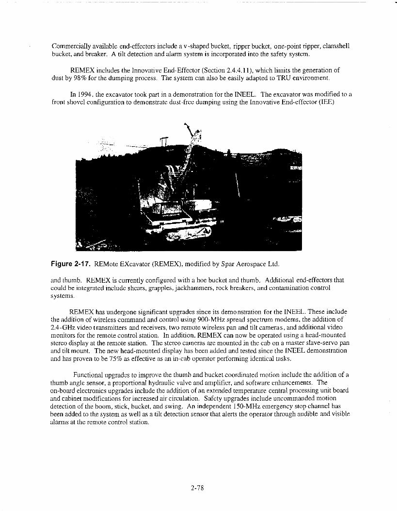
Commercially available end-effectors include a v-shaped bucket, ripper bucket, one-point ripper, clamshellbucket, and breaker. A tilt detection and alarm system is incorporated into the safety system.
REMEX includes the Innovative End-Effector (Section 2.4.4.11), which limits the generation ofdust by 98% for the dumping process. The system can also be easily adapted to TRU environment.
In 1994, the excavator took part in a demonstration for the INEEL. The excavator was modified to afront shovel configuration to demonstrate dust-free dumping using the Innovative End-effector (IEE)
Figure 2-17. REMote EXcavator (REMEX), modified by Spar Aerospace Ltd.
and thumb. REMEX is currently configured with a hoe bucket and thumb. Additional end-effectors thatcould be integrated include shears, grapples, jackhammers, rock breakers, and contamination controlsystems.
REMEX has undergone significant upgrades since its demonstration for the INEEL. These includethe addition of wireless command and control using 900-MHz spread spectrum modems, the addition of2.4-GHz video transmitters and receivers, two remote wireless pan and tilt cameras, and additional videomonitors for the remote control station. In addition, REMEX can now be operated using a head-mountedstereo display at the remote station. The stereo cameras are mounted in the cab on a master slave-servo panand tilt mount. The new head-mounted display has been added and tested since the INEEL demonstrationand has proven to be 75% as effective as an in-cab operator performing identical tasks.
Functional upgrades to improve the thumb and bucket coordinated motion include the addition of athumb angle sensor, a proportional hydraulic valve and amplifier, and software enhancements. Theon-board electronics upgrades include the addition of an extended temperature central processing unit boardand cabinet modifications for increased air circulation. Safety upgrades include uncommanded motiondetection of the boom, stick, bucket, and swing. An independent 150-MHz emergency stop channel hasbeen added to the system as well as a tilt detection sensor that alerts the operator through audible and visiblealarms at the remote control station.
2-78

2.4.2.16.2 Applications—The REMEX-IEE-SGTV system is a complete remediation package.However, IEE may not be needed if in situ soil-binding techniques are used. SGTV could be used fortransporting the waste within or outside of the confinement facility. However, a remotely controlledforklift may also be applicable for this need.
REMEX is tentatively scheduled to work with International Union of Operating Engineers (IUOE)this spring and summer. However, Spar has indicated that REMEX would be made available for the next4 years for the HSRS project. The excavator could be ready for a cold demonstration within 2 months.
2.4.2.16.3 Issues/Gaps in Technology—Fine tuning of the radio frequency system wouldneed to performed at a cost of about $50,000. For hot demonstration, radiation-hardened and protectedelectronics and decontamination strategies need to be implemented. Estimated time to complete is6 months, with a rough order of magnitude cost of $300,000.
Currently, there is no method of removing soil and waste from the SGTV transfer boxes. Asystem must be developed to remove the waste and package it in standard waste boxes.
2.4.2.16.4 Source—Personal communication between Lee Maher, Spar EnvironmentalSystems, Brampton, Ontario, Canada, and Doug Stacey, LMITCO (response to LMITCO's January 29,1997 CBD solicitations), February 7, 1997.
Package of Information on REMEX, Innovative End-Effector, SGTV, and Remote Operation ofExcavators dated February 7, 1997, from Lee Maher, Director of Environmental Systems at SparAerospace Ltd.
Personal communication between Thomas J. Crocker, RAHCO International 4, Spokane,Washington, and Reva Hyde, LMITCO, November 1, 1996.
Package on REMEX and SGTV dated November 1, 1996, from Thomas J. Crocker, BusinessDevelopment at RAHCO Internationalml.
2.4.3 Cranes
2.4.3.1 General Description. Cranes are commonly used for remediation tasks that requireprecision and accuracy. A quote from Removal of Overburden Soils from Buried Waste Sites, a reportwritten by Phil Rice (INEEL) and John Skaggs (Sonsub®, Inc.), states that "The ease of operating thebridge crane versus a remote controlled excavator could be compared to driving a railroad train engineon tracks versus driving a truck on a highway" (Rice and Skaggs 1993). Gantry cranes offer ease ofcontrol and precise deployment of tooling. Some of the other advantages of a crane are high productionrates, public acceptance, robustness, and adaptability to many end-effectors. Table 2-9 provides a briefsummary of the equipment that was researched.
Requirements were taken into consideration when looking at crane equipment. Theserequirements were taken from the HSRS Requirements Document and are listed in Section 2.4.2.1.
2.4.3.2 Cooperative Telerobotic Retrieval System (CTRS).
2.4.3.2.1 Description—Engineers at the INEEL have developed an 80-ft remotely operatedgantry crane for the remediation of hazardous/radioactive waste. The Cooperative Telerobotic Retrieval
2-79

System (CTRS) provides universal access to the waste area (see Figure 2-18). The remote gantry cranesystem consists of an 80-ft wide girder; two trolley assemblies with vertically telescoping masts (z-masts) each having 22 ft of vertical travel; two six-degree-of-freedom manipulators mounted to the baseof each z-mast; and a trolley and 5-ton hoist assembly mounted on a separate track. The manipulatorsmounted on the z-masts provide for dexterous teleoperation, telerobotic operations, or full roboticsoperations of equipment. Because the manipulators are mounted to the base of the z-masts, they can beused in cooperation with each other or can be operated separately. The manipulators are mounted so thatthey
Table 2-9. Crane vendor and equipment list.
Vendor/Supplier Crane Technology
Idaho National Engineering andEnvironmental Laboratory
National Institute of Standards andTechnology/Intelligent Systems Division
Sandia National Laboratories
SICOR
Sonsub International® Inc.
Cooperative Telerobotic Retrieval System (CTRS),80-ft remotely operated gantry crane designed forselective retrieval.
RoboCrane®, cable-driven Stewart Platform for aParallel Link Manipulator.
"Swing free" technology for controlling cranecables.
Cable/tower system to deploy a small areamanipulator (SAM).
Mobile work system capable of digging, sorting,packaging, and replacing overburden.
2-80

Figure 2-18. Cooperative Telerobotic Retrieval System.
can be used in cooperation with the hoist hook for remotely attaching or removing a load from the hook.The system contains 12 closed-circuit television cameras and pan/tilt units for visualization of theworkspace during operations. Three of the pan/tilt units have been modified to automatically track objectswithin the workspace, allowing operations personnel to concentrate on crane and manipulator operations.Three-dimensional cameras are mounted to each manipulator and to the trolley that holds the hoist. Theentire system consists of 37 degrees of freedom and has closed-loop control using a modified commercialrobotics control system. The rails for the system are spaced 60 ft apart and have a length of 60 ft, but thecrane could be used on longer rails with minor modifications. The crane also incorporates a 20-ft cantileveroverhang for loading equipment into trucks or other vehicles. Maximum loading values for the crane are2,000 lb in the vertical (z-masts) and 10,000 lb vertical with the hoist. The system has a vacuum hosesystem for the retrieval of soil. Other end-effectors include a drum handler, grappler, variouscharacterization sensors, and other removal tools.
2.4.3.2.2 Applications—This unit is at the INEEL and can be used as part of HSRS. It is aviable option for the HSRS main excavation tool.
2-81

2.4.3.2.3 issues/Gaps in Technology—The current system is not easily portable at the wastesite, and the rails require footings in the soil. The crane might be mounted on wheels if funding wasapplied. The span of the crane might also be too narrow for hot spot remediation. Exact dimensions ofthe waste site are unknown.
2.4.3.2.4 Source—Information is from the Cooperative Telerobotic Retrieval System Phase 1Technology Evaluation Report written by R. A. Hyde and K. M. Croft in March of 1995.
2.4.3.3 RoboCrane®.
2.4.3.3.1 Description—The RoboCrane® is being developed by the Intelligent SystemsDivision at the National Institute of Standards and Technology (NIST). The RoboCrane® is a cable-driven, multi-purpose manipulator based on the Stewart Platform Parallel Link Manipulator. It providesa six-degree-of-freedom load control via teleoperative, graphic off-line programming, and hybrid controlmodes. Originally, the RoboCrane® was developed under a Defense Advanced Research Project Agencycontract to stabilize loads on conventional cranes. Currently, configurations have advanced to includeland, sea, air-lifted, and space applications. It can be designed for high lift-to-weight ratio, stable gantryconfigurations, flexibility, precise maneuverability, and mobility over a variety of surfaces includingvery rough terrain.
A 6-m octahedral RoboCrane® system has been fabricated and used to demonstrate heavy loadmanipulation, sawing, grinding, gripping, welding, and assembly tasks under teleoperative,preprogrammed, and hybrid control modes. Accuracy of this prototype has been measured at up to 1 mmin translation and angular motion of approximately 0.5 degrees throughout a minimum 100-m3 workvolume. Mobility has been demonstrated with a 2-m radio-controlled model.
The RoboCrane® control system currently consists of the controller, a graphic programmer, and aremote control panel connected by a network. The graphic programmer allows for the easy and safegeneration of move commands and the timely movement and activation of tools. The RoboCrane®control system is capable of master-slave control (default mode) with one or two operators, graphic off-line control, go home capability, and manual teach control. In the near future, a heads-up remote controlpanel will be interfaced with the controller of a stereo vision assembly. A sensor on the back of the unitcan sense the orientation of the head of the operator. This information will be transmitted to the stereovision assembly controller, which will be commanded to follow the motions of the head of the operator,thus providing a natural telepresence view of the work-space. Voice activation of control functions andan animation feedback will also be added.
The control system was developed using commercially available Macintosh hardware andsoftware. The Graphic Programmer runs on a Silicon Graphics computer and controls the operation of aDeneb simulator and animator for three-dimensional solid models.
NIST has fabricated a small-scale model of a RoboCrane® that could be used for the radiologicaland hazardous waste cleanup. The test model's working platform is fitted with an inverted excavator.The RoboCrane® sits atop three tracked vehicles for mobility. The model has demonstrated that theRoboCrane® would be an excellent platform for retrieving hazardous waste and munitions.
The framework of the model consists of a six-legged structure resting on three support points.These are mounted on the three vehicles for mobility. The top of the structure consists of a triangularframe. Each vertex of the triangle supports two cables. Together, the six cables support a lower work
2-82

platform. The six cables kinematically constrain the lower platform so that an attached excavator canexert the necessary forces and torques required for excavating material. The length of each cable iscontrolled by a winch. By controlling the six winches, an operator can maneuver the lower workplatform in six degrees of freedom. Using a joystick, an operator can precisely control the motion of thelower platform in both translation and rotation. There are three degrees of translation: forward-back,left-right, and up-down. There are also three degrees of rotation; roll, pitch, and yaw. All six degrees offreedom can be controlled simultaneously.
For mobility, each of the three legs are attached to a tracked vehicle. An operator can use ajoystick to command the RoboCraneg to move and turn. The vehicles are controlled by a computer thatcan make all three vehicles move and turn in a coordinated manner. This configuration allows theRoboCrane®'s working platform to be positioned directly over an excavation site without actuallydriving onto it. This eliminates many of the problems associated with using conventional excavators,such as the need for installing sheeting and pilings to stabilize the ground. The RoboCrane® provides anexcellent means of straddling or cantilevering over dangerous waste sites. The work platform cansupport an excavator, tools (saws, grippers, diggers, drills), equipment (sensors packages, wasteconveyors), and manipulators to gently and precisely uncover waste. Accuracy and resolution aredependent on the waste site size, desired configuration, and accessibility.
The geometric shape of the RoboCrane® gives it an extremely high strength-to-weight ratio. TheRoboCrane® can lift and manipulate loads many times its own weight. Its geometric shape is also idealfor supporting a containment enclosure to prevent radioactive dust or toxic dust from escaping to theatmosphere.
The small RoboCrane® model's design scales easily to much larger sizes. A 100-m design madefrom cross-braced triangular trusses is feasible. The RoboCrane® work volume thus can range from 3 mto over 30 m on a side. Lift capacity may range from 1,000 lb to over 20 tons.
The developers of the RoboCrane® feel that the technology is ready to move from the researchlaboratory into practical applications. All major technical problems appear to be solved for applying theRoboCrane® to radiological and toxic wasted cleanup operations. Most system components areavailable off the shelf.
2.4.3.3.2 Application—The RoboCrane® system is a very versitile machine. It can span thewaste site and retrieve boxes, barrels, and other waste containers.
2.4.3.3.3 lssues/Gaps in Technology—Unfortunately, a RoboCrane® for HSRS would haveto be designed and fabricated. Much of the design work has been done with the design of the smallworking model. However,there would be a large investment in time and equipment. A very largeRoboCrane® would be necessary for remediation activities.
2.4.3.3.4 Source—Package from Edward Amatucci, National Institute of Standards andTechnology, Gaithersburg, Maryland, to Doug Stacey, LMITCO (response to LMITCO's January 29,1997 CBD solicitations), February 14, 1997.
Package on RoboCrane® dated February 14, 1997, from Edward Amatucci, Mechanical Engineerfor National Institute of Standards and Technology, in the form of conference papers. The point ofcontact is Ken Goodwin.
2-83

2.4.3.4 Swing Free Crane Control.
2.4.3.4.1 Description—Sandia National Laboratories (SNL) has developed "swing-free"technology that is applicable to crane control. This technology allows for the operation of a gantry cranewithout the large swinging motions that are common. The system, patented by Sandia NationalLaboratory (number 4,997,095), can be used on any length cable, weight, and path. SNL has developed areal-time operating system with an operator "in the loop." Sensor-based, swing-free crane controlsincorporate a sensor at the top of the cable that measures cable displacement. This system has beenproven on a 30-ton, ac motor-driven crane. The swing induced by the load was reduced from 30 to 3 cm.This system eliminates the need for manual dampening of swing after a load has been moved, before itcan be set down. SNL and ORNL are seeking crane manufacturing companies interested inimplementing this technology. Convolve, Inc. has expressed interest.
2.4.3.4.2 Applications—This technology could be implemented onto any remote crane toreduce swing in the cable, allowing for more precise placement of barrels and boxes.
Issues/Gaps in Technology—It is unknown how easy or difficult it would be toadapt the technology to a specific crane.
2.4.3.4.4 Source—Information on the Swing-Free Crane Control from the June 1995Technology Summary, Department of Energy—Office of Environmental Management TechnologyDevelopment.
2.4.3.5 SICOR Excavator.
2.4.3.5.1 Description—SICOR has developed a system for excavation. However, this systemis not applicable and is proprietary information. As a result, the information cannot be incorporated intothis report.
2.4.3.5.2 Applications—SICOR's equipment is not applicable. See issues and gaps intechnology.
2.4.3.5.3 Issues and Gaps in Technology—This system is not capable of exerting largeforces in the downward direction to remove waste.
2.4.3.5.4 Source—Personal communication between Carl Holland, SICOR, Charleston, SouthCarolina, and Doug Stacey, LMITCO (response to LMITCO's January 29, 1997 CBD solicitations),February 4, 1997.
Multiple packages on Virtual Tools, ISO (tower manipulator), and SAM dated February 4-19,1997, from Carl S. Holland, President of SICOR.
2.4.3.6 Building System to Excavate Transuranic Contamination.
2.4.3.6.1 Description—Sonsub International® Inc. has developed the world's largest remotelyoperated mobile work system. This 1,500-ton, self-propelled machine is 260 ft long, 100 ft wide, and
2-84

60 ft high. It was designed to span a distance of 120 ft. As the system digs, it separates the waste fromthe soil, packages the material for transport or processing, and backfills the excavation pit.
The mobile work system is operated entirely by remote control and uses two neutron radiationdetectors to look into the digface for radiation sources that require special handling. Two soil retrievaltools use brushes to dig out soil and expose waste. Two grapple tools are used to gather and size reducewaste to be placed in boxes for transport. A seventh tool is used for routine maintenance on the othertools.
The software for the system prevents tools from colliding with each other and allows digging onlyin areas that have been surveyed. A 1,000-ft fiber optic cable connects the facility to the remotecommand station.
The remotely operated work systems separate the soil and waste, package them, and ensure thatradiation levels are acceptable for transport. All operations are performed in a rugged shelter designed towithstand 84-mph winds. The structure also provides negative pressure to prevent the spread ofcontamination.
2.4.3.6.2 Applications—A smaller version of this system would be applicable for hot spotremoval.
2.4.3.6.3 Issues/Gaps in Technology—This system is too large for multiple mobilizationand demobilization activities. Transportation of the facility is an issue. Furthermore, this systemrequires rails and footings for the facility to run on. The rail system limits the flexibility of on-sitemobility, and placing footings in the ground is time consuming if the equipment will only be at the sitetemporarily. This system would be custom designed and manufactured, which is a disadvantage whenoff-the-shelf equipment can be used.
2.4.3.6.4 Source—Personal communication between Charles Yemington, P.E., SonsubInternational® Inc., Houston, Texas, and Doug Stacey, LMITCO (response to LMITCO's January 29,1997 CBD solicitations), February 10, 1997.
Package containing information the Soil Skinner end-effector and the Retrieval System for theINEEL Pit 9 Remediation dated February 10, 1997, from Charles Yemington, Surface Operations &Technology for Sonsub International® Inc.
2.4.4 End-Effectors
2.4.4.1 General Description. End-effectors can be used for a number of operations includingdigging, cutting, grappling, shearing, crushing, auging, dozing, compacting, raking, etc. End-effectorsare important because they are in direct contact with the waste being retrieved.
In the following section a list of company and DOE end-effectors will be summarized. Theinformation was collected in the form of Commerce Business Daily ads, Rainbow Books, and additionalresearch. Table 2-10 provides a list of the equipment that was researched.
Requirements were taken into consideration when looking at end-effectors. These requirementswere taken from the HSRS Requirements Document and are listed in Section 2.4.2.1.
2-85

Table 2-10. End-effector vendor and equipment list.
Vendor/Supplier End-Effector
Concept Engineering Group Inc.
Foster-Miller, Inc.
Kinetic Sciences Inc.
Lawrence Livermore NationalLaboratory
0A0 Robotics
Redzone Robotics Inc.
Robotech Industries Ltd.
Sandia National Laboratories
Sonsub International® Inc.
Safe Excavation (SAFEXTm), airjet/vacuum end-effectorsystem.
2-Armed, Tethered Hydraulically Powered InterstitialConveyance System (2THPIC), crane-deployed system withtwo excavators/vacuums—concept design.
TentacleTM (patents filed), similar to an elephant trunk—highly manipulative.
Hydraulic Impact End-Effector (HIEF), water cannondesigned for tank applications.
Air Knife - proprietary information.
Schilling Titan II, manipulators deployed by a crane forselective retrieval.
Mineclaw, manipulator with strong electro-magnet to pickup barrels.
Confined Sluicing End-Effector (CSEF), waterjet designedfor waste tank cleanout procedures.
Soil SkimmerTM (patent pending), end-effector designedspecifically for the removal of overburden in 3-, 4-, and 6-in. increments.
Spar Environmental Innovative End-Effector (IEE), end-effector designedspecifically for the retrieval of soil and dust-free dumping ofthe waste into an SGTV waste transfer unit.
University of Missouri—Rolla End-effector; unsure if they can provide further information.
Weldco-Beales Quick-change couplers for end-effector changeouts.
Multiple vendors Vacuum systems for contamination control and retrieval ofsoil and dust.
2.4.4.2 Safe Excavation Technology (SAFEXT1).
2.4.4.2.1 Description--Concept Engineering Group Inc. developed the Safe Excavation(SAFEXTM) remotely operated excavation equipment. There is a patent pending on this system. Thesystem is composed of a high-pressure jet-like probe that dislodges compacted soil, hardened sand, toughclay, solidified sludge, saltcake, and shale. Supersonic air jets vacuum up dust and soil. The jet ofcompressed air breaks up porous materials but does not harm man-made objects like plastic, clay, metalpipes, plastic drums, unexploded ordnance, or even the shell of a raw egg.
The system (attached to any applicable excavator or crane) uses an integrated boom and digginghead along with a material separator that is designed to eliminate downtime due to clogging. The
2-86

excavated material is discharged continuously through the material handling system to eliminate the needfor bins or hoppers (excavation throughput of 3.5 ft3/min). Using fingertip controls, one person canoperate the excavating head and digging boom. The soil removed by the vacuum is placed on anonboard conveyor that transports it to a dump truck.
The jet probe and vacuum system can be mounted on a crane or excavation unit. The operator isable to view the site through a stereo-television setup.
2.4.4.22 Applications—This system could be used to break up the soil and remove it viavacuum.
2.4.4.2.3 Issues/Gaps in Technology—Based on experience with the company, anyengineering modifications to the original system should be done at the INEEL. If WAXFIT is used tostabilize the soil, it is undesirable to break up the matrix.
2.4.4.2.4 Source—Private communication between Richard Natherson, Concept EngineeringGroup Inc., Pittsburgh, Pennsylvania, and Doug Stacey, LMITCO (response to LMITCO's January 29,1997 CBD solicitations), February 11, 1997.
Package on SAFEXT)4 system from Richard Natherson, President of Concept Engineering GroupInc. dated February 11, 1997, in the form of photos and background information.
2.4.4.3 2-Armed, Tethered Hydraulically Powered Interstitial Conveyance System(2THPIC).
2.4.4.3.1 Description—Foster-Miller, Inc. developed the 2-Armed, Tethered HydraulicallyPowered Interstitial Conveyance System (2THPIC). This unit is crane-deployed from a rotatableplatform. Two excavators possess extendible booms with mechanical diggers and vacuum pickups. Thevacuum system is composed of off-the-shelf components, a 100-hp motor, a cyclone separator, and aself-cleaning dust filter. The maximum load the two manipulators can lift is 700 lb. The throughput ofthe system is designed for 3.62 m3 (128 ft3) per hour. Designed for low-level radiation fields, 2THPICremoves soils and segregates it by picking up particles smaller than V2 in. Smooth surfaces and aprotective sleeve facilitate decontamination. Envelope limiters have been incorporated into the design toprevent the equipment from entering undesired locations. The system was designed to be installed in a5-week window for the LMAES Pit 9 retrieval building. 2THPIC provides a means for vacuuming soilfrom a waste pit and performing wipedowns on equipment for decontamination. This system is only aconcept design and is not in production.
2.4.4.3.2 Applications—These manipulators could be used in conjunction with a gantry cranefor selective retrieval of barrels, boxes, and miscellaneous waste.
2.4.4.3.3 Issues/Gaps in Technology—This system must be deployed from a crane structurefor operation. Futhermore, this type of system would break up the contamination controls that will beapplied to the soil, thus causing dust generation.
2-87

2.4.4.3.4 Source•---Private communication between Blair J. Hough, Foster-Miller Inc.,Waltham, Massachusetts, and Doug Stacey, LMITCO (response to LMITCO's January 29, 1997 CBDsolicitations), February 4, 1997.
Package including FERRET, 2THPIC, and ROME information dated February 4, 1997, from BlairJ. Hough, Business Development Manager of Foster-Miller, Inc.
2.4.4.4 TentacleTM.
2.4.4.4.1 Description—Kinetic Sciences Inc. has developed a teleoperated end-effector calledthe TentacleTM (U.S. Patent Numbers 5,317,952 - manipulator and 5,181,452 - bellows actuator). A fewof its options include wrist rotation and a two-finger gripper. The physical description of the TentacleTMis much like that of an elephant's trunk. It is able to control vacuum hoses, scrapers, sluicers, cameras,etc. The TentacleTM can be attached to excavation equipment and is highly manipulative.
2.4.4.4.2 Applications—This system would be applicable for a situation using a crane andmanipulator.
2.4.4.4.3 Issues/Gaps in Technology—This system has limited load capabilities and wouldnot lift a 4,000-lb load.
2.4.4.4.4 Source—Private communication between Keith Antonelli, Kinetic Sciences Inc.,Vancouver, British Columbia, Canada, and Doug Stacey, LMITCO (response to LMITCO's January 29,1997 CBD solicitations), February 10, 1997.
Package on TentacleTM Manipulator dated February 10, 1997, from Keith Antonelli, RoboticsEngineer for Kinetic Sciences Inc., in the form of conference packages.
2.4.4.5 Hydraulic Impact End-effector (HIEF).
2.4.4.5.1 Description—Lawrence Livemore National Laboratory is developing the HydraulicImpact End-effector (HIEF). This end-effector is attached to a robotic manipulator arm and is used tobreak up monolithic or large pieces of hard cake. The system uses water as a cannon to break up thehard, large pieces of contamination. This technology was developed to break up monoliths that formaround the risers in storage tanks. Water is compressed to 40 ksi to blast apart hard cake with forcescomparable to blasts from explosives. This system does not have the hazards of "fly" rock or toxicfumes. HIEF discharges 200 mL of water at 40 ksi before recharging. The end-effector can fire 5-second blasts repeatedly. The power unit is located 100 ft away from the end-effector and requires480 V ac, 7-gpm cooling water, and 90-psi compressed air. The flexible hose connecting the end-effector to the reservoir has safety shielding, burst pressure of 105 ksi, and a minimum blast pressure of95 ksi. The end-effector costs $90,000, and the power source costs $50,000. The rubbilizer is expectedto break up waste at a rate of 12 gpm with fragments not exceeding 14 in. Liquid carbon dioxide is beingconsidered as an alternate cutting solution because it evaporates in ambient conditions. The HIEF is amodified off-the-shelf commercial unit.
2-88

2.4.4.5.2 Applications—Current application is for tanks. The major disadvantage, due to theintroduction of water to the hot spot, may outweigh any advantages. If the hot spot is within a tank, thiscould be applicable.
2.4.4.5.3 Issues/Gaps in Technology—The end-effector would create mud/sludge that is notseparable in its current design. Furthermore, at this time, a lot of design work is still needed for theequipment.
2.4.4.5.4 Source—Information on the Hydraulic Impact End-effector from the Department ofEnergy, Office of Environmental Management and Office of Technology Development.
2.4.4.6 Air Knife.
2.4.4.6.1 Description—OAO Robotics has developed an end-effector known as the Air Knife.Further information can not be provided due to proprietary restrictions.
2.4.4.6.2 Applications—This type of system would break up the contamination controls (soilstabilizers) that will be applied to the soil, thus causing dust generation. However, if anothercontamination control method is used, this system can break up hard soil around the hot spot.
2.4.4.6.3 Issues/Gaps in Technology—The generation of dust could be a concern.
2.4.4.6.4 Source—Personal communication between Joseph W. Foley, 0A0 Robotics,Ijamsville, Maryland, and Doug Stacey, LMITCO (response to LMITCO's January 29, 1997 CBDsolicitations), March 5, 1996.
Package on TODS, TORCE, and Air Knife dated March 5, 1996, from Joseph W. Foley, Directorof Robotics at Numatec. Information is from the company and is not from a catalog.
2.4.4.7 Schilling Titan 11 Manipulators.
2.4.4.7.1 Description—Redzone Robotics, Inc. has developed a modular manipulator usingtwo Schilling Titan II manipulators. The system is comprised of four basic components including thehydraulic system, positioning system, electronics module, and the mechanical interface. These modulesare interconnected for deployment from an overhead bridge crane or a floor-based test stand. Thehydraulic system is driven by a 10-hp, 1,800-rpm electric motor that is capable of delivering 3,000 psiand has a reservoir of 20 gal. The electronics module contains a camera and lighting interface, powersupplies, two Titan II slave controllers, two Titan II power supplies, a VME rack, fans, and power andsignal distribution components. Safety components for the system include a manual switch-activatedarrest of all functions and computer fault-activated emergency stop. The enclosure of the system isaluminum. This system was still under development during the correspondence.
2.4.4.7.2 Applications—The Schilling manipulators must be deployed from a crane structurefor operation. The manipulators would be applicable for the retrieval of barrels from the soil.
2.4.4.7.3 Issues/Gaps in Technology—This system must be used in conjunction withanother system (vacuum or bucket) to retrieve soil. The manipulators will only retrieve solid objects.
2-89

2.4.4.7.4 Source—Personal communication between Leona C. Bares, Redzone Robotics, Inc.,and Brad E. Griebenow, EG&G Idaho Inc., December 13, 1993.
Package on Dual-arm Platform dated December 13, 1997, from Leona C. Bares, Program Managerfor Redzone Robotics, Inc.
2.4.4.8 MineClaw.
2.4.4.8.1 Description—Robotech Industries Ltd. has developed the MineClaw which is agrappling end-effector with a several hundred pound payload capacity. This custom grapple incorporatesa strong electro-magnet located in the "palm" to retrieve metals. The operator directs the grapple using ajoystick that allows for movement anywhere in 3-D space.
2.4.4.8.2 Applications—The MineClaw grappling end-effector must be deployed from a cranestructure for operation. The manipulators would be applicable for the retrieval of barrels from the soil.
2.4.4.8.3 Issues/Gaps in Technology—Another retrieval system (vacuum or bucket) mustbe used in conjunction with the MineClaw to retrieve soil. The MineClaw is also unable to lift a 4,000-lbload.
2.4.4.8.4 Source—Personal communication between Raquel Kuntz, Robotech Industries,Calgary, Canada, and Doug Stacey, LMITCO (response to LMITCO's January 29, 1997 CBDsolicitations), February 12, 1997.
Package on HazHandler, MineClaw, and remote bulldozer dated February 12, 1997, from RaquelKuntz, Marketing Coordinator for Robotech Industries Ltd.
2.4.4.9 Confined Sluicing End-effector (CSEF).
2.4.4.9.1 Description—Sandia National Laboratories is developing the Confined Sluicing End-effector (CSEF), which is a remotely operated end-effector tool attached to the end of a manipulator arm.This tool is capable of dislodging, mobilizing, and removing all waste forms (hard cake, sludge, and bulksupemate). This system was designed for tank applications, but could be applicable to dry, non-tankuses. The end-effector uses high-pressure waterjets (10,000 psi or 70 MPa) to cut material into smallpieces and then evacuate the particles with a powerful vacuum jet pump (7,000 psi or 50 MPa). All cutmaterial and water is removed through the vacuum before it can spread contamination. The slurry wateris then captured for the separation of the contaminants from the water. This water is then recirculateddown through the system. Material is removed from the site at a rate of 30 gpm with a solid-to-waterratio between 2:1 and 4:1. This system requires less than 500 hp to operate.
2.4.4.9.2 Applications—This system breaks up the soil to accommodate the use of a vacuumsystem. The waterjet would break up the proposed in situ contamination control and would generateadditional waste in the form of waste water. Other end-effectors are capable of removing the soil fromthe ground without additional waste generation.
2.4.4.9.3 Issues/Gaps in Technology—This system still requires a lot of design work.
2-90

2.4.4.9.4 Source—Information on the High Pressure Waterjet Dislodging and ConveyanceEnd-effector Using Confined Sluicing from the Department of Energy, Office of EnvironmentalManagement and Office of Technology Development.
2.4.4.10 Soil Skimmerm
2.4.4.10.1 Description—The Soil SkimmerTM (patent pending) end-effector, developed bySonsub International®, is deployed by a conventional excavator with sufficient boom length and power(see Figure 2-19). The Soil SkimmerTM controls the depth of cut without disturbing the soil underneath.Adjustable depth control planes limit the depth of soil removal, and the bucket floats with a constantdownward force to help follow the surface contours. At the end of each cut, a hydraulically operateddoor closes over the opening. The door scoops in any soil being pushed ahead of the Soil SkimmerTM,which prevents spilling during the lift-and-rotate cycles of the boom. Sensors are placed at the leadingedge of the end-effector, which indicate contamination levels on a display in the cab. New informationis displayed over the previous contamination map to show the operator when sufficient contaminationhas been removed. Suction inside the Soil SkimmerTM draws in fugitive dust and transports it through ahose with a filter (any filter can be used including HEPA).
2.4.4.10.2 Applications—This end-effector may be a good choice for the removal ofoverburden because it was specifically designed for this purpose. The Soil SkimmerTM travels along theground in 3-, 4-, and 6-in. thick layers to dig up the overburden. A special air control flap across thefront of the end-effector creates an air dam to help maintain negative pressure. For dust generationcontrol, vacuums are incorporated on the front and rear of the end-effector. Dust control for the dumpingprocess was not considered for the Soil SkimmerTM, but is not an issue if soil grouting/fixidents areutilized. The end-effector rotates 180 degrees to dump the soil, which can cause considerable dust. Thissystem can be used with other excavators.
2-91

Figure 2-19. Soil SkimmerTM attached to an excavator, developed by Sonsub International®.
2.4.4.10.3 Issues/Gaps in Technology—The soil may cling or glob onto the end-effector ifsoil stabilizers are used. Coatings to make the end-effector surface smoother may need to be applied.
2.4.4.10.4 Source—Personal communication between Charles Yemington, SonsubInternational® Inc., Houston, Texas, and Doug Stacey, LMITCO (response to LMITCO's January 29,1997 CBD solicitations), February 10, 1997.
Package including information of the Soil SkimmerTM and remote excavation facility datedFebruary 10, 1997, from Charles Yemington, Surface Operations and Technology, Sonsub International®Inc.
2.4.4.11 Innovative End-Effector (IEE).
2.4.4.11.1 Description—Spar Environmental developed the Inovative End-Effector (IEE) to beused in conjunction with the REMote EXcavator (REMEX) excavator and Self Guided Transfer Vehiclesystem (SGTV) waste transfer unit. The system reduces dust generation by scooping soil and debris upand covering it with a thumb on the bucket. The bucket is then dropped into SGTV for transport. As aresult, dust is not generated when the soil is placed into the containers. IEE has a 9,000-lb capacity, and thedetachable portion of the bucket holds 1.4 yd3 of soil. The bucket is capable of carrying 4-ft by 4-ft by 8-ftwaste boxes.
The Innovative End-Effector, as shown in Figure 2-20, reduces dust generation during digging anddumping operations and is another possible means to control contamination spread. The end-effectorconsists of three structural assemblies (a thumb, an attachable/detachable integrated transfer module
2-92
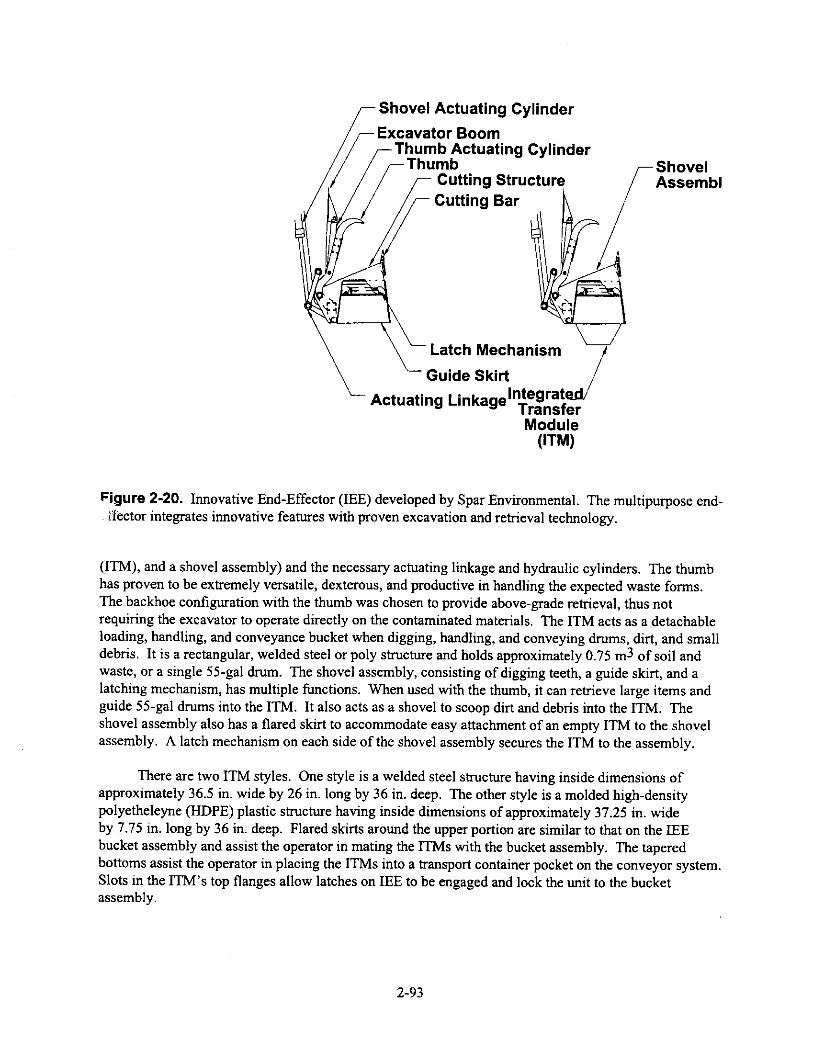
Shovel Actuating Cylinder
Excavator BoomThumb Actuating CylinderThumb Shovel
Cutting Structure
/AssemblCutting Bar
Latch Mechanism
Guide Skirt
Actuating Linkagelnlnergrasteslfer
Module(ITM)
Figure 2-20. Innovative End-Effector (IEE) developed by Spar Environmental. The multipurpose end-if ector integrates innovative features with proven excavation and retrieval technology.
(ITM), and a shovel assembly) and the necessary actuating linkage and hydraulic cylinders. The thumbhas proven to be extremely versatile, dexterous, and productive in handling the expected waste forms.The backhoe configuration with the thumb was chosen to provide above-grade retrieval, thus notrequiring the excavator to operate directly on the contaminated materials. The ITM acts as a detachableloading, handling, and conveyance bucket when digging, handling, and conveying drums, dirt, and smalldebris. It is a rectangular, welded steel or poly structure and holds approximately 0.75 m3 of soil andwaste, or a single 55-gal drum. The shovel assembly, consisting of digging teeth, a guide skirt, and alatching mechanism, has multiple functions. When used with the thumb, it can retrieve large items andguide 55-gal drums into the ITM. It also acts as a shovel to scoop dirt and debris into the ITM. Theshovel assembly also has a flared skirt to accommodate easy attachment of an empty ITM to the shovelassembly. A latch mechanism on each side of the shovel assembly secures the ITM to the assembly.
There are two ITM styles. One style is a welded steel structure having inside dimensions ofapproximately 36.5 in. wide by 26 in. long by 36 in. deep. The other style is a molded high-densitypolyetheleyne (HDPE) plastic structure having inside dimensions of approximately 37.25 in. wideby 7.75 in. long by 36 in. deep. Flared skirts around the upper portion are similar to that on the IEEbucket assembly and assist the operator in mating the ITMs with the bucket assembly. The taperedbottoms assist the operator in placing the ITMs into a transport container pocket on the conveyor system.Slots in the ITM's top flanges allow latches on IEE to be engaged and lock the unit to the bucketassembly.
2-93

2.4.4.11.2 Applications—IEE may be a viable method of retrieval for the soil. It can retrievesoil and debris while limiting the spread of contamination—due to lack of dumping process.
2.4.4.11.3 Issues/Gaps in Technology—If soil stabilizers are used for contaminationcontrol, dust-free dumping may not be an issue.
2.4.4.11.4 Source—Personal communication between Lee Maher, Spar EnvironmentalSystems, Brampton, Ontario, Canada, and Doug Stacey, LMITCO (response to LMITCO's January 29,1997 CBD solicitations), February 7, 1997.
Package of information on REMEX, Innovative End-effector, SGTV, and remote operation ofexcavators dated February 7, 1997, from Lee Maher, Director if Environmental Systems at SparAerospace Ltd.
Personal communication between Thomas J. Crocker, RAHCO InternationalTM, Spokane,Washington, and Reva Hyde, LMITCO (response to LMITCO's January 29, 1997 CBD solicitations),November 1, 1997.
Package on REMEX and SGTV dated November 1, 1997, from Thomas J. Crocker, BusinessDevelopment at RAHCO InternationalTM.
2.4.4.12 Waterjet.
2.4.4.12.1 Description—The University of Missouri-Rolla is developing a waterjet end-effector. They would like to give more information, but are unsure if they are able to due to proprietaryrestrictions.
2.4.4.12.2 Applications—A waterjet end-effector would cause additional waste in the form ofwaste water. The advantages of using a waterjet system are most likely outweighed by thedisadvantages.
2.4.4.12.3 Issues/Gaps in Technology—The university was unsure whether or not theycould provide additional information due to proprietary concerns.
2.4.4.12.4 Source--Letter expressing interest in possibly providing further information on awaterjet end-effector dated February 13, 1997, from David A. Summers, University of Missouri-Rolla.
2.4.4.13 Quick-Change Couplers.
2.4.4.13.1 Description—Weldco-Beales carries quick-change couplers for end-effectorchangeouts. These quick couplers are available in manual and hydraulic versions. Both of the couplersare designed to fit any make of excavator with a given size range. The manual coupler requires theremoval of a few pins to change the end-effector. The hydraulic coupler can change the end-effectorremotely. In order for the system to operate correctly, the Weldco-Beales end-effectors must be used inconjunction with Weldco-Beales couplers. Weldco-Beales offers a variety of buckets, rakes, clamps,rippers, and other end-effectors.
2-94

2.4.4.13.2 Application—The hydraulic coupler may be required to use sizing equipment andend-effectors. This would allow for remote changeouts and would eliminate the need for a secondexcavator for sizing equipment.
2.4.4.13.3 Issues/Gaps in Technology—If mechanical sizing equipment is used that must bedeployed from the end of the excavator, the sizing equipment must be modified to accommodate thequick couplers.
2.4.4.13.4 Source—Package on couplers and end-effectors dated May 5, 1997, from Ray C.Glavish, Territory Sales Manager for Weldco-Beales. Responded to telephone inquiry on product line.
2.4.4.14 Vacuum System.
2.4.4.14.1 Description—Vacuum systems are commercially available for use in contaminationcontrol. These vacuum systems are used either to control the dust at the site of the excavation activitiesby sucking up any dust generated, or to clean up any loose particulate knocked off of equipment duringdecontamination. Nuclear grade vacuum systems with HEPA filtration and critically safe wastecontainers are readily available products.
These systems can also be used for removal of sand and soil at the digface. Other end-effectors,including waterjets and airjets, may be required to break up hard soil.
2.4.4.14.2 Applications—HSRS could use a vacuum system to suck up dust/debris generatedat the excavation site in close proximity to the end-effector on the excavator, or in conjunction with thechosen decontamination system.
2.4.4.14.3 Issues/Gaps in Technology—A vacuum system, as a means of dust control, isnot very efficient, as it is only capable of sucking up the dust in close proximity to the vacuum hoseitself. It is not meant to be used for large areas, such as the confinement enclosure.
It is difficult to find a vacuum capable of providing enough suction to prove beneficial andefficient at the digface during excavation.
2.4.4.14.4 Sources—The number of vendors capable of providing some means of vacuumingthe waste is enormous and would thus require a competitive bid.
2.4.5 Mining Technologies
2.4.5.1 General Description. In an effort to evaluate alternative technologies for the retrieval of hotspot waste, mining techniques have been addressed. The following technologies require lengthy setupand demobilization periods, and are not easily transportable.
2.4.5.2 Requirements. Requirements were taken into consideration when looking at miningequipment. These requirements were taken from the HSRS Requirements Document and are listed inSection 2.4.2.1.
2-95
2.4.5.3 Mining.
2.4.5.3.1 Description—Northwest Research Associates, Inc. has developed a mining techniquefor remediation purposes.
This information is proprietary, however, and cannot be included in this report.
2.4.5.3.2 Applications—See the section below describing Issues/Gaps in Technology.
2.4.5.3.3 Issues/Gaps in Technology—This system does not address the need for removingboxes, drums, and other miscellaneous waste. It requires a large setup and generates secondary waste.
2.4.5.3.4 Source—Personal communication between G. Stuart Knoke, NorthWest ResearchAssociates, Inc., Bellevue, Washington, and Doug Stacey, LMITCO (response to LMITCO's January 29,1997 CBD solicitations), February 19, 1997.
Package on borehole mining technology dated February 19, 1997, from Dr. G. Stuart Knoke,Research Scientist for NorthWest Research Associates, Inc.
2.4.5.4 Transuranic M.-ling.
2.4.5.4.1 Description—Waste mining is an innovative concept that has been proposed byPhil Rice of the INEEL for the remediation of TRU contaminated and/or hazardous waste. Althoughthere are many issues associated with waste mining that must be investigated more thoroughly, theadvantage of eliminating the retrieval enclosure and the associated requirements for stringentcontamination control offers a very compelling reason to further examine this approach.
Waste mining involves placing a cap, probably a steel-reinforced concrete slab, over the selectedpit. An approach tunnel is then dug into the basalt or bedrock and the waste remotely mined from belowthe slab. A variety of commercially available mining equipment could be fitted for remote operationsand deployed to excavate the waste. Ceiling supports are installed as the waste is removed to support theroof slab as the material is excavated. Negative air pressure is used to keep contaminates from back-flowing through the approach tunnels and underground support facilities.
The material handling could be performed in a facility below grade, or the material could betransferred to a facility on the surface. After the waste is removed, the vault could be lined, andmonitoring equipment could be installed. Later, the pit would be back-filled with approved material.The approach tunnel could then be back-filled with grout or some other method to seal any potentialcontaminate migration paths. The approach tunnels and any underground support facilities could beconstructed outside the boundary of the waste site. A single entrance could theoretically support below-surface retrieval of the entire landfill. As previously stated, this is only an idea that certainly needs agreat deal more thought and study. However, there seems to be a number of distinct advantages to thisapproach.
2.4.5.4.2 Applications—This idea allows the contaminated soil to be removed withoutdisturbing the overburden and eliminates the need for a confinement enclosure.
2-96

2.4.5.4.3 Issues/Gaps in Technology—Problems in this technology include greatlyincreased interim storage capacity requirements and overburden soil that may have to be treated. Also,archeological retrieval may not be practical. This idea is not fully developed.
2.4.5.4.4 Source—Personal communication between Phil Rice, INEEL, and Doug Stacey,LMITCO (response to LMITCO's January 29, 1997 CBD solicitations).
Small package received concerning underground waste mining, from Phil Rice of INEEL.
2.5 Waste Separation/Segregation
2.5.1 General Description
Sorting techniques to remove debris (greater than 1-in.3 pieces) from soil, radiologicallycontaminated from non-radiologically contaminated materials, transuranic from non-transuranic debris inburial grounds, and materials that exceed toxicity characteristic leaching procedure from those that donot are an important aspect to waste remediation. Advanced sorting (and assaying) of retrieved wastesinto types (soils, metals, combustibles, non-combustibles, TRU, low-level, hazardous, mixed, etc.) usingcontinuous or batch processes will greatly reduce the cost associated with storage/treatment of the wastefarther downstream.
Waste separation/segregation can include thermal, biological, chemical, physical, and/orradiological methods (e.g., desorption/extraction, ion exchange, and incineration).
Soil washing is a technology in which the soil is first slurried with a liquid medium, such as water.Next, the liquid medium is separated from the soil by means of centrifuges. Some of the contaminantswill be removed from the soil in the liquid medium, depending on how the contaminant of concern reactswith the medium. For example, chlorides can be removed from the soil by means of a water slurry—thechlorides stay in the water. The liquid medium could then be treated separately from the soil.
It is recognized that not all waste will be able to be sorted.
2.5.2 Requirements and Applications
There are no waste separation requirements defined for the Hot Spot Removal System. The hotspot is identified using the characterization methods discussed in Section 2.2 and is then selectivelyremoved. The purpose of designing a hot spot removal system is to identify a highly concentrated/contaminated area within a larger cleanup site and then remove it. This selective removal separates thehighly contaminated waste from the cleaner waste, allowing the cleaner waste to be remediated usingconventional methods.
As hot spots are, by definition, smaller portions of the overall problem, it is not cost effective tofurther separate the waste stream taken from a hot spot by physical size, radioactivity, or contaminant ofconcern, and will thus not be included in this System Description. The following descriptions ofdifferent separation technologies are included here for information purposes only. If an individual sitedecides later that further separation is necessary, it can be added to the HSRS suite of capabilities in thefuture for an additional cost.
2-97

2.5.3 Technologies
2.5.3.1 Sorting System.
2.5.3.1.1 Description—The Radwaste sorting system, developed by Container ProductsCorporation, has an automatic forward/reverse variable speed conveyor that feeds waste through thesystem (see Figure 2-21). Operators manually separate the waste as it goes through the system via dualoperator stations with Lexan safety view windows and large gloveports. The system is enclosed in astainless steel enclosure and has electric or pneumatically operated discharge ports. The waste can befed into a compactor or directly into waste containers.
Figure 2-21. Radwaste sorting system, developed by Container Products Corporation.
If this system is used, operators would be required to separate the waste manually. The systemwould have to be modified to either incorporate robotics to separate the waste remotely, or providesufficient shielding for the operators.
A system for loading the waste into the separator directly from the excavator would have to bedesigned.
2.5.3.1.2 Application—The Radwaste sorting system would be used to sort the smaller debrisout of the soil prior to packaging, if required by a specific site.
2-98

2.5.3.1.3 Issues—Operators would be required to manually separate the waste, which may notbe much of an'advantage. More information on shielding would be needed to determine how hot thewaste can be with the operators standing right there.
We are unsure of how much waste could be loaded into this system at a time.
2.5.3.1.4 Source—A brochure was received from James Grantham of Container ProductsCorporation in response to a Commerce Business Daily advertisement placed on March 19, 1997.
2.5.3.2 Global Dewatering Ltd. - Soil Washing.
2.5.3.2.1 Description—Global Dewatering offers a system that can add water to the soilmatrix, slurry the mix, and then centrifuge the water off of the soil. The water is actually squeezed out of
the soil matrix via large centrifuges. This system is capable of separating oil from a clay/water/oilemulsion. The soil is then transferred from the centrifuge to a waste container via a conveyor. Thesystem has a throughput of approximately 1 m3 per minute with a cost of about $20 to $25/m3.
These soil washing systems can be remote controlled by means of a 500-ft tether or FM radiocontrols to the programmable logic controller (PLC). The operators never have to handle or go near thewaste as it is being washed. The system is run on 480 V/3-phase power.
Physically, the centrifuge/conveyor system is 10 ft by 45 ft; the conveyor is another 30 ft long andis constructed of stainless steel. The pumps are 10 ft by 22 ft Basically, HSRS would need about 30 ftby 100 ft to operate this system.
The system is completely modular; thus, Global Dewatering can work with HSRS to put a systemtogether that will meet our requirements. The company is also willing to partner with HSRS and othercompanies to put together a system that will meet our needs. If HSRS decided to buy the equipment, itwould cost approximately $1.5M.
2.5.3.2.2 Applications—This company has experience washing PCBs out of soil. Othercontaminants of concern amenable to soil washing are heavy metals, pentose nucleic acids, arsenic,mercury, pesticides, and low-level radioactive waste. Depending on the contaminants in the liquid, itcould be injected back into the soil via deep injection wells. This company could also provide theequipment to do the injection wells.
2.5.3.2.3 Issues—This company has never worked with radioactive waste before and does notknow how well it would work with radionuclides.
2-99

Each site would have to provide the water.
As water is added to the soil to create a slurry, a secondary waste stream is created that would alsohave to be disposed of or treated at a later date. Contamination migration may also be an issue.
2.5.3.2.4 Source--Literature was received from Global Dewatering in response to aCommerce Business Daily advertisement on January 29, 1997, and private communications between DebScott of Global Dewatering and Michelle Dahlmeir of LMITCO.
2.5.3.3 Advanced Sciences, Inc./Commodore Applied TechnologiesaSoil Washing.
2.5.3.3.1 Description—Advanced Sciences, Inc., a subsidiary of Commodore AppliedTechnologies, has developed the SETFM process, a physical/chemical process in which halogenatedmaterials (those materials containing chlorine, fluorine, bromine, and iodine) are actually destroyed orneutralized, being chemically converted to harmless salts or other substances. The process works byfeeding the toxic waste (soil) into a tank filled with liquid anhydrous (water-free) ammonia and thenintroducing a base metal, usually sodium, calcium, or lithium, into the tank, thus dissolving theammonia. The metal begins to dissolve immediately, turning blue as the electrons are freed. Thehalogenated comlb, which have a natural affinity for free electrons, are mixed with the solution, and arechemically neutralized. The non-toxic waste is removed and can then go for additional treatment,disposal, etc., depending on what is left The ammonia solution is recycled to be used again in Phase 1.
The process takes place at or below room temperature; thus, it has application to mixed wastestreams that cannot be treated thermally. In soils with low-level radioactive components, heavy metals,etc. in conjunction with halogenated organic comlb, the process can destroy the halogenated organiccomlb without oxidizing or volatilizing the metallic component.
The amount of soil that can be processed varies with the tank size and the ammonia handlingcapacity, but has been estimated to handle approximately 50 tons/day operating in a continuous mode(see Figure 2-22).
2.5.3.3.2 Application—SETT" removes PCBs, chlorinated solvents (benzene, etc.),refrigerants containing chlorinated fluorocarbons, pesticides, PCPs, dioxins, pesticides, herbicides,fungicides, energetics (TNT, etc.) and chemical warfare agents from the soil matrix.
2.5.3.3.3 Issues/Gaps in Technology—Mobilization and demobilization issues would haveto be resolved to make the system portable. This process does not destroy the metallic or radionuclideconstituents. Remote controls/remote operation capability may have to be developed.
2.5.3.3.4 Source—Literature was received in response to an advertisement placed in theCommerce Business Daily on March 19, 1997.
2.5.3.4 Soil Washing.
2.5.3.4.1 Description—Alternative Remedial Technologies, Inc. (ART) has a soil washingtechnique based on proven principles and equipment from the mining and mineral processing businesses.
2-100

The oversize is selectively excavated from the working pile in the field using a hopper mounted with avibrating grizzly and a trommel screen to produce a plant feed pile less than 2 in. The oversize is
Commodore Applied Technologies, Inc.
The Basic SETTh' Process
Add
A mnoiniuSodiuinSolution furRecycling
••
Ntulraltredwaste for flihpoul
or finalprnry,njug
Figure 2-22. SETTm soil washing process, developed by Advanced Sciences, Inc.
removed from the hopper and staged for recycling. The feed soil is fed to the plant by conveyor and goesto a wet screening module, where six high-pressure water spray headers break up the small clods andform a slurry with debris less than 2 mm. The process oversize, material that is greater than 2 mm, isanalyzed and then returned to the site as backfill. The slurry then goes to the separation subsystem,which uses hydrocyclones in circuits. The slurry enters the cyclone tangentially, which causes thecoarse-grained sands to leave through the bottom and the fine-grained materials and water to dischargefrom the top of the unit. The cutoff point between coarse-grained sands and fine-grained materials canbe adjusted depending on the site and the treatment needs farther downstream, thus minimizing thevolume of sludge cake, which is the dewatered fine-grained material, requiring treatment/off-sitedisposal.
The coarse-grained material can then be treated using froth-flotation treatment units, in which asurfactant is used to reduce the surface tension binding the contaminant to the sand, make thecontaminant hydrophobic, and allow the contaminants to float into a froth, which is then removed fromthe surface of the flotation cell. The froth is usually added to the fine-grained materials, and the coarse-grained sand is dewatered and returned to the site as clean backfill.
2-101

The froth/fine-grained sands mixture is normally treated in a manner similar to a wastewatersludge by polymer addition, sedimentation, thickening, and dewatering. The water is returned to the wetscreening area for reuse. The now dewatered fine-grained material, or sludge cake, is where thecontaminants are now concentrated and is disposed of or treated appropriately.
The equipment is run on three-phase, 440-V service and needs 15 to 25 gal of water per minute.ART has two different plants, a full-scale plant that handles 25 tons per hour, and a pilot plant, with athroughput of 15 tons per hour. Both plants are modular, the pilot plant having a footprint of 30 ft by50 ft and the full-scale plant a footprint of 60 ft by 100 ft. These plants are unloaded and erected using astandard 25-ton crane with an extension boom. The pilot plant requires 2 days to set it up, and the full-scale plant requires 5 days.
The amount of water remaining in the soil washing plant at the conclusion of the operation isapproximately 35,000 gal for the full-scale plant and 8,000 gal for the pilot plant, and can usually bedisposed of on-site as non-hazardous.
Cost ranges from $50 to $200/ton.
2.5.3.4.2 Application—The primary contaminants soil washing is good for heavy metals,semi-volatile organics, PNAs, pesticides, PCBs, and low-level radioactive waste.
2.5.3.4.3 Issues—The waste water would have to be properly disposed of at the end of theoperation.
A sampling phase is required to do a sieve analysis, construct a particle-size distribution curve,and perform a chemical analysis for the contaminants of concern. This phase results in a good "go/nogo" decision point. This phase takes 4 weeks and requires $3,000 to $10,000 to accomplish.
If it is determined a "go" in the first phase, a bench-scale investigation to confirm specific unitoperations takes place. This study takes from 6 to 8 weeks to complete and costs $25,000 to $75,000.
A volume of more than 5,000 tons is required for soil washing to compete economically.
2.5.3.5 Naturally Occurring Radioactive Materials (NORM).
2.5.3.5.1 Description—BPF Incorporated is currently completing the field testing of aproprietary process for the separation and subsequent disposal of radioactive materials out of the oil andgas production waste stream. The process is called the mobile naturally occurring radioactive materials(NORM) treatment and disposal system and is company proprietary. Due to the proprietary nature of theinformation, details of the system will not be discussed in this report.
2.5.3.5.2 Application—This system is designed for naturally occurring radioactive material,or, basically, radon. This is not a contaminant of concern for HSRS.
2.5.3.5.3 Issues—This system is currently only in the bench-scale testing phase.
This is a treatment technology, not really a waste separation technology.
2-102

2.5.3.6 Automated Conveyor Monitor.
2.5.3.6.1 Description—Canberra has a new technology called the Automated Conveyor Monitor,which separates the waste into three different output streams based on nuclide-specific activity read usinggermanium detectors (see Figure 2-23). The waste is dumped into a hopper and is then fed into anautomated conveyor monitor equipped with a bin/feeder to accurately dispense the sample to be countedover a thickness range of 2 to 12 in. A counting conveyor then moves the material past fully shielded,sensitive germanium gamma ray detectors, which are on an adjustable platform to vary sensitivity, todetermine the radionuclides. The Ge detectors have a sensitivity of 1 pCi/g for radium and thorium, and0.1 pCi/g for InCs and "'Co in normal soil. The system can also be supplied with NaI(T1) detectors wherelower resolution is not a problem. The waste then goes through a computer-controlled divertor to send theoutput to one of three different streams depending on the radioactivity level.
This system handles a throughput of 50 tons/hr. The conveyor system, detector, and instrumentcontrol room are all mounted on a single 40-ft trailer. The output conveyor and diverter gate are shippedseparately.
The OS/2-based Genie-PC basic spectroscopy package serves as the base for the system's software.All results from the Ge detectors are stored in a relational database.
2.5.3.6.2 Applications—The Canberra system can be used to separate the waste into differentwaste streams, thus minimizing the waste volume. It would be good only for radium, thorium, 137Cs, and5°Co.
!n Jill, ';urveyJ
'.31htokidt.'h2c10
operlhar A ..ntrtrine h' 1007
sorjrneuab.41;:hrf into
throe cateponus, 9.6• Goan• rnproresNabh• awl:Prin.-mm.1-
Figure 2-23. Automated Conveyor Monitor, developed by Canberra.
2-103

2.5.3.6.3 Source—Literature was provided in response to an advertisement placed in theCommerce Business Daily on March 19, 1997.
2.6 Waste Minimization
2.6.1 General Description
There are several technologies in industry used to minimize waste during hazardous/radioactivecleanup. These can include using characterization techniques (geophysical, radiological, and chemical)to identify the hot waste and selectively retrieve only that waste, separating the waste by physical size, orseparating the waste by contaminant of concern. This section discusses only those technologies dealingwith the compaction of the waste once it has been removed from the waste pit. The different methods ofseparating the waste stream are discussed in Section 2.5.
2.6.2 Requirements and Applications
There are no waste minimization requirements defined for the Hot Spot Removal System. It isassumed that the purpose behind using HSRS is to minimize the volume of waste at a site, which must bedisposed of/treated as a highly contaminated waste by selectively removing the most concentrated areas.Thus, HSRS is, by definition, minimizing waste by selectively removing the most hazardous/radioactiveportions of the site, thus allowing the remainder of the site to be remediated using more conventional,less expensive methods.
As the Hot Spot Removal System is targeting only the highly contaminated areas, further wasteminimization is not considered feasible and will not be discussed in this System Description.Compactors could be easily added later to HSRS if an individual site desired them (for an added cost)and are included for information purposes only.
2.6.3 Compactors
Compaction is a mechanical volume—reduction process by which waste material is compressedinto disposal containers. The process achieves volume reduction by removing void space. Compactionis a well-proven treatment technology. Compactor systems consist of a press, using horizontal or verticalrams to apply pressure to the waste in a drum or box-type container. Volume reduction achieved duringcompaction is a function of void space in the waste, the force applied by the press, the bulk density of thematerial, and its springback characteristics. The volume reduction factors are generally between 3 and10. Param that determine the size and power requirement of a compactor include the throughput, type ofwaste, size of items to be compressed, disposal container size, and desired volume reduction. The mostcommon system used in the nuclear industry is the 55—gal drum compactor, which contains a power unit,a hydraulic or mechanical drive, a platen, a base plate, structural supports, a drum-positioning platform,and a control panel. Waste is loaded into the drum, and the power unit is activated to bring the platendown onto the material in the drum. The platen is then raised, the drum recharged, and the processrepeated. Compactors can be divided into two main categories: low-pressure and high-pressure units.Low-pressure systems typically have ram pressures of around 35 psig, and are used to reduce generalcombustible and compactible trash. High-pressure compactors (supercompactors) have ram pressuresranging from 5,200 to 11,400 psig, and are capable of volume reduction with both noncombustible andtraditionally non-compactible waste. Supercompactors can achieve a 2- to 4-volume reduction factor fornon-compactible waste, and a 6 to 7 factor for compactible trash. The volume reduction achieved by a
2-104

compactor can be improved by pre-shredding the waste, using antispringback devices, and increasing thepower of the unit (supercompactor).
Input consists primarily of dry solid wastes, with sufficient void space to achieve a useful volumereduction factor. For low-pressure systems, the typical feedstream consists of clothing, laboratoryequipment, paper, and plastics.
The compacting process usually generates airborne particulates, which can be removed by aconventional exhaust system using I-IEPA filters.
Advantages of compaction include: (1) compaction is a proven process used throughout the worldin the nuclear industry, (2) compaction systems are simple and tend to be reliable and trouble-free,(3) waste compaction is relatively inexpensive, and (4) the process is simple to operate.
Compaction and supercompaction have been used throughout the world in both nuclear and;nuclear industries.
2.6.3.1 Issues. Disadvantages of compaction include: (1) most commercial compactor systems arenot available with adequate exhaust equipment and must be modified, (2) compactors cannot reduce thehazard of the incoming waste and are therefore not appropriate for treating waste streams with hazardousconstituents, (3) compaction is not recommended for wastes containing free liquids or with wastescontaining explosives, and (4) compaction should not be used on dense or bulky items where minimumvolume reduction would be achieved.
2.6.3.2 Source. Information was taken from Commercially Available Low-Level Radioactive andMixed Waste Treatment Technologies, by Russell S. Garcia, October 1996, DOE/LLW-240.
2.6.3.3 B-1000 Series Compactor.
2.6.3.3.1 Description—The B-1000 series compactor made by Container ProductsCorporation combines a crushing force in excess of 10 million lb with a negative-pressure airevacuation/filtration system of stainless steel to make the compactor useful in radioactive waste volumereduction.
The compactor can handle articles the size of 55-gal drums or less.
Included with the compactor is an integral weighing system, which weighs the loaded containerwithout being removed from the compaction chamber.
The control console for this system can be adjacent to the compactor or remote, depending onapplication. The weight of the container is digitally displayed on an indicator mounted in the maincontrol console.
2.6.3.3.2 Application—This would follow waste separation/segregation and would be a goodtool for reducing the volume of waste to be returned to the excavation site, stored, or treated later. As itcan be operated remotely, the enclosure could be located inside the containment enclosure.
2-105
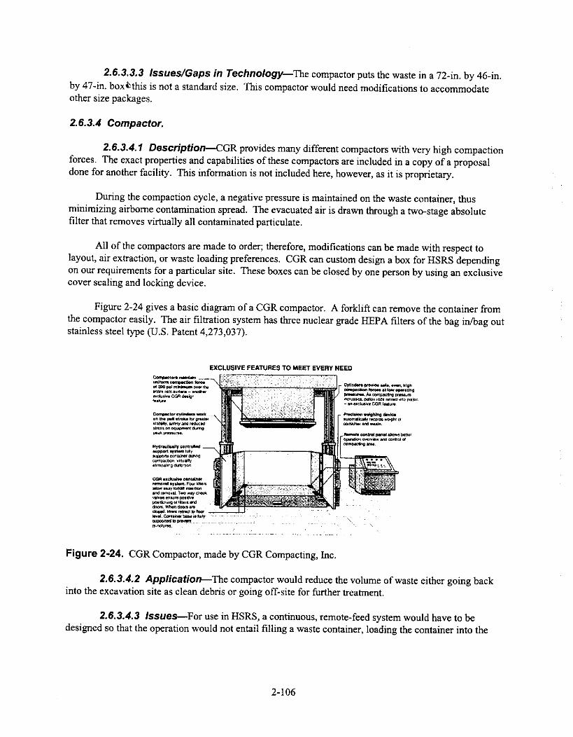
2.6.3.3.3 Issues/Gaps in Technology—The compactor puts the waste in a 72-in. by 46-in.by 47-in. boxibthis is not a standard size. This compactor would need modifications to accommodateother size packages.
2.6.3.4 Compactor.
2.6.3.4.1 Description—CGR provides many different compactors with very high compactionforces. The exact properties and capabilities of these compactors are included in a copy of a proposaldone for another facility. This information is not included here, however, as it is proprietary.
During the compaction cycle, a negative pressure is maintained on the waste container, thusminimizing airborne contamination spread. The evacuated air is drawn through a two-stage absolutefilter that removes virtually all contaminated particulate.
All of the compactors are made to order; therefore, modifications can be made with respect tolayout, air extraction, or waste loading preferences. CGR can custom design a box for HSRS dependingon our requirements for a particular site. These boxes can be closed by one person by using an exclusivecover sealing and locking device.
Figure 2-24 gives a basic diagram of a CGR compactor. A forklift can remove the container fromthe compactor easily. The air filtration system has three nuclear grade HEPA filters of the bag in/bag outstainless steel type (U.S. Patent 4,273,037).
EXCLUSIVE FEATURES TO MEET EVERY NEEDCornpeclors mantels undone toritgeeden lameof MO sal minimum owe thesnare MIA Itielata - ana6orinclusive CGR deaiwnInane*
Cornpactor cylinders workon tha pull evoke for gnawatatiely. aniely one reducedAnsi on etit.p.enr duongpeak Femurs..
Hydraulically controlledmewl spawn fayIowans exmaJner owingkaammton.eliminating distortion.
COR gadgets* oonteinwremoval sysient. Fear Idlersallow easy odds keels.and remain& Two way checkvalve/leisure peed»pcedicrong of lidera anddoors When Coots aredoted. Nom mow to floorla... Corbin. kbsi is lunysupported b pnisprsnincitires.
Figure 2-24. CGR Compactor, made by CGR Compacting, Inc.
Cylinders preside are even, nighcornikacilon lanes al low operatingreestiores As compacting pima.incn...5. Dimon rods retreat Into- on sadushs COR !*dune.
_ Necklace weighing Arida'automencally riconils stnht ofcontainer and wait,
AM10111 melee! wet &Sows honor
[ciwnilion overvbw and oxitrol ofcompacting Atm.
2.6.3.4.2 Application—The compactor would reduce the volume of waste either going backinto the excavation site as clean debris or going off-site for further treatment.
2.6.3.4.3 Issues—For use in HSRS, a continuous, remote-feed system would have to bedesigned so that the operation would not entail filling a waste container, loading the container into the
2-106
compactor, compacting the waste, unloading the container to load more waste into it, putting thecontainer back into the compactor, compacting the waste again, etc.
2.6.3.4.4 Source—This information was received in response to an advertisement placed inthe Commerce Business Daily on March 19, 1997.
2.6.3.5 9600 HM Compactor.
2.6.3.5.1 Description—Enviro-Pak® supplies hazardous waste compactors in various shapesand sizes. The Model 9600 HM is the largest and is capable of delivering 85,000 lb of compaction forceinto a waste container measuring 47 in. high by 72 in. wide by 46.5 in. long. This box has a weightcapacity of 2,000 lb. The box is loaded and removed by means of a removable forklift pallet. Thecomplete system measures 7 ft 4 in. wide by 4 ft 5 in. deep by 11 ft 10 in. high, weighs 10,000 Ib, and isrun on 240/480 V ac, 60-Hz power. The cycle time is 65 seconds. Optional features include anexplosion-proof electrical system, a HEPA filter system, a PLC computer control system, a stainless steelram, a box-full indicator light, and a variable ram hold down.
The standard HEPA filter system includes a 24-in. square, 2-in. thick pre-filter, a 24-in. square,12-in. thick HEPA filter providing 99.97% efficiency on 0.3 micron particles, an 800-cfm blower with a1-hp electric motor, vibration isolators, and a minimum air flow opening of 6 in. in diameter.
2.6.3.5.2 Application—It is used to compact either clean or hazardous/radioactive waste forfinal treatment and disposal. Depending on the compaction requirements for HSRS and the finaldisposition of the materials, the fact that these compactors are available in several different sizes is anadvantage.
2.6.3.5.3 Issues—It does not handle standard size waste boxes.
2.6.3.5.4 Source—This information was received in response to an advertisement placed inthe Commerce Business Daily on March 19, 1997.
2.7 Waste Sizing
2.7.1 General Description
Sizing equipment may be necessary for the size reduction of buried waste at hot spot sites. Drums,boxes, and miscellaneous equipment may be larger than the storage containers for the waste. Sizingwould also help reduce the amount of void space within each storage container, which is highlydesirable. The sizing mechanism must be capable of reducing the size of the waste without causing anexplosion or spreading dust contaminants.
The following information was taken from Garcia (1996). A few minor modifications were madeto this information to make it directly applicable to HSRS.
Sizing is usually one of the first approaches to treating waste. There is often a need to reduce thesize of the waste by cutting, shredding, or fracturing before proceeding to using another technology.Often wastes are shredded before compaction or incineration.
2-107

This section contains various sizing techniques that can be used to prepare the materials forvarious volume reduction technologies, as a pretreatment for decontamination, treatment, or incinerationsystems, or as a stand-alone size reduction process. These operations are typically used to process largemetal or plastic items. For many of the methods, cutting can be carried out either in the dry state orunder water.
Sizing is versatile and can be performed at various stages of a process. Typically, there are twomain types of applications: at the source (reducing transportation costs) or within a treatment process.These technologies, in general, have hundreds of suppliers and are considered to be a proven technology.It should be noted, however, that not all suppliers have sized radioactive waste. Suppliers exist for bothsize reduction services and various sizing equipment.
Sections 2.7.2 through 2.7.15 include information concerning the following:
• Arc saw cutting (Section 2.7.2)
• Plasma arc cutting (Section 2.7.3)
• Oxygen burning (Section 2.7.4)
• Hacksaws and guillotine saws (Section 2.7.5)
• Shredding (Section 2.7.6)
• Cryogenic fracturing (Section 2.7.7)
• Abrasive cutter (Section 2.7.8)
• Thermite reaction lance (Section 2.7.9)
• Laser cutting (Section 2.7.10)
• Water jet cutting (Section 2.7.11)
• Abrasive jet cutting (Section 2.7.12)
• Cryogenic cutting (Section 2.7.13)
• Shears (Section 2.7.14)
• Pipe and wire cutters (Section 2.7.15).
2.7.2 Arc Saw Cutting
2.7.2.1 Description. A circular, toothless saw blade is used to cut metals by establishing ahigh-current electric arc between the blade and the material being cut. No physical contact occursbetween the blade and the work piece. The polarity of the current is chosen so that the major materialremoval occurs to the work piece, although the blade is gradually consumed. Rotation of the blade isessential to aid in cooling of the blade and maintenance of its structural integrity. However, the
2-108

rotational speed (300 to 1,800 rpm) is not a critical parameter. The depth of the cut is limited by theblade diameter.
2.7.2.2 Applications.
Input Streams
The input stream is typically conductive metals up to 36 in. (0.9 m) thick.
Output Streams
The output stream is typically the sized input stream, and small, highly oxidized pellet cuttings ofthe material that has been cut.
Some advantages of arc saw cutting are the following: (1) arc saw cutting is a "noncontact"cutting process and requires less force to hold the work piece in place than other mechanical cuttingprocesses, (2) the cutting process operates at a much higher energy level, resulting in faster cuttingspeeds than other process such as oxygen burning, (3) the ability to sever any electrically conductivematerial makes it especially attractive for cutting nonferrous metals that could not be cut by theoxygen-burning process, (4) the process can be started up instantly without requiring a preheat system,(5) it can operate under water or in air, and (6) the rotating blade lasts longer than the tungsten electrodeused in plasma arc cutting.
2.7.2.3 Issues/Gaps in Technology. Some disadvantages of arc saw cutting are the following:(1) increased hazards exist, such as electrical shock, fire, intense light, fumes and gases, and noise thatmay not be present with mechanical processes, (2) there is increased difficulty for close tolerance work,(3) equipment tends to be more expensive than oxygen burning equipment, (4) the process requires alarge amount of electric power, (5) the process alters the structure of the metal in the cut zone andintroduces internal tensile stresses from the rapid expansion, upsetting, and contraction of the metal atthe cut surface, (6) the depth of cut is limited by the blade diameter that gets smaller with increased use,and (7) the process promotes the spread of contamination.
2.7.2.4 Technology Status. Proven: Arc saw cutting has been used to cut irradiated pipe and metal.
2.7.3 Plasma Arc Cutting
2.7.3.1 Description. The plasma arc cutting process severs metal by using a constricted, dc arc tomelt a localized area of a work piece, removing the molten material with a high-velocity jet of ionizedgas (plasma) issuing from the constricting orifice. Plasma arcs operate typically at temperatures of18,000 to 25,000°F (9,983 to 13,871°C).
Plasma cuts in plates up to approximately 3 in. (8 cm) thick may have a surface smoothnesssimilar to that produced by oxyfuel gas cutting. On thicker plates, low travel speeds produce a roughersurface and discoloration. On thick stainless steel, 5 to 7 in. (13 to 18 cm), the plasma arc process haslittle advantage over oxyfuel gas powder cutting. The cut widths (kerf) of plasma arc cuts are 1.5 to 2times the width of oxyfuel gas cuts in plates up to 2 in. (5 cm) thick. This width increases as thethickness of the material to be cut increases.
2-109

The plasma cutting process is currently used with either a handheld torch or a mechanicallymounted torch. Several types and sizes of each are available, depending on the thickness of metal to becut. The equipment includes (1) torch positioning equipment, (2) a torch traveling system, (3) air,starting gas, and plasma gas supplies, (4) a constant-current or drooping volt-ampere characteristic,relatively high-voltage dc power supply, and (5) associated automatic controls. Plasma arc equipmentnormally includes controls to (1) start and stop the equipment, (2) sequence the entire operation,including varying the gas flow and power level if necessary, (3) shut down the torch in the event of gasfailure since the torch may be damaged by internal arcing without an adequate supply of gas, and(4) control coolant for high-current torches.
2.7.3.2 Applications.
Input Streams
This process was initially used for cutting aluminum, but can cut carbon steel, or any otherconductive nonferrous metal, including those resistant to acetylene cutting. The maximum cut depth formany materials is 7 in. (18 cm). The process has been used to cut stainless steel up to 5 in. (13 cm) thickor aluminum alloy up to 6 in. (15 cm) thick.
Output Streams
The output will consist of smaller pieces of the input material, small amounts of the cuttings, andsmall amounts of oxidized and/or devolatilized metals.
Some advantages of plasma arc cutting are the following: (1) the amount of force required to holdthe work piece in place and move the torch (or vice versa) is much lower with the "noncontact" plasmaarc cutting process than other mechanical cutting processes, (2) the cutting process operates at a muchhigher energy level, resulting in faster cutting speeds than oxygen burning, (3) the ability to sever anyelectrically conductive material makes it especially attractive for cutting nonferrous metals that could notbe cut by the oxygen burning process, (4) the process can be started up instantly without requiringpreheat system and can operate under water or in air, and (5) the process can be a hand-held operation orautomated.
2.7.3.3 Issues/Gaps in Technology. Some of the disadvantages of plasma arc cutting are thefollowing: (1) increased hazards exist, such as electrical shock, fire, intense light, fumes and gases, andnoise that may not be present with mechanical processes, (2) there is increased difficulty for closetolerance work, (3) equipment tends to be more expensive than oxygen-burning equipment, (4) theprocess requires a large amount of electric power, (5) the process alters the structure of the metal in thecut zone and introduces internal tensile stresses from the rapid expansion, upsetting, and contraction ofthe metal at the cut surface, (6) the depth of cut is limited by the blade diameter that gets smaller withincreased use, (7) the tip and electrode wear during cutting so that cutting performance is compromised,and (8) the process promotes the spread of contamination.
2-110

2.7.3.4 Technology Status. Proven: Plasma arc cutting has been extensively used on full-scalenonradioactive hardware, and its effectiveness has been confirmed in segmenting bulky metallic wastematerials. It has also been proven to be successful in decommissioning reactor vessels and segmentingirradiated piping.
2.7.4 Oxygen Burning
2.7.4.1 Description. Oxygen burning, also known as oxyfuel cutting, is a process where the metal issevered or removed by the chemical reaction of oxygen with the metal at elevated temperatures, leavinga clean cut surface. Oxygen burning consists of circulating a mixture of a fuel gas and oxygen at theorifice of an ignited torch. The cutting tip of the torch is at the main oxygen jet orifice. This orifice issurrounded by a ring of preheater jets. The oxygen jet rapidly oxidizes most of the metal in a narrowsection to make the cut. Metal oxides and molten metal are expelled from the cut by the kinetic energyof the oxygen stream. In the case of oxidation resistant metals, the reaction is aided by adding chemicalfluxes or metal powders to the cutting oxygen stream.
Oxygen burning can be used to cut plates up to 7 ft (2 m) thick. As material thickness increases,oxygen flow rates must usually be increased. Cutting tips with larger cutting oxygen ports are requiredto handle the higher flow rates. Consequently, the width of the cut (kerf) also increases as the materialthickness being cut increases. Varying the cutting speed from those recommended for best quality cutsusually results in irregularities in the kerf.
The two basic types of oxygen-burning equipment are either manual or machine. The manualequipment is used primarily for maintenance, scrap cutting, cutting risers off castings, and otheroperations that do not require a high degree of accuracy or a high-quality cut surface. Cutting machinesare used for accurate, high-quality work, and for large-volume cutting, such as in steel fabricating shops.
The basic equipment needed for manual oxygen burning is the following: (1) one or more cuttingtorches suitable for the preheat fuel gas to be used and the range of material thicknesses to be cut,(2) cutting tips to cut a range of material thicknesses, (3) oxygen and fuel gas hoses, (4) oxygen and fuelgas pressure regulators, (5) sources of oxygen and fuel gases to be used, and (6) flame strikers, eyeprotection, flame and heat resistant gloves and clothing, and safety devices.
Machine cutting equipment often includes (1) a machine to move one or more torches in therequired cutting pattern, (2) torch mounting and adjusting arrangements on the machine, (3) a cuttingtable to support the work, (4) means for loading and unloading the cutting table, and (5) automaticpreheat ignition devices for multiple torch machines.
2.74.2 Applications.
Input Streams
This process can only be used on metals that undergo rapid exothermic oxidation; namely, ferrousmetals and wrought iron products [up to 7 ft (2 m) thick]. This process cannot be used on stainless steel,cast iron, aluminum, and nonferrous metals without increasing the cutting temperature above the meltingpoint of the refractory oxides.
2-111

Output Streams
The output will consist of smaller pieces of the input material.
Some advantages of oxygen burning are the following: (1) steels can generally be cut faster thanby mechanical chip removal processes, (2) section shapes and thicknesses that are difficult to produce bymechanical means can be severed economically, (3) equipment costs are low compared to machine tools,(4) equipment is portable and can be used in the field, (5) cutting direction can be changed rapidly on asmall radius during operation, (6) large plates can be cut rapidly in place by moving the torch rather thanthe plate, and (7) the process can be a hand-held operation or automated.
2.7.4.3 lssues/Gaps in Technology. Some disadvantages of oxygen burning are the following:(1) dimensional tolerances are significantly poorer than machine tool capabilities, (2) the process isessentially limited commercially to cutting steels and cast iron, although other readily oxidized metals,such as titanium, can be cut, (3) the preheat flames and expelled red hot slag present fire and burnhazards to personnel, (4) fuel combustion and oxidation of the metal require proper fume control andadequate ventilation, (5) special process modifications are needed for high-alloy steels and cast iron, and(6) hardenable steels may require preheat, postheat, or both to control their metallurgical structures andmechanical properties adjacent to the cut edges. Oxygen burning is not recommended for extensiveremote cutting.
2.7.4.4 Technology Status. Proven: Oxygen burning has been used in the nuclear industry.
2.7.5 Hacksaws and Guillotine Saws
2.7.5.1 Description. Hacksaws and guillotine saws are common industrial tools used for cutting allmetals. The cutting process results from the reciprocating action of a hardened steel saw blade againstthe metal being cut. Portable power hacksaws are clamped with a chain to a pipe in a position such thatthe blade contacts the underside of the pipe. This allows the weight of the motor to advance the bladeinto the work piece about the chain mount pivot point. An operator may increase the feed pressuremanually by applying downward force on the motor body or by suspending weights from the body. As ageneral rule, an 8-in. (20-cm) diameter Schedule 40 pipe can be cut in 6 to 10 minutes with a powerhacksaw. In general, blade lubrication is not necessary.
A portable guillotine saw also clamps by chain to a pipe, but the saw and motor are mountedabove the cut, allowing the weight of the unit to advance the saw into the work piece. Cutting 4-7 speedis approximately 1 minute for each inch of pipe diameter based on Schedule 40 pipe. In general, bladelubrication is not necessary.
2.7.5.2 Applications.
Input Streams
Inputs consist of metals, piping [up to 14-in. (36-cm) diameter for power hacksaws and up to18-in. (46-cm) diameter for guillotine saws], wood products, and plastics.
2-112
metal.
Output Streams
Outputs consist of segmented metals, pipes, wood products, and plastics and secondary wastesteams from cutting fluids if used.
Some of the advantages of hacksaws and guillotine saws are the following: (1) reduced firehazards, (2) simpler radioactive contamination control because no fumes or gases occur, (3) available inportable or stationary modes, (4) requires minimum operator assistance after positioning, thus reducingoperator exposures when cutting in high-radiation zones, (5) motors powered by air or electricity,(6) automatic feed, measure, and cutoff of a series of pieces (production-type machines), (7) easy tochange from one job to another, (8) inexpensive alloy and high steel blades have long lives, (9) accepts awide variety of materials, and (10) low operating costs.
2.7.5.3 lssues/Gaps in Technology. Some of the disadvantages of hacksaws and guillotine sawsare the following: (1) the process is slow because the stroke of a hack saw is intermittent, (2) the rate ahack saw penetrates the material depends on the feeding force, (3) cutting fluids, if used, will produce asecondary waste stream, and (4) the process promotes the spread of contamination.
2.7.5.4 Technology Status. Proven: Hacksaws and guillotine saws have been used in the nuclearindustry.
2.7.6 Shredding
2.7.6.1 Description. Shredding is normally used for processing dry solids before incineration,compaction, or other treatment of the solids. Low-speed shredders simultaneously open the wastecontainers and size the wastes for processing. Shredder operation consists of two counter-rotating shaftswith cutter wheels attached. The cutter wheels intermesh and tear apart the waste as it is drawn through.
The waste material is trapped between the wheels and cut to the size of the clearance between thewheels. A "comb" is used on the noncutting side of the shafts to prevent waste from falling through.The discharged material is dropped into a container that can be processed by incineration or compaction.
A typical shredder contains a number of intermeshing, counter-rotating shafts driven by a variable-speed motor. Features such as a motor controller, which reverses the direction of the motor and shaft ifjamming occurs, along with various design of cutting teeth, are readily available. The waste is usuallyfed to the shredder by a conveyer.
2.7.6.2 Applications.
Input Streams
Shredders can be used on all types of dry solids: paper, cloth, plastics, wood, and even some light
Output Streams
The output materials consist of pieces of the input material that have been shredded to a smaller,more uniform size distribution.
2-113
Some advantages of shredding include (1) reliability, (2) low power requirements, (3) easyremoval of unshreddable items left on top of cutters when shredder is turned off, and (4) waste notpulverized, which would create large amounts of dust.
The advantages of shredding before compaction are the following: (1) springback aftercompaction is reduced, (2) traditionally "non-compactible" waste such as wood can be compacted, (3)the required compaction pressure may be reduced because material deformation is not necessary forcompaction, and (4) mixing of the waste during shredding prevents the generation of "hot spots" duringcompaction.
2.7.6.3 Issues/Gaps in Technology. Some of the disadvantages of shredding include (1) fugitivedust emissions (2) cleaning of internal hopper area and shredding teeth, which could affect overallprocessing time, and (3) high maintenance.
2.7.6.4 Technology Status. Proven: The shredding process is well proven in nonnuclear industriesand has been used in the nuclear industry in more recent years.
2.7.7 Cryogenic Fracturing
2.7.7.1 Description. In cryogenic fracturing, solid materials are cooled in a liquid nitrogen bath toreduce their temperature to below their nil-ductility temperature. The nitrogen bath temperature is-320°F (-196°C ). At this temperature, the materials are more brittle and easily broken, having lost theirability to absorb energy via plastic deformation. Articles are removed from the liquid nitrogen andplaced in a hydraulic press to crush the frozen materials. Adequate force applied to a material belownil-ductility temperature causes the material to brittle fracture into shards. A recycle system allows largepieces to recycle back through the cryogenic fracturing process.
The time required to freeze a sealed container can be reduced by puncturing the container. Thetypical time required to cool a nonpunctured drum can be reduced from approximately 17 hours to45 minutes. Typical hydraulic press forces during cryogenic fracturing can range from 60 to 900 tons.
Cryogenic fracturing equipment consists of storage tanks for the liquid nitrogen, liquid nitrogenbaths, a hydraulic press, and equipment to move the parts from the liquid nitrogen baths to the press.
2.7.7.2 Applications.
Input Streams
Input streams can include cloth, paper, plastic, wood, carbon steel concrete, asphalt, lifting cables,electrical cables, and other materials that become brittle when cooled to -320°F (-196°C).
Output Streams
Same type of wastes as influent except the size is reduced to smaller particles.
Some advantages of cryogenic fracturing include the following: (1) the colder temperaturesdecrease the average energy of the molecules, (2) cryogenic temperatures freeze bioactivity andsignificantly reduce chemical reaction rates and volatility, (3) cryogenic fracturing produces small
2-114

amounts of secondary wastes, (4) the process is suited for fully remote-automated design, and (5) lessenergy is required due to the embrittlement of the material to be sized.
2.7.7.3 Issues/Gaps in Technology. Some of the disadvantages of cryogenic fracturing include thefollowing: (1) requirements are high for liquid nitrogen (liquid nitrogen is currently very expensive),(2) when cryogenic fracturing soil, concrete, and asphalt, these materials build up under the hydraulicpress, preventing the crusher from traveling the full stroke, (3) the cooled materials must be processedquickly before the materials can warm up, (4) some carryout of radioactive materials can occur due toentrainment in the rapidly vaporizing nitrogen gas, (5) the cryofraction system is very large andimmobile (requires engineering design to reduce system size), and (6) the freezing process takes too longfor field use.
2.7.7.4 Technology Status. Emerging: Initially, the cryogenic fracturing process was developed torender inert and destroy chemical weapons. Cryogenic fracturing technology has been tested at NRT inSan Diego, California, for treatment of INEEL waste using 55-gal steel drums and 2 by 2 by 8 ft (0.6 by0.6 by 2 m) plywood boxes filled with various articles.
2.7.8 Abrasive Cutter
2.7.8.1 Description. An electrically, hydraulically, or pneumatically powered wheel with an abrasivesurface of resin-bonded particles of aluminum oxide or silicon carbide cuts through the work piece bygrinding the metal away. This produces a clear cut (kerf). Cutting ranges for stationary abrasive wheelsare approximately 1 in. (2.5 cm) of cut area every 7 seconds. Reported wear rates for wheels average1 in. of surface area consumed for each square inch of cut area. Water lubricants can be used to improvewear resistance by 50%.
2.7.8.2 Applications.
Input Streams
Inputs consist of metals, piping, or stock less than 8 in. in diameter, chord, high-density alloys,nonferrous alloys, and nonmetallic materials such as composites, plastics, natural stone, glass, andrefractory products.
Output Streams
The output stream will consist of the sized input materials, cuttings, and secondary waste steamsfrom cutting fluids if used.
Some advantages of abrasive cutters are (1) low cost, (2) usefulness on a wide variety of materials,and (3) portable or stationary equipment.
2.7.8.3 Issues/Gaps in Technology. Some disadvantages of abrasive cutters are the following:(1) contamination control is difficult, since the particles are removed in small pieces, (2) water lubricantsused to decrease wear on the grinding surface generate secondary wastes, (3) the cutting process creates anoise level of 140 to 160 dB, requiring hearing protection for operators, (4) the cutting process generatessparks, making it unsafe to operate near combustibles, and (5) the process promotes the spread ofcontamination.
2-115

Stationary applications require that the materials to be cut be brought to an establishedworkstation. The disadvantages of portable hand-held abrasive cutters include the following: (1) theyare relatively slow, (2) they require constant operator attention, (3) the reaction force of the work pieceagainst the operator for long periods of time is tiring, and (4) the applicability of manual cutting isgenerally limited to pipe and components of less than 2 in. (5 cm) in diameter.
2.7.8.4 Technology Status. Proven: Abrasive cutting has been used in the nuclear industry.
2.7.9 Thermite Reaction Lance
2.7.9.1 Description. A thermite reaction lance is an iron pipe packed with steel, aluminum, andmagnesium wires with a flow of oxygen gas through it, which cuts by a thermite reaction at its tip, whichcauses the metal to melt. The thermite reaction lance is capable of cutting any metal. The maximumdepth of the cut is limited only by the ability to keep the cut (kerf) clear of the molten metal. The rate formetal cutting has been reported as generating a hole approximately 1 in. (2.5 cm) in diameter at the rateof 12 in. (30 cm) deep per minute, provided the molten metal is free to flow away from the kerf.
The lance is currently used only in the manual (hand-held) mode. A typical lance cutting systemconsists of a lance holder, the lance, oxygen supply, gas regulator, and an oxygen hose. Each lance willburn for approximately 6 minutes and consume about 60 ft (6 m) of oxygen.
2.7.9.2 Applications.
Input Streams
Input streams are all metals at practically any thickness.
Output Streams
Output streams are molten metals and smaller pieces of the original metal.
The advantages of a thermite reaction lance include (1) usefulness in air or under water,(2) relatively low cost, and (3) ability to cut all type of metals at any thickness.
2.7.9.3 Issues/Gaps in Technology. The disadvantages of a thermite reaction lance include thefollowing: (1) the operator must wear fireproof protective clothing and faceshield, which is difficult touse under water, (2) the flames and expelled red hot slag present fire and burn hazards to personnel, and(3) hardenable steels may require preheat, postheat, or both to control their metallurgical structures andmechanical properties adjacent to the cut edges.
2.7.9.4 Technology Status. Proven: The thermite reaction lance has been used in the nuclearindustry.
2.7.10 Laser Cutting
2.7.10.1 Description. Laser beam cutting is a thermal cutting process that severs material by locallymelting or vaporizing the material using a laser beam. The process is used with or without assist gas to
2-116

aid the removal of molten and vaporized material. Depending on the material, a jet of reactive gas suchas oxygen can be applied coaxially with the beam, improving process speed and cut edge.
Laser cutting equipment consists of a laser, a beam delivery system, supply of assist gases(helium, nitrogen, and carbon dioxide), and the ability to maneuver the work piece or the cutting beam.For optimum cut quality, the optics should be held motionless to avoid any vibration or misalignment inthe beam delivery system. Fiber optic systems have been developed to allow greater flexibility indirecting the cutting beam.
The carbon dioxide (CO2} laser is the most powerful and reliable type of laser in general use. TheCO2 laser is a gas-discharge device that operates by sending an electric current through a gas. Ahigh-power CO2 laser can cut carbon steel up to 1 in. (2.5 cm) thick. However, good quality cuts onsteel are typically made on metal thinner than 0.375 in. (0.9 cm) because of the limited depth of focus ofthe laser beam. Typical cutting speed for 0.375-in. (0.9-cm) carbon steel is 50 in./min (1.3 rn/min) with apower consumption of 1,500 W. However, these rates assume that the cut quality is of importance. Forsimple sizing operations, "raw" processing capabilities will need to be investigated to determine theprocessing rate.
Laser cutting results are highly reproducible, and laser systems have achieved operating uptimesgreater than 95%. Relative movement between the beam and work piece can be easily programmed.Lasers also have the flexibility for power and time sharing so that cost effectiveness of full-time beamoperation can be maximized.
2.7.10.2. Applications.
Input Streams
The laser can cut an extremely wide range of materials (metals, ceramics, inorganics, organics,and composites) without regard to their hardness or electrical conductivity. Inorganic materials, as aclass, have low vapor pressures and poor thermal conductivities, making them good candidates for lasercutting. Unfortunately, many common varieties have high melting points and poor thermal shockresistance, which tend to make them harder to process than metals. Organic materials generallydecompose by laser light, which enables cutting to be done at higher speeds or with lower power lasers.
Output Streams
Output streams consist of smaller pieces of input material.
Laser cutting has the advantages of (1) high cutting speeds, (2) narrow cut (kerf) widths,(3) high-quality edges, (4) low-heat input, (5) minimal work distortion, (6) easy automation, (7) changeof cut geometry without the major rework required with mechanical tools, (8) no tool wear, (9) finishingoperations that are not usually required, (10) minimal job setup time, (11) no mechanical contactbetween the cutting device and the work piece, (12) cutting of aluminum without leaving any dross,(13) elimination of secondary wastes, and (14) noise, vibration, and fume levels involved that are quitelow compared to most conventional processes.
2-117

2.7.10.3 Issues/Gaps in Technology. The disadvantages of laser cutting include (1) high initialcosts, (2) exposure to high-voltage power supplies, (3) exposure to direct or reflected light, (4) exposureto fumes from materials being cut, and (5) promotion of the spread of contamination.
Fixed beam laser cutting has the disadvantages of the following: (1) complicated systems arerequired to move large work pieces, (2) the minimum floor area required is four times the maximumsheet size, and (3) automatic sheet feeding and part removal are difficult, as is accurate contouring withwidely varying loads.
Moving optical systems have the disadvantages of the following: (1) beam divergence exists dueto the variance of diam, focal point, and spot size as a function of both distance from their source, andthe location where the laser beam intercepts the lens, (2) the beam must be allowed to travel across theentire work piece without a change in alignment, (3) vibration and deflection are more difficult tosuppress, and (4) it is harder to seal the beam path against dirt on the optical elements since manymoving beam systems share enclosures with gears, motors, and other sources of contaminants,shortening the life of the optics.
2.7.10.4 Technology Status. Available: Among the laser material processing applications, cuttingis the most common process, and is experiencing an excellent growth rate worldwide.
2.7.11 Water Jet Cutting
2.7.11.1 Description. A wide variety of materials, both nonmetals and metals, can be cut using ahigh-velocity water jet. The jet is formed by forcing water through an orifice 0.004 to 0.024 in. (0.1 to0.6 mm) in diameter in a tungsten carbide or synthetic sapphire nozzle, under high pressure (30,000 to60,000 psig) to obtain jet velocities ranging from 1,700 to 3,000 ft/sec (518 to 914 m/sec). The nozzle istypically 0.010 to 1.0 in. (0.3 to 25 mm) from the work piece, with distances under 0.25 in. (6 mm) beingpreferred. At these speeds and pressures, the water erodes many materials rapidly, acting like a sawblade. Metals and other hard materials are cut by adding an abrasive in powder form to the water stream.
Resulting work piece tolerances depend on the equipment, work piece material, and thickness, butcan be as close as + 0.004 in. (0.1 mm) on dimensions and +0.002 in. (0.05 mm) on positioning. Insimple water jet cutting, the cut (kerf) width is usually 0.005 in. (0.13 mm) or wider. In abrasive waterjet cutting, it is usually 0.032 in. (0.8 mm) or larger. Kerf tapering may be reduced by adding long chainpolymers, such as polyethylene oxide, to the water or by reducing cutting speed.
The water stream, with a flow rate of 0.1 to 5 gpm, is usually manipulated by a robot or gantrysystem, but small work pieces may be guided past a stationary water jet by hand. The key pieces ofequipment for a water jet or an abrasive water jet system are (1) the special high pressure pump orintensifier used to provide the stream of water, (2) the plumbing and tank or catcher unit to handle thewater, (3) the gantry, robotic, or other delivery system to transverse and guide the water jet, and (4) thenozzle assemble unit that forms the jet. In the case of abrasive water jets, an abrasive delivery systemincludes a hopper, a metering valve, and a mixing unit, which mixes the abrasive particles into the waterstream.
2-118
2.7.11.2 Applications.
Input Streams
Water jet cutting can be used on a wide range of materials (metals, concrete, leather, cardboard,plastics, and composites). An abrasive jet is particularly good for cutting laminates of different materialsincluding sandwiches of metals and nonmetals.
Output Streams
Output streams from this process include (1) smaller sized pieces of the material being cut and(2) contaminated water and abrasive materials.
The advantages of water jet cutting include the following: (1) it has a wide application range,(2) no predrilling is required to start cutting, (3) cutting may be omnidirectional, (4) minimal or nodeburring is required, (5) the process is easily adapted to robot control, (6) it has minimal tool wearout,other than the orifice, nozzle, and wear on the robot mechanism, (7) minimal lateral forces are generated,simplifying fixturing, and (8) the part being cut does not heat up.
2.7.11.3 Issues/Gaps in Technology. The disadvantages of the water jet cutting include thefollowing: (1) cutting speeds are low, (2) initial capital costs are high because of the pumps and pressurechamber required to propel and direct the water jet, (3) nozzles must be replaced every 2 to 4 hours inabrasive water jet systems, (4) a collection device must be provided to collect the exhaust liquid from thecutting stream, (5) the material to be cut must be softer than the abrasive used, (6) thin ductile metalstend to suffer bending stress from the abrasive jet and show exit burrs, (7) ceramics show a decrease inas-fired strength, (8) the abrasive grit wears the carbide nozzles to an out-of-round condition, and the jetloses its symmetry, causing cut quality to deteriorate, (9) secondary wastes are created by this processthat must be disposed of properly, and (10) the process promotes the spread of contamination.
2.7.11.4 Technology Status. Available: Industries that use water jet cutting include automotive,aerospace and defense, building supply, circuit board manufacturing, steel fabrication, foundries, foodprocessing, glass manufacture, mining, oil and gas well equipment, packaging, paper, rubber, shipyards,and steel service centers. Equipment is available in a range from individual components to finishedmachine tools. More complex systems, such as a five-axis robotic system, tend to be custom-built. Noinformation was obtainable to indicate that this technology had been used in a nuclear environment.
2-119

2.7.12 Abrasive Jet Cutting
2.7.12.1 Description. Similar to water jet cutting, high-pressure gas or liquid jets containing abrasivematerials are used to cut through many materials, ranging from foam rubber to the hardest steels. Air,nitrogen, or carbon dioxide are ordinarily used as carrier gases, and water or light oil as carrier liquids.The abrasive materials most often used are aluminum oxide, silicon carbide, dolomite, sodiumbicarbonate, and small glass beads. The technique functions by entraining the abrasive material in thecarrier stream, focusing the carrier/abrasive stream through a tungsten carbide or synthetic sapphirenozzle, then impinging that stream onto the work piece. The abrasive action of the high-speed particlescause the cutting action.
The key pieces of equipment for an abrasive jet cutting system are (1) the special high pressurepump or intensifier used to provide the stream of liquid or supply of high-pressure gas, (2) the plumbingand tank or catcher unit to handle the liquid, abrasive material, and work piece chips, (3) the gantry,robotic, or other delivery system to transverse and guide the fluid jet, (4) the nozzle assembly unit thatforms the jet, and (5) an abrasive delivery system including a hopper, a metering valve, and a mixingunit, which mixes the abrasive particles into the fluid stream.
2.7.12.2 Applications.
Input Streams
The input stream for this technology can consist of almost any solid material (metals, concrete,leather, cardboard, plastics, and composites). Layered (metallic-nonmetallic) material that can poseproblems with thermal cutting techniques can also be cut.
Output Streams
The output streams consist of the cut work pieces, small particles of the material being cut,contaminated carrier gas or liquid and contaminated abrasive materials.
The advantages of abrasive jet cutting include the following: (1) it has a wide application range,(2) it has the ability to cut fragile, brittle, extremely hard or heat-sensitive material, (3) no predrilling isrequired to start cutting, (4) cutting may be omnidirectional, (5) minimal or no deburring is required,(6) the process is easily adapted to robot control, (7) it has minimal tool wearout, other than the orifice,nozzle, and wear on the robot mechanism, (8) minimal lateral forces are generated, simplifying fixturing,and (9) the part being cut does not heat up.
2.7.12.3 Issues/Gaps in Technology. The disadvantages of the abrasive jet cutting include thefollowing: (1) cutting speeds are low, (2) initial capital costs are high because of the pumps orcompressors, and pressure chamber required to propel and direct the water jet, (3) nozzles must bereplaced every 2 to 4 hours in abrasive jet systems, (4) a collection device must be provided to collect theexhaust liquid from the cutting stream, (5) the material to be cut must be softer than the abrasive used,(6) thin ductile metals tend to suffer bending stress from the abrasive jet and show exit burrs, (7) theabrasive grit wears the carbide nozzles to an out-of-round condition, and the jet loses its symmetry,causing cut quality to deteriorate, (8) secondary wastes are created by this process that must be disposedof properly, and (9) he process promotes the spread of contamination.
2.7.12.4 Technology Status. Available: This technology is used in the nuclear industry.
2-120

2.7.13 Cryogenic Cutting
2.7.7 1 Description. Cryogenic cutting is also referred to as zero added waste cutting, abrading, anddrilling (ZAWCAD). In an effort to reduce, minimize, and eliminate the creation of waste, the INEELhas developed ZAWCAD technologies that focus on cutting, abrading, drilling, and cleaning processeswithout generating a secondary waste stream.
This technology could be used to
• Size and reduce a broad spectrum of material types
• Remove surface contamination or coatings for many material types
• Eliminate secondary waste streams inherent in other technologies.
The ZAWCAD technology was first demonstrated in fiscal year 1993 by ejecting 60,000 psicryogenic nitrogen through an orifice 0.007 in. in diameter. The method was later enhanced by combingcarbon dioxide snow with the high-velocity jet to enhance cutting effectiveness. The components thatmake up the jet are traveling in excess of 3,000 ft/sec. When these components strike a surface or object,the impact forces rip away tiny pieces of the object, which results in a cutting or abrading process.
The ZAWCAD technology
• Is similar to abrasive waterjet technologies in appearance and function
• Uses liquid cryogenic nitrogen instead of water
• Uses solidified carbon dioxide particles instead of abrasive powders
• Cuts materials ranging from foods to metals such as stainless steel
• Abrades material surfaces to remove contaminants or coatings such as paint.
2.7.13.2 Applications.
Input Streams
Cryogenic cutting sizes a broad spectrum of material types, including foods to metals such asstainless steel.
Output Streams
Sized objects and gases.
The ZAWCAD is an environmentally friendly technology because it produces only secondarystreams.
• Nitrogen makes up 78% of the air we breathe.
2-121

• Carbon dioxide is also an atmospheric gas, which we produce as we breathe.
• Atmospheric gases are used as jet components, which are filtered and returned to theatmosphere.
2.7.13.3 issues/Gaps in Technology. The technology is not fully refined at this time.
2.7.13.4 Technology Status. Work continues to make ZAWCAD a more efficient and cost-effective technology. Industrial and university relationships have been established in the areas of controlsystems, nozzle design, and heat transfer processes. These Cooperative Research and DevelopmentAgreements, cost share agreements, and licenses are the mechanisms by which ZAWCAD is becomingavailable to the common market for use in solving a spectrum of cutting and cleaning problems.
2.7.14 Shears
2.7.14.1 Description. Shears are used to cut a variety of materials, including metals (sheets, angleiron, etc.), rubber, plastics, etc. Two blades come together to cut the object(s). Shears can be manually,hydraulically, pneumatically, or electrically driven. They come in various sizes and are typically used atthe waste generation source to reduce the size of items that must be transported for treatment.
2.7.14.2 Applications.
Input Streams
The input stream is a thin, large object typically made of metal, plastic, or rubber.
Output Streams
The output stream is a smaller version of the input stream.
Some advantages of shears are the following:
• They are generally inexpensive
• The process can be started immediately
• Shears have no secondary waste generation
• Shears can be deployed manually or remotely.
2.7.14.3 issues/Gaps in Technology. The process may require a lot of power to cut objects.Shears require high maintenance to ensure that the blades are sharp. This is also not a high-precisionoperation.
2.7.14.4 Technology Status. Proven: Shears are routinely used during the pretreatment process oflow-level radioactive wastes.
2-122

2.7.15 Pipe and Wire Cutters
2.7.15.1 Description. Pipe cutters, wire nippers, glass hose, or tubing cutters are used to cut a varietyof materials. Typically, these cutters are manually operated and work using various mechanicaladvantages including hinges, ratchets, chains, etc. There are a variety of sizes available and can handleup to a 12-in, pipe. These various cutters are typically used at the waste generation source to reduce thesize of the items that must be transported for treatment.
2.7.15.2 Applications.
Input Streams
The input stream is a long object such as a pipe, hose, chain, or wire. The object can be madefrom numerous materials; typically, however, low-level waste will be metals or plastics.
Output Streams
The output stream is typically a smaller version of the input streams.
Some advantages are typically the following:
• Inexpensive
• Immediate initiation of the process
• No secondary waste generation.
2.7.15.3 Issues/Gaps in Technology.
Some disadvantages are the following:
• High maintenance is required to ensure that the tools are sharp
• It is not a high-precision operation
• Pipe and wire cutters deform the object being cut.
2.7.15.4 Technology Status. Proven: Pipe and wire cutters are routinely used in the pretreatmentof low-level radioactive wastes.
2.8 Waste Packaging/Transfer/Sizing
2.8.1 General Description
The waste transfer system is a system specifically designed to receive waste from a remotelycontrolled excavator/crane and to transport that waste to an area designated to package it. The system isalso responsible for transporting the waste from the confinement enclosure to a truck/trailer for transportto a treatment facility. This transfer function must be accomplished by remote means. Transporting the
2-123

waste must be accomplished in a manner to minimize the spread of contamination. The waste transfersystem will operate within the confinement enclosure and through a connecting tunnel/air lock system tothe outside world.
As the waste stream is excavated, it will need to be packaged in a durable container for transport tostorage or treatment facilities. It is anticipated that each candidate site will have specific material andgeometric (boxes, drums) requirements for these waste containers. At some of the more hazardous sites,the waste containers will need to be filled and enclosed using remote operations. The waste packagingsystem will therefore need to be capable of filling and enclosing various types of containers remotely.The packaging system will interface with the excavation equipment in such a way as to minimize oreliminate the amount of waste that is spilled.
A waste transfer system will be necessary to transfer the packaged waste containers once theyhave been filled. At many sites, this may consist of something as simple as a forklift that will transferthe waste containers from the excavation site to a truck for transport to storage or treatment facilities. Atother sites where there are alpha emitters present in the waste stream, this system will need to remotelyremove the waste containers from the containment enclosure and transport them to some type of vehiclefor transport to storage or treatment facilities. It will need to accommodate different sizes and shapes ofwaste containers, since different sites will have different packaging requirements.
2.8.2 Ground Level Transport
The following information was received after placing a request for information in the CommerceBusiness Daily. Other information was provided from general knowledge. The technologies aresummarized and critiqued with respect to hot spot requirements and objectives.
2.8.2.1 Waste Packaging and Transfer Requirements. The requirements listed below are takenfrom the draft Hot Spot Removal System Requirements Document:
1. The waste packaging system shall be capable of packaging the excavated waste intogeometrically different types of containers (4 ft x 4 ft x 8 ft boxes, 4 ft x 4 ft x 7 ft boxes,55-gal drums, and 83-gal drums), which maybe covered in heat shrink plastic (Section 5.5,#1)
2. Waste package shall be acceptable by the U.S. Department of Transportation as well as besite transferable (Section 5.5, #1)
3. Shall be capable of packaging the excavated waste remotely (Section 5.5, #2)
4. Shall interface with the excavation equipment in such a way as to minimize or eliminate theamount of waste that is spilled (Section 5.5, #3)
5. Shall not add to contamination control problems (e.g., if a transport vehicle is used, it mustuse clean floors) (Section 5.6, #1)
6. Shall provide for control of the system from the remote control location (Section 5.6, #3)
7. System shall be compatible with waste/contamination chemical constituents (Section 4.2,#1)
2-124
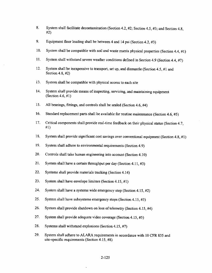
8. System shall facilitate decontamination (Section 4.2, #2; Section 4.5, #3; and Section 4.8,#2)
9. Equipment floor loading shall be between 4 and 14 psi (Section 4.2, #3)
10. System shall be compatible with soil and waste matrix physical properties (Section 4.4, #1)
11. System shall withstand severe weather conditions defined in Section 4.9 (Section 4.4, #7)
12. System shall be inexpensive to transport, set up, and dismantle (Section 4.5, #1 andSection 4.8, #2)
13. System shall be compatible with physical access to each site
14. System shall provide means of inspecting, servicing, and maintaining equipment(Section 4.6, #1)
15. All bearings, fittings, and controls shall be sealed (Section 4.6, #4)
16. Standard replacement parts shall be available for routine maintenance (Section 4.6, #5)
17. Critical components shall provide real-time feedback on their physical status (Section 4.7,#1)
18. System shall provide significant cost savings over conventional equipment (Section 4.8, #1)
19. System shall adhere to environmental requirements (Section 4.9)
20. Controls shall take human engineering into account (Section 4.10)
21. System shall have a certain throughput per day (Section 4.11, #3)
22. Systems shall provide materials tracking (Section 4.14)
23. System shall have envelope limiters (Section 4.15, #1)
24. System shall have a systems wide emergency stop (Section 4.15, #2)
25. System shall have subsystems emergency stops (Section 4.15, #3)
26. System shall provide shutdown on loss of telemetry (Section 4.15, #4)
27. System shall provide adequate video coverage (Section 4.15, #5)
28. Systems shall withstand explosions (Section 4.15, #7)
29. System shall adhere to ALARA requirements in accordance with 10 CFR 835 andsite-specific requirements (Section 4.15, #8)
2-125

30. System shall adhere to OSHA requirements as listed in Section 3.0, General Requirements(Section 4.15, #9)
31. System shall meet Quality Assurance program quality level 3 requirements (Section 4.16,#2)
32. System shall remove sufficient waste to return the area to below cleanup level requirements(Section 4.16, #3)
33. System shall require a key or password to operate (Section 4.17, #1).
2.8.2.2 Generic Conveyors.
2.8.2.2.1 Description—Roller and belt conveyors are produced by many differentmanufacturers and can be set up to operate on or above the ground. Many conveyors are modular andcan create intricate process flow paths.
2.8.2.2.2 Applications—A conveyor system may be applicable for transferring packagedmaterial from the excavator to a decontamination station or compactor. The conveyor system could thentransfer the materials through the decontamination chamber and out through an airlock. This type ofsystem would help minimize the number of times a package would be transferred from different piecesof equipment.
2.8.2.2.3 Issues/Gaps in Technology—Decontamination of conveyors is an issue. Manyconveyors have intricate moving parts with voids in between them; this makes decontamination difficult.
2.8.2.2.4 Source—Many conveyor vendors exist.
2.8.2.3 Self Guided Transport Vehicle (SGTV).
2.8.2.3.1 Description—RAHCO InternationalTM and Spar Environmental have developed atransfer unit capable of moving transuranic waste with relatively little dust creation for the INEEL. TheSGTV (Self Guided Transport Vehicle) is a 40-ton, prototypical, track-mounted, unmanned vehicle foruse in hazardous environments. The vehicle can travel at speeds of 5 mph on a pre-programmed course(within an accuracy of 9 SGTV can be instructed in real time to operate on a variety of groundconditions. Video imaging, ultra sonic ranging, and safety shutdown systems are housed onboard SGTV.A global positioning system and graphical user interface were installed on the most recent design. Thetrack hydraulics are in a closed loop to reduce hydraulic latency, and the transport system is powered bya 100-hp diesel engine. The waste containers were modified for end loading and are made of disposablematerials. SGTV is able to traverse uneven ground with the use of an electronic compass and pitch androll information. Incorporated in the system is a sensor array that detects objects in front of and behindSGTV. If the vehicle comes within 35 ft of an object, the operator is warned. If SGTV comes to within20 ft, the operator is warned and the vehicle slows. At 6 ft, SGTV automatically stops and shuts down.
2.8.2.3.2 Applications—SGTV could be used for the transport of boxes from theconfinement facility. The system has been proven at the INEEL.
2-126

2.8.2.3.3 Issues—This system would not be ideal for use inside of the containment facility—toes not possess any manipulator arms for transferring the boxes and might cause excessive dusteration.
2.8.2.3.4 Source—Personal communication between Thomas J. Crocker, RAHCOInternationalTM, Spokane, Washington, and Reva Hyde, LMITCO (response to LMITCO's January 29,1997 CBD solicitations), November 1, 1996.
Package included information on REMEX and SGTV dated November 1, 1996, from Thomas J.Crocker, Business Development at RAHCO InternationalTM.
Personal communication between Lee Maher, Spar Environmental, Brampton, Ontario, Canada,and Doug Stacey, LMITCO (response to LMITCO's January 29, 1997 CBD solicitations), February 7,1997.
Package containing information on SGTV waste transfer unit and remotely operated forklift datedFebruary 7, 1997, from Lee Maher, Director of Environmental Systems for Spar Environmental.
2.8.2.4 Remote Controlled Materials Handling System.
2.8.2.4.1 Description—Spar Environmental has developed the Remote Controlled MaterialsHandling System designed to lift and transport drums with hazardous/radioactive waste. The system iscomposed of a modified 8,000-lb capacity forklift, umbilical cord or radio frequency equipment, andhardware and software for remote operations. Vision for the forklift includes two high-performancecolor charge coupled device cameras and quartz halogen lamps mounted on pan/tilt brackets. An audiomicrophone for engine performance queues is included. Other attachments for the forklift includestandard forklift tines and a loose material cleanup tool. Attachments are installed quickly viaquick-connect hydraulic, electrical, and mechanical interfaces. The system has automatic shutdown incase of an emergency or failure. Command of the forklift, attachments, and vision is controlled byswitches and joysticks. The vehicle can also be operated in a manual setting. Other features includeautomatic wheel centering and a remotely operated park brake.
2.8.2.4.2 Applications—A remote-controlled forklift could be utilized for moving the wastebetween processes within the confinement facility (i.e., move waste from packaging to decontaminationchamber). The forklift could also be used to transport the waste away from the confinement facility.
2.8.2.4.3 Issues—Stereoscopic vision may have to be installed on the forklift Also, thisforklift may not be applicable for rough terrain. Dust generation may be a concern for a vehicle thatoperates on the ground.
2.8.2.4.4 Source•--Personal communication between Lee Maher, Spar Environmental,Brampton, Ontario, Canada, and Doug Stacey, LMITCO (response to LMITCO's January 29, 1997 CBDsolicitations), February 7, 1997.
Package containing information on SGTV waste transfer unit and remotely operated forklift datedFebruary 7, 1997, from Lee Maher, Director of Environmental Systems for Spar Environmental.
2-127

2.8.3 Above-Ground Transport
2.8.3.1 Remotely Operated Drum Opener and Transport System.
2.8.3.1.1 Description—DOE has provided funding at the INEEL to develop a remotelyoperated drum opener and transport system for waste drums. A rotating chuck allows the end-effector tograb 30-, 55-, and 83-gal drums. The drums are transported by an remote gantry robot and can be placedinto machines that require top loading. This system has been tested on a 55-gal drum weighing 1,000 lband works with deformed containers. Sensors on the drum-lifter end-effector measure relative force anddisplacement of the lifting straps.
2.8.3.1.2 Applications—The drum handling system could be utilized to transport drums ofrepackaged waste from various sites within the confinement facility.
2.8.3.1.3 Issues/Gaps in Technology—Currently, this system requires a gantry crane andcannot be used on an excavator. It is only applicable if the waste is repackaged into drums.Modifications must be made to enable the system the capacity of lifting boxes.
2.8.3.1.4 Source—Information on Waste Container Operating and Transportation gatheredfrom the Robotics Technology Crosscutting Program—Technology Summary for June 1995.
2.8.3.2 Generic Trolley Crane.
2.8.3.2.1 DescriptionRailltrolley systems are well developed and can be easily adapted to avariety of situations. A trolley system could be fabricated for the specific tasks desired at a hot spot.Special end-effectors can be attached to the crane for grabbing and transporting objects, and the materialcan be transported over the ground without creating any dust.
2.8.3.2.2 Applications—An overhead system would eliminate the need for a ground-basedsystem (i.e., a remotely operated forklift) and would reduce the generation of fugitive dust. Standardcomponents are available and could be used to design a system specifically for HSRS.
2.8.3.2.3 Issues/Gaps in Technology—This type of technology is well developed andproven, but must also be designed according to the special requirements of the Hot Spot RemovalSystem. A system must also be designed to close the container before transport.
2.8.3.2.4 Source—Many trolley/crane vendors exist.
2.8.4 Sizing/Packaging
2.84.1 Hazardous Waste Shredders.
2.8.4.1.1 Description—SSI Shredding Systems, Inc. is a company that provides hazardouswaste sizing and packaging technologies. Currently, SSI has a variety of vertical and horizontal feedshredders that are capable of sizing drums and other loose materials. After the waste is shredded, thematerial is fed directly into drums or boxes for transport. The shredders use a boot to prevent thegeneration of dust when the sized material is fed into the barrel and box containers.
2-128

SSI currently engineers and fabricates special shredders for each customer. Modifications can bemade to an existing model, or a complete system can be designed according to HSRS requirements.
2.8.4.1.2 Applications—This type of system could be utilized for the sizing and packaging ofwaste into drums or boxes. It is capable of sizing drums, boxes, and various other loose waste materials.
2.8.4.1.3 Issues/Gaps in Technology—The sizing equipment is not capable of shreddingthick and hard material. Automobile engine blocks and 1-in.-thick pressure vessels must be sized usinganother technique. Shredding could cause containers with explosive gases and liquids to discharge. As aresult, the shredder must be placed in an inert atmosphere and be designed for explosions. Specialventing must be used to prevent the spread of plutonium particles.
2.8.4.1.4 Source—Personal communication between Joyce Beasley, SSI Shredding Systems,Inc., Wilsonville, Oregon, and Steven Swanson, LMITCO (response to LMITCO's Sizing CBDsolicitation), March 27, 1997.
Package containing information on shredding technologies dated March 27, 1997, from JoyceBeasley, Technical Salesperson - Hazardous Waste Solutions for SSI Shredding Systems, Inc.
2.8.4.2 Mobile Industrial Vacuum System.
2.8.4.2.1 Description—GapVax® Incorporated specializes in vacuum recovery andpackaging systems. Further information can not be provided due to proprietary restrictions.
2.8.4.2.2 Applications—This system is not applicable. Decontaminating the vehicle isundesirable.
2.8.4.2.3 Issues/Gaps in Technology—See the applications section.
2.8.4.2.4 Source—Personal communication between Matt Hughes, GapVax® Incorporated,Johnstown, Pennsylvania, and Steven Swanson, LMITCO (response to LMITCO's CBD solicitation),March 24, 1997.
Package containing information on truck-mounted vacuum technologies dated March 24, 1997,from Matt Hughes, Industrial Sales Manager for GapVax® Incorporated.
2.8.5 Double Door Systems
2.8.5.1 Drum Entry Airlock Door Module.
2.8.5.1.1 Description—Merrick Engineers & Architects has developed airlock systems fordrums and boxes. These glovebox systems are capable of opening the container, crushing emptycontainers, characterizing contents, and maintenancing equipment. All of these operations take place ina concealed environment that prevents the spread of contamination. Conveyors pass the containersthrough the series of cells for operations.
Merrick is capable of producing equipment specifically designed for HSRS needs. Modificationsto the existing equipment can be made to help reach the project requirements.
2-129
2.8.5.1.2 Applications—A system similar to this may be applicable for closing the lids oncontainers, and transferring them outside of the facility. Characterization of the containers can be donebefore they are introduced into the uncontrolled environment. This type of system would be used afterthe waste was re-packaged into the new standard containers. Modifications can also be made to matethis system with a decontamination chamber.
2.8.5.1.3 issues/Gaps in Technology—This system would require the addition ofmanipulator arms to replace the need for personnel to sort and open/close containers. Other airlocksystems are available and may be more applicable to HSRS requirements.
2.8.5.1.4 Source—Personal communication between Scott Gustafsen, Merrick Engineers &Architects, Los Alamos, Pennsylvania, and Steven Swanson, LMITCO (response to LMITCO's CBDsolicitation), March 24, 1997.
Package containing information on the drum entry airlock door module, dated March 24, 1997,from Scott Gustafsen, Lead Equipment Design Engineer for Merrick Engineers & Architects.
2.9 Decontamination
2.9.1 General Description
The decontamination system/method will either be housed in the containment enclosure orattached to it and has two basic functions: (1) decontaminate the exterior of the waste packages or fixthe contamination for transportation to a location of the individual sites choice and (2) decontaminate theequipment used for HSRS. The level to which the waste packages will be decontaminated will be sitedependent. The ease in which HSRS equipment can be decontaminated will play a large factor in thecost of the system. If equipment cannot be decontaminated, it will have to be left at the site, thuscreating additional waste as well as increasing the cost of using HSRS. For levels to which theequipment will have to be decontaminated in order to be released from the site, please reference the HotSpot Removal System Requirements Document, Mobility Requirements, Section 4.5.
In Sections 2.9.3 through 2.9.6, decontamination technologies are described that are eitheravailable from industry or DOE/DOD as well as emerging technologies. The following technologies arediscussed: mechanical decontamination, strippable coatings, decontamination chambers, and chemicaldecontamination. Please note that in this report, decontamination can refer either to the removal ofcontaminants from the surface or to a method used to fix the contaminants to the surface for transportpurposes. Both processes will bring the equipment into acceptable levels of contamination.
2.9.2 Decontamination Requirements
The following requirements were taken from the draft Hot Spot Removal System RequirementsDocument, Section 5.7.
1. Contain decontamination water, if used, during the decontamination operation
2. Read radiation levels at real time to determine decontamination needs
3. Provide for control of the system from the remote control location.
2-130

2.9.3 Mechanical Decontamination
2.9.3.1 General Description. Mechanical decontamination methods are based on physicallydislodging the surface contamination. A variety of methods are available, including wiping/scrubbing,grinding/machining, media blasting, high-pressure water or steam jets, vacuum cleaning, ultrasoniccleaning, and vibratory finishing. Wiping and scrubbing are labor intensive, involving manual cleaningwith cloths or pads. Abrasive media can be used with the wipes, the abrasiveness varied depending onthe type of surface and deposit involved. Mechanical decontamination can be combined with chemicaldecontamination when various chemical agents are added to react with and loosen the deposits and/orimprove the ability of the wipes to retain the loosened material. Grinding and machining are essentiallymechanically assisted variations of the manual wiping/scrubbing process.
Cleaning with water can be accomplished by simply flushing a surface if the deposits are easilydislodged. If more aggressive deposit removal is required, jets of high-pressure water or steam can beemployed, as well as detergents or cleansers. Equipment requirements for high-pressure applicationsinclude a supply of water or steam; a pump, hose, and nozzle for delivery; and handling tools, asappropriate, for positioning the nozzle.
Media blasting is based on the use of solid particles suspended in a fluid that is sprayed at highpressure to abrasively dislodge the contamination from the surface. Various media can be useddepending on the abrasiveness required. These media include minerals such as sand or garnet, solidcarbon dioxide, glass beads, plastic beads, ground nut shells, and wheat starch. Equipment requirementsfor media blasting are similar to those for water jets.
The vacuum cleaning process is suitable for removing loose or easily removed particulatecontamination by drawing the particulate into a vacuum system. Equipment requirements include asource of vacuum, hoses, nozzles, brushes, and a filtration system to collect the removed particulate.
The basis of ultrasonic cleaning is the immersion of the items to be decontaminated into a liquidbath that is ultrasonically excited. The excitation causes the liquid to cavitate at the interface with thesolid surface. Water is usually used in the ultrasonic bath, and chemicals can be added to assist insoftening or solubilizing the contamination. The equipment required is an immersion tank and theassociated system necessary to induce the desired level of ultrasonic excitation.
Carbon dioxide pellets have been used to dislodge contamination from the surface of equipment.See Section 2.9.3.5 for a more detailed description of this technology.
The advantages of mechanical decontamination include the following: (1) mechanicaldecontamination is well developed, (2) it can result in reclassification of large waste items, making themmuch easier and cheaper to dispose, (3) many processes create either a relatively small waste stream, or awaste stream that can be further processed such that the overall result is a smaller waste stream, (4) withsome methods, the waste wash can be regenerated and reused, and (5) the various blasting techniques arewell suited for use on large, complex surfaces.
All of the mechanical techniques for mechanical decontamination are well developed and havebeen used with radioactive waste.
2-131

2.9.3.2 Applications. Some smaller tools used in HSRS may be wiped down to an acceptable level.This technique would be used for those tools that could be handled manually, both from size andcontamination level standpoints.
Mechanical forms of decontamination may be combined with the use of a decontaminationchamber (Section 2.9.5) to clean the larger retrieval equipment just prior to leaving a site.
This method may be applicable for the final decontamination process, after the grosscontamination had been removed from the equipment.
2.9.3.3 Issues. The disadvantages of mechanical decontamination include the following: (1) someforms of mechanical decontamination are not amenable to remote operation, (2) it is limited to surfaceand near-surface deposits, (3) surface contamination on internal surfaces is usually more difficult toremove than external surface contamination, (4) the secondary waste streams must be treated, (5) waterflushing, steam cleaning, and media blasting can generate large volumes of waste, and can also causesignificant splashing and spread of contamination if not controlled carefully, (6) the scrubbing andwiping techniques are labor intensive and are less applicable to large work pieces, and (7) vacuuming iseffective for only loose contamination.
A decontamination chamber, with associated ventilation system, would have to be used inconjunction with this type of decontamination technique to be feasible both financially and based onALARA practices.
2.9.3.4 Source. Information was taken from Commercially Available Low-Level Radioactive andMixed Waste Treatment Technologies, by Russell S. Garcia, October 1996, DOE/LLW-240.
Vendor sources of equipment needed to mechanically decontaminate the equipment are toonumerous to list here, and some suppliers may be inadvertently omitted.
2.9.3.5 Carbon Dioxide Pellet Blasting. The information for the following description wasreceived from Non-Destructive Cleaning via an advertisement in the Commerce Business Daily andforms the basis for the discussion that follows. It should be remembered, however, that several vendorsare capable of providing carbon dioxide pellet blasting for decontamination purposes. Not all of thesevendors will be listed here as the list is long and some vendors may be inadvertently omitted.
2.9.3.5.1 Description—Non-Destructive Cleaning provides a patented process/facility thatuses carbon dioxide (CO2) particles, propelled by dry compressed air, to decontaminate surfaces. TheCO2 particles shatter upon impact and flash into dry CO2 gas. This flash causes the dry CO2 gas torapidly expand, lifting and flushing the contamination from the surface of the material being cleanedwithout damaging the surface of the equipment. The facility is furnished with HEPA filters andHEPA-filtered vacuum cleaners to capture the contamination knocked loose.
The CO2 unit is capable of being operated manually, teleoperated, or robotically. Items up to4,000 Ib can be decontaminated in this mobile facility. It has a large entry door and an internal hoistcapable of handling up to 2 tons. Smaller items can also be cleaned in the decontamination cell room.Small parts and fixtures are brought in small lots or 55-gal drums.
2-132

. The process has been found to decontaminate tools down to less than 1,000 disintegrations perminute (dpm)/100 cm2 smearable, allowing the tools to be free released. Gloveboxes with fixed alphacontamination in excess of 400,000 dpm/100 cm2 were reduced to less than 100 dpm/100 cm2.
The CO2 unit is 8 ft by 16 ft by 40 ft and is easy to set up and tear down. It can be transported inthree pieces that are joined together on site—two CONEX boxes and a flat bed containing the CO2 tankand air compressor. The electrical connections are managed by a central power cable connected to apower control and distribution panel located within the mobile unit.
The unit comes with a machinery and electrical room, a large decontamination room, adecontamination cell room, and a count room where cleaned items are surveyed after cleaning. Acomplete HVAC system designed for CO2 gas handling at a negative pressure within the facility itselfand an exhaust filtration system, which fulfills federal and state regulations, comes with the unit. Thefacility meets OSHA requirements for acoustics, ergonomics, and air quality.
2.9.34.2 Applications—The carbon dioxide pellet blasting form of decontamination can beused on metal objects, wood, plastics, glass, and rubber materials without causing damage to the surface.
Carbon dioxide blasting does not create any secondary waste, as the CO2 pellets flash into a drygas.
2.9.3.5.3 issues—HSRS, or the site, would have to provide 10-ton lifting equipment foroff-loading the two steel enclosures, and one 480-V, 300- (full-load) A, 3-phase power supply. Thepower supply is hard wired into the Non-Destructive Cleaning unit's power distribution panel.
Is not currently capable of handling an excavator.
The blasting would have to be done in an enclosed environment within the confinement enclosureso that the confinement enclosure ventilation system would not have to be oversized to accommodateCO2 blasting.
If the carbon dioxide is not done remotely, a ventilation system capable of handling the blastingwill have to be designed. In addition, personnel would be exposed to an atmosphere devoid of oxygen;thus, it would require respirators in addition to any other personnel protective equipment deemednecessary.
2.9.4 Strippable Coatings
2.9.4.1 General Description. Strippable coatings have been developed in industry and can besprayed on the surface of the equipment being used and peeled off when finished. Once peeled awayfrom the equipment, it can leave the surface cleaner than it was before application. They may also beused to fix contamination on the equipment.
Typically, these coatings are not made for use under extreme conditions, such as on the end-effector, where the surfaces are in direct contact with the waste, and must be removed from theequipment manually. As such, strippable coatings will have limited use in HSRS.
2.9.4.2 Heat Shrink. Heat shrink is commonly used in industry to enclose the item to bedecontaminated. It does not actually decontaminate the surface, but fixes the contamination in place so
2-133

that the object can be transported. It adheres to itself, not to the surface it comes in contact with, and isthus easily removed later, if desired.
2.9.4.3 ISOLOCK.
2.9.4.3.1 Description—The ISOLOCK coating (patent pending) is the toughest strippablecoating that ISOTRON® manufactures. They suggest applying a thin release film based on a waxemulsion to those surfaces where there is not likely to be any physical contact with the waste. This filmwould not be applied to those areas where a strong bond is required, as it aids in removal of the coatinglater. A layer of strippable ISOLOCK would then be applied to the piece of equipment. This coatinglocks down the contaminants on the equipment, thus eliminating any airborne particles or spread ofcontaminants during transport. As the equipment is used at each site, upon completion of the job, a freshlayer of ISOLOCK would be applied on the equipment prior to transport. The film would becomeincreasingly thick and durable. At the final job site, a final layer would be applied to lock down thecontaminants. Once it had cured, a high-pressure water blaster could be used to remove any residualcoating. The contaminants would be locked in the coating and could be disposed of in the final wastebox.
This coating could be injected into the soil to provide in situ control with a cure time of 24 to48 hours.
The price of these coatings ranges from $40 to $80/gal, each gallon covering 20 to 40 ft2.
2.9.4.3.2 Applications—These coatings adhere to almost any surface and could be used onthe end-effector, excavator, tools, etc. It should be noted, however, that these coatings may beinadvertently stripped off of those places coming in contact with the waste, depending on the frictioninvolved.
2.9.4.3.3 Issues—The gelation time, if used in situ, is quite long.
If used as suggested (applying a new layer at each site), the coating would become more durable,but the final waste associated with the coating may be untreatable/disposable due to cross-contaminationwithin the layers themselves.
Some new tooling would be required to peel the coatings off of the equipment remotely, ifpossible.
2.9.4.3.4 Source—There are numerous companies in industry that can supply strippablecoatings.
The discussion above was based on information received via a response to an advertisementplaced in the Commerce Business Daily requesting information on contamination control technologiesand posted January 29, 1997, and on private communications between Henry Lomasney of ISOTRON®and Michelle Dahlmeir of LMITCO.
2.9.5 Decontamination Chambers
2.9.5.1 General Description. Decontamination chambers are usually skid/trailer mounted orpermanent facilities into which the equipment to be cleaned is loaded. The size of equipment these
2-134

chambers decontaminate depends on the size of the chamber and varies greatly. These chambers havedifferent decontamination media used for knocking the contamination levels on the equipment down toacceptable levels, and include grit/sand blasting, high-pressure water, carbon dioxide pellet blasting, etc.The level to which each of these systems decontaminate the equipment also varies.
2.9.5.2 Application. Decontamination chambers can be used to decontaminate the equipment used inHSRS, including but not limited to the retrieval equipment, the ventilation equipment (if necessary), anyother waste packaging or transfer equipment, and the loaded waste packages.
2.9.5.3 General Issues/Gaps in Technology. The optimum use for a decontamination chamberwould be to use it both to decontaminate the waste boxes and to transfer the clean box to the outsideworld. To do this, a framework/mating type scheme would have to be designed between the wastepackaging system described in Section 2.8 and the decontamination chamber, as well as between thedecontamination chamber and the confinement. The decontamination chamber would have to be capableof handling large equipment (excavator/crane, shredder, etc.), in addition to smaller tools. In addition, ameans to swipe the waste package remotely while still in the decontamination chamber would have to beprovided through gloveports or some other means. This swipe has to be removed from the immediatevicinity of the box in order to determine the contamination level on the outside surface. If the count wasperformed inside the chamber, only direct readings from the source inside the box would be read, notactual contamination levels.
2.9.5.4 Sources. There are numerous vendors that can custom build a decontamination chamber forHSRS, not necessarily including the framework/mating schemes to use in conjunction with thepackaging system and the confinement enclosure. The following descriptions are for information onlyand are LMITCO-owned equipment or information received in a request for information that went in theCBD on January 29, 1997. They are included as representative examples to demonstrate what iscommercially available. This discussion does not mean to imply that these companies are more capableof providing what HSRS needs than are other companies.
2.9.5.5 HazCo Trailer.
2.9.5.5.1 Description—The Inactive Sites group of LMITCO has a stainless steel trailer usedas a decontamination chamber for larger pieces of equipment. The trailer has ramps on both ends toallow an excavator, etc., to drive in, be decontaminated, and drive out. The trailer comes with collectiontanks for any media used to decontaminate the equipment. Currently, the Inactive Sites group uses thistrailer in conjunction with a SuperSAPP truck, which is a decontamination truck complete with ahigh-pressure water system to knock the contamination off of the equipment, cyclone separators, oilseparation techniques, ion exchange columns, and a vacuum system to suck up the loose contaminationthat comes off during the process.
2.9.5.5.2 Application—This trailer could be used as a part of the decontamination system forthe retrieval equipment. The Inactive Sites group stated that they have not used this trailer, as they havebeen able to use more conventional means of decontamination, and would most likely be able to supportHSRS.
2-135

trailer.2.9.5.5.3 Issues—A decontamination system would have to be designed for use with this
2.9.5.5.4 Source—Inactive Sites group, LMITCO, at the INEEL.
2.9.5.6 Kelly Decontamination System.
2.9.5.6.1 Description—Container Products Corporation has several decontamination systemsdeveloped for different applications. The system most applicable to HSRS is the Kelly Decon System inconjunction with the Remote Decon Vehicle. The system can be used for high-level jobs up to 300 ftaway. The system may be used as a stand-alone unit or trailer- or skid-mounted unit.
2.9.5.6.2 Applications—Might be able to use a system like this for decontamination after thewaste is packaged, or for any tools used during remediation.
2.9.5.6.3 Issues—This particular model is only a single door, which does not permit the wasteto travel through the decontamination chamber to the outside of the containment facility.
This chamber would not be capable of decontaminating a 60,000-lb excavator or large crane.
2.9.5.6.4 Source—This information was received from advertisements in the CommerceBusiness Daily on January 29 and March 19, 1997.
2.9.6 Chemical Decontamination
2.9.6.1 Description. Chemical decontamination includes methods that use chemical agents to loosenor solubilize the surface contamination. Contact may be achieved either by immersion of the work piecein a chemical bath or by surface application of the agent as a liquid, foam, gel, or paste. Chemical agentsthat are most commonly used include aqueous solutions of mineral or organic acids, chelating agents, ordetergents used separately or in various combinations. Chemical decontamination is often done inconjunction with some form of mechanical process such as wiping/scrubbing, grinding, or ultrasoniccleaning. In particular, flushing the surface with water after chemical application is a chemical processenhanced by the effect of a flowing liquid. For chemical decontamination by immersion, the equipmentrequired includes a tank, pump, and agitator. The system can be modified to include the appropriateelectrochemical equipment to assist the process by enhancing appropriate oxidation/reduction reactions.For surface application, the equipment includes a reservoir for the chemical agent, a pump, hose, andnozzles. Since the surface-applied chemicals are usually removed by flushing with water, additionalequipment includes a source of water and water delivery system.
The advantages of chemical decontamination include the following: (1) it can result inreclassification of large waste items, making them much easier and cheaper to dispose of, (2) the wastewash can be regenerated and reused, and (3) immersion in chemical baths generates low volumes ofwaste.
All of the chemical decontamination techniques are well developed and have been used withradioactive wastes in the past.
2-136

2.9.6.2 Applications. It will be used in the chemical decontamination of the equipment used forHSRS.
2.9.6.3 Issues. The disadvantages of chemical decontamination include the following: (1) it islimited to surface and near-surface deposits, (2) surface contamination on internal surfaces is usuallymore difficult to remove than external surface contamination, (3) the secondary waste streams must betreated, and (4) water flushing can generate large volumes of waste, and can also cause significantsplashing and spread of contamination if not controlled carefully.
2.9.6.4 Sources. This information was taken from Commercially Available Low-Level Radioactiveand Mixed Waste Treatment Technologies, by Russell S. Garcia, October 1996, DOE/LLW-240.
Vendor sources of equipment needed to chemically decontaminate the equipment are toonumerous to list here, and some suppliers may be inadvertently omitted. Corpex Technologies Inc.responded to an advertisement in the Commerce Business Daily and is written up in this report toprovide a more detailed description of a chemical decontamination process. As mentioned earlier, this isjust one of many vendors capable of providing a means of chemical decontamination.
2.9.6.5 Corpex Technologies, Inc..
2.9.6.5.1 Description—The Corpex® Nuclear decontamination process, supplied by CorpexTechnologies, Inc., is a chemical decontamination process which uses a proprietary chelant to remove awide range of radioactive contaminants, oil, grease, and grime, and to dissolve metal oxide layers fromany surface. This chelant works at neutral pH levels, thus minimizing corrosion to underlying metals andother construction materials, and increasing operator safety.
Vats containing the prepared reagents at optimum temperatures are used for small tools and itemsthat can be disassembled. The typical application temperature is 205°F and is maintained at thistemperature for about 2 hours. The items are put in baskets and first dipped in CORPEX®-960 topre-treat the oxide layer. The items then go through two rinse cycles with deionized water and aredrained. The basket is then dipped in CORPEX*-921 to remove the oxide layer. Sometimes,mechanical agitation is used in this system to help clean crevices. Please note that CORPEX®-960 andCORPEX®-92I are just examples, as other reagents are available depending on the site's needs. Forexample, CORPEX®-96I precipitates 99.8% of the sequestered radioactive metal ions and their oxidesand hydroxides out of the solution as oxides or hydroxides. This precipitate can then be filtered, theresulting filtrate polished by ion exchange, rendering the decontaminated component suitable for releaseor reuse.
For items that cannot be placed in these vats, as the chelant is aqueous-based, it can be applied bymeans of a spray, fog, mist, gel, or foam. Mists have an advantage over sprays as they can wet all areas.However, sprays often have the advantage of higher delivery pressures; therefore, a combination of thetwo is probably optimum. CORPEX® has a 3-D nozzle on a lance that can be re-positioned to minimizeshadow from internal structures or components during the spray application. The application time islonger due to the lower application temperatures associated with maintaining negative pressures on theequipment. For each 18°F decrease in the application temperature, the exposure time doubles. Once thereagent has been in contact with the surface for a specified amount of time, the reagent is rinsed off withwater.
2-137

The reagents are collected in a waste process tank where they are oxidized, volume reduced,and/or solidified. If the equipment is not decontaminated sufficiently after being run through thisprocess, the reagents can be recycled to decontaminate the equipment again, thus adding no additionalwaste.
This process can be done remotely. This company is willing to work with customers to make aspecialized system for HSRS's needs.
2.9.6.5.2 Application—This decontamination method works on stainless steel, aluminum,carbon steel, monel, copper, brass, bronze, nickel, painted and unpainted concrete, oily and greasysurfaces, etc., without causing embrittlement. It also works on any surface texture, including porous,rusted, scaled, etc.
This process has been shown to remove uranium, technetium, plutonium oxides, and oxides ofother heavy radioisotopes. Other corrosion products, such as iron oxide, are also removed, thusremoving that radioactive contamination trapped in the corrosion product matrix.
2.9.6.5.3 Issues—An additional waste stream is produced (reagent/contaminant mixture).
This waste stream is not, however, mixed waste.
For the larger equipment, a chamber capable of holding the retrieval equipment and thencontaining the contaminated water during the rinse cycle would have to be provided or designed.
2.9.6.5.4 Source—This information was received in response to advertisement placed in theCommerce Business Daily on March 19, 1997.
2.10 Remote Vision/Telecommunication
2.10.1 General Description
When operating a piece of equipment, the operator makes use of the five senses. In most remote
operations, information is not provided in a way that allows inherent use of these senses in the samemanner. In normal operations, for example, the operator has three-dimensional vision of the operatingenvironment, allowing intuitive depth-perception capabilities, as well as peripheral vision and the abilityto quickly change the field of view by moving his head. For remote operations, remote vision is notnearly as sophisticated. Stereo vision continues to improve but is still far from providing an intuitivedepth perception capability in many cases. Pan and tilt units move at a much slower rate than anoperator's head can turn. Auto iris and auto focus do not always bring the desired object into view.
Similarly, tactile senses have not been sufficiently reproduced in the remote environment. Althoughforce feedback systems do exist, they do not supply the tactile information in the manner that a manual
operator is accustomed. Audio is often provided to the remote operator but seldom in a form that allowsthe operator to determine the location, in three dimensions, from which the sound came. These
limitations to the sensory capabilities of the remote operator lead to more cognitive demands. Themajority of the information presented to the operator is provided in a visual format, requiring theoperator to process the information, decipher the meaning of the data, and then determine an appropriate
response action.
2-138

Remote operations also provide some enhanced capabilities to the operator. The modificationsmade to equipment allowing remote operations often result in improved performance capabilities. Anexample of this is crowd control of an excavator bucket, a process used to make a level cut of a specifieddepth through the soil. In manual operations, this activity requires the operator to simultaneously controlthe bucket roll, stick angle, and boom angle. An operator of a remote excavator, with closed loopcontrol, has the capability to perform this function using coordinated control through a simple command.
Remote operation will be used in the Hot Spot Removal System to perform several different tasks,which could include but are not limited to the following:
• Get a tool
• Put back a tool
• Retrieve object(s)
• Put overburden or waste into transfer mechanism
• Perform characterization calibration
• Perform characterization scans
• Vacuum overburden and other soils
• Use camera(s) to get information
• Manipulate a light to see a shadowed area
• Traverse entire work envelope
• Start up systems such as hydraulics, electric, pneumatic
• Perform monitor system overview
• Control contamination
• Perform remote maintenance
• Monitor all equipment
• Control fires.
In order for remote operation to function well, it is important to understand:
• Where the task will occur within the working envelope
• How critical vision is to the successful completion of that activity
• How often that task will be performed.
2-139

Remote vision involves the use of cameras to determine the location of equipment in theconfinement enclosure and aids in the subsequent remote operation of said equipment. Several factorsmust be considered in choosing a camera system for remote vision, and include the following:
• Working envelope
• Frequency of use of certain areas within the working envelope
• Criticality of camera view for certain operations
• Tasks to be performed
• How close the video cameras must be brought to the area of interest
• Pan, tilt, zoom, or translational capability requirements
• Color importance.
One important feature that the camera system will likely require is depth perception. Humanstypically get depth cues from:
• Size of objects
• Interposition
• Linear perspective
• Contrast, clarity, and brightness
• Shadows
• Motion parallax
• Stereopsis.
In order to have sufficient teleproprioception, depth cues can be accomplished by:
• Two separate video cameras
• A single camera outfitted with two optical paths sharing the video field in time or space(stereo vision)
• Computed generated geometric model.
Bandwidth (bits/second) should be considered in choosing a camera system and is the product ofthree variables that require a tradeoff analysis:
• Frame rate (frames/second)
2-140

• Resolution (pixels/frame)
• Gray scale (bits/pixel).
Sections 2.10.2.3 through 2.10.2.20 provide summaries and critiques on equipment and technologythat were received from the request for information placed in the Commerce Business Daily. Table 2-11provides a list of the researched vendors and equipment.
2.10.2 Remote Vision Requirements
The following requirements were taken into consideration when looking at the various remoteviewing equipment and were taken from the draft Hot Spot Removal System Requirements Document:
1. Equipment shall be compatible with waste/contamination chemical constituents(Section 4.2, #1)
2. Equipment shall facilitate decontamination (Section 4.2, #2)
3. Shall be remotely operable (Section 4.4, #6)
4. Shall withstand severe weather conditions as defined in Section 4.9, EnvironmentalRequirements (Section 4.4, #7)
5. System shall be easily and inexpensively transportable from one site to another (Section 4.5,#1)
Table 2-11. Vision technology vendors and equipment.
Vendor/Supplier Vision Technologies
Aquatic Sciences Inc.
August Design Inc.
Dimension Technologies Inc.
Foster-Miller, Inc.
Framatome Technologies, Inc.
Kaiser Electronics
Pipecrawler, 4,000-ft tethered robot designed for video inspectionof piping.
Skycamtm, towers, and winches used to suspend a camera in the airfor video information gathering.
Autostereoscopic vision monitors.
FERRET, robot with 100-lb carrying and 11-ft reaching capacities.Comes with lighting and camera.
LVA-I, a 64-source remote vision and audio monitoring controlsystem with a 300-ft viewing distance.
Virtual Interactive Enhanced Workstation (VIEWTm), head-mounted display (HMD) monitoring system capable of providing36 video sources one at a time.
K2T, Inc. Franklin Scanner, provides rough virtual reality and video imagesfrom a laser scanner.
Michigan State University Camera-Aided Virtual Reality Builder (CAVRB), virtual realitybuilder using matched points from multiple cameras (patent filed).
2-141

National Institute of Standards and TRICLOPS, high-velocity pan/tilt unit. Houses wide-angle andTechnology zoom cameras.
OAO Robotics Generic two-camera, HMD, vision system for excavators.
Precam Associates, Inc. MAR-512, cameras provide structured, edge-based descriptions ofthe scene.
Precam Associates, Inc. Laser Ranging Telerobot, system overcomes changes in ambientinfrared lighting and maintains depth of field.
REMOTEC Andros robots for hazardous environment operations.
Remote Ocean Systems Various components including explosion-proof housings, radiofrequency operation cameras, 360-degree pan/tilts, and high-radiation equipment.
Robotech Industries Ltd.
Spar Environmental
TPL Inc.
VE Technologies
Scout, two-camera vision system with an HMD and head trackerunit.
3D cameras used to build virtual reality representations of thescene.
High-resolution, digital, real-time, video imaging system to be usedwith visible, gamma, and x-ray sources.
VE-379, intelligent sub-framing camera designed for autonomoustracking and recognition.
6. System shall provide a means of inspecting, servicing, and maintaining equipment(Section 4.6, #1)
7. All bearings, fittings, and controls shall be sealed (Section 4.6, #4)
8. Standard replacement parts shall be available for routine maintenance (Section 4.6, #5)
9. System must be more cost effective at retrieving the source term than it would be to useconventional equipment (Section 4.8, #1)
10. System shall be inexpensive to transport, set up, decontaminate, and dismantle (Section 4.8,#2)
11. System shall accommodate human capabilities and limitations using human engineering(Sections 4.10, #1 through #10, excluding #4 and #6)
12. Equipment will be ready to place in the Hot Spot Removal project (Section 4.11, #5 and #6)
13. System shall withstand explosions (Section 4.15, #7)
14. Equipment shall adhere to OSHA requirements as listed in Section 3.0, GeneralRequirements (Section 4.15, #9)
2-142

15. System shall meet Quality Assurance program quality level 3 requirements (Section 4.16,#2)
16. System shall remove sufficient waste to return the area to below cleanup level requirements(Section 4.16, #3)
17. Equipment/control system shall have a password/lockout system (Section 4.17, #1)
18. Equipment shall allow for easy access to electronic equipment for maintenance (Section 5.3,#2)
19. Video cameras shall be capable of self-cleaning or defogging (Section 5.3, #14).
2.10.3 Pipecrawler
2.10.3.1 Description. Aquatic Sciences Inc. has developed a tether-controlled pipe inspection unit.The robot is track-driven and carries a pressure-housed color CCD camera with full tilt and pancapabilities. The umbilical cable for the robot is a standard 1,000-ft length and can be increased to alength of 4,000 m. A motorized tether manager system controls the reeling and unreeling of the cableand relays the distance of penetration directly to the video display. All operations of the Pipecrawler,track, camera, and lights are controlled by a computer keypad in a remote location. The size of thePipecrawler is very compact (less than 4 ft by 4 ft).
Aquatic Sciences Inc. would also like to adapt underwater camera equipment to dry landapplications.
2.10.3.2 Application. The Pipecrawler may be applicable for additional lighting and camera views.It does require a tether, which limits its capabilities. Other units could be used that are radio frequencyoperated.
2.10.3.3 Issues/Gaps in Technology. The unit is tether controlled and crawls on the ground.Decontamination would be a major concern.
2.10.3.4 Source. Personal communication between Bill Sherwood, Aquatic Sciences Inc., St.Catherines, Ontario, Canada, and Steven Swanson, LMITCO (response to LMITCO's March 19, 1997CBD solicitations), March 26, 1997.
Package on ASI Pipecrawler and company's desire to adapt underwater technology to dry landdated March 26, 1997, from Bill Sherwood, Manager of the Robotics Division for Aquatic Sciences Inc.
2.10.4 Skycam'sq
2.10.4.1 Description. August Design Inc. has developed the SkycamTm for maneuvering a cameraoverhead during sporting events at arenas. It can operate in areas as small as a room or bigger than theworlds largest stadium. The SkycamTm camera is held aloft by nearly invisible Kevlar fiber optic cablesthat are wound onto small motorized drums. The drums are controlled by a computer that instructs eachto let out or take up cable according to where the camera operator, using a joystick, wants the camera to
2-143

be. The camera can move at speeds up to 27 mph and will give a steady picture due to the gyro-stabilizerthat counterbalances it on top of the cable.
2.10.4.2 Applications. The SkycamTM system could be utilized to provide an overhead view of theworksite for manual collision avoidance and orientation.
2.10.4.3 Issues/Gaps in Technology. The system may not be applicable for hazardous/radioactiveenvironments. The cost of the system is substantial and might not be as cost effective as using facilitymounted cameras.
2.10.4.4 Source. Private communication between Ed Dougherty, August Design Inc., Merion,Pennsylvania, and Doug Stacey, LMITCO (response to LMITCO's January 29, 1997 CBD solicitations),February 17, 1997.
Fax on SkycamTM from Ed Dougherty, President of August Design Inc. dated February 17, 1997,in the form of rough sketches that did not come from a catalog.
2.10.5 Stereoscopic Vision
2.10.5.1 Description. Dimension Technologies Inc. has developed an autostereoscopic monitor forstereoscopic representations. The latest unit is very lightweight and possesses high resolution. An olderunit was utilized on the Cooperative Telerobotic Retrieval System crane (Section 2.4.3.2) and functionedwell.
2.10.5.2 Applications. Autostereoscopic monitors are very convenient for viewing stereoscopicimages. Once the operator has used them for a short while, the 3D images can be acquired ratherquickly. This system does not require any glasses.
2.10.5.3 Issues/Gaps in Technology. No major gaps identified a this time.
2.10.5.4 Source. Demonstration of autostereoscopic monitors at the INEEL, April 25, 1997.
2.10.6 FERRET
2.10.6.1 Description. Foster-Miller, Inc. has developed the FERRET (a remotely operated materialhandling robot). The FERRET is capable of carrying 100 lb and has a reach of 11 ft. The telescopingarm, with its three degrees of freedom, can be manipulated by a simple joystick and is controlled byradio or cable. A low-light CCTV camera provides feedback to the operator. This system was designedto dispose of improvised ordnance.
2.10.6.2 Applications. The FERRET could be used for additional camera and lighting. It also mightbe applicable for small tool conveyance.
2.10.6.3 Issues/Gaps in Technology. The FERRET may be too small for conveying tools betweenequipment. Decontamination is also an issue with vehicles that drive on the ground.
2-144

2.10.6.4 Source. Private communication between Blair J. Hough, Foster-Miller, Inc., Waltham,Massachusetts, and Doug Stacey, LMITCO (response to LMITCO's January 29, 1997 CBD solicitations),February 4, 1997.
Package including FERRET, 2THPIC, and ROME information dated February 4, 1997, fromBlair J. Hough, Business Development Manager of Foster-Miller Inc.
2.10.7 LVA-1
2.10.7.1 Description. Framatome Technologies, Inc. has developed the LVA-1 remote video andaudio monitoring and control system. The system communicates over fiber optic local area networksfrom a single computer at a central location. Controls for multiple cameras include pan, tilt, zoom,focus, iris, and light intensity. The LAV-1 can be engineered to meet the specialized needs of eachinstallation. All system components are packaged in protective cabinets to simplify setup: The systemcan accommodate up to 64 video channels without any modifications, and any number of externalmonitors can be configured as required. Any monitor can receive information from any camera.Lengths of 4,000 ft can be used in fiber optic cabling before amplification equipment is needed.
The cost of a system with four pan/tilt and four stationary cameras is approximately $35,000.
2.10.7.2 Applications. The LVA-1 might be a viable camera and lighting controller because it wouldbe capable of controlling the lighting and cameras for the excavator, waste transfer/packaging, remotevehicle, and confinement facility.
2.10.7.3 Issues/Gaps in Technology. The system may require some radioactive environmentaltesting. The control boxes have a survival level of 10,000 RAD.
2.10.7.4 Source. Personal communication between William S. Cooper, Framatome Technologies,Inc., and Steven Swanson, LMITCO (response to LMITCO's March 19, 1997 CBD solicitations), April2, 1997.
E-mail containing information on LVA-1 video and audio control system dated April 2, 1997,from William S. Cooper, Manager - Government Services for Framatome Technologies, Inc.
2.10.8 Virtual Interactive Enhanced Workstation (VIEWTM)
2.10.8.1 Description. Kaiser Electronics has developed a head-mounted display (HMD) that iscapable of controlling and displaying 36 separate video sources. The Virtual Interactive EnhancedWorkstation (VIEWTM) uses a powerful electronic control unit, state-of-the-art headset, and awardwinning head tracking technology. The head position of the operator is monitored to allow for cameraview selection. As the operator turns his/her head, different camera views are displayed. The IIMD wasdesigned to provide optimum peripheral vision. With the headset on, the operator still has the ability tosee to the sides of the HMD and below the HMD to view controls.
2.10.8.2 Applications. The VIEWTM system may be a compact solution to the vision displays forHSRS. It could eliminate the need for a bulky monitor wall. VIEWTM is capable of inputting signals forstereoscopic and monoscopic vision.
2-145

2.10.8.3 Issues/Gaps in Technology. Only one video source can be displayed at one time peroperator. Many times, operators would like to quickly view a series of cameras (monitor screens) toreceive orientation or collision avoidance information. With the VIEWTM system, the operator wouldhave to continuously move his/her head around to receive these same views.
2.10.8.4 Source. Personal communication between Michael P. Browne, Ph.D., Kaiser Electronics,San Jose, California, and Steven Swanson, LMITCO (response to LMITCO's March 19, 1997 CBDsolicitations), April 11, 1997.
Package containing information on the VIEWTM multi-view HMD, dated April 11, 1997, fromMichael Browne, Senior Optical Engineer of Advanced Systems at Kaiser Electronics.
2.10.9 Franklin Scanner
2.10.9.1 Description. K2T, Inc. has developed a laser ranging unit that is capable of gatheringinformation at a very high rate. This allows the scanner to produce 3D images in real-time. TheFranklin Scanner can scan the environment a full 360 degrees in the horizontal and in the vertical +1- 15-degree planes. From the information that is gathered, the system can produce gray scale images of theenvironment, or display rough virtual reality images.
2.10.9.2 Applications. The Franklin Scanner can provide images in real time for rough virtual realityscenes.
2.10.9.3 Issues/Gaps in Technology. This is relatively new technology. Using an adequatenumber of cameras will eliminate the need for this type of equipment.
2.10.9.4 Source. Personal communication between Ryan M. Sullivan, K2T, Inc., Duquesne,Pennsylvania, and Steven Swanson, LMITCO (response to LMITCO's March 19, 1997 CBDsolicitations), April 14, 1997.
Package containing information on the Franklin Scanner, dated April 14, 1997, from Ryan M.Sullivan, Project Manager for K2T, Inc.
2.10.10 Camera-Aided Virtual Reality Builder (CAVRB)
2.10.10.1 Description. Michigan State University has developed a software package that can create3D virtual reality images of objects and scenes from 3D cameras (patent filed). The Camera-AidedVirtual Reality Builder (CAVRB) needs only a few images to model an object. It then computes the 3Dshapes from these images using matched object points specified by the user through an intuitivegraphics-based user interface. The natural textures are then mapped over the top of the images produced.The images can be taken from off-the-shelf commercially available CCD video or still cameras. Theimages seem realistic due to the perceived 3D shape, shading, specularity, texture, and texture variation.The observer can view the area by switching back and forth between cameras. This system does nothave the ability to blend the images together.
2.10.10.2 Applications. The CAVRB is still under development. At this time, stereoscopic cameraswould provide the operator with more useful information.
2-146

2.10.10.3 Issues/Gaps in Technology. This technology is new and is still under development. Itis designed as a graphical computer tool and was not designed for this type of application.
2.10.10.4 Source. Private communication between John J. Weng, Michigan State University, andSteven Swanson, LMITCO (response to LMITCO's March 19, 1997 CBD solicitations), March 20, 1997.
Letter on Camera-Aided Virtual Reality Builder dated March 19, 1997, from John J. Weng,Associate Professor at Michigan State University.
2.10.11 TRICLOPS
2.10.11.1 Description. The National Institute of Standards and Technology has developed the real-time TRICLOPS vision system to be controlled by a computer. This technology can be used to enhance"model-based vision." TRICLOPS uses three micro-miniature video cameras to simultaneously providea wide-angle, low-resolution view, and two higher resolution views with stereo vision. TRICLOPS canoperate at velocities and accelerations comparable to humans, track moving objects at speeds exceedinghumans, track targets with partial occlusions, and track with a full six degrees of freedom. TRICLOPSwas recently used to autonomously follow lane markers to guide a vehicle at speeds up to 80 km/h inrain, shadowing, and night-time driving with headlights.
2.10.11.2 Applications. TRICLOPS can provide stereo and monoscopic vision to an operator at avery high rate of speed. TRICLOPS could keep up with the head movements of an operator beingtracked with a head tracker.
2.10.11.3 Issues/Gaps in Technology. No gaps in technology have been identified at this time.
2.10.11.4 Source. Personal communication between Edward Amatucci, National Institute ofStandards and Technology, and Doug Stacey, LMITCO (response to LMITCO's January 29, 1997 CBDsolicitations), February 14, 1997.
Package including information on TRICLOPS model-based Active Vision system datedFebruary 14, 1997, from Edward Amatucci, Mechanical Engineer at National Institute of Standards andTechnology.
2.10.12 Excavator Vision
2.10.12.1 Description. 0A0 Robotics has put together a standard video system for excavators.Further information can not be provided due to proprietary restrictions.
2-147

2.10.12.2 Applications. This system would be applicable to excavator lighting and cameras.
2.10.12.3 Issues/Gaps in Technology. This system has not yet been implemented.
2.10.12.4 Source. Personal communication between Joseph W. Foley, OAO Robotics, Ijamsville,Maryland, and Steven Swanson, LMITCO (response to LMITCO's March 19, 1997 CBD solicitations),April 2, 1997.
Package containing information on HMD stereo camera systems dated April 2, 1997, from JosephW. Foley, Director of Robotics for OAO Robotics.
2.10.13 MAR-512
2.10.13.1 Description. Precarn Associates, Inc. has developed the MAR-512 Vision System foradvanced 2D imaging, which produces a structured, edge-based description of the scene. The hardwarefor the system allows for real-time imaging and operation in a variety of lighting conditions. The outputrate for the system is 10 images per second.
2.10.13.2 Applications. The MAR-512 Vision System may provide the necessary two-dimensionalvision equipment needed for HSRS.
2.10.13.3 Issues/Gaps in Technology. No additional information was gathered.
2.10.13.4 Source. Personal communication between Margaret Dalziel, Precam, Ottawa, Ontario,Canada, and Doug Stacey, LMITCO (response to LMITCO's January 29, 1997 CBD solicitations),February 19, 1997.
Packet including information on the MAR-512 Vision System dated February 19, 1997, fromMargaret Dalziel, Technology Marketing Manager of Precarn.
2-148

2.10.14 Laser Ranging Telerobot
2.10.14.1 Description. Precam Associates, Inc. has developed a Laser Ranging Telerobot, which iscomposed of a manipulator, laser range camera, end-effector tooling for the manipulator, and acontrolling computer with user interface. This system is able to overcome changes in ambient infraredlighting and maintain depth of field. Precarn is currently working on a system that will model theenvironment in a virtual environment.
2.10.14.2 Applications. The Laser Ranging Telerobot may be applicable for additional cameras andlighting at the digface or within the confinement enclosure. It could also convey tooling at the site.
2.10.14.3 Issues/Gaps in Technology. Decontamination may be an issue with a robot that driveson the ground. The manipulator arm may not be long enough or have the required strength for lifting,turning, pulling, etc., which would be required for maintenance actions.
2.10.14.4 Source. Personal communication between Margaret Dalziel, Precarn, Ottawa, Ontario,Canada, and Doug Stacey, LMITCO (response to LMITCO's January 29, 1997 CBD solicitations),February 19, 1997.
Packet including information on the Laser Ranging Telerobot dated February 19, 1997, fromMargaret Dalziel, Technology Marketing Manager of Precarn.
2.10.15 Andros Robots
2.10.15.1 Description. REMOTEC has developed a series of robots (Andros) designed for operatingin hazardous environments including explosives handling, nuclear surveillance/maintenance, and otherdangerous activities. The robots are environmentally sealed, all-terrain, and wireless. A series of fourrobots can be used for a variety of tasks. Manipulator arms are optional for the robot, and low-lightcameras are standard.
2.10.15.2 Applications. A robot may be needed for additional camera angles or lighting. The robotcould also be used for maintenance or tool handling.
2.10.15.3 lssues/Gaps in Technology. Decontamination may be an issue with a robot that driveson the ground. The manipulator arm may not be long enough or have the required strength for lifting,turning, pulling, etc., which would be required for maintenance actions.
2.10.15.4 Source. Personal communication between Mark Tchemeshoff, REMOTEC, Oak Ridge,Tennessee, and Michelle Dahlmeir, LMITCO (response to LMITCO's January 29, 1997 CBDsolicitations).
Packet including information on the Andros robot series, from Mark Tchemeshoff, BusinessDevelopment Manager for REMOTEC.
2.10.16 Vision Components
2.10.16.1 Description. Remote Ocean Systems has developed a variety of camera and lightingcomponents and systems for nuclear and hazardous environments, and is capable of supplying a
2-149

complete control system along with lighting and cameras designed for low-light and high-resolutionimaging. One system includes a wireless TV system that is totally enclosed. This system provides ahigh-resolution, auto-focus, color camera with built in pan/tilt capabilities. The housing is weatherproof,and the system can have an autonomous power supply. One of the lighting options from Remote OceanSystems is the HPS-1000 Lighting System. It provides 140,000 lumens with a bulb life of 24,000 hours.
An estimate for a system including nine CCD color cameras with zoom and autofocus, three panand tilt units, controllers for the cameras and pan and tilts, wireless transmission, stereoscopic conversionequipment, and view/record/playback units is approximately $110,000. The cameras will be robust inorder to resist hazardous environments and can withstand severe shock. Cameras and equipment willalso be easily decontaminated.
2.10.16.2 Applications. Remote Ocean Systems has equipment capable of 360-degree pan/tilt, radiofrequency controlled, radiation tolerant equipment, sealed equipment, and weather-proof camerahousings. A complete system could be designed by Remote Ocean Systems.
2.10.16.3 Issues/Gaps in Technology. No gaps have been identified at this time.
2.10.16.4 Source. Personal communication between Eric A. Zatrine, Remote Ocean Systems, SanDiego, California, and Steven Swanson, LMITCO (response to LMITCO's March 19, 1997 CBDsolicitations), March 26, 1997.
Package including information on complete remote camera systems dated March 26, 1997, fromEric A. Zatrine, Sales Representative for Remote Ocean Systems.
2.10.17 Scout
2.10.17.1 Description. Robotech Industries Ltd. has developed the "Scout" visual system forremotely controlled vehicles. This system can be used in conjunction with any remotely controlledvehicle. Video and control graphics are shown to the operator via a color, stereoscopic headkmounteddisplay. Two cameras are mounted on pan/tilt platforms, which are slaved to a head tracking unit. Thissystem has been used for the remediation of UXOs and toxic substances.
2.10.17.2 Applications. The Scout vision system is another possibility for excavator sight. Itincorporates stereoscopic vision, an HMD, and head tracking.
2.10.17.3 Issues/Gaps in Technology. The Scout has not been tested. It is a new product.
2.10.17.4 Source. Personal communication between Bradley Moore, Robotech Industries, Calgary,Alberta, Canada, and Steven Swanson, LMITCO (response to LMITCO's March 19, 1997 CBDsolicitations), March 27, 1997.
Etmail on HazHandler and world-wide-web address on ViewPoint and RigWatch dated March27, 1997, from Bradley Moore, Vice President of Marketing for Robotech Industries Ltd.
2-150

2.10.18 3D Laser Camera
2.10.18.1 Description. Spar Environmental has developed a 3D laser camera that generates 3Dcomputer images of the scene. The camera was designed specifically for highly radioactiveenvironments and produces range and intensity images along with accurate values for distance andintensity. The operator interface is on a Silicon Graphics workstation where the operator controls theview of the camera. A laser emits visible light from the camera so the operator can see where the camerais scanning. Views with common footage can be quickly fitted together to form an overall scene.
2.10.18.2 Applications. This system could be used for the development of 3D virtual reality modelsof the site for collision avoidance and path planning.
2.10.18.3 Issues/Gaps in Technologies. This system builds up 3D virtual reality environmentsusing CCD cameras for mapping purposes; the laser is simply for navigation. For HSRS, virtual realitywill not be necessary. Adequate cameras will provide the necessary visual information.
2.10.18.4 Source. Personal communication between Lee Maher, Spar Environmental, Brampton,Ontario, Canada, and Doug Stacey, LMITCO (response to LMITCO's January 29, 1997 CBDsolicitations), February 7, 1997.
Package containing information on VERO (3D laser camera imaging) and laser range cameraequipment dated February 7, 1997, from Lee Maher, Director of Environmental Systems for SparEnvironmental.
2.10.19 Gamma/X-ray Imaging System
2.10.19.1 Description. TPL, Inc. is developing a high-resolution, digital, real-time video imagingsystem that can be used with visible light, gamma, and x-ray sources. The system will be highlytolerable to high radiation and chemically caustic environments. Experiments are under way to test partsof the equipment in I-Mrad fields. The system can be operated in two manners: imaging in the visiblelight spectrum, or imaging using ionized radiation by coupling the array directly to a scintillator. Thearray will be made of amorphous hydrogenated silicon and will possess a large number of pixels (over3 million). Images are downloaded to the computer for data collection, analysis, display, storage, andcommunications. The software will operate under DOS and will incorporate background subtraction,edge enhancement, multiple image analysis, and automated feature detection. The system will operate inareas that would cause regular CCD cameras to fail in a relatively short amount of time (100 times moretolerant). This system will not be available for about 2 years. The cost of the array-based camera isroughly two to three times the cost of general purpose CCD cameras.
2.10.19.2 Applications. The system is not applicable to HSRS.
2.10.19.3 Issues/Gaps in Technology. The system will not be available for about 2 years.
2.10.19.4 Source. Personal communication between Timothy Tiernan, TPL Inc., Albuquerque, NewMexico, and Steven Swanson, LMITCO (response to LMITCO's March 19, 1997 CBD solicitations),March 24, 1997.
2-151

Package containing information on a digital pixel-array vision technology dated March 24, 1997,from Timothy Tiernan, Senior Scientist of TPL Inc.
2.10.20 VE-379
2.10.20.1 Description. VE Technologies developed the VE-379 intelligent sub-framing camerasystem for high-speed, high-resolution inspection and surveillance tasks. The system is able to acquire awide field of view with a normal (768 by 94 pixels) video camera resolution. It can then analyze thescene and areas of interest within 100 milliseconds and begin acquiring sub-frame images at up to40 times the resolution of the image scene. Subframes can be captured by the system at a rate of 30 Hz.This package includes two modules, a camera head, and a computer controller. This system wasdesigned to emulate the capabilities of the human foveal vision system. The price for the system isbelow $50,000.
2.10.20.2 Applications. This technology is for automated object recognition and would not beapplicable for HSRS since many unknown objects will be encountered during retrieval.
2.10.20.3 Issues/Gaps in Technology. This system was designed for the intelligent selection ofobjects in automated atmospheres, where the objects are well defined.
2.10.20.4 Source. Personal communication between Kristan Norman, VE Technologies, St. John's,New Foundland, Canada, and Steven Swanson, LMITCO (response to LMITCO's March 19, 1997 CBDsolicitations), April 1, 1997.
E—mail containing world-wide-web page address for camera and camera control technologiesdated April 1, 1997, from Kristan Norman, representative of VE Technologies.
2.10.21 General Issues/Gaps in Vision Technology
There are no major gaps identified with this technology. Issues such as what focal length shouldbe used on the stereoscopic cameras, and how many cameras are needed, must be addressed.
2.11 Control System
2.11.1 General Description
Control systems for the excavation equipment are necessary to allow for teleoperation. Thesystem must coordinate the driving and end-effector functions of the excavator/crane with the inputsgiven by an operator at a location hundreds of feet away.
Safety equipment including emergency stop and envelope limiters are required so that theequipment will be unable to operate in areas that are undesirable. Collision avoidance will also benecessary because several pieces of equipment will occupy the confinement enclosure.
In Sections 2.11.3 through 2.11.7, a few general controllers will be identified, as shown inTable 2-12. The information in this section was gathered from a request for information placed in theCommerce Business Daily and from DOE Rainbow Books. Other controllers, that are not listed, areavailable for specific or general classes of equipment.
2-152

2.11.2 Control System Requirements
Requirements were taken into consideration when looking at the various control systemequipment. These requirements were taken from the draft Hot Spot Removal System RequirementsDocument and are listed in Section 2.10.2.
2.11.3 VME Control System
2.11.3.1 Description. Framatome Technologies, Inc. has developed and adapted numerous controlssystems for operation in hazardous and nuclear environments. Framatome has created a standard controlsystem using a VME architecture with a power-PC communications interface board programmed in the
Table 2-12. List of controller vendors and equipment.
Vendor/supplier Control technologies
Framatome Technologies, Inc.
Sandia National Laboratories
Sandia National Laboratories
SICOR
Spar Environmental
Control system for multiple robots and excavators.
Highly modular supervisory control system.
Enabling system software and the Generic IntelligentSystem Control for pre-planning, virtual realitytracking, and collision avoidance.
A proprietary control system.
Three-dimensional, virtual reality control system forexcavators and end-effectors.
VX-Works environment, a Delta Tau motion controller, and a series of support cards for A/D, D/A andanalog/digital I/O. The control boxes are configured according to each tool application. The controlinterface is a 3D graphic control package that allows the operator to simulate the remote tool in itsenvironment and to visualize the position of the tool during tasks.
2.11.3.2 Applications. This system does not appear to be applicable. The software is designed for astationary environment and does not provide real-time updating. As a result, this equipment is forautomated operations in environments where the boundaries and objects are known.
2.11.3.3 Issues/Gaps in Technology. No additional information has been provided.
2.11.3.4 Source. Personal communication between William S. Cooper, Framatome Technologies,Inc., and Steven Swanson, LMITCO (response to LMITCO's March 19, 1997 CBD solicitation), April 2,1997.
E-mail containing information on LVA-1 video and audio control system dated April 2, 1997,from William S. Cooper, Manager - Government Services for Framatome Technologies, Inc.
2-153

2.11.4 Supervisory Control System
2.11.4.1 Description. The design of a highly modular supervisory control system is currently underdevelopment at Sandia National Laboratories. The system is being developed to accommodate a widerange of robotic vehicles and manipulators without extensive modifications to the software.
The supervisory controller will be able to monitor sensors and alert remote equipment operatorsabout potentially unsafe operations or movements that might cause inadvertent collisions. Furthermore,sensor information can be utilized to form maps to verify the safety of operator commands and automatecertain repetitive operations.
Three-dimensional graphical representations of the robot's environment will be incorporated toallow the operator to perform a "fly through" of the work site. Equipment can be viewed from anyvantage point, not just where cameras are located.
Advanced operator controls are easy to use and are intuitive. They are safe to use because they`supervise' the operator to prevent collisions and other mistakes, and fast to use because the operator canconcentrate on the task instead of how to move the robot.
Nonvisual sensory feedback is also being incorporated into the software libraries. Sensoryinformation, such as force reflection, will be possible for the remote robot operator.
This project is also focusing on the development of graphical displays that minimize thedependence on proprietary software and specific kinematic packages.
Detailed world models (3D virtual reality), when coupled with graphic interfaces, will provide theoperator an intuitive interface for robot motion planning and motion monitoring. The geometric modelunderlying the graphic interface automatically converts graphic commands into actual robot motionprograms.
Some of the accomplishments that have already occurred include using the 3D graphic model tocommand a robot's path and functions (using point-and-click methods), using laser scanners to produceprecise 3D models (generated in a few minutes), using magnetic and thermal sensors to indicate thelocation and shape of hot spots and hidden objects, using a head tracking camera system, and using athrough-the-window control display for enhanced operator telepresence (the system uses a curved mirrorand projectors to reflect images to the operator—the view moves with operators head movement).
2.11.4.2 Applications. This type of system is highly modular and would most likely be applicablefor remediation use. Generic software libraries will be developed for collision avoidance, vibrationcontrol, 3D vision, head tracking, pre-planning, and kinematic control.
2.11.4.3 Issues/Gaps in Technology. This system is still under development and may not be readyin time to participate in the Hot Spot Removal System.
2.11.4.4 Source. An Internet search at http://em-52.em.doe.gov contained information in Rainbowpublications. Information was gathered on May 1, 1997 by Steven Swanson, LMITCO.
The point of contact for this project is Michael J. McDonald, Senior Member Technical Staff inthe Intelligent Systems Department I for Sandia National Laboratories.
2-154

2.11.5 Enabling System Software/Generic Intelligent System Control
2.11.5.1 Description. Sandia National Laboratories is heading up an effort to develop highlymodular "enabling system software." The system is being designed to quickly and reliably adapt tocustom combinations of hardware and software components. The "enabling system software" will beable to mix and match software library modules as readily as hardware components are changed.
Manipulator, sensor, computer controlled electrical and hydraulic systems, operator handcontrollers, and other equipment will have generic modular libraries that can be easily adapted to thespecific needs at hand. This "plug-and-work" system will enable engineers to synthesize the new controlcapabilities when an old module is removed and a new module is installed. Using well-characterizedsoftware modules in new applications also improves the overall reliability of the control software.
The Generic Intelligent System Control modules and generic software libraries are currently beingdeveloped. Automated path planning, control of kinemetics, joint limiters (to prevent manipulators fromattempting to bend into a configuration they can not reach), multi-robot controls for coordinated motionbetween robots, and vibration control for manipulators are also included in the scope of the project (seeFigure 2-25).
Some of the benefits of the project include integration of computer models and environment inreal time, collision avoidance, seamless transfer between manual and autonomous control, pre-programming/previewing of tasks, automation of repetitious tasks, vibration control/dampening of tools,and enablement of simulations to determine cost trade-offs between different construction/destructionmethods.
Advanced controls have been developed to provide true cooperative motion between multiplerobotic arms so that complicated operations like disassembling contaminated equipment withoutdropping any pieces can be done quickly and easily.
2.11.5.2 Applications. This type of system can be used for the control of multiple robots that mustinterface with each other or work around each other. The system is going to be highly modular and willutilize generic software libraries. It may take modifications to use these generic modules for HSRSequipment.
2.11.5.3 Issues/Gaps in Technology. This system is still under development and may not be readyin time to participate in HSRS.
2.11.5.4 Source. An Internet search at http://em-52.em.doe.gov contained information in Rainbowpublications. Information was gathered on May 1, 1997 by Steven Swanson, LMITCO.
The point of contact for this project is Michael J. McDonald, Senior Member Technical Staff inthe Intelligent Systems Department I for Sandia National Laboratories.
2-155
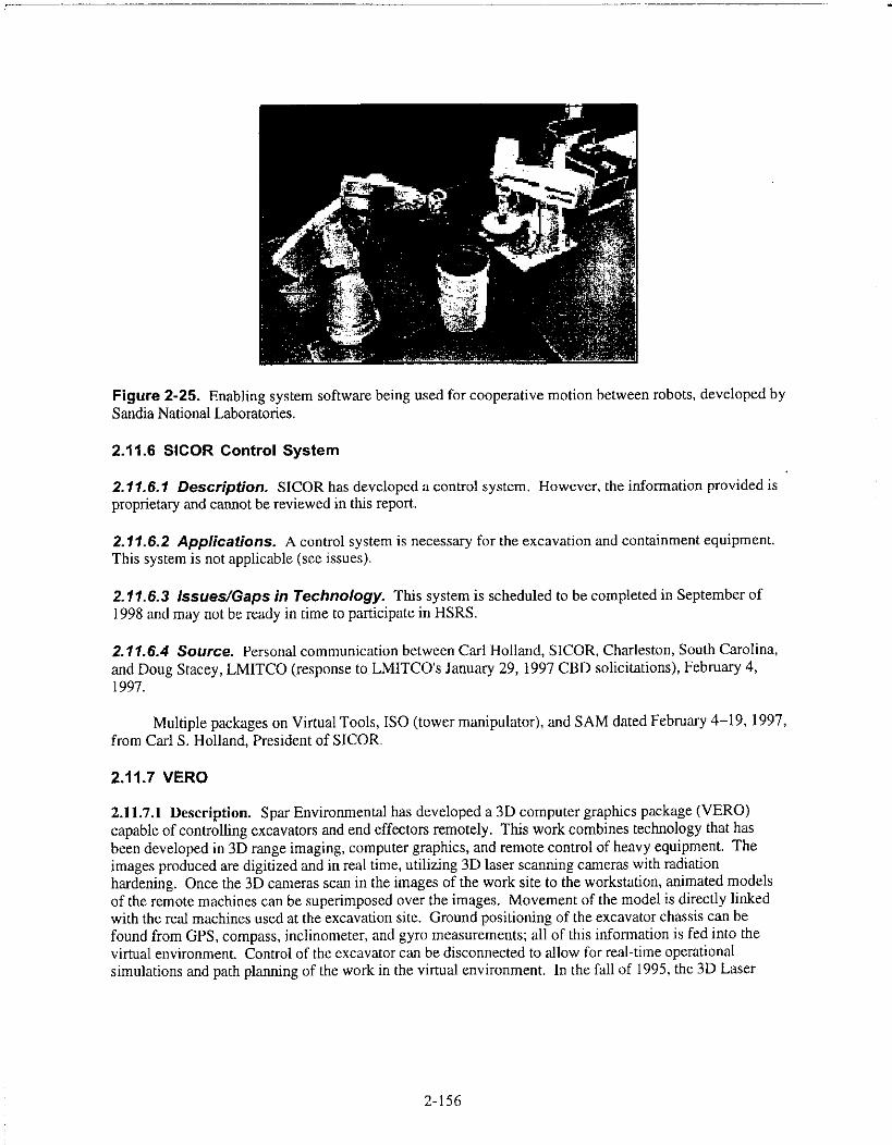
Figure 2-25. Enabling system software being used for cooperative motion between robots, developed bySandia National Laboratories.
2.11.6 SICOR Control System
2.11.6.1 Description. SICOR has developed a control system. However, the information provided isproprietary and cannot be reviewed in this report.
2.11.6.2 Applications. A control system is necessary for the excavation and containment equipment.This system is not applicable (see issues),
2.11.6.3 Issues/Gaps in Technology. This system is scheduled to be completed in September of1998 and may not be ready in time to participate in HSRS.
2.11.6.4 Source. Personal communication between Carl Holland, SICOR, Charleston, South Carolina,and Doug Stacey, LMITCO (response to LMITCO's January 29, 1997 CBD solicitations), February 4,1997.
Multiple packages on Virtual Tools, ISO (tower manipulator), and SAM dated February 4-19, 1997,
from Carl S. Holland, President of SICOR.
2.11.7 VERO
2.11.7.1 Description. Spar Environmental has developed a 3D computer graphics package (VERO)
capable of controlling excavators and end effectors remotely. This work combines technology that has
been developed in 3D range imaging, computer graphics, and remote control of heavy equipment. Theimages produced are digitized and in real time, utilizing 3D laser scanning cameras with radiation
hardening. Once the 3D cameras scan in the images of the work site to the workstation, animated models
of the remote machines can be superimposed over the images. Movement of the model is directly linkedwith the real machines used at the excavation site. Ground positioning of the excavator chassis can befound from GPS, compass, inclinometer, and gyro measurements; all of this information is fed into thevirtual environment. Control of the excavator can be disconnected to allow for real-time operationalsimulations and path planning of the work in the virtual environment. In the fall of 1995, the 3D Laser
2-156

Scanner Camera was used in the imaging of buried waste for retrieval using the REMEX remotelyoperated excavator.
2.11.7.2 Applications. The 3D graphics/control package can provide images of the excavator withrelation to the work site in a 3D virtual reality setting. This system has been used on the REMEX.
2.11.7.3 Issues/Gaps in Technology. Virtual reality modeling may not be necessary for HSRS.This system may not be able to control multiple vehicles or systems.
2.11.7.4 Source. Personal communication between Lee Maher, Spar Environmental, Brampton,Ontario, Canada, and Doug Stacey, LMITCO (response to LMITCO's January 29, 1997 CBDsolicitations), February 7, 1997.
Package containing information on VERO (3D laser camera imaging) and laser range cameraequipment dated February 7, 1997, from Lee Maher, Director of Environmental Systems for SparEnvironmental.
2-157

3. AVAILABLE TECHNOLOGIES
Following is a discussion on available technologies that could be leveraged in part or in whole tosupport the Hot Spot Removal System. The only costs associated with using this equipment would befor shipping. These technologies may, however, require modification to support HSRS mission.
3.1 T-Rex
The T-Rex system was developed by Lockheed Martin Advanced Environment Systems (LMAES)to retrieve and handle buried waste containers stored at the Transuranic Storage Area located in theRWMC at the 1NEEL.
T-Rex is a teleoperated, heavy-lift, long-reach excavator designed to remotely retrieve boxes,drums, and other types of radioactive waste containers from storage by using a modified Caterpillar235D front shovel excavator. Modifications include a totally enclosed, fan-cooled, medium-voltage,electric motor (4,160 V ac) in lieu of a diesel engine. Electric/hydraulic proportional pressure-reducingvalves superimposed on the main directional valves replaced the standard hydraulically operated valves.Cylinder mounted linear displacement transducers, sensors for excavator status (motor amperage, motortemperature, tilt, proximity), a collision avoidance system, and a computer control system forcoordinated control (tool mode) were also included. Other additional functions include local and remoteoperator control stations, a communications link, a CCTV vision system, multiple end-effectors, and aquick—change end-effector system. End-effectors include a 2.38-yd3 heaped-capacity bottom-dumpingbucket, large (8-ft) forklift tines, small (4-ft) forklift tines, a drum handler for 30-, 55-, and 83-gal drums,and a crane hook. Power and communication to and from the excavator are supplied through umbilicalcables and an onboard cable management system. The cable management system allows up to272 degrees of upper structure rotation.
T-Rex performs all functions with the operator either onboard or remotely located. The remoteoperator console, located up to 1,250 ft from the excavator, is designed to allow the operator to functionat least 8 hours a day without undue stress or fatigue while performing work. It includes an operatorchair, right and left consoles with operator input devices, foot pedals, a desk containing the computer,three 19-in. monitors, two audio speakers, a headphone jack, and audio/video electronics. The center19-in. monitor provides full color stereo viewing while the left screen provides monocular color video.A stereo vision system includes a Pentium-based 90-MHz computer and software that acquires anddisplays field sequential stereo video in real time, providing depth perception to the operator. The rightmonitor is a 9-in. PC-based touch screen and provides status and control information to the operator.Two stereo-pair, low-light, color CCD cameras with an 8-mm fixed focal length are mounted on pan/tiltmechanisms. One low-light, color CCD mono camera with remote zoom, auto iris, and focus is mountedon a pan/tilt mechanism. One omni-directional motor compartment microphone and one end-effectormicrophone are used to provide sound queues to the operator.
The retrieval tasks require the operator to precisely position and maneuver the end-effector withpayloads up to 16,000 lb at arm extensions to 27 ft. T-Rex can position a tool with a relative positionalaccuracy of +1- 1.00 in. and can position large payloads to within +1- 1/8 in. T-Rex also provides theoperator with tool mode, which offers a high degree of controllability using a single joystick to commandcomputer controlled, coordinated motion of the boom, stick, and end-effector pitch axes. This isachieved with an adaptive controller licensed to LMAES by NeuRobotics Inc. (Toronto, Ontario,
3-1
Canada) and is based on their patented Neural Net Adaptive Control system, which provides highlycoordinated motion accuracy as well as robustness.
T-Rex is equipped with an on-board collision detection and warning system to help alert theremote operator from potentially colliding the counterweight into objects in the retrieval area. Ultrasonicproximity sensors located on the excavator counterweight sense the presence of obstacles to triggervisual and audible warnings of potential or impending collision to the operator. The sensors are set todetect an object the size of a 30-gal drum at a distance of 10 ft away. A hand-held pendant foremergency operation is also included in the system.
Reconfigurability
In preparing this report, LMAES was asked what modifications to T-Rex would be necessary toconvert T-Rex into an excavator. LMAES responded that since T-Rex is a front shovel machine, thearrangement of the linkages and cylinders are optimized to move material at grade level and above. If thebucket were to be simply turned around, T-Rex would be limited to a maximum digging depth ofapproximately 8 ft. A new end-effector, such as a backhoe bucket on an extension, may be explored toprovide additional digging depth. Modifications to permit deep digging would most likely requirereplacing the existing boom, stick, bucket and quick-change mechanism links and cylinder with abackhoe arrangement. The new linkage arrangement would require software modifications to theproprietary control system (Lockheed Martin's Reconfigurable Remote Control System, R2CS, is aVME-based distributed multiprocessor architecture). LMAES indicated that they are capable ofperforming these modifications, but feel that modifying the T-Rex would not be as cost effective as usinga different excavator, such as their CAT 320L.
3.2 Contamination Control Unit
The Contamination Control Unit (CCU) was specifically developed to suppress and fixcontamination, and inhibit its spread during retrieval operations of buried wastes that are normally quitedusty. The CCU, a field-deployable, self-contained unit, is capable of dispensing soil fixatives, dustsuppression agents, and misted water, and uses a vacuum system to control contamination spread.Natural polysaccharides can also be applied for dust control measures using the CCU. Dust control usingthe CCU is 70% efficient. All of the dust control products are non-hazardous and can be disposed of insanitary landfills. The CCU is a 9 by 26-ft trailer.
The vacuum, a nuclear grade system with a HEPA filter and a critically safe 55-gal wastecontainer, can pull 1.5-in. debris (3/4 in. if the debris is heavy) through 100 ft of hose. The dustsuppression system applies a water mist, soil fixant, and dust suppressant.
The water misting system, Dryfog (manufactured by Sonics, Inc.), uses compressed air to forcedemineralized water through six nozzles. Each nozzle can be attached to its own stand from 1 to 18 ftover the area to be misted. The nozzles discharge a mist curtain that captures and removes aerosolizedsoil. The CCU can hold 300 gal of water for use in the water misting system.
The concentrated soil fixant, Foamer (manufactured by 3M, Inc.), is combined with a stabilizerand water pumped from a trailer-mounted 325-gal tank. The stabilizer and concentrate are stored in 5-gal cans near the nozzle and are delivered by suction to the expansion nozzle. This foamer is a vapor-suppressing foam used for uneven contaminated soil, such as steep sloping digfaces. The cure time forthis foam is 30 to 90 seconds.
3-2

In a field-deployable setting, the unit is capable of fixing 500 ft2/15 min with a totalencapsulation (3M Foamer), or applying 1,000 ft2/15 min of dust suppressant (Flambinder) whilesimultaneously providing 2 gpm mist from six misting nozzles. The vacuum system can beoperated continuously during the spray operation. In an emergency response situation, the systemis capable of spraying dust suppressant at a rate of 1,000 ft2/3 min. The system has been used atHanford for a retrieval treatability study and by INEEL Environmental Restoration during acapping action at EBR-I. At EBR-I, Wendon dust suppressant was used on 1.5 acres.
3.3 Cooperative Telerobotic Retrieval System
Engineers at the INEEL have developed an 80-ft remotely operated gantry crane for theremediation of hazardous/radioactive waste (see Figure 3-1). The Cooperative TeleroboticRetrieval System (CTRS) provides universal access to the waste area. The remote gantry cranesystem consists of an 80-ft wide girder, two trolley assemblies with vertically telescoping masts (z-masts) each having 22 ft of vertical travel, two six-degree-of-freedom manipulators mounted to thebase of each z-mast, and a trolley and 5-ton hoist assembly mounted on a separate truck. Themanipulators mounted on the z-masts provide for dexterous teleoperation, telerobotic operations, orfull robotics operations of equipment.
7
•-4111W+1,6 4
_41'271 :4 .40°'
:,;(7
Figure 3-1. Cooperative Telerobotic Retrieval System.
3-3

used in cooperation with the hoist hook for remotely attaching or removing a load from the hook.The system contains 12 closed-circuit television cameras and pan/tilt units for visualization of theworkspace during operations. Three of the pan/tilt units have been modified to automatically trackobjects within the workspace, allowing operations personnel to concentrate on crane andmanipulator operations. Three-dimensional cameras are mounted to each manipulator and to thetrolley that holds the hoist. The entire system consists of 37 degrees-of-freedom and has closed-loop control using a modified commercial robotics control system. The rails for the system arespaced 60 ft apart and have a length of 60 ft, but the crane could be used on longer rails with minormodifications. The crane also incorporates a 20-ft cantilever overhang for loading equipment intotrucks or other vehicles. Maximum loading values for the crane are 2,000 lb in the vertical (z-masts) and 10,000 lb vertical with the hoist. The system has a vacuum hose system for theretrieval of soil. Other end-effectors include a drum handler, grappler, various characterizationsensors, and other removal tools.
3.4 Rapid Transuranic Monitoring Laboratory
A field test of the Rapid Transuranic Monitoring Laboratory (RTML) was conducted at theINEEL during the summer of 1993. The RTML is a mobile laboratory developed at the INEELfor use in characterizing low-level radiological source terms at buried radioactive waste remediationsites (see Figure 3-2). Analytical instruments installed in the RTML include a thin window,germanium photon spectrometer equipped with an automatic sample changer, two large-areaionization chamber alpha spectrometers, and four alpha continuous air monitors. The RTML wastested for the Buried Waste Integration Demonstration Program and the Test Reactor Area andCold Test Pit.
Figure 3-2. Interior of RTML (93-444-1-0).
3-4

Direct alpha spectrometry with a large-area ionization chamber and photon spectrometry with ahigh-resolution, n-type, extended range germanium spectrometer were shown to be rapid, sensitivemethods for the measurement of transuranic isotopes on smears and in soil and dust samples. The twoanalysis techniques do not require elaborate sample preparation or time-consuming chemical separations;soil samples for the photon spectrometer are dried and sieved before analysis, and soil samples for theionization chambers are dried, sieved, and ground in 30% ethanol before analysis. Smears and filters areanalyzed directly without any sample preparation.
The RTML consists of two separate trailers that are powered from portable diesel generators. Onetrailer, 8 ft by 24 ft, houses the sample preparation laboratory that is equipped with a Class A fume hood,a drying oven, sieving equipment, two analytical balances, and sample containers. Samples are receivedand prepared for analysis in this trailer. The second trailer, 8 ft by 48 ft, houses the germanium photonspectrometer, two ionization chamber alpha spectrometers, and a computer that controls operation andanalyzes the spectral data acquired by the spectrometers. The computer is a VAX 4000 model 100equipped with terminals and printers to display and generate the analysis results reports. The RTML isalso equipped with four alpha CAMs that are operated remotely from the RTML analysis trailer. Thealpha CAMs can be operated at distances up to 200 m from the trailer.
Including quality control and blind soil standards, over 300 samples were analyzed by photonspectrometry, and 136 samples were analyzed by ionization chamber alpha spectrometry during the fieldtest. Seventy-nine samples were analyzed during a 24-hour period with the photon spectrometer. In a5-hour time period of continuous work, 33 prepared samples were analyzed with the two ionizationchamber alpha spectrometers for an average rate of about six samples per hour. If we assume that thisrate can be maintained for 7 hours during an 8-hour shift, the total number of samples that can beanalyzed with the ionization chambers during an 8-hour shift is 42. Based on these sample throughputrates, which together equate to 121 samples being prepared and analyzed in one day. The cost to analyzeone sample is about $18.
All spectral analyses of the photon data were performed automatically with no input from theoperator beyond basic sample parameters. No positive results were obtained for either the 143 soilsamples analyzed by photon spectrometry, or for the 96 soil samples analyzed by ionization chamberalpha spectrometry. Each of the 96 analyses of the 20 blind soil standards performed by photonspectrometry identified and quantified one or more of the four radionuclides present in the standards.There was some underestimated bias that occurred, and potential systematic errors are being activelypursued to remove this bias and reduce the total uncertainty.
The system is comprised of commercially available components. A commercial partner couldbegin manufacturing the integrated system. Disclosure of this research through professional journals andpresentations at technical conferences will enhance transfer of this technology to private-sectorcontractors that may be performing waste site remediations.
3.5 Digface Characterization System
The Digface Characterization System, currently funded by the Subsurface Contaminants FocusArea, is a comprehensive system for effective and efficient remote, real-time characterization duringremoval operations.
3-5

Digface monitoring promotes the use of on-line site characterization and monitoring during wasteretrieval efforts, a need that arises from safety and efficiency considerations during the cleanup of acomplex waste site. Information concerning conditions at the active dig face can be used by operators asa basis for adjusting retrieval activities to reduce safety risks and to promote an efficient transitionbetween retrieval and downstream operations. Most importantly, workers are given advance warning ofupcoming dangerous conditions. In addition, detailed knowledge of digface conditions provides a basisfor selecting tools and methods that avoid contamination spread and work stoppages.
Characterization tasks performed at the digface fall into two functional categories, hazarddetection and object detection. Hazard detection devices for assay are strictly for detecting hazardsduring removal operations. Object detection activities define the physical (rather than chemical orradiological) characteristics of the subsurface.
Several deployment platforms (car, trolley, Warthog—see Section 2.2.4.3) and several sensors(geophysical, radiological, and chemical) are available.
3-6

4. INDUSTRY INTEREST
4.1 RAHCO International"'
Thomas J. Crocker of RAHCO InternationalTM sent a letter to Reva A. Hyde of LMITCO onNovember 1, 1996, to express interest in a partnership relationship with LMITCO to develop,demonstrate, and commercialize HSRS. After subsequent discussions, a Memorandum of Agreementwas signed in March 1997 that allows the two companies to work together when it makes sense to do so.RAHCO InternationalTM was specifically interested in our real-time characterization capabilities forremediations, including UXO. As discussed above, RAHCO IntemationalTM and their partner, SparAerospace, are interested in providing remote excavation and transport equipment.
4.2 Sage Earth Sciences
Sage Earth Sciences is a spinoff company from the INEEL. Sage is the sole provider of the RapidGeophysical Surveyor. This technology was developed by DOE and has been licensed to Sage. Sagecontinues to provide geophysical surveys to industrial and national customers. Located in Idaho Falls,Sage is committed to supporting the INEEL and DOE.
Sage Earth Sciences is interested in using some of the real-time characterization equipment thathas been developed in support of HSRS. The company would deploy the sensor(s) from a cart systemfor large-area scans. They are most interested in a plastic scintillator for gross gamma counting to mapthe distribution of contamination near the surface of a radioactively contaminated area. A Memorandumof Agreement is in process.
This information was received by private communication (via meetings and teleconference)between Glenn Carpenter, Sage Earth Sciences, and Reva A. Hyde, LMITCO, February and March 1997.
4-1

5. SCHEDULE
The Hot Spot Removal System must be completed in a timely fashion to support remediation ofthe sites identified with selective retrieval as the preferred alternative. Technologies that support HSRSmust also meet the schedule needs identified within the Ten Year Plans. Many of the technologies thatwill support HSRS are critical to meeting the needs identified not only by DOE EnvironmentalRestoration, but Decontamination and Dismantlement, Waste Management, and others in the Ten YearPlans.
The development of HSRS must be timely to support the remediation of contaminated sites at theAlbuquerque, Idaho, Nevada, Oak Ridge, Oakland, Richland, and Savannah River Operations Offices.Table 5-1 shows the schedules, if available, from the sites currently slated for some type of selectiveremoval.
Table 5-1. Schedules of hot spot removal candidate sites.
Operations OfficeOV/GroupName Facility Schedule
Albuquerque VMTRA American Auto None AvailableSalvage Landfill
Idaho Idaho WAG 2 Misc. TRA Location Remedial Decision: 1999Completion Date: 2000
Idaho Idaho WAG 7,OV 7-13,OU 7-14
Subsurface DisposalArea
Alternative Analysis: 1997Remedial Decision: 1998Completion Date: 2020(some slip anticipated)
Nevada DNA Muck Area 12 None availablePiles
Nevada Soils Media OU Clean Slates & Alternative Analysis: 2001Double Tracks
Oak Ridge ORNL WAG 5 SWSA 5 South and None availableSWSA 5 North
Oakland LEHR 1 & 5 LEHR Alternative Analysis: 1997Remedial Design: 1998
Richland OU-200 200 Area Burial TRU Drums completion date:Ground 2002
TRU caissons completion date:2038
Richland OU-300-FF-2 300 Area Burial Remedial Decision: 1998Ground Completion Date: 2038
Savannah River 488D Ash Basin Alternative Analysis: 1997Remedial Decision: 1998Start Removal: 2001Completion Date: 2030
Savannah River URWDF/OBG Burial Grounds Remedial Decision: 1996Start Removal: 2001
5-1
Completion Date: 2030It is important to note that HSRS will aid many other retrieval and in situ remedial activities, but
this discussion is limited to those sites that have specified some type of selective removal as theirpreferred option.
To support the alternative analysis of the sites, this document will be forwarded to the SiteTechnology Coordination Groups. As shown in Table 5-1, three sites have alternative analysis due thisfiscal year, and Nevada will complete theirs in 2001. Remedial decisions for four sites are to becompleted in 1998 and one in 1999. Removal actions will start at two sites in 2001. Completion datesfor the remedial actions of these sites can be divided into short term and long term. Two sites haveshort-term completion dates, in 2000 and 2002. Five sites identified long-term completion dates thatvaried from 2020 to 2038. One site has already completed the Remedial Decision, most likely excludingHSRS.
Looking at the schedule table, priority for subsystem development should focus on Idaho WAG 2,assuming SRS LLRWDF/OBG cannot take advantage of HSRS. The contaminants of concern at IdahoWAG 2 are strontium, cesium, and cobalt.
The rest of the site schedules appear to be very similar, and no further prioritization based onschedule is recommended. Section 7 discusses the gaps that need to be addressed to complete HSRS sothat it is robust enough to address those sites that have chosen selective removal as their preferred option.
5-2

6. ALTERNATIVE EVALUATION/TECHNICAL SCREENING OFTECHNOLOGIES
Fourteen sites have been identified as selective retrieval sites, with hot spot removal as thepreferred method of retrieval. As such, these sites drive the design of HSRS (see Figure 6-1).
The Air Force Institute of Technology (AFIT) developed a decision analysis methodology basedon the Comprehensive Environmental Responsibility, Compensation, and Liability Act (CERCLA)criteria. The methodology will enable responsible parties to evaluate remedial options based on criteriadeveloped by the EPA and quantified by the AFIT through scoring functions and weighting of eachcriterion. The INEEL WAG 7 Feasibility Study team reviewed the methodology and improved thescoring functions (Interdepartmental Communication from T. W. Bollander to D. K. Jorgensen,TWB-01-97, "Remittance of Draft CERCLA Evaluation Criteria Scoring Measures," March 21, 1997).This enhanced version was used to evaluate the technologies discussed in the previous sections.
The AFIT criterion was modified from its original format to allow for the evaluation of dissimilarequipment and technologies (the criterion was initially intended for evaluating equipment and methodsof implementation within the same remediation technology).
Most of the equipment that was reviewed for inclusion into HSRS fell short on a number of therequirements identified in the draft Hot Spot Removal System Requirements Document. No one piece ofequipment or technology performed the necessary tasks perfectly. As a result, the requirements thatwere considered most important to HSRS were used as the evaluating criteria in the AFIT format. Therequirements not used as evaluating criteria were those that could easily be met with modifications to theequipment.
N sousow
ista AIM
101.P 8 Tigoll4 1(C
a Eke EFFECIOR
PROCESS FLOW SHEET
HOT SPOT REMOVAL SYSTEM
SEPARATECROUTRIXTIKR
flt011
'CLEW' 11A51E"CCIOPXFO
PAAATE PSIEff CCC OR
500
POP E HOI
NOT TA
DECON MIL. aIRMISqii FTCOMFP{11011
commausir
RIO SMO PRO
The dashed line indicates those activities typicallyassociated with a Lill-scale retrieval. As the HSRSis for hat spots only, these steps are not deemednecesSary.
DECCM fl(C. 6MUER PERCCWIIKLIENI
H RUN 'CLEW111151E TO
1E11014 snr
Figure 6-1. HSRS process flow.
6-1

6.1 Site Characterization
Characterization of each site will take place prior to and during any retrieval activities done byHSRS. The types of sensors and detectors used for characterization are dependent on the contaminantsof concern, and will thus be evaluated and chosen for each site individually.
6.2 Contamination Control
Contamination control is a key risk driver in hot spot removal. As such, an aggressive approach tothe control of fugitive dust and other means of contamination control must be taken. Thesecontamination controls methods must be evaluated and a method decided upon early in the decisionprocess as it determines retrieval methods, waste separation techniques, etc. In HSRS, the contaminationthat must be dealt with will be, by definition of hot spot, the most concentrated andhazardous/radioactive waste there is and should thus be controlled as close to the source as possible. Ofall of the contamination control methods discussed in Section 2.3, in situ stabilization controls thecontamination closest to its source, in the soil/waste matrix itself; therefore, it is the preferred choice ofHSRS and will be used as the main source of control. This does not mean, however, that secondary formsof contamination control will not be used.
6.2.1 In Situ Stabilization
Due to the nature of in situ stabilization, choosing this method drives how the rest of the systemwill come together. Retrieval will consequently focus on "muck and truck" excavation rather than"surgical" retrieval techniques, as the waste matrix will be an agglomeration of contaminants, soil,debris, and in situ stabilization media. This thus eliminates the need for highly specialized end-effectorsand cranes.
Waste separation is also eliminated if in situ stabilization is used because the waste will beencapsulated in a grout, polymer, or paraffin based product. The material used for in situ stabilizationcould be separated from the waste following retrieval, and then further separated by physical size orcontaminant of concern, prior to treatment. It is assumed, however, that for HSRS, the individual siteswill be responsible for any desired waste separation; thus, separation technologies will not be evaluatedin this System Description.
The encapsulated waste could be compacted once retrieved. This is not as efficient as separatingthe grout/polymer/resin from the waste prior to compaction and thus will not be included as a standardoption in HSRS. If an individual site requests waste compaction in the future, it would not be difficult toadd this capability to HSRS for an added cost.
There are several methods of in situ stabilization, as discussed in Section 2.3.7. Before going anyfarther, a method of in situ stabilization must be determined. Two basic methods of in situ stabilizationwere presented, jet-grouting (Section 2.3.7.2) and cryogenic retrieval (Section 2.3.7.3), and will beevaluated here.
6-2

Effectiveness
The Air Force Institute of Technology (AFIT) developed the decision analysis methodologymentioned at the beginning of this section, which is intended to compare different technologies, not thesame basic technology, and was thus modified to meet the needs of HSRS. In the AFIT decisionanalysis, the overall effectiveness of a remediation activity is given an overall evaluation weighting of66.7%. This was then broken down into subcategories: long-term effectiveness and permanence;reduction of toxicity, mobility, or volume; and short-term effectiveness with the intent of comparing thecompleteness of the remediation task when using different technologies to accomplish said remediationtask. This does not mean anything when comparing two techniques in temporary in situ stabilization.The proposed "overall effectiveness" criteria in evaluating the in situ stabilization methods will bebroken down into three subcategories as follows: (I) dust control efficiency, (2) impact future treatment,and (3) mitigate mobility of contaminants.
Dust control efficiency will be given an internal rating of 50% (33.35% overall), as the level towhich dust is controlled affects the amount of alpha contamination spread throughout the retrievalprocess, decontamination of equipment farther downstream, the ability to manually operate in bubblesuits as opposed to remotely, the amount of capital equipment that would have to be replaced due to theinability to decontaminate it, and the maintenance required on equipment due to dust. The rating will behandled as follows: 90 to 100% = 10, 80 to 90% = 9, 70 to 80% = 8, and so on.
Impact future treatment will be given an internal weighting of 45% (30.01% overall), because if itcan't be treated later, it shouldn't be retrieved. The rating of the impact future treatment will be a yes orno rating, a yes receiving 0 points, and a no receiving 10 points.
Mitigate mobility of contaminant categories will be given an internal weighting of 5% (3.34%overall). The mitigate mobility of contaminant category will also be a yes or no rating, yes receiving a10, no receiving a 0.
Implementability
In the AFIT decision analysis, the implementability of a remediation activity is given an overallevaluation weighting of 16.7% and is broken into the following subcategories: (1) technical feasibility,(2) availability of services and materials, and (3) administrative feasibility. In HSRS, implementabilitywill be broken into two subcategories: (1) technical feasibility and (2) availability of services andmaterials.
Technical feasibility will be given an internal weighting of 75% (12.53% overall). A high ratingon this category was given because not all methods of in situ stabilization will work in retrievalsituations, and if a technology is not going to work or will need major modifications in the basic designof the equipment in order to function as intended, it should be accounted for in the overall evaluation ofthe technologies. The rating of each individual technology will be handled by giving a score of 10 if thetechnology has been effectively demonstrated; a 7 if it has been effectively demonstrated but requiresminor modifications; a 5 if it has been demonstrated and shown to require major modifications; a 3 if ithas been demonstrated, the ultimate feasibility is in question, and major modifications are needed; and a0 if no demonstration has been performed, as the feasibility of the technology cannot be determined.
Availability of services and materials is thus given an internal weighting of 25% (4.15% overall).This will also be based on three basic ratings, a 10 if the materials are not unique and are readily
6-3
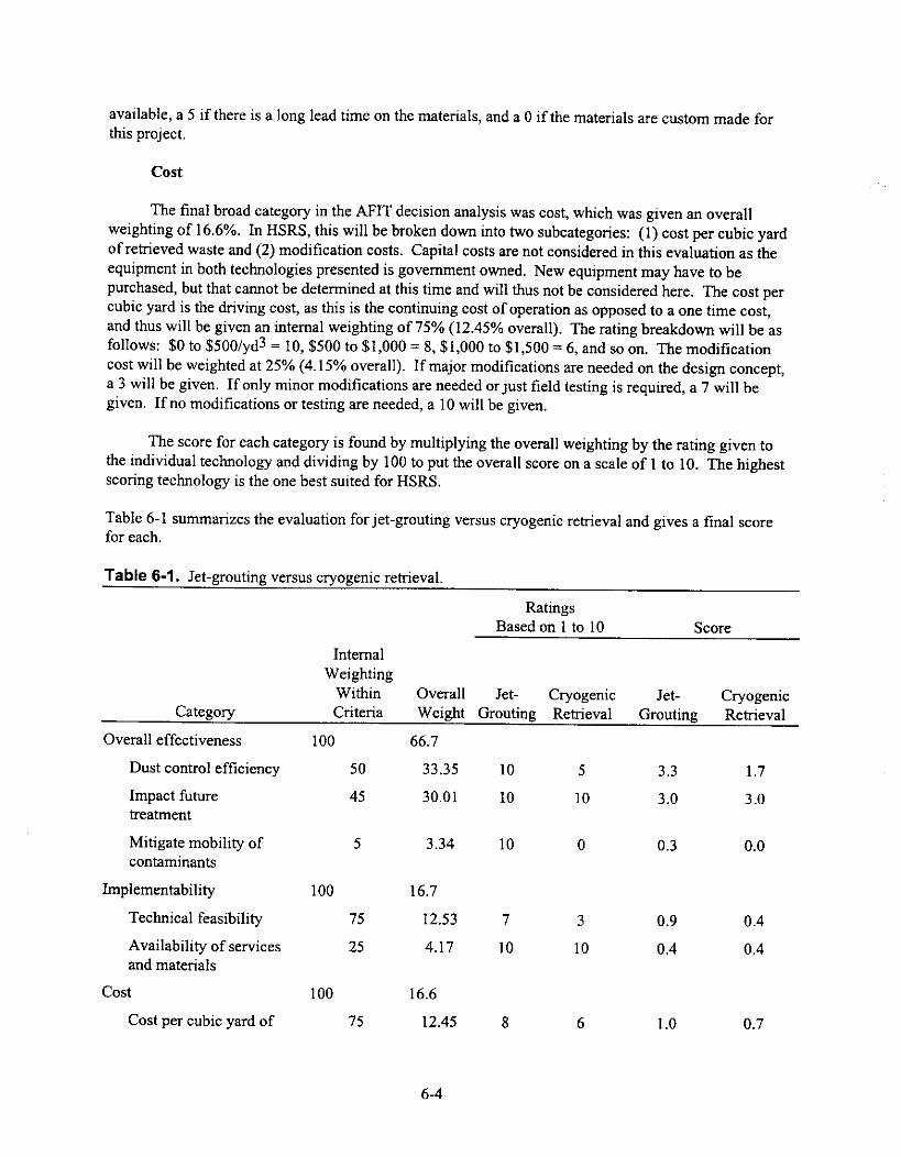
available, a 5 if there is a long lead time on the materials, and a 0 if the materials are custom made forthis project.
Cost
The final broad category in the AFIT decision analysis was cost, which was given an overallweighting of 16.6%. In HSRS, this will be broken down into two subcategories: (1) cost per cubic yardof retrieved waste and (2) modification costs. Capital costs are not considered in this evaluation as theequipment in both technologies presented is government owned. New equipment may have to bepurchased, but that cannot be determined at this time and will thus not be considered here. The cost percubic yard is the driving cost, as this is the continuing cost of operation as opposed to a one time cost,and thus will be given an internal weighting of 75% (12.45% overall). The rating breakdown will be asfollows: $0 to $500/yd3 = 10, $500 to $1,000 = 8, $1,000 to $1,500 = 6, and so on. The modificationcost will be weighted at 25% (4.15% overall). If major modifications are needed on the design concept,a 3 will be given. If only minor modifications are needed or just field testing is required, a 7 will begiven. If no modifications or testing are needed, a 10 will be given.
The score for each category is found by multiplying the overall weighting by the rating given tothe individual technology and dividing by 100 to put the overall score on a scale of 1 to 10. The highestscoring technology is the one best suited for HSRS.
Table 6-1 summarizes the evaluation for jet-grouting versus cryogenic retrieval and gives a final scorefor each.
Table 6-1. Jet-grouting versus cryogenic retrieval.
RatingsBased on 1 to 10 Score
Category
InternalWeightingWithinCriteria
Overall Jet- CryogenicWeight Grouting Retrieval
Jet-Grouting
CryogenicRetrieval
Overall effectiveness 100 66.7
Dust control efficiency 50 33.35 10 5 3.3 1.7
Impact futuretreatment
45 30.01 10 10 3.0 3.0
Mitigate mobility ofcontaminants
5 3.34 10 0 0.3 0.0
Implementability 100 16.7
Technical feasibility 75 12.53 7 3 0.9 0.4
Availability of servicesand materials
25 4.17 10 10 0.4 0.4
Cost 100 16.6
Cost per cubic yard of 75 12.45 8 6 1.0 0.7
6-4
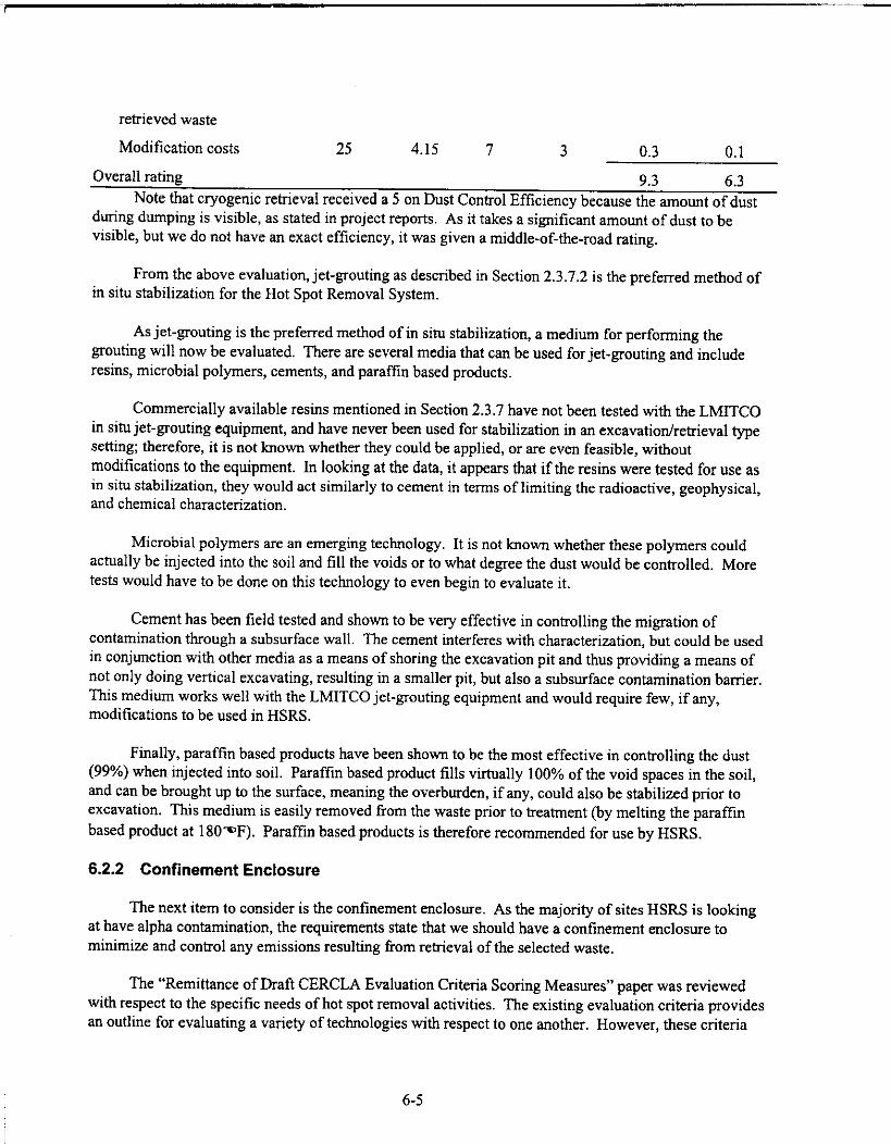
retrieved waste
Modification costs 25 4.15 7 3 0.3 0.1
Overall rating 9.3 6.3Note that cryogenic retrieval received a 5 on Dust Control Efficiency because the amount of dust
during dumping is visible, as stated in project reports. As it takes a significant amount of dust to bevisible, but we do not have an exact efficiency, it was given a middle-of-the-road rating.
From the above evaluation, jet-grouting as described in Section 2.3.7.2 is the preferred method ofin situ stabilization for the Hot Spot Removal System.
As jet-grouting is the preferred method of in situ stabilization, a medium for performing thegrouting will now be evaluated. There are several media that can be used for jet-grouting and includeresins, microbial polymers, cements, and paraffin based products.
Commercially available resins mentioned in Section 2.3.7 have not been tested with the LMITCOin situ jet-grouting equipment, and have never been used for stabilization in an excavation/retrieval typesetting; therefore, it is not known whether they could be applied, or are even feasible, withoutmodifications to the equipment. In looking at the data, it appears that if the resins were tested for use asin situ stabilization, they would act similarly to cement in terms of limiting the radioactive, geophysical,and chemical characterization.
Microbial polymers are an emerging technology. It is not known whether these polymers couldactually be injected into the soil and fill the voids or to what degree the dust would be controlled. Moretests would have to be done on this technology to even begin to evaluate it.
Cement has been field tested and shown to be very effective in controlling the migration ofcontamination through a subsurface wall. The cement interferes with characterization, but could be usedin conjunction with other media as a means of shoring the excavation pit and thus providing a means ofnot only doing vertical excavating, resulting in a smaller pit, but also a subsurface contamination barrier.This medium works well with the LMITCO jet-grouting equipment and would require few, if any,modifications to be used in HSRS.
Finally, paraffin based products have been shown to be the most effective in controlling the dust(99%) when injected into soil. Paraffin based product fills virtually 100% of the void spaces in the soil,and can be brought up to the surface, meaning the overburden, if any, could also be stabilized prior toexcavation. This medium is easily removed from the waste prior to treatment (by melting the paraffinbased product at 1809DF). Paraffin based products is therefore recommended for use by HSRS.
6.2.2 Confinement Enclosure
The next item to consider is the confinement enclosure. As the majority of sites HSRS is lookingat have alpha contamination, the requirements state that we should have a confinement enclosure tominimize and control any emissions resulting from retrieval of the selected waste.
The "Remittance of Draft CERCLA Evaluation Criteria Scoring Measures" paper was reviewedwith respect to the specific needs of hot spot removal activities. The existing evaluation criteria providesan outline for evaluating a variety of technologies with respect to one another. However, these criteria
6-5
were inadequate for directly comparing equipment of the same technology. As a result, new criteria forevaluating HSRS remediation equipment were developed.
For the Hot Spot Removal System project, criteria were required to systematically andquantitatively evaluate different confinement enclosure packages. The divisions of the new criteriafollow the CERCLA approach identified in the Code of Federal Regulations Title 40 Section 300.430 (40CFR 300.430) with direction given in EPA (1988). State regulatory acceptance is omitted since it isassumed that HSRS has already been approved as the preferred action.
Weightings
The main categories for remediation activities include effectiveness, implementability, and cost.
Effectiveness
According to the AFIT analysis, the overall effectiveness of a remediation activity is worth 66.7%of the overall evaluation weighting. This category is broken down into three subcategories: (1) long-term effectiveness and permanence, (2) reduction of toxicity, mobility, or volume, and (3) short-termeffectiveness. These subcategories are based on (1) residual cancer risks due to remaining waste, (2) themobility of the waste to enter air, groundwater, and surface water, (3) the reduction in contaminants ofconcern and generation of other waste, (4) the irreversibility of waste treatment. The effectivenesscriteria was designed to compare different technologies with respect to the completeness of theremediation task. For the Hot Spot Removal System, confinement enclosures will be required; eachstructure will have similar confinement capabilities.
To compare different equipment within the same technology, the effectiveness of remediationtasks were broken down into three subcategories: (1) modularity, (2) airflow, and (3) loadings (strength).The weighting of effectiveness was chosen to be 50% of the overall weighting for remediation activities.This number places a major emphasis on the safety and reliability for the system, but is reduced from66.7% to help emphasize implementability issues.
Modularity of the structure was assigned 45% of the effectiveness category weighting for anoverall weighting of 22.5% (see Table 6-2 below). This factor determines the ease of covering a varietyof waste site sizes and allowing for easy access of personnel and equipment inside the structure. It alsotakes into account the ease of adding airlock doors and corridors for multiple confinement enclosures.
Company experience was taken into consideration when evaluating the confinement enclosures.Companies that have had extensive experience should receive a higher score on the evaluation becausethey have solved problems associated with hazardous/negative-pressure environments. This portion ofthe effectiveness category was assigned 35% (overall percentage of 17.5%).
The ability of the confinement enclosure to withstand environmental loads was assigned 20% ofthe effectiveness category (overall weighting is 10%). It is important that the structure be able to
6-6

Table 6-2. Relative effectiveness weighting and overall weighting of contamination control.
Category Weighting Overall Weighting
Effectiveness 100% 50%
Modularity 45% 22.5%
Airflow 35% 17.5%
Loadings 20% 10%withstand severe weather conditions at a variety of sites. • However, most of the structures conform tobuilding codes for seismic and snow loadings. Therefore, the ability of the structure to withstandexcessive wind loads is evaluated.
Implementability
According to AFIT analysis, the implementability of a remediation activity is worth 16.7% of theoverall evaluation weighting. This category is broken down into three subcategories: (1) technicalfeasibility, (2) administrative feasibility, and (3) availability of services and materials. As with theeffectiveness category, this criterion was designed for evaluating different technologies with respect toone another and was not designed for evaluating similar equipment.
The HSRS subcategories are (1) mobilization/demobilization time, (2) required equipment/personnel, and (3) foundation requirements. The criteria weighting for implementability was assigned35% of the overall weighting. This number is significantly larger than the 16.7% figure used by AFIT.The higher percentage is meant to help emphasize the need for a system that is easily transported,mobilized, and demobilized.
Mobilization and demobilization were assigned 35% of the implementability weighting for anoverall weighting of 12.25% (see Table 6-3). The equipment will be at a particular site for severalweeks, then moved to another location. When equipment is moved around often, mobilization/demobilization time is essential.
The equipment and personnel were also considered. The importance of using limited resourcesand personnel to mobilize and demobilize the structure called for a high percentage of the criteria. Whileit is likely that each site will have a crane in its possession for the construction of the confinementenclosure, it would be desirable to have a system that can be set up or torn down by hand in a shortperiod of time; then, there is no possibility of a scheduling conflict for the crane. It is also desirable touse the least number of personnel possible to safely construct the structure. This subcategory is worth
40% of the Implementability category (14% overall).
To avoid long mobilization periods for HSRS, equipment must be portable and easily set up.Foundations inherently oppose this goal. As a result, structure requiring foundations should be avoidedwhenever possible. Some of the structures are capable of anchoring directly into the ground without theneed for a cement pier or steel base. To minimize setup times, systems not capable of ground anchoringare penalized by not receiving the full 8.75% of the criteria.
6-7

Table 6-3. Relative implementability weighting and overall weighting of contamination control.
CategoryWeighting Overall Weighting
Implementability 100% 35%
Mob/demob time 35% 12.25%
Required equipment/personnel 40% 14%
Foundation requirements 25% 8.75%
Cost
The 16.6% weighting for the cost of the system is relatively similar to the weighting suggested byAFIT. For the new criteria, the overall cost weighting was set at 15%. The reduction in percentageweighting allows for additional emphasis to be placed on Implementability.
The cost category is broken down into two main sub-categories: initial capital cost and lifeexpectancy. Initial capital cost was weighted at 65% of the cost percentage, and life expectancy wasgiven 35%. Table 6-4 provides a list of the contributions to the overall criteria. Life expectancy wasassigned a considerable percentage to provide an advantage to systems that will last a substantial lengthof time, since HSRS could be used for a number of years.
Ratings
The equipment was rated on a scale from 0 to 10 with 10 being the most desirable number.Requirements were set after initial information was gathered on the equipment. From this information,the best ratings were equated to the highest performing attributes for the equipment. The worst scoreswere extrapolated from the information received and were given a 0. See the attached evaluation sheetsto review the breakdown on rating ranges.
Score
The score is equal to the overall weighting multiplied by the rating. The scores for each categorywere added up to provide a final score. The highest final score that can be achieved was 1,000, and thelowest final score that can be achieved was 0. The equipment with the highest final score is the preferredequipment, according to these limited criteria. However, some engineering judgment is reserved forconsiderations not present in the criteria.
See Appendix E for the scores, criteria, and breakdown on rating ranges of the confinementenclosures in the final evaluation.
Structure Recommendation
According to the evaluation described in the preceding section, a confinement enclosure fromRubb Building Supplies is the highest ranked piece of equipment with a score of 824.75 out of a possible1,000. The second highest rated structure was Sprung Structures' confinement with a score of 817.5.Anchor Industries' structure received a score of 650.75, and Weather Block received 424.75.
6-8

Table 6-4. Relative cost weighting and overall weighting of contamination control.
Category Weighting Overall Weighting
Cost 100% 15%
Initial capital cost 65% 9.75%
Life expectancy 35% 5.25%
These scores were based on initial data and should not necessarily determine the finalrecommendation. Due to budgetary constraints, site visitations were not possible; therefore, theequipment has not been seen in action. From this preliminary evaluation, Rubb Building Supplies orSprung Structures structure should be used as the confinement enclosure for HSRS. However, acompetitive bid is warranted for the confinement enclosures.
6.2.3 Discussion
The contamination control methods previously described constitute the primary defense againstthe spread of contamination. Several other methods of contamination control were presented in Section2.3, most of which will be discussed in Section 7, "The Plan," as most of the technologies are applicableto different aspects of HSRS and will be used in one form or another; therefore, an evaluation, per se, isnot necessary here. The only technology that should be mentioned here is the dust suppression/soilfixatives, as there is a choice as to which product to use. Previous studies done at the INEEL have shownthat the fixative Flambinder (Section 2.3.10.3) was shown to be the most effective and durable duringglovebox tests with plutonium-contaminated soils (Winberg and Wixom 1992). The naturalpolysaccharides were shown to be the most effective on vertical walls, such as during verticalexcavations, and will thus be used as well in HSRS. A competitive bid is warranted for the confinementenclosures.
6.3 Retrieval
Contamination control methods have now been decided. A means to retrieve the waste must nowbe evaluated. Three basic means of retrieval were presented in Section 2.4, and these were the use ofeither an excavator, a crane, or mining techniques/equipment.
Retrieval Method Evaluation: Excavator Versus Crane
Excavators are commonly used as the "workhorse" of excavation/retrieval activities. They offerseveral advantages including high production rates, mobility on site, public acceptance, ease of transport,robustness, and adaptability to many end-effectors. According to EPA (1991), excavators are the mostcommonly used piece of equipment for hazardous waste remediation. Furthermore, according toValentich (1993), excavators are fully capable of remediation tasks for buried transuranic waste.
Cranes are commonly used for remediation tasks that require precision and accuracy. A quotefrom Rice and Skaggs (1993) states that: "The ease of operating the bridge crane versus a remotecontrolled excavator could be compared to driving a railroad train engine on tracks versus driving a truck
6-9

on a highway." Gantry cranes offer ease of control and precise deployment of tooling. Cranes offerseveral advantages including high production rates, public acceptance, robustness, and adaptability tomany end-effectors.
Direct evaluation of a crane versus an excavator brings to light issues with using a crane. A cranewould be an asset for a removal project with a long duration period, but is not well suited for projectsaimed at rapid setup, dismantling, and transportation. To mobilize a gantry crane, cement footings mustbe placed into the ground to support the weight of the rails that the crane moves on. This is notunreasonable for operations that are stationary; however, if the equipment is moved often, this equipmentis undesirable.
Gantry cranes are also not applicable for large pit (large span) areas. In large pit environments,gantry cranes must be very large to ensure that the entire waste area can be excavated. This requiresdependable site data; if the crane is not large enough to span the entire waste pit or landfill, the footingsand crane must be relocated to finish remediation activities.
The cost of a crane is considerably more expensive than an excavator. They have a lowerthroughput than an excavator, and the cost for a remotely controlled, track-driven, gantry crane isconsiderably more expensive than a comparable remote-controlled excavator. Furthermore, the site-to-site transportation of a gantry crane would not be as convenient or cost effective as a standard excavator.
Mining Evaluation
Mining techniques offer the advantage of removing contaminated soil without removing theoverburden. The overburden acts as a natural shield or confinement against the spread of contamination.As a result, operations on the surface might be performed without a confinement facility. However, themining technology was considered too immobile for the remediation of hot spots. The turnaround timefor hot spot removal is roughly several weeks. Also, additional waste in the form of cutting fluid wouldbe generated. Of the two mining techniques discussed in Section 2.4.5, one did not offer a solution toretrieving the solid wastes (barrels, boxes, etc.), and the other is not a fully developed technology. As aresult, mining techniques are not the preferred retrieval technology.
Excavator Size
After evaluating the advantages and disadvantages of a crane, mining setup, and excavator,excavators are the recommended remediation tool for HSRS.
In using an excavator, the next area of concern is the size of the excavator to be used in HSRS.The excavation vehicle must be capable of digging a 20-ft pit and lifting out 4,000-lb objects. ACaterpillar® 320B L hydraulic excavator (45,000-lb class) is capable of digging down to 20 ft 7 in. withan R2.5B stick, 22 ft 0 in. with an R2.98 stick, or 25 ft 1 in. with an R3.9B stick. A heavy-duty bucketwill be applicable for the clay, soil, sand, mine tailings, silt, and gravel expected at the waste sites.However, the standard buckets for the excavator (0.6, 0.8, and 1.0 m3) do not accommodate a 4,000-lbload. Furthermore, the excavator would not be capable of lifting a 4,000-lb load at various positionswithin the boom/stick operating envelope.
A Caterpillar® 322B L hydraulic excavator (53,000-lb class) is capable of digging to 24 ft 1 in.with an R3.6B stick, 21 ft 10 in. with an R2.95S stick, 20 ft 5 in. with an R2.5S stick, or 19 ft 6 in. withan M2.5D stick. Two heavy duty buckets are capable of carrying a 4,000-lb load: a 1.3-m3 bucket on a
6-10

2.95S or 2.5S stick, and a 1.6-m3 bucket on a 2.95S or 2.5S stick. The excavator is capable of lifting the4,000-lb load out of the pit in the entire working envelope of the boom and stick for both stick options.However, if an overburden end-effector (i.e., Sonsub International®'s Soil SkimmerTM, Section 2.4.4.10)is going to be used, a 60,000-lb class excavator is required. Also, if a thumb is added to the end of thestick, an additional 1,000 lb will be added to the load. Thus, the excavator will not be capable of lifting a4,000-lb load when the boom and stick are fully extended. The downside of having a larger excavator isthat it will add to the required working envelope space within a confinement enclosure as well as to thecost of having a larger facility.
A Caterpillar® 325B L hydraulic excavator (60,000-lb class) is capable of digging to 23 ft 4 in.with an R/M3.2C stick, 21 ft 7 in. with an R2.7C stick, 21 ft 6 in. with an R/M3.2C stick, or 19 ft 10 in.with an M2.5D stick. Eight heavy duty buckets are capable of carrying a 4,000-lb load: 1.3-m3 bucketon an R/M3.2C or R2.7C stick, and 1.2- to 2.2-m3 buckets on an M2.5D. The excavator is capable oflifting the 4,000-lb load out of the pit in the entire working envelope of the boom and stick for all fourstick options. The added weight and power of the engine and hydraulics would allow a larger,unexpected object in the waste area to be moved or retrieved. The excavator can also handle theadditional weight of a Balderson thumb.
A 60,000-lb class excavator is recommended to help accommodate the retrieval of unknownobjects. Furthermore, a 60,000-lb excavator would be capable of using an overburden end-effector.
An independent recommendation for the excavator size was provided during a telephoneconversation with Brent Kunz (In-Store Sales) of Western States Equipment (Caterpillar® Dealer) inPocatello, Idaho. Brent Kunz indicated that a Caterpillar® 322B or 325B excavator would be the bestchoice for remediating objects of 4,000 lb.
Excavator Controls
In choosing an excavator, another important consideration is the control unit that operates theexcavator remotely and how compatible the controller is with the other systems used in HSRS. Most ofthe companies that responded to the request for information can provide control units for a 60,000-lbexcavator with little modifications to their systems. From the responses to the request for informationplaced in the Commerce Business Daily, only one company was specifically identified as havingmodified a 60,000-lb caterpillar® for remote operations. Lockheed Martin Tactical Defense hasdeveloped a Caterpillar® 325 excavator for hazardous/UXO remediation. However, this company doesnot possess any experience in radiation environments.
As a result, field testing will be required for the evaluation of the excavators' remote controlsystems to determine exactly which excavator and associated control system is the most efficient andergonomically correct for use in HSRS. At this point in the evaluation, it has been decided to go with a60,000-lb excavator, the vendor of such equipment to be determined at a later date.
End-Effector Evaluation
Once the decision to use a 60,000-lb excavator has been made, the end-effectors (Section 2.4.4) touse with said excavator can now be evaluated.
6-11

Manipulator arms are not necessary due to the soil stabilization methods being proposed. Wastewill be encapsulated and will not require the retrieval of independent objects. Manipulators are also notapplicable to excavators.
Using a water jet end-effector would generate additional waste in the form of waste water. Theadvantages to using this technology are outweighed by the disadvantages. Furthermore, other end-effectors are available that do not generate additional waste (air jet/vacuum systems).
Air jet/vacuum systems were removed from consideration when the contamination control methodwas determined. Once the soil fixative is applied to the soil, it is not desirable to re-break the soil intosmall pieces, thereby causing dust generation.
Quick-change couplers are highly recommended for attaching end-effectors and sizing equipmentto the excavator. Hydraulic couplers allow an operator to change the end-effector remotely, whileregular quick-change end-effectors require the removal of a few pins for changeouts. The regular quick-change couplers would require a remotely controlled robot with manipulator arm to remove the pins andis time consuming.
A bucket with a Balderson thumb is highly mobile and maneuverable with an excavator and iscapable of lifting and carrying large objects. Because it meets all of the needs of HSRS, it is concludedthat a heavy duty bucket with a Balderson thumb is the most effective end-effector for HSRS.
For the overburden removal, the soil skimmer is the most applicable end-effector, as it is the onlyend-effector that removes the overburden in discrete layers and can be used on a 60,000-lb excavator.
Evaluation of "Pre-packaged" Excavators
Following is the evaluation process for the selection of a remotely controlled excavator for usewith the Hot Spot Removal System. Phase I consisted of looking at the equipment to determine whetheror not the remediation tasks could be completed with each piece of equipment without comprehensivemodifications.
Phase II incorporated criteria that were specifically developed for the evaluation of the excavators.Evaluation was based on effectiveness, implementability, and cost.
Phase I
In Table 6-5, the companies are advanced to Phase II if the equipment is capable of digging down20 ft and retrieving a 4,000-lb object. If the equipment was unable to perform these requirements, it wasplaced in the "No Go" column and was not advanced to Phase II for a final evaluation. Equipment couldalso be eliminated from the final evaluation list for other reasons. The "Reasons" column explains whythe excavator was rejected as a viable solution to HSRS.
Phase II
The "Remittance of Draft CERCLA Evaluation Criteria Scoring Measures" paper was reviewedwith respect to the specific needs of HSRS. The existing evaluation criteria provide an outline forevaluating a variety of technologies with respect to one another. However, these criteria were inadequate
6-12

for directly comparing equipment of the same technology. As a result, new criteria for evaluating HSRSequipment was developed.
For the Hot Spot Removal System project, criteria were required to systematically andquantitatively evaluate different remotely controlled excavator packages and their corresponding optionsfor remote remediation activities. The divisions of the new criteria follow the CERCLA approachidentified in 40 CFR 300.430 with direction given in EPA (1988). State regulatory acceptance is omittedsince it is assumed that HSRS has already been approved as the preferred action. The main categoriesfor remediation activities include effectiveness, implementability, and cost.
Weightings
Effectiveness
According to AFIT, the overall effectiveness of a remediation activity is worth 66.7% of theoverall evaluation weighting. This category is broken down into three subcategories: (1) long-termeffectiveness and permanence, (2) reduction of toxicity, mobility, or volume, and (3) short-termeffectiveness. These subcategories are based on (1) residual cancer risks due to remaining waste, (2) themobility of the waste to enter air, groundwater, and surface water, (3) the reduction in contaminants of
Table 6-5. Phase I—comparison with requirements.
Company/Equipment Go No Go Reasons
Foster-Miller, Inc. x Excavator was developed 15 years ago; old(ROME) technology
LMAES x Front loader—requires serious modifications; over-(T-Rex) sized load
LMAES x(TeleoperatedExcavator)
LMTD x Prototype; currently not available(REVS)
LMTD x(AOE)
OAO Robotics x Too small for digging, carrying, and end-effector(TODS) usage
OAO Robotics x(TORCE)
ORNL x Too small for digging and lifting(SEE)
Precarn/Robotech x The excavator was not presented by Robotech and(CAT® 215B) may not be available; information was provided by
Precam; base excavator is an early 1980s modelexcavator
Precarn/Robotech x The excavator was not presented by Robotech and(CAT® 325 FB) may not be available; information was provided by
6-13

Company/Equipment Go No Go ReasonsPrecarn
Precam x Too small for digging and lifting/not an excavator(Bobcat®)
Robotech x Too small for digging and lifting/not an excavator(HazHandler)
Spar/Rahco(REMEX)
Remote control kits x Prefer full system if one is applicable
concern and generation of other waste, and (4) the irreversibility of waste treatment. The effectivenesscriterion was designed to compare different technologies with respect to the completeness of theremediation task. For the Hot Spot Removal System, excavators have been determined to be thepreferred remediation tool for excavation; each excavator will have similar remediation capabilities (seethe Retrieval Method Evaluation subsection above for the evaluation of retrieval methods).
As a result of comparing different equipment within the same technology, the effectivenesscategory was broken down into three subcategories: (1) throughput, (2) robustness and reliability, and(3) number of required operators. The weighting of effectiveness was chosen to be 60% of the overallweighting for remediation activities. This number places a major emphasis on safety and reliability ofthe system. The effectiveness percentage was reduced from AFIT's 66.7% to help emphasize theimportance of implementability; HSRS equipment will be mobilized and demobilized over several weeksfor transport between sites.
Throughput and reliability of the system were each assigned 40% of the effectiveness categoryweighting for an overall weighting of 24% each (see Table 6-6). These factors consider the requiredtime and associated costs for equipment and operating crews to be deployed at the waste site. Thenumber of required operators for the excavator was assigned an overall percentage of 12% due to the factthat additional operators expose inefficiencies in the control system.
Implementability
According to AFIT, the implementability of a remediation activity is worth 16.7% of the overallevaluation weighting. This category is broken down into three subcategories: (1) technical feasibility,(2) administrative feasibility, and (3) availability of services and materials. As with the effectivenesscategory, this criterion was designed for evaluating different technologies with respect to one anotherand was not designed for evaluating similar equipment.
The new HSRS criteria weighting for implementability is 25% of the overall weighting for remoteremediation activities (see Table 6-7). Maintenance was given 30% of the implementability weighting toaccommodate ALARA standards. Because it is highly undesirable to send maintenance personnel into ahigh radiation field, maintenance should be performed remotely if possible. Mobilization anddemobilization were assigned 25% of the implementability weighting for overall weightings of 6.25%.These numbers help quantify the need for a system that is easily transported, mobilized, anddemobilized. The equipment will be at a particular site for several weeks, then moved to anotherlocation. These considerations are important when equipment is moved frequently.
6-14

Table 6-6. Relative effectiveness weighting and overall weighting of retrieval.
Category Weighting Overall Weighting
Effectiveness 100% 60%
Throughput 40% 24%
Robustness/reliability 40% 24%
Number of requiredoperators
20% 12%
Table 6-7. Relative implementability weighting and overall weighting of retrieval.
Category Weighting Overall WeightingImplementability 100% 25%
Mobilization 25% 6.25%Demobilization 25% 6.25%Number of personnelfor mob/demob
20% 5.00%
Maintenance 30% 7.50%Cost
The 16.6% weighting for the cost of the system is relatively close to the weightings suggested byAFIT. For the new criteria, the overall cost weighting was set at 15%. The reduction in percentageweighting allows for additional emphasis to be placed on implementability.
The cost category is broken down into four main sub-categories: initial capital cost, modificationcost, maintenance cost, and required number of personnel for operation (see Table 6-8). Initial capitalcost was weighted at 50% of the cost percentage, and modification cost was given 30%. Themodification costs were assigned a considerable percentage of the cost weighting to provide anadvantage to systems that fully comply with HSRS requirements without modifications. Systems thatare fully tested and fully meet HSRS requirements should receive higher scores in the evaluation.Maintenance cost and the required number of personnel for operation were each assigned an overallweighting of 1.5%. The maintenance and required operators requirements for each piece of equipmentare relatively similar. As a result, these subcategories are not weighted very highly.
Ratings
The equipment was rated on a scale from 0 to 10 with 10 being the most desirable number.Requirements were set after initial information was gathered on the equipment. From this information,the best ratings were equated to the highest performing attributes for the equipment. The worst scoreswere extrapolated from the information received and were given a 0. A rating of 7 was given for areas inwhich the information was not known.
Score
The score is equal to the overall weighting multiplied by the rating. The scores for each categorywere added up to provide a final score. The highest final score that can be achieved was 1,000, and the
6-15
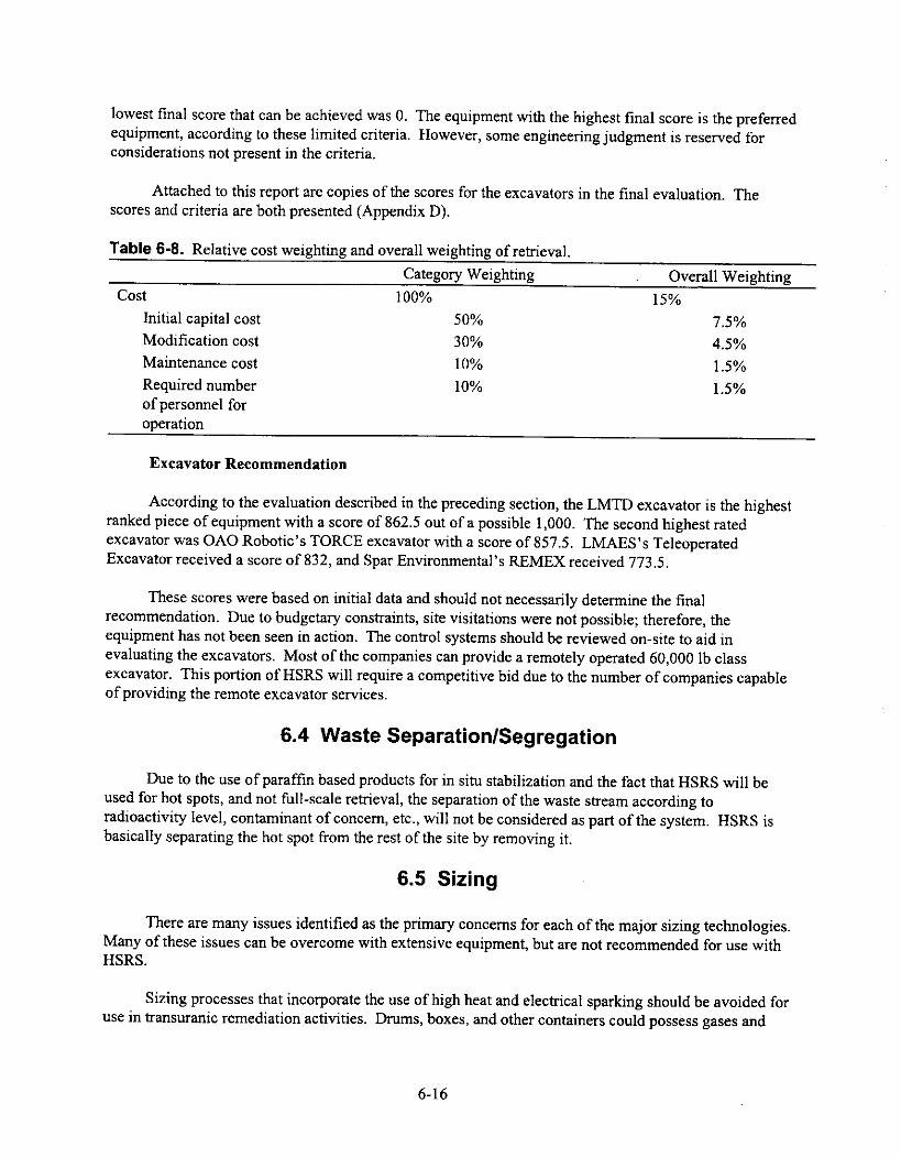
lowest final score that can be achieved was 0. The equipment with the highest final score is the preferredequipment, according to these limited criteria. However, some engineering judgment is reserved forconsiderations not present in the criteria.
Attached to this report are copies of the scores for the excavators in the final evaluation. Thescores and criteria are both presented (Appendix D).
Table 6-8. Relative cost weighting and overall weighting of retrieval.
Category Weighting . Overall WeightingCost 100% 15%
Initial capital cost 50% 7.5%Modification cost 30% 4.5%Maintenance cost 10% 1.5%Required numberof personnel foroperation
10% 1.5%
Excavator Recommendation
According to the evaluation described in the preceding section, the LMTD excavator is the highestranked piece of equipment with a score of 862.5 out of a possible 1,000. The second highest ratedexcavator was OAO Robotic's TORCE excavator with a score of 857.5. LMAES's TeleoperatedExcavator received a score of 832, and Spar Environmental's REMEX received 773.5.
These scores were based on initial data and should not necessarily determine the finalrecommendation. Due to budgetary constraints, site visitations were not possible; therefore, theequipment has not been seen in action. The control systems should be reviewed on-site to aid inevaluating the excavators. Most of the companies can provide a remotely operated 60,000 lb classexcavator. This portion of HSRS will require a competitive bid due to the number of companies capableof providing the remote excavator services.
6.4 Waste Separation/Segregation
Due to the use of paraffin based products for in situ stabilization and the fact that HSRS will beused for hot spots, and not full-scale retrieval, the separation of the waste stream according toradioactivity level, contaminant of concern, etc., will not be considered as part of the system. HSRS isbasically separating the hot spot from the rest of the site by removing it.
6.5 Sizing
There are many issues identified as the primary concerns for each of the major sizing technologies.Many of these issues can be overcome with extensive equipment, but are not recommended for use withHSRS.
Sizing processes that incorporate the use of high heat and electrical sparking should be avoided foruse in transuranic remediation activities. Drums, boxes, and other containers could possess gases and
6-16

liquids that react when heat and electricity are introduced. Some containers could contain materials thatreact when exposed to oxygen. As a result, the sizing process should take place in an inert environment.
The following cutting processes have been eliminated due to the possibility of initiating anexplosion caused by the introduction of heat, electricity, or sparking: arc saw cutting, plasma arc cutting,oxygen burning, abrasive cutting, laser cutting, and therrnite reaction lances.
Water jet cutting and abrasive jet cutting produce a secondary waste that is not desirable. Thesetypes of systems would also break up the soil stabilization matrix that could be applied to the soil. As aresult, the advantages of using these types of technologies are outweighed by the technology'sdisadvantages.
Pipe/wire cutters, hacksaws, and guillotine saws are unable to accommodate objects as large as acar body. Objects of this size could be encountered at waste sites. As a result, these methods wereeliminated from use with HSRS.
Cryogenic cutting is able to cut wooden objects, but is not advanced enough to size metal objects.Most of the larger items encountered in the waste streams will possess metal parts or be entirelycomprised of metal.
Mechanical shears that attach to an excavator could be used. However, an excavator must bededicated for this task because the shear might not be capable of remote changeouts. According toLaBounty Manufacturing representatives, the force required to shear 0.5-in. steel plate would take a largeexcavator with the stick and end-effector removed. Also, in order to prevent the spread ofcontamination, shearing should be applied in a contained environment.
Shredding and cryogenic fracturing processes are capable of sizing large cars (cryogenic fracturingcan size the engine block, shredding cannot) and tanks (less than 0.5-in. thickness for steel). Shreddingwould require an inert atmosphere to prevent the ignition of pyrophorics. Cryofracturing also requiresmajor engineering to make the system more easily transportable and inexpensive.
Cyrogenic fracturing was removed because the process for freezing drums and other waste is toolong (45 minutes/container). Furthermore, the cryofracture system is currently not mobile and wouldrequire major modifications. As a result, cryogenic cutting is not applicable.
According to EPA (1991), shredding machines are the most common piece of equipment used forsizing at hazardous waste sites. If car bodies and large, thick pressure vessels are not going to be sized,shredders will be a viable technology.
Shredding technologies have been used in the past for this type of application. The shreddingmachine would be capable of withstanding pyrophoric explosions, have negative pressure, and becapable of dumping the sized material directly into a standard container for packaging. Shredders arealso capable of reducing the size of the objects most efficiently.
6.6 Waste Minimization
Waste minimization is a very large concern in environmental remediation due to the high costassociated with treating, storing, or disposing of waste. Hot spot removal is minimizing waste simply by
6-17

removing the hot spot; because the concentrated waste is removed from the waste stream, moreconventional, cheaper methods may be used on the rest of the site. Due to this, and the fact that hot spotsare not large chunks of the overall site anyway, special measures will not be taken to further reduce thevolume of waste.
Waste compactors are available in many different sizes with very high compression forces. Thesecompactors are standard in industry and could be added to HSRS in the future. Several of thecommercially available compactors are available with negative-pressure compaction chambers for use inhazardous/radioactive environments and can be operated remotely. The waste is compacted into avariety of standard waste packages, including different sized boxes, 55- and 83-gal drums. Using acompactor facilitates the packaging of the waste as it is all taken care of with one piece of equipment,thus minimizing the decontamination required later.
6.7 Waste Packaging
The only piece of equipment that was identified for packaging the waste directly into the standardcontainers was the shredder. This system is capable of simultaneously sizing and packaging the waste.Modifications must be made to allow the system to accept multiple sizes of containers. For HSRS, off-the-shelf systems are available for this type of application.
6.8 Decontamination
As the sites that the Hot Spot Removal System will be operating in are the nastiest, with the wastematrix consisting of basically anything, in any concentration, decontamination of the equipment so that itcan be used again is a prime cost driver, and thus must be looked at in great detail. It is assumed thatstandard decontamination methods will be used where applicable and will not be evaluated here (such ason low-level contamination items, operators can manually wipe the equipment off or just bag it fortransport). It will be assumed in this report that the camera equipment falls into the category ofequipment to be decontaminated using standard methods. There are basically three items of concern to beaddressed by means of a formal evaluation; the confinement enclosure: the excavator and associatedend-effectors, and the waste boxes.
6.8.1 Confinement Enclosure
The confinement enclosure will be kept as clean as possible via the aggressive contaminationcontrol measures taken. In addition, the enclosure will be provided with a liner (polyethylene), whichcan be disposed of as compactible waste in the last waste package, if necessary. Any furtherdecontamination needed would be due to small hot spots on the enclosure, which could be taken care ofmanually using standard methods.
6.8.2 Excavator
The main part of the excavator (the cab, body, tracks, and controls) will be protected from dust viathe in situ soil stabilization contamination control, as well as secondary measures described later inSection 7. The end-effector portion, the part of the excavator that actually comes into contact with thewaste, will be evaluated here. Several methods were discussed in Section 2.9: mechanicaldecontamination (wiping/scrubbing, grinding/machining, media blasting, high-pressure water or steamjets, vacuum cleaning, ultrasonic cleaning, and vibratory finishing), strippable coatings (resins, polymers,
6-18

heat shrink), decontamination chambers, and chemical decontamination (aqueous solutions of mineral ororganic acids, chelating agents, or detergents). Of these methods, strippable coatings will not beevaluated as these coating are not durable enough to stay on the excavator during retrieval activities.They would peel off, and the equipment would be contaminated. Of the remaining three categories,decontamination; chambers will not be evaluated separately as it is assumed that a decontaminationchamber will have to be used in conjunction with any mechanical or chemical form of decontamination;the only question is how complex this decontamination chamber must be.
6.8.3 End-Effector
The end-effector will come into contact with paraffin based products during the retrieval activities;therefore, whatever form of decontamination is used, the paraffin based products must be removed. Forthis evaluation, mechanical decontamination will refer to some type of remote media blasting (high-pressure water, carbon dioxide, etc.), as it is not considered feasible to wipe/scrub the excavator as theprimary means of decontamination due to the size of the equipment and the level of contamination, andvacuum cleaning probably won't remove the paraffin based products. Chemical decontamination willrefer immersing the end-effector into a hot water bath at 180°F, the melting temperature of paraffin basedproducts, and using scrubbers afterwards to remove any remaining paraffin based products.
Following the logic as in the evaluation for cryogenic retrieval and jet-grouting above, the end-effector decontamination evaluation will be broken into the same three broad categories, thesubcategories being changed to apply to decontamination issues.
Effectiveness
For effectiveness (66.7% overall), the following subcategories will be used: minimizecontamination spread and clean to acceptable levels. The minimization of contamination spread duringthe decontamination of the excavator is essential in that the contamination control methods discussedearlier are useless unless we maintain the same "keep it clean" principle throughout the process. On theother hand, the level to which the excavator can be cleaned, and whether or not it has to be buried whenHSRS is done due to unacceptable contamination levels, is a big cost driver. Thus, these are bothimportant issues in the decontamination of the excavator and will be given equal internal weightings of50% each (overall weightings of 33.35% each).
The ratings to minimize contamination spread will be as follows: minimizes contamination spreadwithout modifications = 10, minimizes contamination spread with use of decontamination chamber = 5,and does not minimize contamination spread = 0. For the clean to acceptable levels category, a 10 willbe given for a yes, a 0 for a no.
Implementability
The implementability category (16.7% overall) will be broken into two subcategories:negative-pressure decon chamber needed and remotely operable. As the need for a negative-pressuredecontamination chamber adds costs for engineering, fabrication, construction, and more complexremote operations, it will be given an internal weighting of 75% (12.53% overall). The remotelyoperable category is thus given an internal weighting of 25% (4.17% overall). Remote operability isimportant, but as the contamination is fixed to the end-effector by means of the paraffin based products,it is not as big a driver in the overall scheme as the decontamination chamber.
6-19

The ratings for negative-pressure decon chamber needed will be based on a simple yes or no, a yesreceiving a score of 0 and a no a 10. The remotely operable category is also yes/no, yes receiving a 10and no a 0.
Cost
The cost category is a little harder to break down, as both options would require some engineeringdesign and both use the same basic media for decontamination, just applied differently. For this reason,cost will be given an overall weighting of 16.6% and will be scaled as follows: (1) if complexengineering is required (negative-pressure ventilation system requiring significant maintenance, remotecontrols, etc.), a score of 5 will be given, (2) if basic engineering is required (simple vats, basic remotecontrols, etc.), a score of 7 will be given, and (3) if no engineering is required, a score of 10 will begiven.
Table 6-9 summarizes the above categories and provides a score for each.
This evaluation shows that the best way to decontaminate the end-effector would be to design ahot water bath for the end-effector and then scrub/wipe the remaining paraffin based products off usingremote tools.
6.8.4 Waste Packages
The next item to be considered is the decontamination of the waste packages prior to removal fromthe confinement enclosure. Of the decontamination methods discussed in Section 2.9, the methods mostapplicable to the waste boxes are the strippable coatings and decontaminating the boxes usingmechanical/chemical methods. In this evaluation, the strippable coatings will be further broken down toevaluate the use of paraffin based products, heat shrink, or resin strippable coatings to fix thecontamination on the packages prior to transfer as opposed to decontaminating them to acceptable levels.
Effectiveness
The effectiveness (66.7% overall) category will be broken down into three subcategories:fix/remove COC for transport, add new waste stream, and minimize secondary waste.
The fix/remove COC for transport category refers to the degree to which the contamination can beremoved or fixed for transfer to another facility. The level of cleanliness to which the boxes must bedecontaminated will be site dependent. However, this category will determine the feasibility of thedecontamination method, as some methods, such as media blasting at high pressures, can drive thecontamination farther into the surface, making the problem worse. As the level of cleanliness candetermine whether or not the package will even leave the site, it is of utmost importance and will thus be
6-20

Table 6-9. End effector—mechanical versus chemical decontamination.
RatingsBased on 1 to 10 Score
Category
InternalWeightWithinCriteria
OverallWeight
MechanicalDecon
ChemicalDec on
MechanicalDecon
ChemicalDecon
Overall effectiveness 100 66.7
Minimizecontaminationspread
50 33.35 5 10 1.7 3.3
Clean to acceptablelevels
50 33.35 10 10 3.3 3.3
Implementability 100 16.7
Negative pressuredecon chamber
75 12.53 0 10 0.0 1.3
Remotely operable 25 4.17 10 10 0.4 0.4
Cost 100 16.6 5 7 0.8 1.2
Overall rating 6.2 9.5given an internal weighting of 70% (46.70% overall) and will be rated according to the following scale:removal of contaminants to acceptable levels for transfer = 10, fix contaminants sufficiently totransfer = 8, and drive contaminants farther into package = 3.
The add a new waste stream criterion is important in that if a decontamination method doesintroduce a new waste stream, that waste stream will have to be disposed of or treated later as well, thusincreasing the waste volume and the ultimate cost of the project. This category will be given an internalweighting of 15% (10.00% overall). The scoring will be based on a yes/no scale, yes receiving 0 points,no, 10 points.
Minimizing secondary waste is as important as avoiding the addition of new wastes in that itcreates more waste volume to be dealt with later. Secondary waste includes any polymer/resin used toencapsulate the waste as well as any media used to decontaminate the waste to acceptable levels. It isgiven an internal weighting of 15% (10.00% overall) as well. The scoring will be based on thefollowing: no secondary waste created = 10, minimal secondary waste = 7, and continually applied(media blasting - must continually apply until package meets acceptable levels) = 3.
Implementability
The implementability category (16.7% overall) will be broken down as follows: reducecontamination spread, easily applied/removed remotely, and easily removed without adding secondarywaste. As the contamination control issue is the overall driver in HSRS, the reduction in contaminationspread is of vital importance, especially when discussing the waste packages themselves, as they will be
6-21

leaving the confinement enclosure to go to other facilities. In keeping with this thought, the reducecontamination spread category is given a high internal weighting of 80% (13.36% overall). The othertwo subcategories are considered equal in importance, and are each given an internal weighting of 10%(1.67% overall).
The scoring for the reduce contamination spread category will be as follows: direct application ofcontaminant fixant (i.e., finished product comes in direct contact with surface) = 10, product is sprayedon, which will result in minimal spread = 7, and any product which uses high-pressure blasting = 3, asthis will spread contamination significantly.
The scoring for easily applied/removed remotely will be based on the following scale: can bedone remotely with no modifications = 10, some tools to operate remotely would need to be designed,but still easily removed = 7, harder to remove and risk some contamination spread = 5, cannot remove =0.
The scoring for the easily removed without adding secondary waste criterion will be based on ayes getting a 10, minimal waste a 5, and significant secondary waste a 0.
Cost
The cost (16.6% overall) will be broken into two subcategories: equipment needed and materialneeded. As the equipment needed criterion is a one-time cost as opposed to continuing operational costsfor materials, it will be given an internal weighting of 25% (4.15% overall). The material needed is thusgiven an internal weighting of 75% (12.45%), as this is the cost that continues to be repeated.
As the equipment used to spray on the different resins, polymers, paraffin based products, andstrippable coatings is basically the same and readily available with only minor modifications for use inHSRS, the equipment cost will not be based on actual prices, but rather on the level of engineering thatwould be required to make it work in HSRS environment. If the product is simply sprayed on and left inplace (not removed), a score of 10 will be given, as this is the easiest scenario in a remotely operatedenvironment. If only simple tools must be designed to apply/remove the product remotely, a score of 7will be given. If complex application/removal equipment must be designed, a score of 5 will be given.
The material cost will be based on the cost to encapsulate one 4-ft by 4-ft by 8-ft box and will bescored as follows: $0 to $100/box = 10, $100 to $200 = 8, $200 to $300 = 6, $300 to $400 = 4, $400 to$500 = 2, >$500 = 0. The decontamination/actual cleaning of the waste box will be given amiddle-of-the-road score, as the exact cost cannot be determined due to cleanliness levels, to what extentthe package must be decontaminated, etc.
The following assumptions must be made in the calculations determining the price per waste box:
• Paraffin based products will be assumed to cost $5/gal and cover the same square footage asa basic resin per gallon
• Heat shrink is 7 mm thick and comes on a roll 40 ft by 100 ft at $187.04 per roll (pricereceived from Dr. Shrink, the supplier of heat shrink used at the Test Reactor Area, and isused as an average price)
6-22

In the easily applied/removed remotely category, strippable coatings were given a score of 5 as thecoatings will adhere to the surface of the package and may require more effort to remove.
A new waste stream is not created in using paraffin based products because there is alreadyparaffin based products in the box itself, and this is the preferred medium for jet-grouting.
Decontamination will be given a middle-of-the-road rating of 5 on both the easilyapplied/removed remotely category and the easily removed without adding a secondary waste categorybecause it really doesn't fit into these categories, but would need some engineering design to be usedremotely, and would add a secondary waste (the medium used to decontaminate.)
From Table 6-10, the waste packages should be encapsulated in paraffin based products to fix thecontamination on the surface prior to transfer out of the confinement.
6.9 Waste Transfer
Once the waste is packaged and the packages decontaminated, they must be removed from theconfinement enclosure via a waste transfer system of some kind. Transfer equipment within the facilitymust be capable of minimizing dust generation. Because dust is the primary cause of contaminationspread, efforts must be made to reduce its generation. As a result, remotely operated equipment that isdriven over the soil is highly undesirable; a remotely operated forklift is not the optimum piece ofequipment for waste transfer.
Systems that are stationary cause little dust generation. Trolley/crane systems and stationaryconveyors are more applicable to HSRS requirements. However, many conveyors are difficult todecontaminate due to the many voids between the large number of moving parts.
Trolley crane systems are easily designed and manufactured. They are simple machines and arereliable. The system can be designed to retrieve packaged waste from the packaging equipment and
6-23

Table 6-10. Waste package decontamination.
Category
InternalWeighting
Within CriteriaOverallWeight
RatingsBased on 1 to 10 Score
Paraffinbased
productsStrippable HeatCoating Shrink Decon
Paraffinbased
productsStrippableCoating
HeatShrink Decon
Overall Effectiveness 100 66.70
Fix/remove COC for transport 70 46.70 8 8 8 10 3.7 3.7 3.7 4.7Add new waste stream 15 10.00 10 0 0 0 1.0 0.0 0.0 0.0Minimize secondary waste 15 10.00 7 7 7 3 0.7 0.7 0.7 0.3
Implementability 100 16.70
Reduce contamination spread 80 13.36 7 7 10 3 0.9 0.9 1.3 0.4Easily applied/removedremotely
10 1.67 7 5 7 5 0.1 0.1 0.1 0.1
Easily removed w/o addingsecondary waste
10 1.67 10 5 5 5 0.2 0.1 0.1 0.1
Cost 100 16.60
Equipment needed 25 4.15 10 10 7 5 0.4 0.4 0.3 0.2Material needed 75 12.45 10 4 10 10 1.2 0.5 1.2 1.2
Overall rating 6.7 5.5 6.0 5.5
transfer it to the decontamination chamber or airlock with little or no dust generation. As a result, atrolley/crane system is recommended for indoor waste transfer.
After the waste is removed from the confinement enclosure, a remotely operated forklift or theSGTV could be used to transfer the waste to the flatbed of a truck. If the SGTV is used, a forklift will beneeded to remove the waste containers from the SGTV and place them on the transport vehicle. If thesites do not possess extreme rough terrain conditions, a remotely operated rough-terrain forklift would bethe most applicable piece of equipment for outside the confinement facility.
6.10 Vision Systems
The progression of vision technologies has developed well over the past few years. Equipmentcapable of meeting the HSRS requirements has been fully developed. Companies currently havetechnologies allowing for radio frequency operation. A few companies have synchronous brushlessmotor pan/tilt units for continuous 360-degree rotation to allow unrestricted movement of the cameras.Weather-proof and explosion-proof housings are available for the cameras, and radiation-tolerantequipment is readily available. Sealed equipment can be used to facilitate decontamination. A widerange of zoom, illumination capabilities, resolutions, gray scales, and viewing angles are also available.Furthermore, pan and tilt units are capable of movements similar to human head movements and speeds.
Stereoscopic Vision
Stereoscopic vision provides the viewer with a three-dimensional representation of theenvironment by providing depth perception. Stereoscopic vision images can be gathered by using acamera that shifts its view at a rapid rate. These images are then interpreted by using filtering glassesand a monitor designed to display the phase shift, a regular monitor with flickering glasses,autostereoscopic monitor, or head mounted display.
A second method is more like the human vision system. The 3D images are achieved by usingtwo cameras that are slightly offset, just like our eyes. The two images are sent to a monitor-glassessetup, autostereoscopic monitor, or head-mounted display (one camera view for each eye) forinterpretation by the viewer. The only apparent disadvantage of using stereoscopic cameras is the lack ofzoom capability, which is currently under development.
Head-Mounted Displays
Head-mounted displays (HMDs) offer a remote operator an increased sense of being at the worksite. Stereoscopic vision is sent to a display that covers the head and eyes of the operator. Surroundingthe operators eyes with the remote images allows the operator to feel immersed into the remoteenvironment. This is an important aspect in remote control systems. Greater depth perception can beaccomplished, due to the stereoscopic inputs. HMDs also allow the operator to view 3D virtual realityrepresentations of the working environment when 3D laser ranging cameras are used to gather videoinputs. Some HMDs have one major drawback, however. Once the helmet is placed over the head of theoperator, only the images that are fed into the helmet can be viewed. To view other sources, such assecondary monitors, the helmet must be removed. This operation can become tedious after a number ofremote actions; multiple views are not fed into the HMD.
6-25

See-through head mounted displays are similar to the heads-up displays used in military aircraftImages from a screen are reflected from a 45-degree angle onto the viewing glass. These images can beinputted from monoscopic or stereoscopic cameras. These images are transparent and allow the operatorto view the "outside world" without taking off the helmet. These HMDs are used in military aircraft toallow the pilot to see the sky in front of him/her and also see the status of the weapons and navigation.Thus, secondary information is superimposed over the pilots line of sight.
This technology will not be applicable to the remote operation of an excavator. Secondary videoscreens could distract the operator from the primary see-through HMD images.
Head mounted displays are being developed to allow the operator to see multiple video sources.Viewing selection is determined by the operator's head orientation, which is monitored by a headtracking device. This type of vision management system is capable of replacing bulky monitors thatrequire a lot of space. Multiple personnel can view video at the same time to allow for multipleequipment operations. Images are relayed to the HMD one at a time.
Monitors
Monitors allow the operator to view multiple video sources almost simultaneously and do notcover the operators line of sight, which could slow down throughput because the operator cannotconveniently see the controls. Stereoscopic monitors are highly recommended for providing theoperator's depth perception of the work site. Monitors do not immerse the operator into the remoteenvironment as well as head mounted displays, but it is felt that the advantages to HMDs are outweighedby the disadvantages.
Stereoscopic cameras and monitors have proven to produce much higher throughputs whenperforming remotely operated activities. Many tasks prove to be extremely difficult using two-dimensional cameras, but are not difficult when using stereoscopic vision. Throughput of the system isimproved by no less than 50% when using stereoscopic vision for many activities.
Recommendations
The technologies present a variety of options for the vision feedback of an excavator. Afterreviewing these options, monitors are the recommended method for viewing remote video sources.Monitors will allow the operator freedom within the control environment and will provide almostsimultaneous visual feedback of all the video sources.
Stereoscopic vision is highly recommended for remote activities based on the throughput increasesdemonstrated on the Cooperative Telerobotic Retrieval system. Zoom capabilities on the stereoscopiccameras are now becoming available and are also highly recommended if the technology is provenreliable.
6-26

7. THE PLAN
This section contains the recommendations and gaps in technology (see also related gaps inSection 2) for equipment and technologies to be incorporated into HSRS. Information is included on thefollowing topics:
• Characterization (Section 7.1)
• Contamination control strategy (Section 7.2)
• Site preparation and equipment staging (Section 7.3)
• Contaminated soil removal (Section 7.4)
• Waste separation/segregation (Section 7.5)
• Sizing and packaging (Section 7.6)
• Decontamination (Section 7.7)
• Remote vision (Section 7.8)
• Control system (Section 7.9)
• Summary (Section 7.10).
7.1 Characterization
7.1.1 Recommendations
Geophysical, radiological, and chemical characterization of the site must occur before anyremediation/retrieval can take place, during removal, and for verification that the hot spot has beenremoved. The sensors used to accomplish this task would be site specific and would be chosenaccording to historical data (what is expected or sampling activities). Based on the information currentlyavailable on the 14 representative sites that have selective retrieval as their preferred option, somepreliminary recommendations on which sensors to deploy are presented. Table 7-1 gives therecommended geophysical sensors based on the soil characteristics of the site, waste type, and the depthto the waste. Please note that the recommended sensor(s) for geophysical characterization arepreliminary due to missing information and are based on information available at the time of this writing.They may change with more information. Table 7-2 presents the recommended sensors for chemical andradiological characterization at the digface based on the contaminants of concern.
After determining those sensors most suitable for a given site, a platform to deploy the sensorswould be chosen. The platforms available are discussed in Section 2.2.4: the Rapid GeophysicalSurveyor, the Three-axis Trolley, and the Warthog (patent pending). The platform chosen is dependenton site location, access, type of site, etc. For site characterization, a cart system is recommended. Fordigface characterization, the Warthog system is recommended and would be deployed from theexcavator or as needed per site requirements.
7-1

Table 7-1. Recommended geophysical sensor(s).
Site Soil Media Debris/Soil
Depth toWaste(ft)
Recommended GeophysicalSensor(s)
AlbuquerqueUMTRA
D/S Electromagnetic, magnetic
IdahoWAG 2
Clay soils 0 Sampling more appropriate,acoustic for depth
Idaho D/S 3 Electromagnetic, magneticWAG 7
Nevada DNA muckpiles
Mine tailings 0 Electromagnetic, dc resistivity, IPfor depth
Nevada Soils Media Sand, silt, gravel S Can't make recommendationOU
Oak Ridge WAG 5 Clay soils S Electromagnetic, magneticSWSA 5 South
Oak Ridge WAG 5 D/S Electromagnetic, magneticSWSA 5 North
OaklandLEHR 1 & 5
Clay soils S Electromagnetic, magnetic,possibly ground-penetrating radar
Richland OU-200TRU caissons
D/S Electromagnetic, magnetic,possibly ground-penetrating radar
Richland OU-200TRU drums
D Electromagnetic, magnetic,possibly ground-penetrating radar
Richland OU-300-FF-2 debris
D/S Electromagnetic, magnetic,possibly ground-penetrating radar
Richland OU 300-FF-2 soil
S Electromagnetic, magnetic,possibly ground-penetrating radar
Savannah River 488 Clay soils S 5 Electromagnetic, magneticD Ash Basin
Savannah RiverLLRWDF/OBG
D/S Electromagnetic, magnetic,possibly ground-penetrating radar
7-2

Table 7-2. Recommended chemical and radiological sensor(s).
SiteContaminant(s) of
ConcernRecommended
Chemical Sensor(s)
AlbuquerqueUM'1RA
IdahoWAG 2
IdahoWAG 7
Nevada DNA MuckPiles
Nevada Soils MediaOU
Oak Ridge WAG 5SWSA 5 South
Oak Ridge WAG 5SWSA 5 North
TCA, TRICHLOROETHYLENE, PCE,freon 11 and freon131
Co, Cs, Sr
TRU, Tc, C-14,VOCs, EPA ToxicMetals
H-3, Pb
Pu, Am
Pu, Am, Cm, U, Cs,Sr, Th, Pb, Co, Hg,PCBs, TRU
Cm, Cs, Sr, Pb, TRU,Co, Hg
Oakland LEHR 1 & 5 Not available
Richland OU-200TRU Caissons
Richland OU-200TRU Drums
Richland OU-300-FF-2 Debris
Richland OU 300-FF-2 Soil
Savannah River 488D Ash Basin
Savannah RiverLLRWDF/OBG
TRU
Sr, TRU, Cs
TRU, U, pyrophorics
TRU, U
PCBs, Ba, Fe, Mg,Na, TRICHLOROETHYLENE
Cd, alpha, Pb, Hg,Toulene, Benzene,Beta, TRU, solvents
Recommended RadiologicalSensor(s)
LIBS, Rapid Mapping N/AVOC Sensor
N/A
VOC Sensor, XRF
XRF
N/A
VOC Sensor, XRF
XRF
Can't makerecommendation
N/A
N/A
N/A
N/A
LIBS
LIBS, XRF
Plastic scintillator, three-layerxenon proportional counter
Calcium fluoride
N/A
Calcium fluoride
Calcium fluoride, plasticscintillator, three-layer xenonproportional counter
Calcium fluoride, plasticscintillator, three-layer xenonproportional counter
Can't make recommendation
Calcium fluoride
Calcium fluoride, plasticscintillator, three-layer xenonproportional counter
Calcium fluoride, Gespectrometer
Calcium fluoride, Gespectrometer
N/A
Calcium fluoride, plasticscintillator
7-3

In order for some of these sensors to work as a part of HSRS, some gaps in the technologies wouldhave to be either filled with research and development, or testing. These gaps are addressed inSection 7.1.2.
7.1.2 Gaps in Characterization Technology
Gaps in technologies for site characterization, as well as characterization, are identified forgeophysical, radiological, and chemical sensing techniques. Filling these gaps is crucial to enable hotspot removal at the sites identified across the DOE complex.
7.1.2.1 Geophysical. At present, it is difficult to non-intrusively detect and characterize many hotspots within the subsurface. The main difficulty is that the resolution and correlation of geophysicaltechniques to the param that define the hot spot are not known or understood.
Resolution at a specific site is difficult because each site has different requirements, and differenthot spots have different physical properties, some easier to detect than others. There are, however, threebasic questions that need to be addressed when determining if the required resolution can be achieved:(1) What is the minimum size object, structure or change in physical property associated withcontamination that can be detected with the system used? (2) How well can the position of the hot spotbe defined? and (3) How well can the hot spot be distinguished from other objects or areas near the hotspot but not of concern?
The first two questions depend on the intrinsic resolution of the technique and the survey design;the intrinsic resolution depends on the detection limits of the system. For example, for object imaging,high-frequency data need to be collected; however, these systems are often severely attenuated by thehost medium making resolution difficult, and if the contrast between the hot spot's measured physicalproperties and those of the host is small, resolution also becomes more difficult. The survey designaffects the resolution in several ways: If data are not collected far from the object, the response of thetarget may be too small to detect; or if data are not collected at a sufficient spacing, the object may beundetected; or the signals from many objects may interfere to produce an unresolvable signal. Forexample, unexploded ordnance (UXO) is often detected using densely spaced magnetometer data.
The third question depends on correct interpretation of the measured quantities. This involvesunderstanding the relationship between the measured quantities and the hot spot. In some cases,geophysical systems detect containers but not the contents of the container that are the real concern. Inother cases, they directly detect an object of concern (such as UXO). In others, they detect the structurescontrolling the position of the hot spot (such as geologic traps for dense non-aqueous phase liquids orwaste seam boundaries). Finally, in some cases, the technique may be used to directly detect acontaminant of concern, as is the case for some organics.
There are several ways to improve the resolution to some degree, but basic research is needed tobetter define the methods (to improve resolution) and also to better understand the relationship betweenthe risk drivers and the physical properties measured using geophysical techniques. This includeslaboratory investigation of the physical properties of contaminants or other hazards. Sitecharacterization information collected to determine the physical properties needs to include soil samples,structural information, a list of possible contaminants, and also possible containers, among otherinformation that may be site dependent. Along with better understanding of the physical properties ofthe medium, the hot spot, and how the medium and hot spot physical properties interact, a betterunderstanding of the resolution of a given geophysical method at a specific site is needed. This can be
7-4

obtained through numerical modeling, but current models need to be verified and further developed.Therefore, there is a need to verify and develop these types of models. In the short term, one way toimprove the resolution of characterization is to collect more data on a larger and denser grid using moresurvey points, as well as utilizing boreholes. This is often cost prohibitive using standard shallowgeophysical equipment. Currently, better methods of data collection are being developed but have notbeen extensively tested. This includes the use of non-traditional survey design, and improvinginterpretation techniques.
However, improvements could be achieved by developing geophysical hardware systems that usemultiple sensors and multiplexing devices to collect larger amounts of data in a relatively short time.Improvement in collection rates would allow investigators to collect data at denser spacing with differentgeometric layouts, and also allow for the collection of more than one type of data.
Collecting more data is only one aspect of development. Methods to utilize the informationcollected with multiple sensors at denser sampling spacings are needed. Better imaging techniques thatutilize all the data collected at a site, not just data collected with one geophysical technique, need to bedeveloped. This may include developing and using data fusion technology to integrate geophysical,hydrological, historical, and other site-relevant data. Other data integration techniques should also bedeveloped. Often, the data collected are not best utilized in their initial state and must be processed toachieve data that can be used in integration or fusion applications. However, this is often slow andcumbersome and can add noise to the data. Thus, there is a need to perform not only data fusiondevelopment but also develop better and more efficient data processing/interpretation software.Improvements might include improving existing three-dimensional inverse modeling, migration,scattering and other interpretation techniques, or developing new, multi-sensor imaging algorithms.
The ability to distinguish different types of metallic objects within a waste site is not easilyaccomplished. Currently, distinctions are made based solely on size. Further research may improve thissituation.
Finally at all sites, the data collected using geophysical equipment must not be analyzed in avacuum. Input from all sources must be used to achieve detection of hot spots.
7.1.2.2 Radiological. In the radiological characterization arena, assay in the presence of multipleradionuclides requires a method of determining the relative amounts of the individual radionuclides.This requires the use of a detector, or detectors, that can distinguish between the radionuclides. Usuallythis requires measurements with a Ge semiconductor detector, since it has good resolution of both (y-raysand x-rays. If a multi-channel analyzer is used with an NaI(Tl) detector, it can often be used todistinguish the various radionuclides (excluding the separation of the various actinides).
Some issues would have to be resolved before the above detectors would be field deployable inHSRS. The plastic detector has been used to map the radioactivity, but its count rates could be convertedto radioactivity levels only in cases where only 137Cs and background radiation are present. Adetermination of the electronic cutoff energy and some calibration measurements are needed to do this.Also, a procedure for determining the background and subtracting it would be needed. It might bepossible to get some depth profile information from the plastic scintillator. This would require putting amultichannel analyzer on the detector and writing a special spectral analysis code. If the plastic detectorwere used for this purpose, much longer counting times would be needed.
7-5
Sodium iodide scintillators could be used in place of the plastic scintillator at many sites. If used,the sodium iodide scintillators would need to be matched to give the same height electronic pulse for agiven y-ray energy. Whether the data from this detector should be processed with a single-channel or amulti-channel analyzer needs to be determined. If the latter is preferred, analysis software will beneeded. In addition, the electronics for the sodium iodide multi-detector array would need to bedesigned, built, and the protocol prepared to match the detectors. The lower level of detection wouldneed to be determined.
This system would not be as robust as the plastic scintillator system due to the multiple number ofdetectors to be matched and checked in the field.
At present, there are no effective in situ analysis techniques for 14C and 99Tc, and one should notexpect any to be developed for the low activity levels expected at waste sites.
It would probably be desirable to be able to make measurements with and without a shield for theGe spectrometer. In the unshielded configuration, the detector will survey a large area, so a comparisonof the unshielded and shielded count rates can be used to get a crude idea of the source distribution,thereby increasing the spacing between the points at which measurements are needed. Therefore, oneshould consider designing a system for which the shield can be retracted from the control center.
A three-layer xenon proportional counter should be purchased and tested for real-time fielddeployment and measurement of 90Sr.
7.1.2.3 Chemical. Due to toxicity and explosive characteristics of some volatile organics, it willalways be worthwhile to know when such substances are present in the vicinity of a digging operation.Currently, there are no means of accomplishing this.
A volatile gas analyzer is probably the closest thing there is to an all purpose contaminant sensorfor a group of compounds that are (1) organic, (2) hazardous, and (3) volatile. However, a volatile gasanalyzer is not currently available.
It is not currently known how effective the above technologies would be in a digfacecharacterization system used for HSRS. There are three specific issues related to real-timecharacterization of chemical contamination.
First, an air sampling sensor must be maneuvered around a rugged digface with adequate controlto rapidly and precisely map the presence of volatile organics. This capability could be developed, but isnot currently done. Realistically, the complete robotic deployment system capable of maneuvering intotight spots, sampling the air, and recording the position is probably more sophisticated than anythingbeing currently attempted. However, data collected using a lesser capability (i.e., greater averagestandoff from the digface) should still be informative and valuable. It is reasonable to expect that thesensor could be maneuvered in tight quarters on occasion as the need arises. A good design for a hood orhose system to gather close-in samples could also be developed.
The second issue concerns the effect of air currents, which will tend to move and disperse vaporsemanating from the digface. In the worst case, the locations where volatile organic compounds aredetected may be completely unrelated to the location of the contaminants in the waste seam. Thisphenomenon should be recognized, since the mapped distribution of volatile organics would itselfindicate whether one is looking at dispersed gases or gases residing in the vicinity of their source. A
7-6
hood or hose sampling system as described above could help alleviate this problem. In any case, for acontained retrieval where the air currents arise from artificial ventilation, air flow would be weak toavoid generation of dust and airborne contamination.
The third issue concerns the effectiveness of any gas sampling sensor when the retrieval operationincludes dust suppression. Foams or mists would undoubtedly block free movement of soil gases intothe atmosphere. This would mean that VOCs could probably not be detected unless a major releaseoccurred.
7.1.2.4 Deployment Platform. Some sensors may need to be adapted for deployment from theWarthog. An adapter plate would need to be designed and fabricated to mate the Warthog to theexcavator.
7.2 Contamination Control Strategy
7.2.1 Recommendation
An overall contamination control strategy for HSRS is impossible, since it is quite dependent onthe site contamination. Based on information currently available, preliminary recommendations for acontamination control strategy are given in Table 7-3. Major factors in developing a contaminationcontrol strategy include the COC(s), soil type, waste type, and depth to waste.
7.2.1.1 In Situ Stabilization. The sites requiring the most stringent contamination control strategyare typified by alpha contamination in debris or soil. For this worst-case scenario, a recommendation isprovided as follows. For less stringent site needs, fewer systems would be shipped and deployed asreflected in Table 7-3.
Subsurface walls three boreholes wide would be jet-grouted, using cement as the medium aroundthe excavation pit to allow vertical excavation, thus reducing the size of the excavation pit required, andminimizing the waste volume of the hot spot. Each site may require a different agent for in situstabilization of the waste matrix itself, so limited tests should be performed prior to full deployment. Thegrout material would then be jet-grouted into the waste matrix to provide a first line defense against thespread of dust. During the injection process, any drums known to exist in the waste matrix from thecharacterization process should be punctured and filled with grout to quasi-solidify the contents of thedrum before excavation. This minimizes the threat of small explosions due to pressure or gas buildup inthe drums.
The paraffin based media could be injected such that any overburden present would also bestabilized and removed with the waste. This would be site dependent, as some waste volume would beadded.
7.2.1.2 Confinement Enclosure. For those sites requiring a confinement enclosure, a SprungStructures or Rubb Building Supplies enclosure would be erected over the excavation site. This wouldinclude the ventilation system and airlock entry/exit systems. The structure would be bermed to helpmaintain a negative pressure during retrieval activities.
7.2.1.3 Secondary Contamination Control. In addition to the confinement enclosure as a meansof contamination control, several secondary contamination control measures should be taken during
7-7

Table 7-3. Summary of recommended contamination control strategies.
SiteContaminant (s)of Concern
SoilMedia
Debris/Soil
Depth toWaste(ft)
AlbuquerqueUMTRA
TCA, TCE,PCE, freon 11and freon 131
D/S
Idaho Co, Cs, Sr Clay Soils S 0WAG 2
IdahoWAG 7
TRU, Tc, C-14,VOCs, EPA
D/S 3
Toxic Metals
Nevada DNA H-3, Pb Mine 0Muck Piles Tailings
Nevada SoilsMedia OU
Pu, Am Sand, silt,gravel
S
Oak Ridge Pu, Am, Cm, U, Clay soils SWAG 5 Cs, Sr, Th, Pb,SWSA 5 South Co, Hg, PCBs,
TRU
Oak Ridge Cm, Cs, Sr, Pb,WAG 5 TRU, Co, HgSWSA 5 North
OaklandLEHR 1 & 5
Richland OU- TRU200 TRUCaissons
D/S
Not available Clay soils S
D/S
Recommended Contamination ControlStrategy
Contamination Control Unit withFlambinder, natural polysaccharides,and water misters
Contamination Control Unit withFlambinder, natural polysaccharides,and water misters
Confinement Enclosure withventilation system, in situ jet-groutedcement pilings, jet-grouted paraffinbased media for stabilization,electrostatic curtains, ContaminationControl Unit with Flambinder, naturalpolysaccharides, and water misters
Contamination Control Unit withFlambinder, natural polysaccharides,and water misters
Confinement enclosure with ventilationsystem, in situ jet-grouted cementpilings, jet-grouted paraffm basedmedia for stabilization, electrostaticcurtains, Contamination Control Unitwith Flambinder, naturalpolysaccharides, and water misters
Confinement enclosure with ventilationsystem, in situ jet-grouted cementpilings, jet-grouted paraffm basedmedia for stabilization, electrostaticcurtains, Contamination Control Unitwith Flambinder, naturalpolysaccharides, and water misters
Confinement enclosure with ventilationsystem, in situ jet-grouted cementpilings, jet-grouted paraffin basedmedia for stabilization, electrostaticcurtains, Contamination Control Unitwith Flambinder, naturalpolysaccharides, and water misters
Can't make recommendation based onlack of information
Confinement enclosure with ventilationsystem, in situ jet-grouted cementpilings, jet-grouted paraffm based forstabilization, electrostatic curtains,Contamination Control Unit withFlambinder, natural polysaccharides,and water misters
7-8

Table 7-3. (continued).
SiteContaminant (s)of Concern
Soil Debris/Media Soil
Richland OU-2 TRUDrums
Sr, TRU, Cs
Richland OU- TRU, U,300-FF-2 pyrophoricsDebris
Richland OU TRU, U300-FF-2 Soil
D
D/S
S
Savannah PCBs, Ba, Fe, Clay soils SRiver 488 D Mg, Na, TCEAsh Basin
Savannah Cd, alpha, Pb,River Hg, Toulene,LLRWDF/ Benzene, Beta,OBG TRU, solvents
D/S
Depth toWaste Recommended Contamination Control(ft) Strategy
Confinement enclosure with ventilationsystem, in situ jet-grouted cementpilings, jet-grouted paraffin based forstabilization, electrostatic curtains,Contamination Control Unit withFlambinder, natural polysaccharides,and water misters
Confinement enclosure with ventilationsystem, in situ jet-grouted cementpilings, jet-grouted paraffm based forstabilization, electrostatic curtains,Contamination Control Unit withFlambinder, natural polysaccharides,and water misters
Confinement enclosure with ventilationsystem, in situ jet-grouted cementpilings, jet-grouted paraffm basedmedia for stabilization, electrostaticcurtains, Contamination Control Unitwith Flambinder, naturalpolysaccharides, and water misters
5 Contamination Control Unit withFlambinder, natural polysaccharides,and water misters
Confinement enclosure with ventilationsystem, in situ jet-grouted cementpilings, jet-grouted paraffm basedmedia for stabilization, electrostaticcurtains, Contamination Control Unitwith Flambinder, naturalpolysaccharides, and water misters
retrieval activities in accordance with the aggressive contamination control strategy deemed necessaryfor hot spot retrieval.
Prior to alpha waste removal, electrostatic curtains would be installed around the excavation pit tocontrol the spread of dust to the confinement enclosure as well as the retrieval equipment.
The soil fixant (Flambinder) would be applied on all traffic areas within the confinement tominimize the airborne dust associated with vehicle traffic. This would be applied using the INEELContamination Control Unit.
Natural polysaccharides would be sprayed on the vertical walls of the excavation pit to help keepthe walls from eroding, as well as to further minimize the dust generated.
7-9

Mats/tarps would be put down around the excavation site for the retrieval equipment to keep theequipment from coming into contact with the soil itself.
The Contamination Control Unit would be used for its water misters, foams, as needed.
7.2.2 Gaps in Technology
As previously mentioned, a detailed contamination control strategy should be developed for eachsite once more is known about the site.
In Situ Stabilization Gaps. A paraffin based product is the preferred medium for injectinginto the waste for dust control, if it proves to be effective at the given site. Prior to utilizing a paraffinbased agent for jet-grouting, however, the following should occur in order to achieve the fulleffectiveness of the technology:
• Determine, through field tests, if a paraffin based product will work for a given site. If not,other in situ agents should be investigated for that particular site.
• A spoils return management strategy for the molten paraffin based product should berefined, as currently there is a 33% return of the injected volume.
• The drilling system should be modified for radioactive applications.
• The paraffin based media should go beyond the hot spot or zone to be retrieved to preventsurrounding soils from sloughing into the waste pit, causing aerosolization during retrieval.
• An on-line flow meter to alert operators of potential plugging of nozzles during jet-groutingis recommended. In the event of a plugged nozzle, the hole should be grouted again.
• When using in situ stabilization for shoring walls, the interior of the wall should beexcavated using other contamination control technologies, such as misting systems, fixants,or ventilation.
• The physical properties of the paraffin based product would have to be determined, as theparaffin product could change the resistivity, dielectric permeability, and acoustic velocity,thus affecting geophysical characterization.
• The density of the waste matrix/paraffin based product composition would have to bedetermined prior to characterization, as the sensitivity of the radiological sensors would beaffected and would have to be adjusted for the new density.
• A study on how paraffin products change the mobilization of radionuclides should beperformed.
• A study should be done to determine if VOCs/gases stick with the paraffin products.
There is some promise in using microbial polymers as an in situ stabilization media. They arebiodegradable, and thus can be removed easily from the site following retrieval, if desired. As some sites
7-10

may not like to retain the cement subsurface walls indefinitely, this option may be preferable. Fieldtesting should be done on this medium, described in Section 2.3.7.4.
• Limited tests should be performed for each site prior to full deployment.
• This technology has not been through full-scale field demonstrations. It is developed to thepoint where bench-scale testing with site-specific param could be started.
• Field demonstration/bench-scale testing could take up to 24 months.
• Further investigations would have to be completed to determine if the equipment used inSection 2.3.7.2, "Jet-Grouting," could be used to apply the microbial polymer.
7.2.2.2 Confinement Enclosure Gaps. The ventilation system would have to be designed for thespecific structure used in HSRS, as all blowers, fans, HEPA filters, etc., must be sized to the specific airvolume in the confinement chosen. The system would be comprised of off-the-shelf componentsdes'gned for use in hazardous/radioactive environments. These components are readily available inindustry.
Other issues that need to be addressed include the following: methods need to be developed tomaintain negative pressures at high winds, wind loadings will be site specific and will require a hazardanalysis, and a method for anchoring the confinement enclosure (with high winds, negative pressure,mobility in mind) must be engineered.
For local ventilation methods, some type of hood/shroud would have to be designed for use withthe retrieval equipment used in HSRS. Several hundred different hoods have been designed forcontamination control and could possibly be modified for use in HSRS. References are given inWinberg et al. (1992) as to where these designs are, and it should be consulted as a source of informationwhen designing a local ventilation system to control contaminants.
7.2.2.3 Secondary Contamination Control Gaps. In order to use electrostatic curtains as ameans of contamination control for alpha contamination, a secondary enclosure must be designed andbuilt from electrostatic curtain materials. At this time, electrostatic curtains must be developed tooperate on a full scale. This enclosure will surround the excavation pit and provide access holes throughwhich the retrieval equipment will work, thus providing a form of dust shield for the equipment. Theseaccess ports would have seals between the enclosure and the equipment to prevent leaks. The enclosuremust be designed such that the shredder, monitoring equipment, Contamination Control Unit, anddigface monitoring equipment fit inside the enclosure.
If electrostatic curtains are used, anti-contamination clothing should be made of conductivematerials to minimize the spread of contamination, and engineering design would have to be done(explaining how to actually make the enclosure, how to make it modular, design access ports forequipment, etc.).
7-11

7.3 Site Preparation and Equipment Staging
7.3.1 Overburden Removal
If the overburden was not injected with a paraffin based media or grout, it would be removedusing Sonsub Intemationallirs Soil SkimmerTM (Section 2.4.4.10) with a 60,000-lb class excavator.
According to Rice and Skaggs (1993), several modifications need to be made to the Soil Skimmerin order to improve efficiency.
Modifications need to be made to allow more complete filling of the end-effector by using ahydraulic door to scoop in material. A wider front opening and shorter depth would also allow morecomplete filling. A laser grade control system would facilitate in helping reduce the stress on theoperator while trying to perform level cuts with the end-effector.
Modifications also need to be made on the vacuum system. Vacuums should be placed at the frontand aft of the end-effector to reduce the escape of fugitive dust. Furthermore, a boom attachmentrotation point closer in vertical alignment to the cutter blade would make the end-effector easier tocontrol.
7.3.2 Site Preparation
Following overburden removal, the site would be prepared for waste removal. This would includethe following, unless already done during overburden removal: leveling and grading the site, installingpiling (location will be based on characterization data), obtaining containers for retrieved waste,preparing the administrative/control trailer, and obtaining and placing fire safety and personnelprotective equipment. This assumes that all documents, including a Safety Analysis Report, a Health andSafety Plan, National Environmental Policy Act documents, air permits, etc., are approved and readyprior to any activities. Until site preparation is initiated, a protective (meaning waterproof) cover wouldbe spread over the area to preserve dry soil so that HSRS can initiate building installation and stagingany time during the year.
7.3.3 Equipment Staging
Once the confinement enclosure is up and the ventilation system installed, equipment would bemobilized to the area. This equipment will include the following:
• Excavator
• Waste transfer equipment
• End-effector for overburden removal
• Shredder for sizing
• Packaging system
• Monitoring equipment
7-12

• Contamination Control Unit
• Electrostatic curtains
• Decontamination chamber for excavator
• Decontamination equipment
• Digface monitoring
• Small tools.
7.4 Contaminated Soil Removal
7.4.1 Recommendation
Prior to retrieval, the characterization sensor(s) recommended in Section 7.1 will be used to surveythe pit to determine the depth to the overburden/waste seam interface and to locate contaminants ofconcern. If more than 6 in. of overburden can be removed prior to hitting the waste seam interface andno COCs are detected, additional overburden removal would be accomplished using the remoteexcavator and the Soil Skimmer end-effector. This would be repeated until less than 6 in. of overburdenremain, or until COCs are detected. (This assumes that the site chose not to bring the paraffin basedencapsulation agent up to the surface of the site, but just to the overburden/waste seam interface.) Theoverburden will be packaged in waste drums, boxes, etc., and transferred from the excavation pit to theairlock entry/exit via a trolley/crane system. This prevents the waste package from coming into contactwith the floor of the confinement enclosure, thus minimizing any contaminants on the outside surface ofthe box. Once the package reaches the full box staging area, it can be surveyed for subsequent assay andremoval from the enclosure. (Please note that some sites may prefer to remove the overburden prior toerecting the contamination control confinement enclosure.)
A 60,000—lb class, remotely/manually operated excavator will be used for the retrieval of soil andlarge objects that may be encountered in the waste stream. The excavator, fitted with a large, heavy dutybucket and Balderson hydraulic thumb, will have a high throughput and is highly manipulative. Thisexcavator could also be used to operate the Soil Skimmer mentioned earlier.
During retrieval operations, operators will determine what the objects are, such as drums, pseudo-homogeneous waste/soil mixture, or debris and/or objects. If an intact drum is found, and was not filledwith paraffin based media, it will be vented for safety purposes using standard procedures.
7.4.2 Gaps in Technology
A trolley crane system would have to be designed and manufactured for the transferring of wastewithin the confinement enclosure. They are simple machines and are reliable. The system can bedesigned to lift the waste package from the waste packaging equipment for easy access to encapsulatewith a paraffin based media, and transfer it to the airlock with little or no dust generation.
A supervisory control system would have to be developed in order to safely coordinate control ofretrieval, packaging, transfer, and confinement equipment.
7-13

7.5 Waste Separation/Segregation
Due to the use of a paraffin based grout media for in situ stabilization and the fact that HSRS willbe used for hot spots and not full-scale retrieval, the separation of the waste stream according toradioactivity level, contaminant of concern, etc., will not be considered as part of the system. HSRS isbasically separating the hot spot from the rest of the site by selectively retrieving it.
7.6 Sizing and Packaging
7.6.1 Recommendation
An overall, cost-effective sizing strategy for HSRS is to provide one robust system that can handlethe expected objects in the 14 representative sites. As discussed in the technical screening section, thiswill be a shredder.
A shredder was the preferred sizing method, if needed, due to the fact that shredders arecommonly used in retrieval actions, robust enough to handle a variety of objects, and incorporate a wastepackaging method into the system. The shredding machine would be capable of withstanding pyrophoricexplosions, have negative pressure, and be capable of dumping the sized material directly into a standardcontainer for packaging. The packaging would be done such that the waste packages themselves are notin direct contact with the digface to prevent the spread of contamination. This could be done viatarps/mats, which are placed on the excavation pit floor.
The packaged waste would then be picked up and transferred to the trolley/crane systemmentioned earlier. Any airborne dust that is close to the open waste package could be controlled bymeans of soil fixants, dust suppressants, and the Contamination Control Unit. The package could then betransferred to a staging area, where samples would be taken, as needed, for off-site or on-site shippingrecords or verification of treatment compatibility. Information from these sampling efforts would beentered into the material tracking system. The material tracking system will be a computer database thatlogs the original waste location, any historical records, digface characterization data (time, location, andextent of contamination), and sampling data.
7.6.2 Gaps in Technology
There are many shredders available in industry. A standard shredder would have to be modified tofill all of the various waste packages necessary for HSRS. In addition, some form of controllers wouldhave to be developed in order to run the shredder remotely. The shredder must be designed to withstandexplosions and fire. Measures must be taken to eliminate fugitive dust generation. The shredder mightneed a ramming device to feed the cutting teeth all of the waste. A device may be needed to clear theteeth if the shredder jams. Finally, a means of transferring the filled waste package from the shredder tothe trolley/crane system for transfer would have to be designed and fabricated.
7-14

7.7 Decontamination
7.7.1 Recommendation
While still suspended from the trolley system, a paraffin based encapsulation agent would besprayed on the waste package, thus fixing any contaminants on the package, and labeled using a bar codethat links each container to the material tracking database. The packages would then be transferred to anairlock entry/exit via the trolley/crane and out of the confinement enclosure, thus never coming intodirect contact with the soil.
After all of the waste has been removed from the hot spot, the retrieval equipment must bedecontaminated prior to demobilization. As the contamination control method used in thealpha-contaminated environments was very aggressive, it is assumed that the excavator will not beextremely contaminated. The end-effector and boom will be the most affected areas. The bucket andBalderson thumb end-effector, having come into contact with the paraffin based product (if used for insitu stabilization), will be dipped into a hot water bath (180°F) to melt the paraffin product. This will bedone while the excavator is still within the confinement enclosure. The paraffin product/water dip willthen be either solidified and disposed of, sent to a treatment facility with the rest of the waste, or storedpending final treatment.
Once the hot spot has been removed and the ventilation system run sufficiently to allow mannedentry into the contamination enclosure, the other equipment used for retrieval (trolley/crane system,cameras, etc.) can be decontaminated using standard decontamination practices.
7.7.2 Gaps in Technology
A method of remotely spraying the paraffin based agent on the waste packages while suspendedabove the pit would have to be designed and fabricated. Also, a mating system between the trolley/craneand an airlock exit would have to be designed and fabricated.
7.8 Remote Vision
7.8.1 Recommendation
Concurrently with the above activities, a remote vision system must be used in order to facilitateremote operations. The preferred method of remote vision is stereoscopic vision. A combination ofstereoscopic and 2D cameras and monitors have proven to produce much higher throughputs whenperforming remotely operated activities. They allow the operator freedom within the controlenvironment and will provide almost simultaneous visual feedback of all the video sources. Many tasksproved to be extremely difficult using two-dimensional cameras, but were not difficult when usingstereoscopic vision. Throughput of the system was improved by no less than 50% when usingstereoscopic vision for many activities.
Stereoscopic vision will be used for remote activities based on the throughput increasesdemonstrated on the Cooperative Telerobotic Retrieval system. Zoom capabilities on the stereoscopiccameras are now becoming available and are also highly recommended if the technology is provenreliable.
7-15
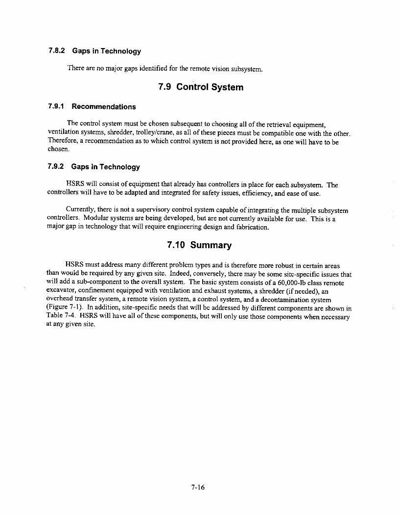
7.8.2 Gaps in Technology
There are no major gaps identified for the remote vision subsystem.
7.9 Control System
7.9.1 Recommendations
The control system must be chosen subsequent to choosing all of the retrieval equipment,ventilation systems, shredder, trolley/crane, as all of these pieces must be compatible one with the other.Therefore, a recommendation as to which control system is not provided here, as one will have to bechosen.
7.9.2 Gaps in Technology
HSRS will consist of equipment that already has controllers in place for each subsystem. Thecontrollers will have to be adapted and integrated for safety issues, efficiency, and ease of use.
Currently, there is not a supervisory control system capable of integrating the multiple subsystemcontrollers. Modular systems are being developed, but are not currently available for use. This is amajor gap in technology that will require engineering design and fabrication.
7.10 Summary
HSRS must address many different problem types and is therefore more robust in certain areasthan would be required by any given site. Indeed, conversely, there may be some site-specific issues thatwill add a sub-component to the overall system. The basic system consists of a 60,000-lb class remoteexcavator, confinement equipped with ventilation and exhaust systems, a shredder (if needed), anoverhead transfer system, a remote vision system, a control system, and a decontamination system(Figure 7-1). In addition, site-specific needs that will be addressed by different components are shown inTable 7-4. HSRS will have all of these components, but will only use those components when necessaryat any given site.
7-16
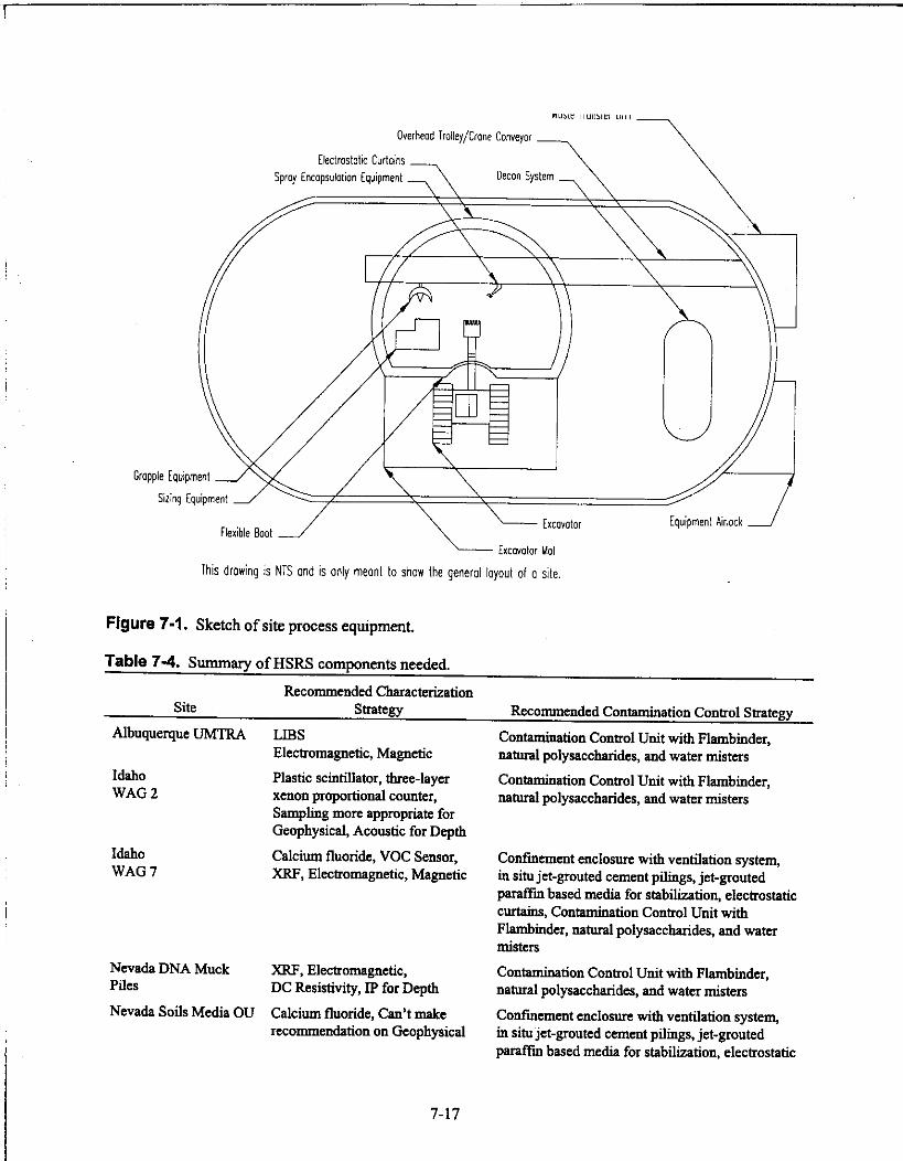
nude umiel unit
Overhead TroJley/Crane Conveyor
Electrostatic Curtains Spray Encapsulation Equipment
Grapple Equipment
Siring Equipment
Flexible Boot
Decoy System
Excavator
Excavator Mat
This drowing is NTS and is only meant to show the general layout of a site.
Figure 7-1. Sketch of site process equipment.
Table 7-4. Summary of HSRS components needed.
Equipment Airlock
Recommended CharacterizationSite Strategy
Albuquerque UMTRA LIBSElectromagnetic, Magnetic
Idaho Plastic scintillator, three-layerWAG 2 xenon proportional counter,
Sampling more appropriate forGeophysical, Acoustic for Depth
Idaho Calcium fluoride, VOC Sensor,WAG 7 XRF, Electromagnetic, Magnetic
Nevada DNA MuckPiles
Nevada Soils Media OU
XRF, Electromagnetic,DC Resistivity, IP for Depth
Calcium fluoride, Can't makerecommendation on Geophysical
Recommended Contamination Control Strategy
Contamination Control Unit with Flambinder,natural polysaccharides, and water misters
Contamination Control Unit with Flambinder,natural polysaccharides, and water misters
Confinement enclosure with ventilation system,in situ jet-grouted cement pilings, jet-groutedparaffin based media for stabilization, electrostaticcurtains, Contamination Control Unit withFlambinder, natural polysaccharides, and watermisters
Contamination Control Unit with Flambinder,natural polysaccharides, and water misters
Confinement enclosure with ventilation system,in situ jet-grouted cement pilings, jet-groutedparaffin based media for stabilization, electrostatic
7-17

Table 7-4. (continued).
SiteRecommended Characterization
Strategy
Oak Ridge WAG 5SWSA 5 South
Oak Ridge WAG 5SWSA 5 North
Oakland LEHR 1 & 5
Richland OU-200 TRUCaissons
Richland OU-200 TRUDrums
Richland OU-300-FF-2Debris
Richland OU 300-FF-2Soil
Calcium fluoride, plasticscintillator, three-layer xenonproportional counter, VOC Sensor,XRF, Electromagnetic, Magnetic
Calcium fluoride, plasticscintillator, three-layer xenonproportional counter, XRF,Electromagnetic, Magnetic
Can't make recommendation onchemical or radiological,Electromagnetic,Magnetic, possiblyground-penetrating radar
Calcium fluoride, Electromagnetic,Magnetic, possiblyground-penetrating radar
Calcium fluoride, plasticscintillator, three-layer xenonproportional counter,Electromagnetic, Magnetic,possibly ground-penetrating radar
Calcium fluoride, Ge spectrometer,Electromagnetic, Magnetic,possibly ground-penetrating radar
Calcium fluoride, Ge spectrometer,Electromagnetic, Magnetic,possibly ground-penetrating radar
Recommended Contamination Control Strategycurtains, Contamination Control Unit withFlambinder, natural polysaccharides, and watermisters
Confinement enclosure with ventilation system,in situ jet-grouted cement pilings, jet-groutedparaffm based media for stabilization, electrostaticcurtains, Contamination Control Unit withFlambinder, natural polysaccharides, and watermisters
Confinement enclosure with ventilation system,in situ jet-grouted cement pilings, jet-groutedparaffm based media for stabilization, electrostaticcurtains, Contamination Control Unit withFlambinder, natural polysaccharides, and watermisters
Can't make recommendation based on lack ofinformation
Confinement enclosure with ventilation system,in situ jet-grouted cement pilings, jet-groutedparaffin based media for stabilization, electrostaticcurtains, Contamination Control Unit withFlambinder, natural polysaccharides, and watermisters
Confinement enclosure with ventilation system,in situ jet-grouted cement pilings, jet-groutedparaffin based media for stabilization, electrostaticcurtains, Contamination Control Unit withFlambinder, natural polysaccharides, and watermisters
Confinement enclosure with ventilation system,in situ jet-grouted cement pilings, jet-groutedparaffin based media for stabilization, electrostaticcurtains, Contamination Control Unit withFlambinder, natural polysaccharides, and watermisters
Confinement enclosure with ventilation system,in situ jet-grouted cement pilings, jet-groutedparaffin based media for stabilization, electrostaticcurtains, Contamination Control Unit withFlambinder, natural polysaccharides, and watermisters
Savannah River 488 D LIBS, Electromagnetic, Magnetic Contamination Control Unit with Flambinder,Ash Basin natural polysaccharides, and water misters
7-18

Table 7-4. (continued).
Site
Savannah RiverLLRWDF/OB G
Recommended CharacterizationStrategy
Calcium fluoride, plasticscintillator, LIDS, XRF,Electromagnetic, Magnetic,possibly ground-penetrating radar
Recommended Contamination Control Strategy
Confinement enclosure with ventilation system,in situ jet-grouted cement pilings, jet-groutedparaffin based media for stabilization, electrostaticcurtains, Contamination Control Unit withFlambinder, natural polysaccharides, and watermisters
7-19
8, REFERENCES
Borns, D. 1,1995, Geophysical Characterization of Subsurface Barriers, SAND 95-1461, SandiaNational Laboratories, Albuquerque, NM, August, 34 p.
DOE (U.S. Department of Energy), 1992, Buried Waste Integrated Demonstration Program Report for1994, DOE/ID-10454, Office of Technology Development.
DOE, 1994a, Technology Catalogue, DOE/EM-0138P, February, p. 131.
DOE, 1994b, Buried Waste Integrated Demonstration (BWID), DOE/EM-0149P, March, p. 21.
EPA (U.S. Environmental Protection Agency), 1988, Guidance for Conducting Remedial Investigationsand Feasibility Studies Under CERCLA, Interim Final, EPA/540/G-89/004, October.
EPA, 1991, Survey of Materials-Handling Technologies Used at Hazardous Waste Sites,EPA/540/2-91/010, Office of Research and Development, June.
Garcia, R. S., 1996, Commercially Available Low-Level Radioactive and Mixed Waste TreatmentTechnologies, DOE/LLW-240, National Low-Level Waste Management Program, October.
Hildenbrand, T. G., 1982, "Models of the southeastern margin of the Mississippi Valley graben nearMemphis, Tennessee from the interpretation of truck-magnetometer data," Geology, Vol. 10,pp. 476-480.
Loomis, G. G., D. N. Thompson, and J. H. Heiser, 1995, Innovative Subsurface Stabilization ofTransuranic Pits and Trenches, INEL-95/0632, December.
Loomis, G. G., A. P. Zdinak, and C. W. Bishop, 1996, Innovative Subsurface Stabilization Project-Final Report, INEL-96/0439.
Meyer, L. C., 1992, Electrostatic Curtain Studies, EGG-WTD-10255, EG&G Idaho, Inc., May.
Reichhardt, D. K., A. T. Hart, and J. D. Betsill, 1997, Principles and Objectives of ContainmentVerification and Performance Monitoring and Technology Selection, SAND-97-0111C, SandiaNational Laboratories, Albuquerque, NM, January, 7 p.
Rice, P. and J. Skaggs, 1993, Removal of Overburden Soils from Buried Waste Sites, EGG-WTD-10767,EG&G Idaho, Inc. and Sonsub, Inc., October.
Sackschewsky, M. R., 1993, Fixation of Soil Surface Contamination Using Natural Polysaccharides,WHC-EP-0688, Westinghouse Hanford Company, Richland, WA, September.
Thompson, D. N., A. L. Freeman, and V. E. Wixom, 1993, Evaluation of Contamination Control UnitDuring Simulated Transuranic Waste Retrieval, EGG-WTD-10973, EG&G Idaho, Inc., November.
Valentich, D. J. and E. L. Yokuda, 1992, Final Report for the Cryogenic Retrieval Demonstration,EGG-WTD-10397, EG&G Idaho, Inc., September.
8-

Valentich, D. J., 1993, Full-Scale Retrieval of Simulated Buried Transuranic Waste, EGG-WTD-10895,EG&G Idaho, Inc., September.
Winberg, M. R. and V. E. Wixom, 1992, Fugitive Dust Control Experiments Using Soil Fixatives onVehicle Traffic Surfaces, EGG-WTD-10354, EG&G Idaho, Inc., August.
Winberg, M. R. et al., 1992, Fugitive Dust Control Experiments Using Directed Airflow in DumpingOperations, EGG-WTD-10360, EG&G Idaho, Inc., July.
Zimon, A. D., 1982, Adhesion of Dust and Powder, 2nd ed., Consultant Bureau, New York, NY.
8-

Appendix A
Responses to Contamination Control Commerce BusinessDaily Advertisement

Appendix AResponses To Contamination Control Commerce Business Daily Advertisement
Info.Company, Contact, & Phone Number Rec'd Phone Conversations Action ItemsApplied Geotechnical Engineering &Const., Inc.
Seleste WilliamsRichland, WA(509) 946-0338
Auclair & AssociatesKim Auclair(360) 887-4651 phone; WA(360) 905-871I pager
BDM Petroleum TechnologiesScott Baileyhttp://www.bdm.com
Biorem TechnologiesBrian Herner(519) 767-9100; Canada
Yes Letter received 2/13/97.
No February 13, 1997: Worked on some projects for BWID - has worked withAaron Armstrong. Solution providers, not widget people. Will send resume,references within LMITCO, etc.
Talked to him again on February 14, 1997. He will fax some information thisafternoon or Monday.
Left message 2/26/97 @ 4:15. Talked to him 2/27/97 @ 10:21. Putting apackage together with cradle-to-grave info. Wrapping up and will get to meFriday aft (2/28) or Monday morning.
Yes January 30, 1997; 12:00 p.m.: Located in Oklahoma. Their technologies incontamination control have not been demonstrated. Have 15 full-service labs,subsurface flow properties - product movement migrations. Wanted to know ifI wanted a pre-proposal, full proposal, etc. Told him we are just looking forinformation right now. Anything he has will be looked at.
No February 12, 1997 @ 7:30: Works with USITA, a group in Ontario, Canada,who does environmental technologies advancements. They have a technologythat actually reduces the amount of contaminants in the soil (hazardous only).Told him we are looking at any and all technologies at this stage, not limiting itto just contamination control per se. His phone number is (519) 767-9100 andhe is located in Gulbf, near Toronto.
Call and get moreinformation - letterdoes not explaintechnologies
N/A - does not haveany technologiesper se - he is a one-man consultingengineering firm.
What kind of soilsdoes this work in?
How is it applied?
Call him and see ifhe has/is going tosend something.

Company, Contact, & Phone NumberInfo.Rec'd Phone Conversations Action Items
Consolidated Power SupplyTim Bollinger(205) 655-5515; Alabama
Container Products CorporationJames Grantham(910) 392-6100; NC
CoreGroup ServicesKarl Ashley(352) 332-7411; Atlanta, Georgia
Yes February 14, 1997: Got our RFI out of Defense Cleanup Magazine. Does SSTclean up - decon aspect. Mainly do metals - have worked with NASA. Will faxme some information.
Yes No Call - Just sent information. Have waste compactor forhazardous/radioactive waste - 10,000,000-lb ram force in negative-pressure airevacuation-filtration closure system of SST. Weighs boxed waste whenfinished - need more information on how waste is loaded into system andexactly what type of containers can put waste in - how containers areIoaded/unloaded.
Yes February 13, 1997 @ 3:00: Has done work at Savannah River with Tom Hicks.Has a fast cast resin - control cure to between 5 seconds and 30 minutes. Is aspent waste resin - so already a waste, not creating more.
Has three different things can do:1. Solidify contents inside a vessel.2. Upon removal of waste, can cocoon waste with this resin.3. Add mix with soil - make resinous bricks of soil.
Not applicable toHSRS - supplymetal.
Applicable to wastetransfer portion -Call for more info.(see comments)
Letter/reporthow/which way wedecided to go. Sendto everyone.

Info.Company, Contact, & Phone Number Rec'd Phone Conversations Action Items
Yes February 21, 1997 @ 9:30: Called to see if I received information. Have tomix his resin with the soil. Spray on and zap with microwave to cure - forms acover over waste. A blow torch does not affect resin. Solidified in place -along with rocks, trees, etc. Mix in place with augers, etc. Resinous cast cover- lets water out. Soil is a filler - use hazardous waste fillet - waste in that itdoesn't meet spec for material (i.e., too much activator - not toxic but won'twork in industry.
If a drum is leaking - can cocoon it in 5 seconds to stop leak. Can be remotelyoperated - spray on and then just need a triggering burst, or catalyst, frommicrowave, which starts the reaction. They figure out the minimum amount ofpolymer in the resin that will work with what want to solidify.
Resin is like a cement type of thing - a lot of filler, not a lot of concrete. Doesn'tknow how cost effective it is. Passes Tclip tests at 98 - 100% cross-linking.Honey type substance - can be pumped or injected.
Look in DOE Rainbow Books theory. Can excavate buried debris - would haveto know chemistry of stuff. Could have drums with or without liquid, nodrums, etc. Asked him how to apply and how to mix. Said doesn't know - hedoesn't want to compete with us, but has engineering. People who could helpdetermine chemistry, etc., but let us apply as we have technology, badges, siteaccess, etc. I said we may design equipment to apply his stuff - who knows.May lead to sub-contract, procurement, etc. Who knows? Told him on 2/21/97@ 9:30: about hot spots, have >3000 sites - not sure where we're going, wepicked 14 with various types of contaminants. Some will be remote, some maynot be. Asked me if we were going to write a letter or something once we haveall of the information and let people know which way we're going. Told himwe were dealing with existing equip. only at this point.

Info.Company, Contact, & Phone Number Rec'd Phone Conversations Action ItemsDelta 21 ResourcesDave Samples(509) 375-5191; Hanford
Enviro SearchMike May(208) 345-8292; Boise
EnviroConLaurie Matthews(406) 523-1150; Montana
Foster-MillerBlair Hough(617) 684-4000; Bostonhttp://[email protected]
Yes February 6, 1997 @ 4:24: Working with Canadian firms in British Columbia.He will be in BC through Friday and can be reached at Anton Kuipers office(604) 844-1914. He called again and left number at Hanford (509) 375-5191. Ireturned call 2/7/97 @ 2:55. No answer. Finally talked to him February 10,1997. Told him we are in information gathering stages only. He was actuallyglad to hear that. He will FED EX me information. It should be here byWednesday, February 12, 1997. If we were not only gathering information, heprobably couldn't have responded. He will be sending a video tape showingtheir technologies.
No February 3, 1997 @ 10:07: Left message. Phone is (208) 345-8292. Calledhim back on Friday, February 7, 1997. He has a consulting firm and wanted toknow if we needed hard core engineering stuff. I told him we are looking forexisting technologies at this time that we could just take and use.
No January 29, 1997; 9:36 a.m.: Wanted a copy of the CBD announcement thatwent out. I didn't actually talk to her, but to her secretary. I faxed a copy of theCBD pulled off the Internet and sent to (406) 543-7987 (FAX).
Yes No call - just sent information.
I don't think he willbe sendinginformation.
I don't think shewill be sendinginformation

Company, Contact, & Phone NumberInfo.Rec'd Phone Conversations Action Items
IsotronHenry Lomasney(504) 254-4624; New Orleanshttp://[email protected]
McCabe Brothers Drilling & DuragardCoatings
Jim Barrett(208) 522-5437; Idaho Falls
MEC SystemsDarrell/Peter Melnyk(604) 792-7779; BC, Canadawww.ntonline.corn/[email protected]
NumatechGary Speegan(208) 526-0034; Idaho Falls
Yes No call - just sent information. Has a spray-poly technology which can besprayed onto equipment and then peeled off later, taking the contamination withit. Information is sketchy as to what it can adhere to, how durable it is, etc.
Yes January 29, 1997; 8:00 a.m.: Has a CRADA/LDRD to do DOT testing ofencapsulated drums - 100% portable. The drums are also 100% waterproofonce encapsulated.
This company owns a patent on equipment that encapsulates soil/contaminatedsoil with a 100% permeable barrier. The chemicals used are sold by anothercompany.
Any size area can be done. What they do is dig deep wells around the perimeterof the pit/trench/whatever and inject polyurethane under extremely highpressures. This flows wherever water can flow. They then test the digface toensure complete saturation. The soil can then be excavated, dust free.
He will compile an information catalog and get it to me. He has only beenworking with this company for a couple of weeks, so has to actually put acatalog together.
February 3, 1997 @ 1:07: His number is 524-0684. Larry Whitmill has info.
Yes February 4, 1997 @ 4:25: Water misters. His phone is (604) 792-7779. Leftmessage 2/7/97 @ 3:25. They only work Monday - Thursday. Talked to himon 2/10/97. He works for the same company as Peter Melnyk - I receivedinformation from him today (2/10/97).
No February 7, 1997 @ 4:00: Talked to him, told him what I needed. His phone I don't know if henumber is 526-0034. will send info.

Company, Contact, & Phone NumberInfo.Rec'd Phone Conversations Action Items
Pacific Chemicals Inc.Clyde Waselenkoff(604) 828-0218; BC, Canada
Sensor ApplicationsRick Krahe(703) 759-6000; Virginia
SESCDonald Engelman, P.O. Box 840Richland, WA 99352
Sevenson Environmental ServicesChuck McPheeters(812) 988-9930
Yes February 6, 1997 @ 12:34: His number is (250) 828-0218 in British Columbia.Has a complete package together and wants to know time frame - should heFED EX or mail? I talked to him on 2/10/97 - he will mail the package todayand I should have it some time next week. He works a lot in western U.S. andhas won awards for environmentally sound work. Has 2 emulsion facilities.They can specially create products for us, including some that make waste smellbetter. Did one for Hanford so that waste smelled like vanilla. Will send info.
Yes January 30, 1997: They have a mobile trailer with programmable chemicaldetectors. Two people here at LMITCO have seen it demonstrated - Don Virile(6-2286) and Ken Watts (6-9628). They train people on their equipment. M90chemical detector. His phone number is (703) 759-6000.
I told him we want a mobile system, we are in conceptual phase, haven'tdesigned system yet, want dust suppression, contamination control for alpha,beta, and gamma contamination.
He will send information.
Yes Sent letter - did not send literature.
No February 14, 1997 : Responding to RFI - will get something to me by 2/28/97.Talked again 2/27/97 @ 9:57. Is over-nighting a package FED EX. Told himinformation didn't have to be in until next week as several people were going tobe late, so he is going to take advantage of extra time. Will get back next week.
Not applicable -detectors do notwork in soil - onlyin ambient air
Not applicable -provide engineeringservices only - donot have their owntechnologies
Expect by 3/7/97
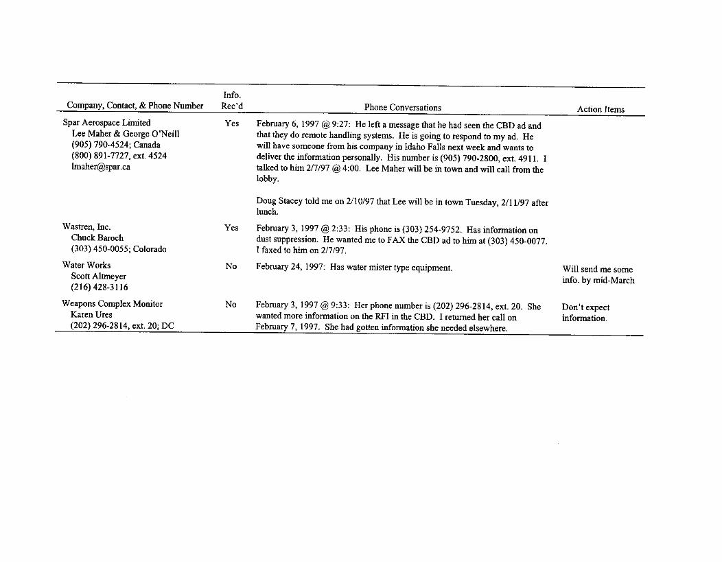
Company, Contact, & Phone NumberInfo.Rec'd Phone Conversations Action Items
Spar Aerospace LimitedLee Maher & George O'Neill(905) 790-4524; Canada(800) 891-7727, ext. [email protected]
Wastren,Chuck Baroch(303) 450-0055; Colorado
Water WorksScott Altmeyer(216) 428-3116
Weapons Complex MonitorKaren Ures(202) 296-2814, ext. 20; DC
Yes February 6, 1997 @ 9:27: He left a message that he had seen the CBD ad andthat they do remote handling systems. He is going to respond to my ad. Hewill have someone from his company in Idaho Falls next week and wants todeliver the information personally. His number is (905) 790-2800, ext. 4911. Italked to him 2/7/97 @ 4:00. Lee Maher will be in town and will call from thelobby.
Yes
No
No
Doug Stacey told me on 2/10/97 that Lee will be in town Tuesday, 2/11/97 afterlunch.
February 3, 1997 @ 2:33: His phone is (303) 254-9752. Has information ondust suppression. He wanted me to FAX the CBD ad to him at (303) 450-0077.I faxed to him on 2/7/97.
February 24, 1997: Has water mister type equipment. Will send me someinfo. by mid-March
February 3, 1997 @ 9:33: Her phone number is (202) 296-2814, ext. 20. She Don't expectwanted more information on the R.FI in the CBD. I returned her call on information.February 7, 1997. She had gotten information she needed elsewhere.

Appendix B
Confinement Structure Data From Scientech

Appendix B
Confinement Structure Data From Scientech
Manufacturer Type MaterialNegative Snow, Foundation
Size Pressure Wind Load Requirements LightInfiltration
Sprung instant structures
Rubb building systems
Weather block
Anchor industries
Weather - port
Environmental structures
American structuralcomposites
Cover it
United partition systems
Sheds america
Fabric tensioned, PVC-coated fabric,aluminum I beamframe
metal frame
Fabric tensioned,metal frame
Fabric tensioned,metal frame
Width 30' - 130' Yesheight 16' - 50'
PVC-coated fabric, Width 30' - 250' Yesgalvanized steel height >16'frame
Fabric tensioned, 20-oz. vinyl,metal frame aluminum box beam
frame
Fabric tensioned,metal frame
Air supported,double wall
Width 12' - 300' Yesheight up to 50'
Width 30' - 100'height >18'
Galvanized steel Width 8' - 100 inframe
18 -24 psf Earth auger 18 in. Opaque130 mph flap w/skylight
20 -30 psf Earth auger base Good80 mph angle
20 - 30 psf Earth auger ground Translucent120 mph rail
20 -30 psf Concrete pier for80 mph base plate
Polyethylene fabric, Width 20' - 300' No Designed toEarth augersteel cables height >20' shed
The following systems where investigated and are not recommended for this application:
Pre-moldedmodular units
Fabric tensioned,metal frame
Modular panels,indoor use only
Metal buildingsand panels
Aluminum andfiberglass faced
Fiberglass Smaller housingunits
PVC-coated fabric, Width 4' - 50' No Light dutyaluminum frame height 30'
Vinyl-clad hardboard Unlimited Noheight 8' - 20'
Smaller units No
Concretefoundation
Earth auger
Concrete slab
Concrete slab
No

Appendix C
Waste Minimization, Separation, & DecontaminationCommerce Business Daily Responses

Appendix C
Waste Minimization, Separation, & Decontamination Commerce Business DailyResponses
Company, Contact, & PhoneNumber Info. Rec'd Phone Conversations Action Items
Absolute Control Systems Yes - letter and Letter dated 3/25/97 to Steve Swanson - isolation barrier systems.Eliot J. Cook brochure(303) 420-8622E-mail: [email protected]
Advanced Sciences No Called 3/21/97 in response to March 19, 1997 CBD announcement to ask if this None - didn'tScott Ploger is DOE complex wide or on site (INEEL) only. soundIdaho Falls, ID
interestedAdvanced Sciences, Inc. Yes - letter No call - just sent information package.Subsidiary of Commodore and brochuresApplied Technologies
Peter E. Harrod, P.E.(505) 872-3508
Alternative Remedial Yes - letter & No call - just sent information dated 3/24/97 - response to WasteTechnologies, Inc. catalog Segregation/Separation.
Jill C. Besch(813) 264-3506; Tampa, FL
Avondale Shipyards Division Yes - letter and Construct toxic waste incineration units to be employed during excavation and NotJulius A. Laurent photo retrieval of buried hazardous waste. applicable to(504) 436-2121
HSRS -treatment
BPF Yes - letter & Called —3/25/97 in response to 3/19/97 CBD announcement. They have a smallDr. Tom Bush abstract business that deals in radiation waste in the oil field. Two years into the process.(972) 709-3890; TX Scaling up - built for use in commercial operations. Will send more information.(972) 709-3899 FAX
A-1

Company, Contact, & PhoneNumber Info. Rec'd Phone Conversations Action Items
CanberraJudy Miller
CGR Compacting Inc.Bill Lyons(413) 664-1076; MA
Chow EngineeringBruce Clark(510) 636-8500; Oakland, CA
Container Products CorporationJames Grantham(910) 392-6100; NC
CoreGroup ServicesKarl Ashley(352) 332-7411; Atlanta,
Georgia
Corpex TechnologiesTom Morris(919) 941-0847
Donivan DemolitionsJeff Panarelli(talked to Steve)(502) 676-3192
Yes - letter andbrochure
Yes - letter andbrochure
No - as of4/10/97
Yes -informationpacket and 2videos
Yes - receivedinformationundercontaminationcontrol CBD
Yes - letter andtechnicalreports
Called 3/31/97 in response to 3/19/97 CBD announcement. Will FED EX me apackage.
No call - just sent information. Has done low level radioactive wasteminimization before at several labs.
Called 3/26/97 in response to 3/19/97 CBD announcement and left message.Wanted more information. Finally talked to him 3/27/96 - he will be sending mesome information on decontamination technologies.
No call - just sent information. Have waste compactor for hazardous/radioactivewaste - 10,000,000-lb ram force in negative-pressure air evacuation-filtrationclosure system of SST. Weighs boxed waste when finished - need moreinformation on how waste is loaded into system and exactly what type ofcontainers can put waste in - how containers are loaded/unloaded.
Called —3/31/97 in response to 3/19/97 CBD announcement. Has a fast castwaste resin. His people are Level C Hazwoppers. They can do the setup andstaging the first time and show us how it is done - labor is the big cost in thistechnology. They enhance polymers - application is where the money becomesan issue. Torn Hicks at Savannah River has been very interested in it. Theywould have to engineer an application technique for us - does not work withplain soil washing process. To get rid of PCBs, have a solvent extraction phase -actually removes solvent. Based on simple classification system. Separation -cleaning up of soil.
Called 4/1/97 in response to 3/19/97 CBD announcement. Requested address forFED EX.
No Called 3/31/97 in response to 3/19/97 CBD announcement. Left message to callhim back, but he talked to Steve Swanson instead.
Look into thisfurther - looksgood

Company, Contact, & PhoneNumber Info. Rec'd Phone Conversations Action Items
EET, Inc.Michael E. Bonem(713) 662-0727
Enviro-PakMike Resweber(800) 737-5533
Filtration Treatment SystemsChris Montovino(206) 872-9007; Seattle, WA
Frisby TechnologiesMamie Studdard(803) 642-0296
GapVaxMatt Hughes(800) 535-4717(814) 535-6766
Global DewateringMr. Deb Scott(403) 440-4848; based in
Canada
Yes - letter and Chemical decontamination process.brochures
Yes- letter andbrochures
Yes - brochure
Yes
Yes - letter andbrochures
Yes - binder
No call - received 4/10/97.
Called —3/31/97 in response to 3/19/97 CBD announcement. (Actually saw ad inPacific Northwest Catalyst.) Responded to waste minimization and segregation.Has equipment to do soil washing with nuclear waste. Could provide part of theequipment. Use soil screen - screen out larger chunks - let finer soil settle out.Use different soil screens with different sieve sizes - these screens vibrate. Willsend more information.
Sent letter dated March 27, 1997 requesting specifications for theDecontamination, Waste Minimization, and Waste Segregation/SeparationTechnologies - addressed to Ms. Godbee. Doesn't mention what kind oftechnologies they have.
Sent information on single mode vacuum loaders.
Called 3/31/97 in response to 3/19/97 CBD announcement. Called on wasteminimization techniques. Will send an information book via courier. Workswith NAFTA in USA.
Where is soilwashingequip?How mobile?
Notapplicable.
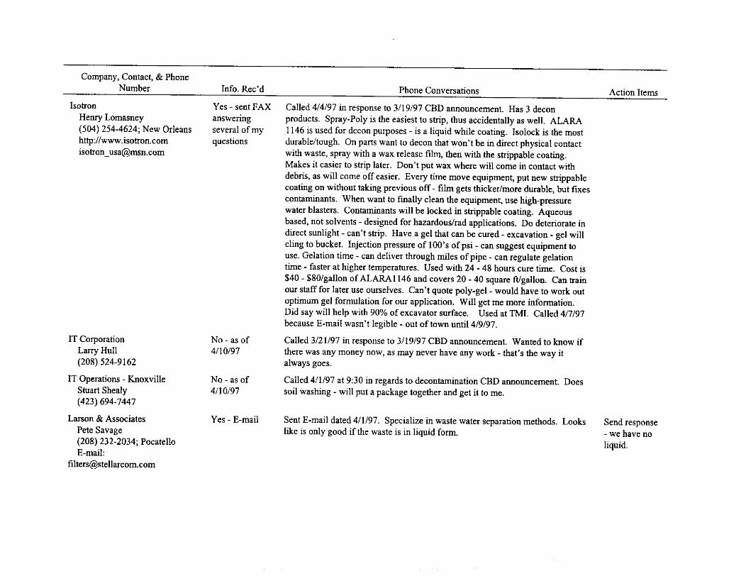
Company, Contact, & PhoneNumber Info. Rec'd Phone Conversations Action Items
IsotronHenry Lomasney(504) 254-4624; New Orleanshttp://[email protected]
IT CorporationLarry Hull(208) 524-9162
IT Operations - KnoxvilleStuart Shealy(423) 694-7447
Larson & AssociatesPete Savage(208) 232-2034; PocatelloE-mail:
Yes - sent FAXansweringseveral of myquestions
No - as of4/10/97
No - as of4/10/97
Yes - E-mail
Called 4/4/97 in response to 3/19/97 CBD announcement. Has 3 deconproducts. Spray-Poly is the easiest to strip, thus accidentally as well. ALARA1146 is used for decon purposes - is a liquid while coating. Isolock is the mostdurable/tough. On parts want to decon that won't be in direct physical contactwith waste, spray with a wax release film, then with the strippable coating.Makes it easier to strip later. Don't put wax where will come in contact withdebris, as will come off easier. Every time move equipment, put new strippablecoating on without taking previous off - film gets thicker/more durable, but fixescontaminants. When want to finally clean the equipment, use high-pressurewater blasters. Contaminants will be locked in strippable coating. Aqueousbased, not solvents - designed for hazardous/rad applications. Do deteriorate indirect sunlight - can't strip. Have a gel that can be cured - excavation - gel willcling to bucket. Injection pressure of 100's of psi - can suggest equipment touse. Gelation time - can deliver through miles of pipe - can regulate gelationtime - faster at higher temperatures. Used with 24 - 48 hours cure time. Cost is$40 - $80/gallon of ALARA1146 and covers 20 - 40 square ft/gallon. Can trainour staff for later use ourselves. Can't quote poly-gel - would have to work outoptimum gel formulation for our application. Will get me more information.Did say will help with 90% of excavator surface. Used at TMI. Called 4/7/97because E-mail wasn't legible - out of town until 4/9/97.
Called 3/21/97 in response to 3/19/97 CBD announcement. Wanted to know ifthere was any money now, as may never have any work - that's the way italways goes.
Called 4/1/97 at 9:30 in regards to decontamination CBD announcement. Doessoil washing - will put a package together and get it to me.
Sent E-mail dated 4/1197. Specialize in waste water separation methods. Lookslike is only good if the waste is in liquid form.
Send response- we have noliquid.

Company, Contact, & PhoneNumber Info. Rec'd Phone Conversations Action Items
McLeran-HeartDale Richards(714) 756-2667; CA
Yes - letter andbrochures
Mercury Recovery Services Yes - letter andChris Kelly brochures(412) 843-5000; PA
Multi-Media Resource Recovery No - as ofSystems 4/10/97
Pete Rosell
Called 4/1/97 in response to 3/19/97 CBD announcement. Works in wasteminimization. Works with Chem-Risk. All of his people are Q cleared. Hasworked with Dave Eve? In mixed waste at the site. Has done 3 jobs for RockyFlats - thermally desorbed off RCRA components - created non-mixed waste -saved $2M - 33 months ahead of schedule. Real world stuff - typical chlorinatedmercury and PCB. Unique technology - pull vacuum at 28 in. mercury - watercoming off as is being heated due to vacuum. Is a batch process which is mobileand can be deconned easily. Can control dust. Can handle debris - have donerailroad ties. If it can be thermally desorbed, it can be put in there. Mercury isthe big one. Can't handle liquids, but can sludges (low level heating sludge.)Could work with resins - depends - would have to be looked at further. Consistsof a big tray the size of a mini van. Infrared heat waste in an inert atmosphere(closed system) - have filters in-line. Commercially available - willing to jointventure. Won't work everywhere - does work in clay soils. If you can circulateair through waste matrix - it should work. The higher boilers are better -Savannah River/Westinghouse likes it. Dr. John Allen in the EPA is aware of itand approves, but does not have final EPA paperwork. Has brought PCB levelsbelow EPA limits - started at 37,000 ppm. It costs —$350/cubic yard at RockyFlats - includes disposal. There is a conference in Arizona put on by ClydeFrank, Western governors, and Complex Monitor. Cleanup technologies.Could come up and do a demo - company has been around for 20 years. Can doarea-wide risk assessments - can help determine clean-up levels. Do RiskBased Cleanup Areas (RBCA) - cleanup levels are based on Universal TreatmentStandards. Said risk assessments are based on 60% ecological issues, 40%human issues. Argonne has called them in to do drums with TOXCA waste.
Called —3/24/97 in response to 3/19/97 CBD announcement. Have a patentedprocess in which mercury in all forms can be extracted from mixed waste. Haveunits in the field and are in commercial production.
Called 4/4/97 at 9:15 in response to CBD ad placed on 3/19/97. Does mineralprocessing/soil washing work. Treats the water used in the soil washing. Needclean water in the final rinse - use clean water as make-up water. Told him hehad until April 14 to get me information. Said he would FAX something.
Look throughin detail -may go intreatment fileand not insystemdescription.
If don'treceiveinformationby 4/16/97 -call him

Company, Contact, & PhoneNumber Info. Rec'd Phone Conversations Action Items
Non-Destructive Cleaning Yes - letter andPatrick Gillis brochure(508) 660-3064
Nuclear Fuel ServicesStephen Schutt(423) 743-9141; Tennessee
Nuclear Fuel Services Yes - letter andJames V. Mohatt brochure(509) 943-0639; Richland, WA
Nuclear Metals No - as ofBill Quapp 4/10/97(208) 535-9001; Idaho Falls
RadComp, Inc.Bob Diorio(410) 964-2400
SSI Shredding Systems, Inc.Joyce Beasley, Technical Sales(503) 682-3633; Wilsonville,
OR
Yes - letter andbrochures
Yes -informationpacket
Called 4/9/97. Will be sending some information regarding decontaminationtechnologies. Told her still accepting information through 4/14/97.
Yes - letter and No call - just sent information on decon and volume reduction system (DVRS)brochure
Called 4/1/97 at 9:30 in response to 3/19/97 CBD announcement. Will FAXsomething by tomorrow (4/2/97).
Called 4/4/97. Used to manage EM-50 work here - said he has worked withReva before. Will call in a couple of weeks to show me how his ceramicsstabilization process works - if can stabilize anything - will be the mosteconomical. As soil is mainly metal oxides, this process incinerates the oxides.Ceramics are thermodynamically stable at 1,000 - 1,200 F, arsenic is not. Notclear arsenic did not work with this process - not enough data yet. Cesiumalways a problem. Most grout doubles/triples the volume. Always 20%reduction - depends on hydrated waters - factor of 80% reduction. If conditionsare right, mass lost during process. Systems use binders - adds 10% mass ofadditives - approaches 85% crystal density. Doesn't treat drums. Did demo ofWERF ash. Only good for granular types of matrices.
Called/FAXED response to CBD ad placed on 3/19/97 on 413197. Has a newdecon shower with three sections, one to remove contaminated clothing, one fora shower, and one to dress in clean clothing. Will send information.
Didn't call - just sent information.
Will call in acouple ofweeks withmoreinformationor come talkto me.
Notapplicable tous - justwanted me topass on toanyone whocould use it.

Company, Contact, & PhoneNumber Info. Rec'd Phone Conversations Action Items
Stone Bridge FacilitiesGerrit Boyle(206) 889-1205
Thermo NuTechChuck Hater(510) 427-1094(908) 469-5050, room 248 until
4/14
Wastren, Inc.Bob Morris(970) 248-6704
Yes -photographs
Yes -brochures, info- need moretechnical
No - as of4/10/97
Called 4/7/97. Had talked to Del Browning at Alpha Engineers when he wasresearching the confinement structures for us and wanted to know if I had theinformation he had provided. I couldn't place it when we were on the phone asthe name he gave was Weather Pole structures - found info. later under WeatherBlock structures with a sticky with his name on it. He is sending moreinformation anyway. (Info came in - not same info - not complete - no technicaldata whatsoever.)
Called 4/4/97 in response to ad in Defense Cleanup Magazine. His technology iscalled the segmented gates process. Is a waste minimization technology. TerryStoddard at INEEL has done cost benefit analysis on it. He has done work @ Pit9 from Sept - Jan of 96/97 processing soil. Going to do overburden removal -field tested and proven. Cesium processing is no problem. Going to sendpackage FED EX. Karen Garcia is following this company. She was given MikeBrennan of Westinghouse and Jason Darby of DOE, Oakridge as POCs.
Called 3/21/97 in response to March 19, 1997 CBD announcement. Has severalretrieval technologies. Has worked with Mike Sandvig (Health & SafetyManager for B&W up at TAN). Mike is sending 2 - 3 people to Grand Junctionon April 7, 1997 to a demonstration of the technologies used @ Los Alamos(opened 1,400 drums). Non-technical type of deal. Sort, survey, decon.Sampling and rad surveys done at Mound - their technology proved inventoriesnot truly mixed. Will put data package together and send it.
Call him - hesent notechnicalinformationwhatsoever
Talk to KarenGarciawhether ornot shecontactedPOCs.
If don'treceiveinformationby 4/16/97 -call him

Appendix D
Excavator Evaluations

Comments
Sheetl
LMAES Teleoperated Excavator This system is unable to lift a 4 000 Pb toad. The control system can be applied tq a larger excavator This current system must be leased and may be difficult with decontamination and scheduling, Cost is based on leasing.Criteria Weighting % Overall Weighting % Rating Score
Implemental:10y 25
Mobilization 25 6.25 7Demobilization 25 6.25 7#People for mob and demob 20 5 7Maintenance 30 7.5 7
Cost 15
Initial capital cost 50 7.5 0Modification cost 30 4.5 7Maintenance cost 10 1.5 7#Required operators 10 1.5 10
Effectiveness 60
Throughput 40 24 10Robustness/reliability 40 24 10#Required operators 20 12 10
43.7543.75
3552.5
Score 1 175
031.510.515
240240120
Score 2 57
Mobilization and demobilization will be graded on the amount of time required to perform the task:<30 min=10 <1 hr=8 <1.5 hr=6 <2 hr=4
#People required to mobilize and demobilize will be scored as follows: 10-2=10 3-4=8
Maintenance will be scored according to the ease: remotely=10
Initial capital costs wilt be scored as follows:
5-6=6 7-8=4
Score 3 600Total Score 832
<2.5 hr=2
9-10=2
>3 hr=0
<10=0
with anti-c's=7 cannot maintenance=0
10-$199K=10 $200K-$399K=8 $400K-$599K=6Modification costs will be scored as follows:
$600K-$799K-=4 $800K-$1000K=2 >$1000K=0
Ino modifications = 10 some modifications = 7Maintenance costs will be scored as follows:
'Jess than average maintenance required = 1( average maintenance = 7Throughput of the system will be graded as follows:
<15 cu.m/hr=10Robustness will be scored as follows:
15-13 cu.m/hr=8 12-11 cu.m/hr=6
designed for UXO/radthaz=10#Required operators will be scored as follows:
1=10
10-9 cu.m/hr=4
designed for rad/haz=7
2=8 3=6 4=4
serious modifications = 5
more than average maintenance = 5
8-7 cu.m/hr=2 >7 cu.rn/hr=0
designed for haz=5
5=2 <5=0
Page 1

Sheer!
Comments _
LMTO AOE ExcavatorThis system is ed on a Caterpillar 325L excavator and possesses remel iong r ach and depth capabilities.LMTD could remote an exc,zrator if a joint research effort was developed. Othe ise a subcontractor would perform the work.Criteria Weighting % Overall Weighting % Rating Score
implementability 25
Mobilization 25 6.25 10 62.5Demobilization 25 6.25 10 62.5#People for mob and demob 20 5 8 40Maintenance 30 7.5 7 52.5
Score 1 217.5Cost 15
Initial capital cost 50 7.5 8 60Modification cost 30 4.5 7 31.5Maintenance cost 10 1.5 7 10.5#Required operators 10 1.5 10 15
Score 2 117Effectiveness 60
Throughput 40 24 7 168Robustness/reliability 40 24 10 240#Required operators 20 12 10 120
Score 3 528Total Score 862.5
Mobilization and demobilization will be graded on the amount of time required to perform the task:<30 min=10 j<1 hr=8 <1.5 hr=6 <2 hr=4 <2.5 hr=2 >3 hr=0
#People required to mobilize and demobilize will be scored as follows:0-2=10 3-4=8 5-6=6 7-8=4 9-10=2 <10=0
Maintenance will be scored according to the ease:remotely=10 with anti-c's=7 cannot maintenance=0
Initial capital costs will be scored as follows:I0-$199K=10 $200K-$399K=8 $400K-$599K=6 $600K-$799K=4 $800K-$1000K=2 >$1000K=0
Modification costs will be scored as follows:no modifications = 10 some modifications = 7 serious modifications = 5
Maintenance costs will be scored as follows: rless than average maintenance required = 1(average maintenance = 7 more than averse maintenance = 5
Throughput of the system will be graded as follows: <15 cu.m/hr=10 15-13 cu.m/hr=8 12-11 cu.m/hr=6 10-9 cu.m/hr=4 8-7 cu.m/hr=2 >7 cu.rn/hr=0Robustness will be scored as follows: designed for UXO/rad/haz=10 designed for rad/haz=7 designed for haz=5#Required operators will be scored as follows:
1=10 2=8 3=6 4=4 5=2 <5=0
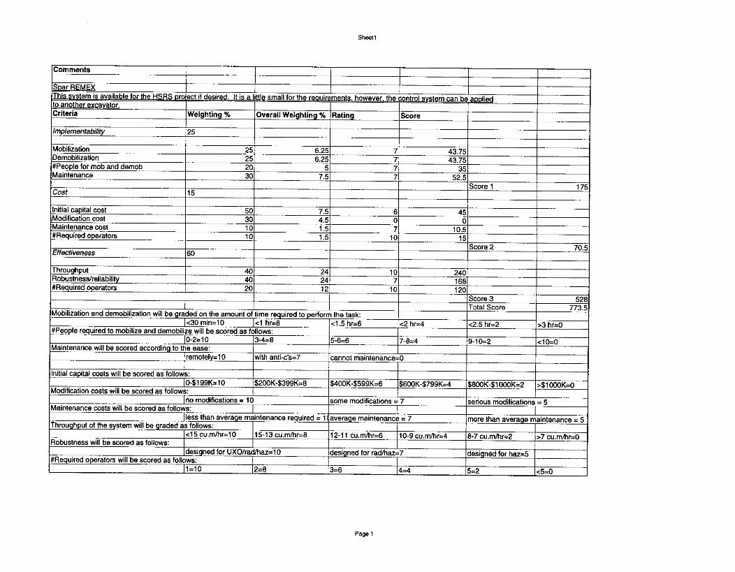
Shavit
Comments
Spar REMEXThis system is av_ailable for the I-I..5RS pro ect if desired. It is a little small for the requirements,however, the control system can be appliedto another excavator. Criteria Weighting % Overall Weighting % Rating Score
Implementability 25
Mobilization 25 6.25 7 43.75Demobilization 25 6.25 7 43.75#People for mob and demob 20 5 7 35Maintenance 30 7.5 7 52.5
Score 1 175Cost 15
Initial capital cost 50 7.5 6 45Modification cost 30 4.5 0 0Maintenance cost 10 1.5 7 10.5#Required operators 10 1.5 10 15
Score 2 70.5Effectiveness 60
Throughput 40 24 10 240Robustness/reliability 40 24 7 168#Required operators 20 12 10 120
Score 3 528.Total Score 773.5
Mobilization and demobilization will be graded on the amount of time required to perform the task:<30 min=10 <1 hr=8 <1.5 hr=6 <2 hr=4 <2.5 hr=2 >3 hr=0
#People required to mobilize and demobilize will be scored as follows:I0-2=10 3-4=8 5.6=6 7-8=4 9-10=2 <10=0
Maintenance will be scored according to the ease:remotely=10 with anti-c's=7 cannot maintenance=0
Initial capital costs will be scored as follows:[0-$199K=10 $200K-$399K=8 $400K-$599K=6 $600K-$799K=4 $800K-$1000K=2 >$1000K=0
Modification costs will be scored as follows:no modifications = 10 some modifications = 7 serious modifications = 5
Maintenance costs will be scored as follows: Iless than average maintenance required = 11average maintenance = 7 more than average maintenance = 5
Throughput of the system will be graded as follows:<15 cu.m/hr=10 15-13 cu.m/hr=8 12-11 cu.mlhr=6 10-9 cu.m/hr=4 8-7 cu.m/hr=2 >7 cu.m/hr=0
Robustness will be scored as follows:designed for UXO/rad/haz=10 designed for rad/haz=7 designed for haz=5
#Required operators will be scored as follows:12=81=10 3=6 4=4 5=2 <5=0

Appendix E
Confinement Structure Evaluations
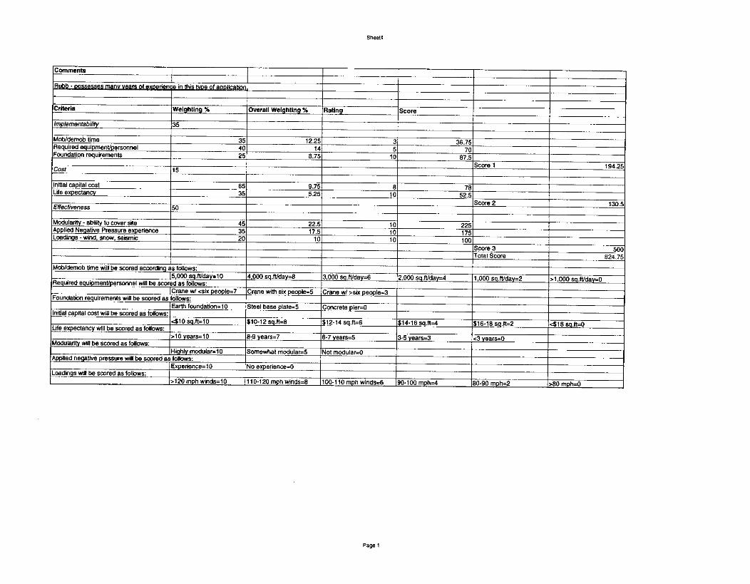
Sheell
Comments
,Bubb -possesses many years of expzience in thiLlype of aoolicatior
Criteria Weighting % Overall Weighting % Rating Score
implementabilify 35
Mob/demob time 35 12.25 3 36.75Required equipment/personnel 40 14 5 70Foundation requirements 25 8.75 10 87.5
Score 1 194.25Cost 15
initial capital cost 65 9.75 8 78Life expectancy 35 5.25 10 52.5
Score 2 130.5Effectiveness 50
Modularity - ability to cover site 45 22.5 10 225Applied Negative Pressure experience 35 17.5 10 175Loadings - wind, snow, seismic 20 10 10 100
Score 3 500Total Score 824.75
Mob/demob time will be scored according as follows:15,000 sq.11/day=10 4.000 sq.ft/clay=8 3,000 sq.ft/day=6 2,000 sq.ft/day=4 1,000 sq.ft/day=2 >1,000 sq.fliday=0Required equipment/personnel will be scored as follows:(Crane w/ <six people=7 Crane with six people=5 Crane w/ >six people=3
Foundation requirements will be scored as follows:Earth foundation=10 Steel base plate=5 Concrete pier=0
initial capital cost will be scored as follows: 410 sq.ft=10 $10-12 sq.ft=8 $12-14 sq.ft=6 $14-16 501=4 $16-18 sq.f1=2 <$18 sq.NO
Life expectancy will be scored as follows:>10 years=10 8-9 years=7 6-7 years=5 3-5 years-3 <3 years--0
Modularity will be scored as follows:Highly modular=10 Somewhat modular=5 Not modular =0
Applied negative pressure will be scored as follows:Expedence=10 No experience-0
Loadings will be scored as follows:>120 mph winds=10 110-120 mph winds=8 100-110 mph winds=6 90.100 mph=4 80-90 mph=2 >80 mph=0

Sheer!
Comments T
Soruno Structures - very modular and possess many vears of exoedence _
Criteria Weighting % Overall Weighting % Rating Score _
Implementability 35
Mob/demob time 35 12.25 45
49Required equipment/perscnnel 40 14 70Foundation requirements 25 8.75 10 87.5
Score 1 206.5Cost 15
Initial capital cost 65 9.75 6 58.5Life expectancy 35 5.25 10 52.5
Score 2 111Effectiveness 50
Modularity - ability to cover site 45 22.5 10 225Applied Negative Pressure experience 35 17.5 10 175Loadings - wind, snow, seismic 20 10 10 100
Score 3 500Total Score 817.5
Mob/demob time will be scored according as follows: 5,000 sq.lt/day-10 4,000 sq.ft/day=8 3,000 sq.tVday=6 2,000 sq.tt/day=4 1,000 sg.ft/day=2 >1,000 sq.ft/day=0Required equipment/personnel will be scored as follows: Crane w/ <six people=7 Crane with six people=5 Crane w/ >six people=3Foundation requirements will be scored as follows:
Earth foundation=10 Steel base plate-5 Concrete pier -C1initial capital cost will be scored as follows: <$10 sq.ft=10 $10-12 sq.ft=8 $12-14 sq.ft=6 $14-16 sq.ft=4 $16-18 sq.tt=2 <$18 sq.ft=0Life expectancy will be scored as follows: >10years=10 8-9 years=7 6.7 years=5 3-5years=3 <3 years=0Modular ty wilt be scored as follows: Nighty modular=10 Somewhat modular=5 Not modular=0Applied negative pressure will be scored as follows:
Experience-10 No experience=0Loadings will be scored as follows:
>120 mph winds=10 110-120 mph winds=8 100-110 mph winds=6 90-100 mph=4 80-90 mph=2 >80 mph=0

Sheeil
Comments
Anchor industrits - no experience with neoative pressures
Criteria Weighting % Overall Weighting % Rating Score
/mplementabifity 35
Mob/demob time 35 12.25 10 122.5Required equipmenVpersonnel 40 14 5 70Foundation requirements 25 8.75 10 87.5
Score 1 280,Cost 15
Initial capital cost 65 9.75 2 19.5Life expectancy 35 5.25 5 2625
Score 2 45.75Effectiveness 50
Modularity - ability to cover site 45 22.5 10 225Applied Negative Pressure experience 35 17.5 0 0Loadings - wind, snow, seismic 20 10 10 100
Score 3 325Total Score 650.75
Mob/demob time will be scored according as follows:5,000 sq.ft/day=10 4,000 sq.ffiklay=8 3,000 sq.8./day=6 2,000 sq.fVday=4 1,000 sq.ft/day=2 >1,000 sq.ft/day=0
Required equipment/personnel will be scored as follows:}Crane w/ <six people=7 Crane with six people=5 Crane w/ >six people=3
Foundation requirements will be scored as follows:Earth foundation=10 Steel base plat5 Concrete pier-0
Initial capital cost will be scored as follows:410 sq.ft=10 $10-12 sq.ft4 $12-14 sq.ft=6 $14-16 sq.ft=4 $16-18 sq.ft=2 418 sq.ft=0
Life expectancy will be scared as follows:>10 years=I0 8-9 years=7 6-7 years=5 3-5 years=3 <3 years=0
Modularity wilt be scored as follows:Highly modular=10 Somewhat modular=5 Not modular=0
Applied negative pressure will be scored as follows:Expe donee= 1 0 No experience4
Loadings will be scored as follows:>120 mph winds=10 110-120 mph winds=8 100-110 mph winds=6 90.100 mph=4 80-90 mph=2 >80 mph=0
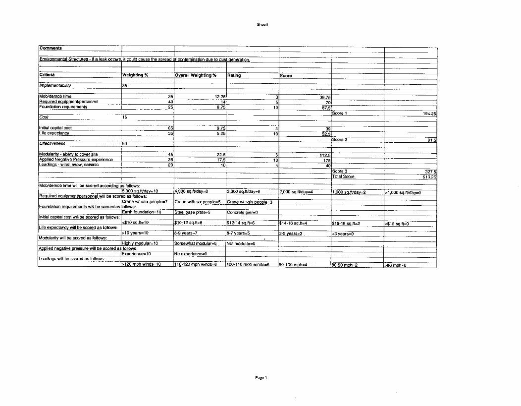
Sheell
Comments
Environmental Structures - if a leak occurs it Could cause the spread of contamination due to dus aeneratiOn
Criteria Weighting % Overall Weighting % Haling Score
implementability 35
Mob/demob time 35 12.25 3 36.75Required equipment/personnel 40 14 5 70Foundation requirements 25 8.75 10 87.5
Score 1 194.25Cost 15
Initial capital cost 65 9.75 4 39Life expectancy 35 5.25 10 52.5
Score 2 91.5Effectiveness 50
Modularity - ability to cover site 45 22.5 5 112.5Applied Negative Pressure experience 35 17.5 10 175Loadings - wind, snow, seismic 20 10 4 40
Score 3 327.5Total Score 613.25
Mob/demob time will be scored according as follows:5000 sq.ft/day=10 4,000 sq.ft/day=8 3,000 sg.ft/day=6 2,000 sq.ft/day=4 1,000 sq.ft./day=2 >1 000 sq.ft/day=0
Required equipment/personnel will be scored as follows:Crane vd <six people=7 Crane with six people=5 Crane w/ >six people-3
Foundation requirements will be scored as follows:Earth foundation=10 Steel base plate=5 Concrete pler=0
Initial capital cost will be scored as follows:<$10 sq.ft=10 $10-12 sq.f1-,13 512.14 sq.ft=6 $14-16 sq.ft=4 $16-18 sq.tt--2 <$113 sq.ft=0
Life expectancy will be scored as follows:>10 years=10 8-9 years-7 6-7 years=5 3-5 years=3 <3 years=0
Modularity will be scored as follows: iHighly modular=10 Somewhat modular=5 Not modular=0
Applied negative pressure will be scored asfollows:Experience=10 No experience=0
Loadings will be scored as follows:>120 mph winds=l0 110.120 mph winds=8 100-110 mph w nds=6 90-100 mph=4 ,80-90 mph=2 >80 mph=0
Page 1

Sheet1
Comments
Weather Block • no experience into confipements in this Woe of abdication.
Criteria Weighting % Overall Weighting % Rating Score
implementability 35
Mob/demob time 35 12.25 3 36.75Required equipmentipersonnel 40 14 5 70Foundation requirements 25 8.75 10 87.5
Score 1 194.25Cosi 15
Initial capital cost 65 9.75 8 78Life expectancy 35 5.25 10 52.5
Score 2 130.5Effectiveness 50
Modularity - ability to cover site 45 22.5 0 0Applied Negative Pressure experience 35 17.5 0 0Loadings - wind, snow, seismic 20 10 10 100
Score 3 100Total Score 424.75
Mob/demob time will be scored according asfollows:5,000 sq.ft/day=10 4,000 sq.fUday=8 3,000 sq.ft/day=6 2,000 sq.ft/day=4 1,000 sq.fVday=2 >1,000 sq.ft/day=0
Required equipment/personnel will be scored as follows:!Crane w/ <six people=7 Crane with six people=5 Crane w/ ›six people=3
Foundation requirements will be scored as follows:Earth foundation=10 Steel base plate=5 Concrete pier=0
Initial capital cost will be scored as follows:410 sq.tt=10 $10.12 sq.ft=8 $12-14 sq.ft=6 $14.16 sq.ft=4 $16-18 sq.ft=2 418 sq.ft=0
Life expectancy will be scored as follows:>10 years=10 8-9 years=7 8-7 years=5 3-5 years=3 <3 years=0
Modularity will be scored as follows:Highly modular=10 Somewhat modular=-5 Not modular=0
Applied negative pressure wiN be scored as follows:Experience=10 No experience =0
Loadings will be scored as follows:>120 mph winds=10 _110-120 mph winds=8 100-110 mph winds=6 90-100 mph=4 '80-90 mph=2 >80 mph=0
Page 1