HORN´S CUSTOMER MAGAZINE
24
Edition 2/09 SUBJECT: MEDICAL TECHNOLOGY: MILLING BONE RONGEURS OPTIMISED HORN´S CUSTOMER MAGAZINE ■ Innovative production secures location ■ DD drill bits on the road to success ■ Successful premiere of the HORN Technology Days ■ Innovations at the EMO
-
Upload
khangminh22 -
Category
Documents
-
view
3 -
download
0
Transcript of HORN´S CUSTOMER MAGAZINE
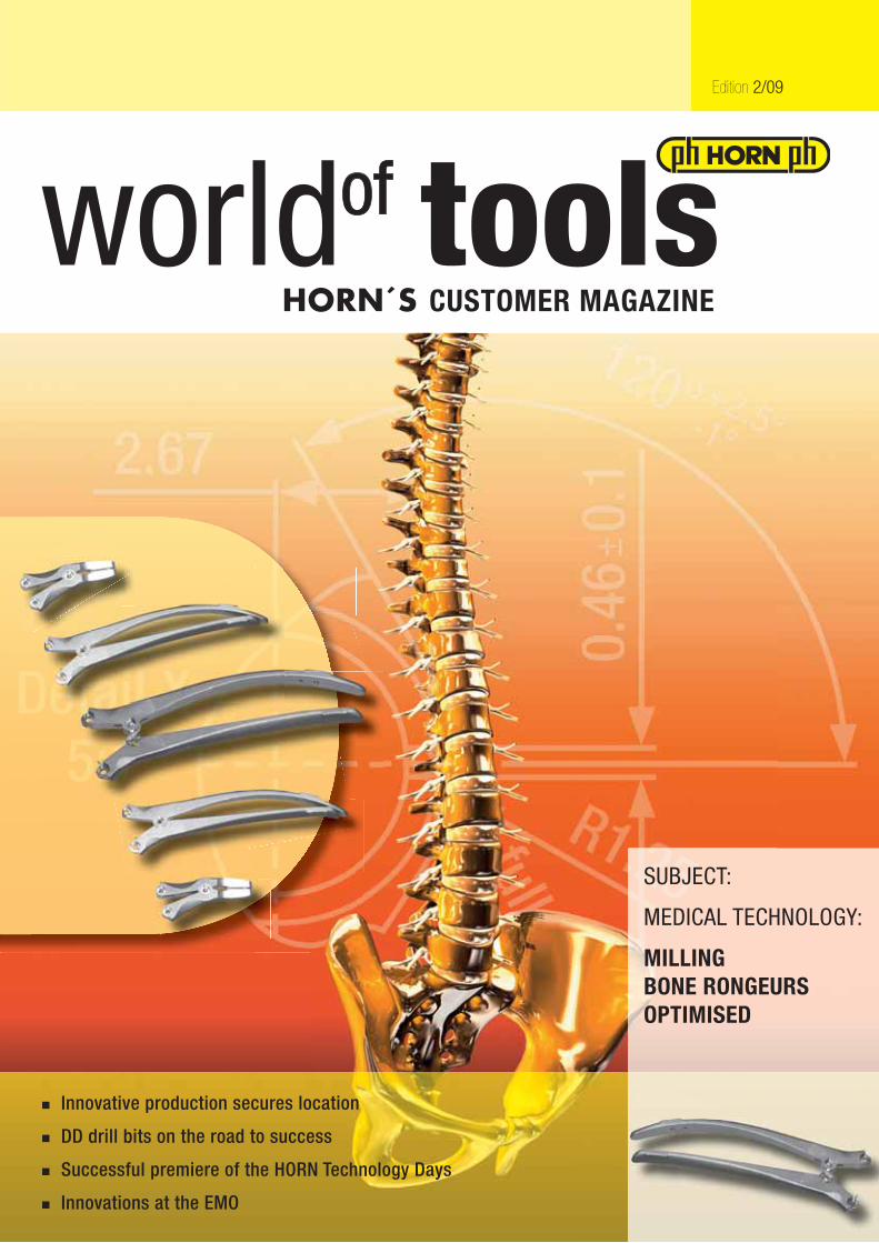
Edition 2/09
SUBJECT:
MEDICAL TECHNOLOGY:
MILLINGBONE RONGEURSOPTIMISED
HORN´S CUSTOMER MAGAZINE
■ Innovative production secures location
■ DD drill bits on the road to success
■ Successful premiere of the HORN Technology Days
■ Innovations at the EMO
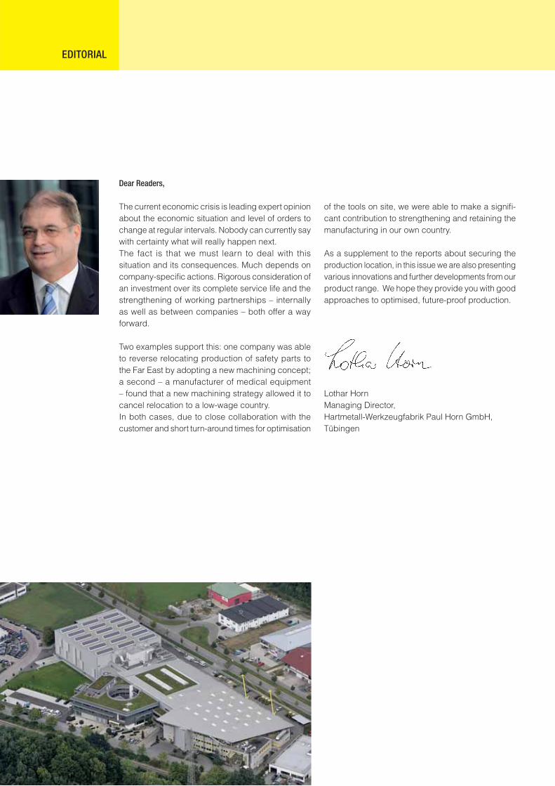
Dear Readers,
The current economic crisis is leading expert opinion about the economic situation and level of orders to change at regular intervals. Nobody can currently say with certainty what will really happen next.The fact is that we must learn to deal with this situation and its consequences. Much depends on company-specifi c actions. Rigorous consideration of an investment over its complete service life and the strengthening of working partnerships – internally as well as between companies – both offer a way forward.
Two examples support this: one company was able to reverse relocating production of safety parts to the Far East by adopting a new machining concept; a second – a manufacturer of medical equipment – found that a new machining strategy allowed it to cancel relocation to a low-wage country.In both cases, due to close collaboration with the customer and short turn-around times for optimisation
EDITORIAL
of the tools on site, we were able to make a signifi -cant contribution to strengthening and retaining the manufacturing in our own country.
As a supplement to the reports about securing the production location, in this issue we are also presenting various innovations and further developments from our product range. We hope they provide you with good approaches to optimised, future-proof production.
Lothar HornManaging Director, Hartmetall-Werkzeugfabrik Paul Horn GmbH, Tübingen
3
HORN´S CUSTOMER MAGAZINE
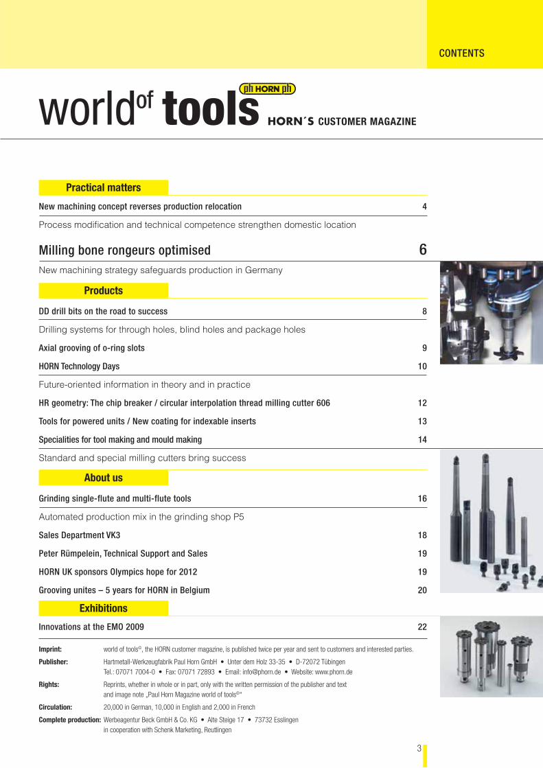
CONTENTS
Practical matters
Products
About us
Exhibitions
New machining concept reverses production relocation 4
Process modifi cation and technical competence strengthen domestic location
Milling bone rongeurs optimised 6New machining strategy safeguards production in Germany
DD drill bits on the road to success 8
Drilling systems for through holes, blind holes and package holes
Axial grooving of o-ring slots 9
HORN Technology Days 10
Future-oriented information in theory and in practice
HR geometry: The chip breaker / circular interpolation thread milling cutter 606 12
Tools for powered units / New coating for indexable inserts 13
Specialities for tool making and mould making 14
Standard and special milling cutters bring success
Grinding single-flute and multi-flute tools 16
Automated production mix in the grinding shop P5
Sales Department VK3 18
Peter Rümpelein, Technical Support and Sales 19
HORN UK sponsors Olympics hope for 2012 19
Grooving unites – 5 years for HORN in Belgium 20
Innovations at the EMO 2009 22
Imprint: world of tools©, the HORN customer magazine, is published twice per year and sent to customers and interested parties.
Publisher: Hartmetall-Werkzeugfabrik Paul Horn GmbH • Unter dem Holz 33-35 • D-72072 Tübingen Tel.: 07071 7004-0 • Fax: 07071 72893 • Email: [email protected] • Website: www.phorn.de
Rights: Reprints, whether in whole or in part, only with the written permission of the publisher and text and image note „Paul Horn Magazine world of tools©“
Circulation: 20,000 in German, 10,000 in English and 2,000 in French
Complete production: Werbeagentur Beck GmbH & Co. KG • Alte Steige 17 • 73732 Esslingen in cooperation with Schenk Marketing, Reutlingen
4
Production relocations to the Far East do not always prove to be so benefi cial as assumed. By contrast, the perceived cost advantages of a relocation can not only be matched by innovative work processes but also transformed into genuine location advantages.
A closer look at costs: electromechanical safety door opener
Assa Abloy Sicherheitstechnik GmbH, Germany, is well-known world wide as a supplier of high quality products and systems for mechanical and electro-mechanical safety solutions. In the course of the global activities of the company, the production of various safety-relevant components was relocated from the Swabian Albstadt to the Far East for cost reasons. The parts manufactured there using the metal powder injection moulding process (MIM) obtain their fi nal shape in only one work operation – apparently a signifi cant benefi t compared with previous prac-tice using machining by milling, turning and drilling. However, MIM made reaction to changing quantities and product variation diffi cult and the tight tolerance requirements could not always be maintained due to shrinkage differences during sintering.
Wanted: competitive solutions in a high-wage economy
Therefore, the members of the Group in Germany previously involved with the production of the door openers looked for solutions. For example, to not only
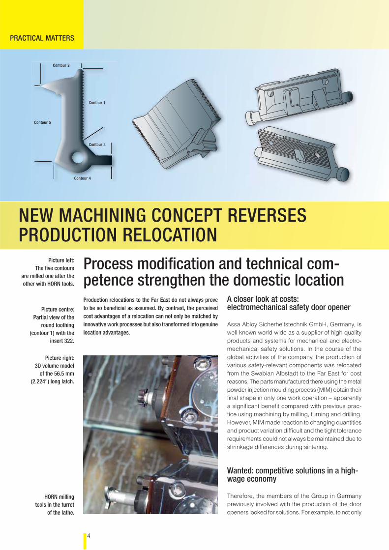
Picture left:The fi ve contours
are milled one after the other with HORN tools.
Picture right:3D volume model
of the 56.5 mm (2.224") long latch.
Picture centre:Partial view of the
round toothing(contour 1) with the
insert 322.
HORN milling tools in the turret
of the lathe.
NEW MACHINING CONCEPT REVERSES PRODUCTION RELOCATION
Process modifi cation and technical com-petence strengthen the domestic location
PRACTICAL MATTERS
Contour 2
Contour 1
Contour 3
Contour 4
Contour 5
5
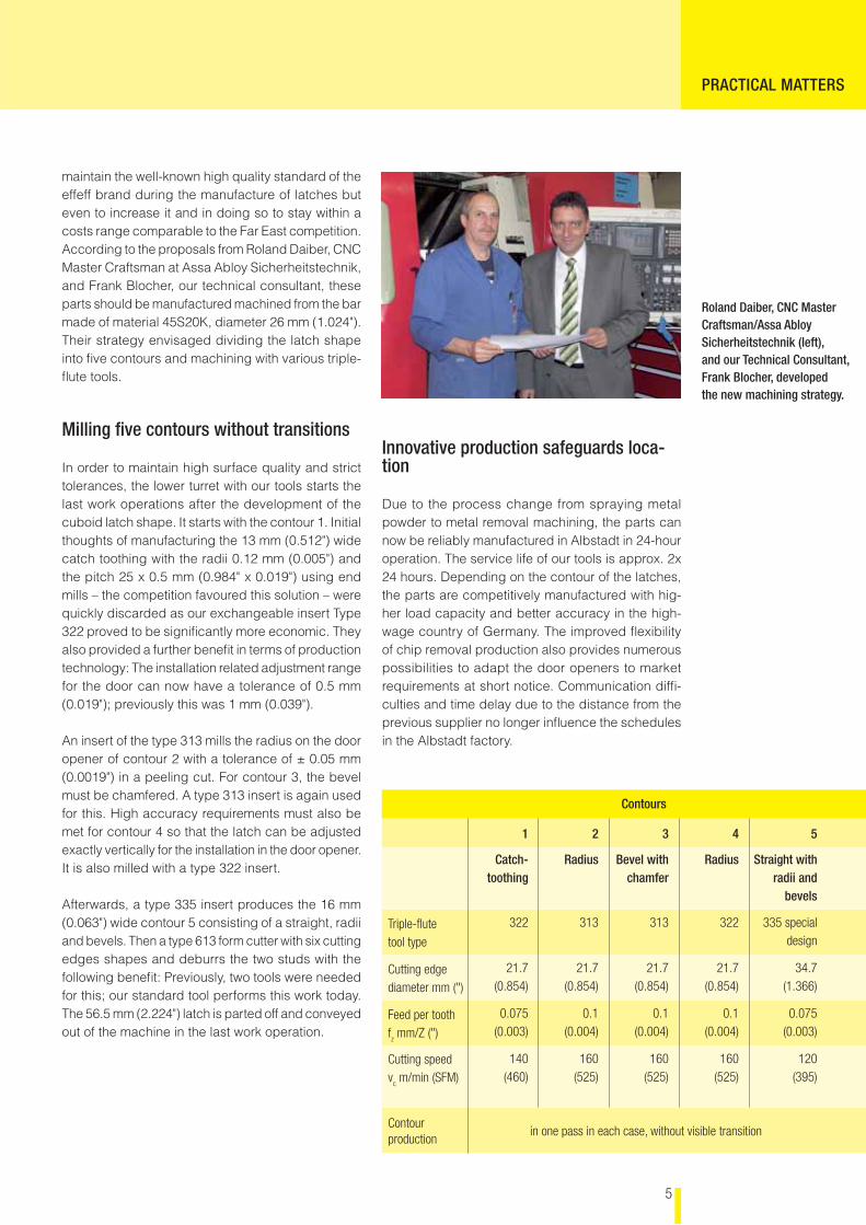
Roland Daiber, CNC Master Craftsman/Assa Abloy Sicherheitstechnik (left), and our Technical Consultant, Frank Blocher, developed the new machining strategy.
maintain the well-known high quality standard of the effeff brand during the manufacture of latches but even to increase it and in doing so to stay within a costs range comparable to the Far East competition. According to the proposals from Roland Daiber, CNC Master Craftsman at Assa Abloy Sicherheitstechnik, and Frank Blocher, our technical consultant, these parts should be manufactured machined from the bar made of material 45S20K, diameter 26 mm (1.024"). Their strategy envisaged dividing the latch shape into fi ve contours and machining with various triple-fl ute tools.
Milling fi ve contours without transitions
In order to maintain high surface quality and strict tolerances, the lower turret with our tools starts the last work operations after the development of the cuboid latch shape. It starts with the contour 1. Initial thoughts of manufacturing the 13 mm (0.512") wide catch toothing with the radii 0.12 mm (0.005") and the pitch 25 x 0.5 mm (0.984" x 0.019") using end mills – the competition favoured this solution – were quickly discarded as our exchangeable insert Type 322 proved to be signifi cantly more economic. They also provided a further benefi t in terms of production technology: The installation related adjustment range for the door can now have a tolerance of 0.5 mm (0.019"); previously this was 1 mm (0.039"). An insert of the type 313 mills the radius on the door opener of contour 2 with a tolerance of ± 0.05 mm (0.0019") in a peeling cut. For contour 3, the bevel must be chamfered. A type 313 insert is again used for this. High accuracy requirements must also be met for contour 4 so that the latch can be adjusted exactly vertically for the installation in the door opener. It is also milled with a type 322 insert.
Afterwards, a type 335 insert produces the 16 mm (0.063") wide contour 5 consisting of a straight, radii and bevels. Then a type 613 form cutter with six cutting edges shapes and deburrs the two studs with the following benefi t: Previously, two tools were needed for this; our standard tool performs this work today. The 56.5 mm (2.224") latch is parted off and conveyed out of the machine in the last work operation.
Innovative production safeguards loca-tion
Due to the process change from spraying metal powder to metal removal machining, the parts can now be reliably manufactured in Albstadt in 24-hour operation. The service life of our tools is approx. 2x 24 hours. Depending on the contour of the latches, the parts are competitively manufactured with hig-her load capacity and better accuracy in the high-wage country of Germany. The improved fl exibility of chip removal production also provides numerous possibilities to adapt the door openers to market requirements at short notice. Communication diffi -culties and time delay due to the distance from the previous supplier no longer infl uence the schedules in the Albstadt factory.
Contours
1 2 3 4 5
Catch-toothing
Radius Bevel with chamfer
Radius Straight withradii and
bevels
Triple-fl ute tool type
322 313 313 322 335 special design
Cutting edge diameter mm (")
21.7 (0.854)
21.7 (0.854)
21.7 (0.854)
21.7 (0.854)
34.7(1.366)
Feed per toothfz mm/Z (")
0.075 (0.003)
0.1 (0.004)
0.1(0.004)
0.1(0.004)
0.075(0.003)
Cutting speed v
c m/min (SFM)
140(460)
160(525)
160(525)
160(525)
120(395)
Contour production
in one pass in each case, without visible transition
PRACTICAL MATTERS
6
PRACTICAL MATTERS
New machining strategy safeguards production in Germany Before a production relocation abroad, a manufacturer of medical equipment wanted to exploit all possibilities at the domestic location. In doing so, he found strong arguments for in-house production.
Can our bone rongeurs (bone cutting forceps) con-tinue to be produced competitively in Germany? This question had occupied Martin and Andreas Wenzler of the instrument manufacturer Raimund Wenzler GmbH in Balgheim for a long time as they – in con-trast to the competition – were reluctant to relocate the products to a low-wage country. With this project,
the philosophy of the company founder would be continued. More than 60 years ago the bone rongeurs were instrumental in establishing the excellent repu-tation of the Swabian company as a manufacturer of surgical instruments for neurosurgery, orthopaedics and fi xation devices for implants.
Bone rongeurs with eventful history
Little has changed in the design of the instrument, which, among others, is used in the surgical treatment of spinal conditions such as slipped disc. On the other hand, the infl uences on the costs calculation and the quantities have changed signifi cantly. At the beginning, bone rongeurs were manufactured ma-nually on different machines using HSS tools. Later, carbide tools enabled signifi cantly higher cutting values which, however, could not be completely used on account of the tendency for “smearing”. As well as the effects on tool life, surface quality and also the delivery times, it was mainly the question of costs which demanded new production processes for the by now 12 variants made of stainless steel 1.4021. Andreas Wenzler also obtained ideas at ex-hibitions and from suppliers. In doing so, he also had
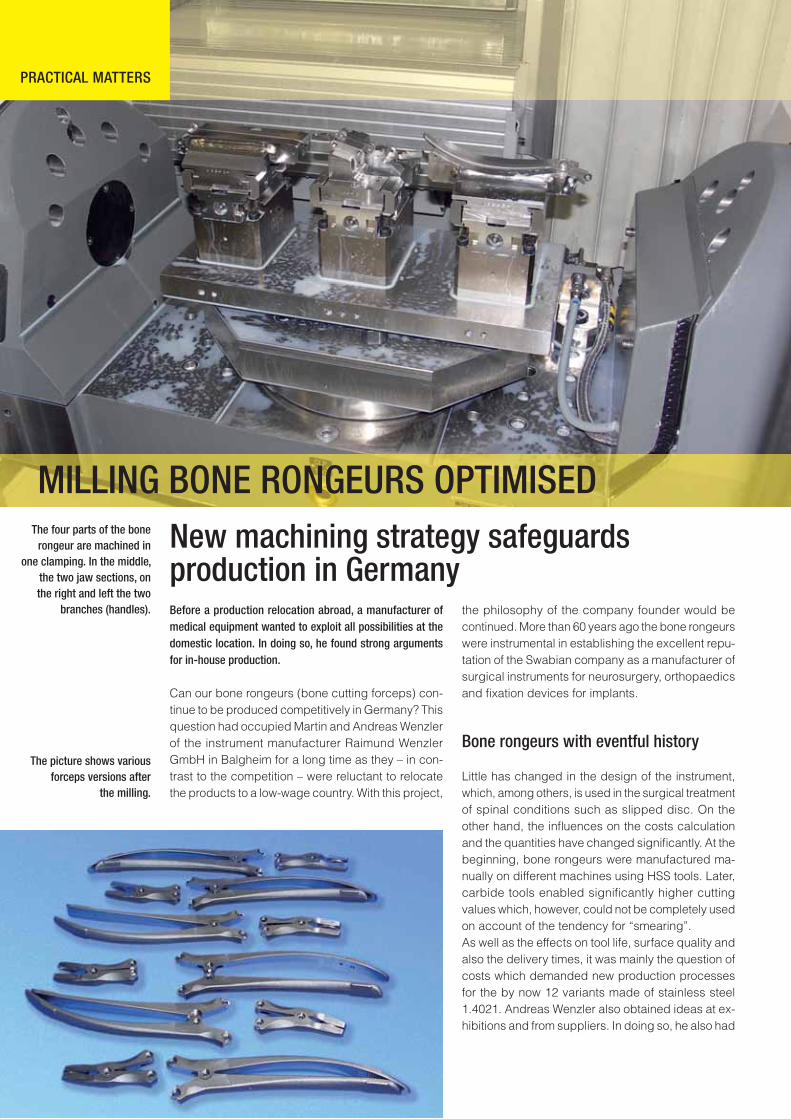
The picture shows variousforceps versions after
the milling.
The four parts of the bone rongeur are machined in
one clamping. In the middle, the two jaw sections, on the right and left the two
branches (handles).
MILLING BONE RONGEURS OPTIMISED
7
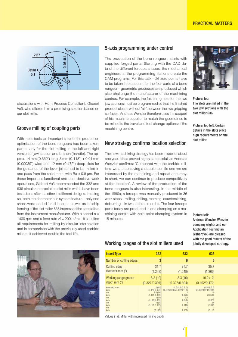
2.67
Detail X5:1
R1.25
120° +2.5°-1°
full R
0.46
+ 0.1
–
PRACTICAL MATTERS
discussions with Horn Process Consultant, Gisbert Voß, who offered him a promising solution based on our slot mills.
Groove milling of coupling parts
With these tools, an important step for the production optimisation of the bone rongeurs has been taken, particularly for the slot milling in the left and right version of jaw section and branch (handle). The ap-prox. 14 mm (0.552") long, 3 mm (0.118") + 0.01 mm (0.00039") wide and 12 mm (0.472") deep slots for the guidance of the lever joints had to be milled in one pass from the solid metal with Ra ≤ 0.8 µm. For these important functional and cost decisive work operations, Gisbert Voß recommended the 332 and 636 circular interpolation slot mills which have been tested one after the other in different designs. In doing so, both the characteristic system feature – only one shank was needed for all inserts – as well as the chip forming of the slot miller 636 impressed the specialists from the instrument manufacturer. With a speed n = 1400 rpm and a feed rate vf = 200 m/min, it satisfi ed all requirements for milling by circular interpolation and in comparison with the previously used carbide millers, it achieved double the tool life.
Picture left: Andreas Wenzler, Wenzler company (right), and our Application Technician Gisbert Voß are pleased with the good results of the jointly developed strategy.
Picture, top:The slots are milled in the two jaw sections with the slot miller 636.
Picture, top left: Certain details in the slots place high requirements on the slot miller.
5-axis programming under control
The production of the bone rongeurs starts with supplied forged parts. Starting with the CAD da-ta of the different forceps shapes, the mechanical engineers at the programming stations create the CAM programs. For this task – 26 zero points have to be taken into account for the four parts of a bone rongeur – geometric processes are produced which also challenge the manufacturer of the machining centres. For example, the fastening hole for the two jaw sections must be programmed so that the fi nished product closes without "air" between the two gripping surfaces. Andreas Wenzler therefore uses the support of his machine supplier to match the geometries to be milled to the travel and tool change options of the machining centre.
New strategy confi rms location selection
The new machining strategy has been in use for about one year. It has proved highly successful, as Andreas Wenzler confi rms: "Compared with the carbide mil-lers, we are achieving a double tool life and we are impressed by the machining and repeat accuracy. In short, we can continue to produce competitively at the location". A review of the production of the bone rongeurs is also interesting. In the middle of the 1990s, a forceps was manually produced in 36 work steps – milling, drilling, reaming, countersinking, deburring – in two to three months. The four forceps parts today are produced in one clamping on a ma-chining centre with zero point clamping system in 15 minutes.
Working ranges of the slot millers used
Insert Type 332 632 636
Number of cutting edges 3 6 6
Cutting edge diameter mm (")
31.7(1.248)
31.7(1.248)
35.7(1.366)
Working range groove depth mm (")
8.3 (10)(0.327/0.394)
8.3 (10)(0.327/0.394)
10.2 (12)(0.402/0.472)
Insert width mminchmminchmminchmminchmminch
2 (1.5)(0.079 (0.059))
2.5 (1.6)(0.098 (0.063))
3 (2.0)(0.118 (0.079))
4 (2.5)(0.157 (0.098))
(3)((0.118))
(1.5 /1.6 /2.5 /3)((0.059)/0.063/0.098/0.118))
2(0.079)
2.5(0.098)
3(0.118)
4(0.157)
(1.5 /2 /2.5)((0.059/0.079/0.098))
1.5(0.0591)
2(0.079)
2.5(0.098)
3(0.118)
Values in (): Miller with increased milling depth
8
DD DRILL BITS ON THE ROAD TO SUCCESS
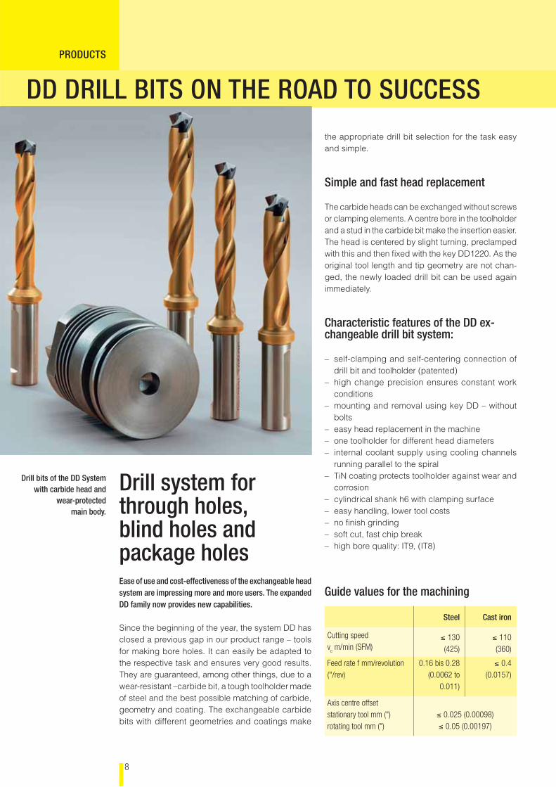
Ease of use and cost-effectiveness of the exchangeable head system are impressing more and more users. The expanded DD family now provides new capabilities.
Since the beginning of the year, the system DD has closed a previous gap in our product range – tools for making bore holes. It can easily be adapted to the respective task and ensures very good results. They are guaranteed, among other things, due to a wear-resistant –carbide bit, a tough toolholder made of steel and the best possible matching of carbide, geometry and coating. The exchangeable carbide bits with different geometries and coatings make
Drill bits of the DD Systemwith carbide head and
wear-protectedmain body.
Drill system for through holes, blind holes and package holes
PRODUCTS
the appropriate drill bit selection for the task easy and simple.
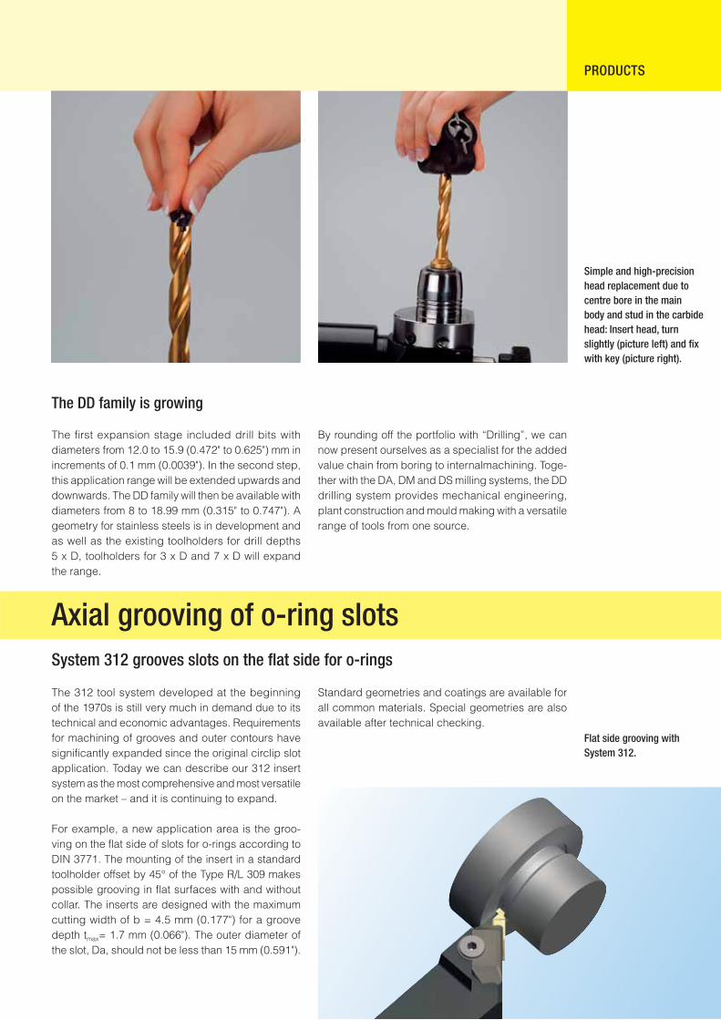
Simple and fast head replacement
The carbide heads can be exchanged without screws or clamping elements. A centre bore in the toolholder and a stud in the carbide bit make the insertion easier. The head is centered by slight turning, preclamped with this and then fi xed with the key DD1220. As the original tool length and tip geometry are not chan-ged, the newly loaded drill bit can be used again immediately.
Characteristic features of the DD ex-changeable drill bit system:
– self-clamping and self-centering connection of drill bit and toolholder (patented)
– high change precision ensures constant work conditions
– mounting and removal using key DD – without bolts
– easy head replacement in the machine– one toolholder for different head diameters– internal coolant supply using cooling channels
running parallel to the spiral– TiN coating protects toolholder against wear and
corrosion– cylindrical shank h6 with clamping surface– easy handling, lower tool costs– no fi nish grinding– soft cut, fast chip break– high bore quality: IT9, (IT8)
Guide values for the machining
Steel Cast iron
Cutting speed v
c m/min (SFM)
≤ 130(425)
≤ 110(360)
Feed rate f mm/revolution("/rev)
0.16 bis 0.28(0.0062 to
0.011)
≤ 0.4(0.0157)
Axis centre offset stationary tool mm (")rotating tool mm (")
≤ 0.025 (0.00098)≤ 0.05 (0.00197)
The DD family is growing
The fi rst expansion stage included drill bits with diameters from 12.0 to 15.9 (0.472" to 0.625") mm in increments of 0.1 mm (0.0039"). In the second step, this application range will be extended upwards and downwards. The DD family will then be available with diameters from 8 to 18.99 mm (0.315" to 0.747"). A geometry for stainless steels is in development and as well as the existing toolholders for drill depths 5 x D, toolholders for 3 x D and 7 x D will expand the range.
Simple and high-precision head replacement due to centre bore in the main body and stud in the carbide head: Insert head, turn slightly (picture left) and fi x with key (picture right).
PRODUCTS
By rounding off the portfolio with “Drilling”, we can now present ourselves as a specialist for the added value chain from boring to internalmachining. Toge-ther with the DA, DM and DS milling systems, the DD drilling system provides mechanical engineering, plant construction and mould making with a versatile range of tools from one source.
Flat side grooving with System 312.
Axial grooving of o-ring slotsSystem 312 grooves slots on the fl at side for o-rings
The 312 tool system developed at the beginning of the 1970s is still very much in demand due to its technical and economic advantages. Requirements for machining of grooves and outer contours have signifi cantly expanded since the original circlip slot application. Today we can describe our 312 insert system as the most comprehensive and most versatile on the market – and it is continuing to expand.
For example, a new application area is the groo-ving on the fl at side of slots for o-rings according to DIN 3771. The mounting of the insert in a standard toolholder offset by 45° of the Type R/L 309 makes possible grooving in fl at surfaces with and without collar. The inserts are designed with the maximum cutting width of b = 4.5 mm (0.177") for a groove depth tmax= 1.7 mm (0.066"). The outer diameter of the slot, Da, should not be less than 15 mm (0.591").
Standard geometries and coatings are available for all common materials. Special geometries are also available after technical checking.
10
PRODUKTEPRODUCTS
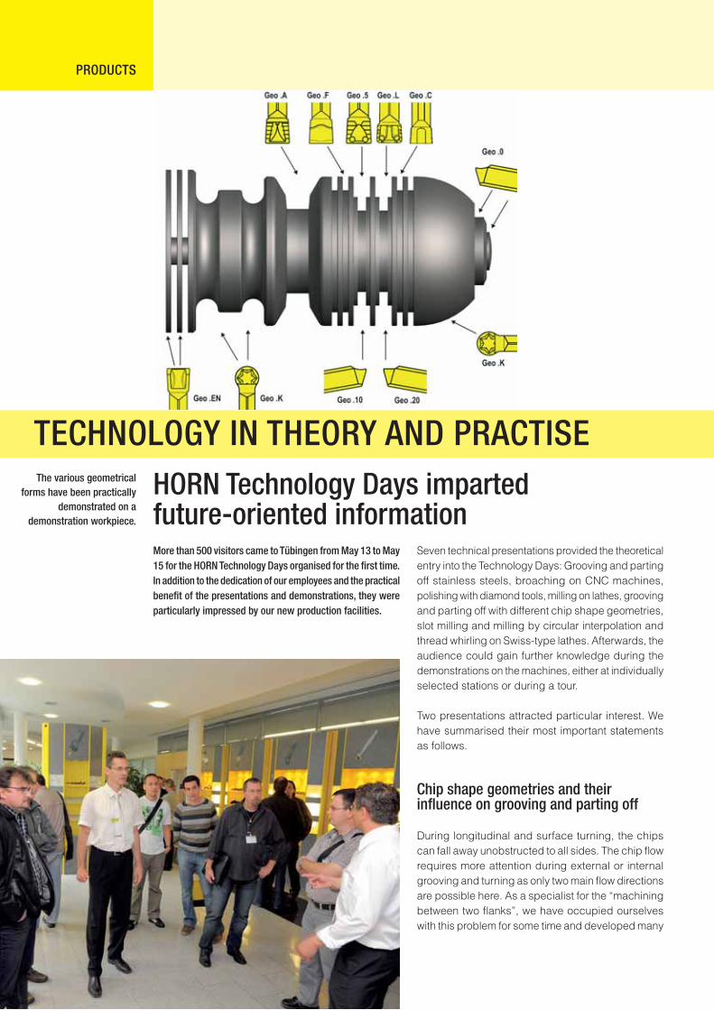
HORN Technology Days imparted future-oriented informationMore than 500 visitors came to Tübingen from May 13 to May 15 for the HORN Technology Days organised for the fi rst time. In addition to the dedication of our employees and the practical benefi t of the presentations and demonstrations, they were particularly impressed by our new production facilities.
Seven technical presentations provided the theoretical entry into the Technology Days: Grooving and parting off stainless steels, broaching on CNC machines, polishing with diamond tools, milling on lathes, grooving and parting off with different chip shape geometries, slot milling and milling by circular interpolation and thread whirling on Swiss-type lathes. Afterwards, the audience could gain further knowledge during the demonstrations on the machines, either at individually selected stations or during a tour.
Two presentations attracted particular interest. We have summarised their most important statements as follows.
Chip shape geometries and their infl uence on grooving and parting off
During longitudinal and surface turning, the chips can fall away unobstructed to all sides. The chip fl ow requires more attention during external or internal grooving and turning as only two main fl ow directions are possible here. As a specialist for the “machining between two fl anks”, we have occupied ourselves with this problem for some time and developed many
The various geometrical forms have been practically
demonstrated on a demonstration workpiece.
TECHNOLOGY IN THEORY AND PRACTISE
11
“problem-solving” chip shape geometries using many years of experience and in numerous tests.
The principal tasks of the chip shape geometry for grooving and turning are the chip control and the chip forming. Unfavourable chips such as ribbon, snarl and spiral chips must be prevented and at the same time chip width needs to be reduced. Therefore, the selection of the geometry must fi rst be oriented to the material to be machined and the type of machining. Afterwards, the cutting division and the stability of the system, which in turn infl uence the feed speed, must be taken into account.
21 geometries listed in the catalogue help with the decision for a geometry for external radial and for external axial/radial grooving and turning and for parting off. This is supplemented by many years of experience in the cutting speeds dependent on the material and the coating – irrespective of whether standard or special geometries are required. Our knowledge is available to you.
The theoretical intro-ductions were followed by the demonstration on the machine.
PRODUCTS
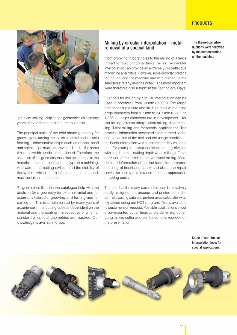
Milling by circular interpolation – metal removal of a special kind
From grooving in bore holes to the milling of a large thread to multifunctional tasks, milling by circular interpolation can provide an extremely cost-effective machining alternative. However, some important criteria for the tool and the machine and with respect to the selected strategy must be noted. The most important were therefore also a topic at the Technology Days.
Our tools for milling by circular interpolation can be used in boreholes from 10 mm (0.039"). The range comprises triple-fl ute and six-fl ute tools with cutting edge diameters from 9.7 mm to 34.7 mm (0.382" to 1.366") – larger diameters are in development – for slot milling, circular interpolation milling, thread mil-ling, T-slot milling and for special applications. The practical information presented concentrated on the point of action of the tool and the usage conditions; the basic information was supplemented by valuable tips, for example, about coolants, cutting division with chip breaker, cutting depth when milling a T-slot neck and about climb or conventional milling. More detailed information about the face side threaded coupling of insert and shank and about the repair service for used shafts provided important approaches to saving costs.
The fact that the many parameters can be relatively easily assigned to a process and printed out in the form of a cutting data and performance calculation was explained using our HCT program. This is available to customers on request. Possible applications of our arbor-mounted cutter head and side milling cutter, gang milling cutter and combined tools rounded off the presentation.
Some of our circular interpolation tools for special applications.
12
1
3
2
4
PRODUCTS
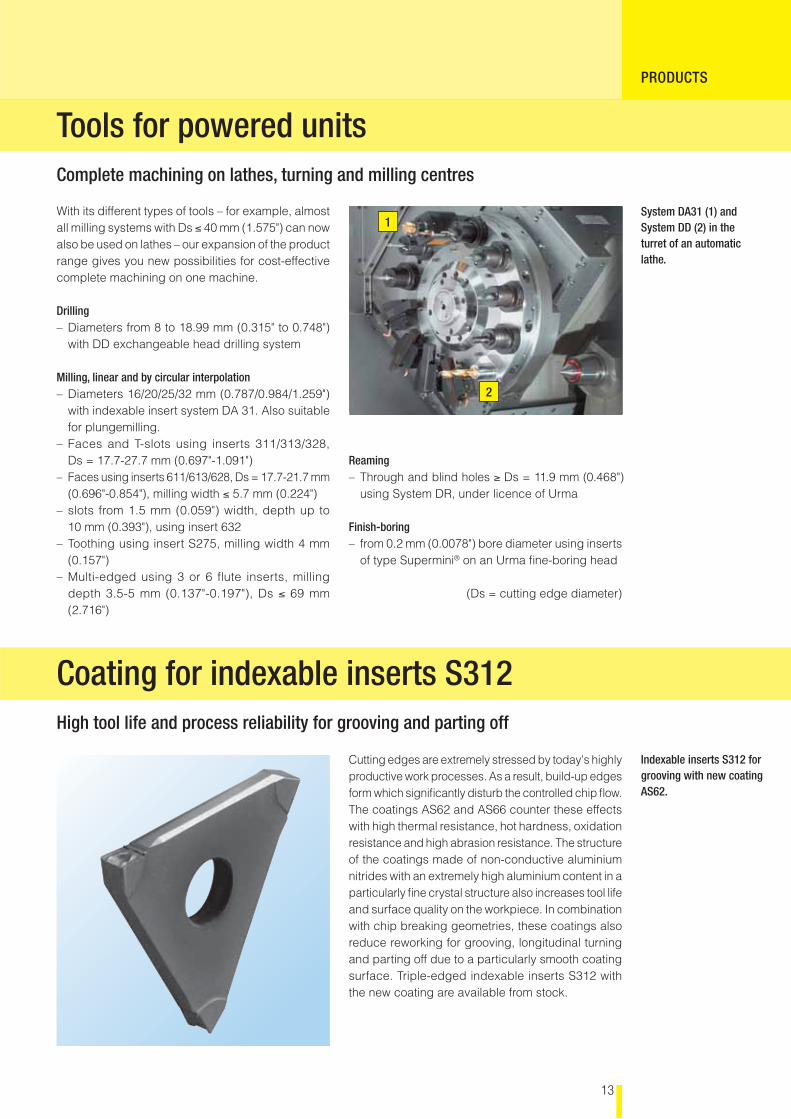
Circular interpolation thread milling insert 606Milling of internal threads from 12 mm (0.472") bore diameter
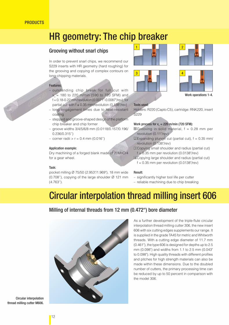
HR geometry: The chip breakerGrooving without snarl chips
Tools used:Holders: R220 (Capto C5), cartridge: RNK220, insert S229
Work process for vc = 220 m/min (720 SFM):1 Grooving in solid material, f = 0.28 mm per
revolution (0.11"/rev)2 Expanding plunge cut (partial cut), f = 0.35 mm/ revolution (0.138"/rev)3 Copying small shoulder and radius (partial cut) f = 0.35 mm per revolution (0.0138"/rev)4 Copying large shoulder and radius (partial cut) f = 0.35 mm per revolution (0.0138"/rev)
Result:– signifi cantly higher tool life per cutter– reliable machining due to chip breaking
In order to prevent snarl chips, we recommend our S229 inserts with HR geometry (hard roughing) for the grooving and copying of complex contours on long-chipping materials.
Features:– outstanding chip break for full cut with
vc = 180 to 220 m/min (590 to 720 SFM) and f = 0.18-0.22 mm/revolution (0.0071"-0.0087"/rev), for partial cut with f ≤ 0.35 mm/revolution (0.138"/rev)
– long engagement times due to heat-resistant coating
– stepped and groove-shaped design of the platform chip breaker and chip former
– groove widths 3/4/5/6/8 mm (0.0118/0.157/0.196/0.236/0.315’’)
– corner radii > r = 0.4 mm (0.016’’)
Application example:Dry machining of a forged blank made of 20MnCr4 for a gear wheel. Task:pocket milling Ø 75/50 (2.953"/1.969"), 18 mm wide (0.708’’), copying of the large shoulder Ø 121 mm (4.763’’).
Work operations 1-4.
As a further development of the triple-fl ute circular interpolation thread milling cutter 306, the new insert 606 with six cutting edges supplements our range. It is supplied in the grade TA45 for metric and Whitworth threads. With a cutting edge diameter of 11.7 mm (0.461"), the type 606 is designed for depths up to 2.5 mm (0.098") and widths from 1.1 to 2.5 mm (0.043" to 0.098"). High quality threads with different profi les and pitches for high strength materials can also be made within these dimensions. Due to the doubled number of cutters, the primary processing time can be reduced by up to 50 percent in comparison with the model 306.
Circular interpolation thread milling cutter M606.
13
1
2
PRODUCTS
Coating for indexable inserts S312High tool life and process reliability for grooving and parting off
Tools for powered unitsComplete machining on lathes, turning and milling centres
With its different types of tools – for example, almost all milling systems with Ds ≤ 40 mm (1.575") can now also be used on lathes – our expansion of the product range gives you new possibilities for cost-effective complete machining on one machine.
Drilling – Diameters from 8 to 18.99 mm (0.315" to 0.748")
with DD exchangeable head drilling system
Milling, linear and by circular interpolation– Diameters 16/20/25/32 mm (0.787/0.984/1.259")
with indexable insert system DA 31. Also suitable for plungemilling.
– Faces and T-slots using inserts 311/313/328, Ds = 17.7-27.7 mm (0.697"-1.091")
– Faces using inserts 611/613/628, Ds = 17.7-21.7 mm (0.696"-0.854"), milling width ≤ 5.7 mm (0.224")
– slots from 1.5 mm (0.059") width, depth up to 10 mm (0.393"), using insert 632
– Toothing using insert S275, milling width 4 mm (0.157")
– Multi-edged using 3 or 6 fl ute inserts, milling depth 3.5-5 mm (0.137"-0.197"), Ds ≤ 69 mm (2.716")
Reaming– Through and blind holes ≥ Ds = 11.9 mm (0.468") using System DR, under licence of Urma
Finish-boring– from 0.2 mm (0.0078") bore diameter using inserts
of type Supermini® on an Urma fi ne-boring head
(Ds = cutting edge diameter)
Cutting edges are extremely stressed by today's highly productive work processes. As a result, build-up edges form which signifi cantly disturb the controlled chip fl ow. The coatings AS62 and AS66 counter these effects with high thermal resistance, hot hardness, oxidation resistance and high abrasion resistance. The structure of the coatings made of non-conductive aluminium nitrides with an extremely high aluminium content in a particularly fi ne crystal structure also increases tool life and surface quality on the workpiece. In combination with chip breaking geometries, these coatings also reduce reworking for grooving, longitudinal turning and parting off due to a particularly smooth coating surface. Triple-edged indexable inserts S312 with the new coating are available from stock.
Indexable inserts S312 for grooving with new coating AS62.
System DA31 (1) and System DD (2) in the turret of an automatic lathe.
14
PRODUKTEPRODUCTS
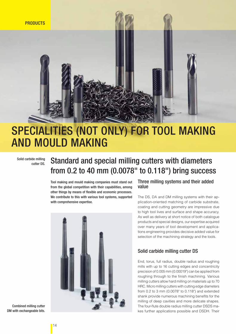
Standard and special milling cutters with diameters from 0.2 to 40 mm (0.0078" to 0.118") bring successTool making and mould making companies must stand out from the global competition with their capabilities, among other things by means of fl exible and economic processes. We contribute to this with various tool systems, supported with comprehensive expertise.
Three milling systems and their added value
The DS, DA and DM milling systems with their ap-plication-oriented matching of carbide substrate, coating and cutting geometry are impressive due to high tool lives and surface and shape accuracy. As well as delivery at short notice of both catalogue products and special designs, our expertise acquired over many years of tool development and applica-tions engineering provides decisive added value for selection of the machining strategy and the tools.
Solid carbide milling cutter DS
End, torus, full radius, double radius and roughing mills with up to 16 cutting edges and concentricity precision of 0.005 mm (0.00019") can be applied from roughing through to the fi nish machining. Various milling cutters allow hard milling on materials up to 70 HRC. Micro milling cutters with cutting edge diameters from 0.2 to 3 mm (0.0078" to 0.118") and extended shank provide numerous machining benefi ts for the milling of deep cavities and more delicate shapes. The four-fl ute double radius milling cutter DSDS ma-kes further applications possible and DSDH. Their
Solid carbide milling cutter DS.
Combined milling cutter DM with exchangeable bits.
SPECIALITIES (NOT ONLY) FOR TOOL MAKING AND MOULD MAKING
15
diameters of 6-16 mm (0.236"-0.629") are designed for soft and hard milling up to 45 HRC.
Combination milling cutter DM with exchangeable milling heads
With these tools, one shank can be used to support all types of milling cutters within the same diameter range. In this way, combinations can be formed whose cost-effectiveness is based on the marriage between impressive cutting values and a lower tool require-ment. With carbide shanks up to 140 mm (5.512") long – also in shrinkable design – deep cavities can be milled with maximum concentricity precision and strict tolerances. The cutters with two cutting edges, available with and without corner radii, provide nu-merous options for the best suited tool combination. Multi-fl ute tools are currently in development.
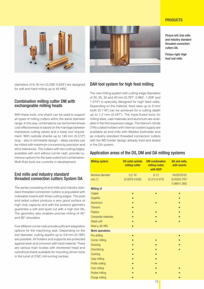
End mills and industry standard threaded connection cutters System DA
The series consisting of end mills and industry stan-dard threaded connection cutters is populated with indexable inserts with three cutting edges. The axial and radial cutters produce a very good surface at high chip capacity and with the positive geometry guarantee a soft and quiet cut with a high tool life. The geometry also enables precise milling of 45° and 90° shoulders.
Five different corner radii provide suffi cient adaptation options for the machining task. Depending on the tool diameter, cutting depths up to 4.8 mm (0.189") are possible. All holders and supports are protected against wear and corrosion with hard material. There are various main bodies with shortened head and cylindrical shank available for mounting driven tools in the turret of CNC mill-turning centres.
PRODUCTS
DAH tool system for high feed milling
The new milling system with cutting edge diameters of 20, 25, 32 and 40 mm (0.787", 0.984", 1.259" and 1.574") is specially designed for high feed rates. Depending on the material, feed rates up to 3 mm/tooth (0.118") can be achieved for a cutting depth up to 1.2 mm (0.047"). The triple-fl uted tools for milling steel, cast materials and aluminium are avail-able in the fi rst expansion stage. The titanium nitride (TiN) coated holders with internal coolant supply are available as end mills with Weldon toolholder and as industry standard threaded connection cutters with the MD holder design already tried and tested in the DA system.
Picture left: End mills and industry standard threaded connection cutters DA.
Picture right: High feed end mills.
Application areas of the DS, DM and DA milling systems
Milling system DS solid carbide milling cutter
DM combination milling cutter,
with WSP
DA end mills, with inserts
Nominal diameter mm (")
0.2-16(0.0078-0.630)
8-12(0.315-0.472)
16/20/25/32(0.630/0.787/0.984/1.260)
Milling of
Copper • • •
Graphite • •
Aluminium • • •
Titanium • •
Plastics • • •
Composite materials • • •
Steels soft • • •
Steel ≥ 56 HRC •
Work operations
Pre-drilling • •
Corner milling • • •
Grooving • • •
Chamfering • • •
Centring • •
Copy milling • •
Profi le milling • •
Face milling • • •
Pocket milling • • •
Plunge milling • •
ABOUT US
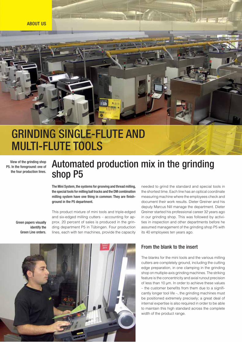
Automated production mix in the grinding shop P5The Mini System, the systems for grooving and thread milling, the special tools for milling ball tracks and the DM combination milling system have one thing in common: They are fi nish-ground in the P5 department.
This product mixture of mini tools and triple-edged and six-edged milling cutters – accounting for ap-prox. 20 percent of sales is produced in the grin-ding department P5 in Tübingen. Four production lines, each with ten machines, provide the capacity
needed to grind the standard and special tools in the shortest time. Each line has an optical coordinate measuring machine where the employees check and document their work results. Dieter Greiner and his deputy Marcus Nill manage the department. Dieter Greiner started his professional career 32 years ago in our grinding shop. This was followed by activi-ties in inspection and other departments before he assumed management of the grinding shop P5 with its 40 employees ten years ago.
From the blank to the insert
The blanks for the mini tools and the various milling cutters are completely ground, including the cutting edge preparation, in one clamping in the grinding shop on multiple-axis grinding machines. The striking feature is the concentricity and axial runout precision of less than 10 µm. In order to achieve these values – the customer benefi ts from them due to a signifi -cantly longer tool life –, the grinding machines must be positioned extremely precisely; a great deal of internal expertise is also required in order to be able to maintain this high standard across the complete width of the product range.
Green papers visually identify the
Green Line orders.
View of the grinding shop P5. In the foreground: one of
the four production lines.
GRINDING SINGLE-FLUTE AND MULTI-FLUTE TOOLS
5
1
2
4
3
ABOUT US
High degree of automation despite product diversity
For example, mini, triple-edged, four-edged and six-edged tools in different quantities are machined automatically at the same time in one production line. This production philosophy requires a degree of automation approaching 100 percent which is based, among other things, on the “multifunction grinding machine” concept. It is used in all departments of the grinding shop and automated and set up depending on the products to be ground. In turn, this requires a high degree of modularity. Thanks to the standar-dised machine confi guration and controller, we can process orders in any way within the department with high retooling fl exibility and thus react very quickly to external delivery date requirements irrespective of tool type and shape.
For the parts feed, an image processing system ac-quires the shape and position of the blank on the pallet which is then attached to the workpiece carrier and exchanged in the grinding machine automatically. Its position is recorded by a measuring probe and corrected automatically if necessary. Afterwards, the controller activates the CNC program and the grin-ding wheel changer exchanges the required grinding wheels – complete machining in one clamping.
Green Line throughput accelerator
With the Green Line organisational form – it applies for the complete company – we have implemented basic elements of the Lean Production philosophy for our objectives: We want to further reduce the short throughput times which make us stand out. All orders with small quantities should be produced in three days maximum and shipped within one week after further work operations including coating. The
Sales Department decides which orders run under Green Line. It specifi es the delivery date and can thus help the users in an emergency.
Green Line is also visually differentiated from “normal” orders. Green Line stands out already at the operating data acquisition using a highlighted screen display. All order-dependent papers can be easily recognised by their green colour. The special storage areas for the blanks and the fi nished parts are also green.
The requirement for every Green Line order is: Start within one shift! Thereby, the employee decides himself in the context of specifi c requirements how he inserts these “express orders” into the daily workload of the standard and special tools and on which machine he processes them. This requirements profi le, from the scheduling and utilisation planning to the set-ting up and programming of the machine to the part approval, requires high technical, organisational and co-ordination skills. Knowledge which we expand for our employees through training and qualifi cation measures to make them able to solve problems in-dependently.
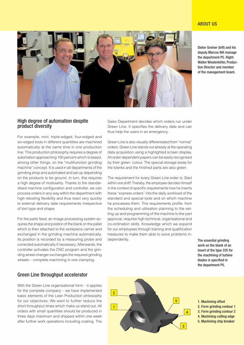
Dieter Greiner (left) and his deputy Marcus Nill manage the department P5. Right: Walter Wiedenhöfer, Produc-tion Director and member of the management board.
The essential grinding work on the blank of an insert of the type 335 for the machining of turbine blades is specifi ed in the department P5.
1. Machining offset2. Form grinding contour 13. Form grinding contour 24. Machining cutting edge5. Machining chip breaker
18
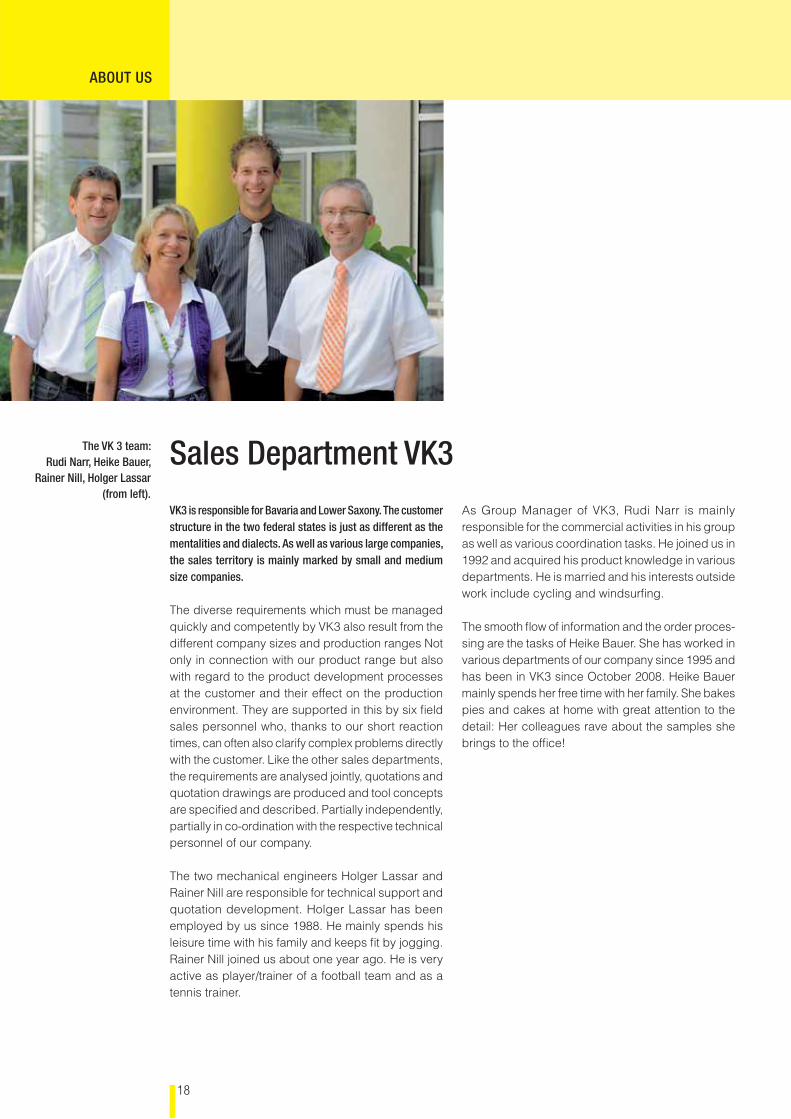
VK3 is responsible for Bavaria and Lower Saxony. The customer structure in the two federal states is just as different as the mentalities and dialects. As well as various large companies, the sales territory is mainly marked by small and medium size companies.
The diverse requirements which must be managed quickly and competently by VK3 also result from the different company sizes and production ranges Not only in connection with our product range but also with regard to the product development processes at the customer and their effect on the production environment. They are supported in this by six fi eld sales personnel who, thanks to our short reaction times, can often also clarify complex problems directly with the customer. Like the other sales departments, the requirements are analysed jointly, quotations and quotation drawings are produced and tool concepts are specifi ed and described. Partially independently, partially in co-ordination with the respective technical personnel of our company. The two mechanical engineers Holger Lassar and Rainer Nill are responsible for technical support and quotation development. Holger Lassar has been employed by us since 1988. He mainly spends his leisure time with his family and keeps fi t by jogging. Rainer Nill joined us about one year ago. He is very active as player/trainer of a football team and as a tennis trainer.
As Group Manager of VK3, Rudi Narr is mainly responsible for the commercial activities in his group as well as various coordination tasks. He joined us in 1992 and acquired his product knowledge in various departments. He is married and his interests outside work include cycling and windsurfi ng. The smooth fl ow of information and the order proces-sing are the tasks of Heike Bauer. She has worked in various departments of our company since 1995 and has been in VK3 since October 2008. Heike Bauer mainly spends her free time with her family. She bakes pies and cakes at home with great attention to the detail: Her colleagues rave about the samples she brings to the offi ce!
The VK 3 team:Rudi Narr, Heike Bauer,
Rainer Nill, Holger Lassar(from left).
Sales Department VK3
ABOUT US
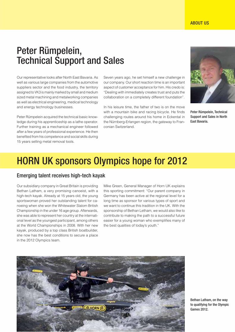
HORN UK sponsors Olympics hope for 2012 Emerging talent receives high-tech kayak
Bethan Latham, on the way to qualifying for the Olympic Games 2012.
Our subsidiary company in Great Britain is providing Bethan Latham, a very promising canoeist, with a high-tech kayak. Already at 15 years old, the young sportswoman proved her outstanding talent for ca-noeing when she won the Whitewater Slalom British Championship in the under 16 age group. Afterwards, she was able to represent her country at the internati-onal level as the youngest participant, among others at the World Championships in 2008. With her new kayak, produced by a top class British boatbuilder, she now has the best conditions to secure a place in the 2012 Olympics team.
Mike Green, General Manager of Horn UK explains this sporting commitment: “Our parent company in Germany has been active at the regional level for a long time as sponsor for various types of sport and we want to continue this tradition in the UK. With the sponsorship of Bethan Letham, we would also like to contribute to making the path to a successful future easier for a young woman who exemplifi es many of the best qualities of today’s youth.”
Peter Rümpelein, Technical Support and Sales in North East Bavaria.
Our representative looks after North East Bavaria. As well as various large companies from the automotive suppliers sector and the food industry, the territory assigned to VK3 is mainly marked by small and medium sized metal machining and metalworking companies as well as electrical engineering, medical technology and energy technology businesses.
Peter Rümpelein acquired the technical basic know-ledge during his apprenticeship as a lathe operator. Further training as a mechanical engineer followed after a few years of professional experience. He then benefi ted from his competence and social skills during 15 years selling metal removal tools.
Seven years ago, he set himself a new challenge in our company. Our short reaction time is an important aspect of customer acceptance for him. His credo is: “Dealing with immediately creates trust and puts the collaboration on a completely different foundation”.
In his leisure time, the father of two is on the move with a mountain bike and racing bicycle. He fi nds challenging routes around his home in Eckental in the Nürnberg-Erlangen region, the gateway to Fran-conian Switzerland.
Peter Rümpelein,Technical Support and Sales
ABOUT US
20
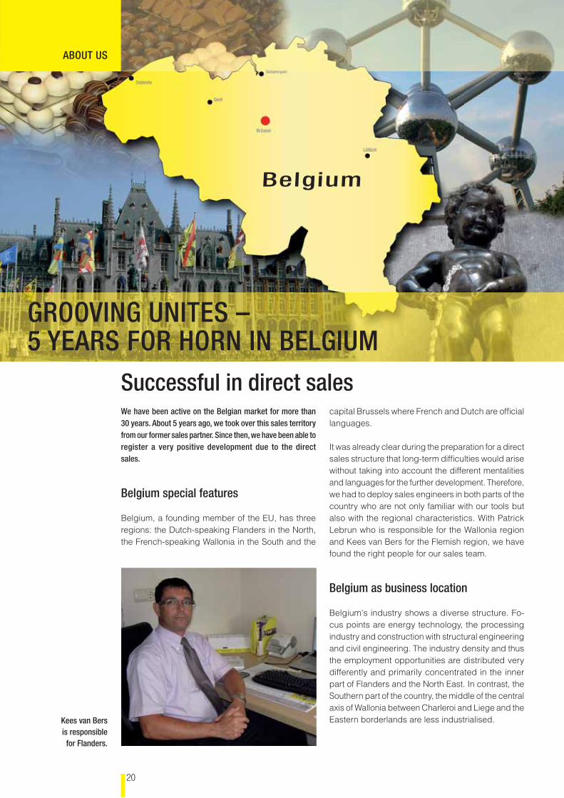
We have been active on the Belgian market for more than 30 years. About 5 years ago, we took over this sales territory from our former sales partner. Since then, we have been able to register a very positive development due to the direct sales.
Belgium special features
Belgium, a founding member of the EU, has three regions: the Dutch-speaking Flanders in the North, the French-speaking Wallonia in the South and the
capital Brussels where French and Dutch are offi cial languages.
It was already clear during the preparation for a direct sales structure that long-term diffi culties would arise without taking into account the different mentalities and languages for the further development. Therefore, we had to deploy sales engineers in both parts of the country who are not only familiar with our tools but also with the regional characteristics. With Patrick Lebrun who is responsible for the Wallonia region and Kees van Bers for the Flemish region, we have found the right people for our sales team.
Belgium as business location
Belgium's industry shows a diverse structure. Fo-cus points are energy technology, the processing industry and construction with structural engineering and civil engineering. The industry density and thus the employment opportunities are distributed very differently and primarily concentrated in the inner part of Flanders and the North East. In contrast, the Southern part of the country, the middle of the central axis of Wallonia between Charleroi and Liege and the Eastern borderlands are less industrialised.
ABOUT US
Kees van Bers is responsible for Flanders.
Successful in direct sales
Belgium
GROOVING UNITES – 5 YEARS FOR HORN IN BELGIUM
21
Following the largest mechanical engineering ex-port growth to Belgium in the year 2008, very strong declines must now be recorded. Belgium occupies the 19th place in the export of German mechanical engineering in 2008. The total volume of EUR 139 million corresponds to an export share of 1.7 percent. This breaks down into EUR 125 million for machines and EUR 25 million for spare parts. It is striking that this volume as compared with 2007 means a decline of 22 percent.
German-Belgian collaboration
Since 2004, the complete country has been sup-ported from Tübingen by a few people. Thus the delivery, support and other services are available to the customers in Belgium directly from Tübingen. The administrative activities for Belgium are supported by two technical sales colleagues. Patrick Lebrun has been active in machining technology for many years and was able to acquire extensive experience at another tool manufacturer. Today he is supporting the customer base in Wallonia and the small mar-ket of the Grand Duchy of Luxembourg. Kees van Beers is available locally to the Flemish customers for all technical issues. He also has many years of experience in tooling technology which he applies to provide customers with the most cost-effective tool solution in each case.
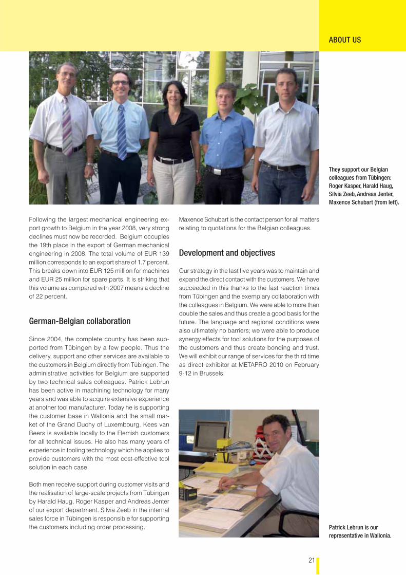
Both men receive support during customer visits and the realisation of large-scale projects from Tübingen by Harald Haug, Roger Kasper and Andreas Jenter of our export department. Silvia Zeeb in the internal sales force in Tübingen is responsible for supporting the customers including order processing.
Maxence Schubart is the contact person for all matters relating to quotations for the Belgian colleagues.
Development and objectives
Our strategy in the last fi ve years was to maintain and expand the direct contact with the customers. We have succeeded in this thanks to the fast reaction times from Tübingen and the exemplary collaboration with the colleagues in Belgium. We were able to more than double the sales and thus create a good basis for the future. The language and regional conditions were also ultimately no barriers; we were able to produce synergy effects for tool solutions for the purposes of the customers and thus create bonding and trust. We will exhibit our range of services for the third time as direct exhibitor at METAPRO 2010 on February 9-12 in Brussels.
ABOUT US
Patrick Lebrun is our representative in Wallonia.
They support our Belgian colleagues from Tübingen: Roger Kasper, Harald Haug, Silvia Zeeb, Andreas Jenter, Maxence Schubart (from left).
22
EXHIBITIONS
EMO Milan, October 5-10, 2009
Lothar Horn concluded after the exhibition closed on October 10th:“After a rather slow fi rst day of the exhibition the number of visitors increased on the following days, but as a matter of fact the visitor numbers of the last EMO in Milan in 2003 couldn’t be reached. Against all the critical voices and comments before the show the response can be considered positive. It is also important to mention that the precision tool manuf-acturers were the largest group of the international exhibitors during the EMO in Milan 2009. 100 out of 450 tool manufacturers were German based companies. Beside the Italian visitors there were also a signifi cant number of visitors from Europe and Overseas.
On our joined booth with Febametal the live product demonstrations attracted the audience and we’ve had interesting conversations and made numerous new and promising contacts.”
Review
Amongst our standard product range, we introduced the following innova-tions and new developments:
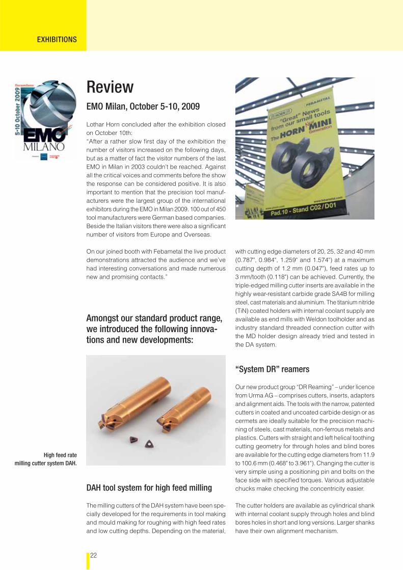
DAH tool system for high feed milling
The milling cutters of the DAH system have been spe-cially developed for the requirements in tool making and mould making for roughing with high feed rates and low cutting depths. Depending on the material,
High feed rate milling cutter system DAH.
with cutting edge diameters of 20, 25, 32 and 40 mm (0.787", 0.984", 1.259" and 1.574") at a maximum cutting depth of 1.2 mm (0.047"), feed rates up to 3 mm/tooth (0.118") can be achieved. Currently, the triple-edged milling cutter inserts are available in the highly wear-resistant carbide grade SA4B for milling steel, cast materials and aluminium. The titanium nitride (TiN) coated holders with internal coolant supply are available as end mills with Weldon toolholder and as industry standard threaded connection cutter with the MD holder design already tried and tested in the DA system.
“System DR” reamers
Our new product group “DR Reaming” – under licence from Urma AG – comprises cutters, inserts, adapters and alignment aids. The tools with the narrow, patented cutters in coated and uncoated carbide design or as cermets are ideally suitable for the precision machi-ning of steels, cast materials, non-ferrous metals and plastics. Cutters with straight and left helical toothing cutting geometry for through holes and blind bores are available for the cutting edge diameters from 11.9 to 100.6 mm (0.468" to 3.961"). Changing the cutter is very simple using a positioning pin and bolts on the face side with specifi ed torques. Various adjustable chucks make checking the concentricity easier.
The cutter holders are available as cylindrical shank with internal coolant supply through holes and blind bores holes in short and long versions. Larger shanks have their own alignment mechanism.
23
EXHIBITIONS
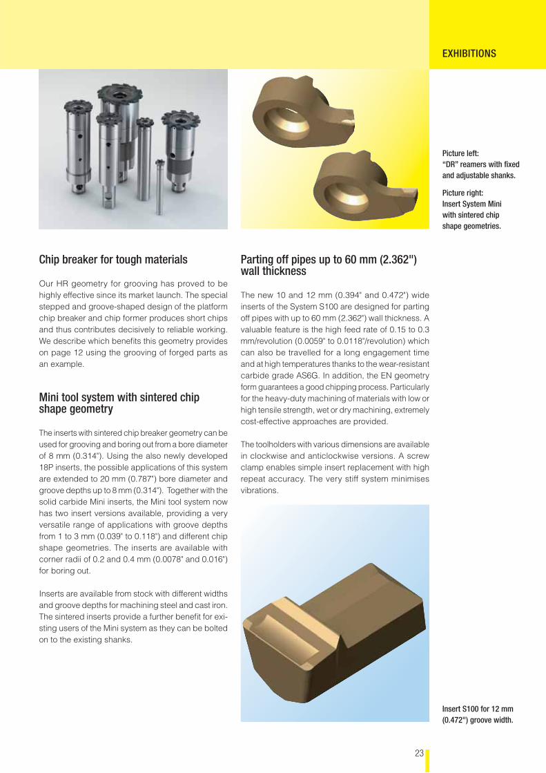
Picture left:“DR” reamers with fi xed and adjustable shanks.
Picture right:Insert System Mini with sintered chip shape geometries.
Chip breaker for tough materials
Our HR geometry for grooving has proved to be highly effective since its market launch. The special stepped and groove-shaped design of the platform chip breaker and chip former produces short chips and thus contributes decisively to reliable working. We describe which benefi ts this geometry provides on page 12 using the grooving of forged parts as an example.
Mini tool system with sintered chip shape geometry
The inserts with sintered chip breaker geometry can be used for grooving and boring out from a bore diameter of 8 mm (0.314"). Using the also newly developed 18P inserts, the possible applications of this system are extended to 20 mm (0.787") bore diameter and groove depths up to 8 mm (0.314"). Together with the solid carbide Mini inserts, the Mini tool system now has two insert versions available, providing a very versatile range of applications with groove depths from 1 to 3 mm (0.039" to 0.118") and different chip shape geometries. The inserts are available with corner radii of 0.2 and 0.4 mm (0.0078" and 0.016") for boring out.
Inserts are available from stock with different widths and groove depths for machining steel and cast iron. The sintered inserts provide a further benefi t for exi-sting users of the Mini system as they can be bolted on to the existing shanks.
Insert S100 for 12 mm (0.472") groove width.
Parting off pipes up to 60 mm (2.362") wall thickness
The new 10 and 12 mm (0.394" and 0.472") wide inserts of the System S100 are designed for parting off pipes with up to 60 mm (2.362") wall thickness. A valuable feature is the high feed rate of 0.15 to 0.3 mm/revolution (0.0059" to 0.0118"/revolution) which can also be travelled for a long engagement time and at high temperatures thanks to the wear-resistant carbide grade AS6G. In addition, the EN geometry form guarantees a good chipping process. Particularly for the heavy-duty machining of materials with low or high tensile strength, wet or dry machining, extremely cost-effective approaches are provided.
The toolholders with various dimensions are available in clockwise and anticlockwise versions. A screw clamp enables simple insert replacement with high repeat accuracy. The very stiff system minimises vibrations.
HORN France S.A.S.665, Av. Blaise PascalBat Anagonda I I IF-77127 LieusaintTel.: +33 1 64885958Fax: +33 1 64886049E-Mail: [email protected]
HORN CUTTING TOOLS LTD.32 New StreetRingwood, HampshireGB-BH24 3AD, EnglandTel.: +44 1425 481800Fax: +44 1425 481890E-Mail: [email protected]
HORN USA Inc.Suite 205320, Premier Court USA-Franklin, TN 37067 Tel.: +1 615 771-4100Fax: +1 615 771- 4101E-Mail: [email protected]
FEBAMETAL S.p.a.Via Grandi, 15I-10095 GrugliascoTel.: +39 011 7701412 Fax: +39 011 7701524 E-Mail: [email protected]
HORN Magyarország Kft.Szent István út 10/AHU-9021 Györ Tel.: +36 96 550531Fax: +36 96 550532E-Mail: [email protected]
PLUNGE CUTTING CUTTING OF GROOVING BROACHING COPY MILLING DRILLING
Subsidiaries or agencies
Hartmetall-Werkzeugfabrik Paul Horn GmbHPostfach 17 2072007 TübingenTel.: 07071 7004-0Fax: 07071 72893E-Mail: [email protected]
HORN is at home in over 70 countries across the world