HONDA Service Manual - Magna VF750C/CD - 1994-2003
306
1994-2003 MAGNA® VF750C/CD ©HONDA MOTOR CO., LTD. 1994
-
Upload
khangminh22 -
Category
Documents
-
view
0 -
download
0
Transcript of HONDA Service Manual - Magna VF750C/CD - 1994-2003

1994-2003 MAGNA® VF750C/CD
©HONDA MOTOR CO., LTD. 1994


,.---------- Important Safety Notice -----------,
INM@ii�h Indicates a strong possibility of severe personal injury or death if instructions are not followed.
CAUTION: Indicates a possibility of personal injury or equipment damage if instructions are not followed.
N OTE: G ives helpful information .
Deta i led descriptions of standard workshop procedures, safety principles and service operations are not included . It is important to note that this manual contains some warnings and cautions against some specific service methods which could cause PERSONAL INJURY to service personnel or could damage a vehicle or render it unsafe . Please understand that those warnings could not cover a l l conceivable ways in which service, whether or not recommended by Honda, might be done or of the possibly hazardous consequences of each conceivable way, nor could Honda investigate al l such ways . Anyone using service procedures or tools, whether or not recommended by Honda, must satisfy h imself thoroughly that neither personal safety nor vehicle safety wil l be jeopardized by the service methods or tools selected .

Introduction This service manual desc�ibes the service procedures for the MAGNA VF7 50C/C D .
This Model Specific Manual includes every service procedure that is of a specific nature to this particular model . Basic service procedures that are common to other Honda Motorcycle/Motor Scooter/ATVs are covered in the Common Service Manual . This Model Specific Service Manual should be used together with the Common Service Manual in order to provide complete service information on al l aspects of this motorcycle .
Follow the Maintenance Schedule (Section 3) recommendations to ensure that the vehicle is in peak operating condition and the emission levels are within the standards set by the U . S . Environmental Protection Agency and the C al ifornia Air Resources Board . Performing the first scheduled maintenance is very important. It compensates for the initial wear that occurs during the break-in period .
Sections 1 and 3 apply to the whole motorcycle . Section 2 i l lustrates procedures for removal/instal lation of components that may be required to perform service described in the fol lowing sections. Sections 4 through 1 9 describe parts of the motorcycle, g rouped according to locatio n .
Find t h e section y o u want on this page, then turn t o the table of contents on the first page of the section .
Most sections describe the service procedure throug h system i l lustration . Refer t o t h e next page for details o n h o w t o u s e this manua l .
If you are not familiar with this motorcycle, read Technical Feature in section 20.
If you don't know the source of the trouble, go to section 2 1 Troubleshooting .
All information, illustrations, directions and specifi
cations included in this publication are based on the
latest product information available at the time of
approval for printing. Honda Motor Co., LTD.
reserves the right to make changes at any time
without notice and without incurring any obligation
whatever. No part of this publication may be
reproduced without written for permission. This
manual is written for persons who have acquired
basic knowledge of maintenance on Honda motor
cycles, motor scooters or ATVs.
HONDA MOTOR CO., LTD.
Service Publications Office
Date of Issue: June, 1 994 © H O N DA M OTOR CO . , LTD .
c: ·a; .. I-CD >
·;: c "0 c: ca CD c:
·c, c: w
0 ·;; 0 ca .c: (J
"Cii u ·;: t) CD jjj
Contents
General Information
Frame/Body Panels/Exhaust System
Maintenance
Lubrication System
Fuel System
Cooling System
Engine Removal/Installation
Cylinder Head/Valves
Clutch System
Gearshift Linkage
Crankshaft/Piston/Transmission
Front Wheel/Suspension/Steering
Rear Wheel/Suspension
Brake System
Charging System/ Alternator
Ignition System
Electric Starter/Starter Clutch
Lights/Meters/Switches
Wiring Diagram
Technical Feature
Troubleshooting
Index
How To Use This Manual
Finding The Information You Need
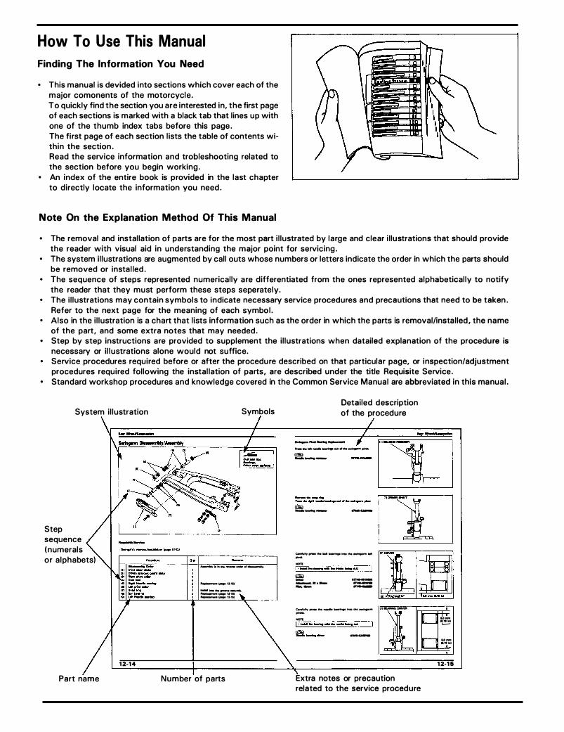
• This manual is devided into sections which cover each of the m ajor comonents of the motorcycle . To quickly find the section you are interested in, the first page of each sections is marked with a black tab that lines up with one of the thumb index tabs before this page . The fi rst page of each section l ists the table of contents within the section . Read the service information and trobleshooting related to the section before you begin working .
• An index of the entire book is provided in the last chapter to directly locate the information you need .
N ote On the Explanation Method Of This Manual
• The removal and instal lation of parts are for the most part i l lustrated by large and clear i l lustrations that should provide the reader with visual aid in understanding the major point for servicing .
• The system i l lustrations are augmented by cal l outs whose numbers or letters indicate the order in which the parts should be removed or insta l led .
• The sequence of steps represented numerical ly a re differentiated from the ones represented a lphabetical ly to notify the reader that they must perform these steps separately.
• The i l lustrations may contain symbols to indicate necessary service procedures and precautions that need to be taken . Refer to the next page for the meaning of each symbo l .
• Also in the i l lustration is a chart that l ists information such as the order in which the parts is removal/instal led, the name of the part , and some extra notes that may needed .
• Step by step instructions are provided to supplement the i l lustrations when datailed explanation of the procedu re is necessary or i l lustrations alone would not suffice.
• Service procedures required before or after the procedu re described on that particular page, or inspection/adjustment procedures required fol lowing the instal lation of parts, are described under the title Requisite Service .
• Standard workshop procedures and knowledge covered in the Common Service Manual are abbreviated in this manual .
System i l lustration
Step sequence (numerals or a lphabets)
Part name
12-14
Symbols
........., ....... _ .... ,.._........
.......... .... g.,. ............. .,___,, ............ .... . , .. ._._..... .... 13-111
Number of parts
Detailed description of the procedure
-............................ .......... _...._._, ... .........,....,.. I!SI ---
lllil --- -
Cllwfully ............ ........................... .. -.... , . ....... ........... .......... .... � ---··----
..,_ --
t.eflllly,.. .... � ......................... -.... , . ....... ........... ........... .... -
111UNMGDIWD
l Extra notes or precaution related to the service procedure
1'--'
h
u-.. ... ._..
u-.....
12-16
$ymbols
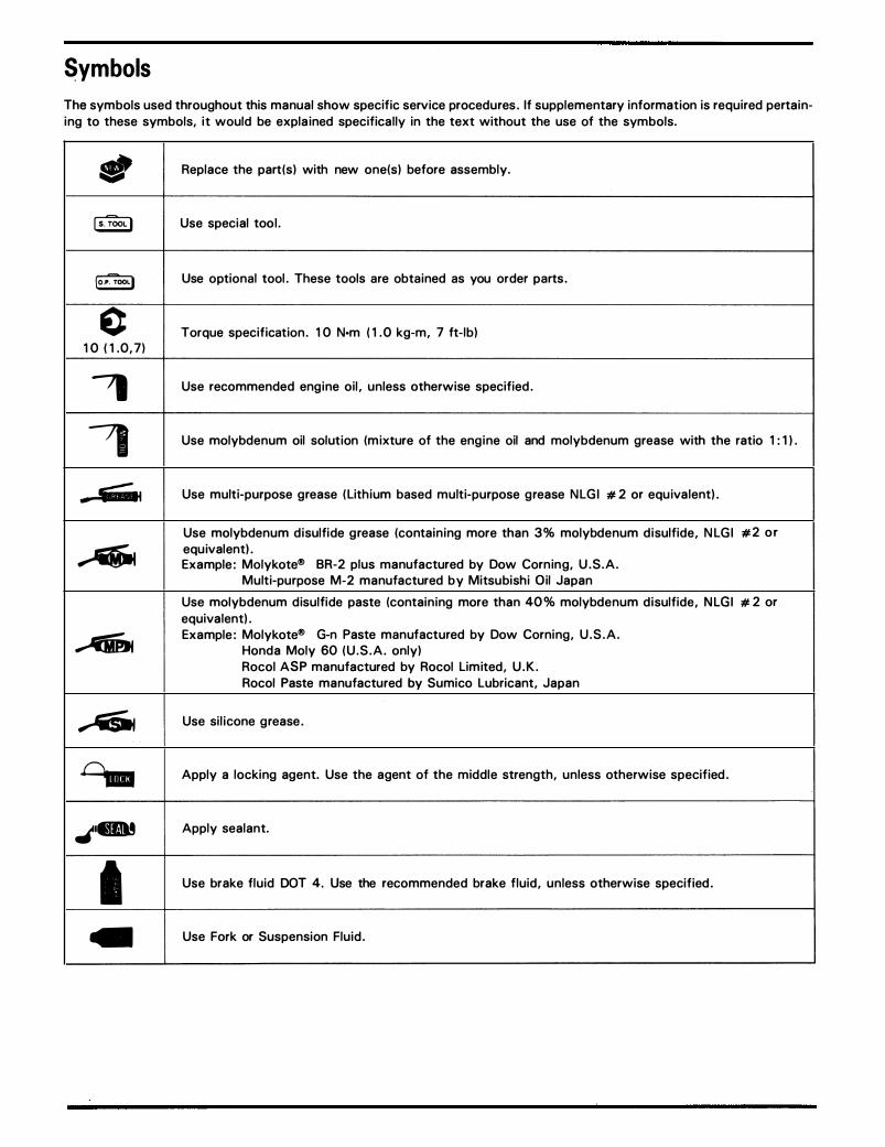
The symbols used throughout this manual show specific service procedures . If supplementary information is required pertaining to these symbols, it would be explained specifically in the text without the use of the symbols.
- Replace the part(s) with new one(s) before assembly.
ls.TOOl! Use special too l .
lo.P�OOLI Use optional tool . These tools are obtained as you order parts .
c Torque specification . 1 0 N·m ( 1 . 0 kg-m, 7 ft- lb) 1 0 ( 1 .0 , 7)
, Use recommended engine oil , unless otherwise specified .
, Use molybdenum oil solution (mixture of the engine oil and molybdenum grease with the ratio 1 : 1 ) .
- � Use multi-purpose grease ( Lithium based multi-purpose grease N LG I # 2 or equivalent) .
Use molybdenum disulfide grease (containing more than 3% molybdenum disulfide , N LG I # 2 o r
� equivalent) . Example: Molykote® BR-2 plus manufactured by Dow Corning, U . S .A .
Multi-purpose M-2 manufactured by Mitsubishi Oil Japan
Use molybdenum disulfide paste (containing more than 40% molybdenum disulfide , N LGI # 2 or equivalent) .
...... Example: Molykote® G-n Paste manufactured by Dow Corning , U . S . A . Honda Moly 60 ( U . S . A . only) Rocol ASP manufactured by Rocol Limited , U . K . Rocol Paste manufactured by Sumico Lubricant, Japan
� Use silicone grease .
0.. Apply a locking agent. Use the agent of the middle strength, unless otherwise specified .
.t•.a! Apply sealant.
I Use brake fluid DOT 4. Use the recommended brake fluid , unless otherwise specified .
... Use Fork or Suspension Fluid .

MEMO

General Safety 1-1 Model Identification 1-3 Specifications 1-4 Torque Values 1-12 Tools 1-15
General Safety
Carbon Monoxide If the engine must be running to do some work, make sure the area is well ventilated. Never run the engine in an enclosed area .
• The exhaust cotains poisonous carbon monoxide gas that may cause loss of consciouness and may lead to death.
Run the engine in an open area or with an exhaust evacuation system in an enclosed area.
Gasoline Work in a well ventilated area. Keep cigarettes, flames or sparks away from the work area or where gasoline is stored.
• Gasoline is extremely flammable and is explosive under certain conditions. KEEP OUT OF REACH OF CHILDREN.
Hot Components
• Engine and exhaust system parts become very hot and remain hot for some time after the engine Is run. Wear insulated gloves or walt until the engine and exhaust system have cooled before handling these parts.
1 . General Information Lubrication & Seal Points 1-17 Cable & Harness Routing 1-20 Emission Control System (U.S.A. Only) 1-27 Emission Control Information Labels (U.S.A Only) 1-30
Used Engine/Transmission Oil
• Used engine oH (or transmission oil in two-stroke) may
cause skin cancer if repeatedly left in contact with the skin for prolonged periods. Althrough this is unlikely unless you handle used oil on a daily basis, it is still advisable to thoroughly wash your hands with soap
and water as soon as possible after handling used oil. KEEP OUT OF REACH OF CHILDREN.
Brake Dust
Never use an air hose or dry brush to clean brake assemblies. Use an OSHA-approved vacuum c leaner or a lternate method approved by OSHA, designed to minimize the hazard caused by airborne asbestos fibers .
• Inhaled asbestos fibers have been found to cause respiratory disease and cancer.
Brake Fluid
CAUTION
• Spilling fluid on painted, plastic or rubber parts wiU damage them. Place a clean shop towel over these parts whenever the system is serviced. KEEP OUT OF REACH OF CHILDREN.
1-1

General Information
Coolant
Under some conditions, the ethylene glycol in engine coolant is combustible and its flame is not visible . If the ethylene glycol does ignite, you will not see any flame, but you can be burned .
• Avoid spilling engine coolant on the exhaust system
or engine parts. They may be hot enough to cause the
coolant to ignite and burn without a visible flame.
Coolant (ethylene glycol) can cause some skin irrita
tion and is poisonous if swallowed. KEEP OUT OF
REACH OF CHILDREN. • Do not remove the radiator cap when the engine is
hot. The coolant is under pressure and could scald
you. • Keep hands and clothing away from the cooling fan,
as it starts automatically.
If it contacts your skin, wash the affected areas immediately with soap and water. If it contacts your eyes, f lush them thoroughly with fresh water and get immediate medical attention . If it is swallowed , the victim must be forced to vomit, then rinse mouth and throat with fresh water before obtaining medical attention. Because of these dangers, always store coolant in a safe place, away from the reach of chi ldren .
1-2
Nitrogen Pressure
For shock absorbers with a gas-fi l led reservoir:
• Use only nitrogen to pressurize the shock absorber.
The use of an unstable gas can cause a fire or explo
sion resulting in serious injury. • The shock absorber contains nitrogen under high pres
sure. Allowing fire or heat near the shock absorber
could lead to an explosion that could result in serious
injury. • Failure to release the pressure from a shock absorber
before disposing of it may lead to a possible explo
sion and serious injury if it is heated or pierced.
To prevent the possibi l ity of an explosion, release the nitrogen by pressing the valve core . Then remove the valve stem from the shock absorber reservoir . Dispose of the oil in a manner acceptable to the Environmental Protection Agency (EPA) .
Before d isposal of the shock absorber, release the nitrogen by pressing the valve core . Then remove the valve stem from the shock absorber.
Battery Hydrogen Gas & Electrolyte
• The battery gives off explosive gases; keep sparks,
flames and cigarettes away. Provide adequate venti
lation when charging. • The battery contains sulfuric acid (electrolyte). Con
tact with skin or eyes may cause severe burns. Wear
protective clothing and a face shield.
- If electrolyte gets on your skin, flush with water.
- If electrolyte gets in your eyes, flush with water
for at least 15 minutes and call a physician im
mediately. • Electrolyte is poisonous.
- If swallowed, drink large quantities of water or milk
and follow with milk of magnesia or vegetable oil
and call a physician. KEEP OUT OF REACH OF
CHILDREN.

Model Identification
'94 MAGNA VF750C shown
(2 ) E N G I N E SERIAL N U M BER
(2 )The engine serial number is stamped on the right s ide of the upper crankcsase .
(4) CARBURETOR I D ENTIFI CATION N U M BER
(4)The carburetor indentification number is stamped on the carburetor body intake side .
General Information
( 1) FRAME SERIAL N U M BER
(1 )The frame serial number is stamped on the r ight side of the steering head .
(3) VEHICLE I DENTIF ICATION N U MBER
(3)The vehicle Identification Number (VIN ) is located on the Safety Certification Label on the left side of the steering head .
(5 ) COLOR LABEL
( 5)The color label is attached as shown . When ordering color-coded parts, a lways specify the designated color code.
1-3

General Information
Specifications r- General
Item Specifications Dlmel ..... Overall length '94-'00 2,332 mm (91.8 in)
After '00 2,338 mm (92.0 in) Overall width 854 mm (33.6 in) OveraA height (VF750C) 1,136 mm (44.7 in)
(VF750CD) 1,1go mm (46.9 in) Wheelbase 1,652 mm (65 in) Seat height 710 mm (28 in) Footpeg height 290 mm (11.4 in) Group clearance 155 mm (6.1 in) Dry weight
(VF750C: 49 states, Canadian type) 229 kg (5051bs) (VF750C: California type) 231 kg (509 lbs) (VF750CD: 49 states, Canadian type) 230 kg (507 lbs) (VF750CD: California type) 232 kg (511 lbs)
Curb weight (VF750C: 49 states, Canadian type) 247 kg (545 lbs) (VF750C: California type) 249 kg (549 lbs) (VF750CD: 49 states, Canadian type) 248 kg (547 lbs) (VF750CD: California type) 250 kg (551 lbs)
Maximum weight capacity 180 kg (397 lbs)
Frame Frame type Double cradle Front suspension Telescopic fork Front wheel travel 150 mm (5.91 in) Rear suspension Swingarm Rear wheel travel 100 mm (3.94 in) Rear damper Double effect type Front tire size 120/80- 17M/C 61V Rear tire size 150/80 - 15M/C 70V Tire brand (Front/Rear) K555F/K555 (Dunlop) Front brake Hydraulic brake Rear brake Internal expanding shoe Caster angle 32'
Trail length 137 mm (5.39 in) Fuel tank capacity 13.91iter (3 .7 US gal, 3.11mp gal) Fuel tank reserve capacity 3.3 liter (0.87 US gal, 0.37 Imp gal)
Engine Bore and stroke 70.0 x 48.6 mm (2.76 x 1.91 in) Displacement 748.1 cc (45.65 cu-in) Compression ratio 10.8:1 Valve train Silent multi-link chain drive and DOHC Intake valve opens (at 1 mm lift) 10· BTDC Intake valve closes (at 1 mm lift) 25"ABDC Exhaust valve opens (at 1 mm lift) 35' BBDC Exhaust valve closes (at 1 mm lift) -5.ATDC Lubrication system Forced pressure and wet sump Oil pump type Trochoid Cooling system Liquid cooled Air filtration Paper filter Crankshaft type Unit-type, 4 main journal Engine dry weight 80.3 kg (1n lbs) Firing order 1 -go· -4 - 270. -3- go• -2 - 270. -1 Cylinder arrangement 4 cylinder oo· v LEFT Cylinder number -
G 8 FRONT
8 8 -
1-4

General Information
r- General (Cont'dl
Item Specifications
Carburetor Carburetor type CV (Constant Velocity) type, with flat valve Venturi diameter 33 mm (1.30 in)
Drive Train Clutch system Multi-plate, wet Clutch operation system Cable operating Transmission 5 speeds Primary reduction 1.939 (64/33) Secondary reduction --
Third reduction --
Final reduction 2.500 (40/16) Gear ratio 1st 2.846 (37/13) Gear ratio 2nd 1.882 (32/17) Gear ratio 3rd 1 .450 (29/20) Gear ratio 4th 1.227 (27/22) Gear ratio 5th 1.035 (29/28) Gear ratio 6th --
Gear ratio reverse --
Gearshift pattern Left foot operated return system 1-N-2-3-4-5
Electrical Ignition system Full transistor ignition Starting system Starter motor Charging system Triple phase output alternator Regulator/rectifier type SCR shorted/triple phase, full-wave rectification Lighting system Battery AC regulator type --
1-5

General Information
Unit: mm (in) r- Lubrication ----------------.-----------------,--------,
Item
Engine oil capacity at draining at disassembly at oil filter change
Recommended engine oil OIL VISCOSITIES
I I
I I
o zo 40 eo eo tOO •F
-20 -oo o 10 20 :so 40 'C
Oil pressure at oil pressure switch
Oil pump rotor tip clearance G) body clearance ® end clearance @
Standard Service Limit
3.0 lit ( 3. 2 US qt, 2. 6 Imp qt) --
3.8 lit (4.0 US qt, 3,3 Imp qt) --
3. 1 lit ( 3. 3 US qt, 2. 7 Imp qt) --
Use Honda GN4 4-stroke Oil or equivalent API Service Classification: SF or SG Viscosity: SAE 1 0W - 40
Other viscosities shown in the chart may be used when the average temperature in your riding area is within the indicated range.
490 - 588 kPa ( 5 - 6 kg/cm2, 7 1 . 1 - 85 . 3 psi) at 6,000 rpm (80°C/ 1 76°F) 0. 1 0 (0. 004) 0. 1 5 - 0. 22 (0. 006- 0.009) 0.02 - 0. 09 (0.001 - 0.004)
0. 1 5 (0 .006) 0. 3 5 (0. 0 1 4) 0. 1 0 (0. 005)
--, FueiSystem ----------------.----------------�----�
Carburetor identification number (49 states type) (California type) (Canadian type)
Main jet Slow jet Pilot screw initial opening Pilot screw high altitude adjustment Float level Carburetor vacuum difference Base carburetor (For carburetor synchronization) Idle speed (49 states type)
(California type) (Canadian type)
Throttle grip free play Pulse secondary air (PAIR) injection system
(California type) Pulse secondary air inje'ction control valve vacuum pressure
VP31A VP30A VP32D # 1 02 # 40 see page 5- 1 6 see page 5- 1 7 1 3. 7 (0. 54) Within 20 mmHg (0. 8 inHg) No. 1 carburetor 1 ,000 ± 1 00 rpm 1 , 1 00 ± 1 00 rpm 1 ,000 ± 1 00 rpm 2 - 6 ( 1 /8 - 1 /4) PAIR check valves are buit in to the PAIR control valve
--, Cooling System --------------.---------------,.----------, Cooling capacity (Radiator and engine)
(Reserve tank) Radiator cap relief pressure Thermostat begins to open Thermostat fully open Thermostat valve lift
1-6
2.4 i (0. 6 US gal, 0. 5 Imp gal) 0.4 i (0. 1 US gal, 0.09 Imp gal) 1 07.9 kPa ( 1 . 1 kg/cm2, 1 5. 64 psi) 80 - 84°C ( 1 76 - 1 83°F) 95°C ( 203°Fl 8.0 (0. 3 1 5) min.

General Information
Unit: mm (in) Cylinder Head --------------.----------------.----------,
Item
Cylinder compression
Cylinder compression synchronization difference Valve clearance IN
EX Cylinder head warpage Cam lobe height CD IN
IN EX EX
Camshaft runout ® Camshaft oil clearance
H OLO
Camshaft journal O . D . Camshaft holder I.D. Valve stem O . D . IN
EX Valve guide I.D. IN
EX Stem-to-guide clearance IN
EX
(California type)
(California type)
Valve guide projection above cylinder head I N EX
Valve seat width
Before guide installation: 1 . Chill the valve guides in the
freezer section of the refrigerator for about an hour.
2. Heat the cylinder head to 212-300°F (1 00-150°C)
Valve spring free length Valve lifter O . D . Valve lifter bore I.D.
Standard
1,275 kPa (184.9 psi, 13.0 kg/cm2)/ 500 rpm
0.16 ± 0.02 (0.006 ± 0.001) 0.25 ± 0.02 (0.010 ± 0.001)
35.980-36.140 (1.4165�1.4228)
35.670-35.830 (1.4043-1.4106)
0.030-0.072 (0.0012-0.0028)
24.949-24.970 (0.9822-0.9831) 25.000-25.021 (0.9843-0.9851) 4.475-4.490 (0.1762-0.1767) 4.465-4.480 (0.4758-0.1764) 4.500-4.512 (0.1772-0.1776) 4.500-4.512 (0.1772-0.1776) 0.010-0.037 (0.0004-0.0015) 0.020-0.04 7 (0.0008-0.0019) 15.30-15.50 (0.602-0.61 0) 15.30-15.50 (0.602-0.61 0)
1.0 (0.04) 37.86 (1.49) 25.978-25.993 (1.0225-1.0233) 26.010-26.026 ( 1.0240-1.0246)
Service Limit
0. 10 (0.004) 35.95 (1.4153)
35.64 (1.4031)
0.05 (0.002) 0. 1 0 (0.004)
24.94 (0.982) 25.05 (0.986) 4.46 (0. 1 75) 4.45 (0. 175) 4.56 (0.179) 4.56 (0.179)
1.5 (0.06) 36.1 (1.42) 25.96 (1.022) 26.04 ( 1.025)
1 -7

General Information
..- Clutch System Item
Clutch lever free play Clutch outer guide I . D . Clutch spring free length Clutch disc thickness A
B (Judder spring side) Clutch palte warpage
..- Cylinder/Piston Cylinder I . D . Cylinder out of round Cylinder taper Cylinder warpage Piston mark direction Piston O . D . (D) Piston O.D . measurement point (H) Piston pin hole O . D . (d)
d !""-"'
[OJ ( 1'--<'l (0] Cylinder-to-piston clearance Piston pin O . D . Piston-to-piston p i n clearance
W' D �
Connecting rod-to-piston clearance Top ring-to-ring groove clearance Second ring-to-ring groove clearance Top ring end gap Second ring end gap Oi l ring (side ra i l ) end gap Top ring mark Second ring mark
Unit: mm ( in)
Standard Service Limit
10-20 (0.4-0.8) --24.995-25.012 (0.9841-0.9847) 25.08 (0.987) 44.4 (1. 75) 41.2 (1.62) 2.92-3.08 (0.115-0.121) 2.5 (0.10) 2.92-3.08 (0.115-0.121) 2.5 (0.10) -- --
70.000-70.015 (2. 755-2. 756) 70.10 (2. 759) -- 0. 1 0 (0.004) -- 0.10 (0.004) -- 0.10 (0.004)
With "IN" mark facing to the intake side --69.970-69.990 (2. 755-2. 756) 69.85 (2. 750) 10 (0.4) --17.002-17.008 (0.6694-0.6695) 17.02 (0.670)
� H
0.010-0.035 (0.0004-0.0014) --16.994-17.000 (0.6691-0.6693) 16.98 (0.669) 0.002-0.014 (0.0001-0.0005) --0.016-0.040 (0.0006-0.0016) --0.015-0.050 (0.0006-0.0019) 0.10 (0.04) 0.015-0.045 (0.0006-0.0018) 0. 1 0 (0.004) 0.20-0.35 (0.008-0.014) 0.5 (0.02) 0.35-0.50 (0.014-0.020) 0.7 (0.03) 0.20-0.80 (0.008-0.031) 1.00 (0.039) I nstal l with the marked side up --I nstal l with the marked side up --
Crankshaft ------------------------------.---------------------------�------------� Connecting rod smal l end I . D . Connecting rod big end side clerance
rad ia l clearance Crankshaft runout G)
Crankpin oi l clearance Connecting rod bearing selection Main journal oi l clearance Main journal bearing selection
1-8
17.016-17.043 (0.6699-0.6706) 0.10-0.30 (0.004-0.012)
0.030-0.052 (0.0012-0.0020) See page 11-9 0.019-0.037 (0.0007 -0.0015) See page 11-8
17.04 (0.671) 0.40 (0.016)
0.05 (0.002)
0.08 (0.003)
0.05 (0.019)
General Information
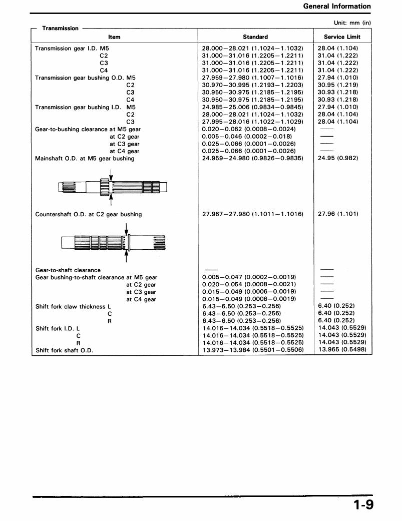
Unit: mm ( in ) Transmission --------------.------------------,--------,
Item
Transmission gear I . D . M 5 C 2 C 3 C4
Transmission gear bushing O . D . M 5 C 2 C3 C4
Transmission gear bushing I . D . M 5 C 2 C 3
Gear-to-bushing clearance a t M 5 gear at C2 gear at C3 gear at C4 gear
Mainshaft O . D . at M5 gear bushing
Countershaft O . D . at C2 gear bushing
Gear-to-shaft clearance Gear bushing-to-shaft clearance at M5 gear
at C2 gear at C3 gear at C4 gear
Shift fork claw thickness L c R
Shift fork I . D . L c R
Shift fork shaft O . D .
Standard
28.000 - 28 . 021 (1.1024 -1.1032) 31.000 - 31.016 (1. 2205 - 1 . 2 211) 31.000 - 31. 016 ( 1. 2205 -1.2211) 31.000 - 31.016 (1. 2205 - 1 . 2 211) 2 7 . 9 59 - 27 . 980 (1. 1007 -1.1 016) 30. 9 70 - 30 . 9 9 5 (1. 2193 - 1 . 2 203) 30. 9 50 - 30 . 9 7 5 (1. 2185 -1. 2195) 30. 9 50 - 30 . 9 7 5 (1. 218 5 - 1 . 2195) 24. 985 - 2 5 . 006 (0 .9834 - 0 . 9845) 28 .000 - 28. 021 (1.1024 -1.1032) 2 7 . 995 - 2 8 . 016 (1.1 022 -1.1 029) 0 .020 - 0 . 062 (0.0008 - 0 . 0024) 0 . 005 - 0 . 046 (0 .0002 - 0 . 018) 0 .02 5 - 0. 066 (0 .0001 - 0 . 0026) 0 .025 - 0 . 066 (0 .0001 - 0 . 0026) 24. 9 5 9 - 24. 980 (0 .9826 - 0 . 9835)
2 7 . 967 - 2 7 . 980 (1.1011-1.1016)
0 . 005 - 0 . 047 (0. 0002 - 0 . 0019) 0 .020 - 0 .054 (0 .0008 - 0 . 0021) 0 .015 - 0 . 049 (0. 0006 - 0 . 00 1 9) 0 .015 - 0. 049 (0. 0006 - 0 . 0019) 6 .43 - 6 . 50 (0 .253 - 0 . 2 56) 6.43-6 . 50 (0. 2 5 3 - 0 . 2 56) 6 .43- 6.50 (0 . 2 53 - 0 . 2 56) 14.016 - 14. 034 (0. 5518 - 0 . 5 5 2 5) 14.016 - 14. 034 (0. 5518 - 0 . 5 5 2 5) 14.016 - 14. 034 (0. 5518 - 0 . 5525) 13 . 9 7 3 - 13. 984 (0. 550 1 - 0 . 5506)
Service Limit
2 8 . 04 (1.104) 31. 04 (1. 222) 31. 04 (1. 222) 31. 04 (1. 222) 2 7 . 94 (1. 010) 30. 9 5 (1. 219) 30. 93 (1. 218) 30 . 9 3 (1. 218) 2 7 . 94 (1. 010) 2 8 . 04 (1.104) 2 8 . 04 (1.104)
24. 9 5 (0 .982)
2 7 . 96 (1.10 1 )
6 .40 (0. 2 5 2 ) 6 .40 (0 . 252) 6 . 40 (0. 2 5 2 ) 1 4. 043 (0. 5 5 2 9) 14. 043 (0 . 5 529) 1 4. 043 (0. 5529) 1 3 . 96 5 (0. 5498)
1-9

General Information
Unit: mm ( in ) r- Wheel/Tires
Item Standard Service Limit
Minimum tire tread depth (FR) -- 1.5 (0.06) (RR) -- 2.0 (0.08)
Cold tire pressure Up to 90 kg (200 lb) load (FR) 250 kPa (2.50 kg/cm2, 36 psi) --
Up to 90 kg (200 lb ) load (RR) 250 kPa (2.50 kg/cm2, 36 psi ) --
Up to maximum weight capacity (FR) 250 kPa (2.50 kg/cm2, 36 psi) --
Up to maximum weight capacity (RR) 290 kPa (2.90 kg/cm2, 42 psi) --
Front and rear axle runout -- 0.2 (0.01) Front and rear wheel rim runout (Radial ) -- 2.0 (0.08)
(Axial) -- 2.0 (0.08) Wheel balance weight (Front) -- 60 g (2.1 oz)
(Rear) -- 60 g (2.1 oz) Drive chain slack 20-30 (3/4-1·3/16) --
Drive chain size/l ink ( D I D) D I D 50V4/118 --
IRK) RK 50 MFOZ1/118 --
r- Front Suspension -------------.-----------------.---------, Fork spring free length Fork spring d i rection Fork tube runout Recommended fork oil Fork oi l level Fork oil capacity Steering bearing preload
410.7 (16.17) Tapered coil facing down
Fork fluid 122 (4.80) 521cc (17.62 U S oz, 18.29 Imp oz) 0.1-0.15 kg-m
402.5 (15.85)
0.2 (0.01)
r- Rear Suspension -------------�-------------�------�
Shock absorber spring free length Shock absorber spring adjuster standard position Shock absorber spring direction
241.8 (9.52) 2nd groove Small coil end facing down
237.0 (9.33)
- Brakes ----------------�--------------,-------� Front
Rear
1- 10
brake fluid brake pad wear ind icator G)
~ brake disc thickness brake disc runout master cyl inder J . D . master piston O . D . cal iper cyl inder J . D . caliper piston O . D . brake pedal free play brake drum J . D . brake l in ing thickness
DOT 4
6.0 (0.24)
11.0-11.043 (0.4331-0.4348) 10.957-10.984 (0.4314-0.4324) 25.400-25.450 (1.000-1.0020) 25.335-25.368 (0.9974-0.9987) 20-30 (0.8-1.2) 180-180.3 (7.086-7.098) 5.0 (0.2)
To the groove
5.0 (0.20) 0.25 (0.01) 11.055 (0.4352) 10.945 (0.4309) 25.461 (1.002) 25.33 (0.997)
181 (7.12) 2.0 (0.08)

General Information
Unit: mm (in) r- B c attery/ harging System
Item Standard Service Limit
Alternator/charging coil resistance (at 20°C/68°F) 0.1-1.0 0 --
Regulator/rectifier regulated voltage/amperage 14-15.5 V/below 0.5 A/3,000 rpm --
Battery capacity 12 V-10 Ah --
Battery charging rate (Normal) 1.2 A (5-10h) --
(Quick) 5 A (1h) --
Battery voltage (fully charged 20°C/68°F) Over 13.1 V --
(needs charging 20°C/68°F) Below 12.5 V --
r- Ignition System --------------.---------------.----------.., Spark plug
(Standard NGK) (Standard NIPPONDENSO) (For cold climate/below 5°C/41 °F NGK) (For cold climate/below 5°C/41 °F NIPPONDENSO) (For extended high speed riding NGK) (For extended high speed riding NIPPONDENSO)
Spark plug gap Ignition timing "F" mark Advance start
stop Full advance Ignition coil resistance (Primary: at 20°C/68°F)
(Secondary with plug cap) (Secondary without plug wire)
Pulse generator resistance (At 20°C/68°F)
CR8EH9 U24FER9
CR9EH9 U27FER9 0.8-0.9 (0.03-0.04) 12° BTDC at idle 2,000 rpm
2-4 0 23-27 kO 13-17 k0 450-550 0
Starter System --------------,----------------r------�
Starter motor brush length Starter clutch driven gear O.D.
12.0-13.0 (0.47-0.51) 47.175-47.200 (1.8573-1.8583)
6.5 (0.26) 47.16 (1.857)
- Lights/Meters/Switches -----------.....---------------,----------. Main fuse Fuse Headlight (high/low beam) Tail/brake light Position light bulb Front turn signal lights Rear turn signal lights Instrument lights Oil pressure warning indicator Side stand indicator Coolant temperature indicator High beam indicator Turn signal indicator Neutral indicator Coolant temperature sensor resistance 85°C (185°F)
120°C (248°F) Fan motor switch Starts to close (ON)
Stops to open (OFF)
30 A 10 A x 3, 15 A X 1 12 v 60/55 w 12 V 32/3 cp 12 V 3 cp x 2 12 V 32/3 cp x 2 12 V 32 cp x 2 12 V 1. 7 W X 1, 12 V 1.4 W X 2 12 v 3 w 12 v 3 w 12 v 3 w 12 v 3 w 12 v 3 w 12 v 3 w 39-49 0 14-18 0 97-103°C (207-217°F) 92-98°C (198-208°F)
1- 1 1

General Information
Torque Values
r- Standard
Fasteners Type Torque
Fasteners Type Torque
N·m (kg-m, ft-lb) N·m (kg-m, ft-lb)
5 mm hex bolt and nut 5 (0.5, 3.5) 5 mm screw 4 (0.4, 3) 6 mm hex bolt and nut 10 (1.0, 7) 6 mm screw 9 (0.9, 7) 8 mm hex bolt and nut 22 (2.2, 16) 6 mm flange bolt (8 mm head ) 9 (0.9, 7) 1 0 mm hex bolt and nut 35 (3.5, 25) 6 mm flange bolt ( 10 mm head) and nut 12 (1.2, 9) 12 mm hex bolt and nut 55 (5.5, 40) 8 mm flange bolt and nut 27 (2.7, 20)
1 0 mm flange bolt and nut 40 (4.0, 29)
Torque specifications listed below are for important fasteners. Others should be tightened to standard torque values listed above.
Notes: 1. Apply sealant to the threads. 2. Apply a locking agent to the threads. 3 . Apply molybdenum disulfide oi l to the threads and f lange surface . 4. Left hand threads . 5. Stake . 6. Apply oi l to the threads and flange surface . 7. Apply clean engine oi l to the 0-ring . 8 . Torque wrench scale reading using a special too l . 9. Apply grease to the threads and flange surface .
1 0. UBS bolt. 11. U-nut. 12. ALOC bolt; Replace with a new one.
r- Engine
Item O'ty
Maintenance : Timing hole cap 1
Lubrication : Oil pressure switch 1 Oil filter 1 Oil filter stud bolt 1 Oil drain bolt 1 Oil pump bolt 3 Oil pump driven sprocket bolt 1 Oil pipe nut (After '94) 1
Fuel Systems: Connecting tube band screw 4
Cooling Systems: Water pump cover 2 Water pump mounting bolt 2
Cylinder Head : Spark plug 4 Head cover protector 8 Cylinder head cover bolt 8 Breather case bolt 6 Cylinder head protector bolt 12 Cylinder head sealing bolt 4 Cylinder head bolt (9 mm) 16 Cylinder head bolt (6 mm) 4 Camshaft holder bolt 32 Cam chain tensioner mounting bolt 4 Boost joint bolt -
1 - 1 2
Thread dia . (mml
45
PT 1/8 20 20 12
6 6 6
5
6 6
10 6 6 6 6
18 9 6 6 6 5
Torque Remarks
N•m (kg-m, ft-lbl
18 (1.8, 13) Note 9
12 (1.2, 9) Note 1 10 (1.0, 7) Note 6 18 (1.8, 13) Note 2 34 (3.4, 25) 13 (1.3,9) 18 (1.8, 13) Note 2 12 (1.2, 9) Note 11
1 (0.1, 0.7)
13 (1.3, 9) 13 (1.3, 9)
12 (1.2, 9) 10 (1.0, 7) 10 (1.0, 7) 10 (1.0, 7) 12 (1.2, 9) 44 (4.4, 32) Note 2 44 (4.4, 32) Note 6 12 (1.2, 9) 12 (1.2, 9) Note 6 12 (1.2,9)
4 (0.4, 2.9)

General Information
r- Engine
Item Q'ty Thread Torque Remarks
dia. (mml N·m (kg-m, ft-lb)
Clutch/Gearshift Linkage Right crankcase cover bolt 13 6 12 (1.2, 9) Clutch cable holder bolt 1 10 23 (2.3, 171 Clutch spring bolt 5 6 12 (1.2, 9) Clutch center lock nut ('94) 1 22 90 (9.0, 65) Note 5, 6
(After '94) 1 22 110 (11.0,80) Note 5, 6 Gearshift l ink joint bolt 1 6 9 (0.9, 6.5) Change pedal pivot bolt 1 8 27 (2.7, 20) Drive sprocket cover bolt 3 6 10 (1.0, 7) Drive sprocket cover rubber bolt 2 6 12 (1.2, 9) Drive sprocket bolt 1 10 51 (5.1, 37) Shift drum center bolt 1 8 23 (2.3, 17) Note 2 Shift return spring pin 1 8 23 (2.3, 17)
Crankcase/Crankshaft : Upper crankcase bolt ( 1 0 mm) 2 10 39 (3.9, 28) Upper crankcase bolt (6 mm) 7 6 12 (1.2, 9) lower crankcase bolt (9 mm) 8 9 31 (3.1,22) Note 6 lower crankcase bolt (8 m) 1 8 23 (2.3, 17) lower crankcase bolt (6 mm) 8 6 12 (1.2,9) Cam chain tensioner sl ipper bolt 2 6 12 (1.2, 9) Note 2 Cam chain sl ipper bolt 2 6 12 (1.2,9) Note 2 Connecting rod bearing cap nut 8 8 33 (3.3, 24) Note 6 Seal ing bolt 1 8 18 (1.8, 13) Note 2
Alternator: left crankcase cover bolt 6 6 12 (1.2,9) Flywheel bolt 1 10 83 (8.3, 61) Note 6 Stator mounting bolt 3 6 12 (1.2,9)
Ignition System : Pulse generator mounting bolt 3 6 10 (1.0, 7)
Starter Clutch: Starter motor f lange nut 1 6 10 (1.0, 7) Starter motor case bolt 2 5 5 (0.5, 3.6) Starter clutch bolt 1 12 90 (9.0, 65) Note 6 Starter clutch outer cover bolt 3 8 40 (4.0, 29) Note 2
Lights/Meters/Switches : Neutral switch 1 10 12 (1.2, 9)
.--- Frame
Item Q'ty Thread Torque Remarks
dia . (mml N•m (kg-m. ft-lbl
Engine mounting: Front cyl inder head mounting bolt 2 10 54 (5.4, 39) Front engine mounting bracket bolt 4 8 39 (3.9, 28) Front engine mounting bolt 2 10 44 (4.4, 32) Rear engine mounting bracket bolt 2 8 39 (3.9, 28) Rear engine mounting bolt 1 12 64 (6.4, 46) Note 9 Rear cylinder head mount bolt 2 10 44 (4.4, 32) Rear cylinder head mount bracket bolt 4 8 39 (3.8, 28)
1-13

General Information
r- Frame
Item O'ty Thread Torque Remarks
dia. (mm) N•m (kg-m. ft-lb)
Front Suspension : Handlebar upper holder bolt 4 6 23 (2.3, 17) Front fender bolt 4 6 12 (1.2, 9)
Steering stem nut 1 24 105 (10.5, 76) =:] page 12-12
lock nut 1 26 Steering head bearing adjusting nut 1 26 30 (3.0, 22)
Fork pinch bolt (upper) 2 8 27 (2.7, 20)
(lower) 2 10 39 (3.9, 28)
Fork cap 2 37 23 (2.3, 17) Fork socket bolt 2 8 20 (2.0, 14) Note 2
Fork drain bolt 2 6 8 (0.8, 5.8)
Rear Suspension : Frame pivot adjusting bolt 1 20 15 (1.5, 11) .=j page 13-10
Frame lock nut 1 20 64 (6.4, 46) Frame lock bolt 1 10 39 (3.9, 28) Swingarm pivot nut 1 14 89 (8.9, 65) Note 11
Chain slider screw 2 5 6 (0.6, 4.3)
Chain tensioner 2 8 22 (2.2, 16) Shock absorber mounting bolt (upper) 2 8 27 (2.7, 20)
(lower) 2 10 37 (3.7, 27)
Wheels: Speedometer cable screw 1 5 4 (0.4, 2.9) Rear axle nut 1 18 93 (9.3, 63) Note 11
Front axle bolt 1 14 59 (5.9, 43)
Axle pinch bolt 4 8 22 (2.2, 16)
Brake disc bolt 6 8 42 (4.2, 30) Note 12
Driven sprocket nut 5 12 108 (10.8, 79) Note 11
Brake System: Brake hose bolt 2 10 35 (3.5, 25) Caliper bracket bolt 2 8 31 (3.1, 22) Note 12
Front brake hose clamp nut 2 6 12 (1.2,9) Note 11 Front master cylinder holder bolt 2 6 12 ( 1.2, 9) Front master cylinder reservoir cover screw 2 4 1. 5 (0.15, 1. 1) Front brake light switch screw 1 4 1.2 (0.12,,0.9) Front brake lever pivot bolt 1 6 1 (0.1, 0.7)
nut 1 6 6 (0.6, 4.3) Pad pin plug 1 10 2.5 (0.25, 1.8) Pad pin 1 10 18 (1.8, 13) Brake caliper bleeder bolt 1 8 5.5 (0.55, 4) Brake caliper bracket pin bolt 1 8 13 (1.3, 9) Note 2 Brake caliper pin bolt 1 8 23 (2.3, 17) Note 2 Rear brake pedal pivot bolt 1 10 39 (3.9, 28) Rear brake pedal linkage joint pinch bolt 1 8 27 (2.7, 20) Rear brake arm pinch bolt 1 8 29 (2.9, 21) Note 12 Rear brake stopper arm nut 2 8 22 (2.2. 16)
Frame/Exhaust Systems: Exhaust pipe joint nut 8 8 12 (1.2, 9) Exhaust pipe band bolt 4 8 21 (2.1, 15) Exhaust pipe protector bolt 6 6 12 (1.2, 9) Muffler mounting bolt 2 8 27 (2.7, 20)
Lights/Meters/Switches: Side stand pivot bolt 1 10 10 (1.0, 7)
nut 1 10 30 (3.0, 22) Side stand switch 1 6 10 (1.0, 7)
Others: Footpeg bracket bolt 4 8 27 (2.7 20) Fuel valve 1 22 23 (2.3, 17)
1- 14

Tools
Description
Maintenance : Oil filter wrench Drive chain cutter
Link plate holder
Lubrication : Oil pressure gauge Oi l pressure gauge attachment
Fuel System: Float level gauge Pilot screw wrench (Canadian type)
(49 states, Cal ifornia type) Cylinder Head/Cylinder/Piston:
Valve spring compressor Valve spring compressor attachment Tappet hole protector Valve guide drivier Valve guide reamer, 4. 5 mm Valve seat cutter
seat cutter, 24. 5 mm (45° EX) 29 mm (45 ° I N )
flat cutter, 2 5 mm ( 3 2 ° EX) 30 mm ( 3 2 ° I N )
interior cutter, 26 mm ( 6 0 ° EX) 30 mm (60° I N )
cutter holder, 4. 5 mm Compression gauge attachment Tensioner stopper
Clutch/Gearshift Linkage: Lock nut wrench, 26 x 30 mm Extension bar Clutch center holder
Crankshaft/Transmission : Universal bearing pul ler Inner driver C Attachment, I . D . 2 5 mm
Front Wheel/Suspension/Steering: Bearing remover shaft Bearing remover head , 20 mm Attachment, 42 x 47 mm Pilot, 20 mm Fork seal d river Fork seal driver attachment Steering stem socket wrench Bal l race remover - attachment
- driver handle
Bal l race remover Attachment, 52 x 55 mm Steering stem driver Driver
Tool Nunber
07HAA - PJ 7 0 1 00 07H M H - M R 1 0 1 02
or 07H M H - M R 1 0 1 0B 07N M H - MW00 1 1 0
or 07PM H - MZ20 1 1 0
07 506 - 3000000 07 5 1 0 - 4220 1 00
0740 1 - 00 1 0000 07908 - 422020 1
07MMA - MV90 1 0A
07757 - 00 1 0000 07959 - KM 30 1 0 1
07HMG - MR70002 07HM D - M L00 1 0 1 07H M H - M L00 1 0 1
07780 - 00 1 0 1 00 07780 - 00 1 0300 07780 - 00 1 2000 07780 - 00 1 2200 07780 - 00 1 4500 07780 - 00 1 4000 0778 1 - 00 1 0600 07JMJ - KY20 1 00
07NMG - MY90 1 00
077 1 6 - 0020203 077 1 6 - 0020500 07724 - 005000 1
0763 1 - 00 1 0000 07746 - 0030 1 00 07746 - 0030200
07746 - 0050 1 00 07746 - 0050600 07746 - 00 1 0300 07746 - 0040500 07947 - KA501 00 07947 - KF00 1 00 079 1 6 - 37 1 0 1 0 1 07953 - MJ 1 0000 07953 - MJ 1 0 1 00
or 07953 - MJ 1 000A 07953 - MJ 1 0200
or M9360 - 27 7 - 9 1 774 07946 - 3 7 1 0500 07746 - 00 1 0400 07946 - M BOOOOO 07749 - 00 1 0000
General Information
Applicability
U . S .A. only
Not avai lable in U . S . A .
Not avai lable in U . S . A.
' 94 only '94 only Equivalent commercia l ly avai lable in U . S . A .
U . S .A. only
U . S .A . only
1- 1 5

General Information
Description Tool Number Applicability
Rear Wheel/Suspension : Bearing remover shaft 07746-0050100 Bearing remover head, 20 mm 07746-0050600 Attachment, 42 x 4 7 mm 07746-0010300 Pilot, 20 mm 07746-0040500 Attachment, 52 x 55 mm 07746-0010400 Attachment, 62 x 68 mm 07746-0010500 Pilot, 25 mm 07746-0040600 Shock absorber compressor 07959-3290001 Driver shaft 07946-MJ00100
or 07949-3710001 U.S.A. only Attachment, 28 x 30 mm 07946-1870100 Pilot, 22 mm 07746-0041000 Attachment, 32 x 35 mm 07746-0010100 Pilot, 15 mm 07746-0040300 Needle bearing remover attachment 07GMD-KT70200 Bearing remover or M967X-038-XXXXX U.S.A. only Attachment, 30 mm 07746-0030300 U.S.A. only Driver 07749-0010000
Brake: Snap ring pl iers 07914-3230001
Charging System/ Alternator: Flywheel holder 07725-0040000 Rotor pul ler 07733-0020001
Electric Starter/Starter Clutch : Gear holder 07724-0010100
Electrical Equipment: Digital multimeter (KOWAl 07411-0020000 Equivalent commercial ly
avai lable in U.S.A. Analog tester 07308-0020001 (SANWAl Not avai lable in U.S.A.
or TH-5H (KOWAl
1- 16

General Information
Lubrication & Seal Points
� Engine ------------------------------�----------------------�----------------------� Location
Crankcase mating surface
0
L .... - ..J
Right crankcase cover mating surface
20-30 mm (0.8-1.2 i1) ("" ' l
�----·--.. � T .)T Left crankcase cover mating surface
20-30 mm (0.8-1.2 in) ��
0
0
0
--===::w Cylinder head semi-circular cut-out
,\
Crankshaft main bearing thrust surface Connecting rod big end bearing
small end Valve stem (valve guide sliding surface) VaJve lifter outer sliding surface Camshaft lobes/journals M3/4, C5 and shifter gear (shift fork grooves) Shift fork shaft sliding area Shift drum Primary drive gear sliding area Each gear
Cylinder head cover gasket mating surface (cover side)
Material
Liquid sealant
Molybdenum disulfide oil (A mixture of 1/2 engine oil and 1/2 molybdenum disulfide grease)
Honda Bond A
Remarks
• Wipe off the excess sealant • Do not apply the sealant to
near the bearing
1-17

General Information
- E . ngme Location Material Remarks
Right crankcase cover rubber plate bolt threads Locking agent - Clean and apply to the threads Drive chain guard bolt threads Apply area : 5.5-7.5 mm Crankcase sealing bolt threads -
Oil pump driven sprocket bolt threads -
Cam chain tensioner sl ipper bolt threads -
Cam chain sl ipper bolt threads -
Mainshaft bearing set plate bolt threads -
Shift drum bearing set plate bolt threads -
Shift drum center bolt -
Starter clutch outer cover bolt -
Oil filter stud bolt threads Cylinder head seal ing bolt threads
Oi l pressure switch threads Liquid sealant Thermo sensor threads
Lower crankcase bolt (9 mm) threads Engine oil Cylinder head bolt (9 mm) threads and flange
surface Camshaft holder bolt (6 mm) threads and flange
surface Piston sl iding surface
pin hole ring
Connecting rod bolt and nut threads Starter clutch bolt threads and seating surface Flywheel bolt threads and seating surface Oil filter threads Clutch disc l in ing surface Clutch center lock nut Each bearing
Clutch l ifter guide Multi-purpose grease Timing hole cap threads Each oi l seal l ips Each 0-ring
1-18

General Information
�
Location Material Remarks Side stand pivot bolt sliding surface Multi-purpose grease Rear brake pedal linkage sliding surface Rear brake pedal pivot surface Rear brake spindle sliding surface Right/left footpeg sliding surface Gearshift pedal pivot surface Apply thin coat of grease Throttle pipe sliding surface Clutch lever pivot bolt sliding surface
Steering head bearings '94-'02: Steering head bearing dust seal lips Multi-purpose grease
After'02: Urea based multi-purpose grease for Extreme pressure (example: EXCELITE EP2 manufactured by KYODO YUSHI, Japan, 'Shell Stamina EP2) Or equivalent
Swingarm pivot nut flange surface Multi-purpose grease Swingarm bearings Swingarm dust seal lips Front wheel dust seal lips Rear wheel dust seal lips Rear wheel sliding surface (driven flange) Rear engine mounting nut threads and seating
surface Each bearing Each dust seal lips
Throttle cables Engine oil Choke cable Clutch cable Speedometer cable Steering stem lock nut threads Flywheel bolt threads and flange surface
Handle grip inner surface Honda Bond A Honda Hand Grip Cement (U.S.A. only}
Front brake lever pivot and piston tips Silicone grease Brake caliper pin bolt sliding surface Brake caliper bracket pin bolt sliding surface Brake cam sliding surface Brake anchor pin sliding surface
Brake caliper pin bolt threads Locking agent Clean and apply to the threads Brake caliper bracket pin bolt threads Fork socket bolt threads
Front fork oil seal/dust seal lips Fork fluid Front fork
Brake master cylinder DOT 4 brake fluid
1- 19

General Information
Cable & Harness Routing
(8) RIGHT HANDLEBAR SWITCH WIRE HARNESS
(6) COMBINATION METER WIRE HARNESS
(5) HIGH BEAM/TURN "SIGNAL/ NEUTRAL INDICATOR WIRE HARNESS
(10) 9P-RED CONNECTOR (TURN SIGNAL SWITCH HORN SWITCH, DIMMER SWITCH)
1-20
(9) 9P-BLACK ECTOR (STARTER SWITCH, ENGINE STOP SWITCH)
( 1) LEFT HANDLEBAR SWITCH WIRE HARNESS
(2) CLUTCH CABLE
3) SPEEDOMETER CABLE

(5) IGNITION SWITCH WIRE HARNESS
General Information
(2) EVAPORATIVE EMISSION PURGE CONTROL VALVE
(3) CLUTCH CABLE
1-21

General Information
1-22
( 1 0) H I G HT BEAM/TURN SIGNAL/ NEUTRAL I N DICATOR WIRE
(6) STARTER MOTOR CABLE ( 5) PULSE SECON DARY AIR I NJECTION
PIPES (CALIFORNIA TYPE O N LY)

(8) FRONT PULSE SECONDARY AIR I NJECTION CONTROL VALVE (CALIFORNIA TYPE ONLY)
(6) EVAPORA VE EMISSION PURGE CONTROL VALVE (CALIFORNIA TYPE ONL Yl
( 5) FUEL
General Information
EVAPORATIVE EMISS ION CARBURETOR AIR VENT CONTROL VALVE (CALIFORNIA TYPE ONL Yl
FUEL TAN K BREATHER TUBE
(4) REAR PULSE SECON DARY AIR INJECTIO N CONTROL VALVE (CALIFORNIA TYPE ONL Yl
1 -23
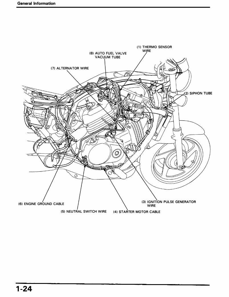
General Information
( 1 } THERMO SENSOR WIRE
( 7} ALTERNATOR WIRE
(6) ENGINE GROUND CABLE (3) I G N IT ION PULSE GENERATOR
WIRE
1-24
(5) N EUTRAL SWITCH WIRE (4) STARTER MOTOR CABLE

(8) I G N ITION PULSE GENERATOR CONNECTOR
(6) S IDE STAND SWITCH --..\----H--t:;;�.>.;:jrF'N CONNECTOR
(4) STARTER MOTOR CABLE
General Information
(1) MAIN WIRE HARN ESS
2) N EUTRAL SWITCH CONNECTOR
1-25

General Information
1 -26
(4) FUEL TAN K BR THEA TUBE 149 STATES, CANADIAN TYPE)
(7 ) R IGHT TURN S IGNAL WIRE
(9) TAIL/STOP LIGHT WIRE
AND SWITCH

General Information
Emission Control System
The U.S. Environmental Protection Agency and California Air Resources Board (CARB) require manufacturers to certify that their motorcycles comply with applicable exhaust emissions standard during their useful life, when operated and maintained according to the instructions provided, and that motorcycles built after January 1 , 1 983 comply with applicable noise emission standards for 1 year or 6,000 km (3. 730 miles) after the time of sale to the ultimate purchaser, when operated and maintained according to the instructions provided. Compliance with the terms of the Distributor's Warranties for Honda Motorcycle Emission Control Systems is necessary in order to keep the emissions system warranty in effect.
Source Of Emissions
The combustion process produces carbon monoxide and hydrocarbons. Control of hydrocarbons is very important because, under certain conditions, they react to form photochemical smog when subjected to sunlight. Carbon monoxide does not react in the same way, but it is toxic.
Honda Motor Co., ltd. utilizes lean carburetor settings as well as other systems, to reduce carbon monoxide and hydrocarbons.
Crankcase Emission Control System
The crankcase emission control system routes crankcase emissions through the air cleaner and into the combustion chamber.
( 1 ) AIR CLEANER
(2) CARBURETOR
<=:>: (3) FRESH AIR .. : (4) BLOW-BY GAS
1-27

General Information
Exhaust Emission Control System (Pulse Secondary Air Injection System)
California type only The exhaust emission control system consists of a pulse secondary air injection system which introduces fi ltered air into the exhaust gases in the exhaust port. Fresh air is drawn into the exhaust port whenever there is a negative pressure pulse in the exhaust system . This charge of fresh air promotes burning of the unburned exhaust gases and changes a considerable amount of hydrocarbons and carbon monoxide into relatively harmless carbon dioxide and water vapor. This model has two pulse secondary air injection control valves with bu ilt-in check valves . The PAI R check valves prevent reverse air flow through the system. The pulse secondary air injection control valve reacts to high intake manifold vacuum and wil l cut off the supply of fresh air during engine deceleration, thereby preventing afterburn in the exhaust system.
No adjustments to the secondary air supply system should be made, although periodic inspection of the components is recommended .
(1 I FRONT PULSE SECONDARY AIR I NJECTION (PAIR) CONTROL VALVE
(4) EXHAUST PORT
1-28
(2) AIR CLEANER

General Information
Evaporative Emission Control System ( California Type Only)
This vehicle compl ies with the Cal ifornia Air Resources Board requirements for control of evaporative emissions .
Fuel vapor from the fuel tank and carburetor is routed into the evaporative emission canister where it is absorbed and stored whi le the engine is stopped . When the engine is running and the evaporative emission purge control d iaphragm valve is open fuel vapor in the evaporative emission canister is drawn into the engine through the carburetor. At the same time, the evaporative emission carburetor air vent control valve is open and air is drawn into the carburetor through the valve .
(1) EVAPORATIVE EMISSION (EVAP) PURGE CONTROL VALVE
c:::> : (7) FRESH A I R .. : (8) F U E L VAPOR
(6) EVAPORATIVE EM ISSION CARBURETOR AIR VENT (EVAP CAV) CONTROL VALVE
Noise Emission Control System
(2) FUEL TAN K
(3) EVAPORATIVE (EVAP)
CAN I STER
(4) FRESH AIR
' (5) DRAIN
TAMPERING WITH THE NOISE CONTROL SYSTEM IS PRO H I BITED: Federal law prohibits the following acts or the causing thereof : ( 1) the removal or rendering inoperative by any person, other than for purposes of maintenance, repa ir or replacement, of any device or element of design incorporated into any new vehicle for purpose of noise control prior to its sale or del ivery to the ultimate purchaser or whi le it is in use; or (2) the use of the vehicle after such device or element of design has been removed or rendered inoperative by any person .
Among those acts presumed to constitute tampering are the acts listed below:
1. Removal of , or puncturing the muffler, baffles, header pipes or any other component which conducts exhaust gases . 2 . Removal of, or puncturing of any parts of the intake system. 3. lack of proper maintenance . 4. Replacing any moving parts of the vehicle, or parts of the exhaust or intake system, with parts other than those specified
by the manufacturer.
1 -29

General Information
Emission Control Information labels (U .S .A. Only)
An Emission I nformation Label is located on the frame as shown. The right s ide cover must be removed to v iew i t . I t g ives basic tune-up specifications.
Vehicle Emission Control Information Update Label
After making a high altitude carburetor adjustment, attach an update label on the right down tube as shown .
After re-adjusting the carburetor back to standard settings for low al itude, remove the update label .
Vacuum Hose Routing Diagram Label (California Type Only)
The Vacuum Hose Routing Diagram Label is on the rear fender as shown. The seat must be removed to view it.
Route the vacuum hoses as shown on this label .
( 1 l VACUUM HOSE ROUTING LABEL
1 -30
( 1 ) E M I SSION CONTROL I N FORMATION LABEL
( 1 ) U PDATE LABEL
VAC U UM H OSE R O U T I NG D I A G RAM ENG I NE FAM I L Y -E V A P O R A T I V E F A M I L Y-CAL I FORN I A V E H I CLE

2 . Frame/Body Panels/Exhaust System Service Information
Troubleshooting
Seat Removal/Installation
Fuel Tank Removal/Installation
Side Cover Removal/Installation
Service Information
2- 1
2- 1
2-2
2-2
2-3
Front Side Cover Removal/Installation 2-3
Exhaust System Removal/Installation 2-4
Rear Fender Removal/Installation 2-7
Upper Fairing Removal/Installation (VF7 50CD) 2-8
• Gasoline is extremely flammable and is explosive under certain conditions. KEEP OUT OF REACH OF CHILDREN. • Serious burns may result if the exhaust system is not allowed to cool before components are removed or serviced.
• Work in a well ventilated area: Smoking or al lowing flames or sparks in the working area or where gasol ine is stored can cause a f ire or explosion .
• This section covers removal and instal lation of the frame body panels, fuel tank and exhaust system . • Always replace the exhaust pipe gaskets after removing the exhaust pipe from the engine . • When insta l l ing the exhaust pipe, instal l a l l the fasteners loosely . Next, tighten the exhaust p ipe joint nuts first, then tight
en th� mounting fasteners . If you tighten the mounting fasteners first, the exhaust pipe may not seat properly . • Always inspect the exhaust system for leaks after insta l lation .
Troubleshooting
Excessive Exhaust Noise • Broken exhaust system • Exhaust gas leak
Poor Performance • Deformed exhaust system • Exhaust gas leak • Clogged muffler
2- 1

Frame/Body Panels/Exhaust System
Seat Removal/Installation
Remove the seat by removing the three mounting bolts .
During seat instal lation, al ign the seat hook with the frame hook and holes of the seat with the bosses on the side covers .
Insta l l the three mounting bolts .
CAUTION
Be careful not to pinch the wire harness between the seat and frame.
Fuel Tank Removal/Installation
• Gasoline is extremely flammable and is explosive under certain conditions .
Remove the seat (above ) .
Turn the fuel valve O F F . D isconnect t h e fuel tube . Remove the mounting bolt and col lar . Disconnect the breather tube .
Remove the fuel tank .
Instal l the fue l tank in the reverse order of remova l . After insta l lation, turn t h e fuel valve ON a n d check t h e fuel l ine for leakage .
Instal l the seat (above ) .
2-2
(2) BOLTS
(5) BOSS
( 1 ) FUEL TANK
(4) FUEL TUBE (3) BREATH ER TUBE
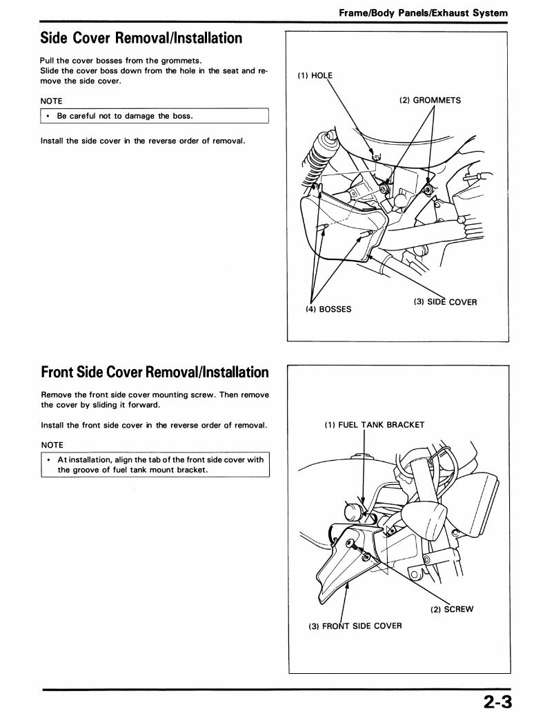
Side Cover Removal/Installation
Pul l the cover bosses from the grommets . Sl ide the cover boss down from the hole in the seat and remove the side cover.
NOTE
I • Be careful not to damage the boss .
I nstal l the side cover in the reverse order of removal .
Front Side Cover Removal/Installation
Remove the front side cover mounting screw . Then remove the cover by sl iding it forward .
I nstal l the front side cover in the reverse order of removal .
NOTE
• At instal lation, al ign the tab of the front side cover with the groove of fuel tank mount bracket .
Frame/Body Panels/Exhaust System
( 1 ) HOLE
14) BOSSES
( 1 ) FUEL TANK BRACKET
2-3
Frame/Body Panels/Exhaust System
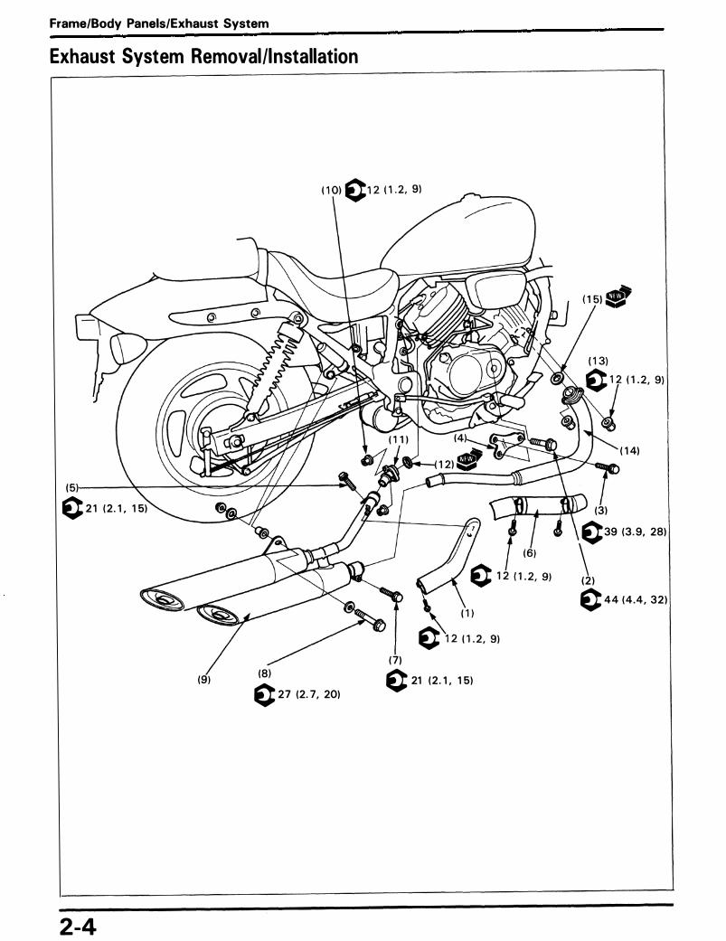
Exhaust System Removal/Installation
( 1 4)
( 5)-----'�-__,�-==_...::;"'7""-++-+---�
c 2 1 ( 2 . 1 . 1 5) (3) c39 (3 . 9. 28)
\ ( 2 ) c 4 4 ( 4 . 4 , 3 2 )
( 7)
(9) (8) c 27 (2 . 7, 20)
c 21 ( 2 . 1 , 1 5)
2-4

Frame/Body Panels/Exhaust System
NOTE
• When insta l l ing the exhaust pipe/muffler, always tighten the exhaust pipe joint nuts f irst, then tighten the mounting fasteners, see next page.
Procedure Q'ty Remarks
Removal Order I nstal lation is in the reverse order of removal . ( 1 ) Rear exhaust pipe protector 1 Instal lation (page 2-61 (2 ) Rear cyl inder head mount bolt 1 (3) Rear cylinder heat mount bracket bolt 2 (4) Rear cyl inder head mount bracket 1 ( 5) Rear exhaust pipe band bolt 1 Loosen the band bolt . (6) Front exhaust pipe protector 1 (7 ) Front exhaust pipe band bolt 1 Loosen the band bolt . (8) M uffler mounting bolt 1 (9) Muffler assembly 1
( 1 0) Rear exhaust pipe joint nut 2 ( 1 1 ) Rear exhaust pipe 1 ( 1 2) Exhaust pipe gasket 1 ( 1 3) Front exhaust pipe joint nut 2 ( 1 4) Front exhaust pipe 1 ( 1 5) Exhaust pipe gasket 1
2-5
Frame/Body Panels/Exhaust System
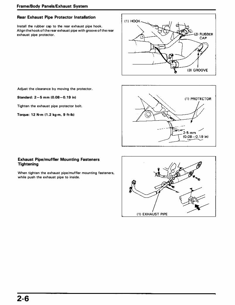
Rear Exhaust Pipe Protector Installation
I nstal l the rubber cap to the rear exhaust pipe hook. Al ign the hook of the rear exhaust pipe with groove of the rear exhaust pipe protector .
Adjust the clearance by moving the protector .
Standard : 2 -5 mm (0.08 - 0. 1 9 in)
Tighten the exhaust pipe protector bolt.
Torque: 1 2 N•m ( 1 . 2 kg-m, 9 ft-lbl
Exhaust Pipe/muffler Mounting Fasteners Tightening
When tighten the exhaust pipe/muffler mounting fasteners, whi le push the exhaust pipe to inside .
2-6
( 1 ) EXHAUST PI PE

Frame/Body Panels/Exhaust System
Rear Fender Removal/Installation
( 1 ) ( 5)
NOTE
• Route the wire harness properly (page 1 -20) .
Requisite Service
• Seat removal/instal lation (page 2-2) . • Side covers removal/instal lation (page 2-3)
Procedure O'ty Remarks
Removal Order I nstal lation is in the reverse order of remova l . ( 1 ) Rear turn signal l ight connector 4 Disconnect the connector. (2 ) Brake/tai l l ight connector 3 Disconnect the connector . (3) Rear fender mounting bolt/nut 8/4 (4) Grab rai l 2 ( 5) Rear fender assembly 1 (6) Sub frame 1
2-7

Frame/Body Panels/Exhaust System
Upper Fairing Removal/Installation (VF750CD)
CAUTION
• Do not scratch and damage the windscreen .
Procedure Q'ty Remarks
Removal Order I nstal lation is in the reverse order of remova l . ( 1 ) Upper fairing mounting bolt 3 (2) Upper fairing 1 At instal lation, al ign the tab of the upper fair ing stay with
the hole of the cable guige.
2-8

Windscreen Replacement
Remove the screws, plastic washers and rubber washers . Remove the windscreen and upper fair ing stays .
Insta llation is in the reverse order of remova l .
Frame/Body Panels/Exhaust System
( 1 ) STAYS
(4) SCREW (3) PLASTIC WASHER
2-9

MEMO

3 . Maintenance Service Information
Service Access Guide
Maintenance Schedule
Air Cleaner
Service Information
3- 1 Valve Clearance
3-2 Drive Chain
3-4 Headlight Aim
3-5
• Refer to Common Service Manual for items not included in this manual . • Refer to Specifications (Section 1) for maintenance data .
3-5
3-8
3- 1 0
3- 1

Maintenance
Service Access Guide • The following shows the locations of the parts that must be removed for the maintenance items l isted below.
Refer to the Common Service Manual for items not included in this manual . • Refer to section 2 (Frame/Body Panels/Exhaust System) . for the parts that must be removed for service.
For example: Air Cleaner (Contamination, clogging, replacement) : Parts • Rear Fairing -The part required to be removed for service .
( 1 8) Valve Clearance ( Inspection/Adjustment : page 3-5) • Fuel tank
( 1 7) Spark Plug (Wear, damage, color)
( 1 6) Suspension (Loose, wear, damage)
( 1 5) Brake Drum (Shoe wear)
( 1 4) Wheel ( Damage, runout, corrosion)
( 1 3) Tire (Wear, damage, air pressure)
( 1 2) Brake Light Switch (Operation)
( 1 1 ) Reserve Coolant Tank Cap
( 1 0) Oi l Level Gauge (Oi l level check, replacement)
3-2
( 1 ) Throttle Grip (Operation, free play)
(2) Brake Lever (Air in system )
(3) Master Cylinder (Level check, fluid replacement)
(4) Headl ight (Ai m : page 3- 1 0)
(6) Tire
(5 ) Wheel ( Damage, runout, corrosion)
(Wear, damage, a ir pressure)
( 7) Radiator Cap (Coolant replacement)
(8 ) Pulse Secondary Air I njection System (Cal ifornia type only; Air leaks, deterioration, damage) ·
(9) Brake Peda l ( Free play, height)

( 1 3) Air Cleaner (Contamination, clogging, replacement; page 3-5)
• Fuel tank
( 1 2) Clutch lever (Free play)
( 1 1 ) Steering Head Bearing (Damage)
( 1 0) Suspension (loose, wear, damage)
(9) Caliper (Pad wear)
(8 ) Brake Hose (leakage, deterioration,
damage)
(7) Oil Fi lter (Replacement)
(6) Carburetor Choke (Operation)
Maintenance
( 1 ) Synchronization Adjusting Screw (Carburetor synchronizatron; page 5- 1 4) • Middle cover
(2) Fuel line (Damage, leakage)
(3) Drive chain (Free play, lubrication, replacement; page 3-8)
(4) Side stand (Operation)
( 5) Throttle Stop Screw
3-3

Maintenance
Maintenance Schedule
Perform the PRE-RIDE I NSPECTION in the Owner's Manual at each scheduled maintenance period . 1 : I nspect and clean, Adjust, Lubricate, or Replace if necessary . R: Replace, C: Clean, L: Lubricate, A: Adjust The following items require some mechanical knowlege. Certain items (particularly those marked * and * * ) may require more technical information and tools. Consult their authorized Honda dealer.
� Note Odometer Rading (Note 1 )
Refer x 1 ,000 mi 0. 6 4 8 12 1 6 20 24 To
x 100 km 10 64 128 1 92 256 320 384 Page s
* Fuel Line I I I Note 5 * Throttle Operation I I I Note 5 * Carburetor Choke I I I Note 5
en * Air Cleaner Note 2 R R 3-5
� Spark Plug I R I R I R Note 5 w !::: * Valve Clearance I 3-5 0
w I- Engine Oi l R R R R Note 5 <( ....I
Engine Oi l Filter R R R R Note 5 w a: z * Carburetor Synchronization I I I 5- 14 Q * Carburetor Idle Speed I I I I I I I Note 5 en en
� Radiator Coolant Note 3 I I R Note 5 w * Cool ing System I I I Note 5
* Secondary Air Supply System Note 4 I I I Note 5 * Evaporative Emission Control
System Note 4 I I Note 5
Drive Chain Every 600 mi ( 1 ,000 km) I , L Note 5 en �
Brake Fluid Note 3 I I R I I R Note 5 w Brake Shoe/Pad Wear I I I I I I Note 5 !::: 0 Brake System I I I I Note 5 w I- * Brake Light Switch I I I Note 5 <( ....I w * Headlight Aim I I I Note 5 a: z Clutch System I I I I I I I Note 5 0 c;; Side Stand I I I Note 5 en
� * Suspension I I I Note 5 w z * Nuts, Bolts , Fasteners I I I I 1- 12 0 z * * Wheels/Tires I I I Note 5
* * Steering Head Bearings I I I I Note 5 * Should be serviced by an authorized Honda dealer, unless the owner has the proper tools and service data and is mechani
cally qual ified . * * I n the interest of safety, we recommended these items be serviced only by an authorized Honda dealer.
Notes: 1. At higher odometer readings, repeat at the frequency interval established here . 2 . Service more frequently when riding in unusual ly wet or dusty areas. 3 . Replace every 2 years, or at indicated odometer interval , whichever comes first . Replace requires mechanical ski l l . 4. Cal ifornia type only. 5 . Refer to Common Service Manual .
3-4

Air Cleaner
Remove the fuel tank (page 2-2) . Remove the front side cover (page 2-3 ) . Remove the two screws and airduct stopper. Remove the air duct by sl iding it backward .
Remove the nine screws and air cleaner housing cover/air cleaner. Remove the a ir cleaner from the air cleaner housing cover.
Discard the a i r c leaner in accordance with the maintenance schedule . Also, replace the element any time it is excessively d i rty or damaged .
Instal l the removed parts in the reverse order of remova l .
Valve Clearance
Inspection
NOTE
• I nspect and adjust the valve clearance whi le the engine is cold (Below 3 5 ° C/95 ° F) .
Remove the following : - timing hole cap - seat (page 2-2) - fuel tank (page 2-2) - rear cylinder head cover (page 8-2)
Remove the lower radiator hose guide. Remove the lower radiator mounting bolts , loosen the upper mounting bolt and swing the radiator forward , then secure it out of the way.
CAUTION
• Be careful not to damage the radiator fins.
Remove the front cyl inder head cover (page 8-2) .
Maintenance
( 1 l AIR DUCT STOPPER
3- 5

Maintenance
Turn the crankshaft clockwise and al ign its "T 1 " mark with the index mark on the right crankcase cover.
Make sure that No. 1 piston is at TDC (Top Dead Center) on the compression stroke. If it is not on the compression stroke, turn the crankshaft one ful l turn (360 ° ) clockwise .
I nsert the feeler gauge between the valve l ifter and the cam lobe. Check the valve clearances for the No. 1 cyl inder intake and exhaust valves using a feeler gauge .
Valve clearance: IN: 0. 1 6 ± 0.02 mm (0.006 ± 0.001 in) EX: 0 . 25 ± 0.02 mm (0.0 1 0 ± 0.001 in)
NOTE
• Record the clearance for each valve for reference in shim selection if adjustment is required .
Turn the crankshaft clockwise 1 /4-turn ( 90 ° ) and al ign its "T2" mark with the index mark on the right crankcase cover.
Check the valve clearances for the No. 4 cyl inder.
Turn the crankshaft clockwise 3/4-turn ( 2 7 0 ° ) and al ign its "T 1 " mark with the index mark on the right crankcase cover .
Check the valve clearances for the No. 3 cyl inder.
Turn the crankshaft clockwise 1 /4-turn ( 90 ° ) and al ign its "T2" mark with the index mark on the right crankcase cover .
Check the valve clearances for the No. 2 cyl inder.
Adjustment
Remove the camshafts (page 8-2 ) . Remove the valve l ifters a n d shims.
NOTE
• Shims may stick to the inside of the valve l ifter . Do not a l low the shims to fal l into the crankcase .
• Mark al l l ifters and shims to ensure correct reassembly. • The valve l ifter can be easi ly removed with a valve lap
ping tool or magnet . • The shims can be easily removed with tweezers or a
magnet.
3-6
( 1 ) I NDEX MARK
( 2) "T 1 " MARK
( 1 ) The cyl inder numbering is g iven below:
(3) LEFT
(2 ) FRONT
(4) Fir ing order
(5) # 1 - 90 ° - # 4 - 270° - # 3 - 90 ° - # 2 - 270 ° - # 1
( 1 )VALVE LIFTER

Clean the valve shim contact area in the valve l ifter with compressed a i r .
Measure the shim thickness and record it .
NOTE
• Sixty-five d ifferent shim thickness are available : from the thinnest ( 1 . 200 mml to the thickest ( 2 . 800 mml in intervals of 0.025 mm.
Calculate the new shim thickness using the equation below.
A = B - C + D
A: New shim thickness B: Recorded valve clearance C: Specified valve clearance D: Old shim thickness
Example:
Recorded valve clearance : 0. 1 6 mm Old shim thickness: 1 . 725 mm Specified valve clearance: 0 . 20 mm
A = 0 . 1 6 - 0 . 20 + 1 . 725
A = 1 .685
NOTE
• Make sure of the correct shim thickness by measuring the shim with m icrometer.
• Replace the valve seat if a carbon deposit results in a calculated d imension of over 2 . 800 mm.
Instal l the newly selected sh im on the valve retainer. Apply molybdenum d isulfide oi l to the valve l ifter . I nstal l the valve l ifter in the valve l ifter holes.
NOTE
• I nstal l the unchange shims and valve l ifters in their original locations.
Maintenance
( 1 I SH IM
e e e e 1 . 80 mm 1 . 825 mm 1 . 8 5 mm 1 . 8 7 5 mm
3-7

Maintenance
I nstal l the camshaft and camshaft holders (page 8-8) . Rotate the camshafts by rotating the crankshaft clockwise several times. Recheck the valve clearance .
Apply Honda Bond A to the cylinder head cover grooves as shown. Instal l the cover gasket with the " IN" mark facing the intake side .
I nstal l the cover bolt washer with the " U P" mark facing up . Tighten the cover bolts .
Torque: 1 0 N·m ( 1 .0 kg-m, 7 ft-lbl
I nstal l the removed parts in the reverse order of remova l .
Drive Chain
Replacement
The MAGNA VF750C uses a drive chain with a staked master l ink . Loosen the drive chain .
Assemble the special too l .
I s.TooL I Drive chain cutter
NOTE
07HMH - M R 1 0 1 02 or 07HMH - MR 1 0 1 0B
(U.S.A. only)
• When using the special tool , follow the manufacture's operating instructions.
3-8
(2 ) GROOVES ( 1 ) COVER GASKET
(3) CYLIN D E R H EAD COVER
( 11 1 s.TooL I DRIVE CHAIN CUTTER

locate the crimped pin ends of the master l ink from the outside of the chain and remove the l ink with the drive chain cutter .
! s TooL ! Drive chain cutter
NOTE
07HMH-MR 1 0 1 02 or 07HMH-MR 1 0 1 0B (U .S.A. only)
• When using the special tool , follow the manufacture's operating instructions.
Remove the drive chain .
Remove the excess drive chain l inks from the new drive chain with the drive chain cutter .
NOTE
• Include the master l ink when you count the drive chain l inks .
Standard l ink: 1 1 8 link
Replacement chain : RK 50 MFOZ 1 : DID 50 V4
I s.TooL I Drive chain cutter
Link plate holder
CAUTION
07HMH-MR 1 0 1 02 or 07HMH-MR 1 0 1 0B (U .S .A. only) 07NMH-MW001 1 0 or 07PMH-MZ20 1 1 0
• Never reuse the old drive chain, master link, master link plate and 0-rings.
Instal l the new drive chai n . Assemble the new master l ink, 0-rings and plate .
CAUTION
• Insert the master link from the inside of the drive chain and install the plate with the identification mark facing the outside.
Assemble and set the drive chain cutter .
Make sure that the master l ink p ins are installed properly. Measuring the master l ink pin length projected from the plate .
Standard length : 1 .2-1 .4 mm (0.05-0.06 in)
Stake the master l ink pins.
Maintenance
( 1 ) 1 LI�� � ( 21 MASTER LIN K
I f-o!ICI----- ( 3) 1 1 8 L IN K
(41 1 s.TooL I DRIVE CHAIN CUTTER
( 1 ) MASTER L INK
\
lT I I L J I
1 . 2 - 1 . 4 m m lOS: I
. ( 21 1 s.Tool I DRIVE CHAIN CUTTER
3-9

Maintenance
Make sure that the pins are staked properly by measuring the diameter of the staked area using a sl ide cal ipers .
Diameter of the staked area : DID: 5 .50 - 5.80 mm (0.2 1 7 -0.228 in) RK: 5.55 - 5.85 mm (0 .2 1 0 -0.230 in)
After staking, check the staked area of the master l ink for cracks . In there is any cracking, replace the master l ink, 0-rings and plate .
CAUTION
• Drive chain with clip-type master link must not be used .
Headlight Aim
• An improperly adjusted headlight may blind oncoming drivers, or it may fail to light the road for a safe distance.
VF750CD : Adjust the headlight a i m horizontally and vertically, turning the adjusting screws as shown .
VF750C : Refer to section 2 of the common Service Manua l .
3- 1 0
( 1 1 SL IDE CALIPER
0 X
( 1 1 ADJUSTING SCREWS

4. Lubrication System Service Information
Troubleshooting
4-1 4-1 4-2
Oil Pump Removal/Instal lation
Oil Pump Disassembly I Assembly
4-3 4-4
Lubrication System Diagram
Service Information
• If the engine must be running to do some work, make sure the area is well ventilated. Never run the engine in an enclosed area. The exhaust contains poisonous carbon monoxide gas that can cause loss of consciousness and may lead to death. Run the engine in an open area or with an exhaust evacuation system in an enclosed area.
• Used engine oil may cause skin cancer if repeatedly left in contact with the skin for prolonged periods. Although this is unlikely unless you handle used oil on a daily basis, it is stil l advisable to thoroughly wash your hands with soap and water as soon as possible after handling used oil. KEEP OUT OF REACH OF CHILDREN.
• The o i l pump can be serviced with the engine insta l led i n the frame. • For o i l pressu re check, refer to section 4 of the Common Service Manua l ; for the switch location, see page 1 8-2 of th is
manua l • The service procedures i n this section must be performed with the engine o i l dra ined. • When removing and insta l l i ng the o i l pump use care not to a l low dust or d i rt to enter the engine. • If any portion of the o i l pump is worn beyond the specified service l im its, replace the o i l pump as an assem bly. • After the o i l pump has been insta l led check that there a re no o i l leaks and that o i l pressure is correct.
Troubleshooting Oil Level Low • Oi l consumption • External o i l leak • Worn piston r ing or i ncorrect piston r ing insta l lation • Worn va lve gu ide or sea l
Low Or No Oil Pressure • Clogged o i l orifice • I ncorrect o i l being used
No Oil Pressure • Oi l level too low • Oi l pump drive cha in or sprocket broken • Oi l pump damaged ( rotor shaft) • I nternal o i l leaks
Low Oil Pressure • Clogged o i l stra iner screen • Oi l pump worn or damaged • I nterna l oi l leak • Pressu re re l ief va lve stuck open • I ncorrect o i l being used • Low oil level
High Oil Pressure • Plugged o i l fi lter, ga l lery, or meter ing orifice • Pressure re l ief va lve stuck closed • I ncorrect o i l being used
4- 1
Lubrication System
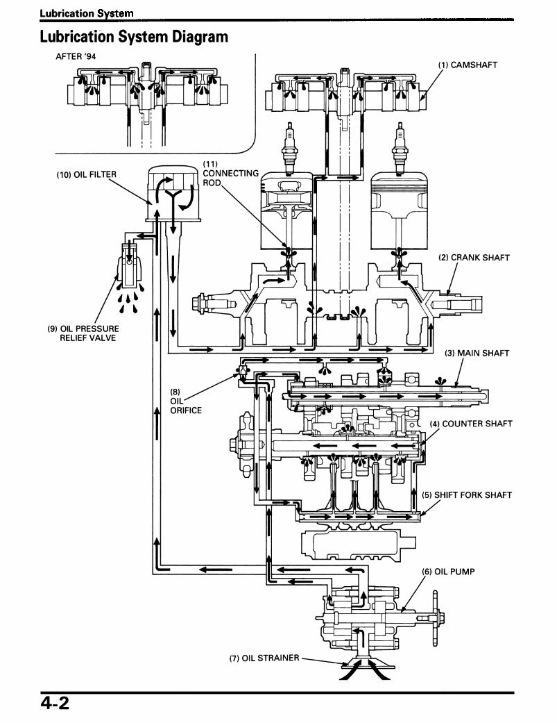
Lubrication System Diagram AFTER '94
(9) OIL PRESSURE RELIEF VALVE
4-2
•
( 1 ) CAMSHAFT

Oil Pump Removal/Instal lation
_, : 0-ring )«j��-(10) r:w c 1 8 ( 1 .8, 1 3)
NOTE
• Use care to keep dust or d i rt out of the engine. • After insta l l at ion, check that there a re no o i l leaks.
Requisite Service
• Engine o i l d ra in ing/refi l l ing • Clutch remova l/insta l l ation (page 9-4, 6)
Procedure O'ty
Removal Order ( 1 ) Oi l pan bolt 1 2 (2) Oi l pan 1 (3) Gasket 1 (4) Pressure rel ief va lve 1 (5) 0-ri ng 1 (6) Oil stra iner 1 (7) 0-ring 1 (8) Oi l p ipe 2 (9) 0-ring 4
( 1 0) Oi l pump driven sprocket bolt 1 ( 1 1 ) Oi l pump driven sprocket 1 ( 1 2) Oi l pump mounting bolt 3 ( 13 ) O i l pump assembly 1 ( 1 4) Dowel p in 2
Lubrication System
• Exhaust system remova l/insta l lation ( page 2-4) • Water pump remova l/i nsta l lation (page 6-7)
Remarks
I nsta l l ation is in the reverse order of remova l . At insta l lation, tighten the bolts as shown.
Apply a locki ng agent to the th reads.
4-3

Lubrication System
Oil Pump Disassembly I Assembly
NOTE
( 1 3) ( 1 2 )
( 1 ) (2 ) Sit .,
( 1 1 )
( 1 0)
• If any portion of the o i l pump is worn beyond the specified service l im it, replace it as an assembly. • Before assembly them, clean a l l d isassembled parts thoroughly with clean engine o i l . • Refer to section 4 of the Common Service Manua l for i nspection information . • Refer to page 1 -6 for specification.
Requisite Service
• Oi l pump remova l/insta l lation (page 4-3)
Procedure
Disassembly Order ( 1 ) Cotter p in (2) 0-ring (3) Oil stra iner p ipe (4) Bolt (5) Pump cover (6) Dowel p in (7 ) Feed pump cover (8) Dowel p in (9) Outer rotor
( 1 0) Inner rotor ( 1 1 ) Rotor shaft ( 1 2) Drive p in ( 1 3) Washer ( 1 4) O i l pump body
4-4
O'ty Remarks
Assembly is i n the reverse order of d isassembly. 1 1 1 3 After insta l lation, check that the rotor shaft turns freely. 1 2 1 2 1 Insta l l with the punch mark fac ing the o i l pump body. 1 Insta l l a l ign ing the cut out with the drive p in . 1 1 Insta l l i n the rotor shaft hole. 1 1

5. Fuel System Service Information
Troubleshooting
Air Cleaner Housing Removal/ Installation
Carburetor Removal/Installation
Carburetor Separation
Carburetor Disassembly I Assembly
Carburetor Combination
Carburetor Tube Routing (California Type Only)
Service Information
5-1 5-2
5-3 5-4 5-6 5-8 5-1 0
5-1 3
Carburetor Synchronization
Pilot Screw Adjustment
High Altitude Adjustment (U .S.A. Only)
Evaporative Emission Canister (EVAP Canister) Removal/Installation (California Type Only)
Pulse Secondary Air Injection Control Valve (PAIR Control Valve) Removal/ Installation (California Type Only)
5-1 4 5-1 6
5-1 7
5-1 8
5-1 8
• Gasoline is extremely flammable and is explosive under certain conditions. KEEP OUT OF REACH OF CHILDREN. • Bending or twisting the control cables will impair smooth operation and could cause the cables to stick or bind,
resulting in loss of vehicle control .
• Work i n a wel l venti lated a rea. Smoking or a l lowing flames or spa rks i n the work a rea or where gaso l ine is stored can cause a fi re or explosion.
CAUTION • To prevent damage, be sure to removed the diaphragms before cleaning air and fuel passages with compressed
air. The diaphragms might be damaged.
• Refer to section 2 for fuel tank remova l and i nsta l lation . • When d isassembl ing fuel system parts, note the locations of the 0-rings. Replace them with new ones on reassem
bly. • Before removing the carburetors, place the suitable conta iner under the carbu retor d ra in tube, loosen the dra in bolts
and dra in the carbu retors. • After removing the carburetor, wrap the intake port of the engine with a shop towel or cover it with pieces of tape to
prevent any foreign materia l from dropping i nto the engine. • The vacuum chamber and float chamber can be serviced with the carbu retors assembled. • Cal ifornia Type On ly:
All hoses used in the evaporative em ission contro l system are numbered for identificat ion. When connecti ng one of these hose, com pare the hose number with the Vacuum Hose Routi ng Diagram Label, page 1 -30, and ca rbu retor tubes routi ng, page 5- 1 3.
NOTE
• If the veh ic le is to be stored for more than one month, dra in the float bowls. Fuel left i n the float bowls may cause c logged jets resu lt ing in hard starti ng or poor d riveab i l ity.
5- 1

Fuel System
Troubleshooting Engine Won't Start
Too m uch fuel getting to the engine - Air cleaner c logged - Flooded carbu retor I ntake a i r leak Fuel contam inated/deteriorated No fuel to carbu retor - Fuel stra i ner c logged - Fuel tube clogged - Fuel va lve stuck - Float level misadjusted - Fuel tank breather tube c logged
Lean Mixture • Fuel jets clogged • Float va lve fau lty • Float level too low • Fuel l ine restricted • Carburetor a i r vent tube c logged • I ntake air leak • Throttle va lve fau lty • Vacuum piston fau lty • Cal ifornia Type On ly: Evaporative em ission carbure
tor a i r vent control va lve fau lty
Rich Mixture • Starting enrichment va lve i n ON position • Float valve fau lty • F loat level too h igh • Ai r jets c logged • Air cleaner contaminated • Flooded carbu retor
Engine Stall, Hard To Start, Rough Idling • Fuel l i ne restricted • Ign it ion ma lfunction • Fuel m ixtu re too lean/rich • Fuel contaminated/deteriorated • I ntake a i r leak • Id le speed misadjusted • Float level misadjusted • Fuel tank breather tube c logged • Pi lot screw misadjusted • Slow c i rcu it or starting enr ichment c i rcu it c logged • E mission control system ma lfunction (Cal iforn ia Type
On ly) - Evaporative emiss ion carbu retor a i r vent control
valve fau lty - Evaporative emiss ion purge control valve fau lty - Loose, d isconnected or deteriorated hoses of the
em ission control system
5-2
Afterburn When Engine Braking is Used • Lean m ixtu re i n s low c i rcu it • Ai r cut-off va lve ma lfunction • Emission control system ma lfunction (Cal ifornia Type
On ly) . - Pu lse secondary a i r supply system fau lty - Loose, d isconnected or deteriorated hoses of the
em ission contro l system
Backfiring Or Misfiring During Acceleration • Ign it ion system fau lty • Fuel mixture too lean
Poor Performance (Driveability) And Poor Fuel Economy • Fuel system clogged • Ign it ion ma lfunction _ • Em ission control system ma lfunction (Cal ifornia Type
On ly) - Loose, d isconnected or deteriorated hoses of the
emission control t!YStem

Fuel System
Air Cleaner Housing Removal/Instal lation
Requisite Service
• Fuel tank remova l/insta l lation (page 2-2)
Procedure
Removal Order ( 1 ) Left midd le cover stay bolt (2 ) R ight m iddle cover stay bolt (3) Front pu lse secondary a i r i njection control
va lve bolt (4) Rear pu lse secondary air i njection contro l
va lve a i r i ntake p ipe (5) Air c leaner housing screw (6) Front pu lse secondary air i njection contro l
va lve a i r i ntake tube (7) Rear pu lse secondary air i njection contro l
va lve a i r i ntake tube (8) Crankcase breather tube (9) Air cleaner housing
Q'ty
3 1 2
1
3 1
1
1 1
• Air cleaner remova l/insta l lation (page 3-5)
Remarks
Insta l l at ion is in the reverse order of remova l .
Ca l ifornia type only
Cal ifornia type only
Ca l ifornia type only
Ca l ifornia type only
Move the air c leaner housing out of the carbu retor on the left. CAUTION • Be careful not to damage the air cleaner housing dur-
ing removal/ installation.
5-3

Fuel System
Carburetor Removal/Instal lation
5-4
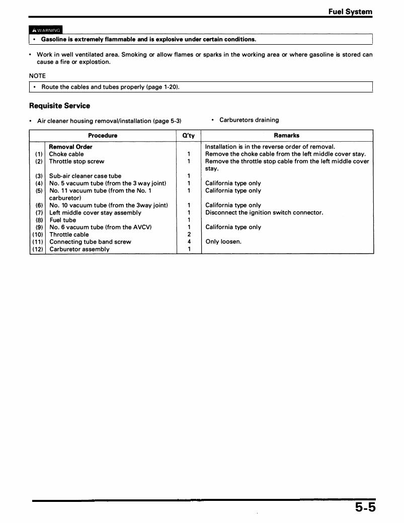
Fuel System
• Gasoline is extremely flammable and is explosive under certain conditions.
• Work i n wel l venti lated a rea. Smoking or a l low flames or sparks i n the working a rea or where gasol ine is stored can cause a fi re or explostion .
NOTE
I • Route the cables and tubes properly (page 1 -20).
Requisite Service
• Air c leaner housing remova l/insta l lation (page 5-3)
Procedure
Removal Order ( 1 ) Choke cable (2 ) Th rottle stop screw
(3) Sub-a i r c leaner case tube (4) No. 5 vacuum tube (from the 3 way jo int) (5) No. 1 1 vacuum tube (from the No. 1
carburetor) (6) No. 10 vacuum tube (from the 3way joint) (7) Left middle cover stay assembly (8) Fuel tube (9) No. 6 vacuu m tube (from the AVCV)
( 1 0) Throttle cable ( 1 1 ) Connecting tube band screw ( 1 2) Carbu retor assembly
• Carburetors d ra in ing
O'ty Remarks
I nsta l lation is i n the reverse order of remova l . 1 Remove the choke cable from the left m idd le cover stay. 1 Remove the th rottle stop cable from the left m iddle cover
stay. 1 1 Ca l ifornia type only 1 Cal ifornia type only
1 Ca l ifornia type on ly 1 Disconnect the ign ition switch connector. 1 1 Ca l ifornia type only 2 4 On ly loosen. 1
5-5

Fuel System
Carburetor Separation
( 1 )
, �
(5) (26)
5-6

Requisite Service
• Carbu retor remova l/i nsta l lation (page 5-4)
Procedure
Separate No. 4 carb. from No. 1 /2/3 carb. ( 1 ) Air cham ber screw (2) Lock plate (3) Air chamber/a i r fun nel (4) 0-ring (5) Choke cable (6) Start ing enr ichment va lve arm screw (7 ) P lastic washer (8) Start ing enr ichment va lve a rm (9) Plastic co l la r
( 1 0) Return spring ( 1 1 ) Carburetor connecti ng nut
( 1 2 ) No. 4 carburetor ( 1 3) No. 5 vacuum tube (from the No. 4 carburetor) ( 1 4) Thrust spring ( 1 5) Choke cable holder
Separate No. 3 carb. from No. 1 /2 carb. ( 1 6) No. 5 vacuum tube (from the No. 3 carburetor) ( 1 7 ) No. 3 carburetor ( 1 8) Thrust spr ing ( 1 9) Sub-a i r jo int pipe/tube/0-r ing (20) No. 6 vacuum tube/jo int pipe/0-r ing (2 1 ) No. 5 vacuum tube (from the No. 1 /2
carbu retor) (22) Front col l a red dowel pin (23) Rear co l la red dowel pin (24) Center col l a r (25) Fuel tube/jo int pipe/o-ri ng (26) Sta rti ng enrichment va lve l i nk assembly
Separate No. 2 carb. from No. 1 carb. (27) �arburetor connecting bolt (28) Throttle l i nk (29) No. 2 carburetor (30) No. 1 ca rburetor
Q'ty
1 2 4
4/4 4 1 4 4 2 4 2 6
1 1 1 1
1 1 1
2/1/4 2/2/4 6/3
1 1 1
2/3/6 1
3 1 1 1
Fuel System
• Carburetor synchron ization (page 5- 1 4)
Remarks
NOTE • Loosen the nuts g radua l ly and a lternately. • Do not remove the connecting bolts.
Ca l ifornia type only
Cal ifornia type only
Ca l ifornia type only
5-7

Fuel System
Carburetor Disassembly I Assembly
(23)
( 1 2 )
( 1 5) ( 1 4)
�: 0-ring, gasket
5-8

Fuel System
NOTE
• Vacuum chamber, float chamber and jets can be serviced without separati ng the carbu retors. • Note the location of the each ca rburetor parts so they can be back i n the i r orig i na l location .
Requisite Service
• Carburetor separation (page 5-6)
Procedure
Disassembly Order Vacuum Chamber Disassembly Order
( 1 ) Vacuum chamber cover screw (2) Vacuum cham ber cover (3) D iaphragm spring
(4) D iaphragm/vacuum piston
(5) Jet need le holder (6) Jet need le holder spr ing (7) Jet need le/washer
Float Chamber Disassembly Order (8) Float chamber cover screw (9) Float chamber
( 1 0) 0-ring ( 1 1 ) Float pin ( 1 2) Float ( 1 3) Float va lve ( 1 4) Main jet ( 1 5) Need le jet holder ( 1 6) Slow jet ( 1 7 ) Pi lot screw ( 1 8) Spring ( 1 9) Washer (20) 0-ring
Starting Enrichment Valve Disassembly Order
(2 1 ) Valve n ut (22) Spr ing (23) Starting earchment va lve
Air Cut Off Valve Disassembly Order (24) Ai r cut off va lve cover screw
(25) Air cut off valve cover (26) 0-ri ng
(27) Air cut off va lve
Q'ty Remarks
Assembly is i n the reverse order of d isassembly.
3 1 1 NOTE
• At insta l lation, be ca refu l not to damage the spring . 1 NOTE
• At insta l lation, a l ign the tab of the d iaphragm with the carbu retor body g roove.
1 Remova l/i nsta l l at ion (page 5- 1 2 ) 1
1/1
3 1 1 1 1 1 1 1 1 1 1 1 1
4 1 1
1 At i nsta l lation , be s u re the d i a p h ra g m a n d spr ing a re properly seated, then t ight them.
1 Do not lose the spring when va lve cover remova l . 3 At i nsta l lation , i n sta l l the new 0-ri ng with its flat s ide
toward the carbu retor body. 1
5-9

Fuel System
Carburetor Combination
(27 )
D � D
No. 1 CARBURETOR
(25) , : 0-R ING, COTIER PIN (5)
5- 1 0
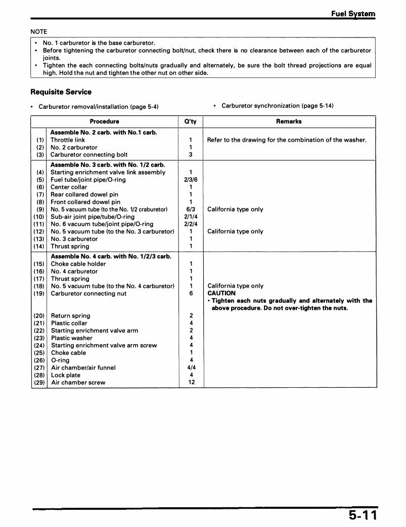
NOTE
o No. 1 carburetor is the base carburetor.
Fuel System
o Before t ighten ing the carbu retor connecti ng bo lt/nut, check there is no clearance between each of the carbu retor jo ints.
o Tighten the each connecti ng bolts/nuts g radua l ly and a lternately, be sure the bolt thread project ions a re equa l h igh . Ho ld the n ut and tighten the other n ut on other side.
Requisite Service
o Carburetor remova l/i nsta l lation (page 5-4)
Procedure
Assemble No. 2 carb. with No. 1 carb. ( 1 ) Th rottle l i nk ( 2 ) No. 2 carburetor (3) Carburetor connecting bolt
Assemble No. 3 carb. with No. 1 /2 carb. (4) Start ing enrichment va lve l ink assembly (5) Fuel tube/jo int pipe/0-ri ng (6) Center col la r (7 ) Rear co l la red dowel p in (8 ) Front co l la red dowel p in (9 ) No. 5 vacuum tube (to the No. 1/2 craburetor)
( 1 0) Sub-a i r jo int pipe/tube/0-r ing ( 1 1 ) No. 6 vacuum tube/jo int pipe/0-r ing ( 1 2 ) No. 5 vacuum tube (to the No. 3 carbu retor) ( 1 3) No. 3 carburetor ( 1 4) Thrust spring
Assemble No. 4 carb. with No. 1 /2/3 carb. ( 1 5) Choke cable holder ( 1 6) No. 4 carburetor ( 1 7 ) Thrust spring ( 1 8) No. 5 vacuu m tube (to the No. 4 carbu retor) ( 1 9) Carburetor connecti ng n ut
(20) Return spr ing (2 1 ) Plastic col la r (22) Start ing enrichment valve a rm (23) P lastic washer (24) Start ing en richment va lve arm screw (25) Choke cable (26) 0-ri ng (27) Air chamber/a i r funne l (28) Lock plate (29) Air cham ber screw
Q'ty
1 1 3
1 2/3/6
1 1 1
6/3 2/1/4 2/2/4
1 1 1
1 1 1 1 6
2 4 2 4 4 1 4
4/4 4 1 2
o Carburetor synchron izat ion (page 5- 1 4)
Remarks
Refer to the d rawing for the combination of the washer.
Cal ifornia type only
Ca l ifornia type on ly
Ca l ifornia type on ly CAUTION o Tighten each nuts gradually and alternately with the
above procedure. Do not over-tighten the nuts.
5- 1 1

Fuel System
Jet Needle Holder Removal/Installation
Removal Remove the vacuum piston (page 5-8) .
Te m po ra r i l y i n sta l l the 4 m m sc rew or e q u i v a l e n t (Example; vacuu m chamber screw). Pu l l the screw and remove the jet needle ho lder.
CAUTION • Be careful not to damage the diaphragm. • Do not remove the jet needle holder by pushing the
jet needle.
Installation I nsta l l the jet need le holder i nto the vacuum piston u nt i l you fe lt the cl ick.
I nsta l l the vacuu m piston (page 5-8) .
Carburetor Body Cleaning
Clean the fue l stra i ner i n the float va lve us ing the compressed a i r from the float va lve seat side.
5- 1 2
( 1 ) J ET NEEDLE HOLDER
If (2 ) 4 mm SCREW
(3) VACUUM PISTON
( 1 ) JET NEI:DLE HOLDER
(4) JET NEEDLE
( 1 ) FLOAT VALVE SEAT

Carburetor Tube Routing (Cal ifornia Type Only)
g�g�===' (5) TO EVAP PURGE CONTROL VALVE
(2) FUEL TUBE
(3) TO EVAP CAV CONTROL VALVE
(4) TO SU B-AIR CLEANER
Fuel System
5- 1 3

Fuel System
Carburetor Synchronization NOTE
• Refer to section 2 of the Common Service Manua l for carbu retor synchron ization procedu re.
• Synchron ize the carburetors with the engine at normal operati ng temperature, the transm ission i n neutra l and the m oto rcyc l e supported sec u re ly o n a level surface.
Remove the left and r ight middle covers.
Remove the No. 2 cyl i nder i ntake port vacuum p lug .
Connect the vacuum gauge adaptor to the No. 2 cyl inder i ntake port.
D i sco n n ect the N o . 4 cyl i n d e r vacu u m tube fro m the engine intake port, apply vacuum to the d isconnected tube and p inch the tube with a c l ip .
Connect the vac u u m gauge tube to the No. 4 cyl i nder i ntake port adaptor.
49 States type: Remove the No. 1 cyl inder i ntake port vacuum p lug .
Connect the vacuum gauge adaptor to the No. 1 cyl i nder i ntake port.
California type: D i sco n n ect the N o . 1 cyl i n d e r vac u u m t u b e from the engine i ntake port.
Connect the vac u u m gauge t u be to the N o . 1 cyl i nder i ntake port adaptor.
49 States type: Remove the No. 3 cyl i nder i ntake port vacuum p lug .
Connect the vacuum gauge adaptor to the No. 3 cyl inder i ntake port.
California type: D i sco n n ect the N o . 3 cyl i n d e r vac u u m tube fro m the engine i ntake port.
Connect the vacu u m gauge tube to the N o . 3 cyl i nder i ntake port adaptor.
5- 1 4
( 1 ) V�CUUM PLUG
( 1 ) VACUUM TUBE
( 1 ) VACUUM TUBE
( 1 ) VACU U M TUBE

Start the engine . Turn the th rott l e sto p sc rew knob and adj u st the i d l e speed .
Idle speed: 49 states type: 1 ,000 ± 100 rpm California type: 1 , 100 ± 100 rpm Canadian type: 1 ,000 ± 100 rpm
Check the each carbu retor i ntake vacuum pressure is within 20 mm (0.8 i n ) Hg of the base carburetor.
NOTE
• The base carbu retor is the No. 1 carbu retor.
Synch ro n ize to specif icat i on by t u r n i n g the ad just i n g screws.
Recheck the id le speed and each cyl i nder i ntake vacuu m pressure s o i t is with i n 2 0 mm (0.8 i n ) Hg of the base carbu retor read ing after snapping the .th rottle gr ip 3 - 4 t imes.
Remove the vacuum gauge and adaptors.
Fuel System
( 1 ) THROTTLE STOP SCREW KNOB
( 1 ) SCREW (No . 3 CARBURETOR)
( 1 ) .... ..... , ... ... (No . 2, 4 CARBURETOR)
5- 1 5

Fuel System
Pilot Screw Adjustment Idle Drop Procedure
• If the engine must be running to do some work, make sure the area is well ventilated. Never run the engine in an enclosed area.
• The exhaust contains poisonous carbon monoxide gas that may cause loss of consciousness and may lead to death.
NOTE
• Make sure the carbu retor synch ron ization is with i n specification before p i lot screw adjustment (page 5-1 4) .
• The p i lot screw is factory pre-set and no adjustment is necessary u n less it is replaced.
• The eng ine must be warm for accu rate adjustment. Ten m inutes of stop-and-go r id ing is sufficient.
• U se a tac h o m ete r with g ra d u at i o n of 50 rpm o r s m a l l e r t h a t w i l l a c c u rate l y i n d i cate a 50 r p m change.
1 . Us ing the specia l p i lot screw wrench, turn each pi lot screw clockwise u nti l it seats l ightly. Then back it out to the specification .
CAUTION • Damage to the pilot screw seat will occur if the pilot
screw is tightened against the seat.
I s. TOOL I Pilot screw wrench: Canadian type: 07908 - 4220201
49 states, California type: 07MMA - MV9010A
Initial Opening: 49 states type: 2-1 /2 turns out California, Canadian type: 2-3/8 turns out
2. Warm u p the engine to operati ng tem peratu re. 3. Stop the engine and attach the tachometer accord ing
to the manufactu rer's instruct ion. 4. Sta rt the eng ine and adj ust the id le speed with the
th rottle stop screw knob.
Idle Speed: 49 states type: 1 ,000 ± 100 rpm California, Canadian type: 1 , 100 ± 1 00 rpm
5. Tu rn No . 1 ca rburetor p i lot screw in or out s lowly to obta i n the h ighest eng ine speed .
6. Perform step 5 for a l l the ca rbu retor p i lot screws. 7. Lightly open the th rott le 2 - 3 ti mes, adjust the id le
speed with the th rottle stop screw. 8. Turn No . 1 carbu retor p i lot screw in g radua l ly u nt i l the
engine speed drops 50 rpm. 9. Turn No . 1 carbu retor p i lot screw counterclockwise to
the fi na l open ing from the position in step 8.
Final Opening: 49 states type: 3/4 turns out from step 8 California, Canadian type: 1 /4 turns out from step 8
1 0. Perform steps 8 and 9 for the No. 2, 3 and 4 carbu retor p i lot screws.
5- 1 6
(2 ) PI LOT SCREW
( 1 ) I •. -;;;OL I PILOT SCREW WRENCH
( 1 ) THROTTLE STOP SCREW KNOB
Revised: July, 1 995, '94 - '95 Magna VF750C/CD © 1 995 American Honda Motor Co., Inc. - All Rights Reserved MSV 691 3 fQ�04\
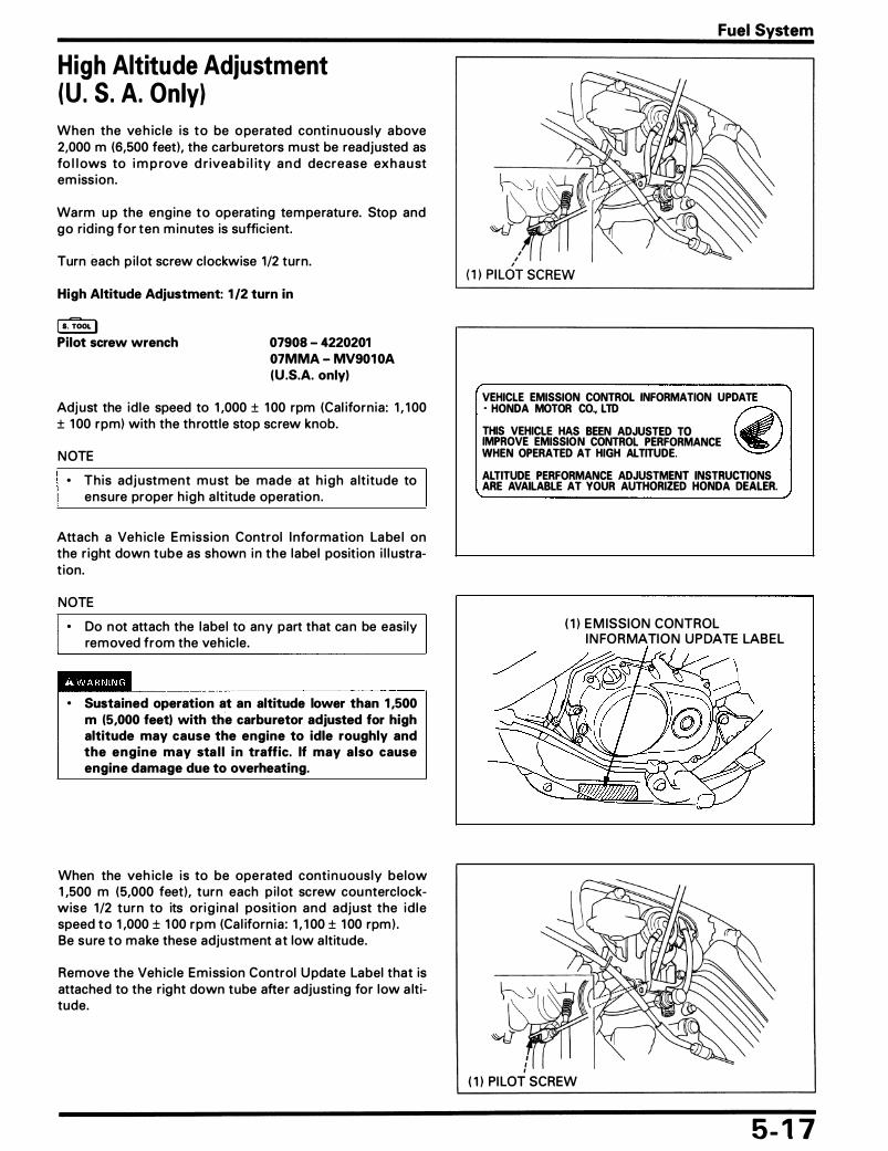
High Altitude Adjustment (U . S. A. Only) When the veh ic le is to be operated conti n uously above 2,000 m (6,500 feet), the carbu retors must be readjusted as fo l l ows to i m p rove d r ivea b i l ity a n d decrease exh a u st em iss ion .
Warm u p the engine to operati ng temperatu re. Stop and go rid ing for ten m inutes is sufficient.
Turn each p i lot screw clockwise 1/2 turn.
High Altitude Adjustment: 1 /2 turn in
i s. TOOL I Pilot screw wrench 07908 - 4220201
07MMA - MV9010A (U .S.A. only)
Adjust the id le speed to 1 ,000 ± 1 00 rpm (Cal iforn ia : 1 , 1 00 ± 1 00 rpm) with the th rottle stop screw knob.
NOTE
• This adj ustment must be made at h igh a lt itude to ensure proper h igh a ltitude operation .
Attach a Veh ic le E m iss ion Control I nformation La be l on the r ight down tube as shown i n the label posit ion i l l ustrat ion.
NOTE
• Do not attach the label to any part that can be easi ly removed from the veh icle.
• Sustained operation at an altitude lower than 1 ,500 m (5,000 feet) with the carburetor adjusted for high altitude may cause the engine to idle roughly and the engine may sta l l in traffic. If may also cause engine damage due to overheating.
When the veh ic le is to be operated conti n uously below 1 ,500 m (5,000 feet) , turn each p i lot screw cou nterclockwise 1 /2 turn to its ori g i na l posit ion and adjust the id le speed to 1 ,000 ± 1 00 rpm (Ca l iforn ia : 1 , 1 00 ± 1 00 rpm) . Be sure to make these adjustment at low a ltitude.
Remove the Veh icle Emission Control Update Label that is attached to the right down tube after adjusti ng for low a ltitude.
Fuel System
VEHICLE EMISSION CONTROL INFORMATION UPDATE • HONDA MOTOR CO., LTD � THIS VEHICLE HAS BEEN ADJUSTED TO � IMPROVE EMISSION. CONTROL PERFORMANCE �. WHEN OPERATED AT HIGH ALTITUDE.
ALTITUDE PERFORMANCE ADJUSTMENT INSTRUCTIONS ARE AVAILABLE AT YOUR AUTHORIZED HONDA DEALER.
( 1 ) E M ISSION CONTROL I N FORMATION UPDATE LABEL
( 1 ) PI LOT SCREW
5- 1 7

Fuel System
Evaporative Emission Canister (EVAP Canister) Removal/Instal lation (Cal ifornia Type Only) Disconnect the No. 4 tube. Disconnect the No. 1 tube. Remove the bolts and EVAP can ister.
Insta l lation is i n the reverse order of remova l .
Pulse Secondary Air Injection Control Valve (PAIR Control Valve) Removal/Instal lation (Cal ifornia Type Only) CAUTION
• To prevent damage to the PAIR control valve, do not use high air pressure sources. Use a hand operated air pump only.
Front cylinder Remove the rad iator (page 6-5) .
Disconnect and remove ttie fo l lowing: - No. 1 0 vacuum tube - a i r i njection hose - PAI R control va lve mounting bolt - a i r i ntake hose � PAI R control va lve
Insta l lation is i n the reverse order of remova l . After insta l l ing, check the tubes for loose con nections and k inks.
I nsta l l the rad iator (page 6-5) .
Rear cylinder Remove the seat (page 2-2 ) .
Disconnect and remove the fo l lowing: - a i r i ntake hose - air i njection hose - PAI R control va lve mounting bolt - No. 10 vacuum tube - PAI R contro l va lve
Insta l l at ion is in the reverse order of remova l . After i nsta l l i ng, check the tubes for loose connections and k inks.
Insta l l the seat (page 2-2) .
5·- 1 8
( 1 )AIR INJECTION HOSE
\
(5) PAI R CONTROL VALVE
(4) BOLTS
( 1 ) No. 1 0 TUBE
(2) AIR I NTAKE HOSE
(3) AIR I NJ ECTION : HOSES

6. Cool ing System Service Information
Troubleshooting
System Flow Pattern
Coolant Draining
Service Information
6-1 6- 1 6-2 6-3
Thermostat Removal/Installation 6-4 Radiator Removal/Installation 6-5 Radiator Disassembly I Assembly 6-6 Water Pump Removal/Installation 6-7
• Wait until the engine is cool before slowly removing the radiator cap. Removing the cap while the engine is hot and the coolant is under pressure may cause serious scalding.
• Radiator coolant is toxic. Keep it away from eyes, mouth, skin and clothes. - If any coolant gets in your eyes, rinse them with water and consult a doctor immediately. - If any coolant is swallowed, induce vomiting, gargle and consult a physician immediately. - If any coolant gets on your skin or clothes, rinse thoroughly with plenty of water.
• KEEP OUT OF REACH OF CHILDREN.
• Add coo lant at the reserve tank. Do not remove the radiator cap except to refi l l or dra in the system. • Al l coo l ing system services can be done with the engine i n the frame. • Avoid spi l l i ng coolant on pai nted surfaces. • After servici ng the system, check for leaks with a cool ing system tester. • Refer to section 25 of the Common Service Manua l for fan motor switch and thermo sensor i nspection .
Troubleshooting Engine Temperature Too High • Fau lty rad iator cap • I nsufficient coolant • Passages blocked i n radiator, hoses or water jacket • Air i n system • Fau lty water pump • Thermostat stuck closed • Fau lty temperatu re gauge or thermo sensor • Fau lty coo l ing fan motor • Fau lty fan motor switch • I ncorrect fan shroud insta l lation
Engine Temperature Too Low • Fau lty tem peratu re gauge or thermo sensor • Thermostat stuck open • Fau lty coo l ing fan motor switch
Coolant Leaks • Fau lty water pump mechan ical sea l • Deteriorated/fau lty 0-rings • Damaged or deteriorated gasket • Loose hose connection or clamp • Damaged or deteriorated hose • Fau lty rad iator cap
6- 1

Cooling System
System Flow Pattern
( 1 ) SIPHON TU BE
(5) THERMOSTAT
(2) RESERVE TAN K
(3) WATE PUMP
6-2

Coolant Draining
• Wait until the engine i s cool before servicing the cooling system. Removing the radiator cap while the engine is hot and the coolant is under pressure may cause serious scalding.
NOTE
• For coo l ant replacement, refer to sect ion 5 of the Common Service Manua l .
Remove the water pump dra i n bolt and sea l ing washer.
Remove the rad iator cap screw and radiator cap and d ra in the coolant.
Remove the cyl inder dra i n bolts and sea l i ng washers and d ra i n the coolant.
I nstal l the water pump dra i n bolt with a new sea l i ng washer. I nsta l l the cyl inder d ra i n bolts with new sea l i ng washers.
Refi l l the coolant to upper leve l .
Cooling System
{2 ) SEALIN G WASHER
( 1 ) SEALING WASHERS
6-3
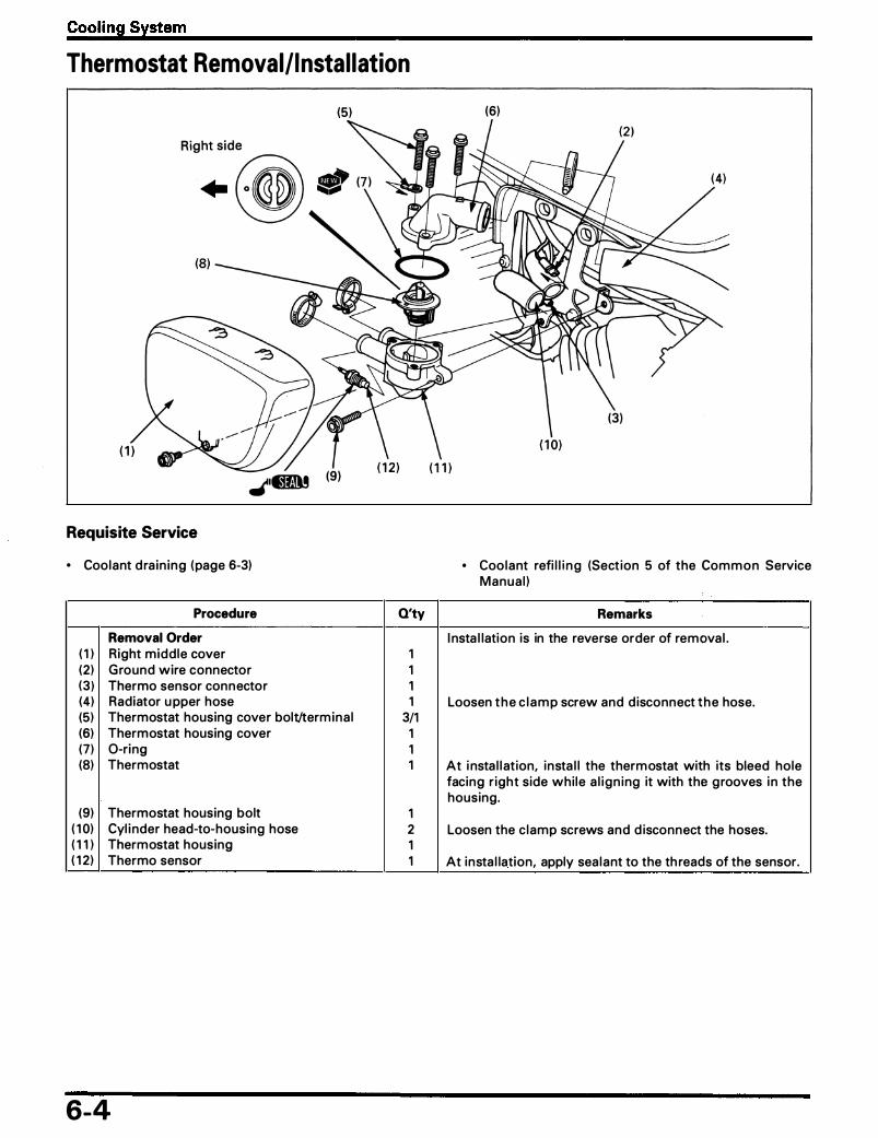
Cooling System
Thermostat Removal/Instal lation
Requisite Service
• Coolant d ra in ing (page 6-3)
Procedure
Removal Order ( 1 ) Right middle cover (2 ) Ground wire connector (3 ) Thermo sensor connector (4) Radiator u pper hose
(5)
(5) Thermostat housing cover bolt/termina l (6) Thermostat housing cover (7) 0-ring (8) Thermostat
(9) Thermostat housing bolt ( 1 0) Cyl i nder head-to-housing hose ( 1 1 ) Thermostat housing ( 1 2 ) Thermo sensor
6-4
Q'ty
1 1 1 1
3/1 1 1 1
1 2 1 1
(6)
• Coo lant refi l l i ng (Sect ion 5 of the Common Service Manua l )
Remarks
I nsta l lation is in the reverse order of remova l .
Loosen the c l amp screw and d isconnect the hose.
At i nsta l l at ion, insta l l the thermostat with its bleed hole facing r ight side whi le a l ign ing it with the g rooves i n the housing.
Loosen the c lamp screws and d isconnect the hoses.
At insta l lation, apply sea lant to the th reads of the sensor.

Radiator Removal/Instal lation
Requisite Service
• Coolant d ra i n i ng (page 6-3) • Coolant refi l l (Section 5 of the Common Service Manual)
Procedure Q'ty
Removal Order ( 1 ) Radiator s iphon tube 1 (2 ) Radiator upper hose 1 (J) Radiator lower hose 1 (4) Fan motor switch connector 1 (5) Radiator mounting bolt 3 (6) Radiator assembly 1
Cooling System
(4)
• Front side cover remova l/insta l l at ion (page 2-3)
Remarks
Insta l lation is in the reverse order of remova l .
Loosen the c lamp screw and d isconnect the hose. Loosen the c lamp screw and d isconnect the hose.
Remove it after re leas ing the projection on the r ight radi-ator stay. CAUTION • During removal and installation, be careful not to dam-
age the radiator core.
6-5

Cooling System
Radiator Disassembly I Assembly
CAUTION
(5)
\� (7} an:n.• (8)
-���
:. llliiiiii'
I o Be careful not to damage the radiator core.
Requisite Service
o Radiator remova l/insta l l ation (page 6-5)
Procedure
Disassembly Order ( 1 ) Radiator g ri l l
(2) Fan motor switch connector (3) Coo l ing fan shroud bolt
(4) Cool ing fan nut (5) Coo l ing fan
(6) Fan motor mounting n ut (7) Fan motor (8) Fan motor switch (9) 0-ring
6-6
O'ty Remarks
Assembly is in the reverse order of d isassembly. 1 Release the two g rooves from u nder of rad i ator, then
remove the rad iator gri l l . 1 3 At i n sta l lation , i n sta l l the g round eye let jo int with the
bolt. 1 1 At insta l lation, a l ign the coo l ing fan g roove with the fan
motor shaft. 3 1 1 At insta l l at ion, apply sea lant to the switch threads. 1

Water Pump Removal/Instal lation
Requisite Service
• Coolant d ra in ing (page 6-3) • Drive sprocket cover remova l/insta l lation (page 1 0-2)
Procedure Q'ty
Removal Order ( 1 ) Exhaust p ipe protector 1 (2) Gearsh ift l i nk jo int bolt/jo int 1/1 (3) Radiator lower hose 1 (4) Water pump cover bolt 2 (5) Water pum p mounting bolt 2 (6) Water pump cover 1 (7) 0-ring 1 (8) Dowel pin 2 (9) Pump-to-engine hose 1
( 1 0) Water pump body 1
( 1 1 ) 0-ring 1
Cooling System
�GN OIL PUMP SHAFT
• Coo l a nt refi l l (Sect i o n 5 of the C o m m o n S e rv ice Manua l )
Remarks
I nsta l l at ion is i n the reverse order of remova l .
Loosen the c lamp screw and d isconnect the hose.
Loosen the hose c lamp screw and d isconnect it. At insta l l at ion, a l ign the cut-out of the water pump shaft with the o i l pump shaft. At insta l l at ion, apply the engine oil to the new 0-ri ng.
6-7

MEMO

7 . Engine Removal/Instal lation Service Information 7-1 Engine Removal/Installation
Service Information • Dur ing remova l and insta l lation, support the motorcycle using a safety stand or hoist.
• The fo l lowing components can be serviced with the engine i nsta l led i n the frame. - Oi l pump (Section 4) - Carburetor (Section 5) - Water pump (Section 6) - Camshaft/cyl inder head (Section 8) - Clutch (Section 9) - Gearsh ift l i nkage (Section 10 ) - Alternator (Section 1 5) - Pu lse generator (Section 1 6) - Starter c lutch (Section 1 7 ) - Starter motor (Section 1 7 )
• The fo l lowing components requ i re engine remova l for service. - Piston/connecting rod/cy l inder (Section 1 1 ) - Cra nkshaft/transmission (Section 1 1 ) - Shift forks/shift drum (Section 1 1 )
7-2
7- 1

Engine Removal/Installation
Engine Removal/Instal lation
c 39 (3.9, 28)
( 1 9) 0 27 (0.7, 20)
( 1 2 )
( 1 1 )
., ( 1 3)
(25)
(26) c 44 (4 .4, 32) (28)
7-2
(7)
(27) c 39 (3.9, 28) (3)
c 54 (5.4, 39)
(24)
c 9 (0.9, 6.5)
(2 1 )
(22) c 27 (0.7, 20)
J?) C s1 (5. 1 , 37)
( 1 5)
( 1 0) ., (9)
(8)

CAUTION
I • Do not support the engine using the oil filter.
NOTE
• Support the motorcycle using safety stand or a hoist.
Engine Removal/Instal lation
• A floor jack or other adjustable support is requ i red to support and maneuver the engine . The jack height must be continua l ly adjusted to re l ieve stress for ease of bolt remova l .
• Turn the ign ition switch OFF and disconnect the battery ground (-) termina l . • Note the d i rection of the engine mounting bolts. • Route the wi re ha rnesses and tubes properly (page 1 -20) .
Requisite Service
• Fuel tan k remova l/insta l l ation (page 2-2) • Carbu retor remova l/insta l lation ( page 5-4) • Exhaust system remova l/i nsta l lation (page 2-4)
Procedure
Removal Order ( 1 ) Alternator 3P connector (2 ) Ign it ion pu lse generator 3P connector (3) Starter motor cable (4) G round cable eyelet (5) Spark plug cap (6) Auto fue l va lve mounting bolt (7) Auto fue l va lve (8) F ront air suction pipe jo int bolt (9) Front air suction pipe
( 1 0) Gasket ( 1 1 ) Rear a i r suction pipe jo int bolt ( 1 2 ) Rear a i r suction pipe ( 1 3) Gasket ( 1 4) No. 4 vacuu m tube ( 1 5) Drive sprocket bolt ( 1 6) Washer ( 1 7 ) Drive sprocket ( 1 8) Brake pedal l i nkage jo int pinch bolt/jo int ( 19 ) R ight foot peg bracket bolt (20) R ight foot peg bracket assembly ( 2 1 ) Gearsh ift l i n k jo int bolt/jo int (22) Left foot peg bracket bolt (23) Left foot peg bracket assembly (24) Front cylinder head mounting bolt/nut/Washer (25) Col l a r (f624 x 30 m m ) (26) Front engine mounting bolt/nut (27) Front engine mounti ng bracket bolt (28) Front engine mounting bracket (29) Rear engine mounti ng bolt/nut (30) Col l a r (f62 1 x 29.8 m m) (31 ) Rear engine mounting bracket bolt/nut (32) Rear engine mount ing bracket (33) Eng ine assembly
Q'ty
1 1 1 1 4 2 1 4 -2 -2 -4 -2 -2 -1 -1 1 1
1/1 2 1
1/1 2 1
2/2/2 2
2/2-4 -2
1/1 -1
2/2-2 1
• Drive sprocket cover remova l/insta l lation (page 1 0-2) • Radiator remova l/i nsta l lation ( page 6-5) • Right midd le cover stay remova l/insta l l at ion
Remarks
I nsta l lation is in the reverse order of remova l .
Ca l ifornia type on ly.
Al ign the punch marks.
Al ign the punch marks.
Tighten ing procedure (page 7-4)
Apply clean g rease to the nut threads and flange surface.
Move the engine assembly out of the frame to right. CAUTION • Carefully align mounting points with the jack to pre-
vent damage to mounting bolt threads, wire harnesses and cable.
7-3

Engine Removal/Installation
Engine Mounting Bolt lightening Procedure
Loosely insta l l a l l engine mounting bolts, nuts and engine mounting bracket.
Tighten the 1 0 mm front cyl inder head mount ing bolts CD and ® .
Torque: 54 N·m (5.4 kg-m, 39 ft-lb)
Tighten the 8 mm engine mounting bracket bo lts @, @, @ , @ and ® .
Torque: 39 N·m (3.9 kg-m, 28 ft-lb)
Tighten the 1 0 mm engine mounting bolts ®, @, @l and @. Torque: 44 N·m (4.4 kg-m, 32 ft-lb)
Tighten the 1 2 mm engine mounting n ut @ .
Torque: 64 N·m (6.4 kg-m, 46 ft-lb)
7-4
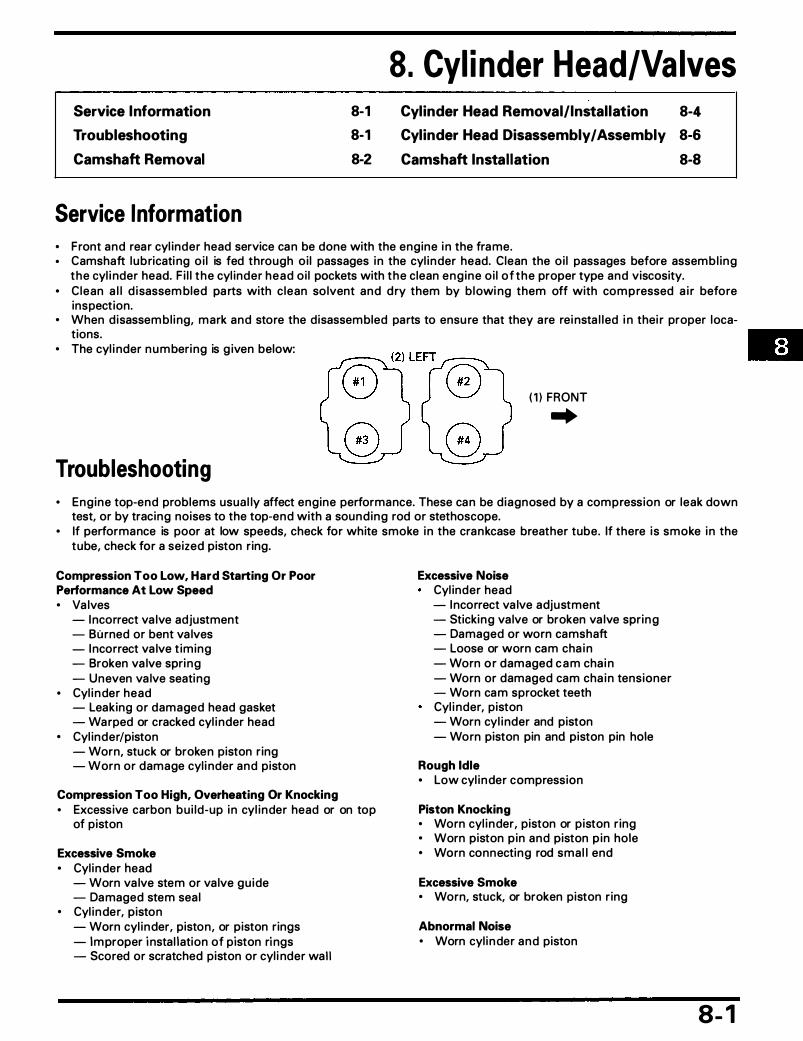
Service Information
Troubleshooting
Camshaft Removal
Service Information
8-1 8-1 8-2
8. Cyl inder Head/Valves Cylinder Head Removal/Installation 8-4 Cylinder Head Disassembly I Assembly 8-6 Camshaft Installation 8-8
• Front and rea r cyl inder head service can be done with the engine i n the frame. • Camshaft lubricati ng o i l is fed through o i l passages i n the cyl i nder head. Clean the o i l passages before assembl ing
the cyl i nder head. F i l l the cyl inder head o i l pockets with the clean eng ine o i l of the proper type and viscosity. • Clean a l l d i sassem bled pa rts with c lean so lvent and d ry them by b lowi ng them off with compressed a i r before
inspection. • When d isassem bl i ng, mark and store the d isassembled parts to ensu re that they a re rei nsta l led i n thei r proper loca
tions. • The cyl i nder numberi ng is g iven below:
Troubleshooting
( 1 ) FRONT
..
• Eng ine top-end problems usua l ly affect engine performance. These can be d iagnosed by a compression or leak down test, or by tracing noises to the top-end with a sound ing rod or stethoscope.
• If performance is poor at low speeds, check for white smoke i n the crankcase breather tube. If there i s smoke i n the tube, check for a seized piston r ing.
Compression Too Low, Hard Starting Or Poor Performance At Low Speed • Va lves
- Incorrect va lve adjustment - Burned or bent va lves - Incorrect va lve t iming - Broken va lve spri ng - Uneven va lve seati ng
• Cyl i nder head - Leaking or damaged head gasket - Warped or cracked cyl i nder head
• Cyl inder/piston - Worn, stuck or broken piston r ing - Worn or damage cyl i nder and piston
Compression Too High, Overheating Or Knocking • Excessive carbon bu i ld-up i n cyl i nder head or on top
of piston
Excessive Smoke • Cyl inder head
- Worn va lve stem or va lve gu ide - Damaged stem sea l
• Cyl inder, piston - Worn cyl inder, piston, or piston r ings - Improper i nsta l lation of piston ri ngs - Scored or scratched piston or cyl i nder wall
Excessive Noise Cyl inder head - Incorrect va lve adjustment - Sticking va lve or broken va lve spring - Damaged or worn camshaft - Loose or worn cam cha i n - Worn o r damaged c a m cha i n - Worn or damaged cam cha in tensioner - Worn cam sprocket teeth Cyl i nder, piston - Worn cyl i nder and piston - Worn piston pin and piston pin hole
Rough Idle • Low cyl i nder compression
Piston Knocking • Worn cyl i nder, piston or p iston r ing • Worn piston p in and piston p in hole • Worn connecting rod sma l l end
Excessive Smoke • Worn, stuck, or broken piston r ing
Abnormal Noise • Worn cyl i nder and piston
8- 1

Cylinder Head/Valves
Camshaft Removal
8-2
AFTER '95 (Except some '96 early production units)
Revised: July, 1 995, '94 - '95 Magna VF750C/CD © 1 995 American Honda Motor Co. , Inc. - All Rights Reserved MSV 691 3 (9504)

Cylinder Head/Valves
NOTE
• Service the front cyl i nder camshaft using the same procedu re as the rear cyl i nder. • Remove the cam cha in tensioner before removing the camshaft. • The "T1 " tim ing marks on the starter c lutch a re for rea r cyl inder head service. • The "T2" tim ing marks on the starter c lutch are for front cyl i nder head service. • Be carefu l not to drop parts i nto the eng ine open ing .
Requisite Service
Rear cylinder: • Fuel tank remova l/insta l lation (page 2-2) • Spark p lug cap remova l/insta l lation
Front cylinder: • Fuel tank remova l/insta l l at ion (page 2-2) • Radiator remova l/insta l lation (page 6-5)
Procedure
Removal Order ( 1 ) S ide stand switch connector (2 ) Auto fuel va lve (3) Breather tube (4) Breather case bolt (5) Breather case (6) Breather p late (7) Head cover protector bolt (8) Head cover protector (9) Head cover protector rubber
( 1 0) Rear cyl inder head cover bolt ( 1 1 ) Washer ( 1 2) Rear cyl inder head cover ( 1 3) Head cover gasket ( 1 4) Cam cha in tensioner sea l ing bolt/washer ( 1 5) Cam cha in tensioner mounting bolt ( 1 6) Cam cha i n tensioner ( 1 7) Gasket ( 1 8) Camshaft holder bolt
Q'ty
1 -1 -1 -6-1 -1 -4 2 6 4 4 1 1
1/1 2 1 1
1 6
• M uffler remova l/insta l lation (page 2-4)
• Spark p lug cap remova l/i nsta l lation • Front PAI R control va lve remova l/insta l lation
(Ca l ifornia type on ly page 5- 1 8)
Remarks
Rear cyl inder head on ly.
NOTE • Before loosen ing, a l ign the "T1 " (front cyl i nder: "T2 " )
mark on the starter c lutch with the index mark o n the r ight crankcase cover, and make sure the No. 1 p iston (front cyl inder: No. 4 piston ) is on compression stroke. If it is not on the compression stroke, turn the cra n k-shaft clockwise 360° and a l ign the marks aga i n .
• Loosen the holder bolts i n a g radua l , crisscross pattern.
( 1 9) Cam cha in gu ide 1 (20) Camshaft holder 4 (2 1 ) Camshaft I N/EX 2 (22) Cam chain 1 Dera i l the cam cha in from the sprocket and attach a
piece of mechanic's wire to it to prevent it from d ropping i nto the crankcase.
(23) Dowel pin 8
8-3

Cylinder Head/Valves
Cyl inder · Head Removal/ Instal lation
( 2 ) c 44 (4.4, 32)
( 1 ) c 1 2 ( 1 .2, 9)
, (6)
(4)
(3) c 13 ( 1 .3, 9)
8-4

Cylinder Head/Valves
NOTE
• Service the front cyl i nder head using the same procedu re as the rea r cyl i nder. • Apply eng ine o i l to the seat and threads of the cyl i nder head bo lts. • Before removing the engine mounting bolts from the cyl inder head, support the eng ine with a jack or other sup
port to avoid over-loading the other bolts.
Requisite Service
Rear cylinder: • Camshaft remova l/insta l lation (page 8-2, 8) • Carbu retor remova l/insta l lation ( page 5-4)
Front cylinder: • Camshaft remova l/insta l lation (page 8-2, 8) • M uffler remova l/i nsta l lation (page 2-4) • Air suction p ipe remova l/i nsta l lation (Ca l ifornia type
on ly)
Procedure Q'ty
Removal Order ( 1 ) Cyl inder head 6 m m bolt 8�8] (2 ) Cyl inder head 9 mm bolt/washer
(3) Cyl i nder head protector bolt 6 (4) Cyl i nder head protector 2 (5) Cyl i nder head 1 (6) Cyl inder head gasket 1
(7) Dowel pin 2
• Thermostat remova l/insta l lation ( page 6-4) • Air suction p ipe remova l/insta l lation (Ca l iforn ia type
on ly)
• Carburetor remova l/insta l lation ipage 5-4) • Thermostat remova l/insta l lation (page 6-4)
Remarks
• Loosen the fasteners in a criss-cross pattern i n 2 or 3 steps.
• Refer to page 8- 1 7 for insta l l at ion.
Disassembly (page 8-6) Insta l l with the " UP " mark facing up and " I N " mark fac-ing i ntake side.
8-5
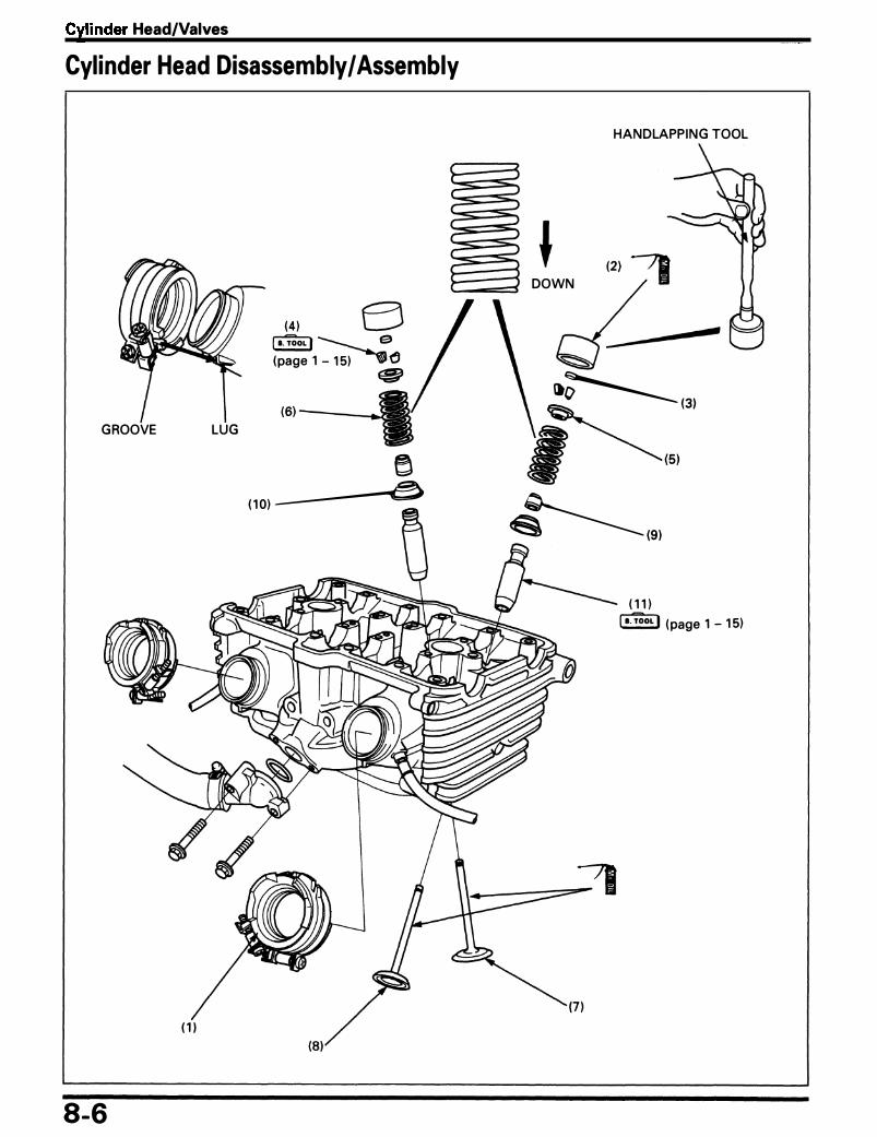
Cylinder Head/Valves
Cylinder Head Disassembly I Assembly
GROOVE LUG
8-6
(4) j s.TooL I ------ . e (page 1 - 1 5) ��
�
e ( 1 0) ------�
HANDLAPPING TOOL
DOWN
(2) ?1
�
()�(3) � (51
�(91 ( 1 1 )
l s.TooL I ( page 1 - 1 5)
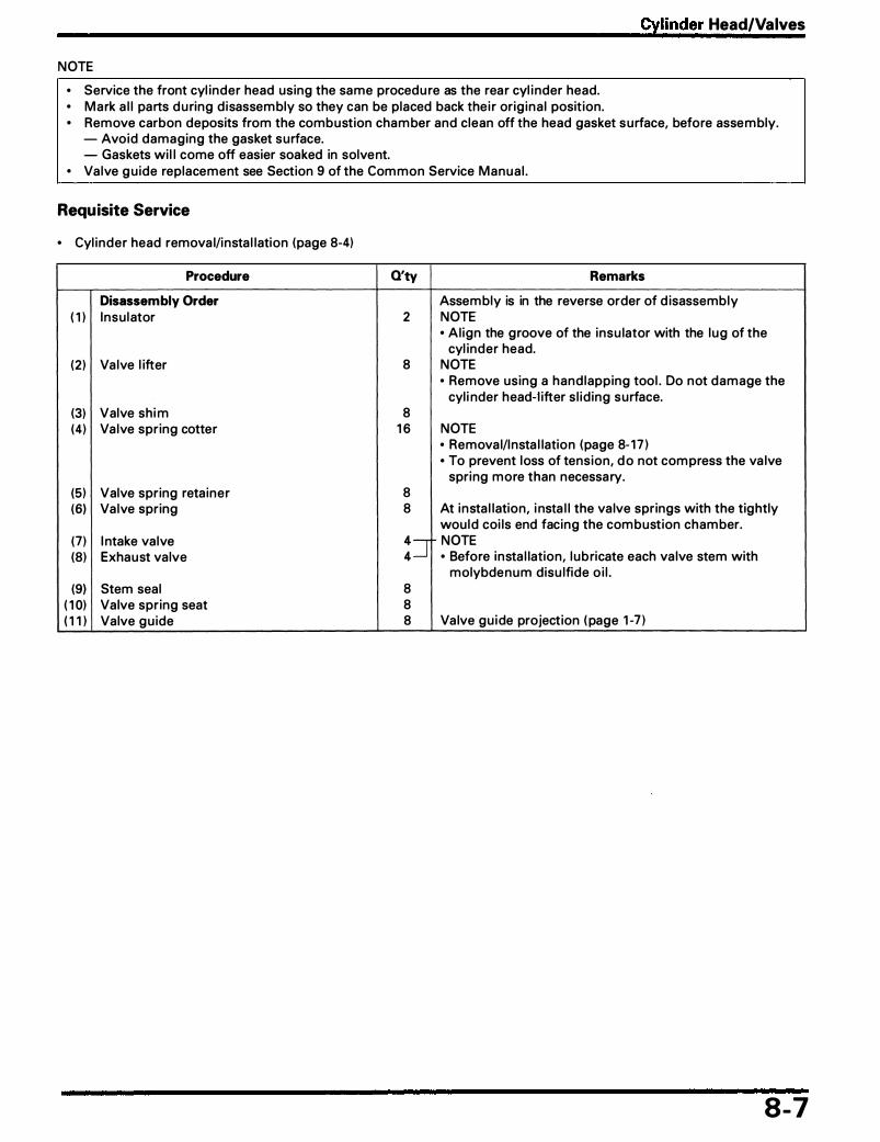
Cylinder Head/Valves
NOTE
• Service the front cyl inder head using the same procedu re as the rea r cyl i nder head. • Mark a l l parts du ring d isassembly so they can be placed back the i r orig ina l posit ion. • Remove carbon deposits from the combustion cham ber and clean off the head gasket surface, before assembly.
- Avoid damaging the gasket surface. - Gaskets wi l l come off easier soaked in solvent.
• Valve g u ide replacement see Section 9 of the Common Service Manua l .
Requisite Service
• Cyl inder head remova l/insta l lation (page 8-4)
Procedure
Disassembly Order ( 1 ) Insu lator
(2 ) Va lve l ifter
(3) Valve sh i m (4) Va lve spr ing cotter
(5) Valve spring reta iner (6) Va lve spring
(7) I ntake va lve (8) Exhaust va lve
(9) Stem seal ( 1 0) Valve spr ing seat ( 1 1 ) Valve gu ide
Q'ty Remarks
Assembly is in the reverse order of d isassembly 2 NOTE
• Al ign the groove of the insu lator with the lug of the cyl inder head.
8 NOTE • Remove using a hand lapping tool . Do not damage the
cyl i nder head-l ifter s l id ing surface. 8
1 6 NOTE • Remova l/Insta l lation (page 8- 1 7 ) • To prevent loss of tension, d o not compress the va lve
spring more than necessary. 8 8 At insta l lation, i nsta l l the va lve springs with the tightly
wou ld coi ls end facing the combustion chamber.
:=r NOTE • Before insta l lation, l ubricate each va lve stem with
molybdenum disu lfide o i l . 8 8 8 Va lve gu ide projection ( page 1 -7 )
8-7

Cylinder Head/Valves
Camshaft Instal lation
(2)
( 1 )
8-8
AFTER '95 (Except some '96 early production units)
(7)
-(9) c 1 2 ( 1 .2, 9)
I N
r : � @ ... @
EX
Revised: July, 1 995, '94 - '95 Magna VF750C/CD © 1 995 American Honda Motor Co., Inc. - All Rights Reserved MSV 691 3 f9504l

Cylinder Head/Valves
NOTE
• Service the front cyl inder camshaft us ing the same procedu re as the rea r cyl inder. • Each camshaft has an identification mark. Use these marks du ring insta l l at ion to ensure that the camshafts a re
properly located. FRONT I NTAKE: "FR" , " I N " REAR I NTAKE: " R R " , " I N " FRONT EXHAUST: "FR" , "EX" REAR EXHAUST: "RR", "EX"
• Be ca refu l not to d rop any parts i nto the engine open ing .
Requisite Service
Rear cylinder: • Fuel tan k remova l/insta l lation (page 2-2) • Spark p lug cap remova l/insta l lation
Front cylinder: • Fuel tank remova l/insta l lation (page 2-2) • Spark p lug cap remova l/i nsta l l at ion
Procedure
Installation Order ( 1 ) Dowel p in (2) Cam chain (3) Camshaft I N/EX (4) Camshaft holder (5) Cam cha in gu ide (6) Camshaft holder bolt (7) Gasket (8) Cam cha in tensioner (9) Cam chai n tensioner mounting bolt
( 1 0) Cam cha in tensioner sea l i ng bolt/washer ( 1 1 ) Head cover gasket
Q'ty
8 1 2 -4 -1 -
1 6 -1 -1 -2
1/1 1
• M uffler remova l/i nsta l lation ( page 2-4)
• Radiator remova l/i nsta l lation ( page 6-4) • Front PAI R control va lve removal/i nsta l l at ion
(Ca l ifornia type on ly page 5- 1 8)
Remarks
Refer to page 8- 1 0 for i nsta l l ation
NOTE • Apply Honda Bond A or equ iva lent to the head cover
and insta l l the gasket with " I N " mark fac ing the i ntake side.
( 1 2) Rear cyl i nder head cover 1 ( 1 3) Washer 4 Insta l l with the " U P" mark fac ing u p. ( 1 4) Rear cyl i nder head cover bolt 4 • Tighten the bolts i n the order shown.
• Tighten the G) bolt aga in after tighten ing the other bolts.
( 1 5) Head cover protector rubber 6 ( 1 6) Head cover protector 2 ( 1 7 ) Head cover protector bolt 4 ( 1 8) Breather p late 1 - • I nsta l l with the " U P" mark fac ing u p and " I N " mark fac-( 1 9) Breather case 1 - ing the i ntake side. (20) Breather case bolt 6- • Rear cyl inder head on ly. ( 2 1 ) Breather tube 1 -(22) S ide stand switch connector 1 -
(23) Auto fuel va lve 1 -
8-9

Cylinder Head/Valves
Camshaft Installation
Each ca m s haft h a s an i d e nt if icat i o n m a rk. I n sta l l the camshafts i n the correct positions, noting the identification marks below:
Front Intake: "FR", "IN" Front Exhaust: "FR", "EX" Rear Intake: "RR", "IN" Rear Exhaust: "RR", "EX"
When Both Front And Rear Cylinder Camshaft Were Removed
• Rear cylinder Align the "T1 " mark on the starter cl utch with the index mark on the right crankcase cover.
I nsta l l the camshaft ho lder dowel p ins onto the rea r cyl i nder head. Lubricate the camshaft journa l su rface of the cyl inder head, camshaft holder and cam lobes with molydenum disu lfide o i l .
I nsta l l the camshafts onto the rear cyl i nder head. The " R-EX" tim ing mark on the rea r exhaust camshaft sprocket is level with the cyl i nder head u pper edge as shown.
Check that the " R- I N " tim i ng mark on the rea r i ntake camshaft sprocket is level with the cyl i nder head u pper edge as shown.
I nsta l l the ca mshaft ho lders in the correct posit ions, checking the identificat ion marks on the ho lders and cyl i nder head. Insta l l the cam cha in gu ide.
8- 1 0
( 1 ) EX or I N MARK
( 1 ) I N DEX MARK
(3) "T1 " MARK
(2) FR or RR MARK
(2) R IGHT CRAN KCASE COVER
(2) " R- I N " MARK
(3) REAR CYLI NDER HEAD U PPER EDGE
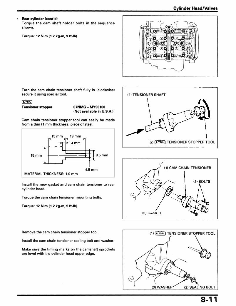
• Rear cylinder (cont'dl Torq ue the c a m s haft h o l d e r bo lts i n the seq uence shown.
Torque: 12 N·m ( 1 .2 kg-m, 9 ft-lb)
Turn the cam cha in tensioner shaft fu l ly in (c lockwise) secure it us ing specia l tool .
I •.TooL I Tensioner stopper 07NMG - MY90100
(Not available in U.S.A.)
Cam cha in tensioner stopper too l can easi ly be made from a th i n ( 1 mm th ickness) piece of steel .
1 5 m m 1 9 m m
1 5 m m 8.5 mm
4.5 m m MATERIAL THICKNESS: 1 .0 m m
Insta l l the new gasket a n d cam cha in tensioner to rear cyl i nder head.
Torque the cam chain tensioner mounting bolts.
Torque: 12 N·m ( 1 .2 kg-m, 9 ft-lbl
Remove the cam cha in tensioner stopper tool .
Insta l l the c a m c h a i n tensioner sea l i ng bolt a n d washer.
Make sure the tim i ng marks on the camshaft sprockets a re level with the cyl inder head upper edge.
Cylinder Head/Valves
( 1 ) TENSIONER SHAFT
(2) I a. TooL I TENSIONER STOPPER TOO L
( 1 ) CAM CHAIN TENSIONER
( 1 ) � TENSIONER �OL
8- 1 1

Cylinder Head/Valves
• Front cylinder Rotate the crankshaft c lockwise 90° to a l i gn the "T2" mark with the index mark on the right crankcase cover.
I nsta l l the camshaft ho lder dowel p ins onto the front cyl i nder head.
Lubricate the camshaft journal surface, camshaft holder and cam lobes with molybdenum d isu lfide o i l .
Insta l l the camshafts onto the front cyl inder head. Check that the " F-EX " tim i ng mark on the front exhaust camshaft sprocket is level with the cyl i nder head u pper edge as shown.
Check that the " F-IN " t iming mark on the front i ntake camshaft sprocket is level with the cyl i nder head upper edge as shown.
I nsta l l the camshaft ho lders in the correct posit ions, checking the identificat ion marks on the ho lders and cyl i nder head. Insta l l the cam chain gu ide.
Torq u e the cam s h aft h o l d e r bo lts in the seq u ence shown.
Torque: 12 N·m ( 1 .2 kg-m, 9 ft-lbl
8- 1 2
( 1 ) I N DEX MARK
(3) "T2" MARK (2 ) R IGHT CRANKCASE COVER
( 1 ) " F- I N " MARK
(3) FRONT CYLIN DER HEAD UPPER EDGE
(2 ) " F-EX" MARK

• Front cylinder (cont'd) Turn the cam cha in tensioner shaft com pletely in (clockwise) and secure it us ing the stopper tool . Th is tool c a n easi ly b e made from a th i n ( 1 mm thickness) piece of steel .
15 mm 1 3.5 mm ... - -
J 3 mm I ' I
+ r- - - -
lr I
8.5 mm 1 5 m m
MATERIAL THICKNESS: 1 mm 3.5 m m
Insta l l a new gasket a n d cam cha i n tensioner.
Torque the cam cha i n tensioner mounting bolts.
Torque: 12 N·m ( 1 .2 kg-m, 9 ft-lb)
Remove the cam cha in tensioner stopper tool .
Insta l l the c a m cha in tensioner sea l i ng bolt a n d washer.
Make sure the tim ing marks on the camshaft sprockets a re level with the cyl inder head u pper edge.
When The Rear Cylinder Camshaft Only Was Removed
A l i g n the "T2 " m a rk with the i ndex m a rk on the r ight crankcase cover. Remove the front cyl i nder head cover ( page 8-2) .
Make sure #2 cyl i nder is TDC on the compression stroke.
If it is not, turn the c rankshaft c lockwise 360° and make s u re "T2" mark a l igns with the i ndex mark on the r ight crankcase cover.
Rotate the cra n kshaft c lockwise 270° to a l ig n the "T1 " mark with the i ndex mark on the r ight crankcase cover.
cylinder Head/Valves
( 1 ) TENSIONER SHAFT
( 1 ) I N DEX MARK
/ (3) "T2" MARK
(2) TENSIONER STOPPER TOOL
(2) CAM CHAIN TENSIONER
(2 ) R IGHT CRANKCASE COVER
8- 1 3

Cylinder Head/Valves
I nsta l l the camshaft holder dowel p ins in the rear cyl i nder head.
Lubricate the camshaft journa l su rfaces, camshaft holder and cam lobes with molybdenum d isu lfide oi l .
I nsta l l the camshafts onto the rea r cyl i nder head.
Check that the " R-EX" ti m ing mark on the rea r exhaust camshaft sprocket is level with the cyl inder head u pper edge as shown.
Check that the " R- I N " t i m i n g m a rk on the rea r i ntake camshaft sprocket is level with the cyl i nder head u pper edge as shown.
Insta l l the camshaft holders i n the correct positions, checking the identificat ion marks on the ho lders and cyl i nder head.
I nsta l l the cam chain gu ide.
Torque the cam shaft holder bolts i n the sequence shown.
Torque: 12 N·m ( 1 .2 kg-m, 9 ft-lb)
Turn the cam cha in tensioner shaft com pletely in (c lockwise) and secure it using the spec ia l too l .
l a.TooL I Tensioner stopper 07NMG - MY901 00
(Not available in U.S.A.)
Cam cha in tensioner stopper tool can easi ly be made from a th in (1 mm th ickness) p iece of steel .
1 5 m m 1 9 mm
1 5 m m 8.5 m m
4.5 m m MATERIAL TH ICKNESS: 1 .0 m m
8- 1 4
(3) REAR cYLINDER HEAD I « UPPER EDGE ('Ali
(2 ) I a. TooL I TENSIONER STOPPER TOOL

I nsta l l a new gasket and cam chain tensioner.
Torque the cam chain tensioner mounting bolts.
Torque: 12 N·m ( 1 .2 kg-m, 9 ft-lb)
Remove the cam chain tensioner stopper tool .
I nsta l l the cam chain tensioner sea l ing bolt a n d washer.
Make sure the timing marks on the camshaft sprockets a re level with the cyl inder head u pper edge.
When The Front Cylinder Camshaft Only Was Removed
A l i g n the "T1 " m a rk with the i n dex m a rk on the r ight crankcase cover.
Remove the rea r cyl inder head cover ( page 8-2) .
Make sure #1 cyl inder is TDC on the compression stroke.
If it is not, turn the cra n kshaft c lockwise 360° and make su re "T1 " mark a l igns with the i ndex mark on the r ight crankcase cover.
Rotate the crankshaft c lockwise 90° to a l ign the "T2" mark with the index mark on the right crankcase cover.
Insta l l the camshaft holder dowel pins onto the front cyl inder head.
Lubricate the camshaft journa l su rface, camshaft holder and cam lobes with molybden u m disu lfide o i l .
I nsta l l the csmshafts onto the front cyl inder head. Check that the " F-EX" timing mark on the front exhaust camshaft sprocket i s l evel with the cyl i nder head u pper edge as shown.
Check that the " F- I N " t i m i n g m a rk o n the front i ntake camshaft sprocket is leve l with the cyl i nder head u pper edge as shown.
Cylinder Head/Valves
( 1 ) CAM CHAIN TENSIONER
( 1 ) I a. TooL I TENS lONER STO�
( 1 ) INDEX MARK
(3) "T1 " MARK (2) RIGHT CRANKCASE COVER
( 1 ) "F-IN" MARK
(2) " F-EX" MARK
(3) FRONT CYLINDER HEAD U PPER EDGE
8- 1 5

Cylinder Head/Valves
I nsta l l the camshaft holders in the correct positions, checking the i ndetificat ion m arks on the ho lders and cyl i nder head.
I nsta l l the cam cha in gu ide.
To rq ue the cam sh aft ho lde r bo lts in the seq uence as shown.
Torque: 12 N·m ( 1 .2 kg-m, 9 ft-lb)
Turn the cam cha in tensioner shaft com pletely in (c lockwise) and secure it using the stopper tool . This tool can easi ly be made from a th in ( 1 mm th ickness) piece of steel .
1 5 m m
lr
1 5 m m 1 3 .5 mm ..
- .
J 3 mm .I I
- - ----1
I
MATERIAL THICKNESS: 1 mm
+ 8.5 mm
3.5 m m
I nsta l l a new gasket a n d cam cha in tensioner.
Torque the cam cha in tensioner mounting bolts.
Torque: 12 N·m ( 1 .2 kg-m, 9 ft-lb)
8- 1 6
(2) IDE NTIF ICATION MARKS
( 1 ) TENSIONER SHAFT
(2) TE NSIONER STOPPER TOOL
(2) CAM CHAI N TE NSIONER

Remove the cam cha in tensioner stopper tool .
Insta l l the cam chain tensioner sea l ing bo lt and washer.
Make sure the tim ing marks on the camshaft sprockets are level with the cyl inder head upper edge.
Valve Cotter Removal/Installation
Remove the va lve l ifters and sh ims.
N OTE • Mark the positions of a l l va lve l ifters and sh ims to
ensure correct reassem bly. • It is easy to remove the va lve l i fter with a va lve lap
p ing too l or magnet. • Remove the sh ims with tweezers or a magnet.
I nsta l l the tappet hole protector i nto the va lve l ifter bore.
l s.TooL I Tappet hole protector 07HMG - MR70002
Not available in U.S.A
I n sta l l the va lve spr ing com presso r onto the va lve a n d compress the va lve spring .
CAUTION: • To prevent loss of tension, do not compress the
valve springs more than necessary.
Remove the va lve cotters.
l a.TooL I Valve spring compressor 07757 - 0010000 Valve spring compressor attachment
07959 - KM30101
I nsta l lation is i n the reverse order of remova l .
Cylinder Head Bolt Installation
Apply engine oil to the seating su rface and threads, then t ighten the cyl i nder head mount ing bolts g radua l ly in a crisscross pattern i n the order as shown .
Torque: 6 mm bolt: 12 N·m ( 1 .2 kg-m, 9 ft·lb) 9 mm bolt: 44 N·m (4.4 kg·m, 32 ft·lb)
Cylinder Head/Valves
( 1 ) l s.TooL I TAPPET HOLE PROTECTOR
(2 ) I s. TooL I COMPRESSOR
6 m m BOLT
8- 1 7

MEMO

9. Clutch System Service Information
Troubleshooting
Right Crankcase Cover Removal/
9-1 9·1
Instal lation 9-2
Service Information
Clutch Removal
Clutch Installation
• Clutch maintenance can be done with the engine i n the frame.
9-4 9-6
• Transmission o i l viscosity and level have a n effect on c lutch d isengagement. When the c lutch does not d isengage or the veh icle creeps with c l utch d isengaged, inspect the transmission o i l level before servic ing the c l utch system .
Troubleshooting Clutch Slips When Accelerating • I ncorrect clutch adjustment • Worn c lutch d iscs • Weak c lutch springs • T ra n s m i s s i o n o i l m i xed w i t h m o l y bd e n u m o r
g raph ite additive
Motorcycle Creeps With The Engine Idling • I ncorrect c lutch adjustment • Clutch p lates warped • Fau lty c lutch l ifter • I ncorrect engine o i l weight
9- 1

Clutch System
Right Crankcase Cover Removal/Instal lation
(6)
(7) c 1 2 ( 1 .2. 9) ( 1 ) c 27 (2 .7. 20) (2 ) c 27 (2 .7. 20)
Jl.ru 20 - 30 mm (0.8 - 1 .2 i n ) �· ===®:�=-----
9-2

Clutch System
Requisite Service
• Engine o i l dra in ing/refi l l i ng
Procedure Q'ty Remarks
Removal Order Insta l lation is in the reverse order of remova l , ( 1 ) Brake peda l pivot bolt/nut 1/1 (2 ) R ight foot peg bracket bolt 2 (3) R ight foot peg bracket 2 (4) Front exhaust p ipe protector bolt 2 (5 ) Front exhaust p ipe protector 1 (6) Evaporative emission can ister p ipe bolt 1 Ca l ifornia type only (7) R ight crankcase cover bolt 1 3 NOTE
• I nsta l l the c la m ps in the correct posit ions and c lam p the starter motor cable.
(8) R ight cra nkcase cover 1 (9) Gasket 1
( 1 0) Dowel p in 2
9-3

Clutch System
Clutch Removal
9-4
(3)
( 1 3)
( 1 2)
( 1 0) l a.TooL I ( page 9
(9)
-8)
(7 )

Clutch System
NOTE
• When removing the o i l pump driven sprocket, loosen the sprocket bolt before removing the clutch assembly. The bolt is treated with a locking agent so be carefu l not to damage the bolt when loosen ing .
Requisite Service
• Right crankcase cover removal (page 9-2)
Procedure
Removal Order ( 1 ) C lutch spring bolt (2 ) C lutch spring (3) C lutch pressure p late (4) Clutch pressure p late bearing (5) C lutch l ifter guide
(6) Stopper r ing (7) · Lifter rod (8) C lutch disk A/cl utch p late (9) C lutch disk B
( 1 0) J udder spring ( 1 1 ) Spring seat ( 1 2) C lutch center lock n ut
{ 1 3) Spring washer ( 1 4) C lutch center ( 1 5) C lutch outer ( 1 6) N eedle bearing ( 1 7 ) O i l pum p driven sprocket bolt ( 1 8) O i l pump driven sprocket ( 1 9) Clutch outer gu ide (20) O i l pum p drive chain (2 1 ) O i l pump d rive sprocket (22) Col l a r
Q'ty
5 5 1 1 1
1 1
8/8 1 1 1 1
1 1 1 1 1 1 -1 1 -1 -1
• Starter c l utch remova l (page 1 7- 1 0)
Remarks
Detac h fro m t h e pressu re p l ate bea r i n g o n ly w h e n replacing the beari ng.
Larger I . D. tha n c lutch d isc A
• Unstake the lock n ut. • Hold the c lutch center with the specia l tool (page 9-8) .
• Remove them as a n assembly.
9-5

Clutch System
Clutch Instal lation
( 1 0)
0
9-6

Requisite Service
• Starter c lutch insta l lation (page 1 7- 1 0)
Procedure
Installation Order ( 1 ) Col l a r (2) Clutch outer guide
(3) Oil pump drive sprocket (4) Oi l pump drive chain (5) Oil pump driven sprocket (6) Oil pum p driven sprocket bolt (7) Needle bearing (8) Clutch outer (9) Clutch center
( 1 0) Spring washer ( 1 1 ) Clutch center lock n ut
( 1 2) Spring seat ( 1 3) J udder spring ( 1 4) Clutch d isc B ( 1 5) Clutch d isc A/clutch plate ( 1 6) Lifter rod ( 1 7 ) Stoppen r ing ( 1 8) Clutch l ifter gu ide ( 1 9) Pressure p late bearing (20) Pressure p late (2 1 ) Clutch spring (22) Clutch spring bolt
Q'ty
1 1
E r 1 1 1 1 1 1
� =r 1
8/8 1 1 1 1 1 5 5
Clutch System
• Right crankcase cover insta l lation ( page 9-2)
Remarks
NOTE • Lubricate the inner and outer s l id ing su rfaces with a
engine oi l . - • Insta l l them as an assembly.
• Insta l l the drive sprocket with the boss side facing out.
Clean and apply a locking agent to the threads.
Insta l lation (page 9-8).
"OUT SIDE" mark facing cover. • Hold the clutch center with the special tool (page 9-8) . • Stake the lock nut with a punch.
- Insta l l the spring seat and judder spring on the clutch center as shown.
Larger I . D. than clutch disc A.
Insta l l the l ifter rod as shown. Insta l l securely into the l ifter guide groove. Insta l l into the pressure plate bearing. Insta l l into the pressure plate.
Tighten them in a gradual, crisscross pattern .
9-7

Clutch System
Clutch Center Lock Nut
Removal U nstake the c lutch center lock n ut.
NOTE • Be ca refu l not to damage the ma inshaft threads.
Hold the c lutch center with the specia l too l and loosen the c l utch center lock nut. Remove the tools and the lock nut.
I s.TooL I Clutch center holder
'94 only: Lock nut wrench, 26 x 30 mm
Installation
07724 - 0050001 Equivalent commercially available in U.S.A. 07716 - 0020203
Hold the c l utch center with the c l utch center ho lder, and tighten the new lock n ut to the specified torque .
Torque: 90 N·m (9.0 kg-m, 65 ft-lb)
I s.TooL I Clutch center holder
'94 only: Lock nut wrench, 26 x 30 mm
07724 - 0050001 Equivalent commercially available in U.S.A. 0771 6 - 0020203
Stake a new lock n ut with a center punch.
N OTE • Be careful not to damage the ma i nshaft th reads.
Clutch Outer Installation
I nsta l l the c lutch outer onto the mai nshaft.
Turn the oi l pump d riven sprocket and a l i gn the pins on the oi l pump drive sprocket with the ho les of the c l utch outer.
9-8
(3) I s.TooL I CLUTCH CE NTER HOLDER
D
(2 ) [ s.TooL I LOCK N UT WRENCH ( '94 O N L Yl
(3) I s.TooL I CLUTCH CE NTER HOLDER
G ( 1 ) U N STAKE
( 1 ) STAKE
*
( 1 ) OIL PU M P DR IVE S PROCKET
(3) CLUTCH OUTE R (2 ) PINS

Service Information
Troubleshooting
Drive Sprocket Cover Removal/
1 0-1 1 0-1
Installation 1 0-2
Service Information
1 0 . Gearsh ift Linkage Gearshift Linkage Removal/ Installation 1 0-4
• The gearsh ift l i nkage maintenance can be done with the engine i n the frame. • Never a l low foreign materials to get into the engine.
Troubleshooting Hard To Shift • I mproper o i l viscosity • I ncorrect c lutch adjustment • Bent shift forks • Bent shift fork shaft • Bent fork claw • Loose stopper plate bolt • Damaged stopper plate and pin • Damaged gearshift spindle • Damaged sh ift drum g roove • Damaged g u ide pin
Transmission Jumps Out Of Gear • Worn sh ift drum stopper a rm • Worn gear engagement dogs or s lots • Weak or broken sh ift arm return spring • Loose stopper p late bolt • Damaged or bent shift fork
Gearshift Pedal Will Not Return • Weak or broken gearsh ift spindle retu rn spring • Bent gearshift spindle
1 0- 1

Gearshift Linkage
Drive Sprocket Cover Removal/ Instal lation
( 1 4) ........,:;:::;::,__ ___ ____.ii!111 c 1 2 ( 1 .2, 9)
1 0-2
(9) (3) c 1 0 ( 1 .0, 7)
( 1 2)
( 1 3)

Gearshift Linkage
Procedure Q'ty Remarks
Removal Order I nsta l lation is in the reverse order of remova l . ( 1 ) Cl utch cable holder bolt 1 (2 ) Clutch cable/holder 1 (3) Drive sprocket cover bolt 3 (4) Drive sprocket cover 1 (5) Gasket 1 (6) Dowel p in 2
Disassembly Order Assem bly is in the reverse order of d isassembly. (7) Clutch l ifter piece 1 Remove the piece by turn ing the l ifter a rm clockwise. (8) Clutch l ifter arm 1 (9) Return spring 1
( 1 0) Washer 1 ( 1 1 ) Dust seal 1 ( 1 2 ) Drive chain guard bolt 2 ( 1 3) Drive chain guard 1 ( 1 4) Drive sprocket cover rubber bolt/Washer 212 ( 1 5) Drive sprocket cover rubber 1
1 0-3

Gearshift Linkage
Gearshift Linkage Removal/Instal lation
(8) SHIFTE R PLATE ASSEM BLY
( 1 )
1 0-4

Gearshift Linkage
NOTE
• Gearsh ift l i n kage service can be performed with the engine in the frame. • When removi ng the water pu m p, it is not necessary to d iscon nect the water hoses. • After insta l lation, check the gearshift l i n kage for proper operation .
Requisite Service
• Drive sprocket cover remova l/insta l lation (page 1 0-2)
Procedure O'ty
Removal Order ( 1 ) Gearsh ift l i nkage cover bolt/washer 5/2 (2 ) Gearshift l i n kage cover 1
(3) Gasket/dowel p in 1/2 (4) Gear sh ift spindle assembly 1
(5) Washer 1 (6) S h ifter col l a r 1 (7) Sh ifter plate attach ing bolt 2 (8) Sh ifter plate assembly 1
(9) S h ift drum center bolt 1 ( 1 0) Sh ift drum center 1
( 1 1 ) Dowel p in 1 ( 1 2) Washer 1 ( 1 3) Stopper a rm spring 1 ( 1 4) Stopper a rm assembly 1
( 1 5) Col la r 1 ( 1 6) Dowel p in 2 ( 1 7 ) Sh ift d r u m bea ring stopper plate 1
• Water pump remova l/insta l lation (page 6-7 )
Remarks
I nsta l lation is i n the reverse order of remova l .
NOTE • When rem ovin g and insta l l i ng , turn the l i n kage cover
s l ightly c lockwise.
I n sta l l the sh ifter col l a r i nto the s p i n d l e ho le , and the return spring onto the return spring p in .
L u b ricate each pa rt with eng ine o i l , a n d assem b l y as i l l ustrated. I nsta l l on the sh ift drum center with the drum center positioned at any gea r stop except neutra l . Apply a locking agent to the threads. I n sta l l by a l i g n i n g the cut out with the d owe l p i n as shown .
I n sta l l the s n a p r i n g with t h e c h a mfe red s i d e fac i n g i nside, a n d seat fu l ly i n the flange col la r g roove.
1 0-5

MEMO

1 1 . Crankshaft/Piston/Transmission Service Information 1 1 -1
1 1 -1 1 1 -2
Countershaft Disassembly I Assembly 1 1 - 1 2 Troubleshooting
Crankcase Separation
Crankshaft/Connecting Rod Removal/ Instal lation
Piston Disassembly I Assembly
Transmission Removal/Installation
Mainshaft Disassembly I Assembly
Service Information
1 1 -4 1 1 -6 1 1 -8 1 1 - 1 0
Crankcase Combination
Crankshaft Bearing Replacement
Connecting Rod Selection
Liquid Sealant Application
Crankcase Bolt Location
1 1 - 1 4 1 1 - 1 6 1 1 - 1 8 1 1 - 1 8 1 1 - 1 8
• Th is section covers crankcase sepa ration for service of the crankshaft, cyl inder s leeve, piston and transm ission . • The fol l owing parts must be removed before servici ng .
Service Item Removed Components
Connect ing rod • Cyl inder head (page 8-2) • Crankcase sepa rat ion ( page 1 1 -2 ) • Piston ( page 1 1 -6)
Crankshaft • Sta rter c l utch ( page 1 7- 1 0) • F lywheel (page 1 5- 1 0) • Crankcase separation ( page 1 h2) • Connecting rod bear ing cap (page 1 1 -4)
Transmission • Gearshaft l i nkage ( page 1 0-4) • Crankcase sepa ration ( page 1 1 -2)
• Mark and store the bearing i nserts for reassembly. If the i nserts � re i m properly insta l led they wi l l b lock the o i l h oles, ca us ing insufficient l u brication and eventua l engine se izu re .
• Prior to assembl ing the crankcase ha lves a pply a sea lant to the i r mati ng surface. Wipe off excess sea lant thorough ly. • Mark and store the d isassembled pa rts to ensure that they are re insta l led i n their or ig ina l locations. • Remove the piston, cyl i nder s leeve and connect ing rod as an assembly. • Be carefu l not to damage the crankshaft main journal bea ring wh i le removing or insta l l ing the crankshaft. • Al l bea r ing i nserts a re select fitted and are identified by co lor code. Select rep lacement bea r ings from the select ion
tab le (page 1 1 - 1 6) . • After insta l l i ng new bea rings, recheck them with p lastigauge to verify c learance. • Apply m olybdenum disu lfide o i l to the ma in journa ls and crankpins d u ring assembly.
Troubleshooting Cylinder Compression Is Too Low, Or Engine Is Hard To Start • Worn, stuck or broken piston r ing • Worn or damaged cyl inder or piston
Cylinder Compression Is Too High, Or Engine Overheats Or Knocks • Carbon deposits on the cyl inder head and/or piston
Piston Sounds • Worn cyl inder, piston and/or piston r ing • Worn piston p in hole and piston p in • Worn connecti ng rod sma l l end
Excessive Smoke • Worn, stuck or broken piston r ing • Weak va lve stem sea l
Excessive Noise • Worn connecti ng rod big-end bear ing • Bent connecting rod • Worn crankshaft main bearing • Worn transm ission bea ring
Engine Vibration • Excessive crankshaft runout
Hard To Shift • Improper c lutch operation • I ncorrect transmission o i l weight • I ncorrect c lutch adjustment • Bent sh ift fork • Bent fork shaft • Bend fork claw • Da maged sh ift d ru m ca m g rooves • Bent sh ift spi nd le
Transmission Jumps Out Of Gear • Worn gear dogs or s lots • Bent fork shaft • Broken sh ift drum stopper • Worn or bent sh ift forks • Broken sh ift l i nkage return spring • Worn gear sh ift fork claw
1 1 - 1
Dl

Crankshaft/Piston/Transmission
Crankcase Separation
(6)
(5)
1 1 -2
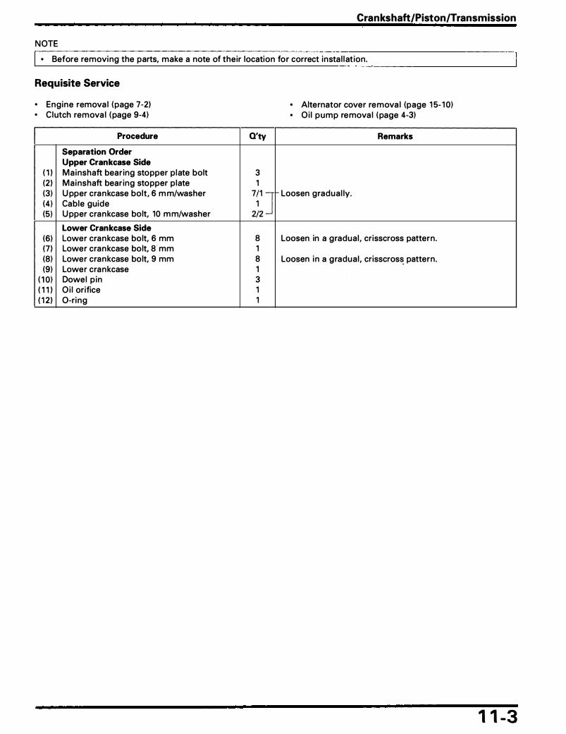
Crankshaft/Piston/Transmission
NOTE
• Before removi ng the parts, make a note of their location for correct insta l l at ion.
Requisite Service
• Engine remova l ( page 7-2) • Clutch remova l ( page 9-4)
Procedure
Separation Order Upper Crankcase Side ( 1 ) Mainshaft bear ing stopper plate bolt (2 ) Mai nshaft bear ing stopper plate
(3) U pper cra n kcase bolt, 6 m m/washer (4) Cable guide (5) U pper cra n kcase bolt, 10 m m/washer
Lower Crankcase Side (6) Lower cra n kcase bolt, 6 mm (7) Lower cra n kcase bolt, a· mm (8) Lower cra nkcase bolt, 9 mm (9) Lower cra nkcase
( 1 0) Dowel p in ( 1 1 ) O i l orifice ( 1 2 ) 0-ri ng
Q'ty
3 1 7�1, ] 2/2 8 1 8 1 3 1 1
• Alternator cover remova l (page 1 5- 1 0) • Oi l pump remova l ( page 4-3)
Remarks
Loosen gradua l ly.
Loosen in a gradual , crisscross pattern.
Loosen i n a g radual , crisscros� pattern.
1 1 -3

Crankshaft/Piston/Transmission
Crankshaft/Connecting Rod Removal/ Instal lation
0 1 2 ( 1 .2. 9 )
( 1 1 ) cw --:7J
(4)
1 1 -4
AFTER '94
( 1 1 ) naa c 1 2 ( 1 .2, 9)
( 1 ) , c 33 (3.3, 24)
(9) 0g c 1 2 ( 1 .2, 9)
�---( ) cw c 1 2 ( 1 .2, 9)
ROTATI N G DIRECTIO N

Crankshaft/Piston/Transmission
N OTE • Mark a l l pa rts d u ring d isassembly so they can be replaced in the i r orig ina l locations. • Al l bea r ing inserts are se lect fitted and are identified by co lor code. Select replacement bea ri ngs from the code
ta ble ( page 1 1 - 1 6) . After i nsta l l i ng new bea rings, recheck them with p lastigauge to verify the c lea rance. • Apply molybdenum disu lfide o i l to the con necting rod/main journa l bea rings, ma in journa l and crankpi n .
Requisite Service
• Refer to Service Information (page 1 1 - 1 )
Procedure
Removal Order ( 1 ) Connecti ng rod bea ri ng cap n ut (2 ) Connect ing rod bea ring ca p
(3) Connecting rod/piston assem bly
(4) Connecti ng rod bearing (5) Crankshaft (6) Crankshaft main journa l bearing (7 ) Front cam cha in tensioner s l i pper bolt (8) Front cam chain tensioner s l i pper (9) Rea r cam chain tensioner s l ipper bolt
( 1 0) Rea r cam cha in tensioner s l ipper ( 1 1 ) Front/rear cam cha in s l ipper bolt ( 1 2 ) F ront/rear cam cha in s l i pper
Installation Order ( 1 2 ) Front/rear cam cha i n s l i pper ( 1 1 ) F ront/rear cam chain s l i pper bolt ( 1 0) Rea r ca m chain tensioner s l i pper
(9) Rea r cam cha in tensioner s l ipper bolt (8) Front cam cha in tensioner s l ipper (7) F ront cam chain tensioner s l ipper bolt (6) Crankshaft main journal bear ing
(5) Crankshaft (4) Connecting rod bearing
(3) Con nect ing rod/piston assembly
(2 ) Connecting rod bea ring cap ( 1 ) Con nect ing rod bearing cap nut
Q'ty Remarks
I nsta l lation is in the reverse order of remova l . 8 4 NOTE
• Note the d i rection of the bea r ing ca p. 4 CAUTION
• Do not try to remove the connecting rod/piston as-sembly from the bottom of the cylinder. The oil ring will become wedged in the gap between the cylinder liner and the upper crankcase.
8 Wi pe a l l o i l from bea ring seat ing a reas. 1 8 Wi pe a l l o i l from bearing seat ing areas. 1 1 1 1 2 1
1 2 Clean and apply a locki ng agent to the th reads. 1 1 Clea n and apply a locking agent to the threads. 1 1 Clean a nd apply a locking agent to the th reads. 8 NOTE
• At insta l l at ion, a l i gn the o i l ho les between the crank-case a n d bea r i n g , a n d t h e bea r i n g ta bs w i th t h e groove i n the crankcase.
1 8 NOTE
• At insta l l at ion, a l i g n the o i l h o les between the con-nect ing rod and bearing, and the beari ng tabs with the groove in the connecti ng rod and bearing cap.
4 NOTE • Each connecti ng rod has an identificat ion m ark; " M L7-
F" (Front), " M L7-R" (Rear) . • At i n sta l l a t i o n , i n sta l l the c o n n ect i n g rod/ p i st o n
assembly with the o i l h o l e on the connect ing rod fac-ing opposite the rotati ng d i rection of the crankshaft.
4 8 NOTE
• At i n sta l l ati on , app ly e n g i n e o i l to the th reads a n d seati ng su rface of the nut.
• Tighten the nuts gradua l ly and a lternate ly.
1 1 -5

Crankshaft/Piston/Transmission
Piston Disassembly I Assembly
( 1 ) .,
" I N " MARK
, (2)
(4)
I DE NTIFICATION
( 1 0) , .--�-t-20 m m (0.8 i n ) OR MORE
1 1 -6

Crankshaft/Piston/Transmission
N OTE
I • Apply molybden um d isu lfide o i l to the connecti ng rod sma l l end and piston p in .
Requisite Service
• Piston remova l (page 1 1 -4)
Procedure
Disassembly Order ( 1 ) Piston pin c l ip
(2 ) Piston pin
(3) F ront piston assembly
(4) F ront connecti ng rod (5) Rea r piston assembly
(6) Rear connecting rod (7 ) Top ring (8) Second r ing (9) Side ra i l
( 1 0) Spacer
Q'ty Remarks
Assem bly is in the reverse order of d isassem bly. 8 CAUTION
• Do not reuse the piston pin clips. 4 NOTE
• Apply molybde n u m disu lfide o i l to the piston p in and connecting rod sma l l end .
2 NOTE • Identify the front connecting rod by the marking " M L7-
F " . I nsta l l the piston on the front connecti ng rod so that the " I W mark on the piston head faces the o i l hole side of the con necting rod .
• It is not necessa ry to remove the piston ri ngs u n less they need replacing.
2 2 NOTE
• Identify the rear connecting rod by the m a rking " M L7-R " . I nsta l l the piston on the rear con nect ing rod so that the " I N " mark on the piston head faces the side oppo-site the connecting rod oil hole .
• It is not necessa ry to rem ove the piston ri ngs u n l ess they need replacing .
2
: J At insta l lation , insta l l the piston r ings with the i r ma rks facing up.
8 4
1 1 -7

Crankshaft/Piston/Transmission
Transmission Removal/Instal lation
, (1 )
1 1 -8

Crankshaft/Piston/Transmission
NOTE
• Turn the mainshaft and cou ntershaft to ensure that the gears turn smoothly after reassem bly. • After i nsta l lation, l u b ricate gears with clean recommended engine o i l .
Requisite Service
• Refer to service I nformation (page 1 1 - 1 )
Procedure
Removal Order ( 1 ) Mainshaft/cou ntershaft assembly
(2 ) Countershaft bear ing set plate (3) Dowel pin (4) S h ift fork shaft (5) S h ift fork (6) S h ift drum
Installation Order (6) S h ift drum (5) Sh ift fork
(4) S h ift fork shaft (3) Dowel pin (2) Countershaft bearing set plate ( 1 ) Mainshaft/cou ntershaft assembly
Q'ty Remarks
1 • Remove the mainshaft and cou ntershaft as a n assem-bly.
• Disassembly (page 1 1 - 1 0, 1 2 ) 1 1 1 3 1
1 3 I n sta l l t h e m w i t h t h e i d e n t i f icat i o n m a r k ( R : R i g ht ,
C: Center, L: Left) side facing the rig ht s ide as shown. 1 1 1 Fit i n the u pper cra n kcase secu rely. 1 • I nsta l l the mainshaft and countershaft as a n assembly.
• Fit the cou ntershaft bea r i n g set pin a n d p l ate in the u pper crankcase g roove, and the dowel p in i n the hole in the needle bear ing case.
1 1 -9

Crankshaft/Piston/Transmission
Mainshaft Disassembly I Assembly
( 1 4)
(5)
( 1 3 ) ( 1 2 ) ( 1 0)
( 1 1 ) (9)
(7) '94 - '95 (and some '96 early (3) ( 1 ) production units)
'94 - '95 (and some '96 early production units)
AFTER '95 (Except some '96 early production units)
( 1 2 ) (8) (5) (4)
�==�---t-L-������==���
( 1 3) ( 1 0)
---:71) : SHIFTER GEAR ---:71) : GEAR SLIDI N G m G ROOVE m SU RFACE
(9) (8) (7) (6) (3)
( 1 )
1 1 - 1 0 Revised: July, 1 995, '94 - '95 Magna VF750C/CD © 1 995 American Honda Motor Co., Inc. - All Rights Reserved MSV 691 3 19504)

Crankshaft/Piston/Transmission
N OTE
• Apply molybden u m o i l solution to the sh ifter gear g rooves. Apply o i l to a l l s l id ing su rfaces of the ma inshaft, countershaft and bush ings.
• I n sta l l the thrust washers and snap ri ngs with the chamfered edge facing the th rust load side. • Refer to section 1 3 of the Common Service Manua l for inspection i nformation .
Requisite Service
• Transm ission remova l/insta l lation ( page 1 1 -81
Procedure Q'ty Remarks
Disassembly Order Assem bly is in the reverse o rder of d isassem bly. ( 1 ) Needle bea ri ng case (2) Need le bearing (3) Thrust washer (4) M 2 gear ( 1 7TI (51 Col l a r (6) Spl ine washer (7) Snap r ing (8) M3/M4 gear (20/22TI (9) Snap ring
( 1 0) Sp l ine washer ( 1 1 ) M 5 bush ing ( 1 2 ) M5 gear (28TI ( 1 3) Washer ( 1 4) Mainshaft/M 1 gear ( 1 3TI
Revised: July, 1 995, '94 -· '95 Magna VF750C/CD © 1 995 American Honda Motor Co. , Inc. - All Rights Reserved MSV 691 3 f9504l
1 1 1 1 1 '94 - '95 (and some '96 early production units) 1 1 1 1 1 1 1 1 1
1 1 - 1 1
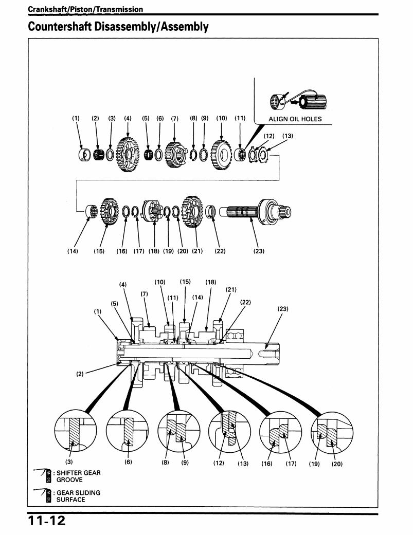
Crankshaft/Piston/Transmission
Countershaft Disassembly I Assembly
( 1 4) ( 1 5)
(3)
--:7D : S H I FTER G EAR . I GROOVE
-:7ll : G EAR SLI D I N G . I SURFACE
1 1 - 1 2
(6)
(22)
( 1 0) ( 1 5) ( 1 8)
ALI G N O I L HOLES
(23)
(8) (9) ( 1 2) ( 1 3) ( 1 6) ( 1 7 ) ( 1 9) (20)

Crankshaft/Piston/Transmission
N OTE
• Apply molybdenum o i l so l ution to the sh ifter gear g rooves. Apply o i l to a l l s l id ing su rfaces of the mainshaft, countershaft and bush ings.
• I nsta l l the th rust washers and snap rings with the chamfered edge facing to the thrust load side. • Refer to section 1 3 of the common Service Manual for i nspection i nformation .
Requisite Service
• Transm ission remova l/insta l lation (page 1 1 -8)
Procedure Q'ty Remarks
Disassembly Order Assem bly is in the reverse order of d isassembly. ( 1 ) Need le beari ng case 1 (2 ) Needle bearing 1 (3) Thrust washer 1 (4) C 1 gea r (37T) 1 (5) Needle bea ring 1 (6) Thrust washer 1 (7) C5 gear (29T) 1 (8) Snap ring 1 (9) Sp l ine washer 1
( 1 0) C4 gear (27T) 1 ( 1 1 ) C4 spl i ne bush ing 1 Al ign the o i l holes of the bushi n g and countershaft. ( 1 2 ) Tanged washer 1 At assembly, fit the tangs i nto the lock washer cut-outs. ( 1 3) Lock washer 1 ( 1 4) C3 spl ine bushing 1 ( 1 5) C3 gear (29T) 1 ( 1 6) Sp l ine washer 1 ( 1 7 ) S n a p ring 1 ( 1 8) Sh ifter gea r 1 ( 1 9) Snap ring 1 (20) Spl ine washer 1 (2 1 ) C2 gea r (32T) 1 (22) C2 bush ing 1 (23) Cou ntershaft 1
1 1 - 1 3

Crankshaft/Piston/Transmission
Crankcase Combination
-,0 31 (3. 1 , 221
(51
c 23 (2.3, 1 71
(6)
1 1 - 1 4
c 1 2 ( 1 .2, 91 (7)
< 1 (81 c 1 2 ( 1 .2, 91 c 39 (3.9, 28)
ALI G N
(9)

Crankshaft/Piston/Transmission
CAUTION • Instal l the oil orifice with the larger inner diameter side facing the lower crankcase. • If the lower crankcase installation is difficult, make sure the transmission assembly is installed correctly.
NOTE
• Refer to page 1 1 - 1 8 for crankcase sea lant area and deta i l of the bolt locations.
Requisite Service
• O i l pu m p insta l lation ( page 4-3) • Starter motor insta l lation ( page 17-7 ) • Alternator insta l l ation (page 1 5- 1 0) • Clutch insta l lation ( page 9-6)
Procedure
Combination Order ( 1 ) U pper cra n kcase
(2 ) O i l or ifice/0-r ing (3) Dowel p in (4) Lower crankcase
(5) Lower cra n kcase bolt, 9 mm (6) Lower crankcase bolt, 8 mm (7) Lower crankcase bolt, 6 m m/washer (8) U pper crankcase bolt, 10 m m/washer (9) Cable g u ide
( 1 0) U pper cra n kcase bolt, 6 mm/washer ( 1 1 ) Ma inshaft bearing set plate ( 1 2 ) Mainshaft bearing set plate bolt
Q'ty
1
1/1 3 1
! I 2�2 J 7/1
1 3
• Gearshift i i n kage insta l lation ( page 1 0-4) • Cyl i nder head/ca mshaft insta l lation ( page 8-2 ) • Engine insta l lation ( page 7-2)
Remarks
CAUTION • Do not apply sealant around the oil passage area and
main journal bearing area. Refer to page 1 1 - 1 8 for deta i l for the appl ication a rea. I nsta l l it as i l l ustrated.
At insta l lation, make sure the shift forks engage properly with the corresponding gea rs.
f.-Tightening order ( page 1 1 - 1 8)
Tighten ing order ( page 1 1 - 1 9 )
Al ign t h e cut out o f t h e shift fork shaft with t h e set plate. Clean and apply a locki ng agent to the bolt threads.
1 1 - 1 5

Crankshaft/Piston/Transmission
Crankshaft Bearing Replacement Main Journal Bearing Selection
Record the crankcase I .D . code letters from the pad on the left side of the upper crankcase.
NOTE
The letters (A, B or C) on the u pper crankcase a re the codes fo r the m a i n j o u rn a l I . D .s . fro m the left to right.
Record the correspond ing m a i n journa l O .D . code n u m bers from t h e crank weight.
NOTE
• The n u m bers ( 1 , 2 or 3) on the crank weight are the codes for the main journa l O.D.s.
Cross-reference the case and journal codes to determine the replacement bearing color codes.
Main Journal Bearing Selection Table: U n it: mm ( in )
�:�: 37.000�37.005 37.006 � 37.01 1 37.0 1 2� 37.018 �.�� ����nal � ( 1 .4567 - 1 .4569) ( 1 .4569 - 1 .4572) ( 1 .4572 - 1 .4574) 1 34·007 - 34·0 13 Yel low Green Brown ( 1 .3389 - 1 .339 1 ) 2 34.001 - 34.006
( 1 .3386 - 1 .3388) 3 33.995 - 34.000
( 1 .3368 - 1 .3385)
Bearing thickness:
Blue: Th ick Black: l Brown: Green: Yel low: Th in
1 1 - 1 6
Green Brown Black
Brown Black Blue
( 1 ) CRAN KCASE 1 .0. CODE
( 1 ) MAI N JOURNAL O.D. CODE
( 1 ) MAI N JOURNAL BEARI N G S

Connecting Rod Bearing Selection
Inspect the con necting rod bea ring and cra nkpin oil clea rance (See section 1 4 of the Common Service Manua l ) .
Record the con necti ng rod I . D. code n u m ber ( 1 , 2 or 3) or measu re the I .D. with the bea r ing cap i n sta l led without bear ing insert.
If you rep lace the cra n ksh aft, record the co rrespon d i ng crankpin O.D. code n u m ber (A, B or C) .
If you a re reus ing the cra n kshaft, measu re the cra n kp in O.D. with a m icrometer.
NOTE
• N u m bers (A, B o r C) o n the cra n k we i g ht a re the codes for the cra n k p in O.D.s.
Cross-reference the crankpin and rod codes to determ i ne the replacement bear ing color.
NOTE
• One pai nted mark identifies the front connecting rod bearings and two painted marks the rea r.
Connecting Rod Bearing selection Table: U n it: mm ( in )
�����:�� 35.995:36.000 35.989 � 35.994 35.982 � 35.988 �::����� ( 1 .4 171 - 1 .4173) ( 1 .4169 - 1 .4 1 7 1 ) ( 1 .4166 - 1 .4 1 69) 39.000 - 39.005 1 ( 1 .5354 - 1 .5356) 39.006 - 39.01 1 2 ( 1 .5357 - 1 .5359) 39.01 2 - 39.01 8 3 ( 1 .5359 - 1 .536 1 )
Bearing thickness:
Blue: Thick B lack: l Brown: Green: Yel low: Th in
Yel low Green Brown
Green Brown Black
Brown Black Blue
Crankshaft/Piston/Transmission
( 1 ) CON NECTI N G ROD I . D. CODE
(2 ) REAR
(3) CON NECTI N G ROD BEAR I N G
1 1 - 1 7
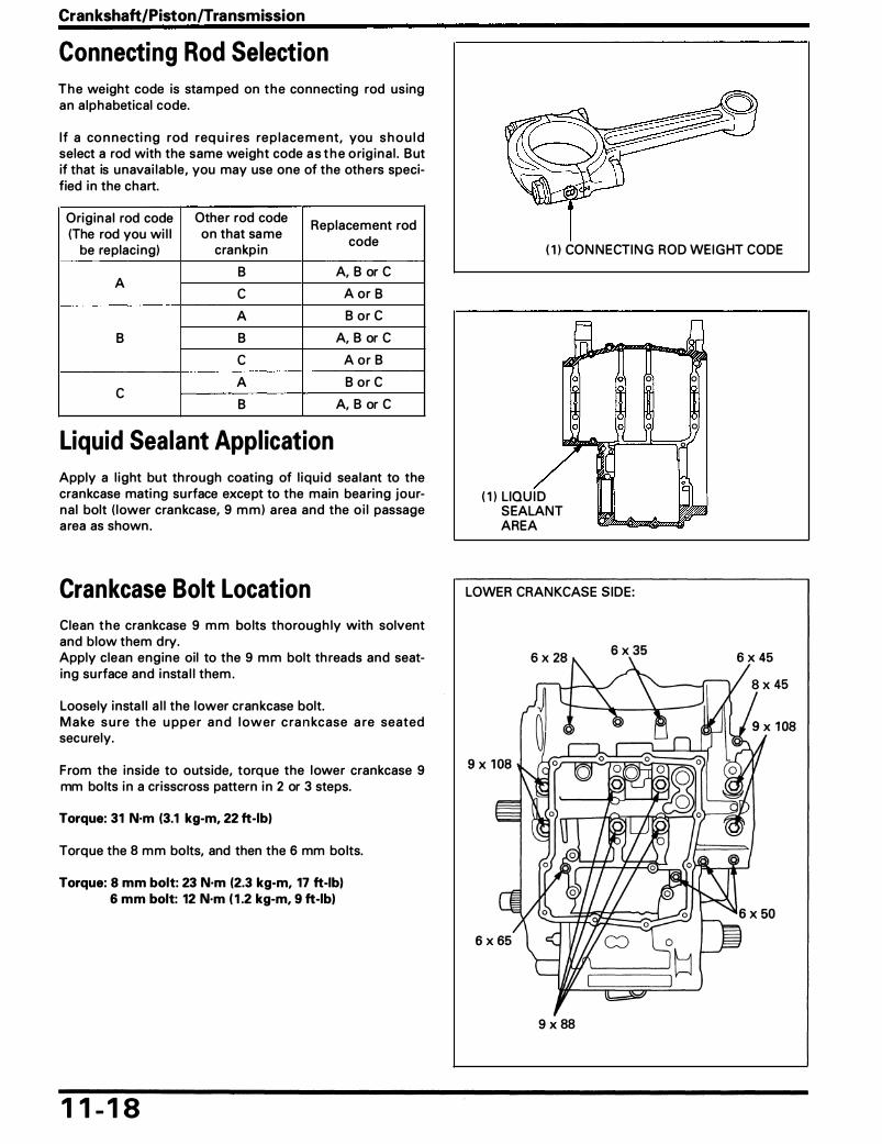
Crankshaft/Piston/Transmission
Connecting Rod Selection
T h e weight code is stam ped on t h e connecti ng rod using an a lphabetical code.
I f a co n n ecti n g rod req u i res re p l a ce m e nt, you s h o u l d select a rod with the same weight code a s t h e o rig ina l . But if that is u navai lable, you may use one of the others specified in the chart.
Orig ina l rod code Other rod code Replacement rod (The rod you wi l l on that sa me
code be replaci ng) crankp in
B A, B or C A c A or B
A B or e
B B A, B or C
c A or B
A B or C c B A, B or C
( 1 ) CON N ECTI N G ROD WEI G HT CODE
0 0
0 0
Liquid Sealant Appl ication o
Apply a l ight but th rough coating of l iqu id sea lant to the crankcase mati ng su rface except to the main bea ring journa l bolt ( lower crankcase, 9 m m ) a rea and the o i l passage a rea as shown .
Crankcase Bolt Location
Clean t h e crankcase 9 m m bolts thoroug h ly with solvent and blow them dry. Apply clean engine oil to the 9 mm bolt th reads and seating su rface and i nsta l l them .
Loosely insta l l a l l the lower crankcase bolt. M a ke s u re t h e u pp e r a n d l ower c ra n kcase a re seated securely.
F rom the inside to outside, torq ue the lower crankcase 9 mm bolts i n a crisscross pattern i n 2 or 3 steps.
Torque: 31 N·m (3.1 kg-m, 22 ft-lbl
Torque the 8 mm bolts, and then the 6 mm bolts.
Torque: 8 mm bolt: 23 N·m (2.3 kg-m, 17 ft-lbl 6 mm bolt: 12 N·m ( 1 .2 kg-m, 9 ft-lbl
1 1 - 1 8
( 1 ) LIQU I D SEALANT AREA
LOWER CRANKCASE SIDE:
9 x 88

Loose ly i nsta l l a l l the u pper cra n kcase bo lts, the sea l i n g washers and cable gu ide.
Torque the 1 0 m m bolts, and then the 6 mm bo lts.
Torque: 10 mm bolt: 39 N·m (3.9 kg·m, 28 ft·lb) 6 mm bolt: 12 N·m ( 1 .2 kg-m, 9 ft-lb)
Crankshaft/Piston/Transmission
U PPER CRAN KCASE S IDE :
1 1 - 1 9

MEMO

1 2 . Front Wheel/Suspension/Steering Service Information 1 2- 1 Fork Removal/Instal lation 1 2-6 Troubleshooting 1 2- 1 Fork Disassembly 1 2-8 Handlebar Removal/Instal lation 1 2-2 Fork Assembly 1 2-1 0 Front Wheel Removal/Instal lation 1 2-4 Steering Stem Removal/Instal lation 1 2- 1 2 Front Wheel Disassembly/ Assembly 1 2-5
Service Information
• A contaminated brake disc or pad reduces stopping power. Discard contaminated pads and clean a contaminated disc with a high quality brake degreasing agent.
• Refer to section 1 4 for brake system i nformation. • Refer to section 1 8 for l ight, meter and switch i nformation. • When servicing the front wheel , fork or steering stem, su pport the motorcycle securely with a safety stan d o r hoist.
Do not use the oi l fi lter as a jack point.
Troubleshooting Hard Steering • Steering head bearing adjustment n ut too t ight • Fau lty steeri ng head bearings • Insufficient t i re pressu re • Fau lty t ire
Steers To One Side Or Does Not Track Straight • Bent fork • Bent front axle • Wheel insta l led i ncorrectly • Fau lty steering head bearings • Bent frame • Work wheel bea ring • Worn swingarm pivot components
Front Wheel Wobbling • Bent ri m • Worn front wheel beari ngs • Fa u lty ti re • U n ba lanced t i re and wheel
Wheel Turns Hard • Fau lty wheel bearing • Fau lty speedometer gear • Bent front axle • Brake d rag
Soft Suspension • I nsufficient flu i d i n fork • Weak springs • Low flu id level in fork • Low tire pressu re
Hard Suspension • Incorrect flu id weight • Bent fork tubes • Clogged flu id passage • High ti re pressu re
Front Su1pen1ion Noisy • I nsufficient flu id i n fork • Loose fork fasteners • Lack of g rease i n speedometer gear
1 2- 1
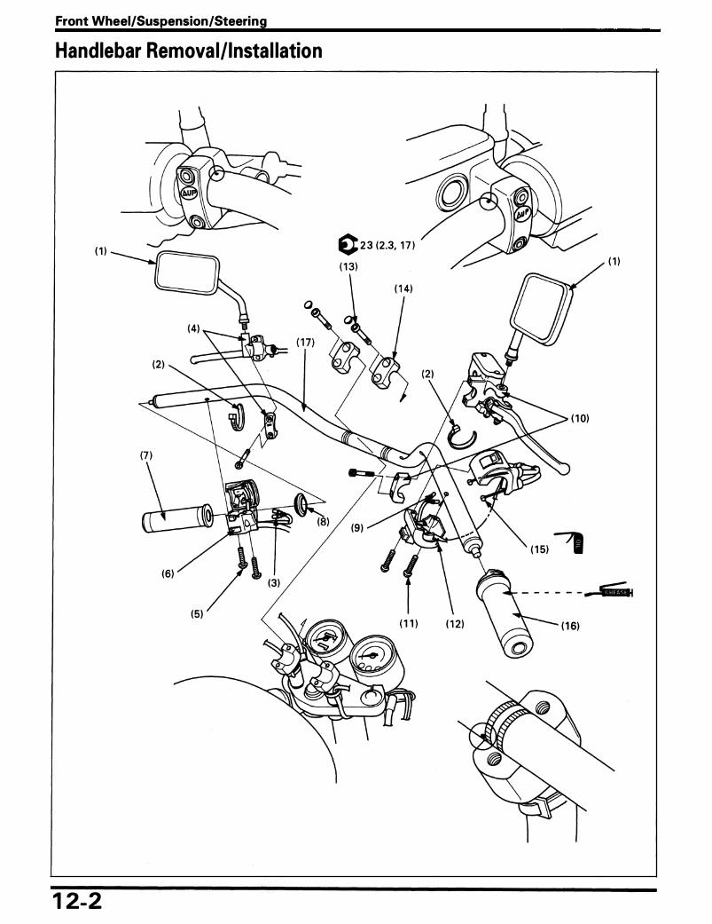
Front Wheel/Suspension/Steering
Handlebar Removal/ Insta l lation
( 1 ) c 2 3 (2 .3, 1 7 )
( 1 )
( 1 0)
( 1 5) ,
1 2-2

Front Wheel/Suspension/Steering
• Contaminates in the system may cause a reduction or loss of braking ability.
NOTE
• Using wi res, hang the front brake master cyl i nder at least as h igh as the position it was orig ina l ly insta l led at to prevent a i r from gett ing i nto the master cyl i nder. Do not twist the brake hose.
• Route the cables and wi re harnesses properly (page 1 -20). • After i nsta l l i ng the hand lebar, adjust-
• the th rott le cab le • the c l utch cable • the choke cable
Procedure
Removal Order ( 1 ) Rea rview m i rror (2 ) Wi re ban d (3) Cl utch switch con nector (4) C lutch lever assembly
(5) Left hand lebar switch housing screw (6) Left hand lebar switch housing
(7) Hand le gr ip
(8) Switch housing side protector (9) B rake l i g ht switch con n ector
( 1 0) Master cyl inder
( 1 1 ) R ight hand lebar switch housing screw ( 1 2) R ight hand lebar switch housing
( 1 3) Hand lebar holder bolt ( 1 4) Hand lebar u pper ho lder
( 1 5) Th rott le cab le end ( 1 6) Th rott le p ipe ( 1 7 ) Hand lebar
O'ty Remarks
I nsta l lation is in the reverse order of remova l . 2 2 2 1 Al ign the spl it between the holder and lever support with
the punch mark on the hand lebar a n d face the holder " U P" mark u pward . Tighten the u pper bolt fi rst, then the lower bolt.
2 Tighten the front screw fi rst, then the rea r screw. 1 Al ign the l ocati ng pi n i n the l eft hand lebar switch with
the ho le in the ha ndlebar. 1 Apply Honda Bond A or Honda Hand G ri p Cement
( U .S .A. on ly) to the inside su rface of the g rip . 1 2 1 Al ign the sp l it between the ho lder and master cyl inder
body with the punch mark on the handlebar a n d face the holder " U P" mark u pward . Tighten the upper bolt fi rst, then the l ower bolt.
2 Tighten the front screw fi rst, then the rea r screw. 1 Al ign the locating p in i n the right hand lebar switch with
the ho le in the hand lebar. 4 Tighten the front bo lts fi rst, then the rea r bo lts. 2 Insta l l the upper holder with its punch mark fac ing for-
ward . 2 1 1 P lace the hand lebar onto the lower ho lder and a l i g n the
punch m arks on the hand lebar with mati ng surface of the hand lebar ho lder.
1 2-3
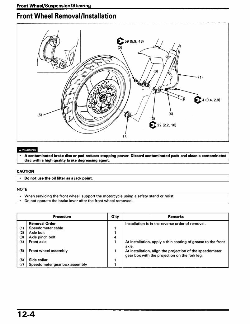
Front Wheel/Suspension/Steering
Front Wheel Removal/Insta l lation
c 59 (5.9, 43)
(2 )
(7)
( 1 )
(3) c 22 (2.2. 1 6)
• A contaminated brake disc or pad reduces stopping power. Discard contaminated pads and clean a contaminated disc with a high quality brake degreasing agent.
CAUTION • Do not use the oil filter as a jack point.
N OTE
• When servicing the front wheel, support the m otorcycle using a safety stand or hoist. • Do not operate the brake lever after the front wheel removed .
Procedure Q'ty Remarks
Removal Order I nsta l l ation is in the reverse order of removal . ( 1 ) Speedometer cable 1 (2 ) Axle bolt 1 (3) Axle p inch bolt 4 (4) F ront axle 1 At insta l lat ion, apply a th in coati ng of g rease to the front
axle. (5) F ront wheel assembly 1 At insta l lation, a l ign the projection of the speedometer
gea r box with the projection on the fork leg. (6) Side co l l a r 1 (7 ) Speedometer gear box assem bly 1
1 2-4

Front Wheel/Suspension/Steering
Front Wheel Disassembly I Assembly
(2 )
( 1 ) (2 )
c 42 (4.2, 30)
• A contaminated brake disc or pad reduces stopping power. Discard contaminated pads and clean a contaminated disc with a high quality brake degreasing agent.
N OTE
• Always replace wheel bearings as a set. • For wheel bea ring replacement, refer to section 1 of the Common Service Manua l .
Requisite Service
• Front wheel remova l/insta l lation ( page 1 2-4)
Procedure
Removal Order ( 1 ) Brake d isc bolt (2 ) Brake d isc (3) Dust sea l (4) Speedometer gear reta i ner (5) R ight wheel bea ring (6004 U U ) (6) Distance col l a r (7 ) Left wheel bearing (6004 U U )
Q'ty Remarks
I nsta l lation is i n the reverse order of removal . 6 1 I nsta l l with stam ped side outward . 2 At insta l lation, apply g rease to the dust sea l l i ps. 1 1 1 1 NOTE
• At assembly, d rive in the left side bear ing fi rst, then the r ight side bear ing.
(8) F ront wheel/ti re 1/1
1 2-5
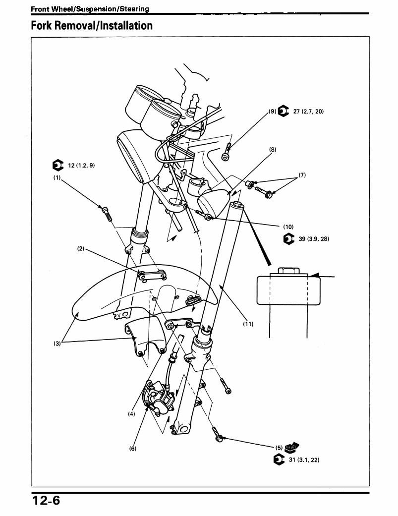
Front Wheel/Suspension/Steering
Fork Removal/Instal lation
( 9 ) c 27 (2 .7, 20)
(8)
c 1 2 ( 1 .2 , 9)
( 1 )
( 1 0) c 39 (3.9, 28)
(3)
(5) ., c 3 1 (3. 1 , 22)
1 2-6

Front Wheel/Suspension/Steering
CAUTION
• Support the removed caliper so that it does not hang from the brake hose. Do not twist the brake hose.
NOTE
• If the fork legs wi l l be d isassem bled, tem porari ly tighten the bottom bridge pinch bolt to loosen the fork cap.
Requisite Service
• Front wheel removal/i nsta l lation (page 1 2-4)
Procedure
Removal Order ( 1 ) F ront fender bolt (2 ) Front fender col l a r (3) Front fender (4) Brake hose c lamp (5 ) Ca l i per bracket bolt (6) Ca l i per assembly (7 ) Front turn s ignal bolt/col l a r (8) F ront turn signal assembly (9) Fork p inch bolt ( upper)
( 1 0) Fork pinch bolt ( l ower)
( 1 1 ) Fork assembly
I
Q'ty
4 1 1 1 2 1
2/2 2 2 2
2
• U pper fair ing remova l/insta l lation (VF750CD: page 2-8)
Remarks
Insta l lation is in the reverse order of remova l .
On ly loosen the bolts. • Only loosen the bolts. • If the fork leg wi l l be disassembled, tem pora ri ly t ighten
the bottom pi nch bolt to loosen the fork cap. At i nsta l lation, a l ign the tops of fork tubes with the u pper su rface of the top bridge.
1 2-7
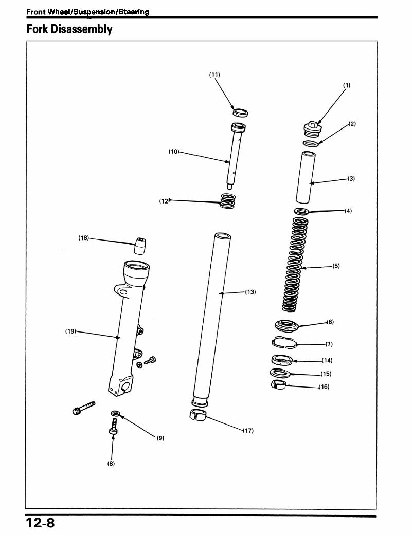
Front Wheel/Suspension/Steering
Fork Disassembly
( 1
� ( 1 0)
( 1 2lr-----...Ja!:§il�l!'i( ( 1 8)-------s
( 1 9
�(9) � 1 71
(8)
1 2-8
( 1 )
�(4)
�6)
�(7) (91.. (1 4) �(15) lB------< 1 6)
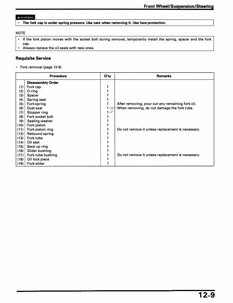
Front Wheel/Suspension/Steering
• The fork cap is under spring pressure. Use care when removing it. Use face protection.
NOTE
• If the fork piston moves with the socket bolt d u ring removal , tem po ra ri ly i nsta l l the spri ng, spacer and the fork cap.
• Always replace the o i l sea ls with new ones.
Requisite Service
• Fork remova l ( page 1 2-6)
Procedure
Disessembly Order ( 1 ) Fork cap (2 ) 0-ring (3) Spacer (4) Spr ing seat (5) Fork spring (6) Dust seal (7 ) Stopper ri ng (8) Fork socket bolt (9) Sea l i n g washer
( 1 0) Fork piston ( 1 1 ) Fork piston ring ( 1 2) Rebound spring ( 1 3) Fork tube ( 1 4) O i l sea l ( 1 5) Back u p r ing ( 1 6) S l ider bushing ( 1 7 ) Fork tu be bush ing ( 1 8) O i l lock piece ( 1 9) Fork s l ider
Q'ty Remarks
1 1 1 1 1 After removing, pour out any remain ing fork o i l .
� T When rem oving, do not damage the fork tube.
1 1 1 1 Do not remove it u n less replacement is necessary. 1 1 1 1 1 1 Do not remove it u n less replacement is necessary. 1 1
1 2-9

Front Wheel/Suspension/Steering
Fork Assembly
(3)
(4)-------s
P e� c 8 (0.8, 5.8)
(8) c 20 (2.0, 1 4) 1 2- 1 0
(2 )�
( 1 3) ., ...
~ (5)
c 23 (2.3, 1 7 ) ( 1 8) �17)-
�- ( 1 5)
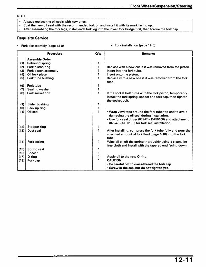
NOTE
• Always replace the o i l sea ls with new ones.
Front Wheel/Suspension/Steering
• Coat the new o i l sea l with the recommended fork o i l and insta l l it with its mark fac ing up . • After assem bl ing the fork legs, insta l l each fork leg i nto the lower fork bridge fi rst, then torque the fork cap.
Requisite Service
• Fork d isassem bly (page 1 2-8)
Procedure
Assembly Order ( 1 ) Rebound spring (2) Fork piston ri ng (3) Fork piston assembly (4 ) O i l lock piece (5) Fork tube bushing
(6 ) Fork tube (7 ) Sea l i n g washer (8) Fork socket bolt
(9) Sl ider bushing ( 1 0) Back u p r ing ( 1 1 ) O i l sea l
( 1 2 ) Stopper r ing ( 1 3) Dust sea l
( 1 4) Fork spring
( 1 5) Spr ing seat ( 1 6) Spacer ( 1 7 ) 0-ring ( 1 8) Fork cap
Q'ty
1 1 1 1 1
1 1 1
1 1 1
1 1
1
1 1 1 1
• Fork insta l lation ( page 1 2-6)
Remarks
Replace with a new one if it was removed from the piston. I nsert into the fork tube. Insert onto the pisto n . Replace with a new one i f i t was removed from t h e fork tube.
If the socket bolt turns with the fork piston, tem porari ly i nsta l l the fork spring, spacer and fork cap, then tighten the socket bolt.
• Wrap vinyl ta pe arou nd the fork tube top end to avoid damaging the o i l sea l d u ring i nsta l lation .
• Use fork sea l d river (07947 - KA501 00) and attachment (07947 - KF001 00) for fork sea l insta l l at ion.
After insta l l ing, compress the fork tu be fu l ly and pour the specified amount of fork fl u id (page 1 - 1 0) i nto the fork tube. Wipe al l oi l off the spring thoro u g h ly using a c lea n , l i nt free c loth and insta l l with the ta pered end fac ing down .
Apply o i l to the new 0-ring . CAUTION • Be careful not to cross-thread the fork cap. • Screw in the cap, but do not tighten yet.
1 2- 1 1

Front Wheel/Suspension/Steering
Steering Stem Removal/Installation , , ,c
(5)
., (8)
-� NOTE
6) c 30 (3.0, 22)
1 •.-;;c,.. I ( page 1 -15)
-!f'tl-...,..::::::..__ ( 1 4) J a.T-. hpage 1 2-1 3)
( 1 5) J s.T-. I (page 1 2-13)
J a.T-. I (page 1 2-1 3)
(13)
NOTE------------------------------�
Use the specified grease : Urea based multi-purpose grease for Extreme pressure (example: EXCELITE EP2 manufactured by KYODO YUSHI Japan, 'Shell Stamina EP2) or equivalent
1 2- 1 2
SHORTER TABS: • Bend down LONGER TABS: • Bend up

NOTE
• Replace the bea rings and races as a set. • At insta l lation, apply g rease to a l l bea ring a rea.
Front Wheel/Suspension/Steering
• Check the steering head bea ring preload ( page 1 - 1 0) after torqu ing the stem n ut.
Requisite Service
• Fork remova l/i nsta l lation ( page 1 2-6) • Hand lebar remova l/insta l lation ( page 1 2-2)
Procedure
Removal Order ( 1 ) Steering stem n ut (2 ) Th rust washer (3) Top bridge (4) Lock nut (5) Lock washer (6) Steering head bea ring adjustment nut (7) Dust seal (8) Steering stem (9) U pper bearing inner race
( 1 0) U pper bear ing ( 1 1 ) Lower bea ring ( 1 2 ) Lower beari ng inner race ( 1 3) Dust seal ( 1 4) U pper bearing outer race ( 1 5) Lower bea ring outer race
( 1 6) Lower holder n ut/washer ( 1 7 ) Lower holder
Installation Oder ( 1 7 ) Lower holder ( 1 6) Lower holder n ut/washer ( 1 5) Lower bearing outer race ( 1 4) U pper bea ring outer race ( 1 3) Dust sea l . ( 1 2 ) Lower bearing inner race ( 1 1 ) Lower bea ring ( 1 0) U pper bear ing
(9) U pper bea ring inner race (8) Steering stem (7) Dust seal {6) Steering head bearing adjustment n ut (5) Lock washer (4) Lock n ut (3) Top bridge (2 ) Th rust washer ( 1 ) Steering stem nut
Q'ty
1 1 1 1 1 1 1 1 1 1 1 1 -1 -1 -1 -
2/2 2
2 2/2
1 -1 -1 -1 -1 -1 -1 -1 1
E r 1 1 1
• Meter remova l/insta l lation ( page 1 8-7 ) • Head l ight remova l/i nsta l l ation ( page 1 8-6)
Remarks
After removing, remove the fork.
Remove, after stra ighten ing the lock washer tabs.
Replace if removed. • U se race re mover attach m e nt ( 07953 - MJ 1 0 1 00 o r
07953 - MJ 1 000A [ U . S .A. o n ly ) ) with d rive r (07953 -MJ 1 0200 or M9360 - 277 - 91 774 [U .S.A. on ly]) for u pper outer race removal .
• Use race remover (07946 - 37 1 0500) fo r l owe r o uter race remova l .
Tighten ing procedure ( page 1 2- 1 4) . Replace as a set, if necessary. • Use attach ment, 52 x 55 m m (07746 - 001 0400) and dri-
ver (07749 - 00 1 0000) for lower outer race insta l l atio n . • U s e attachment, 4 2 x 4 7 m m (07746 - 00 1 0300) and d ri-
ver (07749 - 00 1 0000) for u pper o uter race insta l lation . • Use steering stem d river (07946 - M BOOOOO) for l ower
inner race insta l lation .
I n sta l lation : refer to section 1 8 of the Com m o n Service Manua l ( Reta iner-Type Ba l l Bear ings) .
Tem porari ly insta l l fork and torque the n ut.
1 2- 1 3

Front Wheel/Suspension/Steering
Handlebar Lower Holder Nut Tightening Procedure I nsta l l the handlebar lower holder. Loosely insta l l the washers and n uts.
I nsta l l the hand lebar and upper holder (page 1 2-2) .
Tighten the u pper holder bolts.
Torque: 5 N·m (0.5 kg-m, 3.6 ft-lb)
Adjust the hand lebar stra ight-ahead by tap the end of hand lebar. Make sure that the length A and B are eq ua l .
Tighten the lower ho lder n uts.
Torque: 27 N·m (2.7 kg-m, 20 ft-lb)
Tighten the u pper holder bolts (page 1 2-2) .
Torque: 23 N·m (2.3 kg-m, 1 7 ft-lb)
Make sure that the length A and B are eq ual .
1 2- 1 4
(2 ) U PPER HOLDER

Service Information
Troubleshooting
Rear Wheel Removal/Instal lation
Rear Wheel Disassembly I Assembly
Service Information
1 3 . Rear Wheel/Suspension 1 3-1 1 3-1
Shock Absorber Removal/Instal lation 1 3-6 Shock Absorber Disassembly I Assembly 1 3-7
1 3-2 Swingarm Removal/Instal lation
1 3-4 Swingarm Disassembly I Assembly
1 3-9 1 3- 1 1
• Inhaled asbestos fibers have been found to cause respiratory disease and cancer. Never use an air hose or dry brush to clean brake assemblies. Use an OSHA-approved vacuum cleaner or alternate method approved by OSHA, designed to minimize the hazard caused by airborne asbestos fibers.
• A contaminated brake drum or shoe reduces stopping power. Discard contaminated shoes and clean a contaminated drum with a high quality brake degreasing agent.
• Any attempt to mount automobile tires on a motorcycle rim may cause the tire . bead to separate from the rim with enough explosive force to cause serious injury or death.
• When servic ing the rea r wheel, su pport the motorcycle using a safety stand or hoist. • Refer to the section 1 4 for brake system i nformation . • Tubeless ti re remova l , repai r, and remounting procedu res a re covered i n the sect ion 1 6 of the Com mon Service
Manua l .
Troubleshooting
Soft Suspension • Weak spring • O i l leakage from damper u n it • I ncorrect suspension adjustment • Low ti re pressu re
Hard Suspension • I ncorrectly suspension adjustment • Bent swingarm pivot • Damaged swingarm pivot bea rings • Bent damper rod • High ti re pressu re
Steers To One Side Or Does Not Track Straight • Bent rear axle • Axle a l i g n ment/cha i n adj ustment not eq ua l on both
sides
Rear Wheel Wobbling • Bent rim • Worn rea r wheel bea ri ngs • Fau lty ti re • U n ba lanced ti re and wheel • Low ti re pressu re • Fau lty swi ngarm pivot bearings
1 3- 1

Rear Wheel/Suspension
Rear Wheel Removal/Instal lation
( 1 5)
( 1 8)
(7 ) 0 22 (2 .2 . 1 6)
( 1 2) c 93 (9.3, 63)
(2 )
(9 ) ( 1 0)
1 3-2

Rear Wheel/Suspension
• Inhaled asbestos fibers have been found to cause respiratory disease and cancer. Never use an air hose or dry brush to clean brake assemblies. Use an OSHA-approved vacuum cleaner or alternate method approved by OSHA designed to minimize the hazard caused by airborne asbestos fibers.
• A contaminated brake drum or shoe reduces stopping power. Discard contaminated shoe and clean a contami· nated drum with a high quality brake degreasing agent.
NOTE
• When servicing the rea r wheel , su pport the motorcycle using a safety stand or hoist. • Adjust the d rive cha in free play after insta l l ing the wheel . • Apply th in layer of g rease to the rear axle su rface.
Procedure Q'ty
Removal Order ( 1 ) Brake adjusti ng n ut 1 (2 ) Brake rod 1 (3) Spring 1 (4) Brake rod jo int piece 1 (5) Drive chain adjusting nut 2 (6) Cotter p in 1 (7) N ut 1 (8) Washer 1 (9) Ru bber cushion 1
( 1 0) Brake stopper arm pivot bolt 1 ( 1 1 ) Brake stopper arm 1 ( 1 2 ) Rea r axle n ut/washer 1/1 ( 1 3) Drive chain adjuster 1
Remarks
Insta l lation is in the reverse order of remova l .
Loosen t h e adjusting n ut fu l ly.
( 1 4) Drive chain 1 Move the rear wheel forwa rd and remove the d rive cha in from the d riven sprocket.
( 1 5) Rea r axle 1 ( 1 6) Rear wheel assem bly 1 ( 1 7 ) R ight side col l a r 1 ( 1 8) Left side col lar 1 ( 1 9) Brake panel assembly 1 Disassembly ( page 1 4-7) .
1 3-3

Rear Wheel/Suspension
Rear Wheel Disassembly I Assembly
(8) (3) .,
(9)
(7)
(2)
-� (8) - (6)
( 1 1 ) ( 1 0) (3)
1 3-4
(4)
(5) c 1 08 ( 1 0.8, 79)
(4)

Rear Whee/Suspension
• Inhaled asbestos fibers have been found to cause respiratory disease and cancer. Never use an air hose or dry brush to clean brake assemblies. Use an OSHA-approved vacuum cleaner or alternate method approved by OSHA designed to minimize the hazard caused by airborne asbestos fibers.
• A contaminated brake drum or shoe reduces stopping power. Discard contaminated shoes and clean contaminated drums with a high quality brake degreasing agent.
NOTE
• For d riven sprocket rem ova l , loosen the sprocket n uts with the driven flange insta l led into the wheel h u b. • Replace wheel bearings as a set. • For wheel bea ring replacement, refer to the section 1 of the Common Service Manua l .
Requisite Service
• Rea r wheel remova l/insta l lation (page 1 3-2)
Procedure
Disassembly Order ( 1 ) Dust sea l
Driven Flange Disassembly Order (2 ) Driven fla nge assembly (3) - Driven flange col lar (4) - Driven flange beari ng (6305 U U ) (5) - Driven sprocket nut (6) - Driven sprocket (7) - Driven flange
(8) 0-ring (9 ) Rea r wheel damper
( 1 0) Left wheel bearing (6304 U U ) ( 1 1 ) Distance col l a r
Q'ty Remarks
Assem bly is in the reverse order of d isassembly. 1 At assembly, apply grease to the dust sea l l i ps.
1 1 1 5 1 1
1 5 1 1
( 1 2) R ight wheel bea ri ng (6204 U U ) 1 Drive i n the rig ht side beari ng fi rst, then the left si de bearing.
( 1 3) Rea r wheel/ti re 1/1
1 3-5

Rear Wheel/Suspension
Shock Absorber Removal/Instal lation
c 2 7 (2.7, 20)
NOTE
• When servicing the shock a bsorber, support the motorcycle using a safety stand or hoist. • Adjust the shock a bsorber to the softest position for d isassembly.
Procedure O'ty Remarks
Removal Order I nsta l lation is in the reverse o rder of remova l . ( 1 ) Shock a bsorber mounting bolt ( upper) 1 (2 ) P la in washer 1 (3) Shock a bsorber mounting bolt ( lower) 1 NOTE
• Move the m uffler outside, remove the mounting bolt. (4) Shock absorber assem bly 1
1 3-6

Rear Wheel/Suspension
Shock Absorber Disassembly I Assembly
( 1 ) I a. TooL I ( page 1 3-8)
�
(3)
Requisite Service
• Rear shock a bsorber remova l/insta l lation (page 1 3-6)
Procedure Q'ty
Disassembly Order ( 1 ) U pper seat 1 (2 ) Spring cover 1 (3) Spring 1
(4) Preload adjuster 1 (5) Damper u n it assembly 1
Remarks
Assem bly is i n the reverse order of d isassembly. See page 1 3-8.
I nsta l l the spring with the sma l l coi l end toward the bottom .
1 3-7

Rear Wheel/Suspension
Spring, Upper Seat Removal/Installation
I n sta l l the sh ock a bsorber com pressor on the shock a bsorber.
l a.TooL I Shock absorber compressor 07959 - 3290001
C o m p ress the s h ock a bso rber spr i n g a n d re m ove the upper seat.
CAUTION
• Do not compress the spring more than necessary.
L o o s e n t h e s h oc k a bs o r b e r c o m p re s s o r s l ow l y a n d remove the shock absorber. Remove the spring cover and shock a bsorber spring.
I nsta l l the spring with the sma l l coi l end toward the bottom.
Insta l l the spring cover.
I nsta l l the specia l tools and compress the shock a bsorber spring . I nsta l l the spr ing seat secure ly.
l a.TooL I Shock absorber compressor 07959 - 3290001
L o o s e n t h e s h o c k a bs o r b e r c o m p re s s o r s l ow l y a n d remove the shock a bsorber.
1 3-8
( 1 ) I a. TooL I COMPRESSOR
( 1 ) DOWN

Swingarm Removal/Instal lation
c 37 (3.7 , 27 ) Requisite Service
• Rear wheel remova l/insta l lation (page 1 3-2) Procedure
Removal Order ( 1 ) Frame pivot lock bolt (2 ) F rame pivot lock nut (3) Frame pivot adjusting bolt (4) Drive cha in cover (5) Shock absorber lower mounting bolt
(6) Cap (7 ) Swingarm pivot n ut (8) Swingarm pivot bolt (9) Swi ngarm assembly
/
Q'ty
� j 1 2 2 1 1 1
Rear Wheel/Suspension
(7 1 -�Cas (8.9, 651
(6)
c 39 (3.9, 28) ( 1 ) �
• Drive sprocket cover remova l/insta l lation ( page 1 0-2) Remarks
Insta l lation is in the reverse o rder of remova l . t-Adjustment (page 1 3- 1 0)
NOTE • Move the m uffler outside, remove the mount ing bolts.
1 3-9 -- -- - -� ----- ·�--�--- ---- -

Rear Wheel/Suspension
Frame Pivot Adjusting Bolt Adjustment
Removal Remove the pivot lock bolt. Remove the adjusting bolt lock nut.
NOTE
• Remove the lock n ut wh i l e ho ld i ng the adjusti ng bolt.
Remove the adjusting bolt.
Installation Tighten the adjusting bolt.
Torque: 15 N·m ( 1 .5 kg-m, 1 1 ft-lb)
Tighten the lock nut whi le ho ld ing the adjusting bolt.
Torque: 64 N·m (6.4 kg-m, 46 ft-lb)
Tighten the pivot lock bolt.
Torque: 39 N·m (3.9 kg-m, 28 ft-lb)
1 3- 1 0
( 1 ) LOCK N UT
�
( 1 ) ADJ U STI N G BOLT

Swingarm Disassembly I Assembly
(5)
NOTE
• For p ivot bearing replacement, see next page.
Requisite Service
• Swing a rm removal/insta l l ation ( page 1 3-9)
Procedure
Disassembly Order ( 1 ) Cotter p in (2) N ut (3) Pla i n washer (4) Rubber cushion (5) Brake stopper arm (6) Drive chain sl ider screw (7 ) Drive chain s l ider (8) Right pivot col l a r (9) Left pivot col lar
( 1 0) Dust sea l ( 1 1 ) Distance col l a r ( 1 2) Needle bearing ( 1 3) Snap ri ng ( 1 4) Ba l l bearing
Q'ty
1 1 1 1 1 2 1 1 1 2 1 1 1 1
Rear Wheel/Suspension
(2) 0 22 (2.2, 1 6)
�
(7 ) � (61 0 6 (0.6, 431
Remarks Assembly is in the reverse order of disassembly.
Apply grease to the l ip.
Insta l l it i nto the groove securely.
1 3-1 1

Rear Wheel/Suspension
Swingarm Pivot Bearing Replacement
Press the right pivot bearing (bal l bearing) out of swingarm.
l s.rooL I Driver Shaft 07946 - MJ00100 or
07949 - 3710001 (U.S.A. only)
Set the needle bearing remover onto the left pivot bearing ( need le bea ring) as shown.
Needle bearing remover attachment
Driver Shaft or (U.S.A. only): Bearing remover Driver Pilot, 15 mm Attachment, 30 mm
07GMD - KT70200 07946 - MJ001 00
M967X - 038 - XXXX 07949 - 3710001 07746 - 0040300 07746 - 0030300
P ress t h e need l e bea r i n g i nto t h e swi n g a rm with t h e marked side faci ng out.
NOTE
• The bearing su rface shou ld be fl ush with the p ivot i nside su rface as shown.
l s.rooL I Driver Attachment, 28 x 30 mm Pilot, 22 mm
07749 - 0010000 07946 - 18701 00 07746 - 0041000
Press the ba l l beari ng in u nt i l it bottoms in the swi ngarm.
l •.rooL 1 Driver Attachment, 32 x 35 mm Pilot, 15 mm
1 3- 1 2
07749 - 0010000 07746 - 0010100 07746 - 0040300
( 1 ) N E EDLE BEARI N G
//
(41 PI LOT
/
/ / /

1 4. Brake System Service Information
Troubleshooting
Front Brake Pad Replacement
Front Brake Cal iper Removal/ Instal lation
Front Brake Caliper Disassembly I Assembly
Service Information
1 4-1 1 4-1 1 4-2
1 4-3
1 4-4
Front Master Cylinder Removal/ Instal lation
Front Master Cylinder Disassembly I Assembly
Rear Brake Panel Disassembly I Assembly
Brake Pedal Removal/Instal lation
1 4-5
1 4-6
1 4-7 1 4-8
• Inhaled asbestos fibers have been found to cause respiratory disease and cancer. Never use an air hose or dry brush to clean brake assemblies. Use an OSHA-approved vacuum cleaner or alternate method approved by OSHA designed to minimize the hazard caused by airborne asbestos fibers.
• A contaminated brake disc, drum, pad or shoe reduces stopping power. Discard contaminated pads/shoes and clean a contaminated disc/drum with a high quality brake degreasing agent.
• Spi l led brake fl u i d wi l l severe ly damage i nstrument lenses and painted surfaces. It is a lso harmfu l to some rubber pa rts. Be ca refu l whenever you remove the reservoi r cap: make sure the reservoi r is horizonta l fi rst.
• Never a l low conta m i nates (d i rt, water, etc . ) to get i nto an open reservoi r. • Once the hydra u l ic system has been opened, or if the brake fee l spongy, the system m ust be b led. • Always use fresh DOT 4 brake flu id from a sea led conta i ner when servic ing the system . Do not mix d ifferent types of
fl u i d as they may not be com patib le . • Always check brake operation before r id ing the motorcycle.
Troubleshooting Front Brake: Brake Lever Soft Or Spongy • Air bu bbles i n the hydrau l ic system • Leaking hydrau l ic system • Conta m i nated brake pad/d isc • Worn ca l i per piston seal • Worn master cyl inder piston seal • Worn bra ke pad/d isc • Contaminated ca l i per • Ca l i pe r not s l id ing properly • Low flu i d level • Clogged flu i d passage • Warped/deformed brake d isc • Sticking/worn ca l i per piston • Stick ing/worn master cyl inder piston • Contaminated master cyl inder
Rear brake: Poor Brake Performance • I m properly adjusted brake • Worn bra ke l i n i ngs • Worn bra ke drum • Worn brP.ke cam • I mproperly insta l led brake l i n i ngs • Brake l i n kage needs l u brication • Conta mi nated bra ke l i n i ngs • Contaminated brake drum • Worn brake shoes at cam contact area • I m proper engagement between brake arm and cam
serrations
Brake Lever Hard • Clogged/restricted bra ke system • Sticki ng/worn ca l i pe r piston • Cal i per not s l id ing properly • Clogged/restricted fl u id passage • Worn ca l i pe r piston sea l • Sticking/worn master cyl inder piston • Bent bra ke lever
Brakes Drag • Conta m i nated brake pad/disc • M isa l igned wheel • Worn brake pad/disc • Warped/deformed brake d isc • Ca l i per not s l id ing properly
Brake Pedal Hard Or Slow Return • Worn/broken retu rn spring • I m properly adjusted bra ke • Sticking brake drum due to conta m ination • Worn brake shoes at cam contact a rea • Bra ke l i n kage needs l u b rication • I mproperly i nsta l led brake l i n i ngs
Brake Squeaks • Worn brake l i n ings • Worn brake drum • Conta m i nated brake l i n i ngs • Contaminated brake drum
1 4- 1
lEI
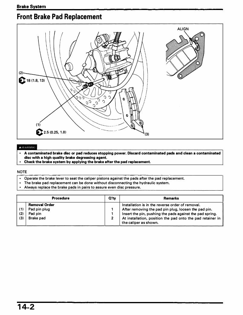
Brake System
Front Brake Pad Replacement
ALI G N
(2 ) \ l I /! I
0 2.5 (0.25. 1 .8 ) ------- .---
• A contaminated brake disc or pad reduces stopping power. Discard contaminated pads and clean a contaminated disc with a high quality brake degreasing agent.
• Check the brake system by applying the brake after the pad replacement.
NOTE
• Operate the brake lever to seat the ca l i per pistons agai nst the pads after the pad replacement. • The brake pad replacement can be done without d isconnecting the hyd ra u l ic system . • Always replace the bra ke pads i n pai rs to assu re even d isc pressu re.
Procedure Q'ty Remarks
Removal Order I nsta l lation is in the reverse order of remova l . ( 1 ) Pad p in p lug 1 After rem oving the pad p in p lug, loosen the pad p in . (2) Pad pin 1 I nsert the pin, push i ng the pads agai nst the pad spring. (3) Brake pad 2 At i nsta l lation, position the pad onto the pad reta i ner i n
t h e ca l iper a s shown.
1 4-2
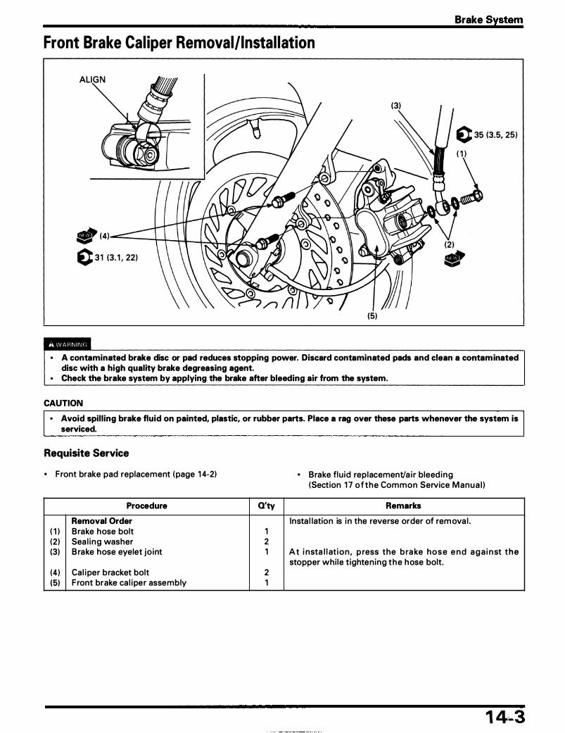
Brake System
Front Brake Cal iper Removal/Instal lation
(3)
c 35 (3.5, 25)
( 1 )
(5)
• A contaminated brake disc or pad reduces stopping power. Discard contaminated pads and clean a contaminated disc with a high quality brake degreasing agent.
• Check the brake system by applying the brake after bleeding air from the system.
CAUTION • Avoid spilling brake fluid on painted, plastic, or rubber parts. Place a rag over these parts whenever the system is
serviced.
Requisite Service
• Front brake pad replacement ( page 1 4-2)
Procedure
Removal Order ( 1 ) Brake hose bolt (2 ) Sea l i n g washer (3) B rake hose eyelet jo int
(4) Ca l i per bracket bolt (5) F ront brake ca l i per assembly
O'ty
1 2 1
2 1
• Brake flu id replacement/a i r bleed i n g (Section 1 7 o f t h e Common Service M a n u a l )
Remarks
Insta l lation is i n the reverse order of rem ova l .
A t i nsta l l at i o n , p ress the b ra ke h o s e e n d a g a i n st t h e stopper whi le t ighten ing t h e h ose bolt.
1 4-3

Brake System
Front Brake Cal iper Disassembly I Assembly
(7) ., (8)
(6) c 23 (2.3, 1 7 )
1 oa /c5.5 (0.55, 41 I
�
(3)
CAUTION • Avoid spilling brake fluid on painted, plastic, or rubber parts. Place a rag over these parts whenever the system is
serviced.
Requisite Service
• Front brake ca l i per removal/insta l lation ( page 1 4-3)
Procedure
Disassembly Order ( 1 ) Pad spring (2) Cal i per bracket (3) Bracket p in bolt boot (4) Cal i per p in bolt boot (5) Bracket p in bolt (6) Ca l i per p in bolt (7) Cal iper piston
(8) Dust sea l (9) Piston sea l
1 4-4
O'ty Remarks
Assem bly is in the reverse order of d isassem bly. 1 N ote spring dj rection as shown. 1 1 1 Insta l l i nto the bracket g roove secu re ly. 1 At i nsta l lat ion, apply a locki ng agent to the th reads. 1 At insta l lation, apply a locki ng agent to the th reads. 2 At i nsta l l at ion , i n sta l l t h e p i ston with the d is h e d e n d
toward t h e ca l i per.
� =r r- CAUTION • Be careful not to damage the piston · sliding surface
when removing the seals.

Brake System
Front Master Cylinder Removal/Instal lation
( 2 ) c 1 (0. 1 , 0.7) ( 1 0) ( 1 )
(3)
(8) c 12 ( 1 .2, 9) (9)
CAUTION
• Avoid spilling brake fluid on painted, plastic, or rubber parts. Place a rag over these parts whenever the system is serviced.
• When removing the hose bolt, cover the end of the brake hose to prevent contamination. • Do not allow foreign material to enter the system.
NOTE
I • Use DOT 4 brake fl u id from a sea led conta iner.
Requisite Service
• Brake system a i r b leeding (Section 1 7 of the Com m on Service Manua l )
Procedure Q'ty Remarks
Removal Order Insta l lation is in the reverse of o rder of remova l . ( 1 ) R ight rearview m irror 1 Loosen the mounting n ut and remove the m i rror. (2 ) F ront brake lever pivot bolt/nut 1/1 (3) Brake lever 1 (4) F ront brake hose bolt 1 (5) Front brake hose 1 At i nsta l lation , press the hose end aga i nst the stopper
wh i le t ightening the h ose bolt. (6) Sea l ing washer 2 (7) B rake l ight switch connector 2 (8) Master cyl i nder holder bolt 2 At insta l lation, tighten the upper bolt fi rst, then th� lower
bolt. (9) Master cyl i nder holder 1 I nsta l l the holder with its " UP" mark facing up .
( 1 0) Master cyl i nder assembly 1 At insta l lation, a l ig n the mating su rface with the pu nch mark on the handlebar.
1 4-5

Brake System
Front Master Cylinder Disassembly I Assembly
-
NOTE
K..---C 1 .5 (0. 1 5, 1 . 1 )
"---- ( 1 )
(2 )
• Replace the master piston, spring, cups, stopper plate, snap r ing and boot as a set.
Requisite Service
• Front master cyl i nder remova l/insta l lation ( page 1 4-5) • Brake system a i r bleeding (Section 1 7 of the Com mon Service Manua l )
Procedure Q'ty Remarks
Disassembly Order Assem bly is i n the reverse order of d isassembly. ( 1 ) Reservoi r cover 1 (2 ) Diaphragm plate 1 (3) Diaphragm 1 (4) Brake l ight switch 1 (5) Boot 1 (6) Snap r ing 1 CAUTION
• Be certain the snap ring is fully seated in the groove. (7) Stopper plate 1 (8) Master piston assembly 1 (9) Spring 1 I nsta l l the spring with the sma l l coi l end faci ng the
piston .
14-6

Brake System
Rear Brake Panel Disassembly I Assembly
� ( 1 ) 0 29 (2 .9, 2 1 )
(4), (2 )------4 .... ,
( 1 0)� (5) -
(9)
(5) ., • Inhaled asbestos fibers have been found to cause respiratory disease and cancer. Never use an air hose or dry
brush to clean brake assemblies. Use an OSHA-approved vacuum cleaner or alternate method approved by OSHA designed to minimize the hazard caused by airborne asbestos fibers.
• A contaminated brake drum or shoe reduces stopping power. Discard contaminated shoes and clean a contaminated drum with a high quality brake degreasing agent.
Requisite Service
• Rear wheel remova l/insta l lation ( page 1 3-2)
Procedure
Disassembly Order ( 1 ) Brake a rm pinch bolt (2 ) Brake a rm
(3) Brake ind icator
(4) Felt sea l (5) Cotter pin (6) Cotter p in plate (7) Brake shoe (8) Shoe spring (9) Brake cam
( 1 0) Brake panel
Q'ty Remarks
Assembly is in the reverse order of d isassem bly. 1 1 At insta l lation, a l i g n the punch marks on the brake cam
and arm. 1 At insta l lation, a l ign the wide tooth with the wide slot i n
the brake cam. 1 2 Insta l l with c losed end facing out. 1 2 2 1 At insta l l at ion, a pply s i l icone g rease to the s l id ing s u r-
face and cam portion . 1
1 4-7

Brake System
Brake Pedal Removal/Instal lation
( 1 4) ( 1 6) -�
c 27 (2.7, 20) (8)
Procedure Q'ty Remarks
Removal Order I nsta l l ation is i n the reverse o rder of remova l . ( 1 ) Brake rod adjusti ng n ut 1 (2 ) Brake rod spri ng 1 (3) Brake rod joint piece 1 (4) Brake pedal p ivot bolt/nut 1/1 (5) Col lar 1 (6) Dust sea l 2 (7) Brake pedal l i n kage jo int pinch bolt 1 Al ign the punch marks. (8) Brake pedal l i n kage assem bly 1 (9) Cotter pin 2
( 1 0) Jo int p in 2 ( 1 1 ) Brake pedal l i n kage jo int 1 ( 1 2 ) Brake pedal 1 ( 1 3) Brake l ight switch spring 1 ( 1 4) Brake pedal return spring 1 ( 1 5) Cotter p in 1 ( 1 6) Jo int p in 1 ( 1 7 ) Brake rod l i n kage 1 ( 1 8) Brake rod 1
1 4-8
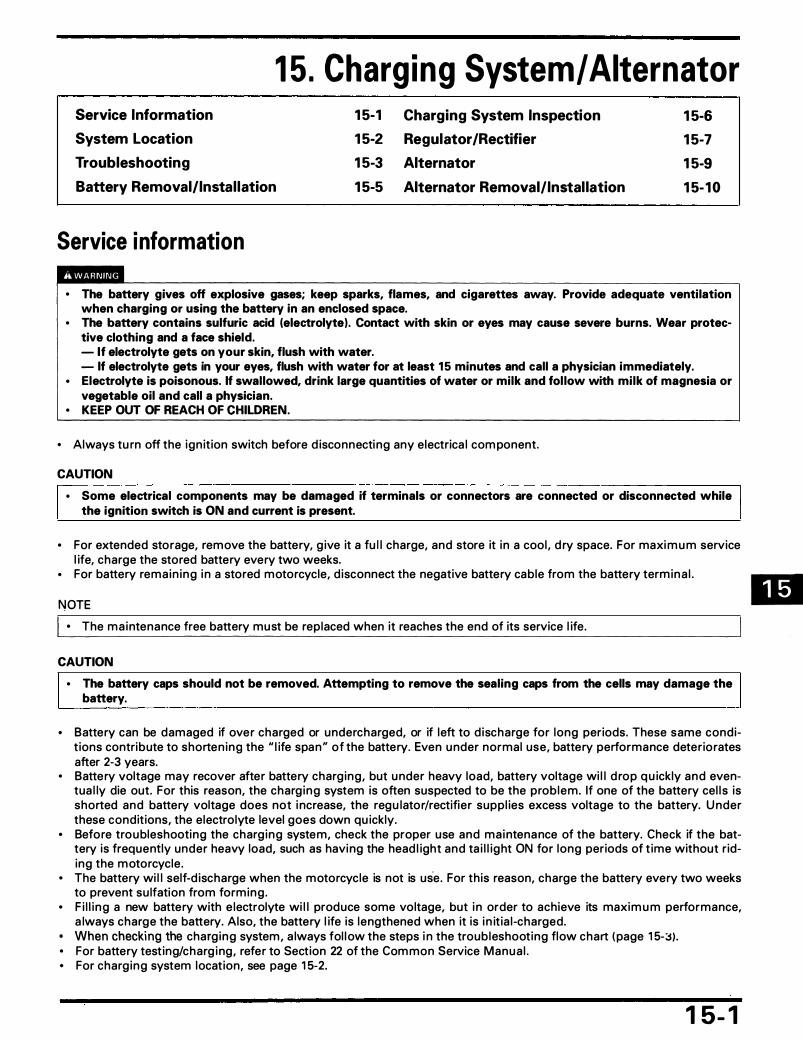
1 5 . Charg ing System/ Alternator Service Information
System Location
Troubleshooting
Battery Removal/Instal lation
Service information
1 5-1 1 5-2 1 5-3 1 5-5
Charging System Inspection 1 5-6 Regulator/Rectifier 1 5-7 Alternator 1 5-9 Alternator Removal/Instal lation 1 5- 1 0
• The battery gives off explosive gases; keep sparks, flames, and cigarettes away. Provide adequate ventilation when charging or using the battery in an enclosed space.
• The battery contains sulfuric acid (electrolyte). Contact with skin or eyes may cause severe burns. Wear protective clothing and a face shield. - If electrolyte gets on your skin, flush with water. - If electrolyte gets in your eyes, flush with water for at least 15 minutes and call a physician immediately.
• Electrolyte is poisonous. If swallowed, drink large quantities of water or milk and fol low with milk of magnesia or vegetable oil and call a physician.
• KEEP OUT OF REACH OF CHILDREN.
• Always tu rn off the ign it ion switch before d isconnecti ng any electrica l com ponent.
CAUTION
• Some electrical components may be damaged if terminals or connectors are connected or disconnected while the ignition switch is ON and current is present.
• For extended storage, remove the battery, g ive it a fu l l charge, and store it i n a cool , d ry space. For maxi m u m service l ife, charge the stored battery every two weeks.
• For battery rema in ing i n a stored motorcycle, d isconnect the negative battery cable from the battery termina l .
NOTE • The ma intenance free battery must be replaced when it reaches the end of its service l ife.
CAUTION • The battery caps should not be removed. Attempting to remove the sealing caps from the cells may damage the
battery.
• Battery can be damaged if over charged or undercharged, or if left to d ischarge for long periods. These same condit ions contribute to shorten ing the " l ife spa n " of the battery. Even u nder normal use, battery performance deteriorates after 2-3 years.
• Battery voltage may recover after battery charg ing, but u nder heavy load, battery voltage wi l l d rop q u ickly and eventua l ly die out. For this reason, the charg ing system is often suspected to be the prob lem. If one of the battery cel l s is shorted and battery voltage does not i ncrease, the regu lator/rectifier suppl ies excess voltage to the battery. U nder these condit ions, the e lectro lyte level goes down qu ickly.
• Before troubleshooting the charg ing system, check the proper use and ma i ntena nce of the battery. Check if the battery is frequently under heavy load, such as havi ng the head l ight and ta i l l ight ON for long periods of t ime without riding the m otorcycle .
• The battery wi l l self-d ischarge when the motorcycle is not is use. For th is reason, charge the battery every two weeks to prevent su lfation from forming .
• F i l l i ng a new battery with e lectrolyte wi l l produce some voltage, but i n order to achieve its maxi m u m performance, a lways charge the battery. Also, the battery l ife is lengthened when it is i n it ia l-charged.
• When checking the charg ing system , a lways fol l ow the steps i n the troub leshooting flow chart ( page 1 5-::S) . • For battery test ing/charg i ng , refer to Section 22 of the Com mon Service Manua l . • For charg ing system locat ion, see page 1 5-2.
1 5- 1

Charging System/ Alternator
System Location
(4) ALTERNATOR
1 5-2
( 1 ) BATIERY
(3) R E G U LATOR/RECTIF IER
(3) REGULATOR/ RECTIF I E R
(2 ) MAI N F U S E 30 A
(2) MAIN FUSE 30 A
-
( 1 ) BATIERY 1 2 V 1 0 Ah
R: Red W: White Y: Yel low G : G reen

Charging System/ Alternator
Troubleshooting Battery Overcharging • Fa u lty regu lator/rectifier
Battery Undercharging
NOTE
• I n order to o bta i n an accu rate test reading when charg ing the system , the battery must be fu l ly charged and i n good condition . See Common Service Manual Section 22 for check the battery condition .
Meas u re the battery current leakage am pere ( leak test: page 1 5-6).
Standard: 0.01 mA max.
Correct
Inspect the regu l ated voltage ( page 1 5-6).
Standard: 1 4 - 1 5.5 V/3,000 rpm
N ot charg ing
•
I ncorrect
Correct
Check the regu lator/rectifier ( page 1 5-7 ) .
I ncorrect Correct
� • Shorted wi re h arness • Fau lty i g n it ion switch
Check the battery us ing the battery tester.
I ncorrect Correct
0 .
. . ! . h • pen c 1 rcu 1t 1 n w1 re arness
• Poorly connected connectors
• E lectric system over- loading • Fau lty battery
1 5-3

Charging System/ Alternator
Abnormal Check the voltage between the regu lator/recti- 1----------. . Open c ircu it in wire harness fi e r batte ry c h a rg i n g l i n e a n d g ro u n d l i n e • Poorly connected connectors ( page 1 5-7 ) .
Connection: Red/White (+ ) - Green (-) Standard: Battery voltage
Normal
Check the a lternator (charging coi l ) resistance at the regu lator/rectifier connector ( page 1 5-7) .
Connection: Yellow - Yellow Standard: 0.1 - 1 .0 0
Normal
Check the regu lator/rectifier u n it ( page 1 5-8) .
Abnormal
Abnormal
Check the charg ing coi l resistance at the a lternator connector ( page 1 5-9) .
.--;? �w_ J l!lfW!l#)lt Connection: Yellow - Yellow Standard: 0.1 - 1 .0 0
Abnormal Normal L • Poorly connected a lternttor con nector • Open or short c i rcuit i n Yel l ow wi re
• Fau lty a lternator
1-----------� • Fau lty regu lator/rectifier
Normal '-------------------. • Fau lty battery
1 5-4

Charging System/ Alternator
Battery Removal/ Instal lation
NOTE
• Always turn the ign it ion switch OFF before removing or i nsta l l ing the battery.
Requisite Service
• Seat remova l/insta l lation ( page 2-2)
Procedure
Removal Order ( 1 ) Battery holder band (2 ) Negative termina l (3 ) Positive term ina l
(4 ) Battery
O'ty Remarks
I nsta l lation is in the reverse o rder of remova l . 1
� =r - • After insta l lation, apply clean g rease to the cable end, battery term ina ls and bolts.
• At i nsta l lation, pu l l the cover over the positive termi-na l .
1
1 5-5

Charging System/ Alternator
Charging System Inspection Leakage Test
Turn the ign it ion switch off, and d isconnect the g round (-) cable from the battery.
Connect the ammeter (+) probe to the g round cable and the ammeter (-) probe to the battery (-) termina l . With the ign it ion switch off, check for cu rrent leakage.
NOTE
• When measu ring the cu rrent using a tester, set it to a h ig h range, and then bring the range down to an appropriate leve l . Cu rrent flow larger than the range selected may blow out the fuse i n the tester.
• Wh i l e measur ing cu rrent, do not turn the i g n it ion switch O N . A sudden surge of cu rrent may b low out the fuse in the tester.
Specified Current Leakage: 0.01 rnA max.
If cu rrent leakage exceeds the specified va l ue, a shorted c ircuit is l i kely.
Regulated Voltage/ Ampere Inspection
• If the engine m ust be running to do some work, make sure the area is well-ventilated. Never run the engine in an enclosed area.
• The exhaust contains poisonous carbon monoxide gas that may cause loss of consciousness and may lead to death.
NOTE
• Before perfo rm i n g th is test, be s u re the battery is fu l ly charged and that the voltage between its terminals is g reater than 1 3.0 V.
Sta rt the eng ine and wa rm it to operati n g tem pe ratu re, then turn the ign it ion switch OFF.
Connect the m u lti meter between the battery term ina ls .
i a.TooL I Digital multimeter
Analogue tester
1 5-6
0741 1 - 0020000 Equivalent commercially available in U.S.A. 07308 - 0020001 (Not available in U.S.A.)
( 1 ) AMMETER
(2) GROU N D CABLE
( 1 ) BATTERY

Disconnect the sta rter re lay switch connector and remove the ma in fuse (30 A). Reconnect the connector onto the re lay switch.
Connect the a m m eter between the fuse holder term ina ls as shown. Start the engine and i ncrease the engine speed g radua l ly and check that the voltage and a m pere are reg u lated .
CAUTION
• Be careful not to short any tester probes. • Although the current could be measured when the
ammeter is connected between the battery positive terminal and the positive cable, a sudden surge of currant to the starter motor could damage the ammeter.
• Always turn the ignition switch OFF when conducting the test. Disconnecting the ammeter or wire when currant is flowing may damage the ammeter.
NOTE
• Before making this test, a l l the l ights and the other e lectrica l eq u ipment shou ld b� OFF.
• Use fu l ly charged battery to make this test i n order to get a correct measurement.
Regulated: Battery terminals: Charging current:
14 - 1 5.5 V/3,000 rpm 0 - 0.5 A/3,000 rpm
Regulator /Rectifier System Inspection
Remove the seat ( page 2-2) .
Disconnect t h e reg u lator/rectifier connectors. Check the con n ectors for loose or corroded term ina l .
Measu re the fo l lowing between con nector termina l of the wi re harness side.
Item Terminals Specification
Battery charg ing Red/Wh ite (+) Battery voltage l i n e and G reen (-) should reg ister.
G round l i n e G reen and ground Contin u ity exist.
· Charg ing coi l Yel l ow and Yel low 0. 1 - 1 .0 (} l i n e (20°C/68°F)
If the c h a rg i n g coi l l i n e rea d i ng is out of s pecificatio n , check t h e a lternator ( page 1 5-9) .
Charging System/ Alternator
( 1 ) (+) PROBE: R E D/WHITE
I
( 1 ) REG U LATOR/RECTIF IER 4P CON N ECTOR (WI RE HARN ESS SIDE)
( 1 ) REG U LATOR/RECTIF IER 3P CON NECTOR (WIRE HARN ESS SIDE)
1 5-7
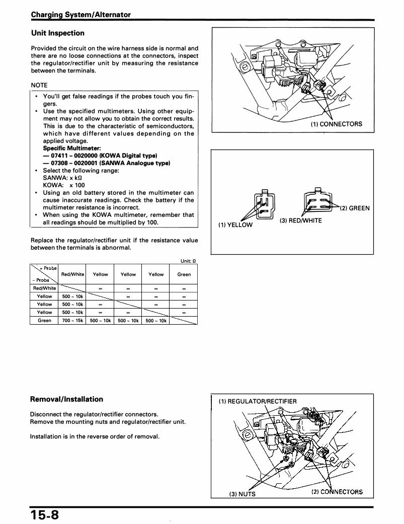
Charging System/ Alternator
Unit Inspection
Provided the ci rcuit on the wi re ha rness side is norm a l and there are no loose connections at the connectors, inspect the reg u l ator/rectifi e r u n it by measur ing the res ista nce between the term ina ls .
NOTE
• You' l l get fa lse readings if the probes touch you fi ngers.
• U se the specified m u lt imeters. U s i n g oth e r eq u i pment may not a l low you to obta i n the correct resu lts. This is due to the characteristic of sem iconductors, w h i c h h a ve d i ffe r e n t va l u e s d e p e n d i n g o n t h e appl ied voltage. Specific Multimeter: - 0741 1 - 0020000 (KOWA Digital type) - 07308 - 0020001 (SANWA Analogue type)
• Select the fo l l owing range: SANWA: x kO KOWA: x 1 00
• Using a n o l d battery stored i n the m u lti m ete r can cause i n accu rate read i ngs. Check the battery if the m u ltimeter resistance is i ncorrect.
• When using the KOWA m u lt imeter, remember that a l l read ings should be m u lt ip l ied by 1 00.
Replace the reg u lator/rectifier u n it if the resistance va l u e between t h e termina ls is abnorm a l .
Unit· 0
� Red/White Yel low Yel low Yellow Green e
Red/White -------- � � � �
Yel low 500 - 1 0k ---- � � �
Yel low 500 - 1 0k � -------- � �
Yel low 500 - 10k � � ---- �
Green 700 - 1 5k 500 - 1 0k 500 - 10k 500 - 10k ----
Removal/Instal lation
Disconnect the regu lator/rectifier connectors. Remove the mounting n uts and regu l ator/rectifier u n it.
Insta l l at ion is i n the reverse order of remova l .
1 5-8
� ( 1 ) YELLOW
p(2 ) G R E E N
(3) RED/WHITE
( 1 ) REG U LATOR/RECTIF IER
(3 ) N UTS

Alternator N OTE
• It is not necessa ry to remove the stator to make this test.
Remove the fuel tank ( page 2-2 ) . Disconnect the a lternator 3P connector.
Measu re the resistance between the Yel low wi re termina ls a n d check for n o conti n u ity between each term i n a l and body g round.
Standard: 0 .1 - 1 .0 0 (20°C/68°F)
Replace the stator if the resistance is out of specification or if there is conti n u ity between Yel low wi re term ina l and g round.
Charging System/ Alternator
( 1 ) ALTERNATOR 3P CON N E CTOR
1 5-9
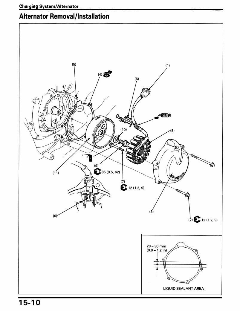
Charging System/ Alternator
Alternator Removal/Instal lation
(5)
(4) -
(6)
1 5- 1 0
(7 ) 0 12 ( 1 .2, 9)
( 1 )
) c 1 2 ( 1 .2, 9)
LIQU I D SEALANT AREA

Charging System/ Alternator
N OTE
• The engine o i l wi l l run out when the left crankcase cover is removed . Set a clean o i l pan u nder the eng ine and add the recommended o i l to the specified level after the insta l lation.
• The left cra n kcase cover (stator) is magnetica l ly attached to the flywheel, be carefu l to the remova l/insta l lation . • Apply a l ight but thorough coating of l iqu id sea lant to the crankcase as shown .
Requisite Service
• Fue l tank remova l/i nsta l l ation ( page 2-2)
Procedure
Removal Order ( 1 ) Alternator connector (2 ) Left cra n kcase cover bolt (3) Left crankcase cover (4) Gasket (5) Dowel p in (6 ) Stator wire ho lder (7) Stator mount ing bolt (8) Stator assembly
Flywheel Removal Order (9) F lywheel bolt
( 1 0) Washer ( 1 1 ) F lywheel
O'ty Remarks
Insta l lation is i n the reverse order of remova l . 1 6 1 1 2 1 4 1 At instal lation, apply sea lant to the g rommet a n d insta l l
the g rommet secure ly i nto the .groove i n t h e l eft crankcase cover.
Insta l lation is in the reverse order of remova l . 1 Apply clean engine o i l to the bolt th reads. 1 1 Before insta l lation, wipe any o i l off the mating su rface of
the cra n kshaft a n d flywheel .
1 5- 1 1

MEMO

1 6. Ign ition System Service Information
System Location
Troubleshooting
Ignition System Inspection
Ignition Coil Inspection
1 6-1 1 6-2 1 6-3 1 6-8 1 6-8
Ignition Pulse Generator Inspection 1 6-9
Service Information
Ignition Coil Removal/Instal lation
Ignition Control Module (ICM) Removal/Instal lation
Ignition Pulse Generator Removal/Instal lation
Ignition liming
1 6-9
1 6- 1 0
1 6- 1 1 1 6- 1 2
o H the engine must be running to do some work, make sure the area is well-ventilated. Never run the engine in an enclosed area.
o The exhaust contains poisonous carbon monoxide gas that may cause loss of consciousness and lead to death.
CAUTION o Some electrical components may . be damaged if terminals o� connectors are connected or disconnected while
the ignition switch is ON and current is present.
o When checki ng the ign it ion system, a lways fo l low the steps in the troubleshooting flow chart ( page 1 6-3). o The Ign it ion control mod u l e ( ICM) may be damaged if d ropped. Also, if the connector is d isconnected when current is
present, the excessive voltage may damage the u n it. Always turn off the ign it ion switch before servicing . o I g n it ion ti m i ng cannot be adj u sted si nce the I g n it ion control modu le ( ICMI is non-adj ustab le . If i g n it ion ti m i n g is
i ncorrect, check the system components and replace any fau lty parts. o A fau lty ign it ion system is often related to poorly con nected or corroded con nectors. Check those connections before
proceed ing . o U se spark p lugs of the correct heat range. Using spark plugs with an i ncorrect heat range can damage the engine.
Refer to Section 2 of the Common Service Manual . o For neutra l switch i nspection, refer to Section 25 of the Common Service Manua l . For switch location, see page 1 6-2
of th is manual (System Location) . ... o For· s ide stand switch , engine stop switch and ign it ion switch inspection, check for conti n u ity chart of the Wir ing �
Diagram, page 1 9- 1 . Disconnect the ign it ion and engine stop switch con nectors i n the front side cover ( page 2-3), s ide stand switch connector u n der the fue l tank and check it.
1 6-1

Ignition System
System Location
( 1 3) N EUTRAL I N DICATOR ---,ff---.,;�
(9) S IDE STAND SWITCH
( 1 1 ) I G N ITION SWITCH
(3) FUSE 1 5 A R�<r RfBI B I/Br
(8) N EUTRAL SWITCH
(6) CLUTCH SWITCH DIODE
(7) MAI N FUSE (30 A)
( 1 3) N E UTRAL I N DICATOR (6) CLUTCH SWITCH DIODE
(7) MAIN FUSE 30 A
BI/Br--®--Lg/B I I IJ)ll l l� I I a: � 0; (!) ....J
I G N ITION COILS
SPARK PLUGS
1 6-2
(4)L-B
-ATT
___.E RY
(3) FUSE 1 0 A ( 1 ) S IDE STAND I N DICATOR
DOWN (2) E N G I N E STOP SWITCH
B lfW�o-BI Y/Bia (8) N E UTRAL ·"� GJSWITCH
�----------� G/W
(5) 1CM
UP
(9) S IDE STAND SWITCH
-
...----___,, I --� :t_ G/W ---<Y o-G/R -----------'
iii iii ( 1 2) CLUTCH SWITCH 00 ( 1 0) I G N ITION PU LSE G E N ERATOR
Bl . . . . . BLACK Y . . . . . . YELLOW Bu . . . . BLUE G . . . . . . G R E E N R . . . . . . RED W . . . . . WHITE Lg . . . . . L IGHT G R E E N

Ignition System
Troubleshooting • I nspect the fo l lowi ng before d iagnosing the system .
- Loose spark p lug caps or spark p lug wi re connections. - Water i n the spa rk plug cap. - Loose or poor contact of ign ition system con nectors.
No Spark At All Plugs (Faulty Input System) • If there is no spa rk to the p l ugs, the problem cou l d be the input to the ign it ion system ( i g n it ion pu lse generator,
power i n put c ircuit of the ign ition control module ( ICM), neutra l switch, or side stand switch because if controls the ign it ion control module ( ICM) ) .
Check if the battery voltage is measu red between power sou rce i nput l ine at the ign ition contro l mod u l e ( ICM) connector with the ign it ion switch ON a n d the engine stop switch at R U N ( page 1 6-8) . 14----------1 ���.,J
"" / Connection: Black/White (+) - Green (-) Standard: Battery voltage
Battery voltage measured
Measu re the i g n it ion pu lse generator resistance at t h e i g n it i o n contro l m o d u l e ( I C M ) con n ector (page 1 6-8).
Connection: Black/Yellow - Black/White Standard: 450 - 550 0
Normal
1
� No voltage tt/ l ... (
1------,::..._____._. • Fau lty ign it ion switch or eng ine stop switch • Open c ircu it i n wire harness • Loose or poor connector contact
1-----A
_b_n_o_rm_al_--..t Check the i g n it ion p u l se generator ( page 1 6-
9) .
Connection: Black/Yellow - Black/White Standard: 450 - 550 0
Abnormal
+ Normal � • Fau lty ign it ion pu lse generator
• Open c i rcu it in B lack/White wire • Open c i rcu it i n B lack/Yel low wire • Loosen or poor ign it ion pu lse generator con
nector contacts
1 6-3

Ignition System
Check the neutra l switch at the ign it ion control module ( ICM) connector ( page 1 6-8).
�
/ Connection: Black/Light green - Ground Standard:
Continuity in neutral No continuity in any gear except neutral
Normal
Check the side stand switch at ign it ion control module ( ICM) con nector ( page 1 6-8) .
�
� Side stand up:
Black/Green - Black: Continuity Side stand down:
Black/Green - Black: No continuity
Normal
• Fau lty ign it ion control module ( ICM)
1 6-4
Abnormal
Abnormal
Connection: Light green/Red - Ground Standard: Continuity in neutral
No continuity in any gear
Normal Abnorma l
I j • Fau lty neutra l switch
• Open c i rcu it in Light g reen/Red wi re • Loose or poor neutra l switch con nector contacts
Side stand u� Green/White - Green: Continuity
Side stand down: Yellow/Black - Green: Continuity
Normal Abnormal
J • • Fau lty side stand switch
• Open c ircu it in G reen/White wi re • Open c i rcu it in Yel l ow/Black wire • Loose or poor side stand switch con n ector con
tacts

Ignition System
No Spark At Either Ignition Group
• If there is no spark at either g roup, the problem is probably i n the pr imary coi l s ide of the ign it ion system ( ign it ion coi l , or u n it and ign ition coi l c i rcu it) . � �
Switch the ign ition coi l pri m a ry term ina l connection between the fa u lty pai r and good pa ir . Try spark test aga i n .
" N o spark" condition shift to other pai r
M eas u re resista nce o f the i g n it ion p ri m a ry coi l at i gn it ion control module ( ICM) connector.
Connection: No. 1 -3: Black/White - Black/Yellow No. 2-4: Black/White - Black/Blue
Standard: 2 - 4 0
Normal � • Fau lty ign it ion control module ( ICM)
" N o spark" condition
remains with the fau lty pa i r
Abnormal
Remove the fau lty ign it ion coi l s and check the ign it ion coi l resistance (page 1 6-8) .
Standard: Primary: 2 - 4 0 Between the plug caps: 23 - 27 kO Between the spark plug wire: 1 3 - 1 7 kO
Abnormal
� • Fa u lty ign it ion coi l • Fau lty spark p lug wire • Fau lty spark p lugs
�------... • Poor or loose ign it ion coi l connector contacts • Open c i rcu it in B lack/White wire • Open c i rcu it i n Black/Yel low wire • Open c i rcu it i n Black/B l ue wire
1 6-5

Ignition System
No Spark At One Plug (Trouble In Secondary Coil Side)
• Fau lty spark p lug is most l i kely.
R e p l ace ( s u s pected bad s p a r k p l u g ) w i t h known good s p a r k p l u g a n d c o n d u ct s p a r k test.
Standard: 23 - 27 kO
Abnormal
R e m ove the s p a r k p l u g cap, a n d m e a s u re resistance of the i g n it ion coi l ( page 1 6-9) .
Standard: 13 - 17 kO
Normal � • Poor contact of spark p lug cap • Fau lty spark p lug cap • Fau lty spark plugs
1 6-6
Normal Condact spark test on good ign it ion coi l .
Abnormal T" 1--------... . Fau lty ign it ion coi l

Ignition System
Engine Starts, But Side Stand Switch Does Not Function
NOTE
The side stand switch should fu nction as fo l lows: • When the transm ission is sh ifted i nto a gear from neutra l with the side stand down, the ign it ion sh uts off and the
engine stops. • When i n neutra l , the neutra l switch l i ne (a ) of the ign ition control module ( ICM) is connected to g round via the side
stand switch . When the s ide stand is up, the s ide stand switch l ine (b) of the ign ition control module ( ICM) passes to g round v ia the s ide stand switch. The ign ition control module ( ICM) mon itors l i nes (a ) and (b) , and provides spark only when one or both of those l i nes is connected to ground via the neutra l switch or the side stand switch.
Check the s ide stand ind icator fu nction. Normal 1--------... • Open ci rcuit i n G reen/White wire
Abnormal
Normal Check for contin u ity between each term ina l of 1--------.... . Loose or poor contact of related connectors side stan d switch as fo l l ows.
• Open ci rcu it in G reen/White wire
�-->,....-<.)C.::: Side stand up: Green/White - Green Side stand down: Yellow/Black - Green
• Bu rnt indicator b u l b
Abnormal '------------------- · Fau lty side stand switch
1 6-7
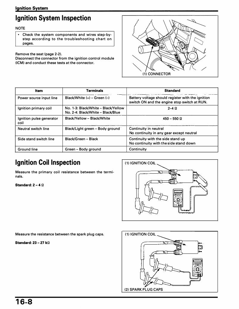
Ignition System
Ignition System Inspection
NOTE
• Check the system com ponents a n d wi res step-byste p accord i n g to t h e t ro u b l es h oot i n g c h a rt o n pages.
Remove the seat (page 2-2 ) . Disconnect the connector from the ign it ion control module ( ICM) and conduct these tests at the con nector.
Item Terminals
Power sou rce i nput l i ne B lack/White (+) - G reen (-)
Ign it ion primary coi l N o . 1 -3: B lack/White - B lack/Ye l l ow No. 2-4: B lack/White - B lack/Blue
Ign ition pu lse generator B lack/Ye l low - Black/White coi l
Neutra l switch l i n e B lack/Lig ht g reen - Body g round
Side stand switch l ine B lack/G reen - B lack
G round l i ne G reen - Body g round
Ignition Coil Inspection Measu re t h e pri m a ry co i l res ista nce between the termina ls .
Standard: 2 - 4 0
Measure the resistance between the spa rk p lug caps.
Standard: 23 - 27 kO
1 6-8
( 1 ) CON N ECTOR
Standard
Battery voltage should reg ister with the ign it ion switch ON and the engine stop switch at R U N .
2-4 0
450 - 550 0
Conti n u ity i n neutra l No conti n u ity i n a ny gear except neutra l
Conti n u ity with the side stand u p No conti n u ity with t h e s i d e stand down
Conti n u ity
( 1 ) I G N ITION COIL
( 1 ) I G N ITION COI L
(2 ) SPARK P L U G CAPS
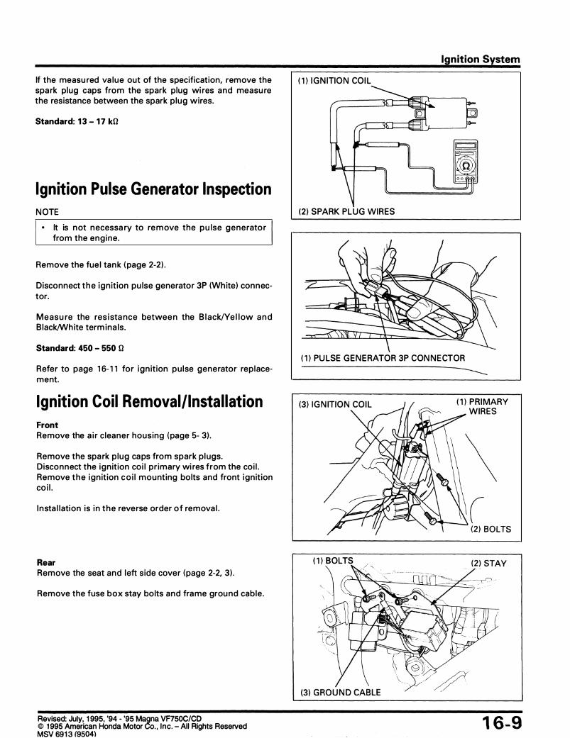
If the measu red va lue out of the specification, remove the spa rk plug caps from the spark plug wi res and measu re the resistance between the spark p lug wires.
Standard: 1 3 - 1 7 kO
Ignition Pulse Generator Inspection N OTE
• It is n ot n ecessa ry to re m ove the pu lse generato r from the engine .
Remove the fue l tan k ( page 2-2) .
Disconnect t h e ign it ion pu lse generator 3P (White) con n ector.
Me as u re the res i sta nce betwee n the B l ack/Ye l l ow a n d B lack/Wh ite term ina ls .
Standard: 450 - 550 0
Refer to page 1 6- 1 1 for ign it ion pu lse generator rep lacement.
Ignition Coil Removal/Instal lation Front Remove the a i r c leaner housing ( page 5- 3) .
Remove the spa rk p lug ca ps from spark p l ugs. Disconnect the ign it ion coi l pr imary wi res from the coi l . Remove t h e ign it ion c o i l mounting bolts and front ign ition co i l .
I n sta l lation is i n t h e reverse order o f remova l .
Rear Remove the seat and left side cover (page 2-2, 3 ) .
Remove the fuse box stay bolts and frame grou nd cable .
Revised: July, 1 995, '94 - '95 Magna VF750C/CD © 1 995 American Honda Motor Co. , Inc . - All Rights Reserved 04\
Ignition System
( 1 ) I G N ITIO N COI L
---�-------->� (2 ) SPARK PLUG WIRES
( 1 ) PU LSE G E N E RATOR 3P CON N E CTOR
( 1 ) BOLTS
( 1 ) PRIMARY WIRES
1 6-9

Ignition System
Remove the spark p lug caps from spark plugs. Disconnect the ign it ion coi l primary wires from the coi l . Remove the ign it ion coi l mounting bolts a n d front ign it ion coi ls .
Insta l lation is i n the reverse order of remova l .
Ignition Control Module ( ICM) Removal/Instal lation Remove the battery case mounting bolts.
Move the battery case left ward and d isconnect the ign it ion control modu le ( ICM) connector. Remove the ign it ion control modu le ( ICM) .
I nsta l l ation is i n the reverse order of removal .
1 6- 1 0
( 1 ) BOLTS (2) PRI MARY WIRES
(3) I G N ITION COIL
(2 ) BATTERY CASE

Ignition System
Ignition Pulse Generator Removal/Instal lation
Requisite Service
• Right crankcase cover remova l/i nsta l lation (page 9-2) • Fuel tan k remova l/insta l l ation (page 2-2)
Procedure
Removal Order ( 1 ) Ign it ion pu lse generator con nector (2 ) O i l pressu re switch termina l (3) Ign it ion pu lse generator wire g rommet
(4) Ign it ion pu lse generator mounting bolt (5 ) Ign it ion pu lse generator assembly (6) Dowel pin
Q'ty
1 1 1
3 1 2
Remarks
I nsta l lation is in the reverse o rder of remova l .
At i nsta l lation, apply seal a nt t o t h e wire g ro m met, and insta l l the i nto the rotor cover g roove securely.
Route the ign ition pu lse generator wire as shown.
1 6- 1 1

Ignition System
Ignition liming
NOTE
• The ign ition contro l module ( ICM) system is factory p re-set a n d c a n n ot be a d j u sted . I g n it i o n t i m i n g i nspection procedu res are g iven to inspect the fu nct ion of the i g n it ion control m o d u l e ( I C M ) com ponents.
• If the ti m i n g a ppears wrong, check a n other spark p lug wire for confi rmation.
Warm up the engine to operati ng tem perature .
• If the engine must be running to do some work, make sure the area is well-ventilated. Never run the engine in an enclosed area.
• The exhaust contains poisonous carbon monoxide gas that may cause loss of consciousness and may lead to death.
Stop the engine and remove the t iming hole cap.
Connect a ti ming l ight to the spark p lug wire. Start the engine and let it id le .
The timing is correct if the " F " mark a l igns with the i ndex mark on the right cra n kcase cover.
I ncrease the e n g i n e speed by rotat ing the th rott le stop screw knob and make sure the " F " mark beg ins to move cou nterclockwise at approxi mately 2,000 rpm .
Check t h e ti ming h o l e cap's 0-ring for damage, replace the new one if desi red.
Apply g rease to the th reads, and insta l l the t im i ng ho le cap.
Torque: 18 N·m ( 1 .8 kg-m, 13 ft-lb)
1 6- 1 2
( 1 ) I N DEX MARK (2) "F" MARK

Service Information
System Location
Troubleshooting
1 7 . Electric Starter /Starter Clutch
Starter Motor Removal/Installation
1 7-1 Starter Motor Disassembly/Assembly 1 7-8 1 7-2 Starter Clutch Removal/Installation 1 7- 1 0 1 7-3 Starter Clutch Disassembly/Assembly 1 7- 1 2 1 7-7
Service Information
• Always turn the ignition switch OFF before servicing the starter motor. The motor could suddenly start, causing serious injury.
• A weak battery may be u nable to tu rn the starter motor q u ickly enough, or su pply adequate ign it ion cu rrent. • If current is appl ied to the starter motor wh i le the engine is not turn ing over, the sta rter motor may be damaged. • For the fol l owing components i nspections, refer to the Common Service Manua l or the fo l lowi ng pages; for the pa rts
locations, see page 1 7-2 of this manua l (System Location) .
Component Inspection method Remarks
Cl utch switch diode Section 24 of the Common Service Manua l
Starter motor Section 24 of the Common Service Manua l
C l utch switch Section 25 of the Common Service Manua l
Neutra l switch Section 25 of the Com mon Service Manua l Torque: 12 N·m ( 1 .2 kg-m, 9 ft-lb) I gn it ion switch Check for conti nu ity on the contin u ity chart of
the Wiring Diagram, page 1 9- 1 .
S ide stand switch See page 1 8-9.
1 7- 1
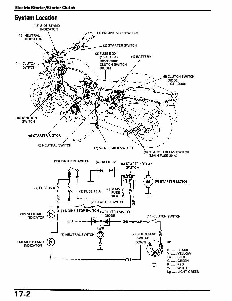
Electric Starter/Starter Clutch
System Location ( 1 3) SIDE STAND
INDICATOR
( 1 2 ) NEUTRAL INDICATOR
( 10) IGNITION SWITCH
(8) NEUTRAL SWITCH
1 1 1 ENGINE STOP SWITCH
(2 ) STARTER SWITCH
(3) FUSE BOX (4) BATTERY ( 10 A, 1 5 AI (After 2000: CLUTCH SWITCH DIODE I
(5) CLUTCH SWITCH DIODE ( : '94 - 2000)
(S) STARTER RELAY SWITCH (MAIN FUSE 30 A)
( 10) IGNITION SWITCH (4) BATTERY
(3) FUSE 15 A (6) MAIN
(1 2) NEUTRAL INDICATOR
( 1 3) SIDE STAND INDICATOR
1 7-2
(3) FUSE 1 0 A FUSE 30 A .
� � � 12 1 STARTER SWITCH a
1 ) ENGINE ST0�(5) CLUTCH SWITCi ( 1 1 ) CLUTCH SWITCH DIODE
'--+-- Lg/81 1 •1 T I� I G/R /R�1 Lg/R
� (7) SIDE STAND C) (8) NEUTRAL SWITCH SWITCH
DOWN UP
Bl .. ... BLACK y . . .... YELLOW Bu .... BLUE G ...... GREEN L------------Y/BI R ... ... RED W ..... WHITE Lg ..... LIGHT GREEN

Troubleshooting
NOTE
• Check for the fo l lowi ng before troubleshooti ng the system . - Blown m a i n fuse (30 A ) or s u b fuse ( 1 0 A). - Loose battery and sta rter motor cable. - Discharged battery.
• The sta rter motor should operate when the transm ission is in neutra l .
Electric Starter/Starter Clutch
• The starter motor shou ld operate when the transm ission is i n a ny gea r as i n d icated the chart below.
Gear Position Side Stand Clutch Lever Sta rte r Motor
U p
I n Any Gear Down
Starter motor wil l not turn
Check for loose or poorly con nected batte ry te r m i n a l s a n d o p e n e d o r s h o rted batte ry cable .
Normal
C h eck for l oose o r poorly con nected sta rter re lay switch termina ls and 4P connector.
Normal j
Pul led i n Operates
Released Does Not O perate
Pu l led i n Does Not Operate
Released Does N ot Operate
Abnormal 1------------i., . Poorly con nected battery termina ls
• Open or short c ircu it battery ca ble
Abnorma l 1--------• · Poorly connected term ina ls of 4P con n ector
1 7-3

Electric Starter/Starter Clutch
Check fo r loose or poorly connected sta rter motor cable, and open cable .
Normal
Abnormal r----------. . Poorly con nected battery term i na ls
• Open c i rcuit i n sta rter motor cable
C l icks With the ign ition switch " O N " push the sta rter r---------1 Connect the starter motor term i n a l to the bat-button and check for a "C l ick" sou nd from the tery positive termina l d i rectly. sta rter relay switch . ( Because a large amount o f cu rrent flows, d o
not u s e th in wi res)
No c l ick
Disconnect sta rter re lay switch con nector, a n d check t h e re lay coi l g round l ine as below for conti n u ity: 1 . G reen/Red term ina l-to-cl utch switch d iode
to- n e utra l switch l i n e (with tra n s m iss ion i nto neutra l and c l utch lever re leased) .
2 . G reen/Red term ina l -to-cl utch switch-to-side stand switch l ine ( i n any gear except neutra l , and with the c lutch lever p u l led i n and the s ide stand up) .
Cont inu ity
� 1 7-4
---
l - -
Sta rter motor turns Sta rter motor does not turn 1 � • Fau lty starter motor
• Loose or d isconnected starter motor cable • Fau lty sta rter relay switch
N o conti n u ity �------.... • Fau lty neutra l switch
• Fau lty clutch switch • Fau lty side stand switch • Loose or poor contact of con n ector • Open ci rcu it i n wi re harness

Electric Starter/Starter Clutch
No Voltage C o n n ect the sta rte r re lay switch co n necto r. �-----=--• . Fau lty ign ition switch With the i g n it ion switch O N a n d the sta rter • Fau lty engine stop switch button pushed, measure the sta rter relay volt- • Fau lty sta rter switch age at the starter switch con nector. • Blown out m a i n or sub fuses
Connection: Yellow/Red (+) - Body ground (-) Standard: Battery voltage
Battery vo ltage registers
• Loose or poor contact of con nector • Open ci rcuit i n wi re harness
Remove the sta rter re lay switch . Connect a fu l ly c h a rged 12 V battery to the starter re lay switch .
Normal �------• • Loose or poor contact of the starter re lay
Check the contin u ity between the switch large term i n a l .
Battery Connection: Yellow/Red (+) - Green/Red 1-1
Standard: Continuity
switch connector
Abnorma l 1---------.. • Fau lty sta rter re lay switch
Starter motor turns when the transmission is in neutral, but does not turn with transmission in any gear with the side stand up, and the clutch lever pulled in.
Check that the side sta nd switch is operati ng properly with the ign ition O N .
Normal 1
Abnorma l 1-------___, • . Fau lty side stand switch
• Bu rnt bu lb • Open c ircu it i n wire harness
1 7-5

Electric Starter/Starter Clutch
Abnormal Check the cl utch switch operation . 1---------- • Fau lty clutch switch
Normal
Abnormal Check the side stand switch (page 1 8-9) . 1---------- • Fau lty side stand switch
Normal L------------------ • Open c i rcu it i n wi re harness
Starter motor turns slowly • Low specific g ravity i n battery (or dead battery) • Poorly connected battery term i na l cab le • Poorly connected starter motor cable • Fau lty starter motor
Starter motor turns, but engine does not turn • Starter motor is run n i n g backward
- Case assem bled improperly - Termina ls connected i mproperly
• Fau lty starter cl utch • Damaged reduction gear
Starter relay switch "clicks", but engine does not turn over • Crankshaft does not turn due to i nternal mecha n ical engine problem • Excessive reduction gear frictio n
1 7-6
• Loose o r poor contact of con n ector

Electric Starter/Starter Clutch
Starter Motor Removal/Instal lation
.$B fl (5)
• With the ignition switch OFF, remove the negative cable at the battery before servicing the starter motor.
NOTE
I • Route the wi re and cables properly (page 1 -20) .
Procedure Q'ty Remarks
Removal Order I nsta l lation is in the reverse order of remova l . ( 1 ) F lange n ut 1 After insta l lation, i nsta l l the rubber cap. (2 ) Starter motor cable eyelet 1 (3) Starter motor mounting bolt 2 (4) Starter m otor 1 Disassembly ( page 1 7-8) (5) 0-ring 1 Apply o i l when insta l l i ng .
1 7-7

Electric Starter/Starter Clutch
Starter Motor Disassembly I Assembly
(6)
(8)
( 1 ) C 5 (0.5, 3.6)
(9
( 1 6)
(2 )
(3 )
(4) � (5)
ALI G N
1 7-8
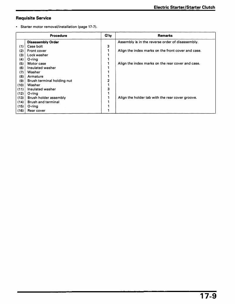
Requisite Service
• Starter motor remova l/i nsta l lation (page 1 7-7 ) .
Procedure
Disassembly Order ( 1 ) Case bolt (2 ) F ront cover (3) Lock washer (4) 0-ri ng (5) Motor case (6) I nsu lated washer (7) Washer (8 ) Armatu re (9) Brush term ina l ho ld ing n ut
( 1 0) Washer ( 1 1 ) Insu lated washer ( 1 2 ) 0-ring ( 1 3) Brush holder assem bly ( 1 4) Brush and termi n a l ( 1 5) 0-ri ng ( 1 6) Rear cover
Electric Starter/Starter Clutch
Q'ty Remarks
Assem bly is i n the reverse order of d isassem bly. 3 1 Al ign the i ndex marks on the front cover and case . 1 1 1 Al ign the i ndex ma rks on the rea r cover and case. 1 1 1 2 1 3 1 1 Al ign the holder tab with the rear cover g roove. 1 1 1
1 7-9

Electric Starter/Starter Clutch
Starter Clutch Removal/ Instal lation
( 1
tf!!tt. 90 (9.0, 65) � i a.TooL I (page 1 7- 1 1 )
1 7- 1 0
WIDE G ROOVE
SCREW DRIVER
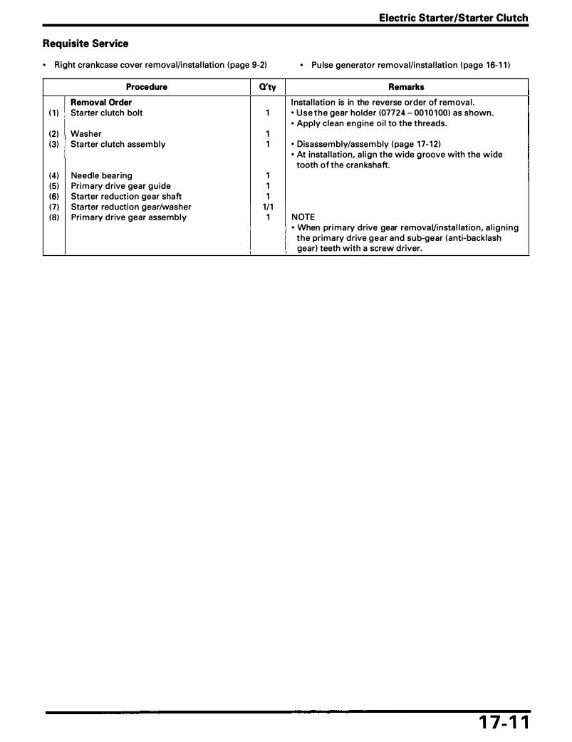
Requisite Service
• Right cra n kcase cover remova l/i nsta l lation ( page 9-2)
Procedure Q'ty
Removal Order ( 1 ) Sta rter c lutch bolt 1
(2) Washer 1 (3) Starter cl utch assem bly 1
(4) Needle bearing 1 (5) Pri mary d rive gear gu ide 1 (6) Starter reduction gear shaft 1 (7) Starter red uction gear/washer 1/1 (8) Pri mary d rive gear assembly 1
Electric Starter/Starter Clutch
• Pu lse generator remova l/insta l lation ( page 1 6- 1 1 )
Remarks
I nsta l lation is in the reverse order of rem ova l . • U s e t h e gear holder (07724 - 001 0 1 00) as shown . • Apply clean engine o i l to the threads.
• Disassem bly/assem bly ( page 1 7- 1 2) • At insta l lation, a l ign the wide g roove with the wide
tooth of the cra n kshaft.
N OTE • When pri mary drive gear remova Vi nsta l lation, a l i g n i n g
t h e primary d rive g e a r and su b-gear (anti·backlash gear) teeth with a screw d river.
1 7- 1 1
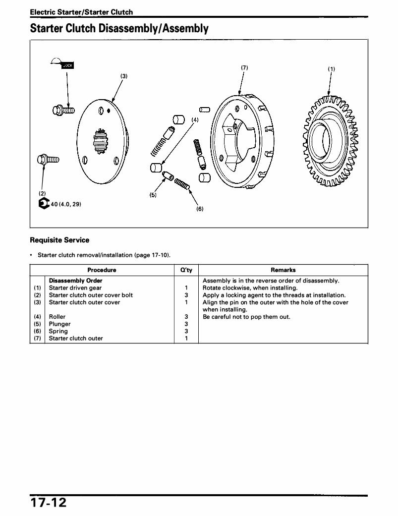
Electric Starter /Starter Clutch
Starter Clutch Disassembly I Assembly
(3)
r (2 ) c 40 (4 .0 , 29)
Requisite Service
• Starter cl utch remova l/insta l lation ( page 1 7- 1 0) .
Procedure
Disassembly Order ( 1 ) Starter d riven gear (2) Starter clutch outer cover bolt (3) Starter clutch outer cover
(4) Rol ler (5 ) P lunger (6) Spr ing (7 ) Starter cl utch outer
1 7- 1 2
(7 ) ( 1 )
(6)
Q'ty Remarks
Assem bly is i n the reverse order of d isassem bly. 1 Rotate c lockwise, when insta l l i ng . 3 Apply a locki ng agent to the th reads at insta l lation . 1 Al ign the p in on the outer with the hole of the cover
when i nsta l l i ng . 3 Be carefu l not to pop them out. 3 3 1

1 8 . Lights/Meters/Switches Service Information
System Location
Troubleshooting
Bulb Replacement
Headlight Removal/Installation
Combination Meter Removal/ Installation
Service Information
1 8-1 1 8-2 1 8-3 1 8-5 1 8-6
1 8-7
Combination Meter Disassembly I Assembly
Ignition Switch Replacement
Side Stand Switch
1 8-8 1 8-9 1 8-9
• A halogen headlight bulb becomes very hot while the headlight is ON, and remains hot for a while after it is turned OFF. Be sure to let it cool down before servicing.
• Use an electric heating element and heated water/coolant mixture for the thermo sensor inspection. Keep al l flammable materials away from the burner. Wear protective clothing, insulated gloves and adequate eye protection.
• An improperly adjusted headlight may bling on-coming drivers, or it may fail to light the road for a safe distance.
• Note the fo l l owing when replacing the ha logen headl ight bu lb. - Wear clean g loves whi le replacing the bu lb. Do not put fi nger pri nts on the head l ight b u l b, as they may create hot
spots on the bu lb and cause it to break. - If you touch the bu lb with you r bare ha nds, clean it with a clotch moistened with a lcoho l . - Be sure to insta l l the dust cover after replaci ng the bu l b.
• A l l p lastic connecto rs have locki ng tabs that m u st be re leased befo re d i scon n ecting , a n d m u st be a l i g ned a n d engaged fu l ly when recon necti ng.
• Always turn off the ign it ion switch before d isconnecting any e lectrica l component. • A conti n u ity test can be made with switches insta l led on the motorcycle. • Check the battery condit ion before performing any inspection that req u i res proper battery voltage. • F o r the fo l l owi ng component l ocations see the Co m m o n Service M a n u a l or page 1 8-2 of th is m a n u a l (System
Location) ; for inspections, refer to the app l icable pages.
Component Inspection method Remarks
Front brake l ight switch Section 25 of the Com mon Service Manua l
Horn Section 25 of the Com mon Service Manua l
Hand lebar switch Check for contin u ity on the conti n u ity chart
Ign it ion switch of the Wiring Diagram, page 1 9- 1
Neutra l switch Section 25 of the Com mon Service Manua l Torque: 12 N·m ( 1 .2 kg-m, 9 1b-ftl Apply sea lant to the threads.
O i l pressure switch/ Section 25 of the Com mon Service Manua l O i l pressu re check: Section 4 of the wa rning l ight Com mon Service Manua l .
Torque: 12 N·m ( 1 .2 kg-m, 9 lb-ft) Apply sea lant to the threads.
Rear brake l i g ht switch Section 25 of the Com mon Service Manua l
Turn s igna l l ights Section 25 of the Com mon Service Manua l
1 8- 1

Lights/Meters/Switches
System Location
( 1 ) FRONT BRAKE LIG HT SWITC
(8) N EUTRAL (6) COOLANT TEMPERATURE I N DICATOR U N IT (5) FUSE BOX
(7) S IDE STAND SWITCH
1 8-2
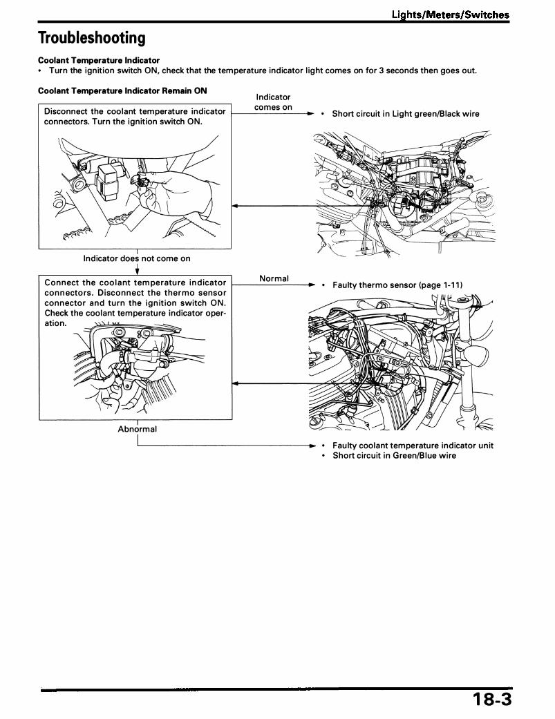
Lights/Meters/Switches
Troubleshooting Coolant Temperature Indicator • Turn the ign it ion switch ON, check that the tem perature ind icator l ig ht comes on for 3 seconds then goes out.
Coolant Temperature Indicator Remain ON I nd icator
Disconnect the coo lant tem perature ind icator 1---c_o_m_e_s_o_n __ connectors. Turn the ign it ion switch O N .
Ind icator does not come on
Normal C o n n ect the coo l a nt tem pe ratu re i n d icato r 1-------_. co n n ecto rs . D i sco n n ect the t h e r m o senso r con n ecto r a n d tu rn the i g n it ion switch O N . Check the coolant tem peratu re ind icator operation .
Abnormal
• Short c i rcuit i n Lig ht g reen/Black wi re
• Fau lty thermo sensor (page 1 - 1 1 )
• Fau lty coolant temperatu re ind icator u n it • Short c ircu it i n G reen/B l ue wi re
1 8-3

Lights/Meters/Switches
Coolant Temperature Indicator Remains OFF I n d icator does not come on Disconnect the coolant tem peratu re ind icator 1---------.
connectors. Connect a j u m per wire to the 4P connector and body g rou nd, turn the ign it ion switch O N .
Ind icator come on
Abnormal Check the coo l a nt tem peratu re i n d icato r 4P to-----�-,.... connector and body g round for conti n u ity.
Abnormal Check the voltage between the coo l a nt tem- 1---------. p e rat u re i n d icator 4 P co n n ecto r a n d body g round, turn the ign ition switch O N .
Normal
1 8-4
• Blown indicator b u l b • Open c ircuit i n L ight g reen/Black wi re
• Open c i rcu it i n G reen wire
• Open c ircu it i n Black/Brown wire
• Faulty coolant temperatu re ind icator u n it
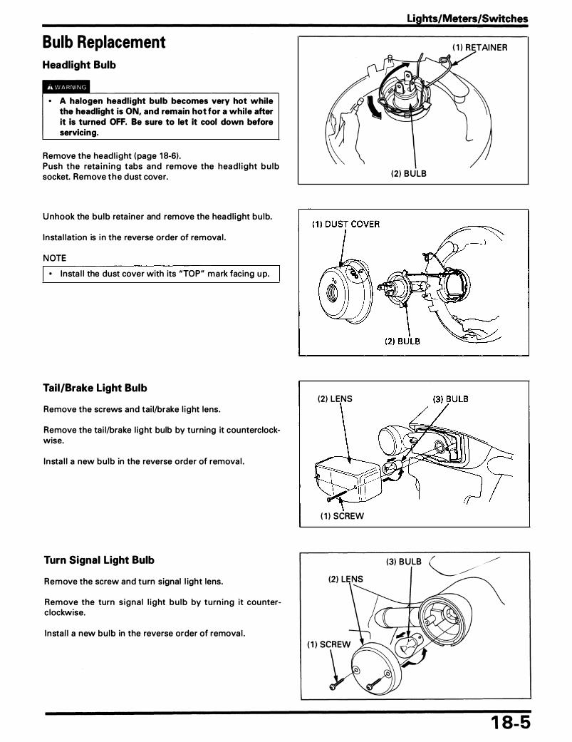
Bulb Replacement Headlight Bulb
• A halogen headlight bulb becomes very hot while the headlight is ON, and remain hot for a while after it is turned OFF. Be sure to let it cool down before servicing.
Remove the head l ight ( page 1 8-6) . Push the reta i n i n g tabs a n d remove the hea d l i g ht b u l b socket. Remove t h e d ust cover.
U nhook the b u l b reta iner and remove the head l ight b u l b.
Insta l lation is i n the reverse order of remova l .
NOTE
• I nsta l l the dust cover with its "TOP" mark facing u p.
Tail/Brake Light Bulb
Remove the screws and tai l/brake l ight lens.
Remove the ta i l/brake l ig ht bulb by turning it counterclockwise.
I n sta l l a new b u l b in the reverse order of remova l .
Turn Signal Light Bulb
Remove the screw and turn signal l ight lens.
Remove the turn s igna l l i g ht b u l b by turn i n g it cou nterc lockwise.
I n sta l l a new b u l b in the reverse order of remova l .
Lights/Meters/Switches
( 1 ) RETAI N ER
(2 ) B U LB
(2) LENS
( 1 ) SCREW
(3) B U LB �
1 8-5

Lights/Meters/Switches
Headlight Removal/Instal lation
• An improperly adjusted headlight may blind on-comil'!g drivers, or it may fail to light the road for a safe distance.
NOTE
• Adjust the head l ight beam as specified by loca l laws and reg u lations. • After insta l l at ion, route the wi res and ca ble properly (page 1 -20) .
Requisite Service
• U pper fa ir ing remova l/insta l l at ion (VF750CD: page 2-8)
Procedure Q'ty Remarks
Removal Order I nsta l lation is in the reverse order of remova l . ( 1 ) Screw 2 (2) Head l ight con nector 1 (3) Head l ight assembly 1 (4) Head l ight case bolt/nut 2/2 (5) U pper fa ir ing stay 1 VF750CD on ly. (6) Head l ight case 1
1 8-6

Lights/Meters/Switches
Combination Meter Removal/Instal lation
NOTE
• Route the wi res and cables properly (page 1 -20).
Requisite Service
• Front side cover remova l/i nsta l lation (page 2-3)
Procedure
Removal Order ( 1 ) Speedometer cable (2) Com bination meter connector (3) Com bination meter mounting bolt/g u ide (4) Com bi nation meter assem bly
Q'ty
1 3
2/2 1
• U pper fa ir ing remova l/insta l lation (VF750CD: page 2-8)
Remarks
Insta l l ation is in the reverse order of remova l .
Disassembly/Assem bly ( page 1 8-8)
1 8-7

Lights/Meters/Switches
Combination Meter Disassembly I Assembly Remove t h e screws and c lamps.
Remove the meter rear cover and meter stay.
Pu l l the ind icator b u l bs out of the meter. Remove the wi re harness c lamp. Disconnect the meter termina ls, and remove the wire harness.
Separate the meter rear covers and meter stay.
Assemble the meters i n the reverse order of d isassembly.
NOTE
• Connect the proper co l o r wire to the meter term i nals . Y/G: Yellow/Green G: Green
1 8-8
( 1 ) SCREWS
( 1 ) REAR COVERS

Ignition Switch Replacement Remove the left middle cover stay assem bly ( page 5-4) .
Remove the screw and ign it ion switch cover. Remove the i g n it ion switch m o u nting bolts using a d ri l l , then remove the switch.
I nsta l l the new ign it ion switch and new mounting bolts. Tighten the mount ing bolts u nt i l the head twist off.
Insta l l the left middle cover stay assembly ( page 5-4) .
Side Stand Switch Inspection
Disconnect the side stand switch 3P ( G reen ) connector and check for contin u ity between each color of wi re termina l as shown i n the chart below.
There shou ld be conti n u ity between the o-o positions on the fol l owing chart u nder the conditions shown here.
G reen/White Yel low/Black G reen
Side stand ,.... ,....
� �
u p
Side stan d ,.... ,....
� �
down
Removal/Installation
Disconnect the side stand switch 3P ( G reen) connector.
R e m ove the s i d e sta n d switch m o u nt i n g bolt a n d s ide stan d switch .
Insta l l the switch i n the reverse order of removal .
Torque: 10 N·m ( 1 ,0 kg-m, 7 ft·lb)
NOTE
• A l i g n the switch p i n with the s ide sta nd ho le a n d a l ig n the switch g roove with the s i d e stan d retu rn spring ho ld ing p in .
Lights/Meters/Switches
(3) COVER (2) MOU NTI N G BOLTS .,
( 1 ) S IDE STAND SWITCH CON N ECTOR
1 8-9

MEMO

...... CD I ......
'94 - 2000:
,.,..,.. UGMT 12Y1.4WI2
� �;�===::::;-]
STARTDtS'I'lT'OI 162 ST HL HLI
FREE I QiQ. PUSH �
STNiftll MOTOR
19. Wiring Diagram
11¥32/!CP
liLAC< a, . . . . . . . . BROWN YELlOW 0 ORANGE BLUE lb LIGHT BLUE
. . . GREEN " · · · · · · UGHT GREEN REO PINK WIITE .. . . . . . . GRAY
0030Z- M Z 5 - 6700
� ::u -z C) c ;;: C) ::u l> 31:

...... CD . , N
After 2000:
lAOCIMEltJI UGIIT 12V1.4W X2
00 00 IQNITlCfi COIL
IIIGHT II[AR TIA'I $1GML
�� 12V21W
lAAlE AND l.t.llltc»>T
12V32/3cp
� REAR lAAKE UGtiT SWITCH
81 BUCK 8< BROWN y YELLOW ORANGE a. llltlE "' LIGHT lUI:
GA£EN l.t LIGHT GREEN ... PINK WHITE "' GRAY
0030Z- M Z 5 -ABOO

CT Bolt
Some pa rts of this motorcycle are tightened with the CT bo lts, i . e . Co m b i nat i o n T h re a d bo lts w h i c h m a ke t h e female th reads when they screw i n .
T h e lower ha lf o f t h e C T bolt featu res t h e com bination of the standard threads and the low th reads.
When the CT bolt is screwed i nto the u nt h readed p i l ot hole, the bolt makes the female threads i n the p i lot hole by defo rm i n g the wa l l of the ho le . Few ch ips and shavings a re produced this t ime, which is d ifferent from threading by a mach ine.
NOTE
• When the CT bolt is reused, t ig hten the bolt with care not to ru i n the female threads that were made when the bolt was t ightened fi rst t ime.
• The standard bolt is appl icab le to the female th reads that were made by means of the plastic deformation d u ri n g tighten ing the CT bolt.
• The service replacement parts of the parts tightened with the CT bolts have the th reads.
When the CT bolt replacement is req u i red, use new CT bolt or Honda gen u ine standard bolt ( length £ ).
CAUTION
I • Do not use the length £ ' standard bolt.
Application list
Parts Bolt Qty
Breather case, Rear cyl inder head cover M6 6
Cyl inder head fi n , Cyl inder head M6 1 2
Oi l pump M6 3
Water pump M6 3
20. Technical Feature
( 1 ) CT BOLT
( 1 ) STANDARD THREAD
( 1 ) AFTER PLASTIC DEFORMATION
(2) I NTRODUCTION PART (3) LOWE R HALF OF BOLT
(CO M B I NATION OF STA N DARD THREADS AND LOW THREADS)
'------- (4 ) U PPER HALF OF BOLT (STANDARD THREADS)
14------ £ '----+1
(3) I NTRODUCTION PART
(2) STANDARD BOLT
20-1

MEMO
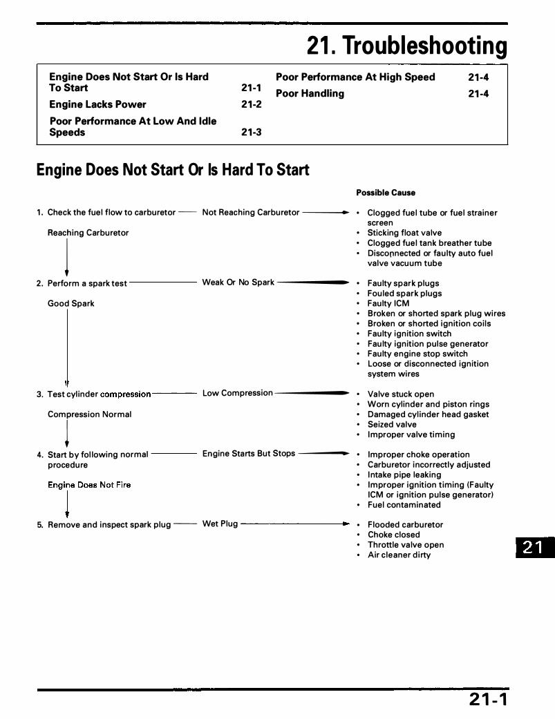
21 . Troubleshooting Engine Does Not Start Or Is Hard To Start 21 -1
2 1 -2
Poor Performance At High Speed
Poor Handling
21 -4 21 -4
Engine Lacks Power
Poor Performance At Low And Idle Speeds 2 1 -3
Engine Does Not Start Or Is Hard To Start
1 . Check the fue l flow to carbu retor -- Not Reaching Carbu retor -----
R•acrno carbu retor
2 . Perform a spark test ------ Weak Or No Spark ------•
Good Spark
3. Test cyl inder compression ---- Low Compression ------•
comression Normal
4. Start by fol lowing normal ---- Engine Starts But Stops ------1•
procedu re
5. Remove and i nspect spark p lug -- Wet Plug _________ ..,.
Possible Cause
• Clogged fue l tube or fue l stra iner screen
• Sticking float va lve • Clogged fue l tan k breather tu be • Disconnected or fau lty a uto fuel
va lve vacu u m tube
• Fau lty spark p lugs • Fou led spark p lugs • Fau lty ICM • Broken or shorted spark p lug wi res • Broken or shorted ign it ion coi ls • Fau lty ign it ion switch • Fau lty ign it ion pu lse generator • Fau lty eng ine stop switch • Loose or d isconnected ign it ion
system wi res
• Va lve stuck open • Worn cyl inder and piston rings • Damaged cyl inder head gasket • Seized valve • I mproper va lve ti m i n g
• Improper choke operation • Carbu retor i ncorrectly adjusted • I ntake p ipe leaking • I m proper ign it ion t iming (Fau lty
ICM or ign it ion pu lse generator) • Fuel contaminated
• F looded carbu retor • Choke closed • Throttle va lve open • Air c leaner d i rty
2 1 - 1
fD

Troubleshooting
Engine Lacks Power Possible Cause
1 . Raise wheels off the g round Wheels Do Not Spin F reely . Brake dragg ing and spin by hand . Worn or damaged wheel bearings
. Drive cha in too tight Wheel Spins Freely
' 2. Check t ire pressure Pressu re Low . Fau lty t i re valve
Pressu re Normal
+ 3. Accelerate rapidly from Engine Speed N ot Changed . Cl utch s l ipp ing
low to second When Cl utch Is Released . Worn clutch d iscs/plates . Warped c lutch d iscs/pl ates
Eng ine Speed Lowered . Weak c lutch spring When Cl utch Is Released
+ 4. Accelerate l ightly Eng ine Speed Does Not . Carbu retor chock closed
I ncrease . Clogged a i r c leaner Engine Speed I ncrease . Restricted fue l flow j . Clogged m uffler
. Pi nched fuel tank breather
5. Check ign it ion tim ing I ncorrect . Fau lty ICM . Fau lty ign it ion pu lse generator Correct
6. '
Test cyl i nder compression Too Low . Valve stuck open . Worn cyl i nder and piston r ings Normal . Leaking head gasket
� . I m p roper va lve ti m i ng
7 . Check carbu retor for c logg ing -- Clogged . Carbu retor not serviced frequently enough
Not clogg ing
+ 8. Remove spark p lug Fou led Or Discolored . Plugs not serviced frequently
enough Not fou led Or Discolored . Spa rk p lugs a re i ncorrect heat
i range
9. Check oi l l eve l and condition I ncorrect . Oi l l evel too h i g h . O i l level too low Correct . Conta m i n ated o i l
• 1 0. Remove cyl i nder head cover Va lve Tra i n Not Lubricate . Clogged o i l passage
and inspect l u b rication Properly . Clogged o i l contro l orifice
Valve Tra i n Lubricate Properly
2 1 -2
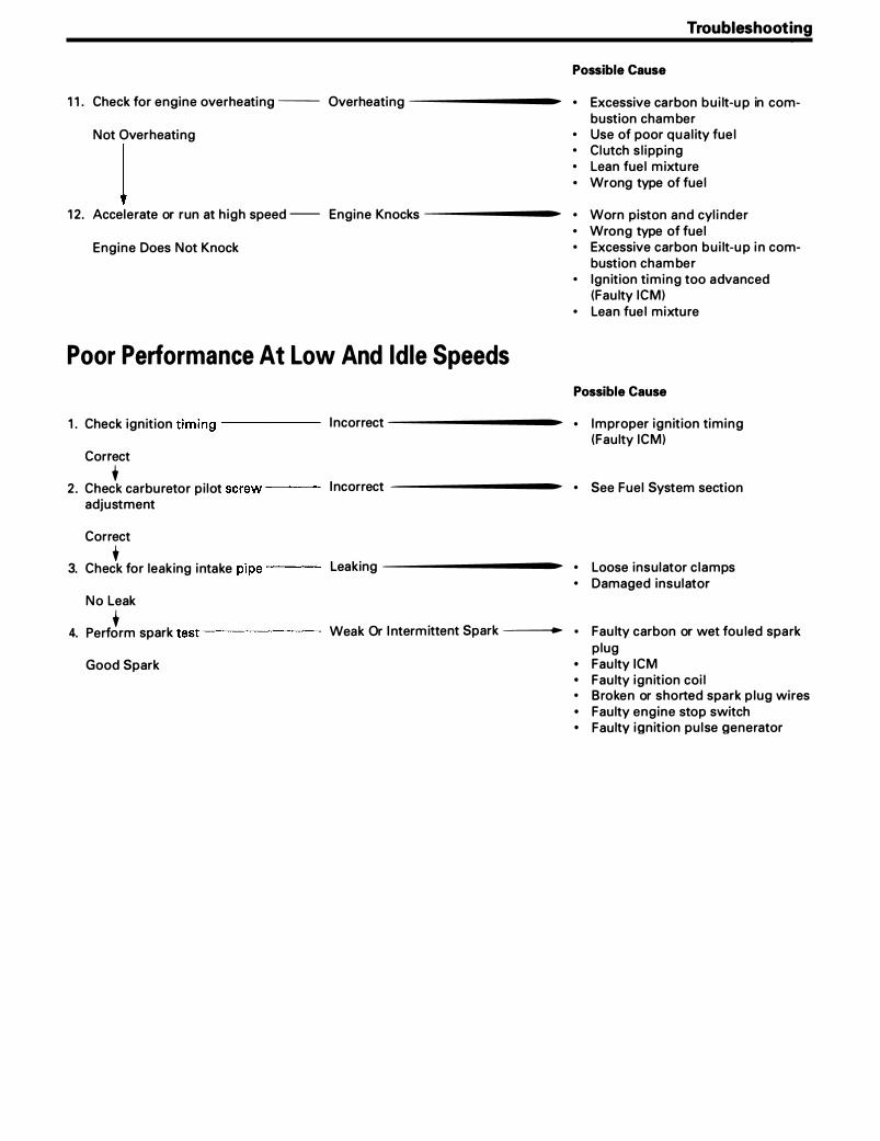
1 1 . Check for engine overheating -- Overheating -----------.
Not Overheati ng
j 1 2 . Accelerate or run at h igh speed -- Engine Knocks ----------..
Engine Does Not Knock
Poor Performance At Low And Idle Speeds
1 . Check ign it ion t iming ------ I ncorrect -----------t�
Correct
+ 2 . Check carbu retor p i lot screw --- I ncorrect -----------
adjustment
Correct
+ 3. Check for leaking i ntake pipe --- Leaking ----------•
N o Leak
+ 4. Perform spark test ------- Weak Or I ntermittent Spark ----t�
Good Spark
Troubleshooting
Possible Cause
• Excessive carbon b u i lt-u p in com-bustion cham ber
• Use of poor q u a l ity fue l • Cl utch s l ipping • Lean fue l m ixtu re • Wrong type of fue l
• Worn piston and cyl i nder • Wrong type of fue l • Excessive carbon b u i lt-u p i n com
bustion cham be r • Ign it ion ti m i n g too advanced
(Fau lty ICM) • Lean fue l mixtu re
Possible Cause
• I mproper ign it ion tim ing (Fau lty ICM)
• See Fuel System section
• Loose insu lator c lamps • Damaged insu lator
• Fau lty carbon or wet fou led spark p lug
• Fau lty ICM • Fau lty ign it ion coi l • Broken or shorted spark p lug wires • Fau lty engine stop switch • Fau lty ign it ion pu l se generator

Troubleshooting
Poor Performance At High Speed
1" Check ign ition t iming ------ I ncorrect _________ __..
Correct
2. Disc�nnect fue l tube at carbu retor - Fuel F low Restricted _____ __..
Fuel F lows Freely
+ 3. Remove the ca rbu retor and check - Clogged ----------
for clogged j uts
Not clogged
t 4. Check va lve t iming I ncorrect _________ __..
Correct
• 5. Check va lve spri ng VVeak -----------
Not VVeakened
Poor Handl ing
1 . I f steering i s heavy --------------------•
Possible Cause
• Fau lty ICM • Fau lty ign it ion pu lse generator
• Clogged fue l l i n e • Clogged fuel ta nk breather • Clogged fuel stra iner screen
• Clean
• Cam sprocket not insta l led properly
• Fau lty spri ng
Possible Cause
• Steering stem adj usti ng nut too tig ht
• Damaged steer ing head bearings

Air Cleaner . . . . . . . . . . . . . . . . . . . . . . . . . . . . . . . . . . . . . . . . . . . . . . . . . . . . . . . . . . . . . . . . . 3-5 Housing Remova l/I nsta l lation . . . . . . . . . . . . . . . . . . . . . . . 5-3
Alternator . . . . . . . . . . . . . . . . . . . . . . .. .. .. .. . . . . . . . . . . . . . . . . .. . . . . . . . . . .. . . . .. .. 1 5-9 Remova l/I nsta l lation . . . . . . . . . . . . . . . . . . . . . . . . . . . . . . . . . . . . . . 1 5- 1 0
Battery Remova l/I nsta l l ation . . . . . . . . . . . . . . . . . . . . . . . . . . . . . . . . . . . . 1 5-5 Brake Peda l Remova l/I nsta l lation . . . . . . . . . . . . . . . . . . . . . . . . . . . . 1 4-8 B u l b Replacement . . . . . . . . . . . . . . . . . . . . . . . . . . . . . . . . . . . . . . . . . . . . . . . . . . . . . 1 8-5 CT Bolt (Techn ical Feature) . . . . . . . . . . . . . . . . . . . . . . . . . . . . . . . . . . . . . . 20- 1 Cable & Ha rness Routing . . . . . . . . . . . . . . . . . . . . . . . . . . . . . . . . . . . . . . . . . 1 -20 Camshaft Insta l lation . . . . . . . . . . . . . . . . . . . . . . . . . . . . . . . . . . . . . . . . . . . . . . . . 8-8
Remova l . . . . . . . . . . . . . . . . . . . . . . . . . . . . . . . . . . . . . . . . . . . . . . . . . . . . . . . . . . 8-2 Carbu retor Com bination . . . . . . . . . . . . . . . . . . . . . . . . . . . . . . . . . . . . . . . . . . 5- 1 0
Disassem bly/Assembly . . . . . . . . . . . . . . . . . . . . . . . . . . . . . . . . . 5-8 Remova l/Insta l lation . . . . . . . . . . . . . . . . . . . . . . . . . . . . . . . . . . . . . . 5-4 Sepa ration . . . . . . . . . . . . . . . . . . . . . . . . . . . . . . . . . . . . . . . . . . . . . . . . . . . . . . 5-6 Synchron ization . . . . . . . . . . . . . . . . . . . . . . . . . . . . . . . . . . . . . . . . . . . . . 5- 1 4 Tu be Routi ng (Ca l ifornia Type On ly) . . . . . . . . . . . . 5- 1 3
Charg i n g System I nspection . . . . . . . . . . . . . . . . . . . . . . . . . . . . . . . . . . . . 1 5-6 Cl utch I nsta l lation . . . . . . . . . . . . . . . . . . . . . . . . . . . . . . . . . . . . . . . . . . . . . . . . . . . . . 9-6
Remova l . . . . . . . . . . . . . . . . . . . . . . . . . . . . . . . . . . . . . . . . . . . . . . . . . . . . . . . . . . 9-4 Combination Meter Disassembly/Assembly . . . . . . . . . . 1 8-8
Remova l/I nsta l lation . . . . . . . . . . . . . . . . . . . . . . . . . . . . . . . . . . . . . . 1 8-7 Connecting Rod Selection . . . . . . . . . . . . . . . . . . . . . . . . . . . . . . . . . . . . . . . . 1 1 - 1 8 Cool a nt Dra i n i n g . . . . . . . . . . . . . . . . . . . . . . . . . . . . . . . . . . . . . . . . . . . . . . . . . . . . . . . 6-3 Cou ntershaft Disassembly/Assembly . . . . . . . . . . . . . . . . . . . . . 1 1 - 1 2 Crankcase Bolt Location . . . . . . . . . . . . . . . . . . . . . . . . . . . . . . . . . . . . . . . . . . . 1 1 - 1 8
Combination . . . . . . . . . . . . . . . . . . . . . . . . . . . . . . . . . . . . . . . . . . . . . . . . . . . 1 1 - 1 4 Sepa ration . . . . . . . . . . . . . . . . . . . . . . . . . . . . . . . . . . . . . . . . . . . . . . . . . . . . . . 1 1 -2
Cra n kshaft Bearing Replacement . . . . . . . . . . . . . . . . . . . . . . . . . . . . 1 1 - 1 6 Crankshaft/Connecting Rod Removal/Insta l lation . . . 1 1 -4 Cyl inder Head Disassembly/Assem bly . . . . . . . . . . . . . . . . . . . 8-6
Remova l/Insta l lation . . . . . . . . . . . . . . . . . . . . . . . . . . . . . . . . . . . . . . 8-4 Drive Chai n . . . . . . . . . . . . . . . . . . . . . . . . . . . . . . . . . . . . . . . . . . . . . . . . . . . . . . . . . . . . . . . . 3-8 Drive Sprocket Cover Remova l/I nsta l lation . . . . . . . . . . . . 1 0-2 Em ission Control I nformation Labels ( U .S .A. O n ly) . . . . . . . . . . . . . . . . . . . . . . . . . . . . . . . . . . . . . . . . . . . . . . . . . . . . . . . . . . . . . 1 -30 Emission Control System . . . . . . . . . . . . . . . . . . . . . . . . . . . . . . . . . . . . . . . . . 1 -27 Eng ine Remova l/I nsta l lation . . . . . . . . . . . . . . . . . . . . . . . . . . . . . . . . . . . . 7-2 Evaporative E mission Can ister ( EVAP Can ister) Remova l/Insta l l ation (Cal ifornia Type On ly) . . . . . . . . . . . . . . . . . . . . . . . . . . . . . . . . . . . . . . . . . . . . . . . 5- 1 8 Exhaust System Remova l/Insta l l ation . . . . . . . . . . . . . . . . . . . . 2-4 Fork Assem bly . . . . . . . . . . . . . . . . . . . . . . . . . . . . . . . . . . . . . . . . . . . . . . . . . . . . . . . . . . 1 2- 1 0
Disassembly . . . . . . . . . . . . . . . . . . . . . . . . . . . . . . . . . . . . . . . . . . . . . . . . . . . 1 2-8 Remova l/Insta l l ation . . . . . . . . . . . . . . . . . . . . . . . . . . . . . . . . . . . . . . 1 2-6
Front Brake Ca l i per Disasse m bly/Assem bly . . . . . . . . . . . 1 4-4 Remova l/Insta l lation . . . . . . . . . . . . . . . . . . . . . . . . . . . . . . . . . . . . . . 1 4-3
Front Brake Pad Replacement . . . . . . . . . . . . . . . . . . . . . . . . . . . . . . . . . 1 4-2 Front Master Cyl i nder Disassembly/Assembly . . . . . . 1 4-6
Remova l/I nsta l lation . . . . . . . . . . . . . . . . . . . . . . . . . . . . . . . . . . . . . . 1 4-5 Front Side Cover Remova l/I nsta l lation . . . . . . . . . . . . . . . . . . . 2-3 Front Wheel Disassembly/Assembly . . . . . . . . . . . . . . . . . . . . . . 1 2-5
Remova l/I nsta l lation . . . . . . . . . . . . . . . . . . . . . . . . . . . . . . . . . . . . . . 1 2-4 Fuel Tank Remova l/I nsta l lation . . . . . . . . . . . . . . . . . . . . . . . . . . . . . . . 2-2 Gearshift Li n kage Remova l/Insta l lation . . . . . . . . . . . . . . . . . . 1 0-4 Genera l Safety . . . . . . . . . . . . . . . . . . . . . . . . . . . . . . . . . . . . . . . . . . . . . . . . . . . . . . . . . . 1 - 1 Hand lebar Remova l/Insta l lation . . . . . . . . . . . . . . . . . . . . . . . . . . . . . . 1 2-2 Head l ight Aim . . . . . . . . . . . . . . . . . . . . . . . . . . . . . . . . . . . . . . . . . . . . . . . . . . . . . . . . . . . . 3- 1 0
Remova l/I nsta l lation . . . . . . . . . . . . . . . . . . . . . . . . . . . . . . . . . . . . . . 1 8-6 H igh Altitude Adjustment ( U .S.A. Only) . . . . . . . . . . . . . . . . . 5- 1 7 I g n it ion Coi l I nspection . . . . . . . . . . . . . . . . . . . . . . . . . . . . . . . . . . . . . . . . . . . . . 1 6-8
Remova l/Insta l lation . . . . . . . . . . . . . . . . . . . . . . . . . . . . . . . . . . . . . . 1 6-9
22. I ndex Ign ition contro l Modu le ( ICM)
Remova l/I nsta l lation . . . . . . . . . . . . . . . . . . . . . . . . . . . . . . . . . . . . . . 1 6- 1 0 Ign ition Pu lse Generator Inspection . . . . . . . . . . . . . . . . . . . . . . . . 1 6-9
Remova l/I nsta l lat ion . . . . . . . . . . . . . . . . . . . . . . . . . . . . . . . . . . . . . . 1 6- 1 1 Ign ition Switch Replacement . . . . . . . . . . . . . . . . . . . . . . . . . . . . . . . . . . . 1 8-9 Ign ition System I nspection . . . . . . . . . . . . . . . . . . . . . . . . . . . . . . . . . . . . . . 1 6-8 Ign ition Ti ming . . . . . . . . . . . . . . . . . . . . . . . . . . . . . . . . . . . . . . . . . . . . . . . . . . . . . . . . . . 1 6- 1 2 Liqu id Sea lant Appl ication . . . . . . . . . . . . . . . . . . . . . . . . . . . . . . . . . . . . . . . 1 1 - 1 8 Lubrication & Sea l Poi nts . . . . . . . . . . . . . . . . . . . . . . . . . . . . . . . . . . . . . . . . . 1 - 1 7 Lubrication System Diagram . . . . . . . . . . . . . . . . . . . . . . . . . . . . . . . . . . . 4-2 Mainshaft Disassembly/Assem bly . . . . . . . . . . . . . . . . . . . . . . . . . . 1 1 - 1 0 Mai ntena nce Sched u le . . . . . . . . . . . . . . . . . . . . . . . . . . . . . . . . . . . . . . . . . . . . . 3-4 Model Identification . . . . . . . . . . . . . . . . . . . . . . . . . . . . . . . . . . . . . . . . . . . . . . . . . . 1 -3 Oi l Pump Disassembly/Assembly . . . . . . . . . . . . . . . . . . . . . . . . . . . 4-4
Remova l/I nsta l lation . . . . . . . . . . . . . . . . . . . . . . . . . . . . . . . . . . . . . . 4-3 Pu lse Secondary Ai r I njection Control Valve ( PAIR Control Valve) Remova l/I nsta l l ation (Cal ifornia Type On ly) . . . . . . . . . . . . . . . . . . . . . . . . . . . . . . . . . . . . . . . . . . . . . . . 5- 1 8 Pi lot Screw Adj ustment . . . . . . . . . . . . . . . . . . . . . . . . . . . . . . . . . . . . . . . . . . . . 5- 1 6 Piston Disassembly/Assembly . . . . . . . . . . . . . . . . . . . . . . . . . . . . . . . . . 1 1 -6 Radiator Disassembly/Assembly . . . . . . . . . . . . . . . . . . . . . . . . . . . . . 6-6
Remova l/I nsta l lation . . . . . . . . . . . . . . . . . . . . . . . . . . . . . . . . . . . . . . 6-5 Rear Brake Panel Disassem bly/Assembly . . . . . . . . . . . . . . 1 4-7 Rear Fender Remova l/I nsta l l at ion . . . . . . . . . . . . . . . . . . . . . . . . . . . 2-7 Rea r Wheel Disassembly/Assembly . . . . . . . . . . . . . . . . . . . . . . . . 1 3-4
Remova l/I nsta l lation . . . . . . . . . . . . . . . . . . . . . . . . . . . . . . . . . . . . . . 1 3-2 Reg u lator/Rectifier . . . . . . . . . . . . . . . . . . . . . . . . . . . . . . . . . . . . . . . . . . . . . . . . . . . . 1 5-7 R ight Cra n kcase Cover Remova l/I nsta l l at ion . . . . . . . . . 9-2 Seat Remova l/I nsta l l ation . . . . . . . . . . . . . . . . . . . . . . . . . . . . . . . . . . . . . . . . 2-2 Service Access G u i de . . . . . . . . . . . . . . . . . . . . . . . . . . . . . . . . . . . . . . . . . . . . . . . 3-2 Service I nformation ( B rake System ) . . . . . . . . . . . . . . . . . . . . . . . 1 4- 1
(Charg ing System/Alternator) . . . . . . . . . . . . . . . . . . . . . . . 1 5- 1 (Cl utch System ) . . . . . . . . . . . . . . . . . . . . . . . . . . . . . . . . . . . . . . . . . . . . . . 9- 1 (Coo l ing System ) . . . . . . . . . . . . . . . . . . . . . . . . . . . . . . . . . . . . . . . . . . . 6- 1 (Cra n kshaft/Piston/Transm ission) . . . . . . . . . . . . . . . . . 1 1 - 1 (Cyl inder HeadNalves) . . . . . . . . . . . . . . . . . . . . . . . . . . . . . . . . . . 8- 1 (E lectric Sta rter/Sta rter C l utch ) . . . . . . . . . . . . . . . . . . . . . 1 7- 1 (Eng ine Remova l/Insta l lation) . . . . . . . . . . . . . . . . . . . . . . . 7 - 1 (Frame/Body Panels/Exhaust System ) . . . . . . . . . 2 - 1 (Front Wheel/Suspension/Steeri n g ) . . . . . . . . . . . . . 1 2-1 (Fuel System ) . . . . . . . . . . . . . . . . . . . . . . . . . . . . . . . . . . . . . . . . . . . . . . . . . 5- 1 (Gearshift Li nkage) . . . . . . . . . . . . . . . . . . . . . . . . . . . . . . . . . . . . . . . . . 1 0- 1 ( I g n it ion System ) . . . . . . . . . . . . . . . . . . . . . . . . . . . . . . . . . . . . . . . . . . . . 1 6- 1 ( Lights/Meters/Switches) . . . . . . . . . . . . . . . . . . . . . . . . . . . . . . . 1 8- 1 (Lubrication System ) . . . . . . . . . . . . . . . . . . . . . . . . . . . . . . . . . . . . . 4- 1 (Maintenance) . . . . . . . . . . . . . . . . . . . . . . . . . . . . . . . . . . . . . . . . . . . . . . . . 3-1 (Rear Wheel/Suspension) . . . . . . . . . . . . . . . . . . . . . . . . . . . . . . 1 3- 1
Shock Absorber Disassem bly/Assem bly . . . . . . . . . . . . . . . . 1 3-7 Remova l/I nsta l lation . . . . . . . . . . . . . . . . . . . . . . . . . . . . . . . . . . . . . . 1 3-6
Side Cover Remova l/I nsta l lation . . . . . . . . . . . . . . . . . . . . . . . . . . . . . 2-3 Side Stand Switch . . . . . . . . . . . . . . . . . . . . . . . . . . . . . . . . . . . . . . . . . . . . . . . . . . . . 1 8-9
�iae�:;c������ oi��·���·�·bi�ii.\'����·t;j� · : : : : : : : : : : : : : : : : : : : : 1 7 � �� flJI Remova l/I nsta l lation . . . . . . . . . . . . . . . . . . . . . . . . . . . . . . . . . . . . . . 1 7 - 1 0
Starter Motor Disassembly/Assem bly . . . . . . . . . . . . . . . . . . . . 1 7-8 Remova l/I nsta l lation . . . . . . . . . . . . . . . . . . . . . . . . . . . . . . . . . . . . . . 1 7-7
Steering Stem Remova l/I nsta l l at ion . . . . . . . . . . . . . . . . . . . . . . . 1 2- 1 2 Swingarm Disassem bly/Assembly . . . . . . . . . . . . . . . . . . . . . . . . . . 1 3- 1 1
Remova l/I nsta l l ation . . . . . . . . . . . . . . . . . . . . . . . . . . . . . . . . . . . . . . 1 3-9 System F low Pattern . . . . . . . . . . . . . . . . . . . . . . . . . . . . . . . . . . . . . . . . . . . . . . . . 6-2
2 2 - 1
Index
System Location (Charg ing System/Alternator) . . • .
(E lectric Sta rter/Sta rter Clutch) . . . . . . . . . . . . . . . . . . . . .
( Ign it ion System ) . . . . . . . . . . . . . . . . . . . . . . . . . . . . . . . . . . . . . . . . . . . .
( Lights/Meters/Switches) . . . . . . . . . . . . . . . . . . . . . . . . . . . . . . .
Thermostat Removal/Insta l lation . . . . . . . . . . . . . . . . . . . . . . . . . . . .
Tools . . . . . . . . . . . . . . . . . . . . . . . . . . . . . . . . . . . . . . . . . . . . . . . . . . . . . . . . . . . . . . . . . . . . . . . . . .
Torque Va l ues . . . . . . . . . . . . . . . . . . . . . . . . . . . . . . . . . . . . . . . . . . . . . . . . . . . . . . . . . . .
Transmission Remova l/Insta l l at ion . . . . . . . . . . . . . . . . . . . . . . . . .
Troubleshooting (Brake System ) . . . . . . . . . . . . . . . . . . . . . . . . . . . . .
(Charg ing System/Alternator) . . . . . . . . . . . . . . . . . . . . . . .
(Clutch System ) . . . . . . . . . . . . . . . . . . . . . . . . . . . . . . . . . . . . . . . . . . . . . .
(Coo l i ng System ) . . . . . . . . . . . . . . . . . . . . . . . . . . . . . . . . . . . . . . . . . . .
(Crankshaft/Piston/Transm ission ) . . . . . . . . . . . . . . . . .
(Cyl i nder HeadNalves) . . . . . . . . . . . . . . . . . . . . . . . . . . . . . . . . . .
(E lectric Starter/Sta rter Cl utch) . . . . . . . . . . . . . . . . . . . . .
(Engine Does Not Start Or Is Hard To Start) (Engine Lacks Power) . . . . . . . . . . . . . . . . . . . . . . . . . . . . . . . . . . . .
(Frame/Body Panels/Exhaust System ) . . . . . . . . .
(Front Wheel/Suspension/Steer ing) . . . . . . . . . . . . .
(Fuel System ) . . . . . . . . . . . . . . . . . . . . . . . . . . . . . . . . . . . . . . . . . . . . . . . . .
(Gearsh ift L inkage) . . . . . . . . . . . . . . . . . . . . . . . . . . . . . . . . . . . . . . . . .
( Ign it ion System ) . . . . . . . . . . . . . . . . . . . . . . . . . . . . . . . . . . . . . . . . . . . .
( Lights/Meters/Switches) . . . . . . . . . . . . . . . . . . . . . . . . . . . . . . .
(Lubrication System ) . . . . . . . . . . . . . . . . . . . . . . . . . . . . . . . . . . . . .
( Poor Hand l ing ) . . . . . . . . . . . . . . . . . . . . . . . . . . . . . . . . . . . . . . . . . . . . . .
( Poor Performance At H igh Speed) . . . . . . . . . . . . . .
(Poor Performance At Low And Idle Speeds) . . .
(Rear Wheel/Suspension) . . . . . . . . . . . . . . . . . . . . . . . . . . . . . .
U pper Fair ing Removal/Insta l lation (VF750CD) . . . . . . . Valve Cleara nce . . . . . . . . . . . . . . . . . . . . . . . . . . . . . . . . . . . . . . . . . . . . . . . . . . . . . . . .
Water Pump Remova l/Insta l lation . . . . . . . . . . . . . . . . . . . . . . . . . . . Wir ing Diagram . . . . . . . . . . . . . . . . . . . . . . . . . . . . . . . . . . . . . . . . . . . . . . . . . . . . . . . . .
22-2
1 5-2 1 7-2 1 6-2 1 8-2 6-4
1 - 1 5 1 - 1 2 1 1 -8 1 4- 1 1 5-3 9- 1 6- 1
1 1 - 1 8- 1
1 7-3 2 1 - 1 2 1 -2
2-1 1 2- 1 5-2
1 0- 1 1 6-3 1 8-3 4- 1
2 1 -4 2 1 -4 2 1 -3 1 3- 1 2-8 3-5 6-7
1 9- 1
(232)
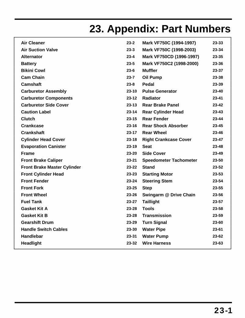
23-1
23. Appendix: Part Numbers
Air Cleaner 23-2 Mark VF750C (1994-1997) 23-33
Air Suction Valve 23-3 Mark VF750C (1998-2003) 23-34
Alternator 23-4 Mark VF750CD (1996-1997) 23-35
Battery 23-5 Mark VF750C2 (1998-2000) 23-36
Bikini Cowl 23-6 Muffler 23-37
Cam Chain 23-7 Oil Pump 23-38
Camshaft 23-8 Pedal 23-39
Carburetor Assembly 23-10 Pulse Generator 23-40
Carburetor Components 23-12 Radiator 23-41
Carburetor Side Cover 23-13 Rear Brake Panel 23-42
Caution Label 23-14 Rear Cylinder Head 23-43
Clutch 23-15 Rear Fender 23-44
Crankcase 23-16 Rear Shock Absorber 23-45
Crankshaft 23-17 Rear Wheel 23-46
Cylinder Head Cover 23-18 Right Crankcase Cover 23-47
Evaporation Canister 23-19 Seat 23-48
Frame 23-20 Side Cover 23-49
Front Brake Caliper 23-21 Speedometer Tachometer 23-50
Front Brake Master Cylinder 23-22 Stand 23-52
Front Cylinder Head 23-23 Starting Motor 23-53
Front Fender 23-24 Steering Stem 23-54
Front Fork 23-25 Step 23-55
Front Wheel 23-26 Swingarm @ Drive Chain 23-56
Fuel Tank 23-27 Taillight 23-57
Gasket Kit A 23-28 Tools 23-58
Gasket Kit B 23-28 Transmission 23-59
Gearshift Drum 23-29 Turn Signal 23-60
Handle Switch Cables 23-30 Water Pipe 23-61
Handlebar 23-31 Water Pump 23-62
Headlight 23-32 Wire Harness 23-63

Appendix A: Part Numbers
23-2
Air Cleaner
# Description Q’ty Price 01 CLIP, DRAIN TUBE
15772-GB5-670 004 $2.45
02 AIR CLEANER 17210-MZ5-000
001 $47.21
03 COVER, A/CLNR HSG 17220-MZ5-000
001 $67.73
04 AIR CLEANER HOUSING 17230-MZ5-910 (replaces 17230-MZ5-000)
001 $88.79
04 AIR CLEANER HOUSING 17230-MZ5-740
001 $84.37
05 PIPE, AIR 17234-MZ5-740
001 $15.15
06 CASE, SUB A/CLNR 17251-KT8-000
001 $17.60
07 DUCT 17251-MZ5-000
001 $44.45
08 FILTER, SUB A/CLNR 17254-KAZ-000
001 $2.08
09 COVER, SUB A/CLNR 17256-MM4-000
001 $16.56
10 TUBE, SUB A/CLNR 17258-MZ5-000
001 $11.07
# Description Q’ty Price 11 STOPPER
17259-MZ5-000 001 $11.42
12 TUBE A, BREATHER
17355-MZ5-000 001 $3.22
13 SCREW (5X12) 90105-MB1-000
004 $2.02
14 SCREW, PAN (5X19) 90141-KT8-000
003 $3.65
15 SCREW, PAN (4X40) 90141-MZ5-000
005 $7.11
16 NUT, SPECIAL (6X7) 61304-958-003(replaces 90301-471-000)
002 $2.64
17 CLIP, SWITCH CORD 91400-MR8-000
001 $3.27
18 SCREW-WASHER (5X10) 93891-05010-07
002 $0.43
19 BULK HOSE (12X1000) 95005-12001-10M
001 $31.53
20 BOLT, FLANGE (6X45) 95701-06045-07 (replaces 95701-06045-00)
001 $0.97
NI TIE, CABLE 32901-VB5-800
001 $2.10

Appendix A: Part Numbers
23-3
Air Suction Valve
# Description Q’ty Price 01 CLIP B, FUEL HOSE
16968-MC7-000 006 $4.67
02 JOINT, VACUUM TUBE 17201-MG9-000
002 $12.51
03 CLIP, BREATHER TUBE 17369-KB4-670
004 $2.78
04 CONTROL VALVE, FR. 18600-MZ5-740
001 $129.72
05 HOSE A 18612-MZ5-740
002 $19.67
06 HOSE A, RR. AIR 18613-MZ5-740
002 $18.62
07 HOSE C, RR. AIR 18615-MZ5-740
001 $20.69
08 TUBE, FR. 18616-MZ5-740
001 $17.16
09 STAY, FR. 18617-MZ5-740
002 $12.13
10 CONTROL VALVE, RR. 18620-MZ5-740
001 $153.78
11 TUBE 18625-MZ5-740
001 $31.86
12 TUBE 18626-MZ5-740
001 $10.66
# Description Q’ty Price 13 PIPE, R. FR. AIR
18640-MZ5-740 001 $47.54
14 GSKT, AIR FEED PIPE 18645-MT4-730
004 $1.96
15 PIPE, L. FR. AIR 18645-MZ5-740
001 $47.54
16 PIPE, RR. AIR 18650-MZ5-740
001 $99.53
17 BOLT 90007-PY3-000
002 $2.88
18 CLAMP, TUBE (D17) 91405-MF5-860
002 $2.51
19 CLIP, TUBE (B7) 95002-02070
010 $0.82
20 BULK HOSE (3.5X1000) 95005-35001-20M
001 $5.42
21 BULK HOSE (3.5X1000) 95005-35001-20M
002 $5.42
22 *95701-06016-08 95701-06016-00
008 $0.73
23 BOLT, FLANGE (6X20) 95701-06020-00
004 $0.60

Appendix A: Part Numbers
23-4
Alternator
# Description Q’ty Price 01 GASKET
11636-MY7-000 001 $12.98
02 COVER, ALTERNATOR 11641-MZ5-920 (replaces 11641-MZ5-000)
001 $329.16
03 FLYWHEEL 31110-MZ5-004
001 $386.83
04 STATOR 31120-MZ5-004
001 $332.99
05 CLAMP, CABLE 32111-MZ5-000
001 $6.36
06 BOLT, FLANGE (6X32) 90001-GHB-690
005 $2.96
# Description Q’ty Price 07 BOLT, FLANGE (6X60)
90001-GHB-750 001 $3.93
08 BOLT, FLANGE (10X35) 90003-MN4-000
001 $4.76
09 BOLT, SOCKET (6X40) 90116-375-000
004 $3.18
10 WASHER (10X25X4) 90405-ML0-000
001 $4.76
11 PIN, DOWEL (8X14) 94301-08140
002 $1.00

Appendix A: Part Numbers
23-5
Battery
# Description Q’ty Price 01 BATTERY (YTX12-BS)
31500-HF1-678 (replaces 31500-HA0-686, 31500-HF1-677, 31500-KM1-836, 31500-KM1-837)
001 $69.17
02 CABLE 32401-MZ5-000
001 $25.07
03 CABLE, STARTER MOTOR 32410-MZ5-000
001 $51.75
04 COVER 32411-230-000 (replaces 32411-253-000)
001 $5.60
05 COVER 32414-MZ5-000
001 $4.04
06 CABLE 32601-MZ5-000
001 $27.51
07 SWITCH ASSY. 35850-MR5-007
001 $83.87
08 RUB, SHOCK ABSORBER 35856-MR5-000
001 $6.95
# Description Q’ty Price 09 BOX ASSY., BATTERY
50330-MZ5-000 001 $86.89
10 BODY, KEY 83507-422-000
001 $2.76
11 STOPPER, KEY BODY 83508-KBG-000 (replaces 83508-438-000)
001 $2.04
12 BOLT, SOCKET (5X9) 90111-MR5-000
002 $1.87
13 NUT, SPECIAL (6X7) 61304-958-003 (replaces 90301-471-000)
003 $2.64
14 PIN, SPRING (2X14) 94305-20141
001 $0.67
15 BAND F, BATTERY 95012-17001
001 $5.89
16 BOLT, FLANGE (6X12) 96001-06012-00
003 $0.78
17 FUSE, BLADE (30A) 98200-33000
002 $0.67
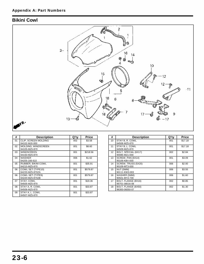
Appendix A: Part Numbers
23-6
Bikini Cowl
# Description Q’ty Price 01 CLIP, SCREEN MOLDING
64102-MJ0-000 002 $3.58
02 MOLDING, WINDSCREEN 64105-MZ5-870
001 $8.60
03 WINDSCREEN 64150-MZ5-870
001 $218.56
04 WASHER 64205-166-610
006 $1.62
05 RUBBER, BIKINI COWL 64215-MZ5-870
001 $35.91
06 COWL SET (TYPE10) 64220-MZ5-870ZA
001 $579.87
06 COWL SET (TYPE9) 64220-MZ5-870ZB
001 $579.87
07 STAY, COWL 64505-MZ5-870
001 $19.36
08 STAY A, R. COWL 64506-MZ5-870
001 $33.87
09 STAY A, L. COWL 64507-MZ5-870
001 $33.87
# Description Q’ty Price 10 STAY B, R. COWL
64508-MZ5-870 001 $17.18
11 STAY B, L. COWL 64509-MZ5-870
001 $17.18
12 BOLT, SPECIAL (6X17) 90085-MZ1-000
002 $2.84
13 SCREW, PAN (6X14) 90106-KBV-000
001 $3.09
14 SCREW, TRUSS (5X20) 90109-MT3-000
006 $2.00
15 NUT (5MM) 90111-KW3-003
006 $3.55
16 WASHER (5MM) 90501-MY2-700
006 $1.60
17 BOLT, FLANGE (8X16) 95701-08016-08
002 $0.85
18 BOLT, FLANGE (6X50) 96300-06050-07
002 $1.30

Appendix A: Part Numbers
23-7
Cam Chain
# Description Q’ty Price 01 GSKT, TENSIONER HOLE
12194-HC5-740 001 $1.78
02 GSKT, TENSIONER HOLE 12194-KW3-880
001 $1.67
03 CHAIN, CAM 14401-MZ5-921 (replaces 14401-MZ5-003)
002 $89.02
04 TENSIONER, FR. 14510-MZ5-770 (replaces 14510-MZ5-000)
001 $108.09
05 TENSIONER, RR. 14515-MZ5-770 (replaces 14515-MZ5-000)
001 $108.09
06 LIFTER ASSY., RR. 14520-MZ5-003
001 $75.99
07 LIFTER ASSY., FR. 14530-MZ5-003
001 $75.99
08 PIN, TENSIONER 14531-MZ5-000
001 $7.04
09 GUIDE B, CAM CHAIN 14546-MZ5-000
002 $28.15
10 GUIDE, FR. CAM CHAIN 14620-MZ5-000
001 $50.43
# Description Q’ty Price 11 GUIDE, RR. CAM CHAIN
14625-MZ5-000 001 $51.58
12 STAY 14627-MZ5-000
001 $23.11
13 BOLT, FLANGE (6X10) 90004-GHB-600 (replaces 90001-GHB-600)
002 $2.47
14 BOLT, FLANGE (6X25) 90004-GHB-670 (replaces 90001-GHB-670)
004 $2.22
15 BOLT (6X14) 90009-MZ8-H00 (replaces 90009-ME5-000)
002 $1.15
16 WASHER (6MM) 90442-397-000
002 $1.33
16 WASHER (6MM) 90502-KBV-000
002 $0.93
17 WASHER (6.5MM) 90463-ML7-000
002 $2.25
18 PIN (6MM) 90607-ME5-000
001 $1.95
19 BOLT, FLANGE (6X14) 95701-06014-00
002 $0.63
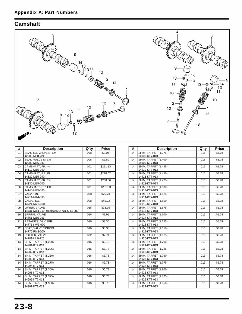
Appendix A: Part Numbers
23-8
Camshaft
# Description Q’ty Price 01 SEAL, EX. VALVE STEM
12208-ML0-721 008 $8.07
02 SEAL, VALVE STEM 12209-MZ5-003
008 $7.69
03 CAMSHAFT, FR. IN. 14110-MZ5-000
001 $261.83
04 CAMSHAFT, RR. IN. 14120-MZ5-000
001 $278.02
05 CAMSHAFT, FR. EX. 14130-MZ5-000
001 $258.56
06 CAMSHAFT, RR. EX. 14140-MZ5-000
001 $261.83
07 VALVE, IN. 14711-MT4-000
008 $25.73
08 VALVE, EX. 14721-MY3-000
008 $45.22
09 LIFTER, VALVE 14731-MT4-010 (replaces 14731-MT4-000)
016 $33.35
10 SPRING, VALVE 14751-MZ5-003
016 $7.96
11 RETAINER, VLV SPR 14771-KW3-900
016 $8.36
12 SEAT, VALVE SPRING 14775-PM3-000
016 $3.38
13 COTTER, VALVE 14781-ML0-720
032 $2.71
14 SHIM, TAPPET (1.200) 14901-KT7-013
016 $6.78
14 SHIM, TAPPET (1.225) 14902-KT7-013
016 $6.78
14 SHIM, TAPPET (1.250) 14903-KT7-013
016 $6.78
14 SHIM, TAPPET (1.275) 14904-KT7-013
016 $6.78
14 SHIM, TAPPET (1.300) 14905-KT7-013
016 $6.78
14 SHIM, TAPPET (1.325) 14906-KT7-013
016 $6.78
14 SHIM, TAPPET (1.350) 14907-KT7-013
016 $6.78
# Description Q’ty Price 14 SHIM, TAPPET (1.375)
14908-KT7-013 016 $6.78
14 SHIM, TAPPET (1.400) 14909-KT7-013
016 $6.78
14 SHIM, TAPPET (1.425) 14910-KT7-013
016 $6.78
14 SHIM, TAPPET (1.450) 14911-KT7-013
016 $6.78
14 SHIM, TAPPET (1.475) 14912-KT7-013
016 $6.78
14 SHIM, TAPPET (1.500) 14913-KT7-013
016 $6.78
14 SHIM, TAPPET (1.525) 14914-KT7-013
016 $6.78
14 SHIM, TAPPET (1.550) 14915-KT7-013
016 $6.78
14 SHIM, TAPPET (1.575) 14916-KT7-013
016 $6.78
14 SHIM, TAPPET (1.600) 14917-KT7-013
016 $6.78
14 SHIM, TAPPET (1.625) 14918-KT7-013
016 $6.78
14 SHIM, TAPPET (1.650) 14919-KT7-013
016 $6.78
14 SHIM, TAPPET (1.675) 14920-KT7-013
016 $6.78
14 SHIM, TAPPET (1.700) 14921-KT7-013
016 $6.78
14 SHIM, TAPPET (1.725) 14922-KT7-013
016 $6.78
14 SHIM, TAPPET (1.750) 14923-KT7-013
016 $6.78
14 SHIM, TAPPET (1.775) 14924-KT7-013
016 $6.78
14 SHIM, TAPPET (1.800) 14925-KT7-013
016 $6.78
14 SHIM, TAPPET (1.825) 14926-KT7-013
016 $6.78
14 SHIM, TAPPET (1.850) 14927-KT7-013
016 $6.78

Appendix A: Part Numbers
23-9
# Description Q’ty Price 14 SHIM, TAPPET (1.875)
14928-KT7-013 016 $6.78
14 SHIM, TAPPET (1.900) 14929-KT7-013
016 $6.78
14 SHIM, TAPPET (1.925) 14930-KT7-013
016 $6.78
14 SHIM, TAPPET (1.950) 14931-KT7-013
016 $6.78
14 SHIM, TAPPET (1.975) 14932-KT7-013
016 $6.78
14 SHIM, TAPPET (2.000) 14933-KT7-013
016 $6.78
14 SHIM, TAPPET (2.025) 14934-KT7-013
016 $6.78
14 SHIM, TAPPET (2.050) 14935-KT7-013
016 $6.78
14 SHIM, TAPPET (2.075) 14936-KT7-013
016 $6.78
14 SHIM, TAPPET (2.100) 14937-KT7-013
016 $6.78
14 SHIM, TAPPET (2.125) 14938-KT7-013
016 $6.78
14 SHIM, TAPPET (2.150) 14939-KT7-013
016 $6.78
14 SHIM, TAPPET (2.175) 14940-KT7-013
016 $6.78
14 SHIM, TAPPET (2.200) 14941-KT7-013
016 $6.78
14 SHIM, TAPPET (2.225) 14942-KT7-013
016 $6.78
14 SHIM, TAPPET (2.250) 14943-KT7-013
016 $6.78
14 SHIM, TAPPET (2.275) 14944-KT7-013
016 $6.78
14 SHIM, TAPPET (2.300) 14945-KT7-013
016 $6.78
14 SHIM, TAPPET (2.325) 14946-KT7-013
016 $6.78
14 SHIM, TAPPET (2.350) 14947-KT7-013
016 $6.78
14 SHIM, TAPPET (2.375) 14948-KT7-013
016 $6.78
14 SHIM, TAPPET (2.400) 14949-KT7-013
016 $6.78
# Description Q’ty Price 14 SHIM, TAPPET (2.425)
14950-KT7-013 016 $6.78
14 SHIM, TAPPET (2.450) 14951-KT7-013
016 $6.78
14 SHIM, TAPPET (2.475) 14952-KT7-013
016 $6.78
14 SHIM, TAPPET (2.500) 14953-KT7-013
016 $6.78
14 SHIM, TAPPET (2.525) 14954-KT7-013
016 $6.78
14 SHIM, TAPPET (2.550) 14955-KT7-013
016 $6.78
14 SHIM, TAPPET (2.575) 14956-KT7-013
016 $6.78
14 SHIM, TAPPET (2.600) 14957-KT7-013
016 $6.78
14 SHIM, TAPPET (2.625) 14958-KT7-013
016 $6.78
14 SHIM, TAPPET (2.650) 14959-KT7-013
016 $6.78
14 SHIM, TAPPET (2.675) 14960-KT7-013
016 $6.78
14 SHIM, TAPPET (2.700) 14961-KT7-013
016 $6.78
14 SHIM, TAPPET (2.725) 14962-KT7-013
016 $6.78
14 SHIM, TAPPET (2.750) 14963-KT7-013
016 $6.78
14 SHIM, TAPPET (2.775) 14964-KT7-013
016 $6.78
14 SHIM, TAPPET (2.800) 14965-KT7-013
016 $6.78
14 SHIM, TAPPET (2.825) 14966-KT7-013
016 $6.78
14 SHIM, TAPPET (2.850) 14967-KT7-013
016 $6.78
14 SHIM, TAPPET (2.875) 14968-KT7-013
016 $6.78
14 SHIM, TAPPET (2.900) 14969-KT7-013
016 $6.78

Appendix A: Part Numbers
23-10
Carburetor Assembly

Appendix A: Part Numbers
23-11
# Description Q’ty Price 01 ROD SET, LINK
16018-MZ5-600 001 $45.42
02 JOINT SET 16026-MZ5-600
001 $31.65
03 JOINT SET, FUEL 16027-MB6-671
001 $28.47
04 JOINT SET 16027-MZ5-600
001 $31.65
05 LEVER SET, LINK 16035-MZ5-600
001 $31.51
06 GASKET B SET 16040-MZ5-600
002 $13.73
07 JOINT SET, FUEL 16047-KE7-003
001 $32.87
08 JOINT SET 16047-MZ5-600
002 $30.27
09 SPRING 16050-MZ5-600
001 $9.69
10 SPRING 16051-MZ5-670
002 $7.91
11 SPRING 16053-MB0-671
001 $7.09
12 SCREW-WASHER 16081-KAZ-000
004 $2.22
13 BOLT 16083-MZ5-670
002 $23.65
14 BOLT 16084-MZ5-670
001 $23.65
15 WASHER, PLAIN 16085-MV4-000
004 $1.95
16 WASHER 16090-MZ5-600
004 $2.95
17 CARBURETOR ASSY. 16100-MZ5-670
001 $1,644.16
18 CARBURETOR ASSY. 16100-MZ5-740
001 $1,644.16
19 CARBURETOR ASSY. 1 16101-MZ5-670
001 $480.69
19 CARBURETOR ASSY. 1 16101-MZ5-740
001 $480.69
20 CARBURETOR ASSY. 2 16102-MZ5-670
001 $480.69
20 CARBURETOR ASSY. 2 16102-MZ5-740
001 $480.69
21 CARBURETOR ASSY. 3 16103-MZ5-670
001 $480.69
21 CARBURETOR ASSY. 3 16103-MZ5-740
001 $480.69
22 CARBURETOR ASSY. 4 16104-MZ5-670
001 $480.69
22 CARBURETOR ASSY. 4 16104-MZ5-740
001 $480.69
23 LEVER, STARTER 16121-MZ5-600
002 $30.40
24 FUNNEL, AIR 16141-MZ5-600
004 $20.85
# Description Q’ty Price 25 STAY, JOINT
16169-MZ5-670 001 $21.11
26 COLLAR 16172-MZ5-670
001 $19.36
27 COLLAR 16173-MZ5-670
001 $15.85
28 COLLAR 16174-MZ5-670
001 $19.36
29 COLLAR 16175-MZ1-000
004 $9.40
30 T-JOINT 16179-MB2-881
001 $22.62
31 BASE, AIR CLEANER 16188-MZ5-600
001 $149.59
32 TUBE (15X170) 16195-MZ5-670
001 $4.64
33 TUBE, FUEL 16197-MZ5-670
001 $12.65
34 TUBE, FUEL 16198-MZ5-671
001 $15.31
35 TUBE 16199-MZ5-670
001 $3.62
36 T-JOINT 17193-MN5-000
001 $13.60
37 T-JOINT 17194-MN5-000
002 $8.89
38 SCREW, PAN (4X16) 93500-04016-0G
016 $0.47
39 NUT, FLANGE (6MM) 94050-06000
006 $0.72
40 CLIP, TUBE (B18) 95002-02089
008 $0.76
41 CLIP, TUBE (B10) 95002-02109
004 $1.02
42 CLIP, TUBE (B12) 95002-02129
004 $1.02
43 CLIP, TUBE (B12.5) 95002-02139
001 $1.02
44 BULK HOSE (4.5X1000) 95005-45001-20M
001 $19.42
45 BULK HOSE (4.5X1000) 95005-45001-20M
001 $19.42
46 BULK HOSE (4.5X1000) 95005-45001-20M
002 $19.42
47 BULK HOSE (5.5X3000) 95005-55003-20M
001 $18.33
48 BULK HOSE (5.5X3000) 95005-55003-20M
001 $18.33
49 BULK HOSE (7X1000) 95005-70001-50M
001 $7.63

Appendix A: Part Numbers
23-12
Carburetor Components
# Description Q’ty Price 01 GASKET SET A
16010-MZ5-600 004 $32.85
02 NEEDLE SET, JET 16012-MZ5-600
004 $34.20
02 NEEDLE SET, JET 16012-MZ5-670
004 $33.85
03 FLOAT SET 16013-MY1-000
004 $36.55
04 CHAMBER SET, FLOAT 16015-MV9-670
002 $100.65
05 SCREW SET 16016-MAS-670 (replaces 16016-MV9-730)
004 $17.36
06 CHAMBER SET, FLOAT 16023-MV9-670
002 $127.01
07 SCREW SET 16028-MZ5-600
003 $32.13
08 SCREW SET 16029-MZ5-600
001 $24.80
09 PLATE SET, VALVE 16037-MV4-000
004 $18.07
10 GASKET SET C 16041-MZ5-600
004 $12.42
11 VALVE SET, STARTER 16046-MV9-670
004 $47.54
12 SPRING 16051-MV4-000
004 $13.67
13 SPRING 16051-MZ5-600
004 $7.91
14 SPRING 16052-MV4-000
003 $2.95
15 SCREW, PAN 16080-MV4-000
012 $1.67
16 BOLT-WASHER (5X16) 16082-PH9-005
012 $2.16
17 TOP 16107-MZ5-671
004 $38.78
# Description Q’ty Price 18 SCREW
16108-MW0-750 004 $1.73
19 PISTON, VACUUM 16111-MZ5-600
004 $119.21
20 PLATE, STAY 16119-MZ2-600
001 $13.64
21 PLATE, STAY 16119-MZ5-600
001 $13.96
22 STAY, WIRE 16119-MZ5-670
001 $17.35
23 VALVE, FLOAT 16155-MN9-004
004 $23.04
24 HOLDER, NEEDLE JET 16165-MN4-013
004 $14.63
25 VALVE ASSY., AIR CUT 16510-MZ2-650
004 $59.62
26 SCREW-WASHER (4X10) 93892-04010-00 (replaces 93892-04010-10)
001 $0.60
27 SCREW-WASHER (5X10) 93892-05010-00 (replaces 93892-05010-10)
002 $0.30
28 BULK HOSE (3.5X1000) 95005-35001-20M
004 $5.42
29 JET, MAIN (#102) 99101-GHB-1020 (replaces 99101-393-1020)
004 $5.20
29 JET, MAIN (#102) 99101-GHB-1020
004 $5.20
30 JET, SLOW (#40) 99103-MT2-0400
004 $8.38
31 JET, SLOW AIR (#110) 99108-MW0-1102 (replaces 99108-MW0-1100)
004 $4.56
31 JET (#110) 99108-MY1-1100
004 $8.24

Appendix A: Part Numbers
23-13
Carburetor Side Cover
# Description Q’ty Price 01 CVR, CARBURETOR SIDE
17255-MZ5-000 001 $72.38
02 BASE, R. 17256-MZ5-000
001 $48.58
03 BASE, L. 17266-MZ5-000
001 $46.88
04 PROTECTOR 17267-MZ5-300
001 $12.13
05 COVER SET, L. 17268-MZ5-000
001 $91.70
06 CABLE, CHOKE 17950-MZ5-000
001 $23.56
07 LOCK SET 35010-MZ5-000
001 Call For Price
08 SWITCH, COMBINATION 35100-MZ5-A01 (replaces 35100-MZ5-007)
001 $49.44
09 BASE 35102-MR1-000
001 $9.75
10 COLLAR 35103-MR1-000
001 $15.58
11 COVER 35110-MZ5-000
001 $14.45
# Description Q’ty Price 12 KEY, BLANK (TYPE1)
35121-MR1-770 001 $7.38
12 KEY, BLANK (TYPE2) 35122-MR1-770
001 $7.38
13 GROMMET, A/CLNR HSG 83551-GE2-000
004 $3.18
14 BOLT, BREAK OFF 90107-MR1-000
002 $6.16
15 BOLT, FLANGE (6MM) 90113-KW3-000
002 $2.84
16 SCREW, RR. COVER 90114-GB6-920
001 $1.18
17 BOLT, FLANGE (6X10) 95701-06010-00
002 $0.75
18 *95701-06016-08 95701-06016-00
002 $0.73
19 BOLT, FLANGE (6X30) 95701-06030-00
001 $0.83
20 BOLT, FLANGE (6X35) 95701-06035-00
001 $0.75

Appendix A: Part Numbers
23-14
Caution Label
# Description Q’ty Price 01 DIAGRAM
87135-MZ5-740 001 $3.27
02 LABEL, HIGH ALTITUDE 87139-463-670
001 $5.02
03 LABEL, TIRE 87505-MZ5-670
001 $3.78
04 LABEL, DRIVE CHAIN 87507-MZ5-670
001 $3.78
05 MARK 87512-MZ3-670
001 $4.51
06 LABEL, DRIVE (TYPE2) 87560-MW0-670ZB
001 $4.62
# Description Q’ty Price 07 LABEL (R201) (TYPE1)
87565-MZ5-670ZA 001 $2.16
07 LABEL (NH1) (TYPE2) 87565-MZ5-670ZB
001 $2.16
07 LABEL (Y124) (TYPE3) 87565-MZ5-670ZC
001 $2.16
08 LABEL, FUEL (TYPEG) 87586-MR6-670ZA
001 $2.33
08 LABEL, FUEL (TYPEB) 87586-MR6-670ZF
001 $2.22

Appendix A: Part Numbers
23-15
Clutch
# Description Q’ty Price 01 SPROCKET
15131-ML7-000 001 $28.64
02 CLUTCH (OUTER) 22100-MZ5-010 (replaces 22100-MZ5-000)
001 $349.77
03 GUIDE, CLUTCH 22116-MB0-000
001 $22.93
04 COLR, CLUTCH (OUTER) 22117-ML7-690
001 $8.11
05 CENTER, CLUTCH 22120-ML7-010 (replaces 22120-ML7-000)
001 $96.21
06 SEAT, JUDDER SPRING 22125-ML7-000
001 $8.11
07 DISK, CL FRICTION 22201-MS6-620 (replaces 22201-KG0-980, 22201-KM4-000)
008 $11.24
08 DISK B, CL FRICTION 22202-ML4-611
001 $12.51
09 PLATE, CLUTCH 22321-MR7-000 (replaces 22321-ML7-000)
008 $10.64
10 PLATE, CLU PRESS 22350-ML7-000
001 $52.03
11 PIECE, CLUTCH JOINT 22366-KE8-000
001 $8.73
12 SPRING, CLUTCH 22401-KZ3-000 (replaces 22401-ML7-000)
005 $3.51
13 SPRING, JUDDER 22402-ML7-000
001 $17.18
# Description Q’ty Price 14 ROD, CLUTCH LIFTER
22850-MZ5-000 001 $24.56
15 GEAR, PRIMARY DRIVE 23110-ML7-010
001 $167.74
16 SPRING 23115-MG8-300
003 $2.33
17 BOLT-WASHER (6X25) 90022-MM5-000
005 $2.33
18 NUT, LOCK (22MM) 90231-MK7-670
001 $7.93
19 NUT, LOCK (22MM) 90231-MZ7-000
001 $8.22
20 WASHER (22MM) 90432-MB0-010
001 $6.58
21 GUIDE 90509-MR7-000
001 $35.22
22 BEARING (16003) 91011-KK6-013 (replaces 91008-362-000, 91008-KK6-000, 91010-HC0-003)
001 $12.09
23 BEARING (35X42X30) 91024-MB0-003
001 $56.71
24 CIRCLIP (32MM) 94510-32000
001 $0.97
25 CLIP (15MM) 94601-15000
001 $0.68

Appendix A: Part Numbers
23-16
Crankcase
# Description Q’ty Price 01 CRANKCASE SET
11000-MZ5-000 001 $2,318.80
02 GUIDE, HOSE 11337-MZ5-000
001 $7.62
03 RECEIVER 22821-MZ5-000
001 $22.47
04 SWITCH, OIL PRESSURE 35500-MJ4-024
001 $32.20
05 BOLT, FLANGE (6X96) 90003-PC9-000
001 $4.37
06 BOLT, UBS (9X88) 90014-ML7-000
004 $7.33
07 BOLT, UBS (9X10⁸) 90016-ML7-000
004 $8.73
08 BOLT, FLANGE (10X20) 90130-126-900
002 $3.18
09 WASHER (10MM) 90403-MG7-000
002 $2.62
10 WASHER (6.5MM) 90463-ML7-000
003 $2.25
11 ORIFICE (1.0) 90701-ML7-000
001 $5.65
12 PIN, DOWEL (10X16) 90701-MV9-670
002 $3.38
13 OIL SEAL (8X25X8) 91204-MB0-013
001 $3.18
# Description Q’ty Price 14 O-RING (7.7X2.3)
91301-PC9-003 (replaces 91308-283-000, 91313-393-003)
001 $1.45
15 PIN, DOWEL (8X14) 94301-08140
001 $1.00
16 BOLT, FLANGE (6X12) 95701-06012-00
002 $0.72
17 BOLT, FLANGE (6X28) 95701-06028-00
002 $0.85
18 BOLT, FLANGE (6X35) 95701-06035-00
001 $0.75
19 BOLT, FLANGE (6X40) 95701-06040-00
003 $0.85
20 BOLT, FLANGE (6X45) 95701-06045-07 (replaces 95701-06045-00)
002 $0.97
21 BOLT, FLANGE (6X50) 95701-06050-00
003 $0.98
22 BOLT, FLANGE (6X55) 95701-06055-00
001 $1.70
23 BOLT, FLANGE (6X65) 95701-06065-00
002 $1.03
24 BOLT, FLANGE (8X45) 95701-08045-00
001 $1.02
25 BOLT, FLANGE (10X90) 95701-10090-00
002 $2.72
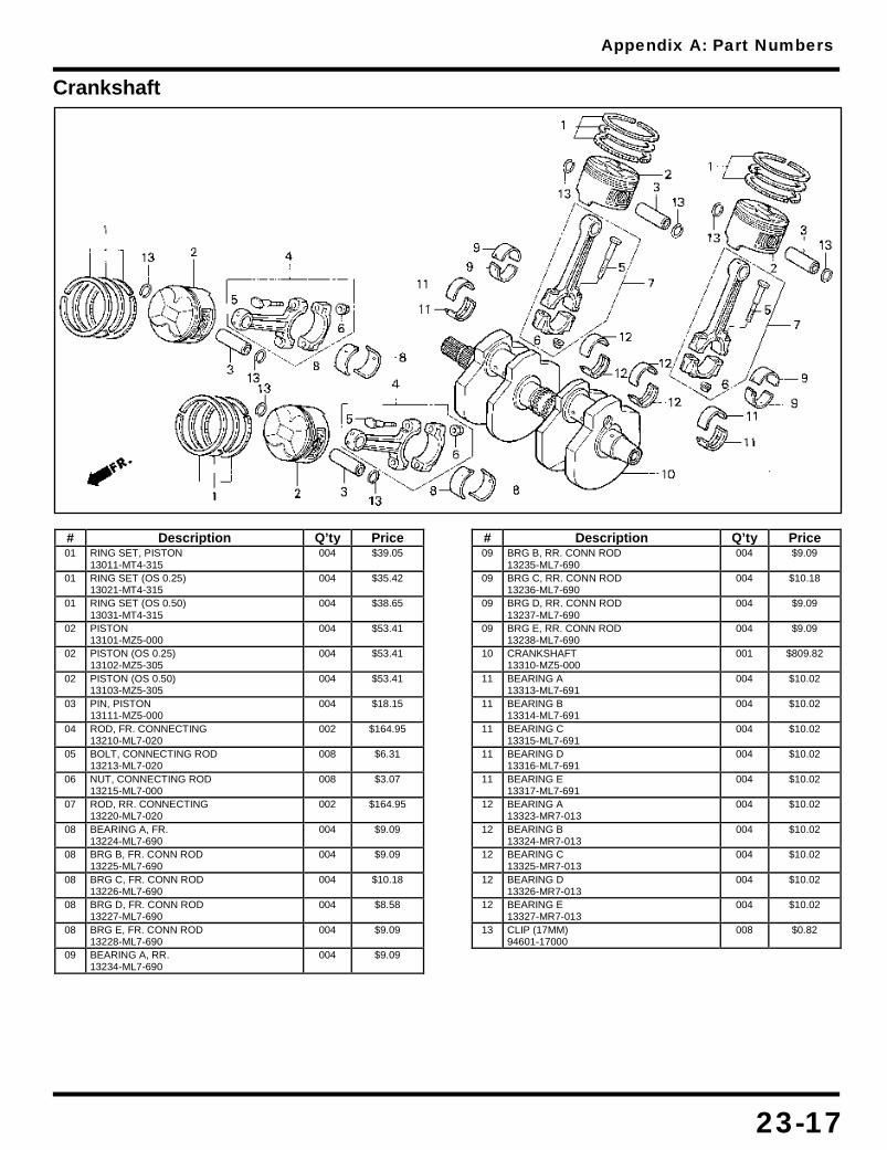
Appendix A: Part Numbers
23-17
Crankshaft
# Description Q’ty Price 01 RING SET, PISTON
13011-MT4-315 004 $39.05
01 RING SET (OS 0.25) 13021-MT4-315
004 $35.42
01 RING SET (OS 0.50) 13031-MT4-315
004 $38.65
02 PISTON 13101-MZ5-000
004 $53.41
02 PISTON (OS 0.25) 13102-MZ5-305
004 $53.41
02 PISTON (OS 0.50) 13103-MZ5-305
004 $53.41
03 PIN, PISTON 13111-MZ5-000
004 $18.15
04 ROD, FR. CONNECTING 13210-ML7-020
002 $164.95
05 BOLT, CONNECTING ROD 13213-ML7-020
008 $6.31
06 NUT, CONNECTING ROD 13215-ML7-000
008 $3.07
07 ROD, RR. CONNECTING 13220-ML7-020
002 $164.95
08 BEARING A, FR. 13224-ML7-690
004 $9.09
08 BRG B, FR. CONN ROD 13225-ML7-690
004 $9.09
08 BRG C, FR. CONN ROD 13226-ML7-690
004 $10.18
08 BRG D, FR. CONN ROD 13227-ML7-690
004 $8.58
08 BRG E, FR. CONN ROD 13228-ML7-690
004 $9.09
09 BEARING A, RR. 13234-ML7-690
004 $9.09
# Description Q’ty Price 09 BRG B, RR. CONN ROD
13235-ML7-690 004 $9.09
09 BRG C, RR. CONN ROD 13236-ML7-690
004 $10.18
09 BRG D, RR. CONN ROD 13237-ML7-690
004 $9.09
09 BRG E, RR. CONN ROD 13238-ML7-690
004 $9.09
10 CRANKSHAFT 13310-MZ5-000
001 $809.82
11 BEARING A 13313-ML7-691
004 $10.02
11 BEARING B 13314-ML7-691
004 $10.02
11 BEARING C 13315-ML7-691
004 $10.02
11 BEARING D 13316-ML7-691
004 $10.02
11 BEARING E 13317-ML7-691
004 $10.02
12 BEARING A 13323-MR7-013
004 $10.02
12 BEARING B 13324-MR7-013
004 $10.02
12 BEARING C 13325-MR7-013
004 $10.02
12 BEARING D 13326-MR7-013
004 $10.02
12 BEARING E 13327-MR7-013
004 $10.02
13 CLIP (17MM) 94601-17000
008 $0.82
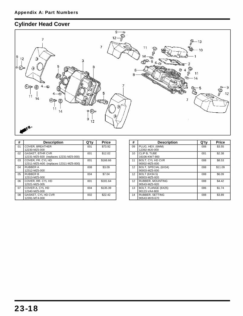
Appendix A: Part Numbers
23-18
Cylinder Head Cover
# Description Q’ty Price 01 COVER, BREATHER
12230-MZ5-000 001 $73.92
02 GASKET, BTHR CVR 12231-MZ5-920 (replaces 12231-MZ5-000)
001 $12.02
03 COVER, FR. CYL HD 12311-MZ5-A00 (replaces 12311-MZ5-000)
001 $166.66
04 RUBBER A 12312-MZ5-000
008 $3.09
05 RUBBER B 12313-MZ5-000
004 $7.04
06 COVER, RR. CYL HD 12321-MZ5-305
001 $181.64
07 COVER A, CYL HD 12340-MZ5-000
004 $135.39
08 GASKET, CYL HD CVR 12391-MT4-000
002 $22.42
# Description Q’ty Price 09 PLUG, HEX. (6MM)
12392-MJ0-000 008 $3.55
10 CLIP B, TUBE 16106-KW7-900
001 $2.38
11 BOLT, CYL HD CVR 90002-MZ5-000
008 $8.53
12 BOLT, SPECIAL (6X34) 90003-MZ5-000
008 $11.09
12 BOLT (6X34.5) 90003-MZ5-920
008 $6.09
12 RUBBER, MOUNTING 90543-MZ5-920
008 $4.42
13 BOLT, FLANGE (6X25) 90123-VA4-800
006 $1.74
14 RUBBER, SETTING 90543-MV9-670
008 $3.89

Appendix A: Part Numbers
23-19
Evaporation Canister
# Description Q’ty Price 01 CLIP, TUBE
15772-MB3-000 003 $1.62
02 CLIP, BREATHER TUBE 15772-500-010 (replaces 15772-500-013)
004 $3.09
03 JOINT, FUEL TUBE 16958-MB0-000
001 $8.29
04 JOINT, VACUUM TUBE 17201-MG9-000
001 $12.51
05 TUBE, OPEN AIR 17290-MZ5-740
001 $13.66
06 VALVE ASSY. 17300-MZ5-740
001 $192.58
07 TUBE 17301-MZ5-740
001 $14.18
08 RUBBER, SETTING 17305-MJ4-771
001 $8.11
09 CANISTER 17410-MR1-682
001 $241.47
10 TUBE 17411-MZ5-740
001 $14.80
11 TUBE 17412-MZ5-740
001 $6.98
12 TUBE 17413-MZ5-740
001 $14.46
13 TUBE 17414-MZ5-740
001 $16.58
14 PIPE 17415-MZ5-740
001 $81.68
15 TUBE 17416-MZ5-740
001 $17.44
16 VALVE 17440-MZ5-740
001 $60.45
# Description Q’ty Price 17 RUBBER
17451-ME5-760 001 $9.24
18 TUBE 17525-MZ5-740
001 $8.38
19 TUBE 18630-MZ5-740
001 $12.94
20 JOINT B, WASHER TUBE 38562-663-920
001 $4.57
21 COLLAR (6.3X13) 50324-425-010
002 $3.96
22 RUBBER 84703-MN5-000
002 $3.51
23 CLAMP, TUBE (12.5MM) 90661-GHB-610
001 $1.16
24 CLIP, TUBE (B7) 95002-02070
008 $0.82
25 CLIP, TUBE (B8) 95002-02080
004 $0.82
26 CLIP, TUBE (B12) 95002-02120
005 $0.90
27 BULK HOSE (3.5X1000) 95005-35001-20M
001 $5.42
28 BULK HOSE (3.5X1000) 95005-35001-20M
001 $5.42
29 BULK HOSE (3.5X1000) 95005-35001-20M
001 $5.42
30 BULK HOSE (4.5X1000) 95005-45001-20M
001 $19.42
31 BOLT, FLANGE (6X25) 95701-06025-07
002 $0.75

Appendix A: Part Numbers
23-20
Frame
# Description Q’ty Price 01 COLR, FR. WHEEL SIDE
44311-045-670 001 $3.76
02 FRAME 50100-MZ5-600 (replaces 50100-MZ5-000)
001 $1,794.77
02 FRAME 50100-MZ5-740
001 $1,794.77
03 PLATE, R. FR. 50136-MZ5-000
001 $21.64
04 PLATE, L. FR. 50137-MZ5-000
001 $21.64
05 PLATE, R. RR. 50138-MZ5-000
001 $29.60
06 PLATE, L. RR. 50139-MZ5-000
001 $29.60
07 PLATE, RR. ENG HGR 50141-MZ5-000
001 $12.00
08 COLLAR, ENG HGR 50350-MZ5-000
002 $9.15
09 COVER, R. FR. SIDE 50650-MZ5-000
001 $47.84
10 HOLDER ASSY., HELMET 50710-GB4-007
001 $51.71
11 HOLDER ASSY., HELMET 50710-086-007
001 $45.65
12 COVER, L. FR. SIDE 50750-MZ5-000
001 $72.97
13 NUT, ACCUMULATOR 57071-SB0-800
001 $4.04
14 BOLT, UBS (8X60) 90029-MG8-000
002 $3.89
15 BOLT, FLG (10X105) 90101-MZ5-000
002 $7.69
# Description Q’ty Price 16 BOLT, FLANGE (8X25)
90103-MZ5-000 008 $3.09
17 BOLT, FLG (12X265) 90105-MM8-880
001 $17.84
18 BOLT 90107-MJ1-000
002 $3.51
19 BOLT 90116-MZ5-000
001 $22.76
20 SCREW, TRUSS 90133-SD4-000
002 $1.05
21 CAP, R. LOCK NUT 90302-ME5-000
002 $13.84
22 WASHER, FLAT (10MM) 94102-10700 (replaces 90503-MZ5-000)
002 $0.57
23 CLIP (15) 90690-GHB-601
001 $1.69
24 CLIP, CABLE (8MM) 90690-GHB-631
003 $1.60
25 CLIP, CABLE (25MM) 90690-GHB-671
004 $1.60
27 NUT, FLANGE (8MM) 94050-08070
002 $0.33
28 NUT, FLANGE (10MM) 90303-428-900 (replaces 94050-10070)
002 $2.62
29 NUT, FLANGE (12MM) 94050-12000
001 $0.76
30 BOLT, FLANGE (10X35) 95701-10035-07
002 $1.35
31 BOLT, FLANGE (10X45) 95701-10045-02
002 $2.45
32 BOLT, FLANGE (10X85) 95701-10085-00
001 $1.95

Appendix A: Part Numbers
23-21
Front Brake Caliper
# Description Q’ty Price 01 SEAL SET, PISTON
06451-GE2-405 002 $8.67
02 PAD SET, FR. 06455-MS9-405
001 $40.00
03 SCREW, BLEEDER 43352-568-003
001 $5.07
04 CAP, BLEEDER 43353-461-771
001 $3.96
05 CLPR, L. FR. BRAKE 45100-MZ5-006
001 $412.36
06 PISTON 45107-MN5-006
002 $28.75
07 SPRING, PAD 45108-ML7-922
001 $4.85
08 BRACKET, L. FR. 45110-MZ6-006
001 $91.77
09 RETAINER 45112-MS9-611
001 $4.29
# Description Q’ty Price 10 BOLT A, PIN
45131-ML7-921 001 $11.71
11 PIN, BOLT 45131-166-016
001 $6.00
12 BUSH, PIN 45132-166-016
001 $4.29
13 BOOT B 45133-MA3-006
001 $4.29
14 CALIPER SUB-ASSY. 45150-MZ5-305
001 $342.69
15 PLUG, PIN 45203-MG3-016
001 $4.00
16 PIN, HANGER 45215-ML7-922
001 $8.11
17 BOLT (8X32) 90101-MZ8-000
002 $5.31

Appendix A: Part Numbers
23-22
Front Brake Master Cylinder
# Description Q’ty Price 01 SWITCH, FR. STOP
35340-MM5-600 001 $15.44
02 HOSE, FR. BRAKE 45126-MZ5-003
001 $55.67
03 BOOT 45504-410-003
001 $9.24
04 SPRING 45506-KA3-731
001 $4.15
04 SPRING 45506-KA3-831
001 $3.71
05 M/CYL SUB-ASSY, FR. 45510-MZ8-305
001 $241.36
06 PROTECTOR 45512-MA6-006
001 $3.38
07 CAP, MASTER CYLINDER 45513-MR1-016 (replaces 45513-MR1-006)
001 $23.25
08 HOLDER 45517-MR1-671
001 $19.49
09 PLATE, DIAPHRAGM 45518-MM5-006
001 $8.09
10 DIAPHRAGM 45520-MM5-006
001 $11.47
# Description Q’ty Price 11 MASTER CYLINDER SET
45530-MN9-305 001 $38.51
12 LEVER, R. HANDLEBAR 53175-MR1-671
001 $14.31
13 BOLT, R. 90114-MA5-671
001 $7.15
14 BOLT, OIL (10X22) 90145-MS9-612 (replaces 90145-MS9-611)
002 $5.29
15 NUT, CAP (6MM) 90201-415-000
001 $1.58
16 WASHER, OIL BOLT 90545-300-000
004 $2.18
17 CIRCLIP 90651-MA5-671
001 $2.07
18 SCREW, FLAT (4X12) 93600-04012-1A
002 $0.32
19 SCREW-WASHER (4X12) 93893-04012-07 (replaces 93893-04012-17)
001 $0.70
20 BOLT, SOCKET (6X22) 96600-06022-10 (replaces 96700-06022-10)
002 $1.20
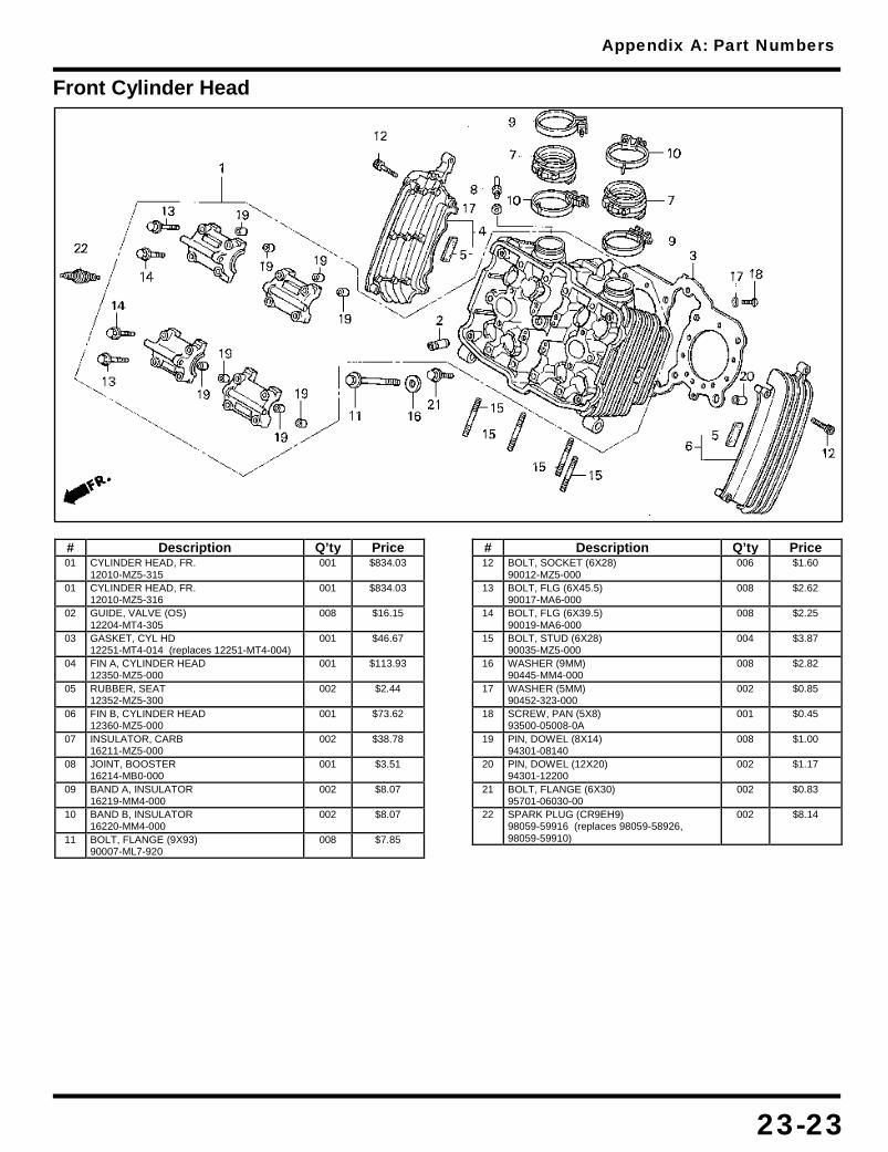
Appendix A: Part Numbers
23-23
Front Cylinder Head
# Description Q’ty Price 01 CYLINDER HEAD, FR.
12010-MZ5-315 001 $834.03
01 CYLINDER HEAD, FR. 12010-MZ5-316
001 $834.03
02 GUIDE, VALVE (OS) 12204-MT4-305
008 $16.15
03 GASKET, CYL HD 12251-MT4-014 (replaces 12251-MT4-004)
001 $46.67
04 FIN A, CYLINDER HEAD 12350-MZ5-000
001 $113.93
05 RUBBER, SEAT 12352-MZ5-300
002 $2.44
06 FIN B, CYLINDER HEAD 12360-MZ5-000
001 $73.62
07 INSULATOR, CARB 16211-MZ5-000
002 $38.78
08 JOINT, BOOSTER 16214-MB0-000
001 $3.51
09 BAND A, INSULATOR 16219-MM4-000
002 $8.07
10 BAND B, INSULATOR 16220-MM4-000
002 $8.07
11 BOLT, FLANGE (9X93) 90007-ML7-920
008 $7.85
# Description Q’ty Price 12 BOLT, SOCKET (6X28)
90012-MZ5-000 006 $1.60
13 BOLT, FLG (6X45.5) 90017-MA6-000
008 $2.62
14 BOLT, FLG (6X39.5) 90019-MA6-000
008 $2.25
15 BOLT, STUD (6X28) 90035-MZ5-000
004 $3.87
16 WASHER (9MM) 90445-MM4-000
008 $2.82
17 WASHER (5MM) 90452-323-000
002 $0.85
18 SCREW, PAN (5X8) 93500-05008-0A
001 $0.45
19 PIN, DOWEL (8X14) 94301-08140
008 $1.00
20 PIN, DOWEL (12X20) 94301-12200
002 $1.17
21 BOLT, FLANGE (6X30) 95701-06030-00
002 $0.83
22 SPARK PLUG (CR9EH9) 98059-59916 (replaces 98059-58926, 98059-59910)
002 $8.14

Appendix A: Part Numbers
23-24
Front Fender
# Description Q’ty Price 01 CLAMP B, BRAKE HOSE
45158-MZ5-000 001 $16.56
02 GUIDE, FR. 45451-473-000
001 $5.15
03 FENDER, FR. *NH1* 61100-MZ5-000ZC
001 $154.96
03 FENDER, FR. *Y124P* 61100-MZ5-000ZD
001 $154.96
# Description Q’ty Price 03 FENDER, FR. *R201*
61100-MZ5-000ZE 001 $154.96
04 PLATE, FR. FENDER 61103-MZ5-000
001 $11.33
05 BOLT (6X25) 90080-MG8-000
004 $3.07
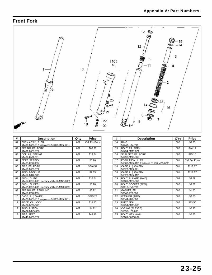
Appendix A: Part Numbers
23-25
Front Fork
# Description Q’ty Price 01 FORK ASSY., R. FR.
51400-MZ5-912 (replaces 51400-MZ5-671) 001 Call For Price
02 SPRING, FR. FORK 51401-MZ5-671
002 $66.38
03 COLLAR, SPRING 51402-KV3-701
002 $18.24
04 SEAT, SPRING 51403-KF0-003
002 $3.76
05 PIPE, FR. FORK 51410-MZ5-671
002 $246.51
06 RING, BACK-UP 51412-MB4-003
002 $7.33
07 BUSH, GUIDE 51414-KCR-003 (replaces 51414-MN5-003)
002 $10.64
08 BUSH, SLIDER 51415-KCR-003 (replaces 51415-MM8-003)
002 $8.78
09 SPRING, FR. REBOUND 51416-KF0-003
002 $5.22
10 CASE, R. (LOWER) 51420-MZ5-912 (replaces 51420-MZ5-671)
001 $295.28
11 PIECE, OIL LOCK 51432-MV9-003
002 $18.85
12 RING, PISTON 51437-MM5-003
002 $4.22
13 PIPE, SEAT 51440-MZ5-671
002 $48.46
# Description Q’ty Price 14 RING
51447-KA4-711 002 $3.55
15 BOLT, FR. FORK 51454-MM9-671
002 $44.11
16 SEAL SET, FR. FORK 51490-MN8-305
002 $25.16
17 FORK ASSY., L. FR. 51500-MZ5-912 (replaces 51500-MZ5-671)
001 Call For Price
18 CASE, L. (LOWER) 51520-MZ5-671
001 $218.67
18 CASE, L. (LOWER) 51520-MZ5-912
001 $218.67
19 BOLT, FLANGE (8X45) 90109-MR7-000
004 $3.89
20 BOLT, SOCKET (8MM) 90116-KV3-701
002 $3.07
21 GASKET, FR. 90543-273-000
002 $1.60
22 WASHER (8MM) 90544-283-000
002 $2.05
23 DUST SEAL 91254-MM8-003
002 $13.55
24 O-RING (21.7X3.5) 91356-KF0-003
002 $2.93
25 BOLT, HEX. (6X8) 92101-06008-0A
002 $0.63

Appendix A: Part Numbers
23-26
Front Wheel
# Description Q’ty Price 01 WEIGHT (10G)
42704-MB0-000 AR $9.07
01 WEIGHT (20G) 42705-MB0-000
AR $10.36
01 WEIGHT, BALANCE (20) 42705-MCF-D60
AR $10.36
01 WEIGHT, BALANCE (30) 42706-MCF-D60 (replaces 42706-MB0-000)
AR $10.36
02 VALVE, RIM 42753-ML7-004
001 $9.67
03 AXLE, FR. WHEEL 44301-MZ5-000
001 $47.29
04 COLR, FR. WHEEL SIDE 44311-MM8-000
001 $13.69
05 COLLAR, FR. 44620-MT3-000
001 $13.07
06 WHEEL SUB-ASSY., FR. 44650-MZ5-335 (replaces 44650-MZ5-305, 44650-MZ5-315, 44650-MZ5-325)
001 $526.65
07 RETAINER, GEAR BOX 44680-ML7-000
001 $3.76
08 TIRE (120/80-17) 44711-MZ5-024 (replaces 44710-MZ5-004, 44711-MZ5-004, 44711-MZ5-014)
001 $138.46
# Description Q’ty Price 08 TIRE (120/80-17)
44711-MZ5-024 001 $138.46
10 BOX ASSY. 44800-ML7-691
001 $73.35
11 GEAR, SPEEDOMETER 44806-ML7-691
001 $22.22
12 WASHER 44809-ML7-003
002 $2.25
13 DISK, FR. BRAKE 45251-MS9-750
001 $273.18
14 BOLT, DISK (8X24) 90105-MV9-003
006 $4.87
15 BOLT, FR. AXLE 90305-ML7-000
001 $7.96
16 BEARING (6004UU) 91054-MAM-003 (replaces 91054-MN8-741)
002 $24.45
17 DUST SEAL (28X42X8) 91257-MAY-003 (replaces 91257-KA3-711, 91257-KA3-712)
001 $6.93
18 DUST SEAL (45X55X5) 91258-ML7-003 (replaces 91258-ML7-004)
001 $6.56
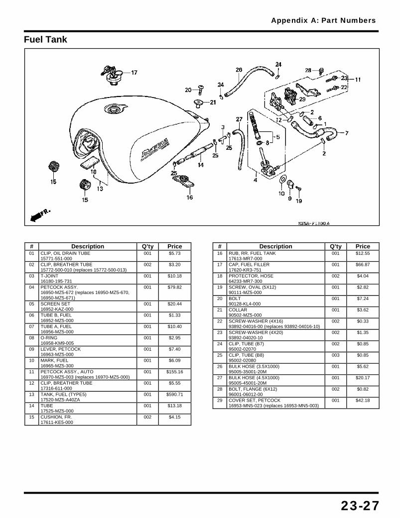
Appendix A: Part Numbers
23-27
Fuel Tank
# Description Q’ty Price 01 CLIP, OIL DRAIN TUBE
15771-551-000 001 $5.73
02 CLIP, BREATHER TUBE 15772-500-010 (replaces 15772-500-013)
002 $3.20
03 T-JOINT 16180-195-731
001 $10.18
04 PETCOCK ASSY. 16950-MZ5-672 (replaces 16950-MZ5-670, 16950-MZ5-671)
001 $79.82
05 SCREEN SET 16952-KAZ-000
001 $20.44
06 TUBE B, FUEL 16952-MZ5-000
001 $1.33
07 TUBE A, FUEL 16956-MZ5-000
001 $10.40
08 O-RING 16958-KM9-005
001 $2.95
09 LEVER, PETCOCK 16963-MZ5-000
001 $7.40
10 MARK, FUEL 16965-MZ5-300
001 $6.09
11 PETCOCK ASSY., AUTO 16970-MZ5-003 (replaces 16970-MZ5-000)
001 $155.16
12 CLIP, BREATHER TUBE 17316-611-000
001 $5.55
13 TANK, FUEL (TYPE5) 17520-MZ5-A40ZA
001 $590.71
14 TUBE 17525-MZ5-000
001 $13.18
15 CUSHION, FR. 17611-KE5-000
002 $4.15
# Description Q’ty Price 16 RUB, RR. FUEL TANK
17613-MR7-000 001 $12.55
17 CAP, FUEL FILLER 17620-KR3-751
001 $66.87
18 PROTECTOR, HOSE 64233-MR7-300
002 $4.04
19 SCREW, OVAL (5X12) 90111-MZ5-000
001 $2.82
20 BOLT 90128-KL4-000
001 $7.24
21 COLLAR 90502-MZ5-000
001 $3.62
22 SCREW-WASHER (4X16) 93892-04016-00 (replaces 93892-04016-10)
002 $0.33
23 SCREW-WASHER (4X20) 93892-04020-10
002 $1.35
24 CLIP, TUBE (B7) 95002-02070
002 $0.85
25 CLIP, TUBE (B8) 95002-02080
003 $0.85
26 BULK HOSE (3.5X1000) 95005-35001-20M
001 $5.62
27 BULK HOSE (4.5X1000) 95005-45001-20M
001 $20.17
28 BOLT, FLANGE (6X12) 96001-06012-00
002 $0.82
29 COVER SET, PETCOCK 16953-MN5-023 (replaces 16953-MN5-003)
001 $42.18

Appendix A: Part Numbers
23-28
Gasket Kit A
# Description Q’ty Price 00 GASKET KIT A
06111-MZ5-010 (replaces 06111-MZ5-000) 001 $171.63
01 GSKT, TENSIONER HOLE 12194-HC5-740
001 $1.78
02 GSKT, TENSIONER HOLE 12194-KW3-880
001 $1.67
03 SEAL, EX. VALVE STEM 12208-ML0-721
008 $8.07
04 SEAL, VALVE STEM 12209-MZ5-003
008 $7.69
05 GASKET, BTHR CVR 12231-MZ5-920 (replaces 12231-MZ5-000)
001 $12.02
# Description Q’ty Price 06 GASKET, CYL HD
12251-MT4-014 (replaces 12251-MT4-004) 002 $46.67
07 GASKET, CYL HD CVR 12391-MT4-000
002 $22.42
08 GASKET, EX. PIPE 18291-MN4-920
004 $4.22
09 WASHER (6.5MM) 90463-ML7-000
002 $2.25
10 RUBBER, SETTING 90543-MV9-670
008 $3.89
11 O-RING (21.2X2.4) 91331-PC9-003
002 $1.95
Gasket Kit B
# Description Q’ty Price 00 GASKET KIT B
06112-MZ5-000 001 $58.31
01 GASKET, OIL PAN 11315-MY7-000
001 $10.31
02 GASKET, L. 11343-MZ5-000
001 $4.57
03 GASKET, R. 11394-MY7-000
001 $18.08
04 GASKET, SHIFT COVER 11632-MY7-000
001 $9.47
05 GASKET 11636-MY7-000
001 $12.98
06 GASKET, OIL STRAINER 15154-ML7-000
001 $5.20
07 GASKET 19226-ML7-000
001 $3.53
08 WASHER (10MM) 90403-MG7-000
002 $2.62
09 WASHER (6.5MM) 90463-ML7-000
006 $2.25
10 GSKT, CONNECTING CAP 91301-MB0-000
002 $3.05
11 O-RING (48.1X3.6) 91301-ML7-003
001 $3.11
# Description Q’ty Price 12 O-RING (18.3X2.3)
91301-147-023 002 $1.42
13 O-RING (22X3.0) 91307-425-003 (replaces 91301-250-000)
001 $1.47
14 O-RING (32.95X2.62) 91302-MB0-013
001 $2.07
15 O-RING (6X2) 91307-ML7-004
002 $1.87
16 O-RING 91309-MA6-000
001 $2.93
17 O-RING (14.6X3.7) 91309-MB0-003
002 $2.93
18 O-RING (14.8X2.2) 91313-MG7-004 (replaces 91313-MB0-003)
001 $2.35
19 O-RING (7.7X2.3) 91301-PC9-003 (replaces 91308-283-000, 91313-393-003)
001 $1.45
20 SEAL, WATER PIPE 91315-MB0-013
001 $1.95
21 O-RING (8.4X2.4) 91316-MJ8-003
001 $1.87
22 O-RING (21.2X2.4) 91331-PC9-003
001 $1.95
23 WASHER, DRAIN (12MM) 94109-12000
001 $0.50

Appendix A: Part Numbers
23-29
Gearshift Drum
# Description Q’ty Price 01 FORK, R. GEARSHIFT
24211-MZ5-000 001 $52.64
02 FORK 24212-ML7-000
001 $58.36
03 FORK, L. GEARSHIFT 24213-ML7-000
001 $66.61
04 SHAFT 24261-ML7-000
001 $35.95
05 DRUM, GEARSHIFT 24310-MZ5-000
001 $132.91
06 CENTER 24312-KT7-752
001 $26.78
07 PIN, SHIFTER 24315-HA0-000
001 $9.58
08 SHIFTER, DRUM 24321-KT8-030
001 $39.36
09 COLLAR, SHIFTER 24322-MM4-000
001 $4.00
10 PAWL A, RATCHET 24324-KA3-711
001 $10.02
11 PAWL B, RATCHET 24325-KA3-711
001 $10.02
12 PLUNGER, PAWL 24326-KBH-901
002 $4.56
13 PLATE, GUIDE 24328-MR7-010
001 $13.07
14 SPRING, PAWL PLUNGER 24329-KA3-740
002 $2.07
15 COLLAR 24329-KT7-000
001 $3.89
16 STOPPER, DRUM 24430-MR7-000
001 $18.04
# Description Q’ty Price 17 COLLAR, DRUM STOPPER
24434-MR7-000 001 $6.36
18 SPRING 24435-KBV-000
001 $3.40
19 SPINDLE, GEARSHIFT 24610-MR7-000
001 $79.90
20 SPRING 24651-MR7-000
001 $5.71
21 PIN 24652-035-000
001 $3.13
22 PLATE 24655-MR7-000
001 $9.67
23 SWITCH, NEUTRAL 35600-KE8-003 (replaces 35600-KE8-010)
001 $14.33
24 WASHER (14MM) 90451-155-000
001 $3.15
25 WASHER (12MM) 90485-MR7-000
002 $3.76
26 WASHER, OIL BOLT 90545-300-000
001 $2.18
27 BEARING (16005) 91008-374-003
001 $11.40
28 PIN, DOWEL (8X31.5) 91104-KT7-000
002 $3.51
29 CIRCLIP (12MM) 94510-12000
001 $1.02
30 CIRCLIP (14MM) 94510-14000
001 $0.57
31 BOLT, FLANGE (6X45) 95701-06045-07 (replaces 95701-06045-00)
002 $0.97
32 ROLLER (4X8) 96220-40080
001 $0.33
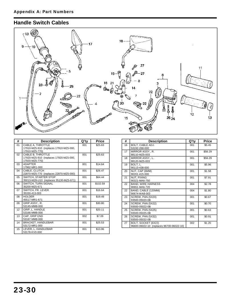
Appendix A: Part Numbers
23-30
Handle Switch Cables
# Description Q’ty Price 01 CABLE A, THROTTLE
17910-MZ5-910 (replaces 17910-MZ5-000, 17910-MZ5-770)
001 $25.63
02 CABLE B, THROTTLE 17920-MZ5-910 (replaces 17920-MZ5-000, 17920-MZ5-770)
001 $25.63
03 ADAPTER 17962-MR1-000
001 $14.64
04 CABLE, CLUTCH 22870-MZ5-770 (replaces 22870-MZ5-000)
001 $26.47
05 SWITCH, STARTER STOP 35013-MZ8-U10 (replaces 35130-MZ5-671)
001 $64.44
06 SWITCH, TURN SIGNAL 35200-MZ5-671
001 $102.59
07 SWITCH, FR. LEVER 35330-413-003
001 $16.64
08 HOLDER 45517-MR1-671
001 $19.49
09 GRIP ASSY., R. 53145-MM8-000
001 $30.80
12 GRIP, L. HANDLE 53166-MM8-000
001 $20.11
13 CAP, GRIP END 53167-MM8-000
002 $7.09
14 BRACKET, HANDLEBAR 53172-MR1-000
001 $25.53
15 LEVER, L. HANDLEBAR 53178-KV0-000
001 $13.96
# Description Q’ty Price 16 BOLT, CABLE ADJ.
53192-268-000 001 $5.45
17 MIRROR ASSY., R. 88110-MZ5-003
001 $56.29
18 MIRROR ASSY., L. 88120-MZ5-003
001 $56.29
19 BOLT, L. 90113-438-000
001 $5.96
20 NUT, CAP (6MM) 90201-415-000
001 $1.58
21 NUT, FIXING 90321-MA6-750
001 $7.91
22 BAND, WIRE HARNESS 90651-MA6-720
004 $2.78
22 BAND, CABLE (120MM) 90674-WA8-003
004 $1.80
23 SCREW, PAN (5X20) 93500-05020-0B
001 $0.67
24 SCREW, PAN (5X22) 93500-05022-0B
001 $0.70
25 SCREW, PAN (5X25) 93500-05025-0B
001 $0.63
26 SCREW, PAN (5X32) 93500-05032-0B
001 $0.91
27 BOLT, SOCKET (6X22) 96600-06022-10 (replaces 96700-06022-10)
002 $1.20

Appendix A: Part Numbers
23-31
Handlebar
# Description Q’ty Price 01 HANDLEBAR
53101-MZ5-000 001 $142.97
02 HLDR, HANDLE (UPPER) 53131-MM8-000
002 $14.58
03 HLDR, HANDLE (LOWER) 53231-MM8-000
002 $25.84
04 BRIDGE, FORK TOP 53300-MZ5-000
001 $217.98
05 EMBLEM, WING MARK 86150-MR1-760
001 $5.91
06 BOLT, SOCKET (8X30) 90112-KM4-000
002 $2.98
# Description Q’ty Price 07 BOLT, SOCKET (8X32)
90154-ME9-000 004 $4.47
08 NUT, STEERING STEM 90304-415-000
001 $15.02
09 NUT, FLANGE (8MM) 90309-428-731
002 $2.98
10 WASHER 90503-283-000
001 $3.51
11 WASHER 90535-KB9-000
002 $4.67
12 CAP (8MM) 91455-MB0-010
004 $2.95

Appendix A: Part Numbers
23-32
Headlight
# Description Q’ty Price 01 HDLT (12V 60/55W)
33100-MK7-671 001 $182.85
02 RIM, HEADLIGHT 33101-MK7-671
001 $47.61
03 STAY 33102-MK7-671
001 $8.07
04 SCREW, BEAM ADJ. 33103-MK7-671
002 $3.22
05 SCREW, SPECIAL 33104-MK7-671
002 $2.33
06 NUT, SPECIAL 33105-MK7-671
002 $3.33
07 SCREW, SPECIAL 33106-MK7-671
001 $2.33
08 SPRING 33107-MK7-671
002 $2.98
09 SPRING, SETTING 33108-MK7-671
002 $2.33
10 NUT, BEAM ADJUSTING 33117-415-003
002 $1.60
11 HEADLIGHT UNIT 33120-MK7-671
001 $78.44
12 NUT, UNIT HOLDER 33128-471-003
001 $1.20
13 CVR, ADJUSTING SCREW 33136-111-671
002 $1.44
14 COVER, RUBBER 33180-MJ0-010
001 $11.67
# Description Q’ty Price 15 BULB (12V60/55W)
34901-MC7-601AH (replaces 34901-MC7-601)
001 $7.65
16 CASE, HEADLIGHT 61301-MN0-003
001 $73.70
17 COLLAR 61304-292-000
002 $2.73
18 STAY, HEADLIGHT 61305-MZ5-000
001 $49.05
19 RUBBER 61315-MZ5-000
004 $2.07
20 COLR, HEADLIGHT STAY 61316-MK7-000
002 $2.33
21 BOLT, CAP (6MM) 90132-MK7-000
002 $2.25
22 NUT, CAP (6MM) 90201-425-700
002 $3.33
23 NUT, U (6MM) 90301-MG3-000
002 $5.40
24 SCREW, PAN (5X16) 93500-05016-0B
002 $0.68
25 SCREW, TAP (4X10) 93901-34210
002 $0.47
26 WASHER, SPRING (5MM) 94111-05000
002 $0.50
27 CLIP (4X90) 94591-49000
002 $2.38

Appendix A: Part Numbers
23-33
Mark VF750C (1994-1997)
# Description Q’ty Price 01 MARK A (TYPE1)
87121-MZ5-300ZA 002 $34.98
01 MARK A (TYPE2) 87121-MZ5-300ZB
002 $34.98
# Description Q’ty Price 01 MARK A (TYPE3)
87121-MZ5-300ZC 002 $34.98

Appendix A: Part Numbers
23-34
Mark VF750C (1998-2003)
# Description Q’ty Price 01 MARK (TYPE5)
87121-MZ5-A00ZA 002 $24.02
01 MARK (TYPE6) 87121-MZ5-A40ZA
002 $20.96
# Description Q’ty Price 01 MARK (TYPE7)
87121-MZ5-M10ZA 002 $22.60

Appendix A: Part Numbers
23-35
Mark VF750CD (1996-1997)
# Description Q’ty Price 01 MARK (TYPE10)
64221-MZ5-870ZA 001 $20.29
01 MARK (TYPE9) 64221-MZ5-870ZB
001 $20.29
02 STRIPE, RR. (TYPE1) 80111-MZ5-950ZA
001
02 STRIPE, RR. (TYPE2) 80111-MZ5-950ZB
001 $96.40
02 STRIPE, RR. (TYPE3) 80111-MZ5-A10ZA
001 $79.53
02 STRIPE, RR. (TYPE4) 80111-MZ5-A10ZB
001 $79.53
03 MARK (TYPE1) 87121-MZ5-950ZA
002 $26.47
03 MARK (TYPE2) 87121-MZ5-950ZB
002 $26.47
03 MARK (TYPE3) 87121-MZ5-A10ZA
002 $23.38
# Description Q’ty Price 03 MARK (TYPE4)
87121-MZ5-A10ZB 002 $21.73
04 STRIPE, R. (TYPE1) 87123-MZ5-950ZA
001 $93.75
04 STRIPE, R. (TYPE2) 87123-MZ5-950ZB
001 $93.75
04 STRIPE, R. (TYPE3) 87123-MZ5-A10ZA
001 $82.16
04 STRIPE, R. (TYPE4) 87123-MZ5-A10ZB
001 $76.33
05 STRIPE, L. (TYPE1) 87124-MZ5-950ZA
001 $93.75
05 STRIPE, L. (TYPE2) 87124-MZ5-950ZB
001 $93.75
05 STRIPE, L. (TYPE3) 87124-MZ5-A10ZA
001 $82.16
05 STRIPE, L. (TYPE4) 87124-MZ5-A10ZB
001 $76.33
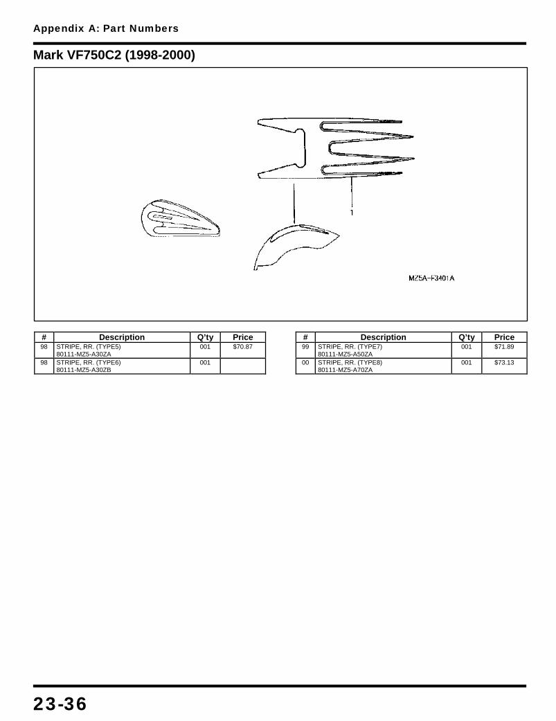
Appendix A: Part Numbers
23-36
Mark VF750C2 (1998-2000)
# Description Q’ty Price 98 STRIPE, RR. (TYPE5)
80111-MZ5-A30ZA 001 $70.87
98 STRIPE, RR. (TYPE6) 80111-MZ5-A30ZB
001
# Description Q’ty Price 99 STRIPE, RR. (TYPE7)
80111-MZ5-A50ZA 001 $71.89
00 STRIPE, RR. (TYPE8) 80111-MZ5-A70ZA
001 $73.13

Appendix A: Part Numbers
23-37
Muffler
# Description Q’ty Price 01 MUFFLER, R. EX.
18100-MZ5-003 001 $699.35
02 MUFFLER, L. EX. 18200-MZ5-003
001 $699.35
03 GASKET, EX. PIPE 18291-MN4-920
004 $4.22
04 RUBBER 18293-ME9-000
002 $1.95
05 PIPE, R. FR. EX. 18320-MZ5-981 (replaces 18320-MZ5-003)
001 $114.12
06 CVR, R. FR. EX. PIPE 18340-MZ5-003
001 $105.55
07 JOINT, R. RR. CYL HD 18350-MZ5-003
001 $87.87
08 BAND, R. EX. PIPE 18373-ML4-003
001 $21.73
09 BAND, EX. PIPE 18373-KAB-000 (replaces 18373-MN1-670)
001 $15.44
10 BAND, L. EX. PIPE 18374-ML4-003
001 $12.42
11 BAND, L. EX. PIPE 18374-MN1-670
001 $10.95
12 BAND, EX. PIPE COVER 18376-MR1-000
006 $6.45
13 CVR, R. RR. EX. PIPE 18380-MZ5-003
001 $96.68
14 GASKET, MUFFLER 18391-MB0-891
002 $13.58
15 GASKET, MUFFLER 18391-ML8-000
002 $13.73
16 PIPE, L. FR. EX. 18420-MZ5-981 (replaces 18420-MZ5-003)
001 $114.12
# Description Q’ty Price 17 RUB, MUFFLER SETTING
18421-MB0-000 002 $4.98
18 COLLAR 18422-MB0-000
002 $5.22
19 CVR, L. FR. EX. PIPE 18440-MZ5-003
001 $106.57
20 JOINT, L. RR. CYL HD 18450-MZ5-003
001 $87.87
21 CVR, L. RR. EX. PIPE 18480-MZ5-003
001 $99.99
22 RUBBER, STOPPER 50501-KT7-810
002 $3.09
23 RUBBER, BATTERY BOX 83618-GF0-751
001 $3.05
24 BOLT (8X50) 90109-MZ5-000
002 $5.11
25 BOLT, FLANGE (8X35) 90161-ML7-000
004 $2.84
26 NUT, SPECIAL (6MM) 90304-HB3-771
004 $4.76
27 NUT, FLANGE (6MM) 94050-06000
004 $0.72
28 NUT, FLANGE (8MM) 94050-08070
002 $0.33
29 WASHER, PLAIN (8MM) 94103-08000
002 $0.29
30 WASHER, PLAIN (8MM) 94103-08700
002 $0.45
31 WASHER, SPRING (6MM) 94111-06800
004 $0.50
32 BOLT, FLANGE (6X20) 95701-06020-00
006 $0.60
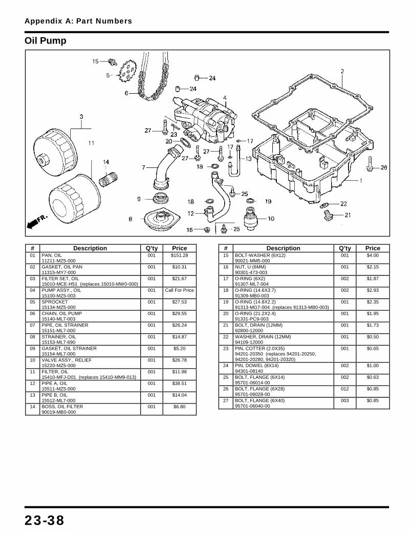
Appendix A: Part Numbers
23-38
Oil Pump
# Description Q’ty Price 01 PAN, OIL
11211-MZ5-000 001 $151.28
02 GASKET, OIL PAN 11315-MY7-000
001 $10.31
03 FILTER SET, OIL 15010-MCE-H51 (replaces 15010-MW0-000)
001 $21.67
04 PUMP ASSY., OIL 15100-MZ5-003
001 Call For Price
05 SPROCKET 15134-MZ5-000
001 $27.53
06 CHAIN, OIL PUMP 15140-ML7-003
001 $29.55
07 PIPE, OIL STRAINER 15151-ML7-000
001 $26.24
08 STRAINER, OIL 15153-ML7-690
001 $14.87
09 GASKET, OIL STRAINER 15154-ML7-000
001 $5.20
10 VALVE ASSY., RELIEF 15220-MZ5-000
001 $26.78
11 FILTER, OIL 15410-MFJ-D01 (replaces 15410-MM9-013)
001 $11.98
12 PIPE A, OIL 15511-MZ5-000
001 $38.51
13 PIPE B, OIL 15512-ML7-000
001 $14.04
14 BOSS, OIL FILTER 90019-MB0-000
001 $6.80
# Description Q’ty Price 15 BOLT-WASHER (6X12)
90021-MM5-000 001 $4.00
16 NUT, U (6MM) 90301-473-003
001 $2.15
17 O-RING (6X2) 91307-ML7-004
002 $1.87
18 O-RING (14.6X3.7) 91309-MB0-003
002 $2.93
19 O-RING (14.8X2.2) 91313-MG7-004 (replaces 91313-MB0-003)
001 $2.35
20 O-RING (21.2X2.4) 91331-PC9-003
001 $1.95
21 BOLT, DRAIN (12MM) 92800-12000
001 $1.73
22 WASHER, DRAIN (12MM) 94109-12000
001 $0.50
23 PIN, COTTER (2.0X35) 94201-20350 (replaces 94201-20250, 94201-20280, 94201-20320)
001 $0.65
24 PIN, DOWEL (8X14) 94301-08140
002 $1.00
25 BOLT, FLANGE (6X14) 95701-06014-00
002 $0.63
26 BOLT, FLANGE (6X28) 95701-06028-00
012 $0.85
27 BOLT, FLANGE (6X40) 95701-06040-00
003 $0.85

Appendix A: Part Numbers
23-39
Pedal
# Description Q’ty Price 01 PEDAL, GEARSHIFT
24705-MZ5-700 (replaces 24705-MZ5-000) 001 $54.18
02 RUBBER, DUST SEAL 24706-MK3-770
002 $3.51
03 ARM, GEARSHIFT 24706-MZ5-000
001 $35.67
04 COVER, DUST 24724-422-000
002 $5.67
05 RUB, GEARSHIFT PEDAL 24781-KR3-770
001 $2.65
06 SWITCH, RR. STOP 35350-MZ5-003
001 $12.13
07 SPRING, STOP SWITCH 35357-MF8-000
001 $3.71
08 ROD, RR. BRAKE 43451-MZ5-000
001 $24.84
09 PIN 43456-MK7-000
002 $6.45
10 PEDAL, BRAKE 46500-MZ5-000
001 $62.88
11 ARM, RR. 46501-MZ5-000
001 $29.73
12 SPRING SET 46513-KY7-000
001 $7.96
13 TUBE 46515-KY7-000
001 $3.86
14 COLLAR, RR. 46515-MM8-000
001 $8.89
15 ARM, RR. 46530-MZ5-000
001 $10.51
16 ROD, RR. 46540-MZ5-000
001 $44.51
17 BOLT, TIE ROD 90065-MN4-000
001 $3.89
18 BOLT, CHANGE PIVOT 90115-KAF-000
001 $14.96
# Description Q’ty Price 19 BOLT, SOCKET (10X52)
90153-MW0-000 001 $5.04
20 NUT 90201-700-000
001 $0.55
21 WASHER (10.3MM) 90527-230-000
001 $1.44
22 DUST SEAL (17X23X3) 91206-968-003
002 $2.98
23 BOLT, HEX. (6X18) 92101-06018-0A
001 $0.62
24 NUT, HEX. (6MM) 94001-06020-0S
001 $0.63
25 NUT, HEX. (6MM) 94002-06000-0S
001 $1.60
26 NUT, FLANGE (8MM) 94050-08000
001 $0.67
27 NUT, FLANGE (10MM) 94050-10000
001 $0.93
28 PIN, SPLIT (2.0X12) 94201-20120
001 $0.47
29 PIN, SPLIT (2.0X15) 94201-20150
002 $0.35
30 SPRING A, BRAKE ROD 95014-73100
001 $0.53
31 JOINT, BRAKE ARM 95015-32001
001 $0.49
32 NUT B 95015-42000
001 $1.40
33 PIN, JOINT 95015-53000
001 $2.42
34 BOLT, FLANGE (8X25) 95701-08025-00
001 $1.00
35 BOLT, FLANGE (6X20) 96001-06020-00
001 $0.83

Appendix A: Part Numbers
23-40
Pulse Generator
# Description Q’ty Price 01 GEAR (21T/83T)
28101-ML7-920 001 $76.41
02 PIN (10X36.5) 28102-ML7-000
001 $6.56
03 GEAR (48T) 28110-MB0-010
001 $109.19
04 FLANGE 28115-MZ5-000
001 $73.01
05 CLUTCH, STARTER 28120-MZ5-000
001 $152.21
06 SPRING 28125-MT4-000
003 $1.42
07 CAP 28126-415-000
003 $12.98
08 GEN, IGNITION PULSE 30300-MZ5-003 (replaces 30300-MZ5-000)
001 $98.46
09 BOLT, FLANGE (12X45) 90023-MA6-000
001 $7.96
# Description Q’ty Price 10 WASHER (12X30X4.5)
90401-KK9-960 001 $7.91
11 WASHER (18X10.2) 90405-ML7-000
001 $2.84
12 PIN, DOWEL (8X8) 90702-MB0-000
002 $2.73
13 BEARING (30X35X17) 91022-MB0-004 (replaces 91022-MB0-003)
001 $26.51
14 ROLLER (15X13) 91101-516-000
003 $4.53
15 BOLT, FLANGE (8X14) 95701-08014-08
003 $0.78
16 BOLT, FLANGE (6X25) 96001-06025-00
003 $0.93
17 ROLLER (6X15) 96220-60150
001 $0.62

Appendix A: Part Numbers
23-41
Radiator
# Description Q’ty Price 01 RADIATOR COMP
19010-MZ5-P00 (replaces 19010-MZ5-671) 001 $612.40
02 SHROUD 19015-MZ5-003
001 $57.00
03 FAN, COOLING 19025-MN4-003
001 $42.05
04 MOTOR ASSY., FAN 19030-MZ5-003
001 $240.71
05 CAP, RADIATOR 19045-MY3-671
001 $30.69
06 RUBBER 19051-KA3-830
004 $2.67
07 COLLAR 19052-MN8-000
003 $2.04
08 TANK, RESERVE 19101-MZ5-000
001 $30.89
09 CAP, RESERVE TANK 19104-MB0-700
001 $9.24
10 TUBE, RESERVE TANK 19106-MZ5-000
001 $25.16
11 GRILLE, RADIATOR 19112-MZ5-670 (replaces 19110-MZ5-000)
001 $70.69
12 PROTR, RADIATOR HOSE 19120-MZ5-910 (replaces 19120-MZ5-000)
001 $36.55
13 PROTR, RADIATOR HOSE 19121-MZ5-000
001 $10.15
14 THERMOSTAT ASSY. 19300-ML7-003
001 $33.89
15 COVER, THERMOSTAT 19311-MZ5-000
001 $60.67
16 COVER, THERMOSTAT 19315-MV9-670
001 $48.56
17 HOSE, RADIATOR 19500-MZ5-000
001 $20.91
18 HOSE, RADIATOR 19501-MZ5-000
001 $29.96
19 HOSE, FR. 19502-MZ5-000
001 $13.64
20 HOSE, RR. HEAD WATER 19503-MZ5-000
001 $12.42
21 GUIDE, WATER HOSE 19504-MZ5-000
001 $7.71
# Description Q’ty Price 22 CLAMP B, WATER HOSE
19506-KS6-700 004 $6.13
23 CLAMP, HOSE (30-37) 19516-GAG-003
004 $10.95
24 CONNECTOR, GROUND 32152-MB3-000
001 $1.33
25 REFLECTOR, FR. 33740-KR3-671
002 $22.31
26 SENDING UNIT 37750-PC1-004
001 $43.83
27 SWITCH, THERMOSTAT 37760-MT2-003
001 $49.49
28 NUT, SPECIAL (6X7) 61304-958-003 (replaces 90301-471-000)
001 $2.64
29 NUT, SERRATE (5MM) 90315-MK3-003
004 $1.67
30 WASHER, FR. 90556-MB4-000
001 $1.91
31 O-RING (13.5X1.4) 91307-PH7-660 (replaces 91307-611-000)
001 $1.72
32 O-RING (47.5X2) 91311-KE8-000
001 $1.64
32 O-RING (45.5X2.5) 91373-733-003
001 $3.20
33 SCREW, TAPPING (3X8) 93901-22180
001 $0.47
34 NUT, FLANGE (6MM) 94050-06000
001 $0.72
34 CLIP, TUBE (B10) 95002-02100
003 $0.90
35 BULK HOSE (5.5X3000) 95005-55003-20M
001 $18.33
36 BOLT, FLANGE (6X12) 95701-06012-00
002 $0.72
37 BOLT, FLANGE (6X22) 95701-06022-00
001 $0.72
38 BOLT, FLANGE (6X10) 96001-06010-00
003 $0.85
39 BOLT, FLANGE (6X22) 96001-06022-00
003 $0.91
40 BOLT, SOCKET (6X25) 96600-06025-07
003 $0.88

Appendix A: Part Numbers
23-42
Rear Brake Panel
# Description Q’ty Price 01 SHOE KIT, BRAKE
06430-MZ5-003 001 $40.27
02 AXLE, RR. WHEEL 42301-MZ5-003
001 $47.41
03 COLR, RR. WHEEL SIDE 42311-MZ1-610 (replaces 42311-MZ1-000)
001 $16.18
04 COLLAR, RR. 42313-MZ5-000
001 $15.69
05 PANEL, RR. 43100-MJ1-832
001 $182.85
06 WASHER, ANCHOR PIN 43102-319-000
001 $4.96
07 TUBE 43124-MZ5-000
002 $5.48
08 DUST SEAL, BRAKE CAM 43134-300-000
001 $1.62
09 CAM, RR. BRAKE 43141-MB0-010 (replaces 43141-MB0-000)
001 $28.64
# Description Q’ty Price 10 INDICATOR, RR. BRAKE
43145-ME5-000 001 $4.58
11 SPRING, RR. 43151-346-000
002 $4.64
12 ARM, RR. BRAKE 43410-MZ5-000
001 $26.58
13 BOLT, FLANGE (8X25) 90107-MZ5-000
001 $3.65
14 NUT, U (18MM) 90305-KZ4-891 (replaces 90305-KZ4-890)
001 $11.42
15 WASHER (18X32X2) 90401-KZ4-890
001 $3.58
16 WASHER, RR. AXLE 90559-MJ0-630
001 $10.16
17 PIN, COTTER (2.5MM) 94201-25300 (replaces 94201-25200, 94201-25250)
002 $0.53

Appendix A: Part Numbers
23-43
Rear Cylinder Head
# Description Q’ty Price 01 CYLINDER HEAD, RR.
12020-MZ5-315 001 $834.03
01 CYLINDER HEAD, RR. 12020-MZ5-316
001 $834.03
02 GUIDE, VALVE (OS) 12204-MT4-305
008 $16.15
03 GASKET, CYL HD 12251-MT4-014 (replaces 12251-MT4-004)
001 $46.67
04 FIN A, CYLINDER HEAD 12350-MZ5-000
001 $113.93
05 RUBBER, SEAT 12352-MZ5-300
002 $2.44
06 FIN B, CYLINDER HEAD 12360-MZ5-000
001 $73.62
07 INSULATOR, CARB 16211-MZ5-000
002 $38.78
08 JOINT, BOOSTER 16214-MB0-000
002 $3.51
09 BAND A, INSULATOR 16219-MM4-000
002 $8.07
10 BAND B, INSULATOR 16220-MM4-000
002 $8.07
11 BOLT, FLANGE (9X93) 90007-ML7-920
008 $7.85
# Description Q’ty Price 12 BOLT, SOCKET (6X28)
90012-MZ5-000 006 $1.60
13 BOLT, FLG (6X45.5) 90017-MA6-000
008 $2.62
14 BOLT, FLG (6X39.5) 90019-MA6-000
008 $2.25
15 BOLT, STUD (6X22) 90036-MZ5-000
004 $4.29
16 WASHER (9MM) 90445-MM4-000
008 $2.82
17 WASHER (5MM) 90452-323-000
002 $0.85
18 SCREW, PAN (5X8) 93500-05008-0A
002 $0.45
19 PIN, DOWEL (8X14) 94301-08140
008 $1.00
20 PIN, DOWEL (12X20) 94301-12200
002 $1.17
21 BOLT, FLANGE (6X30) 95701-06030-00
002 $0.83
22 SPARK PLUG (CR9EH9) 98059-59916 (replaces 98059-58926, 98059-59910)
002 $8.14

Appendix A: Part Numbers
23-44
Rear Fender
# Description Q’ty Price 01 REFLECTOR, REFLEX
33741-MS6-921 001 $10.55
02 RUB, METER CUSHION 37215-MA6-008
002 $2.33
03 GROMMET, ENG HGR 50370-HA2-770
003 $1.51
04 RUBBER, BATTERY 50383-GB6-300
002 $3.24
05 GROM, SPEAKER PANEL 64266-MG9-770
001 $2.45
06 COLLAR, ROTO-STOP 75133-960-000
002 $2.58
07 GRAB RAIL, R. 77330-MZ5-000
001 $105.00
08 GRAB RAIL, L. 77340-MZ5-000
001 $105.00
09 FENDER B,REAR 80100-MZ5-000YB (replaces 80100-MZ5-000ZC)
001 $164.39
09 FENDER B *Y124P* 80100-MZ5-000ZD
001 $180.00
09 FENDER B, RR. *R201* 80100-MZ5-000ZE
001 $154.24
10 BRKT, NUMBER PLATE 80101-MZ5-670
001 $40.85
11 STAY, RR. REFLECTOR 80102-MM8-010
001 $17.82
12 GROM, ENGINE COVER 80103-GJ5-000
002 $1.55
13 FENDER A, RR. 80105-MZ5-000
001 $66.36
# Description Q’ty Price 14 SUB-FRAME, RR.
80125-MZ5-000 001 $149.92
15 GROMMET, SIDE COVER 83601-MN5-000
001 $2.25
16 RUBBER 84702-MF2-670
002 $3.11
17 BOLT (8X56) 90064-KK3-830
004 $3.55
18 BOLT 90215-ML0-000
002 $1.60
19 NUT 90305-SH3-000
002 $3.65
20 NUT, CAP (8MM) 90443-107-000
004 $2.30
21 WASHER, PLAIN (8MM) 90518-921-000
004 $1.12
22 PLUG, CONE TYPE 90899-422-610
003 $1.45
23 CLIP, WIRE 91406-166-000
002 $2.93
24 BOLT, HEX. (6X10) 92101-06010-0G
002 $0.67
25 NUT, HEX. (6MM) 94002-06070-0S
002 $0.55
26 NUT, FLANGE (5MM) 94050-05000
001 $0.60
27 NUT, FLANGE (6MM) 94050-06070
002 $0.73
28 BOLT, FLANGE (6X12) 95701-06012-00
002 $0.72

Appendix A: Part Numbers
23-45
Rear Shock Absorber
# Description Q’ty Price 01 SHOCK ABSORBER, RR.
52400-MZ5-672 (replaces 52400-MZ5-671) 002 $306.24
02 BUSH, RR. SHOCK 52485-KR3-003
002 $3.76
03 COLLAR, RUBBER BUSH 52486-GA7-003
002 $2.91
04 BUSH, RUBBER (UPPER) 52489-GS3-003
002 $3.58
# Description Q’ty Price 05 BOLT, FLANGE (8X16)
90106-MB2-000 002 $3.18
06 WASHER, PLAIN 90501-MZ5-000
002 $1.91
07 BOLT, FLANGE (10X35) 95817-10035-00 (replaces 95801-10035-00)
002 $1.23

Appendix A: Part Numbers
23-46
Rear Wheel
# Description Q’ty Price 01 SPROCKET (40T)
41200-MZ5-770 (replaces 41200-MA3-000, replaces 41200-MZ5-670)
001 $127.81
02 ARRESTER, NOISE 41212-MK4-010 (replaces 41212-MK4-000)
001 $8.29
03 DAMPER, RR. WHEEL 41241-MM5-000
005 $10.47
04 SLEEVE, RR. AXLE 42606-MS2-000
001 $15.93
05 FLANGE, FINAL DRIVEN 42610-MS2-000
001 $243.35
06 COLLAR, RR. 42620-MZ5-000
001 $19.36
07 WHEEL SET, RR. 42650-MZ5-305
001 $705.94
08 WEIGHT (10G) 42704-MB0-000
AR $9.07
08 WEIGHT (20G) 42705-MB0-000
AR $10.36
08 WEIGHT, BALANCE (20) 42705-MCF-D60
AR $10.36
# Description Q’ty Price 08 WEIGHT, BALANCE (30)
42706-MCF-D60 (replaces 42706-MB0-000) AR $10.36
09 TIRE, RR. 42711-MZ5-024 (replaces 42710-MZ5-004, 42711-MZ5-004)
001 $152.63
11 VALVE, RIM 42753-ML7-004
001 $9.67
12 NUT, FLANGE (12MM) 90306-KF0-003
005 $3.15
13 OIL SEAL (34X62.2X7) 90753-MG5-670
001 $9.20
14 BEARING,BALL RADI 91051-MBT-611 (replaces 91051-MAT-003, 91051-MM5-003)
001 $23.11
15 BEARING (6204UU) 91052-MM5-003
001 $23.13
16 BEARING (6304UU) 91053-MM5-004
001 $24.36
17 O-RING (69X2) 91302-MS2-003
001 $3.07
18 BOLT, STUD (12X28) 92918-12028-0E
005 $2.15
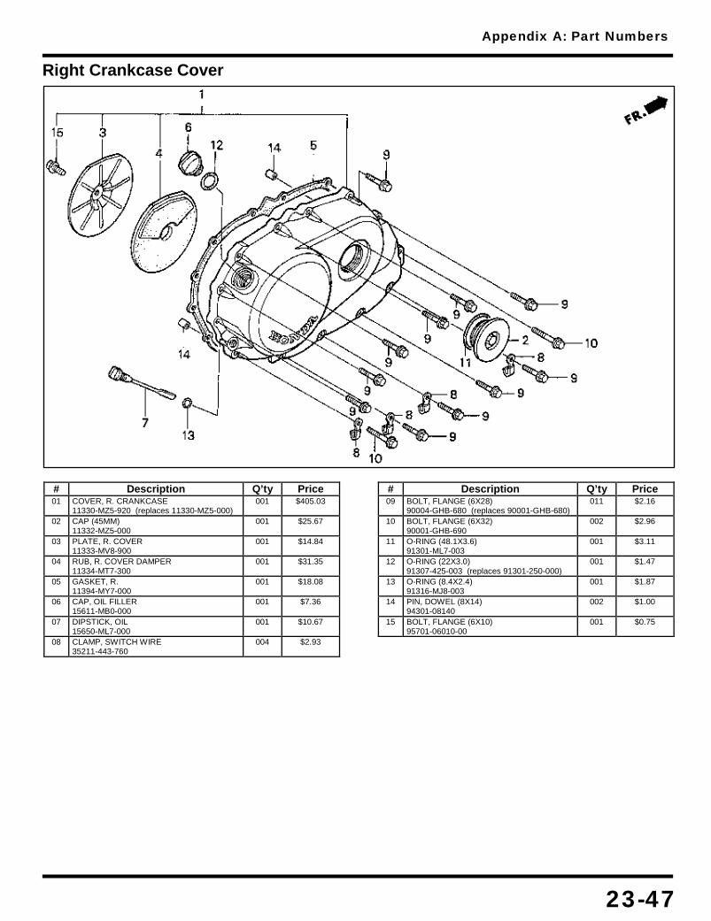
Appendix A: Part Numbers
23-47
Right Crankcase Cover
# Description Q’ty Price 01 COVER, R. CRANKCASE
11330-MZ5-920 (replaces 11330-MZ5-000) 001 $405.03
02 CAP (45MM) 11332-MZ5-000
001 $25.67
03 PLATE, R. COVER 11333-MV8-900
001 $14.84
04 RUB, R. COVER DAMPER 11334-MT7-300
001 $31.35
05 GASKET, R. 11394-MY7-000
001 $18.08
06 CAP, OIL FILLER 15611-MB0-000
001 $7.36
07 DIPSTICK, OIL 15650-ML7-000
001 $10.67
08 CLAMP, SWITCH WIRE 35211-443-760
004 $2.93
# Description Q’ty Price 09 BOLT, FLANGE (6X28)
90004-GHB-680 (replaces 90001-GHB-680) 011 $2.16
10 BOLT, FLANGE (6X32) 90001-GHB-690
002 $2.96
11 O-RING (48.1X3.6) 91301-ML7-003
001 $3.11
12 O-RING (22X3.0) 91307-425-003 (replaces 91301-250-000)
001 $1.47
13 O-RING (8.4X2.4) 91316-MJ8-003
001 $1.87
14 PIN, DOWEL (8X14) 94301-08140
002 $1.00
15 BOLT, FLANGE (6X10) 95701-06010-00
001 $0.75

Appendix A: Part Numbers
23-48
Seat
# Description Q’ty Price 01 RUB, SEAT MOUNTING
77110-KA3-730 002 $3.96
02 SEAT ASSY. 77200-MZ5-000
001 $308.50
03 STAY A, RR. SEAT 77206-MZ5-000
001 $15.89
04 STAY B, RR. SEAT 77207-MZ5-000
001 $12.82
# Description Q’ty Price 05 RUBBER B
77215-GC2-000 002 $3.96
06 SEAT ASSY., RR. 77300-MZ5-000
001 $188.28
07 BOLT (8X12) 90125-KR3-000
003 $3.07
08 NUT, FLANGE (6MM) 94050-06080
006 $0.23

Appendix A: Part Numbers
23-49
Side Cover
# Description Q’ty Price 01 RUBBER B, STOPPER
50354-428-000 002 $2.09
02 CAP, STEP HOLDER END 50713-ML0-720
002 $2.16
03 GROMMET, A/CLNR HSG 83551-300-000
004 $2.96
04 COVER, R. SIDE *NH1* 83650-MZ5-000ZC
001 $95.47
04 CVR, R. SIDE *Y124P* 83650-MZ5-000ZD
001 $84.82
# Description Q’ty Price 04 CVR, R. SIDE *R201*
83650-MZ5-000ZE 001 $142.83
05 COVER, L. SIDE *NH1* 83750-MZ5-000ZC
001 $84.82
05 CVR, L. SIDE *Y124P* 83750-MZ5-000ZD
001 $84.82
05 CVR, L. SIDE *R201* 83750-MZ5-000ZE
001 $152.19

Appendix A: Part Numbers
23-50
Speedometer Tachometer

Appendix A: Part Numbers
23-51
# Description Q’ty Price 01 BULB (12V3W)
34908-KM1-671 006 $1.68
02 BULB (12V1.7W) 34908-MB9-871
001 $1.95
03 BULB (12V1.4W) 34908-MN8-700
002 $2.27
04 METER, COMBINATION 37100-MZ5-671
001 $974.79
05 SPEEDOMETER ASSY. 37200-MZ5-671
001 $363.85
06 COVER, SPEEDOMETER 37202-MZ5-008
001 $58.98
07 RUBBER, SPEEDOMETER 37204-MK4-611
001 $7.15
08 BRKT, METER (LOWER) 37211-MZ5-008
001 $65.47
09 BRKT, METER (UPPER) 37212-MZ5-008
001 $57.34
10 RUBBER 37213-MW3-671
001 $7.27
11 COVER, METER BRACKET 37214-MZ5-008
001 $70.22
12 CLAMP 37215-KM1-670
001 $1.53
13 RUB, BRACKET SETTING 37215-MW3-671
003 $1.60
14 GUIDE, R. CABLE 37216-MZ5-000
001 $8.82
15 GUIDE, L. CABLE 37217-MZ5-000
001 $10.78
16 KNOB, TRIP METER 37220-MB4-671
001 $10.04
17 SOCKET 37224-MZ5-008
001 $35.71
18 BAND, SELF-LOCK 37226-MZ5-008
002 $2.35
19 WASHER, PLAIN 37244-MA6-008
003 $1.60
20 TACHOMETER ASSY. 37250-MZ5-671
001 $409.83
21 COVER, TACHOMETER 37252-MZ5-008
001 $59.10
22 RUBBER 37253-MK4-611
002 $2.33
23 RUBBER, TACHOMETER 37254-MK4-611
001 $7.15
24 RUBBER 37255-MK4-611
002 $2.33
# Description Q’ty Price 25 CUSHION, RUBBER
37255-MZ5-008 002 $2.44
26 GROMMET, TACHOMETER 37257-MK4-601
001 $5.13
27 SOCKET 37562-MZ5-008
001 $43.49
28 BOX ASSY., PILOT 37600-MZ5-008
001 $80.14
29 COLLAR 37606-MR1-008
002 $4.00
30 RUBBER, SETTING 37607-MZ5-008
002 $4.62
31 CAP 37618-MB2-008
001 $1.60
32 SOCKET, METER 37619-MZ5-671
001 $117.14
33 CABLE, SPEEDOMETER 44830-MT3-000
001 $23.23
34 CABLE (INNER) 44831-MM5-000 (replaces 44831-443-720)
001 $4.46
35 SCREW, TRUSS (4X12) 90106-KN8-008
004 $1.51
36 SCREW-WASHER (3X10) 90108-GN2-008
002 $1.65
37 SCREW, TAP (4X14) 90109-MZ5-008
002 $3.24
38 SCREW, PAN (2X6) 90158-KM7-911
001 $1.42
39 O-RING (6.8X1.9) 91306-PJ4-000 (replaces 91301-027-000, 91310-MC7-003)
001 $1.43
40 SCREW, OVAL (5X20) 93700-05020-0G
001 $0.35
41 SCREW-WASHER (4X16) 93891-04016-07
002 $0.37
42 SCREW, TAP (4X12) 93903-24310
001 $0.47
43 NUT, HEX. (6MM) 94002-06070-0S
003 $0.55
44 WASHER, PLAIN (8MM) 94101-08700
003 $0.45
45 BOLT, FLANGE (8X16) 95701-08016-08
002 $0.85

Appendix A: Part Numbers
23-52
Stand
# Description Q’ty Price 01 SWITCH, SIDE STAND
35070-MZ5-A80 (replaces 35700-MZ5-305) 001 $41.75
02 BAR, SIDE STAND 50532-MZ5-000
001 $69.70
03 SPRING, SIDE STAND 50541-KV3-830
001 $6.04
# Description Q’ty Price 04 BOLT
90108-MR5-000 001 $6.31
05 BOLT, SPECIAL (6X16) 90147-MCE-950 (replaces 90147-MK6-671)
001 $1.84
06 NUT, SIDE STAND 90203-MF9-710
001 $2.84

Appendix A: Part Numbers
23-53
Starting Motor
# Description Q’ty Price 01 MOTOR ASSY., STARTER
31200-MZ5-003 001 $455.40
02 TERMINAL SET, BRUSH 31201-KS5-901
001 $17.73
03 SPRING, CARBON BRUSH 31204-KS5-901
002 $2.20
04 BOLT, SETTING 31205-MN0-008
003 $3.93
05 HOLDER SET, BRUSH 31206-KW1-901
001 $18.91
# Description Q’ty Price 06 RING
31207-KS5-901 002 $2.58
07 NUT-WASHER (6MM) 90071-MB0-000
002 $1.53
08 O-RING 91309-MA6-000
001 $2.93
09 O-RING 91320-MB0-000
001 $1.82
10 BOLT, FLANGE (6X25) 96001-06025-00
002 $0.93
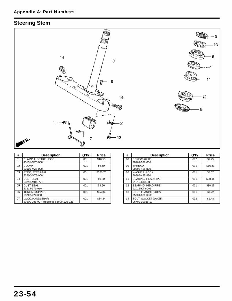
Appendix A: Part Numbers
23-54
Steering Stem
# Description Q’ty Price 01 CLAMP A, BRAKE HOSE
45131-MZ5-000 001 $10.53
02 CLAMP 53105-MZ5-000
001 $6.60
03 STEM, STEERING 53200-MZ5-000
001 $320.76
04 DUST SEAL 53213-MB4-771
001 $9.20
05 DUST SEAL 53214-371-010
001 $9.56
06 THREAD (UPPER) 53220-422-000
001 $24.84
07 LOCK, HANDLEBAR 53600-086-007 (replaces 53600-126-921)
001 $34.24
# Description Q’ty Price 08 SCREW (6X12)
90164-028-000 002 $1.25
09 THREAD 90302-425-830
001 $16.51
10 WASHER, LOCK 90506-425-830
001 $5.67
11 BEARING, HEAD PIPE 91015-KT8-005
001 $30.15
12 BEARING, HEAD PIPE 91016-KT8-005
001 $30.15
13 BOLT, FLANGE (6X12) 95701-06012-00
001 $0.72
14 BOLT, SOCKET (10X25) 96700-10025-10
002 $1.48

Appendix A: Part Numbers
23-55
Step
# Description Q’ty Price 01 PIN, STEP BAR JOINT
50603-033-010 002 $2.55
02 BAR, R. STEP 50612-MR1-000
001 $21.58
03 BRACKET, R. STEP 50615-MZ5-000
001 $88.37
04 SPRING, STEP RETURN 50617-MB1-700
002 $4.55
05 STOPPER, STEP RUBBER 50619-MN0-000
002 $13.18
06 BRACKET, L. STEP 50625-MZ5-000
001 $91.59
07 BAR, L. STEP 50642-MR1-000
001 $21.58
08 RUBBER, MAIN STEP 50661-MN0-000
002 $8.16
09 RUB, PILLION FOOTPEG 50716-371-660 (replaces 50710-377-000)
002 $10.78
10 WASHER 50712-413-000
002 $2.62
# Description Q’ty Price 11 BAR, PILLION STEP
50715-MN0-000 002 $25.25
12 BOLT, HEX. (6X12) 92101-06012-0A
002 $0.53
13 BOLT, CAP (6X12) 92501-06012-0A
002 $1.75
14 WASHER, PLAIN (6MM) 94101-06800 (replaces 94101-06000, 94101-06080)
002 $0.30
15 WASHER, PLAIN (8MM) 94101-08000
002 $0.40
16 PIN, SPLIT (1.6X12) 94201-16120
002 $0.43
17 PIN, SPLIT (2.0X15) 94201-20150
002 $0.35
18 PIN A, PILLION STEP 95015-81000
002 $1.58
19 BOLT, FLANGE (8X18) 95701-08018-00
004 $0.83
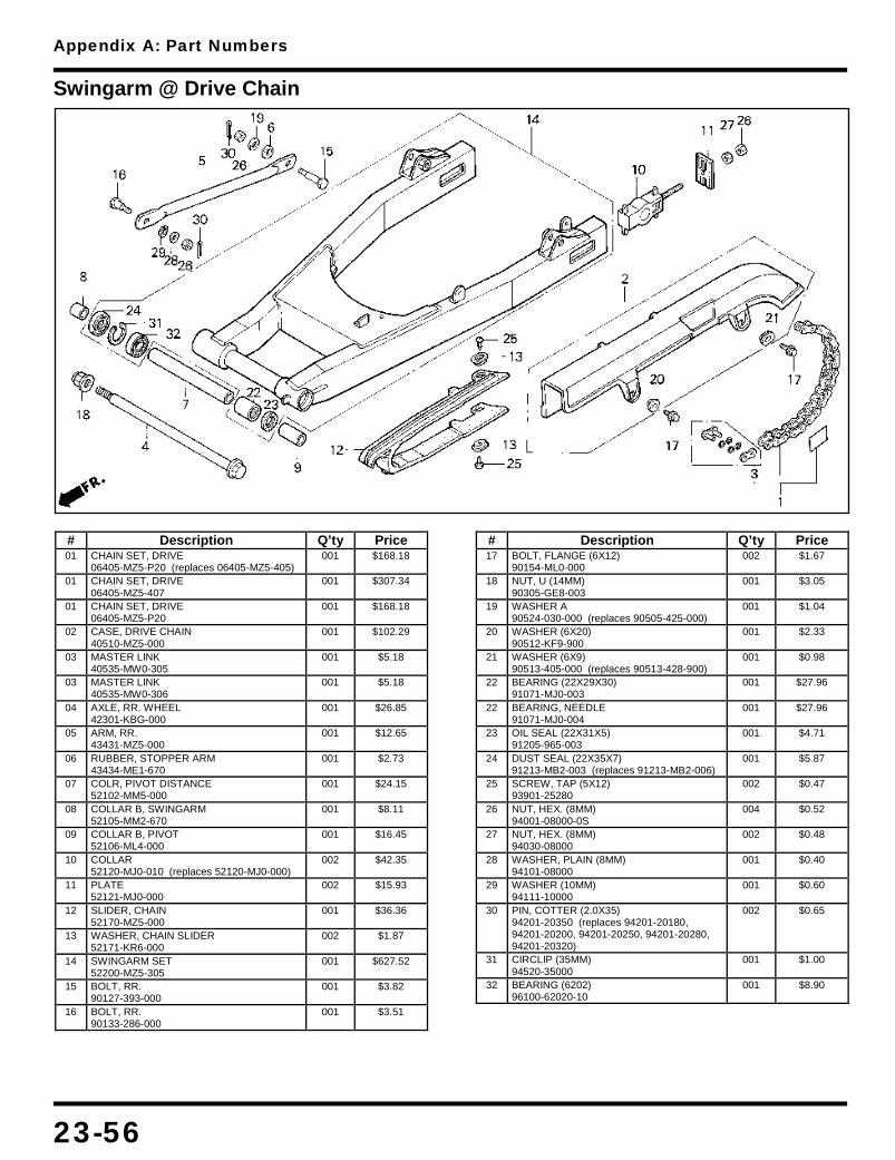
Appendix A: Part Numbers
23-56
Swingarm @ Drive Chain
# Description Q’ty Price 01 CHAIN SET, DRIVE
06405-MZ5-P20 (replaces 06405-MZ5-405) 001 $168.18
01 CHAIN SET, DRIVE 06405-MZ5-407
001 $307.34
01 CHAIN SET, DRIVE 06405-MZ5-P20
001 $168.18
02 CASE, DRIVE CHAIN 40510-MZ5-000
001 $102.29
03 MASTER LINK 40535-MW0-305
001 $5.18
03 MASTER LINK 40535-MW0-306
001 $5.18
04 AXLE, RR. WHEEL 42301-KBG-000
001 $26.85
05 ARM, RR. 43431-MZ5-000
001 $12.65
06 RUBBER, STOPPER ARM 43434-ME1-670
001 $2.73
07 COLR, PIVOT DISTANCE 52102-MM5-000
001 $24.15
08 COLLAR B, SWINGARM 52105-MM2-670
001 $8.11
09 COLLAR B, PIVOT 52106-ML4-000
001 $16.45
10 COLLAR 52120-MJ0-010 (replaces 52120-MJ0-000)
002 $42.35
11 PLATE 52121-MJ0-000
002 $15.93
12 SLIDER, CHAIN 52170-MZ5-000
001 $36.36
13 WASHER, CHAIN SLIDER 52171-KR6-000
002 $1.87
14 SWINGARM SET 52200-MZ5-305
001 $627.52
15 BOLT, RR. 90127-393-000
001 $3.82
16 BOLT, RR. 90133-286-000
001 $3.51
# Description Q’ty Price 17 BOLT, FLANGE (6X12)
90154-ML0-000 002 $1.67
18 NUT, U (14MM) 90305-GE8-003
001 $3.05
19 WASHER A 90524-030-000 (replaces 90505-425-000)
001 $1.04
20 WASHER (6X20) 90512-KF9-900
001 $2.33
21 WASHER (6X9) 90513-405-000 (replaces 90513-428-900)
001 $0.98
22 BEARING (22X29X30) 91071-MJ0-003
001 $27.96
22 BEARING, NEEDLE 91071-MJ0-004
001 $27.96
23 OIL SEAL (22X31X5) 91205-965-003
001 $4.71
24 DUST SEAL (22X35X7) 91213-MB2-003 (replaces 91213-MB2-006)
001 $5.87
25 SCREW, TAP (5X12) 93901-25280
002 $0.47
26 NUT, HEX. (8MM) 94001-08000-0S
004 $0.52
27 NUT, HEX. (8MM) 94030-08000
002 $0.48
28 WASHER, PLAIN (8MM) 94101-08000
001 $0.40
29 WASHER (10MM) 94111-10000
001 $0.60
30 PIN, COTTER (2.0X35) 94201-20350 (replaces 94201-20180, 94201-20200, 94201-20250, 94201-20280, 94201-20320)
002 $0.65
31 CIRCLIP (35MM) 94520-35000
001 $1.00
32 BEARING (6202) 96100-62020-10
001 $8.90

Appendix A: Part Numbers
23-57
Taillight
# Description Q’ty Price 01 TAILLIGHT UNIT
33701-MZ5-671 001 $103.47
02 LENS, TAILLIGHT 33702-MC4-671
001 $22.96
03 SOCKET, TAILLIGHT 33703-MZ5-671
001 $51.15
04 GSKT, TAILLIGHT LENS 33709-KB7-003
001 $3.31
05 BULB (12V27/8W) 34906-425-771
001 $3.18
# Description Q’ty Price 06 COLLAR
80135-MZ5-000 002 $9.98
07 SCREW, TAP (4X40) 90105-GAM-000
002 $3.87
08 WASHER (5MM) 91409-VM0-770
002 $2.33
09 BOLT, HEX. (5X35) 92101-05035-0A
002 $1.28
10 WASHER, SPRING (5MM) 94111-05000
002 $0.50
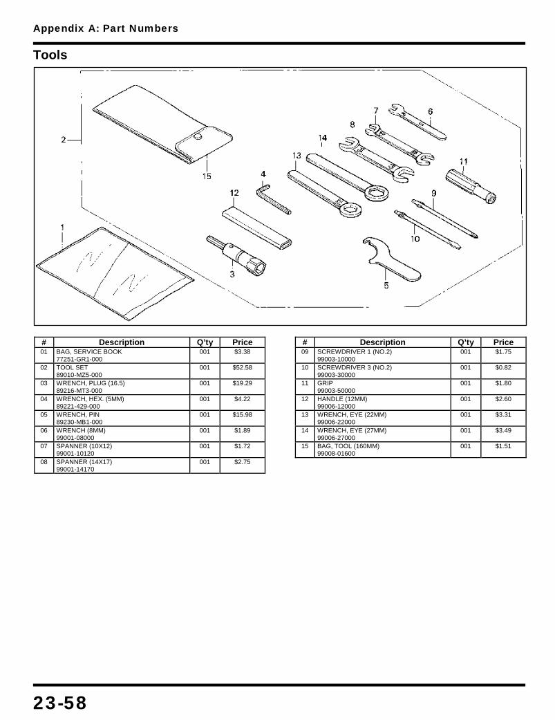
Appendix A: Part Numbers
23-58
Tools
# Description Q’ty Price 01 BAG, SERVICE BOOK
77251-GR1-000 001 $3.38
02 TOOL SET 89010-MZ5-000
001 $52.58
03 WRENCH, PLUG (16.5) 89216-MT3-000
001 $19.29
04 WRENCH, HEX. (5MM) 89221-429-000
001 $4.22
05 WRENCH, PIN 89230-MB1-000
001 $15.98
06 WRENCH (8MM) 99001-08000
001 $1.89
07 SPANNER (10X12) 99001-10120
001 $1.72
08 SPANNER (14X17) 99001-14170
001 $2.75
# Description Q’ty Price 09 SCREWDRIVER 1 (NO.2)
99003-10000 001 $1.75
10 SCREWDRIVER 3 (NO.2) 99003-30000
001 $0.82
11 GRIP 99003-50000
001 $1.80
12 HANDLE (12MM) 99006-12000
001 $2.60
13 WRENCH, EYE (22MM) 99006-22000
001 $3.31
14 WRENCH, EYE (27MM) 99006-27000
001 $3.49
15 BAG, TOOL (160MM) 99008-01600
001 $1.51

Appendix A: Part Numbers
23-59
Transmission
# Description Q’ty Price 01 MAINSHAFT (13T)
23211-ML7-920 001 $146.95
02 PLATE 23212-ML7-000
001 $8.73
03 COUNTERSHAFT 23220-MT4-000
001 $223.89
04 GEAR (37T) 23421-ML7-000
001 $110.83
05 GEAR (17T) 23431-MV8-900
001 $40.44
06 GEAR (32T) 23441-MV8-900
001 $92.55
07 COLLAR (28MM) 23442-ML7-000
001 $19.96
08 GEAR 23451-MZ5-000
001 $110.83
09 GEAR (29T) 23461-MV8-900
001 $101.60
10 GEAR (27T) 23481-MV8-900
001 $98.99
11 COLLAR (28X13.5) 23482-MR7-000
002 $22.11
12 GEAR 23491-MZ5-010
001 $99.68
13 COLLAR (25X12) 23495-MB0-000
001 $18.78
14 GEAR 23501-MZ5-010
001 $112.42
15 COLLAR (25X18.4) 23512-MZ5-000
001 $21.00
16 SHIFTER 23521-MV8-900
001 $65.32
17 SPROCKET (16T) 23801-MCJ-000 (replaces 23801-ML7-920)
001 $48.18
18 BOLT, SPECIAL (10MM) 90037-422-003
001 $5.78
19 WASHER (25X31X1.5) 90451-MR7-000
002 $3.89
20 WASHER (28X34X1.5) 90452-MR7-000
003 $4.58
# Description Q’ty Price 21 WASHER (20X1.00)
90454-428-000 001 $2.02
22 WASHER B (22MM) 90455-ML7-000
002 $3.89
22 WASHER A (22MM) 90456-ML7-000
002 $3.89
22 WASHER C (22MM) 90457-ML7-000
002 $3.89
23 WASHER (25MM) 90456-MA6-000
001 $2.02
24 WASHER (10.2MM) 90459-438-000
001 $4.67
25 WASHER (28MM) 90463-MR7-000
001 $7.71
26 WASHER, LOCK (28MM) 90464-MR7-000
001 $7.71
27 CIRCLIP (25MM) 90601-107-000
002 $2.91
28 SET-RING (68MM) 90602-MR7-000
001 $6.36
29 CIRCLIP (28MM) 90602-MM5-000 (replaces 90603-MN4-000)
003 $2.91
30 BEARING (20MM) 91022-MT4-000
001 $30.56
31 BEARING (22MM) 91023-MZ5-003
001 $40.07
32 BEARING (22X26X11) 91026-MB4-003
001 $22.58
33 OIL SEAL (40X68X7.2) 91207-MR7-003
001 $11.24
34 PIN B, DOWEL (8X10) 94302-08100
001 $1.03
35 *95701-06016-08 95701-06016-00
003 $0.73
36 BEARING (6305) 96100-63050-00
001 $11.98

Appendix A: Part Numbers
23-60
Turn Signal
# Description Q’ty Price 01 SUB-WIRE, R. RR.
32360-MZ5-000 001 $14.73
02 SUB-WIRE, L. RR. 32365-MZ5-000
001 $10.69
03 WINKER LIGHT ASSY 33400-MK7-P00 (replaces 33400-MN0-003)
001 $49.09
04 LENS, FR. 33401-MK7-672
004 $8.46
05 BASE, R. FR. 33402-MK7-671
002 $34.20
06 REFLECTOR, R. RR. 33405-MN0-003
001 $18.04
07 GASKET 33407-MK7-671
004 $3.07
08 TURN SIGNAL, L. FR. 33450-MN0-003
001 $38.04
09 BASE, L. FR. 33452-MK7-671
002 $34.20
10 REFLECTOR, L. RR. 33455-MN0-003
001 $15.69
11 STAY, R. FR. 33490-MZ5-000
001 $39.56
12 STAY, L. FR. 33491-MZ5-000
001 $39.56
# Description Q’ty Price 13 TURN SIGNAL ASSY.
33600-MR1-000 001 $49.11
14 REFLECTOR, R. RR. 33605-MR1-000
001 $27.04
15 TURN SIGNAL ASSY. 33650-MR1-000
001 $49.11
16 REFLECTOR, L. RR. 33655-MR1-000
001 $27.04
17 STAY, RR. 33690-MZ5-000
002 $23.75
18 BULB (12V23W32CP) 34905-268-671
002 $1.67
19 BULB (12V23/8W) 34905-425-671
002 $4.33
20 COLLAR 84702-KV0-670
002 $4.00
21 SCREW, SPECIAL (6X8) 90380-MZ5-000
004 $3.58
22 SCREW, TAP (4X25) 93901-34610
008 $0.20
23 NUT, FLANGE (8MM) 94050-08080
002 $0.25
24 BOLT, FLANGE (6X30) 96001-06030-07
002 $1.15

Appendix A: Part Numbers
23-61
Water Pipe
# Description Q’ty Price 01 CLIP B, TUBE
16106-KW7-900 001 $2.38
02 PIPE, CONNECTING 19507-MB0-000
001 $17.71
03 CAP A 19508-MZ5-000
001 $32.62
04 CAP B 19509-MZ5-000
001 $41.04
05 CLAMP (24-32MM) 19516-ML7-691
002 $10.95
06 PIPE A, WATER 19521-ML7-000
001 $72.16
07 JOINT, WATER 19523-MT4-000
002 $24.76
08 HOSE A, WATER 19525-ML7-000
001 $6.31
# Description Q’ty Price 09 BOLT, FLANGE (6X12)
90004-GHB-610 (replaces 90001-GHB-610) 001 $2.33
10 GSKT, CONNECTING CAP 91301-MB0-000
002 $3.05
11 O-RING (18.3X2.3) 91301-147-023
002 $1.42
12 SEAL, WATER PIPE 91315-MB0-013
001 $1.95
13 O-RING (21.2X2.4) 91331-PC9-003
002 $1.95
14 BOLT, FLANGE (6X22) 96001-06022-00
005 $0.91
15 BOLT, FLANGE (6X35) 96001-06035-00
003 $1.00

Appendix A: Part Numbers
23-62
Water Pump
# Description Q’ty Price 01 COVER, L. CRANKCASE
11340-MZ5-000 001 $360.59
02 RUBBER, L. 11342-MZ5-300
001 $33.87
03 GASKET, L. 11343-MZ5-000
001 $4.57
04 GUIDE, DRIVE CHAIN 11365-MZ5-000
001 $16.04
05 COVER, CHANGE 11630-MZ5-000
001 $64.40
06 GASKET, SHIFT COVER 11632-MY7-000
001 $9.47
07 WATER PUMP ASSY. 19200-MZ5-010 (replaces 19200-MZ5-000)
001 $185.14
08 COVER, WATER PUMP 19220-MZ5-000 (replaces 19221-MZ5-305)
001 $57.43
09 GASKET 19226-ML7-000
001 $3.53
10 LEVER, CLUTCH 22710-MZ5-000
001 $31.58
11 SPRING, CLUTCH LEVER 22815-MZ5-000
001 $3.09
12 PIECE 22852-ML0-780
001 $5.40
13 BOLT, FLANGE (6X16) 90004-GHB-630 (replaces 90001-GHB-630)
002 $2.75
14 BOLT, FLANGE (6X10) 90011-HB9-000
002 $1.67
15 BOLT (6X12) (CT200) 90013-883-000
001 $1.34
16 BOLT (6X75) 90021-MZ5-000
001 $6.78
# Description Q’ty Price 17 BOLT (6X95)
90025-MZ5-000 002 $8.53
18 BOLT, FLANGE (6X25) 90121-MV9-670
002 $2.11
19 WASHER (6.5MM) 90463-ML7-000
003 $2.25
20 WASHER, TANK RUBBER 90503-898-000
002 $2.06
21 WASHER, BRAKE ARM 90525-GC4-700
001 $1.73
22 OIL SEAL (12X20X6) 91201-427-003
001 $3.91
23 OIL SEAL (13X22X5) 91204-KE8-003
001 $2.58
24 O-RING (10.5X6.5) 91301-ML0-781
001 $2.07
25 O-RING (32.95X2.62) 91302-MB0-013
001 $2.07
26 PIN, DOWEL (8X14) 94301-08140
004 $1.00
27 BOLT, FLANGE (6X32) 96001-06032-00
001 $0.95
28 BOLT, FLANGE (6X35) 96001-06035-00
001 $1.00
29 BOLT, FLANGE (6X40) 96001-06040-00
002 $1.02
30 BOLT, FLANGE (6X60) 96001-06060-00
002 $1.18
31 BOLT, FLANGE (6X75) 96001-06075-00
001 $1.47
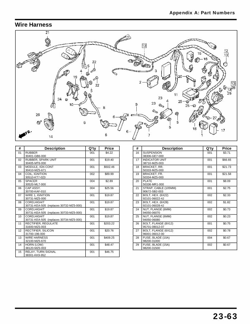
Appendix A: Part Numbers
23-63
Wire Harness
# Description Q’ty Price 01 RUBBER
30401-GB6-000 001 $4.22
02 RUBBER, SPARK UNIT 30405-MT6-000
001 $19.40
03 MODULE, IGN CONT 30410-MZ5-671
001 $502.46
04 COIL, IGNITION 30510-KT7-023
002 $89.99
05 SPACER 30520-ML7-000
004 $2.89
06 CAP ASSY. 30700-KAF-010
004 $25.56
07 WIRE 1, IGNITION 30731-MZ5-000
001 $19.87
08 CORD,HIGH/T 30731-KEA-505 (replaces 30732-MZ5-000)
001 $19.87
09 CORD,HIGH/T 30731-KEA-505 (replaces 30733-MZ5-000)
001 $19.87
10 CORD,HIGH/T 30731-KEA-505 (replaces 30734-MZ5-000)
001 $19.87
11 RECTIFIER, REGULATE 31600-MZ5-003
001 $203.22
12 RECTIFIER, SILICON 31700-196-000
001 $20.76
13 WIRE HARNESS 32100-MZ5-670
001 $409.25
14 HORN (LOW) 38120-MZ5-003
001 $48.47
15 RELAY, TURN SIGNAL 38301-KK9-952
001 $46.75
# Description Q’ty Price 16 SUSPENSION
38306-GE7-000 001 $3.71
17 INDICATOR UNIT 38710-MZ5-003
001 $66.65
18 BRACKET, RR. 50333-MZ5-000
001 $21.73
19 BRACKET, FR. 50334-MZ5-000
001 $21.58
20 PLATE 50336-MR1-000
001 $8.09
21 STRAP, CABLE (105MM) 90672-SB2-003
001 $2.75
22 BOLT, HEX. (6X22) 92101-06022-4J
002 $2.33
23 BOLT, HEX. (6X28) 92101-06028-4J
002 $1.82
24 NUT, FLANGE (6MM) 94050-06070
002 $0.73
25 NUT, FLANGE (6MM) 94050-06080
002 $0.23
26 BOLT, FLANGE (8X12) 95701-08012-07
001 $0.75
27 BOLT, FLANGE (6X12) 96001-06012-00
002 $0.78
28 FUSE, BLADE (10A) 98200-31000
004 $0.67
29 FUSE, BLADE (15A) 98200-31500
002 $0.67

MEMO

24-1
24. Appendix: Gasket Diagrams
Alternator Cover Gasket 24-2
Cam Chain Tensioner Gaskets 24-3
Oil Pan Gasket 24-4
Right Crankcase Cover Gasket 24-5
Shift Cover Gasket 24-6
Sprocket Cover Gasket 24-7
NOTE
• Diagrams must be printed without using any scaling to fit paper. • Some of the diagrams must be printed on larger than letter sized paper, or must be pieced together using the guides
included on the images

Appendix B: Gasket Diagrams
24-2
Alternator Cover Gasket
NOTE
Description Part Number Alternator Cover Gasket 11636-MY7-000
Material Thickness Paper 0.0218”
• Grey area is a thin bead of sealant
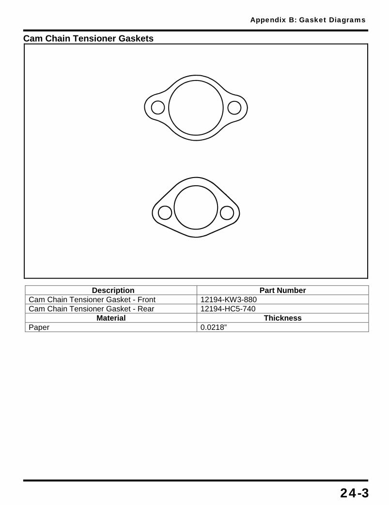
Appendix B: Gasket Diagrams
24-3
Cam Chain Tensioner Gaskets
Description Part Number Cam Chain Tensioner Gasket - Front 12194-KW3-880 Cam Chain Tensioner Gasket - Rear 12194-HC5-740
Material Thickness Paper 0.0218”

Appendix B: Gasket Diagrams
24-4
Oil Pan Gasket
Description Part Number Oil Pan Gasket 11315-MY7-000
Material Thickness Paper 0.0218”

Appendix B: Gasket Diagrams
24-5
Right Crankcase Cover Gasket
Description Part Number Right Crankcase Cover Gasket 11394-MY7-000
Material Thickness Paper 0.0218”

Appendix B: Gasket Diagrams
24-6
Shift Cover Gasket
Description Part Number Shift Cover Gasket 11632-MY7-000
Material Thickness Paper 0.0218”

Appendix B: Gasket Diagrams
24-7
Sprocket Cover Gasket
Description Part Number Sprocket Cover Gasket 11343-MZ5-000
Material Thickness Paper 0.0218”


61 MZ509 HONDA MOTOR CO. , LTD. TOKYO, JAPAN M A D E F R O M 5 0 % RECYCLED PAPER
M I N I M U M 1 0% POST-CONSUMER CONTENT
D RC 3750 .03.08 P R I NTED I N USA