
Home Wiring Guide - Villawood Properties
10
Document No: TG-002 Issue Date: 19/04/2012 Version: 2.2 Home Wiring Guide
-
Upload
khangminh22 -
Category
Documents
-
view
0 -
download
0
Transcript of Home Wiring Guide - Villawood Properties

Document No: TG-002
Issue Date: 19/04/2012
Version: 2.2
Home Wiring Guide

Home Wiring Guide
2
Document Control Sheet
Record of Issue
Issue Date Description
A 16-Nov-08 First draft document issued for discussion
1.0 14-Jan-08
2.0 20-Mar-09 Template Change. General Updated
2.1 2-Sep-2009 Update Pay TV requirements
2.2 19-Apr-2012 Internal ONT
Acceptance and Approval
Issue Name Position Signature Date
A S. Davies GM, Operations 16-Nov-08
1.0 S. Davies GM, Operations 14-Jan-08
2.0 S. Davies GM, Operations 20-Mar-09
2.2 S. Davies GM, Operations 19-Apr-12
In the event of any enquiries with respect to this document, please contact:
Name Position Phone Email
S. Davies GM, Operations - [email protected]
Copyright Statement
Copyright of this material resides with OptiComm Co Pty Ltd. Apart from any fair dealing for the purposes of private study, research, criticism or review, as permitted under the Copyright Act 1968, no part may be reproduced or reused for any purposes whatever without prior written permission of the owner.

Home Wiring Guide
3
1.0 PURPOSE
The aim of this document is to outline what is required for homeowners and their builders, or developers to connect to telecommunication networks based on Fibre to the Home (FTTH) technology.
2.0 SCOPE
This document extends to detached or semi-detached buildings that are being built for residential or small business use. It covers requirements of connection from the telecommunications pit to the Home Distribution Unit.
3.0 THINGS YOU SHOULD KNOW ABOUT A FIBRE COMMUNITY
Modern technology has brought many changes to the way we live, specifically in communications where many new services are being introduced that require high-speed delivery infrastructure. New Digital Telephone, Ultra-High Speed Internet and Television Services (including pay and free to air) offer greatly enhanced performance when compared to older technology. To accommodate these changes, residential developments must move forward with technology and provide infrastructure that will have the capacity for not only today but also for future technological advancements.
In standard residential areas, the incumbent carrier meets the basic communication needs of the community. At OptiComm, our commitment is about being at the forefront of the education and broadband revolution, and as such we provide advanced fibre optic communication infrastructure as a replacement for the traditional copper network.
3.1 Services
OptiComm’s fibre optic based communication network will provide a range of services, including reticulation of the analogue and digital free to air television signals, Pay TV, Ultra-High-Speed Internet, and a Standard Telephone Service. Additional services, such as Community Intranet, security monitoring, gate control, and new entertainment services such as IPTV and Video-on-Demand, are all possibilities with this latest technology. These may be introduced in the future.
3.2 Connection
A fibre optic enabled community allows for you to connect to the network that runs past your property. A fibre optic lead in cable connects to a connection box on the external wall of your home. This is called a Premises Connection Device (PCD) and it is where the internal Optical Fibre cabling joins the Fibre cabling from the street. An Optical fibre cable is run from the PCD to the Network Termination Device (NTD) inside the house and it is where the optical signal (light) is converted to an electrical signal and retransmitted on twisted pair and coaxial cable to your Home Distribution Unit (HDU).
4.0 HOME WIRING GUIDELINES
A structured cabling system in today’s home is important to take full advantage of modern telecommunications systems. All cabling shall use a star wire topology, that is all cabling is wired from the Home Distribution Hub in the garage to the outlet plate or device as an individual feed without joints, tap offs or splitting.

Home Wiring Guide
4
All telecommunications cabling must be installed by a licensed contractor to TS009, AS3000, relevant Australian Standards and ACIF guidelines – otherwise your home may not be compliant. This document details the correct separations and installation requirements.
4.1 Standards
This document is the technical specification and is to be provided to your Builder/Telecommunications Contractor. If you are unsure of any of the information contained herein, please don’t hesitate to contact us to ensure the correct standards are followed – we are more than happy to provide you with the right advice and support so that you get it right the first time.
For more information contact the
OptiComm Customer Connection Information Desk
on 1300 137 800
or via email [email protected]
4.2 Smart Wiring
“Smart wiring” is a term commonly used to describe home wiring that may include, but is not limited to, one or more of the following:
structured telephone, data (Internet) and TV cabling (such as described in this document)
home security — intruder detection, back-to-base monitoring or CCTV (Closed Circuit Television)
home theatre and/or in-house audio/video distribution
home automation — “intelligent” lighting, automatic/remote control of electrical appliances, HVAC (Heating, Ventilation and Air Conditioning), lawn/garden irrigation, etc.
paging/intercom, which may include music distribution or CCTV.
Such systems may be wired separately by different installers or may be included in a total wiring package offered by a SmartWired builder or contractor. However, this document only describes the telephone, data and TV cabling system.
Warning! All customer premises cabling work MUST be performed by a registered cabler. If a cabler is registered, they will have a card which proves that they can legally perform cabling work.
The cabling work must comply with the Cabling Provider Rules, which detail the minimum requirements for telecommunications cabling installations to ensure that network integrity and the health and safety of end-users, other cablers, and carrier personnel is protected.
The cabling is required to have adequate separation or segregation from electrical cabling to avoid creating a dangerous situation.
Failure to use a registered telecommunications cabler may result in fines of up to $13,200.

Home Wiring Guide
5
Figure 1 - Sample Home Wiring

Home Wiring Guide
6
4.3 Data/telephone outlets
In Smart Wired ™ homes there is no difference between a telephone point and a data point, so consider all points as being cable of both telephone and data. A data/telephone outlet is terminated with a RJ45 socket.
For data and telephone points UTP Cat5e cable needs to be used from the HDU. The signal can transmit for up to 100m from the NTD. Cat6 cable can be used which will provide for larger bandwidth needs in the future, however there is additional cost.
Method of Installation
Two methods of cabling are possible. One method is to locate future data switches/routers in a study or computer room where tie cables need to be run from the HDU to the study with all outlets star wired from the HDU to the final outlets terminating in a RJ45 outlet. The recommended method is to locate the data switch/router in the HDU with star wiring to all outlets terminating in a RJ45 outlet.
At pre-plaster stage, your Builder/Telecommunications Contractor must provide Cat5e cable from each telephone point in the home to meet (star wired) at the HDU. A Telephone socket (RJ45) socket must also be installed in the HDU configured in a ‘mode 3’ format for the security monitoring device.
4.4 RF Outlets (Television)
The RF Outlets supply both the free to air and pay television signal. Their terminations must be F type female.
Pay TV outlets must be a separate wall plate or a wall plate with 2 x F type connectors with one marked PAY TV
Coaxial cable (RG6 Quad Shield) cable star wired (not loop or tap and drop) needs to run from each TV outlet location to the HDU. The maximum length of cable between the HDU and the RF outlet is 23m. This can be extended to 32m if an amplifier or RG11 cable is used between the HDU and the RF outlet.
FOXTEL have specific requirements as to what materials are to be used in the wiring from the ONT up to and including the wall plate. Cable and connectors MUST be FOXTEL approved if you intend to have a FOXTEL connection. A list of approved FOXTEL components and a FOXTEL wring guide can be downloaded from
http://www.foxtel.com.au/support/Getting-Started/Connecting-Cabling/default.htm
Method of Installation
All splitters/amplifiers need to be located within the HDU. The presentation is via one F type connector to be provided by the Builder or Telecommunications Contractor. The typical RF output level from the network is 75dBµV ± 2dB. A high quality amplifier (capable of handling 60+ channels) may be required if more than 4 outlets are required.
Figure 2 - Data/Telephone Outlet
Figure 3 - RF Outlet

Home Wiring Guide
7
4.5 Data with every RF Point
To take advantage of network capable Digital Video Recorders, Intelligent PayTV Set Top Boxes (e.g. FoxTel IQ) and any future Video on Demand or IPTV services, it is recommended to install an RJ45 socket (data/telephone) wherever an RF point is located.
4.6 Wireless Access Point
A wireless access point can be installed to provide a wireless local area network to the home. Consider the location of the data/telephone outlet for the access point. Have it in an open area on a high point to optimise data speed and minimize attenuation from walls.
4.7 Security
If a monitored security alarm is to be installed in the building, a mode 3 connection is to be installed to give the alarm priority access to the telephone line. The alarm panel should be connected between the NTD and HDU in regards to the first telephone line.
While often used as generic descriptions, “Smart Wiring” and “SmartWire” are trademarks of the Copper Development Centre. The SmartWired web site is www.smartwiredhouse.com.au.
5.0 Home Distribution Unit
The HDU is the central hub of the smart wiring network of the home. Typically it is a steel cabinet installed in the garage with a lock that houses all of the passive and active equipment. All services enter and exit this cabinet. This allows for total flexibility to the home owner in the future. It must be of a minimum size of 405mm wide (to fit between studs), 600mm high and 112mm deep. Typically the bottom of the cabinet is mounted 1200mm above finished floor level and is recessed into the wall with bottom and top ventilation into the cavity wall.
It needs to be large enough to can cater for any active device such as alarm panels, television amplifiers, data switches and 240Vac power outlets and have enough room for cable looms, IDC blocks, splitters and couplers.
It is the responsibility of the Builder/Telecommunications Contractor to provide the smart wiring and Home Distribution Unit.
5.1 Location of HDU
The HDU is typically installed inside the house in an accessible location. Choose a dry, well-ventilated area at least 1m away from high energy rating electrical equipment to prevent electromagnetic interference. This can include electrical switchboards, supply meters, fluorescent lights, electrical transformers, generators, ducted vacuum motors, and power tools in operation, air conditioning units, refrigerators or freezers. The bottom of the HDU must be mounted at a height above floor level between 350mm and 1700mm.
Home Wiring Guide
8
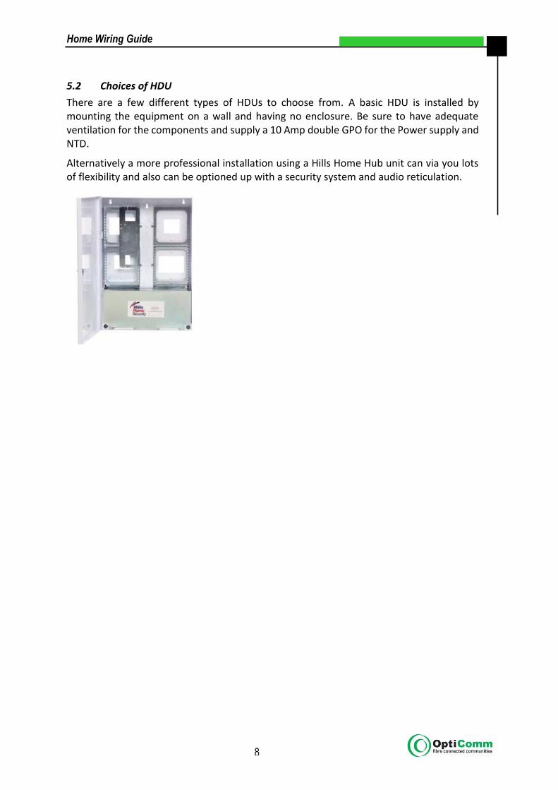
5.2 Choices of HDU
There are a few different types of HDUs to choose from. A basic HDU is installed by mounting the equipment on a wall and having no enclosure. Be sure to have adequate ventilation for the components and supply a 10 Amp double GPO for the Power supply and NTD.
Alternatively a more professional installation using a Hills Home Hub unit can via you lots of flexibility and also can be optioned up with a security system and audio reticulation.

Home Wiring Guide
9
6.0 Planning out your Home Wiring
Use this chart to calculate what TV, internet, data, telephone and other services you need in the rooms of your home.
Rooms
Simply the appropriate box to calculate the points required
Home Hub TV Internet Telephone GPO
Lounge
Family Room
Master Bedroom
Bed 2
Bed 3
Bed 4
Study
Kitchen
Dining
Garage

Telecommunications cabling advice (TCA1) Copies required for customer, cabler and employer (if applicable) Instructions for completion
Requirements
A registered cabling provider must complete this form after each cabling job (except for certain exemptions). Cablers must retain a copy of this form for at least 12 months and pass a copy to the customer and/or employer.
Print clearly. Illegible, unclear or incomplete application forms may delay processing.
Where proposed works may be compromised by existing cabling, a TCA2 form should be completed.
Enquiries
For advice on completing this form, please go to ACMA’s website at www.acma.gov.au (go to For licensees & industry: Service & technical requirements > Telecommunications : Cabling requirements > TCA forms > How to complete TCA forms).
Technical enquiries about cabling should be directed to:
Email: [email protected]
Tel: 1300 850 115
Registered cabling provider
Name
SURNAME
GIVEN NAMES
Address
POSTCODE
Contact details
WORK ( )
MOBILE
Registration number
Name of registrar
Employer (IF APPLICABLE)
Name of company
Contact details
WORK ( )
MOBILE
Address
POSTCODE
Description of work (INCLUDING ANY SUPERVISION)
Customer details
Name
Address
POSTCODE
Contact details
WORK ( )
FAX ( )
Certification
I hereby certify that the cabling work described in this advice complies with the Wiring Rules (AS/ACIF S009:2006 or its replacement).
SIGNATURE PRINT FULL NAME
DATE