wiring accessories cable management domestic circuit ...
211
2010 wiring accessories cable management domestic circuit protection
-
Upload
khangminh22 -
Category
Documents
-
view
2 -
download
0
Transcript of wiring accessories cable management domestic circuit ...

2010wiring accessoriescable management
domestic circuit protection


Crabtree’s reputation for pioneering new concepts in the
electrical industry – right from the acclaimed Lincoln Switch
in 1919 to the launch of the Starbreaker Modular Circuit
Protection System, and Platinum low profile & flat plate
wiring accessories, put us at the forefront of manufacturing
technology. It is this insight into our customers’ needs,
together with the technical expertise to turn innovative ideas
into top quality products that has made Crabtree a
market leader.
Crabtree is part of Electrium, one of the UK’s largest
electrical groups, which has offices and manufacturing
sites in the UK, India, China and the Middle East.
Acknowledged as one of Britain‘s leading manufacturers ofwiring accessories and circuit protection equipment.Crabtree‘s diverse product range is renowned for its outstandingquality and excellent value for money.Specified worldwide, Crabtree products are designed to satisfythe needs of specifiers, wholesalers, contractors and end-users indomestic, commercial and industrial markets alike.
LeftElectrium’s purposebuilt CommercialCentre in Cannock,Staffordshire

CAPITAL POWER & CONTROL 4CAPITAL & MINDER L IGHTING CONTROL 14
ANTI-MICROBIAL SELECTION OF WIR ING ACCESSORIES 26
PLATINUM WHITE MOULDED 36
CAPITAL METAL PLATE 68CAPITAL METALCLAD 78ROCKERGRID MODULAR SYSTEM 82WEATHERSEAL WATER & DUST PROTECTED 90CAPITAL INTERIORS & PANEL MOUNTING 98CAPITAL BOXES & SERVICE ITEMS 102LSC LUMINAIRE SUPPORT COUPLERS 106
WIRING ACCESORIES
DATAPAK DATA, VOICE & PATCH PANELS 22
PART M SELECTION OF WIR ING ACCESSORIES 30SEEK LIGHT PROVIDES NIGHT ILLUMINATION 34
PLATINUM LOW PROFILE & FLAT PLATE 42TRANSFORM SELECTION OF WIR ING ACCESSORIES 58
LDB LUMINAIRE DISTR IBUTION BOXES 108
Co
nten
ts

STARBREAKER BUILT UP CONSUMER UNIT 130STARBREAKER COMPONENTS 140LOADSTAR DOMESTIC CIRCUIT PROTECTION 148MODULAR CONTROL DEVICES 152LIFESTAR RCD 156DIN ENCLOSURES 160
CABLE MANAGEMENT
WARWICK PVC TRUNKING 110BRITMAC POWERTRACK 118BRITMAC FLOOR BOX 124
Co
nten
ts
DOMESTIC CIRCUIT PROTECTION
All Crabtree products comply with the applicable British Standard specification and should be installed by suitablyqualified personnel in accordance with the requirements of relevant legislation, regulations (including IEE WiringRegulations) and the accepted practice in the industry.
The products listed or described in this publication may be protected by one or more patents, and/or registered designsand/or applications. A full list of patents registered designs and applications may be obtained from the companysecretary of Electrium Limited.
NUMERICAL INDEX 200
TECHNICAL DATA 162DIMENSIONS 187

4

Unique labyrinth switchdesign minimises visiblearc flash and preventsfront access to live parts.
Positive drive switchaction preventsbalancing between the‘on’ and ‘off’ positionand gives reliableindication of the contactposition.
Wide concave rockersare easy to operate.
Capital power and control accessories are fullydesign co-ordinated to offer consistent stylingand inherent safety features across a broad rangeof applications.The range of socket outlets, fused connectionunits and switches is complemented by productswhich cater for specific applications such ascooker control units, shaver units, fan controlswitches and shower control switches.
Two earth terminals are fitted asstandard to the Switched Single andTwin Socket.
Shutter mechanism isoperated by earth pinof plug.
CA
PIT
AL
PO
WE
R &
CO
NT
RO
L
5
POWER & CONTROL

CA
PIT
AL
PO
WE
R
6
4304/3 4306
4828 4827/3
4307
7255
13A SWITCHED SOCKET OUTLETSl
BS 1363 PACK QTY
1 gang SP 10 4304
1 gang DP 10 4304/D
1 gang DP fitted with neon indicator 10 4304/3D
2 gang SP 5 4306
2 gang DP 5 4306/D
2 gang DP fitted with neon indicator 5 4306/3DDimensions 1 gang 86mm x 86mm
2 gang 146mm x 86mmMounting boxes 1 gang 9047 surface, SB655 flush galv. or SB619 dry lining
2 gang 9048 surface, SB665 flush galv. or SB629 dry lining
� Large capacity terminals for easy wiring.� Shallow back projection for ease of installation in a 25mm deep box.� Fitted with two Earth terminals for use where compliance with BS7671: 2008
regulation 543-7 ( IEE wiring Regulations ).
13A SWITCHED SOCKET OUTBOARD ROCKERSl
BS 1363 PACK QTY
2 gang DP outboard rockers 5 4307
2 gang DP outboard rockers with neon indicator 5 4307/3Dimensions 2 gang 146mm x 86mmMounting boxes 2 gang 9048 surface, SB665 flush galv. or SB629 dry lining
� Large capacity terminals for easy wiring.� Shallow back projection for ease of installation in a 25mm deep box.� Fitted with two Earth terminals for use where compliance with BS7671: 2008
regulation 543-7 ( IEE wiring Regulations ).
13A UNSWITCHED SOCKET OUTLETSl
BS 1363 PACK QTY1 gang unswitched 10 72552 gang unswitched 5 7257Dimensions 1 gang 86mm x 86mm
2 gang 146mm x 86mmMounting boxes 1 gang 9047 surface, SB655 flush galv. or SB619 dry lining
2 gang 9048 surface, SB665 flush galv. or SB629 dry lining
� Complete with 1 Earth Terminal.
13A FUSED CONNECTION UNITSl
BS 1363 PACK QTY
DP Switched 10 4827
DP Switched with neon indicator 10 4827/3
Unswitched 10 4828
Unswitched with neon indicator 10 4828/3
Dimensions 86mm x 86mmMounting boxes 9047 surface, SB655 flush galv. or SB619 dry lining
� Fitted with knock-out position in bottom edge of plate for use with or without cord outlet. Suitable for flexible cord up to 10mm outside diameter.
� Fused on the line side with a 13A fuse link.� Fuse marked to BS1362. For spare fuse links see page 8.� With fuse removed, carrier may be padlocked for extra on site ‘maintenance’
safety.� Suitable padlock see page 143.� Shallow back projection for ease of installation in a 25mm deep box.

CA
PIT
AL
PO
WE
R
7
4406/A03
7047 7046
7062
4001 4002
Reset buttongives a highlyvisible indicationof device status.
Double poleoperation,
3mm contactgap.
13A SAFETYSOCKET WITH RCD PROTECTIONl
BS 7288 PACK QTY
2 gang switched with neon indicator 1 4406/A0330mA tripping current
Dimensions 146mm x 86mmMounting boxes 9048 surface, SB665 flush galv. or SB629 dry lining
See page 159 for further information.Can be installed to replace any 2 gang size socket outlet on 25mm deep box.
All available with two earth terminals to enable installation to comply with BS7671:2008 regulation 543-7 ( IEE wiring Regulations ).
2A, 5A, SOCKET OUTLETSl
BS 546 WHERE APPLICABLE PACK QTY
2A Unswitched shuttered 10 7046
5A Unswitched shuttered 10 7047
Dimensions 86mm x 86mmMounting boxes 7044, 7046, 7047–9047 surface, SB655 flush galv.
or SB619 dry lining
15A 125V AMERICAN STANDARDSOCKET OUTLETS
l
NEMA CONFIGURATION 5-15 PACK QTY
2 gang Horizontal 5 7062
Dimensions 2 gang 86mm x 146mmMounting boxes 2 gang 9048 surface, SB665 flush galv.
or SB629 dry lining
Tunnel Type termination accepts 6.0mm2 cable (7062).
BLANKING PLATESl
BS 5733 WHERE APPLICABLE PACK QTY
1 gang 20 4001
2 gang 20 4002
1 gang architrave 20 4003
2 gang architrave 20 4004
Dimensions 1 gang 86mm x 86mm, 2 gang 146mm x 86mm1 gang architrave 33mm x 86mm2 gang architrave 33mm x 146mm
2330 2382
5A, 15A SWITCHED SOCKET OUTLETSl
BS 546 PACK QTY
5A Shuttered SP 10 2330
15A Shuttered SP 10 2382
Dimensions 86mm x 86mmMounting boxes 2330 – 9047 surface, SB655 flush galv.
or SB619 dry lining2382 – 9041 surface, SB615 flush galv.or SB619 dry lining

CA
PIT
AL
PO
WE
R
8
6920/3 6920/5 6920/13
7011 7111 7211
7222/WH
13NP
13A FUSED RESILIENT PLUGSl
BS 1363/A PACK QTY
Fused at 13A – White 10 7222/WH
Live and neutral pins have moulded nylon sleeves for safety.Cover in rubber material. Base in nylon.Fitted with fuse-link marked to BS 1362, List No.6920/13, see below.
13A NON-INTERCHANGEABLE PLUGSl
PACK QTY
Fused at 13A – White 10 13NP
Only for use with Britmac non-standard floor box sockets
2A,5A, 15A PLUGSl
BS 546 PACK QTY
2A 10 7011
5A 10 7111
15A 10 7211
Moulded from white thermoset plastic.Live and neutral pins have moulded nylon sleeves for safety.Round pin plugs are not fused.
FUSE LINKSl
PACK QTY
3A Red 100 6920/3
5A Black 100 6920/5*
13A Brown 100 6920/13
Type tested to BS 1362 and ASTA certified.* Price and delivery on application.

CA
PIT
AL
CO
NT
RO
L
9
4017 4017/1
4015 4015/31
4013/3
4016 4016/3
4018
3A CARD SWITCHl
BS 5733 PACK QTY
3A Card Switch 5 4018
Dimensions 86mm x 86mmMounting boxes SB655 flush galv. or SB619 dry lining
Controls energy consumption in installations such as hotels by ensuring that appliancesare not left on when rooms are unoccupied.The switch is operated by a door entry card and controls the supply to a room via asuitably rated contactor.Will accept door entry cards up to 86mm x 54mm x 1mm.Mounting box must be minimum 25mm in depth.Fitted with neon for illumination through Card Switch entry see page 170.
6A TP CONTROL SWITCHESl
BS EN 60669-1 BS EN 60947-3 PACK QTY
6A Three pole isolating switch marked 5 4017with isolator symbol
6A Three pole isolating switch marked 5 4017/1with isolator and fan symbol
Dimensions 86mm x 86mmMounting boxes 9043 surface, SB623 flush galv. or SB619 dry lining
Provides local isolation of fans with or without timers whilst the rest of the circuit remains live.Enables repair or routine maintenance of fans.240V only.For full details of compliance with BS EN 60947-3 see Technical Data page 165.
20A DP CONTROL SWITCHESl
BS EN 60669-1 PACK QTY
20A DP Control Switch 10 4015
Fitted with neon indicator 10 4015/3
Fitted with neon indicator and marked 10 4015/31’water heater‘
Dimensions 86mm x 86mmMounting boxes 9047 surface, SB655 flush galv. or SB619 dry lining
Fitted with knock out position in bottom edge of plate for use with orwithout cord outlet. Cord outlet suitable for flexible cord up to 10mm outside diameter.Two earthing terminals are fitted to the switches.
32A DP CONTROL SWITCHl
BS EN 60669-1 PACK QTY
Fitted with neon indicator 10 4013/3
Dimensions 86mm x 86mmMounting boxes 9041 surface, SB615 flush galv. or SB619 dry lining
Fitted with knock-out position in bottom edge of plate for use with orwithout cord outlet. Cord outlet suitable for flexible cord up to 10mm outside diameter.Two earthing terminals are fitted to the switches.
45A DP CONTROL SWITCHESl
BS EN 60669-1 PACK QTY
45A DP Control Switch 5 4016
With neon indicator 5 4016/3
Dimensions 86mm x 86mmMounting boxes 9041 surface, SB615 flush galv. or SB619 dry lining
Dual Screw Terminal .

CA
PIT
AL
CO
NT
RO
L
10
4521/31
4520/31
4523/3
4506 45064507 rear view
45A DP ‘SLIM LINE’ COOKER CONTROL UNITSl
BS 4177 & BS 1363 PACK QTY
45A DP main switch and 13A switch socket 1 4521/1outlet. Faceplate marked ‘cooker’
45A DP main switch and 13A switch socket with 1 4521/31neon indicators. Faceplate marked ‘cooker’
Dimensions 146mm x 86mmMounting boxes 9054 surface, SB625 flush galv. or SB629 dry lining
� Same plate size as standard twin socket.� Large capacity tunnel terminals on live and neutral take up to 10mm2 cable.� Two earth terminals are fitted.� Separate double pole switching for both cooker and socket outlet.
45A DP COOKER CONTROL UNITSl
BS 4177 & BS 1363 PACK QTY
45A DP main switch and 13A switch socket 1 4520/1outlet. Faceplate marked ‘cooker’
45A DP main switch and 13A switch socket with 1 4520/31neon indicators. Faceplate marked ‘cooker’
Dimensions 168mm x 114mmMounting boxes 9052 surface or 9338/GV flush
50A DP COOKER CONTROL UNITSl
PACK QTY
Faceplate marked ‘cooker’ 1 4523
Faceplate marked ‘cooker’ 1 4523/3and fitted with neon indicator
Blank Faceplate 1 4211/BLANK
Dimensions 165mm x 178mmMounting boxes For ‘retro fit’ applications – allows use of original flush box
� Durable white powder coated metal faceplate.
45A CABLE OUTLETSl
BS 5733 PACK QTY
With terminals and cable clamp 10 4506Terminals will accept 2 x 10mm2 cable
With cable clamp 10 4507Cable clamp will accept 1 x 16mm2 through cable
Dimensions 86mm x 86mmMounting boxes 9041 surface, SB615 flush galv. or SB632 dry lining
Cable knock-out in cover prevents access to terminals before outgoing cable is fitted.

CA
PIT
AL
CO
NT
RO
L
11
4075 rear view
4500
RED ROCKERSl
For applications where essential supply systems are in use, sockets andfused connection units with red rockers are available to order.These are ideal for use in hospitals, computer installations, etc.
To order add suffix to List No.ie 4306 with red rockers = 4306/WH/RD.4304 with red rockers = 4304/WH/RD.4827 with red rockers = 4827/RD.4307 with red rockers = 4307/RD.All the above come complete with two Earth terminals for use where compliancewith BS7671: 2008 regulation 543-7 ( IEE wiring regulations ).
For Rockergrid switches with Red rockers see Rockergrid section page 86.
For products with a Red Frontplate and Red Rocker please see selection in theAntimicrobial section (page 28).
4304/WH/RD 4827/RD
50A DP CONTROL SWITCHESl
BS EN 60669-1 PACK QTY
50A DP Control Switch 5 4500
Faceplate marked ’cooker‘ 5 4500/1
Fitted with neon indicator 5 4500/3
Faceplate marked ’cooker‘ and fitted with 5 4500/31neon indicator
Dimensions 86mm x 146mmMounting boxes 9040 surface, SB625 flush galv. or SB629 dry lining
BS EN 60947-3 rating 240V 50A category of duty AC22.
20A CORD OUTLETl
BS 5733 PACK QTY
With cable clamp 10 4075
Dimensions 86mm x 86mmMounting boxes 9047 surface, SB655 flush galv. or SB619 dry lining
Outgoing cable 2.5mm2 max with 11mm diameter max outer sheath.

PRODUCT MARKING SERVICEl
A wide range of markings can be added to 13A fused connection unitsand double pole control switches. The majority of these markings areconsistent in style, colour and position with the standard Tampo-printed ‘water heater’ marking on List No.4015/31. All of the markingsoffer the same high level of durability.
To order any of the markings listed below, add suffix to List No.ie 4827 marked ‘fridge freezer’ = 4827/FF.
MARKING SUFFIXair conditioner ACalarm ALappliance APPbathroom BAbell transformer BEbathroom extract fan BEFbathroom heater BHboiler BOboiler supply BOSboost BSTBritish Telecom BTcaravan CACCTV CCTVcentral heating CHcooker CKcupboard light CLconvector heater CNHday boost DBdetector DEdownflow heater DHdoor bell DOdish washer DWdryer DYemergency circuit ECextractor fan EFextractor hood EHfire alarm FAfor cleaners use only FCOfan coil unit FCUfeature fire FEfridge/freezer FFfan heater FHfire FIfan FNfridge FRfreezer FZgas ignition GIgarden shed GShand dryer HAhob HBcooker hood HDheating HGhair dryer HIheating isolator HSheater HT
MARKING SUFFIXhumidity vent HVintruder alarm IAimmersion heater IHinfra red sauna IRSjacuzzi JAkitchen extract fan KEFlight LGlift LIloft light LLmicrowave MWnight immersion NIoff peak OFFPoutside light OLon peak ONPoven OVpelmet light PELplinth heater PLHpanel heater PHrefrigerator RFsecurity alarm SAsocket below SBsmoke detector SDsecurity equipment SEsaniflo SFshower SHsecurity light SLshower pump SPstorage heater STsteam cabinet STCstair lift STLtanning cabinet TCtumble dryer TDtowel rail TRtraditional sauna TSTV amplifier TVAunderfloor heating UHunderlights ULvent fan VFwater heater WAwater cooler WCwaste disposal WDwashing machine WMwasher WS
These popular markings are offered on a fast track service in the standard wiringaccessories colour. For price and delivery information on other markings not listedabove, contact our Technical Services Department.
CA
PIT
AL
PO
WE
R &
CO
NT
RO
L
12
4827/3/FF 4827/3/DW
4827/BE 4827/3/SA
4013/3/NI 4013/3/ST
4015/ST 4015/3/CL
4304/D/FR 4304/D/DY

For 6A ceiling switches see Capital Lighting section, page 17.
CA
PIT
AL
CO
NT
RO
L
13
2400
2402/E
2161 2163
2167
SHAVER SUPPLY UNITl
BSEN 61558-2-5 PACK QTY
input 240V 50Hz 1 2400
output{ 115V 50Hz240V 50Hz
Dimensions 86mm x 146mmMounting boxes 9053 surface, SB628 flush galv. or SB631 dry lining
Complies with the requirements of the IEE Wiring Regulations (BS 7671) for use inrooms containing a fixed bath or shower.
LIGHT & SHAVER UNITl
BS EN 61558-2-5, BS 4533-102.1 PACK QTY
input 240V 50Hz Unswitched 1 2402/E
output{ 115V 50Hz 240V 50Hz
60W 284mm tungsten lamp
Dimensions 492mm x 59mm x 70mm
Complies with the requirements of the IEE Wiring Regulations (BS 7671) for use inrooms containing a fixed bath or shower.
LIGHT & SHAVER UNIT� Tough, impact resistant, all-moulded construction.� Diffuser is removed complete with lamp fitting to facilitate safer lamp changes.� 60W lamp can be switched independently by a separate pull switch.� Moulded back-plate may be used as a template.� The transformer incorporated in this product has an isolating 20VA loading
and outputs of 230V & 115V.� Suitable for use for ‘Mains shavers only’.� Incorporates an automatic thermistor protection device.� Accepts most standard British, Continental, American and Australian 2 pin plugs.� Pull switch operates both lamp and socket.
16A CEILING SWITCHESl
BS EN 60669-1 PACK QTY
2 way SP 10 2161
1 way DP with neon indicator 10 2163
Dimensions 68.5mm diameter x 42.5mmMounting boxes Integral pattress for surface mounting.
Can be mounted to a small circular conduit box.
Two way switch may be wired as one way.Standard pull cord/acorn is 1.5m long, in white.Fully rated for fluorescent or inductive loads.Suitable for use with 16mm x 16mm mini-trunking.
50A CEILING SWITCHESl
BS EN 60669-1 PACK QTY
1 way DP with neon and 1 2167mechanical indicator
Mounting boxes Integral pattress for surface mounting.Can be mounted to a large circular conduit box.
Complies with the requirements of the IEE Wiring Regulations (BS 7671) for use as anisolating device.Terminals will accept up to 10mm2 cable.Standard pull cord/acorn is 1.5m long, in white.Suitable for use with 25mm x 16mm trunking.Rated for non-inductive loads only.

The extensive Capital lighting rangeof plate switches and ceiling
accessories combines modern stylingwith advanced safety design features.
The standard range of ceilingaccessories now offers a competitive
alternative to the safety range.
The new compact fluorescentlampholder allows domestic dwellingsto have some form of energy efficient
lighting.
14
Design of the Safetylampholder body is
common to both pendantand batten lampholders.
This ensures that the lampmust be fully inserted
before the lampholdercontacts become ‘live’.
Wide concave rockersare easy to operate.
Unique LabyrinthSwitch design minimises
visible arc flash andprevents front access to
live parts
LIGHTING CONTROL

Minder passive infra red sensors (PIR)allow for the automatic control oflighting and other equipment.
CA
PIT
AL
& M
IND
ER
LIG
HT
ING
CO
NT
RO
L
15
PIR SENSORS
Energy saving –Provides power onlywhen movement isdetected.
Courtesy – Automaticillumination ofdoorways towelcome visitors.
Security – Automaticlighting control todeter intruders.
Minder PIR Sensor.

CA
PIT
AL
LIG
HT
ING
CO
NT
RO
L
16
4070 4171 41734170 4175
4176
4130/PU 4192/PU
4096/B 4096/P
10AX PLATE SWITCHESl
BS EN 60669-1 PACK QTY
1 gang 1 way SP 10 4070
1 gang 2 way SP 10 4170
1 gang 1 way DP 10 4171
2 gang 2 way SP 10 4172
3 gang 2 way SP 10 4173
4 gang 2 way SP 5 4174
1 gang intermediate 10 4175
6 gang 2 way SP 5 4176
Dimensions 1–3 gang 86mm x 86mm4–6 gang 146mm x 86mm
Mounting boxes 1–3 gang 9043 surface, SB623 flush galv. or SB619 dry lining4–6 gang 9048/1 surface, SB665 flush galv. or SB629 dry lining
Two way switches can be wired as one way.Fully rated for fluorescent or inductive loads.
� All 86mm x 86mm switches will flush mount with seek light shown on page 35.
10A RETRACTIVE SWITCHESl
BS EN 60669-1 PACK QTY
1 gang 1 way SP marked with bell symbol 10 4096/B
1 gang 2 way SP marked with bell symbol 10 4096/2WB
1 gang 2 way SP marked ’press‘ 10 4096/P
1 gang 2 way SP marked ’press‘ with Red Rocker 10 4096/P/RD
1 gang 2 way SP 10 4096/NM
1 gang 2 way SP marked ’press to exit‘ in Green 10 4096/G/PE
Dimensions 86mm x 86mmMounting boxes 9043 surface, SB623 flush galv. or SB619 dry lining
� All 86mm x 86mm switches will flush mount with seek light shown on page 35.� Can be wired for normally open (N/O) or normally closed (N/C) circuits.
DIMMER SWITCHESl
BS EN 55014 BS EN 60669-2-1
ROTARY MODULES PACK QTY
1 gang 250W - Push on/off 10 4130/PU
2 gang 250W - Push on/off 10 4132/PU
1 gang 400W - Push on/off 10 4190/PU
2 gang 400W - Push on/off 10 4192/PU
Dimensions 1-2 gang 86mm x 86mmMinimum installation depth 35mm
� Suitable for Tungsten filament lamps.2 x 400W dimmer modules on a 1 gang plate should have a combined ratingof 500W maximum.

SHAVER SUPPLY UNIT l
BS EN 61558-2-5 PACK QTY
input 240V 50Hz 1 2400
CA
PIT
AL
LIG
HT
ING
CO
NT
RO
L
17
5170
2041 2147
2402/E
4177 4097/B 4097/P 417841794180
output{ 115V 50Hz240V 50Hz
10A ‘CORINTHIAN’ PLATE SWITCHESl
BS EN 60669-1 PACK QTY
10AX 1 gang 2 way SP 10 5170
10AX 2 gang 2 way SP 10 5172
10AX 3 gang 2 way SP 10 5173
20AX 1 gang intermediate 10 5175
10A 1 gang retractive marked ‘Press’ 10 5177
20AX 1 gang DP 10 5176
Dimensions 86mm x 86mmMounting boxes 9047 surface, SB623 flush galv. or SB619 dry lining
Intermediate switches require a 29mm back box.Fully rated for fluorescent or inductive loads.
� Clip-on trim conceals fixing screws.� Extra wide rocker makes Corinthian ideal for use in sheltered housing installations.
6A CEILING SWITCHESl
BS EN 60669-1 PACK QTY
1 way SP 10 2041
2 way SP 10 2141
Retractive SP 10 2147
Dimensions 68.5mm dia x 42.5mmMounting boxes Complete with pattress for surface mounting.
Can be mounted to small circular conduit box.
Two way switch can be wired as one way.Retractive switch can be wired for normally open (N/O) or normally closed (N/C) circuits.Standard pull cord/acorn is 1.5m long in white.Retractive pull cord/acorn is 2m long in red.Fully rated for fluorescent or inductive loads.Variations to retractive switch are available to order.For 16A & 50A ceiling switches see Capital Power & Control section, page 13.
10AX ARCHITRAVE SWITCHESl
BS EN 60669-1 PACK QTY
1 gang retractive SP marked with bell symbol 10 4097/B
1 gang retractive SP marked ’press‘ 10 4097/P
1 gang 2 way SP 10 4177
2 gang 2 way SP 10 4178
1 gang 1 way DP 10 4179
1 gang intermediate 10 4180
Dimensions 1 gang 32mm x 86mm2 gang 32mm x 146mm
Mounting boxes 1 gang 4005 surface or 9257 flush2 gang 4006 surface or 9258 flush
Two way switches can be wired as one way.Fully rated for fluorescent or inductive loads.Retractive switches can be wired for normally open (N/O) or normally closed (N/C) circuits.Retractive switches are 10A rated.
LIGHT & SHAVER UNITl
BS EN 61558-2-5, BS 4533-102.1 PACK QTY
input 240V 50Hz Unswitched 1 2402/E
output{ 115V 50Hz 240V 50Hz
60W 284mm tungsten lamp
For more information on the Shaver Unit see page 13.

SAFETY LAMPHOLDER PENDANT SETl
BS67 BS EN 61184, T2 RATING PACK QTY
With 6" cord 10 5855/S
With 9" cord 10 5855/S9
With 12" cord 10 5855/S12
Comprises standard ceiling rose (List No.3443) and safety pendant lampholder(List No.5850), supplied with appropriate length of heat resistant 0.7mm2 twincore circular cord to BS 6141 for service loads up to 2.5kg.
CA
PIT
AL
LIG
HT
ING
CO
NT
RO
L
5850
5851 5801
5855
5856
5855/S
18
SAFETY PENDANT LAMPHOLDERSl
BS EN 61184, T2 RATING PACK QTY
Safety pendant lampholder 20 5850
Fixed terminals on pendant lampholder accept 1.0mm cable.
� ‘Wipe clean’ contacts avoid lamp seizure to pins making for safe and easylamp replacement.
� Cord grip on pendant lampholder prevents strain on the terminal wiring.
SAFETY BATTEN LAMPHOLDERSl
BS EN 61184, T2 RATING PACK QTY
Safety batten lampholder 1 5851
Home office shield 50 5801
Batten lampholder has terminals for live, neutral, loop in and protective earth.Fixing centres 50.8mm.Fixed terminal strip on batten lampholder accepts 1.5mm cable.Home office shield supplied with the safety batten lampholder.Base diameter 92mm.
� ‘Wipe clean’ contacts avoid lamp seizure to pins making for safe and easylamp replacement.
SAFETY PENDANT SETSl
BS67 BS EN 61184, T2 RATING PACK QTY
With 6" cord 10 5855
With 9" cord 10 5855/9
With 12" cord 10 5855/12
Comprises safety ceiling rose (List No.5860) and safety pendant lampholder(List No.5850), supplied with appropriate length of heat resistant 0.75mm2 twincore circular cord to BS 6141 for service loads up to 2.5kg.
SAFETY HEAVY DUTY PENDANT SETl
BS67 BS EN 61184, T2 RATING PACK QTY
With 6" cord 10 5856
Comprises heavy duty ceiling rose (List No.5861) and safety pendant lampholder(List No.5850), supplied with appropriate length of heat resistant 0.75mm2 twincore circular cord to BS 6141 for service loads up to 2.5kg.

CA
PIT
AL
LIG
HT
ING
CO
NT
RO
L
19
3450/LECFL
5860
5861
3443
3443/HALO
LOW ENERGY LAMPHOLDERSl
10/13W LOW ENERGY LAMPHOLDERS FOR 4 PIN CFLsPACK QTY
6” pendant set with 1 3450/LECFLcompact fluorescent lampholder
Compact fluorescent batten lampholder 1 5870/LECFL
� Lampshade requires 42mm diameter.� Will accept 10/13W G24q1 or 18W G24q2, 4 pin plug in lamp (not supplied).� See page 173 for Technical details.
SAFETY CEILING ROSEl
BS 67 PACK QTY
Safety ceiling rose 10 5860
Terminals for live, neutral, loop in and protective earth.Fixed terminal strip accepts 1.5mm cable.For service loads up to 2.5kg.Fixing centres 50.8mm.Base diameter 92mm.Cord grip prevents strain on the terminal wiring.
HEAVY DUTY CEILING ROSEl
BS 67 PACK QTY
Heavy duty ceiling rose 10 5861
Terminals for live, neutral, loop in and protective earth.Base diameter 81mm.
� Two screw cover fixing giving strong secure fixing and automatic earthingof decorative luminaires.
� 15kg load capacity.� Integral pattress for surface mounting.� Can be mounted on circular conduit box.
STANDARD CEILING ROSEl
BS 67 PACK QTY
Ceiling rose with integral terminal block 10 3443
� Terminals accept up to 1.5mm2 cable.� Separate earth terminals with 6mm2 capacity.� 50.8mm fixing centres.� 3 sets of knockouts.
STANDARD CEILING HALOl
PACK QTY
Ceiling Halo 10 3443/HALO
The Ceiling Rose Halo gives a neat finish should the ceiling be damaged.
� Outside diameter 120mm.

3410 3420
3422
3432
3442 3450
CA
PIT
AL
LIG
HT
ING
CO
NT
RO
L
20
3462/WH 3463/BK
STANDARD STRAIGHT BATTEN LAMPHOLDERSl
BS EN 61184, T2 RATING PACK QTY
Batten lampholder, 3 terminal direct 10 3410wiring with short skirt
Batten lampholder, integral terminal 10 3420block with short skirt
Batten lampholder, integral terminal 10 3422block with Home Office skirt
Replacement standard short skirt 50 3401
Dimensions 3410 - 64.2mm Dia3420, 3422 - 89mm Dia
� 50.8mm fixing centres.� Non-rising terminals.� Non-stick skirt.� 3 sets of knockouts are supplied on units with integral terminal block.� 3420, 3422 fitted with heat resistant tails.
STANDARD ANGLE BATTEN LAMPHOLDERSl
BS EN 61184, T2 RATING PACK QTY
Angle batten lampholder, seperate 4 way 10 3432terminal block with Home Office skirt
� Lampholder is fitted with heat-resistant tails.� Supplied with integral backplate.� 50.8mm fixing centres.� Non-rising terminals.� Non-rising skirt.
STANDARD PENDANT SETS & LAMPHOLDERSl
BS 67 & BS EN 61184, T2 RATING PACK QTY
Pendant lampholder, T2 rating with 10 3442spring plungers
Pendant set with 6” cord 10 3450
Pendant set with 9” cord 10 3450/9
Pendant sets comprise ceiling rose (List No 3443) and pendant lampholder (List No. 3442),supplied with appropriate length of heat resistant 0.75mm2 twin core circular cord.
� Lampholder is constructed from one-piece thermoplastic interior.
STANDARD JUNCTION BOXESl
BS 6220 PACK QTY
20A 4 terminal junction box, white 10 3462/WH
20A 4 terminal junction box, black 10 3462/BK
30A 3 terminal junction box, white 10 3463/WH
30A 3 terminal junction box, black 10 3463/BK
� Slotted pillar-type terminals accept a maximum 4 x 4.0mm2 (30A) or 4 x 1.5mm2 (20A) twin and earth cables.
� Shutters on cover close any entry holes not in use.� clear symbols indicate which entries are open and closed.

6887
68426841
MIN
DE
RL
IGH
TIN
G C
ON
TR
OL
21
6845
6846
6849
MINDER 90°, 220° & 280° SENSORSl
IP55 PACK QTY
Passive infrared motion detector which switches consumers through atiming element when sources of heat move within its range.
Minder 90 Deg PIR sensor, no remote control, 1 6853surveillance range 12M frontal, 6M lateral
Minder 220 Deg PIR sensor, c /w remote control, 1 6845surveillance range 16M frontal & lateral
Minder 280 Deg PIR sensor, c /w remote control, 1 6846surveillance range 16M frontal & lateral
Dimensions 102mm x 102mm x 182mm
� Minder 90° and 220° can be swivelled vertically +90° -40°� Sensor head can be swivelled horizontally +/- 65°� Can be wall or ceiling mounted� Minder 90° and 220° offer rear-field “anti-creep” protection� Maximum Switching current 16AX
MINDER SECURITY 220° SENSORl
IP55 PACK QTY
Minder Security 220 Deg PIR sensor, c /w remote 1 6849control,surveillance range 16M frontal & lateral
Dimensions 102mm x 102mm x 182mm
� Minder 220° can be swivelled vertically +90° -40°� Sensor head can be swivelled horizontally +/- 65°� Can be wall or ceiling mounted� Minder 220° offers rear-field “anti-creep” protection� Maximum Switching current 16AX
Full technical information - see page 168.
ANCILLIARY ITEMSl
PACK QTY
Corner mounting bracket 1 6887
Manual remote control 1 6841
Service Manual remote control 1 6842

22
Crabtree’s Datapak range compliments the completeCapital and Platinum range of products.
The range consists of a wide variety of Communications,Data and co-axial outlets.

DA
TA
PA
K
23See page 172 for further Technical details.
7080 7071 7172
7176 7086 7174
7069 7065 7067
7066 7064
7081/2 7081
COMMUNICATION MODULESl
PACK QTY
BT Master Voice 25 7080
BT Master Voice, Left Handed 25 7080/LH
BT secondary Voice, 6 wire 25 7071
RJ45 (single) module, 8 wire – Category 5e 25 7172
RJ45 (single) module, 8 wire – Category 6 25 7177
RJ45 ISDN terminated 25 7174
RJ11/12 25 7086
PABX Voice 25 7176
RJ45 (Twin) module 25 7173
Dimensions 25mm x 50mm (1 Module)
Also available in Black - Add suffix BK to list No.ie: BT Master in Black = 7080/BK.
DATA AND CO-AXIAL MODULESl
PACK QTY
BNC single module with 75 Ohm 25 7074crimp connector
TV outlet (male) 25 7065
TV outlet (female) 25 7067
F type Satellite 25 7069
Triplex Unit (TV, FM, Sat) 25 7063
Quadplexer with TV return 10 7064(TV, TV return, FM, Sat1 & Sat 2)
Quadplexer (TV, FM, Sat1 & Sat 2) 10 7066
TV outlet screened, return 25 7060
Phono (Female) 25 7087
Also available in Black - Add suffix BK to list No.ie: triplex unit in black = 7063/BK.
Dimensions 25mm x 50mm (1 Module)(except 7063, 7066 – 50mm x 50mm& 7064 – 75mm x 50mm)
BLANK MODULES & ACCESSORIESl
PACK QTY1/2 module size 25 7081/2
1 module size 25 7081
2 module size 10 7082
IDC Tool 20 6915
IDC Crimp Tool 1 7915
Also available in Black - Add suffix BK to list No. ie: 1 module blank in black = 7081/BK.
Dimensions 7081/2 12.5mm x 50mm7081 25mm x 50mm

DA
TA
PA
K
24
7091 7094
8091/BZ 8094/SS
8092/1 8094/1
7507/SC 7509/HPCshown fitted with mounting grid
8507/PB 8509/SSshown fitted with mounting grid
1091/1 1092/1
MOUNTING PLATES CAPITALl
BS 5733 WHERE APPLICABLE PACK QTY
2 module moulded 10 7091
4 module moulded 10 7094
1 module metal plate (fitted with grid) 5 8091/_ _
2 module metal plate (fitted with grid) 5 8092/_ _
4 module metal plate (fitted with grid) 5 8094/_ _
Dimensions 86mm x 86mm, 1 & 2 module86mm x 146mm, 4 module
Mounting boxes 7091, 8091*, 8092*,9041 surface, SB615 flush galv. or SB619 dry lining7094, 8094*,9040 surface, SB625 flush galv. or SB629 dry lining
* Metal plates complete with mounting grid and available in Satin Chrome (SC),* Bronze (BZ), Highly Polished Chrome (HPC) and Polished Brass (PB) finishes.
MOUNTING GRIDS – SEPARATE SALEl
PACK QTY
2 module grid 10 8092/1
4 module grid 10 8094/1
Separate sale grids enable communications modules to be mounted in OEMs own decorative plates.Supplied complete with earthing tag.
MOUNTING PLATES PLATINUM LOW PROFILEl
BS 5733 WHERE APPLICABLE PACK QTY
2 module 10 7507/_ _
4 module 10 7509/_ _
Dimensions 2 module 88mm x 88mm, 4 module 88mm x 148mm
Finishes available are: Satin Chrome (SC) Highly Polished Chrome (HPC) & Polished Brass (PB).
MOUNTING PLATES PLATINUM FLAT PLATEl
BS 5733 WHERE APPLICABLE PACK QTY
2 module 10 8507/_ _
4 module 10 8509/_ _
Dimensions 2 module 86mm x 86mm, 4 module 86mm x 146mm
Finishes available are: Stainless Steel (SS) Polished Stainless Steel (PSS) & Polished Brass (PB).
MOUNTING PLATES PLATINUM GRIDl
PACK QTY
2 module 10 1091/1
4 module 10 1092/1
Supplied complete with earth terminal.

DA
TA
PA
K
25
7LJ62
7283 7284 72887284 rear view
7265 7266
MOUNTING PLATES LJU6Cl
PACK QTY
Mounting Plate 1 x LJU6C 1G 10 7LJ61
Mounting Plate 2 x LJU6C 1G 10 7LJ62
Mounting Plate 4 x LJU6C 2G 5 7LJ64
Dimensions 1 Gang 86mm x 86mm2 Gang 86mm x 146mm
Mounting boxes 9047 surface, SB655 flush galv. or SB619 dry lining
LJU6C cutout Dimensions 36.6mm x 22.2mm
CO-AXIAL SOCKET OUTLETS-DIRECT CONNECTIONl
BS 3041 WHERE APPLICABLE PACK QTY
1 way direct connection 10 7265
2 way direct connection 10 7266
Dimensions 86mm x 86mmMounting boxes 9047 surface, SB655 flush galv. or SB619 dry lining
7267 7268
CO-AXIAL SOCKET OUTLETS- ISOLATEDl
BS 3041 WHERE APPLICABLE PACK QTY
1 way isolated UHF, VHF 10 7267
2 way isolated UHF, VHF 10 7268
Dimensions 86mm x 86mmMounting boxes 9047 surface, SB655 flush galv. or SB619 dry lining
Isolated UHF, VHF socket outlets for network systems (group aerials & sockets).Isolated units only suitable on installations with earth bond.
TELEPHONE SOCKET OUTLETSl
BS 7671 PACK QTY
IDC tool 20 6915
Single master 10 7283
Single secondary 10 7284
RJ11 Telephone socket 10 7286
Dual outlet adaptor 10 7288
Dimensions 86mm x 86mmMounting boxes 9047 surface, SB655 flush galv. or SB619 dry lining
BT approved by the Department for Trade and Industry.

26

CR
AB
TR
EE
CA
PIT
AL
AN
TI M
ICR
OB
IAL
27
Crabtree have partnered with BioCote®
to introduce a range of wiring accessories which offera second level of protection against microbialcross-contamination.
The active ingredients used in BioCote®
products are incorporated during the manufacturingprocess and are therefore present and active for thelife of the product.
Infection control is becoming increasingly importantwithin healthcare environments, the target being theprevention of Hospital Acquired Infections (HAIs).
BS ISO 22196: 2007 Plastics measurement ofantibacterial activity on plastic surfaces.

13A SWITCHED SOCKET OUTLETSl
BS 1363 PACK QTY
13A 1 gang DP socket 10 AM4304/D
13A 2 gang DP socket 5 AM4306/D
13A 2 gang DP socket, Outboard Rockers 5 AM4307
� All Switched Sockets come complete with two Earth terminals.
13A SOCKET OUTLETS COLOUREDl
BS 1363 PACK QTY
13A 1 gang DP switched socket Green Rocker 10 AM4304/D/GRN
13A 1 gang DP switched socket all RED 10 AM4304/RED
13A 1 gang DP switched socket all BLUE 5 AM4304/DCE/BLUE*
13A 2 gang DP switched socket all RED 5 AM4306/RED
13A 2 gang DP switched socket all BLUE 5 AM4307/DCE/BLUE*outboard rocker
13A 1 gang unswitched socket all BLUE 10 AM7255/CE/BLUE*
13A 2 gang unswitched socket all BLUE 5 AM7257/CE/BLUE*
� All Switched Sockets come complete with two Earth terminals.� Clean Earth sockets come with two isolated earth terminals.* Blue Sockets available Summer 2010
13A FUSED CONNECTION UNITSl
BS 1363 PACK QTY
13A DP switched Fused Connection Unit 10 AM4827
13A DP switch FCU + neon 10 AM4827/3
13A Un-switched Fused Connection Unit 10 AM4828
13A Un-switched FCU + neon 10 AM4828/3
13A DP switched FCU all RED 10 AM4827/RED
13A Un-switched FCU all RED 10 AM4828/RED
� Fitted with knock-out position in bottom edge of plate for use with or without cord outlet. Suitable for flexible cord up to 10mm outside diameter.
� Fused on the line side with a 13A fuse link.� Fuse ASTA certified and marked to BS1362. For spare fuse links see page 8.
AN
TI
MIC
RO
BIA
L
28
AM4304/D AM4306/D
AM4304/D/GRN AM4306/RED
AM4828 AM4827/RED
AM4170 AM4175 AM4172
10AX & 20AX CONTROL SWITCHESl
BSEN 60669-1 PACK QTY
20A DP switch 10 AM4015
20A DP switch + neon 10 AM4015/3
10AX 2 way 1 gang switch Flush 10 AM4170
10AX 2 way 2 gang switch Flush 10 AM4172
10AX Intermediate 1 gang switch Flush 10 AM4175
CR
AB
TR
EE
CA
PIT
AL
AN
TI
MIC
RO
BIA
L
For Technical information on Crabtree Anti Microbial See page 174.

CR
AB
TR
EE
CA
PIT
AL
AN
TI M
ICR
OB
IAL
29
13A SOCKET INTERIORSl
BS 1363 PACK QTY
13A 1 gang SP switched socket 10 AM4314/1
13A 1 gang DP switched socket 10 AM4314/1D
13A 2 gang SP switched socket 5 AM4316/1
13A 2 gang SP switched socket c/w neon 5 AM4316/13
13A 2 gang DP switched socket 5 AM4316/1D
13A 2 gang DP switched socket o’board rocker 5 AM4317/1
2A 3 pin unswitched socket shuttered 10 AM8075/1
� All Switched Sockets come complete with two earth terminals.
13A SOCKET INTERIORS - COLOUREDl
BS 1363 PACK QTY
13A 2 gang SP switched socket Red Rocker 5 AM4316/1RD
13A 2 gang DP switched socket Red Rocker 5 AM4316/1D/RD
13A SOCKET INTERIORS - OUTBOARD ROCKERl
13A 2 gang DP switched socket all RED 5 AM4317/1RED
13A 2 gang DP switched socket all Blue 5 AM4317/1BLUE/CEClean Earth
13A UNSWITCHED SOCKET INTERIORSl
13A 2 gang unswitched socket all RED twin earth 5 AM8257/1RED/TE
13A 2 gang unswitched socket all BLUE 5 AM8257/1BLUE/CEClean Earth
� All Switched Sockets come complete with two earth terminals.� Clean Earth sockets come with two isolated earth terminals.
ROCKERGRID SWITCHESl
BS EN 60669-1 PACK QTY
10AX 1 way 10 AM4430
Fuse unit fitted 13A ASTA certified fuse link 10 AM4436
20AX 1 way 10 AM4450
20AX DP 10 AM4460
20AX DP with Red Rocker 10 AM4460RD
20AX DP complete with key 10 AM4461
10A retractive 10 AM4489
Indicator - Red 10 AM4491
Blanking component 10 AM4492
20AX 2 way 10 AM4550
20AX 2 way and off 10 AM4552
20AX Retractive 2 way and off 10 AM4553
AM4314/1 AM4316/1
AM4317/1RED AM4317/1BLUE/CE
AM5571 AM5574
ROCKERGRID PLATESl
PACK QTY
Rockergrid Moulded Plate 1 gang 20 AM5571
Rockergrid Moulded Plate 2 gang 20 AM5572
Rockergrid Moulded Plate 3 gang 10 AM5573
Rockergrid Moulded Plate 4 gang 10 AM5574
� Grid Yokes not supplied with moulded plates see page 87 for selection.
AM4450 AM4460 AM4552 AM4461
For Technical information on Crabtree Anti Microbial See page 174.

30

PA
RT
M B
UIL
DIN
G R
EG
UL
AT
ION
S
31
The Crabtree Seek Light asshown assists in the locationof the light switches in thedark. Seek light comes onwhen the switch is turned off.Seek light fits all Crabtree1 gang switches.The circuit has been designedto reduce the pulse effect ofthe LED light and give aconstant light source.

PA
RT
MC
RA
BT
RE
E
32
20AX GRID SWITCHESl- RAL 7024
BS EN 60669-120AX 1 way Grid Switch 4450/CHA
20AX 2 way Grid Switch 4550/CHA
20AX DP Grid Switch 4460/CHA
20AX Intermediate Switch 4535/CHA
7009
SEEK LIGHTl
LED Seek/Night Light 7009
� Fits all Crabtree 1 Gang in size light switch plates including the Capitalmoulded and metal plates, Corinthian, Rockergrid, Platinum white moulded, Low profile & Flat plate.
� The seek light comes on when the switch is turned off.� The seek light requires a filament type bulb to operate correctly.
Dimensions 94mm x 94mm
CORINTHIANl- RAL 7024
Corinthian Surround plate 5100/CHA
� Fits all Corinthian Switches5170 - 10AX 1 Gang 2 way SP5172 - 10AX 2 Gang 2 way SP5173 - 10AX 3 Gang 2 way SP5175 - 20AX Intermediate5177 - 10AX 1 Gang Retractive
Dimensions 86mm x 86mm
GRID PLATESl- RAL 7024
1 Gang Plate for Platinum Grid 5511/CHA
2 Gang Plate for Platinum Grid 5512/CHA
3 Gang Plate for Platinum Grid 5513/CHA
4 Gang Plate for Platinum Grid 5514/CHA
GRID YOKESl
1 Gang Platinum Grid 1901
2 Gang Platinum Grid 1902
3 Gang Platinum Grid 1903
4 Gang Platinum Grid 1904
Dimensions 1 Gang 91mm x 91mm2 Gang 151mm x 91mm
10AX GRID SWITCHESl- RAL 7024
BS EN 60669-110AX 1 way Grid Switch 4430/CHA
10AX 2 way Grid Switch 4530/CHA
10A Retractive Grid Switch 4489/CHA
5100/CHA
5514/CHA
4430/CHA 4530/CHA 4489/CHA
4450/CHA 4550/CHA 4460/CHA 4535/CHA
For Complete range of Rockergrid switches in white please see page 86.

PA
RT
MC
RA
BT
RE
E
33
SOCKETSl- RAL 7024
1 Gang 13A DP Switched Socket Front Plate 5504/CHAfor use with Platinum 7314/WH
1 Gang 13A DP Switched Socket with neon Front Plate 5504/3CHAfor use with Platinum 7314/3WH
2 Gang 13A DP Switched Socket Front Plate 5506/CHAfor use with Platinum 7316/WH
2 Gang 13A DP Switched Socket with neon Front Plate 5506/3CHAfor use with Platinum 7316/3WH
Dimensions 1 Gang 91mm x 91mm2 Gang 151mm x 91mm
LIGHT SWITCHESl- RAL 7024
10AX 1 Gang Switch Plate 5501/CHAfor use with Platinum 1 Gang 2 way Switch 7170/WHfor use with Platinum 1 Gang Intermediate Switch 7175/WH
10AX 2 Gang Switch Plate 5502/CHAfor use with Platinum 2 Gang 2 way Switch 7172/WH
Dimensions 1 Gang 91mm x 91mm
COMMUNICATION PLATEl- RAL 7024
2 Euro Module 1 Gang Communication Plate 5507/CHA2 Euro Module 1 Gang Communication Frame 1091/1
4 Euro Module 2 Gang Communication Plate 5509/CHA4 Euro Module 2 Gang Communication Frame 1092/1
Dimensions 1 Gang 91mm x 91mm2 Gang 151mm x 91mm
COMMUNICATION MODULESl
RJ45 Cat 5e Euro Module 7172
TV Outlet (male) 7065
TV Outlet (female) 7067
F Type Satellite Euro Module 7069
Triplex unit (TV, FM, Sat) 7063
Blank 1 Module 7081
Blank 1/2 Module 7081/2
Dimensions 25 x 50mm (1 Module)(except 7063 - 50mm x 50mm)
For other Communication Modules please refer to page 23.
5506/3CHA
5501/CHA
5507/CHA 1091/1
7067 7063 7069
Select the wiringaccessory frontplate to bereplaced.
Remove the existingfront plate using aflat bladedscrewdriver.
Checking it iscorrectly locatedpush new plateinto position.
REPLACING A FACE PLATE

SEEKLIGHTS
EE
KL
IGH
T
34
The new Crabtree Seeklight assists in the location oflight switches in the dark.
It fits all Crabtree one gang size switch plates includingCapital moulded & metal plates, Corinthian, Rockergrid,and Platinum white moulded, low profile & Flat plate.

SEEKLIGHTl
Seeklight will only illuminate when light control is off on a single polecircuit. On a Double pole circuit the Seeklight will be permanently on.The light is an LED type, which has had a circuit board designed toreduce the pulse effect and give a constant light sourceThe Seeklight requires a filament type bulb to operate correctly.
PACK QTY
SEEKLIGHT 10 7009
CR
AB
TR
EE
SE
EK
LIG
HT
35
7009
CAPITAL MOULDED SWITCHESl
The above Seeklight will fit the following plates:
1 gang 1 way 10AX SP 4070
1 gang 2 way 10AX SP 4170
1 gang 1 way 10AX DP 4171
2 gang 2 way 10AX SP 4172
3 gang 12 way 10AX SP 4173
1 gang Intermediate 41754170
CAPITAL CORINTHIAN SWITCHESl
The above Seeklight will fit the following plates:
1 gang 2 way 10AX SP 5170
2 gang 2 way 10AX SP 5172
3 gang 2 way 10AX SP 5173
1 gang Intermediate 20AX 5175
1 gang 2 way 10AX DP 5176
1 gang retractive 10A 51775170
CAPITAL METAL PLATE SWITCHESl
The above Seeklight will fit the following plates:
1 gang 2 way 10AX SP 6170/_ _
2 gang 2 way 10AX SP 6172/_ _
3 gang 2 way 10AX SP 6173/_ _
1 gang Intermediate 20AX 6175/_ _
1 gang retractive 10A 6096/_ _6170/SC
PLATINUM LOW PROFILE & FLAT PLATE SWITCHESThe above Seeklight will fit the following plates:
1 gang 2 way 10AX SP 7170/_ _ or 8170/_ _
2 gang 2 way 10AX SP 7172/_ _ or 8172/_ _
3 gang 2 way 10AX SP 7173/_ _ or 8173/_ _
1 gang Intermediate 20AX 7175/_ _
1 gang retractive 10A 1096/1_ _ & 7501/_ _7170/SC
ROCKERGRID MODULAR SYSTEMl
The above Seeklight will fit the following plates:
1 gang grid front plate moulded 5571
1 gang grid front plate metal finish 6571/_ _
2 gang grid front plate moulded 5572
2 gang grid front plate metal finish 6572/_ _
Please see technical wiring diagrams on page 169.5571

PL
AT
INU
M W
HIT
E M
OU
LD
ED
36
Platinum White Moulded
Crabtree Platinum White Moulded is a new addition to the already extensiverange of Platinum Low Profile Wiring Accessories. A wide selection of Power,Control and Lighting accessories are now available in ‘Screwless’ Low Profile.

PL
AT
INU
M W
HIT
E M
OU
LD
ED
37
The front plate can be easily removed by using a flat bladed screwdriver.
The Screwdriver should be inserted betweenthe notch on the front plate and the rampon the support frame.
The plate should now be gently eased awayfrom the support frame.
Decoration can be safely completed withoutdamage to the Wiring Accessory.
The front plate is easily clipped back intoposition on the clear plastic frame,surrounding the interior.
If required, the Platinum white mouldedrange can be upgraded by using standardPlatinum low profile plates.
Three finishes are available: Satin Chrome,Polished Brass, and Highly Polished Chrome.
a b c
d e f

7314/WH 7316/3WH
7832/WH 7832/3WH
7017/WH 7011/3WH
7015/3WH 7521/WH
7170/WH 7400/D1WH
SOCKETSl
BS13631 Gang 13A DP Switched Socket twin earth 7314/WH
1 Gang 13A DP Switched Socket + neon twin earth 7314/3WH
2 Gang 13A DP Switched Socket twin earth 7316/WH
2 Gang 13A DP Switched Socket + neon twin earth 7316/3WH
1 Gang 15A Round pin switched Socket 7272/WH
1 Gang 5A Round pin Unswitched Socket 7340/WH
Dimensions 1 gang 91 x 91mm2 gang 151 x 91mm
Installation Box depth 35mm
FUSED CONNECTION UNITl
BS136313A DP Switched FCU 7832/WH
13A DP Switched FCU + neon 7832/3WH
Dimensions 1 gang 91 x 91mm
Installation Box depth 35mm
CONTROL SWITCHESl
6A TP ISOLATOR SWITCH BS EN60669-1, BS EN60947-36A Three Pole isolating switch marked 7017/WH
20A DP CONTROL SWITCH BS EN60669-120A DP Switch 7011/WH
20A DP Switch + neon 7011/3WH
32A DP CONTROL SWITCH BS EN60669-132A DP Switch 7012/WH
32A DP Switch + neon 7012/3WH
45A DP CONTROL SWITCH BS EN60669-145A DP Switch 7015/WH
45A DP Switch + neon 7015/3WH
45A COOKER CONTROL UNIT BS 4177 & BS136345A 2 Gang Cooker Control Unit 7521/WH
Dimensions 1 gang 91 x 91mm2 gang 151 x 91mm
LIGHT SWITCHESl
BS EN60669-1
10AX 1 Gang 2 Way plate Switch 7170/WH
10AX 2 Gang 2 Way plate Switch 7172/WH
10AX 3 Gang 2 Way plate Switch 7173/WH
10AX 1 Gang Intermediate plate Switch 7175/WH
DIMMERSl
BS EN55014, BS EN60669-2-1400W Dimmer 1 Gang 2 Way 7400/D1WH*
400W Dimmer 2 Gang 2 Way 7400/D2WH*
Dimensions 1 gang 91 x 91mm
Installation Box depth switches 1&2 gang 16mm, 3 gang 25mm
Installation Box depth dimmers 40mm
* Suitable for mains voltage GLS.
2 x 400W dimmer modules on a 1 gang plate should have a combined ratingof 500W maximum.
PL
AT
INU
MW
HIT
E M
OU
LD
ED
38

PL
AT
INU
MW
HIT
E M
OU
LD
ED
39
GRID PLATESl
1 Gang Plate for Rockergrid 5511/WH
2 Gang Plate for Rockergrid 5512/WH
3 Gang Plate for Rockergrid 5513/WH
4 Gang Plate for Rockergrid 5514/WH
GRID YOKESl
1 Gang Grid 1901
2 Gang Grid 1902
3 Gang Grid 1903
4 Gang Grid 1904
Dimensions 1-2 gang 91 x 91mm3-4 gang 151 x 91mm
GRID SWITCHESl
BS EN60669-1Grid Switch 10AX 1 Way 4430
Grid Switch 10AX 2 Way 4530
Grid Switch 10A Retractive 4489
Grid Switch 20AX 1 Way 4450
Grid Switch 20AX 2 Way 4550
Grid Switch 20AX Double Pole 4460
Grid Switch 20AX Intermediate 4535
Installation Box depth 35mmFor other Rockergrid products please refer to Page 86.
DUAL SHAVER SOCKETl
BS EN61558-2-5 Shaver supply unit 240V 7411/WH
COMMUNICATION PLATEl
2 Euro Module 1 Gang Communication Plate 1091/1 + 5507/WH
4 Euro Module 2 Gang Communication Plate 1092/1 + 5509/WH
Dimensions 1 gang 91 x 91mm2 gang 151 x 91mm
Installation Box depth 35mm
7411/WH 7783/WH
1091/1 5507/WH
7069 7067 7172
1901 5511/WH
4430 4460 4535
COMMUNICATION MODULESl
BT Master Euro Module 7080
RJ45 Cat 5e Euro Module 7172
TV Outlet (male) 7065
TV Outlet (female) 7067
F Type Satellite Euro Module 7069
Triplex unit (TV, FM, Sat) 7063
Blank 1 Module 7081
Blank 1/2 Module 7081/2
Dimensions 25 x 50mm (1 Module)(except 7063 - 50mm x 50mm)
For other Communication Modules please refer to Page 23.
DATA ACCESSORIESl
BS 3041Single Coaxial direct connection 7765/WH
Single BT Secondary 7783/WH
Single BT Master 7784/WH
BLANK PLATESl
BS 57331 Gang Blank plate 1091/1 + 5575/WH
2 Gang Blank plate 1092/1 + 5577/WH
Dimensions 1 gang 91 x 91mm2 gang 151 x 91mm

WHITE PLASTIC PLATES ONLYl
SOCKET PLATES
1 Gang DP Switched Socket 5504/WH
1 Gang DP Switched Socket + neon 5504/3WH
2 Gang DP Switched Socket 5506/WH
2 Gang DP Switched Socket + neon 5506/3WH
1 Gang 15A Switched Socket 5515/WH
1 Gang 5A Unswitched Socket 7579/WH
Comes Complete with clear plate frame.
FUSED CONNECTION UNIT PLATES
13A DP Switched FCU 5508/WH
13A DP Switched FCU + neon 5508/3WH
Comes Complete with clear plate frame.
CONTROL SWITCH PLATES
6AX Three Pole Isolating Switch marked 5505/WH
20A DP Switch 5520/WH
20A DP Switch + neon 5520/3WH
32A DP Switch 5532/WH
32A DP Switch + neon 5532/3WH
45A DP Switch 5545/WH
45A DP Switch + neon 5545/3WH
45A 2 Gang Cooker Control Unit 5546/WH
Comes Complete with clear plate frame.
LIGHT SWITCH PLATES
10AX 1 Gang 2 Way Plate Switch 5501/WH
10AX 2 Gang 2 Way Plate Switch 5502/WH
10AX 3 Gang 2 Way Plate Switch 5503/WH
OTHER ACCESSORIES
Shaver Supply Unit 5510/WH
2 module 1 Gang Communication Plate 5507/WH
4 module 2 Gang Communication Plate 5509/WH
Co-axial 5565/WH
BT Master & Slave 5583/WH1 Gang Blank Plate 5575/WH
2 Gang Blank Plate 5577/WH
1 Gang clear plastic frame 5543
2 Gang clear plastic frame 5544Comes Complete with clear plate frame.
5504/3WH 5506/WH
5508/WH 5508/3WH
5505/WH 5545/WH
5503/WH 5562/WH
5510/WH 5565/WH
DIMMER PLATES
1 Gang Dimmer Plate 5561/WH
2 Gang Dimmer Plate 5562/WHComes Complete with clear plate frame.
PL
AT
INU
MW
HIT
E M
OU
LD
ED
40

CONTROL SWITCH PLATES
6AX Three Pole Isolating Switch marked 7505/_ _
20A DP Switch 7520/_ _
20A DP Switch + neon 7520/3_ _
32A DP Switch 7532/_ _
32A DP Switch + neon 7532/3_ _
45A DP Switch 7545/_ _
45A DP Switch + neon 7545/3_ _
45A 2 Gang Cooker Control Unit 7546/_ _7505/HPC 7508/3HPC
SOCKET PLATES
1 Gang DP Switched Socket Twin Earth 7504/_ _
1 Gang DP Switched Socket + neon Twin Earth 7504/3_ _
2 Gang DP Switched Socket Twin Earth 7506/_ _
2 Gang DP Switched Socket + neon Twin Erath 7506/3_ _
1 Gang 15A Round pin Socket 7515/_ _
1 Gang 5A Unswitched Socket 7579/_ _
FUSED CONNECTION UNIT PLATES
13A DP Switched FCU 7508/_ _
13A DP Switched FCU + neon 7508/3_ _
LIGHT SWITCH PLATES
10AX 1 Gang 2 Way Plate Switch 7501/_ _
10AX 2 Gang 2 Way Plate Switch 7502/_ _
10AX 3 Gang 2 Way Plate Switch 7503/_ _
Plate Dimensions 1 gang 88 x 88mm2 gang 148 x 88mm
7504/PB 7506/3SC
7502/SC 7545/PB
OTHER ACCESSORIES
Shaver Supply Unit 7510/_ _
2 module 1 Gang Communication Plate 7507/_ _
4 module 2 Gang Communication Plate 7509/_ _
1 Gang Plate 7575/_ _
2 Gang Plate 7577/_ _
1 Gang Plate for Rockergrid 7511/_ _
2 Gang Plate for Rockergrid 7512/_ _
3 Gang Plate for Rockergrid 7513/_ _
4 Gang Plate for Rockergrid 7514/_ _
1 Gang Dimmer Plate 7561/_ _
2 Gang Dimmer Plate 7562/_ _
1 Gang Plate for BT Master & Secondary 7583/_ _
2 Gang Plate for Coax 7565/_ _
7565/SC 7561/PB
PL
AT
INU
MW
HIT
E M
OU
LD
ED
41
Indicate the finish you require by adding Suffix to List No. Satin Chrome (SC), Highly Polished Chrome (HPC), and Polished Brass (PB),
The plate shouldbe gently easedaway from thesupport frame.
Platinum whitemoulded range canbe upgraded tometal Platinumplates.
The replacementfront plate simplyclips back ontothe supportframe.
UPGRADE FROM WHITE PLASTIC TO METAL PLATE

42
Wide Concave rockersare easy to operate
Positive drive switchaction prevents balancingbetween the ‘on’ and‘off’ position and givesreliable indication ofthe contact position

Flat Plate
An extensive range of power, control and lightingaccessories, available in a range of high qualitymetal finishes as either screw-fit flat plate orclip-on screwless low profile plate.
With no compromises between style and function,the Platinum range is slim, stylish and packed withsolid Crabtree engineering.
PL
AT
INU
M L
OW
PR
OF
ILE
& F
LA
T P
LA
TE
43
Polished Chrome
Polished Brass
Black Nickel
ScrewlessLow Profile
Polished BrassSatin Chrome
Stainless Steel Polished Stainless Steel

COMPLETE ASSEMBLIES LOW PROFILEl
FINISHES AVAILABLE SC/WH - PB -Satin Chrome Polished BrassWhite interior Black interior
HPC - BKN-Highly Polished Chrome Black NickelBlack interior Black interior
� Indicate the finish you require by adding Suffix to List No.ie: 13A 2 gang DP Switched Socket in Black Nickel = 7316/BKN
� Fully assembled products come complete with display packaging
� Will not fit a 2 gang dual back box
PL
AT
INU
ML
OW
PR
OF
ILE
CO
MP
LE
TE
AS
SE
MB
LIE
S
44
7314/SC/WH 7316/3PB
7832/3BKN 7018/SC
7T72/PB 7172/SC
7775/SC 7340/PB
13A SWITCHED SOCKET OUTLETl
BS13631 gang DP Switched Socket 7314/_ _
1 gang DP Switched Socket with Neon 7314/3_ _
2 gang DP Switched Socket 7316/_ _
2 gang DP Switched Socket with Neon 7316/3_ _Dimensions 1 gang 88mm x 88mm
2 gang 148mm x 88mm
Installation Box depth 35mm� All sockets are supplied as dual Earth
13A FUSED CONNECTION UNITl
BS1363DP Switched 7832/_ _
DP Switched with Neon 7832/3_ _
Dimensions 88mm x 88mm
Installation Box depth 35mm
3A CARD SWITCHl
BS5733 3A card Switch 7018/_ _
Dimensions 88mm x 88mm
Installation Box depth 25mmSee page 170 for more information
10AX PLATE SWITCHl
BS EN 60669-11 gang 2 way 7170/_ _
2 gang 2 way 7172/_ _
3 gang 2 way 7173/_ _
1 gang Intermediate 7175/_ _
Installation Box depth 1 & 2 gang 16mm, 3 gang 25mm
TOGGLE SWITCHESl
BS EN 60669-11 gang 2 way 7T70/_ _
2 gang 2 way 7T72/_ _Dimensions 88mm x 88mm
Installation Box depth 35mm
BLANK PLATESl
BS5733Single Blank complete with grid 7775/_ _
Twin Blank complete with grid 7777/_ _Dimensions 1 gang 88mm x 88mm
2 gang 148mm x 88mm
5A ROUND PIN SOCKETl
5A Round Pin Unswitched Socket 7340/_ _
Dimensions 88mm x 88mm
Installation Box depth 35mm

PL
AT
INU
ML
OW
PR
OF
ILE
CO
MP
LE
TE
AS
SE
MB
LIE
S
45
7011/3SC 7521/3HPC
7016/3SC 7015/3BKN
7765/HPC 7783/SC/WH
7250/D1SC 7400/D2HPC
7400/TD1BKN 7400/RD1PB
COMPLETE ASSEMBLIES LOW PROFILEDIMMER - ROTARY
lBS EN 55014, BS EN 60669-2-1
250W 1 gang 2 way 7250/D1_ _
250W 2 gang 2 way 7250/D2_ _
250W 3 gang 2 way 7250/D3_ _
400W 1 gang 2 way 7400/D1_ _
400W 2 gang 2 way 7400/D2_ _
Dimensions 1 & 2 gang 88mm x 88mm
Installation Box depth 40mmSuitable for mains voltage GLS;2 x 400W dimmer modules on a 1 gang plate should have a combined ratingof 500W maximum.
DIMMER - TOUCHl
BS EN 55015, BS EN 60669-2400W 1 gang 1 way 7400/TD1_ _
DIMMER - REMOTEl
BS EN 55015, BS EN 60669-2400W 1 gang 1 way 7400/RD1_ _Dimensions 1 & 2 gang 88mm x 88mm
Installation Box depth 40mm
Suitable for mains voltage GLS;GU10 or similar HiSpot halogen bulbs up to the rating on the rear of the product.
CONTROL SWITCHES6A TP ISOLATOR SWITCH
lBS EN 60947-3, BS EN 60669-1
6A Triple Pole Fan Isolator 7017/_ _
20A DP CONTROL SWITCHl
BS EN 60669-120A DP Control Switch 7011/_ _
20A DP Control Switch with Neon 7011/3_ _
45A DP CONTROL SWITCHl
BS EN 60669-145A 1 gang DP Control Switch 7015/_ _
45A 1 gang DP Control Switch with Neon 7015/3_ _
45A 1 gang DP Control Switch with Neon 7016/3_ _Mounted on 2 gang vertical plate
45A COOKER CONTROL UNITl
BS 4177 & BS136345A Cooker Control Unit 7521/_ _
45A Cooker Control Unit with Neon 7521/3_ _
DUAL SHAVER SOCKETl
BS EN 61558-2-5Dual Shaver Socket 7411/_ _Dimensions 1 gang 88mm x 88mm
2 gang 148mm x 88mm
COMMUNICATION ACCESSORIESl
BS 3041 Single Co-axial 7765/_ _
BT Secondary Socket 7783/_ _
BT Master Socket 7784/_ _Dimensions 1 gang 88mm x 88mm

PL
AT
INU
ML
OW
PR
OF
ILE
GR
ID
46
PLATINUM GRID
4430/7HPC 4450/7PB 4460/7PSS4530/7SC 4550/7SS
7711/SC 7713/PB
1901 1903
4451/7 4461/74551/7/WH
Switch
Grid yoke to box fixing screws
Clip on location holes Complete AssemblyGrid plate
Grid yoke
GRID PLATES - LOW PROFILEl
Plate for 1 gang grid 7711/_ _
Plate for 2 gang grid 7712/_ _
Plate for 3 gang grid 7713/_ _
Plate for 4 gang grid 7714/_ _
Plate for 6 gang grid 7716/_ _
Plate for 8 gang grid 7718/_ _Dimensions 1-2 gang 88mm x 88mm
3-4 gang 148mm x 88mm6-8 gang 148mm x 148mm
All the following plates are available in Satin Chrome (SC), Polished Brass (PB)and Highly Polished Chrome (HPC)
GRID YOKESl
1 gang Yoke 1901
2 gang Yoke 1902
3 gang Yoke 1903
4 gang Yoke 1904
6 gang Yoke 1906
8 gang Yoke 1908
GRID SWITCHES - NO OUTER TRIMl
BS EN 60669-1
10AX 1 way 4430/7_ _
10AX 2 way 4530/7_ _
10A Retractive 4489/7_ _
10A Retractive-Bell symbol 4490/7_ _
10A Retractive 2 way and Off 4553/7_ _
20AX 1 way 4450/7_ _
20AX 2 way 4550/7_ _
20AX Double Pole 4460/7_ _
20AX Intermediate 4535/7_ _
20AX 2 way & Off 4552/7_ _All the following Switches are available in Satin Chrome (SC), Highly Polished Chrome(HPC), Polished Brass (PB).
Installation Box depth 35mm
GRID KEY SWITCHES - NO OUTER TRIMlBS EN 60669-1
20AX 1 way Grid Key Switch 4451/7/WH*
20AX 2 way Grid Key Switch 4551/7/WH*
20AX DP 1 way Grid Key Switch 4461/7/WH** For Key Switches marked ‘Emergency Light Test’ Please add ‘ELT’ to the List No.
eg. 4451/7/WH/ELT
� For Key Switches with a black front moulding, please remove the /WH from the List No. eg. 4451/7.

PL
AT
INU
ML
OW
PR
OF
ILE
TO
GG
LE
SW
ITC
HE
S A
ND
PL
AT
ES
47
LOW PROFILE TOGGLE SWITCHES AND PLATES
7T01/SC 7T03/HPC
7T02/PB
1901 1903
5430/PB 5550/SC 5552/HPC
Switch Togglefixingscrew
Grid yoke to box fixing screws Securing ring
Complete AssemblyGrid plate
Grid yoke
TOGGLE PLATES-LOW PROFILEl
Plate for 1 gang grid 7T01/_ _
Plate for 2 gang grid 7T02/_ _
Plate for 3 gang grid 7T03/_ _
Plate for 4 gang grid 7T04/_ _
Dimensions 1-2 gang 88mm x 88mm3-4 gang 148mm x 88mm
All the following plates are available in Satin Chrome (SC), Polished Brass (PB)and Highly Polished Chrome (HPC)
All plates come complete with toggle securing ring in appropriate finish
GRID YOKESl
1 gang Yoke 1901
2 gang Yoke 1902
3 gang Yoke 1903
4 gang Yoke 1904
TOGGLE SWITCHESl
BS EN 60669-110AX 2 way Single Pole 5430/_ _
20AX 2 way Single Pole 5550/_ _
20AX 2 way and off Single Pole 5552/_ _All the following switches are available in Satin Chrome (SC), Highly Polished Chrome(HPC), Polished Brass (PB)
Installation Box depth 35mm
One fixing key supplied per pack of 10

PL
AT
INU
ML
OW
PR
OF
ILE
RO
CK
ER
GR
ID F
OR
PL
AT
INU
M
48
ROCKERGRID FOR PLATINUM RANGE
The full range of Rockergrid items are shown on pages 86 & 87 and will fit onto allthe above plates.
7511/SC 7513/PB
7516/PB
4530/6HPC 4550/6PB 4460/6PSS4450/6SC/WH 4430/6SS/WH
Switch
Grid yoke to box fixing screws
Clip on location holes Complete AssemblyGrid plate
Grid yoke
1901 1903
GRID PLATES - LOW PROFILEl
Plate for 1 gang grid 7511/_ _
Plate for 2 gang grid 7512/_ _
Plate for 3 gang grid 7513/_ _
Plate for 4 gang grid 7514/_ _
Plate for 6 gang grid 7516/_ _
Plate for 8 gang grid 7518/_ _Dimensions 1-2 gang 88mm x 88mm
3-4 gang 148mm x 88mm6-8 gang 148mm x 148mm
All the following plates are available in Satin Chrome (SC), Polished Brass (PB)and Highly Polished Chrome (HPC)
GRID YOKESl
1 gang Yoke 1901
2 gang Yoke 1902
3 gang Yoke 1903
4 gang Yoke 1904
6 gang Yoke 1906
8 gang Yoke 1908
GRID SWITCHESl
BS EN 60669-110AX 1 way 4430/6_ _
10AX 2 way 4530/6_ _
10A Retractive 4489/6_ _
20AX 1 way 4450/6_ _
20AX 2 way 4550/6_ _
20AX double Pole 4460/6_ _
20AX intermediate 4535/6_ _
20A 2 way & Off 4552/6_ _All the following Switches are available in Satin Chrome (SC/WH), Highly PolishedChrome (HPC), and Polished Brass (PB).Installation Box depth 35mm

PL
AT
INU
ML
OW
PR
OF
ILE
49
1314/1SC/WH 1316/1PB7504/SC 7506/PB
SECOND FIX LOW PROFILEl
Finishes Standard Made to OrderHPC - Highly Polished Chrome HPC/WH - Highly Polished Chrome- Black moulded insert - White moulded insert
SC/WH - Satin Chrome SC - Satin Chrome- White moulded insert - Black moulded insert
PB - Polished Brass PB/WH - Polished Brass- Black moulded insert - White moulded insert
� Indicate the finish you require by adding suffix to List No.ie: 13A 2 gang DP Switched Socket Interior in Satin Chrome = 1316/1SC/WH2 gang Switched Socket Plate in Satin Chrome = 7506/SC
� All interiors are supplied with appropriate fixing grids� Will not fit a 2 gang dual back box
1832/13PB 1832/1HPC7508/3PB 7508/HPC
1272/1SC/WH 1340/17515/SC 7579/PB
1017/1HPC7505/HPC
Interior
Interior to box fixing screws
Clip on location holes Plate
13A SWITCHED SOCKETl
BS 1363
1 gang DP Switched Socket Interior 1314/1_ _Plate 7504/_ _
1 gang DP Switched Socket with Neon Interior 1314/13_ _Plate 7504/3_ _
2 gang DP Switched Socket Interior 1316/1_ _Plate 7506/_ _
2 gang DP Switched Socket with Neons Interior 1316/13_ _Plate 7506/3_ _
Dimensions 1 gang 88mm x 88mm 2 gang 88mm x 148mm
Installation Box depth 35mm� All sockets are supplied as dual earth.
13A FUSED CONNECTION UNITl
BS 1363
13A Switched Fuse connection unit Interior 1832/1_ _Plate 7508/_ _
13A Switched Fuse connection unit with Neon Interior 1832/13_ _Plate 7508/3_ _
13A Switched FCU with cord outlet Interior 1837/1_ _Plate 7533/_ _
13A Switched FCU with cord outlet & Neon Interior 1837/13_ _Plate 7533/3_ _
Dimensions 1 gang 88mm x 88mm Installation Box depth 35mm
15A ROUND PIN SWITCHED SOCKETl
BS 546
15A round pin Switched Socket Interior 1272/1_ _Plate 7515/_ _
Dimensions 1 gang 88mm x 88mm
Installation Box depth 35mm
5A UNSWITCHED SOCKET l
BS 546
5A round pin Unswitched Socket Interior 1340/1*Plate 7579/_ _
Dimensions 1 gang 88mm x 88mm
Installation Box depth 35mm
*Black moulded insert as standard. If required with white moulded insert add /WH.
6A TP ISOLATOR SWITCHl
BS EN60669-1, BS EN60947-3
6A Triple Pole Isolator Switch Interior 1017/1_ _Plate 7505/_ _
Dimensions 1 gang 88mm x 88mm
Installation Box depth 35mm
2A UNSWITCHED SOCKET l
BS 546
2A round pin unswitched socket Interior 1075/1*Plate 7560/_ _
Dimensions 1 gang 88mm x 88mm
Installation Box depth 35mm
*Black moulded insert as standard. If required with white moulded insert add /WH.

PL
AT
INU
ML
OW
PR
OF
ILE
50
1170/1HPC 1172/1PB7501/HPC 7502/PB
7400/TD1SC 7400/RD1HPC
1011/13PB 1012/13SC7520/3PB 7532/3SC
1522/13PB 7546/3PB
1512/13PB 1512/1HPC7545/3PB 7545/HPC
7250/D1SC 7400/D2PB
LOW PROFILE BS EN 60669-1
10AX PLATE SWITCHl
1 gang 2 way 10AX Switch Interior 1170/1_ _Plate 7501/_ _
1 gang 1 way 10A Retractive Switch Interior 1096/1_ _Plate 7501/_ _
1 gang Intermediate Switch Interior 1175/1_ _Plate 7501/_ _
2 gang 2 way 10AX Switch Interior 1172/1_ _Plate 7502/_ _
3 gang 2 way 10AX Switch Interior 1173/1_ _Plate 7503/_ _
Dimensions 1 gang 88mm x 88mm
Installation Box depth 16mm 1 & 2 gang, 25mm 3 gang
DIMMER-ROTARYl
BS EN 55014, BS EN 60669-2-1
250W 1 gang 2 way 7250/D1_ _
250W 2 gang 2 way 7250/D2_ _
250W 3 gang 2 way 7250/D3_ _
400W 1 gang 2 way 7400/D1_ _
400W 2 gang 2 way 7400/D2_ _2 x 400W dimmer modules on a 1 gang plate should have a combined ratingof 500W maximum.
DIMMER - TOUCHl
BS EN 55015, BS EN 60669-2
400W 1 gang 1 way 7400/TD1_ _
DIMMER - REMOTEl
BS EN 55015, BS EN 60669-2
400W 1 gang 1 way 7400/RD1_ _
Dimensions 1 & 2 gang 88mm x 88mm Installation Box depth 40mm
Suitable for mains voltage GLS;GU10 or similar HiSpot halogen bulbs up to the rating on the rear of the product.
20A DP CONTROL SWITCHl
BS EN60669-1
20A DP Control Switch Interior 1011/1_ _Plate 7520/_ _
20A DP Control Switch with Neon Interior 1011/13_ _Plate 7520/3_ _
32A DP CONTROL SWITCHl
BS EN60669-1
32A DP Control Switch Interior 1012/1_ _Plate 7532/_ _
32A DP Control Switch with Neon Interior 1012/13_ _Plate 7532/3_ _
45A DP CONTROL SWITCHl
BS EN60669-1
45A DP Control Switch Interior 1512/1_ _Plate 7545/_ _
45A DP Control Switch with Neon Interior 1512/13_ _Plate 7545/3_ _
Dimensions 1 gang 88mm x 88mm
Installation Box depth 35mm
45A DP COOKER CONTROL UNIT l
BS 4177 & BS1363
Cooker control unit Interior 1522/1_ _Plate 7546/_ _
Cooker control unit with neon Interior 1522/13_ _Plate 7546/3 _ _
Dimensions 88mm x 148mm
Installation Box depth 35mm

PL
AT
INU
ML
OW
PR
OF
ILE
51
1410/17510/PB
1091/1 1092/17507/SC 7509/HPC
7069 7065 7067
7080 7071 7172
1091/1 7575/HPC
LOW PROFILE
SHAVER SUPPLY UNIT l
BS EN 61558-2-5
Shaver Supply Unit Interior 1410/1*Plate 7510/_ _
Dimensions 88mm x 148mm
Installation Box depth 55mm* Black moulded insert as standard, if required with white moulded insert add /WH
BLANK PLATES l
BS 5733
1 gang Blank Plate Grid 1091/1Plate 7575/_ _
2 gang Blank Plate Grid 1092/1 Plate 7577/_ _
Dimensions 1 gang 88mm x 88mm 2 gang 88mm x 148mm
Installation Box depth 35mm
COMMUNICATION PLATES l
1 gang Communication Module Frame Grid 1091/1 Plate 7507/_ _
2 gang Communication Module Frame Grid 1092/1 Plate 7509/_ _
Dimensions 1 gang 88mm x 88mm 2 gang 88mm x 148mm
Installation Box depth 35mm
COMMUNICATION MODULESl
PACK QTY
BT Master Voice 25 7080
BT secondary Voice, 6 wire 25 7071
RJ45 (single) module, 8 wire – Category 5e 25 7172
RJ45 ISDN terminated 25 7174
DATA AND CO-AXIAL MODULESl
TV outlet (male) 25 7065
TV outlet (female) 25 7067
F type Satellite 25 7069
Triplex Unit (TV, FM, Sat) 25 7063
TV outlet screened, return 25 7060
Phono (Female) 25 7087
BLANK MODULES & ACCESSORIESl
1/2 module size 25 7081/2
1 module size 25 7081
Dimensions 25mm x 50mm (1 Module)(except 7063 – 50mm x 50mm)
7081/2 12.5mm x 50mm7081 25mm x 50mm
Add BK for Black - ie: 7172/BKA full selection of communication modules is shown on Page 23.

COMPLETE ASSEMBLIES FLAT PLATEl
FINISHES AVAILABLE SS/WH -Stainless SteelWhite interior
PSS - Polished Stainless SteelBlack interior
� Fully assembled products come complete with display packaging
� Indicate the finish you require by adding suffix to List No.ie: 13A 2 gang DP Switched Socket in Stainless Steel = 8316/SS/WH
PL
AT
INU
MF
LA
T P
LA
TE
CO
MP
LE
TE
AS
SE
MB
LIE
S
52
8314/PB 8316/SS/WH
8832/3PSS 8832/SS/WH
8170/PB 8173/SS
8011/PSS 8011/3PB
PB - Polished BrassBlack interior
13A SWITCHED SOCKET OUTLETl
BS1363FLAT PLATE
1 gang DP Switched Socket 8314/_ _
2 gang DP Switched Socket 8316/_ _Dimensions 1 gang 86mm x 86mm
2 gang 146mm x 86mm
Installation Box depth 35mm
13A FUSED CONNECTION UNITl
BS1363FLAT PLATE
DP Switched 8832/_ _
DP Switched with Neon 8832/3_ _Dimensions 86mm x 86mm
Installation Box depth 35mm
10AX PLATE SWITCHl
BS EN 60669-1FLAT PLATE
1 gang 2 way 8170/_ _
2 gang 2 way 8172/_ _
3 gang 2 way 8173/_ _Dimensions 86mm x 86mm
Installation Box depth 1 & 2 gang 16mm, 3 gang 25mm
20A DP CONTROL SWITCHl
BS EN 60669-1FLAT PLATE
20A DP Control Switch 8011/_ _
20A DP Control Sw + Neon 8011/3_ _Dimensions 86mm x 86mm
Installation Box depth 35mm

PL
AT
INU
MF
LA
T P
LA
TE
GR
ID
53
PLATINUM GRID
8712/PSS 8714/SS
Switch
Grid yoke to box fixing screws
Front plate fixing holes Complete AssemblyGrid plate
Grid yoke
4430/7HPC 4450/7PB 4460/7PSS4530/7SC 4550/7SS
1901 1903
4451/7 4461/74551/7/WH
GRID PLATE - FLAT PLATEl
Plate for 1 gang grid 8711/_ _
Plate for 2 gang grid 8712/_ _
Plate for 3 gang grid 8713/_ _
Plate for 4 gang grid 8714/_ _
Plate for 6 gang grid 8716/_ _
Plate for 8 gang grid 8718/_ _Dimensions 1-2 gang 86mm x 86mm
3-4 gang 146mm x 86mm6-8 gang 146mm x 146mm
All the following plates are available in Stainless Steel (SS), Polished Brass (PB)and Polished Stainless Steel (PSS)
GRID YOKESl
1 gang Yoke 1901
2 gang Yoke 1902
3 gang Yoke 1903
4 gang Yoke 1904
6 gang Yoke 1906
8 gang Yoke 1908When mounting grid yokes for use with the flat plate remove the outer fixing ears
GRID SWITCHES - NO OUTER TRIMl
BS EN 60669-110AX 1 way 4430/7_ _
10AX 2 way 4530/7_ _
10A Retractive 4489/7_ _
10A Retractive-Bell symbol 4490/7_ _
10A Retractive 2 way and Off 4553/7_ _
20AX 1 way 4450/7_ _
20AX 2 way 4550/7_ _
20AX Double Pole 4460/7_ _
20AX Intermediate 4535/7_ _
20AX 2 way & Off 4552/7_ _All the following Switches are available in Polished Brass (PB), Stainless Steel (SS),and Polished Stainless Steel (PSS)
Installation Box depth 35mm
GRID KEY SWITCHES - NO OUTER TRIMlBS EN 60669-1
20AX 1 way Grid Key Switch 4451/7/WH*
20AX 2 way Grid Key Switch 4551/7/WH*
20AX DP 1 way Grid Key Switch 4461/7/WH** For Key Switches marked ‘Emergency Light Test’ Please add ‘ELT’ to the List No.
eg. 4451/7/WH/ELT
� For Key Switches with a black front moulding, please remove the /WH from the List No. eg. 4451/7.

PL
AT
INU
MF
LA
T P
LA
TE
RO
CK
ER
GR
ID F
OR
PL
AT
INU
M
54
ROCKERGRID FOR PLATINUM RANGE
The full range of Rockergrid items are shown on pages 86 & 87 and will fit onto allthe above plates.
8512/PSS 8514/SS
8516/PB
4530/6HPC 4550/6PB 4460/6PSS4450/6SC/WH 4430/6SS/WH
Switch
Grid yoke to box fixing screws
Front plate fixing holes Complete AssemblyGrid plate
Grid yoke
1901 1903
GRID PLATE S - FLAT PLATEl
Plate for 1 gang grid 8511/_ _
Plate for 2 gang grid 8512/_ _
Plate for 3 gang grid 8513/_ _
Plate for 4 gang grid 8514/_ _
Plate for 6 gang grid 8516/_ _
Plate for 8 gang grid 8518/_ _Dimensions 1-2 gang 86mm x 86mm
3-4 gang 146mm x 86mm6-8 gang 146mm x 146mm
All the following plates are available in Stainless Steel (SS), Polished Brass (PB)and Polished Stainless Steel (PSS)
GRID YOKESl
1 gang Yoke 1901
2 gang Yoke 1902
3 gang Yoke 1903
4 gang Yoke 1904
6 gang Yoke 1906
8 gang Yoke 1908When mounting Grid yokes for use with the Flat plate, remove the outer fixing ears
GRID SWITCHESl
BS EN 60669-110AX 1 way 4430/6_ _
10AX 2 way 4530/6_ _
10A Retractive 4489/6_ _
20AX 1 way 4450/6_ _
20AX 2 way 4550/6_ _
20AX double Pole 4460/6_ _
20AX intermediate 4535/6_ _
20A 2 way & Off 4552/6_ _All the following Switches are available in Stainless Steel (SS/WH), Polished Brass(PB), and Polished Stainless Steel (PSS)Installation Box depth 35mm

PL
AT
INU
MF
LA
T P
LA
TE
55
SECOND FIX FLAT PLATEl
� Standard Finishes: PSS - Polished Stainless Steel- Black moulded insert
SS/WH - Stainless Steel- White moulded insert
PB - Polished Brass- Black moulded insert
� Indicate the finish you require by adding suffix to List No.� ie 13A 2 gang DP Switched Socket Interior + Neon in Polished Brass = 1316/13PB� ie 2 gang Switched Socket Plate + Neon in Polished Brass = 8506/3PB
� All interiors are supplied with appropriate fixing grids
1314/13SS/WH 1316/1PSS8504/3SS 8506/PSS
1832/13PSS 1832/1PB8508/3PSS 8508/PB
1272/1PB8515/PB
1017/1PSS8505/PSS
Interior
Interior to box fixing screws
Plate to grid fixing screws
Plate
1316/13PB
8506/3PB
13A SWITCHED SOCKETl
BS 1363
Interior 1314/1_ _1 gang DP switched socket Plate 8504/_ _
Interior 1314/13_ _1 gang DP switched socket with neon Plate 8504/3_ _
Interior 1316/1_ _2 gang DP switched socket Plate 8506/_ _
Interior 1316/13_ _2 gang DP switched socket with neons Plate 8506/3_ _Dimensions 1 gang 86mm x 86mm, 2 gang 86mm x 146mm
Installation Box depth 35mm
13A FUSED CONNECTION UNITl
BS 1363
Interior 1832/1_ _13A switched fuse connection unit Plate 8508/_ _
Interior 1832/13_ _13A switched fuse connection unit with neon Plate 8508/3_ _
Interior 1837/1_ _13A switched FCU with cord outlet Plate 8533/_ _
Interior 1837/13_ _13A switched FCU with cord outlet & neon Plate 8533/3_ _Dimensions 1 gang 86mm x 86mm
Installation Box depth 35mm
15A ROUND PIN SWITCHED SOCKETl
BS 546
Interior 1272/1_15A round pin switched socket Plate 8515/_ _Dimensions 1 gang 86mm x 86mm
Installation Box depth 35mm
5A UNSWITCHED SOCKETl
BS 546
Interior 1340/1*5A round pin unswitched socket Plate 8579/_ _Dimensions 1 gang 86mm x 86mm
Installation Box depth 35mm
* Black moulded insert as standard, if required with White moulded insert add /WH
2A UNSWITCHED SOCKETl
BS 546
Interior 1075/1*2A round pin unswitched socket Plate 8560/_ _Dimensions 1 gang 86mm x 86mm
Installation Box depth 35mm
* Black moulded insert as standard, if required with White moulded insert add /WH
6A TP ISOLATOR SWITCHl
BS EN 60669-1, BS EN 60947-3
Interior 1017/1_ _6A triple pole isolator switch Plate 8505/_ _Dimensions 1 gang 86mm x 86mm
Installation Box depth 35mm

PL
AT
INU
MF
LA
T P
LA
TE
56
1170/1SS 1173/1PB8501/SS 8503/PB
1011/13SS 1012/1PSS8520/3SS 8532/PSS
1012/13PB 1512/13PB8532/3PB 8545/3PB
1522/13PB8546/3PB
8250/D1PSS 8400/D2PB
FLAT PLATEl
BS EN 60669-1
10AX PLATE SWITCHl
Interior 1170/1_ _1 gang 2 way 10AX switch Plate 8501/_ _
Interior 1096/1_ _1 gang 1 way 10A retractive switch Plate 8501/_ _
Interior 1172/1_ _2 gang 2 way 10AX switch Plate 8502/_ _
Interior 1173/1_ _3 gang 2 way 10AX switch Plate 8503/_ _Dimensions 1 gang 86mm x 86mm
Installation Box depth 16mm 1 & 2 gang, 25mm 3 gang
DIMMER-ROTARYl
BS EN 55015, BS EN 60669-2-1
250W 1 gang 8250/D1_ _
250W 2 gang 8250/D2_ _
400W 1 gang 8400/D1_ _
400W 2 gang 8400/D2_ _
Suitable for Tungsten Loads.
Dimensions 1 & 2 gang 86mm x 86mm
Installation Box depth 40mm
2 x 400W dimmer modules on a 1 gang plate should have a combined rating of500W maximum.
20A DP CONTROL SWITCHl
BS EN 60669-1
Interior 1011/1_ _20A DP control switch Plate 8520/_ _
Interior 1011/13_ _20A DP control switch with neon Plate 8520/3_ _
32A DP CONTROL SWITCHl
BS EN 60669-1
Interior 1012/1_ _32A DP control switch Plate 8532/_ _
Interior 1012/13_ _32A DP control switch with neon Plate 8532/3_ _
45A DP CONTROL SWITCHl
BS EN 60669-1
Interior 1512/1_ _45A DP control switch Plate 8545/_ _
Interior 1512/13_ _45A DP control switch with neon Plate 8545/3_ _Dimensions 1 gang 86mm x 86mm
Installation Box depth 35mm
45A DP COOKER CONTROL UNIT l
BS 4177 & BS1363
Interior 1522/1_ _Cooker control unit Plate 8546/_ _
Interior 1522/13_ _Cooker control unit with neons Plate 8546/3 _ _
Dimensions 86mm x 146mm
Installation Box depth 35mm

PL
AT
INU
MF
LA
T P
LA
TE
57
1410/18510/SS
1091/1 8507/SS
7069 7065 7067
7080 7071 7172
1091/1 8585/PSS
LOW PROFILE
SHAVER SUPPLY UNIT l
BS EN 61558-2-5
Shaver Supply Unit Interior 1410/1*Plate 8510/_ _
Dimensions 88mm x 148mm
Installation Box depth 55mm
* Black moulded insert as standard, if required with white moulded insert add /WH
BLANK PLATES l
BS 5733
1 gang Blank Plate Grid 1091/1Plate 8585/_ _
2 gang Blank Plate Grid 1092/1 Plate 8577/_ _
Dimensions 1 gang 88mm x 88mm2 gang 88mm x 148mm
Installation Box depth 35mm1091/1 with outer fixing ears removed
COMMUNICATION PLATES l
1 gang Communication Module Frame Grid 1091/1 Plate 8507/_ _
2 gang Communication Module Frame Grid 1092/1 Plate 8509/_ _
Dimensions 1 gang 88mm x 88mm2 gang 88mm x 148mm
Installation Box depth 35mm1091/1 with outer fixing ears removed
COMMUNICATION MODULESl
PACK QTY
BT Master Voice 25 7080
BT secondary Voice, 6 wire 25 7071
RJ45 (single) module, 8 wire – Category 5e 25 7172
RJ45 ISDN terminated 25 7174
DATA AND CO-AXIAL MODULESl
TV outlet (male) 25 7065
TV outlet (female) 25 7067
F type Satellite 25 7069
Triplex Unit (TV, FM, Sat) 25 7063
TV outlet screened, return 25 7060
Phono (Female) 25 7087
BLANK MODULES & ACCESSORIESl
1/2 module size 25 7081/2
1 module size 25 7081
Dimensions 25mm x 50mm (1 Module)(except 7063 – 50mm x 50mm)
7081/2 12.5mm x 50mm7081 25mm x 50mm
Add BK for Black - ie: 7172/BKA full selection of communication modules is shown on Page 23.

58

TR
AN
SF
OR
M W
IRIN
G A
CC
ES
SO
RIE
S
59

60
Silv
er
Blac
k
Whi
te
Existing Wiring Accessory
being replaced.
Choice of 3 different moulded finishes
available, silver, black or white.
New Fascia plate of your choice snaps
into place. This can be easily removed
by use of a flat bladed screwdriver.
New Fascia plate secured in position,
see alternative finishes overleaf

TR
AN
SF
OR
M W
IRIN
G A
CC
ES
SO
RIE
S
61
Gla
ss
Woo
d
Ant
ique
Cop
per
Inspiration comeseasy when its assimple as this ...
Go on ... Transform

TR
AN
SF
OR
MW
IRIN
G A
CC
ES
SO
RIE
S
62
POWER & CONTROL l
Module size
13A 1 Gang DP Switched Socket Interior 2
13A 2 Gang DP Switched Socket Interior 4
13A 1 Gang Unswitched Socket Interior 2
13A Switched Fused Connection Unit Interior, c /w neon 2
6A Triple Pole Fan Isolator Interior 2
20A DP Switch Interior, c /w neon 1
45A DP Switch Interior, c /w neon 2
45A DP Cooker Control Unit Interior, c /w neon 4
115V/230V Shaver Socket Interior 4
LIGHTING CONTROL l
10AX 1 Gang 2 way Switch Interior 1
10AX 2 Gang 2 way Switch Interior 2
10AX 3 Gang 2 way Switch Interior 2
10AX 1 Gang Intermediate Switch Interior 1
250W 1 Gang Dimmer Switch 1 G Dimmer
250W 2 Gang Dimmer Switch 2 G Dimmer
400W LV/Mains 1 Way Touch Dimmer 2
400W LV/Mains 1 Way Remote Dimmer 2
COMMUNICATION l
BT Secondary Interior 2
Co-axial Socket Interior 2
FRONT PLATES l
1 Module 3001/WH 3001/SC 3001/AC
2 Module 3002/WH 3002/SC 3002/AC
4 Module 3004/WH 3004/SC 3004/AC
1 Gang Dimmer 3005/WH 3005/SC 3005/AC
2 Gang Dimmer 3006/WH 3006/SC 3006/AC
White Moulded Satin Chrome Antique Copper
TransformThe choice is yours...INTERIORS

TR
AN
SF
OR
MW
IRIN
G A
CC
ES
SO
RIE
S
63
3304/1WH 3304/1BK 3304/1MC
3306/1WH 3306/1BK 3306/1MC
3255/1WH 3255/1BK 3255/1MC
3827/13WH 3827/13BK 3827/13MC
3017/1WH 3017/1BK 3017/1MC
3015/13WH 3015/13BK 3015/13MC
3016/13WH 3016/13BK 3016/13MC
3521/13WH 3521/13BK 3521/13MC
3400/1WH 3400/1BK 3400/1MC
3170/1WH 3170/1BK 3170/1MC
3171/1WH 3171/1BK 3171/1MC
3173/1WH 3173/1BK 3173/1MC
3175/1WH 3175/1BK 3175/1MC
3130/PU/1WH 3130/PU/1BK 3130/PU/1MC
3132/PU/1WH 3132/PU/1BK 3132/PU/1MC
3400TD/1WH 3400TD/1BK 3400TD/1MC
3400RD/1WH 3400RD/1BK 3400RD/1MC
3824/1WH 3824/1BK 3824/1MC
3265/1WH 3265/1BK 3265/1MC
3001/HPC 3001/BKN 3001/LO 3001/DO 3001/GL 3001/MR
3002/HPC 3002/BKN 3002/LO 3002/DO 3002/GL 3002/MR
3004/HPC 3004/BKN 3004/LO 3004/DO 3004/GL 3004/MR
3005/HPC 3005/BKN 3005/LO 3005/DO 3005/GL 3005/MR
3006/HPC 3006/BKN 3006/LO 3006/DO 3006/GL 3006/MR
Polished Chrome Black Nickel Light Oak Dark Oak Glass Mirrored Glass
White Black Silver Effect

TR
AN
SF
OR
MW
IRIN
G A
CC
ES
SO
RIE
S
64
TRANSFORM INTERIORS ONLY
Wiring Accessory Interiors are available in the following finishes.
Indicate the finish you require by adding suffix to List No.
ie: 13A 1 Gang DP Switched Socket Interior in white = 3170/1WH
WH - White Interior
BK - Black Interior
MC - Silver effect Interior
13A SOCKET OUTLETS l
BS1363 Module size List No.
13A 1 Gang DP Switched Socket Interior 2 3304/1_ _
13A 2 Gang DP Switched Socket Interior 4 3306/1_ _
13A Single Unswitched Socket Interior 2 3255/1_ _
Dimensions 1 gang 122mm x 122mm 2 gang 172mm x 122mm
Installation Box Depth 35mm
3306/1
13A FUSED CONNECTION UNIT l
BS1363 Module size List No.
13A Switched FCU with Neon Interior 2 3827/13_ _
Dimensions 1 gang 122mm x 122mm
Installation Box Depth 35mm
3827/13
CONTROL SWITCHES l
BSEN 60669-1, BSEN 60947-3 Module size List No.
6A Triple Pole Fan Isolator Interior 2 3017/1_ _
BSEN 60669-1 Module size List No.
20A DP Switch with Neon Interior 1 3015/13_ _
45A DP Switch with Neon Interior 2 3016/13_ _
Dimensions 1 gang 122mm x 122mm
Installation Box Depth 35mm
3016/13
COOKER CONTROL UNIT l
BS4177 & BS1363 Module size List No.
Cooker Control Unit with Neon Interior 4 3521/13_ _
Dimensions 2 gang 172mm x 122mm
Installation Box Depth 45mm
3521/13

TR
AN
SF
OR
MW
IRIN
G A
CC
ES
SO
RIE
S
65
COMMUNICATION ACCESSORIES l
BS3041 Where applicable Module size List No.
BT Secondary Interior 2 3824/1_ _
Co-axial Socket Interior 2 3265/1_ _
Dimensions 2 gang 122mm x 122mm
Installation Box Depth 30mm
3265/1WH
10AX PLATE SWITCH l
BSEN 60669-1 Module size List No.
10AX 1 Gang 2 way Switch Interior 1 3170/1_ _
10AX 2 Gang 2 way Switch interior 2 3171/1_ _
10AX 3 Gang 2 way Switch interior 2 3173/1_ _
10AX 1 Gang Intermediate Switch Interior 1 3175/1_ _
Dimensions 1 gang 122mm x 122mm
Installation Box Depth 16mm
3170/1WH
DIMMER l
BSEN 55014 & BSEN 60669-2-1 Module size List No.
250W 1 Gang Dimmer Switch Interior 1G Dimmer 3130/PU/1_ _
250W 2 Gang Dimmer Switch Interior 2G Dimmer 3132/PU/1_ _
BSEN 55015 & BSEN 60669-2-1 Module size List No.
400W LV/Mains 1 way Touch Dimmer 2 3400TD/1_ _
400W LV/Mains 1 way Remote Dimmer 2 3400RD/1_ _
Dimensions 1 gang 122mm x 122mm
Installation Box Depth 35mm
Suitable for mains voltage GLS:GU10 or similar Hispot halogen bulbs up to the rating on the rear of the product.2 x 400W dimmer modules on a 1 gang plate should have a combined rating of500W maximum.
3130/PU/1MC
SHAVER SUPPLY UNIT l
BSEN 61558-2-5 Module size List No.
115/230V Shaver Socket Interior 4 3400/1_ _
Dimensions 1 gang 172mm x 122mm
Installation Box Depth 55mm
3400/1BK

TR
AN
SF
OR
MW
IRIN
G A
CC
ES
SO
RIE
S
66
TRANSFORM FRONT PLATES ONLYWHITE MOULDED
lList No.
1 Module 3001/WH
2 Module 3002/WH
4 Module 3004/WH
1 Gang Dimmer 3005/WH
2 Gang Dimmer 3006/WH
3001/WH
SATIN CHROME l
List No.
1 Module 3001/SC
2 Module 3002/SC
4 Module 3004/SC
1 Gang Dimmer 3005/SC
2 Gang Dimmer 3006/SC
3002/SC
ANTIQUE COPPER l
List No.
1 Module 3001/AC
2 Module 3002/AC
4 Module 3004/AC
1 Gang Dimmer 3005/AC
2 Gang Dimmer 3006/AC
3004/AC
POLISHED CHROME l
List No.
1 Module 3001/HPC
2 Module 3002/HPC
4 Module 3004/HPC
1 Gang Dimmer 3005/HPC
2 Gang Dimmer 3006/HPC
3005/HPC
BLACK NICKEL l
List No.
1 Module 3001/BKN
2 Module 3002/BKN
4 Module 3004/BKN
1 Gang Dimmer 3005/BKN
2 Gang Dimmer 3006/BKN
3006/BKN

TR
AN
SF
OR
MW
IRIN
G A
CC
ES
SO
RIE
S
67
TRANSFORM FRONT PLATES ONLYLIGHT OAK
lList No.
1 Module 3001/LO
2 Module 3002/LO
4 Module 3004/LO
1 Gang Dimmer 3005/LO
2 Gang Dimmer 3006/LO
3002/LO
DARK OAK l
List No.
1 Module 3001/DO
2 Module 3002/DO
4 Module 3004/DO
1 Gang Dimmer 3005/DO
2 Gang Dimmer 3006/DO
3004/DO
GLASS l
List No.
1 Module 3001/GL
2 Module 3002/GL
4 Module 3004/GL
1 Gang Dimmer 3005/GL
2 Gang Dimmer 3006/GL
3001/GL
MIRRORED GLASS l
List No.
1 Module 3001/MR
2 Module 3002/MR
4 Module 3004/MR
1 Gang Dimmer 3005/MR
2 Gang Dimmer 3006/MR
3002/MR
DIMENSIONS l
1 Module 122 x 122mm
2 Module 122 x 122mm
4 Module 172 x 122mm
1 Gang Dimmer 122 x 122mm
2 Gang Dimmer 122 x 122mm

68
The sophistication of Satin Chrome and Highly Polished
Chrome, the elegance of Bronze and Polished Brass,
along with durable Stainless Steel and Polished Stainless Steel
finishes, provide stylish options to specifiers of a
comprehensive matching range of wiring accessories.
METAL PLATE

CA
PIT
AL
ME
TAL
PL
AT
E
69
Unique labyrinth switchdesign minimises visiblearc flash and preventsfront access to live partswhilst wide concaverockers are easy tooperate.
Satin Chrome
Bronze
Polished BrassPolished Stainless Steel
Stainless Steel Highly Polished Chrome

CA
PIT
AL
ME
TAL
PL
AT
E
70
4314/PSS 4316/PB
4831/SC 4832/3BZ
4314/PB/6 4316/3SC/6
For full specification details of finishes see Technical Data page 173.
4832/HPC/6 4832/3SCBK/6
13A FLUSH SOCKET OUTLETSl
BS 1363 PACK QTY
1 gang SP switched 10 4314/_ _
2 gang SP switched 5 4316/_ _
1 gang SP switched fitted with neon indicator 10 4314/3_ _
2 gang SP switched fitted with neon indicator 5 4316/3_ _
Dimensions 1 gang 86mm x 86mm2 gang 146mm x 86mm
Mounting boxes 1 gang 9221/BG surface, SB615 flush galv. or SB619 dry lining2 gang 9223/BG surface, SB625 flush galv. or SB629 dry lining
Double pole switched versions are available to order – Add suffix D to List No. ie Double pole 4314/BZ = 4314/DBZ.� All switched sockets are Dual Earth.
13A FLUSH SOCKET OUTLETSWITH METAL ROCKERS
l
BS 1363 PACK QTY
1 gang SP switched 10 4314/_ _/6
2 gang SP switched 5 4316/_ _/6
1 gang SP switched fitted with neon indicator 10 4314/3_ _/6
2 gang SP switched fitted with neon indicator 5 4316/3_ _/6
Dimensions 1 gang 86mm x 86mm 2 gang 146mm x 86mmMounting boxes 1 gang 9221/BG surface, SB615 flush galv. or SB619 dry lining
2 gang 9223/BG surface, SB625 flush galv. or SB629 dry lining
Double Pole switched versions available to order-Add suffix D to List No.- ie: Double Pole 4316/3SC/6 = 4316/3DSC/6.For Black Interior, Add Suffix BK to List No. ie: 4314/SCBK/6. � All switched sockets are Dual Earth.
13A FLUSH FUSED CONNECTION UNITSl
BS 1363 PACK QTY
Unswitched 10 4831/_ _
Unswitched with neon 10 4831/3_ _
DP switched 10 4832/_ _
DP switched with neon indicator 10 4832/3_ _
Unswitched with cord outlet 10 4836/_ _
DP switched with cord outlet 10 4837/_ _
DP switched with cord outlet and neon indicator 10 4837/3_ _
Dimensions 86mm x 86mmMounting boxes 9221/BG surface, SB615 flush galv. or SB619 dry lining
All fused connection units:Fused on the line side with 13A fuse link ASTA certified and marked to BS 1362.For spare fuse links see page 8.Cord outlet suitable for flexible cord up to 10mm outside diameter.Two earthing terminals are fitted to the unit.
13A FLUSH FUSED CONNECTION UNITSWITH METAL ROCKER
l
BS 1363 PACK QTY
DP switched 10 4832/_ _/6
DP switched with neon indicator 10 4832/3_ _/6
DP switched with cord outlet 10 4837/_ _/6
DP switched with cord outlet & neon indicator 10 4837/3_ _/6
Dimensions 86mm x 86mmMounting boxes 9221/BG surface, SB615 flush galv. or SB619 dry lining
For Black Interior, Add Suffix BK to List No. ie: 4832/3SCBK/6.
All the following list numbers are available in Satin Chrome (SC), Bronze (BZ), Highly Polished Chrome (HPC), Polished Brass (PB), Stainless Steel (SS) andPolished Stainless Steel (PSS). Indicate the finish you require by adding suffix to List No. ie: 4314 – 1 gang switch socket in Bronze = 4314/BZ. Products are alsoavailable with Black interiors unless specified, Add Suffix BK to List No. ie: 4316/SC 13A 2 gang Switched Socket in Satin Chrome with Black interior = 4316/SCBK.

CA
PIT
AL
ME
TAL
PL
AT
E
71For full specification details of finishes see Technical Data page 173.
8256/SC
8255/HPC 8257/SC
2372/HPC 2340/SC
8705/SC
13A UNSWITCHED SOCKET OUTLETl
BS 1363 PACK QTY
1 gang unswitched 10 8255/_ _
2 gang unswitched 5 8257/_ _
Dimensions 1 gang 86mm x 86mm2 gang 146mm x 86mm
Mounting boxes 1 gang 9221/BG surface, SB615 flush galv. or SB619 dry lining2 gang 9223/BG surface, SB625 flush galv. or SB629 dry lining
13A HINGED FLOOR SOCKETl
BS 1363 PACK QTY
1 gang unswitched 1 8256/_ _
Dimensions 83mm x 89mmMounting boxes SB615 flush galvanised.
Available in Satin Chrome (SC), Highly Polished Chrome (HPC), and Polished Brass (PB).
Not available with Black Interior.
5A & 15A SWITCHED FLUSH SOCKET OUTLETSl
BS 546 PACK QTY
5A 3 pin switched socket 10 2340/_ _*
15A 3 pin switched socket 10 2372/_ _#
Dimensions 86mm x 86mmMounting boxes 9221/BG surface, SB615 flush galv. or SB619 dry lining
* Available with black inserts, Add suffix BK to List No. ie 2340/SCBK.# Not available with Black Interior.
2A UNSWITCHED FLUSH SOCKET OUTLETSl
PACK QTY
2A 3 pin unswitched socket 10 8075/_ _#
Dimensions 86mm x 86mmMounting boxes 9221/BG surface, SB615 flush galv. or SB619 dry lining
# Not available with Black Interior.
All the following list numbers are available in Satin Chrome (SC), Bronze (BZ), Highly Polished Chrome (HPC), Polished Brass (PB), Stainless Steel (SS), and PolishedStainless Steel (PSS). Indicate the finish you require by adding suffix to list No. ie 2340 – 5A 3 pin switched in Satin Chrome = 2340/SC.Products are also available with Black interior unless specified. Add suffix BK to List No. ie 2340/SC 5A 3 pin switched socket with Black interior = 2340/SC/BK.

CA
PIT
AL
ME
TAL
PL
AT
E
72
6170/BZ 6172/SC6175/BZ
1250W/HPC 2400W/BZ
4018/HPC
5170/HPC
All the following list numbers are available in Satin Chrome (SC), Bronze (BZ), Highly Polished Chrome (HPC), Polished Brass (PB), Stainless Steel (SS),and Polished Stainless Steel (PSS). Indicate the finish you require by adding suffix to List No. ie 6170 - 1 gang Plate Switch in Bronze = 6170/BZ. Products are alsoavailable with Black interiors, Add suffix BK to List No. ie 6170 - 1 gang 2 way Plate Switch in Satin Chrome with Black interior = 6170/SCBK.
10AX PLATE SWITCHESl
BS EN 60669-1 PACK QTY
1 gang 2 way 10 6170/_ _
2 gang 2 way 10 6172/_ _
3 gang 2 way 10 6173/_ _
1 gang Intermediate 10 6175/_ _
1 gang retractive (press) 10A 10 6096/_ _
Dimensions 86mm x 86mmMounting boxes 9043 surface, SB623 flush galv. or SB619 dry lining
Two way switches can be wired as one way.Fully rated for fluorescent or inductive loads. (Except 6096, 10A only)Retractive switch can be wired for normally open (N/O) or normally closed (N/C) circuits.Seeklight facility available, see page 34 for details.
DIMMER SWITCHES - FLUSHl
BS EN 60669-2-1 PACK QTY
1 gang Dimmer 250W 1 1250W/_ _
1 gang Dimmer 400W 1 1400W/_ _
2 gang Dimmer 250W 1 2250W/_ _
2 gang Dimmer 400W 1 2400W/_ _
Suitable for tungsten mains voltage & GU10 or similar HiSpot halogen bulb.
Dimensions 1-2 gang 86mm x 86mmMounting boxes 1-2 gang 9221/BG surface, SB615 flush galv. or SB619 dry lining
2 x 400W dimmer modules on a 1 gang plate should have a combined ratingof 500W maximum.
10A CORINTHIAN METALISED PLATE SWITCHl
BS EN 60669-1 PACK QTY
10AX 1 gang 2 way SP 10 5170/_ _
10AX 2 gang 2 way SP 10 5172/_ _
10AX 3 gang 2 way SP 10 5173/_ _
20AX 1 gang Intermediate 10 5175/_ _
10AX 1 gang retractive Press 10 5177/_ _
Dimensions 86mm x 86mmMounting boxes 9047 Surface, SB623 Flush galv. or SB619 dry lining.
Only available in Highly Polished Chrome (HPC).Not available in Black.
3A CARD SWITCHl
PACK QTY
3A Card Switch 5 4018/_ _
Dimensions 86mm x 86mmMounting boxes SB655 flush galv. or SB619 dry lining
Controls energy consumption in installations such as hotels by ensuring that appliancesare not left on when rooms are unoccupied.The switch is operated by a door entry card and controls the supply to a room via asuitably rated contactor.Will accept door entry cards up to 86mm x 54mm x 1mm.
Mounting Box must be minimum 25mm in depth.
Fitted with neon for illumination through card switch entry. See page 170.

CA
PIT
AL
ME
TAL
PL
AT
E
73
4011/BZ 4014/3SC
4012/3HPC
6017/BZ
20A DP CONTROL SWITCHESl
BS EN 60669-1 PACK QTY
DP switch 10 4011/_ _
DP switch with neon indicator 10 4011/3_ _
DP switch with neon indicator marked 10 4011/31_ _‘Water Heater’
DP switch with neon indicator and cord outlet 10 4014/3_ _
Dimensions 86mm x 86mmMounting boxes 9047 surface, SB655 flush galv. or SB619 dry lining
Cord outlet suitable for flexible cord up to 10mm outside diameter.
32A DP CONTROL SWITCHl
BS EN 60669-1 PACK QTY
DP switch with neon indicator 10 4012/3_ _
Dimensions 86mm x 86mmMounting boxes 9041 surface, SB615 flush galv. or SB619 dry lining
Two earthing terminals are fitted to the switches.
6A TP CONTROL SWITCHl
BS EN 60669-1 BS EN 60947-3 PACK QTY
6A Three Pole Isolating switch 10 6017/_ _
Provides local isolation of Fans with or without timers, whilst the rest of the circuitremains live.
Enables repair or routine maintenance of Fans. 240V only.
Dimensions 86mm x 86mmMounting boxes 9043 surface, SB623 flush galv. or SB619 dry lining
For Technical details see page 165.
Not available with Black Interior.
All the following list numbers are available in Satin Chrome (SC), Bronze (BZ), Highly Polished Chrome (HPC), Polished Brass (PB), Stainless Steel (SS),and Polished Stainless Steel (PSS). Indicate the finish you require by adding suffix to List No. ie 4011 - 20A DP Control Switch in Satin Chrome = 4011/SC.Products are also available with Black interiors, Add suffix BK to List No. ie 4011/SC - 20A DP Control Switch in Satin Chrome with Black interior = 4011/SCBK.
2411/SC
SHAVER SUPPLY UNITl
BS EN 61558-2-5 PACK QTY
240V 50Hz input 1 2411/_ _115V 50Hz } output230V 50Hz
Dimensions 86mm x 146mmMounting boxes 9053 surface, SB628 flush galv. or SB631 dry lining
Not available with Black Interior
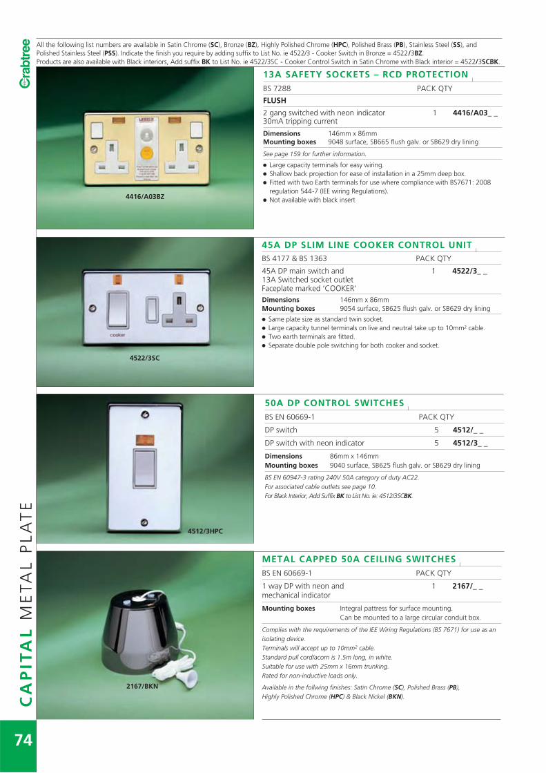
CA
PIT
AL
ME
TAL
PL
AT
E
74
All the following list numbers are available in Satin Chrome (SC), Bronze (BZ), Highly Polished Chrome (HPC), Polished Brass (PB), Stainless Steel (SS), andPolished Stainless Steel (PSS). Indicate the finish you require by adding suffix to List No. ie 4522/3 - Cooker Switch in Bronze = 4522/3BZ.Products are also available with Black interiors, Add suffix BK to List No. ie 4522/3SC - Cooker Control Switch in Satin Chrome with Black interior = 4522/3SCBK.
2167/BKN
METAL CAPPED 50A CEILING SWITCHESl
BS EN 60669-1 PACK QTY
1 way DP with neon and 1 2167/_ _mechanical indicator
Mounting boxes Integral pattress for surface mounting.Can be mounted to a large circular conduit box.
Complies with the requirements of the IEE Wiring Regulations (BS 7671) for use as anisolating device.Terminals will accept up to 10mm2 cable.Standard pull cord/acorn is 1.5m long, in white.Suitable for use with 25mm x 16mm trunking.Rated for non-inductive loads only.
Available in the follwing finishes: Satin Chrome (SC), Polished Brass (PB), Highly Polished Chrome (HPC) & Black Nickel (BKN).
4416/A03BZ
13A SAFETY SOCKETS – RCD PROTECTIONl
BS 7288 PACK QTY
FLUSH
2 gang switched with neon indicator 1 4416/A03_ _30mA tripping current
Dimensions 146mm x 86mmMounting boxes 9048 surface, SB665 flush galv. or SB629 dry lining
See page 159 for further information.
� Large capacity terminals for easy wiring.� Shallow back projection for ease of installation in a 25mm deep box.� Fitted with two Earth terminals for use where compliance with BS7671: 2008
regulation 544-7 (IEE wiring Regulations).� Not available with black insert
4522/3SC
45A DP SLIM LINE COOKER CONTROL UNITl
BS 4177 & BS 1363 PACK QTY
45A DP main switch and 1 4522/3_ _13A Switched socket outletFaceplate marked ‘COOKER’Dimensions 146mm x 86mmMounting boxes 9054 surface, SB625 flush galv. or SB629 dry lining
� Same plate size as standard twin socket.� Large capacity tunnel terminals on live and neutral take up to 10mm2 cable.� Two earth terminals are fitted.� Separate double pole switching for both cooker and socket.
4512/3HPC
50A DP CONTROL SWITCHESl
BS EN 60669-1 PACK QTY
DP switch 5 4512/_ _
DP switch with neon indicator 5 4512/3_ _
Dimensions 86mm x 146mmMounting boxes 9040 surface, SB625 flush galv. or SB629 dry lining
BS EN 60947-3 rating 240V 50A category of duty AC22.For associated cable outlets see page 10.For Black Interior, Add Suffix BK to List No. ie: 4512/3SCBK.

CA
PIT
AL
ME
TAL
PL
AT
E
75For full specification details of finishes see Technical Data page 172.
All the following list numbers are available in Satin Chrome (SC), Bronze (BZ), Highly Polished Chrome (HPC), Stainless Steel (SS) and Polished Stainless Steel (PSS)Indicate the finish you require by adding suffix to List No. ie 8265 – Co-axial socket in Bronze = 8265/BZ.
8092/BZ 8092/SCfitted with modules fitted with modules
7080 7071 7172
4318/SC
7069 7065 7067
COMMUNICATIONS PLATESl
BS 5733 WHERE APPLICABLE PACK QTY
1 module metal plate (fitted with grid) 5 8091/_ _
2 module metal plate (fitted with grid) 5 8092/_ _
4 module metal plate (fitted with grid) 5 8094/_ _
Dimensions 86mm x 86mm, 1 & 2 module86mm x 146mm, 4 module
Mounting boxes 8091*, 8092*–9041 surface, SB615 flush galv. or SB619 dry lining8094*–9040 surface, SB625 flush galv. or SB629 dry lining
The metal plates listed above accept any of the Datapak range of modules.See page 23 for full product selection details.
MULTI MEDIA PLATEl
PACK QTY
Multi Media Plate 1 4318/_ _
The plate comprises 2 Dual Earth, Double pole,twin switched sockets and has provision for upto six Euro modules.
The following finishes are available, please add suffix to List No. Satin Chrome (SC),Stainless Steel (SS), Polished Brass (PB), Highly Polished Chrome (HPC)and White (WH).
Dimensions 267mm x 207mm
Mounting boxes Deep - 254mm x 194mm x 56mm - 9226/BGShallow - 253mm x 193mm x 35mm - 9228/BG
See Page 104 for more details
COMMUNICATION MODULESl
PACK QTY
BT Master Voice 25 7080
BT Master Voice, Left Handed 25 7080/LH
BT secondary Voice, 6 wire 25 7071
RJ45 (single) module, 8 wire – Category 5e 25 7172
DATA AND CO-AXIAL MODULESl
BNC single module with 75 Ohm 25 7074crimp connector
TV outlet (male) 25 7065
TV outlet (female) 25 7067
F type Satellite 25 7069
Triplex Unit (TV, FM, Sat) 25 7063
Quadplexer with TV return (TV, TV Return, 10 7064FM, Sat 1 & Sat 2)
TV outlet screened, return 25 7060
Phono (Female) 25 7087
BLANK MODULES & ACCESSORIESl
1/2 module size 25 7081/2
1 module size 25 7081
IDC Tool 20 6915
IDC Crimp Tool 1 7915
Also available in Black - Add suffix BK to List No. ie: triplex unit in Black = 7063/BK.
Dimensions 25mm x 50mm, (1 module) (except 7063 - 50mm x 50mm &7064 - 75mm x 50mm)
7074 7063 7069

4316/SCRD
RED ROCKERSFor applications where essential supply systems are in use, sockets and fusedconnection units with red rockers are available to order. These are ideal for use inhospitals, computer installations, etc.To order, add suffix to List No.ie 4316/SC with red rockers = 4316/SC/RD.
For Rockergrid switches with red rockers see Rockergrid section page 86-87.
CA
PIT
AL
ME
TAL
PL
AT
E
76
All the following list numbers are available in Satin Chrome (SC), Bronze (BZ), Highly Polished Chrome (HPC), Polished Brass (PB) Stainless Steel (SS) and PolishedStainless Steel (PSS). Indicate the finish you require by adding suffix to List No. ie 8265 Co-axial socket in Bronze = 8265/BZ.
8265/HPC 8268/BZ
8283/HPC 8284/BZ
TELEPHONE PLATESl
BS 7671 PACK QTY
Telephone Master 10 8283/_ _
Telephone Secondary 10 8284/_ _
Dimensions 86mm x 86mmMounting boxes 9047 surface, SB655 flush galv. or SB619 dry lining
CO-AXIAL SOCKET OUTLETSl
BS 3041 WHERE APPLICABLE PACK QTY
1 way direct connection 10 8265/_ _
2 way direct connection 10 8266/_ _
1 way isolated UHF, VHF 1 8267/_ _
2 way isolated UHF, VHF 1 8268/_ _
Dimensions 86mm x 86mmMounting boxes 9047 surface, SB655 flush galv. or SB619 dry liningIsolated units only suitable on installations with earth bond.
6575/BZ 6577/BZ
For full specification details of finishes see Technical Data page 173.
BLANKING PLATESl
BS 5733 WHERE APPLICABLE PACK QTY
1 gang 20 6575/_ _
2 gang 20 6577/_ _
Dimensions 1 gang 86mm x 86mm2 gang 146mm x 86mm

CA
PIT
AL
ME
TAL
PL
AT
E
77
PRODUCT MARKING SERVICEl
A wide range of markings can be added to 13A fused connection unitsand double pole control switches. The majority of these markings areconsistent in style, colour and position with the standard Tampo-printed ‘water heater’ marking on List No.4011/31_ _.All of the markings offer the same high level of durability.
To order any of the markings listed below, add suffix to List No.ie 4832/SC marked ‘fridge freezer’ = 4832/SC/FF.
MARKING SUFFIXair conditioner ACalarm ALbathroom BAbell transformer BEbathroom extract fan BEFbathroom heater BHboiler BOboiler supply BOSboost BSTBritish Telecom BTcaravan CACCTV CCTVcentral heating CHcooker CKcupboard light CLconvector heater CNHday boost DBdetector DEdownflow heater DHdoor bell DOdish washer DWdryer DYemergency circuit ECextractor fan EFextractor hood EHfire alarm FAfor cleaners use only FCOfan coil unit FCUfeature fire FEfridge/freezer FFfan heater FHfire FIfan FNfridge FRfreezer FZgas ignition GIhand dryer HAhob HB
MARKING SUFFIXcooker hood HDheating HGhair dryer HIheating isolator HSheater HTimmersion heater IHkitchen extract fan KEFlight LGlift LIloft light LLmicrowave MWnight immersion NIoff peak OFFPoutside light OLon peak ONPoven OVpelmet light PELplinth heater PLHrefrigerator RFsecurity alarm SAsmoke detector SDsecurity equipment SEshower SHsecurity light SLshower pump SPstorage heater STsteam cabinet STCtumble dryer TDtowel rail TRTV amplifier TVAunderfloor heating UHvent fan VFwater heater WAwater cooler WCwaste disposal WDwashing machine WMwasher WS
These popular markings are offered on a fast track service in the standard wiringaccessories colour. For price and delivery information on other markings not listedabove, contact our Technical Services Department.
4832/HPC/DW 4832/HPC/TD
4832/3HPC/HG 4832/3SC/FF
4832/3SC/EF 4832/3SC/WM
4011/3HPC/HB 4011/3HPC/TD
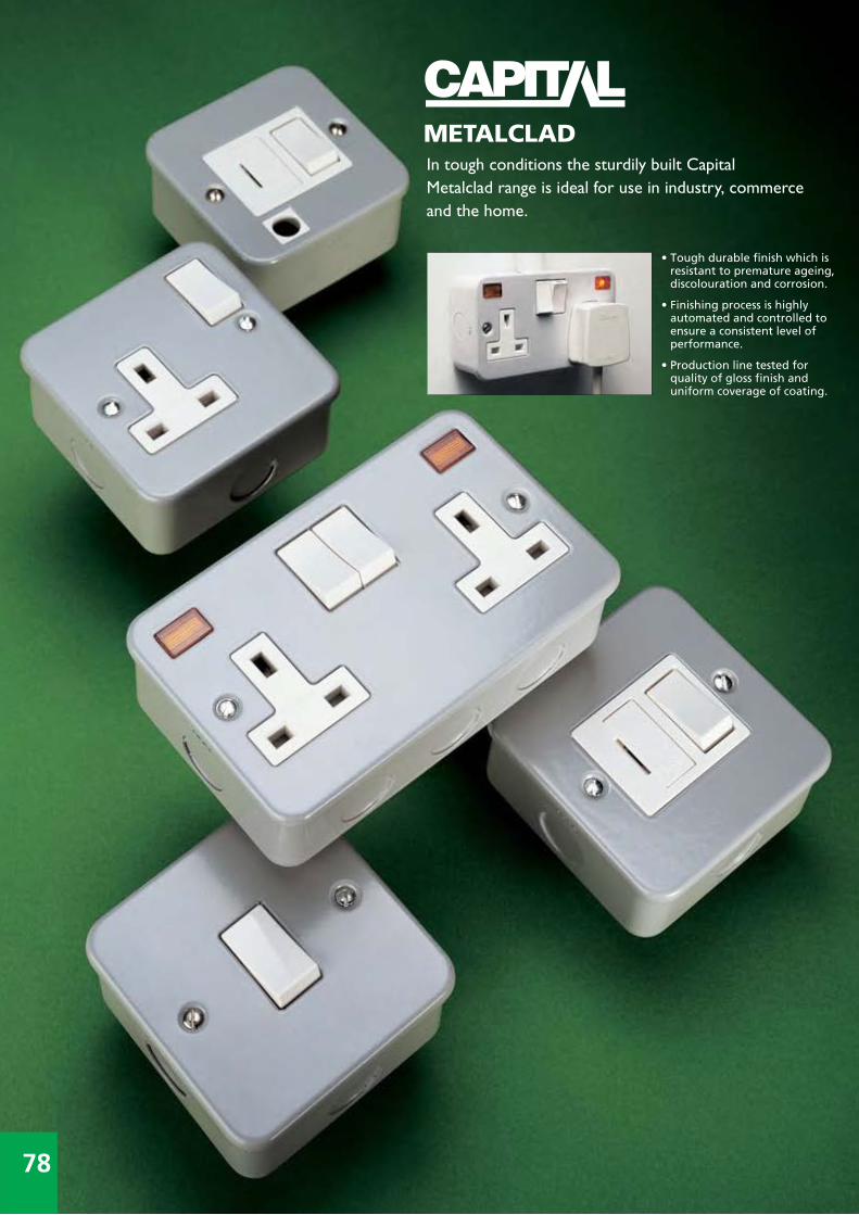
In tough conditions the sturdily built CapitalMetalclad range is ideal for use in industry, commerceand the home.
• Tough durable finish which is resistant to premature ageing,discolouration and corrosion.
• Finishing process is highly automated and controlled to ensure a consistent level of performance.
• Production line tested for quality of gloss finish and uniform coverage of coating.
78
METALCLAD

CA
PIT
AL
ME
TAL
CL
AD
79
4214/BG 4216/3BG
4214/3BG 4216/BG
9685/BG 9687/BG
4841/BG 4846/BG
4842/3BG 4847/3BG
For full specification details of finishes see Technical Data page 173.
13A SWITCHED SOCKET OUTLETSl
BS 1363 PACK QTY
1 gang SP 10 4214/BG
2 gang SP 5 4216/BG
1 gang SP with neon indicator 10 4214/3BG
2 gang SP with neon indicator 5 4216/3BG
Dimensions 1 gang 86.7mm x 86.7mm x 44mm2 gang 143.9mm x 86.9mm x 44mm
For sockets with plain boxes – Add suffix P to List No.eg 4216/BG with plain box = 4216/PBG.Double pole available to order – Add suffix D to List No.eg Double pole 4216/BG = 4216/DBG.� All switched sockets are Dual Earth.
13A UNSWITCHED SOCKET OUTLETSl
BS 1363 PACK QTY
1 gang unswitched 10 9685/BG
2 gang unswitched 5 9687/BG
Dimensions 1 gang 86.7mm x 86.7mm x 44mm2 gang 143.9mm x 86.9mm x 44mm
For sockets with plain boxes – Add suffix P to List No.eg 4216/BG with plain box = 4216/PBG.
13A FUSED CONNECTION UNITSl
BS 1363 WHERE APPLICABLE PACK QTY
Unswitched 10 4841/BG
Unswitched with neon indicator 10 4841/3BG
DP switched 10 4842/BG
DP switched with neon indicator 10 4842/3BG
Unswitched with cord outlet 10 4846/BG
DP switched with cord outlet 10 4847/BG
DP switched with cord outlet and 10 4847/3BGneon indicator
Dimensions 86.7mm x 86.7mm x 44mm
For fused connection units with plain boxes – Add suffix P to List No.eg 4842/BG with plain box = 4842/PBG.Fused on the line side with a 13A fuse link ASTA certified and marked to BS 1362.For spare fuse links see page 8.Cord outlets suitable for flexible cord up to 10mm outside diameter.Two earthing terminals are fitted to the unit.

50A DP CONTROL SWITCHESl
BS EN 60669-1 PACK QTY
DP Switch 10 4512/BG
DP Switch with neon indicator 10 4512/3BGDimensions 142mm x 82mm x 42mm
BS EN 60947-3 rating 240V 50A category of duty AC22.
CA
PIT
AL
ME
TAL
CL
AD
80
2240/BG 2272/BG
4581/BG 4583/BG
4512/BG 4512/3BG
4020/3BG 4021/3BG
4416/A03BG
4426/A03BG
For full specification details of finishes see Technical Data page 173.
13A SAFETYSOCKET WITH RCD PROTECTIONl
BS 7288 PACK QTY2 gang switched with neon indicator 1 4416/A03BG30mA tripping current flush mounting2 gang switched with neon indicator 1 4426/A03BG30mA tripping current surface mountingDimensions Flush –146mm x 86mm Surface –142mm x 82mm x 44mmMounting boxes 4414 & 4416 series
9223/BG surface,SB665 flush galv or SB629 dry lining
For boxes less knockouts see page 104. For further information see page 159.
� Large capacity terminals for easy wiring� Shallow back projection for ease of installation in a 25mm deep box� Fitted with two earth terminals for use where compliance with BS7671: 2008 regulation
543-7 (IEE Wiring Regulations)
5A, 15A SWITCHED SOCKET OUTLETSl
BS 546 PACK QTY
5A shuttered SP 10 2240/BG
15A shuttered SP 10 2272/BGDimensions 86.7mm x 86.7mm x 44mm
For boxes less knockouts see page 104.
10AX SWITCHESl
BS EN 60669-1 PACK QTY
10AX 1 gang 2 way 10 4581/BG
10AX 2 gang 2 way 10 4582/BG
10AX 3 gang 2 way 10 4583/BGDimensions 86.7mm x 86.7mm x 44mm
20A DP CONTROL SWITCHESl
BS EN 60669-1 PACK QTY
DP Switch with neon indicator 10 4020/3BG
DP Switch with neon indicator and 10 4021/3BGcord outlet
Dimensions 86.7mm x 86.7mm x 44mm
Cord outlet suitable for flexible cord up to 10mm outside diameter.Surface box fitted with earth terminal.For switches with plain boxes add suffix P to List No. ie 4020/3BG with plain box = 4020/3PBG.

CA
PIT
AL
ME
TAL
CL
AD
81
4587/BG
1932
3899BG 3809BG
4216/BG/RD
For full specification details of finishes see Technical Data page 173.
6A TP CONTROL SWITCHESl
BS EN 60669-1, BS EN60947-3 PACK QTY
10A Three Pole Isolating Switch 10 4587/BG
Provides local isolation of fans with or without timers whilst the rest of the circuit remains live.Enables repair or routine maintenance of fans. 240V only.
Dimensions 86.7mm x 86.7mm x 44mm
For full details of compliance with BS EN 60947-3 see Technical Data page 165.
TRIPLE POLE & NEUTRAL 415V, 50HZ ACl
PACK QTY
32A with Switched Neutral, for surface mounting 1 1932
32A with Switched Neutral, for flush mounting 1 1932/F� Terminal capacity 10mm.
Dimensions 133mm x 114mm x 61mm
RED ROCKERSl
For applications where essential supply systems are in use, sockets and fusedconnection units with red rockers are available to order.These are ideal for use in hospitals, computer installations, etc.
PART No. PACK QTY
Single switched socket 10 4214/BG/RD
Twin switched socket 5 4216/BG/RD
For Rockergrid switches with red rockers see Rockergrid section page 86.� All switched sockets are Dual Earth.
BLANKING PLATES FOR SURFACEREPLACEMENT BOXES
l
PART No. PACK QTY
For List No 9214/BG 5 3809BG
For List No 9211/BG 10 3899BG
Dimensions 1 gang 86.7mm x 86.7mm2 gang 143.9mm x 86.9mm

Rockergrid provides the design versatility of a
modular switch range whilst incorporating
Capital styling and safety features which
benefit the user and installer alike.
82
MODULAR SYSTEM

• Unique labyrinth switchdesign minimises visiblearc flash and preventsfront access to live parts.
• Positive drive switchaction prevents balancingbetween the ‘on’ and‘off’ position and givesreliable indication of thecontact position.
• Silver alloy contacts forlonger life and lowcontact resistance.
RO
CK
ER
GR
ID M
OD
UL
AR
SY
ST
EM
83
Polished Brass
Satin Chrome
Highly Polished Chrome
PolishedStainless Steel
Bronze
White
Birch Grey

SELECTION TABLEl
PLATES
Gang 1 2 3 4 6 8 9 12
Surface
BIRCH GREY 6581/BG 6582/BG 6583/BG 6584/BG 6586/BG 6588/BG 6589/BG 6580/BGEngraved ‘Water Heater’ 6581/1BG 6582/1BG
Flush
MOULDED WHITE 5571 5572 5573 5574 5576
WHITE METAL 6578/WH 6579/WH 6570/WH
BRONZE 6571/BZ 6572/BZ 6573/BZ 6574/BZ 6576/BZ 6578/BZ 6579/BZ 6570/BZEngraved ‘Water Heater’ 6571/1BZ 6572/1BZ
SATIN CHROME 6571/SC 6572/SC 6573/SC 6574/SC 6576/SC 6578/SC 6579/SC 6570/SCEngraved ‘Water Heater’ 6571/1SC 6572/1SC
HIGHLY POLISHED CHROME 6571/HPC 6572/HPC 6573/HPC 6574/HPC 6576/HPC 6578/HPC 6579/HPC 6570/HPC
POLISHED STAINLESS STEEL 6571/PSS 6572/PSS 6573/PSS 6574/PSS 6576/PSS 6578/PSS 6579/PSS 6570/PSS
POLISHED BRASS 6571/PB 6572/PB 6573/PB 6574/PB 6576/PB 6578/PB 6579/PB 6570/PB
GRIDS
Flush or surface 6901 6902 6903 6904 2 x 6903 2 x 6904 3 x 6903 3 x 6904
BOXES
Flush or surface
with knock-outs 9201/BG 9201/BG 9203/BG 9203/BG 9206/BG 9206/BG 9209/BG 9209/BG
without knock-outs 9201/PBG 9201/PBG 9203/PBG 9203/PBG 9206/PBG 9206/PBG 9209/PBG 9209/PBG
Flush only SB615 SB615 SB625 SB625
ASSEMBLY
RO
CK
ER
GR
ID M
OD
UL
AR
SY
ST
EM
SE
LE
CT
ION
GU
IDE
1 Install box andenter cables.
� Boxes, grids &switchescommon toflush & surfaceinstallations.
2 Remove ‘ears’from grid forsurfaceinstallations.
� When Flush mounting do notremove ‘ears’.
3 Fix switchesinto grid.
� Single screwswitch fixing.
� Fingerproofshroudingaroundterminals.
84

Architrave
18 24 1 2
6580/18BG 6580/24BG
6570/18WH 6570/24WH 6591/WH 6592/WH
6570/18BZ 6570/24BZ 6591/BZ 6592/BZ
6570/18SC 6570/24SC 6591/SC 6592/SC
6570/18HPC 6570/24HPC 6591/HPC 6592/HPC
6570/18PSS 6570/24PSS 6591/PSS 6592/PSS
6570/18PB 6570/24PB 6591/PB 6592/PB
3 x 6906 4 x 6906 1367 1368
9209/18BG 9209/24BG
9209/18PBG 9209/24PBG
9341/GV 9342/GV
Supplied fitted toarchitrave plate
RO
CK
ER
GR
ID M
OD
UL
AR
SY
ST
EM
SE
LE
CT
ION
GU
IDE
4 Connect wiresto relevantswitches &earth terminals.
� Large capacity,easy-to-wireterminals.
� Diagrammaticmarking onrear of switch.
5 Fix wiredswitch/gridassemblyinto box.
� Automatic gridalignment withhorizontaladjustment.
6 Fix face plateonto grid.
� Robust impactresistantconstruction,high qualitymoulded &metal parts.
85
* Metal rocker finishes: Satin Chrome (SC/WH), Bronze (BZ), Polished Brass (PB),Highly Polished Chrome (HPC), Polished Stainless Steel (PSS)and Stainless Steel (SS/WH).
SWITCHESl
ROCKER
MOULDED METAL
10AX 1 way 4430 4430/6_ _*
10AX 2 way 4530 4530/6_ _*
10A Retractive 4489 4489/6_ _*
10A Retractive marked with bell symbol 4490 4490/6_ _*
10A Retractive 2 way and off 4553 4553/6_ _*
20AX 1 way 4450 4450/6_ _*
20AX 1 way key switch c /w key 4451
20AX 2 way 4550 4550/6_ _*
20AX 2 way key switch c /w key 4551
20AX 2 way and off 4552 4552/6_ _
20AX Intermediate 4535 4535/6_ _*
20AX Double pole 4460 4460/6_ _*
20AX Double pole marked ‘ON’ 4469
20AX Double pole key switch c /w key 4461
Switches are available in Black (BK) eg: 4460/BK, 4460/6PBBK
ACCESSORIESl
Cord outlet 4435
13A fused connection unit 4436
Neon indicator (Red) 4491
Neon indicator (Green) 4493
Neon indicator (Amber) 4494
Socket outlet 2.5–16A 4499†
Blanking component 4492
Spare key 6940 (Metal)
Accesories are available in Black (BK) eg: 4436/BK
† Available for export use only.
Switch modules:� Tough impact-resistant thermoplastic moulded construction.� Metal plate switch modules incorporate double insulation.� Suitable for panel mounting and OEM applications.� IP66 protected Rockergrid switch enclosures are available, see Weatherseal section page 77.

RO
CK
ER
GR
IDM
OD
UL
AR
SY
ST
EM
86
4430 4490 4530/BK
4450 4469 4552 4451 694045514461
4436 4491 4492 4494 4435
4430/RD 4460/RD4530/BK 4490/BK
10AX SWITCHES – MOULDED ROCKERl
BS EN 60669-1 PACK QTY
1 way SP 10 4430
2 way SP 10 4530
Retractive 10A 10 4489
Retractive – bell symbol 10A 10 4490
Retractive 2 way and off 10A 10 4553
Available as made to order in Black (BK) eg: 4530/BKFully rated for fluorescent and inductive loads (except List No.4553, 4490 & 4489).4490 Retractive switch can be wired for normally open (N/O) ornormally closed (N/C) circuits. (except List No. 4553)
20AX SWITCHES – MOULDED ROCKERl
BS EN 60669-1 PACK QTY
1 way 10 4450
1 way complete with key 10 4451
1 way with key marked “Emergency Lighting Test” 10 4451/ELT
Double Pole 10 4460
Various markings - See page 89 10 4460/_ _
DP complete with key 10 4461
DP with key marked “Emergency Lighting Test” 10 4461/ELT
DP marked ‘ON’ 10 4469
Intermediate 10 4535
2 way 10 4550
2 way complete with key 10 4551
2 way with key marked “Emergency Lighting Test” 10 4551/ELT
2 way and off 10 4552
Spare key 10 6940
Available as made to order in Black (BK) eg: 4550/BK
ACCESSORIES – MOULDEDl
BS 5733 WHERE APPLICABLE PACK QTY
Cord outlet – 10mm diameter aperture, complete 10 4435with earthing terminal and cable clamp
Fuse unit fitted with 13A ASTA certified fuse link 10 4436
Indicator – Red 10 4491
Blanking component 10 4492
Indicator – Green 10 4493
Indicator – Amber 10 4494
Available as made to order in Black (BK)
OTHER SWITCH VARIATIONSl
The following modules are available with black mouldings.
Black rockers 4430/BK 4491/BK
4450/BK 4493/BK
4490/BK 4550/BK
Red rockers 4430/RD 4530/RD 4450/RD 4535/RD
4460/RD 4550/RD 4490/RD
For panel cut-out details see dimensions on page 189.

RO
CK
ER
GR
IDM
OD
UL
AR
SY
ST
EM
All the following metal plate switches are available with Satin Chrome (SC/WH), Bronze (BZ), High Polished Chrome (HPC) Polished Brass (PB) Polished Stainless Steel (PSS)and Stainless Steel (SS/WH) rockers. Indicate the finish you require by adding the suffix to List No. eg 4430/6 with Bronze rocker = 4430/6BZ.
87
6901 6902
4460/6HPC 4535/6PB 4550/6SS/WH 4450/6SC/WH 4460/6PSS
4430/6SC/WH 4530/HPC4489/6PB
For full specification details of finishes see Technical Data page 173.
4440
10AX SWITCHES – METAL PLATE ROCKERl
BS EN 60669-1 PACK QTY
1 way 10 4430/6_ _
Retractive 10A 10 4489/6_ _
Retractive 2 way and off 10A 10 4553/6_ _
2 way 10 4530/6_ _
Available with White moulding Trim eg: 4530/6SC/WHAvailable with Black moulding Trim eg: 4530/6SCFully rated for fluorescent and inductive loads (except List No. 4489/6_ _ & 4553/6_ _ ) .Retractive switches can be wired for normally open (N/O) or normally closed (N/C) circuits.
20AX SWITCHES – METAL PLATE ROCKERl
BS EN 60669-1 PACK QTY
1 way 10 4450/6_ _
Double Pole 10 4460/6_ _
Intermediate 10 4535/6_ _
2 way 10 4550/6_ _
2 way and off 10 4552/6_ _
Available with White moulding Trim eg: 4530/6SC/WHAvailable with Black moulding Trim eg: 4530/6SCFully rated for fluorescent and inductive loads.
GRIDSl
1 gang 20 6901
2 gang 20 6902
3 gang 10 6903
4 gang 10 6904
6 gang 10 6906
Dimensions 1–2 gang 81mm x 58mm 3–4 gang 141mm x 58mm6 gang 202mm x 58mm
When required for surface mounting assemblies, the fixing ears should be removed orbent inwards at 90°.Complete with earth terminal.
GRID DIMMERSl
BS EN 60669-2-1, BS EN 55015 PACK QTY
250W White 10 4425
250W Black 10 4425/BK
400W White 10 4440
400W Black 10 4440/BK
ILLUMINATED GRID DIMMERSl
250W White 10 4425/BL
250W Black 10 4425/BKBL
400W White 10 4440/BL
400W Black 10 4440/BKBL
� For Technical details of grid dimmers & Illuminated grid dimmers see page 170.� Dimensions on page 191.

RO
CK
ER
GR
IDM
OD
UL
AR
SY
ST
EM
88
5571 5574
6592/SC 6570/24BZ
6581/BG 6580/BG
FLUSH MOULDED PLATESl
PACK QTY
1 gang 20 5571
2 gang 20 5572
3 gang 10 5573
4 gang 10 5574
6 gang 1 5576
Dimensions 1–2 gang 86mm x 86mm3–4 gang 146mm x 86mm6 gang 147mm x 147mm
FLUSH METAL PLATESl
PACK QTY
1 gang 20 6571/_ _
1 gang faceplate printed ‘water heater’ 20 6571/1_ _
2 gang 20 6572/_ _
2 gang faceplate printed ‘water heater’ 20 6572/1_ _
3 gang 10 6573/_ _
4 gang 10 6574/_ _
6 gang 1 6576/_ _
8 gang 1 6578/_ _*
9 gang 1 6579/_ _*
12 gang 1 6570/_ _*
18 gang 1 6570/18_ _*
24 gang 1 6570/24_ _*
1 gang architrave complete with grid 10 6591/_ _*
2 gang architrave complete with grid 10 6592/_ _*
Dimensions 1–2 gang 86mm x 86mm 18 gang 207mm x 267mm3–4 gang 146mm x 86mm 24 gang 207mm x 267mm6–8 gang 147mm x 147mm 1 gang architrave 35mm x 86mm9–12 gang 147mm x 207mm 2 gang architrave 35mm x 146mm
Add to List No. – BZ for Bronze finish, SC for Satin Chrome finish, HPC for HighlyPolished Chrome finish, PB for Polished Brass finish, PSS for Polished Stainless Steelfinish.*Available in White Finish. Add WH to List No.
SURFACE METALCLAD PLATESl
PACK QTY
1 gang 20 6581/BG
1 gang faceplate printed ‘water heater’ 20 6581/1BG
2 gang 20 6582/BG
2 gang faceplate printed ‘water heater’ 20 6582/1BG
3 gang 10 6583/BG
4 gang 10 6584/BG
6 gang 1 6586/BG
8 gang 1 6588/BG
9 gang 1 6589/BG
12 gang 1 6580/BG
18 gang 1 6580/18BG
24 gang 1 6580/24BG
Dimensions 1–2 gang 77mm x 77mm 9–12 gang 137mm x 197mm3–4 gang 137mm x 77mm 18 gang 197mm x 257mm6–8 gang 137mm x 137mm 24 gang 197mm x 257mm

RO
CK
ER
GR
IDM
OD
UL
AR
SY
ST
EM
89
9201/PBG 9209/PBG
4460/HT 4460/WD 4460/EF 4460/WM 4460/HB
For full specification details of finishes see Technical Data page 173.For panel cut out detail, see dimensions on page 189.
BOXES LESS KNOCKOUTSl
PACK QTY
1 and 2 gang surface or flush 10 9201/PBG
3 and 4 gang surface or flush 5 9203/PBG
6 and 8 gang surface or flush 1 9206/PBG
9 and 12 gang surface or flush 1 9209/PBG
18 gang surface or flush 1 9209/18PBG
24 gang surface or flush 1 9209/24PBG
Dimensions 9201/PBG 73mm x 73mm x 40mm9203/PBG 133mm x 73mm x 40mm9206/PBG 133mm x 133mm x 40mm9209/PBG 133mm x 194mm x 40mm9209/18PBG 194mm x 254mm x 56mm9209/24PBG 194mm x 254mm x 56mm
Note: BG boxes fitted with earth terminal. Spare earth terminal (List No.6989) see page 104.
9201/BG 9209/BG
BOXESl
PACK QTY
1 and 2 gang surface or flush 10 9201/BG
3 and 4 gang surface or flush 5 9203/BG
6 and 8 gang surface or flush 1 9206/BG
9 and 12 gang surface or flush 1 9209/BG
18 gang surface or flush 1 9209/18BG
24 gang surface or flush 1 9209/24BG
1 gang architrave flush only 10 9341/GV
2 gang architrave flush only 10 9342/GV
Dimensions 9201/BG 73mm x 73mm x 40mm9203/BG 133mm x 73mm x 40mm9206/BG 133mm x 133mm x 40mm9209/BG 133mm x 194mm x 40mm9209/18BG 194mm x 254mm x 56mm9209/24BG 194mm x 254mm x 56mm9341/GV 27mm x 70mm x 35mm9342/GV 27mm x 130mm x 35mm
16mm knock-outs in 1 and 2 gang box and architrave boxes.20mm and 25mm knock-outs in 3–24 gang boxes.Note: BG boxes fitted with earth terminal. Spare earth terminal (List No.6989) see page 104.
20AX DOUBLE POLE SWITCH MARKING l
“boiler” 4460/BO “cooker hood” 4460/HD
“dishwasher” 4460/DW “extractor fan” 4460/EF
“fridge” 4460/FR “freezer” 4460/FZ
“fridge freezer” 4460/FF “hob” 4460/HB
“heating system” 4460/HT “microwave” 4460/MW
“tumble dryer” 4460/TD “waste disposal” 4460/WD
“washer dryer” 4460/WDR “washing machine” 4460/WM
“water heater” 4460/WA
• can be used with 13A fuse units to build bespoke kitchen/utility roomcontrol panel.All of the above are supplied in pack quantities of 10.

2009Weatherseal
water anddust protected
90

• Socket lid is automatically retained in the open position, enabling the plugto be easily inserted. A simple push down until the fixing click is heard isall that is necessary to create a water-proof seal, safeguarding your family and home.
Water and dust protected to IP56,
Weatherseal is ideal for all environments.
Especially suitable for use in the garden,
workshop or Industry as the robustly
designed socket outlets retain their IP56
rating when used with a moulded on 13A
plug which is standard fitment on many
power tools and appliances.
• Socket outlets retain their IP56 ratingwhen used with any standard 13A plug.
• 1 gang, 2 gang and retractive surfaceswitches all retain their IP56 rating even when in use.
• Communication enclosures will acceptEuro modules featured in the Datapak range.
WATER & DUST PROTECTED
WE
AT
HE
RS
EA
L W
AT
ER
& D
US
T P
RO
TE
CT
ED
91

WE
AT
HE
RS
EA
LW
AT
ER
& D
US
T P
RO
TE
CT
ED
92
SWITCHES l
IP56 BSEN 60669-1 PACK QTY
20AX 1 gang 2 way switch 1 9700
20AX 2 gang 2 way switch 1 9702
20A Retractive switch marked ‘Press’ 1 9703
Dimensions 1 gang 96mm (Height ) x 96mm (Width) x 70mm (Depth)
Supplied as ready assembled units, with two earth terminals in the back boxKnockouts - 1 gang 4x 20mm Dia, one on each edge
13A SOCKETS l
IP56 BS1363 PACK QTY
1 gang Unswitched Socket 1 9704
2 gang DP Switched Socket c /w twin earth terminals 1 9706
Dimensions 1 gang 126mm (Height) x 96mm (Width) x 81mm (Depth)2 gang 143mm(Height) x 164mm(Width) x 81mm(Depth)
The Sockets retain their IP56 rating when used with any standard 13A plug,including flexed plugsSupplied as ready assembled units, with two earth terminals in the back boxKnockouts - 1 gang 4x 20mm Dia, one on each edge
2 gang 6x 20mm Dia, two on the top and bottom, and one on each side
13A SAFETY SOCKETS WITH RCD PROTECTION l
IP56 BS7288 PACK QTY
2 gang DP Switched SRCD c /w neon indicator 1 9708
Dimensions 2 gang 143mm(Height) x 164mm(Width) x 81mm(Depth)
30mA tripping currentSocket complete with twin earth terminalsRCD sockets are all passive control electromechanical operation and will not trip on lossof mains supplyThe Sockets retain their IP56 rating when used with any standard 13A plug,including flexed plugsSupplied as ready assembled units, with two earth terminals in the back boxKnockouts - 2 gang 6x 20mm Dia, two on the top and bottom, and one on each side
See page 159 for further information.
13A SWITCHED FCU l
IP56 BS1363 PACK QTY
13A 1 gang Switched FCU c /w cord outlet 1 9707
Dimensions 1 gang 126mm (Height) x 96mm (Width) x 81mm (Depth)
Fused on the line side with a 13A fuse to BS1362Cord outlet on the front plate is suitable for flexible cord up to 10mm outside diameterSupplied as ready assembled units, with two earth terminals in the back boxKnockouts - Knockouts - 1 gang 4x 20mm Dia, one on each edge
9700 9702
9704 9706
9708
9707

WE
AT
HE
RS
EA
LW
AT
ER
& D
US
T P
RO
TE
CT
ED
93
EURO DATA ENCLOSUREl
IP56 PACK QTY
1 gang 2 euro module enclosure 1 9722
2 gang 4 euro module enclosure 1 9724
Dimensions 1 gang 126mm (Height) x 96mm (Width) x 81mm (Depth)2 gang 143mm(Height) x 164mm(Width) x 81mm(Depth)
The Sockets retain their IP56 rating when in use providing the lid is closed fullySupplied as ready assembled units, with two earth terminals in the back boxKnockouts - 1 gang 4x 20mm Dia, one on each edge
2 gang 6x 20mm Dia, two on the top and bottom, and one on each side
DATA AND CO-AXIAL MODULESl
PACK QTY
BNC single module with 75 Ohm crimp connector 25 7074
TV outlet (male) 25 7065
TV outlet (female) 25 7067
F type satellite 25 7069
Triplex Unit (TV, FM, Sat) 25 7063
TV outlet screened, return 25 7060
Phono (female) 25 7087
Quadplexer (TV, FM, Sat 1 & Sat 2) 10 7066
Quadplexer with TV return 10 7064(TV, TV return, FM, Sat 1 & Sat 2)
Also available in Black - Add suffix BK to list No.ie: Triplex unit in black = 7063/BK.
Dimensions 25mm x 50mm (1 Module) (except 7063 & 7066 - 50mm x 50mm)(except 7064 - 75mm x 50mm 3 Module)
COMMUNICATION MODULESl
PACK QTY
BT Master Voice 25 7080
BT Master Voice, Left Handed 25 7080/LH
BT Secondary Voice, 6 wire 25 7071
RJ45 (single) module, 8 wire - Category 5e 25 7172
RJ45 ISDN terminated 25 7174
RJ11/12 25 7086
PABX Voice 25 7176
RJ45 (Twin) module 25 71731/2 module size 25 7081/2
1 module size 25 7081
2 module size 10 7082
Also available in Black - Add suffix BK to list No.ie: BT Master in black = 7080/BK.
Dimensions 25mm x 50mm (1 Module)
9722 9724
7064 7066
7069 7065 7067
7074 7063 7087
7080 7071 7172
7176 7086 7174

Polycarbonate is a highly durable material which is ideal for use in most environments,however seek advice before installing in environments where chemicals or harshcleaners are likely to be used.
WE
AT
HE
RS
EA
LW
AT
ER
& D
US
T P
RO
TE
CT
ED
94
10A SURFACE SWITCHESl
BS 3676 BS 5490 IP66 PACK QTY
9561 1 gang 1 wayl
4
9562 2 gang 1 wayl
2
Dimensions 1 gang 101mm x 101mm x 76mm2 gang 197mm x 101mm x 76mm
Padlock off facility provided. See page 143 for suitable padlock.Terminals accepted 2.5mm2 cable.
13A PLUGS, SURFACE SOCKETS &COMBINATION UNITS
l
PACK QTY
9565 Single socket outletl
4
9567 Switched socket combinationl
2
Dimensions 1 gang size 101mm x 101mm x 76mm2 gang size 197mm x 101mm x 76mm
Sockets incorporate transparent flap which automatically snaps shut when the plug is withdrawn.Terminals accept maximum 10mm2 cable.
RCD PROTECTED 13A SOCKETSl
SOCKET BS 1363RCD BS EN 61008 PACK QTY
9571 40A 30mA RCD protecting one 13A socketl
1
9572 40A 30mA RCD protecting two 13A socketsl
1
Dimensions 3 gang size 296mm x 102mm x 104mm4 gang size 199mm x 199mm x 104mm
Sockets incorporate transparent flap which automatically snaps shut when the plug iswithdrawn.RCD terminals accept 25mm2 cable.RCD is Type AC operation.
RCD PROTECTED 16A 240V SOCKETl
SOCKET BS 4343RCD BS EN 61008 PACK QTY
9579 40A 30mA RCD protecting 16A 2P + E240V splashproof socket
l1
RCD terminals accept 25mm2 cable.RCD is Type AC operation.Common to 110V and 240V BS 4343 splashproof sockets IP44 protection ismaintained when plug is inserted. IP66 is maintained when cover flap is closed.
9561 rear view
9565 9567
9571 9572
9579
The individual switches and sockets listed on this page are supplied as ready assembled units on shallow enclosures. The switched socket combination unitand RCD protected socket outlets are pre-wired and supplied as ready assembled units on appropriate enclosures.

WE
AT
HE
RS
EA
LW
AT
ER
& D
US
T P
RO
TE
CT
ED
95
13A SOCKET MODULESl
PACK QTY
9565/L 13A single unswitched socketl
8
9567/L 13A switch/socket combinationl
2
Can be assembled in shallow enclosures.
The table below lists module selection details for some additional popular combinations.
The table below lists the modular equivalents to the popular items supplied as ready assembled units.
MODULAR SELECTIONl
The popular items listed on the page opposite in ready-assembled form can also be built up from separate modules to allow greater stockflexibility, whilst additional separate sale switch, socket and cover modules with enclosures up to 6 gang size enable the installer to providehigh IP-rated combinations to suit individual applications.
SWITCH MODULESl
PACK QTY
9561/1L 10A 1 way switchl
4
9561/DL 20A DP switchl
4
9573/L 32A TP switchl
4
9573/RL 32A TP switch – yellow/redl
4
Can be assembled in shallow enclosures. 9573/L 9561/2L 9573/RL
9565/L 9567/L
READY-ASSEMBLED UNITS MODULAR EQUIVALENT SELECTION
DESCRIPTION LIST No COVER MODULE(S) ENCLOSURE RCD
10A switch – 1 gang 1 way 9561 9561/1L 9561/ES –
10A switch – 2 gang 1 way 9562 9561/1L x 2 9562/ES –
13A single socket outlet 9565 9565/L 9561/ES –
13A switched socket 9567 9567/L 9562/ES –
13A single socket with 40A 30mA RCD 9571 9570/2 + 9565/L 9563/E 224/030
13A twin socket with 40A 30mA RCD 9572 9570/2 x 1 + 9565/L x 2 9564/E 224/030
16A 2P + E 240V socket – BS 4343 9579 9570/2 + 9569/L 9563/E 224/030
DESCRIPTION COVER MODULE(S) ENCLOSURE RCD
13A twin socket outlet with single switch 9565/L x 2 + 9561/DL 9563/E –
13A twin-switched socket outlet 9567/L x 2 9564/E –
13A single-switched socket with 40A 30mA RCD 9570/2 x 1 + 9567/L 9564/E 224/030
9566/E + 9569/L + 9561/2L + 9567/L + 9570/2 + 224/030Multi-gang enclosures enable any combination
9567 or 9567/L + 9562/ES

WE
AT
HE
RS
EA
LW
AT
ER
& D
US
T P
RO
TE
CT
ED
96
SOCKET MODULESl
BS 4343 PACK QTY
9569/L 16A 2P + E 240V splashproof socketl
4
9591/L 16A 2P + E 110V splashproof socketl
4
9593/L 16A 3PN + E 415V splashproof socketl
4
Should be assembled in deep enclosures.IP44 protection is maintained when plug is inserted, on 110V and 240V sockets.IP66 is maintained when plug is inserted, on 415V sockets.
ROCKERGRID COVER MODULESl
PACK QTY
9581/RG 1 gangl
4
9582/RG 2 gangl
4
� Suitable for any Rockergrid module.� Rockergrid modules fix directly into moulded-in grid with single screw fixing.� Enables a wide range of switch variations in IP66 rated enclosures.� Can be used to provide 2 gang switching option where space is insufficient
for standard Weatherseal module.
The selection table below lists some of the popular IP66 combinations which can be assembled from the Weathersealand Rockergrid ranges.
MODULE SELECTIONl
ROCKERGRID WEATHERSEAL WEATHERSEALDESCRIPTION module(s) cover module enclosure
10AX 2 gang 1 way switch– single module size 4430 x 2 9582/RG 9561/ES
10AX retractive switch 4489 9581/RG 9561/ES
13A switched FCU 4460 + 4436 9582/RG 9561/ES
13A unswitched FCU + neon 4436 + 4494 9582/RG 9561/ES
20A intermediate switch 4535 9581/RG 9561/ES
20A DP switch + neon 4460 + 4494 9582/RG 9561/ES
20A DP key switch 4461 9581/RG 9561/ES
20A 2 gang 1 way switch– single module size 4450 x 2 9582/RG 9561/ES
See page 86 for full range of Rockergrid switches.
RCD COVER MODULEl
PACK QTY
9570/2 2 gang RCD cover with neon assemblyand RCD mounting cradle
l2
Should be assembled in deep enclosures.
� Suitable for any 2 module RCD from the Lifestar range – see page 158.
9569/L 9591/L 9593/L
9581/RG 9582/RG
Rear view
9570/2 RCD mounting cradleshown in deep enclosure

WE
AT
HE
RS
EA
LW
AT
ER
& D
US
T P
RO
TE
CT
ED
97
ENCLOSURESl
PACK QTY
9561/E 1 gangl
4
9561/ES 1 gang shallowl
8
9562/E 2 gangl
2
9562/ES 2 gang shallowl
4
9563/E 3 gangl
3
9564/E 4 gangl
1
9566/E 6 gangl
1
Dimensions (mm) H W D H W D1 gang enclosure 103 x 102 x 63 3 gang enclosure 296 x 102 x 631 gang shallow enclosure 101 x 101 x 40 4 gang enclosure 199 x 199 x 632 gang enclosure 198 x 102 x 63 6 gang enclosure 296 x 199 x 632 gang shallow enclosure 197 x 101 x 40
REAR SIDE CONDUIT 32/25 25/20SOCKET KNOCK-OUTS ENTRIES REDUCER REDUCER DIVIDER BRIDGE
9561/E 1x32/25 1x25, 1x32 1 1 – –
9561, 9565 1x25/20 2x25 – 1 – –9561/ES
9562/E† 1x25, 1x32 1x25, 1x32 1 1 – 1
9562, 9567 2x25/20 2x25 – 1 – 19562/ES
9563/E* 2x25, 1x32 1x25, 1x32 1 1 – 2
9564/E* 2x25 2x25, 4x32 1 1 2 21x32, 1x40
9566/E* 2x25 2x25, 4x32 1 1 4 32x32, 2x40
* Also supplied with 1 neutral & 1 earth connector. † Also supplied with 1 earth connector.
To maintain IP66 rating, cover all fixing screws with caps provided.Seal bridge/divider slots with suitable silicon sealant.Check all conduit entry points are tight before use.Threaded conduit entries can be fitted to all popular metal and moulded metric conduitusing a variety of proprietory adaptors (less locking ring), reducers, and adhesive whereappropriate.
Polycarbonate is a highly durable material which is ideal for use in most environments,however seek advice before installing in environments where chemicals or harshcleaners are likely to be used.
9561/E 9562/ES
9566/E
BLANK COVER MODULESl
PACK QTY
9561/L 1 gang blank coverl
8
9562/L 2 gang blank coverl
4
9563/L 3 gang blank coverl
3
9561/L 9562/L 9563/L

Interiors and panel mounting products, which complement
the extensive Capital and Rockergrid ranges, are available
to suit many applications.
The Capital range of Switched Sockets and Fused Control
Units are available with metal capped rockers.
Most Capital Products can also be supplied in black as
standard – ideal for brassware manufacturers.
98
INTERIORS & PANEL MOUNTING

CA
PIT
AL
INT
ER
IOR
S &
PAN
EL
MO
UN
TIN
Gl
99For panel cut-out details see pages 188, 189 & 190.
4314/1BK 4316/1
8255/1 8257/1
4416/A103
4831/1 4832/1BK
FUSED CONNECTION UNITSl
PACK QTY
13A unswitched 10 4831/1
13A DP switched 10 4832/1
13A DP switched complete with neon and lens 10 4832/13
13A unswitched with cord outlet 10 4836/1
13A DP switched with cord outlet 10 4837/1
13A DP switched with cord outlet 10 4837/13complete with neon and lensBlack interiors also available – Add suffix BK to List No. eg 4832/1 switched in Black= 4832/1BK
13A UNSWITCHED SOCKET OUTLETSl
PACK QTY
1 gang unswitched 10 8255/1
2 gang unswitched 5 8257/1
1 gang round socket with side entry terminals 10 7259*and north/south fixingsThe 7259 panel mounting socket is suitable for use in any panel or trunking material up to 2.5mmthickness and can be incorporated into a minimum overall internal depth of only 22.5mm.Black mouldings also available, Add Suffix BK to List No. eg 8255/1BK.* Not available in Black.
13A SWITCHED SOCKET OUTLETSl
PACK QTY
1 gang SP 10 4314/1
2 gang SP 5 4316/1
1 gang SP complete with neon and lens 10 4314/13
2 gang SP complete with neon and lens 5 4316/13Black mouldings also available – Add suffix BK to List No.Double pole switching also available to order – Add suffix D to List No.eg 4314/1 switched in Black = 4314/1DBK
� Supplied Complete with two earth terminals
13A SAFETYSOCKET WITH RCD PROTECTIONl
BS 7288 PACK QTY
2 gang switched with neon indicator 1 4416/A10330mA tripping current
See page 159 for further information.
� Supplied Complete with two earth terminals

CA
PIT
AL
INT
ER
IOR
S &
PA
NE
L M
OU
NT
ING
100
4522/1
For panel cut-out details see page 188, 189 & 190.
8075/1 2240/1
4314/16/SC 4316/16BK/PB
4831/13 4832/16BK/PB
METAL CAPPED ROCKERS13A SWITCHED SOCKET OUTLETS
l
PACK QTY
1 gang SP 10 4314/16/_ _
2 gang SP 5 4316/16/_ _
1 gang SP complete with neon and lens 10 4314/136/_ _
2 gang SP complete with neon and lens 5 4316/136/_ _Black mouldings also available – Add suffix BK to List No.Double pole switching also available to order – Add suffix D to List No.eg 4314/1 switched = 4314/16DBK/SCFinishes available are: Satin Chrome (SC), Bronze (BZ), Polished Brass (PB), Highly PolishedChrome (HPC) & Stainless Steel (SS).
� Supplied Complete with two earth terminals
METAL CAPPED ROCKERSFUSED CONNECTION UNITS
l
PACK QTY
13A DP switched 10 4832/16/_ _
13A DP switched complete with neon and lens 10 4832/136/_ _
13A DP switched with cord outlet 10 4837/16/_ _
13A DP switched with cord outlet 10 4837/136/_ _complete with neon and lensBlack interiors also available – Add suffix BK to List No.Finishes available are: Satin Chrome (SC), Bronze (BZ), Polished Brass (PB), Highly PolishedChrome (HPC) & Stainless Steel (SS).
2A, 5A ROUND PIN SOCKET OUTLETSl
PACK QTY
5A shuttered SP 10 2240/1*
2A 3 pin unswitched shuttered 10 8075/1*
* Black mouldings also available – Add suffix BK to List No.
45A DP ‘SLIMLINE’ COOKER CONTROL UNITSl
PACK QTY
45A DP main switch and 13A 5 4522/1switch socket outlet
45A DP main switch and 13A 5 4522/13switch socket outlet with neon indicators
Black interiors also available – Add suffix BK to List No.

CA
PIT
AL
INT
ER
IOR
S &
PAN
EL
MO
UN
TIN
G
101For panel cut-out details see pages 188, 189 & 190.
6170/1 6173/1BK
4011/1 4011/1BK
4512/1BK
8283/1 8284/1BK
8265/1 8266/1
10AX SWITCHESl
PACK QTY
1 gang retractive marked ‘press’ 10 6096/1
1 gang 2 way 10 6170/1
2 gang 2 way 10 6172/1
3 gang 2 way 10 6173/1
4 gang 2 way 10 6174/1
1 gang intermediate 10 6175/1
Interiors with Black rockers available – Add suffix BK to List No.
20A/32A DP SWITCHESl
PACK QTY
20A DP 10 4011/1
20A DP complete with neon and lens 10 4011/13
32A DP 10 4012/1
32A DP complete with neon and lens 10 4012/13
Interiors with Black rockers available – Add suffix BK to List No.
50A DP SWITCHESl
PACK QTY
50A DP 10 4512/1
50A DP with neon indicator 10 4512/13
Black interiors also available – Add suffix BK to List No.
CO-AXIAL SOCKET OUTLETSl
PACK QTY
1 way direct connection 1 8265/1
2 way direct connection 1 8266/1
1 way isolated VHF, UHF 1 8267/1
2 way isolated VHF, UHF 1 8268/1
Isolated units only suitable on installations with earth bond.
TELEPHONE OUTLETSl
PACK QTY
Master 10 8283/1
Secondary 10 8284/1
Black interiors also available – Add suffix BK to List No.Supplied with loose earth terminal.

102
INSTALLATIONBOXES & SERVICE ITEMSThe comprehensive range of white mouldedpatresses offers a facility to surface mountCapital wiring accessories

INS
TAL
LA
TIO
N B
OX
ES
103
4005 4006
9043 9048/1
9040 9053
9052
9406
SURFACE MOULDED BOXESFOR CAPITAL WIRING ACCESSORIES
l
BS 5733 PACK QTY
20mm deepFor Capital single gang moulded architrave 10 4005switches Will accept 16mm x 16mm mini-trunking
Dimensions 33mm x 87mm x 20mm
For Capital double gang moulded architrave 10 4006switches Will accept 16mm x 16mm mini-trunking
Dimensions 33mm x 147mm x 20mm
34mm deepFor 50A Capital switches and Rockergrid 5 9040*3 and 4 gang moulded assembliesFitted with cable clamp
Dimensions 87mm x 147mm x 34mm
44mm deepFor 15A socket outlets, 32A DP switches and 10 9041Rockergrid 1 and 2 gang moulded assemblies
Dimensions 87mm x 87mm x 44mm
20mm deepWith earth terminal 10 9043For 10AX Capital moulded and metalplate,
Dimensions 87mm x 87mm x 20mm
29mm deepDual box for two single gang size accessories 5 9044*Fixed dividing barrier with knockouts
Dimensions 174mm x 87mm x 29mm
For single gang size moulded accessories 10 9047
Dimensions 87mm x 87mm x 29mm
For double gang size moulded accessories 5 9048*
Dimensions 147mm x 87mm x 29mm
With earth terminal 5 9048/1*For Capital 4 to 6 gang switches
Dimensions 147mm x 87mm x 29mm
32mm deep Skirting BackboxMultipurpose box for single gang size accessories 5 9049*
Dimensions 88mm x 165mm x 32mm
Multipurpose box for double gang size accessories 2 9050*
Dimensions 148mm x 165mm x 32mm
45mm deepFor 45A cooker control units 1 9052*Fitted with cable clamp
Dimensions 169mm x 115mm x 45mm
49mm deepFor shaver supply unit 5 9053*Will accept 25mm x 16mm mini-trunking
Dimensions 87mm x 147mm x 49mm
45mm deepFor slimline cooker control units 5 9054*Will accept 25mm x 16mm mini-trunkingFitted with cable clamp
Dimensions 89mm x 147mm x 45mm
20mm deep2 gang Surface conversion patresses 5 9406Converts 1 gang Flush box to 2 gang Surface
Dimensions 147mm x 87mm x 20mm
* Can be secured to flush mounting steel boxes having 60.3mm accessory fitting centres

INS
TAL
LA
TIO
N B
OX
ES
104
9211/BG 9214/BG
9228/BG
9221/PBG 9223/BG
6988 6989
REPLACEMENT STEEL BOXESFOR CAPITAL SURFACE WIRING ACCESSORIES
l
BS 5733 PACK QTY
43mm deep 20mm knockouts 10 9211/BGReplacement box for 5, 13 and 15A single gang sizesurface accessories
As above less knockouts 10 9211/PBG
Dimensions 82.3mm x 82.3mm x 41.6mm
43mm deep 20mm knockouts 5 9214/BGReplacement box for 13A gang sizesurface accessories
As above less knockouts 5 9214/PBG
Dimensions 139.5mm x 82.6mm x 41.5mm
MULTI MEDIA PLATE BACK BOXl
56mm deep 20/25mm knockouts 1 9226/BGMulti media plate back box
Dimensions 254mm x 194mm x 56mm
35mm deep 20mm knockouts 1 9228/BGMulti media plate back box
Dimensions 253mm x 193mm x 35mm
COOKER CONTROL UNIT BACK BOXl
Use with 4520/1 or 4520/31 1 9338/GV
Dimensions 155mm x 101mm x 42mm
SURFACE STEEL BOXESFOR CAPITAL FLUSH WIRING ACCESSORIES
l
BS EN 60669-1 PACK QTY
36mm deep With 20mm knockouts 10 9221/BGFor surface mounting single gang sizeflush accessories
As above less knockouts 10 9221/PBG
Dimensions 86mm x 86mm x 36mm
36mm deep With 20mm knockouts 5 9223/BGFor surface mounting double gang sizeflush accessories
As above less knockouts 5 9223/PBG
Dimensions 146mm x 86mm x 36mm
SPARE EARTH TERMINALSl
Brass (for use with 4 lug metal box) 100 6988
Brass 100 6989

ACCESSORY FIXING SCREWS M3.5mml
PACK QTY
Platinum long fixing screw 50mm 100 735050
20mm long (vandal resistant) 100 735009/*/VR
25mm long (vandal resistant) 100 735010/*/VR
30mm long (vandal resistant) 100 735011/*/VR
25mm long 735010* 20mm long 100 735032
30mm long 735011* 23mm long 100 735038
50mm long 735012* 25mm long 100 735033
40mm long 735013* 30mm long 100 735023
* Add finish required i.e.735010SC.
66
SE
RV
ICE
ITE
MS
105
735010/BZ/VR
735011/SC/VR 735011/BZ
735007/ZP 735008/SC
706097 705094/BZ
7410/RD 7410/WH 6900/1WH
4674 3711 3467
3713
SUNDRY SCREWS & SPACERSl
PACK QTY
Rockergrid switch to grid 100 706124
Capital 50A switch to grid & grid to box 4950/BG series 100 735006/ZP
Rockergrid grid to box 100 735007
Capital plate to box on 4214 & 4216 ranges 100 735008/*
Rockergrid plate to grid 100 705094/*
Rockergrid plate to grid (vandal-resistant) 100 705094/*/VR
Screwdriver for Rockergrid VR screws 1 6913
*All screws are available to match the appropriate Capital Metal Plate and Rockergridfinishes.
CAPITAL CEILING SWITCH ACCESSORY ITEMSl
1.5m long white pull cord and acorn 6900
2m long red pull cord and acorn 6900/1RD
2m long white pull cord with red acorn 6900/1WH
100m ball of white pull cord 6900/2
100m ball of red pull cord 6900/2RD
Ceiling switch acorn red 7410/RD
Ceiling switch acorn white 7410/WH
CAPITAL NEON INDICATORSl
For 13A moulded & metal plate sockets, 13A fuse connection units, 371320A, 32A, 45A capital switches
For 13A safetysockets & slimline cooker control units 100215
CAPITAL NEON LENSESl
For all 50A DP switches & large plate cooker control unit 3467(larger lens) & 32A TP & N switches
For 13A moulded & metal plate sockets, fuse connection units, 371120A capital switches & slimline cooker control unit (smaller lens)
For slimline cooker control unit (large lens) & capital 45A switches 3767
For 50A ceiling switch & large plate cooker control unit (smaller lens) 4674

LUMINAIRESUPPORTCOUPLERSCrabtree luminaire supportcouplers, LSCs, provide flexibility andversatility to meet the demands of manydomestic, commercial and industriallighting applications.
The range conforms to BS 7001and BS 5733 and provides an effectiveplug-in connection with arrangementsincluding 3 and 4 pin versions.
Ceiling outlet can be easilyassembled to pattress andplug provides a simpleplug in connection
Ceiling assembly coversecures to outlet withassembly offering eitherstandard or safetylampholder options
106

LU
MIN
AIR
E S
UP
PO
RT
CO
UP
LE
RS
107
5001 complete assembly
5009
5018
5010 5006
5003 5011
5002
CEILING ASSEMBLIES 3 PINl
Description List No
3 pin 5001
3 pin with 2m 1.0mm2 Heat Resistant (HR) cable 5002
3 pin with 2m 1.0mm2 Low Smoke (LSF) cable 5017
3 pin with 3m 1.0mm2 Heat Resistant (HR) cable 5002/3
3 pin with 3m 1.0mm2 Low Smoke (LSF) cable 5017/3
3 pin with 5m 1.0mm2 Heat Resistant (HR) cable 5002/5
3 pin with 5m 1.0mm2 Low Smoke (LSF) cable 5017/5
• Ceiling assemblies supplied as outlet, LSC plug and cover.• Other lengths and cable options available upon request.
CEILING ASSEMBLIES 4 PIN l
Description List No
4 pin 5009
4 pin with 2m 1.0mm2 Heat Resistant (HR) cable 5018
4 pin with 2m 1.0mm2 Low Smoke (LSF) cable 5019
4 pin with 3m 1.0mm2 Heat Resistant (HR) cable 5018/3
4 pin with 3m 1.0mm2 Low Smoke (LSF) cable 5019/3
4 pin with 5m 1.0mm2 Heat Resistant (HR) cable 5018/5
Cover only for LSC ceiling assembly 5001/CVR
PENDANT SETSl
Description List No
Surface mounting pattress 5005
LSC PLUGSl
Description List No
3 pin 5006
4 pin (with red cover) 5010
• Cable clamp to grip outer cable insulation for maximum support.• 4 pin LSC plug has a red cover as standard.• Prewired versions are available, please contact Technical Services.
CEILING OUTLETS & INTERIORS l
DescriptionList No
3 pin ceiling outlet 5003
4 pin ceiling outlet 5011
For further details of pattress see Technical page 172.

The LSC Interiors are mounted in a combination of 6,8 and 10 outlet configurations contained within asteel fabricated enclosure to provide a LuminaireDistribution Box, LDB.
� Internal connections are made to a terminal block for ease of wiring
� Sufficient side and rear knockouts allow entries for cable or conduit
� Raised mounting feet allow for installation on uneven surfaces
LUMINAIREDISTRIBUTIONBOXES
108

LSC PLUGSl
Description List No
3 pin 5006
3 pin C/W 2m HR cable 5006/2
3 pin C/W 3m HR cable 5006/3
3 pin C/W 4m HR cable 5006/4
4 pin (with red cover) 5010
4 pin C/W 2m HR cable 5010/2
4 pin C/W 3m HR cable 5010/3
4 pin C/W 4m HR cable 5010/4
• Cable clamp to grip outer cable insulation for maximum support.• 4 pin LSC plug has a red cover as standard.• 3 pin LSC plugs can be installed into all LSC interiors.• Different lengths & types of cable are available please contact Technical Services.
4 P
IN L
UM
INA
IRE
SU
PP
OR
T C
OU
PL
ER
S
109
For Dimensions see page 191.
5021/4
5020/4
5010 5006
4 PIN LUMINAIRE DISTRIBUTION BOXESl
Description List No
4 pin 6 way 5020/4
4 pin 8 way 5021/4
4 pin 10 way 5022/4

110

WA
RW
ICK
PV
C T
RU
NK
ING
WARWICKPVC modular trunking range which can bemounted at either Dado or Skirting level,available in 2 different sizes (50mm x 170mm)or (50mm x 212mm).
111

WA
RW
ICK
MO
DU
LA
R P
VC
RA
NG
E
112
WA
RW
ICK
AN
CIL
LA
RY
ITE
MS
AN
DS
PAR
ES
For Technical information see page 175. Dimensions see page 192.
QUICK GUIDE TO FIVE PVC PROFILES
WARWICK 1 WARWICK 2 WARWICK 3 WARWICK 4 WARWICK 5
Ref No Ref No Ref No Ref No Ref No
Trunking Pack BCL1 BCL2 BCL3 BCL4 BCL5
Internal Bend BCL1/IB BCL2/IB BCL3/IB BCL4/IB BCL5/IB
External Bend BCL1/EB BCL2/EB BCL3/EB BCL4/EB BCL5/EB
Flat Angle 90° (Downward) BCL1/FAD BCL2/FAD BCL3/FAD BCL4/FAD BCL5/FAD
Flat Angle 90° (Upward) – BCL2/FAU – BCL4/FAU BCL5/FAU
Flat Tee (Downward) BCL1/FTD BCL2/FTD BCL3/FTD BCL4/FTD BCL5/FTD
Flat Tee (Upward) – BCL2/FTU – BCL4/FTU BCL5/FTU
Stop End - Left BCL1/SEL BCL2/SEL BCL3/SEL BCL4/SEL BCL5/SEL
Stop End - Right – BCL2/SER – BCL4/SER BCL5/SER
Coupler Pack BCL1/CP BCL2/CP BCL3/CP BCL4/CP BCL5/CP
Standard Cable Retainer BCL/SCR BCL/SCR BCL/SCR BCL/SCR BCL/SCR
Square Cable Retainer – BCL/SQCR BCL/SQCR BCL/SQCR BCL/SQCR
Single Gang Accessory Box - 30mm deep BCL/SGB BCL/SGB BCL/SGB BCL/SGB BCL/SGB
Twin Gang Accessory Box - 30mm deep BCL/TGB BCL/TGB BCL/TGB BCL/TGB BCL/TGB
ANGLED COVER SECTIONPack Quantity 5 x 3m BCL/ACS
MAIN COVERPack Quantity 5 x 3m BCL/MC
SQUARE COVER SECTIONPack Quantity 5 x 3m BCL/SCS
BASE EXTENSIONPack Quantity 5 x 3m BCL/BE
VERTICAL MOUNT ADAPTOR PLATEPack Quantity 1 BCL/ADPL
RCD HOUSINGPack Quantity 1 BCL/RCD(RCD not Included)

WA
RW
ICK
1P
VC
TR
UN
KIN
G
113
Profile assembly includes: • Base Section
• 2 x Angled Covers
• 1 x Main Cover
Overall Size: • 170mm x 50mm
50 mm17
0 m
m
85 m
m42
mm
42 m
m
For Technical information see page 175. Dimensions see page 192.
TRUNKING PACKPack Quantity 1 x 3m lengths BCL1
INTERNAL BENDPack Quantity 1 BCL1/IB
EXTERNAL BENDPack Quantity 1 BCL1/EB
FLAT ANGLEPack Quantity 1 BCL1/FAD
FLAT TEEPack Quantity 1 BCL1/FTD
STOP ENDPack Quantity 1 BCL1/SEL
COUPLER PACKPack Quantity 1 BCL1/CP
SINGLE GANG ACCESSORY BOXPack Quantity 10 BCL/SGB30mm deep
TWIN GANG ACCESSORY BOXPack Quantity 5 BCL/TGB30mm deep

WA
RW
ICK
MO
DU
LA
R P
VC
RA
NG
E
114
WA
RW
ICK
2 P
VC
TR
UN
KIN
GProfile assembly includes: • Base Section
• 1 x Angled Cover
• 1 x Main Cover
• 1 x Square Cover
Overall Size: • 170mm x 50mm
50 mm17
0 m
m
85 m
m42
mm
42 m
m
For Technical information see page 175. Dimensions see page 192.
TRUNKING PACKPack Quantity 1 x 3m lengths BCL2
INTERNAL BENDPack Quantity 1 BCL2/IB
EXTERNAL BENDPack Quantity 1 BCL2/EB
FLAT ANGLE (DOWNWARD)Pack Quantity 1 BCL2/FAD
FLAT ANGLE (UPWARD)Pack Quantity 1 BCL2/FAU
FLAT TEE (UPWARD)Pack Quantity 1 BCL2/FTU
FLAT TEE (DOWNWARD)Pack Quantity 1 BCL2/FTD
STOP END (LEFT)Pack Quantity 1 BCL2/SEL
STOP END (RIGHT)Pack Quantity 1 BCL2/SER
COUPLER PACKPack Quantity 1 BCL2/CP
SQUARE CABLE RETAINERPack Quantity 10
BCL/SQCRSINGLE GANG ACCESSORY BOXPack Quantity 10 BCL/SGB
TWIN GANG ACCESSORY BOXPack Quantity 5 BCL/TGB

WA
RW
ICK
3P
VC
TR
UN
KIN
G
115
Profile assembly includes: • Base Section
• 2 x Square Covers
• 1 x Main Cover
Overall Size: • 170mm x 50mm
50 mm17
0 m
m
85 m
m42
mm
42 m
m
For Technical information see page 175. Dimensions see page 192.
TRUNKING PACKPack Quantity 1 x 3m lengths BCL3
INTERNAL BENDPack Quantity BCL3/IB
EXTERNAL BENDPack Quantity 1 BCL3/EB
FLAT ANGLEPack Quantity 1 BCL3/FAD
FLAT TEEPack Quantity 1 BCL3/FTD
STOP ENDPack Quantity 1 BCL3/SEL
COUPLER PACKPack Quantity 1 BCL3/CP
SQUARE CABLE RETAINERPack Quantity 10 BCL/SQCR
SINGLE GANG ACCESSORY BOXPack Quantity 10 BCL/SGB
TWIN GANG ACCESSORY BOXPack Quantity 5 BCL/TGB

WA
RW
ICK
MO
DU
LA
R P
VC
RA
NG
E
116
WA
RW
ICK
4P
VC
TR
UN
KIN
GProfile assembly includes: • Base Section
• 1 x Base Extension
• 1 x Angled Cover
• 2 x Main Covers
Overall Size: • 212mm x 50mm
212
mm
50 mm
85 m
m85
mm
42 m
m
For Technical information see page 175. Dimensions see page 192.
TRUNKING PACKPack Quantity 1 x 3m lengths BCL4
INTERNAL BENDPack Quantity 1 BCL4/IB
EXTERNAL BENDPack Quantity 1 BCL4/EB
FLAT ANGLE (DOWNWARD)Pack Quantity 1 BCL4/FAD
FLAT ANGLE (UPWARD)Pack Quantity 1 BCL4/FAU
FLAT TEE (DOWNWARD)Pack Quantity 1 BCL4/FTD
FLAT TEE (UPWARD)Pack Quantity 1 BCL4/FTU
STOP END (LEFT)Pack Quantity 1 BCL4/SEL
STOP END (RIGHT)Pack Quantity 1 BCL4/SER
COUPLER PACKPack Quantity 1 BCL4/CP
SINGLE GANG ACCESSORY BOXPack Quantity 10 BCL/SGB
TWIN GANG ACCESSORY BOXPack Quantity 5 BCL/TGB

TWIN GANG ACCESSORY BOX30mm Deep Pack Quantity 5 BCL/TGB
212
mm
50 mm
85 m
m85
mm
42 m
m
117
Profile assembly includes: • Base Section
• 1 x Base Extension
• 1 x Square Cover
• 2 x Main Covers
Overall Size: • 212mm x 50mm
For Technical information see page 175. Dimensions see page 192.
TRUNKING PACKPack Quantity 1 x 3m lengths BCL5
INTERNAL BENDPack Quantity 1 BCL5/IB
EXTERNAL BENDPack Quantity 1 BCL5/EB
FLAT ANGLE (DOWNWARD)Pack Quantity 1 BCL5/FAD
FLAT ANGLE (UPWARD)Pack Quantity 1 BCL5/FAU
FLAT TEE (DOWNWARD)Pack Quantity 1 BCL5/FTD
FLAT TEE (UPWARD)Pack Quantity 1 BCL5/FTU
STOP END (LEFT)Pack Quantity 1 BCL5/SEL
STOP END (RIGHT)Pack Quantity 1 BCL5/SER
COUPLER PACKPack Quantity 1 BCL5/CP
SQUARE CABLE RETAINERPack Quantity 10 BCL/SQCR
SINGLE GANG ACCESSORY BOX30mm Deep Pack Quantity 10 BCL/SGB
WA
RW
ICK
5P
VC
TR
UN
KIN
G

118

119
POWERTRACKUNDERFLOOR SYSTEMAND FLOORBOXES
BR
ITM
AC
PO
WE
RT
RA
CK
& F
LO
OR
BO
XE
S

POWER TRACK UNDERFLOOR SYSTEM
The Britmac underfloor power track system has undergone some
radical changes to meet the ever increasing power requirements
of the workplace. The system consists of a series of fully enclosed
single phase busbar module units and is designed to be assembled directly
onto the floor slab of a cavity floor installation using the integral floor fixing
brackets. The track modules have a simple and quick push fit connection
allowing for rapid on site assembly. The modules are available as standard 2P+E,
Clean Earth 2P+E+CE and dual system 4P+E+CE. The system has been designed
with minimal parts to assist the contractor fitting out on site.
� Direct to floor assembly � Universal cable feeder unit� Standard Earth 2P+E - Blue� Clean Earth 2P+E+CE - Yellow� Dual system 4P+E+CE - Brown
120

The Power track module is a 63A single phase busbar unit with the facilityto accept a tap-off unit every 300mm, this allows the removal or addition
of tap off units without the need to isolate the complete system.The system has been designed with the electrical contractor in mind,
where speed and ease of installation are paramount, with push fitconnectors on both the track connections and feed units.
There is a keying system on the track end which operates the shuttermechanism and allows correct location.
The modules come in standard lengths, all compatible with standardfloor modules and cavity floor trunking sizes. Each length comes
complete with an innovative method of track fixing.The fixing bracket simply swivels out to enable
solid fixing to the floor screed.
The standard tap off units comprises a 32A unfused plugfitted with flexible metal conduit.
Where lengths longer than 3m are required, a fused tap offunit is fitted and wired with the appropriate
length of cable.All tap offs have a keying system which ensures
that the correct tap off is fitted
Transparent dust covers are providedto enable easy recognition of
the system installed.The dust cover slides along the
track length to enabletap off plug insertion.
� Push fit � Colour coded� 50mm minimum clearance height � Non interchangeable pin configuration� Pre-wired tap off unit� Complies with BS 7671: 2008 regulation 543.7
BR
ITM
AC
PO
WE
RT
RA
CK
& F
LO
OR
BO
XE
S
121

BR
ITM
AC
PO
WE
RT
RA
CK
& F
LO
OR
BO
XE
S
122
UNDERFLOOR POWER TRACK MODULESl
Track Length Standard Clean Earth Dual Track
1200mm UPT12 UPT12TE UPT12DE
2400mm UPT24 UPT24TE UPT24DE
3600mm UPT36 UPT36TE UPT36DE� Tap off socket at 300mm intervals complete with clear dust cover� Track fixing brackets factory fitted 2 on 1.2m, 3 on 2.4m and 3 on 3.6m� Each length comes with a shuttered interconnection and a track stop end� Colour Coded: Blue - Standard
Yellow - Clean EarthBrown - Dual Track
CABLE SUPPLY FEED INl
Feed unit for standard & clean Earth system UPFLH
Feed unit for Dual Track system UPFLH/DE
CABLE SUPPLY FEED ONl
Universal feed unit UPFRH� The Cable Supply feed end allows the termination of the incoming flexible cables.
The generously sized terminals accept up to 16mm2 cables� 1 x 25mm diameter conduit entry hole� Feed unit for Dual Track system has 2 x 25mm diameter conduit entry holes
FLEXIBLE CORNER UNITl
Standard Clean Earth Dual Track
1 Metre Length UPFC UPFCTE UPFCDE� Comes complete with feed in and feed on units� The flexible corner unit is used for angled bends or to pass around or over an obstruction.
The unit comprises a 1 metre length of 25mm flexible metal conduit and the appropriate 10mm2 LSF cable
UPFCTE
32A TAP OFF UNITl
Standard Clean Earth Dual Track
3M Unfused UPP3 UPP3TE UPP3DE
5M 13A Fused UPP5F UPP5FTE UPP5FDE� 3.0m Unfused tap off wired with 4mm2 LSF cable housed in a 16mm diameter flexible
metal conduit� 5.0m Fused tap offs incorporate a 13A Fuse and are wired with 2.5mm2 LSF cable to Live
and Neutral with the Earth wired using 4mm2 LSF to comply with regulation 543.7� Tap off incorporates a keying system which ensures correct insertion is always achieved
UPP3TE
UPFLH

124
72.4
75
83
48
96 Ctrs
277
Minimum floor void 50mm
Conditional Short Circuit RatingTRACKShort circuit protection provided by fuselinks BS-88 and BS 1361 100 ampmaximum.
Prospective current 16.5kAMechanical withstand 10kA peakThermal withstand 1200A for 0.1 seconds
TAP-OFF UNITSMechanical withstand 10kA peakThermal withstand 1200A for 0.1 seconds
Earth Fault Loop Impedance (measured at 1.0A)
The IEE Wiring Regulations require accurate determination of the total earthloop impedance, which must be low enough to ensure that the protectivedevice will operate within the specified time, which for circuits incorporatingsocket outlets is 0.4 seconds. The values for the Britmac System for calculatingthe earth fault loop impedance are as follows:
Phase busbar 1.97mV/mEarth busbar to housing 1.38mV/mEarth busbar (Clean Earth) 1.97mV/mTrack connector 0.37mVSupply connector 0.24mV32A tap-off (4mm2 x 3m), line 9.92mV
Volt Drop, Combined Phase & Neutral (measured at 1.0A)
Busbar (line & neutral) 3.94mV/A/mTrack connector 0.74mV/ASupply connector 0.48mV/A32A tap-off (4mm2 x 3m), line & earth 19.84mV/A/m
Cable Capacity of TerminalsSupply connector 16mm2 csa stranded conductor
ConstructionTRACKBody extrusion Galvanised SteelTrack base Galvanised steelBusbar High conductivity copperDegree of protection Track IP4X; In-feed housing IP3X C
TAP-OFF UNITSStandard, Clean Earth and Dual Track tap-offs are non- interchangeable.All types available in fused and unfused versions.
32A tap-off unitThe 32A tap-off is unfused with 3 metres of 16mm diameter flexible conduitand 4mm2 cables to BS 6004:2000 which are terminated in the tap-off viawelded connections.
Fused tap-off unitRequired where conduit lengths greater than 3 metres are used. The tap-offunit is used as standard at 13 amps and is fitted to the specified length of16mm diameter conduit and 2.5mm2 cables to BS 6004:1995 which areterminated in the tap-off via welded connections. The flexible conduit ismanufactured to BSEN 50086-1
STANDARDSBSEN 60439: Part 1 & Part 2.
The track system enables compliance with the latest IEE Wiring Regulations,
BS 7671:2008.
TRACK CURRENT RATING63 amps, 240V ac; 50Hz single phase ambient temperature 25C.
TECHNICAL DATA UNDERFLOOR POWER TRACK MODULES
Tap-offunit
Track
Cable feed end
21.2
20.7
83
69
60
41.9 48
41.971
FRONT ELEVATION SIDE ELEVATION
STANDARDCLEAN EARTH
DUAL TRACK
All dimensions in mm
83
71
Minimum floor void 73mm
277
BR
ITM
AC
PO
WE
RT
RA
CK
& F
LO
OR
BO
XE
S
123

FLOOR BOX DISTRIBUTION
The Britmac range of cable management products have been utilised in the design
and installation of electrical systems in commercial and industrial projects for many
years. The comprehensive fast-fit floor box provides a wide choice from which to
select the most appropriate for a specific application. Units can be supplied fitted
with accessories pre-wired to customers’ requirements and fully factory tested in
the UK prior to delivery. The products are supported by a nationwide team of
Sales Engineers and Stockists.
BR
ITM
AC
PO
WE
RT
RA
CK
& F
LO
OR
BO
XE
S
124

� Large capacity cable routing guides ensure cables exit the box safely and neatly
� Lid hinge design ensures that lid will always self-close
� Snap-out facility enables the lid to be removed for access to accessory plates
� Pre-wired saving time during siteinstallation
BR
ITM
AC
PO
WE
RT
RA
CK
& F
LO
OR
BO
XE
S
125

BR
ITM
AC
PO
WE
RT
RA
CK
& F
LO
OR
BO
XE
S
126
GB3SRCD30/BG GB3SSN2/BG
GB3S2/BG GB3SN2/BG
GB3J6C/6BG GB32G/BG GB3J3/BG
GB3ALPHA/BG GB3EURO/BG
GR03G
3 COMPARTMENT FLOOR BOX & ACCESSORIESl
TRIM COLOUR LIST No
Grey GR03G
� The most popular size of raised access floor box for use in commercial office applications where power, voice and data services are required.
� Utilises 87mm wide accessory plates.
For Floor Box Dimensions See page 129.
SWITCHED 13A SOCKETSl
LIST No
13A 2 Gang switched socket TWIN EARTH GB3SS2/BG
13A 2 Gang switched socket CLEAN EARTH GB3SS2CE/BG
13A 2 Gang switched socket NON-STD TWIN EARTH GB3SSN2/BG
13A 2 Gang switched socket NON-STD CLEAN EARTH GB3SSN2CE/BG
13A 2 Gang switched safety socket 30mA GB3SRCD30/BG� Clean Earth has a normal and an isolated earth.
UNSWITCHED 13A SOCKETSl
LIST No
13A 2 Gang unswitched socket TWIN EARTH GB3S2/BG
13A 2 Gang unswitched socket CLEAN EARTH GB3S2CE/BG
13A 2 Gang unswitched socket NON-STD GB3SN2/BG� Clean Earth has a normal and an isolated earth.
DATA AND COMMUNICATIONSl
LIST No
Accessory plate 4 knockout LJU6C/RJ45 GB3J6C/BG
Accessory plate to accept 6x LJU6C/RJ45 GB3J6C/6BG
Accessory plate to accept 2x 1G standard accessory GB3J3/BG
Accessory plate to accept 2G standard accessory GB32G/BG
Blank plate GB3BP/BG
Accessory plate to accept 4x Alpha GB3ALPHA/BG
Accessory plate to accept 2x Euro module GB3EURO/BG(Will accept 4x Crabtree communication modules 25mm x 50mm).
� All plates 87mm x 173mm.� All accessory plates are supplied with fixing screws.

BR
ITM
AC
PO
WE
RT
RA
CK
& F
LO
OR
BO
XE
S
127
KNOCKOUT DIMENSIONSl
LJU6C/RJ45 EURO ALPHA
GBEURO/BG GBALPHA/BG
GBSS2/BG GBSSN2/BG
GBJ6C/BG GBBP/BG
22.2
36.6
50
50
47.6
23.7
GR04G
4 COMPARTMENT FLOOR BOX & ACCESORIESl
TRIM COLOUR LIST No
Grey GR04G
� Compact 4 compartment unit - utilises 66mm wide accessories.� 4 compartment units can provide an attractive and economical solution
for applications, where power, voice and data systems are to be accessed,particularly where both clean and utility power outlets are required or where more than one type of data system is required.
For Floor Box Dimensions See pages 128 & 129.
SWITCHED 13A SOCKETSl
LIST No
13A 2 Gang switched socket TWIN EARTH GBSS2/BG
13A 2 Gang switched socket CLEAN EARTH GBSS2CE/BG
13A 2 Gang switched socket NON-STD TWIN EARTH GBSSN2/BG
13A 2 Gang switched socket NON-STD CLEAN EARTH GBSSN2CE/BG� Power sockets supplied with rear entry terminals as standard.� Clean earth have a normal and an isolated earth.� Only two 13A 2 gang Sockets can be fitted per Floor Box, in centre
compartment only.
DATA AND COMMUNICATIONSl
LIST No
Plate to accept 4 LJU6C voice or 4 RJ45 data outlets GBJ6C/BG
Blank plate for on-site piercing GBBP/BG
Plate to accept 4x Alpha GBALPHA/BG
Plate to accept 2x Euro modules GBEURO/BG(Will accept 4x Crabtree communication modules 25mm x 50mm).
� All plates 66mm x 173mm.� All accessory plates are supplied with fixing screws.
13A accessory plates are supplied with the appropriate interior fitted.

BR
ITM
AC
PO
WE
RT
RA
CK
& F
LO
OR
BO
XE
S
128
FLOOR GROMMETl
In the modern office environment where flexibility is vital,the BRITACCESS floor grommet can accommodate mostrequirements for accessing cables on flexible conduits upto cable managed desks etc.
If the requirement is for a basic access point the top elementwill satisfy that need. To allow a desk module to pass throughfrom a floor void whether it be a 3 core flexible cable or aflexible conduit, the BRITACCESS grommet is suitable for thejob.
FLOOR ACCESS GROMMETl
Top Grommet Only BAG150
Floor Grommet c /w Switched 1G Socket & Back box BAGSS
200013GY
98950-1/A/2
98347-1/A/2
98351-1/H/1 98496-2/E/1
CURRENT RANGEl
GROSVENOR LID REPLACEMENT 3 & 4 GANG
Lid assembly, Grey 200013GY
GROSVENOR SPARES
Trim piece (plain), Grey 98950-1/A/2
Trim piece (handle), Grey - Complete 98347-1/A/2
Cable flap, Grey 98351-1/H/1
Cable retainer, Black 98496-2/E/1

BR
ITM
AC
PO
WE
RT
RA
CK
& F
LO
OR
BO
XE
S
129
BRITMAC FLOOR DISTRIBUTION SYSTEMS
MaterialsAll systems are constructed from high quality materials and are designed tomeet relevant British and International Standards including the installationrequirements of the IEE Wiring Regulations.
Raised Access FloorsThroughout this catalogue the term Raised Access Floor has been used todescribe any modular flooring system which is supported on adjustablepedestals providing a service void. Other names frequently used are CavityFloor, False Floor, Platform Floor, Access Floor, Computer Floor, etc.
FloorboxesThe Grosvenor floorbox has been designed to withstand working loads ofthe PSA MOB PF2 PS/SPU specification for raised floors.The floorboxes listed within this catalogue are capable of accepting a verywide range of accessories fitted in any compartment. However, certaincombinations do impose restrictions on positioning, due to the clashes ofconnectors, plug tops or the cables themselves.
AccessoriesAll accessory plates are supplied complete with the appropriate threadcutting screws. Each fixing hole in the unit frames is unthreaded and deepplunged for ease of location of fixing.The minimum plug clearance between accessory plate and underside of flooris 34mm.
POWER (13A)Twin Earth sockets.Non-standard sockets.Clean Earth sockets.
TELEPHONEComponents for most British Telecom, Mercury and other national andinternational systems.
DATAA wide range of components to suit virtually all systems in current use.These include IBM, Wang, Phillips, ICL and many others.
All dimensions in mm Tolerance on cut-out dimensions is ±1mm
GROSVENOR RAISED ACCESS FLOOR BOXES
300(cut out)
8734
227314
214(cut out)
GR03 – 3 compartmentGR04 – 4 compartment
GROSVENOR ‘FAST FIT’ RAISED ACCESSFLOOR BOXES
150mm
106mm
2 x 28mmOutlet Holes
37mm
Hole 127mm Dia±2mm
65mm
ROTATING TOP COVER
FLOOR ACCESS GROMMET(3 PART)
SECURITY CLAMPMECHANISMS
SPECIFICATIONTop Element (Grommet Only)
Dimensions:
O/A Diameter 150mm
Internal Diameter 120mm
Depth 65mm
Material: High Impact ABS
Colour: RAL 7016

Many configurations including Main Switch, Split -Load, High Integrity
and Dual RCCB combined with the New range of Starbreaker
MCBs and RCBOs provide installers with an option for
all their domestic circuit protection requirements.
Meets the requirements of BSEN 60439-3.
130
ASSEMBLED INSULATED & METALCLADCONSUMER UNITS

ST
AR
BR
EA
KE
R C
ON
SU
ME
R U
NIT
S
131

410/2B
410/2563B
415/2883B
410/3583TDB
ST
AR
BR
EA
KE
RIN
SU
LA
TE
D C
ON
SU
ME
R U
NIT
S
132
MAIN SWITCH INSULATED UNITSl
Total MCB/MS Rating RCBO Ways Main Switch LIST No40A 2 2 402/2B*63A 2 2 402/26B*100A 4 4 404/2B100A 7 7 407/2B100A 10 10 410/2B100A 13 13 413/2B100A 18 18 418/2B
RCBOs are not recommended for use within 402 units.
SPLIT LOAD INSULATED UNITS 100A SWITCH 63A 30mA RCCBMS Rating Total Ways Main Switch RCCB LIST No100A 4 2 2 404/2263B100A 7 2 5 407/2263B100A 7 3 4 407/2363B100A 7 4 3 407/2463B100A 7 5 2 407/2563B100A 10 3 7 410/2363B100A 10 4 6 410/2463B100A 10 5 5 410/2563B100A 10 6 4 410/2663B100A 10 7 3 410/2763B100A 15 5 10 415/2563B100A 15 6 9 415/2663B100A 15 7 8 415/2763B100A 15 8 7 415/2863B100A 15 9 6 415/2963B100A 15 10 5 415/2163B
Both MCBs and RCBOs may be included for final circuit positions that are not protected byresident RCCBs.
SPLIT LOAD INSULATED UNITS 100A SWITCH 80A 30mA RCCBMS Rating Total Ways Main Switch RCCB LIST No100A 7 2 5 407/2283B100A 7 3 4 407/2383B100A 7 4 3 407/2483B100A 7 5 2 407/2583B100A 10 3 7 410/2383B100A 10 4 6 410/2483B100A 10 5 5 410/2583B100A 10 6 4 410/2683B100A 10 7 3 410/2783B100A 12 6 6 412/2683B*100A 15 5 10 415/2583B100A 15 6 9 415/2683B100A 15 7 8 415/2783B100A 15 8 7 415/2883B100A 15 9 6 415/2983B100A 15 10 5 415/2183B
Both MCBs and RCBOs may be included for final circuit positions that are not protected byresident RCCBs.* Available only as a complete assembly.
SPLIT LOAD INSULATED UNIT 100A TIME DELAY RCCB& 63A 30mA RCCBIncoming Total MCB RCCB 1 RCCB 2RCCB Rating Ways (100mA TD) (30mA) LIST No100A 100mA TD 10 5 5 410/3563TDB
SPLIT LOAD INSULATED UNITS 100A TIME DELAY RCCB& 80A 30mA RCCBIncoming Total MCB RCCB 1 RCCB 2RCCB Rating Ways (100mA TD) (30mA) LIST No100A 100mA TD 10 5 5 410/3583TDB100A 100mA TD 15 8 7 415/3883TDB
For components selection & dimensions see Starbreaker Components page 140.

DUAL RCD SPLIT LOAD INSULATED UNITSl
Total MCB RCCB 1 RCCB 2MS Rating Ways Main Switch 63A 30mA 63A 30mA LIST No100A 13 0 7 6 413/2637636B100A 13 0 8 5 413/2638635B100A 13 0 9 4 413/2639634B
Total MCB RCCB 1 RCCB 2MS Rating Ways Main Switch 80A 30mA 63A 30mA LIST No100A 8 0 4 4 408/2834634B100A 13 0 7 6 413/2837636B100A 13 0 8 5 413/2838635B100A 13 0 9 4 413/2839634B
413/236565B
413/2837636B
H913/2WB
908/2834634WB
HIGH INTEGRITY DUAL RCD INSULATED UNITSl
RCCB 1 RCCB 2MS Rating Total Ways Main Switch 63A 30mA 63A 30mA LIST No100A 8 2 3 3 408/226363B100A 13 2 6 5 413/226665B100A 13 2 7 4 413/226764B100A 13 2 8 3 413/226863B100A 13 3 5 5 413/236565B100A 13 3 6 4 413/236664B100A 13 3 7 3 413/236763B100A 13 4 5 4 413/246564B100A 13 4 6 3 413/246663B100A 13 5 4 4 413/256464B100A 13 5 5 3 413/256563B100A 13 6 4 3 413/266463BBoth MCBs and RCBOs may be included for final circuit positions that are not protected byresident RCCBs.RCCB rating variations are available upon request.
RCCB 1 RCCB 2MS Rating Total Ways Main Switch 80A 30mA 80A 30mA LIST No100A 9 1 4 4 409/218484B*100A 9 2 4 3 409/228483B*Both MCBs and RCBOs may be included for final circuit positions that are not protected byresident RCCBs.*Available only as a complete assembly.
SPLIT LOAD 100A SWITCH 63A 30mA RCCBl
MS Rating Total Ways Main Switch RCCB LIST No100A 10 4 6 H910/2463WB100A 10 5 5 H910/2563WB100A 10 6 4 H910/2663WB
Both MCBs and RCBOs may be included for final circuit positions that are not protected byresident RCCBs.
SPLIT LOAD 100A SWITCH 80A 30mA RCCBl
MS Rating Total Ways Main Switch RCCB LIST No100A 10 4 6 H910/2483WB100A 10 5 5 H910/2583WB
Both MCBs and RCBOs may be included for final circuit positions that are not protected byresident RCCBs.Starbreaker spine backplates (H) accept both MCBs and single module RCBOs.
DUAL RCD SPLIT LOADl
RCCB 1 RCCB 2 MS Rating Total Ways Main Switch 80A 30mA 63A 30mA LIST No100A 8 0 4 4 908/2834634WB
For components selection & dimensions see Starbreaker Components page 140.
ASSEMBLED SPINE BACKPLATES
MAIN SWITCHl
Total MCB/MS Rating RCBO Ways Main Switch LIST No100A 13 13 H913/2WB100A 18 18 H918/2WB
ST
AR
BR
EA
KE
RIN
SU
LA
TE
D C
ON
SU
ME
R U
NIT
S
133

404/383B
402/363SU 402/363GU
411/262B
408/22623B
ST
AR
BR
EA
KE
RIN
SU
LA
TE
D C
ON
SU
ME
R U
NIT
S
134
RCD INCOMER INSULATED UNITSl
RCCB Total MCBRating Ways RCCB LIST No40A 30mA 2 2 402/343B63A 30mA 2 2 402/363B63A 30mA 4 4 404/363B80A 30mA 4 4 404/383B80A 30mA 7 7 407/383B100A 30mA 7 7 407/313B80A 30mA 10 10 410/383B100A 30mA 10 10 410/313B80A 30mA 13 13 413/383B100A 30mA 13 13 413/313B80A 30mA 18 18 418/383B100A 30mA 18 18 418/313B
DUAL TARIFF INSULATED UNITSl
Total MCB/ Main Switch Main SwitchRCBO Ways 100A Tariff 1 100A Tariff 2 LIST No5 3 2 405/232B8 3 5 408/232B8 4 4 408/242B8 5 3 408/252B8 6 2 408/262B11 4 7 411/242B11 5 6 411/252B11 6 5 411/262B11 7 4 411/272B11 8 3 411/282B16 6 10 416/262B16 7 9 416/272B16 8 8 416/282B16 9 7 416/292B16 10 6 416/212B16 11 5 416/2112B
RCD INCOMER INSULATED UNITS WITH MCBsl
RCCB Total MCBRating Ways RCCB MCB 1(B) MCB 2(B) LIST No40A 30mA 2 2 6A 32A 402/343GU63A 30mA 2 2 6A 32A 402/363GU63A 30mA 2 2 50A - 402/363SU
MULTI TARIFF INSULATED UNITSl
Total MCB/ Main Switch Main Switch Main SwitchRCBO Ways 100A Tariff 1 100A Tariff 2 100A Tariff 3 LIST No9 4 1 4 409/242124B14 8 1 5 414/282125B14 7 1 6 414/272126B
SPLIT LOAD DUAL TARIFF UNITSl
MS Rating RCCB Main SwitchTotal Ways Main Switch 63A 30mA 100A Tariff 2 LIST No
100A 8 2 3 3 408/22623B100A 13 5 2 6 413/25626B100A 13 3 6 4 413/23624B
Both MCBs and RCBOs may be included for final circuit positions that are not protected byresident RCCBs.
MS Rating Total MCB/ RCCB Main SwitchRCBO Ways Main Switch 80A 30mA 100A Tariff 2 LIST No
100A 13 3 6 4 413/23824B
Both MCBs and RCBOs may be included for final circuit positions that are not protected byresident RCCBs.For components selection & dimensions see Starbreaker Components page 140.

ST
AR
BR
EA
KE
RM
AIN
INC
OM
ING
& O
UT
GO
ING
DE
VIC
ES
135
61/B06 61/B10 61/B16 61/B20 61/B32 61/B40 61/B50
380/030 363/S030
100/M�2 100/2MT 100/SP1 100/DC1 100/DC2
RCBOs Type B and Type C
MINIATURE CIRCUIT BREAKERSl
LIST No
RATING MODULES Type B Type C
6A 1 61/B06 61/C06
10A 1 61/B10 61/C10
16A 1 61/B16 61/C16
20A 1 61/B20 61/C20
32A 1 61/B32 61/C32
40A 1 61/B40 61/C40
50A 1 61/B50 61/C50
� BSEN 60898 6kA – 240V 50Hz.� Type B classification (3–5In). Type C classification (5–10In).� 25mm2 terminal capacity.
RESIDUAL CURRENT CIRCUIT BREAKERWITH OVERCURRENT PROTECTION (RCBOs)
l
LIST No
RATING MODULES 30mA Type B 30mA Type C
6A 1 61/B10630 61/C10630
10A 1 61/B11030 61/C11030
16A 1 61/B11630 61/C11630
20A 1 61/B12030 61/C12030
32A 1 61/B13230 61/C13230
40A 1 61/B14030 61/C14030
50A 1 61/B15030 61/C15030
� EN 61009-1, IEC61009-1.� 230 (240)V AC 50/60 Hz.� 16mm2 terminal capacity.CAUTIONThese devices are electronic units and should be disconnected from the supply duringinsulation and earth fault loop impedance testing.
ACCESSORIESl
Blanking Plate 443Blanking Unit CSB1Blanking Plate twist fit CSBCMCB Padlocking Device MCBLDFor Technical information see pages 178-181.
MAIN INCOMING SPLIT- LOAD DEVICESl
DESCRIPTION RATING MODULES LIST NoMain switch disconnector 40A DP 2 40/M�2Main switch disconnector 63A DP 2 63/M�2Main switch disconnector 100A DP 2 100/M�2Main switch disconnector 100A SP 1 100/SP1Main switch disconnectorc/w tap off terminal 100A DP 2 100/2MTDirect connection unit 100A DP 2 100/DC2Direct connection unit 100A SP 1 100/DC1� IEC 60947-3 � 50mm2 terminal capacity.
RCCBs RCD TYPE AC RCD TYPE A
DESCRIPTION RATING LIST No LIST NoMain incoming RCCB 25A DP, 30mA 325/030 325/A030Main incoming RCCB 40A DP, 30mA 340/030 340/A030Main incoming RCCB 40A DP, 100mA 340/100 -Main incoming RCCB 63A DP, 30mA 363/030 -Main incoming RCCB 80A DP, 30mA 380/030 380/A030Main incoming RCCB 80A DP, 100mA 380/100 -Main incoming RCCB 100A DP, 30mA 310/030 310/A030Main incoming RCCB 100A DP, 100mA 310/100 -Main incoming TD RCCB 100A DP, 100mA 310/100TD -Split-load RCCB 63A DP, 30mA 363/S030 363/AS030Split-load RCCB 63A DP, 100mA 363/S100 -Split-load RCCB 80A DP, 30mA 380/S030 380/AS030Split-load RCCB 80A DP, 100mA 380/S100 380/AS100� BS EN 61008. � Electro-mechanical. � 50mm2 terminal capacity.

810/2B
807/2363B
810/2583B
ST
AR
BR
EA
KE
RM
ETA
L C
ON
SU
ME
R U
NIT
S
136
MAIN SWITCH METAL UNITSl
Total MCB/MS Rating RCBO Ways Main Switch LIST No40A 2 2 802/2B*63A 2 2 802/26B*100A 4 4 804/2B100A 7 7 807/2B100A 10 10 810/2B100A 13 13 813/2B100A 18 18 818/2B
RCBOs are not recommended for use within 802 units.
SPLIT LOAD METAL UNITS 100A SWITCH 63A 30mA RCCBMS Rating Total Ways Main Switch RCCB LIST No100A 4 2 2 804/2263B100A 7 2 5 807/2263B100A 7 3 4 807/2363B100A 7 4 3 807/2463B100A 7 5 2 807/2563B100A 10 3 7 810/2363B100A 10 4 6 810/2463B100A 10 5 5 810/2563B100A 10 6 4 810/2663B100A 10 7 3 810/2763B100A 15 5 10 815/2563B100A 15 6 9 815/2663B100A 15 7 8 815/2763B100A 15 8 7 815/2863B100A 15 9 6 815/2963B100A 15 10 5 815/2163B
Both MCBs and RCBOs may be included for final circuit positions that are not protected byresident RCCBs.
SPLIT LOAD METAL UNITS 100A SWITCH 80A 30mA RCCBMS Rating Total Ways Main Switch RCCB LIST No100A 7 2 5 807/2283B100A 7 3 4 807/2383B100A 7 4 3 807/2483B100A 7 5 2 807/2583B100A 10 3 7 810/2383B100A 10 4 6 810/2483B100A 10 5 5 810/2583B100A 10 6 4 810/2683B100A 10 7 3 810/2783B100A 15 5 10 815/2583B100A 15 6 9 815/2683B100A 15 7 8 815/2783B100A 15 8 7 815/2883B100A 15 9 6 815/2983B100A 15 10 5 815/2183B
Both MCBs and RCBOs may be included for final circuit positions that are not protected byresident RCCBs.
TWO BANK SPLIT LOAD METAL UNITSRCCB
MS Rating Total Ways Main Switch 80A 30mA LIST No100A 20 10 10 820/283B100A 26 13 13 826/283B100A 36 18 18 836/283B
Both MCBs and RCBOs may be included for final circuit positions that are not protected byresident RCCBs.
826/283B
Flush metal units available upon request.For components selection & dimensions see Starbreaker Components page 140.

808/226363B
813/2637636B
808/2834634B
817/26383B
HIGH INTEGRITY DUAL RCD METAL UNITSl
RCCB 1 RCCB 2MS Rating Total Ways Main Switch 63A 30mA 63A 30mA LIST No100A 8 2 3 3 808/226363B100A 13 2 6 5 813/226665B100A 13 2 7 4 813/226764B100A 13 2 8 3 813/226863B100A 13 3 5 5 813/236565B100A 13 3 6 4 813/236664B100A 13 3 7 3 813/236763B100A 13 4 5 4 813/246564B100A 13 4 6 3 813/246663B100A 13 5 4 4 813/256464B100A 13 5 5 3 813/256563B100A 13 6 4 3 813/266463B
Both MCBs and RCBOs may be included for final circuit positions that are not protected byresident RCCBs.RCCB rating variations are available upon request.
DUAL RCD SPLIT LOAD METAL UNITSl
Total MCB RCCB 1 RCCB 2MS Rating Ways Main Switch 63A 30mA 63A 30mA LIST No100A 13 0 7 6 813/2637636B100A 13 0 8 5 813/2638635B100A 13 0 9 4 813/2639634B
DUAL RCD SPLIT LOAD METAL UNITSl
Total MCB RCCB 1 RCCB 2MS Rating Ways Main Switch 80A 30mA 63A 30mA LIST No100A 8 0 4 4 808/2834634B100A 13 0 7 6 813/2837636B100A 13 0 8 5 813/2838635B100A 13 0 9 4 813/2839634B
TWO BANK DUAL RCD SPLIT LOAD METAL UNITSl
Total MCB/ RCCB 1 RCCB 2MS Rating RCBO Ways Main Switch 63A 30mA 80A 30mA LIST No100A 17 0 7 10 817/26383B100A 23 0 10 13 823/26383B100A 33 0 15 18 833/26383B
ST
AR
BR
EA
KE
RM
ETA
L C
ON
SU
ME
R U
NIT
S
137Flush metal units available upon request.For components selection & dimensions see Starbreaker Components page 140.

807/383B
802/343GU
811/282B
808/22623B
ST
AR
BR
EA
KE
RM
ETA
L C
ON
SU
ME
R U
NIT
S
138
RCD INCOMER METAL UNITSl
RCCB Total MCBRating Ways RCCB LIST No40A 30mA 2 2 802/343B63A 30mA 2 2 802/363B80A 30mA 4 4 804/383B80A 30mA 7 7 807/383B80A 30mA 10 10 810/383B100A 30mA 10 10 810/313B80A 30mA 13 13 813/383B100A 30mA 13 13 813/313B80A 30mA 18 18 818/383B100A 30mA 18 18 818/313B
DUAL TARIFF METAL UNITSl
Total MCB/ Main Switch Main SwitchRCBO Ways 100A Tariff 1 100A Tariff 2 LIST No5 3 2 805/232B8 3 5 808/232B8 4 4 808/242B8 5 3 808/252B8 6 2 808/262B11 4 7 811/242B11 5 6 811/252B11 6 5 811/262B11 7 4 811/272B11 8 3 811/282B16 6 10 816/262B16 7 9 816/272B16 8 8 816/282B16 9 7 816/292B16 10 6 816/212B16 11 5 816/2112B
RCD INCOMER METAL UNITS WITH MCBsl
RCCB Total MCBRating Ways RCCB MCB 1(B) MCB 2(B) LIST No40A 30mA 2 2 6A 32A 802/343GU63A 30mA 2 2 6A 32A 802/363GU63A 30mA 2 2 50A - 802/363SU
MULTI TARIFF METAL UNITSl
Total MCB/ Main Switch Main Switch Main SwitchRCBO Ways 100A Tariff 1 100A Tariff 2 100A Tariff 3 LIST No9 4 1 4 809/242124B14 7 1 6 814/272126B14 8 1 5 814/282125B
SPLIT LOAD DUAL TARIFF METAL UNITSl
RCCB Main SwitchMS Rating Total Ways Main Switch 63A 30mA 100A Tariff 2 LIST No100A 8 2 3 3 808/22623B100A 13 5 2 6 813/25626B100A 13 3 6 4 813/23624B
Both MCBs and RCBOs may be included for final circuit positions that are not protected byresident RCCBs.
RCCB Main SwitchMS Rating Total Ways Main Switch 80A 30mA 100A Tariff 2 LIST No100A 13 3 6 4 813/23824B
Both MCBs and RCBOs may be included for final circuit positions that are not protected byresident RCCBs.Flush metal units available upon request.For components selection & dimensions see Starbreaker Components page 140.

ST
AR
BR
EA
KE
RM
AIN
INC
OM
ING
& O
UT
GO
ING
DE
VIC
ES
139
61/B06 61/B10 61/B16 61/B20 61/B32 61/B40 61/B50
380/030 363/S030
100/M�2 100/2MT 100/SP1 100/DC1 100/DC2
RCBOs Type B and Type C
MINIATURE CIRCUIT BREAKERSl
LIST No
RATING MODULES Type B Type C
6A 1 61/B06 61/C06
10A 1 61/B10 61/C10
16A 1 61/B16 61/C16
20A 1 61/B20 61/C20
32A 1 61/B32 61/C32
40A 1 61/B40 61/C40
50A 1 61/B50 61/C50
� BS EN 60898; 6kA – 240V 50Hz.� Type B classification (3–5In). Type C classification (5–10In).� 25mm2 terminal capacity.
RESIDUAL CURRENT CIRCUIT BREAKERWITH OVERCURRENT PROTECTION (RCBOs)
l
LIST No
RATING MODULES 30mA Type B 30mA Type C
6A 1 61/B10630 61/C10630
10A 1 61/B11030 61/C11030
16A 1 61/B11630 61/C11630
20A 1 61/B12030 61/C12030
32A 1 61/B13230 61/C13230
40A 1 61/B14030 61/C14030
50A 1 61/B15030 61/C15030
� EN 61009-1, IEC61009-1.� 230 (240)V AC 50/60 Hz.� 16mm2 terminal capacity.CAUTIONThese devices are electronic units and should be disconnected from the supply duringinsulation and earth fault loop impedance testing.
ACCESSORIESl
Blanking Plate 443Blanking Unit CSB1Blanking Plate twist fit CSBCMCB Padlocking Device MCBLD
MAIN INCOMING & SPLIT-LOAD DEVICESl
DESCRIPTION RATING MODULES LIST NoMain switch disconnector 40A DP 2 40/M�2Main switch disconnector 63A DP 2 63/M�2Main switch disconnector 100A DP 2 100/M�2Main switch disconnector 100A SP 1 100/SP1Main switch disconnectorc/w tap off terminal 100A DP 2 100/2MTDirect connection unit 100A DP 2 100/DC2Direct connection unit 100A SP 1 100/DC1� IEC 60947-3 � 50mm2 terminal capacity.
RCCBs RCD TYPE AC RCD TYPE A
DESCRIPTION RATING LIST No LIST NoMain incoming RCCB 25A DP, 30mA 325/030 325/A030Main incoming RCCB 40A DP, 30mA 340/030 340/A030Main incoming RCCB 40A DP, 100mA 340/100 -Main incoming RCCB 63A DP, 30mA 363/030 -Main incoming RCCB 80A DP, 30mA 380/030 380/A030Main incoming RCCB 80A DP, 100mA 380/100 -Main incoming RCCB 100A DP, 30mA 310/030 310/A030Main incoming RCCB 100A DP, 100mA 310/100 -Main incoming TD RCCB 100A DP, 100mA 310/100TD -Split-load RCCB 63A DP, 30mA 363/S030 363/AS030Split-load RCCB 63A DP, 100mA 363/S100 -Split-load RCCB 80A DP, 30mA 380/S030 380/AS030Split-load RCCB 80A DP, 100mA 380/S100 380/AS100� BS EN 61008. � Electro-mechanical. � 50mm2 terminal capacity.
For Technical information see pages 178-181.

140

The Starbreaker domestic circuit protection range was born of an innovative
modular concept.
By employing a unique busbar system a balance is achieved between the conventional
‘factory built’ approach and the time consuming on-site assembly of many individual
components.
Starbreaker consumer units can be quickly and easily made up on site by selection of
an enclosure, busbar, main incoming device and, if required, RCCBs.
COMPONENTS
ST
AR
BR
EA
KE
R C
OM
PO
NE
NT
S
141

ENCLOSURESl
The range of enclosures from 4 to 20 modules as all insulated and 4 to 40 modulesas metal cased with a steel front cover, all finished in a stylish semi-matt finish.
� Type tested to BS 5486 Part 13: 1989 and BS EN 60439-3 when fully assembled.� All enclosures are supplied ready prepared for the unique busbar to be easily
fitted into place.� Each enclosure is supplied complete with:
– 35mm metal DIN rail.– Factory-fitted 16mm2 flexible neutral connection.– Installation instructions, unique circuit identification labels and user guide.– 16mm2 earth and neutral bar terminal assembly.
� The neutral lead fitted to all enclosures facilitates siting the main incomingdevice on the left hand side.
� Suitable for use with control modules.
815/0A
830/2AF
H915/0W
FLUSH METAL CASED ENCLOSURES SPINE BACKPLATES
415/0A
ST
AR
BR
EA
KE
RE
NC
LO
SU
RE
S
142
ALL INSULATED ENCLOSURESl
H W D4 Modular ways 160 117 102 404/0A*
6 Modular ways 230 190 120 406/0A
9 Modular ways 230 243 120 409/0A
12 Modular ways 230 294 120 412/0A
15 Modular ways 230 344 120 415/0A
20 Modular ways 230 439 120 420/0A
� Large selection of knock-outs suiting any cable routing – also readily accommodatesmini-trunking.
* Includes Busbar. RCBOs are not recommended for use within 4 mod. enclosures.
SURFACE METAL CASEDl
H W D4 Modular ways 185 130 97 804/0A*
6 Modular ways 261 188 122 806/0A
9 Modular ways 261 242 122 809/0A
12 Modular ways 261 292 122 812/0A
15 Modular ways 261 343 122 815/0A
20 Modular ways 261 438 122 820/0A
24 Modular ways 2 Bank 506 295 121 824/2A
30 Modular ways 2 Bank 506 345 121 830/2A
40 Modular ways 2 Bank 506 440 121 840/2A
� Raised keyhole slots for easy mounting on uneven surfaces.� Ample wiring space.� Adequate knock-outs in robust metal box for side or rear entry of wiring.* Includes Busbar. RCBOs are not recommended for use within 4 mod. enclosures.
FLUSH METAL CASEDl
Modular size A B C D E F
6 300 223 121 255 93 181.5 806/0AF
9 300 276 121 255 93 235 809/0AF
12 300 327 121 255 93 286 812/0AF
15 300 377 121 255 93 336 815/0AF
20 300 472 121 255 93 431 820/0AF
24 540 325 121 500 93 286 824/2AF
30 540 375 121 500 93 336 830/2AF
40 540 472 121 500 93 431 840/2AF
SPINE BACKPLATE CHASSISl
Modular size A B C D E
15 235 335 106 180 319.5 H915/0W
20 235 448 105 180 435 H920/0W
CB
A
E
D
UNIT FIXING POSITIONS
B
F
AD
C
E

ST
AR
BR
EA
KE
RM
AIN
INC
OM
ING
& O
UT
GO
ING
DE
VIC
ES
143
61/B06 61/B10 61/B16 61/B20 61/B32 61/B40 61/B50
380/030 363/S030
100/M�2 100/2MT 100/SP1 100/DC1 100/DC2
RCBOs Type B and Type C
MINIATURE CIRCUIT BREAKERSl
LIST No
RATING MODULES Type B Type C
6A 1 61/B06 61/C06
10A 1 61/B10 61/C10
16A 1 61/B16 61/C16
20A 1 61/B20 61/C20
32A 1 61/B32 61/C32
40A 1 61/B40 61/C40
50A 1 61/B50 61/C50
� BS EN 60898; 6kA – 240V 50Hz.� Type B classification (3–5In). Type C classification (5–10In).� 25mm2 terminal capacity.
RESIDUAL CURRENT CIRCUIT BREAKERWITH OVERCURRENT PROTECTION (RCBOs)
l
LIST No
RATING MODULES 30mA Type B 30mA Type C
6A 1 61/B10630 61/C10630
10A 1 61/B11030 61/C11030
16A 1 61/B11630 61/C11630
20A 1 61/B12030 61/C12030
32A 1 61/B13230 61/C13230
40A 1 61/B14030 61/C14030
50A 1 61/B15030 61/C15030
� EN 61009-1, IEC61009-1.� 230 (240)V AC 50/60 Hz.� 16mm2 terminal capacity.CAUTIONThese devices are electronic units and should be disconnected from the supply duringinsulation and earth fault loop impedance testing.
ACCESSORIESl
Blanking Plate 443Blanking Unit CSB1Blanking Plate twist fit CSBCMCB Padlocking Device MCBLDFor Technical information see pages 178-181.
MAIN INCOMING & SPLIT-LOAD DEVICESl
DESCRIPTION RATING MODULES LIST NoMain switch disconnector 40A DP 2 40/M�2Main switch disconnector 63A DP 2 63/M�2Main switch disconnector 100A DP 2 100/M�2Main switch disconnector 100A SP 1 100/SP1Main switch disconnectorc/w tap off terminal 100A DP 2 100/2MTDirect connection unit 100A DP 2 100/DC2Direct connection unit 100A SP 1 100/DC1� IEC 60947-3 � 50mm2 terminal capacity.
RCCBs RCD TYPE AC RCD TYPE A
DESCRIPTION RATING LIST No LIST NoMain incoming RCCB 25A DP, 30mA 325/030 325/A030Main incoming RCCB 40A DP, 30mA 340/030 340/A030Main incoming RCCB 40A DP, 100mA 340/100 -Main incoming RCCB 63A DP, 30mA 363/030 -Main incoming RCCB 80A DP, 30mA 380/030 380/A030Main incoming RCCB 80A DP, 100mA 380/100 -Main incoming RCCB 100A DP, 30mA 310/030 310/A030Main incoming RCCB 100A DP, 100mA 310/100 -Main incoming TD RCCB 100A DP, 100mA 310/100TD -Split-load RCCB 63A DP, 30mA 363/S030 363/AS030Split-load RCCB 63A DP, 100mA 363/S100 -Split-load RCCB 80A DP, 30mA 380/S030 380/AS030Split-load RCCB 80A DP, 100mA 380/S100 380/AS100� BS EN 61008. � Electro-mechanical. � 50mm2 terminal capacity.

ALL-INSULATEDl
Consumer Surface MainAvailable unit moulded incomingways List No enclosure Busbar device RCCB 1 RCCB 2
2 402/2B 404/0A Included 40/MI2
2 402/26B 404/0A Included 63/MI2
4 404/2B 406/0A 9060 100/MI2
7 407/2B 409/0A 9090 100/MI2
10 410/2B 412/0A 9120 100/MI2
13 413/2B 415/0A 9150 100/MI2
18 418/2B 420/0A 9200 100/MI2
2 + 2 404/2263B 409/0A 9530 100/MI2 363/S030
2 + 5 407/2263B 412/0A 9560 100/MI2 363/S030
3 + 4 407/2363B 412/0A 9650 100/MI2 363/S030
4 + 3 407/2463B 412/0A 9740 100/MI2 363/S030
5 + 2 407/2563B 412/0A 9830 100/MI2 363/S030
3 + 7 410/2363B 415/0A 9680 100/MI2 363/S030
4 + 6 410/2463B 415/0A 9770 100/MI2 363/S030
5 + 5 410/2563B 415/0A 9860 100/MI2 363/S030
6 + 4 410/2663B 415/0A 9950 100/MI2 363/S030
7 + 3 410/2763B 415/0A 9104 100/MI2 363/S030
5 + 10 415/2563B 420/0A 9811 100/MI2 363/S030
6 + 9 415/2663B 420/0A 9910 100/MI2 363/S030
7 + 8 415/2763B 420/0A 9109 100/MI2 363/S030
8 + 7 415/2863B 420/0A 9118 100/MI2 363/S030
9 + 6 415/2963B 420/0A 9127 100/MI2 363/S030
10 + 5 415/2163B 420/0A 9136 100/MI2 363/S030
2 + 5 407/2283B 412/0A 9560 100/MI2 380/S030
3 + 4 407/2383B 412/0A 9650 100/MI2 380/S030
4 + 3 407/2483B 412/0A 9740 100/MI2 380/S030
5 + 2 407/2583B 412/0A 9830 100/MI2 380/S030
3 + 7 410/2383B 415/0A 9680 100/MI2 380/S030
4 + 6 410/2483B 415/0A 9770 100/MI2 380/S030
5 + 5 410/2583B 415/0A 9860 100/MI2 380/S030
6 + 4 410/2683B 415/0A 9950 100/MI2 380/S030
7 + 3 410/2783B 415/0A 9104 100/MI2 380/S030
5 + 10 415/2583B 420/0A 9811 100/MI2 380/S030
6 + 9 415/2683B 420/0A 9910 100/MI2 380/S030
7 + 8 415/2783B 420/0A 9109 100/MI2 380/S030
8 + 7 415/2883B 420/0A 9118 100/MI2 380/S030
9 + 6 415/2983B 420/0A 9127 100/MI2 380/S030
10 + 5 415/2183B 420/0A 9136 100/MI2 380/S030
2 + 3 + 3 408/226363B 415/0A - 100/2MT 363/S030 363/030
2 + 6 + 5 413/226665B 420/0A 9576/ST 100/2MT 363/S030 363/030
2 + 7 + 4 413/226764B 420/0A 9585/ST 100/2MT 363/S030 363/030
3 + 5 + 5 413/236565B 420/0A 9666/ST 100/2MT 363/S030 363/030
3 + 6 + 4 413/236664B 420/0A 9675/ST 100/2MT 363/S030 363/030
3 + 7 + 3 413/236763B 420/0A 9684/ST 100/2MT 363/S030 363/030
4 + 5 + 4 413/246564B 420/0A 9765/ST 100/2MT 363/S030 363/030
4 + 6 + 3 413/246663B 420/0A 9774/ST 100/2MT 363/S030 363/030
5 + 4 + 4 413/256464B 420/0A 9855/ST 100/2MT 363/S030 363/030
5 + 5 + 3 413/256563B 420/0A 9864/ST 100/2MT 363/S030 363/030
6 + 4 + 3 413/266463B 420/0A 9957/ST 100/2MT 363/S030 363/030
7 + 6 413/2637636B 420/0A 9387/ST 100/2MT 363/S030 363/030
8 + 5 413/2638635B 420/0A 9396/ST 100/2MT 363/S030 363/030
9 + 4 413/2639634B 420/0A 9315/ST 100/2MT 363/S030 363/030ST
AR
BR
EA
KE
R C
ON
SU
ME
R U
NIT
CO
MP
ON
EN
T S
EL
EC
TIO
N G
UID
E
144
+= ++ +N
N
L
410/2B
410/2563B
415/2883B
413/236565B
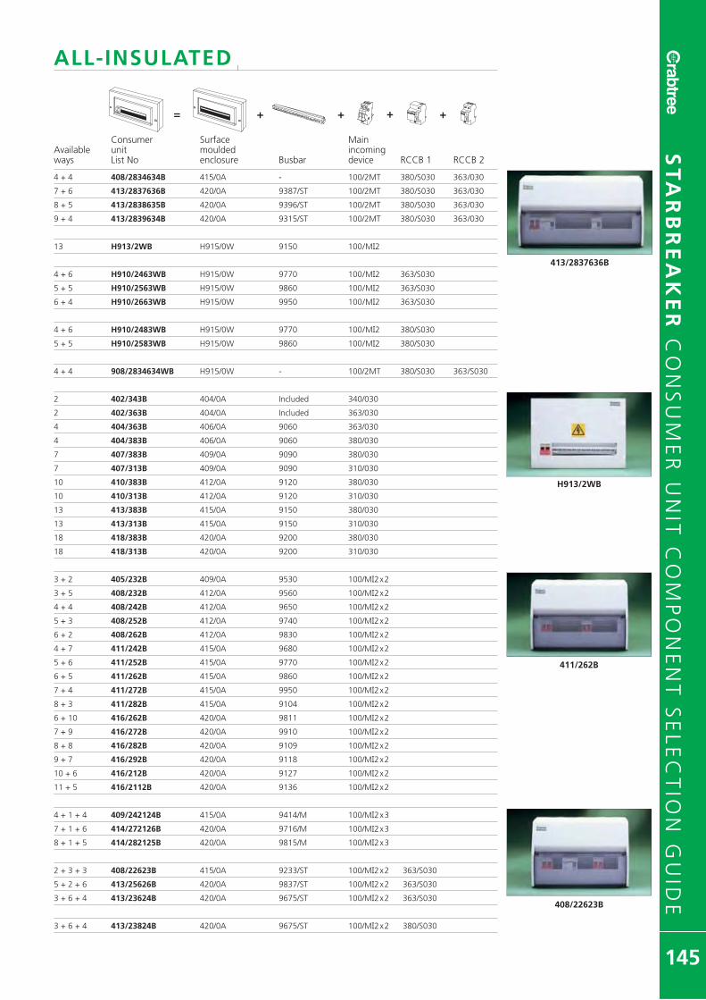
ALL-INSULATEDl
Consumer Surface MainAvailable unit moulded incomingways List No enclosure Busbar device RCCB 1 RCCB 2
4 + 4 408/2834634B 415/0A - 100/2MT 380/S030 363/030
7 + 6 413/2837636B 420/0A 9387/ST 100/2MT 380/S030 363/030
8 + 5 413/2838635B 420/0A 9396/ST 100/2MT 380/S030 363/030
9 + 4 413/2839634B 420/0A 9315/ST 100/2MT 380/S030 363/030
13 H913/2WB H915/0W 9150 100/MI2
4 + 6 H910/2463WB H915/0W 9770 100/MI2 363/S030
5 + 5 H910/2563WB H915/0W 9860 100/MI2 363/S030
6 + 4 H910/2663WB H915/0W 9950 100/MI2 363/S030
4 + 6 H910/2483WB H915/0W 9770 100/MI2 380/S030
5 + 5 H910/2583WB H915/0W 9860 100/MI2 380/S030
4 + 4 908/2834634WB H915/0W - 100/2MT 380/S030 363/S030
2 402/343B 404/0A Included 340/030
2 402/363B 404/0A Included 363/030
4 404/363B 406/0A 9060 363/030
4 404/383B 406/0A 9060 380/030
7 407/383B 409/0A 9090 380/030
7 407/313B 409/0A 9090 310/030
10 410/383B 412/0A 9120 380/030
10 410/313B 412/0A 9120 310/030
13 413/383B 415/0A 9150 380/030
13 413/313B 415/0A 9150 310/030
18 418/383B 420/0A 9200 380/030
18 418/313B 420/0A 9200 310/030
3 + 2 405/232B 409/0A 9530 100/MI2x2
3 + 5 408/232B 412/0A 9560 100/MI2x2
4 + 4 408/242B 412/0A 9650 100/MI2x2
5 + 3 408/252B 412/0A 9740 100/MI2x2
6 + 2 408/262B 412/0A 9830 100/MI2x2
4 + 7 411/242B 415/0A 9680 100/MI2x2
5 + 6 411/252B 415/0A 9770 100/MI2x2
6 + 5 411/262B 415/0A 9860 100/MI2x2
7 + 4 411/272B 415/0A 9950 100/MI2x2
8 + 3 411/282B 415/0A 9104 100/MI2x2
6 + 10 416/262B 420/0A 9811 100/MI2x2
7 + 9 416/272B 420/0A 9910 100/MI2x2
8 + 8 416/282B 420/0A 9109 100/MI2x2
9 + 7 416/292B 420/0A 9118 100/MI2x2
10 + 6 416/212B 420/0A 9127 100/MI2x2
11 + 5 416/2112B 420/0A 9136 100/MI2x2
4 + 1 + 4 409/242124B 415/0A 9414/M 100/MI2x3
7 + 1 + 6 414/272126B 420/0A 9716/M 100/MI2x3
8 + 1 + 5 414/282125B 420/0A 9815/M 100/MI2x3
2 + 3 + 3 408/22623B 415/0A 9233/ST 100/MI2x2 363/S030
5 + 2 + 6 413/25626B 420/0A 9837/ST 100/MI2x2 363/S030
3 + 6 + 4 413/23624B 420/0A 9675/ST 100/MI2x2 363/S030
3 + 6 + 4 413/23824B 420/0A 9675/ST 100/MI2x2 380/S030
ST
AR
BR
EA
KE
R C
ON
SU
ME
R U
NIT
CO
MP
ON
EN
T S
EL
EC
TIO
N G
UID
E
145
+= ++ +N
N
L
413/2837636B
H913/2WB
411/262B
408/22623B

METAL CASEDl
Consumer Surface MainAvailable unit metal incomingways List No enclosure Busbar device RCCB 1 RCCB 2
2 802/2B 804/0A Included 40/MI2
2 802/26B 804/0A Included 63/MI2
4 804/2B 806/0A 9060 100/MI2
7 807/2B 809/0A 9090 100/MI2
10 810/2B 812/0A 9120 100/MI2
13 813/2B 815/0A 9150 100/MI2
18 818/2B 820/0A 9200 100/MI2
2 + 2 804/2263B 809/0A 9530 100/MI2 363/S030
2 + 5 807/2263B 812/0A 9560 100/MI2 363/S030
3 + 4 807/2363B 812/0A 9650 100/MI2 363/S030
4 + 3 807/2463B 812/0A 9740 100/MI2 363/S030
5 + 2 807/2563B 812/0A 9830 100/MI2 363/S030
3 + 7 810/2363B 815/0A 9680 100/MI2 363/S030
4 + 6 810/2463B 815/0A 9770 100/MI2 363/S030
5 + 5 810/2563B 815/0A 9860 100/MI2 363/S030
6 + 4 810/2663B 815/0A 9950 100/MI2 363/S030
7 + 3 810/2763B 815/0A 9104 100/MI2 363/S030
5 + 10 815/2563B 820/0A 9811 100/MI2 363/S030
6 + 9 815/2663B 820/0A 9910 100/MI2 363/S030
7 + 8 815/2763B 820/0A 9109 100/MI2 363/S030
8 + 7 815/2863B 820/0A 9118 100/MI2 363/S030
9 + 6 815/2963B 820/0A 9127 100/MI2 363/S030
10 + 5 815/2163B 820/0A 9136 100/MI2 363/S030
2 + 5 807/2283B 812/0A 9560 100/MI2 380/S030
3 + 4 807/2383B 812/0A 9650 100/MI2 380/S030
4 + 3 807/2483B 812/0A 9740 100/MI2 380/S030
5 + 2 807/2583B 812/0A 9830 100/MI2 380/S030
3 + 7 810/2383B 815/0A 9680 100/MI2 380/S030
4 + 6 810/2483B 815/0A 9770 100/MI2 380/S030
5 + 5 810/2583B 815/0A 9860 100/MI2 380/S030
6 + 4 810/2683B 815/0A 9950 100/MI2 380/S030
7 + 3 810/2783B 815/0A 9104 100/MI2 380/S030
5 + 10 815/2583B 820/0A 9811 100/MI2 380/S030
6 + 9 815/2683B 820/0A 9910 100/MI2 380/S030
7 + 8 815/2783B 820/0A 9109 100/MI2 380/S030
8 + 7 815/2883B 820/0A 9118 100/MI2 380/S030
9 + 6 815/2983B 820/0A 9127 100/MI2 380/S030
10 + 5 815/2183B 820/0A 9136 100/MI2 380/S030
10 + 10 820/283B 824/2A 9120 X2 100/2MT 380/030
13 + 13 826/283B 830/2A 9150 X2 100/2MT 380/030
18 + 18 836/283B 840/2A 9200 X2 100/2MT 380/030
2 + 3 + 3 808/226363B 815/0A - 100/2MT 363/S030 363/030
2 + 6 + 5 813/226665B 820/0A 9576/ST 100/2MT 363/S030 363/030
2 + 7 + 4 813/226764B 820/0A 9585/ST 100/2MT 363/S030 363/030
3 + 5 + 5 813/236565B 820/0A 9666/ST 100/2MT 363/S030 363/030
3 + 6 + 4 813/236664B 820/0A 9675/ST 100/2MT 363/S030 363/030
3 + 7 + 3 813/236763B 820/0A 9684/ST 100/2MT 363/S030 363/030
4 + 5 + 4 813/246564B 820/0A 9765/ST 100/2MT 363/S030 363/030
4 + 6 + 3 813/246663B 820/0A 9774/ST 100/2MT 363/S030 363/030
5 + 4 + 4 813/256464B 820/0A 9855/ST 100/2MT 363/S030 363/030
5 + 5 + 3 813/256563B 820/0A 9864/ST 100/2MT 363/S030 363/030
6 + 4 + 3 813/266463B 820/0A 9957/ST 100/2MT 363/S030 363/030
Flush metal units are available upon request. Flush metal enclosures can be seen on Page 142.
ST
AR
BR
EA
KE
R C
ON
SU
ME
R U
NIT
CO
MP
ON
EN
T S
EL
EC
TIO
N G
UID
E
146
810/2B
807/2363B
826/283B
808/226363B
+= ++ +N
N
L

METAL CASEDl
Consumer Surface MainAvailable unit metal incomingways List No enclosure Busbar device RCCB 1 RCCB 2
7 + 6 813/2637636B 820/0A 9387/ST 100/2MT 363/S030 363/S030
8 + 5 813/2638635B 820/0A 9396/ST 100/2MT 363/S030 363/S030
9 + 4 813/2639634B 820/0A 9315/ST 100/2MT 363/S030 363/S030
4 + 4 808/2834634B 815/0A - 100/2MT 380/S030 363/S030
7 + 6 813/2837636B 820/0A 9387/ST 100/2MT 380/S030 363/S030
8 + 5 813/2838635B 820/0A 9396/ST 100/2MT 380/S030 363/S030
9 + 4 813/2839634B 820/0A 9315/ST 100/2MT 380/S030 363/S030
7 + 10 817/26383B 824/2A 9380/D & 9120 100/2MT 363/S030 380/S030
10 + 13 823/26383B 830/2A 9311/D & 9150 100/2MT 363/S030 380/S030
15 + 8 833/26383B 840/2A 9316/D & 9200 100/2MT 363/S030 380/S030
2 802/343B 804/0A Included 340/030
2 802/363B 804/0A Included 363/030
4 804/383B 806/0A 9060 380/030
7 807/383B 809/0A 9090 380/030
10 810/383B 812/0A 9120 380/030
10 810/313B 812/0A 9120 310/030
13 813/383B 815/0A 9150 380/030
13 813/313B 815/0A 9150 310/030
18 818/383B 820/0A 9200 380/030
18 818/313B 820/0A 9200 310/030
3 + 2 805/232B 809/0A 9530 100/MI2x2
3 + 5 808/232B 812/0A 9560 100/MI2x2
4 + 4 808/242B 812/0A 9650 100/MI2x2
5 + 3 808/252B 812/0A 9740 100/MI2x2
6 + 2 808/262B 812/0A 9830 100/MI2x2
4 + 7 811/242B 815/0A 9680 100/MI2x2
5 + 6 811/252B 815/0A 9770 100/MI2x2
6 + 5 811/262B 815/0A 9860 100/MI2x2
7 + 4 811/272B 815/0A 9950 100/MI2x2
8 + 3 811/282B 815/0A 9104 100/MI2x2
6 + 10 816/262B 820/0A 9811 100/MI2x2
7 + 9 816/272B 820/0A 9910 100/MI2x2
8 + 8 816/282B 820/0A 9109 100/MI2x2
9 + 7 816/292B 820/0A 9118 100/MI2x2
10 + 6 816/212B 820/0A 9127 100/MI2x2
11 + 5 816/2112B 820/0A 9136 100/MI2x2
4 + 1 + 4 809/242124B 815/0A 9414/M 100/MI2x3
7 + 1 + 6 814/272126B 820/0A 9716/M 100/MI2x3
8 + 1 + 5 814/282125B 820/0A 9815/M 100/MI2x3
2 + 3 + 3 808/22623B 815/0A 9233/ST 100/MI2x2 363/S030
5 + 2 + 6 813/25626B 820/0A 9837/ST 100/MI2x2 363/S030
3 + 6 + 4 813/23624B 820/0A 9675/ST 100/MI2x2 363/S030
3 + 6 + 4 813/23824B 820/0A 9675/ST 100/MI2x2 380/S030
Flush metal units are available upon request. Flush metal enclosures can be seen on Page 142.
ST
AR
BR
EA
KE
R C
ON
SU
ME
R U
NIT
CO
MP
ON
EN
T S
EL
EC
TIO
N G
UID
E
147
813/2637636B
817/26383B
807/383B
811/282B
+= ++ +N
N
L

148
DOMESTICCIRCUIT PROTECTIONThe inherent flexibility of Loadstar DomesticCircuit Protection enables simple ‘on site’configuration of a variety of consumerunit arrangements.

LO
AD
ST
AR
DO
ME
ST
IC C
IRC
UIT
PR
OT
EC
TIO
N
149
18LC14
18PRSL12
18LC10HI
18PSDR10
MAIN SWITCH UNITSl
Total MCB/RCBO Ways MS Rating Insulated Metal
1 63A 18LC1*
2 40A 18LC2*
2 63A 18LC2/63* 18PS2*
5 100A 18LC5 18PS5
8 100A 18LC8 18PS8
11 100A 18LC11 18PS11
14 100A 18LC14 18PS14
19 100A 18LC19 18PS19
Supplied with Main Switch and Busbar.Flush Metal versions are available upon request.*Single module RCBOs are not recommended for use within 1 & 2 way units.
FLEXIBLE SPLIT LOAD UNITS l
100A 80A 30mATotal Ways Main Switch RCCB Insulated Metal
6 2 to 4 2 to 4 18LC6SL -
9 3 to 6 3 to 6 18LC9SL 18PRSL09
12 3 to 9 3 to 9 18LC12SL 18PRSL12
17 5 to 12 5 to 12 18LC17SL 18PRSL17
Supplied with Main Switch, DP RCCB and Busbar.
Both MCBs and RCBOs may be included for final circuit positions that are notprotected by resident RCCBs.Flush Metal versions are available upon request.
FLEXIBLE HIGH INTEGRITY DUAL RCD UNITSl
100A 80A 30mA 80A 30mATotal Ways Main Switch RCCB 1 RCCB 2 Insulated Metal
10 2 to 5 2 to 5 2 to 5 18LC10HI 18PSHI10
15 2 to 9 2 to 9 2 to 9 18LC15HI 18PSHI15
Supplied with Main Switch, Two DP RCCBs and Busbar.
Both MCBs and RCBOs may be included for final circuit positions that are notprotected by resident RCCBs.Flush Metal versions are available upon request.
FLEXIBLE DUAL RCD SPLIT LOAD UNITSl
Total MCB 100A 80A 30mA 80A 30mAWays Main Switch RCCB 1 RCCB 2 Insulated Metal
10 - 4 to 6 4 to 6 18LC10DR 18PSDR10
15 - 6 to 9 6 to 9 18LC15DR 18PSDR15
Supplied with Main Switch, Two DP RCCBs and Busbar.Flush Metal versions are available upon request.
For dimensions see page 195.

LO
AD
ST
AR
DO
ME
ST
IC C
IRC
UIT
PR
OT
EC
TIO
N
150
18SB12SL
18LC5/80/30
18SB10HI
RCD INCOMER UNITSl
Total MCB RCCBWays Rating Insulated Metal
1 63A 30mA 18LC1/63/30
2 63A 30mA 18LC2/63/30 18PR2/63/30
5 80A 30mA 18LC5/80/30 18PR5/80/30
8 80A 30mA 18LC8/80/30 18PR8/80/30
11 80A 30mA 18LC11/80/30 18PR11/80/30
14 80A 30mA 18LC14/80/30 18PR14/80/30
19 80A 30mA 18LC19/80/30 18PR19/80/30
Supplied with DP RCCB and Busbar.
ASSEMBLED SPINE BACKPLATES
MAIN SWITCHl
Total MCB/ 100ARCBO Ways Main Switch LIST No
14 14 18SB14
Supplied with Main Switch and Busbar.
FLEXIBLE SPLIT LOADl
Total 100A 80AWays Main Switch RCCB LIST No
12 3 to 9 3 to 9 18SB12SL
Supplied with Main Switch, DP RCCB and Busbar.
Both MCBs and RCBOs may be included for final circuit positions that are notprotected by resident RCCBs.
FLEXIBLE HIGH INTEGRITY DUAL RCDl
Total 100A 80A 80AWays Main Switch RCCB 1 RCCB 2 LIST No
10 2 to 5 2 to 5 2 to 5 18SB10HI
Supplied with Main Switch, Two DP RCCBs and Busbars.
Both MCBs and RCBOs may be included for final circuit positions that are notprotected by resident RCCBs.
FLEXIBLE DUAL RCD SPLIT LOADl
Total MCB 100A 80A 80AWays Main Switch RCCB 1 RCCB 2 LIST No
10 - 4 to 6 4 to 6 18SB10DR
Supplied with Main Switch, Two DP RCCBs and Busbars.
For dimensions see page 195.

LO
AD
ST
AR
DO
ME
ST
IC C
IRC
UIT
PR
OT
EC
TIO
N
151
6MSB06 6MSB16 6MSB32 6MSB50 6MSB10 6MSB20 6MSB40
6FSR32/30B
191002/100
MINIATURE CIRCUIT BREAKERSl
LIST No
RATING POLES MODULES Type B Type C
6A 1 1 6MSB06 6MSC06
10A 1 1 6MSB10 6MSC10
16A 1 1 6MSB16 6MSC16
20A 1 1 6MSB20 6MSC20
32A 1 1 6MSB32 6MSC32
40A 1 1 6MSB40 6MSC40
50A 1 1 6MSB50 6MSC50
� BS EN 60898; 6kA-240V 50Hz� Type B classification (3-5 In). Type C classification (5-10In)� 25mm2 terminal capacity
RESIDUAL CURRENT CIRCUIT BREAKERWITH OVERCURRENT PROTECTION (RCBOs)
l
LIST No
RATING POLES MODULES 30mA Type B 30mA Type C
6A 1 1 6FSR06/30B 6FSR06/30C
10A 1 1 6FSR10/30B 6FSR10/30C
16A 1 1 6FSR16/30B 6FSR16/30C
20A 1 1 6FSR20/30B 6FSR20/30C
32A 1 1 6FSR32/30B 6FSR32/30C
40A 1 1 6FSR40/30B 6FSR40/30C
50A 1 1 6FSR50/30B 6FSR50/30C
� BS EN 61009� 230 (240)V AC 50/60 Hz� 16mm2 terminal capacity (outgoing)
SP & SWN RESIDUAL CURRENT CIRCUIT BREAKERWITH OVERCURRENT PROTECTION (RCBOs)
l
LIST No
RATING POLES MODULES 30mA Type C
6A 2 2 6FSNR063/C
10A 2 2 6FSNR103/C
16A 2 2 6FSNR163/C
20A 2 2 6FSNR203/C
32A 2 2 6FSNR323/C
40A 2 2 6FSNR403/C
� BS EN 61009 � 16mm2 terminal capacity (outgoing)� 230 (240)V AC 50/60 Hz
ACCESSORIES lDescription LIST No
MCB Padlocking Device MCBLD
Blanking Piece 443
Blanking Unit CSB1
Blanking Unit twist fit CSBC
TRIPLE POLE & NEUTRAL 415V 50Hz ACl
Description BS EN 60947-3 LIST No
With switched Neutral for surface mounting withina metal enclosure. 133mm x 114mm x 61mm 1932
With switched Neutral for flush mounting withina metal enclosure. 150mm x 125mm x 61mm 1932/F
DP DOMESTIC SWITCH FUSEl
Description LIST No
DP Domestic Switch Fuse complete with 63A fuse 191002/63
DP Domestic Switch Fuse complete with 80A fuse 191002/80
DP Domestic Switch Fuse complete with 100A fuse 191002/100
The Crabtree Domestic Switch Fuse has a robust steel construction and is completewith a 100A Double Pole Isolator and either 63A, 80A or 100A BS88 Fuse.
Approximate dimensions: Height 305mm, Width178mm, Depth 76mm
For Technical Information see pages 178-181
6FSNR323C

152

MODULARCONTROLDEVICES
MO
DU
LA
R C
ON
TR
OL
DE
VIC
ES
153
35mm DIN rail mounting control devices includingcontactors, time switches and bell transformers.

SIL
EN
T O
PE
RA
TIO
N C
ON
TAC
TO
RS
154
MAXIMUM NUMBER OF LAMPS PER POLETYPE CIK22 CIK24 CIK40 CIK63
Incandescent lamps 60W 33 33 65 85100W 20 20 40 50200W 10 10 20 25500W 3 3 8 101000W 1 1 4 5
Energy saving lamps 7W 40 50 120 16011W 30 40 100 14015W 20 30 85 11520W 17 22 65 85
Halogen lamps 200W 10 10 20 25300W 6 6 13 16500W 3 3 8 101000W 1 1 4 5
Low pressure sodium-vapour 35W 7 9 23 30lamps (uncompensated) 55W 7 9 23 30
90W 4 5 14 19135W 3 4 10 13180W 3 4 10 13
High pressure sodium-vapour 50W 12 12 24 38lamps (uncompensated) 70W 10 10 20 30
110W 8 7 18 26150W 5 6 17 22250W 3 4 10 13400W 2 2 6 81000W - 1 3 3
Low pressure sodium-vapour 35W 1 1 11 16lamps (compensated) 55W 1 1 11 16
90W 1 1 8 12135W – – 4 7180W – – 4 7
High pressure sodium-vapour 50W 3 3 22 33lamps (compensated) 70W 2 3 18 27
110W 2 2 18 27150W 1 1 11 16250W – 1 6 10400W – – 4 61000W – – 2 3
Fluorescent lamps 18W 22 24 90 140(uncompensated) 36W 17 20 65 95
58W 14 17 45 70Fluorescent lamps 18W 7 8 48 73
(compensated) 36W 7 8 48 7358W 4 5 31 47
Fluorescent lamps 18W 2 x 30 2 x 40 2 x 100 2 x 150(dual fitted) 36W 2 x 17 2 x 24 2 x 65 2 x 95
58W 2 x 10 2 x 15 2 x 40 2 x 60Fluorescent lamps with electronic 1 x 18W 25 35 100 140
starting device 1 x 36W 15 20 52 75AC - operation 1 x 58W 14 19 50 72
2 x 18W 12 17 50 702 x 36W 7 10 26 382 x 58W 7 9 25 36
SILENT OPERATION INSTALLATION CONTACTORSl
Thermal Motor RatingRating per Pole AC3 (kW) Pole Configuration
TYPE AC1(A) 230V 400V N/O N/C LIST NoCIK22 20 1.3 N0 – 2 0 CIK22-20
0.75 NC 1 1 CIK22-110 2 CIK22-02
CIK24 25 2.2 4 4 0 CIK24-401.3* 3 1 CIK24-31
2 2 CIK24-220 4 CIK24-04
CIK40 40 5.5 11 4 0 CIK40-403.7* 3 1 CIK40-31
2 2 CIK40-220 4 CIK40-04
CIK63 63 8.5 15 4 0 CIK63-405.0* 3 1 CIK63-31
2 2 CIK63-220 4 CIK63-04
230V 400VAC15
6 4 – – 1 1 CHHSLA112 0 CHHSLA20
* Data for single-phase power is valid for version-22
1 Mod
2 Mod
3 Mod
3 ModCIK22-02 CIK24–40 CIK63–40
For dimensions see page 198
AuxiliaryContacts(CIK40 &63 Only)
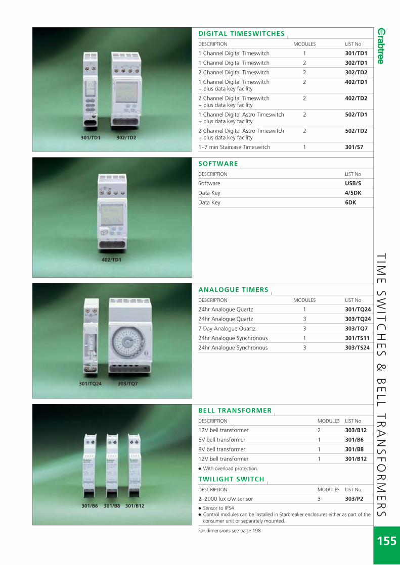
TIM
E S
WIT
CH
ES
& B
EL
L T
RA
NS
FO
RM
ER
S
155
301/TD1 302/TD2
402/TD1
301/TQ24 303/TQ7
301/B6 301/B8 301/B12
DIGITAL TIMESWITCHESl
DESCRIPTION MODULES LIST No
1 Channel Digital Timeswitch 1 301/TD1
1 Channel Digital Timeswitch 2 302/TD1
2 Channel Digital Timeswitch 2 302/TD2
1 Channel Digital Timeswitch 2 402/TD1+ plus data key facility
2 Channel Digital Timeswitch 2 402/TD2+ plus data key facility
1 Channel Digital Astro Timeswitch 2 502/TD1+ plus data key facility
2 Channel Digital Astro Timeswitch 2 502/TD2+ plus data key facility
1-7 min Staircase Timeswitch 1 301/S7
SOFTWAREl
DESCRIPTION LIST No
Software USB/S
Data Key 4/5DK
Data Key 6DK
ANALOGUE TIMERSl
DESCRIPTION MODULES LIST No
24hr Analogue Quartz 1 301/TQ24
24hr Analogue Quartz 3 303/TQ24
7 Day Analogue Quartz 3 303/TQ7
24hr Analogue Synchronous 1 301/TS11
24hr Analogue Synchronous 3 303/TS24
BELL TRANSFORMERl
DESCRIPTION MODULES LIST No
12V bell transformer 2 303/B12
6V bell transformer 1 301/B6
8V bell transformer 1 301/B8
12V bell transformer 1 301/B12
� With overload protection.
TWILIGHT SWITCHl
DESCRIPTION MODULES LIST No
2–2000 lux c/w sensor 3 303/P2
� Sensor to IP54.� Control modules can be installed in Starbreaker enclosures either as part of the
consumer unit or separately mounted.
For dimensions see page 198

156

Crabtree RCDs comply fully with BS EN 61008to Type A and Type AC classification.
TYPE A
Pulsating dc (chopped) waveform
Pulsating dc (half wave rectified) waveform
TYPE AC
Normal ac waveform
Pulsating dc (chopped) waveformwith a constant dc component
RESIDUAL CURRENTDEVICES
Suitable for screw fixing or DIN rail mounting.
Wide range of enclosures available for separatelymounting RCCBs, MCBs and RCBOs.
LIF
ES
TA
RR
ES
IDU
AL
CU
RR
EN
T D
EV
ICE
S
157
Lifestar offers you the protection ofResidual Current Devices (RCDs) forany industrial, commercial or domesticapplication. RCDs rated from 13A to100A are available in sensitivities from10mA to 300mA providing safe,secure protection against fire or shockrisks caused by earth fault currents.

4 POLE RESIDUAL CURRENT CIRCUIT BREAKERSl
TYPE AC SENSITIVITY
CURRENTRATING (A) MODULES 30mA 100mA 300mA
32 4 243/030 - -
40 4 244/030 244/100 244/300
63 4 246/030 246/100 246/300
100 4 241/030 241/100 241/300
4 POLE TYPE AC TIME DELAYl
TYPE AC SENSITIVITY
CURRENTRATING (A) MODULES 100mA
100 4 241/100TD
2 POLE RESIDUAL CURRENT CIRCUIT BREAKERSl
TYPE AC SENSITIVITY
CURRENTRATING (A) MODULES 30mA 100mA 300mA
32 2 223/030 - -
40 2 224/030 224/100 224/300
63 2 226/030 226/100 226/300
80 2 228/030 228/100 -
100 2 221/030 221/100 221/300
2 POLE TYPE AC TIME DELAYl
TYPE AC SENSITIVITY
CURRENTRATING (A) MODULES 100mA
100 2 221/100TD
2 POLE RESIDUAL CURRENT CIRCUIT BREAKERS l
TYPE A SENSITIVITY
CURRENTRATING (A) MODULES 10mA 30mA
16 2 216/A010 -32 2 223/A010 -40 2 - 224/A03063 2 - 226/A03080 2 - 228/A030100 2 - 221/A030
4 POLE RESIDUAL CURRENT CIRCUIT BREAKERS l
TYPE A SENSITIVITY
CURRENTRATING (A) MODULES 10mA 30mA
40 4 - 244/A03063 4 - 246/A030100 4 - 241/A030
SP & SWN RESIDUAL CURRENT CIRCUIT BREAKERWITH OVERCURRENT PROTECTION (RCBOs)
l
TYPE CRATING MODULES 30mA
6 2 2FSNR063/C10 2 2FSNR103/C16 2 2FSNR163/C20 2 2FSNR203/C32 2 2FSNR323/C40 2 2FSNR403/CFor dimensions see page 197
226/030
241/030
241/100TD
2FSNR063/CLIF
ES
TA
RR
ES
IDU
AL
CU
RR
EN
T D
EV
ICE
S
158

LIF
ES
TA
RS
AF
ET
Y S
OC
KE
TS
159
13A SAFETY SOCKETS WITH RCD PROTECTIONl
The Lifestar safety socket is available in 2 gang versions with 30mAsensitivity, enabling products to be precisely matched to specificapplications. All safety sockets incorporate pulsating dc fault currentprotection (Type A operation).
� Double pole operation, 3mm contact gap.� Trip free mechanism for automatic disconnection of supply.� Enables mounting in standard 25mm deep box (moulded variant).� Mechanical indication of contact position.� Unique labyrinth switch design minimises visible arc flash and prevents front
access to live parts.� Surface mounted units supplied with Birch Grey mounting box.� Interior units available for mounting into OEM equipment.� Comply with BS 7288.� RCD sockets are all passive in operation and will not trip on loss of mains
supply.
MOULDED l PACK QTY
2 gang switched with neon indicator. 30mA tripping current 1 4406/A03Dimensions 146mm x 86mmMounting boxes 9048 surface, SB665 flush galv. or SB629 dry lining
FLUSH METAL PLATE* l PACK QTY2 gang switched with neon indicator, 30mA tripping current 1 4416/A03_ _*Dimensions 146mm x 86mmMounting boxes 9223/BG surface, SB625 flush galv. or SB629 dry lining
* Metal plate variants available in Satin Chrome (SC), Bronze (BZ) and PolishedStainless Steel (PSS) – Add suffix to List No. eg 4416/A03SC.For further specification details of finishes see page 202.
INTERIOR l PACK QTY2 gang switched with neon indicator, 30mA tripping current 1 4416/A103For dimensions see page 197
SURFACE METALCLAD l PACK QTY2 gang switched with neon indicator, 30mA tripping current 1 4426/A03BGDimensions 142mm x 82mm x 44mm
FLUSH METALCLAD l PACK QTY2 gang switched with neon indicator, 30mA tripping current 1 4416/A03BGDimensions 146mm x 86mmMounting boxes 9223/BG surface, SB625 flush galv. or SB629 dry lining
4406/A03
4416/A03BZ
4416/A103
4426/A03BG
4416/A03BG
All complete with two earth terminals.

160
DINENCLOSURES35mm DIN rail enclosures to acceptmodular devices.

LIF
ES
TA
RE
NC
LO
SU
RE
S
161
744/3
CBE/3
CBE/BS CBE4/EK
744/4
844/4
MODULAR ENCLOSURESl
Dimensions see page199.
3 MODULEl
DESCRIPTION LIST No
General purpose enclosure (IP20) 744/3
� Complete with DIN rail.� Supplied with cut-out of 2 module size.� Converts to 3 module by removing half blanks.
All purpose enclosure (IP65) CBE/3
� Complete with DIN rail.� Features sealable cover and hinged protective cover.� Polycarbonate construction.� Accessories available.� Self-adhesive way label provided.
NoteMax cable capacity 10mm2. For increased cable sizes use 4 module enclosureList No.CBE/4 (up to 25mm2).
4 MODULEl
DESCRIPTION LIST No
General purpose enclosure (IP20) 744/4
� Complete with DIN rail.� Supplied with cut-out of 3 module size.� Converts to 4 module by removing half blanks.
All purpose enclosure (IP65) CBE/4
� Suitable for all ratings.� Complete with DIN rail.� Features sealable cover and hinged protective cover.� Polycarbonate construction.� Accessories available.� Self-adhesive way label provided.
Fabricated steel enclosure (IP20) 844/4
� Suitable for all ratings.� Complete with DIN rail and earth terminal.� Supplied with blank plates for converting to 2 module opening.
ACCESSORIES FOR ALL PURPOSE ENCLOSURESl
EARTH TERMINAL LIST No
5 way, 3 module CBE3/EK
7 way, 4 module CBE4/EK
NEUTRAL TERMINAL
5 way, 3 module CBE3/NK
7 way, 4 module CBE4/NK
Blanking strip CBE/BS
External fixing bracket ME/FB

N
L
L1 L2
L1
L2 L2
L1
L3 L3
N
L
TECHNICAL DATA
1 2
L
N
4 3
5I
162
TE
CH
NIC
AL
DA
TA

TE
CH
NIC
AL
DA
TA
163
GENERAL pageInternational degree of protection 164WIRING ACCESSORIES
Terminal capacities 165
6A isolating switch 165
Part M Compliance 166
PIR Sensors 168
Seeklight 169
Grid Dimmer & Energy Saving Card Switch 170
Communication 171
Datapak 172
Luminaire Support Couplers 172
Metal plate specifications 173
Low Energy lampholders 173Antimicrobial 174
CABLE MANAGEMENT
PVC Trunking 175
Floor Distribution System 176Under Floor Powertrack 177
DOMESTIC CIRCUIT PROTECTION
MCBs – General 178
MCBs – Starbreaker & Loadstar 179
RCDs – General RCCB, RCBO & SRCD 180
17th - Consumer unit compliance 182
Starbreaker - Consumer unit applications 183
Control Modules 185

IP RATINGSl
The IP (International Protection) rating given to an enclosure states the degree of protection it offers by means of twodigits. A summary of these is shown below; for a more detailed definition, see IEC 529: 1989, BS EN 60529: 1992.
The letter X can be used in place of the first or second digit to indicate that tests have either not been made or are not applicable.
N0TEIn the event of additional holes being drilled/pierced or knockouts removed, suitable measures should be taken to restore the products to the original ratings.
IEC 529, BS EN 60529 does not apply to protection against the risk of explosion or conditions such as humidity, corrosive gases, fungi or vermin.In certain cases equipment designed to be mounted in an enclosure will contribute towards the stated IP rating (eg pushbuttons mounted in an enclosure).Different parts of enclosures can have different degrees of protection and still conform to the standard (eg enclosures with pre-drilled conduit entry).
164
FIRST DIGITProtection against solid foreign objects and access to hazardous parts
l
The first digit covers protection against penetration by solid objects, whichincludes hands and tools such as screwdrivers. At the lowest of seven levels,0, no protection is offered, either of the equipment itself from damage byintrusion or of a person contacting live or moving parts. At the highest, 6,there shall be no entry of dust.
SECOND DIGITProtection against ingress of water
l
The second digit covers the degree of protection against the entry of water,on a progressive scale. For example, number 1 indicates that dripping watershall have no harmful effect, and number 6, that water projected in powerfuljets against the enclosure from any direction shall have no harmful effects.
Protected against solid objectsup to 50mmeg accidental touch by hands
Protected against solid objectsup to 12mmeg fingers
Protected against solid objectsover 2.5mmeg tools and wires
Protected against solid objectsover 1mmeg tools, wires and small wires
Protected against dust– limited ingress, no harmful deposits
No protection
Protected against vertically fallingdrops of watereg condensation
Protected against direct sprays ofwater up to 15° from the vertical
Protected against sprays of waterup to 60° from the vertical
Protected against water splashed fromall directions– limited ingress permitted
Protected against low pressure jetsof water from all directions– limited ingress permitted
Protected against strong jets of watereg for use on ship decks– limited ingress permitted
No protection
1
2
3
4
5
IP
1
2
3
4
5
6
IP
0 0
Totally protected against dust6
TE
CH
NIC
AL
DA
TA
IP
RA
TIN
GS

TE
CH
NIC
AL
DA
TA
WIR
ING
AC
CE
SS
OR
IES
165
BRITISH STANDARDS l
An unqualified reference to the British Standards in this product catalogue indicates that the products referred to are marked with the British Standard and
therefore comply in all respects with the standard stated.
Where a qualification is given against the British Standard, eg BS 3676 where applicable, this means that there is no specific standard for the product in
question and it has been tested as far as possible for compliance with the standard indicated.
TERMINAL CAPACITIES (mm2) l
Product Quantity and gauge of cable accepted by terminals
13A Capital /Platinum socket outlets
13A Capital safety sockets 3 x 2.5mm2, 2 x 4mm2, 2 x 6mm2
13A Capital /Platinum fused conn. units
13A Panel mounting socket 3 x 2.5mm2, 2 x 4mm2, 1 x 6mm2
10AX Capital /Platinum plate switches 4 x 1mm2, 3 x 1.5mm2,
10A Capital architrave switches 1 x 2.5mm2
20A Capital /Platinum DP switches 3 x 2.5mm2, 2 x 4mm2,
32A Capital /Platinum DP switches 1 x 6mm2, 1 x 10mm2
32A Capital TP & N switches 2 x 6mm2, 1 x 10mm2, 1 x 16mm2
45A Capital /Platinum DP switches
50A Capital DP switches2 x 6mm2, 1 x 10mm2, 1 x 16mm2
45A Capital /Platinum cooker control units
Capital /Platinum shaver supply unit
Capital light/shaver unit 4 x 1mm2, 3 x 1.5mm2
6A Capital ceiling switches
16A Capital ceiling switches 2 x 2.5mm2 max
50A Capital ceiling switch3 x 2.5mm2, 2 x 4mm2,
1 x 6mm2, 1 x 10mm2,
Capital ceiling roses1.5mm2 multiway
Capital safety batten lampholder
Capital safety pendant lampholder 1 x 1mm2 flexible cable
16A Minder PIR sensor 6 x 1mm2, 4 x 1.5mm2, 2 x 2.5mm2
6A TP ISOLATING SWITCH l
LIST No. 4017, 4017/1, 6017/_ _ , 7017/_ _ , 1017/1_ _ , IN/3017/1_ _ & 4587/BGComplies fully with requirements of BS EN 60947-3 for switch disconnectors.
Rated SC making capacity 300A
Rated conditional short circuit current 6kA
(when protected by Starbreaker 6A mcb)
Rated insulation voltage 300V
Rated impulse withstand voltage 2.5kV
Rated duty Uninterrupted
Maximum switching rate 120 switch cycles per hour
Rated short time withstand current 100A for 1 second
Utilisation category AC 23B, 6A 250V 50Hz
A POINT ON TESTING l
When installations incorporating electronic devices of the semi-conductor type are being tested, care must normally be taken to ensure that they are not
subjected to the output voltage of an insulation tester. However, dimmer switches complying with BS 5518 will not be damaged by the application of a
normal 500V insulation resistance test. In all other cases where electronic items are fitted, they should be disconnected whilst the insulation of the installation
is tested. A notice, drawing attention to the fact that electronic devices are incorporated in the installation, should always be affixed at the intake position.
This also applies to any neon indicators fitted.
WIRING ACCESSORIES – GENERALl

166
BU
ILD
ING
RE
GU
LA
TIO
NS
PAR
T M
CO
MP
LIA
NC
EBUILDING REGULATIONS APPROVED DOCUMENT PART M - ACCESS TO AND THE USE OF BUILDINGS
l
There are a number of considerations that need to be met by the specifier or contractor ofa buildings installation when covering reasonable provision for the access to and use of abuildings structure and facilities for a disabled person whether visiting, working or dwellingin them. Crabtree have continually been introducing and developing products throughouttheir range of wiring accessories to enable compliance with Part M.
Part M can be split into four sections:
� Height � Visibility � Operation � Freedom from obstruction
MOUNTING HEIGHT AND POSITION
Sockets no nearerthan 350mmto a corner
Sockets/Data/TV400mm-1000mm
Switches400mm-1200mm
Switches that requireprecise hand movements
750mm-1200mm
Controls that needclose vision:
1200-1400mm
Light switches (public)900-1100mm
(aligning with door handles)
DESIGN CONSIDERATIONS
� There should be a consistent relationship with the doorways and corners to reinforce the ease with which people manipulate switches and controls.
� All users should be able to locate a control, know which setting it is on and use it without inadvertently changing its setting.
� Controls that contrast with their surroundings are more convenient for the visually impaired as are light switches that are activated by a large touch pad.
� It is an advantage if individual switches on panels andmultiple socket outlets are well separated, or in theform of large touch plates to avoid the incorrectselection of an adjacent control by visually impairedpeople and people with limited dexterity.
� The colours red and green should not be used in combination as indicators of “on” and “off” for switches and controls. It may be useful to use text ora pictogram to clarify.
Visibility
� Front plates should contrast visually with theirbackgrounds.
� Mains and circuit isolator switches should indicate clearly if they are on or off.
� Switched socket outlets should indicate whether they are on.
Some may consider these requirements refer to thecomplete product contrasting with a wall, whilst others
may consider it is the switch that should contrast withits frontplate. The regulation states that switches, outletsand controls will satisfy requirement M1 if: front platescontrast visually with their background.
The Crabtree Seek light assists in locating light switchesin the dark.
Crabtree have considered both options in their productrange of Platinum, the products can either have contrastingrocker to frontplate which then could contrast with theback wall, or just contrast of frontplate and wall.
� Socket outlets, Telephone points and TV sockets are mounted at 400 - 1000mm with a preference for the lower range.
� Switches should be mounted at 400 - 1200mm unless needed at a higher level for particular appliances.
� Switches and controls that require precise hand movement (eg: Central Heating Controls) at 750 - 1200mm.
� Controls that need close vision at 1200 - 1400mmso that readings may be taken by a person sittingor standing.
� Light Switches for use by the general public align horizontally with door handles within the range 900 - 1100mm.
� Sockets no nearer than 350mm from room corners.

BU
ILD
ING
RE
GU
LA
TIO
NS
PAR
T M
CO
MP
LIA
NC
E
167
Platinum White MouldedA range of power, control andlighting accessories offering alow profile clip on mouldedfront plate.This range can be supplied withalternative colour front platesto contrast with the mouldedrocker or can be combinedwith the Platinum decorativeplates and interiors to provide avisual contrast.
RockergridThis modular system of boxes,grids, plates and switches canbe quickly and easily assembled tocustomers’ individualspecifications enabling severalcircuits to be controlled froma single position.The switches are a modular designthat has a large concave rockerwith a barrier between to avoidinadvertent selection ofadjacent controls.
CorinthianA range of wide rocker 10AXlighting switches with clip onsurrounds that can be providedin alternative colours to meeta variety of LRV values.
BUILDING REGULATIONS APPROVED DOCUMENT PART M - ACCESS TO AND THE USE OF BUILDINGSl
Although the product ranges mentioned aim to meet the design considerations for Part M compliance, Crabtreewould be prepared to discuss any future development on a project by project basis and assist, where possible,
with any other requirements.
Operation
� Light switches, which are to be used by the general public are encouraged to have large rockers at a height corresponding to the door handle, within the 900 - 1100mm range.
This would enable people with a physical disability orvisual impairment to both locate and activate themeasily.
The Crabtree range of electrical wiring accessories allcome with a large concave rocker, with the ‘Corinthian’range having an extra wide rocker.
Freedom from obstruction
� Light switches and controls should be ‘well separated’ or activated by a large push pad to preventinadvertent operation.
� The operation of switches, outlets and controls does not require the simultaneous use of both hands, except where this mode of operation is necessary for safety reasons.
Where several switches on panels are required.In addition the Crabtree Rockergrid range provides awide choice of switch options.
CRABTREE PRODUCT SELECTOR
Seek Light The Crabtree Seek Light asshown above assists in thelocation of the light switchesin the dark. Seek light comeson when the switch is turnedoff. Seek light fits all Crabtree1 gang switches.The circuit has been designed toreduce the pulse effect of theLED light and give aconstant light source.

MINDER PASSIVE INFRA RED SENSORSl
The Minder is a multi-adjustable, passive infrared movement detector. People and animals radiate heat, which
is invisible to the human eye (infrared range). Consequently, the recorded infrared energy pattern changes when
they enter the detection zoneDETECTION RANGE DIAGRAMS
TECHNICAL DATA l
Horizontal range 90˚ 220˚ 280˚of detection
Max. frontal range 12m 16m 16m
Max. bilateral range 6m 16m 10m
Water protection IP55 IP55 IP55
Switch off delay 1-3-5min 10 sec-30min 10 sec-30min
Dusk sensor, in Lux 3/15/Lux 0,5-300/Lux 0,5-300/Lux
Switching Capacity 3680 W/VA 3680 W/VA 3680 W/VA
Max switching Current 16AX 16AX 16AX
Operating Temperature -25˚C - +55˚C -25˚C - +55˚C -25˚C - +55˚C
MINDER FAULT FINDING ANALYSIS l
NATURE OF FAULT REASON FOR FAULT REMEDY
Minder does not operate Lens covered or dirty Check power supply, uncover and/or clean lens
Inadvertent operation of Minder Hot air or smoke e.g. out of kitchens activate Minder Install Minder at a different location
Lamp is permanently on Permanent movement in the monitored area Make sure that no heat source is in the detection zone and wait until adjusted time lapse has run down.. For control purposes, please cover the lens completely.
Minder is bridged to manual operation by Switch to automatic operationadditional switch
INSTALLATION l
The Minder functions optimally when installed lateral to walking direction.When selecting the installation site, ensure that:� The minder is not covered by rigid or moveable objects (e.g. roofing elements,
branches of tree, etc.).� When unit is installed above, or lateral to luminaires, a minimum distance is
always allowed between the unit and the luminaire, in order to prevent maloperation.
� when the unit is installed below luminaires, it is not heated up as a result of radiant heat from the luminaire.
When mounted at a height of 2.5m, the detection range is as above mentioned,though deviations in the mounting height cause changes in the detection range.In the case of special conditions at the site (e.g. rows of trees, small plot of land,proximity to road, etc.) the enclosed masking strip can be used to restrict thedetection range by sticking it on the Minder lens.
Minder 280
Standard Connection With Break Switch
Settings/Restrictions of detection
168
TE
CH
NIC
AL
DA
TA
PIR
SE
NS
OR
S
max 1m
90˚
max 6mmax 6m
max12m
220˚
max 16m
280˚
max 16m
16m 220˚ & 280˚
12m 90˚
1m
2.5m
+-30˚
+-30˚
LED-40˚
+90˚
NL
LS 16A
N L
NL
LS 16A
N L

TE
CH
NIC
AL
DA
TA
SE
EK
LIG
HT
169
SEEKLIGHT l
1 Before commencing work switch off the power supply by removing the fuse in the fuse box, or should isolate at main switch as neutral is a live conductor.
2 Connect seeklight wires as shown in diagrams below. Ensure terminal screws are properly tightened and no bare wire is visible. Push back unit into mounting box making sure conductors are not trapped.
3 Screw the unit to the mounting box. 4 Note: With the standard wiring configurations as described in the diagrams the Seeklight will only illuminate when
the light it controls is off.5 These products must be installed in accordance with the latest Building and IEE wiring regulations. If in any doubt,
please contact a qualified electricianPLEASE NOTE The LED ‘Seeklight’ must be disconnected when carrying out insulation testing to avoid a false reading
L1
L2L3
TOLAMPHOLDER
CEILINGROSE
N
LE
LOOP
TO MAINSSUPPLY
1.0mm TWIN & EARTH CABLE2
TO EARTHTERMINAL
IN BOX
SEEKLIGHTWIRES
L1
L2L3
TOLAMPHOLDER
CEILINGROSE
N
LE
LOOP
TO MAINSSUPPLY
TO EARTHTERMINALIN BOX
TO EARTHTERMINAL IN BOX
SEEKLIGHTWIRES
SEEKLIGHTWIRES
1.0mm TWIN & EARTH CABLE2
1.0mm 3 CORE & EARTH CABLE2
L1
L2L3
L1
L2L3
TOLAMPHOLDER
CEILINGROSE
N
LE
LOOP
TO MAINSSUPPLY
TO EARTHTERMINALIN BOX
TO EARTHTERMINAL IN BOX
SEEKLIGHTWIRES
SEEKLIGHTWIRES
1.0mm TWIN & EARTH CABLE2
1.0mm 3 CORE & EARTH CABLE2
L1
L2L3
L1
L2L3
TOLAMPHOLDER
CEILINGROSE
N
LE
LOOP
TO MAINSSUPPLY
TO EARTHTERMINALIN BOX
TO EARTHTERMINAL IN BOX
SEEKLIGHTWIRES
SEEKLIGHTWIRES
1.0mm TWIN & EARTH CABLE2
1.0mm 3 CORE & EARTH CABLE2
L1
L1 L2
L2
L3
L3 L2L3L1
L1 L3 L2
TOLAMPHOLDER
CEILINGROSE
N
LE
LOOP
TO MAINSSUPPLY
TO EARTHTERMINALIN BOX
TO EARTH TERMINALIN BOX
TO EARTHTERMINAL
IN BOX
2 WAY SWITCH 2 WAY SWITCH
INTERMEDIATE SWITCH
SEEKLIGHTWIRES
SEEKLIGHTWIRES
SEEKLIGHTWIRES
1.0mm TWIN & EARTH CABLE2
L1L1 L3
L2 L4L2L3
L1
L2L3
1.0mm TWIN & EARTH CABLE21.0mm TWIN & EARTH CABLE2
1 Gang 1 Way 10AX Switch with Seeklight 1 Gang 2 Way 10AX Switch with Seeklight
2 Gang 2 Way 10AX Switch with Seeklight 3 Gang 2 Way 10AX Switch with Seeklight
10AX Intermediate Switch with Seeklight

170
TE
CH
NIC
AL
DA
TA
GR
ID D
IMM
ER
, C
AR
D R
EA
DE
R
Card switch shown illuminated. Insertion of the card turns the neonoff. Ideal for helping locate card switch in hotel corridors.Available in Crabtree Capital moulded, Capital Metal Plate &Platinum Low Profile.
Controls energy consumption in installations such as hotels byensuring that appliances are not left on when rooms areunoccupied. Mains Voltage Card Switch is operated by a door entry cardand controls the supply to a room via a suitably rated contactor.Will accept door entry cards up to 86mm x 54mm x 1mm.
LED Illumination withoutDimmer knob
LED Illumination withDimmer knob fitted
Dimmer shown fitted to Grid
GRID LED BACKLIGHT ILLUMINATIONl
GRID DIMMERl
BS 60669 - 12l
ENERGY SAVING CARD SWITCHl
SPECIFICATION AND PERFORMANCEl
Model No. (2-way Push Sw) See Page 89 for SelectionRated Voltage /V ac 230-240V ac - 10% +6%Supply Frequency /Hz 50Hz / 60 HzRated Current /A 1.5A max.Rated Power /W & VA 60W to 250W & 60W to 400WNeutral Required NoFluorescent compatible NoGU10 Mains Halogen compatible YesLV Transformer compatible Yes, Limited Electronic & Electromagnetic2 Way Switch Standard Two-Way switch for On/Off functionTurn On/Off operation style Push On/Push OffDimming operation Full rotary travel by smooth turningOutline Dimensions See DrawingStandards & Approval EN60669-2-1, EN55015, EN61547, EN61000Special Feature Blue LED backlight optionRoHS Compliant Yes

TE
CH
NIC
AL
DA
TA
CO
MM
UN
ICA
TIO
NS
171
CO-AXIAL SOCKET OUTLETSl
In order to comply with the latest EMC directives, allinstallations containing amplification systems orcomprising multiple co-axial socket outlets must befitted with appropriate earth bonding.Isolated Co-Axial Sockets are isolated 2kV.
Separate co-axial cabledown lead to eachoutlet
7267 – Single Isolatedconnection outlet
TV
Amplifier
TV
FMLoft
outlet FMaeriallead
TV aeriallead
Co-axialdown lead
To TV
Living room outlet
To radio7268 – Twinconnectionoutlet
CAPITAL TELEPHONE SOCKET OUTLETSl
The Crabtree Capital range of Telephone Socket Outletshas been developed primarily for use in telephone systemsusing British Telecom standards. The products are similarin specification to units available from British Telecom.
TERMINATIONSl
All telephone outlets should be wired in accordance with the wiring diagramsshown below. Connection of these telephone outlets is by the IDC (InsulationDisplacement Connection) method allowing one or two equal size cables(0.40–0.68mm) to be terminated per connection block, using Crabtreeconnection tool List No.6915 as shown below.
Allow 50mm cable ‘tails’ at each connection block
Push home in direction of arrow with connection tool
Excess cable may be trimmed using wire cutters
WIRING COLOUR CODEl
Pin number Base colour/stripe
1 Green/White2 Blue/White3 Orange/White4 White/Orange5 White/Blue6 White/Green
WIRING DIAGRAMSl
Example of typical connections:1 Connections to 2 & 52 Earth recall (when used) connect to terminal 43 Connection to terminal 3 is not usually requiredNB (a) Standard 4 wire cable is shown below as incoming cable. If terminals
1 and 6 (normally unused) are required, 6 wire cable may be used.NB (b) All socket outlet connections are in parallel – any number of socket
outlets can be connected, but it is recommended that only amaximum of 5 telephones be used at any one time on one line.
WARNING NOTESl
In order to comply with current Wiring Regulations, metal faceplate telephonesocket outlets must be within the ‘equipotential zone’ of the building they arelocated in. Therefore an earth terminal is fitted to metal plate units which shouldbe connected to the electrical installation’s earthing system.
Testing(a) Connect cables as shown in wiring diagram(b) Plug in telephones(c) Lift receivers and check for dial tone(d) Make an incoming call to check bells work(e) If circuit does not work, disconnect and check thoroughly before reconnecting
NoteUnauthorised connection of telephone socket outlets to wiring owned by BritishTelecom is an offence. Further information concerning the requirements of atelephone system installation can be obtained from the Department of Industryor the telephone equipment supplier.
Connection tool
Connection block
123
654
321
321
654
654
Existing incoming cable from PBX, etc
1st socket outlet(Single master)
Additional socket outlet(s)(Single secondary)
7265 – Single Directconnection outlet
TV
TV/FM outlet installation
Co-axial outlet installationCommunal aerial system eg flats, hotels etc
Single connection outletDomestic installation
NoteIf additional outlets arerequired, an amplifiershould be used. Eachoutlet is then wiredseparately to theamplifier.
TV and FM aerialconnections use a twinconnection outlet(7268) and oneco-axial down lead.1 Fit a co-axialconnector to the TVand FM aerial cables.2 Plug connectors into7268 in loft.3 Connect a co-axialcable run betweenback of 7268 in loftand back of 7268 inthe living room, thenplug TV and FM radiointo front of plate.
As seen from rear

172
TELECOM MODULES
Master voice module - BT 601 masterIDC connectors (Krone style)Capacitor, lightning protection, resistor
PABX voice module - IDC connectorsCapacitor, no lightning protection, (resistor optional)
Secondary voice module - IDC connectors
Master voice module (left handed) - BT 601 masterIDC connectorsCapacitor, lightning protection, resistorAccepts left handed plug
DATA MODULES
RJ45 Cat 5e - IDC connector blocksColour coding - socket/cable/patch panelTie wrap facilityUse as socket on ISDN system, multiple sockets “daisy-chained”
ISDN Terminated (blue shutter) - RJ45 socket with 100 ohm resitor betweenpins 4 & 5 and one between pins 3 & 6Ratio 8:1 use
RJ11/12 - clasified as data outlet, but used as telecom socket in Eire & USA No capacitor accepts 6p6c plug (RJ12) and 6p4c plug (RJ11)
MEDIA MODULES AND ACCESSORIESTriplex unit - TV/SAT/FM splitter. One cable in, carrying combined signals,
splits signal back into 3 parts. Each socket is screened, reducing susceptability to noise distortion thus improving picture reception. 50mm x 50mm (double mod size)
TV return - screened TV module, used in conjunction with a distribution amplifier to distribute signals to other rooms
BNC (female) - accepts BNC male plug, 50 ohm or 70 ohm, as found onco-axial data systems (RG58, Ethernet) and CCTV installations.
BAND WIDTH/CAT
Cat 4 - 20Mhz
Cat 5 - 100Mhz
Cat 5e - 160Mhz
Cat 6 - 250Mhz
DATAPAK TYPICAL USE OF PATCH PANELS, PATCH LEADS & DATA OUTLETSl
LUMINAIRE SUPPORT COUPLERSl
TE
CH
NIC
AL
DA
TA
LS
C,
DA
TAPA
K
Technical details:Terminal capacity: 4x2.5mm2, 2x4mm2, 1x6mm2 per outlet terminalStandards: BS7001
BS5733 general electrical requirementsNote: BS 6972 only covers LSC’s rated upto 6A 250V
Rating: max 10A 250V per socket, 16A max per distribution box
Static load: 5kg
The LSC is forming an integral part of design installations for manymajor projects. In new installations the specifier may choose LSCsto offer a versatile lighting system. However, in projects whererefurbishment is being undertaken the LSC system is seen as anideal cost effective solution where hard wiring may already be inplace.
5012 rear view
1 2 3
18" Rack mount Cabinet RJ45 Outlets
PhoneSystem
ComputerSystem
CAT 5e Cabling4 5 6
1 2 3 4 5 6
7 8 9 10 11 12
7 8 9 10 11 12
COMPUTER
Balun TELEPHONE
COMPUTER
Balun TELEPHONE
COMPUTER
Balun TELEPHONE

TE
CH
NIC
AL
DA
TA
WIR
ING
AC
CE
SS
OR
IES
& C
FL
173
Satin Chrome (SC)Base metal Mild Steel
White interior as standard
Polished Brass (PB)Base metal Mild Steel
Black interior as standard
Highly Polished Chrome (HPC)Base metal Mild Steel
Black interior as standard
Black Nickel (BKN)Base metal Mild Steel
Black interior as standard
Stainless Steel (SS)Base metal Stainless Steel
White interior as standard
Polished Brass (PB)Base metal Mild Steel
Black interior as standard
Polished Stainless Steel (PSS)Base metal Stainless Steel
Black interior as standard
WIRING ACCESSORIES – METAL PLATE SPECIFICATIONl
CFL COMPACT FLUORESCENT LAMPHOLDERl
The design of the Lampholder accepts an industry standard 4 pin 10,13 and 18W G24q1 and q2 lamp. This reduces the power consumption,when compared to an equivalent incandescent lamp, by up to 80%.
The Lampholder is designed to European standards and has a diameter of 42mm, which is larger than the typical Lampholder which is 29mm.
A Safety feature which protects the installation will disconnect the supply to the Lampholder:-During a lamp change, when no lamp is present, or in the case of lamp failure at the end of lamp life.This Safety feature is reset by switching the supply to the fitting off for 10 to 15 seconds.
CAPITAL PLATINUM LOW PROFILE
PLATINUM FLAT PLATE
Capital Bronze (BZ)Base metal Mild SteelProcess 1 Linished and brushed
2 Electrophoretically lacquered3 Stoved
Capital Satin Chrome (SC)Base metal Mild SteelProcess 1 Linished and brushed
2 Nickel-chrome plated2 and lanolin wiped
Highly Polished Chrome (HPC)Base metal Mild SteelProcess 1 Polished plate
2 Electrophoretically laquered3 Stoved
Capital Polished Brass (PB)Base metal Mild SteelProcess 1 Polished plate
2 Electrophoretically laquered3 Stoved
Polished Stainless Steel (PSS)Base metal Stainless Steel Process 1 Polished plate
2
Industrial Grey (BG)Base metal Mild SteelProcess 1 Iron phosphated
2 Epoxy polyester powder coated
Stainless Steel (SS)Base metal Stainless Steel

174
TE
CH
NIC
AL
DA
TA
AN
TI-
MIC
RO
BIA
L
Crabtree wiring accessories prefixed with AM have all been independently tested to BS ISO 22196:2007, which is forthe measurement of antibacterial activity on plastic surfaces.
Crabtree use Biocote technology which has undergone 25 years life cycle testing.
The Heartlands study showed a 94.5% reduction in bacteria on Crabtree products as opposed to other untreatedswitches /sockets.
BIOCOTE REDUCES BACTERIA LEVELS BY OVER 95% IN WARD AT HEARTLANDS HOSPITAL
The first ever study to investigate the effectiveness of silver at reducing levels of bacteria in an environment haspublished its initial findings. The environmental trial compares two out-patient wards in the Heart of England NHSFoundation Trust, one at Heartlands Hospital, containing furniture and equipment with BioCote® antimicrobialprotection and one containing standard, untreated items.
BioCote® protected products contain silver, a natural antimicrobial, with a highEfficacy against bacteria, mould and fungi. When micro-organisms come into contact with the silver, their ability toreproduce is inhibited and they die.
Results from the trials show that the facility at Heartlands, which contained BioCote® protected products had95.8% less bacteria present in the environment, than the standard ward with no BioCote® present. Theproducts tested in the trials included waste bins, blinds, tiles, door handles and light switches.
Initial indications show that using silver-based products in a hospital environment can lead to a reduction in bacterialcolonisation, resulting in a more hygienic environment for patients. With fewer bacteria in the environment, it is logicalthat the risks of cross contamination are reduced and consequently the risks of patients being infected with“superbugs” such as MRSA are reduced.
In addition, the results showed that within the facility at Heartlands, furniture and equipment with BioCote®
protection harboured 92.6% less bacteria than those without protection. These results prove that silver cancomplement cleaning and hygiene practices, working in-between cleans to reduce levels of bacteria on BioCote®
protected equipment.
The study also showed that BioCote® protected products can help reduce bacteria counts on unprotected product swithin their vicinity, thus reducing the overall levels of bacteria in the complete environment. Standard equipmentand furniture which were in the ward alongside BioCote® protected products saw a 43.5% reduction inbacteria on their surfaces, than standard products in the ward without Biocote®.
The collaboration between the Heart of England NHS Foundation Trust and BioCote Ltd began in May 2006, whenHeartlands Hospital was the first in the UK to equip an out-patient facility with furniture and equipment that hadBioCote antimicrobial protection. As soon as the facility had been in use for 12 months, tests began to compare theproducts with and without BioCote® protection and also to compare the facility to a similar ward which only containsstandard hospital equipment.
To make the study as consistent as possible, both environments were out-patient wards with a similar through-flow ofpatients. All testing was carried out at an independent laboratory. The study has concentrated on bacteria counts onthe surface of objects, in the form of Total viable count and does not identify actual organisms at this stage.
The Managing Director at BioCote Ltd comments, “We believe that this initial study in conjunction with the NHS helpsto justify the use of BioCote® protected products. These initial findings indicate that the NHS should be increasing theiruse of BioCote® protected products to help support hygiene practices within healthcare environments, leading toreduced HCAI rates”.
With NHS Trusts facing increased pressure from The Healthcare Commission to improve hygiene standards, BioCote®
protected products can complement cleaning and hand hygiene practices by lowering bacteria counts in wardenvironments.
CRABTREE ANTI MICROBIALl

Manufactured to comply with the requirements of BS4678: Part 4 (1982) and BSEN 50085-1 (1999).The Electrium group of companies is registered for assessed capability to ISO 9001:2000 & ISO 14001:2004.The WARWICK range complies with all requirements of the 17th Edition of the IEE Regulations.
MANUFACTUREAll trunking components are manufactured from PVCu material. Base sections, covers and bus-bar base sectionsare extruded.Bends, corners, stop ends, joint covers and accessory boxes are formed by injection moulding.Flat angles and tees are factory pre-fabricated from standard profiles.
STRENGTHHigh impact resistant. The material is formulated to comply with BS4678 Part 4 (1982). Temperature classification-5 to +60°C for permanent application range.
FINISHManufactured in White Semi-gloss finish.
FIRE RESISTANCEThe PVCu used in WARWICK trunking is non-propagating and complies with the requirements of BS476 parts 5 & 7and BS4678 Part 4.
DEGREE OF PROTECTIONIP4X
THERMAL PROPERTIESWater Absorbtion – NegligibleMineral Acids – ExcellentDetergents – ExcellentNote: Some solvents such as Ketones, Aromatics and Hydrocarbons should not be used on PVC trunking
CABLE CAPACITIESPlease refer to the IEE Wiring Regulations 17th Edition
INSTALLATION RECOMMENDATIONS1) The base section and extension base (if used) should be plug and screw fixed to the wall ensuring washers are
used behind the screw head for a more secure fix.2) All joints should have a 5mm gap to allow for expansion and base section corners should be mitred. The cutting
of the base sections is not critical as the manufactured fittings cover the joints and overlap the trunking lids.3) For cutting it is recommended that a fine tooth tenon or hacksaw is used. Use a sharp knife or file for trimming.4) Socket and data boxes can be positioned and wiring can begin.5) On completion of all wiring, the covers, joint covers etc can be inserted.6) Finally, all power/data/telephone accessories can be wired and fixed.The Earth Loop Impedance Test can now be carried out.
INSTALLATION TIPSInstallation around columns.
All boxes are on the same plain. Therefore, holes should be drilled from top or bottom to accommodate data andtelephone cabling.
76 mmMin
138
mm
Min
Drill hole of suitable size
TE
CH
NIC
AL
DA
TA
WA
RW
ICK
PV
C
175
STANDARDS l
Accessory Boxes

176
TE
CH
NIC
AL
DA
TA
FL
OO
RD
IST
RIB
UT
ION
SY
ST
EM
S
MaterialsAll systems are constructed from high quality materials and are designed tomeet relevant British and International Standards including the installationrequirements of the IEE Wiring Regulations.
Raised Access FloorsThroughout this catalogue the term Raised Access Floor has been used todescribe any modular flooring system which is supported on adjustablepedestals providing a service void. Other names frequently used are CavityFloor, False Floor, Platform Floor, Access Floor, Computer Floor, etc.
FloorboxesThe Grosvenor floorbox has been designed to withstand working loads of thePSA MOB PF2 PS/SPU specification for raised floors.The floorboxes listed within this catalogue are capable of accepting a verywide range of accessories fitted in any compartment. However, certaincombinations do impose restrictions on positioning, due to the clashes ofconnectors, plug tops or the cables themselves.
AccessoriesAll accessory plates are supplied complete with the appropriate threadcutting screws. Each fixing hole in the unit frames is unthreaded and deepplunged for ease of location of fixing.The minimum plug clearance between accessory plate and underside of flooris 34mm.
POWER (13A)Twin Earth sockets.Non-standard sockets.Clean Earth sockets.
TELEPHONEComponents for most British Telecom, Mercury and other national andinternational systems.
DATAA wide range of components to suit virtually all systems in current use.These include IBM, Wang, Phillips, ICL and many others.
All dimensions in mm Tolerance on cut-out dimensions is ±1mm
GROSVENOR RAISED ACCESS FLOOR BOXES
300(cut out)
8734
227314
214(cut out)
GR03 – 3 compartmentGR04 – 4 compartment
GROSVENOR ‘FAST FIT’ RAISED ACCESSFLOOR BOXES
150mm
106mm
2 x 28mmOutlet Holes
37mm
Hole 127mm Dia±2mm
65mm
ROTATING TOP COVER
FLOOR ACCESS GROMMET(3 PART)
SECURITY CLAMPMECHANISMS
SPECIFICATIONTop Element (Grommet Only)
Dimensions:
O/A Diameter 150mm
Internal Diameter 120mm
Depth 65mm
Material: High Impact ABS
Colour: RAL 7016
BRITMAC FLOOR DISTRIBUTION SYSTEMSl

TE
CH
NIC
AL
DA
TA
PO
WE
R T
RA
CK
MO
DU
LE
S
177
124
72.4
75
83
48
96 Ctrs
277
Minimum floor void 50mm
Conditional Short Circuit RatingTRACKShort circuit protection provided by fuselinks BS-88 and BS 1361 100 ampmaximum.
Prospective current 16.5kAMechanical withstand 10kA peakThermal withstand 1200A for 0.1 seconds
TAP-OFF UNITSMechanical withstand 10kA peakThermal withstand 1200A for 0.1 seconds
Earth Fault Loop Impedance (measured at 1.0A)
The IEE Wiring Regulations require accurate determination of the total earthloop impedance, which must be low enough to ensure that the protectivedevice will operate within the specified time, which for circuits incorporatingsocket outlets is 0.4 seconds. The values for the Britmac System for calculatingthe earth fault loop impedance are as follows:
Phase busbar 1.97mV/mEarth busbar to housing 1.38mV/mEarth busbar (Clean Earth) 1.97mV/mTrack connector 0.37mVSupply connector 0.24mV32A tap-off (4mm2 x 3m), line 9.92mV
Volt Drop, Combined Phase & Neutral (measured at 1.0A)
Busbar (line & neutral) 3.94mV/A/mTrack connector 0.74mV/ASupply connector 0.48mV/A32A tap-off (4mm2 x 3m), line & earth 19.84mV/A/m
Cable Capacity of TerminalsSupply connector 16mm2 csa stranded conductor
ConstructionTRACKBody extrusion Galvanised SteelTrack base Galvanised steelBusbar High conductivity copperDegree of protection Track IP4X; In-feed housing IP3X C
TAP-OFF UNITSStandard, Clean Earth and Dual Track tap-offs are non- interchangeable.All types available in fused and unfused versions.
32A tap-off unitThe 32A tap-off is unfused with 3 metres of 16mm diameter flexible conduitand 4mm2 cables to BS 6004:2000 which are terminated in the tap-off viawelded connections.
Fused tap-off unitRequired where conduit lengths greater than 3 metres are used. The tap-offunit is used as standard at 13 amps and is fitted to the specified length of16mm diameter conduit and 2.5mm2 cables to BS 6004:1995 which areterminated in the tap-off via welded connections. The flexible conduit ismanufactured to BSEN 50086-1
STANDARDSBSEN 60439: Part 1 & Part 2.
The track system enables compliance with the latest IEE Wiring Regulations,
BS 7671:2008.
TRACK CURRENT RATING63 amps, 240V ac; 50Hz single phase ambient temperature 25C.
Tap-offunit
Track
Cable feed end
21.2
20.7
83
69
60
41.9 48
41.971
FRONT ELEVATION SIDE ELEVATION
STANDARDCLEAN EARTH
DUAL TRACK
All dimensions in mm
83
71
Minimum floor void 73mm
277
TECHNICAL DATA UNDERFLOOR POWER TRACK MODULESl

178
TE
CH
NIC
AL
DA
TA
CIR
CU
IT P
RO
TE
CT
ION
TYPE CLASSIFICATIONl
BS EN 60898 specifies different tripping characteristics for different types ofMCB, depending on the level of overload current required to make the MCBtrip out in less than 100 milliseconds. Crabtree MCBs within this publicationare available as types B and C, enabling installation designers to choose anMCB with a characteristic closely matched to the circuit requirement.
FAULT LEVELSl
Regulation 432.1 of BS 7671 requires that a device providing protectionagainst overload currents and fault currents shall be capable of breaking anyovercurrent up to and including the prospective fault current at the pointwhere the device is installed.In domestic situations this could be as high as 16kA, in industrial situations itcould be even higher.According to regulation 434.5.1, the prospective fault current can be higherthan the breaking capacity of the protective device if another protectivedevice having the necessary breaking capacity is installed on the supply side.This means that MCBs can be backed up by devices of greater capacity suchas HRC fuses.When providing back-up protection, consideration must be given todiscrimination. Discrimination is said to occur when the device nearest thefault operates first.
AMBIENT TEMPERATURE CONSIDERATIONSl
Starbreaker and Loadstar MCBs are calibrated to meet the requirements ofBS EN 60898, 30°C Reference Calibration Temperature. At other temperaturesthe following rating factors should be used:
At 40°C 0.9 At 20°C 1.0 At 0°C 1.1
Adjacent thermal-magnetic MCBs should not be continuously loaded at orapproaching their nominal rated currents when mounted in enclosures. It isgood engineering practice to apply generous de-rating factors or makeprovision for adequate free air between devices. In these situations, and incommon with other manufacturers, we recommend a 70% diversity factor isapplied to the MCB nominal rated current where it is intended to load theMCBs continuously (in excess of 1 hour).
OPERATING CHARACTERISTICS FOR MCBsl
MCB BS EN 60898 Instantaneous triptype type current range Typical application
B B 3–5In Domestic
C C 5–10In CommercialLight Industrial
D D 10–20In GeneralIndustrial
1* – 2.7–4In Domestic
2* – 4–7In Commercial
3* – 7–10In GeneralIndustrial
* MCBs, type 1,2 & 3 to BS 3871
MINIATURE CIRCUIT BREAKERSl
Crabtree MCBs comply fully with BS EN 60898 and therefore enable the requirements of BS 7671 to be met.
FAULT PROTECTIONl
BS 7671, formerly the IEE Wiring Regulations requires that measures aretaken to protect against the risk of electric shock, which can be the result ofcontact with live parts.MCBs can be used in conjunction with earthed equipotential bonding toachieve disconnection times of 0.4 seconds (411.3.2.2) for final circuits notexceeding 32A and 5 seconds (411.3.2.3) for final circuits exceeding 32A(TN Systems).
EARTH FAULT LOOP IMPEDANCES (ZS OHMS) TO GIVE COMPLIANCEWITH BS 7671 REGULATION 411.3.2.2 AND 411.3.2.3 AT 230VMaximum earth fault loop impedance in ohms for instantaneous operation ofdevices giving compliance with the 0.4 second disconnection time ofRegulation 411.3.2.2 and 5 second disconnection time of Regulation411.3.2.3.
RATINGSDEVICE BS EN 6A 10A 16A 20A 32A 40A 50A
MCB 60898 7.666 4.599 2.874 2.299 1.439 1.149 0.919Type B
MCB60898 3.829 2.299 1.439 1.149 0.719 0.569 0.459Type C
RCBO 61009 1667 1667 1667 1667 1667 1667 166730mA
Type B
RCBO 61009 1667 1667 1667 1667 1667 1667 1667 30m
Type C
� The values in these tables should be modified to allow for the cable temperature at time of test
� RCBO values reflect the rated residual operating current characteristics of the device(table 41.5). For the overcurrent characteristics read as related MCB values.
RMS PROSPECTIVE CURRENT AS A MULTIPLE OF RATED CURRENT
OPE
RA
TIN
G T
IME
IN S
ECO
ND
S
2 HRS1 HR
1,000
100
10
1.0
0.1
0.010.001
1 3 5 10 20 100 1,000
TypeB
TypeC
TypeD

3 Establishment of arc between fixed and moving contacts
As the moving contact moves away from the fixed contact, an arc is
established. The arc runs along the arc runner to the arc chamber where it is
split up between the plates and extinguished.
The low inertia and consequent high speed of the moving contact has a
limiting effect on the flow of fault current. The rapid development of the arc,
together with its accelerated extinction in the arc chamber, gives a typical
operating time of 3.5–5 milliseconds.
CURRENT LIMITING ACTIONl
The high speed current limiting action ensures that the MCB operates before
the full prospective fault current is allowed to develop.
Under fault conditions, damage can be sustained to the installation and
associated equipment due to the amount of energy that passes before the
current is completely interrupted. The total energy let-through depends on
the value of current and the time for which it flows, and is denoted by the
symbol I2t. The high speed current limiting action of Starbreaker and Loadstar
MCBs ensures that the energy let-through and any subsequent damage is
minimised. This reduced energy let-through assists greatly with both back-up
and discrimination considerations.
CURRENT LIMITING EFFECTl
I2t ENERGY LET-THROUGHl
Typical values of I2t energy let-through for Starbreaker MCBs are given in thetable below:
MCB rating Total I2t let-through (A2 s) MCB rating Total I2t let-through (A2 s)(A) Type B Type C (A) Type B Type C
6 10,220 14,890 32 31,760 32,470
10 17,900 18,750 40 31,760 32,470
16 22,260 23,820 50 45,160 44,270
20 22,260 32,470
Prospective short circuit test current 6000A
MOUNTING THE MCBl
In Crabtree consumer units the MCBs are mounted on standard 35mm tophat rail to BS 5584: 1978 EN 50022 giving a projection within the Standard of70mm. Due to the method of connection onto the busbar it is not possible touse the Starbreaker range for custom built panels.
MAIN SWITCHl
� Starbreaker 100/MI2 & 100/2MT� Loadstar (Domestic) 100SW2� Specification IEC 60947-3� Rating 100A 230V 50Hz� Utilisation category AC-22A� Type Double pole switch disconnector� Insulation voltage 250V� Impulse withstand voltage 4kV� Rated duty Continuous� Short-time withstand current 2kA for 1 second� Short-circuit making capacity 3.5kA (peak)� Conditional short-circuit current 16kA when protected by 100A HRC fuse
to BS 1361� Pollution degree 3
TE
CH
NIC
AL
DA
TA
CIR
CU
IT P
RO
TE
CT
ION
179
APPLICATIONSl
Single pole MCBs with Type B characteristics (3-5In) are suited for use on loadswith little or no switching surges, such as occur on domestic applications.In addition, a Type B MCB will give fault risk protection at higher levels of earthloop impedance. All ratings are also available in Type C classification (5–10In).MCBs with type C characteristics are suited for use where fluorescent lightingcircuits, small motors etc. may produce switching surges which would operatea type B circuit breaker.
GENERAL CONSTRUCTIONl
Starbreaker and Loadstar MCBs are of the thermal-magnetic current limiting
type, having a compact construction which has been achieved by not only
minimising the number of parts but also the number of welded joints and
connections. Critical material selection ensures reliability and durability. The
MCB has an easy to operate handle with a trip-free toggle mechanism – so
even when the handle is held in the ‘on’ position the MCB is free to trip.
BACK-UP PROTECTIONl
Back-up protection is required only if the prospective short circuit current at
the point of installation exceeds the breaking capacity of the MCB. When
providing back-up protection consideration must be given to discrimination
between the MCB and fuse.
DISCRIMINATIONl
It is desirable that the protective device nearest the fault should operate first.
The low energy let through of Starbreaker and Loadstar MCBs provides better
discrimination with HRC fuse back-up than is given by earlier types of MCB.
METHOD OF OPERATIONl
1 Moderate overload conditions
Detection of moderate overload conditions is achieved by the use of a
thermo-metal element which deflects in response to the current passing
through it. The thermo-metal element moves against the trip bar releasing the
trip mechanism.
2 Short circuit conditions
When the current flowing through the MCB reaches a predetermined level,
the solenoid directly pulls in the plunger which forcibly separates the contacts
and simultaneously releases the trip mechanism.
MINIATURE CIRCUIT BREAKERSl
Maximumprospectivefaultcurrent
Healthycircuitcurrent
Fault
20ms 20ms
Technical Specifications Starbreaker & Loadstar Domestic
Standard BSEN 60898
Tripping characteristic B, C
Rated voltages Un 230/400
Operational voltage min. V AC/DC 24max. V DC/pole 60max. V AC 250
Rated short circuit capacity Icn kA AC 6
Insulation coordination� Rated insulation voltage V AC 250� Degree of pollution for overvoltage category 2/ III
Touch protection acc. to EN50274 Yes
Handle end position, sealable Yes
Degree of protection acc. to EN60529 IP20
CFC silicone-free Yes
Terminals� Terminal tightening torque Nm 2.5 ... 3
Conductor cross-section� Solid and stranded mm2 0.75 ... 25� Finely stranded, with end sleeve mm2 0.75 ... 25
Mounting position Any
Service life on average, with rated load 20000 actuations
Ambient temperature ˚C -25 ...+45, occasionally +55, max.95% humidity,
Storage temperature: -40 ... +75

180
TE
CH
NIC
AL
DA
TA
CIR
CU
IT P
RO
TE
CT
ION
SPECIFICATIONl
� BS EN 61008 RCCBs� EN 61009-1, IEC61009-1 RCBOs� BS 7288 SRCDs� Range of current ratings 13–100A� Range of sensitivities 10–300mA� Pole configurations SP&N, DP & 4P
DP SRCD – 230V� Voltage ratings 1 & 2 Module SP & N – 230V
2 & 3 Module DP – 230V4 Module 4P – 400V
� Frequency rating 50Hz� Tripping principle employed Electro-mechanical (2, 3 & 4 Module RCCBs)
Electronic (1 & 2 Module RCBOs)
OPERATIONl
The RCD employs the current balance principle which involves the supplyconductors to the load (phase and neutral) being wound onto a commontransformer core to form the primary windings. The secondary winding of thecurrent transformer is then connected to the trip mechanism, either an electro-magnetic relay in the case of 2, 3 and 4 module RCCBs or an electronic relayin the case of 1 and 2 module RCBOs. Under healthy circuit conditions, thecurrent in the phase conductor is equal to the current in the neutral and thevector sum of the current is zero. In the event of an earth fault, an amountof current will flow to earth, creating an out of balance situation in thetransformer assembly. This out of balance is detected by the secondarywinding of the transformer and at a pre-determined level of out of balancewill activate the trip mechanism.Single phase and neutral or three phase and neutral units (suitable for 3 or 4wire systems) are available, the latter being suitable for balanced orunbalanced 3 phase loads.The RCD trip mechanism will operate at a residual current of between50–100% of its rated residual operating current (sensitivity).
TEST BUTTONl
A test button is provided on all RCDs to enable the operation of the device tobe checked.It is recommended that an RCD is tested at least quarterly. (See BS 7671Regulation 514-12-2).
RESIDUAL CURRENT DEVICES (RCCBs, RCBOs and SRCDs)l
TERMINAL CAPACITIESl
Lifestar RCCBs 50mm2 Lifestar SRCDs 3 x 2.5mm2
3 x 4mm2
2 x 6mm2
Starbreaker RCBOs 16mm2
Loadstar RCBOs 16mm2
APPLICATIONSl
a) Residual Current Devices (RCDs) may be required to ensure the complianceof an installation with BS 7671, formerly the IEE Wiring Regulations.
An RCD (30mA) meeting the requirements of Regulation 415.1.1 must beused for circuits and cable installations covered by Regulation 411.3.3 (socketoutlets), 522.6.6, 522.6.7, 522.6.8 (wiring systems), and 701.411.3.3(locations containing a bath or shower). Where a high earth fault loopimpedance disqualifies the use of overcurrent protection devices as a meansof providing the necessary automatic disconnection in the case of a fault, anRCD may be used to satisfy the requirements of Regulation 411.3.2.2(411.4.9). To comply with Regulation 411.5.3 the earth fault loopimpedance in Ohms multiplied by the rated tripping current of the RCD inAmperes must not exceed 50(V). With the RCD having a sensitivity of 30mA,the maximum permissible earth fault loop impedance is calculated as follows:ZS (max)=50/0.03=1666 Ohms
Rated residual Maximum earth fault loop Impedance ZS Ohmsoperating current (mA) 120V<Uo≤23030mA 1667100mA 500300mA 167
(b) to provide a higher level of protection than that given by directearthing, against fire or shock risks caused by earth leakage currents.
Overcurrent protection devices cannot detect earth fault currents below theiroperating current. If they are the only means of earth fault protection, it ispossible for sufficient earth fault current to flow undetected to constitute afire risk.By using an RCD, the flow of the sustained earth fault current, above thetripping current of the RCD, is prevented. The shock risk associated with theseearth fault currents is also greatly reduced.To provide complete personnel protection, a high sensitivity RCD to a Type Aclassification with a maximum tripping current of 30mA should be used. Thisis particularly important with portable appliances where there is a danger oflosing earth continuity due to damage or fatigue.Residual current devices are completely selective in their operation. They areunaffected by parallel earth paths and are thus ideally suitable for theprotection of installations in modern high density dwellings or office blocks.They are virtually tamperproof and provide a predetermined level ofprotection. Even if earthing conditions deteriorate substantially, they willcontinue to provide a higher level of protection than would have been givenby direct earthing.
SENSITIVITIESl
10mA provides the highest degree of personal protection, for use in sensitiveareas such as laboratories, schools and workshops where potential hazardsexist from electrical faults caused through misuse, accidental damage orfailure of electrical appliances.
30mA provides a high degree of personal protection, satisfying therequirement of Regulation 415-1 for additional protection. (when anoperating time not exceeding 40ms at 5 times rated residual operating currentis proven.
100mA provides a high level of fire risk protection and a degree of faultprotection.
300mA provide fire risk protection.
TRANSIENT EARTH LEAKAGE CURRENTSl
All Crabtree residual current devices incorporate a high level of immunityto tripping when subjected to transient earth leakage currents.Such transients can occur when there is a significant level of capacitance toearth as can result from cable capacitance (particularly MICC) or RF filternetworks. Crabtree RCDs are therefore less susceptible to nuisance trippingdue to transient earth leakage currents.
N531
L (N)
L (N)two pole
N (L)
N (L)
N642
N531
L1 L2 L3
L1 L2 L3
R
three pole
N642
N531
L1 L2 L3 N
L1 L2 L3four pole
N642
N
RCD circuit diagrams (four pole)
TrippingDevice
Test button(interlocked)
1/2 3/4
2/1 4/3
Testresistor
Current balancetransformer
Fault sensingwinding
RCD circuit diagram (two pole)
NoteExposed installationmetal work must beearthed.
RCCB in a three-phase system without a neutral conductor:
The N terminal should be connected to terminal 5 or 6 via the Rresistor, depending on the supply side, in order to keep 230Vpower supply voltage of the test circuit. Test current is wrongif the value of the R resistor is incorrect or if only a wireconnection is used instead.
NoteExposed installationmetal work must beearthed.

TE
CH
NIC
AL
DA
TA
CIR
CU
IT P
RO
TE
CT
ION
181
APPLICATIONSl
RCBOs provide both earth fault and over current protection. The MCBelement of Starbreaker and Loadstar devices are available as Type B or Type Cmaking them suitable for domestic or light commercial applications. TheseType A Voltage dependent devices are single pole with solid neutral onemodule wide (18mm) with a flying lead. During interruption of the neutralconductor the protective function is guaranteed when FE and PE conductorsare connected. The use of Starbreaker and Loadstar 30mA RCBOs providesindependent RCD protection to individual circuits offering both the degree ofadditional protection that may be required by Regulation 415.1 and theminimum of inconvenience following a single earth fault (Regulation 314.1).
RCDs (RCCBs, RCBOs AND SRCDs)l
INSTALLATION TESTING – CAUTIONl
As Starbreaker and Loadstar RCBOs employ electronic components theyshould be disconnected when carrying out the following tests on the electricalinstallation:(a) Earth fault loop impedance testThe load terminals should be disconnected if it is intended to parallel-out theunit for test purposes.It may incur damage if mains potential is maintained on the load terminals ofthis unit after the trip mechanism has operated.(b) Insulation testWhilst RCBOs can withstand the effects of normal insulation testers withoutdamage, false readings may be given on the test instrument. For this reasonit is recommended that the device is disconnected during this test.
FAULT CURRENT SENSITIVITYl
Semi-conductor devices are now incorporated in equipment used throughoutindustry, commerce and in the home. Typically, the purpose of these semi-conductor devices is for monitoring and controlling industrial equipmenteg speed controls for small motors and temperature controls, along withextensive use in computers, VDUs, printers, washing machines, etc.As the equipment is fed from the mains electrical supply, in the event of anearth fault the presence of semi-conductors may result in the normal acwaveform being replaced by a non-sinusoidal fault current. In some cases thewaveform may be rectified or chopped. These waveforms are said to containa pulsating dc component which can either partially desensitise or totallydisable a standard Type AC RCD.International standards IEC 61008 (RCCBs) and IEC 61009 (RCBOs) divideRCDs into two performance classes:Type ACRCDs for which tripping is ensured for residual sinusoidal alternating currents,whether suddenly applied or slowly arising.Type ARCDs for which tripping is ensured for residual sinusoidal alternating currentsand residual pulsating direct currents, whether suddenly applied or slowly arising.
To ensure the correct level of protection, check for the following symbols:
TYPE AC TYPE Anormal pulsatingac sensitivity dc sensitivity
Crabtree RCCBs are available as both Type AC and Type A devices.
IEC PUBLICATION (60479) CURVES WITH CRABTREE RCD CHARACTERISTICS SUPERIMPOSEDl
TIME/CURRENT ZONES OF EFFECTS OF AC CURRENT (15–100Hz) ON PERSONS
Zone Physiological effects
1 Usually no reaction 4 In addition to the effectseffects. of zone 3, probability of
ventricular fibrillation2 Usually no harmful increased up to 5%
physiological effects. (Curve C2) up to 50%(Curve C3) and above
3 Usually no organic 50% beyond Curve C3.damage to be expected. Increasing with magnitudeLikelihood of muscular and time, pathyphysio-contraction and difficulty logical effects such asof breathing, reversible cardiac arrest, breathingdisturbances of formation arrest and heavy burnsand conduction of may occur.impulses in the heart, andtransient cardiac arrestwithout ventricularfibrillation increases withcurrent magnitude andtime.
10,000
5,000
2000
1000
500
200
100
50
20
100.1 0.2 0.3 0.5 1 2 3 5 10 20 30 50 100 200 300 500 1,000 2,000 10,0005,0003,000
Current in milliamperes (RMS)
100mA30mA
Typical current Limits due to body resistanceat 230V
1 2 3 4
a b c1 c2 c3 IEC 60479
Tim
e in
mill
isec
on
ds
Technical Specifications (RCBOs) up to 50A
Standards EN 61009-1, IEC 61009-1
Approved acc.to IEC/EN 61543
Rated voltages Un V AC 230(240)
Rated frequency fn Hz 50 ... 60
Rated currents In A 6, 10, 16, 20, 32, 40, 50
Rated residual currents IDn mA 30
Rated switching capacity kA 6
Energy limitation class 3
Terminals /conductor cross-sections
� Solid and stranded mm2 0.75 ... 35
� Finely stranded, with end sleeve mm2 0.75 ... 25
Outgoing mm2 0.75 ... 16
Terminal tightening torque Nm 2
Mains connection Bottom
Mounting position Any
Degree of protection acc. to EN60529 IP20 with connected conductors
Touch protection acc. to EN50274 Finger and back-of-hand safe
Service life Test cycle acc. switching .10000 actuations
to IEC/EN 61009 cycles
Storage temperature ˚C -40 ...+45
Ambient temperature ˚C -25 ...+45
Resistance to climate acc. to IEC60068-2-30 28 cycles (55˚C; 95% rel. air humidity
CFC and silicone free Yes

182
TE
CH
NIC
AL
DA
TA
17
thE
DIT
ION
CO
MP
LIA
NC
E
MAINS SUPPLIES FOR SMOKE ALARMSWITHIN DOMESTIC SETTINGS
Clause 7.1 of BS 5839-6 defines a Grade D system as: “A systemof one or more mains-powered smoke alarms, each with an integralstandby supply (The system may in addition, incorporate one or moremains-powered heat alarms each with an integral standby supply).
The 17th Edition of the wiring regulations do not cover every item ofElectrical Equipment likely to be installed. They do not specificallymention Smoke Alarms. However:
CHAPTER 13 REGULATION 134.1.1 states that electrical equipmentshall be installed in accordance with the instructions of the manufacturer of the equipment.
CHAPTER 51 REGULATION 510.2 states that every item of electricalequipment shall be selected and erected so as to allow compliance with the regulations stated in this chapter and the relevant regulationsin other parts of BS7671 and shall take account of manufacturers instructions.
Elements of Electrical Protection will include short circuit, overcurrentand may also include additional protection by a residual current device(30mA) for certain installation methods covered by BS7671 (522.6.7)& (522.6.8)
IF ADDITIONAL PROTECTION IS REQUIRED BY BS7671 THE NEEDFOR SEPARATE ELECTRICAL PROTECTION CANNOT BE MET BYDUAL RCD CONSUMER UNIT ARRANGEMENTS WHERE SINGLERESIDUAL CURRENT DEVICES PROTECT GROUPS OF CIRCUITS.
REQUIREMENTS FOR ELECTRICAL INSTALLATIONS. l
SOCKET CIRCUITS 411.3.3RCDs are now required to provide additional protection. To be recognisedas providing additional protection the RCD must be rated at 30mA or lessand operate within 40ms when tested at 5x rated residual operating current.
� RCDs are now required for all general use socket outlets
rated up to 20A. Two exceptions are allowed for ;
� 1. Socket outlets used under supervision of skilled or instructed persons.
� 2. A socket outlet suitably identified for connection of a particular
item of equipment.
Additional protection must be provided in the event of failure of theprovision of basic protection and/or the provision of fault protection orcarelessness by users of the installation. Protection by 30mA RCD willbe required for ;
� Upstairs ring circuit � Downstairs ring circuit
� Kitchen ring circuit � Cooker control unit c/w socket outlet
CABLES 522.6.6 522.6.7 522.6.8Regulation 522.6.6A cable concealed in a wall or partition at less than 50mm from thesurface shall;1. Incorporate an earthed metallic covering suitable for service as the
circuit CPC - or2. Be enclosed in earthed conduit or3. Be enclosed in trunking or ducting or4. Be mechanically protected against damage from penetration by nails
or screws and the like or5. Be installed in the prescribed zones.Regulation 522.6.7 Where 522.6.6 applies and the installation is notintended to be under the supervision of skilled or instructedpersons, cables installed in accordance with 522.6.6(5) but not havingmechanical protection of 1,2,3 or 4 shall be provided with additionalprotection by means of a 30mA RCD.In the majority of domestic situations cables installed beneath a plastersurface within partition walls without mechanical protection will requireadditional protection by 30mA RCD regardless of their routing.
� Upstairs lighting � Downstairs lighting
� Immersion heater � Smoke alarm
� Burglar alarm
Bathrooms
� Section 7 Special installations or Locations.
� Section 701 Locations containing a bath or shower.
� Zone 3 has been removed.� Suitable equipment can be within 600mm of a bath, excluding 13A
sockets to BS1363 which must be 3m from the edge of a bath or shower.
� Additional protection shall be provided by the use of one or more residual current device with a rated operating current not exceeding 30mA (701.411.3.3).
� Supplementary bonding is not required so long as any Protective Equipotential Bonding has been installed (411.3.1.2).
Additional protection must be provided by one or more 30mA RCDs.
� shower circuit � lighting circuit
� Heating circuit � Ventilation circuit
Chapter 31
314.1 Requires that; Every installation shall be divided into circuits,as necessary, to:i. Avoid danger and minimise inconvenience in the event of a faultii. Facilitate safe inspection, testing and maintenanceiii. Take account of danger that may arise from the failure of a singlecircuit such as a lighting circuitiv. Reduce the possibility of unwanted tripping of residual currentdevices (RCDs) due to excessive protection conductor currentsproduced by equipment in normal operation.
British Standards and IEE regulations are subject to change andamendment. This guide to Crabtree consumer units is not asubstitute for the regulations which should always be used forall types of electrical installation design, and installation work.
ManufacturersInstructions BS7671 BS5839-6
Installation shall be inaccordance with
BS 7671 & BS5839-6
522.6.7522.6.8560.7.1
cable installationmethod
Clause 15.5 states thatGrade D systems can be
wired from either:A. An independent
circuit at the dwellingsmain distribution board.
B. A separatelyelectrically protected
regularly used lightingcircuit.
MainSwitch RCD
MC
B
MC
B
MC
B
MC
B
MC
B
MC
B
RCD
SD SD
MC
B o
r R
CB
O
MC
B o
r R
CB
O
MainSwitch RCD
MC
B o
r R
CB
O
MC
B o
r R
CB
O
MC
B
MC
B
MC
B
MC
B
MC
B
MC
B
RCD
SD SD SD
A.
B.

TE
CH
NIC
AL
DA
TA
CIR
CU
IT P
RO
TE
CT
ION
183
STARBREAKER CONSUMER UNIT APPLICATIONSl
MAIN SWITCHl
This type of unit allows for the use of both MCBs & RCBOs throughout.
MAIN SWITCHl
N L
N
N
MAIN SWITCH
SPLIT LOADl
A familiar arrangement allows the use of MCBs & RCBOs immediatelyfollowing the Main Switch and MCBs following the Split Load RCCB.
N
N L
N N
MAIN SWITCH N
N
SPLITLOADRCCB
HIGH INTEGRITYl
A modern pattern which sees MCBs used between two RCCBs but retainingprovision for a small number of independent MCB or RCBO circuits followingthe Main Switch.
N
N L
N
MAIN SWITCH
L
N N
LN
N
RCCB
N
N
SPLITLOADRCCB
DUAL RCDl
This unit utilizes MCBs throughout divided between two RCCBs. Circuitindependance or separate electrical protection cannot be achieved here.
N
N L
N
MAIN SWITCH
L
N
LN
N
RCCB
N
N
SPLITLOADRCCB
TWO BANKl
Two bank consumer units provide the facility to offer a wide range ofconfigurations for applications which demand increased numbers of circuits.Continuity of supply between top and bottom banks (where required) can beachieved by utilizing the Main Switch with the additional terminal (100/2MT)
N
N L
L
MAIN SWITCH
N
N L
N
N
N L
L
MAIN SWITCH
N
LN
N
RCCB
N
N
N L
L
MAIN SWITCH
LN
N
RCCB
N
N
SPLITLOADRCCB
SPLIT LOADl
DUAL RCCBl

184
TE
CH
NIC
AL
DA
TA
CIR
CU
IT P
RO
TE
CT
ION
STARBREAKER CONSUMER UNIT APPLICATIONSl
The following information illustrates the methods by which consumer units can be installed into more specific applications, for examplemulti-tariff or dual tariff consumer units.
N L
N
N
N L
N
N
MAIN SWITCH MAIN SWITCH
Supply diagram Internal wiring diagram
TWIN-TARIFFl
Twin-tariff combines two independent supplies typically the standard domestic supply and the supply for storage heaters. This installation can be housed withinone standard enclosure thus saving space and installation time.
N
N L
N
N
N L
N N
MAIN SWITCH MAIN SWITCHN
N
SPLITLOADRCCB
Supply diagram Internal wiring diagram
SPLIT-LOAD DUAL-TARIFFl
Combining the added safety of a split-load RCCB and the economy heating tariff into one combined unit offers an all-round saving of space andinstallation time.
MULTI-TARIFFl
Multi-tariff heating provides 3 tariffs catering for total heating applications:1 Direct heating appliances2 Bottom immersion heater3 Storage heating
N
N L
N
MAIN SWITCH
N
N L
MAIN SWITCH
N
N L
MAIN SWITCH
N N
Supply diagram Internal wiring diagram

TE
CH
NIC
AL
DA
TA
CIR
CU
IT P
RO
TE
CT
ION
185
CONTROL MODULES – GENERALl
L N
1
7
OKMENU
+
AUTO ON14 : 00
02 . .NOV 2010
LN
L
L
1
8
O
10
4
N
N
O
L1 L2 1 4 2
LN
1 2
L
N
4 3
5I
Resistive Loads 3600W
Incandescent /Halogen 1000W
Motors 1000W
E S/L V Fluorescent 100W
Mains Halogen 1000W
L V Halogen 2300W
Incandescent /Halogen 1000W
Fluorescent 2500W
Motors 1000W
Mains Halogen 1000W
E S Lamps 150W
L V Halogen 150W
L V Fluorescent 150W
Incandescent 1000W
Halogen 1000W
Fluorescent 2500W
Mains Halogen 1000W
L V Halogen 2000W
Motors 1000W
Incandescent 1800W
Halogen 1800W
Fluorescent 2300W
Mains Halogen 1800W
L V Halogen 2300W
Motors 1800W
Low Energy 100W
Incandescent 1800W
Halogen 1800W
Fluorescent 2300W
Mains Halogen 1800W
L V Halogen 2300W
Motors 1800W
Low Energy 100W
Technical Data 301/TS11 301/TQ24
Supply Voltage 230V 50Hz 230V 50/60Hz
- - R100h/+25˚C
Power Consumption 1W 1W
Accuracy 50Hz ± 2 s/d
Switch Contacts 16A 250V~� cos � =1 16A 250V~� cos � =1
Terminal Capacity Single strand 1- 4mm2 Single strand 1- 4mm2
Multi strand 0.5 - 2.5mm2 Multi strand 0.5 - 2.5mm2
Operating Temp. -10˚C to +55˚C -10˚C to +55˚C
Storage Temp. -10˚C to +55˚C -10˚C to +60˚C
Technical Data 301/TD1
Supply Voltage 230V 50/60Hz
Power Consumption ca. 1W
Contact Rating 16A 250V~� cos � =1
Parallel compensation not allowed
Accuracy ± 2.5 s/d
Terminal Capacity Single strand 1- 4mm2
Multi strand 1.5 - 2.5mm2
Program pictures 8
Battery reserve 100h
Working ambient -10˚C to +55˚C
Storage ambient -10˚C to +60˚C
For safety, when the time switch is connected to the mains supply the contact should not be used onan isolated low voltage supply. And when the time switch is connected to the isolated voltage supplythe contact should not be used on the mains supply.
L 1
N
1
7
C1 C2
2
OKMENU
+
CHANNEL 1AUTO ONTUE 14 : 0002 . .NOV 2010
LN
Technical Data 302/TD2
Supply Voltage 230V 50/60Hz
Effective power Consumption Approx. 1W
Contact Rating 2 changeover contact 16A Parallel compensation 250V~� cos 60VA max.7�F
Accuracy ± 1 s/25˚C
Terminal Capacity Single strand 1.5- 4mm2
Multi strand 1.5 - 2.5mm2
Programmes 28 per channel
Battery reserve 6 years
Working ambient -20˚C to +55˚C
Storage ambient -20˚C to +60˚C
Technical Data 302/TD1
Supply Voltage 230V 50/60Hz
Effective power Consumption Approx. 1W
Contact Rating 1 changeover contact 16A Parallel compensation 250V~� cos 60VA max.7�F
Accuracy ± 1 s/25˚C
Terminal Capacity Single strand 1.5- 4mm2
Multi strand 1.5 - 2.5mm2
Programmes 56
Battery reserve 6 years
Working ambient -20˚C to +55˚C
Storage ambient -20˚C to +60˚C
Technical Data 303/TS24 303/TQ7 303/TQ24
Supply Voltage 230V 50Hz 230V 50/60Hz
- - R100h/+25˚C
Accuracy 50Hz ± 2 s/d
Switch Contact 16A 250V~� cos � =1 16A 250V~� cos � =1
Parallel compensation C≥14�F C≥14�F
Terminal Capacity Single strand 1- 4mm2 Single strand 1- 4mm2
Multi strand 0.5 - 2.5mm2 Multi strand 0.5 - 2.5mm2
Operating Temp. -10˚C to +55˚C -10˚C to +55˚C
Storage Temp. -10˚C to +55˚C -10˚C to +60˚C
Safety notes
This product may be installed only by a qualified electrician. Non-compliance may result in a fire hazard or electric shocks. Before installation, read the operating instructions and observe the product-specific requirements for theinstallation location.
301/TS11 &301/TQ24
303/TS24303/TQ7 &303/TQ24
301/TD1
302/TD1
302/TD2

CONTROL MODULES – GENERALl
P
MCB16Amax
3
N 4
L1 (P)N
Retractive switches
Timed lights
Switch with neon
3
P
MCB16Amax
3
N 4
4
L1 (P)N
Retractive switches
Timed lights
Switch with neon
Normal lighting
16/2402000W
2000W
1 2 3 4 5L N
M
LOAD
N
L
SENSOR
Staircase 3 wireTypical wiring diagram
Staircase 4 wireTypical wiring diagram
STAIRCASE TIME SWITCHl
Operating voltage 190–240V
Mains frequency 50–60Hz
Switching capacity 16A resistive, 2000W tungsten, 2000W fluorescent
Connection: 3-lead rising mains 4-lead rising mainsTimed, reswitchable Timed, reswitchable lighting.lighting. Untimed, standard lighting switches.
� Synchronous motor. � Time range 1–7 minutes. � Glow lamp max 50mA.� Override switch for permanent ‘on’. � Pre-selector switch for 3-4 wire connection.
Twilight switchTypical wiring diagram
TWILIGHT SWITCHl
Operating voltage 190–240V
Mains frequency 45–60Hz
Power consumption 2.2VA
Contact rating resistive @ 240V 10A
Incandescent lamp load 1000W
Brightness range 2–2000 lux
Switching delay (on/off) 80 seconds approx
Switching status indication LED (no delay)
Connection cable for light sensor 2 core cable max length 100m
Permissible ambient temp -10 to +50°C -40 to +70°C
Protection category IP20 IP54� Can be wired normally open or closed. � Delay ‘on/off’ eliminates nuisance switching.� Selector switch for adjustment of ranges: range 1 2–35 lux; range 2 35–2000 lux.� Connection of additional timing device will provide facility to override ‘switch on’ status.
controlunit
controlunit
lightsensor
L SN
1
7
OKMENU
+
S SIGNALAUTO ONTUE 14 : 0002 . .NOV 2010
LN
L 1
N
1
7
C1 C2
2
OKMENU
+
KANAL 1AUTO EINTUE 14 : 0002 . .NOV 2010
LN
L N
1
7
OKMENU
+
AUTO ONTUE 14 : 0002 . .NOV 2010
LN
L 1
N
1
7
C1 C2
2
OKMENU
+
CHANNEL 1AUTO ONTUE 14 : 0002 . .NOV 2010
LN
Resistive Loads 3600W
Incandescent /Halogen 1800W
E S/L V Fluorescent 100W
Motors 1800W
Mains Halogen 1800W
L V Halogen 2300W
Resistive Loads 3600W
Incandescent /Halogen 1800W
E S/L V Fluorescent 100W
Motors 1800W
Mains Halogen 1800W
L V Halogen 2300W
Incandescent /Halogen 1800W
Mains Halogen 1800W
L V Halogen 2300W
E S Lamps 100W
L V Fluorescent 100W
Motors 1800W
Fluorescent 2300W
Incandescent /Halogen 1800W
Mains Halogen 1800W
L V Halogen 2300W
E S Lamps 100W
L V Fluorescent 100W
Motors 1800W
Fluorescent 2300W
502/TD1 Technical Details
Supply Voltage 230V 50/60Hz
Power Consumption ca.1W
Relay Output 1 changeover contact 16A 250V~� cos � =1
Parallel compensation 60VA max. 7�F
Accuracy ±0.2 s/day under typical installation conditions
Wire cross-section Single strand 1.5 - 4mm2
Multi strand 1.5 - 2.5mm2
Programs 28
Geographical Resolution 1˚co-ordinates
Control Cable length Max. 20m
Control Signal 230VAC/ca.2mA 120VAC/ca.2mA 24VAC/ca.2ma
Control -pulse duration > 100ms
Delay time 0 min-23h 59 min
Battery Reserve 6 Years
Storage Temp. -20˚C to +60˚C
Operating Temp. -20˚C to +55˚C
402/TD1 Technical Details
Supply Voltage 230V 50/60Hz
Power Consumption ca.1W
Contact rating 1 changeover contact 16A 250V~� cos � =1
Parallel compensation 60VA max. 7�F
Accuracy ±0.2 s/day under typical installation conditions
Terminal capacity Single strand 1.5 - 4mm2
Multi strand 1.5 - 2.5mm2
Programs 56
Pulse start times 84 (only if pulse function is activated)
Pulse duration 1s-59 min 59 s
Battery Reserve 6 Years
Storage ambient -20˚C to +60˚C
Operating ambient -20˚C to +55˚C
502/TD2 Technical Details
Supply Voltage 230V 50/60Hz
Power Consumption ca.1W
Contact rating 2 changeover contact 16A 250V~� cos � =1
Parallel compensation 60VA max. 7�F
Accuracy ±0.2 s/day under typical installation conditions
Terminal capacity Single strand 1.5 - 4mm2
Multi strand 1.5 - 2.5mm2
Programs 14 per channel
Geographical Resolution 1˚co-ordinates
Battery Reserve 6 Years
Storage ambient -20˚C to +60˚C
Operating ambient -20˚C to +55˚C
402/TD2 Technical Details
Supply Voltage 230V 50/60Hz
Power Consumption ca.1W
Relay Output 2 changeover contact 16A 250V~� cos � =1
Parallel compensation 60VA max. 7�F
Accuracy ±0.2 s/day under typical installation conditions
Wire cross-section Single strand 1.5 - 4mm2
Multi strand 1.5 - 2.5mm2
Programs 28 per channel
Geographical Resolution 1˚co-ordinates
Battery Reserve 6 Years
Storage Temp. -20˚C to +60˚C
Operating Temp. -20˚C to +55˚C
System Requirements USB
Windows 98 (SE), Windows 2000, Windows XPor Windows Vista
Memory Requirements Approx 40Mb
186
TE
CH
NIC
AL
DA
TA
CO
NT
RO
LM
OD
UL
ES

page
WIRING ACCESSORIES 188-190
LDB & GRID DIMMER 191
CABLE MANAGEMENT 192
STARBREAKER 193
LOADSTAR - DCP 195
LIFESTAR 197
MODULAR CONTROL DEVICES 198
DIN ENCLOSURES 199
DIMENSIONS
187

DIM
EN
SIO
NS
WIR
ING
AC
CE
SS
OR
IES
188
R1.5
AF
E
D
CB
A
BGH
J
K
L
P
N M
J
C
E
DF
R1.5
R0.7 R1.0
CL
B A
R1.6
R1.0 R0.7
ALBJ
M
N
K
CD
E
F
D
G
H
CL
AS T
D
K
VW
CD
E
P
R
B
FM
NLH
J
GR1.8 R1.5
AB
HJK
R0.7
G
D
F
FE
C
R0.7
R2.0
CAPITAL 13A SINGLE SOCKET OUTLET INTERIORSl
List No *A* B C D E F G H J K L M N P
4314/1 60.3 12.0 15.4 5.7 28.6 30.4 10.8 38.8 14.2 38.4 – – – –
4314/13 60.3 12.0 15.4 5.7 28.6 30.4 10.8 38.8 14.2 38.4 23.4 16.8 16.6 10.5
7259 60.3 50.0 – – – – – – – – – – – –
8255/1 60.3 24.2 14.2 38.8 38.4 14.2 – – – – – – – –
* Fixing holes drill to accept 4mm countersunk screws.
Max panel thickness 1.6mm (except 7259 – 2.5mm).
All dimensions in mm. General tolerance ±0.13mm. These dimensions are a guideline only, more detailed drawings are available upon request.
CAPITAL 13A TWIN SOCKET OUTLET INTERIORSl
List No *A* B C D E F G H J K L M N
4316/1 120.6 84.4 24.7 14.2 38.8 38.4 30.4 28.6 29.9 – – – –
4316/13 120.6 84.4 24.7 14.2 38.8 38.4 30.4 28.6 29.9 23.4 94.1 16.6 10.5
8257/1 120.6 60.0 21.6 14.2 38.8 38.4 – – – – – – –
8257/1 120.6 60.0 21.4 13.7 38.3 37.9 – – – – – – –BLUE/CE
* Fixing holes drill to accept 4mm countersunk screws.
Max panel thickness 1.6mm.
CAPITAL 45A DP ‘SLIMLINE’ COOKERCONTROL UNIT INTERIORS
l
List No *A* B C D E F G H J K L M N
4522/1 120.6 24.9 42.7 14.0 38.6 17.1 14.2 29.5 19.2 12.6 7.1 31.75 21.1
4522/13 120.6 24.9 42.7 14.0 38.6 17.1 14.2 29.5 19.2 12.6 7.1 31.75 21.1
List No P R S T V W
4522/13 4.5 9.5 31.75 36.77 6.48 0.62
* Fixing holes drill to accept 3.5mm countersunk screws.
Max panel thickness 1.6mm.
PANEL CUT-OUT DETAILSl
CAPITAL13A FUSED CONNECTION UNIT INTERIORS
l
List No *A* B C D E F G H J K
4831/1 60.3 22.0 38.0 – – – – – – –
4832/1 60.3 48.0 38.0 – – – – – – –
4832/13 60.3 48.0 38.0 – – – 23.4 16.8 16.6 10.5
4836/1 60.3 22.0 38.0 29.0 17.0 14.0 – – – –
4837/1 60.3 48.0 38.0 29.0 17.0 14.0 – – – –
4837/13 60.3 48.0 38.0 29.0 17.0 14.0 23.4 16.8 16.6 10.5
* Fixing holes drill to accept 4mm countersunk screws.
Max panel thickness 1.6mm.
4314/1 & 4314/13
8255/1 7259
CAPITAL CO-AXIAL OUTLETSl
List No *A* B List No *A* B C D
8265/1 60.3 15.0 Dia 8266/1 (Old) 60.3 41.0 30.0 3.0
8267/1 60.3 15.0 Dia 8268/1 (New) 60.3 42.5 33.0 2.0
* Fixing holes drill to accept 3.5mm* countersunk screws. *Max panel thickness 1.7mm.
B
AB
C
DA
8265/1 & 8267/1 8266/1 & 8268/1

DIM
EN
SIO
NS
WIR
ING
AC
CE
SS
OR
IES
189
CAPITAL 10AX/20A/32A SWITCH INTERIORSl
List No *A* B C D E F
All 1 gang 60.3 17.1 30.6
6172/1 60.3 33.4 30.6
6173/1 60.3 49.7 30.6
4011/1 & 4012/1 60.3 17.1 30.6 – – –
4011/13 & 4012/13 60.3 17.1 30.6 23.7 10.5 16.6
* Fixing holes drill to accept 4mm countersunk screws.
Max panel thickness 2.5mm.
CAPITAL 50A DP SWITCHESl
List No *A* B C D E F
4512/1 60.3 26.2 44.8 25.35 10.3 16.3
4512/13 60.3 26.2 44.8 25.35 10.3 16.3
* Fixing holes drill to accept 3.5mm countersunk screws.
Max panel thickness 2.5mm.
PANEL CUT-OUT DETAILSl
A
B
C
R1.0
AF
E
DR0.7
C
BR1.0
AF
E
DR0.7
C
BR1.0
6172/1 & 6173/1 4011/1 & 4012/14011/13 & 4012/13
4512/1 &4512/13
C
D
F
R1.2
E
AB
ROCKERGRID PANEL CUT OUT DETAILSl
For Rockergrid switches and accessories, single screw fixing to grid,second fixing hole facilitates panel mounting if required.Extra screws to order.
Dimensions A = 40mmB = 18mmC = 35mmD = 3mm
B
C A
D
2 holes 3.048mm diacountersunk to5.08mm dia at 90°(for 6BA screw) andalternatively tap 6BA
CAPITAL 2A ROUND PIN SOCKET OUTLETSl
List No *A* B C D E F
8075/1 60.3 27 13.9 13.25 12.4 12.65
* Fixing holes drill to accept 3.5mm countersunk screws.
Max panel thickness 1.6mm.
CAPITAL 5A ROUND PIN SOCKET OUTLETSl
List No *A* B C D E F G H J
2240/1 60.3 33.15 16 14.1 35.13 14.28 16 28.7 20
* Fixing holes drill to accept 3.5mm countersunk screws.
Max panel thickness 1.6mm.
CH
R2.35
R1.65
J
A
G
B
D
F
E
These dimensions are a guideline only, more detailed drawings are available upon request.
All dimensions in mm. General tolerance ±0.13mm. These dimensions are a guideline only, more detailed drawings are available upon request.
CAPITAL TELEPHONE OUTLETSl
List No *A* B C
8283/1 60.3 25.3 34.3
8284/1 60.3 25.3 34.3
* Fixing holes drill to accept 3.5mm* countersunk screws. *Max panel thickness 1.7mm.
B
C
AR1.0
8283/1 & 8284/1

DIM
EN
SIO
NS
WIR
ING
AC
CE
SS
OR
IES
190
PANEL CUT-OUT DETAILSl
PLATINUM 13A SINGLE SOCKET OUTLETl
List No A* B C D E F G H I J K L M N P
1314/1 38.4 50.0 12.0 13.8 18.7 14.4 13.8 24.5 38.0 28.5 20.0 - - - -
1314/13 38.4 50.0 12.0 13.8 18.7 14.4 13.8 24.5 38.0 28.5 20.0 19.65 10.30 16.30 33.15
PLATINUM 13A TWIN SOCKET OUTLETl
List No A* B C D E F G H I J K L M N
1316/1 110 38.4 13.8 24.5 38.0 28.5 20.0 29.0 13.8 - - - - -
1316/13 110 38.4 13.8 24.5 38.0 28.5 20.0 29.0 13.8 20.15 10.3 16.3 127.3 84.4
PLATINUM 13A FUSED CONNECTION UNITl
List No A* B C D E F G H I J K
1832/1 27.7 30.5 1.50 17.75 6.20 14.60 - - - - 50.0
1832/13 27.7 30.5 1.50 17.75 6.20 14.60 24.8 10.2 16.2 25.0 50.0
PLATINUM 10AX SWITCHl
List No A* B C D
1170/1 50.0 16.5 30.0 -
1096/1 50.0 16.5 30.0 -
1172/1 50.0 32.8 30.0 -
1173/1 - 49.5 30.0 55.8
A
B
CN
M
L
H�
G
J
K
R1.50
P D E F
J
DE
C
K
AN
L HM
B
�
R1.50
F
G
�J
DE
C
F
K
A B
G
H
BA
C
B
D
These Dimensions are a guideline only, more detailed drawings are available upon request.

DIM
EN
SIO
NS
WIR
ING
AC
CE
SS
OR
IES
191
APPROXIMATE DIMENSIONS (mm)l
LIGHTING DISTRIBUTION BOX (LDB)l
List No A* B C
5020/4 210 245 80.6
5021/4 210 245 80.6
5022/4 208.3 292.7 80.6
PUSH ON/OFF 2 WAY GRID DIMMERl
A* B C D E F G H J K L M
52.0 25.0 44.0 34.4 40.05 12.0 7.10 21.25 17.10 1.20 16.30 17.0
N* P Q
26.0 29.0 34.0
All dimensions are approximate and in mm.Please allow for clearance of approximately 8mmfor interior 21mm for the LSC plug when inserted.
Commercial and office layouts may require frequent modification to the lighting requirements and the LDB can provide a costeffective solution when a number of units are connected through a lighting system. Light fittings can be conveniently un-plugged and re-connected into another LDB at a different point of the lighting circuit to provide optimum light andmaximum flexibility.
A lighting system utilising LDBs with 4 pin interiors offers an emergency light circuit at every point but allows a 3 pin LSC plugto connect to offer standard lighting.
AC E
H
G
F
D
K J
B
L
M
N
P
Q
A
B
C

DIM
EN
SIO
NS
WA
RW
ICK
MO
DU
LA
R P
VC
192
EXTERNAL DIMENSIONS,WARWICK 1
l
Profile assembly includes: • Base Unit
• 2 x Angled Covers
• 1 x Main Cover
Overall Size: • 170mm x 50mm
50 mm
170
mm
85 m
m42
mm
42 m
m
EXTERNAL DIMENSIONS,WARWICK 2
l
Profile assembly includes:• Base Unit
• 1 x Angled Cover
• 1 x Main Cover
• 1 x Square Cover
Overall Size:• 170mm x 50mm
50 mm
170
mm
85 m
m42
mm
42 m
m
EXTERNAL DIMENSIONS,WARWICK 4
l
Profile assembly includes:• Base Unit
• 1 x Base Extension
• 1 x Angled Cover
• 2 x Main Covers
Overall Size:• 212mm x 50mm
212
mm
50 mm
85 m
m85
mm
42 m
m
212
mm
50 mm
85 m
m85
mm
42 m
m
EXTERNAL DIMENSIONS,WARWICK 5
l
Profile assembly includes:• Base Unit
• 1 x Base Extension
• 1 x Angled Cover
• 2 x Main Covers
Overall Size:• 212mm x 50mm
EXTERNAL DIMENSIONS,WARWICK 3
l
Profile assembly includes:• Base Unit
• 2 x Square Covers
• 1 x Main Cover
Overall Size:• 170mm x 50mm
50 mm
170
mm
85 m
m42
mm
42 m
m

DIM
EN
SIO
NS
STA
RB
RE
AK
ER
193
SURFACE ALL-INSULATED ENCLOSURESl
List No A B C
404/0A 160 117 102
406/0A 230 190 120
409/0A 230 243 120
412/0A 230 294 120
415/0A 230 344 120
420/0A 230 439 120
A
BC
SURFACE METAL-CASED ENCLOSURESl
List No A B C
804/0A 185 130 97
806/0A 261 188 122
809/0A 261 242 122
812/0A 261 292 122
815/0A 261 343 122
820/0A 261 438 122
B
A
C
FLUSH METAL-CASED ENCLOSURESl
List No A B C D E F
806/0AF 300 223 121 255 93 181.5
809/0AF 300 276 121 255 93 235
812/0AF 300 327 121 255 93 286
815/0AF 300 377 121 255 93 336
820/0AF 300 472 121 255 93 431
824/2AF 540 325 121 500 93 286
830/2AF 540 375 121 500 93 336
840/2AF 540 472 121 500 93 431
B
F
AD
C
E
APPROXIMATE DIMENSIONS (mm)l

DIM
EN
SIO
NS
STA
RB
RE
AK
ER
194
2 BANK SURFACE METAL CASED ENCLOSURESl
List No A B C
824/2A 506 295 121
830/2A 506 354 121
840/2A 506 440 121
C B
A
SPINE BACKPLATE ASSEMBLIES(WHITE PVC COVER)
l
List No A B C D E
H915/0W 235 335 106 180 319.5
H920/0W 235 448 105 180 435
STARBREAKER MINIATURE CIRCUIT BREAKERSl
List No A B C D E F G H J K
61/B_ _& 61/C_ _ 90 18 45 6 44 70 3 1.5 26 16
STARBREAKER RCBOsl
List No A B C D E
61/B1_ _ 30& 61/C1_ _ 30 125 17.6 45 6.2 44
CB
A
E
D
UNIT FIXING POSITIONS
APPROXIMATE DIMENSIONS (mm)l
C
B D E
A
300mm300mm
B
1
2
AC
EDG
HJ
K
F

DIM
EN
SIO
NS
LO
AD
STA
R
195
SURFACE ALL-INSULATED ENCLOSURESl
List No A B C
18LC2 160 117 102
18LC5 230 190 120
18LC8 230 243 120
18LC11 230 294 120
18LC14 230 344 120
18LC19 230 439 120
18LC6SL 230 243 120
18LC9SL 230 294 120
18LC12SL 230 344 120
18LC17SL 230 439 120
18LC10_ _ 230 344 120
18LC15_ _ 230 439 120
A
BC
SURFACE METAL-CASED ENCLOSURESl
List No A B C
18P-2 185 130 97
18P-5 261 188 122
18P-8 261 242 122
18P-11 261 292 122
18P-14 261 343 122
18P-19 261 438 122
18PRSL09 261 292 122
18PRSL12 261 343 122
18PRSL17 261 438 122
18PS_ _ 10 261 343 122
18PS_ _ 15 261 438 122
B
A
C
APPROXIMATE DIMENSIONS (mm)l
SPINE BACKPLATE ASSEMBLIES(WHITE PVC COVER)
l
List No A B C D E
18SB_ _ _ 235 335 108 166 320
CB
A
E
UNIT FIXING POSITIONS
D

DIM
EN
SIO
NS
LO
AD
STA
R
196
LOADSTAR RCBOs (DOUBLE MODULE)l
List No A B C D E
6FSNR_ _3/C 125 36 45 6.2 44
APPROXIMATE DIMENSIONS (mm)l
LOADSTAR MINIATURE CIRCUIT BREAKERSl
List No A B C D E F G
6MSB_ _& 6MSC_ _ 90 18 45 6 44 70 3
LOADSTAR RCBOs (SINGLE MODULE)l
List No A B C D E
6FSR_ _ 30B& 6FSR_ _ 30C 125 17.6 45 6.2 44
C
B D E
A
600mm600mm
B
1
2
AC
EDG
F
C
B D E
A
300mm

DIM
EN
SIO
NS
LIF
ES
TAR
197
2 MODULE RESIDUAL CURRENT CIRCUIT BREAKERSl
List No A B C
223/A010224/ - - -, 226/ - - -, 228/ - - -224/A - - -, 226/A - - -, 228/A - - - 90 35 75
L
A
BC
KO
H
R0.35
Q M
P
G
LJ
FCD
E
DA
B
CL
R1.60
CL
N
R1.60
R1.00
4 MODULE RESIDUAL CURRENT CIRCUIT BREAKERSl
List No A B C
244/ - - -, 246/ - - -,241/ - - - 85 70 68
244/A - - -, 246/A - - -,241/A - - - 90 70 75 T
A
BC
13A 2 GANG SRCD (SAFETY SOCKET)l
List No A B C D E F G H
4416/A10 - 120.6 79.5 28.45 14.2 38.8 38.4 72.8 27.3
J K L M N O P Q
20.85 113.1 12.9 13.9 32.7 63.5 7.4 14.5
LIFESTAR STAND ALONE RCBOl
List No A B *C* D E
2FSNR_ _3/C 125 36 45 6.2 44
* Allow 4mm for dolly clearance.
APPROXIMATE DIMENSIONS (mm)l
4416/A10 -
C
BD E
A

DIM
EN
SIO
NS
MO
DU
LA
R C
ON
TR
OL
DE
VIC
ES
198
APPROXIMATE DIMENSIONS (mm)l
D
E
FC
G
TWILIGHT SWITCHl
LIST No A B C D E F G H J K L
303/P2 86 54 66 45 60 46 116 61 27 25 –
D
E
C
F
A
B
H
J
G
K
CE
F
A
B
D
CONTACTORSl
LIST No A B C D E F
CIK22-20 85 17.5 65 45 60 49
CIK24-30 85 35 65 45 60 49
CIK24-40 85 35 65 45 60 49
CIK40-20 84 53 65.5 45 60 48.5
CIK40-30 84 53 65.5 45 60 48.5
CIK63-31 84 53 65.5 45 60 48.5
CIK63-40 84 53 65.5 45 60 48.5
BELL TRANSFORMERSl
LIST No A B C D E F
301/B6, B8, & B12 90 18 64 45 44 6
A
B
1 2
3 4
AD
EC
F B
TIME SWITCHESl
LIST No A B C D E
Digital
301/TD1 86 17.5 66 45 50
302/TD1 83 36 66 45 50
302/TD2 83 36 66 45 50
402/TD1 83 36 66 45 50
402/TD2 83 36 66 45 50
502/TD1 83 36 66 45 50
502/TD2 83 36 66 45 50
Analogue
301/TQ24 86 17.5 66 45 50
303/TQ24 90 53 66 45 50
303/TQ7 90 53 66 45 50
301/TS11 86 17.5 66 45 50
303/TS24 90 53 66 45 50
Staircase
301/S7 84 18 70 45 42
E
C B
D A

DIM
EN
SIO
NS
DIN
EN
CL
OS
UR
ES
199
3 MODULE GENERAL PURPOSE ENCLOSURE �P20l
List No A B *C* D
744/3 150 60 79 60
* Allow 4mm for dolly clearance.
C
D
A
B
3 MODULE ALL-PURPOSE ENCLOSURE �P65l
List No A B C D E F G
CBE3 160 85 114 140 65 69 96
F
C G
E
B
D A
4 MODULE ALL-PURPOSE ENCLOSURE �P65l
List No A B C D E F G
CBE4 160 110 114 140 90 69 96
F
C G
E
B
D A
4 MODULEFABRICATED STEEL ENCLOSURE �P20
l
List No A B C D E
844/4 223 112 66 184 73
C EB
D A
4 MODULE GENERAL PURPOSE ENCLOSURES �P20l
List No A B *C* D
744/4 150 79 79 60
* Allow 4mm for dolly clearance.
C
D
B
A
APPROXIMATE DIMENSIONS (mm)l

200
BCL5/FTU
AM4553
CBE3/EK
502/TD2

WIRING ACCESSORIES
CABLE MANAGEMENT
CIRCUIT PROTECTION
NUMERICAL INDEX
201

NU
ME
RIC
AL
IN
DE
X
202
WIRING ACCESSORIES
100215 105
1011/1_ _ 50, 56
1011/13_ _ 50, 5
1012/1_ _ 50, 56
1012/13_ _ 50, 56
1017/1_ _ 49, 55
1075/1 49, 55
1091/1 24, 33, 39, 51, 57
1092/1 24, 33, 39, 51, 57
1096/1_ _ 35, 50, 56
1170/1_ _ 50, 56
1172/1_ _ & 1173/1_ _ 50, 56
1175/1_ _ 50
1250W/_ _ 72
1272/1_ _ 49, 55
1314/1_ _ & 1314/13_ _ 49, 55
1316/1_ _ & 1316/13_ _ 49, 55
1340/1 55, 49
1367/1368 85
13NP 8
1400W/_ _ 72
1410/1 51, 57
1512/1_ _ & 1512/13_ _ 50, 56
1522/1_ _ & 1522/13_ _ 50, 56
1832/1_ _ & 1832/13_ _ 49, 55
1837/1_ _ & 1837/13_ _ 49, 55
1901 32, 39, 46, 47, 48, 53, 54
1902 32, 39, 46, 47, 48, 53, 54
1903 32, 39, 46, 47, 48, 53, 54
1904 32, 39, 46, 47, 48, 53, 54
1906 46, 48, 53, 54
1908 46, 48, 53, 54
1932 81
1932/F 81
2041 17
2141 17
2147 17
2161 13
2163 13
2167 13
2167/_ _ 74
224/030 95
2240/1 100
2240/BG 80
2250W/_ _ 72
2272/BG 80
2330 7
2340/_ _ 71
2372/_ _ 71
2382 7
2400 13, 17
2400W/_ _ 72
2402/E 13, 17
2411/_ _ 73
3001/AC 62, 66
3001/BKN 63, 66
3001/DO 63, 67
3001/GL 63, 67
3001/HPC 63, 66
3001/LO 63, 67
3001/MR 63, 67
3001/SC 62, 66
3001/WH 62, 66
3002/AC 62, 66
3002/BKN 63, 66
3002/DO 63, 67
3002/GL 63, 67
3002/HPC 63, 66
3002/LO 63, 67
3002/MR 63, 67
3002/SC 62, 66
3002/WH 62, 66
3004/1_ _ 64
3004/AC 62, 66
3004/BKN 63, 66
3004/DO 63, 67
3004/GL 63, 67
3004/HPC 63, 66
3004/LO 63, 67
3004/MR 63, 67
3004/SC 62, 66
3004/WH 62, 66
3005/AC 62, 66
3005/BKN 63, 66
3005/DO 63, 67
3005/GL 63, 67
3005/HPC 63, 66
3005/LO 63, 67
3005/MR 63, 67
3005/SC 62, 66
3005/WH 62, 66
3006/AC 62, 66
3006/BKN 63, 66
3006/DO 63, 67
3006/GL 63, 67
3006/HPC 63, 66
3006/LO 63, 67
3006/MR 63, 67
3006/SC 62, 66
3006/WH 62, 66
3015/13_ _ 64
3015/13BK 63
3015/13MC 63
3015/13WH 63
3016/13_ _ 64
3016/13BK 63
3016/13MC 63
3016/13WH 63
3017/1_ _ 64
3017/1BK 63
3017/1MC 63
3017/1WH 63
3130/PU/1_ _ 65
3130/PU/1BK 63
3130/PU/1MC 63
3130/PU/1WH 63
3132/PU/1_ _ 65
3132/PU/1BK 63
3132/PU/1MC 63
3132/PU/1WH 63
3170/1_ _ 65
3170/1BK 63
3170/1MC 63
3170/1WH 63
3171/1_ _ 65
3171/1BK 63
3171/1MC 63
3171/1WH 63
3173/1_ _ 65
3173/1BK 63
3173/1MC 63
3173/1WH 63
3175/1_ _ 65
3175/1BK 63
3175/1MC 63
3175/1WH 63
3255/1_ _ 64
3255/1BK 63
3255/1MC 63
3255/1WH 63
3265/1_ _ 65
3265/1BK 63
3265/1MC 63
3265/1WH 63
3304/1BK 63
3304/1MC 63
3304/1WH 63
3306/1_ _ 64
3306/1BK 63
3306/1MC 63
3306/1WH 63
3400/1_ _ 65
3400/1BK 63
3400/1MC 63
3400/1WH 63
3400RD/1_ _ 65
3400RD/1BK 63
3400RD/1MC 63
3400RD/1WH 63
3400TD/1_ _ 65
3400TD/1BK 63
3400TD/1MC 63
3400TD/1WH 63
3401 20
3410 20
3420 20
3422 20
3432 20
3442 20
3443 19
3443/HALO 19
3450 20
3450/9 20
3450/LEFCL 19
3462/BK 20
3462/WH 20
3463/BK 20
3463/WH 20
3467 105
3521/13_ _ 64
3521/13BK 63
3521/13MC 63
3521/13WH 63
3711 105
3713 105
3767 105
3809BG 81
3824/1_ _ 65
3824/1BK 63
3824/1MC 63
3824/1WH 63
3827/13_ _ 64
3827/13BK 63
3827/13MC 63
3827/13WH 63
3899BG 81
4001 to 4004 7
4005 & 4006 103
4011/_ _ 73
4011/1 & 4011/13 101
4011/3_ _ & 4011/31 73
4012/1 & 4012/13 101
4012/3_ _ 73
4013/3 9
4014/3_ _ 73
4015 to 4018 9
4015/3 9
4015/31 9
4016/3 9
4017/1 9
4018/_ _ 72
4020/3BG 80
4021/3BG 80
4070 16, 35
4075 11
4096/2WB 16
4096/B 16
4096/G/PE 16
4096/NM 16
4096/P 16
4096/P/RD 16
4097/B 17
4097/P 17
4130/PU 16
4132/PU 16
4170 16, 35
4171 16, 35
4172 16, 35
4173 16, 35
4174 16
4175 16, 35
4176 16
4177 to 4180 17
4190/PU 16
4192/PU 16
4211/BLANK 10
4214/3BG 79
4214/BG 79
4214/BG/RD 81
4216/3BG 79
4216/BG 79
4216/BG/RD 81
4304 6
4304/3D 6
4304/D 6
4306 6
4306/3D 6
4306/D 6
4307 6
4307/3 6
4314/_ _ 70
4314/_ _/6 70
4314/1 to 4314/13 99
4314/136/_ _ 100
4314/16/_ _ 100
4314/3_ _ 70
4314/3_ _/6 70
4316/_ _ 70
4316/_ _/6 70
4316/1 to 4316/13 99

WIRING ACCESSORIES
4316/136/_ _ 100
4316/16/_ _ 100
4316/3_ _ 70
4316/3_ _/6 70
4318/_ _ 75
4406/A03 7
4416/A03_ _ 74
4416/A103 99
4425 87
4425/BK 87
4425/BKBL 87
4425/BL 87
4426/A03BG 80
4430 39, 85, 86, 96
4430 96
4430/6_ _ 48, 54, 85, 87
4430/7_ _ 46, 53
4430/BK 86
4430/CHA 32
4430/RD 86
4435 85, 86
4436 85, 86, 96
4440 87
4440/BK 87
4440/BKBL 87
4440/BL 87
4450 39, 85, 86
4450 x 2 96
4450/6_ _ 48, 54, 85, 87
4450/7_ _ 46, 53
4450/BK 86
4450/CHA 32
4450/RD 86
4451 85, 86
4451/7/WH 46, 53
4451/ELT 86
446/A03BG 80
4460 39, 85, 86
4460 96
4460 96
4460/_ _ 86
4460/6_ _ 48, 54, 85, 87
4460/7_ _ 46, 53
4460/BO 89
4460/CHA 32
4460/DW 89
4460/EF 89
4460/FF 89
4460/FR 89
4460/FZ 89
4460/HB 89
4460/HD 89
4460/HT 89
4460/MW 89
4460/RD 86
4460/TD 89
4460/WA 89
4460/WD 89
4460/WDR 89
4460/WM 89
4461 85, 86, 96
4461/7/WH 46, 53
4461/ELT 86
4463 96
4489 39, 85, 86, 96
4489/6_ _ 48, 54, 85, 87
4489/7_ _ 46, 53
4489/CHA 32
4490 85, 86
4490/6_ _ 85
4490/7_ _ 46, 53
4490/BK 86
4490/RD 86
4491 85, 86
4491/BK 86
4492 85, 86
4493 85, 86
4493/BK 86
4494 85, 86, 96
4499 85
4500 11
4500/_ _ 11
4506 10
4507 10
4512/_ _ 74
4512/1 & 4512/13 101
4512/3_ _ 74
4512/3BG 80
4512/BG 80
4520/1 & 4520/31 10
4521/1 10
4521/31 10
4522/1 100
4522/13 100
4522/3_ _ 74
4523 10
4523/3 10
4530 39, 85, 86
4530/_ _ 46
4530/6_ _ 48, 54, 85, 87
4530/7_ _ 53
4530/CHA 32
4530/RD 86
4535 39, 85, 86, 96
4535 85, 86, 96
4535/6_ _ 48, 54, 85, 87
4535/7_ _ 46, 53
4535/CHA 32
4535/RD 86
4550 39, 86
4550/6_ _ 48, 87
4550/7_ _ 46, 53
4550/BK 86
4550/CHA 32
4550/RD 86
4551 85, 86
4551/7/WH 46, 53
4551/ELT 86
4552 85, 86
4552/6_ _ 48, 54, 85, 87
4552/7_ _ 46, 53
4553 85, 86
4553/6_ _ 85, 87
4553/7_ _ 46, 53
4581/BG to 4583/BG 80
4587/BG 81
4674 105
4827 & 4828 6
4827/3 to 4828/3 6
4831/_ _ 70
4831/1 99
4831/3_ _ 70
4832/_ _ 70
4832/_ _/6 70
4832/1 & 4832/13 99
4832/136/_ _ 100
4832/16/_ _ 100
4832/3_ _ 70
4832/3_ _/6 70
4836/_ _ 70
4836/1 99
4837/_ _ 70
4837/_ _/6 70
4837/1 & 4837/13 99
4837/136/_ _ 100
4837/16/_ _ 100
4837/3_ _ 70
4837/3_ _/6 70
4841/3BG & 4841/BG 79
4842/3BG & 4842/BG 79
4846/BG 79
4847/3BG & 4847/BG 79
5001 to 5003 107
5001/CVR 107
5002/3 107
5002/5 107
5005 107
5006 107, 109
5006/2 109
5006/3 109
5006/4 109
5009 107
5010 107, 109
5010/2 109
5010/3 109
5010/4 109
5011 107
5014/3 107
5017/5 107
5018 & 5019 107
5018/3 107
5018/5 107
5019/3 107
5020/4 109
5021/4 109
5022/4 109
5100/CHA 32
517 107
5170 17, 35
5170/_ _ 72
5172 17, 35
5172/_ _ 72
5173 17, 35
5173/_ _ 72
5175 17, 35
5175/_ _ 72
5176 17, 35
5177 17, 35
5177/_ _ 72
5430/_ _ 47
5501/CHA 33
5501/WH 40
5502/CHA 33
5502/WH 40
5503/WH 40
5504/3CHA 33
5504/3WH 40
5504/CHA 33
5504/WH 40
5505/WH 40
5506/3CHA 33
5506/3WH 40
5506/CHA 33
5506/WH 39, 40
5507/CHA 33
5507/WH 40
5508/3WH 40
5508/WH 40
5509/CCHA 33
5509/WH 39, 40
5510/WH 40
5511/CHA 32
5511/WH 39
5512/CHA 32
5512/WH 39
5513/CHA 32
5513/WH 39
5514/CHA 32
5514/WH 39
5515/WH 40
5520/3WH 40
5520/WH 40
5532/3WH 40
5532/WH 40
5543 & 5544 40
5545/3WH 40
5545/WH 40
5546/WH 40
5550/_ _ 47
5552/_ _ 47
5561/WH 40
5562/WH 40
5565/WH 40
5571 35, 84, 88
5572 35, 84, 88
5573 84, 88
5574 84, 88
5575/WH 40
5576 84, 88
5577/WH 39, 40
5583/WH 40
5801 18
5850 & 5851 18
5855 & 5856 18
5855/12 18
5855/5 18
5855/9 18
5855/S12 18
5855/S9 18
5860 & 5861 19
5870/LEFCL 19
6017/_ _ 73
6096/_ _ 35, 72
6096/1 101
6170/_ _ 35, 72
6170/1 101
6172/_ _ 35, 72
6172/1 101
6173/_ _ 35, 72
6173/1 101
NU
ME
RIC
AL
IND
EX
203

NU
ME
RIC
AL
IN
DE
X
204
WIRING ACCESSORIES
6174/1 101
6175/_ _ 35, 72
6175/1 101
6570/_ _ 88
6570/18_ _ 88
6570/18BZ 85
6570/18HPC 85
6570/18PB 85
6570/18PSS 85
6570/18SC 85
6570/18WH 85
6570/24_ _ 88
6570/24BZ 85
6570/24HPC 85
6570/24PB 85
6570/24PSS 85
6570/24SC 85
6570/24WH 85
6570/BZ 84
6570/HPC 84
6570/PB 84
6570/PSS 84
6570/SC 84
6570/WH 84
6571/_ _ 35, 88
6571/1_ _ 88
6571/1BZ 84
6571/1SC 84
6571/BZ 84
6571/HPC 84
6571/PB 84
6571/PSS 84
6571/SC 84
6572/_ _ 35, 84, 88
6573/_ _ 84, 88
6574/_ _ 88
6574/BZ 84
6574/HPC 84
6574/PB 84
6574/PSS 84
6574/SC 84
6575/_ _ 76
6576/_ _ 88
6576/BZ 84
6576/HPC 84
6576/PB 84
6576/PSS 84
6576/SC 84
6577/_ _ 76
6578/_ _ 88
6578/BZ 84
6578/HPC 84
6578/PB 84
6578/PSS 84
6578/SC 84
6579/_ _ 88
6579/BZ 84
6579/HPC 84
6579/PB 84
6579/PSS 84
6579/SC 84
6579/WH 84
6580/18BG 85, 88
6580/24BG 85, 88
6580/BG 84, 88
6581/1BG 84, 88
6581/BG to 6584/BG 84, 88
6582/1BG 84, 88
6586/BG 84, 88
6588/BG & 6589/BG 84, 88
6591/_ _ 88
6591/BZ 85
6591/HPC 85
6591/PB 85
6591/PSS 85
6591/SC 85
6591/WH 85
6592/_ _ 88
6592/BZ 85
6592/HPC 85
6592/PB 85
6592/PSS 85
6592/SC 85
6592/WH 85
6841 & 6842 21
6845 & 6846 21
6849 21
6853 21
6887 21
6900 105
6900/1RD 105
6900/1WH 105
6900/2 105
6900/2RD 105
6901 to 6904 84, 87
6906 85, 87
6913 105
6915 23, 25, 75
6920/13 8
6920/3 8
6920/5 8
6940 85, 86
6988 & 6989 104
7009 32, 35
7011 8
7011/_ _ 45
7011/3_ _ 45
7011/3WH 38
7011/WH 38
7012/3WH 38
7012/WH 38
7015/_ _ 45
7015/3_ _ 45
7015/3WH 38
7015/WH 38
7016/3_ _ 45
7017/_ _ 45
7017/WH 38
7018/_ _ 44
7046 & 7047 7
705094/*/VR 105
705095/* 105
7060 23, 51, 57, 75, 93
706097 105
7062 7
7063 23, 33, 39, 51, 57, 93
7064 23, 75, 93
7065 23, 33, 39, 51, 57, 75, 93
7066 23, 93
7067 23, 33, 39, 51, 57, 75, 93
7069 23, 33, 39, 51, 57, 93
70697063 75
7071 23, 51, 57, 93
7074 23, 75, 93
708 51
7080 23, 39, 57, 75, 93
7080/LH 23, 75, 93
7081 23, 33, 39, 51, 57, 75, 93
7081/2 23, 33, 39, 51, 57, 75, 93
7082 23, 9
7086 23, 93
7087 23, 51, 57, 75, 93
7091 24
7094 24
7111 8
7170/_ _ 35, 44
7170/WH 38
7172 23, 33, 39, 51, 57, 75, 93
7172/_ _ 35, 44
7172/WH 38
7173 23, 93
7173/_ _ 35, 44
7173/WH 38
7174 23, 51, 57, 93
7175/_ _ 35, 44
7175/WH 38
7176 23, 93
7177 23
7211 8
7222/WH 8
7250/D1_ _ 45, 50
7250/D2_ _ 45, 50
7250/D3_ _ 45, 50
7255 6
7257 6
7259* 99
7265 to 7268 25
7272/WH 38
7283 & 7284 25
7286 25
7288 25
7314/_ _ & 7314/3_ _ 44
7314/3WH & 7314/WH 38
7316/_ _ & 7316/3_ _ 44
7316/3WH & 7316/WH 38
7340/_ _ 44
7340/WH 38
735006/ZP 105
735007 105
735008/* 105
735009/*/VR 105
735010* 105
735010/*/VR 105
735011* 105
735011/*/VR 105
735012* 105
735013* 105
735023 105
735032 105
735033 105
735038 105
735050 105
7400/D1_ _ 45, 50
7400/D1WH 38
7400/D2_ _ 45, 50
7400/D2WH 38
7400/RD1_ _ 45, 50
7400/TD1_ _ 45, 50
7410/RD & 7410/WH 105
7411/_ _ 45
7411/WH 39
7501/_ _ 35, 41, 50
7502/_ _ 41, 50
7503/_ _ 41, 50
7504/_ _ 41, 49
7504/3_ _ 41, 49
7505/_ _ 41, 49
7506/_ _ 41, 49
7506/3_ _ 41, 49
7507/_ _ 24, 41, 51
7508/_ _ 41
7508/1_ _ 49
7508/3_ _ 41, 49
7509/_ _ 24, 41, 51
7510/_ _ 41, 51
7511/_ _ 41, 48
7512/_ _ 41, 48
7513/_ _ 41, 48
7514/_ _ 41, 48
7515/_ _ 41, 49
7516/_ _ 48
7518/_ _ 48
7520/_ _ 41, 50
7520/3_ _ 41, 50
7521/_ _ 45
7521/3_ _ 45
7521/WH 38
7532/_ _ 41, 50
7532/3_ _ 41, 50
7533/_ _ 49
7533/3_ _ 49
7545/_ _ 41, 50
7545/3_ _ 41, 50
7546/_ _ 41, 50
7546/3_ _ 50
7560/_ _ 49
7561/_ _ & 7562/_ _ 41
7562/_ _ 41
7565/_ _ 41
7575/_ _ 41, 51
7577/_ _ 41, 51
7579/_ _ 41, 49
7579/WH 40
7583/_ _ 41
7711/_ _ to 7714/_ _ 46
7716/_ _ 46
7718/_ _ 46
7765/_ _ 45
7765/WH 39
7775/_ _ 44
7777/_ _ 44
7783/_ _ 45
7783/WH 39
7784/_ _ 45
7784/WH 39
7832/_ _ 44
7832/3_ _ 44
7832/3WH 38
7832/WH 38
7915 23, 75

7LJ61 & 7LJ62 25
7LJ64 25
7T01/_ _ & 7T04/_ _ 47
7T70/_ _ 44
7T72/_ _ 44
8011/_ _ 52
8011/3_ _ 52
8075/_ _ 71
8075/1 100
8091/_ _ & 8092/_ _ 24, 75
8092/1 24
8094/_ _ 24, 75
8094/1 24
8250/D1_ _ & 8250/D2_ _ 56
8255/_ _ 71
8255/1 99
8256/_ _ & 8257/_ _ 71
8257/1 99
8265/_ _ to 8268/_ _ 76
8265/1 to 8268/1 101
8283/_ _ & 8284/_ _ 76
8283/1 & 8284/1 101
8314/_ _ 52
8316/_ _ 52
8400/D1_ _ & 8400/D2_ _ 56
8501/_ _ to 8503/_ _ 56
8504/_ _ to 8506/_ _ 55
8504/3_ _ 55
8506/3_ _ 55
8507/_ _ 24, 57
8508/_ _ & 8508/3_ _ 55
8509/_ _ 24, 57
8510/_ _ 57
8511/_ _ to 8518/_ _ 54
8520/_ _ & 8520/3_ _ 56
8532/_ _ & 8532/3_ _ 56
8533/_ _ & 8533/3_ _ 55
8545/_ _ & 8545/3_ _ 56
8546/_ _ & 8546/3_ _ 56
8560/_ _ 55
8577/_ _ 57
8579/_ _ 55
8585/_ _ 57
8711/_ _ to 8718/_ _ 53
8832/_ _ & 8832/3_ _ 52
9040 103
9041 103
9043 103
9044 103
9047 103
9048 103
9048/1 103
9049 103
9050 103
9052 103
9053 103
9054 103
9201/BG 84, 89
9201/PBG 84, 89
9203/BG 84, 89
9203/PBG 84, 89
9206/BG 84, 89
9206/PBG 84, 89
9209/18BG 85, 89
9209/18PBG 85, 89
9209/24BG 85, 89
9209/24PBG 85, 89
9209/BG 84, 89
9209/PBG 84, 89
9211/BG 104
9211/PBG 104
9214/BG 104
9214/PBG 104
9221/BG 104
9221/PBG 104
9223/BG 104
9223/PBG 104
9226/BG 104
9228/BG 104
9338/GV 104
9341/GV 85, 89
9342/GV 85, 89
9406 103
9561 97
9561 to 9562 94, 95
9561/1L 95
9561/DL 95
9561/E 97
9561/ES 95
9561/ES 96, 97
9561/L 97
9562 97
9562/E 97
9562/ES 95, 97
9562/L 97
9563/E 95, 97
9563/L 97
9564/E 95, 97
9565 94, 95, 97
9565/L 95
9566/E 97
9567 94, 95, 97
9567/L 95
9569/L 96
9570/2 95, 96
9571 to 9572 94, 95
9573/L 95
9573/RL 95
9579 94, 95
9581/RG 96
9582/RG 96
9591/L 96
9593/L 96
9685/BG 79
9687/BG 79
9700 92
9702 to 9704 92
9706 to 9708 92
9722 93
9724 93
A4304/D 28
AM4015 28
AM4015/3 28
AM4170 28
AM4172 28
AM4175 28
AM4304/D/GRN 28
AM4304/DCE/BLUE 28
AM4304/RED 28
AM4306/D 28
AM4306/DCE/BLUE 28
AM4306/RED 28
AM4307 28
AM4307/DCE/BLUE* 28
AM4314/1 29
AM4314/1D 29
AM4316/1 29
AM4316/13 29
AM4316/1D 29
AM4316/1D/RD 29
AM4316/1RD 29
AM4317/1 29
AM4317/1BLUE/CE 29
AM4317/1RED 29
AM4430 29
AM4436 29
AM4450 29
AM4460 29
AM4460RD 29
AM4461 29
AM4489 29
AM4491 29
AM4492 29
AM4550 29
AM4552 29
AM4553 29
AM4827 28
AM4827/3 28
AM4827/RED 28
AM4828 28
AM4828/3 28
AM4828/RED 28
AM5571 to AM5574 29
AM7255/CE/BLUE 28
AM7257/CE/BLUE 28
AM8075/1 29
AM8257/1BLUE/CE 29
AM8257/1RED/TE 29
SB615 84
SB625 84
200013GY 128
98347-1/A/2 128
98351-1/H/1 128
98496-2/E/1 128
98950-1/A/2 128
BAG150 128
BAGSS 128
BCL/ACS 112
BCL/ADPL 112
BCL/BE 112
BCL/EB 113
BCL/MC 112
BCL/RCD 112
BCL/SCR 112
BCL/SCS 112
BCL/SGB 112, 113, 114, 115, 116,117
BCL/SQCR 112, 114, 115, 117
BCL/TGB 112, 113, 114, 115, 116, 117
BCL1 112, 113
BCL1/CP 112, 113
BCL1/EB 112
BCL1/FAD 112, 113
BCL1/FDT 113
BCL1/FTD 112
BCL1/IB 112, 113
BCL1/SEL 112, 113
BCL2 112, 114
BCL2/1B 114
BCL2/CP 112, 114
BCL2/EB 112, 114
BCL2/FAD 112, 114
BCL2/FAU 112, 114
BCL2/FTD 112, 114
BCL2/FTU 112, 114
BCL2/IB 112
BCL2/SEL 112, 114
BCL2/SER 112, 114
BCL3 112, 115
BCL3/CP 112, 115
BCL3/EB 112, 115
BCL3/FAD 112, 115
BCL3/FTD 112, 115
BCL3/IB 112, 115
BCL3/SEL 112, 115
BCL4 112, 116
BCL4/CP 112, 116
BCL4/EB 112, 116
BCL4/FAD 112, 116
BCL4/FAU 112, 116
BCL4/FTD 112, 116
BCL4/FTU 112, 116
BCL4/IB 112, 116
BCL4/SEL 112, 116
BCL4/SER 112, 116
BCL5 112, 117
BCL5/CP 112, 117
BCL5/EB 112, 117
BCL5/FAD 112, 117
BCL5/FAU 112, 117
BCL5/FTD 112, 117
BCL5/FTU 112
BCL5/IB 112, 117
BCL5/SEL 112, 117
BCL5/SER 112, 117
BCL5FTU 117
NU
ME
RIC
AL
IND
EX
205
WIRING ACCESSORIES CABLE MANAGEMENT

NU
ME
RIC
AL
IN
DE
X
206
CABLE MANAGEMENT CIRCUIT PROTECTION
GB32G/BG 126
GB3ALPHA/BG 126
GB3BO/BG 126
GB3EURO/BG 126
GB3J3/BG 126
GB3J6C/6BG 126
GB3J6C/BG 126
GB3S2/BG 126
GB3S2CE/BG 126
GB3SN2/BG 126
GB3SRCD30/BG 126
GB3SS2/BG 126
GB3SS2CE/BG 126
GB3SSN2/BG 126
GB3SSN2CE/BG 126
GBALPHA/BG 127
GBBP/BG 127
GBEURO/BG 127
GBJ6C/BG 127
GBSS2/BG 127
GBSS2CE/BG 127
GBSSN2/BG 127
GBSSN2CE/BG 127
GR03G 126
GR04G 127
UPFC 122
UPFCDE 122
UPFCTE 122
UPFLH 122
UPFLH/DE 122
UPFRH 122
UPP3 122
UPP3DE 122
UPP3TE 122
UPP5F 122
UPP5FDE 122
UPP5FTE 122
UPT12 122
UPT12DE 122
UPT12TE 122
UPT24 122
UPT24DE 122
UPT24TE 122
UPT36 122
UPT36DE 122
UPT36TE 122
100/2MT 135, 139, 143
100/DC1 135, 139, 143
100/DC2 135, 139, 143
100/MI2 135, 139, 143
100/SP1 135, 139, 143
18LC1 149
18LC1/63/30 150
18LC10DR 149
18LC10HI 149
18LC11 149
18LC11/80/30 150
18LC12SL 149
18LC14 18PS14 149
18LC14/80/30 150
18LC15DR 149
18LC15HI 149
18LC17SL 149
18LC19 149
18LC19/80/30 150
18LC2 149
18LC2/63 149
18LC2/63/30 150
18LC5 149
18LC5/80/30 150
18LC6SL 149
18LC8 149
18LC8/80/30 150
18LC9SL 149
18PR11/80/30 150
18PR14/80/30 150
18PR19/80/30 150
18PR2/63/30 150
18PR5/80/30 150
18PR8/80/30 150
18PRSL09 149
18PRSL12 149
18PRSL17 149
18PS11 149
18PS19 149
18PS2 149
18PS5 149
18PS8 149
18PSDR10 149
18PSDR15 149
18PSHI10 149
18PSHI15 149
18SB10DR 150
18SB10HI 150
18SB12SL 150
18SB14 150
191002/100 151
191002/63 151
191002/80 151
1932 151
1932/F 151
216/A010 158
221/030 158
221/100 158
221/100TD 158
221/300 158
221/A030 158
223/030 158
223/A010 158
224/030 158
224/100 158
224/300 158
224/A030 158
226/030 158
226/100 158
226/300 158
226/A030 158
228/030 158
228/100 158
228/A030 158
241/030 158
241/100 158
241/100TD 158
241/300 158
241/A030 158
243/030 158
244/030 158
244/100 158
244/300 158
244/A030 158
246/030 158
246/100 158
246/300 158
246/A030 158
2FSNR063/C 158
2FSNR103/C 158
2FSNR163/C 158
2FSNR203/C 158
2FSNR323/C 158
2FSNR403/C 158
301/B12 155
301/B6 155
301/B8 155
301/S7 155
301/TD1 155
301/TQ24 155
301/TS11 155
302/TD1 155
302/TD2 155
303/B12 155
303/P2 155
303/TQ24 155
303/TQ7 155
303/TS24 155
310/030 135, 139, 143
310/100 135, 139, 143
310/100TD 135, 139, 143
310/A030 135, 139, 143
325/030 135, 139, 143
325/A030 135, 139, 143
340/030 135, 139, 143
340/100 135, 139, 143
340/A030 135, 139, 143
363/030 135, 139, 143
363/AS030 135, 139, 143
363/S030 135, 139, 143
363/S100 135, 139, 143
380/030 135, 139, 143
380/100 135, 139, 143
380/A030 135, 139, 143
380/AS030 135, 139, 143
380/AS100 135, 139, 143
380/S030 135, 139, 143
380/S100 135, 139, 143
4/5DK 155
40/MI2 135, 139, 143
402/26B 144
402/26B 132
402/2B 144
402/2B 132
402/343B 134, 145
402/343GU 134
402/363B 134, 145
402/363GU 134
402/363SU 134
402/TD1 155
402/TD2 155
404/0A 142
404/2263B 132, 144
404/2B 132, 144
404/363B 134, 145
404/383B 134, 145
405/232B 134, 145
406/0A 142
407/2263B 132, 144
407/2283B 132, 144
407/2363B 132, 144
407/2383B 132, 144
407/2463B 132, 144
407/2483B 132, 144
407/2563B 132, 144
407/2583B 132, 144
407/2B 132, 144
407/313B 134, 145
407/383B 134, 145
408/22623B 134, 145
408/226363B 133, 144
408/232B 134, 145
408/2384634B 133
408/242B 134, 14
408/252B 134, 145
408/262B 134, 145
408/2834634B 145
409/0A 142
409/218484B 133
409/228483B 133
409/242124B 134, 145
410/2363B 132, 144
410/2383B 132, 144
410/2463B 132, 144
410/2483B 132, 144
410/2563B 132, 144
410/2583B 132, 144
410/2663B 132, 144
410/2683B 132, 144
410/2763B 132, 144
410/2783B 132, 144
410/2B 132, 144
410/313B 134, 145
410/3563TDB 132
410/3583TDB 132
410/383B 134, 145
411/242B 134, 145
411/252B 134, 145
411/262B 134, 145
411/272B 134, 145
411/282B 134, 145
412/0A 142
412/2683B 132
413/226665B 133, 144
413/226764B 133, 144

413/226863B 133
413/23624B 134, 145
413/236565B 133, 144
413/236664B 133, 144
413/236763B 133, 144
413/23824B 134, 145
413/246564B 133, 144
413/246663B 133, 144
413/25626B 134, 145
413/256464B 133, 144
413/256563B 133, 144
413/2637636B 133, 144
413/2638635B 133, 144
413/2639634B 133
413/266463B 133, 144
413/2837636B 133, 145
413/2838635B 133, 145
413/2839634B 133, 144, 145
413/2B 132, 144
413/313B 134, 145
413/383B 134, 145
414/272126B 134, 145
414/282125B 134, 145
415/0A 142
415/2163B 132, 144
415/2183B 132, 144
415/2563B 132, 144
415/2583B 132, 144
415/2663B 132, 144
415/2683B 132, 144
415/2763B 132, 144
415/2783B 132, 144
415/2863B 132, 144
415/2883B 132, 144
415/2963B 132, 144
415/2983B 132, 144
415/3883TDB 132
416/2112B 134, 145
416/212B 134, 145
416/262B 134, 145
416/272B 134, 145
416/282B 134, 145
416/292B 134, 145
418/0A 144
418/2B 132
418/313B 134, 145
418/383B 134, 145
420/0A 142
4406/A03 159
4416/A03BG 159
4416/A103 159
4426/A03BG 159
443 135, 139, 143, 151
502/TD1 155
502/TD2 155
61/13230 143
61/B06 135, 139, 143
61/B10 135, 139, 143
61/B10630 135, 139, 143
61/B11030 135, 139, 143
61/B11630 135, 139, 143
61/B12030 135, 139, 143
61/B13230 135, 139
61/B14030 135, 139, 143
61/B15030 135, 139, 143
61/B16 135, 139, 143
61/B20 135, 139, 143
61/B32 135, 139, 143
61/B40 135, 139, 143
61/B50 135, 139, 143
61/C06 135, 139, 143
61/C10 135, 139, 143
61/C10630 135, 139, 143
61/C11030 135, 139, 143
61/C11630 135, 139, 143
61/C12030 135, 139, 143
61/C13230 135, 139, 143
61/C14030 135, 139, 143
61/C15030 135, 139, 143
61/C16 135, 139, 143
61/C20 135, 139, 143
61/C32 135, 139, 143
61/C40 135, 139, 143
61/C50 135, 139, 143
63/MI2 135, 139, 143
6DK 155
6FSNR063/C 151
6FSNR103/C 151
6FSNR163/C 151
6FSNR203/C 151
6FSNR323/C 151
6FSNR403/C 151
6FSR06/30B 151
6FSR06/30C 151
6FSR10/30B 151
6FSR10/30C 151
6FSR16/30B 151
6FSR16/30C 151
6FSR20/30B 151
6FSR20/30C 151
6FSR32/30B 151
6FSR32/30C 151
6FSR40/30B 151
6FSR40/30C 151
6FSR50/30B 151
6FSR50/30C 151
6MSB06 151
6MSB10 151
6MSB16 151
6MSB20 151
6MSB32 151
6MSB40 151
6MSB50 151
6MSC06 151
6MSC10 151
6MSC16 151
6MSC20 151
6MSC32 151
6MSC40 151
6MSC50 151
744/3 161
744/4 161
802/26B 136, 146
802/2B 136, 146
802/343B 138, 147
802/343GU 138
802/363B 138, 147
802/363GU 138
802/363SU 138
804/0A 142
804/2263B 136, 146
804/2B 136, 146
804/383B 138, 147
805/232B 138, 147
806/0A 142
806/0AF 142
807/2263B 136, 146
807/2283B 136, 146
807/2363B 136, 146
807/2383B 136, 146
807/2463B 136, 146
807/2483B 136, 146
807/2563B 136, 146
807/2583B 136, 146
807/2B 136, 146
807/383B 138, 147
808/22623B 138, 147
808/226363B 137, 146
808/232B 138, 147
808/242B 138, 147
808/252B 138, 147
808/262B 138, 147
808/2834634B 137, 147
809/0A 142
809/0AF 142
809/242124B 138, 147
810/2363B 136, 146
810/2383B 136, 146
810/2463B 136, 146
810/2483B 136, 146
810/2563B 136, 146
810/2583B 136, 146
810/2663B 136, 146
810/2683B 136, 146
810/2763B 136, 146
810/2783B 136, 146
810/2B 136, 146
810/313B 138, 147
810/383B 138, 147
811/242B 138, 147
811/252B 138, 147
811/262B 138, 147
811/272B 138, 147
811/282B 138, 147
812/0A 142
812/0AF 142
813/226665B 137, 146
813/226764B 137, 146
813/226863B 137
813/23624B 138, 147
813/236565B 137, 146
813/236664B 137, 146
813/236763B 137, 146
813/23824B 138, 147
813/246564B 137, 146
813/246663B 137, 146
813/25626B 138, 147
813/256464B 137, 146
813/256563B 137, 146
813/2637636B 137, 14
813/2638635B 137, 147
813/2639634B 137, 147
813/266463B 137, 146
813/2837636B 137, 147
813/2838635B 137, 147
813/2839634B 137, 147
813/2B 136, 146
813/313B 138, 147
813/383B 138, 147
814/272126B 138, 147
814/282125B 138, 147
815/0A 142
815/0AF 142
815/2163B 136, 146
815/2183B 136, 146
815/2563B 136, 146
815/2583B 136, 14
815/2663B 136, 146
815/2683B 136, 146
815/2763B 136, 146
815/2783B 136, 146
815/2863B 136, 146
815/2883B 136, 146
815/2963B 136, 146
815/2983B 136, 146
816/2112B 138, 147
816/212B 138, 147
816/262B 138, 147
816/272B 138, 147
816/282B 138, 147
816/292B 138, 147
817/26383B 137, 147
818/2B 136, 146
818/313B 138, 147
818/383B 138, 147
820/0A 142
820/0AF 142
820/283B 136, 146
823/26383B 137, 147
824/2A 142
824/2AF 142
826/283B 136, 146
830/2A 142
830/2AF 142
833/26383B 137, 147
836/283B 136, 146
840/2A 142
840/2AF 142
844/4 161
908/2834634WB 133, 145
CBE/3 161
CBE/BS 161
CBE3/EK 161
CBE3/NK 161
CBE4/EK 161
CBE4/NK 161
CSB1 135, 139, 143, 151
CSBC 135, 139, 143, 151
H910/2463WB 133, 145
H910/2483WB 133, 145
H910/2563WB 133, 145
H910/2583WB 133, 145
H910/2663WB 133, 145
H913/2WB 133, 145
H915/0W 142
H918/2WB 133
H920/0W 142
MCBLD 135, 139, 143, 151
ME/FB 161
USB/S 155
NU
ME
RIC
AL
IND
EX
207
CIRCUIT PROTECTION

CONDITIONS OF SALE OF GOODSl
HOME1 Contract Terms Quotations & Orders1.1 Unless other terms and conditions are expressly accepted by
Electrium by means of a specific written amendment hereto signedby Electrium or a Director of Electrium the contract will be on theterms and conditions set out below (“the Contract Terms”) to theexclusion of any other terms and conditions (except those impliedin favour of a seller which are not inconsistent with the ContractTerms) whether or not the same are endorsed upon, delivered withor referred to in any purchase order or other document deliveredor sent by the Customer to Electrium or by Electrium to the Buyerreference made by Electrium to the Customer’s order, specificationor like document will not be deemed to imply that any terms orconditions endorsed upon, delivered with or referred to in suchorder, specification or like document will have effect to theexclusion or amendment of the Contract Terms. No variation,addition or modification of the Contract Terms conditions shall bebinding on Electrium unless such variation, addition or modificationbe agreed to in writing under the signature of a Director ofElectrium.
1.2 Any quotation is given on the basis that no contract will come intoexistence until the Customer places an order pursuant thereto.Anyquotation is valid for a period of 30 days only from its dateprovided that Electrium has not previously withdrawn it.
2 PriceThe price of Goods supplied hereunder (“the Goods”) is exclusive ofVAT or any successor tax thereto unless otherwise agreed in writing.Theprice for the Goods shall be (unless otherwise agreed by Electrium inwriting) the list price of Electrium current at the date of despatch and inthe case of an order for delivery by instalments the price payable foreach instalment shall be Electrium’s list price current at the date ofdespatch for each instalment.All prices are based on standard pack sizesand quantities and Electrium reserves the right to levy an additionalcharge if such packs must be broken up to fulfil an order.The price ofGoods is inclusive of costs of carriage to the Customer’s premises inGreat Britain and Northern Ireland except on individual orders having anet value calculated by reference to the Company’s most recent price listof less than £200 (excluding VAT) which shall be subject to an additionalcharge of not less than £15.00 (excluding VAT) to cover carriage andpacking.The price of Goods is based on the costs of materials, labour,sub-contracts, transport, taxes, duties and currency exchange rates rulingat the date of the quotation. Electrium reserves the right to amend thecontract price to take account of any variations in these costs or theimposition of any new taxes or duties occurring from whatever causebefore delivery of the Goods.3 PaymentThe due date for payment shall be the last day of the month followingthe month of despatch of Goods supplied by Electrium. Payment madebefore the due date for payment shall be subject to a settlementdiscount of 2.5%.VAT is calculated on the discounted value of the invoiceand is not subject to settlement discount. Interest at an annual rate of 3%per month will accrue daily and be calculated on a daily basis on overdueaccounts from the date of invoice until payment. Notwithstanding anyContract Term allowing the Customer credit payment shall become dueand payable to Electrium immediately upon the termination of thecontract.The Customer shall not be entitled to exercise any right of set-off or lien or any similar right or claim in connection with the Goods orthe price payable therefor.4 Packing MaterialsPacking cases and cartons will be provided free of charge by Electrium.All pallets used shall remain at all times the property of Electrium andare to be returned to Electrium on demand in good condition. Electriumreserves the right to alter the method of packing without reference tothe Customer.5 Damage or Loss in TransitElectrium will not be liable in respect of any damage or discrepancy,shortage or loss in transit or any claim that the Goods delivered do nototherwise comply with the contract unless the Customer shall haveinformed the Company in writing, telex or facsimile as follows:(a) Within three days of delivery in the event of any damage,
discrepancy or shortage.(b) Within seven days of delivery in the event that the Goods do not
comply with the contract,and(c) Within twenty-one days of receipt of the Company’s invoice in the
event of non-delivery.Where the Goods are accepted from the Company’s carriers they shallbe deemed to have been checked by the Purchaser and accepted unlessthe delivery receipt is signed and endorsed ‘unexamined’ and the packingand its contents are retained for later inspection.6 DeliveryThe place of delivery for Goods shall be the Customer’s premises or asotherwise agreed by Electrium in writing.The time of delivery will be asagreed between the parties or if no such agreement has been reachedwill be within a reasonable time and the Company will be entitled tomake delivery by instalments. In no circumstances will Electrium be liablefor loss or damage of any kind whatsoever caused directly or indirectlyby any delay in the delivery of Goods, nor unless such delay exceeds 180days will any delay entitle the Customer to terminate or rescind thecontract. Notwithstanding any other Contract Term, risk in the Goodsshall pass to the Buyer when the Goods are delivered to the Customeror its agent.7 Title of GoodsUntil Electrium has been paid in full for the Goods comprised in thisand/or any other contract between the Customer and Electrium, theCustomer shall hold the Goods in a fiduciary capacity as bailee forElectrium and:(i) the title to, ownership of, and the property in, the Goods shall
remain vested in Electrium (notwithstanding delivery of the sameand parting of the risk therein to the Customer) until payment infull for all Goods comprised in this and every other contractbetween Electrium and the Customer has been received byElectrium.
(ii) The Customer shall be in possession of the Goods as Electrium’sbailee. If so required the Customer shall store the Goods forElectrium without charge to Electrium separate from any goodswhich are the property of the Customer and/or any third party andensure that they are clearly marked and identified as belonging toElectrium.
(iii) Electrium reserves the right to require the Customer to return theGoods and may recover and sell the same at any time. For thatpurpose Electrium’s servants and agents together with all necessary
and appropriate transport shall be entitled to unrestricted access tothe Customer’s premises and any other location where the Goodsare situated to take possession of the Goods and, if necessary,dismantle the Goods from any article or articles to which they mayhave been attached and to remove the Goods from the Customer’spremises.
(iv) Prior to the property in the Goods passing to the CustomerElectrium permits the Customer to deliver the Goods to a thirdparty pursuant to a bona fide and arms-length agreement to re-sellthe Goods and allows the Customer to convert or incorporate theGoods into or mix the Goods with other goods but such libertywill cease upon the termination of the contract.
(v) Where Electrium is unable to determine whether any goods areElectrium’s Goods the Customer shall be deemed to have sold allgoods of the kind sold by Electrium to the Customer in the orderin which they were invoiced to the Customer.
8 Descriptive MatterDescriptive matter, illustrations, dimensions and weights issued byElectrium are to be regarded as being for guidance only and cannot beheld as binding in any way. In pursuance of Electrium’s policy of productimprovement Electrium reserves the right to alter patterns and designswithout prior notice.9 GuaranteeElectrium will make good by replacement (or its option by repair)defects which under proper use appear in the Goods within a period oftwelve calendar months after the Goods have been despatched, andwhich arise solely from faulty design, materials or workmanship providedalways that defective Goods have been returned to Electrium andElectrium was notified of the defect or suspected defect immediately thesame became known to the Customer.The cost of carriage on suchreturned Goods and the cost of re-delivery of the repaired or newGoods to be borne by Electrium. Save for the Electrium’s controlequipment which has been correctly repaired or modified by the use ofstandard parts supplied by Electrium for such purpose, Electriumexcludes all liability in respect of any Goods which have been re-finishedand dismantled or altered in any way or if the Goods were improperlyinstalled or connected or if the Customer fails to observe or performthe requirements of any maintenance procedures relating to the Goods.Any Goods replaced will belong to Electrium.Any repaired orreplacement Goods will be guaranteed on these terms for the unexpiredportion of the twelve month period. In addition, the obligations ofElectrium under this condition will not apply if the Customer is in breachof this or any other contract with Electrium. Subject to this condition, allconditions, warranties and representations, whether express or implied(by statute or otherwise) relating to the Goods are hereby excludedinsofar as the same can be excluded without such exclusion being voidor unenforceable.Electrium will be under no liability under the contract for any personalinjury, death, loss or damage of any kind whatsoever (other than death orpersonal injury resulting from Electrium’s negligence) whetherconsequential or otherwise including but not limited to loss of profitsand Electrium hereby excludes all conditions, warranties and stipulationsexpress or implied, statutory, customary or otherwise which but for suchexclusion would or might subsist in favour of the Customer except thatsuch exclusion will not apply to any implied condition that Electrium hasor will have the right to sell the Goods when the property is to pass; orwhen Electrium deals as a consumer (as defined in section 12 of theUnfair Contract Terms Act 1977), any implied term relating to theconformity of the Goods with their description or sample or as to theirquality or fitness for a particular purpose. In no circumstances willElectrium or its employees, agents or sub-contractors be liable for anyloss or damage of any kind whatsoever (other than death or personalinjury resulting from Electrium’s negligence) whether consequential orotherwise caused directly or indirectly by any negligence or othertortious act or breach of statutory duty on the part of Electrium or onthe part of any of its employees, agents or sub-contractors in connectionwith or arising out of the manufacture or supply of the Goods or inconnection with any statement given or made (or advice not given ormade) by or on behalf of Electrium.10 PatentsElectrium will indemnify the Customer against any claim of infringementof letters patent, registered design, trademark or copyright (existing atthe date of the contract) arising from the use or sale of any article ormaterials supplied by Electrium to the Customer and against all costs anddamages which the Customer may incur in any action for suchinfringement or for which the Customer may become liable in any suchaction provided always that this indemnity shall not apply to anyinfringement which arises in connection with any design or instructionissued or given by the Customer to Electrium or to the use of sucharticle or material in a manner or for a purpose outside the UK or toany infringement which is due to the use of such article or material inassociation or combination with any other article or material notsupplied by Electrium and provided also that this indemnity is conditionalon the Customer making no admission in respect of such allegedinfringement and giving Electrium the earliest possible notice in writing ofany claim being made or action threatened or brought against theCustomer and on the Customer permitting Electrium at Electrium’sexpense to conduct any litigation that may ensue and all negotiations forthe settlement of a claim.The Customer warrants that any design or instruction issued or given bythe Customer shall not be such as will cause Electrium to infringe anyletters patent, registered design, trademark or copyright in the executionof the Customer’s order and the Customer agrees to indemnify and keepElectrium indemnified against all liability in the event that such warrant isfound to be untrue, misleading or breached.11 AdviceAdvice which Electrium or its agents may give to the Customer shall begiven in good faith but Electrium shall not be liable for any loss ordamage arising directly or indirectly therefrom or attributable theretounless contained in any written representation or statement issueddirectly by Electrium.
12 SafetyThe Customer shall ensure that any modifications whatsoever made tothe Goods supplied hereunder comply with the requirements of anyapplicable Safety Regulations. Plugs supplied hereunder shall be soconnected as to ensure that they are safe and in full compliance with anyapplicable Safety Regulations. The Customer shall ensure that any kitssupplied hereunder are so assembled as to ensure that the assembledproduct is safe and complies with the requirements of any applicableSafety Regulations.Without prejudice to the above provisions, whereElectrium provides the Customer with information about the use forwhich Goods are designed and have been tested and about anyconditions to ensure that when put to that use they would be safe and
without risk to health, the Customer shall use the Goods accordingly andcomply with the said conditions.To be properly used the Goods shall beselected, installed, commissioned and maintained in accordance with goodengineering practice and under the supervision of suitably qualifiedpersonnel.13 Statutory and other RegulationsIf the cost to Electrium of performing its obligations under any contractshall be increased or reduced by reason of making or amendment afterthe date of its quotation of any law or of any other order, regulation orbye-law having the force of law that shall affect the performance ofElectrium’s contractual obligations, the amount of such increase orreduction shall be added to or deducted from the contract price as thecase may be.14 CancellationIf the Customer cancels, extends or delays or purports to cancel, extendor delay the contract or part thereof, or fails to take delivery of anyGoods at the time agreed (if any) or if no time is agreed within areasonable time, then the Customer will be liable (without prejudice toany other rights of Electrium to claim damages) to indemnify and keepindemnified Electrium against any resulting loss, damage or expenseincurred by Electrium in connection with the supply or non-supply of theGoods including the cost of any material, used or intended to be usedtherefor and the cost of labour and other overheads including apercentage in respect of profit. If Electrium is unable (whethertemporarily or permanently) to procure any services or goods necessaryto enable it to supply the Goods or if the supply of the Goods isprevented or hindered by reason of any cause beyond Electrium’sreasonable control which for the avoidance of doubt and withoutprejudice to the generality of the foregoing shall include governmentalaction, war, riot, civil commotion, fire, flood, epidemic, labour disputesincluding labour disputes involving the work force or any part thereof ofElectrium, restraints or delays affecting shipping or carriers, currencyrestrictions and Act of God, Electrium may cancel the contract by noticein writing to the Customer so far as it relates to Goods not thensupplied or work not then done and such cancellation shall not give riseto any claims by the Customer provided that the Customer shall remainliable to pay for Goods delivered prior to the date of such cancellation.15 General(a) The headings herein are inserted for convenience only and shall not
affect the interpretation of the Contract Terms.(b) Should any clause contained in the Contract Terms be held to be
invalid such invalidity will not affect the validity of the remainingclauses.
(c) Any dispute arising out of this contract or the Contract Terms shallbe referred in writing to an independent arbitrator who shall beappointed by agreement between Electrium and the Customer or indefault of agreement by the President for the time being of theInstitute of Electrical Engineers whose decision shall be binding onboth parties.
(d) The formation, interpretation and operation of the contract will besubject to English Law and the Customer submits himself to thenon-exclusive jurisdiction of the English Courts.
(e) Electrium will be entitled to assign sub-contract or sub-let thecontract or any part thereof.
(f) Failure by Electrium to enforce any of the Contract Terms willnot be construed as a waiver of any of its rights hereunder.
EXPORTAll Contract Terms set out above apply to overseas transactions (ie salesoutside the United Kingdom), where appropriate, except the following:1.2 Any quotation is given on the basis that no contract will come into
existence until Electrium despatches an acknowledgement of orderto the Customer.Any quotation is valid for a period of 30 days only from its date provided that Electrium has notpreviously withdrawn it.
2 PriceThe price of Goods includes the cost of packing for shipment FOBBritish Port or Airport except that orders having a net value of £500 andbelow shall be subject to an additional charge to cover packing andcarriage. No allowance will be made in lieu of transportation if theCustomer accepts delivery at the factory, container depot or at anyother inland destination or provides his own transportation or wherepacking of a lesser standard is required.3 PaymentFirst orders from overseas Customers should be accompanied by bankreferences to enable payment terms to be agreed. Unless otherwiseagreed in writing, payment is due on delivery. Goods shall be deemed tohave been delivered when the invoice has been presented in the UnitedKingdom accompanied by the appropriate documents of title.16 OthersThe Goods will be sold FOB British Port or Airport and the Seller willbe under no obligation to give the Buyer notice as specified in Section32(3) of the Sale of Goods Act 1979. CIF or C & F arrangements can bemade if requested by the Customer, at cost, and Electrium will, on receiptof Customer’s indemnity, take all reasonable steps to recover from theUnderwriters any loss or damage for which they may be liable.The Customer shall be solely responsible for complying with alllegislation and regulations governing the importation of the Goods intothe country of destination including import and export licences and thepayment of duties thereon including but not limited to customs dutiesand VAT.The Customer shall indemnify Electrium against all costs claimsand demands arising out of any breach by the Customer of thisAgreement.
CONDITIONS OF USEThe products listed in this publication should be installed by suitablyqualified personnel in accordance with the requirements of relevantlegislation, regulations (including the IEE Wiring Regulations) and theaccepted practice in the industry.Any further information which may berequired about the use for which any specific product has been designedand tested, or about conditions of use, is available on request. Inpursuance of our policy of continuing product improvement, equipmentdescribed in this publication is subject to change without notification.

ELECTRIUM SALES LIMITED A SIEMENS COMPANYCommercial Centre, Lakeside Plaza, Walkmill Lane, Bridgtown, Cannock WS11 0XE.
eMail: [email protected] Web: www.electrium.co.uk
UK SALESTelephone: 01543 455010 Facsimile: 01543 455011 eMail: [email protected]
TECHNICALTelephone: 01543 438310 Facsimile: 01543 438311 eMail: [email protected]
EXPORT SALESTelephone: +44 1543 455049 Facsimile: +44 1543 455048 eMail: [email protected]
DUBAI OFFICETelephone: +971 4 3660053 Facsimile: +971 4 3660676
Although every effort has been made to ensure accuracy in the compilation of the technical detail within this publication, specifications and performance data are constantly changing. Latest details can be obtained from Crabtree.
Publication No.AB2038 1/10Printed in England.