
Elastimold®/Fisher Pierce® Cable accessories — A - TNB.CA
116
Elastimold ® /Fisher Pierce ® Cable accessories — A
-
Upload
khangminh22 -
Category
Documents
-
view
0 -
download
0
Transcript of Elastimold®/Fisher Pierce® Cable accessories — A - TNB.CA

Elastimold®/Fisher Pierce®
Cable accessories
— A

— A
Elastimold/Fisher PierceCable accessories

— Table of contentsSection A
Ratings A4
Standard interfaces A6
200 A loadbreak A7
200 A deadbreak A13
600 series deadbreak A17
600 series deadbreak – Cam-Op® A24
600 series deadbreak –Stick-Op® A27
600 series deadbreak – cable joints A31
Molded multi-point junctions A34
Power cable joints A38
Cable terminations A41
Shield adapters, sealing and grounding A44
Equipment bushings A46
How to specify size-sensitive products A47
AEIC and ICEA cable insulation diameter A50
WX size tables A54
Shrink-Fit cable joints A56
Ranger2™ terminations A60
Faulted circuit indicators A67
Underground distribution switchgear A77
Molded fuse products A91
Surge arresters A104
Molded vacuum recloser A114

B1 copy starts here
B2 copy starts here
B3 copy starts here
A4 E L A S TI M O LD/F I S H E R PI E RCE C A B L E ACCE SSO R IE S
Elastimold separable connectors, cable joints, cable terminators and other cable accessory products have been designed and tested per applicable portions of IEEE, ANSI and other industry standards including:• IEEE 386 standard for separable connectors• IEEE 404 standard for cable joints and splices• IEEE 48 standard for cable terminations• IEEE 592 standard for exposed
semiconducting shields• ANSI C119.4 standard for copper and aluminum
conductor connectors• AEIC CS8 standards for XLP and EPR
insulated cables• ICEA S-94-649-2004 and S-97-682-2000 standard
for cables rated 5,000 – 46,000 V
Cable joints and terminations ratingsRefer to the pages listed below for rating information:• PCJ™ cable joints, page A38• SFJ Shrink Fit cable joints, page A31• Cable terminations, page A41
Separable connector ratingsThe following chart shows voltage and current ratings that apply to all separable connectors, including 200 A loadbreak, 200 A deadbreak and 600/900 A series deadbreak products. The next chart shows switching and fault close ratings, which only apply to 200 A loadbreak connectors.
—Elastimold underground cable accessories Overview
15 kV class ratings 25 kV class ratings 35 kV class ratings
Operating voltage maximum line-to-ground (kV) (see application info note 1)
8.3 15.2 21.1
BIL impulse withstand 1.2 x 50 microsecond wave (kV)
95 125 150
Withstand voltageAC one minute DC 15 minute (kV)
34 53
40 78
50 103
Corona extinction level @ 3pc sensitivity (kV)
11 19 26
200 A products Continuous current: Symmetrical momentary current:
– – 200 A 10 kA sym, 10 cycle duration*
600 Series products Continuous current: Symmetrical momentary current:
– – 600 and 900 A 25 kA sym, 10 cycle duration*
* Designed for 90 °C maximum continuous operating temperature.
—Voltage and current ratings
A5
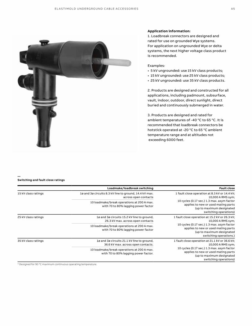
Application information: 1. Loadbreak connectors are designed and rated for use on grounded Wye systems. For application on ungrounded Wye or delta systems, the next higher voltage class product is recommended.
Examples: • 5 kV ungrounded: use 15 kV class products; • 15 kV ungrounded: use 25 kV class products; • 25 kV ungrounded: use 35 kV class products.
2. Products are designed and constructed for all applications, including padmount, subsurface, vault, indoor, outdoor, direct sunlight, direct buried and continuously submerged in water.
3. Products are designed and rated for ambient temperatures of -40 °C to 65 °C. It is recommended that loadbreak connectors be hotstick operated at -20 °C to 65 °C ambient temperature range and at altitudes not exceeding 6000 feet.
Loadmake/loadbreak switching Fault close
15 kV class ratings 1ø and 3ø circuits 8.3 kV line to ground, 14.4 kV max. across open contacts
1 fault close operation at 8.3 kV or 14.4 kV; 10,000 A RMS sym;
10 cycles (0.17 sec.) 1.3 max. asym factor applies to new or used mating parts
(up to maximum designated switching operations)
10 loadmake/break operations at 200 A max. with 70 to 80% lagging power factor
25 kV class ratings 1ø and 3ø circuits 15.2 kV line to ground, 26.3 kV max. across open contacts
1 fault close operation at 15.2 kV or 26.3 kV; 10,000 A RMS sym;
10 cycles (0.17 sec.) 1.3 max. asym factor applies to new or used mating parts
(up to maximum designated switching operations.)
10 loadmake/break operations at 200 A max. with 70 to 80% lagging power factor
35 kV class ratings 1ø and 3ø circuits 21.1 kV line to ground, 36.6 kV max. across open contacts.
1 fault close operation at 21.1 kV or 36.6 kV; 10,000 A RMS sym;
10 cycles (0.17 sec.) 1.3 max. asym factor applies to new or used mating parts
(up to maximum designated switching operations)
10 loadmake/break operations at 200 A max. with 70 to 80% lagging power factor.
* Designed for 90 °C maximum continuous operating temperature.
—Switching and fault close ratings
EL A S TI M O L D U N D ER G R O U N D C A B L E ACCE SSO R I E S

B1 copy starts here
B2 copy starts here
B3 copy starts here
A6 E L A S TI M O LD/F I S H E R PI E RCE C A B L E ACCE SSO R IE S
—Elastimold underground cable accessoriesOverview
Bushing interface
Voltage class (kV)
Interface description
Standard no. Figure no.
200 A deepwell equipment bushing
15, 25 and 35 200 A bushingwell interface
8.3 kV, 15.2 kV and 21.1 kV
IEEE 386 Fig. 3
200 A loadbreak insert
15 200 A loadbreak 8.3 kV and 8.3 kV/14.4 kV
IEEE 386 Fig. 5
200 A loadbreak insert
25 200 A loadbreak 15.2 kV and 15.2 kV/26.3 kV
IEEE 386 Fig. 7, Note 1
200 A loadbreak insert
35 200 A loadbreak interface no. 2
21.1 kV and 21.1 kV/36.3 kV
IEEE 386 Fig. 7, Note 1
200 A deadbreak insert
15 and 25 200 A deadbreak 8.3 kV and 15.2 kV
IEEE 386 Fig. 4
600 Series equipment bushing
15 and 25 600 A deadbreak interface no. 1
8.3 kV and 15.2 kV
IEEE 386 Fig.11
600 Series equipment bushing
35 600 A deadbreak interface no. 1
21.1 kV
IEEE 386 Fig.13
Note: 1. Elastimold uses Fig. 7 interface for both 25 and 35 kV applications.
—Types of interfaces supplied by Elastimold
Standard interfaces for separable connectors, components and equipment bushingThe latest revision of IEEE standard 386 defines the specific interface dimensions to which 200 A and 600 series elbows, inserts, junctions, equipment bushings and any mating components must
conform to ensure interchangeability. The table below provides information concerning the types of interfaces supplied by Elastimold products for various applications and is useful to ensure proper matching of components.

A7
—200 A loadbreak elbowsConnectors and accessories
200 A loadbreak connectors and accessories provide a convenient method to connect/disconnect cable and equipment on power distribution systems. Loadbreak elbows include provisions for energized operation using standard hotstick tools, allowing loadmake/break operation and a visible disconnect. Components can be isolated with insulated caps, plugs and parking bushings.
Optional accessories allow system grounding, testing, bypass, surge protection and current limiting fusing. Additional connecting points and taps can be provided by use of junctions or feed-thrus.
—Elastimold 200 A loadbreak elbow (15 kV and 25 kV)
Switching made easierThe Elastimold 200 A loadbreak elbow (15 kV and 25 kV series) incorporates decades of innovative design and manufacturing experience that directly addresses end users’ needs. The design incorporates safety performance features, increases range flexibility and improves life cycle cost reduction. In addition, Elastimold 200-amp loadbreak elbow has Rural Utilities Service (RUS) acceptance from the U.S. Department of Agriculture (USDA), which authorizes its use in rural infrastructure construction and improvements.
Enhance safety• Rigid probe support to ensure proper switching• No stick interface when used with Elastimold
bushings (NEETRAC* tested)• Robust stainless-steel pulling eye • Dual grounding eye positions
Increase flexibility• Additional sizes available• Improved wider cable ranges• Easy order system• Optional integral jacket seal
Improve life cycle cost reduction• Optimized for switching operations• Lifetime ease of operation and non-stick when
used with Elastimold bushings• Seal system for traditional and jacket seal options
IEEE 386 compliant ANSI certification Rural Utilities Service (RUS) acceptance
* National Electric Energy Testing, Research and Applications Center
EL A S TI M O L D U N D ER G R O U N D C A B L E ACCE SSO R I E S
B1 copy starts here
B2 copy starts here
B3 copy starts here
A8 E L A S TI M O LD/F I S H E R PI E RCE C A B L E ACCE SSO R IE S
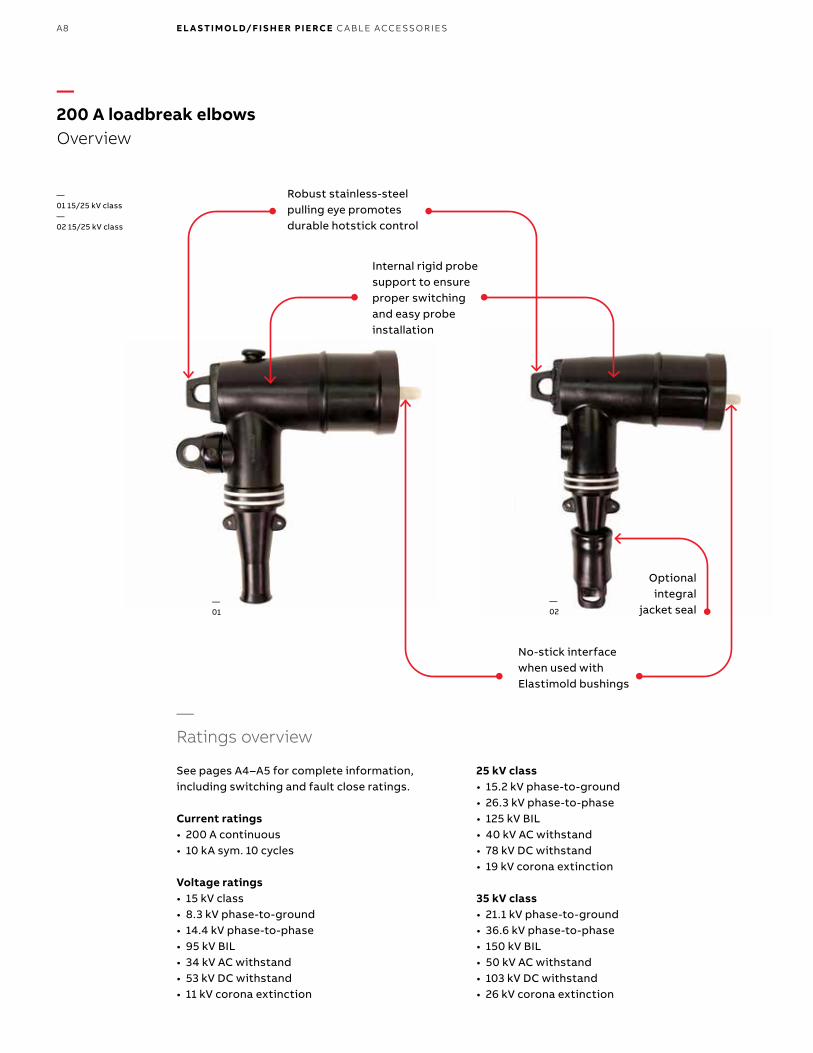
—200 A loadbreak elbowsOverview
—Ratings overview
See pages A4–A5 for complete information, including switching and fault close ratings.
Current ratings• 200 A continuous• 10 kA sym. 10 cycles
Voltage ratings• 15 kV class• 8.3 kV phase-to-ground• 14.4 kV phase-to-phase• 95 kV BIL• 34 kV AC withstand• 53 kV DC withstand• 11 kV corona extinction
25 kV class• 15.2 kV phase-to-ground• 26.3 kV phase-to-phase• 125 kV BIL• 40 kV AC withstand• 78 kV DC withstand• 19 kV corona extinction
35 kV class• 21.1 kV phase-to-ground• 36.6 kV phase-to-phase• 150 kV BIL• 50 kV AC withstand• 103 kV DC withstand• 26 kV corona extinction
Robust stainless-steel pulling eye promotes durable hotstick control
Optional integral
jacket seal
Internal rigid probe support to ensure proper switching and easy probe installation
No-stick interface when used with Elastimold bushings
—01 15/25 kV class—02 15/25 kV class
—01
—02

A9
—200 A loadbreak separable connectorsComponents
Cable to equipment connectionsABB offers the complete package of underground cable accessories – everything you need to connect, ground, splice, terminate and protect underground
cable from 5 kV to 138 kV – along with solid dielectric switchgear in compact, modular designs that fit easily into tight vaults.
—Operating accessories
Bushing well plug
Bushing well
Loadbreak bushing insert
Extended bushing insert
Loadbreak feed-thru insert
Bolted elbowwith tap
Insulated parking bushing
Grounding plug
Parking stand
Feed thru
Loadbreak elbow connector with or without test point
Grounding elbow
Repair elbow
Replacement elbow
Fused elbow
Insulated cap
Insulated cap with ground
Test rod
Assembly tool
See cable notes
See cable notes
See cable notes
See pages A104-A113 for surge arrester
applications.
EL A S TI M O L D U N D ER G R O U N D C A B L E ACCE SSO R I E S
B1 copy starts here
B2 copy starts here
B3 copy starts here
A10 E L A S TI M O LD/F I S H E R PI E RCE C A B L E ACCE SSO R IE S
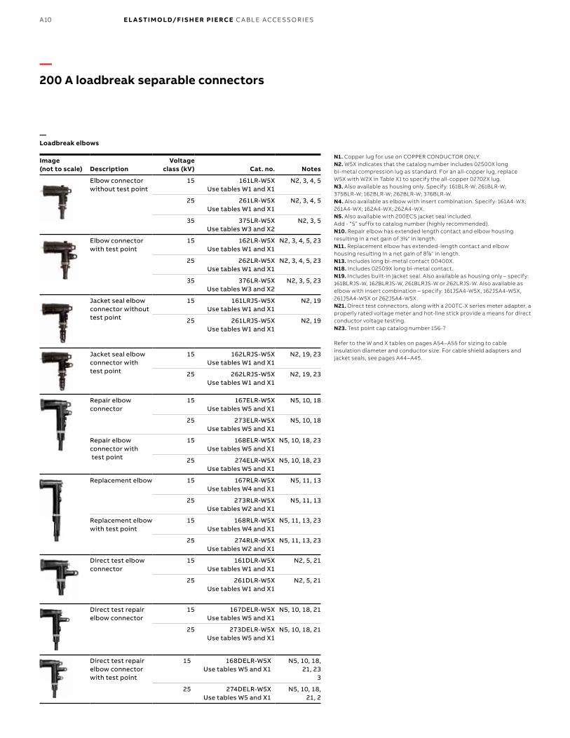
—Loadbreak elbows
Image (not to scale) Description
Voltage class (kV) Cat. no. Notes
Elbow connector without test point
15 161LR-W5X Use tables W1 and X1
N2, 3, 4, 5
25 261LR-W5X Use tables W1 and X1
N2, 3, 4, 5
35 375LR-W5X Use tables W3 and X2
N2, 3, 5
Elbow connector with test point
15 162LR-W5X Use tables W1 and X1
N2, 3, 4, 5, 23
25 262LR-W5X Use tables W1 and X1
N2, 3, 4, 5, 23
35 376LR-W5X Use tables W3 and X2
N2, 3, 5, 23
Jacket seal elbow connector without test point
15 161LRJS-W5X Use tables W1 and X1
N2, 19
25 261LRJS-W5X Use tables W1 and X1
N2, 19
Jacket seal elbow connector with test point
15 162LRJS-W5X Use tables W1 and X1
N2, 19, 23
25 262LRJS-W5X Use tables W1 and X1
N2, 19, 23
Repair elbow connector
15 167ELR-W5X Use tables W5 and X1
N5, 10, 18
25 273ELR-W5X Use tables W5 and X1
N5, 10, 18
Repair elbow connector with test point
15 168ELR-W5X Use tables W5 and X1
N5, 10, 18, 23
25 274ELR-W5X Use tables W5 and X1
N5, 10, 18, 23
Replacement elbow 15 167RLR-W5X Use tables W4 and X1
N5, 11, 13
25 273RLR-W5X Use tables W2 and X1
N5, 11, 13
Replacement elbow with test point
15 168RLR-W5X Use tables W4 and X1
N5, 11, 13, 23
25 274RLR-W5X Use tables W2 and X1
N5, 11, 13, 23
Direct test elbow connector
15 161DLR-W5X Use tables W1 and X1
N2, 5, 21
25 261DLR-W5X Use tables W1 and X1
N2, 5, 21
Direct test repair elbow connector
15 167DELR-W5X Use tables W5 and X1
N5, 10, 18, 21
25 273DELR-W5X Use tables W5 and X1
N5, 10, 18, 21
Direct test repair elbow connector with test point
15 168DELR-W5X Use tables W5 and X1
N5, 10, 18, 21, 23
3
25 274DELR-W5X Use tables W5 and X1
N5, 10, 18, 21, 2
N1. Copper lug for use on COPPER CONDUCTOR ONLY. N2. W5X indicates that the catalog number includes 02500X long bi-metal compression lug as standard. For an all-copper lug, replace W5X with W2X in Table X1 to specify the all-copper 02702X lug.N3. Also available as housing only. Specify: 161BLR-W; 261BLR-W; 375BLR-W; 162BLR-W; 262BLR-W; 376BLR-W.N4. Also available as elbow with insert combination. Specify: 161A4-WX; 261A4-WX; 162A4-WX; 262A4-WX.N5. Also available with 200ECS jacket seal included. Add - “S” suffix to catalog number (highly recommended).N10. Repair elbow has extended length contact and elbow housing resulting in a net gain of 311⁄44" in length. N11. Replacement elbow has extended-length contact and elbow housing resulting in a net gain of 877⁄88" in length.N13. Includes long bi-metal contact 00400X.N18. Includes 02509X long bi-metal contact.N19. Includes built-in jacket seal. Also available as housing only – specify: 161BLRJS-W, 162BLRJS-W, 261BLRJS-W or 262LRJS-W. Also available as elbow with insert combination – specify: 161JSA4-W5X, 162JSA4-W5X, 261JSA4-W5X or 262JSA4-W5X.N21. Direct test connectors, along with a 200TC-X series meter adapter, a properly rated voltage meter and hot-line stick provide a means for direct conductor voltage testing.N23. Test point cap catalog number 156-7
Refer to the W and X tables on pages A54–A55 for sizing to cable insulation diameter and conductor size. For cable shield adapters and jacket seals, see pages A44–A45.
—200 A loadbreak separable connectors
A11
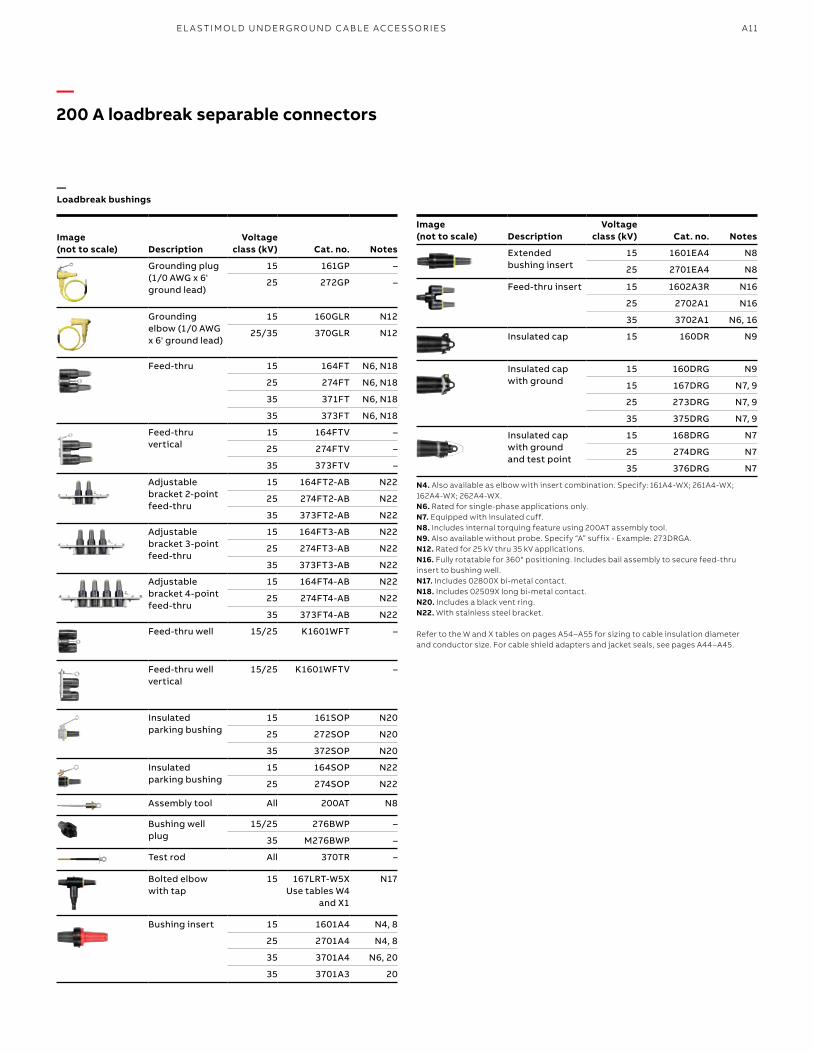
—200 A loadbreak separable connectors
—Loadbreak bushings
Image (not to scale) Description
Voltage class (kV) Cat. no. Notes
Grounding plug (1/0 AWG x 6' ground lead)
15 161GP –
25 272GP –
Grounding elbow (1/0 AWG x 6' ground lead)
15 160GLR N12
25/35 370GLR N12
Feed-thru 15 164FT N6, N18
25 274FT N6, N18
35 371FT N6, N18
35 373FT N6, N18
Feed-thru vertical
15 164FTV –
25 274FTV –
35 373FTV –
Adjustable bracket 2-point feed-thru
15 164FT2-AB N22
25 274FT2-AB N22
35 373FT2-AB N22
Adjustable bracket 3-point feed-thru
15 164FT3-AB N22
25 274FT3-AB N22
35 373FT3-AB N22
Adjustable bracket 4-point feed-thru
15 164FT4-AB N22
25 274FT4-AB N22
35 373FT4-AB N22
Feed-thru well 15/25 K1601WFT –
Feed-thru well vertical
15/25 K1601WFTV –
Insulated parking bushing
15 161SOP N20
25 272SOP N20
35 372SOP N20
Insulated parking bushing
15 164SOP N22
25 274SOP N22
Assembly tool All 200AT N8
Bushing well plug
15/25 276BWP –
35 M276BWP –
Test rod All 370TR –
Bolted elbow with tap
15 167LRT-W5X Use tables W4
and X1
N17
Bushing insert 15 1601A4 N4, 8
25 2701A4 N4, 8
35 3701A4 N6, 20
35 3701A3 20
Image (not to scale) Description
Voltage class (kV) Cat. no. Notes
Extended bushing insert
15 1601EA4 N8
25 2701EA4 N8
Feed-thru insert 15 1602A3R N16
25 2702A1 N16
35 3702A1 N6, 16
Insulated cap 15 160DR N9
Insulated cap with ground
15 160DRG N9
15 167DRG N7, 9
25 273DRG N7, 9
35 375DRG N7, 9
Insulated cap with ground and test point
15 168DRG N7
25 274DRG N7
35 376DRG N7
N4. Also available as elbow with insert combination. Specify: 161A4-WX; 261A4-WX; 162A4-WX; 262A4-WX.N6. Rated for single-phase applications only.N7. Equipped with insulated cuff.N8. Includes internal torquing feature using 200AT assembly tool.N9. Also available without probe. Specify “A” suffix - Example: 273DRGA.N12. Rated for 25 kV thru 35 kV applications.N16. Fully rotatable for 360° positioning. Includes bail assembly to secure feed-thru insert to bushing well.N17. Includes 02800X bi-metal contact.N18. Includes 02509X long bi-metal contact.N20. Includes a black vent ring.N22. With stainless steel bracket.
Refer to the W and X tables on pages A54–A55 for sizing to cable insulation diameter and conductor size. For cable shield adapters and jacket seals, see pages A44–A45.
EL A S TI M O L D U N D ER G R O U N D C A B L E ACCE SSO R I E S

B1 copy starts here
B2 copy starts here
B3 copy starts here
A12 E L A S TI M O LD/F I S H E R PI E RCE C A B L E ACCE SSO R IE S
N1. Repair elbow has extended-length contact and elbow housing resulting in a net gain of 311⁄44" in length. N2. Copper lug for use on COPPER CONDUCTOR ONLY.N3. Replacement elbow has extended-length contact and elbow housing resulting in a net gain of 877⁄88" in length.N4. 160CA cable size adapter can only be used with elbow catalog numbers 165LR/166LR C, H or CC size only.N5. Also available as rubber only, without straps. Specify suffix “-4” in place of “-5” in the catalog number.N6. Supplied with replaceable stud. Replacement stud available separately. Specify 1000-150.N7. Hardware packages, consisting of brackets and straps only, may be ordered separately by specifying “-6” in the catalog number. Example 164J4-6.N8. Hardware package, consists of “U” straps and back plate only, may be ordered separately by specifying 1601US-J2.N9. Hardware package, consists of “U” straps and back plate only, may be ordered separately by specifying 1601US-J3.N10. Hardware package, consists of “U” straps and back plate only, may be ordered separately by specifying 1601US-J4.N11. Hardware package, consists of “U” straps and back plate only, may be ordered separately by specifying 271-68.N12. Hardware package, consists of “U” straps and back plate only, may be ordered separately by specifying 271-61.N13. Hardware package, consists of “U” straps and back plate only, may be ordered separately by specifying 271-70.N14. For use with direct test connectors.
Refer to the W and X tables on pages A54–A55 for sizing to cable insulation diameter and conductor size. For cable shield adapters and jacket seals, see pages A44–A45.
Image (not to scale) Description
Voltage class (kV) Cat. no. Notes
Contacts: LR long bi-metal
All Use Table X1 02500X
–
ELR bi-metal 15/25 02509X N1
LR copper All 02702X N2
LRT contact 15 02800X –
RLR contact 15/25 00400X N3
Elbow probe 15 166LRF –
35 375LRF –
Elbow cable entrance insulating plug
All 10EP-W Use Table W6
–
Cable size adapter 15 160CA-W Use Table W6
EB-FA Only
N4
Direct voltage test meter adapter for: HD electric meters
All 200TC-1 N14
Ross meters – 200TC-2 N14
Chance meters – 200TC-4 N14
2-Way well junction with stainless steel bracket
15/25 K1601WJ2 N6
2-Way well junction with “U” straps
15/25 K1601WJ2-5 N5, 6, 11
3-Way well junction with stainless steel bracket
15/25 K1601WJ3 N6
3-Way well junction with “U” straps
15/25 K1601WJ3-5 N5, 6, 12
4-Way well junction with stainless steel bracket
15/25 K1601WJ4 N6
4-Way well junction with “U” straps
15/25 K1601WJ4-5 N5, 6, 13
2-Point junction with stainless steel bracket
15 164J2 N7
25 274J2 N7
35 373J2 N7
2-Point junction with “U” straps
15 164J2-5 –
25 274J2-5 N5, 8 N5, 11
35 373J2-5 N5, 11
3-Point junction with stainless steel bracket
15 164J3 N7
25 274J3 N7
35 373J3 N7
3-Point junction with “U” straps
15 164J3-5 N5, 9
25 274J3-5 N5, 12
35 373J3-5 N5, 12
4-Point junction with stainless steel bracket
15 164J4 N7
25 274J4 N7
35 373J4 N7
4-Point junction with “U” straps
15 164J4-5 N5, 10
25 274J4-5 N5, 13
35 373J4-5 N5, 13
—200 A loadbreak separable connectorsConnectors and accessories
—Connectors and accessories

A13
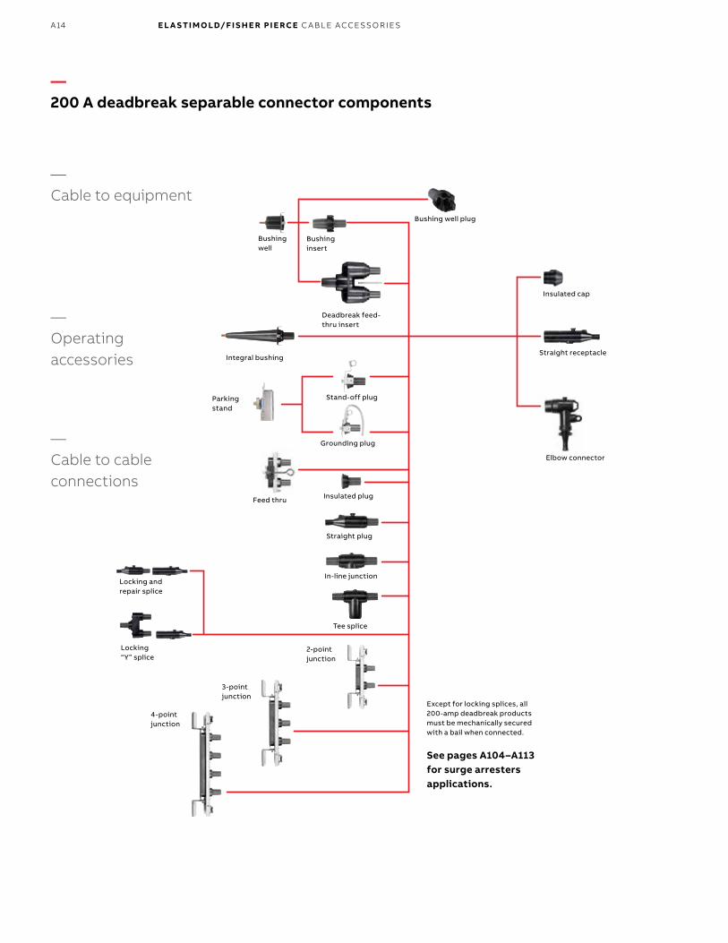
200 A deadbreak connectors and accessories provide a quick-disconnect feature for cable and equipment connections on power distribution systems.
All deadbreak connectors must be de- energized before operating and must be mechanically secured with bails when connected. Components can be isolated with insulated caps, plugs and parking bushings.
All deadbreak elbows are equipped with test points as standard. Optional accessories allow system grounding, bypass and lightning surge protection. Additional connecting points and taps can be provided by use of junctions or feed-thrus.
Ratings overviewSee pages A4–A5 for complete information.
Current ratings• 200 A continuous• 10 kA sym. 10 cycles
Voltage ratings 15 kV class• 8.3 kV phase-to-ground• 14.4 kV phase-to-phase• 95 kV BIL• 34 kV AC withstand• 53 kV DC withstand• 11 kV corona extinction
25 kV class• 15.2 kV phase-to-ground• 26.3 kV phase-to-phase• 125 kV BIL• 40 kV AC withstand• 78 kV DC withstand• 19 kV corona extinction
—200 A deadbreak separable connectorsConnectors and accessories
EL A S TI M O L D U N D ER G R O U N D C A B L E ACCE SSO R I E S
B1 copy starts here
B2 copy starts here
B3 copy starts here
A14 E L A S TI M O LD/F I S H E R PI E RCE C A B L E ACCE SSO R IE S
—Cable to equipment
—Operating accessories
—Cable to cable connections
—200 A deadbreak separable connector components
Except for locking splices, all 200-amp deadbreak products must be mechanically secured with a bail when connected.
See pages A104–A113 for surge arresters applications.
Locking and repair splice
Locking “Y” splice
Feed thru
Parking stand
Stand-off plug
Integral bushing
Grounding plug
Insulated plug
Straight plug
In-line junction
Tee splice
Bushing well
Bushing insert
Bushing well plug
Deadbreak feed-thru insert
3-point junction
4-point junction
2-point junction
Insulated cap
Straight receptacle
Elbow connector

A15
Image (not to scale) Description
Voltage class (kV) Cat. no. Notes
Elbow connector with test point
15/25 252LR-W0X Use tables W16
and X1
N1, 2
Jacket seal elbow connector with test point
15/25 252LRJS-W5X Use tables W16
and X1
N2, 19
Bail assembly for 156LR elbow
15/25 150BA –
Bushing insert 15/25 K1501A1 N3
Feed-thru insert 15/25 K1502A1 N3, 4
Insulated plug 15/25 K150DP N3
Insulated cap 15/25 K150DR N3
Insulated parking bushing
15/25 K151SOP N3
Grounding plug 15/25 151GP N3
Feed-thru 15/25 K1501FT N3, 6
2-point junction 15/25 K1501J2-U8 N3, 6
3-point junction 15/25 K1501J3-U8 N3, 6
4-point junction 15/25 K1501J4-U8 N3, 6
Elbow probe 15/25 156LRF DP 0438609
–
Straight receptacle 15/25 K151SR-W0X Use tables W1
and X1
N3, 12, 13, 17, 18
Straight plug 15/25 K151SP-W0X Use tables W1
and X1
N3, 12, 13, 19
—200 A deadbreak separable connectors
N1. Includes bail assembly.N2. W5X indicates that the catalog number includes a 02500X bi-metal compression lug, which is rated for either aluminum or copper conductor, as standard. For an all-copper lug, replace W5X with W2X. Use Table X1 to specify the all-copper 02702X lug.N3. Bails are required but not included. Order separately. Consult factory for bails not listed for a specific application.N4. Fully rotatable for 360° positioning. Includes bail assembly to secure feed-thru insert to bushing well. Elbows bail assemblies are required but not included with the feed-thru insert.N6. Center-to-center spacing equals 4 inches.N12. Also available as housing only. Specify K151BSP-W or K151BSR-W.N13. Also available in EB-FA sizes per Table W6 by using 160CA cable adapter with C size plugs and receptacles.N17. Straight receptacles are also available with test point. Specify K152SR-W0X catalog number.N18. W0X indicates that the catalog number includes a 01500X universal aluminum compression lug, which is rated for either aluminum or copper, as standard. For an all-copper lug, replace W0X with W2X in Table X1 to specify the all-copper 01502X lug.N19. W0X indicates that the catalog number includes a 01600X universal aluminum compression lug, which is rated for either aluminum or copper, as standard. For an all-copper lug, replace W0X with W2X in Table X1 to specify the all-copper 01602X lug.N22. Direct test connectors, along with a 200TC-X series meter adapter, a properly rated voltage meter and hot-line stick provides a means for direct conductor voltage testing. See page A12 for meter adapters.
Refer to the W and X tables on pages A54–A55 for sizing to cable insulation diameter and conductor size. For cable shield adapters and jacket seals, see pages A44–A45.
—200 A deadbreak separable connectorsConnectors and accessories
EL A S TI M O L D U N D ER G R O U N D C A B L E ACCE SSO R I E S

B1 copy starts here
B2 copy starts here
B3 copy starts here
A16 E L A S TI M O LD/F I S H E R PI E RCE C A B L E ACCE SSO R IE S
—200 A deadbreak connectors and accessories
N3. Bails are required but not included. Order separately. Consult factory for bails not listed for a specific application.N5. Refer to factory for application details.N7. Copper lug for copper cable only.N8. To order cable legs for different cable sizes, list each leg size “W” and “X”. Example: K151LY-A1240-A1240-B1220. See Tables W1 and X1 for sizes.N9. To order locking contacts for K151LS and K151LY, order 01401X (Al) or 01402X (Cu) for plug contact. Order 01301X (Al) or 01302X (Cu) for receptacle. See Table X1 for sizes.N10. For use with 156LR elbows.N11. For use with K151SR, K151SP, K151LS, K151LY receptacles, plugs and splices.N13. Also available in EB-FA sizes per Table W6 by using 160CA cable adapter with C size plugs and receptacles.N14. 160CA cable adapter can only be used with C size plugs and receptacles.N15. Bails are not required for locking splices.N16. When used as a repair splice, the assembled length allows 4" for cable replacement/repair.N17. Straight receptacles are also available with test point. Specify K152SR-W0X catalog number.N20. W0X indicates that the catalog number includes a 01400X universal aluminum compression lug, which is rated for either aluminum or copper, as standard. For an all-copper lug, replace W0X with W2X in Table X1 to specify the all-copper 01402X lug.N21. W0X indicates that the catalog number includes a 01300X universal aluminum compression lug, which is rated for either aluminum or copper, as standard. For an all-copper lug, replace W0X with W2X in Table X1 to specify the all-copper 01302X lug.N23. Gains approximately 4" of repair length.
Refer to the W and X tables on pages A54–A55 for sizing to cable insulation diameter and conductor size. For cable shield adapters and jacket seals, see pages A44–A45.
Image (not to scale) Description
Voltage class (kV) Cat. No. Notes
Tee splice 15/25 K150T N3
In-line junction 15/25 K150S N3
Locking splice/ repair splice
15/25 K151LS-W0X Use tables W1
and X1
N8, 9, 13, 15, 16, 17,
20, 23
Locking “Y” splice 15/25 K151LY-W0X Use tables W1
and X1
N8, 9, 13, 15, 17, 21
Bail 15/25 150TB1 N5
Bail 15/25 150TB2 N5
Bail 15/25 150TB3 N5
Bail 15/25 150TB4 N5
Bail 15/25 150TB5 N5
Bail 15/25 150TB6 N5
Contacts: long bi-metal copper
15/2515/25
02500X 02702X
N7
Elbow cable entrance insulating plug
15/25 10EP-W Use table W6
N10
Cable entrance insulating plug
15/25 152EA-W Use table W6
N11
Cable size adapter 15/25 160CA-W Use table W6
EB-FA only
N14
—200 A deadbreak separable connectorsConnectors and accessories

A17
—600 A deadbreak separable connectors600 series deadbreak components
600 Series deadbreak elbows, straight receptacles, junctions, vault stretchers and accessories are used to connect equipment and cable on primary feeder and network circuits. Designs accommodate large conductors and feature bolted connections and deadfront modular construction for maximum reliability, performance and versatility.De-energized connectors can be quickly and easily connected and disconnected using standard hand tools and equipment in accordance with accepted operating practices. Optional accessories allow visible external separation, bypass, isolation, dead-ending, grounding and testing as well as adding taps, surge arresters and circuit protection.Hotstick-operable and separable joint systems are shown on pages A22–A28.
—Spiking aid
When spiking a medium voltage cable near a separable connector, the Elastimold spiking aid is a specially designed product to reduce outage time and cost. Medium voltage cable is spiked as a means to ensure the circuit is de-energized where there is no sectionalizing device, direct testing means or provision for grounding.
—GAD
When available fault currents exceed 10 kA in underground systems, the Elastimold GAD may provide a solution. The Elastimold GAD is rated 25 kA and installs in the rear interface of a 600 series elbow connector (T-body). The GAD is normally covered and insulated with an insulating cap that contains capacitive test and a hotstick operating band. Once the circuit is opened at a disconnecting device, the test point cap is removed with a hotstick, and then using an appropriate capacitive test point meter, the test point is checked for voltage. The insulating cap is then removed with a hotstick and a high voltage meter is used to confirm the de-energized state before a ground cable is connected.
—Ratings overview
See pages A4–A5 for complete information.
Current ratings (Prefixes: 650, K650, K651, K655, K656, 750, 755, 756 and 03700)• 600 A continuous• 25 kA sym., 10 cycles
(Prefixes 675, K671, K675, K676, 775, 776 and 03702)• 900 A continuous• 25 kA sym., 10 cycles
Note: 900 A ratings require copper cable and copper current-carrying components.
Voltage ratings15/25 kV class (5 kV thru 28 kV)• 16.2 kV phase-to-ground• 28 kV phase-to phase• 140 kV BIL• 45 kV AC withstand• 84 kV DC withstand• 21.5 kV corona extinction
35 kV class• 21.1 kV phase-to-ground• 36.6 kV phase-to-phase• 150 kV BIL• 50 kV AC withstand• 103 kV DC withstand• 26 kV corona extinction
Note: Elastimold has increased the IEEE Standard Prod uction and Design Test levels for 25 kV class products to include 27 kV and 28 kV systems.
* Tested at 8.3/14.9 kV † Tested at 15.2/26.3 kV • Tested at 21.1/36.6 kV
EL A S TI M O L D U N D ER G R O U N D C A B L E ACCE SSO R I E S

B1 copy starts here
B2 copy starts here
B3 copy starts here
A18 E L A S TI M O LD/F I S H E R PI E RCE C A B L E ACCE SSO R IE S
†
†
*†• Test and ground
†
†
*†• Test and ground
—Cable to equipmentSee pages A104–A113 for surge arrester applications.
—Straight receptacle
—Elbow connector
200 A taps
—600 Series taps—
Cable to cable (using junctions)See pages A34–A37 for additional junctions
Integral bushing
Threaded stud
Bushing extender
Connecting plug
2-Pt junction
4-Pt junction
—Operating accessories
Grounding plug
Insulated parking bushing
Cable adapter
Compression lug
Vault stretcher
Threaded stud
Vault stretcher connector
Compression lug
Cable adapter
Threaded stud
Insulated cap with test point
Bushing extender
Cable adapter
Compression lug
Threaded stud
600 Series elbow
Insulatedplug
Voltage detection cap
Connecting plug
Straight receptacle adapter
Bolt & washer
Straight receptacle housing
Compression lug
Cable adapter
Retaining ring
200A deadbreak
200 A loadbreak
Spanner wrench
Deadbreak reducing tap plug
Reducing tap well
Loadbreak elbow tap plug
3-Pt junction
—600 A deadbreak separable connectors600 series deadbreak components
—* Tested at 8.3/14.9 kV † Tested at 15.2/26.3 kV • Tested at 21.1/36.6 kV

A19
N1. For 900 A ratings, substitute 675 for 650 and 655; 676 for 656; K671 for K651; K675 for K650 and K655; K676 for K656; 775 for 750 and 755; 776 for 756 and 2X for 0X in the catalog number. The 900 A rating requires copper current-carrying connector components and copper conductor cable.N2. Add suffix symbol from page A17 to include cable shield grounding kit and/or cable jacket sealing kit.N3. Available without the stud by adding “N” to the catalog number.N4. Straight receptacle adapter is used to connect straight receptacles K655YBSR and K655YSR-W0X (page A33) to equipment bushings.N5. Aluminum lug for use on aluminum or copper conductors. DO NOT substitute threaded 03600X lug.N6. Copper lug for use on COPPER CONDUCTOR ONLY. DO NOT substitute threaded 03602X lug.N7. Available with the stud factory-assembled by adding “SP” to the catalog number. 675ETP, K675ETP and 775ETP are available as -SP only. The stud is not field removable.N8. Available with a loose stud by adding suffix “S” to the catalog number.N9. 600SW spanner wrench is recommended for installation of deadbreak reducing tap plugs and reducing tap wells.N10. Use 600ATM assembly tool.N11. 600 Series elbows and straight receptacles with IEEE Std. 386 capacitive test points are available by substituting 656 for 655; K656 for K655; K676 for K675; 756 for 755; 676 for 675; K676 for K675 and 776 for 775 in the catalog number.N12. Direct test connectors, along with a 200TC-X series meter adapter, a properly rated voltage meter and hot-line stick; provides a means for direct conductor voltage testing.N13. With stainless steel bracket.N15. Available with 200 kV BIL adding suffix “-200”.N16. Bimetallic Lug for use on aluminum or copper conductors. DO NOT substitute threaded 05501X lug
Refer to the W and X tables on pages A54–A55 for sizing to cable insulation diameter and conductor size. For cable shield adapters and jacket seals, see pages A44–A45.
Image (not to scale) Description
Voltage class (kV) Cat. no. Notes
600 Series elbow (with insulating plug, cap, stud, lug and cable adapter)
15/25 K655LR-W0X Use tables W7 and X6
N1, 2
35 755LR-W0X Use tables W9 and X6
N1, 2, 15
600 Series direct test elbow (with insulating plug, cap, stud lug and cable adapter)
15/25 K655DLR-W0X Use tables W7 and X6
N1, 2, 12
35 755DLR-W0X Use tables W9 and X6
N1, 2, 12, 15
600 Series elbow with test point (with insulating plug, cap, stud, lug and cable adapter)
15/25 K656LR-W0X Use tables W7 and X6
N1, 2
35 756LR-W0X Use tables W9 and X6
N1, 2, 15
600 Series direct test elbow with test point (with insulating plug, cap, stud, lug and cable adapter)
15/25 K656DLR-W0X Use tables W7 and X6
N1, 2, 12
35 756DLR-W0X Use tables W9 and X6
N1, 2, 12, 15
600 Series elbow without test point housing only (with stud)
15/25 K655BLR N1, 3
35 755BLR N1, 3, 15
600 Series elbow with test point housing only (with stud)
15/25 K656BLR N1, 3
35 756BLR N1, 3, 15
600 Series straight receptacle (with cable adapter, lug and retaining ring)
15/25 K655SR-W0X Use tables W7 and X6
N1, 2, 11
600 Series direct test straight receptacle elbow
15/25 K655DSR-W0X Use tables W7 and X6
N1, 2, 11, 12
600 Series straight receptacle housing (lug and cable adapter not included)
15/25 K655BSR N1,11
Straight receptacle adapter
15/25 K650SRA N1, 4
600 Series vault stretcher (housing only with stud)
15/25 kV K655BVS N1, 9
35 kV 755BVS N1, 9
—600 A deadbreak elbows
—600 A deadbreak separable connectors600 A deadbreak elbows
EL A S TI M O L D U N D ER G R O U N D C A B L E ACCE SSO R I E S

B1 copy starts here
B2 copy starts here
B3 copy starts here
A20 E L A S TI M O LD/F I S H E R PI E RCE C A B L E ACCE SSO R IE S
—600 A deadbreak accessories
Image (not to scale) Description
Voltage class (kV) Cat. no. Notes
Cable size adapter 15/25 655CA-W Use tables W7
–
35 755CA-W Use tables W9
–
Compression lug All 03700X Use tables X6
N5
All 03702X Use tables X6
N6
Bimetallic compression lug All 04601XXX Use Table X6
N16
Epoxy connecting plug 15/25 K650CP N9
600 Series elbow and vault stretcher size sensitive kit (cable adapter and lug)
15/25 655CK-W0X Use tables W7 and X6
N2
35 755CK-W0X Use tables W9 and X6
N2
Adapter retaining ring All 650ARR-X Use Table X6
–
600 Series straight receptacle size sensitive kit (cable adapter, retaining ring and lug)
15/25 655CK-W0X-ARR Use tables W7 and X6
N2
Bushing extender (with stud) 15/25 K655BE N1, 3
35 755BE N1, 3
Insulated cap with test point (with stud) 15/25 K656DR N3, 7
35 756DR –
Insulated cap with test point (with stud) and ground
15/25 K656DRG N3, 7
35 756DRG –
Insulating plug (with cap) 15/25 K650BIP N1, 7, 8
35 750BIP N1, 7, 8
Grounding plug (ground lead 2/0 AWG x 30") 15/25 650GP N1, 7, 8
35 750GP N1, 7, 8
Insulated parking bushing 15/25 K650SOP N7, 8
35 750SOP N7, 8
Connecting plug 15/25 K651CP N1, 7, 8, 10
35 750CP N1, 7, 8, 10
Deadbreak reducing tap plug 15/25 K650RTP N1, 7, 8, 9
Reducing tap well 15/25 K650RTW N1, 7, 8, 9
Loadbreak elbow tap plug 15 650ETP N1, 7, 8, 10
25 K650ETP N1, 7, 8, 10
35 750ETP N1, 7, 8, 10
Vault stretcher threaded stud 15/25 650VSA N1
35 750VSA N1
600 Series elbow threaded stud 15/25 650SA N1
35 750SA N1
Assembly tool (window-op) All 600ATM –
Spanner wrench All 600SW N9
Direct voltage test meter adapter for: HD electric meters
All 200TC-1 N12
Ross meters 200TC-2 N12
Chance meters 200TC-4 N12
N1. For 900 A ratings, substitute 675 for 650 and 655; 676 for 656; K671 for K651; K675 for K650 and K655; K676 for K656; 775 for 750 and 755; 776 for 756 and 2X for 0X in the catalog number. The 900 A rating requires copper current-carrying connector components and copper conductor cable.N2. Add suffix symbol from page A17 to include cable shield grounding kit and/or cable jacket sealing kit.N3. Available without the stud by adding “N” to the catalog number.N4. Straight receptacle adapter is used to connect straight receptacles K655YBSR and K655YSR-W0X (page A33) to equipment bushings.N5. Aluminum lug for use on aluminum or copper conductors. DO NOT substitute threaded 03600X lug.N6. Copper lug for use on COPPER CONDUCTOR ONLY. DO NOT substitute threaded 03602X lug.N7. Available with the stud factory-assembled by adding “SP” to the catalog number. 675ETP, K675ETP and 775ETP are available as -SP only. The stud is not field removable.N8. Available with a loose stud by adding suffix “S” to the catalog number.N9. 600SW spanner wrench is recommended for installation of deadbreak reducing tap plugs and reducing tap wells.N10. Use 600ATM assembly tool.N11. 600 Series elbows and straight receptacles with IEEE Std. 386 capacitive test points are available by substituting 656 for 655; K656 for K655; K676 for K675; 756 for 755; 676 for 675; K676 for K675 and 776 for 775 in the catalog number.N12. Direct test connectors, along with a 200TC-X series meter adapter, a properly rated voltage meter and hot-line stick; provides a means for direct conductor voltage testing.N13. With stainless steel bracket.N15. Available with 200 kV BIL adding suffix “-200”.N16. Bimetallic lug for use on aluminum or copper conductors. DO NOT substitute threaded 05501X lug.
Refer to the W and X tables on pages A54–A55 for sizing to cable insulation diameter and conductor size. For cable shield adapters and jacket seals, see pages A44–A45.
—600 A deadbreak separable connectors600 series deadbreak components
A21
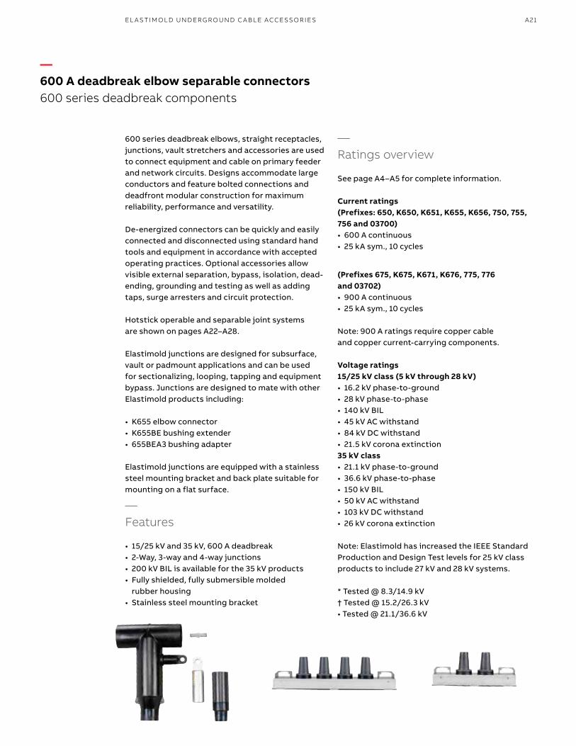
600 series deadbreak elbows, straight receptacles, junctions, vault stretchers and accessories are used to connect equipment and cable on primary feeder and network circuits. Designs accommodate large conductors and feature bolted connections and deadfront modular construction for maximum reliability, performance and versatility.
De-energized connectors can be quickly and easily connected and disconnected using standard hand tools and equipment in accordance with accepted operating practices. Optional accessories allow visible external separation, bypass, isolation, dead-ending, grounding and testing as well as adding taps, surge arresters and circuit protection.
Hotstick operable and separable joint systems are shown on pages A22–A28.
Elastimold junctions are designed for subsurface, vault or padmount applications and can be used for sectionalizing, looping, tapping and equipment bypass. Junctions are designed to mate with other Elastimold products including:
• K655 elbow connector • K655BE bushing extender • 655BEA3 bushing adapter
Elastimold junctions are equipped with a stainless steel mounting bracket and back plate suitable for mounting on a flat surface.
—Features
• 15/25 kV and 35 kV, 600 A deadbreak • 2-Way, 3-way and 4-way junctions • 200 kV BIL is available for the 35 kV products• Fully shielded, fully submersible molded
rubber housing • Stainless steel mounting bracket
—600 A deadbreak elbow separable connectors600 series deadbreak components
—Ratings overview
See page A4–A5 for complete information.
Current ratings (Prefixes: 650, K650, K651, K655, K656, 750, 755, 756 and 03700)• 600 A continuous• 25 kA sym., 10 cycles
(Prefixes 675, K675, K671, K676, 775, 776 and 03702)• 900 A continuous• 25 kA sym., 10 cycles Note: 900 A ratings require copper cable and copper current-carrying components.
Voltage ratings 15/25 kV class (5 kV through 28 kV)• 16.2 kV phase-to-ground• 28 kV phase-to-phase• 140 kV BIL• 45 kV AC withstand• 84 kV DC withstand• 21.5 kV corona extinction35 kV class• 21.1 kV phase-to-ground• 36.6 kV phase-to-phase• 150 kV BIL• 50 kV AC withstand• 103 kV DC withstand• 26 kV corona extinction Note: Elastimold has increased the IEEE Standard Prod uction and Design Test levels for 25 kV class products to include 27 kV and 28 kV systems.
* Tested @ 8.3/14.9 kV† Tested @ 15.2/26.3 kV• Tested @ 21.1/36.6 kV
EL A S TI M O L D U N D ER G R O U N D C A B L E ACCE SSO R I E S

B1 copy starts here
B2 copy starts here
B3 copy starts here
A22 E L A S TI M O LD/F I S H E R PI E RCE C A B L E ACCE SSO R IE S
—Separable connectors 600 series deadbreak
—Hotstick operable 600 series connectors See pages A22–A28
—Cable to equipment
—Straight receptacle
—Elbow connector
—600 Series taps
—Cable to cable using L-kits
—Cable to cable (using junctions)
—Operating accessories
Threaded compression lug
Stick-Op loadbreak reducing tap plug
Cam-Op retainer sleeves
Cam-Op link connector
—Cable to cable using vault stretchers
L-4
L-3
L-2
L-1
VS2
VS3
VS4
See pages A104–A113 for surge arrester applications.
A23
N1. For 900 A ratings, substitute 675 for 650 and 655; 676 for 656; K675 for K650 and K655; K676 for K656; 775 for 750 and 755; 776 for 756 and 2X for 0X in the catalog number. The 900 A rating requires copper current-carrying connector components and copper conductor cable.N2. L-Kits and VS-Kits do not include cable adapters or compression lugs. These items must be ordered separately.N3. 600 Series Elbows and Straight Receptacles with IEEE Std. 386 capacitive test points are available by substituting 656 for 655; K656 for K655; K676 for K675; 756 for 755; 676 for 675; K676 for K675 and 776 for 775 in the catalog number.N4. 600ATM is recommended for installing K651CP and 750CP.N5. Can be used as a repair joint mounting hardware. (Gains 311⁄22" of repair length.)N6. Can be used as a reducing joint for different size cables.N7. Rubber junction with stainless steel mounting plate and back plate. Add “-U” for rubber junction with stainless steel mounting plate, back plate and adjustable mounting bracket. Add “-4” for rubber junction only. Add “-5” for rubber junction, stainless steel U-straps and back plate. Add “-6” Hardware package consists of brackets and straps only.N8. Two - six-position multi-point junctions shown on pages A34–A35.N9. Replace “L” for “E” when connecting to equipment and one BIP is not required (i.e., K655E2, K655E3, K655VSE3).N10. Add “G” after “L” to replace a BIP with a GAD + GADDR or “GB” for a BGAD+BGADDR (i.e., K655EG2, K655LGB3, K655VSEG3).N11. Available with 200 kV BIL adding sufix "-200".
Refer to the next page for L-kits and vault stretcher kits ordering information.
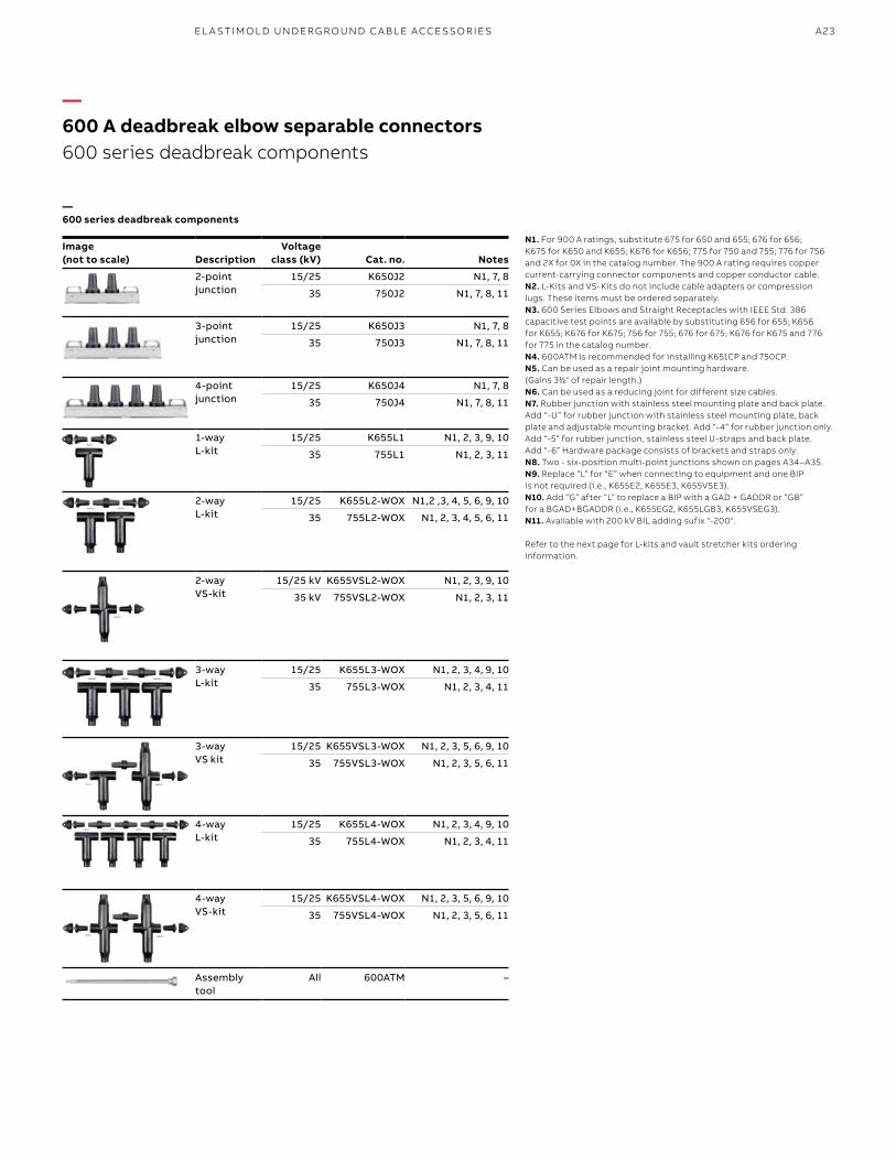
Image (not to scale) Description
Voltageclass (kV) Cat. no. Notes
2-point junction
15/25 K650J2 N1, 7, 8
35 750J2 N1, 7, 8, 11
3-point junction
15/25 K650J3 N1, 7, 8
35 750J3 N1, 7, 8, 11
4-point junction
15/25 K650J4 N1, 7, 8
35 750J4 N1, 7, 8, 11
1-wayL-kit
15/25 K655L1 N1, 2, 3, 9, 10
35 755L1 N1, 2, 3, 11
2-wayL-kit
15/25 K655L2-WOX N1,2 ,3, 4, 5, 6, 9, 10
35 755L2-WOX N1, 2, 3, 4, 5, 6, 11
2-wayVS-kit
15/25 kV K655VSL2-WOX N1, 2, 3, 9, 10
35 kV 755VSL2-WOX N1, 2, 3, 11
3-wayL-kit
15/25 K655L3-WOX N1, 2, 3, 4, 9, 10
35 755L3-WOX N1, 2, 3, 4, 11
3-wayVS kit
15/25 K655VSL3-WOX N1, 2, 3, 5, 6, 9, 10
35 755VSL3-WOX N1, 2, 3, 5, 6, 11
4-wayL-kit
15/25 K655L4-WOX N1, 2, 3, 4, 9, 10
35 755L4-WOX N1, 2, 3, 4, 11
4-wayVS-kit
15/25 K655VSL4-WOX N1, 2, 3, 5, 6, 9, 10
35 755VSL4-WOX N1, 2, 3, 5, 6, 11
Assembly tool
All 600ATM –
—600 A deadbreak elbow separable connectors600 series deadbreak components
—600 series deadbreak components
EL A S TI M O L D U N D ER G R O U N D C A B L E ACCE SSO R I E S

B1 copy starts here
B2 copy starts here
B3 copy starts here
A24 E L A S TI M O LD/F I S H E R PI E RCE C A B L E ACCE SSO R IE S
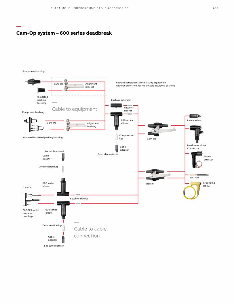
The Elastimold 600 series Cam-Op deadbreak connector system incorporates provisions for hotstick operation of de-energized primary feeder or network circuits. Configurations allow external visible break, testing, grounding and isolation. Retrofit kits allow upgrading existing equipment.
The Cam-Op system utilizes pin and socket connectors and can be retrofitted to existing equipment. The Cam-Op connector is easily installed or removed by hotstick operation of the cam-action disconnect lever.
—Features
• 15/25 and 35 kV, 600 A deadbreak-rated Cam-Op link
• Provides 200 A tap for testing and grounding connections
• Cam-Op lever for hotstick operation and easy installation and removal
• Visi-Break series provides for independent isolation of circuits
—600 A deadbreak elbow separable connectors600 series Cam-Op™ deadbreak connector system
—Ratings overview
See pages A4–A5 for complete information.
Current ratings600 A and 900 A continuous25 kA sym., 10 cycles
Note: 900 A ratings require copper cable and copper current-carrying components.
Continuous voltage ratings 15 kV class• 8.3 kV phase-to-ground• 14.4 kV phase-to-phase• 95 kV BIL• 34 kV AC withstand• 53 kV DC withstand• 11 kV corona extinction25 kV class• 15.2 kV phase-to-ground• 26.3 kV phase-to-phase• 125 kV BIL• 40 kV AC withstand• 78 kV DC withstand• 19 kV corona extinction35 kV class• 21.1 kV phase-to-ground• 36.6 kV phase-to-phase• 150 kV BIL• 50 kV AC withstand• 103 kV DC withstand• 26 kV corona extinction
A25
—Cam-Op system – 600 series deadbreak
Insulated parking bushing
Compression lug
Cable adapter
Compression lug
Cable adapter
Equipment bushing
Equipment bushing
Alignment bracket
Cam-Op
Mounted insulated parking bushing
Alignment bushing
Cam-Op
See cable notes
Cam-Op
600 series elbow
Retainer sleeves
600 series elbow
Compression lug
Cable adapter
BI-SOP 2-point insulated bushings
600 series elbow
Retainer sleeves
Bushing extender
Retrofit components for existing equipment without provisions for mountable insulated bushing
Cam-Op
Visi link
Insulated cap
Loadbreak elbowConnector
Elbow arrester
Test rod
Grounding elbow
See cable notes
ELASTIMOLD
ELASTIMOLD
RR
ELASTIM
OLD
ELASTIM
OLD
RR
See cable notes
ELASTIMOLD
ELASTIMOLD
RR
ELASTIM
OLD
ELASTIM
OLD
RR
—Cable to cable connection
—Cable to equipment
EL A S TI M O L D U N D ER G R O U N D C A B L E ACCE SSO R I E S

B1 copy starts here
B2 copy starts here
B3 copy starts here
A26 E L A S TI M O LD/F I S H E R PI E RCE C A B L E ACCE SSO R IE S
N1. Cam-Op connector kit includes: (1) Cam-Op link; (1) elbow housing; (1) cable adapter; (1) 0370 style lug; (1) bushing extender; (2) retainer sleeves; (1) insulated cap; (1) mountable insulated bushing and (1) alignment bracket.N2. Mountable insulated bushing included with Cam-Op connector kit. Requires three threaded studs on equipment faceplate for installation.N3. Use with the retrofit Cam-Op connector kit.N4. Retrofit Cam-Op connector kit includes: (1) link; (1) elbow housing; (1) cable adapter; (1) 0370 style lug; (1) bushing extender; (2) retainer sleeves; (1) insulated cap; (1) insulating plug; and (1) alignment bracket.N5. Aluminum lug for use on aluminum or copper conductors. DO NOT substitute threaded 03600X lug. N6. Copper lug for use on COPPER CONDUCTOR ONLY. DO NOT substitute 03602X threaded lug.N7. Cam-Op cable joint kit includes: (1) Cam-Op link; (1) Cam-Op BI-SOP; (2) elbow housings; (2) cable adapters; (2) 0370 style lugs; (2) retainer sleeves; (1) insulated cap.N8. 600ATM is recommended for installing Cam-Op retaining sleeves. N9. For 900-amp ratings, substitute 675 for 650 and 655; 676 for 656; K675 for K650 and K655; K676 for K656; 775 for 750 and 755; 776 for 756 and 2X for 0X in the catalog number. The 900-amp rating requires copper current-carrying connector components and copper conductor cable.N10. Add suffix symbol from page A17 to include cable shield grounding kit and/or cable jacket sealing kit.N11. To add elbows or arresters instead of insulating caps, replace the “DRG” with “LR-WX” for elbows (with test point) or “ESA” for elbow arresters.N12. 600 series elbows with IEEE 386 capacitive test points are available by substituting 656 for 655; K656 for K655; K676 for K675; 756 for 755; 676 for 675; K676 for K675 and 776 for 775 in the catalog number.N13. Rated for both 25 kV and 35 kV applications.
Refer to the W and X tables on pages A54–A55 for sizing to cable insulation diameter and conductor size. For cable shield adapters and jacket seals, see pages A44–A45.
—600 series Cam-Op system
Image (not to scale) Description
Voltage class (kV) Cat. no. Notes
Cam-Op connector kit
15 655LINK-C-LR-W0X-B-DRG Use tables W7 and X6
N1, 2, 8, 10, 11, 12
25 K655LINK-C-LR-W0X-B-DRG Use tables W7 and X6
N1, 2, 8, 10, 11, 12
35 755LINK-C-LR-W0X-B-DRG Use tables W9 and X6
N1, 2, 8, 10, 11, 12
Mountable insulated bushing
25 K650LBM-3 N2
35 750LBM-3 N2
Retrofit Cam-Op connector kit
15 655LINK-C-LR-W0X-A-DRG Use tables W7 and X6
N4, 8, 10, 11, 12
25 K655LINK-C-LR-W0X-A-DRG Use tables W7 and X6
N4, 8, 10, 11, 12
35 755LINK-C-LR-W0X-A-DRG Use tables W9 and X6
N4, 8, 10, 11, 12
Insulating plug
25 K650LB N3
35 750LB N3
Cam-Op alignment bracket
15 650CAB –
25 K650CAB –
35 750CAB –
Compression lug All 03700X Use table X6
N5
03702X Use table X6
N6
04601X –
Cam-Op size sensitive kit (cable adapter and lug)
15/25 655CK-W0X Use tables W7 and X6
N10
35 755CK-W0X Use tables W9 and X6
N10
Cam-Op retaining sleeve
All 650RSC N8
Cam-Op cable joint kit
15 655BI-LINK-C-LR-WOX-DRG Use tables W7 and X6
N7, 8, 10, 11, 12
25 K655BI-LINK-C-LR-WOX-DRG Use tables W7 and X6
N7, 8, 10, 11, 12
35 755BI-LINK-C-LR-WOX-DRG Use tables W9 and X6
N7, 8, 10, 11, 12
Cam-Op loadbreak reducing tap plugs (visi-break)
15 650LK-C-VB –
25 K650LK-C-VB –
35 750LK-C-VB –
Cam-Op link
15 650LK-C –
25 K650LK-C –
35 750LK-C –
Grounding elbow (1/0 AWG x 6' ground lead)
15 160GLR –
25 370GLR N 13
35 370GLR N 13
Test rod All 370TR –
—600 A deadbreak elbow separable connectors600 series Cam-Op deadbreak connector system
A27
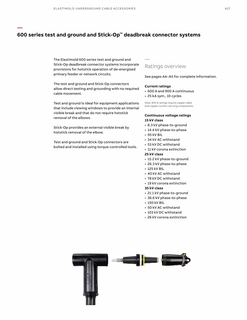
The Elastimold 600 series test and ground and Stick-Op deadbreak connector systems incorporate provisions for hotstick operation of de-energized primary feeder or network circuits.
The test and ground and Stick-Op connectors allow direct testing and grounding with no required cable movement.
Test and ground is ideal for equipment applications that include viewing windows to provide an internal visible break and that do not require hotstick removal of the elbows.
Stick-Op provides an external visible break by hotstick removal of the elbow.
Test and ground and Stick-Op connectors are bolted and installed using torque-controlled tools.
—600 series test and ground and Stick-Op™ deadbreak connector systems
—Ratings overview
See pages A4–A5 for complete information.
Current ratings• 600 A and 900 A continuous• 25 kA sym., 10 cycles
Note: 900 A ratings require copper cable and copper current-carrying components.
Continuous voltage ratings 15 kV class• 8.3 kV phase-to-ground• 14.4 kV phase-to-phase• 95 kV BIL• 34 kV AC withstand• 53 kV DC withstand• 11 kV corona extinction25 kV class• 15.2 kV phase-to-ground• 26.3 kV phase-to-phase• 125 kV BIL• 40 kV AC withstand• 78 kV DC withstand• 19 kV corona extinction35 kV class• 21.1 kV phase-to-ground• 36.6 kV phase-to-phase• 150 kV BIL• 50 kV AC withstand• 103 kV DC withstand• 26 kV corona extinction
EL A S TI M O L D U N D ER G R O U N D C A B L E ACCE SSO R I E S

B1 copy starts here
B2 copy starts here
B3 copy starts here
A28 E L A S TI M O LD/F I S H E R PI E RCE C A B L E ACCE SSO R IE S
—Stick-Op and test and ground system – 600 series deadbreak
See cable notes
Integral bushing
Threaded compression lug Stick-Op orcompression lug test and ground
Cable adapter
—600 series elbow
Test and ground ETP elbow tap plug
Stick-Op LRTP loadbreak tap plug
Insulated cap
Stand-off plug
Grounding plug
Stick-Op 600DB/200LB bushing elbow adapter
Test rod
Assembly tool (test and ground)
Assembly tool (Stick-Op)
Grounding elbow
See pages A104–A113 for surge arrester applications.
—600 A deadbreak elbow separable connectors600 series test and ground and Stick-Op deadbreak connector systems
—Operating accessories
A29
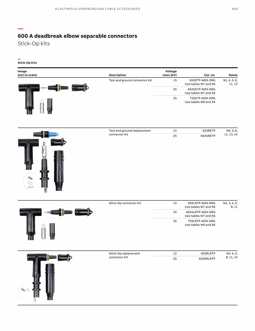
—Stick-Op kits
Image (not to scale)
Description
Voltage class (kV)
Cat. no.
Notes
Test and ground connector kit 15 655ETP-W0X-DRG Use tables W7 and X6
N1, 4, 5, 6, 11, 13
25 K655ETP-W0X-DRG Use tables W7 and X6
35 755ETP-W0X-DRG Use tables W9 and X6
Test and ground replacement connector kit
15 655RETP N4, 5, 6, 11, 13, 1425 K655RETP
Stick-Op connector kit 15 655LRTP-W0X-DRG Use tables W7 and X6
N2, 3, 4, 5, 8, 11
25 K655LRTP-W0X-DRG Use tables W7 and X6
35 755LRTP-W0X-DRG Use tables W9 and X6
Stick-Op replacement connector kit
15 655RLRTP N3, 4, 5, 8, 11, 1425 K655RLRTP
—600 A deadbreak elbow separable connectorsStick-Op kits
EL A S TI M O L D U N D ER G R O U N D C A B L E ACCE SSO R I E S

B1 copy starts here
B2 copy starts here
B3 copy starts here
A30 E L A S TI M O LD/F I S H E R PI E RCE C A B L E ACCE SSO R IE S
—Stick-Op accessories Image (not to scale)
Description
Voltage class (kV)
Cat. no.
Notes
Stick-Op size-sensitive kit (cable adapter and threaded lug)
15/25 655TCK-W0X Use tables W7 and X6
N5
35 755TCK-W0X Use tables W9 and X6
N5
Extraction tool All 650ET N10
Grounding elbow (1/0 AWG x 6' ground lead)
15 160GLR –
25 370GLR N12
35 370GLR N12
Test rod All 370TR –
Assembly tool (Stick-Op)
All 600AT N3
Assembly tool (test and ground)
All 600ATM N13
Test and ground loadbreak elbow tap plug
15 650ETP N4, 13, 16
25 K650ETP N4, 13, 16
35 750ETP N4, 13, 16
Stick-Op loadbreak reducing tap plug
15 650LRTPA3 N3, 4
25 K650LRTPA2 –
35 750LRTPA2 –
Stick-Op bushing adapter 15 655BEA3 N3, 4
25 K655BEA2 –
35 755BEA2 –
Compression lug test and ground
All 03700X Use tables X6
N6
All 03702X Use tables X6
N7
Threaded compression lug Stick-Op
All 03600X Use tables X6
N8, 15
All 03602X Use tables X6
N9
Test and ground size- sensitive kit (cable adapter and lug)
15/25 655CK-W0X Use tables W7 and X6
N4, 5
35 755CK-W0X Use tables W9 and X6
N4, 5
N1. Test and ground kit includes: insulated cap; test and ground reducing tap plug; 600 series elbow housing; cable adapter; and 0370 style compression lug.N2. Stick-Op kit includes insulated cap; Stick-Op loadbreak reducing tap plug; 600 series elbow housing; cable adapter; and threaded 0360 style compression lug.N3. 600AT assembly tool required for operation and/or installation of Stick-Op.N4. For 900 A ratings, substitute 675 for 650 and 655; 676 for 656; K675 for K650 and K655; K676 for K656; 775 for 750 and 755; 776 for 756 and 2X for 0X in the catalog number. The 900 A rating requires copper current-carrying connector components and copper conductor cable.N5. Add suffix symbol from page A17 to include cable shield grounding kit and/or cable jacket sealing kit.N6. Aluminum lug for use on aluminum or copper conductors. DO NOT substitute threaded 03600X lug.N7. Copper lug for use on COPPER CONDUCTOR ONLY. DO NOT substitute 03602X threaded lug.N8. Threaded aluminum lug (Stick-Op only) for use on copper or aluminum conductors. DO NOT substitute unthreaded 03700X lugs. DO NOT use with 675, 676, K675, K676, 775 or 776 catalog numbers.N9. Threaded copper lug (Stick-Op only) for use on copper conductors only. DO NOT substitute unthreaded 03702X lugs.N10. Required to disassemble Stick-Op loadbreak reducing tap plug from the threaded compression lug and 600 series elbow after the shear-pin is broken during assembly.N11. 600 series Elbows with IEEE 386 capacitive test points are available by substituting 656 for 655; K656 for K655; K676 for K675; 756 for 755; 676 for 675; K676 for K675 and 776 for 775 in the catalog number.N12. Rated for both 25 kV and 35 kV applications.N13. 600ATM assembly tool required for test and ground assembly. 50–60 ft./lbs. torque wrench required but not included.N14. Replacement elbow includes: insulated cap; reducing tap plug; 600 series elbow housing; I-adapter; straight receptacle, resulting in a net gain of 20" in length vs. a standard elbow kit. Compression lugs and cable adapters are ordered separately.N15. Retrofit sleeve to convert 03600X series lug to a 03700X series lug (catalog number 650-353).N16. Add “SP” to the part number to include factory-assembled stud.
Refer to the W and X tables on pages A54–A55 for sizing to cable insulation diameter and conductor size. For cable shield adapters and jacket seals, see pages A44–A45.
—600 A deadbreak elbow separable connectors600 series test and ground and Stick-Op deadbreak connector systems
A31
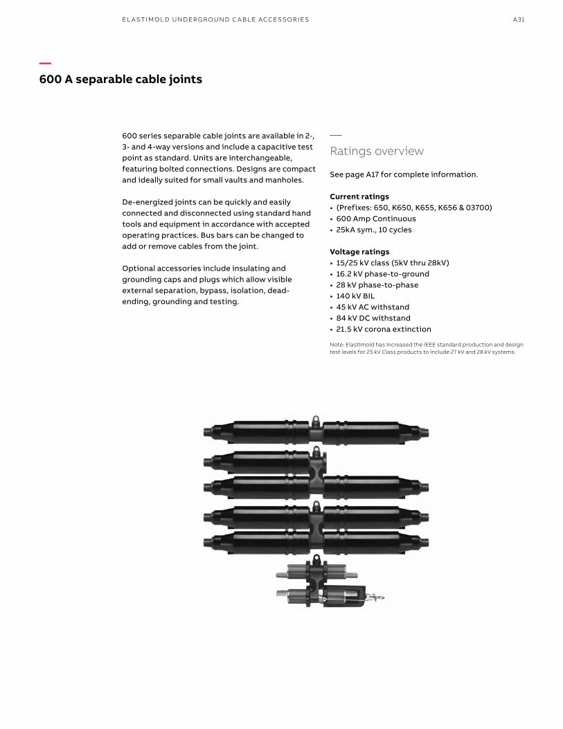
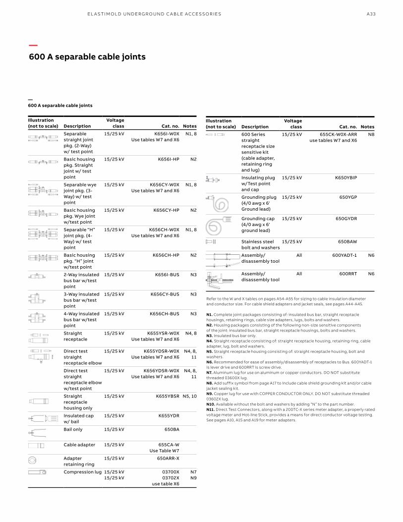
600 series separable cable joints are available in 2-, 3- and 4-way versions and include a capacitive test point as standard. Units are interchangeable, featuring bolted connections. Designs are compact and ideally suited for small vaults and manholes.
De-energized joints can be quickly and easily connected and disconnected using standard hand tools and equipment in accordance with accepted operating practices. Bus bars can be changed to add or remove cables from the joint.
Optional accessories include insulating and grounding caps and plugs which allow visible external separation, bypass, isolation, dead-ending, grounding and testing.
—600 A separable cable joints
—Ratings overview
See page A17 for complete information.
Current ratings• (Prefixes: 650, K650, K655, K656 & 03700)• 600 Amp Continuous• 25kA sym., 10 cycles
Voltage ratings• 15/25 kV class (5kV thru 28kV)• 16.2 kV phase-to-ground• 28 kV phase-to-phase• 140 kV BIL• 45 kV AC withstand• 84 kV DC withstand• 21.5 kV corona extinction
Note: Elastimold has increased the IEEE standard prod uction and design test levels for 25 kV Class products to include 27 kV and 28 kV systems.
EL A S TI M O L D U N D ER G R O U N D C A B L E ACCE SSO R I E S
B1 copy starts here
B2 copy starts here
B3 copy starts here
A32 E L A S TI M O LD/F I S H E R PI E RCE C A B L E ACCE SSO R IE S
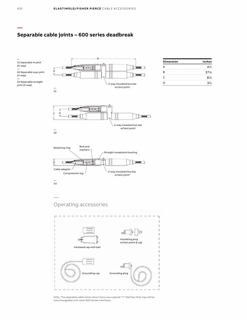
—Separable cable joints – 600 series deadbreak
A
B
4-way insulated bus bar w/test point
—01 Separable H-joint (4-way)—02 Separable wye-joint (3-way)—03 Separable straight joint (2-way)
—01
—02
—03
Note: The separable cable joints shown here use a special “Y” interface that may not be interchangeable with other 600 Series interfaces.
—Operating accessories
Insulated cap with bail
Insulating plug w/test point & cap
Grounding cap Grounding plug
Dimension Inches
A 41⁄4
B 371⁄8
C 81⁄8
D 37⁄8
AC
3-way insulated bus bar w/test point
2-way insulated bus bar w/test point
D
Straight receptacle housing
Bolt and washers
Retaining ring
Cable adapter
Compression lug
A33
Refer to the W and X tables on pages A54-A55 for sizing to cable insulation diameter and conductor size. For cable shield adapters and jacket seals, see pages A44-A45.
N1. Complete joint packages consisting of: insulated bus bar, straight receptacle housings, retaining rings, cable size adapters, lugs, bolts and washers.N2. Housing packages consisting of the following non-size sensitive components of the joint: insulated bus bar, straight receptacle housings, bolts and washers.N3. Insulated bus bar only.N4. Straight receptacle consisting of: straight receptacle housing, retaining ring, cable adapter, lug, bolt and washers.N5. Straight receptacle housing consisting of: straight receptacle housing, bolt and washers.N6. Recommended for ease of assembly/disassembly of receptacles to Bus. 600YADT-1 is lever drive and 600RRT is screw drive.N7. Aluminum lug for use on aluminum or copper conductors. DO NOT substitute threaded 03600X lug.N8. Add suffix symbol from page A17 to include cable shield grounding kit and/or cable jacket sealing kit.N9. Copper lug for use with COPPER CONDUCTOR ONLY. DO NOT substitute threaded 03602X lug.N10. Available without the bolt and washers by adding “N” to the part number.N11. Direct Test Connectors, along with a 200TC-X series meter adapter, a properly rated voltage meter and Hot-line Stick, provides a means for direct conductor voltage testing. See pages A10, A15 and A19 for meter adapters.
—600 A separable cable joints
Illustration(not to scale) Description
Voltageclass Cat. no. Notes
Separable straight joint pkg. (2-Way) w/ test point
15/25 kV K656I-W0XUse tables W7 and X6
N1, 8
Basic housing pkg. Straight joint w/ test point
15/25 kV K656I-HP N2
Separable wye joint pkg. (3-Way) w/ test point
15/25 kV K656CY-W0XUse tables W7 and X6
N1, 8
Basic housing pkg. Wye joint w/test point
15/25 kV K656CY-HP N2
Separable “H” joint pkg. (4-Way) w/ test point
15/25 kV K656CH-W0X Use tables W7 and X6
N1, 8
Basic housing pkg. “H” joint w/test point
15/25 kV K656CH-HP N2
2-Way insulated bus bar w/test point
15/25 kV K656I-BUS N3
3-Way insulated bus bar w/test point
15/25 kV K656CY-BUS N3
4-Way insulated bus bar w/test point
15/25 kV K656CH-BUS N3
Straight receptacle
15/25 kV K655YSR-W0X Use tables W7 and X6
N4, 8
Direct test straight receptacle elbow
15/25 kV K655YDSR-W0X Use tables W7 and X6
N4, 8, 11
Direct test straight receptacle elbow w/test point
15/25 kV K656YDSR-W0XUse tables W7 and X6
N4, 8, 11
Straight receptacle housing only
15/25 kV K655YBSR N5, 10
Insulated cap w/ bail
15/25 kV K655YDR
Bail only 15/25 kV 650BA
Cable adapter 15/25 kV 655CA-WUse Table W7
Adapter retaining ring
15/25 kV 650ARR-X
Compression lug 15/25 kV 15/25 kV
03700X03702X
use table X6
N7 N9
—600 A separable cable joints
Illustration(not to scale) Description
Voltageclass Cat. no. Notes
600 Series straight receptacle size sensitive kit (cable adapter, retaining ring and lug)
15/25 kV 655CK-W0X-ARRuse tables W7 and X6
N8
Insulating plug w/Test point and cap
15/25 kV K650YBIP
Grounding plug (4/0 awg x 6'Ground lead)
15/25 kV 650YGP
Grounding cap (4/0 awg x 6' ground lead)
15/25 kV 650GYDR
Stainless steel bolt and washers
15/25 kV 650BAW
Assembly/disassembly tool
All 600YADT-1 N6
Assembly/ disassembly tool
All 600RRT N6
EL A S TI M O L D U N D ER G R O U N D C A B L E ACCE SSO R I E S
B1 copy starts here
B2 copy starts here
B3 copy starts here
A34 E L A S TI M O LD/F I S H E R PI E RCE C A B L E ACCE SSO R IE S
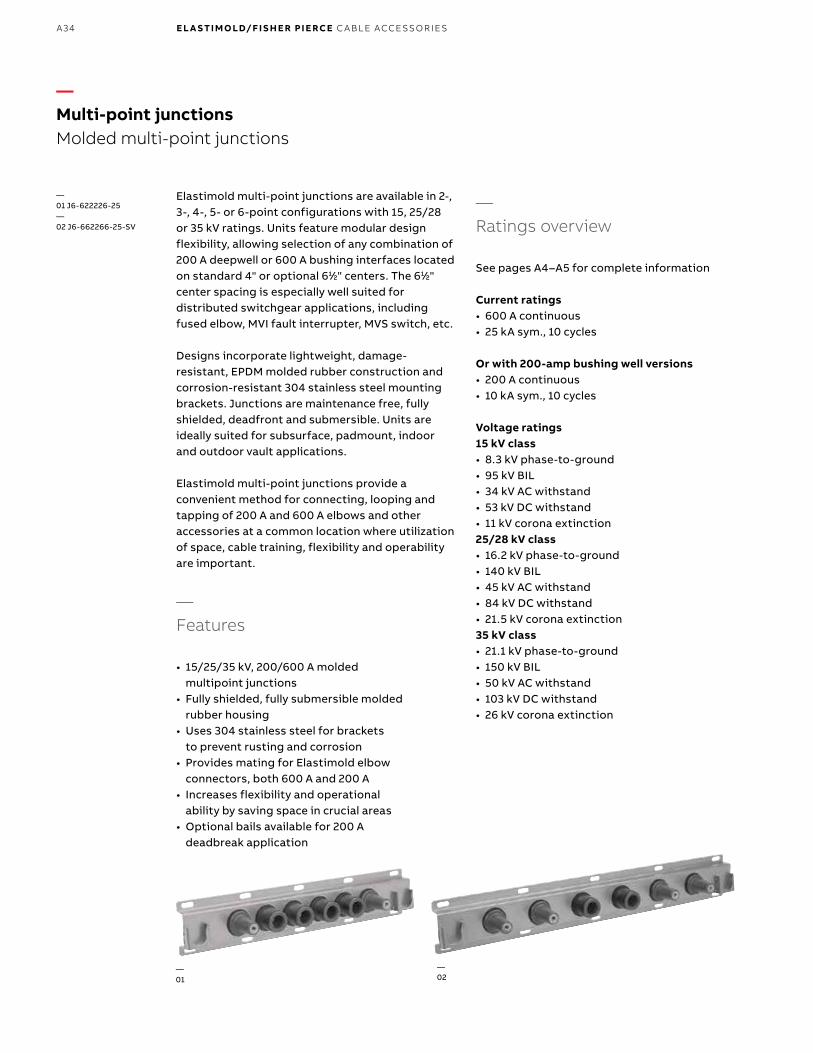
Elastimold multi-point junctions are available in 2-, 3-, 4-, 5- or 6-point configurations with 15, 25/28 or 35 kV ratings. Units feature modular design flexibility, allowing selection of any combination of 200 A deepwell or 600 A bushing interfaces located on standard 4" or optional 611⁄22" centers. The 611⁄22" center spacing is especially well suited for distributed switchgear applications, including fused elbow, MVI fault interrupter, MVS switch, etc.
Designs incorporate lightweight, damage-resistant, EPDM molded rubber construction and corrosion-resistant 304 stainless steel mounting brackets. Junctions are maintenance free, fully shielded, deadfront and submersible. Units are ideally suited for subsurface, padmount, indoor and outdoor vault applications.
Elastimold multi-point junctions provide a convenient method for connecting, looping and tapping of 200 A and 600 A elbows and other accessories at a common location where utilization of space, cable training, flexibility and operability are important.
—Features
• 15/25/35 kV, 200/600 A molded multipoint junctions
• Fully shielded, fully submersible molded rubber housing
• Uses 304 stainless steel for brackets to prevent rusting and corrosion
• Provides mating for Elastimold elbow connectors, both 600 A and 200 A
• Increases flexibility and operational ability by saving space in crucial areas
• Optional bails available for 200 A deadbreak application
—Ratings overview
See pages A4–A5 for complete information
Current ratings• 600 A continuous• 25 kA sym., 10 cycles
Or with 200-amp bushing well versions • 200 A continuous• 10 kA sym., 10 cycles
Voltage ratings 15 kV class• 8.3 kV phase-to-ground• 95 kV BIL• 34 kV AC withstand• 53 kV DC withstand• 11 kV corona extinction25/28 kV class• 16.2 kV phase-to-ground• 140 kV BIL• 45 kV AC withstand• 84 kV DC withstand• 21.5 kV corona extinction35 kV class• 21.1 kV phase-to-ground• 150 kV BIL• 50 kV AC withstand• 103 kV DC withstand• 26 kV corona extinction
—01
—02
—Multi-point junctionsMolded multi-point junctions
—01 J6-622226-25—02 J6-662266-25-SV

A35
—Dimensional information
Optional tilt mounting adapter
Type of junction
Figure 1 Figure 2
Dimensions (in.)Number of mounting
holes
Dimensions (in.)Number of mounting
holesA B C A B C
J2 15 711⁄22 6 6 1911⁄22 10 811⁄44 6
J3 19 1111⁄22 8 6 26 1611⁄22 1111⁄22 6
J4 24 1511⁄22 10 6 3211⁄22 23 911⁄44 8
J5 27 1911⁄22 12 6 39 2911⁄22 12 8
J6 31 2311⁄22 933⁄88 8 4511⁄22 36 811⁄44 10
99⁄1616" x 1" mounting holes
A
B
C
511⁄22" 633⁄44"
Grounding lugNameplate
4"Typ
D511⁄44"
Grounding lug—02
99⁄1616" x 1" mounting holes
A
B
511⁄22" 633⁄44"
C111⁄22"
Nameplate
611⁄22"TYP
D511⁄44"
111⁄22"
15° to 60° adjustable angle
—Multi-point junctionsMolded multi-point junctions
—01 Figure 1: Multi–point junctions with 4" interface spacings.—02 Figure 2: Multi–point junctions with 611⁄22" interface spacings.
—01
EL A S TI M O L D U N D ER G R O U N D C A B L E ACCE SSO R I E S
B1 copy starts here
B2 copy starts here
B3 copy starts here
A36 E L A S TI M O LD/F I S H E R PI E RCE C A B L E ACCE SSO R IE S
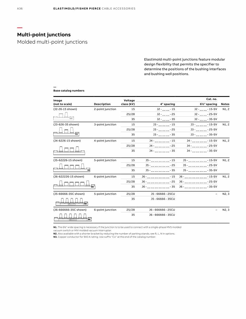
Elastimold multi-point junctions feature modular design flexibility that permits the specifier to determine the positions of the bushing interfaces and bushing well positions.
—Base catalog numbers
Image(not to scale) Description
Voltage class (kV)
Cat. no.
Notes4" spacing 611⁄22" spacing
(J2-26-15 shown) 2-point junction 15 J2 - __ __ - 15 J2 - __ __ - 15-SV N1, 2
25/28 J2 - __ __ - 25 J2 - __ __ - 25-SV
35 J2 - __ __ - 35 J2 - __ __ - 35-SV
(J3-626-35 shown) 3-point junction 15 J3 - __ __ __ - 15 J3 - __ __ __ - 15-SV N1, 2
25/28 J3 - __ __ __ - 25 J3 - __ __ __ - 25-SV
35 J3 - __ __ __ - 35 J3 - __ __ __ - 35-SV
(J4-6226-15 shown) 4-point junction 15 J4 - __ __ __ __ - 15 J4 - __ __ __ __ - 15-SV N1, 2
25/28 J4 - __ __ __ __ - 25 J4 - __ __ __ __ - 25-SV
35 J4 - __ __ __ __ - 35 J4 - __ __ __ __ - 35-SV
(J5-62226-15 shown) 5-point junction 15 J5 - __ __ __ __ __ - 15 J5 - __ __ __ __ __ - 15-SV N1, 2
25/28 J5 - __ __ __ __ __ - 25 J5 - __ __ __ __ __ - 25-SV
35 J5 - __ __ __ __ __ - 35 J5 - __ __ __ __ __ - 35-SV
(J6-622226-15 shown) 6-point junction 15 J6 - __ __ __ __ __ __ - 15 J6 - __ __ __ __ __ __ - 15-SV N1, 2
25/28 J6 - __ __ __ __ __ __ - 25 J6 - __ __ __ __ __ __ - 25-SV
35 J6 - __ __ __ __ __ __ - 35 J6 - __ __ __ __ __ __ - 35-SV
(J5-66666-35C shown) 5-point junction 25/28 J5 - 66666 - 25CU – N2, 3
35 J5 - 66666 - 35CU
(J6-666666-35C shown) 6-point junction 25/28 J6 - 666666 - 25CU – N2, 3
35 J6 - 666666 - 35CU
N1. The 611⁄22" wide spacing is necessary if the junction is to be used to connect with a single-phase MVS molded vacuum switch or MVI molded vacuum interrupter.N2. Also available with a shorter bracket by reducing the number of parking stands; see R, L, N in options.N3. Copper conductor for 900 A rating. Use suffix "CU" at the end of the catalog number.
—Multi-point junctionsMolded multi-point junctions

A37
To specify and order Elastimold multi-point junctions: Use Table 1 to construct a catalog number describing the required junction.
Ordering example ATo order a 4-point, 15 kV junction with 4" spacings and 600 series interfaces on the outside ways and 200 A wells on the inside ways, specify catalog number J4-6226-15.
Ordering example BTo order a 6-point, 25/28 kV junction with 61⁄2" spacings and 600 series interfaces on ways 1, 3, 4 and 6 and 200 A wells on the ways 2 and 5, specify catalog number J6-626626-25-SV.
—Table 1. Catalog number construction
—Multi-point junctionsOrdering information
J - - - -
Number of points2 points 23 points 34 points 45 points 56 points 6
Voltage class 15 kV 1525/28 kV 2535 kV 35
Interface spacingStandard spacing 4" centers BlankOptional 611⁄22" centers SV
Interface identification * and positioning200 A bushing well interface 2600 A bushing interface 6Blank position* When there is a 200 A interface on one side of the junction and a 600 series interface on the other side, always start with the 200 A side. B
OptionsNo tilt mounting BlankTilt mounting adapter. Bolts to the bottom of the standard mounting bracket to provide 15 ,̊ 30 ,̊ 45˚ or 60˚ adjustable angle mounting. (Two tilt mounting adapters are required for each installation.) TMALeft parking stand LRight parking stand RNo parking stand N
Multi-point junction
EL A S TI M O L D U N D ER G R O U N D C A B L E ACCE SSO R I E S
B1 copy starts here
B2 copy starts here
B3 copy starts here
A38 E L A S TI M O LD/F I S H E R PI E RCE C A B L E ACCE SSO R IE S
PCJ power cable joints use permanently crimped connectors. PCJ housings are fully in sulated, shielded and sealed for direct-burial, vault, submersible and other severe service applications. Units have been designed and tested per IEEE Standard 404 to ensure system-matched performance and ratings equal to the cable to which the splice will be installed.
PCJ power cable joints are available in two styles:Style 1 uses a single-piece housing that is sized to accommodate a specific range of cable. Style 1 units are ideally suited for straight splicing of the same or similar cable.
Style 2 designs incorporate a universal housing with separate cable adapters to allow transition splices of different types and sizes of cable.
—Electrical ratings summary
The follow ratings summary is based on IEEE 404 and applies to all Elastimold PCJ power cable joints.
VoltageA. 15 kV class (8.7 kV phase-to-ground)B. 25 kV class (14.4 kV phase-to-ground)C. 35 kV class (20.2 kV phase-to-ground)• Impulse withstand: A = 110 kV, B = 150 kV,
C = 200 kV BIL, 1.2 x 50 microsecond wave• Corona extinction voltage: A = 13 kV, B = 22 kV,
C = 30 kV minimum, 3 pC sensitivity• DC withstand: During installation, A = 56 kV,
B = 80 kV, C = 100 kV • DC withstand: After installation and in service for
the first 5 years, A = 18 kV, B = 25 kV, C = 31 kV for XLPE insulated cables and A = 45 kV, B = 64 kV, C = 80 kV for EPR insulated cables (reference AEIC CS6 and CS8, Section L.2)
CurrentContinuous rating equal to the rating of the cableShort-time rating equal to the rating of the cable up to 35 kA
Shield design• Meets IEEE 592 for exposed semiconducting
shields on premolded high voltage cable joints and separable insulated connectors
Production tests include 100% tests of the premolded joints to ensure:• Corona extinction voltage: A = 13 kV, B = 22 kV,
C = 30 kV minimum, 3 pC sensitivity• AC withstand: A = 35 kV, B = 52 kV, C = 69 kV,
60 Hz, 1 minute
Design tests on production joints demonstrate compliance with IEEE 404 including:• Corona extinction voltage: A = 13.0 kV, B = 22.0 kV,
C = 30.0 kV minimum, 3 pC sensitivity• AC withstand: A = 35 kV, B = 52 kV, C = 69 kV,
60 Hz, 1 minute• DC withstand: A = 75 kV, B = 105 kV, C = 140 kV
negative polarity, 15 minutes• Impulse withstand (BIL): A = 110 kV, B = 150 kV,
C = 200 kV, 10 positive and 10 negative, 1.2 x 50 microsecond wave, at conductor temperatures of 20 °C and 130 °C, nominal
• Short-time current: Magnitude equal to cable up to 35 kA
• Cyclic aging: 30 days at A = 26 kV, B = 43 kV, C = 61 kV AC continuous, load current for 8 hours per day, providing 130 oC conductor temperature; joints then subjected to A = 31 kV, B = 50 kV, C = 71 kV for 5 hours followed by A = 39 kV, B = 65 kV, C = 91 kV for 5 min
• Load cycle: Connectors meet require ments of ANSI C119.4, Class A and Class 3 ratings
—Permanent distribution cable jointsPCJ power cable joints

A39
—Ordering information
—PCJ style 1
With single-piece housing
—PCJ style 2
With universal housing and separate cable adapters that can be varied with the cable application
—Permanent distribution cable jointsPCJ power cable joints
P C J W 1 X
Voltage indicator15 kV 1525 kV 2535 kV 35
Style Style 1 1Style 2 2
ConductorAluminum 1Copper 2
Insulation diameterW sizing information and selectionUse table W8 for 15 PCJUse table W9 for 25 PCJUse table W10 for 35 PCJ
Conductor size codeX sizing information and selection N3Use table X7 for 15 PCJUse table X7 for 25 PCJUse table X7 for 35 PCJ
Power Cable Joint
EL A S TI M O L D U N D ER G R O U N D C A B L E ACCE SSO R I E S

B1 copy starts here
B2 copy starts here
B3 copy starts here
A40 E L A S TI M O LD/F I S H E R PI E RCE C A B L E ACCE SSO R IE S
Dimension Aoverall length
Dimension Boutside dia.
N1. Kit includes aluminum compression connector suitable for splicing aluminum conductor to aluminum conductor or aluminum conductor to copper conductor. An all-copper connector is required for copper-to-copper connections.N2. Kit includes copper compression connector suitable for splicing copper conductors to copper conductor only. DO NOT use copper connectors on aluminum conductors.N3. When constructing a catalog number for a transition (two different-size cables) joint, list the larger connector first and the smaller connector second.
Refer to the W and X tables on pages A54–A55 for sizing to cable insulation diameter and conductor size. For cable shield adapters and jacket seals, see pages A44–A45.
DescriptionVoltage
class (kV) Cat. no. Notes
Power cable jointStyle 1
15 15PCJ1W1X N1
15 15PCJ1W2X N2
25 25PCJ1W1X N1
25 25PCJ1W2X N2
35 35PCJ1W1X N1
35 35PCJ1W2X N2
Power cable jointStyle 2
15 15PCJ2W1X N1
15 15PCJ2W2X N2
25 25PCJ2W1X N1
25 25PCJ2W2X N2
35 35PCJ2W1X N1
35 35PCJ2W2X N2
Style 1 Cat. no.
A B
inches inches
15PCJ1FX 101⁄4 13⁄4
15PCJ1GX 101⁄4 13⁄4
25PCJ1GX 143⁄8 27⁄16
15/25/35PCJ1HX 143⁄8 27⁄16
15/25/35PCJ1JX 143⁄8 27⁄16
15/25/35PCJ1KX 143⁄8 225⁄32
15/25/35PCJ1LX 143⁄8 225⁄32
15/25PCJ1LMX 143⁄8 225⁄32
15/25/35PCJ1MX 143⁄8 225⁄32
15/25/35PCJ1NX 153⁄4 33⁄16
15/25/35PCJ1PX 153⁄4 33⁄16
15/25/35PCJ1QX 153⁄4 33⁄16
Style 2 Cat. no.
A B
inches inches
15PCJ2FX 163⁄8 225⁄32
15/25PCJ2GX 163⁄8 225⁄32
15/25/35PCJ2HX 163⁄8 225⁄32
15/25/35PCJ2JX 163⁄8 225⁄32
15/25/35PCJ2KX 21 33⁄4
15/25/35PCJ2LX 21 33⁄4
15/25/35PCJ2MX 21 33⁄4
15/25/35PCJ2NX 21 33⁄4
15/25/35PCJ2PX 21 33⁄4
15/25/35PCJ2QX 21 33⁄4
—PCJ power cable joint
—Dimensional data
—Dimensional data
—Permanent distribution cable jointsPCJ power cable joints

A41
—Pre-molded terminationsCable terminations
Elastimold cable terminations are available in a single-piece design. Terminators allow connection and transition from shielded, underground cable to bare overhead conductors and live-front equipment. Units are designed and rated per IEEE 48 for riser pole, padmount, indoor and outdoor applications. PCT1 and PCT2 terminators provide sufficient creep, strike and weather sealing for Class 1 outdoor service. PCT1 and PCT2 also include an integral cable jacket seal.
—Electrical ratings summary
The following ratings summary is based on IEEE Standard 48 and applies to all the terminations on this page. Elastimold terminations are designed for use on three-phase systems, either 3-wire or 4-wire, and the single-phase laterals of these systems.
—Cable terminations
Description Voltage class (kV) Cat. no. Notes
Single-piece terminator (class 1)
15 PCT1-1X-4 Use table X9
N2, 3, 4, 5
25 PCT2-1X-4 Use table X9
N2, 3, 4, 6
Housing only 15 PCT1-4 N5
25 PCT2-4 N6
Rod contact for PCT 15/25 00700X Use table X9
N1, 3, 4
Two-hole spade for PCT All 01000X Use table X9
N1
One-hole spade for PCT All 01100X Use table X9
N1
PCT positioning bracket All PB-1 N1, 7
N1. Use with PCT1 or PCT2 terminators.N2. Includes rod contact as standard. Specify suffix “-3” in place of “-4” for two-hole spade lug. Specify suffix “-5” in place of “-4” for one-hole spade lug.N3. Use 1X for an aluminum rod contact for aluminum conductors only.N4. Substitute 0X for 1X for a universal aluminum rod contact for aluminum or copper conductors.N5. Use for insulation dia. range from 0.640" thru 1.070".N6. Use for insulation dia. range from 0.830" thru 1.180".N7. Fits overall cable O.D. from 0.750" to 1.625".
Voltage ratings 15 kV class • 9.5 kV phase-to-ground• 110 kV BIL 1.2 x 50 microsecond wave• AC withstand:
- 50 kV 1 min. – Dry - 35 kV 6 hr. – Dry - 45 kV 10 sec. – Wet
• 13 kV corona extinction
25 kV class• 16 kV phase-to-ground• 150 kV BIL 1.2 x 50 microsecond wave• AC withstand:
- 65 kV 1 min. – Dry - 55 kV 6 hr. – Dry - 60 kV 10 sec. – Wet
• 21.5 kV corona extinction
Terminations
BRACKETS
PB-1PCT-1 PCT-2
SINGLE PIECE TERMINATORS
PCT1 PCT2 PB-1
BRACKETS
PB-1PCT-1 PCT-2
SINGLE PIECE TERMINATORS
BRACKETS
PB-1PCT-1 PCT-2
SINGLE PIECE TERMINATORS
EL A S TI M O L D U N D ER G R O U N D C A B L E ACCE SSO R I E S
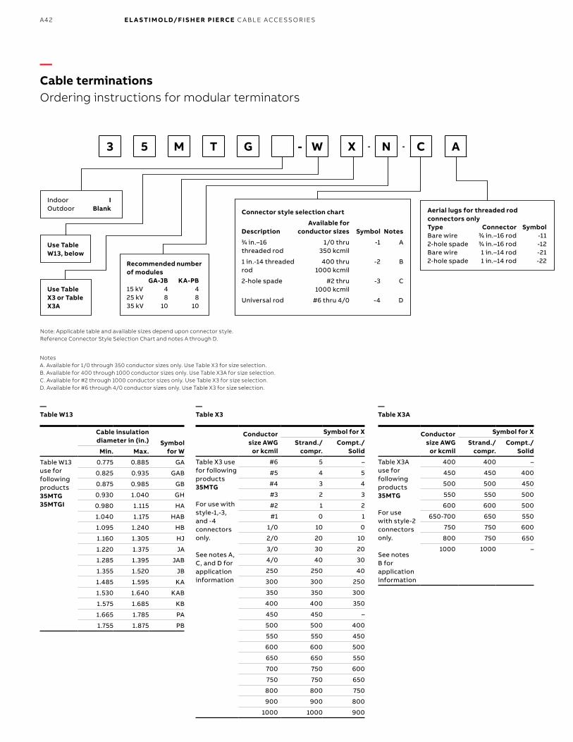
B1 copy starts here
B2 copy starts here
B3 copy starts here
A42 E L A S TI M O LD/F I S H E R PI E RCE C A B L E ACCE SSO R IE S
3 5 M T G - W X - N - C A
—Table W13
Cable insulation diameter in (in.) Symbol
for WMin. Max.
Table W13 use for following products 35MTG35MTGI
0.775 0.885 GA
0.825 0.935 GAB
0.875 0.985 GB
0.930 1.040 GH
0.980 1.115 HA
1.040 1.175 HAB
1.095 1.240 HB
1.160 1.305 HJ
1.220 1.375 JA
1.285 1.395 JAB
1.355 1.520 JB
1.485 1.595 KA
1.530 1.640 KAB
1.575 1.685 KB
1.665 1.785 PA
1.755 1.875 PB
Indoor IOutdoor Blank
Use Table W13, below
Use Table X3 or Table X3A
Recommended number of modules GA-JB KA-PB15 kV 4 425 kV 8 835 kV 10 10
Aerial lugs for threaded rod connectors onlyType Connector SymbolBare wire 33⁄44 in.–16 rod -112-hole spade 33⁄44 in.–16 rod -12Bare wire 1 in.–14 rod -212-hole spade 1 in.–14 rod -22
Note: Applicable table and available sizes depend upon connector style.Reference Connector Style Selection Chart and notes A through D.
Notes A. Available for 1/0 through 350 conductor sizes only. Use Table X3 for size selection.B. Available for 400 through 1000 conductor sizes only. Use Table X3A for size selection.C. Available for #2 through 1000 conductor sizes only. Use Table X3 for size selection.D. Available for #6 through 4/0 conductor sizes only. Use Table X3 for size selection.
Connector style selection chart
DescriptionAvailable for
conductor sizes Symbol Notes33⁄44 in.–16 threaded rod
1/0 thru 350 kcmil
-1 A
1 in.-14 threaded rod
400 thru1000 kcmil
-2 B
2-hole spade #2 thru1000 kcmil
-3 C
Universal rod #6 thru 4/0 -4 D
—Cable terminationsOrdering instructions for modular terminators
—Table X3
Conductor size AWG
or kcmil
Symbol for X
Strand./ compr.
Compt./ Solid
Table X3 use for following products 35MTG
For use with style-1,-3, and -4 connectors only.
See notes A,C, and D for application information
#6 5 –
#5 4 5
#4 3 4
#3 2 3
#2 1 2
#1 0 1
1/0 10 0
2/0 20 10
3/0 30 20
4/0 40 30
250 250 40
300 300 250
350 350 300
400 400 350
450 450 –
500 500 400
550 550 450
600 600 500
650 650 550
700 750 600
750 750 650
800 800 750
900 900 800
1000 1000 900
—Table X3A
Conductor size AWG
or kcmil
Symbol for X
Strand./ compr.
Compt./ Solid
Table X3A use for following products 35MTG
For use with style-2 connectors only.
See notes B for application information
400 400 –
450 450 400
500 500 450
550 550 500
600 600 500
650-700 650 550
750 750 600
800 750 650
1000 1000 –

A43
—Cable terminationsTerminations
—Terminations Illustration (not to scale)
Description
Voltage class
Cat. no.
Notes
PCT positioning bracket All PB-1 N1, 12
16THG bracket All 16TB-2 N6
Bracket for crossarm 16THG All 16TB-3 N6
Bracket for riser pole mounting 16THG
All 16TB-4 N6
Bracket for tri-mounting16THG
All 16TB-5 N6
Kellums grip bracket All 35MTB1-A N1, 2, 6, 7
All 35MTB1-B N1, 3, 6, 7
All 35MTB1-C N1, 4, 6, 7
All 35MTB1-D N1, 5, 6, 7
Kellums bracket for crossarm mounting
All 35MTB3-A N1, 2, 6, 7
All 35MTB3-B N1, 3, 6, 7
All 35MTB3-C N1, 4, 6, 7
All 35MTB3-D N1, 5, 6, 7
Bracket (for riser pole mounting)
All 35MTB4-A N1, 2, 6, 7
All 35MTB4-B N1, 3, 6, 7
All 35MTB4-C N1, 4, 6, 7
All 35MTB4-D N1, 5, 6, 7
Kellums bracket for tri-mounting
All 35MTB5-A N1, 2, 6, 7
All 35MTB5-B N1, 3, 6, 7
All 35MTB5-C N1, 4, 6, 7
All 35MTB5-D N1, 5, 6, 7
Aluma form bracket All 1535AFB-1 N1, 6, 7, 13
Aluma form bracket for crossarm mounting
All 1535AFB-3 N1, 6, 7, 13
Aluma form bracket for riser-pole mounting
All 1535AFB-4 N1, 6, 7, 13
Aluma form bracket for tri-mounting
All 1535AFB-5 N1, 6, 7, 13
N1. Use with PCT-1 or PCT-2 terminators.N2. Fits overall cable O.D. from 1.195 in. to 1.625 in.N3. Fits overall cable O.D. from 0.925 in. to 1.335 in.N4. Fits overall cable O.D. from 0.890 in. to 1.185 in.N5. Fits overall cable O.D. from 1.500 in. to 2.000 in.N6. Use with 16THG and 16THGS terminators.N7. Use with MTG, MTG1 and MSC terminators.N8. For conductors from 1/0 thru 350 kcmil.N9. For conductors from 400 kcmil thru 1000 kcmil.N10. For conductors from #2 to 1000 kcmil.N11. For conductors from #6 thru 4/0.N12. Fits overall cable O.D. from 0.750 in. to 1.625 in.N13. Fits overall cable O.D. from 0.750 in. to 2.000 in.
EL A S TI M O L D U N D ER G R O U N D C A B L E ACCE SSO R I E S

B1 copy starts here
B2 copy starts here
B3 copy starts here
A44 E L A S TI M O LD/F I S H E R PI E RCE C A B L E ACCE SSO R IE S
—Cable shield adapters and jacket seals
CONCENTRICNEUTRAL
CABLE
JACKETEDCONCENTRIC
NEUTRALCABLE
DRAINWIRE
SHIELDEDCABLE
COPPERTAPE
SHIELDEDCABLE
LEADJACKETED
CABLE
UNISHIELDCABLE
600/200ECS
600/200ECSG1-2
600/200ECSG2-2
600/200ECSG3
NONEREQUIRED
10TL
CONDUCTOR
INSULATION
EXTRUDED SHIELD
CONCENTRIC NEUTRAL WIRES
OUTER JACKET
CONDUCTOR
INSULATION
EXTRUDED SHIELD
DRAIN WIRES
OUTER JACKET
CONDUCTOR
INSULATION
EXTRUDED SHIELD
COPPER SHIELD
OUTER JACKET
CONDUCTOR
INSULATION
EXTRUDED SHIELD
OUTER JACKET
CONDUCTOR
INSULATION
EXTRUDED CONDUCTIVE JACKET
DRAIN WIRES
CONDUCTOR
INSULATION
EXTRUDED SHIELD
CONCENTRIC NEUTRAL WIRES
CABLE ENTRANCE DETAIL
INSULATIONEPDM RUBBER
MOLDED SHIELDCONDUCTIVE EPDM RUBBER
CABLESHIELDTYPES
Elastimold elbows, cable joints and terminators have been designed for use on XLP, EPR or similar solid dielectric insulated power cables. These cables are available with a variety of optional shielding and jacket constructions. In order to properly mate and install the cable to an Elastimold product, the use of a shield adapter, grounding kit
or jacket seal may be required. The diagram below provides information concerning the application and selection of various shield adapters, grounding kits and jacket seals for the most popular cable types. Consult your ABB representative for recommendations concerning other cable constructions.
Cable entrance detail
Insulation EPDM rubber
Molded shield conductive EPDM rubber
10TL600/200
ECSG3
600/200 ECSG2-2
600/200 ECSG1-2
600/200 ECS
Conductor Conductor
None required
Conductor Conductor Conductor Conductor
Insulation Insulation Insulation Insulation Insulation Insulation
Extruded shield Extruded shield
Copper shield
Extruded shield Extruded shield Extruded
shield
Extruded conductive jacketConcentric
neutral wiresConcentric neutral wires
Jacketed concentric
neutral cable
Concentric neutral cable
Drain wire shielded cable
Copper tape shielded cable
Lead jacketed cable
Unishield cable
Outer jacket Outer jacketOuter jacket Outer jacket
Drain wires
Drain wires
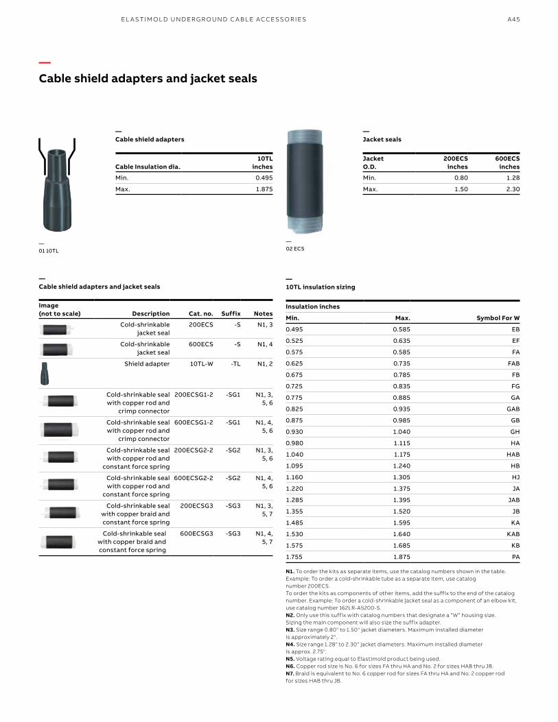
A45
—02 ECS
—Cable shield adapters
Cable Insulation dia.10TL
inches
Min. 0.495
Max. 1.875
—Jacket seals
JacketO.D.
200ECSinches
600ECSinches
Min. 0.80 1.28
Max. 1.50 2.30
—01 10TL
—10TL insulation sizing
Insulation inches
Symbol For WMin. Max.
0.495 0.585 EB
0.525 0.635 EF
0.575 0.585 FA
0.625 0.735 FAB
0.675 0.785 FB
0.725 0.835 FG
0.775 0.885 GA
0.825 0.935 GAB
0.875 0.985 GB
0.930 1.040 GH
0.980 1.115 HA
1.040 1.175 HAB
1.095 1.240 HB
1.160 1.305 HJ
1.220 1.375 JA
1.285 1.395 JAB
1.355 1.520 JB
1.485 1.595 KA
1.530 1.640 KAB
1.575 1.685 KB
1.755 1.875 PA
N1. To order the kits as separate items, use the catalog numbers shown in the table. Example: To order a cold-shrinkable tube as a separate item, use catalog number 200ECS.To order the kits as components of other items, add the suffix to the end of the catalog number. Example: To order a cold-shrinkable jacket seal as a component of an elbow kit, use catalog number 162LR-A5200-S.N2. Only use this suffix with catalog numbers that designate a “W” housing size. Sizing the main component will also size the suffix adapter.N3. Size range 0.80" to 1.50" jacket diameters. Maximum installed diameter is approximately 2".N4. Size range 1.28" to 2.30" jacket diameters. Maximum installed diameter is approx. 2.75".N5. Voltage rating equal to Elastimold product being used.N6. Copper rod size is No. 6 for sizes FA thru HA and No. 2 for sizes HAB thru JB.N7. Braid is equivalent to No. 6 copper rod for sizes FA thru HA and No. 2 copper rod for sizes HAB thru JB.
—Cable shield adapters and jacket seals
Image(not to scale) Description Cat. no. Suffix Notes
Cold-shrinkable jacket seal
200ECS -S N1, 3
Cold-shrinkable jacket seal
600ECS -S N1, 4
Shield adapter 10TL-W -TL N1, 2
Cold-shrinkable seal with copper rod and
crimp connector
200ECSG1-2 -SG1 N1, 3, 5, 6
Cold-shrinkable seal with copper rod and
crimp connector
600ECSG1-2 -SG1 N1, 4, 5, 6
Cold-shrinkable seal with copper rod and
constant force spring
200ECSG2-2 -SG2 N1, 3, 5, 6
Cold-shrinkable seal with copper rod and
constant force spring
600ECSG2-2 -SG2 N1, 4, 5, 6
Cold-shrinkable seal with copper braid and constant force spring
200ECSG3 -SG3 N1, 3, 5, 7
Cold-shrinkable seal with copper braid and constant force spring
600ECSG3 -SG3 N1, 4, 5, 7
—Cable shield adapters and jacket seals
EL A S TI M O L D U N D ER G R O U N D C A B L E ACCE SSO R I E S
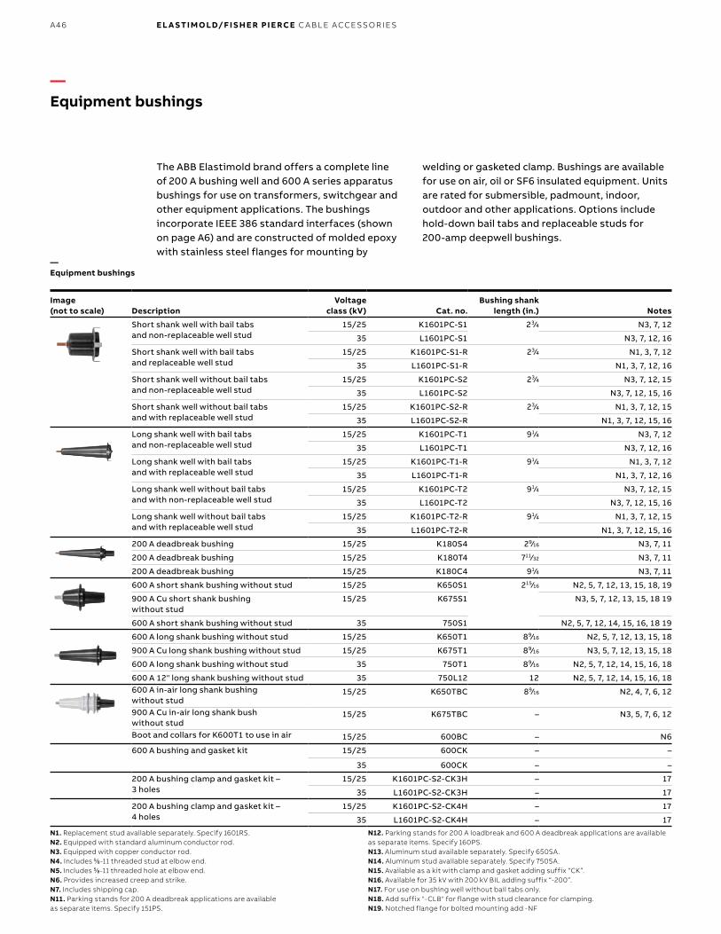
B1 copy starts here
B2 copy starts here
B3 copy starts here
A46 E L A S TI M O LD/F I S H E R PI E RCE C A B L E ACCE SSO R IE S
—Equipment bushings
N1. Replacement stud available separately. Specify 1601RS.N2. Equipped with standard aluminum conductor rod.N3. Equipped with copper conductor rod.N4. Includes 55⁄88-11 threaded stud at elbow end.N5. Includes 55⁄88-11 threaded hole at elbow end.N6. Provides increased creep and strike.N7. Includes shipping cap.N11. Parking stands for 200 A deadbreak applications are available as separate items. Specify 151PS.
N12. Parking stands for 200 A loadbreak and 600 A deadbreak applications are available as separate items. Specify 160PS.N13. Aluminum stud available separately. Specify 650SA.N14. Aluminum stud available separately. Specify 750SA.N15. Available as a kit with clamp and gasket adding suffix “CK”.N16. Available for 35 kV with 200 kV BIL adding suffix “-200”.N17. For use on bushing well without bail tabs only.N18. Add suffix "-CLB" for flange with stud clearance for clamping.N19. Notched flange for bolted mounting add -NF
The ABB Elastimold brand offers a complete line of 200 A bushing well and 600 A series apparatus bushings for use on transformers, switchgear and other equipment applications. The bushings incorporate IEEE 386 standard interfaces (shown on page A6) and are constructed of molded epoxy with stainless steel flanges for mounting by
welding or gasketed clamp. Bushings are available for use on air, oil or SF6 insulated equipment. Units are rated for submersible, padmount, indoor, outdoor and other applications. Options include hold-down bail tabs and replaceable studs for 200-amp deepwell bushings.
—Equipment bushings
Image (not to scale) Description
Voltage class (kV) Cat. no.
Bushing shank length (in.) Notes
Short shank well with bail tabs and non-replaceable well stud
15/25 K1601PC-S1 23⁄4 N3, 7, 12
35 L1601PC-S1 N3, 7, 12, 16
Short shank well with bail tabs and replaceable well stud
15/25 K1601PC-S1-R 23⁄4 N1, 3, 7, 12
35 L1601PC-S1-R N1, 3, 7, 12, 16
Short shank well without bail tabs and non-replaceable well stud
15/25 K1601PC-S2 23⁄4 N3, 7, 12, 15
35 L1601PC-S2 N3, 7, 12, 15, 16
Short shank well without bail tabs and with replaceable well stud
15/25 K1601PC-S2-R 23⁄4 N1, 3, 7, 12, 15
35 L1601PC-S2-R N1, 3, 7, 12, 15, 16
Long shank well with bail tabs and non-replaceable well stud
15/25 K1601PC-T1 91⁄4 N3, 7, 12
35 L1601PC-T1 N3, 7, 12, 16
Long shank well with bail tabs and with replaceable well stud
15/25 K1601PC-T1-R 91⁄4 N1, 3, 7, 12
35 L1601PC-T1-R N1, 3, 7, 12, 16
Long shank well without bail tabs and with non-replaceable well stud
15/25 K1601PC-T2 91⁄4 N3, 7, 12, 15
35 L1601PC-T2 N3, 7, 12, 15, 16
Long shank well without bail tabs and with replaceable well stud
15/25 K1601PC-T2-R 91⁄4 N1, 3, 7, 12, 15
35 L1601PC-T2-R N1, 3, 7, 12, 15, 16
200 A deadbreak bushing 15/25 K180S4 29⁄16 N3, 7, 11
200 A deadbreak bushing 15/25 K180T4 711⁄32 N3, 7, 11
200 A deadbreak bushing 15/25 K180C4 91⁄4 N3, 7, 11
600 A short shank bushing without stud 15/25 K650S1 215⁄16 N2, 5, 7, 12, 13, 15, 18, 19
900 A Cu short shank bushing without stud
15/25 K675S1 N3, 5, 7, 12, 13, 15, 18 19
600 A short shank bushing without stud 35 750S1 N2, 5, 7, 12, 14, 15, 16, 18 19
600 A long shank bushing without stud 15/25 K650T1 89⁄16 N2, 5, 7, 12, 13, 15, 18
900 A Cu long shank bushing without stud 15/25 K675T1 89⁄16 N3, 5, 7, 12, 13, 15, 18
600 A long shank bushing without stud 35 750T1 89⁄16 N2, 5, 7, 12, 14, 15, 16, 18
600 A 12" long shank bushing without stud 35 750L12 12 N2, 5, 7, 12, 14, 15, 16, 18600 A in-air long shank bushing without stud
15/25 K650TBC 89⁄16 N2, 4, 7, 6, 12
900 A Cu in-air long shank bush without stud
15/25 K675TBC – N3, 5, 7, 6, 12
Boot and collars for K600T1 to use in air 15/25 600BC – N6
600 A bushing and gasket kit 15/25 600CK – –
35 600CK – –
200 A bushing clamp and gasket kit – 3 holes
15/25 K1601PC-S2-CK3H – 17
35 L1601PC-S2-CK3H – 17
200 A bushing clamp and gasket kit – 4 holes
15/25 K1601PC-S2-CK4H – 17
35 L1601PC-S2-CK4H – 17
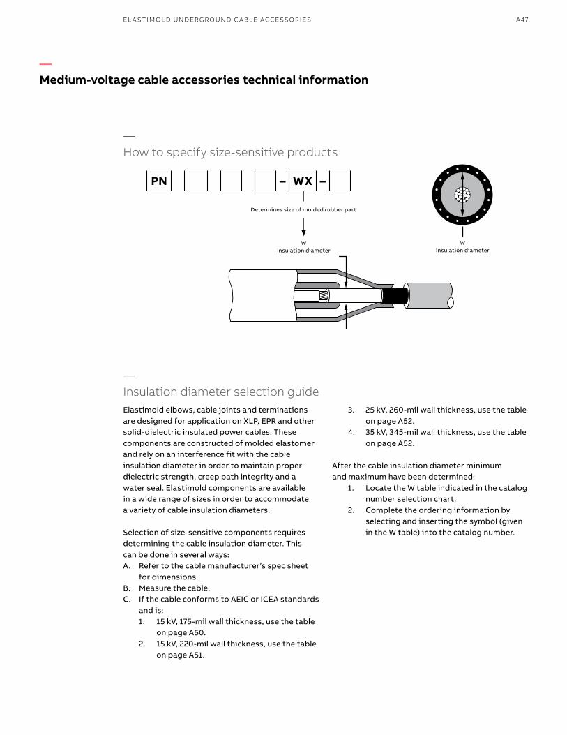
A47
—Medium-voltage cable accessories technical information
—Insulation diameter selection guide
‘W’CABLE
INSULATIONDIAMETER
—How to specify size-sensitive products
‘W’INSULATIONDIAMETER
Determines Size of Molded Rubber Part
W Insulation diameter
W Insulation diameter
Determines size of molded rubber part
Elastimold elbows, cable joints and terminations are designed for application on XLP, EPR and other solid-dielectric insulated power cables. These components are constructed of molded elastomer and rely on an interference fit with the cable insulation diameter in order to maintain proper dielectric strength, creep path integrity and a water seal. Elastimold components are available in a wide range of sizes in order to accommodate a variety of cable insulation diameters.
Selection of size-sensitive components requires determining the cable insulation diameter. This can be done in several ways:A. Refer to the cable manufacturer’s spec sheet
for dimensions.B. Measure the cable.C. If the cable conforms to AEIC or ICEA standards
and is: 1. 15 kV, 175-mil wall thickness, use the table
on page A50. 2. 15 kV, 220-mil wall thickness, use the table
on page A51.
3. 25 kV, 260-mil wall thickness, use the table on page A52.
4. 35 kV, 345-mil wall thickness, use the table on page A52.
After the cable insulation diameter minimum and maximum have been determined: 1. Locate the W table indicated in the catalog
number selection chart. 2. Complete the ordering information by
selecting and inserting the symbol (given in the W table) into the catalog number.
PN – WX –
EL A S TI M O L D U N D ER G R O U N D C A B L E ACCE SSO R I E S
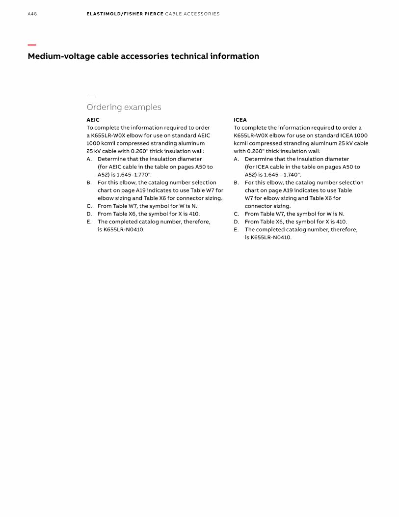
B1 copy starts here
B2 copy starts here
B3 copy starts here
A48 E L A S TI M O LD/F I S H E R PI E RCE C A B L E ACCE SSO R IE S
—Ordering examplesAEICTo complete the information required to order a K655LR-W0X elbow for use on standard AEIC 1000 kcmil compressed stranding aluminum 25 kV cable with 0.260" thick insulation wall:A. Determine that the insulation diameter
(for AEIC cable in the table on pages A50 to A52) is 1.645–1.770".
B. For this elbow, the catalog number selection chart on page A19 indicates to use Table W7 for elbow sizing and Table X6 for connector sizing.
C. From Table W7, the symbol for W is N.D. From Table X6, the symbol for X is 410.E. The completed catalog number, therefore,
is K655LR-N0410.
ICEATo complete the information required to order a K655LR-W0X elbow for use on standard ICEA 1000 kcmil compressed stranding aluminum 25 kV cable with 0.260" thick insulation wall:A. Determine that the insulation diameter
(for ICEA cable in the table on pages A50 to A52) is 1.645 – 1.740".
B. For this elbow, the catalog number selection chart on page A19 indicates to use Table W7 for elbow sizing and Table X6 for connector sizing.
C. From Table W7, the symbol for W is N.D. From Table X6, the symbol for X is 410.E. The completed catalog number, therefore,
is K655LR-N0410.
—Medium-voltage cable accessories technical information
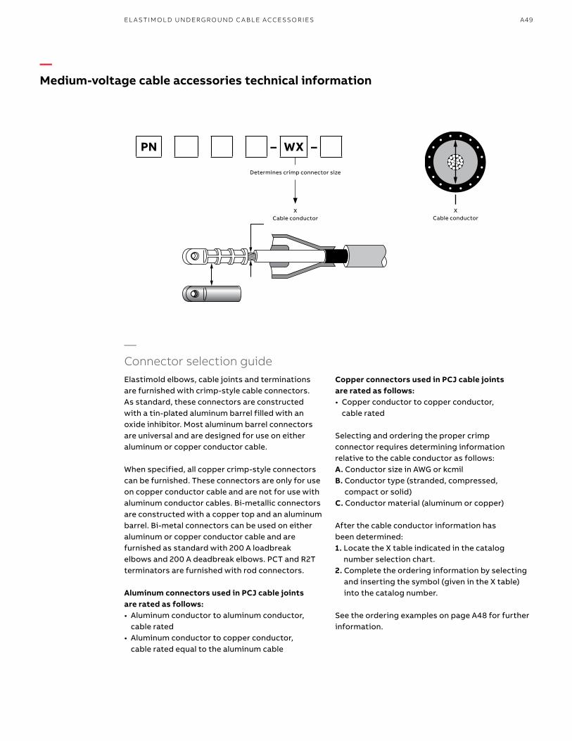
A49
Elastimold elbows, cable joints and terminations are furnished with crimp-style cable connectors. As standard, these connectors are constructed with a tin-plated aluminum barrel filled with an oxide inhibitor. Most aluminum barrel connectors are universal and are designed for use on either aluminum or copper conductor cable.
When specified, all copper crimp-style connectors can be furnished. These connectors are only for use on copper conductor cable and are not for use with aluminum conductor cables. Bi-metallic connectors are constructed with a copper top and an aluminum barrel. Bi-metal connectors can be used on either aluminum or copper conductor cable and are furnished as standard with 200 A loadbreak elbows and 200 A deadbreak elbows. PCT and R2T terminators are furnished with rod connectors.
Aluminum connectors used in PCJ cable joints are rated as follows: • Aluminum conductor to aluminum conductor,
cable rated• Aluminum conductor to copper conductor,
cable rated equal to the aluminum cable
Copper connectors used in PCJ cable joints are rated as follows: • Copper conductor to copper conductor,
cable rated Selecting and ordering the proper crimp connector requires determining information relative to the cable conductor as follows:A. Conductor size in AWG or kcmilB. Conductor type (stranded, compressed,
compact or solid)C. Conductor material (aluminum or copper)
After the cable conductor information has been determined:1. Locate the X table indicated in the catalog
number selection chart.2. Complete the ordering information by selecting
and inserting the symbol (given in the X table) into the catalog number.
See the ordering examples on page A48 for further information.
‘X’CABLE
CONDUCT OR
Determ ines Crim p Connector Size
‘W’CABLE
INSULATIONDIAMETER
X Cable conductor
X Cable conductor
Determines crimp connector size
—Connector selection guide
PN – WX –
—Medium-voltage cable accessories technical information
EL A S TI M O L D U N D ER G R O U N D C A B L E ACCE SSO R I E S

B1 copy starts here
B2 copy starts here
B3 copy starts here
A50 E L A S TI M O LD/F I S H E R PI E RCE C A B L E ACCE SSO R IE S
AEIC CS8-06Specification for extruded dielectric, shielded power cable rated 5–46 kV
AEIC-calculated diameters – Solid and compressed stranding from tables C-4 and C-6 and compact stranding from tables C-5 and C-7
ANSI/ICEA S-94-649-2004 & S-97-682-2000Standard for concentric neutral cables and utility shielded power cables rated 5–46 kV
ICEA – Concentric stranding from table C-3, compressed stranding from table C-4, compact stranding from table C-5
ICEA abbreviated – For additional cables, please refer to the standard
Wall
—15 kV cable (100% level, 175 mil)
Aluminum and copper conductor size (AWG or kcmil)
Industry standard
Solid conductor Stranded conductor Compressed conductor Compact conductor
Diameter in inches over insulation
Diameter in inches over insulation
Diameter in inches over insulation
Diameter in inches over insulation
Min. Max. Min. Max. Min. Max. Min. Max.
#2 AEIC 0.610 0.700 – – 0.635 0.725 0.620 0.710
ICEA 0.610 0.695 0.645 0.730 0.635 0.720 0.620 0.705
#1 AEIC 0.645 0.730 – – 0.675 0.765 0.655 0.740
ICEA 0.645 0.725 0.685 0.770 0.675 0.760 0.655 0.735
1/0 AEIC 0.680 0.770 – – 0.715 0.805 0.690 0.775
ICEA 0.680 0.760 0.725 0.810 0.715 0.800 0.690 0.775
2/0 AEIC – – – – 0.760 0.850 0.730 0.815
ICEA – – 0.775 0.855 0.760 0.845 0.730 0.815
3/0 AEIC – – – – 0.810 0.900 0.775 0.865
ICEA – – 0.825 0.905 0.810 0.895 0.775 0.860
4/0 AEIC – – – – 0.865 0.955 0.830 0.915
ICEA – – 0.880 0.965 0.865 0.950 0.830 0.910
250 AEIC – – – – – – – –
ICEA – – 0.935 1.020 0.920 1.005 0.880 0.965
350 AEIC – – – – 1.025 1.115 0.980 1.065
ICEA – – 1.045 1.130 1.025 1.110 0.980 1.065
500 AEIC – – – – 1.150 1.245 1.100 1.185
ICEA – – 1.175 1.260 1.150 1.235 1.100 1.185
750 AEIC – – – – 1.340 1.440 1.280 1.370
ICEA – – 1.370 1.455 1.340 1.425 1.280 1.365
1000 AEIC – – – – 1.485 1.590 1.430 1.520
ICEA – – 1.520 1.610 1.485 1.575 1.430 1.515
ICEA Note: Diameters specified in the above table are different than specified by AEIC CS8-00. Consult accessory manufacturer for proper selection of accessories. Diameters to be measured in accordance with 9.6.
—Medium-voltage cable accessories technical informationAEIC and ICEA cable insulation diameter
15 kV 100% – 175 mil insulation (0.175")15 kV 133% – 220 mil insulation (0.220")25 kV 100% – 260 mil insulation (0.260")35 kV 100% – 345 mil insulation (0.345")
W = insulation diameter (conductor
+ 2x conductor shield + 2x wall)
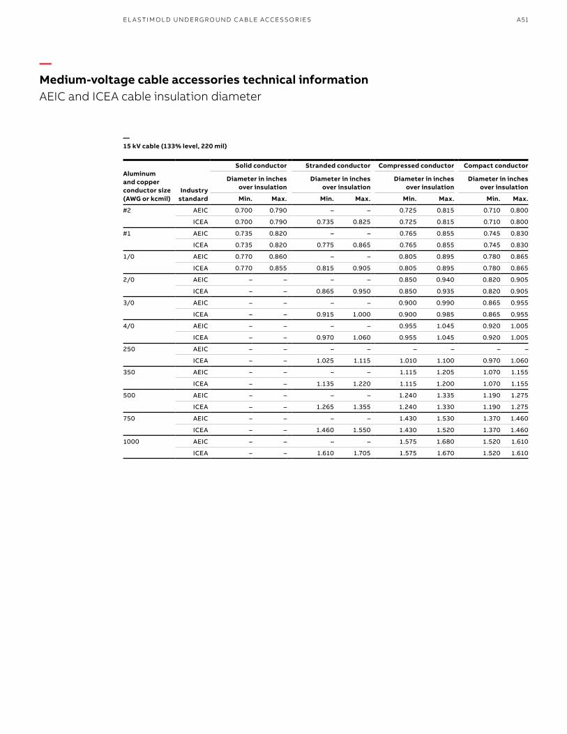
A51
—15 kV cable (133% level, 220 mil)
Aluminum and copper conductor size (AWG or kcmil)
Industry standard
Solid conductor Stranded conductor Compressed conductor Compact conductor
Diameter in inches over insulation
Diameter in inches over insulation
Diameter in inches over insulation
Diameter in inches over insulation
Min. Max. Min. Max. Min. Max. Min. Max.
#2 AEIC 0.700 0.790 – – 0.725 0.815 0.710 0.800
ICEA 0.700 0.790 0.735 0.825 0.725 0.815 0.710 0.800
#1 AEIC 0.735 0.820 – – 0.765 0.855 0.745 0.830
ICEA 0.735 0.820 0.775 0.865 0.765 0.855 0.745 0.830
1/0 AEIC 0.770 0.860 – – 0.805 0.895 0.780 0.865
ICEA 0.770 0.855 0.815 0.905 0.805 0.895 0.780 0.865
2/0 AEIC – – – – 0.850 0.940 0.820 0.905
ICEA – – 0.865 0.950 0.850 0.935 0.820 0.905
3/0 AEIC – – – – 0.900 0.990 0.865 0.955
ICEA – – 0.915 1.000 0.900 0.985 0.865 0.955
4/0 AEIC – – – – 0.955 1.045 0.920 1.005
ICEA – – 0.970 1.060 0.955 1.045 0.920 1.005
250 AEIC – – – – – – – –
ICEA – – 1.025 1.115 1.010 1.100 0.970 1.060
350 AEIC – – – – 1.115 1.205 1.070 1.155
ICEA – – 1.135 1.220 1.115 1.200 1.070 1.155
500 AEIC – – – – 1.240 1.335 1.190 1.275
ICEA – – 1.265 1.355 1.240 1.330 1.190 1.275
750 AEIC – – – – 1.430 1.530 1.370 1.460
ICEA – – 1.460 1.550 1.430 1.520 1.370 1.460
1000 AEIC – – – – 1.575 1.680 1.520 1.610
ICEA – – 1.610 1.705 1.575 1.670 1.520 1.610
—Medium-voltage cable accessories technical informationAEIC and ICEA cable insulation diameter
EL A S TI M O L D U N D ER G R O U N D C A B L E ACCE SSO R I E S
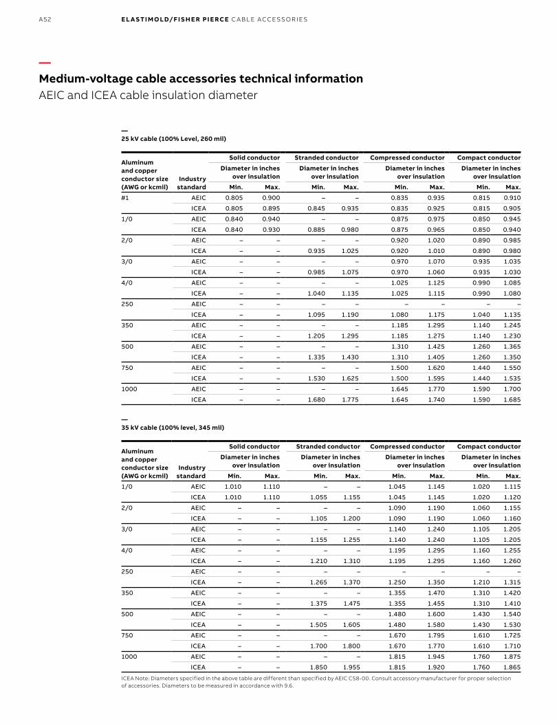
B1 copy starts here
B2 copy starts here
B3 copy starts here
A52 E L A S TI M O LD/F I S H E R PI E RCE C A B L E ACCE SSO R IE S
—25 kV cable (100% Level, 260 mil)
Aluminum and copper conductor size (AWG or kcmil)
Industry standard
Solid conductor Stranded conductor Compressed conductor Compact conductor
Diameter in inches over insulation
Diameter in inches over insulation
Diameter in inches over insulation
Diameter in inches over insulation
Min. Max. Min. Max. Min. Max. Min. Max.
#1 AEIC 0.805 0.900 – – 0.835 0.935 0.815 0.910
ICEA 0.805 0.895 0.845 0.935 0.835 0.925 0.815 0.905
1/0 AEIC 0.840 0.940 – – 0.875 0.975 0.850 0.945
ICEA 0.840 0.930 0.885 0.980 0.875 0.965 0.850 0.940
2/0 AEIC – – – – 0.920 1.020 0.890 0.985
ICEA – – 0.935 1.025 0.920 1.010 0.890 0.980
3/0 AEIC – – – – 0.970 1.070 0.935 1.035
ICEA – – 0.985 1.075 0.970 1.060 0.935 1.030
4/0 AEIC – – – – 1.025 1.125 0.990 1.085
ICEA – – 1.040 1.135 1.025 1.115 0.990 1.080
250 AEIC – – – – – – – –
ICEA – – 1.095 1.190 1.080 1.175 1.040 1.135
350 AEIC – – – – 1.185 1.295 1.140 1.245
ICEA – – 1.205 1.295 1.185 1.275 1.140 1.230
500 AEIC – – – – 1.310 1.425 1.260 1.365
ICEA – – 1.335 1.430 1.310 1.405 1.260 1.350
750 AEIC – – – – 1.500 1.620 1.440 1.550
ICEA – – 1.530 1.625 1.500 1.595 1.440 1.535
1000 AEIC – – – – 1.645 1.770 1.590 1.700
ICEA – – 1.680 1.775 1.645 1.740 1.590 1.685
—35 kV cable (100% level, 345 mil)
Aluminum and copper conductor size (AWG or kcmil)
Industry standard
Solid conductor Stranded conductor Compressed conductor Compact conductor
Diameter in inches over insulation
Diameter in inches over insulation
Diameter in inches over insulation
Diameter in inches over insulation
Min. Max. Min. Max. Min. Max. Min. Max.
1/0 AEIC 1.010 1.110 – – 1.045 1.145 1.020 1.115
ICEA 1.010 1.110 1.055 1.155 1.045 1.145 1.020 1.120
2/0 AEIC – – – – 1.090 1.190 1.060 1.155
ICEA – – 1.105 1.200 1.090 1.190 1.060 1.160
3/0 AEIC – – – – 1.140 1.240 1.105 1.205
ICEA – – 1.155 1.255 1.140 1.240 1.105 1.205
4/0 AEIC – – – – 1.195 1.295 1.160 1.255
ICEA – – 1.210 1.310 1.195 1.295 1.160 1.260
250 AEIC – – – – – – – –
ICEA – – 1.265 1.370 1.250 1.350 1.210 1.315
350 AEIC – – – – 1.355 1.470 1.310 1.420
ICEA – – 1.375 1.475 1.355 1.455 1.310 1.410
500 AEIC – – – – 1.480 1.600 1.430 1.540
ICEA – – 1.505 1.605 1.480 1.580 1.430 1.530
750 AEIC – – – – 1.670 1.795 1.610 1.725
ICEA – – 1.700 1.800 1.670 1.770 1.610 1.710
1000 AEIC – – – – 1.815 1.945 1.760 1.875
ICEA – – 1.850 1.955 1.815 1.920 1.760 1.865
ICEA Note: Diameters specified in the above table are different than specified by AEIC CS8-00. Consult accessory manufacturer for proper selection of accessories. Diameters to be measured in accordance with 9.6.
—Medium-voltage cable accessories technical informationAEIC and ICEA cable insulation diameter

A53
Conductor size(AWG or kcmil)
No. of strandsand their nom.
strand dia. (in.)
Cross-sectional areaStranded
conductors(inches)
Compressedconductors
(inches)
Compactconductors
(inches)
Solidconductors
(inches)Squareinches
mm2
conversion
#14 7 x 0.0242 0.0032 2.08 0.073 – – 0.064
#12 7 x 0.0305 0.0051 3.31 0.092 – – 0.081
#10 7 x 0.0385 0.0082 5.26 0.116 – – 0.102
#8 7 x 0.0486 0.0130 8.37 0.146 – – 0.129
#6 7 x 0.0612 0.0206 13.30 0.184 – – 0.162
#4 7 x 0.0772 0.0328 21.15 0.232 – – 0.204
#2 7 x 0.0974 0.0521 33.62 0.292 0.283 0.268 0.258
#1 19 x 0.0664 0.0657 42.41 0.332 0.322 0.299 0.289
1/0 19 x 0.0745 0.0829 53.49 0.373 0.362 0.336 0.325
2/0 19 x 0.0837 0.1054 67.43 0.418 0.405 0.376 –
3/0 19 x 0.0940 0.1318 85.01 0.470 0.456 0.423 –
4/0 19 x 0.1055 0.1662 107.2 0.528 0.512 0.475 –
250 37 x 0.0822 0.1964 127 0.575 0.558 0.520 –
350 37 x 0.0973 0.2749 177 0.681 0.661 0.616 –
500 37 x 0.1162 0.3924 253 0.813 0.789 0.736 –
600 61 x 0.0992 0.4712 304 0.893 0.866 0.813 –
700 61 x 0.1071 0.5498 355 0.964 0.935 0.877 –
750 61 x 0.1109 0.5890 380 0.998 0.968 0.908 –
800 61 x 0.1145 0.6283 405 1.031 1.000 0.938 –
900 61 x 0.1215 0.7069 456 1.094 1.061 0.999 –
1000 61 x 0.1280 0.7854 507 1.152 1.117 1.060 –
1100 91 x 0.1099 0.8639 557 1.209 1.173 – –
1200 91 x 0.1148 0.9425 608 1.263 1.225 – –
1250 91 x 0.1172 0.9818 633 1.289 1.250 – –
1300 91 x 0.1195 1.021 659 1.315 1.276 – –
1400 91 x 0.1240 1.100 709 1.364 1.323 – –
1500 91 x 0.1284 1.178 760 1.412 1.370 – –
1600 127 x 0.1122 1.257 811 1.459 1.415 – –
1700 127 x 0.1157 1.335 861 1.504 1.459 – –
1750 127 x 0.1174 1.374 887 1.526 1.480 – –
1800 127 x 0.1191 1.414 912 1.548 1.502 – –
1900 127 x 0.1223 1.492 963 1.590 1.542 – –
2000 127 x 0.1225 1.571 1010 1.632 1.583 – –
CABLE
CONDUCTOR
Cable conductor
—Conductor diameters for copper and aluminum (Class B) stranded, compressed, compact and solid cables
—Conductor diameters for copper and aluminum (Class B) stranded, compressed, compact and solid cables
EL A S TI M O L D U N D ER G R O U N D C A B L E ACCE SSO R I E S

B1 copy starts here
B2 copy starts here
B3 copy starts here
A54 E L A S TI M O LD/F I S H E R PI E RCE C A B L E ACCE SSO R IE S
Applicable cat. no. use for following products
Cable insulation diameter in inches Symbol
for W
Applicable cat. no. use for following products
Cable insulation diameter in inches Symbol
for WMin. Max. Min. Max.
Table W1 Table W7
151SP/SR151LS/LY161DLR 161/162LR161/162LRJS161LR/161LRJS261LR/261LRJS162LR/162LRJS261DLR262LR/262LRJS
0.575 0.740 A K656I/CY/CHK655/656LRK655/656SR655/656LINKK655/656LINK655/656ETPK655/656ETP655/656RTPK655/656LRTP655/656BI-LINK
0.420 0.660 D
0.635 0.905 B 0.530 0.680 E
0.805 1.060 C 0.640 0.820 F
0.890 1.220 D 0.760 0.950 G
1.090 1.310 E 0.850 1.050 H
0.980 1.180 J
1.090 1.310 K
1.180 1.465 L
Table W2 1.280 1.430 LM
273RLR274RLR273DLR
0.760 0.950 G 1.370 1.630 M
0.850 1.050 H 1.550 1.780 N
0.980 1.180 J 1.665 1.785 PA
1.090 1.310 K 1.725 1.935 P
Table W3 Table W8
375LR376LR
0.850 1.050 H 15PCJ-115PCJ-2
0.640 0.820 F
0.980 1.180 J 0.760 0.950 G
1.090 1.310 K 0.850 1.050 H
1.235 1.465 L 0.980 1.180 J
Table W4 1.090 1.310 K
167/168RLR167LRT
0.640 0.820 F 1.180 1.465 L
0.760 0.950 G 1.280 1.430 LM
0.850 1.050 H 1.370 1.630 M
0.980 1.180 J 1.515 1.780 N
1.090 1.310 K 1.725 1.935 P
Table W5 1.900 2.120 Q
167/168ELR273/274DELR 273/274ELR167/168DELR
0.665 0.895 6689 Table W9
0.740 0.950 7495 25PCJ-125PCJ-2755/756LR755/756LINK755/756ETP755/756LRTP755/756BI-LINK755CA/CK/TCK
0.760 0.950 G
0.880 1.100 88110 0.850 1.050 H
1.090 1.310 K 0.980 1.180 J
Table W6 1.090 1.310 K
10EP152EA160CA*(*EB-FA only)
0.495 0.585 EB 1.180 1.465 L
0.525 0.635 EF 1.370 1.630 M
0.575 0.685 FA 1.515 1.780 N
0.625 0.735 FAB 1.725 1.935 P
0.675 0.785 FB 1.900 2.120 Q
0.725 0.835 FG 2.115 2.235 R
0.775 0.885 GA
0.825 0.935 GAB
0.875 0.985 GB
—Table W
—Medium-voltage cable accessories technical informationTable W

A55
—Medium-voltage cable accessories technical informationTable W & Table X
Applicable cat. no. use for following products
Conductor size AWG
or kcmil
Symbol for W Applicable cat. no. use for following products
Conductor size AWG
or kcmil
Symbol for W
Strand./ compr.
Compt./ solid.
Strand./ compr.
Compt./ solid.
Table W10 Table W16
35PCJ-135PCJ-2
0.850 1.050 H 252LR252LRJS
0.575 0.740 A
0.980 1.180 J 0.635 0.905 B
1.090 1.310 K 0.805 1.060 C
1.180 1.465 L 0.890 1.220 D
1.370 1.630 M 1.090 1.310 E
1.515 1.780 N
1.725 1.935 P
1.900 2.120 Q
—Table W (continued)
Applicable cat. no. use for following products
Conductor size AWG
or kcmil
Symbol for X Applicable cat. no. use for following products
Conductor size AWG
or kcmil
Symbol for X
Strand./ compr.
Compt./ solid.
Strand./ compr.
Compt./ solid.
Table X1 Table X6
167/168ELR/DELR273/274ELR/DELR156LR, 161/162LR261/262LR,167LRT 167/168RLR,167DLR273/274RLR,273DLR00400, 02500, 02509, 02702, 02800, K151SP/SR, 375LR/376LR
#2 210 220 K655/656ETP755/756ETP655/656BI-LINKK655/656BI-LINK755BI-LINK 655CK, 755CK 655TCK, 0360003602, 03700, 03702
650 750/800 360
#1 220 230 700/750 900 380
1/0 230 240 800 – 390
2/0 240 250 900 1,000 400
3/0 250 260 1,000 – 410
4/0 260 270 – 1,250 420
250 270 – 1250 – 440
Table X2 Table X7
375/376LR375/376LR
1/0 230 240 15PCJ125PCJ135PCJ115PCJ225PCJ235PCJ2
#2 220 210
2/0 240 250 #1 230 220
3/0 250 260 1/0 240 230
4/0 260 270 2/0 250 240
Table X6 3/0 260 250
655/656LRTPK655/656LRTP755/756LRTPK656I/Y/H, K655/656LR755/756LR, K655/656SR655/656LINK, K655/656LINK755/756LINK, 655/656ETPK655/656ETP, 755/756ETP655/656BI-LINKK655/656BI-LINK755BI-LINK, 655CK 755CK, 655TCK, 03600, 03602, 03700, 03702K655/656LRTP755/756LRTP, K656I/Y/HK655/656LR, K655/656LR755/756LR, K655/656SR655/656LINK, K655/656LINK 755/756LINK, 655/656ETP K655/656ETP, 755/756ETP
– #2 210 4/0 270 260
#2 #1 220 250 280 270
#1 1/0 230 350 300 290
1/0 2/0 240 500 330 310
2/0 3/0 250 750 380 360
3/0 4/0 260 1,000 410 400
4/0 250 270 1,250 440 420
250 300 280 Table X9
300 350 290 PCT1PCT20100001010
#2 220 210
350 400 300 #1 230 220
400 450 310 1/0 240 230
450 500/550 320 2/0 250 240
500 600 330 3/0 260 250
550 650 340 4/0 270 260
600 700 350
—Table X
EL A S TI M O L D U N D ER G R O U N D C A B L E ACCE SSO R I E S

B1 copy starts here
B2 copy starts here
B3 copy starts here
A56 E L A S TI M O LD/F I S H E R PI E RCE C A B L E ACCE SSO R IE S
—Shrink-Fit cable joints
—Splice medium-voltage cables fast – No ripcords, no heat!
—01
—02
—03
For over 50 years, the Elastimold brand has been associated with reliable, high-quality, pre-molded power cable splices that are designed to stand the rigors of the toughest utility applications. These products provide a cost-effective method to splice medium voltage cables using a push-on motion, and allowing cable neutrals to be solidly connected across the body of the splice without the use of any external braids. For those who prefer a more range-taking solution without the use of any physical force to install, the only options available have been cumbersome heat-shrink products that require multiple steps and the use of an open flame that makes achieving uniform cable coverage tedious and time-consuming or braid/jacket combinations that make achieving a solid neutral connection across the splice a challenge.
Now there’s a faster and easier way to splice medium-voltage cables – One that combines all of the convenience and flexibility of a pre-molded splice, with the range-taking ease of installation offered in a cold- or heat-shrink product, but without the use of ripcords, heat or excessive force. Introducing the Elastimold Shrink-Fit cable joints from ABB.
The Shrink-Fit cable joints are made of the same molded EPDM elastomer as our other Elastimold cable accessories. This high-performance material offers more durability than silicone for direct burial. The joints feature a four-piece plastic support core, which is placed over the cable for installation of the splice. The support core is then easily removed with the supplied tool, allowing the elastomer joint to contour over the spliced cable for a uniform seal every time.
Each Elastimold Shrink-Fit cable joint covers a wide range of cable sizes, features an insulated, semi-conductive shield and can be used with either a standard aluminum or optional copper compression splice. Optional kits are available for neutral, shielding and jacket restoration.
Features• Core removal without ripcords or heat required
for installation• High-quality molded EPDM elastomer housing
withstands the elements in harsh direct-burial, vault, manhole and overhead applications
• Four sizes support a wide range of cable and conductor sizes
• IEEE 404 rated Shrink-Fit cable joint• Includes restoration kit
Typical applications• Direct burial• Handhole/pullbox• Manhole• Vault• Overhead
—01 SFJ225 Shrink-Fit cable joint—02 Disposable four-piece plastic support core—03 SFJ with -RK restoration kit option
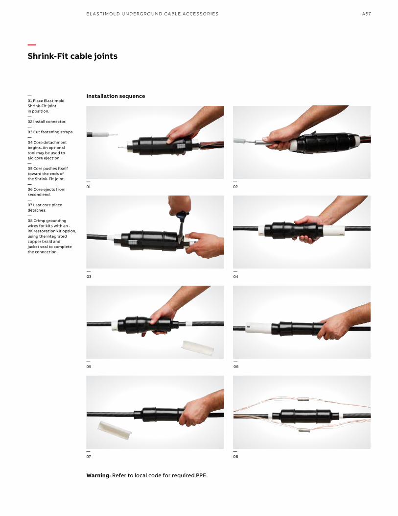
A57
Installation sequence
—Shrink-Fit cable joints
—01 Place Elastimold Shrink-Fit joint in position.—02 Install connector.—03 Cut fastening straps.—04 Core detachment begins. An optional tool may be used to aid core ejection.—05 Core pushes itself toward the ends of the Shrink-Fit joint.—06 Core ejects from second end.—07 Last core piece detaches.—08 Crimp grounding wires for kits with an - RK restoration kit option, using the integrated copper braid and jacket seal to complete the connection.
—01
—02
—03
—05
—06
—08
—07
—04
Warning: Refer to local code for required PPE.
EL A S TI M O L D U N D ER G R O U N D C A B L E ACCE SSO R I E S

B1 copy starts here
B2 copy starts here
B3 copy starts here
A58 E L A S TI M O LD/F I S H E R PI E RCE C A B L E ACCE SSO R IE S
—Dimensions
Cable joint sizeD
(in.)L
(in.)
1 1.85 11
2 2.12 16
3 2.40 18
4 2.60 18
—Ratings
Voltage class (kV) 15 25/28 35
Max. phase-to-ground operating voltage (kV) 8.7 14.4 20.2
BIL impulse withstand (1.2 x 50µsec. wave) (kV)
110 150 200
Corona extinction level @ 3.0 pC sensitivity (kV)
13 22 30
DC withstand during installation (kV) 56 80 100
DC withstand up to 5 yrs.* – XLPE insulation (kV)
18 25 31
DC withstand up to 5 yrs.* – EPR insulation (kV)
45 64 80
AC withstand at 60 Hz for 60 sec. (kV) 35 52 69
Continuous current Equal to that of cable Equal to that of cable Equal to that of cable
Short-term current Equal to that of cable up to 35 kA
Equal to that of cable up to 35 kA
Equal to that of cable up to 35 kA
*Reference: AEC CS6 and CS8, section L.2.
D
L
—Insulation range
Cable joint sizeMin. (in.)
Max. (in.)
Min. (mm)
Max. (mm)
1 0.610 0.860 15.49 21.84
2 0.805 1.060 20.44 26.92
3 0.935 1.355 23.75 34.41
4 1.210 1.920 30.73 48.76
—Shrink-Fit cable joints
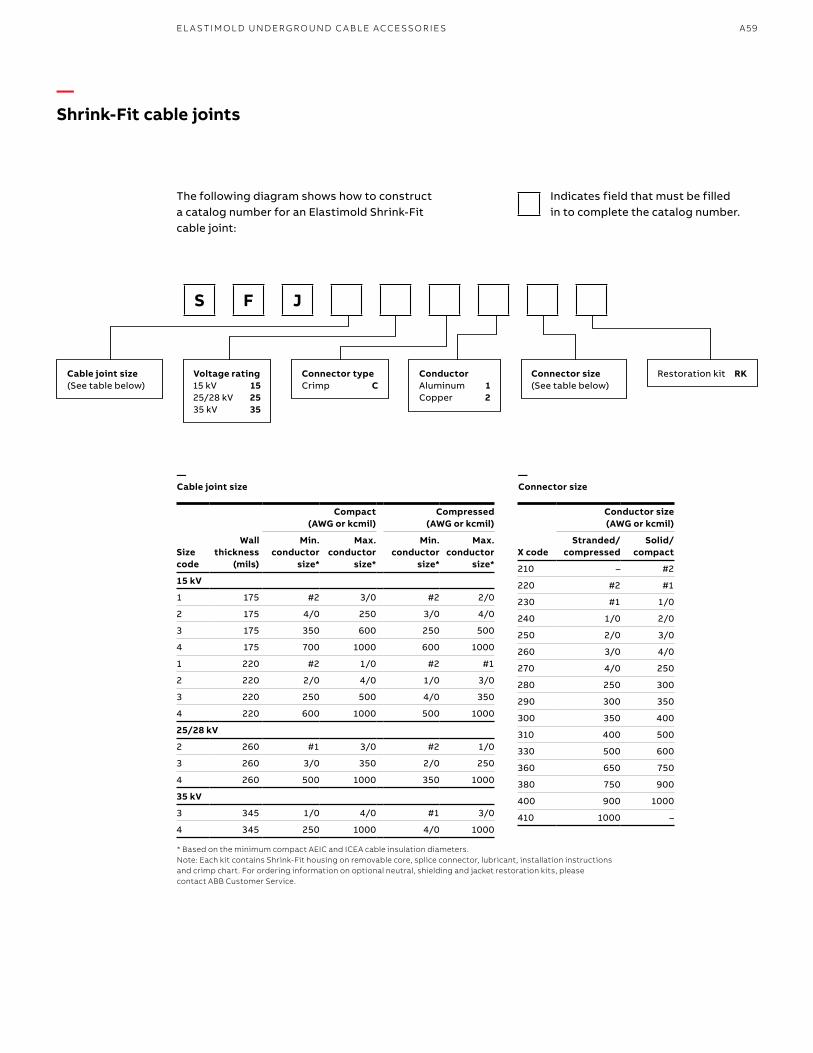
A59
The following diagram shows how to construct a catalog number for an Elastimold Shrink-Fit cable joint:
* Based on the minimum compact AEIC and ICEA cable insulation diameters. Note: Each kit contains Shrink-Fit housing on removable core, splice connector, lubricant, installation instructions and crimp chart. For ordering information on optional neutral, shielding and jacket restoration kits, please contact ABB Customer Service.
X code
Conductor size (AWG or kcmil)
Stranded/ compressed
Solid/ compact
210 – #2
220 #2 #1
230 #1 1/0
240 1/0 2/0
250 2/0 3/0
260 3/0 4/0
270 4/0 250
280 250 300
290 300 350
300 350 400
310 400 500
330 500 600
360 650 750
380 750 900
400 900 1000
410 1000 –
Size code
Wall thickness
(mils)
Compact (AWG or kcmil)
Compressed (AWG or kcmil)
Min. conductor
size*
Max. conductor
size*
Min. conductor
size*
Max. conductor
size*
15 kV
1 175 #2 3/0 #2 2/0
2 175 4/0 250 3/0 4/0
3 175 350 600 250 500
4 175 700 1000 600 1000
1 220 #2 1/0 #2 #1
2 220 2/0 4/0 1/0 3/0
3 220 250 500 4/0 350
4 220 600 1000 500 1000
25/28 kV
2 260 #1 3/0 #2 1/0
3 260 3/0 350 2/0 250
4 260 500 1000 350 1000
35 kV
3 345 1/0 4/0 #1 3/0
4 345 250 1000 4/0 1000
—Shrink-Fit cable joints
S F J
Voltage rating15 kV 1525/28 kV 2535 kV 35
Connector typeCrimp C
ConductorAluminum 1Copper 2
Restoration kit RKCable joint size(See table below)
Connector size(See table below)
Indicates field that must be filled in to complete the catalog number.
—Connector size
—Cable joint size
EL A S TI M O L D U N D ER G R O U N D C A B L E ACCE SSO R I E S
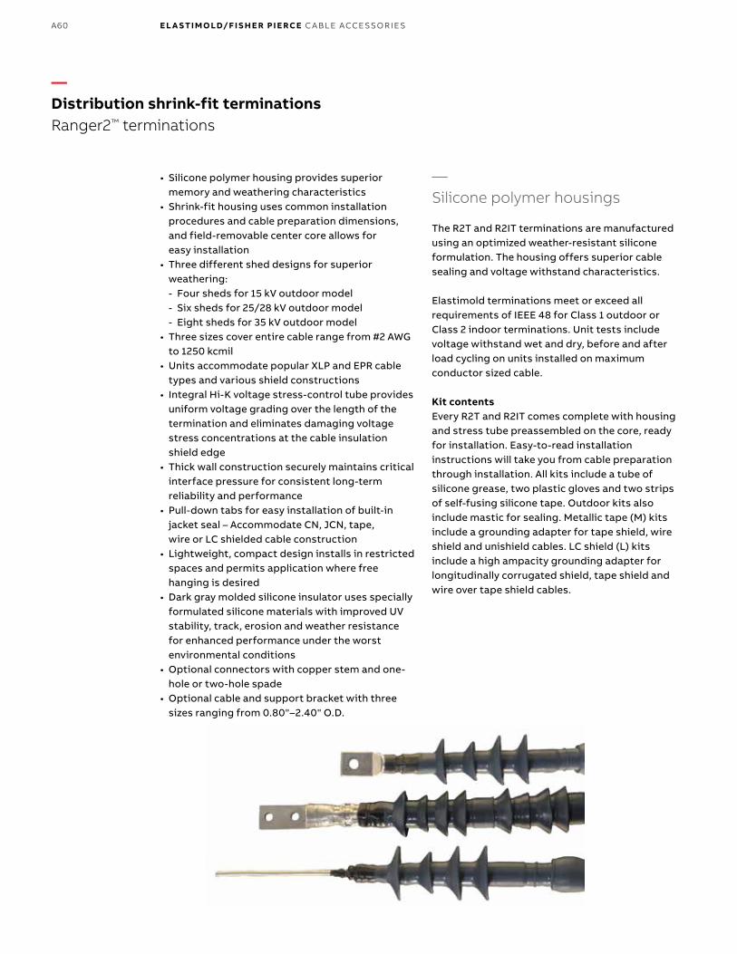
B1 copy starts here
B2 copy starts here
B3 copy starts here
A60 E L A S TI M O LD/F I S H E R PI E RCE C A B L E ACCE SSO R IE S
• Silicone polymer housing provides superior memory and weathering characteristics
• Shrink-fit housing uses common installation procedures and cable preparation dimensions, and field-removable center core allows for easy installation
• Three different shed designs for superior weathering: - Four sheds for 15 kV outdoor model - Six sheds for 25/28 kV outdoor model - Eight sheds for 35 kV outdoor model
• Three sizes cover entire cable range from #2 AWG to 1250 kcmil
• Units accommodate popular XLP and EPR cable types and various shield constructions
• Integral Hi-K voltage stress-control tube provides uniform voltage grading over the length of the termination and eliminates damaging voltage stress concentrations at the cable insulation shield edge
• Thick wall construction securely maintains critical interface pressure for consistent long-term reliability and performance
• Pull-down tabs for easy installation of built-in jacket seal – Accommodate CN, JCN, tape, wire or LC shielded cable construction
• Lightweight, compact design installs in restricted spaces and permits application where free hanging is desired
• Dark gray molded silicone insulator uses specially formulated silicone materials with improved UV stability, track, erosion and weather resistance for enhanced performance under the worst environmental conditions
• Optional connectors with copper stem and one-hole or two-hole spade
• Optional cable and support bracket with three sizes ranging from 0.80"–2.40" O.D.
—Distribution shrink-fit terminationsRanger2™ terminations
—Silicone polymer housings
The R2T and R2IT terminations are manufactured using an optimized weather-resistant silicone formulation. The housing offers superior cable sealing and voltage withstand characteristics.
Elastimold terminations meet or exceed all requirements of IEEE 48 for Class 1 outdoor or Class 2 indoor terminations. Unit tests include voltage withstand wet and dry, before and after load cycling on units installed on maximum conductor sized cable.
Kit contents Every R2T and R2IT comes complete with housing and stress tube preassembled on the core, ready for installation. Easy-to-read installation instructions will take you from cable preparation through installation. All kits include a tube of silicone grease, two plastic gloves and two strips of self-fusing silicone tape. Outdoor kits also include mastic for sealing. Metallic tape (M) kits include a grounding adapter for tape shield, wire shield and unishield cables. LC shield (L) kits include a high ampacity grounding adapter for longitudinally corrugated shield, tape shield and wire over tape shield cables.

A61
Connector
Conductor Gray molded silicone
insulator
Built-in cable entrance seal
Silicone tape seal
Cable insulation
Cable shield
Mastic
Concentric neutral wires
Hi-k voltage stress-control
tube
Cable jacket
—Stress relief
The R2T and R2IT terminations provide electric stress control for the cable by means of a flexible tube with a high permittivity dielectric constant.
The stress-relief tube is preassembled on the core under the polymer housing. As the core is removed, the stress-relief tube and housing shrink onto the cable at the same time, in exactly the right position. No secondary operations are required during installation. The electrical fields are refracted through the high dielectric constant tube and housing as shown.
—Installation
Standard cable preparation techniques are used for all R2T Elastimold Ranger2 outdoor terminations and R2IT Elastimold Ranger2 indoor terminations. The Elastimold shrink-fit terminations are assembled on a removable core. After the termination is placed onto the prepared cable, the core is removed by pulling on the end. The housing then collapses onto the prepared cable. Memory of the material provides the interface solid dielectric and sealing properties required to meet the electrical ratings and prevent the ingress of moisture.
—Certified
Elastimold Ranger2 terminations have been designed and tested per applicable portions of ANSI, IEEE, AEIC, ICEA and other industry standards.
IEEE 48 Standard for indoor and outdoor cable terminations.
ANSI C119.4Standard for cable connectors for aluminum and copper conductors.
AEIC CS8-06 and ANSI/ICEA S-94-649-2004 and S-97-682-2000 Standards for XLP and EPR insulated cables.
STRESS RELIEF
Terminal housing
Cable insulation
Terminal stress relief Cable semi-conductor
Conductor
—Voltage stress
STRESS RELIEF
—Distribution shrink-fit terminationsRanger2 terminations
EL A S TI M O L D U N D ER G R O U N D C A B L E ACCE SSO R I E S
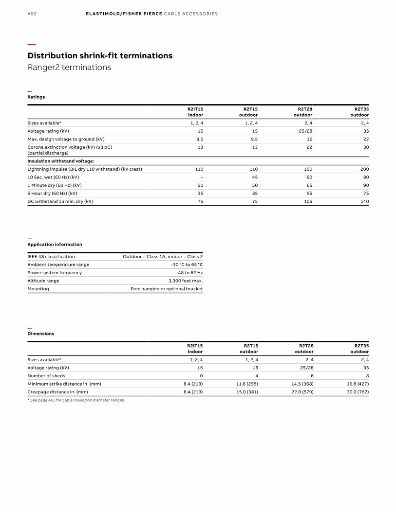
B1 copy starts here
B2 copy starts here
B3 copy starts here
A62 E L A S TI M O LD/F I S H E R PI E RCE C A B L E ACCE SSO R IE S
R2IT15 indoor
R2T15 outdoor
R2T28 outdoor
R2T35 outdoor
Sizes available* 1, 2, 4 1, 2, 4 2, 4 2, 4
Voltage rating (kV) 15 15 25/28 35
Max. design voltage to ground (kV) 9.5 9.5 16 22
Corona extinction voltage (kV) (≤3 pC) (partial discharge)
13 13 22 30
Insulation withstand voltage:
Lightning impulse (BIL dry 110 withstand) (kV crest) 110 110 150 200
10 Sec. wet (60 Hz) (kV) – 45 60 80
1 Minute dry (60 Hz) (kV) 50 50 65 90
5 Hour dry (60 Hz) (kV) 35 35 55 75
DC withstand 15 min. dry (kV) 75 75 105 140
R2IT15 indoor
R2T15 outdoor
R2T28 outdoor
R2T35 outdoor
Sizes available* 1, 2, 4 1, 2, 4 2, 4 2, 4
Voltage rating (kV) 15 15 25/28 35
Number of sheds 0 4 6 8
Minimum strike distance in. (mm) 8.4 (213) 11.6 (295) 14.5 (368) 16.8 (427)
Creepage distance in. (mm) 8.4 (213) 15.0 (381) 22.8 (579) 30.0 (762)
* See page A63 for cable insulation diameter ranges.
IEEE 48 classification Outdoor = Class 1A, indoor = Class 2
Ambient temperature range -30 °C to 65 °C
Power system frequency 48 to 62 Hz
Altitude range 3,300 feet max.
Mounting Free hanging or optional bracket
—Distribution shrink-fit terminationsRanger2 terminations
—Dimensions
—Application information
—Ratings

A63
The R2T and R2IT termination design couples shrink-fit technology and Elastimold’s pull-down jacket seal feature to provide a termination line that covers the widest range of applications with the fewest number of models. Three sizes cover 0.64" (16 mm) to 2.10" (53 mm) insulation diameter cables (#2 AWG through 1,250 kcmil).
The R2T housings are designed for maximum performance in all field conditions with superior creepage and strike distances for long-term service. Insulating silicone sleeves are also available when more creepage is required or when wildlife protection is needed to insulate the connectors. Contact your ABB sales representative for further information.
—Ranger2 terminations base catalog numbers
kV class Type
Cable range (insulation diameter)
Cat. no.
Concentric neutral and
jacketed concentric
neutral cable
Tape shield, wire shield and unishield cable
LC shield, wire over tape
shield and tape shield cableInches mm
15 Indoor 0.64 to 1.12 16.3 to 28.4 R2IT15J1 R2IT15M1 R2IT15L1
0.84 to 1.38 21.3 to 35.1 R2IT15J2 R2IT15M2 R2IT15L2
1.30 to 2.10 33.0 to 53.3 R2IT15J4 R2IT15M4 R2IT15L4
15 Outdoor 0.64 to 1.12 16.3 to 28.4 R2T15J1 R2T15M1 R2T15L1
0.84 to 1.38 21.3 to 35.1 R2T15J2 R2T15M2 R2T15L2
1.30 to 2.10 33.0 to 53.3 R2T15J4 R2T15M4 R2T15L4
25/28 Outdoor 0.84 to 1.38 20.3 to 35.1 R2T28J2 R2T28M2 R2T28L2
1.30 to 2.10 33.0 to 53.3 R2T28J4 R2T28M4 R2T28L4
35 Outdoor 0.84 to 1.38 20.03 to 35.1 R2T35J2 R2T35M2 R2T35L2
1.30 to 2.10 33.0 to 53.3 R2T35J4 R2T35M4 R2T35L4
—Distribution shrink-fit terminationsRanger2 terminations
EL A S TI M O L D U N D ER G R O U N D C A B L E ACCE SSO R I E S
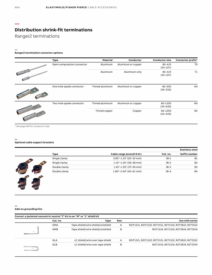
B1 copy starts here
B2 copy starts here
B3 copy starts here
A64 E L A S TI M O LD/F I S H E R PI E RCE C A B L E ACCE SSO R IE S
—Optional cable support brackets
Type Cable range (overall O.D.)
Stainless steel
Cat. no. Suffix number
Single clamp 0.80"–1.25" (20–32 mm) JB-1 B1
Single clamp 1.10"–1.50" (28–38 mm) JB-2 B2
Double clamp 1.45"–1.95" (37–50 mm) JB-3 B3
Double clamp 1.80"–2.40" (45–61 mm) JB-4 B4
—Ranger2 termination connector options
Type Material Conductor Conductor size Connector prefix*
Stem compression connector Aluminum Aluminum or copper #2–4/0 (34–107)
T0
Aluminum Aluminum only #2–4/0 (34–107)
T1
One-hole spade connector Tinned aluminum Aluminum or copper #2–500 (34–253)
H0
Two-hole spade connector Tinned aluminum Aluminum or copper #2–1250 (34–633)
N0
Tinned copper Copper #2–1250 (34–633)
N2
* See page A65 for conductor code.
—Add-on grounding kits
Convert a jacketed concentric neutral “J” kit to an “M” or “L” shield kit
Cat. no. Type Size Use with series
GMA Tape shield/wire shield/unishield A R2IT15J1, R2IT15J2, R2T15J1, R2T15J2, R2T28J2, R2T35J2
GMB Tape shield/wire shield/unishield B R2IT15J4, R2T15J4, R2T28J4, R2T35J4
GLA LC shield/wire over tape shield A R2IT15J1, R2IT15J2, R2T15J1, R2T15J2, R2T28J2, R2T35J2
GLB LC shield/wire over tape shield B R2IT15J4, R2T15J4, R2T28J4, R2T35J4
—Distribution shrink-fit terminationsRanger2 terminations

A65
—Ordering information for Ranger2 terminations
Ranger2 terminations may be ordered in components or as complete kits by following the steps outlined and using the model below to develop the catalog number for your application. Contact your local ABB sales representative for special requirements.
The following diagram shows how to construct a catalog number for a Ranger2 termination.
Connector only
* To help in selecting the proper terminator, ICEA and AEIC standard dimensions for XLP and EPR cables are on pages A50 to A52.** In 28 kV, the connector type "NO" is only for insulation range 2 and 4.
Housing only
Connector option
Add a connector
Cable support bracket option
Add a cable support bracket
—Distribution shrink-fit terminationsRanger2 terminations
TypeOutdoor R2TIndoor R2IT
kV code15 kV 1525/28 kV 2835 kV 35
Cable typeConcentric neutral/jacketed concentric neutral JTape shield/wire shield/unishield MLC shield tape shield/wire over tape shield L
Step 1. Select the termination housing:Select outdoor or indoor (15 kV only) housing style ASelect applicable voltage class BSelect neutral/shield type CSelect the size based on the cable insulation diameter* D
Step 2. Select the connector:Select desired connector ESelect connector code based on conductor size and conductor type F
Step 3. Select the cable support bracket:Select cable support bracket based on the overall O.D. of the cable G
Insulation range0.64"–1.12" (16mm–28 mm) (15 kV only) 10.84"–1.38" (21mm–35 mm) (15 kV, 25 kV, 35 kV) 21.30"–2.10" (33mm–53 mm) (15 kV, 25 kV, 35 kV) 4
Connector typeUniversal aluminum barrel for Al or Cu conductor with copper wire lead #2–4/0 TOAluminum barrel for Al conductor only with copper wire lead #2–4/0 T1Aluminum 1-hole spade #2–500 kcmil HOAluminum 2-hole spade #2–1250 kcmil NOCopper 2-hole spade #2–1250 kcmil N2
Stranded or compressed (AWG or kcmil)#2 220#1 2301/0 2402/0 2503/0 2604/0 270250 280300 290350 300400 310500 330650 360750 380900 4001000 4101250 440
Compact or solid (AWG or kcmil)#2 210#1 2201/0 2302/0 2403/0 2504/0 260250 270300 280350 290400 300500 310600 330750 360900 3801000 4001250 420
Cable mounting bracket materialSize PMS0.80"–1.25" (20–32 mm) B11.10"–1.50" (28–38mm) B21.45"–1.95" (37–50 mm) B31.80"–2.40" (45–61 mm) B4
Indicates field that must be filled in to complete order. Note: Availability of selected configuration will be verified at quotation time.
EL A S TI M O L D U N D ER G R O U N D C A B L E ACCE SSO R I E S

B1 copy starts here
B2 copy starts here
B3 copy starts here
A66 E L A S TI M O LD/F I S H E R PI E RCE C A B L E ACCE SSO R IE S
—Distribution shrink-fit terminationsRanger2 terminations
Typical installation of Elastimold Ranger2 shrink-fit terminations (R2T – Outdoor and R2IT – Indoor)Warning: Refer to local code for required PPE.
—01 Train the cable into position and cut to length. Using standard practices, cut back the cable jacket, metallic shield, semi-conductive shield and cable insulation, exposing the conductor.—02 Finish preparing the metallic shield. For concentric neutral or jacketed concentric neutral cables, bend back the neutral wires and seal with mastic strips and vinyl tape. For metallic tape, drain wire, unishield or LC shield cables: install the ground braid using the constant force spring and seal with mastic strips and vinyl tape. —03 Clean the exposed conductor, install and crimp the connector.—04 Use mastic and vinyl tape to fill any gap or step between the connector and the cable insulation. Clean the cable.—05 Apply a liberal bead of silicone lubricant to the semi-con shield step.—06 Pull the loose end of the core cord until the core is even with the end of the termination housing.—07 Position the terminator onto the cable.—08 Shrink into place by unwinding the removable core. —09 Apply silicone lubricant to skirt and mastic area.—10 Fold down the skirt over the mastic to seal the cable entrance.—11 Seal the top of the terminator at the connector area with silicone tape.—12 Attach the neutral wires or optional ground braid to the system ground per local code. Install the optional cable support bracket if required.
—10
—11
—12
—09
—07
—06
—05
—01, 02, 03, 04
—08
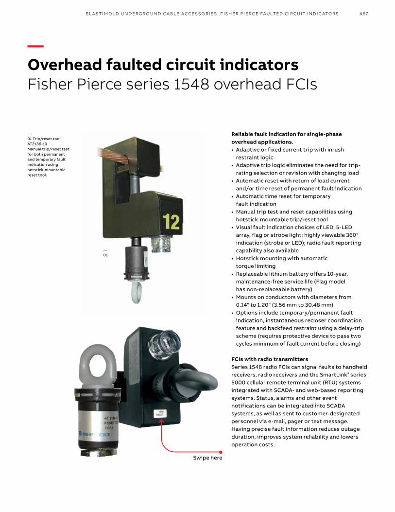
—Overhead faulted circuit indicatorsFisher Pierce series 1548 overhead FCIs
Swipe here
Reliable fault indication for single-phase overhead applications.• Adaptive or fixed current trip with inrush
restraint logic • Adaptive trip logic eliminates the need for trip-
rating selection or revision with changing load• Automatic reset with return of load current
and/or time reset of permanent fault indication• Automatic time reset for temporary
fault indication• Manual trip test and reset capabilities using
hotstick-mountable trip/reset tool• Visual fault indication choices of LED, 5-LED
array, flag or strobe light; highly viewable 360° indication (strobe or LED); radio fault reporting capability also available
• Hotstick mounting with automatic torque limiting
• Replaceable lithium battery offers 10-year, maintenance-free service life (Flag model has non-replaceable battery)
• Mounts on conductors with diameters from 0.14" to 1.20" (3.56 mm to 30.48 mm)
• Options include temporary/permanent fault indication, instantaneous recloser coordination feature and backfeed restraint using a delay-trip scheme (requires protective device to pass two cycles minimum of fault current before closing)
FCIs with radio transmittersSeries 1548 radio FCIs can signal faults to handheld receivers, radio receivers and the SmartLink® series 5000 cellular remote terminal unit (RTU) systems integrated with SCADA- and web-based reporting systems. Status, alarms and other event notifications can be integrated into SCADA systems, as well as sent to customer-designated personnel via e-mail, pager or text message. Having precise fault information reduces outage duration, improves system reliability and lowers operation costs.
—01 Trip/reset tool AT2186-10Manual trip/reset test for both permanent and temporary fault indication using hotstick-mountable reset tool.
—01
A67EL A S TIM O L D U N D ER G R O U N D C A B L E ACC E SSO R IE S , F ISH ER P IER C E FAU LTED C IR C U IT IN D I C ATO R S

B1 copy starts here
B2 copy starts here
B3 copy starts here
—Overhead faulted circuit indicatorsSpecifications
(All dimensions in inches with millimeter equivalents in parentheses)
System voltage:• Flag, strobe models: 44 kV max.• LED, radio models: 69 kV max.Continuous withstand load: 1,000 A max.Operating temperature: -40 °C to 85 °CReset time accuracy: ±10% at 23 °CCurrent reset: 3 A or 8 A min. (model specific)Fixed trip current level: 50 to 1,500 AAdaptive trip: 100 di/dt, 300 di/dtFault withstand: 25 kA for 10 cycles (per ANSI/IEEE 495-1986)Trip accuracy: ±10% at 23 °CBattery: Replaceable 10-yr. lithium cell (flag model non-replaceable)
Battery operating life at 23 °C:• Single ultra bright LED & flag: 1,000
operating hrs.• 5 red LEDs: 400 operating hrs.• Strobe: 120 operating hrs.• Radio with LED: 800 operating hrs.Temporary fault model:• 1 amber (temporary fault) LED:
1,500 operating hrs.• 4 red (permanent fault) LEDs: 400 operating hrs.Housing: Semi-conductive UV-stable polycarbonateCable diameter: 0.14" to 1.2" (3.56 mm to 30.48 mm)Certifications:• Complies with ANSI/IEEEE 495-1986
—Mechanical data
2.10(53.34)
11.80 max.
4.75(120.65)
5.95(151.13)
1.25 (31.75)
0.98 (24.892 )
2.525(64.135)
1.2 cable max.
A68 E L A S TI M O LD/F I S H E R PI E RCE C A B L E ACCE SSO R IE S
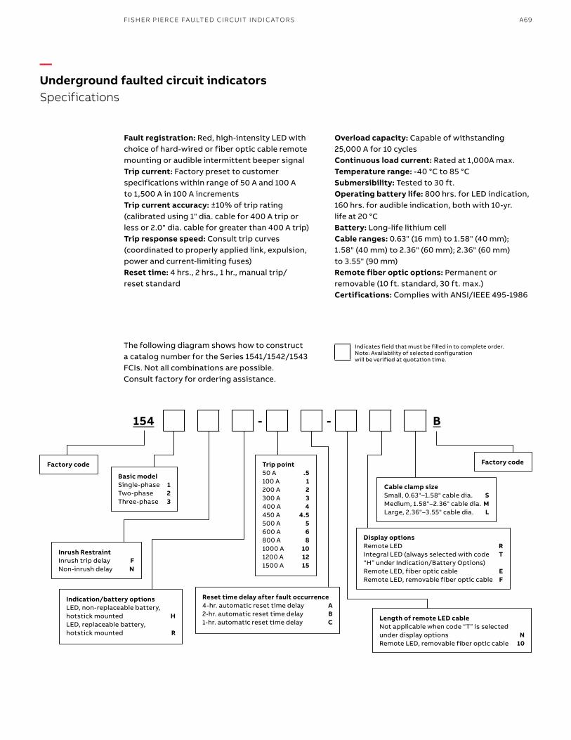
Fault registration: Red, high-intensity LED with choice of hard-wired or fiber optic cable remote mounting or audible intermittent beeper signalTrip current: Factory preset to customer specifications within range of 50 A and 100 A to 1,500 A in 100 A incrementsTrip current accuracy: ±10% of trip rating (calibrated using 1" dia. cable for 400 A trip or less or 2.0" dia. cable for greater than 400 A trip)Trip response speed: Consult trip curves (coordinated to properly applied link, expulsion, power and current-limiting fuses)Reset time: 4 hrs., 2 hrs., 1 hr., manual trip/ reset standard
Overload capacity: Capable of withstanding 25,000 A for 10 cyclesContinuous load current: Rated at 1,000A max.Temperature range: -40 °C to 85 °CSubmersibility: Tested to 30 ft.Operating battery life: 800 hrs. for LED indication, 160 hrs. for audible indication, both with 10-yr. life at 20 °CBattery: Long-life lithium cellCable ranges: 0.63" (16 mm) to 1.58" (40 mm); 1.58" (40 mm) to 2.36" (60 mm); 2.36" (60 mm) to 3.55" (90 mm)Remote fiber optic options: Permanent or removable (10 ft. standard, 30 ft. max.)Certifications: Complies with ANSI/IEEE 495-1986
The following diagram shows how to construct a catalog number for the Series 1541/1542/1543 FCIs. Not all combinations are possible. Consult factory for ordering assistance.
—Underground faulted circuit indicatorsSpecifications
Trip point50 A .5100 A 1200 A 2300 A 3400 A 4450 A 4.5500 A 5600 A 6800 A 81000 A 101200 A 121500 A 15
154 - - B
Inrush RestraintInrush trip delay FNon-inrush delay N
Indication/battery optionsLED, non-replaceable battery, hotstick mounted HLED, replaceable battery, hotstick mounted R
Reset time delay after fault occurrence4-hr. automatic reset time delay A2-hr. automatic reset time delay B1-hr. automatic reset time delay C
Cable clamp sizeSmall, 0.63"–1.58" cable dia. SMedium, 1.58"–2.36" cable dia. MLarge, 2.36"–3.55" cable dia. L
Display optionsRemote LED RIntegral LED (always selected with code T “H” under Indication/Battery Options)Remote LED, fiber optic cable ERemote LED, removable fiber optic cable F
Length of remote LED cableNot applicable when code “T” is selected under display options NRemote LED, removable fiber optic cable 10
Basic modelSingle-phase 1Two-phase 2Three-phase 3
Factory code Factory code
Indicates field that must be filled in to complete order. Note: Availability of selected configuration will be verified at quotation time.
A69FISH ER P IER CE FAU LTED CIR C U IT IN D I C ATO R S
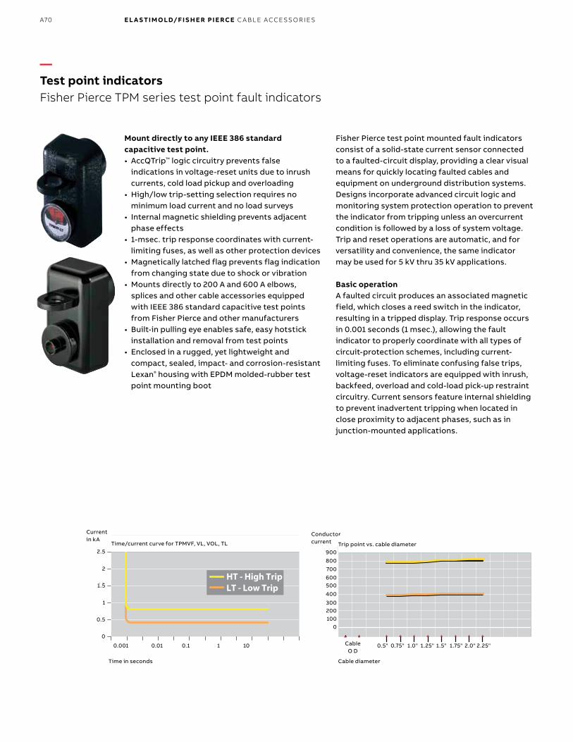
B1 copy starts here
B2 copy starts here
B3 copy starts here
—Test point indicatorsFisher Pierce TPM series test point fault indicators
Mount directly to any IEEE 386 standard capacitive test point. • AccQTrip™ logic circuitry prevents false
indications in voltage-reset units due to inrush currents, cold load pickup and overloading
• High/low trip-setting selection requires no minimum load current and no load surveys
• Internal magnetic shielding prevents adjacent phase effects
• 1-msec. trip response coordinates with current-limiting fuses, as well as other protection devices
• Magnetically latched flag prevents flag indication from changing state due to shock or vibration
• Mounts directly to 200 A and 600 A elbows, splices and other cable accessories equipped with IEEE 386 standard capacitive test points from Fisher Pierce and other manufacturers
• Built-in pulling eye enables safe, easy hotstick installation and removal from test points
• Enclosed in a rugged, yet lightweight and compact, sealed, impact- and corrosion-resistant Lexan® housing with EPDM molded-rubber test point mounting boot
Fisher Pierce test point mounted fault indicators consist of a solid-state current sensor connected to a faulted-circuit display, providing a clear visual means for quickly locating faulted cables and equipment on underground distribution systems.Designs incorporate advanced circuit logic and monitoring system protection operation to prevent the indicator from tripping unless an overcurrent condition is followed by a loss of system voltage. Trip and reset operations are automatic, and for versatility and convenience, the same indicator may be used for 5 kV thru 35 kV applications.
Basic operationA faulted circuit produces an associated magnetic field, which closes a reed switch in the indicator, resulting in a tripped display. Trip response occurs in 0.001 seconds (1 msec.), allowing the fault indicator to properly coordinate with all types of circuit-protection schemes, including current-limiting fuses. To eliminate confusing false trips, voltage-reset indicators are equipped with inrush, backfeed, overload and cold-load pick-up restraint circuitry. Current sensors feature internal shielding to prevent inadvertent tripping when located in close proximity to adjacent phases, such as in junction-mounted applications.
Time/current curve for TPMVF, VL, VOL, TL
Current in kA
Conductor current
Time in seconds Cable diameter
0.001
0
0.5
1
1.5
2
2.5
0.01 0.1 1 10 0.5" 0.75" 1.0" 1.25" 1.75" 2.0" 2.25"1.5"
1000
200300
400500600700800900
Cable O D
Trip point vs. cable diameter
A70 E L A S TI M O LD/F I S H E R PI E RCE C A B L E ACCE SSO R IE S

Cat. no. Description
TPMTL-[ _ ] Time reset with LED display (auto-resets to normal after 4 hrs.; may also be manually reset using an FTT test tool)
TPMVF-[ _ ] Voltage reset with flag display (auto-resets to normal after system voltage restoration; reset requires 5 kV min. voltage with time required for reset proportional to system voltage)
TPMVL-[ _ ] Voltage reset with LED display (auto-resets to normal after system voltage restoration; reset requires 5 kV min. voltage with time required for reset proportional to system voltage)
TPMVOL-[ _ ] Voltage operated, time reset, LED display (auto-resets after 4 hrs.; longer time resets available upon request)
Cat. no. suffix Description
-LT For 200 A. All fused taps use LOW trip rating. For URD applications, use LOW trip rating.
-HT For 600A. For URD applications, use HIGH trip rating.
Note: For overhead bulk feeder applications, use HIGH or LOW trip ratings (whichever is greater than the minimum pickup setting of the related protection device). AccQTrip and AccQClamp™ are trademarks of Quality Indications, Inc.
Pulling eye for hotstick installation and removal
Faulted circuit display
Test point
Test point mounting plug
377⁄88 (98)
111⁄88 (29)
133⁄88 (35)
211⁄44 (57)
311⁄44 (83)
—Test point indicatorsMechanical data
—Fisher Pierce® TPM series test point fault indicators
Dimensions
(All dimensions in inches with millimeter equivalents in parentheses)
A71FISH ER P IER CE FAU LTED CIR C U IT IN D I C ATO R S
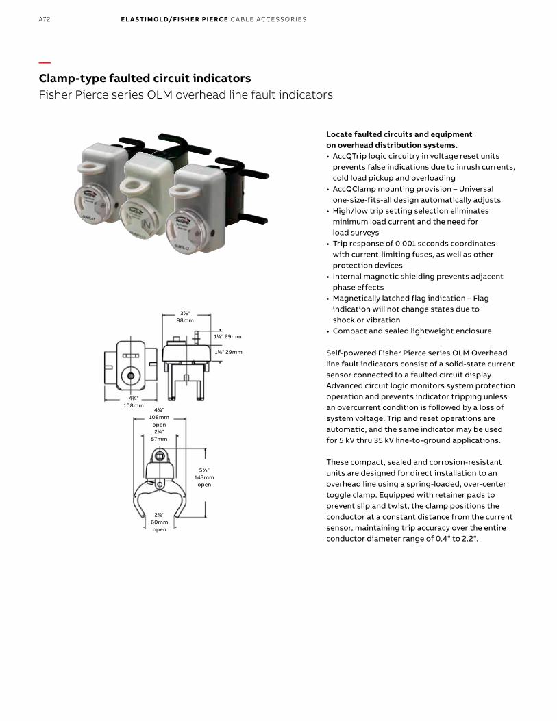
B1 copy starts here
B2 copy starts here
B3 copy starts here Locate faulted circuits and equipment on overhead distribution systems. • AccQTrip logic circuitry in voltage reset units
prevents false indications due to inrush currents, cold load pickup and overloading
• AccQClamp mounting provision – Universal one-size-fits-all design automatically adjusts
• High/low trip setting selection eliminates minimum load current and the need for load surveys
• Trip response of 0.001 seconds coordinates with current-limiting fuses, as well as other protection devices
• Internal magnetic shielding prevents adjacent phase effects
• Magnetically latched flag indication – Flag indication will not change states due to shock or vibration
• Compact and sealed lightweight enclosure
Self-powered Fisher Pierce series OLM Overhead line fault indicators consist of a solid-state current sensor connected to a faulted circuit display. Advanced circuit logic monitors system protection operation and prevents indicator tripping unless an overcurrent condition is followed by a loss of system voltage. Trip and reset operations are automatic, and the same indicator may be used for 5 kV thru 35 kV line-to-ground applications.
These compact, sealed and corrosion-resistant units are designed for direct installation to an overhead line using a spring-loaded, over-center toggle clamp. Equipped with retainer pads to prevent slip and twist, the clamp positions the conductor at a constant distance from the current sensor, maintaining trip accuracy over the entire conductor diameter range of 0.4" to 2.2".
411⁄44"108mm
open211⁄44"
57mm
555⁄88"143mm
open
233⁄88"60mmopen
377⁄88" 98mm
411⁄44" 108mm
111⁄88" 29mm
111⁄88" 29mm
—Clamp-type faulted circuit indicatorsFisher Pierce series OLM overhead line fault indicators
A72 E L A S TI M O LD/F I S H E R PI E RCE C A B L E ACCE SSO R IE S

Cable diameter
Conductor current
0.5" 0.75" 1.0" 1.25" 1.75" 2.0"2.25"1.5"
0100200300400500600700800900
Cable O. D.
Trip point vs. cable diameter
Time/current curve for OLMVF, VL, VOL, TL
Time in seconds
Current in kA
0.0010
0.5
1
1.5
2
2.5
0.01 0.1 1 10
—Clamp-type faulted circuit indicatorsBasic operation
Basic operationA faulted circuit produces a magnetic field, which closes a reed switch in the indicator and causes a tripped display. A trip response time of 0.001 seconds enables the indicator to properly coordinate with all circuit-protection schemes, including current-limiting fuses.
To eliminate confusing false trips, indicators feature inrush, overload and cold-load pick-up restraint circuitry as standard. Internal shielding of current sensors prevents inadvertent tripping when in close proximity to adjacent phases.
A73FISH ER P IER CE FAU LTED CIR C U IT IN D I C ATO R S
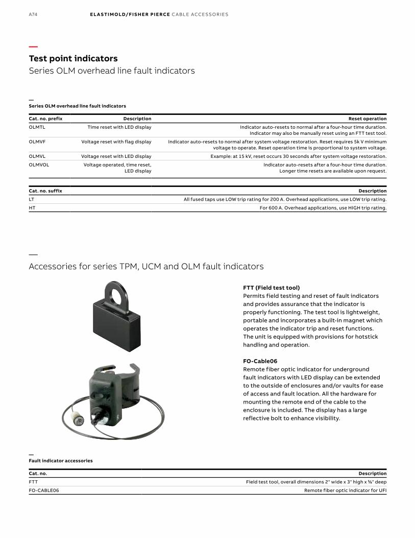
B1 copy starts here
B2 copy starts here
B3 copy starts here
—Test point indicatorsSeries OLM overhead line fault indicators
—Accessories for series TPM, UCM and OLM fault indicators
—Series OLM overhead line fault indicators
—Fault indicator accessories
Cat. no. prefix Description Reset operation
OLMTL Time reset with LED display Indicator auto-resets to normal after a four-hour time duration. Indicator may also be manually reset using an FTT test tool.
OLMVF Voltage reset with flag display Indicator auto-resets to normal after system voltage restoration. Reset requires 5k V minimum voltage to operate. Reset operation time is proportional to system voltage.
OLMVL Voltage reset with LED display Example: at 15 kV, reset occurs 30 seconds after system voltage restoration.
OLMVOL Voltage operated, time reset, LED display
Indicator auto-resets after a four-hour time duration. Longer time resets are available upon request.
Cat. no. suffix Description
LT All fused taps use LOW trip rating for 200 A. Overhead applications, use LOW trip rating.
HT For 600 A. Overhead applications, use HIGH trip rating.
Cat. no. Description
FTT Field test tool, overall dimensions 2" wide x 3" high x 55⁄88" deep
FO-CABLE06 Remote fiber optic indicator for UFI
FTT (Field test tool)Permits field testing and reset of fault indicators and provides assurance that the indicator is properly functioning. The test tool is lightweight, portable and incorporates a built-in magnet which operates the indicator trip and reset functions. The unit is equipped with provisions for hotstick handling and operation.
FO-Cable06Remote fiber optic indicator for underground fault indicators with LED display can be extended to the outside of enclosures and/or vaults for ease of access and fault location. All the hardware for mounting the remote end of the cable to the enclosure is included. The display has a large reflective bolt to enhance visibility.
A74 E L A S TI M O LD/F I S H E R PI E RCE C A B L E ACCE SSO R IE S

Test point
Test point mounting plug
Flashing neon light indicates energized status
Pulling eye for hotstick installation and removal
EPDM molded rubber housing
—Test point indicatorsV2 Voltage indicator
Easy way to visually determine the energized status of underground distribution circuits.• Single model supports applications from
5 kV to 35 kV• Flash rate per minute indicates system voltage
(see chart on following page)• Mounts to 200 A and 600 A elbows, splices and
other cable accessory components equipped with IEEE 386 capacitive test points from Fisher Pierce or other manufacturers
• Molded EPDM rubber housing for shielded, sealed and corrosion-resistant construction
• Built-in pulling eye enables safe, easy hotstick installation and removal from test point
• 20-year neon bulb yields long, maintenance-free service life
• Easily tested for confirmation of proper operation with the V2-TB voltage indicator test box
The V2 voltage indicator consists of a self-powered voltage sensor connected to a neon light that flashes when energized. Simply plug it into any IEEE 836 standard capacitive test point to determine the energized status of underground distribution circuits. Because the flash rate is proportional to the phase-to-phase system voltage, as indicated in the chart, one V2 model supports a wide range of applications — from 5 to 35 kV.
A75FISH ER P IER CE FAU LTED CIR C U IT IN D I C ATO R S

B1 copy starts here
B2 copy starts here
B3 copy starts here
33⁄88(10) 133⁄44
(44)
311⁄44(44)2
(51)
(All dimensions in inches with millimeter equivalents in parentheses)
Cat. no. Description
V2 Voltage indicator with neon display
V2-TB Voltage indicator test box
Voltage (kV) Flash rate
5 20
10 40
15 70
20 100
Voltage (kV) Flash rate
25 140
30 160
35 180
V2-TB test box for easy field testing of V2 voltage indicators.If the V2 neon voltage indicator indicates a power failure in an underground distribution circuit, you’ll want to ensure that it’s actually the circuit that’s failed and not the V2 itself. For fast, simple assurance, field test the V2 with the compact, portable V2-TB voltage indicator test box, powered by replaceable C batteries.
—Test point indicatorsMechanical data
—V2 voltage indicator – Test point mounted
A76 E L A S TI M O LD/F I S H E R PI E RCE C A B L E ACCE SSO R IE S

A77
Available with 600 A one-piece bushings or 200 A wells on either/both terminals.
(4) Mounting holes, 55⁄88" dia. x 77⁄88" (16 x 22 mm) (4) Mounting holes, 55⁄88" dia. x 77⁄88" (16 x 22 mm)
41⁄16" (103 mm)
Open Closed
121⁄2" (318 mm)
67⁄16" (164 mm)
51⁄2" (140 mm)
137⁄16" (341 mm)
23 25⁄32" (604 mm)
815⁄16" (227 mm)
85⁄32" (207 mm)
615⁄64" (176 mm)
43°
615⁄64" (176 mm)
121⁄2" (318 mm)
51⁄2" (140 mm)
61⁄16" (154 mm)
135⁄64" (39 mm)
Open Closed
137⁄16" (341 mm)
10 5⁄32" (258 mm)
25 27⁄32" (656 mm)
43°
8 1⁄32" (204 mm) 6 51⁄64"
(173 mm)
—Underground distribution switchgearMolded vacuum switches and fault interrupters
Single-phase switches approximate weight: 30 lbs.
MVS molded vaccum switchesSpring-energy, load-switching devices that make, carry and interrupt load currents through 600 A on 5 to 38 kV distribution systems.
MVS molded vacuum switches include molded-in elbow connection interfaces and spring-energy mechanisms. Available in both single- and three-phase models, units are manually operated with a hotstick. Motor operator, SCADA and auto-transfer control options are available.
• EPDM molded rubber insulation — MVSs are fully sealed and submersible.
• Vacuum switching and vacuum — Interruption Components are maintenance-free and require no gas or oil.
• Compact and lightweight — Small footprint enables MVSs to fit in tight padmount, subsurface, vault or riser pole installations.
FISH ER P I ER CE FAU LTED CI R C U IT I N D I C ATO R S , EL A S TI M O L D U N D ER G R O U N D D IS TR I B U TI O N S W ITCH G E A R
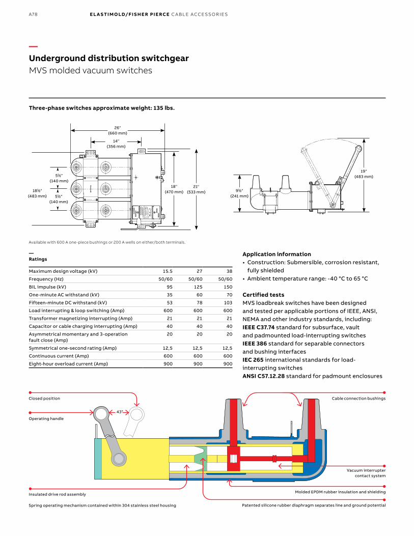
B1 copy starts here
B2 copy starts here
B3 copy starts here
A78 E L A S TI M O LD/F I S H E R PI E RCE C A B L E ACCE SSO R IE S
19"(483 mm)
911⁄22"(241 mm)
Available with 600 A one-piece bushings or 200 A wells on either/both terminals.
1811⁄22"(483 mm)
26"(660 mm)
14"(356 mm)
21"(533 mm)
18"(470 mm)
511⁄22"(140 mm)
511⁄22"(140 mm)
Three-phase switches approximate weight: 135 lbs.
—Underground distribution switchgearMVS molded vacuum switches
—Ratings
Maximum design voltage (kV) 15.5 27 38
Frequency (Hz) 50/60 50/60 50/60
BIL impulse (kV) 95 125 150
One-minute AC withstand (kV) 35 60 70
Fifteen-minute DC withstand (kV) 53 78 103
Load interrupting & loop switching (Amp) 600 600 600
Transformer magnetizing interrupting (Amp) 21 21 21
Capacitor or cable charging interrupting (Amp) 40 40 40
Asymmetrical momentary and 3-operation fault close (Amp)
20 20 20
Symmetrical one-second rating (Amp) 12,5 12,5 12,5
Continuous current (Amp) 600 600 600
Eight-hour overload current (Amp) 900 900 900
Application information• Construction: Submersible, corrosion resistant,
fully shielded• Ambient temperature range: -40 °C to 65 °C
Certified testsMVS loadbreak switches have been designed and tested per applicable portions of IEEE, ANSI, NEMA and other industry standards, including:IEEE C37.74 standard for subsurface, vault and padmounted load-interrupting switchesIEEE 386 standard for separable connectors and bushing interfacesIEC 265 international standards for load-interrupting switchesANSI C57.12.28 standard for padmount enclosures
Molded EPDM rubber insulation and shielding
Closed position
Vacuum interrupter contact system
Cable connection bushings
Operating handle
Insulated drive rod assembly
Spring operating mechanism contained within 304 stainless steel housing Patented silicone rubber diaphragm separates line and ground potential
43°

A79
Make, carry and automatically interrupt currents through 25,000 A symmetrical on 5–38 kV distribution systems. • Vacuum interrupters, programmable, electronic,
self-powered controls and EPDM rubber insulation provide compact, lightweight and submersible overcurrent protection
• Field programmable with a wide range of time-current characteristic (TCC) curves and trip settings
• TCC curves provide predictable tripping for ease of coordination with upstream and/or downstream protective devices
• Control monitors the circuit condition – when the programmed parameters are exceeded, a signal is sent to the tripping mechanism
• Available motor operators and controls enable radial feeders or loops to be reconfigured, either manually or via SCADA
—Underground distribution switchgearMVI molded vacuum fault interrupters
MVI molded vacuum fault Interrupters include molded-in elbow connection interfaces and trip-free mechanisms. They are available in single- and three-phase models.
Application informationConstruction: submersible, corrosion resistant, fully shieldedOperating temperature range: -40 °C to 65 °C
For dimensions, see page A81.
EL A S TI M O L D U N D ER G R O U N D D IS TR I B U TI O N S W ITCH G E A R
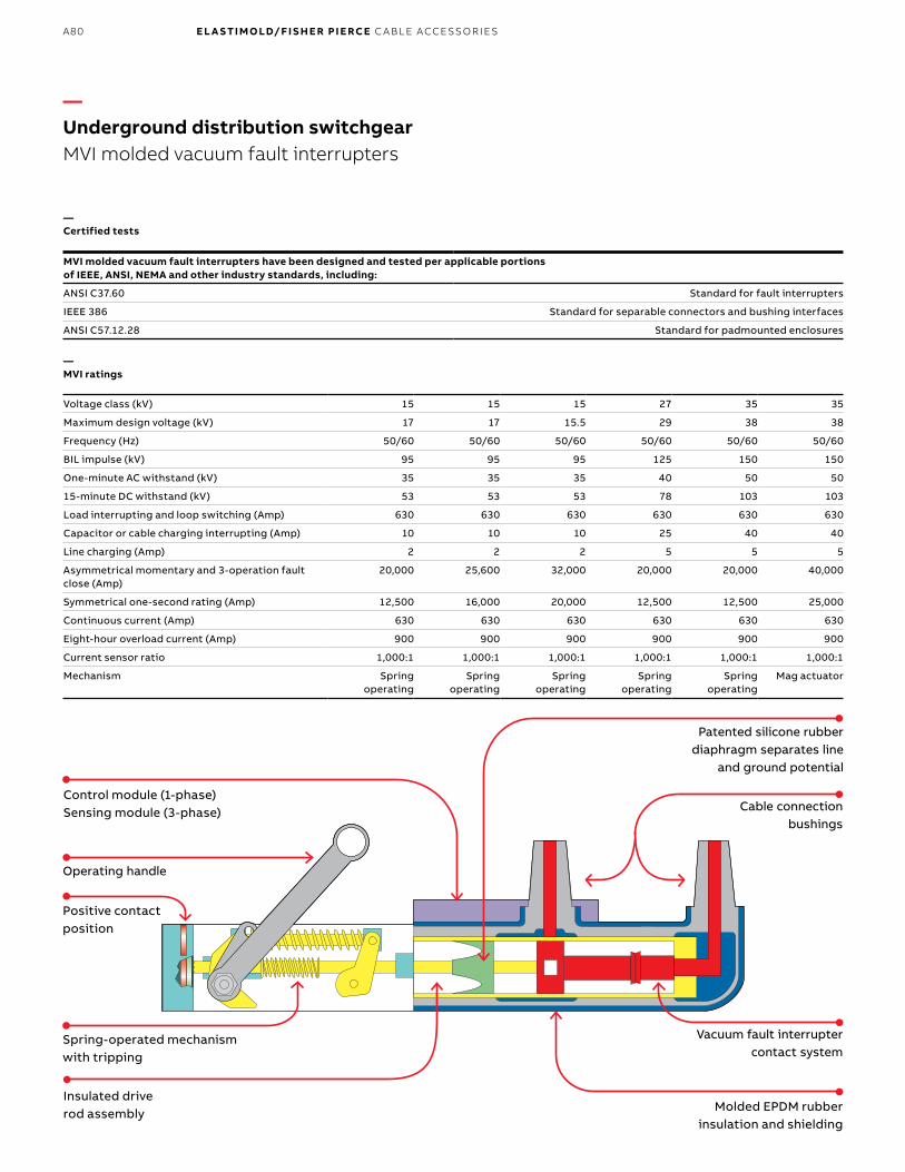
B1 copy starts here
B2 copy starts here
B3 copy starts here
A80 E L A S TI M O LD/F I S H E R PI E RCE C A B L E ACCE SSO R IE S
—Underground distribution switchgearMVI molded vacuum fault interrupters
Spring-operated mechanism with tripping
Cable connection bushings
Vacuum fault interrupter contact system
Molded EPDM rubber insulation and shielding
Positive contact position
Operating handle
Patented silicone rubber diaphragm separates line
and ground potential
Insulated drive rod assembly
Control module (1-phase) Sensing module (3-phase)
MVI molded vacuum fault interrupters have been designed and tested per applicable portions of IEEE, ANSI, NEMA and other industry standards, including:
ANSI C37.60 Standard for fault interrupters
IEEE 386 Standard for separable connectors and bushing interfaces
ANSI C57.12.28 Standard for padmounted enclosures
Voltage class (kV) 15 15 15 27 35 35
Maximum design voltage (kV) 17 17 15.5 29 38 38
Frequency (Hz) 50/60 50/60 50/60 50/60 50/60 50/60
BIL impulse (kV) 95 95 95 125 150 150
One-minute AC withstand (kV) 35 35 35 40 50 50
15-minute DC withstand (kV) 53 53 53 78 103 103
Load interrupting and loop switching (Amp) 630 630 630 630 630 630
Capacitor or cable charging interrupting (Amp) 10 10 10 25 40 40
Line charging (Amp) 2 2 2 5 5 5
Asymmetrical momentary and 3-operation fault close (Amp)
20,000 25,600 32,000 20,000 20,000 40,000
Symmetrical one-second rating (Amp) 12,500 16,000 20,000 12,500 12,500 25,000
Continuous current (Amp) 630 630 630 630 630 630
Eight-hour overload current (Amp) 900 900 900 900 900 900
Current sensor ratio 1,000:1 1,000:1 1,000:1 1,000:1 1,000:1 1,000:1
Mechanism Spring operating
Spring operating
Spring operating
Spring operating
Spring operating
Mag actuator
—Certified tests
—MVI ratings
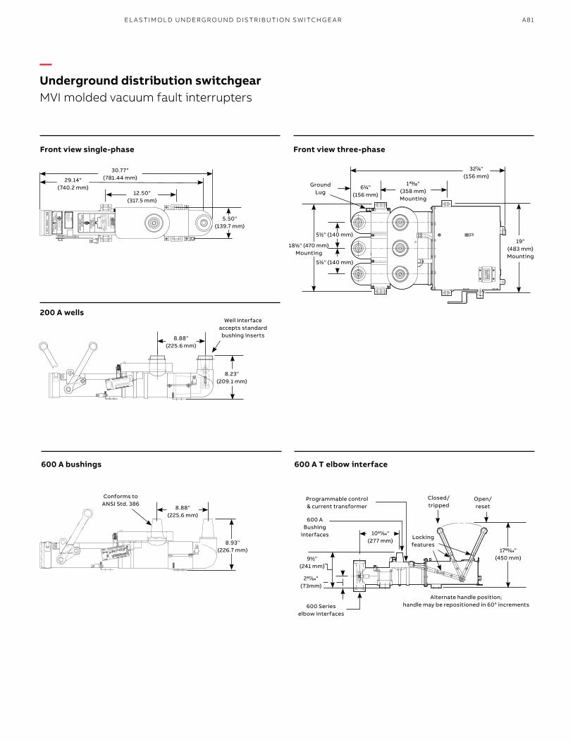
A81EL A S TI M O L D U N D ER G R O U N D D IS TR I B U TI O N S W ITCH G E A R
—Underground distribution switchgearMVI molded vacuum fault interrupters
8.88" (225.6 mm)
Well interface accepts standard bushing inserts
8.23"(209.1 mm)
Conforms to ANSI Std. 386
611⁄44" (156 mm)
Ground Lug
Open/ reset
Closed/ tripped
600 A Bushing
interfaces
911⁄22" (241 mm)
5.50" (139.7 mm)
30.77"(781.44 mm)29.14"
(740.2 mm)12.50"
(317.5 mm)
8.88" (225.6 mm)
8.93" (226.7 mm)
19"(483 mm) Mounting
3277⁄88" (156 mm)
1811⁄22" (470 mm) Mounting
14343⁄3232" (358 mm) Mounting
174545⁄6464" (450 mm)
105757⁄6464" (277 mm)
511⁄22" (140 mm)
Locking features
Alternate handle position;handle may be repositioned in 60° increments
511⁄22" (140 mm)
600 Series elbow interfaces
25757⁄6464" (73mm)
Programmable control & current transformer
600 A T elbow interface600 A bushings
Front view three-phaseFront view single-phase
200 A wells
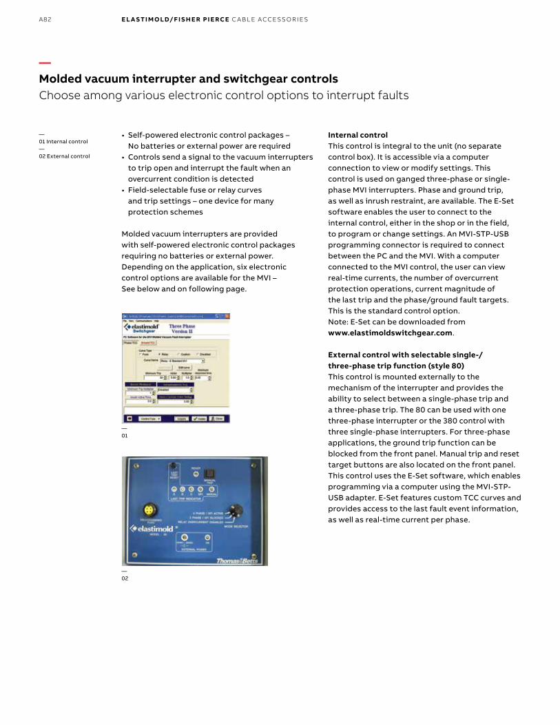
B1 copy starts here
B2 copy starts here
B3 copy starts here
A82 E L A S TI M O LD/F I S H E R PI E RCE C A B L E ACCE SSO R IE S
• Self-powered electronic control packages – No batteries or external power are required
• Controls send a signal to the vacuum interrupters to trip open and interrupt the fault when an overcurrent condition is detected
• Field-selectable fuse or relay curves and trip settings – one device for many protection schemes
Molded vacuum interrupters are provided with self-powered electronic control packages requiring no batteries or external power. Depending on the application, six electronic control options are available for the MVI – See below and on following page.
—01 Internal control—02 External control
—01
—02
—Molded vacuum interrupter and switchgear controlsChoose among various electronic control options to interrupt faults
Internal controlThis control is integral to the unit (no separate control box). It is accessible via a computer connection to view or modify settings. This control is used on ganged three-phase or single- phase MVI interrupters. Phase and ground trip, as well as inrush restraint, are available. The E-Set software enables the user to connect to the internal control, either in the shop or in the field, to program or change settings. An MVI-STP-USB programming connector is required to connect between the PC and the MVI. With a computer connected to the MVI control, the user can view real-time currents, the number of overcurrent protection operations, current magnitude of the last trip and the phase/ground fault targets. This is the standard control option.Note: E-Set can be downloaded from www.elastimoldswitchgear.com.
External control with selectable single-/ three-phase trip function (style 80)This control is mounted externally to the mechanism of the interrupter and provides the ability to select between a single-phase trip and a three-phase trip. The 80 can be used with one three-phase interrupter or the 380 control with three single-phase interrupters. For three-phase applications, the ground trip function can be blocked from the front panel. Manual trip and reset target buttons are also located on the front panel. This control uses the E-Set software, which enables programming via a computer using the MVI-STP-USB adapter. E-Set features custom TCC curves and provides access to the last fault event information, as well as real-time current per phase.

A83EL A S TI M O L D U N D ER G R O U N D D IS TR I B U TI O N S W ITCH G E A R
Curve no. Curve
reference no. Curve type
Relay curves (minimum trip 30–600 A)
01 MVI-TCC-01 E slow
02 MVI-TCC-02 E standard
03 MVI-TCC-03 Oil fuse cutout
04 MVI-TCC-04 K
05 MVI-TCC-05 Kearney QA
06 MVI-TCC-06 Cooper EF
07 MVI-TCC-07 Cooper NX-C
08 MVI-TCC-08 CO-11-1
09 MVI-TCC-09 CO-11-2
10 MVI-TCC-10 T
11 MVI-TCC-11 CO-9-1
12 MVI-TCC-12 CO-9-2
13 MVI-TCC-13 Cooper 280ARX
14 MVI-TCC-14 F
16 MVI-TCC-16 Kearney KS
17 MVI-TCC-17 GE relay
18–23 MVI-TCC-18–23 CO-8-1–CO-8-6
24–27 MVI-TCC-24–27 CO-9-3–CO-9-6
28–31 MVI-TCC-28–31 CO-11-3–CO-11-6
Fuse curves (minimum trip 10–200 A)
54 MVI-TCC-54 E slow
55 MVI-TCC-55 E standard
56 MVI-TCC-56 Oil fuse cutout
57 MVI-TCC-57 K
58 MVI-TCC-58 Kearney QA
59 MVI-TCC-59 Cooper NX-C
60 MVI-TCC-60 T
Smart grid readyWorks with the industry-leading protection and automation controls• SEL automation controls from Schweitzer
Engineering Laboratories
—Molded vacuum interrupter and switchgear controls
—01 SEL-751AFeeder protection—02 SEL-451 Automation and auto-transfer controls (standard and fast transfer options)
—01
—02
—Elastimold 80 control time current curves (TCCs)

B1 copy starts here
B2 copy starts here
B3 copy starts here
A84 E L A S TI M O LD/F I S H E R PI E RCE C A B L E ACCE SSO R IE S
Suffix Description
80 External 80 control with selectable single-/three-phase trip function (to be used on ganged three-phase MVI mechanism)
380 External 80 control with selectable single-/three-phase trip function (to be used on three single-phase mechanisms)
MO120A 120 V AC motor controller for MVS3 or MVI3 units (includes standard 30-ft. cable)
MO12D 12–24 V DC motor controller for MVS3 or MVI3 units (includes standard 30-ft. cable)
PS Parking stand for MVS or MVI (between bushings for single- or three-phase units)
MPS Parking stand for MVS3, MVI3 or RMVI3 on mechanism cover
PS6 Double parking stand for MVS3, MVI3 or RMVI3 (between bushings and on mechanism cover)
BT Bail tab plate installed for three-phase units only
P Customer settings to be programmed at the factory
NOTE: Leave suffix blank for internal (self-contained) control.
The following diagram shows how to construct a catalog number for molded vacuum switches and interrupters.
—1) For riser pole option, specify where to locate air bushings.2) Wind farm option is only for 38 kV, 600 A interrupter.3) Air bushings can only be specified for 600 A.
M V 2 1 Suffix
Indicates field that must be filled in to complete order.
—Ordering informationElastimold MVS and MVI units
Example: The catalog number for a molded vacuum interrupter on a three-phase, 27 kV system, with 600 A terminal and parking stands between bushings is MVI3212766PS.
Switch typeRiser pole1 R Network N Wind farm2 W Subsurface Blank
Interface600 A T body E End interface R rotated 180° Air bushings AB (for riser pole)3
Main interface200 A bushing well 2 600 A bushing 6
Interface600 A T body E End interface R rotated 180° Air bushings AB (for riser pole)3
Voltage class (Sym/asym kA)15.0 kV 15 (12.5/20) 15.0 kV (20/32) 15A interrupter only15.0 kV (16/25.6) 15B interrupter only 27.0 kV 27 (12.5/20) 38.0 kV 38 (12.5/20) 38.0 kV (25/40) 38B interrupter only
DeviceSwitch S Interrupter I
PhasesSingle-phase 1 Three-phase 3
End interface200 A 2 bushing well 600 A 6 bushing
—Controls and accessories

A85EL A S TI M O L D U N D ER G R O U N D D IS TR I B U TI O N S W ITCH G E A R
—Accessories (order separately)
Cat. no. Description
MVI-STP-USB Adapter for connection between MVI units with internal control and a computer for programming/viewing settings
MV1PMB Pole-mounting bracket for 1-phase units only
MV3PMB Pole-mounting bracket for 3-phase units only
MV3HPMB Horizontal pole-mounting bracket for 3-phase units only
MV13PMB Pole-mounting bracket for three 1-phase units only
35AL-11 Connector bare wire type 3⁄4"–16 rod for riser pole units; qty. Of 1 needed per phase
35AL-12 Connector 2-hole spade type 3⁄4"–16 rod for riser pole units; qty. Of 1 needed per phase
Notes: Weights and dimensions are approximate.X = 6 for 600 A or 2 for 200 A or 6E for 600 A T interface.Y = 10, 20, 30, 80 for different electronic controls.Leave blank for internal (self-contained) control.Accessories should be added as suffix to the main catalog number unless otherwise noted.Other configurations are available. Please consult your local representative on configurations not shown here.The 3-phase vacuum interrupters are motor-ready.
—Elastimold MVI molded vacuum interrupters***
Cat. no. DescriptionWidth in.
(mm)Height in.
(mm)Depth in.
(mm)Weight lb.
(kg) Diagram
Riser pole (three-phase installations only)
RMVI3-21-15-6ABX-YY 15 kV 2-way 3-phase interrupter with air bushings on top terminals 30 (762) 45 (1,143) 25 (635) 150 (68)
RMVI3-21-27-6ABX-YY 25 kV 2-way 3-phase interrupter with air bushings on top terminals 30 (762) 45 (1,143) 25 (635) 150 (68)
RMVI3-21-38-6ABX-YY 38 kV 2-way 3-phase interrupter with air bushings on top terminals 30 (762) 45 (1,143) 25 (635) 150 (68)
RMVI1-21-15-6ABX-3YY 15 kV 2-way 3-phase interrupter with air bushings on top terminals, 1-phase trip selectable
30 (762) 45 (1,143) 25 (635) 150 (68)
RMVI1-21-27-6ABX-3YY 27 kV 2-way 3-phase interrupter with air bushings on top terminals, 1-phase trip selectable
30 (762) 45 (1,143) 25 (635) 150 (68)
RMVI1-21-38-6ABX-3YY 38 kV 2-way 3-phase interrupter with air bushings on top terminals, 1-phase trip selectable
30 (762) 45 (1,143) 25 (635) 150 (68)
Subsurface single-phase vacuum switches
MVI1-21-15-XX 15 kV 2-way 1-phase interrupter 6 (152) 31 (787) 9 (229) 45 (20)
MVI1-21-15-6EX 15 kV 2-way 1-phase interrupter, elbow interface 6 (152) 31 (787) 11 (279) 45 (20)
MVI1-21-27-XX 27 kV 2-way 1-phase interrupter 6 (152) 31 (787) 9 (229) 45 (20)
MVI1-21-27-6EX 27 kV 2-way 1-phase interrupter, elbow interface 6 (152) 31 (787) 11 (279) 45 (20)
MVI1-21-38-XX 38 kV 2-way 1-phase interrupter 6 (152) 31 (787) 9 (229) 45 (20)
MVI1-21-38-6EX 38 kV 2-way 1-phase interrupter, elbow interface 6 (152) 31 (787) 11 (279) 45 (20)
Subsurface three-phase vacuum switches
MVI1-21-15-XX-3YY 15 kV 2-way 3-phase interrupter, 1-phase trip selectable ext. control
20 (508) 31 (787) 9 (229) 145 (66)
MVI1-21-27-XX-3YY 27 kV 2-way 3-phase interrupter, 1-phase trip selectable ext. control
20 (508) 31 (787) 9 (229) 145 (66)
MVI1-21-38-XX-3YY 38 kV 2-way 3-phase interrupter, 1-phase trip selectable ext. control
20 (508) 31 (787) 9 (229) 145 (66)
MVI3-21-15-XX-YY 15 kV 2-way 3-phase interrupter 20 (508) 33 (838) 10 (254) 145 (66)
MVI3-21-27-XX-YY 27 kV 2-way 3-phase interrupter 20 (508) 33 (838) 10 (254) 145 (66)
MVI3-21-38-XX-YY 38 kV 2-way 3-phase interrupter 20 (508) 33 (838) 10 (254) 145 (66)
*** Air bushings on top terminal.
—Underground distribution switchgearMolded vacuum switchs and fault interrupters
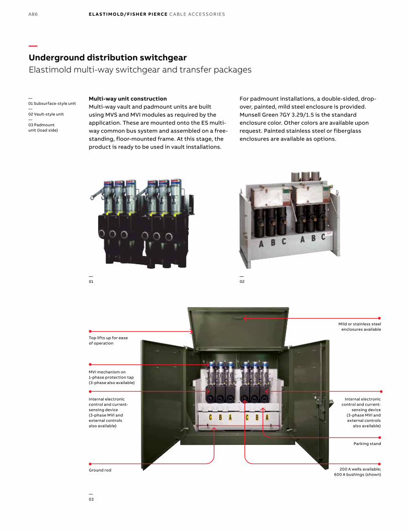
B1 copy starts here
B2 copy starts here
B3 copy starts here
A86 E L A S TI M O LD/F I S H E R PI E RCE C A B L E ACCE SSO R IE S
Multi-way unit constructionMulti-way vault and padmount units are built using MVS and MVI modules as required by the application. These are mounted onto the ES multi-way common bus system and assembled on a free-standing, floor-mounted frame. At this stage, the product is ready to be used in vault installations.
For padmount installations, a double-sided, drop-over, painted, mild steel enclosure is provided. Munsell Green 7GY 3.29/1.5 is the standard enclosure color. Other colors are available upon request. Painted stainless steel or fiberglass enclosures are available as options.
Top lifts up for easeof operation
200 A wells available; 600 A bushings (shown)
Internal electronic control and current-sensing device (3-phase MVI and external controls also available)
Ground rod
Parking stand
Mild or stainless steel enclosures available
Internal electronic control and current-
sensing device (3-phase MVI and external controls
also available)
—Underground distribution switchgearElastimold multi-way switchgear and transfer packages
—01 Subsurface-style unit—02 Vault-style unit—03 Padmount unit (load side)
—01
—02
—03
MVI mechanism on 1-phase protection tap (3-phase also available)

A87EL A S TI M O L D U N D ER G R O U N D D IS TR I B U TI O N S W ITCH G E A R
The following diagram shows how to construct a catalog number for multi-way switchgear or transfer packages.
Example: Multi-way switchgearMD3142T2P62XIXXAE000: Multi-way, double-sided padmount, 3-phase, 15.0 kV, 95 kV BIL, 12.5 kA interrupting capability, 4-ways, 2 source ways, source component: three-phase molded vacuum switches (MVS3), 2 load ways, load component: three-phase molded vacuum interrupter (MVI3), 600 A bushing interfaces (source), 200 A bushing well interfaces (load), source control: none, load control: Elastimold MVI internal control, PT: PT not required, enclosure: mild steel, Munsell green 7GY 3.29/1.5 and flat ground bar, English labels and instructions.
—Underground distribution switchgearElastimold multi-way switchgear and transfer packages
Example: Auto transfer switchgear with SEL control packageTD3242H2P62GHFXAE000: Automatic transfer, double-sided padmount, 3-phase, 27.0 kV, 125 kV BIL, 12.5 kA interrupting capability, 4-ways, 2 source ways, source component: three-phase molded vacuum switches (MVS3) with 12–24 V DC motor and voltage sensors, 2 load ways, load component: three-phase molded vacuum interrupter (MVI3), 600 A bushing interfaces (source), 200 A bushing well interfaces (load), source control: sel 451-5 relay, load control: SEL 751A relay, PT: two (2) 27 kV PT (13200–14400 V AC (WYE), enclosure: mild steel, Munsell green 7GY 3.29/1.5 and flat ground bar, English labels and instructions.
Indicates field that must be filled in to complete order.
Switch typeMulti-way M switchgearStandard T auto transfer – motorsFast auto F transfer – actuatorsAuto loop L restoration
Mounting styleDouble-sided D padmountSingle-sided P padmountSubsurface V (dry vault)Subsurface S (submersible external control)
Voltage class15.0 kV 127.0 kV 238.0 kV 3Subsurface S (submersible external control)
Number of ways2-way 23-way 34-way 45-way 56-way 6
Number of source ways1-way 12-way 23-way 34-way 45-way 56-way 6
Number of load ways (no. of ways – no. source ways)None X1-way 12-way 23-way 34-way 45-way 5
Source ways interface200 A 2 bushing well source600 A 6 bushing well source
Source way componentsSolid tap/direct bus connection (600 A or 200 A) B3-phase MVS switch T3-phase MVS switch with motor U3-phase MVS switch with motor & voltage sensors H3-phase MVS switch with magnetic actuator M & voltage sensors (fast transfer units only)3-phase MVI fault interrupter P3-phase MVI fault interrupter with motor R3-phase MVI fault interrupter with motor & voltage sensors G
Load way components None XSolid tap/direct bus connection B (600 A or 200 A)1-phase MVS switch S3-phase MVS switch T3-phase MVS switch with motor U3-phase MVS switch with motor H & voltage sensors1-phase MVI fault interrupter J3-phase MVI fault interrupter P3-phase MVI fault interrupter R with motor3-phase MVI fault interrupter G with motor & voltage sensors
Phases3-phase 3
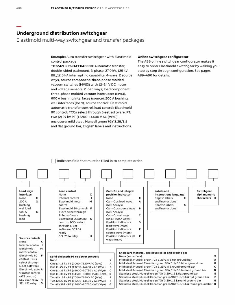
B1 copy starts here
B2 copy starts here
B3 copy starts here
A88 E L A S TI M O LD/F I S H E R PI E RCE C A B L E ACCE SSO R IE S
Example: Auto transfer switchgear with Elastimold control packageTD3242H2P62AFFXAE000: Automatic transfer, double-sided padmount, 3-phase, 27.0 kV, 125 kV BIL, 12.5 kA interrupting capability, 4-ways, 2 source ways, source component: three-phase molded vacuum switches (MVS3) with 12–24 V DC motor and voltage sensors, 2 load ways, load component: three-phase molded vacuum interrupter (MVI3), 600 A bushing interfaces (source), 200 A bushing well interfaces (load), source control: Elastimold automatic transfer control, load control: Elastimold 80 control: TCCs select through E-set software, PT: two (2) 27 kV PT (13200–14400 V AC (WYE), enclosure: mild steel, Munsell green 7GY 3.29/1.5 and flat ground bar, English labels and instructions.
Online switchgear configuratorThe ABB online switchgear configurator makes it easy to order Elastimold switchgear by walking you step by step through configuration. See pages A89–A90 for details.
—Underground distribution switchgearElastimold multi-way switchgear and transfer packages
Load ways interfaceNone X200 A 2 bushing well load600 A 6 bushing load
Source controlsNone XInternal control IElastimold M motor controlElastimold 80 F control: TCCs select through E-Set softwareElastimold auto A transfer control (ATS control)SEL 751A relay HSEL 451 relay G
Load controlNone XInternal control IElastimold motor M controlElastimold 80 control: F TCC's select through E-Set softwareElastimold SCADA 80 S control: TCCs select through E-Set software, SCADA readySEL 751A relay H
Labels and instructions languageEnglish labels E and instructionsSpanish labels S and instructions
Switchgear alphanumeric characters 0
Cam-Op and integral position indicatorNone XCam-Ops load ways A (600 A ways)Cam-Ops source ways B (600 A ways)Cam-Ops all ways C (on all 600 A ways)Position indicators D load ways (m&m)Position indicators E source ways (m&m)Position indicators all F ways (m&m)
Solid dielectric PT to power controlsNone XOne (1) 15 kV PT (7000–7620 V AC (Wye) AOne (1) 27 kV PT (13200–14400 V AC (Wye) BOne (1) 38 kV PT (19000–20750 V AC (Wye) COne (1) 38 kV PT (34500–38000 V AC (Delta) DTwo (2) 15 kV PT (7000–7620 V AC (Wye) ETwo (2) 27 kV PT (13200–14400 V AC (Wye) F Two (2) 38 kV PT (19000–20750 V AC (Wye) G
Enclosure material, enclosure color and ground barNone (subsuface) XMild steel, Munsell green 7GY 3.29/1.5 & flat ground bar AMild steel, Munsell Canadian green 9GY 1.5/2.6 & flat ground bar BMild steel, Munsell green 7GY 3.29/1.5 & round ground bar CMild steel, Munsell Canadian green 9GY 1.5/2.6 & round ground bar DStainless steel, Munsell green 7GY 3.29/1.5 & flat ground bar EStainless steel, Munsell Canadian green 9GY 1.5/2.6 & flat ground bar FStainless steel, Munsell green 7GY 3.29/1.5 & round ground bar GStainless steel, Munsell Canadian green 9GY 1.5/2.6 & round ground bar H
Indicates field that must be filled in to complete order.
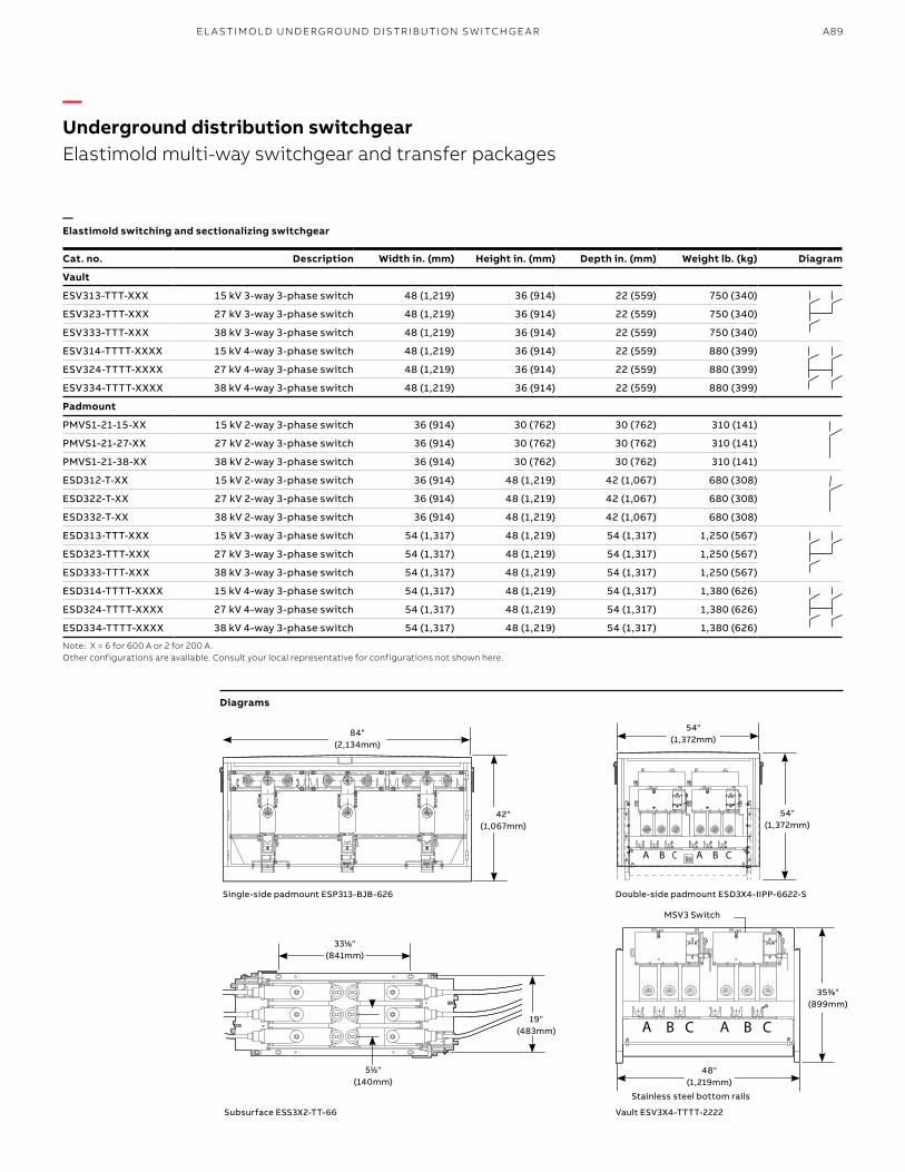
A89EL A S TI M O L D U N D ER G R O U N D D IS TR I B U TI O N S W ITCH G E A R
Single-side padmount ESP313-BJB-626 Double-side padmount ESD3X4-IIPP-6622-S
Subsurface ESS3X2-TT-66
MSV3 Switch
Stainless steel bottom rails
511⁄22"(140mm)
84"(2,134mm)
42"(1,067mm)
54"(1,372mm)
54"(1,372mm)
3311⁄88"(841mm)
19"(483mm)
3533⁄88"(899mm)
48"(1,219mm)
—Elastimold switching and sectionalizing switchgear
Cat. no. Description Width in. (mm) Height in. (mm) Depth in. (mm) Weight lb. (kg) Diagram
Vault
ESV313-TTT-XXX 15 kV 3-way 3-phase switch 48 (1,219) 36 (914) 22 (559) 750 (340)
ESV323-TTT-XXX 27 kV 3-way 3-phase switch 48 (1,219) 36 (914) 22 (559) 750 (340)
ESV333-TTT-XXX 38 kV 3-way 3-phase switch 48 (1,219) 36 (914) 22 (559) 750 (340)
ESV314-TTTT-XXXX 15 kV 4-way 3-phase switch 48 (1,219) 36 (914) 22 (559) 880 (399)
ESV324-TTTT-XXXX 27 kV 4-way 3-phase switch 48 (1,219) 36 (914) 22 (559) 880 (399)
ESV334-TTTT-XXXX 38 kV 4-way 3-phase switch 48 (1,219) 36 (914) 22 (559) 880 (399)
Padmount
PMVS1-21-15-XX 15 kV 2-way 3-phase switch 36 (914) 30 (762) 30 (762) 310 (141)
PMVS1-21-27-XX 27 kV 2-way 3-phase switch 36 (914) 30 (762) 30 (762) 310 (141)
PMVS1-21-38-XX 38 kV 2-way 3-phase switch 36 (914) 30 (762) 30 (762) 310 (141)
ESD312-T-XX 15 kV 2-way 3-phase switch 36 (914) 48 (1,219) 42 (1,067) 680 (308)
ESD322-T-XX 27 kV 2-way 3-phase switch 36 (914) 48 (1,219) 42 (1,067) 680 (308)
ESD332-T-XX 38 kV 2-way 3-phase switch 36 (914) 48 (1,219) 42 (1,067) 680 (308)
ESD313-TTT-XXX 15 kV 3-way 3-phase switch 54 (1,317) 48 (1,219) 54 (1,317) 1,250 (567)
ESD323-TTT-XXX 27 kV 3-way 3-phase switch 54 (1,317) 48 (1,219) 54 (1,317) 1,250 (567)
ESD333-TTT-XXX 38 kV 3-way 3-phase switch 54 (1,317) 48 (1,219) 54 (1,317) 1,250 (567)
ESD314-TTTT-XXXX 15 kV 4-way 3-phase switch 54 (1,317) 48 (1,219) 54 (1,317) 1,380 (626)
ESD324-TTTT-XXXX 27 kV 4-way 3-phase switch 54 (1,317) 48 (1,219) 54 (1,317) 1,380 (626)
ESD334-TTTT-XXXX 38 kV 4-way 3-phase switch 54 (1,317) 48 (1,219) 54 (1,317) 1,380 (626)
Note: X = 6 for 600 A or 2 for 200 A. Other configurations are available. Consult your local representative for configurations not shown here.
Vault ESV3X4-TTTT-2222
—Underground distribution switchgearElastimold multi-way switchgear and transfer packages
Diagrams
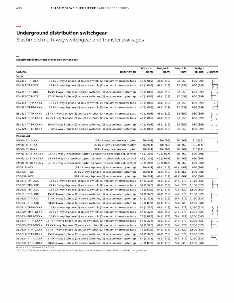
B1 copy starts here
B2 copy starts here
B3 copy starts here
A90 E L A S TI M O LD/F I S H E R PI E RCE C A B L E ACCE SSO R IE S
—Elastimold overcurrent protection switchgear
Cat. no. DescriptionWidth in.
(mm)Height in.
(mm)Depth in.
(mm)Weight lb. (kg) Diagram
Vault
ESV313-TPP-XXX 15 kV 3-way 3-phase (1) source switch, (2) vacuum interrupter taps 40 (1,016) 48 (1,219) 22 (559) 660 (299)
ESV323-TPP-XXX 27 kV 3-way 3-phase (1) source switch, (2) vacuum interrupter taps 40 (1,016) 48 (1,219) 22 (559) 660 (299)
ESV313-TTP-XXX 15 kV 3-way 3-phase (2) source switches, (1) vacuum interrupter tap 40 (1,016) 48 (1,219) 22 (559) 660 (299)
ESV323-TTP-XXX 27 kV 3-way 3-phase (2) source switches, (1) vacuum interrupter tap 40 (1,016) 48 (1,219) 22 (559) 660 (299)
ESV314-TPPP-XXXX 15 kV 4-way 3-phase (1) source switch, (3) vacuum interrupter taps 40 (1,016) 48 (1,219) 22 (559) 880 (399)
ESV324-TPPP-XXXX 27 kV 4-way 3-phase (1) source switch, (3) vacuum interrupter taps 40 (1,016) 48 (1,219) 22 (559) 880 (399)
ESV314-TTPP-XXXX 15 kV 4-way 3-phase (2) source switches, (2) vacuum interrupter taps 40 (1,016) 48 (1,219) 22 (559) 880 (399)
ESV324-TTPP-XXXX 27 kV 4-way 3-phase (2) source switches, (2) vacuum interrupter taps 40 (1,016) 48 (1,219) 22 (559) 880 (399)
ESV314-TTTP-XXXX 15 kV 4-way 3-phase (3) source switches, (1) vacuum interrupter tap 40 (1,016) 48 (1,219) 22 (559) 880 (399)
ESV324-TTTP-XXXX 27 kV 4-way 3-phase (3) source switches, (1) vacuum interrupter tap 40 (1,016) 48 (1,219) 22 (559) 880 (399)
Padmount
PMVI1-21-15-XX 15 kV 2-way 1-phase interrupter 36 (914) 30 (762) 30 (762) 310 (141)
PMVI1-21-27-XX 27 kV 2-way 1-phase interrupter 36 (914) 30 (762) 30 (762) 310 (141)
PMVI1-21-38-XX 38 kV 2-way 1-phase interrupter 36 (914) 30 (762) 30 (762) 310 (141)
PMVI1-21-15-XX-3YY 15 kV 2-way 3-phase interrupter 1-phase trip selectable ext. control 48 (1,219) 42 (1,067) 30 (762) 680 (308)
PMVI1-21-27-XX-3YY 27 kV 2-way 3-phase interrupter 1-phase trip selectable ext. control 48 (1,219) 42 (1,067) 30 (762) 680 (308)
PMVI1-21-38-XX-3YY 38 kV 2-way 3-phase interrupter 1-phase trip selectable ext. control 48 (1,219) 42 (1,067) 30 (762) 680 (308)
ESD312-P-XX 15 kV 2-way 3-phase (1) vacuum interrupter tap 36 (914) 48 (1,219) 42 (1,067) 680 (308)
ESD322-P-XX 27 kV 2-way 3-phase (1) vacuum interrupter tap 36 (914) 48 (1,219) 42 (1,067) 680 (308)
ESD332-P-XX 38 kV 2-way 3-phase (1) vacuum interrupter tap 36 (914) 48 (1,219) 42 (1,067) 680 (308)
ESD313-TPP-XXX 15 kV 3-way 3-phase (1) source switch, (2) vacuum interrupter taps 54 (1,372) 48 (1,219) 54 (1,372) 1,160 (526)
ESD323-TPP-XXX 27 kV 3-way 3-phase (1) source switch, (2) vacuum interrupter taps 54 (1,372) 48 (1,219) 54 (1,372) 1,160 (526)
ESD333-TPP-XXX 38 kV 3-way 3-phase (1) source switch, (2) vacuum interrupter taps 72 (1,829) 54 (1,372) 72 (1,829) 1,500 (680)
ESD313-TTP-XXX 15 kV 3-way 3-phase (2) source switches, (1) vacuum interrupter tap 54 (1,372) 48 (1,219) 54 (1,372) 1,160 (526)
ESD323-TTP-XXX 27 kV 3-way 3-phase (2) source switches, (1) vacuum interrupter tap 54 (1,372) 48 (1,219) 54 (1,372) 1,160 (526)
ESD333-TTP-XXX 38 kV 3-way 3-phase (2) source switches, (1) vacuum interrupter tap 72 (1,829) 54 (1,372) 72 (1,829) 1,500 (680)
ESD314-TPPP-XXXX 15 kV 4-way 3-phase (1) source switch, (3) vacuum interrupter taps 54 (1,372) 48 (1,219) 54 (1,372) 1,380 (626)
ESD324-TPPP-XXXX 27 kV 4-way 3-phase (1) source switch, (3) vacuum interrupter taps 54 (1,372) 48 (1,219) 54 (1,372) 1,380 (626)
ESD334-TPPP-XXXX 38 kV 4-way 3-phase (1) source switch, (3) vacuum interrupter taps 72 (1,829) 54 (1,372) 72 (1,829) 1,500 (680)
ESD314-TTPP-XXXX 15 kV 4-way 3-phase (2) source switches, (2) vacuum interrupter taps 54 (1,372) 48 (1,219) 54 (1,372) 1,380 (626)
ESD324-TTPP-XXXX 27 kV 4-way 3-phase (2) source switches, (2) vacuum interrupter taps 54 (1,372) 48 (1,219) 54 (1,372) 1,380 (626)
ESD334-TTPP-XXXX 38 kV 4-way 3-phase (2) source switches, (2) vacuum interrupter taps 72 (1,829) 54 (1,372) 72 (1,829) 1,500 (680)
ESD314-TTTP-XXXX 15 kV 4-way 3-phase (3) source switches, (1) vacuum interrupter tap 54 (1,372) 48 (1,219) 54 (1,372) 1,380 (626)
ESD324-TTTP-XXXX 27 kV 4-way 3-phase (3) source switches, (1) vacuum interrupter tap 54 (1,372) 48 (1,219) 54 (1,372) 1,380 (626)
ESD334-TTTP-XXXX 38 kV 4-way 3-phase (3) source switches, (1) vacuum interrupter tap 72 (1,829) 54 (1,372) 72 (1,829) 1,500 (680)
Note: X = 6 for 600 A or 2 for 200 A. YY = 10, 20, 30, 80 for different electronic controls. Consult your local representative on 38 kV multi-way configurations.
—Underground distribution switchgearElastimold multi-way switchgear and transfer packages
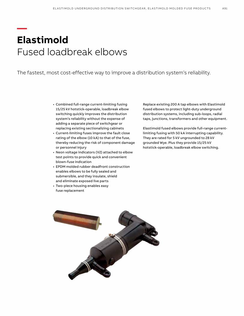
A91EL A S TI M O L D U N D ER G R O U N D D IS TR I B U TI O N S W ITCH G E A R , EL A S TI M O L D M O L D ED FUSE PR O D U C TS
• Combined full-range current-limiting fusing 15/25 kV hotstick-operable, loadbreak elbow switching quickly improves the distribution system’s reliability without the expense of adding a separate piece of switchgear or replacing existing sectionalizing cabinets
• Current-limiting fuses improve the fault close rating of the elbow (10 kA) to that of the fuse, thereby reducing the risk of component damage or personnel injury
• Neon voltage indicators (V2) attached to elbow test points to provide quick and convenient blown-fuse indication
• EPDM molded rubber deadfront construction enables elbows to be fully sealed and submersible, and they insulate, shield and eliminate exposed live parts
• Two-piece housing enables easy fuse replacement
Replace existing 200 A tap elbows with Elastimold fused elbows to protect light-duty underground distribution systems, including sub-loops, radial taps, junctions, transformers and other equipment.
Elastimold fused elbows provide full-range current-limiting fusing with 50 kA interrupting capability. They are rated for 5 kV ungrounded to 28 kV grounded Wye. Plus they provide 15/25 kV hotstick-operable, loadbreak elbow switching.
—ElastimoldFused loadbreak elbows
The fastest, most cost-effective way to improve a distribution system’s reliability.
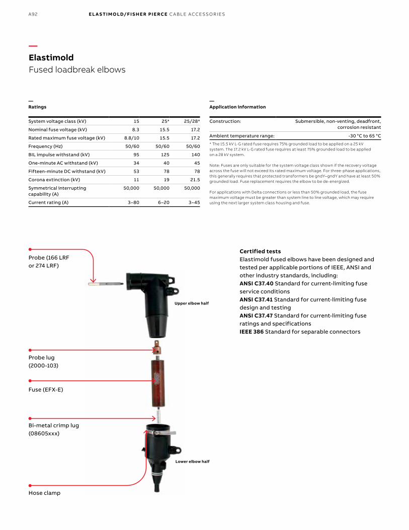
B1 copy starts here
B2 copy starts here
B3 copy starts here
A92 E L A S TI M O LD/F I S H E R PI E RCE C A B L E ACCE SSO R IE S
—Ratings
System voltage class (kV) 15 25* 25/28*
Nominal fuse voltage (kV) 8.3 15.5 17.2
Rated maximum fuse voltage (kV) 8.8/10 15.5 17.2
Frequency (Hz) 50/60 50/60 50/60
BIL impulse withstand (kV) 95 125 140
One-minute AC withstand (kV) 34 40 45
Fifteen-minute DC withstand (kV) 53 78 78
Corona extinction (kV) 11 19 21.5
Symmetrical interrupting capability (A)
50,000 50,000 50,000
Current rating (A) 3–80 6–20 3–45
—Application information
Construction: Submersible, non-venting, deadfront, corrosion resistant
Ambient temperature range: -30 °C to 65 °C
* The 15.5 kV L-G rated fuse requires 75% grounded load to be applied on a 25 kV system. The 17.2 kV L-G rated fuse requires at least 75% grounded load to be applied on a 28 kV system.
Note: Fuses are only suitable for the system voltage class shown if the recovery voltage across the fuse will not exceed its rated maximum voltage. For three-phase applications, this generally requires that protected transformers be gndY–gndY and have at least 50% grounded load. Fuse replacement requires the elbow to be de-energized. For applications with Delta connections or less than 50% grounded load, the fuse maximum voltage must be greater than system line to line voltage, which may require using the next larger system class housing and fuse.
Lower elbow half
Hose clamp
Bi-metal crimp lug(08605xxx)
Fuse (EFX-E)
Probe lug(2000-103)
Upper elbow half
Probe (166 LRF or 274 LRF)
Certified tests Elastimold fused elbows have been designed and tested per applicable portions of IEEE, ANSI and other industry standards, including: ANSI C37.40 Standard for current-limiting fuse service conditionsANSI C37.41 Standard for current-limiting fuse design and testingANSI C37.47 Standard for current-limiting fuse ratings and specificationsIEEE 386 Standard for separable connectors
—Elastimold Fused loadbreak elbows

A93EL A S TI M O L D M O L D ED FUSE PR O D U C TS
—Elastimold Fused loadbreak elbows
—Electrical characteristics of Elastimold EFX-E elbow fuses
System voltage class (kV)
Nominal fuse voltage
rating (kV)
Current rating
(amps)
Fusecat. no.
(N1)
Ratedmaximum
voltage (kV)
Maximumcontinuous current (A)
(N2) (N6) (N7)Peak arcvoltage
(kV) (N5)
Minimummelt I2t
(amp2-sec)
Maximumtotal I2t
(amp2-sec)(N3) (N4)
Fuse housing25 °C 40 °C 65 °C
15 8.3 3 EFX083003-E 10.0 4.3 4.2 3.9 30 100 350 168FLR1
6 EFX083006-E 9.5 9.0 8.5 32 620 2,700
8 EFX083008-E 11.5 11.0 10.5 28 800 4,000
10 EFX083010-E 14.0 13.5 13.0 28 800 4,000
12 EFX083012-E 19.0 18.5 17.5 26 920 8,000
18 EFX083018-E 21.0 20.0 19.0 26 1,310 9,500
20 EFX083020-E 26.0 25.0 24.0 26 1,620 11,000
25 EFX083025-E 34.0 33.0 31.0 26 3,660 22,000
30 EFX083030-E 37.5 36.5 34.5 26 5,250 30,000
40 EFX083040-E 43.0 42.0 40.0 26 8,700 50,000
45 EFX083045-E 49.0 47.0 45.0 26 12,800 70,000
65 EFX083065-E 8.8 70.0 68.0 64.5 23 34,000 200,000 168FLR3
80 EFX083080-E 80.0 77.5 73.5 22 51,200 280,000
25 15.5 6 EFX155006-E 15.5 8.5 8.0 7.7 52 620 3,000 274FLR1
8 EFX155008-E 10.5 10.0 9.5 40 800 4,300
10 EFX155010-E 13.0 12.5 12.0 40 800 4,300
12 EFX155012-E 16.0 15.5 15.0 38 920 8,000
18 EFX155018-E 20.0 19.5 18.5 38 1,620 13,000
20 EFX155020-E 23.5 22.5 21.5 38 2,200 16,500
25/28 17.2 3 EFX172003-E 17.2 4.3 4.2 3.9 51 100 510 274FLR3
6 EFX172006-E 9.5 9.0 8.5 54 620 3,250
8 EFX172008-E 11.5 11.0 10.5 46 800 4,600
10 EFX172010-E 14.0 13.5 13.0 46 800 4,600
12 EFX172012-E 18.0 17.5 16.5 43 920 8,500
18 EFX172018-E 20.0 19.5 18.5 45 1,310 10,000
20 EFX172020-E 24.0 23.0 22.0 45 1,620 12,500
25 EFX172025-E 31.5 30.5 29.0 45 3,660 27,500
30 EFX172030-E 35.5 34.5 32.5 45 5,250 37,500
40 EFX172040-E 41.0 40.0 38.0 45 8,700 62,500
45 EFX172045-E 46.0 45.0 42.5 45 12,800 87,500
Notes:N1. Ratings have maximum interrupting capability of 50 kA, except 17.2 kV 3 A (EFX172003-E) which tested at 44 kA.N2. Fuses have a rated maximum application temperature (RMAT) of 65 °C. RMAT is the maximum temperature of the air, in contact with the elbow housing, at which fuses have been shown to be suitable for use.N3. Tabulated maximum total I2t values are for currents of 50,000 A at the nominal voltage of the fuse. Values for 8.3 kV fuses at 10 kV are approximately 30% higher. Values for 17.2 kV fuses at 15.5 kV are approximately 20% lower. N4. Maximum total I2t values are reduced for currents below 50,000 A. For example, at 10,000 A, maximum total I2t values are approximately 15% less than the published values.N5. Peak arc voltages listed are for 50,000 A currents at the rated maximum voltage listed. Reduced currents and voltages will reduce the peak arc voltage. Consult the factory for further information.N6. Maximum continuous currents at ambient temperatures other than those listed may be determined by derating the fuses by .2% per degree C over 25 °C. For example: At 40 °C the derating would be 15 x .2 = 3%, making the maximum continuous current of a 17.2 kV, 25 A fuse 31.5 x .97 = 30.5 A.N7. Time-current characteristic curves are published at 25 °C. Reduction in the long time melting current of the fuses (approximately one hour and longer) due to higher ambient temperatures is the same as described above for “Maximum continuous currents.”

B1 copy starts here
B2 copy starts here
B3 copy starts here
A94 E L A S TI M O LD/F I S H E R PI E RCE C A B L E ACCE SSO R IE S
—Elastimold Fused loadbreak elbows
—Recommended Elastimold EFX-E elbow fuse at 40 °C ambient temperature (3-phase GNDY-GNDY transformers)
Recommended fuse current ratings (amps)
Fuse voltage 8.3 kV 15.5 kV (17.2 kV)
3-phaseGNDY-GNDYtransformer kVA
Transformer 3-phase voltage rating (kV), phase to phase
2.4 4.16 4.8 7.2–7.96 8.32 12.47 13.2–14.4 20.8 22.9–24.9
A B A B A B A B A B A B A B A B A B
15 – 6 – 3 – 3 – 3a – 3a – 6a – 6a – 6a – (3a)
22.5 – 8 – 6a – 6a – 3 – 3 – 6a – 6a – 6a – (3a)
30 10 12 – 6 – 6 – 6a – 3 – 6a – 6a – 6a – (3a)
45 12 20 – 10 – 8 – 6 – 6a – 6a – 6a – 6a – (3a)
75 20 30 12 20 – 12 – 8 – 8 – 6 – 6 – 6a – (3)
100 30 45 18 25 18 20 – 12 – 10 – 8 – 8 – 6a – (6a)
112.5 40 65 20 25 18 25 – 12 – 12 – 8 – 8 – 6 – (6a)
150 45 80 25 40 20 30 18 20 12 20 10 12 10 12 – 6 – (6)
200 65 80 40 65 30 45 20 25 18 25 12 18 12 18 8 10 – (8)
225 80 – 45 65 40 65 20 30 20 25 12 20 12 18 8 10 – (10)
300 – – 65 80 45 80 30 45 25 40 18 25 18 25 12 18 – (12)
500 – – – – 80 – 65 80 45 80 30 45 30 45 18 (25) (18) (25)
750 – – – – – – 80 – 80 – 45 65 45 – (25) (45) (25) (40)
1,000 – – – – – – – – – – 80 – – – (40) – (40) –
Notes:1.Column A = 140–200% of transformer rating and Column B = 200–300% of transformer rating.2.Ratings in parentheses are 17.2 kV fuses.3. 8.3 kV, 3–45 A fuses and 15.5 kV, 6–20 A fuses are used in the small (size 1) elbow housing; 8.3 kV, 65–80 A fuses and 17.2 kV, 3–45 A fuses are used in the large (size 3) elbow fuse housing.4. Recommended fuses meet inrush criteria of 12 times transformer full-load current for .1 second and 25 times transformer full-load current for .01 second. Fuses also meet cold-load pickup criteria of 6 times transformer full-load current for 1 second and 3 times transformer full-load current for 10 seconds.A. Fuse allows greater than 300% of transformer rating.For applications with Delta connections or less than 50% grounded load, the fuse maximum voltage must be greater than system line to line voltage, which may require using the next larger system class housing and fuse.
—Recommended Elastimold EFX-E elbow fuse at 40 °C ambient temperature (single-phase transformer)
Recommended fuse current ratings (amps)
Fuse voltage 8.3 kV 15.5 kV (17.2 kV)
1-phase transformer kVA
Transformer 1-phase voltage rating (kV) phase-to-ground
2.4 4.16 4.8 7.2 7.62 12 14.4 16
A B A B A B A B A B A B A B A B
10 – 6 – 6a – 3 – 3 – 3 – 6a – 6a – (3a)
15 – 10 – 6 – 6a – 3 – 3 – 6a – 6a – (3a)
25 12 20 – 8 – 8 – 6 – 6 – 6a – 6a – (3)
37.5 20 25 – 12 – 12 – 8 – 6 – 6 – 6a – (6a)
50 25 40 18 20 12 20 10 12 – 10 – 6 – 6 – (6a)
75 45 65 20 30 20 25 12 20 12 18 – 10 – 8 – (8)
100 65 80 30 45 25 40 18 25 18 25 12 18 10 12 – (10)
167 – – 65 80 45 65 25 45 25 45 18 (25) 18 20 (12) (20)
250 – – 80 – 80 – 45 65 45 65 (25) (45) 20 (30) (20) (30)
333 – – – – – – 65 – 80 – (40) – (30) (45) (25) (45)
500 – – – – – – – – – – – – (45) – (45) –

A95EL A S TI M O L D M O L D ED FUSE PR O D U C TS
Notes: 1. All dimensions rounded up to the nearest eighth inch.2. Also available with direct test port.3. Dimensions with direct test port units are 1011⁄44" (260 mm) or 1055⁄88" (270 mm).4. 168FLR3 uses a large housing with a 15 kV, 200 A elbow interface.
168FLR1 274FLR1 168FLR3 274FLR3
Cable insulation diameter Codein. mm0.575–0.740 15–19 A0.635–0.905 16–23 B.805–1.060 20–27 C.890–1.220 25–31 D
Conductor size(AWG)Stranded/compressed
Solid/compact
Connector code
6 – 180– 4 1904 – 200– 2 2102 1 2201 1/0 2301/0 2/0 2402/0 3/0 2503/0 4/0 2604/0 – 270
611⁄44"(159 mm)
1055⁄88"(270 mm)
611⁄44"(159 mm)
1055⁄88"(270 mm)
911⁄44"(235 mm) A
1055⁄88"(270 mm)
1011⁄22"(270 mm)
The following diagram shows how to construct a catalog number for fuse housings.
A = 877⁄88" (225 mm)A = 911⁄44" (235 mm)
877⁄88"(225 mm)
Indicates field that must be filled in to complete order.
FLR - 5
—ElastimoldFuse housings
Housing Ratings CodeSmall 8.3 kV 3–45 A 1 15.5 kV 6–20 ALarge 8.3 kV 65–80 A 17.2 kV 3–45 A 3
Fuse test port CodeTwo direct test ports ATwo capacitive test points Blank
Nominal fuse voltage rating (kV) Code8.3 16815.5 27417.2 274
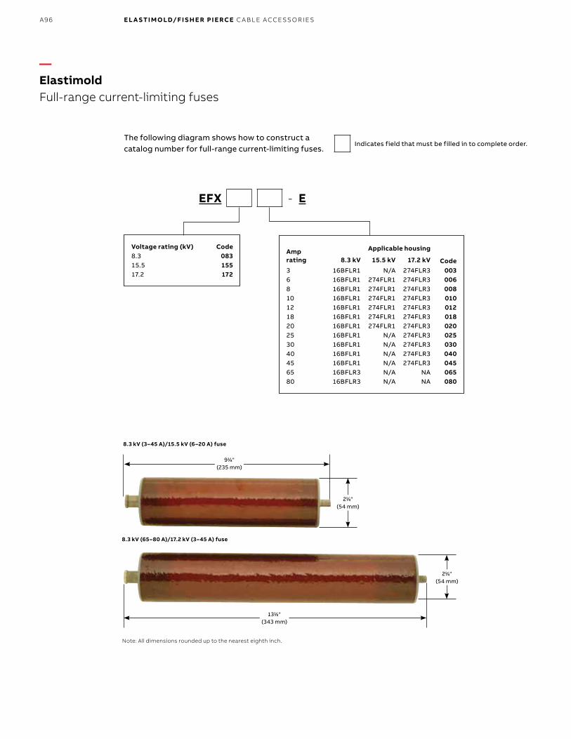
B1 copy starts here
B2 copy starts here
B3 copy starts here
A96 E L A S TI M O LD/F I S H E R PI E RCE C A B L E ACCE SSO R IE S
8.3 kV (3–45 A)/15.5 kV (6–20 A) fuse
8.3 kV (65–80 A)/17.2 kV (3–45 A) fuse
Note: All dimensions rounded up to the nearest eighth inch.
1311⁄22"(343 mm)
911⁄44"(235 mm)
211⁄44"(54 mm)
211⁄44"(54 mm)
The following diagram shows how to construct a catalog number for full-range current-limiting fuses.
Indicates field that must be filled in to complete order.
EFX - E
Voltage rating (kV) Code8.3 08315.5 15517.2 172
Amp rating
Applicable housing
Code8.3 kV 15.5 kV 17.2 kV
3 16BFLR1 N/A 274FLR3 0036 16BFLR1 274FLR1 274FLR3 0068 16BFLR1 274FLR1 274FLR3 00810 16BFLR1 274FLR1 274FLR3 01012 16BFLR1 274FLR1 274FLR3 01218 16BFLR1 274FLR1 274FLR3 01820 16BFLR1 274FLR1 274FLR3 02025 16BFLR1 N/A 274FLR3 02530 16BFLR1 N/A 274FLR3 03040 16BFLR1 N/A 274FLR3 04045 16BFLR1 N/A 274FLR3 04565 16BFLR3 N/A NA 06580 16BFLR3 N/A NA 080
—ElastimoldFull-range current-limiting fuses
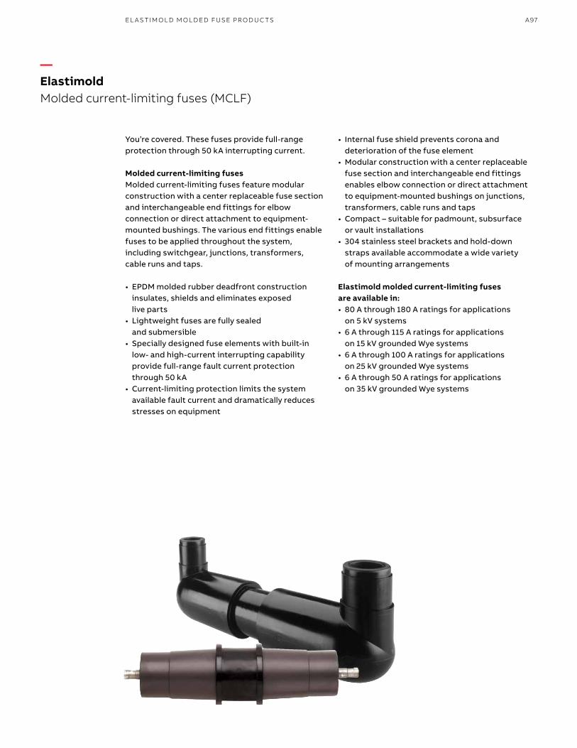
A97EL A S TI M O L D M O L D ED FUSE PR O D U C TS
You’re covered. These fuses provide full-range protection through 50 kA interrupting current.
Molded current-limiting fusesMolded current-limiting fuses feature modular construction with a center replaceable fuse section and interchangeable end fittings for elbow connection or direct attachment to equipment-mounted bushings. The various end fittings enable fuses to be applied throughout the system, including switchgear, junctions, transformers, cable runs and taps.
• EPDM molded rubber deadfront construction insulates, shields and eliminates exposed live parts
• Lightweight fuses are fully sealed and submersible
• Specially designed fuse elements with built-in low- and high-current interrupting capability provide full-range fault current protection through 50 kA
• Current-limiting protection limits the system available fault current and dramatically reduces stresses on equipment
• Internal fuse shield prevents corona and deterioration of the fuse element
• Modular construction with a center replaceable fuse section and interchangeable end fittings enables elbow connection or direct attachment to equipment-mounted bushings on junctions, transformers, cable runs and taps
• Compact – suitable for padmount, subsurface or vault installations
• 304 stainless steel brackets and hold-down straps available accommodate a wide variety of mounting arrangements
Elastimold molded current-limiting fuses are available in:• 80 A through 180 A ratings for applications
on 5 kV systems• 6 A through 115 A ratings for applications
on 15 kV grounded Wye systems• 6 A through 100 A ratings for applications
on 25 kV grounded Wye systems• 6 A through 50 A ratings for applications
on 35 kV grounded Wye systems
—ElastimoldMolded current-limiting fuses (MCLF)
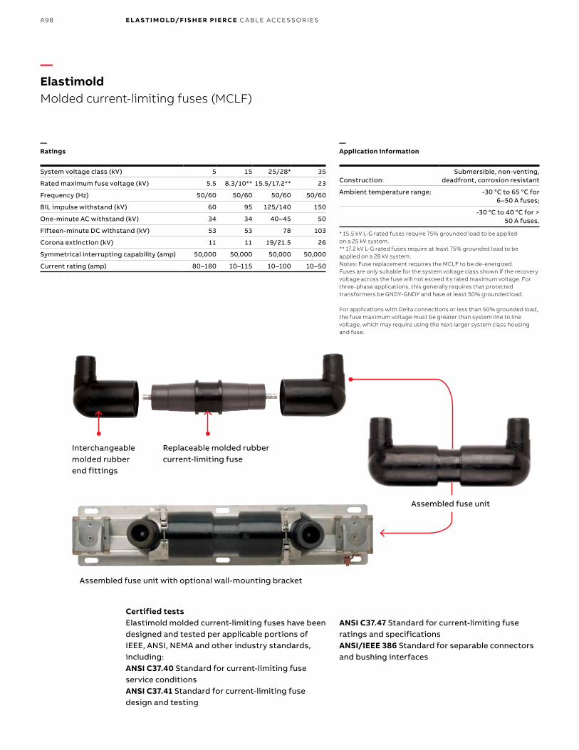
B1 copy starts here
B2 copy starts here
B3 copy starts here
A98 E L A S TI M O LD/F I S H E R PI E RCE C A B L E ACCE SSO R IE S
Interchangeable molded rubber end fittings
Assembled fuse unit
Replaceable molded rubber current-limiting fuse
Assembled fuse unit with optional wall-mounting bracket
—Application information
Construction: Submersible, non-venting,
deadfront, corrosion resistant
Ambient temperature range: -30 °C to 65 °C for 6–50 A fuses;
-30 °C to 40 °C for > 50 A fuses.
* 15.5 kV L-G rated fuses require 75% grounded load to be applied on a 25 kV system. ** 17.2 kV L-G rated fuses require at least 75% grounded load to be applied on a 28 kV system.Notes: Fuse replacement requires the MCLF to be de-energized. Fuses are only suitable for the system voltage class shown if the recovery voltage across the fuse will not exceed its rated maximum voltage. For three-phase applications, this generally requires that protected transformers be GNDY-GNDY and have at least 50% grounded load. For applications with Delta connections or less than 50% grounded load, the fuse maximum voltage must be greater than system line to line voltage, which may require using the next larger system class housing and fuse.
Certified tests Elastimold molded current-limiting fuses have been designed and tested per applicable portions of IEEE, ANSI, NEMA and other industry standards, including:ANSI C37.40 Standard for current-limiting fuse service conditionsANSI C37.41 Standard for current-limiting fuse design and testing
ANSI C37.47 Standard for current-limiting fuse ratings and specificationsANSI/IEEE 386 Standard for separable connectors and bushing interfaces
—Ratings
System voltage class (kV) 5 15 25/28* 35
Rated maximum fuse voltage (kV) 5.5 8.3/10** 15.5/17.2** 23
Frequency (Hz) 50/60 50/60 50/60 50/60
BIL impulse withstand (kV) 60 95 125/140 150
One-minute AC withstand (kV) 34 34 40–45 50
Fifteen-minute DC withstand (kV) 53 53 78 103
Corona extinction (kV) 11 11 19/21.5 26
Symmetrical interrupting capability (amp) 50,000 50,000 50,000 50,000
Current rating (amp) 80–180 10–115 10–100 10–50
—ElastimoldMolded current-limiting fuses (MCLF)
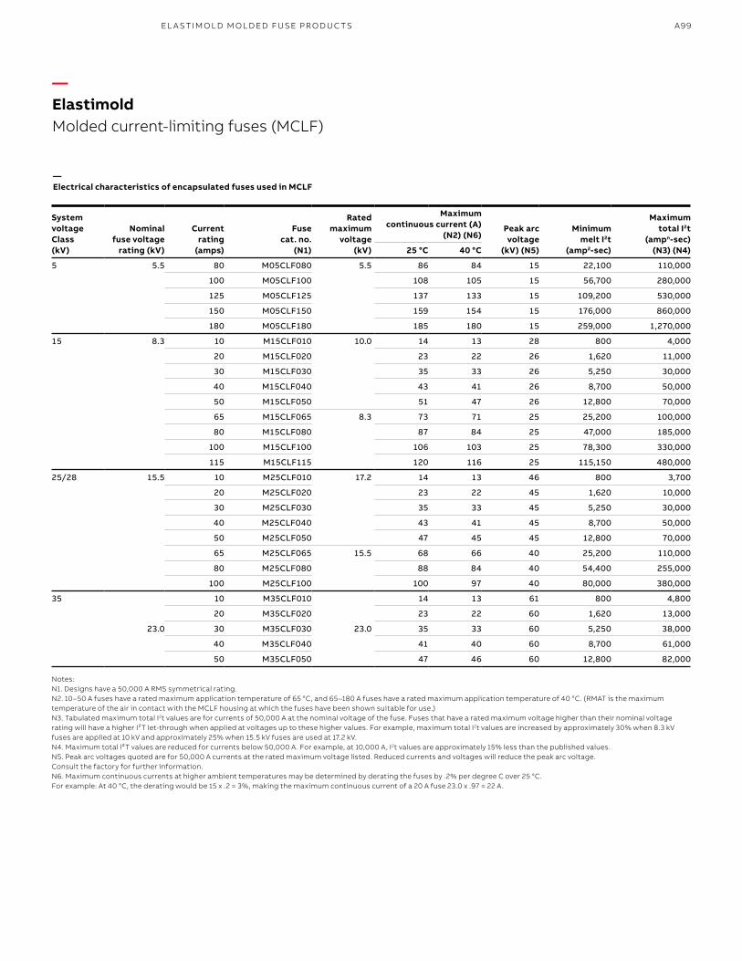
A99EL A S TI M O L D M O L D ED FUSE PR O D U C TS
—Electrical characteristics of encapsulated fuses used in MCLF
System voltage Class (kV)
Nominal fuse voltage
rating (kV)
Currentrating
(amps)
Fusecat. no.
(N1)
Ratedmaximum
voltage(kV)
Maximum continuous current (A)
(N2) (N6)Peak arcvoltage
(kV) (N5)
Minimummelt I2t
(amp2-sec)
Maximumtotal I2t
(ampn-sec)(N3) (N4)25 °C 40 °C
5 5.5 80 M05CLF080 5.5 86 84 15 22,100 110,000
100 M05CLF100 108 105 15 56,700 280,000
125 M05CLF125 137 133 15 109,200 530,000
150 M05CLF150 159 154 15 176,000 860,000
180 M05CLF180 185 180 15 259,000 1,270,000
15 8.3 10 M15CLF010 10.0 14 13 28 800 4,000
20 M15CLF020 23 22 26 1,620 11,000
30 M15CLF030 35 33 26 5,250 30,000
40 M15CLF040 43 41 26 8,700 50,000
50 M15CLF050 51 47 26 12,800 70,000
65 M15CLF065 8.3 73 71 25 25,200 100,000
80 M15CLF080 87 84 25 47,000 185,000
100 M15CLF100 106 103 25 78,300 330,000
115 M15CLF115 120 116 25 115,150 480,000
25/28 15.5 10 M25CLF010 17.2 14 13 46 800 3,700
20 M25CLF020 23 22 45 1,620 10,000
30 M25CLF030 35 33 45 5,250 30,000
40 M25CLF040 43 41 45 8,700 50,000
50 M25CLF050 47 45 45 12,800 70,000
65 M25CLF065 15.5 68 66 40 25,200 110,000
80 M25CLF080 88 84 40 54,400 255,000
100 M25CLF100 100 97 40 80,000 380,000
35
23.0
10 M35CLF010
23.0
14 13 61 800 4,800
20 M35CLF020 23 22 60 1,620 13,000
30 M35CLF030 35 33 60 5,250 38,000
40 M35CLF040 41 40 60 8,700 61,000
50 M35CLF050 47 46 60 12,800 82,000
Notes: N1. Designs have a 50,000 A RMS symmetrical rating.N2. 10–50 A fuses have a rated maximum application temperature of 65 °C, and 65–180 A fuses have a rated maximum application temperature of 40 °C. (RMAT is the maximum temperature of the air in contact with the MCLF housing at which the fuses have been shown suitable for use.)N3. Tabulated maximum total I2t values are for currents of 50,000 A at the nominal voltage of the fuse. Fuses that have a rated maximum voltage higher than their nominal voltage rating will have a higher I²T let-through when applied at voltages up to these higher values. For example, maximum total I2t values are increased by approximately 30% when 8.3 kV fuses are applied at 10 kV and approximately 25% when 15.5 kV fuses are used at 17.2 kV.N4. Maximum total l²T values are reduced for currents below 50,000 A. For example, at 10,000 A, I2t values are approximately 15% less than the published values.N5. Peak arc voltages quoted are for 50,000 A currents at the rated maximum voltage listed. Reduced currents and voltages will reduce the peak arc voltage. Consult the factory for further information.N6. Maximum continuous currents at higher ambient temperatures may be determined by derating the fuses by .2% per degree C over 25 °C. For example: At 40 °C, the derating would be 15 x .2 = 3%, making the maximum continuous current of a 20 A fuse 23.0 x .97 = 22 A.
—Elastimold Molded current-limiting fuses (MCLF)
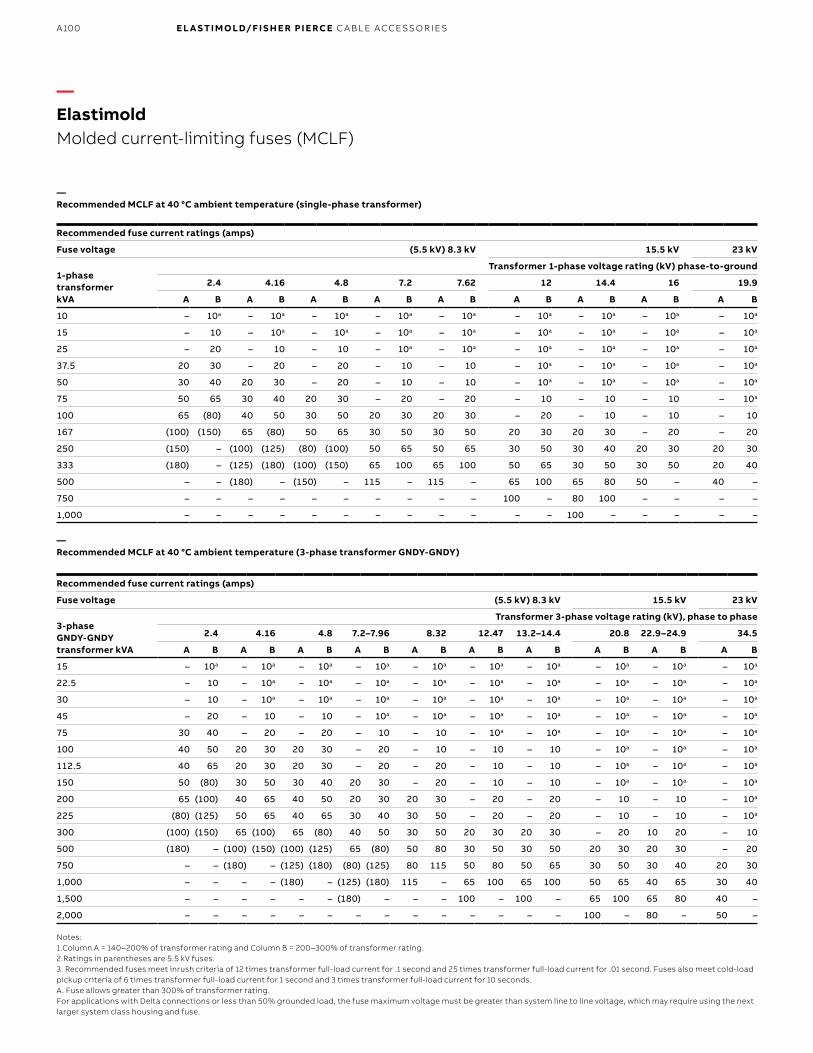
B1 copy starts here
B2 copy starts here
B3 copy starts here
A100 E L A S TI M O LD/F I S H E R PI E RCE C A B L E ACCE SSO R IE S
—Recommended MCLF at 40 °C ambient temperature (3-phase transformer GNDY-GNDY)
Recommended fuse current ratings (amps)
Fuse voltage (5.5 kV) 8.3 kV 15.5 kV 23 kV
3-phaseGNDY-GNDYtransformer kVA
Transformer 3-phase voltage rating (kV), phase to phase
2.4 4.16 4.8 7.2–7.96 8.32 12.47 13.2–14.4 20.8 22.9–24.9 34.5
A B A B A B A B A B A B A B A B A B A B
15 – 10a – 10a – 10a – 10a – 10a – 10a – 10a – 10a – 10a – 10a
22.5 – 10 – 10a – 10a – 10a – 10a – 10a – 10a – 10a – 10a – 10a
30 – 10 – 10a – 10a – 10a – 10a – 10a – 10a – 10a – 10a – 10a
45 – 20 – 10 – 10 – 10a – 10a – 10a – 10a – 10a – 10a – 10a
75 30 40 – 20 – 20 – 10 – 10 – 10a – 10a – 10a – 10a – 10a
100 40 50 20 30 20 30 – 20 – 10 – 10 – 10 – 10a – 10a – 10a
112.5 40 65 20 30 20 30 – 20 – 20 – 10 – 10 – 10a – 10a – 10a
150 50 (80) 30 50 30 40 20 30 – 20 – 10 – 10 – 10a – 10a – 10a
200 65 (100) 40 65 40 50 20 30 20 30 – 20 – 20 – 10 – 10 – 10a
225 (80) (125) 50 65 40 65 30 40 30 50 – 20 – 20 – 10 – 10 – 10a
300 (100) (150) 65 (100) 65 (80) 40 50 30 50 20 30 20 30 – 20 10 20 – 10
500 (180) – (100) (150) (100) (125) 65 (80) 50 80 30 50 30 50 20 30 20 30 – 20
750 – – (180) – (125) (180) (80) (125) 80 115 50 80 50 65 30 50 30 40 20 30
1,000 – – – – (180) – (125) (180) 115 – 65 100 65 100 50 65 40 65 30 40
1,500 – – – – – – (180) – – – 100 – 100 – 65 100 65 80 40 –
2,000 – – – – – – – – – – – – – – 100 – 80 – 50 –
Notes:1.Column A = 140–200% of transformer rating and Column B = 200–300% of transformer rating.2.Ratings in parentheses are 5.5 kV fuses.3. Recommended fuses meet inrush criteria of 12 times transformer full-load current for .1 second and 25 times transformer full-load current for .01 second. Fuses also meet cold-load pickup criteria of 6 times transformer full-load current for 1 second and 3 times transformer full-load current for 10 seconds. A. Fuse allows greater than 300% of transformer rating.For applications with Delta connections or less than 50% grounded load, the fuse maximum voltage must be greater than system line to line voltage, which may require using the next larger system class housing and fuse.
—Recommended MCLF at 40 °C ambient temperature (single-phase transformer)
Recommended fuse current ratings (amps)
Fuse voltage (5.5 kV) 8.3 kV 15.5 kV 23 kV
1-phase transformer kVA
Transformer 1-phase voltage rating (kV) phase-to-ground
2.4 4.16 4.8 7.2 7.62 12 14.4 16 19.9
A B A B A B A B A B A B A B A B A B
10 – 10a – 10a – 10a – 10a – 10a – 10a – 10a – 10a – 10a
15 – 10 – 10a – 10a – 10a – 10a – 10a – 10a – 10a – 10a
25 – 20 – 10 – 10 – 10a – 10a – 10a – 10a – 10a – 10a
37.5 20 30 – 20 – 20 – 10 – 10 – 10a – 10a – 10a – 10a
50 30 40 20 30 – 20 – 10 – 10 – 10a – 10a – 10a – 10a
75 50 65 30 40 20 30 – 20 – 20 – 10 – 10 – 10 – 10a
100 65 (80) 40 50 30 50 20 30 20 30 – 20 – 10 – 10 – 10
167 (100) (150) 65 (80) 50 65 30 50 30 50 20 30 20 30 – 20 – 20
250 (150) – (100) (125) (80) (100) 50 65 50 65 30 50 30 40 20 30 20 30
333 (180) – (125) (180) (100) (150) 65 100 65 100 50 65 30 50 30 50 20 40
500 – – (180) – (150) – 115 – 115 – 65 100 65 80 50 – 40 –
750 – – – – – – – – – – 100 – 80 100 – – – –
1,000 – – – – – – – – – – – – 100 – – – – –
—ElastimoldMolded current-limiting fuses (MCLF)

A101EL A S TI M O L D M O L D ED FUSE PR O D U C TS
1655⁄88" (422 mm)
1911⁄22" (343 mm)
511⁄88"(130 mm)
Approx. weight 30 lb. (13.6 kg)
833⁄1616"(208 mm)
4"(102 mm)
1655⁄88" (422 mm)
2355⁄88" (343 mm)
511⁄88" (130 mm)
833⁄1616"(208 mm)
Approx. weight 35 lb. (15.9 kg)
1655⁄88" (422 mm)
2755⁄88" (702 mm)
511⁄88"(130 mm)
4"(102 mm)
4"(102 mm)
833⁄1616"(208 mm)
Approx. weight 40 lb. (18.1 kg)
1655⁄88" (422 mm)
1955⁄88" (498 mm)
511⁄88"(130 mm)
933⁄1616"(233 mm)
Approx. weight 40 lb. (18.1 kg)
Lifting eye
1111⁄88"(283 mm)
99⁄1616" (14 mm) x 1" (25 mm) mounting slots on
511⁄22" (140 mm) centers
233⁄44"(70 mm)
33⁄44"(19 mm)
633⁄88"(162 mm)
2211⁄22"(572 mm)
1855⁄88"(473 mm)
511⁄88"(130 mm)
Approx. weight 30 lb. (13.6 kg)
—Elastimold Molded current-limiting fuses (MCLF)
Model 22
Model 222
Model 2222
Model 66
Model 6E2

B1 copy starts here
B2 copy starts here
B3 copy starts here
A102 E L A S TI M O LD/F I S H E R PI E RCE C A B L E ACCE SSO R IE S
The following diagram shows how to construct a catalog number for a molded current-limiting fuse:
Note: Other models are available such as 26.
1111⁄88"(283 mm)
Lifting eye
Voltage class (kV) Code5.0 0515.0 1525.0 2535.0 35 See page A14 for additional information.
Amps
Voltage class Amp code5 kV 15 kV 25 kV 35 kV
– 10 10 10 010– 20 20 20 020– 30 30 30 030– 40 40 40 040– 50 50 50 050– 65 65 – 06580 80 80 – 080100 100 100 – 100– 115 – – 115125 – – – 125150 – – – 150185 – – – 185
See page A17 for additional information.
Optional mounting brackets/accessories
Bracket code
Wall mounting bracket with parking stands and bolted style hold down straps (HDS)
WMB
Wall mounting bracket with parking stands and quick release style hold down straps (QRS)
WMBQ
Tilt mounting adapter; requires either WMB or WMBQ to enable up to 60° angle
TMA
Support mounting bracket for use with models 6E2 or 6E6 end-fitting arrangements; includes bolted-style hold-down strap
SMB
Bolted-style hold-down strap (qty: 1 required per end fitting)
HDS
Quick-release style hold-down strap (qty: 1 required per end fitting)
QRS
*Options maybe purchased separately
Indicates field that must be filled in to complete order.
M CLF -
BushingsBushing
code
200 A bushing wells both ends 22
200 A bushing well on one end and two 200 A bushing wells on the other end
222
Two 200 A bushing wells on both ends
2222
600 A bushings on both ends 66
600 A elbow connector on one end and 200 A bushing well on the other end (not available for 35 kV)
6E2
600 A elbow connector on one end and 600 A bushing on the other end (not available for 35 kV)
6E6
See outline drawings preceding this chart for additional details.
—ElastimoldMolded current-limiting fuses (MCLF)
Model 6E6
99⁄1616" (14 mm) x 1" (25 mm) mounting slots on
511⁄22" (140 mm) centers
511⁄88"(130 mm)
233⁄44"(70 mm)
633⁄88"(162 mm)
2211⁄22"(572 mm)
1855⁄88"(473 mm)
11⁄22"(13 mm)
Approx. weight 30 lb. (13.6 kg)

A103EL A S TI M O L D M O L D ED FUSE PR O D U C TS
15 to 60°
Approx. Weight 8 lb. (3.6 kg) 9⁄16" (14 mm) x 1" (25 mm) Mounting slots
63⁄4"(171 mm)
Optional WMB mounting bracket with adjustable parking stands for vertical mounting and fuse hold-down strips
Optional – TMA universal tilt mounting
51⁄2"(140 mm)
—Mounting options
293⁄4" (756 mm)
323⁄4" (832 mm)
—Optimal end fittings
Cat. no. Description System voltage class (kV)IEEE 386-1995
interface reference
EF2 200 A bushing well end fitting 5, 15, 25 Figure 3
EF22 Double 200 A bushing well end fitting 5, 15, 25 Figure 3
EF6 600 A bushing end fitting 5, 15, 25 Figures 11 and 13
EF6E 600 A elbow connector end fitting 5, 15, 25 Figure 11
Note: EF6E is equipped with a standard through-hole spade lug (Type 03700). Use this table only if end fittings are to be ordered and shipped separately from the fuse. See pages A98-A99 for assembled units.
3⁄8" (10 mm)Sq. drive
3⁄16" (5 mm) Hex
—Other options
Cat. no. Description
MCLF-ADT Hex wrench for set screw removal and replacement when disassemblingend fittings. Supplied as standard with replacement fuses.
—Elastimold Molded current-limiting fuses (MCLF)
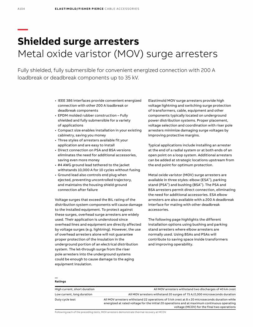
B1 copy starts here
B2 copy starts here
B3 copy starts here
A104 E L A S TI M O LD/F I S H E R PI E RCE C A B L E ACCE SSO R IE S
High current, short duration All MOV arresters withstand two discharges of 40 kA crest
Low current, long duration All MOV arresters withstand 20 surges of 75 A/2,000 microseconds duration
Duty cycle test
All MOV arresters withstand 22 operations of 5 kA crest at 8 x 20 microseconds duration while energized at rated voltage for the initial 20 operations and at maximum continuous operating
voltage (MCOV) for the final two operations
Following each of the preceding tests, MOV arresters demonstrate thermal recovery at MCOV.
—Shielded surge arrestersMetal oxide varistor (MOV) surge arrestersFully shielded, fully submersible for convenient energized connection with 200 A loadbreak or deadbreak components up to 35 kV.
• IEEE 386 interfaces provide convenient energized connection with other 200 A loadbreak or deadbreak components
• EPDM molded rubber construction – Fully shielded and fully submersible for a variety of applications
• Compact size enables installation in your existing cabinetry, saving you money
• Three styles of arresters available fit your application and are easy to install
• Direct connection on PSA and BSA versions eliminates the need for additional accessories, saving even more money
• #4 AWG ground lead tethered to the jacket withstands 10,000 A for 10 cycles without fusing
• Ground lead also controls end plug when ejected, preventing uncontrolled trajectory, and maintains the housing shield ground connection after failure
Voltage surges that exceed the BIL rating of the distribution system components will cause damage to the installed equipment. To protect against these surges, overhead surge arresters are widely used. Their application is understood since overhead lines and equipment are directly affected by voltage surges (e.g. lightning). However, the use of overhead arresters alone will not guarantee proper protection of the insulation in the underground portion of an electrical distribution system. The let-through surge from the riser pole arresters into the underground systems could be enough to cause damage to the aging equipment insulation.
Elastimold MOV surge arresters provide high voltage lightning and switching surge protection of transformers, cable, equipment and other components typically located on underground power distribution systems. Proper placement, voltage selection and coordination with riser pole arresters minimize damaging surge voltages by improving protective margins.
Typical applications include installing an arrester at the end of a radial system or at both ends of an open point on a loop system. Additional arresters can be added at strategic locations upstream from the end point for optimum protection.
Metal oxide varistor (MOV) surge arresters are available in three styles: elbow (ESA™), parking stand (PSA™) and bushing (BSA™). The PSA and BSA arresters permit direct connection, eliminating the need for additional accessories. ESA elbow arresters are also available with a 200 A deadbreak interface for mating with other deadbreak accessories.
The following page highlights the different installation options using bushing and parking stand arresters where elbow arresters are normally used. Using BSAs and PSAs will contribute to saving space inside transformers and improving operability.
—Ratings
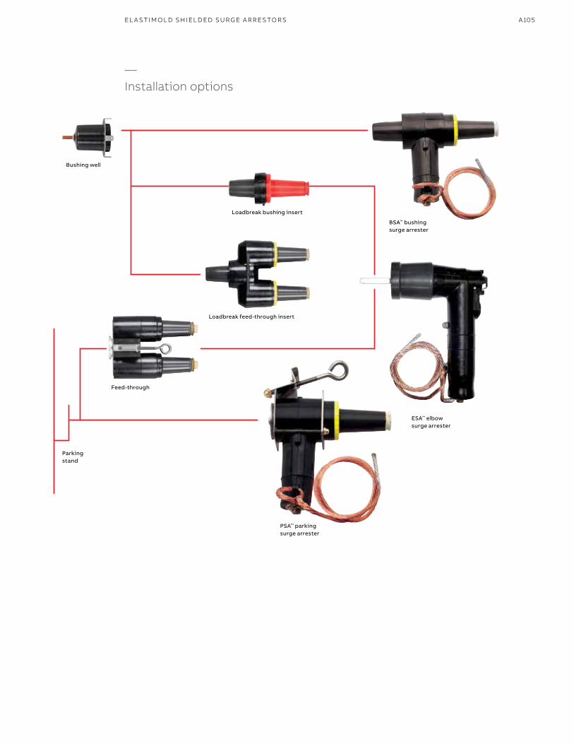
A105EL A S TI M O L D SH I EL D ED SU R G E A R R E S TO R S
PSA™ parking surge arrester
BSA™ bushing surge arrester
Loadbreak bushing insert
Loadbreak feed-through insert
Parking stand
Feed-through
ESA™ elbow surge arrester
—Installation options
Bushing well

B1 copy starts here
B2 copy starts here
B3 copy starts here
A106 E L A S TI M O LD/F I S H E R PI E RCE C A B L E ACCE SSO R IE S
Elbow arrester and parking stand arresterThis approach can reduce overcrowding by eliminating the feed-through device. This is desirable in a mini-pad transformer.
Two elbow arresters and a feed-throughThis approach uses elbow arresters only. (One of the elbow arresters may be mounted on the H1A bushing if operating procedures permit.)
—Shielded surge arrestersLoop-feed circuit (type 2 transformer)
Bushing arrester and parking stand arrester* This approach is best for increasing operability and reducing transformer overcrowding.
The bushing arrester enables the source cable to be positioned on H1A, which conforms with some operating practices.
A bushing arrester mounted on H1A can be directed downward without interference. Potential interference between an elbow arrester on H1B and a cable parked on P is eliminated.
The bushing arrester requires significantly less space than an elbow arrester used with a feed-through insert.
Operability is enhanced because the open point can be closed by moving the parked cable to H1B without removing an arrester. * Transformers must be specified with bushing wells.
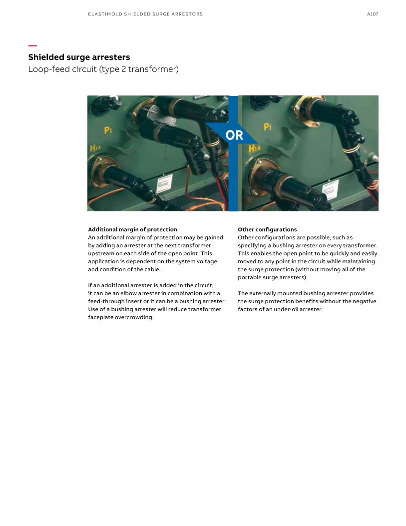
A107EL A S TI M O L D SH I EL D ED SU R G E A R R E S TO R S
OR
Additional margin of protection An additional margin of protection may be gained by adding an arrester at the next transformer upstream on each side of the open point. This application is dependent on the system voltage and condition of the cable.
If an additional arrester is added in the circuit, it can be an elbow arrester in combination with a feed-through insert or it can be a bushing arrester. Use of a bushing arrester will reduce transformer faceplate overcrowding.
Other configurations Other configurations are possible, such as specifying a bushing arrester on every transformer. This enables the open point to be quickly and easily moved to any point in the circuit while maintaining the surge protection (without moving all of the portable surge arresters).
The externally mounted bushing arrester provides the surge protection benefits without the negative factors of an under-oil arrester.
—Shielded surge arrestersLoop-feed circuit (type 2 transformer)

B1 copy starts here
B2 copy starts here
B3 copy starts here
A108 E L A S TI M O LD/F I S H E R PI E RCE C A B L E ACCE SSO R IE S
Single-bushing transformerTo add surge protection to a single-bushing transformer, use a bushing arrester or an elbow arrester with a feed-through insert.
Two-bushing transformerTo add surge protection to a two-bushing transformer at the end point of a radial-feed circuit, add an elbow arrester to the unoccupied bushing or use a bushing arrester.
—Shielded surge arrestersRadial-feed circuit (end point)
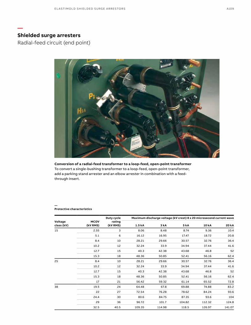
A109EL A S TI M O L D SH I EL D ED SU R G E A R R E S TO R S
Conversion of a radial-feed transformer to a loop-feed, open-point transformerTo convert a single-bushing transformer to a loop-feed, open-point transformer, add a parking stand arrester and an elbow arrester in combination with a feed-through insert.
—Shielded surge arrestersRadial-feed circuit (end point)
—Protective characteristics
Voltage class (kV)
MCOV (kV RMS)
Duty cycle rating
(kV RMS)
Maximum discharge voltage (kV crest) 8 x 20 microsecond current wave
1.5 kA 3 kA 5 kA 10 kA 20 kA
15 2.55 3 8.06 8.48 8.74 9.36 10.4
5.1 6 16.12 16.95 17.47 18.72 20.8
8.4 10 28.21 29.66 30.57 32.76 36.4
10.2 12 32.24 33.9 34.94 37.44 41.6
12.7 15 40.3 42.38 43.68 46.8 52
15.3 18 48.36 50.85 52.41 56.16 62.4
25 8.4 10 28.21 29.66 30.57 32.76 36.4
10.2 12 32.24 33.9 34.94 37.44 41.6
12.7 15 40.3 42.38 43.68 46.8 52
15.3 18 48.36 50.85 52.41 56.16 62.4
17 21 56.42 59.32 61.14 65.52 72.8
38 19.5 24 64.48 67.8 69.88 74.88 83.2
22 27 72.54 76.28 78.62 84.24 93.6
24.4 30 80.6 84.75 87.35 93.6 104
29 36 96.72 101.7 104.82 112.32 124.8
32.5 40.5 109.35 114.98 118.5 126.97 141.07

B1 copy starts here
B2 copy starts here
B3 copy starts here
A110 E L A S TI M O LD/F I S H E R PI E RCE C A B L E ACCE SSO R IE S
—Shielded surge arresters
—To specify and order an MOV surge arrester:
1. Determine the appropriate maximum continuous operating voltage (MCOV) for your system voltage using the arrester application table below.
2. Specify the appropriate Elastimold catalog number from the selection chart.
—Arrester application table
Voltage class (kV)
System line-to-line voltage kV RMSMCOV* kV RMS
Solidly grounded neutral circuits
3-Wire ungrounded circuitsNominal Maximum
15 2.40 2.54 2.55 2.55
4.16 4.40 2.55 5.10
4.80 5.08 5.10 5.10
6.90 7.26 5.10 8.40
8.32 8.80 5.10 8.40
12.47 13.20 8.40 15.30
13.20 13.97 8.40 15.30
13.80 14.50 8.40** 15.30
13.80 14.50 10.20 15.30
25 6.90 7.26 5.10 8.40
8.32 8.80 5.10 8.40
12.47 13.20 8.40 15.30
13.20 13.97 8.40 15.30
13.80 14.50 8.40** 15.30
13.80 14.50 10.20 15.30
20.78 22.00 12.70 –
20.78 22.00 15.30** –
23.00 24.34 15.30 –
24.94 26.40 15.30 –
24.94 26.40 17.00** –
28.00 29.80 17.00 –
* MCOV = maximum continuous operating voltage.** Preferred arrester MCOV for this system voltage.
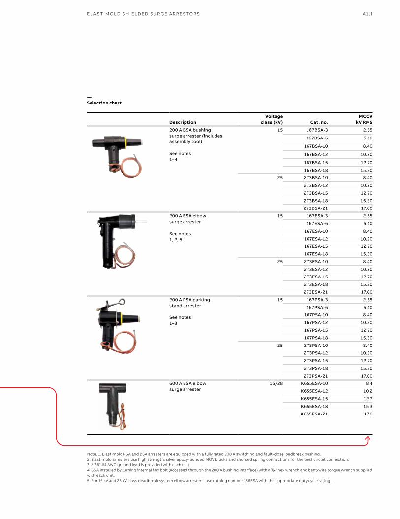
A111
—Selection chart
DescriptionVoltage
class (kV) Cat. no.MCOV
kV RMS
200 A BSA bushing surge arrester (includes assembly tool) See notes1–4
15 167BSA-3 2.55
167BSA-6 5.10
167BSA-10 8.40
167BSA-12 10.20
167BSA-15 12.70
167BSA-18 15.30
25 273BSA-10 8.40
273BSA-12 10.20
273BSA-15 12.70
273BSA-18 15.30
273BSA-21 17.00
200 A ESA elbow surge arrester See notes1, 2, 5
15 167ESA-3 2.55
167ESA-6 5.10
167ESA-10 8.40
167ESA-12 10.20
167ESA-15 12.70
167ESA-18 15.30
25 273ESA-10 8.40
273ESA-12 10.20
273ESA-15 12.70
273ESA-18 15.30
273ESA-21 17.00
200 A PSA parking stand arrester See notes1–3
15 167PSA-3 2.55
167PSA-6 5.10
167PSA-10 8.40
167PSA-12 10.20
167PSA-15 12.70
167PSA-18 15.30
25 273PSA-10 8.40
273PSA-12 10.20
273PSA-15 12.70
273PSA-18 15.30
273PSA-21 17.00
600 A ESA elbow surge arrester
15/28 K655ESA-10 8.4
K655ESA-12 10.2
K655ESA-15 12.7
K655ESA-18 15.3
K655ESA-21 17.0
Note: 1. Elastimold PSA and BSA arresters are equipped with a fully rated 200 A switching and fault-close loadbreak bushing.2. Elastimold arresters use high strength, silver epoxy-bonded MOV blocks and shunted spring connections for the best circuit connection.3. A 36" #4 AWG ground lead is provided with each unit.4. BSA installed by turning internal hex bolt (accessed through the 200 A bushing interface) with a 55⁄1616" hex wrench and bent-wire torque wrench supplied with each unit.5. For 15 kV and 25 kV class deadbreak system elbow arresters, use catalog number 156ESA with the appropriate duty cycle rating.
EL A S TI M O L D SH I EL D ED SU R G E A R R E S TO R S

B1 copy starts here
B2 copy starts here
B3 copy starts here
A112 E L A S TI M O LD/F I S H E R PI E RCE C A B L E ACCE SSO R IE S
—To specify and order an MOV surge arrester:
1. Determine the appropriate maximum continuous operating voltage (MCOV) for your system voltage using the arrester application table below.
2. Specify the appropriate Elastimold catalog number from the selection chart.
—Shielded surge arresters
—Arrester application table
Voltage class (kV)
System line-to-line voltage kV RMS MCOV* kV RMS
Nominal Maximum Solidly grounded neutral circuits 3-Wire ungrounded circuits
35 23.00 24.34 – 22.00
34.50 36.51 22.00** –
34.50 36.51 24.40 29.00
* MCOV = maximum continuous operating voltage. ** Preferred arrester MCOV for this system voltage.

A113
—Selection chart
DescriptionVoltage
class (kV) Cat. no.MCOV
kV RMS
200 A BSA bushing surge arrester See notes 1–4
35 375BSA-24 19.50
375BSA-27 22.00
375BSA-30 24.40
200 A ESA elbow surge arrester See notes 2–3
35 375ESA-24 19.50
375ESA-27 22.00
375ESA-30 24.40
375ESA-36 29.00
200 A PSA parking stand arrester See notes 1–3
35 375PSA-24 19.50
375PSA-27 22.00
375PSA-30 24.40
600 A ESA elbow surge arrester
35 755ESA-18 15.3
755ESA-24 19.5
755ESA-27 22.0
755ESA-30 24.4
755ESA-33 26.8
755ESA-36 29.0
755ESA-40.5 32.5
Note: 1. Elastimold PSA and BSA arresters are equipped with a fully rated 200 A switching and fault-close loadbreak bushing.2. Elastimold arresters use high strength, silver epoxy-bonded MOV blocks and shunted spring connections for the best circuit connection.3. A 36" #4 AWG ground lead is provided with each unit.4. BSA installed by turning internal hex bolt (accessed through the 200 A bushing interface) with a 55⁄1616" hex wrench and bent-wire torque wrench supplied with each unit.5. For 15 kV and 25 kV class deadbreak system elbow arresters, use catalog number 156ESA with the appropriate duty cycle rating.
EL A S TI M O L D SH I EL D ED SU R G E A R R E S TO R S
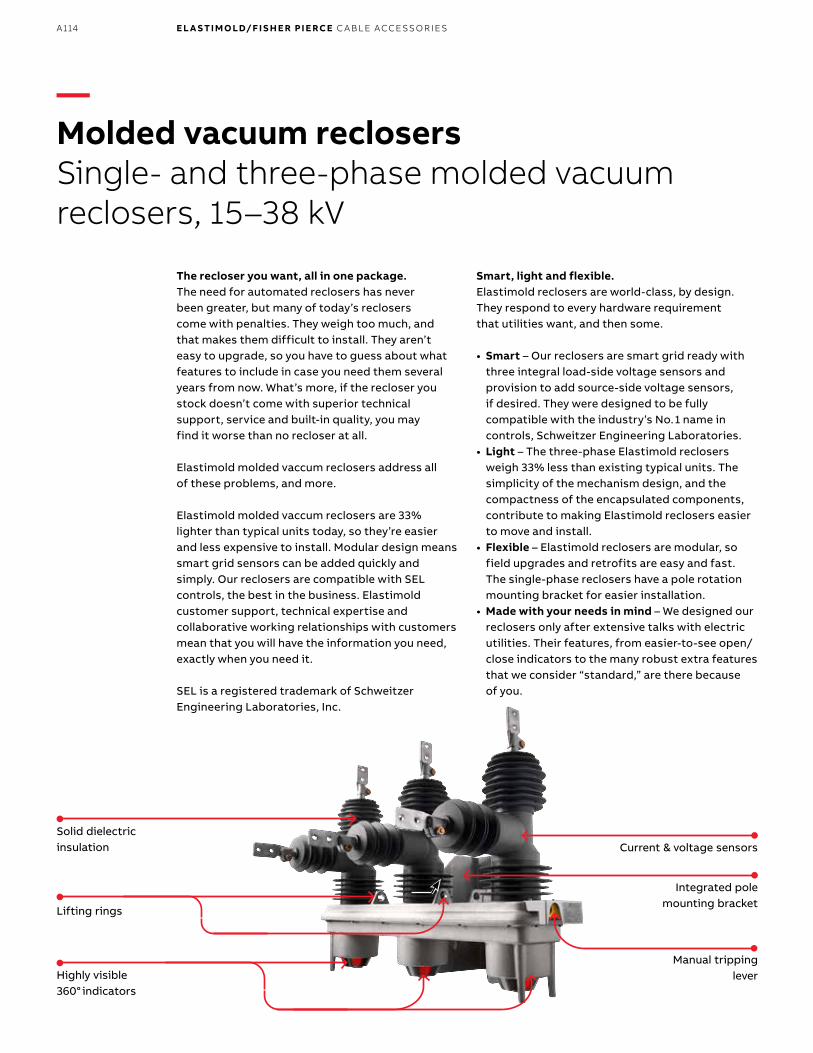
B1 copy starts here
B2 copy starts here
B3 copy starts here
A114 E L A S TI M O LD/F I S H E R PI E RCE C A B L E ACCE SSO R IE S
The recloser you want, all in one package.The need for automated reclosers has never been greater, but many of today’s reclosers come with penalties. They weigh too much, and that makes them difficult to install. They aren’t easy to upgrade, so you have to guess about what features to include in case you need them several years from now. What’s more, if the recloser you stock doesn’t come with superior technical support, service and built-in quality, you may find it worse than no recloser at all.
Elastimold molded vaccum reclosers address all of these problems, and more.
Elastimold molded vaccum reclosers are 33% lighter than typical units today, so they’re easier and less expensive to install. Modular design means smart grid sensors can be added quickly and simply. Our reclosers are compatible with SEL controls, the best in the business. Elastimold customer support, technical expertise and collaborative working relationships with customers mean that you will have the information you need, exactly when you need it.
SEL is a registered trademark of Schweitzer Engineering Laboratories, Inc.
Smart, light and flexible.Elastimold reclosers are world-class, by design. They respond to every hardware requirement that utilities want, and then some.
• Smart – Our reclosers are smart grid ready with three integral load-side voltage sensors and provision to add source-side voltage sensors, if desired. They were designed to be fully compatible with the industry’s No. 1 name in controls, Schweitzer Engineering Laboratories.
• Light – The three-phase Elastimold reclosers weigh 33% less than existing typical units. The simplicity of the mechanism design, and the compactness of the encapsulated components, contribute to making Elastimold reclosers easier to move and install.
• Flexible – Elastimold reclosers are modular, so field upgrades and retrofits are easy and fast. The single-phase reclosers have a pole rotation mounting bracket for easier installation.
• Made with your needs in mind – We designed our reclosers only after extensive talks with electric utilities. Their features, from easier-to-see open/close indicators to the many robust extra features that we consider “standard,” are there because of you.
—Molded vacuum reclosersSingle- and three-phase molded vacuum reclosers, 15–38 kV
Manual tripping leverHighly visible
360° indicators
Lifting rings
Current & voltage sensors
Integrated pole mounting bracket
Solid dielectric insulation
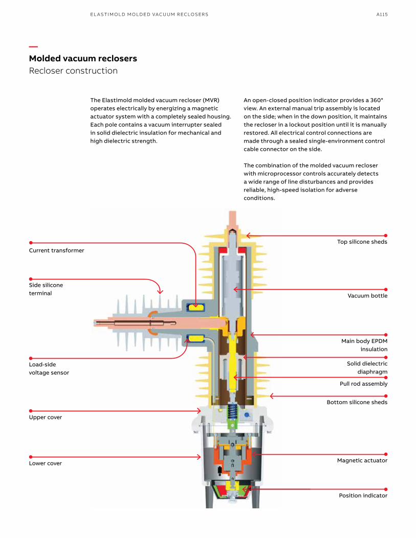
A115EL A S TI M O L D M O L D ED VAC U U M R ECLOSER S
The Elastimold molded vacuum recloser (MVR) operates electrically by energizing a magnetic actuator system with a completely sealed housing. Each pole contains a vacuum interrupter sealed in solid dielectric insulation for mechanical and high dielectric strength.
An open-closed position indicator provides a 360° view. An external manual trip assembly is located on the side; when in the down position, it maintains the recloser in a lockout position until it is manually restored. All electrical control connections are made through a sealed single-environment control cable connector on the side.
The combination of the molded vacuum recloser with microprocessor controls accurately detects a wide range of line disturbances and provides reliable, high-speed isolation for adverse conditions.
—Molded vacuum reclosersRecloser construction
Position indicator
Magnetic actuator
Bottom silicone sheds
Pull rod assembly
Solid dielectric diaphragm
Main body EPDM insulation
Vacuum bottle
Top silicone sheds
Upper cover
Lower cover
Load-side voltage sensor
Side silicone terminal
Current transformer
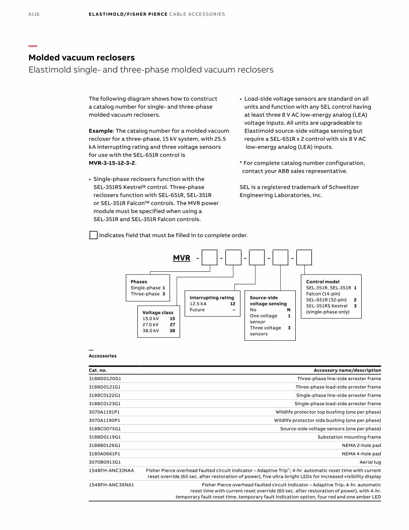
B1 copy starts here
B2 copy starts here
B3 copy starts here
A116 E L A S TI M O LD/F I S H E R PI E RCE C A B L E ACCE SSO R IE S
—Accessories
Cat. no. Accessory name/description
3188D0120G1 Three-phase line-side arrester frame
3188D0121G1 Three-phase load-side arrester frame
3188C0122G1 Single-phase line-side arrester frame
3188C0123G1 Single-phase load-side arrester frame
3070A1191P1 Wildlife protector top bushing (one per phase)
3070A1190P1 Wildlife protector side bushing (one per phase)
3188C0075G1 Source-side voltage sensors (one per phase)
3188D0119G1 Substation mounting frame
3188B0126G1 NEMA 2-hole pad
3180A0661P1 NEMA 4-hole pad
3070B0913G1 Aerial lug
1548FH-ANC3JNAA Fisher Pierce overhead faulted circuit indicator – Adaptive Trip™; 4-hr. automatic reset time with current reset override (60 sec. after restoration of power), five ultra-bright LEDs for increased visibility display
1548FH-ANC3XNA1 Fisher Pierce overhead faulted circuit indicator – Adaptive Trip; 4-hr. automatic reset time with current reset override (60 sec. after restoration of power), with 4-hr.
temporary fault reset time, temporary fault indication option, four red and one amber LED
The following diagram shows how to construct a catalog number for single- and three-phase molded vacuum reclosers.
Example: The catalog number for a molded vacuum recloser for a three-phase, 15 kV system, with 25.5 kA interrupting rating and three voltage sensors for use with the SEL-651R control is MVR-3-15-12-3-2.
• Single-phase reclosers function with the SEL-351RS Kestrel® control. Three-phase reclosers function with SEL-651R, SEL-351R or SEL-351R Falcon™ controls. The MVR power module must be specified when using a SEL-351R and SEL-351R Falcon controls.
• Load-side voltage sensors are standard on all units and function with any SEL control having at least three 8 V AC low-energy analog (LEA) voltage inputs. All units are upgradeable to Elastimold source-side voltage sensing but require a SEL-651R x 2 control with six 8 V AC low-energy analog (LEA) inputs.
* For complete catalog number configuration, contact your ABB sales representative.
SEL is a registered trademark of Schweitzer Engineering Laboratories, Inc.
MVR - - - - -
—Molded vacuum reclosersElastimold single- and three-phase molded vacuum reclosers
Indicates field that must be filled in to complete order.
PhasesSingle-phase 1Three-phase 3
Voltage class15.0 kV 1527.0 kV 2738.0 kV 38
Interrupting rating12.5 kA 12Future –
Source-side voltage sensingNo NOne voltage 1 sensor Three voltage 3 sensors
Control modelSEL-351R, SEL-351R 1 Falcon (14-pin)SEL-651R (32-pin) 2SEL-351RS Kestrel 3 (single-phase only)