AccuSpin Micro 17 / 17R - Thermo Fisher
79
Instructions for use AccuSpin Micro 17 / 17R
-
Upload
khangminh22 -
Category
Documents
-
view
3 -
download
0
Transcript of AccuSpin Micro 17 / 17R - Thermo Fisher

Instructions for useAccuSpin Micro 17 / 17R

How to use this manual Use this manual to get acquainted with your centrifuge and its accessories.
The manual helps you to avoid inappropriate handling. Make sure to keep it always close to the centrifuge. A manual that is not kept available cannot provide protection against improper handling and thus against damage to persons and objects.
This manual comprises chapters on:
• Safety regulations• Instrument description• Transportation and hook-up the centrifuge• Rotor program and accessories• Use of the centrifuge• Maintenance and care• Troubleshooting• Technical data• Index
Please fold out
Overleaf you will find a graphic illustra-tion of the control panel with a survey of
the most important functions

rotor turns
rpm/RCF switch key
display
run time quick run
open lid
(only for instruments with refrigeration unit) temperature speed/RCF
stop
start
“set“ keys “set“ keys pre-temperature-regulation (only for instruments with refrigeration unit)
Before switching on the centrifuge please read this manual!
Note that “min-1” stands for “rpm” and “x g” stands for “RCF”

Control panel Display panels Speed / RCF Resting state: During run:
End:Error codes:
Run time Resting/End:
current value (0) or pre-selected set-point value present current value of speed or RCF (after activation of switch key) Circulating light-points: rotor turns "End“flashing display with error code
current value (0) / “End”, or pre-selected set point value (in minutes, or "hd" for permanent operation)
Time selection/run: - remaining time till “0” in minutes Permanent operation (hd): - run time passed in seconds/ minutes
"Quick run“: - run time passed in seconds/ minutes
Temperature* according to: current sample temperature in °C
(in temperature equilibrium)
* only for instruments with refrigeration unit
Keys start: start of the centrifuge stop: manually stop of a run open lid: open lid
(possible only with the instrument switched on and standstill of the rotor)
quick run: short-term run up of the centrifuge as long as key remains pressed
Switch Speed/RCF: switching between speed and RCF display Pre-temp: pre-temp-function* "set" keys: stepwise increase/decrease of set-point values
Short pressing of any of the "set" keys: switch from current to pre-selected set-point value, signaled by flashing display.
(Error codes (see "Troubleshooting“section):
E-14: over temperature centrifuge chamber (> 50 °C) E-22: troubled speed measurementE-24: lid will not openE-31: over temperature motorE-36: over amperage or over voltageE-46: lid was opened manually during runE-57: imbalanceE-60: under temperature centrifuge chamber (< -20 °C)

Contents
1
Contents For your safety............................................ 3
Safety instructions in this manual ............................ 3 Proper use................................................................ 4 Improper use ............................................................ 4 Centrifuging hazardous materials ............................ 4 Handling the centrifuge ............................................ 4 Conformity to current standards............................... 5
Description of the instrument.................... 7 Pieces delivered....................................................... 7 Safety systems......................................................... 7 Properties................................................................. 8
Before use................................................... 9 Where to install the centrifuge ................................. 9 Transport and installation the centrifuge.................. 9
Centrifuge with refrigeration unit .......................... 9 Mains connection ................................................... 10 Removing the transport protection......................... 10
Accessories .............................................. 11 Rotors for the accuSpin Micro 17........................... 12 Rotors for the accuSpin Micro 17R ........................ 14 Adapter................................................................... 16
Handling the rotor .................................... 17 Rotor lid with a spring lock ................................. 17
Operation without rotor lid .................................. 18 Rotor lid with screw plug .................................... 19
Aerosol-tight application......................................... 20 Checking for aerosol-tightness........................... 22
Operation .................................................. 23 Switching on the centrifuge .................................... 23 Opening the lid ....................................................... 23 Closing the lid......................................................... 23 Installing the rotor................................................... 24 Loading the rotor .................................................... 26
Maximum load .................................................... 26 Filling the centrifuge tubes ................................. 26 Placing the tubes in the rotor.............................. 27
Entering parameters............................................... 28 Switching from speed to RCF display .................... 28 Selecting speed...................................................... 28 Entering the RCF value.......................................... 29
Concerning the RCF value ................................. 29 Selecting the run time ............................................ 30
Run time selection .............................................. 30 Continuous operation ......................................... 30
Setting the temperature.......................................... 31 Pretemp .............................................................. 32
Starting the centrifuge ............................................ 33 Changing the settings during the run ..................... 33

Inhalt
2
Stopping the centrifuge .......................................... 34 Preset run time ................................................... 34 Continuous operation ......................................... 34
Short-time centrifugation ........................................ 34 Removing the rotor................................................. 35 Audible alarm ......................................................... 35 Turning off the centrifuge ....................................... 36 WEEE Compliance:................................................ 36
Maintenance and care .............................. 37 Maintenance to be performed by the customer ..... 37
Cleaning.............................................................. 37 Cleaning the filter unit......................................... 38 Disinfection ......................................................... 39 Decontamination................................................. 41 Autoclaving ......................................................... 41
Troubleshooting ....................................... 43 Mechanical emergency lid release......................... 43 Problems you can handle yourself ......................... 45 Contacting Service ................................................. 51
Technical data........................................... 53 Component parts.................................................... 53 The "Easycontrol" user interface............................ 54 Performance........................................................... 55 Electrical connections............................................. 57
Appendix ................................................... 59
Speed/RCF diagram............................................... 60 Autoclaving protocol ............................................... 66
Index .......................................................... 69

For your safety
3
For your safety
Safety instructions in this manual This symbol denotes potential hazards to persons.
This symbol denotes potential damage to the centrifuge or parts in its imme-diate surroundings.
Warning: hot surfaces
General danger area Before switching on the centrifuge please read this manual!
General hints are marked with this symbol.
Fisher Scientific® centrifuges are manufactured accord-ing to current technical standards and regulations. Nonetheless, centrifuges may pose danger to indi-viduals and surrounding if:• they are not used as designed• they are operated by untrained personnel• their design is improperly changed• the safety instructions are not followed
Therefore, personnel involved with op-eration and maintenance of the centri-fuge must read and follow the safety instructions.
In addition, the pertinent regulations for prevention of accidents must be strictly followed.
This manual is an integral part of the centrifuge as-sembly and must be kept close at hand at all times.
When damages to the power cord or at casing are noticed the centrifuge must be set out of operation!

For your safety
4
Proper use The centrifuge is designed to separate liquid-suspended materials having different densities and particle size (maximum sample density is 1.2 g/cm³ at maximum speed). Improper use During a run, a safety zone of 30 cm around the centri-fuge must be maintained where neither persons nor hazardous materials may be present. The centrifuge may cause harm to its user or other persons or may damage goods if safety measures are not followed:
Centrifuging hazardous materials • The centrifuge is neither made inert, nor is it explo-
sion-proof. Therefore never use the centrifuge in anexplosion-prone environment.
• Do not centrifuge explosive or flammable sub-stances. The same holds for substances prone toreact violently with each other.
• Do not centrifuge toxic or radioactive substances orpathogenic micro-organisms without suitable safetysystems.If microbiological samples of risk group II (accord-ing to "Laboratory Bio-safety Manual" of WHO) are
being centrifuged, aerosol-tight bio-seals have to be used. For materials in a higher risk group, more than one precaution is required.
• Should toxins or pathogenic substances enter thecentrifuge or its parts, you must perform appropri-ate procedures for disinfection (see "Maintenanceand care – Disinfection").
• Strongly corrosive substances that may causedamage to materials and reduce the mechanicalstrength of the rotor may be centrifuged only insideprotective tubes.
Handling the centrifuge • Use only original accessories for the centrifuge.
The only exceptions are common glass or plasticcentrifuge tubes if they are approved for the rotorspeed and RCF values.
• Never use the centrifuge unless the rotor is properlyinstalled.
• You may use the centrifuge only with a properlyloaded rotor. You must not overload the rotor.
• Strictly follow the rules and regulations for cleaningand disinfection.
• If the rotor or the rotor lid shows signs of corrosionor wear, you must stop using it.

For your safety
5
• Never open the lid manually if the rotor is still turn-ing.
• You may use the emergency lid release only incase of emergency, e.g. during an interruption ofpower supply(see chapter "Troubleshooting").
• Never use the centrifuge with an opened lid.• Never use the centrifuge if the front panel has been
partially or totally removed.• Changes in mechanical or electrical components of
the centrifuge may only be carried out by individu-als authorized by Fisher Scientific®.
Conformity to current standards Fisher Scientific® centrifuges are manufactured and tested according to the following standards and regula-tions
- for all voltages• IEC 61010-1
IEC 61010-2-020
- for 120 V only•
- for 230 V only•
Please get acquainted with the details of the test stan-dards from the technical data

For your safety
6
for your notes
Description of the instrument
7
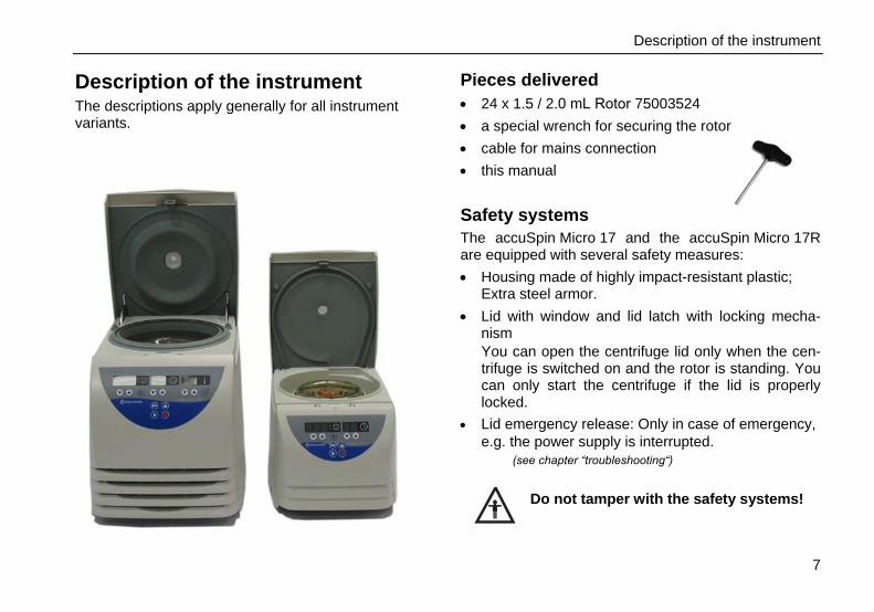
Description of the instrument The descriptions apply generally for all instrument variants.
Pieces delivered • 24 x 1.5 / 2.0 mL Rotor 75003524• a special wrench for securing the rotor• cable for mains connection• this manual
Safety systems The accuSpin Micro 17 and the accuSpin Micro 17R are equipped with several safety measures: • Housing made of highly impact-resistant plastic;
Extra steel armor.• Lid with window and lid latch with locking mecha-
nismYou can open the centrifuge lid only when the cen-trifuge is switched on and the rotor is standing. Youcan only start the centrifuge if the lid is properlylocked.
• Lid emergency release: Only in case of emergency,e.g. the power supply is interrupted.
(see chapter “troubleshooting“)
Do not tamper with the safety systems!

Description of the instrument
Properties
The accuSpin Micro 17 and the accuSpin Micro 17R are tabletop centrifuges designed for the use in bio-chemical and medical laboratories. The preset speed is reached in seconds. You can also spin samples for only a few seconds using the "quick run" key ( ) if this is required for the task in question. The extremely long-lived, maintenance-free induction motor provides quiet and vibration-free operation even at high speeds.The user-friendly user interface “Easy control” permits easy handling. Prior to the run, when the centrifuge is switched on and the lid is closed, the current values are displayed and the pre-selected set point value can be set. While the centrifuge is operating, the display informs of current values or (by quickly pressing one of the “set” keys or ) the pre-selected set point val- ues for speed/RCF and runtime, as well as tempera- ture in the refrigerated units. After the run, the speed control panel displays “End”.
8
If you press one of the keys or repeatedly, you increase or decrease the corresponding pre-selected set point value stepwise. If you press the chosen key and hold it pressed, the respective chosen measure-ment value increases or decreases continuously, at first slowly and, after a few seconds, at an accelerated pace. You can change the set values during operation.
"Quick run" operation As long as the "quick run" key ( ) is pressed, the rotor is accelerated with maximum power (potentially up to the maximum speed).

Before use
9
Before use Where to install the centrifuge The centrifuge may only be used indoors. Its location must meet the following criteria: • A safety zone of 30 cm around the centrifuge must
be maintained. Hazardous materials must not bekept within this zone during centrifugation.
• The substructure must be stable and resonance-free. A good support is provided by a plane labora-tory bench or a large laboratory carriage with cast-ers that may be locked.
• In the area of 15 cm around the centrifuge a suffi-cient air circulation has to be ensured.
• The centrifuge must be protected from heat anddirect sunshine. The ultraviolet radiation may dam-age the housing.
• The installation site should be always well venti-lated.
Transport and installation the centrifuge
Transport the centrifuge only in the upright position, using the special box provided with the in-strument, and secure it properly.
Place the centrifuge carefully to avoid damages.
Lift up the instrument only on the bottom plate. Mind the weight of the centrifuge during the transport! (See "Technical data") Let someone assist you in carrying the centrifuge!
Centrifuge with refrigeration unit
In order to allow the coolant to set-tle down in the compressor, the instrument must be left idle at the new location for approx. 1 hour.

Before use
10
Mains connection Make sure that the mains supply and the frequency meet the specifications printed on the centrifuge type plate. First turn the mains switch of the centrifuge off (press "0") and only then connect the centrifuge with the mains supply using the power cord supplied.
Removing the transport protection Before using the centrifuge, make sure that the rotor transport protection has been removed!
Turn the instrument on at the power switch. Open the centrifuge lid by pressing the "open lid" key and remove the transport protection for the rotor. Check the free run of the rotor body by lightly turning it, and make sure the rotor is tightly screwed and the rotor lid is securely mounted.

Accessories
11
Accessories The centrifuge is delivered complete with a fixed-angle rotor with 24 holes for placing Microliter tubes with a volume of 1.5 or 2.0 ml. In addition you may order three sets of adapters con-taining 24 reduction sleeves each. With these adapters you can centrifuge all commercially available Microliter tubes with a volume between 0.2 and 0.6 ml as well as 0.2 ml PCR reaction vessels. Wide range of various additional rotors is available.
Please consult our sales documentation for a complete collection of accessories including technical data and order numbers. For more information you can visit our web site at http://www.fishersci.com

Accessories
12
Rotors for the accuSpin Micro 17 Table 1: Performance characteristics for accuspin Micro 17
rotor designation
order no.
24 x 1.5 / 2.0 mL Rotor
75003524
36 x 0.5 mL Rotor
75003436
Dual Row 18 x 2 / 0.5 mL Rotor
75003418
places / volume 24 x 1.5 / 2 ml 36 x 0.5 ml 18 x 2 ml + 18 x 0.5 ml
maximum permissible load [ g ] 24 x 4 36 x 0.5 18 x 4 + 18 x 0.5
minimum speed nmin [ min-1 ] 300 300 300
maximum speed nmax [ min-1 ] 13300 13300 13300
maximum RCF value at nmax 17000 15600 16800
acceleration / deceleration time [ s ] 11/12 9/10 11/12
radius maximum/ minimum [ cm ] 8.6 / 5.1 7.9 / 5.0 8.5 / 4.8
angle [ ° ] 45 45 45
heating of samples at nmax [ °C ] relative to room temperature 23 °C, run time 1 hour
33 31 33
aerosol-tight * yes no no
permissible temperature range autoclavable (number of cycles)
-4 °C to +40 °C121 °C, (20 cycles)
-4 °C to +40 °C121 °C, (20 cycles)
-4 °C to +40 °C121 °C, (20 cycles)
* Tested and approved by HPA, Porton-Down, UK – Please see the references in the chapter "Aerosoltight Application"!

Accessories
13
Table 1: Performance characteristics for accuSpin Micro 17
rotor designation
order no.
PCR 4 x 8 Rotor 75003440
PCR 8 x 8 Rotor 75003489
Hematocrit Rotor
75003473
places / volume 4 x PCR-Strip 8 x PCR-Strip 24 x Blood capillary tubes 75 mm
maximum permissible load [ g ] 4 x 4 (32 x 0.5) 8 x 4 (64 x 0.5) 24 x 0.2
minimum speed nmin [ min-1 ] 300 300 300
maximum speed nmax [ min-1 ] 13300 13300 13300
maximum RCF value at nmax 13100 13800 16800
acceleration / deceleration time [ s ] 10 / 11 7 / 8 10 / 11
radius maximum / minimum [ cm ] 6.6 / 4.7 7.0 / 4.4 2.0 / 8.5
angle [ ° ] 45 60 90
heating of samples at nmax [ °C ] relative to room temperature 23 °C, run time 1 hour
31 31 34
aerosol-tight * yes no no
permissible temperature range autoclavable (number of cycles)
-4 °C to +40 °C121 °C, (20 cycles)
-4 °C to +40 °C121 °C, (20 cycles)
-4 °C to +40 °C134 °C
* Tested and approved by HPA, Porton-Down, UK – Please see the references in the chapter "Aerosoltight Application"!

Accessories
14
Rotors for the accuSpin Micro 17R Table 3: Performance characteristics for accuSpin Micro17R differences of 120V instruments are shown in parentheses
rotor designation
order no.
24 x 1.5 / 2.0 mL Rotor
75003524
Dual Row 18 x 2 / 0.5 mL Rotor
75003418
places / volume 24 x 1.5 / 2 ml 36 x 0.5 ml 18 x 2 ml + 18 x 0.5 ml
maximum permissible load [ g ] 24 x 4 36 x 0.5 18 x 4 + 18 x 0.5
minimum speed nmin [ min-1 ] 300 300 300
maximum speed nmax [ min-1 ] 13300 13300 13300
maximum RCF value at nmax 17000 15600 16800
acceleration / deceleration time [ s ] 10 / 12 8 / 10 10 / 12
radius maximum / minimum [ cm ] 8.6 / 5.1 7.9 / 5.0 8.5 / 4.8
angle [ ° ] 45 45 45
minimum temperature at nmax [ °C ] relative to room temperature 23 °C < 0 < 0 < 0
aerosol-tight * yes no no
permissible temperature range autoclavable (number of cycles)
-4 °C to +40 °C121 °C, (20 cycles)
-4 °C to +40 °C121 °C, (20 cycles)
-4 °C to +40 °C121 °C, (20 cycles)
* Tested and approved by HPA, Porton-Down, UK – Please see the references in the chapter "Aerosoltight Application"!
36 x 0.5 mL Rotor
75003436

Accessories
15
Table 3: Performance characteristics for accuSpin Micro 17R
rotor designation order no.
PCR 4 x 8 Rotor 75003440
PCR 8 x 8 Rotor 75003489
Hematocrit Rotor 75003473
places / volume 4 x PCR-Strip 8 x PCR-Strip 24 x Blood capillary tubes 75 mm
maximum permissible load [ g ] 4 x 4 8 x 4 24 x 0.2
minimum speed nmin [ min-1 ] 300 300
maximum speed nmax [ min-1 ] 13300 13300 13300
maximum RCF value at nmax 13100 13800 16800
acceleration / deceleration time [ s ] 9 / 12 6 / 8 9 / 11
radius maximum / minimum [ cm ] 6.6 / 4.7 7.0 / 4.4 2.0 / 8.5
angle [ ° ] 45 60 90
minimum temperature at nmax [ °C ] relative to room temperature 23 °C < 0 < 0 < 0
aerosol-tight * yes no no
permissible temperature range autoclavable (number of cycles)
-4 °C to +40 °C121 °C, (20 cycles)
-4 °C to +40 °C121 °C, (20 cycles)
-4 °C to +40 °C134 °C
* Tested and approved by HPA, Porton-Down, UK – Please see the references in the chapter "Aerosoltight Application"!

Accessories
16
Adapter Table 3: Adapter
adapter for 24 x 1.5 / 2.0 mL Rotor 75003524
max. tube dimensions d1) x length [ mm ]
tube capacity [ ml ]
number per set
color no. oforder
reduction sleeve PCR 0.2 24 grey 76003250
reduction sleeve 0.5 / 0.6 24 turquoise 76003252
reduction sleeve 0.25 / 0.4 24 red 76003251

Handling the rotor
17
Handling the rotor Rotor temperature
The rotors are only to be used within the temperature range from – 9 °C to +40 °C. Pre-tempering in a freezerbelow – 9 °C is forbidden.
Lifetime of the rotor There is no limitation on the service life of the high performance rotors. However please observe the fol-lowing due to safety reasons:
Rotors and accessories made of plastic should not be exposed to direct sunlight and UV radiations.
If the rotor shows signs of discolor-ation, deformation or wear, or imbal-ance it has to be exchanged straight away!
Rotor lid with a spring lock Opening The rotor lid is held on the central rotor nut integrated into the rotor
The rotor lid is opened by pressing the red unlocking-button in the central handhold of the rotor lid. The lid can be lift-off easy.
Handhold
Unlocking-button

Handling the rotor
18
- ClosingFor closing the rotor place the rotor lid centrically on the rotor nut. Press the rotor lid down now until the lock is audio-visually locked If the lid will not lock or it locks only with difficulty, the seals should be checked for proper fit and fouling and if necessary cleaned and softly lubricated. Likewise the lid mechanics is to be checked for fouling and proper functionality. Damaged parts must be exchanged immediately.
Always verify the tight fit of the rotor lid by pulling the lid after locking it!
Operation without rotor lid If you are going to operate the rotor without the rotor lid the aerosol-seals must be removed prior to use.
During the centrifugation without a rotor lid the aerosol seals are not longer fixed and may cause serious damage to the centrifuge! During the operation with opened tube caps, they can break away and cause damages.
Aerosol-seals

Handling the rotor
19
Rotor lid with screw plug For this kind of rotor the rotor lid will be held centrically on the rotor collar.
To close the rotor, place the rotor lid centrically on the rotor nut. By clockwise turning of the lid-handle the rotor lid is fixed.
Please always verify the fixed anchorage of the rotor lid!
These rotors are not designed for aerosoltight applications! The O-Ring in the rotor collar pro-vides only for tight fit of screw plug. The external lid lip cannot be sealed for these rotors.

Handling the rotor
20
Aerosol-tight application Only with the designated rotors!
See the "Rotor tables" from page 12.
Aerosol-tight rotors and tubes are only to be opened in an approved safety work bench when centrifuging danger-ous samples!
It is indispensable to observe the maximum permissible filling quantities!
Attention: Please check that your sample tubes are suitable for the centrifugal application desired:
- Gravitation fields up to 21100 x g,- temperature in uncooled devices maximum
approx. 15 K above room temperature.
Tubes are only to be filled to a level where the sample does not reach the brim of the tubes during centrifuga-tion.
Please observe the permissible filling volumes! Nominal volume: Permissible volume: 2.0 ml - 1.5 ml 1.5 ml - 1.0 ml others - 2/3 nominal volume
Aerosol-tight application not with open tube caps!

Handling the rotor
21
Correct operation when filling the sample tubes and closing the rotor lid are prerequisites for aerosol bio-containment.
Prior to each application, the seals in the rotors have to be checked for correct fit, abrasion or damage and have to be slightly greased.
Replace damaged seals immediately!
Use only the special lubricant 76003500 to grease the seals!
A set of spare seals is supplied with the rotor and can be ordered separately as spare seal set 75003405.
The following steps have to be carried out: • Lubricate the seals before inserting them
(lubricant order no. 76003500)
• Press the smaller V-seal into the groove of therotor collar (a).
• Insert the seal (C-profile) in the outer groove of therotor body (b).
Pay attention after loading the rotor to safe closing of the rotor cover!
Replace damaged or dulled rotor lids promptly!

Handling the rotor
22
Checking for aerosol-tightness The checking of the rotor type and bucket was done according to the dynamic microbiological test proce-dure with regard to EN 61010-2-020 appendix AA. The aerosol-tight bio-containment of the rotor mainly depends on proper handling!
Check the aerosol-tight bio-containment of your rotor whenever necessary!
It is very important that all the seals and seal-surfaces are carefully inspected for wear and damages like cracks, scratches and embrittlement!
For a quick test one can check the fixed angle rotors according to the following procedure: • Slightly grease all seals.• Fill the rotor with approx. 10 ml carbon dioxide
mineral water.• Close the rotor according to the respective han-
dling instructions.• Due to the shaking, the carbon dioxide of the water
is released, and an overpressure is built up. Do notpress the lid simultaneously.
• Leaks are recognized by humidity release andaudible disinflation of gas mix.
• In case of leakage the aerosol-seals have to bereplaced and the leakage check has to be re-peated.
• Dry rotor, rotor lid and lid seal.

Operation
23
Operation Switching on the centrifuge Set the main power switch of the instrument. For a couple of seconds the following reading appears in the control panel (the temperature display field only) for cooled instrument:
The display shows that the instrument is going through an internal check of its software. After this check, the display switches into the current value mode. The speed and remaining run time show 0. The refrigeration unit display shows the current tem-perature of the sample. (Prior to the start of the centrifuge, the display usually shows the temperature of the rotor chamber). The following figure gives an example of possible read-ings of the display. A detailed description of possible settings is given below in this chapter.
Opening the lid For activating the lid release the centrifuge must be connected to mains and switched on!
. To open the lid press the “open-lid”-button The display reads:
(Emergency release in case of malfunction or power failure: see chapter “Troubleshooting”)
Closing the lid The centrifuge lid is locked by slightly pressing down the front part of the lid.
Do not slam the lid!

Operation
24
Installing the rotor
Improper or improperly combined accessories may cause severe dam-age to the centrifuge!
The centrifuge rotors approved are detailed in the chapter “Accessories”. Use only rotors listed for this instrument. To insert the rotor, you need the special wrench deliv-ered with the instrument (see chapter “accessories”).
You may insert the rotor only when the temperature difference of the drive and the rotor drive shaft achieves maximum 20 °C. Otherwise the rotor may jam during the installation.
The installation of a clamping rotor can lead to damages of the drive shaft and rotor!
Proceed as follows:
1. Open the centrifuge lid and make sure that therotor chamber and the rotor are clean. Removeeventual dust, foreign material or sample residues.The thread and the O-Ring on the motor shaft mustbe in perfect condition.
2. Turn the rotor so that the notch for engaging thedrive shaft points downward.
3. Place the rotor on top of the drive shaft so that thenotch of the rotor is located precisely above the re-taining pin. (There are two bars in the labelling onthe upper side of the rotor indicating the position ofthe notch). These bars make the positioning easy.

Operation
25
4. Press the rotor gently down until it stops.5. Grip the rotor tightly and use the provided rotor
wrench to tighten up the rotor.
Do not push the rotor down using force.
If the rotor cannot be tightened, you have to remove it carefully, align the notch and the retaining pin again and re-install it.
6. Place the rotor lid onto the rotor, and attend to thetight fit of the rotor.
Check tight placement of the rotor regularly and re-tighten the rotor as needed.
Attention at the replacement of the rotor after the centrifugation!
Rotor drive and motor end shield may be hot (>55 °C).

Operation
26
Loading the rotor Maximum load
Overloading may cause the rotor to explode!
Exploding parts may severely damage the centrifuge!
The centrifuge can reach high rotational speeds imply-ing enormous centrifugal force. The rotors are de-signed in a way warranting sufficient residual strength even at the highest permissible speed. However, this safety system presupposes that the maximum permissible load of the rotor is not exceeded. If you wish to centrifuge samples that together with the adapters exceed the maximum permissible load, you must either reduce the sample volume or calculate the permissible speed nperm according to the following for-mula:
load actual
load epermissibl maximumn
permn ∗=
max
Filling the centrifuge tubes
Please note that plastic sample vessels only have a limited service life - particularly when used at maximum performance (rpm or tem-perature) - and must be replaced as neces-sary!
Check carefully whether your sam-ple vessels are permissible for the respective g value and reduce the speed if necessary.
The smaller the centrifuge imbalance, the better the separation, because separated zones are no longer perturbed by vibration. It is therefore important to bal-ance the centrifuge tubes as well as possible. To minimize imbalance you should fill the tubes as evenly as possible. You can achieve this by eye. How-ever, you must nonetheless ensure that opposite tubes are filled to the same level.
Operation
27
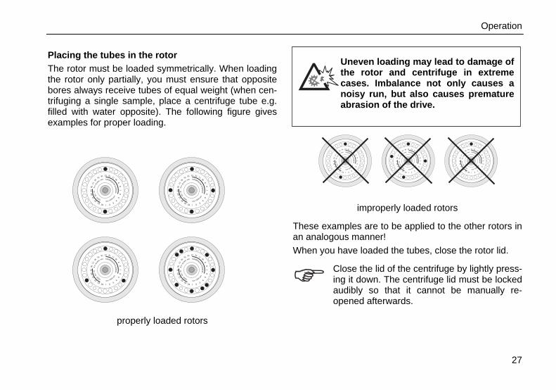
Placing the tubes in the rotor The rotor must be loaded symmetrically. When loading the rotor only partially, you must ensure that opposite bores always receive tubes of equal weight (when cen-trifuging a single sample, place a centrifuge tube e.g. filled with water opposite). The following figure gives examples for proper loading.
properly loaded rotors
Uneven loading may lead to damage of the rotor and centrifuge in extreme cases. Imbalance not only causes a noisy run, but also causes premature abrasion of the drive.
improperly loaded rotors
These examples are to be applied to the other rotors in an analogous manner! When you have loaded the tubes, close the rotor lid.
Close the lid of the centrifuge by lightly press-ing it down. The centrifuge lid must be locked audibly so that it cannot be manually re-opened afterwards.
1 23
4
56
78
910
1112131415
1617
1819
2021
2223
24 1 23
4
56
78
910
1112131415
1617
1819
2021
2223
24 1 23
4
56
78
910
1112131415
1617
1819
2021
2223
24
max 13000 rpm
HE
RA
EU
SIN
STRUMENTSmaxload
24x
4g
pp1/96
#3324max 13000 rp
mH
ER
AE
US
INSTRUMENTSmaxload
24x
4g
pp1/96
#3324max 13000 rp
mH
ER
AE
US
INSTRUMENTSmaxload
24x
4g
pp1/96
#3324
1 23
45
67
89
1011
1213141516
1718
1920
2122
2324
1 23
45
67
89
1011
1213141516
1718
1920
2122
2324
1 23
45
67
89
1011
1213141516
1718
1920
2122
2324
1 23
45
67
89
1011
1213141516
1718
1920
2122
2324
max 13000 rpm
HE
RA
EU
SIN
ST
RUMENTSmaxload
24x
4g
pp1/96
#3324
max 13000 rpm
HE
RA
EU
SIN
ST
RUMENTSmaxload
24x
4g
pp1/96
#3324
max 13000 rpm
HE
RA
EU
SIN
ST
RUMENTSmaxload
24x
4g
pp1/96
#3324
max 13000 rpm
HE
RA
EU
SIN
ST
RUMENTSmaxload
24x
4g
pp1/96
#3324

Operation
28
Entering parameters Switching from speed to RCF display Upon turning on the centrifuge, the speed display is set. By activating the selection key you can switch to the RCF- value or change between rpm and RCF displays.
Selecting speed The centrifuge speed can be set to a minimum of 300 rpm. The maximum speed depends on the centrifuge version). You can adjust the speed in 100 rpm increments. Proceed as follows: 1. Press one of the "set" keys (for increase) or
(for decrease) in the field “speed” of the control panel to enter the pre-selected value mode (cf. foldout leaf in the cover):
By pressing the key briefly, you increase or decrease the speed in one step (of 100 rpm). This option is supposed to be used for small changes and fine tuning.
2. If you hold the key pressed, the display changescontinuously at first slowly and after a few secondsat an accelerated pace to the higher or lower val-ues.
3. Release the key as soon as you reached the de-sired value and fine tune if necessary by repeatedlybriefly pressing the selected key). The first digit be-hind the decimal point flashes for a few secondsand then switches permanently inro the currentvalue mode. The new pre-selected speed is nowstored.

Operation
29
Entering the RCF value You can adjust the RCF pre-selected value in steps of 100 xg. The setting of pre-selected value is entered analogously to the speed. The RCF value can be set to a minimum of 100xg. The setting of a maximum RCF depends on the type of centrifuge.
The displayed RCF value is always corres-ponding to the maximum of centrifuge radius of the 24 x 1.5 / 2.0 mL Rotor (75003524).
For other rotors please use the formula beneath or follow the enclosed speed/RCF diagrams.
Mind the rounding difference! Due to limited display digits there is a need to round the values. The direct comparison between the two values speed and RCF is therefore restricted.
Concerning the RCF value The relative centrifugal force (RCF) is given in multi-ples of the earth gravity g. It is a dimensionless number value that allows one to compare the efficiency of separation or sedimentation of diverse instruments, since it is independent of the instrument used. The only values entered in the equation are radius and speed of centrifugation:
rnRCF ∗⎟⎠⎞
⎜⎝⎛∗=
2
100018.11
r = radius of centrifugation in cm n = speed in rpm
The maximum RCF value refers to the maximum ra-dius of the vessel bore.
Please note that this value becomes lower depending on the tubes and adapters used.
You may take this into account when calculating the RCF value for your application.

Operation
30
Selecting the run time You can select a run time between 1 and 99 min or continuous operation [hd].
Run time selectionTo predetermine the fixed run time, proceed as follows:1. Press one of the "set" keys (for increase) or
(for decrease) in the field “time” of the control panelto enter the pre-selected value mode (cf. foldoutleaf in the cover):
By pressing the selected key briefly, you increase or de-crease the preset run time in steps of 1 min. This option is supposed to be used for small changes and fine tuning.
2. If you keep the key pressed, the display changes atfirst slowly and after a few seconds at an acceler-ated pace to the higher or lower values.
3. Release the key as soon as you have reached the desired value and fine tune if necessary by repeat-edly briefly pressing one of the keys. The run time display flashes for a number of seconds, then changes to permanent display of the current value mode. The new pre-selected run time is now stored.
Continuous operation To operate the centrifuge in the continuous mode, you must press the key until the display changes to “hd” (for “hold”).
In this mode the centrifuge runs until you stop the run by manually pressing the “Stop”-button .
Please note that the lifetime of particularly plastic rotor tubes is limited. Continuous operation (extended use) may cause dam-age to them!

Operation
31
Setting the temperature To determine the sample temperature for instruments with refrigeration unit, operate as adviced: 1. Press one of the "set" keys (for increase) or
(for decrease) in the field “temperature” of the control panel to enter the pre-selected value mode (cf. foldout leaf in the cover):
By pressing the key briefly, you increase or decrease the tempe-rature in steps of 1 °C.
This option is supposed to be used for small changes and fine tuning.
2. If you keep the key pressed, the display changesat first slowly and after a few seconds at an accel-erated pace to the higher or lower values.
3. Release the key as soon as you are close to thedesired value and fine tune if necessary by repeat-edly briefly pressing the key. The display flashesfor a few seconds and then turns to permanentdisplay of the current value mode. The new pre-selected temperature is now stored.
The refrigeration starts operating after closing the cen-trifuge lid, at once if the pre-selected temperature is below the current temperature of the rotor chamber.

Operation
Pretemp The pretemp-function allows quick and easy tempering of the unloaded rotor. After calling the function by pressing the key only the desired temperature still must be chosed.
(If any other key is pressed, the pretemp function will be quit).
After activating the "start“ key the rotor will be oper-ated at optimal speed until the the desired tempera-turen is reached.
An LED above the “ ” key indicates operation at the activated pretemp function.
32
If you wish to change the temperature of your samples, please consider that the time required for temperature adjustment is prolonged. The farther apart initial and final temperature, the longer it takes for the tempera-ture to adjust.
The temperature reading does not give the change in the temperature of the sample (the temperature display reading is delayed with respect to the /actual/ sample tempera-ture change). You can neither witness the heating nor the cooling of the samples di-rectly. For critical applications you should take other precautions to ensure that the desired temperature is actually reached and maintained (e.g. by measuring the tempera-ture immediately after the centrifugation run).

Operation
33
Starting the centrifuge Once the rotor is properly installed, the main switch turned on and the lid closed, you can start the centri-fuge. Press the "start" key in the control panel. The centri-fuge accelerates to the pre-selected value, simultane-ously, the run time display starts counting backwards per minute. If the remaining run time of one minute is under-run, the time display switches to counting sec-onds.
The rotating light in the speed display indicates that the centrifuge is running. During continuous operation “hd”, the run time is dis-played in forward run. Display first starts per second, after one minute the display switches to minutes.
During the run, you cannot open the lid.
Changing the settings during the run You can change the settings while the rotor is spinning. Through a one-time pressing of any key of the control panel, the current value will switch into the pre-selecting value mode.
The setting to be altered value flashes, and can then be changed. Once the display switches into the current value mode after completion of the entered values, the new values are activated. You can stop the centrifuge at any time by pressing the “stop” key . .

Operation
34
Stopping the centrifuge Preset run time Normally the run time has been pre-selected, and all you have to do, is to wait until the centrifuge terminates the run automatically. As soon as the speed is down to zero, the display reads "End". By pressing the "open lid" key , you can now open the lid and remove your centrifugation sam-ples. You can stop the centrifuge at any time by pressing the "stop“ key .
Continuous operation If you have chosen continuous operation, you must stop the centrifuge manually. Press the "stop" key in the control panel. The centrifuge starts braking at once and stops within a few seconds. The display reads "End", the electrical lid unlocking mechanism is avail-able. You can now open the lid by pressing the "open lid" key and remove your centrifugation samples.
Short-time centrifugation For short-term operation, the centrifuge is equipped with the "quick run" function. Short-term centrifugation is started by pressing the "quick run" key continuously; it stops as soon as the key is released. In this mode the centrifuge accelerates with full power up to the maximum speed unless you release the "quick run" key . The pre-selected speed is ignored.
The centrifuge accelerates to the maximum speed.
Check carefully whether you have to maintain a specific speed limit for your application.
During the activating of the "quick run" key first the time is counted forward in seconds. After 60 seconds the display changes to the minute cycles.

Operation
35
Removing the rotor To remove the rotor you have to proceed in the reserve order as at the installation of the rotor. In case of contamination you can remove the rotor from the drive shaft without opening the aerosol lid. Then you can open the removed rotor e.g. in a safety work bench and decontaminate it.
1. Open the centrifuge lid.2. Unscrew the rotor nut with the provided. Turn the
rotor nut counterclockwise.3. Grab the rotor centrically and carefully pull it per-
pendicularly off the drive shaft. Make sure not to tiltit.
Audible alarm Accompanying all error messages, a warning signal is given out which can be silenced upon pressing any key. By default there is an acoustic signal at the end of any centrifugation run. You have the possibility to switch off this signal. For this, you have to press the "speed/ RCF" switch key while switching on the centrifuge.
Depending on the pre-selected mode the display shows the following signs: “Snd” “on” or "Snd" "oF". By pressing the set keys or in the field “time” the acoustic signal function can be turned off or on. Sub-sequently, by pressing the stop key the new setting will be activated.

Operation
36
Turning off the centrifuge The centrifuge is turned off by switching the main switch into the "0" position.
The main power switch should be turned off after a complete centrifugation run. Without motor deceleration, it takes much longer until the rotor comes to a halt.
The centrifuge is equipped with a special switch for balancing potential voltage discrepancies in the power grid. After pressing the mains switch the display therefore may still flash up to 10 seconds.
The opening of the centrifuge lid is only possible by means of "lid open“ key while the centrifuge is switched on!
WEEE Compliance: This product is required to comply with the European Union`s Waste Electrical & Electronic Equipment (WEEE) Directive 2012/19/EU. It is marked with the following symbol:
Fisher Scientific® has contracted with recycling / dis-posal companies in each EU Member State, and this product should be disposed of or recycled through them. Further information on Fisher Scientific`s compliance with these Directives, the recyclers in your country, and information on Fisher Scientific® products which may assist the detection (EU-standard on the limitation of hazardous substances) of substances subject to the RoHS Directive are available at www.fishersci.com

Maintenance and care
37
Maintenance and care Maintenance to be performed by the customer For the protection of persons, environment and mate-rial you are obliged to clean the centrifuge regularly and to disinfect it if necessary.
Unsuitable cleaning agents or disin-fection procedures may damage the centrifuge and its accessories!
Before using cleaning agents or dis-infection procedures not recom-mended by the manufacturer, the user have to make sure by consulting the manufacturer, that the procedure foreseen does not cause any dam-ages to the instrument!
Instruments with refrigeration unit: If a strong ice sheet is present in the internal chamber, be sure to remove all condensate after defrosting!
Cleaning
Pull mains plug before cleaning the in-strument!
Clean the casing, the rotor chamber, the rotor and the accessories regularly and in case of need. This is indi-cated both for reasons of hygiene and to prevent cor-rosion due to contamination sticking to the instrument and its accessories. Clean them with mild agents of pH values ranging from 6 to 8. Immediately after cleaning, dry the aluminum parts or put them into a warm-air dryer at a temperature not exceeding 50 °C.
During cleaning liquids and espe-cially organic solvents should not come into contact with the drive shaft and the ball bearing.
Organic solvents may decompose the lubricant of the motor bearing causing the drive shaft to lock.
Maintenance and care
38
Clip of the filter unit
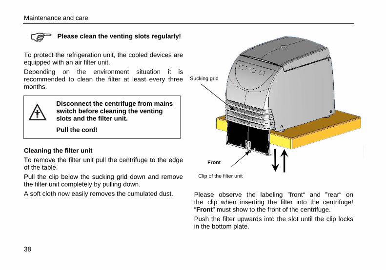
Please clean the venting slots regularly!
To protect the refrigeration unit, the cooled devices are equipped with an air filter unit. Depending on the environment situation it is recommended to clean the filter at least every three months.
Disconnect the centrifuge from mains switch before cleaning the venting slots and the filter unit.
Pull the cord!
Cleaning the filter unit To remove the filter unit pull the centrifuge to the edge of the table. Pull the clip below the sucking grid down and remove the filter unit completely by pulling down. A soft cloth now easily removes the cumulated dust. Please observe the labeling "front“ and "rear“ on
the clip when inserting the filter into the centrifuge! “Front” must show to the front of the centrifuge. Push the filter upwards into the slot until the clip locks in the bottom plate.
Sucking grid
Front

Maintenance and care
39
Disinfection If a centrifuge tube containing infectious material leaks, during a centrifugation run, you have to disinfect immediately the rotor, and/or also the centrifuge.
Infectious material could enter the centri-fuge if spills or tube breakage occur. Danger of infection may occur upon con-tact! Take appropriate protective measures for personnel! Mind the permissible filling volumes and loading limits for the tubes! In case of contamination the operator has to make sure, that no further persons are jeopardized! Contaminated parts have to be decon-taminated immediately. If required further protective measures have to be initiated.
Rotor and rotor chamber must be treated with a neutral, universal disinfectant. Best suited for this purpose are disinfectant sprays, ensuring that all rotor and ac-cessory surfaces are covered evenly.
Please note the safety measures and handling hints when applying these substances!
You may disinfect the rotor and the accessories as described in the following section. Be sure to follow the pertinent safety procedures for handling infectious material. 1. Unplug mains cord.2. Unscrew the rotor from the shaft.3. Grab the rotor with both hands and pull it perpen-
dicularly off the drive shaft.4. Remove the centrifuge tubes and adapters, and
disinfect them or dispose of them as necessary.

Maintenance and care
40
5. Treat the rotor and the rotor lid according to theinstructions given for the disinfectant (soaking inliquid or spraying). You must strictly observe thespecified action times!
6. Turn the rotor head down and drain off the disinfec-tant. Thereafter thoroughly rinse rotor and lid withwater.
7. Dispose of the disinfectant according to valid regu-lations.
8. Aluminum rotors have to be treated with anticorro-sive protective oil subsequently.
9. All seals have to be lubricated again.
Disinfection with bleaching lye
These agents contain highly ag-gressive hypochlorite's and must not be used with aluminum rotors!
The following precautionary measures are to be taken for extensive protection of the plastic rotors: 1. Avoid high temperatures!
The bleaching solution and the rotor should not be warmer than about 25 °C.
2. Do not let the bleaching solution act longer than absolutely necessary!
3. After disinfection, rinse the rotor thoroughly with distilled water and allow drying.
4. All seals have to be lubricated again.

Maintenance and care
41
Decontamination
For general radioactive decontamination, use a solution of equal parts of 70 % ethanol, 10 % SDS and water. Follow this with ethanol rinses, then deionized water rinses, and dry with a soft absorbent cloth. Dispose of all washing solutions in appropriate radioactive waste containers!
Autoclaving
Check whether autoclaving is permitted!
You may autoclave the rotor, rotor lid and the adapters at 121 °C. Maximum permissible autoclaving cycle: 20 minutes at 121 °C.
For safety reasons, the plastic rotors and rotor lids must only be subjected to a maximum of 20 autoclaving cycles!
The rotor must be cleaned and rinsed with distilled water before being autoclaved. Remove the rotor lid, the centrifuge tubes and the adapters. Place plastic rotors on an even surface to avoid deformation.
Chemical additives to the steam are not permitted.
Never exceed the maximum permis-sible values for autoclaving tem-perature and autoclaving time.
Should the rotor show signs of wear or corrosion, you must stop using it!

Maintenance and care
42

Troubleshooting
43
Troubleshooting Mechanical emergency lid release In case of a power failure you cannot open the lid nor-mally using the electric emergency release. To permit unloading even in this case, the centrifuge is equipped with a hand operated lid unlocking system. However, you may use this system only in case of emergency.
Rotor can spin at high speed! Touching it may cause severe inju-ries!
Always wait for several minutes until the rotor has come to a complete standstill without deceleration. With-out power the brake does not func-tion, and braking takes much longer
than normal!
Should it be necessary to open the lid manually, pro-ceed as follows using an appropriate/special tool:
1. Make sure the rotor stands still. (control window).2. Unplug the mains cord.3. Push a small straight wire of a length of approx.
7 cm (e.g. a bended paper clip etc.) through thehole located in the middle above the display, atthe chamber edge.

Troubleshooting
44
4. Gently press the centrifuge lid down to disengagethe lid-latch.
5. While pressing down the lid push the wire downfurther until you hear and feel the lid-latch unlock-ing. Remove the auxiliary tool and open the centri-fuge lid.
6. In case the rotor still turns, close centrifuge lid im-mediately and wait until it has come to a completestandstill.
Never brake the rotor using your hands or tools!
7. As soon as the rotor stands still, remove your sam-ples and close the centrifuge lid.

Troubleshooting
45
Problems you can handle yourself If problems other than those described in the following tables arise, you must consult your nearest au-thorized service.
Error Symptom Possible causes and corrective measures
Displays remain dark The drive stops. The rotor stops without deceleration. The lid cannot be opened.
Mains voltage disconnection 1. Is the mains switch turned on?2. Check the mains connection.
If the mains connection is ok, contact the servicerepresentative.
Displays fail briefly. The drive stops suddenly. The rotor stops without deceleration.
Main connection was briefly interrupted 1. Turn off mains switch.2. Check whether the mains power cord is connected
properly.3. Restart the centrifuge.
Centrifuge lid cannot be opened.
Pressing the "open lid" key has no effect.
Centrifuge lid not correctly engaged or lid warped. 1. Check if mains connection is working and the instrument
is switched on (display is lit).2. If this is unsuccessful, you may open the centrifuge lid
using the mechanical emergency lid release (see"mechanical emergency lid release" page 43).

Troubleshooting
46
Error Symptom Possible causes and corrective measures
– Exceptionally running noise.
Imbalance. 1. Stop the centrifuge by pressing the "stop" key, in case of
emergency, unplug mains power cord.2. Wait until the centrifuge comes to a complete stop.3. Check whether the rotor is properly loaded.4. Check whether a broken tube, damage to the rotor or
motor is responsible for the run noise.If you cannot locate and solve the problem yourself, contact a service representative
Display "oP" appears although lid is closed.
Will not start. Centrifuge lid not properly closed - Open the lid and repeat locking procedure.If you cannot locate and solve the problem yourself, contact a service representative.
“Lid” Rotor stops with deceleration to standstill.
Centrifuge lid was opened manually during the run. - Close centrifuge lid immediatelyThe instrument phases out with deceleration.For further centrifugation, you have to switch the instrument off and switch it on again.

Troubleshooting
47
Error Symptom Possible causes and corrective measures
"bAL" The rotor stops with decel-eration.
Imbalance switch releases. 1. Open the instrument by pressing the “lid open” in case.
2. Check whether the rotor is properly loaded.3. Check whether a broken tube or a damage to the rotorrelease the imbalance switch.
If you cannot locate and solve the problem yourself, contact a service representative.
E-01|
E-13
Rotor stops without deceleration to standstill. Instrument cannot be operated.
Internal program error. Switch the instrument off and on again. If the error persists, contact service representative.
E-14 Rotor stops with deceleration to standstill. Instrument cannot be operated.
Overtemperature in the centrifuge chamber. Switch the centrifuge off and turn it on again after approx. one minute. If the error persists, contact service representative.
E-15|
E-16
Rotor stops with deceleration to standstill. Instrument cannot be operated.
Temperature measurement error. Switch the instrument off and on again. If the error persists, contact service representative.

Troubleshooting
48
Error Symptom Possible causes and corrective measures
E-22/E-23 Rotor stops without deceleration to standstill. Instrument cannot be operated.
Error in speed entry Switch the instrument off and on again. If the error persists, contact service representative.
E-24 Instrument cannot be operated.
Wrong status information from the lid-latch. 1. Turn the centrifuge off and on.2. After re-switching on, the display shows "Lid FAiL"3. If the centrifuge lid has been already opened, the display
shows "Close Lid". Thereupon close the lid.4. The centrifuge tries to open the lid to switch for starting
the normal operation mode.If the error persists, contact service representative.
E-29 Motor does not start. Motor or rotor blocked. 1. Switch instrument off and on again using the mains
switch.2. Open the centrifuge lid.3. Check whether the rotor can turn freely.If you cannot clear the malfunction, contact a service representative.

Troubleshooting
49
Error Symptom Possible causes and corrective measures
E-31 Rotor stops without deceleration to standstill or does not start.
Overtemperature in the motor. 1. Turn instrument off and unplug mains power cord.2. Check and clean the venting slots if necessary and re-
spectively the filter unit of the cooled centrifuge.3. After approx. 60 minutes you can restart the instrument.Observe the maximum permissible environmental temperature! If the error persists, contact a service representative.
E-33 Rotor stops with deceleration to standstill or does not start.
Overpressure in the refrigeration system 1. Turn instrument off and unplug mains power cord.2. Check and clean the venting slots if necessary and re-
spectively the filter unit of the cooled centrifuge.3. After approx. 60 min. you can restart the instrument.Observe the maximum permissible environmental temperature! If the error persists, contact a service representative.
E-36 Rotor stops without deceleration to standstill. Instrument cannot be operated.
Overcurrent or error in current measurement. Switch the instrument off and on again. If the error persists, contact service representative.

Troubleshooting
50
Error Symptom Possible causes and corrective measures
E-41|
E-56
Rotor stops without deceleration to standstill. Instrument cannot be operated.
Internal program error. Switch the instrument off and on again. If the error persists, contact service representative.
E-60 Rotor stops with decelera-tion.
Insufficient temperature in the refrigeration unit. 1. Stop the centrifugation run.2. Open the centrifuge lid, defrost the chamber.
Never touch the chamber directly with your hands – you may freeze up!
3. After approx. 60 minutes you can restart the instrument.Observe the maximum permissible environmentaltemperature!
4. If a strong ice sheet is present in the internal chamber,be sure to remove all condensate after defrosting.
If the error persists, contact service representative.

Troubleshooting
51
Contacting Service Should you require help from your service represen-tative, please indicate the catalog and serial number of your instrument. You will find the pertinent infor-mation at the specifications, near the socket for the main plug. Moreover it is helpful for our service representative to know your software version. You can determine the software version as follows: 1. Switch the instrument off.2. pressed and switch on the Keep "stop“key instrumentFor approx. 1 second all displays read:
Subsequently, the following readings will be dis-played for 5 seconds each
Software number SoFt 0 5 8 3 _
Software version _ 0 1
NV-RAM number EEPro 4 6 2 1 _
NV-RAM version _ 0 1
The last information displayed indicates the current cycle status.
Cycle counter CYCLE 0 0 1 2 5
The values shown above are just examples. Your readings may be different. In the example shown here the values mean the following: • Software 0583 version 01• NV-Ram 4621 version 01• 125 cycles completes

Troubleshooting
52
for your notes

Technical data
53
Technical data Component parts
Part / function Description
Hausing/body Sheet steel chassis with attached plastic housing and steel reinforcement
Keys and display panel Keys and display panel covered with easy care protective foil
Operation "Easycontrol" system
Rotor chamber dimensions (D x H) (diameter x height):
accuSpin Micro 17accuSpin Micro 17R
190 mm x 70 mm 200 mm x 75 mm
Chamber Up to 48 ml of spilled liquids are retained in the chamber and cannot enter the in-strument.
Lid lock Automatic locking when the lid is pressed shut
Lid opening Electromagnetic release via the "open lid" key when connected to mains
Emergency lid release Lid release in case of power failure: emergency opening with auxiliary tool.

Technical data
54
The "Easycontrol" user interface Function Performance
Start Start key ( )
Stop Stop key ( )
Quick starting and stopping "Quick run" key ( ): short-time run when pressed permanently; stop when re-leased
Indication of operating state Spinning rotor indicated by rotating lights (LED) in the speed display panel
End of centrifugation Speed display reads "End"
Cycle counter The cycle counter is displayed while switching on the centrifuge and simultane-ously pressing the "Stop“-button
Digital parameter display • speed/RCF• run time• temperature* (only for refrigeration units)
Speed selection adjustable in steps of 100 min-1 in the range 300 min-1 to nmax*
Run time selection adjustable in minutes between 1 min and 99 min; "hd" mode: continuous operation
Time display in "quick run" mode between 1 s and 60 s in seconds, above 60 s in minutes
*depending on the instrument

Technical data
55
Performance
Performance Value/description (accuSpin Micro 17/ 17R in parentheses)
environmental conditions - indoor use- maximum elevation 2000 m above sea level- maximum relative humidity 80 % up to 31 °C;
linearly decreasing down to 50 % relative humidity at 40 °C.
permissible temperature of the environment 5 °C to + 40 °C during operation (no condensation) -10 °C to 50 °C for storage and shipping
minimum speed nmin 300 min-1
maximum speed nmax 14800 min-1 (13300 min-1)
maximum RCF value at nmax 21000 (17000) 24 x 1.5 / 2.0 mL Rotor 75003524
maximum kinetic energy 2.35 kNm (1.90 kNm)
set temperature range AccuSpin Micro 17R adjustable in steps of 1 °C between -9 °C and 40 °C
noise at maximum speed AccuSpin Micro 17 AccuSpin Micro 17R
56 dB (A) 50 dB (A)

Technical data
56
Performance Value/description
dimensions (H x W x D) accuSpin Micro 17 accuSpin Micro 17R
230 mm x 240 mm x 350 mm 330 mm x 292 mm x 440 mm
weight with rotor accuSpin Micro 17 accuSpin Micro 17R
10.5 kg 28.0 kg
Testing standards - all devices manufactured and examined inagreement with:
- for 120 V only
- for 230 V only
IEC 61010-1:1990 + amendment 1:1992 + amendment 2:1995 IEC 61010-2-020:1993 + amendment 1:1996
- Pollution degree 2, - Overvoltage category IIIEC 60529 protection version IP 20
CAN/CSA-C22.2 No. 1010-1.92 CAN/CSA-C22.2 No. 1010-1.B97 amendment 2 UL 61010 A-1
EN 61010-1, EN 61010-2-020 EN 61326, EN 55011 B

Technical data
57
Electrical connections Order no. Voltage Frequency Nominal
current Power
consumptionFuses inside instrument *
accuSpin Micro 17 75002460 230 V ±10% 50/60 Hz 1.4 A 180 W 2 x 4.0 AT 250 V (5 x 20 mm)
accuSpin Micro 17 75002461 120 V ±10% 60 Hz 2.6 A 180 W 2 x 6.3 AT 250 V (6.3 x 32 mm)
accuSpin Micro 17R 75002462 230 V ±10% 50/60 Hz 1.9 A 320 W 2 x 4.0 AT 250 V (5 x 20 mm)
accuSpin Micro 17R 75002463 120 V ±10% 60 Hz 3.9 A 330 W 2 x 6.3 AT 250 V (6.3 x 32 mm)
* The fuse may be replaced only by authorized servicing personnel!

Technical data
58
Centrifuge Refrigerant Quantity Pressure GWP CO2e
75002462 Fisher Scientific AccuSpin Micro 17R
R-134a 0.26 kg 21 bar 1430 0.37 t
75002463 Fisher Scientific AccuSpin Micro 17R
R-134a 0.26 kg 21 bar 1430 0.37 t
Order No.
Refrigerant
Contains fluorinated greenhouse gases in a hermetically sealed system.

Appendix
59
Appendix

Appendix
60
1
10
100
1000
10000
100000
100 1000 10000 100000
Speed/RCF diagram
Speed/RCF diagram 24 x 1.5 / 2.0 mL Rotor 75003524
RC
F [x
g]
speed (rpm)
rmax = 8.6 cm rmin = 5.1 cm
nmax = 14800 min-1 RCF (rmax nmax) = 21058

Appendix
61
1
10
100
1000
10000
100000
100 1000 10000 100000
Speed/RCF diagram 36 x 0.5 mL Rotor 75003436
RC
F [x
g]
speed (min-1)
nmax = 14 800 min-1 RCF (rmax nmax) = 19344
rmax = 7.9 cm rmin = 5.0 cm

Appendix
62
1
10
100
1000
10000
100000
100 1000 10000 100000
Speed/RCF diagram Dual Row 18 x 2 / 0.5 mL Rotor 75003418
RC
F [x
g]
Speed (min-1)
nmax = 14 800 min-1 RCF (rmax nmax) = 20813
rmax = 8.5 cm rmin = 4.8 cm

Appendix
63
1
10
100
1000
10000
100000
100 1000 10000 100000
Speed/RCF diagram PCR 4 x 8 Rotor 75003440
RC
F [x
g]
speed (min-1)
nmax = 14 800 min-1 RCF (rmax nmax) = 16161
rmax = 6.6 cm rmin = 4.7 cm

Appendix
64
1
10
100
1000
10000
100000
100 1000 10000 100000
Speed /RCF diagram PCR 8 x 8 Rotor 75003489
RC
F [x
g]
speed (min-1)
nmax = 14 800 min-1 RCF (rmax nmax) = 17140
rmax = 7.0 cm rmin = 4.4 cm

Appendix
65
For your notes

Appendix
66
Autoclaving protocol Date Remark Operator Signature
1
2
3
4
5
6
7
8
9
10

Appendix
67
Autoclaving protocol Date Remark Operator Signature
11
12
13
14
15
16
17
18
19
20

Appendix
68
For your notes

Index
69
Index
A acceleration 8 acceleration time 12, 13 accessories
rotor 11 Adapter 16 aerosol-tight 12, 13, 22 aerosol-tightness
test 22 aluminum rotor: 40 approved rotors 24 autoclaving 41 autoclaving cycle
permissible maximum 41
C centrifuge
starting 33 centrifuge exceptionally noisy 46 centrifuge tubes
types 11 volume range 11
cleaning 37 common glass or plastic centrifuge tubes 4 Conformity 5
contamination necessary measures 39
continuous operation 30, 34 corrosion 4 corrosive substances
protective tubes for corrosive substances 4
D damage
symbol for potential 3 dangerous chemicals 4 deceleration time 12, 13 decontamination 39, 41 Decontamination 41 dimensions 56 disinfectant 39 disinfection 4
procedure 39 display
during run 33 displays
brief failure 45
E electrical connections 57 error codes

Index
70
„OPEN“ with lid closed 46 error codes
E-01 ... E-60 47
F fine tuning
temperature 31 fixed-angle rotor 11 formula
maximum permissible load 26 fuses 57
H handling the centrifuge 4 Handling the rotor 17 hazardous substances 4 hints
symbol for 3
I icons
for denoting dangers and potential damage 3 indoor use 9 infectious material
precautions in case of tube breakage 39 installation
place of 9 Installing the rotor 24
K key
"quick run" 8 "start" 33
keys general operation 8
kinetic energy 55
L lid
blockage 45 Lid lock with safety check 7 light
rotating 33 location 9 lubricant 21, 37
M mains connection 10 maintenance 37 manual lid release 43 manual stop 33, 34 Maximum loading 26
Index
71
maximum permissible load formula for 26
maximum sample density 4 mechanical lid release 43
N noise 55 noise suppression g 56
O operation
continuous 34 preselected run time 30 short-time 34
Order no. 57 organic solvents
not allowed for cleaning 37 overloading
dangers implied 26
P partial loading
of rotor 27 pathogenic microorganisms
protection against 4 permissible speed 26
Placing the tubes 27 power supply 10 power switch 23 pretemp 32 problems
handling of 45 protective tubes
for corrosive substances 4
Q quick run function 34 quick run key 8
R radius 12, 13, 29 radius of centrifugation
for calculation of RCF value 29 RCF 12, 13, 28, 29, 55 RCF setpoint 29 RCF value
relative centrifugal force 29 recycling 36 reduction sleeve 16 refrigeration unit 37 relative centrifugal force 29 remain dark 45 Removing the rotor 35 rotating light 33

Index
72
rotor 17, 41 loading 27 partial loading 27
rotor cap 25 rotor insertion
temperature 24 rotor wrench 35 rotors
approved 24 run time
continuous operation 30 range 30 setting 30
S safety instructions 3 safety measures 4 safety standards 5 safety systems 4 safety zone 4
30 cm around centrifuge 9 sample density
maximum 4 Selecting speed 28 setting
run time 30 speed 28
settings change during run 33
short-time operation 34 site of installation 9 software check
internal 23 software version
determination 51 speed 28
permissible 26 speed, maximum 12, 13, 55 start key 33 starting run 33 stopping 34 substructure 9 Switching from speed to RCF display and vice versa 28
T technical data 53 temperature
fine tuning 31 test
aerosol-tightness 22 Testing standards 56 tools for installing the rotor 24 toxins
protection against 4 transport
precautions for 9 Transport 9 transport protection 10

Index
73
tube breakage with infectious material 39
tubes types 11 volume range 11
Turning the centrifuge off 36
U unbalance detection 27
W warning signal 35 wear 4 weight 56 wrench
for rotor insertion 24

74
for your notes
In the interest of continuous product development, we reserve the right to make changes without express notice.
©2020 Fisher Scientific® All Rights Reserved.
20058341-c AccuSpin Micro 17/17R UK 03/2020 Printed in Germany
For Ordering or Technical Information
Thermo Electron LED GmbH Zweigniederlassung Osterode Am Kalkberg37520 Osterode am Harz Germany