1955-57 CLASSIC UPDATE WIRING KIT
9
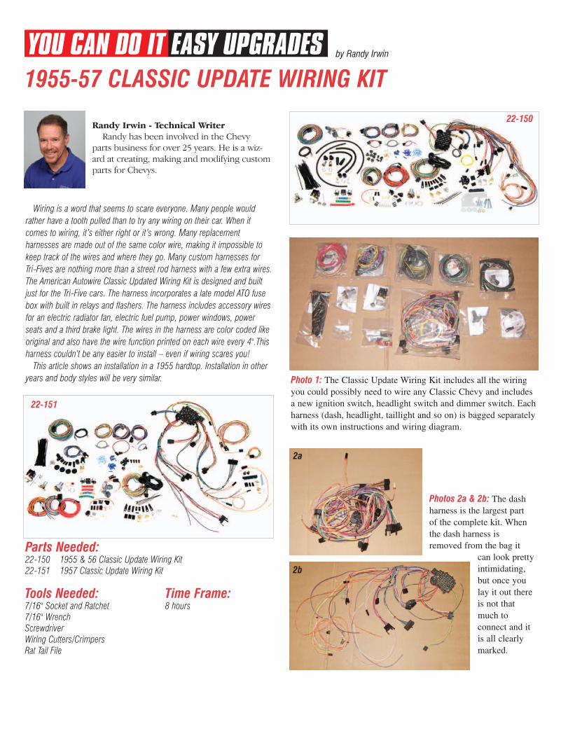
by Randy Irwin 22-150 Tools Needed: 7/16" Socket and Ratchet 7/16" Wrench Screwdriver Wiring Cutters/Crimpers Rat Tail File Time Frame: 8 hours Wiring is a word that seems to scare everyone. Many people would rather have a tooth pulled than to try any wiring on their car. When it comes to wiring, it’s either right or it’s wrong. Many replacement harnesses are made out of the same color wire, making it impossible to keep track of the wires and where they go. Many custom harnesses for Tri-Fives are nothing more than a street rod harness with a few extra wires. The American Autowire Classic Updated Wiring Kit is designed and built just for the Tri-Five cars. The harness incorporates a late model ATO fuse box with built in relays and flashers. The harness includes accessory wires for an electric radiator fan, electric fuel pump, power windows, power seats and a third brake light. The wires in the harness are color coded like original and also have the wire function printed on each wire every 4".This harness couldn’t be any easier to install – even if wiring scares you! This article shows an installation in a 1955 hardtop. Installation in other years and body styles will be very similar. 1955-57 CLASSIC UPDATE WIRING KIT 22-151 Parts Needed: 22-150 1955 & 56 Classic Update Wiring Kit 22-151 1957 Classic Update Wiring Kit Photo 1: The Classic Update Wiring Kit includes all the wiring you could possibly need to wire any Classic Chevy and includes a new ignition switch, headlight switch and dimmer switch. Each harness (dash, headlight, taillight and so on) is bagged separately with its own instructions and wiring diagram. Photos 2a & 2b: The dash harness is the largest part of the complete kit. When the dash harness is removed from the bag it can look pretty intimidating, but once you lay it out there is not that much to connect and it is all clearly marked. 2a 2b Randy Irwin - Technical Writer Randy has been involved in the Chevy parts business for over 25 years. He is a wiz- ard at creating, making and modifying custom parts for Chevys.
-
Upload
khangminh22 -
Category
Documents
-
view
4 -
download
0
Transcript of 1955-57 CLASSIC UPDATE WIRING KIT
by Randy Irwin
22-150
Tools Needed: 7/16" Socket and Ratchet7/16" WrenchScrewdriver Wiring Cutters/CrimpersRat Tail File
Time Frame: 8 hours
Wiring is a word that seems to scare everyone. Many people wouldrather have a tooth pulled than to try any wiring on their car. When itcomes to wiring, it’s either right or it’s wrong. Many replacementharnesses are made out of the same color wire, making it impossible tokeep track of the wires and where they go. Many custom harnesses forTri-Fives are nothing more than a street rod harness with a few extra wires.The American Autowire Classic Updated Wiring Kit is designed and builtjust for the Tri-Five cars. The harness incorporates a late model ATO fusebox with built in relays and flashers. The harness includes accessory wiresfor an electric radiator fan, electric fuel pump, power windows, powerseats and a third brake light. The wires in the harness are color coded likeoriginal and also have the wire function printed on each wire every 4".Thisharness couldn’t be any easier to install – even if wiring scares you!
This article shows an installation in a 1955 hardtop. Installation in otheryears and body styles will be very similar.
1955-57 CLASSIC UPDATE WIRING KIT
22-151
Parts Needed: Catalog price Member price
22-150 1955 & 56 Classic Update Wiring Kit $499.99 $474.99 kit22-151 1957 Classic Update Wiring Kit $499.99 $474.99 kit
Photo 1: The Classic Update Wiring Kit includes all the wiringyou could possibly need to wire any Classic Chevy and includesa new ignition switch, headlight switch and dimmer switch. Eachharness (dash, headlight, taillight and so on) is bagged separatelywith its own instructions and wiring diagram.
Photos 2a & 2b: The dashharness is the largest partof the complete kit. Whenthe dash harness isremoved from the bag it
can look prettyintimidating,but once youlay it out thereis not thatmuch toconnect and itis all clearlymarked.
2a
2b
Randy Irwin - Technical WriterRandy has been involved in the Chevy
parts business for over 25 years. He is a wiz-ard at creating, making and modifying customparts for Chevys.
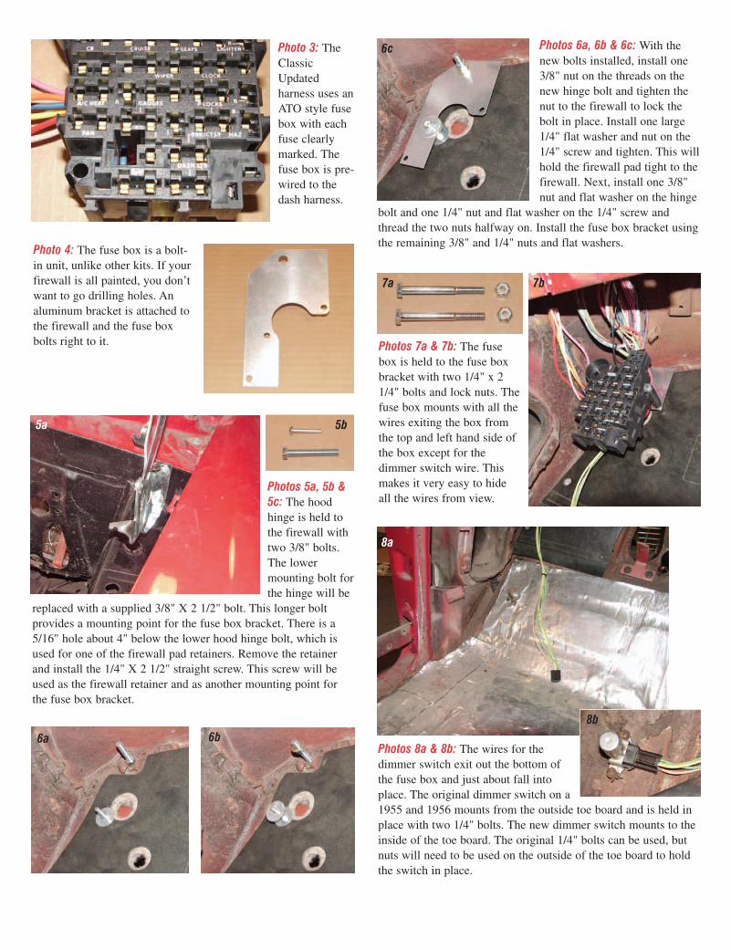
Photo 3: TheClassicUpdatedharness uses anATO style fusebox with eachfuse clearlymarked. Thefuse box is pre-wired to thedash harness.
Photo 4: The fuse box is a bolt-in unit, unlike other kits. If yourfirewall is all painted, you don’twant to go drilling holes. Analuminum bracket is attached tothe firewall and the fuse boxbolts right to it.
Photos 5a, 5b &5c: The hoodhinge is held tothe firewall withtwo 3/8" bolts.The lowermounting bolt forthe hinge will be
replaced with a supplied 3/8" X 2 1/2" bolt. This longer boltprovides a mounting point for the fuse box bracket. There is a5/16" hole about 4" below the lower hood hinge bolt, which isused for one of the firewall pad retainers. Remove the retainerand install the 1/4" X 2 1/2" straight screw. This screw will beused as the firewall retainer and as another mounting point forthe fuse box bracket.
5a 5b
Photos 6a, 6b & 6c: With thenew bolts installed, install one3/8" nut on the threads on thenew hinge bolt and tighten thenut to the firewall to lock thebolt in place. Install one large1/4" flat washer and nut on the1/4" screw and tighten. This willhold the firewall pad tight to thefirewall. Next, install one 3/8"nut and flat washer on the hinge
bolt and one 1/4" nut and flat washer on the 1/4" screw andthread the two nuts halfway on. Install the fuse box bracket usingthe remaining 3/8" and 1/4" nuts and flat washers.
6a 6b
6c
Photos 7a & 7b: The fusebox is held to the fuse boxbracket with two 1/4" x 21/4" bolts and lock nuts. Thefuse box mounts with all thewires exiting the box fromthe top and left hand side ofthe box except for thedimmer switch wire. Thismakes it very easy to hideall the wires from view.
7a 7b
Photos 8a & 8b: The wires for thedimmer switch exit out the bottom ofthe fuse box and just about fall intoplace. The original dimmer switch on a1955 and 1956 mounts from the outside toe board and is held inplace with two 1/4" bolts. The new dimmer switch mounts to theinside of the toe board. The original 1/4" bolts can be used, butnuts will need to be used on the outside of the toe board to holdthe switch in place.
8a
8b
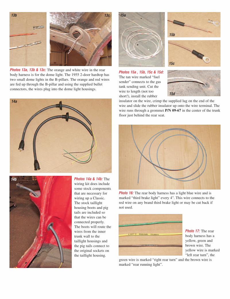
Photos 11a, 11b & 11c: Usingthe wiring diagram suppliedwith the dash harness, locatethe male jacks for the frontand rear lights. The rear bodyharness includes the wires forthe running lights, brake lights,turn signals, license platelights and dome light wires. Italso includes a wire for a thirdbrake light if one is going tobe used. Plug the rear bodyharness into the corresponding female jack from the fuse box.
11a
11b
11c
Photo 12: The front and rear body harnesses are made extra longso that the wires can be routed anyway you want which makes itgreat on custom cars when you wish to hide the wires.
13a
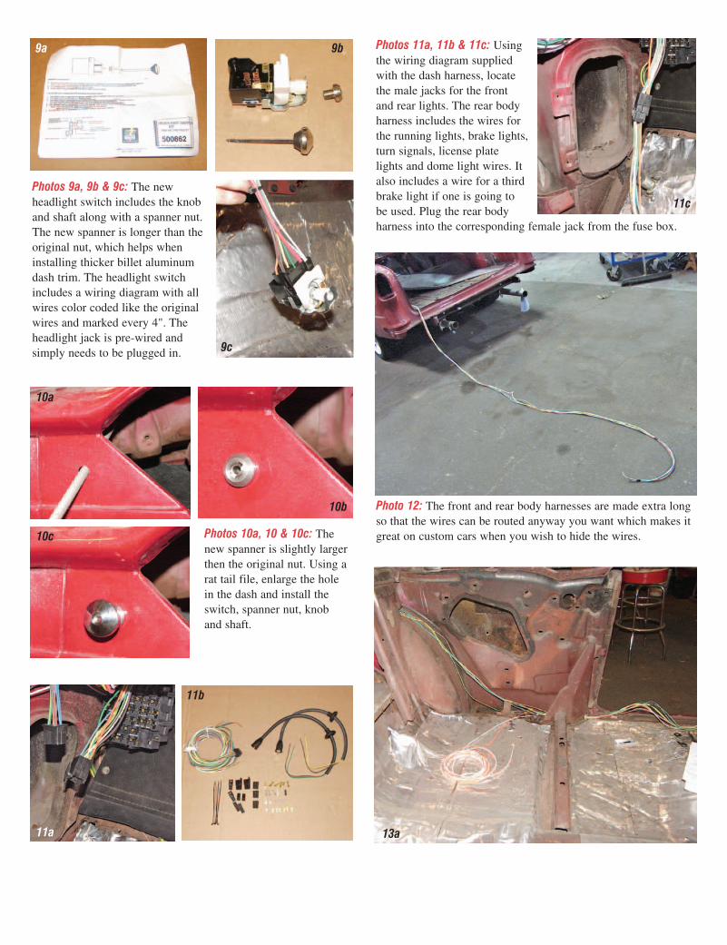
Photos 9a, 9b & 9c: The newheadlight switch includes the knoband shaft along with a spanner nut.The new spanner is longer than theoriginal nut, which helps wheninstalling thicker billet aluminumdash trim. The headlight switchincludes a wiring diagram with allwires color coded like the originalwires and marked every 4". Theheadlight jack is pre-wired andsimply needs to be plugged in.
9a 9b
9c
Photos 10a, 10 & 10c: Thenew spanner is slightly largerthen the original nut. Using arat tail file, enlarge the holein the dash and install theswitch, spanner nut, knoband shaft.
10a
10b
10c
Photos 13a, 13b & 13c: The orange and white wire in the rearbody harness is for the dome light. The 1955 2-door hardtop hastwo small dome lights in the B-pillars. The orange and red wiresare fed up through the B-pillar and using the supplied bulletconnectors, the wires plug into the dome light housings.
13b 13c
Photos 14a & 14b: Thewiring kit does includesome stock componentsthat are necessary forwiring up a Classic.The stock taillighthousing boots and pigtails are included sothat the wires can beconnected properly.The boots will route thewires from the innertrunk wall to thetaillight housings andthe pig tails connect tothe original sockets onthe taillight housing.
14a
14b
15a
15b
Photos 15a , 15b, 15c & 15d:The tan wire marked “fuelsender” connects to the gastank sending unit. Cut thewire to length (not tooshort!), install the rubberinsulator on the wire, crimp the supplied lug on the end of thewire and slide the rubber insulator up onto the wire terminal. Thewire runs through a grommet P/N 09-67 in the center of the trunkfloor just behind the rear seat.
15c
15d
Photo 16: The rear body harness has a light blue wire and ismarked “third brake light” every 4". This wire connects to thered wire on any brand third brake light or may be cut back ifnot used.
Photo 17: The rearbody harness has ayellow, green andbrown wire. Theyellow wire is marked“left rear turn”, the
green wire is marked “right rear turn” and the brown wire ismarked “rear running light”.

Photos 22a & 22b: The lastwire in the rear body harness isthe light green wire marked“back up Lt”, this wire is forthe back-up lights if they aregoing to be used. If your carwas not originally equippedwith back-up lights, P/N 22-152 includes the back-up lightsockets and plates, springs and wire ends you will need tocomplete the installation.
22a 22b
Photos 18a, 18b & 18c: The rear body harness includes male andfemale connectors that are used to connect the rear body harnessto the taillight pig tails. Crimp the male wire terminals on theends of the wires from the taillight housing and install the wireends into the female plastic jack. Note the location of the wiresin the jack.
18a
18b 18c
Photos 19a, 19b & 19c: Next, cut the yellow & brown wires inthe rear body harness to length so that the wires meet up with thetaillight harness jack. The brown wire runs across the rear of thecar and powers the right side taillights and the license platelights. Install the female terminals on the ends of the two wiresand install them in the male jack that matches the female jack onthe taillight harness. Make sure to orient the wires in the malejack so that they match up to the wires in the female jack.
19a 19b 19c
Photos 20a, 20b & 20c: There is a hole on each side of the tailpanjust to inside of the taillight housing for the license plate lights.Cut the brown wire to length, connect this wire to the existingbrown wire in the harness and install the female terminal andsingle plastic jack. The single plastic jack plugs into the licenseplate pig tail. Now feed the brown wire over to the passengerside of the car and repeat the same process for the passenger sidelicense light.
20a 20b 20c
Photo 21: Feed the greenwire in the rear bodyharness marked “rightrear turn” across the rearof the car along with thebrown wire and connectthe brown and green
wire to the passenger side taillight housing in the same manneras the driver’s side taillight housing.
Photo 23: The frontharness includesthe wires for theheadlights (high &low beam), parkinglights, turn signals,horns and electricfan if one is goingto be used. Thefront harness alsoincludes theheadlight bucket grommets and tubes as well as the parking lightgrommets and tubes.
Photos 24a & 24b: The rear harness plugs into the correspondingjack from the fuse box.
24a 24b
Photos 25a & 25b: The stock hole and grommet in the firewallcan be used for the front body harness if you desire. We aregoing to hide all the wires in the engine compartment for acleaner look so we will drill a hole down low out of sight. Using
25a 25b

28a 28b
Photos 28a , 28b, 28c & 28d:The front harness includes twoshort black wires with a roundlug on one end marked “ground”. These wires are used as theground wires for the front headlights. The round lug end of thewire should be connected to a good body ground. Cut the groundwire to length and install the supplied female spade connector.Now, using the supplied wiring diagram, install the three femaleconnectors into the headlight jack. The headlight jack plugsdirectly into the headlight bulb. With the left side headlightwired, feed the remaining tan and green wires across to thepassenger side of the car for the right side headlight.
28c 28d
Photos 29a & 29b: In the front harness there is a brown wiremarked “park lights”, a light gray wire marked “left front turn”and a light blue wire marked “right front turn”. The brown wireis for the left and right front parking lights.
29a 29b
Photos 30a, 30b & 30c: Cut the light gray and brown wire tolength for the left hand parking light. The brown wire will needto be spliced and run over to the right side of the car for the rightside parking light. The wiring harness includes parking lightboots which is a must for the 1955 and 1956 cars to keep thewater and trash out of the parking light sockets. The brown wirewill need to be soldered and heat shrink tubing used to insulatethe connection so that the brown and light gray wire will slideinto the parking light boot easily.
30a 30b
30c
a 1-3/8" hole saw, we drilled a hole in the toe board just abovethe dimmer switch. Feed the wires through the hole in the toeboard and using the ignition/starter grommet P/N 09-09, insulatethe wires from the metal surrounding the hole.
Photos 26a & 26b: Our wires will be run on the outside of theinner fender to give the engine compartment a very clean look.Like the rear body harness, the front body harness is plenty longenough torun thewiresanywhereyou want.
26a
26b
Photos 27a & 27b: The front wiring harness has a tan wiremarked “low beam” and a light green wire marked “high beam”.The tan and light green wires will need to be connected to eachheadlight. Cut the tan and light green wires to length on thedrivers side of the car and connect the excess light green wire tothe now cut green wire and connect the excess tan to the now cuttan wire. These wires run across the front of the car to power theright side headlight. Now install female spade connectors on thetan and green wires.
27a 27b
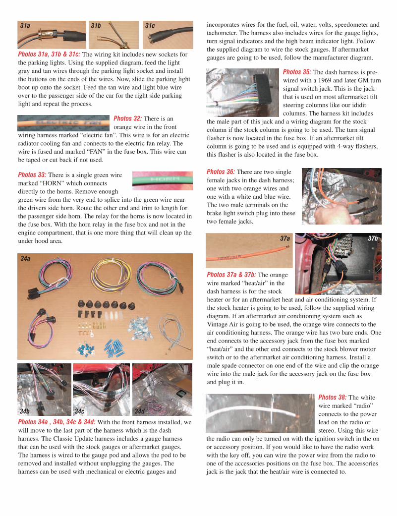
Photos 31a, 31b & 31c: The wiring kit includes new sockets forthe parking lights. Using the supplied diagram, feed the lightgray and tan wires through the parking light socket and installthe buttons on the ends of the wires. Now, slide the parking lightboot up onto the socket. Feed the tan wire and light blue wireover to the passenger side of the car for the right side parkinglight and repeat the process.
31a 31b 31c
Photos 32: There is anorange wire in the front
wiring harness marked “electric fan”. This wire is for an electricradiator cooling fan and connects to the electric fan relay. Thewire is fused and marked “FAN” in the fuse box. This wire canbe taped or cut back if not used.
Photos 33: There is a single green wiremarked “HORN” which connectsdirectly to the horns. Remove enoughgreen wire from the very end to splice into the green wire nearthe drivers side horn. Route the other end and trim to length forthe passenger side horn. The relay for the horns is now located inthe fuse box. With the horn relay in the fuse box and not in theengine compartment, that is one more thing that will clean up theunder hood area.
34a
Photos 34a , 34b, 34c & 34d: With the front harness installed, wewill move to the last part of the harness which is the dashharness. The Classic Update harness includes a gauge harnessthat can be used with the stock gauges or aftermarket gauges.The harness is wired to the gauge pod and allows the pod to beremoved and installed without unplugging the gauges. Theharness can be used with mechanical or electric gauges and
34b 34c 34d
Photos 35: The dash harness is pre-wired with a 1969 and later GM turnsignal switch jack. This is the jackthat is used on most aftermarket tiltsteering columns like our ididitcolumns. The harness kit includes
the male part of this jack and a wiring diagram for the stockcolumn if the stock column is going to be used. The turn signalflasher is now located in the fuse box. If an aftermarket tiltcolumn is going to be used and is equipped with 4-way flashers,this flasher is also located in the fuse box.
Photos 36: There are two singlefemale jacks in the dash harness;one with two orange wires andone with a white and blue wire.The two male terminals on thebrake light switch plug into thesetwo female jacks.
incorporates wires for the fuel, oil, water, volts, speedometer andtachometer. The harness also includes wires for the gauge lights,turn signal indicators and the high beam indicator light. Followthe supplied diagram to wire the stock gauges. If aftermarketgauges are going to be used, follow the manufacturer diagram.
Photos 37a & 37b: The orangewire marked “heat/air” in thedash harness is for the stockheater or for an aftermarket heat and air conditioning system. Ifthe stock heater is going to be used, follow the supplied wiringdiagram. If an aftermarket air conditioning system such asVintage Air is going to be used, the orange wire connects to theair conditioning harness. The orange wire has two bare ends. Oneend connects to the accessory jack from the fuse box marked“heat/air” and the other end connects to the stock blower motorswitch or to the aftermarket air conditioning harness. Install amale spade connector on one end of the wire and clip the orangewire into the male jack for the accessory jack on the fuse boxand plug it in.
37a 37b
Photos 38: The whitewire marked “radio”connects to the powerlead on the radio orstereo. Using this wire
the radio can only be turned on with the ignition switch in the onor accessory position. If you would like to have the radio workwith the key off, you can wire the power wire from the radio toone of the accessories positions on the fuse box. The accessoriesjack is the jack that the heat/air wire is connected to.

Photos 39a & 39b: The Classic Update wiring harness includestwo courtesy lights that may be mounted under the dash. There isa two-wire male jack in the dash harness with an orange andwhite wire. This jack is for the courtesy lights and dome lights. Ifthe door jam switches are going to be used, wires from the doorjam switches should be spliced into the white wire using thesupplied terminals and jacks. Follow the wiring diagram suppliedwith the dash harness. If the door jam switches are not going tobe used, the only way the courtesy and dome lights will operatewill be to turn the knob on the headlight switch.
39a 39b
Photos 40a &40b: There aretwo violet wiresin the dashharness marked“startersolenoid”. If thecar has a manualtransmission,
these two wires should be connected together. We recommendsoldering this connection and using heat shrink tubing. If the carhas an automatic transmission, the two wires will connect to theneutral safety switch. Install female spade connectors and thesingle spade female connector covers on the ends of the twowires and plug the wires onto the male spade terminals on theright hand side of the neutral safety switch.
40a 40b
Photos 41: If the car hasback-up lights, the lightgreen wire marked “backup” and the orange wiremarked “12-volt fused” in
the dash harness will plug onto the two left hand terminals onthe neutral safety switch. Female connectors and covers willneed to be installed on these wires as well.
Photos 42: There is awhite wire marked“wiper feed”. Thiswire is used to powerthe wiper motor. If the car has a stock electric wiper motormounted on the firewall, this wire is fed out to the wiper motorin the engine compartment. If the car has an aftermarket wipersystem, this wire connects to the power wire on the wiper switch.
Photos 43: There isa yellow wire witha female spadeconnector on theend marked “clock bat”. This is the power wire for the clock.
Photos 44: There are twogrey wires with light bulbsockets on the ends marked“dash light”. One socket isfor the ignition switch andthe other socket is for theheater control panel.
Photos 45: The last single wire in thedash harness is a black wire with around lug on the end marked “ground”.This wire needs to be connected to a good body ground.
Photos 46: There arethree male multi-wirejacks in the dash harness.The three wire black jackis the starter harnessjack. All three wiresconnect to the starter andwill work with a stock
starter or a gear reduction starter. The six wire clear jack is theignition harness jack and connects to the oil and water senders,the ignition coil, the alternator and the starter solenoid if thestock ignition coil and distributor are going to be used. The largeround black jack is for the ignition switch and will plug directlyinto the supplied ignition switch.
Photos 47: The wires in the ignition/starter harness kit are plentylong enough to route the wires anywhere you want to hide them.The kit includes the jacks and terminals to connect to the dashharness. A 10-gauge red wire with a fusible link is supplied toconnect the alternator to the starter.
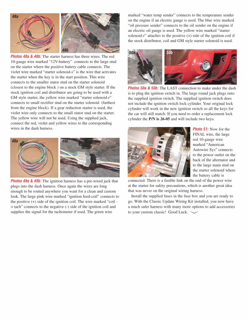
Photos 48a & 48b: The starter harness has three wires. The red10-gauge wire marked “12V-battery” connects to the large studon the starter where the positive battery cable connects. Theviolet wire marked “starter solenoid-s” is the wire that activatesthe starter when the key is in the start position. This wireconnects to the smaller stator stud on the starter solenoid(closest to the engine block ) on a stock GM style starter. If thestock ignition coil and distributor are going to be used with aGM style starter, the yellow wire marked ”starter solenoid-r”connects to small rectifier stud on the starter solenoid (farthestfrom the engine block). If a gear reduction starter is used, theviolet wire only connects to the small stator stud on the starter.The yellow wire will not be used. Using the supplied jack,connect the red, violet and yellow wires to the correspondingwires in the dash harness.
48a
48b
Photos 49a & 49b: The ignition harness has a pre-wired jack thatplugs into the dash harness. Once again the wires are longenough to be routed anywhere you want for a clean and customlook. The large pink wire marked “ignition feed-coil” connects tothe positive (+) side of the ignition coil. The wire marked “coil -> tach” connects to the negative (-) side of the ignition coil andsupplies the signal for the tachometer if used. The green wire
49a 49b
Photos 50a & 50b: The LAST connection to make under the dashis to plug the ignition switch in. The large round jack plugs ontothe supplied ignition switch. The supplied ignition switch doesnot include the ignition switch lock cylinder. Your original lockcylinder will work in the new ignition switch so all the keys forthe car will still match. If you need to order a replacement lockcylinder the P/N is 26-05 and will include two keys.
50a 50b
Photo 51: Now for theFINAL wire, the largered 10-gauge wiremarked “AmericanAutowire Sys” connectsto the power outlet on theback of the alternator andto the large main stud onthe starter solenoid wherethe battery cable is
connected. There is a fusible link on the end of the power wireat the starter for safety precautions, which is another great ideathat was never on the original wiring harness.
Install the supplied fuses in the fuse box and you are ready togo. With the Classic Update Wiring Kit installed, you now havea much safer harness with many more options to add accessoriesto your custom classic! Good Luck.
marked “water temp sender” connects to the temperature senderon the engine if an electric gauge is used. The blue wire marked“oil pressure sender” connects to the oil sender on the engine ifan electric oil gauge is used. The yellow wire marked “startersolenoid-r” attaches to the positive (+) side of the ignition coil ifthe stock distributor, coil and GM style starter solenoid is used.