Historical Review of Parallel Hybrid Active Power Filter for ...
6
Historical Review of Parallel Hybrid Active Power Filter for Power Quality Improvement Yang-Wen Wang l , Man-Chung Wong l , 2 , Senior Member, IEEE, Chi-Seng Lam l) , Member, IEEE I - Department ofElectrical and Computer Engineering, Facul of Science and Technolo, University of Macau, Macao, China 2 - State Key Laboratory of Analog and Mixed-Signal VLS Universi ofMacau, Macao, China E-mail: [email protected].mcwong@umac.mo.cslam@umac.mo Abstract-Hybrid active power filter (HAPF) has already been an effective and widely-used method for power quality improvement. This paper presents historical review and developing progress of the HAPFs' functionalities as harmonic and reactive power compensation. The structures of HAPFs are discussed in different historical periods, and divided into four developing pattern: parallel active part with parallel element, parallel active part with series element, b-shape, and three-phase four-wire structure. It is aimed at making a comprehensive analysis of HAPFs' historical developing tendency in structure and function design. The future possible developing guidelines are discussed as conclusion in the last. Kwords- Current harmonics; hybrid active power fier (HAPF); reactive power I. INTRODUCTION Due to the advancement of technology, industrial sucture reforming, and the development of smart grid technology recently, people have a higher demand for improved power quality [1]. However, with the proliferation and increased use of power eleconics devices and motor loading, it is becoming more difficult to achieve this goal [2]-[10]. In mid 1940s, passive power filters (PPF) were developed to suppress current harmonics and compensate reactive power [11]. In 1976, active power filters (APF) were developed to compensation harmonics. HAPFs are more attractive in harmonic filtering than pure APFs om both viability and economical view [12][13]. To achieve the best performance, the united power quality converter (UPQC), has been developed with an exemely high cost [14]. During 1967�2005, HAPFs are mainly applied to traditional indusy, such as steel ace, ASD, etc. Most research works focus on basic and single nction, just harmonic compensating. Aſter 2005, many researchers focus on the development of application, optimal design, and dynamic reactive power compensating. Some literatures [15]-[18] have discussed the feasibility of HAPF in railway, wind , and photovoltaic generator. As the price and operating loss of power eleconic switcher limit the performance of HAPF, many researchers have proposed optimal design method in parameter selection [19], conol method [20][21], and structures. Many review papers make a comprehensive summary of HAPF. In 2000, "Active power filters: A review" classified the research work published in five aspects: power rating and respond speed, configuration and connection, compensated system parameters, conol techniques, reference signal estimating technique [22]. In 2005, "Hybrid filters for power 978-1-4799-8641-5115/$31.00 © 2015 IEEE quality improvement" summarized the most HAPF suctures based on different combination of AF and PF. The selection criteria are also list in details [23]. In 2005, "Active harmonic filters" discussed the performance of three HAPF in detail: the hybrid of active shunt and passive series, the hybrid of active series and passive shunt, ansformerless LC-HAPF [24]. In 2012, "A Comprehensive Analysis of Hybrid Active Power Filter for Power Quality Enhancement" divided ten HAPFs in two aspects: shunt filter and series filter. Five basic control method are also discussed in this paper, as Fourier ansform, Synchronous reference ame, Instantaneous reactive power theory, High-pass filter method, Low-pass filter method, and Adaptive linear neurons conol [25]. In 2013, "Review of Hybrid Active Power Filter Topologies and Conollers" divided all HAPFs based on topology, converter configuration, supply system, passive filter type and listed some new control methods in harmonic detecting and conoller technologies [26]. This paper aims at presenting the developing progress of HAPF structures. By summarizing the different historical period of HAPF development, the inner thought and ture research work of development can be analyzed. In this paper, there are four sections. The section I is the introduction. In Section II�III, the development of different HAPF in each period are discussed in the items ofnctionality and structure. In section IV, the conclusion of ture development of HAPF is discussed. II. FUNCTIONALITY The historical periods of the development of HAPF nction can be divided into three sategies: origin stage, developing stage and mature stage. The main research work of the nctionality of HAPF in each historical period are presented in Fig.1. A. Current Harmonic Compensation Harmonic compensation is the most basical and earliest nction of HAPF. 1976�1995 is the origin stage. During this period, researchers began to use HAPF to damping balance cuent harmonic. In this period, HAPFs were thought to be only suitable in low-and medium-voltage system and benefit in damping harmonic resonance [27]. In 1996�2005, the nction of harmonic compensation came into developing period. Three main directions, like high-voltage application, damping harmonic resonance, and unbalance harmonic compensation, have been proposed. In 2005�now, it can be called mature period. Most papers focused on three aspects: renewable source, multi-nction, and optimal design. Some published research work on the
-
Upload
khangminh22 -
Category
Documents
-
view
2 -
download
0
Transcript of Historical Review of Parallel Hybrid Active Power Filter for ...
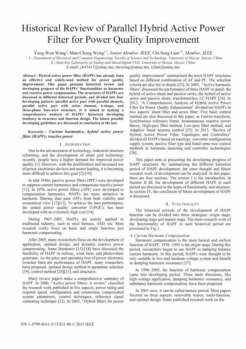
Historical Review of Parallel Hybrid Active Power Filter for Power Quality Improvement
Yang-Wen Wangl, Man-Chung Wongl,2, Senior Member, IEEE, Chi-Seng Laml), Member, IEEE I - Department of Electrical and Computer Engineering, Faculty of Science and Technology, University of Macau, Macao, China
2 - State Key Laboratory of Analog and Mixed-Signal VLS!, University of Macau, Macao, China
E-mail: [email protected]@[email protected]
Abstract-Hybrid active power filter (HAPF) has already been
an effective and widely-used method for power quality
improvement. This paper presents historical review and
developing progress of the HAPFs' functionalities as harmonic
and reactive power compensation. The structures of HAPFs are
discussed in different historical periods, and divided into four
developing pattern: parallel active part with parallel element,
parallel active part with series element, b-shape, and
three-phase four-wire structure. It is aimed at making a
comprehensive analysis of HAPFs' historical developing
tendency in structure and function design. The future possible
developing guidelines are discussed as conclusion in the last.
Keywords- Current harmonics; hybrid active power filter (HAPF); reactive power
I. INTRODUCTION
Due to the advancement of technology, industrial structure reforming, and the development of smart grid technology recently, people have a higher demand for improved power quality [1]. However, with the proliferation and increased use of power electronics devices and motor loading, it is becoming more difficult to achieve this goal [2]-[10].
In mid 1940s, passive power filters (PPF) were developed to suppress current harmonics and compensate reactive power [11]. In 1976, active power filters (APF) were developed to compensation harmonics. HAPFs are more attractive in harmonic filtering than pure APFs from both viability and economical view [12][13]. To achieve the best performance, the united power quality converter (UPQC), has been developed with an extremely high cost [14].
During 1967�2005, HAPFs are mainly applied to traditional industry, such as steel furnace, ASD, etc. Most research works focus on basic and single function, just harmonic compensating.
After 2005, many researchers focus on the development of application, optimal design, and dynamic reactive power compensating. Some literatures [15]-[18] have discussed the feasibility of HAPF in railway, wind farm, and photovoltaic generator. As the price and operating loss of power electronic switcher limit the performance of HAPF, many researchers have proposed optimal design method in parameter selection [19], control method [20][21], and structures.
Many review papers make a comprehensive summary of HAPF. In 2000, "Active power filters: A review" classified the research work published in five aspects: power rating and respond speed, configuration and connection, compensated system parameters, control techniques, reference signal estimating technique [22]. In 2005, "Hybrid filters for power
978-1-4799-8641-5115/$31.00 © 2015 IEEE
quality improvement" summarized the most HAPF structures based on different combination of AF and PF. The selection criteria are also list in details [23]. In 2005, "Active harmonic filters" discussed the performance of three HAPF in detail: the hybrid of active shunt and passive series, the hybrid of active series and passive shunt, transformerless LC-HAPF [24]. In 2012, "A Comprehensive Analysis of Hybrid Active Power Filter for Power Quality Enhancement" divided ten HAPFs in two aspects: shunt filter and series filter. Five basic control method are also discussed in this paper, as Fourier transform, Synchronous reference frame, Instantaneous reactive power theory, High-pass filter method, Low-pass filter method, and Adaptive linear neurons control [25]. In 2013, "Review of Hybrid Active Power Filter Topologies and Controllers" divided all HAPFs based on topology, converter configuration, supply system, passive filter type and listed some new control methods in harmonic detecting and controller technologies [26].
This paper aims at presenting the developing progress of HAPF structures. By summarizing the different historical period of HAPF development, the inner thought and future research work of development can be analyzed. In this paper, there are four sections. The section I is the introduction. In Section II�III, the development of different HAPF in each period are discussed in the items offunctionality and structure. In section IV, the conclusion of future development of HAPF is discussed.
II. FUNCTIONALITY
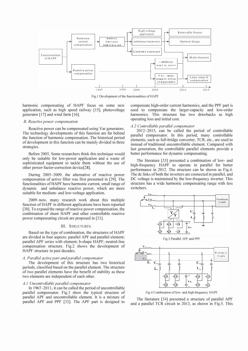
The historical periods of the development of HAPF function can be divided into three strategies: origin stage, developing stage and mature stage. The main research work of the functionality of HAPF in each historical period are presented in Fig. 1.
A. Current Harmonic Compensation Harmonic compensation is the most basical and earliest
function of HAPF. 1976� 1995 is the origin stage. During this period, researchers began to use HAPF to damping balance current harmonic. In this period, HAPFs were thought to be only suitable in low-and medium-voltage system and benefit in damping harmonic resonance [27].
In 1996�2005, the function of harmonic compensation came into developing period. Three main directions, like high-voltage application, damping harmonic resonance, and unbalance harmonic compensation, have been proposed.
In 2005�now, it can be called mature period. Most papers focused on three aspects: renewable source, multi-function, and optimal design. Some published research work on the
Function al ities
of HAP F
Harmonic
current
com pensatlOn
Reactive power
com pensatlOn
1967 1995
High-voltage
application
unbalance harm onic
2000 2005
Renewable Source
Optim al design
2010
Multi-function
Large range Q
com pensatlOn
I � 2015
F ig.l Development of the functionalities of HAPF
harmonic compensating of HAPF focus on some new application, such as high speed railway [15], photovoltage generator [17] and wind farm [16].
B. Reactive power compensation
Reactive power can be compensated using Var generators. The technology developments of this function are far behind the function of harmonic compensation. The historical period of development in this function can be mainly divided in three strategies.
Before 2005, Some researchers think this technique would only be suitable for low-power application and a waste of sophisticated equipment to tackle them without the use of other power-factor-correction device[28].
During 2005�2009, the alternative of reactive power compensation of active filter was first presented in [29]. The functionalities of HAPF have harmonic current, small range of dynamic and unbalance reactive power, which are more suitable for medium- and low-voltage application.
2009�now, many research work about this multiple function of HAPF in different applications have been reported [30]. To expand the range of reactive power compensation, the combination of shunt HAPF and other controllable reactive power compensating circuit are proposed in [31].
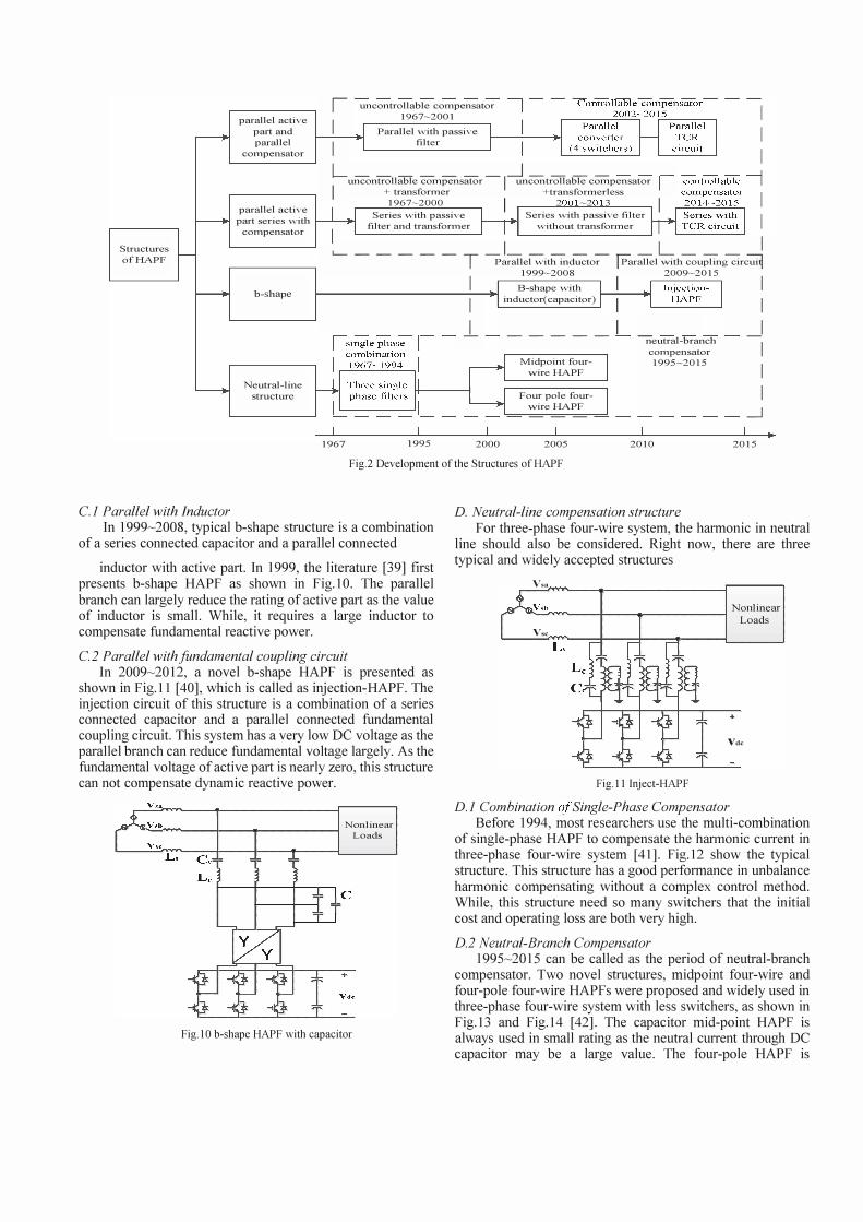
III. STRUCTURES
Based on the type of combination, the structures of HAPF are divided in four aspects: parallel APF and parallel element; parallel APF series with element; b-shape HAPF; neutral-line compensation structure. Fig.2 shows the development of HAPF structure in past decades.
A. Parallel active part and parallel compensator The development of this structure has two historical
periods, classified based on the parallel element. The structure of two parallel elements have the benefit of stability as these two elements are independent of each other.
A.I Uncontrollable parallel compensator In 1967�20 11, it can be called the period of uncontrollable
parallel compensator. Fig.3 show the typical structure of parallel APF and uncontrollable element. It is a mixture of parallel APF and PPF [32]. The APF part is designed to
compensate high-order current harmonics, and the PPF part is used to compensate the larger-capacity and low-order harmonics. This structure has two drawbacks as high operating loss and initial cost.
A.2 Controllable parallel compensator 2012�2015, can be called the period of controllable
parallel compensator. In this period, many controllable elements, such as full-bridge converter, TCR, etc., are used to instead of traditional uncontrollable element. Compared with last generation, the controllable parallel elements provide a better performance for dynamic compensating.
The literature [33] presented a combination of low- and high-frequency HAPF to operate in parallel for better performance in 2012. The structure can be shown as Fig.4. The dc links of both the inverters are connected in parallel, and DC voltage is maintained by the low-frequency inverter. This structure has a wide harmonic compensating range with less switchers.
V.t. Nonlinear --��-+--�------1I-------t------i Loads
L,
Fig.3 Parallel APF and PPF
Fig.4 Combination of low- and high-frequency HAPF
The literature [34] presented a structure of parallel APF and a parallel TCR circuit in 2013, as shown in Fig.5. This

structure can be useful for asymmetrical and nonlinear loads in the function of current harmonic.
�3��_'ru�N�------,:��:ar
L, �:J q J'q �'q tf ' �
), J, � !:� '� �J -tJ T-
Fig.S Injection-HAPF parallel with TCR
B. Parallel active part series with element The structure of parallel active part series with
compensator normally have less operating loss. But each part of the configuration affects each other. Based on the series element, there are three main historical period of this structure type, divided as transformer and parallel element.
B.1 Uncontrollable series compensator with transformer In 1990�2000, many research work use the structure of
LC-HAPF with transformer structure, as shown in Fig.6 [35]. In this structure, the APF connect with a coupling LC part in series through a transformer. It is especially suitable for medium- and high-voltage applications, as the passive part reduces the fundamental voltage applied to switchers.
B.2 Uncontrollable series compensator without transformer In 2001�2013, with the development of power electronic
switcher, higher-voltage IGBT has already been available [36]. It make possible that the active filter can be connected to passive filter directly without a transformer. Compared with last generation, the initial cost in this period is reduced largely.
Vsn ;Vsh Nonlinear
""'-�""'---+--+-------l Loads Vsc
�.
Vdc
Fig.6 HAPF with transformer
The literature [37] presented a combination of parallel IGBT converter and parallel MOSFET converter in 2013, as shown in Fig.7. The function of the IGBT converter support fundamental voltage and compensate the fundamental reactive power. The MOSFET converter fulfills the function of harmonic current compensation [37]. This structure has a wide compensating range. But it has very high initial cost due to the 12 switchers.
""'-"r'----+----f"-------------1 Nonlinear Loads
I I : I
Fig.7 IGBT converter series with MOSFET converter
The typical transformerless HAPF is proposed in 2003, as shown in Fig.8 [36]. This structure has been widely used in industry. It is effective in harmonic and reactive power compensating. While, the compensating range of reactive power is limited as the fixed LC circuit.
B.3 Controllable series compensator without transformer In 2014�2015, the structure of controllable series
compensator is proposed. The literature [38] firstly presented a combined system of a thyristor controlled reactor and a shunt hybrid power filter in 2014, as shown in Fig.9. By using the FC-TCR circuit, this structure has a larger reactive power compensating range than the last generation.
v sa
fv" Nonlinear Loads
Vsc L, C e,, : - J
��� . ], �� �� �� 4'
i'
Vdc
Fig.S Transformerless HAPF
Fig.9 Transformerless HAPF series with TCR
C. b-shape HAP F A b-shape type is defined as 2 external elements connected
in series and one of them is in parallel with active filter. Due to the shunt branch, the current rating of active part is less than normal structure. While, the performance of harmonic part of the compensating current will flow into the external branch.
uncontrollable cOlnpensator 1967-2001 parallel active
part and parallel
cOIllpensator
I I I
Parallel with passive filter
L -------I�----
--, lUlcontrollable cOIllpensator "lillcontrollable cOIllpensator I I + transformer +transfonnerless
parallel active part series with
compensator
1967-2000 I 7 -7 3 I Series with passive Series with passive filter
filter and transformer without transfonner
Structures '-- -----ofHAPF
b-shape
Neutral-line structure
1967 1995
_1 - ----T Parallel with inductor
I 1999-2008
B-shape with
I inductor(capacitor)
1.- -----Midpoint four-
-wire HAPF
Four pole four--wire HAPF ---
2000 2005
_ L ___
I �rallel -with coupling circ� 2009-2015
neutral-branch cOIllpensator 1995-2015
2010
I I
� I I I
�
2015 •
Fig.2 Development of the Structures of HAPF
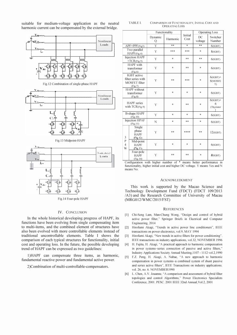
C.l Parallel with Inductor In 1999�2008, typical b-shape structure is a combination
of a series connected capacitor and a parallel connected
inductor with active part. In 1999, the literature [39] first presents b-shape HAPF as shown in Fig. 10. The parallel branch can largely reduce the rating of active part as the value of inductor is small. While, it requires a large inductor to compensate fundamental reactive power.
C.2 Parallel with fundamental coupling circuit In 2009�2012, a novel b-shape HAPF is presented as
shown in Fig.ll [40], which is called as injection-HAPF. The injection circuit of this structure is a combination of a series connected capacitor and a parallel connected fundamental coupling circuit. This system has a very low DC voltage as the parallel branch can reduce fundamental voltage largely. As the fundamental voltage of active part is nearly zero, this structure can not compensate dynamic reactive power.
Vsb Nonlinear ����--�r----1---------� Loads
Fig.IO b-shape HAPF with capacitor
D. Neutral-line compensation structure For three-phase four-wire system, the harmonic in neutral
line should also be considered. Right now, there are three typical and widely accepted structures
Vsa
""V.::":r.' rvvo�_+ ________ --1 Nonlinear Loads
Vsc
Vdc
Fig. 11 Inject-HAPF
D.I Combination of Single-Phase Compensator Before 1994, most researchers use the multi-combination
of single-phase HAPF to compensate the harmonic current in three-phase four-wire system [41]. Fig.12 show the typical structure. This structure has a good performance in unbalance harmonic compensating without a complex control method. While, this structure need so many switchers that the initial cost and operating loss are both very high.
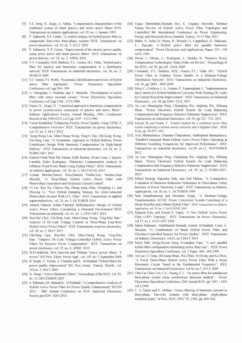
D.2 Neutral-Branch Compensator 1995�20 15 can be called as the period of neutral-branch
compensator. Two novel structures, midpoint four-wire and four-pole four-wire HAPFs were proposed and widely used in three-phase four-wire system with less switchers, as shown in Fig.13 and Fig.14 [42]. The capacitor mid-point HAPF is always used in small rating as the neutral current through DC capacitor may be a large value. The four-pole HAPF is
suitable for medium-voltage application as the neutral harmonic current can be compensated by the external bridge.
VSt'I ��N!Vi'�---!-----1--------l Nonlinear
Loads
Fig.12 Combination of single-phase HAPF
-":'';;::'''��--I----1'----------l Nonlinear Loads
Fig.13 Midpoint-HAPF
Fig.14 Four-pole HAPF
IV. CONCLUSION
In the whole historical developing progress of HAPF, its functions have been evolving from single compensating item to multi-items, and the combined element of structures have also been evolved with more controllable elements instead of traditional uncontrollable elements. Table I shows the comparison of each typical structures for functionality, initial cost and operating loss. In the future, the possible developing trend of HAPF can be expressed as two guidelines:
I )HAPF can compensate three items, as harmonic, fundamental reactive power and fundamental active power.
2)Combination of multi-contro Ilab Ie-compensators.
TABLE I.
APF+PPF(Fig3) Two parallel HAPF(Fig4)
Injection HAPF +TCR(Fig5) HAPF with transformer
(Fig.6) IGBT active
filter series with MOSFET filter
(Fig. 7) HAPF without
transformer (Fig.S)
HAPF series with TCR(Fig.9)
B-shape HAPF (Fig.IO)
Injection HPAF (Fig.Il)
Single phase HAPF
3 (Fig.12) P Mid-point 4 HAPF W (Fi '.13)
Four-pole HAPF (Fig. 14)
COMPARISON OF FUNCTIONALITY, INITIAL COST AND OPERATING Loss
Functionality Operating Loss
Dynamic Initial
DC Switcher Q
Harmonic Cost voltage Number
y ** * ** 6(IGBT)
y *** *** * 8(IGBT)
y * ** ** 6(IGBT)
y * ** * 6(IGBT)
6(IGBT)+ y ** *** * 6(MOSFE
T)
y * * * 6(IGBT)
6(IGBT)+
y * ** * 6 (Thyristor
) y * * * 6(IGBT)
N * ** * 6(IGBT)
y ** **** ** 12(IGBT)
Y * * * 6(IGBT)
y ** ** * 8(IGBT)
ConfiguratIOn wIth hIgher number of * means better performance III functionality, higher initial cost and higher DC voltage. Y means Yes and N means No.
ACKNOWLEDGMENT
This work is supported by the Macao Science and Technology Development Fund (FDCT) (FDCT 109/2013 IA3) and the Research Committee of University of Macau (MRGOI2/WMC/20IS/FST)
REFERENCES
[I] Chi-Seng Lam, Man-Chung Wong, "Design and control of hybrid active power filter," Springer Briefs in Electrical and Computer Engineering, 2014
[2] Hirofumi Akagi, "Trends in active power line conditioners", IEEE transactions on power electronics, vol.9, MAY 1994
[3] Hirofumi Akagi, "New trends in active filters for power conditioning". IEEE transactions on industry applications, vo1.32, NOVEMBER 1996
[4] H. Fujita, H. Akagi, "A practical approach to harmonic compensation in power systems-series connection of passive and active filters," Industry Applications Society Annual Meeting, 1107 - 1112 vo1.2, 1990
[5] F.Z. Peng, H. Akagi, A. Nabae, "A new approach to harmonic compensation in power systems-a combined system of shunt passive and series active filters", IEEE Transactions on industry applications. vol. 26, no. 6. NOVEMBERI990
[6] L. Chen, A.Y. Jouanne, "A comparison and assessment of hybrid filter topologies and control Algorithms," Power Electronics Specialists Conference, 2001. PESC. 2001 IEEE 32nd Annual,Vol.2, 2001
[7] F.Z. Peng, H. Akagi, A Nabae, "Compensation characteristics of the combined system of shunt passive and series active filters."IEEE Transactions on industry applications, vol. 29, no. I, January 1993
[8] P. Salmer6n, S.P. Litfiln, "A control strategy for hybrid power filter to compensate four-wires three-phase systems."IEEE Transactions on power electronics, vol. 25, no. 7, JULY 2010
[9] P. Salmeron, S.-P. Litran, "Improvement of the electric power quality using series active and shunt passive filters" IEEE Transactions on power delivery, vol. 25, no. 2, APRIL 2010
[10] V.F. Corasaniti, M.B. Barbieri, P.L. Arnera, M.1. Valla, "Hybrid active filter for reactive and harmonics compensation in a distribution network",IEEE Transactions on industrial electronics, vol. 56, no. 3, MARCH 2009
[11] S.T. Senini, P.l. Wolfs, "Systematic identification and review of hybrid active filter topologies". Power Electronics Specialists Conference,vol.l,pp.394 - 399
[12] A Nakagima, J. Nishidai, and T. Shiraishi, "Development of active filter with series resonant circuit," Power Electronics Specialists Conference,voI.2,pp.1168 - 1173,1988
[13] Fujita, H.; Akagi, H. "A practical approach to hannonic compensation in power systems-series connection of passive and active filters". Industry Applications Society Annual Meeting, 1990., Conference Record of the 1990 IEEE,voI.2,pp.1107 - 1112,1990
[14] Vinod Khadkikar,"Enhancing Electric Power Quality Using UPQC:A Comprehensive Overview".IEEE Transactions on power electronics, vol. 27, no. 5, MAY 2012
[15] Keng-Weng Lao, Man-Chung Wong, NingYi Dai, Chi-Kong Wong, Chi-Seng Lam. "A Systematic Approach to Hybrid Railway Power Conditioner Design With Harmonic Compensation for High-Speed Railway". IEEE Transactions on industrial electronics, vol. 62, no. 2, FEBRUARY 2015
[16] Khairul Nisak Binti Md. Hasan, Kalle Rauma, Alvaro Luna, J. Ignacio Candela, Pedro Rodriguez, "Hannonic Compensation Analysis in Offshore Wind Power Plants Using Hybrid Filters", IEEE Transactions on industry applications, vol. 50, no. 3, MA Y/JUNE 2014
[17] Ayman Blorfan,Patrice Wira,Damien Flieller,Guy Sturtzer,Jean Merckl':, "A Three-Phase Hybrid Active Power Filter with Photovoltaic Generation and Hysteresis Current Control"
[18] Yi Lei, Wei Xu, Chaoxu Mu, Zheng ming Zhao, Hongbing Li, and Zhiyong Li. "New Hybrid Damping Strategy for Grid-Connected Photovoltaic Inverter With LCL Filter". IEEE Transactions on applied superconductivity, vol. 24, no. 5, OCTOBER 2014
[19] Ahmed Faheem Zobaa."Optimal Multiobjective Design of Hybrid Active Power Filters Considering a Distorted Environment".IEEE Transactions on industrial, vol. 61, no. I, JANUARY 2014
[20] Wai-Hei Choi, Chi-Seng Lam, Man-Chung Wong, Ying-Duo Han." Analysis of DC-Link Voltage Controls in Three-Phase Four-Wire Hybrid Active Power Filters". IEEE Transactions on power electronics, vol. 28, no. 5, MAY 2013
[21] Chi-Seng Lam, Wai-Hei Choi, Man-Chung Wong, Ying-Duo Han. "Adaptive DC-Link Voltage-Controlled Hybrid Active Power Filters for Reactive Power Compensation". IEEE Transactions on power electronics, vol. 27, no. 4, APRIL 2012
[22] M.EI-Habrouk, M.K.Darwish and PMehta."Active power filters: A review".IEE Proc.-Elertr. Power Appl., vol. 147, no. 5, September 2000
[23] B. Singh, Y. Verma, A Chandra and K. AI-Haddad."Hybrid filters for power quality improvement".IEE Proc.-Gener. Transm. Distrib., vol. 152,no. 3, MAY 2005
[24] H. Akagi, "Active Harmonic Filters". Proceedings of the IEEE, vol. 93, no. 12, DECEMBER 2005
[25] S. Rahmani,Ab. Hamadi,K. AI-Haddad,"A Comprehensive Analysis of Hybrid Active Power Filter for Power Quality Enhancement".IECON 2012 - 38th Annual Conference on IEEE Industrial Electronics SocietY,pp.6258 - 6267,2012
[26] Tugye Demirdelen,Mustafa Inci, K. <;:agatay Bayindir, Mehmet Tumay."Review of Hybrid Active Power Filter Topologies and Controllers".4th International Conference on Power Engineering, Energy and Electrical Drives Istanbul, Turkey, 13-17 May 2013
[27] Balbo, N.; Sella, D.; Penzo, R.; Bisiach, G.; Cappellieri, D.; Malesani, L.; Zuccato, A"Hybrid active filter for parallel harmonic compensation". Power Electronics and Applications, Pages: 133 - 138 voI.8, 1993.
[28] Dixon, .I.; Moran, L.; Rodriguez, .I.; Domke, R. "Reactive Power Compensation Technologies: State-of-the-Art Review", Proceedings of the IEEE, vol: 93, pp.144 - 2164, 2005
[29] Corasaniti, Y.F.; Barbieri, M.B.; Arnera, P.L.; Valla, M.I.. "Hybrid Power Filter to Enhance Power Quality in a Medium-Voltage Distribution Network", IEEE Transactions on Industrial Electronics, vol: 56, pp. 2885 - 2893,2009
[30] Silva, c.; Cordova, L.A; Lezana, P.; Empringham, L. "Implementation and Control of a Hybrid Multilevel Converter With Floating DC Links for Current Waveform Improvement", IEEE Transactions on Industrial Electronics , vol: 58, pp.2304 - 2312, 2011
[31] An Luo, Shuangjian Peng, Chuanping Wu, Jingbing Wu, Zhikang Shuai. "Power Electronic Hybrid System for Load Balancing Compensation and Frequency-Selective Harmonic Suppression", IEEE Transactions on Industrial Electronics, vol: 59, pp.723 - 732, 2012
[32] Fukuda, S, and Endoh, T. "Control method for a combined active tilter
system employing a current source converter and a highpass tilter", IEEE
Truiz, pp. 59-597, 1995 [33] Avik Bhattacharya, Chandan Chakraborty, Subhashish Bhattacharya,
"Parallel-Connected Shunt Hybrid Active Power Filters Operating at Different Switching Frequencies for Improved Perfonnance", IEEE Transactions on industrial electronics, vol. 59, no.11, NOVEMBER 2012
[34] An Luo, Shuangjian Peng, Chuanping Wu, Jingbing Wu, Zhikang Shuai, "Power Electronic Hybrid System for Load Balancing Compensation and Frequency-Selective Harmonic Suppression", IEEE Transactions on Industrial Electronics, vol. 59, no. 2, FEBRUARY, 2012
[35] Mukul Rastogi, Rajendra Naik, and Ned Mohan, "A Comparative Evaluation of Harmonic Reduction Techniques in Three-phase Utility Interface of Power Electronic Loads", IEEE Transactions on Industry Applications, vol. 30, no. 5 , OCTOBER 1994
[36] Sunt Srianthumrong and Hirofumi Akagi, "A Medium-Voltage Transfonnerless AC/DC Power Conversion System Consisting of a Diode Rectifier and a Shunt Hybrid Filter", IEEE Transactions on Industry Application, vol. 39, no. 3, MAY/JUNE 2003
[37] Sangsun Kim, and Prasad N. Enjeti, "A New Hybrid Active Power Filter (APF) Topology", IEEE Transactions on Power Electronics, vol. 17, no.l, JANUARY 2002
[38] Salem Rahmani, Abdelhamid Hamadi, Kamal AI-Haddad, Louis A Dessaint, "A Combination of Shunt Hybrid Power Filter and Thyristor-Controlled Reactor for Power Quality", IEEE Transactions on Industry Electronics, vo1.61, no.5,MAY 2014
[39] Sukin Park; Jeong-Hyoun Sung; Kwanghee Nam, "A new parallel hybrid filter configuration minimizing active filter size", IEEE Power Electronics Specialists Conference, vol: I Pages: 400 - 405,1999
[40] An Luo, Ci Tang, Zhi Kang Shuai, Wei Zhao, Fei Rong, and Ke Zhou, "A Novel Three-Phase Hybrid Active Power Filter With a Series Resonance Circuit Tuned at the Fundamental Frequency", IEEE Transactions on Industrial Electronics, vo1.56, no.7, JULY 2009
[41] Chin Lin Chen; Lin, C.E.; Huang, c.L. "An active filter for unbalanced three-phase system using synchronous detection method", Power Electronics Specialists Conference, 25th Annual IEEE, pp. 1451 - 1455 vo1.2,1994
[42] C. A. Quinn and N. Mohan, "Active filtering of harmonic currents in three-phase, four-wire systems with three-phase, single-phase nonlinear loads," in Proc. IEEE APEC'92, 1992, pp. 829-836.