Hinkley Point C Pre-Construction Safety Report 2012 - ONR
71
NOT PROTECTIVELY MARKED Office for Nuclear Regulation An agency of HSE ASSESSMENT REPORT Template Ref. ONR-DOC-TEMP-004 Revision 4 NOT PROTECTIVELY MARKED Civil Nuclear Reactors Programme NNB GenCo: Hinkley Point C Pre-Construction Safety Report 2012 – Assessment Report for the Civil Engineering Work Stream Assessment Report: ONR-CNRP-AR-13-080 Revision 0 Version 2 21 March 2014
-
Upload
khangminh22 -
Category
Documents
-
view
1 -
download
0
Transcript of Hinkley Point C Pre-Construction Safety Report 2012 - ONR

NOT PROTECTIVELY MARKED
Office for Nuclear RegulationAn agency of HSE
ASSESSMENT REPORT
Template Ref. ONR-DOC-TEMP-004 Revision 4
NOT PROTECTIVELY MARKED
Civil Nuclear Reactors Programme
NNB GenCo: Hinkley Point C Pre-Construction Safety Report 2012 – Assessment Report for the Civil Engineering Work Stream
Assessment Report: ONR-CNRP-AR-13-080 Revision 0 Version 2
21 March 2014

NOT PROTECTIVELY MARKED
Report ONR-CNRP-AR-13-080Office for Nuclear Regulation An agency of HSE
Revision 0C
Page 1
NOT PROTECTIVELY MARKED
COPYRIGHT
© Crown copyright 2014 You may reuse this information (excluding logos) free of charge in any format or medium, under the terms of the Open Government Licence. To view the licence visit TTUUwww.nationalarchives.gov.uk/doc/open-government-licence/, write to the Information Policy Team, The National Archives, Kew, London TW9 4DU, or email [email protected].
Some images and illustrations may not be owned by the Crown so cannot be reproduced without permission of the copyright owner. Enquiries should be sent to [email protected].
Unless otherwise stated, all corporate names, logos, and Registered® and Trademark™ products mentioned in this Web site belong to one or more of the respective Companies or their respective licensors. They may not be used or reproduced in any manner without the prior written agreement of the owner(s).
For published documents, the electronic copy on the ONR website remains the most current publically available version and copying or printing renders this document uncontrolled.

NOT PROTECTIVELY MARKED
Report ONR-CNRP-AR-13-080Office for Nuclear Regulation An agency of HSE
Revision 0C
Page 2
NOT PROTECTIVELY MARKED
EXECUTIVE SUMMARY
This assessment report (AR) reviews that portion of the Hinkley Point C Pre-Construction Safety Report 2012 (HPC PCSR2012) that falls within the scope of the civil engineering work stream. Most of this material lies in HPC PCSR2012 Chapters 2 and 3 but other material found in sub-Chapters 1.2, 11.4 and 11.5 has also been reviewed.
This assessment report has been written to support a summary assessment report that addresses whether HPC PCSR2012 demonstrates suitable progress towards meeting ONR’s requirement for an adequate Pre-Construction Safety Report.
A final version of the Generic Design Assessment (GDA) Pre-Construction Safety Report (PCSR) issued in November 2012 formed the basis for issue by ONR on 13 December 2012 of a Design Acceptance Confirmation (DAC) for the UK EPR™ design. The GDA PCSR addressed only the key elements of the design of a single UK EPR™ unit (the generic features on “the nuclear island”) and excluded ancillary installations that a potential purchaser of the design could choose after taking the site location into account. Certain matters were also deemed to be outside the scope of the GDA PCSR.
In parallel with the ONR assessment of the generic UK EPR™, NNB Generation Company Ltd (NNB GenCo) formally applied for a nuclear site licence for Hinkley Point C in July 2011. This application was on the basis that a site- specific PCSR was not required at that stage. Despite this, ONR expected that relevant sections or chapters of the PCSR would be developed sufficiently to support licence granting, notably around confirmation that the site-specific parameters are bounded by the GDA design envelope, with appropriate arrangements in place to address any discrepancies. NNB GenCo addressed this expectation by providing early batch submissions for ONR assessment prior to the granting of the nuclear site license. The ONR civil engineering work stream assessment report for nuclear site licensing of Hinkley Point C was completed in February 2013.
In contrast to the GDA PCSR, the HPC PCSR2012 addresses the whole Hinkley Point C licensed site comprising the proposed twin UK EPR™ units and all ancillary installations. Some matters that were outside the scope of GDA PCSR are also addressed in HPC PCSR2012. As the generic features were addressed in the GDA process, my focus is on site-specific documentation that has not been formally assessed by ONR. The remaining generic documentation has been copied into PCSR2012 from an earlier March 2011 GDA PCSR, but this has now been superseded by the November 2012 GDA PCSR report. .
It is important to note that HPC PCSR2012 alone is not sufficient to inform a future ONR decision on whether to permission construction of Hinkley Point C. NNB GenCo intends to submit a major revision to HPC PCSR2012 before seeking consent for nuclear island construction which will fully integrate the final GDA PCSR and will be supported by other documentation.
My assessment reviews the adequacy of the HPC PCSR2012 and builds upon the ONR civil engineering assessment for site licensing phase. The intent is to satisfy regulatory expectations that NNB GenCo has adequate arrangements for producing a competent construction stage PCSR, currently known as PCSR3. Much of the detailed design has yet to be carried out, which is normal for this stage in the design of a nuclear power plant. My assessment has therefore considered concept and basic designs for the topics sampled. There are certain structures for which construction activities are planned prior to the issue of PCSR3 and for which construction is intended to proceed under a Construction Safety Justification (CSJ). I have therefore sampled these areas in more detail.

NOT PROTECTIVELY MARKED
Report ONR-CNRP-AR-13-080Office for Nuclear Regulation An agency of HSE
Revision 0C
Page 3
NOT PROTECTIVELY MARKED
The scope of my assessment has been to sample the current status of the following:
geological and geotechnical information;
technical galleries;
heat sink structures;
buildings and structures classification;
other material of relevance to civil engineering within HPC PCSR 2012; and
progress of design and resolution of GDA assessment findings.
The assessment scope has been selected by adopting a sampling approach. The samples have been selected using the following criteria:
the importance of the element to safety;
the quantity of new or revised material in the safety case; and
whether construction activities are planned prior to the issue of PCSR3 and hence the work is intended to proceed under CSJ.
In conclusion, I am broadly satisfied with the claims, arguments and evidence laid down within the licensee’s safety case, whilst recognising that no construction permissions will be given on the basis of this safety case, with further submissions prior to PCSR3 being covered by submission of construction safety justifications.
I am broadly satisfied that those elements of the site-specific environmental and external hazards envelope of relevance to the civil engineering design are bounded by the generic environmental and external hazards envelope assumed during GDA, although I have noted that formal substantiation is necessary to confirm that the geological and geotechnical properties are bounded by the GDA envelope.
I am broadly satisfied with the integration of the GDA PCSR into the HPC PCSR 2012, although I have noted that resolution plans for the GDA assessment findings have yet to be assessed by ONR.
Notwithstanding the above comments there are a number of areas where a considerable amount of further design substantiation is required in support of the CSJs. I recognise that the majority of this substantiation is not yet available but that it should become available as the detailed design progresses. I consider it to be very important that the CSJs are competent submissions that clearly and comprehensively set out and substantiate the safety arguments.
My assessment has identified 6 level 3 regulatory issues and 14 level 4 regulatory issues. For ease of reference the level 3 issues are listed in Table 2 and the level 4 issues are listed in Table 3. The issues focus on aspects of site-specific design not considered during GDA.
The regulatory issues will be recorded on ONR’s Issues database and should be addressed during the forward work programme as part of normal regulatory business however they must be addressed as part of the planned CSJ submissions and closed out in advance of first nuclear safety-related concrete construction.
To reflect the significant number of level 3 and 4 issues raised as a result of this assessment, I consider that an Integrated Intervention Strategy (IIS) rating of 4, i.e. ‘below standard’, is appropriate.
With the exception of the regulatory issues no other recommendations have arisen from my assessment of HPC PCSR2012.

NOT PROTECTIVELY MARKED
Report ONR-CNRP-AR-13-080Office for Nuclear Regulation An agency of HSE
Revision 0C
Page 4
NOT PROTECTIVELY MARKED
LIST OF ABBREVIATIONS
AF Assessment Finding
ALARP As Low as Reasonably Practicable
AR Assessment Report
ACWS Auxiliary Cooling Water System
BMS (ONR) How2 Business Management System
BOD Basis of Design
BDR Basic Design Reference
CCWS Component Cooling Water system
CDM Construction (Design and Management) Regulations
CSJ Construction Safety Justification
CWFS Circulation Water Filtration System
DA Design Authority
DAC Design Acceptance Confirmation
DLT Design Liaison Team
DR&A Design Review and Acceptance
DSR Design Substantiation Report
EFWS Emergency Feed Water system
EPR™ The generic design of pressurised water reactor submitted for GDA
ESWS Essential Service Water System
FEA Finite Element Analysis
GDA Generic Design Assessment
GDR Geotechnical Design Report
HSE Health and Safety Executive
HPC Hinkley Point C
HPC PCSR2012 Hinkley Point C Pre-Construction Safety Report 2012
ISFS Interim Spent Fuel Store
KER Monitoring and release of radioactive liquid wastes
LC Licence Condition
NAB Nuclear Auxiliary Building
NC Non-Classified
NNB GenCo NNB Generation Company Ltd
OD Ordnance Datum
ONR Office for Nuclear Regulation (an agency of HSE)

NOT PROTECTIVELY MARKED
Report ONR-CNRP-AR-13-080Office for Nuclear Regulation An agency of HSE
Revision 0C
Page 5
NOT PROTECTIVELY MARKED
LIST OF ABBREVIATIONS
PCSR Pre-construction Safety Report
RC1 Reference Configuration 1
SAP Safety Assessment Principle(s) (HSE)
SDMS Structural Design Method Statement
SEK Conventional island liquid waste system
SEN Auxiliary cooling water system
SI Site Investigation
SQEP Suitably Qualified and Experienced Person
SSC System, Structure and Component
SSSI Structure-Soil-Structure Interaction
TAG Technical Assessment Guide(s) (ONR)
TBM Tunnel Boring Machine
TER Complementary liquid waste storage system
TRIM ONR’s document management system
UCWS Ultimate Cooling Water System

NOT PROTECTIVELY MARKED
Report ONR-CNRP-AR-13-080Office for Nuclear Regulation An agency of HSE
Revision 0C
Page 6
NOT PROTECTIVELY MARKED
TABLE OF CONTENTS
1 INTRODUCTION...................................................................................................................... 8
1.1 Background..................................................................................................................... 8
Scope.............................................................................................................................. 8
1.2 8
1.3 Methodology ................................................................................................................... 9
2 ASSESSMENT STRATEGY .................................................................................................. 10
2.1 Standards and Criteria .................................................................................................. 10
2.2 Safety Assessment Principles....................................................................................... 10 2.2.1 Technical Assessment Guides ........................................................................................ 10
2.2.2 National and International Standards and Guidance....................................................... 10
2.3 Use of Technical Support Contractors .......................................................................... 10
2.4 Integration with other Assessment Topics .................................................................... 10
2.5 Out-of-scope Items ....................................................................................................... 11
3 LICENSEE’S SAFETY CASE ................................................................................................ 12
3.1 HPC PCSR2012 Material Assessed ............................................................................. 12
4 ONR ASSESSMENT.............................................................................................................. 14
4.1 Scope of Assessment Undertaken................................................................................ 14 4.1.1 Geological and geotechnical information......................................................................... 14
4.1.2 Technical galleries ........................................................................................................... 14
4.1.3 Heat sink structures ......................................................................................................... 14
4.1.4 Buildings and structures classification............................................................................. 15
4.1.5 Other material relevant to civil engineering ..................................................................... 15
4.1.6 Progress of design and resolution of GDA assessment findings .................................... 15
4.2 Assessment .................................................................................................................. 15 4.2.1 Assessment of geological and geotechnical information................................................. 15
4.2.2 Assessment of technical galleries.................................................................................... 20
4.2.3 Assessment of heat sink structures................................................................................. 32
4.2.4 Assessment of Building Structures Classification............................................................ 38
4.2.5 Assessment of other material relevant to civil engineering ............................................. 43
4.2.6 Assessment of progress of design and resolution of GDA assessment findings ............ 48
4.3 Comparison with Standards, Guidance and Relevant Good Practice .......................... 50
5 CONCLUSIONS AND RECOMMENDATIONS...................................................................... 52
5.1 Conclusions .................................................................................................................. 52
5.2 Recommendations ........................................................................................................ 53
6 REFERENCES....................................................................................................................... 54
Tables
Table 1: Relevant Safety Assessment Principles Considered During the Assessment 57
Table 2: Proposed level 3 Issues 61

NOT PROTECTIVELY MARKED
Report ONR-CNRP-AR-13-080Office for Nuclear Regulation An agency of HSE
Revision 0C
Page 7
NOT PROTECTIVELY MARKED
Table 3: Proposed level 4 Issues 64
Table 4: HPC Technical Galleries 68
Annexes
Annex 1: Interventions since submission of HPC PCSR2012 70
NOT PROTECTIVELY MARKED
Report ONR-CNRP-AR-13-080Office for Nuclear Regulation An agency of HSE
Revision 0C
Page 8
NOT PROTECTIVELY MARKED
1 INTRODUCTION
1.1 Background
1 This report presents the findings of the assessment of that portion of the Hinkley Point C Pre-Construction Safety Report 2012 (HPC PCSR2012), Ref. 1, that falls within the scope of the civil engineering work stream.
2 Assessment was undertaken in accordance with the requirements of the Office for Nuclear Regulation (ONR) How2 Business Management System (BMS) procedure AST/003 (Ref. 2). The ONR Safety Assessment Principles (SAP), Ref. 3, together with supporting Technical Assessment Guides (TAGs), Ref. 4, have been used as the basis for this assessment.
3 This assessment report (AR) has been written to support a summary assessment report (Ref. 47) that addresses whether HPC PCSR2012 demonstrates suitable progress towards meeting ONR’s requirement for an adequate pre-construction safety report. To this end this AR has identified regulatory issues relating to matters that need to be addressed either in the Construction Safety Justifications (CSJs) or in next revision of HPC PCSR (currently known as PCSR3).
1.2 Scope
4 The scope of this report covers the civil engineering work stream. Most of this material lies in HPC PCSR2012 Chapters 2 and 3 but other material found in sub-Chapters 1.2, 11.4 and 11.5 has also been reviewed.
5 A final version of the Generic Design Assessment (GDA) Pre-Construction Safety Report (PCSR) issued in November 2012 formed the basis for issue by ONR on 13 December 2012 of a Design Acceptance Confirmation (DAC) for the UK EPRPPTM design. The GDA PCSR addressed only the key elements of the design of a single UK EPRTM unit (the generic features on “the nuclear island”) and excluded ancillary installations that a potential purchaser of the design could choose after taking the site location into account. Certain matters were also deemed to be outside the scope of the GDA PCSR.
6 In contrast HPC PCSR2012 addresses the whole Hinkley Point C licensed site comprising the proposed twin UK EPRTM units and all ancillary installations. Some matters that were outside the scope of GDA PCSR are addressed in HPC PCSR2012. As the generic features were addressed in the GDA process, attention has been concentrated here on site-specific documentation that has not been formally assessed by ONR. The remaining, generic documentation has been copied into PCSR2012 from an earlier March 2011 GDA PCSR but this has now been superseded by the November 2012 GDA report. The generic documentation has only been revisited if recent developments have materially affected the case being made.
7 It is important to note that HPC PCSR2012 alone is not sufficient to inform a future ONR decision on whether to permission construction of Hinkley Point C and NNB GenCo intends to submit other supporting documentation. Note also that HPC PCSR2012 will be superseded by a further site-specific revision intended to fully reflect the final GDA PCSR and other design changes from Flamanville 3, which is the reference design for Hinkley Point C.
8 It should also be noted that the approach to safety function categorisation and safety system classification agreed during GDA is not fully reflected in HPC PCSR2012 which largely uses the approach employed on Flamanville 3. The integration of the methodology agreed during GDA will be demonstrated in the next revision of HPC PCSR.

NOT PROTECTIVELY MARKED
Report ONR-CNRP-AR-13-080Office for Nuclear Regulation An agency of HSE
Revision 0C
Page 9
NOT PROTECTIVELY MARKED
9 The new material within the civil engineering work stream is focussed around a series of summary documents that act as sign-posts and reference out to the more detailed studies and basic design assumptions. All of this new material has been assessed in relation to its civil engineering content. The status of those civil engineering designs that were not assessed during GDA was, at the time of issue of HPC PCSR2012, generally at the concept or at best close to the completion of the basic design stages. The PCSR thus does not contain any detailed design substantiation. This detailed substantiation will need to be included or referenced within the planned CSJs for those structures intended for early construction.
10 This report also briefly reviews the key design progress that has been made since the submission of HPC PCSR2012, both in terms of progress in closing out the GDA AF and also in terms of the further development of the civil engineering design.
1.3 Methodology
11 The methodology for the assessment follows the requirements of the ONR BMS ‘produce assessments’ step in the nuclear safety permissioning process and Ref. 2, in particular in relation to mechanics of assessment.
12 A sampling approach has been adopted in the assessment. Although all the major new documents of relevance to civil engineering have been assessed, the assessment has only sampled the relevant claims, arguments and evidence contained within them.
13 Where appropriate, regulatory issues have been raised and entered onto ONR’s issues database (Ref. 44) when areas of concern within the PCSR have been identified as part of the assessment. Issues have been graded based on the following levels:
Level 1 Issue: Direction to cease construction.
Level 2 Issue: A major shortfall in regulatory expectations which will prevent a positive judgement of a hold point.
Level 3 Issue: A shortfall in regulatory expectations which has the risk of preventing a positive judgement of a hold point.
Level 4 Issue: Meeting action which relates to the intervention strategy, or a regulatory query, including request for additional information.

NOT PROTECTIVELY MARKED
Report ONR-CNRP-AR-13-080Office for Nuclear Regulation An agency of HSE
Revision 0C
Page 10
NOT PROTECTIVELY MARKED
2 ASSESSMENT STRATEGY
14 My assessment strategy is set out in this section. This identifies the scope of the assessment and the standards and criteria that have been applied.
2.1 Standards and Criteria
15 The relevant standards and criteria adopted within this assessment are principally the Safety Assessment Principles (SAP), Ref. 3, internal ONR Technical Assessment Guides (TAG), Ref. 4, relevant national and international standards and relevant good practice informed from existing practices adopted on UK nuclear licensed sites. The key SAPs and relevant TAGs are detailed within this section. National and international standards and guidance have been referenced where appropriate within the assessment report. Relevant good practice, where applicable, has also been cited within the body of the assessment.
2.2 Safety Assessment Principles
16 The key SAPs applied within the assessment are included within Table 1 of this report.
2.2.1 Technical Assessment Guides
17 The following Technical Assessment Guides have been used as part of this assessment (Ref. 4):
NS-TAST-GD-017 Civil Engineering
NS-TAST-GD-051 The purpose, scope and content of safety cases
2.2.2 National and International Standards and Guidance
18 The following international standards and guidance have been used as part of this assessment (Refs 5, 6, 7 and 39):
IAEA Safety Standards: Geotechnical aspects of Site Evaluation and Foundations for Nuclear Power Plants – Safety Guide No. NS-G-3.6.
BS EN 1992-3:2006 - Eurocode 2 - Design of Concrete. Liquid Retaining and Containment Structures (incorporating UK National Annex).
EN 1997-2:2007 – Eurocode 7. Geotechnical Design. Ground investigation and testing (incorporating UK National Annex).
AFCEN ETC-C-2010 Edition: ETC-C EPR Technical Code for Civil Works and UK Companion Document to AFCEN ETC-C.
2.3 Use of Technical Support Contractors
19 Technical Support Contractors were generally not used for assessment carried out post-licensing, however some of the documents contained within the safety case are identical to those reviewed prior to licensing by technical support contractors. Information relating to these support contracts was therefore incorporated within the licensing assessment report (Ref. 8) and hence is not repeated in this report. Some geotechnical information that emerged post-licensing was assessed by a technical support contractor on behalf of ONR, and this work is described in section 4.2.1.2.
2.4 Integration with other Assessment Topics
20 The definition of hazards which form the design basis for safety-classified civil structures are assessed as part of the external hazards work stream.

NOT PROTECTIVELY MARKED
Report ONR-CNRP-AR-13-080Office for Nuclear Regulation An agency of HSE
Revision 0C
Page 11
NOT PROTECTIVELY MARKED
21 The external hazards assessment will cover the potential for capable faulting at the site and will cover the derivation of the HPC site-specific seismic hazard ground response spectra. These topics are not assessed as part of the civil engineering work stream but directly relate to the site geology. The suitability of the site geology to provide long-term support to the structures as well as the adequacy of the site investigations are considered in the civil engineering work stream.
22 External hazards assessors will cover the assessment of the extent to which the generic external hazards envelope bounds the site-specific parameters (sub-Chapter 2.2 of the PCSR). The civil engineering assessment will focus on whether, for those structures within the scope of GDA, the site geology and hydro-geology are bounded by the assumptions made during GDA. It will further confirm whether any changes to design parameters derived from the external hazards assessment are likely to have a negative impact on the design assessed during GDA.
23 The external hazards assessment will cover the potential for flooding of the site, whereas the civil engineering assessment considers NNB GenCo’s approach to the hydro-geological conditions at HPC and the mitigation of high ground-water levels provided by the proposed drainage gallery. The assessment of the predicted ground-water levels is a key area of interface between civil engineering and external hazards assessors that will be further developed during later design stages.
24 The design of the technical galleries with respect to fire or flood compartmentalisation is the subject of ongoing assessment by specialist assessors in other disciplines within ONR such as fire safety and internal hazards. These interfaces have not been progressed at this preliminary stage.
25 My assessment of the buildings and structures classification summary report (Ref. 17) has focussed only on the comprehensiveness of the classification and the adequacy with which the appropriate building design rules have been specified. Specialist ONR assessors in other disciplines will consider the adequacy of the safety classification of the overall safety systems contained within the buildings or structures.
2.5 Out-of-scope Items
26 The following items are outside the scope of the assessment:
areas where there are no changes to the GDA design and safety case;
areas where the design concept has been accepted in GDA; and
areas where revisions to the safety case rely on arguments previously accepted during GDA.

NOT PROTECTIVELY MARKED
Report ONR-CNRP-AR-13-080Office for Nuclear Regulation An agency of HSE
Revision 0C
Page 12
NOT PROTECTIVELY MARKED
3 LICENSEE’S SAFETY CASE
3.1 HPC PCSR2012 Material Assessed
27 The majority of material relating to the civil engineering work stream is located in Chapters 2 and 3, specifically in sub-Chapters 2.1 and 3.3, however the material assessed is primarily contained within the supporting references to these sub-Chapters.
28 Other relevant material is contained in the Forward Work Activities document (part of the Head Document) and in sub-Chapters 1.2, 2.2, 2.3, 11.4 and 11.5.
29 Site-specific, new and updated material since the GDA PCSR is identified within Figures 2 to 22 of the Head Document.
30 Sub-Chapter 1.2, General Description of the Units, is new for HPC PCSR2012 and contains a high-level description of the principal buildings and main systems.
31 Sub-Chapter 2.1, Site Description and Data, has been substantially updated since the GDA PCSR to include site-specific information. The majority of the document concerns the definition of external hazards, but the sections relating to soil characteristics and site geology are relevant to the civil engineering work stream. The following supporting references have been assessed:
Site geology summary document (Ref. 9);
Onshore geotechnical interpretive report (Ref. 10); and
Offshore geotechnical interpretive report, including plans and sections (Ref. 11).
32 Sub-Chapter 2.2, Verification of Bounding Character of GDA Site Envelope, compares site-specific characteristics with those of the generic site envelope. It is primarily concerned with the definition of external hazards and no specific supporting references have been assessed as part of the civil engineering work stream. Sub-Chapter 2.2 has been assessed to consider whether any of the site-specific conditions may have an effect on the civil engineering design assessed during GDA.
33 Sub-Chapter 2.3, Site Plot Plan Summary, has been substantially updated since the GDA PCSR to include site-specific information and has therefore been assessed.
34 Sub-Chapter 3.3, Design of Safety Classified Civil Structures, has not been amended since the GDA PCSR however additional supporting references have been added. The following supporting references of relevance to civil engineering and which contain site-specific, new or updated information have been assessed:
Silting in water intake structures (Ref. 12);
Civil engineering summary document (Ref. 13);
Description of heat sink related structures (HPF-HP-HCA-HCB and HOJ Buildings) (Ref. 14);
Technical galleries summary document (Ref. 15);
Justification for installation of a site wide drainage gallery (Ref. 16); and
Buildings and structures classification summary report (Ref. 17).
35 Sub-Chapter 11.4, Effluent and Waste treatment Systems Design Architecture, is new for HPC PCSR2012 and discusses the design aspects related to the waste (gaseous, liquid and solid) treatment systems. It presents the systems that take part in the storage, treatment and/or discharge of effluent produced within the nuclear island and some site

NOT PROTECTIVELY MARKED
Report ONR-CNRP-AR-13-080Office for Nuclear Regulation An agency of HSE
Revision 0C
Page 13
NOT PROTECTIVELY MARKED
facilities. The supporting references to this sub-Chapter contain conceptual design information relating to storage tanks which is of relevance to the civil engineering work stream, in particular the following:
Overall description of KER-TER-SEK tanks building (HXA), (Ref. 19). This is a building that stores and monitors liquid effluents prior to discharge and comprises 12 linked concrete tanks.
36 Sub-Chapter 11.5, Interim Storage Facilities and Disposability, is new for HPC PCSR 2012 and covers the interim storage of intermediate level waste and the Interim Spent Fuel Store (ISFS). The design of the ISFS is of particular interest to the civil engineering work stream and has therefore been assessed, in particular the following supporting reference:
Conceptual design of the underwater spent fuel interim storage facility (Ref. 18).
37 In support of nuclear site licensing, and prior to submission of HPC PCSR2012, NNB GenCo supplied ONR with a number of ‘early batch submissions’ to cover some of the site-specific aspects not considered during GDA. ONR provided comments on a sample of the items submitted as part of the batch submissions and received a response from NNB GenCo (Ref. 20). In advance of the granting of the nuclear site licence some of the batch documents were revised following the comments received. The ONR assessment report for site licensing for the civil engineering work stream (Ref. 8) considered the batch submissions as part of the licensing assessment and hence ONR has already assessed some of the new material included in HPC PCSR2012. Where ONR has previously assessed material as part of the nuclear site licensing process this will be noted in my report in the appropriate parts of Section 4.
38 The civil engineering summary document (Ref. 13) provides a review of the fundamental principles of the civil engineering design, describes the main buildings, and also summarises the state of design progress at the time of submission. One of the main purposes of the document is to provide the references for supporting documents which contain the key claims, arguments and evidence in support of the safety case. Other summary documents, such as that for the technical galleries, are intended to fulfil a similar purpose.

NOT PROTECTIVELY MARKED
Report ONR-CNRP-AR-13-080Office for Nuclear Regulation An agency of HSE
Revision 0C
Page 14
NOT PROTECTIVELY MARKED
4 ONR ASSESSMENT
39 My assessment has been carried out in accordance with ONR HOW2 BMS policy (Ref. 2).
4.1 Scope of Assessment Undertaken
40 The scope of my assessment is described in the following sub-sections:
geological and geotechnical information (refer to Section 4.1.1);
technical galleries (refer to Section 4.1.2);
heat sink structures (refer to Section 4.1.3);
buildings and structures classification (refer to Section 4.1.4);
other material of relevance to civil engineering (refer to Section 4.1.5); and
progress of design and resolution of GDA assessment findings (refer to Section 4.1.6).
41 The assessment scope has been selected by adopting a sampling approach. The samples have been selected using the following criteria:
the importance of the element to safety;
the quantity of new or revised material in the safety case; and
whether construction activities are planned prior to the next issue of the PCSR and hence the work is intended to proceed under a Construction Safety Justification (CSJ).
4.1.1 Geological and geotechnical information
42 This topic is assessed in Section 4.2.1 and will be divided into the following sub-topics:
Methodology adopted for the geological and geotechnical assessment.
Assessment of the adequacy of the onshore interpretative site investigation report.
Assessment of the adequacy of the offshore interpretative site investigation report.
Assessment of the adequacy of the site geology summary document.
4.1.2 Technical galleries
43 This topic is assessed in Section 4.2.2 and will be divided into the following sub-topics:
General description and functions of the technical galleries.
Assessment of the claim that technical gallery HGS ensures a controlled water table level in order to maintain stability of the buildings.
Assessment of the claim that the concept design of the technical galleries is complete and sufficiently well-defined for the nuclear safety arguments to be clearly presented.
4.1.3 Heat sink structures
44 This topic is assessed in Section 4.2.3 and will be divided into the following sub-topics:
General description and functions of the heat sink structures.
Assessment of the design measures to limit silting in the heat sink structures.

NOT PROTECTIVELY MARKED
Report ONR-CNRP-AR-13-080Office for Nuclear Regulation An agency of HSE
Revision 0C
Page 15
NOT PROTECTIVELY MARKED
Assessment of the status of the design for the onshore heat sink structures.
Assessment of the inspection and maintenance arrangements for the marine works.
4.1.4 Buildings and structures classification
45 This topic is assessed in Section 4.2.4 and will be divided into the following sub-topics:
Assessment of the claim that the building safety functions have been identified and assigned categories based on their importance to safety.
Assessment of the claim that the safety-functional groups of SSC and safety features that fulfil the safety functions have been identified and classified based on their importance to safety.
Assessment of the claim that the safety classifications have been linked to a set of requirements for design, construction and operation.
4.1.5 Other material relevant to civil engineering
46 This topic is assessed in Section 4.2.5 and will be divided into the following sub-topics:
Assessment of the civil engineering summary document (a supporting reference to sub-Chapter 3.3).
Assessment of the impact of the difference between the generic site environmental and external hazards envelope and that of the site-specific environmental and external hazards envelope.
Assessment of the status of the Interim Spent Fuel Store (ISFS) civil design.
Assessment of the status of the KER, TER and SEK Tanks (HXA) civil design.
4.1.6 Progress of design and resolution of GDA assessment findings
47 This topic is assessed in Section 4.2.6 and will be divided into the following sub-topics:
Assessment of progress with the resolution of GDA assessment findings.
Assessment of progress of the civil engineering design since submission of HPC PCSR2012.
4.2 Assessment
48 My assessment is described in the following sub-sections:
4.2.1 Assessment of geological and geotechnical information
4.2.1.1 Methodology adopted for the geological and geotechnical assessment
49 In assessing the adequacy of the various reports my assessment has focussed primarily on the following aspects:
Whether the site investigations were carried out in accordance with modern standards and relevant good practice.
Whether NNB GenCo fulfilled its intelligent customer role with respect to control of the investigations.
Whether the investigations have resulted in adequate categorisation of the ground strata to provide the design information required for a competent design.
NOT PROTECTIVELY MARKED
Report ONR-CNRP-AR-13-080Office for Nuclear Regulation An agency of HSE
Revision 0C
Page 16
NOT PROTECTIVELY MARKED
Substantiation that both the onshore and offshore interpretative reports have been adequately peer reviewed by a UK geotechnical expert as claimed by NNB GenCo.
Whether NNB GenCo has compared the onshore and offshore investigation results to build up a complete geological picture.
50 The key SAPs which are applicable to my assessment are:
ECE.4: Investigations should be carried out to determine the suitability of the natural site materials to support the foundation loadings specified for normal operation and fault conditions.
ECE.5: The design of foundations should utilise information derived from geotechnical site investigation.
4.2.1.2 Assessment of the adequacy of the onshore interpretative site investigation report
51 The onshore interpretative report (Step 2), (Ref. 10), dated 5 March 2012 was written by EDF (CEIDRE). The phases of site investigations (SI) that EDF has undertaken so far are listed on page 503 of Ref. 10 and are:
1) EDF / Structural Soils Ltd 2008-9 (onshore Step 1);
2) EDF / Structural Soils Ltd 2009-10 (onshore Step 1);
3) EDF / EMU Ltd 2008 (offshore Step 1);
4) EDF / Fugro Seagrove Ltd 2009-10 (offshore Step 2);
5) EDF / Hydrock 2010 (onshore Step 2); and
6) AMEC / STATs 2010 (onshore Step 2).
52 Ref. 10 incorporates the results from 5) and 6) and therefore supersedes the Onshore Step 1 EDF CEIDRE report EDTGG090141A, which was limited to 1) and 2) site investigations.
53 Ref. 10 was sampled in the ONR assessment for site licensing (Ref. 8) and a detailed review was instigated by employing a technical support contractor (Atkins Ltd). It was not possible to complete the review prior to Ref. 8 being issued and so it has been completed under this assessment of HPC PCSR2012. Atkins reported its review of the Step 2 Onshore Interpretative Report in its report 5116777-11-001 (Ref. 42). ONR raised the resulting seven queries with NNB GenCo, and its response was received on 18 June 2013 (Ref. 43).
54 I have reviewed Ref. 10 and NNB GenCo’s response and I am satisfied that the missing information identified in ONR comments 2 to 7 (Ref. 43) has been provided in supporting documents, such as earlier EDF technical reports and the SI contractors’ factual reports.
55 Comment 1 in Ref. 42 regarded additional testing that was identified by EDF following the Step 1 investigations, including very high resolution seismic reflection profiling and additional geophysical investigations (electro-magnetic ground conductivity mapping, GEM-2, and electrical resistivity tomography profiling, ERT). In its response, NNB GenCo has confirmed that the former was abandoned after an inconclusive trial and the latter was carried out by Structural Soils in 2010 (refer to Section 5.4 of Ref. 10).
56 I am therefore satisfied that the queries raised by ONR have been adequately answered. Although it could be argued that the final onshore interpretative report could be made clearer with regards to the results of the additional tests identified by EDF, I do not regard this as requiring the raising of a regulatory issue.

NOT PROTECTIVELY MARKED
Report ONR-CNRP-AR-13-080Office for Nuclear Regulation An agency of HSE
Revision 0C
Page 17
NOT PROTECTIVELY MARKED
57 One area that has been recognised (post-HPC PCSR2012 submission) by NNB GenCo as requiring further work is in relation to the site investigation within Structural Zone 2. The site has been divided into three zones according to the geometry of the underlying geology as described in Section 3.2.3 of Ref. 9. Zone 2 is folded and faulted and it was NNB GenCo’s intention not to site any safety-classified buildings within this zone. To allow for the possible location of a limited number of safety-classified buildings in Zone 2, NNB GenCo has recently instigated a programme of further site investigation within this area (see Ref. 32). This additional investigation work will also seek to provide reassurance that conservative soil properties have been used in the design of those galleries that are within Structural Zone 1 but are close to the boundary with Structural Zone 2.
58 NNB GenCo intends to commence detailed design on the technical galleries on the basis of what they believe are conservative assumptions for design geotechnical parameters and to validate those assumptions at a later date when the new interpretative report for Structural Zone 2 is available. I consider this approach to have a relatively low risk in relation to the technical galleries design.
59 I am satisfied that the ‘Onshore Geological, Geotechnical and Hydro-geological Interpretive Report (Step 2)’, (Ref. 10), is adequate for the next stage of design work when the design geotechnical parameters will be decided.
4.2.1.3 Assessment of the adequacy of the offshore interpretative site investigation report
60 The offshore interpretative report (Ref. 11) presents the work carried out by EDF’s geotechnical specialists: firstly a desk-study of regional geology and then an interpretation of the site investigation contractor’s records; the latter forms the majority of the report.
61 This report was included in the ONR assessment for site licensing (Ref. 8) but was not sampled deeply or commented upon at that time. The actual SI field records have now been received by ONR and so I have carried out a further review of Ref. 11.
62 Part 3 of the report details the desk study of regional geology. It uses historical data for the east end of the Bristol Channel from nine technical papers authored by bodies such as the British Geological Survey and the Geology Society. The EDF discussion mainly relies on a paper from the Journal of Petroleum Geology (Ref. 13 of the interpretative report) for cross-sections of faults and strata. What seem to be missing are any investigations which were carried out for Hinkley Point Stations A or B or pre-2008 offshore investigations for Hinkley Point C. Presumably, these could be a source of detailed, very local information, and yet have not been included. In contrast the onshore geotechnical interpretative report (Ref 10) does include within its Appendix 26 a review of previous site investigations. This issue has previously been discussed between ONR and EDF at a level 4 meeting in November 2009 (Ref. 34), where EDF stated that the review of historical data would form part of the final interpretative report. I therefore intend to raise the following level 4 Issue which will be dealt with as a matter of routine regulatory business.
NNB GenCo shall take into account relevant historical offshore site investigation data from Hinkley Point A and B stations or pre-2008 offshore investigations for Hinkley Point C when deriving ground models for the design of offshore structures.
63 Part 4 of the interpretative report details the site investigation carried out for the Hinkley Point C station in 2009-10. EDF specified the numbers, positions and testing requirements for each borehole or sampling location. EDF then employed contractors Fugro Seacore Ltd (FSL) to carry out the works. FSL is a well-known firm providing

NOT PROTECTIVELY MARKED
Report ONR-CNRP-AR-13-080Office for Nuclear Regulation An agency of HSE
Revision 0C
Page 18
NOT PROTECTIVELY MARKED
specialist near-shore and offshore drilling services and geo-consultancy services. Step 1 of the offshore SI (2008) was carried out by EMU Ltd which has since been taken over by FSL.
64 EDF states that the investigation is in accordance with IAEA Safety Guide No. NS-G-3.6: Geotechnical aspects of Site Evaluation and Foundations for Nuclear Power Plants (Ref. 5) and Eurocode 7, BS EN 1997-2:2007, ‘Geotechnical Design. Ground investigation and testing’ and its UK National Annex (Ref. 7). I concur that the interpretative report is equivalent to the “Ground Investigation Report” in Eurocode 7. I consider there to be an adequate spread and location of samples, for instance the deeper boreholes adjacent to intake and outfall shafts have been selected to reach strata below these structures.
65 The opening sentence of Section 4.1 states that “some stratigraphical limits proposed by FSL are wrong.” EDF audited the borehole core logs by FSL and noted inconsistencies between core descriptions by different staff. I note that the qualifications/experience of the FSL geologists is not questioned. Neither does EDF give the qualifications and experience of its own geologists who undertook re-logging. Although further investigation is possible into whether either party used suitably qualified and experienced staff, this was found to be satisfactory by ONR at the time (refer to paragraph 99 of Ref. 8) and so I do not consider it needs further assessment.
66 I consider that the re-logging of cores demonstrates that EDF has exerted its intelligent customer responsibility. It is encouraging that EDF had sufficient oversight of the borehole logging to identify the inconsistencies, and to re-log the cores to the required standard.
67 The results of the geological interpretative report (Ref. 11) is that six stereographical limits (strata) called Unit I, Unit II, Unit III, Unit IV, Unit V and Unit VI were identified by EDF geologists after re-logging. These are the same strata types as for the onshore geology, but due to faulting are at different depths and configuration. The four geological sections presented in Ref. 11 shows how the strata lie compared with the marine structures.
68 Detailed laboratory results are given in the rest of Section 4. The codes and standards used for these tests are mainly British Standards, and these are correct and current for this work. I also note that EDF has specified the investigation using Eurocode 7, Part 2 (Ref. 7) and that the test standards used are in accordance with the UK National Annex. The approach to testing is also compliant with the ETC-C Parts 1 and 2 and its UK Companion Document (Ref. 39)
69 The findings of the interpretative report are that the strata identified for the marine works are very similar to those of the onshore geology and have the same potential problems, for example swelling, anisotropy, chemical aggressiveness to concrete structures and also have the potential for generating gases. The detailed design will have to account for these effects, and that is recognised by this interpretative report.
70 The initial in-situ stresses have not been measured but have been inferred from the onshore studies. A statement is also made that the in-situ stresses at Hinkley Point appear to be significantly different from usual. Although I concur that there are strong similarities between the onshore and offshore strata, no other evidence is given that it is reasonable to use the same in-situ stress for both. I would expect some sensitivity studies or further evidence that a conservative margin is used for this property in order to justify the detailed design models for the marine works.
71 Similarly, the design models for the marine works will use Young’s modulus (E) for each ground type. The interpretative report has identified six different strata (or units) but notes

NOT PROTECTIVELY MARKED
Report ONR-CNRP-AR-13-080Office for Nuclear Regulation An agency of HSE
Revision 0C
Page 19
NOT PROTECTIVELY MARKED
that rock mass deformation modulus (ERRm) is over-estimated and EDF has observed this before in similar contexts. It concludes that there is a high degree of uncertainty and therefore proposes to use the same E value for all strata except the stiffer part of Unit VI. This approach is reasonable, but I would expect the detailed design to justify that the actual Em value used is conservative.
72 The report states in Section 4.3 that the assessment of the aggressive ground conditions on the durability of concrete structures is to be carried out under a separate report. This report will be needed before detailed design starts so that parameters such as the correct concrete cover can be specified. I expect that justification of the concrete durability will form part of the CSJ to be submitted prior to PCSR3.
73 I conclude that the offshore site investigation and the interpretative report are adequate for the ongoing design of the civil marine structures. The final parameters from the site investigations that will be used in the detailed design are still being developed since they will also need the input of the level 3 (detailed) design contractors. NNB GenCo will need to substantiate the final design geotechnical parameters when available. I intend to raise a level 4 Issue to capture this current shortfall in the PCSR (see Section 4.2.1.4).
4.2.1.4 Assessment of the adequacy of the site geology summary document
74 The site geology summary document (Ref. 9) is dated 16 August 2012 and is the latest version of this document received by ONR. It was previously assessed under the nuclear site licensing permissioning work as reported in Ref. 8. It was produced in response to ONR comments between June and August 2012.
75 In my assessment I have chosen to sample the following claims made by NNB GenCo for the adequacy of the geology and geotechnical information as given in Section 1.4 of Ref. 9:
“The staged process of the Site Investigation for the HPC site has been undertaken in a staged, progressive manner commensurate with best industry guidance for site evaluation of NPP’s in IAEA Safety Guide NS-G-3.6, Eurocode 7 and ETC-C” (Refs. 5, 7 and 39).
“All site investigation work has been carefully specified and controlled by EDF experts in SI activities and geological interpretation. All reports were subject to QA technical review and acceptance by the Architect Engineer. The Onshore and Offshore Step 2 Interpretive Reports have been subject to NNB GenCo DR&A surveillance to ensure adequacy. The NNB GenCo surveillance included recourse to independent peer oversight from a UK geotechnical expert.”
“Potential degradation mechanisms that could compromise the performance of the foundation strata or foundations have been identified.”
“Adequate protection measures will be put in place to counteract potential degradation mechanisms that could compromise the performance of the foundation strata.”
76 The assessment report for site licensing (Ref. 8) states that ONR were content with NNB GenCo’s intention to have both onshore and offshore interpretative reports peer reviewed by a UK geotechnical specialist. I have looked for the evidence for this in the submission, but have found the same statement in the site geology summary document that “NNB surveillance included recourse to independent peer oversight from a UK geotechnical expert.” I note the use of the word oversight which does not convey a detailed review. Also, as the name of the expert person and organisation is not stated I cannot tell if this is

NOT PROTECTIVELY MARKED
Report ONR-CNRP-AR-13-080Office for Nuclear Regulation An agency of HSE
Revision 0C
Page 20
NOT PROTECTIVELY MARKED
indeed an expert. It states a Design Acceptance Record (DAR) has been produced that details the peer-review by the Design Authority, Architect Engineer and the expert and the close-out of actions. This document has not been provided to ONR and so I intend to raise the following level 4 Issue which will be dealt with as a matter of routine regulatory business:.
NNB GenCo shall provide substantiation that the onshore and offshore interpretative reports have been peer reviewed by a suitably qualified and experienced UK geotechnical expert to ensure full utilisation of relevant good practice and experience
77 The site geology summary document states that EDF (CEIDRE) is currently developing the preliminary Geotechnical Design Reports (GDR) for the onshore and offshore structures. These reports will provide a range of geotechnical design parameters, based upon its respective site investigations. The site geology summary document does not adequately cover the offshore works and hence I intend to raise the following level 4 Issue which will be dealt with as a matter of routine regulatory business:
NNB GenCo shall confirm the value of the geological design parameters, both its own interim evaluation and the final evaluation by level 3 (detailed) design contractors, for the finite element modelling and detailed design of the marine structures. NNB GenCo shall provide justification within the structural design method statement that the geological design parameters are appropriate and demonstrably conservative.
78 The site geology summary document describes mainly the geology of the onshore site. There are mentions of the offshore geology, but a comparison between the two does not seem to have been carried out. The onshore geology has been classed as Structural Zones 1, 2 and 3 (refer to Figure 2 in Ref. 9) and the safety-classified buildings have been generally sited in Zone 1. The offshore geology has not been classified and so it is unknown if it is also included in Zone 1. Clarification on this matter would be useful.
79 I therefore find that the site geology summary document currently does not adequately describe the offshore geology and how it interfaces with the onshore geology. I expect these improvements to be made to the document when it is re-submitted in support of the appropriate Construction Safety Justification.
4.2.2 Assessment of technical galleries
4.2.2.1 General description and functions of the technical galleries
80 The technical galleries are a series of underground reinforced concrete box structures that link the various site buildings. The main purpose of the galleries is to house various pipes, electrical cables and control and instrumentation services. The galleries do not provide a route for personnel except for galleries HGW. The drainage gallery HGS is defined as a technical gallery but has a different purpose to that of the other galleries as it does not house services. The purpose of HGS is to capture the flow of ground-water and divert it towards an outlet in order to limit the ground-water table levels to within the design allowances for other structures on the site (see Section 4.2.2.2).
81 The list of technical galleries and their functions are given in Table 4.

NOT PROTECTIVELY MARKED
Report ONR-CNRP-AR-13-080Office for Nuclear Regulation An agency of HSE
Revision 0C
Page 21
NOT PROTECTIVELY MARKED
4.2.2.2 Assessment of the claim that technical gallery HGS ensures a controlled water table level in order to maintain stability of the buildings
82 The following is a summary of the key claims made by NNB GenCo (from Ref. 16 unless noted otherwise):
“The proposed HPC development will be susceptible to high ground water levels, so the drainage gallery is being built to reduce and control these conditions”, (Ref. 15).
“Technical gallery HGS ensures a controlled water table level in order to maintain stability of the buildings”, (Ref. 15).
“The gallery will be located along the east, south and west of the main site to capture ground-water and discharge it to the sea via the outfall structure (HCA)”, (Ref. 15).
“HGS contains no safety-classified equipment as it houses a passive drainage system. However it performs a safety function in lowering and controlling ground-water levels. Its building safety classification is therefore Class 1”, (Ref. 15).
“After consideration of the advantages and disadvantages of each option (for example ballasting, anchoring and ground-water drainage) in a qualitative analysis only, it is concluded that the ALARP” (As Low As Reasonably Practicable) “solution for dealing with this issue” (ie high ground-water levels) “is the implementation of a ground-water drainage system that consists of:
A main site-wide drainage gallery with relief wells, accessible to personnel and heavy maintenance machinery.
A network of inspectable contact drains around the safety-related structures.
A discharge into the forebay.”
“The minimum ground-water level is established at 8 m OD in order to:
Minimise the risk of gypsum dissolution (minimise the impact of ground-water flows in the underlying Blue Anchor aquitard).
Avoid the creation of north-south flows (from the sea to the site).”
“The potential re-use of the site material as backfill could create local captive perched water tables due to the very low permeability of the material. The site ground-water drainage gallery and contact drains option combines the site drainage gallery with the contact drains in order to facilitate the inspection and maintenance of the drainage wells whilst ensuring that the ground-water level is not locally raised due to the impermeable nature of the backfill. “
“Only the combined drainage gallery and contact drains is (sic) examined in detail (ie by NNB GenCo) as it is clear by inspection that it is the drainage solution which best responds to these requirements” (ie for a robust and inspectable ground-water control mechanism).
“The relatively low flows expected permit the installation of no(n)-return valves that close off the discharge when the sea or forebay level is too high, the ground-water discharge volume being stored in the gallery itself. The rise in water level due to an exceptionally high tide is pessimistically estimated at approximately 10 cm. “

NOT PROTECTIVELY MARKED
Report ONR-CNRP-AR-13-080Office for Nuclear Regulation An agency of HSE
Revision 0C
Page 22
NOT PROTECTIVELY MARKED
“A network of piezometers shall be installed around the site. The number and location of piezometers can be adapted to ensure that the ground-water level can be monitored correctly.”
“The discharge from the drainage gallery could be continuously or regularly monitored through the use of a calibrated gate immediately prior to the outlet.“
“Access shafts located at the extremities allow the introduction of small drilling machinery that can be used to clean or even re-bore the relief wells.”
“In the unlikely event of the drainage gallery failing locally, the use of draining fill in contact around it would prevent a build-up of ground-water as this would simply by-pass the affected section.“
“Failure of isolated relief wells would not present a problem as the presence of other relief wells nearby would limit any rise in the ground-water table.“
“Gradual clogging of the relief wells and drainage pipes would be detectable by inspection/monitoring of the ground-water levels and flows and would therefore lead to corrective maintenance actions.“
“The discharge pipes (and no(n)-return valves) are doubled in order to give some redundancy in terms of a failure of a valve to re-open.”
“In the case that a no-return valve fails and the water level inside the gallery rises above the drained level, discharge would be interrupted for a few hours and the gallery may act as an input to the ground-water. However given the low permeability of the soils and the short duration of any such event, even this case should not affect the stability of the safety-related structures.”
“The sea levels may be higher than the proposed drainage gallery level under some circumstances however this occurs rarely and is limited to a few hours at high tide. Coupled with the relative impermeability of the material constituting the site platform and the distances between the sea and the structures in question this means that the ground-water does not have time to rise above the design level even under extreme situations.”
“The inertial effect of the ground and the low replenishing of the water table limit the level elevation speed and leave time for the discovery of malfunctions and the taking of necessary actions to re-establish the service”, (see Ref. 21).
83 The control of ground-water level is very important on the HPC site, because according to Ref. 16, if the ground-water level is uncontrolled it might rise as high as an estimated 13.5 m OD compared with the site platform level of 14 m OD. The reference design for the Nuclear Island foundations, based on Flamanville 3, assumes a lower ground-water level than 13.5 m OD, hence if the reference design was unmodified there would be a potential for flotation and unacceptable damage to safety-related structures. The proposed characteristic ground-water level based on a 1 in 100 year return period, for use in the design of the Nuclear Island, is 9.5 m OD (Ref. 22) and the proposal is to use the drainage gallery (HGS) to limit ground-water levels to a nominal maximum value of 8 m OD. The ground-water level caused by site flooding (accidental action) has yet to be defined.
84 The key SAPs which are applicable to my assessment are given below. Other relevant SAPs are referenced as applicable in the appropriate sections.

NOT PROTECTIVELY MARKED
Report ONR-CNRP-AR-13-080Office for Nuclear Regulation An agency of HSE
Revision 0C
Page 23
NOT PROTECTIVELY MARKED
ECE.10: The design should be such that the facility remains stable against possible changes in the ground-water conditions.
EKP.2: The sensitivity of the facility to potential faults should be minimised.
EDR.2: Redundancy, diversity and segregation should be incorporated as appropriate within the designs of structures, systems and components important to safety.
ERL.1: The reliability claimed for any structure, system or component important to safety should take into account its novelty, the experience relevant to its proposed environment, and the uncertainties in operating and fault conditions, physical data and design methods.
85 The concept of a passive drainage system should provide greater assurance of reliability, since it will not rely on mechanical components and hence will be less susceptible to potential faults. The sizing of the galleries also appears to provide for capability of expansion of the number of vertical drainage components and hence draw-down capability, as well as additional storage volume, which is appropriate given the uncertainties inherent in hydro-geological modelling. I am content that the overall design concept appears to be a feasible means of managing the determined hydro-geological characteristics and has been compared favourably against the alternatives of ballasting and anchoring of foundations susceptible to uplift. I note however that the ground-water lowering system does not provide a complete solution to the uplift problem for the deeper heat sink structure foundations and that additional anchoring is proposed for these structures.
86 There are a considerable number of claims made in Ref. 16 that have no clear link to developed arguments and evidence. For example, in relation to clogging of relief wells, NNB GenCo has not described the safety-classified system that would be used to detect this problem and indeed they also state that the drainage gallery will not contain any safety-classified systems. The intended maintenance actions in the event of such clogging being detected appear to consist of drilling additional wells, which I consider could take some considerable time to complete. It is unclear both what the timescales would be for carrying out these modifications, and how these timescales would relate to the potential for the ground-water to continue to rise until it might exceed the characteristic value for the design of the affected building foundations.
87 Although I note that the concrete structure of the gallery has been classified as C1, there is no evidence that a comprehensive fault study has been undertaken and that the safety- functional requirements of all the relevant structures, systems and components have been identified. Without this work being undertaken I consider that the detailed design of all the relevant components of the drainage gallery system, such as. structural concrete, drainage wells, outfalls and piezometers cannot proceed further without a risk of abortive work. The following SAPs are applicable to my assessment:
EDR.1: Due account should be taken of the need for structures, systems and components important to safety to be designed to be inherently safe or to fail in a safe manner and potential failure modes should be identified, using a formal analysis where appropriate.
ECS.2: Structures, systems and components that have to deliver safety functions should be identified and classified on the basis of those functions and their significance with regard to safety.

NOT PROTECTIVELY MARKED
Report ONR-CNRP-AR-13-080Office for Nuclear Regulation An agency of HSE
Revision 0C
Page 24
NOT PROTECTIVELY MARKED
88 I consider that the use of a series of drainage wells to allow the passage of ground-water into the gallery provides a potential source of common cause failure, in that wells in a general area of the gallery are likely to become clogged at a similar time, as opposed to isolated wells becoming clogged. I consider it to be very important therefore that there is early detection of well clogging in order to allow preventative maintenance to occur, or if necessary the installation of additional wells. The following SAP is applicable to my assessment:
EDR.3: Common cause failure (CCF) should be explicitly addressed where a structure, system or component important to safety employs redundant or diverse components, measurements or actions to provide high reliability
89 The key to detecting any deterioration in well performance appears to be the piezometers. The piezometers are instruments located in boreholes, strategically drilled over the area of the site, and which must be capable of detecting and reporting ground-water level (or pressure) changes in relation to measured rainfall events, so that the operator can make on-going judgements on the effectiveness of the vertical wells that feed the drainage galleries. Thus, on the basis of measured performance, judgements can be made on the need to enhance vertical drainage capability for potential future rainfall events. I am concerned that there is no reference to this monitoring network being safety-classified. I am therefore unclear from the information presented how a sufficiently robust safety case can be made for the use of the drainage galleries to control ground-water levels and believe that significant additional work is required to provide the necessary arguments and evidence to support the claims being made on this system. The following SAPs are applicable to my assessment:
ECS.2: Structures, systems and components that have to deliver safety functions should be identified and classified on the basis of those functions and their significance with regard to safety
EMT.6: Provision should be made for testing, maintaining, monitoring and inspecting structures, systems and components important to safety in service or at intervals throughout plant life commensurate with the reliability required of each item
90 The design does not currently present developed arguments as to how an adequate level of defence-in-depth against potential significant faults has been achieved (see SAP EKP.3: A nuclear facility should be so designed and operated that defence-in-depth against potentially significant faults or failures is achieved by the provision of several levels of protection).
91 Whilst there is apparent redundancy in the design (eg the gallery is over-sized compared with the expected volume of ground-water), there appears to be little demonstration of diversity or segregation and relevant arguments will need to be further developed (see SAP EDR.2: Redundancy, diversity and segregation should be incorporated as appropriate within the designs of structures, systems and components important to safety).
92 The means of monitoring the water levels within the wells and the piezometers has not been fully defined. I consider that automated monitoring of the ground-water levels is required in order to minimise the response time to possible fault conditions. See SAP ERL3: Where reliable and rapid protective action is required, automatically initiated engineered safety features should be provided..
93 The current design is largely at concept level and does not yet present any information on the design of the piezometers, wells or other instrumentation. I am content that these

NOT PROTECTIVELY MARKED
Report ONR-CNRP-AR-13-080Office for Nuclear Regulation An agency of HSE
Revision 0C
Page 25
NOT PROTECTIVELY MARKED
elements can be further developed during the detailed design stage, but I am concerned that the overall ground-water lowering concept design has not been adequately justified at this stage. In order to de-risk the design process it is necessary for NNB GenCo to demonstrate that they have an adequate understanding of the safety arguments for the overall system being proposed and are clear about the demands being placed on the structures, systems and components.
94 I acknowledge that ONR has already requested that NNB GenCo submits a ground-water safety strategy document to set out the relevant claims, arguments and evidence in relation to the drainage gallery system; however this document, which is the subject of an existing level 4 Issue, has not yet been formally submitted to or assessed by ONR. Whilst I further acknowledge that the design presented in HPC PCSR2012 is incomplete and that a CSJ will be prepared in support of permissioning for first nuclear safety-related concrete, there are significant gaps in the current PCSR. As a result of these gaps, and due to the importance of this matter, I intend to raise the following new level 3 Issue which will be dealt with as a matter of routine regulatory business:
NNB GenCo shall provide a comprehensive justification of the structures, systems and components (SSC) required to lower and maintain site ground-water levels within operating limits. The justification shall as a minimum address the following:
Provide details of the systematic process that will be used to determine the safety-functional requirements of all the SSC associated with ground-water lowering and monitoring.
Provide details of the hazards that would result from ground-water levels exceeding their design limits including identifying which buildings would be affected.
Provide a demonstration that an appropriate level of defence-in-depth against potentially significant faults or failures is achieved by the provision of several levels of protection.
Provide evidence of the reliability of the calculated ground-water flows within the galleries.
Provide details of the intended testing, commissioning and maintenance arrangements.
Provide evidence on the reliability of the proposed method of lowering water levels
Provide evidence on the reaction times required to further lower water levels should the system not perform as expected.
Provide evidence that the construction of the drainage gallery will not lead to detrimental effects caused by the disturbance and dissolution of gypsum
Provide details of any instrumentation proposed to monitor the performance of the system, including details of its safety classification and whether it is manually or automatically operated.
95 In summary, I am satisfied that NNB GenCo has demonstrated that there is a credible means of ensuring a controlled water table level in the overall design of the safety-related plant, however there is a significant amount of further work required in order to develop

NOT PROTECTIVELY MARKED
Report ONR-CNRP-AR-13-080Office for Nuclear Regulation An agency of HSE
Revision 0C
Page 26
NOT PROTECTIVELY MARKED
the necessary safety arguments and to demonstrate sufficient defence-in-depth. I anticipate that the planned ground-water safety strategy is the initial vehicle to provide such evidence, with further detail being provided as necessary in the CSJ once the detailed design has been produced.
4.2.2.3 Assessment of the claim that the concept design of the technical galleries is complete and sufficiently well-defined for the nuclear safety arguments to be clearly presented.
96 The following is a summary of the key claims provided by NNB GenCo in Refs 15 and 23 unless noted otherwise:
“The galleries will fulfil the requirements of the classifications assigned to them. The classifications are detailed and explained in the Building and Structures Classification Report”, (Ref. 17).
“The concept design for the technical galleries is complete and sufficiently well-defined for the nuclear safety arguments to be clearly presented.”
“The design and details are preliminary and will be subject to change as the design evolves. Items of ongoing work are recognised which will finalise and substantiate certain aspects of the design and the safety arguments.”
“The seismic classifications of internal structures are not necessarily the same as that of the gallery housing them.”
“The galleries shall be self-supporting and wherever possible be independent from any adjacent structure.”
“Where two galleries intersect, the intersecting sectors constitute a solid structure that can be considered as a single underground structure.”
“The galleries maintain the following conditions under normal and abnormal conditions – no leakage at joints.”
“The gallery design shall prevent the passage of fluids or gases from external sources into the galleries. Leakages from within the galleries shall be contained within the galleries and no transfer of fluids or gases will be allowed into the surrounding environment.”
“The galleries will be fire resistant for 2 hours.”
“Further design substantiation of the technical galleries will be presented prior to construction as part of a Construction Safety Justification.”
97 In order to assess NNB GenCo’s claims regarding the status of the design of the technical galleries my assessment has focussed on the civil and structural basis of design (Ref. 23). This document has been assessed in terms of its suitability for use by a civil engineering designer to prepare the level 3 (detailed) design. This document represents the status of the design in September 2011, and I acknowledge that further development of the level 2 (basic) design has occurred since that date. I have therefore sought to highlight the main areas of ONR interest in the basis of design, as referenced within the HPC PCSR2012, in order to inform ONR’s future intervention strategy in this area and to establish ONR’s expectations for the CSJ.
98 The following SAPs are the most relevant to the assessment of this topic. Other relevant SAPs are described in the appropriate sections:

NOT PROTECTIVELY MARKED
Report ONR-CNRP-AR-13-080Office for Nuclear Regulation An agency of HSE
Revision 0C
Page 27
NOT PROTECTIVELY MARKED
ECE.1: The required safety-functional performance of the civil engineering structures under normal operating and fault conditions should be specified.
ECE.2: For structures requiring the highest levels of reliability, several related but independent arguments should be used.
ECE.6: For safety-related structures, load development and a schedule of load combinations within the design basis together with their frequency should be used as the basis for the design against operating, testing and fault conditions.
ECE.16: Civil construction materials should be compliant with the design methodologies used, and shown to be suitable for the purpose of enabling the design to be constructed, operated, inspected and maintained throughout the life of the facility.
EKP.2: The sensitivity of the facility to potential faults should be minimised.
EKP3: A nuclear facility should be so designed and operated that defence-in-depth against potentially significant faults or failures is achieved by the provision of several levels of protection.
99 I note that the scope of work for the galleries includes three reinforced concrete buildings (shown on Drawings 16035-030-HPC-GND-0014 and 16035-030-HPC-GND-0027) but I could not find any details of their safety-classification or design requirements in the Basis of Design (BOD) and I therefore intend to raise the following level 4 Issue which will be dealt with as a matter of routine regulatory business:
NNB GenCo shall confirm the safety classification and design requirements for the three reinforced concrete buildings above the transformer galleries as shown on Drawings 16035-030-HPC-GND-0014 and 16035-030-HPC-GND-0027 and which are included within the technical galleries scope of work.
100 I note that a key deliverable expected from the level 3 contractor is a Structural Design Method Statement (SDMS). This will be a very important document, as the way in which the BOD is written relies heavily on the proposals made by the level 3 contractor, particularly with respect to the seismic design. There is a resulting risk that the level 3 designer will not produce a document of sufficient quality and that will require several iterations. This approach has also meant that ONR has not had early scrutiny of the key seismic design proposals for the galleries, again leaving an attendant risk that ONR will not be content with the level 3 designer’s proposals.
101 There is a general lack of an auditable trail between the specified requirements in the BOD and the source data for these requirements (for example the data relating to the permissible joint leakage in Section 7.9). The lack of an auditable trail makes it difficult for ONR to carry out an effective deep slice sample into the technical galleries design and will make it difficult for NNB GenCo to produce a comprehensive Design Substantiation Report (DSR) as well as lead to the possibility of errors in the basic design data being perpetuated into the detailed design.
102 There is a lack of clarity in the BOD with respect to liquid tightness. The functional requirements state that no ingress or egress of water is permitted “for all applicable load cases” but the applicable load cases are not clearly defined. It is also unclear whether the liquid tightness requirements apply at the ultimate limit state or only the serviceability limit state.
103 Regarding how the functional requirements for liquid tightness will be demonstrated, there is a particularly confusing table in Section 7.13.2 of the BOD that specifies a water

NOT PROTECTIVELY MARKED
Report ONR-CNRP-AR-13-080Office for Nuclear Regulation An agency of HSE
Revision 0C
Page 28
NOT PROTECTIVELY MARKED
tightness class of 3 to EC 2 Part 3 (see BS EN 1992-3, Table 7.105) which is incompatible with the design crack width of 0.3 mm also stated in Section 7.13.2. In fact BS EN 1992-3 states that for liquid tightness class 3 structures “generally, special measures (eg liners or pre-stress) will be required to ensure water-tightness.” Whilst an external waterproofing membrane has been specified, this will not be able to be maintained during the life of the structure and hence if the membrane developed defects there is a likelihood that water would seep through cracks of 0.3 mm width. I believe that arguments demonstrating the defence-in-depth provisions against liquid ingress and egress need to be provided in future versions of the BOD. I therefore intend to raise the following level 4 Issue which will be dealt with as a matter of routine regulatory business:
NNB GenCo shall clarify the liquid tightness requirements (tightness class to BS EN 1992 part 3) for the technical galleries, and for other applicable structures outwith the nuclear island, in particular with respect to the tolerable degree of ingress or egress of liquid from the joints and concrete and shall confirm which load combinations under ultimate and serviceability conditions the liquid tightness requirements apply to.
104 There is a functional requirement that gallery deflections and differential settlements are to be within the pipework tolerances but these tolerances do not appear to be stated. I consider that these tolerances will need to be clarified within the CSJ submission.
105 The classification of Gallery HGY as C1/SC1 as identified in the summary document is not shown in the table in Section 4.1 of the BOD. I consider that the classification will need to be clarified within the CSJ submission.
106 Section 4.4.4 of the summary document (Ref. 15) highlights the fact that whilst the overall concrete structure of each gallery has been classified, the status of the various internal components such as stairways, doors and ladders is presently unclear. A comprehensive approach to classification of all relevant structures, systems and components is required in order to ensure absolute clarity of safety arguments and to define the safety-functional requirements of SSC, thus ensuring that they can be designed in accordance with the appropriate standards.
107 The code compliance requirements given in sections 4.3, 4.4 and 4.5 of the BOD are insufficiently detailed with respect to which code covers which functional requirement and how the requirements will differ depending on the classification of the gallery under consideration. I consider that greater attention will need to be given to this aspect within the CSJ submission.
108 I consider that the treatment by the designer of the complex intersections and interfaces between different gallery types is particularly important, yet this aspect receives little consideration in the BOD. The expectations for how the required seismic performance in particular will be demonstrated are not given and left to the designer to develop in his SDMS. This is a particularly complex area of the design and will receive detailed scrutiny from ONR when the SDMS becomes available.
109 It is unclear in the BOD how common structural elements at intersections between galleries will be classified, yet the summary document (Ref. 15) states that where crossing galleries share common structural elements and the lesser classified gallery was Non-Classified (NC), then the common element should be classified as C2/SC2. The relevant SAP is: ECS.2: Structures, systems and components that have to deliver safety functions should be identified and classified on the basis of those functions and their significance with regard to safety. I do not consider that this classification methodology is satisfactory, as the performance of the C1 structure would have to be substantiated with

NOT PROTECTIVELY MARKED
Report ONR-CNRP-AR-13-080Office for Nuclear Regulation An agency of HSE
Revision 0C
Page 29
NOT PROTECTIVELY MARKED
the common member removed, and hence it would be advisable to classify all common structural elements affecting a classified gallery as C1/SC1.
110 To reflect my concerns regarding the safety classification of some elements of the technical galleries I intend to raise the following level 4 Issue which will be dealt with as a matter of routine regulatory business:
NNB GenCo shall clarify and justify the proposed safety classifications for the following elements of the technical galleries:
secondary components within the galleries such as cast-in items, ladders, platforms, drainage wells, monorail and doors etc to enable a full understanding of the classification of all applicable structures, systems and components; and
the intersections of differently classified technical galleries that share common structural elements.
111 A key functional requirement is that there is no leakage at joints (sections 4.3 and 4.4 of the BOD), however section 7.9 of the BOD appears to indicate that some leakage will be permitted for certain joint details which is inconsistent with the key functional requirement. Given the lack of access to the joint components post-construction, it is unclear from the BOD how the necessary arguments for defence-in-depth against possible joint leakage will be made to demonstrate the functional requirement of no joint leakage for an 80 year design life. Joints are difficult to maintain, especially in buried structures, and most commonly available types do not normally perform adequately for such an extended design life. I consider that the issue of permissible joint leakage should be presented with much greater clarity within the future CSJ submission. The following SAP is applicable:
EAD.1: The safe working life of structures, systems and components that are important to safety should be evaluated and defined at the design stage
112 The designer is given an initially estimated joint width of 50 mm between the galleries and adjacent structures (section 7.9 of the BOD) and is expected to confirm that this width is suitable to resist all design actions and retain structural integrity. It is unclear however how the level 3 designer will demonstrate this requirement has been met given that he will not know what proportion of this joint width might be taken up with the movement of the adjacent structure. I consider that the CSJ submission will need to demonstrate that the joint widths between adjacent structures have been considered by both designers and that the results have been coordinated to confirm the overall adequacy of the joints.
113 There is a lack of clarity in relation to how the requirements for gas tightness should be achieved, what the reasons are for requiring gas tightness and whether the requirement relates to gas leaking into or out from the galleries. Sole reliance (see section 7.11 of the BOD) appears to be placed on the application of an internal “applied sealant (brush or spray) or a paint finish).” Even if such a coating could be demonstrated to be gas tight on initial application it is difficult to envisage how the necessary arguments can be made to demonstrate sufficient defence-in-depth against the functional requirements for gas tightness. I therefore intend to raise the following level 4 Issue which will be dealt with as a matter of routine regulatory business:
NNB GenCo shall confirm whether there are safety-functional requirements for gas tightness for the technical galleries, and if so what those requirements are, and shall additionally provide appropriate justification that the basic design can meet the safety-functional requirements.

NOT PROTECTIVELY MARKED
Report ONR-CNRP-AR-13-080Office for Nuclear Regulation An agency of HSE
Revision 0C
Page 30
NOT PROTECTIVELY MARKED
114 There is a lack of clarity in relation to how the requirements for the containment of radioactively contaminated liquids will be achieved. For example, section 7.11 of the BOD describes an internal paint finish but does not specify any performance requirements for it other than it being ‘non slip.’ As a further example, section 7.9 of the BOD requires joint details to take into consideration constraints related to contamination but needs to be more specific than this and needs to state what performance requirements are needed from joint materials when exposed to radiation. It is also unclear how spills of radioactively contaminated liquids will be collected and disposed of. I therefore intend to raise the following level 4 Issue which will be dealt with as a matter of routine regulatory business:
NNB GenCo shall confirm how the safety functional requirements for containment of spillages of radioactively contaminated liquids within the technical galleries will be demonstrated (including requirements for both concrete and joints) and how such spillages will be collected and removed.. It shall also be demonstrated that joint materials used in the technical galleries can, where required, fulfill their safety-functional requirements when exposed to the effects of radiation.
115 There is little detail given on how the structures will be tested to demonstrate that the functional requirements have been met prior to operation. The relevant SAP for this assessment is: ECE.22: Civil engineering structures that retain or prevent leakage should be tested against the leak tightness requirements prior to operation to demonstrate that the design intent has been met. Section 7.12 of the BOD implies that only material tests will be required, but this type of testing is usually insufficient to demonstrate acceptable performance for liquid containing structures, as material testing alone does not identify the defects that can occur during construction (for example during jointing of sealants).
116 It is unclear how the leak tightness of the joints would be tested following an inspection or design basis earthquake (DBE). The relevant SAP for this assessment is: ECE.20: Provision should be made for inspection during service that is capable of demonstrating that the structure can meet its safety-functional requirements.
117 As a result of my concerns regarding the adequacy of the proposals for insitu testing I therefore intend to raise the following level 4 Issue which will be dealt with as a matter of routine regulatory business:
NNB GenCo shall confirm its proposals for the insitu testing of joints and membranes for the technical galleries so as to demonstrate:
that any construction defects can be detected and rectified; and
how leak tightness (for liquids and gases) will be confirmed following inspection or design basis earthquakes (DBE).
118 I note that there appears to be no reference in the BOD to any requirement for the level 3 designer to consider Structure-Soil-Structure Interaction (SSSI) in his design. I consider that given the proximity of the galleries to other safety-classified structures that this type of analysis is essential to ensure the safety not only of the galleries but also of adjacent structures. The requirement for SSSI analysis is confirmed in GDA Assessment Finding AF-UKEPR-020 (Ref. 24) which is to be closed-out prior to first structural concrete. I would expect to see the detailed proposals for SSSI within the SDMS documents for the technical galleries and the other Seismic Class 1 and 2 structures lying outwith the nuclear island, and this information will form a key component of the CSJ submissions.
119 I note that the natural soils that will be used for backfill can be particularly aggressive to concrete, especially with respect to their sulphate content. I note that this has been

NOT PROTECTIVELY MARKED
Report ONR-CNRP-AR-13-080Office for Nuclear Regulation An agency of HSE
Revision 0C
Page 31
NOT PROTECTIVELY MARKED
considered in the BOD but also note some apparent inconsistencies in the information presented. For example, section 7.13.7 states that the Design Chemical class shall be DC4 + 1, which equates to an ACEC Class of AC-4 in BRE Special Digest 1 (Ref. 36), however Section 7.13.1 states a DC class of DC-04 plus APM3 which equates to an ACEC Class of AC-5 (see Table D2 of Ref. 36).
120 Given the very high likelihood of sulphate attack on the concrete and the difficulties in detecting, inspecting and repairing affected buried concrete, a robust design approach will be necessary to address the risk of unacceptable concrete deterioration over the design life of the structures. Whilst I am content that the correct relevant good practice is being consulted in selecting minimum concrete specifications and identifying minimum requirements for protective membranes, I believe that the BOD does not yet develop the overall safety arguments to demonstrate that a satisfactory level of defence-in-depth will be achieved. A range of related but independent arguments will be required that will not just address the particular combination of concrete specification and additional protective measures but also the demonstrable longevity of the protection, its robustness against damage during construction and the difficulties of in-service inspection. I consider that the CSJ submission will need to demonstrate an acceptably robust design approach to ensure that the concrete will achieve its design life.
121 I am unclear why section 7.11 of the BOD implies that waterproof protective membranes are not required for the drainage gallery, and if this is a correct statement it will need to be justified, as reliance is generally being placed on membranes to provide defence-in-depth against the high levels of sulphates in the soils and backfill. The following SAP is applicable to this assessment: EAD.2: Adequate margins should exist throughout the life of a facility to allow for the effects of materials ageing and degradation processes on structures, systems and components that are important to safety. Given that the function of the drainage gallery is to collect ground-water, the measures proposed to protect the base slab and lower sections of the walls against sulphate attack are important and will need to be identified.
122 Where reliance is placed on external membranes to prevent ingress of water or gases into the galleries or to provide additional protective measures against sulphate attack on the concrete, then evidence will need to be provided to justify the intended design life of 80 years.
123 The mass concrete and blinding has been specified as C16/20, however such a grade of concrete is unlikely to have adequate resistance to sulphate attack, with the consequent likelihood that it will deteriorate and potentially compromise the robustness of the foundation for the galleries.
124 As a result of my concerns regarding the adequacy of the design for the technical galleries in relation to resistance to sulphate attack, I intend to raise the following level 4 Issue which will be dealt with as a matter of routine regulatory business:
NNB GenCo shall provide evidence to justify the following aspects of the design for the technical galleries:
that the protective measures to be provided for the drainage gallery (HGS) will mitigate the risk of sulphate attack;
that external membranes used to prevent the ingress of water or gases or to provide additional protective measures against sulphate attack on the concrete have appropriate effectiveness and longevity; and

NOT PROTECTIVELY MARKED
Report ONR-CNRP-AR-13-080Office for Nuclear Regulation An agency of HSE
Revision 0C
Page 32
NOT PROTECTIVELY MARKED
that the design of the mass/blinding concrete will contain appropriate allowances for the high sulphate content of the soils.
125 The responsibility for design of the cast-in plates described in Section 7.13.5 of the BOD is unclear. Reference is made to standard details being provided to the designer, but subsequent reference is made to “the Level 3 Engineering Contractor shall undertake the detailed design of all aspects of the following embedded plates and fixings.” I consider that it is important that the responsibility for the design of these key interface items is made absolutely transparent and confirmed early in the detailed design process.
126 Although general principles for protection against internal flooding and fire have been outlined, these will have to be substantiated by comprehensive strategies and will affect the detailed design.
127 In summary, I consider that the concept/basic design for the technical galleries has been further developed since earlier versions seen by ONR, but the designs referenced within HPC PCSR2012 are insufficiently well-defined to permit detailed design to commence without significant risk to the quality and adequacy of the design outputs. I acknowledge however that NNB GenCo does not intend to commence detailed design using the documentation within the HPC PCSR2012 and that the design has been further developed since submission. I find that not all of the nuclear safety arguments have yet been clearly presented, in particular the incomplete safety classification and the lack of an auditable trail linking claims to arguments and evidence. I note there will be an opportunity for ONR to re-assess the safety arguments for these structures when the relevant CSJ is submitted.
4.2.3 Assessment of heat sink structures
4.2.3.1 General description and functions of the heat sink structures
128 The general arrangements of the structures are given in the heat sink summary document (Ref. 40). This describes the intake structures, discharge structures, forebays and pumping station (Sections 3.2.2 to 3.2.5 respectively). Additional information is given in EDF document ‘Description of the HPF, HP, HCA, HCB and HOJ Buildings’ (Ref. 14).
129 The following is a summary of the layout of the structures contained in the above two documents. The structures comprise the following (refer also to Figure 3 of Ref. 40):
Two 6 m diameter, 3.3 km long, intake tunnels: one for each unit. Constructed by tunnel boring machine (TBM) 25 to26 m below the sea bed of the Bristol Channel. Each tunnel has two vertical shafts at the seaward end which rise above sea bed level and each shaft has a rectangular intake structure 40 m by 10 m in plan by 3 m high which sits 1 m above the sea bed (refer to Figure 4 of Ref. 40).
Each intake tunnel enters the onshore forebay structures (HPF) which are a semi-circular entrance chamber to the northern part of the pumping stations (HP). The normal operation inflow is 65 cubic metres per second per unit.
The forebays are interconnected by two 1.8 m diameter tunnels (called galleries) which provide cross transfer of flow (less than three cubic metres per second) between the two if required.
The pumping station takes four feeds from the forebays (refer to Figure 7 of Ref. 40). These are separate sections, each with its own filtration plant, and provide segregation to the four trains so that the minimum number required remains operating for different fault scenarios.

NOT PROTECTIVELY MARKED
Report ONR-CNRP-AR-13-080Office for Nuclear Regulation An agency of HSE
Revision 0C
Page 33
NOT PROTECTIVELY MARKED
Return of cooling water is to the onshore discharge ponds (HCA), one for each unit. The flow then exits via the outfall gallery, which is a 5 m diameter tunnel. The two galleries meet at the start of the outfall tunnel at the “triple point” shaft.
Single outfall tunnel, 7 m in diameter, 1.8 km long, again constructed by TBM below the sea bed. Two vertical outfall shafts are provided at the seaward end of the tunnel, each with an outfall head to diffuse the cooling water (refer to Figure 6 of Ref. 40). Normal operation outflow is 65 cubic metres per second per unit.
Diversification galleries – tunnels which link each HCA discharge/outfall pond to the pumping station. These provide a route for inflow (less than three cubic metres per second) through the outfall tunnel in the event of both intake tunnels being out of use (refer to Figure 5 of Ref. 40).
The debris recovery building (HCB) is an open rectangular concrete structure located between the pumping station and the discharge pond. This takes wash water from the filtration plant within the pumping station, and raises it up so that it can drain back to the estuary.
The fire fighting water storage building (HOJ) is located to the west of the discharge pond. It is a rectangular, cellular, concrete building which comprises two fire fighting water reservoirs each with two fire fighting pumps. There are also two pumps supplying the Emergency Feed Water System (EFWS).
130 The following is a summary of the functions of the heat sink pumping station (HP):
The two central sections of the pumping station provide two trains for the unclassified circulating water system (CWS). The CWS is the main cooling water circuit (condenser cooling). Filtration is provided by drum screens due to the high flow rates required.
The safety-classified, Class 1, Essential Service Water System (ESWS), provides cooling of the Component Cooling Water System (CCWS)/(ESWS) heat exchangers. There is one ESWS pump in each of the four sections of the pumping station.
The safety classified, Class 1, Ultimate Cooling Water System (UCWS), provides cooling of the intermediate containment heat removal system heat exchanger. There is one UCWS pump in each of the two side sections of the pumping station. Filtration is provided by band screens due to the lower flow rate.
The unclassified conventional Auxiliary Cooling Water System (ACWS), provides cooling of the CICCW/ACWS heat exchangers. One feed is taken from each of the two central, CWS, sections for the ACWS.
In addition to the above four principal circuits, the pumping station supplies the safety-classified Circulation Water Filtration System (CWFS) low pressure washing pumps.
131 The functions of the forebay are to:
eliminate the pressure flows entering through the intake tunnel, to achieve steady conditions;
keep the water calm during the pump start-up/shut-down phases; and
ensure the required water flow rates into the four pumping station sections.
132 The functions of the discharge pond (HCA), also known as the outfall building, are to:

NOT PROTECTIVELY MARKED
Report ONR-CNRP-AR-13-080Office for Nuclear Regulation An agency of HSE
Revision 0C
Page 34
NOT PROTECTIVELY MARKED
maintain sufficient pressure in the CWS main cooling circuit to prevent the condenser unit draining during normal operation;
prevent significant overpressures during CWS pump start-up and shutdown operations;
provide sufficient head on the outfall tunnel shaft;
maintain a stable pressure head for the CWS pumps;
provide outfall for the ACWS circuit;
provide a safety-classified outfall for the ESWS and UCWS circuits;
supply the diversification intake for the UCWS and ESWS; and
provide normal outfall for polluted surface water (SEH) and foul water (SEP) via pumping.
133 The functions of the debris recovery building are to take the wash water from the HP screens and return the fish and small debris back to the estuary.
134 The fire fighting water storage building (HOJ) must store and supply the required volumes of water for fire fighting and for loss of heat sink for the EFWS pumps.
135 The heat sink summary document (Ref. 40, Section 3.0) states that the concept design “is sufficiently well defined for nuclear safety arguments.” It also states that a technical review of the concept design was held in September 2011. Section 7.0, Conclusions, states that “this review gives confidence that the heat sink concept design is sound and that it provides a firm basis for the following basic design and detailed design stages. Items of ongoing work have been identified (Section 8) which will finalise and substantiate certain aspects of the design and the safety arguments.”
136 The concept design of the heat sink structures is described in the ‘HPC PCSR2 Heat Sink Summary Document’, (Ref. 40). This is dated 31 Jan 2012 and so is two years old. It states on page 19 that a further version of this document will be presented prior to construction as part of PCSR3. However, since there is to be an interim CSJ stage I would expect an updated version of this document to be submitted as part of the CSJ justification.
137 At the time Ref. 40 was written, the outcome of the September 2011 review was still being appraised. The report therefore gives ‘Ongoing Items’ in Section 8 of which there are 26. Some of these will have an effect on the civil structure layouts either through changes to plant operations which could affect walls or new openings through the walls. Others may affect the load cases, such as thermal loads or hydraulic loads. The most significant for civil structures are:
Ongoing Item 4: Modelling study into siltation of the intake heads, forebay, pumping station and discharge pond.
Ongoing Item 5: Moving position of ESWS discharge weirs so that they are geographically separate to protect against external impacts.
Ongoing Item 6: Provision for access for inspection and maintenance.
Ongoing Item 8: Design of heat sink structures against buoyancy forces due to high ground water level.
Ongoing Item 9: Review of pumping station layout to comply with UK fire safety regulations.

NOT PROTECTIVELY MARKED
Report ONR-CNRP-AR-13-080Office for Nuclear Regulation An agency of HSE
Revision 0C
Page 35
NOT PROTECTIVELY MARKED
Ongoing Item 12: Protection for impacts from man-made external hazards.
Ongoing Items 1, 7, 13, 14 and 15: Loading from internal hazards, for example impacts, hydraulics, thermal.
Ongoing Items 2, 16 to 24: Protection against natural external hazards.
Ongoing Item 25: Design of fish protection system which may require a spillway to the forebay requiring a new opening in the forebay perimeter wall.
4.2.3.2 Assessment of the design measures to limit silting in the heat sink structures
138 NNB GenCo has considered the possibility of siltation of the intakes and forebays by ingress of sea bed sediment. This study is presented in the document ‘Silting in water intake structures at Hinkley Point’ (Ref. 12). The general arrangements of the intake heads, intake shafts and tunnels, outfall heads and shafts and outfall tunnel are stated as concept design and have yet to be detailed. No major changes to the structures are anticipated. There are however, further studies planned which include numerical modelling of the flows and sediment transport through the structures and physical fluid laboratory tests to model the same; this is Ongoing Item 4.
139 The intake heads have been sized such that inflow will be below 0.3 metres per second, as specified by the Environment Agency, to minimise fish being drawn into the heads. The control against excessive build-up of sediment is achieved by ensuring a flow rate of 2 metres per second to prevent deposition of sediment carried in the water, but also by monitoring and if required removal of any sediment build up. Ref. 12 is dated as 27 April 2012, which is after the heat sink summary document issue date (Ref. 40).
140 Ref. 12 states that the concept design has four measures to limit any silting of the water intake structures:
location of intake heads;
design of the structures;
instrumentation to monitor; and
inspection and maintenance programme.
141 To justify the first measure, the report refers to various sedimentology studies for the Bristol estuary, both global and local. Other than EDF produced documents, studies referenced are:
(1) HR Wallingford – sedimentology study 2009
(2) EMU Ltd – geophysical survey 2009
(4) Jacobs – concept design for intake and outfall structures, 2010
(5), (6) and (7) INCKA consultants – study of flow in EPR buffer pool.
142 Section 4 of the siltation report is titled “Sedimentation Studies” and it draws solely on the HR Wallingford report. This report was not available to ONR for my assessment. HR Wallingford is a reputable firm and is a specialist in environmental hydraulics, including sedimentation problems with dams and reservoirs. However, without seeing its report it is difficult to gauge the depth of data. There is little emphasis on very local conditions such as historical knowledge of the River Parrett and sediment movement within its influence. Figure 1 in Ref. 12 is taken from British Geological Survey information on sea bed sediment for the area. A note has been added, presumably by EDF, that “clayey silt from River Parrett, liable to spread westwards along coast.” This would take it towards the

NOT PROTECTIVELY MARKED
Report ONR-CNRP-AR-13-080Office for Nuclear Regulation An agency of HSE
Revision 0C
Page 36
NOT PROTECTIVELY MARKED
intake and outfall head locations. Figure 1 also indicates that the original intake head location at 5.3 km offshore was in an area of gravels, whereas the current location at 3.3 km offshore is in an area of mud. The original intention to site the intake heads away from mud seems to have been overridden.
143 I do not think that NNB GenCo has substantiated the claim that the current location of the intake heads has improved their resilience to sediment ingress. The report suggests that the shortening of the tunnels has been decided on the basis of decreasing the flow resistance and on cost. Therefore, minimising silt ingress must be provided by the other three measures. I question whether this represents an ALARP solution, since keeping the original intake head position at 5.3 km offshore may have had a significant effect on reducing the amount of silt ingress.
144 The concept design of the intake heads is to mount them on foundations built on the sea bed, but to provide a minimum of 1 m clearance to the underside of the intake. I have looked for studies that confirm that the presence of the head itself will not cause changes in tidal flows that result in sediment mounding up against the head structure. Section 4.5 of Ref. 12 states that HR Wallingford carried out sediment transport modelling and concluded that “there could be a considerable quantity of sediments (ie several hundred tonnes per day) flowing through the intake/outfall circuits”. EDF has therefore taken the approach that silt ingress will occur, but it will be managed by fast water flows and avoiding stagnation points. The amount of siltation will be monitored and cleared if required.
145 NNB GenCo’s approach is therefore to carry out further numerical and physical modelling and an EDF specification for this work is referenced in Ref. 12. This modelling is a key part of the justification that this approach will work and that the maintenance required to remove silt is not excessive or frequent. .
146 The forebays to the onshore pumping station are required to calm the water inflow and so there is a greater potential for sediment deposition here. This is discussed further in Section 4.2.3.4.
147 The possibility of siltation in the outfalls is not discussed. This may be a problem when there is minimal flow, such as during an outage, or where there is inflow, such as for emergency supply to ECWS and UCWS, when both intakes are unavailable. Although these flows are low, and hence the amount of sediment transport may be low, I would still expect this phenomenon to be investigated.
148 As a result of my concerns regarding the current status of the design for the heat sink structures I intend to raise the following level 3 Issue which will be dealt with as a matter of routine regulatory business:
NNB GenCo shall justify that the decision to site the intake heads 3.3 km from shore has been taken on ALARP principles. As part of this justification NNB GenCo shall provide the substantiation for the modelling of sediment transport and deposition within the intake heads, intake tunnels and forebay and for the ingress of sediment into the outfall structure. This modelling shall include the upper bound, median and lower bound deposition scenarios and an indication of the type/duration of maintenance required to remove the sediment in each case.
4.2.3.3 Assessment of the status of the design of the onshore heat sink structures
149 The Heat Sink Summary Document (Ref. 40) states that there are several ongoing studies into plant operations, which may result in changes to the civil structures.

NOT PROTECTIVELY MARKED
Report ONR-CNRP-AR-13-080Office for Nuclear Regulation An agency of HSE
Revision 0C
Page 37
NOT PROTECTIVELY MARKED
150 Section 3.2.4 of Ref. 40 states the following potential modifications may be required to resolve the outstanding design issues. There may be a requirement for a spillway to the forebay (under Ongoing Item 24) which would require a large penetration in the forebay wall. Such an opening would need to be modelled in the Finite Element (FE) design model for detailed design. The buoyant uplift on the pumping station (Ongoing Item 8) may be resisted by either a thicker foundation or by anchorage piles. Again, this will need to be confirmed to allow seismic analysis to progress. De-watering of the forebay for inspection access (Ongoing Item 6) may require either a dividing wall in the forebay or large diameter pipes. Again such changes would significantly affect the FE model.
151 I therefore conclude that the design of the onshore pumping station and forebay is still subject to significant change. The control of the structures’ configuration to satisfy the safety case must remain with NNB GenCo. At this stage, in the absence of a current basis of design document, it is unclear what decisions will be taken by the level 3 contractor and how these will be authorised by the NNB GenCo Design Authority. These changes will also need to be assessed by ONR and so these will need to be contained within the CSJ submission for construction prior to the submission of PCSR3. As these structures have been identified for early construction I am concerned at the lack of reference to a confirmed basis of design, although a recent level 4 meeting (Ref. 46) has highlighted the significant design progress made since submission of HPC PCSR 2012 and hence I am content that this matter does not warrant the raising of a regulatory issue at this stage.
4.2.3.4 Assessment of the inspection and maintenance arrangements for the marine works
152 NNB GenCo claims in Ref. 12 that inspection and maintenance to prevent excessive build-up of sediment in the cooling water structures is provided by:
Monitoring of flows and water levels to alert excessive build-up of sediment.
Maintenance, including clean out of siltation as it occurs.
153 The following SAPs are relevant to my assessment:
ECE.20: Provision should be made for inspection during service that is capable of demonstrating that the structure can meet its safety-functional requirements.
154 Personnel access to the forebays and tunnels is proposed as part of the maintenance. This requires the intake shafts to be plugged with two circular slabs (one for redundancy) and the tunnel to be drained completely. The exact arrangements for this are still to be developed.
155 The proposed monitoring and maintenance is described in Section 7.2.1 of Ref. 12. It states that EDF is currently defining the Inspection and Maintenance Programme but the reference quoted is dated 2011. It is disappointing that this document has not been provided as part of HPC PCSR2012, and I would expect this to be an early issue for the CSJ.
156 Ref. 12 states that there will be periodic monitoring of water level in the forebays compared to sea water level, every 6 months, to predict the silting that has occurred. I cannot see why this is not continuous monitoring and also why no suggestion is made to visually inspect the tunnels remotely, for example using closed-circuit television or robotic cameras.
157 Ref. 12 also states that bathymetric surveys of the intake and outfall heads will be carried out 6 monthly initially, moving to yearly. I regard these frequencies as too low, since

NOT PROTECTIVELY MARKED
Report ONR-CNRP-AR-13-080Office for Nuclear Regulation An agency of HSE
Revision 0C
Page 38
NOT PROTECTIVELY MARKED
initially the sea bed flow regime could change due to the presence of these structures, and secondly, yearly monitoring would not pick up seasonal variations.
158 Since the final monitoring, inspection and maintenance programme has not been submitted to ONR, I therefore intend to raise the following level 4 Issue which will be dealt with as a matter of routine regulatory business.
NNB GenCo shall justify that the proposed monitoring, inspection and maintenance regime for the water intake structures and outfall structure will prevent silt building up to an extent that will compromise the ability of the structures to fulfil their safety-functional requirements.
159 Ref. 12 also states that there will be divers’ inspections inside the intake heads at outages. A double plug will be used at the top of the intake shafts (for redundancy) and the tunnels will be drained. This inspection access should be robustly assessed in accordance with the Construction Design and Management (CDM) Regulations (Ref. 41). Currently the justification provided by NNB GenCo does not convince me that this type of access cannot be designed out or minimised further and so the design could be challenged under CDM 2007. Due to the importance of this matter I therefore intend to raise the following level 3 Issue which will be dealt with as a matter of routine regulatory business:
NNB GenCo shall justify that the inspection and maintenance operations planned for the marine structures and forebays have been robustly assessed for compliance with the Construction (Design and Management) Regulations 2007 in terms of reducing risk to people carrying out the maintenance works..
4.2.4 Assessment of Building Structures Classification
4.2.4.1 Assessment of the claim that the building safety functions have been identified and assigned categories based on their importance to safety
160 The stated purpose of the building and structures classification summary report (Ref. 17) is to provide a synthesis of the safety classifications of buildings and structures and to set out the associated justifications. The adopted classification approach is described in detail in sub-Chapter 3.2. The steps in the classification process are summarised as:
Identify safety functions and assign categories based on their importance to safety.
Identify the safety functional groups of SSCs and safety features which fulfil the safety functions, and assign a classification based on the importance of the safety functions they perform.
Link the classification to a set of requirements for design, construction and operation which will ensure that the SSCs perform the safety functions expected at the required level of quality.
161 As explained in the civil engineering summary document (Ref. 13) the civil structures are classified in a different way to systems and components and it is appropriate to summarise here the method of classification used.
162 The classified civil structures are considered to have two main safety functions:
protecting systems/components against hazards; and
providing a barrier to the release of radioactivity
163 A C1 structure is defined as:

NOT PROTECTIVELY MARKED
Report ONR-CNRP-AR-13-080Office for Nuclear Regulation An agency of HSE
Revision 0C
Page 39
NOT PROTECTIVELY MARKED
A civil structure which houses or supports Class 1 or Class 2 components or Class 3 components which have a barrier role is classified as Safety Class 1 and must meet C1 requirements.
Civil structures which ensure a containment function are also classified as Safety Class 1 and must meet C1 requirements.
164 With respect to the seismic design requirements of C1 structures:
A C1 (main) structure will always have an SC1 seismic requirement. The purpose of this requirement is to protect the classified equipment housed within the structure.
C1 (other structures) have an SC2 or NC requirement. Other structures are defined as the parts of the structure that are not part of the main elements such as removable parts, non-load bearing walls and internal steelwork.
165 A C2 structure is defined as:
A civil structure which houses or supports a Class 3 system or component.
Structures that ensure a containment function which meet certain Class 2 containment requirements (yet to be determined).
A civil structure whose failure could impair the integrity of Class 1 structures.
166 With respect to the seismic design requirements of C2 structures:
Structures whose failure can have an unacceptable impact on an SSC with a safety class of C1/SC1 are given a seismic requirement of SC2.
All other C2 structures have no seismic requirements.
167 Structures with no safety function and whose failure cannot impair the integrity of a C1 structure have no safety classification and are given the classification NC.
168 I consider that the system of classification adopted is in broad agreement with the relevant SAPs and that the document is clearly laid out and well explained. The document acknowledges that there are some areas where further work is required, in particular with respect to distinguishing between Class 1 and Class 2 containment functions and completing the system classification (for example HZO, HHC/HHD). The following SAPs are relevant to my assessment:
ECE.1: The required safety-functional performance of the civil engineering structures under normal operating and fault conditions should be specified.
ECS.2: Structures, systems and components that have to deliver safety functions should be identified and classified on the basis of those functions and their significance with regard to safety.
EDR.3: Common cause failure (CCF) should be explicitly addressed where a structure, system or component important to safety employs redundant or diverse components, measurements or actions to provide high reliability.
EKP.2: The sensitivity of the facility to potential faults should be minimised.
169 The summary classifications for each building where further work is being undertaken could be more clearly identified. For example for HZC it is noted that a study is being carried out that could lead to an increased classification requirement however the structural safety classification of “NC” is not noted as being provisional.

NOT PROTECTIVELY MARKED
Report ONR-CNRP-AR-13-080Office for Nuclear Regulation An agency of HSE
Revision 0C
Page 40
NOT PROTECTIVELY MARKED
170 I did not find that the link between the building classification and the systems classification was sufficiently explicit and auditable and could be improved. For example, for each building, the document should identify which classified systems are contained within the building and provide their classification with reference to the document that defined the systems classification. I consider that this improvement can be made as part of the CSJ submissions.
171 The method of classifying the structure primarily based on whether or not it contains classified systems has led to a number of anomalous situations. For example, for gallery HGS it is noted that the gallery does not contain safety systems yet it is given a safety classification of C1 because it provides protection against hazards to (unspecified) safety class 1 systems. As a further example the HCB debris recovery pit does not contain any classified systems but is given a classification of C2 as its function of evacuating filtering debris from the filtering equipment has to be ensured as its failure could impair the functioning of (safety-classified) filter cleaning equipment installed in an SC1 structure. Furthermore its seismic classification of SC2 has been allocated because the failure of the building in a seismic event can have an unacceptable impact on an SSC with an SC1 requirement. These examples suggest that the definitions for C1 and C2 structures and SC1 and SC2 seismic requirements need to be refined to reflect the full range of situations.
172 The document identifies the key safety functions with respect to protection of safety- classified systems and for earthquake resistance but does not identify other important safety functions such as protection from aircraft impact or external explosion.
173 The safety functions of secondary components which are attached to the structure but not part of the main structure (for example doors, ladders and brackets) and which are called ‘other structures’ have not been identified, with the exception of those for the reactor building, which are described in sub-Chapter 3.2, Table 5. The classification of such ‘other structures’ is therefore presently unclear. The shortfall is captured by a level 4 Issue as described in Section 4.2.4.3.
4.2.4.2 Assessment of the claim that the safety-functional groups of SSCs and safety features that fulfil the safety functions have been identified and classified based on their importance to safety
174 I note that in Section 2 of Ref. 17 a number of open points and issues regarding the safety classifications are stated, including that all the classifications given are to be considered as provisional. Many of the open topics concern the development of methods to be used to assess whether the failure of a currently unclassified building is capable of impairing Class 1 structures. Notwithstanding these provisional classifications I have nevertheless assessed the document on the basis that the current classifications are final.
175 I have already noted under 4.2.4.1 that the only SSCs included in this report are for the main structures of buildings and that no secondary components have been identified or classified. This lack of detailed definition of SSCs is also a problem for such structures as the CRF Main Cooling Water Structure for which it is noted that only certain parts of the structure will be given a classification of C2/SC2 and the remainder will be NC. It is unclear how the safety-classified components of the CRF structure will be identified.
176 I am unclear why there are a number of structures that are not classified for seismic design but for which reference is made to “the considered spectrum is defined specifically for this non-classified structure”; see for example section 10.2, HF non-classified electrical building. Given these statements I do not find that the classification clearly defines

NOT PROTECTIVELY MARKED
Report ONR-CNRP-AR-13-080Office for Nuclear Regulation An agency of HSE
Revision 0C
Page 41
NOT PROTECTIVELY MARKED
whether a building requires seismic design or not. I consider that this improvement can be made as part of the CSJ submissions.
177 There is no auditable trail to identify the location of the assessment report where the effect of failure of a building on other buildings is determined and the classification of NC is justified.
178 Some of the claims and arguments presented for individual buildings are inconsistent. For example the HCB filtering debris recovery pit, which states that the structural safety classification is NC but that the structural requirement is C2 and the seismic classification SC2. It is also stated that the structure has no safety function, when its safety function appears to be to ensure the evacuation of filtering debris from the filtering equipment in the pumping station, with the consequences of failure to perform this safety function being the impairment of the safety-classified filter cleaning equipment. Although the conclusion that the structure is C2/SC2 may in fact prove to be correct, the approach taken to reach this conclusion is unclear and does not appear to be in accordance with the stated approach to building classification.
179 Regarding the sea protection structures, section 17.2, it is noted that both structures are protecting the site against external hazards, but that the sea wall is not classified, however the set-back wall is classified as C2/SC2. I believe that the detailed arguments and evidence for not classifying the sea wall should be summarised in this report and I would expect to find them in the next issue of this document. In addition I note that the set-back wall protects the external platform from flooding but is allocated a safety classification of C2, whereas the drainage gallery HGS similarly provides protection for safety class 1 systems against flooding but has been classified as C1. Sufficiently detailed arguments need to be included in this document to explain these apparent anomalies in approach between different structures.
180 I note that for many buildings of classification C2 (for example the HGL electrical gallery) it is stated that the structure has no safety function but then explains the allocated classification based on the effect of its failure. I interpret this to mean that in these cases the structures do have a safety function and that the safety function is that they shall not fail in such a manner that would have a negative impact on a Class 1 structure. I therefore intend to raise the following level 4 Issue which will be dealt with as a matter of routine regulatory business:
181 For the drainage gallery structure HGS, the classification process should explain which buildings are affected by a failure of this structure to perform its safety function and the safety function should be more precisely defined. I consider that these matters can be addressed as part of the justification required by the proposed level 3 Issue described in Section 4.2.2.2.
182 Regarding the outfall structures I note that these are stated as being not classified (NC), however during a recent level 4 meeting (Ref. 32) NNB GenCo stated that these structures were now being treated as structural classification C1 as part of a de-risking strategy. The effects on the concept design of a change from NC to C1 are likely to be significant and will need to be reflected in the CSJ submission.
183 As a result of my concerns regarding the adequacy of the building classification I intend to raise the following level 3 Issue which will be dealt with as a matter of routine regulatory business:
With respect to the safety-functional and design performance requirements for the safety-classified buildings, NNB GenCo shall:

NOT PROTECTIVELY MARKED
Report ONR-CNRP-AR-13-080Office for Nuclear Regulation An agency of HSE
Revision 0C
Page 42
NOT PROTECTIVELY MARKED
clearly and comprehensively document the safety-functional and design performance requirements for the safety-classified buildings and structures, including those 'other structures' that are contained within the main buildings;
provide an auditable trail within the classification report to identify the location of the assessment report where the effects of failure of a building on other buildings are determined and the classification of NC (Not Classified) is justified;
provide appropriate arguments and evidence to justify the proposed classification of the set-back wall as C2/SC2; and
review the safety classification of those buildings and structures that are identified as not having any safety-functional requirements because they do not contain any classified systems, but where it is clear that they do have a safety-functional requirement, such as not to collapse onto adjacent structures.
4.2.4.3 Assessment of the claim that the safety classifications have been linked to a set of requirements for design, construction and operation
184 The general design requirements for classified structures are stated as being:
For C1 structures the ETC-C AFCEN-EPR Technical Code for Civil works (December 2010) and its UK companion document dated July 2011. (note that the current UK Companion Document is Revision E, dated August 2012, as described in Ref. 39).
The seismic spectrum for SC1 structures is the GDA Design Basis Earthquake Spectrum for those structures that are included in the reference design assessed as part of GDA (defined in ETC-C) and the HPC Design Basis Earthquake Spectrum for site-specific structures (defined in SEPTEN Report ENGSDS100088A, which is not included in this assessment).
For C2 structures dedicated design rules are used (defined in SEPTEN reports ENSN110130A and ENGSGC110254A, which are not included in this assessment).
The seismic spectrum for SC2 structures is the HPC Design Basis Earthquake Spectrum for site-specific structures (defined in SEPTEN Report ENGSDS100088A, which is not included in this assessment).
185 The method adopted for linking each structure to its design requirements captures the major codified items, but may miss additional site-specific requirements such as water tightness, fire protection, minimum thickness and resistance to aircraft impact. For example, the liquid containment design requirements for the technical galleries are not defined or referenced within this document. A more detailed tabulation of these additional design requirements is needed and would normally follow on from a comprehensive hazard analysis that resulted in the identification of the safety-functional requirements of all relevant SSC including those ‘other structures’ for which no safety classification has yet been attempted.
186 I consider that, as a minimum, a schedule of all relevant civil engineering SSC should be produced to clearly define the safety-functional requirements of each structure (including the ‘other structures’) and their associated design requirements. This schedule could take the form of a preliminary Engineering Schedule that could be used at a later date as the

NOT PROTECTIVELY MARKED
Report ONR-CNRP-AR-13-080Office for Nuclear Regulation An agency of HSE
Revision 0C
Page 43
NOT PROTECTIVELY MARKED
basis for the substantiation of each SSC. Due to the importance of this matter I have included it within the level 3 Issue described in Section 4.2.4.2.
4.2.5 Assessment of other material relevant to civil engineering
4.2.5.1 Assessment of the Civil Engineering Summary document (a supporting reference to sub-Chapter 3.3)
187 This document (Ref. 13) provides a useful summary of the status of the civil engineering design, NNB GenCo surveillance activities and progress with procurement for the initial civil engineering related contracts. It is also a helpful route-map to key supporting references. It is not primarily a document that sets out the detailed safety claims, arguments and evidence in relation to the civil engineering structures, as these are contained within its supporting references.
188 It would be preferable for future HPC PCSR documents not to refer to the GDA PCSR for important sections of the safety case (as referenced in section 2.1.1 of Ref. 13) but for the safety case to be a self-contained suite of documents.
189 The claims and requirements included in section 3.4 of Ref. 13 relating to the site investigations, geology and hydro-geology have been previously assessed (Ref. 8) as part of nuclear site licensing, based on advance submissions of batch documents which are unchanged in HPC PCSR 2012 and hence have not been re-assessed in detail. A further assessment of the adequacy of the site investigation reports is however carried out as part of this assessment report (see section 4.2.1) as the project moves forwards from site licensing towards the completion of basic design and the letting of detailed design contracts.
190 Section 3 of Ref. 13 is titled “Suitability of the Site Specific Foundations” and references the various studies comparing GDA design parameters with the site specific. No details are given for design values of soil parameters, just that “this information and requirements for individual buildings will be included in the relevant Hypothesis Note”. A hypothesis note is the term used by EDF for the basis of design document for a structure.
191 There is a useful description given in Section 6.1 of Ref. 13 detailing NNB GenCo’s design surveillance arrangements. The NNB GenCo company procedure for design review and acceptance (NNB-OSL-PRO-000035) tends to focus on reviewing and commenting on deliverables. Although technical review meetings are described there is little information given as to the scope and content of these meetings and whether there is independent peer input from NNB GenCo staff not involved in the routine oversight of the RD. I consider that the effectiveness of active challenge to decisions that affect safety that are made during the design process is significantly enhanced by the use of peer reviewers that have not been directly involved in either the design or the immediate oversight of the RD for the structure under review. I consider that the extent of independent challenge in the design of those items for early construction should be described in the CSJ submission.
192 Section 6.2 of Ref. 13 contains a list of software proposed for use in the detailed design contract for the Nuclear Island. I note that the main analysis software proposed (ANSYS, FLUSH, SAP2000 and Shake) was, with the exception of ANSYS, not assessed during GDA (Ref. 24). It also appears that the use of ANSYS will be significantly expanded from its intended role as described during GDA; for example it will replace the use of ASTER and NASTRAN, amongst others. I also note that the extent of use of the various software packages is not clearly identified. The following SAPs are applicable:

NOT PROTECTIVELY MARKED
Report ONR-CNRP-AR-13-080Office for Nuclear Regulation An agency of HSE
Revision 0C
Page 44
NOT PROTECTIVELY MARKED
ECE.12: Structural analysis or model testing should be carried out to support the design and should demonstrate that the structure can fulfil its safety-functional requirements over the lifetime of the facility.
ECE.15: Where analyses have been carried out on civil structures to derive static and dynamic structural loadings for the design, the methods used should be adequately validated.
193 I note that it is NNB GenCo’s intention to undertake surveillance focused on the validation of the installation of the main software and to carry out a ‘Full Technical Review’ for other software. I also note NNB GenCo’s intention to prepare a ‘Software Verification Report’ which will report the results of its surveillance. I have been unable to locate further guidance within the civil engineering summary document to adequately identify the scope and proposed methodology for the verification and validation of the proposed software. I consider that the verification and validation of software is a very important area of surveillance for NNB GenCo and that the methods to be adopted need to be clearly presented. Due to the importance of this matter I therefore intend to raise the following level 3 Issue which will be dealt with as a matter of routine regulatory business:
NNB GenCo shall identify the scope and proposed methodology for the verification and validation of the proposed analysis and design software.
194 I am concerned that significant changes are being proposed to the software that was previously assessed during the GDA process. Validation packages will need to be produced for each item of software that clearly set out the intended application; its relative novelty for use in nuclear safety applications and the extent of uncertainty of the methodology adopted. For structures already assessed during GDA, the validation package will need to clarify the extent of the analysis using the new software (for example global or local models) and how this analysis work is to be integrated with the previous analysis of the reference design. I therefore intend to raise the following level 4 Issue which will be dealt with as a matter of routine regulatory business:
NNB GenCo shall confirm, for structures assessed during GDA, the extent of the proposed analysis using different software from that assessed during GDA (for example global or local models) and how this analysis work is to be integrated with the previous analysis of the reference design.
195 A list is presented within section 6.3 of Ref. 13 indicating typical examples of work that would be within the delegated scope of work of the Design Liaison Team (DLT), whose function is to resolve site technical issues within their delegated responsibility and to liaise with the designer to resolve non-delegated issues. The examples given for where the DLT do not need to liaise with the designer include layout modifications in terms of main structural dimensions and reinforcement adaptations in complex areas. In my opinion these are important areas in which the DLT must consult with the designer before responding to requests and notices and should not take decisions without reference to the designer. I consider that this topic falls within SAP MS.2: The organisation should have the capability to secure and maintain the safety of its undertakings. I therefore intend to raise the following level 4 Issue which will be dealt with as a matter of routine regulatory business:
NNB GenCo shall review the proposed aspects of designs that can be modified within the authority of the Design Liaison Team without reference to the designers to ensure that such authority does not extend to modifications that can have an effect on nuclear safety.

NOT PROTECTIVELY MARKED
Report ONR-CNRP-AR-13-080Office for Nuclear Regulation An agency of HSE
Revision 0C
Page 45
NOT PROTECTIVELY MARKED
196 With respect to the intended hold points it is very important that the precise definition of the terms ‘first safety concrete’ and ‘nuclear island concrete’ are given. For example the pre-stressing gallery is an important C1/SC1 structure that will contain the pre-stressing strands and anchorages for the inner containment structure, and during and after stressing will form an integral part of the inner containment structure. I note however that the pre-stressing gallery will be built before the common raft and hence based on the definition given in Table 21 of Ref. 13 would be constructed prior to the Hold Point for Nuclear Island Concrete. It does not appear to be logical to exclude the C1/SC1 classified pre-stressing gallery from the Nuclear Island Concrete and a robust case will need to be made to justify such an approach. Due to the importance of this matter I therefore intend to raise the following level 3 Issue which will be dealt with as a matter of routine regulatory business
NNB GenCo shall confirm the safety classification and safety-functional requirements for the pre-stressing gallery and shall justify the proposal to build the gallery in advance of the hold point for first pour of nuclear island concrete.
197 I note the state of progress described for the Service Water Pump Building and Forebay and that these are intended to be two of the items for early construction to be covered by a CSJ. I am concerned that there is little visibility within HPC PSCR 2012 of the design proposals for these buildings and that previous proposals are subject to revision. This lack of early visibility by ONR of the design proposals may mean that there is a risk of more extensive comment on the relevant CSJ when it becomes available.
198 With respect to Table 14 in Ref. 13, which gives the minimum requirements for a SDMS, I note that there should be a reference to the loadings and load combinations that will be used in the design for operating, testing and fault conditions. I consider that this information can be incorporated within the planned CSJ submission. The relevant SAP is:
ECE.6: For safety-related structures, load development and a schedule of load combinations within the design basis together with their frequency should be used as the basis for the design against operating, testing and fault conditions.
199 The civil engineering summary document gives a good over-view of the structures and ongoing design development and is therefore adequate for the purpose for which it is intended. I expect the document to be further developed and re-submitted as part of the construction safety justification for first nuclear safety-related concrete.
4.2.5.2 Assessment of the impact of the difference between the generic site environmental and external hazards envelope and that of the site-specific environmental and external hazards envelope
200 This assessment topic is described within sub-Chapters 2.1, 2.2 and 2.3 of HPC PCSR2012. The majority of the site-specific data presented is directly relevant to the external hazards work stream and is not further assessed here. This assessment will focus on whether the site geology and hydro-geology are bounded by the assumptions made during GDA, for those structures within the scope of GDA, and will further confirm whether any design parameters derived from the external hazards assessment are likely to have a negative impact on designs within the scope of GDA.
201 Sub-Chapter 2.2 of HPC PCSR2012 compares site-specific characteristics with those of the generic site envelope. The characteristics potentially relevant to civil engineering and which relate to external hazards confirm that the site-specific values are bounded by the GDA characteristics, with the exception of:

NOT PROTECTIVELY MARKED
Report ONR-CNRP-AR-13-080Office for Nuclear Regulation An agency of HSE
Revision 0C
Page 46
NOT PROTECTIVELY MARKED
The extreme high instantaneous temperature of 43.9 °C is higher than the value assumed during GDA (42 °C).
The extreme high 12-hourly mean temperature of 39.4 °C is higher than the value assumed during GDA (36 °C).
The extreme high seawater temperature based on a 1 in 100 year return period of 27.5 °C is higher than the value assumed during GDA (26 °C). The high sea water temperature for the 1 in 10 000 year return period (30 °C) does however correspond with the GDA value for the Design Basis Fault plant states.
The extreme low seawater temperature is stated as -1.6 °C in Section 7.1, however Section 7.6.2.4 of sub-Chapter 2.1 states a value of -1.8 °C as being more appropriate and reports further studies that imply the temperature could be lower still. The statement in Section 7.1 of sub-Chapter 2.2 that the extreme low sea water temperature is bounded by the GDA assessment is therefore incorrect. The assessment report for the external hazards work stream (Ref 45), Section 4.2.2, has expressed concerns regarding the quality of the site-specific data used.
202 Whilst I consider the above changes with respect to GDA of external hazard inputs to the civil engineering design to be relatively minor, the effect of these un-bounded temperatures on the generic design will require a formal assessment by NNB GenCo. The risk of frazil ice formation, as noted in Section 7.6.3 of sub-Chapter 2.1, is a potential concern for civil engineering design and at this stage is being considered further by the external hazards work stream.
203 Sub-Chapter 2.2, section 2.1, describes the six standard ground conditions (SA, MA, MB, MC, HA and HF) considered during GDA and states: “The approach for each site consists in demonstrating that local ground conditions and seismic hazard are covered by the generic design qualification.” Sub-chapter 2.2 does not provide any demonstration that local ground conditions are covered by the generic design qualification, although it does provide confirmation that the GDA design spectrum bounds the seismic hazard for the HPC site.
204 The site geology summary document (Ref. 9) has justified the claim that “the geology of the site will provide a secure, long term support to the necessary structures, systems and components” and describes ongoing studies that assess bearing capacity, settlement, differential settlement and rock degradation for the HPC site based on the site investigations undertaken. In the GDA design of the Nuclear Island buildings a range of soil properties have been assessed and incorporated into the relevant finite element models. Given the wide range of soil properties included in the GDA design, I consider that the likelihood that the generic design does not bound the site-specific design is low. HPC PCSR2012 does not yet justify that the local ground conditions are covered by the generic design qualification. Whilst I note that GDA assessment finding AF-UKEPR-CE-004 (Ref. 24) may be pertinent to this matter I have not yet had sight of NNB GenCo’s resolution plan for that finding and I therefore intend to raise the following level 4 Issue which will be dealt with as a matter of routine regulatory business:
NNB GenCo shall provide formal justification that, for structures within the scope of the GDA assessment, the site-specific ground conditions are enveloped by the generic design qualification.
205 The site plot plan summary document was issued to ONR in May 2012 as part of an advance Batch 3.1 submission (Ref. 26) and is unchanged from the earlier submission.

NOT PROTECTIVELY MARKED
Report ONR-CNRP-AR-13-080Office for Nuclear Regulation An agency of HSE
Revision 0C
Page 47
NOT PROTECTIVELY MARKED
The document was assessed in the civil engineering assessment report for site licensing (Ref. 8). The sub-topics assessed were:
The site is of a sufficient size to allow construction.
The implications of a twin reactor site have been considered.
The effects of a twin reactor site on constructability have been considered.
Issues of ageing management of shared facilities during follow-on construction have been addressed.
The civil engineering aspects of the layout are feasible and describe the design optioneering and justification employed during the development of the site layout.
206 The comments and conclusions of the previous assessment as contained in Ref. 8 remain valid as the site plot plan document is unchanged. The previous assessment did not identify any relevant findings.
4.2.5.3 Assessment of the status of the Interim Spent Fuel Store (ISFS) civil design
207 Conceptual design details relating to the ISFS (HHK) building are presented in sub-Chapter 11.5 and in Ref. 18. These reports present the conclusions of the conceptual design studies and with respect to the civil engineering design are at a very high level, with little detail provided. I note however that the ISFS is not a building identified for early construction and hence I expect that a much greater level of detail will be included within future revisions of the Pre-Construction Safety Report. .
208 The following SAPs are relevant to my assessment:
ECE.16: Civil construction materials should be compliant with the design methodologies used, and shown to be suitable for the purpose of enabling the design to be constructed, operated, inspected and maintained throughout the life of the facility
EAD.1: The safe working life of structures, systems and components that are important to safety should be evaluated and defined at the design stage.
EAD.2: Adequate margins should exist throughout the life of a facility to allow for the effects of materials ageing and degradation processes on structures, systems and components that are important to safety.
209 Due to its location close to the sea, this structure will be frequently subjected to moist salt-laden air, which can be corrosive and detrimental to the structural integrity of the building. I note that it is the intention of NNB GenCo that plant ageing effects will be taken into account during the detailed design process and the structure will be subjected to routine maintenance, testing and inspection throughout its life to ensure that its integrity has been maintained. The results of this testing will have to be reported on within the 10-yearly Periodic Safety Review (PSR) required under Licence Condition 15, which will confirm the adequacy, or otherwise, of the structure. I note that the designers of such concrete structures cannot guarantee a design life greater than 100 years, therefore the structure will have to be revalidated for use after the 100 year design life if a life extension is required. This revalidation will form part of the ageing management programme and will take account of the lifetime performance of the structure and the observed ageing effects.
210 Although the design is noted as being at the end of the concept stage, the building safety classification is still incomplete (Ref. 17). Although a provisional classification of C1/SC1 is given for the building as a whole, it is unclear for example whether this classification will

NOT PROTECTIVELY MARKED
Report ONR-CNRP-AR-13-080Office for Nuclear Regulation An agency of HSE
Revision 0C
Page 48
NOT PROTECTIVELY MARKED
also be allocated to the other components of the structure, such as the 55 m high discharge stack, and what the consequences of stack failure would be for the ISFS and adjacent facilities. I consider that these points can be addressed within future revisions of the Pre-Construction Safety Report.
211 Section 2.3.6 of sub-Chapter 11.5 states that although it is not intended to replace civil engineering structures (including the pond liner), 'consideration of replacement solutions will be made after a number of decades'. Notwithstanding the allowances for ageing made in the design, if the various monitoring methods do reveal a problem it would be preferable for the replacement solution to have been considered in the original design and appropriate allowance made so that such replacement was feasible, rather than leaving consideration of replacement options to a much later date after the facility has been built. I consider that these points can be addressed within future revisions of the Pre-Construction Safety Report.
4.2.5.4 Assessment of the status of the KER, TER and SEK Tanks (HXA) civil design
212 This is a building that stores and monitors liquid effluents prior to discharge and comprises 12 linked concrete tanks.
213 The document (Ref. 19) presents an overall description of the three different types of effluent tanks and identifies their function, size and cross sectional arrangement, including basic details of the system for the detection of leaks in the liner welds. The amount of information presented is at concept (level 1) stage rather than basic design (level 2) however I note that section 4 (design and construction schedule) implies that the level 2 basic design was complete by March 2011. The basic design requires the preparation of a civil engineering hypothesis note, but such a document is not referenced in the present document. I consider that a civil engineering hypothesis note for this structure should be produced prior to the commencement of detailed design and expect that a much greater level of detail will be included within future revisions of the Pre-Construction Safety Report.
4.2.6 Assessment of progress of design and resolution of GDA assessment findings
4.2.6.1 Assessment of progress with the resolution of GDA assessment findings
214 A total of 66 Assessment findings (AFs) were identified in Ref. 24 although at the time of submitting HPC PCSR2012 the GDA Issues had not been closed out (see Forward Work Assessment document, Section 3.1). Of the 66 AF, 18 must be resolved prior to first nuclear concrete.
215 Subsequent to the submission of HPC PCSR2012 the GDA Issues have been closed via a series of close-out reports (Ref. 27 to 31). In closing out the GDA Issues a further 17 assessment findings were generated (AF-UKEPR-CE-69 to AF-UKEPR-CE-85 inclusive). Not all of these AF are relevant to first nuclear concrete, those that are required to be resolved for first nuclear island concrete or subsequent to that will be addressed as part of PCSR3. The following six AF must be resolved prior to first nuclear concrete:
216 AF-UKEPR-CE-71: The licensee shall justify that the final seismic analyses used for the detailed design of the UK EPRTM are adequate for the site specific conditions. Any deviations from the generic methodology documents, ENGSGC100140 Rev C, ENGSDS100268 Rev B and ENGSDS100269 Rev B shall be highlighted and adequate justification provided.
NOT PROTECTIVELY MARKED
Report ONR-CNRP-AR-13-080Office for Nuclear Regulation An agency of HSE
Revision 0C
Page 49
NOT PROTECTIVELY MARKED
217 AF-UKEPR-CE-72: The licensee shall ensure that the torsional responses of the common raft and the Nuclear Island structures are adequately modelled such that torsional effects are included in the design values for the civil works and the floor response spectra. The licensee shall justify the method selected for the site specific design of the UK EPRTM.
218 AF-UKEPR-CE-73: The licensee shall provide sufficient evidence to justify the boundary interfaces between finite element analysis models and sub-models for the site specific inner containment analysis. Justification shall include the calculation of the boundary conditions, to prove adequate modelling of the soil structure interaction for seismic and non-seismic load cases.
219 AF-UKEPR-CE-74: The licensee shall provide evidence that the boundary conditions used for sub-models are compatible with the global response spectra model, such that the data generated by the global model eg seismic motion or loading, can be applied correctly to the sub-model.
220 AF-UKEPR-CE-75: The licensee shall provide sufficient evidence to justify the mesh size is adequate to model the local stress concentrations in the gusset region in the site specific detailed inner containment finite element analysis model.
221 AF-UKEPR-CE-77: The licensee shall confirm that design shear strength used for reinforced concrete structures accounts for the final type(s) of aggregates used in the concrete mix design in accordance with the UK National Annex to Eurocode 2, BS EN 1992-1-1.
222 In total therefore there are 24 AF that require resolution prior to first nuclear concrete (ie prior to the close-out of PCSR3). I note that NNB GenCo are in the process of preparing resolution plans and the latest position as described at a level 4 meeting on 2 October 2013 (Ref. 32) was that a significant number of plans were already complete and that all the resolution plans were intended to be complete by 31 December 2013. Although NNB GenCo has reported that a significant number of plans are complete, none has yet been submitted to ONR. I note that NNB GenCo intends to provide evidence of or link to evidence of appropriate resolution of assessment findings relating to first nuclear safety concrete into CSJ-01 in due course and I am content with that proposal.
4.2.6.2 Assessment of progress of the civil engineering design since submission of HPC PCSR2012
223 A significant number of interventions have taken place since the submission of HPC PCSR 2012 and these are summarised in Annex 1.
224 The recent focus for interventions has been on early construction items such as the technical galleries, for which NNB GenCo intends to provide a CSJ prior to the issue of PCSR3. I observed during these interventions that the basic design for the galleries has been significantly developed since the submission of HPC PCSR2012 and that level 3 detailed design contracts have now been placed. As part of ONR’s intervention strategy for the technical galleries (Ref. 33) a further intervention into the basis of design and outline drawings issued for the level 3 design is being undertaken.
225 NNB GenCo is considering a number of changes to the GDA design for the inner containment in relation to the pre-stressing arrangement and the fixing of the base liner (see level 4 intervention report, Ref. 37). Early engagement by ONR is being undertaken whilst NNB GenCo decides whether to incorporate the changes. Any design changes will need to be fully described and justified within PCSR3.

NOT PROTECTIVELY MARKED
Report ONR-CNRP-AR-13-080Office for Nuclear Regulation An agency of HSE
Revision 0C
Page 50
NOT PROTECTIVELY MARKED
226 ONR raised concerns regarding the adequacy of the safety strategy for ground-water control on 23 November 2012 and this was raised in the ONR Regulatory Issues database (Ref. 44) as Issue No 1267. The action was for NNB GenCo to “provide a summary of how the defined permanent ground-water control system will achieve the required levels of reliability that will be required by the safety case.” The progress of this action has been tracked during level 4 meetings and the due date for completion of this action has been extended on several occasions. The assessment contained within section 4.2.2.1 represents the latest ONR position on this issue as the ground-water safety strategy has not yet been formally submitted.
227 I note that since the submission of HPC PCSR 2012 the responsible designer has proposed to lower the nominal level of the proposed drainage gallery from 8 m OD to 7 m OD (Ref. 25). The gallery lowering has been proposed to provide additional time for operators to respond to fault conditions. The PCSR (Ref. 16) cautions against the lowering of the gallery level below 8m AD due to the risk of gypsum dissolution and therefore the expected ground-water safety strategy document will need to fully substantiate such a lowering of gallery level.
228 A significant number of proposals resulting from Early Contractor Involvement (ECI) have been discussed at length at level 4 meetings. The majority of the proposals have related to the technical galleries, and NNB GenCo has confirmed that these proposals will be considered during detailed design. Of particular interest are proposals for joint details and protective measures to mitigate the risk of sulphate attack. These topics are relevant to the regulatory issues described in Section 4.2.2.3.
229 ONR expressed concerns at the level 4 meeting on 3 July 2013 (Ref. 38) regarding NNB GenCo’s plans to initiate detailed design contracts for early civil works in advance of Basic Design Reference (BDR) and appropriate hazard analysis. These concerns are reflected in the significant number of regulatory issues raised in this report.
230 Following concerns expressed by ONR in relation to the inspection and maintenance access proposals for the marine works (Ref. 35), NNB GenCo has initiated further studies into this topic and progress was reported at the level 4 meeting on 2 October 2013 (Ref. 32).
4.3 Comparison with Standards, Guidance and Relevant Good Practice
231 I note that NNB GenCo’s responsible designer planned the site investigations on the basis of guidance provided in Eurocode 7, (EN1997-2) (Ref. 7). I am satisfied that the Step 2 onshore and offshore site investigation works have been carried out in accordance with the principles of Eurocode 7, and that the detailed laboratory tests have used the current British Standards for testing.
232 The guidance provided in IAEA Safety Guide NS-G-3.6 (Ref. 5) ‘Geotechnical Aspects of Site Evaluation and Foundations for Nuclear Power Plants’ clearly represents relevant good practice. Although the site investigation interpretative report does not make reference to the IAEA Safety Guide NS-G-3.6 I have noted that NNB GenCo Design Authority has recognised this guidance in its site geology summary document (Ref. 9). NNB GenCo Design Authority has clearly used the guide as a means of forming its own judgements on the site investigations performed by its responsible designer.
233 Although the EDF geologists are suitably qualified and experienced, knowledge of the local area is very important. Therefore, the NNB GenCo commitment to carry out an independent review by a UK geotechnical specialist is welcomed. I have requested the

NOT PROTECTIVELY MARKED
Report ONR-CNRP-AR-13-080Office for Nuclear Regulation An agency of HSE
Revision 0C
Page 51
NOT PROTECTIVELY MARKED
detailed justification of this expert’s credentials (see Section 4.2.1.4) to confirm that this review incorporates current UK good practice.
234 I note that NNB GenCo has made reference to BRE Special Digest 1 (Ref. 36) for advice on concrete mix design and additional protective measures to achieve adequate resistance against the effects of sulphate attack on buried concrete. This is an important aspect in the design for this project due to the potentially high sulphate levels in the soil. I consider that the guidance within Special Digest 1 constitutes a source of relevant good practice.
235 I note that AFCEN code ETC-C and the UK companion document (Ref. 39) is proposed for use in civil engineering design. This code has been assessed as part of GDA (Ref. 24) and was the subject of an Assessment Issue which has now been closed out, however this closure process has generated 12 new assessment findings (Refs 27 and 30). Consequently I am content that, subject to the close-out of the findings AF-UKEPR-CE-71, AF-UKEPR-CE-72 and AF-UKEPR-CE-76 to 83, the use of the ETC-C represents the use of an appropriate standard.
236 I intend to raise a level 3 Issue (as noted in Section 4.2.3.4) for NNB GenCo to provide justification that the proposed inspection and maintenance programme for the marine works has been robustly assessed for compliance with the CDM Regulations 2007 (Ref. 41) and that risks to people are reduced as required. The programme described is to seal the intake heads and then drain the tunnels and the forebay, so that people can enter to clean out sediment build-up if required. The CDM Regulations require designers to attempt to limit this type of risk to people in their design process. A key design decision has been to move the intake heads closer to shore than originally considered (see Section 4.2.3.2), and this may increase the amount of silt ingress, thus increasing time at risk for maintenance staff.
237 I am therefore broadly satisfied that there has been good use made of appropriate standards, guidance and relevant good practice for the site investigations and basic designs.

NOT PROTECTIVELY MARKED
Report ONR-CNRP-AR-13-080Office for Nuclear Regulation An agency of HSE
Revision 0C
Page 52
NOT PROTECTIVELY MARKED
5 CONCLUSIONS AND RECOMMENDATIONS
5.1 Conclusions
238 This report presents the findings of the ONR civil engineering assessment of the HPC PCSR2012.
239 This assessment report has been written to support a summary assessment report that addresses whether HPC PCSR2012 demonstrates suitable progress towards meeting ONR’s requirement for an adequate Pre-Construction Safety Report.
240 To conclude, I am broadly satisfied with the claims, arguments and evidence laid down within the licensee’s safety case in relation to the items within the scope of this assessment, and recognising that no construction permissions will be given on the basis of this safety case. Further submissions of safety documentation prior to PCSR3 will be covered by submission of construction safety justifications.
241 I am broadly satisfied that those elements of the site-specific environmental and external hazards envelope of relevance to the civil engineering design are bounded by the generic environmental and external hazards envelope assumed during GDA, although I have noted that formal substantiation is necessary to confirm that the geological and geotechnical properties are bounded by the GDA envelope.
242 I am broadly satisfied with the integration of the GDA PCSR into the HPC PCSR 2012, although I have noted that resolution plans for the GDA assessment findings have yet to be assessed by ONR.
243 Notwithstanding the above comments there are a number of areas where a considerable amount of further substantiation is required in support of the construction safety justifications. I recognise that the majority of this design substantiation is not yet available and that it should become available as the detailed design progresses. I consider it to be very important that the construction safety justifications are competent submissions that clearly and comprehensively set out and substantiate the safety arguments.
244 I have identified 6 level 3 regulatory issues that are listed in Table 2 together with milestones for completion. These issues should be addressed during the forward work programme as part of routine regulatory business however they must be fully addressed as part of the planned CSJ submissions and closed out in advance of first nuclear safety-related concrete construction. The level 3 issues have higher safety significance than level 4 issues and cover:
Justification of the structures, systems and components required to lower and maintain site ground-water levels within operating limits.
The ALARP justification for siting of the intake heads 3.3 km from shore.
Assessment of compliance of arrangements for inspection and maintenance of marine structures and forebays with the Construction (Design and Management) Regulations 2007.
Documentation of the safety-functional and design performance requirements for the safety-classified buildings and structures, including those ‘other structures’ that are contained within the main buildings.
Confirmation of the scope and methodology for the verification and validation of the proposed analysis and design software.

NOT PROTECTIVELY MARKED
Report ONR-CNRP-AR-13-080Office for Nuclear Regulation An agency of HSE
Revision 0C
Page 53
NOT PROTECTIVELY MARKED
Clarification of the safety classification and safety-functional requirements for the pre-stressing gallery and justification for the proposal to build the gallery in advance of the hold point for first pour of nuclear island concrete.
245 I have also identified 14 level 4 regulatory issues within my report that are listed in Table 3 together with milestones for completion. These issues should be addressed during the forward work programme as part of routine regulatory business however they must be fully addressed as part of the planned CSJ submissions and closed out in advance of first safety-related concrete construction.
246 To reflect the significant number of level 3 and 4 issues raised as a result of this assessment, I consider that an Integrated Intervention Strategy (IIS) rating of 4, i.e. ‘below standard’, is appropriate.
5.2 Recommendations
247 With the exception of the regulatory issues no other recommendations have arisen from my assessment of HPC PCSR2012

NOT PROTECTIVELY MARKED
Report ONR-CNRP-AR-13-080Office for Nuclear Regulation An agency of HSE
Revision 0C
Page 54
NOT PROTECTIVELY MARKED
6 REFERENCES
1 NNB GenCo Submission of HPC PCSR 2012; Letter NNB-OSL-RIO-000322; ONR-HPC-20337N; 6 December 2012; TRIM Ref. 2013/16143.
2 ONR How2 Business Management System: Guidance on Production of Reports; AST/003 Revision 7; September 2013. www.hse.gov.uk/nuclear/operational/assessment/ast003.pdf
3 Safety Assessment Principles for Nuclear Facilities. 2006 Edition Revision 1. HSE. January 2008. www.hse.gov.uk/nuclear/saps/index.htm
4 Technical Assessment Guides (TAGs): Civil Engineering – NS-TAST-GD-017 Revision 3 (May 2013). The purpose, scope and content of safety cases – NS-TAST-GD-051 Revision 3 (July 2013). www.hse.gov.uk/nuclear/tagsrevision.htm
5 IAEA Safety Standards: Geotechnical aspects of Site Evaluation and Foundations for Nuclear Power Plants – Safety Guide No. NS-G-3.6.
6 BS EN 1992-3:2006 - Eurocode 2 - Design of Concrete. Liquid Retaining and Containment Structures (incorporating UK National Annex).
7 BS EN 1997-2:2007 – Eurocode 7. Geotechnical Design. Ground investigation and testing (incorporating UK National Annex).
8 Civil Nuclear Reactor Programme – Civil Engineering Work Stream – nuclear site licensing of Hinkley Point C; Assessment report: ONR-CNRP-AR-12-088 Revision 1; 14 January 2013; TRIM Ref. 2013/88666.
9 Site Geology Summary Document; NNB GenCo Document: HPC-NNBSOL-U0-000-RES-000079 Revision 1.0; 16 August 2012; HPC PCSR2012 Chapter 2, Supporting Document 2AB; TRIM Ref. 2013/16476
10 Onshore geological, geotechnical and hydro-geological Interpretive Report (step 2); EDF Document EDTGG100807, Revision A; 5 March 2012; HPC PCSR2012 Chapter 2, Supporting Document 2B; TRIM Ref. 2013/16520
11 Offshore Interpretive Report (2009-2010 site investigations); EDF Document EDTGG100509 Revision A; 20 April 2011; HPC PCSR2012 Chapter 2, Supporting Document 2C; TRIM Ref. 2013/16638. Associated plans and sections are in TRIM Refs 2013/16601; 2013/16614; 2013/16623; 2013/16630.
12 Silting in water intake structures at Hinkley Point; EDF Document ETDOIG100034 Revision C1; 4 May 2012: HPC PCSR2012 Chapter 3, Supporting Document 3D; TRIM Ref. 2013/18541.
13 Civil Engineering Summary Document; NNB GenCo Document HPC-NNB-OSL-U0-000-RES-000041, Revision 1.0; 2 October 2012: HPC PCSR2012 Chapter 3, Supporting Document 3E; TRIM Ref. 2013/18547.
14 Description of the HPF – HP – HCA - HCB and HOJ Buildings; EDF Document ETDOIG110551 Revision A; 23 March 2012: HPC PCSR2012 Chapter 3, Supporting Document 3I; TRIM Ref. 2013/18554.
15 Technical Galleries Summary Document; NNB GenCo Document HPC-NNBOSL-U0-000-RES-000025 Revision 1.0; 28 August 2012: HPC PCSR2012 Chapter 3, Supporting Document 3J; TRIM Ref. 2013/18561.

NOT PROTECTIVELY MARKED
Report ONR-CNRP-AR-13-080Office for Nuclear Regulation An agency of HSE
Revision 0C
Page 55
NOT PROTECTIVELY MARKED
16 EPR UK – Hinkley point C – Justification for the installation of a site-wide ground-waterdrainage gallery - EDF Document ETDOIG110348 Revision A; 19 October 2011: HPC PCSR2012 Chapter 3, Supporting Document 3K; TRIM Ref. 2013/18567
17 EPR HPC – Buildings and structures classification summary report - EDF Document ECEIG111827 Revision A; 20 April 2012: HPC PCSR2012 Chapter 3, Supporting Document 3P; TRIM Ref. 2013/18582.
18 EPR Hinkley Point C - Conceptual design of the underwater spent fuel interim storage facility: synthesis report - EDF Document ELIDC1100270 Revision A; 4 July 2011: HPC PCSR2012 Chapter 11, Supporting Document 11G; TRIM Ref. 2013/20071.
19 Overall description of KER-TER-SEK tanks building (HXA) - EDF Document ECEIG102043 Revision A; 30 March 2011: HPC PCSR2012 Chapter 3, Supporting Document 11E; TRIM Ref. 2013/20050.
20 NNB GenCo Ltd – Response to ONR comments on PCSR2 early submission batches to support NSL granting - NNB GenCo Document HPC-NNBOSL-U0-000-RES-000080 Revision 1.0; July 2012; TRIM Ref. 2012/296050.
21 EPR UK Hinkley Point C –Site drainage and associated ground-water table levels - EDF Document ETDOIG100400 Revision A; 8 December 2010; TRIM Ref. 2013/431786.
22 UK EPR - Hinkley Point – preliminary ground-water conditions & feasibility of a permanent drainage system - EDF Document EDTGG100533 Revision A; 18 March 2011; TRIM Ref. 2011/503734.
23 UK EPR Hinkley point C Technical Galleries – Civil and Structural Basis of Design – EDF Document PHK-0300-0016-TIG-N (16035-030-HPC-RPT-0001) Issue F; 8 April 2011; TRIM Ref. 2013/431786
24 Generic Design Assessment – New Civil reactor Build – Step 4 Civil Engineering and external Hazards Assessment of the EDF and AREVA UK EPRTM Reactor; ONR-GDA-AR-11-018 Rev 0; 25 November 2011; TRIM Ref. 2010/581513.
25 Intervention Report – Level 4 Civil Engineering Meeting; 21 August 2013; ONR-NNB-IR-13-048, Revision 0; TRIM Ref. 2013/359948.
26 Pre-Construction Safety report, Submission of Batch 3.1, Justification that the Hinkley Point C site is of sufficient size; NNB GenCo letter to ONR, Ref. NNB-OSL-RIO-000160; 18 May 2012; TRIM Ref. 2012/213435.
27 Generic Design Assessment – New Civil Reactor Build – GDA Close-out for the EDF and AREVA UK EPRTM Reactor – GDA Issue GI-UKEPR-CE-05 Revision 1 – reliability of the ETC-C; ONR-GDA-AR-12-001, revision 1; 24 May 2012; TRIM Ref. 2012/1
28 Generic Design Assessment – New Civil Reactor Build – GDA Close-out for the EDF and AREVA UK EPRTM Reactor – GDA Issue GI-UKEPR-CE-06 Revision 1 – Seismic Analysis Methodology for the Design of the UK EPRTM; ONR-GDA-AR-12-002, revision 1; 24 May 2012; TRIM Ref. 2012/2.
29 Generic Design Assessment – New Civil Reactor Build – GDA Close-out for the EDF and AREVA UK EPRTM Reactor – GDA Issue GI-UKEPR-CE-03 Revision 1 - Beyond Design Basis Performance of the Inner Containment; GDA Issue GI-UKEPR-CE-04 Revision 1 -Analysis of the Containment; ONR-GDA-AR-12-003, revision 0; 17 January 2013; TRIM Ref. 2012/3.
30 Generic Design Assessment – New Civil Reactor Build – GDA Close-out for the EDF and AREVA UK EPRTM Reactor – GDA Issue GI-UKEPR-CE-02 Revision 1 – Use of ETC-C for the Design and Construction of the UK EPR™; ONR-GDA-AR-12-004, revision 1; 12 February 2013; TRIM Ref. 2012/4.

NOT PROTECTIVELY MARKED
Office for Nuclear Regulation An agency of HSE
Report ONR-CNRP-AR-13-080Revision 0C
Page 56
NOT PROTECTIVELY MARKED
31 Generic Design Assessment – New Civil Reactor Build – GDA Close-out for the EDF and AREVA UK EPRTM Reactor - GDA Issue GI-UKEPR-CE-01 Revision 1 - Hypothesis and Methodology Notes for Class 1 Structures; ONR-GDA-AR-12-006, revision 1; 17 January 2013; TRIM Ref. 2012/6.
32 Intervention Report – Level 4 Civil Engineering Meeting; 2 October 2013; ONR-NNB-IR-13-060, Revision 0; TRIM Ref. 2013/400726
33 ONR Intervention Project Record, Nuclear Island and Technical Galleries Design and Safety Case – B6 - NNB-HPC1-IPR-33 Issue 1, TRIM Ref. 2013/137516.
34 ONR Contact Report - HPC Geotechnical and Geological Site Investigations, ONR, 18 November 2009; ONR Ref. CR09014; TRIM Ref. 2009/504153.
35 Intervention Report – Level 4 Balance of Plant/Marine Works Meeting; 5 June 2013; ONR-NNB-IR-13-021, Revision 0; TRIM Ref. 2013/285332.
36 Special Digest 1: Concrete in aggressive ground; Building Research Establishment (BRE), 2005.
37. Intervention Report – Level 4 Civil Engineering Meeting – Possible modifications to the inner containment; 26 November 2013; ONR-NNB-IR-13-087, Revision 0; TRIM: Ref. 8036
38. Intervention Report – Level 4 Civil Engineering Meeting; 3 July 2013; ONR-NNB-IR-13-028, Revision 0; TRIM Ref. 2013/279648.
39 AFCEN ETC-C -2010 Edition: ETC-C EPR Technical Code for Civil Works. AFCEN. 23 December 2010. TRIM Ref. 2011/403452. UK Companion Document to AFCEN ETC-C; ENGSGC110015 Rev E; EDF and AREVA; August 2012; TRIM Ref. 2012/350151.
40 HPC PCSR2, Heat Sink Summary document, HPC-NNBOSL-U0-000-RET-000011 V2.0; 31 January 2012; TRIM Ref. 2012/61317.
41 Construction (Design and Management) Regulations 2007. (CDM) Approved Code of Practice, HSE Books; ISBN 9780717662234.
42 ONR Review of Geotechnical Technical Documents – Hinkley Point C – task 3 – Review of final Interpretive Report on onshore Site Investigation (Step 2); Atkins Ltd Report No. 5116777-11-001 Rev 0; 1 March 2013; TRIM Ref. 2013/89066.
43 Onshore SI Interpretive Report – RD response to ONR comments; NNB Ref. NNB-OSL-DAR-000040; 18 June 2013; TRIM Ref. 2013/232102.
44 ONR Regulatory Issues Database; ONR; HOW2 Business Management System for Regulatory Issues Management.
45 NNB GenCo - Hinkley Point C Pre-Construction Safety Report 2012 - Assessment Report for Work Stream B7 External Hazards; ONR-CNRP-AR-13-108; TRIM Ref. 2013/463256.
46
Intervention Report – Level 4 Civil Engineering Meeting; 22 June 2014; ONR-NNB-IR-13-098, Revision 0; TRIM Ref. 2014/65433.
47 NNB GenCo – Hinkley Point C Pre-Construction Safety Report 2012 – Summary Assessment Report; ONR-CNRP-AR-13-106, Rev 0; TRIM Ref. 2013/475462.

NOT PROTECTIVELY MARKED
Office for Nuclear Regulation Report ONR-CNRP-AR-13-080
An agency of HSE Revision 0C
Page 57
NOT PROTECTIVELY MARKED
Table 1: Relevant Safety Assessment Principles Considered During the Assessment
SAP No. SAP Title Description
MS.2 Leadership and management for safety: Capable organisation. The organisation should have the capability to secure and maintain the safety of its undertakings.
EKP.2 Engineering principles: key principles. Inherent safety The sensitivity of the facility to potential faults should be minimised
EKP.3 Engineering principles: key principles. Defence-in-depth A nuclear facility should be so designed and operated that defence-in-depth against potentially significant faults or failures is achieved by the provision of several levels of protection.
ECS.2 Engineering principles: safety classification and standards. Safety classification of structures, systems and components
Structures, systems and components that have to deliver safety functions should be identified and classified on the basis of those functions and their significance with regard to safety
EDR.1 Engineering principles: design for reliability. Failure to safety
Due account should be taken of the need for structures, systems and components important to safety to be designed to be inherently safe or to fail in a safe manner and potential failure modes should be identified, using a formal analysis where appropriate
EDR.2 Engineering principles: design for reliability. Redundancy, diversity and segregation
Redundancy, diversity and segregation should be incorporated as appropriate within the designs of structures, systems and components important to safety.

NOT PROTECTIVELY MARKED
Office for Nuclear Regulation Report ONR-CNRP-AR-13-080
An agency of HSE Revision 0C
Page 58
NOT PROTECTIVELY MARKED
Table 1: Relevant Safety Assessment Principles Considered During the Assessment
SAP No. SAP Title Description
EDR.3 Engineering principles: design for reliability. Common cause failure
Common cause failure (CCF) should be explicitly addressed where a structure, system or component important to safety employs redundant or diverse components, measurements or actions to provide high reliability
ERL.1 Engineering principles: reliability claims. Form of claims
The reliability claimed for any structure, system or component important to safety should take into account its novelty, the experience relevant to its proposed environment, and the uncertainties in operating and fault conditions, physical data and design methods.
ERL.3 Engineering principles: reliability claims. Engineered safety features
Where reliable and rapid protective action is required, automatically initiated engineered safety features should be provided.
EMT.6 Engineering principles: maintenance, inspection and testing. Reliability claims
Provision should be made for testing, maintaining, monitoring and inspecting structures, systems and components important to safety in service or at intervals throughout plant life commensurate with the reliability required of each item
EAD.1 Engineering principles: ageing and degradation. Safe working life The safe working life of structures, systems and components that are important to safety should be evaluated and defined at the design stage
EAD.2 Engineering principles: ageing and degradation. Lifetime margins Adequate margins should exist throughout the life of a facility to allow for the effects of materials ageing and degradation processes on structures, systems and components that are important to safety.

NOT PROTECTIVELY MARKED
Office for Nuclear Regulation Report ONR-CNRP-AR-13-080
An agency of HSE Revision 0C
Page 59
NOT PROTECTIVELY MARKED
Table 1: Relevant Safety Assessment Principles Considered During the Assessment
SAP No. SAP Title Description
ECE.1 Engineering principles: civil engineering: Functional performance The required safety-functional performance of the civil engineering structures under normal operating and fault conditions should be specified
ECE.2 Engineering principles: civil engineering: Independent arguments For structures requiring the highest levels of reliability, several related but independent arguments should be used.
ECE.4 Engineering principles: civil engineering: investigations. Natural site materials
Investigations should be carried out to determine the suitability of the natural site materials to support the foundation loadings specified for normal operation and fault conditions.
ECE.5 Engineering principles: civil engineering: investigations. Geotechnical investigation
The design of foundations should utilise information derived from geotechnical site investigation.
ECE.6 Engineering principles: civil engineering: design. Loadings
For safety-related structures, load development and a schedule of load combinations within the design basis together with their frequency should be used as the basis for the design against operating, testing and fault conditions.
ECE.7 Engineering principles: civil engineering: design. Foundations The foundations should be designed to support the structural loadings specified for normal operation and fault conditions.

NOT PROTECTIVELY MARKED
Office for Nuclear Regulation An agency of HSE
Report ONR-CNRP-AR-13-080Revision 0C
Page 60
NOT PROTECTIVELY MARKED
Table 1: Relevant Safety Assessment Principles Considered During the Assessment
SAP No. SAP Title Description
ECE.10 Engineering principles: civil engineering: design. Ground-Water The design should be such that the facility remains stable against possible changes in the ground-water conditions.
ECE.12 Engineering principles: civil engineering design: structural analysis and model testing
Structural analysis or model testing should be carried out to support the design and should demonstrate that the structure can fulfil its safety-functional requirements over the lifetime of the facility.
ECE.15 Engineering principles: civil engineering design: structural analysis and model testing
Where analyses have been carried out on civil structures to derive static and dynamic structural loadings for the design, the methods used should be adequately validated.
ECE.16 Engineering principles: civil engineering: construction. Materials
Civil construction materials should be compliant with the design methodologies used, and shown to be suitable for the purpose of enabling the design to be constructed, operated, inspected and maintained throughout the life of the facility.
ECE.20 Engineering principles: civil engineering: in-service inspection and testing.
Provision should be made for inspection during service that is capable of demonstrating that the structure can meet its safety-functional requirements.
ECE.22 Engineering principles: civil engineering in-service inspection and testing. Leak tightness
Civil engineering structures that retain or prevent leakage should be tested against the leak tightness requirements prior to operation to demonstrate that the design intent has been met.
…
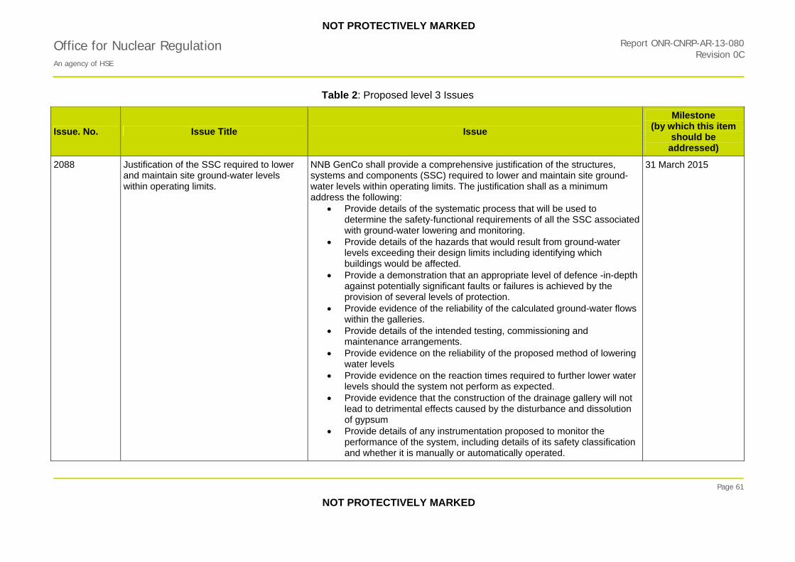
NOT PROTECTIVELY MARKED
Office for Nuclear Regulation Report ONR-CNRP-AR-13-080
An agency of HSE Revision 0C
Table 2: Proposed level 3 Issues
Page 61
NOT PROTECTIVELY MARKED
Issue. No. Issue Title Issue
Milestone (by which this item
should be addressed)
2088
Justification of the SSC required to lower and maintain site ground-water levels within operating limits.
NNB GenCo shall provide a comprehensive justification of the structures, systems and components (SSC) required to lower and maintain site ground-water levels within operating limits. The justification shall as a minimum address the following:
Provide details of the systematic process that will be used to determine the safety-functional requirements of all the SSC associated with ground-water lowering and monitoring.
Provide details of the hazards that would result from ground-water levels exceeding their design limits including identifying which buildings would be affected.
Provide a demonstration that an appropriate level of defence -in-depth against potentially significant faults or failures is achieved by the provision of several levels of protection.
Provide evidence of the reliability of the calculated ground-water flows within the galleries.
Provide details of the intended testing, commissioning and maintenance arrangements.
Provide evidence on the reliability of the proposed method of lowering water levels
Provide evidence on the reaction times required to further lower water levels should the system not perform as expected.
Provide evidence that the construction of the drainage gallery will not lead to detrimental effects caused by the disturbance and dissolution of gypsum
Provide details of any instrumentation proposed to monitor the performance of the system, including details of its safety classification and whether it is manually or automatically operated.
31 March 2015

NOT PROTECTIVELY MARKED
Office for Nuclear Regulation Report ONR-CNRP-AR-13-080
An agency of HSE Revision 0C
Table 2: Proposed level 3 Issues
Page 62
NOT PROTECTIVELY MARKED
Issue. No. Issue Title Issue
Milestone (by which this item
should be addressed)
2089
Justification for the location of the intake heads and substantiation for the modelling of sediment transport and deposition.
NNB GenCo shall justify that the decision to site the intake heads 3.3 km from shore has been taken on ALARP principles. As part of this justification NNB GenCo shall provide the substantiation for the modelling of sediment transport and deposition within the intake heads, intake tunnels and forebay and for the ingress of sediment into the outfall structure. This modelling shall include the upper bound, median and lower bound deposition scenarios and an indication of the type/duration of maintenance required to remove the sediment in each case.
30 November 2014
2090
Justification that the planned inspection and maintenance operations for marine structures comply with the CDM Regulations.
NNB GenCo shall justify that the design and the planned inspection and maintenance operations for the marine structures and forebays have been robustly assessed for compliance with the Construction (Design and Management) Regulations 2007 in terms of reducing risk to people carrying out the inspection and maintenance works.
31 August 2014

NOT PROTECTIVELY MARKED
Office for Nuclear Regulation An agency of HSE
Report ONR-CNRP-AR-13-080Revision 0C
Table 2: Proposed level 3 Issues
Page 63
NOT PROTECTIVELY MARKED
Issue. No. Issue Title Issue
Milestone (by which this item
should be addressed)
2091
Adequacy of documentation for the safety-functional and design performance requirements for the safety-classified buildings.
With respect to the safety-functional and design performance requirements for the safety-classified buildings, NNB GenCo shall:
clearly and comprehensively document the safety-functional and design performance requirements for the safety-classified buildings and structures, including those ‘other structures’ that are contained within the main buildings;
provide an auditable trail within the classification report to identify the location of the assessment report where the effects of failure of a building on other buildings are determined and the classification of NC (Not Classified) is justified;
provide appropriate arguments and evidence to justify the proposed classification of the set-back wall as C2/SC2; and
review the safety classification of those buildings and structures that are identified as not having any safety-functional requirements because they do not contain any classified systems, but where it is clear that they do have a safety-functional requirement, such as not to collapse onto adjacent structures.
31 March 2015
2092
Confirmation of the scope and methodology for the verification and validation of the proposed analysis and design software.
NNB GenCo shall confirm the scope and methodology for the verification and validation of the proposed analysis and design software.
31 August 2014
2093
Confirmation of the safety functional requirements for the pre-stressing gallery and justification for early construction.
NNB GenCo shall confirm the safety classification and safety-functional requirements for the pre-stressing gallery and shall justify the proposal to build the gallery in advance of the hold point for first pour of nuclear island concrete.
30 June 2014

NOT PROTECTIVELY MARKED
Office for Nuclear Regulation Report ONR-CNRP-AR-13-080
An agency of HSE Revision 0C
Table 3: Proposed level 4 Issues
Page 64
NOT PROTECTIVELY MARKED
Issue No. Issue Title Issue
Milestone (by which this item
should be addressed)
2094 Incorporation of local historical offshore site investigation data into geotechnical desk studies.
NNB GenCo shall take into account relevant historical offshore site investigation data from Hinkley Point A and B stations or pre-2008 offshore investigations for Hinkley Point C when deriving ground models for the design of offshore structures.
31 July 2014
2095 Adequacy of peer review of geotechnical interpretative reports.
NNB GenCo shall provide substantiation that the onshore and offshore interpretative reports have been peer reviewed by a suitably qualified and experienced UK geotechnical expert to ensure full utilisation of relevant good practice and experience.
31 July 2014
2096 Confirmation of the geotechnical design parameters for the marine structures.
NNB GenCo shall confirm the value of the geological design parameters, both its own interim evaluation and the final evaluation by level 3 (detailed) design contractors, for the finite element modelling and detailed design of the marine structures. NNB GenCo shall provide justification within the structural design method statement that the geological design parameters are appropriate and demonstrably conservative.
31 March 2015
2097 Confirmation of the safety classification of buildings ancillary to the transformer galleries.
NNB GenCo shall confirm the safety classification and design requirements for the three reinforced concrete buildings above the transformer galleries as shown on Drawings 16035-030-HPC-GND-0014 and 16035-030-HPC-GND-0027 and which are included within the technical galleries scope of work.
30 September 2014
2098 Clarification of the liquid tightness requirements for the technical galleries.
NNB GenCo shall clarify the liquid tightness requirements (tightness class to BS EN 1992 part 3) for the technical galleries, and for other applicable structures outwith the nuclear island, in particular with respect to the tolerable degree of ingress or egress of liquid from the joints and concrete and shall confirm which load combinations under ultimate and serviceability conditions the liquid tightness requirements apply to.
30 September 2014

NOT PROTECTIVELY MARKED
Office for Nuclear Regulation Report ONR-CNRP-AR-13-080
An agency of HSE Revision 0C
Table 3: Proposed level 4 Issues
Page 65
NOT PROTECTIVELY MARKED
Issue No. Issue Title Issue
Milestone (by which this item
should be addressed)
2099 Clarification and justification of the proposed safety classification of elements of the technical galleries.
NNB GenCo shall clarify and justify the proposed safety classifications for the following elements of the technical galleries:
secondary components within the galleries such as cast-in items, ladders, platforms, drainage wells, monorail and doors etc to enable a full understanding of the classification of all applicable structures, systems and components; and
the intersections of differently classified technical galleries that share common structural elements.
30 September 2014
2100 Confirmation of the safety requirements for gas tightness in the technical galleries.
NNB GenCo shall confirm whether there are safety functional requirements for gas tightness for the technical galleries, and if so what those requirements are, and shall additionally provide appropriate justification that the basic design can meet the safety-functional requirements
30 September 2014
2101 Confirmation of safety-functional requirements for containment of spillages of radioactively contaminated liquids.
NNB GenCo shall confirm how the safety-functional requirements for containment of spillages of radioactively contaminated liquids within the technical galleries will be demonstrated (including requirements for both concrete and joints) and how such spillages will be collected and removed. It shall also be demonstrated that joint materials used in the technical galleries can, where required, fulfill their safety-functional requirements when exposed to the effects of radiation.
30 November 2014
2102 Confirmation of proposals for insitu testing for the technical galleries
NNB GenCo shall confirm its proposals for the insitu testing of joints and membranes for the technical galleries so as to demonstrate:
that any construction defects can be detected and rectified; and how leak tightness (for liquids and gases) will be confirmed following
inspection or design basis earthquakes (DBE).
31 March 2015

NOT PROTECTIVELY MARKED
Office for Nuclear Regulation Report ONR-CNRP-AR-13-080
An agency of HSE Revision 0C
Table 3: Proposed level 4 Issues
Page 66
NOT PROTECTIVELY MARKED
Issue No. Issue Title Issue
Milestone (by which this item
should be addressed)
2103 Adequacy of the technical galleries to resist sulphate attack
NNB GenCo shall provide evidence to justify the following aspects of the design for the technical galleries:
that the protective measures to be provided for the drainage gallery (HGS) will mitigate the risk of sulphate attack;
that external membranes used to prevent the ingress of water or gases or to provide additional protective measures against sulphate attack on the concrete have appropriate effectiveness and longevity; and
that the design of the mass/blinding concrete will contain appropriate allowances for the high sulphate content of the soils.
31 March 2015
2104 Justification that the monitoring, inspection and maintenance regime for the heat sink structures will prevent unacceptable build-up of silt.
NNB GenCo shall justify that the proposed monitoring, inspection and maintenance regime for the water intake structures and outfall structure will prevent silt building up to an extent that will compromise the ability of the structures to fulfil their safety-functional requirements.
30 September 2015
2105 Confirmation of compatibility of analysis software with that used during GDA
NNB GenCo shall confirm, for structures assessed during GDA, the extent of the proposed analysis using different software from that assessed during GDA (for example global or local models) and how this analysis work is to be integrated with the previous analysis of the reference design.
30 September 2015
2106 Review of the delegated powers of site staff to agree modifications that can have an effect on nuclear safety
NNB GenCo shall review the proposed aspects of designs that can be modified within the authority of the Design Liaison Team without reference to the designers to ensure that such authority does not extend to modifications that can have an effect on nuclear safety.
31 March 2015
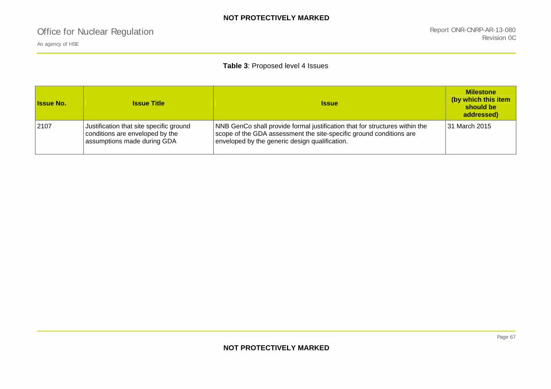
NOT PROTECTIVELY MARKED
Office for Nuclear Regulation An agency of HSE
Report ONR-CNRP-AR-13-080Revision 0C
Table 3: Proposed level 4 Issues
Page 67
NOT PROTECTIVELY MARKED
Issue No. Issue Title Issue
Milestone (by which this item
should be addressed)
2107 Justification that site specific ground conditions are enveloped by the assumptions made during GDA
NNB GenCo shall provide formal justification that for structures within the scope of the GDA assessment the site-specific ground conditions are enveloped by the generic design qualification.
31 March 2015

NOT PROTECTIVELY MARKED
Report ONR-CNRP-AR-13-080Office for Nuclear Regulation An agency of HSE
Revision 0C
Page 68
NOT PROTECTIVELY MARKED
Table 4: HPC Technical Galleries
Galleries Structure
ID Description of Function
Diesel generator galleries HGA HGB HGC HGD
Independently protect the in-house back-up power supply to equipment supporting each of the 4 trains of the Emergency Service Water System (ESWS).
ESWS galleries HGF HGG HGH HGI
House the pipes that provide the reactor building with emergency services water. They also house the cooling water pipes that provide the reactor building cooling component and the electrical power supply cables from HL and electrical back-up supply cables from HD. The galleries are designed as four independent trains.
Electrical and mechanical galleries
HGL HGM
Accommodate non-classified electrical and mechanical systems. The failure of these galleries could impair the integrity of C1 structures where the routes cross. Both galleries where they cross classified galleries are therefore structurally and seismically C2 and SC2 classified
Nuclear Auxiliary Building (NAB) gallery
HGN Links the Electrical and Mechanical galleries with the NAB. The classification is still under consideration.
Firewater gallery HGO Connects ESWS galleries to the fire-fighting water building.
Pump house gallery HGP Provides the routing of unclassified services (the SEN inlet pipes and the general service pipes) to the pump house. The failure of this gallery could impair the integrity of C1 structures where the routes cross. Both galleries where they cross classified galleries are therefore structurally and seismically C2 and SC2 classified
Effluent gallery HGQ Contains pipes containing radioactive waste and links the NAB on Unit 2 to the radioactive waste process building on Unit 1. The gallery contributes to confinement of these wastes in the event of leakage from the pipe
SEN (auxiliary cooling water system) discharge gallery
HGR Links the turbine hall to the outfall structure and provides the routing for the SEN outlet pipes and the fire network pipes. HGR does not contain safety-classified equipment. The failure of the gallery could impair the integrity of Class 1 structures and could have an unacceptable impact on a SSC with a SC1 requirement, so structural and seismic classifications of C2 and SC2 have been assigned.
Auxiliary transformer galleries and step-down transformer galleries
HGJ HGK HGT HGU
Link the transformers to the non-classified electrical building. They contain no safety-classified equipment, have no safety function and do not have any structural or seismic requirements.

NOT PROTECTIVELY MARKED
Office for Nuclear Regulation An agency of HSE
Report ONR-CNRP-AR-13-080Revision 0C
Page 69
NOT PROTECTIVELY MARKED
Table 4: HPC Technical Galleries
Galleries Structure
ID Description of Function
HN-HXA Liaison gallery HGV Houses pipes that connect the NAB to the liquid waste discharge tanks. HGV contains radioactive effluent pipes which are safety-classified equipment.
Access tower galleries HGW Link the access tower on each unit to the Operational Service Centre. They contain no safety-classified equipment. The failure of this gallery could impair the integrity of C1 structures when the routes cross. This gallery, where it crosses classified galleries, is therefore structurally and seismically C2 and SC2 classified.
Demineralisation gallery HGY Links the demineralisation station to a number of other plants. It contains no safety-classified equipment and does not have any structural or seismic requirements. However the classification is currently under re-consideration because of potential for the discharge of radioactive waste leaks. This could require the gallery to provide a containment and protection function to the environment and consequently to be re-classified as a C1 structure.
Forebay Liaison gallery and Diversification gallery
n/a The safety classification and functional requirements of these galleries is under review.
Drainage Galleries HGS To provide drainage of site to lower the ground water level to that required by building foundation design.
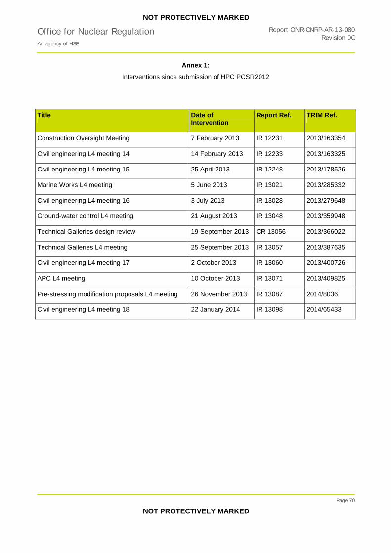
NOT PROTECTIVELY MARKED
Report ONR-CNRP-AR-13-080Office for Nuclear Regulation An agency of HSE
Revision 0C
Annex 1:
Interventions since submission of HPC PCSR2012
Page 70
NOT PROTECTIVELY MARKED
Title Date of Intervention
Report Ref. TRIM Ref.
Construction Oversight Meeting 7 February 2013 IR 12231 2013/163354
Civil engineering L4 meeting 14 14 February 2013 IR 12233 2013/163325
Civil engineering L4 meeting 15 25 April 2013 IR 12248 2013/178526
Marine Works L4 meeting 5 June 2013 IR 13021 2013/285332
Civil engineering L4 meeting 16 3 July 2013 IR 13028 2013/279648
Ground-water control L4 meeting 21 August 2013 IR 13048 2013/359948
Technical Galleries design review 19 September 2013 CR 13056 2013/366022
Technical Galleries L4 meeting 25 September 2013 IR 13057 2013/387635
Civil engineering L4 meeting 17 2 October 2013 IR 13060 2013/400726
APC L4 meeting 10 October 2013 IR 13071 2013/409825
Pre-stressing modification proposals L4 meeting 26 November 2013 IR 13087 2014/8036.
Civil engineering L4 meeting 18 22 January 2014 IR 13098 2014/65433