himalayan - Hitchcocks Motorcycles
294
EURO IV - HIMALAYAN VEHICLE SERVICE MANUAL CHASSIS HIMALAYAN www.hitchcocksmotorcycles.com
-
Upload
khangminh22 -
Category
Documents
-
view
1 -
download
0
Transcript of himalayan - Hitchcocks Motorcycles

EURO IV - HIMALAYAN VEHICLE SERVICE MANUALCHASSIS
HIMALAYAN
www.hitchcocksmotorcycles.com

ROYAL ENFIELD HIMALAYAN EURO IV VEHICLE SERVICE MANUAL 1
PREFACE
“FIRST TIME RIGHT” is a very important element for enhancing Customer Satisfaction.
Royal Enfield is committed to upgrade the skills and knowledge of technicians so that they follow scientific repair
techniques to ensure “FIRST TIME RIGHT” practices and carry out repairs accurately so that customers will enjoy
trouble free performance at all times.
This manual will help in complete understanding of systematic procedures for dismantling, inspection, diagnosis and
reassembly for the new Royal Enfield Himalayan motorcycle, in a simple and scientific manner.
While this manual is updated with latest Information and Specifications at the time of going to print, due to continuous
improvements being done to improve performance, some of the data, illustrations etc., in this manual may be different
from some of the parts fitted in the motorcycle.
Please do feel free to write to us at [email protected] , if you have any queries, clarification, suggestions or
feedback.
With warm regards
SERVICE HEAD QUARTERS
Royal Enfield, A Unit of Eicher Motors Limited,
Thiruvottiyur High Road, Thiruvottiyur, Chennai - 600 019.
E-mail: [email protected]
Website: www.royalenfield.com
Part No: 1017122/A / Oct. ’17
01
www.hitchcocksmotorcycles.com
ROYAL ENFIELD HIMALAYAN EURO IV VEHICLE SERVICE MANUAL2
HIMALAYAN – VEHICLE VIEWS
VEHICLE VIEW LH
02
www.hitchcocksmotorcycles.com
ROYAL ENFIELD HIMALAYAN EURO IV VEHICLE SERVICE MANUAL 3
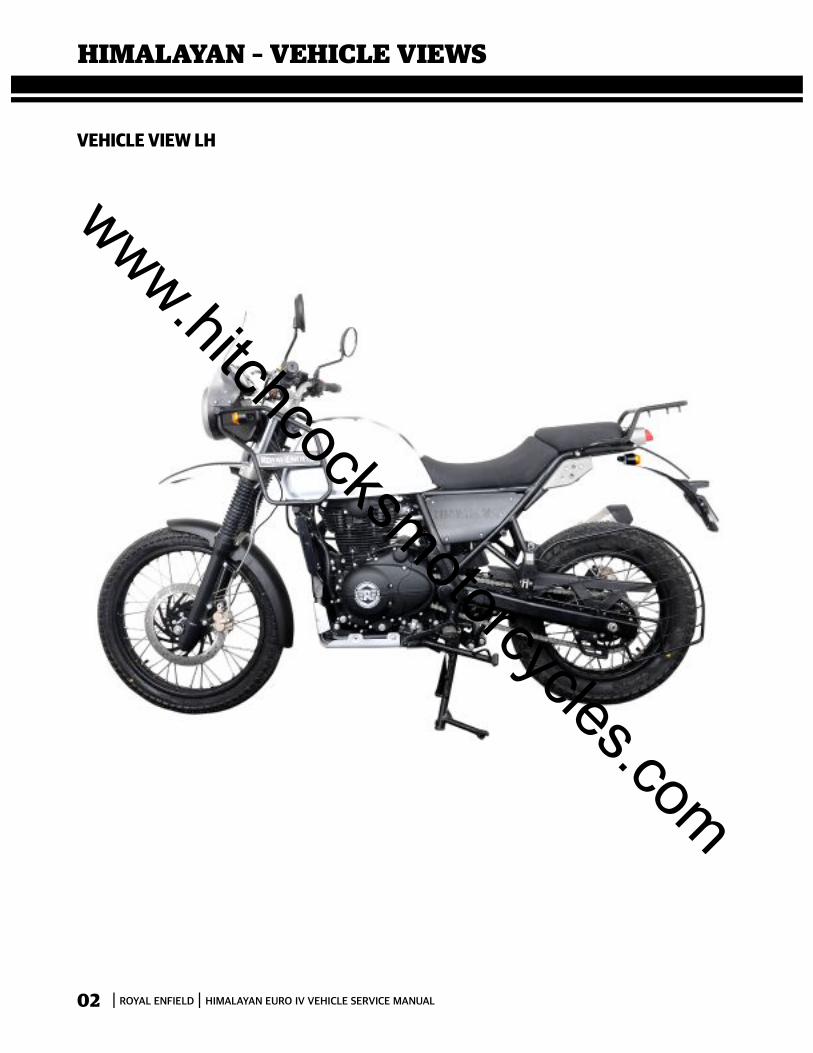
VEHICLE VIEW RH
03
www.hitchcocksmotorcycles.com
ROYAL ENFIELD HIMALAYAN EURO IV VEHICLE SERVICE MANUAL4
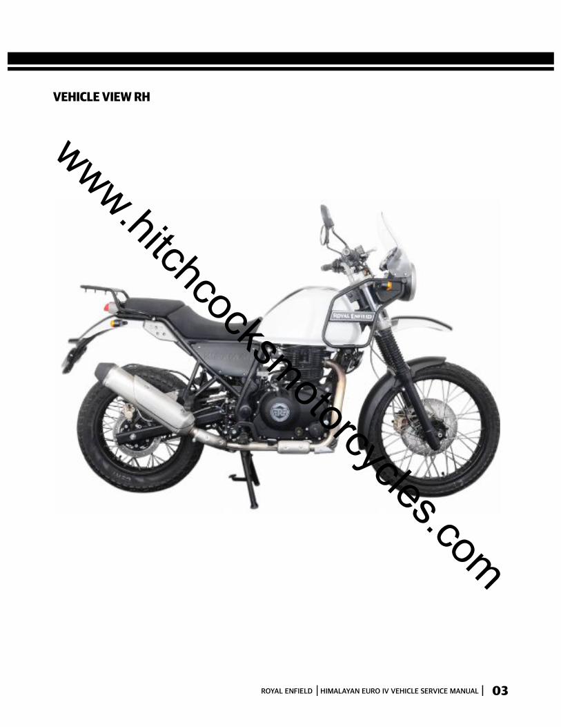
VEHICLE VIEW TOP
04
www.hitchcocksmotorcycles.com
ROYAL ENFIELD HIMALAYAN EURO IV VEHICLE SERVICE MANUAL 5
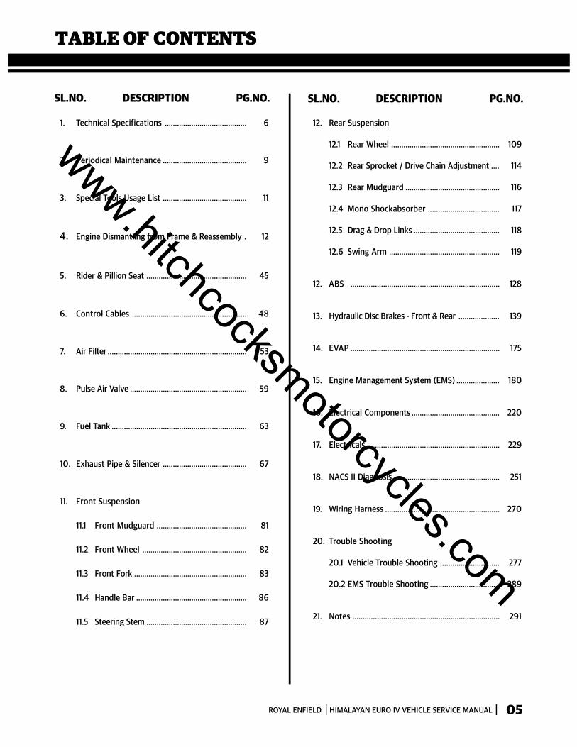
TABLE OF CONTENTS
SL.NO. DESCRIPTION PG.NO. SL.NO. DESCRIPTION PG.NO.
1. Technical Specifications ........................................ 6
2. Periodical Maintenance ......................................... 9
3. Special Tools Usage List ......................................... 11
4. Engine Dismantling from Frame & Reassembly . 12
5. Rider & Pillion Seat ................................................. 45
6. Control Cables ........................................................ 48
7. Air Filter .................................................................... 53
8. Pulse Air Valve ......................................................... 59
9. Fuel Tank .................................................................. 63
10. Exhaust Pipe & Silencer ......................................... 67
11. Front Suspension
11.1 Front Mudguard ............................................ 81
11.2 Front Wheel ................................................... 82
11.3 Front Fork ....................................................... 83
11.4 Handle Bar ...................................................... 86
11.5 Steering Stem ................................................. 87
12. Rear Suspension
12.1 Rear Wheel ..................................................... 109
12.2 Rear Sprocket / Drive Chain Adjustment .... 114
12.3 Rear Mudguard .............................................. 116
12.4 Mono Shockabsorber ................................... 117
12.5 Drag & Drop Links .......................................... 118
12.6 Swing Arm ...................................................... 119
12. ABS ......................................................................... 128
13. Hydraulic Disc Brakes - Front & Rear .................... 139
14. EVAP ......................................................................... 175
15. Engine Management System (EMS) ..................... 180
16. Electrical Components ........................................... 220
17. Electricals ................................................................. 229
18. NACS II Diagnosis .................................................... 251
19. Wiring Harness ........................................................ 270
20. Trouble Shooting
20.1 Vehicle Trouble Shooting ............................. 277
20.2 EMS Trouble Shooting .................................. 289
21. Notes ........................................................................ 291
05
www.hitchcocksmotorcycles.com
ROYAL ENFIELD HIMALAYAN EURO IV VEHICLE SERVICE MANUAL6
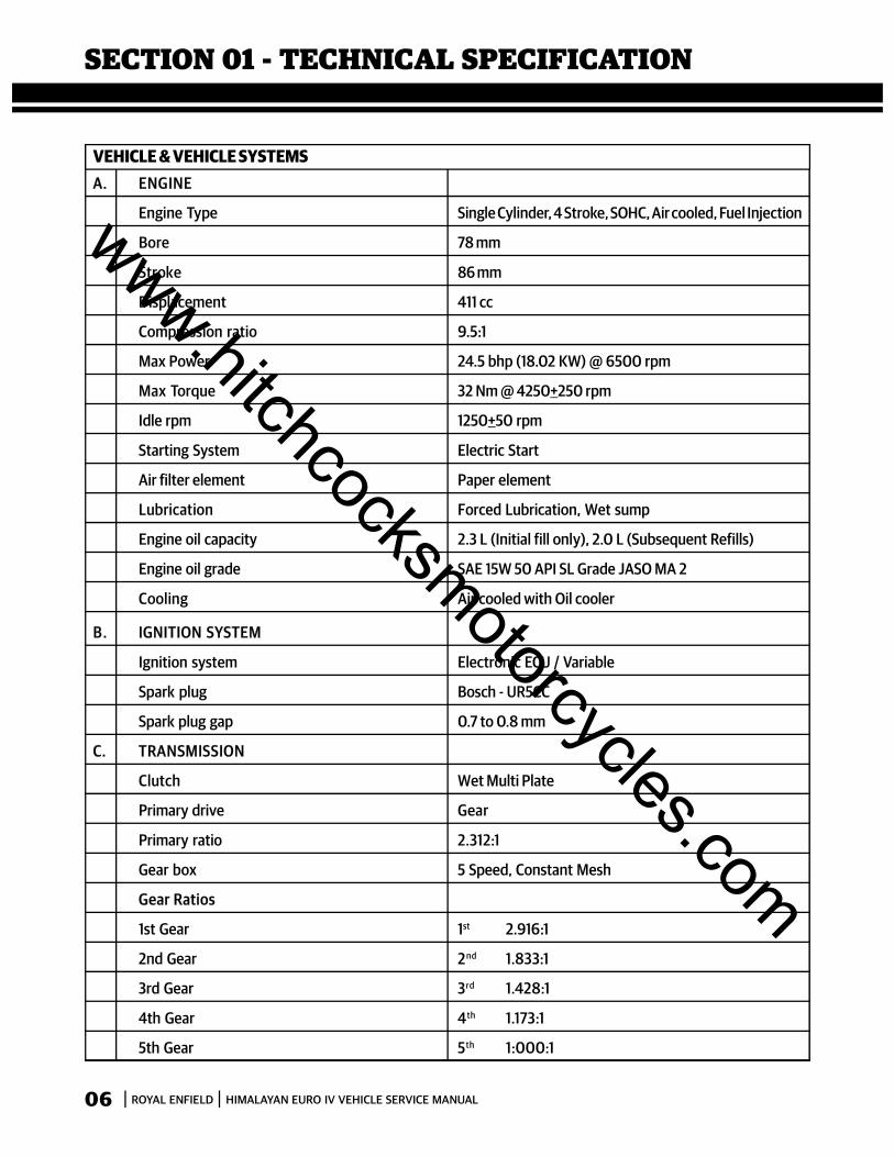
SECTION 01 - TECHNICAL SPECIFICATION
A. ENGINE
Engine Type Single Cylinder, 4 Stroke, SOHC, Air cooled, Fuel Injection
Bore 78 mm
Stroke 86 mm
Displacement 411 cc
Compression ratio 9.5:1
Max Power 24.5 bhp (18.02 KW) @ 6500 rpm
Max Torque 32 Nm @ 4250+250 rpm
Idle rpm 1250+50 rpm
Starting System Electric Start
Air filter element Paper element
Lubrication Forced Lubrication, Wet sump
Engine oil capacity 2.3 L (Initial fill only), 2.0 L (Subsequent Refills)
Engine oil grade SAE 15W 50 API SL Grade JASO MA 2
Cooling Air cooled with Oil cooler
B. IGNITION SYSTEM
Ignition system Electronic ECU / Variable
Spark plug Bosch - UR5CC
Spark plug gap 0.7 to 0.8 mm
C. TRANSMISSION
Clutch Wet Multi Plate
Primary drive Gear
Primary ratio 2.312:1
Gear box 5 Speed, Constant Mesh
Gear Ratios
1st Gear 1st 2.916:1
2nd Gear 2nd 1.833:1
3rd Gear 3rd 1.428:1
4th Gear 4th 1.173:1
5th Gear 5th 1:000:1
VEHICLE & VEHICLE SYSTEMS
06
www.hitchcocksmotorcycles.com
ROYAL ENFIELD HIMALAYAN EURO IV VEHICLE SERVICE MANUAL 7
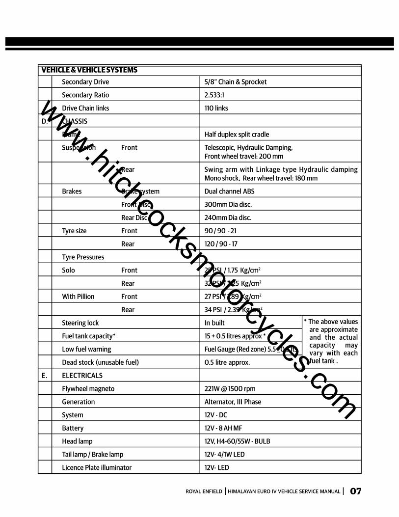
VEHICLE & VEHICLE SYSTEMSSecondary Drive 5/8” Chain & Sprocket
Secondary Ratio 2.533:1
Drive Chain links 110 links
D. CHASSIS
Frame Half duplex split cradle
Suspension Front Telescopic, Hydraulic Damping,Front wheel travel: 200 mm
Rear Swing arm with Linkage type Hydraulic dampingMono shock, Rear wheel travel: 180 mm
Brakes Brake system Dual channel ABS
Front Disc 300mm Dia disc.
Rear Disc 240mm Dia disc.
Tyre size Front 90 / 90 - 21
Rear 120 / 90 - 17
Tyre Pressures
Solo Front 25 PSI / 1.75 Kg/cm2
Rear 32 PSI / 2.25 Kg/cm2
With Pillion Front 27 PSI / 1.89 Kg/cm2
Rear 34 PSI / 2.39 Kg/cm2
Steering lock In built
Fuel tank capacity* 15 + 0.5 litres approx *
Low fuel warning Fuel Gauge (Red zone) 5.5 +0.5 lts.
Dead stock (unusable fuel) 0.5 litre approx.
E. ELECTRICALS
Flywheel magneto 221W @ 1500 rpm
Generation Alternator, III Phase
System 12V - DC
Battery 12V - 8 AH MF
Head lamp 12V, H4-60/55W - BULB
Tail lamp / Brake lamp 12V- 4/1W LED
Licence Plate illuminator 12V- LED
* The above valuesare approximateand the actualcapacity mayvary with eachfuel tank .
07
www.hitchcocksmotorcycles.com

ROYAL ENFIELD HIMALAYAN EURO IV VEHICLE SERVICE MANUAL8
Front position lamp 12V - LED
Speedometer lamp 12V - LED
Hi beam indicator 12V - LED
Neutral lamp telltale 12V - LED
Turn signal telltale 12V - LED
Turn signal 12V, 10W * 4 Nos.
Horn 12V, 2.5 Amp.
Starter Motor 12V, 0.7 KW
Instrument Cluster Digital cluster with mainand compass LCD
Side Stand indicator LCD Indication
F. DIMENSIONS
Length 2190 mm
Width 840 mm
Height 1360 mm
Wheel base 1465 mm
Ground clearance. 220 mm
Saddle Height 800 mm
G. WEIGHTS
Kerb weight (90% fuel&oil) 191 kgs.
Max. Pay load 174 Kgs.
WARNINGUsing bulbs/ electrical gadgetsother than specified ratingmay lead to overloading /eratic behaviour / prematurefailure of electrical system.
Modifications or fitmentswhich are not approved byRoyal Enfield, will seriouslyaffect the performance of thevehicle and will render thewarranty void.
Values / Dimensionsmentioned above arefor reference only.
In view of continuousimprovements beingdone on ourmotorcycles, thespecifications aresubject to changewithout prior notice.
08
VEHICLE & VEHICLE SYSTEMS
www.hitchcocksmotorcycles.com

ROYAL ENFIELD HIMALAYAN EURO IV VEHICLE SERVICE MANUAL 9
SECTION 02 - PERIODICAL MAINTENANCE
The Periodical maintenance schedule detailed below is based upon average riding conditions and indicates theIntervals at which regular inspections, adjustments, replacements and lubrications must be carried out to help maintainyour Himalayan motorcycle meticulouslyIf in case the motorcycle is used frequently in very dusty environment / severe climatic conditions / Poor Roads /stagnant water etc., the maintenance will need to be done earlier as may be required.Contact a nearest Royal Enfield Authorised Dealer / Service Center to carry out the periodical maintenance and forany expert advice.S.No. DESCRIPTION
whichever is earlierPAID SERVICEFREE SERVICE
whichever is earlier
NOTE:For maintenance after 50,000 Kms. , please repeat same frequency specified above, in consultation with a RoyalEnfield Authorised Dealer / Service Center.
A : A d j u s t C : C l e a n I : I n s p e c t L : L u b r i c a t e R : R e p l a c e* Refer Service Manual. # Check every time after vehicle is used for off road riding
Kms (x 1000) 0.5 5 10 15 20 25 30 35 40 45 50
Months 1.5 6 12 18 24 30 36 42 48 54 60
1 Engine Oil (Level check / Replace)R I R I R I R I R I R
Check level at every 1000 Kms or earlier as required
2 Oil Filter Element R R R R R R
3 Engine oil strainer on crankcase LH C C C C C C
4 Inlet / Exhaust Tappet setting I & A I & A I & A I & A I & A I & A I & A I & A I & A I & A I & A
5 Rubber hose, Inlet manifold * I I R I R I R I R I R
6 Oil cooler inlet & outlet pipes * I I I R I I R I I R I
7 Spark plug C & A C & A C & A R C & A C & A R C & A C & A R C & A
8 HT leads for crack I I I I I I R I I I I
9 Fuel Hose I I I R I I R I I R I
10 Fuel Hose & Clip/ Injector ‘O’ ring/ Seal Ring I I I R I I R I I R I
11 Fuel Pump Check for screw tightness in all services
C C R C R C R C R C R
12 Air filter element Clean/ Replace more frequently if motorcycle always usedindusty / off Road conditions.
13 Accelerator Cable I I R I R I R I R I R
14 Rubber Hose, Air fitler to Throttle body I I R I R I R I R I R
15 PAV pipes & Hose clip I I I I I R I I I I R
16 Throttle body- Cleaning spray* Carbo cleaner/ carb click/ or Fuel line cleaner spray every6000 Km or 6 months whichever is earlier
17 Clutch Cable I I R I R I R I R I R
09
www.hitchcocksmotorcycles.com
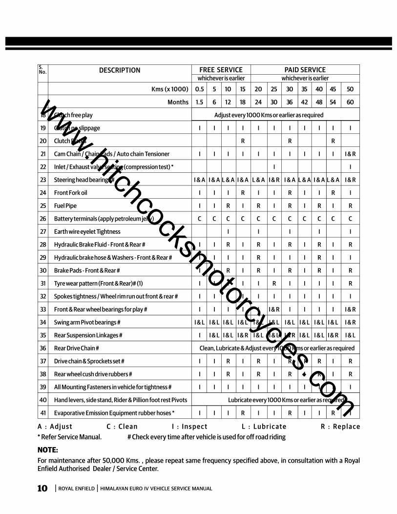
ROYAL ENFIELD HIMALAYAN EURO IV VEHICLE SERVICE MANUAL10
S.No. DESCRIPTION
whichever is earlierPAID SERVICEFREE SERVICE
whichever is earlier
Kms (x 1000) 0.5 5 10 15 20 25 30 35 40 45 50
Months 1.5 6 12 18 24 30 36 42 48 54 60
18 Clutch free play Adjust every 1000 Kms or earlier as required
19 Clutch no slippage I I I I I I I I I I I
20 Clutch Plates R R R
21 Cam Chain / Chain Pads / Auto chain Tensioner I I I I I I I I I I I & R
22 Inlet / Exhaust valve seating (compression test) * I I
23 Steering head bearings # I & A I & A L & A I & A L & A I & R I & A L & A I & A L & A I & R
24 Front Fork oil I I I R I I R I I R I
25 Fuel Pipe I I R I R I R I R I R
26 Battery terminals (apply petroleum jelly) C C C C C C C C C C C
27 Earth wire eyelet Tightness I I I I I
28 Hydraulic Brake Fluid - Front & Rear # I I R I R I R I R I R
29 Hydraulic brake hose & Washers - Front & Rear # I I I I R I I I R I I
30 Brake Pads - Front & Rear # I I R I R I R I R I R
31 Tyre wear pattern (Front & Rear)# (1) I I I I I R I I I I R
32 Spokes tightness / Wheel rim run out front & rear # I I I I I I I I I I I
33 Front & Rear wheel bearings for play # I I I I I I & R I I I I I & R
34 Swing arm Pivot bearings # I & L I & L I & L I & L I & L I & L I & L I & L I & L I & L I & R
35 Rear Suspension Linkages # I I & L I & L I & R I & L I & L I & R I & L I & L I & R I & L
36 Rear Drive Chain # Clean, Lubricate & Adjust every 1000 Kms or earlier as required
37 Drive chain & Sprockets set # I I R I R I R I R I R
38 Rear wheel cush drive rubbers # I I R I R I R I R I R
39 All Mounting Fasteners in vehicle for tightness # I I I I I I I I I I I
40 Hand levers, side stand, Rider & Pillion foot rest Pivots Lubricate every 1000 Kms or earlier as required
41 Evaporative Emission Equipment rubber hoses * I I I R I I R I I R I
NOTE:For maintenance after 50,000 Kms. , please repeat same frequency specified above, in consultation with a RoyalEnfield Authorised Dealer / Service Center.
A : A d j u s t C : C l e a n I : I n s p e c t L : L u b r i c a t e R : R e p l a c e* Refer Service Manual. # Check every time after vehicle is used for off road riding
www.hitchcocksmotorcycles.com
ROYAL ENFIELD HIMALAYAN EURO IV VEHICLE SERVICE MANUAL 11
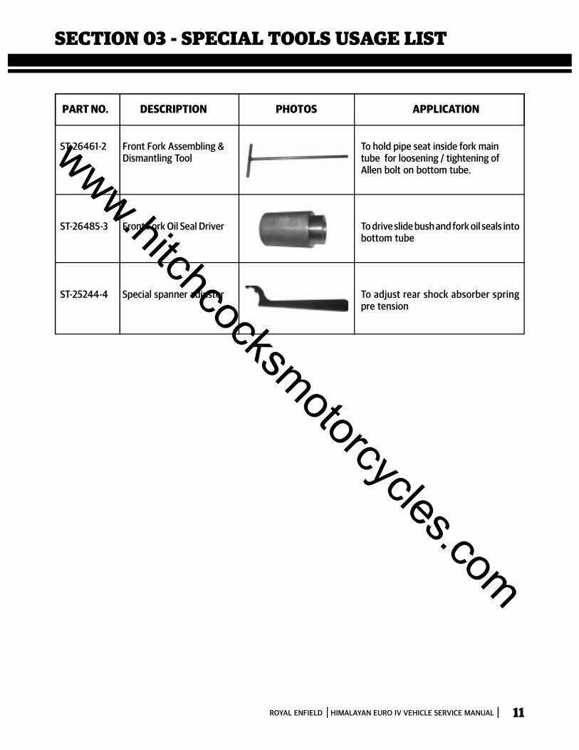
SECTION 03 - SPECIAL TOOLS USAGE LIST
ST-26461-2 Front Fork Assembling & To hold pipe seat inside fork mainDismantling Tool tube for loosening / tightening of
Allen bolt on bottom tube.
ST-26485-3 Front Fork Oil Seal Driver To drive slide bush and fork oil seals intobottom tube
ST-25244-4 Special spanner adjuster To adjust rear shock absorber springpre tension
PART NO. DESCRIPTION PHOTOS APPLICATION
www.hitchcocksmotorcycles.com
ROYAL ENFIELD HIMALAYAN EURO IV VEHICLE SERVICE MANUAL12
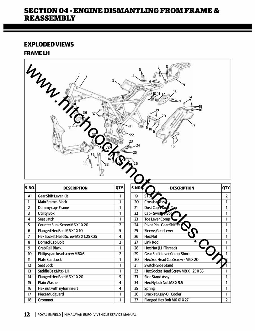
SECTION 04 - ENGINE DISMANTLING FROM FRAME &REASSEMBLY
EXPLODED VIEWSFRAME LH
S. NO. DESCRIPTION QTY. S. NO. DESCRIPTION QTY.
A1 Gear Shift Lever Kit 11 Main Frame- Black 12 Dummy cap- Frame 13 Utility Box 14 Seat Latch 15 Counter Sunk Screw M6 X 1 X 20 26 Flanged Hex Bolt M6 X 1 X 10 57 Hex Socket Head Screw M8 X 1.25 X 25 48 Domed Cap Bolt 29 Grab Rail Black 110 Philips pan head screw M6X6 211 Plate Seat Lock 112 Seat Lock 113 Saddle Bag Mtg - LH 114 Flanged Hex Bolt M6 X 1 X 20 515 Plain Washer 416 Hex nut with nylon insert 417 Piece Mudguard 118 Grommet 1
19 STUD 220 Crossbar Assy 121 Dust Cap-Frame Top 122 Cap - Swing pivot 123 Toe Lever Comp 124 Pivot Pin - Gear Shifter 125 Sleeve, Gear Lever 126 Hex Nut 127 Link Rod 128 Hex Nut (LH Thread) 129 Gear Shift Lever Comp-Short 130 Hex Soc Head Cap Screw – M5 X 20 231 Switch-Side Stand 132 Hex Socket Head Screw M8 X 1.25 X 35 133 Side Stand Assy 134 Hex Nylock Nut M8 X 9.5 135 Spring 136 Bracket Assy-Oil Cooler 137 Flanged Hex Bolt M6 X1 X 27 2
1 23
4
5
6
7 8
9
10 11 12 13
714
1516
17
15
16
1920
661821
22
2324
25
2627282914
32
33
34
35
31
30
14
36 37
www.hitchcocksmotorcycles.com
ROYAL ENFIELD HIMALAYAN EURO IV VEHICLE SERVICE MANUAL 13
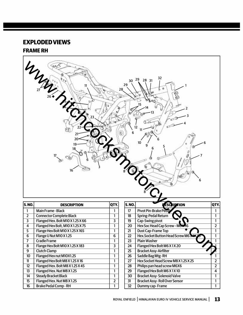
EXPLODED VIEWSFRAME RH
S. NO. DESCRIPTION QTY. S. NO. DESCRIPTION QTY.1 Main Frame - Black 12 Connector Complete Black 13 Flanged Hex. Bolt M10 X 1.25 X 66 34 Flanged Hex Bolt, M10 X 1.25 X 75 15 Flange Hex Bolt M10 X 1.25 X 165 16 Flange U Nut M10 X 1.25 67 Cradle Frame 18 Flange Hex Bolt M10 X 1.25 X 183 39 Clutch Clamp 110 Flanged Hex nut M10X1.25 111 Flanged Hex Bolt M8 X 1.25 X 16 112 Flanged Hex. Bolt M8 X 1.25 X 45 113 Flanged Hex. Nut M8 X 1.25 114 Steady Bracket Black 115 Flanged Hex. Nut M8 X 1.25 216 Brake Pedal Comp - RH 1
17 Pivot Pin-Brake Pedal 118 Spring-Pedal Return 119 Cap-Swing pivot 120 Hex Soc Head Cap Screw – M6 X 16 221 Dust Cap-Frame Top 122 Hex.Socket Button Head Screw M6 X 1 X 16 123 Plain Washer 124 Flanged Hex Bolt M6 X 1 X 20 125 Bracket Assy-Airfilter 126 Saddle Bag Mtg- RH 127 Hex Socket Head Screw M8 X 1.25 X 25 228 Philips pan head screw M6X6 229 Flanged Hex Bolt M6 X 1 X 10 430 Bracket Assy- Solenoid Valve 131 Bracket Assy- Roll Over Sensor 132 Dummy cap- Frame 1
27
262524
11
2120
1918
617
163
3
8
8
6
7
656
6
910
116
12
1314
15
4
3
2
1
3231282930
2928
23
22
8
www.hitchcocksmotorcycles.com
ROYAL ENFIELD HIMALAYAN EURO IV VEHICLE SERVICE MANUAL14
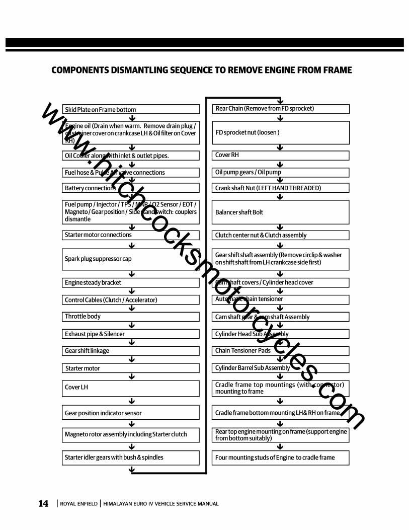
COMPONENTS DISMANTLING SEQUENCE TO REMOVE ENGINE FROM FRAME
Skid Plate on Frame bottom
Engine oil (Drain when warm. Remove drain plug /oil strainer cover on crankcase LH & Oil filter on CoverRH)
Oil Cooler along with inlet & outlet pipes.
Fuel hose & Pulse Air valve connections
Battery connections
Fuel pump / Injector / TPS / MAP / O2 Sensor / EOT /Magneto / Gear position / Side stand switch: couplersdismantle
Starter motor connections
Spark plug suppressor cap
Engine steady bracket
Control Cables (Clutch / Accelerator)
Throttle body
Exhaust pipe & Silencer
Gear shift linkage
Starter motor
Cover LH
Gear position indicator sensor
Magneto rotor assembly including Starter clutch
Starter idler gears with bush & spindles
Rear Chain (Remove from FD sprocket)
FD sprocket nut (loosen )
Cover RH
Oil pump gears / Oil pump
Crank shaft Nut (LEFT HAND THREADED)
Balancer shaft Bolt
Clutch center nut & Clutch assembly
Gear shift shaft assembly (Remove circlip & washeron shift shaft from LH crankcase side first)
Cam shaft covers / Cylinder head cover
Automatic chain tensioner
Cam shaft gear & cam shaft Assembly
Cylinder Head Sub Assembly
Chain Tensioner Pads
Cylinder Barrel Sub Assembly
Cradle frame top mountings (with connector)mounting to frame
Cradle frame bottom mounting LH& RH on frame
Rear top engine mounting on frame (support enginefrom bottom suitably)
Four mounting studs of Engine to cradle frame
www.hitchcocksmotorcycles.com
ROYAL ENFIELD HIMALAYAN EURO IV VEHICLE SERVICE MANUAL 15
S.No.
Fastener, Size, Tool Usage, Precautions, PhotosAggregate to Dismantle/Instructions
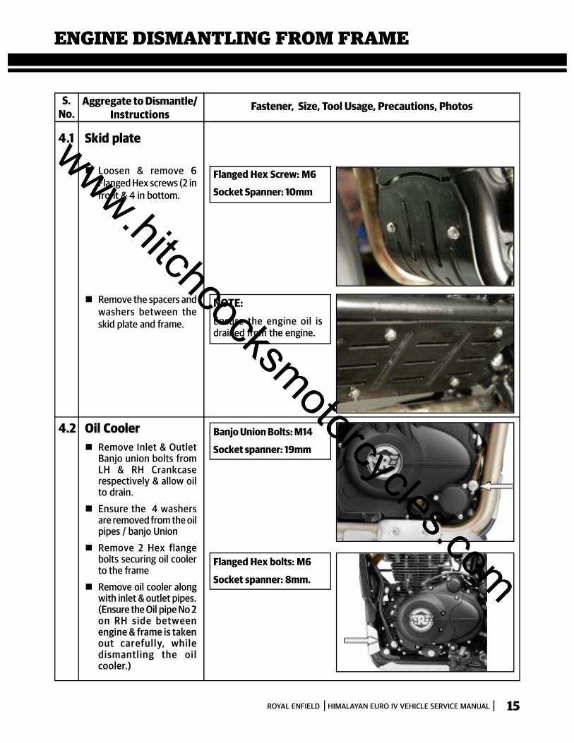
4.1 Skid plate
Loosen & remove 6Flanged Hex screws (2 infront & 4 in bottom.
Flanged Hex Screw: M6
Socket Spanner: 10mm
NOTE:Ensure the engine oil isdrained from the engine.
Remove the spacers andwashers between theskid plate and frame.
4.2 Oil Cooler Remove Inlet & Outlet
Banjo union bolts fromLH & RH Crankcaserespectively & allow oilto drain.
Ensure the 4 washersare removed from the oilpipes / banjo Union
Remove 2 Hex flangebolts securing oil coolerto the frame
Remove oil cooler alongwith inlet & outlet pipes.(Ensure the Oil pipe No 2on RH side betweenengine & frame is takenout c ar eful l y, whil edi sm antl ing the oi lcooler.)
Banjo Union Bolts: M14
Socket spanner: 19mm
Flanged Hex bolts: M6
Socket spanner: 8mm.
ENGINE DISMANTLING FROM FRAME
www.hitchcocksmotorcycles.com
ROYAL ENFIELD HIMALAYAN EURO IV VEHICLE SERVICE MANUAL16
S.No.
Fastener, Size, Tool Usage, Precautions, PhotosAggregate to Dismantle/Instructions
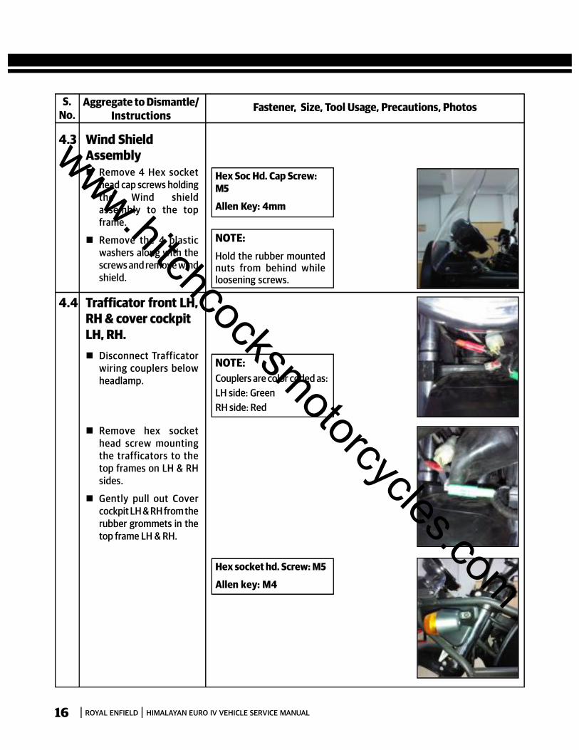
4.3 Wind ShieldAssembly Remove 4 Hex socket
head cap screws holdingthe Wind shieldassembly to the topframe.
Remove the 4 plasticwashers along with thescrews and remove windshield.
Hex Soc Hd. Cap Screw:M5
Allen Key: 4mm
NOTE:Hold the rubber mountednuts from behind whileloosening screws.
4.4 Trafficator front LH,RH & cover cockpitLH, RH. Disconnect Trafficator
wiring couplers belowheadlamp.
Remove hex sockethead screw mountingthe trafficators to thetop frames on LH & RHsides.
Gently pull out Covercockpit LH & RH from therubber grommets in thetop frame LH & RH.
NOTE:Couplers are color coded as:LH side: GreenRH side: Red
Hex socket hd. Screw: M5
Allen key: M4
www.hitchcocksmotorcycles.com
ROYAL ENFIELD HIMALAYAN EURO IV VEHICLE SERVICE MANUAL 17
S.No.
Fastener, Size, Tool Usage, Precautions, PhotosAggregate to Dismantle/Instructions
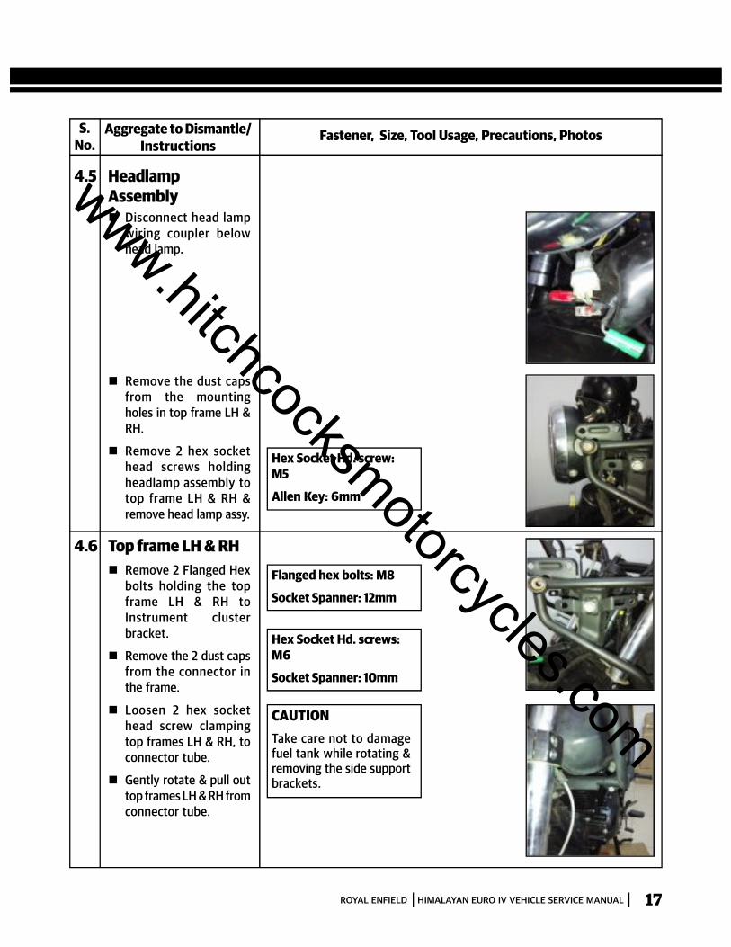
4.5 HeadlampAssembly Disconnect head lamp
wiring coupler belowhead lamp.
Hex Socket Hd. screw:M5
Allen Key: 6mm
Remove the dust capsfrom the mountingholes in top frame LH &RH.
Remove 2 hex sockethead screws holdingheadlamp assembly totop frame LH & RH &remove head lamp assy.
4.6 Top frame LH & RH Remove 2 Flanged Hex
bolts holding the topframe LH & RH toInstrument clusterbracket.
Remove the 2 dust capsfrom the connector inthe frame.
Loosen 2 hex sockethead screw clampingtop frames LH & RH, toconnector tube.
Gently rotate & pull outtop frames LH & RH fromconnector tube.
Flanged hex bolts: M8
Socket Spanner: 12mm
Hex Socket Hd. screws:M6
Socket Spanner: 10mm
CAUTIONTake care not to damagefuel tank while rotating &removing the side supportbrackets.
www.hitchcocksmotorcycles.com
ROYAL ENFIELD HIMALAYAN EURO IV VEHICLE SERVICE MANUAL18
S.No.
Fastener, Size, Tool Usage, Precautions, PhotosAggregate to Dismantle/Instructions
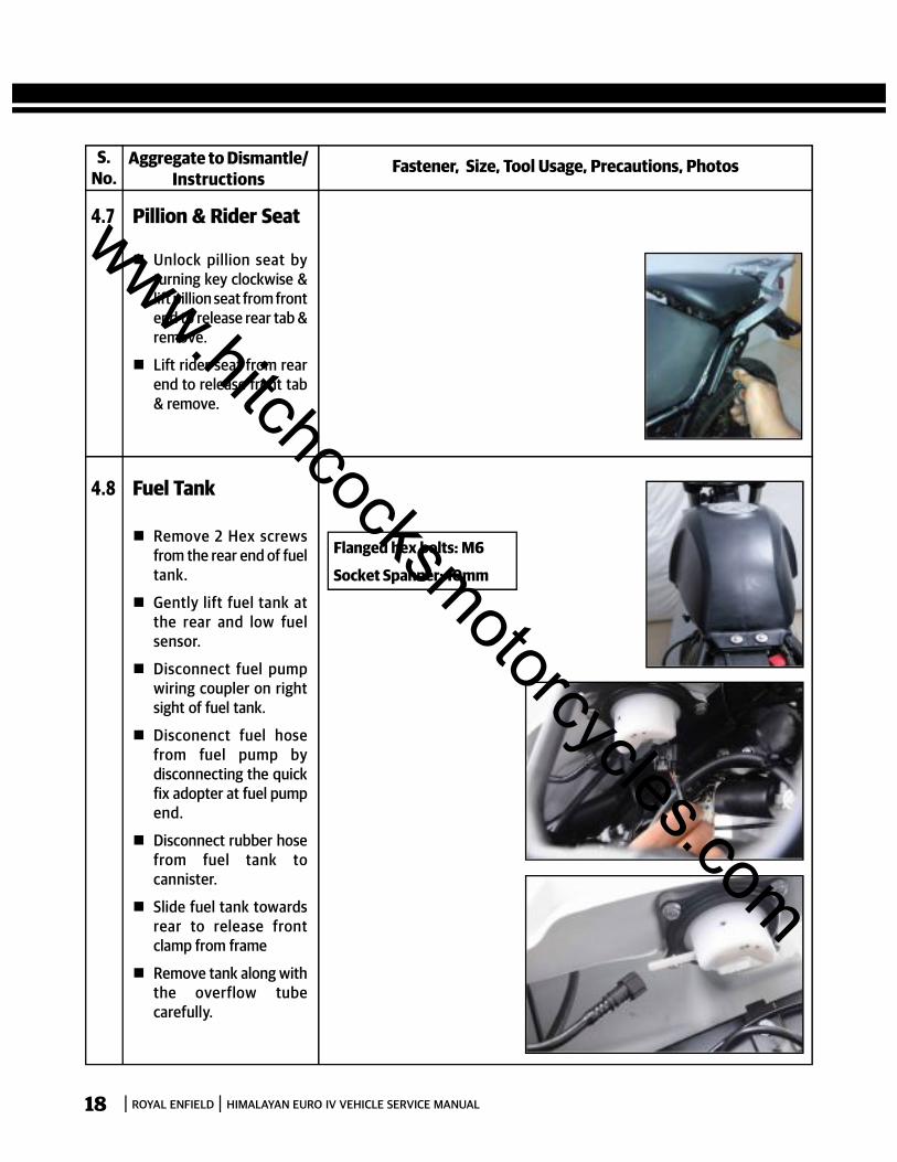
4.7 Pillion & Rider Seat
Unlock pillion seat byturning key clockwise &lift pillion seat from frontend to release rear tab &remove.
Lift rider seat from rearend to release front tab& remove.
4.8 Fuel Tank
Remove 2 Hex screwsfrom the rear end of fueltank.
Gently lift fuel tank atthe rear and low fuelsensor.
Disconnect fuel pumpwiring coupler on rightsight of fuel tank.
Disconenct fuel hosefrom fuel pump bydisconnecting the quickfix adopter at fuel pumpend.
Disconnect rubber hosefrom fuel tank tocannister.
Slide fuel tank towardsrear to release frontclamp from frame
Remove tank along withthe overflow tubecarefully.
Flanged hex bolts: M6
Socket Spanner: 10mm
www.hitchcocksmotorcycles.com

ROYAL ENFIELD HIMALAYAN EURO IV VEHICLE SERVICE MANUAL 19
S.No.
Fastener, Size, Tool Usage, Precautions, PhotosAggregate to Dismantle/Instructions
4.9 Steady EngineBracket Hold U nut at the cylinder
head mounting areawith a double endspanner and loosen Hexbolt at the front of thesteady engine bracket.
Remove the bolt andnut.
Support steady enginebracket, Loosen &remove the 2 Flangedhex bolts at the rear endof the bracket andremove the bolts andsteady engine bracket.
Flanged hex bolt: M10
Socket Spanner: 12mm
Flanged hex nut: M10
Socket Spanner: 12mm
4.10 Throttle cable
Push rubber grommetsdown and loosen hexnuts completely.
Gently pull throttle cablefrom bracket to releasethe threaded positionfrom the bracket.
Remove inner cablefrom the throttle bodyrotor eyelet.
Double End Spanner:13mm
www.hitchcocksmotorcycles.com

ROYAL ENFIELD HIMALAYAN EURO IV VEHICLE SERVICE MANUAL20
S.No.
Fastener, Size, Tool Usage, Precautions, PhotosAggregate to Dismantle/Instructions
4.11 Clutch Cable
Loosen & remove outerlocknut from the rear ofthe cable adjuster.
Loosen inner locknutfully & push adjusterfully into bracket.
Release inner cable fromthe clevis in the clutchshaft
Remove rubber grommet& outer lock nut &remove clutch cablefrom the bracket.
Hex Nut: M8
D E Spanner: 12mm
NOTE:Gently push the rubbergrommet away from theadjuster while removingnut.
4.12 Bi-starter Cable Remove the Bi starter
cable from the clutchlever at handle bar end.
At throttle body end Remove the tank assy.
(as detailed in section 10) Loosen the hex faced
plastic nut on holdercable valve at thethrottle body end slowlypull out the valve bistarter from throttlebody.
Compress spring &disconnect cable fromthe vale bi starter.
Remove spring & valve bistarter & slide out cablefrom the guide.
At handle bar end Loosen switch LH
holding screws at thebottom & seperate theswitch.
Disconnect cable fromlever & remove.
Double end spanner :12 x 13 mm
CAUTIONSpring loaded cable henceremove slowly.
www.hitchcocksmotorcycles.com
ROYAL ENFIELD HIMALAYAN EURO IV VEHICLE SERVICE MANUAL 21
S.No.
Fastener, Size, Tool Usage, Precautions, PhotosAggregate to Dismantle/Instructions
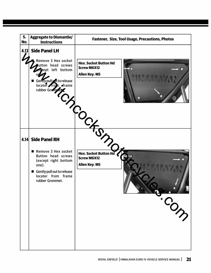
4.13 Side Panel LH
Remove 3 Hex socketButton head screws(except left bottomone).
Gently pull out to releaselocater from framerubber Grommet.
Hex. Socket Button HdScrew M6X12
Allen Key: M5
4.14 Side Panel RH
Remove 3 Hex socketButton head screws(except right bottomone).
Gently pull out to releaselocater from framerubber Grommet.
Hex. Socket Button HdScrew M6X12
Allen Key: M5
www.hitchcocksmotorcycles.com

ROYAL ENFIELD HIMALAYAN EURO IV VEHICLE SERVICE MANUAL22
S.No.
Fastener, Size, Tool Usage, Precautions, PhotosAggregate to Dismantle/Instructions
4.14 Electrical connectionsA. Battery Remove negative terminal
sc rew and disconnectnegative battery cable.
Remove positive terminalscrew and disconnectpositive battery cable.
B. Starter Motor Remove the Hex nut
securing the wire eyeletto starter motor terminaland remove the wire.
Remove flanged hexbolt securing the earthwire eyelet to crankcase.
C. Throttle PositionSensor (TPS)
Disconnect blackcoupler from thethrottlebody on LH side.
D. MAP Disconnect black
coupler from throttlebody top as RH side.
E. Fuel Injector sensor Disconnect black
coupler from fuelinjector at LH side.
F. EOT Disconnect EOT Sensor
coupler (white) on RHside.
G. Oxygen Sensor Disconnect black
coupler from Oxygensensor as exhauste pipetop.
Socket Spanner: 10mm
Hex flange bolt: M6 X 30
Socketspanner: 8mm
CAUTIONEnsure Ignition switch &engine stop switch are inOFF position beforedisconnection battery &wiring couplers.
Philips Hd screw driver
TPS
MA P
www.hitchcocksmotorcycles.com
ROYAL ENFIELD HIMALAYAN EURO IV VEHICLE SERVICE MANUAL 23
S.No.
Fastener, Size, Tool Usage, Precautions, PhotosAggregate to Dismantle/Instructions
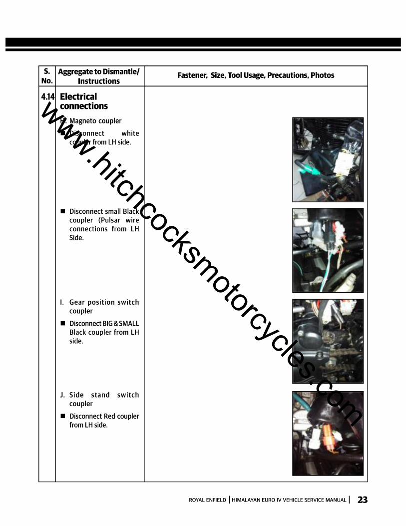
4.14 ElectricalconnectionsH. Magneto coupler
Disconnect whitecoupler from LH side.
Disconnect small Blackcoupler (Pulsar wireconnections from LHSide.
I. Gear position switchcoupler
Disconnect BIG & SMALLBlack coupler from LHside.
J. Si de stand swi tc hcoupler
Disconnect Red couplerfrom LH side.
www.hitchcocksmotorcycles.com
ROYAL ENFIELD HIMALAYAN EURO IV VEHICLE SERVICE MANUAL24
S.No.
Fastener, Size, Tool Usage, Precautions, PhotosAggregate to Dismantle/Instructions
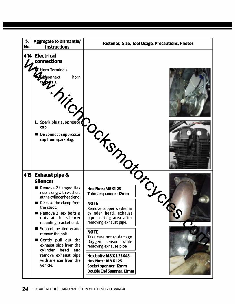
4.14 ElectricalconnectionsK. Horn Terminals
Disconnect hornterminals.
L. Spark plug suppressorcap
Disconnect suppressorcap from sparkplug.
4.15 Exhaust pipe &Silencer Remove 2 flanged Hex
nuts along with washersat the cylinder head end.
Release the clamp fromthe studs.
Remove 2 Hex bolts &nuts at the silencermounting bracket end.
Support the silencer andremove the bolt.
Gently pull out theexhaust pipe from thecylinder head andremove exhaust pipewith silencer from thevehicle.
Hex Nuts: M8X1.25Tubular spanner - 12mm
NOTERemove copper washer incylinder head, exhaustpipe seating area afterremoving exhaust pipe.
Hex bolts: M8 X 1.25X45Hex Nuts: M8 X1.25Socket spanner -12mmDouble End Spanner: 12mm
NOTETake care not to damageOxygen sensor whileremoving exhause pipe.
www.hitchcocksmotorcycles.com

ROYAL ENFIELD HIMALAYAN EURO IV VEHICLE SERVICE MANUAL 25
S.No.
Fastener, Size, Tool Usage, Precautions, PhotosAggregate to Dismantle/Instructions
4.16 EXAI / REEDConnectionsA. Br ai ded ho se to
Cylinder head
Loosen screw on theworm clip at end.
Loosen & remove 2 hexsocket head cap screws,holding the braidedhose to cylinder head.
Gently pull out thebraided hose from thebottom tube andremove along withgasket from cylinderhead.
Hd. Cap screws: M6X20
Allen Key: M5
4.17 Fuel Injector &Throttle body
A. Fuel Injector Ensure wiring coupler is
disconnected. Loosen Hex nut and
remove completely. Gently pull out fuel
injector along with fuelhose and spacer tube.
B. Throttle body Ensure TPS & MAP
Sensor coupler aredisconnecting.
Remove Bi starter fromthrottle body afterloosening plastic nut.
www.hitchcocksmotorcycles.com
ROYAL ENFIELD HIMALAYAN EURO IV VEHICLE SERVICE MANUAL26
S.No.
Fastener, Size, Tool Usage, Precautions, PhotosAggregate to Dismantle/Instructions
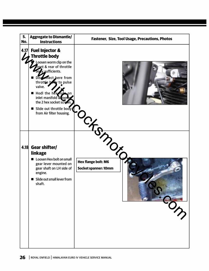
4.17 Fuel Injector &Throttle body Loosen worm clip on the
front & rear of throttlebody sufficients.
Disconnect here fromthrottle body to pulsevalve.
Hodl the hex nuts oninlet manifold & loosenthe 2 hex socket screws.
Slide out throttle bodyfrom Air filter housing.
4.18 Gear shifter/linkage Loosen Hex bolt on small
gear lever mounted ongear shaft on LH side ofengine.
Slide out small lever fromshaft.
Hex flange bolt: M6
Socket spanner: 10mm
www.hitchcocksmotorcycles.com
ROYAL ENFIELD HIMALAYAN EURO IV VEHICLE SERVICE MANUAL 27
S.No.
Fastener, Size, Tool Usage, Precautions, PhotosAggregate to Dismantle/Instructions
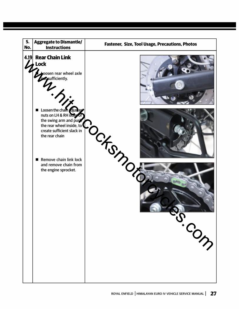
4.19 Rear Chain LinkLock Loosen rear wheel axle
nut sufficiently.
Loosen the chain adjusternuts on LH & RH sides ofthe swing arm and pushthe rear wheel inside, tocreate sufficient slack inthe rear chain
Remove chain link lockand remove chain fromthe engine sprocket.
www.hitchcocksmotorcycles.com
ROYAL ENFIELD HIMALAYAN EURO IV VEHICLE SERVICE MANUAL28
S.No.
Fastener, Size, Tool Usage, Precautions, PhotosAggregate to Dismantle/Instructions
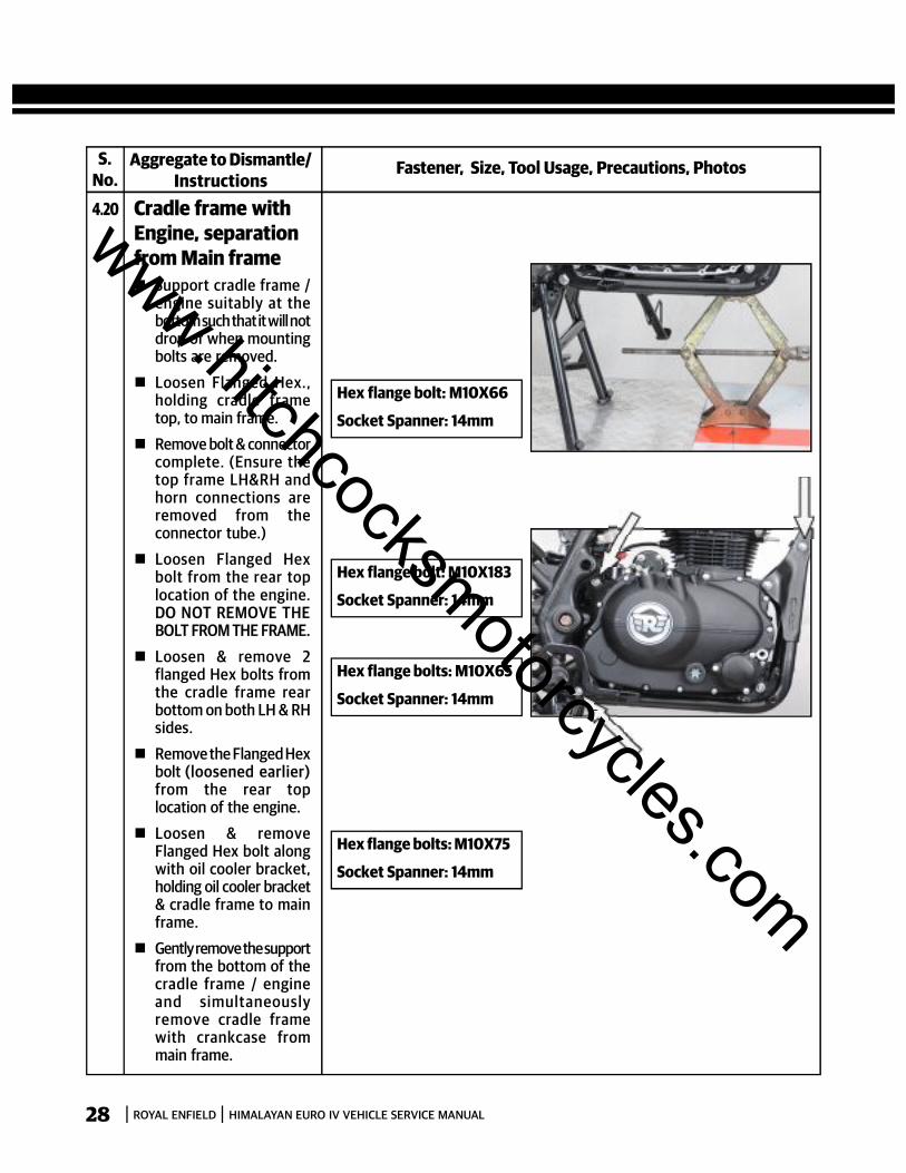
4.20 Cradle frame withEngine, separationfrom Main frame Support cradle frame /
engine suitably at thebottom such that it will notdrop of when mountingbolts are removed.
Loosen Flanged Hex.,holding cradle frametop, to main frame.
Remove bolt & connectorcomplete. (Ensure thetop frame LH&RH andhorn connections areremoved from theconnector tube.)
Loosen Flanged Hexbolt from the rear toplocation of the engine.DO NOT REMOVE THEBOLT FROM THE FRAME.
Loosen & remove 2flanged Hex bolts fromthe cradle frame rearbottom on both LH & RHsides.
Remove the Flanged Hexbolt (loosened earlier)from the rear toplocation of the engine.
Loosen & removeFlanged Hex bolt alongwith oil cooler bracket,holding oil cooler bracket& cradle frame to mainframe.
Gently remove the supportfrom the bottom of thecradle frame / engineand simultaneouslyremove cradle framewith crankcase frommain frame.
Hex flange bolt: M10X66
Socket Spanner: 14mm
Hex flange bolt: M10X183
Socket Spanner: 14mm
Hex flange bolts: M10X65
Socket Spanner: 14mm
Hex flange bolts: M10X75
Socket Spanner: 14mm
www.hitchcocksmotorcycles.com
ROYAL ENFIELD HIMALAYAN EURO IV VEHICLE SERVICE MANUAL 29
S.No.
Fastener, Size, Tool Usage, Precautions, PhotosAggregate to Dismantle/Instructions
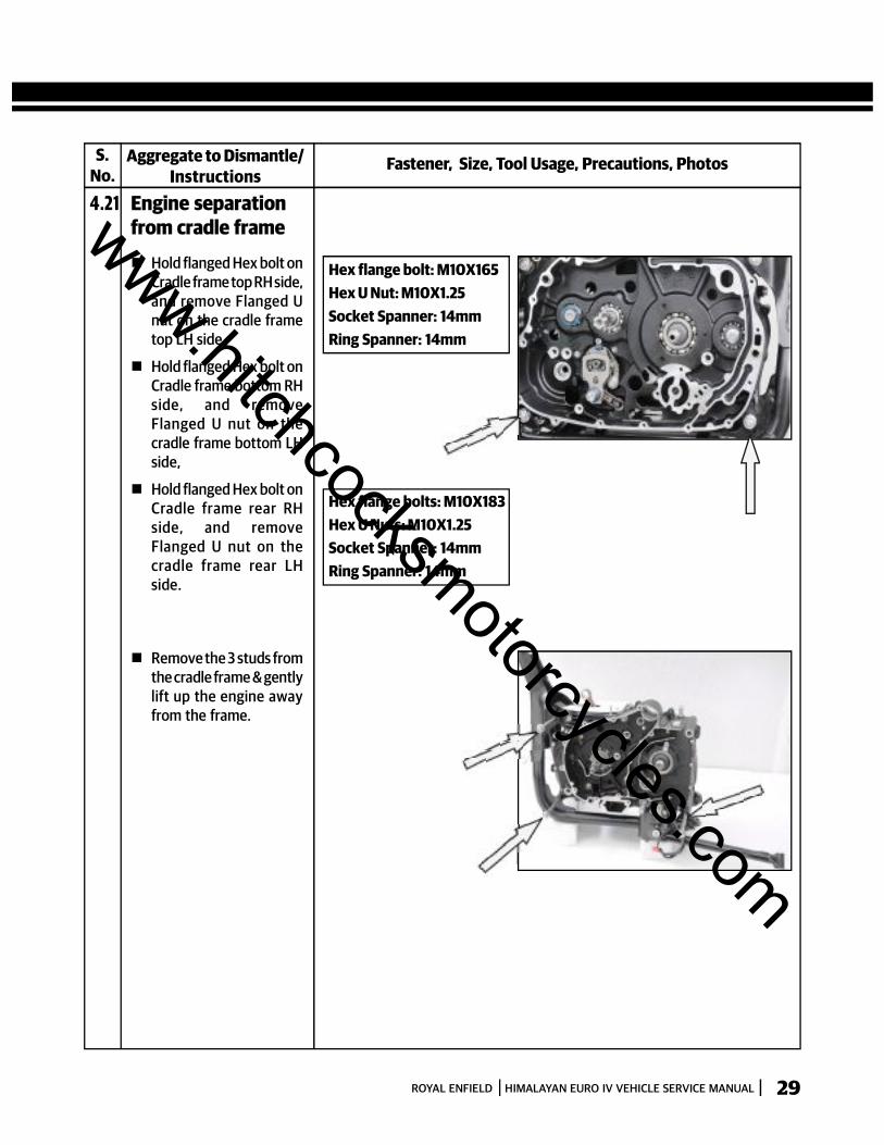
4.21 Engine separationfrom cradle frame
Hold flanged Hex bolt onCradle frame top RH side,and remove Flanged Unut on the cradle frametop LH side.
Hold flanged Hex bolt onCradle frame bottom RHside, and removeFlanged U nut on thecradle frame bottom LHside,
Hold flanged Hex bolt onCradle frame rear RHside, and removeFlanged U nut on thecradle frame rear LHside.
Hex flange bolt: M10X165Hex U Nut: M10X1.25Socket Spanner: 14mmRing Spanner: 14mm
Hex flange bolts: M10X183Hex U Nuts: M10X1.25Socket Spanner: 14mmRing Spanner: 14mm
Remove the 3 studs fromthe cradle frame & gentlylift up the engine awayfrom the frame.
www.hitchcocksmotorcycles.com

ROYAL ENFIELD HIMALAYAN EURO IV VEHICLE SERVICE MANUAL30
INSPECTION & PRECAUTIONS Inspect all the studs & bolts for bends, distortion, thread wear , threads stripped off etc
Inspect all nuts for thread wear , threads stripped off etc
DO NOT REUSE Nylock Nuts and Hex U nuts, and Pre coated fasteners once they have been tightened andremoved. Replace them every time they have been removed.
DO NOT REUSE Washers, O Rings, Oil seals, Dust seals, rubber and plastic material rubber parts, plastic parts,gaskets etc once they have been used and removed
Inspect all control cables for internal cables fraying / damage
Carefully inspect studs and nuts that are welded in the frame for any thread damage. If found damaged, usesuitable thread cleaning dies to repair the damages. If the threads are beyond repair, remove the damaged studs/nuts and reweld new studs / nuts correctly.
Clean the threads in the frame carefully using suitable cleaning and solving agents to clean off dirt and scales
Apply suitable thread locking liquid as appropriate on non precoated fasteners before assembling and tighteningto torque.
Always tighten fasteners diagonally and evenly to the correct specified torque values
Clean, and repaint rusted areas in frame and other parts before assembly
www.hitchcocksmotorcycles.com

ROYAL ENFIELD HIMALAYAN EURO IV VEHICLE SERVICE MANUAL 31
TORQUE VALUES
S.No. Aggregate Fastener
TorqueNM Kg.M
1 Engine Mtg to Cradle Frame - Flanged Hex Bolt 50 5.0 42.5 4.3 57.5 5.8front top M10X1.25X165
2 Engine Mtg to Cradle Frame - Flanged Hex Bolt 50 5.0 42.5 4.3 57.5 5.8front Bottom M10X1.25X183
3 Engine Mtg to Cradle Frame - Flanged Hex Bolt 50 5.0 42.5 4.3 57.5 5.8Rear Bottom M10X1.25X183
4 Cradle frame Mtg to Frame top Flanged Hex Bolt M10X1.25X60 50 5.0 42.5 4.3 57.5 5.8
5 Cradle frame Mtg to Frame Hex Flange Bolt 50 5.0 42.5 4.3 57.5 5.8rear bottom M10X1.25X65
6 Oil Cooler Mtg to frame Hex Flange M6X1X20 10 1.0 8.5 0.9 11.5 1.2
7 Steady Bracket Mtg to Hex Flange Bolt 50 5.0 42.5 4.3 57.5 5.8Cylinder head M10X1.25X47
8 Steady Bracket Mtg to Frame Hex Flange Bolt M8X1.25X20 25 2.5 21.3 2.1 28.8 2.9
9 Skid Plate Mtg to Cradle frame Hex Flanged Bolt M6X1X10 10 1.0 8.5 0.9 11.5 1.2
10 Side Panels mounting to frame Hex Button Head M6X1X12 5 0.5 4.3 0.4 5.8 0.6
11 Gear Shift Linkage Mtg to Frame M10X1.25 30 3.0 25.5 2.6 34.5 3.5
12 Gear Shift Linkage to Shift shaft M6X1 10 1.0 8.5 0.9 11.5 1.2
13 Fuel tank Mtg to frame Hex Flange M6X1X27 5 0.5 4.3 0.4 5.8 0.6
14 Exhaust Pipe Mtg to Cyl Head Flanged Hex Nut M8X1.25 10 1.0 8.5 0.9 11.5 1.2
15 Silencer Mtg to Frame Hex Socket M8X1.25X25 25 2.5 21.3 2.1 28.8 2.9
17 Rear Wheel Spindle Nut Hex U Nut M16X1.5 7 0 7.0 59.5 6.0 80.5 8.1
18 Chain Adjuster Lock nut Hex Nut M8X1.25 25 2.5 21.3 2.1 28.8 2.9
19 Head Lamp Mtg to Support Hex Soc. Hd. screw 10 1.0 8.5 0.9 11.5 1.2Brackets M8X1.25X25
20 Trafficators Mtg to Support Button Head M6X1X20 5 0.5 4.3 0.4 5.8 0.6Brackets
21 Windshield Mtg to Support Hex Socket Head Screws M5X16 5 0.5 4.3 0.4 5.8 0.6Brackets
Min. Torque(Nm) (Kg.M)
Max. Torque(Nm) (Kg.M)www.hitchcocksmotorcycles.com

ROYAL ENFIELD HIMALAYAN EURO IV VEHICLE SERVICE MANUAL32
ENGINE ASSEMBLY TO FRAME
S.No.
Fastener, Size, Tool Usage, Precautions, PhotosAggregate to Assemble/Instructions
4.22 Engine on CradleFrame Locate Engine on cradle
frame & ensure the 3mounting holes of thecradle frame and theengine are aligned.
Insert Hex bolt M10X165from RH side andassemble U nutM10X1.25. DO NO TTIGHTEN FULLY.
Insert2 flanged Hex boltsM10X183 from the front& rear bottom RH sideand assemble U nutM10X1.25. DO NO TTIGHTEN FULLY.
Ti ghten al l themountings diagonallyto torque.
Hex flange bolts:M10X165 & M10X183Hex U Nuts: M10X1.25Ring Spanner: 14mm.Socket Spanner: 14mm.
Torque: 50 Nm (5.0 Kg.M)
Hex flange bolts:M10X183 & M10X165Hex U Nuts: M10X1.25Ring Spanner: 14mm.Socket Spanner: 14mm.
4.23 Cradle frame withengine, on MainFrame Locate cradle frame /
engine from underneathmain frame and lift upwith suitable supportunder engine such thatthe stud mounting holesalign as follows:
- Crankcase rear top holewith frame mounting.
- 2 mounting holes ofcradle frame with 2 holesin frame down tube.
- 2 mounting holes at therear bottom of cradle framewith 2 holes in main frame.
Insert flanged Hex BoltM10X 183 at rear top ofengine and assemble Unut.DO NO T TIGH TE NFULLY.
Torque: 50 Nm (5.0 Kg.M)
www.hitchcocksmotorcycles.com
ROYAL ENFIELD HIMALAYAN EURO IV VEHICLE SERVICE MANUAL 33
S.No.
Fastener, Size, Tool Usage, Precautions, PhotosAggregate to Assemble/Instructions
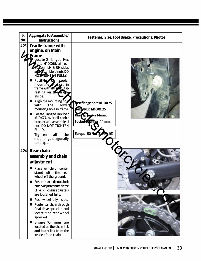
4.23 Cradle frame withengine, on MainFrame Locate 2 flanged Hex
bolts M10X65, at rearbottom, LH & RH sidesand assemble U nuts DONOT TIGHTEN FULLY.
Position Oil coolermounting bracket inframe with its small tabresting on the frameinside.
Align the mounting holewith the lowermounting hole in frame.
Locate Flanged Hex boltM10X75, over oil coolerbracket and assemble Unut. DO NOT TIGHTENFULLY.Ti ghten al l themountings diagonallyto torque.
Hex flange bolt: M10X75
Hex U Nut: M10X1.25
Ring Spanner: 14mm.
Socket Spanner: 14mm.
Torque: 50 Nm (5.0 Kg.M)
4.24 Rear chainassembly and chainadjustment Place vehicle on center
stand with the rearwheel off the ground.
Ensure rear axle nut, locknuts & adjuster nuts on theLH & RH chain adjustersare loosened fully.
Push wheel fully inside. Route rear chain through
final drive sprocket andlocate it on rear wheelsprocket
Ensure ‘O’ rings arelocated on the chain linkand Insert link from theinside of the chain.
www.hitchcocksmotorcycles.com

ROYAL ENFIELD HIMALAYAN EURO IV VEHICLE SERVICE MANUAL34
S.No.
Fastener, Size, Tool Usage, Precautions, PhotosAggregate to Assemble/Instructions
4.24 Rear chainassembly and chainadjustment Assemble ‘O’ Rings on
the chain link andassemble the link plate.
Assemble chain link lockon the chain link,ensuring the closed endof the lock is towards thenormal direction ofrotation of the chain.
Tighten adjuster nuts onLH & RH side evenly tillthe chain has a slack of20 to 25 mm on its toprun.
Ensure the referencelines on the LH & RH chainadjusters are matchingat the same referencelines in the swing arm onLH & RH sides.
Tighten rear wheel axlenut to torque.
Tighten lock nuts againstthe adjuster nuts on LH& RH sides.
Hex U Nut: M17
Socket Spanner: 24mm.
Torque: 70-80Nm(7.0-8.0Kg.M)
4.25 Gear Shifter /Linkage Locate small lever on
gear shift shaft, ensuring,small lever is vertical toground and the gearshift pedal is parallel torider footrest LH.
Assemble Hex bolt ongear shift lever shortfrom the front side andtighten to torque.
Hex Flange Bolt : M6X20
Socket Spanner : 10mm.
Torque: 10Nm(1.0Kg.M)
www.hitchcocksmotorcycles.com
ROYAL ENFIELD HIMALAYAN EURO IV VEHICLE SERVICE MANUAL 35
S.No.
Fastener, Size, Tool Usage, Precautions, PhotosAggregate to Assemble/Instructions
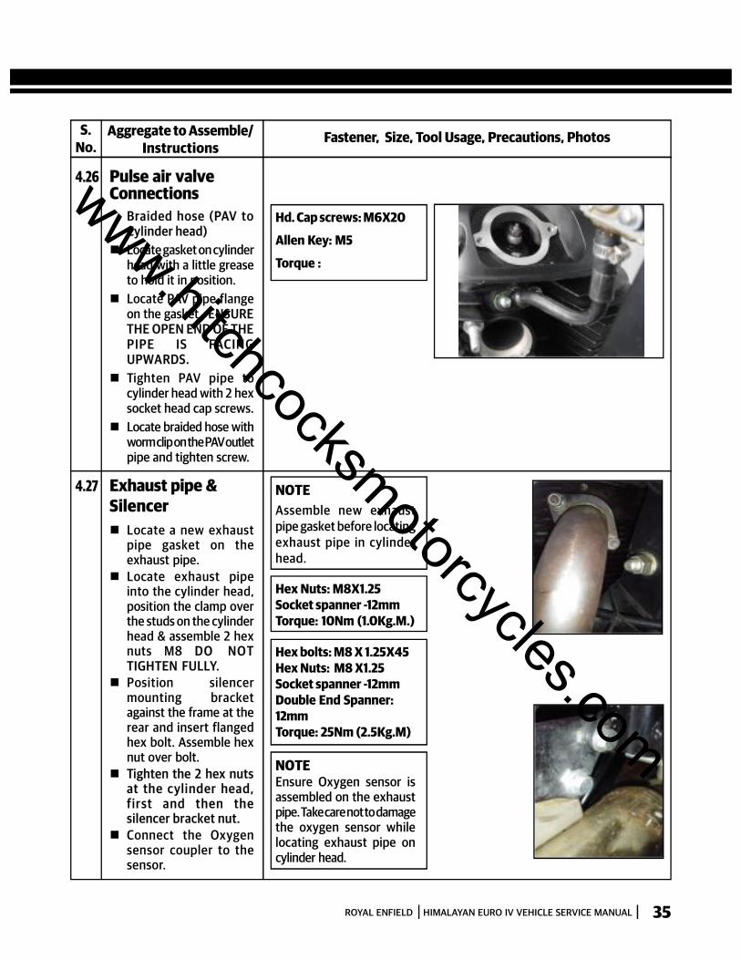
4.26 Pulse air valveConnections
Braided hose (PAV toCylinder head)
Locate gasket on cylinderhead with a little greaseto hold it in position.
Locate PAV pipe flangeon the gasket. ENSURETHE OPEN END OF THEPIPE IS FACIN GUPWARDS.
Tighten PAV pipe tocylinder head with 2 hexsocket head cap screws.
Locate braided hose withworm clip on the PAV outletpipe and tighten screw.
Hd. Cap screws: M6X20
Allen Key: M5
Torque :
NOTEAssemble new exhaustpipe gasket before locatingexhaust pipe in cylinderhead.
4.27 Exhaust pipe &Silencer Locate a new exhaust
pipe gasket on theexhaust pipe.
Locate exhaust pipeinto the cylinder head,position the clamp overthe studs on the cylinderhead & assemble 2 hexnuts M8 DO NO TTIGHTEN FULLY.
Position silencermounting bracketagainst the frame at therear and insert flangedhex bolt. Assemble hexnut over bolt.
Tighten the 2 hex nutsat the cylinder head,fir st and then thesilencer bracket nut.
Connect the Oxygensensor coupler to thesensor.
Hex Nuts: M8X1.25Socket spanner -12mmTorque: 10Nm (1.0Kg.M.)
Hex bolts: M8 X 1.25X45Hex Nuts: M8 X1.25Socket spanner -12mmDouble End Spanner:12mmTorque: 25Nm (2.5Kg.M)
NOTEEnsure Oxygen sensor isassembled on the exhaustpipe. Take care not to damagethe oxygen sensor whilelocating exhaust pipe oncylinder head.
www.hitchcocksmotorcycles.com

ROYAL ENFIELD HIMALAYAN EURO IV VEHICLE SERVICE MANUAL36
S.No.
Fastener, Size, Tool Usage, Precautions, PhotosAggregate to Assemble/Instructions
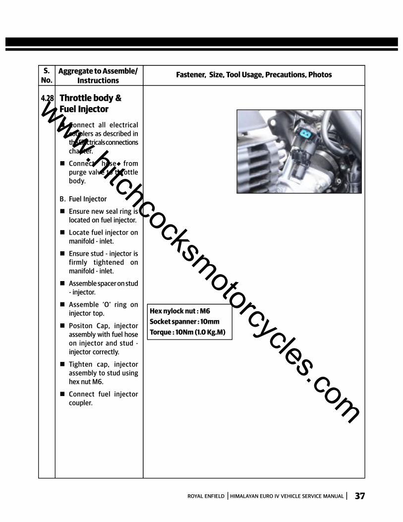
4.28 Throttle body &Fuel Injector
A. Throttle Body
Ensure worm clip islocated on air filterbellow.
Locate throttle bodyinside air filter bellow.
Ensure clip hose islocated on inlet manifoldadaptor.
Assemble inlet manifoldadaptor on throttle body.
Locate ‘O’ ring on Inletmanifold.
Position inlet manifoldadaptor (with throttlebody) against inlet mani-fold. Ensure the 2mounting holes arealigned.
Assemble new copperwashers on the 2 hex sochead cap screws andinsert from the inletmanifod adaptor end.
Assemble 2 hex nuts onthe screws and tightenadaptor to manifold -inlet.
Tighten worm clip screwon air filter bellow andinlet manifold adaptor.
Insert valve - Bi Starterplunger into throttlebody are tighten theplastic hex nut to throttlebody sufficiently.
Hex Soc. Hd. Cap Screw :M6 x 25Hex nylock nut : M6Allen Key : 5 mmDouble end spanner :10mmTorque : 10Nm (1.0 Kg.M)
www.hitchcocksmotorcycles.com
ROYAL ENFIELD HIMALAYAN EURO IV VEHICLE SERVICE MANUAL 37
S.No.
Fastener, Size, Tool Usage, Precautions, PhotosAggregate to Assemble/Instructions
4.28 Throttle body &Fuel Injector
Connect all electricalcouplers as described inthe Electricals connectionschapter.
Connect hose frompurge valve to throttlebody.
B. Fuel Injector
Ensure new seal ring islocated on fuel injector.
Locate fuel injector onmanifold - inlet.
Ensure stud - injector isfirmly tightened onmanifold - inlet.
Assemble spacer on stud- injector.
Assemble ‘O’ ring oninjector top.
Positon Cap, injectorassembly with fuel hoseon injector and stud -injector correctly.
Tighten cap, injectorassembly to stud usinghex nut M6.
Connect fuel injectorcoupler.
Hex nylock nut : M6Socket spanner : 10mmTorque : 10Nm (1.0 Kg.M)
www.hitchcocksmotorcycles.com
ROYAL ENFIELD HIMALAYAN EURO IV VEHICLE SERVICE MANUAL38
S.No.
Fastener, Size, Tool Usage, Precautions, PhotosAggregate to Assemble/Instructions
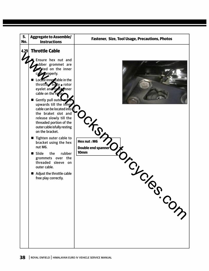
4.29 Throttle Cable
Ensure hex nut andrubber grommet arelocated on the innercable properly.
Locate inner cable in thethrottle body rotoreyelet and route innercable on the rotor.
Gently pull outer cableupwards till the innercable can be located intothe braket slot andrelease slowly till thethreaded portion of theouter cable isfully restingon the bracket.
Tighten outer cable tobracket using the hexnut M6.
Slide the rubbergrommets over thethreaded sleeve onouter cable.
Adjust the throttle cablefree play correctly.
Hex nut : M6
Double end spanner :10mm
www.hitchcocksmotorcycles.com
ROYAL ENFIELD HIMALAYAN EURO IV VEHICLE SERVICE MANUAL 39
S.No.
Fastener, Size, Tool Usage, Precautions, PhotosAggregate to Assemble/Instructions
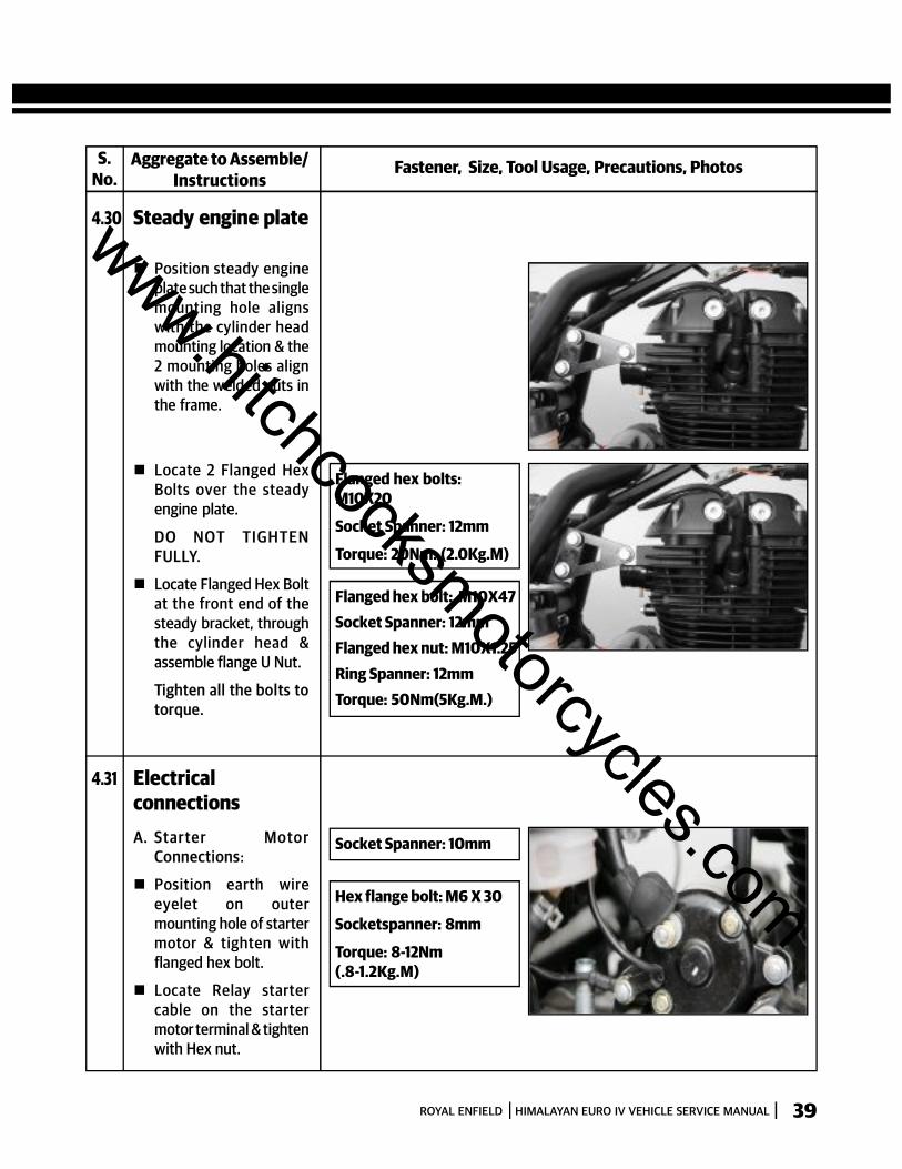
4.30 Steady engine plate
Position steady engineplate such that the singlemounting hole alignswith the cylinder headmounting location & the2 mounting holes alignwith the welded nuts inthe frame.
Locate 2 Flanged HexBolts over the steadyengine plate.
DO NO T TIGH TE NFULLY.
Locate Flanged Hex Boltat the front end of thesteady bracket, throughthe cylinder head &assemble flange U Nut.
Tighten all the bolts totorque.
Flanged hex bolts:M10X20
Socket Spanner: 12mm
Torque: 20Nm. (2.0Kg.M)
Flanged hex bolt: M10X47Socket Spanner: 12mmFlanged hex nut: M10X1.25Ring Spanner: 12mmTorque: 50Nm(5Kg.M.)
4.31 ElectricalconnectionsA. Star ter Moto r
Connections:
Position earth wireeyelet on outermounting hole of startermotor & tighten withflanged hex bolt.
Locate Relay startercable on the startermotor terminal & tightenwith Hex nut.
Socket Spanner: 10mm
Hex flange bolt: M6 X 30
Socketspanner: 8mm
Torque: 8-12Nm(.8-1.2Kg.M)
www.hitchcocksmotorcycles.com
ROYAL ENFIELD HIMALAYAN EURO IV VEHICLE SERVICE MANUAL40
S.No.
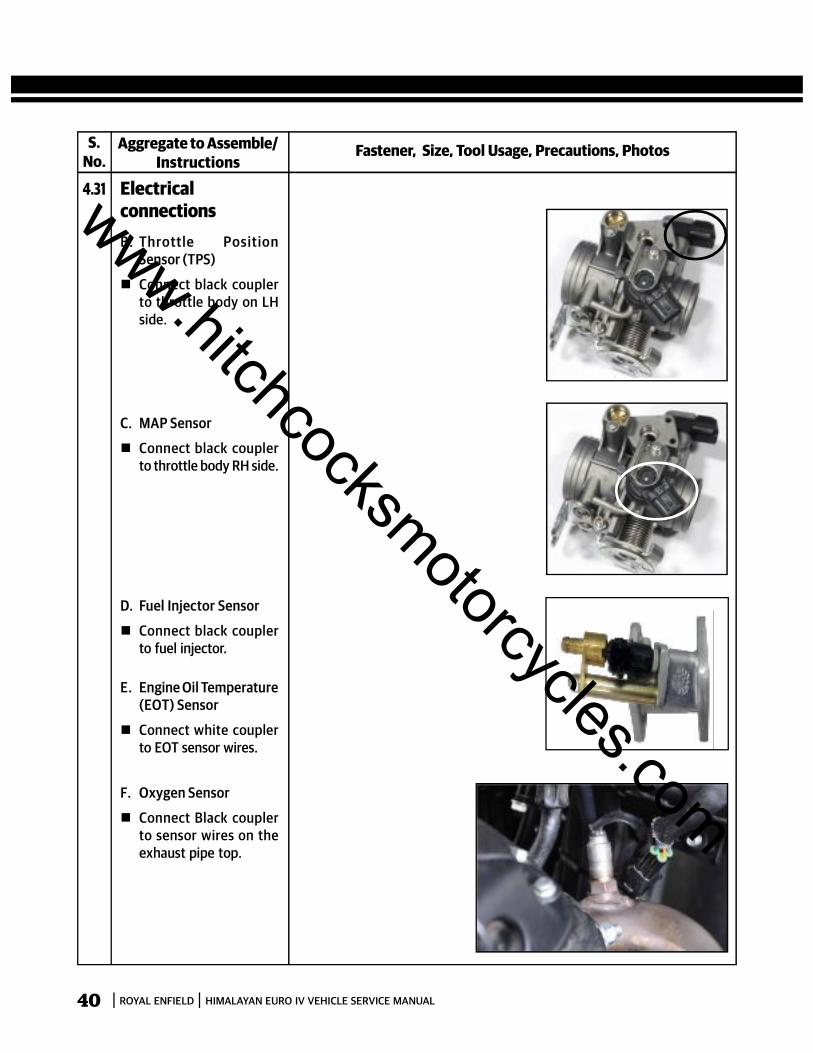
Fastener, Size, Tool Usage, Precautions, PhotosAggregate to Assemble/Instructions
4.31 ElectricalconnectionsB. Throttle Position
Sensor (TPS)
Connect black couplerto throttle body on LHside.
C. MAP Sensor
Connect black couplerto throttle body RH side.
F. Oxygen Sensor
Connect Black couplerto sensor wires on theexhaust pipe top.
D. Fuel Injector Sensor
Connect black couplerto fuel injector.
E. Engine Oil Temperature(EOT) Sensor
Connect white couplerto EOT sensor wires.
www.hitchcocksmotorcycles.com
ROYAL ENFIELD HIMALAYAN EURO IV VEHICLE SERVICE MANUAL 41
S.No.
Fastener, Size, Tool Usage, Precautions, PhotosAggregate to Assemble/Instructions
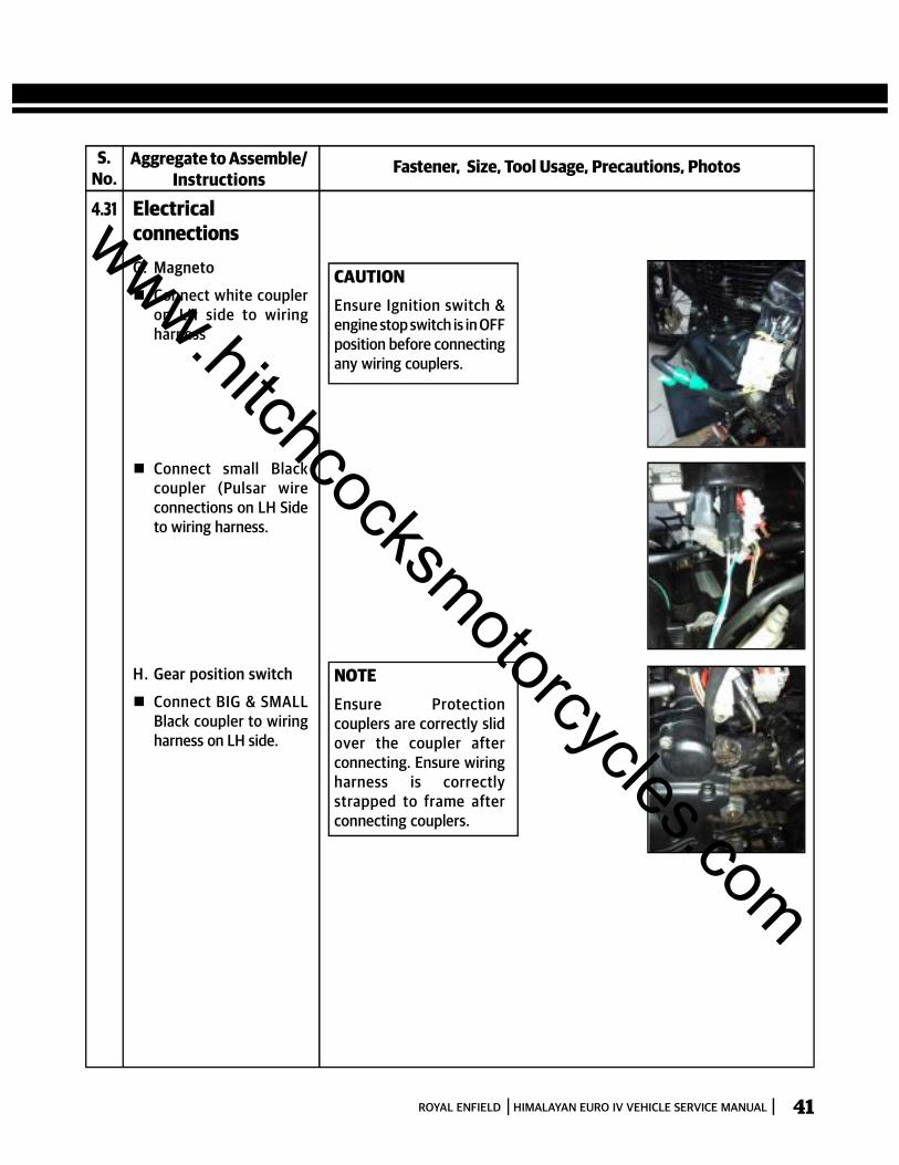
4.31 ElectricalconnectionsG. Magneto
Connect white coupleron LH side to wiringharness
Connect small Blackcoupler (Pulsar wireconnections on LH Sideto wiring harness.
H. Gear position switch
Connect BIG & SMALLBlack coupler to wiringharness on LH side.
CAUTIONEnsure Ignition switch &engine stop switch is in OFFposition before connectingany wiring couplers.
NOTEEnsure Protectioncouplers are correctly slidover the coupler afterconnecting. Ensure wiringharness is correctlystrapped to frame afterconnecting couplers.
www.hitchcocksmotorcycles.com

ROYAL ENFIELD HIMALAYAN EURO IV VEHICLE SERVICE MANUAL42
S.No.
Fastener, Size, Tool Usage, Precautions, PhotosAggregate to Assemble/Instructions
4.31 ElectricalconnectionsI. Si de stand swi tc h
coupler
Connect Red coupler towiring harness on LHside.
J. Battery Connections
Connect Positiveterminal (Red) to thepositive terminal of thebattery.
Connect negativeterminal (Black) tonegative terminal of thebattery.
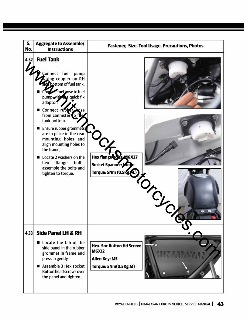
4.32 Fuel Tank
Align the two clamps inthe fuel tank insidechannel, with the rubbersupports on the frameand gently push forwardto lock in place. Lift rearend of the tank slightly and
- Route the drain hosebetween the framewithout any kinks.
- Connect blue coupler ofLow fuel sensor to wiringharness
CAUTIONWhen connecting the fuel& cannister hoses ensurethey are routed correctlywithout any kinks.
www.hitchcocksmotorcycles.com
ROYAL ENFIELD HIMALAYAN EURO IV VEHICLE SERVICE MANUAL 43
S.No.
Fastener, Size, Tool Usage, Precautions, PhotosAggregate to Assemble/Instructions
4.32 Fuel Tank
Connect fuel pumpwiring coupler on RHside bottom of fuel tank.
Connect fuel hose to fuelpump with the quick fixadaptor.
Connect rubber hosefrom cannister to fueltank bottom.
Ensure rubber grommetsare in place in the rearmounting holes andalign mounting holes tothe frame,
Locate 2 washers on thehex flange bolts,assemble the bolts andtighten to torque.
Hex flange bolts: M6X27
Socket Spanner: 10mm
Torque: 5Nm (0.5Kg.M.)
4.33 Side Panel LH & RH Locate the tab of the
side panel in the rubbergrommet in frame andpress in gently.
Assemble 3 Hex socketButton head screws overthe panel and tighten.
Hex. Soc Button Hd Screw:M6X12
Allen Key: M5
Torque: 5Nm(0.5Kg.M)
www.hitchcocksmotorcycles.com
ROYAL ENFIELD HIMALAYAN EURO IV VEHICLE SERVICE MANUAL44
S.No.
Fastener, Size, Tool Usage, Precautions, PhotosAggregate to Assemble/Instructions
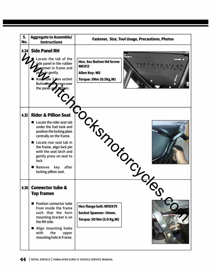
4.34 Side Panel RH Locate the tab of the
side panel in the rubbergrommet in frame andpress in gently.
Assemble 3 Hex socketButton head screws overthe panel and tighten.
Hex. Soc Button Hd ScrewM6X12
Allen Key: M5
Torque: 5Nm (0.5Kg.M)
4.35 Rider & Pillion Seat Locate the rider seat tab
under the fuel tank andposition the locking platecentrally on the frame.
Locate rear seat tab inthe frame, align lock pinwith the seat latch andgently press on seat tolock.
Remove key afterlocking pillion seat.
4.36 Connector tube &Top frames
Position connector tubefrom inside the framesuch that the hornmounting bracket is onthe RH side.
Align mounting holeswith the uppermounting hole in Frame.
Hex flange bolt: M10X75
Socket Spanner: 14mm.
Torque: 50 Nm (5.0 Kg.M)
www.hitchcocksmotorcycles.com
ROYAL ENFIELD HIMALAYAN EURO IV VEHICLE SERVICE MANUAL 45
S.No.
Fastener, Size, Tool Usage, Precautions, PhotosAggregate to Assemble/Instructions
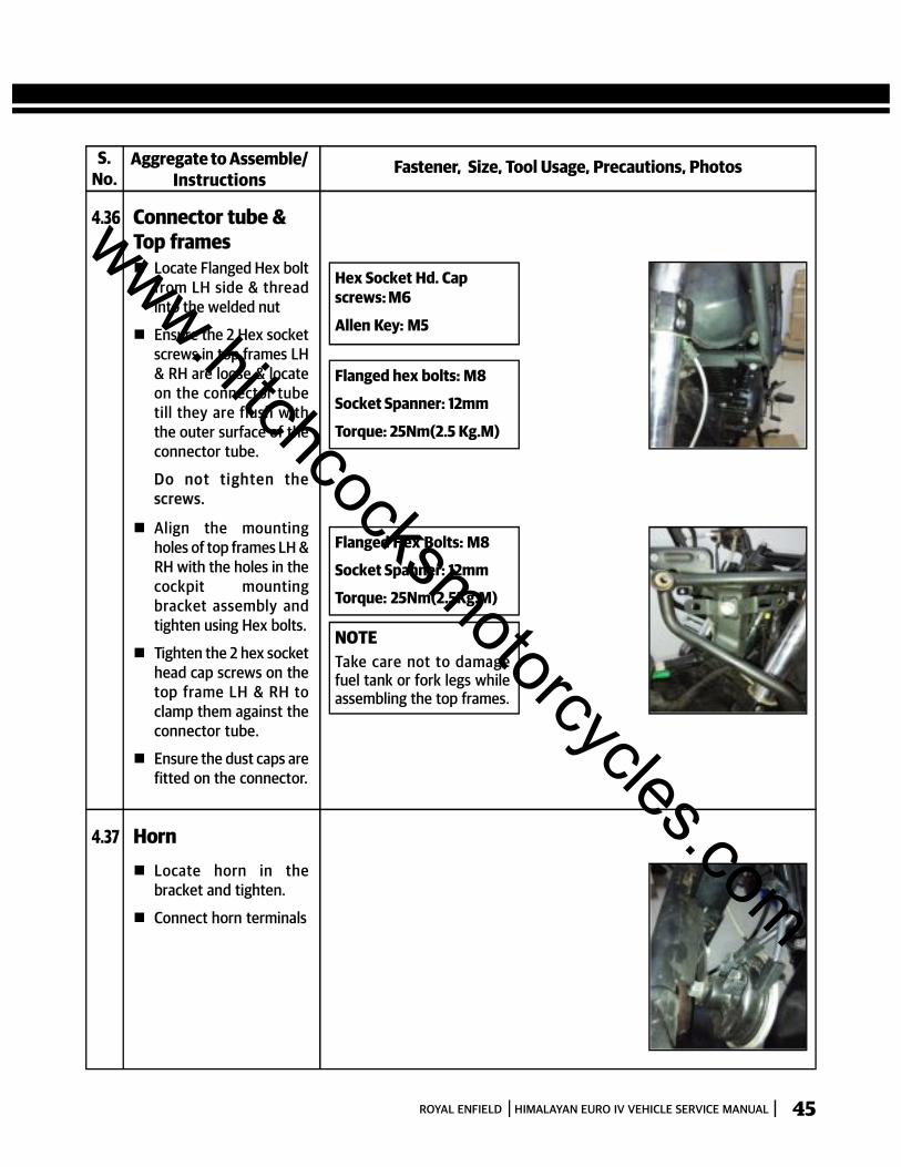
4.36 Connector tube &Top frames Locate Flanged Hex bolt
from LH side & threadinto the welded nut
Ensure the 2 Hex socketscrews in top frames LH& RH are loose & locateon the connector tubetill they are flush withthe outer surface of theconnector tube.
Do not ti ghten thescrews.
Hex Socket Hd. Capscrews: M6
Allen Key: M5
Flanged hex bolts: M8
Socket Spanner: 12mm
Torque: 25Nm(2.5 Kg.M)
Align the mountingholes of top frames LH &RH with the holes in thecockpit mountingbracket assembly andtighten using Hex bolts.
Tighten the 2 hex sockethead cap screws on thetop frame LH & RH toclamp them against theconnector tube.
Ensure the dust caps arefitted on the connector.
Flanged Hex Bolts: M8
Socket Spanner: 12mm
Torque: 25Nm(2.5Kg.M)
NOTETake care not to damagefuel tank or fork legs whileassembling the top frames.
4.37 Horn Locate horn in the
bracket and tighten.
Connect horn terminals
www.hitchcocksmotorcycles.com
ROYAL ENFIELD HIMALAYAN EURO IV VEHICLE SERVICE MANUAL46
S.No.
Fastener, Size, Tool Usage, Precautions, PhotosAggregate to Assemble/Instructions
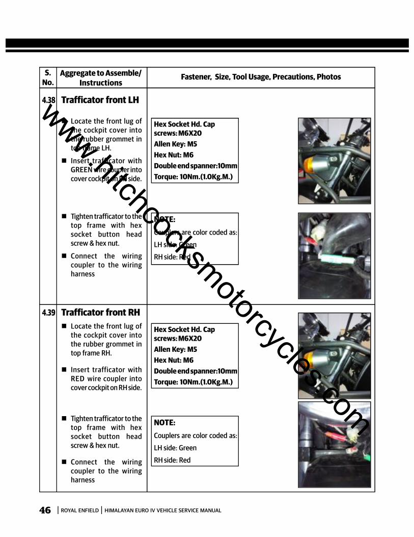
Hex Socket Hd. Capscrews: M6X20Allen Key: M5Hex Nut: M6Double end spanner:10mmTorque: 10Nm.(1.0Kg.M.)
4.38 Trafficator front LH
Locate the front lug ofthe cockpit cover intothe rubber grommet intop frame LH.
Insert trafficator withGREEN wire coupler intocover cockpit on LH side.
NOTE:Couplers are color coded as:
LH side: Green
RH side: Red
Tighten trafficator to thetop frame with hexsocket button headscrew & hex nut.
Connect the wiringcoupler to the wiringharness
4.39 Trafficator front RH Locate the front lug of
the cockpit cover intothe rubber grommet intop frame RH.
Insert trafficator withRED wire coupler intocover cockpit on RH side.
Tighten trafficator to thetop frame with hexsocket button headscrew & hex nut.
Connect the wiringcoupler to the wiringharness
Hex Socket Hd. Capscrews: M6X20Allen Key: M5Hex Nut: M6Double end spanner:10mmTorque: 10Nm.(1.0Kg.M.)
NOTE:Couplers are color coded as:
LH side: Green
RH side: Red
www.hitchcocksmotorcycles.com
ROYAL ENFIELD HIMALAYAN EURO IV VEHICLE SERVICE MANUAL 47
S.No.
Fastener, Size, Tool Usage, Precautions, PhotosAggregate to Assemble/Instructions
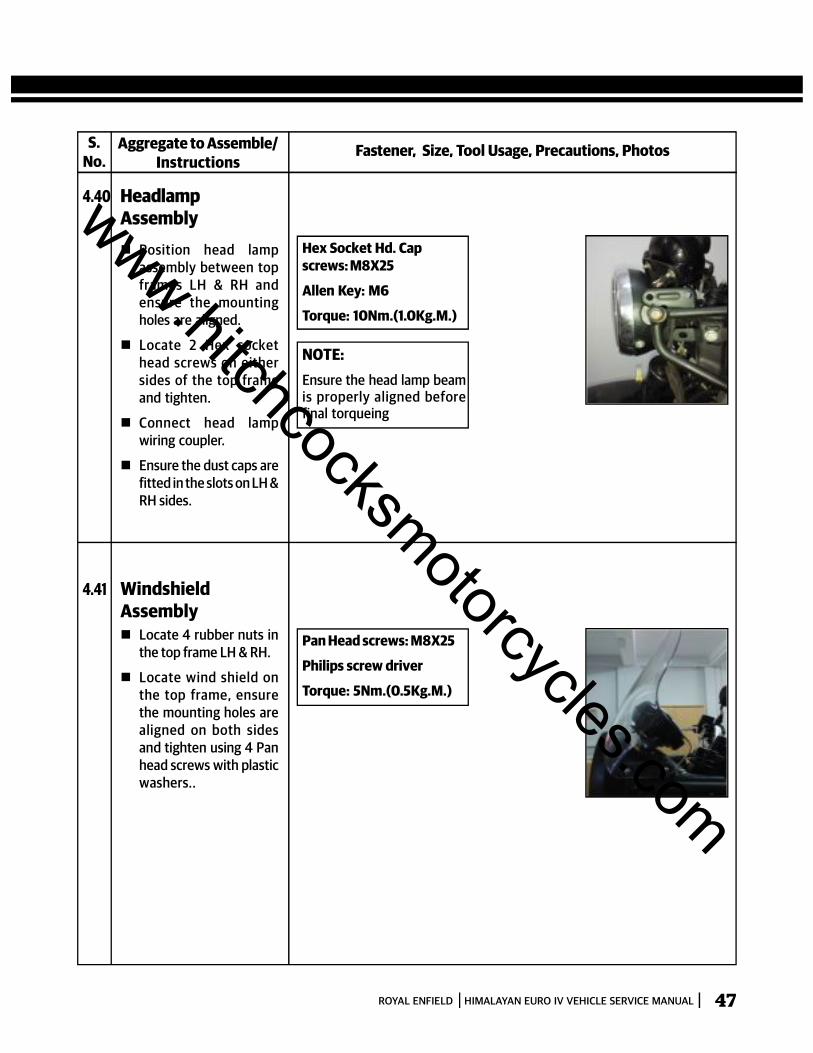
4.40 HeadlampAssembly Position head lamp
assembly between topframes LH & RH andensure the mountingholes are aligned.
Locate 2 Hex sockethead screws on eithersides of the top frameand tighten.
Connect head lampwiring coupler.
Ensure the dust caps arefitted in the slots on LH &RH sides.
Hex Socket Hd. Capscrews: M8X25
Allen Key: M6
Torque: 10Nm.(1.0Kg.M.)
NOTE:Ensure the head lamp beamis properly aligned beforefinal torqueing
4.41 WindshieldAssembly Locate 4 rubber nuts in
the top frame LH & RH.
Locate wind shield onthe top frame, ensurethe mounting holes arealigned on both sidesand tighten using 4 Panhead screws with plasticwashers..
Pan Head screws: M8X25
Philips screw driver
Torque: 5Nm.(0.5Kg.M.)
www.hitchcocksmotorcycles.com
ROYAL ENFIELD HIMALAYAN EURO IV VEHICLE SERVICE MANUAL48
S.No.
Fastener, Size, Tool Usage, Precautions, PhotosAggregate to Assemble/Instructions
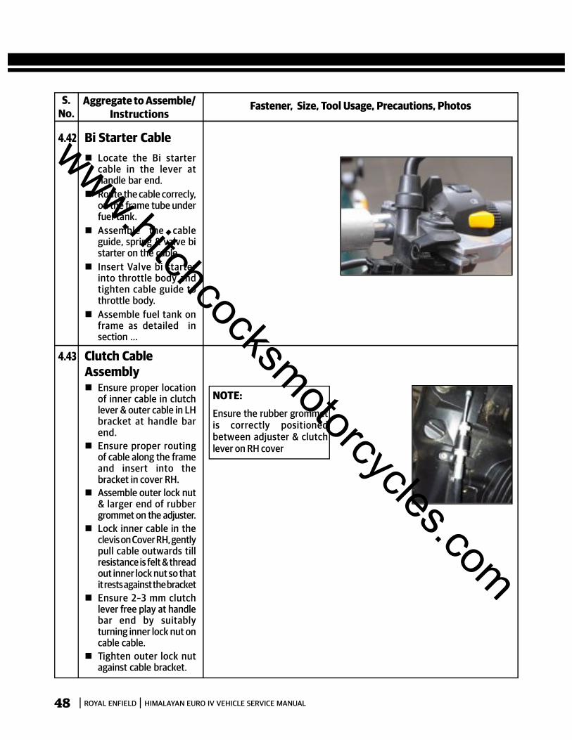
4.42 Bi Starter Cable Locate the Bi starter
cable in the lever athandle bar end.
Route the cable correcly,on the frame tube underfuel tank.
Assemble the cableguide, spring & valve bistarter on the cable.
Insert Valve bi starterinto throttle body andtighten cable guide tothrottle body.
Assemble fuel tank onframe as detailed insection ...
4.43 Clutch CableAssembly Ensure proper location
of inner cable in clutchlever & outer cable in LHbracket at handle barend.
Ensure proper routingof cable along the frameand insert into thebracket in cover RH.
Assemble outer lock nut& larger end of rubbergrommet on the adjuster.
Lock inner cable in theclevis on Cover RH, gentlypull cable outwards tillresistance is felt & threadout inner lock nut so thatit rests against the bracket
Ensure 2–3 mm clutchlever free play at handlebar end by suitablyturning inner lock nut oncable cable.
Tighten outer lock nutagainst cable bracket.
NOTE:Ensure the rubber grommetis correctly positionedbetween adjuster & clutchlever on RH cover
www.hitchcocksmotorcycles.com
ROYAL ENFIELD HIMALAYAN EURO IV VEHICLE SERVICE MANUAL 49
S.No.
Fastener, Size, Tool Usage, Precautions, PhotosAggregate to Assemble/Instructions
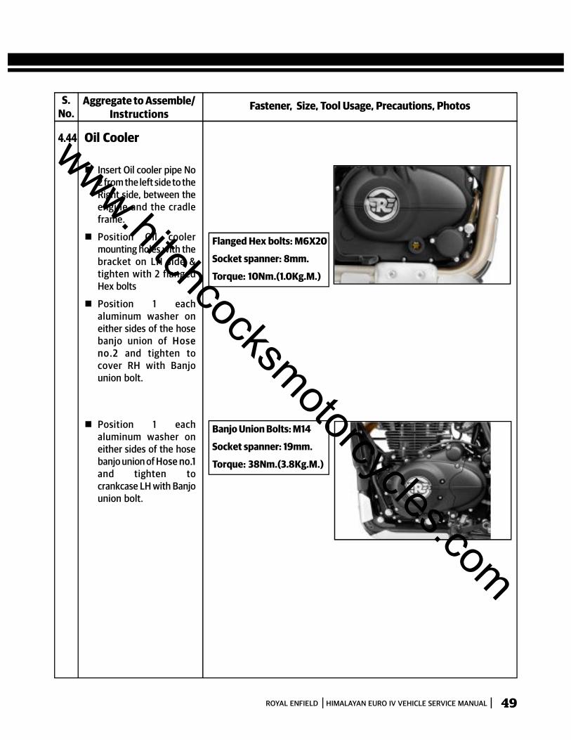
4.44 Oil Cooler
Insert Oil cooler pipe No2 from the left side to theRight side, between theengine and the cradleframe.
Position Oil coolermounting holes with thebracket on LH side &tighten with 2 flangedHex bolts
Position 1 eachaluminum washer oneither sides of the hosebanjo union of H oseno.2 and tighten tocover RH with Banjounion bolt.
Flanged Hex bolts: M6X20
Socket spanner: 8mm.
Torque: 10Nm.(1.0Kg.M.)
Position 1 eachaluminum washer oneither sides of the hosebanjo union of Hose no.1and tighten tocrankcase LH with Banjounion bolt.
Banjo Union Bolts: M14
Socket spanner: 19mm.
Torque: 38Nm.(3.8Kg.M.)
www.hitchcocksmotorcycles.com

ROYAL ENFIELD HIMALAYAN EURO IV VEHICLE SERVICE MANUAL50
S.No.
Fastener, Size, Tool Usage, Precautions, PhotosAggregate to Assemble/Instructions
4.44 Skid Plate
Assemble the 4 rubberbushes in the bottommounting holes of theSkid plate and locate 4damper bushes on therubber bushes.
Position the Skid plateunder the cradle frameand align the mountingholes. Ensure thedamper bushes do notfall off.
Assemble 4 FlangedHex Bolts M6 X1 X 35 atthe bottom of the Skidplate.
Assemble 2 FlangedHex Bolts, M6 X 1 X 14at the front of the skidplate.
Tighten all the 6 boltsevenly and diagonally.
Flanged Hex Screw: M6
Socket Spanner: 10mm
Torque: 10Nm (0.1 Kg.M)
www.hitchcocksmotorcycles.com
ROYAL ENFIELD HIMALAYAN EURO IV VEHICLE SERVICE MANUAL 51
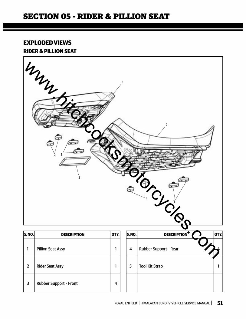
SECTION 05 - RIDER & PILLION SEAT
EXPLODED VIEWSRIDER & PILLION SEAT
43
4 3
5
2
1
S. NO. DESCRIPTION QTY. S. NO. DESCRIPTION QTY.
1 Pillion Seat Assy 1
2 Rider Seat Assy 1
3 Rubber Support - Front 4
4 Rubber Support - Rear 4
5 Tool Kit Strap 1
www.hitchcocksmotorcycles.com
ROYAL ENFIELD HIMALAYAN EURO IV VEHICLE SERVICE MANUAL52
S.No.
Fastener, Size, Tool Usage, Precautions, PhotosAggregate to Dismantle/Instructions
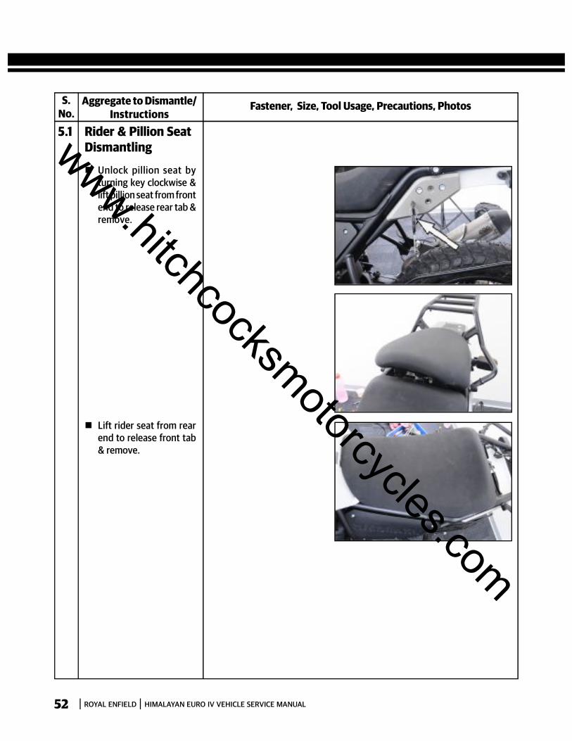
5.1 Rider & Pillion SeatDismantling
Unlock pillion seat byturning key clockwise &lift pillion seat from frontend to release rear tab &remove.
Lift rider seat from rearend to release front tab& remove.
www.hitchcocksmotorcycles.com
ROYAL ENFIELD HIMALAYAN EURO IV VEHICLE SERVICE MANUAL 53
S.No.
Fastener, Size, Tool Usage, Precautions, PhotosAggregate to Assemble/Instructions
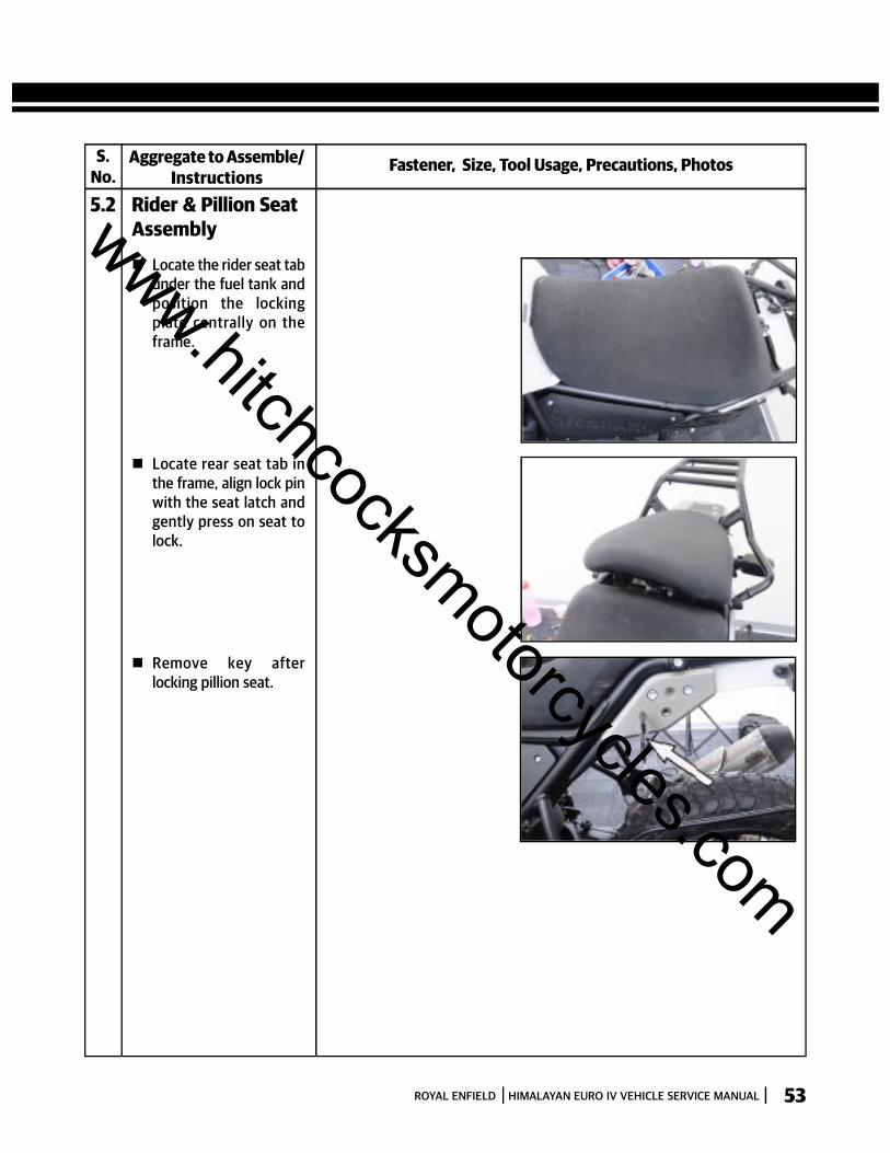
5.2 Rider & Pillion SeatAssembly
Locate the rider seat tabunder the fuel tank andposition the lockingplate centrally on theframe.
Locate rear seat tab inthe frame, align lock pinwith the seat latch andgently press on seat tolock.
Remove key afterlocking pillion seat.
www.hitchcocksmotorcycles.com

ROYAL ENFIELD HIMALAYAN EURO IV VEHICLE SERVICE MANUAL54
SECTION 06 - CONTROL CABLES
EXPLODED VIEWSCONTROL CABLES
1
3
2
S. NO. DESCRIPTION QTY.
1 Clutch Cable Assy. 1
2 Throttle Cable Assembly 1
3 Seat Latch Cable Assy 1
www.hitchcocksmotorcycles.com
ROYAL ENFIELD HIMALAYAN EURO IV VEHICLE SERVICE MANUAL 55
S.No.
Fastener, Size, Tool Usage, Precautions, PhotosAggregate to Dismantle/Instructions
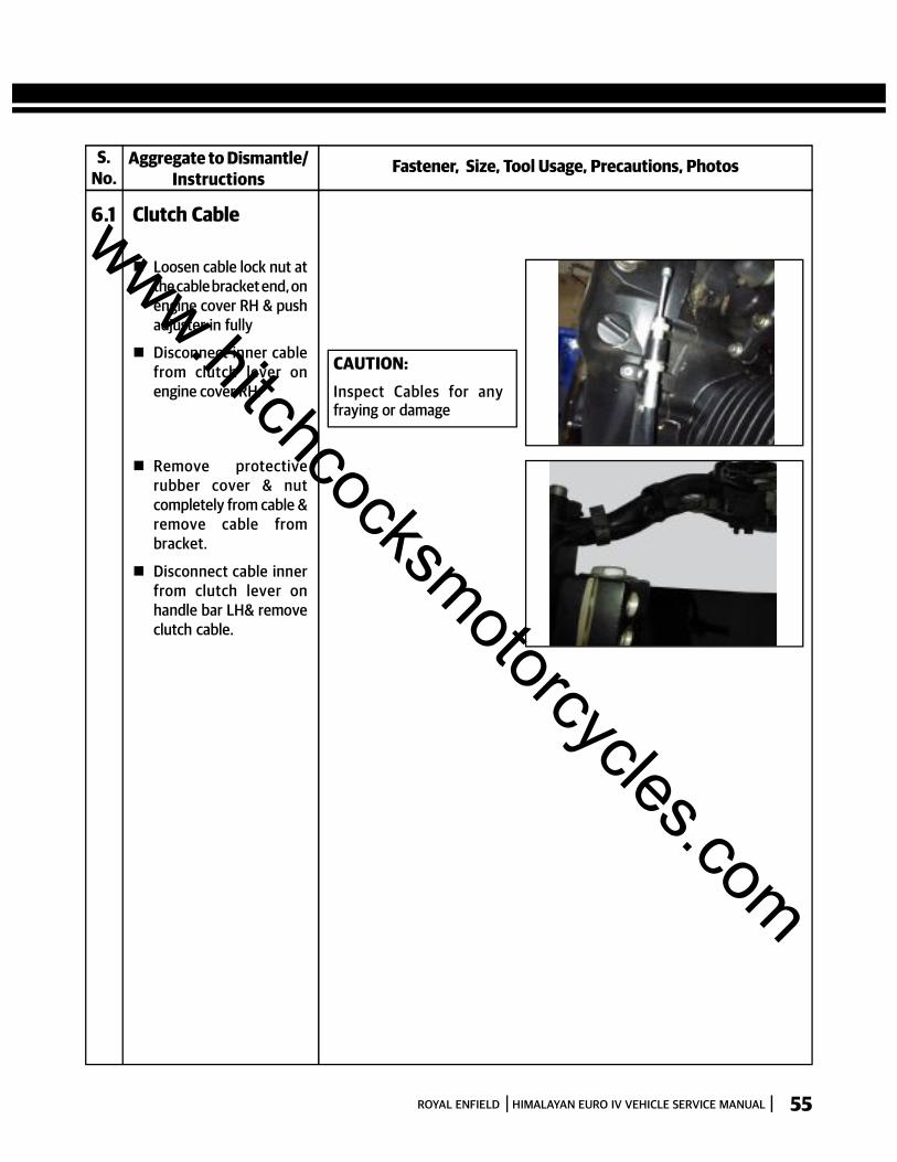
6.1 Clutch Cable
Loosen cable lock nut atthe cable bracket end, onengine cover RH & pushadjuster in fully
Disconnect inner cablefrom clutch lever onengine cover RH.
Remove protectiverubber cover & nutcompletely from cable &remove cable frombracket.
Disconnect cable innerfrom clutch lever onhandle bar LH& removeclutch cable.
CAUTION:Inspect Cables for anyfraying or damage
www.hitchcocksmotorcycles.com
ROYAL ENFIELD HIMALAYAN EURO IV VEHICLE SERVICE MANUAL56
S.No.
Fastener, Size, Tool Usage, Precautions, PhotosAggregate to Dismantle/Instructions
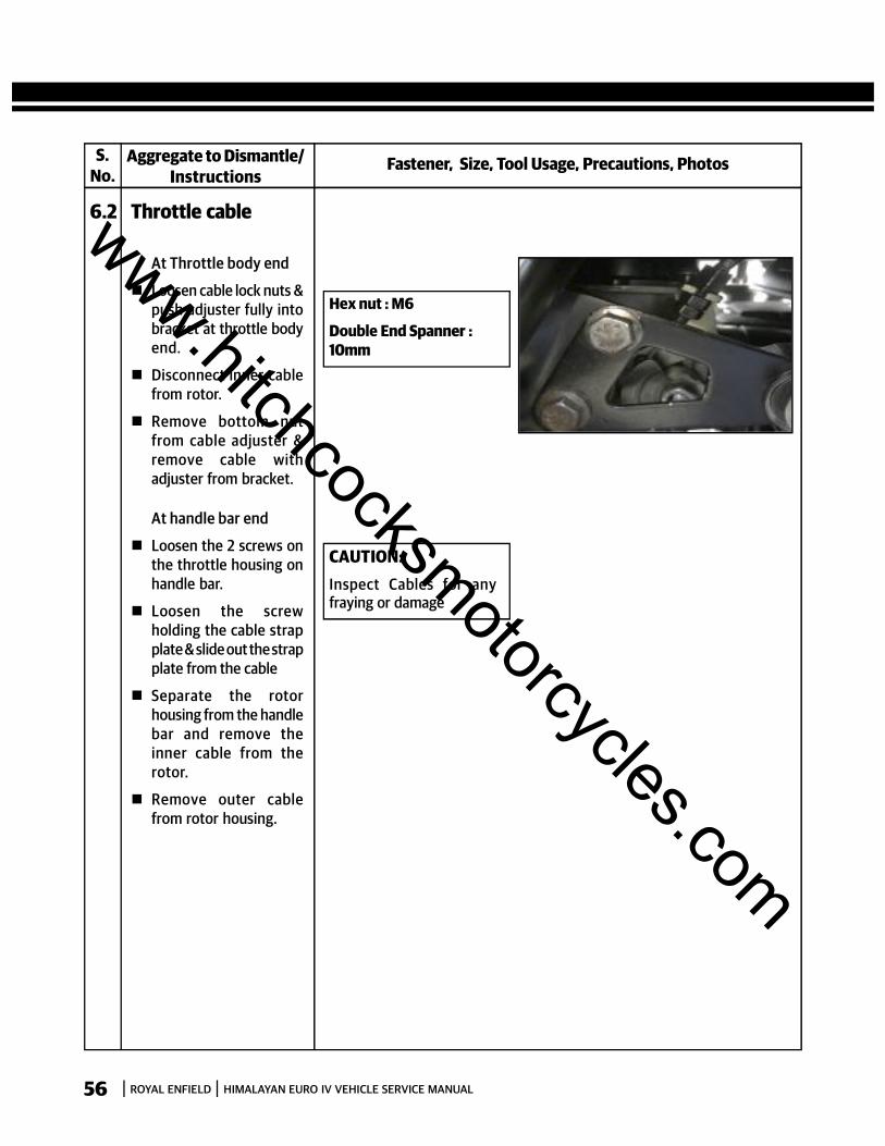
6.2 Throttle cable
At Throttle body end
Loosen cable lock nuts &push adjuster fully intobracket at throttle bodyend.
Disconnect inner cablefrom rotor.
Remove bottom nutfrom cable adjuster &remove cable withadjuster from bracket.
At handle bar end
Loosen the 2 screws onthe throttle housing onhandle bar.
Loosen the screwholding the cable strapplate & slide out the strapplate from the cable
Separate the rotorhousing from the handlebar and remove theinner cable from therotor.
Remove outer cablefrom rotor housing.
Hex nut : M6
Double End Spanner :10mm
CAUTION:Inspect Cables for anyfraying or damage
www.hitchcocksmotorcycles.com
ROYAL ENFIELD HIMALAYAN EURO IV VEHICLE SERVICE MANUAL 57
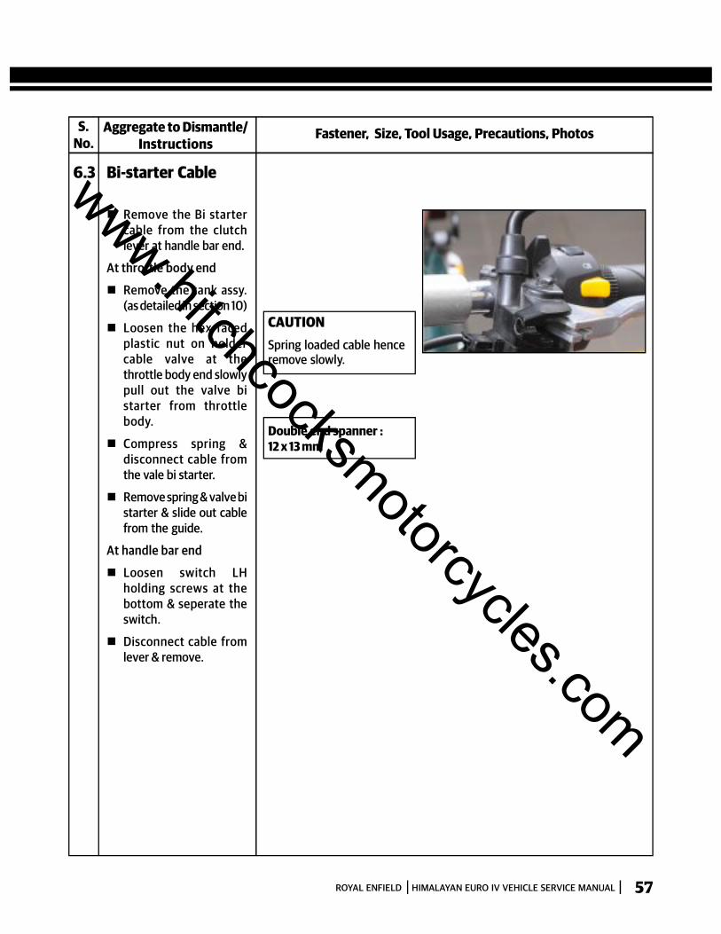
Double end spanner :12 x 13 mm
CAUTIONSpring loaded cable henceremove slowly.
S.No.
Fastener, Size, Tool Usage, Precautions, PhotosAggregate to Dismantle/Instructions
6.3 Bi-starter Cable
Remove the Bi startercable from the clutchlever at handle bar end.
At throttle body end
Remove the tank assy.(as detailed in section 10)
Loosen the hex facedplastic nut on holdercable valve at thethrottle body end slowlypull out the valve bistarter from throttlebody.
Compress spring &disconnect cable fromthe vale bi starter.
Remove spring & valve bistarter & slide out cablefrom the guide.
At handle bar end
Loosen switch LHholding screws at thebottom & seperate theswitch.
Disconnect cable fromlever & remove.
www.hitchcocksmotorcycles.com

ROYAL ENFIELD HIMALAYAN EURO IV VEHICLE SERVICE MANUAL58
S.No.
Fastener, Size, Tool Usage, Precautions, PhotosAggregate to Assemble/Instructions
6.4 Clutch Cable
Ensure proper locationof inner cable in clutchlever & outer cable in LHbracket at handle barend.
Ensure proper routingof cable along the frameand insert into thebracket in cover RH.
Assemble outer lock nut& larger end of rubbergrommet on theadjuster.
Lock inner cable in theclevis on Cover RH,gently pull cableoutwards till resistanceis felt & thread out innerlock nut so that it restsagainst the bracket
Ensure 2–3 mm clutchlever free play at handlebar end by suitablyturning inner lock nut oncable cable
Tighten outer lock nutagainst cable bracket
NOTE:Ensure the rubbergrommet is correctlypositioned betweenadjuster & clutch lever onRH cover
www.hitchcocksmotorcycles.com
ROYAL ENFIELD HIMALAYAN EURO IV VEHICLE SERVICE MANUAL 59
S.No.
Fastener, Size, Tool Usage, Precautions, PhotosAggregate to Assemble/Instructions
6.5 Throttle cable
At Handle bar end
Locate outer cable onrotor housing.
Locate the rotorhousing on the handlebar and locate the innercable on the rotor.
Install the screw holdingthe cable strap plate &slide out the strap platefrom the cable.
Install the 2 screws onthe throttle housing onhandle bar.
At Throttle body end
Locate the Throttlecable assembly.
Slacken the adjusters atthe throttle body end forboth cables.
Hex nut:
Double End Spanner:10mm
CAUTION:Inspect Cables for anyfraying or damage
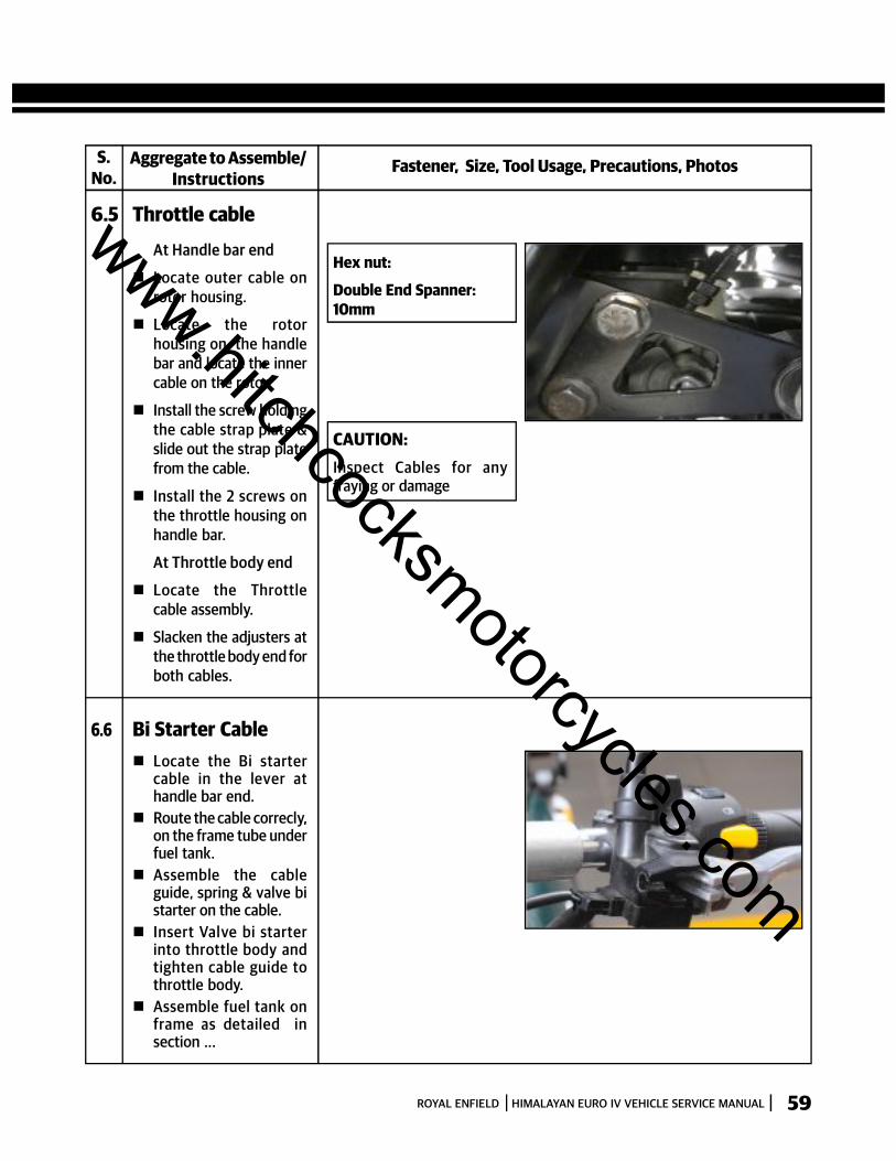
6.6 Bi Starter Cable Locate the Bi starter
cable in the lever athandle bar end.
Route the cable correcly,on the frame tube underfuel tank.
Assemble the cableguide, spring & valve bistarter on the cable.
Insert Valve bi starterinto throttle body andtighten cable guide tothrottle body.
Assemble fuel tank onframe as detailed insection ...
www.hitchcocksmotorcycles.com

ROYAL ENFIELD HIMALAYAN EURO IV VEHICLE SERVICE MANUAL60
1
32
4
5
6
7
8
12
11
13
A2
10
9
S. NO. DESCRIPTION QTY. S. NO. DESCRIPTION QTY.
A1 Air Filter Element Kit 1
A2 Air Filter Box Assembly 1
1 Screws M5 3
2 Inlet Cover 1
3 Seal 1
4 Element Air Filter 1
5 Clamp 1
6 Pipe Outlet 1
7 Drain Tube 1
8 Clip 1
9 TA SENSOR 1
10 HEX SOCKET HEAD CAP SCREW M5 X 16 2
11 Hex Flange Bolt, M6 X 1 X 14 2
12 Rear Damper - Tank 1
13 Lid – Battery Carrier 1
SECTION 07 - AIR FILTER
EXPLODED VIEWSAIRFILTER
A1
Key Nos.3 & 4
A2
Key Nos.1 to 8
www.hitchcocksmotorcycles.com
ROYAL ENFIELD HIMALAYAN EURO IV VEHICLE SERVICE MANUAL 61
S.No.
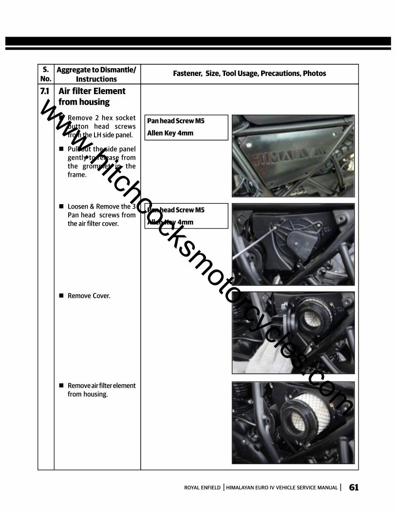
Fastener, Size, Tool Usage, Precautions, PhotosAggregate to Dismantle/Instructions
7.1 Air filter Elementfrom housing
Remove 2 hex socketbutton head screwsfrom the LH side panel.
Pull out the side panelgently to release fromthe grommet in theframe.
Loosen & Remove the 3Pan head screws fromthe air filter cover.
Remove Cover.
Remove air filter elementfrom housing.
Pan head Screw M5
Allen Key 4mm
Pan head Screw M5
Allen Key 4mm
www.hitchcocksmotorcycles.com

ROYAL ENFIELD HIMALAYAN EURO IV VEHICLE SERVICE MANUAL62
S.No.
Fastener, Size, Tool Usage, Precautions, PhotosAggregate to Dismantle/Instructions
7.2 Air filter Housingfrom frame
Disconnect batteryterminals and removefrom air filter housing.(refer electricals sectionfor dismantling battery)
Remove 4 flanged hexbolts and remove piecemudguard.
Disconnect breatherhose from air filterhousing
Loosen throttle bodyworm clip sufficiently.
Loosen & remove 2flanged hex bolts,holding air filter housingto frame
Gently pull out Fuse boxalong with its rubberholder from air filterhousing
Remove RR unit with itsrubber holder from airfilter housing
Loosen and remove 3flange hex bolts holdingthe cross bar assemblybelow air filter housingto frame
Remove cross barassembly
Loosen flanged Hexbolt, holding bracket airfilter to frame andremove the bolt andbracket air filter.
Remove air filter housingfrom rear side of theframe.
Hex Bolts: M6
Socket spanner: 8mm
Screw driver
Hex Bolts: M8
Socket spanner: 12mm
NOTE:Ensure the wiring connectionsare removed
Hex Bolts: M6
Socket spanner: 10mm
Hex Bolts: M8
Socket spanner: 12mm
www.hitchcocksmotorcycles.com
ROYAL ENFIELD HIMALAYAN EURO IV VEHICLE SERVICE MANUAL 63
INSPECTION & CLEANING Inspect air filter element carefully for any deformation, damages, heavily clogged with dirt, soggy condition, and
/ or foreign particles embedded in the element. Replace if any of these conditions are observed.
Inspect rubber seals, hoses, for cuts, cracks, damages.
Clean Air filter element every 5,000 Kms OR more frequently if motorcycle is used in dusty / Off road conditions.
Gently Tap filter element with minimum force to dislodge heavy / embedded dust particles.
Use compressed air from the outside of the filter element to remove dust particles
Clean the element on the inside and outside using a soft cloth
Clean the insides of the air filter housing and cover using a soft cloth
Replace seals, ‘O’ Rings and rubber parts whenever the induction system is serviced.
Replace Air filter element every 15,000 Kms or earlier if motorcycle is used in dusty / off road conditions.
TORQUE VALUES
S.No. Aggregate Fastener
TorqueNM Kg.M
1 Bracket Assy-Airfilter top Flanged Hex Bolt M8 X 1.25 X 16 22.5 2.25
2 Bracket Assy-Airfilter bottom Flanged Hex Bolt M6 X 1 X 20 10 1.0
3 Crossbar Assy Flanged Hex Bolt, M6 X 1 X 14 10 1.0
4 Piece mudguard Flanged Hex Bolt, M6 X 1 X 20 10 1.0
5 Lid battery carrier Flanged Hex Bolt, M6 X 1 X 14 10 1.0
Min. Torque(Nm) (Kg.M)
Max. Torque(Nm) (Kg.M)
20 2.0
8 0.8
8 0.8
8 0.8
8 0.8
25 2.5
12 1.2
12 1.2
12 1.2
12 1.2
www.hitchcocksmotorcycles.com
ROYAL ENFIELD HIMALAYAN EURO IV VEHICLE SERVICE MANUAL64
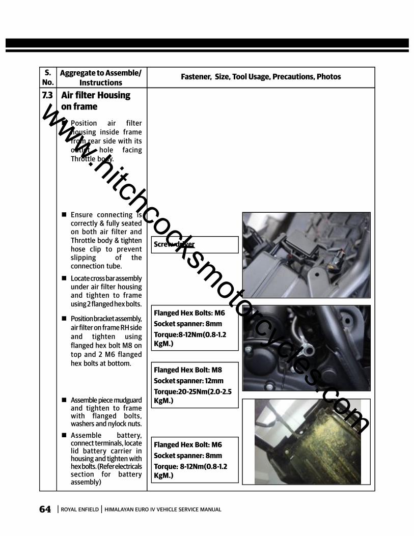
S.No.
Fastener, Size, Tool Usage, Precautions, PhotosAggregate to Assemble/Instructions
7.3 Air filter Housingon frame
Position air filterhousing inside framefrom rear side with itsoutlet hole facingThrottle body.
Ensure connecting iscorrectly & fully seatedon both air filter andThrottle body & tightenhose clip to preventslipping of theconnection tube.
Locate cross bar assemblyunder air filter housingand tighten to frameusing 2 flanged hex bolts.
Position bracket assembly,air filter on frame RH sideand tighten usingflanged hex bolt M8 ontop and 2 M6 flangedhex bolts at bottom.
Assemble piece mudguardand tighten to framewith flanged bolts,washers and nylock nuts.
Assemble battery,connect terminals, locatelid battery carrier inhousing and tighten withhex bolts. (Refer electricalssection for batteryassembly)
Screw driver
Flanged Hex Bolts: M6Socket spanner: 8mmTorque:8-12Nm(0.8-1.2KgM.)
Flanged Hex Bolt: M8Socket spanner: 12mmTorque:20-25Nm(2.0-2.5KgM.)
Flanged Hex Bolt: M6Socket spanner: 8mmTorque: 8-12Nm(0.8-1.2KgM.)
www.hitchcocksmotorcycles.com
ROYAL ENFIELD HIMALAYAN EURO IV VEHICLE SERVICE MANUAL 65
S.No.
Fastener, Size, Tool Usage, Precautions, PhotosAggregate to Assemble/Instructions
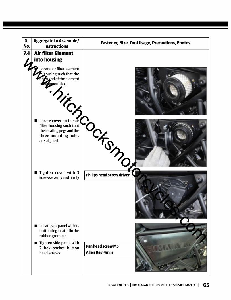
7.4 Air filter Elementinto housing
Locate air filter elementin housing such that theopen end of the elementis facing outside.
Locate cover on the airfilter housing such thatthe locating pegs and thethree mounting holesare aligned.
Tighten cover with 3screws evenly and firmly
Locate side panel with itsbottom leg located in therubber grommet
Tighten side panel with2 hex socket buttonhead screws
Philips head screw driver
Pan head screw M5Allen Key 4mm
www.hitchcocksmotorcycles.com
ROYAL ENFIELD HIMALAYAN EURO IV VEHICLE SERVICE MANUAL66
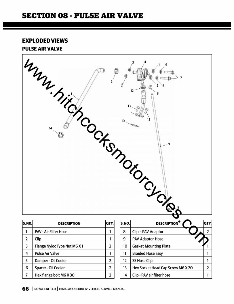
SECTION 08 - PULSE AIR VALVE
14
1
2
12
13
10 13
9
8
8
7
65
653 4
S. NO. DESCRIPTION QTY. S. NO. DESCRIPTION QTY.
1 PAV - Air Filter Hose 1
2 Clip 1
3 Flange Nyloc Type Nut M6 X 1 2
4 Pulse Air Valve 1
5 Damper - Oil Cooler 2
6 Spacer - Oil Cooler 2
7 Hex flange bolt M6 X 30 2
8 Clip – PAV Adaptor 2
9 PAV Adaptor Hose 1
10 Gasket Mounting Plate 1
11 Braided Hose assy 1
12 SS Hose Clip 1
13 Hex Socket Head Cap Screw M6 X 20 2
14 Clip - PAV air filter hose 1
EXPLODED VIEWSPULSE AIR VALVE
www.hitchcocksmotorcycles.com
ROYAL ENFIELD HIMALAYAN EURO IV VEHICLE SERVICE MANUAL 67
S.No.
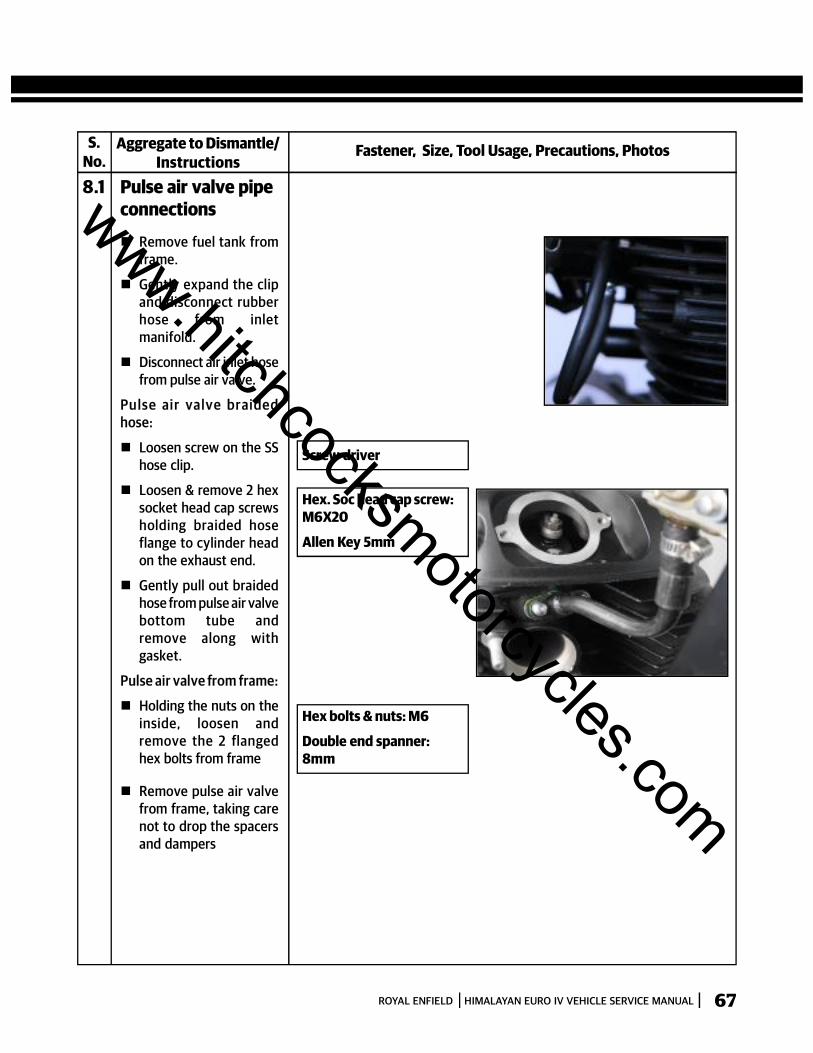
Fastener, Size, Tool Usage, Precautions, PhotosAggregate to Dismantle/Instructions
8.1 Pulse air valve pipeconnections
Remove fuel tank fromframe.
Gently expand the clipand disconnect rubberhose from inletmanifold.
Disconnect air inlet hosefrom pulse air valve.
Pu lse ai r valve br ai dedhose:
Loosen screw on the SShose clip.
Loosen & remove 2 hexsocket head cap screwsholding braided hoseflange to cylinder headon the exhaust end.
Gently pull out braidedhose from pulse air valvebottom tube andremove along withgasket.
Pulse air valve from frame:
Holding the nuts on theinside, loosen andremove the 2 flangedhex bolts from frame
Remove pulse air valvefrom frame, taking carenot to drop the spacersand dampers
Screw driver
Hex. Soc head cap screw:M6X20
Allen Key 5mm
Hex bolts & nuts: M6
Double end spanner:8mm
www.hitchcocksmotorcycles.com
ROYAL ENFIELD HIMALAYAN EURO IV VEHICLE SERVICE MANUAL68
INSPECTION Inspect the hoses for ageing, cuts and / or cracks. Replace as recommended.
Inspect braided hose for any leaks, cracks and proper sealing at cylinder head
TORQUE VALUES
S.No. Aggregate Fastener
TorqueNM Kg.M
1 Braided hose mtg to cyl head Hex Socket Head Cap Screw M6 X 20 10 1.0
2 PAV mtg to frame Hex flange bolt M6 X 30 10 1.0
Min. Torque(Nm) (Kg.M)
Max. Torque(Nm) (Kg.M)
8 0.8
8 0.8
12 1.2
12 1.2
www.hitchcocksmotorcycles.com
ROYAL ENFIELD HIMALAYAN EURO IV VEHICLE SERVICE MANUAL 69
S.No.
Fastener, Size, Tool Usage, Precautions, PhotosAggregate to Assemble/Instructions
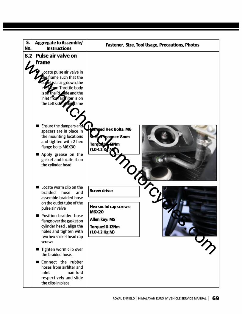
8.2 Pulse air valve onframe
Locate pulse air valve inthe frame such that theoutlet is facing down, theinlet from Throttle bodyis on the RH side and theinlet from air filter is onthe Left side of the frame
Ensure the dampers andspacers are in place inthe mounting locationsand tighten with 2 hexflange bolts M6X30
Apply grease on thegasket and locate it onthe cylinder head
Locate worm clip on thebraided hose andassemble braided hoseon the outlet tube of thepulse air valve
Position braided hoseflange over the gasket oncylinder head , align theholes and tighten withtwo hex socket head capscrews
Tighten worm clip overthe braided hose.
Connect the rubberhoses from airfilter andinlet manifoldrespectively and slidethe clips in place.
Flanged Hex Bolts: M6
Socket spanner: 8mm
Torque:10-12Nm(1.0-1.2 Kg.M)
Screw driver
Hex soc hd cap screws:M6X20
Allen key: M5
Torque:10-12Nm(1.0-1.2 Kg.M)
www.hitchcocksmotorcycles.com

ROYAL ENFIELD HIMALAYAN EURO IV VEHICLE SERVICE MANUAL70
SECTION 09 - FUEL TANK
EXPLODED VIEWFUEL TANK
S. NO. DESCRIPTION QTY. S. NO. DESCRIPTION QTY.
1Fuel Tank With Sticker - Granite 1Fuel Tank With Sticker - Snow 1
2 Front Damper-Tank 23 O Ring-Fuel Gauge 14 Fuel Level Sensor Unit 15 Hex Flange Nut M5 X 0.8 46 O Ring- Fuel pump 17 Fuel Pump Assy 18 Clamp Plate (FPM) 1
9 Flanged Hex Bolt M6 X 1 X 10 410 P.A. Tube Assy 111 Drain Hose 112 Rear Damper-Tank 213 Bush - Fuel Tank 214 Flanged Hex Bolt M6 X 1 X 27 215 Cap - Fuel Tank 116 Hex socket head cap screw m5x15 3
1
2
3
4
5
6
7
8
9
10
2
11
12
13
14
15
16www.hitchcocksmotorcycles.com
ROYAL ENFIELD HIMALAYAN EURO IV VEHICLE SERVICE MANUAL 71
S.No.
Fastener, Size, Tool Usage, Precautions, PhotosAggregate to Dismantle/Instructions
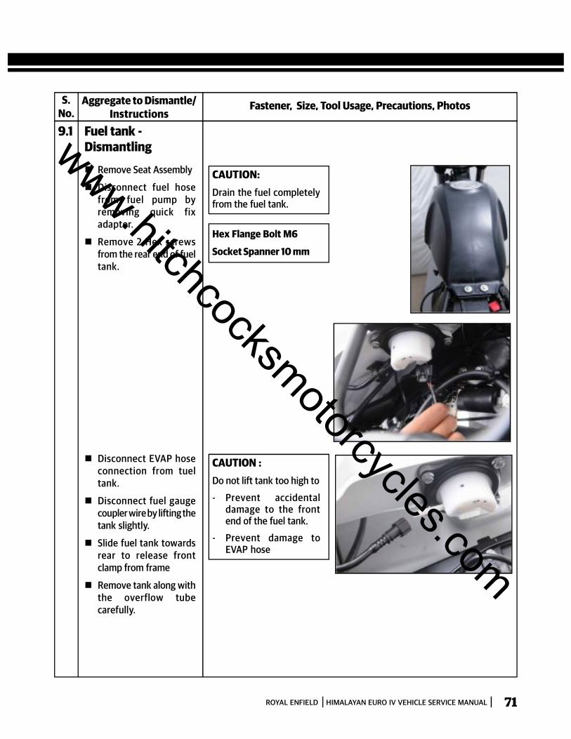
9.1 Fuel tank -Dismantling
Remove Seat Assembly
Disconnect fuel hosefrom fuel pump byremoving quick fixadaptor.
Remove 2 Hex screwsfrom the rear end of fueltank.
CAUTION:Drain the fuel completelyfrom the fuel tank.
Hex Flange Bolt M6
Socket Spanner 10 mm
CAUTION :Do not lift tank too high to
- Prevent accidentaldamage to the frontend of the fuel tank.
- Prevent damage toEVAP hose
Disconnect EVAP hoseconnection from tueltank.
Disconnect fuel gaugecoupler wire by lifting thetank slightly.
Slide fuel tank towardsrear to release frontclamp from frame
Remove tank along withthe overflow tubecarefully.
www.hitchcocksmotorcycles.com
ROYAL ENFIELD HIMALAYAN EURO IV VEHICLE SERVICE MANUAL72
INSPECTION Carefully inspect fuel hose, EVAP hose and vent hose for damage, cuts, cracks, holes, wear or general
deterioration. Replace if necessary.
WARNING Gasoline is extremely flammable and highly explosive, which could result in serious injury.
Do not smoke or allow open flame or sparks in the vicinity.
Store the fuel carefully to avoid spillage.
TORQUE VALUES
Fuel Tank Fuel tank Mounting Flanged Hex Bolt M6 * 1*27 5 0.5
Torque Range NM Kg-M
Aggregate FastenerComponent
www.hitchcocksmotorcycles.com
ROYAL ENFIELD HIMALAYAN EURO IV VEHICLE SERVICE MANUAL 73
S.No.
Fastener, Size, Tool Usage, Precautions, PhotosAggregate to Assemble/Instructions
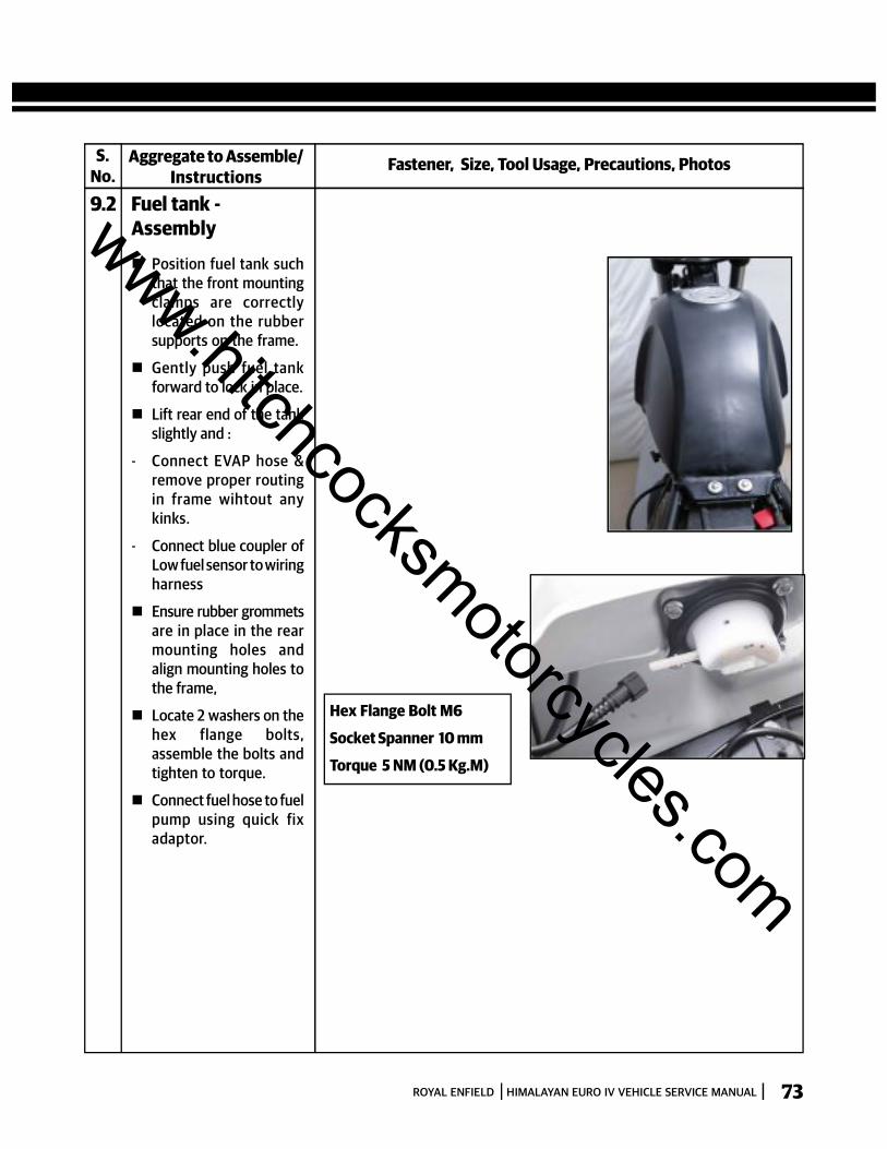
9.2 Fuel tank -Assembly
Position fuel tank suchthat the front mountingclamps are correctlylocated on the rubbersupports on the frame.
Gently push fuel tankforward to lock in place.
Lift rear end of the tankslightly and :
- Connect EVAP hose &remove proper routingin frame wihtout anykinks.
- Connect blue coupler ofLow fuel sensor to wiringharness
Ensure rubber grommetsare in place in the rearmounting holes andalign mounting holes tothe frame,
Locate 2 washers on thehex flange bolts,assemble the bolts andtighten to torque.
Connect fuel hose to fuelpump using quick fixadaptor.
Hex Flange Bolt M6
Socket Spanner 10 mm
Torque 5 NM (0.5 Kg.M)
www.hitchcocksmotorcycles.com
ROYAL ENFIELD HIMALAYAN EURO IV VEHICLE SERVICE MANUAL74
SECTION 10 – EXHAUST PIPE & SILENCER
EXPLODED VIEWSEXHAUST PIPE & SILENCER
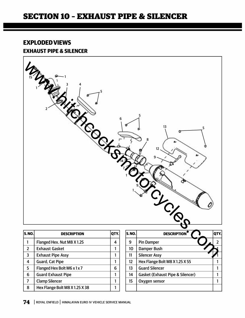
S. NO. DESCRIPTION QTY. S. NO. DESCRIPTION QTY.
1 Flanged Hex. Nut M8 X 1.25 42 Exhaust Gasket 13 Exhaust Pipe Assy 14 Guard, Cat Pipe 15 Flanged Hex Bolt M6 x 1 x 7 66 Guard Exhaust Pipe 17 Clamp Silencer 18 Hex Flange Bolt M8 X 1.25 X 38 1
9 Pin Damper 210 Damper Bush 111 Silencer Assy 112 Hex Flange Bolt M8 X 1.25 X 55 113 Guard Silencer 114 Gasket (Exhaust Pipe & Silencer) 115 Oxygen sensor 1
19
10
111
7
9
12
5
5
8
5
4
6
13
31
1
2
15
14
www.hitchcocksmotorcycles.com
ROYAL ENFIELD HIMALAYAN EURO IV VEHICLE SERVICE MANUAL 75
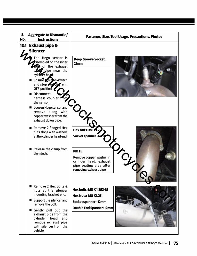
S.No.
Fastener, Size, Tool Usage, Precautions, PhotosAggregate to Dismantle/Instructions
10.1 Exhaust pipe &Silencer
Remove 2 flanged Hexnuts along with washersat the cylinder head end.
Hex Nuts: M8X1.25
Socket spanner -12mm
Hex bolts: M8 X 1.25X45
Hex Nuts: M8 X1.25
Socket spanner - 12mm
Double End Spanner: 12mm
NOTE:Remove copper washer incylinder head, exhaustpipe seating area afterremoving exhaust pipe.
Remove 2 Hex bolts &nuts at the silencermounting bracket end.
Support the silencer andremove the bolt.
Gently pull out theexhaust pipe from thecylinder head andremove exhaust pipewith silencer from thevehicle.
Release the clamp fromthe studs.
The Hego sensor isassembled on the innerside of the exhaustdown pipe near thecylinder head.
Ensure Ignition switchand stop switch are inOFF position.
Disconnect wiringharness coupler fromthe sensor.
Loosen Hego sensor andremove along withcopper washer from theexhaust down pipe.
Deep Groove Socket:21mm
www.hitchcocksmotorcycles.com

ROYAL ENFIELD HIMALAYAN EURO IV VEHICLE SERVICE MANUAL76
INSPECTION Inspect Silencer and Exhaust assembles for any damages / dents as it might cause damage to the internals.
Inspect silencer and exhaust pipe joint for any signs of exhaust gas leakage.
CAUTION : Do not clean the silencer and exhaust internals with any solvents, gasoline etc as it will damage the catalytic
converters.
REPLACE Copper gasket between exhaust pipe and cylinder head whenever exhaust pipe is dismantled from cylinder
head.
1 Exhaust Pipe Mounting to Cyl.head Flanged Hex Bolt M8 X 1.25 X 16 10 1
2 Silencer Mounting to Frame Hex Socket M8X1.25X25 25 2.5
Torque Range NM Kg-M
S No. Aggregate Fastener
www.hitchcocksmotorcycles.com

ROYAL ENFIELD HIMALAYAN EURO IV VEHICLE SERVICE MANUAL 77
Fastener, Size, Tool Usage, Precautions, PhotosAggregate to Assemble/Instructions
10.2 Exhaust pipe &Silencer
Locate a new gasket onthe exhaust pipe.
Locate exhaust pipeinto the cylinder head,position the clamp overthe studs on the cylinderhead & assemble 2 hexnuts M8 DO NO TTIGHTEN FULLY.
Hex Nuts: M8X1.25
Socket spanner -12mm
Torque: 10Nm (1.0Kg.M.)
Hex bolts: M8 X 1.25X45Hex Nuts: M8 X1.25Socket spanner -12mmDouble End Spanner: 12mmTorque: 25Nm (2.5Kg.M)
Position silencermounting bracketagainst the frame at therear and insert flangedhex bolt. Assemble hexnut over bolt.
Tighten the 2 hex nuts atthe cylinder head, firstand then the silencerbracket nut.
S.No.-
Deep Groove Socket:21mm
Locate Hego sensoralong with copperwasher on the exhaustdown pipe near thecylinder head.
Ensure Ignition switchand stop switch are inOFF position.
Connect wiring harnesscoupler on the sensor.
www.hitchcocksmotorcycles.com
78 ROYAL ENFIELD HIMALAYAN EURO IV VEHICLE SERVICE MANUAL
SECTION 11 - TOP BRACKET, HANDLE BAR,FRONT MUDGUARD, FRONT WHEEL FRONT
SUSPENSION & STEERING STEM
www.hitchcocksmotorcycles.com
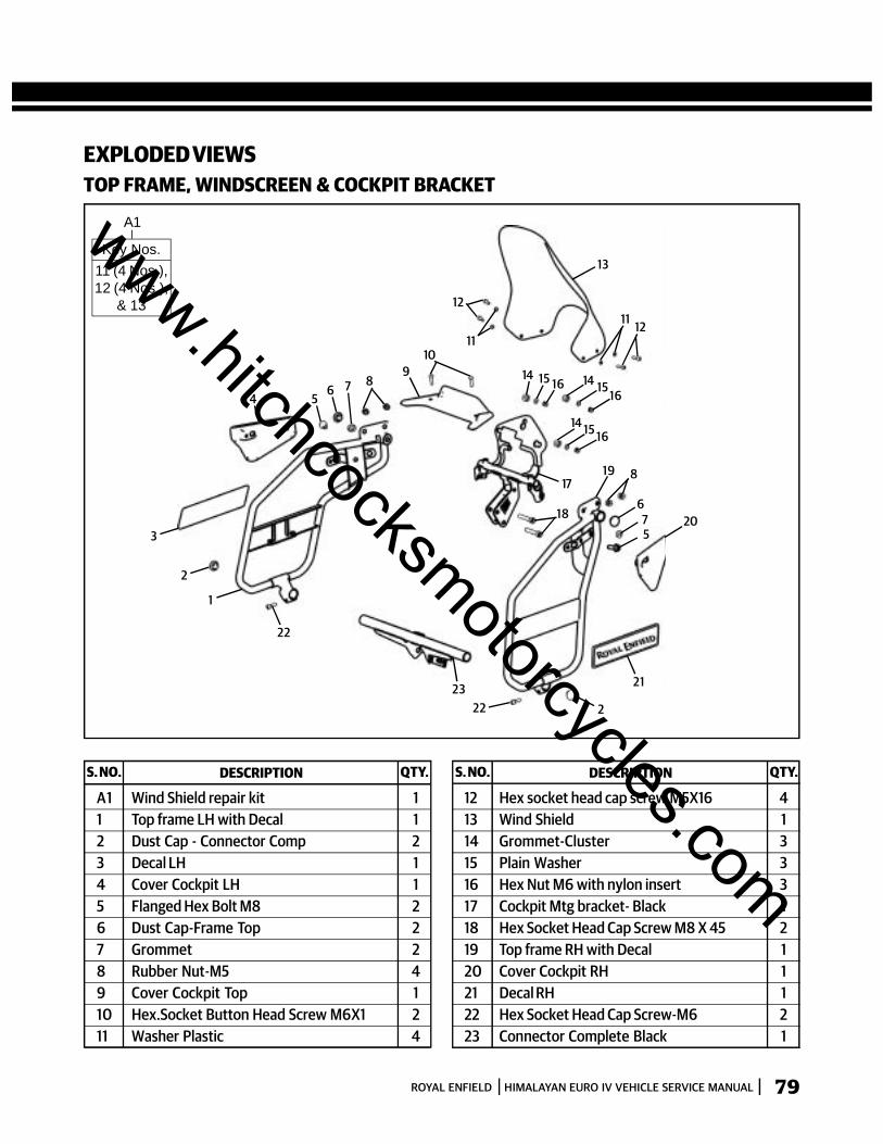
79ROYAL ENFIELD HIMALAYAN EURO IV VEHICLE SERVICE MANUAL
2223 21
2
22
2
3
4 56 7 8
910
11
12
13
11 12
14 15 16 14 1516
14 15 16
17
18
19 8
675
20
1
EXPLODED VIEWSTOP FRAME, WINDSCREEN & COCKPIT BRACKET
S. NO. DESCRIPTION QTY. S. NO. DESCRIPTION QTY.
A1 Wind Shield repair kit 11 Top frame LH with Decal 12 Dust Cap - Connector Comp 23 Decal LH 14 Cover Cockpit LH 15 Flanged Hex Bolt M8 26 Dust Cap-Frame Top 27 Grommet 28 Rubber Nut-M5 49 Cover Cockpit Top 110 Hex.Socket Button Head Screw M6X1 211 Washer Plastic 4
12 Hex socket head cap screw M5X16 413 Wind Shield 114 Grommet-Cluster 315 Plain Washer 316 Hex Nut M6 with nylon insert 317 Cockpit Mtg bracket- Black 118 Hex Socket Head Cap Screw M8 X 45 219 Top frame RH with Decal 120 Cover Cockpit RH 121 Decal RH 122 Hex Socket Head Cap Screw-M6 223 Connector Complete Black 1
A1
Key Nos.11 (4 Nos.),12 (4 Nos.),
& 13
www.hitchcocksmotorcycles.com
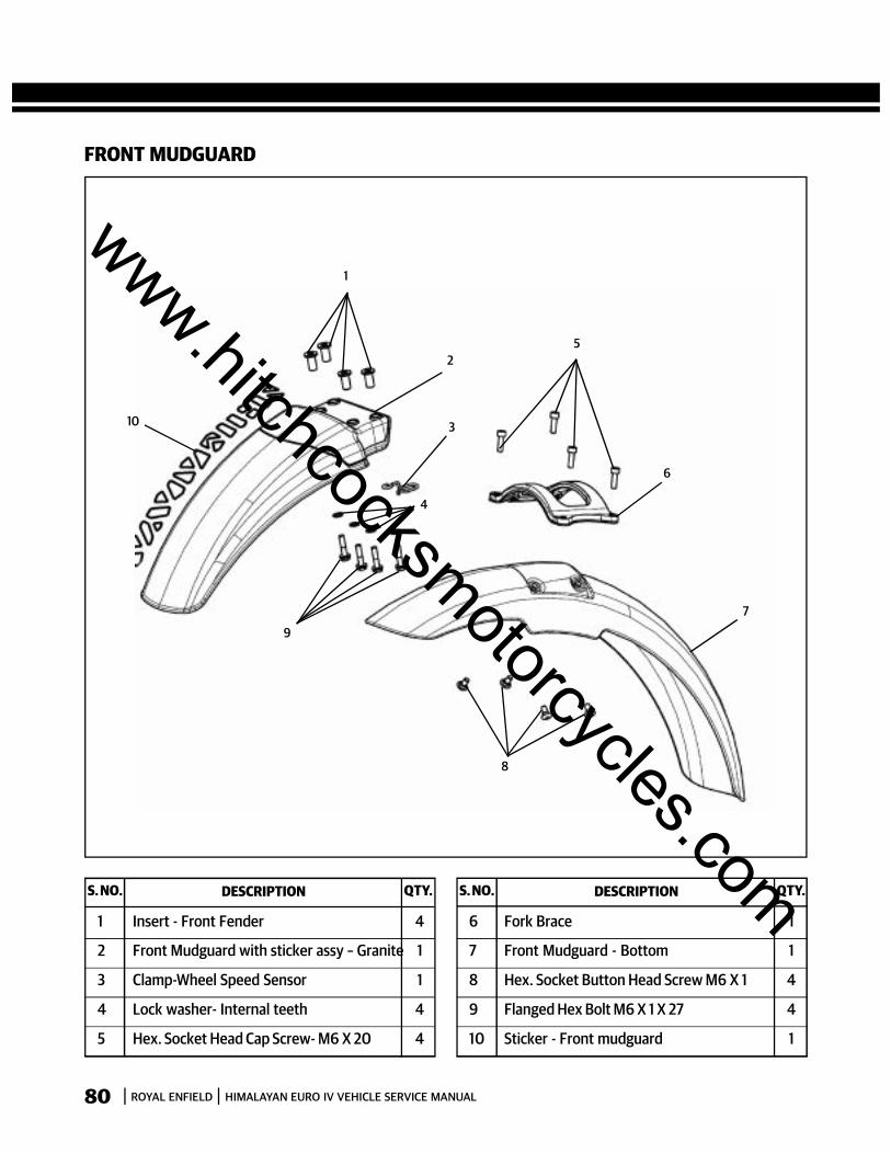
80 ROYAL ENFIELD HIMALAYAN EURO IV VEHICLE SERVICE MANUAL
FRONT MUDGUARD
S. NO. DESCRIPTION QTY. S. NO. DESCRIPTION QTY.
1 Insert - Front Fender 4
2 Front Mudguard with sticker assy – Granite 1
3 Clamp-Wheel Speed Sensor 1
4 Lock washer- Internal teeth 4
5 Hex. Socket Head Cap Screw- M6 X 20 4
6 Fork Brace 1
7 Front Mudguard - Bottom 1
8 Hex. Socket Button Head Screw M6 X 1 4
9 Flanged Hex Bolt M6 X 1 X 27 4
10 Sticker - Front mudguard 1
1
2
3
4
5
6
9
8
7
10
www.hitchcocksmotorcycles.com
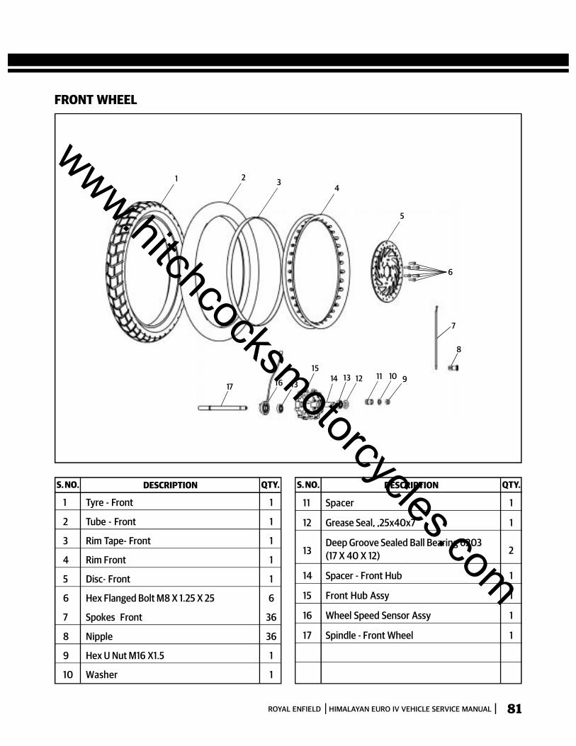
81ROYAL ENFIELD HIMALAYAN EURO IV VEHICLE SERVICE MANUAL
FRONT WHEEL
2 34
5
6
1
7
8
9101112131415
131617
S. NO. DESCRIPTION QTY. S. NO. DESCRIPTION QTY.
1 Tyre - Front 1
2 Tube - Front 1
3 Rim Tape- Front 1
4 Rim Front 1
5 Disc- Front 1
6 Hex Flanged Bolt M8 X 1.25 X 25 6
7 Spokes Front 36
8 Nipple 36
9 Hex U Nut M16 X1.5 1
10 Washer 1
11 Spacer 1
12 Grease Seal, ,25x40x7 1
13Deep Groove Sealed Ball Bearing 6203(17 X 40 X 12) 2
14 Spacer - Front Hub 1
15 Front Hub Assy 1
16 Wheel Speed Sensor Assy 1
17 Spindle - Front Wheel 1
www.hitchcocksmotorcycles.com
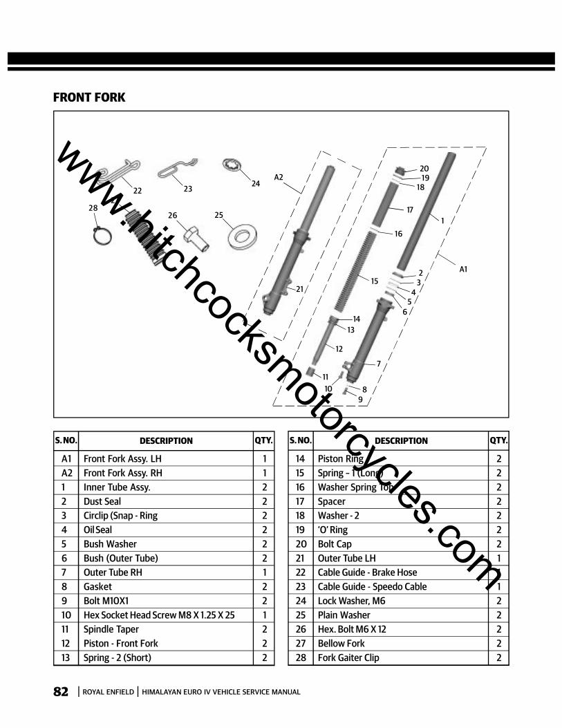
82 ROYAL ENFIELD HIMALAYAN EURO IV VEHICLE SERVICE MANUAL
FRONT FORK
S. NO. DESCRIPTION QTY. S. NO. DESCRIPTION QTY.
A1 Front Fork Assy. LH 1A2 Front Fork Assy. RH 11 Inner Tube Assy. 22 Dust Seal 23 Circlip (Snap - Ring 24 Oil Seal 25 Bush Washer 26 Bush (Outer Tube) 27 Outer Tube RH 18 Gasket 29 Bolt M10X1 210 Hex Socket Head Screw M8 X 1.25 X 25 111 Spindle Taper 212 Piston - Front Fork 213 Spring - 2 (Short) 2
14 Piston Ring 215 Spring – 1 (Long) 216 Washer Spring Top 217 Spacer 218 Washer - 2 219 ‘O’ Ring 220 Bolt Cap 221 Outer Tube LH 122 Cable Guide - Brake Hose 123 Cable Guide - Speedo Cable 124 Lock Washer, M6 225 Plain Washer 226 Hex. Bolt M6 X 12 227 Bellow Fork 228 Fork Gaiter Clip 2
98
7
1011
12
1314
15
16
17
1819
20
21
65
432
1
A1
A224
25
23
26
2227
28
www.hitchcocksmotorcycles.com
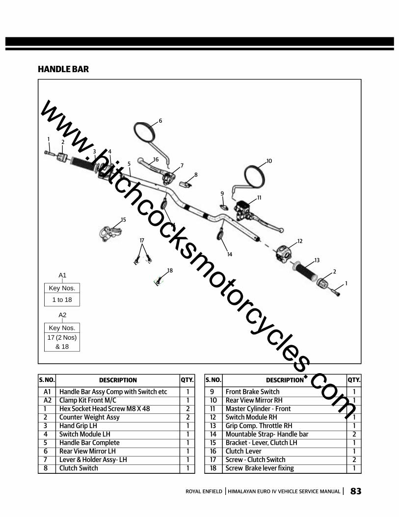
83ROYAL ENFIELD HIMALAYAN EURO IV VEHICLE SERVICE MANUAL
1 2
3 4
5 78
9
10
11
12
13
2
1
14
14
16
6
15
17
18
HANDLE BAR
S. NO. DESCRIPTION QTY. S. NO. DESCRIPTION QTY.
A1 Handle Bar Assy Comp with Switch etc 1A2 Clamp Kit Front M/C 11 Hex Socket Head Screw M8 X 48 22 Counter Weight Assy 23 Hand Grip LH 14 Switch Module LH 15 Handle Bar Complete 16 Rear View Mirror LH 17 Lever & Holder Assy- LH 18 Clutch Switch 1
9 Front Brake Switch 110 Rear View Mirror RH 111 Master Cylinder - Front 112 Switch Module RH 113 Grip Comp. Throttle RH 114 Mountable Strap- Handle bar 215 Bracket - Lever, Clutch LH 116 Clutch Lever 117 Screw - Clutch Switch 218 Screw Brake lever fixing 1
A1
Key Nos.
1 to 18
A2
Key Nos.17 (2 Nos)
& 18
www.hitchcocksmotorcycles.com
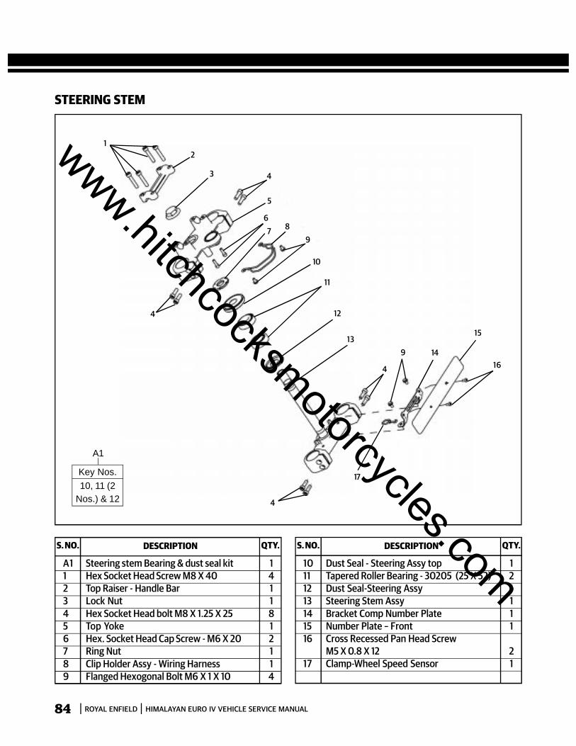
84 ROYAL ENFIELD HIMALAYAN EURO IV VEHICLE SERVICE MANUAL
STEERING STEM
S. NO. DESCRIPTION QTY. S. NO. DESCRIPTION QTY.
A1 Steering stem Bearing & dust seal kit 11 Hex Socket Head Screw M8 X 40 42 Top Raiser - Handle Bar 13 Lock Nut 14 Hex Socket Head bolt M8 X 1.25 X 25 85 Top Yoke 16 Hex. Socket Head Cap Screw - M6 X 20 27 Ring Nut 18 Clip Holder Assy - Wiring Harness 19 Flanged Hexogonal Bolt M6 X 1 X 10 4
10 Dust Seal - Steering Assy top 111 Tapered Roller Bearing - 30205 (25 X 52) 212 Dust Seal-Steering Assy 113 Steering Stem Assy 114 Bracket Comp Number Plate 115 Number Plate – Front 116 Cross Recessed Pan Head Screw
M5 X 0.8 X 12 217 Clamp-Wheel Speed Sensor 1
12
3 4
5
4
67 8
9
10
11
13
12
4
9 14
15
16
17
4
A1
Key Nos.10, 11 (2
Nos.) & 12
www.hitchcocksmotorcycles.com
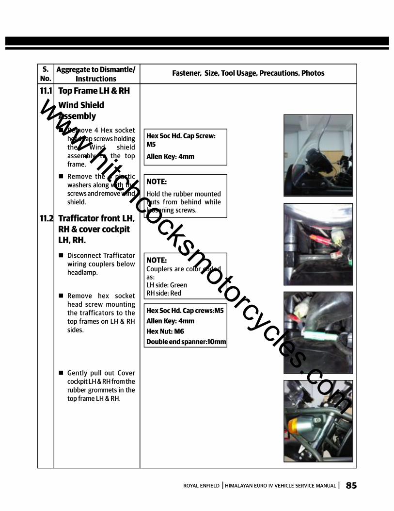
85ROYAL ENFIELD HIMALAYAN EURO IV VEHICLE SERVICE MANUAL
S.No.
Fastener, Size, Tool Usage, Precautions, PhotosAggregate to Dismantle/Instructions
11.1 Top Frame LH & RHWind ShieldAssembly Remove 4 Hex socket
head cap screws holdingthe Wind shieldassembly to the topframe.
Remove the 4 plasticwashers along with thescrews and remove windshield.
Hex Soc Hd. Cap Screw:M5
Allen Key: 4mm
11.2 Trafficator front LH,RH & cover cockpitLH, RH. Disconnect Trafficator
wiring couplers belowheadlamp.
NOTE:Hold the rubber mountednuts from behind whileloosening screws.
NOTE:Couplers are color codedas:LH side: GreenRH side: Red
Hex Soc Hd. Cap crews:M5Allen Key: 4mmHex Nut: M6Double end spanner:10mm
Remove hex sockethead screw mountingthe trafficators to thetop frames on LH & RHsides.
Gently pull out Covercockpit LH & RH from therubber grommets in thetop frame LH & RH.
www.hitchcocksmotorcycles.com
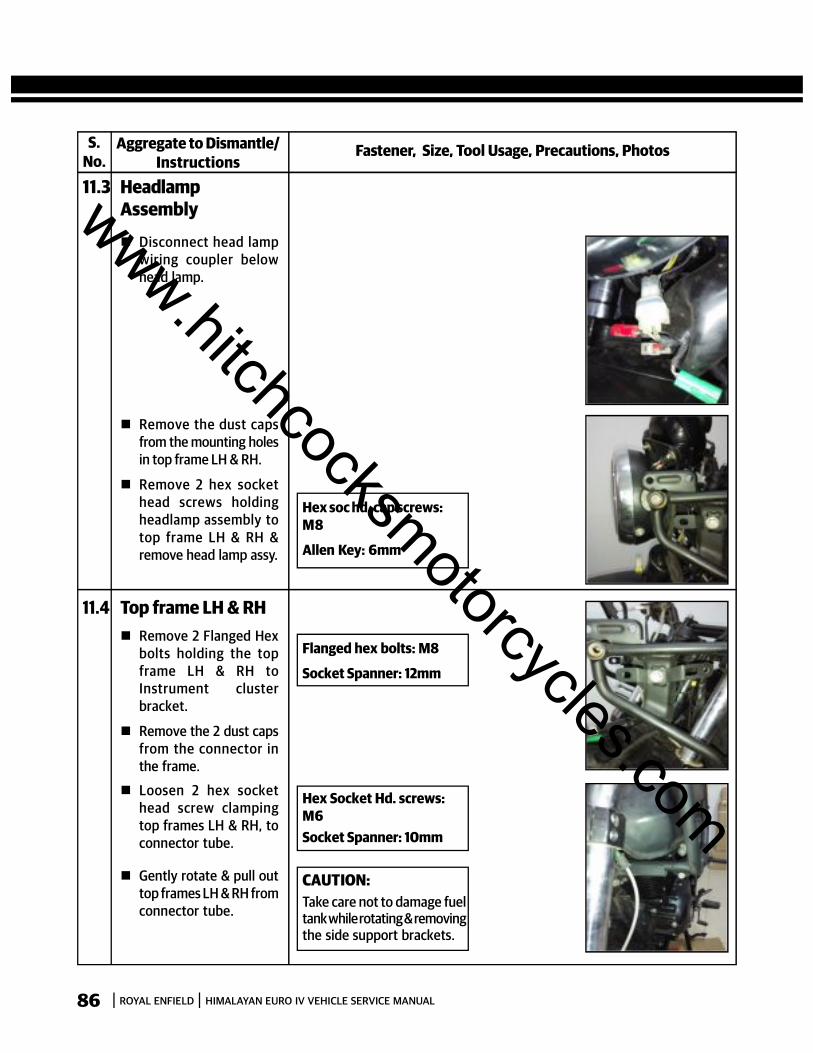
86 ROYAL ENFIELD HIMALAYAN EURO IV VEHICLE SERVICE MANUAL
S.No.
Fastener, Size, Tool Usage, Precautions, PhotosAggregate to Dismantle/Instructions
11.3 HeadlampAssembly
Disconnect head lampwiring coupler belowhead lamp.
Hex soc hd. cap screws:M8
Allen Key: 6mm
Remove the dust capsfrom the mounting holesin top frame LH & RH.
Remove 2 hex sockethead screws holdingheadlamp assembly totop frame LH & RH &remove head lamp assy.
11.4 Top frame LH & RH Remove 2 Flanged Hex
bolts holding the topframe LH & RH toInstrument clusterbracket.
Remove the 2 dust capsfrom the connector inthe frame.
Flanged hex bolts: M8
Socket Spanner: 12mm
Hex Socket Hd. screws:M6Socket Spanner: 10mm
CAUTION:Take care not to damage fueltank while rotating & removingthe side support brackets.
Loosen 2 hex sockethead screw clampingtop frames LH & RH, toconnector tube.
Gently rotate & pull outtop frames LH & RH fromconnector tube.
www.hitchcocksmotorcycles.com

87ROYAL ENFIELD HIMALAYAN EURO IV VEHICLE SERVICE MANUAL
S.No.
Fastener, Size, Tool Usage, Precautions, PhotosAggregate to Dismantle/Instructions
11.5 Instrument clusterIgnition switch &Cockpit mountingbracket Disconnect the
instrument clusterwiring coupler
CAUTION:Instrument cluster mustalways be stored verticallyand away from magneticobjects to prevent damageto the compass and displays.
Loosen and remove the3 Hex cap nuts along withthe washers.
Remove the Instrumentcluster from the cockpitbracket
Disconnect ignitionswitch wiring coupler.
Loosen and remove 2hex socket head capscrews beneath switchand remove switch.
Remove 2 Allen screwsmounting theInstrument clusterbracket to frame headtube.
Hex cap nuts: M6
Socket Spanner: 10mm
Hex soc. Hd. cap Screw: M5
Allen key: 4mm
Hex soc. Hd. cap Screw:M8Allen key: 6mm
www.hitchcocksmotorcycles.com

88 ROYAL ENFIELD HIMALAYAN EURO IV VEHICLE SERVICE MANUAL
S.No.
Fastener, Size, Tool Usage, Precautions, PhotosAggregate to Dismantle/Instructions
11.6 Front MudguardFront Mudguard Top Remove 4 Hex bolts
from inside ofmudguard.
Remove frontmudguard top.
Hex bolt: M6
D E Spanner: 10mm
NOTE:Ensure the 4 inserts areremoved from the top ofthe mudguard.
11.7 Front MudguardBottom
Remove 4 Allen screwssecuring fork brace tofork legs.
Remove 4 Allen screwsinside front mudguardbottom to separatemudguard from forkbrace.
Hex soc. Hd. cap Screw:M5
Allen key: 4mm
Hex soc. Hd. cap Screw:M5
Allen key: 4mm
www.hitchcocksmotorcycles.com

89ROYAL ENFIELD HIMALAYAN EURO IV VEHICLE SERVICE MANUAL
S.No.
Fastener, Size, Tool Usage, Precautions, PhotosAggregate to Dismantle/Instructions
11.8 Front Wheel
Support front end ofengine suitably suchthat the front wheel isoff the ground.
Loosen pinch bolt onright fork end with 6mm Allen key.
Hold spindle on rightside and remove spindlenut and washer from leftside.
Support wheel and pullout spindle from rightside.
Remove wheel alongwith wheel speed sensorand spacer.
Remove speedo sensor.
Place a suitable spacer of4 mm thickness,between the brake padsto avoid accidentalcompression of thebrake lever.
CAUTION:Do not press the brake leverwhen wheel is removed asthis will result in the brakepads coming out too farfrom the brake caliper.
www.hitchcocksmotorcycles.com
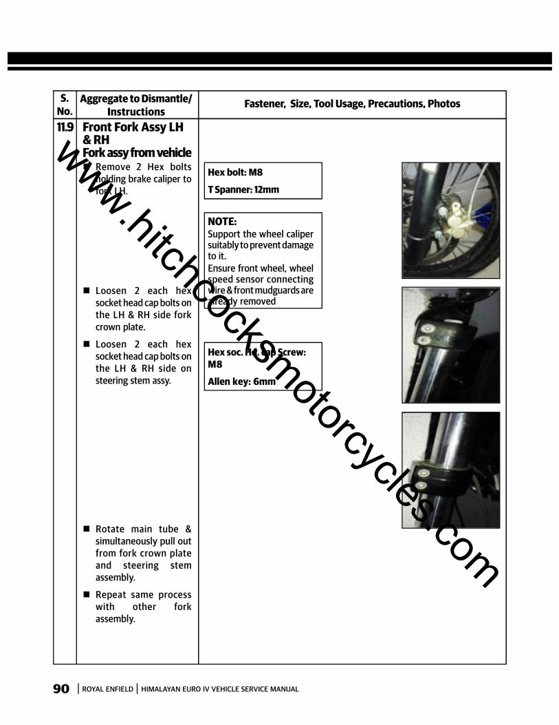
90 ROYAL ENFIELD HIMALAYAN EURO IV VEHICLE SERVICE MANUAL
S.No.
Fastener, Size, Tool Usage, Precautions, PhotosAggregate to Dismantle/Instructions
11.9 Front Fork Assy LH& RHFork assy from vehicle Remove 2 Hex bolts
holding brake caliper tofork LH.
Loosen 2 each hexsocket head cap bolts onthe LH & RH side forkcrown plate.
Loosen 2 each hexsocket head cap bolts onthe LH & RH side onsteering stem assy.
Rotate main tube &simultaneously pull outfrom fork crown plateand steering stemassembly.
Repeat same processwith other forkassembly.
Hex bolt: M8
T Spanner: 12mm
NOTE:Support the wheel calipersuitably to prevent damageto it.Ensure front wheel, wheelspeed sensor connectingwire & front mudguards arealready removed
Hex soc. Hd. cap Screw:M8
Allen key: 6mm
www.hitchcocksmotorcycles.com

91ROYAL ENFIELD HIMALAYAN EURO IV VEHICLE SERVICE MANUAL
S.No.
Fastener, Size, Tool Usage, Precautions, PhotosAggregate to Dismantle/Instructions
11.10 Front Fork Internals
Hold fork assembly in abench vice with soft jaws,approximately 6 inchesfrom the top and loosencap nut.
Remove fork assemblyfrom the bench vise,hold upright andremove cap nut withwasher slowly to allowthe main spring toexpand completely.
Remove washer, spacerand washer spring topand main spring from theinner tube.
Invert the fork assemblyto drain out the oil fromthe fork.
Gently pump main tubeinto the bottom tube todrain out the oilcompletely.
Hex cap nut : M16
Ring spanner: 24mm
Fork oil capacity:455ml/leg
www.hitchcocksmotorcycles.com
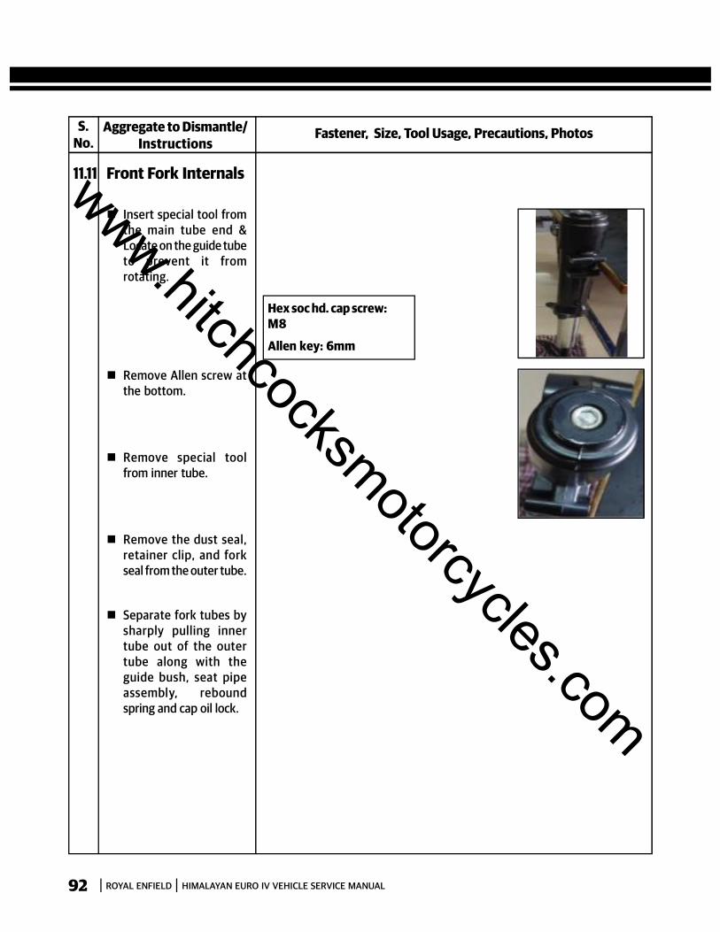
92 ROYAL ENFIELD HIMALAYAN EURO IV VEHICLE SERVICE MANUAL
S.No.
Fastener, Size, Tool Usage, Precautions, PhotosAggregate to Dismantle/Instructions
11.11 Front Fork Internals
Insert special tool fromthe main tube end &Locate on the guide tubeto prevent it fromrotating.
Remove Allen screw atthe bottom.
Remove special toolfrom inner tube.
Remove the dust seal,retainer clip, and forkseal from the outer tube.
Separate fork tubes bysharply pulling innertube out of the outertube along with theguide bush, seat pipeassembly, reboundspring and cap oil lock.
Hex soc hd. cap screw:M8
Allen key: 6mm
www.hitchcocksmotorcycles.com

93ROYAL ENFIELD HIMALAYAN EURO IV VEHICLE SERVICE MANUAL
S.No.
Fastener, Size, Tool Usage, Precautions, PhotosAggregate to Dismantle/Instructions
11.12 Handle BarAssembly Remove rear view
mirrors LH & RH fromhandle bar
Disconnect clutch andthrottle cables. (refersection 5)
Disconnect wiringcouplers of LH and RHswitch assemblies fromthe wiring harness
Disconnect Front BrakeSwitch wire connections.
Disconnect clutch switchwiring coupler.
Remove 2 Hex bolts frommaster cylinder topmounting bracket onhandle bar RH andremove master cylindercomplete with brakelever from handle bar.
Remove 4 Hex socketscrews mounting topraiser to steering stemtop bracket & removehandle bar with topraiser.
Hex nut: M10
Double end spanner:14mm
Hex bolt: M6
Socket spanner: 8mm
Hex soc hd. cap screw: M8
Allen key: 6mm
www.hitchcocksmotorcycles.com
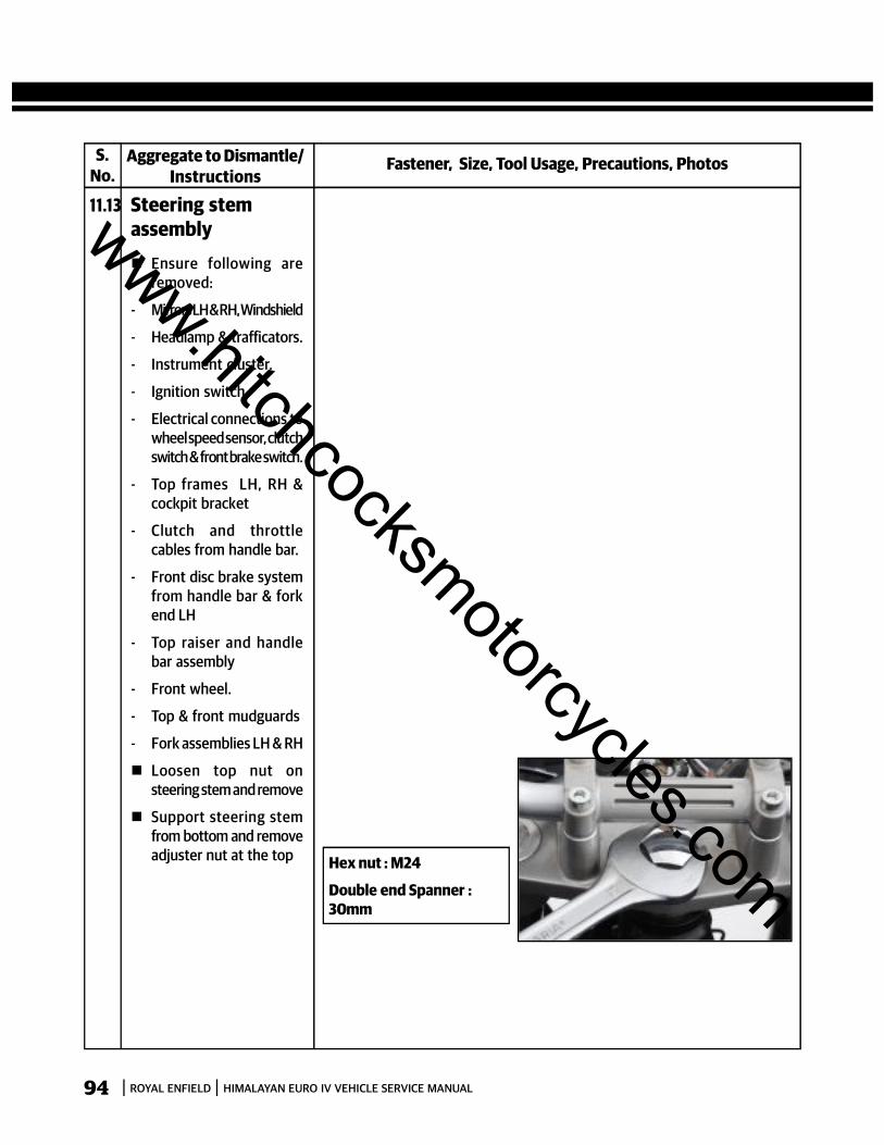
94 ROYAL ENFIELD HIMALAYAN EURO IV VEHICLE SERVICE MANUAL
S.No.
Fastener, Size, Tool Usage, Precautions, PhotosAggregate to Dismantle/Instructions
11.13 Steering stemassembly Ensure following are
removed:
- Mirrors LH & RH, Windshield
- Headlamp & trafficators.
- Instrument cluster.
- Ignition switch.
- Electrical connections towheel speed sensor, clutchswitch & front brake switch.
- Top frames LH, RH &cockpit bracket
- Clutch and throttlecables from handle bar.
- Front disc brake systemfrom handle bar & forkend LH
- Top raiser and handlebar assembly
- Front wheel.
- Top & front mudguards
- Fork assemblies LH & RH
Loosen top nut onsteering stem and remove
Support steering stemfrom bottom and removeadjuster nut at the top Hex nut : M24
Double end Spanner :30mm
www.hitchcocksmotorcycles.com

95ROYAL ENFIELD HIMALAYAN EURO IV VEHICLE SERVICE MANUAL
S.No.
Fastener, Size, Tool Usage, Precautions, PhotosAggregate to Dismantle/Instructions
11.13 Steering stemassembly Remove dust washer
from the top
Remove steering stemfrom the frame
Remove tapper rollerbearing from the framehead tube.
NOTE:The bottom taper rollerbearing will be tight in thesteering stem and will haveto be pulled out of the stemusing suitable puller.
www.hitchcocksmotorcycles.com
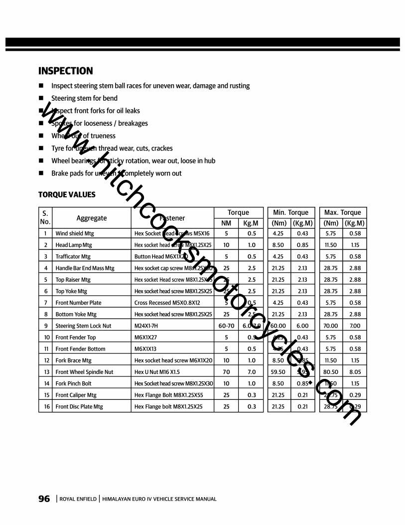
96 ROYAL ENFIELD HIMALAYAN EURO IV VEHICLE SERVICE MANUAL
INSPECTION Inspect steering stem ball races for uneven wear, damage and rusting
Steering stem for bend
Inspect front forks for oil leaks
Spokes for looseness / breakages
Wheel out of trueness
Tyre for uneven thread wear, cuts, crackes
Wheel bearings for sticky rotation, wear out, loose in hub
Brake pads for uneven / completely worn out
TORQUE VALUES
S.No. Aggregate Fastener
TorqueNM Kg.M
1 Wind shield Mtg Hex Socket Head Screws M5X16 5 0.5 4.25 0.43 5.75 0.58
2 Head Lamp Mtg Hex socket head screw M8X1.25X25 10 1.0 8.50 0.85 11.50 1.15
3 Trafficator Mtg Button Head M6X1X20 5 0.5 4.25 0.43 5.75 0.58
4 Handle Bar End Mass Mtg Hex socket cap screw M8x1.25X50 25 2.5 21.25 2.13 28.75 2.88
5 Top Raiser Mtg Hex socket Head screw M8X1.25X45 25 2.5 21.25 2.13 28.75 2.88
6 Top Yoke Mtg Hex socket head screw M8X1.25X25 25 2.5 21.25 2.13 28.75 2.88
7 Front Number Plate Cross Recessed M5X0.8X12 5 0.5 4.25 0.43 5.75 0.58
8 Bottom Yoke Mtg Hex socket head screw M8X1.25X25 25 2.5 21.25 2.13 28.75 2.88
9 Steering Stem Lock Nut M24X1-7H 60-70 6.0-7.0 60.00 6.00 70.00 7.00
10 Front Fender Top M6X1X27 5 0.5 4.25 0.43 5.75 0.58
11 Front Fender Bottom M6X1X13 5 0.5 4.25 0.43 5.75 0.58
12 Fork Brace Mtg Hex socket head screw M6X1X20 10 1.0 8.50 0.85 11.50 1.15
13 Front Wheel Spindle Nut Hex U Nut M16 X1.5 7 0 7.0 59.50 5.95 80.50 8.05
14 Fork Pinch Bolt Hex Socket head screw M8X1.25X30 10 1.0 8.50 0.85 11.50 1.15
15 Front Caliper Mtg Hex Flange Bolt M8X1.25X55 25 0.3 21.25 0.21 28.75 0.29
16 Front Disc Plate Mtg Hex Flange bolt M8X1.25X25 25 0.3 21.25 0.21 28.75 0.29
Min. Torque(Nm) (Kg.M)
Max. Torque(Nm) (Kg.M)
www.hitchcocksmotorcycles.com
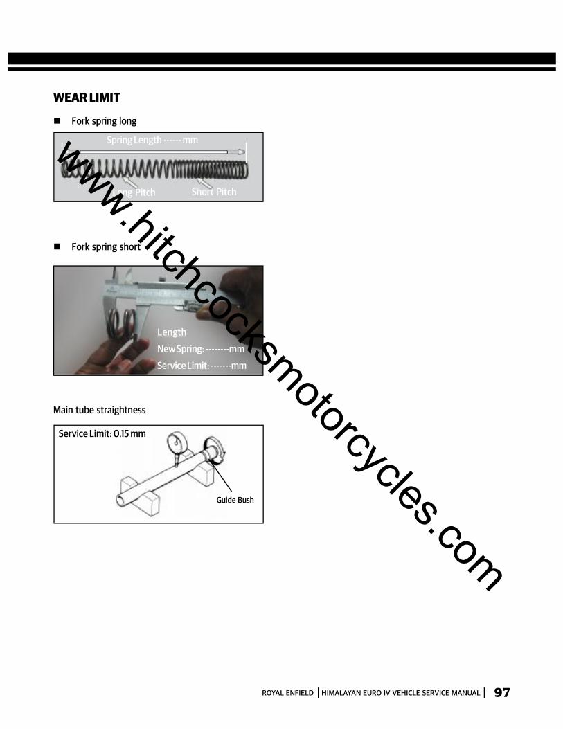
97ROYAL ENFIELD HIMALAYAN EURO IV VEHICLE SERVICE MANUAL
Main tube straightness
Long Pitch Short Pitch
Spring Length ------ mm
Fork spring short
Service Limit: 0.15 mm
Guide Bush
Length
New Spring: --------mm
Service Limit: -------mm
WEAR LIMIT
Fork spring long
www.hitchcocksmotorcycles.com
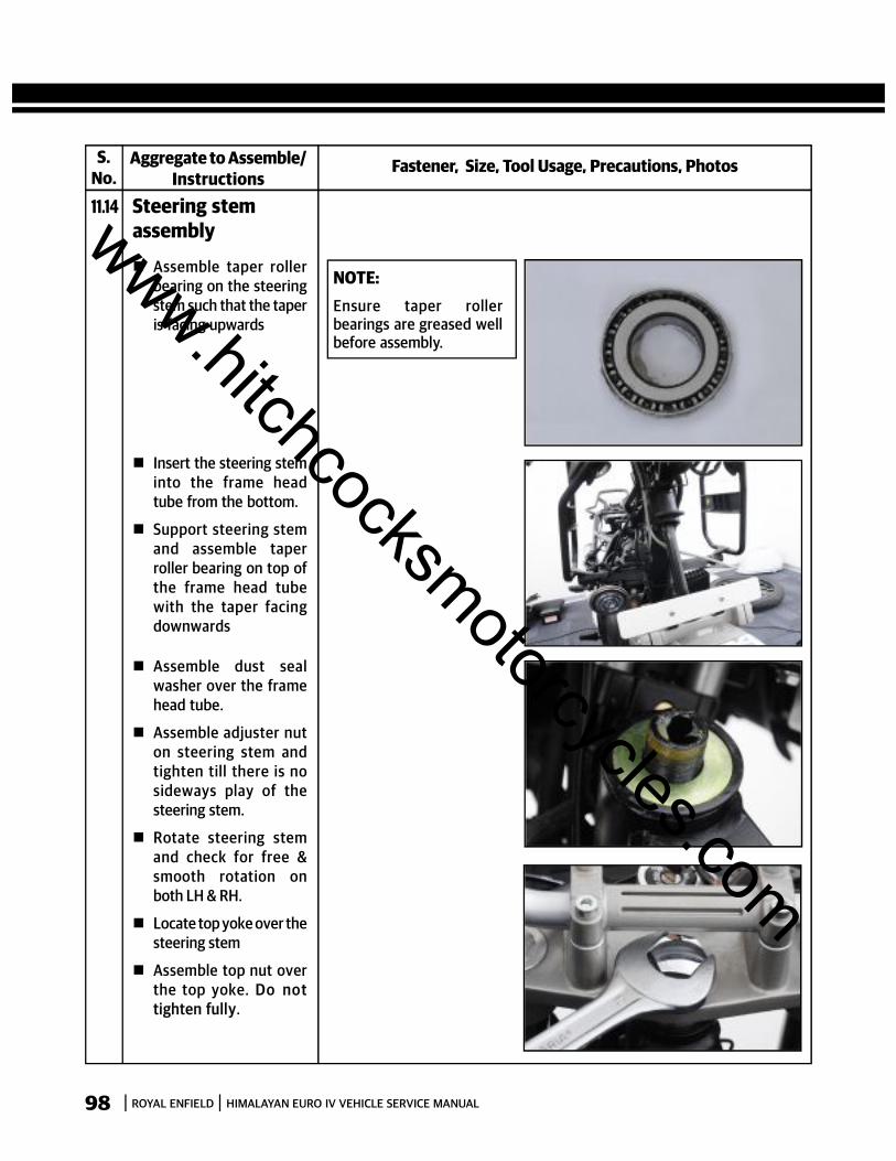
98 ROYAL ENFIELD HIMALAYAN EURO IV VEHICLE SERVICE MANUAL
Fastener, Size, Tool Usage, Precautions, PhotosAggregate to Assemble/Instructions
11.14 Steering stemassembly
Assemble taper rollerbearing on the steeringstem such that the taperis facing upwards
Insert the steering steminto the frame headtube from the bottom.
Support steering stemand assemble taperroller bearing on top ofthe frame head tubewith the taper facingdownwards
Assemble dust sealwasher over the framehead tube.
Assemble adjuster nuton steering stem andtighten till there is nosideways play of thesteering stem.
Rotate steering stemand check for free &smooth rotation onboth LH & RH.
Locate top yoke over thesteering stem
Assemble top nut overthe top yoke. Do nottighten fully.
NOTE:Ensure taper rollerbearings are greased wellbefore assembly.
S.No.
www.hitchcocksmotorcycles.com
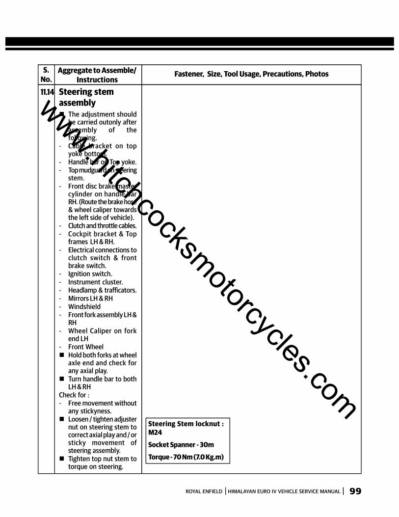
99ROYAL ENFIELD HIMALAYAN EURO IV VEHICLE SERVICE MANUAL
Fastener, Size, Tool Usage, Precautions, PhotosAggregate to Assemble/Instructions
11.14 Steering stemassembly The adjustment should
be carried outonly afterassembly of thefollowing.
- Cable bracket on topyoke bottom.
- Handle bar on Top yoke.- Top mudguard on steering
stem.- Front disc brake master
cylinder on handle barRH. (Route the brake hose& wheel caliper towardsthe left side of vehicle).
- Clutch and throttle cables.- Cockpit bracket & Top
frames LH & RH.- Electrical connections to
clutch switch & frontbrake switch.
- Ignition switch.- Instrument cluster.- Headlamp & trafficators.- Mirrors LH & RH- Windshield- Front fork assembly LH &
RH- Wheel Caliper on fork
end LH- Front Wheel Hold both forks at wheel
axle end and check forany axial play.
Turn handle bar to bothLH & RH
Check for :- Free movement without
any stickyness. Loosen / tighten adjuster
nut on steering stem tocorrect axial play and / orsticky movement ofsteering assembly.
Tighten top nut stem totorque on steering.
S.No.
Steering Stem locknut :M24
Socket Spanner - 30m
Torque - 70 Nm (7.0 Kg.m)
www.hitchcocksmotorcycles.com

100 ROYAL ENFIELD HIMALAYAN EURO IV VEHICLE SERVICE MANUAL
Fastener, Size, Tool Usage, Precautions, PhotosAggregate to Assemble/Instructions
11.15 Handle BarAssembly
Locate handle bar ontop yoke.
Assemble top raiser overhandle bar and tightenwith 4 hex socket headscrews.
Locate Master cylinderon handle bar RH side.
Locate top clamp overbracket and tighten with2 Hex bolts. (Route thebrake hose & wheelcaliper towards the leftside of vehicle)
Connect Front BrakeSwitch wire connections.
Connect clutch andthrottle cables. (refersection 5)
Connect clutch switchwiring coupler.
Connect wiring couplersof LH and RH switchassemblies from thewiring harness
Assemble rear viewmirrors LH & RH fromhandle bar.
S.No.
Hex soc hd. cap screw: M8
Allen key: 6mm
Torque: 25Nm (2.5Kg.M)
www.hitchcocksmotorcycles.com

101ROYAL ENFIELD HIMALAYAN EURO IV VEHICLE SERVICE MANUAL
Fastener, Size, Tool Usage, Precautions, PhotosAggregate to Assemble/Instructions
11.16 Front Fork Assy LH& RHFront Fork Internals Locate dust cap, oil seal
with its spring facingdownwards and spacerfrom the bottom ofinner tube assembly.
Assemble spring 2 (short)on piston – front fork andinsert tapered end intomain tube from the top.
Locate spindle taperwith a little bit of greaseto hold it in position, onthe piston – front fork
Insert special tool intoinner tube assembly,from top to hold piston –front fork.
S.No.
www.hitchcocksmotorcycles.com
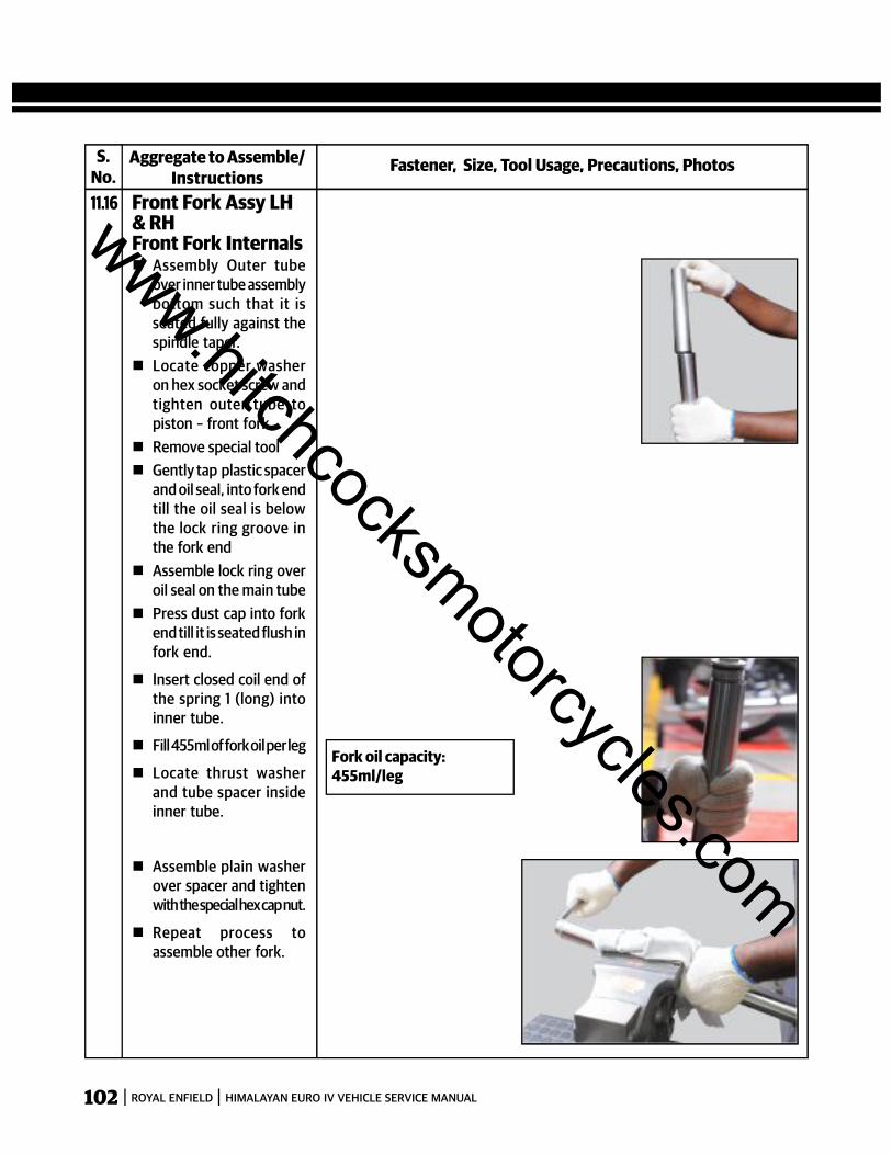
102 ROYAL ENFIELD HIMALAYAN EURO IV VEHICLE SERVICE MANUAL
Fastener, Size, Tool Usage, Precautions, PhotosAggregate to Assemble/Instructions
S.No.
Fork oil capacity:455ml/leg
11.16 Front Fork Assy LH& RHFront Fork Internals Assembly Outer tube
over inner tube assemblybottom such that it isseated fully against thespindle taper.
Locate copper washeron hex socket screw andtighten outer tube topiston – front fork.
Remove special tool Gently tap plastic spacer
and oil seal, into fork endtill the oil seal is belowthe lock ring groove inthe fork end
Assemble lock ring overoil seal on the main tube
Press dust cap into forkend till it is seated flush infork end.
Insert closed coil end ofthe spring 1 (long) intoinner tube.
Fill 455ml of fork oil per leg
Locate thrust washerand tube spacer insideinner tube.
Assemble plain washerover spacer and tightenwith the special hex cap nut.
Repeat process toassemble other fork.
www.hitchcocksmotorcycles.com

103ROYAL ENFIELD HIMALAYAN EURO IV VEHICLE SERVICE MANUAL
Fastener, Size, Tool Usage, Precautions, PhotosAggregate to Assemble/Instructions
11.17 Front Fork Assy LH& RHFork assy onsteering stem Insert fork assy LH from
LH side of steering stembottom till it is seatedinto the top yoke andflush with the top of thetop yoke.
Insert fork assy RH fromRH side of steering stembottom till it is seatedinto the top yoke andflush with the top of thetop yoke.
Tighten 4 Hex sockethead screws on the LHand RH sides of thesteering stem assemblysufficiently.
Tighten 4 Hex sockethead screws on LH andRH sides of the top yokesufficiently.
Assemble frontmudguard and brace
Locate front wheelcaliper on fork Lh andtighten with 2 Hex flangebolts.
S.No.
Hex. Socket screw : M8
Allen head socket : 6mm
Torque : 22.5 Nm (2.25Kg.m)
Hex. Socket screw : M8
Allen head socket : 6mm
Torque : 22.5 Nm (2.25Kg.m)
www.hitchcocksmotorcycles.com
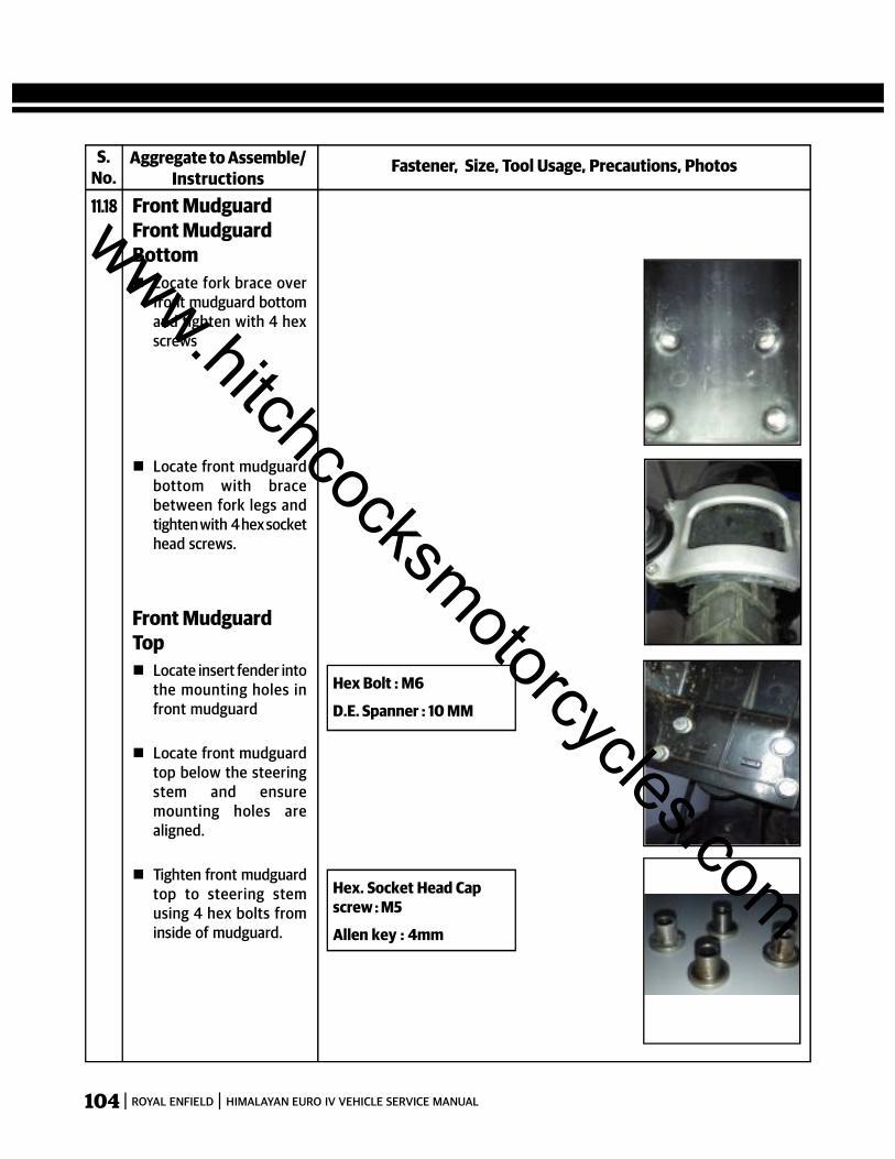
104 ROYAL ENFIELD HIMALAYAN EURO IV VEHICLE SERVICE MANUAL
Fastener, Size, Tool Usage, Precautions, PhotosAggregate to Assemble/Instructions
11.18 Front MudguardFront MudguardBottom Locate fork brace over
front mudguard bottomand tighten with 4 hexscrews
Locate front mudguardbottom with bracebetween fork legs andtighten with 4 hex sockethead screws.
S.No.
Front MudguardTop Locate insert fender into
the mounting holes infront mudguard
Locate front mudguardtop below the steeringstem and ensuremounting holes arealigned.
Tighten front mudguardtop to steering stemusing 4 hex bolts frominside of mudguard.
Hex Bolt : M6
D.E. Spanner : 10 MM
Hex. Socket Head Capscrew : M5
Allen key : 4mm
www.hitchcocksmotorcycles.com

105ROYAL ENFIELD HIMALAYAN EURO IV VEHICLE SERVICE MANUAL
Fastener, Size, Tool Usage, Precautions, PhotosAggregate to Assemble/Instructions
11.19 Front wheel
Locate the spacer placedbetween the brakepads.
Locate wheel speedsensor lugs on the hubslot carefully.
Position wheel alongwith wheel speed sensorand spacer on left sidebetween the front forklegs, ensuring the brakedisc is located betweenthe brake pads.
Insert wheel spindlefrom right fork end.
Position wheel speedsensor such that it isparallel to ground.
Hold spindle on rightside, locate washer andnut on spindle on leftside and tighten firmly.
Tighten pinch bolt onright fork end.
Rotate wheel and checkfor smooth rotation.
Press brake lever andcheck front brake forefficiency.
S.No.
www.hitchcocksmotorcycles.com

106 ROYAL ENFIELD HIMALAYAN EURO IV VEHICLE SERVICE MANUAL
Fastener, Size, Tool Usage, Precautions, PhotosAggregate to Assemble/Instructions
11.20 Top Frame LH & RHCockpit mountingbracket, instrumentcluster & Ignitionswitch Locate Ignition switch in
top yoke and tightenwith 2 Hex socket headscrews.
Connect ignition switchwiring coupler toignition switch
Position cockpitmounting bracket onframe head tube andtighten with 2 Allenscrews .
Locate instrumentcluster on cockpitmoutnig bracket
Assemble 3 washers onthe studs and tightenwith 3 cap nuts
Connect instrumentcluster wiring coupler.
S.No.
Hex Soc Hd. Cap Screw: M5Allen Key: 4mmTorque :
Hex soc. Hd. cap Screw: M8Allen key: 6mmTorque :
CAUTION:Instrument cluster mustalways be stored verticallyand away from magneticobjects to prevent damageto the compass anddisplays.
Hex cap nuts: M6Socket Spanner: 10mmTorque :
www.hitchcocksmotorcycles.com
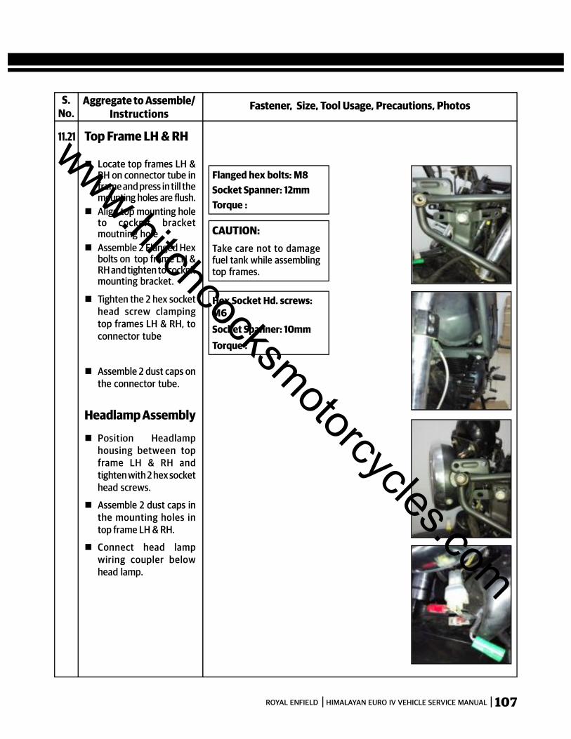
107ROYAL ENFIELD HIMALAYAN EURO IV VEHICLE SERVICE MANUAL
Fastener, Size, Tool Usage, Precautions, PhotosAggregate to Assemble/Instructions
11.21 Top Frame LH & RH
Locate top frames LH &RH on connector tube inframe and press in till themounting holes are flush.
Align top mounting holeto cockpit bracketmoutning hole
Assemble 2 Flanged Hexbolts on top frame LH &RH and tighten to cockpitmounting bracket.
S.No.
Flanged hex bolts: M8Socket Spanner: 12mmTorque :
CAUTION:Take care not to damagefuel tank while assemblingtop frames.
Hex Socket Hd. screws:M6Socket Spanner: 10mmTorque :
Tighten the 2 hex sockethead screw clampingtop frames LH & RH, toconnector tube
Assemble 2 dust caps onthe connector tube.
Headlamp Assembly
Position Headlamphousing between topframe LH & RH andtighten with 2 hex sockethead screws.
Assemble 2 dust caps inthe mounting holes intop frame LH & RH.
Connect head lampwiring coupler belowhead lamp.
www.hitchcocksmotorcycles.com
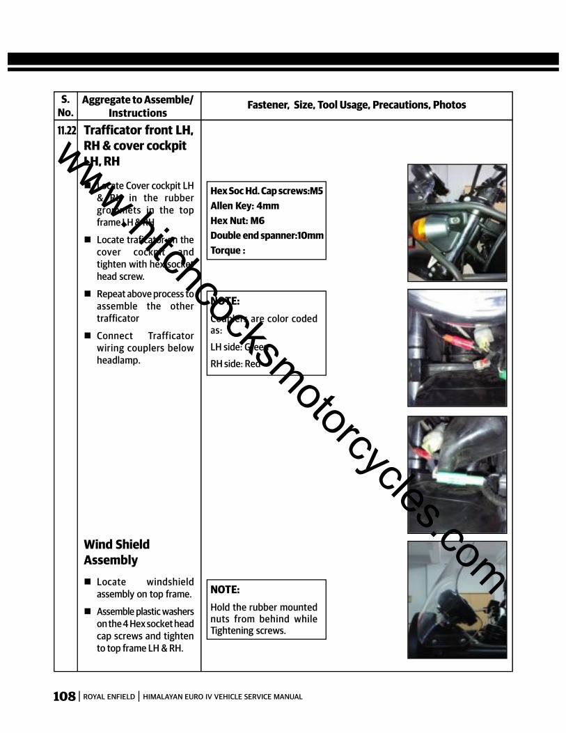
108 ROYAL ENFIELD HIMALAYAN EURO IV VEHICLE SERVICE MANUAL
Fastener, Size, Tool Usage, Precautions, PhotosAggregate to Assemble/Instructions
11.22 Trafficator front LH,RH & cover cockpitLH, RH
Locate Cover cockpit LH& RH in the rubbergrommets in the topframe LH & RH
Locate traficator on thecover cockpit andtighten with hex sockethead screw.
Repeat above process toassemble the othertrafficator
Connect Trafficatorwiring couplers belowheadlamp.
S.No.
Hex Soc Hd. Cap screws:M5Allen Key: 4mmHex Nut: M6Double end spanner:10mmTorque :
NOTE:Couplers are color codedas:
LH side: Green
RH side: Red
NOTE:Hold the rubber mountednuts from behind whileTightening screws.
Wind ShieldAssembly Locate windshield
assembly on top frame.
Assemble plastic washerson the 4 Hex socket headcap screws and tightento top frame LH & RH.
www.hitchcocksmotorcycles.com
109ROYAL ENFIELD HIMALAYAN EURO IV VEHICLE SERVICE MANUAL
SECTION 12 - REAR WHEEL, CHAIN &SPROCKET, SAREE GUARD, CHAIN GUARD,
REAR GUARDS, SHOCK ABSORBER, DRAG &DROP LINKS, SWING ARM, REAR CHAINADJUSTMENT AND WHEEL ALIGNMENT
www.hitchcocksmotorcycles.com
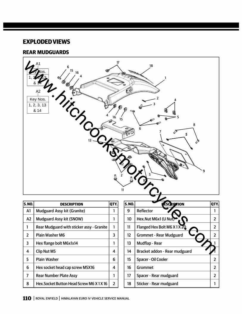
110 ROYAL ENFIELD HIMALAYAN EURO IV VEHICLE SERVICE MANUAL
EXPLODED VIEWSREAR MUDGUARDS
S. NO. DESCRIPTION QTY. S. NO. DESCRIPTION QTY.
A1 Mudguard Assy kit (Granite) 1
A2 Mudguard Assy kit (SNOW) 1
1 Rear Mudguard with sticker assy - Granite 1
2 Plain Washer M6 3
3 Hex flange bolt M6x1x14 1
4 Clip Nut M5 4
5 Plain Washer 6
6 Hex socket head cap screw M5X16 4
7 Rear Number Plate Assy 1
8 Hex.Socket Button Head Screw M6 X 1 X 16 2
9 Reflector 1
10 Hex.Nut M6x1 (U Nut) 2
11 Flanged Hex Bolt M6 X 1 X 20 2
12 Grommet - Rear Mudguard 2
13 Mudflap - Rear 1
14 Bracket addon - Rear mudguard 1
15 Spacer - Oil Cooler 2
16 Grommet 2
17 Spacer - Rear mudguard 2
18 Sticker - Rear mudguard 1
1
2
34
5
6
557
8
95
10
11
2
12
13
14
15164
41615
617
18A1
Key Nos.1, 2, 3, 13
& 14
A2
Key Nos.1, 2, 3, 13
& 14
www.hitchcocksmotorcycles.com
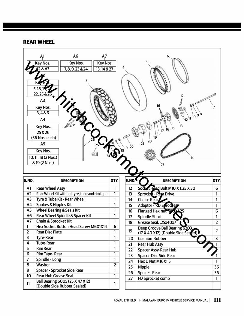
111ROYAL ENFIELD HIMALAYAN EURO IV VEHICLE SERVICE MANUAL
REAR WHEEL
3
45
6
2
1
2526
14
27
16
12
7
89101112
131517
1819
2021
16
22191823824
A1Key Nos.A2 & A3
A2Key Nos.
5, 18, 19, 21,22, 25 & 26
A3Key Nos.3, 4 & 6
A4Key Nos.25 & 26
(36 Nos. each)A5
Key Nos.10, 11, 18 (2 Nos.)
& 19 (2 Nos.)
A6Key Nos.
7, 8, 9, 23 & 24
A7Key Nos.
13, 14 & 27
S. NO. DESCRIPTION QTY. S. NO. DESCRIPTION QTY.
A1 Rear Wheel Assy 1A2 Rear Wheel Kit without tyre, tube and rim tape 1A3 Tyre & Tube Kit - Rear Wheel 1A4 Spokes & Nipples Kit 1A5 Wheel Bearing & Seals Kit 1A6 Rear Wheel Spindle & Spacer Kit 1A7 Chain & Sprocket Kit 11 Hex Socket Button Head Screw M6X1X14 62 Rear Disc Plate 13 Tyre-Rear 14 Tube-Rear 15 Rim Rear 16 Rim Tape- Rear 17 Spindle - Long 18 Washer 29 Spacer - Sprocket Side Rear 110 Rear Hub Grease Seal 1
11 Ball Bearing 6005 (25 X 47 X12)[Double Side Rubber Sealed] 1
12 Socket Head Bolt M10 X 1.25 X 30 613 Sprocket - Rear Drive 114 Chain- Rear 115 Adaptor - RD Sprocket 116 Flanged Hex nut M10X1.25 617 Spindle Short 118 Grease Seal, ,25x40x7 2
19Deep Groove Ball Bearing 6203(17 X 40 X12) [Double Side Sealed] 2
20 Cushion Rubber 321 Rear Hub Assy 122 Spacer Assy-Rear Hub 123 Spacer-Disc Side Rear 124 Hex U Nut M16X1.5 125 Nipple 3626 Spokes Rear 3627 FD Sprocket comp 1
www.hitchcocksmotorcycles.com
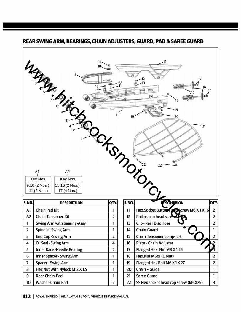
112 ROYAL ENFIELD HIMALAYAN EURO IV VEHICLE SERVICE MANUAL
REAR SWING ARM, BEARINGS, CHAIN ADJUSTERS, GUARD, PAD & SAREE GUARD
S. NO. DESCRIPTION QTY. S. NO. DESCRIPTION QTY.
A1 Chain Pad Kit 1A2 Chain Tensioner Kit 21 Swing Arm with bearing-Assy 12 Spindle - Swing Arm 13 End Cup -Swing Arm 24 Oil Seal - Swing Arm 45 Inner Race -Needle Bearing 26 Inner Spacer - Swing Arm 17 Spacer - Swing Arm 18 Hex Nut With Nylock M12 X 1.5 19 Rear Chain-Pad 110 Washer-Chain Pad 2
11 Hex.Socket Button Head Screw M6 X 1 X 16 212 Philips pan head screw M6X6 213 Clip - Rear Disc Hose 214 Chain Guard 115 Chain Tensioner comp- LH 216 Plate - Chain Adjuster 217 Flanged Hex. Nut M8 X 1.25 418 Hex.Nut M6x1 (U Nut) 219 Flanged Hex Bolt M6 X 1 X 27 220 Chain – Guide 121 Saree Guard 122 SS Hex socket head cap screw (M6X25) 3
A1
Key Nos.9,10 (2 Nos.),
11 (2 Nos.)
A2
Key Nos.15,16 (2 Nos.),
17 (4 Nos.)
1110
14
121310
111312
9
1 19
19
20
18
21
1516
17
17
2222
2
34
5
4
6
4
54
37
8
www.hitchcocksmotorcycles.com

113ROYAL ENFIELD HIMALAYAN EURO IV VEHICLE SERVICE MANUAL
REAR SUSPENSION
S. NO. DESCRIPTION QTY. S. NO. DESCRIPTION QTY.
A1 Link Assy Kit 1
1 Mono Shock 1
2 Flange U Nut M10 X 1.25 6
3 Flanged Hex. Bolt M10 X 1.25 X 52 2
4 Inner Race- Drag Link Back 1
5 Inner Race- Drag Link Front 1
6 Flanged Hex. Bolt M10 X 1.25 X 66 1
7 Drag link Assy with bearing 1
8 Dust Seal Linkage 8
9 Flanged Hex. Bolt M10X1.25 X 132 1
10 Drop link Assy with bearing 2
11 Flanged Hex. Bolt M10X1.25 X 47 2
12 Inner Race- Drop Link 2
13 Swing Arm with bearing-Assy 1
13
118
128
2
8
128
11
9
2
10
8
6
7
3
3
2
1
2
4 5
A1Key Nos.
7, 8 (8 Nos.),10 (2 Nos.),
4, 5 &12 (2 nos.)
www.hitchcocksmotorcycles.com

114 ROYAL ENFIELD HIMALAYAN EURO IV VEHICLE SERVICE MANUAL
S.No.
Fastener, Size, Tool Usage, Precautions, PhotosAggregate to Dismantle/Instructions
12.1 Rear Wheel Chain &Sprocket
Ensure the motorcycle ison a firm, flat surface andthe rear wheel is off theground.
Gently remove the brakehose along with itsrubber grommets fromthe locating clips on theswing arm.
Loosen rear axle nut onthe right side andremove along withwasher.
Pull out the wheel axlefrom the left side, takingcare not to drop thewheel spacers.
Remove the brakecaliper assembly fromthe slot in the swing armand support it suitably,to avoid damage to thebrake hose.
Slide out the rear wheelfrom the swing arm,taking care not to dropthe spacers on the wheelhub.
CAUTION:Do not press the brakepedal when wheel isremoved as this will result inthe brake pads coming outtoo far from the brakecaliper.
* Place a suitable spacer of 4mm thickness, between thebrake pads to avoid padscompression in the eventthe brake pedal is pressedaccidentally.
www.hitchcocksmotorcycles.com

115ROYAL ENFIELD HIMALAYAN EURO IV VEHICLE SERVICE MANUAL
S.No.
Fastener, Size, Tool Usage, Precautions, PhotosAggregate to Dismantle/Instructions
12.2 Saree & Chainguards Remove 2 hex socket
head cap screws at thetop and 1 hex sockethead cap screw at thebottom of saree guard.
Remove saree guard andchain guard from swingarm.
Hex soc hd. cap screws: M6
Allen Key: 5mm
Hex Bolt: M6
Socket spanner:10mm
12.3 Piece mudguard
Remove 4 Hex bolts (2 atthe top & 2 at the bottom)
Remove piece mudguard
www.hitchcocksmotorcycles.com
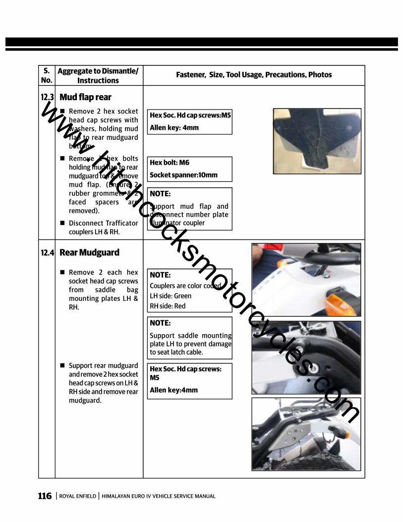
116 ROYAL ENFIELD HIMALAYAN EURO IV VEHICLE SERVICE MANUAL
S.No.
Fastener, Size, Tool Usage, Precautions, PhotosAggregate to Dismantle/Instructions
12.4 Rear Mudguard
Remove 2 each hexsocket head cap screwsfrom saddle bagmounting plates LH &RH.
Support rear mudguardand remove 2 hex sockethead cap screws on LH &RH side and remove rearmudguard.
NOTE:Couplers are color coded :LH side: GreenRH side: Red
NOTE:Support saddle mountingplate LH to prevent damageto seat latch cable.
Hex Soc. Hd cap screws:M5
Allen key:4mm
Hex Soc. Hd cap screws:M5
Allen key: 4mm
12.3 Mud flap rear Remove 2 hex socket
head cap screws withwashers, holding mudflap to rear mudguardbottom.
Remove 2 hex boltsholding mud flap to rearmudguard top & removemud flap. (Ensure 2rubber grommets & 2faced spacers areremoved).
Disconnect Trafficatorcouplers LH & RH.
Hex bolt: M6
Socket spanner:10mm
NOTE:Support mud flap anddisconnect number plateilluminator coupler
www.hitchcocksmotorcycles.com
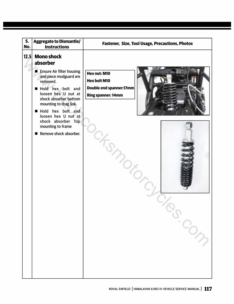
117ROYAL ENFIELD HIMALAYAN EURO IV VEHICLE SERVICE MANUAL
S.No.
Fastener, Size, Tool Usage, Precautions, PhotosAggregate to Dismantle/Instructions
12.5 Mono shockabsorber Ensure Air filter housing
and piece mudguard areremoved.
Hold hex bolt andloosen hex U nut atshock absorber bottommounting to drag link.
Hold hex bolt andloosen hex U nut atshock absorber Topmounting to frame
Remove shock absorber.
Hex nut: M10
Hex bolt M10
Double end spanner:17mm
Ring spanner: 14mm
www.hitchcocksmotorcycles.com
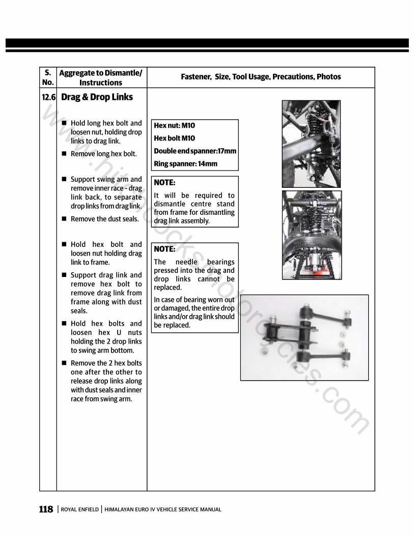
118 ROYAL ENFIELD HIMALAYAN EURO IV VEHICLE SERVICE MANUAL
S.No.
Fastener, Size, Tool Usage, Precautions, PhotosAggregate to Dismantle/Instructions
12.6 Drag & Drop Links
Hold long hex bolt andloosen nut, holding droplinks to drag link.
Remove long hex bolt.
Support swing arm andremove inner race – draglink back, to separatedrop links from drag link.
Remove the dust seals.
Hold hex bolt andloosen nut holding draglink to frame.
Support drag link andremove hex bolt toremove drag link fromframe along with dustseals.
Hold hex bolts andloosen hex U nutsholding the 2 drop linksto swing arm bottom.
Remove the 2 hex boltsone after the other torelease drop links alongwith dust seals and innerrace from swing arm.
Hex nut: M10
Hex bolt M10
Double end spanner:17mm
Ring spanner: 14mm
NOTE:It will be required todismantle centre standfrom frame for dismantlingdrag link assembly.
NOTE:The needle bearingspressed into the drag anddrop links cannot bereplaced.
In case of bearing worn outor damaged, the entire droplinks and/or drag link shouldbe replaced.
www.hitchcocksmotorcycles.com
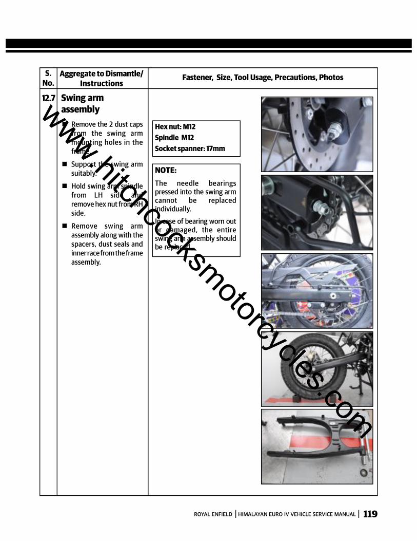
119ROYAL ENFIELD HIMALAYAN EURO IV VEHICLE SERVICE MANUAL
S.No.
Fastener, Size, Tool Usage, Precautions, PhotosAggregate to Dismantle/Instructions
12.7 Swing armassembly Remove the 2 dust caps
from the swing armmounting holes in theframe.
Support the swing armsuitably.
Hold swing arm spindlefrom LH side andremove hex nut from RHside.
Remove swing armassembly along with thespacers, dust seals andinner race from the frameassembly.
Hex nut: M12Spindle M12Socket spanner: 17mm
NOTE:The needle bearingspressed into the swing armcannot be replacedindividually.
In case of bearing worn outor damaged, the entireswing arm assembly shouldbe replaced.
www.hitchcocksmotorcycles.com
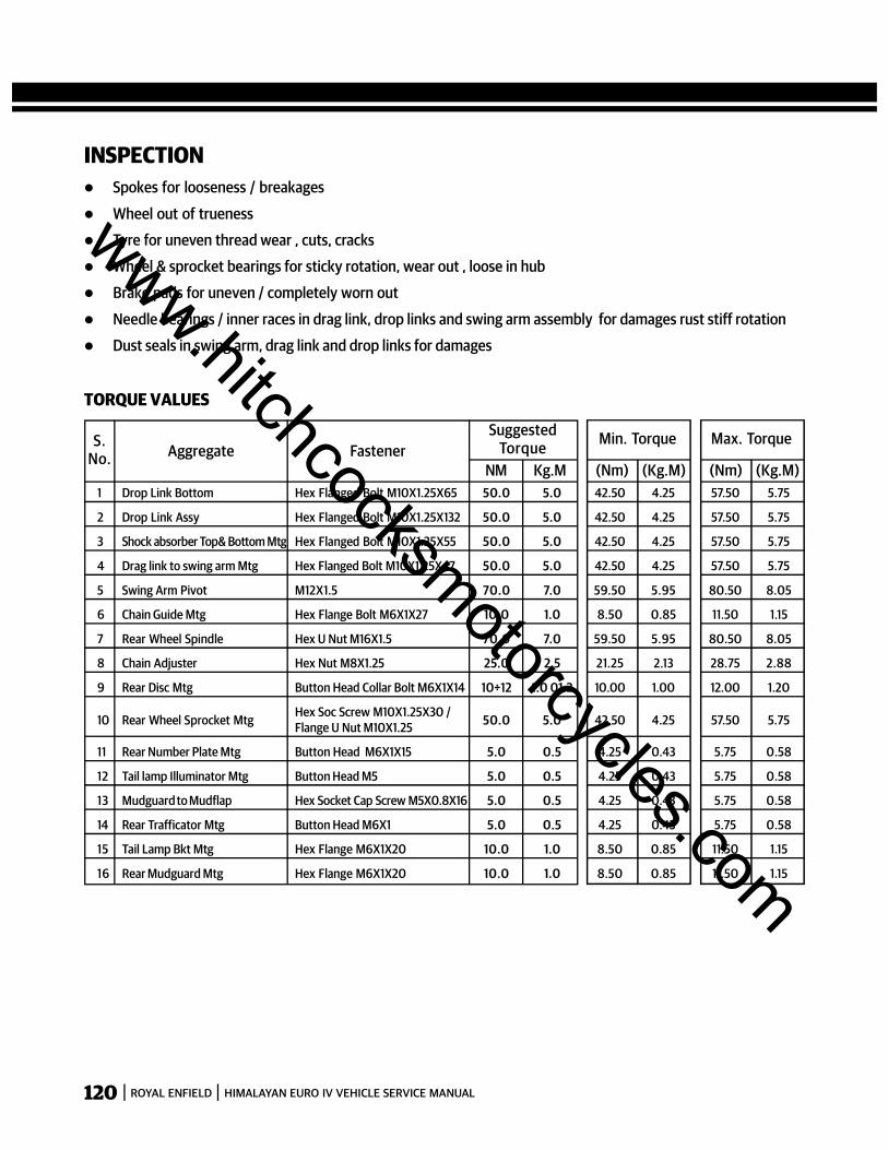
120 ROYAL ENFIELD HIMALAYAN EURO IV VEHICLE SERVICE MANUAL
INSPECTION Spokes for looseness / breakages
Wheel out of trueness
Tyre for uneven thread wear , cuts, cracks
Wheel & sprocket bearings for sticky rotation, wear out , loose in hub
Brake pads for uneven / completely worn out
Needle bearings / inner races in drag link, drop links and swing arm assembly for damages rust stiff rotation
Dust seals in swing arm, drag link and drop links for damages
TORQUE VALUES
S.No. Aggregate Fastener
SuggestedTorque
NM Kg.M1 Drop Link Bottom Hex Flanged Bolt M10X1.25X65 50.0 5.0 42.50 4.25 57.50 5.75
2 Drop Link Assy Hex Flanged Bolt M10X1.25X132 50.0 5.0 42.50 4.25 57.50 5.75
3 Shock absorber Top& Bottom Mtg Hex Flanged Bolt M10X1.25X55 50.0 5.0 42.50 4.25 57.50 5.75
4 Drag link to swing arm Mtg Hex Flanged Bolt M10X1.25X47 50.0 5.0 42.50 4.25 57.50 5.75
5 Swing Arm Pivot M12X1.5 70.0 7.0 59.50 5.95 80.50 8.05
6 Chain Guide Mtg Hex Flange Bolt M6X1X27 10.0 1.0 8.50 0.85 11.50 1.15
7 Rear Wheel Spindle Hex U Nut M16X1.5 70.0 7.0 59.50 5.95 80.50 8.05
8 Chain Adjuster Hex Nut M8X1.25 25.0 2.5 21.25 2.13 28.75 2.88
9 Rear Disc Mtg Button Head Collar Bolt M6X1X14 10÷12 1.0 01.2 10.00 1.00 12.00 1.20
10 Rear Wheel Sprocket Mtg Hex Soc Screw M10X1.25X30 / 50.0 5.0 42.50 4.25 57.50 5.75Flange U Nut M10X1.25
11 Rear Number Plate Mtg Button Head M6X1X15 5.0 0.5 4.25 0.43 5.75 0.58
12 Tail lamp Illuminator Mtg Button Head M5 5.0 0.5 4.25 0.43 5.75 0.58
13 Mudguard to Mudflap Hex Socket Cap Screw M5X0.8X16 5.0 0.5 4.25 0.43 5.75 0.58
14 Rear Trafficator Mtg Button Head M6X1 5.0 0.5 4.25 0.43 5.75 0.58
15 Tail Lamp Bkt Mtg Hex Flange M6X1X20 10.0 1.0 8.50 0.85 11.50 1.15
16 Rear Mudguard Mtg Hex Flange M6X1X20 10.0 1.0 8.50 0.85 11.50 1.15
Min. Torque
(Nm) (Kg.M)
Max. Torque
(Nm) (Kg.M)
www.hitchcocksmotorcycles.com

121ROYAL ENFIELD HIMALAYAN EURO IV VEHICLE SERVICE MANUAL
Fastener, Size, Tool Usage, Precautions, PhotosAggregate to Assemble/Instructions
12.8 Swing arm
Ensure rear chain pad isassembled on the swingarm RH side
Locate the 2 inner racesinside the needlebearing in the swing arm
Locate new dust seals inthe swing arm on eithersides of the inner raceson the swing arm.
Position the swing armcorrectly between theframe and locate newend cups on either sideof the swing arm outerand frame inner.
Locate inner spacerbetween the swing armeyelets in the centre.
Ensure all mountingholes of the swing armspacers, swing arm,inner spacer are alignedand insert spindle fullyinto frame from the LHside.
Assemble spacer washerand hex nylock nut onthe spindle RH side andtighten to torque.
Ensure free and smoothup and down movementof swing arm.
NOTE:Ensure the needle bearingand inner races are greasedwell before assembly.
S.No.
Hex nut: M12
Spindle: M12
Socket spanner: 17mm
Torque: 70Nm(7 KgM)
www.hitchcocksmotorcycles.com

122 ROYAL ENFIELD HIMALAYAN EURO IV VEHICLE SERVICE MANUAL
Fastener, Size, Tool Usage, Precautions, PhotosAggregate to Assemble/Instructions
12.9 Drag & Drop Links
Locate larger end ofdrop link with inner raceand dust seal in place inswing arm and assemblehex bolt.
Assemble flange U nutand tighten to torque
Repeat above process toassemble second droplink in swing arm.
Ensure free movementof both drop links.
Ensure the drag link ispositioned such that thelonger side is facingtowards the mountinghole in frame.
Position drop links withdust seals on either sideof the drag link, ensurethe holes are aligned andinsert inner race - draglink back, through thedrop link till it is flush oneither sides of the droplinks.
Assemble long hex boltand hex nut. DO NO TTIGHTEN
Support swing arm andposition drag link withinner race – drag linkfront and dust seals inthe mounting bracket inframe, ensure holes arealigned and insert hexbolt to lock drag link toframe.
Assemble hex nut onbolt.
Tighten all fasteners ofdrag and drop links totorque.
Ensure free movementof swing arm, drag anddrop links.
NOTE:Ensure the needle bearingsand inner races are greasedwell before assembly.
S.No.
Hex nut: M10
Hex bolt M10
socket spanner:17mm
Ring spanner: 14mm
Torque: 50Nm(5 KgM)
Hex nut: M10Hex bolt M10socket spanner:17mmRing spanner: 14mmTorque: 50Nm(5 KgM)
www.hitchcocksmotorcycles.com
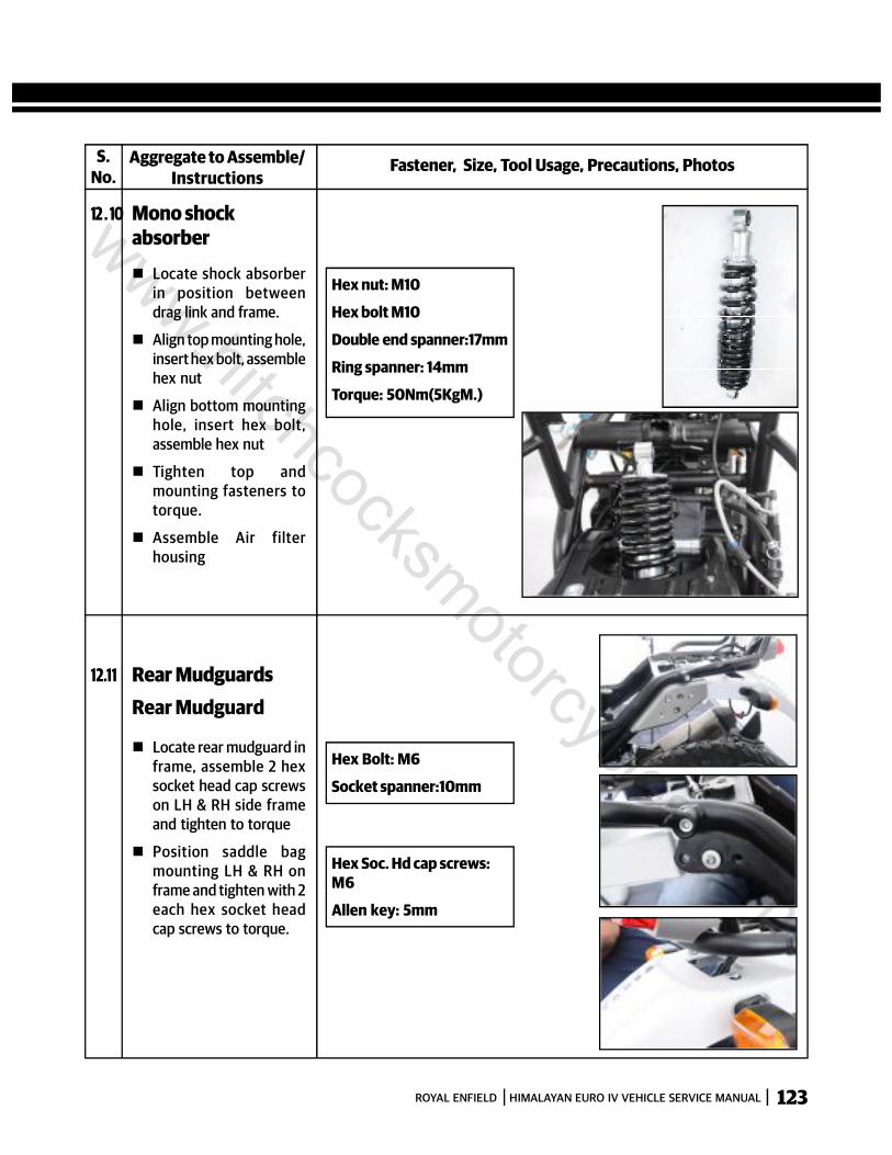
123ROYAL ENFIELD HIMALAYAN EURO IV VEHICLE SERVICE MANUAL
Fastener, Size, Tool Usage, Precautions, PhotosAggregate to Assemble/Instructions
12 . 10 Mono shockabsorber
Locate shock absorberin position betweendrag link and frame.
Align top mounting hole,insert hex bolt, assemblehex nut
Align bottom mountinghole, insert hex bolt,assemble hex nut
Tighten top andmounting fasteners totorque.
Assemble Air filterhousing
S.No.
Hex nut: M10
Hex bolt M10
Double end spanner:17mm
Ring spanner: 14mm
Torque: 50Nm(5KgM.)
12.11 Rear MudguardsRear Mudguard
Locate rear mudguard inframe, assemble 2 hexsocket head cap screwson LH & RH side frameand tighten to torque
Position saddle bagmounting LH & RH onframe and tighten with 2each hex socket headcap screws to torque.
Hex Bolt: M6
Socket spanner:10mm
Hex Soc. Hd cap screws:M6
Allen key: 5mm
www.hitchcocksmotorcycles.com
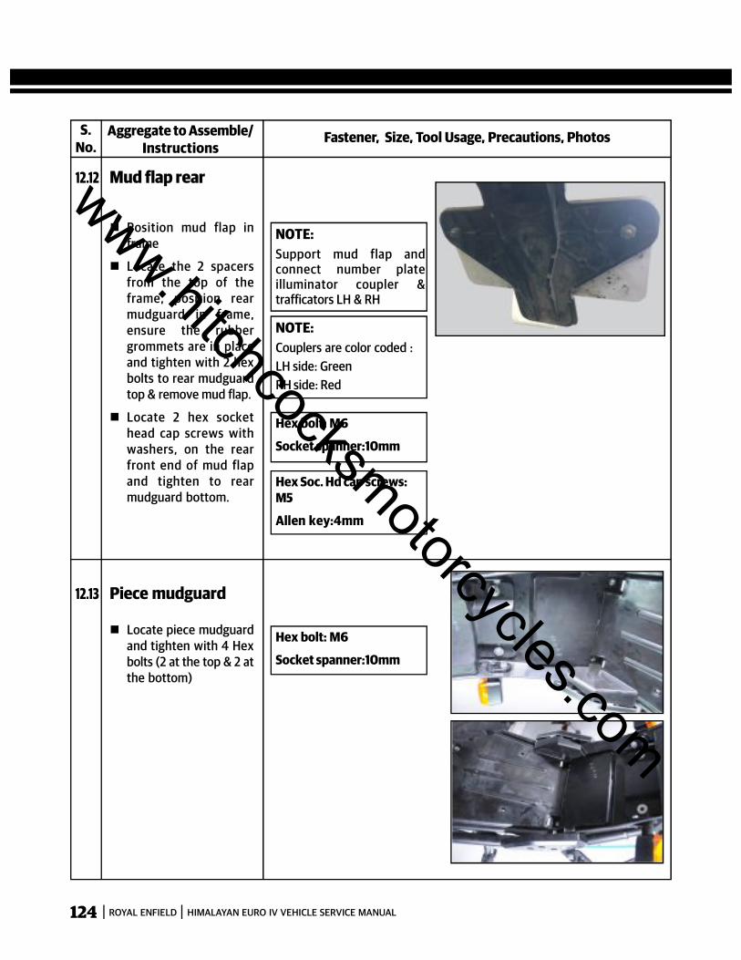
124 ROYAL ENFIELD HIMALAYAN EURO IV VEHICLE SERVICE MANUAL
Fastener, Size, Tool Usage, Precautions, PhotosAggregate to Assemble/Instructions
12.12 Mud flap rear
Position mud flap inframe
Locate the 2 spacersfrom the top of theframe, position rearmudguard in frame,ensure the rubbergrommets are in placeand tighten with 2 hexbolts to rear mudguardtop & remove mud flap.
Locate 2 hex sockethead cap screws withwashers, on the rearfront end of mud flapand tighten to rearmudguard bottom.
S.No.
NOTE:Support mud flap andconnect number plateilluminator coupler &trafficators LH & RH
NOTE:Couplers are color coded :LH side: GreenRH side: Red
Hex bolt: M6
Socket spanner:10mm
Hex Soc. Hd cap screws:M5
Allen key:4mm
12.13 Piece mudguard
Locate piece mudguardand tighten with 4 Hexbolts (2 at the top & 2 atthe bottom)
Hex bolt: M6
Socket spanner:10mm
www.hitchcocksmotorcycles.com
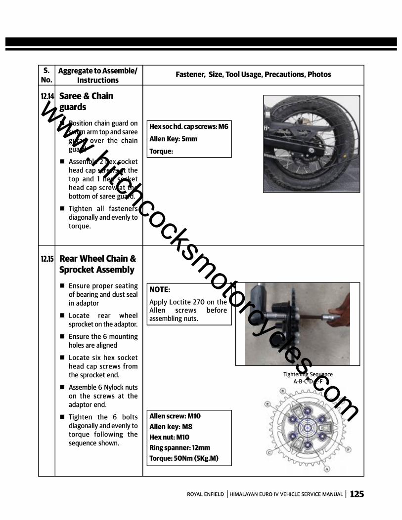
125ROYAL ENFIELD HIMALAYAN EURO IV VEHICLE SERVICE MANUAL
Fastener, Size, Tool Usage, Precautions, PhotosAggregate to Assemble/Instructions
12.14 Saree & Chainguards
Position chain guard onswign arm top and sareegurad over the chainguard
Assemble 2 hex sockethead cap screws at thetop and 1 hex sockethead cap screw at thebottom of saree guard.
Tighten all fastenersdiagonally and evenly totorque.
S.No.
Hex soc hd. cap screws: M6
Allen Key: 5mm
Torque:
12.15 Rear Wheel Chain &Sprocket Assembly
Ensure proper seatingof bearing and dust sealin adaptor
Locate rear wheelsprocket on the adaptor.
Ensure the 6 mountingholes are aligned
Locate six hex sockethead cap screws fromthe sprocket end.
Assemble 6 Nylock nutson the screws at theadaptor end.
Tighten the 6 boltsdiagonally and evenly totorque following thesequence shown.
NOTE:Apply Loctite 270 on theAllen screws beforeassembling nuts.
Allen screw: M10Allen key: M8Hex nut: M10Ring spanner: 12mmTorque: 50Nm (5Kg.M)
Tightening SequenceA-B-C-D-E-F
www.hitchcocksmotorcycles.com
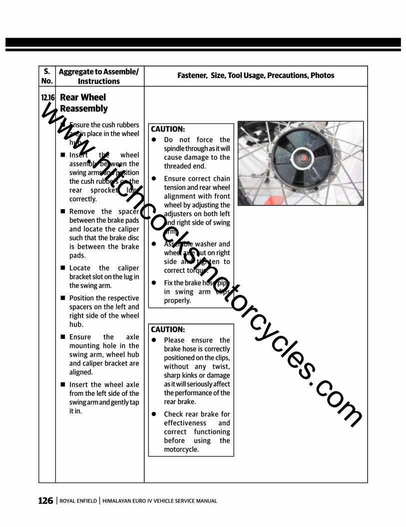
126 ROYAL ENFIELD HIMALAYAN EURO IV VEHICLE SERVICE MANUAL
Fastener, Size, Tool Usage, Precautions, PhotosAggregate to Assemble/Instructions
12.16 Rear WheelReassembly
Ensure the cush rubbersare in place in the wheelhub.
Insert the wheelassembly between theswing arms and positionthe cush rubbers on therear sprocket lugscorrectly.
Remove the spacerbetween the brake padsand locate the calipersuch that the brake discis between the brakepads.
Locate the caliperbracket slot on the lug inthe swing arm.
Position the respectivespacers on the left andright side of the wheelhub.
Ensure the axlemounting hole in theswing arm, wheel huband caliper bracket arealigned.
Insert the wheel axlefrom the left side of theswing arm and gently tapit in.
S.No.
CAUTION: Do not force the
spindle through as it willcause damage to thethreaded end.
Ensure correct chaintension and rear wheelalignment with frontwheel by adjusting theadjusters on both leftand right side of swingarm.
Assemble washer andwheel axle nut on rightside and tighten tocorrect torque.
Fix the brake hose pipein swing arm clipsproperly.
CAUTION: Please ensure the
brake hose is correctlypositioned on the clips,without any twist,sharp kinks or damageas it will seriously affectthe performance of therear brake.
Check rear brake foreffectiveness andcorrect functioningbefore using themotorcycle.
www.hitchcocksmotorcycles.com
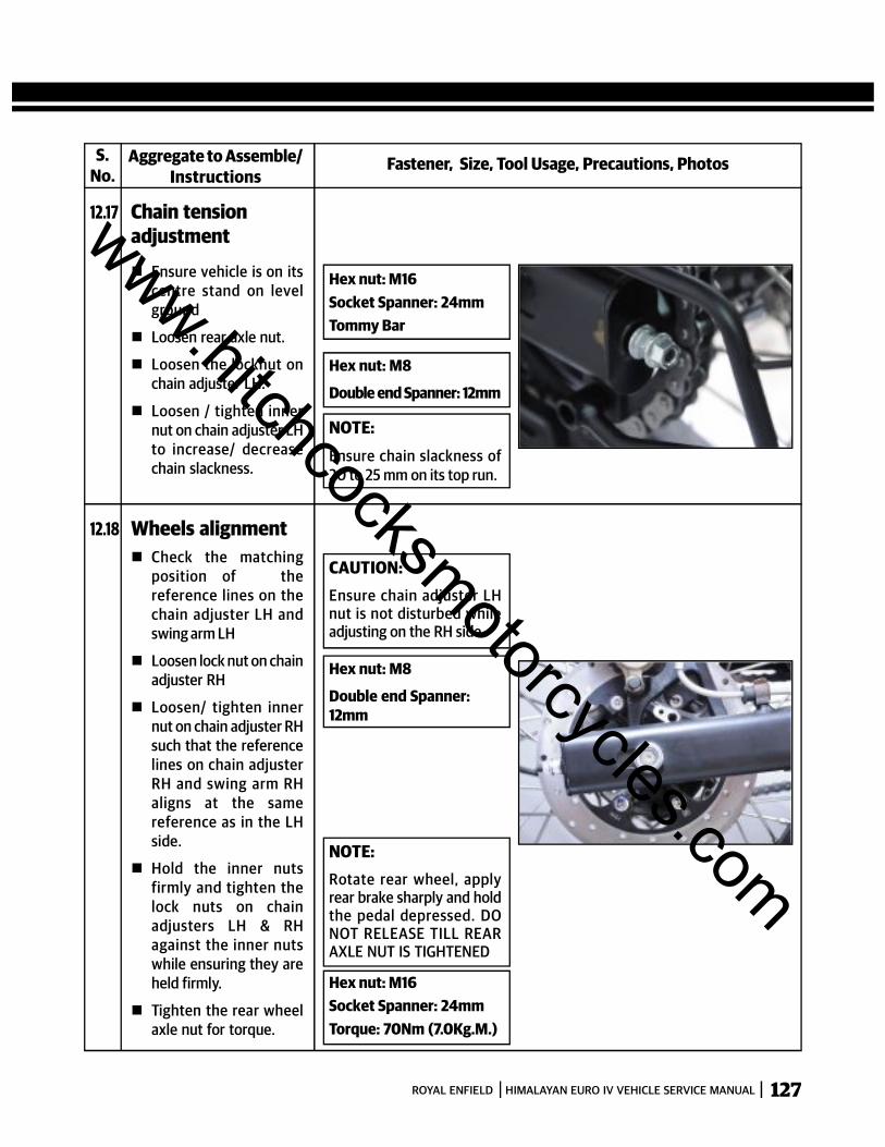
127ROYAL ENFIELD HIMALAYAN EURO IV VEHICLE SERVICE MANUAL
Fastener, Size, Tool Usage, Precautions, PhotosAggregate to Assemble/Instructions
12.17 Chain tensionadjustment
Ensure vehicle is on itscentre stand on levelground
Loosen rear axle nut.
Loosen the locknut onchain adjuster LH.
Loosen / tighten innernut on chain adjuster LHto increase/ decreasechain slackness.
S.No.
Hex nut: M16Socket Spanner: 24mmTommy Bar
Hex nut: M8
Double end Spanner: 12mm
NOTE:Ensure chain slackness of20 to 25 mm on its top run.
12.18 Wheels alignment Check the matching
position of thereference lines on thechain adjuster LH andswing arm LH
Loosen lock nut on chainadjuster RH
Loosen/ tighten innernut on chain adjuster RHsuch that the referencelines on chain adjusterRH and swing arm RHaligns at the samereference as in the LHside.
Hold the inner nutsfirmly and tighten thelock nuts on chainadjusters LH & RHagainst the inner nutswhile ensuring they areheld firmly.
Tighten the rear wheelaxle nut for torque.
CAUTION:Ensure chain adjuster LHnut is not disturbed whileadjusting on the RH side.
Hex nut: M8
Double end Spanner:12mm
NOTE:Rotate rear wheel, applyrear brake sharply and holdthe pedal depressed. DONOT RELEASE TILL REARAXLE NUT IS TIGHTENED
Hex nut: M16Socket Spanner: 24mmTorque: 70Nm (7.0Kg.M.)
www.hitchcocksmotorcycles.com
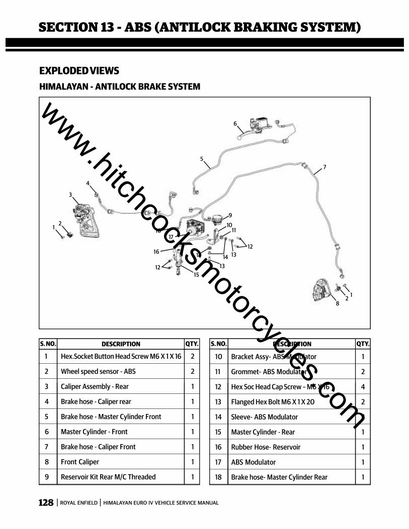
128 ROYAL ENFIELD HIMALAYAN EURO IV VEHICLE SERVICE MANUAL
SECTION 13 - ABS (ANTILOCK BRAKING SYSTEM)
1 Hex.Socket Button Head Screw M6 X 1 X 16 2
2 Wheel speed sensor - ABS 2
3 Caliper Assembly - Rear 1
4 Brake hose - Caliper rear 1
5 Brake hose - Master Cylinder Front 1
6 Master Cylinder - Front 1
7 Brake hose - Caliper Front 1
8 Front Caliper 1
9 Reservoir Kit Rear M/C Threaded 1
EXPLODED VIEWSHIMALAYAN - ANTILOCK BRAKE SYSTEM
10 Bracket Assy- ABS Modulator 1
11 Grommet- ABS Modulator 2
12 Hex Soc Head Cap Screw – M6 X 16 4
13 Flanged Hex Bolt M6 X 1 X 20 2
14 Sleeve- ABS Modulator 2
15 Master Cylinder - Rear 1
16 Rubber Hose- Reservoir 1
17 ABS Modulator 1
18 Brake hose- Master Cylinder Rear 1
1 2
3
4
5
6
7
128
9
1011
1213
131411
1215
16
1718
S. NO. DESCRIPTION QTY. S. NO. DESCRIPTION QTY.
www.hitchcocksmotorcycles.com
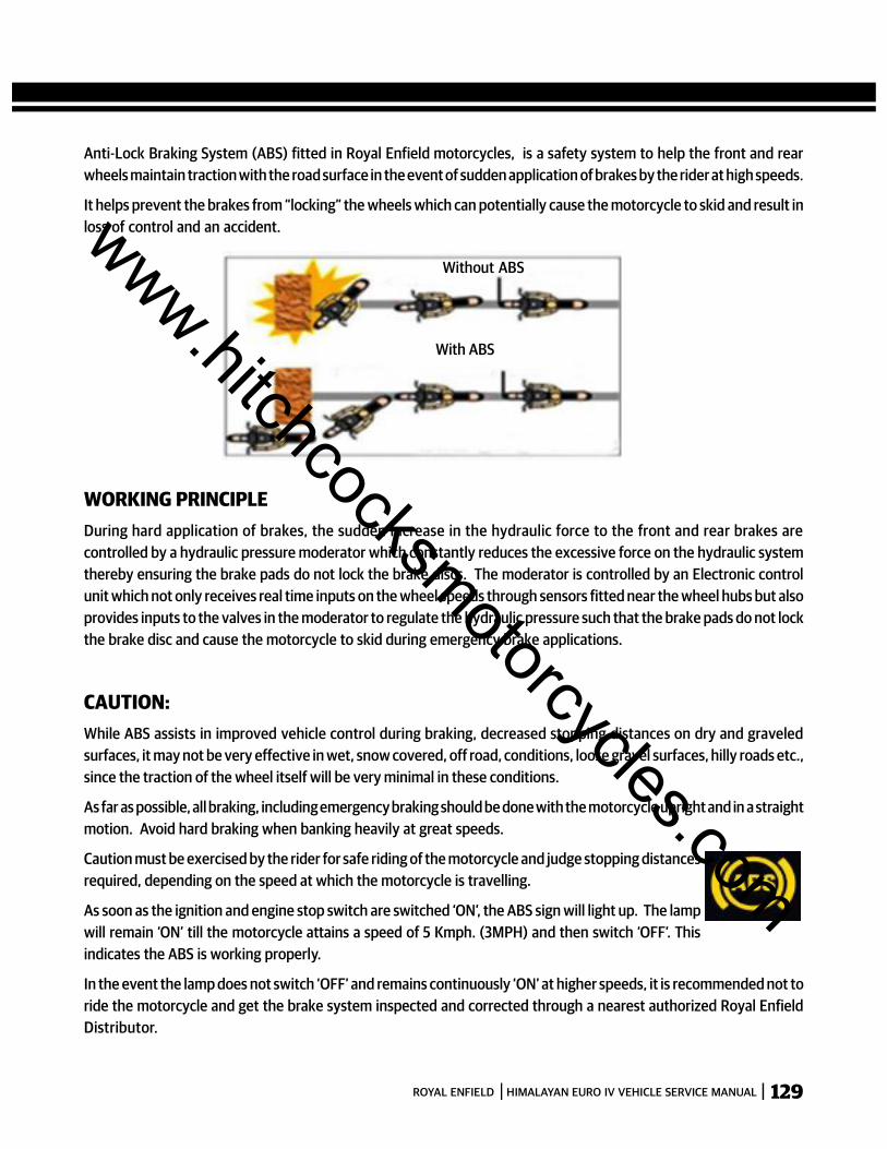
129ROYAL ENFIELD HIMALAYAN EURO IV VEHICLE SERVICE MANUAL
Anti-Lock Braking System (ABS) fitted in Royal Enfield motorcycles, is a safety system to help the front and rearwheels maintain traction with the road surface in the event of sudden application of brakes by the rider at high speeds.
It helps prevent the brakes from “locking” the wheels which can potentially cause the motorcycle to skid and result inloss of control and an accident.
WORKING PRINCIPLEDuring hard application of brakes, the sudden increase in the hydraulic force to the front and rear brakes arecontrolled by a hydraulic pressure moderator which constantly reduces the excessive force on the hydraulic systemthereby ensuring the brake pads do not lock the brake discs. The moderator is controlled by an Electronic controlunit which not only receives real time inputs on the wheel speeds through sensors fitted near the wheel hubs but alsoprovides inputs to the valves in the moderator to regulate the hydraulic pressure such that the brake pads do not lockthe brake disc and cause the motorcycle to skid during emergency brake applications.
CAUTION:While ABS assists in improved vehicle control during braking, decreased stopping distances on dry and graveledsurfaces, it may not be very effective in wet, snow covered, off road, conditions, loose gravel surfaces, hilly roads etc.,since the traction of the wheel itself will be very minimal in these conditions.
As far as possible, all braking, including emergency braking should be done with the motorcycle upright and in a straightmotion. Avoid hard braking when banking heavily at great speeds.
Caution must be exercised by the rider for safe riding of the motorcycle and judge stopping distancesrequired, depending on the speed at which the motorcycle is travelling.
As soon as the ignition and engine stop switch are switched ‘ON’, the ABS sign will light up. The lampwill remain ‘ON’ till the motorcycle attains a speed of 5 Kmph. (3MPH) and then switch ‘OFF’. Thisindicates the ABS is working properly.
In the event the lamp does not switch ‘OFF’ and remains continuously ‘ON’ at higher speeds, it is recommended not toride the motorcycle and get the brake system inspected and corrected through a nearest authorized Royal EnfieldDistributor.
Without ABS
With ABS
www.hitchcocksmotorcycles.com

130 ROYAL ENFIELD HIMALAYAN EURO IV VEHICLE SERVICE MANUAL
3. ABS ECU
Located adjacent to Modulator
4. FRONT BRAKE MASTER CYLINDER.
Located on Handle bar RH side
8.1 LOCATION OF THE ABS SYSTEM PARTS
Located inside the Instrument Cluster.
Located inside panel RH.
1. ABS INDICATOR
2. MODULATOR
ABS
www.hitchcocksmotorcycles.com
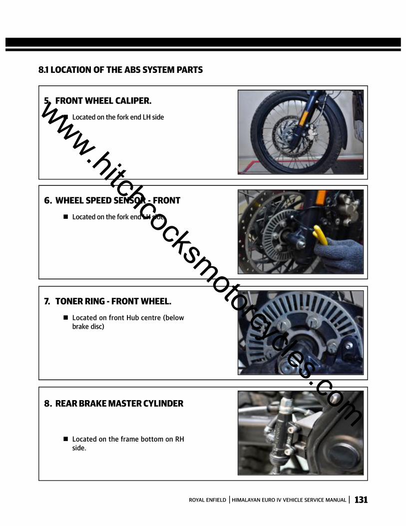
131ROYAL ENFIELD HIMALAYAN EURO IV VEHICLE SERVICE MANUAL
8.1 LOCATION OF THE ABS SYSTEM PARTS
5. FRONT WHEEL CALIPER.
Located on the fork end LH side
6. WHEEL SPEED SENSOR - FRONT
Located on the fork end LH side
7. TONER RING - FRONT WHEEL.
Located on front Hub centre (belowbrake disc)
8. REAR BRAKE MASTER CYLINDER
Located on the frame bottom on RHside.
www.hitchcocksmotorcycles.com

132 ROYAL ENFIELD HIMALAYAN EURO IV VEHICLE SERVICE MANUAL
10. REAR WHEEL CALIPER
Located on swing arm RH side
11. WHEEL SPEED SENSOR - REAR
Located on the rear caliper assemblymounting bracket
12. TONER RING – REAR WHEEL
Located on Rear wheel right side.
9. REAR HYDRAULIC FLUID RESERVOIR
Located on Frame RH Side.
8.1 LOCATION OF THE ABS SYSTEM PARTS
www.hitchcocksmotorcycles.com
133ROYAL ENFIELD HIMALAYAN EURO IV VEHICLE SERVICE MANUAL
CAUTION :DO NOT REMOVE OR DISMANTLE ANY PART OF THE ABS SYSTEM - BRAKE HOSE CONNECTIONS, MODULATOR, ECUETC AS IS WILL NOT ONLY AFFECT THE BRAKING EFFICIENCY SEVERELY BUT WILL ALSO DEACTIVATE THEMODULATOR AND THE ECU
DO NOT ATTEMPT TO REMOVE THE ECU OR THE ELECTRICAL CONNECTIONS FROM THE MODULATOR AS IT WILLERASE THE MEMORY AND THE PROGRAMME.
IF FOR ANY REASON THE BRAKE HOSES OR THE MODULATOR HAS TO BE SERVICED, THEN THE ENTIRE HYDRAULICFLUID SYSTEM BLEEDING HAS TO BE CARRIED OUT AND THE ECU HAS TO BE REPROGRAMMED.
www.hitchcocksmotorcycles.com

134 ROYAL ENFIELD HIMALAYAN EURO IV VEHICLE SERVICE MANUAL
S.No.
Fastener, Size, Tool Usage, Precautions, PhotosAggregate to Dismantle /Instructions
Loosen and remove the4 banjo bolts holding 4brake hoses to themodulator.
13.2 ABS Modulator &ECU
Ensure Ignition switchand engine stop switch isin OFF position.
Drain out hydraulicbrake fluid from thefront and rear reservoirsand brake calipers byloosening the bleedingscrews in the front andrear calipers and gentlypumping the brakes.
Remove the side panelRH by loosening 2 Sockethead cap screws on thesides.
CAUTION:Brake fluid is extremelycorrosive and hence pleasetake care not to spill on anypart of the motorcycle
Head cap Screw : M6
Allen Key : 5 mm
www.hitchcocksmotorcycles.com

135ROYAL ENFIELD HIMALAYAN EURO IV VEHICLE SERVICE MANUAL
S.No.
Fastener, Size, Tool Usage, Precautions, PhotosAggregate to Dismantle /Instructions
13.2 ABS Modulator &ECU Remove wiring coupler
to the ABS ECU andgently pull out ECU.
Remove 2 hex bolts onthe sides and 1 hex boltat the bottom, holdingmodulator to the mount-ing bracket.
Remove modulater fromthe bracket.
Hex Bolt: M6
Double end spanner:10mm
www.hitchcocksmotorcycles.com
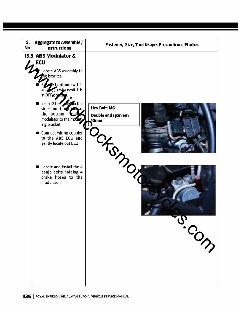
136 ROYAL ENFIELD HIMALAYAN EURO IV VEHICLE SERVICE MANUAL
S.No.
Fastener, Size, Tool Usage, Precautions, PhotosAggregate to Assemble /Instructions
13.3 ABS Modulator &ECU Locate ABS assembly to
the bracket.
Ensure Ignition switchand engine stop switch isin OFF position.
Install 2 hex bolts on thesides and 1 hex bolt atthe bottom, holdingmodulator to the mount-ing bracket
Connect wiring couplerto the ABS ECU andgently locate out ECU.
Hex Bolt: M6
Double end spanner:10mm
Locate and install the 4banjo bolts holding 4brake hoses to themodulator.
www.hitchcocksmotorcycles.com

137ROYAL ENFIELD HIMALAYAN EURO IV VEHICLE SERVICE MANUAL
S.No.
Fastener, Size, Tool Usage, Precautions, PhotosAggregate to Assemble /Instructions
13.3 ABS Modulator &ECU Locate the side panel RH
on the RH side byinstalling 2 socket headcap screws on the sides.
Head cap Screw : M6
Allen Key : 5 mm
www.hitchcocksmotorcycles.com

138 ROYAL ENFIELD HIMALAYAN EURO IV VEHICLE SERVICE MANUAL
ABS (ANTI-LOCK BRAKING SYSTEM) EFI TROUBLE SHOOTING CODES
S.No. P Codes for ABS Components monitored and malfunction type
1 5043 H Front wheel speed sensor Disconnection/ground Short/Uz Short
2 5042 H Front wheel speed sensor malfunction – Plausibility
3 5045 H Rear wheel speed sensor Disconnection/ground Short/Uz Short
4 5044 H Rear wheel speed sensor malfunction – Plausibility
5 5025 H Deviation between Wheel speeds (WSS_GENERIC)
6 5017 H Front Inlet Valve malfunction (EV)
7 5018 H Front Outlet Valve malfunction (AV)
8 5013 H Rear Inlet Valve malfunction (EV)
9 5014 H Rear Outlet Valve malfunction (AV)
10 5035 H Pump Motor Malfunction
11 5019 H Valve Relay malfunction (Failsafe relay)
12 5055 H ECU malfunction
13 5052 H Power Supply Malfunction (Low Voltage)
14 5053 H Power Supply Malfunction (High Voltage)
15 5122 H Varcode EEPROM ReadError
16 5223 H VarCode EEPROM Out Of Range
17 5331 H Front Wheel Pressure sensor ohmic fault
18 5332 H Front wheel pressure sensor offset/Test Pulse/POT fault
19 5333 H External Supply for Pressure sensor failure
www.hitchcocksmotorcycles.com
139ROYAL ENFIELD HIMALAYAN EURO IV VEHICLE SERVICE MANUAL
SECTION 14 - HYDRAULIC DISC BRAKES
www.hitchcocksmotorcycles.com
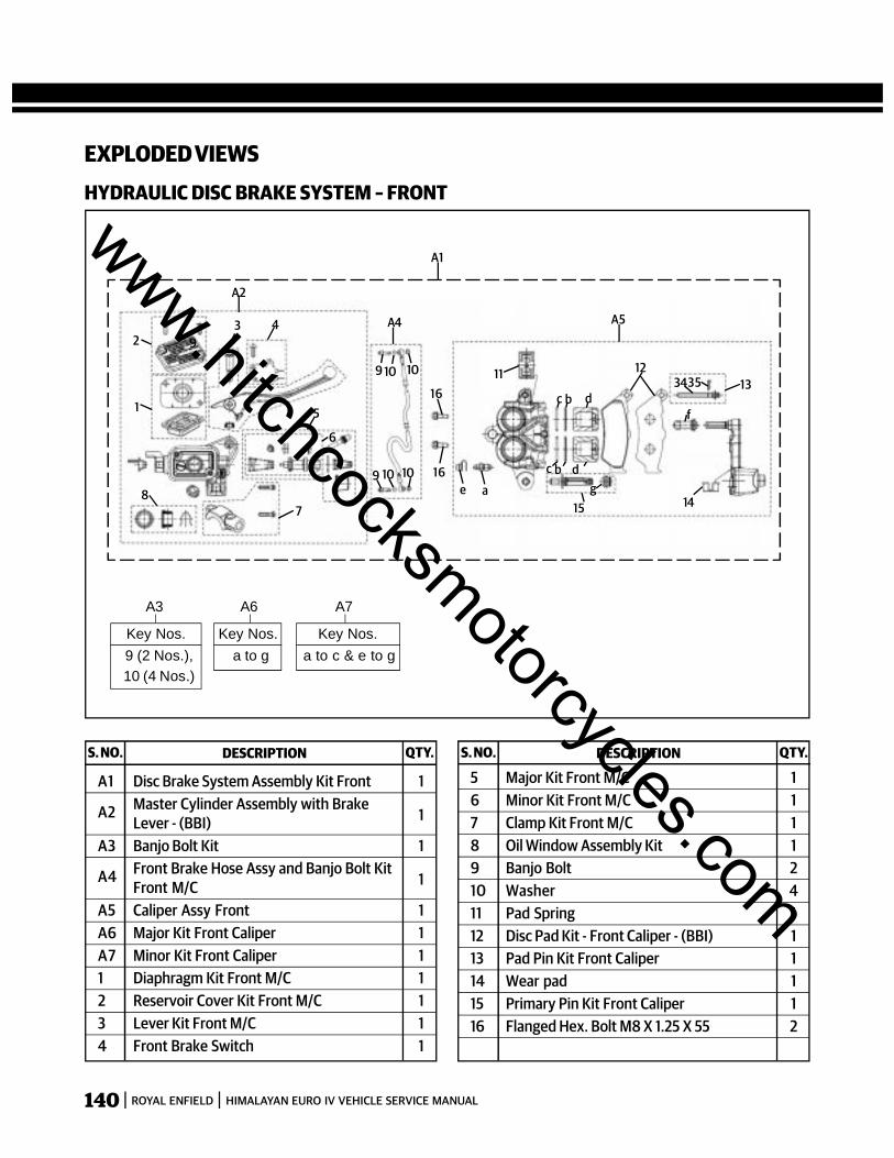
140 ROYAL ENFIELD HIMALAYAN EURO IV VEHICLE SERVICE MANUAL
EXPLODED VIEWSHYDRAULIC DISC BRAKE SYSTEM – FRONT
S. NO. DESCRIPTION QTY. S. NO. DESCRIPTION QTY.
A1 Disc Brake System Assembly Kit Front 1
A2 Master Cylinder Assembly with BrakeLever - (BBI) 1
A3 Banjo Bolt Kit 1
A4 Front Brake Hose Assy and Banjo Bolt KitFront M/C 1
A5 Caliper Assy Front 1A6 Major Kit Front Caliper 1A7 Minor Kit Front Caliper 11 Diaphragm Kit Front M/C 12 Reservoir Cover Kit Front M/C 13 Lever Kit Front M/C 14 Front Brake Switch 1
16
16e a g
15
c b d
c b d
14
3534 1311 12
A5
9 10 10
9 10 10
A4
A2
92
1
87
5
6
43
f
A1
A3
Key Nos.9 (2 Nos.),10 (4 Nos.)
A6
Key Nos.a to g
A7
Key Nos.a to c & e to g
5 Major Kit Front M/C 16 Minor Kit Front M/C 17 Clamp Kit Front M/C 18 Oil Window Assembly Kit 19 Banjo Bolt 210 Washer 411 Pad Spring 112 Disc Pad Kit - Front Caliper - (BBI) 113 Pad Pin Kit Front Caliper 114 Wear pad 115 Primary Pin Kit Front Caliper 116 Flanged Hex. Bolt M8 X 1.25 X 55 2
www.hitchcocksmotorcycles.com
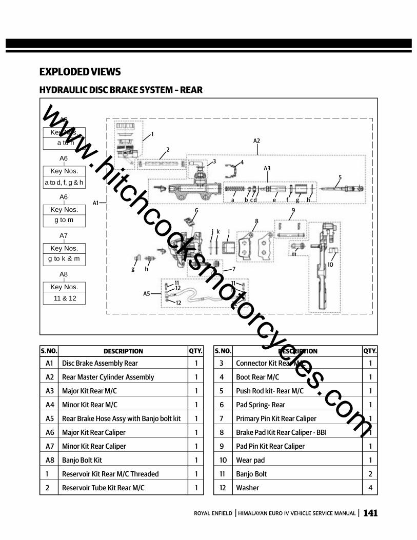
141ROYAL ENFIELD HIMALAYAN EURO IV VEHICLE SERVICE MANUAL
EXPLODED VIEWSHYDRAULIC DISC BRAKE SYSTEM – REAR
S. NO. DESCRIPTION QTY. S. NO. DESCRIPTION QTY.
A1 Disc Brake Assembly Rear 1
A2 Rear Master Cylinder Assembly 1
A3 Major Kit Rear M/C 1
A4 Minor Kit Rear M/C 1
A5 Rear Brake Hose Assy with Banjo bolt kit 1
A6 Major Kit Rear Caliper 1
A7 Minor Kit Rear Caliper 1
A8 Banjo Bolt Kit 1
1 Reservoir Kit Rear M/C Threaded 1
2 Reservoir Tube Kit Rear M/C 1
1
2
3 4
A2
A3
a b c d e f g h
5
A1
g h
m
i
j k l
8
6 9
107
1112
12
1112
12
A5
A3
Key Nos.a to h
A6
Key Nos.
a to d, f, g & h
A6
Key Nos.g to m
A7
Key Nos.g to k & m
A8
Key Nos.
11 & 12
3 Connector Kit Rear M/C 1
4 Boot Rear M/C 1
5 Push Rod kit- Rear M/C 1
6 Pad Spring- Rear 1
7 Primary Pin Kit Rear Caliper 1
8 Brake Pad Kit Rear Caliper - BBI 1
9 Pad Pin Kit Rear Caliper 1
10 Wear pad 1
11 Banjo Bolt 2
12 Washer 4
www.hitchcocksmotorcycles.com
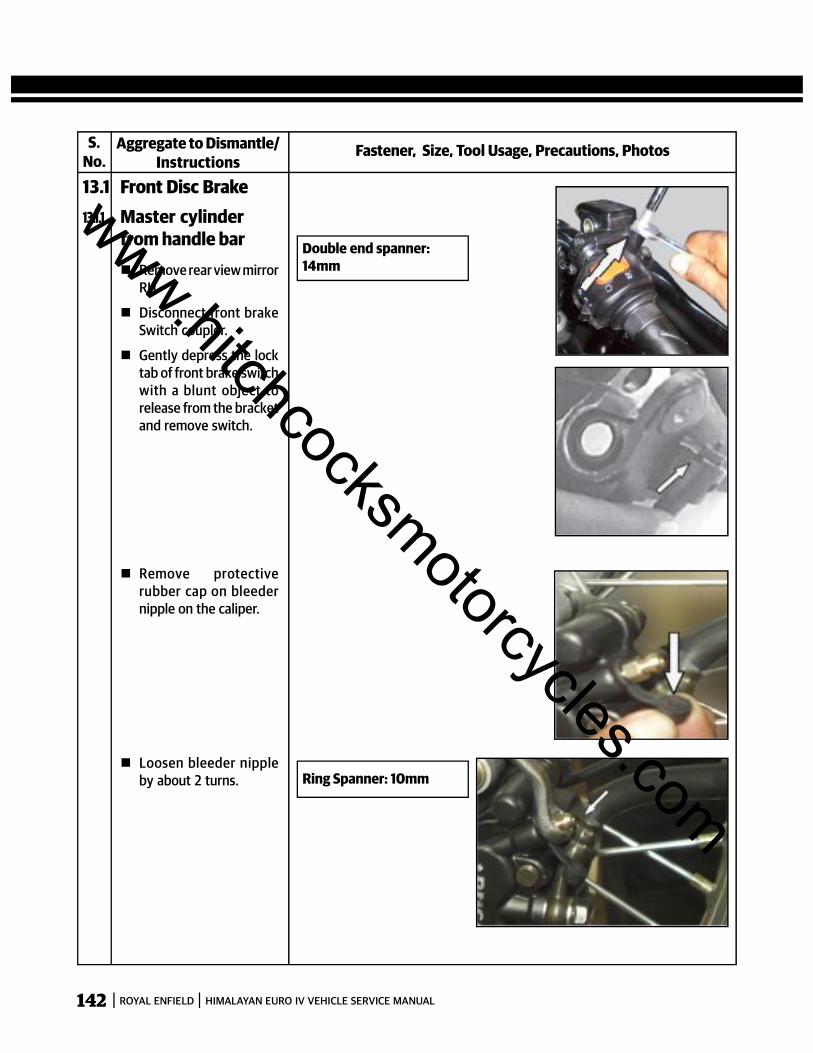
142 ROYAL ENFIELD HIMALAYAN EURO IV VEHICLE SERVICE MANUAL
S.No.
Fastener, Size, Tool Usage, Precautions, PhotosAggregate to Dismantle/Instructions
13.1 Front Disc Brake13.1.1 Master cylinder
from handle bar Remove rear view mirror
RH.
Disconnect front brakeSwitch coupler.
Gently depress the locktab of front brake switchwith a blunt object torelease from the bracketand remove switch.
Double end spanner:14mm
Remove protectiverubber cap on bleedernipple on the caliper.
Loosen bleeder nippleby about 2 turns. Ring Spanner: 10mm
www.hitchcocksmotorcycles.com

143ROYAL ENFIELD HIMALAYAN EURO IV VEHICLE SERVICE MANUAL
S.No.
Fastener, Size, Tool Usage, Precautions, PhotosAggregate to Dismantle/Instructions
13.1 Front Disc Brake13.1.1 Master cylinder
from handle bar Connect one end of a
transparent flexibletube of length about 12"(30cms.) firmly to thebleeder nipple.
Insert the other end ofthe tube into a cleanglass or plastic containerto collect the brake fluid.
Gently depress brakelever slowly and releaseto drain the brake fluidthrough the bleederscrew. Repeat thisprocess several times tillthe fluid is completelydrained from the brakesystem.
CAUTION:Brake fluid is extremelycorrosive hence ensure itdoes not spill on anypainted, rubber parts.
www.hitchcocksmotorcycles.com
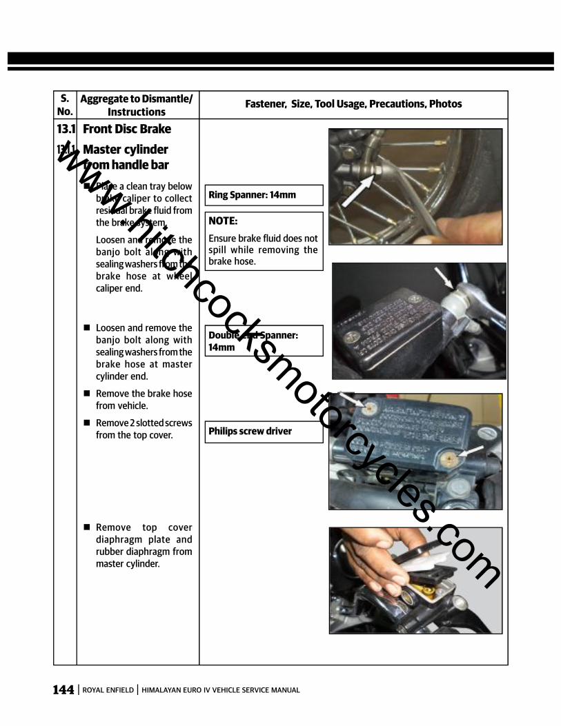
144 ROYAL ENFIELD HIMALAYAN EURO IV VEHICLE SERVICE MANUAL
S.No.
Fastener, Size, Tool Usage, Precautions, PhotosAggregate to Dismantle/Instructions
13.1 Front Disc Brake13.1.1 Master cylinder
from handle bar Place a clean tray below
brake caliper to collectresidual brake fluid fromthe brake system.
Loosen and remove thebanjo bolt along withsealing washers from thebrake hose at wheelcaliper end.
Ring Spanner: 14mm
Loosen and remove thebanjo bolt along withsealing washers from thebrake hose at mastercylinder end.
Remove the brake hosefrom vehicle.
Remove 2 slotted screwsfrom the top cover.
Remove top coverdiaphragm plate andrubber diaphragm frommaster cylinder.
NOTE:Ensure brake fluid does notspill while removing thebrake hose.
Double end Spanner:14mm
Philips screw driver
www.hitchcocksmotorcycles.com
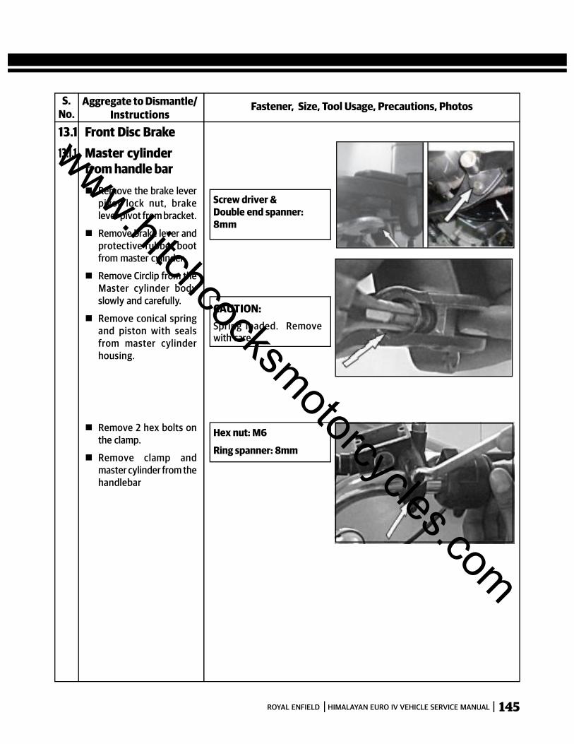
145ROYAL ENFIELD HIMALAYAN EURO IV VEHICLE SERVICE MANUAL
S.No.
Fastener, Size, Tool Usage, Precautions, PhotosAggregate to Dismantle/Instructions
13.1 Front Disc Brake13.1.1 Master cylinder
from handle bar Remove the brake lever
pivot lock nut, brakelever pivot from bracket.
Remove brake lever andprotective rubber bootfrom master cylinder.
Remove Circlip from theMaster cylinder bodyslowly and carefully.
Remove conical springand piston with sealsfrom master cylinderhousing.
Screw driver &Double end spanner:8mm
CAUTION:Spring loaded. Removewith care.
Remove 2 hex bolts onthe clamp.
Remove clamp andmaster cylinder from thehandlebar
Hex nut: M6
Ring spanner: 8mm
www.hitchcocksmotorcycles.com
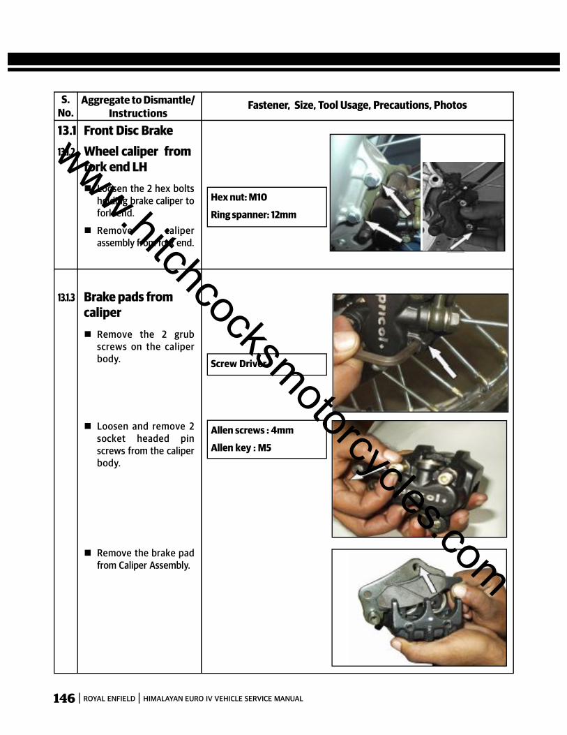
146 ROYAL ENFIELD HIMALAYAN EURO IV VEHICLE SERVICE MANUAL
S.No.
Fastener, Size, Tool Usage, Precautions, PhotosAggregate to Dismantle/Instructions
13.1 Front Disc Brake13.1.2 Wheel caliper from
fork end LH Loosen the 2 hex bolts
holding brake caliper tofork end.
Remove caliperassembly from fork end.
Hex nut: M10
Ring spanner: 12mm
13.1.3 Brake pads fromcaliper Remove the 2 grub
screws on the caliperbody. Screw Driver
Loosen and remove 2socket headed pinscrews from the caliperbody.
Remove the brake padfrom Caliper Assembly.
Allen screws : 4mm
Allen key : M5
www.hitchcocksmotorcycles.com

147ROYAL ENFIELD HIMALAYAN EURO IV VEHICLE SERVICE MANUAL
S.No.
Fastener, Size, Tool Usage, Precautions, PhotosAggregate to Dismantle/Instructions
13.1.3 Brake pads fromcaliper
Remove MountingBracket from the CaliperAssembly.
Remove the Padtensioner spring platefrom caliper.
13.1 Front Disc Brake13.1.4 Pistons & seals
from caliper Remove the bellow &
boot from the caliperassembly.
Hold the caliper bodywith the pistons facingdownwards.
Blow low pressurecompressed air with anozzle into the oilpassage hole on thecaliper, to drive out thepistons from the caliperbores.
Gently remove the sealsfrom caliper using ablunt and soft tool.
www.hitchcocksmotorcycles.com
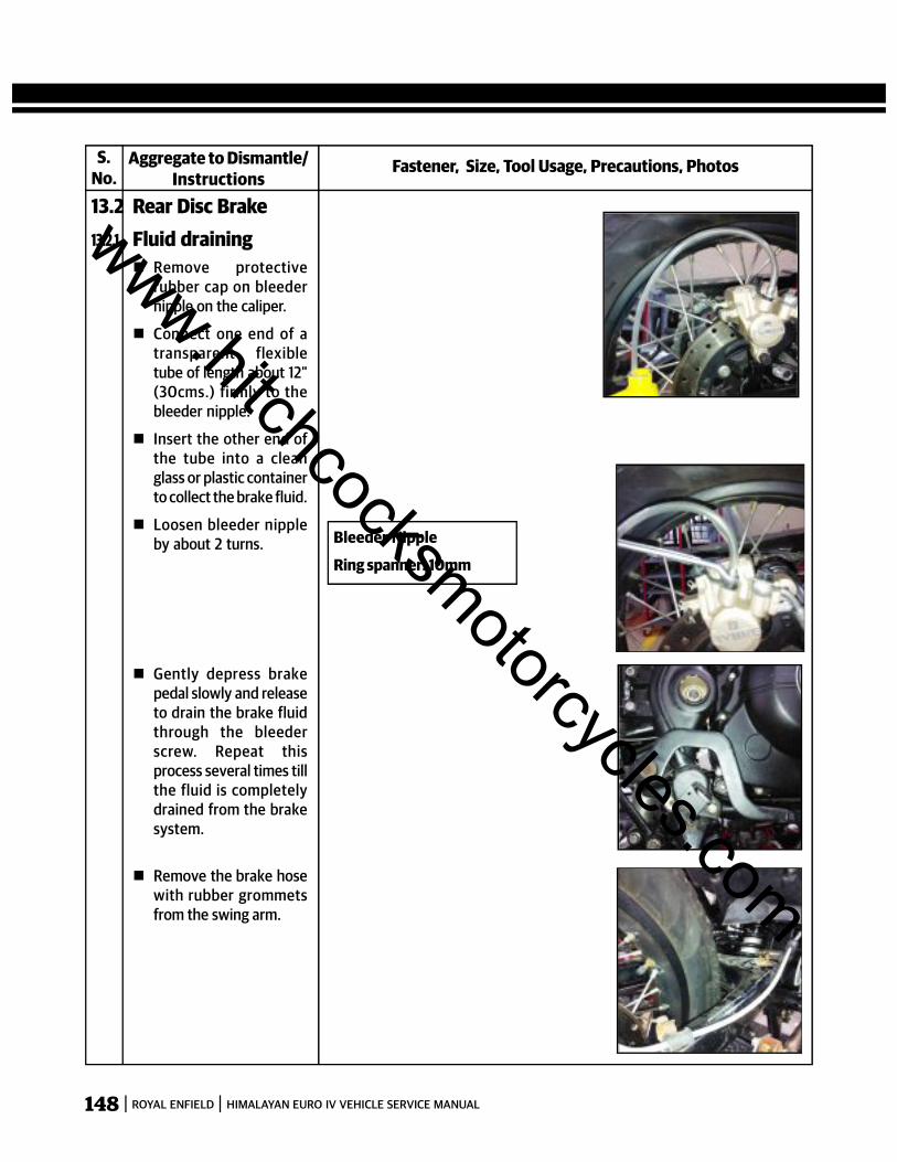
148 ROYAL ENFIELD HIMALAYAN EURO IV VEHICLE SERVICE MANUAL
S.No.
Fastener, Size, Tool Usage, Precautions, PhotosAggregate to Dismantle/Instructions
13.2 Rear Disc Brake13.2.1. Fluid draining
Remove protectiverubber cap on bleedernipple on the caliper.
Connect one end of atransparent flexibletube of length about 12"(30cms.) firmly to thebleeder nipple.
Insert the other end ofthe tube into a cleanglass or plastic containerto collect the brake fluid.
Loosen bleeder nippleby about 2 turns. Bleeder Nipple
Ring spanner: 10mm
Gently depress brakepedal slowly and releaseto drain the brake fluidthrough the bleederscrew. Repeat thisprocess several times tillthe fluid is completelydrained from the brakesystem.
Remove the brake hosewith rubber grommetsfrom the swing arm.
www.hitchcocksmotorcycles.com
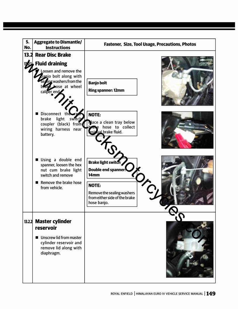
149ROYAL ENFIELD HIMALAYAN EURO IV VEHICLE SERVICE MANUAL
S.No.
Fastener, Size, Tool Usage, Precautions, PhotosAggregate to Dismantle/Instructions
13.2 Rear Disc Brake13.2.1. Fluid draining
Loosen and remove thebanjo bolt along withsealing washers from thebrake hose at wheelcaliper end.
Disconnect the rearbrake light switchcoupler (black) fromwiring harness nearbattery.
Using a double endspanner, loosen the hexnut cum brake lightswitch and remove
Remove the brake hosefrom vehicle.
Banjo bolt
Ring spanner: 12mm
NOTE:Place a clean tray belowbrake hose to collectresidual brake fluid.
Brake light switch
Double end spanner:14mm
NOTE:Remove the sealing washersfrom either side of the brakehose banjo.
13.2.2 Master cylinderreservoir
Unscrew lid from mastercylinder reservoir andremove lid along withdiaphragm.
www.hitchcocksmotorcycles.com
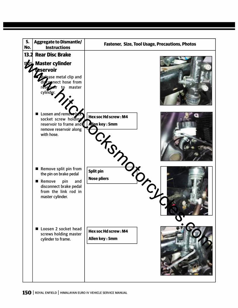
150 ROYAL ENFIELD HIMALAYAN EURO IV VEHICLE SERVICE MANUAL
S.No.
Fastener, Size, Tool Usage, Precautions, PhotosAggregate to Dismantle/Instructions
13.2 Rear Disc Brake13.2.1. Master cylinder
reservoir Release metal clip and
disconnect hose fromreservoir to mastercylinder.
Hex soc Hd screw : M4
Allen key : 5mm
Loosen and remove hexsocket screw holdingreservoir to frame andremove reservoir alongwith hose.
Split pin
Nose pliers
Remove split pin fromthe pin on brake pedal
Remove pin anddisconnect brake pedalfrom the link rod inmaster cylinder.
Hex soc Hd screw : M4
Allen key : 5mm
Loosen 2 socket headscrews holding mastercylinder to frame.
www.hitchcocksmotorcycles.com
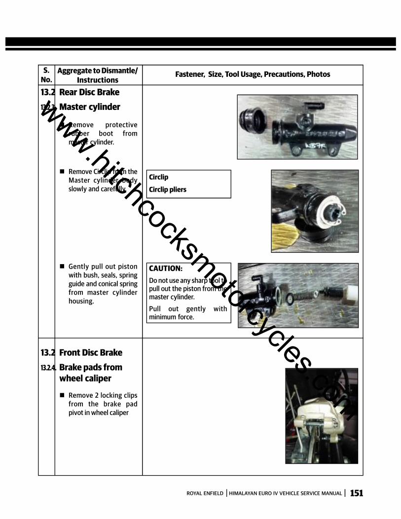
151ROYAL ENFIELD HIMALAYAN EURO IV VEHICLE SERVICE MANUAL
S.No.
Fastener, Size, Tool Usage, Precautions, PhotosAggregate to Dismantle/Instructions
13.2 Rear Disc Brake13.2.3. Master cylinder
Remove protectiverubber boot frommaster cylinder.
Remove Circlip from theMaster cylinder bodyslowly and carefully.
Circlip
Circlip pliers
Gently pull out pistonwith bush, seals, springguide and conical springfrom master cylinderhousing.
CAUTION:Do not use any sharp tool topull out the piston from themaster cylinder.
Pull out gently withminimum force.
13.2 Front Disc Brake13.2.4. Brake pads from
wheel caliper
Remove 2 locking clipsfrom the brake padpivot in wheel caliper
www.hitchcocksmotorcycles.com

152 ROYAL ENFIELD HIMALAYAN EURO IV VEHICLE SERVICE MANUAL
S.No.
Fastener, Size, Tool Usage, Precautions, PhotosAggregate to Dismantle/Instructions
13.2 Rear Disc Brake13.2.4. Brake pads from
wheel caliper Pull out the pivot pin
from the inside of thecaliper.
Remove the brake padsfrom the caliper.
13.2.5. Wheel caliper fromswing arm
Loosen and remove rearwheel axle nut.
Pull out the pivot pinfrom the inside of thecaliper.
Separate the MountingBracket from the CaliperAssembly by gentlypulling them apart.
www.hitchcocksmotorcycles.com

153ROYAL ENFIELD HIMALAYAN EURO IV VEHICLE SERVICE MANUAL
S.No.
Fastener, Size, Tool Usage, Precautions, PhotosAggregate to Dismantle/Instructions
13.2 Rear Disc Brake13.2.5. Wheel caliper from
swing arm Remove the Pad
tensioner spring platefrom caliper andmounting bracket.
Hold the caliper bodywith the piston facingdownwards.
Blow low pressurecompressed air with anozzle into the oilpassage hole on thecaliper, to drive out thepiston from the caliperbore.
Gently remove thepiston with seal fromcaliper using a blunt andsoft tool.
13.2 Rear Disc Brake13.2.5. Piston & seal from
caliper
CAUTION:Do not use high pressure air.
Support piston whileremoving from caliper.
Ensure the bore in thecaliper does not get scoredor damaged.
Ensure piston outsidesurfaces does not getscored or damaged.
www.hitchcocksmotorcycles.com
154 ROYAL ENFIELD HIMALAYAN EURO IV VEHICLE SERVICE MANUAL
GENERAL PRECAUTIONS Check the system for any fluid leaks at banjo union joints, damaged brake hose etc. at periodic intervals as detailed
in the maintenance schedule.
Whenever checking brake fluid level, ensure vehicle is on its centre stand and the fluid reservoir is parallel to theground, whenever checking fluid level.
Cover motorcycle painted surfaces, plastic and rubber parts while overhauling or bleeding a brake system. Donot allow brake fluid to come in contact with any parts of the motorcycle as brake fluid has highly corrosiveproperties.
CLEANING
Clean master cylinder filler cap before removing.
Use only fresh brake fluid to clean rubber and other parts of the hydraulic brake system. DO NOT use anypetroleum based cleaning solvents, water or detergents etc.
INSPECTION:
Inspect brake fluid level is always between the MAX and MIN level markings in the reservoir.
Prior to riding the motorcycle every time, check brake disc inside and outside surfaces carefully for anycontamination with oil, grease, slippery substances, brake fluid etc. as these will render the braking systemineffective. In case of any contamination, wash the brake disk with water and mild detergent to remove thecontaminations, clean well with a good degreasing agent, blow compressed air to dry the brake disc thoroughly.
Inspect brake hose joints; reservoir and wheel caliper ends for any traces of fluid seepage or leaks. Check andcorrect the leaks immediately, if any noticed.
Inspect Brake hoses for any damage, cracks or cuts, ageing etc and replace damaged parts immediately.
Inspect brake pads for embedded foreign objects, abnormal wear, age hardening of friction material etc.
Inspect and ensure the pads are not worn out beyond the wear indication limit marks on the pads. Replace padsas soon as they have reached the wear limit marks
Check rubber seals on the plunger for wear, cracked edges or any other damage. Replace seals whenever theplunger is removed
Check master cylinder housing and piston for any scoring, pitting due to corrosion or any other damages.
Check the master cylinder bore for any damages, scoring marks etc.
Check piston outside surfaces for any damages, scoring marks, corrosion etc. Replace pistons if any of the aboveis observed.
CAUTION: Use only DOT 3 or DOT 4 grade brake fluid from a sealed container. Do not mix different types of brake fluid
as they may not be compatible.
Whenever the disc brake system is overhauled, ensure that the old fluid is drained out completely and then filledwith fresh brake fluid ONLY from a sealed container.
In case of any brake fluid contamination in the brake system, the contaminated brake fluid must be flushed outcompletely from the entire system, the internal parts cleaned well, filled with fresh brake fluid and the brakesystem bleeding must be carried out.
www.hitchcocksmotorcycles.com
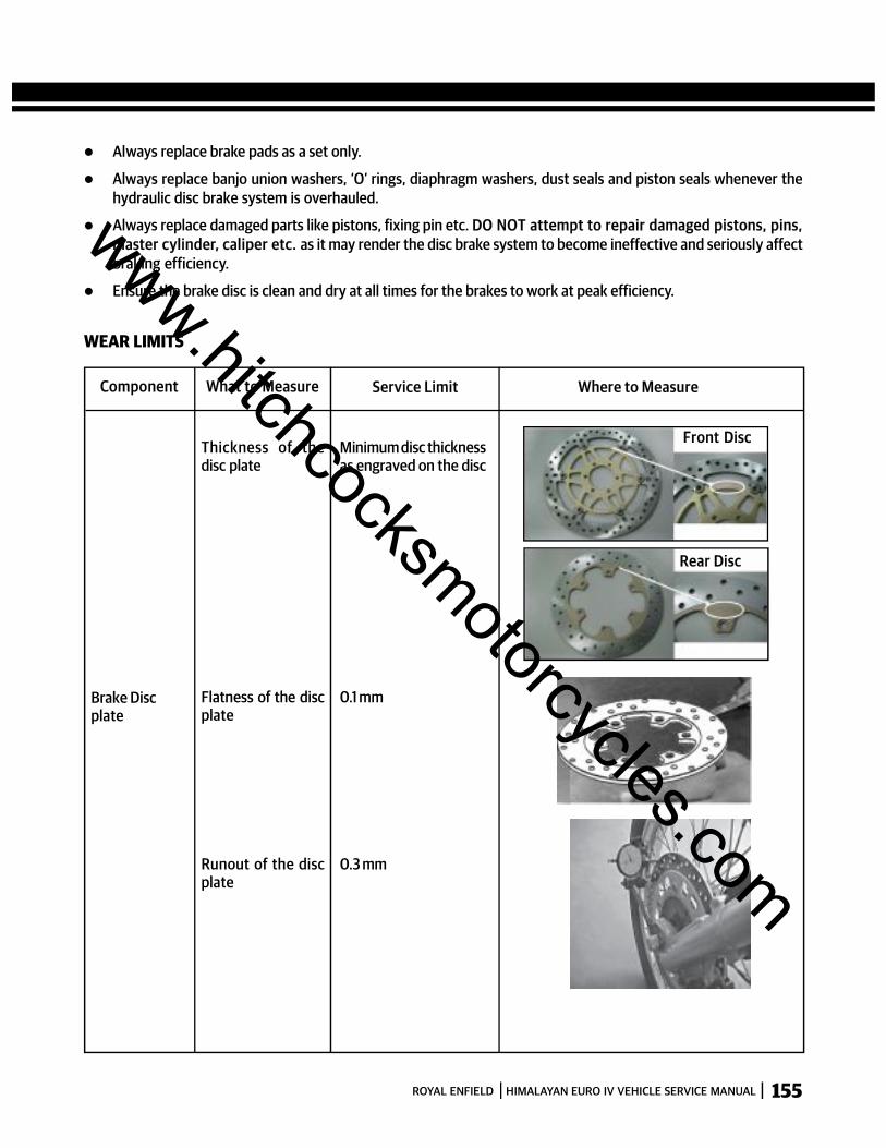
155ROYAL ENFIELD HIMALAYAN EURO IV VEHICLE SERVICE MANUAL
Always replace brake pads as a set only.
Always replace banjo union washers, ‘O’ rings, diaphragm washers, dust seals and piston seals whenever thehydraulic disc brake system is overhauled.
Always replace damaged parts like pistons, fixing pin etc. DO NOT attempt to repair damaged pistons, pins,master cylinder, caliper etc. as it may render the disc brake system to become ineffective and seriously affectbraking efficiency.
Ensure the brake disc is clean and dry at all times for the brakes to work at peak efficiency.
WEAR LIMITS
Component What to Measure Service Limit Where to Measure
Front Disc
Rear Disc
Thickness of thedisc plate
Minimum disc thicknessas engraved on the disc
Flatness of the discplate
0.1 mmBrake Discplate
Runout of the discplate
0.3 mm
www.hitchcocksmotorcycles.com
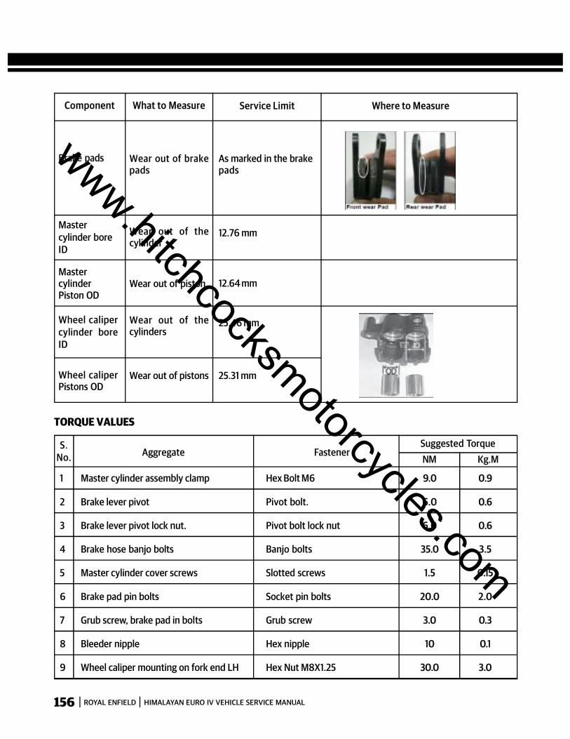
156 ROYAL ENFIELD HIMALAYAN EURO IV VEHICLE SERVICE MANUAL
Component What to Measure Service Limit Where to Measure
Wear out of brakepads
As marked in the brakepads
Brake pads
Wear out of thecylinder
12.76 mmMastercylinder boreID
Wear out of piston 12.64 mmMastercylinderPiston OD
Wear out of thecylinders
25.46 mmWheel calipercylinder boreID
Wear out of pistons 25.31 mmWheel caliperPistons OD
TORQUE VALUES
S.No. Aggregate Fastener
Suggested TorqueNM Kg.M
1 Master cylinder assembly clamp Hex Bolt M6 9.0 0.9
2 Brake lever pivot Pivot bolt. 6.0 0.6
3 Brake lever pivot lock nut. Pivot bolt lock nut 6.0 0.6
4 Brake hose banjo bolts Banjo bolts 35.0 3.5
5 Master cylinder cover screws Slotted screws 1.5 0.15
6 Brake pad pin bolts Socket pin bolts 20.0 2.0
7 Grub screw, brake pad in bolts Grub screw 3.0 0.3
8 Bleeder nipple Hex nipple 10 0.1
9 Wheel caliper mounting on fork end LH Hex Nut M8X1.25 30.0 3.0
www.hitchcocksmotorcycles.com

157ROYAL ENFIELD HIMALAYAN EURO IV VEHICLE SERVICE MANUAL
GENERAL INSTRUCTIONS – DISC BRAKE
Check, monthly or every 2000 kms., the Brake fluid level through the Sight-glass whether it is above the‘MINLINE’ mark. While checking, turn the handle bar straight, until the reservoir is horizontal.
Never mix different types of brake fluids. (DOT 4 & ABOVE Together)
Do not clean the rubber parts with petrol or any other gasoline product or water. Use clean brake fluid only.
In case of water contamination of Brake fluid, drain the fluid completely, refill the system and bleed.
Do not top up brake fluid above “Max” level to avoid front wheel binding problem
Check periodically whether the Disc has been contaminated with oil, brake fluid or grease and clean contaminatedDisc with a high quality brake-degreasing agent.
Always keep the disc clean and dry at all times for the brakes to work at peak efficiency.
www.hitchcocksmotorcycles.com
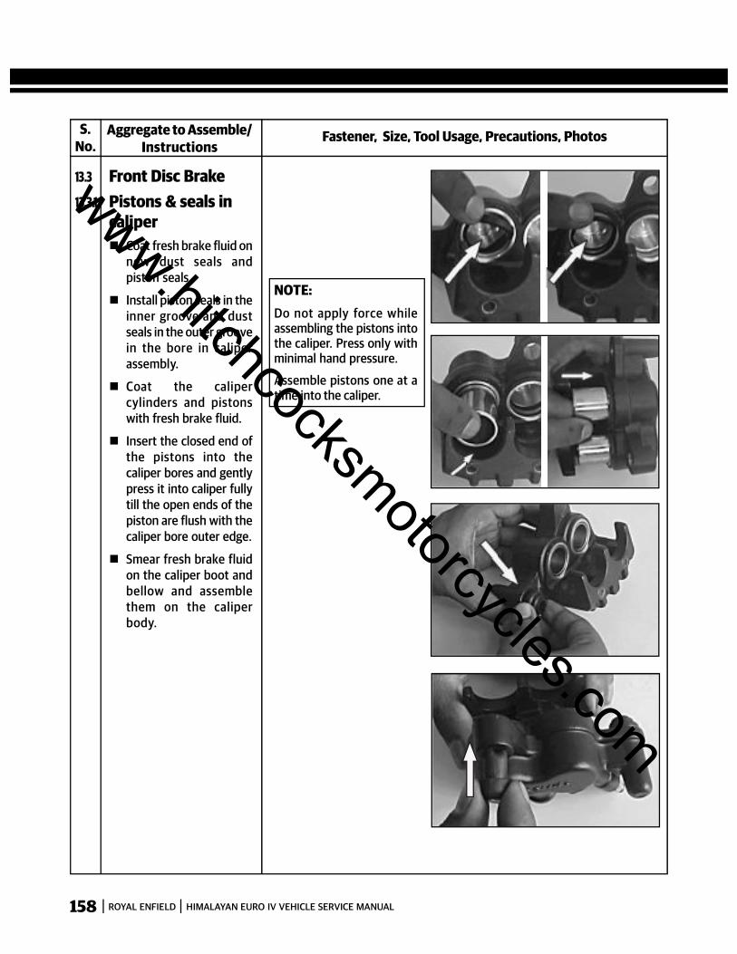
158 ROYAL ENFIELD HIMALAYAN EURO IV VEHICLE SERVICE MANUAL
Fastener, Size, Tool Usage, Precautions, PhotosAggregate to Assemble/Instructions
13.3 Front Disc Brake
Coat fresh brake fluid onnew dust seals andpiston seals.
Install piston seals in theinner groove and dustseals in the outer groovein the bore in caliperassembly.
Coat the calipercylinders and pistonswith fresh brake fluid.
Insert the closed end ofthe pistons into thecaliper bores and gentlypress it into caliper fullytill the open ends of thepiston are flush with thecaliper bore outer edge.
Smear fresh brake fluidon the caliper boot andbellow and assemblethem on the caliperbody.
S.No.
13.3.1 Pistons & seals incaliper
NOTE:Do not apply force whileassembling the pistons intothe caliper. Press only withminimal hand pressure.
Assemble pistons one at atime into the caliper.
www.hitchcocksmotorcycles.com
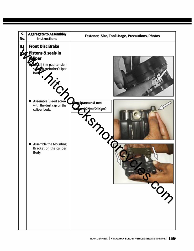
159ROYAL ENFIELD HIMALAYAN EURO IV VEHICLE SERVICE MANUAL
Fastener, Size, Tool Usage, Precautions, PhotosAggregate to Assemble/Instructions
13.3 Front Disc Brake
Install the pad tensionspring plate in the Caliperbody.
S.No.
13.3.1 Pistons & seals incaliper
Assemble Bleed screwwith the dust cap on thecaliper body.
Assemble the MountingBracket on the caliperBody.
Ring Spanner: 8 mm
Torque: 10Nm (0.1Kgm)
www.hitchcocksmotorcycles.com
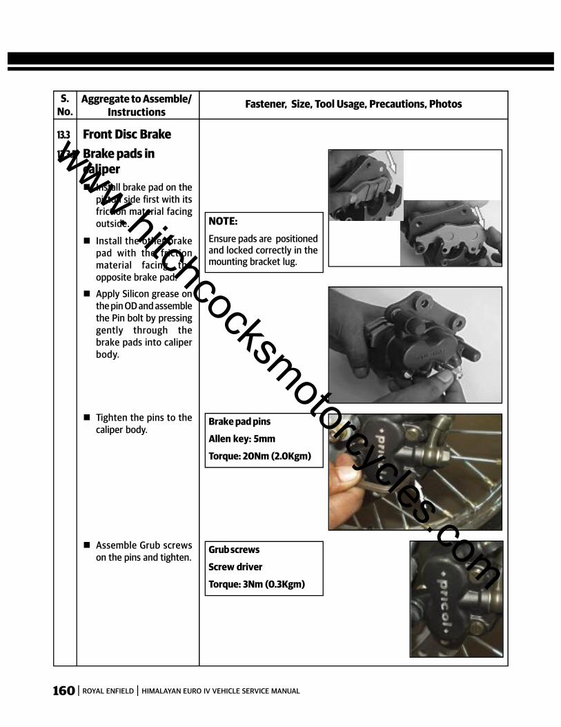
160 ROYAL ENFIELD HIMALAYAN EURO IV VEHICLE SERVICE MANUAL
Fastener, Size, Tool Usage, Precautions, PhotosAggregate to Assemble/Instructions
13.3 Front Disc Brake
Install brake pad on thepiston side first with itsfriction material facingoutside.
Install the other brakepad with the frictionmaterial facing theopposite brake pad.
S.No.
13.3.2 Brake pads incaliper
Apply Silicon grease onthe pin OD and assemblethe Pin bolt by pressinggently through thebrake pads into caliperbody.
NOTE:Ensure pads are positionedand locked correctly in themounting bracket lug.
Tighten the pins to thecaliper body.
Assemble Grub screwson the pins and tighten.
Brake pad pins
Allen key: 5mm
Torque: 20Nm (2.0Kgm)
Grub screws
Screw driver
Torque: 3Nm (0.3Kgm)
www.hitchcocksmotorcycles.com

161ROYAL ENFIELD HIMALAYAN EURO IV VEHICLE SERVICE MANUAL
Fastener, Size, Tool Usage, Precautions, PhotosAggregate to Assemble/Instructions
13.3 Front Disc Brake
Locate caliper on forkend LH and ensure thebrake disc is positionedbetween the brakepads.
Tighten caliper assemblyto fork end with 2 hexbolts.
S.No.
13.3.3 Wheel caliper onfork end LH
Hex bolt: M10
Socket spanner: 12mm
Torque: 30Nm (3.0Kgm)
13.3 Front Disc Brake
Locate master cylinderassembly on the handlebar.
Locate clamp on handlebar and tighten themaster cylinder assy. Tohandle bar with 2 hexbolts.
Smear the piston, sealsand cylinder bore withfresh brake fluid andassemble piston sub-assembly into themaster cylinder by gentlypushing it into the bore.
13.3.4 Master cylinder onhandle bar
Hex Bolts : M6
Socket spanner : 8mm
Torque : 9Nm (0.9 KgM)
NOTE:Ensure the circlip is seatedcorrectly inside the groove.
www.hitchcocksmotorcycles.com
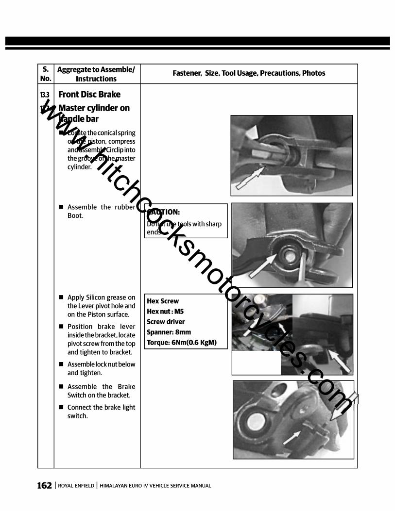
162 ROYAL ENFIELD HIMALAYAN EURO IV VEHICLE SERVICE MANUAL
Fastener, Size, Tool Usage, Precautions, PhotosAggregate to Assemble/Instructions
13.3 Front Disc Brake
Assemble the rubberBoot.
S.No.
13.3.4 Master cylinder onhandle bar
Apply Silicon grease onthe Lever pivot hole andon the Piston surface.
Position brake leverinside the bracket, locatepivot screw from the topand tighten to bracket.
Assemble lock nut belowand tighten.
CAUTION:Do not use tools with sharpends.
Locate the conical springon the piston, compressand assemble Circlip intothe groove of the mastercylinder.
Hex ScrewHex nut : M5Screw driverSpanner: 8mmTorque: 6Nm(0.6 KgM)
Assemble the BrakeSwitch on the bracket.
Connect the brake lightswitch.
www.hitchcocksmotorcycles.com
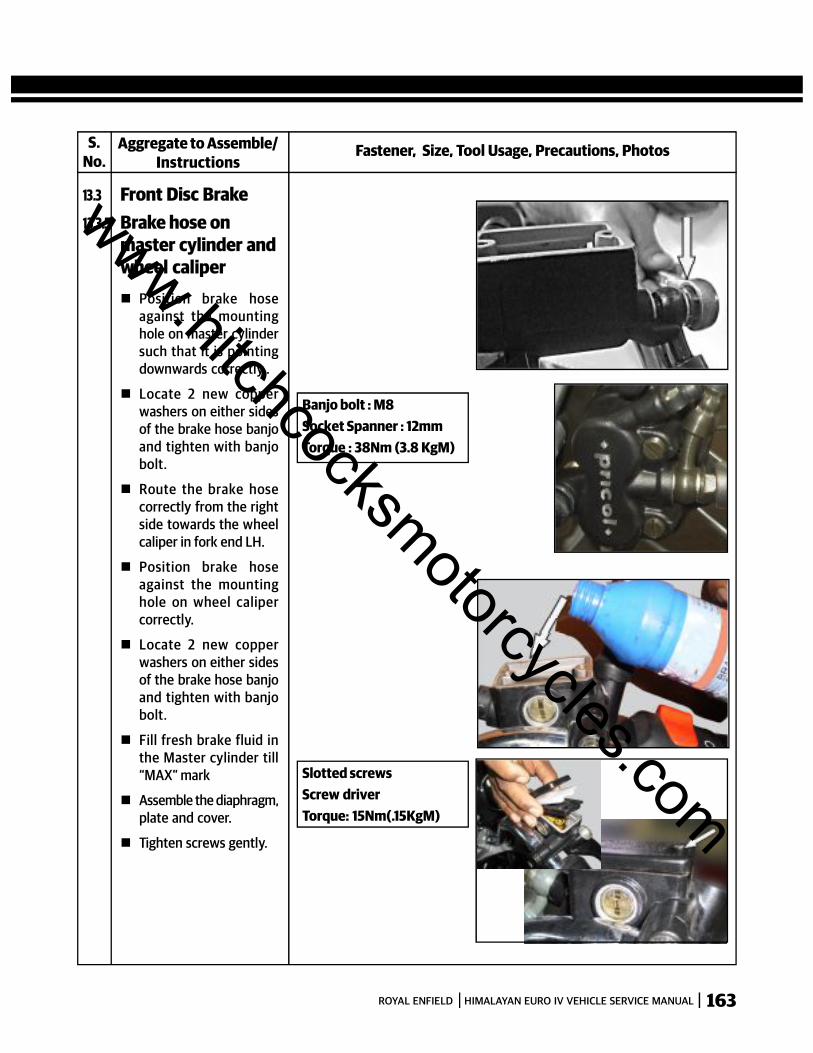
163ROYAL ENFIELD HIMALAYAN EURO IV VEHICLE SERVICE MANUAL
Fastener, Size, Tool Usage, Precautions, PhotosAggregate to Assemble/Instructions
13.3 Front Disc Brake
Position brake hoseagainst the mountinghole on master cylindersuch that it is pointingdownwards correctly..
Locate 2 new copperwashers on either sidesof the brake hose banjoand tighten with banjobolt.
Route the brake hosecorrectly from the rightside towards the wheelcaliper in fork end LH.
Position brake hoseagainst the mountinghole on wheel calipercorrectly.
Locate 2 new copperwashers on either sidesof the brake hose banjoand tighten with banjobolt.
Fill fresh brake fluid inthe Master cylinder till“MAX” mark
Assemble the diaphragm,plate and cover.
Tighten screws gently.
S.No.
13.3.5 Brake hose onmaster cylinder andwheel caliper
Banjo bolt : M8Socket Spanner : 12mmTorque : 38Nm (3.8 KgM)
Slotted screwsScrew driverTorque: 15Nm(.15KgM)
www.hitchcocksmotorcycles.com

164 ROYAL ENFIELD HIMALAYAN EURO IV VEHICLE SERVICE MANUAL
Fastener, Size, Tool Usage, Precautions, PhotosAggregate to Assemble/Instructions
13.3 Front Disc Brake
S.No.
13.3.5 Brake hose onmaster cylinder andwheel caliper Assemble the rear view
mirror.
Bleed the air out of thehydraulic brake system.
13.4 Rear Disc Brake13.4.1 Piston & seals in
caliper
Coat fresh brake fluid onnew dust seals andpiston seals.
Install piston seals in theinner groove and dustseals in the outer groovein the bore in caliperassembly.
Coat the caliper cylinderand piston with freshbrake fluid.
Insert the closed end ofthe piston into thecaliper bore and gentlypress it into caliper fullytill the open ends of thepiston are flush with thecaliper bore outer edge.
NOTE:Do not apply force whileassembling the piston intothe caliper. Press only withminimal hand pressure.
www.hitchcocksmotorcycles.com

165ROYAL ENFIELD HIMALAYAN EURO IV VEHICLE SERVICE MANUAL
Fastener, Size, Tool Usage, Precautions, PhotosAggregate to Assemble/Instructions
13.4 Rear Disc Brake
Install the pad tensionspring plate in the Caliperbody.
S.No.
13.4.1 Piston & seals incaliper
Ring Spanner: 8 mm
Torque: 10Nm (0.1Kgm)
Assemble Bleed screwwith the dust cap on thecaliper body.
Position the guides onthe Caliper andmounting bracketcorrectly on the rubberboot and assemblecaliper body in themounting bracket
www.hitchcocksmotorcycles.com
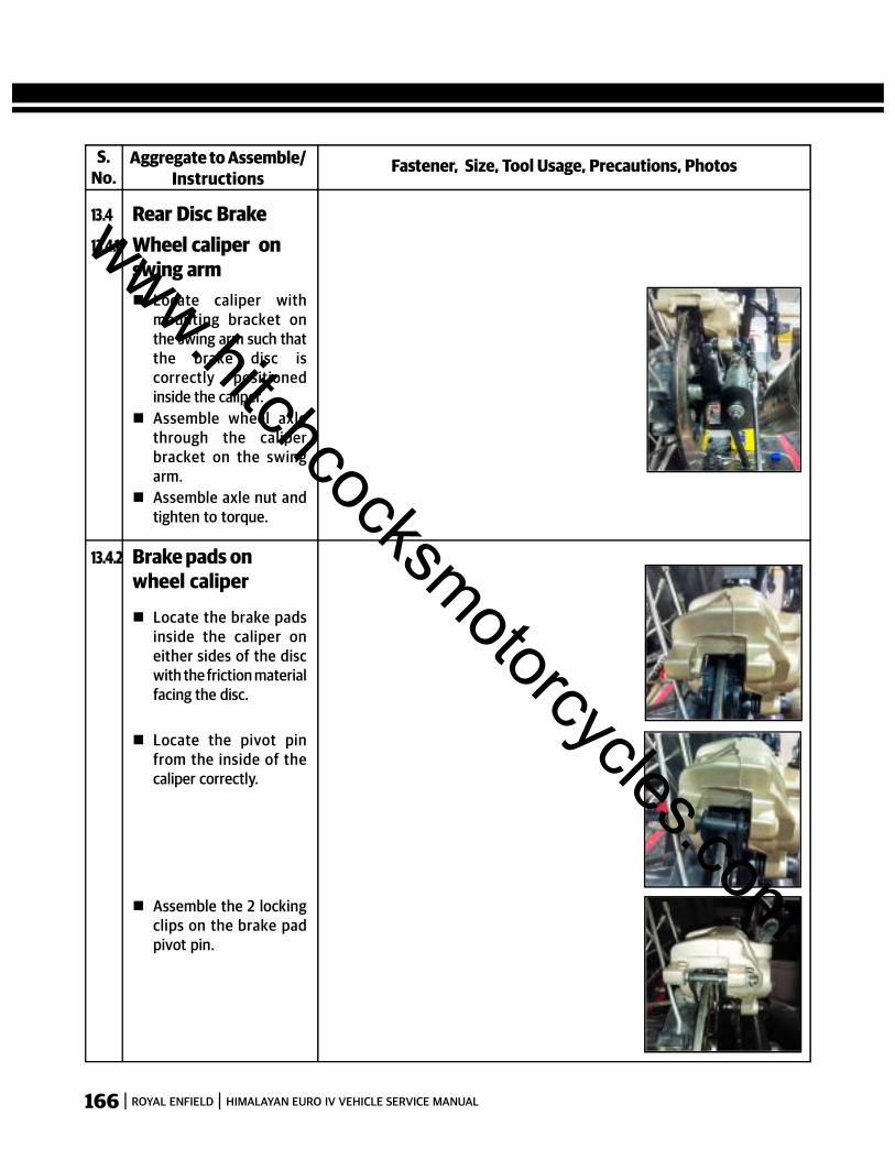
166 ROYAL ENFIELD HIMALAYAN EURO IV VEHICLE SERVICE MANUAL
Fastener, Size, Tool Usage, Precautions, PhotosAggregate to Assemble/Instructions
13.4 Rear Disc Brake
Locate caliper withmounting bracket onthe swing arm such thatthe brake disc iscorrectly positionedinside the caliper.
Assemble wheel axlethrough the caliperbracket on the swingarm.
Assemble axle nut andtighten to torque.
S.No.
13.4.1 Wheel caliper onswing arm
Locate the brake padsinside the caliper oneither sides of the discwith the friction materialfacing the disc.
13.4.2 Brake pads onwheel caliper
Locate the pivot pinfrom the inside of thecaliper correctly.
Assemble the 2 lockingclips on the brake padpivot pin.
www.hitchcocksmotorcycles.com

167ROYAL ENFIELD HIMALAYAN EURO IV VEHICLE SERVICE MANUAL
Fastener, Size, Tool Usage, Precautions, PhotosAggregate to Assemble/Instructions
13.4 Rear Disc Brake
Locate new O ring insidethe master cylinderbore.
Assemble the springguide on the small end ofthe spring.
Locate the peg on thepiston, on the springguide
Locate large bush overthe piston.
Insert the large end ofthe spring along with thepiston and guide bushinto the master cylinderbore and hold it incompressed positioninside the mastercylinder.
Assemble Circlip in themaster cylinder bodyand ensure it is lockedproperly in the groove
Assemble the protectiverubber boot on themaster cylinder.
S.No.
13.4.3 Master cylinder
CAUTION:Do not use any sharp toolto assemble the O ring orpiston in the mastercylinder.
Circlip
Circlip pliers
www.hitchcocksmotorcycles.com
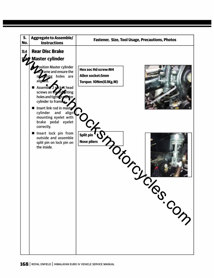
168 ROYAL ENFIELD HIMALAYAN EURO IV VEHICLE SERVICE MANUAL
Fastener, Size, Tool Usage, Precautions, PhotosAggregate to Assemble/Instructions
13.4 Rear Disc Brake
Position Master cylinderon frame and ensure themounting holes arealigned.
Assemble 2 socket headscrews on the mountingholes and tighten mastercylinder to frame.x
Insert link rod in mastercylinder and alignmounting eyelet withbrake pedal eyeletcorrectly.
Insert lock pin fromoutside and assemblesplit pin on lock pin onthe inside.
S.No.
13.4.3 Master cylinder
Hex soc Hd screw:M4Allen socket:5mmTorque: 10Nm(0.1Kg.M)
Split pin
Nose pliers
www.hitchcocksmotorcycles.com
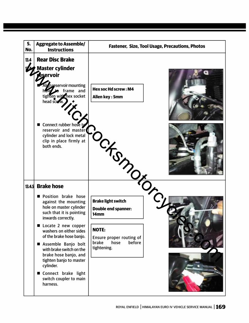
169ROYAL ENFIELD HIMALAYAN EURO IV VEHICLE SERVICE MANUAL
Fastener, Size, Tool Usage, Precautions, PhotosAggregate to Assemble/Instructions
13.4 Rear Disc Brake
Align reservoir mountinghole to frame andtighten with hex sockethead screw.
S.No.
13.4.4 Master cylinderreservoir
Hex soc Hd screw : M4
Allen key : 5mm
Connect rubber hose toreservoir and mastercylinder and lock metalclip in place firmly atboth ends.
Position brake hoseagainst the mountinghole on master cylindersuch that it is pointinginwards correctly.
Locate 2 new copperwashers on either sidesof the brake hose banjo.
Assemble Banjo boltwith brake switch on thebrake hose banjo, andtighten banjo to mastercylinder.
Connect brake lightswitch coupler to mainharness.
13.4.5 Brake hose
Brake light switch
Double end spanner:14mm
NOTE:Ensure proper routing ofbrake hose beforetightening.
www.hitchcocksmotorcycles.com
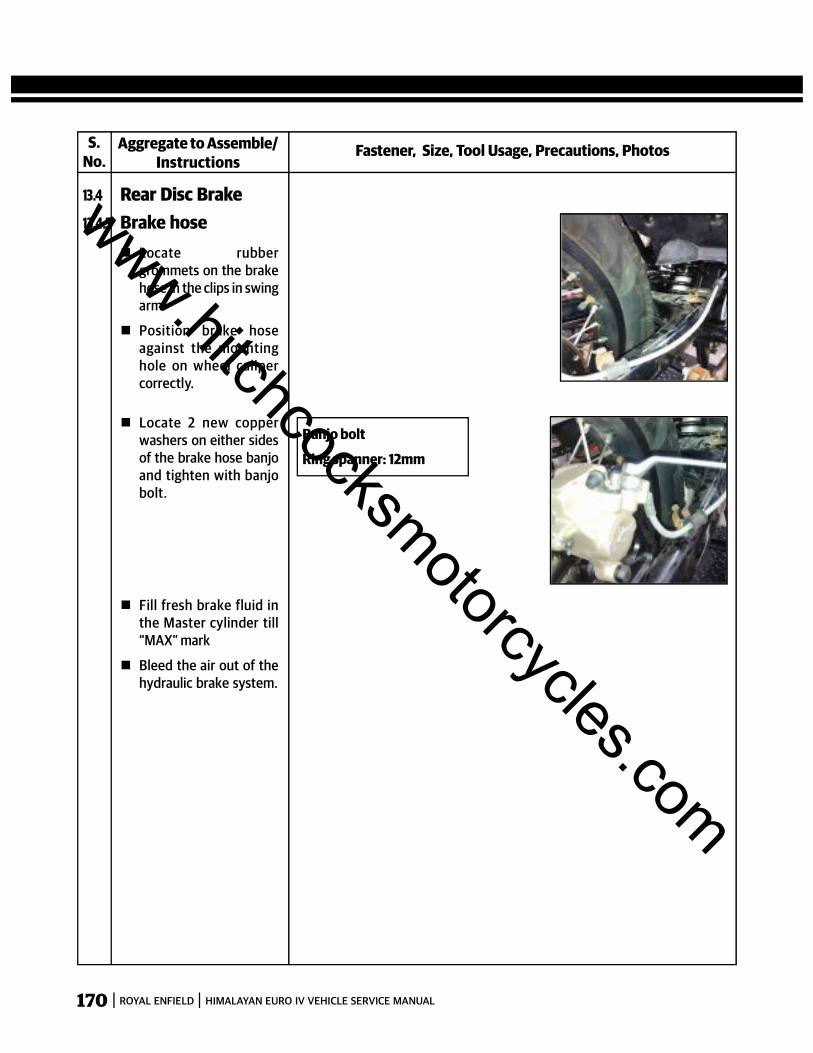
170 ROYAL ENFIELD HIMALAYAN EURO IV VEHICLE SERVICE MANUAL
Fastener, Size, Tool Usage, Precautions, PhotosAggregate to Assemble/Instructions
13.4 Rear Disc Brake
Locate rubbergrommets on the brakehose in the clips in swingarm
Position brake hoseagainst the mountinghole on wheel calipercorrectly.
S.No.
13.4.5 Brake hose
Locate 2 new copperwashers on either sidesof the brake hose banjoand tighten with banjobolt.
Banjo bolt
Ring spanner: 12mm
Fill fresh brake fluid inthe Master cylinder till“MAX” mark
Bleed the air out of thehydraulic brake system.
www.hitchcocksmotorcycles.com
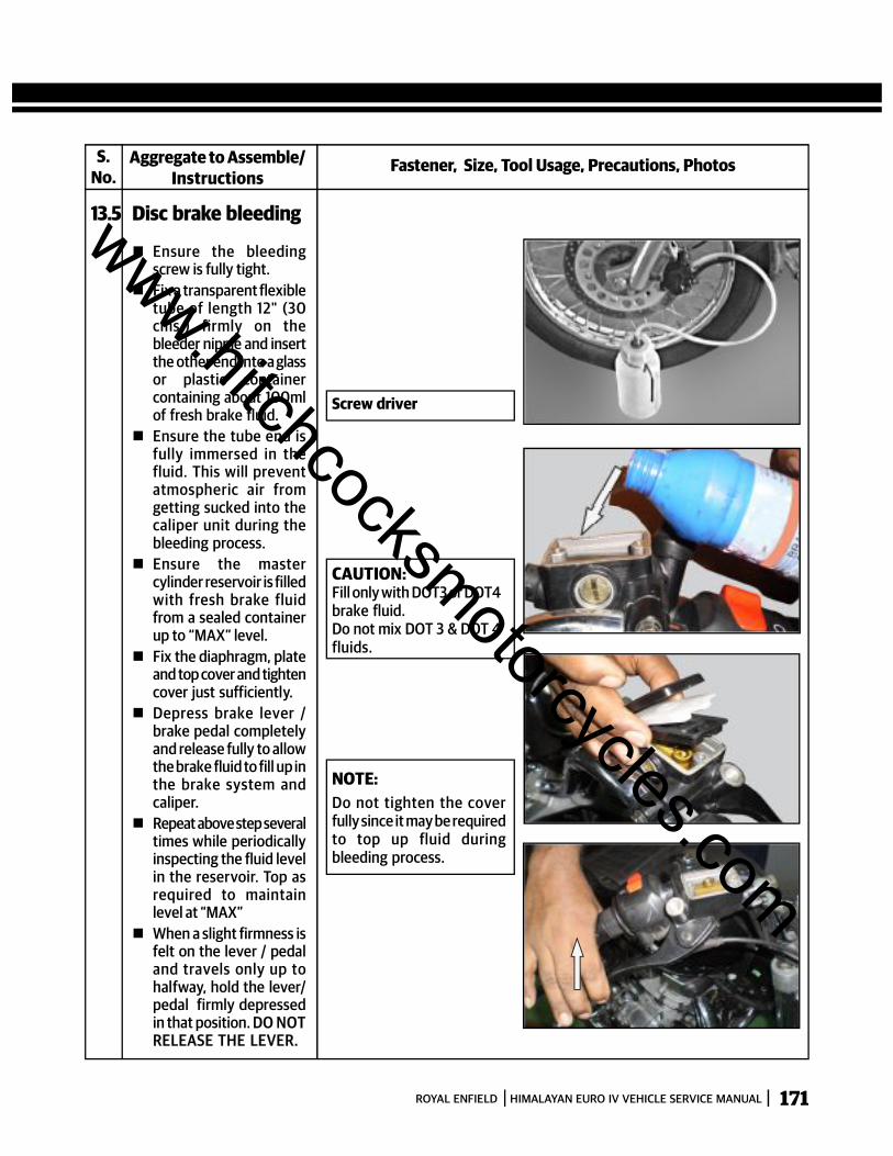
171ROYAL ENFIELD HIMALAYAN EURO IV VEHICLE SERVICE MANUAL
Fastener, Size, Tool Usage, Precautions, PhotosAggregate to Assemble/Instructions
13.5 Disc brake bleeding
Ensure the bleedingscrew is fully tight.
Fix a transparent flexibletube of length 12" (30cms.) firmly on thebleeder nipple and insertthe other end into a glassor plastic containercontaining about 100mlof fresh brake fluid.
Ensure the tube end isfully immersed in thefluid. This will preventatmospheric air fromgetting sucked into thecaliper unit during thebleeding process.
Ensure the mastercylinder reservoir is filledwith fresh brake fluidfrom a sealed containerup to “MAX” level.
Fix the diaphragm, plateand top cover and tightencover just sufficiently.
Depress brake lever /brake pedal completelyand release fully to allowthe brake fluid to fill up inthe brake system andcaliper.
Repeat above step severaltimes while periodicallyinspecting the fluid levelin the reservoir. Top asrequired to maintainlevel at “MAX”
When a slight firmness isfelt on the lever / pedaland travels only up tohalfway, hold the lever/pedal firmly depressedin that position. DO NOTRELEASE THE LEVER.
S.No.
Screw driver
CAUTION:Fill only with DOT3 or DOT4brake fluid.Do not mix DOT 3 & DOT 4fluids.
NOTE:Do not tighten the coverfully since it may be requiredto top up fluid duringbleeding process.
www.hitchcocksmotorcycles.com

172 ROYAL ENFIELD HIMALAYAN EURO IV VEHICLE SERVICE MANUAL
Fastener, Size, Tool Usage, Precautions, PhotosAggregate to Assemble/Instructions
13.5 Disc brake bleeding
Loosen the bleederscrew at caliper end by ½to 1 turn to allow airbubbles in the brakesystem to escape intothe transparent tubeconnected to the nipple.
When the bleeder screwis loosened and airescapes from the brakesystem along with brakefluid through thebleeder nipple, the brakelever / pedal will depressfurther. DO NOTRELEASE THE LEVERBUT HO LD IT FIRMLYAT THIS POSITION.
After all the air bubblesescape thro the bleedernipple, tighten bleederscrew firmly and thenonly release brake lever/ pedal.
Check and top up brakefluid in the masterreservoir up to “MAX”level.
Repeat the steps above,till the brake lever / pedalmovement is minimaland locks firmly withoutany sponginess inapplied position.
Also check and ensurethere are no more airbubbles being carriedout by the fluid whilebleeding the system.
S.No.
Bleeder Nipple: M6
Ring spanner: 10mm
Torque: 10Nm (0.1KgM)
www.hitchcocksmotorcycles.com
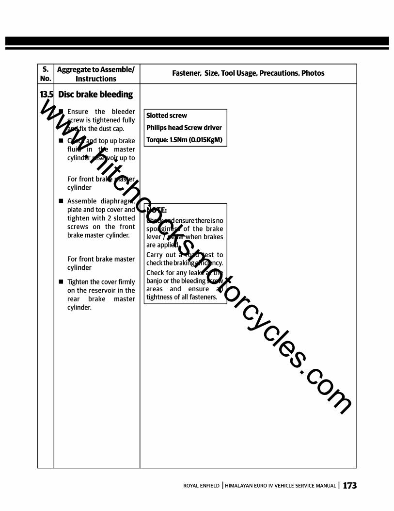
173ROYAL ENFIELD HIMALAYAN EURO IV VEHICLE SERVICE MANUAL
Fastener, Size, Tool Usage, Precautions, PhotosAggregate to Assemble/Instructions
13.5 Disc brake bleeding
Ensure the bleederscrew is tightened fullyand fix the dust cap.
Check and top up brakefluid in the mastercylinder reservoir up to
S.No.
Slotted screw
Philips head Screw driver
Torque: 1.5Nm (0.015KgM)
NOTE:Check and ensure there is nosponginess of the brakelever / pedal when brakesare applied.Carry out a road test tocheck the braking efficiency.Check for any leaks at thebanjo or the bleeding screwareas and ensure alltightness of all fasteners.
For front brake mastercylinder
Assemble diaphragm,plate and top cover andtighten with 2 slottedscrews on the frontbrake master cylinder.
For front brake mastercylinder
Tighten the cover firmlyon the reservoir in therear brake mastercylinder.
www.hitchcocksmotorcycles.com

174 ROYAL ENFIELD HIMALAYAN EURO IV VEHICLE SERVICE MANUAL
SECTION 14 – EVAPORATIVE EMISSIONS
HIMALAYAN MODEL
S. NO. DESCRIPTION QTY. S. NO. DESCRIPTION QTY.
1 Skid plate with Canister pad 1
2 Flanged Hex Bolt M6 X 1 X 10 6
3 Hex.Socket Button Head Screrw M6 X 1 X 12 5
4 Bracket Assy- Canister mounting 2
5 Rubber Strap- Canister 1
6 Canister Assy 1
7 Clip 1
8 Hose- Air vent 1
9 Hose- Purge Valve to Throttle body 1
10 Hose-Clip 4
10
109
1112
1314
3
10
19
10
12
18
12
21617
1215
12 52
4
6
7
8
3
2
11 Hose- Canister to Purge valve 1
12 Hose-Clip 6
13 Purge Valve 1
14 Grommet- Purge Valve 1
15 Hose- Canister to T Connector 1
16 Bracket Assy- Purge Valve 1
17 T Connector 1
18 Hose- T Connector to Purge Valve 1
19 Hose- Fuel tank to Purge Valve 1
www.hitchcocksmotorcycles.com

175ROYAL ENFIELD HIMALAYAN EURO IV VEHICLE SERVICE MANUAL
LOCATION OF EVAP IN MOTORCYCLEThe canister is connected to the fuel tank to trap all the fuel vapours that build up in the fuel tank .
HIMALAYANLocation : Located on Skid Plate.www.hitchcocksmotorcycles.com
176 ROYAL ENFIELD HIMALAYAN EURO IV VEHICLE SERVICE MANUAL
PURGE VALVE
The purge valve is a mechanically controlled one way valve. When the engine is off, the purge valve is closed. When theengine is started, the vacuum created in the suction port is used to open this one way valve and allow the vapors togo into the inlet port.
The Evaporative emission control system EVAP fitted in our motorcycles prevents gasoline vapors from escapinginto the atmosphere from the fuel tank.
As soon as the motorcycle is parked after riding or parked under the sun, the hot radiation from the engine / sunlightcauses the fuel in the tank to warm up and releases fuel vapors.
The EVAP system prevents these fuel vapors recycled to engine to avoid vapor into the atmosphere and stored in acharcoal canister.
As soon as the engine is started, these vapours are purged from the canister, into the combustion chamber.
The system consists of a canister, purge valve, rubber hoses, connectors and a sealed fuel tank cap.
www.hitchcocksmotorcycles.com
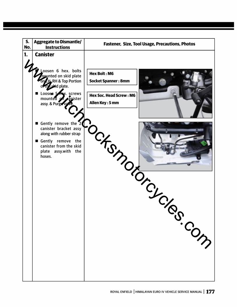
177ROYAL ENFIELD HIMALAYAN EURO IV VEHICLE SERVICE MANUAL
S.No.
Fastener, Size, Tool Usage, Precautions, PhotosAggregate to Dismantle/Instructions
1. Canister
Hex Bolt : M6
Socket Spanner : 8mm
Hex Soc. Head Screw : M6
Allen Key : 5 mm
Loosen 6 hex. boltsmounted on skid plateon LH, RH & Top Portionof the skid plate.
Loosen 5 hex. screwsmounted on canisterassy. & Purge valve.
Gently remove the 2canister bracket assyalong with rubber strap
Gently remove thecanister from the skidplate assy.with thehoses.
www.hitchcocksmotorcycles.com
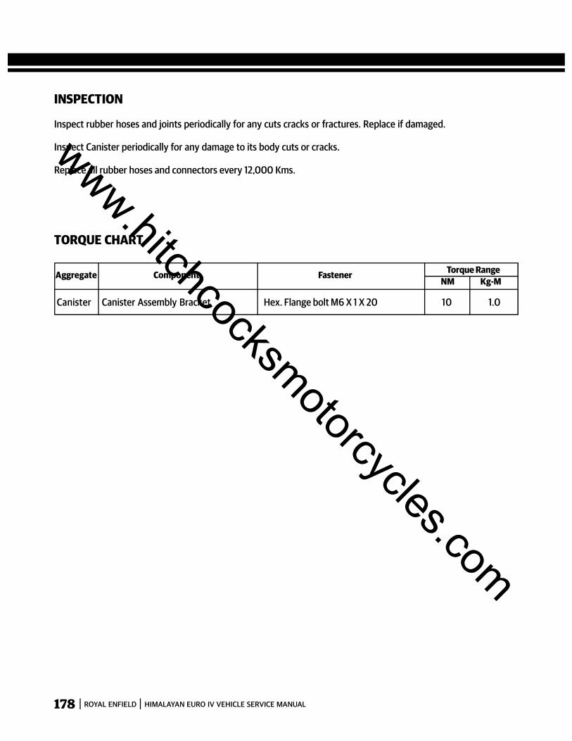
178 ROYAL ENFIELD HIMALAYAN EURO IV VEHICLE SERVICE MANUAL
INSPECTION
Inspect rubber hoses and joints periodically for any cuts cracks or fractures. Replace if damaged.
Inspect Canister periodically for any damage to its body cuts or cracks.
Replace all rubber hoses and connectors every 12,000 Kms.
Aggregate Component Fastener Torque Range NM Kg-M
Canister Canister Assembly Bracket Hex. Flange bolt M6 X 1 X 20 10 1.0
TORQUE CHART
www.hitchcocksmotorcycles.com

179ROYAL ENFIELD HIMALAYAN EURO IV VEHICLE SERVICE MANUAL
S.No.
Fastener, Size, Tool Usage, Precautions, PhotosAggregate to Assemble/Instructions
1. Canister
Hex Bolt : M6
Socket Spanner : 8mm
Torque : 10 Nm
Hex Soc. Head Screw : M6
Allen Key : 5 mm
Locate canister assy onthe skid plate along withthe hoses.
Locatge the canisterbracket assy. on the skidplate along with rubberstrap.
Install 5 hex screws okncanister assy. & purgevalve.
Install 6 hex bolts on skidplate LH, RH & Topportion.
www.hitchcocksmotorcycles.com
180 ROYAL ENFIELD HIMALAYAN EURO IV VEHICLE SERVICE MANUAL
SECTION 15 -ENGINE MANAGEMENT SYSTEM (EMS)
www.hitchcocksmotorcycles.com
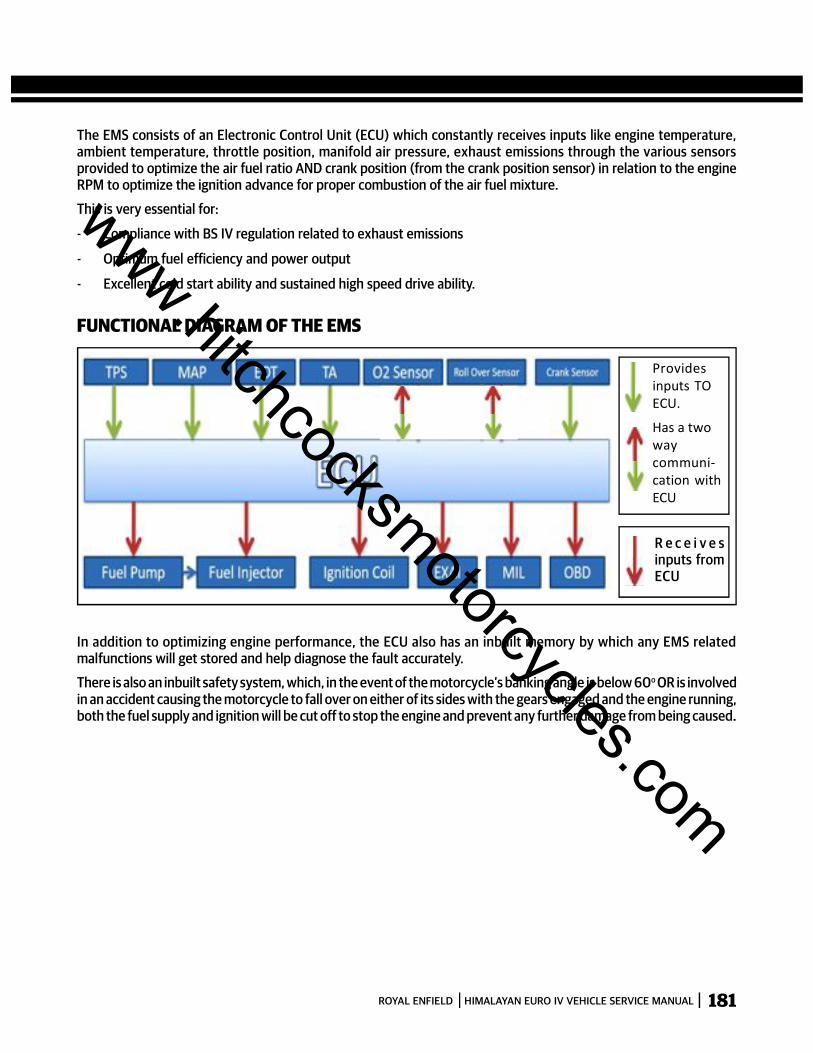
181ROYAL ENFIELD HIMALAYAN EURO IV VEHICLE SERVICE MANUAL
The EMS consists of an Electronic Control Unit (ECU) which constantly receives inputs like engine temperature,ambient temperature, throttle position, manifold air pressure, exhaust emissions through the various sensorsprovided to optimize the air fuel ratio AND crank position (from the crank position sensor) in relation to the engineRPM to optimize the ignition advance for proper combustion of the air fuel mixture.
This is very essential for:
- Compliance with BS IV regulation related to exhaust emissions
- Optimum fuel efficiency and power output
- Excellent cold start ability and sustained high speed drive ability.
FUNCTIONAL DIAGRAM OF THE EMS
In addition to optimizing engine performance, the ECU also has an inbuilt memory by which any EMS relatedmalfunctions will get stored and help diagnose the fault accurately.
There is also an inbuilt safety system, which, in the event of the motorcycle’s banking angle is below 60o OR is involvedin an accident causing the motorcycle to fall over on either of its sides with the gears engaged and the engine running,both the fuel supply and ignition will be cut off to stop the engine and prevent any further damage from being caused.
Providesinputs TOECU.
Has a twowaycommuni-cation withECU
R e c e i v e sinputs fromECU
www.hitchcocksmotorcycles.com

182 ROYAL ENFIELD HIMALAYAN EURO IV VEHICLE SERVICE MANUAL
SPECIFICATIONS / FUNCTIONS OF THE VARIOUS EMS PARTS
1. ELECTRONIC CONTROL UNIT (ECU)
LOCATIONThe Electronic Control Unit (ECU) is located under the seat.
The ECU consists of a microprocessor with two memories Flash Memory and E2 PROM.
Flash memory is an exclusive recording unit. It collects different inputs from various sensors and calculates optimizedvalues and provides the outputs to the respective controlling devices.
E2PROM is an abbreviation for Electronically Erasable Programmable Read Only Memory. This memory recordsinformation related to performance of the various sensors in the EMS on a real time basis AND also records any sensorfailures if it occurs during operation of the motorcycle.
The main advantage of E2PROM is it records data, even when the motorcycle’s electrical system is switched OFF.
This will help in diagnosing the motorcycle performance and also to view the history and defect codes, whenever theRoyal Enfield NACS II diagnostic tool is connected to the socket in the wiring harness of the motorcycle.
Once the defect is diagnosed and corrected, the history of the defect can be erased using the Royal Enfield NACS IIdiagnostic tool.
SPECIFICATIONOperating Voltage: 8 – 16 V
Sensor Supply Voltage: 5 V
Operating temperature: –10ºC to + 60ºC
Storage Temperature: –20ºC to + 80ºC
www.hitchcocksmotorcycles.com

183ROYAL ENFIELD HIMALAYAN EURO IV VEHICLE SERVICE MANUAL
ECU LAYOUT ECU PIN DETAILSPin No. Name Function
1 IGP Ignition Power2 LG Logic Ground3 HEGO HEGO Sensor4. SG Sensor Ground5 TH Throttle Position Sensor6 VCC Sensor Power Output (+SV)7 - -8 FP Fuel Pump9 PG1 Power Ground110 PG2 Power Ground211 IG Ignition Coil12 CRK-P Crank Pulse Sensor13 - -14 TA Air Temperature15 TEST Test Switch16 INJ Injector17 VSP Vehicle Speed Sensor18 - -19 - -20 - -21 - -22 MIL Multi Indicator Lamp23 CRK-M Crank Pulse Sensor GND24 TW Engine Temp. Sensor25 SSTAND Side Stand Switch26 ROLL Roll Sensor27 PM Manifold Pressure Sensor28 EXAJ Exhaust Air Injection29 NLSW Neutral Switch30 K-LINE Diagnostic Tool31 - -32 - -33 HEGO HT HEGO Sensor Heater
www.hitchcocksmotorcycles.com
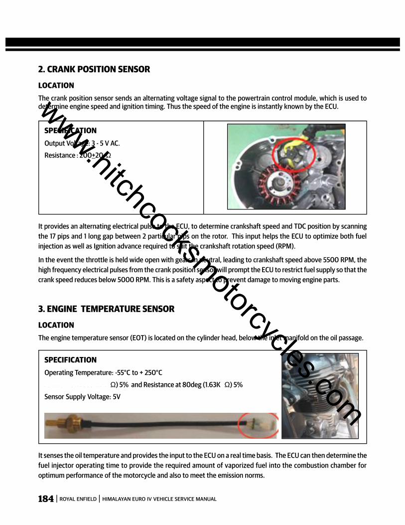
184 ROYAL ENFIELD HIMALAYAN EURO IV VEHICLE SERVICE MANUAL
2. CRANK POSITION SENSOR
LOCATIONThe crank position sensor sends an alternating voltage signal to the powertrain control module, which is used todetermine engine speed and ignition timing. Thus the speed of the engine is instantly known by the ECU.
SPECIFICATIONOutput Voltage: 3 - 5 V AC.
Resistance : 200+20 Ω
It provides an alternating electrical pulse to the ECU, to determine crankshaft speed and TDC position by scanningthe 17 pips and 1 long gap between 2 particular pips on the rotor. This input helps the ECU to optimize both fuelinjection as well as Ignition advance required to suit the crankshaft rotation speed (RPM).
In the event the throttle is held wide open with gears in neutral, leading to crankshaft speed above 5500 RPM, thehigh frequency electrical pulses from the crank position sensor will prompt the ECU to restrict fuel supply so that thecrank speed reduces below 5000 RPM. This is a safety aspect to prevent damage to moving engine parts.
3. ENGINE TEMPERATURE SENSOR
LOCATIONThe engine temperature sensor (EOT) is located on the cylinder head, below the inlet manifold on the oil passage.
It senses the oil temperature and provides the input to the ECU on a real time basis. The ECU can then determine thefuel injector operating time to provide the required amount of vaporized fuel into the combustion chamber foroptimum performance of the motorcycle and also to meet the emission norms.
SPECIFICATIONOperating Temperature: -55°C to + 250°C
R e s i s t a n c e : 2 5 d e g ( 1 0 K Ω) 5% and Resistance at 80deg (1.63K Ω) 5%
Sensor Supply Voltage: 5V
www.hitchcocksmotorcycles.com
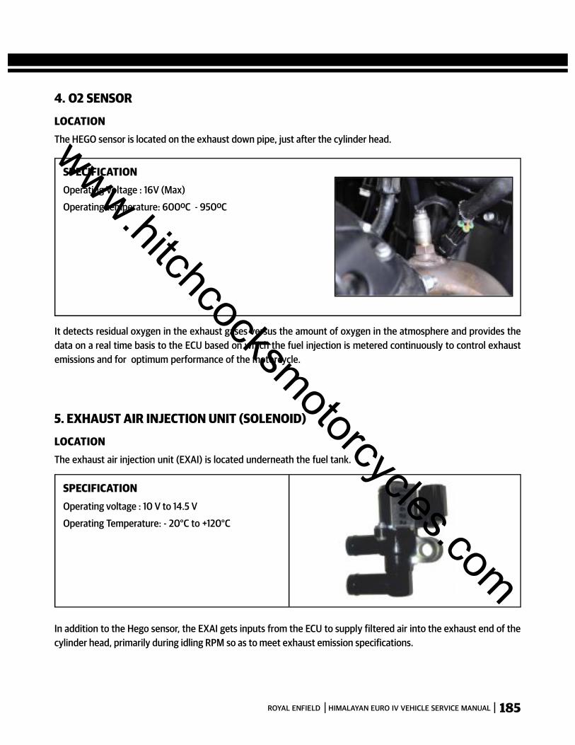
185ROYAL ENFIELD HIMALAYAN EURO IV VEHICLE SERVICE MANUAL
4. O2 SENSOR
LOCATIONThe HEGO sensor is located on the exhaust down pipe, just after the cylinder head.
SPECIFICATIONOperating Voltage : 16V (Max)
Operating temperature: 600ºC - 950ºC
It detects residual oxygen in the exhaust gases versus the amount of oxygen in the atmosphere and provides thedata on a real time basis to the ECU based on which the fuel injection is metered continuously to control exhaustemissions and for optimum performance of the motorcycle.
5. EXHAUST AIR INJECTION UNIT (SOLENOID)
LOCATIONThe exhaust air injection unit (EXAI) is located underneath the fuel tank.
In addition to the Hego sensor, the EXAI gets inputs from the ECU to supply filtered air into the exhaust end of thecylinder head, primarily during idling RPM so as to meet exhaust emission specifications.
SPECIFICATIONOperating voltage : 10 V to 14.5 V
Operating Temperature: - 20°C to +120°C
www.hitchcocksmotorcycles.com
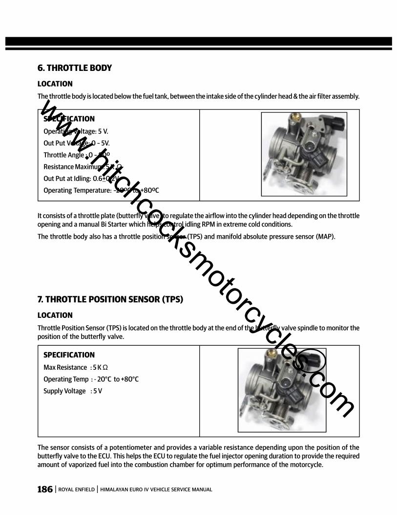
186 ROYAL ENFIELD HIMALAYAN EURO IV VEHICLE SERVICE MANUAL
6. THROTTLE BODY
LOCATIONThe throttle body is located below the fuel tank, between the intake side of the cylinder head & the air filter assembly.
SPECIFICATIONOperating Voltage: 5 V.
Out Put Voltage: 0 – 5V.
Throttle Angle : 0 – 80º
Resistance Maximum: 5 K ΩOut Put at Idling: 0.6+0.2V.
Operating Temperature: –20ºC to +80ºC
It consists of a throttle plate (butterfly valve) to regulate the airflow into the cylinder head depending on the throttleopening and a manual Bi Starter which helps control idling RPM in extreme cold conditions.
The throttle body also has a throttle position sensor (TPS) and manifold absolute pressure sensor (MAP).
7. THROTTLE POSITION SENSOR (TPS)
LOCATIONThrottle Position Sensor (TPS) is located on the throttle body at the end of the butterfly valve spindle to monitor theposition of the butterfly valve.
The sensor consists of a potentiometer and provides a variable resistance depending upon the position of thebutterfly valve to the ECU. This helps the ECU to regulate the fuel injector opening duration to provide the requiredamount of vaporized fuel into the combustion chamber for optimum performance of the motorcycle.
SPECIFICATIONMax Resistance : 5 K ΩOperating Temp : - 20°C to +80°C
Supply Voltage : 5 V
www.hitchcocksmotorcycles.com
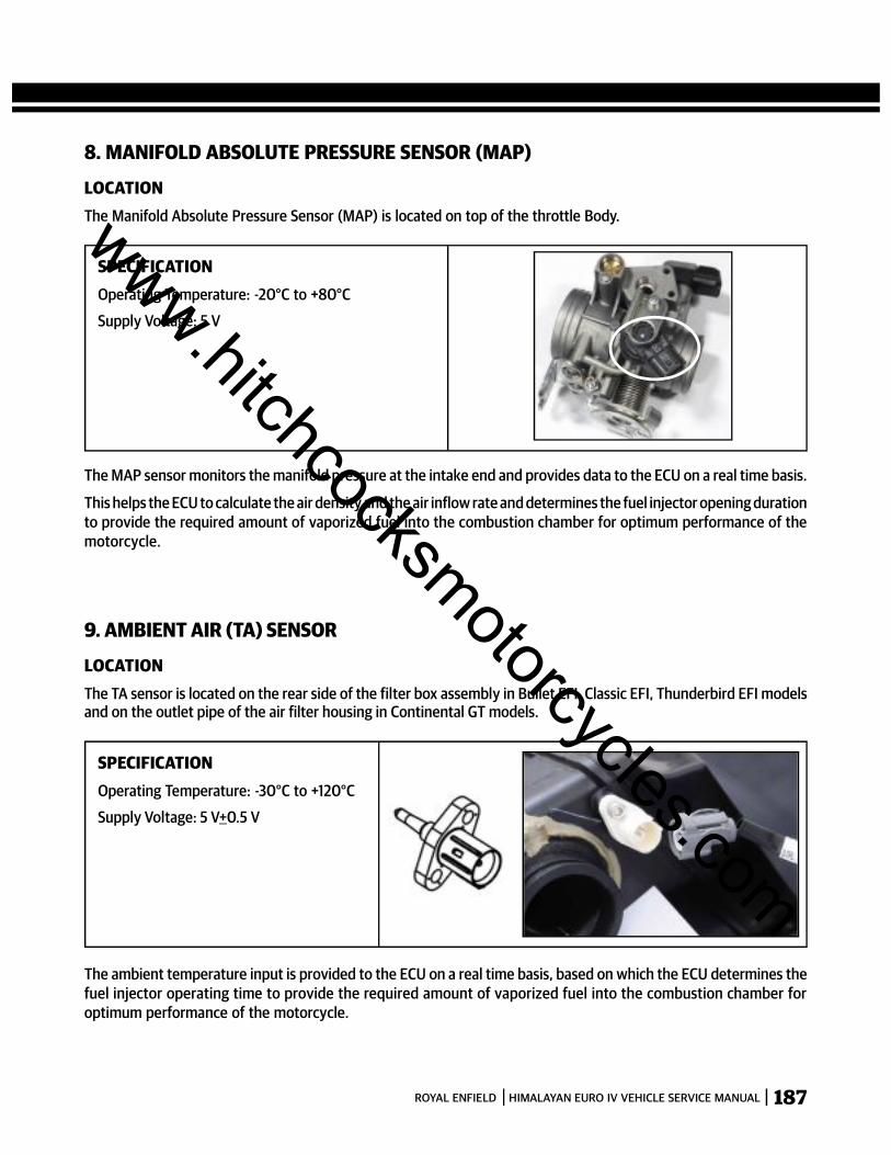
187ROYAL ENFIELD HIMALAYAN EURO IV VEHICLE SERVICE MANUAL
8. MANIFOLD ABSOLUTE PRESSURE SENSOR (MAP)
LOCATIONThe Manifold Absolute Pressure Sensor (MAP) is located on top of the throttle Body.
SPECIFICATIONOperating Temperature: -20°C to +80°C
Supply Voltage: 5 V
The MAP sensor monitors the manifold pressure at the intake end and provides data to the ECU on a real time basis.
This helps the ECU to calculate the air density and the air inflow rate and determines the fuel injector opening durationto provide the required amount of vaporized fuel into the combustion chamber for optimum performance of themotorcycle.
9. AMBIENT AIR (TA) SENSOR
LOCATIONThe TA sensor is located on the rear side of the filter box assembly in Bullet EFI, Classic EFI, Thunderbird EFI modelsand on the outlet pipe of the air filter housing in Continental GT models.
The ambient temperature input is provided to the ECU on a real time basis, based on which the ECU determines thefuel injector operating time to provide the required amount of vaporized fuel into the combustion chamber foroptimum performance of the motorcycle.
SPECIFICATIONOperating Temperature: -30°C to +120°C
Supply Voltage: 5 V+0.5 V
www.hitchcocksmotorcycles.com

188 ROYAL ENFIELD HIMALAYAN EURO IV VEHICLE SERVICE MANUAL
10. FUEL PUMP ASSEMBLY
LOCATIONThe fuel pump is located on the left side bottom of the fuel tank and submerged in the fuel so that it cannot ignite itselfdue to any electrical short circuits. The fuel pump has an inbuilt micro filter which helps to filter even the minute dustparticles that may come in the fuel.
SPECIFICATIONOperating Voltage: 6 V to 15 V
Operating Temperature: -15°C to +60°C
Fuel Pressure: 294 Kpa
As soon as the Ignition switch and the engine kill switch are in ON position, the fuel pump creates a positive pressureof 294KPa in the fuel line and up to the injector. The fuel pump operation is determined by the ECU so that there is noexcessive pressure in the fuel system to prevent damage to the fuel injector, fuel hose. Any excess pressure is bypassedback into the fuel tank.
11. FUEL INJECTOR
LOCATIONThe fuel injector is located at an angle on the intake side of the cylinder head so as to maximize fuel spray and minimizewall wetting, for optimum performance of the motorcycle.
The Fuel Injector is a solenoid operated electromagnetic valve, which enables the pressurized fuel delivered by thefuel pump, to be atomized and sprayed into the cylinder head combustion chamber.
The fuel injector operation and duration to deliver vaporized fuel is controlled by the ECU based on the criticaloperating inputs received from the crank position sensor, EOT sensor, ambient air temperature sensor, throttleposition sensor, manifold pressure sensor and HEGO sensor.
SPECIFICATIONOperating Voltage : 10 V to 16 V
Operating Temperature : -30°C to +120°C
Fuel Pressure : 343 Kpa
Resistance : 10.3 +0.5 Ohms
Injector
www.hitchcocksmotorcycles.com
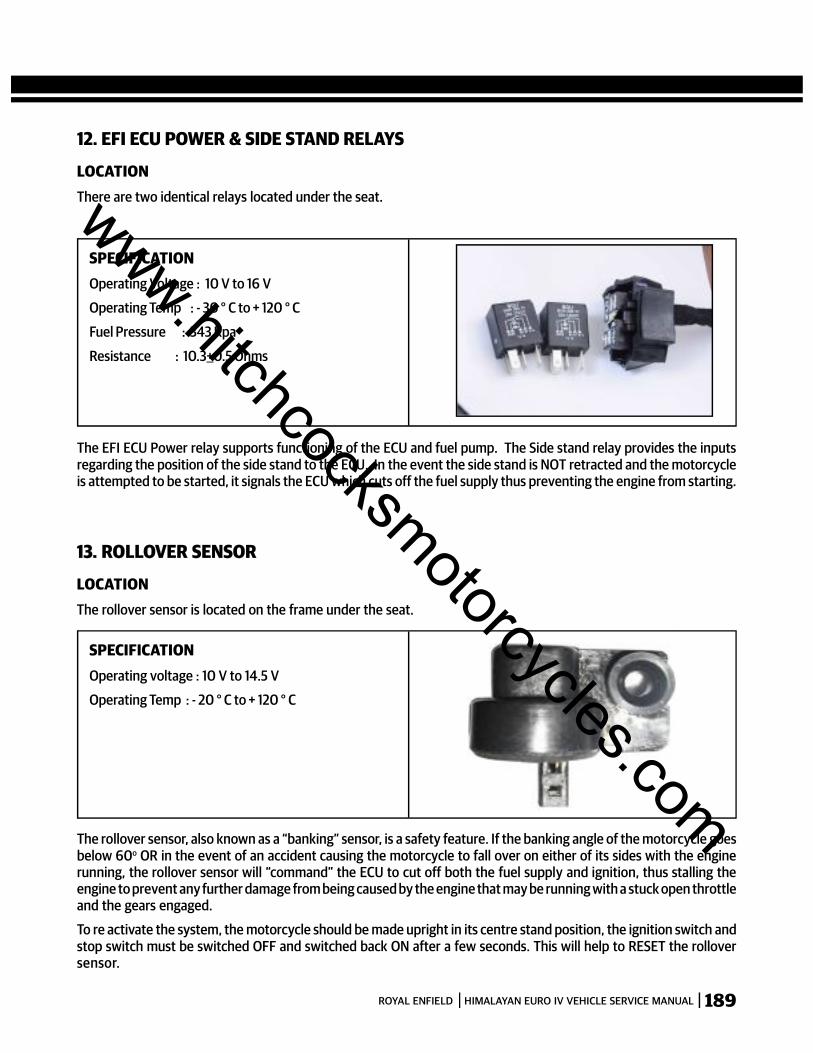
189ROYAL ENFIELD HIMALAYAN EURO IV VEHICLE SERVICE MANUAL
12. EFI ECU POWER & SIDE STAND RELAYS
LOCATIONThere are two identical relays located under the seat.
SPECIFICATIONOperating Voltage : 10 V to 16 V
Operating Temp : - 30 ° C to + 120 ° C
Fuel Pressure : 343 Kpa
Resistance : 10.3+0.5 Ohms
The EFI ECU Power relay supports functioning of the ECU and fuel pump. The Side stand relay provides the inputsregarding the position of the side stand to the ECU. In the event the side stand is NOT retracted and the motorcycleis attempted to be started, it signals the ECU which cuts off the fuel supply thus preventing the engine from starting.
13. ROLLOVER SENSOR
LOCATIONThe rollover sensor is located on the frame under the seat.
The rollover sensor, also known as a “banking” sensor, is a safety feature. If the banking angle of the motorcycle goesbelow 60o OR in the event of an accident causing the motorcycle to fall over on either of its sides with the enginerunning, the rollover sensor will “command” the ECU to cut off both the fuel supply and ignition, thus stalling theengine to prevent any further damage from being caused by the engine that may be running with a stuck open throttleand the gears engaged.
To re activate the system, the motorcycle should be made upright in its centre stand position, the ignition switch andstop switch must be switched OFF and switched back ON after a few seconds. This will help to RESET the rolloversensor.
SPECIFICATIONOperating voltage : 10 V to 14.5 V
Operating Temp : - 20 ° C to + 120 ° C
www.hitchcocksmotorcycles.com

190 ROYAL ENFIELD HIMALAYAN EURO IV VEHICLE SERVICE MANUAL
14. MALFUNCTION INDICATOR LAMP (MIL)
LOCATIONMalfunction Indicator Lamp (MIL) is located in the small meter on the Headlamp casing
When both the Ignition & Engine kill switch is “ON” and after vehicleis started, MIL will glow for few seconds and switch OFF, this indicatesthat all the functions of EMS are functioning correctly.
In the event of any malfunction the MIL will glow continuously. TheEMS should be checked using either the test pin method OR theRoyal Enfield NACS II diagnostic tool connected to the socket in thewiring harness of the motorcycle.
www.hitchcocksmotorcycles.com
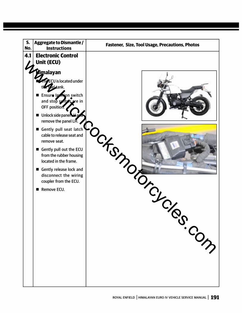
191ROYAL ENFIELD HIMALAYAN EURO IV VEHICLE SERVICE MANUAL
S.No.
Fastener, Size, Tool Usage, Precautions, PhotosAggregate to Dismantle /Instructions
4.1 Electronic ControlUnit (ECU)
Himalayan The ECU is located under
the fuel tank.
Ensure Ignition switchand stop switch are inOFF position.
Unlock side panel LH andremove the panel LH.
Gently pull seat latchcable to release seat andremove seat.
Gently pull out the ECUfrom the rubber housinglocated in the frame.
Gently release lock anddisconnect the wiringcoupler from the ECU.
Remove ECU.
www.hitchcocksmotorcycles.com

192 ROYAL ENFIELD HIMALAYAN EURO IV VEHICLE SERVICE MANUAL
4.2 Crank positionsensor The Crank position
sensor is located insidethe cover RH of theengine assembly.
Drain engine oil from theengine.
Ensure Ignition switchand stop switch are inOFF position.
Disconnect Magnetowiring coupler from theelectrical harness.
Loosen and remove 2Hex Flange Bolt M6 X 1 X85 from cover RH front.
Loosen and remove 7Hex Flange Bolt M6 X 1 X70 from cover RH, top,centre and bottom.
Loosen and remove 1Hex Flange Bolt M6 X 1 X45 from cover RH rear.
It may be necessary togently tap and removecover RH as the magneticforces in the rotor can beacting on the stator andmaking it difficult toremove.
Remove gasket.
Remove 2 Hex FlangeBolt M5 X 0.8 X 16,holding Pulsar coil tocover RH inside.
Remove 3 Hex SocketHead Cap Screw M5 X 30,holding stator coil tocover RH inside.
Fastener, Size, Tool Usage, Precautions, PhotosAggregate to Dismantle /Instructions
S.No.
CAUTION: Ensure stator coupler is
disconnected beforeremoving cover RH.
Gently tap on the tabsprovided in the frontand rear of Cover RH torelease the cover fromthe crankcase.
www.hitchcocksmotorcycles.com
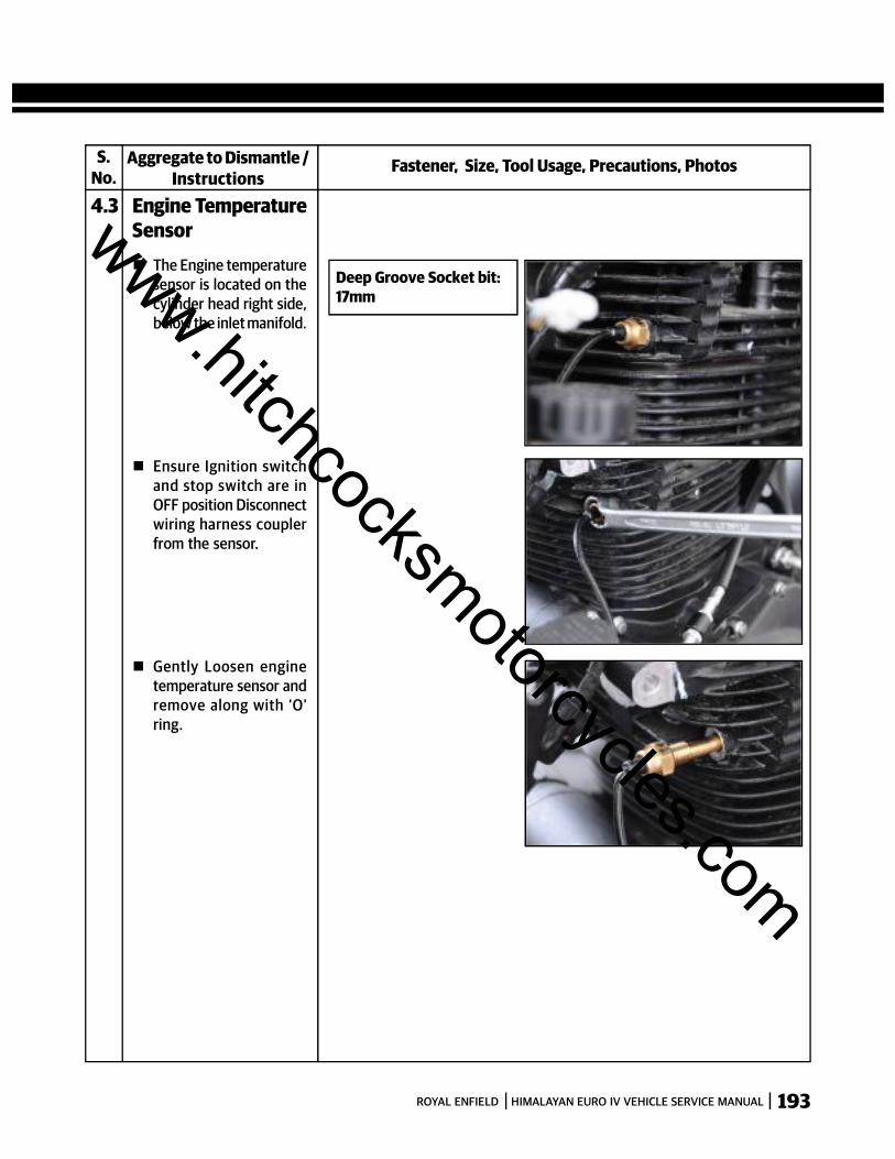
193ROYAL ENFIELD HIMALAYAN EURO IV VEHICLE SERVICE MANUAL
S.No.
Fastener, Size, Tool Usage, Precautions, PhotosAggregate to Dismantle /Instructions
4.3 Engine TemperatureSensor The Engine temperature
sensor is located on thecylinder head right side,below the inlet manifold.
Deep Groove Socket bit:17mm
Gently Loosen enginetemperature sensor andremove along with ‘O’ring.
Ensure Ignition switchand stop switch are inOFF position Disconnectwiring harness couplerfrom the sensor.
www.hitchcocksmotorcycles.com
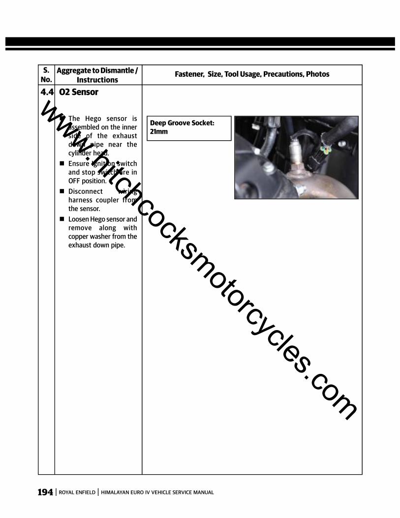
194 ROYAL ENFIELD HIMALAYAN EURO IV VEHICLE SERVICE MANUAL
S.No.
Fastener, Size, Tool Usage, Precautions, PhotosAggregate to Dismantle /Instructions
4.4 O2 Sensor
The Hego sensor isassembled on the innerside of the exhaustdown pipe near thecylinder head.
Ensure Ignition switchand stop switch are inOFF position.
Disconnect wiringharness coupler fromthe sensor.
Loosen Hego sensor andremove along withcopper washer from theexhaust down pipe.
Deep Groove Socket:21mm
www.hitchcocksmotorcycles.com
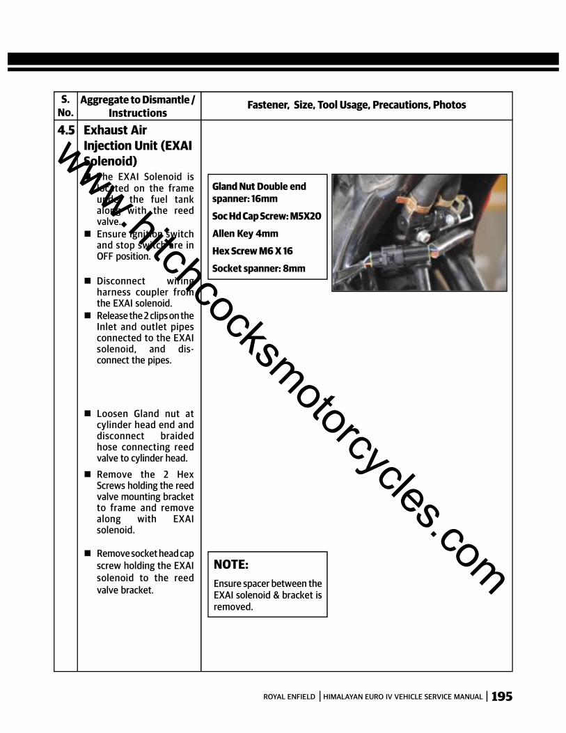
195ROYAL ENFIELD HIMALAYAN EURO IV VEHICLE SERVICE MANUAL
S.No.
Fastener, Size, Tool Usage, Precautions, PhotosAggregate to Dismantle /Instructions
4.5 Exhaust AirInjection Unit (EXAISolenoid) The EXAI Solenoid is
located on the frameunder the fuel tankalong with the reedvalve.
Ensure Ignition switchand stop switch are inOFF position.
Disconnect wiringharness coupler fromthe EXAI solenoid.
Release the 2 clips on theInlet and outlet pipesconnected to the EXAIsolenoid, and dis-connect the pipes.
Gland Nut Double endspanner: 16mm
Soc Hd Cap Screw: M5X20
Allen Key 4mm
Hex Screw M6 X 16
Socket spanner: 8mm
NOTE:Ensure spacer between theEXAI solenoid & bracket isremoved.
Loosen Gland nut atcylinder head end anddisconnect braidedhose connecting reedvalve to cylinder head.
Remove the 2 HexScrews holding the reedvalve mounting bracketto frame and removealong with EXAIsolenoid.
Remove socket head capscrew holding the EXAIsolenoid to the reedvalve bracket.
www.hitchcocksmotorcycles.com
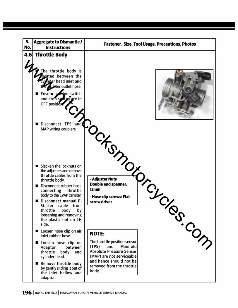
196 ROYAL ENFIELD HIMALAYAN EURO IV VEHICLE SERVICE MANUAL
S.No.
Fastener, Size, Tool Usage, Precautions, PhotosAggregate to Dismantle /Instructions
4.6 Throttle Body
The throttle body islocated between thecylinder head inlet andthe air filter outlet hose.
Ensure Ignition switchand stop switch are inOFF position.
NOTE:The throttle position sensor(TPS) and ManifoldAbsolute Pressure Sensor(MAP) are not serviceableand hence should not beremoved from the throttlebody.
Slacken the locknuts onthe adjusters and removethrottle cables from thethrottle body.
Disconnect rubber hoseconnecting throttlebody to the EVAP canister.
Disconnect manual BiStarter cable fromthrottle body byloosening and removingthe plastic nut on LHside.
Loosen hose clip on airinlet rubber hose.
Loosen hose clip onAdaptor betweenthrottle body andcylinder head.
Remove throttle bodyby gently sliding it out ofthe inlet bellow andadaptor.
- Adjuster NutsDouble end spanner:12mm
- Hose clip screws: Flatscrew driver
Disconnect TPS andMAP wiring couplers.
www.hitchcocksmotorcycles.com
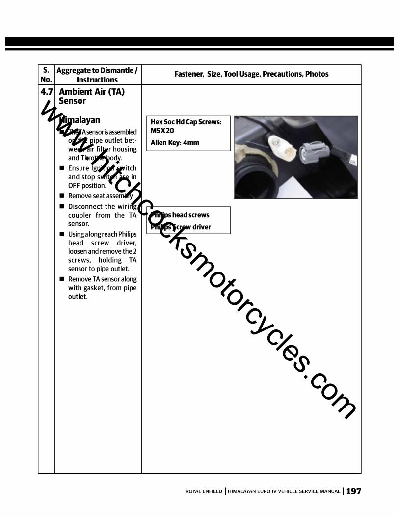
197ROYAL ENFIELD HIMALAYAN EURO IV VEHICLE SERVICE MANUAL
S.No.
Fastener, Size, Tool Usage, Precautions, PhotosAggregate to Dismantle /Instructions
4.7 Ambient Air (TA)Sensor
Philips head screws
Philips Screw driver
Hex Soc Hd Cap Screws:M5 X 20
Allen Key: 4mm
Himalayan The TA sensor is assembled
on the pipe outlet bet-ween air filter housingand Throttle body.
Ensure Ignition switchand stop switch are inOFF position.
Remove seat assembly Disconnect the wiring
coupler from the TAsensor.
Using a long reach Philipshead screw driver,loosen and remove the 2screws, holding TAsensor to pipe outlet.
Remove TA sensor alongwith gasket, from pipeoutlet.
www.hitchcocksmotorcycles.com
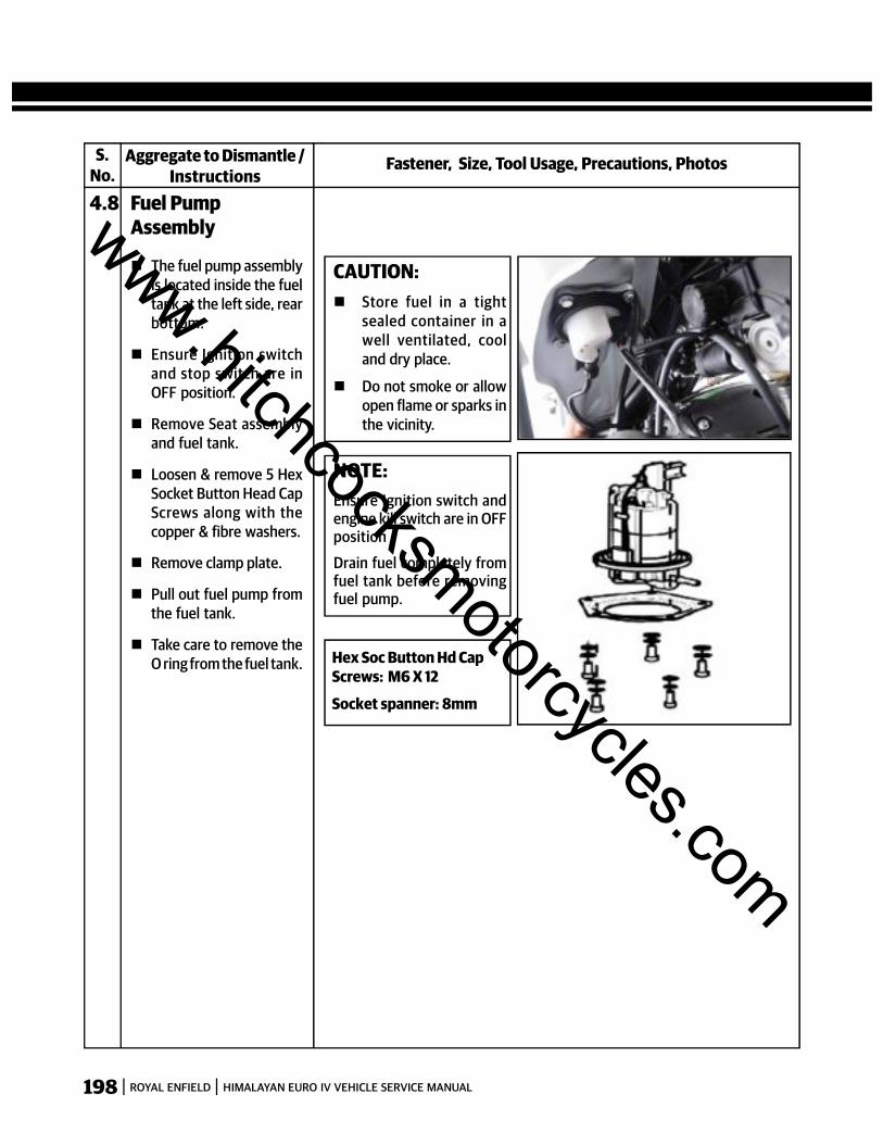
198 ROYAL ENFIELD HIMALAYAN EURO IV VEHICLE SERVICE MANUAL
S.No.
Fastener, Size, Tool Usage, Precautions, PhotosAggregate to Dismantle /Instructions
4.8 Fuel PumpAssembly
The fuel pump assemblyis located inside the fueltank at the left side, rearbottom.
Ensure Ignition switchand stop switch are inOFF position.
Remove Seat assemblyand fuel tank.
Loosen & remove 5 HexSocket Button Head CapScrews along with thecopper & fibre washers.
Remove clamp plate.
Pull out fuel pump fromthe fuel tank.
Take care to remove theO ring from the fuel tank.
CAUTION: Store fuel in a tight
sealed container in awell ventilated, cooland dry place.
Do not smoke or allowopen flame or sparks inthe vicinity.
NOTE:Ensure Ignition switch andengine kill switch are in OFFposition
Drain fuel completely fromfuel tank before removingfuel pump.
Hex Soc Button Hd CapScrews: M6 X 12
Socket spanner: 8mm
www.hitchcocksmotorcycles.com

199ROYAL ENFIELD HIMALAYAN EURO IV VEHICLE SERVICE MANUAL
S.No.
Fastener, Size, Tool Usage, Precautions, PhotosAggregate to Dismantle /Instructions
4.9 Fuel Injector
The fuel injector isassembled on the inletside of cylinder headbelow the fuel tank.
Ensure Ignition switchand stop switch are inOFF position.
Remove Seat assemblyand fuel tank.
Disconnect the wiringcoupler from the fuelinjector.
Loosen worm clip on theinlet fuel hose andremove fuel hose fromcap injector assembly.
Remove hex nut fromtop of injector capassembly and removeinjector cap along with“O” ring.
Remove the spacer fromthe stud.
Gently pull out theInjector from thecylinder head.
Hex U nut: M6 X 1
Ring spanner: 8mm
www.hitchcocksmotorcycles.com

200 ROYAL ENFIELD HIMALAYAN EURO IV VEHICLE SERVICE MANUAL
S.No.
Fastener, Size, Tool Usage, Precautions, PhotosAggregate to Dismantle /Instructions
4.10 EFI ECU Power &Side Stand Relays
Himalayan Two identical relays are
located near the battery.
Located in a rubberholder on the side of thebattery carrier.
Ensure Ignition switchand stop switch are inOFF position.
Remove side panel LH.
Gently pull out relayfrom the rubber holderand electrical socket.
www.hitchcocksmotorcycles.com
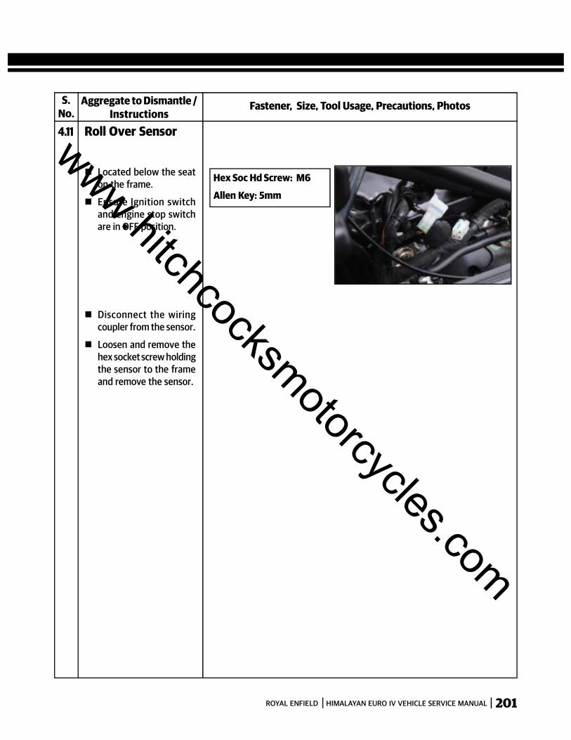
201ROYAL ENFIELD HIMALAYAN EURO IV VEHICLE SERVICE MANUAL
S.No.
Fastener, Size, Tool Usage, Precautions, PhotosAggregate to Dismantle /Instructions
4.11 Roll Over Sensor
Located below the seaton the frame.
Ensure Ignition switchand engine stop switchare in OFF position.
Disconnect the wiringcoupler from the sensor.
Loosen and remove thehex socket screw holdingthe sensor to the frameand remove the sensor.
Hex Soc Hd Screw: M6
Allen Key: 5mm
www.hitchcocksmotorcycles.com

202 ROYAL ENFIELD HIMALAYAN EURO IV VEHICLE SERVICE MANUAL
S.No.
Fastener, Size, Tool Usage, Precautions, PhotosAggregate to Dismantle /Instructions
4.12 MalfunctionIndicator LampHimalayan Located in the RPM
meter in the instrumentcluster.
Ensure Ignition switchand engine stop switchare in OFF position.
The instrument clusterdoes not have anyindividual serviceableparts.
www.hitchcocksmotorcycles.com
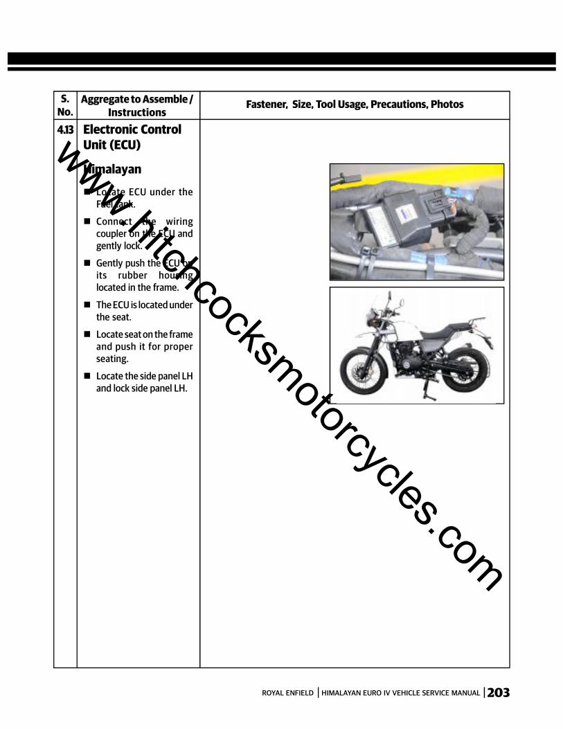
203ROYAL ENFIELD HIMALAYAN EURO IV VEHICLE SERVICE MANUAL
S.No.
Fastener, Size, Tool Usage, Precautions, PhotosAggregate to Assemble /Instructions
4.13 Electronic ControlUnit (ECU)
Himalayan
Locate ECU under theFuel tank.
Connect the wiringcoupler on the ECU andgently lock.
Gently push the ECU onits rubber housinglocated in the frame.
The ECU is located underthe seat.
Locate seat on the frameand push it for properseating.
Locate the side panel LHand lock side panel LH.
www.hitchcocksmotorcycles.com
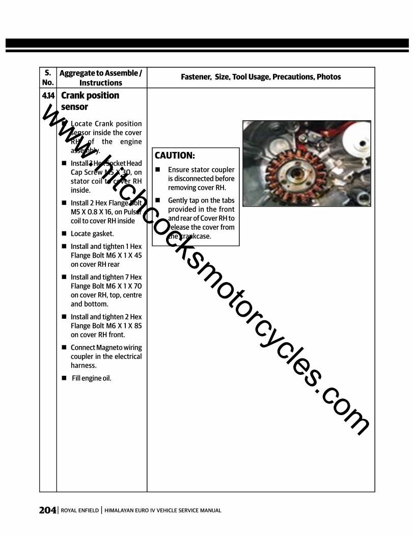
204 ROYAL ENFIELD HIMALAYAN EURO IV VEHICLE SERVICE MANUAL
4.14 Crank positionsensor
Locate Crank positionsensor inside the coverRH of the engineassembly.
Install 3 Hex Socket HeadCap Screw M5 X 30, onstator coil to cover RHinside.
Install 2 Hex Flange BoltM5 X 0.8 X 16, on Pulsarcoil to cover RH inside
Locate gasket.
Install and tighten 1 HexFlange Bolt M6 X 1 X 45on cover RH rear
Install and tighten 7 HexFlange Bolt M6 X 1 X 70on cover RH, top, centreand bottom.
Install and tighten 2 HexFlange Bolt M6 X 1 X 85on cover RH front.
Connect Magneto wiringcoupler in the electricalharness.
Fill engine oil.
CAUTION: Ensure stator coupler
is disconnected beforeremoving cover RH.
Gently tap on the tabsprovided in the frontand rear of Cover RH torelease the cover fromthe crankcase.
S.No.
Fastener, Size, Tool Usage, Precautions, PhotosAggregate to Assemble /Instructions
www.hitchcocksmotorcycles.com
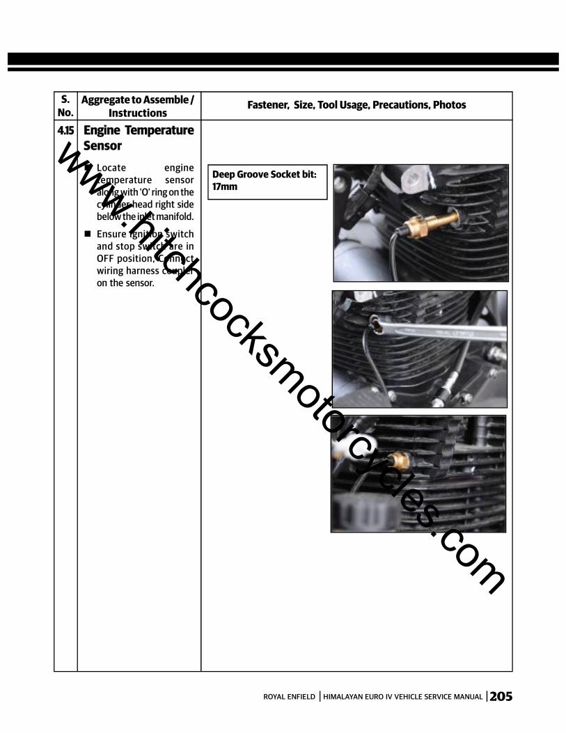
205ROYAL ENFIELD HIMALAYAN EURO IV VEHICLE SERVICE MANUAL
S.No.
Fastener, Size, Tool Usage, Precautions, PhotosAggregate to Assemble /Instructions
4.15 Engine TemperatureSensor Locate engine
temperature sensoralong with ‘O’ ring on thecylinder head right sidebelow the inlet manifold.
Ensure Ignition switchand stop switch are inOFF position, Connectwiring harness coupleron the sensor.
Deep Groove Socket bit:17mm
www.hitchcocksmotorcycles.com
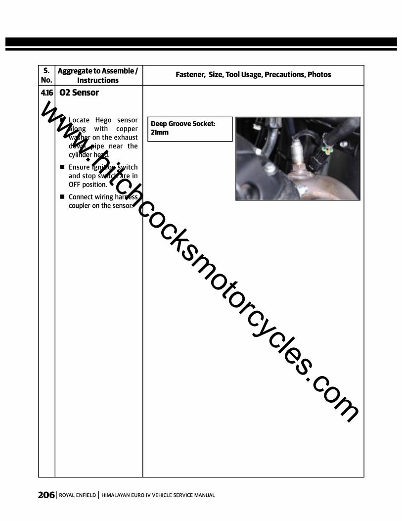
206 ROYAL ENFIELD HIMALAYAN EURO IV VEHICLE SERVICE MANUAL
S.No.
Fastener, Size, Tool Usage, Precautions, PhotosAggregate to Assemble /Instructions
4.16 O2 Sensor
Deep Groove Socket:21mm
Locate Hego sensoralong with copperwasher on the exhaustdown pipe near thecylinder head.
Ensure Ignition switchand stop switch are inOFF position.
Connect wiring harnesscoupler on the sensor.
www.hitchcocksmotorcycles.com
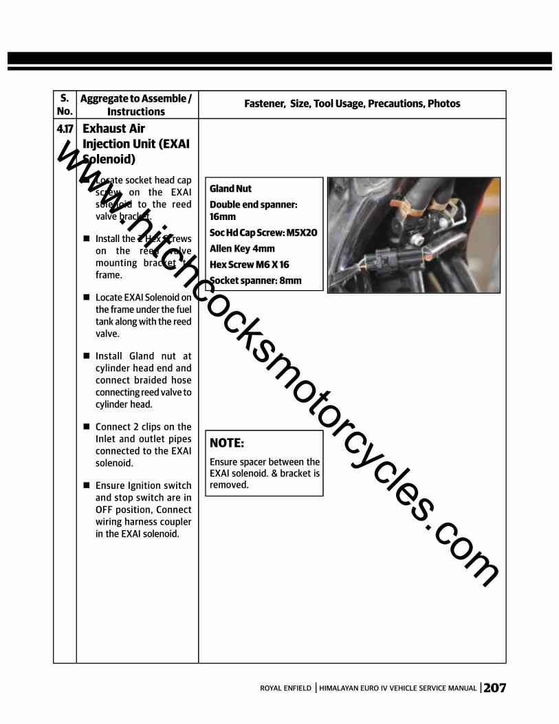
207ROYAL ENFIELD HIMALAYAN EURO IV VEHICLE SERVICE MANUAL
S.No.
Fastener, Size, Tool Usage, Precautions, PhotosAggregate to Assemble /Instructions
4.17 Exhaust AirInjection Unit (EXAISolenoid)
Gland NutDouble end spanner:16mmSoc Hd Cap Screw: M5X20Allen Key 4mmHex Screw M6 X 16Socket spanner: 8mm
Locate socket head capscrew on the EXAIsolenoid to the reedvalve bracket.
Install the 2 Hex Screwson the reed valvemounting bracket toframe.
Locate EXAI Solenoid onthe frame under the fueltank along with the reedvalve.
Install Gland nut atcylinder head end andconnect braided hoseconnecting reed valve tocylinder head.
Connect 2 clips on theInlet and outlet pipesconnected to the EXAIsolenoid.
Ensure Ignition switchand stop switch are inOFF position, Connectwiring harness couplerin the EXAI solenoid.
NOTE:Ensure spacer between theEXAI solenoid. & bracket isremoved.
www.hitchcocksmotorcycles.com

208 ROYAL ENFIELD HIMALAYAN EURO IV VEHICLE SERVICE MANUAL
S.No.
Fastener, Size, Tool Usage, Precautions, PhotosAggregate to Assemble /Instructions
4.18 Throttle Body
NOTE:The throttle position sensor(TPS) and ManifoldAbsolute Pressure Sensor(MAP) are not serviceableand hence should not beremoved from the throttlebody.
- Adjuster NutsDouble end spanner:12mm
- Hose clip screws: Flatscrew driver
Locate throttle bodybetween the cylinderhead inlet and air filteroutlet house.
Gently slide throttlebody on the inlet bellowand adaptor.
Locate hose clip onAdaptor betweenthrottle body and cylinderhead.
Locate hose clip on airinlet rubber hose.
Connect manual BiStarter cable on throttlebody by tightening andlocating the plastic nuton LH side.
Connect rubber hosefrom throttle body tothe EVAP canister.
Locate the locknuts onthe adjusters and locatethrottle cables on thethrottle body.
Ensure Ignition switchand stop switch are inOFF position.
Connect TPS and MAPwiring couplers.
www.hitchcocksmotorcycles.com
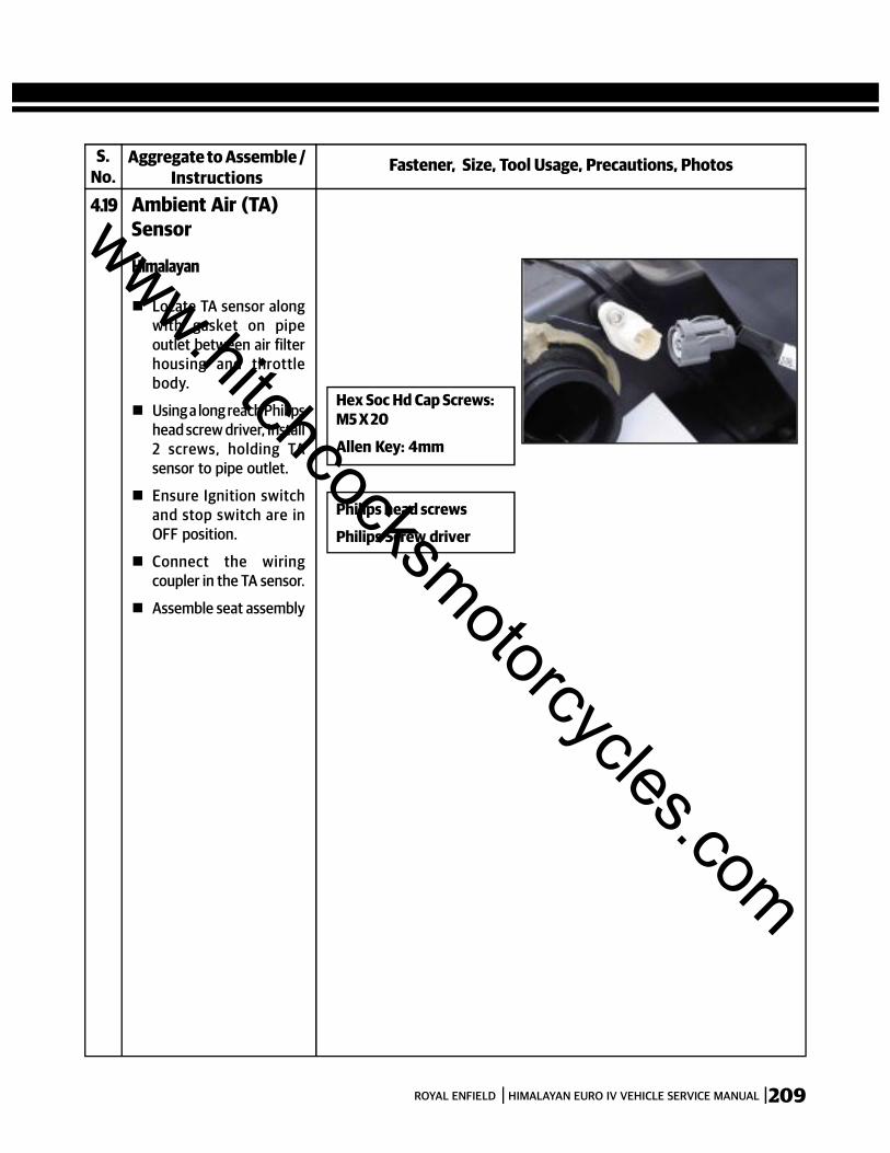
209ROYAL ENFIELD HIMALAYAN EURO IV VEHICLE SERVICE MANUAL
S.No.
Fastener, Size, Tool Usage, Precautions, PhotosAggregate to Assemble /Instructions
4.19 Ambient Air (TA)Sensor
Philips head screws
Philips Screw driver
Hex Soc Hd Cap Screws:M5 X 20
Allen Key: 4mm
Himalayan
Locate TA sensor alongwith gasket on pipeoutlet between air filterhousing and throttlebody.
Using a long reach Philipshead screw driver, Install2 screws, holding TAsensor to pipe outlet.
Ensure Ignition switchand stop switch are inOFF position.
Connect the wiringcoupler in the TA sensor.
Assemble seat assembly
www.hitchcocksmotorcycles.com
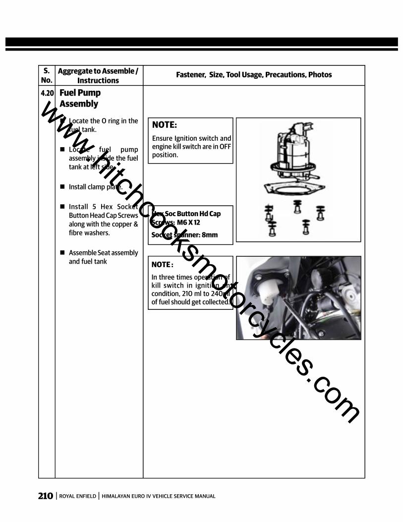
210 ROYAL ENFIELD HIMALAYAN EURO IV VEHICLE SERVICE MANUAL
S.No.
Fastener, Size, Tool Usage, Precautions, PhotosAggregate to Assemble /Instructions
4.20 Fuel PumpAssembly
NOTE:Ensure Ignition switch andengine kill switch are in OFFposition.
Hex Soc Button Hd CapScrews: M6 X 12
Socket spanner: 8mm
Locate the O ring in thefuel tank.
Locate fuel pumpassembly inside the fueltank at left side.
Install clamp plate.
Install 5 Hex SocketButton Head Cap Screwsalong with the copper &fibre washers.
Assemble Seat assemblyand fuel tank NOTE :
In three times operation ofkill switch in ignition oncondition, 210 ml to 240mlof fuel should get collected.
www.hitchcocksmotorcycles.com
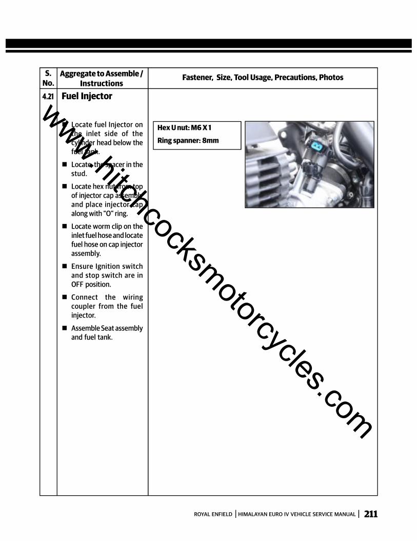
211ROYAL ENFIELD HIMALAYAN EURO IV VEHICLE SERVICE MANUAL
S.No.
Fastener, Size, Tool Usage, Precautions, PhotosAggregate to Assemble /Instructions
4.21 Fuel Injector
Hex U nut: M6 X 1
Ring spanner: 8mm
Locate fuel Injector onthe inlet side of thecylinder head below thefuel tank.
Locate the spacer in thestud.
Locate hex nut from topof injector cap assemblyand place injector capalong with “O” ring.
Locate worm clip on theinlet fuel hose and locatefuel hose on cap injectorassembly.
Ensure Ignition switchand stop switch are inOFF position.
Connect the wiringcoupler from the fuelinjector.
Assemble Seat assemblyand fuel tank.
www.hitchcocksmotorcycles.com
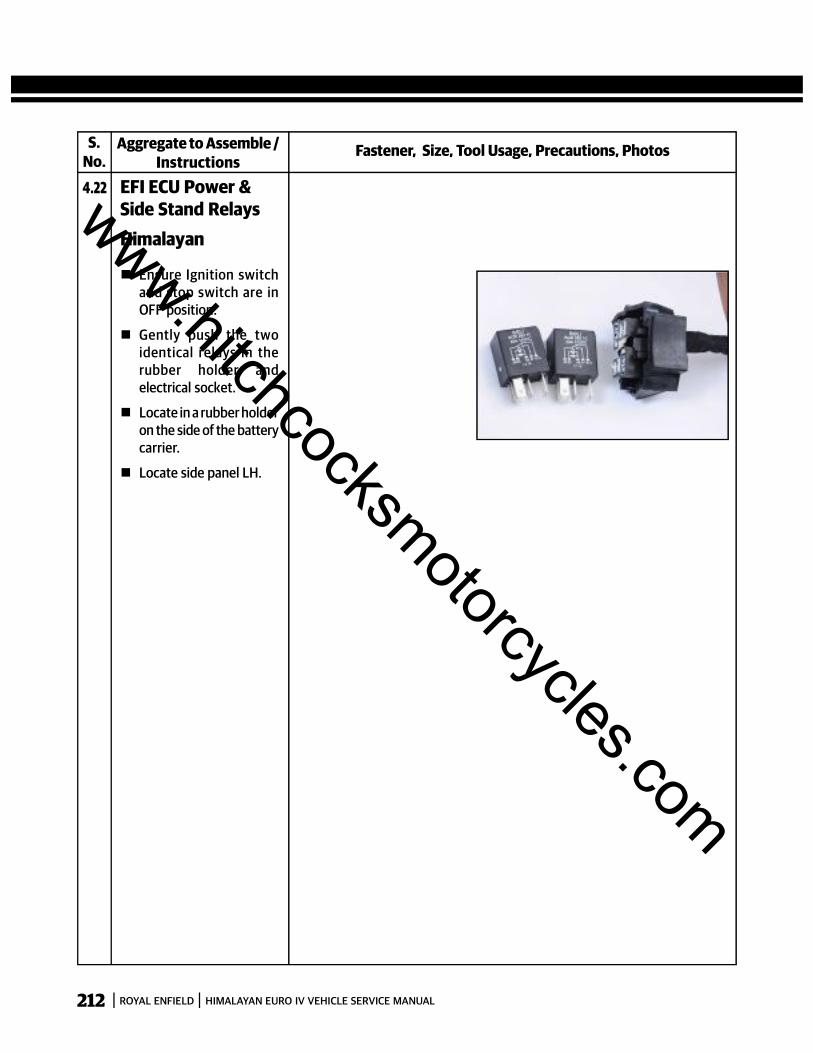
212 ROYAL ENFIELD HIMALAYAN EURO IV VEHICLE SERVICE MANUAL
S.No.
Fastener, Size, Tool Usage, Precautions, PhotosAggregate to Assemble /Instructions
4.22 EFI ECU Power &Side Stand RelaysHimalayan
Ensure Ignition switchand stop switch are inOFF position.
Gently push the twoidentical relays in therubber holder andelectrical socket.
Locate in a rubber holderon the side of the batterycarrier.
Locate side panel LH.
www.hitchcocksmotorcycles.com
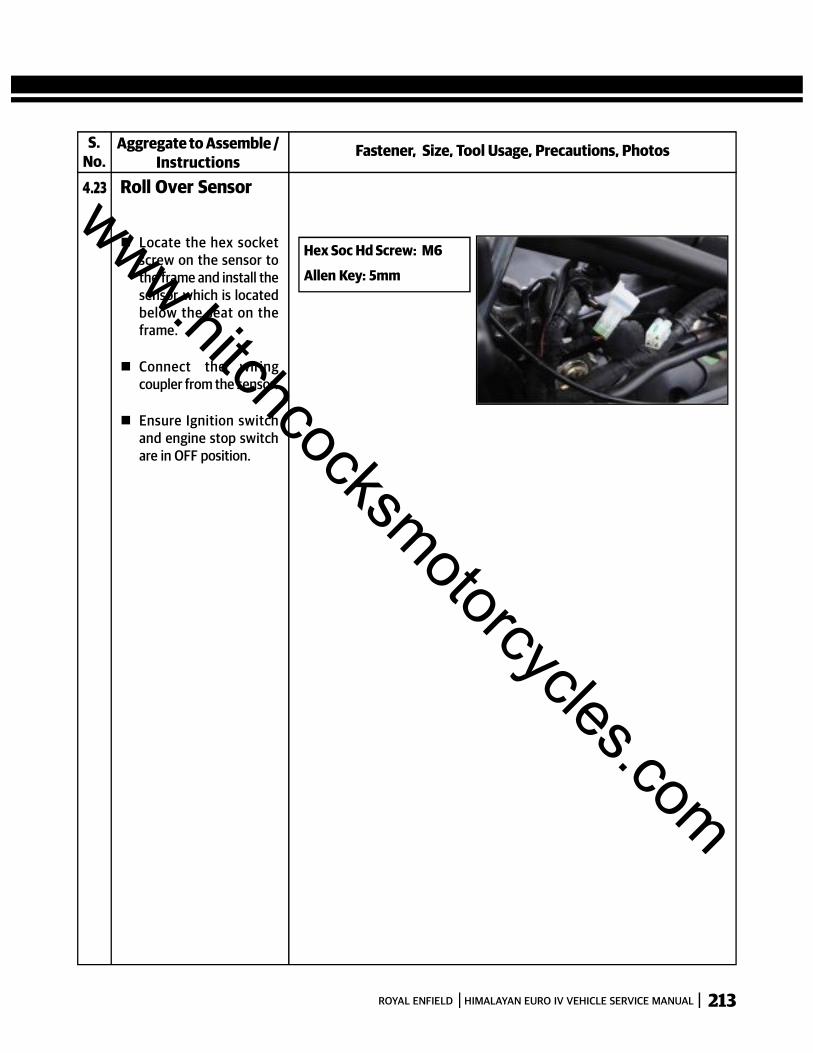
213ROYAL ENFIELD HIMALAYAN EURO IV VEHICLE SERVICE MANUAL
S.No.
Fastener, Size, Tool Usage, Precautions, PhotosAggregate to Assemble /Instructions
4.23 Roll Over Sensor
Hex Soc Hd Screw: M6
Allen Key: 5mm
Locate the hex socketscrew on the sensor tothe frame and install thesensor which is locatedbelow the seat on theframe.
Connect the wiringcoupler from the sensor.
Ensure Ignition switchand engine stop switchare in OFF position.
www.hitchcocksmotorcycles.com
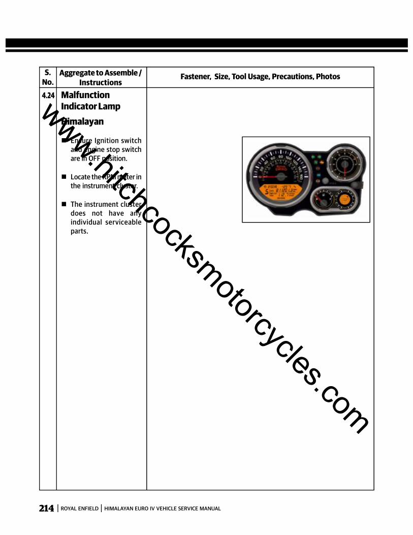
214 ROYAL ENFIELD HIMALAYAN EURO IV VEHICLE SERVICE MANUAL
S.No.
Fastener, Size, Tool Usage, Precautions, PhotosAggregate to Assemble /Instructions
4.24 MalfunctionIndicator LampHimalayan
Ensure Ignition switchand engine stop switchare in OFF position.
Locate the RPM meter inthe instrument cluster.
The instrument clusterdoes not have anyindividual serviceableparts.
www.hitchcocksmotorcycles.com
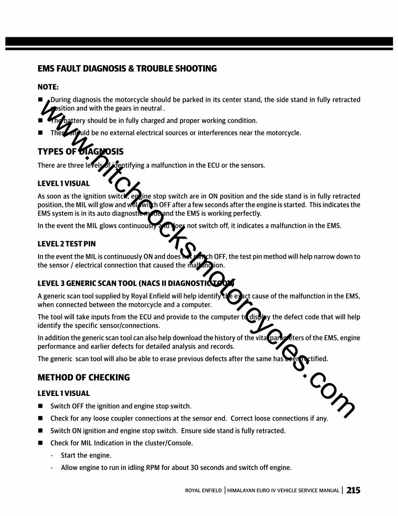
215ROYAL ENFIELD HIMALAYAN EURO IV VEHICLE SERVICE MANUAL
EMS FAULT DIAGNOSIS & TROUBLE SHOOTING
NOTE: During diagnosis the motorcycle should be parked in its center stand, the side stand in fully retracted
position and with the gears in neutral .
The battery should be in fully charged and proper working condition.
There should be no external electrical sources or interferences near the motorcycle.
TYPES OF DIAGNOSISThere are three levels of identifying a malfunction in the ECU or the sensors.
LEVEL 1 VISUALAs soon as the ignition switch, engine stop switch are in ON position and the side stand is in fully retractedposition, the MIL will glow and will switch OFF after a few seconds after the engine is started. This indicates theEMS system is in its auto diagnostic mode and the EMS is working perfectly.
In the event the MIL glows continuously and does not switch off, it indicates a malfunction in the EMS.
LEVEL 2 TEST PINIn the event the MIL is continuously ON and does not switch OFF, the test pin method will help narrow down tothe sensor / electrical connection that caused the malfunction.
LEVEL 3 GENERIC SCAN TOOL (NACS II DIAGNOSTIC TOOL)A generic scan tool supplied by Royal Enfield will help identify the exact cause of the malfunction in the EMS,when connected between the motorcycle and a computer.
The tool will take inputs from the ECU and provide to the computer to display the defect code that will helpidentify the specific sensor/connections.
In addition the generic scan tool can also help download the history of the vital parameters of the EMS, engineperformance and earlier defects for detailed analysis and records.
The generic scan tool will also be able to erase previous defects after the same has been rectified.
METHOD OF CHECKING
LEVEL 1 VISUAL Switch OFF the ignition and engine stop switch.
Check for any loose coupler connections at the sensor end. Correct loose connections if any.
Switch ON ignition and engine stop switch. Ensure side stand is fully retracted.
Check for MIL Indication in the cluster/Console.
- Start the engine.
- Allow engine to run in idling RPM for about 30 seconds and switch off engine.
www.hitchcocksmotorcycles.com
216 ROYAL ENFIELD HIMALAYAN EURO IV VEHICLE SERVICE MANUAL
- Repeat the above process for 2 more times.
- Ensure MIL Indications goes off after above method.
- This will help to recalibrate the MIL and store the error code in the ECU.
If in case the defect is not eliminated and the MIL glows continuously, proceed to level 2 test pin methodto resolve the defect.
LEVEL 2 TEST PIN METHODAn open single pole connector is provided close to the UCE.
Connect a piece of wire to this connector and suitably ground it to the motorcycle body.
Switch ON ignition and engine stop switch and observe the MIL keenly for a series of short and long blinksat different intervals, to identify the defective sensor / wiring connection as detailed in the table below,
www.hitchcocksmotorcycles.com
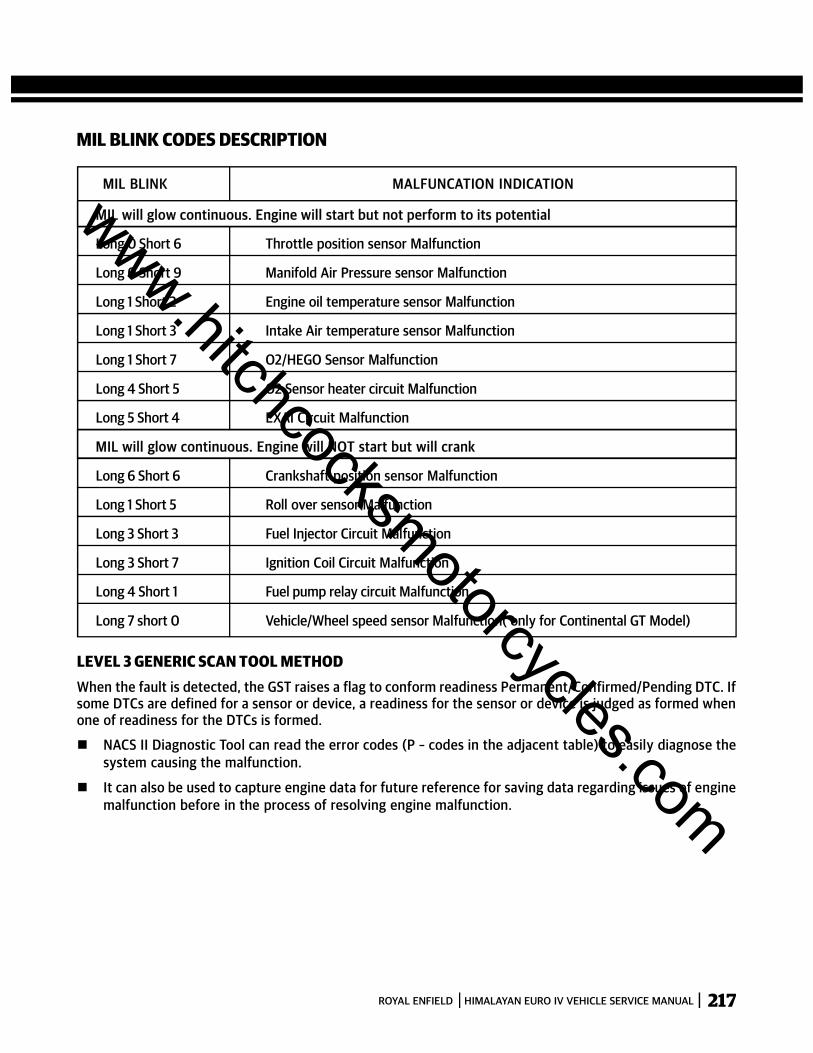
217ROYAL ENFIELD HIMALAYAN EURO IV VEHICLE SERVICE MANUAL
MIL BLINK CODES DESCRIPTION
MIL BLINK MALFUNCATION INDICATION
MIL will glow continuous. Engine will start but not perform to its potential
Long 0 Short 6 Throttle position sensor Malfunction
Long 0 Short 9 Manifold Air Pressure sensor Malfunction
Long 1 Short 2 Engine oil temperature sensor Malfunction
Long 1 Short 3 Intake Air temperature sensor Malfunction
Long 1 Short 7 O2/HEGO Sensor Malfunction
Long 4 Short 5 O2 Sensor heater circuit Malfunction
Long 5 Short 4 EXAI Circuit Malfunction
MIL will glow continuous. Engine will NOT start but will crank
Long 6 Short 6 Crankshaft position sensor Malfunction
Long 1 Short 5 Roll over sensor Malfunction
Long 3 Short 3 Fuel Injector Circuit Malfunction
Long 3 Short 7 Ignition Coil Circuit Malfunction
Long 4 Short 1 Fuel pump relay circuit Malfunction
Long 7 short 0 Vehicle/Wheel speed sensor Malfunction( only for Continental GT Model)
LEVEL 3 GENERIC SCAN TOOL METHODWhen the fault is detected, the GST raises a flag to conform readiness Permanent/Confirmed/Pending DTC. Ifsome DTCs are defined for a sensor or device, a readiness for the sensor or device is judged as formed whenone of readiness for the DTCs is formed.
NACS II Diagnostic Tool can read the error codes (P – codes in the adjacent table) to easily diagnose thesystem causing the malfunction.
It can also be used to capture engine data for future reference for saving data regarding issues of enginemalfunction before in the process of resolving engine malfunction.
www.hitchcocksmotorcycles.com
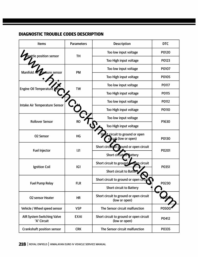
218 ROYAL ENFIELD HIMALAYAN EURO IV VEHICLE SERVICE MANUAL
DIAGNOSTIC TROUBLE CODES DESCRIPTION
Throttle position sensor THToo low input voltage P0120
Too High input voltage P0123
Manifold Air Pressure sensor PMToo low input voltage P0107
Too High input voltage P0105
Engine Oil Temperature Sensor TWToo low input voltage P0117
Too High input voltage P0115
Intake Air Temperature Sensor TAToo low input voltage P0112
Too High input voltage P0110
Rollover Sensor ROToo low input voltage
P1630Too High input voltage
O2 Sensor HG Short circuit to ground or opencircuit (low or open) P0130
Fuel Injector IJ1Short circuit to ground or open circuit
P0201Short circuit to Battery
Ignition Coil IG1Short circuit to ground or open circuit
P0351Short circuit to Battery
Fuel Pump Relay FLRShort circuit to ground or open circuit
P0230Short circuit to Battery
O2 sensor Heater HR Short circuit to ground or open circuit P0030(low or open)
Vehicle / Wheel speed sensor VSP The Sensor circuit malfunction P0500
AIR System Switching Valve EXAI Short circuit to ground or open circuit P0412“A” Circuit (low or open)
Crankshaft position sensor CRK The Sensor circuit malfunction P0335
Items Parameters Description DTCwww.hitchcocksmotorcycles.com
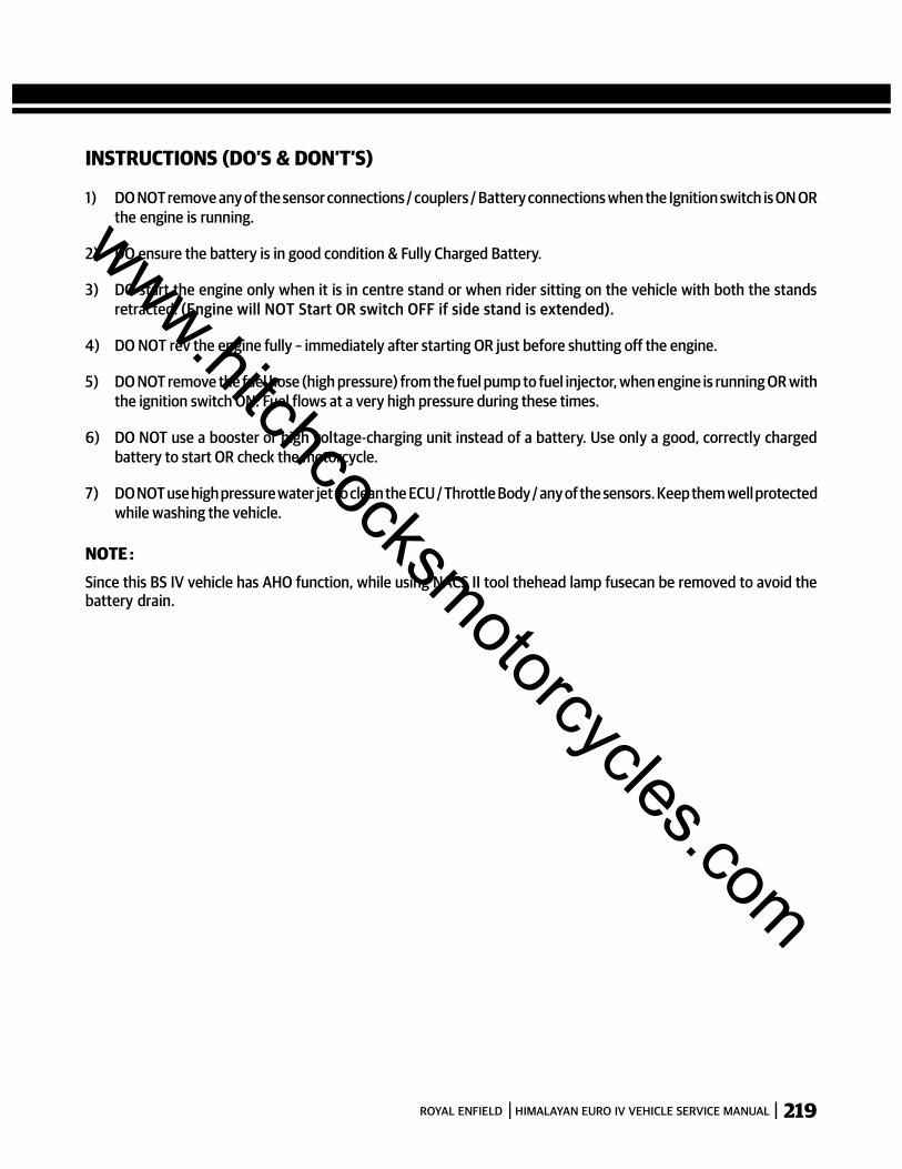
219ROYAL ENFIELD HIMALAYAN EURO IV VEHICLE SERVICE MANUAL
INSTRUCTIONS (DO’S & DON’T’S)
1) DO NOT remove any of the sensor connections / couplers / Battery connections when the Ignition switch is ON ORthe engine is running.
2) DO ensure the battery is in good condition & Fully Charged Battery.
3) DO start the engine only when it is in centre stand or when rider sitting on the vehicle with both the standsretracted. (Engine will NOT Start OR switch OFF if side stand is extended).
4) DO NOT rev the engine fully – immediately after starting OR just before shutting off the engine.
5) DO NOT remove the fuel hose (high pressure) from the fuel pump to fuel injector, when engine is running OR withthe ignition switch ON. Fuel flows at a very high pressure during these times.
6) DO NOT use a booster or high voltage-charging unit instead of a battery. Use only a good, correctly chargedbattery to start OR check the motorcycle.
7) DO NOT use high pressure water jet to clean the ECU / Throttle Body / any of the sensors. Keep them well protectedwhile washing the vehicle.
NOTE :Since this BS IV vehicle has AHO function, while using NACS II tool thehead lamp fusecan be removed to avoid thebattery drain.
www.hitchcocksmotorcycles.com

220 ROYAL ENFIELD HIMALAYAN EURO IV VEHICLE SERVICE MANUAL
SECTION 16 - ELECTRICAL COMPONENTS
www.hitchcocksmotorcycles.com
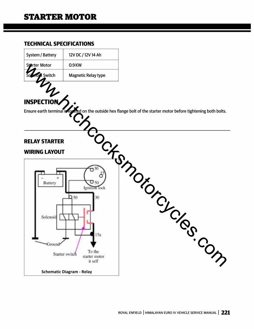
221ROYAL ENFIELD HIMALAYAN EURO IV VEHICLE SERVICE MANUAL
Schematic Diagram - Relay
RELAY STARTER
WIRING LAYOUT
TECHNICAL SPECIFICATIONS
System / Battery 12V DC / 12V 14 Ah
Starter Motor 0.9 KW
Solenoid Switch Magnetic Relay type
STARTER MOTOR
INSPECTIONEnsure earth terminal is located on the outside hex flange bolt of the starter motor before tightening both bolts.
www.hitchcocksmotorcycles.com
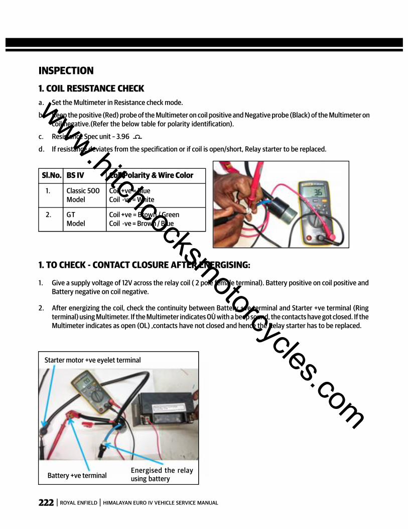
222 ROYAL ENFIELD HIMALAYAN EURO IV VEHICLE SERVICE MANUAL
INSPECTION1. COIL RESISTANCE CHECKa. Set the Multimeter in Resistance check mode.
b. Keep the positive (Red) probe of the Multimeter on coil positive and Negative probe (Black) of the Multimeter oncoil negative.(Refer the below table for polarity identification).
c. Resistance Spec unit – 3.96
d. If resistance deviates from the specification or if coil is open/short, Relay starter to be replaced.
1. TO CHECK - CONTACT CLOSURE AFTER ENERGISING:
1. Give a supply voltage of 12V across the relay coil ( 2 pole female terminal). Battery positive on coil positive andBattery negative on coil negative.
2. After energizing the coil, check the continuity between Battery +ve terminal and Starter +ve terminal (Ringterminal) using Multimeter. If the Multimeter indicates 0Ù with a beep sound, the contacts have got closed. If theMultimeter indicates as open (OL) ,contacts have not closed and hence the Relay starter has to be replaced.
Energised the relayusing batteryBattery +ve terminal
Starter motor +ve eyelet terminal
Sl.No. BS IV Coil Polarity & Wire Color
1. Classic 500 Coil +ve = BlueModel Coil -ve = White
2. GT Coil +ve = Brown / GreenModel Coil -ve = Brown / Blue
c
www.hitchcocksmotorcycles.com
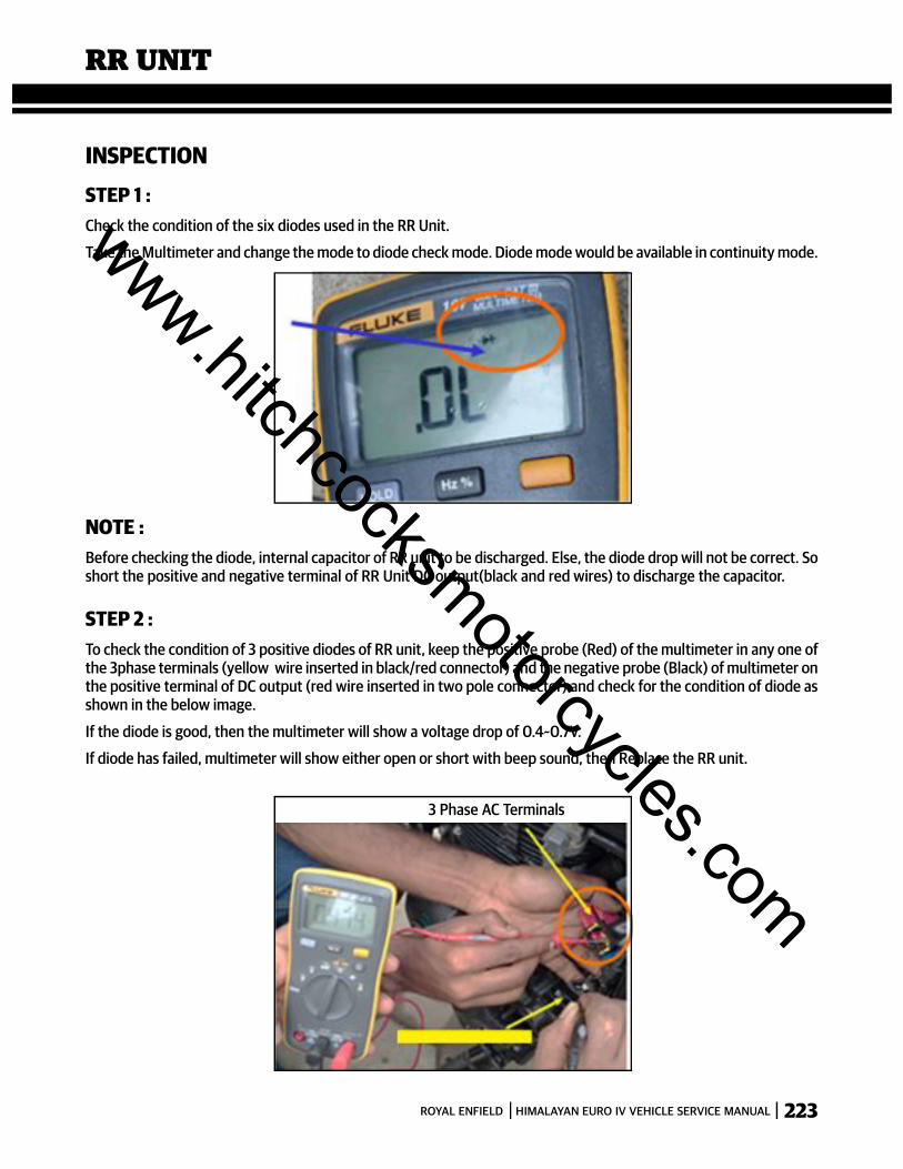
223ROYAL ENFIELD HIMALAYAN EURO IV VEHICLE SERVICE MANUAL
INSPECTIONSTEP 1 :Check the condition of the six diodes used in the RR Unit.
Take the Multimeter and change the mode to diode check mode. Diode mode would be available in continuity mode.
NOTE :Before checking the diode, internal capacitor of RR unit to be discharged. Else, the diode drop will not be correct. Soshort the positive and negative terminal of RR Unit DC output(black and red wires) to discharge the capacitor.
STEP 2 :To check the condition of 3 positive diodes of RR unit, keep the positive probe (Red) of the multimeter in any one ofthe 3phase terminals (yellow wire inserted in black/red connector) and the negative probe (Black) of multimeter onthe positive terminal of DC output (red wire inserted in two pole connector) and check for the condition of diode asshown in the below image.
If the diode is good, then the multimeter will show a voltage drop of 0.4~0.7V.
If diode has failed, multimeter will show either open or short with beep sound, then Replace the RR unit.
3 Phase AC Terminals
RR UNIT
www.hitchcocksmotorcycles.com

224 ROYAL ENFIELD HIMALAYAN EURO IV VEHICLE SERVICE MANUAL
STEP 3 :The positive probe of the multimeter shall be kept on all the 3 phase terminals one by one and the
condition of the 3 diodes to be checked as mentioned in Step 2.
STEP 4 :To check the condition of other 3 negative diodes, positive probe (Red colour) of the multimeter shall be kept on thenegative terminal of DC output (black wire with eyelet/single pole connector) and negative probe (Black colour) ofthe multimeter shall be kept on anyone of the 3 phase terminals (yellow wire).
If the diode is good, then the multimeter will show a voltage drop of 0.4~0.7V.
If diode has failed, multimeter will show either open or short with beep sound, then Replace the RR unit.
STEP 5 :All the three diodes to be checked by keeping the multimeter negative probe on all the 3 phase terminals one by one.If the RR Unit is not working, replace with good working RR Unit.
www.hitchcocksmotorcycles.com

225ROYAL ENFIELD HIMALAYAN EURO IV VEHICLE SERVICE MANUAL
SUPRESSOR CAP
INSPECTIONSTEP 1 :1. Set the Multimeter in Resistance check mode.
2. Keep the positive(Red) and negative (Black)probes of the multimeter on two ends of the suppressor cap.
3. Resistance shall be 3.75 to 6.25 Kilo Ohms
4. If resistance deviates from the specification or open, Suppressor cap to be replaced.
www.hitchcocksmotorcycles.com
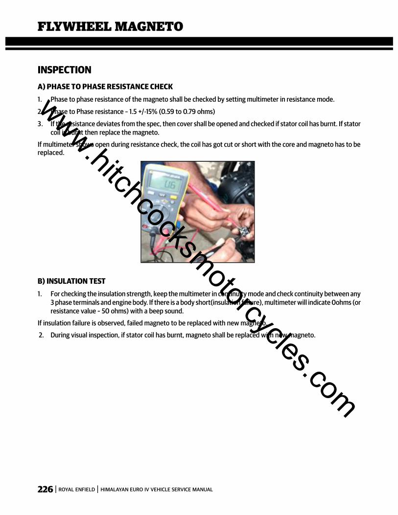
226 ROYAL ENFIELD HIMALAYAN EURO IV VEHICLE SERVICE MANUAL
INSPECTIONA) PHASE TO PHASE RESISTANCE CHECK1. Phase to phase resistance of the magneto shall be checked by setting multimeter in resistance mode.
2. Phase to Phase resistance – 1.5 +/-15% (0.59 to 0.79 ohms)
3. If the resistance deviates from the spec, then cover shall be opened and checked if stator coil has burnt. If statorcoil is burnt then replace the magneto.
If multimeter shows open during resistance check, the coil has got cut or short with the core and magneto has to bereplaced.
B) INSULATION TEST1. For checking the insulation strength, keep the multimeter in continuity mode and check continuity between any
3 phase terminals and engine body. If there is a body short(insulation failure), multimeter will indicate 0ohms (orresistance value ~ 50 ohms) with a beep sound.
If insulation failure is observed, failed magneto to be replaced with new magneto.
2. During visual inspection, if stator coil has burnt, magneto shall be replaced with new magneto.
FLYWHEEL MAGNETO
www.hitchcocksmotorcycles.com
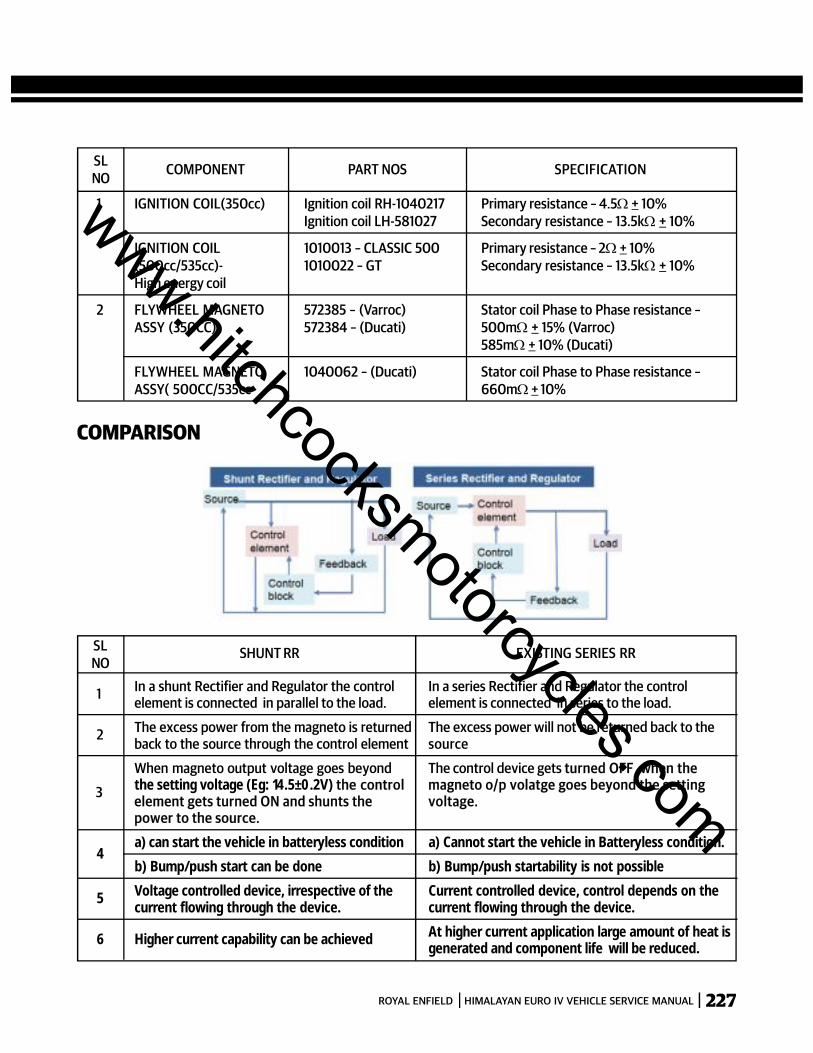
227ROYAL ENFIELD HIMALAYAN EURO IV VEHICLE SERVICE MANUAL
SLNO COMPONENT PART NOS SPECIFICATION
1 IGNITION COIL(350cc) Ignition coil RH-1040217 Primary resistance – 4.5 + 10%Ignition coil LH-581027 Secondary resistance – 13.5k + 10%
IGNITION COIL 1010013 – CLASSIC 500 Primary resistance – 2 + 10%(500cc/535cc)- 1010022 – GT Secondary resistance – 13.5k + 10%High energy coil
2 FLYWHEEL MAGNETO 572385 – (Varroc) Stator coil Phase to Phase resistance –ASSY (350CC) 572384 – (Ducati) 500m + 15% (Varroc)
585m + 10% (Ducati)
FLYWHEEL MAGNETO 1040062 – (Ducati) Stator coil Phase to Phase resistance –ASSY( 500CC/535cc 660m + 10%
COMPARISON
SLNO
SHUNT RR EXISTING SERIES RR
1 In a shunt Rectifier and Regulator the control In a series Rectifier and Regulator the controlelement is connected in parallel to the load. element is connected in series to the load.
2 The excess power from the magneto is returned The excess power will not be returned back to theback to the source through the control element source
When magneto output voltage goes beyond The control device gets turned OFF when the
3 the setting voltage (Eg: 14.5±0.2V) the control magneto o/p volatge goes beyond the settingelement gets turned ON and shunts the voltage.power to the source.
4a) can start the vehicle in batteryless condition a) Cannot start the vehicle in Batteryless condition.
b) Bump/push start can be done b) Bump/push startability is not possible
5 Voltage controlled device, irrespective of the Current controlled device, control depends on thecurrent flowing through the device. current flowing through the device.
6 Higher current capability can be achieved At higher current application large amount of heat isgenerated and component life will be reduced.
www.hitchcocksmotorcycles.com
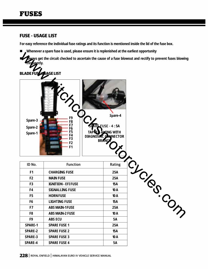
228 ROYAL ENFIELD HIMALAYAN EURO IV VEHICLE SERVICE MANUAL
FUSES
FUSE - USAGE LISTFor easy reference the individual fuse ratings and its function is mentioned inside the lid of the fuse box.
Whenever a spare fuse is used, please ensure it is replenished at the earliest opportunity
Always get the circuit checked to ascertain the cause of a fuse blowout and rectify to prevent fuses blowingfrequently.
BLADE FUSE USAGE LIST
F1 CHARGING FUSE 25AF2 MAIN FUSE 25AF3 IGNITION - EFI FUSE 15AF4 SIGNALLING FUSE 10AF5 HORN FUSE 10AF6 LIGHTING FUSE 15AF7 ABS MAIN-1 FUSE 25AF8 ABS MAIN-2 FUSE 10AF9 ABS ECU 5A
SPARE-1 SPARE FUSE 1 25ASPARE-2 SPARE FUSE 2 15ASPARE-3 SPARE FUSE 3 10ASPARE-4 SPARE FUSE 4 5A
RatingFunctionID No.
Spare-1Spare-2
Spare-3F9F8F7F6F5F4F3F2F1
SPARE FUSE - 4 : 5A
TAPPED ALONG WITHDIAGNOSTIC CONNECTOR
BRANCH
Spare-4
www.hitchcocksmotorcycles.com
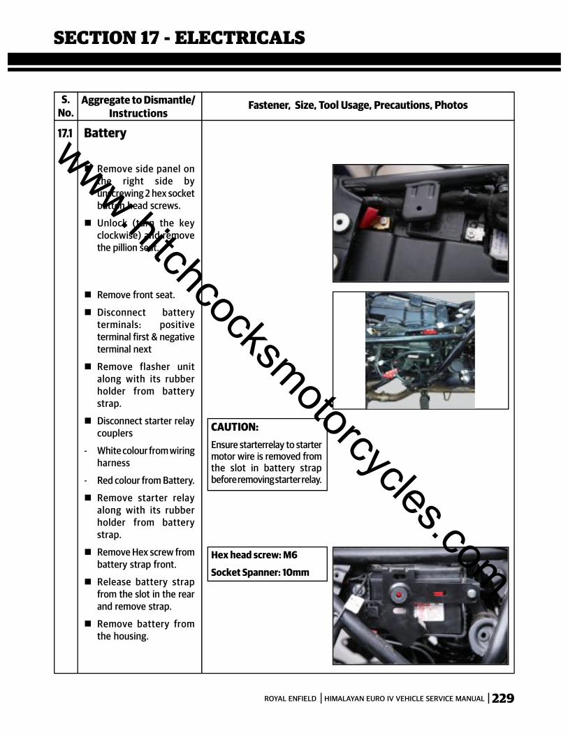
229ROYAL ENFIELD HIMALAYAN EURO IV VEHICLE SERVICE MANUAL
SECTION 17 - ELECTRICALS
S.No.
Fastener, Size, Tool Usage, Precautions, PhotosAggregate to Dismantle/Instructions
17.1 Battery
Remove side panel onthe right side byunscrewing 2 hex socketbutton head screws.
Unlock (turn the keyclockwise) and removethe pillion seat.
Remove front seat.
Disconnect batteryterminals: positiveterminal first & negativeterminal next
Remove flasher unitalong with its rubberholder from batterystrap.
Disconnect starter relaycouplers
- White colour from wiringharness
- Red colour from Battery.
Remove starter relayalong with its rubberholder from batterystrap.
Remove Hex screw frombattery strap front.
Release battery strapfrom the slot in the rearand remove strap.
Remove battery fromthe housing.
CAUTION:Ensure starterrelay to startermotor wire is removed fromthe slot in battery strapbefore removing starter relay.
Hex head screw: M6
Socket Spanner: 10mm
www.hitchcocksmotorcycles.com
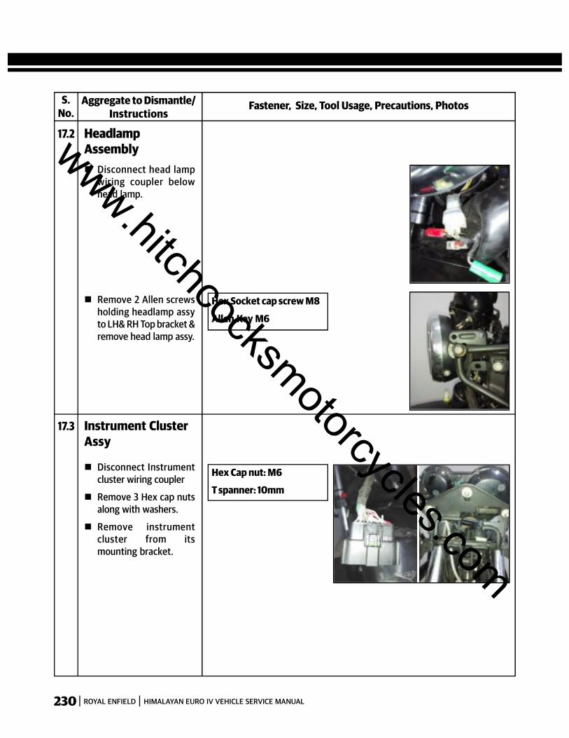
230 ROYAL ENFIELD HIMALAYAN EURO IV VEHICLE SERVICE MANUAL
S.No.
Fastener, Size, Tool Usage, Precautions, PhotosAggregate to Dismantle/Instructions
17.2 HeadlampAssembly Disconnect head lamp
wiring coupler belowhead lamp.
Remove 2 Allen screwsholding headlamp assyto LH& RH Top bracket &remove head lamp assy.
Hex Cap nut: M6
T spanner: 10mm
17.3 Instrument ClusterAssy
Disconnect Instrumentcluster wiring coupler
Remove 3 Hex cap nutsalong with washers.
Remove instrumentcluster from itsmounting bracket.
Hex Socket cap screw M8
Allen Key M6
www.hitchcocksmotorcycles.com

231ROYAL ENFIELD HIMALAYAN EURO IV VEHICLE SERVICE MANUAL
S.No.
Fastener, Size, Tool Usage, Precautions, PhotosAggregate to Dismantle/Instructions
17.4 Trafficator frontLH& RH Disconnect Trafficator
wiring couplers belowheadlamp.
Remove Allen screwmounting the trafficatorto the side supportbracket.
Pull out the decorativecover from the rubbergrommet in the sidesupport bracket.
NOTE:The couplers are colorcoded as:LH side: GreenRH side: Red
Hex Socket Cap screw M6
Allen key: 4 mm
17.5 Trafficator RearLH& RH Disconnect Trafficator
couplers red & green Remove the screw from
the trafficator housingback side.
Remove outer lens. Remove the fused bulb
by pushing and turninganticlockwise.
17.6 Tail Lamp & Numberplate illuminator The tail lamp has a LED
lighting system. In theevent of failure, theentire tail lamp assemblyshould be replaced.
www.hitchcocksmotorcycles.com
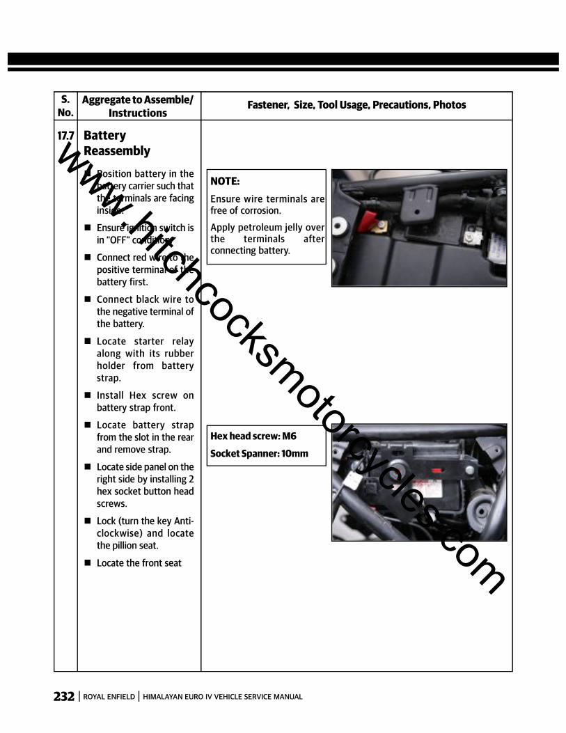
232 ROYAL ENFIELD HIMALAYAN EURO IV VEHICLE SERVICE MANUAL
Fastener, Size, Tool Usage, Precautions, PhotosAggregate to Assemble/Instructions
17.7 BatteryReassembly
Position battery in thebattery carrier such thatthe terminals are facinginside.
Ensure ignition switch isin “OFF” condition.
Connect red wire to thepositive terminal of thebattery first.
Connect black wire tothe negative terminal ofthe battery.
Locate starter relayalong with its rubberholder from batterystrap.
Install Hex screw onbattery strap front.
Locate battery strapfrom the slot in the rearand remove strap.
Locate side panel on theright side by installing 2hex socket button headscrews.
Lock (turn the key Anti-clockwise) and locatethe pillion seat.
Locate the front seat
S.No.
NOTE:Ensure wire terminals arefree of corrosion.
Apply petroleum jelly overthe terminals afterconnecting battery.
Hex head screw: M6
Socket Spanner: 10mm
www.hitchcocksmotorcycles.com
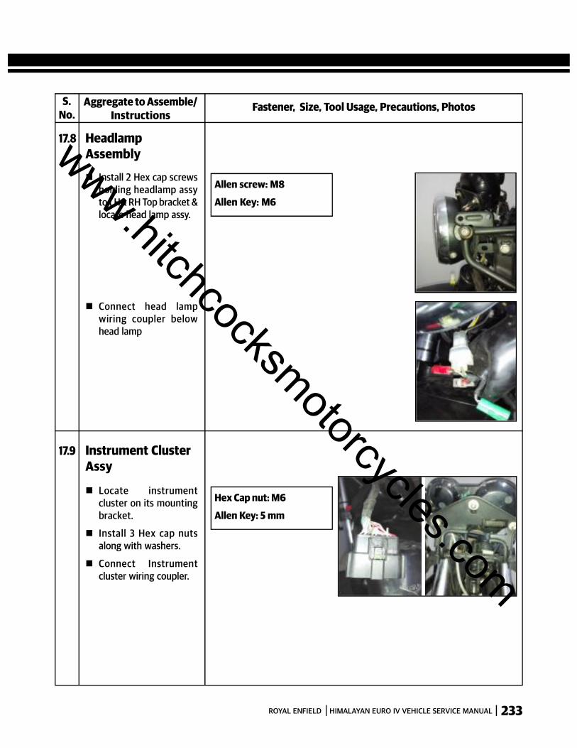
233ROYAL ENFIELD HIMALAYAN EURO IV VEHICLE SERVICE MANUAL
Fastener, Size, Tool Usage, Precautions, PhotosAggregate to Assemble/Instructions
17.8 HeadlampAssembly
Install 2 Hex cap screwsholding headlamp assyto LH& RH Top bracket &locate head lamp assy.
Connect head lampwiring coupler belowhead lamp
S.No.
Allen screw: M8
Allen Key: M6
17.9 Instrument ClusterAssy
Locate instrumentcluster on its mountingbracket.
Install 3 Hex cap nutsalong with washers.
Connect Instrumentcluster wiring coupler.
Hex Cap nut: M6
Allen Key: 5 mm
www.hitchcocksmotorcycles.com

234 ROYAL ENFIELD HIMALAYAN EURO IV VEHICLE SERVICE MANUAL
Fastener, Size, Tool Usage, Precautions, PhotosAggregate to Assemble/Instructions
17.10 Trafficator frontLH& RH
Push inside thedecorative cover on therubber grommet in theside support bracket
Install Allen screwmounting the trafficatorto the side supportbracket.
Connect Trafficatorwiring couplers belowheadlamp.
S.No.
Hex Cap Screw M6
Allen key: 5 mm
NOTE:The couplers are color codedas:LH side: GreenRH side: Red
17.11 Trafficator RearLH& RH
Locate the bulb bypushing and turningclockwise.
Locate outer lens
Install the screw on thetrafficator housing backside.
Connect Trafficatorcouplers red & green
www.hitchcocksmotorcycles.com
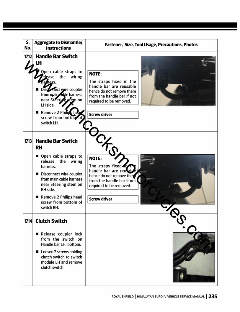
235ROYAL ENFIELD HIMALAYAN EURO IV VEHICLE SERVICE MANUAL
S.No.
Fastener, Size, Tool Usage, Precautions, PhotosAggregate to Dismantle/Instructions
17.12 Handle Bar SwitchLH Open cable straps to
release the wiringharness.
Disconnect wire couplerfrom main cable harnessnear Steering stem onLH side.
Remove 2 Philips headscrew from bottom ofswitch LH.
Screw driver
NOTE:The straps fixed in thehandle bar are reusablehence do not remove themfrom the handle bar if notrequired to be removed.
17.13 Handle Bar SwitchRH Open cable straps to
release the wiringharness.
Disconnect wire couplerfrom main cable harnessnear Steering stem onRH side.
Remove 2 Philips headscrew from bottom ofswitch RH.
Screw driver
NOTE:The straps fixed in thehandle bar are reusablehence do not remove themfrom the handle bar if notrequired to be removed.
17.14 Clutch Switch
Release coupler lockfrom the switch onHandle bar LH, bottom.
Loosen 2 screws holdingclutch switch to switchmodule LH and removeclutch switch
www.hitchcocksmotorcycles.com
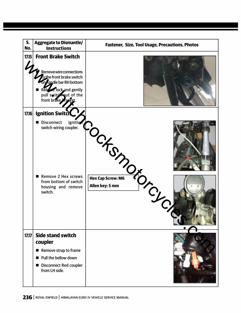
236 ROYAL ENFIELD HIMALAYAN EURO IV VEHICLE SERVICE MANUAL
S.No.
Fastener, Size, Tool Usage, Precautions, PhotosAggregate to Dismantle/Instructions
17.15 Front Brake Switch
Remove wire connectionsto the front brake switchon handle bar RH bottom
Release lock and gentlypull switch out of thefront brake bracket.
17.16 Ignition Switch Disconnect ignition
switch wiring coupler.
Remove 2 Hex screwsfrom bottom of switchhousing and removeswitch.
Hex Cap Screw: M6
Allen key: 5 mm
17.17 Side stand switchcoupler Remove strap to frame
Pull the bellow down
Disconnect Red couplerfrom LH side.
www.hitchcocksmotorcycles.com

237ROYAL ENFIELD HIMALAYAN EURO IV VEHICLE SERVICE MANUAL
S.No.
Fastener, Size, Tool Usage, Precautions, PhotosAggregate to Assemble/Instructions
17.18 Handle Bar SwitchLH Install 2 Philips head
screw on bottom ofswitch LH
Connect wire coupler onmain cable harness nearSteering stem on LH side.
Close cable straps to lockthe wiring harness. Screw driver
NOTE:The straps fixed in thehandle bar are reusablehence do not remove themfrom the handle bar if notrequired to be removed.
17.19 Handle Bar SwitchRH
Install 2 Philips headscrew on bottom ofswitch RH.
Connect wire coupler onmain cable harness nearSteering stem on RHside.
Close cable straps to lockthe wiring harness.
Screw driver
NOTE:The straps fixed in thehandle bar are reusablehence do not remove themfrom the handle bar if notrequired to be removed.
17.20 Clutch Switch
Install 2 screws holdingclutch switch to switchmodule LH and locateclutch switch
Locate coupler lock onthe switch on Handle barLH, bottom.
www.hitchcocksmotorcycles.com

238 ROYAL ENFIELD HIMALAYAN EURO IV VEHICLE SERVICE MANUAL
S.No.
Fastener, Size, Tool Usage, Precautions, PhotosAggregate to Assemble/Instructions
17.21 Front Brake Switch
Locate lock and gentlypush switch inside thefront brake bracket.
Locate wire connectionsto the front brake switchon handle bar RHbottom
Hex Cap Screw: M6
Allen key: 5 mm
17.22 Ignition Switch Install 2 Hex screws from
bottom of switchhousing and locateswitch.
Connect ignition switchwiring coupler.
17.23 Side stand switchcoupler Connect Red coupler
from LH side.
Push the bellowupwards.
Locate strap to frame
www.hitchcocksmotorcycles.com
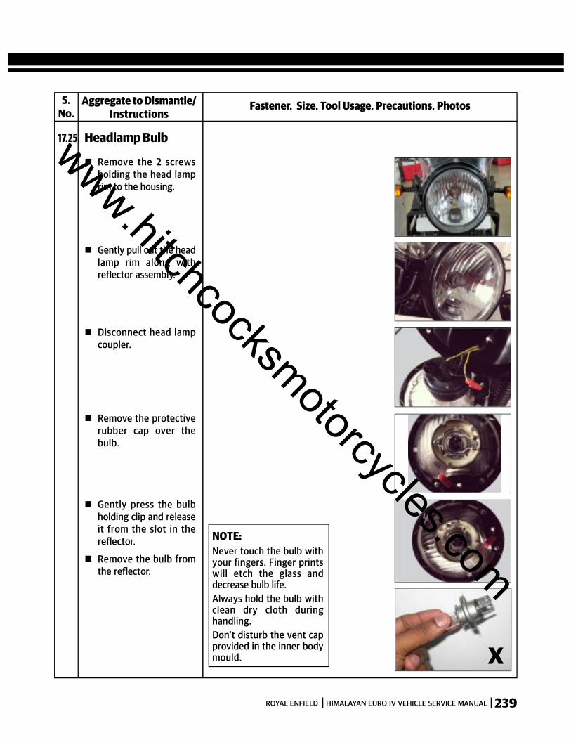
239ROYAL ENFIELD HIMALAYAN EURO IV VEHICLE SERVICE MANUAL
S.No.
Fastener, Size, Tool Usage, Precautions, PhotosAggregate to Dismantle/Instructions
17.25 Headlamp Bulb
Remove the 2 screwsholding the head lamprim to the housing.
Gently pull out the headlamp rim along withreflector assembly.
Disconnect head lampcoupler.
Remove the protectiverubber cap over thebulb.
Gently press the bulbholding clip and releaseit from the slot in thereflector.
Remove the bulb fromthe reflector.
X
NOTE:Never touch the bulb withyour fingers. Finger printswill etch the glass anddecrease bulb life.Always hold the bulb withclean dry cloth duringhandling.Don’t disturb the vent capprovided in the inner bodymould.
www.hitchcocksmotorcycles.com
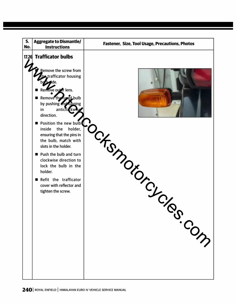
240 ROYAL ENFIELD HIMALAYAN EURO IV VEHICLE SERVICE MANUAL
S.No.
Fastener, Size, Tool Usage, Precautions, PhotosAggregate to Dismantle/Instructions
17.26 Trafficator bulbs
Remove the screw fromthe trafficator housingback side.
Remove outer lens.
Remove the fused bulbby pushing and turningin anticlockwisedirection.
Position the new bulbinside the holder,ensuring that the pins inthe bulb, match withslots in the holder.
Push the bulb and turnclockwise direction tolock the bulb in theholder.
Refit the trafficatorcover with reflector andtighten the screw.
www.hitchcocksmotorcycles.com
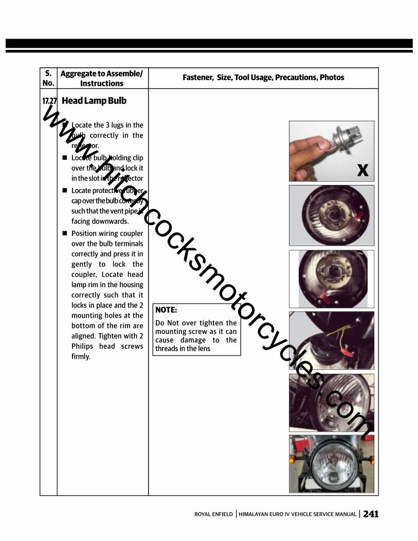
241ROYAL ENFIELD HIMALAYAN EURO IV VEHICLE SERVICE MANUAL
S.No.
Fastener, Size, Tool Usage, Precautions, PhotosAggregate to Assemble/Instructions
17.27 Head Lamp Bulb
Locate the 3 lugs in thebulb correctly in thereflector.
Locate bulb holding clipover the bulb and lock itin the slot in the reflector
Locate protective rubbercap over the bulb correctlysuch that the vent pipe isfacing downwards.
Position wiring couplerover the bulb terminalscorrectly and press it ingently to lock thecoupler, Locate headlamp rim in the housingcorrectly such that itlocks in place and the 2mounting holes at thebottom of the rim arealigned. Tighten with 2Philips head screwsfirmly.
NOTE:Do Not over tighten themounting screw as it cancause damage to thethreads in the lens
X
www.hitchcocksmotorcycles.com

242 ROYAL ENFIELD HIMALAYAN EURO IV VEHICLE SERVICE MANUAL
S.No.
Fastener, Size, Tool Usage, Precautions, PhotosAggregate to Assemble/Instructions
17.28 Trafficator Bulb
Position bulb in thereflector, ensuring thatthe pinsin the bulb,match with slots in theholder
Locate bulb correctly inthe reflector, gentlypress bulb and turnclockwise to lock bulbinholder.
Refit trafficator coverwith reflector into thehousing and tighten thescrew.
www.hitchcocksmotorcycles.com

243ROYAL ENFIELD HIMALAYAN EURO IV VEHICLE SERVICE MANUAL
S.No.
Fastener, Size, Tool Usage, Precautions, PhotosAggregate to Dismantle/Instructions
17.29 RR Unit
Remove single poleblack connector (chassisground).
Pull the bellow down onmiddle RH side anddisconnect 2 pole T-typeconnector to mainharness.
Loosen 2 hex boltsholding RR unit to frame.
Remove RR unitmounting from frame.
17.30 HT Coil Assy
Disconnect the whitecoupler from the mainwiring harness HT coil.
Loosen the 2 Hex flangebolts mounted on thewelded nut in frame.
Remove HT Coil assyfrom frame.
Hex Flange Bolt : M6
Socket Spanner : 10 mm
Hex Flange Bolt : M6
Socket Spanner : 10 mm
www.hitchcocksmotorcycles.com
244 ROYAL ENFIELD HIMALAYAN EURO IV VEHICLE SERVICE MANUAL
S.No.
Fastener, Size, Tool Usage, Precautions, PhotosAggregate to Assemble/Instructions
17.31 RR Unit
Position RR unit on theframe and align themounting holes tightenRR Unit to frameusing 2hex bolts.
Push the bellowupwards on middle RHside and connect 2 poleT-type connector tomain harness.
Locate single pole blackconnector (chassisground)
Hex Flange Bolt : M6
Socket Spanner : 10 mm
17.32 HT Coil Assy
Position the HT coil onthe frame such that thecoupler is on the left sideand the HT coil is towardsthe rear of the frame
Assemble 2 Hex flangebolts M6X14 into thewelded nut in frame
Tighten the bolts using 8mm socket spanner to atorque of 10-12 Nm (1.0-1.2 KgM)
Connect the whitecoupler on the mainwiring harness HT coil.
Torque : 10 Nm
Hex Flange Bolt : M6
Socket Spanner : 10 mm
www.hitchcocksmotorcycles.com

245ROYAL ENFIELD HIMALAYAN EURO IV VEHICLE SERVICE MANUAL
S.No.
Fastener, Size, Tool Usage, Precautions, PhotosAggregate to Dismantle/Instructions
17.33 Fuses
Fuse carrier is locatedunder the rider seat.
Remove pillion seat &rider seat.
Open the fuse carrier lid& replace fuse asindicated inside the lid.
Replace the requiredfuse with the spare fuseavailable in the fusecarrier.
17.34 BLADE FUSE USAGELIST
F1 CHARGING FUSE 25A
F2 MAIN FUSE 25A
F3 IGNITION - EFI FUSE 15A
F4 SIGNALLING FUSE 10A
F5 HORN FUSE 10A
F6 LIGHTING FUSE 15A
F7 ABS MAIN-1 FUSE 25A
F8 ABS MAIN-2 FUSE 10A
F9 ABS ECU 5A
SPARE-1 SPARE FUSE 1 25A
SPARE-2 SPARE FUSE 2 15A
SPARE-3 SPARE FUSE 3 10A
SPARE-4 SPARE FUSE 4 5A
RatingFunctionID No.
Spare-1Spare-2
Spare-3 F9F8F7F6F5F4F3F2F1
SPARE FUSE - 4 : 5ATAPPED ALONG WITH
DIAGNOSTICCONNECTOR
BRANCH
Spare-4
www.hitchcocksmotorcycles.com
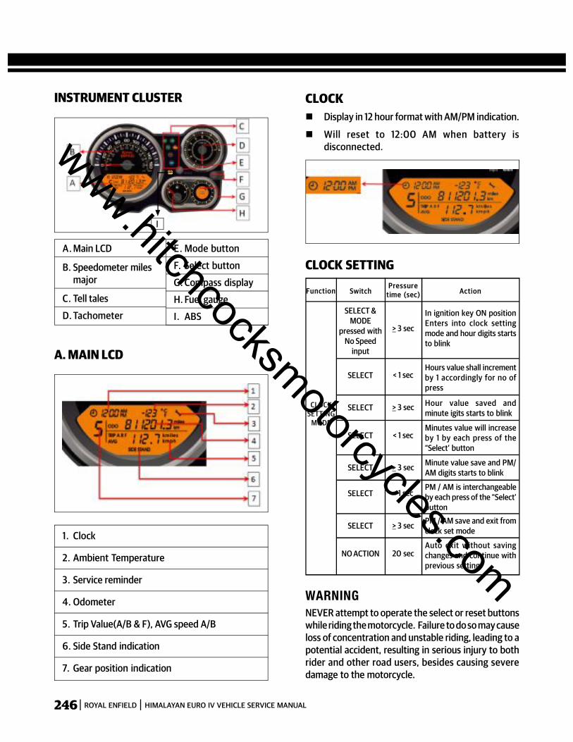
246 ROYAL ENFIELD HIMALAYAN EURO IV VEHICLE SERVICE MANUAL
INSTRUMENT CLUSTER
A. Main LCD
B. Speedometer milesmajor
C. Tell tales
D. Tachometer
E. Mode button
F. Select button
G. Compass display
H. Fuel gauge
I. ABS
1. Clock
2. Ambient Temperature
3. Service reminder
4. Odometer
5. Trip Value(A/B & F), AVG speed A/B
6. Side Stand indication
7. Gear position indication
A. MAIN LCD
CLOCK Display in 12 hour format with AM/PM indication.
Will reset to 12:00 AM when battery isdisconnected.
CLOCK SETTING
Function SwitchPressure
time (sec) Action
SELECT &MODE
pressed withNo Speed
input
CLOCKSETTING
MODE
> 3 sec
In ignition key ON positionEnters into clock settingmode and hour digits startsto blink
SELECT < 1 secHours value shall incrementby 1 accordingly for no ofpress
SELECT > 3 sec Hour value saved andminute igits starts to blink
SELECT < 1 secMinutes value will increaseby 1 by each press of the“Select’ button
SELECT > 3 sec Minute value save and PM/AM digits starts to blink
SELECT < 1 secPM / AM is interchangeableby each press of the “Select’button
SELECT > 3 sec PM / AM save and exit fromclock set mode
NO ACTION 20 secAuto exit without savingchanges and continue withprevious setting
NEVER attempt to operate the select or reset buttonswhile riding the motorcycle. Failure to do so may causeloss of concentration and unstable riding, leading to apotential accident, resulting in serious injury to bothrider and other road users, besides causing severedamage to the motorcycle.
WARNING
I
www.hitchcocksmotorcycles.com
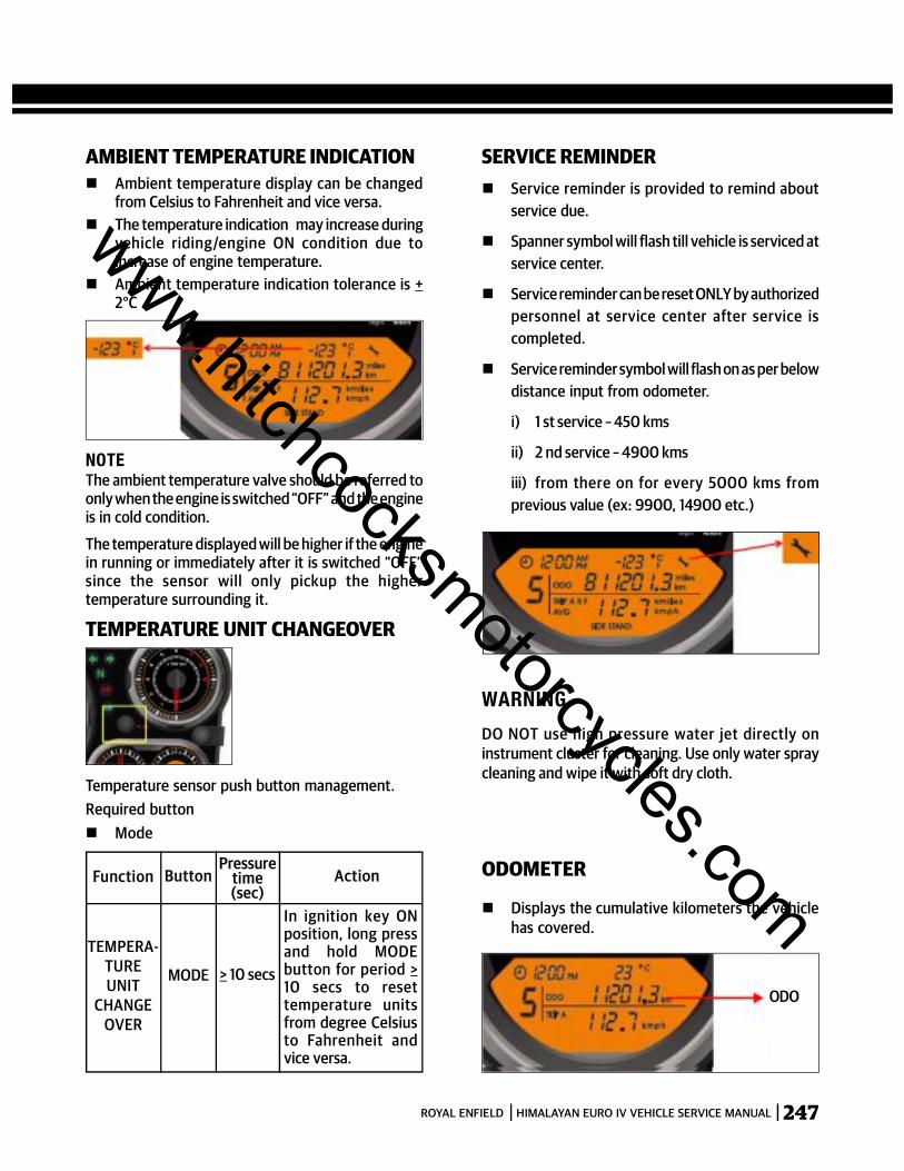
247ROYAL ENFIELD HIMALAYAN EURO IV VEHICLE SERVICE MANUAL
AMBIENT TEMPERATURE INDICATION Ambient temperature display can be changed
from Celsius to Fahrenheit and vice versa. The temperature indication may increase during
vehicle riding/engine ON condition due toincrease of engine temperature.
Ambient temperature indication tolerance is +2°C
NOTEThe ambient temperature valve should be referred toonly when the engine is switched “OFF” and the engineis in cold condition.
The temperature displayed will be higher if the enginein running or immediately after it is switched “OFF”since the sensor will only pickup the highertemperature surrounding it.
Function Button
TEMPERATURE UNIT CHANGEOVER
Pressuretime(sec)
Action
TEMPERA-TUREUNIT
CHANGEOVER
MODE > 10 secs
In ignition key ONposition, long pressand hold MODEbutton for period >10 secs to resettemperature unitsfrom degree Celsiusto Fahrenheit andvice versa.
SERVICE REMINDER Service reminder is provided to remind about
service due.
Spanner symbol will flash till vehicle is serviced atservice center.
Service reminder can be reset ONLY by authorizedpersonnel at service center after service iscompleted.
Service reminder symbol will flash on as per belowdistance input from odometer.
i) 1 st service – 450 kms
ii) 2 nd service – 4900 kms
iii) from there on for every 5000 kms fromprevious value (ex: 9900, 14900 etc.)
WARNINGDO NOT use high pressure water jet directly oninstrument cluster for cleaning. Use only water spraycleaning and wipe it with soft dry cloth.
ODO
ODOMETER
Displays the cumulative kilometers the vehiclehas covered.
Temperature sensor push button management.Required button Mode
www.hitchcocksmotorcycles.com
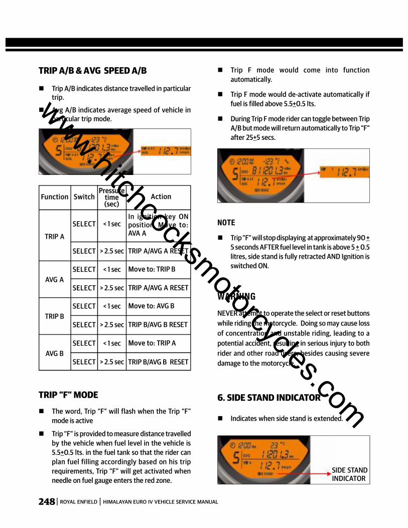
248 ROYAL ENFIELD HIMALAYAN EURO IV VEHICLE SERVICE MANUAL
TRIP A/B & AVG SPEED A/B
Trip A/B indicates distance travelled in particulartrip.
Avg A/B indicates average speed of vehicle inparticular trip mode.
Trip F mode would come into functionautomatically.
Trip F mode would de-activate automatically iffuel is filled above 5.5+0.5 lts.
During Trip F mode rider can toggle between TripA/B but mode will return automatically to Trip “F”after 25+5 secs.
NOTE Trip “F” will stop displaying at approximately 90 +
5 seconds AFTER fuel level in tank is above 5 + 0.5litres, side stand is fully retracted AND Ignition isswitched ON.
WARNINGNEVER attempt to operate the select or reset buttonswhile riding the motorcycle. Doing so may cause lossof concentration and unstable riding, leading to apotential accident, resulting in serious injury to bothrider and other road users, besides causing severedamage to the motorcycle.
6. SIDE STAND INDICATOR
Indicates when side stand is extended.
SIDE STANDINDICATOR
The word, Trip “F” will flash when the Trip “F”mode is active
Trip “F” is provided to measure distance travelledby the vehicle when fuel level in the vehicle is5.5+0.5 lts. in the fuel tank so that the rider canplan fuel filling accordingly based on his triprequirements, Trip “F” will get activated whenneedle on fuel gauge enters the red zone.
TRIP A
Function SwitchPressure
time(sec)
Action
SELECT < 1 secIn ignition key ONposition, Move to:AVA A
SELECT > 2.5 sec TRIP A/AVG A RESET
SELECT < 1 sec
SELECT > 2.5 sec TRIP A/AVG A RESET
Move to: TRIP BAVG A
SELECT < 1 sec
SELECT > 2.5 sec TRIP B/AVG B RESET
Move to: AVG BTRIP B
SELECT < 1 sec
SELECT > 2.5 sec TRIP B/AVG B RESET
Move to: TRIP AAVG B
TRIP “F” MODE
www.hitchcocksmotorcycles.com

249ROYAL ENFIELD HIMALAYAN EURO IV VEHICLE SERVICE MANUAL
GEAR POSITION INDICATION Displays the gear position in which the vehicle is
traveling.
When in neutral the indication will be “0”.
When in gear the appropriate number between 1to 5 will be displayed.
C. TELL TALES
1. Turn Left : Left turn signal ON.
2. Turn right: Right turn signal ON.
3. Neutral : Transmission is in Neutral.
4. Low Battery Indication : Indicator will glowcontinuously if ignition switch is ON & engine isnot running. Indication will switch off as soon asengine is started. If battery voltage is below 12 V,indicator will glow continuously indicating a lowbattery.
5. High Beam Indication: Head lamp high beam ON.
6. EMS Malfunction Indication :
Will be illuminated as soon as ignition & stopswitch are ‘ON’ and will go ‘OFF’ after theengine is started.
Will remain continuously ‘ON’ incase of anymalfunction of the EMS.
TURN LEFT
NEUTRAL
TURN RIGHTEMS MALFUNCTIONINDICATIONLOW BATTERYINDICATIONHI BEAM INDICATION
CAUTIONDO NOT run motorcycle incase the malfunctionremains ‘ON’ continuously as it can cause severedamage to the ECU & Sensors. Please visit the nearestautorise Royal Enfield dealer to diagnose & rectify thedefect in the EMS.
D. TACHO METER
1. Indicates the RPM at which engine is working.
2. Useful for right selection of gear with respect toengine RPM.
WARNING Do not run engine with gears in neutral as RPM
will go beyound red zone.
Do not ride motorcycle in lower gears with highacceleration as it will cause RPM to start to redzone & affect the main parts inside engine.
G. COMPASS LCD
Useful for Navigation during riding. Text indicates heading direction of vehicle. (N, S,
E, W, NE, NW, SE, SW) Arrow will always point to North. Eg. if heading Northwest, text will display NW and
arrow will be in top right corner to indicateNorth.
www.hitchcocksmotorcycles.com

250 ROYAL ENFIELD HIMALAYAN EURO IV VEHICLE SERVICE MANUAL
CAUTION1. Avoid using magnetic key chains, magnetic/
ferrous materials or electronic components withinterference around cockpit area to avoidmalfunctioning of digital compass.
2. If compass LCD enters into calibration mode(“CA”flashing) ride vehicle in “8” direction slowly tocalibrate the compass or approach nearestauthorized service center for assistance andproper calibration.
3. Indication fluctuation during riding is normaloperation due to impact of road irregularities.
4. Compass indication tolerance is + 45°.
WARNINGDO NOT focus on the compass while riding. Doing somany cause loss of concentration and unstable riding,leading to a potential accident, resulting in seriousinjury to both rides & other road users besides causingsevere damage to the motorcycle.
H. FUEL GAUGE
Indicates fuel level in tank
WARNINGDo not use the motorcycle for long duration with thefuel indication in red zone. Refuel at the earliest.
Failure to do so may cause the motorcycle to run outof fuel and get stranded, in addition to causing seriousdamage to the fuel pump.
www.hitchcocksmotorcycles.com
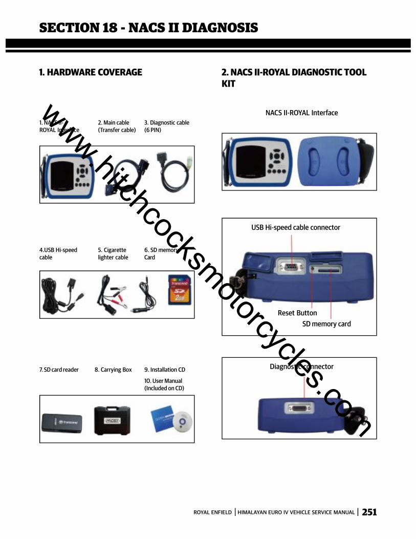
251ROYAL ENFIELD HIMALAYAN EURO IV VEHICLE SERVICE MANUAL
1. HARDWARE COVERAGE
1. NACS II-ROYAL Interface
2. Main cable(Transfer cable)
3. Diagnostic cable(6 PIN)
NACS II-ROYAL Interface
USB Hi-speed cable connector
Reset ButtonSD memory card
Diagnostic connector
4.USB Hi-speedcable
5. Cigarettelighter cable
6. SD memoryCard
7. SD card reader 8. Carrying Box 9. Installation CD
10. User Manual(Included on CD)
2. NACS II-ROYAL DIAGNOSTIC TOOLKIT
SECTION 18 - NACS II DIAGNOSIS
www.hitchcocksmotorcycles.com
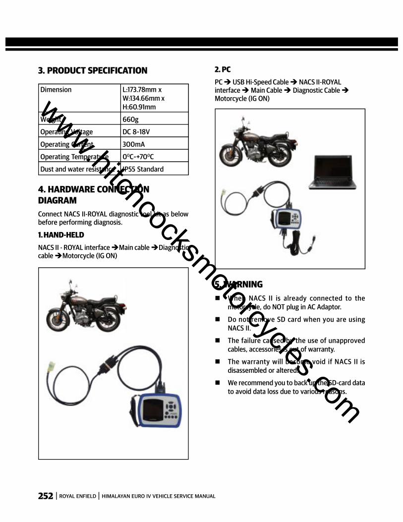
252 ROYAL ENFIELD HIMALAYAN EURO IV VEHICLE SERVICE MANUAL
3. PRODUCT SPECIFICATION
4. HARDWARE CONNECTIONDIAGRAMConnect NACS II-ROYAL diagnostic tool kit as belowbefore performing diagnosis.
1. HAND-HELDNACS II - ROYAL interfaceMain cableDiagnosticcableMotorcycle (IG ON)
Dimension L:173.78mm xW:134.66mm xH:60.91mm
Weight 660g
Operating Voltage DC 8~18V
Operating Current 300mA
Operating Temperature 00C~+700C
Dust and water resistance IP55 Standard
5. WARNING When NACS II is already connected to the
motorcycle, do NOT plug in AC Adaptor.
Do not remove SD card when you are usingNACS II.
The failure caused by the use of unapprovedcables, accessories is out of warranty.
The warranty will become void if NACS II isdisassembled or altered.
We recommend you to back up the SD-card datato avoid data loss due to various reasons.
2. PCPC USB Hi-Speed Cable NACS II-ROYALinterface Main Cable Diagnostic CableMotorcycle (IG ON)www.hitchcocksmotorcycles.com
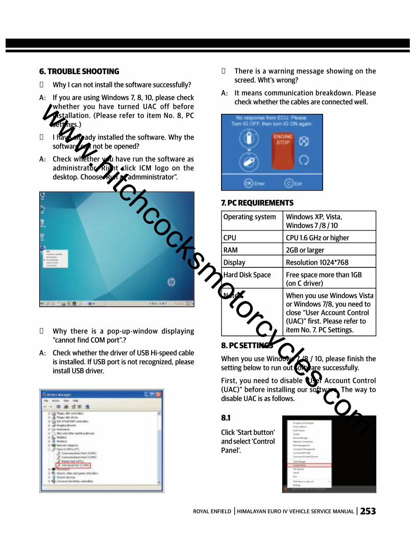
253ROYAL ENFIELD HIMALAYAN EURO IV VEHICLE SERVICE MANUAL
s There is a warning message showing on thescreed. Wht’s wrong?
A: It means communication breakdown. Pleasecheck whether the cables are connected well.
7. PC REQUIREMENTS
Operating system Windows XP, Vista,Windows 7 /8 / 10
CPU CPU 1.6 GHz or higher
RAM 2GB or larger
Display Resolution 1024*768
Hard Disk Space Free space more than 1GB(on C driver)
Notes When you use Windows Vistaor Windows 7/8, you need toclose “User Account Control(UAC)” first. Please refer toitem No. 7. PC Settings.
8. PC SETTINGSWhen you use Windows 7 /8 / 10, please finish thesetting below to run out software successfully.
First, you need to disable “User Account Control(UAC)” before installing our software. The way todisable UAC is as follows.
Click ‘Start button’and select ‘ControlPanel’.
s Why there is a pop-up-window displaying“cannot find COM port”.?
A: Check whether the driver of USB Hi-speed cableis installed. If USB port is not recognized, pleaseinstall USB driver.
8.1
6. TROUBLE SHOOTINGs Why I can not install the software successfully?
A: If you are using Windows 7, 8, 10, please checkwhether you have turned UAC off beforeinstallation. (Please refer to item No. 8, PCsettings.)
s I have already installed the software. Why thesoftware can not be opened?
A: Check whether you have run the software asadministrator. Right click ICM logo on thedesktop. Choose ‘Run as admministrator”.
www.hitchcocksmotorcycles.com

254 ROYAL ENFIELD HIMALAYAN EURO IV VEHICLE SERVICE MANUAL
8.2.
8.3.
9.3.
Move the slider to the Never notify position, Click “OK”to make the change effective.
Click ‘Changer User’ Account Control Settings”.
Click ‘User Accounts’
8.4.
Click ‘Finish’ to complete the installation
ROYAL ENFIELD NACS II DIAGNOSIS 9. SOFTWARE INSTALLATION9.1. Start the computer.
9.2. Insert installation CD to CD-ROM drive and installfollowing software.
a. Main software: NACSII_ROYAL_V0.03_install.exe
b. Recording data analyzing software: NACSII-RECORD_ROYAL-V0_01_setup
www.hitchcocksmotorcycles.com
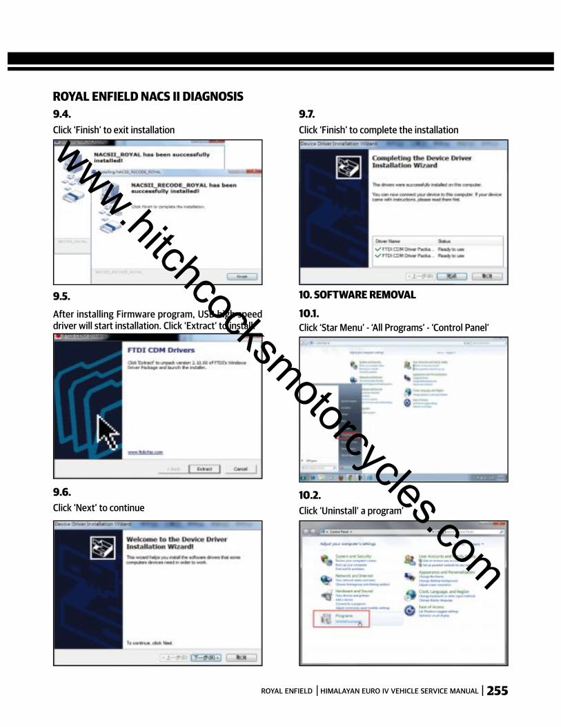
255ROYAL ENFIELD HIMALAYAN EURO IV VEHICLE SERVICE MANUAL
ROYAL ENFIELD NACS II DIAGNOSIS9.7.
10.1.
9.4.
9.5.
9.6.
Click ‘Finish’ to exit installation
After installing Firmware program, USB high speeddriver will start installation. Click ‘Extract’ to install.
Click ‘Next’ to continue
Click ‘Finish’ to complete the installation
10. SOFTWARE REMOVAL
Click ‘Star Menu’ - ‘All Programs’ - ‘Control Panel’
Click ‘Uninstall’ a program’10.2.
www.hitchcocksmotorcycles.com
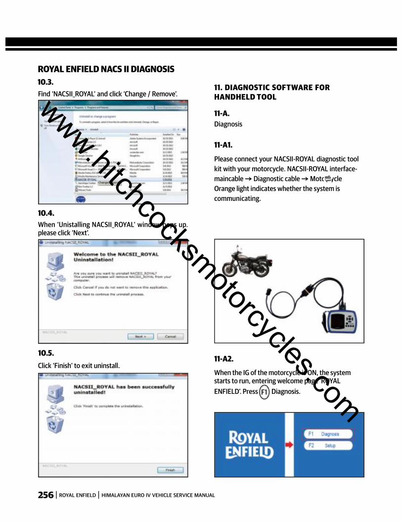
256 ROYAL ENFIELD HIMALAYAN EURO IV VEHICLE SERVICE MANUAL
ROYAL ENFIELD NACS II DIAGNOSIS10.3.
10.4.
10.5.
11. DIAGNOSTIC SOFTWARE FORHANDHELD TOOL
Diagnosis11-A.
Please connect your NACSII-ROYAL diagnostic toolkit with your motorcycle. NACSII-ROYAL interface-maincable Diagnostic cable MotorcycleOrange light indicates whether the system iscommunicating.
11-A1.
When the IG of the motorcycle is ON, the systemstarts to run, entering welcome page ‘ROYALENFIELD’. Press Diagnosis.
11-A2.
F1
Find ‘NACSII_ROYAL’ and click ‘Change / Remove’.
When ‘Unistalling NACSII_ROYAL’ window pops up.please click ‘Next’.
Click ‘Finish’ to exit uninstall.
www.hitchcocksmotorcycles.com
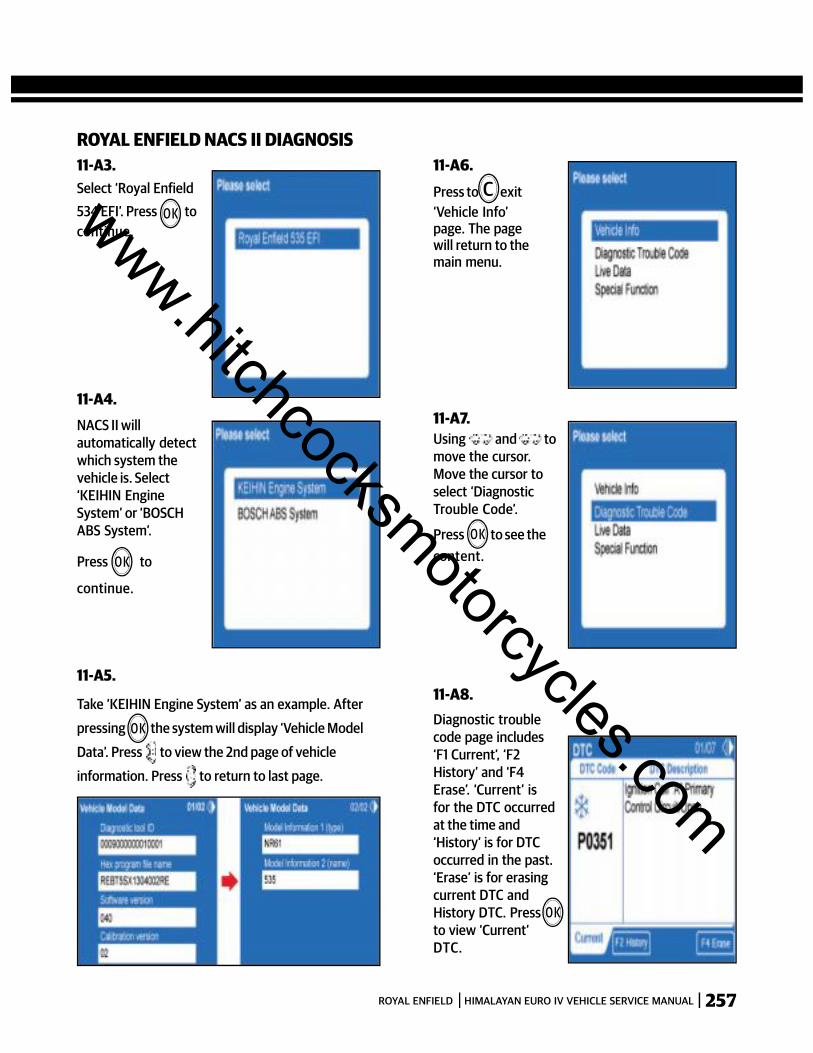
257ROYAL ENFIELD HIMALAYAN EURO IV VEHICLE SERVICE MANUAL
ROYAL ENFIELD NACS II DIAGNOSIS11-A3.
O K
11-A4.
Take ‘KEIHIN Engine System’ as an example. After
pressing the system will display ‘Vehicle Model
Data’. Press to view the 2nd page of vehicle
information. Press to return to last page.
11-A5.
O K
Press to exit‘Vehicle Info’page. The pagewill return to themain menu.
11-A6.C
11-A7.Using and tomove the cursor.Move the cursor toselect ‘DiagnosticTrouble Code’.
Press to see thecontent.
O K
11-A8.Diagnostic troublecode page includes‘F1 Current’, ‘F2History’ and ‘F4Erase’. ‘Current’ isfor the DTC occurredat the time and‘History’ is for DTCoccurred in the past.‘Erase’ is for erasingcurrent DTC andHistory DTC. Pressto view ‘Current’DTC.
O K
O K
Select ‘Royal Enfield534 EFI’. Press tocontinue.
NACS II willautomatically detectwhich system thevehicle is. Select‘KEIHIN EngineSystem’ or ‘BOSCHABS System’.
Press to
continue.
www.hitchcocksmotorcycles.com
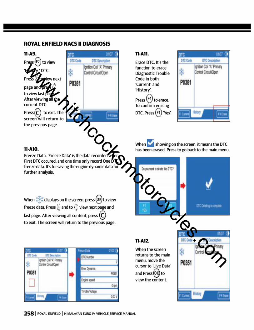
258 ROYAL ENFIELD HIMALAYAN EURO IV VEHICLE SERVICE MANUAL
ROYAL ENFIELD NACS II DIAGNOSIS
Press to view
‘History ‘ DTC.
Press to view next
page and pressto view last page.After viewing all thecurrent DTC.
Press to exit. Thescreen will return tothe previous page.
11-A9.F2
C
Freeze Data. ‘Freeze Data’ is the data recorded whenFirst DTC occured, and one time only record One DTCfreeze data. It’s for saving the engine dynamic data forfurther analysis.
11-A10.
When displays on the screen, press to view
freeze data. Press and to view next page and
last page. After viewing all content, pressto exit. The screen will return to the previous page.
Erace DTC. It’s thefunction to eraceDiagnostic TroubleCode in both‘Current’ and‘History’.
11-A11.
Press to erace.To confirm erasing
DTC. Press ‘Yes’.
When showing on the screen, it means the DTChas been erased. Press to go back to the main menu.
When the screenreturns to the mainmenu, move thecursor to ‘Live Data’
and Press toview the content.
11-A12.
O K
C
F4
F1
O K
www.hitchcocksmotorcycles.com

259ROYAL ENFIELD HIMALAYAN EURO IV VEHICLE SERVICE MANUAL
ROYAL ENFIELD NACS II DIAGNOSIS
Press and to view all the content.
11-A13.
Record data. ‘F2REC’ is forrecording Live data.When viewing ‘Live
Data’, click torecord current
values. Press tostop recording
11-A14.
Press to save
the file.
11-A15.
Back to the mainmenu, move thecursor to ‘SpecialFunction’ andPress
11-A16.
‘Special function’ iscustomized functionsprovided to specificvehicles.
11-A17.
OK
C
F1
Select “COAdjustment”, press
and to adjustthe CO value. is forincreasing fuelinjection value. isfor decreasing fuelinjection value.
After finishadjustment, pressto save. Press toexi t. If you want to
OK
go back to the main page, press unti l the pagereturn to the top of the page.11-B.11-B1.
“F2 Setup” page contains setting Language, viewingSystem Information and setting Date / Time.
www.hitchcocksmotorcycles.com
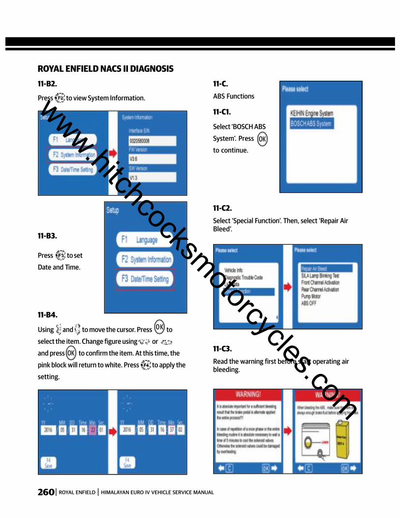
260 ROYAL ENFIELD HIMALAYAN EURO IV VEHICLE SERVICE MANUAL
ROYAL ENFIELD NACS II DIAGNOSIS
Press to view System Information.
11-B2.
Press to set
Date and Time.
11-B3.
Using and to move the cursor. Press to
select the item. Change figure using or
and press to confirm the item. At this time, the
pink block will return to white. Press to apply the
setting.
11-B4.
ABS Functions
11-C.
Select ‘BOSCH ABS
System’. Press
to continue.
11-C1.
Select ‘Special Function’. Then, select ‘Repair AirBleed’.
11-C2.
Read the warning first before start operating airbleeding.
11-C3.
O K
OK
OK
www.hitchcocksmotorcycles.com
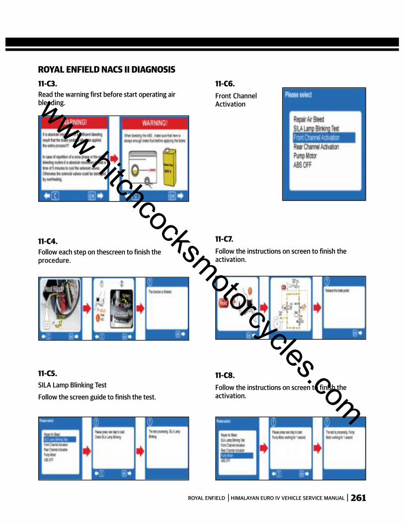
261ROYAL ENFIELD HIMALAYAN EURO IV VEHICLE SERVICE MANUAL
ROYAL ENFIELD NACS II DIAGNOSIS
Read the warning first before start operating airbleeding.
11-C3.
Follow each step on thescreen to finish theprocedure.
11-C4.
SILA Lamp Blinking Test
Follow the screen guide to finish the test.
11-C5.
Front ChannelActivation
11-C6.
Follow the instructions on screen to finish theactivation.
11-C7.
Follow the instructions on screen to finish theactivation.
11-C8.
www.hitchcocksmotorcycles.com
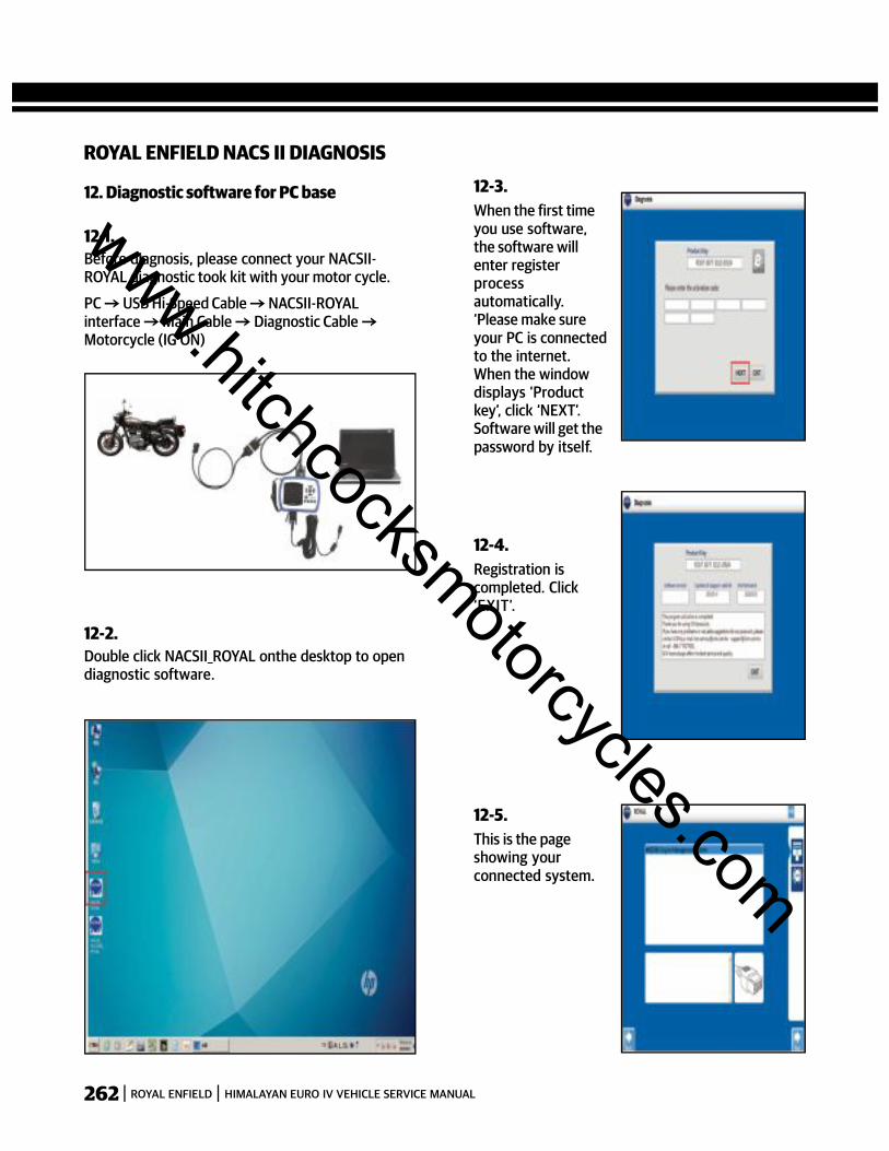
262 ROYAL ENFIELD HIMALAYAN EURO IV VEHICLE SERVICE MANUAL
ROYAL ENFIELD NACS II DIAGNOSIS
12. Diagnostic software for PC base
Before diagnosis, please connect your NACSII-ROYAL diagnostic took kit with your motor cycle.
PC USB Hi-Speed Cable NACSII-ROYALinterface Main Cable Diagnostic CableMotorcycle (IG ON)
12-1.
Double click NACSII_ROYAL onthe desktop to opendiagnostic software.
12-2.
When the first timeyou use software,the software willenter registerprocessautomatically.‘Please make sureyour PC is connectedto the internet.When the windowdisplays ‘Productkey’, click ‘NEXT’.Software will get thepassword by itself.
12-3.
Registration iscompleted. Click‘EXIT’.
12-4.
This is the pageshowing yourconnected system.
12-5.
www.hitchcocksmotorcycles.com

263ROYAL ENFIELD HIMALAYAN EURO IV VEHICLE SERVICE MANUAL
Click to show
Interface info and
Contact info of I.C.M.
12-6.
Click to switch
language.
After selecting
language.
Click to confirm
setting
Click to continue.
12-7.
Connecting to
engine system.
Please wait...
12-8.
There are various
green buttons on
the right.
button is for
displaying all the
vehicle info.
12-9.
ROYAL ENFIELD NACS II DIAGNOSIS
Click to read the
Diagnostic Trouble
code. Click
‘Current’ toread
current DTC. Click
‘History’ to read
history DTC.
12-10.
If you want to
print trouble
code, click
to print DTC
data. It will
take a
moment.
12-11.
www.hitchcocksmotorcycles.com
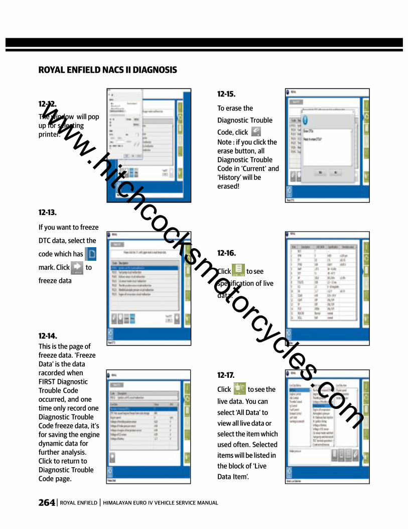
264 ROYAL ENFIELD HIMALAYAN EURO IV VEHICLE SERVICE MANUAL
ROYAL ENFIELD NACS II DIAGNOSIS
The window will popup for selectingprinter.
12-12.
If you want to freeze
DTC data, select the
code which has
mark. Click to
freeze data
12-13.
This is the page offreeze data. ‘FreezeData’ is the dataracorded whenFIRST DiagnosticTrouble Codeoccurred, and onetime only record oneDiagnostic TroubleCode freeze data, it’sfor saving the enginedynamic data forfurther analysis.Click to return toDiagnostic TroubleCode page.
12-14.
To erase the
Diagnostic Trouble
Code, clickNote : if you click theerase button, allDiagnostic TroubleCode in ‘Current’ and‘History’ will beerased!
12-15.
Click to see
specification of live
data.
12-16.
Click to see the
live data. You canselect ‘All Data’ toview all live data orselect the item whichused often. Selecteditems will be listed inthe block of ‘LiveData Item’.
12-17.
www.hitchcocksmotorcycles.com

265ROYAL ENFIELD HIMALAYAN EURO IV VEHICLE SERVICE MANUAL
ROYAL ENFIELD NACS II DIAGNOSIS
Click to view selected data values.
12-17-A.
Click to view wave chart.
12-17-B.
Click to view chart of 2 live data items at the
same time.
12-17.
Click to erase ALL selected live data. If you wantto erase only one item, please press and hold ‘Shift’key and select the item that you want to delete.Then, click button. The selected item will beerased.
12-17-D.
This button is
for special function.
Functions depend
on ECU type. Take
‘CO adjustment’ as
an example. Select
the item and click
12-18.
The page will display
‘What to do’ for
next step. Click
to continue.
12-19.
www.hitchcocksmotorcycles.com

266 ROYAL ENFIELD HIMALAYAN EURO IV VEHICLE SERVICE MANUAL
ROYAL ENFIELD NACS II DIAGNOSIS
Adjust CO value
by clicking
and click
to save
adjusted value.
12-20.
This software is for reading NACS II handheld
recorded data. Please take out SD card from NACS II
handheld tool and insert SD card to PC.
13. RECORD ANALYZING SOFTWARE
Open the
software of
‘NACSII_Record_Royal’.
Select ‘Analyze
Record Data’.
13.1.
Select Record Date
and File name, then
click
13-2.
Select the items
which used often.
Selected items will be
listed in the block of
‘Live Data Item’.
Click to view
wave chart of
selected items.
13-3.
13-4.
Wave chart starts running until press ‘Stop’ button.
Drag Yellow line forward and back to view recorded
live data values.
www.hitchcocksmotorcycles.com
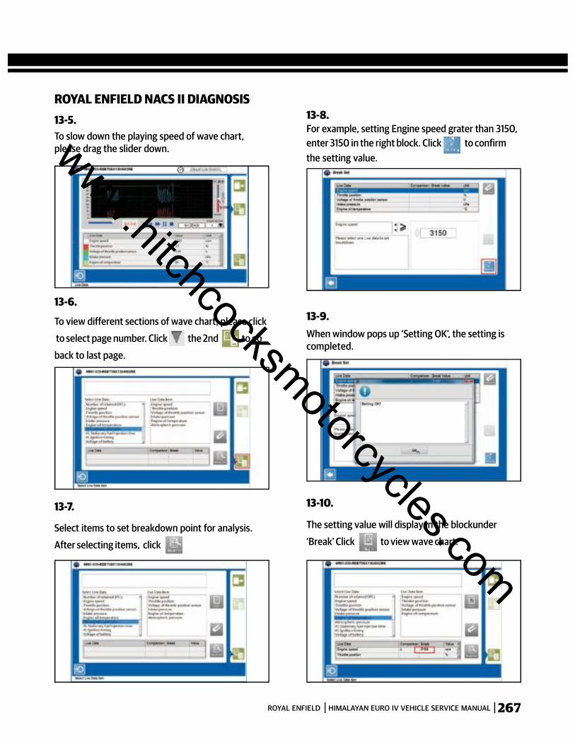
267ROYAL ENFIELD HIMALAYAN EURO IV VEHICLE SERVICE MANUAL
ROYAL ENFIELD NACS II DIAGNOSIS13-5.
13-6.
13-7.
13-8.
To slow down the playing speed of wave chart,please drag the slider down.
To view different sections of wave chart, please click
to select page number. Click the 2nd to go
back to last page.
Select items to set breakdown point for analysis.
After selecting items, click
For example, setting Engine speed grater than 3150,enter 3150 in the right block. Click to confirmthe setting value.
13-9.When window pops up ‘Setting OK’, the setting iscompleted.
13-10.
The setting value will display in the blockunder
‘Break’ Click to view wave chart.
www.hitchcocksmotorcycles.com

268 ROYAL ENFIELD HIMALAYAN EURO IV VEHICLE SERVICE MANUAL
ROYAL ENFIELD NACS II DIAGNOSIS13-11.
13-13.
13-14.
13-15.
13-16.
Click to quickly find matched point of setting value.
Sometimes, setting only one value still can not find themain problem which causes malfunction. In this case,setting the 2nd value or more values can help user tofind satisfied conditions. To set the second valueplease select Live data item. Take throttle position asan example. Enter throttle position grater than 9.8 inthe right block and click to finish setting.
13-12.
After Setting 2 values of the 2 items, the 2 items willbe listed in the block of ‘All value match’ Click togo back to Live data selection page.
Back to Live data selection page, click to viewwave chart of the 2 setting values.
Click to quickly find the 2 matched conditions.
Back to Live data selection page, setting the 3rd
value as the same way as step 18-8. Click to
finish setting.
www.hitchcocksmotorcycles.com
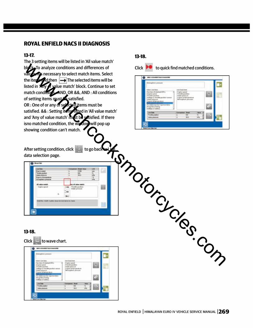
269ROYAL ENFIELD HIMALAYAN EURO IV VEHICLE SERVICE MANUAL
ROYAL ENFIELD NACS II DIAGNOSIS
The 3 setting items will be listed in ‘All value match’block. To analyze conditions and differences ofvalues, it’s necessary to select match items. Selectthe items and then The selected items will belisted in ‘Any of value match’ block. Continue to setmatch conditions : AND, OR &&, AND : All conditionsof setting items must be satisfied.OR : One of or any of selected items must besatisfied. && : Setting items listed in ‘All value match’and ‘Any of value match’ must be satisfied. If thereisno matched condition, the window will pop upshowing condition can’t match.
13-17.
Click to wave chart.
13-18.
Click to quick find matched conditions.
13-18.
After setting condition, click to go back to Livedata selection page.
www.hitchcocksmotorcycles.com
270 ROYAL ENFIELD HIMALAYAN EURO IV VEHICLE SERVICE MANUAL
SECTION 19 - WIRING HARNESS
www.hitchcocksmotorcycles.com
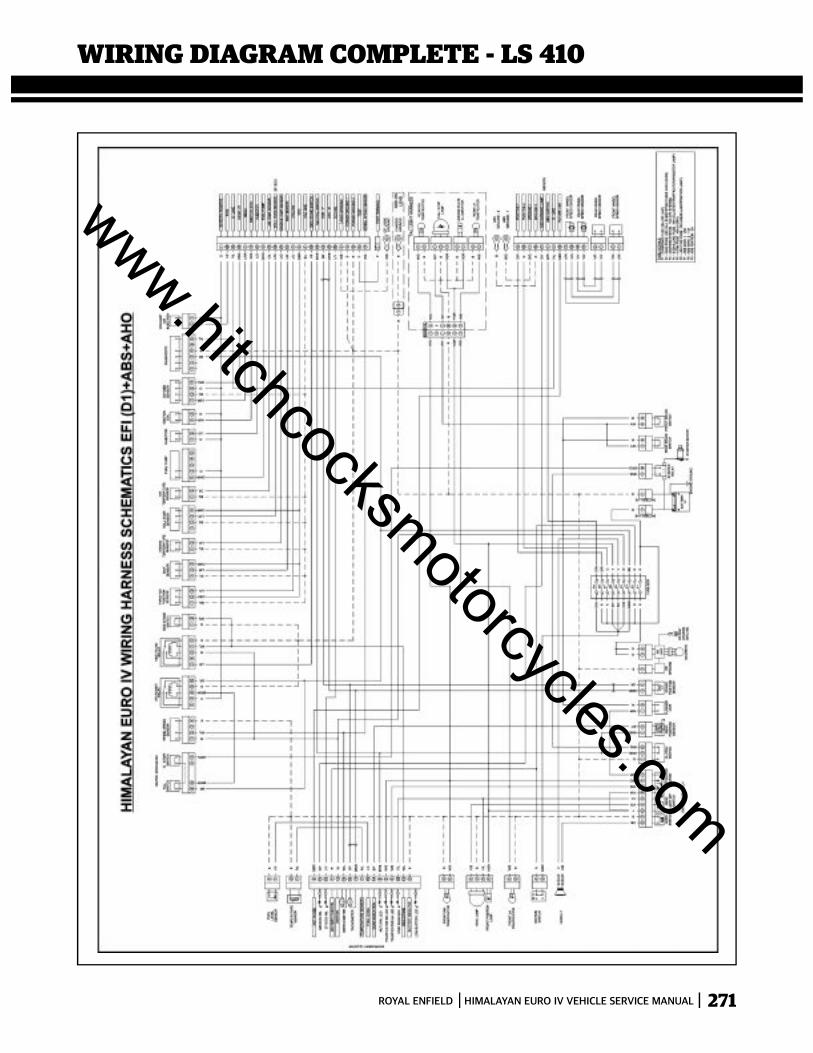
271ROYAL ENFIELD HIMALAYAN EURO IV VEHICLE SERVICE MANUAL
WIRING DIAGRAM COMPLETE - LS 410
www.hitchcocksmotorcycles.com

272 ROYAL ENFIELD HIMALAYAN EURO IV VEHICLE SERVICE MANUAL
www.hitchcocksmotorcycles.com
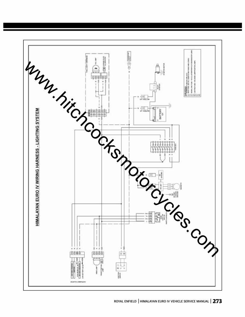
273ROYAL ENFIELD HIMALAYAN EURO IV VEHICLE SERVICE MANUAL
www.hitchcocksmotorcycles.com
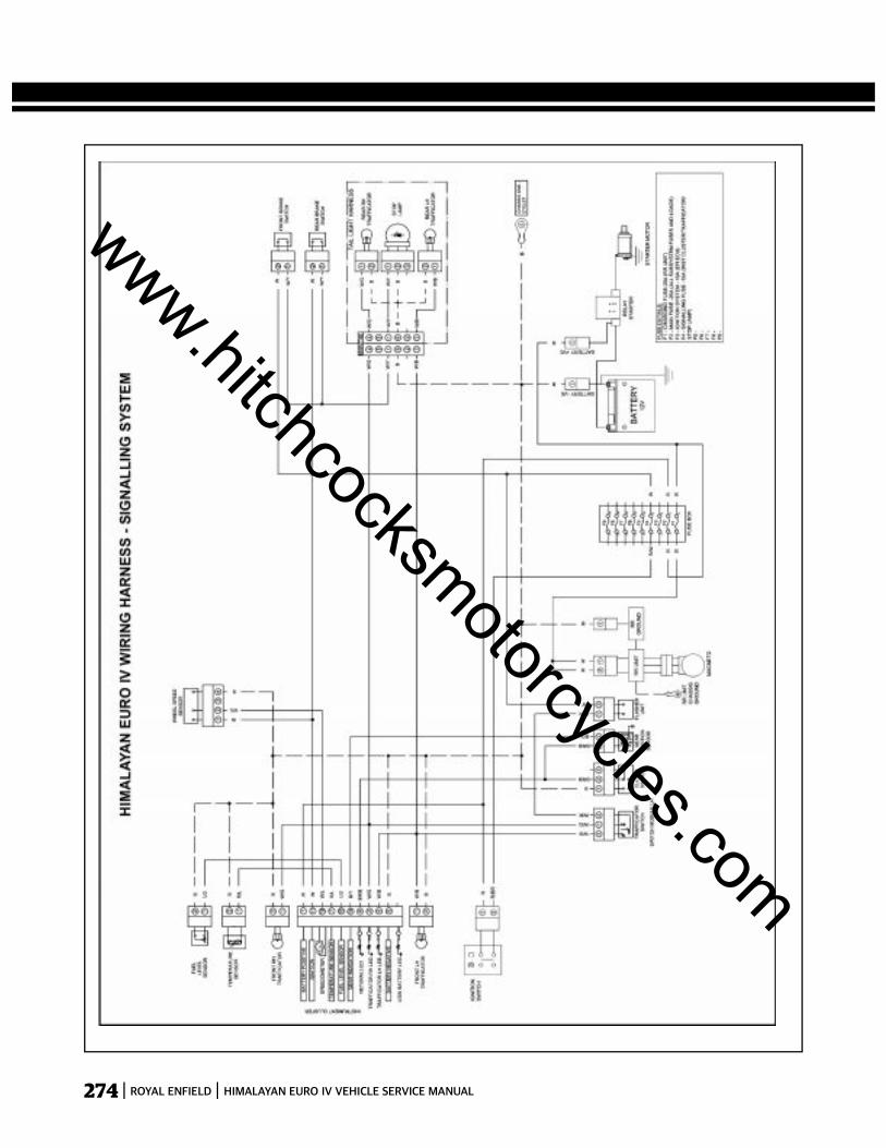
274 ROYAL ENFIELD HIMALAYAN EURO IV VEHICLE SERVICE MANUAL
www.hitchcocksmotorcycles.com
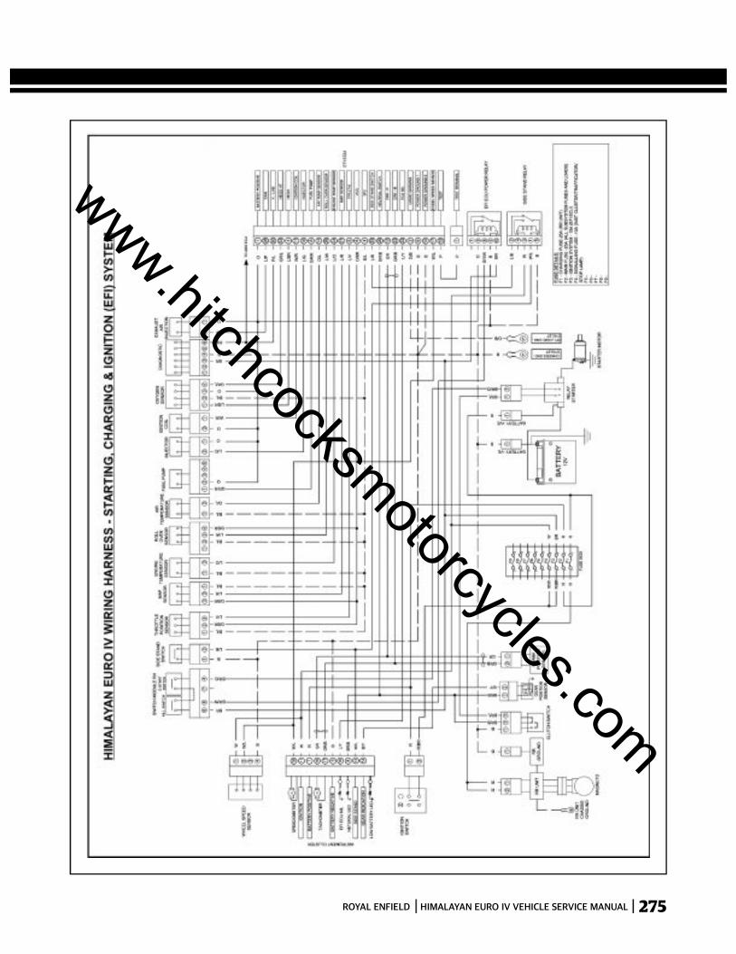
275ROYAL ENFIELD HIMALAYAN EURO IV VEHICLE SERVICE MANUAL
www.hitchcocksmotorcycles.com
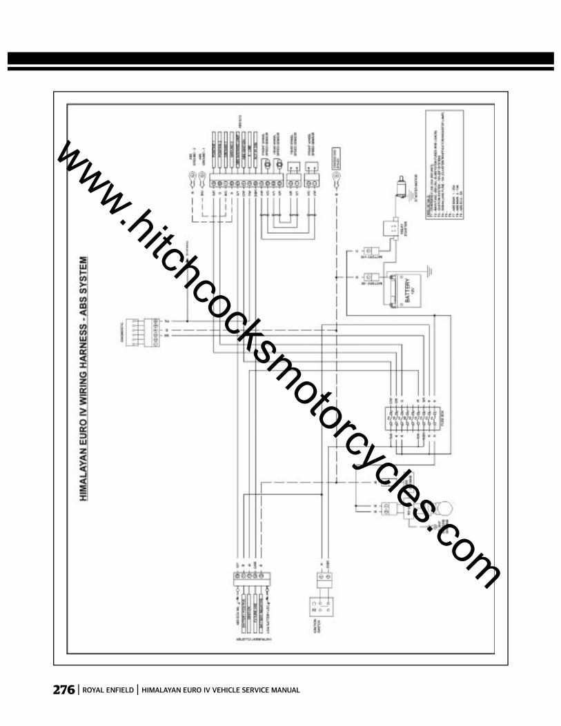
276 ROYAL ENFIELD HIMALAYAN EURO IV VEHICLE SERVICE MANUAL
www.hitchcocksmotorcycles.com
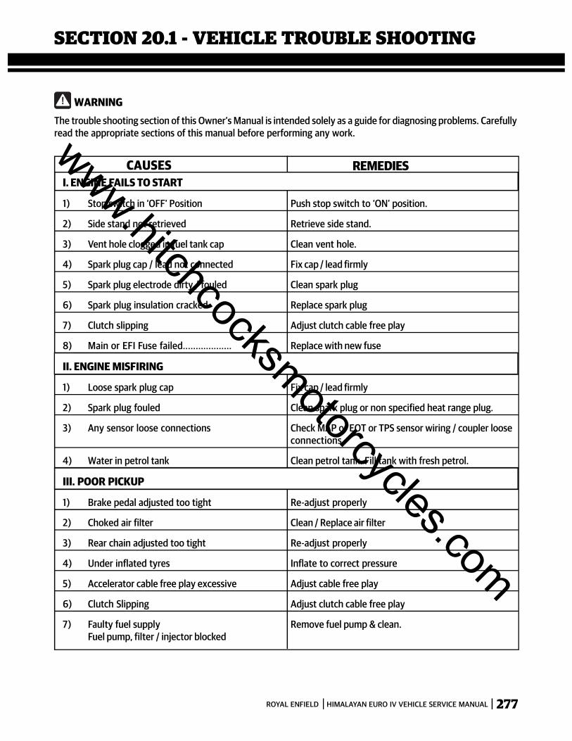
277ROYAL ENFIELD HIMALAYAN EURO IV VEHICLE SERVICE MANUAL
WARNINGThe trouble shooting section of this Owner’s Manual is intended solely as a guide for diagnosing problems. Carefullyread the appropriate sections of this manual before performing any work.
CAUSES REMEDIESI. ENGINE FAILS TO START
1) Stop switch in ‘OFF’ Position Push stop switch to ‘ON’ position.
2) Side stand not retrieved Retrieve side stand.
3) Vent hole clogged in fuel tank cap Clean vent hole.
4) Spark plug cap / lead not connected Fix cap / lead firmly
5) Spark plug electrode dirty / fouled Clean spark plug
6) Spark plug insulation cracked Replace spark plug
7) Clutch slipping Adjust clutch cable free play
8) Main or EFI Fuse failed................... Replace with new fuse
II. ENGINE MISFIRING
1) Loose spark plug cap Fix cap / lead firmly
2) Spark plug fouled Clean spark plug or non specified heat range plug.
3) Any sensor loose connections Check MAP or EOT or TPS sensor wiring / coupler looseconnections
4) Water in petrol tank Clean petrol tank. Fill tank with fresh petrol.
III. POOR PICKUP
1) Brake pedal adjusted too tight Re-adjust properly
2) Choked air filter Clean / Replace air filter
3) Rear chain adjusted too tight Re-adjust properly
4) Under inflated tyres Inflate to correct pressure
5) Accelerator cable free play excessive Adjust cable free play
6) Clutch Slipping Adjust clutch cable free play
7) Faulty fuel supply Remove fuel pump & clean.Fuel pump, filter / injector blocked
SECTION 20.1 - VEHICLE TROUBLE SHOOTING
www.hitchcocksmotorcycles.com
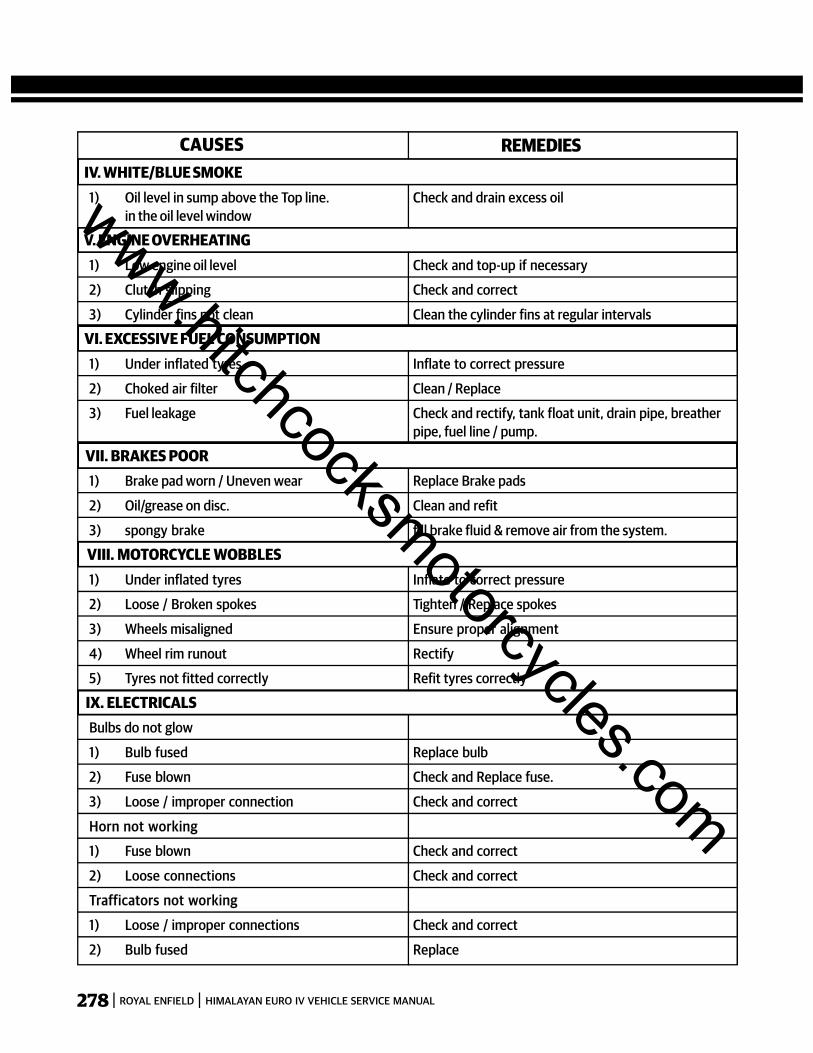
278 ROYAL ENFIELD HIMALAYAN EURO IV VEHICLE SERVICE MANUAL
CAUSES REMEDIES IV. WHITE/BLUE SMOKE
1) Oil level in sump above the Top line. Check and drain excess oilin the oil level window
V. ENGINE OVERHEATING1) Low engine oil level Check and top-up if necessary
2) Clutch slipping Check and correct
3) Cylinder fins not clean Clean the cylinder fins at regular intervals
VI. EXCESSIVE FUEL CONSUMPTION1) Under inflated tyres Inflate to correct pressure
2) Choked air filter Clean / Replace
3) Fuel leakage Check and rectify, tank float unit, drain pipe, breatherpipe, fuel line / pump.
VII. BRAKES POOR1) Brake pad worn / Uneven wear Replace Brake pads
2) Oil/grease on disc. Clean and refit
3) spongy brake fill brake fluid & remove air from the system.
VIII. MOTORCYCLE WOBBLES1) Under inflated tyres Inflate to correct pressure
2) Loose / Broken spokes Tighten / Replace spokes
3) Wheels misaligned Ensure proper alignment
4) Wheel rim runout Rectify
5) Tyres not fitted correctly Refit tyres correctly
IX. ELECTRICALSBulbs do not glow
1) Bulb fused Replace bulb
2) Fuse blown Check and Replace fuse.
3) Loose / improper connection Check and correct
Horn not working
1) Fuse blown Check and correct
2) Loose connections Check and correct
Trafficators not working
1) Loose / improper connections Check and correct
2) Bulb fused Replace
www.hitchcocksmotorcycles.com
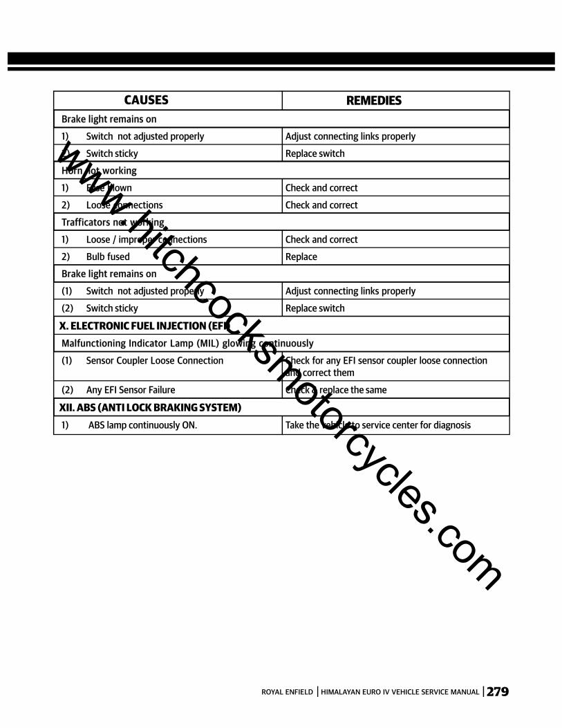
279ROYAL ENFIELD HIMALAYAN EURO IV VEHICLE SERVICE MANUAL
CAUSES REMEDIESBrake light remains on
1) Switch not adjusted properly Adjust connecting links properly
2) Switch sticky Replace switch
Horn not working
1) Fuse blown Check and correct
2) Loose connections Check and correct
Trafficators not working
1) Loose / improper connections Check and correct
2) Bulb fused Replace
Brake light remains on
(1) Switch not adjusted properly Adjust connecting links properly
(2) Switch sticky Replace switch
X. ELECTRONIC FUEL INJECTION (EFI)Malfunctioning Indicator Lamp (MIL) glowing continuously
(1) Sensor Coupler Loose Connection Check for any EFI sensor coupler loose connectionand correct them
(2) Any EFI Sensor Failure Check & replace the same
XII. ABS (ANTI LOCK BRAKING SYSTEM)1) ABS lamp continuously ON. Take the vehicle to service center for diagnosis
www.hitchcocksmotorcycles.com
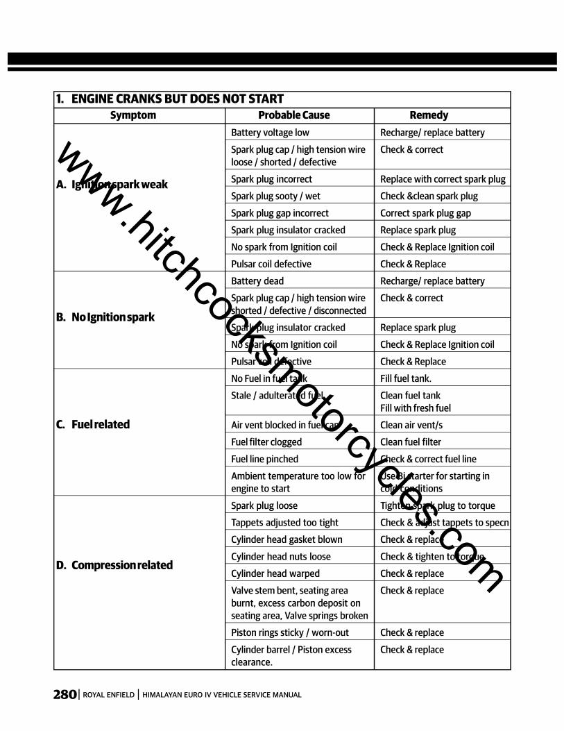
280 ROYAL ENFIELD HIMALAYAN EURO IV VEHICLE SERVICE MANUAL
A. Ignition spark weak
Battery voltage low Recharge/ replace battery
Spark plug cap / high tension wire Check & correctloose / shorted / defective
Spark plug incorrect Replace with correct spark plug
Spark plug sooty / wet Check &clean spark plug
Spark plug gap incorrect Correct spark plug gap
Spark plug insulator cracked Replace spark plug
No spark from Ignition coil Check & Replace Ignition coil
Pulsar coil defective Check & Replace
B. No Ignition spark
Battery dead Recharge/ replace battery
Spark plug cap / high tension wire Check & correctshorted / defective / disconnected
Spark plug insulator cracked Replace spark plug
No spark from Ignition coil Check & Replace Ignition coil
Pulsar coil defective Check & Replace
No Fuel in fuel tank Fill fuel tank.
Stale / adulterated fuel Clean fuel tankFill with fresh fuel
C. Fuel related Air vent blocked in fuel cap Clean air vent/s
Fuel filter clogged Clean fuel filter
Fuel line pinched Check & correct fuel line
Ambient temperature too low for Use Bi starter for starting inengine to start cold conditions
D. Compression related
Spark plug loose Tighten spark plug to torque
Tappets adjusted too tight Check & adjust tappets to specn
Cylinder head gasket blown Check & replace
Cylinder head nuts loose Check & tighten to torque
Cylinder head warped Check & replace
Valve stem bent, seating area Check & replaceburnt, excess carbon deposit onseating area, Valve springs broken
Piston rings sticky / worn-out Check & replace
Cylinder barrel / Piston excess Check & replaceclearance.
Symptom Probable Cause Remedy1. ENGINE CRANKS BUT DOES NOT START
www.hitchcocksmotorcycles.com

281ROYAL ENFIELD HIMALAYAN EURO IV VEHICLE SERVICE MANUAL
Ignition key not in ON position Switch ON ignition keyEngine Kill switch in OFF position Switch ON engine Kill switch
Gears not in neutral (neutral lamp Depress clutch / shift to correctnot glowing) neutral & start
Battery voltage low Check battery. Rechargereplace battery
Starter circuit Fuse blown Check all fuses & replace blownA. Starter motor does not rotate fuse
Starter motor connections loose Check & tighten connections
Starter relay connections loose Check & tighten connections
Ignition Switch defective Check & replace Ignition switch
Starter button defective Check & replace RH switch.
Starter relay failed Check & replace starter relay
Starter motor failed Check & replace starter motor
Major short in Wiring harness Check & correct wiring harness
Motor rotates slowly due to low Check & correct battery /B. Starter motor rotates battery / worn out starter motor starter motor
BUT engine does brush
not crank Magneto rotor woodruff key broken Check & replace woodruff key
Starter clutch assembly slipping Check & replace starter clutchassy
Inlet / Exhaust rocker arm seized in Investigate cause of seizure,rocker shaft check & correct as required
Cam shaft seized in cylinder Investigate cause of seizure,head / cover check & correct as required
Cam chain jammed in sprocket Investigate cause of seizure,gears check & correct as required
C. Engine does not crank and Piston Seized in cylinder barrel Investigate cause of seizure,sounds locked. check & correct as required
Piston Pin seized in connecting Investigate cause of seizure,rod small end check & correct as required
Big end bearing seized in Crank Investigate cause of seizure,pin / connecting rod big end check & correct as required
Crankshaft bearings in LH / RH Investigate cause of seizure,crankcases seized check & correct as required
Symptom Probable Cause Remedy2. ENGINE DOES NOT CRANK
www.hitchcocksmotorcycles.com
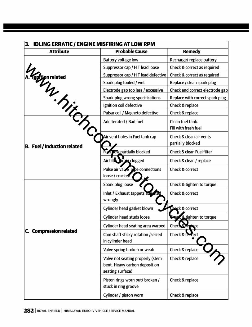
282 ROYAL ENFIELD HIMALAYAN EURO IV VEHICLE SERVICE MANUAL
A. Ignition related
Battery voltage low Recharge/ replace battery
Suppressor cap / H T lead loose Check & correct as required
Suppressor cap / H T lead defective Check & correct as required
Spark plug fouled / wet Replace / clean spark plug
Electrode gap too less / excessive Check and correct electrode gap
Spark plug wrong specifications Replace with correct spark plug
Ignition coil defective Check & replace
Pulsar coil / Magneto defective Check & replace
Adulterated / Bad fuel Clean fuel tank.Fill with fresh fuel
Air vent holes in Fuel tank cap Check & clean air vents
B. Fuel / Induction relatedpartially blocked
Fuel flow partially blocked Check & clean Fuel filter
Air filter dirty / clogged Check & clean / replace
Pulse air valve pipe connections Check & correctloose / cracked
C. Compression related
Spark plug loose Check & tighten to torque
Inlet / Exhaust tappets adjusted Check & correctwrongly
Cylinder head gasket blown Check & correct
Cylinder head studs loose Check & tighten to torque
Cylinder head seating area warped Check & replace
Cam shaft sticky rotation /seized Check & correctin cylinder head
Valve spring broken or weak Check & replace
Valve not seating properly (stem Check & replacebent. Heavy carbon deposit onseating surface)
Piston rings worn out/ broken / Check & replacestuck in ring groove
Cylinder / piston worn Check & replace
Attribute Probable Cause Remedy3. IDLING ERRATIC / ENGINE MISFIRING AT LOW RPM
www.hitchcocksmotorcycles.com
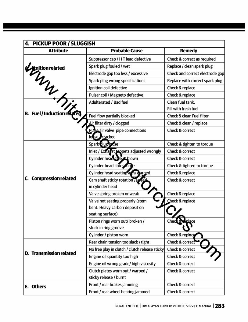
283ROYAL ENFIELD HIMALAYAN EURO IV VEHICLE SERVICE MANUAL
A. Ignition related
Suppressor cap / H T lead defective Check & correct as requiredSpark plug fouled / wet Replace / clean spark plug
Electrode gap too less / excessive Check and correct electrode gapSpark plug wrong specifications Replace with correct spark plug
Ignition coil defective Check & replacePulsar coil / Magneto defective Check & replace
B. Fuel / Induction related
Adulterated / Bad fuel Clean fuel tank.Fill with fresh fuel
Fuel flow partially blocked Check & clean Fuel filterAir filter dirty / clogged Check & clean / replace
Pulse air valve pipe connections Check & correctloose / cracked
C. Compression related
Spark plug loose Check & tighten to torqueInlet / Exhaust tappets adjusted wrongly Check & correct
Cylinder head gasket blown Check & correctCylinder head studs loose Check & tighten to torque
Cylinder head seating area warped Check & replaceCam shaft sticky rotation /seized Check & correctin cylinder headValve spring broken or weak Check & replace
Valve not seating properly (stem Check & replacebent. Heavy carbon deposit onseating surface)
Piston rings worn out/ broken / Check & replacestuck in ring groove
Cylinder / piston worn Check & replace
D. Transmission related
Rear chain tension too slack / tight Check & correct
No free play in clutch / clutch release sticky Check & correctEngine oil quantity too high Check & correct
Engine oil wrong grade/ high viscosity Check & correctClutch plates worn out / warped / Check & correctsticky release / burnt
E. Others Front / rear brakes jamming Check & correctFront / rear wheel bearing jammed Check & correct
4. PICKUP POOR / SLUGGISHAttribute Probable Cause Remedy
www.hitchcocksmotorcycles.com
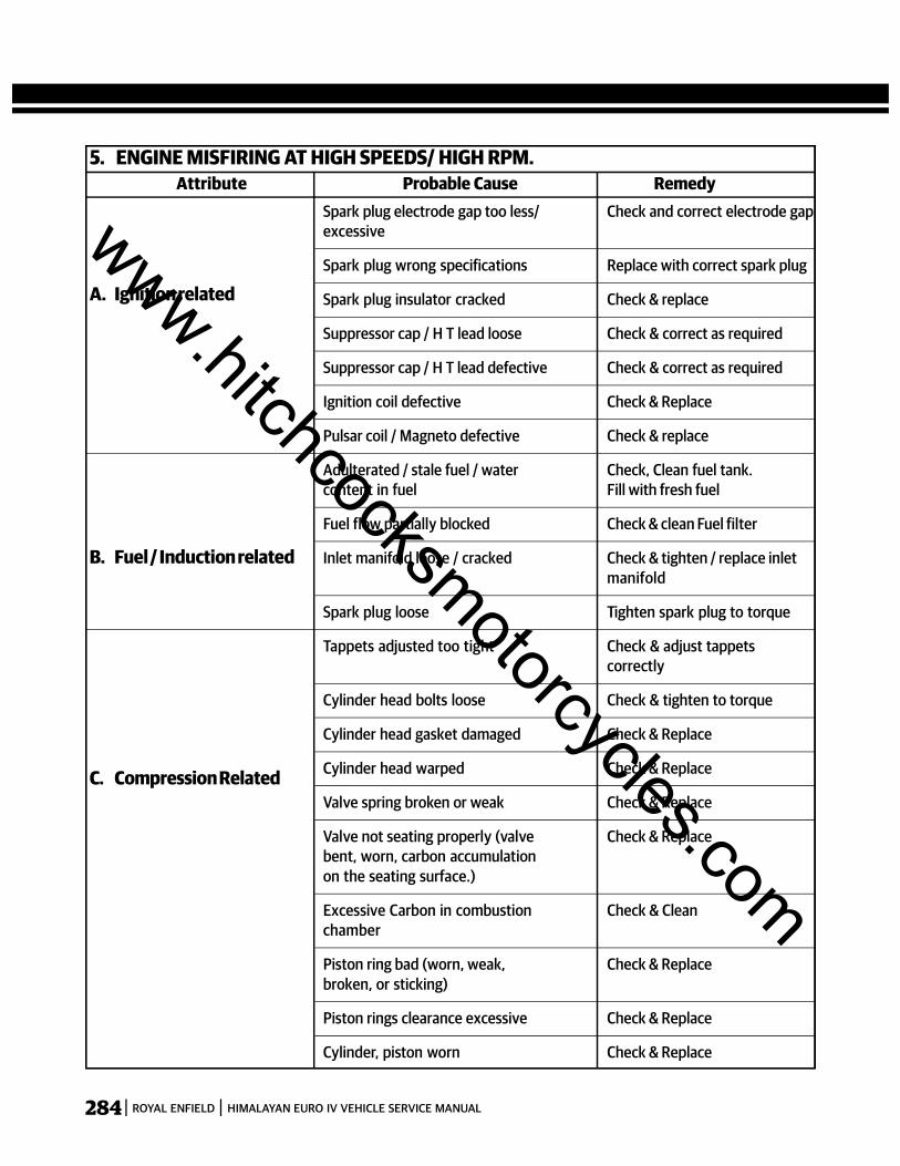
284 ROYAL ENFIELD HIMALAYAN EURO IV VEHICLE SERVICE MANUAL
A. Ignition related
Spark plug electrode gap too less/ Check and correct electrode gapexcessive
Spark plug wrong specifications Replace with correct spark plug
Spark plug insulator cracked Check & replace
Suppressor cap / H T lead loose Check & correct as required
Suppressor cap / H T lead defective Check & correct as required
Ignition coil defective Check & Replace
Pulsar coil / Magneto defective Check & replace
Adulterated / stale fuel / water Check, Clean fuel tank.content in fuel Fill with fresh fuel
Fuel flow partially blocked Check & clean Fuel filter
B. Fuel / Induction related Inlet manifold loose / cracked Check & tighten / replace inletmanifold
C. Compression Related
Spark plug loose Tighten spark plug to torque
Tappets adjusted too tight Check & adjust tappetscorrectly
Cylinder head bolts loose Check & tighten to torque
Cylinder head gasket damaged Check & Replace
Cylinder head warped Check & Replace
Valve spring broken or weak Check & Replace
Valve not seating properly (valve Check & Replacebent, worn, carbon accumulationon the seating surface.)
Excessive Carbon in combustion Check & Cleanchamber
Piston ring bad (worn, weak, Check & Replacebroken, or sticking)
Piston rings clearance excessive Check & Replace
Cylinder, piston worn Check & Replace
5. ENGINE MISFIRING AT HIGH SPEEDS/ HIGH RPM.Attribute Probable Cause Remedy
www.hitchcocksmotorcycles.com

285ROYAL ENFIELD HIMALAYAN EURO IV VEHICLE SERVICE MANUAL
Adulterated / Bad fuel Clean fuel tankFill with fresh fuel
Spark plug Electrode gap too less Check and correct electrode gap
A. Black smoke Spark plug wrong specifications Replace with correct spark plug
Air Filter element clogged Check & Clean
Pulse air valve pipe connections Check & correctloose / cracked
Ignition coil defective Check & replace
B. Brown smokeAdulterated / Bad fuel Clean fuel tank.
Fill with fresh fuel
Air filter box poorly sealed / Check & correctelement partially clogged
C. Bluish / White smoke
Engine oil level too high Check & Maintain Oil level asRecommended
Valve stem seal damaged Check & correct
Excess clearance between valve Check & correctstem & guide
Oil scrapper ring worn out Check & correct
Cylinder barrel / piston clearance Check & replacehigh
Symptom Probable Cause Remedy6. EXHAUST SMOKE EXCESS
www.hitchcocksmotorcycles.com

286 ROYAL ENFIELD HIMALAYAN EURO IV VEHICLE SERVICE MANUAL
Prolonged driving in low gear at High Ride in appropriate gear asspeeds / High gear at Low speeds required by traffic conditions
Engine in Idling RPM for prolonged Switch off Engine if required toperiods be in standstill traffic for more
A. Driving / traffic related than 2 minutes.
Vehicle in standstill with gear engaged and Shift to neutral & release clutchclutch depressed for prolonged periods
Engine RPM high when vehicle at Allow engine to run in idlingstandstill position RPM when in neutral
Riding in traffic with brakes partially Release both brakes and driveengaged for prolonged periods at appropriate speeds
B. Ignition Related
Spark plug electrode gap too less/excessive Check and correct electrode gap
Spark plug wrong specifications Replace with correct spark plug
Spark plug insulator cracked Check & replace
Suppressor cap / H T lead loose Check & correct as required
Suppressor cap / H T lead defective Check & correct as required
Ignition coil defective Check & Replace
Pulsar coil / Magneto defective Check & replace
C. Fuel / Induction relatedAdulterated / Bad fuel Clean fuel tank
Fill with fresh fuel
Air filter dirty / clogged Check & clean / replace
D. Compression Related
Spark plug loose Tighten spark plug to torque
Tappets adjusted too tight Check & adjust tappets correctly
Excessive Carbon in combustion chamber Check & Clean
Poor compression due to cyl. head gasket Check & correctblown, Valve seating improper, Piston ringsworn out / broken, Piston / Cyl. worn out
E. Others
Engine oil less viscous / wrong Check & correctspecification / level too low
Oil cooler fins dirty / blocked Check & clean oil cooler fins
Clutch slipping Check & correct
Front / Rear brakes jammed Check & correct
Engine oil pressure less Check & correct
Silencer choked Check & clean
Attribute Probable Cause Remedy7. ENGINE HEAT EXCESSIVE
www.hitchcocksmotorcycles.com
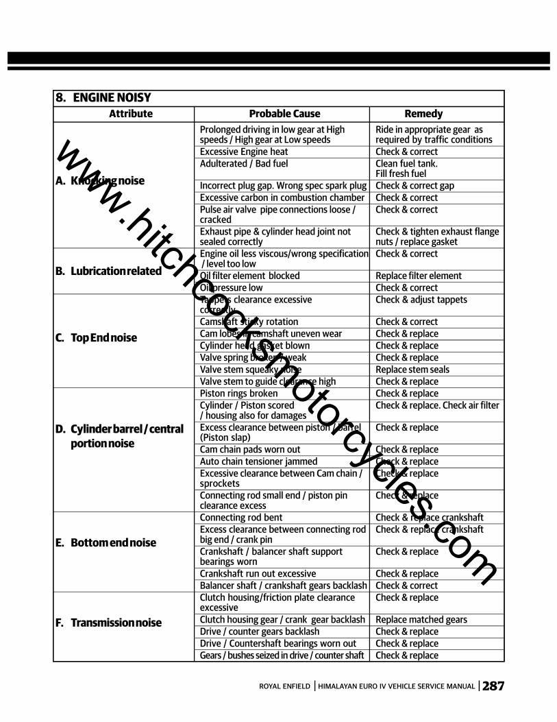
287ROYAL ENFIELD HIMALAYAN EURO IV VEHICLE SERVICE MANUAL
A. Knocking noise
Prolonged driving in low gear at High Ride in appropriate gear asspeeds / High gear at Low speeds required by traffic conditionsExcessive Engine heat Check & correctAdulterated / Bad fuel Clean fuel tank.
Fill fresh fuelIncorrect plug gap. Wrong spec spark plug Check & correct gapExcessive carbon in combustion chamber Check & correctPulse air valve pipe connections loose / Check & correctcrackedExhaust pipe & cylinder head joint not Check & tighten exhaust flangesealed correctly nuts / replace gasket
B. Lubrication relatedEngine oil less viscous/wrong specification Check & correct / level too lowOil filter element blocked Replace filter elementOil pressure low Check & correct
C. Top End noise
Tappets clearance excessive Check & adjust tappetscorrectlyCamshaft sticky rotation Check & correctCam lobes in camshaft uneven wear Check & replaceCylinder head gasket blown Check & replaceValve spring broken / weak Check & replaceValve stem squeaky noise Replace stem sealsValve stem to guide clearance high Check & replace
D. Cylinder barrel / central
Piston rings broken Check & replace
portion noise
Cylinder / Piston scored Check & replace. Check air filter/ housing also for damagesExcess clearance between piston / barrel Check & replace(Piston slap)Cam chain pads worn out Check & replaceAuto chain tensioner jammed Check & replaceExcessive clearance between Cam chain / Check & replacesprocketsConnecting rod small end / piston pin Check & replaceclearance excess
E. Bottom end noise
Connecting rod bent Check & replace crankshaftExcess clearance between connecting rod Check & replace crankshaftbig end / crank pinCrankshaft / balancer shaft support Check & replacebearings wornCrankshaft run out excessive Check & replaceBalancer shaft / crankshaft gears backlash Check & correct
F. Transmission noise
Clutch housing/friction plate clearance Check & replaceexcessiveClutch housing gear / crank gear backlash Replace matched gearsDrive / counter gears backlash Check & replaceDrive / Countershaft bearings worn out Check & replaceGears / bushes seized in drive / counter shaft Check & replace
Attribute Probable Cause Remedy8. ENGINE NOISY
www.hitchcocksmotorcycles.com
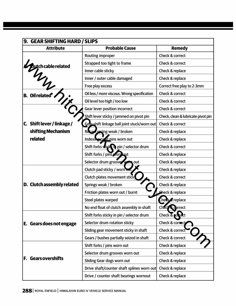
288 ROYAL ENFIELD HIMALAYAN EURO IV VEHICLE SERVICE MANUAL
A. Clutch cable related
Routing improper Check & correct
Strapped too tight to frame Check & correct
Inner cable sticky Check & replace
Inner / outer cable damaged Check & replace
Free play excess Correct free play to 2-3mm
B. Oil related Oil less / more viscous. Wrong specification Check & correct
Oil level too high / too low Check & correct
Gear lever position incorrect Check & correct
Shift lever sticky / jammed on pivot pin Check, clean & lubricate pivot pin
C. Shift lever / linkage / Gear shift linkage ball joint stuck/worn out Check & correct
shifting Mechanism Return spring weak / broken Check & replace
related Indexing pawl pins worn out Check & replace
Shift forks sticky in pin / selector drum Check & correct
Shift forks / pins worn out Check & replace
Selector drum grooves worn out Check & replace
Clutch pad sticky / worn out Check & replace
Clutch plates movement sticky Check & correct
D. Clutch assembly related Springs weak / broken Check & replace
Friction plates worn out / burnt Check & replace
Steel plates warped Check & replace
No end float of clutch assembly in shaft Check & correct
E. Gears does not engage
Shift forks sticky in pin / selector drum Check & correct
Selector drum rotation sticky Check & correct
Sliding gear movement sticky in shaft Check & correct
Gears / bushes partially seized in shaft Check & correct
F. Gears overshifts
Shift forks / pins worn out Check & replace
Selector drum grooves worn out Check & replace
Sliding Gear dogs worn out Check & replace
Drive shaft/counter shaft splines worn out Check & replace
Drive / counter shaft bearings wornout Check & replace
Attribute Probable Cause Remedy9. GEAR SHIFTING HARD / SLIPS
www.hitchcocksmotorcycles.com
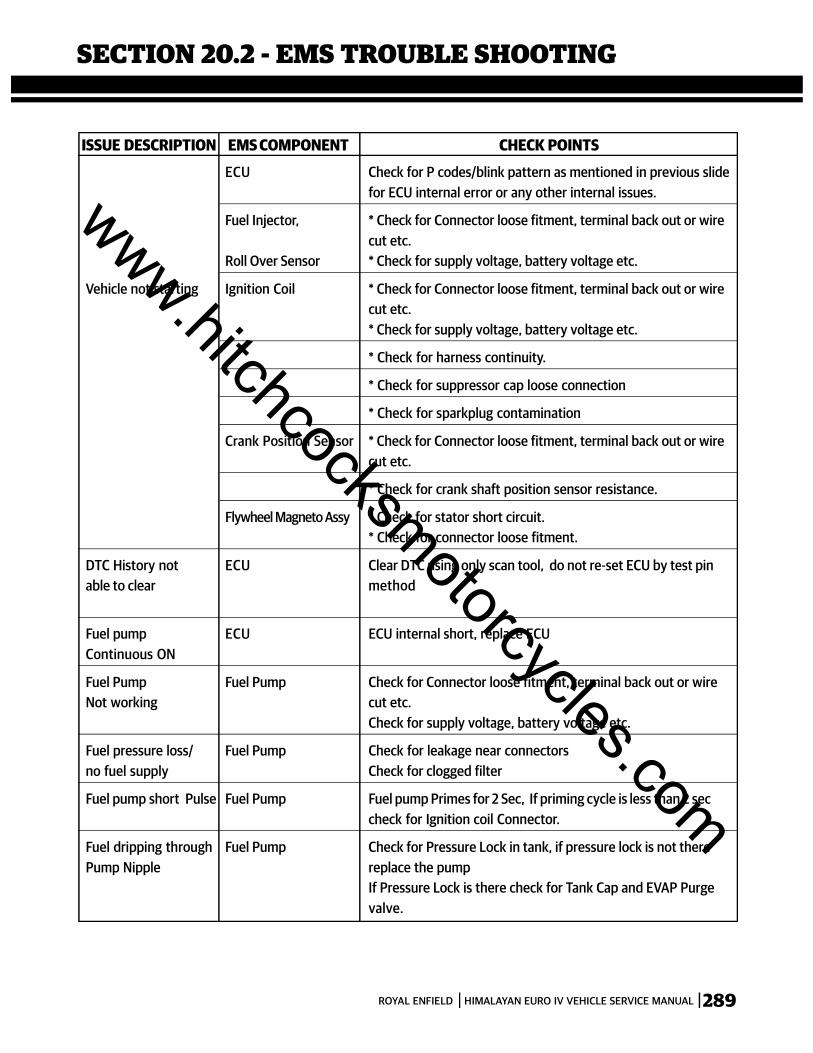
289ROYAL ENFIELD HIMALAYAN EURO IV VEHICLE SERVICE MANUAL
SECTION 20.2 - EMS TROUBLE SHOOTING
ECU Check for P codes/blink pattern as mentioned in previous slidefor ECU internal error or any other internal issues.
Fuel Injector, * Check for Connector loose fitment, terminal back out or wirecut etc.
Roll Over Sensor * Check for supply voltage, battery voltage etc.
Vehicle not starting Ignition Coil * Check for Connector loose fitment, terminal back out or wirecut etc.* Check for supply voltage, battery voltage etc.
* Check for harness continuity.
* Check for suppressor cap loose connection
* Check for sparkplug contamination
Crank Position Sensor * Check for Connector loose fitment, terminal back out or wirecut etc.
* Check for crank shaft position sensor resistance.
Flywheel Magneto Assy * Check for stator short circuit.* Check for connector loose fitment.
DTC History not ECU Clear DTC using only scan tool, do not re-set ECU by test pinable to clear method
Fuel pump ECU ECU internal short, replace ECUContinuous ON
Fuel Pump Fuel Pump Check for Connector loose fitment, terminal back out or wireNot working cut etc.
Check for supply voltage, battery voltage etc.
Fuel pressure loss/ Fuel Pump Check for leakage near connectorsno fuel supply Check for clogged filter
Fuel pump short Pulse Fuel Pump Fuel pump Primes for 2 Sec, If priming cycle is less than 2 seccheck for Ignition coil Connector.
Fuel dripping through Fuel Pump Check for Pressure Lock in tank, if pressure lock is not therePump Nipple replace the pump
If Pressure Lock is there check for Tank Cap and EVAP Purgevalve.
ISSUE DESCRIPTION EMS COMPONENT CHECK POINTS
www.hitchcocksmotorcycles.com
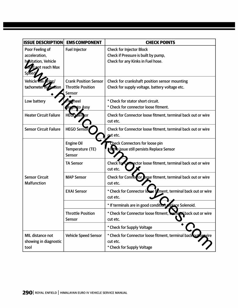
290 ROYAL ENFIELD HIMALAYAN EURO IV VEHICLE SERVICE MANUAL
ISSUE DESCRIPTION EMS COMPONENT CHECK POINTSPoor Feeling of Fuel Injector Check for Injector Blockacceleration, Check if Pressure is built by pump,hesitation, Vehicle Check for any Kinks in Fuel hose.Could not reach MaxSpeed
Vehicle mis-firing/ Crank Position Sensor Check for crankshaft position sensor mountingtachometer fluctuation Throttle Position Check for supply voltage, battery voltage etc.
Sensor
Low battery Flywheel * Check for stator short circuit.Magneto Assy * Check for connector loose fitment.
Heater Circuit Failure HEGO Sensor Check for Connector loose fitment, terminal back out or wirecut etc.
Sensor Circuit Failure HEGO Sensor Check for Connector loose fitment, terminal back out or wirecut etc.
Engine Oil * Check Connectors for loose pinTemperature (TE) * If the issue still persists Replace SensorSensor
TA Sensor Check for Connector loose fitment, terminal back out or wirecut etc.
Sensor Circuit MAP Sensor Check for Connector loose fitment, terminal back out or wireMalfunction cut etc.
EXAI Sensor * Check for Connector loose fitment, terminal back out or wirecut etc.
* If terminals are in good condition replace Solenoid.
Throttle Position * Check for Connector loose fitment, terminal back out or wireSensor cut etc.
* Check for Supply Voltage
MIL distance not Vehicle Speed Sensor * Check for Connector loose fitment, terminal back out or wireshowing in diagnostic cut etc.tool * Check for Supply Voltage
www.hitchcocksmotorcycles.com

291ROYAL ENFIELD HIMALAYAN EURO IV VEHICLE SERVICE MANUAL
NOTES
www.hitchcocksmotorcycles.com

292 ROYAL ENFIELD HIMALAYAN EURO IV VEHICLE SERVICE MANUAL
NOTES
www.hitchcocksmotorcycles.com

Royal Enfield Support : 1800-2100-007Email : [email protected]
Twitter : @RoyalEnfieldSupportWeb : www.royalenfield.com
www.hitchcocksmotorcycles.com