Locally Adaptive DCT Filtering for Signal-Dependent Noise Removal
Upload
khangminh22Category
view
3download
0
International Journal of Innovative Technology and Exploring Engineering (IJITEE)
ISSN: 2278-3075, Volume-8 Issue-12, October, 2019
5166
Published By:
Blue Eyes Intelligence Engineering
& Sciences Publication
Retrieval Number L27711081219/2019©BEIESP
DOI: 10.35940/ijitee.L2771.1081219
Abstract: In this paper, 8x8x8 3D-DCT/IDCT processor based
on CORDIC architecture for high data rate of image processing
and video coding with reduced hardware has been presented. It
uses two stages of CORDIC DCT processor i.e. one is 1D-DCT
and another one is 2D-DCT processor based on fully pipelined
unfolded CORDIC architecture with RAM buffer. The
one-dimensional DCT is useful in processing of speech
waveforms. For images and video signal processing, we need a 3D
version of the DCT/IDCT data, especially in coding for
compression and decompression, for its best performance. This
processor performs both the DCT and IDCT simultaneously with
the help of CORDIC algorithm of both 3D-DCT and IDCT which
has boost the speed of the processor. Ease the use of less
computation based unfolded CORDIC architecture in the
processor reduces complexity and power consumption. With the
working frequency approximately 414 MHz less power
dissipation, low latency and high throughput can be obtained.
The processor has been implemented on Xilinx ISE 14.7 and
design is simulated in DE-2 board. This processor has not only
reduces the complication but also increases the speed which lead
to broad use in image and video processing.
Keywords : CORDIC , 3D-DCT/IDCT, RCF, XILINX ISE
14.7.
I. INTRODUCTION
Now a day, video compression is important for signal
processing applications such as MPEG, JPEG, H.265, HDTV
etc. Everything from the storage of medical images to the
transmission of digital HDTV benefits improves by using
compression algorithms. In latest CMOS technology,
2D-DCT has been employed in many of the compression
methods [1]. While there was research done on three
dimensional DCTs as well as IDCT with moderate success as
far back as 1977, the three dimensional DCT has not enjoyed
similar popularity [2]. The reasons for the lack of the success
include the high computational load and complexity in
calculation of three dimensional DCT/IDCT, the existence of
aggravating artifacts at block boundaries at low bit rates.
With this phenomenon in high rate, frequency, computational
power since 1977, the computational load issue does not seem
as formidable.
The compression technique has been applied to 3D-DCT data
based on 4x4x4 cubes resulting 6:1 compression ratio. The
technique of “natural “extension of 2D-DCT with two stages
Revised Manuscript Received on October 10, 2019
* Correspondence Author
Bharati Masram, Department of Electronics & Telecommunication
Engineering, Yeshwantrao Chavan College of Engineering ,RTM
University, Nagpur, India. Email: [email protected]
P.T.Karule, Department of Electronic Engineering, Yeshwantrao
Chavan College of Engineering, RTM University, Nagpur, India. Email:
of 1D-DCT and similarly 3D-DCT with 2D transform
followed with 1D-DCT (or vice-versa ) has been used[3].
In this proposed [3] vector implementation based on 8x8x8
spatial and temporal frequency with a successive frames in a
video sequence. 3D-DCT computation has been carried out
using Row-Column –frame (RCF).This architecture consist of
three identical 1D-DCT processor and two set of transpose
register which has been achieved 400MHz frequency . As
CORDIC algorithm is a well-known iterative technique to
perform various basic arithmetic operations. The algorithm is
very attractive for the hardware implementation because it
uses only elementary shift-and-add operation to perform the
vector rotation in 2D plane. However the major problem is its
slow computational speed. The problem is solved with the
technique used known as Angle Rotation technique (AR),
Extended Elementary Angle Set (EESA) scheme. This
scheme has effect of reducing the rotation angle error of the
CORDIC algorithm with scaling approach. Improving further
scaling approach we can reduce the number of iteration.
The basic concept of rotation and vector operation modes
used in CORDIC algorithm leads to fast computation of
complex problem [20]. In this paper, CORDIC-based
approach to the implementation of fast 3D-DCT/IDCT
processor is presented. In section 2, Literature Review on 3D
DCT/IDCT is done. In section 3, the proposed architecture of
3D-DCT/IDCT processor in which selection line is used to
select the mode of DCT and IDCT processor. Section 4, has
explained the method of increasing the high throughput in
proposed processor. Hardware implementation and
simulation results are discussed in Section 5. Finally the paper
ends with the conclusion of the 3D DCT/IDCT processor.
II. LITERATURE REVIEW ON 3D DCT/IDCT
Video Compression and decompression is important for many
3-D applications as mentioned earlier to develop high speed
algorithm which has been implemented in literature [4-13].
As literature survey on 3D-DCT of 3D blocks by different
motion estimation performed on each frame of 8*8*8 which
can be used as application of High Definition Television
(HDTV). These blocks are generated from non-interlaced,
these 3D video sequences has been used to exploit the high
degree of temporal correlation between successive frame [3]
[8] and [9]. The image compression technique has been
identified as a milestone in recent years. [10-13]. Efficient VLSI based CORDIC architectures is very much
admired as best design using 2 stage DCT [14]. In the recent
past , 2D-DCT based CORDIC algorithm implemented as
hardware efficient architectures and for the computation of
the 3D DCT[14] [19].
High Throughput CORDIC Architecture Based
3D-DCT/IDCT Processor
Bharati Masram, P.T. Karule

High Throughput CORDIC Architecture Based 3D-DCT/IDCT Processor
5167
Published By:
Blue Eyes Intelligence Engineering
& Sciences Publication
Retrieval Number L27711081219/2019©BEIESP
DOI: 10.35940/ijitee.L2771.1081219
The Row- Column- Frame (RCF) approach has been taken
into consideration for the computation of the 3D DCT, hence
either using 3- stages of 1D DCT computation or 2- stages of
2D-DCT and one stage of 1D-DCT to perform matrix and
volume based transpositions. Row-column approach has been
extensively found as its fundamental units to most 2D DCT
architectures reported in literature. Hence the major issue
that is needed to be taken care in 3D DCT computation is the
volume transposition design resulting the computation of the
final 1D DCT. The architecture proposed in [15] consider
three 1D DCTs which accept the input data serially i.e. one
pixel per clock cycle. The outputs of the 2D DCT are fed into
computational memory, reshuffling to allow the correct
reading for the final N-point 1D DCT. The transposition
operation performed in N2 x N memory needed before the
third 1D DCT cannot be performed in the conventional
manner , due to the fact that this matrix is not square and that
each element of the N-point data fed to the final 1D DCT are
collected every N2 cycles. In [16], this memory is divided into
N distinct N x N memories and a switching network to enable
a fast and simple read/write system. The 3D-DCT with
different architecture is compared for the processing
frequency and think on area consumption of architecture such
serial and parallel architecture but investigation on power
consumption still be the research [17] [18] [19]. We address
the quality issue, and present a method for improved coding
of the 3D DCT as well as 3D-IDCT coefficients. Performance
gain is achieved through the use of dynamically CORDIC
algorithms. A compression ratio greater than to 100:1 for an
excellent reproduction with less computation which increases
the speed. In the proposed work based on CORDIC
algorithm, the 3D DCT /IDCT processor is present with the
two select lines of S0 and S1 for simultaneous working of DCT
and IDCT block. The expression for 3D DCT for an N*N*N
is given by the expression as equation (1) .
1 1 11 2 3
1 2 3
0 0 0 1 2 3
1 2 3
(2 1) (2 1) (2 1)( , , ) ( ) ( ) ( ) ( , , ) cos cos cos
2 2 2
0,1,......... 1 , 0,1,......... 1 , 0,1,.......... 1
N N N
III III
x y z
x u x v x wC u v w u v w f x y z
N N N
where
u N v N w N
and
( )
1
( ) , 0;2
k
k
k
k
u isdefinedas
Nu ifu
N
(1)
The computation of the expression needs use of CORDIC
algorithm for evaluating the image matrix cosine terms. In the
proposed algorithm [24] we decompose 3D-DCT into the
successive operations of the 2D-DCT and 1D-DCT on the
input video data, and it only needs to compute the 2D-DCT
for newly added frames as well as the 1D-DCT along the third
dimension, resulting in high computational efficiency [21].
III. PROPOSED ARCHITECTURE OF 3D DCT/IDCT
PROCESSOR
The novel idea behind the CORDIC based 3D-DCT/IDCT
processor is to find the calculation of the forward and inverse
transform process in the same system. The design of proposed
unfolded CORDIC based architecture [20] of 3D-DCT/IDCT
Processor as shown in Fig.2. It consist of CORDIC block ,
Rotation factor generator ,DCT/IDCT processor ,Dual port
RAM ,Selector ,Truncate and Round block which are
explained as below .
A. Selector
The Selector block has 3 inputs and 1 output given to the
dual Port RAM block .Out of 3 inputs one input is used for
the selection of mode such as „0‟ for DCT & „1‟ for IDCT and
other two inputs are binary vector (image co-efficient) and
input as Truncate and Round block output (angle
coefficients).
B. Dual Port RAM
RAM buffer is used to store the data of the processor .Dual
Port RAM consists of two inputs and two outputs .One
Selector output either „0‟ or „1‟ is given as a input to the RAM
buffer . Data can be read and write through it.
C. DCT/IDCT Processor
The data is feed to the processor through the RAM; the system
start with the signal “start” through the selector will select the
processor DCT or IDCT .The complexity in the computation
of it solved by the CORDIC block.
D. CORDIC Blocks
The CORDIC block consists of 3600 complex rotation and
complex rotator controller as shown in Fig 1 .In the CORDIC
algorithm, shift and add method gives the rotation operation at
each shifting of angle either by increment and decrement .
Complex rotation of angle upto 3600 controlled by the rotator
controller .As shown in Fig 2. X and Y are vector component
similarly X‟ and Y‟ are another vector component after the
increment of angle. In this way number of iteration can be
calculated by rotation direction di= + 1upto the nth
iterations.
Fig.1: Rotation operation in CORDIC algorithm [2]
Equation of the basic CORDIC algorithm of the ith
iteration
are as follows:
x i+1 = xi – yi .di. 2-i
(2)
y i+1 = yi + xi .di. 2-i
(3)
z i+1 = zi – di tan-1
( 2-i
) (4)
Q ={45ο, 26.56
ο,14.036
ο,7.125
ο,3.576
ο,1.79
ο, 0.895
ο,
0.448 ο
,0.2238 ο}
Condition : di = -1 if zi < 0
+1, if zi ≥ 0
Let θ=25 ο
be the desired angle
of rotation

International Journal of Innovative Technology and Exploring Engineering (IJITEE)
ISSN: 2278-3075, Volume-8 Issue-12, October, 2019
5168
Published By:
Blue Eyes Intelligence Engineering
& Sciences Publication
Retrieval Number L27711081219/2019©BEIESP
DOI: 10.35940/ijitee.L2771.1081219
25ο ={ 45
ο -26.565
ο +14.036
ο -7.125
ο-3.576
ο+ 1.79
ο +
0.895 ο+0.448
ο +0.2238
ο } = 25.1268
ο
As the 25.1268 is the approximate answer and the number of
iteration required is N = 8.As per above CORDIC algorithm
another calculations upto to 16 iteration are given in Table 1.
E. Rotation factor Generator
The rotation factor will generate depends on the condition of di. The i
th rotation for n
th iteration for the n= 16 iteration is
given in the following Table.1. This rotation factor given back to the CORDIC block for the computation of any floating point angle.
In this way, proposed architecture of DCT/IDCT processor can be work on the rotation factor generator system. Now the 3D-DCT/IDCT processor has calculate with the help of N*N*N leads to the high data rate or throughput output.
IV. THROUGHPUT IMPROVEMENT IN
3D-DCT/IDCT PROCESSOR
The 3D-DCT [21] and 3D-IDCT [15] worked on the different
parameters such as no. of register required in design
frequency required with different video standards such as
QCIF, SIF, CCIR, CIF, HDTV etc .The CORDIC based
3D-DCT and IDCT system work on the same proposed
system therefore the computational time depends on the
maximum combinational time delay between input and output
time. In this way instead of processing individual block we
have increases the throughput output by processing both the
CORDIC based DCT and IDCT processor.
Table 1: CORDIC Rotation Angles [2]
2-i arctan
(2-i)*360/2Л 45*2-i
0 1 45
1 0.5 26.56505118 4.065051177 22.5
2 0.25 14.03624347 0.753717879 11.5
3 0.125 7.1250163349 0.106894615 5.625
4 0.0625 3.576334375 0.013826201 2.8125
5 0.03125 1.789910608 0.001743421 1.40625
6 0.015625 0.89517371 0.000218406 0.703125
7 0.0078125 0.447614171 2.73158E-05 0.3515625
8 0.00390625 0.2238105 3.41494E-06 0.17578125
9 0.001953125 0.111905677 4.26882E-07 0.087890625
10 0.000976563 0.055952892 5.33607E-08 0.043945313
11 0.000488281 0.027976453 6.6701E-09 0.021972656
12 0.000244141 0.013988227 8.33763E-10 0.0.0109863
28
13 0.00012207 0.006994114 1.0422E-10 0.005493164
14 6.10352E-05 0.003497057 1.30276E-11 0.002746582
15 3.05176E-05 0.0017485228 1.62844E-12 0.001373291
16 1.52588E-05 0.000874264 2.03555E-13 0.000686646
V. HARDWARE IMPLEMENTATION AND
EXPERIMENTAL RESULTS
In this section, proposed architecture is implemented on an
FPGA board .The architecture processor is initially simulated
using VHDL language on the Xilinx ISE 14.7.
A. Implementation Of 3D-DCT/IDCT
The theoretical analysis of CORDIC based 3D- DCT/DCT
processor already discussed in earlier section as per results
shown in this section the comparative analysis done with the
results of conventional 3D-DCT [16],[17] & [19].
The HDL synthesis of Top level 3D DCT/IDCT RTL
Schematic generated using Xilinx ISE14.7 is as shown in
Fig.3. and the RTL View of 3D-DCT/IDCT as shown in Fig.4
VI. CONCLUSION
Fig.3. RTL Schematic of 3D-DCT/IDCT processor (top level module) generated from Xilinx ISE 14.7. The Table 2 describes the signal description used in 3D-DCT/IDCT processor .input and outputs pins are used as per the requirement of processor.
High Throughput CORDIC Architecture Based 3D-DCT/IDCT Processor
5169
Published By:
Blue Eyes Intelligence Engineering
& Sciences Publication
Retrieval Number L27711081219/2019©BEIESP
DOI: 10.35940/ijitee.L2771.1081219
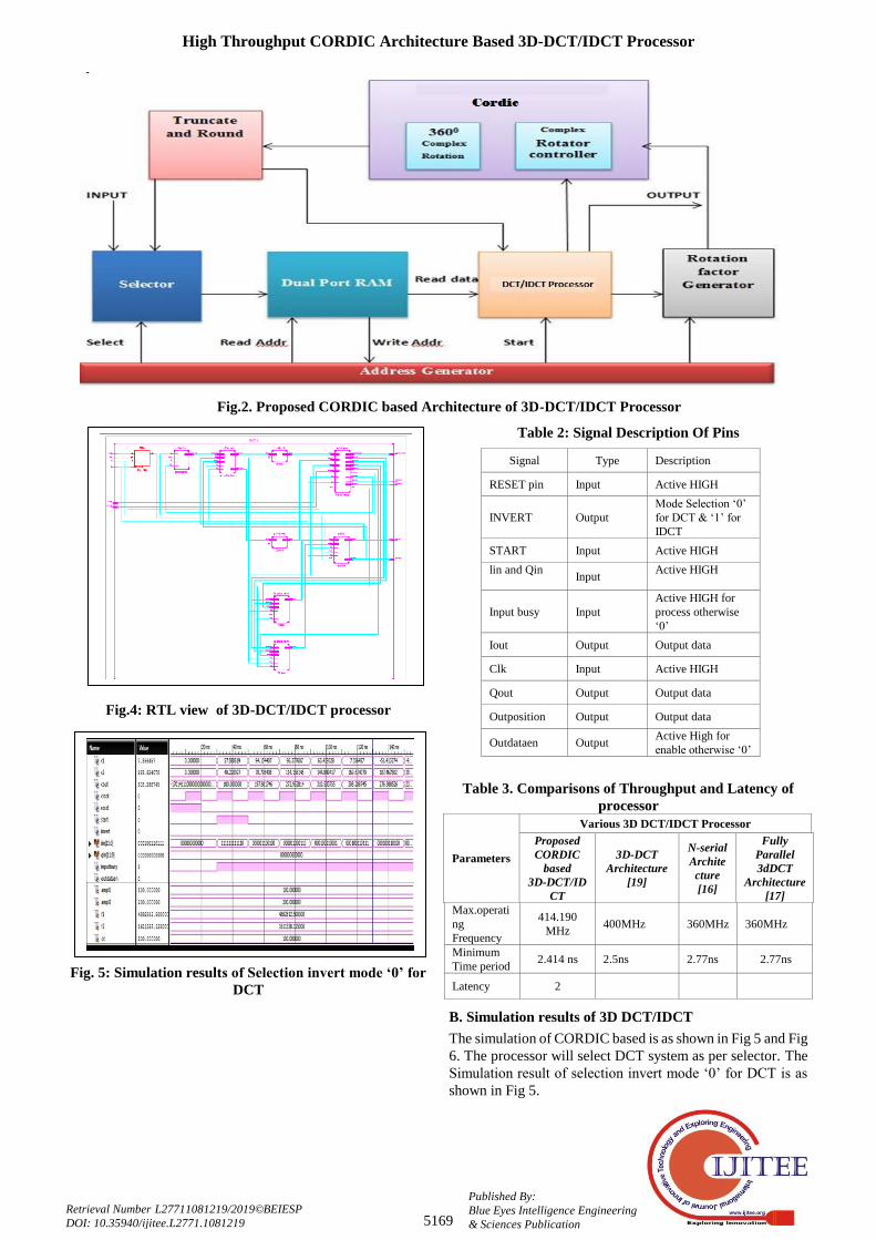
Fig.2. Proposed CORDIC based Architecture of 3D-DCT/IDCT Processor
Table 2: Signal Description Of Pins
Fig.4: RTL view of 3D-DCT/IDCT processor
Fig. 5: Simulation results of Selection invert mode ‘0’ for
DCT
Table 3. Comparisons of Throughput and Latency of
processor
Parameters
Various 3D DCT/IDCT Processor
Proposed
CORDIC
based
3D-DCT/ID
CT
3D-DCT
Architecture
[19]
N-serial
Archite
cture
[16]
Fully
Parallel
3dDCT
Architecture
[17]
Max.operati
ng
Frequency
414.190
MHz 400MHz 360MHz 360MHz
Minimum
Time period 2.414 ns 2.5ns 2.77ns 2.77ns
Latency 2
B. Simulation results of 3D DCT/IDCT
The simulation of CORDIC based is as shown in Fig 5 and Fig
6. The processor will select DCT system as per selector. The
Simulation result of selection invert mode „0‟ for DCT is as
shown in Fig 5.
Signal Type Description
RESET pin Input Active HIGH
INVERT Output
Mode Selection „0‟
for DCT & „1‟ for
IDCT
START Input Active HIGH
lin and Qin
Input
Active HIGH
Input busy Input
Active HIGH for
process otherwise
„0‟
Iout Output Output data
Clk Input Active HIGH
Qout Output Output data
Outposition Output Output data
Outdataen Output Active High for
enable otherwise „0‟

International Journal of Innovative Technology and Exploring Engineering (IJITEE)
ISSN: 2278-3075, Volume-8 Issue-12, October, 2019
5170
Published By:
Blue Eyes Intelligence Engineering
& Sciences Publication
Retrieval Number L27711081219/2019©BEIESP
DOI: 10.35940/ijitee.L2771.1081219
Fig.6. Simulation results of Selection invert mode ‘1’ for
IDCT
The Simulation result of selection invert mode „1‟ for IDCT is
as shown in Fig 6. The design is scripted as a VHDL file and
synthesized using Xilinx ISE 14.7 .The design is synthesized
into Vertex-5.
Fig.7 Power estimation with the help of X -Power
Analyzer
The simulation result for the power consumption is as shown
in Fig.7. The Power Estimation for the Dynamic power
dissipation comes out 10 mW with the help X-power
Analyzer in Xilinx 14.7 ISE simulator.
C. Comparative Results Analysis of 8*8*8 3D-
DCT/IDCT Processor
The CORDIC based 3D-DCT/IDCT has been implemented
using Virtex-5 device of the Xilinx FPGA .From the timing
summary maximum operating frequency for the CORDIC
based 3D-DCT/IDCT is 414.19 MHz, Similarly for 3D DCT
architecture proposed in [19], N-serial architecture in [16]
and Fully parallel 3D-DCT architecture in [17] has achieved
comparative frequency as shown in the following Table 3 .
As seen from the Table 3, our proposed architecture has
achieved high throughput output than the other Architecture.
This is possible only because of both DCT and IDCT
operations are performed simultaneously with help of
selector. The Minimum Time period for the proposed
CORDIC Based 3DDCT/IDCT is 2.414ns and it is less as
compared with the [19], [16], [17].Hence the latency
achieved for the proposed processor is 2.
The device utilization summary is as shown in Table 4. For
the proposed processor area has been reduced to about 88%
as compared with the architecture in [19] and gives 73%
reduction when compared with the other architectures.
Less number of registers and combinational function are used
in present 3D DCT/IDCT processor. Hence we can say area
has been reduced.
Table 4. Device Utilization Summary
Designs
Various 3D DCT/IDCT Processor
Proposed
CORDIC
based
3D-DCT/IDC
T
3D-DCTArc
hictecture
[19]
N-serial
Architect
ure[16]
Fully
Parallel
3DDCT
Architectu
re [17]
Registers 12480 103497 464248 163912
Combinational Functions
No.of
LUTs 588
No.of
logic
blocks
used
572
No.of
LUTs
Flip flop
pairs used
649
No.of
bonded
IOB‟s
46
Total 1855 15320 4905 854
The resource utilization especially for the 3D-DCT
architecture has been reduced about 88% as compared with
[19]. The proposed architecture has an advantage in terms of
area, power consumption and latency .This proposed
architectures has application for the different video
processing standard format such as MPEG, JPEG, HDTV,
H.265 and H.266 etc. Furthermore this architecture gives high
through put output for the high data rates in image and a video
processing application which has been also implemented on
cost effective based FPGA (Field Programmable Gate Array)
for the best performance.
320
340
360
380
400
420
Fre
q in
MH
z
Various 3D DCT/IDCT Processor
Max.operatingFrequency
Fig.8: Comparative Frequency of various 3D DCT
architecture with proposed architecture.
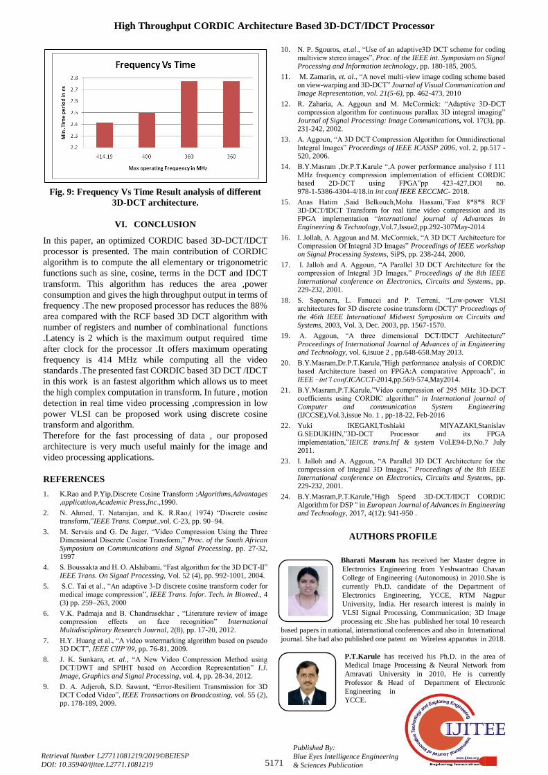
In this Section, Comparative result analysis for various
3D-DCT/IDCT processors such as frequency and time
parameter are explained as shown Fig.8 and in Fig 9.
High Throughput CORDIC Architecture Based 3D-DCT/IDCT Processor
5171
Published By:
Blue Eyes Intelligence Engineering
& Sciences Publication
Retrieval Number L27711081219/2019©BEIESP
DOI: 10.35940/ijitee.L2771.1081219
Fig. 9: Frequency Vs Time Result analysis of different
3D-DCT architecture.
VI. CONCLUSION
In this paper, an optimized CORDIC based 3D-DCT/IDCT
processor is presented. The main contribution of CORDIC
algorithm is to compute the all elementary or trigonometric
functions such as sine, cosine, terms in the DCT and IDCT
transform. This algorithm has reduces the area ,power
consumption and gives the high throughput output in terms of
frequency .The new proposed processor has reduces the 88%
area compared with the RCF based 3D DCT algorithm with
number of registers and number of combinational functions
.Latency is 2 which is the maximum output required time
after clock for the processor .It offers maximum operating
frequency is 414 MHz while computing all the video
standards .The presented fast CORDIC based 3D DCT /IDCT
in this work is an fastest algorithm which allows us to meet
the high complex computation in transform. In future , motion
detection in real time video processing ,compression in low
power VLSI can be proposed work using discrete cosine
transform and algorithm.
Therefore for the fast processing of data , our proposed
architecture is very much useful mainly for the image and
video processing applications.
REFERENCES
1. K.Rao and P.Yip,Discrete Cosine Transform :Algorithms,Advantages ,application,Academic Press,Inc.,1990.
2. N. Ahmed, T. Natarajan, and K. R.Rao,( 1974) “Discrete cosine transform,”IEEE Trans. Comput.,vol. C-23, pp. 90–94.
3. M. Servais and G. De Jager, “Video Compression Using the Three Dimensional Discrete Cosine Transform,” Proc. of the South African Symposium on Communications and Signal Processing, pp. 27-32, 1997
4. S. Boussakta and H. O. Alshibami, “Fast algorithm for the 3D DCT-II” IEEE Trans. On Signal Processing, Vol. 52 (4), pp. 992-1001, 2004.
5. S.C. Tai et al., “An adaptive 3-D discrete cosine transform coder for medical image compression”, IEEE Trans. Infor. Tech. in Biomed., 4 (3) pp. 259–263, 2000
6. V.K. Padmaja and B. Chandrasekhar , “Literature review of image compression effects on face recognition” International Multidisciplinary Research Journal, 2(8), pp. 17-20, 2012.
7. H.Y. Huang et al., “A video watermarking algorithm based on pseudo 3D DCT”, IEEE CIIP’09, pp. 76-81, 2009.
8. J. K. Sunkara, et. al., “A New Video Compression Method using DCT/DWT and SPIHT based on Accordion Representation” I.J. Image, Graphics and Signal Processing, vol. 4, pp. 28-34, 2012.
9. D. A. Adjeroh, S.D. Sawant, “Error-Resilient Transmission for 3D DCT Coded Video”, IEEE Transactions on Broadcasting, vol. 55 (2), pp. 178-189, 2009.
10. N. P. Sgouros, et.al., “Use of an adaptive3D DCT scheme for coding multiview stereo images”, Proc. of the IEEE int. Symposium on Signal Processing and Information technology, pp. 180-185, 2005.
11. M. Zamarin, et. al., “A novel multi-view image coding scheme based on view-warping and 3D-DCT” Journal of Visual Communication and Image Representation, vol. 21(5-6), pp. 462-473, 2010
12. R. Zaharia, A. Aggoun and M. McCormick: “Adaptive 3D-DCT compression algorithm for continuous parallax 3D integral imaging” Journal of Signal Processing: Image Communications, vol. 17(3), pp. 231-242, 2002.
13. A. Aggoun, “A 3D DCT Compression Algorithm for Omnidirectional Integral Images” Proceedings of IEEE ICASSP 2006, vol. 2, pp.517 - 520, 2006.
14. B.Y.Masram ,Dr.P.T.Karule “,A power performance analysiso f 111 MHz frequency compression implementation of efficient CORDIC based 2D-DCT using FPGA”pp 423-427,DOI no. 978-1-5386-4304-4/18.in int conf IEEE EECCMC- 2018.
15. Anas Hatim ,Said Belkouch,Moha Hassani,”Fast 8*8*8 RCF 3D-DCT/IDCT Transform for real time video compression and its FPGA implementation “international journal of Advamces in Engineering & Technology,Vol.7,Issue2,pp.292-307May-2014
16. I. Jollah, A. Aggoun and M. McCormick, “A 3D DCT Architecture for Compression Of Integral 3D Images” Proceedings of IEEE workshop on Signal Processing Systems, SiPS, pp. 238-244, 2000.
17. I. Jalloh and A. Aggoun, “A Parallel 3D DCT Architecture for the compression of Integral 3D Images,” Proceedings of the 8th IEEE International conference on Electronics, Circuits and Systems, pp. 229-232, 2001.
18. S. Saponara, L. Fanucci and P. Terreni, “Low-power VLSI architectures for 3D discrete cosine transform (DCT)” Proceedings of the 46th IEEE International Midwest Symposium on Circuits and Systems, 2003, Vol. 3, Dec. 2003, pp. 1567-1570.
19. A. Aggoun, “A three dimensional DCT/IDCT Architecture” Proceedings of International Journal of Advances of in Engineering and Technology, vol. 6,isuue 2 , pp.648-658.May 2013.
20. B.Y.Masram,Dr.P.T.Karule,”High performance analysis of CORDIC based Architecture based on FPGA:A comparative Approach”, in IEEE –int’l conf.ICACCT-2014,pp.569-574,May2014.
21. B.Y.Masram,P.T.Karule,”Video compression of 295 MHz 3D-DCT coefficients using CORDIC algorithm” in International journal of Computer and communication System Engineering (IJCCSE),Vol.3,issue No. 1 , pp-18-22, Feb-2016
22. Yuki IKEGAKI,Toshiaki MIYAZAKI,Stanislav G.SEDUKHIN,”3D-DCT Processor and its FPGA implementation,”IEICE trans.Inf & system Vol.E94-D,No.7 July 2011.
23. I. Jalloh and A. Aggoun, “A Parallel 3D DCT Architecture for the compression of Integral 3D Images,” Proceedings of the 8th IEEE International conference on Electronics, Circuits and Systems, pp. 229-232, 2001.
24. B.Y.Masram,P.T.Karule,"High Speed 3D-DCT/IDCT CORDIC Algorithm for DSP " in European Journal of Advances in Engineering and Technology, 2017, 4(12): 941-950 .
AUTHORS PROFILE
Bharati Masram has received her Master degree in
Electronics Engineering from Yeshwantrao Chavan
College of Engineering (Autonomous) in 2010.She is
currently Ph.D. candidate of the Department of
Electronics Engineering, YCCE, RTM Nagpur
University, India. Her research interest is mainly in
VLSI Signal Processing, Communication; 3D Image
processing etc .She has published her total 10 research
based papers in national, international conferences and also in International
journal. She had also published one patent on Wireless apparatus in 2018.
P.T.Karule has received his Ph.D. in the area of
Medical Image Processing & Neural Network from
Amravati University in 2010, He is currently
Professor & Head of Department of Electronic
Engineering in
YCCE.
International Journal of Innovative Technology and Exploring Engineering (IJITEE)
ISSN: 2278-3075, Volume-8 Issue-12, October, 2019
5172
Published By:
Blue Eyes Intelligence Engineering
& Sciences Publication
Retrieval Number L27711081219/2019©BEIESP
DOI: 10.35940/ijitee.L2771.1081219
He had worked as a Registrar in YCCE autonomous college , he has
published total 65 research papers in various international journals &
international and national conferences .He received Best paper Award at
PSG college of Engineering, Coimbatore. His research interest is in area of
Image Processing and Embedded System.
Copyright © 2022 FDOKUMEN