High Grade and Industrial Technologies - DALI Technical Sales
108
From Design to Production Oil Drilling Industry Defence Railways Space Aeronautics Medical www.microspire.c m Wound Magnetics Experts High Grade and Industrial Technologies High Grade and Industrial Technologies High Grade and Industrial Technologies ® ®
-
Upload
khangminh22 -
Category
Documents
-
view
6 -
download
0
Transcript of High Grade and Industrial Technologies - DALI Technical Sales

From Design to Production
Oil Drilli
ng
Industry
Defence
Railways
Space Aeronautics
Medical
www.microspire.c m
Wo u n d M a g n e t i c s E x p e r t s
High Grade and Industrial Technologies
High Grade and Industrial Technologies
High Grade and Industrial Technologies
® ®

1 Head Offi ce / Microspire16, parc d’Activités du Beau Vallon57970 Illange, France
Tél : +33 (0) 3 82 59 13 33Fax : +33 (0) 3 82 51 00 49E-mail : [email protected]
Microspire France-North7, rue Pierre Métairie - Z.A. du Bel Air78120 Rambouillet, France
Tél : +33 (0) 1 34 85 56 06Fax : +33 (0) 1 30 41 06 20E-mail : [email protected]
Microspire France-Southand R&D center
137, rue Mayoussard38430 Moirans, France
Tél : +33 (0) 4 76 35 14 04Fax : +33 (0) 4 76 35 14 15E-mail : [email protected]
Industry PortugalDIGICONTROLE LTDAAda Eng. Arantes E Oliveira 5, 2°1900 LISBOA
Antonio ALDIMTél : 00 351 21 84 057 30Fax : 00 351 21 849 03 73E-mail : [email protected]
High Grade England, IrelandWavelength Electronics LtdKent Innovation CentreThanet Reach Business ParkBroadstairsKent CT10 2QQ, England
Paul GloverTél : +44 1843 609 380Fax : +44 1843 609 384E-mail : [email protected]
High Grade, Industry SpainInelec, S.A.Bocangel, 38E-28028 Madrid
Marco Roque - Technical DirectorTél : +34 / 91 726 3500Fax : +34 / 91 726 3334E-mail : [email protected]
High Grade ItalyDimac Red SRLVia Giovanni XXXIII, 2520046 BIASSONO (MI)
Roberto ConsonniTél : +39 039 249 4856Fax : +39 039 491 773E-mail : [email protected]
Industry SingaporeOCTOGRAM10 Ubi Crescent01-84 ubi Techpark, Lobby ESingapore 408564
Shawn WangTél : +65 6749 1518Fax : +65 6749 1521E-mail : [email protected]
High Grade JapanCOMCRAFT CORPORATION1-2-4 Momoi Suginami-KUTokyo 167-0034Japan
Daisuke IchitsuboE-mail : [email protected]
Industry SwitzerlandElectronitel S.A.ch du Grand Clos 1 - CP 142CH - 1752 Villars-sur-Glâne
Michel TilleTél : +41 / 026 401 00 60Fax : +41 / 026 401 00 70E-mail : [email protected]
High Grade SingaporeS&S Electronic Components Pte. Ltd.No. 77. High Street#04-12 High Street PlazaSingapore 179433
BK MohantyTél : +65 633 629 70Fax : +65 633 710 33E-mail : [email protected]
High Grade ChinaWellking ElectronicsSino Finet InternationalBusiness CenterRm. A-7C n°21 XiDuanErhuan Nanlu Xi’anShaanxi 710061, P.R. China
Wang Weijing
High Grade IsraelRelcom Components LTD.P.O.B 3058,HERZLIA, 46103ISRAELhttp://www.relcom-comp.co.il
Ronen HaaseTél : 972-9-9587070Fax : 972-9-9583535Mobile : 972-50-3332244
High GradeNorway, Sweden, Finland
Expando Elektronik ABDanderyd CampusPlan 6 Mörby Centrum18231 Danderyd, SUEDE
Tél : +46 8544 900 44Fax : +46 8755 05 70E-mail : [email protected]
High Grade RussiaPetersburg Electronic Company, JSCZastavskaya st. 32-A St-PetersburgRussia 196084 P.O.Box 400http://www.pec.spb.ru
Alexey ZhuravlevTél : +7 812 703 3035Fax : +7 812 703 3036
High Grade IndiaS.M. Creative Electronics Ltd.#845, 7th Main, 2nd CrossHAL II Stage, Bangalore - 560038
S. BhaskaranTél : +91 80 2521 0268 / 0315 / 0357 / 358Fax : +91 80 25210269Mob : +91 98 45 410 420E-mail : [email protected]
High Grade / Industry BrazilTECHSORua Antonio Carlos 582cj5A 01309010 Sao Paulo
Jacques MarcaisTél : 00 55 11 3120 59 68Fax : 00 55 11 3120 59 68E-mail : [email protected]
High Grade USARAF TABTRONICS2854 GENESEE STREETPIFFARD NY 14533USA
Tél : 585 243 4331Fax : 585 243 3831
High Grade USARAF TABTRONICS200 LEXINGTON AVENUEFL32724 DELANDUSA
Tél : 386 736 1698Fax : 386 736 7338
High GradeSwitzerland, Germany, Netherlands
MSA Components GroupPostfach 425, am glockenberg 13D’57428 Attendorn
Michael SchulteTél : +49 2722 6373 10 ; Mob : +49 171 807 00 60Fax : +49 2722 6373 29E-mail : [email protected]
Industry DenmarkDKI Dansk Komponent Import A/SKongevejen 83 DK 2840 Holte
Henrik JensenTél : +45 45 41 05 00Fax : +45 45 41 05 12E-mail : [email protected]
Industry NetherlandsCOMDES BVPlatinastraatNL 2718 Zoetermeer
Franck PruschenTél : +31 79 36 25 666Fax : +31 79 36 25 133E-mail : [email protected]
32
654 87
9
21
23
10
21 22
18
161514
17 2019
24 25
26
121110
1312

132
67
8
54
9
13
1112
15
16 17
22
2119
20
23
18
24
25
26
10
14
Morocco (Casablanca)- Main production site - 200 employees- Manual and semi automated production- EN / AS 9100 certified- ISO 9001 / V 2000 certified- Manufacturing of medium series and
high grade components- Rotors and stators windings- Plastic injected magnetics
Illange (Metz)- Head office - 80 employees- Design - Prototyping - Industrialisation -
Internal and external production inspection -Supply chain management
- Quality control - logistics- ISO 9001 / V 2000 certified- EN / AS 9100 certified- ISO 14001 in processManufacturing of :- Small series and high grade components- Medium power magnetics
China (Dongguan)- 2 approved subcontractors- High volumes industrial quality- Local sourcing- ISO 9001 / V 2000 certified
Wo u n d M a g n e t i c s E x p e r t s A Worldwide presence

Wo u n d M a g n e t i c s E x p e r t s Locations
France (Illange)
Morocco (Casablanca)
China (Dongguan)
•• EN / AS 9100 •• Qualifas
•• EN / AS 9100 •• Qualifas
•• ISO 9001 / V2000

Wo u n d M a g n e t i c s E x p e r t s
MicrospireR&D department :12 PhD engineers,
engineers andtechnicians,
test laboratory ...
Key Accounts• Aeronautics & Defence
• Space• Oil drilling
• Railways• Industrial• Medical
• 92-95: Electrical models
EN60950, EN61558,DO160, ETSI, MIL STD981, RNC CNES Q 60
504/5, ...
characterization and• 95-98: Material
thermal modeling• 98-01: Characterization
• 01-07: CAD softwareof emitted magnetic field
In collaboration with CNRS :financial support for
post doctorate theses
Design and productionin accordance
with standards
ESA qualified series : MPCI(3201/008), SESI (3201/009)
Capability approval forcustom designs with
SESI Technology
Collaborations :European Space Agency,
CNES French Space Agency
Gathering expertise foryour custom designs
Our know-how in electronic functions•• HF signal, isolation, impedance matching transformers
•• Power transformers up to several 10 KW Flyback, Forward, Push-pull topologies ...
•• Chokes for active or passive PFC ...
•• Integrated Magnetics
•• Gate drive transformers
•• Current sense or voltage measurement transformers
•• 1553 Bus Transformers, Telecom transformers (XDSL, ISDN, 600 Ω)
•• Low/High frequency filtering Power chokes up to l = 300 A
•• ADSL, PLC, train detection filters ...
•• Antennas, sensors, tags ...

Semi - Customemi - Custom
Hig
h G
rade
Tec
hnol
ogie
sig
h G
rade
Tec
hnol
ogie
sS
tand
ard
Tech
nolo
gies
tand
ard
Tech
nolo
gies
CustomustomMagnetic cores andMagnetic cores and
FunctionsFunctionsStandard magnetic coresStandard magnetic cores
and Custom Functionsand Custom FunctionsComponentsComponents
Off The ShelvesOff The Shelves
COTSOTS
Moldedtoroids
Moldedtoroids
SESI Technology :connection on leadframe epoxy
resin encapsulation - Flyback Transformers - FLYT series
P cores
Winding toroidson ceramic substrate
RMcoresleaded
RMcores
Rotors and statorswinding
Toroid onplastic header
CoilWinding
SESI technology :chokes, current transformers, gate drive transformers, flyback transformers
Toroids on plastic baseplate
Lead epoxy resinencapsulation
PQcores
LineMatching
Transformers
SMDCoils
Commonmode chokes
CurrentTransformers
Plasticinjection
Self bonded Coils
DrumCore
Winding
Transfermoulding
Epoxy Resinencapsulation
RM gravitymoulding
Flybacktransformers
ETDleaded
Commonmode chokes
Toroids
Chipinductors
Line matchingtransformers
Currenttransformers
Wide Bandtransformers
EFD, ERand EP cores
PlanarTechnology

Hig
h G
rade
Tec
hnol
ogie
sig
h G
rade
Tec
hnol
ogie
sS
tand
ard
Tech
nolo
gies
tand
ard
Tech
nolo
gies
Medium Poweredium Power Engineering Supportngineering Support Flying terminationsFlying terminations Dedicated TeamDedicated Team
12 pulseTransformers
InterphaseInductors
ToroidalInductors
PlanarPCB
Transformers
StackedInductors
Double ClaminatedSteel cores
Foil winding
Triplewinding
inductors
1°105
105 106 107
1°104
1041°103
103100
MODULUS ZO from primary
Frequency (Hertz)
Mod
ulus
(Ohm
s)
PHASE ZO from primary100
50
0
-50
-100100 103 104 105 106 107
Phas
e (D
egre
es)
Frequency (Hertz)
+-
C4 3.5p
rs3rs2rs1
Is1 600k Is2 1.2 Is3 200m
5.01m 25u 5uC2
2.9p
C
D
C6
1.6p
C5
-1.2p
C3
3.7p
100G
Rinf
E
E1F
F1
250mRp4Lp4
92k
Lp3
20.5k
Lp2
2.5k
Lp1
2.5k
1
1
1.4Rp1
Rp2
Rp3
r1
124Rp
260kC1
A
B
5.3p
valeur efficace de ce courant :
Courant secondaire équivalent (MIN)
Cour
ant s
econ
daire
(A)
Time (s)
IseffMIN = IseffMIN = 0.43IsMIN(1)² dt1T
T
0
0
0.2
0.4
0.6
0.8
0 2 10-6 4 10-6 6 10-6 8 10-6 1 10-5 1.2 10-5 1.4 10-5 1.6 10-5
αmax T
Copperplates assembly

Wo u n d M a g n e t i c s E x p e r t s
Certifications
&
Qualifications

Wo u n d M a g n e t i c s E x p e r t s
All our wound magnetics are RoHS by defect, the RoHS sign is indicated on the packaging of the products. For space market, the components are non RoHS by default and RoHS upon request.
EUROPEAN DIRECTIVESR.o.H.S. and W.E.E.E.
In order to meet the requirements of the R.o.H.S. and W.E.E.E directives issued by the European Union (2002/95/EC and 2002/96/EC), Microspire now removes the dangerous substances of its products.As a consequence, Microspire upgraded its product lines:
by using pure tin matte as external coating for termination (leadframes or pins): this plating is done on a Nickel intermediate layer. Microspire has chosen these materials in order to allow leaded and non leaded soldering processes, and minimize the possibility of tin whisker growth.
by privileging solder alloys like SnAg or SnAgCu for the soldering operations: some Microspire products use high temperature melting solder (containing more than 85% lead). These solders are exempted from WEEE and RoHS regulations, due to the lack of viable compliant solder alloys. This high temperature solder is used only for internal product solder connections. External pin plating for these component types use the one above mentioned.
•
•

ContentsHigh Grade technologies
Custom DesignsHybrid Magnetics / Transfer-Molded Components ............................................................................................ 2Aluninium foil winding components / Customized rotors and stators ................................................................. 2Customized medium power C Inductors / Customized medium power EE core ................................................. 3Customized toroidal Inductors / Planar PCB Transformers and Inductors ......................................................... 3High Grade Custom Planar Magnetics .............................................................................................................. 4
RF and Data MagneticsMiniature Chip Inductors
MPCI 10000 Series .......................................................................................................................................... 6MPCI 12000 Series .......................................................................................................................................... 8MPCI 20000 Series ........................................................................................................................................ 10Miniature Fixed Chip Inductors - H01 Series ................................................................................................... 12Chip Inductors - MPCI 233 Series ................................................................................................................... 14Miniature Fixed Chip Inductors - 233 H01 Series ............................................................................................ 15
Common Mode ChokesCMC HCESC Series ....................................................................................................................................... 16DLEF42 .......................................................................................................................................................... 17
Wide-band RF TransformersWRFT Series .................................................................................................................................................. 18
Bus TransformersDBIT Series .........................................................................................................................................19, 20, 21SBIT x 7.5S .................................................................................................................................................... 22MTLM 1234 Mil .............................................................................................................................................. 23
Power MagneticsCommon Mode Chokes
CMC 17 Series ....................................................................................................................................24, 25, 26CMC Series .................................................................................................................................................... 27CMC 15 Series ....................................................................................................................................28, 29, 30CMC 18 Series ....................................................................................................................................31, 32, 33CMC 22 Series ................................................................................................................................... 34, 35, 36
Technical noteAppendix CMC 15, 18, 22 & CMC 17 Temperature Application ........................................................................ 37
SMD Power High Reliability InductorsSESI SMD Power Inductors and Transformers ................................................................................................ 39SESI Custom Magnetics ................................................................................................................................. 40SESI 9WR ...................................................................................................................................................... 41SESI 9.1WR ................................................................................................................................................... 42SESI 14SR ..................................................................................................................................................... 44SESI 15WR .................................................................................................................................................... 46SESI 15SR ..................................................................................................................................................... 52SESI 18WR .................................................................................................................................................... 50SESI 22WR .................................................................................................................................................... 52SESI 32WR .................................................................................................................................................... 53
Flyback TransformersFLYT Series ................................................................................................................................................... 54FLYT 15 Series .............................................................................................................................................. 55FLYT 18 Series .............................................................................................................................................. 56FLYT 22 Series .............................................................................................................................................. 57
Current TransformersCT91 231 WR ................................................................................................................................................ 58CT08 200 221 PR ........................................................................................................................................... 59
Gate Drive TransformerGDT91 M50 20 1WR ...................................................................................................................................... 60GDT15 M50 60 1WR ...................................................................................................................................... 61

Industrial TechnologiesCustom Designs
Power Magnetics ............................................................................................................................................ 64Custom Bobbins ............................................................................................................................................. 65Custom Designs (EFD, ER, EP, ...) ................................................................................................................ 66
RF and Data MagneticsFiltering & EMI Suppression Chokes
DLEF series ................................................................................................................................................... 67ESC series ..................................................................................................................................................... 68
Common Mode ChokesICMC series ................................................................................................................................................... 69LCMC ............................................................................................................................................................ 70
Wide Band Signal TransformersWRFT series .................................................................................................................................................. 71
Power MagneticsFlyback transformers
FSIT series .................................................................................................................................................... 72FSIT 13 series ................................................................................................................................................ 73FSIT 16 series ................................................................................................................................................ 73FSIT 20 series ................................................................................................................................................ 74FSIT 20.1 series ............................................................................................................................................. 74FSIT 25 series ................................................................................................................................................ 75FSIT 29 series ................................................................................................................................................ 75
Common Mode EMI Suppression ChokesCMESC 10-14 ............................................................................................................................................... 76CMESC 17 .............................................................................................................................................. 77, 78
Leaded Energy Storage and Filtering InductorsPK ................................................................................................................................................................. 79VC 0513 ......................................................................................................................................................... 80VC 1019 ......................................................................................................................................................... 81TC series ....................................................................................................................................................... 82ESI series ...................................................................................................................................................... 83
Current and Voltages TransformersCT05 .............................................................................................................................................................. 84
Engineering ServicesEngineering Services
Electrical ModellingEngineering Services ..................................................................................................................................... 86
Passive FiltersHigh Performances Passive Filters ................................................................................................................. 87
Electromagnetic SimulationsOptimisation of the Electromagnetic Characteristics of Magnetics ................................................................... 88
Design Specifi cation DataDSD Flyback Transformers ............................................................................................................................. 89DSD Storage or Filtering Inductors ................................................................................................................. 90DSD Power Transformers ............................................................................................................................... 91DSD Pulse Transformers ................................................................................................................................ 92DSD Self Bounded Coils ................................................................................................................................. 93DSD Signal Transformers ............................................................................................................................... 94DSD Current-Sense Transformers .................................................................................................................. 95


From Design to Production
www.microspire.c m
Wo u n d M a g n e t i c s E x p e r t s
High Grade Technologies
High Grade Technologies
High Grade Technologies
®
®

Tel : + 33 (0) 3 82 59 13 33 www.microspire.com Specifications may change without prior notice - Revised 06/08
2
....
.Hig
h G
rade
Tec
hnol
ogie
s...
....
....
...
...C
usto
m D
esig
ns..
....
....
...
Custom Designs
Hybrid MagneticsThese mini and micro wound toroids
on ceramic substrates show an excellentQ factor as well as highly stable electrical and
dimensional characteristics. They are delivered with either copper or gold terminations, ultra-thin
wire down to 20 μm, bonded wire and theiroperating range is - 55 °C to + 125 °C.
Aluminium foil winding components
Aluminium foil winding and Cut Core Technology for high grade applications.
300 Hz - 800 Hz Inductors and Transformers, Twelve pulse Transformers (up to 150 kW),
Interphase Inductors.
Customizedrotors and statorsManufacturing of : Stators from 30 to120 mm DC and DC-brushless motors,resolvers with diameters from 10 to 80 mm.
Transfer-Molded ComponentsOur transfer-molded inductive components aredesigned to meet the most stringent space and military requirements. The transfer-molded,ead-frame construction can withstand shock, moisture and vibration tests of MIL-T-55631 standard. The casing is made either of epoxy or silicon resin.

Tel : + 33 (0) 3 82 59 13 33 www.microspire.com Specifications may change without prior notice - Revised 06/08
3
Custom Designs
....
.Hig
h G
rade
Tec
hnol
ogie
s...
....
....
...
...C
usto
m D
esig
ns..
....
....
...
Customized medium power EE core
EE or U assembling forInductors or Transformers,
current < 50 A, frequency < 50 Khz.
Customized mediumpower C core InductorsCut Cores and flat copper wire, current up to 300 A and frequency< 20 Khz.
Customized toroidal InductorsToroidal Inductor moldedinto metal casing.Current < 50 A.
Customized planar PCBTransformers and
InductorsPower rating up to 10 KWatts,
EE or PQ Cores.

Tel : + 33 (0) 3 82 59 13 33 www.microspire.com Specifications may change without prior notice - Revised 11/08
4
• Low profile construction• Best repeatability of electric parameters• Low leakage inductance• Easy to cool with heatsink• Multiple Topologies
High Grade Custom Planar Magnetics
Transformers and inductors will be designed andmanufactured for all types of SMPS within these characteristics
• Electrical circuit : Flat copper foil or spirals• Multi-layer : up to 24 layers• Multi-PCB : up to 5 boards• Insulation : Kapton or Mylar• Planar Core : E14 to E64 (E-E combination) ferrite PLT14 to PLT64 (E-PLT combination) ferrite RM4 / ILP to RM14 / ILP• Cooling : heatsink or thermal pad
Construction
Electrical Data
• Power rating : up to 10 KWatts• Input voltage : 12 Vdc to 240 - 400 Vdc• Output voltage : 3 Vdc to 60 Vdc• Frequency range : 50 kHz to 1 MHz• Typical efficiency : 96 - 99 %• Temperature range : - 40 °C to + 125 °C• Dielectric strength : up to 4000 VRMS
Through-hole ; SMD, strips for cable shoes, eyelet sleeved leads
SMPS Topologies
Mounting, Connections
Full bridge ; Half bridge ; Push-pull ; Forward ;Flyback ; Boost ; Buck
glue
kapton
copper
copper
copper
kapton
kapton
kapton
ferritepins
ferrite
PCB
PCB
solder
• High efficiency and reliability• High insulation between windings• Excellent thermal characteristics• Dimensional accuracy• Customized pin positions
....
.Hig
h G
rade
Tec
hnol
ogie
s...
....
....
...
...P
ower
Mag
neti
cs..
....
....
...
....
.Cus
tom
Des
igns
....
....
....

Tel : + 33 (0) 3 82 59 13 33 www.microspire.com

Tel : + 33 (0) 3 82 59 13 33 www.microspire.com Specifications may change without prior notice - Revised 06/08
6
Typical Dimensions (mm)
Electrical Data ( 25°C )ID Code Inductance*
μHQ
MinTest Freq.
MHzSFR Min.
MHzDCR Max.
ΩDC Current
mA maxTol**
% MinMPCI 10 000 010 0.010 60 150 2000 0.025 750
10MPCI 10 000 012 0.012 60 150 2000 0.025 750MPCI 10 000 015 0.015 60 150 1800 0.04 750MPCI 10 000 018 0.018 60 150 1500 0.04 750MPCI 10 000 022 0.022 51 100 1400 0.04 750
5
MPCI 10 000 027 0.027 51 100 1200 0.04 750MPCI 10 000 033 0.033 47 100 1200 0.05 640MPCI 10 000 039 0.039 47 100 1200 0.07 600MPCI 10 000 047 0.047 47 100 1000 0.08 550MPCI 10 000 056 0.056 47 100 900 0.09 520MPCI 10 000 068 0.068 47 100 900 0.10 480MPCI 10 000 082 0.082 47 100 750 0.11 470MPCI 10 000 100 0.10 47 50 620 0.11 470
10
MPCI 10 000 120 0.12 47 50 540 0.11 470MPCI 10 000 150 0.15 47 50 450 0.12 450MPCI 10 000 180 0.18 51 50 400 0.14 430MPCI 10 000 220 0.22 51 50 380 0.20 350MPCI 10 000 270 0.27 51 50 340 0.25 310MPCI 10 000 330 0.33 51 50 280 0.30 280MPCI 10 000 390 0.39 47 50 240 0.45 240MPCI 10 000 470 0.47 47 25 210 0.50 230 5MPCI 10 000 560 0.56 52 25 180 0.55 220
ID Code Inductance* μH
QMin
Test Freq.MHz
SFR Min.MHz
DCR Max.Ω
DC Current mA max
Tol**% Min
MPCI 10 000 680 0.68 52 25 160 0.58 2105MPCI 10 000 820 0.82 52 25 130 0.60 200
MPCI 10 001 000 1.00 52 25 110 0.65 190MPCI 10 001 200 1.20 42 7.9 110 0.75 180
2
MPCI 10 001 500 1.50 42 7.9 100 1.1 160MPCI 10 001 800 1.80 48 7.9 95 1.2 150MPCI 10 002 200 2.20 48 7.9 90 1.3 140MPCI 10 002 700 2.70 48 7.9 65 1.5 130MPCI 10 003 300 3.30 48 7.9 55 1.8 120MPCI 10 003 900 3.90 48 7.9 45 2.0 110MPCI 10 004 700 4.70 48 7.9 43 2.3 100MPCI 10 005 600 5.60 48 7.9 40 2.5 100MPCI 10 006 800 6.80 46 7.9 38 2.6 98MPCI 10 008 200 8.20 46 7.9 35 2.8 95MPCI 10 010 000 10.0 46 7.9 33 3.3 87
* Standard inductance tolerance : ± 10 % ** Tightest achievable tolerances.Other inductance values and S parameters on request.Inductance variation : 35 PPM / °C max. in the range 0.01 to 1.2 μH 80 PPM / °C max. in the range 1.5 to 10 μH
1 st significant figure
2nd significant figure
Multiplier
0.13
2.80MAX2.67 MAX
0.46
2.16MAX
2.8
2.66
3.7
0.96 2.6
"S" Version
"A" Version
1 st significant figure
2nd significant figure
Multiplier
0.13
2.80MAX2.67 MAX
0.46
2.16MAX
2.8
2.66
3.7
0.96 2.6
"S" Version
"A" Version
2.2 μH
560 to 820 μH
1.1 to 1.8 μH 1.1 to 1.8 μH
270 μH
470 to 680 μH
220-330-390 μH
100 μH to 180 μH
1 10 100
110
100
90
80
70
60
50
40
30
20
FREQUENCY - MHz
Q vs frequency
Packaging
....
.Hig
h G
rade
Tec
hnol
ogie
s...
....
....
...
...R
F an
d D
ata
mag
neti
cs..
....
....
...
....
.Min
iatu
re C
hip
Indu
ctor
s...
....
....
.
Chip Inductors - MPCI 10000 Series• qualified 3201/008 and as per Mil Spec M83446/5• Excellent Q values even at high frequencies• Very high self-resonant frequencies (SFRs)• Extremely stable inductance values from - 55 °C to + 125 °C• With or without tab terminations• Tinned or gold plated terminations• Frequency range : 7.9 MHz to 500 MHz• Operating temperature range : - 55 °C to + 125 °C• Weight : 0.07 gram
Tape and Reel (without tab) : 500 piecesor Tray : 81 pieces without tab, 49 pieces with tab

Tel : + 33 (0) 3 82 59 13 33 www.microspire.com Specifications may change without prior notice - Revised 06/08
7
Cross reference chartMicrospire Non-QPL
ID CodeMicrospire QPL
ID CodeESA SCC
Component Part NumberMPCI 10 000 010 x y 10 MSCI 10 000 010 x y 10 3201008 aa b L010 KMPCI 10 000 012 x y 10 MSCI 10 000 012 x y 10 3201008 aa b L012 KMPCI 10 000 015 x y 10 MSCI 10 000 015 x y 10 3201008 aa b L015 KMPCI 10 000 018 x y 10 MSCI 10 000 018 x y 10 3201008 aa b L018 KMPCI 10 000 022 x y 10/5 MSCI 10 000 022 x y 10/5 3201008 aa b L022 K/JMPCI 10 000 027 x y 10/5 MSCI 10 000 027 x y 10/5 3201008 aa b L027 K/JMPCI 10 000 033 x y 10/5 MSCI 10 000 033 x y 10/5 3201008 aa b L033 K/JMPCI 10 000 039 x y 10/5 MSCI 10 000 039 x y 10/5 3201008 aa b L039 K/JMPCI 10 000 047 x y 10/5 MSCI 10 000 047 x y 10/5 3201008 aa b L047 K/JMPCI 10 000 056 x y 10/5 MSCI 10 000 056 x y 10/5 3201008 aa b L056 K/JMPCI 10 000 068 x y 10/5 MSCI 10 000 068 x y 10/5 3201008 aa b L068 K/JMPCI 10 000 082 x y 10/5 MSCI 10 000 082 x y 10/5 3201008 aa b L082 K/JMPCI 10 000 100 x y 10 MSCI 10 000 100 x y 10 3201008 aa b L10 KMPCI 10 000 120 x y 10 MSCI 10 000 120 x y 10 3201008 aa b L12 KMPCI 10 000 150 x y 10 MSCI 10 000 150 x y 10 3201008 aa b L15 KMPCI 10 000 180 x y 10 MSCI 10 000 180 x y 10 3201008 aa b L18 KMPCI 10 000 220 x y 10 MSCI 10 000 220 x y 10 3201008 aa b L22 KMPCI 10 000 270 x y 10 MSCI 10 000 270 x y 10 3201008 aa b L27 KMPCI 10 000 330 x y 10 MSCI 10 000 330 x y 10 3201008 aa b L33 KMPCI 10 000 390 x y 10 MSCI 10 000 390 x y 10 3201008 aa b L39 KMPCI 10 000 470 x y 10/5 MSCI 10 000 470 x y 10/5 3201008 aa b L47 K/J
To Order MPCI 10 ### ### x y zMPCI 10 ### ### x y z
Radio FrequencyFixed Coils
Size Inductance Value (nH)from 000 010
to 010 000
Terminationsx = G for Goldx = T for Tinned
Terminations shapey = S without taby = A with tab (Not valid for space use)
Tolerance : z = 10 for ±10%z = 5 for ±5%z = 2 for ±2%
Microspire Non-QPLID Code
Microspire QPLID Code
ESA SCC Component Part Number
MPCI 10 000 560 x y 10/5 MSCI 10 000 560 x y 10/5 3201008 aa b L56 K/JMPCI 10 000 680 x y 10/5 MSCI 10 000 680 x y 10/5 3201008 aa b L68 K/JMPCI 10 000 820 x y 10/5 MSCI 10 000 820 x y 10/5 3201008 aa b L82 K/JMPCI 10 001 000 x y 10/5 MSCI 10 001 000 x y 10/5 3201008 aa b 1L0 K/JMPCI 10 001 200 x y 10/5/2 MSCI 10 001 200 x y 10/5/2 3201008 aa b 1L2 K/J/GMPCI 10 001 500 x y 10/5/2 MSCI 10 001 500 x y 10/5/2 3201008 aa b 1L5 K/J/GMPCI 10 001 800 x y 10/5/2 MSCI 10 001 800 x y 10/5/2 3201008 aa b 1L8 K/J/GMPCI 10 002 200 x y 10/5/2 MSCI 10 002 200 x y 10/5/2 3201008 aa b 2L2 K/J/GMPCI 10 002 700 x y 10/5/2 MSCI 10 002 700 x y 10/5/2 3201008 aa b 2L7 K/J/GMPCI 10 003 300 x y 10/5/2 MSCI 10 003 300 x y 10/5/2 3201008 aa b 3L3 K/J/GMPCI 10 003 900 x y 10/5/2 MSCI 10 003 900 x y 10/5/2 3201008 aa b 3L9 K/J/GMPCI 10 004 700 x y 10/5/2 MSCI 10 004 700 x y 10/5/2 3201008 aa b 4L7 K/J/GMPCI 10 005 600 x y 10/5/2 MSCI 10 005 600 x y 10/5/2 3201008 aa b 5L6 K/J/GMPCI 10 006 800 x y 10/5/2 MSCI 10 006 800 x y 10/5/2 3201008 aa b 6L8 K/J/GMPCI 10 008 200 x y 10/5/2 MSCI 10 008 200 x y 10/5/2 3201008 aa b 8L2 K/J/GMPCI 10 010 000 x y 10/5/2 MSCI 10 010 000 x y 10/5/2 3201008 aa b 100 K/J/G
aa b K/J/G (tolerance)
aa = 01 for Au Terminationaa = 02 for SnPb Termination
b = B for Chart III level Bb = C for Chart III level C
K for ±10%J for ±5%G for ±2%
MPCI 10000 series are usually installed on Military applications and breadboards for Space applications.
Since January 2003, Microspire has been manufacturing Radio Frequency Fixed Coils, MPCI 10000 series fulfilling ESA ESCC Generic specification N° 3201 and detail specification N° 3201/008.
This range is named MSCI (S for space applications).
This qualification approval includes final production tests Chart II, burn-in and electrical measurements to testing level B Chart III and qualification testing Chart IV.
For procurement, different quality levels are offered :
• Final production tests Chart II• Burn-in and electrical measurements Chart III with level B or C (as required)• Lot acceptance testing Chart V if required
Components delivered through this specification need to be processed and inspected in accordance with the Microspire Process Identification Document (P.I.D.).
Each component delivered is traceable to its production lot.
QPL ComponentsMiniature Chip Inductors MSCI 10000
....
.Hig
h G
rade
Tec
hnol
ogie
s...
....
....
...
...R
F an
d D
ata
Mag
neti
cs..
....
....
...
....
.Min
iatu
re C
hip
Indu
ctor
s...
....
....
.

Tel : + 33 (0) 3 82 59 13 33 www.microspire.com Specifications may change without prior notice - Revised 06/08
8
Typical Dimensions (mm)
1 st significant figure
2nd significant figure
Multiplier
0.13
2.80MAX2.67 MAX
0.6
2.54MAX
2.8
2.66
3.7
0.96 2.6
"S" Version
"A" Version
2.41
1 st significant figure
2nd significant figure
Multiplier
0.13
2.80MAX2.67 MAX
0.6
2.54MAX
2.8
2.66
3.7
0.96 2.6
"S" Version
"A" Version
2.41
10
00 μH
390 μH
15 μH to 56 μH
Hμ
001 ot Hμ 28
FREQUENCY - MHz 101
80
70
60
50
40
30
20
10
Q vs frequency
Packaging
ID Code Inductance* μH
QMin
Test Freq.MHz
SFR Min.MHz
DCR Max.Ω
DC Current mA max
Tol**% Min
MPCI 12 270 000 270 26 0.79 4.0 36 26
5
MPCI 12 330 000 330 24 0.79 3.7 42 24MPCI 12 390 000 390 24 0.79 3.5 46 23MPCI 12 470 000 470 24 0.79 3.0 68 19MPCI 12 560 000 560 22 0.79 2.8 77 18MPCI 12 680 000 680 20 0.79 2.5 85 17MPCI 12 820 000 820 16 0.79 2.0 100 16
MPCI 12 1000 000 1000 12 0.79 1.5 120 15
* Standard inductance tolerance : ± 10 % ** Tightest achievable tolerances.Other inductance values and S parameters on request.Inductance variation : 80 PPM / °C max. in the range 12 to 100 μH 35 PPM / °C max. in the range 120 to 1000 μH
Chip Inductors - MPCI 12000 Series
Electrical Data ( 25°C )ID Code Inductance*
μHQ
MinTest Freq.
MHzSFR Min.
MHzDCR Max.
ΩDC Current
mA maxTol**
% MinMPCI 12 012 000 12 42 2.5 26 2.0 110
2
MPCI 12 015 000 15 44 2.5 24 2.2 105MPCI 12 018 000 18 44 2.5 21 2.8 100MPCI 12 022 000 22 48 2.5 20 3.5 85MPCI 12 027 000 27 49 2.5 19 4.3 75MPCI 12 033 000 33 50 2.5 14 5.5 68MPCI 12 039 000 39 52 2.5 12 6.5 61MPCI 12 047 000 47 53 2.5 11 8.5 54MPCI 12 056 000 56 56 2.5 10 12 46MPCI 12 068 000 68 53 2.5 9.0 13 42MPCI 12 082 000 82 49 2.5 8.0 15 40MPCI 12 100 000 100 49 2.5 7.0 18 36MPCI 12 120 000 120 37 0.79 6.0 21 34
5MPCI 12 150 000 150 30 0.79 5.0 26 31MPCI 12 180 000 180 30 0.79 5.0 28 29MPCI 12 220 000 220 26 0.79 4.5 32 29
• qualified 3201/008 and as per Mil Spec M83446/6• Excellent Q values even at high frequencies• Very high self-resonant frequencies (SFRs)• Extremely stable inductance values from - 55 °C to + 125 °C• With or without tab terminations• Tinned or gold plated terminations• Frequency range : 790 KHz to 30 MHz• Operating temperature range : - 55 °C to + 125 °C• Weight : 0.07 gram
....
.Hig
h G
rade
Tec
hnol
ogie
s...
....
....
...
...R
F an
d D
ata
mag
neti
cs..
....
....
...
....
.Min
iatu
re C
hip
Indu
ctor
s...
....
....
.
Tape and Reel (without tab) : 500 piecesor Tray : 81 pieces without tab, 49 pieces with tab

Tel : + 33 (0) 3 82 59 13 33 www.microspire.com Specifications may change without prior notice - Revised 06/08
9
Cross reference chartMicrospire Non-QPL
ID CodeMicrospire QPL
ID CodeESA SCC
Component Part NumberMPCI 12 012 000 x y 10/5/2 MSCI 12 012 000 x y 10/5/2 3201008 aa b 120 K/J/GMPCI 12 015 000 x y 10/5/2 MSCI 12 015 000 x y 10/5/2 3201008 aa b 150 K/J/GMPCI 12 018 000 x y 10/5/2 MSCI 12 018 000 x y 10/5/2 3201008 aa b 180 K/J/GMPCI 12 022 000 x y 10/5/2 MSCI 12 022 000 x y 10/5/2 3201008 aa b 220 K/J/GMPCI 12 027 000 x y 10/5/2 MSCI 12 027 000 x y 10/5/2 3201008 aa b 270 K/J/GMPCI 12 033 000 x y 10/5/2 MSCI 12 033 000 x y 10/5/2 3201008 aa b 330 K/J/GMPCI 12 039 000 x y 10/5/2 MSCI 12 039 000 x y 10/5/2 3201008 aa b 390 K/J/GMPCI 12 047 000 x y 10/5/2 MSCI 12 047 000 x y 10/5/2 3201008 aa b 470 K/J/GMPCI 12 056 000 x y 10/5/2 MSCI 12 056 000 x y 10/5/2 3201008 aa b 560 K/J/GMPCI 12 068 000 x y 10/5/2 MSCI 12 068 000 x y 10/5/2 3201008 aa b 680 K/J/GMPCI 12 082 000 x y 10/5/2 MSCI 12 082 000 x y 10/5/2 3201008 aa b 820 K/J/GMPCI 12 100 000 x y 10/5/2 MSCI 12 100 000 x y 10/5/2 3201008 aa b 101 K/J/GMPCI 12 120 000 x y 10/5 MSCI 12 120 000 x y 10/5 3201008 aa b 121 K/JMPCI 12 150 000 x y 10/5 MSCI 12 150 000 x y 10/5 3201008 aa b 151 K/JMPCI 12 180 000 x y 10/5 MSCI 12 180 000 x y 10/5 3201008 aa b 181 K/J
To Order MPCI 12 ### ### x y zMPCI 12 ### ### x y z
Radio FrequencyFixed Coils
Size Inductance Value (nH)from 012 000to 1000 000
Terminationsx = G for Goldx = T for Tinned
Terminations shapey = S without taby = A with tab (Not valid for space use)
Tolerance : z = 10 for ±10%z = 5 for ±5%z = 2 for ±2%
Microspire Non-QPLID Code
Microspire QPLID Code
ESA SCC Component Part Number
MPCI 12 220 000 x y 10/5 MSCI 12 220 000 x y 10/5 3201008 aa b 221 K/JMPCI 12 270 000 x y 10/5 MSCI 12 270 000 x y 10/5 3201008 aa b 271 K/JMPCI 12 330 000 x y 10/5 MSCI 12 330 000 x y 10/5 3201008 aa b 331 K/JMPCI 12 390 000 x y 10/5 MSCI 12 390 000 x y 10/5 3201008 aa b 391 K/JMPCI 12 470 000 x y 10/5 MSCI 12 470 000 x y 10/5 3201008 aa b 471 K/JMPCI 12 560 000 x y 10/5 MSCI 12 560 000 x y 10/5 3201008 aa b 561 K/JMPCI 12 680 000 x y 10/5 MSCI 12 680 000 x y 10/5 3201008 aa b 681 K/JMPCI 12 820 000 x y 10/5 MSCI 12 820 000 x y 10/5 3201008 aa b 821 K/JMPCI 12 1000 000 x y 10/5 MSCI 12 1000 000 x y 10/5 3201008 aa b 102 K/J
aa b K/J/G (tolerance)
aa = 01 for Au Terminationaa = 02 for SnPb Termination
b = B for Chart III level Bb = C for Chart III level C
K for ±10%J for ±5%G for ±2%
QPL ComponentsMiniature Chip Inductors MSCI 12000
MPCI 12000 series are usually installed on Military applications and breadboards for Space applications.
Since January 2003, Microspire has been manufacturing Radio Frequency Fixed Coils, MPCI 12000 series fulfilling ESA ESCC Generic specification N° 3201 and detail specification N° 3201/008.
This range is named MSCI (S for space applications).
This qualification approval includes final production tests Chart II, burn-in and electrical measurements to testing level B Chart III and qualification testing Chart IV.
For procurement, different quality levels are offered :
• Final production tests Chart II• Burn-in and electrical measurements Chart III with level B or C (as required)• Lot acceptance testing Chart V if required
Components delivered through this specification need to be processed and inspected in accordance with the Microspire Process Identification Document (P.I.D.).
Each component delivered is traceable to its production lot.
....
.Hig
h G
rade
Tec
hnol
ogie
s...
....
....
...
...R
F an
d D
ata
Mag
neti
cs..
....
....
...
....
.Min
iatu
re C
hip
Indu
ctor
s...
....
....
.

Tel : + 33 (0) 3 82 59 13 33 www.microspire.com Specifications may change without prior notice - Revised 06/08
10
Typical Dimensions (mm)
ID Code Inductance* μH
QMin
Test Freq.MHz
SFR Min.MHz
DCR Max.Ω
DC Current mA max
Tol**% Min
MPCI 20 008 200 8.20 65 7.9 34 3.00 130
2
MPCI 20 010 000 10.0 65 7.9 29 3.50 120MPCI 20 012 000 12.0 60 2.5 27 3.60 118MPCI 20 015 000 15.0 60 2.5 22 3.70 115MPCI 20 018 000 18.0 60 2.5 17 3.80 114MPCI 20 022 000 22.0 60 2.5 16 3.90 113MPCI 20 027 000 27.0 65 2.5 15 4.00 110MPCI 20 033 000 33.0 65 2.5 14 5.00 100MPCI 20 039 000 39.0 65 2.5 13 7.00 84MPCI 20 047 000 47.0 70 2.5 12 8.00 79MPCI 20 056 000 56.0 70 2.5 11 10.0 70MPCI 20 068 000 68.0 65 2.5 10 11.0 67MPCI 20 082 000 82.0 60 2.5 9 12.0 64MPCI 20 100 000 100 60 2.5 8 13.0 62MPCI 20 120 000 120 40 0.79 7 14.0 59MPCI 20 150 000 150 40 0.79 6 16.0 56MPCI 20 180 000 180 40 0.79 5 18.0 52MPCI 20 220 000 220 40 0.79 4 24.0 45MPCI 20 270 000 270 40 0.79 3.3 25.0 44MPCI 20 330 000 330 40 0.79 3;1 29.0 41MPCI 20 390 000 390 40 0.79 2.9 32.0 39MPCI 20 470 000 470 35 0.79 2.4 35.0 37MPCI 20 560 000 560 35 0.79 2.1 45.0 33MPCI 20 680 000 680 35 0.79 1.9 55.0 30MPCI 20 820 000 820 30 0.79 1.8 70.0 26
MPCI 20 1000 000 1000 30 0.79 1.7 80.0 25
* Standard inductance tolerance : ± 10 % ** Tightest achievable tolerances.Other inductance values and S parameters on request.Inductance variation : 60 PPM / °C max. in the range 0.01 to 1 μH 80 PPM / °C max. in the range 1.2 to 10 μH
150 PPM / °C max. in the range 12 to 100 μH300 PPM / °C max. in the range 120 to 1000 μH
1 st significant figure
2nd significant figure
Multiplier
0.13
4.14MAX3.38 MAX
4.21.02
0.64MAX
3.3MAX
4.14MAX
3.38
1.85 3.73
"S" Version
"A" Version
1 st significant figure
2nd significant figure
Multiplier
0.13
4.14MAX3.38 MAX
4.21.02
0.64MAX
3.3MAX
4.14MAX
3.38
1.85 3.73
"S" Version
"A" Version1 3 5 10 30 50 100 300 1000500
140
120
100
80
60
40
20100 μH100 μH
82 μH82 μH33 μH33 μH
10 μH10 μH8.2 μH8.2 μH
3.3 μH3.3 μH
820820nHnH
330 nH330 nH100 nH100 nH
82 nH82 nH
33 nH33 nH
10 nH10 nH
100 μH
82 μH33 μH
10 μH8.2 μH
3.3 μH
820nH
330 nH100 nH
82 nH
33 nH
10 nH
FREQUENCY - MHz
Q vs frequencyPackaging
Chip Inductors - MPCI 20000 Series
Electrical Data ( 25°C )ID Code Inductance*
μHQ
MinTest Freq.
MHzSFR Min.
MHzDCR Max.
ΩDC Current
mA maxTol**
% MinMPCI 20 000 010 0.010 60 150 2000 0.04 1000
10MPCI 20 000 012 0.012 70 150 1800 0.04 1000MPCI 20 000 015 0.015 75 150 1500 0.04 1000MPCI 20 000 018 0.018 75 150 1500 0.04 1000MPCI 20 000 022 0.022 60 100 1300 0.05 1000
5
MPCI 20 000 027 0.027 60 100 1300 0.05 1000MPCI 20 000 033 0.033 60 100 1000 0.05 1000MPCI 20 000 039 0.039 60 100 1000 0.06 900MPCI 20 000 047 0.047 65 100 800 0.06 900MPCI 20 000 056 0.056 65 100 760 0.06 900MPCI 20 000 068 0.068 65 100 700 0.07 840MPCI 20 000 082 0.082 65 100 650 0.07 840MPCI 20 000 100 0.100 65 50 570 0.07 840
10
MPCI 20 000 120 0.120 65 50 520 0.07 840MPCI 20 000 150 0.150 75 50 400 0.08 790MPCI 20 000 180 0.180 75 50 360 0.08 790MPCI 20 000 220 0.220 70 50 320 0.08 790MPCI 20 000 270 0.270 70 50 270 0.10 700MPCI 20 000 330 0.330 70 50 240 0.10 700MPCI 20 000 390 0.390 70 50 220 0.10 700MPCI 20 000 470 0.470 70 25 190 0.14 590
5MPCI 20 000 560 0.560 70 25 170 0.19 510MPCI 20 000 680 0.680 70 25 160 0.26 430MPCI 20 000 820 0.820 75 25 150 0.30 400MPCI 20 001 000 1.00 75 25 130 0.34 380MPCI 20 001 200 1.20 65 7.9 120 0.45 330
2
MPCI 20 001 500 1.50 65 7.9 110 0.57 290MPCI 20 001 800 1.80 65 7.9 100 0.72 260MPCI 20 002 200 2.20 65 7.9 80 0.90 230MPCI 20 002 700 2.70 65 7.9 60 1.10 210MPCI 20 003 300 3.30 60 7.9 50 1.20 200MPCI 20 003 900 3.90 60 7.9 45 1.40 180MPCI 20 004 700 4.70 60 7.9 42 1.60 170MPCI 20 005 600 5.60 65 7.9 40 1.80 160MPCI 20 006 800 6.80 65 7.9 37 2.40 140
• qualified 3201/008 and as per Mil Spec M83446/10• Excellent Q values even at high frequencies• Very high self-resonant frequencies (SFRs)• Extremely stable inductance values from - 55 °C to + 125 °C• With or without tab terminations• Tinned or gold plated terminations• Frequency range : 790 KHz to 500 MHz• Operating temperature range : - 55 °C to + 125 °C• Weight : 0.15 gram
....
.Hig
h G
rade
Tec
hnol
ogie
s...
....
....
...
...R
F an
d D
ata
mag
neti
cs..
....
....
...
....
.Min
iatu
re C
hip
Indu
ctor
s...
....
....
.
Tape and Reel (without tab) : 500 piecesor Tray : 49 pieces

Tel : + 33 (0) 3 82 59 13 33 www.microspire.com Specifications may change without prior notice - Revised 11/08
11
QPL ComponentsMiniature Chip Inductors MSCI 20000
Cross reference chartMicrospire Non-QPL
ID CodeMicrospire QPL
ID CodeESA SCC
Component Part NumberMPCI 20 000 010 x y 10 MSCI 20 000 010 x y 10 3201008 aa b L010 KMPCI 20 000 012 x y 10 MSCI 20 000 012 x y 10 3201008 aa b L012 KMPCI 20 000 015 x y 10 MSCI 20 000 015 x y 10 3201008 aa b L015 KMPCI 20 000 018 x y 10 MSCI 20 000 018 x y 10 3201008 aa b L018 KMPCI 20 000 022 x y 10/5 MSCI 20 000 022 x y 10/5 3201008 aa b L022 K/JMPCI 20 000 027 x y 10/5 MSCI 20 000 027 x y 10/5 3201008 aa b L027 K/JMPCI 20 000 033 x y 10/5 MSCI 20 000 033 x y 10/5 3201008 aa b L033 K/JMPCI 20 000 039 x y 10/5 MSCI 20 000 039 x y 10/5 3201008 aa b L039 K/JMPCI 20 000 047 x y 10/5 MSCI 20 000 047 x y 10/5 3201008 aa b L047 K/JMPCI 20 000 056 x y 10/5 MSCI 20 000 056 x y 10/5 3201008 aa b L056 K/JMPCI 20 000 068 x y 10/5 MSCI 20 000 068 x y 10/5 3201008 aa b L068 K/JMPCI 20 000 082 x y 10/5 MSCI 20 000 082 x y 10/5 3201008 aa b L082 K/JMPCI 20 000 100 x y 10 MSCI 20 000 100 x y 10 3201008 aa b L10 KMPCI 20 000 120 x y 10 MSCI 20 000 120 x y 10 3201008 aa b L12 KMPCI 20 000 150 x y 10 MSCI 20 000 150 x y 10 3201008 aa b L15 KMPCI 20 000 180 x y 10 MSCI 20 000 180 x y 10 3201008 aa b L18 KMPCI 20 000 220 x y 10 MSCI 20 000 220 x y 10 3201008 aa b L22 KMPCI 20 000 270 x y 10 MSCI 20 000 270 x y 10 3201008 aa b L27 KMPCI 20 000 330 x y 10 MSCI 20 000 330 x y 10 3201008 aa b L33 KMPCI 20 000 390 x y 10 MSCI 20 000 390 x y 10 3201008 aa b L39 KMPCI 20 000 470 x y 10/5 MSCI 20 000 470 x y 10/5 3201008 aa b L47 K/JMPCI 20 000 560 x y 10/5 MSCI 20 000 560 x y 10/5 3201008 aa b L56 K/JMPCI 20 000 680 x y 10/5 MSCI 20 000 680 x y 10/5 3201008 aa b L68 K/JMPCI 20 000 820 x y 10/5 MSCI 20 000 820 x y 10/5 3201008 aa b L82 K/JMPCI 20 001 000 x y 10/5 MSCI 20 001 000 x y 10/5 3201008 aa b 1L0 K/JMPCI 20 001 200 x y 10/5/2 MSCI 20 001 200 x y 10/5/2 3201008 aa b 1L2 K/J/GMPCI 20 001 500 x y 10/5/2 MSCI 20 001 500 x y 10/5/2 3201008 aa b 1L5 K/J/GMPCI 20 001 800 x y 10/5/2 MSCI 20 001 800 x y 10/5/2 3201008 aa b 1L8 K/J/GMPCI 20 002 200 x y 10/5/2 MSCI 20 002 200 x y 10/5/2 3201008 aa b 2L2 K/J/GMPCI 20 002 700 x y 10/5/2 MSCI 20 002 700 x y 10/5/2 3201008 aa b 2L7 K/J/GMPCI 20 003 300 x y 10/5/2 MSCI 20 003 300 x y 10/5/2 3201008 aa b 3L3 K/J/GMPCI 20 003 900 x y 10/5/2 MSCI 20 003 900 x y 10/5/2 3201008 aa b 3L9 K/J/GMPCI 20 004 700 x y 10/5/2 MSCI 20 004 700 x y 10/5/2 3201008 aa b 4L7 K/J/G
To Order MPCI 20 ### ### x y zMPCI 20 ### ### x y z
Radio FrequencyFixed Coils
Size Inductance Value (nH)from 000 010
to 010 000
Terminationsx = T for Tinnedx = G for Tinned
Terminations shapey = S without taby = A with tab (Not valid for space use)
Tolerance : z = 10 for ±10%z = 5 for ±5%z = 2 for ±2%
Microspire Non-QPLID Code
Microspire QPLID Code
ESA SCC Component Part Number
MPCI 20 005 600 x y 10/5/2 MSCI 20 005 600 x y 10/5/2 3201008 aa b 5L6 K/J/GMPCI 20 006 800 x y 10/5/2 MSCI 20 006 800 x y 10/5/2 3201008 aa b 6L8 K/J/GMPCI 20 008 200 x y 10/5/2 MSCI 20 008 200 x y 10/5/2 3201008 aa b 8L2 K/J/GMPCI 20 010 000 x y 10/5/2 MSCI 20 010 000 x y 10/5/2 3201008 aa b 100 K/J/GMPCI 20 012 000 x y 10/5/2 MSCI 20 012 000 x y 10/5/2 3201008 aa b 120 K/J/GMPCI 20 015 000 x y 10/5/2 MSCI 20 015 000 x y 10/5/2 3201008 aa b 150 K/J/GMPCI 20 018 000 x y 10/5/2 MSCI 20 018 000 x y 10/5/2 3201008 aa b 180 K/J/GMPCI 20 022 000 x y 10/5/2 MSCI 20 022 000 x y 10/5/2 3201008 aa b 220 K/J/GMPCI 20 027 000 x y 10/5/2 MSCI 20 027 000 x y 10/5/2 3201008 aa b 270 K/J/GMPCI 20 033 000 x y 10/5/2 MSCI 20 033 000 x y 10/5/2 3201008 aa b 330 K/J/GMPCI 20 039 000 x y 10/5/2 MSCI 20 039 000 x y 10/5/2 3201008 aa b 390 K/J/GMPCI 20 047 000 x y 10/5/2 MSCI 20 047 000 x y 10/5/2 3201008 aa b 470 K/J/GMPCI 20 056 000 x y 10/5/2 MSCI 20 056 000 x y 10/5/2 3201008 aa b 560 K/J/GMPCI 20 068 000 x y 10/5/2 MSCI 20 068 000 x y 10/5/2 3201008 aa b 680 K/J/GMPCI 20 082 000 x y 10/5/2 MSCI 20 082 000 x y 10/5/2 3201008 aa b 820 K/J/GMPCI 20 100 000 x y 10/5/2 MSCI 20 100 000 x y 10/5/2 3201008 aa b 101 K/J/GMPCI 20 120 000 x y 10/5/2 MSCI 20 120 000 x y 10/5/2 3201008 aa b 121 K/J/GMPCI 20 150 000 x y 10/5/2 MSCI 20 150 000 x y 10/5/2 3201008 aa b 151 K/J/GMPCI 20 180 000 x y 10/5/2 MSCI 20 180 000 x y 10/5/2 3201008 aa b 181 K/J/GMPCI 20 220 000 x y 10/5/2 MSCI 20 220 000 x y 10/5/2 3201008 aa b 221 K/J/GMPCI 20 270 000 x y 10/5/2 MSCI 20 270 000 x y 10/5/2 3201008 aa b 271 K/J/GMPCI 20 330 000 x y 10/5/2 MSCI 20 330 000 x y 10/5/2 3201008 aa b 331 K/J/GMPCI 20 390 000 x y 10/5/2 MSCI 20 390 000 x y 10/5/2 3201008 aa b 391 K/J/GMPCI 20 470 000 x y 10/5/2 MSCI 20 470 000 x y 10/5/2 3201008 aa b 471 K/J/GMPCI 20 560 000 x y 10/5/2 MSCI 20 560 000 x y 10/5/2 3201008 aa b 561 K/J/GMPCI 20 680 000 x y 10/5/2 MSCI 20 680 000 x y 10/5/2 3201008 aa b 681 K/J/GMPCI 20 820 000 x y 10/5/2 MSCI 20 820 000 x y 10/5/2 3201008 aa b 821 K/J/GMPCI 20 1000 000 x y 10/5/2 MSCI 20 1000 000 x y 10/5/2 3201008 aa b 102 K/J/G
aa b K/J/G (tolerance)
aa = 03 for Au Terminationaa = 04 for SnPb Termination
b = B for Chart III level Bb = C for Chart III level C
K for ±10%J for ±5%G for ±2%
MPCI 20000 series are usually installed on Military applications and breadboards for Space applications.Since January 2003, Microspire has been manufacturing Radio Frequency Fixed Coils, MPCI 20000 series fulfilling ESA ESCC Generic specification N° 3201 and detail specification N° 3201/008.This range is named MSCI (S for space applications).This qualification approval includes final production tests Chart II, burn-in and electrical measurements to testing level B Chart III and qualification testing Chart IV. For procurement, different quality levels are offered :
• Final production tests Chart II• Burn-in and electrical measurements Chart III with level B or C (as required)• Lot acceptance testing Chart V if required
Components delivered through this specification need to be processed and inspected in accordance with the Microspire Process Identification Document (P.I.D.).Each component delivered is traceable to its production lot. ..
...H
igh
Gra
de T
echn
olog
ies.
....
....
...
....
.RF
and
Dat
a M
agne
tics
....
....
....
...
...M
inia
ture
Chi
p In
duct
ors.
....
....
...

Tel : + 33 (0) 3 82 59 13 33 www.microspire.com
2.0± 0.1
4.0± 0.1
4.70 ± 0.1
8.00 ± 0.1
4.5 ± 0.1
3.40 +0.1/-0.0
1.75 ± 0.1
12.0
0 ±
0.3
3.60+0.1/-0.0
5.50
± 0
.1
Ø1.55 ± 0.05
MAXR0.3
REF
1.6
Specifications may change without prior notice - Revised 01/09
12
To Order MPCI H01 ### 1xyMPCI H01 ### 1 x y
Range Inductance value
Version Terminationsx = G for Goldx = T for Tinned
y = S without taby = A with tab
Electrical Data ( 25°C )ID Code Inductance
μH ±15%IDC*
AmpsDCR
mΩ ±15%MPCI H01 K38 1xy 0.38 1.5 29MPCI H01 K67 1xy 0.67 1.25 39MPCI H01 1K0 1xy 1.0 1.0 54MPCI H01 1K5 1xy 1.5 0.85 73MPCI H01 2K0 1xy 2.0 0.70 100MPCI H01 2K7 1xy 2.7 0.62 120MPCI H01 3K4 1xy 3.4 0.55 150MPCI H01 4K6 1xy 4.6 0.49 190MPCI H01 5K6 1xy 5.6 0.44 230MPCI H01 7K1 1xy 7.1 0.41 270MPCI H01 10K 1xy 10.0 0.34 390MPCI H01 12K 1xy 12.0 0.29 530MPCI H01 27K 1xy 27.0 0.20 1040MPCI H01 M10 1xy 100.0 0.10 3800
* Max permanent DC current at + 125 °C.Ambient temperature : - 40 °C / + 100 °CStorage temperature : - 55 °C / + 125 °C
Packaging
Output filtering in low power DC / DC conversion
Application
Typical Dimensions (mm)
1K00.13
4.14MAX
3.38MAX
1.02
0.64MAX
3.3MAX
4.14MAX
3.38 MAX
4.40 MAX
1.85 3.73
"S" Version
"A" Version
0.13
4.14MAX
3.38MAX
1.02
0.64MAX
3.3MAX
4.14MAX
3.38 MAX
4.40 MAX
1.85 3.73
"S" Version
"A" Version
Miniature Fixed Chip Inductors - H01 Series• With or without tab terminations• Terminations with tin-lead coating• Q factor ≥ 30 at 1 MHz• SRF ≥ 8 MHz• ∆ L/L ± 1000 ppm / °C• Materials meet UL94-V0 rating• Weight : 0.12 gram
....
.Hig
h G
rade
Tec
hnol
ogie
s...
....
....
...
...R
F an
d D
ata
mag
neti
cs..
....
....
...
....
.Min
iatu
re C
hip
Indu
ctor
s...
....
....
.
Tape and Reel (without tab) : 500 pieces ; or Tray : 49 pieces

Tel : + 33 (0) 3 82 59 13 33 www.microspire.com Specifications may change without prior notice - Revised 01/09
13
....
.Hig
h G
rade
Tec
hnol
ogie
s...
....
....
...
...R
F an
d D
ata
Mag
neti
cs..
....
....
...
....
.Min
iatu
re C
hip
Indu
ctor
s...
....
....
.
QPL ComponentsMiniature Chip Inductors MSCI H01
Microspire Non-QPLID Code
Microspire QPLID Code
ESA SCC Component Part Number
MPCI H01 K38 1TS 15 MSCI H01 K38 1TS 15 3201008 05 b L38 LMPCI H01 K67 1TS 15 MSCI H01 K67 1TS 15 3201008 05 b L67 LMPCI H01 1K0 1TS 15 MSCI H01 1K0 1TS 15 3201008 05 b 1L0 LMPCI H01 1K5 1TS 15 MSCI H01 1K5 1TS 15 3201008 05 b 1L5 LMPCI H01 2K0 1TS 15 MSCI H01 2K0 1TS 15 3201008 05 b 2L0 LMPCI H01 2K7 1TS 15 MSCI H01 2K7 1TS 15 3201008 05 b 2L7 LMPCI H01 3K4 1TS 15 MSCI H01 3K4 1TS 15 3201008 05 b 3L4 LMPCI H01 4K6 1TS 15 MSCI H01 4K6 1TS 15 3201008 05 b 4L6 LMPCI H01 5K6 1TS 15 MSCI H01 5K6 1TS 15 3201008 05 b 5L6 LMPCI H01 7K1 1TS 15 MSCI H01 7K1 1TS 15 3201008 05 b 7L1 LMPCI H01 10K 1TS 15 MSCI H01 10K 1TS 15 3201008 05 b 100 LMPCI H01 12K 1TS 15 MSCI H01 12K 1TS 15 3201008 05 b 120 LMPCI H01 27K 1TS 15 MSCI H01 27K 1TS 15 3201008 05 b 270 LMPCI H01 M10 1TS 15 MSCI H01 M10 1TS 15 3201008 05 b 101 L
05 b L (tolerance)
05 for SnPb Termination b = B for Chart III level Bb = C for Chart III level C
L for ±15%
MPCI H01 series are usually installed on Military applications and breadboards for Space applications.Since January 2003, Microspire has been manufacturing Radio Frequency Fixed Coils, MPCI H01 series fulfilling ESA ESCC Generic specification N° 3201 and detail specification N° 3201/008.This range is named MSCI (S for space applications).This qualification approval includes final production tests Chart II, burn-in and electrical measurements to testing level B Chart III and qualification testing Chart IV. For procurement, different quality levels are offered :
• Final production tests Chart II• Burn-in and electrical measurements Chart III with level B or C (as required)• Lot acceptance testing Chart V if required
Components delivered through this specification need to be processed and inspected in accordance with the Microspire Process Identification Document (P.I.D.).Each component delivered is traceable to its production lot.

Tel : + 33 (0) 3 82 59 13 33 www.microspire.com Specifications may change without prior notice - Revised 06/08
14
1 3 5 10 30 50 100 300 1000500
140
120
100
80
60
40
20100 μH100 μH
82 μH82 μH33 μH33 μH
10 μH10 μH8.2 μH8.2 μH
3.3 μH3.3 μH
820820nHnH
330 nH330 nH100 nH100 nH
82 nH82 nH
33 nH33 nH
10 nH10 nH
100 μH
82 μH33 μH
10 μH8.2 μH
3.3 μH
820nH
330 nH100 nH
82 nH
33 nH
10 nH
FREQUENCY - MHz
Connections
PadLayout(mm)
3.40
2.50
3.8
5.70
5
3.30
3.40
2.50
3.8
5.70
5
3.30
1st significant figure
2nd significant figure
Multiplier1
2
4.80
5.80
Chip Inductors - MPCI 233 Series
Electrical Data ( 25°C )ID Code Inductance*
μHQ
MinTest Freq.
MHzSFR Min.
MHzDCR Max.
ΩDC Current
mA maxTol**
% MinMPCI 233 000 010 0.010 60 150 2000 0.04 1000
10MPCI 233 000 012 0.012 70 150 1800 0.04 1000MPCI 233 000 015 0.015 75 150 1500 0.04 1000MPCI 233 000 018 0.018 75 150 1500 0.04 1000MPCI 233 000 022 0.022 60 100 1300 0.05 1000
5
MPCI 233 000 027 0.027 60 100 1300 0.05 1000MPCI 233 000 033 0.033 60 100 1000 0.05 1000MPCI 233 000 039 0.039 60 100 1000 0.06 900MPCI 233 000 047 0.047 65 100 800 0.06 900MPCI 233 000 056 0.056 65 100 760 0.06 900MPCI 233 000 068 0.068 65 100 700 0.07 840MPCI 233 000 082 0.082 65 100 650 0.07 840MPCI 233 000 100 0.100 65 50 570 0.07 840
10
MPCI 233 000 120 0.120 65 50 520 0.07 840MPCI 233 000 150 0.150 75 50 400 0.08 790MPCI 233 000 180 0.180 75 50 360 0.08 790MPCI 233 000 220 0.220 70 50 320 0.08 790MPCI 233 000 270 0.270 70 50 270 0.10 700MPCI 233 000 330 0.330 70 50 240 0.10 700MPCI 233 000 390 0.390 70 50 220 0.10 700MPCI 233 000 470 0.470 70 25 190 0.14 590
5MPCI 233 000 560 0.560 70 25 170 0.19 510MPCI 233 000 680 0.680 70 25 160 0.26 430MPCI 233 000 820 0.820 75 25 150 0.30 400MPCI 233 001 000 1.00 75 25 130 0.34 380MPCI 233 001 200 1.20 65 7.9 120 0.45 330
2
MPCI 233 001 500 1.50 65 7.9 110 0.57 290MPCI 233 001 800 1.80 65 7.9 100 0.72 260MPCI 233 002 200 2.20 65 7.9 80 0.90 230MPCI 233 002 700 2.70 65 7.9 60 1.10 210MPCI 233 003 300 3.30 60 7.9 50 1.20 200MPCI 233 003 900 3.90 60 7.9 45 1.40 180MPCI 233 004 700 4.70 60 7.9 42 1.60 170MPCI 233 005 600 5.60 65 7.9 40 1.80 160MPCI 233 006 800 6.80 65 7.9 37 2.40 140MPCI 233 008 200 8.20 65 7.9 34 3.00 130MPCI 233 010 000 10.0 65 7.9 29 3.50 120MPCI 233 012 000 12.0 60 2.5 27 3.60 118MPCI 233 015 000 15.0 60 2.5 22 3.70 115
ID Code Inductance* μH
QMin
Test Freq.MHz
SFR Min.MHz
DCR Max.Ω
DC Current mA max
Tol**% Min
MPCI 233 018 000 18.0 60 2.5 17 3.80 114
2
MPCI 233 022 000 22.0 60 2.5 16 3.90 113MPCI 233 027 000 27.0 65 2.5 15 4.00 110MPCI 233 033 000 33.0 65 2.5 14 5.00 100MPCI 233 039 000 39.0 65 2.5 13 7.00 84MPCI 233 047 000 47.0 70 2.5 12 8.00 79MPCI 233 056 000 56.0 70 2.5 11 10.0 70MPCI 233 068 000 68.0 65 2.5 10 11.0 67MPCI 233 082 000 82.0 60 2.5 9 12.0 64MPCI 233 100 000 100 60 2.5 8 13.0 62MPCI 233 120 000 120 40 0.79 7 14.0 59MPCI 233 150 000 150 40 0.79 6 16.0 56MPCI 233 180 000 180 40 0.79 5 18.0 52MPCI 233 220 000 220 40 0.79 4 24.0 45MPCI 233 270 000 270 40 0.79 3.3 25.0 44MPCI 233 330 000 330 40 0.79 3;1 29.0 41MPCI 233 390 000 390 40 0.79 2.9 32.0 39MPCI 233 470 000 470 35 0.79 2.4 35.0 37MPCI 233 560 000 560 35 0.79 2.1 45.0 33MPCI 233 680 000 680 35 0.79 1.9 55.0 30MPCI 233 820 000 820 30 0.79 1.8 70.0 26
MPCI 233 1000 000 1000 30 0.79 1.7 80.0 25
* Standard inductance tolerance : ± 10 % ** Tightest achievable tolerances.Other inductance values and S parameters on request.Inductance variation : 60 PPM / °C max. in the range 0.01 to 1 μH 80 PPM / °C max. in the range 1.2 to 10 μH
150 PPM / °C max. in the range 12 to 100 μH300 PPM / °C max. in the range 120 to 1000 μH
To Order MPCI 233 ### ### xyMPCI 233 ### ### x yRange Inductance
ValueTerminations
x = G for Goldx = T for Tinned
Tolerance : y = 10 for ±10%y = 5 for ±5%y = 2 for ±2%
Q vs frequencyTypical Dimensions(mm)
• High temp. RF inductances• Excellent Q values even at high frequencies• Very high self-resonant frequencies (SFRs)• With or without tab terminations• Tinned or gold plated terminations• Frequency range : 1 MHz to 1 GHz• Operating temperature range : - 55 °C to + 175 °C• Weight : 0.15 gram
PackagingTray
....
.Hig
h G
rade
Tec
hnol
ogie
s...
....
....
...
...R
F an
d D
ata
mag
neti
cs..
....
....
...
....
.Min
iatu
re C
hip
Indu
ctor
s...
....
....
.

Tel : + 33 (0) 3 82 59 13 33 www.microspire.com
Typical Dimensions (mm)
Specifications may change without prior notice - Revised 06/08
15
3.40
2.50
3.80
5.70
5
3.30
3.40
2.50
3.80
5.70
5
3.30 K38
Pad Layout (mm)
4.80
5.80
Miniature Fixed Chip Inductors - 233 H01 Series• With or without tab terminations• Terminations with tin-lead coating• Q factor ≥ 30 at 1 MHz• SRF ≥ 8 MHz• ∆ L/L ± 1000 ppm / °C• Materials meet UL94-V0 rating• Weight : 0.12 gram
To Order MPCI 233 H01 ### 1xMPCI 233 H01 ### 1 x
Range Inductance value Version Terminationsx = G for Goldx = T for Tinned
Electrical Data ( 25°C )ID Code Inductance
μH ±15%IDC*
AmpsDCR
mΩ ±15%MPCI 233 H01 K38 1x 0.38 1.5 16.0MPCI 233 H01 K67 1x 0.67 1.25 25.0MPCI 233 H01 1K0 1x 1.0 1.0 38.0MPCI 233 H01 1K5 1x 1.5 0.85 54.0MPCI 233 H01 2K0 1x 2.0 0.70 79.0MPCI 233 H01 2K7 1x 2.7 0.62 100MPCI 233 H01 3K4 1x 3.4 0.55 129MPCI 233 H01 4K6 1x 4.6 0.49 160MPCI 233 H01 5K6 1x 5.6 0.44 200MPCI 233 H01 7K1 1x 7.1 0.41 228MPCI 233 H01 10K 1x 10.0 0.34 335MPCI 233 H01 12K 1x 12.0 0.29 460MPCI 233 H01 27K 1x 27.0 0.20 900MPCI 233 H01 M10 1x 100.0 0.10 3300
* Max permanent DC current at + 125 °C.Ambient temperature : - 55°C / + 175 °CStorage temperature : - 55 °C / + 125 °C
Output filtering in low power DC / DC conversion
Application PackagingTray
....
.Hig
h G
rade
Tec
hnol
ogie
s...
....
....
...
...R
F an
d D
ata
Mag
neti
cs..
....
....
...
....
.Min
iatu
re C
hip
Indu
ctor
s...
....
....
.

Tel : + 33 (0) 3 82 59 13 33 www.microspire.com
2
87 6
5
341
HCESC10 xxx 1x
0,01
0,1
1
10
100
1000
10000
1E+02 1E+03 1E+04 1E+05 1E+06 1E+07 1E+08Frequency (Hz)
Impe
danc
e (Ω
)
HCESC10 15K HCESC10 56K HCESC10 M47
HCESC10 xxx 1x
0
5
10
15
20
25
30
35
1E+04 1E+05 1E+06 1E+07 1E+08Frequency (Hz)
Atte
nuat
ion
(dB
)
HCESC10 15K HCESC10 56K HCESC10 M47
Specifications may change without prior notice - Revised 06/08
16
These common-mode chokes provide excellent attenuation of asymetric EMI on signal lines as well as in DC-DC converters, switch-mode power supplies and other high frequency applications• Surface-mount and through-hole packages• Suited for IR and vapor reflow soldering• Frequency range up to 100 MHz• Operation temperature range : - 55 °C to + 125 °C• Weight : 0.7 gram
Electrical Data ( 25°C )ID Code Inductance
(at 100kHz)μH
Rdc Max(at 80°C)
mΩ
Impedance(at 100kHz)
Ω
Rated Currentmax
A
Isolationbetween windings
Vrms
Max attenuationon 50Ω
dB
HCESC10 15K 1x 15 15 115 2.5 1500 7 (10MHz)HCESC10 56K 1x 56 55 350 1 1500 15 (8MHz)HCESC10 M47 1x 470 400 440 0.4 1500 33 (5MHz)
To Order HCESC10 ### 1xHCESC10 ### 1 x
Range Inductance Value Version x = S for Surface mountx = P for through hole
Typical Dimensions (mm)
10
13.5
16 MAX
4.50 MAX 4.30 MAX
Through-holeHCESC10 ### 1P
Surface-mountHCESC10 ### 1S
1 89.4
0.7545.
334
2
12.06
0.7 x 0.3
Connections
Packaging
Response Curves
Typical Impedance versus Frequency (@100mV)
Typical Attenuation versus Frequency on 50 Ohms(@100mV)
Common-Mode Chokes - HCESC Series
Individually packed in a 160 x 137 x 55 cardboard box.40 parts on 2 layers
....
.Hig
h G
rade
Tec
hnol
ogie
s...
....
....
...
...R
F an
d D
ata
mag
neti
cs..
....
....
...
....
.Com
mon
Mod
e C
hoke
s...
....
....
.

Tel : + 33 (0) 3 82 59 13 33 www.microspire.com Specifications may change without prior notice - Revised 06/08
17
Electrical DataID Code Number
of linesMax. Current
mAL/winding
μHRDC max
mΩIsolation
VrmsDLEF42 020 1S 2 100 5 250 250
To Order DLEF42 020 1SDLEF42 020 1 SRange Number of windings Version S = for surface mount
Packaging
Application
-5
0
5
10
15
20
25
1E+05 1E+06 1E+07 1E+08 1E+09Frequency (Hz)
Atte
nuat
ion
(dB
)
COMMON MODE DIFFERENTIAL MODE
Response Curves
Typical Attenuation versus Frequency on 50hms (@100mV)
Typical Dimensions (mm)
5.5 ± 0.2
4.5± 0.2
Pin Section0.7 x 0.3
6.9 +0.2 -0
10.1 ± 0.3
Surface-mount case
5.5 ± 0.2
0.15
0.1+0.2 -0
5.5 ± 0.2
4.5± 0.2
Pin Section0.7 x 0.3
6.9 +0.2 -0
10.1 ± 0.3
Surface-mount case
5.5 ± 0.2
0.15
0.1+0.2 -0
1
2
3 4
5
6
12
6
1.78
1.1
Topview
1
2
3 4
5
6
12
6
1.78
1.1
Topview
yywwP
DL42
Marking
5
2
6
1
Standard
Connections Pad Layout(mm)
DL42 02 01 :Microspire part number yyww : Date code
Data Line EMI Filters - DLEF 42 Series
Digital video signal filtering for CCD acquisition
These filters virtually eliminate conducted EMI in data lines. They provide excellent common-mode noise attenuation from 15 MHz to300 MHz whilst passing data signals below 300 MHz without attenuation.• Suited for IR and vapor reflow soldering• Materials meet UL94-V0 rating• Operation temperature range : - 55 °C to + 110 °C• Weight : 1.5 gram
Individually packed in a 160 x 137 x 55 mm cardboard box. 40 parts on 2 layers
....
.Hig
h G
rade
Tec
hnol
ogie
s...
....
....
...
...R
F an
d D
ata
Mag
neti
cs..
....
....
...
....
.Wid
e B
and
RF
Tran
sfor
mer
s...
....
....
.

Tel : + 33 (0) 3 82 59 13 33 www.microspire.com
• Transfer-moulded encapsulation for higher reliability• Power input max. 250 mW• Isolation prim. to sec. 500 VDC minimum • Suitable for IR and vapor reflow soldering• SMD or through-hole cases• Bandwidth : 100 KHz to 400 MHz• Operating temperature - 55 °C to + 125 °C• Weight : 1.5 grams• Shielded version upon request
MB4x xxx
1
3
6
4
1
2
3
6
4
Standard Center tap
1
2
3
6
5
4
Shielded Version
Specifications may change without prior notice - Revised 06/08
18
PackagingApplications
Connections
Typical Dimensions (mm)
5.5 ± 0.2
4.5± 0.2
0.15Pin Section
0.7 x 0.3
yywwP yywwP
6.9 +0.2 -0
0.1+0.2 -0
10.1 ± 0.3
7.62
90°105°
Surface-mount caseWRFT4# ### 1S
Through-hole caseWRFT4# ### 1P
5.5 ± 0.2
4.5± 0.2
5.5 ± 0.2 5.5 ± 0.25.5 ± 0.2
4.5± 0.2
0.15Pin Section
0.7 x 0.3
yywwP yywwP
6.9 +0.2 -0
0.1+0.2 -0
10.1 ± 0.3
7.62
90°105°
Surface-mount caseWRFT4# ### 1S
Through-hole caseWRFT4# ### 1P
5.5 ± 0.2
4.5± 0.2
5.5 ± 0.2 5.5 ± 0.2
10.1 ± 0.30
5.3
MA
X
7.10MAX
Pin 6 DOT
SMD shielded caseWRFT4# ### 1Q
6°54
1°2-CT3 3.
556
Pin
Sect
ion
0.70
x 0
.30
6.80 MAX
weight :4.5 grams
yywwP
Pad Layout (mm)
123 4
56
123 4
56
12
6
1.78
1.1
1.78
7.62
Drill Diameter0.9 min.
Topview
Topview
123 4
56
123 4
56
12
6
1.78
1.1
1.78
7.62
Drill Diameter0.9 min.
Topview
Topview
11.0
1.10
7.20
3.556
Marking
MB4x xxx:Microspire part number yyww : Date code
Wide Band RF Transformers - WRFT 4x Series
Electrical Data (25°C)ID Code Impedance ratio
(Ω) 3 dBBandwidth (MHz)
2 dB 1 dBWRFT41 1R0 1X 50 : 50 0.35 - 400 0.35 - 200 2 - 50WRFT41 2R0 1X 50 : 100 0.30 - 300 0.5 - 250 2 - 230WRFT42 2R0 1X 50 : 100 center tap 0.10 - 200 0.5 - 100 2 - 50WRFT41 2R5 1X 50 : 125 0.10 - 100 0.1 - 50 0.1 - 20WRFT41 4R0 1X 50 : 200 0.20 - 350 0.35 - 300 2 - 100WRFT42 5R0 1X 50 : 250 center tap 0.30 - 300 0.6 - 200 0.5 - 100WRFT42 8R0 1X 50 : 400 center tap 0.10 - 140 0.1 - 90 1 - 60WRFT41 12R 1X 50 : 600 0.20 - 110 0.5 - 80 1 - 50WRFT41 13R 1X 50 : 650 0.30 - 130 0.4 - 85 1 - 65WRFT42 13R 1X 50 : 650 center tap 0.30 - 120 0.7 - 80 5 - 20WRFT41 16R 1X 50 : 800 0.30 - 120 0.7 - 80 5 - 20WRFT42 16R 1X 50 : 800 center tap 0.10 - 75 0.2 - 30 0.3 - 20
To Order WRFT4 # ### 1xWRFT4 # ### 1 xRange 1 = without center tap
2 = with center tapImpedance
ratioVersion x = S surface mount
x = P through holex = Q Shielded
Impedance matching, DC isolation, balanced-unbalanced mixing, power splitting, coupling and signal inversion
Individually packed in a 160 x 137 x 55 cardboard box.40 parts on 2 layers
....
.Hig
h G
rade
Tec
hnol
ogie
s...
....
....
...
...R
F an
d D
ata
mag
neti
cs..
....
....
...
....
.Wid
e B
and
RF
Tran
sfor
mer
s...
....
....
.

Tel : + 33 (0) 3 82 59 13 33 www.microspire.com
1
2
3
4
5
6
7
8
TopView
3.81MAX
5.08
16
16
26.5 MAX
1 4
3 82.54
0.8
0.4
DBIT x 3 SyywwP
Specifications may change without prior notice - Revised 06/08
19
Electrical Data ( 25°C )ID Code Turn ratio
1-3 : 4-8Turn ratio1-3 : 5-7
DC MAXResistance 1-3
DC MAXResistance 4-8
Primary Inductance(mH) min at 75 kHz-1V
DBIT 2 3S 1 : 1 1 : 0.707 3 3.3 Lp (1-3) 7DBIT 3 3S 1.2 : 1 1.67 : 1 3 2.7 Lp (1-3) 7DBIT 6 3S 2.3 : 1 3.2 : 1 3 1.5 Lp (1-3) 7DBIT 7 3S 1.25 : 1 1.66 : 1 3 3.3 Lp (1-3) 7DBIT 8 3S 1 : 2.12 1 : 1.5 1.8 3.5 Lp (4-8) 7
• As per MIL-STD 1553 A & B• Meet all the electrical requirements of Manchester II serial bi-phase data transmission, 1 MHz operation• Epoxy molding in accordance with outgassing requirements of ECSS-Q-70-02• Open-circuit impedance greater than 3 kΩ (4 kΩ typical value) from 75 KHz to 1 MHz• Frequency range 75 KHz to 1 MHz• Operating temperature range : - 55 °C to + 125 °C• Weight : 3 to 3.5 grams
To Order DBIT # 3SDBIT # 3 S
Range Transceiver type Case height 3 S SMD
Common mode rejection : 45 dB min.Dielectric withstanding voltage : 100 Vrms.Insulation resistance : 1000 MΩ min.tolerance ratio ± 3 %.
Notes
PackagingIndividually packed : 32 parts on 2 layers.Tape & reel up from 500 pieces minimum.
Typical Dimensions (mm) Marking
Connections
yyww :Date code
MIL-STD 1553 Interface Transformers - DBIT x 3 S
....
.Hig
h G
rade
Tec
hnol
ogie
s...
....
....
...
...R
F an
d D
ata
Mag
neti
cs..
....
....
...
....
.Bus
Tra
nsfo
rmer
s...
....
....
.

Tel : + 33 (0) 3 82 59 13 33 www.microspire.com Specifications may change without prior notice - Revised 06/08
20
1
2
3
4
5
6
7
8
5 -0 +0.5
5.08
16
26.5 MAX
16
1 4
3 82.54
0.4
= 0.1
Top ViewLow-profile design
5 -0 +0.5
5.08
16
26.5 MAX
16
1 4
3 82.54
0.4
= 0.1
Top ViewLow-profile design
DBIT x 5 SyywwP
Typical Dimensions (mm) Marking
Connections
yyww :Date code
MIL-STD 1553 Interface Transformers - DBIT x 5 S• As per MIL-STD 1553 A & B• Meet all the electrical requirements of Manchester II serial bi-phase data transmission, 1 MHz operation• Epoxy molding in accordance with outgassing requirements of ECSS-Q-70-02• Open-circuit impedance greater than 3 kΩ (4 kΩ typical value) from 75 KHz to 1 MHz• Frequency range 75 KHz to 1 MHz• Operating temperature range : - 55 °C to + 125 °C• Weight : 3 to 3.5 grams
Electrical Data ( 25°C )ID Code Turn ratio
1-3 : 4-8Turn ratio1-3 : 5-7
DC MAXResistance 1-3
DC MAXResistance 4-8
Primary Inductance(mH) min at 75 kHz-1V
DBIT 1 5S 1.4 : 1 2 : 1 2.2 1.2 Lp (1-3) 7DBIT 2 5S 1 : 1 1 : 0707 2.2 2.4 Lp (1-3) 7DBIT 3 5S 1.2 : 1 1.67 : 1 2.2 2 Lp (1-3) 7DBIT 5 5S 1 : 2.5 1 : 1.79 1.2 2.7 Lp (4-8) 7DBIT 7 5S 1.25 : 1 1.66 : 1 2.2 2 Lp (1-3) 7DBIT 8 5S 1 : 2.12 1 : 1.5 1.2 2.7 Lp (4-8) 7
To Order DBIT # 5SDBIT # 5 S
Range Part 1 to 8 Case height 5 S SMD
Common mode rejection : 45 dB min.Dielectric withstanding voltage : 100 Vrms.Insulation resistance : 1000 MΩ min.tolerance ratio ± 3 %.
Notes
PackagingIndividually packed : 32 parts on 2 layers.Tape & reel up from 500 pieces minimum.
....
.Hig
h G
rade
Tec
hnol
ogie
s...
....
....
...
...R
F an
d D
ata
mag
neti
cs..
....
....
...
....
.Bus
Tra
nsfo
rmer
s...
....
....
.

Tel : + 33 (0) 3 82 59 13 33 www.microspire.com Specifications may change without prior notice - Revised 06/08
21
Typical Dimensions (mm)
7.3MAX
11 ±1
1612.70
165.08
2.54
Ø 0.65electrolytic tinplating
3
2
1
87654
DBITx7PTopView
7.3MAX
11 ±1
1612.70
165.08
2.54
Ø 0.65electrolytic tinplating
3
2
1
87654
DBITx7PTopView
7.3MAX
16.0 ± 0.3
12.70
Pin Ø 0.50Electrolytictin plating
16±0.3
17.0
2.545.081 4
DBITx7P10 - Bottom view
7.3MAX
16.0 ± 0.3
12.70
Pin Ø 0.50Electrolytictin plating
16±0.3
17.0
2.545.081 4
DBITx7P10 - Bottom view DBITx7STopView
7 -0 +0.40
26.5 MAX
5.0816
MAX
16 MAX
1 4
3 82.54
0.7
0.4
1
2
3
4
5
6
7
8
DBIT x 7 xyywwP
Pin 1 DOT
MarkingConnections
yyww :Date code
MIL-STD 1553 Interface Transformers - DBIT x 7 x• As per MIL-STD 1553 A & B• Meet all the electrical requirements of Manchester II serial bi-phase data transmission, 1 MHz operation• Epoxy molding in accordance with outgassing requirements of ECSS-Q-70-02• Open-circuit impedance greater than 3 kΩ (4 kΩ typical value) from 75 KHz to 1 MHz• Frequency range 75 KHz to 1 MHz• Operating temperature range : - 55 °C to + 125 °C• Weight : < 5 grams
Notes
Packaging
Electrical Data ( 25°C )ID Code Turn ratio
1-3 : 4-8Turn ratio1-3 : 5-7
DC MAXResistance 1-3
DC MAXResistance 4-8
Primary Inductance(mH) min at 75 kHz-1V
DBIT 1 7x 1.4 : 1 2 : 1 2 1.6 Lp (1-3) 7DBIT 2 7x 1 : 1 1 : 0707 2 2.2 Lp (1-3) 7DBIT 3 7x 1.2 : 1 1.67 : 1 2 2 Lp (1-3) 7DBIT 5 7x 1 : 2.5 1 : 1.79 1 2.2 Lp (4-8) 7DBIT 6 7x 2.3 : 1 3.2 : 1 2 1 Lp (1-3) 7DBIT 7 7x 1.25 : 1 1.66 : 1 2 2 Lp (1-3) 7DBIT 8 7x 1 : 2.12 1 : 1.5 1 2.2 Lp (4-8) 7
To Order DBIT # 7xDBIT # 7 x
Range Part 1 to 8 Case height 7 x = P Pinsx = P10 Pins (10 mm)x = S SMD
Common mode rejection : 45 dB min.Dielectric withstanding voltage : 100 Vrms.Insulation resistance : 1000 MΩ min.tolerance ratio ± 3 %.
Individually packed : 32 parts on 2 layers.
....
.Hig
h G
rade
Tec
hnol
ogie
s...
....
....
...
...R
F an
d D
ata
Mag
neti
cs..
....
....
...
....
.Bus
Tra
nsfo
rmer
s...
....
....
.

Tel : + 33 (0) 3 82 59 13 33 www.microspire.com Specifications may change without prior notice - Revised 06/08
22
1.5
18.0
18.0
27.0
27.07.50
5.08
≈19.0 //200μm
16.0 ±0.20/square
Pin section:0.7 x 0.4(width x thick)
25.2 ±0.50
10.1625.2±0.50
131415161718
87654
12 11
1 2 3
Topview
7.50
5.08
≈19.0 //200μm
16.0 ±0.20/square
Pin section:0.7 x 0.4(width x thick)
25.2 ±0.50
10.1625.2±0.50
131415161718
87654
12 11
1 2 3
Topview
SBITx 7.5SYYWW
1(11) (14)
(15)
(16)
(17)
(18)
(12)
(13)
2
3
4
5
6
7
8
Marking Connections
yyww :Date code
Pad Layout
To Order SBIT # 7.5SSBIT # 7.5 S
Range Part 1 to 8 Case height 7.5 S SMD
Interwinding insulation : 500 Vrms - 500 Hz.Flammability compliance : UL94V0.
Notes
Dual staked MIL-STD 1553 Interface Transformers - SBIT x 7.5S
Electrical Data ( 25°C )Parameter Unit SBIT 1xx SBIT 2xx SBIT3xx SBIT 4xx SBIT 5xx SBIT 6xx SBIT 7xx SBIT 8xx
Frequency ResponseOperating Range kHz 75 to 1000 75 to 1000 75 to 1000 75 to 1000 75 to 1000 75 to 1000 75 to 1000 75 to 1000
Common-Mode Rejection (min) dB 45 45 45 45 45 45 45 45
Electrical RequirementsTerminal Winding Resistance Rdc
• 1-3 (max)• 4-8 (max)
ΩΩ
3.53
33
1.91.9
13
13
1.23
3.23
13
Interwinding Capacitance (max) pF 70 30 70 45 45 70 70 70Winding Inductance
• LM (min)• LL (max)
mHμH
7.56.0
7.56.0
7.56.0
6.08.0
6.06.0
8.08.0
8.06.0
6.07.0
Peak-to-Peak Voltage (max)Terminals 1-3 primary Vpp 60 60 60 38 38 39 60 44
Droop (max)3 ms Pulse Duration140 Ω Load Across Terminals 4-8 % 10 10 10 10 10 10 10 10
Decay Time (max)140 Ω Load Across Terminals 4-8 ns 25 25 25 25 25 25 25 25
Backswing140 Ω Load Across Terminals 4-8 % none none none none none none none none
Turns RatiosTerminals
• 1-3 : 4-8• 1-3 : 5-7
1.4 :2 :
1 1
1 :1 :
1 0.707
1.20 :1.67 :
1 1
1 :1 :
2.5 1.75
1 :1 :
2.5 1.79
1 :1 :
3.2 2.3
1.25 :1.66 :
1 1
1 :1 :
2.12 1.5
Typical Dimensions (mm)
• As per MIL-STD 1553 B• Meet all the electrical requirements of Manchester II serial bi-phase data transmission, 1 MHz operation• Epoxy molding in accordance with outgassing requirements of ECSS-Q-70-02• Open-circuit impedance greater than 3 kΩ (4 kΩ typical value) from 75 KHz to 1 MHz• Frequency range 75 KHz to 1 MHz• Operating temperature range : - 55 °C to + 125 °C• Weight : < 5 grams
....
.Hig
h G
rade
Tec
hnol
ogie
s...
....
....
...
...R
F an
d D
ata
mag
neti
cs..
....
....
...
....
.Bus
Tra
nsfo
rmer
s...
....
....
.

Tel : + 33 (0) 3 82 59 13 33 www.microspire.com
• Line isolation and impedance matching• Transfer-moulded encapsulation• Materials meet UL94-V0 rating• Surface-mount package• Frequency range 100 Hz to 10 kHz• Operating temperature range : - 55 °C to + 125 °C• Weight : 2.5 grams
1
3
4
6
Electrical Data ( 25°C )Parameter Value
Primary Impedance (pins 1 - 3) 600ΩSecondary Impedance (pins 4 - 6) 600ΩTurns Ratio at 1kHz 1/1 ± 1%Shunt Inductance at 200Hz, 0.15V ≥ 3HShunt Resistance at 200Hz, 0.15V ≥ 6000ΩLeakage Inductance (1kHz) ≤ 5.5mHPrimary Winding Resistance 115Ω ± 15%Secondary Winding Resistance 115Ω ± 15%Insertion Loss (at 1kHz; 600Ω) 1.75 dB ± 0.25Frequency Response (0.1 - 4kHz) ± 0.25dBReturn Loss (0.2 - 4kHz) ≥ 24dBDistorsion (600Hz; 10 dBm; 600Ω) - 82dBmDielectric Stength (2s) 4kVrmsIsolation 6.5kVdcOperating Temperature Range -55°C to + 125°CStorage Temperature Range -55°C to + 125°C
-5.0
-4.5
-4.0
-3.5
-3.0
-2.5
-2.0
-1.5
-1.0
-0.5
0.0
10 100 1000 10000 100000
AMPLITUDE (dBm) LOAD : 600 Ω @ 0 dBm
FREQ (Hz)
Frequency Response Distorsion
-110
-100
-90
-80
-70
-60
-50
10 1000 10000
T.H. DISTORTION + NOISE (dBm) LOAD : 600 Ω @ -10 dBm
FREQ (Hz)
Typical Dimensions (mm)
12.7
0.7 7.1MAX
2.15MAX1.5
10.70.4
9.2MAX
18 MAX
2.54
0.8
1
3
4
6
12.7
0.7 7.1MAX
2.15MAX1.5
10.70.4
9.2MAX
18 MAX
2.54
0.8
1
3
4
6
Tolerance:± 3 mm
Pad Layout (mm)
2.4
13.5
2.541.0Connections
ApplicationLine isolation and impedance matching
Specifications may change without prior notice - Revised 06/08
Line-Matching Transformer - MTLM 1234 Mil
23
....
.Hig
h G
rade
Tec
hnol
ogie
s...
....
....
...
...R
F an
d D
ata
mag
neti
cs..
....
....
...
....
.Bus
Tra
nsfo
rmer
s...
....
....
.

Tel : + 33 (0) 3 82 59 13 33 www.microspire.com Specifications may change without prior notice - Revised 06/08
24
• Less than 20 % performance variations versus temperature (- 55 °C / + 125 °C)• Minimum impedance attenuation : 100 Ω from 100 kHz to 30 MHz• Compact SMD package (2x4 pins)• Applied standards : MIL-STD-202, ECSS-Q-70-02, DO-160• RMS current range : from 1.1 A to 11.7 A for 40 °C heating above 25 °C• Materials meet UL94-V0 rating• Thermal index according to IEC85 : H (180 °C)• Operating/storage temperature range : - 55 °C to + 125 °C• Approx weight : 10 grams
CM 17 xxx
xR yywwP
1 8
54
1:1 ratio(sector wound construction)
4
1
5
8
3 X 3.811.2 x 0.80
17.0 ±0.4 Pin 1
17.0 ±0.4
26.5 ±0.5
15.4 ±0.4
TopView
20.028.0
3 X 3.81 2.2
Electrical DataID Code Inductance Value
at 25°C (-40/+35%)Typical SRF Max Impedance
(Typical)Max Attenuation
(Z = 50Ω)MAX RMS Current
for ∆T = 40°CMAX DC
Resistance (25°C)Typical Leakage
Inductance (100kHz)CMC17 M45 1WR 0.45 mH 32 MHz 1 kΩ 20 dB 11.7 A 5 mΩ 0.5 μHCMC17 1M2 1WR 1.15 mH 15 MHz 1.9 kΩ 26 dB 8.3 A 10 mΩ 1.1 μHCMC17 2M6 1WR 2.59 mH 8 MHz 3.7 kΩ 32 dB 6 A 18 mΩ 2.3 μHCMC17 5M8 1WR 5.83 mH 1.5 MHz 5.3 kΩ 35 dB 4 A 40 mΩ 6.3 μHCMC17 13M 1WR 13.1 mH 0.6 MHz 9.4 kΩ 40 dB 2.7 A 90 mΩ 13.4 μHCMC17 30M 1WR 30.3 mH 0.3 MHz 15.8 kΩ 44 dB 1.7 A 220 mΩ 32 μHCMC17 69M 1WR 69.2 mH 0.1 MHz 29 kΩ 49 dB 1.1 A 500 mΩ 70 μH
Dielectric strength test : 500 V (50 Hz - 1 min)
Typical Dimensions (mm)
Pad Layout (mm)Marking
Connections
Packaging12 pieces per box, individually packed
yyww :Date code
CMC 17 Common Mode Chokes SeriesHigh Grade - Improved Temperature Stability
....
.Hig
h G
rade
Tec
hnol
ogie
s...
....
....
...
...P
ower
Mag
neti
cs..
....
....
...
....
.Com
mon
Mod
e C
hoke
s...
....
....
.

Tel : + 33 (0) 3 82 59 13 33 www.microspire.com
CMC17 range uses very high performance materials and therefore, offers remarkable temperature stability figures
compared to standard or high-perm ferrite cores.
CMC17
0,01
0,1
1
10
100
0,01 0,1 1 10 100FREQUENCY (MHz)
30M13M
5M8
1M22M6
M45
69M
IMPE
DA
NC
E (k
Ω)
Impedance
Typical values at 25 °C with 1 mT at 10 kHz
CMC17
FREQUENCY (MHz)
ATT
ENU
ATI
ON
(dB
)0
10
20
30
40
50
0,01 0,1 1 10 100
1M2
2M6
5M8
30M
13M
69M
M45
Attenuation
Typical values ( Z = 50 Ω ) at 25 °C with 1 mT at 10 kHz
Att. (dB) = 20 log 10TEST
REF
V
V
50Ω
SIN
50Ω
50Ω
50ΩVTEST
CMC
VREF
VDUAL
Attenuation Measurement Circuit
-80%
-60%
-40%
-20%
0%
20%
40%
60%
80%
100%
120%
-75 -50 -25 0 25 50 75 100 125 150 175
CMC17 range Standard MnZn ferrite High perm ferrite
ΔL/
L (%
)
Operating Temperature (°C)
Variation vs Temperature
Change in inductance value ( < 1 mT at 10 kHz )
Specifications may change without prior notice - Revised 06/08
25
CMC 17 Common Mode Chokes SeriesHigh Grade - Improved Temperature Stability
....
.Hig
h G
rade
Tec
hnol
ogie
s...
....
....
...
...P
ower
Mag
neti
cs..
....
....
...
....
.Com
mon
Mod
e C
hoke
s...
....
....
.

Tel : + 33 (0) 3 82 59 13 33 www.microspire.com Specifications may change without prior notice - Revised 06/08
26
All thermal measurements under atmospheric conditionswith component mounted on 1 dm2 PCB without cooling device.All above graphs indicate maximum RMS current allowed through component v. ambient temperature for a defined ∆T.Maximum operating temperature is + 125 °C.Example : CMC17 M45 for application with Tamb = + 85 °C Maxcurrent allowed is < 11 Arms with ∆T < 40 °C.If temp increase allowed in application is limited to ∆T < 20 °C, current must be reduced to 8 Arms.
Derating CurvesCMC17 M45
Ambient temperature (°C)
Max
allo
wab
le R
MS
curr
ent (
A)
2
6
10
14
18
25 35 45 55 65 75 85 95 105 115 125
ΔT = 80°CΔT = 70°C
ΔT = 90°C
ΔT = 50°CΔT = 40°C
ΔT = 60°C
ΔT = 20°C
ΔT = 10°C
ΔT = 30°C
Max
allo
wab
le R
MS
curr
ent (
A)
Ambient temperature (°C)
CMC17 2M6
0
2
4
6
8
25 35 45 55 65 75 85 95 105 115 125
ΔT = 80°CΔT = 70°C
ΔT = 90°C
ΔT = 50°CΔT = 40°C
ΔT = 60°C
ΔT = 20°C
ΔT = 10°C
ΔT = 30°C
Max
allo
wab
le R
MS
curr
ent (
A)
Ambient temperature (°C)
0
1
2
3
4
25 35 45 55 65 75 85 95 105 115 125
ΔT = 80°CΔT = 70°C
ΔT = 90°C
ΔT = 50°CΔT = 40°C
ΔT = 60°C
ΔT = 20°C
ΔT = 10°C
ΔT = 30°C
CMC17 13M
0
2
4
6
8
10
12
25 35 45 55 65 75 85 95 105 115 125
ΔT = 80°CΔT = 70°C
ΔT = 90°C
ΔT = 50°CΔT = 40°C
ΔT = 60°C
ΔT = 20°C
ΔT = 10°C
ΔT = 30°C
Max
allo
wab
le R
MS
curr
ent (
A)
Ambient temperature (°C)
CMC17 1M2
Max
allo
wab
le R
MS
curr
ent (
A)
Ambient temperature (°C)
0
1
2
3
4
5
6
25 35 45 55 65 75 85 95 105 115 125
ΔT = 80°CΔT = 70°C
ΔT = 90°C
ΔT = 50°CΔT = 40°C
ΔT = 60°C
ΔT = 20°C
ΔT = 10°C
ΔT = 30°C
CMC17 5M8
Max
allo
wab
le R
MS
curr
ent (
A)
Ambient temperature (°C)
CMC17 30M
0
0,5
1
1,5
2
2,5
3
25 35 45 55 65 75 85 95 105 115 125
ΔT = 80°CΔT = 70°C
ΔT = 90°C
ΔT = 50°CΔT = 40°C
ΔT = 60°C
ΔT = 20°C
ΔT = 10°C
ΔT = 30°C
Max
allo
wab
le R
MS
curr
ent (
A)
Ambient temperature (°C)
CMC17 69M
0
0,5
1
1,5
2
25 35 45 55 65 75 85 95 105 115 125
ΔT = 80°CΔT = 70°C
ΔT = 90°C
ΔT = 50°CΔT = 40°C
ΔT = 60°C
ΔT = 20°C
ΔT = 10°C
ΔT = 30°C
CMC 17 Common Mode Chokes SeriesHigh Grade - Improved Temperature Stability
....
.Hig
h G
rade
Tec
hnol
ogie
s...
....
....
...
...P
ower
Mag
neti
cs..
....
....
...
....
.Com
mon
Mod
e C
hoke
s...
....
....
.

Tel : + 33 (0) 3 82 59 13 33 www.microspire.com
• Microspire’s «SESI Technology» planar solution for high grade common mode chokes
• Three standard packages in a qualified technology for extreme working conditions
• Compliant with MIL-STD-202, ECSS-Q-70-02 (aerospace) and DO-160 (avionics) standards
• Already qualified by the CNES for space applications (ESCC Capability Approval in progress with the European Space Agency)
• Low profile and light design
• Highly efficient and reliable technology
• Extended operating temperature range from - 55 °C to + 125 °C
• Enlarged temperature stability of the performances
• SMD versions suited for IR and vapor reflow soldering
Shielded versions with thin six-face tinned copper box upon request (3 times less EMI radiation)
Package Indicative RMS Currentfor 40°C Heating* above 25°C
Max Dimensions(LxWxH in mm)
Number of Pins Weight(grams)
CMC15 0.6A - 6.7A 22 x 16 x 8 2 x 4 SMD 5CMC18 0.9A - 9.9A 26.5 x 20 x 9 2 x 4 SMD 10CMC22 1.9A - 14.3A 37 x 24 x 12.5 2 x 4 SMD 26
* Values without heatsink ; these values can be increased with appropriate cooling device
Specifications may change without prior notice - Revised 06/08
27
Common Mode Chokes for DC/DC Embedded Applications CMC 2WR Series
....
.Hig
h G
rade
Tec
hnol
ogie
s...
....
....
...
...P
ower
Mag
neti
cs..
....
....
...
....
.Com
mon
Mod
e C
hoke
s...
....
....
.

Tel : + 33 (0) 3 82 59 13 33 www.microspire.com Specifications may change without prior notice - Revised 06/08
28
22MAX
8 MAX
16 MAX
3 X 3.81
1.1 x 0.3130 μm
1
8
4
5
22MAX
8 MAX
16 MAX
3 X 3.81
1.1 x 0.3130 μm
1
8
4
5
Top View
Electrical DataID Code Inductance Value
at 25°C (±40%)Typical SRF Max Impedance
(Typical)Max Attenuation
(Z = 50Ω)MAX RMS Current
for ∆T = 40°CMAX DC
Resistance (25°C)Dielectric Strength
(50Hz - 1min)CMC15 52K 2WR 0.05 mH 7.3 MHz 1.6 kΩ 25 dB 6.7 A 15 mΩ 500 VrmsCMC15 M11 2WR 0.11 mH 5.8 MHz 3.7 kΩ 32 dB 4.4 A 35 mΩ 500 VrmsCMC15 M22 2WR 0.22 mH 3.9 MHz 7.3 kΩ 37 dB 3.3 A 65 mΩ 500 VrmsCMC15 M47 2WR 0.47 mH 2.4 MHz 15 kΩ 44 dB 2.2 A 150 mΩ 500 VrmsCMC15 1M0 2WR 1.0 mH 1.8 MHz 33.5 kΩ 51 dB 1.4 A 350 mΩ 500 VrmsCMC15 2M0 2WR 2.0 mH 1.2 MHz 66.9 kΩ 57 dB 0.95 A 770 mΩ 500 VrmsCMC15 4M0 2WR 4.0 mH 0.9 MHz 151 kΩ 64 dB 0.55 A 1750 mΩ 500 Vrms
• Based on Microspire’s «SESI15 Planar Technology»• Low-profile SMD package (2x4 pins)• Applied standards : MIL-STD-202, ECSS-Q-70-02, DO-160• RMS current range : from 0.6 A to 6.7 A for 40 °C heating above 25 °C• Excellent impedance attenuation > 100 Ω from 300 kHz to 65 MHz• Dielectric strength test up to 500 V (50 Hz - 1 min)• Materials meet UL94-V0 rating• Thermal index according to IEC85 : H (180 °C)• Operating/storage temperature range : - 55 °C to + 125 °C• Approx weight : 5 grams
Po
BoF
KoAo
P1
W
So
Tape and Reel : 400 pieces per reel of diameter 330 mm
Packaging
Typical Dimensions (mm)
CM15 xxx
xR yywwP
4 3 2 1
5 6 7 8
TopView
internal crossingfor correct connection
16.024.0
2.13.81 x 3
16.024.0
2.13.81 x 3
Pad Layout (mm) Connections
yyww :Date code
Common Mode Chokes for DC/DC Embedded Applications CMC 15 xxx 2WR Series
Marking
Ao: 16.4Bo: 22.8Ko: 7.8F: 20.2P1: 20.0Po: 4.0W: 44.0So: 28.4
....
.Hig
h G
rade
Tec
hnol
ogie
s...
....
....
...
...P
ower
Mag
neti
cs..
....
....
...
....
.Com
mon
Mod
e C
hoke
s...
....
....
.

Tel : + 33 (0) 3 82 59 13 33 www.microspire.com
CMC15
0,01
0,1
1
10
100
1000
0,01 0,1 1 10 100FREQUENCY (MHz)
IMPE
DA
NC
E (k
Ω)
2M01M0
M47
M11M22
52K
4M0
Impedance
Typical values at 25 °C with 1 mT at 10 kHz
CMC15
0
10
20
30
40
50
60
70
0,01 0,1 1 10 100FREQUENCY (MHz)
ATT
ENU
ATI
ON
(dB
)2M0
1M0M47
M11M2252K
4M0
Attenuation
Typical values ( Z = 50 Ω ) at 25 °C with 1 mT at 10 kHz
Att. (dB) = 20 log 10TEST
REF
V
V
50Ω
SIN
50Ω
50Ω
50ΩVTEST
CMC
VREF
VDUAL
Attenuation Measurement Circuit
-60%
-40%
-20%
0%
20%
40%
60%
80%
100%
120%
140%
-75 -50 -25 0 25 50 75 100 125 150 175 200 225Operating Temperature (°C)
ΔL/
L (%
)
Tc
Variation vs Temperature
Change in inductance value ( < 1 mT at 10 kHz )
Specifications may change without prior notice - Revised 06/08
29
Common Mode Chokes for DC/DC Embedded Applications CMC 15 xxx 2WR Series
....
.Hig
h G
rade
Tec
hnol
ogie
s...
....
....
...
...P
ower
Mag
neti
cs..
....
....
...
....
.Com
mon
Mod
e C
hoke
s...
....
....
.

Tel : + 33 (0) 3 82 59 13 33 www.microspire.com Specifications may change without prior notice - Revised 06/08
30
Derating CurvesCMC15 52K
∆T = 80°C∆T = 70°C
∆T = 90°C
∆T = 50°C∆T = 40°C
∆T = 60°C
∆T = 20°C
∆T=10°C
∆T = 30°C
Ambient temperature (°C)
Max
allo
wab
le R
MS
curr
ent (
A)
0
3
6
9
12
25 35 45 55 65 75 85 95 105 115 125
∆T = 80°C∆T = 70°C
∆T = 90°C
∆T = 50°C∆T = 40°C
∆T = 60°C
∆T = 20°C
∆T=10°C
∆T = 30°C
0
1
2
3
4
5
25 35 45 55 65 75 85 95 105 115 125Ambient temperature (°C)
Max
allo
wab
le R
MS
curr
ent (
A)
CMC15 M22
CMC15 1M0
0
0,5
1
1,5
2
2,5
25 35 45 55 65 75 85 95 105 115 125Ambient temperature (°C)
Max
allo
wab
le R
MS
curr
ent (
A)
∆T = 80°C∆T = 70°C
∆T = 90°C
∆T = 50°C∆T = 40°C
∆T = 60°C
∆T = 20°C
∆T=10°C
∆T = 30°C
0
2,5
5
7,5
25 35 45 55 65 75 85 95 105 115 125Ambient temperature (°C)
Max
allo
wab
le R
MS
curr
ent (
A)
∆T = 80°C∆T = 70°C
∆T = 90°C
∆T = 50°C∆T = 40°C
∆T = 60°C
∆T = 20°C
∆T=10°C
∆T = 30°C
CMC15 M11
∆T = 80°C∆T = 70°C
∆T = 90°C
∆T = 50°C∆T = 40°C
∆T = 60°C
∆T = 20°C
∆T=10°C
∆T = 30°C
CMC15 M47
0
1
2
3
4
25 35 45 55 65 75 85 95 105 115 125Ambient temperature (°C)
Max
allo
wab
le R
MS
curr
ent (
A)
CMC15 2M0
0
0,5
1
1,5
25 35 45 55 65 75 85 95 105 115 125Ambient temperature (°C)
Max
allo
wab
le R
MS
curr
ent (
A) ∆T = 80°C
∆T = 70°C
∆T = 90°C
∆T = 50°C∆T = 40°C
∆T = 60°C
∆T = 20°C
∆T=10°C
∆T = 30°C
CMC15 4M0
0
0,2
0,4
0,6
0,8
1
25 35 45 55 65 75 85 95 105 115 125Ambient temperature (°C)
Max
allo
wab
le R
MS
curr
ent (
A) ∆T = 80°C
∆T = 70°C
∆T = 90°C
∆T = 50°C∆T = 40°C
∆T = 60°C
∆T = 20°C
∆T=10°C
∆T = 30°C
Common Mode Chokes for DC/DC Embedded Applications CMC 15 xxx 2WR Series
All thermal measurements under atmospheric conditionswith component mounted on 1 dm2 PCB without cooling device.All above graphs indicate maximum RMS current allowed through component v. ambient temperature for a defined ∆T.Maximum operating temperature is + 125 °C.Example : CMC15 52K for application with Tamb = + 85 °C Maxcurrent allowed is < 6.5 Arms with ∆T < 40 °C.If temp increase allowed in application is limited to ∆T < 20 °C, current must be reduced to 4.5 Arms.
....
.Hig
h G
rade
Tec
hnol
ogie
s...
....
....
...
...P
ower
Mag
neti
cs..
....
....
...
....
.Com
mon
Mod
e C
hoke
s...
....
....
.

Tel : + 33 (0) 3 82 59 13 33 www.microspire.com Specifications may change without prior notice - Revised 06/08
31
Electrical DataID Code Inductance Value
at 25°C (±40%)Typical SRF Max Impedance
(Typical)Max Attenuation
(Z = 50Ω)MAX RMS Current
for ∆T = 40°CMAX DC
Resistance (25°C)Dielectric Strength
(50Hz - 1min)CMC18 60K 2WR 0.06 mH 4.5 MHz 1.4 kΩ 23 dB 9.9 A 7 mΩ 500 VrmsCMC18 M13 2WR 0.13 mH 3.7 MHz 3 kΩ 30 dB 6.9 A 15 mΩ 500 VrmsCMC18 M27 2WR 0.27 mH 2.5 MHz 6.3 kΩ 36 dB 4.5 A 35 mΩ 500 VrmsCMC18 M54 2WR 0.54 mH 2 MHz 13.2 kΩ 42 dB 3 A 75 mΩ 500 VrmsCMC18 1M1 2WR 1.1 mH 1.4 MHz 33.7 kΩ 51 dB 2 A 175 mΩ 500 VrmsCMC18 2M4 2WR 2.4 mH 0.8 MHz 96.8 kΩ 60 dB 1.3 A 415 mΩ 500 VrmsCMC18 4M9 2WR 4.9 mH 0.55 MHz 325 kΩ 70 dB 0.9 A 920 mΩ 500 Vrms
• Based on Microspire’s «SESI18 Planar Technology»• Low-profile SMD package (2x4 pins)• Applied standards : MIL-STD-202, ECSS-Q-70-02, DO-160• RMS current range : from 0.9 A to 9.9 A for 40 °C heating above 25 °C• Excellent impedance attenuation > 100 Ω from 300 kHz to 45 MHz• Dielectric strength test up to 500 V (50 Hz - 1 min)• Materials meet UL94-V0 rating• Thermal index according to IEC85 : H (180 °C)• Operating/storage temperature range : - 55 °C to + 125 °C• Approx weight : 10 grams
26.5MAX26.5MAX
20 MAX20 MAX
2 x 0.32 x 0.3
3 x 3.813 x 3.819 MAX9 MAX
1
8
4
5
130 μm
Top View
Typical Dimensions (mm)
4 3 2 1
5 6 7 8
TopView
internal crossingfor correct connection
21.025.5
3.03.81 x 3
21.025.5
3.03.81 x 3
Pad Layout (mm) Connections
Common Mode Chokes for DC/DC Embedded Applications CMC 18 xxx 2WR Series
Po
BoF
KoAo
P1
W
So
Tape and Reel : 300 pieces per reel of diameter 330 mm
Packaging
xR yywwP
CM 18 xxx
Marking
yyww :Date code
Ao: 19.4Bo: 26.4Ko: 8.4F: 20.2P1: 24.0Po: 4.0W: 44.0So: 40.4
....
.Hig
h G
rade
Tec
hnol
ogie
s...
....
....
...
...P
ower
Mag
neti
cs..
....
....
...
....
.Com
mon
Mod
e C
hoke
s...
....
....
.

Tel : + 33 (0) 3 82 59 13 33 www.microspire.com Specifications may change without prior notice - Revised 06/08
32
CMC18
0,01
0,1
1
10
100
1000
0,01 0,1 1 10 100FREQUENCY (MHz)
IMPE
DA
NC
E (k
Ω)
2M41M1
M54
M13M27
60K
4M9
Impedance
Typical values at 25 °C with 1 mT at 10 kHz
CMC18
0
10
20
30
40
50
60
70
0,01 0,1 1 10 100FREQUENCY (MHz)
ATT
ENU
ATI
ON
(dB
)
2M41M1
M54
M13M27
60K
4M9
Attenuation
Typical values ( Z = 50 Ω ) at 25 °C with 1 mT at 10 kHz
Att. (dB) = 20 log 10TEST
REF
V
V
50Ω
SIN
50Ω
50Ω
50ΩVTEST
CMC
VREF
VDUAL
Attenuation Measurement Circuit
-60%
-40%
-20%
0%
20%
40%
60%
80%
100%
120%
140%
-75 -50 -25 0 25 50 75 100 125 150 175 200 225Operating Temperature (°C)
ΔL/
L (%
)
Tc
Variation vs Temperature
Change in inductance value ( < 1 mT at 10 kHz )
Common Mode Chokes for DC/DC Embedded Applications CMC 18 xxx 2WR Series
....
.Hig
h G
rade
Tec
hnol
ogie
s...
....
....
...
...P
ower
Mag
neti
cs..
....
....
...
....
.Com
mon
Mod
e C
hoke
s...
....
....
.

Tel : + 33 (0) 3 82 59 13 33 www.microspire.com Specifications may change without prior notice - Revised 06/08
33
Derating CurvesCMC18 60K
0
4
8
12
16
25 35 45 55 65 75 85 95 105 115 125Ambient temperature (°C)
Max
allo
wab
le R
MS
curr
ent (
A) ∆T = 80°C
∆T = 70°C
∆T = 90°C
∆T = 50°C∆T = 40°C
∆T = 60°C
∆T = 20°C
∆T=10°C
∆T = 30°C
CMC18 M27
0
2,5
5
7,5
25 35 45 55 65 75 85 95 105 115 125Ambient Temperature (°C)
Max
allo
wab
le R
MS
curr
ent (
A)
∆T = 80°C∆T = 70°C
∆T = 90°C
∆T = 50°C∆T = 40°C
∆T = 60°C
∆T = 20°C
∆T=10°C
∆T = 30°C
CMC18 1M1
0
1
2
3
25 35 45 55 65 75 85 95 105 115 125Ambient temperature (°C)
Max
allo
wab
le R
MS
curr
ent (
A) ∆T = 70°C
∆T = 90°C
∆T = 50°C∆T = 40°C
∆T = 60°C
∆T = 20°C
∆T=10°C
∆T = 30°C
∆T = 80°C
CMC18 M13
0
3
6
9
12
25 35 45 55 65 75 85 95 105 115 125Ambient temperature(°C)
Max
allo
wab
le R
MS
curr
ent (
A)
∆T = 80°C∆T = 70°C
∆T = 90°C
∆T = 50°C∆T = 40°C
∆T = 60°C
∆T = 20°C
∆T=10°C
∆T = 30°C
CMC18 M54
0
1
2
3
4
5
25 35 45 55 65 75 85 95 105 115 125Ambient temperature (°C)
Max
allo
wab
le R
MS
curr
ent (
A)
∆T = 80°C∆T = 70°C
∆T = 90°C
∆T = 50°C∆T = 40°C
∆T = 60°C
∆T = 20°C
∆T=10°C
∆T = 30°C
CMC18 2M4
0
0,5
1
1,5
2
25 35 45 55 65 75 85 95 105 115 125Ambient temperature (°C)
Max
allo
wab
le R
MS
curr
ent (
A)
∆T = 80°C∆T = 70°C
∆T = 90°C
∆T = 50°C∆T = 40°C
∆T = 60°C
∆T = 20°C
∆T=10°C
∆T = 30°C
CMC18 4M9
0
0,5
1
1,5
25 35 45 55 65 75 85 95 105 115 125Ambient temperature (°C)
Max
allo
wab
le R
MS
curr
ent (
A)
∆T = 80°C∆T = 70°C
∆T = 90°C
∆T = 50°C∆T = 40°C
∆T = 60°C
∆T = 20°C
∆T=10°C
∆T = 30°C
Common Mode Chokes for DC/DC Embedded Applications CMC 18 xxx 2WR Series
All thermal measurements under atmospheric conditionswith component mounted on 1 dm2 PCB without cooling device.All above graphs indicate maximum RMS current allowed through component v. ambient temperature for a defined ∆T.Maximum operating temperature is + 125 °C.Example : CMC18 60K for application with Tamb = + 85 °C Maxcurrent allowed is < 9.6 Arms with ∆T < 40 °C.If temp increase allowed in application is limited to ∆T < 20 °C, current must be reduced to 7 Arms.
....
.Hig
h G
rade
Tec
hnol
ogie
s...
....
....
...
...P
ower
Mag
neti
cs..
....
....
...
....
.Com
mon
Mod
e C
hoke
s...
....
....
.

Tel : + 33 (0) 3 82 59 13 33 www.microspire.com Specifications may change without prior notice - Revised 06/08
34
Electrical DataID Code Inductance Value
at 25°C (±40%)Typical SRF Max Impedance
(Typical)Max Attenuation
(Z = 50Ω)MAX RMS Current
for ∆T = 40°C HeatingMAX DC
Resistance (25°C)Dielectric Strength
(50Hz - 1min)CMC22 58K 2WR 0.06 mH 3 MHz 1.1 kΩ 22 dB 14.3 A 5 mΩ 500 VrmsCMC22 M14 2WR 0.14 mH 2 MHz 2.9 kΩ 30 dB 9.1 A 10 mΩ 500 VrmsCMC22 M34 2WR 0.34 mH 1.5 MHz 9.1 kΩ 39 dB 5.8 A 20 mΩ 500 VrmsCMC22 M74 2WR 0.74 mH 1.1 MHz 21.8 kΩ 47 dB 4.3 A 40 mΩ 500 VrmsCMC22 1M6 2WR 1.6 mH 0.7 MHz 64.6 kΩ 56 dB 2.8 A 95 mΩ 500 VrmsCMC22 3M3 2WR 3.3 mH 0.65 MHz 250 kΩ 68 dB 1.9 A 205 mΩ 500 Vrms
48 pieces per box, individually packed
Packaging
37MAX37MAX
24 MAX24 MAX
2 x 0.32 x 0.3
3 x 3.813 x 3.8112. MAX12. MAX
1
8
4
5
130 μm
Top View
Typical Dimensions (mm)
xR yywwP
CM 22 xxx
4 3 2 1
5 6 7 8
TopView
internal crossingfor correct connection
30.039.0
3.03.81 x 3
30.039.0
3.03.81 x 3
Pad Layout (mm)
Marking
Connections
yyww :Date code
Common Mode Chokes for DC/DC Embedded Applications CMC 22 xxx 2WR Series
• Based on Microspire’s «SESI22 Planar Technology»• Low-profile SMD package (2x4 pins)• Applied standards : MIL-STD-202, ECSS-Q-70-02, DO-160• RMS current range : from 1.9 A to 14.3 A for 40 °C heating above 25 °C• Excellent impedance attenuation > 100 Ω from 300 kHz to 35 MHz• Dielectric strength test up to 500 V (50 Hz - 1 min)• Materials meet UL94-V0 rating• Thermal index according to IEC85 : H (180 °C)• Operating/storage temperature range : - 55 °C to + 125 °C• Approx weight : 26 grams
....
.Hig
h G
rade
Tec
hnol
ogie
s...
....
....
...
...P
ower
Mag
neti
cs..
....
....
...
....
.Com
mon
Mod
e C
hoke
s...
....
....
.

Tel : + 33 (0) 3 82 59 13 33 www.microspire.com Specifications may change without prior notice - Revised 06/08
35
CMC22
0,01
0,1
1
10
100
1000
0,01 0,1 1 10 100FREQUENCY (MHz)
IMPE
DA
NC
E (k
Ω)
3M31M6
M74
M14M34
58K
Impedance
Typical values at 25 °C with 1 mT at 10 kHz
CMC22
0
10
20
30
40
50
60
70
0,01 0,1 1 10 100FREQUENCY (MHz)
ATT
ENU
ATI
ON
(dB
)3M3
1M6M74
M14M34
58K
Attenuation
Typical values ( Z = 50 Ω ) at 25 °C with 1 mT at 10 kHz
Att. (dB) = 20 log 10TEST
REF
V
V
50Ω
SIN
50Ω
50Ω
50ΩVTEST
CMC
VREF
VDUAL
Attenuation Measurement Circuit
-60%
-40%
-20%
0%
20%
40%
60%
80%
100%
120%
140%
-75 -50 -25 0 25 50 75 100 125 150 175 200 225Operating Temperature (°C)
ΔL/
L (%
)
Tc
Variation vs Temperature
Change in inductance value ( < 1 mT at 10 kHz )
Common Mode Chokes for DC/DC Embedded Applications CMC 22 xxx 2WR Series
....
.Hig
h G
rade
Tec
hnol
ogie
s...
....
....
...
...P
ower
Mag
neti
cs..
....
....
...
....
.Com
mon
Mod
e C
hoke
s...
....
....
.

Tel : + 33 (0) 3 82 59 13 33 www.microspire.com Specifications may change without prior notice - Revised 06/08
36
Example : CMC22 58K for application with Tamb = + 85 °C. Max current allowed is < 14 Arms with ∆T < 40 °C.If temp increase allowed in application is limited to∆T < 20 °C, current must be reduced to 10 Arms.
All thermal measurements under atmospheric conditionswith component mounted on 1 dm2 PCB without cooling device.All above graphs indicate maximum RMS current allowed through component v. ambient temperature for a defined ∆T.Maximum operating temperature is + 125 °C.
Derating CurvesCMC22 58K
0
5
10
15
20
25
25 35 45 55 65 75 85 95 105 115 125Ambient temperature (°C)
Max
allo
wab
le R
MS
curr
ent (
A)
∆T = 30°C
∆T=10°C
∆T = 80°C∆T = 70°C
∆T = 90°C
∆T = 50°C∆T = 40°C
∆T = 60°C
∆T = 20°C
∆T = 80°C∆T = 70°C
∆T = 90°C
∆T = 50°C∆T = 40°C
∆T = 60°C
∆T = 20°C
∆T=10°C
∆T = 30°C
CMC22 M34
0
2
4
6
8
10
25 35 45 55 65 75 85 95 105 115 125Ambient temperature (°C)
Max
allo
wab
le R
MS
curr
ent (
A)
∆T = 80°C∆T = 70°C
∆T = 90°C
∆T = 50°C∆T = 40°C
∆T = 60°C
∆T = 20°C
∆T=10°C
∆T = 30°C
CMC22 1M6
0
1
2
3
4
5
25 35 45 55 65 75 85 95 105 115 125Ambient temperature (°C)
Max
allo
wab
le R
MS
curr
ent (
A)
CMC22 M14
0
3
6
9
12
15
25 35 45 55 65 75 85 95 105 115 125Ambient temperature (°C)
Max
allo
wab
le R
MS
curr
ent (
A)
∆T = 80°C∆T = 70°C
∆T = 90°C
∆T = 50°C∆T = 40°C
∆T = 60°C
∆T = 20°C
∆T=10°C
∆T = 30°C
∆T = 80°C∆T = 70°C
∆T = 90°C
∆T = 50°C∆T = 40°C
∆T = 60°C
∆T = 20°C
∆T=10°C
∆T = 30°C
CMC22 M74
0
2,5
5
7,5
25 35 45 55 65 75 85 95 105 115 125Ambient temperature (°C)
Max
allo
wab
le R
MS
curr
ent (
A)
∆T = 80°C∆T = 70°C
∆T = 90°C
∆T = 50°C∆T = 40°C
∆T = 30°C
∆T = 60°C
∆T = 20°C
∆T=10°C
CMC22 3M3
0
1
2
3
25 35 45 55 65 75 85 95 105 115 125Ambient temperature (°C)
Max
allo
wab
le R
MS
curr
ent (
A)
Common Mode Chokes for DC/DC Embedded Applications CMC 22 xxx 2WR Series
....
.Hig
h G
rade
Tec
hnol
ogie
s...
....
....
...
...P
ower
Mag
neti
cs..
....
....
...
....
.Com
mon
Mod
e C
hoke
s...
....
....
.

Tel : + 33 (0) 3 82 59 13 33 www.microspire.com Specifications may change without prior notice - Revised 06/08
37
• The operating temperature announced in the datasheets takes into account maximum ambient temperature around the component + its self heating temperature in operation.• Typical T° range is - 55 °C + 125 °C for usual embedded applications (avionics, defence, space...) in order to ensure a good ageing of the products.• Microspire guarantees an extended lifetime in this operational T° range, because only high temperature class materials are used and offer sufficient safety margin: all plastic materials used are H class according to IEC85 standard ( 180 °C during 20.000 hours ) and magnetic cores show a high Curie temperature value ( Tc > 200 °C ).• Typical values for admissible current at + 25 °C ambient for a 40 °C nominal temperature increase are defined without any heatsink in our litterature.• When using an appropriate cooling device, these values can be slightly increased• The associated derating curves allow to check maximum current possible in the component versus acceptable temperature increase above ambient temperature of the application.
• With the above data, it is clear that the « theoretical » maximum possible current reaches zero for + 125 °C ambient temperature (because heating above is not recommended) !• However, it still remains possible to load the component with current leading to operating temperature greater than + 125 °C but in this case, extended lifetime for the product is not guaranteed any longer.• Heating values versus current above + 125 °C operating temperature can still be calculated upon request.
CMC22 58K
0
5
10
15
20
25
25 35 45 55 65 75 85 95 105 115 125Ambient temperature (°C)
Max
allo
wab
le R
MS
curr
ent (
A)
∆T = 30°C
∆T=10°C
∆T = 80°C∆T = 70°C
∆T = 90°C
∆T = 50°C∆T = 40°C
∆T = 60°C
∆T = 20°C
9.7A
13.7A
MAX OPERATING TEMP(GUARANTEED)
AREA WHERE OPERATINGTEMPERATURE IS > +125°C
EXTENDED LIFETIMEGUARANTEED AREA
ExampleIn this example, CMC22 58K is chosen for an application at Tamb = + 85 °C.Max recommended RMS current is then< 14 A with ∆T < 40 °C.If temperature increase in the application is limited to ∆T < 20 °C. current value must be reduced to < 10 A.
Technical note - Appendix CMC 15 - 18 - 22 & CMC 17 Temperature Application
....
.Hig
h G
rade
Tec
hnol
ogie
s...
....
....
...
...P
ower
Mag
neti
cs..
....
....
...
....
.Com
mon
Mod
e C
hoke
s...
....
....
.


Tel : + 33 (0) 3 82 59 13 33 www.microspire.com Specifications may change without prior notice - Revised 06/08
39
....
.Hig
h G
rade
Tec
hnol
ogie
s...
....
....
...
...P
ower
Mag
neti
cs..
....
....
...
....
.SM
D P
ower
Hig
h R
elia
bilit
y In
duct
ors.
....
....
...
Microspire upgraded aircoil grid transfer + transfer moulding technology by using PLANAR ferrites ; which lead to the SESI product range (SMD Energy Storage Inductors).Main advantages :• Low profile component• Ferrites external assembling.• SMD placement (fixed terminations + tape & reel)• Traceability
The SESI power inductors 9.1 to 18 are European Space Agency qualified. These components have been designed during the last 8 years in order to offer simple functions (SESI 9 to 18 chokes) and/or to be adapted to big volumes in the automotive market.Microspire also designs complex functions (current transformers, forward transformers, gate drive transformers, push-pull transformers, common mode chokes, multiple chokes…) in these packages.
The process tools have already been developed. The bill of material has been validated together with our design, and only package and windings number for the function required need to be defined.No additional manual operation is to be performed on the component (component tearing add up on the board + wire soldering).All the material used for SESI manufacturing is complying with the requirements of space or aerospace environments. For each material, several suppliers have been qualified. For aerospace, the SESI technology may be manufactured either in our French or our Moroccan factories .For simple functions (chokes) the parts have been tested by the CNES according to Microspire test program :
• Thermal shock, life tests, overload • Vibration and shock tests have been performed by a qualified testhouse.
SESI SMD Power Inductors and Transformers
The possible functions in the SESI designELECTRICAL
FUNCTIONS / PACKAGE SESI 9.1 SESI 15 SESI 18 SESI 22 SESI 32Standard SESI
Power Inductors SeriesFrom 0.6μH / 6Ato 0.7mH / 0.2A
From 0.75μH / 14Ato 1.9mH / 0.3A
From 4.2μH / 9.8Ato 231μH / 1.3A
From 3.8μH / 19Ato 1.8mH / 0.8A
From 4.7μH to 4.7mHCurrent up to 27Arms / 38A peak
Multiple Coupled Inductors
Diffrential modeFrom 20kHz to 1MHz2 x 4.2μH - 3.5Adc
122.4μH - 1.6Aplus 27μH - 0.2ATurn ratio 2.1: 1
Common Mode Choke (see CMC Series)
From 2 x 50μH / 6.7Ato 2 x 4mH / 0.55A
From 2 x 60μH / 9.9Ato 2 x 4.9mH / 0.9A
From 60μH / 14.3Ato 3.3mH / 1.9A
PFC Inductors52W -125kHz - L = 2.5mH - 0.9A
Connected to 115V / 400Hz avionicson board supply
115W -100kHz - L = 825μH -1.5AConnected to 115V / 400Hz avionics
on board supply
ForwardTransformers ...
From 30W / 100kHz (1, 2 or 3 secondaries Vin = 14V - αmax =
0.45) to 96W / 185kHz(2 secondaries Vin = 17V - αmax = 0.50)
From 60W / 100kHz(2 secondaries Vin = 130V - αmax = 0.4)
to 300W / 500kHz (Vin = 350V - αmax = 0.45 Output 12V - 25A)
... and associatedOutput Filtering Chokes
4.9μH - 9ARipple at 250kHz
25.5μH - 6ARipple at 100kHz
From 17.5μH / 12.5Ato 220μH / 2A - Ripple at 100kHz
Push-PullTransformers Low-power applications
30W - 200kHzVin = 10V peak-to-peak
Output 3.3 or 5V
60W - 200kHzInput 17 to 32V
Output 2 x 15V / 2A
150W - 200kHzInput 17 to 32V
Output 5V / 30A (Specific package and pins)Full-Bridge
Transformers80W - 200kHz
Input 28V or 300V - Output 26V / 3A160W - 200kHz
Input 28V or 300V - Output 26V / 6A High power applications
Flyback Transformers(see FLYT Series)
0.5W - 100kHz1 secondary winding
Vin = 30V - αmax = 0.4Continuous mode
15W - 250kHz4 secondaries windings - Vin = 25V - αmax = 0.27 - Shielded version - Insulation 500 Vdc Ri > 100MΩ
15.5W - 250kHz6 secondaries
Vin = 25V - αmax = 0.45
18W - 100 kHz2 secondaries windingsVin = 14V - αmax = 0.5
Quasi-resonant discountinuous mode
Flyback - PFC250W - 100kHz
Vin = 28V - αmax = 0.456 outputs
Standard Current Sense Transformers
See our CT91 series - Cur-rent up to 8Arms sine wave / 10.5A square or DC max
Standard series to be developed
Pulse Transformers 20Vμs - 200kHzTurn ratio 1: 1 - Is = 1A peak max
60Vμs - 50/500kHzTurn ratio 1: 1.5 - L > 500μH
23 to 27V - 250μsTurn ratio 1: 1 - For a 100Ω load
Notes : 1. Because of a wide range of possibilities according to working frequency, number of windings, insulation required, output currents... only examples of products already manufactured are presented 2. However, in most cases, our planar SESI technology can replace sucessfully linear and toroid wound component

Tel : + 33 (0) 3 82 59 13 33 www.microspire.com Specifications may change without prior notice - Revised 06/08
40
....
.Hig
h G
rade
Tec
hnol
ogie
s...
....
....
...
...P
ower
Mag
neti
cs..
....
....
...
....
.SM
D P
ower
Hig
h R
elia
bilit
y In
duct
ors.
....
....
...
SESI 32 SESI 22 SESI 18 SESI 15 SESI 14 SESI 9.1 SESI 9
3 x 3.81
36.0
0/+
1
26.0 MAX
13.30MAX
32.0 ±0.4
25.5
Pin section2.0 x 0.30
Weight: 35 grams
Areafor gluing
Pin 5 Pin 8
Pin 1Pin 4
3.0
26
32.0
39.0
MICROSPIREMB0XXXX-Part NberYY/WW/M
29.0
Pad Layout (mm)
Shielded versions
17.78(7 x 2.54)
38.0
0/+
1
26.0 MAX
MICROSPIREMB0XXXX-Part NberYY/WW/M
13.30MAX
32.0 ±0.4
25.5
2.50
Pin section0.80 x 0.50 thick
Weight: 36 grams
Areafor gluing
Pin 9 Pin 16
Pin 1Pin 8
1.30
26
32.0
41.029.0
Pad Layout (mm)
31.9
MA
X
21.2 MAX
MICROSPIREMB0XXXX-Part NberYY/WW/M
9.4MAX
26.0 MA
X25.0
MA
X
Pin section1 x 0.30
15.24(8 x 1.905)
Areafor gluing
Pin 10 Pin 18
Pin 1Pin 9
1.2
27.0
32.9
Pad Layout (mm)
Weight: 16.5 grams
11.43(3 x 3.81)
22 M
AX
17.3 MAX
8.80MAX
17.6 MA
X
17
Pin section1.10 x 0.35
Weight: 9.0 grams
Areafor gluing
Pin 5 Pin 8
Pin 1Pin 4
2.2
13.3
18.5
24.0
MICROSPIREMB0XXXX-Part NberYY/WW/M
Pad Layout (mm)
16.3
• SESI 15 WE • SESI 18.1 WE
• SESI 22.1 WE• SESI 22 WE
SESI 15 WE SESI 18.1 WE SESI 22 WE SESI 22.1 WE
SESI Custom MagneticsUpon request our Engineers can design custom transformers and inductors in the standard SESI 9, 15, 18, 22 and 32 packages. These magnetics can be either surface mount or through-hole and can have up to 8 windings in the SESI 32 package. This design approach offers faster response, no tooling cost and competitve prices because of low materials costs obtained from high-volume standard parts production.

Tel : + 33 (0) 3 82 59 13 33 www.microspire.com Specifications may change without prior notice - Revised 06/08
41
....
.Hig
h G
rade
Tec
hnol
ogie
s...
....
....
...
...P
ower
Mag
neti
cs..
....
....
...
....
.SM
D P
ower
Hig
h R
elia
bilit
y In
duct
ors.
....
....
...
• Energy storage, smoothing, filtering• Applied standards : ECSS-Q-70-02, MIL-STD-202, DO-160• Materials meet UL94-V0 rating• Suited for IR and vapor reflow soldering• Frequency range up to 1 MHz• Operating temperature range : - 55 °C to + 125 °C• Weight : 2 grams
1. Inductance at 0.25 V, 100 kHz2. I rated (permanent DC) without heatsink ; with heatsink I = I rated x 1.43. Typical inductance value at recommended full load4. I peak max = maximum peak value of current at + 125 °C ; L value not guaranted5. 10 % admissible I ripple over I rated at f = 200 kHz6. Isolation voltage 150 Vdc - 1 min - Ri > 100 MΩ between winding and magnetic core
SE 9 xxx
xR yywwP
Po
BoF
KoAo
P1
W
So
10.7 MAX
10.2MAX
2.9 x 0.25 MAX
5.3MAX
13.0 ± 0.5
TopView
14.48.4
3.6
I
1 / f
I ripple
I ratedI peak
t
To Order SESI 9 ### #WRSESI 9 ### # W R
SMD EnergyStorage Inductor
Size Value code4K3 = 4,3 μHM10 = 100 μH
1M0 = 1000 μH
Version GWTerminals
Highreliability
Electrical Data ( 25°C )ID Code L1.2
no loadμH
I3.6
ratedA
L2.4
at rated IμH
I5peak max
A
Rdcat 25°C
mΩ Max
Tol.
SESI 9 1K0 1WR 1.0 6.0 0.6 11.0 8.530SESI 9 1K5 1WR 1.5 5.4 0.9 9.5 11.5
SESI 9 2K0 2WR 2.0 4.3 1.4 8.2 17.0SESI 9 2K6 2WR 2.6 3.6 1.8 7.0 23
20
SESI 9 3K4 2WR 3.4 3.0 2.4 6.2 35SESI 9 4K3 2WR 4.3 2.8 3.0 5.5 40SESI 9 6K2 2WR 6.2 2.3 4.3 4.3 59SESI 9 8K5 2WR 8.5 1.9 6.0 3.7 87SESI 9 10K 2WR 10 1.85 7.0 3.4 93SESI 9 15K 2WR 15 1.50 10.5 2.8 140SESI 9 18K 2WR 18 1.27 12.6 2.5 192SESI 9 22K 2WR 22 1.21 15.4 2.3 215SESI 9 26K 2WR 26 1.03 18.2 2.14 290SESI 9 33K 2WR 33 0.92 23.1 1.9 350
10
SESI 9 47K 2WR 47 0.80 32.9 1.6 470SESI 9 66K 2WR 66 0.73 46.2 1.3 565SESI 9 81K 2WR 81 0.63 56.7 1.21 745SESI 9 M10 2WR 100 0.60 70 1.1 795SESI 9 M15 1WR 150 0.53 105 0.8 750SESI 9 M22 1WR 220 0.43 154 0.7 1165SESI 9 M33 1WR 330 0.36 231 0.6 1475SESI 9 M47 1WR 470 0.30 329 0.5 2220SESI 9 M68 1WR 680 0.25 477 0.4 3255SESI 9 1M0 1WR 1000 0.20 700 0.34 5865
Notes
Connections Marking
Dimensions (mm) Pad Layout(mm)
Tape and Reel:700 pieces per reel of diameter 330 mm
Packaging
yyww :Date code
SMD Power Inductors - SESI 9WR High Reliability Applications
Ao: 11.7Bo: 13.8Ko: 14.9F: 11.5P1: 14.7Po: 4.0W: 24.0So: none

Tel : + 33 (0) 3 82 59 13 33 www.microspire.com Specifications may change without prior notice - Revised 06/08
42
....
.Hig
h G
rade
Tec
hnol
ogie
s...
....
....
...
...P
ower
Mag
neti
cs..
....
....
...
....
.SM
D P
ower
Hig
h R
elia
bilit
y In
duct
ors.
....
....
...
Electrical Data ( 25°C )ID Code L1.2
no loadμH
I3.6
ratedA
L2.4
at rated IμH
I5peak max
A
Rdcat 25°C
mΩ Max
Tol.
SESI 9.1 1K0 1WR 1.0 6.0 0.6 11.0 8.530SESI 9.1 1K5 1WR 1.5 5.4 0.9 9.5 11.5
SESI 9.1 2K0 2WR 2.0 4.3 1.4 8.2 17SESI 9.1 2K6 2WR 2.6 3.6 1.8 7.0 23
20
SESI 9.1 3K4 2WR 3.4 3.0 2.4 6.2 35SESI 9.1 4K3 2WR 4.3 2.8 3.0 5.5 40SESI 9.1 6K2 2WR 6.2 2.3 4.3 4.3 59SESI 9.1 8K5 2WR 8.5 1.9 6.0 3.7 87SESI 9.1 10K 2WR 10 1.85 7.0 3.4 93SESI 9.1 15K 2WR 15 1.5 10.5 2.8 140SESI 9.1 18K 2WR 18 1.27 12.6 2.5 192SESI 9.1 22K 2WR 22 1.21 15.4 2.3 215SESI 9.1 26K 2WR 26 1.03 18.2 2.14 290SESI 9.1 33K 2WR 33 0.92 23.1 1.9 350
10
SESI 9.1 47K 2WR 47 0.8 32.9 1.6 470SESI 9.1 66K 2WR 66 0.73 46.2 1.3 565SESI 9.1 81K 2WR 81 0.63 56.7 1.21 745SESI 9.1 M10 2WR 100 0.6 70 1.1 795SESI 9.1 M15 1WR 150 0.53 105 0.8 750SESI 9.1 M22 1WR 220 0.43 154 0.7 1165SESI 9.1 M33 1WR 330 0.36 231 0.6 1475SESI 9.1 M47 1WR 470 0.3 329 0.5 2220SESI 9.1 M68 1WR 680 0.25 477 0.4 3255SESI 9.1 1M0 1WR 1000 0.2 700 0.34 5865
SE 91 xxx
xR yywwP
10.7 MAX
5.7
10.6MAX
1.5 x 0.28 MAX
5.8MAX
13.4 MAX
12
3 4
TopView
14.4
3.2
8.4
8.4
12
43
yyww :Date code
SMD Power Inductors - SESI 9.1WR High Reliability Applications
• Energy storage, smoothing, filtering• Applied standards : ECSS-Q-70-02, MIL-STD-202, DO-160• ESCC 3201/009 versions upon request• Materials meet UL94-V0 rating• Suited for IR and vapor reflow soldering• Frequency range up to 1 MHz• Operating temperature range : - 55 °C to + 125 °C• Weight : 2 grams
1. Inductance at 0.25 V, 100 kHz2. I rated (permanent DC) without heatsink ; with heatsink I = I rated x 1.43. Typical inductance value at recommended full load4. I peak max = maximum peak value of current at + 125 °C ; L value not guaranted5. 10 % admissible I ripple over I rated at f = 200 kHz6. Isolation voltage 150 Vdc - 1 min - Ri > 100 MΩ between winding and magnetic core
I
1 / f
I ripple
I ratedI peak
t
Notes
To Order SESI 9.1 ### #WRSESI 9.1 ### # W R
SMD EnergyStorage Inductor
Size Value code4K3 = 4,3 μHM10 = 100 μH
1M0 = 1000 μH
Version GWTerminals
Highreliability
Po
BoF
KoAo
P1
W
So
Tape and Reel:700 pieces per reel of diameter 330 mm
Packaging
Connections Marking
Dimensions (mm) Pad Layout(mm)
Ao: 11.7Bo: 13.8Ko: 14.9F: 11.5P1: 14.7Po: 4.0W: 24.0So: none

Tel : + 33 (0) 3 82 59 13 33 www.microspire.com Specifications may change without prior notice - Revised 06/08
43
....
.Hig
h G
rade
Tec
hnol
ogie
s...
....
....
...
...P
ower
Mag
neti
cs..
....
....
...
....
.SM
D P
ower
Hig
h R
elia
bilit
y In
duct
ors.
....
....
...
Cross reference chartMicrospire Non-QPL ID Code ESA SCC
Component Part NumberSESI 9.1 1K0 1WR 3201009 05 x 1L0 NSESI 9.1 1K5 1WR 3201009 05 x 1L5 NSESI 9.1 2K0 2WR 3201009 05 x 2L0 NSESI 9.1 2K6 2WR 3201009 05 x 2L6 MSESI 9.1 3K4 2WR 3201009 05 x 3L4 MSESI 9.1 4K3 2WR 3201009 05 x 4L3 MSESI 9.1 6K2 2WR 3201009 05 x 6L2 MSESI 9.1 8K5 2WR 3201009 05 x 8L5 MSESI 9.1 10K 2WR 3201009 05 x 100 MSESI 9.1 15K 2WR 3201009 05 x 150 MSESI 9.1 18K 2WR 3201009 05 x 180 MSESI 9.1 22K 2WR 3201009 05 x 220 MSESI 9.1 26K 2WR 3201009 05 x 260 MSESI 9.1 33K 2WR 3201009 05 x 330 KSESI 9.1 47K 2WR 3201009 05 x 470 KSESI 9.1 66K 2WR 3201009 05 x 660 KSESI 9.1 81K 2WR 3201009 05 x 810 KSESI 9.1 M10 2WR 3201009 05 x 101 KSESI 9.1 M15 1WR 3201009 05 x 151 KSESI 9.1 M22 1WR 3201009 05 x 221 KSESI 9.1 M33 1WR 3201009 05 x 331 KSESI 9.1 M47 1WR 3201009 05 x 471 KSESI 9.1 M68 1WR 3201009 05 x 681 KSESI 9.1 1M0 1WR 3201009 05 x 102 K
3201009 05 x ### y
x = B for Chart III level Bx = C for Chart III level C
Tolerance : y = N for ±30%y = M for ±20%y = K for ±10%
QPL ComponentsSMD Power Inductors SESI 9.1WR
SESI 9.1WR series are usually installed on Military applications and breadboards for Space applications.
Since January 2003, Microspire has been manufacturing Radio Frequency Fixed Coils, SESI 9.1WR series fulfilling ESA ESCC Generic specification N° 3201 and detail specification N° 3201/009.
This qualification approval includes final production tests Chart II, burn-in and electrical measurements to testing level B Chart III and qualification testing Chart IV.
For procurement, different quality levels are offered :
• Final production tests Chart II• Burn-in and electrical measurements Chart III with level B or C (as required)• Lot acceptance testing Chart V if required
Components delivered through this specification need to be processed and inspected in accordance with the Microspire Process Identification Document (P.I.D.).
Each component delivered is traceable to its production lot.
The terminal material and finish shall be brass, plated with 2 to 4 μm of Nickel, the finish shall be either Sn60Pb40 or Sn90Pb10.

Tel : + 33 (0) 3 82 59 13 33 www.microspire.com Specifications may change without prior notice - Revised 06/08
44
....
.Hig
h G
rade
Tec
hnol
ogie
s...
....
....
...
...P
ower
Mag
neti
cs..
....
....
...
....
.SM
D P
ower
Hig
h R
elia
bilit
y In
duct
ors.
....
....
...
To Order SESI 14 ### 1SRSESI 14 ### 1 S R
SMD EnergyStorage Inductor
Size Value code4K7 = 4,7 μHM10 = 100 μH
1M0 = 1000 μH
Version SMDTerminals
Highreliability
Electrical Data ( 25°C )ID Code L1.2
no loadμH
I3.6
ratedA
L2.4
at rated IμH
I5peak max
A
Rdcat 25°C
mΩ Max
Tol.
SESI 14 3K3 1SR 3.3 5.8 2.3 8.0 15.0
20
SESI 14 4K7 1SR 4.7 5.4 3.3 6.9 17.5SESI 14 6K0 1SR 6.0 4.3 4.2 5.7 26.5SESI 14 8K2 1SR 8.2 3.7 5.7 5.2 42SESI 14 10K 1SR 10 3.3 7.0 4.6 47SESI 14 15K 1SR 15 2.7 10.5 3.8 90SESI 14 22K 1SR 22 2.2 15.4 3.0 110SESI 14 33K 1SR 33 1.8 23.1 2.5 170SESI 14 47K 1SR 47 1.6 32.9 2.1 200
10
SESI 14 56K 1SR 56 1.5 39.2 1.9 240SESI 14 68K 1SR 68 1.3 47.6 1.7 290SESI 14 82K 1SR 82 1.2 57.4 1.5 315SESI 14 M10 1SR 100 1.1 70 1.4 440SESI 14 M12 1SR 120 1.0 84 1.3 500SESI 14 M15 1SR 150 0.9 105 1.1 645SESI 14 M18 1SR 180 0.83 126 1.0 740SESI 14 M22 1SR 220 0.72 154 1.0 980SESI 14 M33 1SR 330 0.57 231 0.8 1575
SE 14 xxx
xR yywwP
16 MAX
9 ±0.05
16.5MAX
5.4MAX
Bottom View
7 18
15.2
Connections Marking
Dimensions (mm)
yyww :Date code
SMD Power Inductors - SESI 14SR High Reliability Applications
• Energy storage, smoothing, filtering• Applied standards : ECSS-Q-70-02, MIL-STD-202, DO-160• ESCC 3201/009 versions upon request• Materials meet UL94-V0 rating• Suited for IR and vapor reflow soldering• Frequency range up to 1 MHz• Operating temperature range : - 55 °C to + 125 °C• Weight : 3.2 grams
1. Inductance at 0.25 V, 100 kHz2. I rated (permanent DC) without heatsink ; with heatsink I = I rated x 1.43. Typical inductance value at recommended full load4. I peak max = maximum peak value of current at + 125 °C ; L value not guaranted5. 40 % admissible I ripple over I rated at f = 200 kHz6. Isolation voltage 500 Vdc - 1 min - Ri > 1 GΩ between winding and magnetic core
I
1 / f
I ripple
I ratedI peak
t
Notes
Po
BoF
KoAo
P1
W
So
Tape and Reel:400 pieces per reel of diameter 330 mm
Packaging Pad Layout(mm)
Ao: 15.4Bo: 16.4Ko: 7.4F: 11.5P1: 20.0Po: 4.0W: 24.0So: none

Tel : + 33 (0) 3 82 59 13 33 www.microspire.com Specifications may change without prior notice - Revised 06/08
45
....
.Hig
h G
rade
Tec
hnol
ogie
s...
....
....
...
...P
ower
Mag
neti
cs..
....
....
...
....
.SM
D P
ower
Hig
h R
elia
bilit
y In
duct
ors.
....
....
...
3201009 01 x ### y
x = B for Chart III level Bx = C for Chart III level C
Tolerance : y = M for ±20%y = K for ±10%
Cross reference chartMicrospire Non-QPL ID Code ESA SCC
Component Part NumberSESI 14 3K3 1SR 3201009 01 x 3L3 MSESI 14 4K7 1SR 3201009 01 x 4L7 MSESI 14 6K0 1SR 3201009 01 x 6L0 MSESI 14 8K2 1SR 3201009 01 x 8L2 MSESI 14 10K 1SR 3201009 01 x 100 MSESI 14 15K 1SR 3201009 01 x 150 MSESI 14 22K 1SR 3201009 01 x 220 MSESI 14 33K 1SR 3201009 01 x 330 MSESI 14 47K 1SR 3201009 01 x 470 KSESI 14 56K 1SR 3201009 01 x 560 KSESI 14 68K 1SR 3201009 01 x 680 KSESI 14 82K 1SR 3201009 01 x 820 KSESI 14 M10 1SR 3201009 01 x 101 KSESI 14 M12 1SR 3201009 01 x 121 KSESI 14 M15 1SR 3201009 01 x 151 KSESI 14 M18 1SR 3201009 01 x 181 KSESI 14 M22 1SR 3201009 01 x 221 KSESI 14 M33 1SR 3201009 01 x 331 K
QPL ComponentsSMD Power Inductors SESI 14SR
SESI 14SR series are usually installed on Military applications and breadboards for Space applications.
Since January 2003, Microspire has been manufacturing Radio Frequency Fixed Coils, SESI 14SR series fulfilling ESA ESCC Generic specification N° 3201 and detail specification N° 3201/009.
This qualification approval includes final production tests Chart II, burn-in and electrical measurements to testing level B Chart III and qualification testing Chart IV.
For procurement, different quality levels are offered :
• Final production tests Chart II• Burn-in and electrical measurements Chart III with level B or C (as required)• Lot acceptance testing Chart V if required
Components delivered through this specification need to be processed and inspected in accordance with the Microspire Process Identification Document (P.I.D.).
Each component delivered is traceable to its production lot.
The terminal material and finish shall be brass, plated with 2 to 4 μm of Nickel, the finish shall be either Sn60Pb40 or Sn90Pb10.

Tel : + 33 (0) 3 82 59 13 33 www.microspire.com Specifications may change without prior notice - Revised 06/08
46
....
.Hig
h G
rade
Tec
hnol
ogie
s...
....
....
...
...P
ower
Mag
neti
cs..
....
....
...
....
.SM
D P
ower
Hig
h R
elia
bilit
y In
duct
ors.
....
....
... • Energy storage, smoothing, filtering
• Applied standards : ECSS-Q-70-02, MIL-STD-202, DO-160• ESCC 3201/009 versions upon request• Materials meet UL94-V0 rating• Suited for IR and vapor reflow soldering• Frequency range up to 1 MHz• Operating temperature range : - 55 °C to + 125 °C• Weight : 5 grams• Shielded version upon request
To Order SESI 15 ### #WRSESI 15 ### - W R
SMD EnergyStorage Inductor
Size Value code4K9 = 4,9 μHM10 = 100 μH
1M0 = 1000 μH
Version GWTerminals
Highreliability
Electrical Data ( 25°C )ID Code L1.2
no loadμH
I3.6
ratedA
L2.4
at rated IμH
I5peak max
A
Rdcat 25°C
mΩ Max
Tol.
SESI 15 1K5 2WR 1.5 14 0.9 19 5.0 30SESI 15 1K8 1WR 1.8 10 1.05 14 5.0SESI 15 2K7 1WR 2.7 8.2 1.9 11.5 6.5
20
SESI 15 4K9 1WR 4.9 6.0 3.4 8.5 11SESI 15 6K4 1WR 6.4 5.3 4.5 7.5 12SESI 15 8K0 1WR 8.0 4.8 5.6 6.5 16SESI 15 12K 1WR 12 4.0 8.4 5.5 23SESI 15 16K 1WR 16 3.4 11.2 4.5 27SESI 15 18K 1WR 18 3.1 12.6 4.2 29SESI 15 21K 1WR 21 2.9 14.7 4.0 36SESI 15 27K 1WR 27 2.6 18.9 3.5 44SESI 15 29K 2WR 30 2.6 20 3.5 72SESI 15 33K 1WR 33 2.3 23 3.2 59SESI 15 48K 1WR 48 1.9 33 2.7 72
10
SESI 15 56K 1WR 56 1.8 39 2.5 82SESI 15 68K 1WR 68 1.6 47 2.2 110SESI 15 82K 1WR 82 1.5 57 2.1 120SESI 15 M10 1WR 100 1.35 70 1.9 155SESI 15 M12 1WR 120 1.2 84 1.7 180SESI 15 M15 1WR 150 1.1 105 1.5 230SESI 15 M22 1WR 220 0.9 154 1.3 355SESI 15 M33 1WR 330 0.74 231 1.0 630SESI 15 1M0 1WR 1000 0.38 800 0.5 2127.5SESI 15 2M3 1WR 2290 0.28 1900 0.36 4400
I
1 / f
I ripple
I ratedI peak
t
SMD Power Inductors - SESI 15WR High Reliability Applications
SE 15 xxx
xR yywwP
16 MAX
1.2 x 0.4 MAX
16.5MAX
22MAX
7.9MAX
14
5 8
TopView
24
3.81
16
2.1
Connections Marking
Dimensions (mm)
1
4
8
5yyww :Date code
Notes
Po
BoF
KoAo
P1
W
So
Tape and Reel:400 pieces per reel of diameter 330 mm
Packaging Pad Layout(mm)
2. Inductance at 0.25 V, 100 kHz3. I rated (permanent DC) without heatsink ; with heatsink I = I rated x 1.44. Typical inductance value at recommended full load5. I peak max = maximum peak value of current at + 125 °C ; L value not guaranted6. 40 % admissible I ripple over I rated at f = 200 kHz7. Isolation voltage 500 Vdc - 1 min - Ri > 1 GΩ between winding and magnetic core
Ao: 16.4Bo: 22.8Ko: 7.8F: 20.2P1: 20.0Po: 4.0W: 44.0So: 28.4

Tel : + 33 (0) 3 82 59 13 33 www.microspire.com Specifications may change without prior notice - Revised 06/08
47
....
.Hig
h G
rade
Tec
hnol
ogie
s...
....
....
...
...P
ower
Mag
neti
cs..
....
....
...
....
.SM
D P
ower
Hig
h R
elia
bilit
y In
duct
ors.
....
....
...
3201009 03 x ### yx = B for Chart III level Bx = C for Chart III level C
Tolerance : y = M for ±20%y = K for ±10%
Cross reference chartMicrospire Non-QPL ID Code ESA SCC
Component Part NumberSESI 15 1K5 2WR 3201009 03 x 1L5 MSESI 15 1K8 1WR 3201009 03 x 1L8 MSESI 15 2K7 1WR 3201009 03 x 2L7 MSESI 15 4K9 1WR 3201009 03 x 4L9 MSESI 15 6K4 1WR 3201009 03 x 6L4 MSESI 15 8K0 1WR 3201009 03 x 8L0 MSESI 15 12K 1WR 3201009 03 x 120 MSESI 15 16K 1WR 3201009 03 x 160 MSESI 15 18K 1WR 3201009 03 x 180 MSESI 15 21K 1WR 3201009 03 x 210 MSESI 15 27K 1WR 3201009 03 x 270 MSESI 15 33K 1WR 3201009 03 x 330 MSESI 15 48K 1WR 3201009 03 x 480 KSESI 15 56K 1WR 3201009 03 x 560 KSESI 15 68K 1WR 3201009 03 x 710 KSESI 15 82K 1WR 3201009 03 x 820 KSESI 15 M10 1WR 3201009 03 x 101 KSESI 15 M12 1WR 3201009 03 x 121 KSESI 15 M15 1WR 3201009 03 x 151 KSESI 15 M22 1WR 3201009 03 x 221 KSESI 15 M33 1WR 3201009 03 x 331 K
QPL ComponentsSMD Power Inductors SESI 15WR
SESI 15WR series are usually installed on Military applications and breadboards for Space applications.
Since January 2003, Microspire has been manufacturing Radio Frequency Fixed Coils, SESI 15WR series fulfilling ESA ESCC Generic specification N° 3201 and detail specification N° 3201/009.
This qualification approval includes final production tests Chart II, burn-in and electrical measurements to testing level B Chart III and qualification testing Chart IV.
For procurement, different quality levels are offered :
• Final production tests Chart II• Burn-in and electrical measurements Chart III with level B or C (as required)• Lot acceptance testing Chart V if required
Components delivered through this specification need to be processed and inspected in accordance with the Microspire Process Identification Document (P.I.D.).
Each component delivered is traceable to its production lot.
The terminal material and finish shall be brass, plated with 2 to 4 μm of Nickel, the finish shall be either Sn60Pb40 or Sn90Pb10.

Tel : + 33 (0) 3 82 59 13 33 www.microspire.com Specifications may change without prior notice - Revised 06/08
48
....
.Hig
h G
rade
Tec
hnol
ogie
s...
....
....
...
...P
ower
Mag
neti
cs..
....
....
...
....
.SM
D P
ower
Hig
h R
elia
bilit
y In
duct
ors.
....
....
...
Electrical Data ( 25°C )ID Code L1.2
no loadμH
I3.6
ratedA
L2.4
at rated IμH
I5peak max
A
Rdcat 25°C
mΩ Max
Tol.
SESI 15 1K5 2SR 1.5 14 0.9 19 5.0 30SESI 15 1K8 1SR 1.8 10 1.05 14 5.0SESI 15 2K7 1SR 2.7 8.2 1.9 11.5 6.5
20
SESI 15 4K9 1SR 4.9 6.0 3.4 8.5 11SESI 15 6K4 1SR 6.4 5.3 4.5 7.5 12SESI 15 8K0 1SR 8.0 4.8 5.6 6.5 16SESI 15 12K 1SR 12 4.0 8.4 5.5 23SESI 15 16K 1SR 16 3.4 11.2 4.5 27SESI 15 18K 1SR 18 3.1 12.6 4.2 29SESI 15 21K 1SR 21 2.9 14.7 4.0 36SESI 15 27K 1SR 27 2.6 18.9 3.5 44SESI 15 29K 2SR 30 2.6 20 3.5 72SESI 15 33K 1SR 33 2.3 23 3.2 59SESI 15 48K 1SR 48 1.9 33 2.7 72
10
SESI 15 56K 1SR 56 1.8 39 2.5 82SESI 15 68K 1SR 68 1.6 47 2.2 110SESI 15 82K 1SR 82 1.5 57 2.1 120SESI 15 M10 1SR 100 1.35 70 1.9 155SESI 15 M12 1SR 120 1.2 84 1.7 180SESI 15 M15 1SR 150 1.1 105 1.5 230SESI 15 M22 1SR 220 0.9 154 1.3 355SESI 15 M33 1SR 330 0.74 231 1.0 630SESI 15 1M0 1SR 1000 0.38 800 0.5 2127.5SESI 15 2M3 1SR 2290 0.28 1900 0.36 4400
To Order SESI 15 ### #SRSESI 15 ### # S R
SMD EnergyStorage Inductor
Size Value code4K9 = 4,9 μHM10 = 100 μH
1M0 = 1000 μH
Version GWTerminals
Highreliability
SMD Power Inductors - SESI 15SR High Reliability Applications
• Energy storage, smoothing, filtering• Applied standards : ECSS-Q-70-02, MIL-STD-202, DO-160• ESCC 3201/009 versions upon request• Materials meet UL94-V0 rating• Suited for IR and vapor reflow soldering• Frequency range up to 1 MHz• Operating temperature range : - 55 °C to + 125 °C• Weight : 4.2 grams
Notes1. Inductance at 0.25 V, 100 kHz2. I rated (permanent DC) without heatsink ; with heatsink I = I rated x 1.43. Typical inductance value at recommended full load4. I peak max = maximum peak value of current at + 125 °C ; L value not guaranted5. 40 % admissible I ripple over I rated at f = 200 kHz6. Isolation voltage 500 Vdc - 1 min - Ri > 1 GΩ between winding and magnetic core
I
1 / f
I ripple
I ratedI peak
t
SE15 xxx
xR wwyyP
16 MAX
16.5MAX
7.4MAX
BottomView
9 ±0.05 7 18
15.2
Connections Marking
Dimensions (mm)
yyww :Date code
Po
BoF
KoAo
P1
W
So
Tape and Reel:400 pieces per reel of diameter 330 mm
Packaging Pad Layout(mm)
Ao: 15.4Bo: 16.4Ko: 7.4F: 11.5P1: 20.0Po: 4.0W: 24.0So: none

Tel : + 33 (0) 3 82 59 13 33 www.microspire.com Specifications may change without prior notice - Revised 06/08
49
....
.Hig
h G
rade
Tec
hnol
ogie
s...
....
....
...
...P
ower
Mag
neti
cs..
....
....
...
....
.SM
D P
ower
Hig
h R
elia
bilit
y In
duct
ors.
....
....
...
3201009 02 x ### yx = B for Chart III level Bx = C for Chart III level C
Tolerance : y = M for ±20%y = K for ±10%
Cross reference chartMicrospire Non-QPL ID Code ESA SCC
Component Part NumberSESI 15 1K5 2SR 3201009 02 x 1L5 MSESI 15 1K8 1SR 3201009 02 x 1L8 MSESI 15 2K7 1SR 3201009 02 x 2L7 MSESI 15 4K9 1SR 3201009 02 x 4L9 MSESI 15 6K4 1SR 3201009 02 x 6L4 MSESI 15 8K0 1SR 3201009 02 x 8L0 MSESI 15 12K 1SR 3201009 02 x 120 MSESI 15 16K 1SR 3201009 02 x 160 MSESI 15 18K 1SR 3201009 02 x 180 MSESI 15 21K 1SR 3201009 02 x 210 MSESI 15 27K 1SR 3201009 02 x 270 MSESI 15 33K 1SR 3201009 02 x 330 MSESI 15 48K 1SR 3201009 02 x 480 KSESI 15 56K 1SR 3201009 02 x 560 KSESI 15 68K 1SR 3201009 02 x 710 KSESI 15 82K 1SR 3201009 02 x 820 KSESI 15 M10 1SR 3201009 02 x 101 KSESI 15 M12 1SR 3201009 02 x 121 KSESI 15 M15 1SR 3201009 02 x 151 KSESI 15 M22 1SR 3201009 02 x 221 KSESI 15 M33 1SR 3201009 02 x 331 K
QPL ComponentsSMD Power Inductors SESI 15SR
SESI 15SR series are usually installed on Military applications and breadboards for Space applications.
Since January 2003, Microspire has been manufacturing Radio Frequency Fixed Coils, SESI 15SR series fulfilling ESA ESCC Generic specification N° 3201 and detail specification N° 3201/009.
This qualification approval includes final production tests Chart II, burn-in and electrical measurements to testing level B Chart III and qualification testing Chart IV.
For procurement, different quality levels are offered :
• Final production tests Chart II• Burn-in and electrical measurements Chart III with level B or C (as required)• Lot acceptance testing Chart V if required
Components delivered through this specification need to be processed and inspected in accordance with the Microspire Process Identification Document (P.I.D.).
Each component delivered is traceable to its production lot.
The terminal material and finish shall be brass, plated with 2 to 4 μm of Nickel, the finish shall be either Sn60Pb40 or Sn90Pb10.

Tel : + 33 (0) 3 82 59 13 33 www.microspire.com Specifications may change without prior notice - Revised 06/08
50
....
.Hig
h G
rade
Tec
hnol
ogie
s...
....
....
...
...P
ower
Mag
neti
cs..
....
....
...
....
.SM
D P
ower
Hig
h R
elia
bilit
y In
duct
ors.
....
....
...
To Order SESI 18 ### #WRSESI 18 ### # W R
SMD EnergyStorage Inductor
Size Value code4K9 = 4,9 μHM10 = 100 μH
1M0 = 1000 μH
Version GWTerminals
Highreliability
Electrical Data ( 25°C )ID Code L1.2
no loadμH
I3.6
ratedA
L2.4
at rated IμH
I5peak max
A
Rdcat 25°C
mΩ Max
Tol.
SESI 18 6K8 1WR 6.8 9.8 4.2 13.6 7.5
20
SESI 18 8K2 1WR 8.2 8.3 5.7 11.5 9.0SESI 18 11K 1WR 11 7.2 7.7 10 12SESI 18 15K 1WR 15 6.35 10.5 8.9 15SESI 18 18K 1WR 18 5.7 12.6 7.9 17SESI 18 22K 1WR 22 5.1 15.4 7.2 20SESI 18 22K 2WR 22.2 5.6 15.4 7.3 33SESI 18 27K 1WR 27 4.7 18.9 6.5 25SESI 18 37K 1WR 37 4.0 25.9 5.6 29
10
SESI 18 49K 1WR 49 3.5 34.3 4.8 45SESI 18 56K 1WR 56 3.3 39 4.6 48SESI 18 70K 1WR 70 2.9 49 4.1 65SESI 18 86K 1WR 86 2.6 60 3.7 72SESI 18 M10 1WR 100 2.4 70 3.3 75SESI 18 M12 1WR 120 2.2 84 3.1 115SESI 18 M15 1WR 150 1.95 105 2.7 125SESI 18 M18 1WR 180 1.8 126 2.6 175SESI 18 M22 1WR 220 1.6 154 2.3 210SESI 18 M33 1WR 330 1.34 231 1.9 250
SMD Power Inductors - SESI 18WR High Reliability Applications• Energy storage, smoothing, filtering• Applied standards : ECSS-Q-70-02, MIL-STD-202, DO-160• ESCC 3201/009 versions upon request• Materials meet UL94-V0 rating• Suited for IR and vapor reflow soldering• Frequency range up to 1 MHz• Operating temperature range : - 55 °C to + 125 °C• Weight : 10 grams• Shielded version upon request
I
1 / f
I ripple
I ratedI peak
t
SE 18 xxx
xR yywwP
20.0 MAX
2.1 x 0.4 MAX
22.0± 0.3
26.4MAX
8.9MAX
14
5 8
TopView
28
3.81
21
3.0
Connections Marking
Dimensions (mm)
1
4
8
5yyww :Date code
Notes
Po
BoF
KoAo
P1
W
So
Tape and Reel:300 pieces per reel of diameter 330 mm
Packaging Pad Layout(mm)
1. Inductance at 0.25 V, 100 kHz2. I rated (permanent DC) without heatsink ; with heatsink I = I rated x 1.43. Typical inductance value at recommended full load4. I peak max = maximum peak value of current at + 125 °C ; L value not guaranted5. 40 % admissible I ripple over I rated at f = 200 kHz6. Isolation voltage 500 Vdc - 1 min - Ri > 1 GΩ between winding and magnetic core
Ao: 19.4Bo: 26.4Ko: 8.4F: 20.2P1: 24.0Po: 4.0W: 44.0So: 40.4

Tel : + 33 (0) 3 82 59 13 33 www.microspire.com Specifications may change without prior notice - Revised 06/08
51
....
.Hig
h G
rade
Tec
hnol
ogie
s...
....
....
...
...P
ower
Mag
neti
cs..
....
....
...
....
.SM
D P
ower
Hig
h R
elia
bilit
y In
duct
ors.
....
....
...
3201009 04 x ### yx = B for Chart III level Bx = C for Chart III level C
Tolerance : y = M for ±20%y = K for ±10%
Cross reference chartMicrospire Non-QPL ID Code ESA SCC
Component Part NumberSESI 18 6K8 1WR 3201009 04 x 6L8 MSESI 18 8K2 1WR 3201009 04 x 8L2 MSESI 18 11K 1WR 3201009 04 x 110 MSESI 18 15K 1WR 3201009 04 x 150 KSESI 18 18K 1WR 3201009 04 x 180 KSESI 18 22K 1WR 3201009 04 x 220 KSESI 18 27K 1WR 3201009 04 x 270 KSESI 18 37K 1WR 3201009 04 x 370 KSESI 18 49K 1WR 3201009 04 x 490 KSESI 18 56K 1WR 3201009 04 x 560 KSESI 18 70K 1WR 3201009 04 x 700 KSESI 18 86K 1WR 3201009 04 x 860 KSESI 18 M10 1WR 3201009 04 x 101 KSESI 18 M12 1WR 3201009 04 x 121 KSESI 18 M15 1WR 3201009 04 x 151 KSESI 18 M18 1WR 3201009 04 x 181 KSESI 18 M22 1WR 3201009 04 x 221 KSESI 18 M33 1WR 3201009 04 x 331 K
QPL ComponentsSMD Power Inductors SESI 18WR
SESI 18WR series are usually installed on Military applications and breadboards for Space applications.
Since January 2003, Microspire has been manufacturing Radio Frequency Fixed Coils, SESI 18WR series fulfilling ESA ESCC Generic specification N° 3201 and detail specification N° 3201/009.
This qualification approval includes final production tests Chart II, burn-in and electrical measurements to testing level B Chart III and qualification testing Chart IV.
For procurement, different quality levels are offered :
• Final production tests Chart II• Burn-in and electrical measurements Chart III with level B or C (as required)• Lot acceptance testing Chart V if required
Components delivered through this specification need to be processed and inspected in accordance with the Microspire Process Identification Document (P.I.D.).
Each component delivered is traceable to its production lot.
The terminal material and finish shall be brass, plated with 2 to 4 μm of Nickel, the finish shall be either Sn60Pb40 or Sn90Pb10.

Tel : + 33 (0) 3 82 59 13 33 www.microspire.com Specifications may change without prior notice - Revised 06/08
52
....
.Hig
h G
rade
Tec
hnol
ogie
s...
....
....
...
...P
ower
Mag
neti
cs..
....
....
...
....
.SM
D P
ower
Hig
h R
elia
bilit
y In
duct
ors.
....
....
...
To Order SESI 22 ### #WRSESI 22 ### # S R
SMD EnergyStorage Inductor
Size Value code7K7 = 7,7 μHM10 = 100 μH
1M0 = 1000 μH
Version GWTerminals
Highreliability
Electrical Data ( 25°C )ID Code L1.2
no loadμH
I3.6
ratedA
L2.4
at rated IμH
I5peak max
A
Rdcat 25°C
mΩ Max
Tol.
SESI 22 5K5 2WR 7 18.9 3.8 24.0 5.0
20
SESI 22 7K7 2WR 7.7 16.0 5.4 20.0 4.5SESI 22 10K 2WR 10.0 13.8 7.0 17.7 5.5SESI 22 13K 2WR 13.0 12.0 9.1 15.6 7.0SESI 22 16K 2WR 19.2 10.9 11.5 14.0 11SESI 22 24K 2WR 24.0 8.4 16.8 11.5 13SESI 22 33K 2WR 33.0 7.7 23.0 9.8 20SESI 22 47K 1WR 47.0 5.7 37.6 8.0 16
10
SESI 22 64K 1WR 64.0 5.0 51.2 7.0 21SESI 22 82K 1WR 82.0 4.3 65.6 6.1 24SESI 22 M10 1WR 100 3.9 80 5.5 30SESI 22 M15 1WR 150 3.2 120 4.7 44SESI 22 M21 1WR 210 2.7 168 3.8 70SESI 22 M34 1WR 340 2.1 272 3.0 120SESI 22 M47 1WR 470 1.8 376 2.5 180SESI 22 M68 1WR 680 1.5 544 2.1 220SESI 22 M82 1WR 820 1.4 656 2.0 300SESI 22 1M0 1WR 1000 1.2 800 1.8 330SESI 22 1M5 1WR 1500 1.1 1200 1.4 500SESI 22 2M2 1WR 2200 0.8 1760 1.2 760
23.5 MAX
2.1 x 0.45 MAX
30.8± 0.4
35.3MAX
12.2MAX
14
5 8
TopView
37.5
3.81
29.0
3.0
Dimensions (mm)
SMD Power Inductors - SESI 22WR High Reliability Applications• Energy storage, smoothing, filtering• Applied standards : ECSS-Q-70-02, MIL-STD-202, DO-160• Materials meet UL94-V0 rating• Suited for IR and vapor reflow soldering• Frequency range up to 1 MHz• Operating temperature range : - 55 °C to + 125 °C• Weight : 26 grams• Shielded version upon request
I
1 / f
I ripple
I ratedI peak
t
SE 22 xxx
xR yywwP
ConnectionsMarking1
4
8
5
yyww :Date code
Notes
48 pieces per box, individually packed.Packaging
Pad Layout(mm)
1. Inductance at 0.25 V, 100 kHz2. I rated (permanent DC) without heatsink ; with heatsink I = I rated x 1.43. Typical inductance value at recommended full load4. I peak max = maximum peak value of current at + 125 °C ; L value not guaranted5. 35 % admissible I ripple over I rated at f = 200 kHz6. Isolation voltage 500 Vdc - 1 min - Ri > 1 GΩ between winding and magnetic core

Tel : + 33 (0) 3 82 59 13 33 www.microspire.com Specifications may change without prior notice - Revised 06/08
53
....
.Hig
h G
rade
Tec
hnol
ogie
s...
....
....
...
...P
ower
Mag
neti
cs..
....
....
...
....
.SM
D P
ower
Hig
h R
elia
bilit
y In
duct
ors.
....
....
...• Inductance values : 4.7 μH to 4700 μH
• Current up to 27 Arms and 38 A peak• Through-hole design• Materials meet UL94-V0 rating• Suited for IR and vapor reflow soldering• Frequency range up to 1 MHz• Operating temperature range : - 55 °C to + 85 °C• Weight : 56 grams• Shielded version upon request
To Order SESI 32 ### 1PRSESI 32 ### 1 P R
SMD EnergyStorage Inductor
Size Value code35K = 35 μH
Version Pins throughhole
Highreliability
Electrical Data ( 25°C )ID Code L1.2
no loadμH
I3.6
ratedA
L2.4
at rated IμH
I5peak max
A
Rdcat 25°C
mΩ Max
Tol.
SESI 32 35K 1PR 35 17 26 20 11.5 30
34.3 MAX
42.5
± 0
.4
8 1
43.6
9 16
0.9 X 0.45 3.81
3.5
13.7 MAX26.67 MAX
43.6
0
Dimensions (mm) Pad Layout
SE 32 xxx
xR yywwP
Marking
yyww :Date code
1
8
16
9
Connections
SMD Power Inductors - SESI 32WR High Reliability Applications
I
1 / f
I ripple
I ratedI peak
t
Notes
Individually packed 20 parts on 2 layers.Packaging
1. Inductance at 0.25 V, 100 kHz2. I rated (permanent DC) without heatsink ; with heatsink I = I rated x 1.43. Typical inductance value at recommended full load4. I peak max = maximum peak value of current at + 85 °C ; L value not guaranted5. 35 % admissible I ripple over I rated at f = 200 kHz6. Isolation voltage 500 Vdc - 1 min - Ri > 1 GΩ between winding and magnetic core
Energy storage, smoothing, filtering.Applications
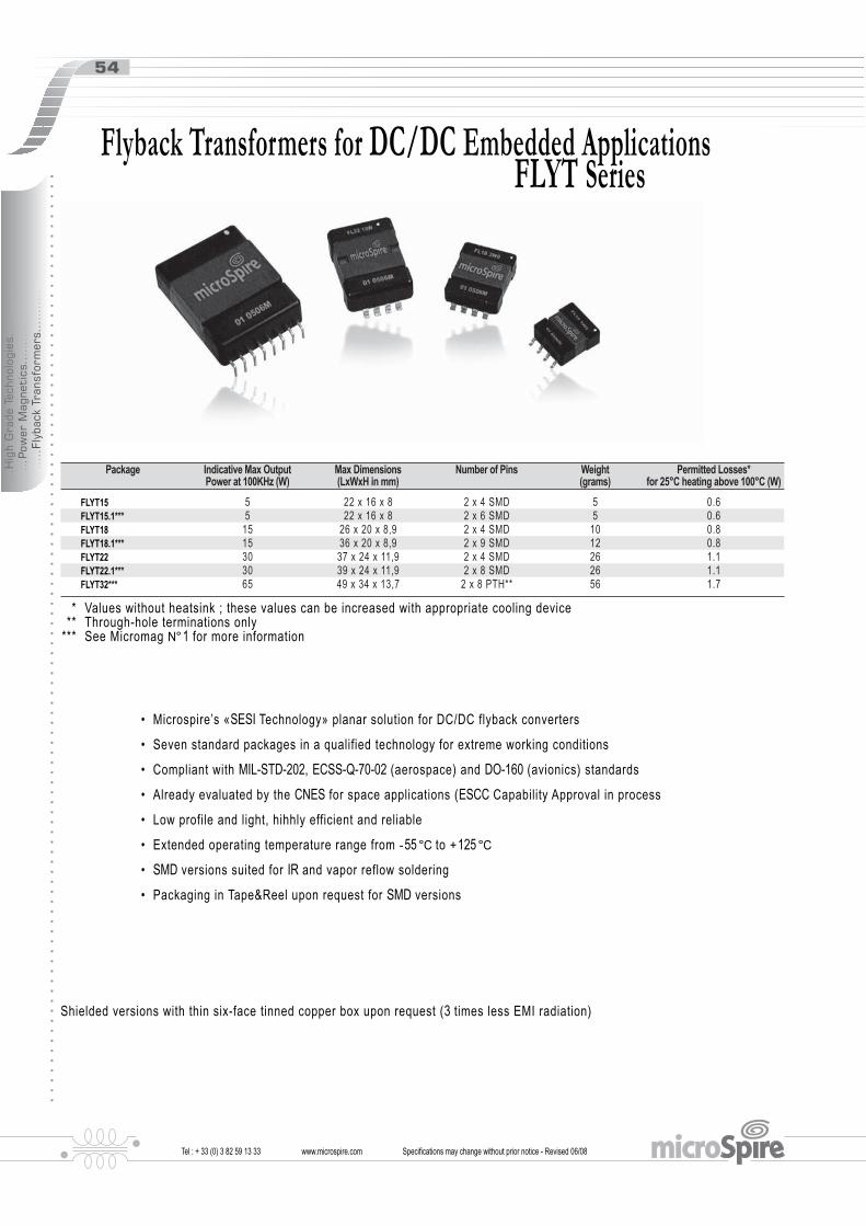
Tel : + 33 (0) 3 82 59 13 33 www.microspire.com Specifications may change without prior notice - Revised 06/08
54
....
.Hig
h G
rade
Tec
hnol
ogie
s...
....
....
...
...P
ower
Mag
neti
cs..
....
....
...
....
.Fly
back
Tra
nsfo
rmer
s...
....
....
.
Package Indicative Max OutputPower at 100KHz (W)
Max Dimensions(LxWxH in mm)
Number of Pins Weight(grams)
Permitted Losses*for 25°C heating above 100°C (W)
FLYT15 5 22 x 16 x 8 2 x 4 SMD 5 0.6FLYT15.1*** 5 22 x 16 x 8 2 x 6 SMD 5 0.6FLYT18 15 26 x 20 x 8,9 2 x 4 SMD 10 0.8FLYT18.1*** 15 36 x 20 x 8,9 2 x 9 SMD 12 0.8FLYT22 30 37 x 24 x 11,9 2 x 4 SMD 26 1.1FLYT22.1*** 30 39 x 24 x 11,9 2 x 8 SMD 26 1.1FLYT32*** 65 49 x 34 x 13,7 2 x 8 PTH** 56 1.7
* Values without heatsink ; these values can be increased with appropriate cooling device ** Through-hole terminations only *** See Micromag N° 1 for more information
Flyback Transformers for DC/DC Embedded Applications FLYT Series
• Microspire’s «SESI Technology» planar solution for DC/DC flyback converters
• Seven standard packages in a qualified technology for extreme working conditions
• Compliant with MIL-STD-202, ECSS-Q-70-02 (aerospace) and DO-160 (avionics) standards
• Already evaluated by the CNES for space applications (ESCC Capability Approval in process
• Low profile and light, hihhly efficient and reliable
• Extended operating temperature range from - 55 °C to + 125 °C
• SMD versions suited for IR and vapor reflow soldering
• Packaging in Tape&Reel upon request for SMD versions
Shielded versions with thin six-face tinned copper box upon request (3 times less EMI radiation)

Tel : + 33 (0) 3 82 59 13 33 www.microspire.com Specifications may change without prior notice - Revised 06/08
55
....
.Hig
h G
rade
Tec
hnol
ogie
s...
....
....
...
...P
ower
Mag
neti
cs..
....
....
...
....
.Fly
back
Tra
nsfo
rmer
s...
....
....
.
22MAX
8 MAX16 MAX
3 X 3.81
1.1 x 0.3
1
8
4
5
130 μm
22MAX
8 MAX16 MAX
3 X 3.81
1.1 x 0.3
1
8
4
5
130 μm
Top View
• Based on Microspire’s « SESI15 Planar Technology »• Low-profile SMD package (2 x 4 pins)• Applied standards : MIL-STD-202, ECSS-Q-70-02, DO-160D• Up to 15 W at 100 kHz in standard heating conditions• Dielectric strength up to 1500 V ( 50 Hz - 1 min )• Materials meet UL94-V0 rating• Thermal index according to IEC85 : H ( 180 °C )• Operating/storage temperature range : - 55 °C to + 125 °C• Approx weight : 5 grams
FL15 xxx
01 yywwP
16.024.0
2.13.81 x 3
16.024.0
2.13.81 x 3
Electrical DataID Code DC Input Voltage
Range (Vdc)Output Power
(W)DesignedOutputs
WorkingFrequency
PrimaryInductance
Insulation> 100MΩ
FLYT15 1W5 01 12 - 0.5V (2° - 1) 1.5 5V / 280mA (7° - 8)-5V / 280mA (5° - 6)
80 - 100kHz 90μH 500Vdc
FLYT15 2W2 01 26 - 29V (2° - 1) 1.1 - 2.2 5,2V / 400mA (7/8° - 5/6)BIAS (3° - 4) optional
130kHz 256μH 500Vdc
FLYT15 2W4 01 26 - 29V (2° - 1) 2.1 - 2.4 9V / 250mA (7/8° - 5/6)BIAS (3° - 4) optional
130kHz 231μH 500Vdc
FLYT15 2W4 02 18 - 40V (1° - 2) 2.4 48V / 50mA (8° - 7) 500kHz 23μH 1500VdcFLYT15 3W3 01 18 - 40V (1° - 2) 3.3 3,3V / 0,5A (8° - 7)
3,3V / 0,5A (6° - 5)500kHz 17.9μH 1500Vdc
FLYT15 4W5 01 18 - 40V (1° - 2) 4.5 15V / 0,3A (8° - 7) 500kHz 13μH 1500VdcFLYT15 10W 01 18 - 40V (1° - 2) 10.5 5,2V / 1A (8° - 7)
5,2V / 1A (6° - 5)BIAS (3° - 4) optional
500kHz 6.2μH 1500Vdc
Typical Dimensions (mm) Pad Layout (mm)
Marking
yyww :Date code
Flyback Transformers for DC/DC converters - FLYT 15 Series
Po
BoF
KoAo
P1
W
So
Tape and Reel:400 pieces per reel of diameter 330 mm
Packaging
Ao: 16.4Bo: 22.4Ko: 7.8F: 20.2P1: 20.0Po: 4.0W: 44.0So: 28.4
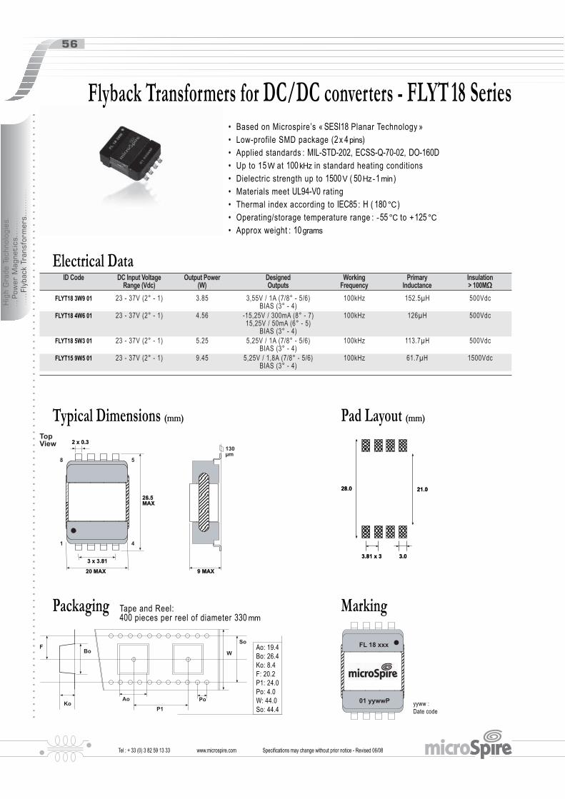
Tel : + 33 (0) 3 82 59 13 33 www.microspire.com Specifications may change without prior notice - Revised 06/08
56
....
.Hig
h G
rade
Tec
hnol
ogie
s...
....
....
...
...P
ower
Mag
neti
cs..
....
....
...
....
.Fly
back
Tra
nsfo
rmer
s...
....
....
.
Electrical DataID Code DC Input Voltage
Range (Vdc)Output Power
(W)DesignedOutputs
WorkingFrequency
PrimaryInductance
Insulation> 100MΩ
FLYT18 3W9 01 23 - 37V (2° - 1) 3.85 3,55V / 1A (7/8° - 5/6)BIAS (3° - 4)
100kHz 152.5μH 500Vdc
FLYT18 4W6 01 23 - 37V (2° - 1) 4.56 -15,25V / 300mA (8° - 7)15,25V / 50mA (6° - 5)
BIAS (3° - 4)
100kHz 126μH 500Vdc
FLYT18 5W3 01 23 - 37V (2° - 1) 5.25 5,25V / 1A (7/8° - 5/6)BIAS (3° - 4)
100kHz 113.7μH 500Vdc
FLYT15 9W5 01 23 - 37V (2° - 1) 9.45 5,25V / 1,8A (7/8° - 5/6)BIAS (3° - 4)
100kHz 61.7μH 1500Vdc
130μm
26.5MAX26.5MAX
20 MAX20 MAX
2 x 0.32 x 0.3
3 x 3.813 x 3.81
9 MAX9 MAX
1
8
4
5
TopView
01 yywwP
FL 18 xxx
21.028.0
3.03.81 x 3
21.028.0
3.03.81 x 3
Typical Dimensions (mm) Pad Layout (mm)
Marking
yyww :Date code
Flyback Transformers for DC/DC converters - FLYT 18 Series• Based on Microspire’s « SESI18 Planar Technology »• Low-profile SMD package (2 x 4 pins)• Applied standards : MIL-STD-202, ECSS-Q-70-02, DO-160D• Up to 15 W at 100 kHz in standard heating conditions• Dielectric strength up to 1500 V ( 50 Hz - 1 min )• Materials meet UL94-V0 rating• Thermal index according to IEC85 : H ( 180 °C )• Operating/storage temperature range : - 55 °C to + 125 °C• Approx weight : 10 grams
Po
BoF
KoAo
P1
W
So
Tape and Reel:400 pieces per reel of diameter 330 mm
Packaging
Ao: 19.4Bo: 26.4Ko: 8.4F: 20.2P1: 24.0Po: 4.0W: 44.0So: 44.4

Tel : + 33 (0) 3 82 59 13 33 www.microspire.com Specifications may change without prior notice - Revised 06/08
57
....
.Hig
h G
rade
Tec
hnol
ogie
s...
....
....
...
...P
ower
Mag
neti
cs..
....
....
...
....
.Fly
back
Tra
nsfo
rmer
s...
....
....
.
Electrical DataID Code DC Input Voltage
Range (Vdc)Output Power
(W)DesignedOutputs
WorkingFrequency
PrimaryInductance
Insulation> 100MΩ
FLYT22 19W 01 12 - 20.5V (2° - 1) 18.5 5V / 450mA (8° - 7)22V / 600mA (6° - 5)
90 - 130kHz 13μH 500Vdc
FLYT22 20W 01 12 - 20.5V (3° - 4) 19.5 5V / 340mA (6° - 5)12V / 1.2mA (8° - 7)
90 - 130kHz 13μH 500Vdc
Flyback Transformers for DC/DC converters - FLYT 22 Series• Based on Microspire’s « SESI22 Planar Technology »• Low-profile SMD package (2 x 4 pins)• Applied standards : MIL-STD-202, ECSS-Q-70-02, DO-160D• Up to 25 W at 100 kHz in standard heating conditions• Dielectric strength up to 1500 V ( 50 Hz - 1 min )• Materials meet UL94-V0 rating• Thermal index according to IEC85 : H ( 180 °C )• Operating/storage temperature range : - 55 °C to + 125 °C• Approx weight : 26 grams
37MAX37MAX
24 MAX24 MAX
2 x 0.032 x 0.03
3 x 3.813 x 3.81
12.5 MAX12.5 MAX
1
8
4
5
TopView
FL22 xxx
01 yywwP
29.037.5
3.03.81 x 3
29.037.5
3.03.81 x 3
Typical Dimensions (mm) Pad Layout (mm)
Marking
yyww :Date code
48 pieces per box, individually packedPackaging

Tel : + 33 (0) 3 82 59 13 33 www.microspire.com
Electrical Data ( 25°C )ID Code Turn ratio DCR1-2
mΩDCR3-4Ω ±15%
L3-4mH ±15%
Frequency rangetriangle wave
Ipk = IDC+∆I/2max
Z Load1% ¼W
Insulation500VDC
CT91 050 231 WR 1/50 <2 0.95 0.4 22kHz to 500kHz 10 6.81Ω >1GΩCT91 075 231 WR 1/75 <2 2.15 0.9 15kHz to 300kHz 10 10.2Ω >1GΩCT91 100 231 WR 1/100 <2 3.70 1.6 9kHz to 200kHz 10 13.7Ω >1GΩCT91 200 231 WR 1/200 <2 14.6 6.4 6kHz to 70kHz 10 27.4Ω >1GΩ
Specifications may change without prior notice - Revised 06/08
58
....
.Hig
h G
rade
Tec
hnol
ogie
s...
....
....
...
...P
ower
Mag
neti
cs..
....
....
...
....
.Cur
rent
Tra
nsfo
rmer
s...
....
....
.
14.4
3.2
8.4
8.4
xR yywwP
CT 91 xxx
1
2
3
4
Z load
• Vout/Ipk ratio : 1 V / 8 A• Global accuracy ± 5 % on E96 series load resistor• Low profile and light• Materials meet UL94V-0 rating• Applied standards : ESCC-3201 generic ( including MIL-STD-202 ) / ECSS-Q-70-02• Frequency range 6 kHz to 500 kHz triangle wave• Operating temperature range : - 55 °C to + 125 °C• Suited for IR and vapor reflow soldering• Weight : 2 grams
To Order CT91 ### 231 WRCT91 ### 231 WR
Range Turn ratio Range Gull wing highrel
NotesTypical performances at + 25 °CStorage Temperature - 55 °C to + 140 °C
ApplicationCurrent detection/measurement for PWM control( Isense ) in High-Rel. SMPS
IIDC
Ipk
tTαT
ΔI
10.7
7.1
10.3±0.05
1.4 x 0.25
5.8MAX
13 ± 0.5
12
3 4
TopView
Pad Layout
yyww :Date code
Connections
Dimensions (mm)
Marking
Current sense Transformer, up to 10Apk - CT91 xxx 231 WR
Po
BoF
KoAo
P1
W
So
Tape and Reel:700 pieces per reel of diameter 330 mm
Packaging
Ao: 11.7Bo: 13.8Ko: 5.5F: 11.5P1: 14.7Po: 4.0W: 24.0So: none

Tel : + 33 (0) 3 82 59 13 33 www.microspire.com Specifications may change without prior notice - Revised 06/08
59
....
.Hig
h G
rade
Tec
hnol
ogie
s...
....
....
...
...P
ower
Mag
neti
cs..
....
....
...
....
.Cur
rent
Tra
nsfo
rmer
s...
....
....
.
• Designed for DC/DC Converter Applications• Measurement up to 5.4 ARMS ( 8 APEAK - 3.6 ADC MAX ) from 100 to 200 KHz with 2 % Accuracy• Applied standards: MIL-STD-202, ECSS-Q-70-02 ESCC-3201, DO-160
• The component is dedicated to measure RMS current up to IIN = 5.4 ARMS ( 8 APEAK and 3.6 ADC MAX ) for a wavform of working frequency from 100 to 200 KHz. Image of this current is the voltage ( VOUT = 3 VRMS MAX ) picked on a resistive load RL = 113 Ω at 1 % ( E96 series ).• The component can also make the measurement keeping the same accuracy but with a ratio VOUT / IIN = 1.00. In this case, image of the current is the voltage ( Vs = 5.4 VRMS MAX ) picked on a resistive load RL = 200 Ω at 1 % ( E96 series ).• Flammability compliance : UL94V0• Insulation class (windings) : H ( 180 °C )• Operating temperature : - 40 °C to + 110 °C• Storage temperature : - 55 °C to + 125 °C
CT 08 xxx
xR yywwP
Marking face
Dot for pin 1
Bottom View
15.80
3.00
8.70
1.40
3.8113.97
10.50
15.00
3 4
2
1
3
4
Marking face
Dot for pin 1
Bottom View
15.80
3.00
8.70
1.40
3.8113.97
10.50
15.00
3 4
2
1
3
4
Application Schem.
CT08 200 221R can be used for measurement of secondary current ( i2 ) of a DC/DC forward converter ( 3.3 V / 8 A output and 100 KHz working frequency example) for regulation and surveillance operations.
n3 n1 n2DTR L
iL IOUT
VOUTV
(-VD)
DC
R
V2
V1
V3
Ve
Dm Tp
i1i3VT
i2
RL
VOUT
CT08 200 221R
n3 n1 n2DTR L
iL IOUT
VOUTV
(-VD)
DC
R
V2
V1
V3
Ve
Dm Tp
i1i3VT
i2
RL
VOUT
CT08 200 221R
1 4IIN
PRIM(Np)
SEC(Ns) RL VOUT
2 3
1 4IIN
PRIM(Np)
SEC(Ns) RL VOUT
2 3
Electrical Data ( 25°C )ID Code Accuracy (-40°C / +110°C) Transformer ratio Secondary Inductance Secondary DC Resistance Insulation
CT08 200 221R < 2% with RL = 113Ω theoretical< 2% with RL = 113Ω at 1% (E96)
VOUT / IIN = 0.56(Np / Ns = 1 : 200)
L3-4 = 11.0 mH (± 25%)(100 kHz - 1VRMS)
R3-4 = 5.8 Ω (± 10%) 500 VDC - 1 min (RI ≥ 100 MΩ)between windings
Marking
yyww :Date code
Notes
Connections
Typical Dimensions (mm)
Current Transformer for DC/DC ApplicationsCT08 200 221 PR

Tel : + 33 (0) 3 82 59 13 33 www.microspire.com Specifications may change without prior notice - Revised 06/08
60
....
.Hig
h G
rade
Tec
hnol
ogie
s...
....
....
...
...P
ower
Mag
neti
cs..
....
....
...
....
.Gat
e D
rive
Tra
nsfo
rmer
s...
....
....
.
• Excellent performances in low profile package• Suited for Avionics and Space applications• ET : 20 Vμs Nominal• Frequency : 200 Khz• Applied standards : ECSS-Q-70-02 / ESCC-3201 screening flow applied / MIL-STD-202• Materials meet UL94V-0 rating• Weight : 2 grams
Connections
xR yywwP
CT 91 xxx
10.7 MAX
7.1
10.3MAX
1.4 x 0.25
5.8MAX
13.1 ± 0.2
12
3 4
TopView
14.4
3.2
8.4
8.4
1
2
4
SECPRIM
3
1
2
4
SECPRIM
3
Electrical Data ( 25°C )ID Code Primary Inductance
MaxTurn ratio
± 0,5%DC Resistances Isolation
VoltageLeakage
InductanceInterwindingCapacitance
GDT91 M50 20 1WR L1-4 > 500μH(10kHz - 1VRMS)
N7-6 / N1-4 = 1.00 R1-2 = < 1.25ΩR3-4 = < 1.25Ω
500 VDC - 1 min(Ri ≥ 100MΩ)
Lf1-2 < 1μH(3-4 in short circuit)
C1-2/3-4 < 100 pF
• Insulation class (windings) : Classe H2• Operating temperature : - 55 °C to + 125 °C
• Storage temperature : - 55 °C to + 140 °C
• I peak : < 1 A ( 100 ns )• Average I : < 50 mA
• V primary : 7.5 V peak
• Q : < 60 mC
Notes
Application Schem.1μ
V
10 Ω Rgate
22 Ω
4
3
1
2
Cmos
1nF
10KΩRmos
1μ
V
10 Ω Rgate
22 Ω
4
3
1
2
Cmos
1nF
10KΩRmos
Dimensions (mm) Pad Layout
yyww :Date code
Marking
Gate Drive Transformer GDT91 M50 20 1WR
Po
BoF
KoAo
P1
W
So
Tape and Reel:700 pieces per reel of diameter 330 mm
Packaging
Ao: 11.7Bo: 13.8Ko: 14.9F: 11.5P1: 14.7Po: 4.0W: 24.0So: none

Tel : + 33 (0) 3 82 59 13 33 www.microspire.com Specifications may change without prior notice - Revised 06/08
61
....
.Hig
h G
rade
Tec
hnol
ogie
s...
....
....
...
...P
ower
Mag
neti
cs..
....
....
...
....
.Gat
e D
rive
Tra
nsfo
rmer
s...
....
....
.
• Excellent performances in low profile package• Suited for Avionics and Space applications• ET : 60 Vμs Nominal• Frequency range : 50 Khz - 500 Khz• Applied standards : ECSS-Q-70-71 / ESCC-3201 screening flow applied / ABD-0100 / DO-160• Materials meet UL94-V0 rating• Approx. weight : 5 grams
22MAX
8 MAX16 MAX
3 X 3.81
1.1 x 0.3
1
8
4
5
22MAX
8 MAX16 MAX
3 X 3.81
1.1 x 0.3
1
8
4
5
Top View
Electrical Data ( 25°C )ID Code Primary Inductance
MaxTurn ratio
± 1%DC Resistances
± 15%IsolationVoltage
LeakageInductance
InterwindingCapacitance
GDT15 M50 60 1WR L1-4 > 500μH(10kHz - 1VRMS)
N7-6 / N1-4 = 1.52 R1-4 = 170mΩR6-7 = 400mΩ
500 VDC - 1 min(Ri ≥ 100MΩ)
Lf1-4 < 2.0μH(6-7 in short circuit)
C1-4/6-7 < 150 pF
• Insulation class (windings) : Classe H• Operating temperature : - 55 °C to + 125 °C
• Storage temperature : - 55 °C to + 140 °C
• Dielectric Strength : 500 VRMS - 50 Hz
NotesDimensions (mm)
Application Schem.1μ
V
10 Ω Rgate
22 Ω
7
6
1
4
Cmos
1nF
10KΩRmos
1μ
V
10 Ω Rgate
22 Ω
7
6
1
4
Cmos
1nF
10KΩRmos
Pad Layout
Connections
GT15 xxx
601 yywwP yyww :Date code
Marking
1
4
7
SECPRIM
6
1
4
7
SECPRIM
6
16.024.0
2.13.81 x 3
16.024.0
2.13.81 x 3
Gate Drive Transformer GDT15 M50 60 1WR
Po
BoF
KoAo
P1
W
So
Tape and Reel:400 pieces per reel of diameter 330 mm
Packaging
Ao: 16.4Bo: 22.8Ko: 7.8F: 20.2P1: 20.0Po: 4.0W: 44.0So: 28.4


From Design to Production
www.microspire.c m
Wo u n d M a g n e t i c s E x p e r t s
Industrial Technologies
Industrial Technologies
Industrial Technologies

Tel : + 33 (0) 3 82 59 13 33 www.microspire.com Specifications may change without prior notice - Revised 06/08
64
Microspire Engineers design compact yet powerful magnetics for a wide range of applications :
• All designs up to 10 kVA• All designs up to 1 kHz• All designs up to 500 A peak
220A 96A 74A 46A
Microspire manufacture custom power magnetics using all materials and technologies available :
• Copper wire, flat, foil• EI, EE, UI and C-cores
....
.Indu
stri
al T
echn
olog
ies.
....
....
...
....
.Pow
er M
agne
tics
....
....
....
...
...C
usto
m D
esig
ns..
....
....
..
Power Magnetics

Tel : + 33 (0) 3 82 59 13 33 www.microspire.com Specifications may change without prior notice - Revised 06/08
65
Current and Voltage TransformersMicroSpire designs 50 Hz transformers to measure currents up to 100 A, with an accuracy reaching 1 % upon request, together with transformers to sense up to 20 A, ± 1 %, at frequencies up to 1 MHz.We develop voltage measurement transformers with ouputs of a few volts and in-out phase shifts of 0,1 %.Applications include feedback control, overload sensing, detecting load drop or overload, and proportional output.
Electro-Magnetic SensorsThese sensors are made of self-bonded coils associated with ferrite cores to realise antennas and sensors with high electro-magnetic performance.This performance is due to the excellent manufacturing repeatability of self-bonded coils and their proximity with the magnetic cores.
Self-Bonded CoilsTheir windings are bonded by a strong adhesive and do not require the support of bobbins, which make these coils economical.Self-bonded coils are used in numerous sensing and detection applications such as ID card systems,electro-mechanical displays, antennas and remote control devices.
Injection-Moulded Coils / Bobbin CoilsThese coils are made of thermo-plastic bobbins wound by fast, fully automated multi-spin machines to keep production costs low.Numerous applications require that bobbin coils be protected against shock, humidity and chemicals by an encapsulation made withinjection-moulded thermoplastic.We can design and manufacture various custom-designedinjection-moulded coils and transformers.
Custom bobbins
....
.Indu
stri
al T
echn
olog
ies.
....
....
...
....
.Pow
er M
agne
tics
....
....
....
...
...C
usto
m D
esig
ns..
....
....
..

Tel : + 33 (0) 3 82 59 13 33 www.microspire.com
....
.Indu
stri
al T
echn
olog
ies.
....
....
...
....
.Pow
er M
agne
tics
....
....
....
...
...C
usto
m D
esig
ns..
....
....
..
Specifications may change without prior notice - Revised 06/08
66
EFD, ER and EP seriesEFD cores with their optimised cross-sections are used to designcompact transformers for DC-DC converters, isolation and pulseapplications.ER cores are low profile, SMT and high inductance components wellsuited for broadband applications and for power transformers up to 500 kHz.EP coils are utilised for the design of pulse and line matchingtransformers and are increasingly being used for power applications up to 300 kHz such as in forward converters.
ETD Coils and TransformersE cores have the advantage of easy winding, compactness and wide openings on each side.ETD cores have the additional benefit of an almost constantcross-section along the magnetic path.ETD coils are suitable for designing transformers in forward andpush-pull SMP supplies and converters. Power ratings of more than a 1000 W can be transformed at frequencies up to 500 kHz.
RM seriesRM coils are compact and well suited for PCB mounting. They are used in broadband transmission of signals, as filters in resonant circuits and as power transformers in SMP supplies.Low profile RM coils are suitable for small-signal, interfa-ce and matching transformers as well as for transformer andenergy storage inductors in DC-DC converters. The RM 14 core will handle a maximum power of 200 W at 100 kHz switchingfrequency.
Planar Magnetics• Power up to 10 KWatts• Input voltage 12 Vac to 240 - 400 Vac• Output voltage 3 Vdc to 60 Vdc• Frequency range 50 kHz to 1 MHz• Typical isolation 3 kV• Electrical circuit Copper foil or PCB• Multi-layer up to 10 layers• Core EE or E/PLT14 to EE or E/PLT64 ferrite• Temperature range : - 40 °C to + 125 °C
Custom Designs

Tel : + 33 (0) 3 82 59 13 33 www.microspire.com Specifications may change without prior notice - Revised 06/08
67
Electrical DataID Code Number
of linesMax. Current
mAL/winding
μHRDC max
mžIsolation
VrmsDLEF12 020 1S 2 100 5 250 250DLEF13 020 1S 3 100 5 250 250DLEF14 020 1S 4 100 5 250 250
Connections
Response Curves
These filters virtually eliminate conducted EMI in data lines. They provide excellent common-mode noise attenuation from 15 MHz to 300 MHz whilst passing data signals below 300 MHz without attenuation.• Suited for IR and vapor reflow soldering• Materials meet UL94-V0 rating• Operating temperature range : - 40 °C to + 100 °C• Weight : 0.5 gram
Atte
nuat
ion
(dB
)
Typical Attenuation versus Frequency on 50 OhmsDLEF1x 020 1S25
20
15
10
5
0
-5
Frequency (Hz)1E+05 1E+06 1E+07 1E+08 1E+09
@100mV
COMMON MODEDIFFERENTIAL MODE
Typical Dimensions (mm)
7.8
8
5
1
45
3.81
5.4
7.4 max
4.3
50.4
1.21
cap
Bottom view
Top view
DLEF0x xxx xS
DLEF1x xxx xS
with cap
without cap
DLEFx2 xxx xS
DLEFx4 xxx xS
DLEFx3 xxx xS
Pad Layout6.2
1.21
0.8
2
Data Line EMI Filters - DLEF Series
Tape and Reel : 2200 piecesPackaging
....
.Indu
stri
al T
echn
olog
ies.
....
....
...
....
.RF
and
Dat
a M
agne
tics
....
....
....
...
...F
ilter
ing
& E
MI S
uppr
essi
on C
hoke
s...
....
....
.

Tel : + 33 (0) 3 82 59 13 33 www.microspire.com Specifications may change without prior notice - Revised 06/08
68
Electrical DataPart Number
(typical values)Inductanceat 100 kHz
μH
Rdc Max(at 80°C)
m
Impedanceat 100 MHz
Ω
Attenuation50Ω at 10MHz
dB
Rated CurrentmaxmA
Isolation betweenwindings
VrmsESC X1 15K 1S 15 20 100 6,5 750 250ESC X1 56K 1S 56 35 250 12 600 250ESC X1 M47 1S 470 470 1200 27,5 250 250
These common-mode chokes provide excellent attenuation of asymmetric EMI on signal lines and in switch-mode power supplies.• Surface-mount package• Suited for IR and vapor reflow soldering• Materials meet UL94-V0 rating• Frequency range up to 100 MHz• Operating temperature range : - 40 °C to + 125 °C• Weight : 0.5 gram
Response CurvesTypical Impedance versus FrequencyESC11 xxx xS
10 000
1 000
100
10
1
0.1
0.011E+02 1E+03 1E+04 1E+05 1E+06 1E+07 1E+08
Frequency (Hz)
Mod
ulus
(Ohm
s)
ESC11 15KESC11 56KESC11 M47
@ 100mV
@ 100mV
ESC11 15KESC11 56KESC11 M47
Typical Attenuation versus Frequency on 50 OhmsESC11 xxx xS30
25
20
15
10
5
0
Atte
nuat
ion
(dB
)
1E+04 1E+05 1E+06 1E+07 1E+08Frequency (Hz)
Typical Dimensions (mm)
7.8
8
5
1
45
3.81
5.4
7.4 max
4.3
50.4
1.21
cap
Bottom view
Top view
ESC0x xxx xS
ESC1x xxx xS
with cap
without cap
Connections
Pad Layout6.2
0.8
2
1.21
12
43
56
87
EMI Suppression Chokes - ESC Series
Tape and Reel : 2200 piecesPackaging
....
.Indu
stri
al T
echn
olog
ies.
....
....
...
....
.RF
and
Dat
a M
agne
tics
....
....
....
...
...F
ilter
ing
& E
MI S
uppr
essi
on C
hoke
s...
....
....
.

Tel : + 33 (0) 3 82 59 13 33 www.microspire.com Specifications may change without prior notice - Revised 06/08
• 2-fo ld current-compensated chokes • 4-fold current-compensated chokes • High insertion loss over a wide frequency range• High inductance values• Low total losses• Amorphous and ferrite toroids, encapsulated in polymer materials listed in UL94-V0• Flat or upright cases• Operating temperature range - 25 °C + 70 °C
Electrical DataPart
NumberLnmH
InA eff
LFμH
RdcΩ
2-fold chokes
ICMC12 1M0 1X 2x1 0.5 0.2 0.1ICMC12 1M7 1X 2x1.7 0.5 0.2 0.15ICMC12 3M3 1X 1x3.3 0.4 0.25 0.2ICMC12 4M7 1X 2x4.7 0.4 0.3 0.25ICMC12 6M8 1X 2x6.8 0.3 0.4 0.3
ICMC12 10M 1X 2x10 0.3 0.45 0.4ICMC12 12M 1X 2x12.5 0.3 0.5 0.45ICMC12 28M 1X 2x28 0.25 1 0.8ICMC12 39M 1X 2x39 0.25 1.1 1ICMC12 50M 1X 2x50 0.25 1.2 1.1ICMC12 70M 1X 2x70 0.2 1.4 1.2
4-fold chokes
ICMC14 1M0 1X 4x1 0.5 0.2 0.1ICMC14 1M7 1X 4x1.7 0.5 0.25 0.15ICMC14 3M6 1X 3x3.6 0.4 0.4 0.2ICMC14 5M0 1X 4x5 0.3 0.45 0.25ICMC14 6M0 1X 4x6 0.3 0.45 0.3ICMC14 7M8 1X 4x7.8 0.25 0.5 0.4ICMC14 10M 1X 4x10 0.25 0.5 0.45ICMC14 11M 1X 4x11.5 0.2 0.5 0.6ICMC14 40M 1X 4x40 0.15 0.9 1.2ICMC14 58M 1X 4x58 0.15 0.5 0.9ICMC14 90M 1X 4x90 0.15 0.5 1.4
Dielectric strength 500 Vrms for 2 seconds.
14
12.5 10.16
12.7 10
□ 0.5
3.5
Horizontal design ICMCxx xxx xH
9
14 10.16
7.62 15
□ 0.5
3.5
Vertical design ICMCxx xxx xV
5 6
1 10
Typical Dimensions (mm)
Symbols
Connections2-fold chokes ICMC12 xxx xx
1 10
65
4-fold chokes ICMC14 xxx xx
1 10
2 9
4 7
5 6
69
Common-Mode Chokes - ICMC Series
In = permissible rated current of a windingLn = rated inductance of a winding ( tol. + 50 % / - 30 % ; f = 10 kHz ; U = 100 mVrms )LF = leakage inductance of a winding when all other windings short circuit ( nominal value )Rdc = DC resistance of winding ( nominal value )
....
.Indu
stri
al T
echn
olog
ies.
....
....
...
....
.RF
and
Dat
a M
agne
tics
....
....
....
...
...C
omm
on M
ode
Cho
kes.
....
....
...

Tel : + 33 (0) 3 82 59 13 33 www.microspire.com Specifications may change without prior notice - Revised 06/08
Measurement CircuitFrequency Response
• Improved EMI performance for FCC class B applications• Maximum common mode attenuation at 1 MHz• Well suited for many telecom applications• Surface mount package• Materials meet UL94-V0 rating• Temperature range : 0 °C to + 70 °C• Weight < 1 gram
70
Electrical DataPart Number OCL
(mH +30%/-40%) (db typ. @ 100kHz)Common Mode Attenuation
(db typ. @ 1MHz) (db typ. @ 10MHz)I max eff
(mA)Isolation
(Vrms min)DCR
(Ω max)LCMC 20 4M7 1S 2 x 4.7 29 40 24 35 500 1.15
Note : values measured at 10 kHz, 100 mVRMS at 25°C. Dielectric strength : 500VRMS - 50Hz - 1min
To Order LCMC 20 4M7 1SLCMC 20 4M7 1 S
Line Common Mode Chokes Size Value code4M7 = 4,7 mH
Version SMD
MB08216-0
0
5
10
15
20
25
30
35
40
45
1E+02 1E+03 1E+04 1E+05 1E+06 1E+07 1E+08Frequency (Hz)
Atte
nuat
ion
(dB
)
Typical attenuation versus frequency on 50 Ohms
@100mV
LCMC 20 4M7 1S
VREF
VTEST
SINVDUAL
50 Ω
50 Ω
50 Ω
50 Ω
Attenuation measured with HP4194A at 100 mVrms( Z = 50 Ohms )
Typical Dimensions (mm) Connections
4
1 2
3
Pin 1 Identifier
4 x Ø 1.14 TYPContact surface
7.62 TYP
8.76± 0.25
10.16 ± 0.25
Bottom view0.64
6.35max
6.22± 0.05
Marking
1 yywwP
LC 20 4M7
yyww :Date code
1
2
4
3
Line Common Mode Choke - LCMC
....
.Indu
stri
al T
echn
olog
ies.
....
....
...
....
.RF
and
Dat
a M
agne
tics
....
....
....
...
...C
omm
on M
ode
Cho
kes.
....
....
...

Tel : + 33 (0) 3 82 59 13 33 www.microspire.com Specifications may change without prior notice - Revised 06/08
71
Electrical DataID Code Impedance ratio
(Ω) 3 dBBandwidth (MHz)
2 dB 1 dBWRFTX1 1R0 1X 50:50 0.15-400 0.35-200 2-50WRFTX1 2R0 1X 50:100 0.30-300 0.5-250 2-230WRFTX2 2R0 1X 50:100 center tap 0.10-200 0.5-100 2-50WRFTX1 2R5 1X 50:125 0.10-100 0.1-50 0.1-20WRFTX1 4R0 1X 50:200 0.20-350 0.35-300 2-100WRFTX2 5R0 1X 50:250 center tap 0.30-300 0.6-200 0.5-100WRFTX2 8R0 1X 50:400 center tap 0.10-140 0.1-90 1-60WRFTX1 12R 1X 50:600 0.20-110 0.5-80 1-50WRFTX1 13R 1X 50:650 0.30-130 0.4-85 1-65WRFTX2 13R 1X 5:650 center tap 0.30-120 0.7-80 5-20WRFTX1 16R 1X 50:800 0.30-120 0.7-80 5-20WRFTX2 16R 1X 50:800 center tap 0.10-75 0.2-30 0.3-20
• Frequency bandpass 100 kHz to 500 MHz• Power input max. 250 mW• Isolation prim. to sec. 500 Vrms minimum • Suited for IR and vapor reflow soldering• Materials meet UL94-V0 rating• Operating temperature range : - 40 °C to + 125 °C• Weight : 0.5 gram
Typical Dimensions (mm)
7.8
8
5
1
45
3.81
5.4
7.4 max
4.3
50.4
1.21
cap
Bottom view
Top view
WRFT0x xxx xS
WRFT1x xxx xS
with cap
without cap
Surface-mount case
Connections
Pad Layout
8
5
1
4
8
6-7
5
1
4
Standard
Center tap
PRI
PRI PRI
6.2
0.8
2
1.21
Wide Band RF Transformers - WRFT Series
Tape and Reel : 400 piecesPackaging
....
.Indu
stri
al T
echn
olog
ies.
....
....
...
....
.RF
and
Dat
a M
agne
tics
....
....
....
...
...W
ide
Ban
d S
igna
l Tra
nsfo
rmer
s...
....
....
.

Tel : + 33 (0) 3 82 59 13 33 www.microspire.com Specifications may change without prior notice - Revised 06/08
72
Package Output Power(W)
Max Dimensions(LxWxH in mm)
Number of pins(through hole)
Connected ICs
FSIT 13 0-6 16 x 15 x 15,5 2 x 5 LNK501, TNY253-254-255, TNY264P/G, TOP242P/G,ICE3A/B0365, VIPer12A, NCP1200
FSIT 16 0-10 19 x 17 x 19,5 6 + 4 LNK501, TNY253-254-255, TNY264-266P/G, TOP242P/G,ICE3A/B0365, VIPer12A-20A, NCP1200
FSIT 20 10-20 22 x 21,5 x 16,5 2 x 4 TOP242-243Y/F, ICE3A/B1065-1565, VIPer22A-50A, NCP1200FSIT 20.1 10-20 22 x 21,5 x 17 2 x 5 TOP242-243Y/F, ICE3A/B1065-1565, VIPer22A-50A, NCP1200FSIT 25 20-35 28 x 28,5 x 20,5 2 x 5 TOP242-244Y/F, ICE3A/B2065-2565, VIPer50A-53-100A, NCP1200FSIT 29 35-70 35,5 x 35,5 x 25,5 6 + 7 TOP244-245-246Y/F, ICE3A/B3065-4065P, VIPer100A, NCP1200
• Thermal index according to IEC85 : from* class A ( 105 °C ) to F ( 155 °C )
Other packages and connections available on demand according to your specification for power range up to 250 W
• Applied standards : EN60950-1, EN61558-1 / -2-17, EN60335-1, EN60065• Materials meet UL94-V0 rating• Ambiant temperature range : - 25 °C + 50 °C ( + 70 °C / + 85 °C ** ) • Storage temperature range : - 40 °C + 85 °C• Associated to latest generation ICs, they replace with competitive pricing and lower size old linear power supplies • Six standard packages for catalog or custom designs• Compliant with basic/supplementary to reinforced insulation from the mains according to common applied standards• Optimized construction of primary winding for low switching losses and low EMI• Low leakage inductance for improved converter efficiency• Utilization of triple insulated wire and high performance ferrites• Increased performances based on optimized designs on accurate automatic software tools linked to transformer
datasheets proposed by ICs manufacturers• Manufacturing in low-cost country
Our transformers can be associated to input common mode filtering chokes and output filtering chokes
* Depending on winding technique used for insulation requirements ** Depending on component heating and thermal class
Packaging to be defined according to batch size.
Flyback Safety Insulating Transformers FSIT Series
....
.Indu
stri
al T
echn
olog
ies.
....
....
...
....
.Pow
er M
agne
tics
....
....
....
...
...F
lyba
ck T
rans
form
ers.
....
....
...

Tel : + 33 (0) 3 82 59 13 33 www.microspire.com Specifications may change without prior notice - Revised 06/08
73
16 MAX 15 MAX 8.6 ± 0.3
Ø 0.6 ± 0.1
2.5
± 0.
315.5
MA
X
Bottom View
110
6 5
19 MAX
Ø 0.6
17 MAX 12.2 ± 0.5
3.5
x 3
=10
.5 ±
0.5
2.7
x 5
=13
.5 ±
0.5
19.5
MA
X
Bottom View
10 1
67
• 0 to 6 W transformers for AC / DC converters connected to the mains• Low cost and small package 2 x 5 pin through hole version• Compliant with basic/supplementary insulation up to 265 Vrms• Clearance and creepage distance up to 4 mm• Dielectric strength up to 2 kV ( 50 Hz - 1 min )• Approx weight : 5 grams
• 0 to 10 W transformers for AC / DC converters connected to the mains ( 50 / 60 Hz )• Low cost and small package 6 + 4 pin through hole version ( EE-16 )• Compliant with reinforced insulation up to 265 Vrms working voltage• Clearance and creepage distance up to 8 mm• Dielectric strength up to 4 kV ( 50 Hz - 1 min )• Approx weight : 7 grams
TypicalDimensions(mm)
FSIT 13
FSIT 13 Series & FSIT 16 SeriesFlyback Safety Insulating Transformers
Electrical Data - FSIT 13ID Code Mains Input Voltage
Range (Vrms)Output Power
(W)Designed Outputs Connected IC(s) Working
FrequencyApplied
standard(s)Standard
RequirementsFSIT13 W85 01 185 - 265V (5° - 1) 0.85W 5V / 50mA (8° - 6)
12V / 50mA (10° - 6)LNK501 42kHz EN60950 Basic / Supplementary
1500VrmsFSIT13 2W5 01 85 - 265V (5° - 4) 2.44W 5V / 200mA (7° - 6)
15V / 80mA (8° - 6)8V / 30mA (10° - 9)
TNY264 132kHz - Operationnal1500Vrms
FSIT13 6W0 01 85V - 265V (4° - 2) 5.95W 5V / 350mA (8° - 6)12V / 350mA (10° - 6)
TNY264, TNY266 132kHz - Operationnal1500Vrms
Electrical Data - FSIT 16ID Code Mains Input Voltage
Range (Vrms)Output Power
(W)Designed Outputs Connected IC(s) Working
FrequencyApplied
standard(s)Standard
RequirementsFSIT16 W80 01 180 - 265V (8° - 9) 0,8W 8V / 100mA (5° - 2) LNK501 42kHz EN60950 Reinforced 3750VrmsFSIT16 1W2 01 180 - 265V (8° - 9) 1,2W 24V / 50mA (5° - 2) LNK501 42kHz EN60950 Reinforced 3750VrmsFSIT16 2W5 01 90 - 264 (10° - 8) 2,35W 5V / 200mA (2° - 1)
15V / 80mA (3° - 1)-5V / 30mA (6° - 5)
BIAS (3° - 1)
VIPer12A 60kHz EN60335-1 Operationnal1500Vrms
FSIT16 4W5 01 85 - 265V (9° - 10) 4,4W 1,8V / 600mA (2° - 1)3,3V / 400mA (4° - 1)6V / 300mA (5° - 1)12V / 15mA (6° - 1)
BIAS (7° - 8)
TOP242 132kHz EN60950 Reinforced 4000Vrms
FSIT16 6W5 01 85 - 265V (9° - 10) 5,86W 12V / 80mA (2° - 1)5V / 80mA (4° - 3)
5V / 900mA (6° - 5)BIAS (7° - 8)
VIPer12A 60kHz EN60950 Reinforced 3750Vrms
FSIT16 8W5 85 - 265V (4° - 6) 8,3W 24V / 200mA (7° - 10)15V / 200mA (8° - 10)5V / 100mA (9° - 10)
BIAS (2° - 1)
VIPer22A 60kHz EN60950 Reinforced 3000Vrms
FSIT16 9W 01 85 - 265V (10° - 9) 9W 6V / 1,5A (5° - 2) TNY268 132kHz EN60950 Reinforced 3750VrmsFSIT16 5W 01 85 - 265V (9° - 10) 5W 12V / 420mA (4° - 3)
BIAS (7° - 8)VIPer22A 50kHz - Operational 1500Vrms
FSIT 16
....
.Indu
stri
al T
echn
olog
ies.
....
....
...
....
.Pow
er M
agne
tics
....
....
....
...
...F
lyba
ck T
rans
form
ers.
....
....
...

Tel : + 33 (0) 3 82 59 13 33 www.microspire.com Specifications may change without prior notice - Revised 06/08
74
Electrical Data FSIT 20.1ID Code Mains Input Voltage
Range (Vrms)Output Power
(W)Designed Outputs Connected IC(s) Working
FrequencyApplied
standard(s)Standard
RequirementsFSIT20.1 3W5 01 50 - 500V (4° - 5) 3,35W 21V / 70mA (10° - 9)
10V / 100mA (7° - 6)35V / 25mA (2° - 1)
TNY255 +external
MOS
130kHz EN60950 Reinforced 4000Vrms
FSIT20.1 7W2 01 180 - 265V (3° - 2) 7,2W 4,4V / 150mA (10° - 9)-35V / 80mA (8° - 7)
-61,8V / 60mA (8° - 6)BIAS (5° - 4)
TOP243 132kHz EN60950 Reinforced 4000Vrms
FSIT20.1 12W5 01 85 - 265V (3° - 1) 12,5W 5V / 1,25A (8° - 7)5V / 1,25A (9° - 6)
TNY268 132kHz EN60950 Reinforced 3750Vrms
FSIT20.1 13W 01 85 - 265V (3° - 1) 12,9W 48V / 270mA (10° - 6) TNY268 132kHz EN60950 Reinforced 3750VrmsFSIT20.1 20W 01 185 - 265V (2° - 1) 19,25W 5V / 0,8A (9° - 10)
7,5V / 0,9A (8° - 10)12V / 30mA (7° - 10)
65V / 125mA (6° - 10)BIAS (5° - 4)
VIPer20ASP 120kHz EN60950 Reinforced 3000Vrms
• 10 to 20 W transformers for AC / DC converters connected to the mains• 2 x 4 pin through hole version ( EF20 )• Compliant with reinforced insulation up to 265 Vrms working voltage• Clearance and creepage distance up to 8 mm• Dielectric strength up to 4 kV ( 50 Hz - 1 min )• Approx weight : 20 grams
• 10 to 20 W transformers for AC / DC converters connected to the mains ( 50 / 60 Hz )• 2 x 5 pin through hole version ( EF20 )• Compliant with reinforced insulation up to 265 Vrms working voltage• Clearance and creepage distance up to 8 mm• Dielectric strength up to 4 kV ( 50 Hz - 1 min )• Approx weight : 20 grams
22 MAX 21.5 MAX
16.5
MA
X 5.0
TYP
15.0 TYP
Bottom View
ø 0.7
8
5 4
1 22 MAX 21.5 MAX
17 M
AX
□ 0.45Ø 0.68
15.24 TYP
Bottom View
3.81TYP
5
110
6
TypicalDimensions(mm)
FSIT 20 FSIT 20.1
FSIT 20 Series & FSIT 20.1 SeriesFlyback Safety Insulating Transformers
Electrical Data FSIT 20ID Code Mains Input Voltage
Range (Vrms)Output Power
(W)Designed Outputs Connected IC(s) Working
FrequencyApplied
standard(s)Standard
RequirementsFSIT20 20W 01 85 - 265V (3° - 4) 20W 15V / 1.35A (5° - 8)
BIAS (2° - 1)TOP244G 132kHz EN60950 Reinforced 4000Vrms
FSIT20 20W 02 85V - 265V (2° - 3) 20W 15V / 1.35A (5° - 8) NCP1200 60kHz EN60950 Reinforced 4000Vrms
....
.Indu
stri
al T
echn
olog
ies.
....
....
...
....
.Pow
er M
agne
tics
....
....
....
...
...F
lyba
ck T
rans
form
ers.
....
....
...

Tel : + 33 (0) 3 82 59 13 33 www.microspire.com Specifications may change without prior notice - Revised 06/08
75
• 20 to 35 W transformers for AC / DC converters connected to the mains• 2 x 5 pin through hole version• Compliant with reinforced insulation up to 265 Vrms working voltage• Clearance and creepage distance up to 8 mm• Dielectric strength up to 4 kV ( 50 Hz - 1 min )• Approx weight : 25 grams
• 35 to 70 W transformers for AC / DC converters connected to the mains ( 50 / 60 Hz )• 6 + 7 pin through hole version ( ETD29 )• Compliant with reinforced insulation up to 265 Vrms working voltage• Clearance and creepage distance up to 8 mm• Dielectric strength up to 4 kV ( 50 Hz - 1 min )• Approx weight : 50 grams
TypicalDimensions(mm)
28 MAX 28.5 MAX
5.08TYP
20.32 TYP
Bottom View
5
110
6□ 0.7
20.5
MA
X
35.5 MAX 35.5 MAX
□ 0.7 25.4 TYP
Bottom View
1
67
135.08TYP
25.5
MA
X
FSIT 25 FSIT 29
FSIT 25 Series & FSIT 29 SeriesFlyback Safety Insulating Transformers
Electrical Data FSIT 25ID Code Mains Input Voltage
Range (Vrms)Output Power
(W)Designed Outputs Connected IC(s) Working
FrequencyApplied
standard(s)Standard
RequirementsFSIT25 15W 01 85 - 265V (2° - 1) 14W 14,5V / 0.95A (10° - 9)
20V / 15mA (7° - 6)BIAS (4° - 5)
VIPer50 100kHz EN60950 Reinforced 4000Vrms
FSIT25 15W 02 180V - 265V (3° - 1) 14,5W 2,4V / 1A (9° - 10)3,3V / 2A (8° - 10)
5,1V / 300mA (7° - 10)32,6V / 120mA (6° - 10)
BIAS (5° - 4)
TOP242TOP243
132kHz EN60950 Reinforced 4000Vrms
FSIT25 25W 01 180 - 480V (2° - 1) 25W 19V / 300mA (9° - 10)24V / 800mA (6° - 7)
NCP1200 40kHz EN60950 Reinforced 4000Vrms
FSIT25 35W 01 185 - 265V (2° - 1) 35W 6,8V / 5A (6 / 7° - 9 / 10)BIAS (5° - 4)
TOP244 132kHz EN60950 Reinforced 4000Vrms
Electrical Data FSIT 29ID Code Mains Input Voltage
Range (Vrms)Output Power
(W)Designed Outputs Connected IC(s) Working
FrequencyApplied
standard(s)Standard
RequirementsFSIT29 48W 01 85 - 265V (3° - 1) 48W 48V / 1A (11° - 13)
BIAS (5° - 4)VIPer53 100Hz EN60950 Reinforced 4000Vrms
FSIT29 48W 02 85 - 265V (3° - 1) 48W 24V / 1A (11° - 12)24V / 1A (10° - 13)
BIAS (5° - 4)
VIPer53 100Hz EN60950 Reinforced 4000Vrms
FSIT29 55W 01 85 - 265V (3° - 1) 55,5W 20,5V / 1,5A (12/13°- 10/11)60V / 400mA (8° - 7)180V / 4mA (9° - 7)
BIAS (5° - 6)
ICE2B765P2 67kHz EN60950 Reinforced 4000Vrms
FSIT29 60W 01 85 - 480V (3° - 1) 60W 24V / 1,1A (13° - 12)10V / 1,1A (11° - 10)
15V / 1,5A (9° - 8)-15V / 250mA (8° - 7)
BIAS (5° - 6)
VIPer100 70kHz EN60950 Reinforced 4000Vrms
FSIT29 70W 01 185 - 265V (4° - 6) 70W 14V / 2,5A (7° - 9)14V / 2,5A (10° - 12)
BIAS (3° - 2)
TOP245Y 132kHz EN60950 Reinforced 4000Vrms
....
.Indu
stri
al T
echn
olog
ies.
....
....
...
....
.Pow
er M
agne
tics
....
....
....
...
...F
lyba
ck T
rans
form
ers.
....
....
...

Tel : + 33 (0) 3 82 59 13 33 www.microspire.com Specifications may change without prior notice - Revised 06/08
76
Electrical DataID Code ln
ALn
mH ± 30%Rdc Typ
ΩCMESC10 47M 1X 0.3 47 1.60CMESC10 39M 1X 0.4 39 1.20CMESC10 27M 1X 0.5 27 0.60CMESC10 18M 1X 0.55 18 0.50CMESC10 15M 1X 0.6 15 0.45CMESC10 10M 1X 0.8 10 0.20CMESC10 6M8 1X 1.2 6.8 0.15CMESC10 3M3 1X 1.5 3.3 0.09CMESC10 2M0 1X 2.0 2.0 0.06
CMESC11 47M 1X 0.4 47 1.20CMESC11 39M 1X 0.5 39 0.90CMESC11 27M 1X 0.8 27 0.60CMESC11 18M 1X 0.9 18 0.50CMESC11 15M 1X 1.0 15 0.30CMESC11 10M 1X 1.2 10 0.20CMESC11 6M8 1X 1.5 6.8 0.10CMESC11 3M3 1X 2.5 3.3 0.07CMESC11 2M0 1X 3.0 2.0 0.04
CMESC12 47M 1X 0.6 47 0.90CMESC12 39M 1X 0.7 39 0.70CMESC12 27M 1X 0.8 27 0.50CMESC12 18M 1X 1.0 18 0.35CMESC12 15M 1X 1.2 15 0.25CMESC12 10M 1X 1.5 10 0.15CMESC12 6M8 1X 2.0 6.8 0.10CMESC12 3M3 1X 4.0 3.3 0.04CMESC12 2M0 1X 6.0 2.0 0.02
CMESC13 47M 1X 0.8 47 0.70CMESC13 39M 1X 1.0 39 0.60CMESC13 27M 1X 1.4 27 0.30CMESC13 18M 1X 1.5 18 0.25CMESC13 15M 1X 1.7 18 0.20CMESC13 10M 1X 1.8 10 0.15CMESC13 6M8 1X 2.2 6.8 0.10CMESC13 3M3 1X 4.0 3.3 0.04CMESC13 2M0 1X 6.0 2.0 0.02
CMESC14 47M 1X 2.0 47 0.35CMESC14 39M 1X 2.3 39 0.25CMESC14 27M 1X 2.5 27 0.20CMESC14 18M 1X 3.0 18 0.15CMESC14 15M 1X 3.5 15 0.10CMESC14 10M 1X 4.0 10 0.09CMESC14 6M8 1X 5.0 6.8 0.05CMESC14 3M3 1X 8.0 3.3 0.02CMESC14 2M0 1X 10.0 2.0 0.01
• Operating single phase voltage 250 Vrms
• Low strayfield winding structure• Thermoplastic cases.• Materials meet with UL94-V0 rating• Through hole design• Operating temperature range : - 40 °C to + 70 °C
Connections
Typical Dimensions (mm)
ID Code L H W A B C pinsCMESC10 xxx xV 17.8 20 12.8 10 15 5 0.9 x 0.6CMESC11 xxx xV 23 25 15.5 12.5 20 10 0.9 x 0.6CMESC12 xxx xV 27 30 18 15 22.5 12.5 0.9 x 0.6CMESC13 xxx xV 32 35 18 15 27.5 12.5 0.9 x 0.6CMESC14 xxx xV 42 45 28 25 40 25 1.1 x 0.8
ID Code L H W A B pinsCMESC10 xxx xH 17.5 12.5 17 10 15 0.9 x 0.6CMESC11 xxx xH 22.5 15.0 22 12.5 20 0.9 x 0.6CMESC12 xxx xH 27.5 17.5 27 15 25 0.9 x 0.6CMESC13 xxx xH 33.5 19.2 33 20 30 0.7 x 0.7CMESC14 xxx xH 42.5 24.3 42 15 40 0.7 x 0.7
a
3.5
bL
HW
1 2
4 3
3.5 H
L
W
12
34
87
65
b c
a
Horizontal design
Vertical design
Vertical design CMESC1x xxx xV
Horizontal design CMESC1x xxx xH
1 4
2 3
2 7
3 6
ApplicationsSuppress asymmetric EMI voltages from 10 kHz to 10 MHz
Common-Mode Chokes - CMESC 10-14
....
.Indu
stri
al T
echn
olog
ies.
....
....
...
....
.Pow
er M
agne
tics
....
....
....
...
...C
omm
on M
ode
EM
I Sup
pres
sion
Cho
kes.
....
....

Tel : + 33 (0) 3 82 59 13 33 www.microspire.com Specifications may change without prior notice - Revised 06/08
77
• Less than 20 % performance variations versus temperature ( - 40 °C / + 125 °C )• Minimum impedance attenuation : 100 Ω from 100 kHz to 30 MHz• RMS current range : from 1.1 A to 11.7 A for 40 °C heating above 25 °C• All plastics used meet UL94V-0 rating• Operating/storage temperature range : - 40 °C to + 125 °C• Approx weight : 10 grams
Electrical DataID Code Inductance Value
at 25°C (-40/+35%)Typical SRF Max Impedance
(Typical)MAX Attenuation
(Z = 50Ω)MAX RMS Current
for ∆T = 40°CMAX DC
Resistance (25°C)Typical Leakage
Inductance (100kHz)CMESC17 69M 1H 69.2 mH 0.1 MHz 29 kΩ 49 dB 1.1 A 500 mΩ 70 μHCMESC17 30M 2H 30.3 mH 0.3 MHz 15.8 kΩ 44 dB 1.7 A 220 mΩ 32 μHCMESC17 13M 1H 13.1 mH 0.6 MHz 9.4 kΩ 40 dB 2.7 A 90 mΩ 13.4 μHCMESC17 5M8 1H 5.83 mH 1.5 MHz 5.3 kΩ 35 dB 4 A 40 mΩ 6.3 μHCMESC17 2M6 1H 2.59 mH 8 MHz 3.7 kΩ 32 dB 6 A 18 mΩ 2.3 μHCMESC17 1M2 1H 1.15 mH 15 MHz 1.9 kΩ 26 dB 8.3 A 10 mΩ 1.1 μHCMESC17 M45 1H 0.45 mH 32 MHz 1 kΩ 20 dB 11.7 A 5 mΩ 0.5 μH
Dielectric strength test : 500 V ( 50 Hz - 1 min )
a
3.5
bL
HW
1 2
4 3
Typical Dimensions (mm)
Horizontal design CMESC1x xxx xH
ID Code L H W A B pinsCMESC17 xxx xH 17.5 12.5 17 10 15 0.9 x 0.6
ConnectionsHorizontal design
1 4
2 3
Common-Mode Chokes - CMESC 17
....
.Indu
stri
al T
echn
olog
ies.
....
....
...
....
.Pow
er M
agne
tics
....
....
....
...
...C
omm
on M
ode
EM
I Sup
pres
sion
Cho
kes.
....
....
...

Tel : + 33 (0) 3 82 59 13 33 www.microspire.com Specifications may change without prior notice - Revised 06/08
78
Att. (dB) = 20 log 10TEST
REF
V
V
50Ω
SIN
50Ω
50Ω
50ΩVTEST
CMESC
VREF
VDUAL
CMESC17 range uses very high performance materials and therefore, offers remarkable temperature stability
figures compared to standard or high-perm ferrite cores.
CMC17
0,01
0,1
1
10
100
0,01 0,1 1 10 100FREQUENCY (MHz)
30M13M
5M8
1M22M6
M45
69M
IMPE
DA
NC
E (k
Ω)
Impedance
Typical values at 25 °C with 1 mT at 10 kHz
CMC17
FREQUENCY (MHz)
ATT
ENU
ATI
ON
(dB
)
0
10
20
30
40
50
0,01 0,1 1 10 100
1M2
2M6
5M8
30M
13M
69M
M45
Attenuation
Typical values ( Z = 50 Ω ) at 25 °C with 1 mT at 10 kHz
Attenuation Measurement Circuit
-80%
-60%
-40%
-20%
0%
20%
40%
60%
80%
100%
120%
-75 -50 -25 0 25 50 75 100 125 150 175
CMESC17 range Standard MnZn ferrite High perm ferrite
ΔL/
L (%
)
Operating Temperature (°C)
Variation vs Temperature
Change in inductance value ( < 1 mT at 10 kHz )
CMESC 17 Common Mode Chokes SeriesImproved Temperature Stability
....
.Indu
stri
al T
echn
olog
ies.
....
....
...
....
.Pow
er M
agne
tics
....
....
....
...
...C
omm
on M
ode
EM
I Sup
pres
sion
Cho
kes.
....
....

Tel : + 33 (0) 3 82 59 13 33 www.microspire.com
PartNumber
L @ 1kHz(mH ± 10%)
Qmin
Q Test freq(MHz)
SRF(MHz) min
Rdc(Ω) max
ldc(mA) max
PK0810-102K-S 1.0 65 0.252 1.4 6.0 450PK0810-122K-S 1.2 140 0.252 1.2 6.0 450PK0810-152K-S 1.5 130 0.252 1.1 7.0 400PK0810-162K-S 1.6 150 0.252 1.1 10 400PK0810-182K-S 1.8 150 0.252 1.1 10 400PK0810-222K-S 2.2 150 0.252 1.0 12 360PK0810-272K-S 2.7 140 0.252 0.9 14 360PK0810-302K-S 3.0 140 0.252 0.9 15 280PK0810-332K-S 3.3 140 0.252 0.86 16 280PK0810-392K-S 3.9 130 0.252 0.81 18 280PK0810-472K-S 4.7 120 0.252 0.77 20 260PK0810-562K-S 5.6 120 0.252 0.72 22 260PK0810-682K-S 6.8 110 0.252 0.54 29 260PK0810-752K-S 7.5 110 0.252 0.52 30 240PK0810-822K-S 8.2 100 0.252 0.50 30 240
PK1012-103K-S 10 140 79.6 0.35 12 280PK1012-123K-S 12 140 79.6 0.31 13 280PK1012-153K-S 15 140 79.6 0.28 18 280PK1012-183K-S 18 130 79.6 0.26 25 280PK1012-223K-S 22 130 79.6 0.22 30 240PK1012-273K-S 27 130 79.6 0.20 35 240PK1012-333K-S 33 110 79.6 0.19 40 200PK1012-393K-S 39 110 79.6 0.17 50 140PK1012-473K-S 47 110 79.6 0.15 50 140PK1012-563K-S 56 100 79.6 0.13 65 140PK1012-683K-S 68 80 79.6 0.12 70 120PK1012-823K-S 82 65 79.6 0.10 85 120PK1012-104K-S 100 60 79.6 0.10 100 120
Specifications may change without prior notice - Revised 06/08
79
Electrical DataPart
NumberL @ 1kHz
(mH ± 10%)Q
minQ Test freq
(MHz)Rdc
(Ω) maxldc
(mA) maxPK0608-122K-S 1.2 70 252 3.5 120PK0608-152K-S 1.5 70 252 4.5 100PK0608-182K-S 1.8 70 252 5.0 100PK0608-222K-S 2.2 70 252 6.2 90PK0608-272K-S 2.7 70 252 7.2 90PK0608-332K-S 3.3 70 252 10.5 60PK0608-392K-S 3.9 70 252 11.7 60PK0608-472K-S 4.7 70 252 13.6 60PK0608-562K-S 5.6 70 252 16.6 50PK0608-682K-S 6.8 70 252 19.6 50PK0608-822K-S 8.2 70 252 25.2 40PK0608-103K-S 10 70 79.6 29.5 40PK0608-123K-S 12 70 79.6 33.8 40PK0608-153K-S 15 70 79.6 45.4 30PK0608-183K-S 18 70 79.6 50.4 30PK0608-223K-S 22 70 79.6 60 30PK0608-303K-S 30 70 79.6 91.5 20PK0608-333K-S 33 70 79.6 98.5 20PK0608-393K-S 39 70 79.6 140 15PK0608-473K-S 47 70 79.6 160 15PK0608-503K-S 50 70 79.6 170 15PK0608-563K-S 56 70 79.6 181 15PK0608-683K-S 68 50 79.6 282 15PK0608-823K-S 82 50 79.6 312 10PK0608-104K-S 100 30 25.2 380 10PK0608-124K-S 120 30 25.2 430 10PK0608-154K-S 150 30 25.2 520 10
• Excellent Q, high SFR• Radial mounting• Small size• PVC sleeving or UL tube• Operating temperature range : - 20 °C to + 80 °C
Specifications• Inductance range : 1.0 to 100 mH• Current rating : Based on max temp rise not exceeding 20 °C• Terminal strength : 0.5 Kg min
12.7 ± 1.0
0.65 Ø5.0 ± 0.8
12.7 ± 0.3
Ø 4.0 ± 0.3
9.0
± 0.
8
2.0
MA
X12
.0 M
IN
+ 1.
0- 0
.518
.0
0.7 ± 0.3
0 ± 2.0
32.5
MA
X
18.5
± 1
T/F Type 12.7 ± 1.0
0.65 Ø5.0 ± 0.8
12.7 ± 0.3
Ø 4.0 ± 0.3
9.0
± 0.
8
2.0
MA
X12
.0 M
IN
+ 1.
0- 0
.518
.0
0.7 ± 0.3
0 ± 2.0
32.5
MA
X
18.5
± 1
T/F Type
ØA max B max C D max ØE +/-0.05 FPK0608 7.0 10.0 15.0 1.5 0.65 2.5 ±0.5PK0810 9.0 12.5 15.0 1.5 0.65 5 ±1.0PK1012 12.0 14.0 15.0 1.5 0.80 6 ±1.0
340 MAX
240MAX
51 MAX
TF Type
340 MAX
240MAX
51 MAX
TF Type
Part Number Packaging quantityPK0608 1300 pcsPK0810 600 pcsPK1012 500 pcs
RF Peaking Coils - PK 0608 - PK 0810 - PK1012 Series
....
.Indu
stri
al T
echn
olog
ies.
....
....
...
....
.Pow
er M
agne
tics
....
....
....
...
...L
eade
d Ene
rgy
Sto
rage
and
Filt
erin
g In
duct
ors.
...

Tel : + 33 (0) 3 82 59 13 33 www.microspire.com Specifications may change without prior notice - Revised 06/08
80
Electrical DataPart
NumberInductance at 1 KHz
(mH ± 10%)Rdc Max
(Ω)Saturation Current
(A)dc Current
(A)VC-0513-3R9K-PVC 3.9 0.019 7.3 1.28VC-0513-4R7K-PVC 4.7 0.022 6.3 1.28VC-0513-5R6K-PVC 5.6 0.024 5.6 1.28VC-0513-6R8K-PVC 6.8 0.026 5.3 1.28VC-0513-8R2K-PVC 8.2 0.028 4.5 1.28VC-0513-100K-PVC 10 0.033 4.1 1.28VC-0513-120K-PVC 12 0.037 3.6 1.28VC-0513-150K-PVC 15 0.040 3.3 1.28VC-0513-180K-PVC 18 0.044 3.0 1.28VC-0513-220K-PVC 22 0.050 2.7 1.28VC-0513-270K-PVC 27 0.058 2.5 1.28VC-0513-330K-PVC 33 0.075 2.2 1.008VC-0513-390K-PVC 39 0.094 2.0 0.804VC-0513-470K-PVC 47 0.109 1.8 0.804VC-0513-560K-PVC 56 0.140 1.7 0.804VC-0513-680K-PVC 68 0.145 1.5 0.804VC-0513-820K-PVC 82 0.152 1.4 0.804VC-0513-101K-PVC 100 0.208 1.2 0.632VC-0513-121K-PVC 120 0.283 1.1 0.508VC-0513-151K-PVC 150 0.340 1.0 0.508VC-0513-181K-PVC 180 0.362 0.95 0.508VC-0513-221K-PVC 220 0.430 0.86 0.508VC-0513-271K-PVC 270 0.557 0.77 0.400VC-0513-331K-PVC 330 0.665 0.70 0.400VC-0513-391K-PVC 390 0.772 0.64 0.400VC-0513-471K-PVC 470 1.15 0.59 0.315VC-0513-561K-PVC 560 1.27 0.54 0.315VC-0513-681K-PVC 680 1.61 0.49 0.250VC-0513-821K-PVC 820 1.96 0.44 0.200VC-0513-102K-PVC 1000 2.30 0.40 0.200VC-0513-122K-PVC 1200 2.65 0.35 0.200VC-0513-152K-PVC 1500 3.45 0.33 0.158VC-0513-182K-PVC 1800 4.03 0.29 0.158VC-0513-222K-PVC 2200 4.48 0.27 0.158VC-0513-272K-PVC 2700 5.90 0.24 0.125VC-0513-332K-PVC 3300 6.56 0.22 0.125VC-0513-392K-PVC 3900 8.63 0.20 0.100VC-0513-472K-PVC 4700 10.5 0.18 0.100VC-0513-562K-PVC 5600 13.9 0.166 0.082VC-0513-682K-PVC 6800 16.3 0.151 0.082VC-0513-822K-PVC 8200 20.8 0.136 0.065VC-0513-103K-PVC 10000 26.4 0.125 0.050VC-0513-123K-PVC 12000 29.2 0.114 0.050VC-0513-153K-PVC 15000 42.5 0.098 0.039VC-0513-183K-PVC 18000 48.3 0.091 0.039
• PVC heat-shrink insulation 2.5 kV isolation• Low DC resistance• DC current rating up to 1.28 A• Inductance range 3.9 μH to 18000 μH ± 10 %• Ferrite core, rugged construction• Tape and reel 1000 pcs/reel, or bulk• Operating temperature range : - 40 °C to + 105 °C
Construction Isolated enamelled copper wire over ferrite core with PVC shrink sleeving.
To Order VC 0513 ###K PVCVC 0513 ### K PVC
Type Core size Inductance ToleranceK for ±10%
PVCsleeving
Typical Dimensions (mm)
DCBAB
A B Ø C Ø D16.5max
38min
6.6max
0.85max
A B
C
D
A B Ø C Ø D355 78 71 17
Tape and Reel : 1000 piecesPackaging
Tape and reel specifications
Axial Lead Power Chokes - VC 0513 Series
....
.Indu
stri
al T
echn
olog
ies.
....
....
...
....
.Pow
er M
agne
tics
....
....
....
...
...L
eade
d Ene
rgy
Sto
rage
and
Filt
erin
g In
duct
ors

Tel : + 33 (0) 3 82 59 13 33 www.microspire.com Specifications may change without prior notice - Revised 06/08
81
Electrical DataPart
NumberInductance at 1 KHz
(mH ± 10%)Rdc Max
(Ω)Saturation Current
(A)dc Current
(A)VC-1019-3R9K-UL 3.9 0.007 15.5 4.0VC-1019-4R7K-UL 4.7 0.008 13.9 4.0VC-1019-6R8K-UL 6.8 0.011 11.6 4.0VC-1019-100K-UL 10 0.017 8.70 4.0VC-1019-150K-UL 15 0.022 7.34 4.0VC-1019-220K-UL 22 0.026 6.07 4.0VC-1019-270K-UL 27 0.027 5.36 4.0VC-1019-330K-UL 33 0.032 4.82 4.0VC-1019-390K-UL 39 0.033 4.36 4.0VC-1019-470K-UL 47 0.035 3.98 4.0VC-1019-560K-UL 56 0.037 3.66 3.2VC-1019-680K-UL 68 0.047 3.31 2.5VC-1019-820K-UL 82 0.060 3.10 2.0VC-1019-101K-UL 100 0.090 2.79 1.6VC-1019-121K-UL 120 0.113 2.54 1.6VC-1019-151K-UL 150 0.129 2.22 1.6VC-1019-181K-UL 180 0.150 1.98 1.6VC-1019-221K-UL 220 0.162 1.89 1.6VC-1019-271K-UL 270 0.208 1.63 1.6VC-1019-331K-UL 330 0.212 1.51 1.6VC-1019-391K-UL 390 0.281 1.39 1.6VC-1019-471K-UL 470 0.380 1.24 1.2VC-1019-561K-UL 560 0.420 1.17 1.0VC-1019-681K-UL 680 0.548 1.05 1.0VC-1019-821K-UL 820 0.655 0.97 0.8VC-1019-102K-UL 1000 0.884 0.87 0.8VC-1019-122K-UL 1200 1.04 0.79 0.6VC-1019-152K-UL 1500 1.18 0.70 0.6VC-1019-182K-UL 1800 1.56 0.64 0.6VC-1019-222K-UL 2200 2.00 0.58 0.5VC-1019-272K-UL 2700 2.06 0.53 0.4VC-1019-332K-UL 3300 2.53 0.47 0.4VC-1019-392K-UL 3900 2.75 0.43 0.4VC-1019-472K-UL 4700 3.19 0.39 0.4VC-1019-562K-UL 5600 3.92 0.359 0.315VC-1019-682K-UL 6800 5.69 0.322 0.250VC-1019-822K-UL 8200 6.32 0.293 0.250VC-1019-103K-UL 10000 7.30 0.266 0.250VC-1019-153K-UL 15000 10.5 0.214 0.200VC-1019-223K-UL 22000 21.8 0.180 0.125VC-1019-333K-UL 33000 25.7 0.146 0.125VC-1019-473K-UL 47000 36.1 0.122 0.100VC-1019-683K-UL 68000 57.3 0.101 0.082VC-1019-104K-UL 100000 89.7 0.081 0.065
• PVC ( UL ) heat-shrink insulation 2.5 kV isolation• Low DC resistance• DC current range to 4 A• 3.9 μH to 100000 μH• Ferrite core, rugged construction• Operating temperature range : - 40 °C to + 105 °C
To Order VC 1019 ###K ULVC 1019 ### K UL
Type Core size Inductance ToleranceK for ±10%
UL sleeving
Axial Lead Power Chokes - VC 1019 Series
BulkPackaging
Typical Dimensions (mm)
DCBAB
A B Ø C Ø D23
max38
min11.5max
0.85max
....
.Indu
stri
al T
echn
olog
ies.
....
....
...
....
.Pow
er M
agne
tics
....
....
....
...
...L
eade
d Ene
rgy
Sto
rage
and
Filt
erin
g In
duct
ors.
...

Tel : + 33 (0) 3 82 59 13 33 www.microspire.com Specifications may change without prior notice - Revised 06/08
82
• Inductance range from 4,9 μH to 1130 μH• Inductance tolerance : M : ± 20 %, K : ± 10 %• Iron powder core material• Operating temperature range : - 55 °C to + 105 °C• Weight : 0.2 to 82 grams
Typical Dimensions (mm - see tables)
D
W
1,5max
15±3
Toroidal Chokes - TC Series
Electrical DataID Code DC Current Inductance (μH) Rdc Dimensions
(A) ldc : 0 rated ldc (mΩ) D x W (mm)TC-270M-0.1A-2026 0.1 27 27.0 33 7.5 x 4.5TC-200M-0.2A-2026 0.2 20 19.8 198 7.5 x 4TC-9R0M-0.3A-2026 0.3 9 8.8 11 8 x 4.5TC-270M-0.3A-2026 0.3 27 25.5 31 8 x 4.5TC-5R0M-0.5A-2026 0.5 5 4.9 7 7.5 x 4.5TC-150M-0.5A-2026 0.5 15 13.5 70 7.5 x 4.5TC-370M-0.5A-3026 0.5 37 33.7 134 10 x 5.5TC-560M-0.5A-3726 0.5 56 53.0 181 12.5 x 5.5TC-111M-0.5A-4426 0.5 110 100.0 250 14 x 6.5TC-141M-0.5A-3026 0.5 140 107.0 265 10 x 6TC-241M-0.5A-3726 0.5 240 190.0 360 13 x 6.5TC-361M-0.5A-4426 0.5 360 285.0 460 14.5 x 7.5TC-120M-1A-3026 1.0 12 10.7 40 10.5 x 6TC-240M-1A-3726 1.0 24 22.0 55 13.5 x 6TC-320M-1A-3026 1.0 32 25.0 65 12 x 7TC-430M-1A-4426 1.0 43 37.0 74 14.5 x 7TC-680M-1A-3726 1.0 68 53.0 95 13.5 x 6.5TC-131M-1A-6026 1.0 68 60.0 101 16 x 7.5TC-141M-1A-4426 1.0 130 116.0 146 19 x 9TC-151M-1A-6826 1.0 140 104.0 140 15 x 7.5TC-221M-1A-5026 1.0 150 137.0 159 21.5 x 7.5TC-471M-1A-6026 1.0 220 162.0 190 16.5 x 8TC-471M-1A-9026 1.0 470 310.0 286 21 x 11TC-471M-1A-9426 1.0 470 398.0 354 26.5 x 13TC-501M-1A-6826 1.0 470 400.0 342 27.5 x 11.5TC-961M-1A-8026 1.0 500 355.0 300 22 x 9TC-132M-1A-9426 1.0 960 625.0 438 25 x 11TC-182M-1A-9026 1.0 1300 933.0 585 28.5 x 12.5TC-8R2M-2A-3726 2.0 1800 1130.0 680 27.5 x 14TC-100M-2A-3026 2.0 8.2 7.2 17 14.5 x 7TC-120M-2A-3026 2.0 10 7.7 17 12 x 7TC-150M-2A-4426 2.0 15 12.6 23 15.5 x 7.5TC-220M-2A-3726 2.0 22 17 30 14.5 x 7.5TC-300M-2A-5026 2.0 30 25.0 35 17 x 8.5TC-580M-2A-6026 2.0 58 45.0 61 20 x 10TC-650M-2A-6826 2.0 65 55.0 55 22 x 9TC-680M-2A-4426 2.0 68 42.0 56 15.5 x 9TC-101M-2A-5026 2.0 100 63.0 81 17 x 9TC-111M-2A-6026 2.0 110 79.0 69 19.5 x 10TC-111M-2A-8026 2.0 110 90.0 74 25 x 10TC-201M-2A-9026 2.0 200 154.0 114 28 x 14TC-221M-2A-9426 2.0 220 170.0 121 28.5 x 12TC-231M-2A-6826 2.0 230 148.0 108 22.5 x 9.5TC-301M-2A-10626 2.0 300 250.0 142 31.5 x 15.5TC-321M-2A-8026 2.0 320 193.0 131 25 x 10.5TC-431M-2A-8026 2.0 430 246.0 150 25 x 11TC-451M-2A-9026 2.0 450 280.0 174 28 x 14TC-781M-2A-9426 2.0 780 428.0 225 28.5 x 13.5TC-851M-2A-10626 2.0 850 567.0 211 32.5 x 16.5TC-200M-2A-5026 3.0 20 15.0 21 17.5 x 9TC-350M-3A-6026 3.0 35 28.0 26 20.5 x 10.5TC-430M-3A-6826 3.0 43 30.0 30.0 23 x 9.5
ID Code DC Current Inductance (μH) Rdc Dimensions(A) ldc : 0 rated ldc (mΩ) D x W (mm)
TC-600M-3A-5026 3 60 30 38 18 x 10TC-750M-3A-8026 3 75 54 39 25.5 x 11TC-820M-3A-8026 3 82 60 42 24.5 x 10.5TC-900M-3A-6026 3 90 52.5 44 20.5 x 12.5TC-131M-3A-6826 3 130 77 55 23 x 10.5TC-131M-3A-9426 3 130 96 61 29 x 13TC-141M-3A-9026 3 140 98 64 28 x 14.5TC-201M-3A-10626 3 200 157 78 32 x 16TC-271M-3A-8026 3 270 140 81 26 x 12TC-471M-3A-9026 3 470 225 118 28.5 x 15.5TC-501M-3A-9426 3 500 242 124 29 x 14TC-290M-4A-6026 4 29 20 20 21 x 11TC-320M-4A-6826 4 32 24 21 23.5 x 10TC-600M-4A-8026 4 60 42 30 26.5 x 11.5TC-101M-4A-9426 4 100 69 42 29.5 x 13.5TC-111M-4A-6826 4 110 56 42 23.5 x 11TC-151M-4A-10626 4 150 110 53 32.5 x 16.5TC-221M-4A-8026 4 220 105 59 26.5 x 13TC-391M-4A-9426 4 390 165 88 29.5 x 15TC-220M-5A-6026 5 22 15 14 21.5 x 11.5TC-250M-5A-6826 5 25 18 16 24 x 10.5TC-500M-5A-8026 5 50 33 22 26.5 x 12TC-820M-5A-9426 5 82 52 33 31 x 15.5TC-900M-5A-9026 5 90 54 34 29.5 x 15.5TC-101M-5A-8026 5 100 53 33 26.5 x 12.5TC-101M-5A-10626 5 100 75 36 33.5 x 17TC-151M-5A-8026 5 150 68 42 27 x 13.5TC-201M-5A-13026 5 200 134 56 39 x 17TC-301M-5A-9426 5 300 120 64 30 x 15.5TC-321M-5A-9026 5 320 120 68 29.5 x 17TC-681M-5A-13026 5 680 295 105 39 x 18.5TC-560M-7A-10626 7 56 41.5 20 34 x 18TC-680M-7A-10626 7 68 46 21 34 x 18TC-820M-7A-10626 7 82 53 23 34 x 18TC-131M-7A-13026 7 130 79 31 41 x 18TC-471M-7A-13026 7 470 190 64 40.5 x 19.5TC-300M-10A-10626 10 30 21 9 36 x 19.5TC-350M-10A-10626 10 35 25 10 36 x 19.5TC-750M-10A-13026 10 75 43 14 42 x 19.5TC-251M-10A-13026 10 250 105 27 42.5 x 21.5
....
.Indu
stri
al T
echn
olog
ies.
....
....
...
....
.Pow
er M
agne
tics
....
....
....
...
...L
eade
d Ene
rgy
Sto
rage
and
Filt
erin
g In
duct
ors

Tel : + 33 (0) 3 82 59 13 33 www.microspire.com Specifications may change without prior notice - Revised 06/08
83
• PEnergy storage, smoothing, filtering• Low drop in inductance under load• Low leakage and high efficiency• Thermoplastic materials compliant with UL94-V0• Frequency range up to 200 kHz• Operating temperature range : - 40 °C to + 125 °C• Possibility to use differencial mode without trap
Electrical DataID Code In
AdcLnμH
LoμH
RdcΩ
Pin Ømm
S series
500μJ
ESI10 M37 1V 1.5 372 550 140 0.71 SESI10 M23 1V 2 230 348 112 0.71 SESI10 M14 1V 2.5 140 208 84 0.71 SESI10 M37 1V 3 93 137 35 0.71 PESI10 M10 1V 3 100 150 60 0.8 SESI10 45K 1V 4 45 64 26 1 SESI10 M23 1V 4 57 87 28 0.71 PESI10 M14 1V 5 35 52 21 0.71 PESI10 M10 1V 6 25 38 15 0.80 PESI10 45K 1V 8 11 16 6 1 P
1500μJ
ESI20 M72 1V 2 720 1140 192 0.80 SESI20 M47 1V 2.5 475 755 136 0.85 SESI20 M63 1V 2.8 632 1300 200 0.8 SESI20 M31 1V 3 310 476 78 1 SESI20 M42 1V 3.5 420 875 130 0.90 SESI20 M17 1V 4 170 262 48 1.12 SESi20 M72 1V 4 180 285 48 0.8 PESI20 M25 1V 4.5 254 540 84 1 SESI20 M47 1V 5 119 190 34 0.85 PESI20 M63 1V 5.6 158 325 50 0.80 PESI20 M31 1V 6 77 120 19 1 PESI20 M14 1V 6 144 310 52 1.12 SESI20 M42 1V 7 105 219 32 0.9 PESI20 M17 1V 8 42 66 12 1.12 PESI20 M25 1V 9 63 135 21 1 PESI20 M14 1V 12 36 77 13 1.12 P
2500μJ
ESI30 80K 1V 6 80 128 21 1 SESI30 48K 1V 7.5 48 84 13 1.12 SESI30 70K 1V 8.5 70 144 17 1 SESI30 46K 1V 10.5 46 96 14 1.12 SESI30 80K 1V 12 20 32 5 1 PESI30 48K 1V 15 12 20 3 1.12 PESI30 70K 1V 17 17.5 36 4 1 PESI30 46K 1V 21 11.5 24 3.5 1.12 P
Typical Dimensions (mm)
7 85 6
3 41 2
H
L
3.5 ±0.5I
a c
b
D
ID Code L I H D a b cESI10 19.1 14 31.5 28 15.24 7.62 5.08ESI20 29.1 22 40 36 25.4 15.24 15.24ESI30 29.1 24 42 36 25.4 15.24 15.24
ConnectionsSeries
Differentialmode
STRAP
Parallel7 8
65
3 4
21IN OUT
7 8
65
3 4
21
IN+ IN-
OUT- OUT+
7 8
65
3 4
21
IN OUT
S = two single windings in seriesP = two single windings in parallelIn = Rated DC currrentLn = Inductance under DC bias by InLo = Inductance without DC biasRdc = DC resistance of windingsPin Ø = Diameter of connection pin
Symbols
Energy Storage Inductors - ESI Series
....
.Indu
stri
al T
echn
olog
ies.
....
....
...
....
.Pow
er M
agne
tics
....
....
....
...
...L
eade
d Ene
rgy
Sto
rage
and
Filt
erin
g In
duct
ors.
...

Tel : + 33 (0) 3 82 59 13 33 www.microspire.com Specifications may change without prior notice - Revised 06/08
Electrical Data (25°C)ID Code Turn ratio
± 1% (A-B / 1-3)
DCR (A-B)mΩ ± 15%
DCR (1-3)Ω ± 15%
L1-3
CT05 150 231W 1 : 150 6 9.6 ≥ 4.8 μHCT05 100 231W 1 : 100 6 4 ≥ 2 μHCT05 075 231W 1 : 75 6 2.8 ≥ 1.2 μHCT05 050 231W 1 : 50 6 1 ≥ 540 μH
• Materials meet UL94-V0 rating• Thermal index : classe B• Max admissible current through primary winding : 2.2 A ( 1.5 A TYP )• Insulation : Ri > 100 MΩ between A-B / 1-3 at 200 VDC• Dielectric strength : 150 Vrms - 50 Hz between A-B / 1-3• Operating temperature range : - 40 °C to + 100 °C• Suited for IR and vapor reflow soldering• Weight : 1 gram
general tolerances : ± 0.1 mm / *± 0.3 mm
8.7 max
7max
4
6
3
1
150150150
B
A
Dot for Pin 1
3.70±0.2
Ht ≤ 5.33
8.30
1.0
3.50
9.505.30 3.00
34
0.6 ±0.1 Typical performances at + 25 °CStorage Temperature - 40 °C to + 85 °C
NotesTypical Dimensions (mm)
Connections
A
B
1T
1
3
Z load
84
Current sense Transformer up to 2.2ACT05 xxx 231 W
Po
BoF
KoAo
P1
W
So
Tape and Reel : 750 pieces per reelPackaging
....
.Indu
stri
al T
echn
olog
ies.
....
....
...
....
.Pow
er M
agne
tics
....
....
....
...
...C
usto
m a
nd V
olta
ge T
rans
form
ers.
....
....
...
Ao: 6.40Bo: 8.40Ko: 8.30F: 7.50P1: 12.0Po: 4.0W*: 16.0So: none

From Design to Production
www.microspire.c m
Wo u n d M a g n e t i c s E x p e r t s
+-
C43.5p
r
rs2
rs1
Is1600k
Is21.2
Is
5.01m
25u
C5
-1.2pC3
3.7p
100GRinf
E
E1F
F1
250m
Rp4
Lp4
92k
Lp3
20.5k
Lp2
2.5k
p1
5k
1
1
1.4
Rp3
5 95 105 115
∆T = 30°C
∆T=10
0°C∆T = 40°C
∆T = 20°C
Engineering Services
Engineering Services

Tel : + 33 (0) 3 82 59 13 33 www.microspire.com
Electrical Modelling of MagneticsOur 10 phd engineers, engineers and technicians use advanced engineering tools to model, analyse and optimise the electrical characteristics of wound magnetics.Our electrical equivalent circuits are based on measurements of either a prototype or a production part and are compatible with simulation software such as PSPICE, SIMPLORER, SABER and CIRCUIT.
1°105
105 106 107
1°104
1041°103
103100
MODULUS ZO from primary
Frequency (Hertz)
Mod
ulus
(Ohm
s)
PHASE ZO from primary100
50
0
-50
-100100 103 104 105 106 107
Phas
e (D
egre
es)
Frequency (Hertz)
Electrical equivalent circuit of a two-windings transformer
Component optimisationthrough electrical model
Thermal characterizationof components/packages
Specifications may change without prior notice - Revised 06/08
86
CMC22 M27
0
5
10
15
20
25
25 35 45 55 65 75 85 95 105 115 125AMBIENT TEMPERATURE (°C)
MAX
ALL
OW
ABLE
RM
S CU
RREN
T (A
)
∆T = 30°C
∆T=10°C
∆T = 80°C∆T = 70°C
∆T = 90°C
∆T = 50°C∆T = 40°C
∆T = 60°C
∆T = 20°C
0
20
40
60
80
100
120
140
160
180
0,0 1,0 2,0 3,0 4,0 5,0 6,0
SESI 18 - TEMP INCREASE VS LOSSES
Total Losses (W)
ΔT
(°C)
DT (°C) - 25°C DT (°C) - 50°C DT (°C) - 75°C DT (°C) - 100°C DT (°C) - 125°C
SESI 18 - EQUIVALENT THERMAL RESISTANCE
27
28
29
30
31
32
33
34
35
36
37
0,0 1,0 2,0 3,0 4,0 5,0 6,0
Total Losses (W)
Rth
(°C
/W)
RTH (°C/W) - 25°C RTH (°C/W) - 50°C RTH (°C/W) - 75°C RTH (°C/W) - 100°C RTH (°C/W) - 125°C
+-
C4 3.5p
rs3rs2rs1
Is1 600k Is2 1.2 Is3 200m
5.01m 25u 5uC2
2.9p
C
D
C6
1.6p
C5
-1.2p
C3
3.7p
100G
Rinf
E
E1F
F1
250mRp4Lp4
92k
Lp3
20.5k
Lp2
2.5k
Lp1
2.5k
1
1
1.4Rp1
Rp2
Rp3
r1
124Rp
260kC1
A
B
5.3p
Engineering Services
Modelling Principles• Valid for wound magnetics up to 3 windings• Independent of geometry and technology• Assumption of linear materials behaviour• Comparison of measured and model plots
Characteristics of an Electrical Model• Composed of R, L, C and perfect couplers• Taking into account : - magnetic coupling ( magnetizing and leakage ) - LF and HF copper and iron losses ( Eddy currents ) - electrical coupling ( parasitic capacitances )• Modelling at operating temperatures
Uses• Simulation of electronic circuits• Computation of gains, losses, efficiencies• Analysis of characteristics dispersion• Approval of equivalent alternative parts• Diagnosis of defective magnetics• Optimisation of a part in its environment• Design of passive filters
Applications• Telecom and signal transformers• Current and voltage measurement transformers• Power supply inductors and transformers• Inductive sensors
....
.Eng
inee
ring
Ser
vice
s...
....
....
...
...E
ngin
eeri
ng S
ervi
ces.
....
....
....
....
.Ele
ctri
cal M
odel
ling.
....
....
...

Tel : + 33 (0) 3 82 59 13 33 www.microspire.com Specifications may change without prior notice - Revised 06/08
87
ADSL Central Office SplittersThe ACOPS splitter cards separate voice and ADSL data at the CentralOffice side. These cards have either 1, 4, 8 or 16 channels, eachchannel having a low-pass and a high-pass filter. All ADSL ( TRT1 ) outputs have a supplementary 1500 Vrms isolation with respect to the line voltage ( TRT3 ) and the voice signal in accordance with the norm EN60950. The filters' impedances are adaptable hence they can operate with other ADSLequipment on the market.
Public Telephone FiltersThese filters are used to block either the 12, 18 or 22kHzbilling count frequencies found in public telephones. They are highly selective with a - 55 dB attenuation at the centre frequency whilst passing without distortion the voice signals outside their narrow rejection band. As they are used in outdoor public telephones, these filters are of a rugged construction and operate between - 25 °C to + 70 °C.
Train Detection FiltersThese medium-frequency filters are connected to rail tracks to detect the passage of trains by sensing the change in the impedance of a track segment at a given frequency.These passive filters tune to and block frequencies as matched pairs to enable their operation in contiguous rail tracks. The filters are rugged to withstand trainvibrations and outdoor temperatures between - 25 °C and + 70 °C.
MicroSpire designs and manufactures passive filters with a high performances and thermal stability for diverse applications such as ADSL telecom, public telephones, railway systems, home automation and so on.
Engineering ServicesHigh Performance Passive Filters
....
.Eng
inee
ring
Ser
vice
s...
....
....
...
...E
ngin
eeri
ng S
ervi
ces.
....
....
....
....
.Pas
sive
Filt
ers.
....
....
...

Tel : + 33 (0) 3 82 59 13 33 www.microspire.com Specifications may change without prior notice - Revised 06/08
88
magnet
metallic piece
coil
position wheel
Component optimisationthrough 2D/3D simulation
Electromagnetic Characteristics of MagneticsOur Engineers use advanced finite-element simulation software such as Flux2D and Flux3D to model, analyse and optimise the electromagnetic behaviour of existing or to be designed magnetics.
Typically, a given part optimisation project undergoes the following :
1 - Definition of the mathematical problem: Taking into account the geometry and physical properties of the part
2 - Simulation of the device’s electromagnetic behaviour: Verification of the simulated device by comparison of results with experimental measurements
3 - Optimisation of the simulated device: Functional analysis of the simulated model adjustments of its parameters
4 - Validation of the model: Definition, making and test of prototypes Examples of applications : Pulse detector for energy metering. Induction heating system. High-sensitivity presence detector in an EMI environment. Neutral position transducer for fuel injection.
Engineering Services
....
.Eng
inee
ring
Ser
vice
s...
....
....
...
...E
ngin
eeri
ng S
ervi
ces.
....
....
....
....
.Ele
ctro
mag
neti
cs S
imul
atio
ns..
....
....
..

Tel : + 33 (0) 3 82 59 13 33 www.microspire.com Specifications may change without prior notice - Revised 06/08
89
IQ04/01/05a Please return by fax this completely filled document at : +33.3.82.51.00.49
Market : AIRSPACE AVIONICS / DEFENCE RAILWAY SYSTEMS
Other : TELECOM INDUSTRY AUTOMOTIVE CONSUMER
Environment : Vibrations and/or shocks : Acceleration :
Humidity : Operating T° : Min/Max Storage T° : Min/Max
Applied Standards :
Functioning Mode : CONTINUOUS Max. permissible ripple current :
DISCONTINUOUS Max. RMS primary current :
Magnetizing Inductance : Value : Tolerance :
Primary Voltage / Duty Cycle : Ve Min / � Max : Ve Max / � Min :
Secondary Characteristics :
Output power range : Diode voltage drop : Working frequency :
Rectified voltage (Vdc) : Vs 1 Vs 2 Vs 3 Vs 4
Current (Adc) : Is 1 Is 2 Is 3 Is 4
Shield : Prim. / Sec. : Sec. / Sec. :
Isolation : Prim. / Sec. : Sec. / Sec. :
Windings / Shields : Windings / Ground :
Maximum Dimensions : Length : Width : Height :
Report Mode : SMD TRHOUGH-HOLE WIRES Other :
Finish : Box Gravity molding Transfer molding Coating
None Dip impregnation Vacuum impregnation Injection
Marking : Sticker on Packing :
Packing : LOOSE STICK REEL TRAY UNITARY
Company Name : Contact :
Product PT-NR : Project : Yearly Quantities :
F L Y B A C K T R A N S F O R M E R S
DESIGNSPECIFICATION DATA
Salesman : Reference : Date :
MECHANICAL DRAWING LAYOUT
....
.Eng
inee
ring
Ser
vice
s...
....
....
...
...D
esig
n S
peci
ficat
ion
Dat
a...
....
....
....
...D
SD
Fly
back
Tra
nsfo
rmer
s...
....
....
.
Sales Engineer :

Tel : + 33 (0) 3 82 59 13 33 www.microspire.com Specifications may change without prior notice - Revised 06/08
90
....
.Eng
inee
ring
Ser
vice
s...
....
....
...
...D
esig
n S
peci
ficat
ion
Dat
a...
....
....
....
...D
SD
Sto
rage
or
Filt
erin
g In
duct
ors.
....
....
...
IQ04/01/05a Please return by fax this completely filled document at : +33.3.82.51.00.49
Market : AIRSPACE AVIONICS / DEFENCE RAILWAY SYSTEMS
Other : TELECOM INDUSTRY AUTOMOTIVE CONSUMER
Environment : Vibrations and/or shocks : Acceleration :
Humidity : Operating T° : Min/Max Storage T° : Min/Max
Applied Standards :
Magnetic Circuit : NO (air coil) YES (to be defined) :
Choke Value : Open : Value / Tolerance :
On load : Value / Tolerance :
Through current : SINUS AAC (RMS) :
DC ADC (AVG) :
With harmonics (please precise) :
DC Resistance : Value / Tolerance :
Working Frequency : Quality Factor :
Isolation :
Maximum Dimensions : Length : Width : Height :
Report Mode : SMD THROUGH-HOLE WIRES Other :
Finish : Box Gravity molding Transfer molding Coating
None Dip impregnation Vacuum impregnation Injection
Marking : Sticker on Packing :
Packing : LOOSE STICK REEL TRAY UNITARY
Company Name : Contact :
Product PT-NR : Project : Yearly Quantities :
S T O R A G E OR F I L T E R I N G I N D U C T O R S
DESIGNSPECIFICATION DATA
Salesman : Reference : Date :
MECHANICAL DRAWING LAYOUT
Sales Engineer :

Tel : + 33 (0) 3 82 59 13 33 www.microspire.com Specifications may change without prior notice - Revised 06/08
91
....
.Eng
inee
ring
Ser
vice
s...
....
....
...
...D
esig
n S
peci
ficat
ion
Dat
a...
....
....
....
...D
SD
Pow
er T
rans
form
ers.
....
....
...
IQ04/01/05a Please return by fax this completely filled document at : +33.3.82.51.00.49
Market : AIRSPACE AVIONICS / DEFENCE RAILWAY SYSTEMS
Other : TELECOM INDUSTRY AUTOMOTIVE CONSUMER
Environment : Vibrations and/or shocks : Acceleration :
Humidity : Operating T° : Min/Max Storage T° : Min/Max
Applied Standards :
Power Supply Type : FORWARD PUSH PULL 50 / 400 Hz Other :
Primary Voltage / Duty Cycle : Ve Min / � Max : Ve Max / � Min :
Secondary Characteristics :
Output power range : Diode voltage drop : Working frequency :
Voltage / Current : AC DC Vs1 / Is1 : Vs2 / Is2 :
Vs3 / Is3 : Vs4 / Is4 :
Shield : Prim. / Sec. : Sec. / Sec. :
Isolation : Prim. / Sec. : Sec. / Sec. :
Windings / Shields : Windings / Ground :
Maximum Dimensions : Length : Width : Height :
Report Mode : SMD THROUGH-HOLE WIRES Other :
Finish : Box Gravity molding Transfer molding Coating
None Dip impregnation Vacuum impregnation Injection
Marking : Sticker on Packing :
Packing : LOOSE STICK REEL TRAY UNITARY
Company Name : Contact:
Product PT-NR : Project : Yearly Quantities :
P O W E R T R A N S F O R M E R S
DESIGNSPECIFICATION DATA
Salesman : Reference : Date :
MECHANICAL DRAWING LAYOUT
Output Inductor (μH) :
Sales Engineer :

Tel : + 33 (0) 3 82 59 13 33 www.microspire.com Specifications may change without prior notice - Revised 06/08
IQ04/01/05a Please return by fax this completely filled document at : +33.3.82.51.00.49
Maximum Dimensions : Length : Width : Height :
Report Mode : SMD THROUGH-HOLE WIRE Other :
Finish : Box Gravity molding Transfer molding Coating
None Dip impregnation Vacuum impregnation Injection
Marking : Sticker on Packing :
Packing : LOOSE STICK REEL TRAY UNITARY
Company Name : Contact :
Product PT-NR : Project : Yearly Quantities :
P U L S E T R A N S F O R M E R S
Salesman : Reference : Date :
Tc (conduction time – lower frequency) : Tm (rising time) :
Td (falling time – higher frequency) : T (period) :
Prim. Voltage : Sec. Voltage : Max. Overshoot :
Prim. Current : Sec. Current : Max. Droop :
Secondary Load Impedance : Source Impedance :
Prim. / Sec. Shield : Prim. / Sec. Isolation :
DESIGNSPECIFICATION DATA
Tm
Td
Tc
T
VOvershoot Droop
MECHANICAL DRAWING LAYOUT
Market : AIRSPACE AVIONICS / DEFENCE RAILWAY SYSTEMS
Other : TELECOM INDUSTRY AUTOMOTIVE CONSUMER
Environment : Vibrations and/or shocks : Acceleration :
Humidity : Operating T° : Min/Max Storage T° : Min/Max
Applied Standards :
92
....
.Eng
inee
ring
Ser
vice
s...
....
....
...
...D
esig
n S
peci
ficat
ion
Dat
a...
....
....
....
...D
SD
Pul
se T
rans
form
ers.
....
....
...
Sales Engineer :

Tel : + 33 (0) 3 82 59 13 33 www.microspire.com Specifications may change without prior notice - Revised 06/08
93
IQ04/01/05a Please return by fax this completely filled document at : +33.3.82.51.00.49
Market : AIRSPACE AVIONICS / DEFENCE RAILWAY SYSTEMS
Other : TELECOM INDUSTRY AUTOMOTIVE CONSUMER
Environment : Vibrations and/or shocks : Acceleration :
Humidity : Operating T° : Min/Max Storage T° : Min/Max
Applied Standards :
Magnetic Circuit : NO (air coil) YES (to be defined) :
Geometry : � Wire (mm) :
Dimensions / Tolerances :
Mechanical Strength (grms) : Number of turns :
Working Frequency :
Inductance : Nominal value / Tolerance :
Quality Factor : Nominal Value / Tolerance :
Maximum RMS Current (mA) :
Isolation :
Maximum Dimensions : Length : Width : Height :
Report Mode : SMD THROUGH-HOLE WIRES (length + tolerance) :
Finish : Box Gravity molding Transfer molding Coating
None Dip impregnation Vacuum impregnation Injection
Marking : Sticker on Packing :
Packing : LOOSE STICK REEL TRAY UNITARY
Company Name: Contact :
Product PT-NR : Project : Yearly Quantities :
DESIGNSPECIFICATION DATA
Salesman : Reference : Date :
LAYOUTMECHANICAL DRAWING
....
.Eng
inee
ring
Ser
vice
s...
....
....
...
...D
esig
n S
peci
ficat
ion
Dat
a...
....
....
....
...D
SD
Sel
f-B
onde
d C
oils
....
....
....
Sales Engineer :

Tel : + 33 (0) 3 82 59 13 33 www.microspire.com
94
Specifications may change without prior notice - Revised 06/08
IQ04/01/05a Please return by fax this completely filled document at : +33.3.82.51.00.49
Market : AIRSPACE AVIONICS / DEFENCE RAILWAY SYSTEMS
Other : TELECOM INDUSTRY AUTOMOTIVE CONSUMER
Environment : Vibrations and/or shocks : Acceleration :
Humidity : Operating T° : Min/Max Storage T° : Min/Max
Applied Standards :
Application : AUDIO TRANSFORMER Other :
Primary Voltage : Vrms Min : Vrms Max :
Secondary Characteristics :
Output power range : THD+N : (dB) Working frequency : Bandwidth :
Output voltage (VAC RMS ) : Vs 1 Vs 2 Vs 3 Vs 4
Output current (AAC RMS) : Is 1 Is 2 Is 3 Is 4
Shield : Prim. / Sec. : Sec. / Sec. :
Isolation : Prim. / Sec. : Sec. / Sec. :
Windings / Shields : Windings / Ground :
Maximum Dimensions : Length : Width : Height :
Report Mode : SMD THROUGH-HOLE WIRES Other :
Finish : Box Gravity molding Transfer molding Coating
None Dip impregnation Vacuum Impregnation Injection
Marking : Sticker on Packing :
Packing : LOOSE STICK REEL TRAY UNITARY
Company Name : Contact :
Product PT-NR : Project : Yearly Quantities :
S I G N A L T R A N S F O R M E R S
DESIGNSPECIFICATION DATA
Salesman : Reference : Date :
MECHANICAL DRAWING LAYOUT
....
.Eng
inee
ring
Ser
vice
s...
....
....
...
...D
esig
n S
peci
ficat
ion
Dat
a...
....
....
....
...D
SD
Sig
nal T
rans
form
ers.
....
....
...
Sales Engineer :

Tel : + 33 (0) 3 82 59 13 33 www.microspire.com
IQ04/01/05a Please return by fax this completely filled document at : +33.3.82.51.00.49
Market : AIRSPACE AVIONICS / DEFENCE RAILWAY SYSTEMS
Other : TELECOM INDUSTRY AUTOMOTIVE CONSUMER
Environment : Vibrations and/or shocks : Acceleration :
Humidity : Operating T° : Min/Max Storage T° : Min/Max
Applied Standards :
Magnetic Circuit : FREE CHOSEN (please precise) :
Is/Ie Turn-Ratio Characteristic : Number : Value(s) :
Tolerance(s) :
Measured Current : DC component :
AC component (RMS value) : Sinus waveform :
With Harmonics :
Working frequency(ies) : Fixed (value) : Variable (band) :
Kind of Load : Resistive (value) : Complex (kind + value) :
Isolation : Prim. / Sec. : Sec. / Sec. :
Windings / Shield : Windings / Ground :
Maximum Dimensions : Length : Width : Height :
Report Mode : SMD THROUGH-HOLE WIRES Other :
Finish : Box Gravity molding Transfer molding Coating
None Dip impregnation Vacuum impregnation Injection
Marking : Sticker on Packing :
Packing : LOOSE STICK
REEL TRAY
UNITARY
Accuracy (� tolerance %) :
Linearity (current) :
Reproducibility (fab.) :
Thermal (temp.) :
Global accuracy :
Company Name : Contact :
Product PT-NR : Project : Yearly Quantities :
C U R R E N T - S E N S E T R A N S F O R M E R S
DESIGNSPECIFICATION DATA
Salesman : Reference : Date :
MECHANICAL DRAWING AND LAYOUT
Specifications may change without prior notice - Revised 06/08
....
.Eng
inee
ring
Ser
vice
s...
....
....
...
...D
esig
n S
peci
ficat
ion
Dat
a...
....
....
....
...D
SD
Cur
rent
-Sen
se T
rans
form
ers.
....
....
...
95
Sales Engineer :

Represented by :
16, parc d'Activités du Beau vallon57970 Illange, France
Tél : +33 (0)3 82 59 13 33Fax : +33 (0)3 82 51 00 49
www.microspire.c mEdition 1.1 - December 2008