High Frequency Absorption of PVC/Iron Oxides and PVC/CoFe$_{2}$ O$_{4}$ /CoO Nanofibers Produced by...
6
IEEE TRANSACTIONS ON MAGNETICS, VOL. 47, NO. 11, NOVEMBER 2011 4511 High Frequency Absorption of PVC/Iron Oxides and PVC/CoFe O /CoO Nanofibers Produced by Electrospinning Technique Ovidiu Chiscan , Ioan Dumitru , Vasile Tura , Horia Chiriac , Fellow, IEEE, and Alexandru Stancu Faculty of Physics, Department of Physics, Alexandru Ioan Cuza University, Iasi 700506, Romania National Institute of Research and Development for Technical Physics, Iasi, Romania In this work, we present a study on the microwave frequency absorption of PVC/ -Fe O , PVC/Fe O , and PVC/CoFe O /CoO nanofibers. The composite nanofibers with size ranging between 100 nm and 1 m where obtained by electrospinning technique. The absorption properties of synthesized nanofibers were measured between two open-end rectangular waveguides in the 8–12 GHz fre- quency domain. The value of the transmission loss was found to be below 10 dB for PVC/Fe O composite nanofibers demonstrating that this material can be used as absorber of electromagnetic radiation in the mentioned frequency range. Index Terms—Composite nanofibers, electromagnetic shielding, electrospinning, microwave absorber. I. INTRODUCTION E LECTROMAGNETIC absorbent materials are an impor- tant part of advanced electronic systems, which are used in electromagnetic shielding, telecommunications, and radar tech- niques [1]–[5]. It is well known that absorption in materials is correlated with their dielectric and magnetic properties [6]. To increase the energy absorption, composite materials with high dielectric and magnetic losses are used [7]. An ideal absorber should have a multilayer structure of materials with numerically equal values of complex permeability and permittivity and high loss tangents over a wide range of frequencies. The first condi- tion ensures a perfect impedance match with air, thus enabling incident signals to enter the material without front-face reflec- tion, and the latter promotes rapid attenuation [8], [9]. Ferromagnetic particles embedded in polymer are increas- ingly used as absorbent materials at high frequencies due to their properties, such as the good control of mechanical prop- erties, and the possible tuning of electromagnetic properties by selecting the matrix and particles’ material and the geometry of the system [10]–[12]. In this paper, we analyze the performance of a simple method to obtain nanostructured composite materials with ferromag- netic behavior, which is the electrospinning technique [13], [14]. By electrospinning one may obtain fibers with diameters ranging from a few nanometers to several micrometers con- trolled by the potential difference in which the process is taking place [15], [16]. Composite nanofibers offer many advantages, such as small thickness, flexibility, and good weather ability which make them the best candidates for a simple inclusion in classical textiles. In this paper, we show our experimental results measured on particles of -Fe O , Fe O , and CoFe O /CoO dispersed in polyvinyl chloride (PVC) matrixes as broad band electromag- netic wave absorbers at microwave frequencies. In the next sec- Manuscript received March 02, 2011; revised May 04, 2011; accepted May 18, 2011. Date of publication May 31, 2011; date of current version October 26, 2011. Corresponding author: A. Stancu (e-mail: [email protected]). Color versions of one or more of the figures in this paper are available online at http://ieeexplore.ieee.org. Digital Object Identifier 10.1109/TMAG.2011.2158109 tion, we present the experimental characterization methods and the samples that have been studied followed by a separate sec- tion dedicated to the high frequency properties and the conclu- sions of the study. II. EXPERIMENTAL SETUP.SAMPLES CHARACTERIZATION Using electrospinning technique [17] we can obtain, under high electric field action, polymer fibers with diameter ranging from several nanometers to several micrometers. A typical elec- trospinning device consists of a syringe containing the spinning solution, a needle, a high dc voltage source and a nanofibres collector. When applying a potential difference between the sy- ringe needle and the collector, the electrically charged solution is forming a cone (called Taylor cone) at the needle tip. When the electric force is greater in value than the surface tension of the spinning solution, from the needle tip emerges a fine jet of solution that is deposited onto the collector. The chemical reagents used in this work were: emulsion powder poly(vinyl chloride)—PVC (Vinycel 124) K value 69 supplied by Polycid, tetrahydrofuran—THF, N,N-dymethilfor- mamide—DMF, iron (II, III) oxide 98% (metals basis), iron (III) oxide 98% (metals basis), and cobalt ferrite/cobalt oxide. These reagents were used for preparing composite nanofibers using a homemade electrospinning device able to provide flow rates between 1.0 and 30 microliters/min. The syringe equipped with a 0.5 mm diameter needle was placed vertically above the collector. The needle and the deposition substrate were con- nected to a Brandenburg Alpha III Series High Voltage power supply (0–30 KV). Based on the results of Lee et al. [18] and our previous work [19], we have determined the optimal concentrations of PVC/ powder solutions for electrospinning. In this study, the electro- spinning solutions were prepared in two stages: first, 1.25 g of PVC was dissolved in a solvent mixture of THF and DMF, and second, 1.1 g powder ( -Fe O , Fe O , CoFe O /CoO) was added to the polymer solution and stirred for an hour. The op- timum solvents volume ratio used in preparing electrospinnable solutions was found to be THF: . The same steps were followed in the preparation of the three materials inves- tigated: PVC/ -Fe O , PVC/Fe O , and PVC/CoFe O /CoO for electrospinning (Table I). 0018-9464/$26.00 © 2011 IEEE
-
Upload
postdoc-uaic -
Category
Documents
-
view
0 -
download
0
Transcript of High Frequency Absorption of PVC/Iron Oxides and PVC/CoFe$_{2}$ O$_{4}$ /CoO Nanofibers Produced by...
IEEE TRANSACTIONS ON MAGNETICS, VOL. 47, NO. 11, NOVEMBER 2011 4511
High Frequency Absorption of PVC/Iron Oxides and PVC/CoFe�O�/CoONanofibers Produced by Electrospinning Technique
Ovidiu Chiscan�, Ioan Dumitru�, Vasile Tura�, Horia Chiriac�, Fellow, IEEE, and Alexandru Stancu�
Faculty of Physics, Department of Physics, Alexandru Ioan Cuza University, Iasi 700506, RomaniaNational Institute of Research and Development for Technical Physics, Iasi, Romania
In this work, we present a study on the microwave frequency absorption of PVC/ -Fe�O�, PVC/Fe�O�, and PVC/CoFe�O�/CoOnanofibers. The composite nanofibers with size ranging between 100 nm and 1 m where obtained by electrospinning technique. Theabsorption properties of synthesized nanofibers were measured between two open-end rectangular waveguides in the 8–12 GHz fre-quency domain. The value of the transmission loss was found to be below 10 dB for PVC/Fe�O� composite nanofibers demonstratingthat this material can be used as absorber of electromagnetic radiation in the mentioned frequency range.
Index Terms—Composite nanofibers, electromagnetic shielding, electrospinning, microwave absorber.
I. INTRODUCTION
E LECTROMAGNETIC absorbent materials are an impor-tant part of advanced electronic systems, which are used in
electromagnetic shielding, telecommunications, and radar tech-niques [1]–[5]. It is well known that absorption in materials iscorrelated with their dielectric and magnetic properties [6]. Toincrease the energy absorption, composite materials with highdielectric and magnetic losses are used [7]. An ideal absorbershould have a multilayer structure of materials with numericallyequal values of complex permeability and permittivity and highloss tangents over a wide range of frequencies. The first condi-tion ensures a perfect impedance match with air, thus enablingincident signals to enter the material without front-face reflec-tion, and the latter promotes rapid attenuation [8], [9].
Ferromagnetic particles embedded in polymer are increas-ingly used as absorbent materials at high frequencies due totheir properties, such as the good control of mechanical prop-erties, and the possible tuning of electromagnetic properties byselecting the matrix and particles’ material and the geometry ofthe system [10]–[12].
In this paper, we analyze the performance of a simple methodto obtain nanostructured composite materials with ferromag-netic behavior, which is the electrospinning technique [13],[14]. By electrospinning one may obtain fibers with diametersranging from a few nanometers to several micrometers con-trolled by the potential difference in which the process is takingplace [15], [16]. Composite nanofibers offer many advantages,such as small thickness, flexibility, and good weather abilitywhich make them the best candidates for a simple inclusion inclassical textiles.
In this paper, we show our experimental results measured onparticles of -Fe O , Fe O , and CoFe O /CoO dispersed inpolyvinyl chloride (PVC) matrixes as broad band electromag-netic wave absorbers at microwave frequencies. In the next sec-
Manuscript received March 02, 2011; revised May 04, 2011; accepted May18, 2011. Date of publication May 31, 2011; date of current version October 26,2011. Corresponding author: A. Stancu (e-mail: [email protected]).
Color versions of one or more of the figures in this paper are available onlineat http://ieeexplore.ieee.org.
Digital Object Identifier 10.1109/TMAG.2011.2158109
tion, we present the experimental characterization methods andthe samples that have been studied followed by a separate sec-tion dedicated to the high frequency properties and the conclu-sions of the study.
II. EXPERIMENTAL SETUP. SAMPLES CHARACTERIZATION
Using electrospinning technique [17] we can obtain, underhigh electric field action, polymer fibers with diameter rangingfrom several nanometers to several micrometers. A typical elec-trospinning device consists of a syringe containing the spinningsolution, a needle, a high dc voltage source and a nanofibrescollector. When applying a potential difference between the sy-ringe needle and the collector, the electrically charged solutionis forming a cone (called Taylor cone) at the needle tip. Whenthe electric force is greater in value than the surface tension ofthe spinning solution, from the needle tip emerges a fine jet ofsolution that is deposited onto the collector.
The chemical reagents used in this work were: emulsionpowder poly(vinyl chloride)—PVC (Vinycel 124) K value 69supplied by Polycid, tetrahydrofuran—THF, N,N-dymethilfor-mamide—DMF, iron (II, III) oxide 98% (metals basis), iron(III) oxide 98% (metals basis), and cobalt ferrite/cobalt oxide.
These reagents were used for preparing composite nanofibersusing a homemade electrospinning device able to provide flowrates between 1.0 and 30 microliters/min. The syringe equippedwith a 0.5 mm diameter needle was placed vertically above thecollector. The needle and the deposition substrate were con-nected to a Brandenburg Alpha III Series High Voltage powersupply (0–30 KV).
Based on the results of Lee et al. [18] and our previous work[19], we have determined the optimal concentrations of PVC/powder solutions for electrospinning. In this study, the electro-spinning solutions were prepared in two stages: first, 1.25 g ofPVC was dissolved in a solvent mixture of THF and DMF, andsecond, 1.1 g powder ( -Fe O , Fe O , CoFe O /CoO) wasadded to the polymer solution and stirred for an hour. The op-timum solvents volume ratio used in preparing electrospinnablesolutions was found to be THF: . The same stepswere followed in the preparation of the three materials inves-tigated: PVC/ -Fe O , PVC/Fe O , and PVC/CoFe O /CoOfor electrospinning (Table I).
0018-9464/$26.00 © 2011 IEEE

4512 IEEE TRANSACTIONS ON MAGNETICS, VOL. 47, NO. 11, NOVEMBER 2011
TABLE ICHEMICAL COMPOSITION OF THE ELECTROSPINNABLE SOLUTIONS
The composite nanofibres preparation was performed at roomtemperature, using a solution flow rate of 7 l/min and a poten-tial difference of 15.5 kV applied between needle and collector.The distance between needle and the deposition substrate was9.5 cm for all the solutions.
The structural properties of the resulted nanofibers wereinvestigated by scanning electron microscopy (SEM, Vega2 Tescan) and X-ray diffraction (XRD, Shimadzu LabXXRD-6000). Magnetic properties were investigated using aPrinceton Measurements Corporation AGM/VSM system Mi-croMag™ 2900/3900. Using the transmission/reflection (T/R)method, various absorber material samples were investigated ina rectangular waveguide fixture at frequencies ranging from 8to 12 GHz. The scattering parameters of the loaded-waveguidesection were measured as a function of frequency using a vectornetwork analyzer, E8361A PNA Network Analyzer, 10 MHzto 67 GHz type.
From SEM images (Fig. 1) we can see that the particles of ironoxide and cobalt oxide are enclosed by polymer threads. Be-cause the densities of the three powders used in this study havedifferent values, they occupy different volumes for the samemass. This explains the fact that using the same mass of powderwe obtain fiber samples with different inclusion densities. Fibersprepared by electrospinning have sizes ranging between 100 nmand 1 m. One can easily observe on the SEM images the for-mation of particle clusters in some areas of the fibers.
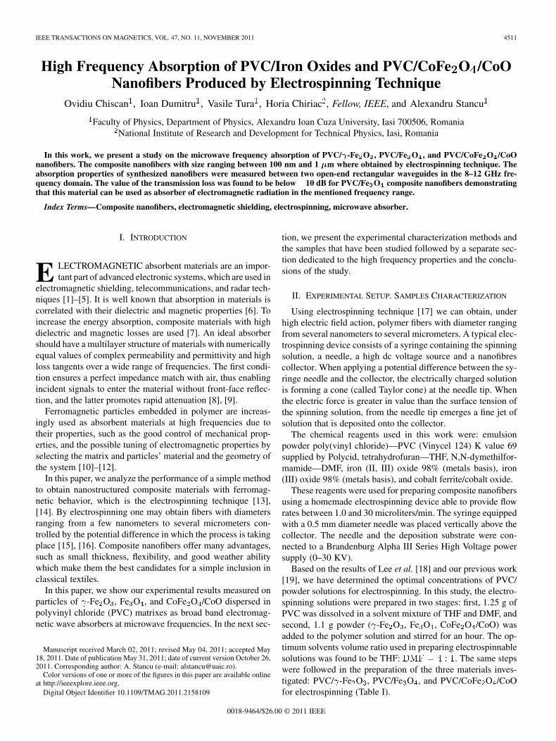
Since powders used in preparation of nanofibres have a cer-tain chemical structure, it was necessary to check whether afterdispersal into the polymer and evaporation of the solvent mix-ture, they kept their initial properties. Fig. 2 shows the XRD pat-terns of obtained composite nanofibers. XRD patterns of PVC/-Fe O show the characteristic diffraction peaks of iron oxide in
phase (JCPDS 04-0755) corresponding to (210), (211), (220),(300), (310), (320), (400), (420) Bragg reflections. For samplePVC/Fe O the observed diffraction peaks correspond to reflec-tions (220), (311), (222), (400), (422), (511), (440), (620), (533),(622) characteristic to magnetite (JCPDS 72-2303). The PVC/CoFe O /CoO sample exhibit diffraction peaks correspondingto Bragg reflection (220), (311), (400), (422), (511), (440), (533)assigned to CoFe O (JCPDS 22–1086) and (111), (200), (220),(311), (222) assigned to CoO (JCPDS 43–1004). These resultsreveal that the crystalline structures of the three types of usedpowders do not change after incorporation into PVC.
The mean size of the crystallites was estimated using theScherer formula and the average size of -Fe O , Fe O , and
Fig. 1. Scanning electron microscopy images of prepared nanofibers:(A)-PVC/�-Fe O , (B)-PVC/Fe O , and (C)-PVC/CoFe O /CoO.
CoFe O /CoO particles incorporated in PVC was calculated tobe 17, 44, and 10 nm, respectively.
To investigate the magnetic properties of the iron oxides andcobalt ferrite/cobalt oxide nanofiber assemblies, magnetic mea-surements were performed on disc-shaped samples (4 mm diam-eter and 1 mm tickness) in magnetic field at room temperature,with the field sweeping from 10 kOe to 10 kOe. Fig. 3 showsthe field dependence of magnetization of the nanofibers com-posites. The magnetization curves recorded on prepared sam-ples show typical ferromagnetic behavior. As one can see in
CHISCAN et al.: HIGH FREQUENCY ABSORPTION OF PVC/IRON OXIDES AND PVC/CoFe O /CoO NANOFIBERS 4513
Fig. 2. Wide-angle XRD patterns of nanofibers composite materials.
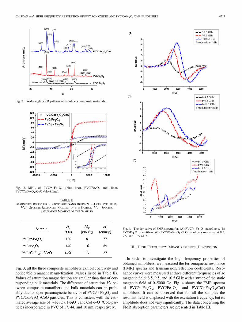
Fig. 3. MHL of PVC/�-Fe O (blue line), PVC/Fe O (red line),PVC/CoFe O /CoO (black line).
TABLE IIMAGNETIC PROPERTIES OF COMPOSITE NANOFIBERS (� —COERCIVE FIELD,� —SPECIFIC REMANENT MOMENT OF THE SAMPLE, � —SPECIFIC
SATURATION MOMENT OF THE SAMPLE)
Fig. 3, all the three composite nanofibers exhibit coercivity andnoticeable remanent magnetization (values listed in Table II).Values of saturation magnetization are smaller than that of cor-responding bulk materials. The difference of saturation be-tween composite nanofibers and bulk materials can be prob-ably due to super-paramagnetic behavior of PVC/ -Fe O andPVC/CoFe O /CoO particles. This is consistent with the esti-mated average size of -Fe O , Fe O , and CoFe O /CoO par-ticles incorporated in PVC of 17, 44, and 10 nm, respectively.
Fig. 4. The derivative of FMR spectra for: (A) PVC/�-Fe O nanofibers, (B)PVC/Fe O nanofibers, (C) PVC/CoFe O /CoO nanofibers measured at 8.5,9.5, and 10.5 GHz.
III. HIGH FREQUENCY MEASUREMENTS. DISCUSSION
In order to investigate the high frequency properties ofobtained nanofibers, we measured the ferromagnetic resonance(FMR) spectra and transmission/reflection coefficients. Reso-nance curves were measured at three different frequencies of acmagnetic field: 8.5, 9.5, and 10.5 GHz with a sweep of the staticmagnetic field of 0–5000 Oe. Fig. 4 shows the FMR spectraof PVC/ -Fe O , PVC/Fe O , and PVC/CoFe O /CoOnanofibers. It can be observed that for all the samples theresonant field is displaced with the excitation frequency, but itsamplitude does not vary significantly. The data concerning theFMR absorption parameters are presented in Table III.
4514 IEEE TRANSACTIONS ON MAGNETICS, VOL. 47, NO. 11, NOVEMBER 2011
TABLE IIITHE MEASURED FMR PARAMETERS: � THE FREQUENCY OF THE EXCITATION
FIELD, � THE RESONANCE FIELD,�� THE RESONANCE LINE WIDTH, AND
THE EVALUATED FMR PARAMETERS: � IS THE GYROMAGNETIC RATIO, �THE INTERNAL FIELD,�� THE FMR LINE WIDTH IN THE FREQUENCY DOMAIN
The observed linear dependence of the resonance field asfunction of frequency could be explain by the approximationof the resonance frequency :
(1)
where is the gyromagnetic ratio, is the resonance field, andthe internal field due to the internal magnetic anisotropy
of fibers and the magnetic interaction between the these. Thematerial parameters and shown in Table III are obtained,for each sample, by linear fitting of the experimental datawith (1). Using the expression ( is thedifference between the field values corresponding to maximumand minimum of derivative FMR spectra) it was evaluated theline width in the frequency domain at different applied fields.For sample PVC/Fe O the estimated line width is larger than3.8 GHz so the FMR absorption can cover almost the entire Xband frequency domain when a proper static field is applied.
The FMR absorption was determined in the same conditionsfor all samples in order to compare the absorption amplitude.It is observed that for PVC/CoFe O /CoO the FMR absorp-tion is smaller compared with PVC/ -Fe O and PVC/Fe Osamples.
Using the transmission/reflection (T/R) method, we havemeasured the absorption properties of samples in a rectangularwaveguide fixture at frequencies ranging from 8 to 12 GHz.The material under test fully fits the waveguide cross section.Using a vector network analyzer, the scattering parametersof the loaded-waveguide section are measured as a functionof frequency. The influence of sample thickness on transmis-sion/reflection coefficient was investigated.
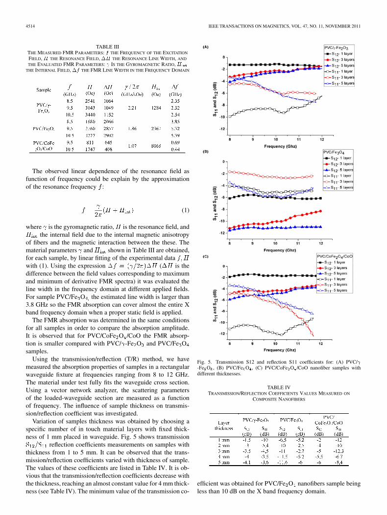
Variation of samples thickness was obtained by choosing aspecific number of in touch material layers with fixed thick-ness of 1 mm placed in waveguide. Fig. 5 shows transmission
reflection coefficients measurements on samples withthickness from 1 to 5 mm. It can be observed that the trans-mission/reflection coefficients varied with thickness of sample.The values of these coefficients are listed in Table IV. It is ob-vious that the transmission/reflection coefficients decrease withthe thickness, reaching an almost constant value for 4 mm thick-ness (see Table IV). The minimum value of the transmission co-
Fig. 5. Transmission S12 and reflection S11 coefficients for: (A) PVC/�-Fe O , (B) PVC/Fe O , (C) PVC/CoFe O /CoO nanofiber samples withdifferent thicknesses.
TABLE IVTRANSMISSION/REFLECTION COEFFICIENTS VALUES MEASURED ON
COMPOSITE NANOFIBERS
efficient was obtained for PVC/Fe O nanofibers sample beingless than 10 dB on the X band frequency domain.
CHISCAN et al.: HIGH FREQUENCY ABSORPTION OF PVC/IRON OXIDES AND PVC/CoFe O /CoO NANOFIBERS 4515
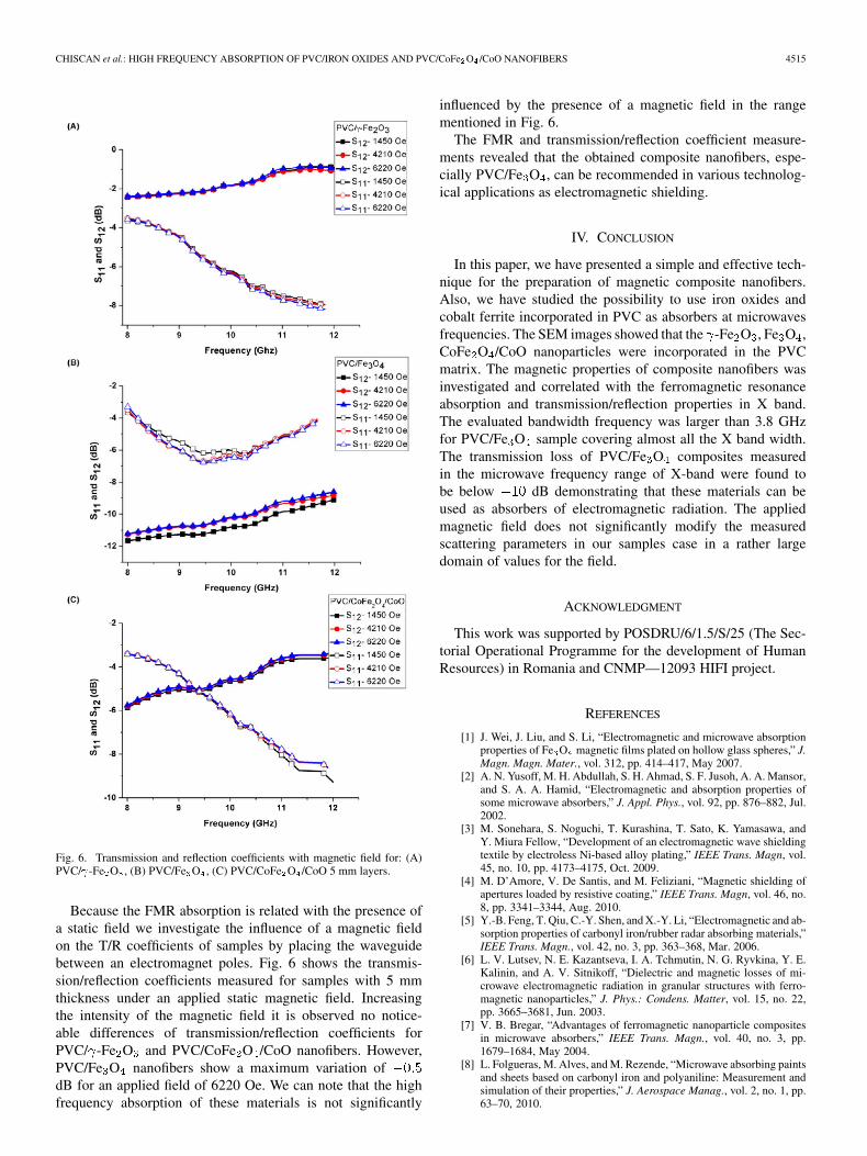
Fig. 6. Transmission and reflection coefficients with magnetic field for: (A)PVC/�-Fe O , (B) PVC/Fe O , (C) PVC/CoFe O /CoO 5 mm layers.
Because the FMR absorption is related with the presence ofa static field we investigate the influence of a magnetic fieldon the T/R coefficients of samples by placing the waveguidebetween an electromagnet poles. Fig. 6 shows the transmis-sion/reflection coefficients measured for samples with 5 mmthickness under an applied static magnetic field. Increasingthe intensity of the magnetic field it is observed no notice-able differences of transmission/reflection coefficients forPVC/ -Fe O and PVC/CoFe O /CoO nanofibers. However,PVC/Fe O nanofibers show a maximum variation ofdB for an applied field of 6220 Oe. We can note that the highfrequency absorption of these materials is not significantly
influenced by the presence of a magnetic field in the rangementioned in Fig. 6.
The FMR and transmission/reflection coefficient measure-ments revealed that the obtained composite nanofibers, espe-cially PVC/Fe O , can be recommended in various technolog-ical applications as electromagnetic shielding.
IV. CONCLUSION
In this paper, we have presented a simple and effective tech-nique for the preparation of magnetic composite nanofibers.Also, we have studied the possibility to use iron oxides andcobalt ferrite incorporated in PVC as absorbers at microwavesfrequencies. The SEM images showed that the -Fe O , Fe O ,CoFe O /CoO nanoparticles were incorporated in the PVCmatrix. The magnetic properties of composite nanofibers wasinvestigated and correlated with the ferromagnetic resonanceabsorption and transmission/reflection properties in X band.The evaluated bandwidth frequency was larger than 3.8 GHzfor PVC/Fe O sample covering almost all the X band width.The transmission loss of PVC/Fe O composites measuredin the microwave frequency range of X-band were found tobe below dB demonstrating that these materials can beused as absorbers of electromagnetic radiation. The appliedmagnetic field does not significantly modify the measuredscattering parameters in our samples case in a rather largedomain of values for the field.
ACKNOWLEDGMENT
This work was supported by POSDRU/6/1.5/S/25 (The Sec-torial Operational Programme for the development of HumanResources) in Romania and CNMP—12093 HIFI project.
REFERENCES
[1] J. Wei, J. Liu, and S. Li, “Electromagnetic and microwave absorptionproperties of Fe O magnetic films plated on hollow glass spheres,” J.Magn. Magn. Mater., vol. 312, pp. 414–417, May 2007.
[2] A. N. Yusoff, M. H. Abdullah, S. H. Ahmad, S. F. Jusoh, A. A. Mansor,and S. A. A. Hamid, “Electromagnetic and absorption properties ofsome microwave absorbers,” J. Appl. Phys., vol. 92, pp. 876–882, Jul.2002.
[3] M. Sonehara, S. Noguchi, T. Kurashina, T. Sato, K. Yamasawa, andY. Miura Fellow, “Development of an electromagnetic wave shieldingtextile by electroless Ni-based alloy plating,” IEEE Trans. Magn, vol.45, no. 10, pp. 4173–4175, Oct. 2009.
[4] M. D’Amore, V. De Santis, and M. Feliziani, “Magnetic shielding ofapertures loaded by resistive coating,” IEEE Trans. Magn, vol. 46, no.8, pp. 3341–3344, Aug. 2010.
[5] Y.-B. Feng, T. Qiu, C.-Y. Shen, and X.-Y. Li, “Electromagnetic and ab-sorption properties of carbonyl iron/rubber radar absorbing materials,”IEEE Trans. Magn., vol. 42, no. 3, pp. 363–368, Mar. 2006.
[6] L. V. Lutsev, N. E. Kazantseva, I. A. Tchmutin, N. G. Ryvkina, Y. E.Kalinin, and A. V. Sitnikoff, “Dielectric and magnetic losses of mi-crowave electromagnetic radiation in granular structures with ferro-magnetic nanoparticles,” J. Phys.: Condens. Matter, vol. 15, no. 22,pp. 3665–3681, Jun. 2003.
[7] V. B. Bregar, “Advantages of ferromagnetic nanoparticle compositesin microwave absorbers,” IEEE Trans. Magn., vol. 40, no. 3, pp.1679–1684, May 2004.
[8] L. Folgueras, M. Alves, and M. Rezende, “Microwave absorbing paintsand sheets based on carbonyl iron and polyaniline: Measurement andsimulation of their properties,” J. Aerospace Manag., vol. 2, no. 1, pp.63–70, 2010.
4516 IEEE TRANSACTIONS ON MAGNETICS, VOL. 47, NO. 11, NOVEMBER 2011
[9] D.-L. Zhao, F. Luo, and W.-C. Zhou, “Microwave absorbing propertyand complex permittivity of nano SiC particles doped with nitrogen,”J. Alloys Comp., vol. 490, no. 1–2, pp. 190–194, Feb. 2010.
[10] Y. Shirakata, N. Hidakal, M. Ishitsuka, A. Teramoto, and T. OhmiFellow, “High permeability and low loss Ni-Fe composite material forhigh-frequency applications,” IEEE Trans. Magn, vol. 44, no. 9, pp.2100–2106, Sep. 2008.
[11] R. Dosoudil, M. Usáková, J. Franek, J. Sláma, and A. Grusková, “Par-ticle size and concentration effect on permeability and EM-wave ab-sorption properties of hybrid ferrite polymer composites,” IEEE Trans.Magn., vol. 46, no. 2, pp. 436–439, Feb. 2010.
[12] X.-C. Li, R.-Z. Gong, H.-H. He, K.-L. Yao, and P.-X. Lu, “Centimeter-and millimeter-wave attenuation properties of carbonyl iron fiber-filledfoam composites,” IEEE Trans. Magn., vol. 44, no. 12, pp. 4567–4570,Dec. 2008.
[13] S. Wang, C. Wang, B. Zhang, Z. Sun, Z. Li, X. Jiang, and X. Bai,“Preparation of Fe O /PVA nanofibers via combining in-situ com-posite with electrospinning,” Mater. Lett., vol. 64, no. 1, pp. 9–11, Jan.2010.
[14] D. Li, T. Herricks, and Y. Xia, “Magnetic nanofibers of nickel ferriteprepared by electrospinning,” Appl. Phys. Lett., vol. 83, no. 22, pp.4586–4588, Dec. 2003.
[15] J. Doshi and D. H. Reneker, “Electrospinning process and applicationsof electrospun fibers,” J. Electrost., vol. 35, no. 2–3, pp. 151–160, Aug.1995.
[16] D. H. Reneker and I. Chun, “Nanometre diameter fibres of polymer,produced by electrospinning,” Nanotechnology, vol. 7, no. 3, pp.216–223, Sep. 1996.
[17] A. L. Yarin and E. Zussman, “Electrospinning of nanofibers frompolymer solutions,” Adv. Appl. Mech., vol. 41, pp. 43–195, 2007.
[18] K. H. Lee, H. Y. Kim, Y. M. La, D. R. Lee, and N. H. Sung, “Influenceof a mixing solvent with tetrahydrofuran and N, N-dimethylformamideon electrospun poly(vinylchloride) nonwoven mats,” J. Polym. Sci. PartB: Polym. Phys., vol. 40, no. 19, pp. 2259–2268, Oct. 2002.
[19] V. Tura and I. I. Mangalagiu, “New insights on the mechanism ofFe O nanoparticles formation by electrospinning of FeCl /PVC so-lutions,” J. Phys. Chem., vol. 123, no. 2–3, pp. 644–648, Oct. 2010.


![A common behaviour of thermoelectric layered cobaltites: incommensurate spin density wave states in [Ca 2 Co 4/3 Cu 2/3 O 4 ] 0.62 [CoO 2 ] and [Ca 2 CoO 3 ] 0.62 [CoO 2 ]](https://static.fdokumen.com/doc/165x107/63455f0bf474639c9b04d131/a-common-behaviour-of-thermoelectric-layered-cobaltites-incommensurate-spin-density.jpg)