Hi - Lo - High -Tech Design to enhance Low
104
1 High -Tech Design to enhance Low - Tech execution Siddharth Jadhav University of Washington 2015 Thesis Committee : Brian R. Johnson Rob Corser Kimo Griggs Program Authorized to Offer Degree : Architecture Hi - Lo A thesis submitted in partial fulfillment of the requirements for the degree of Master of Science in Architecture
-
Upload
khangminh22 -
Category
Documents
-
view
3 -
download
0
Transcript of Hi - Lo - High -Tech Design to enhance Low

1
High -Tech Design to enhance Low - Tech execution
Siddharth Jadhav
University of Washington
2015
Thesis Committee :
Brian R. Johnson
Rob Corser
Kimo Griggs
Program Authorized to Offer Degree : Architecture
Hi - Lo
A thesis submitted in partial fulfillment of the requirements for the degree of
Master of Science in Architecture

2
© Copyright 2015
Siddharth Jadhav

3
Variation, in the form of patterns in space and time, is fundamental to architecture, but produces complexity in design and construc-
tion processes. This complexity is usually managed by constraining variability within a limited palette of choices. By enhancing our
ability to manage much more complexity, computers invite greater variation in design. Improved analysis tools enable us to predict
performance of complex geometries. Generative algorithms and parametric design tools produce systematic variation. Finally,
computer numerically controlled (CNC) machines facilitate the production of variation generated by high-tech performance based
generative design tools. But, CNC machines are not globally accessible. At the same time, low-tech production methodologies do
offer possibilities for producing variation. This thesis proposes and examines a combination of high-tech performance based gen-
erative design tools and low-tech production techniques for use in contexts where CNC machines are not accessible.
University of Washington
Abstract
Hi-Lo : High -Tech Design to enhance Low - Tech execution
Siddharth Jadhav
Chair of the Supervisory Committee:
Brian R. Johnson
Department of Architecture

4
I thank my thesis committee for being extremely supportive, and encouraging me
throughout the process. The process of exploration would not have been so engaging
without their guidance. It has been a pleasure working with
Prof. Brian R. Johnson, Prof. Rob Corser and Prof. Kimo Griggs.
A special vote of thanks to all my DMG mates and the CBE community at large for
providing support and helping me out unconditionally.
I thank all my teachers for blessing me in multiple ways during this exciting journey of
learning.
Acknowledgments

5
This research is dedicated to the developing world.

6
Table of Contents
Table of figures
Introduction
Motivation
Case Studies : Modular {Pre - Fab}
Case Studies : Modular {Pre - Cast}
Case Studies : Performance based generative design
Case Studies : Low-tech construction
Case Studies : Static shading devices
Case Studies : Observations
Thesis statement
Project goals
Project mechanism
Project diagram
Hi - tech design : parametric modeling
Lo - tech production : casting {prototyping}
Hi - tech design : solar analysis
Titles Page numbers
8
10
11
12
14
16
18
29
33
35
36
37
38
40
43
48

7
Table of Contents
Lo - tech production : strategies
Conclusion
Future directions
References
Web references
Titles Page numbers
77
94
97
98
100

8
Table of figures
Figures Source
fig. 10a
fig. 12a
fig. 13a
fig. 14a
fig. 14b
fig. 15a
fig. 15b
fig. 15c
fig. 16a
fig. 17a
fig. 18a
fig. 19a
fig. 20a
fig. 21a
fig. 21b
fig. 22a
fig. 23a
fig. 24a
fig. 24b
fig. 25a
fig. 26a
http://mafana.files.wordpress.com/2011/10/2-0002.jpg
http://inhabitat.com/prefab-friday-living-homes-kieran-timberlake-las-vegas/attachment/18846/
http://iaac-digitalarchitecture.blogspot.com/2007/12/mit-instant-house-project.html
https://www.academia.edu/2964517/Reverse_Layered_Manufacturing_for_Moldable_Composites_using_CAD_CAM_Technolgies
http://modularvariations.files.wordpress.com/2013/02/andrew-kudless-p-wall.pdf
http://wroad.net/wordpress/?p=1
Kolarevic, B., Malkawi, A. (ed), Performative Architecture, Spon Press New York and London, Pg. 211
http://www.earth-auroville.com/world_techniques_introduction_en.php
http://www.earthhomes.net/castearth.html
http://www.ebay.com/itm/1962-Colombia-Cinva-Ram-Block-Making-Machine-for-New-Village-Center-Press-Photo-/400718392703
http://www.earth-auroville.com/auram_earth_equipment_introduction_en.php
http://www.nzdl.org/gsdlmod?e=d-00000-00---off-0hdl--00-0----0-10-0---0---0direct-10---4-------0-1l--11-en-50---20-help---00-0-1-00-0-0-11-1-0utfZz-8-00&a=d&cl=CL3.21&d=HASH4edbf917bee4e6ae86aa2c.23
http://www.earth-auroville.com/various_auram_equipment_en.php
http://www.starship-enterprises.net/files/village-level%20brickmaking.pdf
http://research.history.org/Coffeehouse/Blog/index.cfm/2008/9/20/Making-bricks-at-the-brickyard
http://www.formblock.com.au/what_is_formblock.htm
9
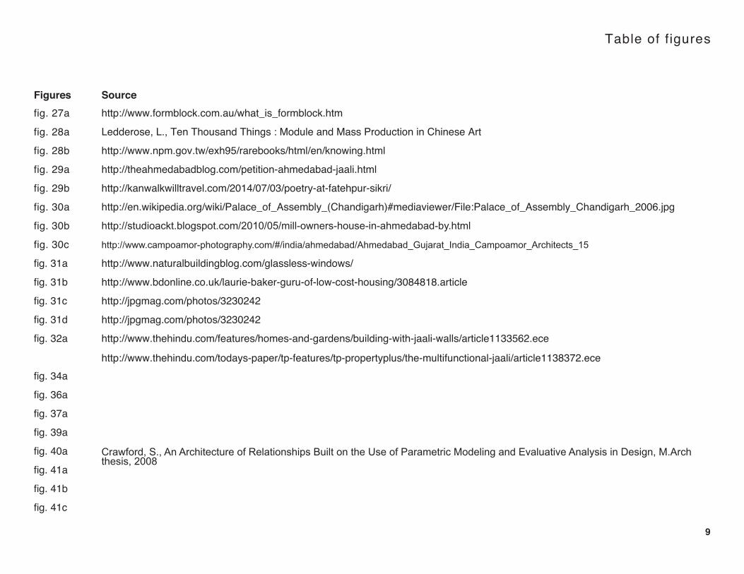
Table of figures
Figures Source
fig. 27a
fig. 28a
fig. 28b
fig. 29a
fig. 29b
fig. 30a
fig. 30b
fig. 30c
fig. 31a
fig. 31b
fig. 31c
fig. 31d
fig. 32a
fig. 34a
fig. 36a
fig. 37a
fig. 39a
fig. 40a
fig. 41a
fig. 41b
fig. 41c
http://www.formblock.com.au/what_is_formblock.htm
Ledderose, L., Ten Thousand Things : Module and Mass Production in Chinese Art
http://www.npm.gov.tw/exh95/rarebooks/html/en/knowing.html
http://theahmedabadblog.com/petition-ahmedabad-jaali.html
http://kanwalkwilltravel.com/2014/07/03/poetry-at-fatehpur-sikri/
http://en.wikipedia.org/wiki/Palace_of_Assembly_(Chandigarh)#mediaviewer/File:Palace_of_Assembly_Chandigarh_2006.jpg
http://studioackt.blogspot.com/2010/05/mill-owners-house-in-ahmedabad-by.html
http://www.campoamor-photography.com/#/india/ahmedabad/Ahmedabad_Gujarat_India_Campoamor_Architects_15
http://www.naturalbuildingblog.com/glassless-windows/
http://www.bdonline.co.uk/laurie-baker-guru-of-low-cost-housing/3084818.article
http://jpgmag.com/photos/3230242
http://jpgmag.com/photos/3230242
http://www.thehindu.com/features/homes-and-gardens/building-with-jaali-walls/article1133562.ece
http://www.thehindu.com/todays-paper/tp-features/tp-propertyplus/the-multifunctional-jaali/article1138372.ece
Crawford, S., An Architecture of Relationships Built on the Use of Parametric Modeling and Evaluative Analysis in Design, M.Arch thesis, 2008

Table of figures
Figures Source
fig. 42a
fig. 42b
fig. 44a
fig. 45a
fig. 45b
fig. 45c
fig. 45d
fig. 46a
fig. 48a
fig. 49a
fig. 49b
fig. 49c
fig. 50a
fig. 50b
fig. 50c
fig. 51a
fig. 51b
fig. 51c
fig. 52a
fig. 52b
fig. 52c
fig. 53a9.1

Table of figures
Figures Source
fig. 53b
fig. 53c
fig. 54a
fig. 54b
fig. 54c
fig. 56a
fig. 57a
fig. 58a
fig. 59a
fig. 60a
fig. 61a
fig. 62a
fig. 63a
fig. 64a
fig. 65a
fig. 66a
fig. 67a
fig. 68a
fig. 69a
fig. 70a
fig. 71a
fig. 72a9.2

Table of figures
Figures Source
fig. 73a
fig. 74a
fig. 75a
fig. 79a
fig. 80a
fig. 81a
fig. 82a
fig. 83a
fig. 84a
fig. 85a
fig. 86a
fig. 87a
fig. 88a
fig. 90a
fig. 91a
fig. 91b
fig. 92a
fig. 92b
fig. 93a
fig. 94a
fig. 95a
http://bloquera-ceta-ram.blogspot.com/2012/09/manual-ceta-ram-en-pdf.html
9.3

10
Introduction
[fig. 10a] Process images, Guggenheim Museum, Bilbao; Gehry Partners, LLP
The realm of architecture, since the introduction of transfer-technol-
ogies [Kieran, Timberlake, 2004], has been in a constant state of
flux. Numerical control has pushed architects to re-think architecture
at multiple levels at every stage of design and construction [Moe,
2010].
The practice of architecture can now be viewed as a combination of
‘making’ and ‘re-making’ [Massie, 2010] [fig. 4a]. Geometric forms
are first made (formed) in the digital world of bits and then re-made
(constructed) in the physical world of atoms through a seamless sys-
tem of information transfer. The couple of computer aided design
(CAD) and computer aided manufacturing (CAM) has pushed the
boundaries of digital and physical formulation.
However, it becomes essential to understand the context specificity
of these technologies. Tools and processes originally developed for
the manufacturing industries may not be easily accessible or ap-
propriately utilized in developing regions of the world for building
construction. The real challenge in such scenarios lies in identifying
a solution space that offers a contextual response not only in terms
of design but also production, taking in to account the resources
available. Hi-Lo aims at identifying a solution space that lies at the
intersection of high-tech design and low-tech production.

11
Motivation
Hi-Lo was born out of the polarity that evolved after witnessing the
potentials of computational process related to ‘making and ‘remak-
ing’ as a graduate student in the United States, and the experience of
understanding the realities of (low-tech) building construction while
practicing architecture in India.
Developing design and production strategies integrating CAD and
CAM tools has become common practice in the field of architecture.
The experience of being personally involved in such processes has
been quite engaging and satisfying. But, it was difficult to remain
detached from the fact that computer numerically controlled (CNC)
tools are not easily accessible in developing parts of the world. And
therefore, developing complex forms (and assemblies) without inte-
grating digital fabrication strategies seemed impossible.
The greater challenge, then, was to evolve a system that enhanc-
es low-tech execution by integrating high-tech computational design
tools. It became imperative to manifest this challenge in the form of
a project.
Arch 485 (Spring 2014), a digital design & fabrication course taught
by Prof. Rob Corser at the College of Built Environments (CBE), Uni-
versity of Washington, offered an opportunity to formulate a project
based on this idea. Grasshopper [URL 12], a generative modeling
plug-in for Rhinoceros 5.0 [URL 16] was used as a high-tech design
tool to generate variation and casting was used as a low-tech indirect
manufacturing methodology. The project was developed through a
bottom-up evolution. A bottom-up design process starts with a de-
tailed resolution of modularity by weaving issues of structure, mate-
riality, fabrication, infrastructure, and so forth in a way where each
contributes toward effect.
This research project aims at investigating the degree of customiza-
tion offered by digital tools in a low-tech manufacturing environment .

12
Pre-fabricated architecture [fig. 12a] falls within the umbrella of a
bottom-up process. Predesigned parts/components can be fabricat-
ed off-site and their assemblies can be re-configured based on site
and programmatic conditions. Architects Stephen Kieran and James
Timberlake, with a heavy influence of the efficiency observed in the
manufacturing of automobiles and airplanes, promote this concept
as a kit-of-parts approach [Kieran,Timberlake, 2004].
Modularity in that sense comes with massive cost implications. The
cost associated with shipping standardized raw material to a factory
for pre-fabrication and storing it in a warehouse until it is shipped to
a construction site for assembly, increases the overall project cost
manifold. Flatpack house [URL 1] is one such venture that offers
unique home design solutions using their catalogue of modular com-
ponents. Their services cost around $200-300 per square foot [URL
1] and may increase based on the degree of customization required
by local or building codes. Whereas, the cost of construction for a
standard home is around $120 per square foot [URL 2].
Professor Larry Sass at MIT, through his research, has proposed a
similar model for disaster management housing [Sass, Botha, 2006].
His research project aimed at developing a modular housing unit
taking cultural aspects of that region into consideration. The solution
was to design a house as a jigsaw puzzle of parts that could be
Case Studies : Modular {Pre - fab}
CNC cut from standard 4’x8’ sheets of plywood [fig. 13a]. The
concept is quite unique as it encourages generative design
ideas and evaluates iterations based on the feasibility of fabri-
cation. The project was developed as an outreach program by
MIT’s Center for Bits and Atoms [URL 3]. But, plywood may not
be a cheap resource and a suitable material for construction in
most parts of the world.
Alistair Parvin, a British architect, has gained popularity for his
venture ‘Wikihouse’ [URL 4]. ‘Wikihouse’ is a novel concept,
[fig. 12a] KT 1.5

13
[fig. 13a] INSTANT HOUSE
based on the idea of co-design, a form of adaptive mass-customiza-
tion. Adaptive customization, as identified by Gilmore and Pine [URL
5], is a type of customization, where one standard but customizable
product is designed so that users can alter it themselves within a limit-
ed range defined by the manufacturer. Wikihouse started with enabling
end-users to design their homes on a web-based system that utilized
Sketchup [URL 6] as a modeling platform. Their business model has
now changed and offers limited services. Google has very recently part-
nered with Parvin to propel the venture. Like Sass’s project, Wikihouse
proposes the use of off-the-shelf material (4’ x 8’ sheets of plywood)
and operates on the assumption that CNC mills are easily accessible.
Rather than CNC fabricating an entire building, a good alternative
could be a combination of existing construction techniques and compu-
tationally customized components. Component customization as seen
in InterLattice (Johnson, 2011) allows generating an interlocking lattice
geometry (slot and tab connection) using a generative modeling tool.
The size of each member in this system remains consistent, but the
slots and tabs are unique to their position. The members can be nested
and CNC cut out of sheets of plywood. The system is structurally stable
and uses less material. The product is proposed to be used as interior
walls, self-supporting awnings and as a part of weatherproofed exterior
structures.

14
Researchers from the Digital Design Fabrication Group [URL 7] at
MIT [Griffith et al., 2012] proposed an interesting solution through
one of their research projects. Instead of using sheet material for
construction, a casting mechanism was developed using sheet ma-
terial for repeatable production of interlocking masonry blocks [fig.
14a]. The solution was proposed for shanty towns in South Africa
where resources are scanty. The mold was designed to cast moldable
composites, and concrete was used for conducting tests. The model
was based on coupling high-tech design and low-tech construction.
Building units were parametrized via scripting in a digital environ-
ment and were fabricated using a laminated object manufacturing
approach (LOM). Casting was identified as a low-tech construction
method but the molds were fabricated using laser cutting and CNC
milling. The proposition involved on-site fabrication via CNC tools
enabled by the digitally scripted design tool [fig. 14b]. Customization,
here, is introduced at the design level by developing a tool that al-
lows the fabrication of unique components. Such a process can very
well be categorized as a bottom-up process.
The P-Wall [fig. 15a] project by educator and artist Andrew Kudless
[URL 8] aimed at generating modular variations through casting hy-
drocal in molds made out of spandex lycra laid over wooden dowels,
fitted within a larger solid mold [fig. 15b]. The elastic expansion of
spandex responded to the change location of dowels and produced
Case Studies : Modular {Pre - cast}
[fig. 14b]
[fig. 14a]

15
variation is the cast pieces. Variation in this system was purely gov-
erned by the fabrication system. In later versions, Kudless used
Rhinoscript to generate variation. The geometry was rationalized by
generating eight variations digitally and fabricated pieces using the
same fabrication methodology. The location of dowels was informed
by the generative tool (Rhinoscript). The tool was not only used for
generating modules with variation in the digital environment but was
also used to extract information for low-tech fabrication. The eight
variations were fabricated in calculated multiples and were arranged
strategically as an assembly that appears as an installation compris-
ing of unique pieces [fig. 15c]. Variation, in this case, was generated
purely for aesthetic reasons. The system, is again an example of a
bottom-up process and portrays a combination of high-tech design
and low-tech production. However, it is important to observe that the
process of information transfer from high-tech to low-tech environ-
ments is not seamless and therefore needs to be carefully addressed
to achieve desired results.
Parameters that drive a bottom-up design process are the varying
change of a form’s mass or the components that define it such as
size and geometry. Size can address depth, height, and width while
geometry can define surface shape, cross section, or even voids.
Integrating a varying thickness in cross section is something that is
best captured by casting an object as displayed in the project de-
scribed above.
[fig. 15a] P-Wall
[fig. 15b] [fig. 15c]

16
The logic that drives bottom-up processes is comparable to genet-
ic mechanisms. Information embedded in a set of genes (modular
chunks) will largely influence the phenotypical characteristics of an
organism. And, is greatly responsible for exhibiting variation in suc-
cessive generations through recombination.
Parametric modeling has been greatly instrumental in establishing
workflows related to performance analysis and digital fabrication due
to its rapid adaptability to changing input and its ability to deliver pre-
cise geometric data [Kolarevic, Malkawi, 2005].
An interesting project by Esmaili (2014) utilizes a bottom up design
logic coupled with performance based generative modeling. She
proposes the use of Grasshopper as a parametric modeling tool to
generate brick screens (solar shading devices) which can be simul-
taneously analyzed for their environmental performance through La-
dybug (a plug-in that connects Grasshopper with Diva). The assem-
bly patterns are customizable based on program and site conditions.
eifForm, a software developed by Kristina Shea for structural op-
timization is based on a parametric modeling platform and utilizes
a stochastic, non-monotonic algorithm called “simulated annealing”
[Kolarevic, Malkawi, 2005]. The software develops the overall form
of a structure dynamically in a time based fashion by repeatedly
Case Studies : Performance based generative design
modifying an initial design with the aim of reaching a goal state
by improving performance through satisfying predefined objec-
tives such as structural efficiency, economy of materials, mem-
ber uniformity, economy of materials and such [fig. 16a].
Form finding techniques used in the design of tensile structures
pioneered by Frei Otto could be considered as the nearest ex-
[fig. 16a] Experimental structure, designed by Kristina Shea et al., erected in Amsterdam in 2002

17
[fig. 17a] Solar diagram for the City Hall building, London
ample of performance driven architectural form generation, prior
to the introduction of generative tools, in which the form of the
membrane is dynamically affected by changing the forces that
act on the model [Kolarevic, Malkawi, 2005].
Generative tools based on performance evaluation are being
increasingly used for form-finding processes in architecture. In
such a process an already structured building typology, with a gener-
ic form, could be subjected to dynamic metamorphic transformation
resulting from the computation of performance targets set in the early
stages.
The City Hall building designed by Foster and Partners has an icon-
ic biomorphic form which portrays a logic of environmental perfor-
mance. The “pebble-like” for resulted from the optimization of its en-
ergy performance by minimizing the surface area exposed to direct
sunlight [Kolarevic, Malkawi, 2005]. The deformed sphere has a 25%
smaller surface area than a cube of identical volume, resulting in re-
duced solar heat gain and loss through the building’s skin.
Performance optimization through evolutionary computing is a terri-
tory commonly explored in the realm of engineering. Its introduction
to architecture has resulted in the some high performance buildings/
assemblies.

18
Case Studies : Low-tech Construction
For centuries, vernacular architectural traditions have proved to be sustainable, and are still being followed in most parts of the world. Forty
percent of the world population lives in earthen dwellings. Earthen architecture falls within the umbrella of sustainable development.
The attempt to sustainable development is to integrate an alternative building process, various appropriate building technologies and renew-
able energy sources.
Soil, an abundant natural resource, when mixed with cement and aggregate in the right proportions can be used as a building material. This
mix is used for cast-earth construction and preparing concrete stabilized earth blocks to be used as building units.
[fig. 18a]

19
Case Studies : Low-tech Construction
Cast earth construction
Cast Earth is a proprietary modified building material developed
since the mid-1990s by Harris Lowenhaupt and Michael Frerk-
ing based on the earlier Turkish Alker, which is a concrete-like
composite with soil of a suitable composition as its bulk compo-
nent stabilized with about 15% calcined gypsum (plaster of Par-
is) instead of Portland cement. It can be used to form solid walls
that need not be reinforced with a steel frame or timber framing,
unless extra seismic reinforcement is necessary. Forms are set
up and filled with Cast Earth, which sets quickly and solidly.
Once the forms are removed the wall stays sound.
The calcined gypsum sets quickly, which is one quality that has
historically made plaster of Paris so useful. Cast Earth uses an-
other retardant for an even greater working time. When the ma-
terial is dry, it is similar to adobe in various ways, outperforming
it in tensile strength, hardness, and erosion resistance. It also
has less tendency to crack and shrink. Cast Earth walls do soak
up water, however, if they are not sealed with a silicone coating
or other waterproofer. It is often less costly, since earth and
calcined gypsum are plentiful and cheap materials to acquire.
Few contractors are licensed in the use of Cast Earth today,
but if public demand for structures made of the material grows,
more builders will seek training in its use
[fig. 19a]

20
CINVA RAM {manual block making machine}
Inventor : Raul Ramirez Year : 1952 Location : Inter-American Housing Center (CINVA), Bogota, Colombia
Case Studies : Low-tech Construction
Compressed stabilized earth blocks
[fig. 20a]

21
Case Studies : Low-tech Construction
Compressed stabilized earth blocks
Compressed Stabilized Earth Block (CSEB) technology is used
worldwide because it represents a synthesis between traditional
practices and a modern technology.
The Auroville Earth Institute (India) has designed manual presses for
CSEB, the Auram [fig. 22a], which are manufactured in Auroville by
Aureka, one of its steel workshops. Today, the press 3000 for com-
pressed stabilized earth blocks is being sold in Asia, Africa, USA,
Middle East and Europe.
In Auroville, CSEB are stabilized with 5% cement and have an aver-
age dry compressive crushing strength of 50 kg/cm2 (5 Mpa) and a
wet compressive crushing strength of 25 kg/cm2. The water absorp-
tion is around 10%.
The AURAM press is a fairly low-tech equipment and can accom-
modate seventy different kinds of molds to create different combina-
tions of interlocking blocks. AURAM makes customization possible
at the component level and at the assembly level. Permutations can
be generated based on the possibility of interlocking these blocks to
create desired geometries [URL 9]. This press is an improvised ver-
sion of the CINVA ram which was developed by Raul Ramirez at the
Inter-American Housing Center (CINVA) in 1956 [URL 19]. [fig. 21b]
[fig. 21a]

22
It is the oldest, truly low-cost, portable soil block press,
and numerous manual presses produced in different
parts of the world are based on the design and working
principle of this machine.
Operating the CINVA-Ram
In the vertical position, the lever arm is fixed to the yoke
by means of a latch. These are pulled back together and
the mold cover swung open. After greasing the sides of
the mold, the soil mix is filled in, making sure that the
corners are properly filled and slightly compressed by
hand. When swinging back the mold cover the surplus
soil is removed.
The lever is brought back to the vertical position and the
latch released. The lever arm is then pulled down on the
side opposite to its previous position, to compress the
block. When the block is fully compacted, the lever arm
is swung back over the mold to its position during filling.
The mold cover is opened and the lever arm depressed
further until the block is completely ejected and held in
this position until it is removed from the press and placed
on edge at the curing site.
[fig. 22a]
Compressed stabilized earth blocks

23
Compressed stabilized earth blocks
[fig. 23a]

24
fig. 23a shows a hinge mold for casting traditional clay bricks
[fig. 23b]. The hinge mold has 3 main parts -
1. The mold box is where the brick is formed. The mold is made
larger than the finished size of brick to allow for shrinkage during the
drying and firing of the brick. The major wear areas are covered with
sheet metal and the corners are reinforced with steel.
2. The hinged bottom allows the production of frogged bricks and
the easy removal of the brick from the mold. The bottom is hinged
on one side.
3. The frog is made from wood and is used to form a cavity or inden-
tation on one side of the brick. The frog makes the brick weigh less,
allows it to dry and fire faster (saving firewood) and gives the brick
a form which improves its adherence when laid in a wall [URL 10].
Mold design forms a major component of a low-tech indirect manu-
facturing process. The most important factor that has to be account-
ed for is the material being used for casting. CSEB needs higher
degree of compression whereas country bricks are made out of a
moldable composite which requires less pressure for casting.
[fig. 24a]
[fig. 24b]
Case Studies : Low-tech Construction
Brick making

25
Brick making
Country bricks are fired in kilns or in the open using fire wood. It is an
industry that provides employment to a large section of people living
in the country side.
The bricks are allowed to dry at least for a period of 7-8 days de-
pending on the moisture content in the composite. After drying, the
bricks are baked to increase their strength and longevity.
Repeatable production is sustainable since it utilizes few molds to
produce a large quantity of units as compared to manufacturing one
off molds to produce unique casts.
[fig. 25a]

26
Case Studies : Low-tech Construction
FORMBLOCK
FORMBLOCK is a wall building system in which stabilized earth, or
concrete blocks are cast in-situ to produce a solid load bearing wall.
In use now for over 15 years in a range of conditions throughout
Australia and New Zealand, it has been thoroughly tested by profes-
sionals, architects and owner builders.
The FORMBLOCK Wall Kit is designed in 300 mm modular units that
is easily assembled to produce a course of blocks, each 600 mm
long, 300 mm high, 300 mm thick, it fits neatly with other convention-
al building systems. The FORMBLOCK Wall Kit requires no expert
skill, it is easy to use and simple to understand and is ideally suited
to tradespersons, owner builders, and handypersons, alike.
The FORMBLOCK method significantly reduces the labour required
to produce an earth wall as compared to adobe (mud brick) or pisé
(rammed earth) methods of earth building. The handling of the earth
material is minimized, by the in-situ nature of block making. Once the
blocks are poured, the wall is effectively complete, with no further
need of on going maintenance.
[fig. 26a]

27
FORMBLOCK
The FORMBLOCK Wall Building Kit conserves natural resources.
Producing earth-based blocks, contributes in saving energy other-
wise used by industry to produce other building materials, such as
fired bricks, etc. Less reliance on timber, means less deforestation.
The FORMBLOCK system is not a wasteful ‘once only use’ form-
work, it is designed and made for long lasting repeated use.
The method of construction involves the creation of blocks and as-
sembly at the same time making the FORMBLOCK system a cost
effective and affordable method of masonry wall construction.
[fig. 27a]

28
Case Studies : Low-tech Customization
Factory Art : Terracota warriors, China
The makers of clay drainage pipes were employed
in constructing this army of warriors. A set number of
molds were created to cast different parts of the body.
Each warrior is a unique assembly. The uniqueness is
a result of permutations and combinations generated
from body parts cast out of a fixed number of molds.
Mass-customization existed in the design and production realm even before the introduction of computer numerically controlled machines.
Permutations and combinations of parameters within a certain set of rules can produce customized results.
[fig. 28a]
Block Printing : Bronze and wood blocks, China
Interchangeability is another attribute of mass-cus-
tomization. Woodblock printing is a technique for
printing text, images or patterns used widely through-
out East Asia and originating in China in antiquity as a
method of printing on textiles and later paper.
[fig. 28b]

29
Case Studies : Static shading devices
Static shading devices act as passive building skins and have been
used as important architectural elements, especially in hot and arid
climates.
A ‘jali’ made in stone is one such element used in vernacular Mughal
[Baweja, 2008] and Rajput [Gupta, 1985] architecture of India. In
Hindi, a ‘jali’ means a net or a screen. In the literal sense, this device
was used for screening interior areas from excess solar penetration
[fig. 24a, b]. These intricately carved patterns would also add to the
aesthetic qualities of facades.
Two laws of physics turn jalis into air-conditioners: the principles of
Venturi and Bernoulli [URL 11].
a.Venturi’s Principle states that air is compressed and increases its
speed when passed through a funnel causing a breeze.
b. Bernoulli law states that when air is compressed and released it
becomes cool.
Static shading devices have also been used as vital elements in
modern architecture [fig. 25 a, b]. Corbusier has incorporated Brise
Soleils in most of his projects in India. Such devices/elements, ex-
pressed in different forms, have been strategically used in enhancing
the environmental performance of buildings.
[fig. 29a] Sidi Syed Mosque, Ahmedabad, India
[fig. 29b] Salim Chishti’s tomb, Fatehpur Sikri, India

30
[fig. 30a] Palace of Assembly, Chandigarh, India
Architect : Le Corbusier
[fig. 30b] Ahmedabad Textile Mill Owners’ Association House’ (ATMA House), Ahmedabad, India
Architect : Le Corbusier
[fig. 30c] Ahmedabad Textile Mill Owners’ Association House (ATMA House), Ahmedabad, India
Architect : Le Corbusier

31
[fig. 31a] Brick Jaali by Laurie Baker
[fig. 31d]
[fig. 31b] Laurie Baker at work
[fig. 31c]

32
Brick Jali :
Figures 28a, b, c & d show jali configurations produced using bricks by architect Lau-
rie Baker in India. Fig. 28a shows how the brick screen shields the interior walls from
direct solar exposure and provides indirect light to the corridor. This approach is a
good example of a sustainable design and construction practice since it is economical
and responds to the hot tropical climate of India.
In current times, Jali modules are being made in different materials, mostly moldable
composites such as poured concrete, cast clay/earth, terracotta, fly-ash etc.
These Jali modules are available in standard sizes and shapes unless customized.
Customized production has added costs. Many designers have been halted in their
approaches from moving beyond the digital world primarily because of the cost of
producing variation at any scale. This is because digitally enabled mass-customiza-
tion increases material costs since it demands the production of individual molds for
casting all the unique modules/components.
[fig. 32a] Jali modules made out of terracota

33
Case Studies : Observations
Several high-tech design approaches have evolved in the realm of
architecture after the introduction of digital tools. Parametric mod-
eling has emerged as a vital tool that has aided the formulation of
these approaches. Parametric modeling offers greater adaptability
as it enables the creation of shapes that can respond automatically
to changes later in a design process. Achim Menges, in his essay
Instrumental Geometry [2010], argues that design is an iterative pro-
cess that involves exploration and resolution of ambiguity; therefore,
computational tools that enable modeling a static representation of
a design is not sufficient. He justifies the use of parametric modeling
tools by stating that digital tools need to be able to generate a range
of potential solutions using the same underlying design principles.
Such tools hold a vital stance in any design process since they facili-
tate the extraction of data for analysis, customization and fabrication
from every unique iteration.
Performance based design techniques have compelled architects to
view architecture through a more pragmatic lens. Digital tools de-
signed for performance analysis play a crucial role in form-finding
processes. Algorithmic search offers possibilities in optimizing per-
formance of design objects. The “solution space” generated through
parametric modeling can be refined using genetic algorithms to sat-
isfy performance based objectives.
It is important to note that GAs can be applied to solve architec-
tural problems only when their complexity can be disintegrated or
simplified into combinatorial and/or numerical problems.
Indirect manufacturing processes such as casting are still being
used as a low-tech methodology to manufacture architectural ele-
ments/components in most parts of the world. Repeatable produc-
tion using locally available moldable composites makes the manu-
facturing process efficient and economical.
The couple of high-tech design and low-tech production is being
explored in different ways as seen in the projects/experiments
done by Griffith et al. and Kudless. The transfer of data, in such a
process, from a digital to a physical environment is not seamless.
The fabrication strategy developed for such a scenario, needs to
address this discontinuous flow of information.
Prior to the existence of air conditioners, passive strategies to en-
hance the environmental performance of buildings were consid-
ered to be a major component of the design process [URL 14].
Certifications such as LEED have made it imperative for architects
to reconsider such strategies in the design process. Static shading
devices are considered to be an important passive strategy for
cooling [URL 15]. Finding low-tech alternatives for passive cooling
is an interesting area of research.

34
Rhinoceros 5.0 [URL 16], a digital modeling platform, offers para-
metric modeling functionality through a graphical scripting plug-in
called Grasshopper (GH) [URL 12]. Galapagos [URL 17] is a com-
ponent built to operate within the GH environment for optimization
through genetic algorithms. GECO [URL 18] is another component
made to function as a solar analysis tool within the GH environment.
A script can be generated in GH using these components to build a
feed-back loop to optimize the environmental performance of a geo-
metrical construct.
The ability to generate multiple variations, by tweaking parameters,
and visualize them has made parametric modeling quite popular
within the design realm. It is not only possible to visualize but also
analyze each unique iteration of a parametric model. In addition to
these features, data required to fabricate each iteration can be easily
extracted from the same model.
Prior to the invention of digital tools, it was possible to generate vari-
ation and customize designs for specific needs. In such a scenario
design iterations had to be physically produced for testing and analy-
sis. But, digital tools make it possible to visualize and analyze differ-
ent iterations without the need to physically produce them, thus sav-
ing time, money and effort. Customization through such a numerical
control is pushing the boundaries of research and experimentation.
parametric modeling + analysis
Rhinoceros 5.0 Ecotect
Gra
ssho
pper
Geco
[fig. 34a]

35
Thesis statement
The production of variation generated by high-tech generative design tools can be facilitated by making
simple yet informed adjustments to a well established low-tech repeatable production methodology.

36
Project goals
The tool should allow designers
1. to generate block geometries and develop assemblies to control direct solar penetration based on site location
and programmatic requirements taking geographical location and facade orientation into consideration.
2. to extract information for low-tech fabrication
To develop a computational tool for designing a customizable static shading device (assembly)
integrating low-tech production methodologies
design (high-tech) production + assembly (low-tech)
+
Hi - Lo
[fig. 36a]

37
Project mechanism
design engine mold
Variable block geometries can be generated via tilting the mold in a
strategic manner.
GH definition has to incorporate the fabri-cation strategy to generate variable block
geometries. And, analyze shading conditions developed by the block assemblies.
product
8”
2 degrees 4 degrees 6 degrees0 degrees
g g gg
mol
dca
st
Hi - Lo
[fig. 37a]

38
User Input
number of modules
LxB dimensions of parent module
range of aperture sizes
range of chamfer angles
range of angles for 3d rotation axis
Grasshopper (GH)(parametric modeling environment)
High-tech design
Output(visual)
geometry of sun_BLOCK assembly
Output(analytical)
shading analysis using GECO
(component for GH)
Low-tech production
manual casting+
assembly
Project diagram
+
Environmental analysis
Output
tilt angles for molds for each module
amount of material for each module
assembly diagram for construction
Output
tilt angles for molds for each module
amount of material for each module
assembly diagram for construction
Hi - Lo

39
Hi - Lo
Lo - tech production : casting {concept}
The process of experimentation began with a cube measuring 10” in length, breadth and height. A void measuring 5” x 5” x 10” was introduced
in the center to reduce weight and allow solar penetration. Different iterations can be generated by tilting the mold and using different inserts
to control void geometries. The diagram shown below illustrates the concept.
{ poured composite } { cast }{ angular tilt }{ void insert }{ mold }
[fig. 39a]

40
Grasshopper (GH) is a generative modeling application for Rhinocer-
os 5.0, developed by David Rutten. It is structured as a component/
node based visual scripting application, that follows the geometric
system developed for Rhinoceros [fig. 31a].
Like most other parametric modeling tools, Grasshopper can be
used to generate associative geometry by establishing parametric
relations between topological features. The geometry is controlled
through the use of components that are connected together with
wires similar to an electrical diagram. Each component has inputs
and outputs, but they can control a wide range of parameters rang-
ing from geometry to logic rules to transformations. The tool allows
custom component development through VBscript, C# , Rhinoscript,
and Python. There are plug-ins/custom components developed for
different applications and are available at www.food4rhino.com.
[fig. 40a] Geometric system
Hi - Lo
Hi - tech design : parametric modeling
41
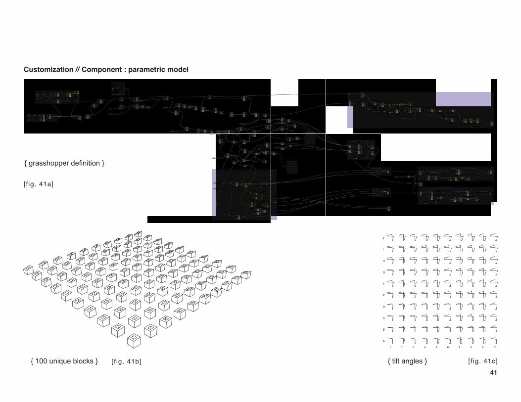
Customization // Component : parametric model
10987654321
J
I
H
G
F
E
D
C
B
A
{ grasshopper definition }
{ 100 unique blocks } { tilt angles }
[fig. 41a]
[fig. 41b] [fig. 41c]

42
Customization // Component : parametric model
The fabrication logic of tilting the mold and using different
inserts to generate unique blocks was embedded in a Grass-
hopper definition (fig. 41a).
The definition was made to generate a hundred unique blocks
(fig. 41b). Tilt angles for each block were extracted using the
same definition. These tilt angles were used to generate cut
profiles to make pieces to control the angular tilt of the mold
assembly (fig. 42b).
[fig. 42b]
[fig. 42a]

43
25.0
0
300.00300.00
150.00 150.00
250.00
300.
0027
4.00
300.
0030
0.00
274.00
300.00
1
2
250.
00
93.7
5
143.
75
250.
00
cut profiles for mold making 1. angular profiles being cut
3. parts of mold being waxed 4. excess wax being removed 5. applying release agent : vaseline
2. wax heated up for sealing
A full scale prototype was developed using hy-
drocal. A hinged mold assembly was developed
using 1/2” pre-laminated board. The tapered
void insert was made out of 1/8” Luan.
The void insert was waxed to lessen friction
while extracting the cast. Petroleum jelly was
used as a release agent. The mold was tilted
using pieces made out of 3/4” plywood. The cut
profiles for these pieces were extracted using a
GH definition(fig. 41a).
The images on pages 43 and 44 explain the
steps adopted during the prototyping process.
This test was performed to study the process
and validate the concept.
Hi - Lo
Lo - tech production : casting {prototyping}
[fig. 43a]

44
6. applying release agent : PAM
7. sealing edges using tape 8. tilted mold assembly 9. hydrocal mixture 10. first batch poured
11. second batch poured 12. caution mark reached 13. cast ready // curing time : 1 day
[fig. 44a]
The result very clearly demonstrates that it is possible to
facilitate the production of unique blocks generated using
grasshopper by simply tilting the mold.
The next set of tests are performed to analyze how dif-
ferent block geometries and their assemblies affect solar
penetration. The tests are performed with the GH environ-
ment, using environmental analysis tools such as Ecotect
and DIVA.

45
Grasshopper + Ecotect
Geco is a plug-in developed for evaluating environmental performance
through Ecotect. Geco establishes a link between the geometry gener-
ated through Grasshopper and Ecotect. Geco, in this research is used
for shading analysis.
A typical Geco workflow adopted in the experiments involves the
following steps -
1. The EcoLink component [fig. 45a] is used to establish links between
GH and Ecotect. A boolean toggle is used to switch the link on and off.
2. The EcoSunpath [fig. 45b] is used to generate a solar path based on
a. geographical location
b. month
c. day
3. The EcoSunRays [fig. 45c] component is used to calculate solar vec-
tor(s) based on time intervals during a diurnal cycle.
4. The mesh shadow [fig. 45d] component is used to generate shadows
[fig. 45d]
[fig. 45c]
[fig. 45a]
Hi - tech design : solar analysis
Hi - Lo
[fig. 45b]

46
DIVA FOR RHINO
Hi - tech design : solar analysis
DIVA FOR RHINO is a daylighting and energy modeling plug-in for Rhinoceros 5.0
[URL 22]. It was initially developed at the Graduate School of Design, Harvard Uni-
versity and is now distributed by Solemma LLC.
Diva is used in the tests for this project to generate Radiance renderings for analyz-
ing the behavior of light in an interior space.
The geometry of assemblies used for testing were generated using GH and were
unified using the boolean union component before baking to produce a NURBS
geometry. The NURBS geometry was then used for Diva analysis. The following
parameters were selected for the analysis.
a. Location : New Delhi
b. Daylighting Materials :
Ceiling : GenericCeiling_70
Floor : GenericFloor_20
Walls and facade to be tested : OutsideFacade_35
C. The parameters selected for simulation are as shown in fig. 46a
[fig. 46a]

47
Ecotect
shading analysis
Diva
Radiance rendering
shading analysis
radiance rendering
parametric modeling + analysis
Hi - tech design : solar analysis
Hi - Lo
information flow

48
30 N
20 N
10 N
70 E 80 E 90 E
New Delhi
New Delhi
28°36′50″N 77°12′32″E
Altitude : 216 m (709 ft)Distance from Tropic of Cancer : 360 miles
Day : Dec. 22 (Winter Solstice)
sunrise : 7.10 amsunset : 5.29 pm
Tropic of Cancer23.5 N
7.10 am
5.29 pm
Hi - Lo
Hi - tech design : solar analysis
Geometries of individual blocks and their as-
semblies are tested on Dec. 22 in New Del-
hi (India) to observe solar penetration. During
winter the solar angles are low and solar pene-
tration is maximum. [fig. 48a]
[fig. 48b]

49
TEST 1
Location : New Delhi (28°36′50″N 77°12′32″E)Day : Dec. 22 (Winter Solstice)
fig 49a . shadow at 9 am fig 49b . shadow at 12 pm fig 49c. shadow at 3 pm
A. size of block : 10” x 10” x 10” size of aperture : 7” x 7” x 10”
Observations
The depth (10”) doesn’t allow direct solar penetration.
Weight of the block (concrete) : 44.27 lb
Shading : 100 %
section elevation
block 1
Customization // Component : solar analysis

50
fig 50a. shadow at 9 am fig 50b. shadow at 12 pm fig 51c. shadow at 3 pm
B. size of block : 10” x 10” x 9” size of aperture : 7” x 7” x 9”
Observations
The depth (9”) doesn’t allow direct solar penetration at 12 pm.
Weight of the block (concrete) : 39.84 lb
Shading at 9 am : 94 % Shading at 12 pm : 100 %Shading at 3 pm : 94 %
section elevation
TEST 1
Location : New Delhi (28°36′50″N 77°12′32″E)Day : Dec. 22 (Winter Solstice)
block 2
Customization // Component : solar analysis

51
C. size of block : 10” x 10” x 6” size of aperture : 7” x 7” x 6”
fig 51a. shadow at 9 am fig 51b. shadow at 12 pm fig 51c. shadow at 3 pm
Observations
The depth (6”) allows direct solar penetration. Weight of the block (concrete) : 26.56 lb
Shading at 9 am : 96% Shading at 12 pm : 85 %Shading at 3 pm : 96%
section elevation
TEST 1
Location : New Delhi (28°36′50″N 77°12′32″E)Day : Dec. 22 (Winter Solstice)
block 3
Customization // Component : solar analysis

52
fig 52a. shadow at 9 am fig 52b. shadow at 12 pm fig 52c. shadow at 3 pm
D. size of block : 10” x 10” x 7” size of aperture : 3.5” x 7” x 7”
Observations
The depth (7”) doesn’t allow direct solar penetration 1 pm onwards. Weight of the block (concrete) : 38.43 lb
Shading at 9 am : 98 % Shading at 12 pm : 96 %Shading at 3 pm : 100 %
section elevation
TEST 1
Location : New Delhi (28°36′50″N 77°12′32″E)Day : Dec. 22 (Winter Solstice)
block 4
Customization // Component : solar analysis

53
section elevation
E. size of block : 10” x 10” x 7” size of aperture : 7” x 3.5” x 7”
fig 53a. shadow at 9 am fig 53b. shadow at 12 pm fig 53c. shadow at 3 pm
Observations
The depth (7”) doesn’t allow direct solar penetration
Weight of the block (concrete) : 38.43 lb
Shading at 9 am : 100 % Shading at 12 pm : 100 %Shading at 3 pm : 100 %
TEST 1
Location : New Delhi (28°36′50″N 77°12′32″E)Day : Dec. 22 (Winter Solstice)
block 5
Customization // Component : solar analysis

54
section elevationfig 54a. shadow at 9 am fig 54b. shadow at 12 pm fig 54c. shadow at 3 pm
Observations
Chamfered block (max. depth 10”)
Weight of the block (concrete) : 37.46 lb
Shading at 9 am : 100% Shading at 12 pm : 100 %Shading at 3 pm : 100%
TEST 1
Location : New Delhi (28°36′50″N 77°12′32″E)Day : Dec. 22 (Winter Solstice)
block 6
Customization // Component : solar analysis
F. size of block : 10” x 10” x 7” size of aperture : 7” x 3.5” x 7”

55
Customization // Component : solar analysis {conclusions}
Winter sun is taken into account for studying these cases since the system doesn’t allow direct solar penetration during summer because of the depth
of the block. The blocks have to be really thin for summer sun to penetrate directly. The summer temperature ranges between 40C(104F) to 48C
(118F) in most cities in the Indian subcontinent. Hence blocking direct solar penetration during summer becomes extremely important.
Coastal cities like Mumbai and Chennai remain quite humid throughout the year. The highest temperature during winter reaches 32C (90F) thus it
becomes important to block direct solar penetration after 12 pm since the temperature start soaring after noon.
Cases A, B and C clearly demonstrate that solar penetration can be controlled by changing the depth of the block. However, a constant change
in depth doesn’t allow the geometry to block solar penetration during certain intervals of the day.
Cases D, E and F display some interesting results. The geometry in case D allows blocking direct solar penetration after 1 pm. If the same block is
rotated 90 degrees (Case E), there is no solar penetration throughout the day. And, if the same block is rotated 180 degrees, the geometry would block
solar penetration until 1pm. Case F performs in the same manner as Case D but is lighter by 1lb than Case D.
These observations clearly indicate that the shape of void, the degree of chamfer and the orientation of the block play a vital role in con-
trolling solar penetration. This degree of micro control may be difficult to achieve using standard units such as bricks.
The tests also justify this particular size and shape of the block. The shape of the void can be controlled by using different inserts during the process
of casting. A mold measuring 10” x10”x10” (cuboidal) can very comfortably accept different void inserts. Having a void in the block increases surface
area. Greater surface area allows excess moisture to easily escape which reduces swelling of the soil. This action reduces cracking during the process
of curing.
The presence of a void in a building block also contributes towards controlling air flow and visibility (and therefore privacy). Tests for understanding
the effect of these parameters with respect to block geometries have not been performed in this exploration.

56
sunrise : 7.10 amsunset : 5.30 pm8.
14 a
m
9.18
am
10.2
2 am
11.2
6 am
12.3
0 pm
1.34
pm
2.38
pm
3.42
pm
4.46
pm
TEST 2
Location : New Delhi (28°36′50″N 77°12′32″E)Day : Dec. 22 (Winter Solstice)
Customization // Assembly : solar analysis
Hi - Lo
The next set of tests were performed for different
assemblies using the same block geometry. These
tests were performed to observe the change in so-
lar penetration at 10 intervals during the day.
New Delhi (India) was selected as the location for
the tests performed on Dec 22.
The diagram on the left shows the solar path on
Dec 22 in New Delhi. The curve is divided in to 10
equal segments and every segment denotes a time
interval during the day as shown in the diagram.
fig. 56a.

57
case A.
TEST 2
Location : New Delhi (28°36′50″N 77°12′32″E)Day : Dec. 22 (Winter Solstice)
Stacking logic
h (8
’4”)
block 7
Elevation
Plan
Customization // Assembly : solar analysis
[fig. 57a]

58
case A.
block 7
Rendered view
Customization // Assembly : solar analysis
[fig. 58a]

59
case A.
Shadow range
direct solar penetration : 7.10 am to 11.26 am
Customization // Assembly : solar analysis
[fig. 59a]

60
Customization // Assembly : solar analysis
8 am 10 am 12 pm 2 pm 4 pm
Radiance renderings
case A.
[fig. 60a]

61
case B.
TEST 2
Location : New Delhi (28°36′50″N 77°12′32″E)Day : Dec. 22 (Winter Solstice)
Elevation
Plan
h (8
’4”)
block 7
Stacking logic
Customization // Assembly : solar analysis
[fig. 61a]

62
case B.
Rendered view
Customization // Assembly : solar analysis
[fig. 62a]

63
case B.
Shadow range
direct solar penetration : 7.10 am to 5.30 pm
Customization // Assembly : solar analysis
[fig. 63a]

64
case B.
8 am 10 am 12 pm 2 pm 4 pm
Radiance renderings
Customization // Assembly : solar analysis
[fig. 64a]

65
Customization // Assembly : solar analysis
case C.
TEST 2
Location : New Delhi (28°36′50″N 77°12′32″E)Day : Dec. 22 (Winter Solstice)
block 7
Elevation
Plan
h (8
’4”)
Stacking logic
[fig. 65a]

66
case C.
Rendered view
Customization // Assembly : solar analysis
[fig. 66a]

67
case C.
Shadow range
direct solar penetration : 9.18 am to 12.30 pm
Customization // Assembly : solar analysis
[fig. 67a]

68
case C.
8 am 10 am 12 pm 2 pm 4 pm
Radiance renderings
Customization // Assembly : solar analysis
[fig. 68a]

69
case D.
TEST 2
Location : New Delhi (28°36′50″N 77°12′32″E)Day : Dec. 22 (Winter Solstice)
Elevation
Plan
h (8
’4”)
block 7
Stacking logic
Customization // Assembly : solar analysis
[fig. 69a]

70
Rendered view
case D.
Customization // Assembly : solar analysis
[fig. 70a]

71
case D.
Shadow range
direct solar penetration : 7.10 am to 11.26 am
Customization // Assembly : solar analysis
[fig. 71a]

72
case E.
TEST 2
Location : New Delhi (28°36′50″N 77°12′32″E)Day : Dec. 22 (Winter Solstice)
block 7
Elevation
Plan
h (8
’6”)
Stacking logic
Customization // Assembly : solar analysis
[fig. 72a]

73
case E.
Rendered view
Customization // Assembly : solar analysis
[fig. 73a]

74
case E.
Shadow range
direct solar penetration : 11.26 am to 1.34 pm
Customization // Assembly : solar analysis
[fig. 74a]

75
case D.
8 am 10 am 12 pm 2 pm 4 pm
Radiance renderings
Customization // Assembly : solar analysis
[fig. 75a]

76
Customization // Assembly : solar analysis {observations}
The tests were performed with the facades facing south. These assemblies
were generated using the same block but display a specific behavior with
respect to block geometry and orientation. The block has an angular face
chamfered at an angle of 30 degrees, and a tapered void.
In the first course of case A, the chamfered faces of all the blocks are
aligned (refer pg. 57). The same course is stacked to create an assembly.
This assembly only allows direct solar penetration from 7.10 am to 11.26
am (refer page 59). Radiance renderings display similar results.
The first course of case B is the same as first course of case A. The second
course in this case, is a mirrored version of the first case. A stacked com-
bination of these courses forms an assembly. This assembly allows direct
solar penetration throughout the day, from 7.10 am to 4.46 pm (refer page
63). Radiance renderings display similar results.
In case C, a unit of two blocks is repeated to form the first course. The unit
is formed by aligning the flat faces. The repetition happens by aligning the
chamfered faces (refer page 65). The second course remains the same
but is shifted by half a block. The solar penetration observed in this case
is quite interesting. The assembly allows solar penetration from 9.18 am to
12.30 pm. The solar penetration observed in the cases discussed above
was quite predictable. But, the solar penetration observed in case C can
only be analyzed using solar analysis tools such as Ecotect and
Diva.
The first course in case D is the same as the first course in case A.
The second course remains the same but is shifted by half a block.
The results observed were very similar to those observed in case
A. Radiance renderings display similar results.
In case E, the first course is generated by rotating the block by 45
degrees and in the second course, the block is rotated by 135 de-
grees (refer pg. 72). The assembly allows solar penetration from
11.26 am to 1.34 pm.
Change in orientation of the blocks and their pattern of assembly
can generate a wide range of unique assemblies displaying chang-
es in behavior with respect to solar position.

77
The next phase of inquiry during the course of research was to identify
suitable fabrication strategies for the block geometries.
In a completely automated production environment, data from a Com-
puter Aided Design system is digitally translated to machine language
for Computer Aided Manufacturing. This allows extremely precise pro-
duction of a variety of parts with minimal error.
In a low tech environment, the production is either partially mechanized
or fully manual. In either case, specific data is required for production
of parts. In the case of brick production, the dimensions of the mold
required to cast bricks governs the size of the brick. In the case of
CINVA ram or its versions (like AURAM), its the size of the mold and
inserts that govern the production of customized compressed interlock-
ing blocks.
Within the context of this research (Hi-Lo), for the production of cus-
tomized blocks, information such size of blocks, size and shape of
voids and chamfer angles is needed. The GH definition that is designed
to generate digital geometry for visualization and analysis, enable the
extraction of the information required for fabrication. This attribute of
generative modeling aids customization, even if the flow of information
is discontinuous.
A standard mold can have a set of inserts to control void geom-
etry. The same mold can be tilted at different angles to gener-
ate chamfered faces. Vertical inserts of varying thickness can
be used to control the size of the blocks using the same mold.
The next section describes the fabrication strategies devised
for production of customized blocks.
Lo - tech production : strategies
Hi - Lo

78
Ecotect
shading analysis
Diva
Radiance rendering
Repeatable production
tilt a
ngle
void
inse
rt
parametric modeling + analysis
Lo - tech production : strategy 1 // casting
Hi - Lo
information flow

79
Customization // production : low-tech {strategy 1}
1. 2. 3. 4. 5. 6. 7.
1. geometry generated in Grasshopper
2. tilt angles extracted to generate cut profiles
3 & 4. set of interlocking keys
5. tilted mold assembly
6. moldable composite poured
7. cast ready
As shown in steps 3 and 4, a set of interlocking keys can be used to maintain the
tilt angle of the mold.
The tilt angles are extracted through the GH definition to generate cut profiles for
fabricating the interlocking keys.
The information required to generate cut profiles for making the keys can be
extracted from the same GH definition that generates block geometries for solar
analysis. The flow of information is not fully discontinuous, which makes the pro-
duction process partially automated.
process
g
[fig. 79a]

80
Customization // production : low-tech {strategy 1}
angu
lar t
ilt
2 degrees
8 degrees
10 degrees
interchangeability
inse
rt op
tions
com
pone
nt it
erat
ions
Ada
ptiv
e C
usto
miz
atio
n
process + parts
The diagram shown above suggests that a combination of tilt angles and insert options can help produce different block geometries using the
same mold.
The GH definition provides the ability to generate block geometries from a fixed number of insert options and a fixed spectrum of tilt angles.
The orientation of the insert, during the process of casting, is an addition to the range of parameters that broaden the spectrum of variation in
this low-tech production mechanism.
[fig. 80a]

81
A. hinged steel plates B. locking pins C. void insert
inse
rt op
tions
D. mold assembly E. tilted mold assembly
Customization // production : low-tech {strategy 1}
process + parts
Since steel is used for making form-work for cast-in-
place concrete, the mold for casting poured-earth is
proposed to be made out of steel.
A hinged assembly of steel plates is designed as
shown in fig. A.
A set of locking pins (as shown in fig. B) keep the
plates locked in place.
Different void inserts can be used to control the shape
of void.
Fig. E shows the mold assembly resting on a set of
interlocking keys that help maintain the tilt angle. [fig. 81a]

82A. tilted mold assembly B. composite {hydrocal} poured C. cast
mold {kit of parts} + cast
Customization // production : low-tech {strategy 1}
process + parts scaled prototype
A mold measuring 3.5” in length, breadth and height was designed to
cast scaled prototypes. The mold and a tapered insert were modeled
in Rhinoceros 5.0 and made out of plexi-glass, fabricated using a laser
cutter.
The profile of each interlocking key has a slope of 5 degrees. The keys
were modeled in Rhinoceros 5.0 and were made out of 1/4” bass wood
. The profiles were cut using a laser cutter.
Hydrocal was a used as a composite to cast the test pieces.
[fig. 82a]
[fig. 82b]

83
SIDE 1 SIDE 2
ITERATION A
Customization // production : low-tech {strategy 1}
assembly iterations
A series of different assemblies were generated using twelve identical blocks. Five iterations have been cataloged.
[fig. 83a]

84
ITERATION B
SIDE 1 SIDE 2
[fig. 84a]

85
ITERATION C
SIDE 1 SIDE 2
[fig. 85a]

86
ITERATION D
SIDE 1 SIDE 2
[fig. 86a]

87
ITERATION E
SIDE 1 SIDE 2
[fig. 87a]

88
Lo - tech production : strategy 2 // compressed stabilized earth blocks
Hi - Lo
precedent
The CETA-RAM is a manually operated block press, developed by the
Roberto Lou Ma just after the February 1976 Guatemalan Earthquake. It
was designed specifically for the production of hollow soil-cement build-
ing blocks. The hollow blocks are intended for use in reinforced masonry
for low cost earthquake resistant housing.
The CETA-RAM is a modified version of the well known CINVA-RAM.
The name CETA-RAM honors the Centro Experimental de Tecnología
Apropiada (CETA), where it was developed, and the Chilean engineer
Raúl Ramírez, creator of the CINVA-RAM.
A revised version (Hi-Lo RAM) of the CET-RAM has been proposed to
produce the block geometries produced in GH. The modeling process
of the Hi-Lo RAM started in Rhinoceros 5.0 from set of drawings of the
CETA-RAM obtained from the following source :
http://biorealis.com/OMV/deeptech/wp-content/uploads/2012/09/CETA-
RAM-Block-Press.pdf
The parts were individually exported as Rhinoceros 4.0 geometry. And
were imported in Solidworks to create an assembly. The assembly was
tested via motion simulation and collision detection in Solidworks.
fig. 88a.

89
Lo - tech production : strategy 2 // compressed stabilized earth blocks
Hi - Lo
information flow
Ecotect
shading analysis
Diva
Radiance rendering
Repeatable production
tilt a
ngle
void
inse
rt
RAM design
parametric modeling + analysis

90
B.
A.
C.
D.
J.
E.
K.
L. F.
G.
H.
I. A. Mold
B. Piston
C. Yoke
D. Lever
E. Cover plate
parts
F. Pin 1
G. Pin 2
H. Pin 3
I. Pin 4
The parts shown in black are parts that belong
to the CETA-RAM. The shape and sizes of those
parts have been slightly modified to satisfy the
production requirements of the Hi-Lo blocks.
The parts shown in red are additions to the exist-
ing design. Part J. is a combination of -
1. Wedge piece - that controls the chamfer angle
of the block.
2. Separator plate.
3. Void insert
4. Base plate
The wedge piece is bolted to the separator plate.
The void insert is welded to the base plate.
And the base plate is bolted to the piston
J. Void insert {assembly}
K. Separator pins
L. Yoke supports
J. Void insert {assembly}
K. Separator pins
L. Yoke supports[fig. 90a]

91
process
>>
A B C D E
load soil-cement mixture disengage pin compress engage pin open cover & eject cast
The first step in the process (A) is to open the cover and load the soil-cement (stabilized earth) mixture. The yoke and the lever
arm are connected through a hinge. An extra pin, if engaged, lock the position of the lever allowing the yoke and lever arm to
act as one entity. In step B, the pin is disengaged so that the lever arm can be pressed in one direction as shown in step C. This
action compresses the piston which in turn compresses the soil-cement mix. In step D, the pin is engaged, the cover is opened,
and lever arm is pushed in the same direction as shown in step E. This action pushes the piston upwards, and the cast is ejected.
[fig. 91a]
[fig. 91b]

92
+ + +
insert options
degree of chamfer
shape of void
interchangeability
Ada
ptiv
e C
usto
miz
atio
n
component iterations
parts
A combination of wedge pieces and insert options can help produce differ-
ent block geometries.
The GH definition provides the ability to generate block geometries from a
fixed number of insert options and wedge pieces. The orientation of the in-
sert, during the process of casting, is an addition to the range of parameters
that broaden the spectrum of variation in this low-tech production mecha-
nism.
[fig. 92a]
[fig. 92b]

93
separator pins disengaged separator pins engaged
RAM assembly
As the yoke rests on the yoke supports (refer diagram on page 90) while ejecting the cast, as explained in step E on page 91, the separator
pins are engaged. The wedge piece and the separator plate will rest on the pins and will get separated from the void insert. As the pressure
on the lever arm is released gradually, the void insert moves down with the piston (step E1). The cast is ready to be moved and left for curing.
E 1 E 2
[fig. 93a]

94
Conclusion
absolute standardization
infinite variation Hi - Lo
Hi
- T
ech
des
ign
Lo
- T
ech
pro
duct
ionAd
aptiv
e C
usto
miz
atio
n
Hi-Lo is situated at the intersection of absolute
standardization and infinite variation. It is a form of
adaptive customization as defined by James Gilmore
and Joseph Pine. In such a system or a product, the
range of customization is defined by the designer or
a manufacturer. A swivel chair is a good example of
such a system. Thus, Hi-Lo offers the possibility of
generating (digitally) and producing (physically) in-
formed variation. [fig. 95a]
This exploration asserts that low-tech production
techniques can be given a new life by integrating
high-tech tools in the design process. Simple yet in-
formed adjustments to a repeatable manufacturing
mechanism can facilitate the production of variation
generated by high-tech design tools.
The preliminary solar studies indicate that the vari-
able block geometries not only create visual interest
when assembled, but also contribute towards pefor-
mative effects in an architectural setting. There are
several other aspects such as air flow, visibility (pri-
vacy), thermal performance etc. that need to be ex-
plored.
Hi - Lo

95
shape of void
Hi-Lo
Ada
ptiv
e C
usto
miz
atio
n
customization parameters
block geometry
assembly type
micro control
macro control
chamfer angle
block orientation
stacking logic
Hi-Lo is a system that can be customized based on program and site conditions.
The degree of customization can be controlled at micro and macro levels. At a micro level, the block geometry can be altered by changing
the shape and orientation of the void and the chamfer angle of one face. At a macro level, the orientation of the blocks and the manner in
which they are assembled in courses can generate unique assemblies. This exploration can be done parametrically via GH, which helps the
user visualize and analyze these geometries at the same time. The lo-tech production mechanisms proposed as a part of this study provide
the ability to manufacture these customized block geometries without employing computer aided manufacturing technologies.
[fig. 94a]

96
A thorough study on robust deployment strategies was identified
as the next big step to further this research, during the final review.
Very interesting thoughts on this topic were discussed during the
review. The range of ideas was pretty broad, but can be segregat-
ed into four main sections.
Communication :
Establishing a communication strategy forms an important part
of deploying these manufacturing techniques in the developing
world. Communicating information for production to block makers
and for construction to masons could be done via -
a. Drawings and diagrams
b. Shipping a project specific set of keys to maintain the tilt angle
of the mold. Or, shipping a wedge with a specific angle and a spe-
cific void insert to produce compressed blocks.
Accessibility :
For making these analytical tools accessible on a wider scale,
an engine for analysis could be designed to get the information
needed for production. In such a scenario, the user or a local mas-
ter-builder would be able to input parameters such as geographi-
cal location and façade orientation to get the desired output. The
engine could be made accessible through the world wide web or
could be distributed in the form of a cellphone application.
Localization :
A catalog of key combinations (for casting) for different facade orien-
tations could be developed for specific geographic locations, consid-
ering climatic conditions and feedback from regional communities.
A mechanism similar to a sun-dial could be included in the kit of
parts. Instead of generating cut profiles to make keys, the dial could
be set at a specific angle to achieve the desired effect.
Hi v/s Lo :
How hi-tech does Hi-Lo have to be?
Solar studies could also be performed using the dial mechanism ex-
plained above. It would involve a lot of experimentation and obser-
vation to understand the behavior of block geometries with respect
to solar position. But, such a process will encourage community par-
ticipation to develop strong local intelligence.

97
Future directions
The exploration and experimentation done so far has aided in establishing a system that offers the possibility of digitally generating variable
block geometries and their assemblies taking in to account lo-tech methods of production. The process of prototyping scaled blocks has val-
idated the manufacturing concepts/strategies explained in this report. But, these developments have created other channels of thoughts that
need to be explored in greater detail.
The following tasks have been identified as possible directions for future research.
1. Perform daylight analysis in greater detail to understand light qualities of different block geometries and their assemblies quantitatively.
Test assemblies with different orientations at different locations to understand the change in behavior geographically. Catalog these results to
help users understand the behavior of block geometries with respect to solar position, geographical location and orientation.
2. Perform thermal analysis taking material properties in to account and catalog the results.
3. Perform physical tests with different soil-cement combinations to understand material behavior with respect to specific void shapes.
4. Perform tests for compressive strength to understand the structural behavior of the assemblies.
5. Perform tests to understand air flow and visibility for different block geometries and their assemblies.
6. Perform tests to compare the behavior of Hi-Lo assemblies with similar brick ‘jali’ configurations.
7. Develop and test deployment strategies in a lo-tech production/construction environment.
The above mentioned tests could contribute towards refining the mold design and exploring other lo-tech methods of production.
Hi - Lo

98
References
Baweja, V., (2008), A Pre-history of Green Architecture: Otto Koenigs-berger and Tropical Architecture, from Princely Mysore to Post-colonial London, Doctoral dissertation, University of Michigan
Benjamin, D.,, “Beyond Efficiency” in Digital Workflows in Architecture, Marble, S., (ed.) (2012), Birkhauser, Basel
Celento, D., “Innovate or Perish : New technologies and Architecture’s Future” in Fabricating architecture, Corser, R.(ed.) (2010), Princeton Architectural Press
Crawford, S.,(2010), A Breathing Building Skin, ACADIA 2010
De Landa, M., Deleuze and the Use of the Genetic Algorithm in Ar-chitecture, Neil Leach (ed) (2002), Designing for a Digital World, New York, Wiley
Duarte J P, (2005), “Towards the mass customization of housing: the grammar of Siza’s houses at Malagueira”, Environment and Planning B: Planning and Design 32(3) 347 – 380
Elghazi, Y., et al. (2014) Daylighting Driven Design : Optimizing Kalei-docycle Façade for Hot Arid Climate, BauSIM 2014
Esmaili, Y., (2014), l o w - t e c h . h i g h - t o u c h : DNA-BRICK AS-SEMBLY, MS. Arch thesis, College of Built Environments, UW
Fasoulaki, E.,(2007), “Genetic Algorithms in Architecture : a Necessity or a Trend ?”, X Generative Art International Conference
Gupta, V., (1985), Natural Cooling Systems of Jaisalmer, Architecture Science Review
Griffith, K; Williams, R.; Knight, T.; Sass, L.; Kamath, A. (2012 ), Cradle molding device: An automated CAD/CAM molding system for manu-facturing composite materials as customizable assembly units for rural application, Automation in Construction, Vol. 21, 114-120
Johnson, L., (2011), InterLattice, International PUARL conference
Kieran, S., Timberlake, J., (2004) Refabricating Architecture, McGraw Hill Co.
Kasapantoniou, S., (2013/2014), Computational Chair Design using Genetic Algorithms, BENVGACC Computational Synthesis 2013/2014
Kolarevic, B., Malkawi, A., (eds.)(2005) Performative Architecture, Spon Press, New York
Kolarevic, B., Klinger, K.(eds.)(2008) Manufacturing Material Effects: Rethinking Design and Making in Architecture, Routledge
Ledderose, L., (2001) Ten Thousand Things : Module and Mass Pro-duction in Chinese Art, Princeton Architectural Press
Li, L., (2012) The Optimization of architectural shape based on Genetic Algorithm, Frontiers of Architectural Research, Vol. 1, Issue 4
Madeddu, D., (2011), Interactive facade optimized for daylighting and pedestrian response using a genetic algorithm, XIV Generative Art International Conference
Malkawi, A., Jabi, W., (1996), Integrating Shadow Casting Methodolgy and Thermal Simulation. In Proceedings of the Solar’96 Conference, 271-276

99
Marin, P. et al., (2008) A Genetic Algorithm for use in Creative Design Processes, ACADIA 2008
Massie, W., “Remaking in a Postprocessed culture” in Fabricating architecture, Corser, R.(ed.) (2010), Princeton Architectural Press
Menges, A., “Instrumental Geometry” in Fabricating architecture, Corser, R.(ed.) (2010), Princeton Architectural Press
Moe, K., Automation Takes Command : The Nonstandard, Un-automatic History of Standardization and Automation in Architec-ture in Fabricating architecture, Corser, R.(ed.) (2010), Princeton Architectural Press
Sass, L., Botha, M. Instant House: A model of design production with digital fabrication. International Journal of Architectural Com-puting, Vol. 4, No. 4, 109–123, 2006.
Sass, L., (2006) Synthesis of design production with integrated digital fabrication, Automation in Construction. Vol. 16, No. 03
Schodek, D.; Bechtold, M.; Griggs, K.; Kao, K.; Steinberg, M.; (2005) Digital Design and Manufacturing : CAD/CAM Applications in Architecture and Design
Willis, D., Woodward, T., Diminishing Difficulty : Mass Custom-ization and the Digital Production of Architecture in Fabricating architecture, Corser, R.(ed.) (2010), Princeton Architectural Press
Woudhuysen, J., Mass Customization and the Manufacture Mod-ule in Fabricating architecture, Corser, R.(ed.) (2010), Princeton Architectural Press

100
Web references
URL 1 http://www.flatpakhouse.com/
URL 2 http://www.home-cost.com/construction-cost-per-sf.html
URL 3 http://www.fabfoundation.org/fab-labs/
URL 4 http://www.wikihouse.cc/
URL 5 http://www.madeforone.com/us/concepts/MCDefinition.html
URL 6 http://www.sketchup.com/
URL 7 http://ddf.mit.edu/
URL 8 http://modularvariations.files.wordpress.com/2013/02/andrew-kudless-p-wall.pdf
URL 9 http://www.earth-auroville.com/auram_earth_equipment_introduction_en.php
URL 10 http://www.starship-enterprises.net/files/village-level%20brickmaking.pdf
URL 11 http://reflectionsofindia.com/2014/06/16/jali/
URL 12 http://www.grasshopper3d.com/
URL 13 http://diva4rhino.com/
URL 14 http://www.aia.org/aiaucmp/groups/aia/documents/pdf/aiab082771.pdf
URL 15 http://www.awninginfo.com/downloads/PAMA_LEED_final_report_July2013.pdf
URL 16 http://www.rhino3d.com/
URL 17 http://www.grasshopper3d.com/group/galapagos

101
URL 18 http://www.food4rhino.com/project/geco?ufh
URL 19
http://www.nzdl.org/gsdlmod?e=d-00000-00---off-0hdl--00-0----0-10-0---0---0direct-10---4-------0-1l--11-en-50---20-help---00-0-1-00-0-0-11-1-0utfZz-8-00&a=d&cl=CL3.21&d=HASH4edbf917bee4e6ae86aa2c.23
URL 20 https://nayeemasif.files.wordpress.com/2014/04/poetry-in-brick.pdf
URL 21 http://biorealis.com/OMV/deeptech/wp-content/uploads/2012/09/CETA-RAM-Block-Press.pdf
URL 22 http://diva4rhino.com/