HI POWER SUPPLY USER MANUAL
31
HI Power Supply User Manual Technical Sales / Customer Service: +1-818-338-7788 • Email: [email protected] 31328 Via Colinas Suite 102 • Westlake Village, CA 91362 USA • www.autec.com 1 / 31 HI POWER SUPPLY USER MANUAL Dear valued customer: Thank you for choosing another Autec Power Systems product and please read the User Manual carefully before use.
-
Upload
khangminh22 -
Category
Documents
-
view
0 -
download
0
Transcript of HI POWER SUPPLY USER MANUAL

HI Power Supply User Manual
Technical Sales / Customer Service: +1-818-338-7788 • Email: [email protected] 31328 Via Colinas Suite 102 • Westlake Village, CA 91362 USA • www.autec.com
1 / 31
HI POWER SUPPLY
USER MANUAL
Dear valued customer:
Thank you for choosing another Autec Power Systems product and please read the User Manual carefully before use.

HI Power Supply User Manual
Technical Sales / Customer Service: +1-818-338-7788 • Email: [email protected] 31328 Via Colinas Suite 102 • Westlake Village, CA 91362 USA • www.autec.com
2 / 31
1. Overview
1.1 General Description
The HI-POWER series are configurable supplementary power products ranging from AC to DC. The
HIPOWER series provides a variety of modules with different output voltages and output currents. And
provide the most flexible and versatile solutions for medical and industrial applications. The HIPOWER
series provides accuracy, resolution and stability as a programmable voltage or current source.
The modular concept includes a HI-POWER rack into which HI-POWER modules are inserted.
The module inputs a programmable 3.2KW output power increment. The HI-POWER output module is
configured to construct a power system by inserting the module into a standard 19-inch rack. Each rack
can accommodate up to 8 modules (25.6KW), and higher power uses 2 racks in parallel to meet
customer needs. The HI-power series provides developers with an analog or digital interface to their
system, supporting standard communication protocols, including CANbus and RS485.
The HI-power series provides efficient power factor correction (PFC) and low total harmonic distortion
(THD)Wide load range. It uses an interleaved continuous mode boost PFC architecture and uses multiple
groups in parallel to reduce the stress of each group and enhance the stability and life of the system.
Users can configure and customize the HI-power module to meet the exact application requirements.
Qualified service personnel can configure the HI-power rack for single-phase or three-phase input.
Modules can be connected in series or in parallel, while realizing accurate voltage and current sharing.
Using group commands, modules can be controlled as a single output in parallel or series. For specific
types of load applications, the HI-power system can be programmed into three different compensation
configurations, including resistive load, capacitive load and LED load. LED load compensation has
opened up new applications for large horticultural farms that require the high voltage of many series
connected LED strings.

HI Power Supply User Manual
Technical Sales / Customer Service: +1-818-338-7788 • Email: [email protected] 31328 Via Colinas Suite 102 • Westlake Village, CA 91362 USA • www.autec.com
3 / 31
1.2 Specification Summary
Tables 1-1 and Table 1-2 below summarize the 24K and 50K input parameters, followed by Table 1-3
outlining the general Module specifications.
Tables 1-1
Note: This product is recommended for CV MODE (Constant Voltage Mode)
Hi-power 240 Electrical Specifications
Input Parameter 19” Rack 24 KW strapped as
1-phase 220 Vac Nominal
19” Rack 24 KW strapped as 3-phase 208/240 Vac Nominal
(Hidc24L3A/L)
Input range 180 Vac to 277 Vac
(Nominal rating 220 Vac) 187 Vac to 277Vac
(Nominal rating 208/240 Vac)
Number of phases 1-phase 3-phase (Wye or Delta) 4 wire total (3-phase and 1 protective
earth ground) Frequency 47-63 Hz
Max current/phase 188 A @180 Vac 122 A @ 220Vac
85 A @ 187 Vac
Under voltage detection Nominal input locked on at turn-on. Under voltage shutdown at
15% below nominal. Turn-on at 12% below nominal. Not to interfere with SEMI F47 specs
Current inrush 2.5 x Max input current Input leakage current < 2.5 mA (Note for fixed condition 3rd edition leakage = 5 mA)
Power switch Front panel power switch provided Input protection Internal fuse (not user serviceable)
Input overvoltage protection Up to 115% of nominal input shall not damage unit Rack parallel Up to 2 racks (50KW)
Standby voltage 5V
Standby max current 1A

HI Power Supply User Manual
Technical Sales / Customer Service: +1-818-338-7788 • Email: [email protected] 31328 Via Colinas Suite 102 • Westlake Village, CA 91362 USA • www.autec.com
4 / 31
Tables 1-2
Note: This product is recommended for CV MODE (Constant Voltage Mode)
Hi-power 500 Electrical Specifications
Input Parameter 19” Rack 50 KW strapped as
3-phase 380/480Vac Nominal 19” Rack 50 KW strapped as 3-
phase 208/240 Vac Nominal
Input range 342Vac to 480Vac
(Nominal rating 220Vac) 187Vac to 277Vac
(Nominal rating 208/240Vac)
Number of phases 3-phase (Wye or Delta) 4 wire total
(3-phase and 1 protective earth ground) Frequency 47-63 Hz
Max current/phase 102A @342Vac 80A @ 432Vac
170A @ 187Vac
Under voltage detection Nominal input locked on at turn-on. Under voltage shutdown at
12% below nominal. Turn-on at 12% below nominal. Not to interfere with SEMI F47 specs
Current inrush 2.5 x Max input current Input leakage current < 2.5 mA (Note for fixed condition 3rd edition leakage = 5 mA)
Power switch Front panel power switch provided Input protection Internal fuse (not user serviceable)
Input overvoltage protection Up to 115% of nominal input shall not damage unit Rack parallel Up to 2 racks (100KW)
Standby voltage 5V
Standby max current 1A

HI Power Supply User Manual
Technical Sales / Customer Service: +1-818-338-7788 • Email: [email protected] 31328 Via Colinas Suite 102 • Westlake Village, CA 91362 USA • www.autec.com
5 / 31
Tables 1-3
1500W/Channel (Typical Configuration)
Input Voltage Code Output Voltage Output Current
187-277Vac LO-1 25-48V 31A
187-277Vac LO-2 28-56V 27A
187-277Vac LO-3 38-80V 20A
187-277Vac LO-4 67-140V 11A
187-277Vac LO-5 84-180V 8.5A
187-277Vac LO-6 115-240V 6.5A
187-277Vac LO-7 144-300V 5A
187-277Vac LO-8 180-375V 4A
187-277Vac LO-9 225-460V 3.2A
3200W/Channel (Typical Configuration)
Input Voltage Code Output Voltage Output Current
187-277Vac HO-1 25-48V 66A
187-277Vac HO-2 28-56V 57A
187-277Vac HO-3 38-80V 40A
187-277Vac HO-4 67-140V 23A
187-277Vac HO-5 84-180V 17A
187-277Vac HO-6 115-240V 13A
187-277Vac HO-7 144-300V 10A
187-277Vac HO-8 180-375V 8A
187-277Vac HO-9 225-460V 6.4A

HI Power Supply User Manual
Technical Sales / Customer Service: +1-818-338-7788 • Email: [email protected] 31328 Via Colinas Suite 102 • Westlake Village, CA 91362 USA • www.autec.com
6 / 31
2. Module Usage
2.1 Single Module Mechanical drawing
2.1.1 Signal Connector
Pin No.
Function Description Pin No.
Function Description
1 VS+5 Remote Value Set(+) 0-5V 13 VS+10 Remote Value Set(+) 0-10V
2 VO+ Positive output voltage 14 VS-10 Remote Value Set(-) Common
3 VS-5 Remote Value Set(-) Common 15 M1 CC Mode: M1 and M2 =Open CV Mode: M1 Open, M2=Close CP Mode: M1 =Close, M2=Open 4 VO- Negative output voltage 16 M2
5 POK Power OK 17 VFB-5 Voltage Feedback 0-5V
6 AUX +5V/0.5A Auxiliary power 18 VFBCOM Voltage Feedback Common
7 GND Aux Common 19 VFB-10 Voltage Feedback 0-10V
8 PAR Parallel operation current share 20 VFBCOM Voltage Feedback Common
9 EN+ Enable(+) 21 IFB-5 Current Feedback 0-5V
10 SYS-GND SYS-Ground 22 IFBCOM Current Feedback Common
11 INHIB+ INHIBIT(+) 23 IFB-10 Current Feedback 0-10V
12 PARG Parallel operation current share Ground 24 IFBCOM Current Feedback Common

HI Power Supply User Manual
Technical Sales / Customer Service: +1-818-338-7788 • Email: [email protected] 31328 Via Colinas Suite 102 • Westlake Village, CA 91362 USA • www.autec.com
7 / 31
2.2 Signal Connector Description Each module is equipped with a simple horn 24Pin, which mainly provides the internal information of each module and startup and shutdown. The simple horn 24Pin is shown in Figure 1.
Figure 1
PIN 1: Use to control the output voltage by applying 0 to 5V to this pin. This pin will function when the module is configured to Analog Voltage Source.
PIN 2: Connect the positive output. PIN 3: 0 to 5V signal ground. PIN 4: Connect to the negative output. PIN 5: A signal to notify the user that the module is normal. PIN 6: Provide 5V/0.5A Auxiliary power. PIN 7: Auxiliary power ground. PIN 8: Signal is used for active current sharing. Interconnecting the ISHARE signal of the modules in a
star connection activate the active current sharing circuitry. Active current sharing is required when modules are connected in parallel. The module’s ISHARE signal and Pin11 should be star connected. This will reduce the introduction of DC offset and noise to the signals.
PIN 9: provides an input signal to enable output. Pin 9 functions as the enable signal of the module. This pin is internally connected to an optocoupler’s LED side. An external 1kohms pull up resistor is required. The pull up resistor is connected to a 5V supply. The maximum pull up resistor voltage is 5V and the maximum sink current is 5mA.
PIN 10: Signal reference ground of Enable and Inhibit. PIN 11: Provide input signal to inhibit output. Pin11 is used as a signal to disable the module. The inhibit
pin is internally connected to the LED side of the optocoupler. One requires an external 1kohm pull-up resistor. The pull-up resistor is connected to the 5V power supply. The maximum voltage of this pullup resistor is 5V, and the maximum sink current is 5mA.
PIN 12: Parallel operation current share Ground. PIN 13: Use to control the output voltage by applying 0 to 10V to this pin. This pin will function when the
module is configured to Analog Voltage Source. PIN 14: 0 to 10V signal ground. PIN 15: Internal module operation mode selection switch control requires. PIN 16: HI POWER SUPPLY PRODUCTS: HIDC-240 DATE: 021/10/11 PAGE: 7 COMPANY: PIN16: Internal
module operation mode selection switch control requires PIN15. PIN 17: Used as the Voltage monitoring signal of the module. It reports Detect the output current by
scaling the voltage in the range of 0 to 5V. PIN 18: Used as the reference signal ground for the voltage monitoring signal (0~5V) of the module. PIN 19: Used as the Voltage monitoring signal of the module. It reports Detect the output current by
scaling the voltage in the range of 0 to 10V. PIN 20: Used as the reference signal ground for the voltage monitoring signal (0~10V) of the module.

HI Power Supply User Manual
Technical Sales / Customer Service: +1-818-338-7788 • Email: [email protected] 31328 Via Colinas Suite 102 • Westlake Village, CA 91362 USA • www.autec.com
8 / 31
PIN 21: Used as the Current monitoring signal of the module. It reports Detect the output current by scaling the voltage in the range of 0 to 5V.
PIN 22: Used as the reference signal ground for the current monitoring signal (0~5V) of the module. PIN 23: Used as the Current monitoring signal of the module. It reports Detect the output current by
scaling the voltage in the range of 0 to 10V. PIN 24: Used as the reference signal ground for the current monitoring signal (0~10V) of the module.
2.3 Signal Connector Function Description -Mode Selection The module can provide three control mode options, respectively; constant power mode, constant current mode, and constant voltage mode. Use PIN 15 and PIN 16 together -Constant Power Mode (CP Mode) -Constant Voltage Mode (CV Mode) -Constant Current Mode (CC Mode)
Notes: 1. X is defined as the PIN is not connected 2. All modules can only choose the same mode 3. Constant current mode is the default shipped from factory 4. This mod is not suitable for CC & CP mode

HI Power Supply User Manual
Technical Sales / Customer Service: +1-818-338-7788 • Email: [email protected] 31328 Via Colinas Suite 102 • Westlake Village, CA 91362 USA • www.autec.com
9 / 31
2.4 Analog Programming There are three control modes inside the module. When using analog programming, you need to determine a control mode before you can perform analog programming. described as follows: -Constant Voltage Mode (CV Mode) If the module is configured as a constant voltage, use 0~5V (Pin1) and 0-10V (Pin13) to program the output voltage by applying an external voltage. When utilizing signal, 0-5V, apply 0V to 5V between pin 1 (0-5V) and pin 3. Table 6 shows the corresponding output power when utilizing this signal.
Table 6
When utilizing signal, 0-10V, apply 0V to 10V between pin 13 (0-10V) and pin 14. Table 7 shows the
corresponding output voltage when utilizing this signal.
Table 7
Notes: 1. Please note that 0-10V and 0-5V cannot be used at the same time 2. If the user will use 0-10V, then 0-5V should be in a floating state 3. If the user will use 0-5V, then 0-10V should be in a floating state
-Constant Current Mode (CC Mode) If the module is configured as a constant current, use 0~5V (Pin1) and 0-10V (Pin13) to program the output Current by applying an external voltage. When utilizing signal, 0-5V, apply 0V to 5V between pin 1 (0-5V) and pin 3 . Table 8 shows the corresponding output current when utilizing this signal.
0~5V Corresponding Output Voltage 1V 20% Nominal Output Voltage
2.5V 50% Nominal Output Voltage 3V 60% Nominal Output Voltage
4V 80% Nominal Output Voltage 5V 100% Nominal Output Voltage
0~10V Corresponding Output Voltage 1V 10% Nominal Output Voltage 2V 20% Nominal Output Voltage 3V 30% Nominal Output Voltage 4V 40% Nominal Output Voltage 5V 50% Nominal Output Voltage
7.5V 75% Nominal Output Voltage
8.6V 86% Nominal Output Voltage
10V 100% Nominal Output Voltage

HI Power Supply User Manual
Technical Sales / Customer Service: +1-818-338-7788 • Email: [email protected] 31328 Via Colinas Suite 102 • Westlake Village, CA 91362 USA • www.autec.com
10 / 31
Table 8
When using the signal 0-10V, please apply a voltage of 0V to 10V between pin 13 (0-10V) and pin 14. Table 9 shows the corresponding output current when using this signal.
Table 9
Notes: 4. Please note that 0-10V and 0-5V cannot be used at the same time 5. If the user will use 0-10V, then 0-5V should be in a floating state 6. If the user will use 0-5V, then 0-10V should be in a floating state
2.5 Isolated Output Enable Provide input signal to enable output. Pin 9 is used as the enable signal of the module. This pin is internally connected to the LED side of the optocoupler. An external 1kohms pull-up resistor is required. The pull-up resistor is connected to the 5V power supply. The maximum pull-up resistor voltage is 5V, and the maximum sink current is 5mA. When the start-up Pulse signal is greater than 70mS, the module starts. Turn off the module and then start the Pulse signal again and it must be greater than 70mS The default pin configuration is:
• Optocoupler LED On = Output is Enabled. • Optocoupler LED Off = Output is Disabled.
0~5V Corresponding Output Current 1V 20% Nominal Output Current
2.5V 50% Nominal Output Current 3V 60% Nominal Output Current 4V 80% Nominal Output Current 5V 100% Nominal Output Current
0~10V Corresponding Output Current 1V 10% Nominal Output Current 2V 20% Nominal Output Current 3V 30% Nominal Output Current 4V 40% Nominal Output Current 5V 50% Nominal Output Current
7.5V 75% Nominal Output Current
8.6V 86% Nominal Output Current
10V 100% Nominal Output Current

HI Power Supply User Manual
Technical Sales / Customer Service: +1-818-338-7788 • Email: [email protected] 31328 Via Colinas Suite 102 • Westlake Village, CA 91362 USA • www.autec.com
11 / 31
Figure 4 shows recommended external circuits to control the enable pin
Figure 4. Isolated Output Enable to externally Enable module. Description: ON signal and OFF signal description
2.6 Isolated Output Inhibit Provide input signal to inhibit output. Pin 11 is used as a signal to disable the module. The inhibit pin is internally connected to the LED side of the optocoupler. One requires an external 1kohm pull-up resistor. The pull-up resistor is connected to the 5V power supply. The maximum voltage of this pull-up resistor is 5V, and the maximum sink current is 5mA. The default pin configuration is
• Optocoupler LED On = Output is Enabled. • Optocoupler LED Off = Output is Disabled
Figure 5 shows recommended external circuits to control the inhibit pin.
Figure 5 Isolated output inhibit circuits to externally inhibit the module.

HI Power Supply User Manual
Technical Sales / Customer Service: +1-818-338-7788 • Email: [email protected] 31328 Via Colinas Suite 102 • Westlake Village, CA 91362 USA • www.autec.com
12 / 31
2.7 Isolated POK Signal During a fault condition, the module provides a fault signal to the system side. Pin 5 POK functions as the fault signal of the module. The signal is internally connected to an open collector output. An external 2kohms pull-up resistor is required. The pull-up resistor should be connected to a 5V supply. The maximum pull-up resistor voltage is 5V and the maximum sink current of 5mA. The default pin configuration is
• POK logic Low = Module is at Fault. • POK logic High = Module is at normal operating condition.
Figure 6 shows recommended external circuits to control the enable pin.
Figure 6 Isolated fault signal to signal a module fault condition
2.8 Voltage Monitor Monitor the output voltage of the module, this module provides two sets of analog signals, 0~5V and 0~10V respectively, for users to choose -PIN 17 and PIN 18 (VFB-5 and VFBCOM) VFB-5 functions as the voltage monitor signal of the module. It reports the sensed output voltage with a scaled voltage between 0 and 5V. When using the output signal 0-5V, it is from 0V to 5V between PIN 17 (0-5V) and PIN 18.
Table 10 lists the corresponding output voltage when the signal is output.
-PIN 19 and PIN 20 (VFB-10 and VFBCOM) VFB-10 functions as the voltage monitor signal of the module. It reports the sensed output voltage with a scaled voltage between 0 and 10V. When using the output signal 0-10V, it is from 0V to 10V between pin 19(0-10V) and pin 20.
0~5V Corresponding Output Voltage 1V 20% Nominal Output Voltage
2.5V 50% Nominal Output Voltage 3V 60% Nominal Output Voltage 4V 80% Nominal Output Voltage 5V 100% Nominal Output Voltage

HI Power Supply User Manual
Technical Sales / Customer Service: +1-818-338-7788 • Email: [email protected] 31328 Via Colinas Suite 102 • Westlake Village, CA 91362 USA • www.autec.com
13 / 31
Table 11 lists the corresponding output voltage when the signal is output.
2.9 Current Monitor Monitor the output current of the module. The module provides two sets of analog signals, 0~5V and 0~10V respectively, for users to choose -PIN 21 and PIN 22 (IFB-5 and IFBCOM) IFB-5 functions as the current monitor signal of the module. It reports the sensed output current with a scaled voltage between 0 and 5V. When using the output signal 0-5V, it is from 0V to 5V between pin 21 (0-5V) and pin 22.
Table 12 lists the corresponding output current when the signal is output.
-PIN 23 and PIN 24 (IFB-10 and IFBCOM) IFB-10 functions as the current monitor signal of the module. It reports the sensed output current with a scaled voltage between 0 and 10V. When using the output signal 0-10V, it is from 0V to 10V between pin 23 (0-10V) and pin 24.
0~10V Corresponding Output Voltage 1V 10% Nominal Output Voltage 2V 20% Nominal Output Voltage 3V 30% Nominal Output Voltage 4V 40% Nominal Output Voltage 5V 50% Nominal Output Voltage
7.5V 75% Nominal Output Voltage
8.6V 86% Nominal Output Voltage
10V 100% Nominal Output Voltage
0~5V Corresponding Output Current 1V 20% Nominal Output Current
2.5V 50% Nominal Output Current 3V 60% Nominal Output Current 4V 80% Nominal Output Current 5V 100% Nominal Output Current

HI Power Supply User Manual
Technical Sales / Customer Service: +1-818-338-7788 • Email: [email protected] 31328 Via Colinas Suite 102 • Westlake Village, CA 91362 USA • www.autec.com
14 / 31
Table 13 lists the corresponding output current when the signal is output.
3. Operation 3.1 Hi-Power System Power-up This section describes the initial startup of HI-power equipment. In this section it is assumed that this will be the first. After HI-power racks and modules are manufactured by ATN Technology, HI-power racks and Hi-power modules will be powered on. Note: Please follow the allowable input AC parameters located on the AC input rating label of the HI-power rack.
3.1.1 Initial Power-up This section discusses the default settings of HI-power rack and HI-power module when ATN Technology ships
●According to user configuration to HI-power rack and HI-power module input and output connections Require. ●Apply input AC power to the HI-power rack.
After the application inputs AC, the internal program will go through the startup sequence. The fan will instantly Open at full speed. The power LED on the front panel (as shown in Figure 3-1) will light up After the startup sequence, each module is equipped with an LED, and the power LED will be steady green.
0~10V Corresponding Output Current 1V 10% Nominal Output Current 2V 20% Nominal Output Current 3V 30% Nominal Output Current 4V 40% Nominal Output Current 5V 50% Nominal Output Current
7.5V 75% Nominal Output Current
8.6V 86% Nominal Output Current
10V 100% Nominal Output Current

HI Power Supply User Manual
Technical Sales / Customer Service: +1-818-338-7788 • Email: [email protected] 31328 Via Colinas Suite 102 • Westlake Village, CA 91362 USA • www.autec.com
15 / 31
-24KW Front Panel Configuration Each module has its own code name, such as Module-1~Module-8
Figure 3-1
3.2 LED Description DC OK LED: DC BUS, indicator light. When AC is input, the internal system (PFC) starts normally, that is, the light is on. When the internal system (PFC) is abnormal, the light is off. Int. LED: When the Inhibit of each module is turned on, the light is on. When the light is on, the module can be used, and when the light is off, the module cannot be used. Ot LED: When each module outputs, the light is on, when the output is stopped, the light is off CP LED: When the module is set to constant power, the light is on. CC LED: When the module is set to constant current, the light is on. CV LED: When the module is set to constant current, the light is on. Err LED: When the internal of each module is abnormal, the red light is on. Power switch AC input switch

HI Power Supply User Manual
Technical Sales / Customer Service: +1-818-338-7788 • Email: [email protected] 31328 Via Colinas Suite 102 • Westlake Village, CA 91362 USA • www.autec.com
16 / 31
3.3 Rear Panel Description The rear panel has AC input, output ground, RS485 and CANBUS mechanism.
RS485/CANBUS Connection To communicate via RS485 or CAN, users need a 6-pin RJ11 connector. There are two same RS485/CAN ports as shown in Figure 3-2, and the pin arrangement of RS485/CAN port 1 and RS485/CAN port 2 is the same. All signals with the same name of RS485/CAN port 1 and RS485/CAN port 2 are Internal connection. The functions of these two ports provide users with simple Hi-power rack to Hi-power rack daisy chain RS485 and CAN communication lines.
Figure 3-2
6Pin RJ11 Dual
CAN L PIN1, PIN7 CAN H PIN2, PIN8 GND PIN3, PIN9 +5V PIN4, PIN10
RS485-A PIN5, PIN11 RS485-B PIN6, PIN12

HI Power Supply User Manual
Technical Sales / Customer Service: +1-818-338-7788 • Email: [email protected] 31328 Via Colinas Suite 102 • Westlake Village, CA 91362 USA • www.autec.com
17 / 31
• CANL and CANH The CAN communication lines are for communicating via the CAN protocol
• RS485_A and RS485_B
The RS485 communication lines are used for communicating using the RS485 protocol.
• GND The GND is used as the common ground for RS485 or CAN communication. The GND signal is internally connected to DSUB9 pin 2 5V Housekeeping Bias Return.
• +5V Bias Supply Bias for CAN and RS485 communication and is internally connected to DSUB9 pin 1 5V Housekeeping Bias.
RS485 Connection. Provide a set of D-Sub 9PIN for users to use.
Figure 3-3
D-Sub-9PIN
+5V PIN1, PIN6 GND PIN5, PIN9
RS485-A PIN2 RS485-B PIN4

HI Power Supply User Manual
Technical Sales / Customer Service: +1-818-338-7788 • Email: [email protected] 31328 Via Colinas Suite 102 • Westlake Village, CA 91362 USA • www.autec.com
18 / 31
L / N connection. The single-phase AC input terminal of the power system, the recommended wire diameter is 0~3AWG. Figure 3-4
Figure 3-3
Ground The ground terminal of the power system.
3.3.1 Module Description 24KW contains 8 3.2KW independently controllable AC-DC modules M1~M8: Respectively detachable independent module 1~module 8. M1~M2: in parallel M3~M4: in parallel M5~M8: in parallel

HI Power Supply User Manual
Technical Sales / Customer Service: +1-818-338-7788 • Email: [email protected] 31328 Via Colinas Suite 102 • Westlake Village, CA 91362 USA • www.autec.com
19 / 31
V+: DC module positive output. V-: DC module negative output
3.3.2 Output Blocking Diode and Antiparallel Diode Recommendation The HI-power modules can be used in a redundant parallel system by connecting the outputs together via OR-ing diodes. For good regulation the remote sense connections must be made after the OR-ing diode at the same point on the busbar or load. The remote sense leads should be the same length for each power supply and a twisted pair should be used for best noise immunity. The current share lines between the power supplies should be connected as shown in Figure 3.5.
Figure 3.5 Blocking diode for use when connecting modules in parallel

HI Power Supply User Manual
Technical Sales / Customer Service: +1-818-338-7788 • Email: [email protected] 31328 Via Colinas Suite 102 • Westlake Village, CA 91362 USA • www.autec.com
20 / 31
An antiparallel diode should be connected across each module’s terminal to prevent sinking of current into one module when it is OFF while the others are ON. The diode should be capable of carrying the maximum current and the forward voltage (Vf) drop should be lower than what is in the table below.
4. Digital Communication Digital communication is necessary to setup and operate the HI-power system. Digital communication will be used to: • Read the configuration setting of the HI-power • Change the configuration setting of the HI-power • Voltage, current, temperature, and power reporting • Status reporting The communication with the HI-power system is controlled through the HI-power COMMD (isolated communication) part of the power supply. All commands are sent to or from HI-power COMMD through the digital communication link. After sending the command to HI-power COMMD, COMMD will process and send the information to the internally installed module. COMMD acts as a bridge between HI-power internal communication and HI-power external communication. Inside the HI-power rack, there is an internal communication bus. The installed module and COMMD are both connected to this internal communication bus but are electrically isolated from each other according to safety requirements. COMMD manages the internal communication and external communication of Hi-power. Once COMMD receives the user's command, COMMD will transmit the command to the module. If the user needs data from the module, the module device will transmit the data to COMMD, and COMMD will send the data to the user.
Model Number Model Code Max Voltage
Rating (V) Max Current
Rating (A) Use below recommended device or its
equivalent
Module1, Module2 HO-2 60V 60A IXYS: DSS2X101-02A
Module3, Module4 HO-5 180V 20A ST: STPSC40065CW
Module5, Module6 Module7, Module8
HO-8 375V 8A ST: STPSC40065CW

HI Power Supply User Manual
Technical Sales / Customer Service: +1-818-338-7788 • Email: [email protected] 31328 Via Colinas Suite 102 • Westlake Village, CA 91362 USA • www.autec.com
21 / 31
4.1 Internal Device Address inside Hi-power A HI-power system is composed of different independent devices (modules). The internal device address is used to identify the specific device or module group that the user wants to communicate with. For the internal device addresses inside the HI-power system, please refer to the table below.
4.2 Internal Device Address Description ● 0x101 Each address contains 8 Byte Length, which represents the output current report of each module, Figure 4.1
Figure 4.1
M1~M8 represent Module1~module8, and they all have corresponding addresses. For example, if the output current of M1 is grounded, the address of M1 shows 0X00
HI-power Internal Device Address
Description
0x101 Output current of module 1~module 8 0x103 Output Voltage of module 1~module 8 0x105 Parameter setting of module 1~module 8 0x111 Internal signal status of module 1~module 8
0x201 Module 1~module 8 mode selection and module startup/shutdown

HI Power Supply User Manual
Technical Sales / Customer Service: +1-818-338-7788 • Email: [email protected] 31328 Via Colinas Suite 102 • Westlake Village, CA 91362 USA • www.autec.com
22 / 31
● 0x103 Each address contains 8 Byte Length, which represents the output voltage report of each module, as shown in Figure 4.2
Figure 4.2 EX: Ground the output voltage of module 2 and display 0X00 in the second bit of 0X103
● 0x105 Mainly for users to set the voltage, current or power parameters of module 1~module 8. Figure 4.3
Figure 4.3 Set module 1 and module 3 to 0V, display 0X00

HI Power Supply User Manual
Technical Sales / Customer Service: +1-818-338-7788 • Email: [email protected] 31328 Via Colinas Suite 102 • Westlake Village, CA 91362 USA • www.autec.com
23 / 31
● 0X111 Indicates the internal system error report of module 1~module 8. Figure 4.4
Figure 4.4 The address of FA in Figure 4.4 represents the system error report of each module. Examples are as follows: Module 1 and module 3 have a system error, the signal will become a LO signal, and it will be converted to binary (1111 1010) at this time, and the binary signal will be converted to hexadecimal to get FA. The address of F7 in Figure 4.4 represents the temperature error report of each module. Examples are as follows: When the module 4 has a temperature error, the signal will become a LO signal, at this time it will be converted to binary (1111 0111), and then the binary signal is converted to hexadecimal to get F7 The address of FE in Figure 4.4 represents the output under voltage error report of each module. Examples are as follows: When the module 1 has an under-voltage error, the signal will become a LO signal, at this time it will be converted to binary (1111 1110), and then the binary signal will be converted to hexadecimal to get FE
Module 8 Module 3 Module 1
Module 4
Module 1
HI Power Supply User Manual
Technical Sales / Customer Service: +1-818-338-7788 • Email: [email protected] 31328 Via Colinas Suite 102 • Westlake Village, CA 91362 USA • www.autec.com
24 / 31
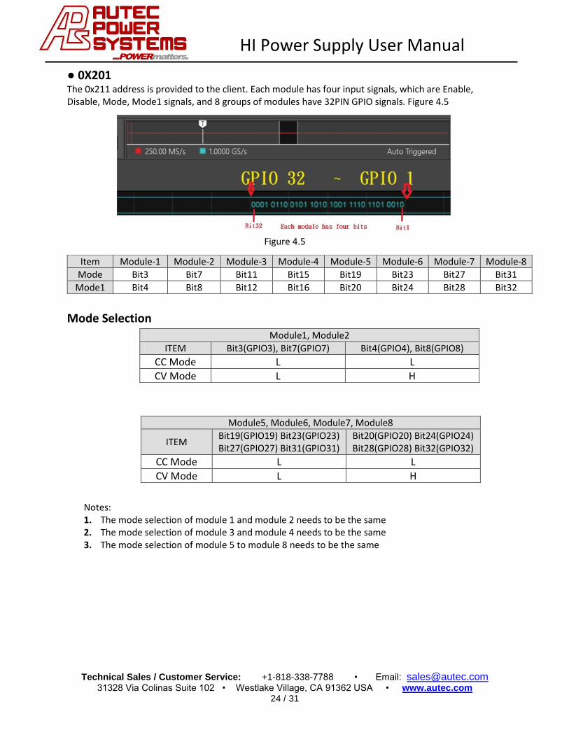
● 0X201 The 0x211 address is provided to the client. Each module has four input signals, which are Enable, Disable, Mode, Mode1 signals, and 8 groups of modules have 32PIN GPIO signals. Figure 4.5
Figure 4.5
Mode Selection
Notes: 1. The mode selection of module 1 and module 2 needs to be the same 2. The mode selection of module 3 and module 4 needs to be the same 3. The mode selection of module 5 to module 8 needs to be the same
Item Module-1 Module-2 Module-3 Module-4 Module-5 Module-6 Module-7 Module-8
Mode Bit3 Bit7 Bit11 Bit15 Bit19 Bit23 Bit27 Bit31
Mode1 Bit4 Bit8 Bit12 Bit16 Bit20 Bit24 Bit28 Bit32
Module1, Module2
ITEM Bit3(GPIO3), Bit7(GPIO7) Bit4(GPIO4), Bit8(GPIO8) CC Mode L L
CV Mode L H
Module5, Module6, Module7, Module8
ITEM Bit19(GPIO19) Bit23(GPIO23) Bit27(GPIO27) Bit31(GPIO31)
Bit20(GPIO20) Bit24(GPIO24) Bit28(GPIO28) Bit32(GPIO32)
CC Mode L L
CV Mode L H

HI Power Supply User Manual
Technical Sales / Customer Service: +1-818-338-7788 • Email: [email protected] 31328 Via Colinas Suite 102 • Westlake Village, CA 91362 USA • www.autec.com
25 / 31
● 0X231 This address represents the Inhib of each module. When Inhib is LO, the module is in a shutdown state. When Inhib is Hi, the module is in a standby state.
● 0X221 This address represents Enable/Disable for each module. When Enable is Lo and Inhib of 0X231 is Hi, the module is in a no output state. When Enable is Hi and Inhib of 0X231 is Hi, the module will be in an output state
Enable Disable 0X231 Hi Hi/Lo 0X221 Hi Lo/Hi

HI Power Supply User Manual
Technical Sales / Customer Service: +1-818-338-7788 • Email: [email protected] 31328 Via Colinas Suite 102 • Westlake Village, CA 91362 USA • www.autec.com
26 / 31
CAN Bus Register
ADC (Voltage and Current feedback values)
ID(Hex) Byte
Length Data(Hex) Note
0x000101 8 (No1) (No2) (No3) (No4) (No5) (No6) (No7) (No8) Module 1~8, output current data (0x00~2xff)
0x000102 8 (No9) (No10) (No11) (No12) (No13) (No14) (No15) (No16) Module 9~16, output current data (0x00~2xff)
0x000103 8 (No1) (No2) (No3) (No4) (No5) (No6) (No7) (No8) Module 1~8, output voltage data (0x00~2xff)
0x000104 8 (No9) (No10) (No11) (No12) (No13) (No14) (No15) (No16) Module 9~16, output voltage data (0x00~2xff)
0x000105 8 (No1) (No2) (No3) (No4) (No5) (No6) (No7) (No8) Module 1~8, voltage setting data (0x00~2xff)
0x000106 8 (No9) (No10) (No11) (No12) (No13) (No14) (No15) (No16) Module 9~16, voltage setting data (0x00~2xff)
AI (Voltage and Current feedback values)
ID(Hex) Byte Length Data(Hex) Note
0x000111 8 05 20(E1H) (E1L) (E2H) (E2L) (E3H) (E3L) Error message for AI
AO (MCU receive Can bus)
ID(Hex) Byte Length Data(Hex) Note
0x000201 8 (M8) (M7) (M6) (M5) (M4) (M3) (M2) (M1) Module status for AO
0x000202 8 (M16) (M15) (M14) (M13) (M12) (M11) (M10) (M9)
DAC (MCU receive Can bus)
ID(Hex) Byte Length Data(Hex) Note
0x000211 8 (M8) (M7) (M6) (M5) (M4) (M3) (M2) (M1) Module status for DAC
Mod forbidden / output signal (MCU receive Can bus)
ID(Hex) Byte Length Data(Hex) Note
0x000221 8 (M8) (M7) (M6) (M5) (M4) (M3) (M2) (M1) Module status for AO
0x000222 8 (M16) (M15) (M14) (M13) (M12) (M11) (M10) (M9)
Module start signal (MCU receive Can bus)
ID(Hex) Byte Length Data(Hex) Note
0x000231 8 (M8) (M7) (M6) (M5) (M4) (M3) (M2) (M1) Module status for AO
0x000232 8 (M16) (M15) (M14) (M13) (M12) (M11) (M10) (M9)

HI Power Supply User Manual
Technical Sales / Customer Service: +1-818-338-7788 • Email: [email protected] 31328 Via Colinas Suite 102 • Westlake Village, CA 91362 USA • www.autec.com
27 / 31
Note. If you use CANPRO software to operate CANBUS program, and use the hardware compiled by USB, you must set the baud rate of CANPRO, the baud rate is 125K, the operation is as follows The baud rate is set in the CanPro program. There is a Start button on the map, and a small window will appear. Select 125K in the baud rate. This picture shows the USB CANPRO compiler used by our company to test CANBUS programs on site.

HI Power Supply User Manual
Technical Sales / Customer Service: +1-818-338-7788 • Email: [email protected] 31328 Via Colinas Suite 102 • Westlake Village, CA 91362 USA • www.autec.com
28 / 31
1. Software Installation Please make sure that the device driver is installed normally, and the device can be recognized and run normally.
After the installation is complete, please copy the files under the "Secondary Development DLL" folder in the CD. Copy "controlcan.dll" to the root directory of the installed CAN Pro software and paste it. To replace, select "Copy and Replace". (For example, the CAN Pro software win7 64-bit is installed by default. The root directory is: C:\Program Files (x86)\CANPro\

HI Power Supply User Manual
Technical Sales / Customer Service: +1-818-338-7788 • Email: [email protected] 31328 Via Colinas Suite 102 • Westlake Village, CA 91362 USA • www.autec.com
29 / 31
2. Start the Software
Open CAN Pro software, you can set custom text color before use, if you need to customize each text color, please select "Action" → "System" before starting the device Parameters" to customize each content in the text display. Custom text color is a great tool, it can effectively distinguish various types of data with set colors in a large amount of data, which is convenient for data analysis

HI Power Supply User Manual
Technical Sales / Customer Service: +1-818-338-7788 • Email: [email protected] 31328 Via Colinas Suite 102 • Westlake Village, CA 91362 USA • www.autec.com
30 / 31
After the definition is complete, click "Start" to open the hardware device. If the device is connected to
the software normally, the device indicators PWR and SYS will have a steady light, A slow flash (about 1
time per second). If it prompts "Failed to open the device", please check whether the device driver has
been installed in the device manager.
Or whether "controlcan.dll" has been overridden and replaced, Or whether the port has been occupied
by opening the hardware device with other software.
Click to start the device and a dialog box to set the baud rate will pop up. The set baud rate must match
the If the bus is consistent, data can be sent and received normally. If you are a dual-channel device, you
can CAN2 set the baud rate respectively, you only need to set the baud rate in the interface, other
options do not need to be set, just keep the default.

HI Power Supply User Manual
Technical Sales / Customer Service: +1-818-338-7788 • Email: [email protected] 31328 Via Colinas Suite 102 • Westlake Village, CA 91362 USA • www.autec.com
31 / 31
3-2 Data sending related functions
3-2-1 Data sending function
Clicking the data send will pop up the data sending dialog box. All operations for data sending can be
done in this dialog.
Frames can be edited according to basic rules, with options to "Send Now" or "Add to Send List",
Multiple data can be added to the send list, and these data will be sent in order from top to bottom. This
function can simulate data to be sent in time sequence, and the sending list can be set to send cyclically
multiple times. And can save to file or load from file, convenient for multiple use.