Hero MotoCorp XTREME 200R
80
PREFACE No : IB15A Thank you for selecting a Hero MotoCorp XTREME 200R. We wish you many miles of continued riding pleasure in the years ahead. We at Hero MotoCorp, are committed to demonstrate excellence in our environment performance on a continual basis, as an intrinsic element of our corporate philosophy. To achieve this we commit ourselves to continue product innovations to improve environment compatibility, comply with all applicable environment legislation and strengthen the green supply chain. This booklet is your guide to the basic operation and maintenance of your new Hero MotoCorp XTREME 200R. Please take time to read it carefully. As with any fine machine, proper care and maintenance are essential for trouble-free operation and optimum performance. Authorised Distributor or the authorised dealer(s) of the Distributor ("Dealer") will be glad to provide further information or assistance and to handle your future service needs. Let us make this world a safer, healthier and more environment friendly place.
-
Upload
khangminh22 -
Category
Documents
-
view
0 -
download
0
Transcript of Hero MotoCorp XTREME 200R

PREFACE No : IB15A
Thank you for selecting a Hero MotoCorp XTREME 200R. We wish you many miles of continued riding pleasure in the years ahead.
We at Hero MotoCorp, are committed to demonstrate excellence in our environment performance on a continual basis, as an intrinsic element of our corporate philosophy. To achieve this we commit ourselves to continue product innovations to improve environment compatibility, comply with all applicable environment legislation and strengthen the green supply chain.
This booklet is your guide to the basic operation and maintenance of your new Hero MotoCorp XTREME 200R. Please take time to read it carefully. As with any fine machine, proper care and maintenance are essential for trouble-free operation and optimum performance.
Authorised Distributor or the authorised dealer(s) of the Distributor ("Dealer") will be glad to provide further information or assistance and to handle your future service needs.
Let us make this world a safer, healthier and more environment friendly place.

ALL INFORMATION, ILLUSTRATION, PHOTOGRAPH, DIRECTIONS, SPECIFICATIONS AND OTHER CONTENTS COVERED IN THIS OWNER'S MANUAL ARE BASED ON THE LATEST PRODUCT INFORMATION AVAILABLE AT THE TIME OF ITS PRINTING APPROVAL, AND THE ACCURACY OR CORRECTNESS OF THE SAME IS NOT UNDERTAKEN OR GUARANTEED. Hero MotoCorp Ltd RESERVES THE RIGHT TO MAKE CHANGES IN ITS CONTENTS AT ANY TIME WITHOUT NOTICE AND/OR INCURRING ANY OBLIGATION, WHATSOEVER. NO ONE IS ALLOWED TO REPRODUCE ANY PART OF THIS PUBLICATION WITHOUT OBTAINING PRIOR WRITTEN PERMISSION FROM Hero MotoCorp Ltd.
NOTE
Pg. No. Pg. No.CONTENTS
OIL FILTER SCREEN & CENTRIFUGAL FILTER CLEANING 38AIR CLEANER 39CARBURETOR 41VALVE CLEARANCE ADJUSTMENT 42CLUTCH LEVER FREE PLAY 43THROTTLE OPERATION 44BYSTARTER OPERATION 45DRIVE CHAIN SLACKNESS 45DRIVE CHAIN SLIDER INSPECTION 48BRAKES 49SUSPENSION 51WHEEL 52MAIN/SIDE STAND LUBRICATION 54TUBELESS TYRE 55NUT, BOLTS & FASTENERS 58BATTERY 58FUSE REPLACEMENT 60STOP LAMP SWITCH 61HEADLAMP FOCUS ADJUSTMENT 61CATALYTIC CONVERTER 62AIR SUCTION VALVE (ASV) 62EVAPORATIVE EMISSION CONTROL SYSTEM 63POLISHING OF VEHICLE 63BASIC TROUBLESHOOTING 64DELIVERY CERTIFICATEHERO GENUINE PARTSJOB APPLICABLE TO PERIODIC SERVICESSERVICE RECORD SHEETSERVICE ADVICE SHEETOWNERSHIP RECORD AND DATA
VEHICLE IDENTIFICATION 1VEHICLE VIEWS 2VEHICLE SPECIFICATION 7ACCESSORIES & MODIFICATIONS 9ANTI-THEFT TIPS 9VEHICLE SAFETY 10• Important Safety Information 10• Protective Apparel 11SAFE RIDING TIPS 12TIPS FOR HEALTHY ENVIRONMENT 13PART FUNCTION 14• Ignition switch 14• Instruments and Indicators 15• LCD panel 17• FEATURES 19HANDLEBAR SWITCHES CONTROL 19ABS INDICATOR 21SIDE STAND INDICATOR/SWITCH 21FUEL TANK 22FUEL VALVE 23SEAT LOCK/HELMET HOLDER 24PRE-RIDE INSPECTION 25STARTING THE ENGINE 62RIDING/BRAKING 27PARKING/TOOL KIT 29CLEANING AND WASHING THE VEHICLE 30MAINTENANCE 30SAFETY PRECAUTION 32MAINTENANCE SCHEDULE 33SPARK PLUG INSPECTION 36ENGINE OIL 36

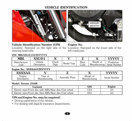
VIN: MBLXXU01XYZXYYYYY
Model: Xtreme 200RVIN EngineVariantsU01 AAElectric start/Front disc with ABS/Rear disc/Cast wheel
MBL XXU01 Y Z X YYYYYManufacturer
codeVehicle
Description Model Year PlantCode
Month of Manufacturing
Production Serial Number
XCheckDigit
Engine No.: XXXXAAYZXYYYYYXXXXAA Y Z X YYYYY
Engine Description
Year of Manufacturing Assembly Plant Month of
Manufacturing Serial Number
VIN and Engine No. may be required:• During registration of the vehicle.• For dealing with legal & insurance departments.
1
VEHICLE IDENTIFICATION
Engine No.Location: Stamped on the lower side of the left crankcase.
Vehicle Identification Number (VIN)Location: Stamped on the right side of the steering head tube.
MBLXXU01XYZXYYYYY
XXXXAAYZXYYYYY
S01 AAElectric start/Front disc Non ABS/Rear disc/Cast wheel

FRONT VIEW
1. Front fender2. Front right turn signal lamp3. Right position lamp4. Front visor
5. Left position lamp6. Front left turn signal lamp7. Headlamp
7
1
2
4
6
53
*Accessories and features shown may not be part of standard fitment.2
VEHICLE VIEWS

REAR VIEW
1. Left rear turn signal lamp2. Tail/stop lamp3. Licence plate lamp
4. Right rear turn signal lamp5. Rear reflex reflector6. Rear fender
2
1
3
*Accessories and features shown may not be part of standard fitment.
3
4
5
6

(1) Fuel tank cap(2) Tachometer(3) Mode button(4) Bystarter lever(5) Horn switch(6) Turn signal switch(7) Clutch lever(8) Pass lamp switch(9) Set button(10) Turn signal indicator(11) ABS indicator(12) High beam indicator
(13) Neutral indicator(14) Side stand indicator(15) Front brake master cylinder(16) Rear view mirror(17) Front brake lever(18) Throttle grip(19) Electric starter switch(20) Engine stop switch(21) LCD panel(22) Fuel gauge(23) Ignition switch
TOP VIEW
7
4
*Accessories and features shown may not be part of standard fitment.
56
8
432
13 14 15 161110 129
1920
1718
21
2322
1

(1) Side reflex reflector(2) Fuel valve(3) Belly pan(4) Starter motor(5) Gear shift pedal(6) Main stand
(7) Rider foot rest(8) Side stand(9) Pillion foot rest(10) Saree guard(11) Rear grip
(12) Seat lock(13) Left side cover(14) Battery compartment (inside)(15) Side stand switch(16) Air suction valve
LEFT SIDE VIEW
*Accessories and features shown may not be part of standard fitment.
4 5 10
11121316 15
5
2 6 8 91 3
14
7

(1) Rear master cylinder(2) Brake pedal(3) Kick starter pedal(4) Rear brake fluid reservoir(5) Oil level dipstick(6) Front caliper assembly(7) Front disc
(8) Carburetor(9) Seat(10) Fuse box(11) Document & Tool kit compartment(12) Rear caliper assembly(13) Exhaust muffler(14) Rear disc
RIGHT SIDE VIEW
2
11
*Accessories and features shown may not be part of standard fitment.
6
3 4
8
1 5 6 7
9
13
14
12
10

SPECIFICATIONSITEMDimensionsOverall lengthOverall widthOverall heightWheelbaseSaddle heightGround clearance
Kerb weight
2062 mm778 mm1072 mm1338 mm795 mm165 mm
149 kg (ABS)148 kg (Non ABS)
Weight
7
VEHICLE SPECIFICATION
Engine oilFuel tankFuel reserve capacityFront fork oil at disassemblyHydraulic brake fluid
Maximum powerMaximum torqueBore and strokeCompression ratioDisplacementSpark plugSpark plug gapValve clearanceIdle speed
Front suspensionRear suspensionCaster angle
1200 ml at disassembly and 1070 ml at draining12.4 litres2.0 litres (Usable reserve)290cc (Per leg)DoT-4/DoT-3
13.5 kW @ 8000 rpm17.1 N-m @ 6500 rpm66.5x57.5 mm10:01199.6 ccNGK-CPR 8 EA 9, BOSCH UR5DC0.8-0.9 mm0.06 mm 0.08 mm1400±100 rpm
Telescopic front forks with anti friction bushRectangular swingarm with mono shock26°
Capacities
Engine
Intake (cold)Exhaust (cold)
Chassis and suspension
Trail length 94 mm

SPECIFICATIONSITEM
Primary reductionFinal reductionGear Box
stGear ratio, 1rd3th4th5
BatteryAlternatorHeadlamp (High/Low)
Tail/Stop lampTurn signal lampMeter illuminationNeutral indicatorTurn signal indicator (RH/LH)
Position lamp
Hi beam indicatorABS indicatorService reminder indicatorLicence plate lampSide stand indicatorFuse
3.350 (67/20)2.846 (37/13)5 Speed constant mesh3.0769 (40/13)1.7895 (34/19)1.500 (30/20)1.100 (22/20)0.9583 (23/24)
12V-4 Ah, (ETZ-5) *MF Battery 140 W @ 5000 rpm12V-35/35W (Halogen bulb, **MFR)
12V-2.1/1.4W (LED)12V-10Wx4 nos. **MFR (Amber bulb-clear lens)LED12V-1.4WLED
12V-0.5Wx2 (LED)
LEDLEDLCD display12V-5WLED20A, 15A, 10A, 10A
Transmission
Tyre size 100/80 x 17-52 P (Tubeless tyre)130/70 x R17-62 P (Tubeless tyre)
FrontRear
Electricals
Tyre pressure2 21.75 kgf/cm /1.75 kgf/cm2 21.96 kgf/cm /2.1 kgf/cm
Front (Rider/pillion)Rear (Rider/pillion)
Brakes Dia. 276 mmDia. 220 mm
Front (Disc type)Rear (Disc type)
nd2
*MF stands for Maintenance Free**MFR stands for Multi-Focal Reflector type
8
VEHICLE SPECIFICATION

9
ACCESSORIES & MODIFICATIONSModifying your vehicle or using non-Hero MotoCorp accessories can make your vehicle unsafe. Before you consider making any modifications or adding an accessory, be sure to read the following information.
operation. Such changes could seriously impair your vehicle's handling, stability and braking, making it unsafe to ride. Removing or modifying your lamps, mufflers, emission control system or other equipment can also make your vehicle illegal.ANTI-THEFT TIPS• Always lock the steering and never leave the
key in the ignition switch. This sounds simple but people do forgets.
• Be sure the registration information for your vehicle is accurate and correct.
• Park your vehicle in a locked garage whenever possible.
• Use an additional anti-theft device of good quality.
• Never park your vehicle in an isolated area. Park as for as possible in a designated area.
• Enter your name, address and phone number in this Owner's Manual and keep it in your vehicle at all times. Many times stolen vehicles are identified by information in the Owner's Manuals that are still with them.
NAME: _____________________________________________ADDRESS: ____________________________________________________________________________________________________________________________________________________________________________________________________________
PHONE NO : _____________________________________
Accessories• Make sure that the accessory does not
obscure any lamps, reduce ground clearance, limit suspension travel or steering travel, affect your riding position or interfere with operating any controls.
• Be sure electrical equipment does not exceed the 's electrical system vehiclecapacity (page 6). A blown fuse can cause a loss of lights.
• Do not pull a trailer or sidecar with your vehicle. This vehicle was not designed for these attachments, and their use can seriously impair your vehicle's handling.
ModificationsWe strongly advise you not to remove any original equipment or modify your vehicle in any way that would change its design or
• Improper accessories or modifications can cause a crash in which you can be seriously hurt or killed.
• Follow all instructions in this owner's manual regarding accessories and modifications.
WARNING!!

10
VEHICLE SAFETYIMPORTANT SAFETY INFORMATIONYour vehicle can provide many years of service and pleasure if you take responsibility for your own safety and understand the challenges you can meet on the road.There is much that you can do to protect yourself when you ride. You will find many helpful recommendations through out this manual. Following are a few that we consider most important.Always wear a helmetIt is a proven fact, Helmet significantly reduces the number and severity of head injuries. So always wear a helmet and make sure your pillion rider does the same. We also recommend that you wear eye protection, sturdy boots, gloves and other protective gear.Before riding your vehicleMake sure that you are physically fit, mentally focused and free of alcohol and drugs. Check that you and your pillion are both wearing an approved vehicle helmet and protective apparel. Instruct your pillion on holding onto the grab rail or your waist, leaning with you in turns, and keeping their feet on the footrest, even when the vehicle is stopped.Take time to learn & practice your vehicleEven if you have ridden other vehicles, practice riding in a safe area to become familiar with how this vehicle works and handles, and to become accustomed to the vehicle's size and weight.
Ride defensivelyAlways pay due attention to other vehicles around you, and do not assume that other drivers see you. Be prepared to stop quickly or perform an evasive maneuver.Make yourself easily visibleSome drivers do not see vehicles because they are not looking for them. To make yourself more visible, wear bright reflective clothing, position yourself so that others can see you, signal before turning or changing lanes, and use horn which will help others to notice you.Ride within your limitsPushing the limits is another major cause of vehicle accidents. Never ride beyond your personal abilities or faster than conditions demand. Remember that fatigue and negligence can significantly reduce your ability to make good judgements and ride safely.Do not drink and rideRiding under the influence of alcohol or drugs is dangerous. Alcohol can reduce your ability to respond to changing conditions and reduce the reaction time. Do not drink and ride. Keep your vehicle in safe conditionFor safe riding, its important to inspect your vehicle before every ride and perform all recommended maintenance. Never exceed load limits, and only use accessories that have been approved by Hero MotoCorp for this vehicle.
11
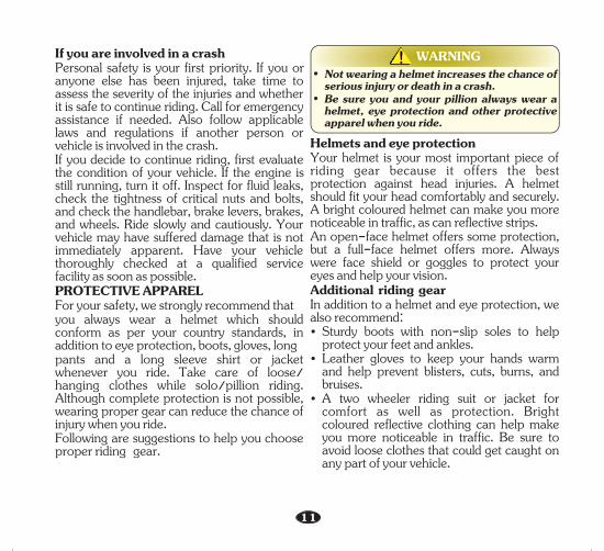
Helmets and eye protectionYour helmet is your most important piece of riding gear because it offers the best protection against head injuries. A helmet should fit your head comfortably and securely. A bright coloured helmet can make you more noticeable in traffic, as can reflective strips.An open-face helmet offers some protection, but a full-face helmet offers more. Always were face shield or goggles to protect your eyes and help your vision.Additional riding gearIn addition to a helmet and eye protection, we also recommend:• Sturdy boots with non-slip soles to help
protect your feet and ankles.• Leather gloves to keep your hands warm
and help prevent blisters, cuts, burns, and bruises.
• A two wheeler riding suit or jacket for comfort as well as protection. Bright coloured reflective clothing can help make you more noticeable in traffic. Be sure to avoid loose clothes that could get caught on any part of your vehicle.
If you are involved in a crashPersonal safety is your first priority. If you or anyone else has been injured, take time to assess the severity of the injuries and whether it is safe to continue riding. Call for emergency assistance if needed. Also follow applicable laws and regulations if another person or vehicle is involved in the crash.If you decide to continue riding, first evaluate the condition of your vehicle. If the engine is still running, turn it off. Inspect for fluid leaks, check the tightness of critical nuts and bolts, and check the handlebar, brake levers, brakes, and wheels. Ride slowly and cautiously. Your vehicle may have suffered damage that is not immediately apparent. Have your vehicle thoroughly checked at a qualified service facility as soon as possible.PROTECTIVE APPAREL For your safety, we strongly recommend thatyou always wear a helmet which should conform as per your country standards, in addition to eye protection, boots, gloves, longpants and a long sleeve shirt or jacket whenever you ride. Take care of loose/ hanging clothes while solo/pillion riding. Although complete protection is not possible, wearing proper gear can reduce the chance of injury when you ride. Following are suggestions to help you choose proper riding gear.
• Not wearing a helmet increases the chance of serious injury or death in a crash.
• Be sure you and your pillion always wear a helmet, eye protection and other protective apparel when you ride.
WARNING!!

SAFE RIDING TIPS
12
Do's:• Always conduct simple pre-ride inspection
(page 25).• Always wear a helmet (ISI marked) with chin strap
securely fastened and insist on a helmet for your pillion rider.
• While riding, sit in a comfortable position with your legs close to fuel tank.
• Ride defensively and at a steady speed (between 40-50 km/hr).
• For stopping vehicle, use both brakes simultaneously, keeping throttle in the close position.
• During night time vehicle, dip headlamps of your for oncoming traffic, or when following another vehicle.
• Give way to others on the road and signal before you make a turn.
• To make yourself more visible, wear bright reflective clothing that fits well.
• Take care of loose/hanging clothes while solo/pillion riding.
• vehicleGet your serviced regularly by the Authorised Distributor/Dealer.
• Before riding make sure that engine stop switch is in “ON” ( ) position.
• Keep checking the ABS indicator. At any point if indicator remains on, then ABS is not working (page 21).
• Keep checking speedometer. In case of ABS malfunction, speed display may go to zero.
• It is suggested to go through the do’s & dont’s of ABS (page 28) and practice your ABS vehicle initially in low-traffic condition unless you are thoroughly familiar with your vehicle and its controls.
Don'ts• Never use cell phone while riding the vehicle.• Avoid sudden acceleration, braking and turning of
your vehicle.• Never shift gears without disengaging the clutch
and closing the throttle.• Never touch any part of the hot exhaust system like
muffler.• Never ride under the influence of alcohol or drugs.• Concentrate on the road and avoid talking to the
pillion rider or others on the road.• Do not litter the road.• Do not cross the continuous white/yellow line in
the center of the road, while overtaking.• Do not attach large or heavy items to the
handlebars, front forks, or fenders.• Never take your hands off the steering handle while
riding.• Do not attempt to apply the front brake lever
intermittently for ABS vehicle.• Do not panic by mechanical noises or slight pedal
pulses while applying the brake in vehicle. These conditions are normal and indicates that ABS is working.
• Do not apply the hard braking in wet or rainy conditions.
• Do not switch off the engine stop switch while riding the vehicle (page 21).

13
The following tips shall ensure a healthy vehicle, healthy environment, and a healthy you.
• Healthy engine: The engine is the lifeline of every vehicle. To keep it healthy, it should be tuned regularly, which will also help reduce pollution and improve vehicle performance & fuel efficiency.
• Regular servicing: Get your vehicle serviced at an Authorised Distributor/Dealer, as per the service schedule, for an optimum performance and keep the emission level under check.
• Genuine spares: Always insist on Hero MotoCorp genuine parts as spurious or incompatible spares and accessories can upset or deteriorate your vehicle’s running condition.
• Genuine engine oil: Hero 4T Plus SAE 10W 30 SJ grade (JASO MA) engine oil recommended by Hero MotoCorp and make sure you change it every 6000 kms. (with top up every 3000 kilometres) to keep the engine fit and environment healthy.
• Noise pollution: Noise beyond a certain decibel is pollution. Whether it is from horns or defective mufflers, excessive noise will cause headaches and discomfort.
• Fuel saving & reduce pollution: Switch "OFF" the engine while waiting at traffic signal points to save fuel and reduce pollution, if the waiting period is long.
TIPS FOR HEALTHY ENVIRONMENT

14
The LCD panel illuminates & initial display of multi function digital segments are displayed. The tachometer needle and the fuel gauge needle will swing to the maximum scale once and back to its normal position. The engine can be started. turn signal lamp, horn, tail/stop lamp, fuel gauge, pass lamp, position lamp & neutral indicator will be functional.
Key cannot be removed.
Engine cannot be started and no electrical system will be functional. Key can be removed.
Steering can be locked. Key can be removed.
“OFF” ( ) Position/Lock Open
“LOCK” Position
“ON” ( )Position
“LOCK”
“ON” ( )
“OFF” ( )
1. Ignition switch2. Ignition key3. “OFF” ( ) position4. Steering lock position5. “ON” ( ) position
Key Position Function Key Removal
PARTS FUNCTIONIgnition switch
4
31
5 2

Sl. No. Description Function1 Set button Button when long pressed resets tripmeter to zero.
2
3Anti-lock braking system (ABS) indicator
Tachometer Indicates engine rpm.
High beam indicator Light glows when headlamp is in Hi beam.4
7 Side stand indicatorService reminder indicator
Light glows when the side stand is put down.
Display when the next service is due (page 18).
6
8
Neutral indicator Light glows when vehicle is in neutral position.
Turn signal indicator Flashes when turn signal switch is operated.5
N111111
111000999888
777
666
555
444
333222 111
000
x1000r/minx1000r/minx1000r/min
ABSABSABS
MO
DE
SE
T
FFF
EEE 88888.888888.888888.8 18:8818:8818:88
km/h
km
AMTRIP A BTOTAL
PM
18:8818:8818:88
Instruments and IndicatorsThe indicators are in the speedometer panel above the headlamp. The functions are as below.
15
1 2 3 4 5 6 7 8
910111314 12
This indicator normally comes on for 1.8 seconds when the ignition switch is turned “ON” ( ) & then keeps blinking until the vehicle attains speed of 5 km/h. If there is a problem with the anti-lock brake system turns on (page 21).

Sl. No. Description Function9
10
11
12
13
14
16
Odometer Shows accumulated mileage (page 18).
Mode button Switches display between odometer, tripmeter-A & B.
Tripmeter A & B Shows the distance travelled during a trip after settingto zero (page 18).
Speedometer Indicates riding speed.
Digital clock Indicates hours & minutes (page 17).
Fuel gauge Indicates approximate fuel quantity.

(a) Digital clock
• To set the hour, press mode button (3) until the desired hour is displayed.• The time is advanced by 1 hour
each time the button is pressed.• The time advances fast when the
button is pressed and held.• "AM" will change to "PM" after 12.
• Press the set button (2). The minutes display starts blinking.
LCD PANEL
• To set the minute press set utton ( ) until b 2the desired minute is displayed. The minute display will return to when is "60" "00" reached without affecting the hour display.• The time advances by 1 minute, each
time the button is pressed.
N111111
111000999888
777
666
555
444
333222 111
000
x1000r/minx1000r/minx1000r/min
ABSABSABS
MO
DE
SE
T
FFF
EEE 0.00.00.0 12:3012:3012:30
km/h
km
AMTRIP A
12:30
10:30
N111111
111000999888
777
666
555
444
333222 111
000
x1000r/minx1000r/minx1000r/min
ABSABSABS
MO
DE
SE
T
FFF
EEE 0.00.00.0 12:3012:3012:30
km/h
km
AMTRIP A
12:30
12:30
N111111
111000999888
777
666
555
444
333222 111
000
x1000r/minx1000r/minx1000r/min
ABSABSABS
MO
DE
SE
T
FFF
EEE 0.00.00.0 10:3010:3010:30
km/h
km
AMTRIP A
10:30
10:30
17
1
2
3
3
2
(1) Digital clock (2) Set button (3) Mode button
(3) Mode button
(2) Set button
Digital clock (1) shows hour and minute. To adjust the time, proceed as follows :• Turn the ignition switch "ON" ( ).• Press and hold set button (2) and mode
button (3) simultaneously for more than 2 seconds. The clock will be set in the adjust mode with the hour's digit display blinking.

• To end the adjustment press set utton (2). bThe display will stop flashing automatically and the adjustment will be saved or if the button is not pressed for about 30 seconds.
(b) Odometer/TripmeterThe odometer (1) shows accumulated distance travelled.The tripmeter shows distance travelled since trip meter was reset last time. There are two tripmeters, tripmeter-A (2) and tripmeter-B (3).Push the mode button (4) to select odometer, tripmeter-A or tripmeter-B. Tripmeter-A or tripmeter-B can be displayed upto " 99999.9"km.
N111111
111000999888
777
666
555
444
333222 111
000
x1000r/minx1000r/minx1000r/min
ABSABSABS
MO
DE
SE
T
FFF
EEE 0.00.00.0 12:4512:4512:45
km/h
km
AMTRIP A
12:45
12:30
2368 kmTOTAL
168.0 kmTRIP B
150.0 kmTRIP A
N111111
111000999888
777
666
555
444
333222 111
000
x1000r/minx1000r/minx1000r/min
ABSABSABS
MO
DE
SE
T
FFF
EEE 0.00.00.0 10:0010:0010:00
km/h
km
AMTRIP A
• The time advances fast when the button is pressed and held.
If the tripmeter exceeds "99999.9" km it will return to "0.0" km automatically. When tripmeter is selected long press the set button to reset tripmeter to zero.The odometer can be displayed from "0 to 999999" km.
NOTEThe clock will reset “AM: 1:00“ if the battery is disconnected.
18
3
1
32
4(1) Odometer (2) Tripmeter-A(3) Tripmeter-B (4) Mode button
(c) Service reminder indicatorThe service reminder indicator (1) is to indicate the user to bring the vehicle to an Authorised Distributor/Dealer for service. The indicator shall start blinking when the vehicle covers kilometers as specified in the maintenance schedule. The indicator will keep on blinking throughout the kilometer interval for a particular service and will stay ‘‘ON’’ thereafter.

19
NOTENOTEAfter getting the vehicle serviced, make sure that the Service Reminder Indicator has been reset.
(1) Service reminder indicator
1
HANDLEBAR SWITCHES CONTROL
Shift the turn signal switch (2) sideways for right/left indications and leave it to come back to its normal position on its own.
2. Turn signal lamp switch ( )
FEATURESSteering lockSteering lock is with the ignition switch, turn the key (1) to “OFF” ( ) position & turn the handle bar towards left or right & push the key downwards & turn towards "Lock" position. After locking take out the key.
(1) Ignition key
Press the pass switch to “PASS” position to operate the pass lamp.
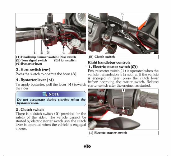
Left handlebar controls1. Headlamp dimmer switch/Pass switchThe headlamp operates only when the engine is running.Press the switch (1) upwards for high beam “ ” downwards for low beam “ ”.
The service reminder indicator can only be reset at an Authorised Distributor/Dealer.
IMPORTANT : To switch “OFF” the turn signal after completing the turn, gently push the switch inside.
1
20
(1) Headlamp dimmer switch/Pass switch (2) Turn signal switch (3) Horn switch (4) Bystarter lever
4. Bystarter lever ( )
NOTEDo not accelerate during starting when the bystarter is on.
To apply bystarter, pull the lever (4) towards the rider.
5. Clutch switchThere is a clutch switch (5) provided for the safety of the rider. The vehicle cannot be started by electric starter switch until the clutch lever is operated when the vehicle is engaged in gear.
3. Horn switch ( )Press the switch to operate the horn (3).
Right handlebar controls1. Electric starter switch ( )Ensure starter switch ( ) is operated when the 1vehicle transmission is in neutral. If the vehicle is engaged in gear, press the clutch lever before operating the starter switch. Release starter switch after the engine has started.
(1) Electric starter switch
3 4
1
(5) Clutch switch
5
21
21
Never hold electric starter switch continuously more than 5 seconds as continuous cranking of engine will discharge the battery.
CAUTION!!
2
WARNING!!While riding the vehicle in normal condition, do not switch off the “Engine stop switch” to avoid any damage (Wheel locking leading to accident, part damage, battery discharge etc.).
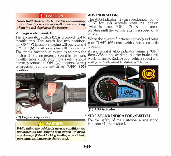
(2) Engine stop switch
2. Engine stop switchThe engine stop switch (2) is provided next to throttle grip. The switch has two positions. In “ON” ( )position, engine will operate and in “OFF” ( ) position, engine will not operate. The prime function of switch is to stop the engine during emergency (Vehicle tip over, throttle cable stuck etc.). The switch should normally remain in “ON” ( ) position. During emergency, put the switch to “OFF” ( ) position.
(1) ABS indicator
1
When the system functions normally indicator goes “OFF” ( ) once vehicle speed exceeds 5 km/h.At any point if ABS indicator remains “ON” then ABS is not working, but the brakes still work normally. Reduce your vehicle speed and visit your Authorised Distributor/Dealer.
ABS INDICATORThe ABS indicator (1) on speedometer come “ON” for 1.8 seconds when the ignition switch is turned “ON” ( ) & then keeps blinking until the vehicle attains a speed of 5 km/h.
SIDE STAND INDICATOR/SWITCHFor the safety of the customer a side stand indicator (1) is provided.
22
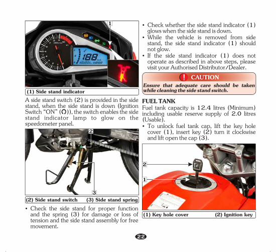
(1) Side stand indicator
1
Ÿ Check the side stand for proper function and the spring (3) for damage or loss of tension and the side stand assembly for free movement.
Ÿ Check whether the side stand indicator (1) glows when the side stand is down.
Ÿ While the vehicle is removed from side stand, the side stand indicator (1) should not glow.
Ÿ If the side stand indicator (1) does not operate as described in above steps, please visit your Authorised Distributor/Dealer.
Ensure that adequate care should be taken while cleaning the side stand switch.
CAUTION!!
(2) Side stand switch (3) Side stand spring
2
A side stand switch (2) is provided in the side stand, when the side stand is down (Ignition Switch “ON” ( )), the switch enables the side stand indicator lamp to glow on the speedometer panel.
FUEL TANKFuel tank capacity is 12.4 litres (Minimum) including usable reserve supply of 2.0 litres (Usable).Ÿ To unlock fuel tank cap, lift the key hole
cover (1), insert key (2) turn it clockwise and lift open the cap (3).
(1) Key hole cover (2) Ignition key
2
1
3

23
(3) Fuel tank cap
3
Ÿ Do not overfill the tank. There should be no fuel in filler neck (4). Fill the tank with fuel (5) as shown.
Ÿ To lock fuel tank cap, close the cap back on the opening and press gently. The key springs back to the normal position and cap gets locked.
Ÿ Remove the key and put back the keyhole cover.
Front
45
(4) Filler Neck (5) Fuel
CAUTION!!Do not park the vehicle under direct sunlight as it causes evaporation of petrol due to heat and deterioration of paint gloss due to ultra violet rays.
WARNING!!Petrol is extremely flammable and is explosive under certain conditions. Refill in a well ventilated area with the engine stopped. Do not smoke or allow flames or sparks in the area where the vehicle is refilled or where petrol is stored.
FUEL VALVEThe three way fuel valve is on the left side of the carburetor.“OFF” ( ) position
(1) “OFF” ( ) position
At “OFF” position (1), marked on the fuel valve body, fuel cannot flow from the tank to the carburetor. Turn the valve “OFF” whenever the vehicle is not in use.
1

24
“ON” ( ) positionAt “ON” position (2), marked on the fuel valve body, fuel will flow from the tank to the carburetor.
(2) “ON” ( ) position
“RES” ( ) position
(3) “RES” ( ) position
At “RES” position (3), marked on the fuel valve body, fuel will flow from the reserve fuel supply to the carburetor. Use the reserve fuel only when the main supply is gone. Refill the tank as soon as possible after switching to “RES”. The reserve fuel supply is 2.0 litres (Usable).
NOTE• Do not operate the vehicle with the fuel valve
in the “RES” ( ) position after refilling. You may run out of fuel, with no reserve.
• Do not keep the fuel valve between “ON” ( ) and “OFF” ( ) position while driving, since this may drain reserve fuel from the tank.
SEAT LOCKLocation : On the left side of the rear cowl, above rear wheel.Operation : Insert the ignition key (1) and turn is clock wise to unlock the seat. To install, engage the hook on the underside of the seat with the frame and slide the seat to the front until the lock clicks.
2
3
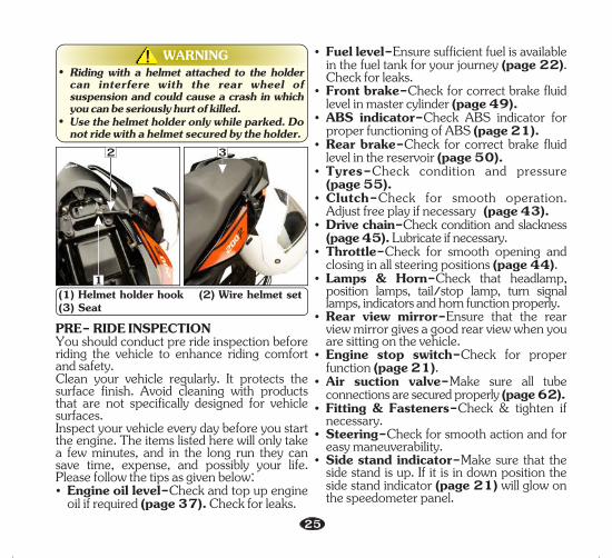
HELMET HOLDERThe helmet holder is located below the seat. Remove the seat. Hang the helmet on the helmet holder hook (1) using wire helmet set (2) supplied with the vehicle. Install the seat (3) and lock it securely.
(1) Seat lock
1
25
PRE- RIDE INSPECTIONYou should conduct pre ride inspection before riding the vehicle to enhance riding comfort and safety.Clean your vehicle regularly. It protects the surface finish. Avoid cleaning with products that are not specifically designed for vehicle surfaces. Inspect your vehicle every day before you start the engine. The items listed here will only take a few minutes, and in the long run they can save time, expense, and possibly your life. Please follow the tips as given below:Ÿ Engine oil level-Check and top up engine
oil if required (page 37). Check for leaks.
Ÿ Fuel level-Ensure sufficient fuel is available in the fuel tank for your journey (page 22). Check for leaks.
Ÿ Front brake-Check for correct brake fluid level in master cylinder (page 49).
Ÿ ABS indicator-Check ABS indicator for proper functioning of ABS (page 21).
Ÿ Rear brake-Check for correct brake fluid level in the reservoir (page 50).
Ÿ Tyres-Check condition and pressure (page 55).
Ÿ Clutch-Check for smooth operation. Adjust free play if necessary (page 43).
Ÿ Drive chain-Check condition and slackness (page 45). Lubricate if necessary.
Ÿ Throttle-Check for smooth opening and closing in all steering positions .(page 44)
Ÿ Lamps & Horn- Check that headlamp,position lamps, tail/stop lamp, turn signal lamps, indicators and horn function properly.
Ÿ Rear view mirror-Ensure that the rear view mirror gives a good rear view when you are sitting on the vehicle.
Ÿ Engine stop switch-Check for proper function (page 21).
Ÿ Air suction valve-M ake sure all tube connections are secured properly (page 62).
Ÿ Fitting & Fasteners-Check & tighten if necessary.
Ÿ Steering-Check for smooth action and for easy maneuverability.
Ÿ Side stand indicator-Make sure that the side stand is up. If it is in down position the side stand indicator will glow on (page 21)the speedometer panel.
(1) Helmet holder hook (2) Wire helmet set(3) Seat
WARNING!!• Riding with a helmet attached to the holder
can interfere with the rear wheel of suspension and could cause a crash in which you can be seriously hurt of killed.
• Use the helmet holder only while parked. Do not ride with a helmet secured by the holder.
2
1
3
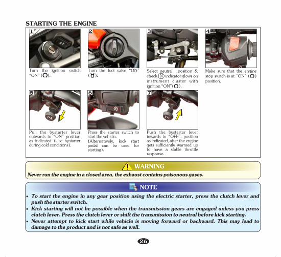
WARNING!!Never run the engine in a closed area, the exhaust contains poisonous gases.
STARTING THE ENGINE1
Turn the ignition switch “ON” ( ).
3
Select neutral position & check N indicator glows on instrument cluster with ignition “ON”( ).
26
2
Turn the fuel valve “ON”( ).
4
Make sure that the engine stop switch is at “ON” ( ) position.
NOTE• To start the engine in any gear position using the electric starter, press the clutch lever and
push the starter switch.• Kick starting will not be possible when the transmission gears are engaged unless you press
clutch lever. Press the clutch lever or shift the transmission to neutral before kick starting.• Never attempt to kick start while vehicle is moving forward or backward. This may lead to
damage to the product and is not safe as well.
Press the starter switch to start the vehicle.(Alternatively, kick start pedal can be used for starting).
6
Pull the bystarter lever outwards to “ON” position as indicated (Use bystarter during cold conditions).
5
Push the bystarter lever inwards to “OFF”, position as indicated, after the engine gets sufficiently warmed up to have a stable throttle response.
7

Flooded engineIf the engine fails to start after repeated attempts, it may be flooded with excess fuel. To clear a flooded engine, turn the ignition switch “OFF” ( ) and push the bystarter lever to “OFF”. Close the throttle fully and crank the engine several times with the kick starter. Turn the ignition switch “ON” ( ) and start the engine without using bystarter. Running inHelp assure your vehicle's future reliability and performance by paying extra attention to how you ride during the first 500 km.During this period, avoid full-thorottle starts and rapid acceleration.RIDING• After the engine has been warmed up, the
vehicle is ready for riding.• While the engine is idling, press the clutch
lever and depress the gearshift pedal stdownwards using the toe to shift into 1 gear.
• Slowly release the clutch lever and at the same time, gradually increase engine speed by opening the throttle. Coordination of the throttle and clutch lever will assure a smooth positive start.
• When the vehicle attains a moderate speed, close the throttle, press the clutch lever and
nd shift to 2 gear by placing the toe on the underside of gear pedal and lift upwards.
• This sequence is repeated progressively to rd th thshift to 3 , 4 and 5 gear.
BRAKING
5
4
1
N
2
3
CAUTION!!Do not shift gears without operation of clutch and without closing the throttle otherwise this would lead to damage of gears.
27
(a) Vehicle with Anti-lock braking system (ABS)This model is equipped with Anti-lock braking system (ABS). ABS enhances active safety by helping to prevent the wheels from locking under braking. ABS is designed to meet two essential requirements during every brake application:• To help provide vehicle stability. • To help maintain steering control and
manoeuvrability–on all types of road surfaces ( concrete, mud, wet, snow, ice).
The ABS system is self-regulating and always active once vehicle speed exceeds 5 km/h.

28
• The ABS computer acts on the basis of the comparative speeds of the front wheel. The use of non-approved tyres can affect the speed of the wheels and supply incorrect information to the ABS computer.
The system has a wheel speed sensor (1), hydraulic electronic control unit (HECU) (2), and an ABS indicator lamp (3) on meter console.
(1) Wheel speed sensor(2) Hydraulic electronic control unit (HECU)Whenever you ride your bike, Wheel speed sensor monitors the speed of the wheel and sends the input to Hydraulic Electronic control unit (HECU). Then HECU monitors your bike and takes control when vehicle speed exceeds 5 km/h.Now whenever you will apply front brake, ABS will come into picture and based on the input from wheel speed sensor, HECU will modulate the pressure at front caliper thus avoiding wheel to lock and in turn resulting safe stop of the vehicle.
1 2
(3) ABS indicatorDo's and Dont'sDo's• Check your brake pads and be sure you
have clean brake fluid. ABS systems can also fail due to worn brake pads or air or dirt in brake fluid.
• Use the recommended brake fluid.• If brake gets wet, apply the brake while
riding at low speed to help them dry. • ABS should be serviced only at Authorised
Distributor/Dealer.• Read your owner's manual for additional
riding instructions.• Carefully remove the wheel during the
puncture/tyre replacement to prevent the Sensing ring damage/bend.
• Use only the recommended make, type and size of tyre (page 55).
• Keep checking speedometer. In case of ABS malfunction, speed display may go to zero.
3

29
Don't's• Do not use the non-standard tyres.• Don't panic by mechanical noises or slight
pedal pulses while applying the brake in vehicle. These conditions are normal and indicates that ABS is working.
• Don't apply the hard braking in wet or rainy conditions.
• Do not adjust the wheel speed sensor air gap yourself.
• Do not attempt to correct the encoder teeth by bending manually or by using any other mode.
• Do not insert any metallic part near wheel speed sensor.
• Don't try to service HECU or open to separate the parts.
• Don't use the non-genuine spares like pads, discs, tyres etc.
(b) Vehicle without Anti-lock braking system (ABS)• For normal braking, close the throttle and
gradually apply both front and rear brakes together while shifting down gears to suit your road speed.
• For maximum deceleration/quick stopping, close the throttle and apply the front and rear brakes simultaneously.
PARKINGAfter stopping the vehicle, shift the transmission to neutral, turn the fuel valve “OFF” ( ), turn the ignition switch “OFF” ( ), park the vehicle on main stand, lock the steering and remove the key.
• When riding in wet or rainy conditions, or on loose surfaces the ability to stop the vehicle reduces.
• All your actions should be smooth under these conditions. Sudden acceleration or turning may cause loss of control. For your safety, exercise extreme caution when, accelerating or turning.
• When descending a long steep slope use engine braking (power) by changing to lower gears, with intermittent use of both brakes. Continuous brake application can overheat the brakes and reduce their effectiveness.
CAUTION!!• Park the vehicle on firm level ground to
prevent overturning.• While parking on side stand engage the first
gear.
WARNING!!• Wherever possible, reduce speed or apply
brake before entering a turn, closing the throttle or braking in mid turn may cause wheel slip. Wheel slip will reduce control over the vehicle.
TOOL KITThe tool kit (1) is located below the seat in the rear. Some emergency repairs, minor adjustment and parts replacement can be performed with the tools contained in the kit.

Kit consists of following tool:Ÿ Tool bagŸ Driver No.2 + , -Ÿ GripŸ Box wrench P16 x 14Ÿ Handle pin spannerŸ Pin spannerŸ No.3 cross point screw driverŸ Wire helmet set
30
1
NOTE• We at Authorised Distributor/Dealer take
all above mentioned precautions like recommended detergents and usage of muffler caps/plugs during wash to ensure quality wash.
• Do not use high pressure water (or air). It can damage certain parts of the vehicle.
CLEANING AND WASHING OF VEHICLEFollow the below mentioned steps for washing the vehicle.• Wet the vehicle with light water spray. Avoid
directing water to muffler outlets and electrical parts.
• Clean the headlamp lens and other plastic parts using a cloth or sponge dampened with a solution of mild detergent and water.
• Rub the soiled area gently rinsing it frequently with fresh water.
• After cleaning spray water thoroughly.• Dry the vehicle by wiping with dry soft cloth.
MAINTENANCEThe importance of maintenanceA well-maintained vehicle is essential for safe economical and trouble-free riding. It will also help reduce pollution.To help you, take proper care of your vehicle, the following pages include a maintenance schedule and a maintenance record for regular scheduled maintenance.
(1) Tool kit

31
WARNING!!• Improperly maintaining this vehicle or
failing to correct a problem before you ride can cause a crash in which you can be seriously hurt or killed.
• Always follow the inspection and maintenance recommendations and schedules in this owner's manual.
Maintenance safetyThis section includes instructions on some important maintenance tasks. You can perform some of these tasks with the tools provided (if you have basic mechanical skills).Other tasks that are more difficult and require special tools are best performed by professionals. Wheel removal should normally be handled only by a Authorised Distributor/ Dealer skilled technician or other qualified technician; instructions are included in this manual only to assist in emergency service.You will come across some of the most important safety precautions in the following pages of this manual. However, we cannot warn you of every conceivable hazard that can arise in performing maintenance. Only you can decide whether or not you should perform a given task.
WARNING!!• Failure to follow maintenance instructions
and precautions properly can seriously injure you.
• Always fol low the procedures and precautions in this owner's manual.
These instructions are based on the assumption that the vehicle will be used exclusively for its designed purpose. Sustained high speed operation or operation in unusually wet or dusty conditions will require more frequent service than specified in the maintenance schedule. Consult your Au tho r i s ed D i s t r i b u t o r/Dea l e r f o r recommendation applicable to your individual needs and use. If your vehicle overturns or is involved in a crash, be sure your Authorised Distributor/Dealer inspects all major parts, even if you are able to make some repairs.

32
SAFETY PRECAUTIONS• Make sure the engine is “OFF” before you
begin any maintenance or repair. This will help to eliminate several potential hazards:• Carbon monoxide poisoning from
engine exhaust. Be sure there is adequate ventilation whenever you operate the engine.
• Burns from hot parts. Let the engine and exhaust system cool before touching.
• Injury from moving parts. Do not run the engine unless instructed to do so.
• Read the instruction before you begin and make sure you have the tools and skills required.
• To help prevent the vehicle from falling over, park it on a firm, level surface on the main stand.
• To reduce the possibility of a fire or explosion, be careful when working around petrol or batteries. Use only nonflammable solvent, not petrol, to clean parts. Keep cigarettes, sparks and flames away from the battery and all fuel-related parts.
Remember that your Authorised Distributor/ Dealer knows your vehicle best and is fully equipped to maintain and repair it.To ensure best quality and reliability, use only new Hero MotoCorp genuine parts for repair and replacement.
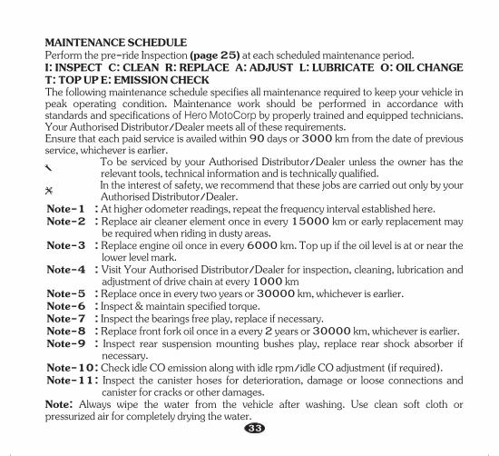
MAINTENANCE SCHEDULEPerform the re-ride Inspection at each scheduled maintenance period.p (page 25)I: INSPECT C: CLEAN R: REPLACE A: ADJUST L: LUBRICATE O: OIL CHANGE T: TOP UP E: EMISSION CHECKThe following aintenance chedule specifies all maintenance required to keep your in m s vehiclepeak operating condition. Maintenance work should be performed in accordance with standards and specifications of by properly trained and equipped technicians. Hero MotoCorp Your meets all of these requirements.Authorised Distributor/DealerEnsure that each paid service is availed within 90 days or 3000 km from the date of previous service, whichever is earlier. To be serviced by your Authorised Distributor/Dealer unless the owner has the
relevant tools, technical information and is technically qualified. In the interest of safety we recommend that these jobs are carried out only by your,
Authorised Distributor/Dealer.Note-1 : At higher odometer readings, repeat the frequency interval established here.Note-2 : Replace air cleaner element once in every 15000 km or early replacement may
be required when riding in dusty areas.Note-3 : Top up if the oil level is at or near the Replace engine oil once in every 6000 km.
lower level mark.Note-4 : Visit for inspection, cleaning, lubrication and Your Authorised Distributor/Dealer
adjustment of drive chain at every 1000 kmNote-5 : Replace once in every two years or 30000 km, whichever is earlier.Note-6 : Inspect & maintain specified torque.Note-7 : Inspect the bearings free play, replace if necessary.Note-8 : Replace front fork oil once in a every 2 years or 30000 km, whichever is earlier.Note-9 : Inspect rear suspension mounting bushes play, replace rear shock absorber if
necessary.Note-10 : Check idle CO emission along with idle rpm/idle CO adjustment (if required).Note-11 : Inspect the canister hoses for deterioration, damage or loose connections and
canister for cracks or other damages. Note: vehicleAlways wipe the water from the after washing. Use clean soft cloth or pressurized air for completely drying the water.
33

3234
Dear Customer, We would strongly recommend the following schedule, to keep your vehicle in perfect running condition and healthy environment. Vehicle subjected to severe use or ridden in dusty area will require more frequent servicing.
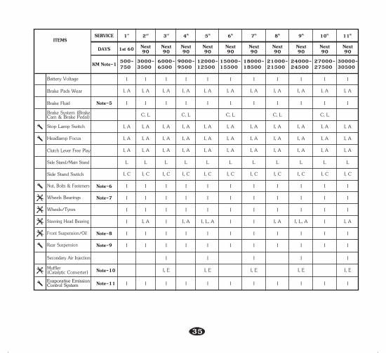
MAINTENANCE SCHEDULE
Fuel Line
Throttle Operation I, A I, A I, A I, A I, A I, A I, A I, AI, A I, A
I
I
I
I
I
I
I
I
I
I
I
I
I
I
I
I
I
I
I
I
I
I
I, A
3000-3500
6000-6500
9000-9500
12000-12500
15000-15500
ITEMS SERVICE st1 nd2 rd3 th4 th5 th6
DAYS
KM Note-1 500-750
Next 90
Next 90
Next 901st 60 Next
90Next 90
th7 th8 th9 th10 th11
Next 90
Next 90
Next 90
Next 90
Next 90
18000-18500
21000-21500
24000-24500
27000-27500
30000-30500
Air Cleaner Element
Spark Plug
Valve Clearance
Engine OilEngine Oil StrainerScreenEngine Oil CentrifugalFilter
R
R
C, A
O O
C
C CC
Electric Starter I I I I I I II
C C C
CCC
I, T I, T I, TI, TOI, TOI, TO
I, A I, A I, A I, A I, A I, A I, A I, A I, AI, A I, A
I, C, A I, C, A I, C, A I, C, AI, C, AI, C, AI, C, AI, C, AI, C, A R
R
AA AC, AAC, A C, AA A
I II
C, AEngine Idle Speed/Carburetor
Do not open air cleaner element unless there is a drivability problem
C C
Note-2
Note-3
I,C,L,A at every 1000 km I,C,L,A at every 1000 kmDrive Chain
Drive Chain Slider
I
I
I
I
I
I
Oil Circulation I I I I I I I
I
I
IIIIII
Note-4
Bystarter Operation
35
Clutch Lever Free Play I, AI, AI, AI, AI, AI, AI, A
Side Stand/Main Stand L L L L L L L LL L L
Side Stand Switch I, C I, C I, C I, C I, C I, C I, C I, C I, CI, C I, C
I
I
I
I
I
I
I
I
ITEMS
Stop Lamp Switch I, A
I, A
I, A
I, A
I, A
I, A
I, A
I, A
I, A
I, A
I, A
I, A
I, A
I, A
I, A
I, A
I, A
I, A
I, A
I, A
I, A
I, A
I, A
I, A
I, A
I, A
I, A
I, A
I, A
I, A
Headlamp Focus I, A I, A I, A I, A I, A I, A I, A
I
I
I
I
I
I
I
I
I
I
I
I
I
I
3000-3500
6000-6500
9000-9500
12000-12500
15000-15500
SERVICE st1 nd2 rd3 th4 th5 th6
DAYS
KM Note-1 500-750
Next 90
Next 90
Next 901st 60 Next
90Next 90
th7 th8 th9 th10 th11
Next 90
Next 90
Next 90
Next 90
Next 90
18000-18500
21000-21500
24000-24500
27000-27500
30000-30500
I
I
I
I
I
I
I
I
I
I
I
I
I
I
I
I
I
I
I
I
I
I
I
I
I
I
Nut, Bolts & Fasteners IIIIIII
Wheels/Tyres I I I I I I I
Steering Head Bearing I I, L, AI, A I, AII, L, AI, AI II, AI
Wheels Bearings IIIIIII
Rear Suspension I
I
I
I
I
I
I
I
I
I
I
I
I
I
I
I
I
Note-9
Front Suspension/Oil I I I I I I INote-8
Note-6
Note-7
Muffler (Catalytic Converter) I, E I, E I, EI, EI, ENote-10
Battery Voltage
Brake Pads Wear
Note-5
Brake System (Brake Cam & Brake Pedal)
Brake Fluid
C, L C, L C, L C, L C, L
Secondary Air Injection
Evaporative Emission Control System Note-11

36
SPARK PLUG INSPECTIONRecommended plugs: NGK-CPR 8 EA9, BOSCH UR5DCFor most riding conditions this spark plug heat range number is satisfactory. However, if the vehicle is going to be operated for extended periods at high speeds or near maximum power in hot climates, the spark plug should be changed to a cold heat range number, consult Authorised Distributor/Dealer on this if required.Ÿ Clean dirt around the spark plug base.Ÿ Disconnect the noise suppressor cap (1)
and remove the spark plug (2) with the help of spark plug box wrench provided in the tool bag.
(1) Noise suppressor cap (2) Spark plugŸ Visually inspect the spark plug electrodes for
wear. The center electrode should have square edges and the side electrode should not be eroded. Discard the spark plug if there is apparent wear or if the insulator is cracked or chipped.
Ÿ Make sure that the spark plug gap is 0.8-0.9 mm using a wire-type feeler gauge. If adjustment is necessary, bend the side electrode carefully. Make sure the plug washer is in good conditions.
Ÿ With the plug washer attached, thread the spark plug in by hand to prevent cross- threading.
Ÿ Tighten a new spark plug 1/2 turn after the plug seats, with a spark plug box wrench to compress the washer. If you are reusing a plug, it should only take 1/8-1/4 turn after the plug seats.
ENGINE OILUse only hero genuine engine oil.BRAND: Hero 4T plusGRADE: SAE 10W 30 SJ Grade (JASO MA).Manufactured by:Ÿ Tide Water Oil Co. (India) Ltd.Ÿ Savita Oil Technologies Limited.Ÿ Bharat Petroleum Corporation Limited.OIL CAPACITY : 1 200 ml
0.8-0.9 mm
1
2

Ÿ After checking the oil circulation, tighten the engine oil check bolt.
Ÿ Stop the engine and wait for 2-3 minutes.Ÿ Remove the oil level dipstick, wipe it clean
and insert without screwing it in.Ÿ Remove the oil level dipstick and check the
oil level.Ÿ If required, add the specified oil up to the
upper level mark. Do not overfill.Ÿ Quantity of oil to be filled is 1070 ml
(approx.) during oil change (when right crankcase cover is not removed).
Ÿ Reinstall the oil level dipstick with new O-ring and check for oil leaks.
Engine oil replacement/Oil circulation inspection• Start the engine, warm it up for several
minutes and then turn it off. • Wait a few minute until the oil settles down.
UPPER
LOWER
Engine oil level inspection/Top up processCheck engine oil level each day before operating the vehicle. The oil level dipstick (1) is on the right crankcase cover for measuring oil level. Oil level must be maintained between the upper (2) and lower (3) level marks on the oil level dipstick.
Ÿ Do top up if oil level reaches towards the lower level mark or every 3000 km whichever is earlier.
Ÿ Park the vehicle on its main stand.Ÿ Start the engine & let it idle for 3-5
minutes.Ÿ Slightly loosen the engine oil check bolt (4)
and check the engine oil entry into the cylinder head cover.
(1) Oil level dipstick (2) Upper level mark(3) Lower level mark
(4) Engine oil check bolt
37
2
3
14
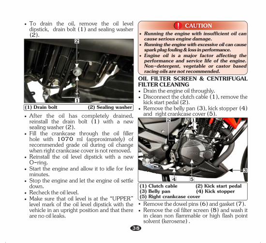
• After the oil has completely drained, reinstall the drain bolt (1) with a new sealing washer (2).
• Fill the crankcase through the oil filler hole with 1070 ml (approximately) of recommended grade oil during oil change when right crankcase cover is not removed.
• Reinstall the oil level dipstick with a new O-ring.
• Start the engine and allow it to idle for few minutes.
• Stop the engine and let the engine oil settle down.
• Recheck the oil level.• Make sure that oil level is at the “UPPER”
level mark of the oil level dipstick with the vehicle in an upright position and that there are no oil leaks.
• To drain the oil, remove the oil level dipstick, drain bolt (1) and sealing washer (2).
2
1(1) Drain bolt (2) Sealing washer
CAUTION!!• Running the engine with insufficient oil can
cause serious engine damage.• Running the engine with excessive oil can cause
spark plug fouling & loss in performance.• Engine oil is a major factor affecting the
performance and service life of the engine. Non-detergent, vegetable or castor based racing oils are not recommended.
OIL FILTER SCREEN & CENTRIFUGAL FILTER CLEANING• Drain the engine oil throughly.• Disconnect the clutch cable (1), remove the
kick start pedal (2).• Remove the belly pan (3), kick stopper (4)
and right crankcase cover (5).
38
2 1
53
(1) Clutch cable (2) Kick start pedal(3) Belly pan (4) Kick stopper(5) Right crankcase cover
• Remove the dowel pins (6) and gasket (7).• Remove the oil filter screen (8) and wash it
in clean non flammable or high flash point solvent (kerosene) .
4

39
(6) Dowel pins (7) Gasket (8) Oil filter screen (9) Centrifugal filter cover• Reinstall the filter screen with the tapered
end facing in.• Remove centrifugal filter cover (9) & clean
the centrifugal filter (10) with non flammable or high flash point solvent (kerosene).
8
(10) Centrifugal filter
9
• Reinstall the dowel pins and gasket.• Reinstall the centrifugal filter cover, right
crankcase cover and connect the clutch cable. Install kick stopper, kick start pedal and under cowl.
• Fill the crankcase with clean engine oil as per specification.
• Clean filters as specified in the maintenance schedule.
• Ensure to replace gasket with new one once removed
NOTE
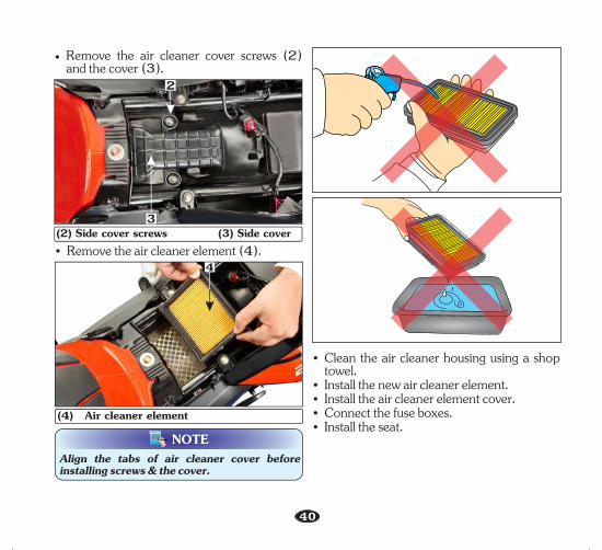
AIR CLEANERAir cleaner element inspectionThe air cleaner is wet paper pleated type filter which has enhances filtering efficiency. The air cleaner replacedshould be at regular intervals When riding in dusty (page 33).areas, more frequent may be replacementnecessary.• (page 24).Remove the seat assembly • Dislodge fuse boxes (1). the
(1) Fuse boxes
1
6
7
10
40
• Remove the air cleaner cover screws (2) and the cover (3).
(2) Side cover screws (3) Side cover• Remove the air cleaner element (4).
4
(4) Air cleaner element
NOTEAlign the tabs of air cleaner cover before installing screws & the cover.
• Clean the air cleaner housing using a shop towel.
• Install the new air cleaner element.• Install the air cleaner element cover.• Connect the fuse boxes.• Install the seat.
2
3

41
CAUTION!!• wet, paper pleated Never wash or clean the
type filter. Replace filter element once in every 15000 km.
• Replace it earlier if it becomes very dirty, damage on surface or on the sealing area.
NOTEAlways ensure to reinstall the drain tube after draining the deposit.
Air cleaner drain tube cleaningRemove the drain tube (1) and drain the deposit into a container.Follow the above process more frequently when riding in rain or at full throttle.
(1) Drain tube1
CARBURETORIdle speed adjustmentThe carburetor is factory preset in order to achieve optimum performance and meet emission standards.However in case of specific requirement of tuning due to engine stalling in idle speed, please follow the instructions given here under:• Warm up the engine and rest the vehicle on
the main stand.• Adjust idle speed with the throttle stop
screw (1).IDLE SPEED: 1400 ± 100 RPM
A B
1
CAUTION!!Do not attempt to compensate for faults in other systems by adjusting idle speed. Visit your Authorised Distributor/Dealer for scheduled carburetor adjustment.
(1) Throttle stop screw (A) Increase rpm (B) Decrease rpm
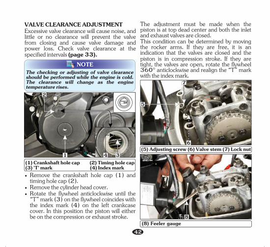
VALVE CLEARANCE ADJUSTMENTExcessive valve clearance will cause noise, and little or no clearance will prevent the valve from closing and cause valve damage and power loss. Check valve clearance at the specified intervals (page 33).
42
• Remove the crankshaft hole cap (1) and timing hole cap (2).
• Remove the cylinder head cover.• Rotate the flywheel anticlockwise until the
“T” mark (3) on the flywheel coincides with the index mark (4) on the left crankcase cover. In this position the piston will either be on the compression or exhaust stroke.
41
The adjustment must be made when the piston is at top dead center and both the inlet and exhaust valves are closed.This condition can be determined by moving the rocker arms. If they are free, it is an indication that the valves are closed and the piston is in compression stroke. If they are tight, the valves are open, rotate the flywheel 360° anticlockwise and realign the “T” mark with the index mark.The checking or adjusting of valve clearance
should be performed while the engine is cold. The clearance will change as the engine temperature rises.
NOTE
(1) Crankshaft hole cap (2) Timing hole cap(3) 'T' mark (4) Index mark
(8) Feeler gauge
(5) Adjusting screw (6) Valve stem (7) Lock nut
5
7
6
8
3
2

43
Before inserting the feeler gauge, smear a bit of engine oil on the feeler gauge to avoid damage to the feeler gauge.
NOTE
CLUTCH LEVER FREE PLAYAdjustmentClutch adjustment may be required if the vehicle stalls when shifting into gear or tends to creep or if the clutch slips, causing acceleration to lag behind engine speed.Normal clutch lever free play (1) is 10-20 mm at the lever (2).
• To adjust the free play, loosen the lock nut (3). Turn the adjusting nut (4) to obtain the specified free play. Tighten the lock nut and check the adjustment.
2
B
A
1(1) Free play 10-20 mm (2) Clutch lever
(3) Lock nut (4) Clutch cable adjusting nut(A) Decrease free play (B) Increase free play
3 4
Standard clearance (cold condition)Intake: 0.06 mm Exhaust: 0.08 mmIf adjustment is required, adjust by loosening the lock nut (7) and turning the adjusting screw until there is a slight drag on the feeler gauge.After tightening the lock nut, check the clearance again.Install the parts in the reverse order of disassembly.
• Check the clearance by inserting the feeler gauge (8) between the adjusting screw (5) and valve stem (6).
44
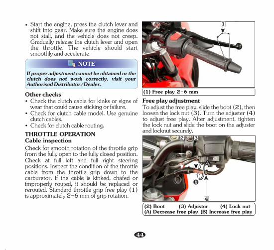
Free play adjustmentTo adjust the free play, slide the boot (2), then loosen the lock nut (3). Turn the adjuster (4) to adjust free play. After adjustment, tighten the lock nut and slide the boot on the adjuster and locknut securely.
2 3THROTTLE OPERATIONCable inspection
Check for smooth rotation of the throttle grip from the fully open to the fully closed position.Check at full left and full right steering positions. Inspect the condition of the throttle cable from the throttle grip down to the carburetor. If the cable is kinked, chafed or improperly routed, it should be replaced or rerouted. Standard throttle grip free play (1) is approximately 2-6 mm of grip rotation.
1
(1) Free play 2-6 mm
(2) Boot (3) Adjuster (4) Lock nut(A) Decrease free play (B) Increase free play
Other checks• Check the clutch cable for kinks or signs of
wear that could cause sticking or failure.• Check for clutch cable model. Use genuine
clutch cables.• Check for clutch cable routing.
If proper adjustment cannot be obtained or the clutch does not work correctly, visit your Authorised Distributor/Dealer.
NOTE
• Start the engine, press the clutch lever and shift into gear. Make sure the engine does not stall, and the vehicle does not creep. Gradually release the clutch lever and open the throttle. The vehicle should start smoothly and accelerate.
B
A
4

45
BYSTARTER OPERATION To apply bystarter, pull the lever (1) outwards, towards the rider to check for smooth operation. After checking the operation, push it back to OFF position (as shown in the picture).
NOTEDo not accelerate during starting when the bystarter is “ON”.
(1) Bystarter operation
DRIVE CHAIN SLACKNESSThe service life of the drive chain depends upon proper lubrication and adjustment.Poor maintenance can cause premature wear or damage to the drive chain and sprockets.The drive chain (1) should be checked and lubricated as part of the pre-ride inspection (page 25). Under severe usage, or when the vehicle is ridden in unusually dusty areas, more frequent maintenance will be necessary.
Inspection• Turn the engine “OFF”, park the vehicle on
its main stand and shift the transmission to neutral.
• Drive chain slack (2) should be checked in the lower run midway between the sprockets. Move the drive chain up and down by hand and chain slack should be adjusted to 20-25 mm vertical movement by hand.
• Rotate the wheel and check the drive chain slack. Repeat this procedure several times. Drive chain slack should remain constant ( only in 20-25 mm). If the chain is slackcertain sections, some links are kinked or binding. Binding and kinking can be eliminated by frequent lubrication.
1
1(1) Drive chain ( ) Drive chain slack2 : 20-25 mm
Drive chain slack should be adjusted at your Authorised Distributor/Dealer as per the specification.
NOTE
2

46
Drive chain• Damaged rollers• Loose pins • Dry or rusted links • Kinked or binding links • Excessive wear • Improper adjustment • Damaged or missing O-rings.Sprockets• Excessively worn teeth • Broken or damaged teeth.
If the drive chain has damaged rollers, loose links or missing O-rings, replace it. If the chain is dry or rusted, it should be lubricated. Lubricate the chain if the links are kinked or binding. If the problem is not solved after lubrication, replace the chain.If the drive chain or sprockets are excessively worn or damaged, they should be replaced.
AdjustmentDrive chain slack should be checked and adjusted, if necessary at every 000 km.1When operated at sustained high speeds or under condi t ions of f requent rapid acceleration, the chain may require more frequent adjustments.If the drive chain requires adjustment, follow the procedures below:
CAUTION!!Always replace the drive chain and sprockets as a set. Otherwise the new part will wear prematurely.
co kr ep tS T enr
eo
thW
corpke
S
t
l
T
a
e
m
e
r
t
o
h
N
orp
cS
kd
ee
t
g
T
a
ee
m
t
a
h
D
• Rotate the rear wheel slowly and inspect the drive chain and sprockets for any of the following conditions.
(3) Chain lock plate (4) Open end
3
4
• Turn the chain to view chain lock plate (3). Ensure that the chain lock plate open end (4) is installed in the opposite direction of the chain rotation.

47
3
(2) Axle (3) Drive chain lock nut(4) Drive chain adjusting nut (5) Index mark (6) Rear edge of adjusting slot
4652
WARNING!!If a torque wrench is not used for installation, see your Authorised Distributor/Dealer as soon as possible to check for proper assembly.
(1) Rear axle nut
1
• Loosen the drive chain lock nut (3).• Turn the adjusting nut (4) in an equal
number of turns until the correct drive chain slack is obtained. Turn the adjusting nut clockwise to decrease the slack or anticlockwise to increase the slack of the chain.
• Align the chain adjuster index mark (5) with the rear edge (6) of the adjusting slots on both sides of the swingarm equally.
Torque: 68 N-m (6.8 kgf-m)• Tighten the rear axle nut.
• Check the drive chain slack again.• If after adjustment of drive chain slack, axle
(2) touches to the rear edge of adjustment slot (6). Chain kit has to be replaced.
• Park the vehicle on its main stand with the transmission in neutral and the ignition switch in “OFF” position.
• Loosen the rear axle nut (1).

48
Cleaning and LubricationLubricate every 00 km or sooner if the 10chain appears dry. • park the vehicle on its Turn the engine off,
main stand and shift the transmission into neutral. Open side stand to facilitate cleaning.
• Spray a commercially available chain cleaner for cleaning the drive chain over its entire length.
• Rotate the rear wheel backwards to expose the next section of the drive chain and repeat STEP-2 until all of the drive chain is cleaned.
• Let the spray dry for about five minutes.• To remove stubborn dirt, scrub the rollers
and side plates with soft nylon brush.• Apply SAE 90 grade oil on the hanger side
of the entire length of the chain using an oil can.
• Wait for 7-10 minutes for penetration of lubricant inside the bush and roller wipe the excessive lubricant from the chain and nearby parts using a clean rag.
Ensure that the chain cleaner and lubricant used is the one recommended for use on an O-ring chain, otherwise the O-rings may deteriorate, fail and lose their sealing properties.
NOTE
Excessive lubricant if not wiped off, will aid in accumulation of dust, sand and dirt on the drive chain, increasing its wear and will also be sprayed on the vehicle as well due to chain movement.
NOTE
CAUTION!!• Steam cleaning, high pressure washers and
certain solvents can damage the drive chain O-rings.
• While lubricating and cleaning hold the rear wheel with one hand to prevent the possibility of your finger being trapped between the chain and sprocket.
• Clean and lubricate the chain, whenever possible, after riding the vehicle under rain or in terrain with excessive dust, mud or sand.
• The drive chain is fitted with O-rings between the link plates. These O-rings retain grease inside the chain to improve its service life. However, special precautions must be taken when adjusting, lubricating, washing and replacing the chain.
• If the chain is excessively dirty, it should be removed and cleaned before lubrication. For your own safety, we recommend that service be performed by an Authorised Distributor/ Dealer.
DRIVE CHAIN SLIDER INSPECTION(Refer to “Maintenance Schedule” on page 33)

49
Check the chain slider (1) for wear, The chain slider must be replaced if wear limit is reached.For replacement, see your Authorised Distributor/Dealer.
CUTOUT
1
2
(1) Chain slider (2) Wear limitBRAKESRefer to the safety precautions on (page 32).(a) Front brakeMaster Cylinder (1)Location : Right handlebar.Brake fluid recommended: DoT-4/DoT-3.Fluid level - Ensure that the brake fluid level does not fall below "MIN'' mark (2) on master cylinder, when checked with the master cylinder parallel to the ground. The level decreases gradually due to piston movement to compensate pad wear. If the level decreases abruptly, check for the leakages in the brake system and consult your Authorised Distributor/Dealer.
(1) Master cylinder (2) "Lower" mark2
1
NOTE• Clean the dirt and mud accumulation
between the brake pads (3), caliper (4) and the disc (5) by using a water jet.
• A lwa y s c o n t a c t y o u r Au t h o r i s e d Distributor/Dealer for refilling of master cylinder when necessary. Do not mix DoT 3 and DoT 4 brake fluid.
(3) Brake pad (4) Caliper (5) Disc
3
5
3
4
50
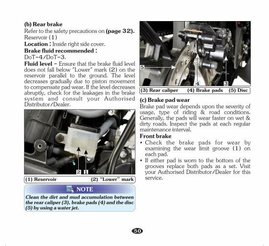
(b) Rear brakeRefer to the safety precautions on (page 32).Reservoir (1)Location : Inside right side cover.Brake fluid recommended : DoT-4/DoT-3.Fluid level - Ensure that the brake fluid level does not fall below "Lower" mark (2) on the reservoir parallel to the ground. The level decreases gradually due to piston movement to compensate pad wear. If the level decreases abruptly, check for the leakages in the brake system and consult your Authorised Distributor/Dealer.
22(1) Reservoir (2) “Lower” mark
1
34(3) Rear caliper (4) Brake pads (5) Disc
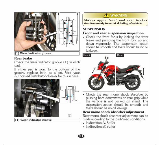
(c) Brake pad wear Brake pad wear depends upon the severity of usage, type of riding & road conditions. Generally, the pads will wear faster on wet & dirty roads. Inspect the pads at each regular maintenance interval.Front brake• Check the brake pads for wear by
examining the wear limit groove (1) on each pad.
• If either pad is worn to the bottom of the grooves replace both pads as a set. Visit your Authorised Distributor/Dealer for this service.
NOTEClean the dirt and mud accumulation between the rear caliper (3), brake pads (4) and the disc (5) by using a water jet.
5
51
Rear brakeCheck the wear indicator groove (1) in each pad. If either pad is worn to the bottom of the groove, replace both as a set. Visit your Authorised Distributor/Dealer for this service.
(1) Wear indicator groove
1 11 1
1(1) Wear indicator groove
WARNING!!Always apply front and rear brakes simultaneously to avoid skidding of vehicle.
SUSPENSIONFront and rear suspension inspection• Check the front forks by locking the front
brake and pumping the front fork up and down vigorously. The suspension action should be smooth and there should be no oil leakage.
Front Rear
• Check the rear mono shock absorber by pushing hard downwards on rear grip while the vehicle is not parked on stand. The suspension action should be smooth and there should be no oil leakage.
Rear mono shock absorber adjustmentRear mono shock absorber adjustment can be made according to the load/road conditions.• In direction A: Stiffer• In direction B: Softer

52
B
A
2
NOTETo adjust the rear mono shock absorber (1), use the rear shock absorber adjustment tool [Pin spanner (2) with handle (3)] available in the tool kit.
(1) Rear mono shock absorber (2) Pin spanner (3) Pin spanner handle(A) Stiffer (B) Softer
13
WHEEL(a) Front wheelRemovalRefer to the safety precautions on (page 32).• Support the vehicle securely on the main
stand and raise the front wheel off the ground.
• Remove the wheel speed sensor bolt (1) from right fork leg and disconnect the cable (2).
• Remove the front axle nut (3), remove the axle and wheel.
(1) Wheel speed sensor bolt(2) Wheel speed sensor cable
1
2
CAUTION!!Do not operate front brake lever when the wheel is removed.
(3) Axle nut3
53
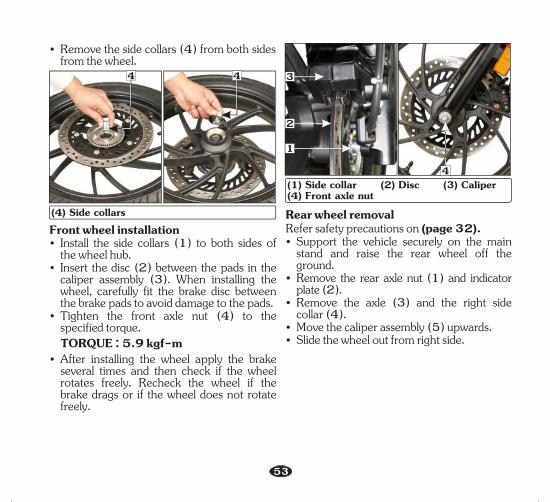
(4) Side collars
4 4
Front wheel installation• Install the side collars (1) to both sides of
the wheel hub.• Insert the disc (2) between the pads in the
caliper assembly (3). When installing the wheel, carefully fit the brake disc between the brake pads to avoid damage to the pads.
• Tighten the front axle nut (4) to the specified torque.
TORQUE : 5.9 kgf-m• After installing the wheel apply the brake
several times and then check if the wheel rotates freely. Recheck the wheel if the brake drags or if the wheel does not rotate freely.
(1) Side collar (2) Disc (3) Caliper (4) Front axle nut
1
2
4
3
Rear wheel removalRefer safety precautions on (page 32).• Support the vehicle securely on the main
stand and raise the rear wheel off the ground.
• Remove the rear axle nut (1) and indicator plate (2).
• Remove the axle (3) and the right side collar (4).
• Move the caliper assembly (5) upwards.• Slide the wheel out from right side.
• Remove the side collars (4) from both sides from the wheel.

54
Rear wheel installation• Install the side collar (1) to the right side of
the wheel hub.• Tilt the vehicle and position the rear wheel
between the swingarm. • Insert the disc (2) between the pads in the
caliper assembly. When installing the wheel, carefully fit the brake disc between the brake pads to avoid damage to the pads.
• Align the rear caliper holder (3) with the swingarm (4).
• Insert the axle (5) from the left side through the swingarm, wheel hub, collar and rear caliper holder.
• indicator plateInstall the (6) and tighten the rear axle nut (7) to the specified torque.
TORQUE : 6.8 kgf-m
4(1) Rear axle nut (2) Indicator plate (3) Axle(4) Side collar (5) Caliper assembly
1
23
5(1) Side collar (2) Disc (3) Caliper holder(4) Swingarm (5) Rear axle (6) Indicator plate (7) Rear axle nut
7
6
1
2
3 5
4
MAIN/SIDE STAND LUBRICATION• Park the vehicle on the level surface.• Check the main/side stand return spring for
damage or loss of tension.• Check the main stand (1)/side stand (2)
for freedom of movement.
(1) Main stand (2) Side stand2 1

55
• Lubricate the side stand pivot if necessary.• Make sure the main/side stand is not bent.
• Using tyres that are excessively worn or improperly inflated can cause a crash in which you can be seriously hurt or killed.
• Follow all instructions in this owner's manual regarding tyres inflation and maintenance.
WARNING!!
Air pressureKeeping your tyres properly inflated provides the best combination of handling, tread life and riding comfort.Generally, under-inflated tyres wear unevenly, adversely affect handling and are more likely to fail from being overheated.Under inflated tyres can also cause wheel damage in rocky terrain.Over-inflated tyres make your vehicle ride harshly, are more prone to damage from road hazards, and wear unevenly.
TUBELESS TYRESThe tyres fitted on your vehicles are of TUBELESS type.To safely operate your vehicle, your tyres must be of the proper type and size, in good condition with adequate tread, and correctly inflated for the load you are carrying. The following pages give more detailed information on how and when to check the air pressure, how to inspect your tyres for damage, and what to do when your tyres need to be repaired or replaced.
We recommend that you visually check your tyres before every ride and use a gauge to measure air pressure at least once a month or any time you think the tyres pressure might be low. Tubeless tyres have some self-sealing ability if they are punctured. However, because leakage is often very slow, you should look closely for punctures whenever a tyre is not fully inflated.Always check air pressure when your tyres are "cold"-when the vehicle has been parked for at least three hours. If you check air pressure when your tyres are "warm"-when the vehicle has been ridden for even a few km-the readings will be higher than if the tyres were "cold". This is normal, so do not let air out of the tyres to match the recommended cold air pressures given below. If you do, the tyres will be under-inflated.The recommended “cold” tyre pressures are:
1
(1) Air pressure gauge

FrontRear
21.75 kgf/cm
21.96 kgf/cm
2 1.75 kgf/cm
22.1 kgf/cm
Rider only Rider and Pillion
Over inflation/Under inflation will affect the performance.
CAUTION!!
InspectionWhenever you check the tyre pressure, you should also examine tyre treads & side walls for wear, damage & foreign objects.Look for:
• Bumps or bulges in the side of the tyre or the tread. Replace the tyre if you find any bumps or bulges.
• Cuts, splits or cracks in the tyre. Replace the tyre if you can see fabric or cord.
• Excessive tread wear.
56
• Carefully inspect the tyres for any damage, if the vehicle hits a pothole or hard object.
Tread wearReplace tyres immediately when the wear indicator (1) appears on the tyre. The tread limits are:MINIMUM TREAD DEPTH:Front: 0.8 mm Rear: 1.0 mmCheck the tread wear indicator for tyre wear.
(1) Tread wear indicator (2) Arrow markTW
I 1
2

Unidirectional tyresWhenever the tyre is removed and put back in case of puncture, ensure the arrow mark (2) on the tyre is in the same direction as that of forward rotation of wheel.Tyre repairIf a tyre is punctured or damaged, you should replace it, not repair it. As mentioned below, a tyre that is repaired either temporarily or permanently, will have lower speed and performance limits than a new tyre.A temporarily repaired, such as an external tubeless tyre plug, may not be safe for normal speeds and riding conditions. If a temporary or emergency repair is made to a tyre, you should ride slowly cautiously to your Authorised Distributor/Dealer and have the tyre replaced. If possible you should not carry a pillion or load until a new tyre is installed.Even if a tyre is professionally repaired with a permanent internal patch plug, it will not be as good as a new tyre.You should not exceed 70 km/hour for the 1st 24 hours or 105 km/hour at any time thereafter. In addition you may not be able to safely carry as much load as with a new tyre. Therefore, we strongly recommend that you replace a damaged tyre. If you decide to have a tyre replace be sure the wheel is balanced before you ride.
57
Tyre replacementThe tyres that were installed on your vehicle were designed to match the performance capabilities of your vehicle and provide the best combination of handling, braking, durability and comfort.The recommended tyre for your vehicle are:FrontRear
WARNING!!• Operation with excessively worn tyres is
hazardous and will adversely affect traction and handling.
• Under-inflation may result in the tyre slipping on or tyre coming off the rim.
• Always use the size and type of tyres recommended in this owner's manual.
NOTEFor repair and replacement of tyre it is advised to visit your Authorised Distributor/Dealer.Important safety reminders• Do not install a tube inside a tubeless tyre on
this vehicle. Excessive heat buildup can cause the tube to burst.
• Use only tubeless tyres on this vehicle. The rims are designed for tubeless tyres, and during hard acceleration or braking, a tube-type tyre could slip on the rim and cause the tyre to rapidly deflate.
100/80 x 17-52 P (Tubeless tyre)130/70 x R17-62 P (Tubeless tyre)
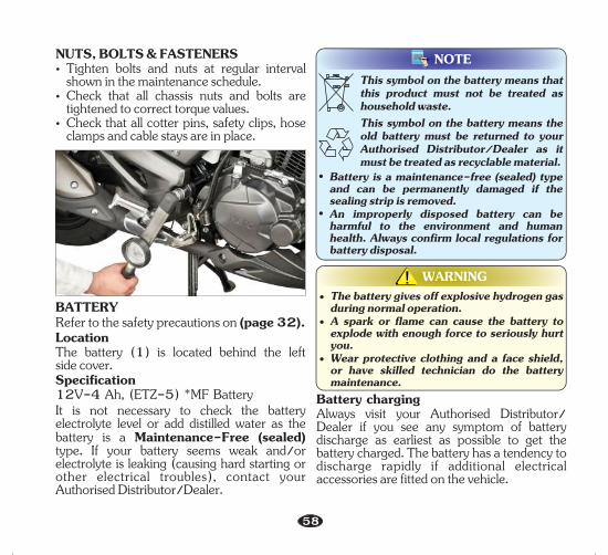
BATTERYRefer to the safety precautions on (page 32).LocationThe battery (1) is located behind the leftside cover.Specification12V-4 Ah, (ETZ-5) *MF Battery It is not necessary to check the battery electrolyte level or add distilled water as the battery is a Maintenance-Free (sealed) type. If your battery seems weak and/or electrolyte is leaking (causing hard starting or other electrical troubles), contact your Authorised Distributor/Dealer.
NOTEThis symbol on the battery means that this product must not be treated as household waste.
58
NUTS, BOLTS & FASTENERSŸ Tighten bolts and nuts at regular interval
shown in the maintenance schedule.Ÿ Check that all chassis nuts and bolts are
tightened to correct torque values.Ÿ Check that all cotter pins, safety clips, hose
clamps and cable stays are in place.This symbol on the battery means the old battery must be returned to your Authorised Distributor/Dealer as it must be treated as recyclable material.
• Battery is a maintenance-free (sealed) type and can be permanently damaged if the sealing strip is removed.
• An improperly disposed battery can be harmful to the environment and human health. Always confirm local regulations for battery disposal.
WARNING!!• The battery gives off explosive hydrogen gas
during normal operation.• A spark or flame can cause the battery to
explode with enough force to seriously hurt you.
• Wear protective clothing and a face shield, or have skilled technician do the battery maintenance.
Battery charging Always visit your Authorised Distributor/ Dealer if you see any symptom of battery discharge as earliest as possible to get the battery charged. The battery has a tendency to discharge rapidly if additional electrical accessories are fitted on the vehicle.

Battery storage • If in case your vehicle is not used for more
than a month remove the battery, fully charge and store in a cool and dry place.
Ÿ If the battery is expected to be stored for more than two months, ensure to fully charge the battery once in a month.
Ÿ Always ensure the battery is fully charged before installation.
Ÿ Ensure the battery leads are properly connected to the battery terminals during installation.
Battery removal • Make sure the ignition switch is “OFF” ( ).• Remove the seat (page 24).• Remove the left side cover screws (1) and
remove the side cover (2).
(1) Left side cover screws (2) Side cover
(6) Battery
• Pullout the battery (6) from the battery box.
• Disconnect the (-)ve terminal lead (3) from the battery first, then disconnect the (+)ve terminal lead (4).
• Remove the battery holding belt (5).59
Battery installation Ÿ Reinstall in the reverse order of removal. Be
sure to connect the (+)ve terminal first, then the (-)ve terminal.
Ÿ Check all fasteners are secure.
(3) (-)ve terminal (4) (+)ve terminal(5) Battery belt
2
1
3 4
5
6

1( ) Starter magnetic switch C(1) Main fuse (20A)
60
FUSE REPLACEMENTRefer to the safety precautions on (page 32).The fuse boxes (A) and (B) are below the seat.(A) : Main (1) : fuse (15A, 10A)
Spare fuse (15A, 10A) (2) :(B) Main : fuse (3) : (10A)
Spare fuse (4) : (10A)
Starter magnetic switch (C)Location : Inside left side cover, below the starter magnetic switch.Fuse Type: Blade fuseMain fuse (1) : (20A)Spare fuse (2) : (20A)
(A) & (B) Fuse box (1) Main fuse (15A, 10A) (2) Spare fuse (15A, 10A) (3) Main fuse (10A) (4) Spare fuse (10A)
2
1 A
B4 3
2(2) Spare fuse (20A)
WARNING!!• Never use a fuse with a different rating from
that specified. It may lead to serious damage to the electrical system or a fire due to short circuit.
• Battery gives off explosive gases. Keep sparks, flames & cigarettes away.
C
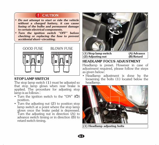
61
GOOD FUSE BLOWN FUSE
CAUTION!!• Do not attempt to start or ride the vehicle
without a charged battery, it can cause fusing of the bulbs and permanent damage to certain electrical components.
• Turn the ignition switch "OFF" before checking or replacing the fuse to prevent accidental short-circuiting.
HEADLAMP FOCUS ADJUSTMENTHeadlamp is preset. However in case of adjustment required, please follow the steps as given below:• Headlamp adjustment is done by the
loosening the bolts (1) located below the headlamp.
1
(1) Headlamp adjusting bolts
STOP LAMP SWITCHThe stop lamp switch (1) must be adjusted so that stop lamp glows when rear brake is applied. The procedure for adjusting stop lamp is as follows :• Turn the ignition switch to the “ON” ( )
position.• Turn the adjusting nut (2) to position stop
lamp switch at a point where the stop lamp glows once the brake pedal is depressed. Turn the adjusting nut in direction (A) to advance switch timing or in direction (B) to retard switch timing.
A
B
(1) Stop lamp switch (A) Advance (2) Adjusting nut (B) Retard
2
1

62
CATALYTIC CONVERTERThis vehicle is equipped with a catalytic converter (1) in the muffler to meet the emission norms.The catalytic converter contains noble metals that serve as catalyst, promoting chemical reactions to convert CO and HC in the exhaust to CO and H O (water vapour).2 2A defective catalytic converter contributes to air pollution and can impair your engine’s performance.Follow these guidelines to protect your vehicle’s catalytic converter.• Always use unleaded petrol. Even a small
amount of leaded petrol can contaminate the catalyst metals, making the catalytic converter ineffective.
• Keep the engine tuned up.
WARNING!!An improperly adjust headlamp may blind oncoming rider/driver or it may fail to light the road for a safe distance. (1) Catalytic converter
1
AIR SUCTION VALVE (ASV)(SECONDARY AIR INJECTION SYSTEM)Further to meet emission standards this vehicle is provided with the air suction valve.Air suction valve (1) supplies fresh air from the air filter to the exhaust manifold to convert carbon monoxide to carbon dioxide. This reduces the in the vehicle’s exhaust.CO%
1
(1) Air suction valve
• Park the vehicle on it main stand on level ground.
• Adjust the headlamp beam by loosening the bolt (1) and moving the headlamp unit forward and backward for correct focus adjustment.
• Tighten the nut after adjustment.

63
POLISHING OF VEHICLEAfter washing your vehicle, wax all painted surfaces (except matte painted surfaces) using a commercially available polish/quality liquid or paste wax to finish the job. Use only a non abrasive polish or wax made specifically for automobiles. Apply the polish or wax according to the instructions on the container.
NOTEPolishing or waxing is not applicable for models having matte paint.
(1) Canister1
EVAPORATIVE EMISSION CONTROL SYSTEMThis vehicle is equipped with an evaporative emission control system to meet emission standards. During warm weather, the petrol vapours which contain HC evaporates easily into the atmosphere from the fuel tank, if the fuel system is unsealed or open.The evaporative emission control system is used to prevent petrol vapours from escaping into the atmosphere from fuel tank.The canister (1) collects the fuel vapour from the fuel tank and then the fuel vapour is drawn into the engine for re-burning to avoid pollution caused by the fuel vapour diffused into the air.

Check fuse
Inspect battery
Check connections, ignition switch/starter switch
OK
OK
OK Loose
Replace fuse (ref. page 60)
Refill
Secure connectionsWeak
FusedC. Electric Starter Not Working
Check ignition switchOK
OK
OK
D. No Spark At Spark Plug
No sparkCheck spark plug for fouling/
improper electrode gapReplace spark plug/adjustSpark Plug Gap (0.8-0.9 mm)
Loose contactCheck for poorly connected
or loose spark plug wire Secure properly
1. STARTING TROUBLE - ENGINE DOES NOT START
“OFF” ( ) position Turn ignition switch “ON” ( )
64
BASIC TROUBLESHOOTING
Check engine stop switch position “OFF”A. ENGINE STOP SWITCH POSITION
Turn to “ON” ( ) position“ON” ( ) position
Check fuel valve position“ON” ( )position
Check fuel in fuel tankOK
OKCheck fuel lines Leakage/Air lock
Turn to “ON” ( ) position
Refill
RectifyNo fuel
“OFF”B. Fuel system
Consult Authorised Distributor/Dealer
Consult Authorised Distributor/Dealer
Consult Authorised Distributor/Dealer
Consult Authorised Distributor/Dealer
Consult Authorised Distributor/Dealer
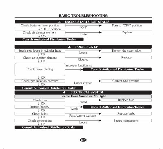
BASIC TROUBLESHOOTING
Spark plug loose in cylinder headOK
Check air cleaner elementOK
OK
Check brake binding
Tighten the spark plug
ReplaceClogged
Loose3. POOR PICK UP
OKCheck tyre inflation pressure Under inflated Correct tyre pressure
Check fuseOK
Inspect batteryOK
OKCheck bulbs Fuse/wrong wattage
Replace fuse
Weak
FusedFeeble Horn Sound or No Light
Replace bulbs
4. ELECTRICAL SYSTEM
OKCheck connections Loose Secure connections
Improper functioning
65
Check bystarter lever position“OFF” position
Check air cleaner elementOK
Turn to “OFF” position
ReplaceDirty
“ON”2. ENGINE STARTS BUT STALLS
Consult Authorised Distributor/Dealer
Consult Authorised Distributor/Dealer
Consult Authorised Distributor/Dealer
Consult Authorised Distributor/Dealer
Consult Authorised Distributor/Dealer

DELIVERY CERTIFICATENo.: IB15ADEALER CODE
Hero MotoCorp Ltd.
I certify having taken delivery of one Hero MotoCorp XTREME 200R Vehicle bearing the following particulars:-
Engine No.
VINColour/Model
Allotment No.
Customer’s Name
I have been explained by the dealer about correct and safe driving habits, warranty terms and conditions, service schedules and maintenance tips.
Customer’s Copy
Key No.
Date of Sale
CUSTOMER’S COPY

Hero MotoCorp Ltd.Alongwith the vehicle I have also received the following:-
2. 2 Nos. Keys1. Owner’s Manual
3. 1 Set of tools (for details see below)4. Standard Accessories5. Battery6. Tyre Front
Rear
MakeMakeMake
Sr. No.Sr. No.Sr. No.
The vehicle has been delivered in factory fresh conditions to my satisfaction & I have understood all terms and conditions of warranty and shall abide by them.
Customer’s AddressCustomer’s Signature
Customer’s Name
Authorised Distributor/Dealer NameAuthorised Distributor/Dealer AddressDetails of Tool kitTool Bag, +, - No. 2 Driver, Grip, Box Wrench P16 x 14, Handle Pin Spanner, Pin Spanner, No. 3 Cross Point Screw Driver, Wire Helmet Set.

Hero MotoCorp Ltd.
I certify having taken delivery of one Hero MotoCorp XTREME 200R Vehicle bearing the following particulars:-
Engine No.
VINColour/Model
Allotment No.
Customer’s Name
I have been explained by the dealer about correct and safe driving habits, warranty terms and conditions, service schedules and maintenance tips.
Key No.
Date of Sale
DELIVERY CERTIFICATE
DEALER CODENo.: IB15A
Authorised Distributor/Dealer copy
AUTHORISED
DISTRIBUTOR/DEALER COPY
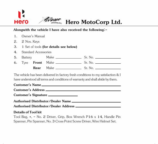
Hero MotoCorp Ltd.Alongwith the vehicle I have also received the following:-
2. 2 Nos. Keys1. Owner’s Manual
3. 1 Set of tools (for details see below)4. Standard Accessories5. Battery6. Tyre Front
Rear
MakeMakeMake
Sr. No.Sr. No.Sr. No.
The vehicle has been delivered in factory fresh conditions to my satisfaction & I have understood all terms and conditions of warranty and shall abide by them.
Customer’s AddressCustomer’s Signature
Customer’s Name
Authorised Distributor/Dealer NameAuthorised Distributor/Dealer AddressDetails of Tool kitTool Bag, +, - No. 2 Driver, Grip, Box Wrench P16 x 14, Handle Pin Spanner, Pin Spanner, No. 3 Cross Point Screw Driver, Wire Helmet Set.

WHAT ARE THE BENEFITS OF Hero MotoCorp GENUINE SPARE PARTS ?• Assures long life• Ensures economy for a long time• Safety of vehicle and rider• Peace of mind• Value for money• Assured quality
CONSEQUENTIAL DAMAGES ON USING NON-GENUINE PARTS
Clutch Plate
• Material used is inferior• Damages other parts of clutch like, clutch center and
outer clutch• Affects fuel efficiency• Poor acceleration
• Poor performance• Reduced life
• Improper sealing• Engine knocking• Leads to leakage and smoky exhaust• Higher emission level
Cam Chain Kit
Gasket Cylinder Head

CONSEQUENTIAL DAMAGES ON USING NON-GENUINE PARTS
Element Air Cleaner• Improper air filtration resulting in premature engine failure• Affects fuel efficiency • Poor engine performance
• Frequent stalling of engine • Higher emission level• Poor engine performance• Affects fuel efficiency
• Poor braking efficiency• Rider safety-an issue• Discs/Drum wear out, resulting in subsequent repair cost
• Noisy Operation• Failure of chain can cause fatal accidentChain Sprocket Kit
Brake Pads/Shoes
Spark Plug

JOBS APPLICABLE TO PERIODIC SERVICES• Test drive the vehicle if required for reported troubles, if any.• Wash the vehicle, blow dry with air at every service.• Fuel line inspection at every service.• Inspect throttle free play and operation at every service, adjust if necessary.• Inspect bystarter operation at every service.• Clean carburetor at first service then every 6000 km., adjust if necessary.• Replace air cleaner element at every 15000 km.• Inspect, clean the spark plug at every service, adjust if necessary. (replace at every 12000 km).• Inspect the valve clearance at every service, adjust if necessary.• tEngine oil op up or change as per the maintenance schedule.• Clean engine oil strainer screen at first service then every 6000 km.• Clean engine oil centrifugal filter at first service then every 6000 km.• Inspect oil circulation at every service.• Inspect electric starter operation at every service.• 1Inspect, clean, lubricate and adjust the drive chain at every 000 km.• Inspect the drive chain slider.• Inspect battery voltage at every service and charge if required.• Inspect brake pad and brake fluid level at every service, adjust brake pad if necessary.• Clean and lubricate brake cam and brake pedal at second service, then every 6000 km.• ampInspect all l s, horn and switches at every service, adjust if necessary.• ampInspect headl focus at every service, adjust if necessary.• Inspect clutch lever free play at every service, adjust if necessary.• Lubricate the side stand and main stand at every service.• at every service.Inspect and clean the side stand switch • Inspect fasteners and tighten to the specified torque (if required).• Inspect the bearings free play, replace if necessary.• Inspect wheels/tyres. Inflate tyre to specified pressure at every service.• Inspect steering for smooth operation, adjust (if necessary) in every alternate service and lubricate at every
12000 km.• Inspect front suspension at every service, replace oil once in every 2 year or 30000 km whichever is earlier.• Inspect rear suspension mounting bushes play, replace if necessary.• Inspect secondary air injection system at every 6000 km.• Inspect the canister hoses for deterioration, damage or loose connections and canister for cracks or other
damages at every service.• Test drive the vehicle for repair of problems reported.• Polish entire vehicle.
Hero MotoCorp Ltd.

NOTEIt is mandatory to avail all free and paid services as per the recommended schedule to be eligible for the warranty benefits. Please ensure that each paid service is availed within 90 days from the date of previous service or as per the recommended schedule, whichever is earlier.
500 - 7503000 - 35006000 - 65009000 - 9500
15000 - 1550012000 - 12500
18000 - 1850021000 - 2150024000 - 24500
IIIIIIIVVVIVIIVIIIIX
27000 - 2750030000 - 3050033000 - 3350036000 - 36500
42000 - 4250039000 - 39500
XXIXIIXIIIXIVXV
45000 - 45500XVI48000 - 48500XVII
Free/PaidService Km. Range Date Km.
ReadingJob Card
No.Authorised
Distributor/Dealer(Sig. & Stamp)
SERVICE RECORD SHEETTo be Filled in by Supervisor
Engine OilTop-up/Replace

REMARKS (IF ANY)
XVIIIXIX
51000 - 5150054000 - 5450057000 - 5750060000 - 6050063000 - 6350066000 - 66500
72000 - 7250069000 - 69500
XXXXIXXIIXXIIIXXIVXXV
SERVICE RECORD SHEETTo be Filled in by Supervisor
Free/PaidService Km. Range Date Km.
ReadingJob Card
No.Authorised
Distributor/Dealer(Sig. & Stamp)
Engine OilTop-up/Replace

DateJob Card No.
KmsAdvice
Authorised Distributor/Dealer
(Sig. & Stamp) Job Card No.Completion Dt.
SERVICE ADVICE SHEETNormal wear and tear components replacement advice

OWNERSHIP RECORD AND DATA
VIN
AUTHORISED DISTRIBUTOR/DEALER NAME
ADDRESS
AUTHORISED DISTRIBUTOR/DEALERSTAMP AND SIGNATURE
Hero MotoCorp Ltd.