Herding Kittens: Advanced BIM Coordination Techniques in ...
61
Page 1 CS125677 Herding Kittens: Advanced BIM Coordination Techniques in Your Construction Projects Matt Stachoni, BIM Manager Tutor Perini Building Corp Description There’s no doubt that Building Information Modeling (BIM) has radically changed how modern Construction Management and Field Operations function at a root level. Understanding how to best use BIM technology in today's complex construction projects takes a lot of work. This class will focus on the tips and techniques that make the most use of today's AEC software in your field operations with BIM coordination, virtual design and construction (VDC) processes, field layout, and the creation of as-builts. We will review how modern BIM coordination efforts work, what things you as a BIM coordinator can do to save time, and review some best practices in both Revit and Navisworks that help facilitate an easier, more concerted BIM coordination effort. We look into how advanced technologies such as Point Layout /Total Stations and laser scanning have revolutionized how general contractors and trade subcontractors optimize their processes to facilitate prefabrication and installation. We’ll also review how integrate low-to-no-cost third party software into the process for enabling better communication among teams, and cover the current developments in Revit software’s latest fabrication capabilities and how it is supplanting the traditional AutoCAD market share. Speaker(s) Matt Stachoni is currently the BIM Manager at Tutor Perini Building Corp, deploying BIM for their Preconstruction group as well as performing BIM Coordination on current projects. Matt has 30 years of experience as a BIM, CAD, and IT manager for a wide range of architectural, engineering, and construction firms, and has been using Autodesk software professionally since 1987. In addition, he has six years of experience as a Senior BIM Specialist for several Autodesk value-added partners where he provided training, BIM implementation, specialized consultation services, and technical support for all of Autodesk’s AEC applications. A contributing writer for AUGIWorld Magazine, this is his 18th consecutive year attending Autodesk University and his 14th year as a speaker. Email: [email protected] Twitter: @MattStachoni [email protected] Learning Objectives • Learn how to optimize the BIM coordination process in construction projects of any size • Understand how to implement advanced Revit techniques to better aid downstream construction processes, such as construction administration, RFI/change order control, quantity takeoff and estimating, 3D clash detection and coordination, and 4D time-based simulations • Learn how to use advanced Navisworks Manage tips and tricks for organizing and running an efficient BIM coordination process • Learn how to use Navisworks software's 2D and 3D capabilities to aid in document control
-
Upload
khangminh22 -
Category
Documents
-
view
5 -
download
0
Transcript of Herding Kittens: Advanced BIM Coordination Techniques in ...

Page 1
CS125677
Herding Kittens: Advanced BIM Coordination Techniques in Your Construction Projects
Matt Stachoni, BIM Manager Tutor Perini Building Corp
Description There’s no doubt that Building Information Modeling (BIM) has radically changed how modern Construction Management and Field Operations function at a root level. Understanding how to best use BIM technology in today's complex construction projects takes a lot of work. This class will focus on the tips and techniques that make the most use of today's AEC software in your field operations with BIM coordination, virtual design and construction (VDC) processes, field layout, and the creation of as-builts. We will review how modern BIM coordination efforts work, what things you as a BIM coordinator can do to save time, and review some best practices in both Revit and Navisworks that help facilitate an easier, more concerted BIM coordination effort. We look into how advanced technologies such as Point Layout /Total Stations and laser scanning have revolutionized how general contractors and trade subcontractors optimize their processes to facilitate prefabrication and installation. We’ll also review how integrate low-to-no-cost third party software into the process for enabling better communication among teams, and cover the current developments in Revit software’s latest fabrication capabilities and how it is supplanting the traditional AutoCAD market share.
Speaker(s) Matt Stachoni is currently the BIM Manager at Tutor Perini Building Corp, deploying BIM for their Preconstruction group as well as performing BIM Coordination on current projects. Matt has 30 years of experience as a BIM, CAD, and IT manager for a wide range of architectural, engineering, and construction firms, and has been using Autodesk software professionally since 1987. In addition, he has six years of experience as a Senior BIM Specialist for several Autodesk value-added partners where he provided training, BIM implementation, specialized consultation services, and technical support for all of Autodesk’s AEC applications. A contributing writer for AUGIWorld Magazine, this is his 18th consecutive year attending Autodesk University and his 14th year as a speaker. Email: [email protected] Twitter: @MattStachoni
Learning Objectives • Learn how to optimize the BIM coordination process in construction projects of any size • Understand how to implement advanced Revit techniques to better aid downstream construction
processes, such as construction administration, RFI/change order control, quantity takeoff and estimating, 3D clash detection and coordination, and 4D time-based simulations
• Learn how to use advanced Navisworks Manage tips and tricks for organizing and running an efficient BIM coordination process
• Learn how to use Navisworks software's 2D and 3D capabilities to aid in document control
Herding Kittens: Advanced BIM Coordination Techniques in Your Construction Projects
Page 2
I. Introduction
It is clear that BIM in general and Revit specifically are not just for building design. Leveraging BIM directly in construction is arguably the most cost effective use of the technology, particularly for the mechanical, electrical, and plumbing (MEP) trades. MEP trade subcontractors are increasingly employing BIM construction specialists for the purposes of coordination, fabrication optimization and documentation, and installation sequencing. Many component manufacturers now provide high quality Revit content of their product lines, and Revit itself now supports the fabrication process with the inclusion of Fabrication Parts. All work together to improve the integrity of construction models and thus increasing the value of the BIM process back to the owner for the purposes of commissioning, operations, and maintenance.
However, the process of construction modeling is not to be underestimated in terms of time, effort, expertise required, and expense. The demands of construction modeling and design modeling are completely different, with different end goals. Even with the most well-coordinated design models at your disposal, considerable effort is going to be spent in creating models that are adequate for the requirements of coordination, fabrication, and installation.
This class is designed to give the General Contractor’s BIM Manager the necessary information and skill set to more seamlessly perform MEP coordination with your trade subcontractors as well as provide BIM related services for the rest of your construction team. For architects and engineers, this class provides insight into what General Contractors do on a day to day basis and what MEP coordination specifically is really all about. For both sides, this class provides tips and tricks for working within Revit, Navisworks, and some specific third-party programs to achieve a more seamless overall coordination process
This class is divided into several major topics:
• The ABCs of MEP BIM coordination • Best Practices for architectural and structural construction modeling in Revit • Setting up and using Navisworks for successful BIM coordination • Integrating Autodesk and non-Autodesk applications for BIM coordination • Implementing advanced construction technologies in the field
It should be noted that the topics discussed in this handout and in our session are surely not the end all, be all of MEP coordination. Rather, they are ideas and Best Practices as I see them in my daily work with Tutor Perini Building Corp.
Over the past year I have been fortunate to be involved with several high profile and very large projects, (some well over $150 million), that have extensive MEP coordination efforts. These projects are very different from each other, the trade contractors involved all have different levels of BIM modeling experience and skill, and the approaches taken for BIM coordination differed a bit as well. This class will, in some ways, attempt to cull the best ideas and practices from those projects as well as others I have worked on over the years to present to you.

Herding Kittens: Advanced BIM Coordination Techniques in Your Construction Projects
Page 3
II. The ABCs of MEP BIM Coordination
Project Delivery Methods and How they Affect BIM Coordination When a construction company goes after a project, there are generally two project delivery methods popular today: Design-Bid-Build, or Design-Build. The project delivery method has a direct impact on how the BIM coordination process will flow.
Design-Bid-Build (D-B-B) is perhaps the more traditional approach where the owner first contracts with the architect to design a building. The architect puts together the A/E Design Team, composed of the architect as the primary contract holder, with civil, structural, and MEP engineers along with ancillary designers who contribute to the whole concept, acting as subcontractors to the architect. Once the design is complete and Construction Documents are issued, the owner puts the drawings out on the street and starts the search for a construction team to build the project.
The owner may not wait for CDs to finish, but start the bidding during Schematic Design or Design Development in order to jump start the process. The general contractor(s) then estimate the project with anywhere from woefully incomplete documents to final CDs, and solicits bids from subcontractors in order to put together the entire bid. A GC and subcontractor team is awarded the job and they mobilize the site.
In Design Build (D-B), the owner contracts with a Design-Build team who puts together a complete design + construction proposal based on typically schematic “Bridging Documents” prepared by an A/E team at some point in the past. These drawings and specifications are able to adequately convey the design and construction requirements to the D-B teams bidding the project. After the D-B teams present their proposals and are typically scored based on price and technical merits, a Design Build is selected and work can progress.
The key difference between these two methods, from a general contractor’s BIM coordination standpoint, is where in the process you, the general contractor’s BIM Manager, get involved. In Design-Bid-Build, you are often initially tasked with the preconstruction activities required to simply get the job. That would involve creating basic models from the construction documents or re-purposing models from the design team for model-based takeoff and estimation, to creating marketing materials, 3D visualization, etc. to be used in proposals and ancillary documents. But you don’t have the job yet, so your modeling process would reflect that in terms of time, effort, and overall quality. You will do the minimum amount required to get the estimating data and perhaps visualization aspects covered.
Once the bids are in and the job is awarded, then you start talking with your trade subcontractors to formulate a plan of attack for MEP coordination. Only then, after design is complete, do you discover that the design drawings are awful, nothing was coordinated, and that lots of things may be flat-out impossible.
In Design Build, it’s a completely different story. Typically the GC is the prime contract holder with the owner, and the A/E team is a sub to the GC. That means you, as the BIM Manager for the construction company, are in the driver’s seat from the start. The architect and rest of the design team works under you, and you get to tell them what to do and how to do it. You drive the BIM bus, and that’s VERY cool.
In Design Build the trade contractors are also on board from day one, which means they can get aid in ensuring a truly coordinated design – i.e., one that works with actual fabricated work, not some fictional design level of development – will result. They can begin to build fabrication models from the design models earlier in the process, and tight communication from designer to fabricator minimizes conflicts. From a content standpoint, there can be a wide gulf between what is in the design models and what is in the construction models, and pushing more construction-level modeling practices into the design phase can result in a much smoother construction process.

Herding Kittens: Advanced BIM Coordination Techniques in Your Construction Projects
Page 4
The Players and the Process Construction teams are composed of a cast of characters that all play critical roles. The construction modeling process centers on the General Contractor, who is responsible for supervising all coordination. Along with the GC’s Project Manager, Project Executive, Project Engineers, Safety Engineers, Superintendents, Interns, and other support staff in the jobsite office, there will be an MEP Coordinator / Superintendent on site whose job it is to oversee the coordination process and installation of the MEP systems across all trades. He ensures the documents and specifications are followed, conducts QA/QC walk-throughs with the owner’s representatives, and works on the commissioning of all MEP systems.
The MEP Coordinator may or may not know BIM, and regardless is way too busy to be directly involved with the construction modeling. The GC’s project BIM/VDC Coordinator/Manager works closely with the MEP Coordinator to review models and ensure things are going to fit.
Pro Tip #1: Make your project’s MEP Coordinator your best friend in the whole wide world. He or she is an invaluable resource to help you in your coordination efforts, and you help them by mining the models for answers to questions.
Initially, the BIM Manager is first responsible for creating the project’s BIM Execution Plan and Coordination Specification. These important documents jump start the construction BIM process by laying out the Who, What, Where, When, and How of the BIM coordination efforts on the job. It identifies things such as the contact information of all trade contractors, software and version used, required level of modeling detail (LOD), subcontractor responsibility matrix (who models what), and the BIM coordination schedule.
The coordination process, once initially set up, should run smoothly throughout construction. The BIM Manager routinely gathers and collates the ongoing trade contractors’ models with the A/S models into Navisworks and/or other applications, and runs the weekly coordination meetings where he runs clash tests and issues clash reports. Initializing the project, i.e., gathering up the models from the various sources and putting them into Navisworks, is a critical part of the process and can determine how smoothly the coordination process can proceed. We spend time later in this handout discussing how to initialize your project and tips to save time.
Aside from the creating the BIM Coordination Plan and running the routine coordination meetings, the BIM Manager is primarily responsible for the care and feeding of the architectural and structural models. In my experience as a GC BIM Manager, I may spend only about 15% of my billable project time actually performing coordination duties. The vast bulk of time is spent building up the architectural and structural models with additional detail, using the models to answer field related questions, generating RFIs, inputting the results of RFIs back into the models, confirming dimensions and clearances, inputting field survey information, and so on. BIM Is an integral part of the overall construction process, and we are constantly generating as-built construction data for our models as the building progresses.
Lastly, each of the trades has their own MEP trade contractor modelers who are responsible for modeling their specific aspect of the work. This is usually broken down into the four major MEP trades: Sheet metal ductwork, mechanical piping and plumbing, electrical, and fire protection. Sometimes the prime mechanical contractor does both piping/plumbing and sheet metal work; other times the prime mechanical contractor does either sheet metal or piping, and subcontracts the other one out. Regardless you usually get separate sheet metal and plumbing/piping models. Electrical work may be broken out into separate power and lighting models. All told, you can expect to gather up a minimum of four or five separate trade contractor models on a weekly basis, combine them in Navisworks, and clash test them against each other and with the structure.

Herding Kittens: Advanced BIM Coordination Techniques in Your Construction Projects
Page 5
The MEP trade modeler accurately models their particular trade’s systems in detail, breaking down the designed elements into the specific fabricated parts, often using specialized (read: likely not Revit) software. They follow the contractor’s shop standards, input the required clearances on equipment, and turn the design level data into fabrication parts. Hopefully they look for ways to prefabricate components in the shop which saves a lot of valuable time and money in the field.
Ideally, your MEP modelers work closely together, coordinating areas among themselves independently without direction from the GC’s BIM Manager. That allows their models to come together much faster, which makes for much shorter weekly coordination meetings as you can focus on the big ticket problems.
What? The Drawings Aren’t Perfect? What are the Chances? Regardless of project delivery method, Architects and building engineers are tasked with delivering a documented design that satisfies the client’s needs. To that end the goal is to deliver a set of construction documents – the drawings and specifications - to the owners and builders which provide detailed instructions on what is to be built, the systems to be installed, and the materials and products to be used in the execution of the project.
The first thing to realize is that, especially in a DBB delivery method, the drawings and the models they are derived from that you may (or may not) get from the design team are going to be all over the place in terms of quality, completeness, level of detail, and usability. But despite all evidence to the contrary, there really are no bad guys here.
Particularly with Design-Bid-Build, where the Owner contracts with the design team, the end result is a series of construction documentation (drawings and specifications) along with Building Information Models that are created for the purposes of design. However, design is not construction. How close the drawings are to being actually constructible really depends on a lot of factors. The construction documents are generated under the control of the architect, who is under the constraints put upon them by the contract (e.g., fee, schedule, budget) and external forces beyond their control (e.g., scope creep by the owner, bad engineering team).
Ask any contractor to rate the quality of the drawings on their last project on a scale of 1 to 100, and you could easily get answers in the single digits if not negative numbers. One factor is the disparate legal, financial, and industry focus considerations between the design and construction industries. Architects and engineers have a different agenda than contractors do. As a result, designers typically don’t care about what the contractor has to go through to get the thing built. This is something that BIM in general and perhaps Integrated Project Delivery (IPD) are attempting to solve, but we aren’t there yet.
In more typical DBB project delivery scenarios, some of the major reasons for “bad drawings” are (a) Incomplete work, resulting in part from too little time to fully flesh out the documents; (b) Inaccurate work, resulting in part from too little time to fully Q/A the documents, and (c) Incompatible work, where two things try to bend the rules of classical physics and occupy the same space at the same time, resulting in part due to a concerted effort to limit professional liability.

Herding Kittens: Advanced BIM Coordination Techniques in Your Construction Projects
Page 6
A Man’s GOT to Know His Limitations Limiting your professional liability surface area essentially means you relieve yourself of responsibilities that are to be taken on by someone else. In most cases, those responsibilities fall to the hapless contractor in charge of installing that part of the work. For example, the following excerpt is from “Section 23 00 00 – Mechanical General Provisions” from an actual project Specification, (my emphasis in bold):
E. Intent of Drawings and Specifications:
1. The intent of the drawings and specifications is to establish minimum acceptable quality standards for materials, equipment and workmanship, and to provide operable mechanical systems complete in every respect.
2. The drawings are diagrammatic, intending to show general arrangement, capacity and location of system components, and are not intended to be rigid in detail. Final placement of equipment, other system components, and coordination of all related trades shall be the contractor’s responsibility.
3. Due to the small scale of the drawings, and to unforeseen job conditions, all required offsets and fittings may not be shown but shall be provided at no additional cost.
4. In the event of a conflict, the Owner’s Representative shall render an interpretation in accordance with the General Conditions.
Put another way, the mechanical engineer is responsible for designing an HVAC air system that provides a particular level of performance, e.g., to deliver 400 CFM out of a specific diffuser. But that engineer may not see themselves as responsible for fully coordinating the ductwork path to that diffuser with the structure or even with other MEP trades. And, sadly, too many of them may not even care. This is why we get models with pipes running through steel beams or conduit running through ductwork.
In my experience this has been the biggest sticking point with MEP trade subcontractors, who routinely object to being tasked with “design assist” work that they were not planning on (and did not include in their bid). What constitutes ‘incomplete design’ can be up for debate; routing a duct through a steel beam isn’t incomplete engineering, it is a mistake or, in the opinion of many engineers, completely outside of their scope of work. On the other hand, if the MEP trade contractor has to resize piping or ductwork, that is faulty engineering.
Design is not Construction As mentioned previously, Design is not Construction. They are two very much related but separate pieces of a larger whole, kind like the Snow Miser and Heat Miser brothers from that Rankin/Bass classic, “The Year Without a Santa Claus.” One doesn’t really exist without the other, even though each one sometimes rather they did. You can say a series of design models are “fully coordinated,” but that doesn’t mean anything at all when it comes to construction. All it means is that the design elements, as they were modeled, do not interfere with each other. Big deal. Here’s a cookie.
Construction Models - DIY or Reuse the Design Models? The GC’s BIM Manager’s primary duty is to create and care for Construction Building Information Models (CBIMs). BIM coordination is largely the low-hanging fruit and mostly “falls out” of the overall BIM construction modeling process.
Design (Left) and Construction (right) …Or is it the other way around? Hmm.
Herding Kittens: Advanced BIM Coordination Techniques in Your Construction Projects
Page 7
CBIMs may be built from scratch from the CDs or may be repurposed from the Design BIMs (DBIMs) provided by the A/E Team, and whether to build them from scratch or repurpose the DBIMs is likely an ongoing argument in most GC offices. Good DBIMs are always welcome but rare. Bad DBIMs are more trouble than they’re worth but yet, they’re everywhere. Most design BIMs are somewhere in between.
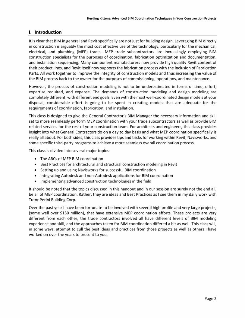
It really comes down to the A/E Team, the complexity of the project, the number of people you can trick into helping with this task, and the time you have available. It’s often easier to ramp up and get started with even a halfway decent set of DBIMs, adding information as it comes in via submittals. On the other hand, modeling CBIMs from scratch exposes the issues, errors, and omissions in the construction documents, and is a great way to generate a flurry of low-hanging RFIs that will likely not be encountered until later on with repurposed DBIMs.
There is also the liability aspect, not from the architect who may not want to give up their precious models, but with the GC not wanting to rely on anything that isn’t a construction document. Models are not construction documents, and the model could contain errors which are not reflected in the CDs and could lead to issues later on. This can also affect the Preconstruction group’s estimation process, where the model-based takeoff numbers are off due to some modeling error, or they model everything as in-place Generic Models, or the BIM data simply does not align with their internal estimating process very well.
For the BIM Manager, taking a DIY-from-CDs approach ensure that CBIMs are generated using time-tested company assets such as templates, project browser organizations, line weights and line styles, annotation families, title blocks, material libraries, predefined schedules, shared parameters, global parameters, family libraries, and a ton of other settings that you would otherwise have to import or transfer.
When the mandate is to build them from scratch, there are still shortcuts and efficiencies to be had. I will first convert the PDF construction documents to CAD in AutoCAD 2018, clean them up there with some custom VisualLISP programming code, and link them into the new pristine Revit model. That allows you to trace the CAD file without polluting the Revit model itself. I’ll review this step in more detail in this handout. Additionally, some of the code I have developed to help this process along is contained within the dataset for this class.
Once things are up and running, however, curating the CBIMs primarily involves adding information as it comes in during construction. It entails modeling additional components and increasing the levels of detail, inputting shop drawing information for various elements, breaking down assemblies into construction parts, taking screen shots of the models as required to generate RFIs, and updating model data from field surveys, laser scans, point data acquisition, and returned RFIs.
At a minimum, the set of CBIMs involved includes an architectural and structural models, but additional models such as those for the site, interior design, signage, furniture, and so on may also be useful. For most MEP trade coordination, the minimum required models are architectural and structural. Whether they are two separate models linked together, or combined into one is at the BIM Manager’s discretion.
Personally, I always create separate models for architecture and structure for several reasons. First, it allows me to minimize what is in any one model, and I can unload the links easily for the entire project or simply turn the link off in a view. I always think in terms of a 3D jigsaw puzzle, where the structural elements (concrete and steel) are in the structural model and everything else is in the architectural, and there is absolutely no overlap. It also keeps elements between the disciplines from joining together, making the distinction between the architect and structural engineer’s work easily identifiable.
The First BIM Manager
Herding Kittens: Advanced BIM Coordination Techniques in Your Construction Projects
Page 8
Submittals and Approvals The reason coordinated design models are largely a work of fiction is that critical pieces of information simply are not known to the designers that directly affect coordination and constructability. And by and large, they don’t want to know (see the previous discussion on liability).
It’s the trade contractors’ job to turn documentation into reality, and they do this by providing submittals to the A/E team for approval of every component to be placed in the building. Submitted items may be the exact same product used as the Basis of Design and included in the design model, but they can also be an approved equal substitution with different details. Long lead times may force the trade contractor to submit a completely different product for approval as well. Until something is submitted, reviewed, and approved by the A/E Team, it’s not bought, fabricated, delivered, or installed.
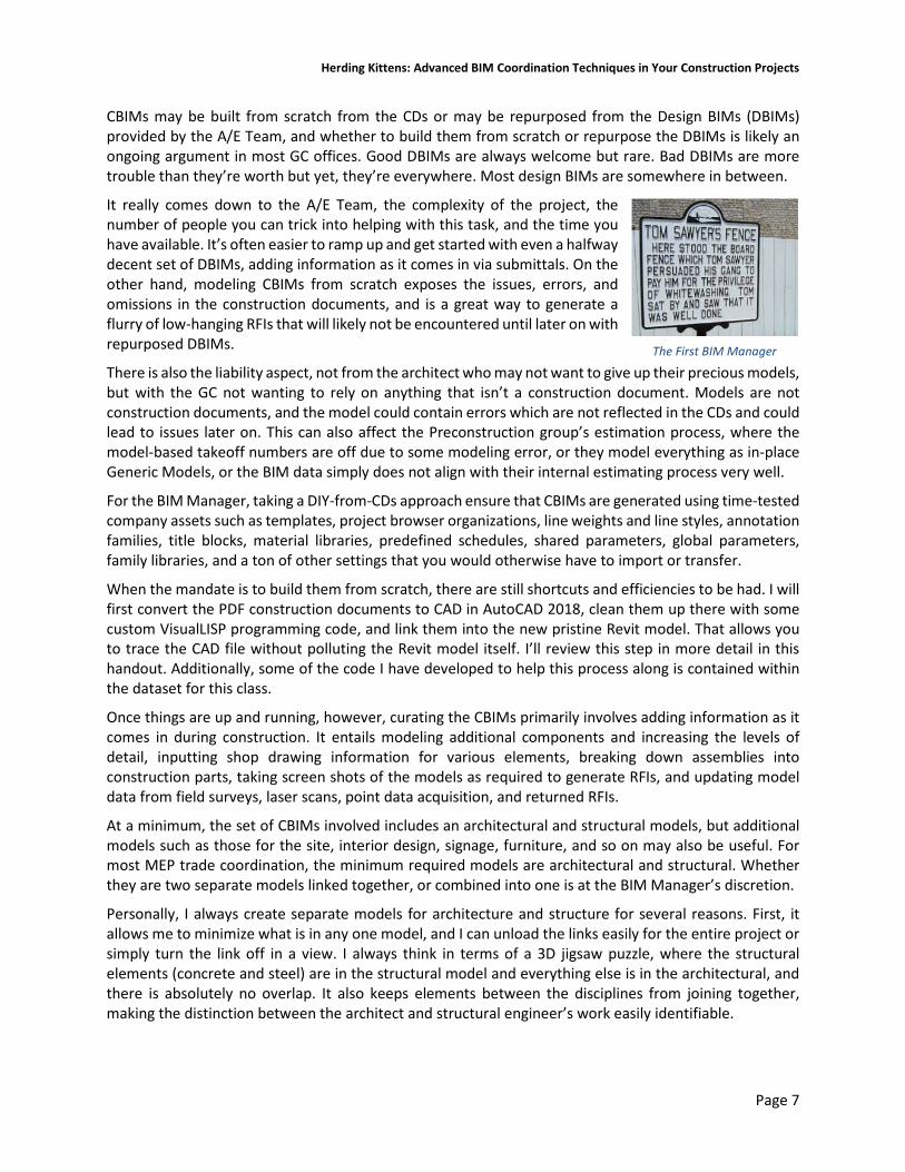
Design vs. Reality in MEP Modeling Many MEP components are custom built by the manufacturer specifically for your project, such as large pieces of mechanical equipment like air handling units. Large AHUs, including makeup air units (MAUs), rooftop units (RTUs), and so on are generally one-off engineered items, built as a collection of sections with heating and/or cooling coils, blowers, filters, sound attenuators, dampers, and mixing boxes, and are not available for coordination until the submittal approval stage well into construction. The locations of inlets and outlets for connecting duct and pipe, access door and motor control clearances, and the physical locations in (or on) the building determines how the MEP trades can run their services to feed the equipment and thus affect coordination.
Figure 1 - Design model (left) and construction model (right)
Above-ceiling components such as variable air volume (VAV) boxes and fan coil units (FCUs) typically have heating and/or cooling water supply and return piping. Although these are more off-the-shelf than AHUs, each make and model is different, and the approved submittal is required before the location of the pipes, clearances, and other coordination sensitive elements are known.
Even standard MEP elements can vary drastically between design and construction. In design, ductwork is represented as simplified rectangular, round, or oval cross-sectional geometry that could be dozens of feet long in the model. Elbow fittings can have arbitrarily-sized necks and be whatever shape and angle. In the real world, ductwork is built to SMACNA standards as well as the sheet metal trade contractor’s shop standards. It is typically manufactured in standard lengths, e.g. 56 ¼” for TDC ductwork and 59 ½” for Slip and Drive ductwork. TDC ductwork is connected together with flanges that may extend 1-1/2” from the face of the duct and often interferes with other elements, so they need to be modeled to coordinate properly. Shop standards may dictate that all fittings have 6” necks or that elbows are of certain angles. All of this works to maximize standard components and minimize the custom pieces to be fabricated or purchased.

Herding Kittens: Advanced BIM Coordination Techniques in Your Construction Projects
Page 9
Insulation is also a huge consideration. It takes up space and is often not modeled in design. When you consider that insulation adds double its thickness in overall pipe or duct size, what once did fit above the ceiling without issue in design may have no way to fit in the real world. Insulation absolutely needs to be considered in the coordination process, and it is best if it happens during the design phase so that appropriate routing can be made by the engineer without the trade subcontractor having to provide such design assistance, submit the possibly dozens of RFIs and wait for the approvals.
Electrical designers more often than limit their modeling efforts to equipment, light fixtures, and devices (receptacles), but do not model wiring, conduit, or cable tray. They may provide a perfunctory run of conduit/cable tray in an area to indicate the basic path, but do not completely route these items. Why? See the “Intent of the Drawings and Specifications” section at the beginning of the Division 26 Electrical Specifications. Put another way, “That’s not my job.”
Good BxP specifications typically specify to model all conduit 1” and over, or any multiple runs of any sized conduit that is in a package larger than say, 8” in width or height. Modeling larger runs of MC (metal clad) armored cable as conduit is also a good idea, so at least everyone knows it is there. Being flexible, MC is usually able to be moved out of the way in case of a clash; as long as the conduit is modeled as a separate type, it can easily be filtered in clash tests and classified as Approved.
Electrical bus duct is a special case because it is prefabricated and complex, with copper or aluminum busbars. It is not easily moved (if at all) in cases of clashes and once its design is set, it’s set in stone. It can require a longer lead time that other MEP components, so electrical contractors like to establish the location and runs of the bus duct early in order to get it into fabrication. Like conduit, it’s often not modeled in design.
Light fixtures are always a point of contention, particularly recessed lights which are in the ceiling. Some electrical contractors model the lights, others rely on the GCs CBIMs to provide them. Regardless, they have housings and clearances, and often interfere with the ductwork and piping located above. Tight ceiling spaces require careful planning so that the sheet metal and piping trades can coexist with lighting fixtures and the cabling to them.
The piping and plumbing trades have their specifics to deal with as well. Especially in cramped mechanical spaces, piping flanges need modeled, and large valves, gauges, and other accessories can and will play a part in coordination. Large pieces of mechanical equipment such as pumps, air separators, tanks, and heat exchangers may require supplemental steel supports from the floor or structure above. Floor sinks have deep receptors and need to be boxed out differently than typical waste lines. P-traps have the general limitation that the top of the fitting must be located below the bottom of the slab in order to make the connection, as well as repair any leaks. This limits how tight you can get the DWV waste lines to the underside of the slab which can interfere with other MEP service routings in tight ceiling spaces in the floor below, e.g. in hotels.
Duct, pipe, and conduit need to be supported somehow, and hanger locations need to be designed and coordinated by the trade contractors. Many of the clashes you will encounter are hanger related; often they can be relocated, but doing so always costs time and money. Today’s modern trade contractors will often record the coordinated location of the hanger in the model using a point layout application in order to accurately place the hanger inserts in the slab before it is cast. This allows the installer to simply thread the hanger instead of drilling yet another hole in the concrete, which also costs time and money.
"Model the conduit? That's not my job!"

Herding Kittens: Advanced BIM Coordination Techniques in Your Construction Projects
Page 10
On the structural side, you have to worry about miscellaneous metals, those smaller steel pieces that support building elements such as precast panels, curtain walls, operable partitions, and provide bracing for structural steel. They are likely not modeled in any great detail (if at all) by the structural engineer, but can and do affect MEP coordination to a great degree. Shop drawings determine the ultimate size and placement of all structural elements, and those shop drawings aren’t complete, submitted, and approved until a lot of construction work has already mobilized. A BIM Manager may spend considerable time modeling the MM in areas like ballrooms and convention centers, where the diagonal support steel bracing for the operable partition rails takes up valuable space required for the ductwork.
Coordination Drawings As part of the project schedule, we establish a regular floor-by-floor coordination schedule to break down the overall building into manageable chunks. For each floor we start by identifying the points at which piping, ductwork, and conduit come through the floor and, if applicable, through any shear walls. As a starting point, the box-outs for pipe, duct, and conduit are often shown on the construction documents, and are always fully modeled in the structural CBIM. While the slab drawing CDs are a good start, they need to be sized appropriate for the services - with the insulation included. In addition there are often other one-off penetrations which may not be included in the design drawings. In particular, floor mounted toilets may not all have their sanitary waste and vent lines shown, which require coordination with the fixture locations, which in turn need to be coordinated with the partitions and even wall finishes to meet ADA spacing regulations.
During the coordination of a specific area, either the GC’s BIM Manager or the primary MEP trade contractor – usually the prime mechanical contractor – is made responsible for creating coordination drawings of three main types: Floor slab/sleeve drawings, showing the locations of all floor penetrations and sleeves; Shear wall penetration drawings (when applicable); and overhead MEP coordination drawings.
Trade contractors will each submit drawings showing the locations and sizes of their slab sleeves, floor box-outs, and shear wall penetrations to the GC. The BIM Manager will input these into the structural model, cutting the holes in the slabs. As part of the coordination process, the trade models are then clash tested against the structural model; when there are zero clashes, the structural model can now be considered authoritative for that floor and composite slab/sleeve drawings can be produced. Using easy-to-make sleeve families, it is easy to create the necessary geometry and documentation for the combined slab/sleeve drawings.
Optimally the slab/sleeve coordination and modeling work is largely done before overhead coordination starts, which allows the slab/sleeve drawings to get completed and submitted first. This can be critical because the slab/sleeve drawings are drawn, submitted, and approved before the concrete is poured. The trade contractors also need time to place embeds and sleeves beforehand as well.
For building types such as hotels, which have large blocks of common floor plans, you can usually complete and submit slab/sleeve drawings for multiple floors quickly because the penetrations are the same floor to floor. For office buildings with common cores, this can also be easy because there are likely not many penetrations outside of the mechanical shafts in the central core, bathrooms, and stairwells where the fire protection risers are located. Large areas such as convention centers have penetrations all over.

Herding Kittens: Advanced BIM Coordination Techniques in Your Construction Projects
Page 11
Regardless of who is taking the lead in creating these drawings, the GC’s BIM Manager is responsible for getting all penetrations into the structural construction model so that MEP trade work does not clash with the slab. The consequences of not getting the penetrations right are huge. When a concrete slab or wall has to be cored for a pipe or conduit sleeve, a specialty coring contractor has to be brought in to have the area x-rayed for rebar (especially on all concrete structures where the rebar is extremely tight) to determine if the location is OK, and core out the concrete. Whenever you see a floor being cored, that’s either the result of a coordination failure or a design change; hopefully it is the latter.
Taken together, there is quite a lot of additional construction modeling that needs to be at a high enough level of detail in order to ensure that what is being built is as close to the real world as possible. The better the constructability modeling, the better the BIM coordination efforts will find errors and clashes that generate the necessary Requests for Information (RFIs) that are issued to solve the problem.
Shop Drawings The Holy Grail of all trade contractor work is the creation, submittal, and approval of the venerable Shop Drawing. That is the contractor’s official interpretation of the drawings and their design intent, which document exactly what is to be installed on the job. MEP trades go through the coordination review process to ensure their resultant shop drawings can be fabricated and installed without conflict.
Shop drawings of all kinds come into the GC and are submitted to the design team for review and approval. As such they are invaluable to the construction modeler. While you may start your construction modeling phase using the construction documents from the design team, once shop drawings start rolling in they should be the definitive documents used for as much modeling as you can.
Typical structural steel shop drawing of a roof truss

Herding Kittens: Advanced BIM Coordination Techniques in Your Construction Projects
Page 12
When creating the structural model, the approved steel shop drawings are critical final arbiters of all steel sizes, locations, elevations, slopes, and other properties. If you can get the steel detailer’s actual model, and it’s easy enough to work with, that’s what you should use in Navisworks for coordination. The problem is that structural steel modeling at the detailer/fabricator level is often very weird compared to Revit. Unless the modeling was done in an Autodesk product such as Revit and/or Advanced Steel, the resulting fabrication model may be in a format that is utterly alien to Revit and possibly Navisworks as well.
If the structural model can be converted to the IFC format, that is possibly better, but realize that IFC is such a moving target that the resulting file may be a real bear to deal with. Ensure you compare it with the actual model and shop drawings to make sure nothing was translated oddly – I’ve seen stairs be offset by four feet in the IFC file making the whole file’s accuracy suspect. If this is the case you may consider simply modeling the structure from scratch based off of the paper shop drawings.
An IFC structural model
Architectural shop drawings also play a critical role in the overall modeling process as well. Detailed, approved shop drawings for exterior precast panels, curtain wall / storefront assemblies, and casework are all often necessary for properly coordinating with MEP.
MEP trade contractors provide detailed shop drawings as well, and just like structural drawings the documentation is largely directly reporting the model data. Even stock Revit is a good application for generating MEP shop drawings, because many of the annotation elements you need are available as parameters that can be reported in tags. With the addition of Fabrication Parts that are able to easily transform standard Revit duct elements to fabrication parts, there really is no reason why Revit cannot be the sheet metal contractor’s tool of choice. And Revit plays very well in coordination with Navisworks.
Herding Kittens: Advanced BIM Coordination Techniques in Your Construction Projects
Page 13
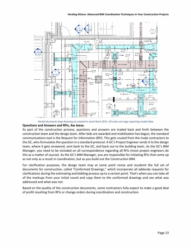
Partial ductwork shop drawing as created in stock Revit 2013. All notes are tags reporting model data
Questions and Answers and RFIs, Aw Jeeze. As part of the construction process, questions and answers are traded back and forth between the construction team and the design team. After bids are awarded and mobilization has begun, the standard communications tool is the Request for Information (RFI). This gets routed from the trade contractors to the GC, who formulates the question in a standard protocol. A GC’s Project Engineer sends it to the design team, where it gets answered, sent back to the GC, and back out to the building team. As the GC’s BIM Manager, you need to be included on all correspondence regarding all RFIs (most project engineers do this as a matter of course). As the GC’s BIM Manager, you are responsible for initiating RFIs that come up as not only as a result in coordination, but as you build out the Construction BIM.
For clarification purposes, the design team may at some point revise and resubmit the full set of documents for construction, called “Conformed Drawings,” which incorporate all addenda requests for clarifications during the estimating and bidding process up to a certain point. That’s when you can take all of the markups from your initial round and copy them to the conformed drawings and see what was addressed and what was not.
Based on the quality of the construction documents, some contractors fully expect to make a good deal of profit resulting from RFIs or change orders during coordination and construction.
Herding Kittens: Advanced BIM Coordination Techniques in Your Construction Projects
Page 14
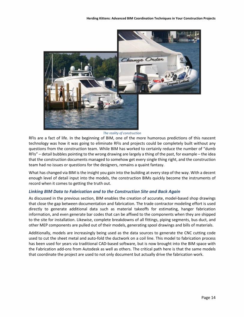
The reality of construction
RFIs are a fact of life. In the beginning of BIM, one of the more humorous predictions of this nascent technology was how it was going to eliminate RFIs and projects could be completely built without any questions from the construction team. While BIM has worked to certainly reduce the number of “dumb RFIs” – detail bubbles pointing to the wrong drawing are largely a thing of the past, for example – the idea that the construction documents managed to somehow get every single thing right, and the construction team had no issues or questions for the designers, remains a quaint fantasy.
What has changed via BIM is the insight you gain into the building at every step of the way. With a decent enough level of detail input into the models, the construction BIMs quickly become the instruments of record when it comes to getting the truth out.
Linking BIM Data to Fabrication and to the Construction Site and Back Again As discussed in the previous section, BIM enables the creation of accurate, model-based shop drawings that close the gap between documentation and fabrication. The trade contractor modeling effort is used directly to generate additional data such as material takeoffs for estimating, hanger fabrication information, and even generate bar codes that can be affixed to the components when they are shipped to the site for installation. Likewise, complete breakdowns of all fittings, piping segments, bus duct, and other MEP components are pulled out of their models, generating spool drawings and bills of materials.
Additionally, models are increasingly being used as the data sources to generate the CNC cutting code used to cut the sheet metal and auto-fold the ductwork on a coil line. This model to fabrication process has been used for years via traditional CAD-based software, but is now brought into the BIM space with the Fabrication add-ons from Autodesk as well as others. The critical path here is that the same models that coordinate the project are used to not only document but actually drive the fabrication work.

Herding Kittens: Advanced BIM Coordination Techniques in Your Construction Projects
Page 15
This model-as-data-source idea does not stop at MEP fabrication, but can impact operations around the entire job site. Autodesk’s Point Layout software is an add-in for Revit, Navisworks, and AutoCAD that allows you to bring model-level accuracy directly to the field. It works by affixing Point objects to the important layout locations on model geometry, such as the column gridlines, edges of concrete formwork, edges/centerlines of studs, centerlines of doors and windows, duct, conduit, and pipe hanger inserts, baseplate anchor bolt locations, and so on. In Revit these are implemented as simple 1” cube Generic Models; being model elements they store 3D points, and just like any other model element they can be given Subcategories. Through the user interface you classify your points as you place them in the model, and the classification system is entirely up to you.
This point positional and type data is exported as a DXF file to a total station, which is an electronic/optical theodolite integrated with an electronic distance measurement unit that reads slope distances from the instrument to a particular point, and an on-board computer to collect data and perform advanced coordinate based calculations. They were typically two-man devices, but newer “robotic” total stations allow one operator to both hold the reflector at an observed point and control the instrument from a distance via remote control, eliminating the need for an assistant to control the total station.
The total stations let the operator mark points on the floor or grade to lay out those elements in precisely in the right spot. In this manner, the drawings not really require dimensions any longer. All pertinent layout data cam come directly from the model and placed on the site a high degree of precision.
It also works in reverse. Total Stations can record three-dimensional points from the field, surveying pipe penetrations, CMU walls, column locations, and so on. Those points can be fed back into the CBIMs and used to update the model geometry.
Lastly, we can use laser scanning to gather as-built information from the job site at various stages of construction, and link that scan data back into Revit / AutoCAD, and correct the models to the locations in the scan. For recording existing conditions, powerful scan-to-BIM software helps automate the creation of walls, doors, windows, and even stairs from scan data. During construction, laser scans accurately record critical as-built information for analysis, such as the flatness in concrete slabs.
In this manner the model becomes a recording of the physical construction which strengthens its role as the definitive as-builts.
Getting Started: Reviewing the Construction Documents The first thing everyone involved in BIM coordination has to do is to perform a thorough review all of the construction documents in order to fully understand all of the systems and their possible points of pain and conflict. While that seems obvious, I try to follow a standard routine for this that I believe is useful.
A thorough familiarization of all floor plans, elevations, sections, framing plans, and all major construction details is required to understand what is happening throughout the building, particularly above the ceiling. This critical space is usually where all of the fun happens MEP-wise, so it’s important to understand where you have room and where you do not. It is true: even in the best BIM design environments, sometimes the HVAC, plumbing, and electrical engineers do not quite coordinate their work as well as perhaps one would like, and end up with things that try to exist in the exact same place at the same time. While the architect, structural engineer, and MEP engineers may live on different planets, it’s your job to ensure their designs work on this one.

Herding Kittens: Advanced BIM Coordination Techniques in Your Construction Projects
Page 16
The Specifications are just as important as the drawings. They often include crucial information that is left out (or is simply incorrect) in the drawings. They may call out things such as the mounting heights for electrical panelboards, the thickness and size of housekeeping pads, requirements for hangers and suspension systems, and so on. Keep on the lookout for discrepancies between the drawings and specifications, and notify the MEP Coordinator of any immediately.
In particular, MEP trade modelers must review the insulation schedules for duct and piping. As mentioned previously, insulation plays a key role in coordination, and insulation schedules can get complex based on service type and location.
A concealed supply air duct run located above an unconditioned space may require 3” of insulation, and the return air ducts may require 2”. If a supply duct needs to cross over a return, the schedule demands that an additional 10” of above-ceiling vertical space be dedicated to insulation.
With the universal desire for Sistine Chapel ceiling heights by architects and Hobbit-like floor to floor heights by owners, losing an additional 10” of prime vertical real estate in the ceiling plenum space is often difficult if not impossible to work around.
Prepare, Mark Up, and Map Out the PDF Documents Back in olden times, as part of the ramp-up process I used to markup full size sets of drawings by hand, using a dozen or so colored highlighters. Today I create detailed markups directly in the project PDF sheet sets. I typically have a separate PDF set for the Civil, Architectural, and Structural, and MEP drawings, and on smaller jobs I’ll combine all sheets into a single project PDF.
Contractors work with PDFs more than any other document type, and in my opinion it is a Best Practice to create a master set of conformed drawing PDFs that can store markups, images, snippets of other PDFs, site photos, and so on. I typically create copies of the “official” PDFs specifically for MEP coordination purposes so that others can reference the original unmolested set.
Duct insulation schedule based on system, duct type, condition status, and location

Herding Kittens: Advanced BIM Coordination Techniques in Your Construction Projects
Page 17
I prep my PDFs before I do much work with the models themselves, although the PDF will be modified throughout construction. But why PDF? Why not just work with the models? Remember that models are not construction documents; the important legal stuff is what is on the paper, and as builders, we build to the legal documents. Models and CAD files are considered “Instruments of Service” and while important, they aren’t held to the same legal standard as the paper. PDFs are invaluable to the construction industry for several reasons.
First, PDF is an open ISO standard. Although created by Adobe, they put PDF format into the public domain and others can create PDF tools with added functionality. But the open format means no one owns PDF or can make a change to the file format in order to shut out a competitor, even Adobe. That has a tendency to perhaps hinder the development necessary to push the format forward, but it does provide stability to the many industries that really need it.
Second: PDFs are somewhat difficult to truly modify, which helps maintain the veracity of the documents. It is not Photoshop, and it is really hard to try to invisibly draw over a drawing using the same pen weights, even with solid markup tools.
Third: PDF drawings produced by design teams’ CAD/BIM software are vector based. You can snap to line endpoints and take measurements of various kinds.
Fourth: You can define areas in PDFs to have different scales, so that each detail on a sheet of details can have its own scale and all measurements and takeoffs are accurate. You can calibrate PDFs to correct for any distortions from the printing process.
Fifth: PDFs can be marked up with symbols, text boxes, clouds, arrows, you name it. Those markups can have intelligence behind them and measurement markups are used to perform takeoffs for pipe lengths, carpet areas, numbers of fire extinguishers, and so on. Custom markups and stamps are easily created, and are highly useful for punch listing.
Sixth: PDFs can contain hyperlinks to other sheets in the same set or to external sheets. You can jump from a plan to elevation to section to detail and back to plan in seconds.
Seventh: PDFs can contain bookmarks to sheets which make navigation and sheet organization easy.
Eighth: You can create “Sets” which are collection of individual sheet PDFs. When you add a new version of a sheet, the old sheet will have a large “Superseded” stamp applied to it, and you can even have the markups on the old version copied to the new one automatically.
There are several PDF tools out there for working with the PDF format, and probably the worst one to use is Adobe Acrobat. The overall functionality and ease of use was just never its strong suit. Currently tool of choice in the construction industry for almost all PDF work is Bluebeam Revu, an AEC purpose-built tool with markup, measurement, takeoff, and sheet set navigation functionality. The Extreme version includes some AEC-specific mission-critical functions such as OCR, batch linking, and batch slip sheeting.
Preparing the PDF drawings requires three major preparation tasks:
1. Make the PDFs easier to navigate; 2. Ensure all sheets and details are of the correct scale; 3. Color code all MEP systems with markups.

Herding Kittens: Advanced BIM Coordination Techniques in Your Construction Projects
Page 18
PDF Navigation I first run through the task of creating bookmarks and page labels for each sheet. Bluebeam has an AutoMark function where it can read the text contained in the title block (if it is in the same physical location on each sheet) and create the label / bookmark automatically for you. It’s not perfect but can get 90% of the job done quickly.
Next I’ll create links between the pages to make it easier to bounce around as needed. Bluebeam can also quickly automate the creation of Hyperlinks by searching all of the text in a sheet for title block sheet numbers, so you get linked detail bubbles. However, they just take you to the sheet, not a detail on the sheet. With more work you can create hyperlinks to a detail area on a sheet, which can save time.
I will also create “dashboards” of hyperlinked text boxes that take you to other sheets, such as enlarged plans, details, and schedules, all of which have linked textboxes that point back to the plans and details. Depending on the sheet contents, I find myself spending a lot of time going from one sheet to another and back again, such as an enlarged floor plan to the enlarged RCP and back. Anything you can do to make flying through the documents to a specific page or detail (and then back again) easier is time well spent.
PDF Scales Next, it is critical that all sheets and areas on those sheets have their correct scale set up. The PDF format supports the ability to set a scale for a sheet for taking measurements. Bluebeam extends this and adds the ability to calibrate a sheet to specific scale by selecting two points and specifying the real-work distance it represents. You can also define separate Viewpoints on a sheet that have their own calibrated scale, so just about everything in the PDF can be measured and taken off. I will step through each sheet and create Viewpoints of every plan, elevation, section, and detail, and assign it the correct scale.
Color Coding MEP Systems As part of the detailed documentation review process for MEP coordination, the last step is to map out the various systems one by one. I first establish a standard coloring system for all my MEP systems. Duct systems may be color coded by system type (Supply, return, exhaust, etc.), and/or by the AHU or VAV they are served from. For piping, I color code the separate systems for domestic hot and cold water, sanitary waste / vent / storm sewer, hydronic chilled and hot water, steam, condensate, fire protection, and so on. Conduit usually is not specifically routed on floor plans, so I code them by conduit trade size on the electrical single line diagrams.
It’s probably a good idea to coordinate colors with your my MEP trade contractors, so if a condensate line is orange in the trade model, it’s orange in the PDF and orange when viewed in Navisworks. Setting up little consistencies like that up front can go a long way to make life easier later.
Tracing out each system using simple PDF polyline markup tools enables you to easily cue off of color, so you can reverse-engineer the designer’s intent and best understand the building as a living, breathing thing. Use solid fills to highlight equipment, and cloud areas to identify issues. Text boxes with leaders call out issues or RFI information. Bluebeam’s Markups List allows you to add data to the markup, which allows you to easily classify them based on trade / discipline and organize and filter them on the screen. I always take the marked up PDFs me into coordination meetings and often directly annotate them during our discussions.

Herding Kittens: Advanced BIM Coordination Techniques in Your Construction Projects
Page 19
Plumbing drawing marked up with color-coded systems and hyperlinked box “dashboards” to other sheets
Adding Supplemental Drawings Supplemental drawings and clarification sketches that revise existing drawings always get inserted into the PDF, highlighting the changes with clouds and callouts. Paper drawings immediately gets scanned and inserted as well. Addenda is inserted into the specifications PDF(s), where I strike out the obsolete text.
Taken together, having a markup and maintenance strategy creates living PDFs which serves as a master project document and negates much of the need to print anything to paper. It is invaluable for communication between construction team members and with the owner and design teams.
On large projects, the task of taking the PDFs and interlinking them can be a full time job for weeks. I recommend you find a service that will do this for you.
LOD vs. LOD When tasked with modeling either for a design team or a construction team, the question of “how much modeling is required” comes up. The AIA has a measurable term called “Level of Development,” or LOD, that quantifies modeling effort with a numbering system that serves to provide the layperson with an idea of how certain the model as a whole is. While the AIA originally defined the idea of LOD it really did not explain it in detail. The BIMForum organization picked this up and ran with it, qualifying and quantifying exactly what Level of Development means in their Level of Development (LOD) Specification.
According to BIMForum, “The Level of Development (LOD) Specification is a reference tool intended to improve the quality of communication among users of Building Information Models (BIMs) about the characteristics of elements in models. The LOD Specification expands upon the LOD schema developed by the American Institute of Architects (AIA) for its E202-2009 BIM and Digital Data Exhibit and updated for the AIA’s G202-2013 Project BIM Protocol Form by providing definitions and illustrations of BIM elements of different building systems at different stages of their development and use in the design and construction process.”

Herding Kittens: Advanced BIM Coordination Techniques in Your Construction Projects
Page 20
BIMForum’s Guide to the LOD Specification is found here: http://bimforum.org/wp-content/uploads/2017/11/LOD-Spec-2017-Guide_2017-11-06.pdf
Their complete LOD Specification is here: http://bimforum.org/wp-content/uploads/2017/11/LOD-Spec-2017-Part-I-2017-11-07.pdf
While this specification is very well done and documents exactly what LOD means, it really doesn’t have anything to do with construction. LOD refers simply to how certain a designer is about a particular component in a building, and how much that component is modeled to the extent that the knowledge is complete. For example, a concrete foundation wall modeled at a low LOD has the height and thickness of the concrete, but no rebar. The high LOD version included the rebar and any other ancillary model componentry included, such as the keyway.
A typical design BIM is modeled to an LOD of 300. That provides enough certainty that the component can be estimated and bought. However, it’s lousy for construction, for the reasons provided previously.
When it comes to construction modeling, this “Level of Development” system is meaningless. We have decided exactly what is to be built, bought, fabricated, and installed, from the size of a steel column down to the toilet flush valve model numbers. What is perhaps variable is the Level of Detail (LOD) to be modeled. But even that is not a real issue.
My rule of thumb is this: Model what you know about what you model. If a full AHU shop drawing is provided, model the full dimensions, ports, access doors, duct connectors, motor locations, access areas, rigging points, right down to the concrete pad it sits on. If you don’t know anything other than the general dimensions, model that to begin with, and add to it later when the shops come in (as they will).
Herding Kittens: Advanced BIM Coordination Techniques in Your Construction Projects
Page 21
III. Revit Tips and Tricks for Construction Modeling
This section discusses some of the more common Best Practices for construction modeling. These are more or less universal concepts, ideas, and specific tips and tricks for many base Revit features that I use in all of my construction projects, either as part of a model-from-scratch process or in reusing Design BIMs from the A/E team. They aren’t necessarily construction-specific, so as a bonus they can (and should) be used for design modeling as well. However, correctly followed, they can help speed up the process of construction modeling, provide valuable assistance for enabling time saving procedures, and help in exporting areas for coordination out to NWC files for Navisworks.
Understanding the Project Base Point, Survey Point, and the 20 Mile Square Limitation Most projects I see come in as Design BIMs have some issue or another with the Project Base Point (PBP) and/or Survey Point. It can be confusing, as Revit isn’t AutoCAD and the old rules of the World Coordinate System (WCS) no longer apply. Autodesk naming of certain program functions, such as “Rotate True North” only make things more confusing.
The Project Base Point is, quite simply, the origin of the Project Coordinate System and everything in the project is built relative to that point.The easiest way to think about the Project Base Point is that it is the World Coordinate System for that particular project file.
The difference is in flexibility. In AutoCAD, you can have a floor plan whose lower left hand corner is at WCS 10,10,0. You can simply select All and move it around the XY plane to “relocate” the project relative to the WCS. You may need to do the same thing for all of the other floor plans in your project, but they are all different files and you can Xref the corrected plan into the others as a means of reference. But there are much fewer dependencies in AutoCAD, such that fixing the rest of the project is likely fairly easy.
In Revit one does not simply move the entire project relative to the PBP. The building, once established, is always relative to the PBP and typically stays in that relative location forever. If you decide to move the building in XY space you need to move the entire building at one time, not just bits of a floor plan. In the process it messes up a lot of other stuff you have in the project, such as sheets, section views, callouts, and notes which live in other views. Not to mention the number of errors you will come up with in the process and forget about it if you have Design Option and/or Phasing to deal with.
The Project Base Point determines the origin of any CAD exports, so ensuring that the project uses a Project Base Point which makes some sense is a very good idea. I’ve never had a project where a carelessly located PBP did not cause some area of consternation somewhere down the line. In construction it gets even worse.
Note: Every Revit file has an internal origin called the Startup Position. This is the true, behind the scenes origin of the file and it is immovable. The Project Base Point is normally located coincident with the Startup Position. However, it can be unpinned for various reason.
Pro Tip #2: Use “Auto-Project Base Point to Project Base Point” to align badly prepared models If you are faced with models that have their Project Base Point at different locations relative to the project, and there is no Shared Coordinate System set up, help is finally here. For example, let’s say you have an architect’s file, the structural file, and the MEP file. Each has the project oriented around a different Project Base Point. There may not be a common Survey Point in place to help align the files.

Herding Kittens: Advanced BIM Coordination Techniques in Your Construction Projects
Page 22
First establish a common “pin point” location on the building that serves as the global alignment point. It should be something geometrically tied to the building, such as a corner of the building or a column grid location. In every model, Unpin the Project Base Point and move it to that location.
Then link each model in using the new “Auto – Project Base Point to Project Base Point” positioning. That will align the buildings using the unpinned Project Base Point.
Pro Tip #3: Establish a Solid Project Base Point by Linking the Design BIM Unpinning the PBP and using Auto-PBP to PBP positioning is very convenient, but is not foolproof. Anyone can reset the PBP to the Statup Position and potentially mess the situation up again.
Another way of dealing with a horribly placed PBP is more severe but is a sure-fire foolproof system. Link the DBIM into a new, blank project using your corporate template. Use Center-to-center positioning just to get it into view. Locate the link with the Project Base Point in the standard location (e.g., lower left corner of the building, a column centerline, etc.).
Once placed, Bind the link. You lose Phasing and Design Options, not to mention any views and sheets, but the content comes over along with the levels and grids. In the process you also get rid of a lot of garbage in the original file, performing a “super purge” as a bargain, and you get all of your project template content like materials, title blocks, and so on.

Herding Kittens: Advanced BIM Coordination Techniques in Your Construction Projects
Page 23
The Survey Point The Survey Point is the origin of the Shared Coordinate System, which is completely separate from but always relative to the project coordinate system. Its purpose is to defines a physical point on the site relative to the project origin; in effect “pinning” the Project Coordinate System to the Shared Coordinate System.
Moving the Survey Point is in reality moving the Project around on the site. To you the observer in a floor plan, it looks like the Survey Point is moving. However, the Project Base Point is always enumerated as a distance and elevation from the Survey Point, so you could think of it as moving the entire project. Using the Relocate Project tool, or simply moving the Survey Point icon, modifies the location of the PBP and thus the entire project relative to the Survey Point.
The Survey Point also determines True North, establishing the orientation of the project on the site as well as its orientation to the sun. This is obviously required for higher-order BIM analysis such as energy analysis, lighting analysis, and so on. The Rotate True North tool is one of the most horribly named commands in Revit. It doesn’t rotate True North. It really rotates the Project Base Point – and thus the entire project - about the Project Base Point. In my view it really should be called Rotate Project North.
However, what determines the location of the site + project on the planet? In the United States, the answer is State Plane Coordinates.
Integrating Civil Files with State Plane Coordinates The State Plane Coordinates System (SPCS) is, in its simplest terms, a standardized set of 124 separate coordinate systems that cover the United States. 110 zones cover the contiguous U.S., 10 are in Alaska, 5 in Hawaii, and one for Puerto Rico and the U.S. Virgin Islands. They are roughly aligned to state counties and are small enough to provide a simple X-Y Cartesian coordinate system that is also highly accurate within each zone (with an error less than 1:10,000). Outside of a state plane zone, accuracy rapidly declines, so the system is not useful for regional or national mapping.
There are different standards of the SPCS out there; the most common is perhaps the North American Datum 1983 (NAD83) standard, which improves upon the original NAD27 system. More information on NAD83 can be found here: https://www.ngs.noaa.gov/PUBS_LIB/ManualNOSNGS5.pdf
NAD83 State Plane Coordinate System
This allows surveyors to use simple “plane surveying" methods to tie their site surveys back to the appropriate coordinate system easily, locating property benchmarks, setting meets and bounds, and establishing the overal project boundaries.

Herding Kittens: Advanced BIM Coordination Techniques in Your Construction Projects
Page 24
Civil Engineers often use State Plane coordinate system in defining the precise location of the property lines that make up the project boundaries as well as surrounding parcels. Civil drawing often have their WCS 0,0,0 point aligned with the State Plane Coordinate System with True North aligned to the Y-axis. Because of how AutoCAD handles drawing units, it can have the origin point be many miles away from the site without noticable loss of precision.
However, Revit does not operate the same way. Autodesk defines a 10-mile-radius sphere inside of which you can place model elements. This is technically incorrect; it is actually a 20-mile square centered on the Startup Position (i.e., the Project Base Point in most projects). Elements can legally be outside of the 10-mile radius sphere but be inside the cube. Internally, all elements are based on 3D Cartesian coordinates from the Startup Position. Once the numbers go past 10 miles in the X, Y, or Z direction, they start to get fuzzy – too fuzzy for a system that relies on numeric precision to determine wall joins, hatch areas, area calculations, and a whole host of mission-critical calculations.
State Plane Coordinates, being potentially many miles across, aren’t directly usable in Revit due to the 20-mile “cube” centered at the Project Base Point, within which you can legally put your project’s elements.
You may want the Survey Point to establish the origin of the State Plane system used; that allows full interoperability with your civil engineers. To make this work, use AutoCAD’s geolocation feature to geolocate the civil engineer’s site plan DWG (which has the property line and meets and bounds) matched to the State Plane Coordinates, and bring that into a new Revit file at the Project/Survey Point. Revit will complain that it’s outside of the 10-mile limit. Pay it no mind.
Next, you can unpin the Survey Point to create a property-specific “marker.” Un-pinning the Survey Point keeps the Shared Coordinate System in the same place, but allows the Survey Point to be moved around to define another point – in this case, align it with a property line benchmark. Armed with this information you can then use Relocate Project to place the Project Base Point at the appropriate location within the project boundary relative to the site plan. Then you can finally build up the project from there, setting the column grid, datum elevations of levels, and so on.
Herding Kittens: Advanced BIM Coordination Techniques in Your Construction Projects
Page 25
Setting the Common Project Origin across BIM and CAD It is critical that the BIM Execution Plan state where the 3D point that spatially defines the project Origin is in 3D space as a function of the Project Base Point. As an XYZ point it determines not only the orientation of the building to the origin but also the elevation of each level. As a matter of course with my company, the Survey Point and Project Base Points are both always set to an elevation of 0, representing Sea Level. Each level is then set to their corresponding Sea Level elevations. I always create a utility “Datum 0” level at Sea Level as well.
Alternatively, you can keep the Project Base Point coincident with a level, e.g. Ground Floor, and set that level’s Sea Level elevation by using the Relocate Project tool, or simply move the PBP up in an elevation or section view. This moves the entire project in space relative to the Survey Point.
This method allows your level elevations to be relative to this base level, or relative to sea level. By default, Levels show their elevations relative to the Project Base Point, so if you follow this route you will get an elevation of 0’-0” for the first level. If you want to see Sea Level elevations, you need to modify the Type Properties of the Level to show Survey Point elevations instead.
If your trade contractors are producing files using AutoCAD-based software, e.g. CADmep+, each 3D coordination volume is typically completed in a single DWG file per trade. Each DWG needs to have as its WCS origin the 3D base origin of the entire project (also spelled out in the BxP), so that the drawings are truly built at their 3D elevation, coordinated with the architectural and structural models as well as the other trades. The end result is that you want all coordination models to come together in Navisworks as one big 3D jigsaw puzzle, with no overlap of elements between them.
Long story short: The WCS in every Trade Contractor Model must equate in 3D space to the common agreed-upon Project Base Point which is set up in the construction architectural and structural models.
If a trade contractor is using Revit, the BxP would provide the same rules, and the trade modeler would set up floor plans and 3D export views that have the same 3D section-box boundaries as your CBIMs.
Project Datum The term Datum in Revit speak means Levels, Grids, and Reference Planes. All three can be customized to help your construction modeling process along.
Pro Tip #4: Create Level Types based on their function (Structural, Utility, Ceiling) Levels and Grids each can have multiple Types which serve different purposes. For Levels, I typically define several types – Standard, Structural, and Utility. That allows me to not only set a level’s purpose by its type, but I can also (more importantly) create filters to turn off Structural and Utility when they aren’t needed.
Grids get the same treatment, but they are usually set to be more project-specific, where I can set up grid types for a particular area or for construction layout purposes. Again I can create filters for turning them on or off based on type.
Pro Tip #5: Set up Reference Plane Subcategories and give them different graphics Reference Planes, which are probably the most used (and overused) datum type, can now have Subcategories. Each Subcategory has its own color and linetype making it functionally the same as defining multiple types. I used them for ceiling layout, partition layout, structural steel layout, and so on.

Herding Kittens: Advanced BIM Coordination Techniques in Your Construction Projects
Page 26
Scope Boxes Scope Boxes are the third type of Datum that usually gets a bum rap. Scope Boxes are annoying because they show up in views they really shouldn’t, but they serve a hugely important purpose that directly affects construction BIM coordination tasks. Scope boxes do two things: The define the 3D boundaries of any Levels, Grids, and Reference Planes that are assigned to them. This allows you to split up a building into smaller masses – both vertical and horizontal – and the Datum inside of those masses will not display where the view does not include the Scope Box area.
For example, if you have a building’s tower sitting on a larger podium, the grids that define supplemental columns in the podium will not show up on the tower floor plans, if they are assigned to the Scope Box for the podium; only Tower-owned grids will show up in tower plans.
Scope Boxes serve a thoroughly important secondary function: They define the Crop Region for any plan or elevation view they are assigned to with the Scope Box view parameter. Because they define an X-Y boundary for a view, they assist in the creation of coordination export views. We discuss this process later in this section.
View Types, View Series, and Project Browser Organization Revit has a predefined set of System Families for your project views: Floor Plan, Ceiling Plan, Elevation, Section, Detail, 3D View, and Drafting View. Because they are System Families they each have their own predefined functionality. However, within these System Families you can create your own View Types, and each View Type can be assigned a View Template that is automatically assigned when you create a new View of that Type. That allows you to classify a view as an ‘Enlarged Floor Plan” and have the template set the scale, detail level, View/Graphics overrides, filters, and so on.
The Views category can also have Project Parameters assigned to it, such that every view can have for example a “View Series” text parameter assigned. This can be used within the Project Browser Organization to classify views as Working, Documentation, Export, Presentation, Coordination, and so on. Considering a project can have hundreds of views, breaking down the views into manageable logical groups makes navigating the Project Browser much easier.
Pro Tip #6: Create an Export series of Views In particular, I recommend you create an Export set of Views for storing specially configured plan and 3D views that can be used for exporting to Navisworks.
Design Options and Option Sets Design Options are used by the design team to create options for owner approval. Design Option Sets are containers for multiple Design Options for a particular purpose, such as a new tenant fitout within a larger plan, or a series of options for reception desks, and so on.
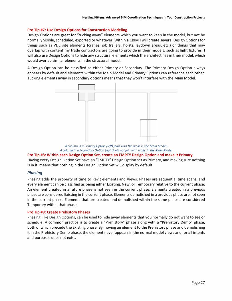
Herding Kittens: Advanced BIM Coordination Techniques in Your Construction Projects
Page 27
Pro Tip #7: Use Design Options for Construction Modeling Design Options are great for “tucking away” elements which you want to keep in the model, but not be normally visible, scheduled, exported or whatever. Within a CBIM I will create several Design Options for things such as VDC site elements (cranes, job trailers, hoists, laydown areas, etc.) or things that may overlap with content my trade contractors are going to provide in their models, such as light fixtures. I will also use Design Options to hide any structural elements which the architect has in their model, which would overlap similar elements in the structural model.
A Design Option can be classified as either Primary or Secondary. The Primary Design Option always appears by default and elements within the Main Model and Primary Options can reference each other. Tucking elements away in secondary options means that they won’t interfere with the Main Model.
A column in a Primary Option (left) joins with the walls in the Main Model.
A column in a Secondary Option (right) will not join with walls in the Main Model Pro Tip #8: Within each Design Option Set, create an EMPTY Design Option and make it Primary Having every Design Option Set have an “EMPTY” Design Option set as Primary, and making sure nothing is in it, means that nothing in the Design Option Set will display by default.
Phasing Phasing adds the property of time to Revit elements and Views. Phases are sequential time spans, and every element can be classified as being either Existing, New, or Temporary relative to the current phase. An element created in a future phase is not seen in the current phase. Elements created in a previous phase are considered Existing in the current phase. Elements demolished in a previous phase are not seen in the current phase. Elements that are created and demolished within the same phase are considered Temporary within that phase.
Pro Tip #9: Create Prehistory Phases Phasing, like Design Options, can be used to hide away elements that you normally do not want to see or schedule. A common practice is to create a “Prehistory” phase along with a “Prehistory Demo” phase, both of which precede the Existing phase. By moving an element to the Prehistory phase and demolishing it in the Prehistory Demo phase, the element never appears in the normal model views and for all intents and purposes does not exist.

Herding Kittens: Advanced BIM Coordination Techniques in Your Construction Projects
Page 28
Filters Filters are by far one of the most useful features in Revit, because they allow you to modify the graphics of elements based on a common subset of properties. Filters are built by specifying the Revit category and the property values the filter applies to. A common filter called “Rated Walls” would be configured to only apply to those walls whose Fire Rating property is greater than zero. When added to the Filters tab in the View / Graphics Override dialog, you can override the projection and/or cut graphics of just your rated walls. You can also turn the filtered elements off, which is a great way to reduce visual clutter.
Building Effective Filters Effective filtering is critical to making views easy to manage. I tend to keep everything turned on in the Model tab in all views, then use Filters alone to selectively turn things on or off as required. Managing the bulk of your visibility requirement via Filters is often easier than in the Model tab, as you can combine categories into a single filter, e.g. pipes, pipe accessories, pipe fittings and pipe insulation, and it works across linked models.
For working with MEP systems, filters are critical because between System Classifications, System Types, System Names, and so on, you have plenty to worry about. Color coding system by their various properties provides a powerful clarity to your views, particularly in 3D.
Pro Tip #10: Create a series of “Generic” filters which apply to whole categories with no filter rules set. This allows you to group related categories together which would be tedious to handle in the Model Elements tab of the View/Graphics Overrides dialog box.
A single filter handles all piping categories

Herding Kittens: Advanced BIM Coordination Techniques in Your Construction Projects
Page 29
Creating “All but this” Filters
Effective filtering also means not only filtering for an item based on a property it has, but also filtering for all elements that do not have that property. For example, I create both “Documentation” and “Working” plans, elevations, and sections in a model. The Working views are for documentation and the callouts for those views should not show up in non-working Views. Thus, I could create a filter called “Working Views” and turn them off in all non-working views.
But how do I turn off all other view types (of which there may be many) in Working views, where I just want to see Working sections and elevation markers? I would have to create many filters, apply them to the view, and turn them all off individually. Or I could create a “Views – Not Working” filter which applies to all views which do not have “Working” in their view name. It would be applied to all Working views (typically via a View Template) and turned off.
Turning this filter off in V/G Overrides will turn off all non-Working callouts
View Templates View templates are also critical for setting up views quickly as well as maintaining view standards within a project. Templates can apply themselves to any or all properties in a view, and creating selective View Templates which only apply to one or two properties is very effective.
Pro Tip #11: Create Selective View Templates that do One Thing For example, it is common practice to link in the structural model into the architectural model, and vice versa. Both files have their own datum (levels and grids) so a common practice is to go into V/G Overrides, drill into the Revit Link overrides, set it to Custom, go into the Annotations Categories tab, make that Custom, and turn off the Grids and Levels (or simply turn off the entire Annotations category wholesale).
That is a lot of work when you have tens of views to process. Instead you can create a “Link Prep” template that only applies to the Revit Links section of the View Template dialog. That way you only affect that one small set of properties and not anything else.

Herding Kittens: Advanced BIM Coordination Techniques in Your Construction Projects
Page 30
Here’s a floor plan with several linked models, before any view templates are applied.
From here we create a new View Template, check only the RVT Links box, and edit its properties:
And here are the results:

Herding Kittens: Advanced BIM Coordination Techniques in Your Construction Projects
Page 31
Creating “Export” Templates to Set up 3D Views You can also create an “Export” view template for floor plans that does the above but also sets the View Range in order to create the correct 3D Section Box for proper exporting of 3D views to Navisworks. As we discuss later in this section, creating 3D views for exporting to Navisworks is part of preparing to assemble your Navisworks files from the A/S CBIMs as well as everyone else. That 3D view needs to be a specific volume, typically from floor to floor, or from the associated level of a floor plan to the level above.
When you create a 3D view, you can right-click on the ViewCube and select “Orient to a View.” If you select a floor plan view, Revit creates a 3D section box based on the Crop Region (in XY) and the Primary Range top and bottom planes from the View Range to establish the section box’s position and height. If you set your floor plans up with an “Export” view template, the View Range can be part of that template making the process of setting up 3D exports a snap.
The only critical setting of concern here is the top and bottom plane. If you leave the offsets at 0’-0”, you will get a tiny sliver of the bottoms of walls from the level above. When you put the floors together in Navisworks, you will also see the two overlapping floor planes of the floor at the bottom of the section box (one from that NWC as well as the top of the NWC from the floor below). You can solve this by setting both offsets to -1/8”. The floor NWC exports will fit together like a glove without any overlapping of 3D faces and you won’t see the walls from the floor above.
In the 3D view, orient the view to that floor plan, and you get this slice of the building ready for MEP coordination:
Construction Modeling Tips
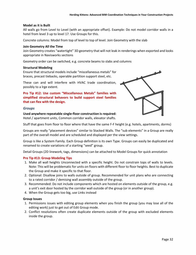
Herding Kittens: Advanced BIM Coordination Techniques in Your Construction Projects
Page 32
Model as it is Built All walls go from Level to Level (with an appropriate offset). Example: Do not model corridor walls in a hotel from level 3 up to level 17. Use Groups for this.
Concrete columns: Model from top of level to top of level. Join Geometry with the slab
Join Geometry All the Time Join Geometry creates “watertight” 3D geometry that will not leak in renderings when exported and looks appropriate in Navisworks sections
Geometry order can be switched, e.g. concrete beams to slabs and columns
Structural Modeling Ensure that structural models include “miscellaneous metals” for braces, precast tiebacks, operable partition support steel, etc.
These can and will interfere with HVAC trade coordination, possibly to a lrge extent.
Pro Tip #12: Use custom “Miscellanous Metals” families with simplified structural behavors to build support steel families that can flex with the design.
Groups Used anywhere repeatable single-floor construction is required: Hotel / apartment units, Common corridor walls, elevator shafts.
Stuff that goes from floor to floor where that have the same F-F height (e.g. hotels, apartments, dorms)
Groups are really “placement devices” similar to Stacked Walls. The “sub elements” in a Group are really part of the overall model and are scheduled and displayed per the view settings.
Group is like a System Family. Each Group definition is its own Type. Groups can easily be duplicated and renamed to create variations of a starting “seed” group.
Detail Groups (2D linework, tags, dimensions) can be attached to Model Groups for quick annotation
Pro Tip #13: Group Modeling Tips 1. Make all wall heights Unconnected with a specific height. Do not constrain tops of walls to levels.
Note: This will be problematic for units on floors with different floor to floor heights. Best to duplicate the Group and make it specific to that floor.
2. Optional: Disallow joins to walls outside of group. Recommended for unit plans who are connecting to a rated corridor / demising wall assembly outside of the group.
3. Recommended: Do not include components which are hosted on elements outside of the group, e.g. a unit’s exit door hosted by the corridor wall outside of the group (or in another group).
4. When the Group gets too big, use Links instead
Group Issues 1. Permissions issues with editing group elements when you finish the group (you may lose all of the
editing work) just to get out of Edit Group mode. 2. Conflict resolutions often create duplicate elements outside of the group with excluded elements
inside the group.
Herding Kittens: Advanced BIM Coordination Techniques in Your Construction Projects
Page 33
Construction Parts Parts Features 1. Break down layered System Families (Walls, Floors, Roofs, and Ceilings) into component layers.
Example: Allow GWB to extend to 6” above ceiling on one or both sides of the wall, with the studs going to the underside of structure above
2. Also works on extended families such as slab foundations, slab edges, fascia and gutters, structural framing, columns, structural columns, as well as In-Place Families.
3. Geometrically break down large elements into smaller chunks. Example: Create individual slab pours, sheets of wall board, etc. that can be seen in Navisworks and phased suing TimeLiner. Use Intersecting References (Datum, such as Levels, Grids, and Reference Planes) to break down elements into smaller bits.
4. Parts can be easily modified with grip-editing tools 5. Assign different phases to parts, e.g. “Demo this layer of GWB from Point A to Point B.” 6. Assign Division Profiles and Gap Offsets to create part boundaries with specific shapes. Example:
Complex precast concrete walls construction joints, gaps, and keyways 7. Parts can be assigned to specific detail levels (coarse, medium, fine). 8. Parts can be merged across the same or multiple originating hosts, and be Excluded and Restored
like Groups. 9. Objects in linked models can be split into parts. 10. Schedule parts using built-in and custom parameters such as Mark, Panel Type, Mold Type, etc.
Fabrication Parts 1. Allows conversion of DBIM MEP ductwork and piping into fabrication CBIM LOD 350+ parts 2. Automated breakdown of long ductwork and pipework into industry standard fabrication lengths
(e.g. 47.25”) and company fabrication standards, such as 6” minimum legs on all elbows 3. Pros: Uses the same ITM technology as Fabrication CADmep+. Data it interchangeable between CAD
and Revit. 4. Cons: Not as fully-featured as Fabrication CADmep+. Difficult to work with piecemeal.
Structural Connections Create detailed, parametric structural connector geometry in the Revit modeling environment.
While Structural Connections are typically not critical for most MEP BIM coordination, they do provide the high level of detail necessary for the high-LOD BIM deliverable as well as ensuring tight conditions have the appropriate clearances.
Pros: 1. Standard Connections are easy to create and modify. 2. Content looks really good, realistic, and adds a lot of pizzazz to the model. Instant marketing materials. 3. Can be very useful when a structural shop-drawing model is not available or otherwise wonky to work
with (see the section on IFC). 4. Accelerates construction process by bringing the model closer to a fabrication point early in the design
phase. 5. Can be cross-pollinated with Advance Steel which allows for a Revit to A/S back to Revit workflow
Cons: 1. Payback can be questionable - Additional time required to model connection geometry may not create
enough of a difference in actual MEP clash detection issues. 2. Another thing to track during the shop drawing phase.

Herding Kittens: Advanced BIM Coordination Techniques in Your Construction Projects
Page 34
Usage Notes and Tips: 1. Structural Connections can only be used with certified families from the \Structural Framing\AISC 14.1
folder (US Imperial and US Metric libraries). 2. For other libraries, check the list of certified families here. 3. Pro Tip #14: Check the Family Type for the existence of a “Section Name Key” parameter under the
Identity Data group. 4. When used with any other type of family you will get an “Invalid connection” error. 5. If you are upgrading an existing structural model with certified families, either customize the AISC 4.1
families with a custom “AISC” material which can be easily identified in Shaded or Consistent Colors 6. Create a Filter for Structural Framing and Structural Column categories that have the “Section Name
Key” parameter.

Herding Kittens: Advanced BIM Coordination Techniques in Your Construction Projects
Page 35
Determining Coordination Phasing and Exporting Strategies Your coordination strategy is driven by the coordination schedule, and is ultimately largely determined by the geometry of the building project. Your coordination phasing plan is responsible for determining two very critical pieces of information: The 3D extents of each area to be coordinated, and the origin point of the project as a whole.
Setting 3D Coordination Extents In any modern building project there are logical physical boundaries by which you phase your coordination efforts around. For example, if the project is a tall hotel or condominium, it makes sense to coordinate it strictly floor by floor, from the top of the slab to the top of the slab for each level. On the other hand, if the buildling is a sprawling single-story structure composed of multiple wings, you would partition it off into the separate wings or buildings, and coordinate each wing in its entirety.
Many projects are combination of multistory building masses, such as a residential complex with a common podium of parking and amenity floors underneath two residential towers. In those cases you may opt to break it down into the large parts first, coordinating the entire podium levels first, then each of the two towers individually. For large floor plans it is typically most convenient to follow the conventions used in the drawings, where the plan is broken up with match lines, so you coordinate standard partial areas of each floor separately.
A critical part of your BIM Execution Plan spells out these 3D coordination volumes specifically, informing all parties of what is really meant by e.g. “3rd floor Area C Overhead Coordination” in terms of the 3D section box that defines that area. As your coordination effort begins with the Revit Architectural and Structural construction models, we use carefully configured Section Boxes in 3D views that are set up specifically for exporting to NWC files.
With Revit 2018, you can insert Coordination Models (Revit’s term for NWC and NWD files) making cross-platform use of Navisworks files more seamless.
Pro Tip #15: Use Scope Boxes and View Range to set 3D Coordination Extents As discussed previously, we can use these tools to the 3D extents for each volume to be coordinated. The tools for setting these up are the View Cube, Scope Boxes, and View Range. All work together to configure 3D extents of Section Boxes in 3D views, which can then be individually exported as NWC files.
Scope Boxes allow you to define 3D boxes that can be assigned to views and datum (Levels, Grids, and Reference Planes). Most importantly, Scope Boxes set the Crop Region in the views to which they are assigned. The View Range setting in floor plans sets up a “Primary Range” which is bounded by a lower plane and an upper plane, with the cut plane somewhere in between.
Pro Tip #16: Efficiently Set Up your Revit 3D Export Views As mentioned previously, you can export individual floor plans or 3D views from Revit. The choice is up to you but
Note: When you use the View Cube “Orient to View” option and select a floor plan, it uses the plan view’s Crop Region for the X/Y boundaries of the Section Box, and the extents of the View Range Primary Range to set the Z boundaries. If the Top or Bottom primary range plane is defined as “Unlimted,” the section box will use the z-elevation of the 3D extents of the plan elements.
Create the NWCs for Revit floors Creating the dummy NWCs for Revit floors is not as straightforward, but not difficult. The issue is that Revit’s NWC Exporter cannot create an NWC with no geometry, so you need something to export. Fortunately, building out a small project file isn’t terribly time consuming.
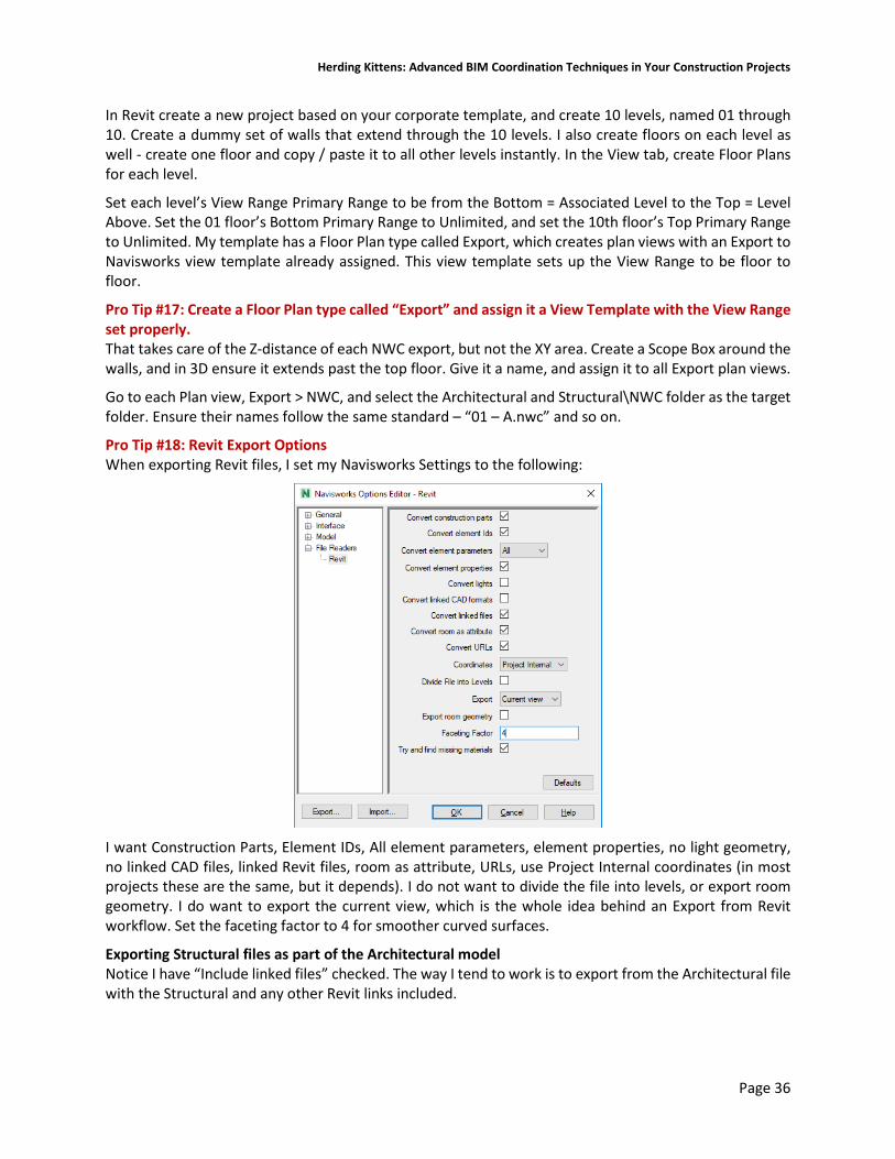
Herding Kittens: Advanced BIM Coordination Techniques in Your Construction Projects
Page 36
In Revit create a new project based on your corporate template, and create 10 levels, named 01 through 10. Create a dummy set of walls that extend through the 10 levels. I also create floors on each level as well - create one floor and copy / paste it to all other levels instantly. In the View tab, create Floor Plans for each level.
Set each level’s View Range Primary Range to be from the Bottom = Associated Level to the Top = Level Above. Set the 01 floor’s Bottom Primary Range to Unlimited, and set the 10th floor’s Top Primary Range to Unlimited. My template has a Floor Plan type called Export, which creates plan views with an Export to Navisworks view template already assigned. This view template sets up the View Range to be floor to floor.
Pro Tip #17: Create a Floor Plan type called “Export” and assign it a View Template with the View Range set properly. That takes care of the Z-distance of each NWC export, but not the XY area. Create a Scope Box around the walls, and in 3D ensure it extends past the top floor. Give it a name, and assign it to all Export plan views.
Go to each Plan view, Export > NWC, and select the Architectural and Structural\NWC folder as the target folder. Ensure their names follow the same standard – “01 – A.nwc” and so on.
Pro Tip #18: Revit Export Options When exporting Revit files, I set my Navisworks Settings to the following:
I want Construction Parts, Element IDs, All element parameters, element properties, no light geometry, no linked CAD files, linked Revit files, room as attribute, URLs, use Project Internal coordinates (in most projects these are the same, but it depends). I do not want to divide the file into levels, or export room geometry. I do want to export the current view, which is the whole idea behind an Export from Revit workflow. Set the faceting factor to 4 for smoother curved surfaces.
Exporting Structural files as part of the Architectural model Notice I have “Include linked files” checked. The way I tend to work is to export from the Architectural file with the Structural and any other Revit links included.

Herding Kittens: Advanced BIM Coordination Techniques in Your Construction Projects
Page 37
This creates a single Architectural and Structural NWC, but the Structural is at the top of the Navisworks object hierarchy and is easily selected and modified separately from the rest of the architectural file. Because I often export out everything floor by floor, this alleviates me having to open the Structural file and export out each floor from there.
Pro Tip #19: Optional Step - Link All CBIMs into a Master Revit Project and Export From There In complex projects with many linked files, I will link all files into a new blank “Master” Revit file and export from there. I may do this if I am re-using the Design BIMs and need to add construction-specific things to the dataset, and I don’t want to add it to the architectural or structural models. For example, I may need to add some dummy piping or ductwork, and export that out as part of the NWC package to send out.

Herding Kittens: Advanced BIM Coordination Techniques in Your Construction Projects
Page 38
IV. Navisworks Tips for Better Coordination
Design Model File Compatibility Navisworks’ main strengths are that it natively reads many of the common file formats used by today’s leading design software, and is relatively easy to use. Its simplicity belies its power, however, in that its system for converting complex, heavy data from BIM, CAD, and 3D applications into lightweight geometry allows it to handle literally city-sized supermodels with ease.
Navisworks has an internal file reader component that can read about 33 different native file formats from 20 different applications (the exact list is detailed here). Primarily it supports all of the 3D CAD formats from most of today’s most popular design applications, such as DWG, DXF, SAT, STP, STL, STP, DGN, 3DS, IGES, PRJ, IFC, and SKP format. Navisworks also supports popular laser scan formats from Leica, Faro, Riegl and others, which can be used in Clash Detective operations.
Navisworks also supports Autodesk’s Object Enabler technology, allowing you to import AutoCAD Architecture and AutoCAD MEP models, as well as popular AutoCAD-based add-ons such as CADmep+ for HVAC and piping design and HydraCAD for fire protection. As soon as you install the appropriate Object Enabler software, Navisworks will take advantage of it when importing DWG files that require it.
Pro Tip #20: Install the Required Object Enablers First Before you start working in Navisworks, establish your trade contractor’s software and version of choice. Install the appropriate Object Enabler to be able to see their geometry as well as understand the data in the Properties window. In particular, ensure you install AutoCAD MEP, which is part of the Architecture, Engineering and Construction (AEC) Industry Collection, as it will install the necessary Object Enablers in Navisworks for you to handle those files. As AutoCAD MEP is built on top of AutoCAD Architecture, installing AutoCAD MEP will also take care of handling AutoCAD Architecture files in Navisworks as well.
Autodesk now includes its Fabrication CADmep+ software as part of the AEC Industry Collection, enabling you to open trade contractor HVAC and piping models in AutoCAD and having full fidelity. I highly recommend you install that package as well.
However, installing CADmep+ does not install the CADmep+ OE for you. For that you need to download and install the OE from Autodesk’s web site. You will also likely need the HydraCAD Object Enabler for your fire protection trade contractor. It’s rare, but some may also need the Object enabler for CADPIPE as well. Note that you need to register as a CADPIPE user before you can access the site to download the OE.
Bringing Design Files into Navisworks To use a design application’s model file in Navisworks, you append (add) it into your current scene inside of Navisworks. There are two ways to do this. Whenever you append any “native” design file format - one that Navisworks’ File Reader supports out of the box - an .NWC (Navisworks Cache) file is created in the same directory with the same name as the original file with an .NWC extension. NWCs are very small - sometimes only 10% the size of the design file – and highly optimized files which contain compressed and simplified 3D geometry as well as object property data from the authoring application.

Herding Kittens: Advanced BIM Coordination Techniques in Your Construction Projects
Page 39
The source file with its extension is still listed in the Selection Tree, but remember you are always working from the corresponding NWC cache file data inside of Navisworks. When you refresh the scene or reopen your Navisworks working file, Navisworks compares the NWCs against the originals; if any of the original files have changed, Navisworks builds a new NWC file automatically.
In this manner you can append a DWG file and view it in Navisworks, open the DWG and make changes, then jump back to Navisworks and hit Refresh, and the changes will appear in the scene.
The second way to get a design file into Navisworks is to first export it to an NWC from the design appliciation. When you install Navisworks, it installs a set of NWC file exporter utilities for supported installed applications. If you are using a file format that is not natively supported by Navisworks, you have to use a file exporter add-on to create the NWC. Autodesk provides a free NWC Exporter add-on for Bentley Microstation and Graphisoft ArchiCAD; other design software developers provide their own NWC exporter utility.
Pro Tip #21: Always Export from Revit to NWC. Never Append RVTs into Navisworks. Likewise, when you want to see a Revit file in Navisworks, you have these two choices; append the RVT directly, or export from Revit to NWC. Always export to NWC from Revit.
The reason is that the resultant export NWC is a direct copy of the view from which you export, including any View/Graphics Overrides, hidden elements, and view extents (a section box, scope box, or crop region). In addition, exporting Floor Plan views results in a 3D slice of the model based on the crop region and the View Range Primary Range’s top and bottom values.
You can readily use this to your advantage: While you can export a whole model, you could alternatively export only a subset, such as each individual floor plate, or a region that has a specific design option or phase showing in that view. By doing so you can composite your exports in Navisworks together seamlessly – it’s kind of like Photoshop for BIM. By exporting floor plans, you can perform easy floor-by-floor model reviews without having to create a Section Box in Navisworks and constantly move it around, which is clumsy by comparison.
In contrast, if you append an RVT file, Revit creates the NWC anyway, in the same folder as the Revit file (probably not something you generally want), and you have no finesse over what is brought in. It just brings in everything based on the RVT File Reader options, discussed later.
Similarly, if you use AutoCAD with an add-on such as CADmep+, it’s smarter to export a 3D view that has all of the text, dimension, and other ancillary layers frozen which results in a pure NWC of 3D geometry only. This requires the File Reader options to not export frozen or off layers. We cover such options later in this handout.
Navisworks NWF and NWD Files You save your collection of appended model files as an .NWF (Navisworks File set). This is your master working file, and contains links to the original native files (DWG, DGN, RVT, SKP) and any Navisworks NWC or NWD files. The NWF contains no geometry at all; it only contains the Navisworks specific data: Saved selection and search sets, viewpoints, animations, geometry appearance overrides (e.g., color, transparency, position), review markups, Clash Detection, TimeLiner, Presenter and Animator/Scripter data. Because no actual model geometry is saved in the NWF file, NWFs are considerably smaller than the other two formats.

Herding Kittens: Advanced BIM Coordination Techniques in Your Construction Projects
Page 40
From the NWF you publish an NWD file. An NWD includes all of the compressed model geometry together with Navisworks specific data, such as review markups and Clash Detection information. The NWD is best thought of as a comprehensive snapshot of the current state of your project models and, like NWCs, are very small in comparison to your actual 3D CAD/BIM models. It can be password protected and is usually ideal for collaboration tasks across offices, and can be freely viewed in Navisworks Freedom.
Pro Tip #22: Use NWF for your internal day to day use. Publish NWDs after the weekly coordination meetings and upload them for others to use. Your daily driver is the NWF file that has CAD DWGs and NWCs appended in. After your weekly coordination meetings, send your Navisworks file out for others to review by publishing the NWD and uploading it to whatever online service you are using to share the project data with trade contractors, e.g. BIM 360 Team, ShareFile, Dropbox, etc.
Pro Tip #23: Fix Issues with AutoCAD MEP Element Properties When exporting to NWC from AutoCAD® (especially vertical products like AutoCAD MEP), after opening the NWC file in Navisworks and selecting elements, the AutoCAD tab in the properties is missing information for the element available within AutoCAD.
This can be fixed by editing the Registry. Run Regedit.exe, go to Edit > Find and search for “HiddenProps.” There will be a data entry for each version of Navisworks you have installed. This is a REG_DWORD value that has a default value of 0. For example:
Computer\HKEY_CURRENT_USER\Software\Autodesk\Navisworks Exporters x64\15.0\AutoCAD
Change each HiddenProps entry from 0 to 1. Restart AutoCAD MEP, export the NWC again, and the MEP properties for selected objects will show up in the AutoCAD tab.

Herding Kittens: Advanced BIM Coordination Techniques in Your Construction Projects
Page 41
When HiddenProps is 0, the Properties tab looks like this:
When set to 1 and the NWC re-exported using NWCOUT, the Properties look like this:
See here for more information.
Maximizing the Navisworks User Interface The Navisworks user interface is fairly simple but can get easily cluttered. It is generally geared towards task-centric workflows. Navisworks users generally need to do one of several things: Appending and managing design files (hiding/showing files); performing basic model review (measuring and markup); Searching and selecting objects based on their properties, and saving those searches for future use; Performing clash testing using the Clash Detective; Setting up a construction simulation using TimeLiner; and animating elements with Animator and Scripter.
Dockable Windows Navisworks is somewhat different from other Autodesk applications in that it extensively uses dockable windows arranged around the central Scene View area, instead of palettes and discrete dialog boxes as in AutoCAD and Revit. Dockable windows are really a combination of palettes and dialog boxes; they can collapse like palette but provide extensive functionality like dialogs. They are responsible for Navisworks’ core feature set and are logically grouped into three categories:
Review Related Windows: The Review-related windows contain tools required to select objects, search for objects, and perform review operations. These windows include the Selection Tree, Selection Sets, Find Items, Properties, Comments, Find Comments, and Measure Tools.

Herding Kittens: Advanced BIM Coordination Techniques in Your Construction Projects
Page 42
Viewport-Related Windows: These windows provide tools required to set up and use Viewpoints. This includes the Saved Viewpoints window, Tilt, Plan View, Section View and Section Plane Settings.
Main Tools Windows: These windows form the major feature set in Revit and are comprised of the Clash Detective, TimeLiner, Presenter, Animator, and Scripter windows.
Dockable windows can be “activated” (enabled in the interface) by pushing the appropriate tool button in the Ribbon. When enabled in the interface, the Ribbon button background will be blue instead of white. This is a visual cue to let you know some function of the program is “turned on” and is quite useful.
Dockable windows can be moved, resized, and either floated in the Scene View or docked to the sides. Windows can also be pinned in place or set to auto-hide, only materializing when moused over. Click-drag on a dockable window title bar to move it around, and Navisworks provides an on-screen window docking indicator along with a blue visual preview area which tell you how a window will lay out when docked.
Docked windows have an Auto-Hide pushpin option in the right corner of the title bar, which act similarly to the Auto Hide in AutoCAD tool palettes. The Navisworks Standard workspace has most of the available Dockable Windows tucked away to the edges of the screen as tabs. Selecting a tab will expand the window.
Due to the layout of a specific window, you will find some windows are more logically placed to the sides or the bottom. For example, the Selection Tree’s layout is tall and skinny, so it is best placed to the left or right of the Scene View. The Find Items and TimeLiner’s wide layouts naturally want them to be on the bottom of the application window.
Windows can be grouped together, such that more than one window can occupy the same amount of space on screen, by dragging them on top of each other. Grouped windows are accessible via tabs at the bottom of the group. Windows can also be stacked on top of each other as well.
Pro Tip #24: Create Task-Centric Workspaces To easily accomplish the task at hand, it is best to clean up the user interface to only show the dockable windows required for that task. You can do this by configuring the UI to your taste and saving it as a Workspace in the View > Workspace panel of the Ribbon.
The resultant Workspace is saved as an .XML file in your Autodesk Navisworks Manage 2018\Workspaces folder under your Windows user profile Application Data folder by default, so it is globally accessible from any Navisworks file. All Workspaces (custom and stock) are listed under the Load Workspace pulldown.
Pro Tip #25: With Multiple Monitors, Use Full Screen Mode If you are running with a dual- or triple-monitor setup - and who isn’t these days – you should check out full screen mode. The View tab > Scene View panel has a Full Screen button for enabling it, or you can hit F11. Normally on a single monitor setup, this simply removes the UI from the screen and gives you only the entire Scene View full screen. However, Full Screen mode with multiple monitors is interesting, because if you put the Navisworks application window on the secondary (usually the right side) monitor and fire up Full Screen mode, it puts the entire Scene View on the primary (left) display monitor, and leaves the UI on the second monitor, enabling for a very effective multi-monitor workspace.

Herding Kittens: Advanced BIM Coordination Techniques in Your Construction Projects
Page 43
Navisworks Manage in Full Screen Mode
Pro Tip #26: Restore the Navisworks Standard Workspace when things get out of control. With all of the dockable windows floating around, especially in Full Screen mode, it’s easy for Navisworks’ UI to get crazy busy. If you lose a dockable window or things just get plain confusing, restore things back to normal by loading a saved workspace or the Navisworks Standard workspace.
Pro Tip #27: Export Navisworks Settings for Future Use, Especially OPTIONS Navisworks NWF files do not contain geometry but they do contain a lot of data. That data is tied up into Clash Tests, TimeLiner schedules, Appearance Profiler settings, Search and Selection Sets, and other things. Many of those things can be exported to .XML files and reused in other Navisworks files, giving you the ability to standardize and transfer Navisworks settings to others (and to yourself when you start a new project).
One key file to export is your Navisworks Options. The Options dialog box is large and complex, and there are literally hundreds of settings to concern yourself with (we cover Options in detail later in this chapter). Having your Options exported to a file for safekeeping is invaluable when you use a different machine or something happens to your Windows user profile.
My Favorite Options Fire up Navisworks. Go into Options. Let’s set up a standard series of program options that make the program work and work well.
You can also access the Options Editor dialog via the F12 key. Navisworks’ Options are divided into five categories: General, Interface, Model, File Readers and Tools. Each category has multiple pages of various settings. As you can see, there are quite a few settings to play with; fortunately you probably won’t need to touch most of them. The few which are important will be reviewed in this document. Only the values I recommend you change from their defaults are listed here.
Note that some of these settings are subjective; your use of Navisworks will largely dictate many of these. I provide a description of what I consider to be the important options below.
Pro Tip #28: Access Extended Options Using the SHIFT Key Holding the SHIFT key down as you launch the Options dialog box from the Application Menu will give you extended options to modify Registry settings and certain export variables.
General > Environment The only setting under here I recommend to change the number of “Maximum Recently Used Files” to 12.
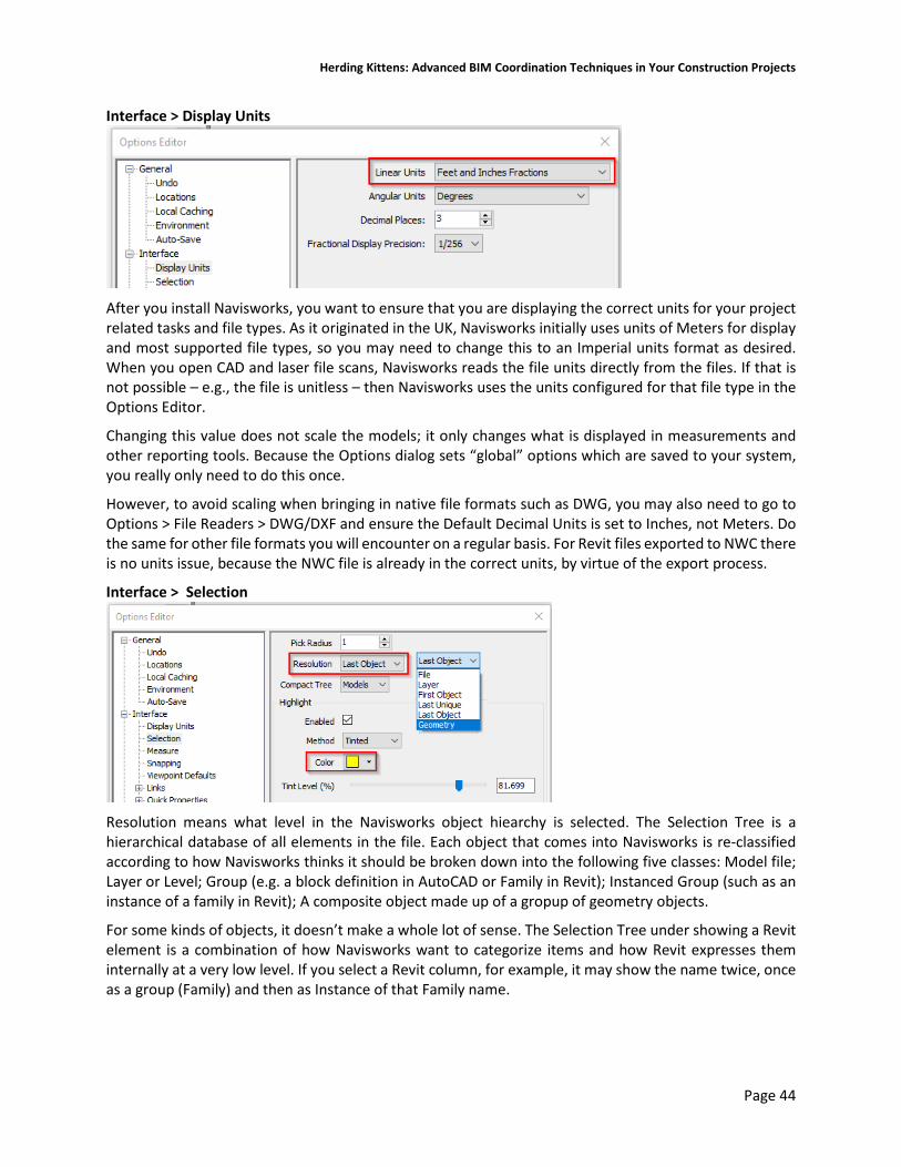
Herding Kittens: Advanced BIM Coordination Techniques in Your Construction Projects
Page 44
Interface > Display Units
After you install Navisworks, you want to ensure that you are displaying the correct units for your project related tasks and file types. As it originated in the UK, Navisworks initially uses units of Meters for display and most supported file types, so you may need to change this to an Imperial units format as desired. When you open CAD and laser file scans, Navisworks reads the file units directly from the files. If that is not possible – e.g., the file is unitless – then Navisworks uses the units configured for that file type in the Options Editor.
Changing this value does not scale the models; it only changes what is displayed in measurements and other reporting tools. Because the Options dialog sets “global” options which are saved to your system, you really only need to do this once.
However, to avoid scaling when bringing in native file formats such as DWG, you may also need to go to Options > File Readers > DWG/DXF and ensure the Default Decimal Units is set to Inches, not Meters. Do the same for other file formats you will encounter on a regular basis. For Revit files exported to NWC there is no units issue, because the NWC file is already in the correct units, by virtue of the export process.
Interface > Selection
Resolution means what level in the Navisworks object hiearchy is selected. The Selection Tree is a hierarchical database of all elements in the file. Each object that comes into Navisworks is re-classified according to how Navisworks thinks it should be broken down into the following five classes: Model file; Layer or Level; Group (e.g. a block definition in AutoCAD or Family in Revit); Instanced Group (such as an instance of a family in Revit); A composite object made up of a gropup of geometry objects.
For some kinds of objects, it doesn’t make a whole lot of sense. The Selection Tree under showing a Revit element is a combination of how Navisworks want to categorize items and how Revit expresses them internally at a very low level. If you select a Revit column, for example, it may show the name twice, once as a group (Family) and then as Instance of that Family name.

Herding Kittens: Advanced BIM Coordination Techniques in Your Construction Projects
Page 45
In the Selection Resolution, you have File and Layer / Level as usual, and then you can select the topmost object in the element tree, the last unique thing in the tree, the last object in the tree, or the invidual piece of geometry. Practice will tell you where to set this, and you can change it on the fly using the right-click shortcut menu in the Scene View. In most cases I want to select items just above the raw geometry, which is why I use Last Object by default. But this changes to File, Layer, and others as I work through my models.
When you select elements on screen, those elements are highlighted in the Selection Tree as well. You can use the Selection Tree hierarchy to drill down into the selected element to see what components make up a complex object. Elements that are hidden are grayed out in the Selection Tree.
When you select an object, it highlights in the Scene View using the color you set under Options > Interface > Selection. This is largely subjective, but I like using bright colors for the selected objects. Yellow seems to work best with a black background (my personal taste). Green or Red may work better with a white background.
Interface > Snapping
The only thing to change here is the Snap to Edge is turned on. This makes it possible to measure the distance to a pipe by selecting its faceted edge.
Interface > Viewpoint Defaults
This is an important one. Viewpoints are the main ways you navigate around the model to go floor by floor and area by area. Setting up Viewpoints entails configuring the Scene View with what you want to see, and saving it in the Viewpoints window. When you create a Viewpoint that you want to recall over and over again, you need to ensure the hide / show status of everything in that Viewpoint is able to be recalled as well.
If not, the hide/show status of the entire scene is “global” and is whatever it was before you went into that Viewpoint. Thus, you need to tweak that hide/show status obf model objects over and over as you switch Viewpoints.

Herding Kittens: Advanced BIM Coordination Techniques in Your Construction Projects
Page 46
With this box checked, the show / hidden will be recorded for every new Viewpoint you create. Note that you can edit any Viewpoint’s settings to turn this on or off. If you reset the Show / Hide status on elements and want to “bake” that into your Viewpoint, you need to right-click on the Viewpoint and hit Update to make it all stick.
The Override Appearance option works the same way with overridden element graphics. For example, If you change the graphics of an element to be blue, and have this option set and save that as a new Viewpoint, that element will always be blue in that Viewpoint. If you change the element to red and click on the Viewpoint to go back to it, the element changes back to Blue.
However, if you set it back to Red, right-click on the Viewpoint and select Update, it resaves the Viewpoint with the object as red and it will be so whenever you go back to this Viewpoint.
In my opinion that allows things to get a little crazy and out of control quickly, as every view can have different graphical overrides. Which leads me to my next tip:
Pro Tip #29: Keep Show/Hide status a property of the Viewpoint. Keep Appearance Overrides Global Let Viewpoints control what is shown and what is hidden. Override element graphics on a global basis via the Appearance Profiler or manual means.
Interface > Display

Herding Kittens: Advanced BIM Coordination Techniques in Your Construction Projects
Page 47
The Display options configure the Scene View to work best with your hardware capabilities to deliver as much eye candy as you can get away with. For the most part the default settings work and work well. Navisworks loves a good fast graphics card, and you do not need “Professional Workstation” cards to get excellent results – gaming cards work perfectly fine, and the more advanced the gaming card you have, the better.
The only setting on this page that I recommend changing is the CPU / GPU Occlusion Culling settings. By default, CPU culling is on and GPU (graphics card) culling is off. However, if you have a decent late-model graphics card in your system, you should get better results with GPU Occlusion Culling enabled and CPU culling off.
Graphics cards are, for many operations, thousands of times faster than CPUs for highly parallel tasks like occlusion culling, so your Scene View performance should go up with this set as shown above.
Interface > Display > Autodesk
In the Display > Autodesk options, turning on Screen Space Ambient Occlusion results in some very nice graphics, providing “contact shadows” at the edges of objects to give the scene real depth and volume. Otherwise things look flat and unrealistic. The Phong shader style seems to give the best overall picture in my view, but this is subjective and pretty difficult to see real differences.

Herding Kittens: Advanced BIM Coordination Techniques in Your Construction Projects
Page 48
Ambient Occlusion Off
2Ambient Occlusion on
As you can see, there is a good deal of difference between the two; the AO really gives the feeling that objects are grounded and have weight. AO works by evaluating the distance between faces and the angles between them, and adding shadows at those corner contact points.
Multi-Sample Anti-Aliasling sets how much the Scene View will try to get rid of the “jaggies” that occur on diagonal geometry, where the edges of one thing are shown against another. Because pixels are square, the resulting image is jagged at the edges of objects. A “moiré pattern” appears where there are multiple diagonal lines close to each other, which is most pronounced in the image on the left below.
Anti-aliasing samples colors on either side of the edge and mixes them with the edge color, producing a smoother overall image. 4x is a usable minimum in my opinion; 16x looks absolutely fantastic.
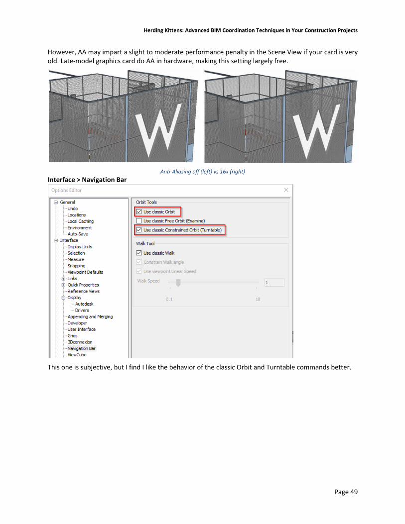
Herding Kittens: Advanced BIM Coordination Techniques in Your Construction Projects
Page 49
However, AA may impart a slight to moderate performance penalty in the Scene View if your card is very old. Late-model graphics card do AA in hardware, making this setting largely free.
Anti-Aliasing off (left) vs 16x (right)
Interface > Navigation Bar
This one is subjective, but I find I like the behavior of the classic Orbit and Turntable commands better.

Herding Kittens: Advanced BIM Coordination Techniques in Your Construction Projects
Page 50
Model > Performance
“Close NWC/NWD files on load” should be checked so that your NWCs can be written to while they are in your current Navisworks file. This lets you re-export from Revit and Refresh the scene without having to get out of Navisworks completely. I’m not sure what Optimize on Load does but it sounds good.
Tools > Clash Detective
Another personal preference of mine is to turn the wireframe display of Transparent Dimming in the Clash Detective off. The highlighted elements just seem to pop better.

Herding Kittens: Advanced BIM Coordination Techniques in Your Construction Projects
Page 51
File Readers > DWG/DXF
File Reader options for DWG/DXF tells Navisworks how to process the DWG files as it turns them into NWCs. Most of the settings on this page are changed from the defaults. In side by side tests I found no difference between a Faceting Factor of 1 (the default) and 4, to see if pipes and other curved surfaces would show more detail and be less faceted. I recommend you leave it at 1.
What will make a difference is almost everything else. The units are set to Inches, I convert off / frozen layers, but I do not convert Xrefs, views, points, lines, text or point clouds. This saves me from seeing a lot of stuff that would otherwise show up, and can reduce the size of the NWC by a considerable factor.
File Readers > Revit We covered Revit export settings under the Revit Tips and Tricks section.
Navisworks Templates Navisworks is not like other applications that work off of a template system like Revit, AutoCAD, or Microsoft Word, You start a project with a blank Navisworks file and add things to it. From a Navisworks standpoint, however, construction projects are more similar than they are different. You can jump start the coordination process and keep yourself from having to do a lot of work later if you don’t start from scratch, but with a well-defined folder tree and a preset Navisworks .NWF file already stuffed with a series of dummy data files in both .NWC and .DWG format. This then allows standard clash tests to be created. You would also add any other standards to this NWF, such as Search Sets and Appearance Profiler data.

Herding Kittens: Advanced BIM Coordination Techniques in Your Construction Projects
Page 52
That way, when you start getting the trade contractor models start coming in, you simply replace the dummy DWG or NWC files. Fire up the NWF or hit Refresh in Navisworks and they will show up, all right in the same place. That is, assuming everyone paid attention to the location of WCS 0,0,0 as properly laid down in your BxP.
Importing previously-exported Search Sets and Appearance Profiler data is highly beneficial. However, every project is different, and Search Sets only gets you so far, particularly if your trade contractors are using AutoCAD because the number of project-independent Search Sets would be limited. Also, you can’t import or set up clash tests in a blank NWF with nothing appended. Nothing beats having a starter Navisworks NWF with trade coordination files pre-populated and ready to go, along with standard sets, clash tests, and so on.
Setting up a Navisworks Working Folder Tree The first step in establishing your project coordination ecosystem is to assemble a standard working folder tree, for both construction modeling in Revit, as well as storing the Navisworks files and trade contractor models. That folder tree and the template Navisworks files can be stored on your network and copy/pasted when you start a new project. Navisworks files are relatively pathed into the NWF, so you can copy and paste the template tree to your actual project drive not lose any linked files.
In this sample template folder tree to the right, the top level folders are reserved for project documents (PDFs), BIM files (Revit and Navisworks), RFIs, Submittals, and MEP coordination sketches. The Project Documents PDFs would be for the original construction documents plus the heavily modified and marked up “working” CDs that were discussed in Section II.
The BIM folder has subfolders for Trades, with a subfolder for each of the different trade contractor construction BIMs, including Architectural and Structural – that’s where your curated DBIMs / CBIMs reside.
Note that Electrical has separate folders for lighting, power, and soda conduits. You want to minimize the number of files in each folder to store only the ones for that trade or sub-trade. Each trade will submit NWCs or DWGs of each floor or major coordination area, and for large buildings this can get excessive.
There is also a folder for copies of the submitted slab/sleeve/shear wall drawings, which will be linked into the Revit structural model and used to help poke holes in the slabs and shear walls.
The Architectural and Structural trade folder is where you will spend the bulk of your time. It stores your CBIM-in-progress Revit files. As such it has subfolders for project families, original Design BIMs, CAD exports, saved Groups, images, and exported NWC files that will be linked into the Navisworks NWF.
The 02 Navisworks folder will contain the NWF, with subfolders for Exports of all kinds – Appearance Profiler .DAT files, Options, Sets, and Viewpoints. The \Clash Tests and NWD folder contains the results of every weekly coordination meeting in dated subfolders (formatted as YYMMDD), which includes a copy of the latest NWD published model file.
The 05 MEP Coordination Sketches folder is reserved for the screen shots and PDFs you create on a daily basis working with your MEP Coordinator to generate RFIs.
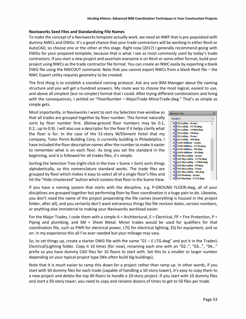
Herding Kittens: Advanced BIM Coordination Techniques in Your Construction Projects
Page 53
Navisworks Seed Files and Standardizing File Names To make the concept of a Navisworks template actually work, we need an NWF that is pre-populated with dummy NWCs and DWGs. It’s a good chance that your trade contractors will be working in either Revit or AutoCAD, so choose one or the other at this stage. Right now (2017) I generally recommend going with DWGs for your prepared template, because that is what I see as most commonly used by today’s trade contractors. If you start a new project and ascertain everyone is on Revit or some other format, build your project using NWCs as the trade contractor file format. You can create an NWC easily by exporting a blank DWG file using the NWCOUT command. Note that you cannot export NWCs from a blank Revit file – the NWC Export utility requires geometry to be created.
The first thing is to establish a standard naming protocol. Ask any one BIM Manager about file naming structure and you will get a hundred answers. My route was to choose the most logical, easiest to use, and above all simplest (but no simpler) format that I could. After trying different combinations and living with the consequences, I settled on “FloorNumber – MajorTrade MinorTrade.dwg.” That’s as simple as simple gets.
Most importantly, in Navisworks I want to sort my Selection tree window so that all trades are grouped together by floor number. This format naturally sorts by floor number first. (Below-ground floor numbers may be 0.1, 0.2…up to 0.9). I will also use a descriptor for the floor if it helps clarify what the floor is for. In the case of the 51-story W/Element Hotel that my company, Tutor Perini Building Corp, is currently building in Philadelphia, I have included the floor descriptive names after the number to make it easier to remember what is on each floor. As long you set the standard in the beginning, and it is followed for all trades files, it’s simple.
Sorting the Selection Tree (right-click in the tree > Scene > Sort) sorts things alphabetically, so this nomenclature standard works. The trade files are grouped by floor which makes it easy to select all of a single floor’s files and hit the “Hide Unselected” button which isolates that floor in the Scene View.
If you have a naming system that starts with the discipline, e.g. P-GROUND FLOOR.dwg, all of your disciplines are grouped together but performing floor by floor coordination is a huge pain to do. Likewise, you don’t need the name of the project prepending the file names (everything is housed in the project folder, after all), and you certainly don’t want extraneous things like file revision dates, version numbers, or anything else immaterial to making your Navisworks workload easier.
For the Major Trades, I code them with a simple A = Architectural, E = Electrical, FP = Fire Protection, P = Piping and plumbing, and SM = Sheet Metal. Minor trades would be used for qualifiers for that coordination file, such as PWR for electrical power, LTG for electrical lighting, EQ for equipment, and so on. In my experience this all I’ve ever needed but your mileage may vary.
So, to set things up, create a starter DWG file with the name “01 – E LTG.dwg” and put it in the Trades\ Electrical\Lighting folder. Copy it 10 times (for now), renaming each one with an “02..”, “03…”, “04…” prefix so you have dummy CAD files for 10 floors to start with. Set this to a smaller or larger number depending on your typical project type (We often build big buildings).
Note that it is much easier to ramp this down for a project rather than ramp up. In other words, if you start with 50 dummy files for each trade (capable of handling a 50-story tower), it’s easy to copy them to a new project and delete the top 40 floors to handle a 10-story project. If you start with 10 dummy files and start a 50-story tower, you need to copy and rename dozens of times to get to 50 files per trade.

Herding Kittens: Advanced BIM Coordination Techniques in Your Construction Projects
Page 54
Pro Tip #30: Be cool with your trade contractors Given this simplistic file naming structure, do not be surprised if your trade contractors balk at using it. Don’t worry about it. While you can impose certain things on them to make your life easier, file naming is often part and parcel of an office’s culture, and having an outsider make demands on file naming can be problematic. If you can get it, great. If not, this is not a battle worth fighting for, even on large projects.
Simply download their files to the folder they belong in, rename any existing file with an “_OLD” suffix, rename the new version to the standard spelled out above, and move on. I keep an _OLD subfolder in each trade folder and dump the previous versions there.
Pro Tip #31: Rename files en masse using Windows Powershell PowerShell is the old-timey Command console on sterioids. The power it has under the hood is quite amazing. We can use it to easily rename files based on the standards set previously.
Copy this initial batch of DWGs to the Electrical\Power folder. In Windows Explorer, hold the Shift key and right-click on the folder and select “Open Powershell window here.” This opens a PowerShell window in the Power folder. Issue this command to rename these files: Get-ChildItem -Filter "*.dwg" | Rename-Item -NewName {$_.name -replace 'LTG', 'PWR' }
Detailed information on the syntax is available here. This renames all DWGs, replacing ‘LTG’ with ‘PWR’ instantaneously. Copy these files to the Piping folder. In the Powershell window use CD to change the directory to the piping folder, or launch a new Powershell instance in that folder. Hit the up arrow to bring up the previous rename command (it works across Powershell sessions), and modify it thusly: Get-ChildItem -Filter "*.dwg" | Rename-Item -NewName {$_.name -replace 'E PWR', 'P’ }
Repeat the copy / rename process until you have the Trade folders filled with their dummy files.
Tie it All Together in Navisworks At this point we have to do the following:
1. Append all files into Navisworks and sort the Selection Tree 2. Set up all of our Selection / Search Sets 3. Set up Clash Detective to clash all trade files against all other trade files
Setting up the Selection and Search Sets Setting up your Sets is arguably the most important part of the process. Being able to do all Navisworks operations by Search Set is a key functionity of the program. While we are ultimately going to perform file vs. file clash testing, many people - especially those using Navisworks for coordination of Revit files – use Search Sets to clash system type against steel structure, or some other specialized search set of elements against another search set of elements. The Find Items dockable window is how you do this.

Herding Kittens: Advanced BIM Coordination Techniques in Your Construction Projects
Page 55
Under each column – Category, Property, Condition, and Value, you set the criteria for your search operation. For most Revit elements, you are going to use Category = “Element” and Property = “Category.” For AutoCAD elements, you will likely use Category = “Item.” Don’t confuse Revit’s “Category” with Navisworks’ Category.
The first step here is to make things easy: Set up a Search Set to look for all “Elements” whose “Category” is set to a [Revit Category Name].
Once you save this “seed” search set, you can easily create all of the others you need by simply selecting one, change the category to search for, and save it as a new Search Set. Search Sets for all default Revit categories are provided in the dataset for this class.
The Find Items window is the bane of my existence. The user interface is just this side of unusable.
Pro Tip #32: Create a “Hide Me” folder with Search and Selection Sets that finds all of the crap When you are working with CAD files from trade contractors, they will contain a lot of stuff you don’t want to see in your model. Linework, text, polylines, 3D solids, arcs, circles – essentially anything that is not ductwork or piping is a candidate to be hidden from view. AutoCAD files always seem to have stuff floating in space away from the building – hide those as well.
To do this easily, first create a “Hide Me” folder. Then create Search and Selection sets to find Dimensions, Text, MText, and any other AutoCAD entity type to hide. Select any floating elements in space, and group them into a Selection Set. Do so until all of the extraneous stuff is found.
Then, simply right-click on the Hide Me folder and select Hide. Selecting a folder selects all selection and search sets underneath of it, so selecting this single folder hides all of the bad stuff you don’t want to see in the model.
It’s also difficult to put together search sets for specific MEP elements types from CAD files. Searching by layers is too dependent on the file, and AutoCAD allows you to put any element on any layer, making it a very unsure proposition. MEP element types depend on the 3rd party software your trade contractor is using. When the OEs are installed, those add-in properties are available for query in search sets, but that’s a variable as well.
Clashing DWG against DWG Thus I’m mostly going to clash test DWG against DWG. Whenever you clash test n numbers of files against each other, you are going to end up with ((n * (n – 1)) / 2) total clash tests. So, for 5 trade contractor files (Sheet Metal, Electrical Lighting, Electrical Power, Plumbing, & Fire Protection) we are going to have ((5*4) / 2) tests, or 10 tests total, per floor. That’s a lot of tests.
What I would do here is only set up the first five floors for testing to start. Unfortunately you cannot group clash tests, only the results. That makes having many tests in a file problematic. Luckily, clash tests can be exported to XML, which is a text-based file. That means you could create the 10 separate tests for the first floor, export the clash test definitions, edit the XML to use the next floor (i.e., replace the ‘01’ with an ‘02’) and import the clash test. Repeat the procedure until you have an acceptable level of clash tests and work your way up the building from there. Remember that clash testing is a weekly procedure, and each floor may take 3 weeks (or more) to clear. You don’t need all clashes in your file on day one.

Herding Kittens: Advanced BIM Coordination Techniques in Your Construction Projects
Page 56
Attaching Coordination Models in AutoCAD and Revit Once exported and distributed to the building team, your trade contractors can attach NWCs and NWDs (what Autodesk terms “coordination models”) into their CAD files and use them as backgrounds for their work. This is much better than exporting 2D CAD files, because you give them full 3D information, including exterior window and ceiling heights, structural steel info, floor penetration locations, plenum spaces, and so on. It also provides the spatial coordination extents by which they develop each of their DWGs.
Also, if you are a trade contractor and your model is part of an NWD published by the GC’s BIM Coordinator, you have the option to turn off your geometry in the NWD so that you do not have duplication. By default it will also zoom to the coordination model within the AutoCAD drawing.
Any AutoCAD file can be exported to NWC as well, so trade contractors with different modeling add-ons can transfer coordination models back and forth, attach them as usual without the need for Object Enablers, and coordinate their work around them.
Coordination models can be inserted into Revit 2018 models as well. NWCs don’t seem to care what version of Revit created them, either. This enables NWC to be, in theory, a universal transfer format capable of overcoming a lot of issues with trying to work across platforms, software capabilities and versions, etc.
Problems with Using Coordination Models in AutoCAD 2018 Attaching an NWC/NWD file is largely similar to attaching drawings, PDFs, and images. However, coordination models do not act the same way AutoCAD files do; in fact they have their own rules which can be rather at odds with what you need coordination models for in the first place.
First, unlike in Navisworks, the internal structure of a coordination model is unavailable to you in AutoCAD. You cannot select individual elements in the NWC, or turn those elements off. There are no layers available to freeze or thaw. If your coordination model typically goes from top of slab to top of slab, you have no way to turn the top slab off and thus see “into” the model.
Second, coordination models do not respect the current viewport graphics settings; from hidden line through shaded with edges, coordination models look and act like visual ghosts, and will not display edges of their geometry. This makes it extremely difficult to see if there is a clash between your work and the coordination model.
Third, they may or may not work in perspective views, which I believe is a bug. In some NWCs that were exported from Revit, if I issue the PERSPECTIVE command, the display of the coordination model is shut off for display and leaves a bounding box instead.
Fourth, neither coordination models nor 3rd’party 3D geometry (even that created in CADmep+) is sectioned using the SECTIONPLANE command. Because you cannot effectively section these, it makes it very difficult if not impossible to see through the model to ascertain if there is a clearance issue or conflict.
Using the Find Items Dialog
Using Selection and Search Sets Use Folders to Group Similar Search Sets Create a “Hide Me” Search Set that contains crap Eliminate CAD linework, MText, dimensions, etc.
Attach a Coordination Model

Herding Kittens: Advanced BIM Coordination Techniques in Your Construction Projects
Page 57
Start with the standard set of Revit Category Search Sets Use Selection Sets sparingly Useful for selecting one-off items or extraneous stuff from CAD files
Linework, MText, Dimensions, etc.
Organization
Viewpoints and Their Uses Viewpoint Default Settings Setting Field of View Grouping Viewpoints Updating Viewpoints Hide / Required vs. Override Appearance
Clash Detective Tips Initial setup using dummy files Running Clash Tests Grouping Clashes

Herding Kittens: Advanced BIM Coordination Techniques in Your Construction Projects
Page 58
V. Interoperability with AutoCAD and Bluebeam Revu
Working with AutoCAD files Why do we still need AutoCAD? When it comes to architectural and engineering design, it is clear that AutoCAD as a production tool is on its way out, if not out completely. Purpose built tools like Revit have clearly dominated the design-firm market for some time, and AutoCAD-only design firms are getting more rare.
However, in the trade contractor space, AutoCAD is still very much alive and kicking. It has been six years since Autodesk acquired MAP software in 2011, and for their part Autodesk has made considerable effort in converting their Fabrication CADmep+ product over to the Revit platform. While they have done a decent job getting Fabrication parts into Revit, most trade contractors remain unconvinced to change over to the Revit platform for a number of reasons.
In many respects it is because the Fabrication CADmep+ tools are very good. Modeling a line of fabrication ductwork in CADmep+ is considerably easier than modeling the same line in Revit. There are editing functions that work on native Revit ductwork that do not work on Fabrication Parts. However, Revit’s strength here is that you can model normal ductwork and convert it to Fabrication Parts easily. And with each release of Revit there seem to be solid improvements in the Fabrication Parts functionality that help bring it on par with CADmep+. How long it will be before it can gain more widespread acceptance in the sheet metal trade contractor arena remains to be seen
Using AutoCAD to assist in Revit family modeling Other than the fabrication side, AutoCAD still serves many valuable utilitarian purposes. I find it a great way to assist in modeling certain things that are typically difficult in Revit. For example, I may need to create a custom reception desk. To do that I need project context – a plan of the reception area. While I can model the desk using an In-Place Family, that is generally considered Bad Practice and something I like to avoid.
In this case, it’s easiest to export a 3D section box of the reception area to DWG. Import the DWG into a new blank Generic Model family. Start a new Casework family, load the Generic Model of the reception area, and model the reception desk with full context.
I use the same technique for modeling complex stair railings. I first create the base stair in Revit, export the stair geometry to DWG, import it into a new GM family, and model the entire custom railing. Then load this GM railing into a Baluster Post family, load it into the project and assign the Baluster Post (and the entire custom railing) to a new Railing type. While this kind of custom workaround is clumsy at best, and is difficult to modify and iterate through design, it does free you from the awful Railing composition tool we have in Revit.
Pro Tip #33: Export to AutoCAD using a Company Standard DWG/DXF Export Setup Exporting Revit floor plans to AutoCAD is still a major aspect of construction BIM administration. Because so many trade contractors, particularly the millwork and casework trades, still use AutoCAD and are always asking for the latest floor plans, it’s a good idea to have a plan for exporting them consistently.
The first thing to do is establish a standard set of Export options. Export options allow you to set up all of the parameters for exporting to DWG and reuse those across projects. Create a company-specific DWG/DXF Export Setup in your corporate Revit template.

Herding Kittens: Advanced BIM Coordination Techniques in Your Construction Projects
Page 59
In any BIM file you work on, start a new project based on your template, and use Transfer Project Standards to import the DWG/DXF Export Setup Settings into your current file.
The issue you may have is that, it is imperative that any floor plan DWG exports be located from the WCS origin point the same distance. This can pose some challenges if you need to export from multiple DBIMs, or export from one DBIM and link the CAD file into another DBIM.
I have seen plenty of models come in that (a) may not have the same Project Base Point relative to the project content, and (b) more often than not do not have a common Survey Point establishing a Shared Coordinate System. That means that the DWGs and DBIMs will not fully interoperate with each other because there is no consistent origin point to work with to establish common positioning.
In the DWG/DXF Export Settings dialog box, Units & Coordinates tab there is the option to set the resulting DWG coordinate system based on the Project Base Point or the Shared Coordinate System. It is typically set to Project Internal by default, which works well – as long as all of the Revit files you need to export are centered about the same Project Base Point. If not, you need to rely on the Survey Point, as you cannot relocate a project’s contents relative to a new Project Base Point.
Once projects are linked together and aligned properly, the Survey Point should be established which sets a common shared coordinate system between all DBIMs. Use the Publish Coordinates tool to write this new Survey Point location to each DBIM. Changing the export option to base the DWG coordinatee system on the Survey Point ensures all DWGs creted from any DBIM will align properly with any others.
When Revit exports a view to AutoCAD, it sets WCS 0,0,0 in the resulting DWG as the Project Base Point in the project. Even if you unclip the PBP and move it around, the WCS will remain at the location of the Project Origin.
Working with IFC Files IFC – or Industry Foundation Classes – is a means to allow Building Information Models to transfer from one source application to another and have both the 3D geometry and non-graphical data remain intact. It’s not a perfect means to transfer files, and IFC is a moving target.

Herding Kittens: Advanced BIM Coordination Techniques in Your Construction Projects
Page 60
However, some very large (and very influential) organizations rely on IFC for BIM file transfer. In particular the General Services Administration – the arm of the Federal Government charged with managing and supporting the office space for all U.S. government offices and federal employees - requires designers and contractors to submit files in IFC. If you want to do work for the GSA, you need to provide them with IFC files.
In addition, steel fabrication shop modeling may be performed in applications completely foreign to Revit. To use them in your construction BIMs, you likely will need them converted to IFC.
Once in IFC, they can be linked into Revit files and used as coordination models are used in AutoCAD. You have some visibility control over individual components, but not much. What you can do, however, is convert IFC files to Revit. They lose a lot of data in the process, and their usefulness needs to be evaluated on a case by case basis, but it’s possible. It is a four-step process.
Pro Tip #34: Opening IFC Files and Converting them to Revit 1. Get the latest IFC Import / Export add-in for Revit 2018 here. Versions for older releases of Revit
are available as well. 2. Create a Blank IFC Import Template. The first step in converting IFCs to Revit is to create a new,
blank Revit template with absolutely nothing in it. Purge the file completely. Save it as your company’s standard IFC Import Template.rte
3. Configure IFC Import Options. Go to File > Open > IFC Settings and review all IFC Class to Revit Category mappings.
4. Ensure the template created in step 1 is assigned to the Default Template for IFC Import. 5. Save the IFC Options as your standard IFC Class Mappings.txt file
.
Once your settings are complete, you can open an IFC file and save it as an RVT.
Specific IFC Info: Importing Tekla IFC files into Revit Download and install the ImportFromTeklaToRevit add ins: https://www.tekla.com/us/products/tekla-structures/tekla-interoperability-autodesk-revit-products

Herding Kittens: Advanced BIM Coordination Techniques in Your Construction Projects
Page 61
Greenshot One of the primary means of communications from the job office is through the use of annotated screenshots. Because PDF is the dominant format used by contractors in all correspondence, it makes sense to find a way to take a screen shot of a model condition, in either Revit or Navisworks, and get it into Bluebeam Revu or Acrobate or whatever your PDF weapon of choice is.
While you can print to PDF – even 3D PDFs with Bluebeam – it’s more of a hassle, because neither Revit or Navisworks allow you to simply print a window. It’s the whole view.
Greenshot is a freely available screen shot program that I have found to be pretty invaluable in my daily work. You can mark screen shots up with limited graphics and text, but the real power is how you can effortlessly export a screenshot right into Photoshop or Bluebeam and mark it up there.
Greenshot 1.2.10.6 is available at http://getgreenshot.org/.
Configuring Greenshot hotkeys Setting up Greenshot is easy. While it is running, right-click on the Greenshot taskbar icon > Preferences. I set my PrntScrn button as a region capture, with CTRL+PrntScrn capturing the full window, ALT+PrntScrn captures the active window, and SHIFT+PrntScrn captures the last window.
Send Greenshot screenshots to Bluebeam and Photoshop In Settings, go to the Plugins tab, select External Command Plugin, and click Configure. Click New to define a new external command. Set the name to “Bluebeam Revu,” use the search button to find the Revu.exe file, and leave the Argument box alone - the “{0}” simply means to send the current screen shot to the application.
Do the same for Photoshop, Paint.net, or any other application you want to easily send a screenshot to.
Now taking a screen shot is as easy as hitting PrintScreen, clicking the Bluebeam icon in the toolbar, and marking up the PDF.